multi-objective optimization of cnc turning process ... - mdpi
TRANSCRIPT
Sustainability 2021, 13, 13803. https://doi.org/10.3390/su132413803 www.mdpi.com/journal/sustainability
Article
Multi‐Objective Optimization of CNC Turning Process
Parameters Considering Transient-Steady State Energy Consumption
Shun Jia 1,*, Shang Wang 1, Jingxiang Lv 2,*, Wei Cai 3,*, Na Zhang 1, Zhongwei Zhang 4 and Shuowei Bai 5
1 Department of Industrial Engineering, Shandong University of Science and Technology, Qingdao 266590,
China; [email protected] (S.W.); [email protected] (N.Z.) 2 Institute of Smart Manufacturing Systems, School of Construction Machinery, Chang’an University,
Xi’an 710064, China 3 College of Engineering and Technology, Southwest University, Chongqing 400715, China 4 School of Mechanical and Electrical Engineering, Henan University of Technology, Zhengzhou 450001,
China; [email protected] 5 School of Mechanical and Electrical Engineering, Qingdao University, Qingdao 266071, China;
* Correspondence: [email protected] (S.J.); [email protected] (J.L.); [email protected] (W.C.)
Abstract: Energy‐saving and emission reduction are recognized as the primary measure to tackle
the problems associated with climate change, which is one of the major challenges for humanity for
the forthcoming decades. Energy modeling and process parameters optimization of machining are
effective and powerful ways to realize energy saving in the manufacturing industry. In order to
realize high quality and low energy consumption machining of computer numerical control (CNC)
lathe, a multi‐objective optimization of CNC turning process parameters considering transient‐
steady state energy consumption is proposed. By analyzing the energy consumption characteristics
in the process of machining and introducing practical constraints, such as machine tool equipment
performance and tool life, a multi‐objective optimization model with turning process parameters as
optimization variables and high quality and low energy consumption as optimization objectives is
established. The model is solved by non‐dominated sorting genetic algorithm‐II (NSGA‐II), and the
pareto optimal solution set of the model is obtained. Finally, the machining process of shaft parts is
studied by CK6153i CNC lathe. The results show that 38.3% energy consumption is saved, and the
surface roughness of workpiece is reduced by 47.0%, which verifies the effectiveness of the optimi‐
zation method.
Keywords: energy saving; multi‐objective optimization; transient steady state energy consumption;
process parameters
1. Introduction
As the main equipment of (computer numerical control) CNC machining, the CNC
machine tool is widely used in various fields of manufacturing. It has complex energy
consumption characteristics, high energy consumption, low energy efficiency, and huge
potential for energy saving and emission reduction [1,2]. Therefore, domestic and foreign
scholars are increasingly active in the research on energy consumption modeling and en‐
ergy‐saving and emission reduction methods of CNC machine tools [3–6]. In the process
of CNC machining, the reasonable selection of process parameters not only affects the
indexes of machining cost [7], quality [8] and efficiency [9], but also is closely related to
the energy consumption of machine tools [10]. How to optimize the process parameters
in the machining process of CNC machine tools is an urgent basic scientific problem to be
solved under the background of green manufacturing [11].
Citation: Jia, S.; Wang, S.; Lv, J.;
Cai, W.; Zhang, N.; Zhang, Z.; Bai, S.
Multi‐Objective Optimization of
CNC Turning Process Parameters
Considering Transient‐Steady State
Energy Consumption. Sustainability
2021, 13, 13803. https://doi.org/
10.3390/su132413803
Academic Editor: Hua Li
Received: 3 November 2021
Accepted: 10 December 2021
Published: 14 December 2021
Publisher’s Note: MDPI stays neu‐
tral with regard to jurisdictional
claims in published maps and institu‐
tional affiliations.
Copyright: © 2021 by the authors. Li‐
censee MDPI, Basel, Switzerland.
This article is an open access article
distributed under the terms and con‐
ditions of the Creative Commons At‐
tribution (CC BY) license (http://crea‐
tivecommons.org/licenses/by/4.0/).
Sustainability 2021, 13, 13803 2 of 25
Traditional research on process parameters optimization mainly aims at optimizing
the quality, cost and efficiency of the process. For example, Zhou et al. [12] took the min‐
imum surface roughness value as an optimization objective, Addona et al. [13] took the
comprehensive optimization of processing cost, quality and time as an optimization ob‐
jective, and Pan et al. [14] took the reliability of milling accuracy as an optimization objec‐
tive. In recent years, with the increasing severity of energy consumption and environmen‐
tal problems in manufacturing industry, research considering the objectives of green and
low carbon optimization has gradually appeared [15,16]. The existing optimization meth‐
ods of CNC machining process parameters can be roughly divided into three categories:
optimization based on experiment, optimization based on optimization algorithm and op‐
timization based on expert knowledge system [17].
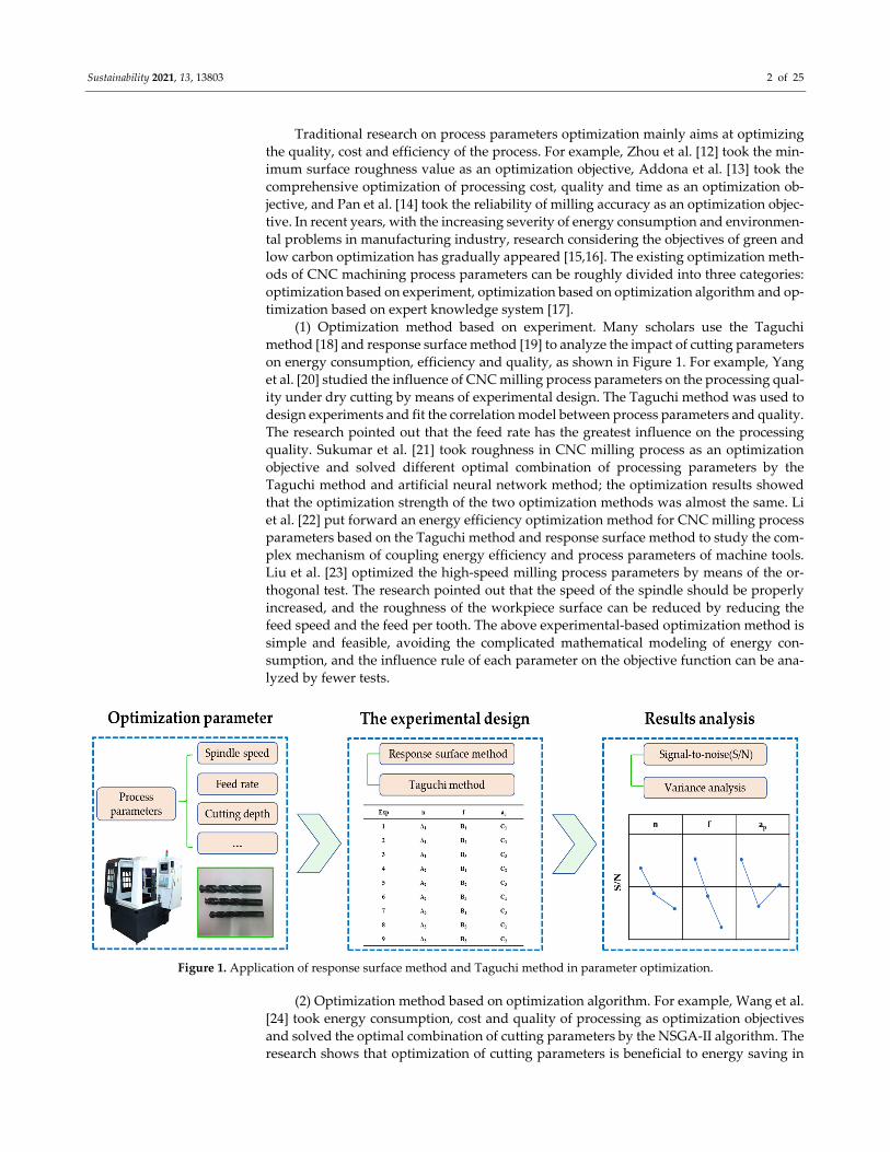
(1) Optimization method based on experiment. Many scholars use the Taguchi
method [18] and response surface method [19] to analyze the impact of cutting parameters
on energy consumption, efficiency and quality, as shown in Figure 1. For example, Yang
et al. [20] studied the influence of CNC milling process parameters on the processing qual‐
ity under dry cutting by means of experimental design. The Taguchi method was used to
design experiments and fit the correlation model between process parameters and quality.
The research pointed out that the feed rate has the greatest influence on the processing
quality. Sukumar et al. [21] took roughness in CNC milling process as an optimization
objective and solved different optimal combination of processing parameters by the
Taguchi method and artificial neural network method; the optimization results showed
that the optimization strength of the two optimization methods was almost the same. Li
et al. [22] put forward an energy efficiency optimization method for CNC milling process
parameters based on the Taguchi method and response surface method to study the com‐
plex mechanism of coupling energy efficiency and process parameters of machine tools.
Liu et al. [23] optimized the high‐speed milling process parameters by means of the or‐
thogonal test. The research pointed out that the speed of the spindle should be properly
increased, and the roughness of the workpiece surface can be reduced by reducing the
feed speed and the feed per tooth. The above experimental‐based optimization method is
simple and feasible, avoiding the complicated mathematical modeling of energy con‐
sumption, and the influence rule of each parameter on the objective function can be ana‐
lyzed by fewer tests.
Figure 1. Application of response surface method and Taguchi method in parameter optimization.
(2) Optimization method based on optimization algorithm. For example, Wang et al.
[24] took energy consumption, cost and quality of processing as optimization objectives
and solved the optimal combination of cutting parameters by the NSGA‐II algorithm. The
research shows that optimization of cutting parameters is beneficial to energy saving in
Sustainability 2021, 13, 13803 3 of 25
the process of machining but increases costs. Yan et al. [25] used cutting energy consump‐
tion, machining efficiency and surface quality as optimization models of milling process
parameters and carried out optimization by gray correlation analysis and the surface re‐
sponse method. Li et al. [26,27] carried out energy efficiency optimization for multi‐step
CNC planar milling process parameters, established target functions, such as energy effi‐
ciency and processing cost, and solved the multi‐objective optimization model by apply‐
ing the multi‐objective particle swarm algorithm based on adaptive grid and continuous
taboo algorithm, and obtained the optimal configuration of cutting parameters and work
steps. Most of the above research on the energy optimization model of the CNC machine
tool consider the steady state process energy consumption but ignore the phenomenon of
frequent transient process energy consumption and high‐power peak in the machining
process and lack the consideration of transient process energy consumption. Therefore, to
accurately reflect the actual energy consumption and running time of CNC machine tools
and guide energy saving of CNC machine tools, a transient‐steady state energy consump‐
tion function model is established.
(3) Optimization method based on expert knowledge system. For example, the expert
knowledge system designed by Arezoo is used to determine the cutting tool and cutting
parameters (feed rate, cutting speed, cutting depth, etc.) in the cutting process to establish
the expert knowledge base, and to establish the reasoning mechanism based on the expert
experience so that the system finally outputs the optimal parameters by gradually adjust‐
ing the parameters [28]. Zhou et al. [29] developed a turning expert system with a self‐
learning function. The system uses the concentrated mathematical model derived from
cutting experiments to store the cutting data and uses the self‐learning function to modify
the cutting mathematical model. It can recommend reasonable and optimized cutting pa‐
rameters, such as tool, cutting speed and tool life, and predict the machining quality and
metal removal rate. The optimization method based on an expert knowledge system de‐
pends on the knowledge level and experience of experts, and the optimization results are
practical.
In the manufacturing industry, in addition to optimizing process parameters, there
are many other methods to achieve energy saving and emission reduction. Liu et al. [30]
focused on the classical job shop environment and proposed that energy saving can be
achieved by turning off the machines when they lay idle for a comparatively long period.
Ma et al. [31] studied how to reduce the energy consumption of holes machining through
optimizing the tool path and cutting parameters simultaneously; the integrated optimiza‐
tion methodology can further reduce the energy consumption, compared with optimizing
the tool path or cutting parameters separately. Petrovic et al. [32] carried out a series of
research on the optimization of machining process route and achieved rich research re‐
sults.
In view of this, this paper comprehensively considers the traditional optimization
objectives and low‐carbon optimization objectives to study the machining of shaft parts.
Firstly, the energy consumption composition characteristics of the CNC lathe machining
process are analyzed, the transient process energy consumption is introduced into the en‐
ergy consumption model of a CNC lathe, and the transient‐steady state energy consump‐
tion model of a CNC lathe is constructed, which further improves the accuracy of the
model. Secondly, a multi‐objective optimization model is established, which takes the
spindle speed, feed rate and cutting depth as the optimization variables, and the high
quality and low energy consumption machining of the CNC machine tool as the optimi‐
zation objective. Then, considering the actual constraints, the model is optimized by a
non‐dominated sorting genetic algorithm with an elite strategy. Finally, the effectiveness
and practicability of the optimization method are verified by a case study.
2. Energy Consumption Characteristics Analysis and Energy Consumption Modeling
The energy consumption characteristics of a CNC lathe are more complex than that
of common machine tools. In this section, firstly, the energy consumption characteristics
Sustainability 2021, 13, 13803 4 of 25
of CNC turning are analyzed in detail through actual machining cases. Secondly, the en‐
ergy consumption of transient process is introduced into the energy consumption model
of a CNC lathe, and a comprehensive energy consumption model of transient steady state,
which is more consistent with the actual situation and has higher accuracy of the energy
consumption prediction, is established.
2.1. Analysis of Energy Consumption Characteristics in CNC Turning Process
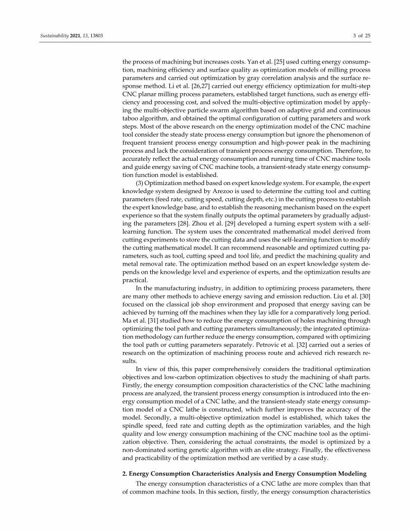
Taking the machining of shaft parts by the ck6153i CNC lathe as an example [33], the
basic principle and energy consumption characteristics of CNC machining are analyzed.
The machining process of this part mainly includes (a) standby; (b) spindle speedup to
500 r/min; (c) rapid positioning; (d) feeding; (e) end‐face turning; (f) rapid positioning and
feeding; (g) rough turning; (h) rapid positioning and spindle speedup to 1000 r/min; (i)
feeding; (j) finish turning; (k) rapid positioning and feeding; (l) chamfer turning; (m) rapid
positioning and spindle speed to 500 r/min; (n) tool changing; (o) rapid positioning and
feeding; (p) grooving; (q) rapid positioning to origin; and (r) standby, machining finished.
The power curve is shown in Figure 2.
Figure 2. Measured power curve of machining process for a shaft part.
According to Figure 2, the power of the basic module to maintain the standby oper‐
ation of the machine tool is stable until the spindle of the machine tool accelerates, mainly
including the operation of CNC systems, fans and other devices of the CNC machine tool
to maintain the basic movement of the machine tool. The spindle starts and accelerates to
the corresponding processing parameters. The duration of this process is short, but the
peak value is large as shown in the power diagram. This process is called spindle acceler‐
ation. After the acceleration of the spindle, the processing activities are carried out at a
constant speed. This power is the spindle rotating power, which is a stable value. The tool
then moves quickly into the given position to the safe cutting position for a short duration.
When positioned in a safe position, the tool approaches the workpiece at a constant feed
speed in preparation for cutting. During the process of end‐face turning, the power curve
of the process changes smoothly without an instantaneous peak value due to the gradual
change of the cutting depth and cutting speed. After the end‐face turning, the tool rapid
feed is positioned to the origin. This process also lasts a short time, but there is an obvious
power peak.
According to the above‐mentioned shaft parts machining process, the energy con‐
sumption of the CNC machine tool machining processes can be decomposed into two
parts: (A) energy consumption of the steady state, such as standby operating, spindle ro‐
tating, feeding, material cutting, etc.; (B) energy consumption of transient state, such as
spindle speedup, rapid positioning, etc. The transient state is the transition process be‐
tween the two steady states, which may lead to peak power. Transient states frequently
occur during a machining process and their energy consumptions should not be ignored.
Among the existing research on energy consumption of CNC machine tools, the
modeling and optimization of energy consumption in the steady state process during
Time(s)
Power(w)
a c d e g i j k
m n
p r
b f h l
Steady stateTransient state
Io
q
I
IIII
IIII
II
II
I I
I
Sustainability 2021, 13, 13803 5 of 25
CNC machine tool machining are more in depth, but the research on the transient process
is relatively little, and the change in power consumption caused by this process is not paid
attention to. For example, the power consumption of transient process is not considered
in the method given by Heʹs research, which results in the calculated value being 9.3%
smaller than the measured value [34]. Therefore, it is very important to consider the en‐
ergy consumption of the transient process in the study of energy consumption optimiza‐
tion of CNC machine tools. As can be seen in Ref. [35], when forecasting the demand for
energy consumption of the whole machining process, the predicted value, taking into ac‐
count the energy consumption of the transient process, is 6.35% higher than the previously
predicted value.
2.2. Energy Consumption Modeling of CNC Turning
Based on the analysis of the energy consumption composition characteristics of CNC
lathe machining process in the previous section, the CNC lathe machining process is di‐
vided into the steady state process and transient state process, and then the CNC lathe
machining process energy consumption is divided into steady state process energy con‐
sumption and transient state process energy consumption.
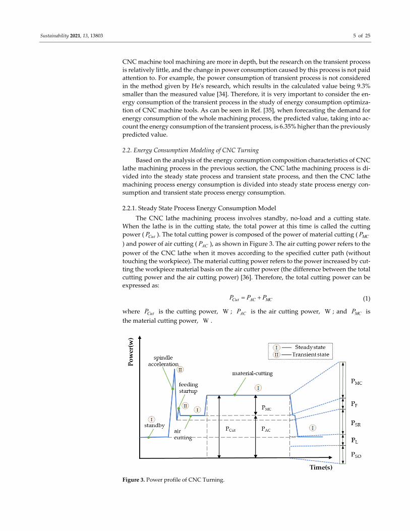
2.2.1. Steady State Process Energy Consumption Model
The CNC lathe machining process involves standby, no‐load and a cutting state.
When the lathe is in the cutting state, the total power at this time is called the cutting
power ( CutP ). The total cutting power is composed of the power of material cutting ( MCP
) and power of air cutting ( ACP ), as shown in Figure 3. The air cutting power refers to the
power of the CNC lathe when it moves according to the specified cutter path (without
touching the workpiece). The material cutting power refers to the power increased by cut‐
ting the workpiece material basis on the air cutter power (the difference between the total
cutting power and the air cutting power) [36]. Therefore, the total cutting power can be
expressed as:
Cut AC MCP P P (1)
where CutP is the cutting power, W ; ACP is the air cutting power, W ; and MCP is
the material cutting power, W .
Figure 3. Power profile of CNC Turning.
Sustainability 2021, 13, 13803 6 of 25
The power of the air cutting is further decomposed into standby operating power,
machine tool lighting power, spindle rotating power and feeding power. Therefore, the
power of the air cutting can be further expressed as:
AC SO L SR FP P P P P (2)
where SOP is the standby operating power, W ; LP is the machine tool lighting power,
W ; SRP is the spindle rotating power, W ; and FP is the feeding power, W .
According to Equations (1) and (2), the cutting power can be further expressed as:
Cut SO L SR F MCP P P P P P (3)
Next, the functional models of the standby operating power ( SOP ), machine tool
lighting power ( LP ), spindle rotating power ( SRP ), feeding power ( FP ) and material cut‐
ting power ( MCP ) are introduced, one by one.
(1). Standby operating power
The standby power refers to the power required by the basic modules (including
control panel, fan, etc.) to ensure the operation of the machine tool. For a given machine
tool, this power is regarded as a fixed value. The standby power can be obtained by pre‐
measurement combined with the following formula [37]:
1
,SON
SO SO SOi
P P i N
(4)
where SOP is the standby operating power, W ; ,SOP i is the standby operation power
value measured for the i‐th time, W ; and SON is the number of times to measure the
standby operating power.
(2). Machine tool lighting power
The lighting power of the machine tool is the power required to maintain the lighting
demand of the machine tool. When the model of the machine tool is determined, the light‐
ing power of the machine tool is equal to the rated power of the lighting device of the
machine tool, and the function expression is [37]:
L LrP P (5)
where LP is the lighting power of the machine tool, W ; and LrP is the rated power of
the lighting device of the machine tool, W .
(3). Spindle rotating power
The spindle rotating power is the power required to ensure spindle rotation. Based
on our previous research results, the spindle rotating power can be written as a linear
piecewise function of speed [35]:
1 1 1
2 2 1 2
3 3 2 3
, 0
,
,
sp sp
SR sp sp
sp sp
A n B n n
P A n B n n n
A n B n n n
(6)
where SRP is the spindle rotation power, W ; n is the spindle speed, r/min ; and 1spA ,
2spA , 3spA , 1spB , 2spB and 3spB are the coefficients of the function, which are obtained
through experimental measurement and statistical analysis.
(4). Feeding power
The feed power refers to the power consumed by the feed device when feeding. The
feed power is related to the performance parameters and operating parameters of the
CNC machine tool itself. During feed execution, the power includes two parts: loss power
of the feed motor itself and output power of the feed motor shaft. According to our
Sustainability 2021, 13, 13803 7 of 25
previous research results, the feed power is expressed as a quadratic function of the feed
speed [38]:
20 1 2
20 1 2
20 1 2
XF x x xf x xf
YF y y yf y yf
ZF z z zf z zf
P C C v C v
P C C v C v
P C C v C v
(7)
where XFP , YFP and ZFP are the feed power of the X, Y and Z axes of the CNC lathe,
W ; 0xC , 0yC and 0zC are constant terms; and 1xC , 2xC , 1yC , 2yC , 1zC and 2zC
are coefficients, which are obtained according to experimental measurement and statisti‐
cal analysis.
(5). Material cutting power
The material cutting power is one of the most complex parts of the total cutting power
of the CNC lathe. According to our previous research results, the function can be ex‐
pressed as [35]:
P P Pn y xMC P c pP C v f a (8)
where MCP is the material cutting power, W ; PC is the coefficient of the material cut‐
ting power; cv is the cutting speed, m/min ; f is the feed rate, mm/r ; pa is the cutting
depth, mm ; and pn , py and px are the indexes of cutting speed, feed rate and cutting
depth, respectively.
According to the above power function models (1) to (8), the steady state process
energy consumption function model in the CNC turning process can be calculated:
0 0 0
20 1 20 0
( )
( )
SO L SR
F MCP P P
steady SO L SR F MC
t t t
SO Lr SP SP
t t n y xf f P c p
E E E E E E
P dt P dt A n B dt
C C v C v dt C v f a dt
(9)
where steadyE is the energy consumption in the steady state process of CNC turning, J ;
SOE is the standby energy consumption of the machine tool, J ; LE is the lighting en‐
ergy consumption of the machine tool, J ; SRE is the rotation energy consumption of the
machine tool spindle, J ; FE is the feed energy consumption of the machine tool, J ; and
MCE is the material cutting energy consumption, J .
2.2.2. Transient State Process Energy Consumption Model
For the modeling of the transient process energy consumption, the energy demand
generated by spindle acceleration and rapid positioning accounts for the majority of the
energy demand generated by the transient process. Therefore, in this paper, the key tran‐
sient process energy consumption is selected as the research object to establish the transi‐
ent process energy consumption model.
(1). Spindle acceleration
Spindle acceleration refers to the transfer process of spindle acceleration from low
speed to high speed under the condition of no cutting load. The energy demand of the
process includes three parts: (1) the energy demand of the spindle system from the begin‐
ning of spindle acceleration to the peak power; (2) the energy demand of spindle system
during the transition from power peak to power stability; and (3) the basic energy demand
during spindle acceleration. According to our previous research, the energy demand for
spindle acceleration can be expressed as [39]:
Sustainability 2021, 13, 13803 8 of 25
1 2
3
1
3
1 2 3
max 210 0
0
1 10
1 1 1 1 2 2
0
( )
2
...
( 30 ) ( 30 )
+0.5[ ( 30 ) ( 30 ) ( )]
+ [ ]
SR SR
SR
SR
SR
SRA SR SR SR
t t SR SRSR
t
SO L
t
SR s
SR SR s SR SR SR
t
So L
E E E E
P P nP dt dt
P P dt
P n t T n t dt
P n t T n t P n t
P P dt
(10)
where SRAE is the energy consumption during spindle acceleration, J ; SRP is the spin‐
dle rotation power, W ; is the acceleration angle of the spindle, 2rad/s ; sT is the ac‐
celeration torque equivalent to the spindle of the spindle system, N m ; 1SRt is the time
from the start of spindle acceleration to the power peak stage, s ; 2SRt is the time of tran‐
sition from the power peak to the stable power period, which is the time of this stage, s ;
3SRt is the spindle acceleration process time, s ; 1n is the initial speed of spindle accel‐
eration, r/min ; and 2n is the target speed, r/min .
(2). Rapid positioning
Rapid positioning refers to the transfer process of the feed system from low feed
speed to maximum feed speed. For a given feed system, the maximum feed speed of each
axis is determined. The energy demand of the process includes two parts: (1) the energy
demand of the feed system in the process of rapid positioning, and (2) the basic energy
demand in the rapid positioning process. According to our previous research, the energy
demand of the rapid positioning process can be expressed as [39]:
1 2
0[ ]FA
FA F F
t
F SO L SR
E E E
P P P P dt
(11)
where FAE is the energy consumption in the rapid positioning process, J , and FAt is
the rapid positioning process time, s . According to the above function models (10) to (11), the energy consumption func‐
tion model of transient process in CNC turning can be obtained:
1
3
1 10
1 1 1 1 2 2
0 0
( 30 ) ( 30 )
+0.5[ ( 30 ) ( 30 ) ( )]
+ [ ] [ ]
SR
SR FA
transient SRA FA
t
SR s
SR SR s SR SR SR
t t
So L F SO L SR
E E E
P n t T n t dt
P n t T n t P n t
P P dt P P P P dt
(12)
where transientE is the energy consumption in the transient process of CNC turning, J .
Therefore, based on the above discussion, the transient‐steady state energy consump‐
tion function model of the CNC turning process is further obtained according to func‐
tional models (9) and (12):
Sustainability 2021, 13, 13803 9 of 25
1
0 0 0
20 1 20 0
1 10
1 1 1
= ( )
( )
( 30 ) ( 30 )
+0.5[ ( 30 ) ( 3
SO L SR
F MCP P P
SR
a steady transient
SO L SR F MC SRA FA
t t t
SO Lr SP SP
t t n y xf f P c p
t
SR s
SR SR s
E E E
E E E E E E E
P dt P dt A n B dt
C C v C v dt C v f a dt
P n t T n t dt
P n t T n
3
1 2 2
0 0
0 ) ( )]
+ [ ] [ ]SR FA
SR SR SR
t t
So L F SO L SR
t P n t
P P dt P P P P dt
(13)
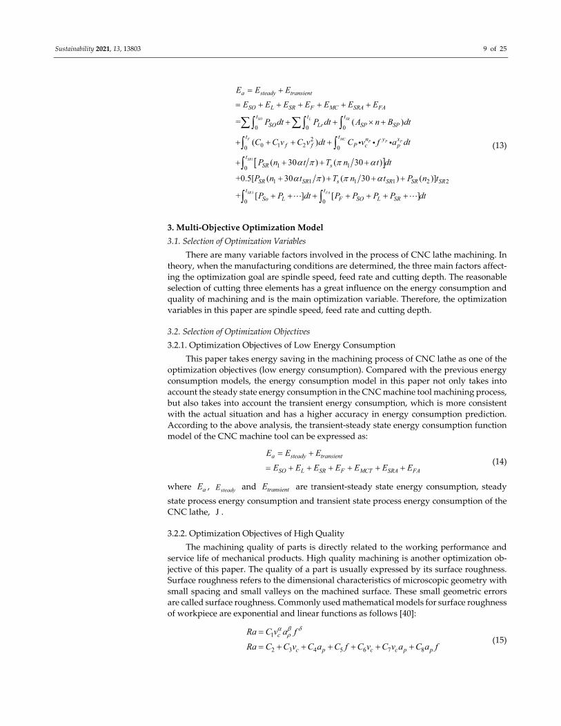
3. Multi‐Objective Optimization Model
3.1. Selection of Optimization Variables
There are many variable factors involved in the process of CNC lathe machining. In
theory, when the manufacturing conditions are determined, the three main factors affect‐
ing the optimization goal are spindle speed, feed rate and cutting depth. The reasonable
selection of cutting three elements has a great influence on the energy consumption and
quality of machining and is the main optimization variable. Therefore, the optimization
variables in this paper are spindle speed, feed rate and cutting depth.
3.2. Selection of Optimization Objectives
3.2.1. Optimization Objectives of Low Energy Consumption
This paper takes energy saving in the machining process of CNC lathe as one of the
optimization objectives (low energy consumption). Compared with the previous energy
consumption models, the energy consumption model in this paper not only takes into
account the steady state energy consumption in the CNC machine tool machining process,
but also takes into account the transient energy consumption, which is more consistent
with the actual situation and has a higher accuracy in energy consumption prediction.
According to the above analysis, the transient‐steady state energy consumption function
model of the CNC machine tool can be expressed as:
a steady transient
SO L SR F MCT SRA FA
E E E
E E E E E E E
(14)
where aE , steadyE and transientE are transient‐steady state energy consumption, steady
state process energy consumption and transient state process energy consumption of the
CNC lathe, J .
3.2.2. Optimization Objectives of High Quality
The machining quality of parts is directly related to the working performance and
service life of mechanical products. High quality machining is another optimization ob‐
jective of this paper. The quality of a part is usually expressed by its surface roughness.
Surface roughness refers to the dimensional characteristics of microscopic geometry with
small spacing and small valleys on the machined surface. These small geometric errors
are called surface roughness. Commonly used mathematical models for surface roughness
of workpiece are exponential and linear functions as follows [40]:
1
2 3 4 5 6 7 8
c
c p c c p p
Ra C v a f
Ra C C v C a C f C v C v a C a f
(15)
Sustainability 2021, 13, 13803 10 of 25
where 1C , 2C , 3C , 4C , 5C , 6C , 7C , 8C , , , and are coefficients; cv is the
cutting speed, mm/s; f is the feed rate, mm/r; and pa is the cutting depth, mm.
Under the experimental data, the precision of the primary function form model is
higher, so this paper uses the primary function form surface roughness model of the work‐
piece.
3.3. Constraint Condition
The selection of the processing parameters needs to consider the performance re‐
quirements of the processing system and the technical requirements of the workpiece,
such as the performance range of CNC, the durability of the tool, etc., which should only
be used within the limited conditions. Therefore, the constraints for the optimization of
cutting parameters should be established according to the actual conditions so that the
optimization results obtained by the algorithm can meet the actual production require‐
ment.
(1) Spindle speed constraint: min maxn n n , where n , minn and maxn are the spin‐
dle speed of the CNC lathe, the minimum speed allowed by the CNC lathe and the max‐
imum speed allowed by the CNC lathe, respectively.
(2) Feed speed constraint: min maxf f fv v v , where fv , minfv and maxfv are the
feed speed, the minimum feed speed allowed by the lathe and the maximum feed speed
allowed by the lathe, respectively.
(3) Cutting depth constraint: max0 p pa a , where pa and maxpa are the cutting
depth and the maximum allowable cutting depth, respectively.
(4) Tool durability constraint [41]: TBx y z
c p
CT T
v f a , where T is the tool durability
and TC is the tool durability coefficient, which is related to tool, workpiece material and
cutting conditions; x, y and z respectively represent the influence of processing parame‐
ters cv , f and pa on tool durability. BT is the reasonable durability of the tool.
(5) Maximum power constraint: spindle ratedP P , where spindleP and ratedP are the
maximum power of the CNC lathe spindle and the rated power of the CNC lathe spindle
motor, respectively.
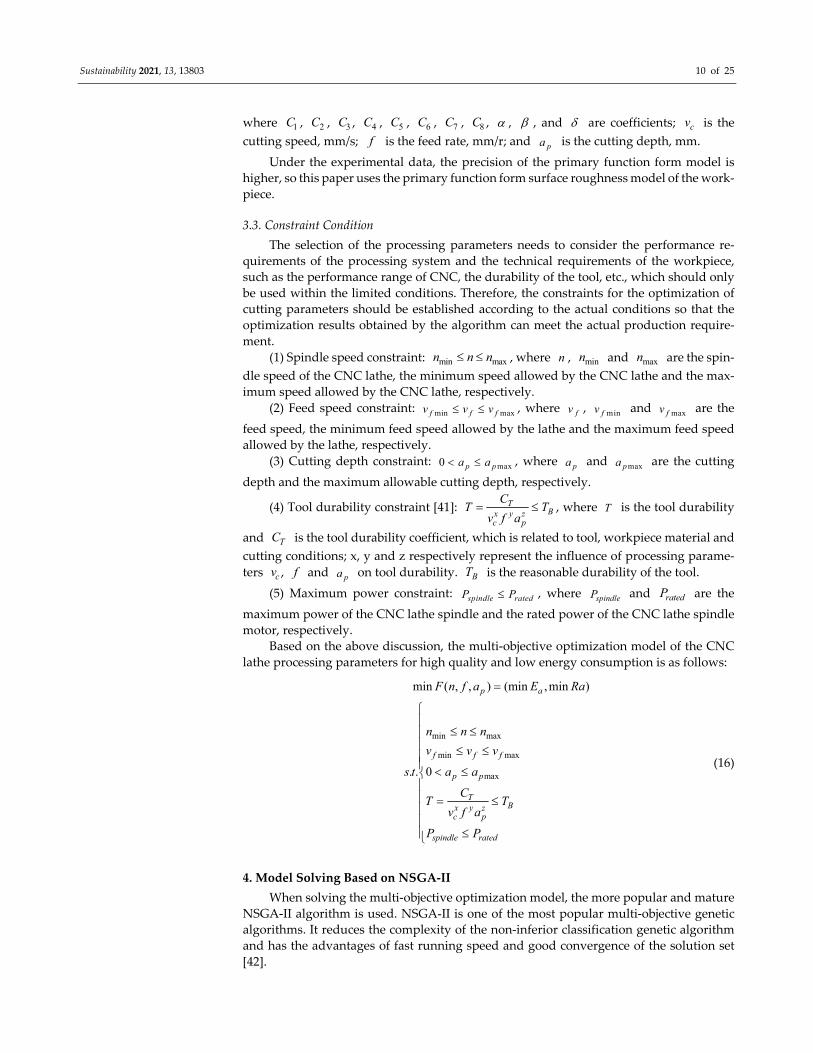
Based on the above discussion, the multi‐objective optimization model of the CNC
lathe processing parameters for high quality and low energy consumption is as follows:
min max
min max
max
min ( , , ) (min ,min )
. . 0
p a
f f f
p p
TBx y z
c p
spindle rated
F n f a E Ra
n n n
v v v
s t a a
CT T
v f a
P P
(16)
4. Model Solving Based on NSGA‐II
When solving the multi‐objective optimization model, the more popular and mature
NSGA‐II algorithm is used. NSGA-II is one of the most popular multi‐objective genetic
algorithms. It reduces the complexity of the non‐inferior classification genetic algorithm
and has the advantages of fast running speed and good convergence of the solution set
[42].

Sustainability 2021, 13, 13803 11 of 25
4.1. The Flow of NSGA‐II
The main process of the NSGA‐II algorithm is as follows:
(1) The initial parent population (0)P with population size S is randomly gener‐
ated, and the child population (0)Q is obtained after non‐dominated sorting, and set up
as 0g .
(2) The above two generations are combined to form a new population ( )R g .
(3) At the same time of the non‐dominated sorting of population ( )R g , the crowding
degree of each front‐end individual is calculated, and the best individual is selected ac‐
cording to the order value and crowding degree of the individual to form a new parent
group ( 1)P g .
(4) ( 1)P g is selected, hybridized and mutated to produce a new offspring popu‐
lation ( 1)Q g .
(5) Judge whether the termination condition is true. Otherwise, 1g g , go back to
(2).
4.2. The Application and Parameter Setting of NSGA‐II
4.2.1. The Application of NSGA‐II
(1). Chromosome coding
In the optimization solution, the mathematical expression of the model should be
coded according to the programming method. In this paper, the optimization variables
are spindle speed n , feed rate f and cutting depth pa . So, this paper adopts real num‐
ber coding. As shown in Figure 4, chromosomes with a length of 3 m are generated by random generation. The first part is the spindle speed n , the second part is the feed rate f , and the third part is the cutting depth pa . According to the specific constraints, the
value range of each variable is given.
Figure 4. Chromosome coding.
(2). Initial population
Initial filling is the starting point of the algorithm, and good initial filling can improve
the efficiency of the algorithm. In this algorithm, the initial population is generated ran‐
domly, but the range can be limited by constraints to obtain a better initial population.
The value range of population size M is generally between 20 and 500. The variable
parameters mainly involved in this paper are three real values, and the chromosome
length is general because the value of population size in this paper is 300.
(3). Fitness calculation
In the NSGA-Ⅱ algorithm, individual fitness is calculated by the non‐dominated level
and congestion distance. Firstly, the double objective function value of each individual in
the population is calculated, and then all individuals in the population are divided into
different non‐dominated grades by the non‐dominated classification method. All non‐
dominated optimal solutions in the current population are regarded as the first non‐dom‐
inated optimal solution level, and the non‐dominated level of each individual is desig‐
nated as level 1. Similarly, the remaining individuals in the population are classified and
Sustainability 2021, 13, 13803 12 of 25
assigned values until all individuals are divided into different levels. It should be noted
that the smaller the grade value, the better the individual.
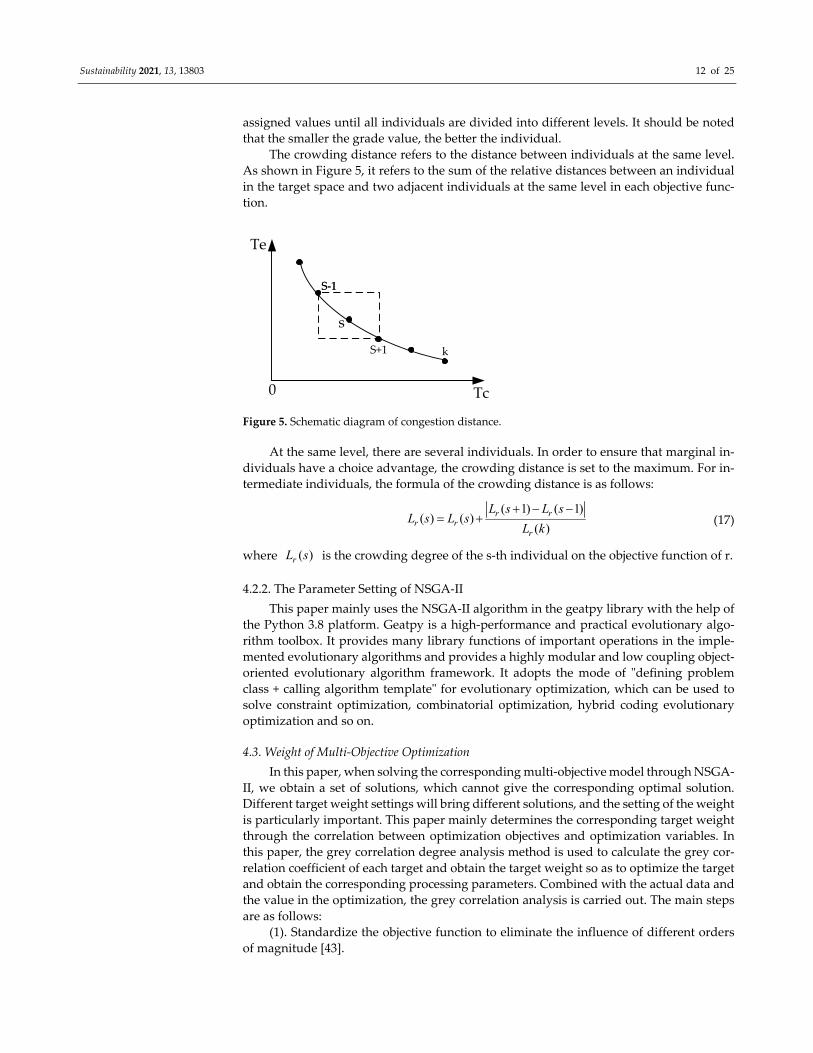
The crowding distance refers to the distance between individuals at the same level.
As shown in Figure 5, it refers to the sum of the relative distances between an individual
in the target space and two adjacent individuals at the same level in each objective func‐
tion.
Te
Tc0
s
S‐1S‐1
S+1 k
Figure 5. Schematic diagram of congestion distance.
At the same level, there are several individuals. In order to ensure that marginal in‐
dividuals have a choice advantage, the crowding distance is set to the maximum. For in‐
termediate individuals, the formula of the crowding distance is as follows:
( 1) ( 1)( ) ( )
( )r r
r rr
L s L sL s L s
L k
(17)
where ( )rL s is the crowding degree of the s‐th individual on the objective function of r.
4.2.2. The Parameter Setting of NSGA‐II
This paper mainly uses the NSGA‐II algorithm in the geatpy library with the help of
the Python 3.8 platform. Geatpy is a high‐performance and practical evolutionary algo‐
rithm toolbox. It provides many library functions of important operations in the imple‐
mented evolutionary algorithms and provides a highly modular and low coupling object‐
oriented evolutionary algorithm framework. It adopts the mode of ʺdefining problem
class + calling algorithm templateʺ for evolutionary optimization, which can be used to
solve constraint optimization, combinatorial optimization, hybrid coding evolutionary
optimization and so on.
4.3. Weight of Multi‐Objective Optimization
In this paper, when solving the corresponding multi‐objective model through NSGA‐
II, we obtain a set of solutions, which cannot give the corresponding optimal solution.
Different target weight settings will bring different solutions, and the setting of the weight
is particularly important. This paper mainly determines the corresponding target weight
through the correlation between optimization objectives and optimization variables. In
this paper, the grey correlation degree analysis method is used to calculate the grey cor‐
relation coefficient of each target and obtain the target weight so as to optimize the target
and obtain the corresponding processing parameters. Combined with the actual data and
the value in the optimization, the grey correlation analysis is carried out. The main steps
are as follows:
(1). Standardize the objective function to eliminate the influence of different orders
of magnitude [43].
Sustainability 2021, 13, 13803 13 of 25
-max
-min
min( , 1, 2,..., )
max( , 1, 2,..., ) min( , 1, 2,..., )
max( , 1, 2,..., )
max( , 1, 2,..., ) min( , 1, 2,..., )
ij ijij
ij ij
ij ijij
ij ij
y y i nZ
y i n y i n
y i n yZ
y i n y i n
(18)
among them, the formula of - maxijZ is used when the objective function takes the maxi‐
mum as the optimal, and the formula of -minijZ is used when the objective function takes
the minimum as the optimal. In this formula, n is the number of experimental data sets
and m is the number of optimization objectives.
(2). Calculate the grey correlation coefficient of the standardization target.
min max( , )
( ) maxo ijoj
Z Zk
(19)
where ( )oZ k is the reference sequence and ( )oj k is the ( )oZ k deviation sequence
from the comparison sequence ( )ijZ k . is the resolution coefficient, and the value range is 0 1 .
(3). Multi‐objective weight calculation.
In this paper, in the multi‐objective weight determination, the influence of the opti‐
mization of processing parameters on the optimization target is used as the standard to
determine the target weight. The weight coefficient is calculated as follows:
1
1 1
pijj
m p
i j
R
Rij
(20)
among them, ,1 ,2 , ,1 ,2 ,max , ,..., min , ,...,ij ij ij ij k ij ij ij kR K K K K K K
where m is the number of optimization objectives, R is the range of grey correlation coefficients, K is the average grey correlation number of each processing process param‐eter at each level, and is the weight of objectives. In the later optimization process,
combined with the actual optimization objectives, different weights are given.
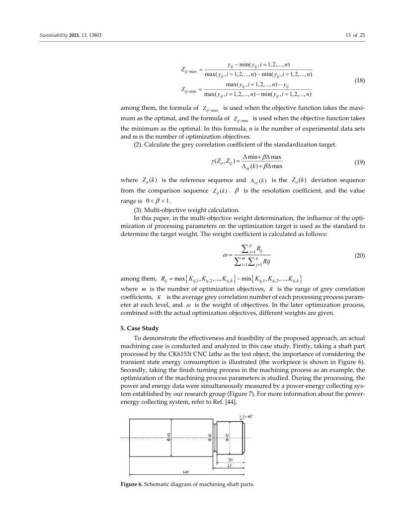
5. Case Study
To demonstrate the effectiveness and feasibility of the proposed approach, an actual
machining case is conducted and analyzed in this case study. Firstly, taking a shaft part
processed by the CK6153i CNC lathe as the test object, the importance of considering the
transient state energy consumption is illustrated (the workpiece is shown in Figure 6).
Secondly, taking the finish turning process in the machining process as an example, the
optimization of the machining process parameters is studied. During the processing, the
power and energy data were simultaneously measured by a power‐energy collecting sys‐
tem established by our research group (Figure 7). For more information about the power‐
energy collecting system, refer to Ref. [44].
Figure 6. Schematic diagram of machining shaft parts.
Sustainability 2021, 13, 13803 14 of 25
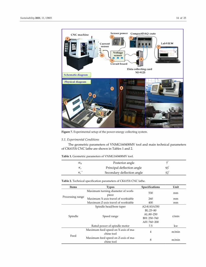
Figure 7. Experimental setup of the power‐energy collecting system.
5.1. Experimental Conditions
The geometric parameters of VNMG160408MV tool and main technical parameters
of CK6153i CNC lathe are shown in Tables 1 and 2.
Table 1. Geometric parameters of VNMG160408MV tool.
0 Posterior angle 7
r Principal deflection angle 93 'r Secondary deflection angle 52
Table 2. Technical specification parameters of CK6153i CNC lathe.
Items Types Specifications Unit
Processing range
Maximum turning diameter of work‐
piece 530 mm
Maximum X‐axis travel of worktable 260 mm
Maximum Z‐axis travel of worktable 400 mm
Spindle
Spindle head/bore taper A2‐8/ASA350
Speed range
BL:25~80
AL:80~250
BH:250~760
AH:760~200
r/min
Rated power of spindle motor 7.5 kw
Feed
Maximum feed speed on X‐axis of ma‐
chine tool 4 m/min
Maximum feed speed on Z‐axis of ma‐
chine tool 8 m/min
Sustainability 2021, 13, 13803 15 of 25
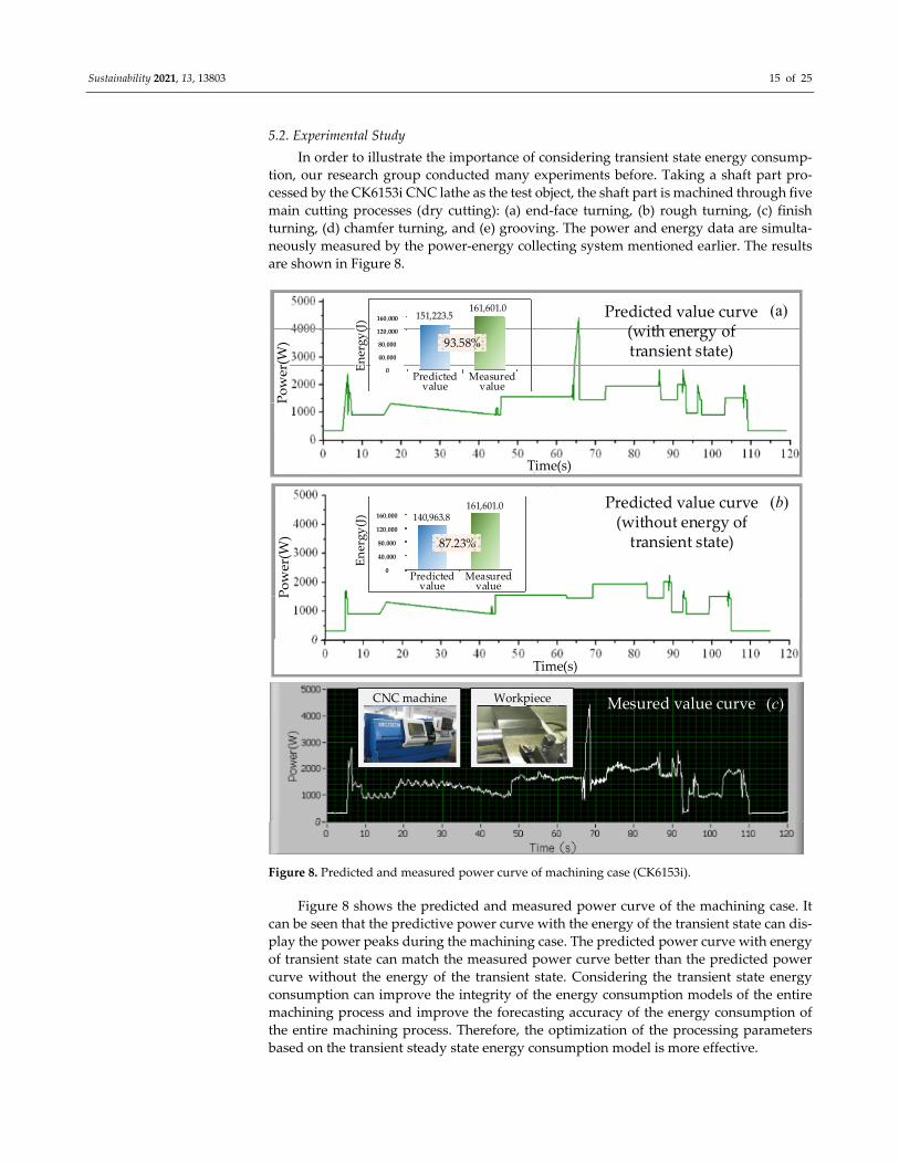
5.2. Experimental Study
In order to illustrate the importance of considering transient state energy consump‐
tion, our research group conducted many experiments before. Taking a shaft part pro‐
cessed by the CK6153i CNC lathe as the test object, the shaft part is machined through five
main cutting processes (dry cutting): (a) end‐face turning, (b) rough turning, (c) finish
turning, (d) chamfer turning, and (e) grooving. The power and energy data are simulta‐
neously measured by the power‐energy collecting system mentioned earlier. The results
are shown in Figure 8.
Mesured value curve
Time(s)
Power(W
)
Predicted value
Predicted value curve(without energy of transient state)
Time(s)
Power(W
)
Predicted value curve(with energy of transient state)
Energy(J)
Energy(J)
(b)
(a)
(c)CNC machine
Measuredvalue
Predicted value
Measuredvalue
Workpiece
93.58%
87.23%
160,000
120,000
80,000
40,000
0
140,963.8161,601.0
161,601.0151,223.5
160,000
120,000
80,000
40,000
0
Figure 8. Predicted and measured power curve of machining case (CK6153i).
Figure 8 shows the predicted and measured power curve of the machining case. It
can be seen that the predictive power curve with the energy of the transient state can dis‐
play the power peaks during the machining case. The predicted power curve with energy
of transient state can match the measured power curve better than the predicted power
curve without the energy of the transient state. Considering the transient state energy
consumption can improve the integrity of the energy consumption models of the entire
machining process and improve the forecasting accuracy of the energy consumption of
the entire machining process. Therefore, the optimization of the processing parameters
based on the transient steady state energy consumption model is more effective.
Sustainability 2021, 13, 13803 16 of 25
5.3. Multi‐Objective Optimization Model
As can be seen in Section 5.2, considering the transient state energy consumption can
improve the forecasting accuracy of energy consumption. Therefore, this section considers
transient steady state energy consumption to study the optimization of the CNC turning
process parameters. At the same time, the main parameters of the machining process un‐
der experience are given, as shown in Table 3.
Table 3. Empirical process parameters of finish turning outer circle.
Items Value
Spindle speed (r/min) 1000
Feed rate (mm/r) 0.10
Cutting depth (mm) 0.5
5.3.1. Energy Consumption Model
According to the relevant dimensions of machining shaft parts, the machining pro‐
cess flow of finishing turning excircle in this case can be divided into seven specific steps:
(a) executing standby; (b) spindle acceleration from static to 1000 r/min; (c) rapid position‐ing; (d) feeding; (e) finishing turning; (f) rapid positioning to origin; and (g) executing
standby. The energy consumption of the machining process mainly includes two transient
processes’ energy consumption (spindle acceleration stage, rapid feed positioning stage)
and four steady state processes’ energy consumption (machine tool standby operation
stage, feed stage and finish turning excircle cutting stage). According to the construction
of the energy consumption model in the previous paper, combined with the experiment
of finishing cylindrical machining, the corresponding mathematical function is given.
(1). Executing standby:
In the case, the standby time of the CNC lathe includes two parts: the start part and
the end part. That is, the SO startt and SO finisht processing parameters do not affect this
part, so the corresponding time is no different from the traditional processing, namely, 5.0
s, and 5.0 s. After several measurements, the execution standby power of the CNC lathe
CK6153i is 200SON , and 312.1wSOP . Then, the execution standby energy consump‐
tion of the CNC lathe in the embodiment is:
02
2 312.1 5 3121J
SOt
SO SOE P dt
(21)
(2). Spindle acceleration:
According to the previous analysis, the energy demand of the spindle process in‐
cludes three parts. According to the equipment parameters of CNC lathe CK6153i and through experimental numerical fitting, the piecewise function model of spindle rotation
power is obtained as follows:
1.09 41.12 ,0 1000r / min
0.558 605.05 ,1000 1300r / min
1.288 358.21 ,1300 1500r / minSR
n n
P n n
n n
(22)
At the same time, it can be seen that the time function of spindle acceleration stage is
calculated as follows:
1 1 2
42 2
3 1 2
2 ( ) / 60
0.037 1.471 10
SR
SR
SR SR SR
t n n
t n
t t t
(23)
Sustainability 2021, 13, 13803 17 of 25
among them, the spindle acceleration angle of the CK61563i CNC lathe is 39.78rad/s ;
the acceleration torque of the spindle is 28.42N msT .
To sum up, according to Formulas (10), (22) and (23), the energy consumption func‐
tion of the spindle acceleration part can be obtained as follows:
1 2 3
-3 2
-3 2
-3 2
-4
-4
5.35 10 0.11 ,0 1000
4.65 10 1.59 ,1000 1300
5.61 10 0.94 ,1300 1500
(1.47 10 0.037) (2.58 41.12),0 1000
(1.47 10 0.037) (2.05 605.05),1000 1300
(1
SRA SR SR SRE E E E
n n n
n n n
n n n
n n n
n n n
-4
-3 2
-3 2
-3 2
.47 10 0.037) (2.78 358.21),1300 1500
0.92 12.29
5.73 10 1.13 13.81,0 1000
4.95 10 2.68 34.67,1000 1300
6.02 10 +0.03 0.97,1300 1500
n n n
n
n n n
n n n
n n n
(24)
(3). Rapid positioning:
In this case, there are two main processes of rapid positioning: rapid positioning from
the origin to the safe processing position. After machining, the tool is quickly positioned
to the origin. For a given feed system, the maximum feed speed of each axis is determined.
The maximum feed speeds of the X‐axis and Z‐axis of the CK6153i CNC lathe are
6000mm/min and 10000mm/min , respectively. In reference, the fast feed power in direc‐
tion and Z direction can be obtained through experimental measurement and statistics,
which can be expressed as 781.33wXFAP , and 874.35wZ
FAP . In this experimental case
study, two rapid positioning processes are included, and the distance corresponding to
the process is shown in Table 4.
Table 4. Fast feed motion decomposition.
Items Processing Activities Distance (mm) Time (s)
Rapid positioning Rapid positioning‐XZ 25, 41.7x yl l 0.25
Rapid positioning‐Z 53.3yl 0.32
Rapid positioning to origin
Rapid positioning‐X 7.5xl 0.075
Rapid positioning‐XZ 20, 33.3x yl l 0.2
Rapid positioning‐Z 90.67yl 0.544
According to Formula (11), the energy consumption generated in the rapid position‐
ing stage in this case design is as follows:
Sustainability 2021, 13, 13803 18 of 25
0
0.25
0
0.32
0
0.2
0
0.544
0
781.33 847.35 312.1
874.35 312.1
781.33 847.35 312.1
874.35 312.1
1.43 1929.15,0 1000r / min
0.73 2670.15,1000 1300r / min
1
FAt
FA XF SO SR
SR
SR
SR
SR
E P P P dt
P n dt
P n dt
P n dt
P n dt
n n
n n
.69 1404.43,1300 1500r / minn n
(25)
(4). Feeding:
This stage means that after the tool is quickly positioned to the safe cutting position,
the tool is slowly close to the material at the cutting feed speed so as to prepare for the
next finishing excircle cutting. In this case design, it mainly includes two parts: x‐feed and
z‐feed. According to the power model of the CNC lathe mentioned above and combined
with the experimental data, the feed power functions in X and Z directions of CK6153i can be obtained as follows:
-6 2
-6 2
-1.63 0.017 4.24 10
0.49 0.030 2.32 10
XF zf xf
ZF zf zf
P v v
P v v
(26)
At the same time, the feed distance in the x‐axis direction is 2.5mmxl and the feed
time can be expressed as / 3sxf x xft l v . If the feed distance in the z‐axis direction is
5mmzl , the feed time in this stage can be expressed as / 5 /z z zf zft l v v .
Therefore, to sum up, the energy consumption in the feeding stage can be expressed
as:
0 0
-1-71.93 10 147 2.16
xf zft t
F XF ZFE P dt P dt
n f n f
(27)
(5). Finish turning:
According to the power model of the lathe outer circle in the previous paper and
combined with the actual experimental data of CK6153i, the power function model of the
lathe outer circle in this process can be fitted as follows:
0.909 0.657 0.91744.57MC c pP v f a (28)
Accordingly, the cutting time at this stage is / 24 /f ft l v v . The energy consump‐
tion function model of the finish turning outer circle can be obtained as follows:
0 0
24
6 2
0
24
0.917 0.252 0.657
0
0.917 0.252 0.657 4 2
(312.1 1.09 41.12 1.63 0.017 4.24 10 )
(110.61 )
(2654.62 26.16 1.02 10 8438.16)
f
f
t t
cut AC MC
vf f
vp f
p f f f
E P dt P dt
n v v
a n v dt
a n v n v v
(29)
Sustainability 2021, 13, 13803 19 of 25
where cutE is the energy consumption value of the CNC lathe finish turning excircle cut‐
ting, J ; ACP is the auxiliary power in the cutting process of the CNC lathe, W ; and
MCP is the material cutting power of the CNC lathe, W .
Combining the above energy consumption mathematical functions, the mathemati‐
cal function of the total energy consumption in the processing process in this case can be
obtained.
-0.091 -0.343 0.917 -6
-1-3 2 -1
-0.091 -0.343 0.917 -6
-3 2 -1
10812.07 1.89 10
5.73 10 2.56 1569.9 506436.6 5062.21,0 1000
10812.07 1.89 10
4.95 10 3.41 1569.9 506436
a SO SRA FA F cut
p
p
E E E E E E
n f a nf
n n f nf n
n f a nf
n n f
-1
-0.091 -0.343 0.917 -6
-1-3 2 -1
.6 5824.08,1000 1300
10812.07 1.89 10
6.02 10 1.72 1569.9 506436.6 4522.71,1300 1500
p
nf n
n f a nf
n n f nf n
(30)
It can be obtained that under the empirical processing process parameters, that is, the
spindle speed is 1000r/minn , the feed rate 0.1mm/minf , and the cutting depth
0.5mmpa , the total energy consumption in the processing process is 40845JaE .
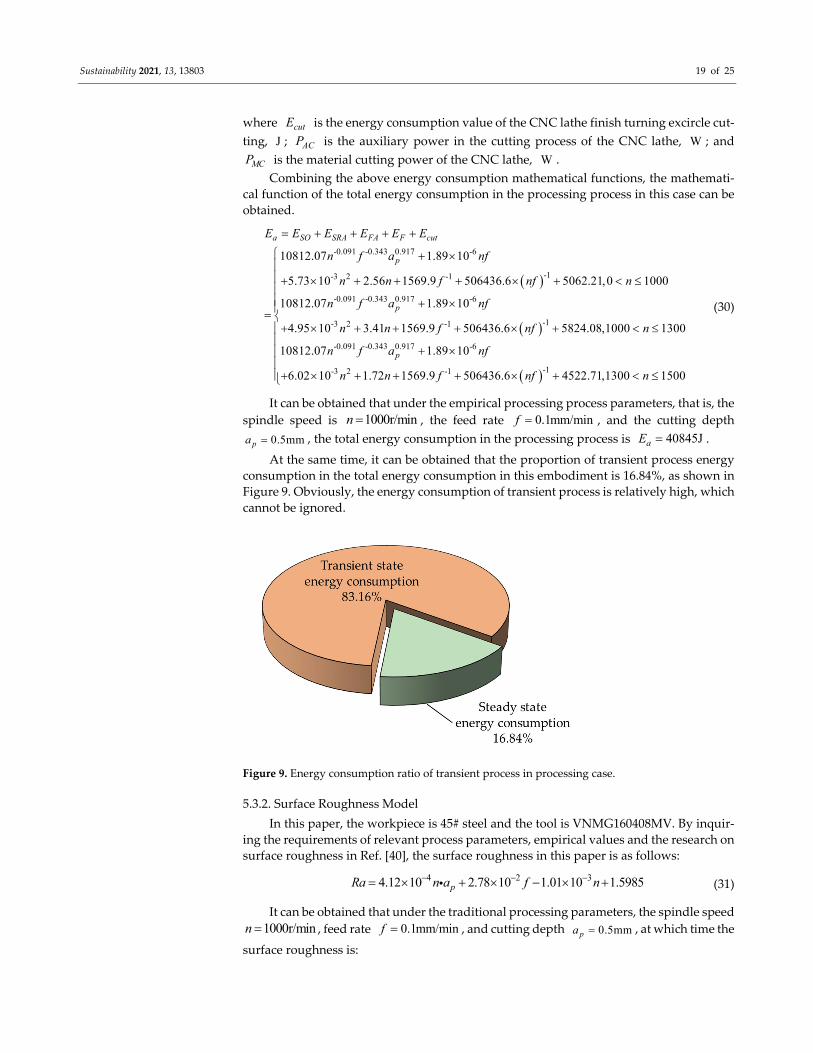
At the same time, it can be obtained that the proportion of transient process energy
consumption in the total energy consumption in this embodiment is 16.84%, as shown in
Figure 9. Obviously, the energy consumption of transient process is relatively high, which
cannot be ignored.
Figure 9. Energy consumption ratio of transient process in processing case.
5.3.2. Surface Roughness Model
In this paper, the workpiece is 45# steel and the tool is VNMG160408MV. By inquir‐
ing the requirements of relevant process parameters, empirical values and the research on
surface roughness in Ref. [40], the surface roughness in this paper is as follows:
4 2 34.12 10 2.78 10 1.01 10 1.5985pRa n a f n (31)
It can be obtained that under the traditional processing parameters, the spindle speed
1000r/minn , feed rate 0.1mm/minf , and cutting depth 0.5mmpa , at which time the
surface roughness is:
Sustainability 2021, 13, 13803 20 of 25
(1000,0.1,0.5) 0.7968μmRa (32)
5.3.3. Constraint Condition
According to the constraints mentioned above, combined with the geometric param‐
eters of VNMG160408MV tool in Table 1 and the technical specification parameters of the
CK6153i CNC lathe in Table 2, and according to the actual cases in this paper, the specific
range of constraints in this paper can be obtained, as shown in Table 5.
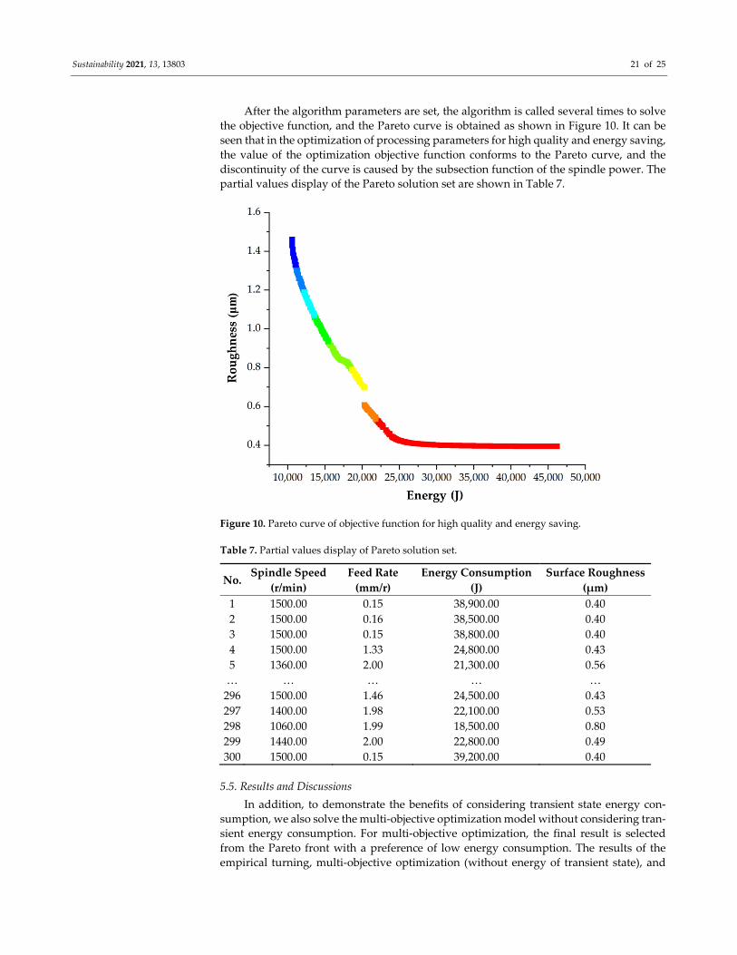
Table 5. Constraint range of cutting parameters.
Cutting Parameters Range
Spindle speed n 100 1500r / minn
Feed rate f 0.10 2mm/rf
Cutting depth pa 0.10 5mmpa
5.3.4. Optimization Model
In summary, the multi‐objective optimization model can be expressed as:
0.091 0.343 0.917 6
3 2 1 1
0.091 0.343 0.917 6
3 2 1
min ( , , )
10812.07 1.89 10
5.73 10 2.56 1569.9 506436.6 ( ) 5062.21,0 1000
10812.07 1.89 10
4.95 10 3.41 1569.9 506436.6 ( )
a p
p
p
E n f a
n f a nf
n n f nf n
n f a nf
n n f nf
1
0.091 0.343 0.917 6
3 2 1 1
4 2 3
5824.08,1000 1300
10812.07 1.89 10
6.02 10 1.72 1569.9 506436.6 ( ) 4522.71,1300 1000
min ( , , )
min(4.12 10 2.78 10 1.01 10 1.5985)
p
p
p
n
n f a nf
n n f nf n
Ra n f a
n a f n
100 1500r / min
. . 0.10 2mm/r
0.10 5mmp
n
s t f
a
(33)
5.4. Model Solving Based on NSGA‐II
During the double objective optimization, the NSGA‐II algorithm is used to solve the
model. Referring to previous literature studies and cases, we preliminarily set the relevant
operation parameters, and through multiple operations, we set the relevant parameters in
the NSGA‐II algorithm as shown in Table 6.
Table 6. Parameter setting in NSGA‐II algorithm.
Operating Parameters Items Value
M Initial population size 300
G Genetic probability 0.9
cR Crossover probability 0.7
mR Variation probability 0.2
N Maximum evolutionary algebra 100
Sustainability 2021, 13, 13803 21 of 25
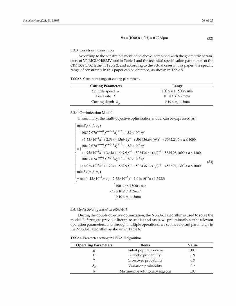
After the algorithm parameters are set, the algorithm is called several times to solve
the objective function, and the Pareto curve is obtained as shown in Figure 10. It can be
seen that in the optimization of processing parameters for high quality and energy saving,
the value of the optimization objective function conforms to the Pareto curve, and the
discontinuity of the curve is caused by the subsection function of the spindle power. The
partial values display of the Pareto solution set are shown in Table 7.
Figure 10. Pareto curve of objective function for high quality and energy saving.
Table 7. Partial values display of Pareto solution set.
No. Spindle Speed
(r/min)
Feed Rate
(mm/r)
Energy Consumption
(J)
Surface Roughness
(μm)
1 1500.00 0.15 38,900.00 0.40
2 1500.00 0.16 38,500.00 0.40
3 1500.00 0.15 38,800.00 0.40
4 1500.00 1.33 24,800.00 0.43
5 1360.00 2.00 21,300.00 0.56
… … … … …
296 1500.00 1.46 24,500.00 0.43
297 1400.00 1.98 22,100.00 0.53
298 1060.00 1.99 18,500.00 0.80
299 1440.00 2.00 22,800.00 0.49
300 1500.00 0.15 39,200.00 0.40
5.5. Results and Discussions
In addition, to demonstrate the benefits of considering transient state energy con‐
sumption, we also solve the multi‐objective optimization model without considering tran‐
sient energy consumption. For multi‐objective optimization, the final result is selected
from the Pareto front with a preference of low energy consumption. The results of the
empirical turning, multi‐objective optimization (without energy of transient state), and
Sustainability 2021, 13, 13803 22 of 25
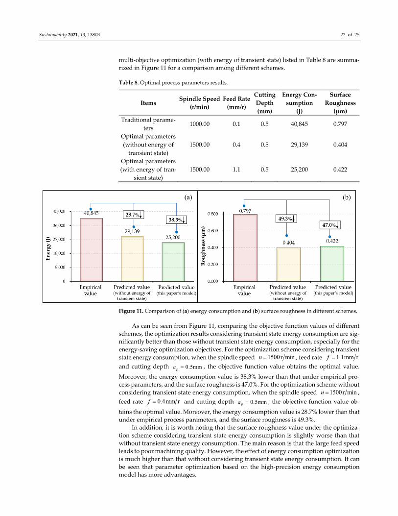
multi‐objective optimization (with energy of transient state) listed in Table 8 are summa‐
rized in Figure 11 for a comparison among different schemes.
Table 8. Optimal process parameters results.
Items Spindle Speed
(r/min)
Feed Rate
(mm/r)
Cutting
Depth
(mm)
Energy Con‐
sumption
(J)
Surface
Roughness
(μm)
Traditional parame‐
ters 1000.00 0.1 0.5 40,845 0.797
Optimal parameters
(without energy of
transient state)
1500.00 0.4 0.5 29,139 0.404
Optimal parameters
(with energy of tran‐
sient state)
1500.00 1.1 0.5 25,200 0.422
Figure 11. Comparison of (a) energy consumption and (b) surface roughness in different schemes.
As can be seen from Figure 11, comparing the objective function values of different
schemes, the optimization results considering transient state energy consumption are sig‐
nificantly better than those without transient state energy consumption, especially for the
energy‐saving optimization objectives. For the optimization scheme considering transient
state energy consumption, when the spindle speed 1500r minn , feed rate 1.1mm rf
and cutting depth 0.5mmpa , the objective function value obtains the optimal value.
Moreover, the energy consumption value is 38.3% lower than that under empirical pro‐
cess parameters, and the surface roughness is 47.0%. For the optimization scheme without
considering transient state energy consumption, when the spindle speed 1500r minn ,
feed rate 0.4mm rf and cutting depth 0.5mmpa , the objective function value ob‐
tains the optimal value. Moreover, the energy consumption value is 28.7% lower than that
under empirical process parameters, and the surface roughness is 49.3%.
In addition, it is worth noting that the surface roughness value under the optimiza‐
tion scheme considering transient state energy consumption is slightly worse than that
without transient state energy consumption. The main reason is that the large feed speed
leads to poor machining quality. However, the effect of energy consumption optimization
is much higher than that without considering transient state energy consumption. It can
be seen that parameter optimization based on the high‐precision energy consumption
model has more advantages.
Sustainability 2021, 13, 13803 23 of 25
6. Conclusions
In this paper, the energy consumption composition characteristics of the CNC lathe
machining process are analyzed, and the energy consumption of the transient process is
introduced into the energy consumption model of the CNC lathe, which further improves
the accuracy of the model. A multi‐objective optimization model is established, taking the
spindle speed, feed rate and cutting depth as optimization variables, and high‐quality and
low‐energy machining as optimization objectives. The above model is optimized by using
the non‐dominated sorting genetic algorithm with elite strategy. Through case analysis,
the optimization results show that it can greatly reduce the machining energy consump‐
tion and workpiece surface roughness.
Energy modeling and parameter optimization of turning were the focuses of this re‐
search. The main limitation of this study is that the influence of the cutting tools was not
considered. Hence, the integrated optimization of machining tools and process parame‐
ters will be the research object in our future work.
Author Contributions: Conceptualization, S.J. and J.L.; methodology, W.C.; software, S.W.; valida‐
tion, S.J., S.W. and N.Z.; formal analysis, Z.Z.; investigation, S.B.; resources, S.J.; data curation, N.Z.;
writing—original draft preparation, S.J. and S.W.; writing—review and editing, S.J.; visualization,
J.L.; supervision, W.C.; project administration, Z.Z.; funding acquisition, S.B. All authors have read and agreed to the published version of the manuscript.
Funding: This research was funded by the National Natural Science Foundation of China (Grant
No. 71971130; 71701113), the Project of Shandong Province Higher Educational Science and Tech‐
nology Program (Grant No. J17KA167), the Key Science and Technology Program of Henan Prov‐
ince (Grant No. 212102210357). This research is also supported by SDUST Research Fund (Grant No.
2018YQJH103).
Institutional Review Board Statement: Not applicable.
Informed Consent Statement: Not applicable.
Data Availability Statement: Not applicable.
Acknowledgments: We deeply appreciate the valuable contribution of the reviewers and editors of
sustainability. Their professional suggestions on the manuscript helped us greatly improve the qual‐
ity of this article.
Conflicts of Interest: The authors declare no conflict of interest.
References
1. Liu, F.; Liu, P.; Li, C.; Tuo, J.; Cai, W. The statue and difficult problems of research on energy efficiency of manufacturing
systems. J. Mech. Eng. 2017, 53, 1–11.
2. Liu, F.; Wang, Q.; Liu, G. Content architecture and future trends of energy efficiency research on machining systems. J. Mech.
Eng. 2013, 49, 87–94.
3. Jia, S.; Cai, W.; Liu, C.; Zhang, Z.; Hu, L. Energy modeling and visualization analysis method of drilling processes in the man‐
ufacturing industry. Energy 2021, 228, 120567.
4. Jia, S.; Yuan, Q.; Cai, W.; Li, M.; Li, Z. Energy modeling method of machine‐operator system for sustainable machining. Energy
Convers. Manag. 2018, 172, 265–276.
5. Kminiak, R.; Dzurenda, L. Impact of Sycamore Maple Thermal Treatment on a Granulometric Composition of Chips Obtained
due to Processing on a CNC Machining Mentre. Sustainability 2019, 11, 718.
6. Zhang, C.; Jiang, P. Sustainability Evaluation of Process Planning for Single CNC Machine Tool under the Consideration of
Energy‐Efficient Control Strategies Using Random Forests. Sustainability 2019, 11, 3060.
7. Xiao, Y.; Jiang, Z.; Gu, Q.; Yan, W.; Wang, R. A novel approach to CNC machining center processing parameters optimization
considering energy‐saving and low‐cost. J. Manuf. Syst. 2021, 59, 535–548.
8. Chen, W.; Huang, C.; Yang, Q.; Yang, Y. Optimal prediction and design of surface roughness for CNC turning of al7075‐t6 by
using the taguchi hybrid QPSO algorithm. T. Can. Soc. Mech. Eng. 2016, 40, 883–895.
9. Pangestu, P.; Pujiyanto, E.; Rosyidi, C. Multi‐objective cutting parameter optimization model of multi‐pass turning in CNC
machines for sustainable manufacturing. Heliyon 2021, 7, e06043.
10. Li, L.; Liu, F.; Chen, B.; Li, C. Multi‐objective optimization of cutting parameters in sculptured parts machining based on neural
network. J. Intell. Manuf. 2015, 26, 891–898.
Sustainability 2021, 13, 13803 24 of 25
11. Moreira, L.; Li, W.; Lu, X.; Fitzpatrick, M. Energy‐Efficient machining process analysis and optimisation based on BS EN24T
alloy steel as case studies. Robot. Cim‐Int. Manuf. 2019, 58, 1–12.
12. Zhou, J.; Ren, J.; Yao, C. Multi‐objective optimization of multi‐axis ball‐end milling Inconel 718 via grey relational analysis
coupled with RBF neural network and PSO algorithm. Measurement 2017, 102, 271–285.
13. Doriana, M.; D’Addona.; Roberto, T. Genetic Algorithm‐based Optimization of Cutting Parameters in Turning Processes. Pro‐
cedia CIRP 2013, 7, 323–328.
14. Pan, B.; Yu, M.; Xiang, Y.; Luo, L.; Ding, W. Accuracy reliability analysis and process optimization design of milling processing
considering toll wear. Comput. Integra. Manuf. 2020, 26, 2982–2991.
15. Feng, C.; Chen, X.; Zhang, J.; Huang, Y.; Qu, Z. Minimizing the Energy Consumption of Holes Machining Integrating the Opti‐
mization of Tool Path and Cutting Parameters on CNC Machines. Int. J. Adv. Manuf. Technol. 2021, doi:10.21203/rs.3.rs‐
859774/v1.
16. Jia, S.; Yuan, Q.; Lv, J.; Liu, Y.; Ren, D.; Zhang, Z. Therblig‐embedded value stream mapping method for lean energy machining.
Energy 2017, 138, 1081–1098.
17. LI, P. Research on Energy Efficiency Oriented CNC Milling Process Parameters Optimization Model and Method. Master’s
Thesis, Chongqing University, Chongqing, China, 2014.
18. Li, C.; Xiao, Q.; Tang, Y.; Li, L. A method integrating Taguchi, RSM and MOPSO to CNC machining parameters optimization
for energy saving. J. Clean. Prod. 2016, 135, 263–275.
19. Tran, C.; Dang, M.; Le, H.; Chau, N.; Dao, T. Optimization of CNC Milling Parameters for Complex 3D Surfaces of SIMOLD
2083 Alloy Mold Core Utilizing Multiobjective Water Cycle Algorithm. Math. Probl. Eng. 2021, 2021, 9946404.
20. Yang, Y.; Shie, J.; Huang, C. Optimization of Dry Machining Parameters for High‐Purity Graphite in End‐Milling Process. Mater.
Manuf. Process. 2006, 21, 832–837.
21. Sukumar, M.; Ramaiah, V.; Nagarjuna, A. Optimization and Prediction of Parameters in Face Milling of Al‐6061 Using Taguchi
and ANN Approach. Procedia Eng. 2014, 97, 365–371.
22. Li, C.; Xiao, Q.; Li, L.; Zhang, X. Optimization method of NC milling parameters for energy efficiency based on Taguchi and
RSM. Comput. Integra. Manuf. 2015, 21, 3182–3191.
23. Liu, Y.; Zhao, C.; Feng, M. Research of Cutting Parameters of High‐Speed Milling Based on Orthogonal of Experimental. Mod‐
ular Machine Tool & Automatic Manufacturing Technique. 2008, 39, 68–71.
24. Wang, Q.; Liu, F.; Wang, X. Multi‐objective optimization of machining parameters considering energy consumption. Int. J. Adv.
Manuf. Technol. 2014, 71, 1133–1142.
25. Yan, J.; Li, L. Multi‐objective optimization of milling parameters—The trade‐offs between energy, production rate and cutting
quality. J. Clean. Prod. 2013, 52, 462–471.
26. Chen, X.; Li, C.; Li, L.; Xiao, Q. Multi‐objective parameter optimization model of multi‐pass CNC milling for energy efficiency.
Comput. Integra. Manuf. 2016, 22, 538–546.
27. Li, C.; Zhu, Y.; Li, L.; Chen, X. Multi‐objective optimization model for numerical control milling machining parameters for
energy efficiency. J. Mech. Eng. 2016, 52, 130–137.
28. Arezoo, B.; Ridgway, K.; Al‐Ahmari, A. Selection of cutting tools and conditions of machining operations using an expert sys‐
tem. Comput. Ind. 2000, 42, 43–58.
29. Zhou, Z.; Yang, Feng.; Huang, W.; Wang, Y.; Tang, A.; Xiao, S. Research on Turning Expert System with Self‐learning. J. Hunan
Univ: Nat. Sci. Ed. 2010, 37, 24–28.
30. Liu, Y.; Dong, H.; Lohse, N.; Petrovic, S. A multi‐objective genetic algorithm for optimisation of energy consumption and shop
floor production performance. Int. J. Prod. Econ. 2016, 179, 259–272.
31. Ma, F.; Zhang, H.; Cao, H.; Hon, K. An energy consumption optimization strategy for CNC milling. Int. J. Adv. Manuf. Technol.
2017, 90, 1715–1726.
32. Petrovic, M.; Mitic, M.; Vukovic, N.; Miljkovic, Z. Chaotic particle swarm optimization algorithm for flexible process planning.
Int. J. Adv. Manuf. Technol. 2016, 85, 2535–2555.
33. Jia, S.; Tang, R.; Lv, J.; Yuan, Q.; Peng, T. Energy consumption modeling of machining transient states based on finite state
machine. Int. J. Adv. Manuf. Technol. 2017, 88, 2305–2320.
34. He, K.; Hong, H.; Tang, R.; Wei, J. Analysis of Multi‐Objective Optimization of Machining Allowance Distribution and Param‐
eters for Energy Saving Strategy. Sustainability 2020, 12, 638.
35. Jia, S. Research on Energy Demand Modeling and Intelligent Computing of Machining Process for Low Carbon Manufacturing.
Master’s Thesis, Zhejiang University, Hangzhou, China, 2014.
36. Li, W.; Kara, S. An empirical model for predicting energy consumption of manufacturing processes: A case of turning process.
Proc. I. Mech. Eng. B‐J. Eng. 2011, 225, 1636–1646.
37. Lv, J. Research on Energy Supply Modeling of Computer Numerical Control Machine Tools for Low Carbon Manufacturing.
Master’s Thesis, Zhejiang University, Hangzhou, China, 2014.
38. Jia, S.; Yuan, Q.; Cai, W.; Lv, J.; Hu, L. Establishing prediction models for feeding power and material drilling power to support
sustainable machining. Int. J. Adv. Manuf. Technol. 2019, 100, 2243–2253.
39. Jia, S.; Yuan, Q.; Ren, D.; Lv, J. Energy Demand Modeling Methodology of Key State Transitions of Turning Processes. Energies
2017, 10, 462.

Sustainability 2021, 13, 13803 25 of 25
40. Cui, F. Research on NC Turning Parameter Optimization Method for Low Energy Consumption and High Surface Quality.
Master’s Thesis, Yanbian University, Yanji, China, 2018.
41. Chen, X.; Li, C.; Jin, Y.; Li, L. Optimization of cutting parameters with a sustainable consideration of electrical energy and
embodied energy of materials. Int. J. Adv. Manuf. Technol. 2018, 96, 775–788.
42. Xu, G.; Chen, J.; Zhou, H.; Yang, J.; Hu, P.; Dai, W. Multi‐objective feedrate optimization method of end milling using the
internal data of the CNC system. Int. J. Adv. Manuf. Technol. 2019, 101, 715–731.
43. Fu, Y. Multi‐Objective Optimization of Milling Process Parameters for Green High Manufacturing. Master’s Thesis, Hunan
University of Science and Technology, Xiangtan, China, 2017.
44. Jia, S.; Tang, R.; Lv, J. Therblig‐based energy demand modeling methodology of machining process to support intelligent man‐
ufacturing. J. Intell. Manuf. 2014, 25, 913–931.