determining the influence of various cutting parameters on surface roughness during wet cnc turning...
TRANSCRIPT
IOSR Journal of Mechanical and Civil Engineering (IOSR-JMCE)
e-ISSN: 2278-1684,p-ISSN: 2320-334X, Volume 7, Issue 2 (May. - Jun. 2013), PP 63-72 www.iosrjournals.org
www.iosrjournals.org 63 | Page
Determining the Influence of Various Cutting Parameters on
Surface Roughness during Wet CNC Turning Of AISI 1040
Medium Carbon Steel.
Yacov sahijpaul1, Gurpreet singh
2
(Research scholar, U.C.O.E. PUNJABI UNIVERSITY, INDIA)1
(Assistant professor, U.C.O.E. PUNJABI UNIVERSITY, INDIA)2
Abstract: The purpose of this experimental investigation was to analyse the effect of controlled cutting
parameters namely cutting speed, feed rate, depth of cut, cutting fluid concentration and two cutting fluids with
different base oils on surface roughness (Ra) of EN8 or AISI 1040 steel during turning operation by applying
design of experiments, custom design method, analysis of variance, leverage plots and desirability profiling
using JMP software to optimize surface roughness during wet CNC turning operation. The analysis reveals that
feed rate has the most significant effect on surface roughness (Ra) and value of surface roughness does not
significantly differ for two different cutting fluids used.
Keywords: CNC turning, custom design, jmp, regression, surface roughness.
I. Introduction Turning is the primary operation in most of the production process in the industry, surface finish of
turned components has a great influence on quality of the product [1]. In machining of parts, surface quality is
one of the most specific customer requirements where major indication of surface quality on machined parts is
surface roughness value [2]. The performance and service life of the machined component are often affected by
its surface finish, nature and extent of residual stresses and presence of surface or sub-surface micro cracks,
particularly when that component is to be used under dynamic loading or in conjugation with some other mating
parts [3]. Surface roughness also determines how a real object interacts with its environment. Rough surfaces usually wear more quickly and have high frictional coefficient than smooth surfaces, roughness is a good
predictor of performance of mechanical components, since irregularities in the surface may form nucleation sites
for cracks and corrosion, although roughness is undesirable it is complex and expensive to control in
manufacturing [4]. In turning process parameters such as cutting speed, feed rate, depth of cut, tool geometry
and material, use of cutting fluids impact the material removal rate and surface roughness [5]. The three primary
input control parameters in turning operation are cutting speed, feed rate and depth of cut [6]. Where cutting
speed is the relative velocity between cutting tool and the surface of the work piece it is operating on, Feed rate
is the relative velocity at which the cutter is advanced along the work piece, its vector is perpendicular to the
vector of cutting speed [7]. Depth of cut is the thickness of the material that can be removed by one pass of
cutting tool over the work piece [6]. EN8 or 080M40 is unalloyed medium carbon steel which has medium
strength and good tensile strength; it is suitable for manufacture of shafts, studs, keys, general purpose axles etc [8]. Many researchers have tried to optimize surface roughness for different materials by varying machining
parameters and by implying different methods for designing the experiments and analysing the results. Yang
and Tarng (1998) [9] used taguchi method to investigate the cutting characteristics of S4SC steel bars using
tungsten carbide tools for optimizing the tool life and surface roughness during turning. Kopak J. et al. (2002)
[10] used signal to noise ratio to achieve the optimal surface roughness during fine turning of cold pre-formed
steel workpieces. Davim (2003) [11] used taguchi technique to study the influence of cutting velocity, feed rate
and cutting time during turning of material matrix composites (MMC). Kirby (2006) [12] investigated the use of
taguchi parameter design for optimizing surface roughness generated by a CNC turning operation while turning
aluminium alloy 6061-T6511 the study utilizes a standard orthogonal array for determining the optimum turning
parameters with an applied noise factor of spindle vibrations due to damaged jaw and found out that feed rate
had highest effect on surface roughness and noise factor showed statistically insignificant effect. Thamizhmanii
et al. (2007) [13] analysed the effect of machining parameters, speed, feed rate, depth of cut on surface roughness using taguchi method utilizing L18 orthogonal array while turning soft SCM 440 steel to find out that
depth of cut had most significant effect in producing lower surface roughness. Though many research’s have
been carried out on the effect of varying levels of primary cutting parameters like cutting speed, feed rate and
depth of cut on surface roughness, tool wear rate and material removal rate like [13] , [14] etc. Korat et al.
(2012) [15] analysed the effects of nose radius, cutting environment (dry and wet) along with primary cutting
factors. H. Singh et al. ( 2011) [16] during dry turning of EN8 investigated the effect of cutting parameters of
Determining The Influence Of Various Cutting Parameters On Surface Roughness During Wet CNC
www.iosrjournals.org 64 | Page
cutting speed, feed rate and depth of cut using ordinary lathe deducing that the spindle speed (the most
significant factor) contributed 63.90%, depth of cut (second most significant factor) contributed only 11.32%
and feed rate contribution was least with 8.33% for Ra. The contribution for feed and RPM was 60.91% and 29.83%.whereas the depth of cut contributed only 7.82% for material removal rate, whereas D. Singh et al.
(2012) [17] also during dry turning of EN 8 on CNC lathe concluded that speed and depth of cut had negligible
effect on the surface roughness and feed rate for surface roughness shows increasing trend. In dry cutting
operations, the friction and adhesion between chip and tool is high resulting in high temperatures and wear rates,
so complete dry cutting is not recommended and cutting fluid is also needed to remove the chips from chip tool
interface thus preventing it to stick to tool [18].Though new techniques of minimum quantity lubrication
(MQL), cryogenic cooling have evolved for cooling of tool and workpiece during machining but still flood
cooling continues to be used as these use some different equipments than regular and in these methods cutting
fluid could not be reused but in flood cooling technique the fluid is filtered and reused., In our experiment we
intent to pay attention on the effects produced by primary cutting parameters of cutting speed, feed rate and
depth of cut along with changing cutting fluid concentration and cutting fluid types on surface roughness and chip tool interface temperature while wet turning EN 8 steel on a CNC lathe machine since no thorough research
work has been carried out on this material during wet CNC turning utilizing this set of parameters, levels and
statistical methods. Since the advent of CNC it has become unusual to use non computerized tool path control
for the purpose of turning in a manufacturing industry as CNC increases the productivity and profit for
manufacturing industry because of its ability to finish a job in minimum time. D.O.E custom design along with
other statistical tools have been used in the experiment to achieve the objective of optimal surface roughness
during wet CNC turning of EN8 medium carbon steel. Two cutting fluids with different base oils have been
used in order to make the design robust to such variations. JMP version 10.0.2 software has been employed to
study the significance of the cutting parameters using leverage plots and confirming their authenticity through
analysis of variance. Desirability profiling using minimum response goal as objective in prediction profiler was
performed to get optimum surface roughness.
II. Experimental detail
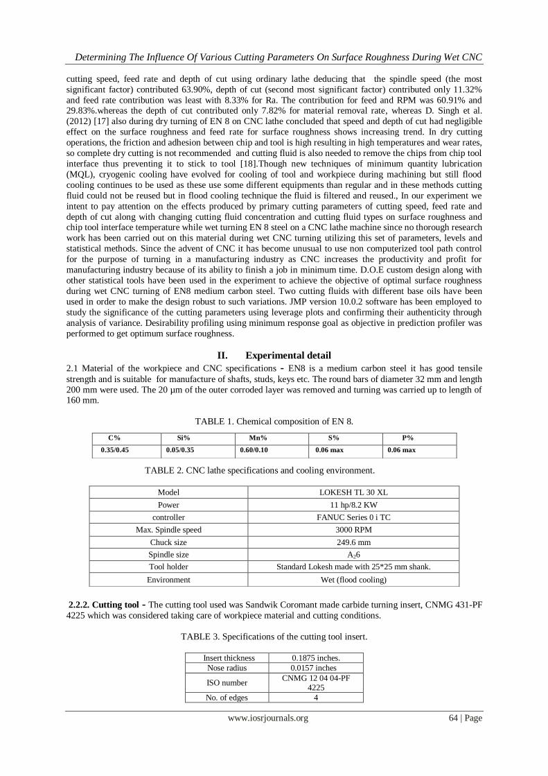
2.1 Material of the workpiece and CNC specifications - EN8 is a medium carbon steel it has good tensile
strength and is suitable for manufacture of shafts, studs, keys etc. The round bars of diameter 32 mm and length
200 mm were used. The 20 µm of the outer corroded layer was removed and turning was carried up to length of 160 mm.
TABLE 1. Chemical composition of EN 8.
TABLE 2. CNC lathe specifications and cooling environment.
2.2.2. Cutting tool - The cutting tool used was Sandwik Coromant made carbide turning insert, CNMG 431-PF
4225 which was considered taking care of workpiece material and cutting conditions.
TABLE 3. Specifications of the cutting tool insert.
Insert thickness 0.1875 inches.
Nose radius 0.0157 inches
ISO number CNMG 12 04 04-PF
4225
No. of edges 4
C% Si% Mn% S% P%
0.35/0.45 0.05/0.35 0.60/0.10 0.06 max 0.06 max
Model LOKESH TL 30 XL
Power 11 hp/8.2 KW
controller FANUC Series 0 i TC
Max. Spindle speed 3000 RPM
Chuck size 249.6 mm
Spindle size A26
Tool holder Standard Lokesh made with 25*25 mm shank.
Environment Wet (flood cooling)
Determining The Influence Of Various Cutting Parameters On Surface Roughness During Wet CNC
www.iosrjournals.org 65 | Page
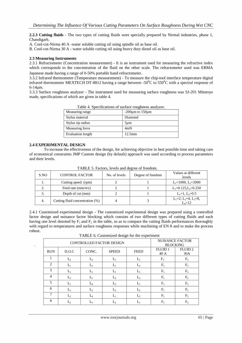
2.2.3 Cutting fluids - The two types of cutting fluids were specially prepared by Nirmal industries, phase 1,
Chandigarh.
A. Cool-cut-Nirma 40 A -water soluble cutting oil using spindle oil as base oil. B. Cool-cut-Nirma 30 A - water soluble cutting oil using heavy duty diesel oil as base oil.
2.3 Measuring Instruments
2.3.1 Refractometer (Concentration measurement) - It is an instrument used for measuring the refractive index
which corresponds to the concentration of the fluid on the other scale. The refractometer used was ERMA
Japanese made having a range of 0-50% portable hand refractometer. 3.3.2 Infrared thermometer (Temperature measurement) - To measure the chip-tool interface temperature digital
infrared thermometer MEXTECH DT-8812 having a range between -500C to 5500C with a spectral response of
6-14µm.
3.3.3 Surface roughness analyzer - The instrument used for measuring surface roughness was SJ-201 Mitutoyo
made, specifications of which are given in table 4.
Table 4. Specifications of surface roughness analyzer. Measuring range -200µm to 150µm
Stylus material Diamond
Stylus tip radius 5µm
Measuring force 4mN
Evaluation length 12.5mm
2.4 EXPERIMENTAL DESIGN To increase the effectiveness of the design, for achieving objective in best possible time and taking care
of economical constraints JMP Custom design (by default) approach was used according to process parameters
and their levels.
TABLE 5. Factors, levels and degree of freedom.
S.NO CONTROL FACTOR No. of levels Degree of freedom Values at different
levels
1. Cutting speed (rpm) 2 1 L1=1000, L2=2000
2. Feed rate (mm/rev) 2 1 L1=0.125,L2=0.250
3. Depth of cut (mm) 2 1 L1=1, L2=0.5
4. Cutting fluid concentration (%) 4 3 L1=2, L2=4, L3=8,
L4=12
2.4.1 Customized experimental design - The customized experimental design was prepared using a controlled
factor design and nuisance factor blocking which consists of two different types of cutting fluids and each
having one level denoted by F1 and F2 in the table, so as to compare the cutting fluids performances thoroughly
with regard to temperatures and surface roughness responses while machining of EN 8 and to make the process
robust.
TABLE 6. Customized design for the experiment
. CONTROLLED FACTOR DESIGN
NUISANCE FACTOR BLOCKING
RUN D.O.C CONC. SPEED FEED FLUID 1
40 A FLUID 2
30A
1 L2 L2 L1 L1 F1` F2
2 L1 L3 L1 L2 F1 F2
3 L1 L1 L1 L1 F1 F2
4 L2 L1 L2 L2 F1 F2
5 L1 L4 L2 L1 F1 F2
6 L1 L2 L2 L2 F1 F2
7 L2 L4 L1 L2 F1 F2
8 L2 L3 L2 L1 F1 F2
Determining The Influence Of Various Cutting Parameters On Surface Roughness During Wet CNC
www.iosrjournals.org 66 | Page
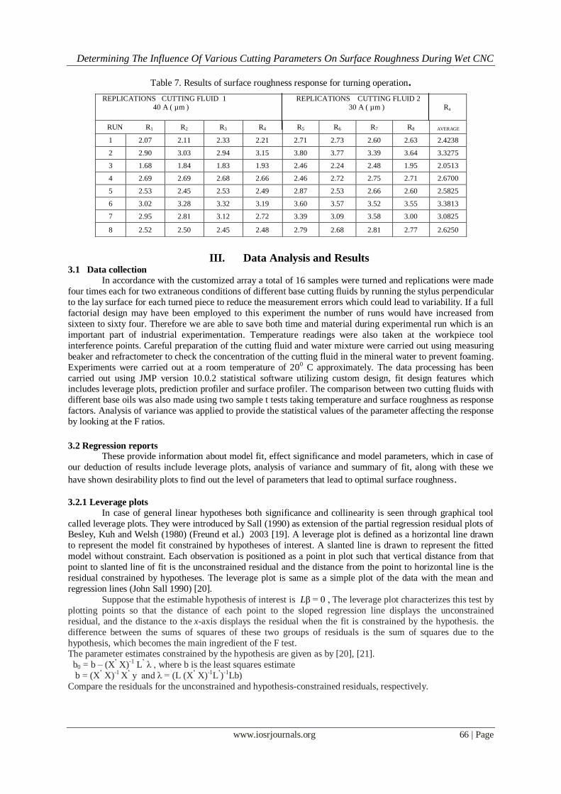
Table 7. Results of surface roughness response for turning operation.
III. Data Analysis and Results 3.1 Data collection
In accordance with the customized array a total of 16 samples were turned and replications were made
four times each for two extraneous conditions of different base cutting fluids by running the stylus perpendicular
to the lay surface for each turned piece to reduce the measurement errors which could lead to variability. If a full
factorial design may have been employed to this experiment the number of runs would have increased from
sixteen to sixty four. Therefore we are able to save both time and material during experimental run which is an
important part of industrial experimentation. Temperature readings were also taken at the workpiece tool
interference points. Careful preparation of the cutting fluid and water mixture were carried out using measuring
beaker and refractometer to check the concentration of the cutting fluid in the mineral water to prevent foaming.
Experiments were carried out at a room temperature of 200 C approximately. The data processing has been
carried out using JMP version 10.0.2 statistical software utilizing custom design, fit design features which includes leverage plots, prediction profiler and surface profiler. The comparison between two cutting fluids with
different base oils was also made using two sample t tests taking temperature and surface roughness as response
factors. Analysis of variance was applied to provide the statistical values of the parameter affecting the response
by looking at the F ratios.
3.2 Regression reports
These provide information about model fit, effect significance and model parameters, which in case of
our deduction of results include leverage plots, analysis of variance and summary of fit, along with these we
have shown desirability plots to find out the level of parameters that lead to optimal surface roughness.
3.2.1 Leverage plots
In case of general linear hypotheses both significance and collinearity is seen through graphical tool
called leverage plots. They were introduced by Sall (1990) as extension of the partial regression residual plots of Besley, Kuh and Welsh (1980) (Freund et al.) 2003 [19]. A leverage plot is defined as a horizontal line drawn
to represent the model fit constrained by hypotheses of interest. A slanted line is drawn to represent the fitted
model without constraint. Each observation is positioned as a point in plot such that vertical distance from that
point to slanted line of fit is the unconstrained residual and the distance from the point to horizontal line is the
residual constrained by hypotheses. The leverage plot is same as a simple plot of the data with the mean and
regression lines (John Sall 1990) [20].
Suppose that the estimable hypothesis of interest is Lβ = 0 , The leverage plot characterizes this test by
plotting points so that the distance of each point to the sloped regression line displays the unconstrained
residual, and the distance to the x-axis displays the residual when the fit is constrained by the hypothesis. the
difference between the sums of squares of these two groups of residuals is the sum of squares due to the
hypothesis, which becomes the main ingredient of the F test. The parameter estimates constrained by the hypothesis are given as by [20], [21].
b0 = b – (X’ X)
-1 L
’ λ , where b is the least squares estimate
b = (X’ X)-1 X’ y and λ = (L (X’ X)-1L’)-1Lb)
Compare the residuals for the unconstrained and hypothesis-constrained residuals, respectively.
REPLICATIONS CUTTING FLUID 1 REPLICATIONS CUTTING FLUID 2
40 A ( µm ) 30 A ( µm ) Ra
RUN R1 R2 R3 R4 R5 R6 R7 R8 AVERAGE
1 2.07 2.11 2.33 2.21 2.71 2.73 2.60 2.63 2.4238
2 2.90 3.03 2.94 3.15 3.80 3.77 3.39 3.64 3.3275
3 1.68 1.84 1.83 1.93 2.46 2.24 2.48 1.95 2.0513
4 2.69 2.69 2.68 2.66 2.46 2.72 2.75 2.71 2.6700
5 2.53 2.45 2.53 2.49 2.87 2.53 2.66 2.60 2.5825
6 3.02 3.28 3.32 3.19 3.60 3.57 3.52 3.55 3.3813
7 2.95 2.81 3.12 2.72 3.39 3.09 3.58 3.00 3.0825
8 2.52 2.50 2.45 2.48 2.79 2.68 2.81 2.77 2.6250

Determining The Influence Of Various Cutting Parameters On Surface Roughness During Wet CNC
www.iosrjournals.org 67 | Page
Fig.1Construction of a leverage plot.
To get a leverage plot, the x-axis values vx of the points are the differences in the residuals due to the hypothesis,
so that the distance from the line of fit (with slope 1) to the x-axis is this difference. The y-axis values vy are just
the x-axis values plus the residuals under the full model.
3.2.2 Superimposing a test on the Leverage Plot
In simple linear regression, you can plot the confidence limits for the expected value as a smooth
function of the regressor variable x
Upper (x) =
Lower (x) = Where, x = [1 x] is the 2-vector of regressors.
This hyperbola is a useful significance-measuring instrument. (JMP SUPPORT)
If the slope parameter is significantly different from zero, the confidence curve will cross the horizontal line
of the response mean.
If the slope parameter is not significantly different from zero, the confidence curve will not cross the
horizontal line of the response mean.
If the t-test for the slope parameter is sitting right on the margin of significance, the confidence curve will
have the horizontal line of the response mean as an asymptote
Fig. 2 Cases of Significant, Borderline, and non significant Confidence Curves.
Determining The Influence Of Various Cutting Parameters On Surface Roughness During Wet CNC
www.iosrjournals.org 68 | Page
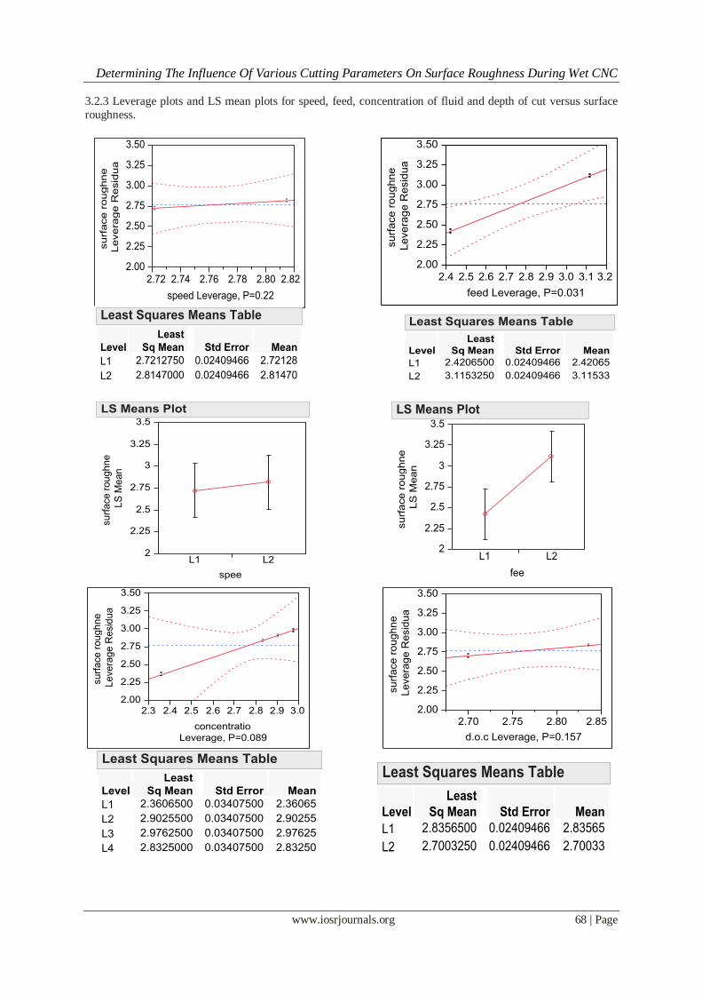
3.2.3 Leverage plots and LS mean plots for speed, feed, concentration of fluid and depth of cut versus surface
roughness.
Determining The Influence Of Various Cutting Parameters On Surface Roughness During Wet CNC
www.iosrjournals.org 69 | Page
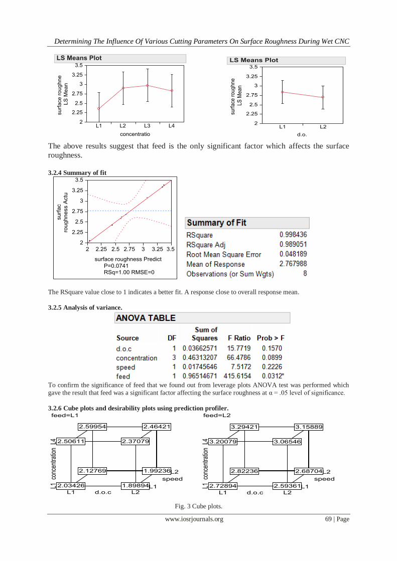
The above results suggest that feed is the only significant factor which affects the surface
roughness.
3.2.4 Summary of fit
The RSquare value close to 1 indicates a better fit. A response close to overall response mean.
3.2.5 Analysis of variance.
To confirm the significance of feed that we found out from leverage plots ANOVA test was performed which
gave the result that feed was a significant factor affecting the surface roughness at α = .05 level of significance.
3.2.6 Cube plots and desirability plots using prediction profiler.
Fig. 3 Cube plots.
Determining The Influence Of Various Cutting Parameters On Surface Roughness During Wet CNC
www.iosrjournals.org 70 | Page
To find out the optimal parameters for surface roughness we plot the cube plots and found out that at constant
feed levels L1 and L2. The parameter feed at L1, speed at L1, depth of cut L2 and cutting fluid concentration of
1.89894 µm. To confirm the credibility of the cube plot we use prediction profiler. Prediction profiles are especially useful in multiple-response models to help judge which factor values can optimize a complex set of
criteria.
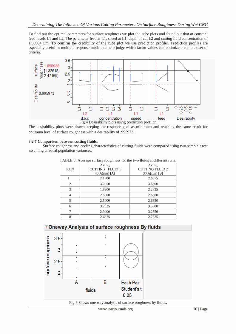
Fig.4 Desirability plots using prediction profiler.
The desirability plots were drawn keeping the response goal as minimum and reaching the same result for
optimum level of surface roughness with a desirability of .995973.
3.2.7 Comparison between cutting fluids.
Surface roughness and cooling characteristics of cutting fluids were compared using two sample t test assuming unequal population variances.
TABLE 8. Average surface roughness for the two fluids at different runs.
RUN Av. Ra
CUTTING FLUID 1 40 A(µm) [A]
Av. Ra
CUTTING FLUID 2 30 A(µm) [B]
1 2.1800 2.6675
2 3.0050 3.6500
3 1.8200 2.2825
4 2.6800 2.6600
5 2.5000 2.6650
6 3.2025 3.5600
7 2.9000 3.2650
8 2.4875 2.7625
Fig.5 Shows one way analysis of surface roughness by fluids.
Determining The Influence Of Various Cutting Parameters On Surface Roughness During Wet CNC
www.iosrjournals.org 71 | Page
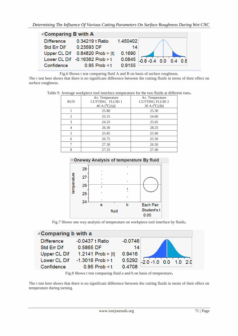
Fig.6 Shows t test comparing fluid A and B on basis of surface roughness.
The t test here shows that there is no significant difference between the cutting fluids in terms of their effect on
surface roughness.
Table 9. Average workpiece tool interface temperature for the two fluids at different runs.
RUN Av. Temperature
CUTTING FLUID 1
40 A (0C) [a]
Av. Temperature
CUTTING FLUID 2
30 A (0C) [b]
1 25.80 25.30
2 25.15 24.60
3 24.25 25.65
4 26.30 28.25
5 25.85 25.60
6 26.75 25.50
7 27.30 26.50
8 27.25 27.40
Fig.7 Shows one way analysis of temperature on workpiece tool interface by fluids.
Fig.8 Shows t test comparing fluid a and b on basis of temperature.
The t test here shows that there is no significant difference between the cutting fluids in terms of their effect on
temperature during turning.
Determining The Influence Of Various Cutting Parameters On Surface Roughness During Wet CNC
www.iosrjournals.org 72 | Page
3.2.8 Verification of optimality.
It was found out by turning operation on levels L1 of speed, feed, concentration and L2 of depth of cut using both cutting fluids, the average surface roughness came out to be 1.91 µm slightly more than 1.898938
predicted with the desirability of .995973.
IV. Conclusion and recommendations In this study we utilized latest statistical techniques and design criteria for determining the optimum
turning parameters for surface finish.
Feed rate has significant and the most dominant effect on surface roughness.
It is found out that surface roughness tends to increase with increase in speed, feed and concentration of
cutting fluid but show opposite trend when depth of cut is increased. The nuisance factor of cutting fluid was found to have statistically insignificant effect but it helped to make
the design more robust.
The use of custom design method in JMP statistical software helped in reducing the number of experiments
from 64 to 16.
The decrease in cutting fluid concentration improves surface roughness of EN 8.
While this study succeeded in achieving the optimal response utilizing minimum resources and time. This area
of research is still wide open as we came to know that the factors like depth of cut are to be explored more as it
shows variable trends in many different experiments. Dry, flood and MQL fluid application methods are to be
compared on the basis of their effect on surface roughness and tool wear rate.
Acknowledgement – Thanking Guru Nanak Industries, Rajpura and Nirmal oils, Chandigarh for their valuable support and assistance.
References
[1] S.S Mahapatra, Amar Patnaik, Prabina Ku. Patnaik, Parametric Analysis and Optimization of Cutting Parameters for Turning
Operations based on Taguchi Method, Proceedings of the International Conference on Global Manufacturing and Innovation, July
27-29,2006.
[2] M. Anthony Xavior, M. Adithan, Determining the influence of cutting fluids on tool wear and surface roughness during turning of
AISI 304 austenic stainless steel, Journal of Materials Processing Technology 209, 2009, 900-909.
[3] M. M. A. Khan, M. A. H. Mithu, N.R. Dhar, Effects of minimum quantity lubrication on turning AISI 9310 alloy steel using
vegetable oil based cutting fluid, Journal of Materials Processing Technology 209, 2009, 5573-5583.
[4] L.B Abhang, M. Hameedullah, Modeling and Analysis for Surface roughness in Machining EN-31 steel using Response Surface
Methodology, International Journal of Applied Research in Mechanical Engineering, Volume-1, Issue.1, 2011.
[5] Chorng-Jyh Tzeng, Yu-Hsin Lin, Yung-Kuang Yang, Ming-Chang Jeng, Optimization of turning operations with multiple
performance characteristics using the Taguchi method and Grey relational analysis, Journal of Materials Processing Technology
209, 2009, 2753-2759.
[6] Rahul Davis, Optimization of Surface Roughness in wet Turning operation of EN24 steel, International Journal of Mechanical and
Production Engineering Research and Development (IJMPERD) ISSN 2249-6890, volume 2, Issue 3, 2012, 28-35.
[7] http://en.wikipedia.org/wiki/Speeds_and_feeds. [8] http://www.steelexpress.co.uk/engineeringsteel/EN8.html . [9] W.H. Yang, Y.S Tarng, Design optimization of cutting parameters for turning operations based on the Taguchi method, Journal of
Material Processing Technology 84, 1998, 122-129.
[10] J. Kopac, M. Bahor and M. Sokovic, Optimal machining parameters for achieving the desired surface roughness in fine turning of
cold pre-formed steel workpieces, International Journal of Machine Tools and Manufacture, 2002,707-716.
[11] J.P. Davim, Design of optimization of cutting parameters for turning metal matrix composites based on orthogonal arrays, , Journal
of Material Processing Technology 132, 2003, 340-344.
[12] E. Daniel Kirby, A parameter design study in a turning operation using the Taguchi method, the Technology Interface, 2006.
[13] S. Thamizhmannii, S. Saparudin, S. Hasan, Journal of Achievements in Materials and Manufacturing Engineering, Volume 20,
Issues 1-2, 2007.
[14] Nitin Sharma, Shahzad Ahmed, Zahid A. Khan, Arshad Noor Siddiquee, Optimization of cutting parameters for Surface roughness
in Turning, International Journal of Advanced Research in Engineering and Technology, Volume 3, Issue 1, 2012, 86-96.
[15] Mahendra Korat, Neeraj Agarwal, Optimization of Different Machining parameters of EN24 alloy steel in CNC Turning by use of
Taguchi method, International Journal of Engineering Research and Applications (IJERA) ISSN 2248-9622,Volume 2, Issue 5,
2012,160-664.
[16] Hardeep Singh, Rajesh Khanna, M.P. Garg, Effect of Cutting parameter on MRR and Surface Roughness in Turning EN-8, Current
Trends in Engineering Research Vol.1, No.1, 2011.
[17] Didar singh, Mukesh Verma, H. Singh, Experimental Investigation of Surface Roughness and MRR in dry Turning of EN-8 on
CNC lathe.
[18] A.E. Diniz, R. Micaroni, Cutting conditions for finish turning process aiming: the use of dry cutting, International Journal of
Machine Tools and Manufacture, Volume 42, 2002, 899-904.
[19] Rudolf Jacob Freund, Ramon C. Littell, Lee Creighton, Regression using JMP, 2003.
[20] John Sall, Leverage plots for General Linear Hypotheses, The American Statistician, Volume 44, No.4, 1990.
[21] http://www.jmp.com/support/help/Leverage_Plot_Details.shtml. .