mud quick-change systems - dme
TRANSCRIPT

®
MUD QUICK-CHANGE SYSTEMS
THIS BOOK IS LINKED BOTH INTERNALLY AND TO THE ESTORE-DOWNLOAD FOR EASY ACCESS
MUD H Frame Ordering Information .........................................................HF 47
Insert Mold Ordering Information .....................................................................HF 47
H Frame Features, Options and Applications ................................................HF 48Companion Insert Mold Features, Options and Applications ....................HF 49
07/07 HF Companion Insert Molds (3.25 x 3.15) ................................. HF 50
08/09 HF Companion Insert Molds (5.0 x 3.5) ...................................... HF 51
10/12 HF Companion Insert Molds (5.0 x 5.0) ...................................... HF 5210/18 HF Companion Insert Molds (5.0 x 8.0) ...................................... HF 5311/14 HF Companion Insert Molds (6.0 x 6.0) ...................................... HF 54
11/18 HF Companion Insert Molds (6.0 x 8.0) ...................................... HF 55
12/11 HF Companion Insert Molds (7.0 x 4.5) ...................................... HF 56
12/13 HF Companion Insert Molds (7.0 x 5.5) ...................................... HF 57
12/15 HF Companion Insert Molds (7.0 x 6.5) ...................................... HF 58
12/19 HF Companion Insert Molds (7.0 x 8.5) ...................................... HF 59
13/13 HF Companion Insert Molds (8.0 x 5.5) ...................................... HF 60
13/15 HF Companion Insert Molds (8.0 x 6.5) ...................................... HF 61
13/17 HF Companion Insert Molds (8.0 x 7.5) ...................................... HF 62
13/19 HF Companion Insert Molds (8.0 x 8.5) ...................................... HF 63
13/23 HF Companion Insert Molds (8.0 x 10.5) .................................... HF 64
14/15 HF Companion Insert Molds (9.0 x 6.5) ...................................... HF 65
14/17 HF Companion Insert Molds (9.0 x 7.5) ...................................... HF 66
14/19 HF Companion Insert Molds (9.0 x 8.5) ...................................... HF 67
14/21 HF Companion Insert Molds (9.0 x 9.5) ...................................... HF 68
14/25 HF Companion Insert Molds (9.0 x 11.5) .................................... HF 69
15/15 HF Companion Insert Molds (10.0 x 6.5) .................................... HF 70
15/17 HF Companion Insert Molds (10.0 x 7.5) .................................... HF 71
15/19 HF Companion Insert Molds (10.0 x 8.5) .................................... HF 72
15/21 HF Companion Insert Molds (10.0 x 9.5) .................................... HF 73
15/25 HF Companion Insert Molds (10.0 x 11.5) ................................. HF 74
17/19 HF Companion Insert Molds (11.0 x 8.5) .................................... HF 75
17/26 HF Companion Insert Molds (11.0 x 12.0) ................................. HF 76
18/22 HF Companion Insert Molds (12.0 x 10.0) ................................. HF 77
18/26 HF Companion Insert Molds (12.0 x 12.0) ................................. HF 78
18/30 HF Companion Insert Molds (12.0 x 14.0) ................................. HF 79
“E” Frame Companion Insert Molds ........................................................... EF 80
MUD U Frame Ordering Information .........................................................UF 12
Insert Mold Ordering Information .....................................................................UF 12
U Frame Features and Applications ..................................................................UF 13
Companion Insert Mold Features and Applications ...................................UF 14
Enhanced Series Mold Inserts – Solid & Laminated ................................... UF 15
05/05 UF Companion Insert Mold (3.25 x 3.75 & 4.0 x 4.7) …… UF 16
07/07 UF Companion Insert Mold (4.5 x 6.25 & 6.0 x 7.25) …… UF 17
08/09 UF Companion Insert Mold (5.0 x 8.0 & 7.85 x 9.0) ……… UF 18
08/10 UF Companion Insert Mold (5.0 x 9.0 & 7.85 x 9.0) ……… UF 19
94/90 UF Companion Insert Mold (6.5 x 8.0 & 8.4 x 9.0) ……… UF 20
84/90 UF Companion Insert Mold (6.5 x 8.0 & 8.4 x 9.0) ……… UF 21
09/07 UF Companion Insert Mold (6.0 x 6.75 & 9.0 x 6.75) …… UF 22
09/07 EB Companion Insert Mold (6.0 x 6.75 & 9.0 x 6.75) …… UF 23
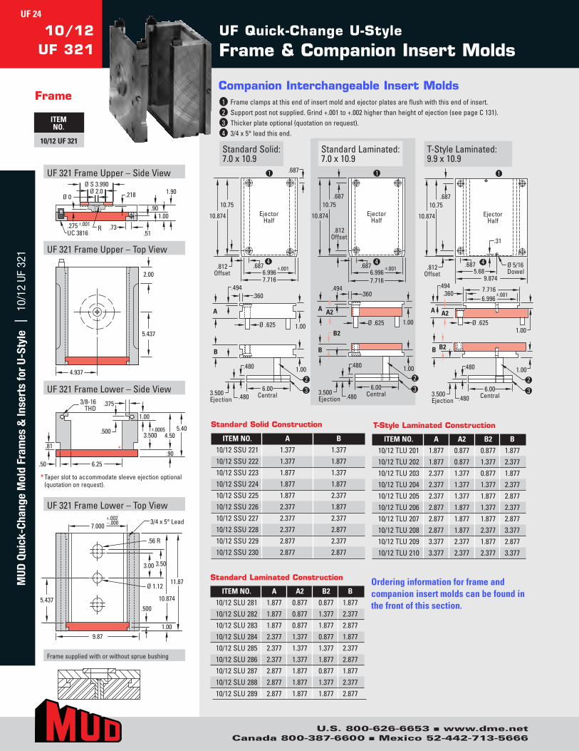
10/12 UF Companion Insert Mold (7.0 x 10.9 & 9.9 x 10.9) …… UF 24
10/14 UF Companion Insert Mold (7.0 x 12.9 & 9.9 x 12.9) …… UF 25
10/16 UF Companion Insert Mold (7.0 x 14.9 & 9.9 x 14.9) …… UF 26
11/11 UF Companion Insert Mold (8.0 x 10.0 & 11.5 x 11.0) …… UF 27
12/08 UF Companion Insert Mold (8.0 x 8.0 & 11.9 x 8.0) ……… UF 28
12/14 UF Companion Insert Mold (8.0 x 12.9 & 11.9 x 12.9) …… UF 29
12/16 UF Companion Insert Mold (8.0 x 14.9 & 11.9 x 14.9) …… UF 30
12/18 UF Companion Insert Mold (8.0 x 16.9 & 11.9 x 16.9) …… UF 31
12/20 UF Companion Insert Mold (8.0 x 18.9 & 11.9 x 18.9) …… UF 32
13/16 UF Companion Insert Mold (9.0 x 14.9 & 12.9 x 14.9) …… UF 33
13/18 UF Companion Insert Mold (9.0 x 16.9 & 12.9 x 16.9) …… UF 34
13/20 UF Companion Insert Mold (9.0 x 18.9 & 12.9 x 18.9) …… UF 35
13/22 UF Companion Insert Mold (9.0 x 20.9 & 12.9 x 20.9) …… UF 36
14/16 UF
14/18 UF
14/20 UF
14/22 UF
16/18 UF
16/21 UF
16/24 UF
16/27 UF
18/20 UF
18/26 UF
Companion Insert Mold (10.0 x 14.9 & 13.9 x 14.9) … UF 37
Companion Insert Mold (10.0 x 16.9 & 13.9 x 16.9) … UF 38
Companion Insert Mold (10.0 x 18.9 & 13.9 x 18.9) … UF 39
Companion Insert Mold (10.0 x 20.9 & 13.9 x 20.9) … UF 40
Companion Insert Mold (11.0 x 15.9 & 15.9 x 15.9) … UF 41
Companion Insert Mold (11.0 x 18.9 & 15.9 x 18.9) … UF 42
Companion Insert Mold (11.0 x 21.9 & 15.9 x 21.9) … UF 43
Companion Insert Mold (11.0 x 24.9 & 15.9 x 24.9) … UF 44
Companion Insert Mold (12.0 x 17.9 & 17.9 x 17.9) … UF 45
Companion Insert Mold (12.0 x 23.9 & 17.9 x 23.9) … UF 46
U FRAME
H FRAME
An Introduction to the MUD Quick-Change™ Concept
A cost-effective approach to injection molding ................................................4-8
Customer Commitment ..................................................................................................9
DME Terms and Conditions of Sale .......................................................................... 10
Sales and Ordering Information ............................................................................... 11
INTRODUCTION
U.S. 800-626-6653 ■ www.dme.net
Canada 800-387-6600 ■ Mexico 52-442-713-5666
2
DME MUD
Table of Contents
U.S. 800-626-6653 n Canada 800-387-6600 n www.dme.net
page content
section3
DOUBLE H FRAMEMUD Double H Frame Ordering Information ...................... DF 81
Insert Mold Ordering Information ........................................................ DF 81
Double H Frame Features, Options & Applications ..................... DF 82
Companion Insert Mold Features, Options & Applications ..... DF 83
12/08 DF Companion Insert Molds (3.25 x 3.15) ................................... DF 84
16/09 DF Companion Insert Molds (5.0 x 3.5) ....................................... DF 85
16/12 DF Companion Insert Molds (5.0 x 5.0) ....................................... DF 86
16/18 DF Companion Insert Molds (5.0 x 8.0) ....................................... DF 87
20/14 DF Companion Insert Molds (6.0 x 6.0) ....................................... DF 88
22/19 DF Companion Insert Molds (7.0 x 8.5) ....................................... DF 89
24/23 DF Companion Insert Molds (8.0 x 10.5) ..................................... DF 90
MUD Components ...............................................................................C 116
Frames & Insert Mold Tapered Leads ...................................................C 117
Leader Pins, Bushings and Accessories ...................................... C 118-119
Sprue Bushings ....................................................................................... C 120-121
Top Locating Rings ............................................................................... C 122-123
Bottom Locating Rings .............................................................................. C 124
Mold Clamps ................................................................................................... C 125
Hoist Rings – INCH: Installation and Ordering Information .... C 126
Ear Plates for T-Style Insert Molds ....................................................... C 127
Standard Ejector Plate Sets ..................................................................... C 128
Guide Posts ...................................................................................................... C 129
Guide Bushings .............................................................................................. C 130
Insert Mold Pillar Posts .............................................................................. C 131
Hardened Runner Pads............................................................................... C 131
Shoulder Screws, Sprue Puller Plugs, Rest Buttons ................... C 132
Insert Mold Holding Clamps ................................................................... C 133
Mold Base Adapter Frame Rollers ........................................................ C 133
ADAPTER FRAME
COMPONENTS
OPTIONS
3
MUD Options FMUD Options Feateaturures and es and ApplicationsApplications ..............................................................................OP 135OP 135
SleevSleeve Ejecte Ejector Plator Plate e AssembliesAssemblies ..................................................................................................................OP 136OP 136
IntIntererloclocking Ejectking Ejector Plator Plate Railse Rails ......................................................................................................................OP 137OP 137
IntIntererloclocking Ejectking Ejector Plator Plateses ..........................................................................................................................................OP 138OP 138
U FU Frrames with Mastames with Master Ejecter Ejector Sor Systystemsems ..................................................................................OP 139OP 139
RemoRemovvable Centable Center Sectionser Sections ..................................................................................................................................OP 140OP 140
RemoRemovvable Centable Center Bar er Bar AssembliesAssemblies ......................................................................................................OP 141OP 141
CentCenter Bar Inserer Bar Insert Moldst Molds .................................................................................................................................. OP 142-143OP 142-143
StrStripper Platipper Plate and e and ThrThree-Platee-Plate Insere Insert Moldst Molds ................................................................OP 143OP 143
UF ExtUF Extended Clamp Bar Setsended Clamp Bar Sets ............................................................................................................................OP 144OP 144
UF Spacer PlatUF Spacer Plate Setse Sets ..............................................................................................................................................................OP 144OP 144
UF AUF Adaptdapter Assemblieser Assemblies ......................................................................................................................................................OP 145OP 145
UF AUF Adaptdapter er PlatPlateses ............................................................................................................................................................................OP 146OP 146
UF BolstUF Bolster Plater Plateses ................................................................................................................................................................................OP 147OP 147
Special ASpecial Adaptdapter er PlatPlateses ..........................................................................................................................................................OP 148OP 148
High High TTemperemperataturure Insulate Insulator Sheetsor Sheets ........................................................................................................OP 149OP 149
AAdditional Ear Slotsdditional Ear Slots ......................................................................................................................................................................OP 149OP 149
InserInsert Mold Loading Railst Mold Loading Rails ..............................................................................................................................................OP 150OP 150
Mold TMold Tooling ooling PrPrototectionection ......................................................................................................................................................OP 151OP 151
TTwwo-Coloro-Color,, T T wwo-Mato-Matererial ial MoldingMolding................................................................................................................OP 152OP 152
StandarStandard Heat Pipesd Heat Pipes ....................................................................................................................................................................OP 153OP 153
Hot RunnerHot Runner-Infused Quic-Infused Quick-Changk-Change™ Se™ Systystemsems ..........................................................OP 154OP 154
ADAPTER FRAME
OPTIONS
3
MUD Options ...............................................................................C 116
MUD Adapter Frame Ordering Information.............................................................AF 91
System Accessories................... ......................................................................................AF 92Ear Plate installation Instructions...................................................................................AF 93Adapter Frame Installation Instructions........................................................................AF 94
12/18 AF Companion Ear Plates (AEP 011 & AEP 022....................................AF 96
14/20 AF Companion Ear Plates (AEP 011 & AEP 022....................................AF 97
16/21 AF Companion Ear Plates (AEP 011 & AEP 022....................................AF 98
18/26 AF Companion Ear Plates (AEP 011 & AEP 022....................................AF 99
22/30 AF Companion Ear Plates (AEP 011 & AEP 022....................................AF 100
24/36AF Companion Ear Plates (AEP 011 & AEP 022....................................AF 101
Balancing Lift Bars & Buttons....................................................................................AF 103
MUD Mold Change Cart...................................................................................................AF 104
Adapter Systems with Instant-Connect Waterlines.....................................................AF 105
Waterline System Ordering Information...................................................................AF 105
Features and Applications...........................................................................................AF 106
4-Coupler Instant-Connect Waterline System........................................................AF 108
6-Coupler Instant-Connect Waterline System...........................................................AF 110
10-Coupler Instant-Connect Waterline System.....................................................AF 112
Mold Base Adapter Back Section Manifolds.......................................................AF 114
Ear Plate Machining Specifications........................................................................AF 114
The MUD Waterline Purge System.........................................................................AF 115
U.S. 800-626-6653 ■ www.dme.netCanada 800-387-6600 ■ Mexico 52-442-713-5666
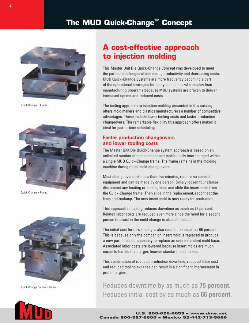
This.Master.Unit.Die.Quick-Change.Concept.was.developed.to.meet.the.parallel.challenges.of.increasing.productivity.and.decreasing.costs..MUD.Quick-Change.Systems.are.more.frequently.becoming.a.part.of.the.operational.strategies.for.many.companies.who.employ.lean.manufacturing.programs.because.MUD.systems.are.proven.to.deliver.increased.uptime.and.reduced.costs.
The.tooling.approach.to.injection.molding.presented.in.this.catalog.offers.mold.makers.and.plastics.manufacturers.a.number.of.competitive.advantages..These.include.lower.tooling.costs.and.faster.production.changeovers..The.remarkable.flexibility.this.approach.offers.makes.it.ideal.for.just-in-time.scheduling.
Faster production changeovers and lower tooling costsThe.Master.Unit.Die.Quick-Change.system.approach.is.based.on.an.unlimited.number.of.companion.insert.molds.easily.interchanged.within.a.single.MUD.Quick-Change.frame..The.frame.remains.in.the.molding.machine.during.these.mold.changeovers.
Most.changeovers.take.less.than.five.minutes,.require.no.special.equipment.and.can.be.made.by.one.person..Simply.loosen.four.clamps,.disconnect.any.heating.or.cooling.lines.and.slide.the.insert.mold.from.the.Quick-Change.frame..Then.slide.in.the.replacement,.reconnect.the.lines.and.reclamp..The.new.insert.mold.is.now.ready.for.production.
This.approach.to.tooling.reduces.downtime.as.much.as.75.percent..Related.labor.costs.are.reduced.even.more.since.the.need.for.a.second.person.to.assist.in.the.mold.change.is.also.eliminated.
The.initial.cost.for.new.tooling.is.also.reduced.as.much.as.66.percent..This.is.because.only.the.companion.insert.mold.is.replaced.to.produce.a.new.part..It.is.not.necessary.to.replace.an.entire.standard.mold.base..Associated.labor.costs.are.lowered.because.insert.molds.are.much.easier.to.handle.than.larger,.heavier.standard.mold.bases.
This.combination.of.reduced.production.downtime,.reduced.labor.cost.and.reduced.tooling.expense.can.result.in.a.significant.improvement.in.profit.margins.
The MUD Quick-Change™ Concept
A cost-effective approach to injection molding
Quick-Change.H.Frame
Quick-Change.U.Frame
Quick-Change.Double.H.Frame Reduces.downtime.by.as.much.as.75 percent..Reduces.initial.cost.by.as.much.as.66 percent..
4
U.S. 800-626-6653 ■ www.dme.netCanada 800-387-6600 ■ Mexico 52-442-713-5666
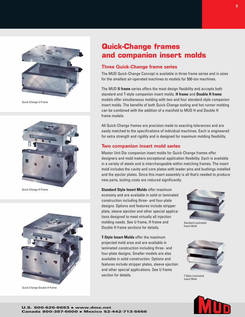
Three Quick-Change frame seriesThe.MUD.Quick-Change.Concept.is.available.in.three.frame.series.and.in.sizes.for.the.smallest.air-operated.machines.to.models.for.500-ton.machines.
The.MUD.U frame.series.offers.the.most.design.flexibility.and.accepts.both.standard.and.T-style.companion.insert.molds..H frame.and.Double H frame.models.offer.simultaneous.molding.with.two.and.four.standard.style.companion.insert.molds..The.benefits.of.both.Quick-Change.tooling.and.hot.runner.molding.can.be.combined.with.the.addition.of.a.manifold.to.MUD.H.and.Double.H..frame.models.
All.Quick-Change.frames.are.precision.made.to.exacting.tolerances.and.are.easily.matched.to.the.specifications.of.individual.machines..Each.is.engineered.for.extra.strength.and.rigidity.and.is.designed.for.maximum.molding.flexibility.
Two companion insert mold seriesMaster.Unit.Die.companion.insert.molds.for.Quick-Change.frames.offer..designers.and.mold.makers.exceptional.application.flexibility..Each.is.available.in.a.variety.of.steels.and.is.interchangeable.within.matching.frames..The.insert.mold.includes.the.cavity.and.core.plates.with.leader.pins.and.bushings.installed.and.the.ejector.plates..Since.this.insert.assembly.is.all.that’s.needed.to.produce.new.parts,.tooling.costs.are.reduced.significantly.
Standard Style Insert Molds.offer.maximum.economy.and.are.available.in.solid.or.laminated.construction.including.three-.and.four-plate.designs..Options.and.features.include.stripper.plate,.sleeve.ejection.and.other.special.applica-tions.designed.to.meet.virtually.all.injection..molding.needs..See.U.frame,.H.frame.and..Double.H.frame.sections.for.details.
T-Style Insert Molds.offer.the.maximumprojected.mold.area.and.are.available.in..laminated.construction.including.three-.and..four-plate.designs..Smaller.models.are.also..available.in.solid.construction..Options.and..features.include.stripper.plates,.sleeve.ejectionand.other.special.applications..See.U.frame..section.for.details.
Quick-Change framesand companion insert molds
Standard.LaminatedInsert.Mold
T-Style.Laminated.Insert.Mold
Quick-Change.H.Frame
Quick-Change.U.Frame
Quick-Change.Double.H.Frame
5
U.S. 800-626-6653 ■ www.dme.netCanada 800-387-6600 ■ Mexico 52-442-713-5666
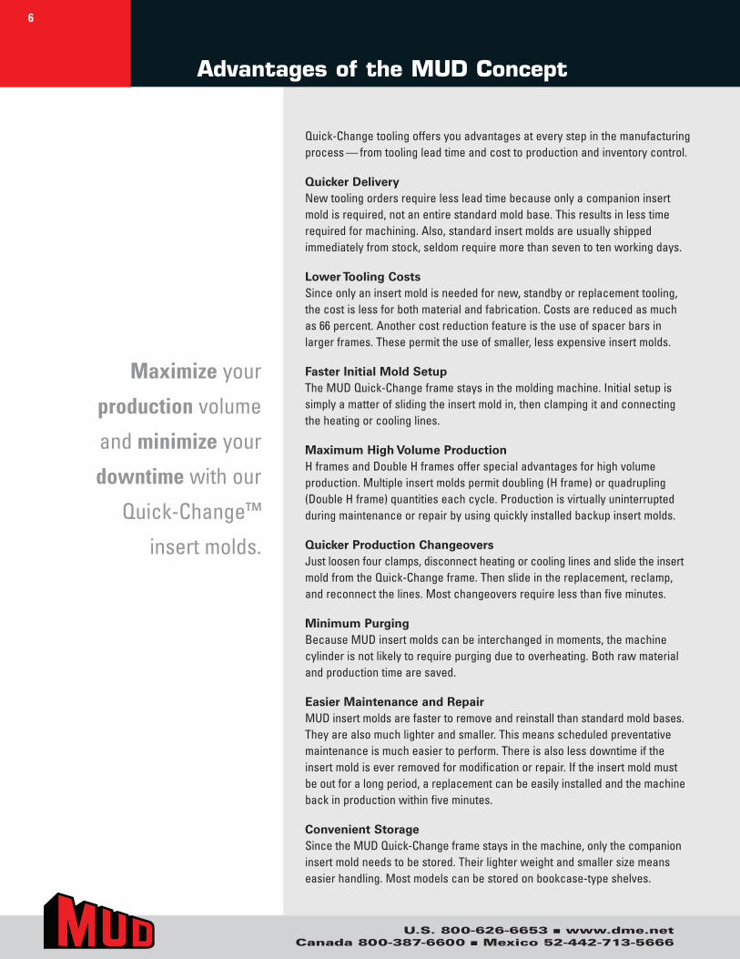
Advantages of the MUD Concept
Quick-Change.tooling.offers.you.advantages.at.every.step.in.the.manufacturing.process — from.tooling.lead.time.and.cost.to.production.and.inventory.control.
Quicker DeliveryNew.tooling.orders.require.less.lead.time.because.only.a.companion.insert..mold.is.required,.not.an.entire.standard.mold.base..This.results.in.less.time.required.for.machining..Also,.standard.insert.molds.are.usually.shipped..immediately.from.stock,.seldom.require.more.than.seven.to.ten.working.days.
Lower Tooling CostsSince.only.an.insert.mold.is.needed.for.new,.standby.or.replacement.tooling,..the.cost.is.less.for.both.material.and.fabrication..Costs.are.reduced.as.much..as.66.percent..Another.cost.reduction.feature.is.the.use.of.spacer.bars.in..larger.frames..These.permit.the.use.of.smaller,.less.expensive.insert.molds.
Faster Initial Mold SetupThe.MUD.Quick-Change.frame.stays.in.the.molding.machine..Initial.setup.is..simply.a.matter.of.sliding.the.insert.mold.in,.then.clamping.it.and.connecting..the.heating.or.cooling.lines.
Maximum High Volume ProductionH.frames.and.Double.H.frames.offer.special.advantages.for.high.volume..production..Multiple.insert.molds.permit.doubling.(H.frame).or.quadrupling.(Double.H.frame).quantities.each.cycle..Production.is.virtually.uninterrupted.during.maintenance.or.repair.by.using.quickly.installed.backup.insert.molds.
Quicker Production ChangeoversJust.loosen.four.clamps,.disconnect.heating.or.cooling.lines.and.slide.the.insert.mold.from.the.Quick-Change.frame..Then.slide.in.the.replacement,.reclamp,..and.reconnect.the.lines..Most.changeovers.require.less.than.five.minutes.
Minimum PurgingBecause.MUD.insert.molds.can.be.interchanged.in.moments,.the.machine..cylinder.is.not.likely.to.require.purging.due.to.overheating..Both.raw.material.and.production.time.are.saved.
Easier Maintenance and RepairMUD.insert.molds.are.faster.to.remove.and.reinstall.than.standard.mold.bases..They.are.also.much.lighter.and.smaller..This.means.scheduled.preventative.maintenance.is.much.easier.to.perform..There.is.also.less.downtime.if.the..insert.mold.is.ever.removed.for.modification.or.repair..If.the.insert.mold.must..be.out.for.a.long.period,.a.replacement.can.be.easily.installed.and.the.machine.back.in.production.within.five.minutes.
Convenient StorageSince.the.MUD.Quick-Change.frame.stays.in.the.machine,.only.the.companion.insert.mold.needs.to.be.stored..Their.lighter.weight.and.smaller.size.means..easier.handling..Most.models.can.be.stored.on.bookcase-type.shelves.
Maximize.your.
production.volume.
and.minimize.your.
downtime.with.our.
Quick-Change™.
insert.molds.
6
U.S. 800-626-6653 ■ www.dme.netCanada 800-387-6600 ■ Mexico 52-442-713-5666
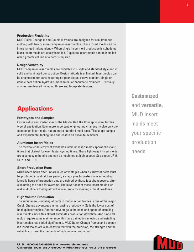
Prototypes and SamplesFaster.setup.and.startup.means.the.Master.Unit.Die.Concept.is.ideal.for.this.type.of.application..Even.more.important,.engineering.changes.involve.only.the.companion.insert.mold,.not.an.entire.standard.mold.base..This.keeps.sample.and.experimental.tooling.time.and.cost.to.an.absolute.minimum.
Aluminum Insert MoldsThe.thermal.conductivity.of.available.aluminum.insert.molds.approaches.four..times.that.of.steel.for.even.faster.cycling.times..These.lightweight.insert.molds.are.also.easy.to.handle.and.can.be.machined.at.high.speeds..See.pages.UF.18,.UF.20.and.UF.21.
Short Production RunsMUD.insert.molds.offer.unparalleled.advantages.when.a.variety.of.parts.must.be.produced.in.a.short.time.period,.a.major.plus.for.just-in-time.scheduling..Literally.hours.of.production.time.are.gained.by.these.fast.changeovers,.often.eliminating.the.need.for.overtime..The.lower.cost.of.these.insert.molds.also.makes.duplicate.tooling.attractive.insurance.for.meeting.critical.deadlines.
High Volume ProductionThe.simultaneous.molding.of.parts.in.multi-section.frames.is.one.of.the.major.Quick-Change.advantages.in.increasing.productivity..So.is.the.lower.cost.of.backup.insert.molds..Another.advantage.is.the.ease.and.speed.of.installing.insert.molds.since.this.almost.eliminates.production.downtime..And.since.all.molds.require.some.maintenance,.this.time.gained.in.removing.and.installing.insert.molds.has.added.significance..MUD.Quick-Change.frames.and.compan-ion.insert.molds.are.also.constructed.with.the.precision,.the.strength.and.the.reliability.to.meet.the.demands.of.high.volume.production.
Applications
Production FlexibilityMUD.Quick-Change.H.and.Double.H.frames.are.designed.for.simultaneous.molding.with.two.or.more.companion.insert.molds..These.insert.molds.can.be.interchanged.independently..When.single.insert.mold.production.is.scheduled,.blank.insert.molds.are.easily.installed..Duplicate.insert.molds.can.be.installed.when.greater.volume.of.a.part.is.required.
Design VersatilityMUD.companion.insert.molds.are.available.in.T-style.and.standard.style.and.in.solid.and.laminated.construction..Design.latitude.is.unlimited..Insert.molds.can.be.engineered.for.parts.requiring.stripper.plates,.sleeve.ejection,.single.or..double.cam.action,.hydraulic,.mechanical.or.pneumatic.cylinders — virtually.any.feature.desired.including.three-.and.four-plate.designs.
Customized
and.versatile,.
MUD.insert.
molds.meet.
your.specific..
production.
needs.
7
U.S. 800-626-6653 ■ www.dme.netCanada 800-387-6600 ■ Mexico 52-442-713-5666
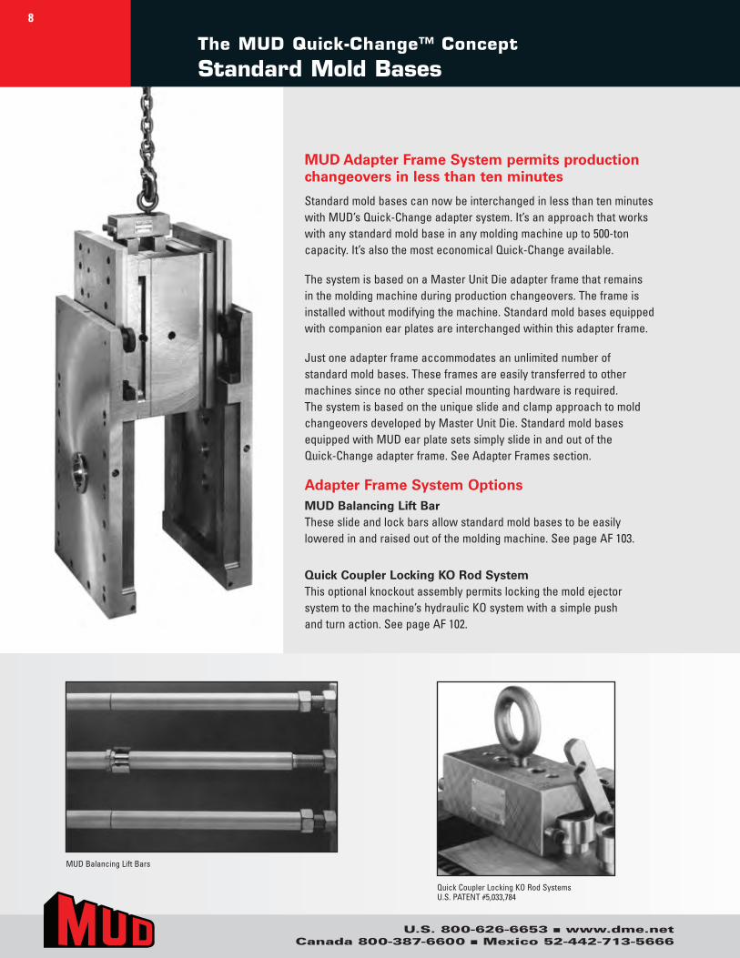
MUD Adapter Frame System permits production changeovers in less than ten minutes
Standard.mold.bases.can.now.be.interchanged.in.less.than.ten.minutes.with.MUD’s.Quick-Change.adapter.system..It’s.an.approach.that.works.with.any.standard.mold.base.in.any.molding.machine.up.to.500-ton.capacity..It’s.also.the.most.economical.Quick-Change.available.
The.system.is.based.on.a.Master.Unit.Die.adapter.frame.that.remains.in.the.molding.machine.during.production.changeovers..The.frame.is.installed.without.modifying.the.machine..Standard.mold.bases.equipped.with.companion.ear.plates.are.interchanged.within.this.adapter.frame.
Just.one.adapter.frame.accommodates.an.unlimited.number.of..standard.mold.bases..These.frames.are.easily.transferred.to.other.machines.since.no.other.special.mounting.hardware.is.required...The.system.is.based.on.the.unique.slide.and.clamp.approach.to.mold.changeovers.developed.by.Master.Unit.Die..Standard.mold.bases.equipped.with.MUD.ear.plate.sets.simply.slide.in.and.out.of.the..Quick-Change.adapter.frame..See.Adapter.Frames.section.
Adapter Frame System OptionsMUD Balancing Lift BarThese.slide.and.lock.bars.allow.standard.mold.bases.to.be.easily..lowered.in.and.raised.out.of.the.molding.machine..See.page.AF.103.
Quick Coupler Locking KO Rod SystemThis.optional.knockout.assembly.permits.locking.the.mold.ejector..system.to.the.machine’s.hydraulic.KO.system.with.a.simple.push..and.turn.action..See.page.AF.102.
The MUD Quick-Change™ Concept
Standard Mold Bases
MUD.Balancing.Lift.Bars
Quick.Coupler.Locking.KO.Rod.SystemsU.S..PATENT.#5,033,784
8

Applications EngineeringWhen.you.contact.DME.with.a.new.application.for.a.hot..runner.system,.many.systems..go.into.action..DME.has.its.own..design.and.applications.engineering.group.consisting..of..professional.engineers.and.experienced.designers..After.you.have.given.us.the..information.necessary.for.proper.application.design.and.analysis,.the.DME.applications.engineering.team.goes.to.work.diligently.analyzing,.designing.and.manufacturing.a..hot.runner.system.that.will.best.suit.your.needs.and.requirements.
Technical ServiceDME.is.proud.to.say.that.it.is.an.industry.model.for.technical.service.coverage.and.response..The.DME.technical.service.department.covers.the.entire.United.States,.Canada.and.Mexico.with.additional.service.representatives.in.Europe,.Asia.and.throughout.the.world..Because.DME.knows.you.need.assistance.starting,.operating,.and.maintaining.hot.runner.systems.it.has.made.a.great.effort.to.strategically.staff.a.Technical.Service.Department.that.is.responsible.for.the.success.of.DME’s.molding.systems.
Field Sales and Customer ServiceWhen.you.need.a.knowledgeable.person.to.help.you.order.parts.and.components,..DME.has.you.covered..Our.direct.field.sales.force.puts.a.local.sales.representative.in.your.area..One.who.understands.your.business.and.can.offer.valuable.assistance.in.helping.you.select.the.molding.system.best.suited.to.your.application.and.your.budget...In.addition,.DME.provides.a.customer.service.department.that.has.been.extensively.trained.on.all.of.DME’s.products.and.systems,.making.it.easier.for.you.to.order.and..have.your.questions.answered..We.can.provide.you.price.and.delivery.information..on.all.DME.items.quickly.and.accurately.
To.take.advantage.of.any.or.all.of.these.services,.or.if.you.have.any.questions,.problems,.or.ideas.please.call.DME.at:■ 800-626-6653.(U.S.)■ 800-387-6600.(Canada)■ 52-442-713-5666.(Mexico)
Part prints or system design prints may be sent in the following ways:■ [email protected]■ 888-808-4363.(U.S.).fax■ 800-461-9965.(Canada).fax■ [email protected].(Mexico)
DME offers a wide range of services from component selection to on-site system installation. Our ever-growing list of services include the ability to:
.■ ..Analyze.the.best.system.to.fit.your.needs■ ..Assist.in.system.design■ ..Perform.computerized.system.analysis.and.resin.qualification.before.any.metal.is.cut.■ ..Marry.your.system.to.the.mold.base,.plates.and.components.required■ ..Provide.quotations.for.and.perform.all.of.the.special.machining.required■ ..Assemble.and.wire.the.system.■ ..Check.mechanical.fit.of.all.components.and.perform.electrical.load.testing■ Assist.with.system.start-up.and.maintenance
All of which gives you ... more time to concentrate on cavities and cores!
Customer Commitment
U.S. 800-626-6653 ■ www.dme.netCanada 800-387-6600 ■ Mexico 52-442-713-5666
9
U.S. 800-626-6653 ■ www.dme.netCanada 800-387-6600 ■ Mexico 52-442-713-5666
Terms and Conditions of Sale 10
1. ACCEPTANCE OF TERMS: Seller’s offer is expressly conditioned upon Buyer’s acceptance of these Terms and Conditions, and Seller expressly objects to any additional or different terms proposed by Buyer. Any subsequent purchase order issued by Buyer shall constitute Buyer’s agree-ment to these Terms and Conditions. Any contrary terms and conditions contained in any purchase order, facility entry form, or other instrument issued by the Buyer are expressly rejected and shall not apply to this transaction. Unless otherwise specified in the quotation, Seller’s quota-tion shall expire 30 days from its date and may be modified or withdrawn by Seller before receipt of Buyer’s conforming purchase order. 2. PAYMENT TERMS: Payment is due in accordance with any applicable progress, advance or other agreed upon payment schedule, or, if no such schedule has been agreed to, no later than 30 days from the date of invoice. Buyer shall pay a late payment charge computed at the lower of 1.5% per month on any overdue balance, or the maximum rate permitted by law. No cash discount is provided. If at any time Seller reasonably de-termines that Buyer’s financial condition or payment history does not jus-tify continuation of Seller’s performance, Seller shall be entitled to require full or partial payment in advance or otherwise restructure payments, request additional forms of payment security, suspend its performance or terminate the order.3. DELIVERY3.1 In the United States, products are sold FCA Incoterms 2020 point of origin; for export sales, terms are FCA Incoterms port of export. Unless otherwise agreed in writing, title and risk of loss shall pass at the time of shipment. Buyer is responsible for all taxes, duties, fees, or other govern-mental charges related to its purchase of goods, with the sole exception of taxes on Seller’s income. Unless otherwise agreed, Buyer shall pay all packing and delivery costs. 3.2. Seller’s quoted lead times and targeted delivery dates are good faith estimates and are not binding on Seller. Buyer’s acceptance of delivery of Seller’s products from the carrier shall constitute a waiver of any claim for delay. If Seller notifies Buyer that the products are ready for shipment and Buyer delays delivery, then Seller may charge Buyer a storage fee equal to 1.5% of the contract price per month for each month of delay. Such stor-age fees are in addition to any other remedies Seller may have.3.3. Buyer shall have a reasonable opportunity to inspect any products prior to shipment. Products shall be deemed to be accepted upon the earlier of: (i) inspection at Seller’s plant (provided that no reasonable ob-jection is then raised by Buyer), or (ii) if no inspection is requested, then at shipment. If an objection is made during inspection, then Products shall be deemed accepted upon resolution of the objection by Seller.4. WARRANTY:4.1. Seller’s express product warranty be as stated in DME’s order speci-fication documentation and shall run from the date of shipment (the “Warranty Period”). During the Warranty Period, Seller warrants that the products and services sold hereunder will be free from material defects in material, workmanship and title (the “Warranty”).4.2. If, during the Warranty Period, Seller reasonably determines that the products do not meet the Warranty, then Seller shall, at its option, repair or replace the defective product or component thereof, reperform any defective services at Seller’s expense, or refund or credit to Buyer its purchase price for the defective products or services.4.3. The Warranty will be void and will not apply: (i) when Buyer fails to promptly notify Seller of any alleged defect, (ii) when Buyer fails to prop-erly install, maintain, or operate the products, (iii) to any product or parts thereof with a useful life, under normal operating conditions, inherently shorter than 1 month, or (iv) to products which were not made by Seller or any of Seller’s affiliates, provided that in such cases Seller shall use reasonable efforts to pass on to Buyer the manufacturer’s warranty.4.4. If Seller provides any parts or services to repair a product that is not under Warranty, then such parts and services will be billed to Buyer at Seller’s prevailing rates for time and materials.4.5. The Warranty set out above is the sole and exclusive warranty provid-ed by Seller for its products and is in lieu of, and Seller expressly disclaims, all other warranties, express or implied, oral, written or statutory. THERE ARE NO WARRANTIES OF MERCHANTABILITY OR FITNESS FOR PURPOSE FOR SELLER’S PRODUCTS. 5. LIMITATION OF LIABILITIES:
5.1. Seller’s total liability to Buyer arising out of or resulting from this Contract or related in any way to Seller’s products or parts thereof shall not exceed the contract price for such products.5.2. Seller shall not be liable for loss of profit or revenues, loss of use of products, interruption of business, downtime costs, increased operating costs, or any special, consequential, incidental indirect or punitive damages, whether incurred by Buyer or Buyer’s customers. 5.3. Because the conditions of actual production in each end user’s plant vary considerably, Buyer assumes all risk for the results obtained by use of Seller’s products in the practice of any process, whether in terms of operating costs, general effectiveness, success or failure, and regardless of any oral or written statements made by Seller related to the use of its products. 6. SECURITY INTEREST. Buyer agrees that the Seller shall have and retain a pur-chase money security interest in the Products securing the payment of all sums becoming due hereunder. Such security interest shall attach, upon completion of manufacture, to the Products and to any parts or accessories attached to the Products and to the proceeds of any sale thereof. Buyer represents that the Prod-ucts are being acquired for use in its business and that such Products will not, without prior written consent of the Seller, be sold or removed from the Buyer’s place of business to which delivery is made. Buyer agrees upon Seller’s request to execute any financing statements or other documents required to perfect, continue or renew Seller’s security interest in the Products.7. CANCELLATION: Unless otherwise agreed, Buyer may cancel all or any part of the order by written notice received by Seller before the completion of the order. On receipt of such cancellation notice, all work on the order or part thereof canceled will be stopped as promptly as is reasonably possible. Buyer will then be invoiced for and will pay to Seller as liquidated damages a cancellation charge. For completed items, the charge will be equal to their established prices. For items not completed, the charge will be equal to 135% of Seller’s full cost as determined by Seller in accordance with Seller’s standard accounting practices (which includes burden and overhead), plus a charge for any packing and stor-age, less a credit for the balance of the material as scrap. 8. RETURNS: All returned items require a Return Merchandise Authorization (RMA) number from DME. Returns are subject to a quality inspection to validate whether it can be returned to inventory. Mold bases, plates, special components, made-to-order products and other date-sensitive products are non-returnable items. Items returned to DME without prior authorization(RMA)may be returned to sender. Items returned for stated defect or non-conforming reason require detailed explanation. No products are returnable beyond 30 days after receipt.9. CONFIDENTIALITY. Any nonpublic information, including without limitation, Seller’s pricing information and the contents of Seller’s quotation or proposal and Buyer’s purchase order, exchanged between the parties is deemed confiden-tial (“Confidential Information”). Each party agrees to maintain the other party’s Confidential Information in confidence, to not disclose the same to any third parties, and to use it only in connection with this sale. These restrictions shall expire two (2) years after the date of disclosure. This provision does not modify or supersede any separate confidentiality or nondisclosure contract signed by the parties.10. FORCE MAJEURE: Seller shall not be liable for any delay in performance or nonperformance which is due to war, fire, flood, pandemic, acts of God, acts of third parties, acts of governmental authority or any agency or commission thereof, accident, breakdown of products, differences with employees or similar or dissimilar causes beyond Seller’s reasonable control, including but not limited to, those interfering with production, supply or transportation of products, raw materials or components or Seller’s ability to obtain, on terms Seller deem reasonable, material, labor, products or transportation.11. MERGER CLAUSE: This Contract entirely supersedes any prior oral or written representations, correspondence, proposals, or contracts between the parties regarding the products. This writing constitutes the final and total expression of such contract between the parties, and it is a complete and exclusive statement of the terms of that contract.12. ASSIGNMENT: Neither party may assign this Contract without the written consent of the other party, except that Seller may assign this Contract to a third party that acquires substantially all of Seller’s assets and Seller may assign the flow of funds arising out of this Contract.13. COMPLIANCE WITH LAWS. Each party agrees to comply with all applicable laws in the performance of its obligations; Buyer shall not trans-ship, re-export, divert or redirect Products outside of the original country of delivery without Seller’s prior written consent.14. GOVERNING LAW: This Contract shall be governed by and construed in accor-dance with the laws of the State of Michigan, without regard to the Convention for the International Sale of Goods (CISG), which shall not apply.
DME COMPANY LLC (“SELLER”)
U.S.A.TERMS AND CONDITIONS OF SALE:.See.previous.page.
PHONE ORDERS – TOLL FREE: 800-626-6653..DME’s.Customer.Service.Dept..operates.Monday.through.Friday.from.8.a.m..to.6.p.m..E.S.T..Calls.can.be.made.from.anywhere.in.the.continental.U.S..and.Puerto.Rico.(Puerto.Rico:.use.“137”.prefix.instead..of.“1”)..Our.Customer.Service.Representatives.will.be.happy.to.answer.your.questions.on.DME.products.or.services,.provide..on-the-spot.feedback.on.product.availability.and.shipping.details,.or.take.any.messages.you.wish.relayed.to.your.local..DME.sales,.manufacturing.or.technical.service.representatives.
MAIL ORDERS:.If.you.prefer.to.order.by.mail,.please.address.your.order.to:■ .DME.Company,.29111.Stephenson.Highway,.Madison.Heights,.Michigan.48071
ATTN:.Customer.Service.Dept.
FAX:.You.may.fax.your.order.to:■ .DME.Customer.Service
248-544-5113.•.888-808-4363
CHECKS OR MONEY ORDERS:.When.paying.invoices.by.check.or.money.order,.please.make.payable.to.DME Company..Include.remittance.copy.of.invoice.and.mail.to:
■ .. DME Company, PO Box 854867 Minneapolis, MN 55485-4867
WALK-IN ORDERS, PICK-UPS AND RETURNS:.If.desired,.ordered.products.in.stock.at.your.nearest.DME.Service.Center.can.be.picked.up.rather.than.shipped..Walk-in.orders.at.Service.Center.locations.can.also.be.processed.while.you.wait..Products.being.returned.for.repair.or.exchange.should.be.processed.through.Customer.Service.prior.to.being.returned.
SPECIAL MACHINING SERVICES:.Prints.for.quotation.on.special.machining.work.can.be.sent.by.EDI.to.dme_cad@dme.net.or.mailed.to.the.Estimating.Department.of.the.DME.manufacturing.location.nearest.you..Call our toll-free number if desired to clarify location which serves your area.
Estimating.locations.are:■ .70.East.Hillis.Street,.Youngwood,.Pa.15697,.FAX:.724-925-2424■ ..1117.Fairplains.Street,.Greenville,.MI.48838,.Tel..616-754-4601,.FAX:.616-225-3924■ ..3275.Deziel.Drive,.Windsor,.Ont.N8W.5A5,.Tel..519-948-5001,.FAX:.519-948-4652■ ..464-466.Windy.Point.Drive,.Glendale.Heights,.IL.60139,.Tel..630-469-4280,.FAX:.630-469-4740.(estimating.only)
Please.add.“DME.Company”.and.“Attn:.Estimating.Dept.”.to.above.addresses.when.mailing.prints..To.obtain.prices.and.delivery.on.special.mold.base.orders.or.to.check.status.of.special.work.in.progress.please.contact.Customer.Service.
CANADATERMS AND CONDITIONS OF SALE:.See.previous.page.
PHONE ORDERS:.Contact.our.Mississauga,.Ontario.office.at.800-387-6600,.FAX:.800-461-9965.
MAIL ORDERS:.Send.to:.DME.Company,.6210.Northwest.Drive,.Mississauga,.Ontario.L4V.1J6.
CHECK OR MONEY ORDERS:.Make.payable.to.DME Company..Include.remittance.copy.of.invoice.and.mail.to.Mississauga.address.above.
WALK-IN ORDERS, PICK-UPS, RETURNS, AND SPECIAL MACHINING:.Contact.our.Mississauga.office.
Sales and Ordering Information
U.S. 800-626-6653 ■ www.dme.netCanada 800-387-6600 ■ Mexico 52-442-713-5666
11
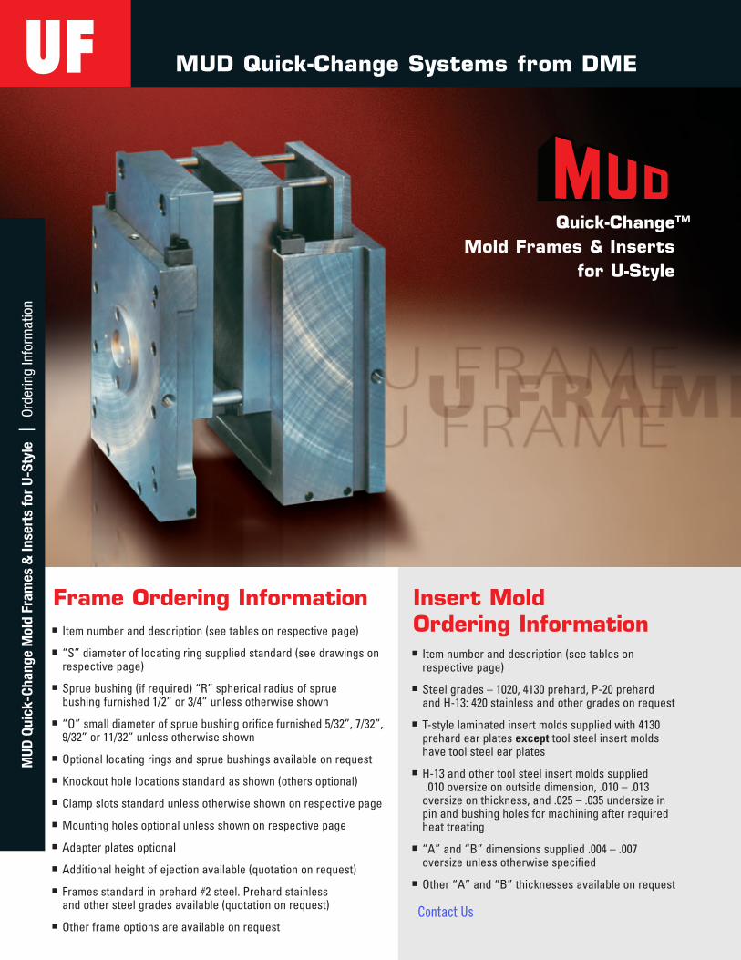
Quick-Change™ Mold Frames & Inserts
for U-Style
Frame Ordering Informationn Itemnumberanddescription(seetablesonrespectivepage)
n “S”diameteroflocatingringsuppliedstandard(seedrawingsonrespectivepage)
n Spruebushing(ifrequired)“R”sphericalradiusofspruebushingfurnished1/2”or3/4”unlessotherwiseshown
n “O”smalldiameterofspruebushingorificefurnished5/32”,7/32”,9/32”or11/32”unlessotherwiseshown
n Optionallocatingringsandspruebushingsavailableonrequest
n Knockoutholelocationsstandardasshown(othersoptional)
n Clampslotsstandardunlessotherwiseshownonrespectivepage
n Mountingholesoptionalunlessshownonrespectivepage
n Adapterplatesoptional
n Additionalheightofejectionavailable(quotationonrequest)
n Framesstandardinprehard#2steel.Prehardstainlessandothersteelgradesavailable(quotationonrequest)
n Otherframeoptionsareavailableonrequest
Insert Mold Ordering Informationn Itemnumberanddescription(seetableson
respectivepage)
n Steelgrades–1020,4130prehard,P-20prehardandH-13:420stainlessandothergradesonrequest
n T-stylelaminatedinsertmoldssuppliedwith4130prehardearplatesexcepttoolsteelinsertmoldshavetoolsteelearplates
n H-13andothertoolsteelinsertmoldssupplied.010oversizeonoutsidedimension,.010–.013
oversizeonthickness,and.025–.035undersizeinpinandbushingholesformachiningafterrequiredheattreating
n “A”and“B”dimensionssupplied.004–.007oversizeunlessotherwisespecified
n Other“A”and“B”thicknessesavailableonrequest
UF MUD Quick-Change Systems from DME
MUD
Qui
ck-C
hang
e M
old
Fram
es &
Inse
rts
for
U-St
yle
| O
rder
ing
Info
rmat
ion
Contact Us
U.S. 800-626-6653 n www.dme.netCanada 800-387-6600 n Mexico 52-442-713-5666
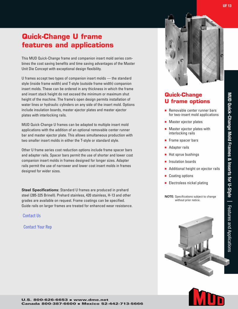
Quick-Change U frame features and applications
ThisMUDQuick-Changeframeandcompanioninsertmoldseriescom-binesthecostsavingbenefitsandtimesavingadvantagesoftheMasterUnitDieConceptwithexceptionaldesignflexibility.
Uframesaccepttwotypesofcompanioninsertmolds—thestandardstyle(insideframewidth)andT-style(outsideframewidth)companioninsertmolds.Thesecanbeorderedinanythicknessinwhichtheframeandinsertstackheightdonotexceedtheminimumormaximumshutheightofthemachine.Theframe’sopendesignpermitsinstallationofwaterlinesorhydrauliccylindersonanysideoftheinsertmold.Optionsincludeinsulationboards,masterejectorplatesandmasterejectorplateswithinterlockingrails.
MUDQuick-ChangeUframescanbeadaptedtomultipleinsertmoldapplicationswiththeadditionofanoptionalremovablecenterrunnerbarandmasterejectorplate.ThisallowssimultaneousproductionwithtwosmallerinsertmoldsineithertheT-styleorstandardstyle.
OtherUframeseriescostreductionoptionsincludeframespacerbarsandadapterrails.Spacerbarspermittheuseofshorterandlowercostcompanioninsertmoldsinframesdesignedforlongersizes.Adapterrailspermittheuseofnarrowerandlowercostinsertmoldsinframesdesignedforwidersizes.
Steel Specifications:StandardUframesareproducedinprehardsteel(285-325Brinell).Prehardstainless,420stainless,H-13andothergradesareavailableonrequest.Framecoatingscanbespecified.Guiderailsonlargerframesaretreatedforenhancedwearresistance.
Quick-Change U frame optionsn Removablecenterrunnerbars
fortwo-insertmoldapplications
n Masterejectorplates
n Masterejectorplateswithinterlockingrails
n Framespacerbars
n Adapterrails
n Hotspruebushings
n Insulationboards
n Additionalheightonejectorrails
n Coatingoptions
n Electrolessnickelplating
NOTE: Specificationssubjecttochangewithoutpriornotice.
UF 13M
UD Quick-Change M
old Frames &
Inserts for U-Style | Features and Applications
Contact Us
Contact Your Rep
U.S. 800-626-6653 n www.dme.netCanada 800-387-6600 n Mexico 52-442-713-5666
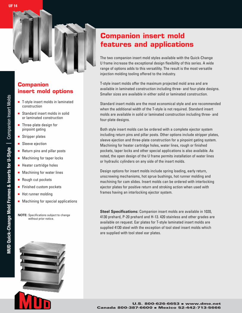
Companion insert mold features and applications
ThetwocompanioninsertmoldstylesavailablewiththeQuick-ChangeUframeincreasetheexceptionaldesignflexibilityofthisseries.Awiderangeofoptionsaddstothisversatility.Theresultisthemostversatileinjectionmoldingtoolingofferedtotheindustry.
T-styleinsertmoldsofferthemaximumprojectedmoldareaandareavailableinlaminatedconstructionincludingthree-andfour-platedesigns.Smallersizesareavailableineithersolidorlaminatedconstruction.
StandardinsertmoldsarethemosteconomicalstyleandarerecommendedwhentheadditionalwidthoftheT-styleisnotrequired.Standardinsertmoldsareavailableinsolidorlaminatedconstructionincludingthree-andfour-platedesigns.
Bothstyleinsertmoldscanbeorderedwithacompleteejectorsystemincludingreturnpinsandpillarposts.Otheroptionsincludestripperplates,sleeveejectionandthree-plateconstructionforapinpointgatingsystem.Machiningforheatercartridgeholes,waterlines,roughorfinishedpockets,taperlocksandotherspecialapplicationsisalsoavailable.Asnoted,theopendesignoftheUframepermitsinstallationofwaterlinesorhydrauliccylindersonanysideoftheinsertmolds.
Designoptionsforinsertmoldsincludespringloading,earlyreturn,unscrewingmechanisms,hotspruebushings,hotrunnermoldingandmachiningforcamslides.Insertmoldscanbeorderedwithinterlockingejectorplatesforpositivereturnandstrokingactionwhenusedwithframeshavinganinterlockingejectorsystem.
Steel Specifications:Companioninsertmoldsareavailablein1020,4130prehard,P-20prehardandH-13.420stainlessandothergradesareavailableonrequest.EarplatesforT-stylelaminatedinsertmoldsaresupplied4130steelwiththeexceptionoftoolsteelinsertmoldswhicharesuppliedwithtoolsteelearplates.
Companioninsert mold options
n T-styleinsertmoldsinlaminatedconstruction
n Standardinsertmoldsinsolidorlaminatedconstruction
n Three-platedesignforpinpointgating
n Stripperplates
n Sleeveejection
n Returnpinsandpillarposts
n Machiningfortaperlocks
n Heatercartridgeholes
n Machiningforwaterlines
n Roughcutpockets
n Finishedcustompockets
n Hotrunnermolding
n Machiningforspecialapplications
NOTE: Specificationssubjecttochangewithoutpriornotice.
UF 14M
UD Q
uick
-Cha
nge
Mol
d Fr
ames
& In
sert
s fo
r U-
Styl
e |
Com
pani
on In
sert
Mol
ds
U.S. 800-626-6653 n www.dme.netCanada 800-387-6600 n Mexico 52-442-713-5666
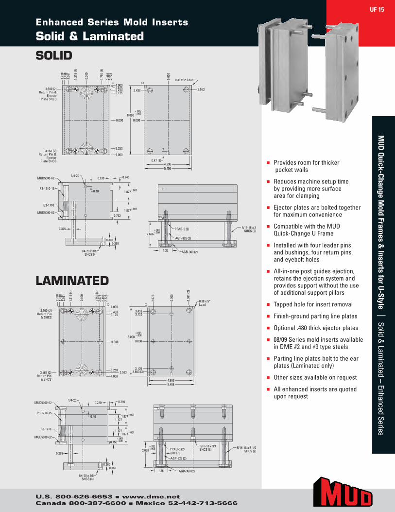
Enhanced Series Mold Inserts
Solid & Laminated
n Providesroomforthickerpocketwalls
n Reducesmachinesetuptimebyprovidingmoresurfaceareaforclamping
n Ejectorplatesareboltedtogetherformaximumconvenience
n CompatiblewiththeMUDQuick-ChangeUFrame
n Installedwithfourleaderpinsandbushings,fourreturnpins,andeyeboltholes
n All-in-onepostguidesejection,retainstheejectionsystemandprovidessupportwithouttheuseofadditionalsupportpillars
n Tappedholeforinsertremoval
n Finish-groundpartinglineplates
n Optional.480thickejectorplates
n 08/09SeriesmoldinsertsavailableinDME#2and#3typesteels
n Partinglineplatesbolttotheearplates(Laminatedonly)
n Othersizesavailableonrequest
n Allenhancedinsertsarequoteduponrequest
2.72
8
3.500 (2) Return Pin
& SHCS
2.49
8 2.
061
1.21
9 (4
)
0.00
0
1.75
0 (4
)
2.49
8 2.
728
3.563 (2) Return Pin
& SHCS
4.000 3.438 3.125
4.000
3.250 3.563
2.07
6
0.000 0.000
3.125
0.00
0
2.06
1 (2
)
2.07
6
3.438 3.125
0.38 x 5°Lead
4.996 5.456
+.005 –.000 8.000
3.563 (3)
0.40
1/4-20 0.230 0.246
1.127
1.127
MUD5000-62
MUD5000-62
0.375
0.360 0.360
P3-1710-15
1/4-20 x 3/8 SHCS (4)
B3-1710
0.750
1.877 ±.001
1.877 ±.001
+.001 -.000
+.001 –.000 2.626
AGB-360 (2)
Ø 0.875
AGP-826 (2)
5/16-18 x 3/4 SHCS (6) PPAB-5 (2) 5/16-18 x 3-1/2
SHCS (2)
1.36
2.72
8
3.500 (2) Return Pin &
Ejector Plate SHCS
2.49
8 2.
061
1.21
9 (4
)
0.00
0
1.75
0 (4
)
2.49
8 2.
728
3.563 (2) Return Pin &
Ejector Plate SHCS
4.000 3.875 3.438 3.125
4.000
3.250
0.000 0.000
0.00
0
3.438 3.563
0.47 (2)
0.38 x 5° Lead
4.996 5.456
+.005 –.000 8.000
+.001 –.000 2.626
AGB-360 (2)
AGP-826 (2)
PPAB-5 (2) 5/16-18 x 3SHCS (2)
1.36
0.40
1/4-20 0.230 0.246 MUD5000-62
MUD5000-62
0.375
0.360 0.360
P3-1710-15
1/4-20 x 3/8 SHCS (4)
B3-1710
0.752
1.877 ±.001
1.877 ±.001
LAMINATED
SOLID
UF 15M
UD Quick-Change M
old Frames &
Inserts for U-Style | Solid & Lam
inated – Enhanced Series
U.S. 800-626-6653 n www.dme.netCanada 800-387-6600 n Mexico 52-442-713-5666
UF Quick-Change U-Style
Frame & Companion Insert Molds05/05
UF 321
Frame
ITEM NO.
05/05 UF 321
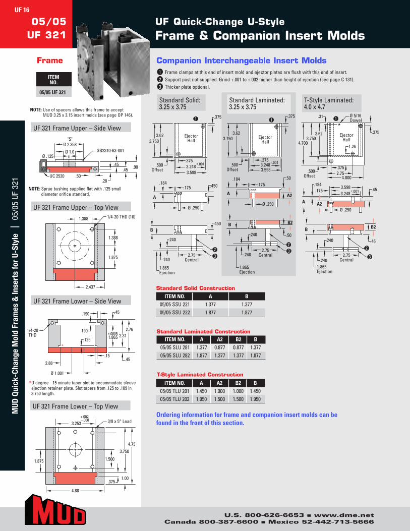
StandardSolid:3.25x3.75
Companion Interchangeable Insert Molds1 Frameclampsatthisendofinsertmoldandejectorplatesareflushwiththisendofinsert.2 Supportpostnotsupplied.Grind+.001to+.002higherthanheightofejection(seepageC131).3 Thickerplateoptional.
T-StyleLaminated:4.0x4.7
StandardLaminated:3.25x3.75
UF321FrameUpper–SideView
UF321FrameUpper–TopView
UF321FrameLower–SideView
UF321FrameLower–TopView
"S" Ø 2.358
Ø 1.0 SB2310-63-001
.45 .45 .90
.28 .50 UC 2520
Ø .125
1.875
1.388
2.437
1.388 1/4-20 THD (10)
1.875 1.500
4.753.750
4.88
3.253+.002–.000 3/8 x 5° Lead
.3751.00
.190
1/4-20THD
Ø 1.001
2.88
.15
2.762.31
.45
.45
.190
.125 1.865±.0005
*
Ejector Half
.375
3.62 3.750
.500 Offset
3.248 3.598
±.001 .375
1
.450
1.865 Ejection
2.75 Central
.175
A
.184
Ø .250
.450
B
2 3
.240
.240
.500 Offset
3.248 3.598
.375
.3751
.175
A
.184
Ø .250
.240
.240 2.75
Central
3.62 3.750
2 3
B
1.865 Ejection
.50
A2
.50
B2
Ejector Half
±.001
2.75 Central
2
3
.240
.240 1.865 Ejection
1
Ø .250
B
.45
B2
.375 2.75
4.000
1.26
.45 3.248 3.598
±.001
.184 .175
A2 A
Ø 5/16 Dowel
.375
.31
3.62 3.750
4.700
.500 Offset
Ejector Half
ITEM NO. A A2 B2 B05/05SLU281 1.377 0.877 0.877 1.37705/05SLU282 1.877 1.377 1.377 1.877
* Odegree-15minutetaperslottoaccommodatesleeveejectionretainerplate.Slottapersfrom.125to.109in3.750length.
ITEM NO. A A2 B2 B05/05TLU201 1.450 1.000 1.000 1.45005/05TLU202 1.950 1.500 1.500 1.950
ITEM NO. A B05/05SSU221 1.377 1.37705/05SSU222 1.877 1.877
Standard Solid Construction
Standard Laminated Construction
T-Style Laminated Construction
Ordering information for frame and companion insert molds can be found in the front of this section.
NOTE:Spruebushingsuppliedflatwith.125smalldiameterorificestandard.
NOTE:UseofspacersallowsthisframetoacceptMUD3.25x3.15insertmolds(seepageOP146).
UF 16M
UD Q
uick
-Cha
nge
Mol
d Fr
ames
& In
sert
s fo
r U-
Styl
e |
05/
05 U
F 32
1
U.S. 800-626-6653 n www.dme.netCanada 800-387-6600 n Mexico 52-442-713-5666
3/8 x 5° Lead
7.25
2.625
3.625
7.50
4.500
7.50.12
6.25
.500
1.00
+.002-.000
Frame
ITEM NO.
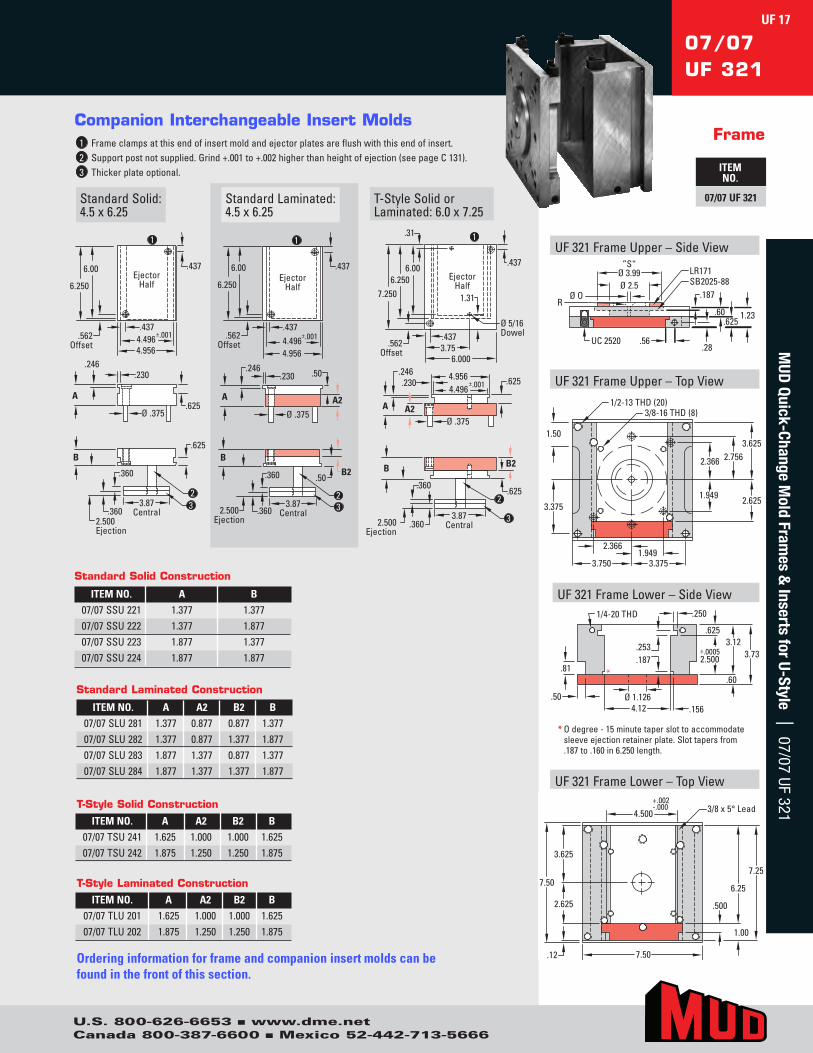
07/07 UF 321StandardSolid:4.5x6.25
Companion Interchangeable Insert Molds1 Frameclampsatthisendofinsertmoldandejectorplatesareflushwiththisendofinsert.2 Supportpostnotsupplied.Grind+.001to+.002higherthanheightofejection(seepageC131).3 Thickerplateoptional.
T-StyleSolidorLaminated:6.0x7.25
StandardLaminated:4.5x6.25
.230
A
B
.360
.246
Ø .375
2 3
.625
.625
.360
.437
.437
6.00
6.250
4.496 4.956
±.001
Ejector Half
.562 Offset
1
2.500 Ejection
3.87 Central
3.87 Central
.230
A
.246
Ø .375
.437
.437
6.00
6.250
4.496 4.956
±.001
Ejector Half
.562 Offset
1
B
.360
2 3 .360 2.500
Ejection
.50
A2
.50 B2
A
B
.360
.246
Ø .375
3
.625
.360
B2
.437 3.75
.625 4.496 4.956
±.001
A2
.437
.31
6.000
2
2.500 Ejection
3.87 Central
1
Ø 5/16 Dowel
.562 Offset
1.31
.230
6.250 7.250
6.00 Ejector
Half
UF321FrameUpper–SideView
UF321FrameUpper–TopView
UF321FrameLower–SideView
UF321FrameLower–TopView
LR171SB2025-88
.56UC 2520
Ø 3.99”S“
Ø 2.5
1.23.60.625
.28
RØ O .187
3.625
2.6253.375
1.50
3/8-16 THD (8)1/2-13 THD (20)
3.3751.949
2.366
3.750
2.7562.366
1.949
1/4-20 THD
4.12 .156
.250
.625
±.00052.500
3.123.73
.60
Ø 1.126.50
.81
.253
.187*
ITEM NO. A B07/07SSU221 1.377 1.37707/07SSU222 1.377 1.87707/07SSU223 1.877 1.37707/07SSU224 1.877 1.877
Standard Solid Construction
ITEM NO. A A2 B2 B07/07SLU281 1.377 0.877 0.877 1.37707/07SLU282 1.377 0.877 1.377 1.87707/07SLU283 1.877 1.377 0.877 1.37707/07SLU284 1.877 1.377 1.377 1.877
Standard Laminated Construction
ITEM NO. A A2 B2 B07/07TSU241 1.625 1.000 1.000 1.62507/07TSU242 1.875 1.250 1.250 1.875
T-Style Solid Construction
ITEM NO. A A2 B2 B07/07TLU201 1.625 1.000 1.000 1.62507/07TLU202 1.875 1.250 1.250 1.875
T-Style Laminated Construction
Ordering information for frame and companion insert molds can be found in the front of this section.
* Odegree-15minutetaperslottoaccommodatesleeveejectionretainerplate.Slottapersfrom.187to.160in6.250length.
07/07UF 321
UF 17M
UD Quick-Change M
old Frames &
Inserts for U-Style | 07/07 UF 321
U.S. 800-626-6653 n www.dme.netCanada 800-387-6600 n Mexico 52-442-713-5666
UF321FrameLower–TopView
4.000
9.008.00
1.00
.500
7.85
5.000+.002–.000 3/8 x 5° Lead
UF Quick-Change U-Style
Frame & Companion Insert Molds08/09
UF 321
Frame
ITEM NO.
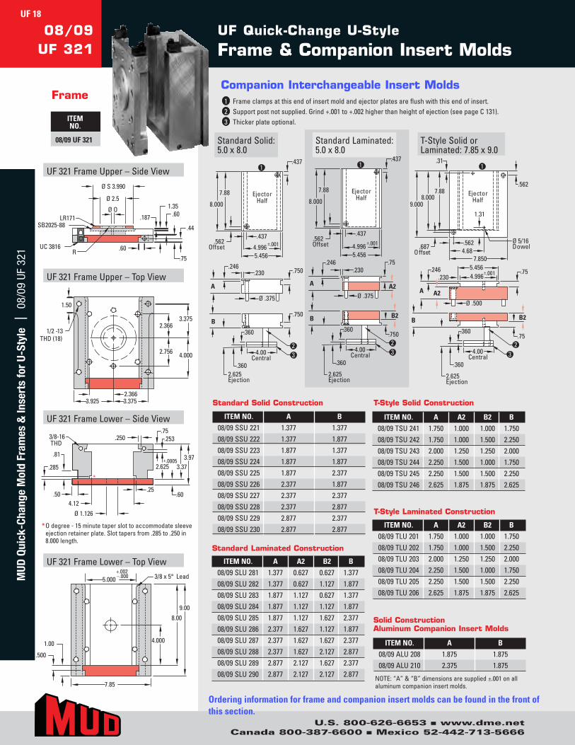
08/09 UF 321 StandardSolid:5.0x8.0
Companion Interchangeable Insert Molds1 Frameclampsatthisendofinsertmoldandejectorplatesareflushwiththisendofinsert.2 Supportpostnotsupplied.Grind+.001to+.002higherthanheightofejection(seepageC131).3 Thickerplateoptional.
T-StyleSolidorLaminated:7.85x9.0
StandardLaminated:5.0x8.0
.437
.437
7.88
8.000
.562 Offset
E je c t o r Half
4.996 5.456
±.001
.230
A
B
.360
.246
Ø .375
2.625 E jection
4.00 Central
2 3
.750
1
.750
.360
.437
.437
7.88
8.000
.562 Offset
E je c t o r Half
4.996 5.456
±.001
.230
A
B
.360
.246
Ø .375
2.625 Ejection
4.00 Central
2 3
.75
1
.750
.360
A2
B2
E je c t o r Half
A
B
.360
.246
Ø .500
2.625 Ejection
4.00 Central
2 3
1
.75
.360
B2
.562 4.68
7 .850
.75 4.996 5.456
±.001
A2
Ø 5/16 D o w e l
.562
.31
7 .88 8.000
9.000
.687 O f f se t
.230
1.31
UF321FrameUpper–SideView
UF321FrameUpper–TopView
UF321FrameLower–SideView
UC 3816 .60
1.35.60
.75
.44SB2025-88LR171
Ø O
Ø 2.5
R
Ø S 3.990
.187
1.50
1/2 -13THD (18)
3.3752.366
4.0002.756
3.3753.9252.366
.2503/8-16THD
4.12Ø 1.126
.25.50
.81
.60
.285
.253.75
3.973.372.625
±.0005
*
ITEM NO. A A2 B2 B08/09SLU281 1.377 0.627 0.627 1.37708/09SLU282 1.377 0.627 1.127 1.87708/09SLU283 1.877 1.127 0.627 1.37708/09SLU284 1.877 1.127 1.127 1.87708/09SLU285 1.877 1.127 1.627 2.37708/09SLU286 2.377 1.627 1.127 1.87708/09SLU287 2.377 1.627 1.627 2.37708/09SLU288 2.377 1.627 2.127 2.87708/09SLU289 2.877 2.127 1.627 2.37708/09SLU290 2.877 2.127 2.127 2.877
* Odegree-15minutetaperslottoaccommodatesleeveejectionretainerplate.Slottapersfrom.285to.250in8.000length.
ITEM NO. A A2 B2 B08/09TLU201 1.750 1.000 1.000 1.75008/09TLU202 1.750 1.000 1.500 2.25008/09TLU203 2.000 1.250 1.250 2.00008/09TLU204 2.250 1.500 1.000 1.75008/09TLU205 2.250 1.500 1.500 2.25008/09TLU206 2.625 1.875 1.875 2.625
ITEM NO. A A2 B2 B08/09TSU241 1.750 1.000 1.000 1.75008/09TSU242 1.750 1.000 1.500 2.25008/09TSU243 2.000 1.250 1.250 2.00008/09TSU244 2.250 1.500 1.000 1.75008/09TSU245 2.250 1.500 1.500 2.25008/09TSU246 2.625 1.875 1.875 2.625
ITEM NO. A B08/09SSU221 1.377 1.37708/09SSU222 1.377 1.87708/09SSU223 1.877 1.37708/09SSU224 1.877 1.87708/09SSU225 1.877 2.37708/09SSU226 2.377 1.87708/09SSU227 2.377 2.37708/09SSU228 2.377 2.87708/09SSU229 2.877 2.37708/09SSU230 2.877 2.877
Standard Solid Construction
Standard Laminated Construction
T-Style Laminated Construction
T-Style Solid Construction
Ordering information for frame and companion insert molds can be found in the front of this section.
ITEM NO. A B08/09ALU208 1.875 1.87508/09ALU210 2.375 1.875
Solid ConstructionAluminum Companion Insert Molds
NOTE:“A”&“B”dimensionsaresupplied±.001onallaluminumcompanioninsertmolds.
UF 18M
UD Q
uick
-Cha
nge
Mol
d Fr
ames
& In
sert
s fo
r U-
Styl
e |
08/
09 U
F 32
1
U.S. 800-626-6653 n www.dme.netCanada 800-387-6600 n Mexico 52-442-713-5666
08/10UF 321
Frame
ITEM NO.
08/10 UF 321StandardSolid:5.0x9.0
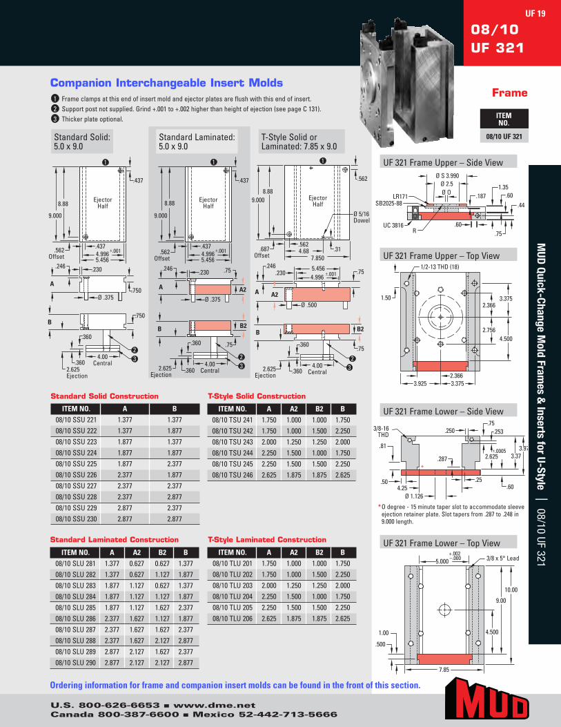
Companion Interchangeable Insert Molds1 Frameclampsatthisendofinsertmoldandejectorplatesareflushwiththisendofinsert.2 Supportpostnotsupplied.Grind+.001to+.002higherthanheightofejection(seepageC131).3 Thickerplateoptional.
T-StyleSolidorLaminated:7.85x9.0
StandardLaminated:5.0x9.0
.230
A
B
.360
.246
Ø .375
2 3
.750
.750
.360
.437
.437
8.88
9.000
4.996 5.456
±.001
Ejector Half
.562 Offset
1
2.625 Ejection
4.00 Central
.230
A
.246
Ø .375
.437
.437
8.88
9.000
4.996 5.456
±.001
Ejector Half
.562 Offset
4.00 Central
B
.360
.360 2.625 Ejection
.75
A2
.75
B2
2 3
1
A
B
.360
.246
Ø .500
.75
.360
B2
.562 4.68
.75 4.996 5.456
±.001
A2
.562
.31
8.88 9.000
7.850
Ejector Half
2.625 Ejection
4.00 Central
Ø 5/16 Dowel
.687 Offset
.230
2 3
1 UF321FrameUpper–SideView
UF321FrameUpper–TopView
UF321FrameLower–SideView
UF321FrameLower–TopView
LR171
Ø S 3.990
.60
SB2025-88
Ø OØ 2.5
RUC 3816
1.35.60
.75
.44.187
1.50 3.3752.366
4.5002.756
3.3753.9252.366
1/2-13 THD (18)
4.500
10.00
9.00
1.00
.500
7.85
5.000+.002–.000 3/8 x 5° Lead
3/8-16THD
.250
4.25Ø 1.126
.25
.81
.253.75
3.973.372.625
±.0005.287
.60
*
.50
ITEM NO. A A2 B2 B08/10SLU281 1.377 0.627 0.627 1.37708/10SLU282 1.377 0.627 1.127 1.87708/10SLU283 1.877 1.127 0.627 1.37708/10SLU284 1.877 1.127 1.127 1.87708/10SLU285 1.877 1.127 1.627 2.37708/10SLU286 2.377 1.627 1.127 1.87708/10SLU287 2.377 1.627 1.627 2.37708/10SLU288 2.377 1.627 2.127 2.87708/10SLU289 2.877 2.127 1.627 2.37708/10SLU290 2.877 2.127 2.127 2.877
ITEM NO. A A2 B2 B08/10TLU201 1.750 1.000 1.000 1.75008/10TLU202 1.750 1.000 1.500 2.25008/10TLU203 2.000 1.250 1.250 2.00008/10TLU204 2.250 1.500 1.000 1.75008/10TLU205 2.250 1.500 1.500 2.25008/10TLU206 2.625 1.875 1.875 2.625
ITEM NO. A B08/10SSU221 1.377 1.37708/10SSU222 1.377 1.87708/10SSU223 1.877 1.37708/10SSU224 1.877 1.87708/10SSU225 1.877 2.37708/10SSU226 2.377 1.87708/10SSU227 2.377 2.37708/10SSU228 2.377 2.87708/10SSU229 2.877 2.37708/10SSU230 2.877 2.877
Standard Solid Construction
Standard Laminated Construction T-Style Laminated Construction
ITEM NO. A A2 B2 B08/10TSU241 1.750 1.000 1.000 1.75008/10TSU242 1.750 1.000 1.500 2.25008/10TSU243 2.000 1.250 1.250 2.00008/10TSU244 2.250 1.500 1.000 1.75008/10TSU245 2.250 1.500 1.500 2.25008/10TSU246 2.625 1.875 1.875 2.625
T-Style Solid Construction
Ordering information for frame and companion insert molds can be found in the front of this section.
* Odegree-15minutetaperslottoaccommodatesleeveejectionretainerplate.Slottapersfrom.287to.248in9.000length.
UF 19M
UD Quick-Change M
old Frames &
Inserts for U-Style | 08/10 UF 321
U.S. 800-626-6653 n www.dme.netCanada 800-387-6600 n Mexico 52-442-713-5666
* Odegree-15minutetaperslottoaccommodatesleeveejectionretainerplate.Slottapersfrom.285to.250in8.000length.
UF321FrameUpper–SideView
UF321FrameUpper–TopView
UF321FrameLower–SideView
UF321FrameLower–TopView
Ø S 3.990
Ø O Ø 2.0
R
UC 38161.65
.90
.75
.218
1.5
4.000
4.675
6.500+.002–.000
4.000
9.35
8.0009.000
1.00
3/8 x 5° Lead
Ø 1.12
.250
5.75 .25
.90
.5
.8
.253 .75
4.27 3.37 2.625
±.0005.285
*
Ordering information for frame and companion insert molds can be found in the front of this section.
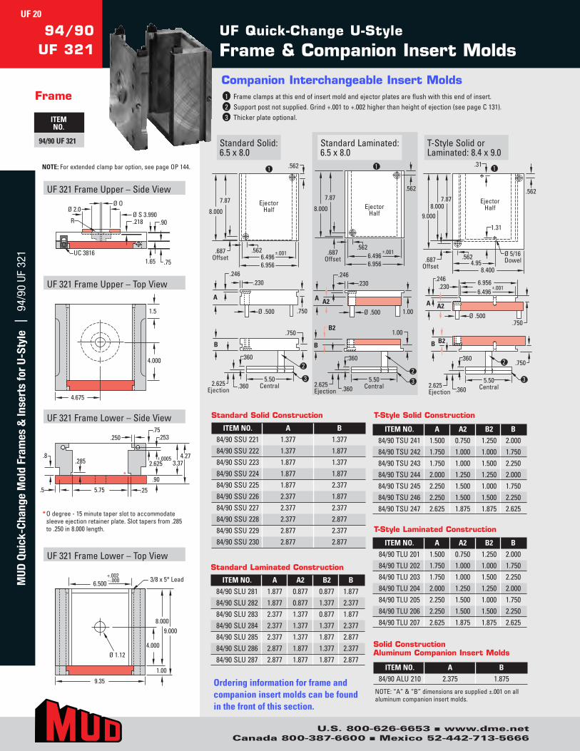
ITEM NO. A A2 B2 B84/90SLU281 1.877 0.877 0.877 1.87784/90SLU282 1.877 0.877 1.377 2.37784/90SLU283 2.377 1.377 0.877 1.87784/90SLU284 2.377 1.377 1.377 2.37784/90SLU285 2.377 1.377 1.877 2.87784/90SLU286 2.877 1.877 1.377 2.37784/90SLU287 2.877 1.877 1.877 2.877
ITEM NO. A A2 B2 B84/90TLU201 1.500 0.750 1.250 2.00084/90TLU202 1.750 1.000 1.000 1.75084/90TLU203 1.750 1.000 1.500 2.25084/90TLU204 2.000 1.250 1.250 2.00084/90TLU205 2.250 1.500 1.000 1.75084/90TLU206 2.250 1.500 1.500 2.25084/90TLU207 2.625 1.875 1.875 2.625
ITEM NO. A B84/90SSU221 1.377 1.37784/90SSU222 1.377 1.87784/90SSU223 1.877 1.37784/90SSU224 1.877 1.87784/90SSU225 1.877 2.37784/90SSU226 2.377 1.87784/90SSU227 2.377 2.37784/90SSU228 2.377 2.87784/90SSU229 2.877 2.37784/90SSU230 2.877 2.877
Standard Solid Construction
Standard Laminated Construction
T-Style Laminated Construction
ITEM NO. A A2 B2 B84/90TSU241 1.500 0.750 1.250 2.00084/90TSU242 1.750 1.000 1.000 1.75084/90TSU243 1.750 1.000 1.500 2.25084/90TSU244 2.000 1.250 1.250 2.00084/90TSU245 2.250 1.500 1.000 1.75084/90TSU246 2.250 1.500 1.500 2.25084/90TSU247 2.625 1.875 1.875 2.625
T-Style Solid Construction
ITEM NO. A B84/90ALU210 2.375 1.875
Solid ConstructionAluminum Companion Insert Molds
NOTE:“A”&“B”dimensionsaresupplied±.001onallaluminumcompanioninsertmolds.
UF Quick-Change U-Style
Frame & Companion Insert Molds94/90
UF 321
Frame
ITEM NO.
94/90 UF 321 T-StyleSolidorLaminated:8.4x9.0
StandardLaminated:6.5x8.0
StandardSolid:6.5x8.0
Companion Interchangeable Insert Molds1 Frameclampsatthisendofinsertmoldandejectorplatesareflushwiththisendofinsert.2 Supportpostnotsupplied.Grind+.001to+.002higherthanheightofejection(seepageC131).3 Thickerplateoptional.
.230
Ø .500 .750
A
.246
2.625 Ejection
.360
.360 5.50
Central
B
.750
.562
7.87
8.000
±.0016.496 6.956
Ejector Half
.687 Offset
.562
2
3
1
2.625 Ejection
.360
.360 5.50
Central
B
1.00 B2
.562 7.87
8.000
±.0016.496 6.956
Ejector Half
.687 Offset
.562
.230
Ø .500
A A2
.246
1.00
2 3
1
2.625 Ejection
.360
.360 5.50
Central
B
.750
B2
6.496 6.956
±.001.230
Ø .500
A A2
.246
.750
.562
8.000 9.000
7.87
8.4004.95
Ejector Half
.687 Offset
1.31
.31
.562 Ø 5/16 Dowel
2
3
1NOTE:Forextendedclampbaroption,seepageOP144.
UF 20M
UD Q
uick
-Cha
nge
Mol
d Fr
ames
& In
sert
s fo
r U-
Styl
e |
94/
90 U
F 32
1
U.S. 800-626-6653 n www.dme.netCanada 800-387-6600 n Mexico 52-442-713-5666
LR171SB2025-88
.60UC 3816
1.35
.60.75
.44
.187Ø O Ø 2.5
ØS 3.990
R
3.3752.366
4.0002.756
3.3754.2002.366
1/2-13 THD (18)
3/8-16 THD .250
Ø 1.126 .25 .60 5.75
.104
.500
.253 .75
3.973.37 2.625
±.0005.285
*
8.5009.00
8.00
4.000
.500
.500
1.008.40
6.500+.002–.000 3/8 x 5°
Lead
.75
.60
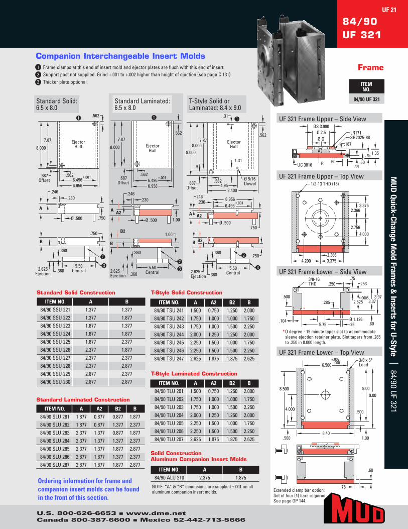
84/90UF 321
Frame
ITEM NO.
84/90 UF 321
Companion Interchangeable Insert Molds1 Frameclampsatthisendofinsertmoldandejectorplatesareflushwiththisendofinsert. 2 Supportpostnotsupplied.Grind+.001to+.002higherthanheightofejection(seepageC131). 3 Thickerplateoptional.
T-StyleSolidorLaminated:8.4x9.0
StandardLaminated:6.5x8.0
StandardSolid:6.5x8.0
.230
Ø .500 .750
A
.246
2.625 Ejection
.360
.360 5.50
Central
B
.750
.562
7.87
8.000
±.0016.496 6.956
Ejector Half
.687 Offset
.562
2
3
1
2.625 Ejection
.360
.360 5.50
Central
B
1.00 B2
.562 7.87
8.000
±.0016.496 6.956
Ejector Half
.687 Offset
.562
.230
Ø .500
A A2
.246
1.00
2 3
1
2.625 Ejection
.360
.360 5.50
Central
B
.750
B2
6.496 6.956
±.001.230
Ø .500
A A2
.246
.750
.562
8.000 9.000
7.87
8.4004.95
Ejector Half
.687 Offset
1.31
.31
.562 Ø 5/16 Dowel
2
3
1 UF321FrameUpper–SideView
UF321FrameUpper–TopView
UF321FrameLower–SideView
UF321FrameLower–TopView
* Odegree-15minutetaperslottoaccommodatesleeveejectionretainerplate.Slottapersfrom.285to.250in8.000length.
Extendedclampbaroption:Setoffour(4)barsrequired.SeepageOP144.
Ordering information for frame and companion insert molds can be found in the front of this section.
ITEM NO. A A2 B2 B84/90SLU281 1.877 0.877 0.877 1.87784/90SLU282 1.877 0.877 1.377 2.37784/90SLU283 2.377 1.377 0.877 1.87784/90SLU284 2.377 1.377 1.377 2.37784/90SLU285 2.377 1.377 1.877 2.87784/90SLU286 2.877 1.877 1.377 2.37784/90SLU287 2.877 1.877 1.877 2.877
ITEM NO. A A2 B2 B84/90TLU201 1.500 0.750 1.250 2.00084/90TLU202 1.750 1.000 1.000 1.75084/90TLU203 1.750 1.000 1.500 2.25084/90TLU204 2.000 1.250 1.250 2.00084/90TLU205 2.250 1.500 1.000 1.75084/90TLU206 2.250 1.500 1.500 2.25084/90TLU207 2.625 1.875 1.875 2.625
ITEM NO. A B84/90SSU221 1.377 1.37784/90SSU222 1.377 1.87784/90SSU223 1.877 1.37784/90SSU224 1.877 1.87784/90SSU225 1.877 2.37784/90SSU226 2.377 1.87784/90SSU227 2.377 2.37784/90SSU228 2.377 2.87784/90SSU229 2.877 2.37784/90SSU230 2.877 2.877
Standard Solid Construction
Standard Laminated Construction
T-Style Laminated Construction
ITEM NO. A A2 B2 B84/90TSU241 1.500 0.750 1.250 2.00084/90TSU242 1.750 1.000 1.000 1.75084/90TSU243 1.750 1.000 1.500 2.25084/90TSU244 2.000 1.250 1.250 2.00084/90TSU245 2.250 1.500 1.000 1.75084/90TSU246 2.250 1.500 1.500 2.25084/90TSU247 2.625 1.875 1.875 2.625
T-Style Solid Construction
ITEM NO. A B84/90ALU210 2.375 1.875
Solid ConstructionAluminum Companion Insert Molds
NOTE:“A”&“B”dimensionsaresupplied±.001onallaluminumcompanioninsertmolds.
UF 21M
UD Quick-Change M
old Frames &
Inserts for U-Style | 84/90 UF 321
U.S. 800-626-6653 n www.dme.netCanada 800-387-6600 n Mexico 52-442-713-5666
1.50
1/2-13 THD (4)
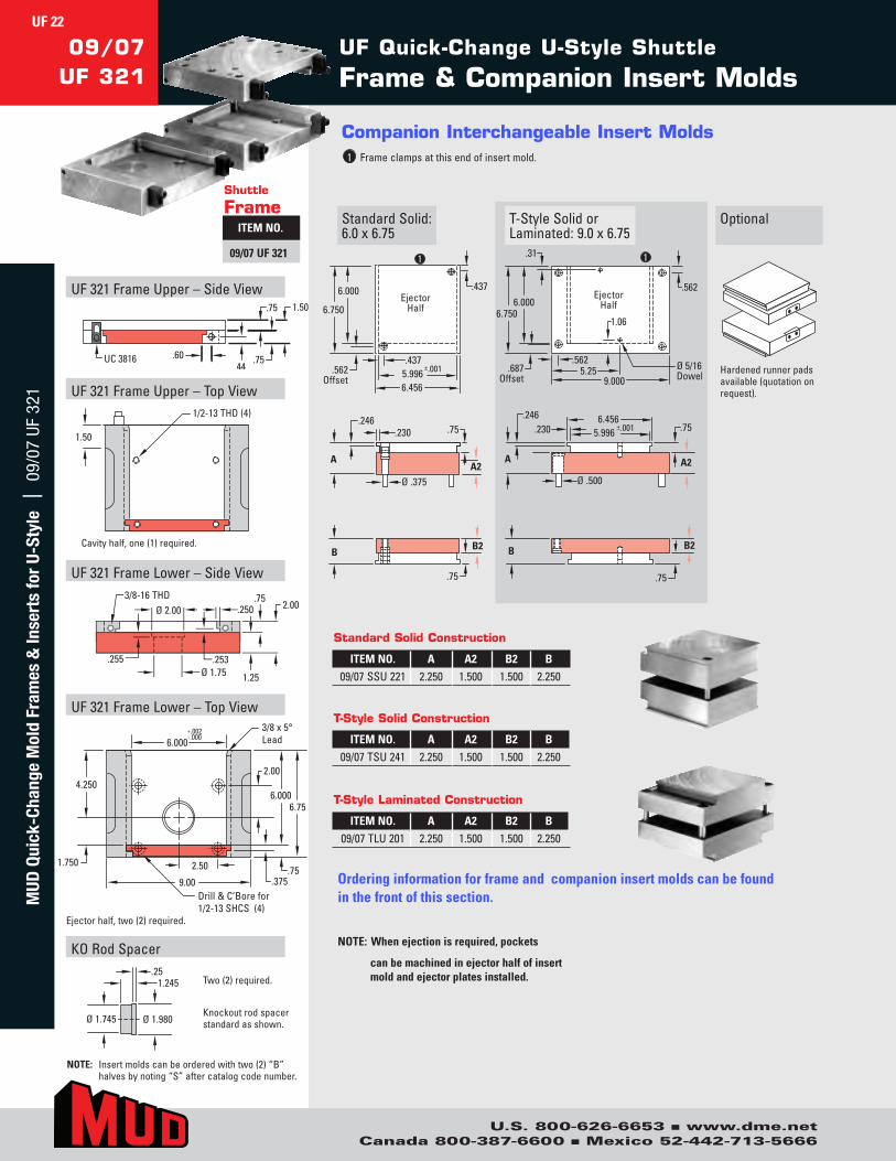
UF Quick-Change U-Style Shuttle
Frame & Companion Insert Molds09/07
UF 321
StandardSolid:6.0x6.75
Companion Interchangeable Insert Molds1 Frameclampsatthisendofinsertmold.
OptionalT-StyleSolidorLaminated:9.0x6.75
.437
.437
6.000
6.750
5.996 6.456
±.001
Ejector Half
.562 Offset
1
.230
A
.246
Ø .375
B
.75
A2
.75
B2
A
B
.246
Ø .500
.75
B2
.562 5.25
.75 5.996 6.456
±.001
A2
.562
.31
9.000
1
Ø 5/16 Dowel
.687 Offset
1.06
.230
6.000 6.750
Ejector Half
Hardenedrunnerpadsavailable(quotationonrequest).
Shuttle
FrameITEM NO.
09/07 UF 321
ITEM NO. A A2 B2 B09/07SSU221 2.250 1.500 1.500 2.250
Standard Solid Construction
Ordering information for frame and companion insert molds can be found in the front of this section.
NOTE: When ejection is required, pockets
can be machined in ejector half of insert mold and ejector plates installed.
ITEM NO. A A2 B2 B09/07TSU241 2.250 1.500 1.500 2.250
T-Style Solid Construction
ITEM NO. A A2 B2 B09/07TLU201 2.250 1.500 1.500 2.250
T-Style Laminated Construction
UF321FrameUpper–SideView
UF321FrameUpper–TopView
UF321FrameLower–SideView
UF321FrameLower–TopView
UC 3816 .60.44
.75
.75 1.50
4.250
1.750
6.000 3/8 x 5°Lead
2.00
6.000 6.75
.75 .375
Drill & C’Bore for 1/2-13 SHCS (4)
2.50
9.00
+.002 -.000
KORodSpacer
Ø 1.745 Ø 1.980
1.245.25
3/8-16 THD
.255
Ø 2.00 .250.75
2.00
.253Ø 1.75 1.25
NOTE: Insertmoldscanbeorderedwithtwo(2)“B”halvesbynoting“S”aftercatalogcodenumber.
Cavityhalf,one(1)required.
Ejectorhalf,two(2)required.
Two(2)required.
Knockoutrodspacerstandardasshown.
UF 22M
UD Q
uick
-Cha
nge
Mol
d Fr
ames
& In
sert
s fo
r U-
Styl
e |
09/
07 U
F 32
1
U.S. 800-626-6653 n www.dme.netCanada 800-387-6600 n Mexico 52-442-713-5666
.50
.75
5.25
.253.81
.250
3/8-16 THD
2.122.75
1.375*.62±.0005
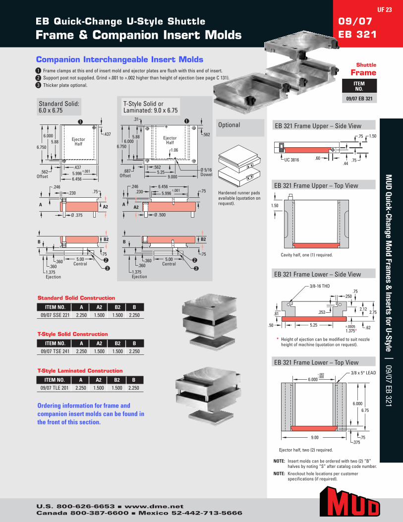
EB Quick-Change U-Style Shuttle
Frame & Companion Insert Molds09/07EB 321
Companion Interchangeable Insert Molds1 Frameclampsatthisendofinsertmoldandejectorplatesareflushwiththisendofinsert. 2 Supportpostnotsupplied.Grind+.001to+.002higherthanheightofejection(seepageC131). 3 Thickerplateoptional.
StandardSolid:6.0x6.75
Optional
T-StyleSolidorLaminated:9.0x6.75
.437
.437
6.000
6.750
5.996 6.456
±.001
5.88 Ejector Half
.562 Offset
1
B
.75
B2
1.375 Ejection
5.00 Central
2
3 .360
.360
.230
A
.246
Ø .375
.75
A2
.562 5.25
.562
.31
9.000
1
Ø 5/16 Dowel
.687 Offset
1.06
6.000 6.750
5.88 Ejector Half
B
.75
B2
1.375 Ejection
5.00 Central
2
3
.360 .360
A A2
.246
Ø .500
.75 5.996 6.456
±.001 .230 Hardenedrunnerpadsavailable(quotationonrequest).
Shuttle
FrameITEM NO.
09/07 EB 321
NOTE: Insertmoldscanbeorderedwithtwo(2)“B”halvesbynoting“S”aftercatalogcodenumber.
NOTE: Knockoutholelocationspercustomerspecifications(ifrequired).
EB321FrameUpper–SideView
EB321FrameUpper–TopView
EB321FrameLower–SideView
EB321FrameLower–TopView
UC 3816 .60.44
.75
.75 1.50
1.50
6.0003/8 x 5° LEAD
6.0006.75
.75.375
9.00
+.002-.000
ITEM NO. A A2 B2 B09/07SSE221 2.250 1.500 1.500 2.250
Standard Solid Construction
Ordering information for frame and companion insert molds can be found in the front of this section.
ITEM NO. A A2 B2 B09/07TSE241 2.250 1.500 1.500 2.250
T-Style Solid Construction
ITEM NO. A A2 B2 B09/07TLE201 2.250 1.500 1.500 2.250
T-Style Laminated Construction
Cavityhalf,one(1)required.
Ejectorhalf,two(2)required.
* Heightofejectioncanbemodifiedtosuitnozzleheightofmachine(quotationonrequest).
UF 23M
UD Quick-Change M
old Frames &
Inserts for U-Style | 09/07 EB 321
U.S. 800-626-6653 n www.dme.netCanada 800-387-6600 n Mexico 52-442-713-5666
UF Quick-Change U-Style
Frame & Companion Insert Molds10/12
UF 321
Frame
ITEM NO.
10/12 UF 321StandardSolid:7.0x10.9
Companion Interchangeable Insert Molds1 Frameclampsatthisendofinsertmoldandejectorplatesareflushwiththisendofinsert.2 Supportpostnotsupplied.Grind+.001to+.002higherthanheightofejection(seepageC131).3 Thickerplateoptional(quotationonrequest).4 3/4x5°leadthisend.
T-StyleLaminated:9.9x10.9
StandardLaminated:7.0x10.9
1 .687
10.75
10.874
±.001 6.996 7.716
Ejector Half
.812 Offset
.687
.360
Ø .625 1.00
A
.494
3
2
3.500 Ejection
.480
.480 6.00
Central
B
1.00
4
1
.687 10.75
10.874
±.001 6.996 7.716
Ejector Half
.812 Offset
.687
.360
Ø .625
A A2
.494
2
3.500 Ejection
.480
.480 6.00
Central
B
1.00
B2
3
4
1.00
6.996 7.716
±.001
1
.687 10.75
10.874
9.874 5.68
Ejector Half
.812 Offset
.31
.687 Ø 5/16 Dowel
.360
Ø .625
A A2
.494
1.00
2
3.500 Ejection
.480
.480 6.00
Central
B
1.00
B2
3
4
ITEM NO. A A2 B2 B10/12SLU281 1.877 0.877 0.877 1.87710/12SLU282 1.877 0.877 1.377 2.37710/12SLU283 1.877 0.877 1.877 2.87710/12SLU284 2.377 1.377 0.877 1.87710/12SLU285 2.377 1.377 1.377 2.37710/12SLU286 2.377 1.377 1.877 2.87710/12SLU287 2.877 1.877 0.877 1.87710/12SLU288 2.877 1.877 1.377 2.37710/12SLU289 2.877 1.877 1.877 2.877
ITEM NO. A A2 B2 B10/12TLU201 1.877 0.877 0.877 1.87710/12TLU202 1.877 0.877 1.377 2.37710/12TLU203 2.377 1.377 0.877 1.87710/12TLU204 2.377 1.377 1.377 2.37710/12TLU205 2.377 1.377 1.877 2.87710/12TLU206 2.877 1.877 1.377 2.37710/12TLU207 2.877 1.877 1.877 2.87710/12TLU208 2.877 1.877 2.377 3.37710/12TLU209 3.377 2.377 1.877 2.87710/12TLU210 3.377 2.377 2.377 3.377
ITEM NO. A B10/12SSU221 1.377 1.37710/12SSU222 1.377 1.87710/12SSU223 1.877 1.37710/12SSU224 1.877 1.87710/12SSU225 1.877 2.37710/12SSU226 2.377 1.87710/12SSU227 2.377 2.37710/12SSU228 2.377 2.87710/12SSU229 2.877 2.37710/12SSU230 2.877 2.877
Standard Solid Construction
Standard Laminated Construction
T-Style Laminated Construction
Ordering information for frame and companion insert molds can be found in the front of this section.
UF321FrameUpper–SideView
UF321FrameUpper–TopView
UF321FrameLower–SideView
UF321FrameLower–TopView
RUC 3816.275 ±.001
Ø S 3.990Ø 2.0 .218
.901.00
1.90
.51.73
Ø 0
2.00
5.437
4.937
.56 R
Ø 1.12
.500
3.00 3.50
10.874
1.00
11.87
+.002–.000 3/4 x 5° Lead
7.000
5.437
9.87
1.00
.90
4.505.40
3.500±.0005
.81
.50 6.25
.500
3/8-16THD
.375
*
Framesuppliedwithorwithoutspruebushing
* Taperslottoaccommodatesleeveejectionoptional(quotationonrequest).
UF 24M
UD Q
uick
-Cha
nge
Mol
d Fr
ames
& In
sert
s fo
r U-
Styl
e |
10/
12 U
F 32
1
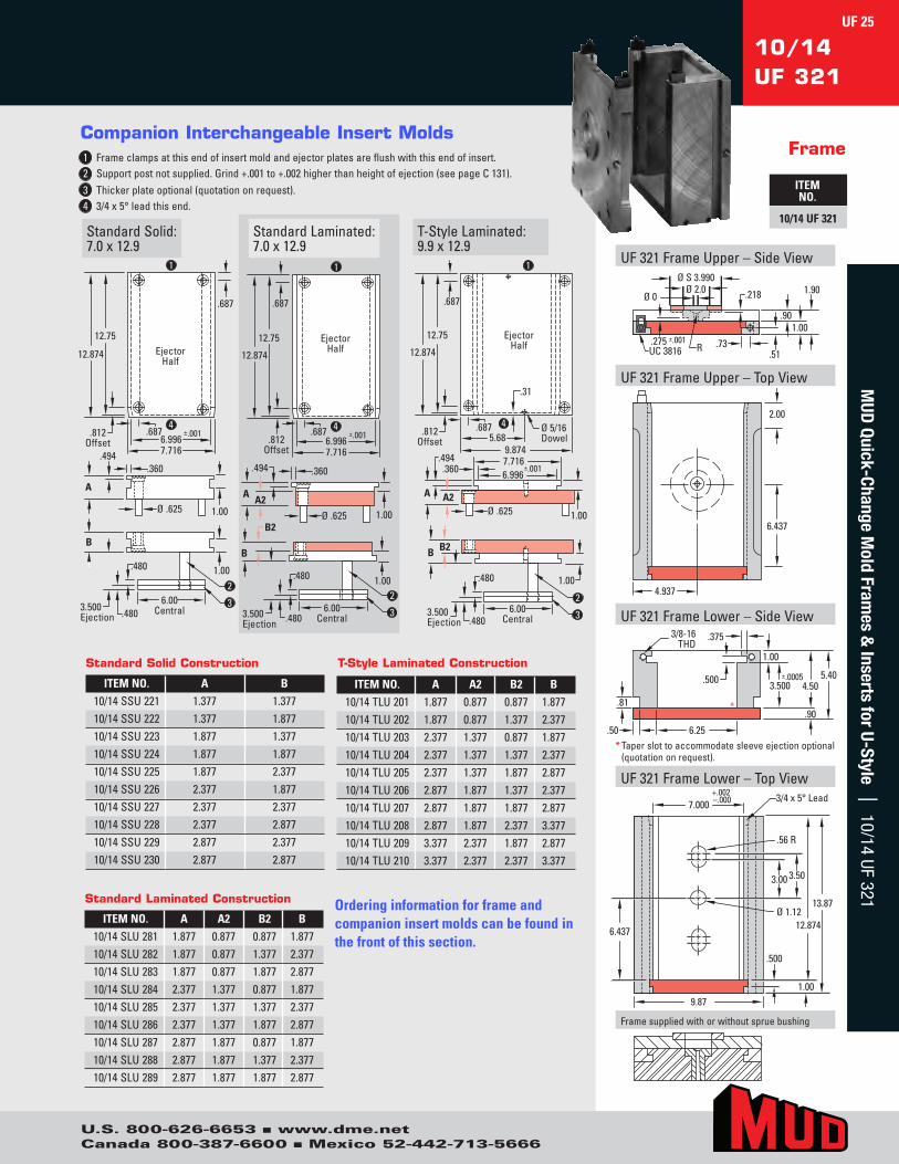
U.S. 800-626-6653 n www.dme.netCanada 800-387-6600 n Mexico 52-442-713-5666
UF321FrameUpper–SideView
UF321FrameUpper–TopView
UF321FrameLower–SideView
RUC 3816.275 ±.001
Ø S 3.990Ø 2.0 .218
.901.00
1.90
.51.73
Ø 0
2.00
6.437
4.937
1.00
.90
4.505.40
3.500±.0005
.81
.50 6.25
.500
3/8-16THD
.375
*
10/14UF 321
Frame
ITEM NO.
10/14 UF 321StandardSolid:7.0x12.9
T-StyleLaminated:9.9x12.9
StandardLaminated:7.0x12.9
4
1
.687
12.75
12.874
±.001 6.996 7.716
Ejector Half
.812 Offset
.687
.360
Ø .625 1.00
A
.494
3
2
3.500 Ejection
.480
.480 6.00
Central
B
1.00
1.00
1
.687
12.75
12.874
±.001 6.996 7.716
Ejector Half
.812 Offset
.687
.360
Ø .625
A A2
.494
2
3.500 Ejection
.480
.480 6.00
Central
B
1.00
B2
3
4
6.996 7.716
±.001
1
.687
12.75
12.874
9.874 5.68
Ejector Half
.812 Offset
.687 Ø 5/16 Dowel
.360
Ø .625
A A2
.494
1.00
2 3.500 Ejection
.480
.480 6.00
Central
B
1.00
B2
3
4
.31
Companion Interchangeable Insert Molds1 Frameclampsatthisendofinsertmoldandejectorplatesareflushwiththisendofinsert. 2 Supportpostnotsupplied.Grind+.001to+.002higherthanheightofejection(seepageC131). 3 Thickerplateoptional(quotationonrequest).4 3/4x5°leadthisend.
ITEM NO. A A2 B2 B10/14SLU281 1.877 0.877 0.877 1.87710/14SLU282 1.877 0.877 1.377 2.37710/14SLU283 1.877 0.877 1.877 2.87710/14SLU284 2.377 1.377 0.877 1.87710/14SLU285 2.377 1.377 1.377 2.37710/14SLU286 2.377 1.377 1.877 2.87710/14SLU287 2.877 1.877 0.877 1.87710/14SLU288 2.877 1.877 1.377 2.37710/14SLU289 2.877 1.877 1.877 2.877
ITEM NO. A A2 B2 B10/14TLU201 1.877 0.877 0.877 1.87710/14TLU202 1.877 0.877 1.377 2.37710/14TLU203 2.377 1.377 0.877 1.87710/14TLU204 2.377 1.377 1.377 2.37710/14TLU205 2.377 1.377 1.877 2.87710/14TLU206 2.877 1.877 1.377 2.37710/14TLU207 2.877 1.877 1.877 2.87710/14TLU208 2.877 1.877 2.377 3.37710/14TLU209 3.377 2.377 1.877 2.87710/14TLU210 3.377 2.377 2.377 3.377
ITEM NO. A B10/14SSU221 1.377 1.37710/14SSU222 1.377 1.87710/14SSU223 1.877 1.37710/14SSU224 1.877 1.87710/14SSU225 1.877 2.37710/14SSU226 2.377 1.87710/14SSU227 2.377 2.37710/14SSU228 2.377 2.87710/14SSU229 2.877 2.37710/14SSU230 2.877 2.877
Standard Solid Construction
Standard Laminated Construction
T-Style Laminated Construction
Ordering information for frame and companion insert molds can be found in the front of this section.
* Taperslottoaccommodatesleeveejectionoptional(quotationonrequest).
UF321FrameLower–TopView
.56 R
Ø 1.12
.500
3.00 3.50
12.874
1.00
13.87
+.002–.000 3/4 x 5° Lead
7.000
6.437
9.87
Framesuppliedwithorwithoutspruebushing
UF 25M
UD Quick-Change M
old Frames &
Inserts for U-Style | 10/14 UF 321

U.S. 800-626-6653 n www.dme.netCanada 800-387-6600 n Mexico 52-442-713-5666
UF Quick-Change U-Style
Frame & Companion Insert Molds10/16
UF 321
Frame
ITEM NO.
10/16 UF 321 StandardSolid:7.0x14.9
Companion Interchangeable Insert Molds1 Frameclampsatthisendofinsertmoldandejectorplatesareflushwiththisendofinsert.2 Supportpostnotsupplied.Grind+.001to+.002higherthanheightofejection(seepageC131).3 Thickerplateoptional(quotationonrequest).4 3/4x5°leadthisend.
T-StyleLaminated:9.9x14.9
StandardLaminated:7.0x14.9
4
1
.687
14.75
14.874
±.001 6.996 7.716
Ejector Half
.812 Offset
.687
.360
Ø .625 1.00
A
.494
3
2
3.500 Ejection
.480
.480 6.00
Central
B
1.00
1.00
1
.687
14.75
14.874
±.001 6.996 7.716
Ejector Half
.812 Offset
.687
.360
Ø .625
A A2
.494
2
3.500 Ejection
.480
.480 6.00
Central
B
1.00
B2
3
4
6.00 Central
6.996 7.716
±.001
1
.687
14.75
14.874
9.874 5.68
Ejector Half
.812 Offset
.687 Ø 5/16 Dowel
.360
Ø .625
A A2
.494
1.00
2 3.500 Ejection
.480
.480
B
1.00
B2
3
4
.31
* Taperslottoaccommodatesleeveejectionoptional(quotationonrequest).
UF321FrameUpper–SideView
UF321FrameUpper–TopView
UF321FrameLower–SideView
UF321FrameLower–TopView
RUC 3816.275 ±.001
Ø S 3.990Ø 2.0 .218
.901.00
1.90
.51.73
Ø 0
2.00
7.437
4.937
Ø 1.12
.500
3.00 3.50
14.874
1.00
15.87
+.002–.000 3/4 x 5° Lead
7.000
7.437
9.87
.56 R
1.00
.90
4.505.40
3.500±.0005
.81
.50 6.25
.500
3/8-16THD
.375
*
Framesuppliedwithorwithoutspruebushing
ITEM NO. A A2 B2 B10/16SLU281 1.877 0.877 0.877 1.87710/16SLU282 1.877 0.877 1.377 2.37710/16SLU283 1.877 0.877 1.877 2.87710/16SLU284 2.377 1.377 0.877 1.87710/16SLU285 2.377 1.377 1.377 2.37710/16SLU286 2.377 1.377 1.877 2.87710/16SLU287 2.877 1.877 0.877 1.87710/16SLU288 2.877 1.877 1.377 2.37710/16SLU289 2.877 1.877 1.877 2.877
ITEM NO. A A2 B2 B10/16TLU201 1.877 0.877 0.877 1.87710/16TLU202 1.877 0.877 1.377 2.37710/16TLU203 2.377 1.377 0.877 1.87710/16TLU204 2.377 1.377 1.377 2.37710/16TLU205 2.377 1.377 1.877 2.87710/16TLU206 2.877 1.877 1.377 2.37710/16TLU207 2.877 1.877 1.877 2.87710/16TLU208 2.877 1.877 2.377 3.37710/16TLU209 3.377 2.377 1.877 2.87710/16TLU210 3.377 2.377 2.377 3.377
ITEM NO. A B10/16SSU221 1.377 1.37710/16SSU222 1.377 1.87710/16SSU223 1.877 1.37710/16SSU224 1.877 1.87710/16SSU225 1.877 2.37710/16SSU226 2.377 1.87710/16SSU227 2.377 2.37710/16SSU228 2.377 2.87710/16SSU229 2.877 2.37710/16SSU230 2.877 2.877
Standard Solid Construction
Standard Laminated Construction
T-Style Laminated Construction
Ordering information for frame and companion insert molds can be found in the front of this section.
UF 26M
UD Q
uick
-Cha
nge
Mol
d Fr
ames
& In
sert
s fo
r U-
Styl
e |
10/
16 U
F 32
1

U.S. 800-626-6653 n www.dme.netCanada 800-387-6600 n Mexico 52-442-713-5666
* Taperslottoaccommodatesleeveejectionoptional(quotationonrequest).
UF321FrameUpper–SideView
UF321FrameUpper–TopView
UF321FrameLower–SideView
UF321FrameLower–TopView
UC 3816.275 ±.001
Ø S 3.990Ø 2.0 .218
.901.00
1.90
.51.73
Ø 0
R
2.00
5.000
5.750
.56 RØ 1.12
.750
3.00 3.50
10.000
1.50
11.50
+.002–.000 3/4 x 5° Lead
8.000
5.000
11.50
1.00
.90
4.50 5.403.500
±.0005
.81
.50 7.25
.500
3/8-16THD
.375
*
Framesuppliedwithorwithoutspruebushing
11/11UF 321
Frame
ITEM NO.
11/11 UF 321StandardSolid:8.0x10.0
T-StyleLaminated:11.5x11.0
StandardLaminated:8.0x10.0
4
1
.6879.88
10.000
±.001 7.996 8.716
Ejector Half
.812 Offset
.687
.360
Ø .625 1.00
A
.494
3
2
3.500 Ejection
.480
.480 7.00
Central
B
1.00
1.00
1
.687 9.88
10.000
±.001 7.996 8.716
Ejector Half
.812 Offset
.687
.360
Ø .625
A A2
.494
2
3.500 Ejection
.480
.480 7.00
Central
B
1.00
B2
3
4
7.996
8.716 ±.001
1 .687
10.000
9.88 11.125
11.500 6.50
Ejector Half
.812 Offset
.31
.687 Ø 5/16 Dowel
.360
Ø .625
A A2
.494
1.00
2
3.500 Ejection
.480
.480 7.00
Central
B
1.00B2
3
4
1.44
Companion Interchangeable Insert Molds1 Frameclampsatthisendofinsertmoldandejectorplatesareflushwiththisendofinsert. 2 Supportpostnotsupplied.Grind+.001to+.002higherthanheightofejection(seepageC131). 3 Thickerplateoptional(quotationonrequest).4 3/4x5°leadthisend.
ITEM NO. A A2 B2 B11/11SLU281 1.877 0.877 0.877 1.87711/11SLU282 1.877 0.877 1.377 2.37711/11SLU283 1.877 0.877 1.877 2.87711/11SLU284 2.377 1.377 0.877 1.87711/11SLU285 2.377 1.377 1.377 2.37711/11SLU286 2.377 1.377 1.877 2.87711/11SLU287 2.877 1.877 0.877 1.87711/11SLU288 2.877 1.877 1.377 2.37711/11SLU289 2.877 1.877 1.877 2.877
ITEM NO. A A2 B2 B11/11TLU201 1.877 0.877 0.877 1.87711/11TLU202 1.877 0.877 1.377 2.37711/11TLU203 2.377 1.377 0.877 1.87711/11TLU204 2.377 1.377 1.377 2.37711/11TLU205 2.377 1.377 1.877 2.87711/11TLU206 2.877 1.877 1.377 2.37711/11TLU207 2.877 1.877 1.877 2.87711/11TLU208 2.877 1.877 2.377 3.37711/11TLU209 3.377 2.377 1.877 2.87711/11TLU210 3.377 2.377 2.377 3.377
ITEM NO. A B11/11SSU221 1.377 1.37711/11SSU222 1.377 1.87711/11SSU223 1.877 1.37711/11SSU224 1.877 1.87711/11SSU225 1.877 2.37711/11SSU226 2.377 1.87711/11SSU227 2.377 2.37711/11SSU228 2.377 2.87711/11SSU229 2.877 2.37711/11SSU230 2.877 2.877
Standard Solid Construction
Standard Laminated Construction
T-Style Laminated Construction
Ordering information for frame and companion insert molds can be found in the front of this section.
UF 27M
UD Quick-Change M
old Frames &
Inserts for U-Style | 11/11 UF 321
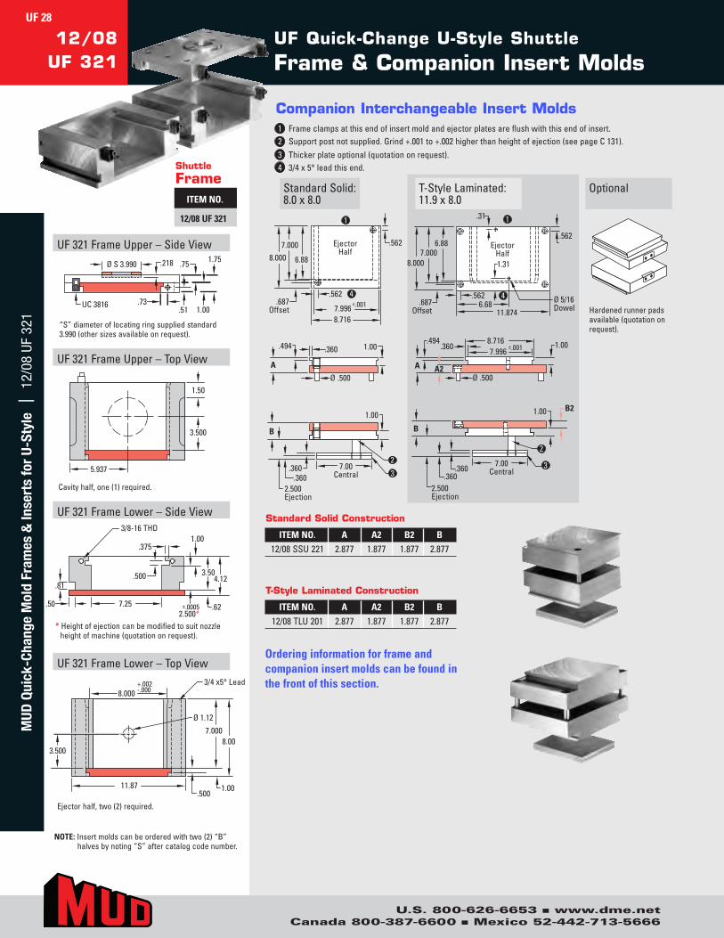
U.S. 800-626-6653 n www.dme.netCanada 800-387-6600 n Mexico 52-442-713-5666
UF321FrameUpper–SideView
UF321FrameUpper–TopView
UF321FrameLower–SideView
UF321FrameLower–TopView
.73UC 3816
Ø S 3.990 1.75.75
1.00.51
.218
1.50
5.937
3.500
3/4 x5° Lead
11.87
7.0008.00
1.00.500
8.000+.002-.000
3.500
Ø 1.12
.50 7.25
.81
3/8-16 THD
2.500*.62
4.123.50.500
.3751.00
±.0005
NOTE:Insertmoldscanbeorderedwithtwo(2)“B”halvesbynoting“S”aftercatalogcodenumber.
Cavityhalf,one(1)required.
Ejectorhalf,two(2)required.
“S”diameteroflocatingringsuppliedstandard3.990(othersizesavailableonrequest).
UF Quick-Change U-Style Shuttle
Frame & Companion Insert Molds12/08
UF 321
StandardSolid:8.0x8.0
OptionalT-StyleLaminated:11.9x8.0
.562
.562
7.000 8.000
7.996 8.716
±.001
6.88
Ejector Half
.687 Offset
1
B
1.00
2.500 Ejection
7.00 Central
2 .360
.360
.360
A
.494
Ø .500
1.00
4
3
.562 6.68
.562
.31
11.874
1
Ø 5/16 Dowel
.687 Offset
1.31 7.000
8.000
6.88 Ejector Half
B
1.00 B2
2.500 Ejection
7.00 Central
3 .360 .360
A2 A
.494
Ø .500
1.00 7.996
8.716 ±.001 .360
4
2
Hardenedrunnerpadsavailable(quotationonrequest).
Companion Interchangeable Insert Molds1 Frameclampsatthisendofinsertmoldandejectorplatesareflushwiththisendofinsert. 2 Supportpostnotsupplied.Grind+.001to+.002higherthanheightofejection(seepageC131). 3 Thickerplateoptional(quotationonrequest).4 3/4x5°leadthisend.Shuttle
FrameITEM NO.
12/08 UF 321
ITEM NO. A A2 B2 B12/08SSU221 2.877 1.877 1.877 2.877
Standard Solid Construction
Ordering information for frame and companion insert molds can be found in the front of this section.
ITEM NO. A A2 B2 B12/08TLU201 2.877 1.877 1.877 2.877
T-Style Laminated Construction
*Heightofejectioncanbemodifiedtosuitnozzleheightofmachine(quotationonrequest).
UF 28M
UD Q
uick
-Cha
nge
Mol
d Fr
ames
& In
sert
s fo
r U-
Styl
e |
12/
08 U
F 32
1

U.S. 800-626-6653 n www.dme.netCanada 800-387-6600 n Mexico 52-442-713-5666
Frame
ITEM NO.
12/14 UF 321
* Taperslottoaccommodatesleeveejectionoptional(quotationonrequest).
UF321FrameUpper–SideView
UF321FrameUpper–TopView
UF321FrameLower–SideView
UF321FrameLower–TopView
RUC 3816.275 ±.001
Ø S 3.990Ø 2.0 .218
.901.00
1.90
.51.73
Ø 0
2.00
6.437
5.937
.56 R
Ø 1.12
.750
3.00 3.50
12.874
1.50
14.37
+.002–.000 3/4 x 5° Lead
8.000
6.437
11.87
1.00
.90
5.005.90
4.000±.0005
.81
.50 7.25
.500
3/8-16THD
.375
*
UF Quick-Change U-Style
Frame & Companion Insert Molds12/14UF 321
StandardSolid:8.0x12.9
T-StyleLaminated:11.9x12.9
StandardLaminated:8.0x12.9
.360
Ø .625 1.00
A
.494
3
2
4.000 Ejection
.480 .480
7.00 Central
B
1.00
4
1
.687
12.75
12.874
±.001 7.994 8.714
Ejector Half
.812 Offset
.687
1.00
.360
Ø .625
A A2
.494
2
4.000 Ejection
.480
.480 7.00
Central
B
1.00
B2
3
1
.687
12.75
12.874
±.001 7.994 8.714
Ejector Half
.812 Offset
.687 4
7.994 8.714
±.001 .360
Ø .625
A A2
.494
1.00
2
4.000 Ejection
.480
.480 7.00
Central
B
1.00
B2
3
1
.687 12.75
12.874
11.874 6.68
Ejector Half
.812 Offset
.687 Ø 5/16 Dowel
4
.31
Companion Interchangeable Insert Molds1 Frameclampsatthisendofinsertmoldandejectorplatesareflushwiththisendofinsert. 2 Supportpostnotsupplied.Grind+.001to+.002higherthanheightofejection(seepageC131). 3 Thickerplateoptional(quotationonrequest).4 3/4x5°leadthisend.
Framesuppliedwithorwithoutspruebushing
ITEM NO. A A2 B2 B12/14SLU281 1.877 0.877 0.877 1.87712/14SLU282 1.877 0.877 1.377 2.37712/14SLU283 1.877 0.877 1.877 2.87712/14SLU284 2.377 1.377 0.877 1.87712/14SLU285 2.377 1.377 1.377 2.37712/14SLU286 2.377 1.377 1.877 2.87712/14SLU287 2.377 1.377 2.377 3.37712/14SLU288 2.877 1.877 0.877 1.87712/14SLU289 2.877 1.877 1.377 2.37712/14SLU290 2.877 1.877 1.877 2.87712/14SLU291 2.877 1.877 2.377 3.37712/14SLU292 3.377 2.377 1.377 2.37712/14SLU293 3.377 2.377 1.877 2.87712/14SLU294 3.377 2.377 2.377 3.377
ITEM NO. A A2 B2 B12/14TLU201 2.377 1.377 1.377 2.37712/14TLU202 2.377 1.377 1.877 2.87712/14TLU203 2.377 1.377 2.377 3.37712/14TLU204 2.877 1.877 1.377 2.37712/14TLU205 2.877 1.877 1.877 2.87712/14TLU206 2.877 1.877 2.377 3.37712/14TLU207 2.877 1.877 2.877 3.87712/14TLU208 3.377 2.377 1.377 2.37712/14TLU209 3.377 2.377 1.877 2.87712/14TLU210 3.377 2.377 2.377 3.37712/14TLU211 3.377 2.377 2.877 3.87712/14TLU212 3.877 2.877 1.877 2.87712/14TLU213 3.877 2.877 2.377 3.37712/14TLU214 3.877 2.877 2.877 3.877
ITEM NO. A B12/14SSU221 1.377 1.37712/14SSU222 1.377 1.87712/14SSU223 1.377 2.37712/14SSU224 1.877 1.37712/14SSU225 1.877 1.87712/14SSU226 1.877 2.37712/14SSU227 1.877 2.87712/14SSU228 2.377 1.37712/14SSU229 2.377 1.87712/14SSU230 2.377 2.37712/14SSU231 2.377 2.87712/14SSU232 2.877 1.87712/14SSU233 2.877 2.37712/14SSU234 2.877 2.877
Standard Solid Construction
Standard Laminated Construction
T-Style Laminated Construction
Ordering information for frame and companion insert molds can be found in the front of this section.
UF 29M
UD Quick-Change M
old Frames &
Inserts for U-Style | 12/14 UF 321

U.S. 800-626-6653 n www.dme.netCanada 800-387-6600 n Mexico 52-442-713-5666
UF Quick-Change U-Style
Frame & Companion Insert Molds12/16
UF 321
Frame
ITEM NO.
12/16 UF 321 StandardSolid:8.0x14.9
Companion Interchangeable Insert Molds1 Frameclampsatthisendofinsertmoldandejectorplatesareflushwiththisendofinsert.2 Supportpostnotsupplied.Grind+.001to+.002higherthanheightofejection(seepageC131).3 Thickerplateoptional(quotationonrequest).4 3/4x5°leadthisend.
T-StyleLaminated:11.9x14.9
StandardLaminated:8.0x14.9
.360
Ø .625 1.00
A
.494
3
2
4.000 Ejection
.480 .480
7.00 Central
B
1.00
4
1
.687
14.75
14.874
±.001 7.994
8.714
Ejector Half
.812 Offset
.687
1.00
.360
Ø .625
A A2
.494
2
4.000 Ejection
.480
.480 7.00
Central
B
1.00
B2
3
1
.687
14.75
14.874
±.001 7.994
8.714
Ejector Half
.812 Offset
.687 4
7.994 8.714
±.001 .360
Ø .625
A A2
.494
1.00
2
4.000 Ejection
.480
.480 7.00
Central
B
1.00
B2
3
1 .687
14.75
14.874
11.874 6.68
Ejector Half
.812 Offset
.687 Ø 5/16 Dowel
4
.31
* Taperslottoaccommodatesleeveejectionoptional(quotationonrequest).
UF321FrameUpper–SideView
UF321FrameUpper–TopView
UF321FrameLower–SideView
UF321FrameLower–TopView
R
UC 3816.275 ±.001
Ø S 3.990Ø 2.0.218
.90
1.00
1.90.51.73
Ø 0
2.00
7.437
5.937
.56 R
Ø 1.12
.750
3.00
3.50
14.874
1.50
16.37
+.002–.000 3/4 x 5° Lead
8.000
7.437
11.87
1.00
.90
5.005.904.000
±.0005.81
.50 7.25
.500
3/8-16THD
.375
*
Framesuppliedwithorwithoutspruebushing
ITEM NO. A A2 B2 B12/16SLU281 1.877 0.877 0.877 1.87712/16SLU282 1.877 0.877 1.377 2.37712/16SLU283 1.877 0.877 1.877 2.87712/16SLU284 2.377 1.377 0.877 1.87712/16SLU285 2.377 1.377 1.377 2.37712/16SLU286 2.377 1.377 1.877 2.87712/16SLU287 2.377 1.377 2.377 3.37712/16SLU288 2.877 1.877 0.877 1.87712/16SLU289 2.877 1.877 1.377 2.37712/16SLU290 2.877 1.877 1.877 2.87712/16SLU291 2.877 1.877 2.377 3.37712/16SLU292 3.377 2.377 1.377 2.37712/16SLU293 3.377 2.377 1.877 2.87712/16SLU294 3.377 2.377 2.377 3.377
ITEM NO. A A2 B2 B12/16TLU201 2.377 1.377 1.377 2.37712/16TLU202 2.377 1.377 1.877 2.87712/16TLU203 2.377 1.377 2.377 3.37712/16TLU204 2.877 1.877 1.377 2.37712/16TLU205 2.877 1.877 1.877 2.87712/16TLU206 2.877 1.877 2.377 3.37712/16TLU207 2.877 1.877 2.877 3.87712/16TLU208 3.377 2.377 1.377 2.37712/16TLU209 3.377 2.377 1.877 2.87712/16TLU210 3.377 2.377 2.377 3.37712/16TLU211 3.377 2.377 2.877 3.87712/16TLU212 3.877 2.877 1.877 2.87712/16TLU213 3.877 2.877 2.377 3.37712/16TLU214 3.877 2.877 2.877 3.877
ITEM NO. A B12/16SSU221 1.377 1.37712/16SSU222 1.377 1.87712/16SSU223 1.377 2.37712/16SSU224 1.877 1.37712/16SSU225 1.877 1.87712/16SSU226 1.877 2.37712/16SSU227 1.877 2.87712/16SSU228 2.377 1.37712/16SSU229 2.377 1.87712/16SSU230 2.377 2.37712/16SSU231 2.377 2.87712/16SSU232 2.877 1.87712/16SSU233 2.877 2.37712/16SSU234 2.877 2.877
Standard Solid Construction
Standard Laminated Construction
T-Style Laminated Construction
Ordering information for frame and companion insert molds can be found in the front of this section.
UF 30M
UD Q
uick
-Cha
nge
Mol
d Fr
ames
& In
sert
s fo
r U-
Styl
e |
12/
16 U
F 32
1

U.S. 800-626-6653 n www.dme.netCanada 800-387-6600 n Mexico 52-442-713-5666
* Taperslottoaccommodatesleeveejectionoptional(quotationonrequest).
UF321FrameUpper–SideView
UF321FrameUpper–TopView
UF321FrameLower–SideView
UF321FrameLower–TopView
R
UC 3816.275±.001
Ø S 3.990Ø 2.0.218
.90
1.00
1.90.51.73
Ø 0
2.00
8.437
5.937
.56 R
Ø 1.12
.750
3.00
3.50
16.874
1.50
18.37
+.002–.000 3/4 x 5° Lead
8.000
8.437
11.87
1.00
.90
5.005.90
4.000±.0005
.81
.50 7.25
.500
3/8-16THD
.375
*
Framesuppliedwithorwithoutspruebushing
12/18UF 321
Frame
ITEM NO.
12/18 UF 321StandardSolid:8.0x16.9
T-StyleLaminated:11.9x16.9
StandardLaminated:8.0x16.9
.360
Ø .625 1.00
A
.494
3 2
4.000 Ejection
.480 .480
7.00 Central
B
1.00
4
1
.687
16.75
16.874
±.001 7.994
8.714
Ejector Half
.812 Offset
.687
1.00
.360
Ø .625
A A2
.494
2 4.000 Ejection
.480
.480 7.00
Central
B
1.00
B2
3
1
.687
16.75
16.874
±.001 7.994
8.714
Ejector Half
.812 Offset
.687 4
7.994 8.714
±.001 .360
Ø .625
A A2
.494
1.00
2 4.000 Ejection
.480
.480 7.00
Central
B
1.00
B2
3
1 .687
16.75
16.874
11.874 6.68
Ejector Half
.812 Offset
.687 Ø 5/16 Dowel
4
.31
Companion Interchangeable Insert Molds1 Frameclampsatthisendofinsertmoldandejectorplatesareflushwiththisendofinsert. 2 Supportpostnotsupplied.Grind+.001to+.002higherthanheightofejection(seepageC131). 3 Thickerplateoptional(quotationonrequest).4 3/4x5°leadthisend.
ITEM NO. A A2 B2 B12/18SLU281 1.877 0.877 0.877 1.87712/18SLU282 1.877 0.877 1.377 2.37712/18SLU283 1.877 0.877 1.877 2.87712/18SLU284 2.377 1.377 0.877 1.87712/18SLU285 2.377 1.377 1.377 2.37712/18SLU286 2.377 1.377 1.877 2.87712/18SLU287 2.377 1.377 2.377 3.37712/18SLU288 2.877 1.877 0.877 1.87712/18SLU289 2.877 1.877 1.377 2.37712/18SLU290 2.877 1.877 1.877 2.87712/18SLU291 2.877 1.877 2.377 3.37712/18SLU292 3.377 2.377 1.377 2.37712/18SLU293 3.377 2.377 1.877 2.87712/18SLU294 3.377 2.377 2.377 3.377
ITEM NO. A A2 B2 B12/18TLU201 2.377 1.377 1.377 2.37712/18TLU202 2.377 1.377 1.877 2.87712/18TLU203 2.377 1.377 2.377 3.37712/18TLU204 2.877 1.877 1.377 2.37712/18TLU205 2.877 1.877 1.877 2.87712/18TLU206 2.877 1.877 2.377 3.37712/18TLU207 2.877 1.877 2.877 3.87712/18TLU208 3.377 2.377 1.377 2.37712/18TLU209 3.377 2.377 1.877 2.87712/18TLU210 3.377 2.377 2.377 3.37712/18TLU211 3.377 2.377 2.877 3.87712/18TLU212 3.877 2.877 1.877 2.87712/18TLU213 3.877 2.877 2.377 3.37712/18TLU214 3.877 2.877 2.877 3.877
ITEM NO. A B12/18SSU221 1.377 1.37712/18SSU222 1.377 1.87712/18SSU223 1.377 2.37712/18SSU224 1.877 1.37712/18SSU225 1.877 1.87712/18SSU226 1.877 2.37712/18SSU227 1.877 2.87712/18SSU228 2.377 1.37712/18SSU229 2.377 1.87712/18SSU230 2.377 2.37712/18SSU231 2.377 2.87712/18SSU232 2.877 1.87712/18SSU233 2.877 2.37712/18SSU234 2.877 2.877
Standard Solid Construction
Standard Laminated Construction
T-Style Laminated Construction
Ordering information for frame and companion insert molds can be found in the front of this section.
UF 31M
UD Quick-Change M
old Frames &
Inserts for U-Style | 12/18 UF 321

U.S. 800-626-6653 n www.dme.netCanada 800-387-6600 n Mexico 52-442-713-5666
UF Quick-Change U-Style
Frame & Companion Insert Molds12/20
UF 321
Frame
ITEM NO.
12/20 UF 321 StandardSolid:8.0x18.9
Companion Interchangeable Insert Molds1 Frameclampsatthisendofinsertmoldandejectorplatesareflushwiththisendofinsert.2 Supportpostnotsupplied.Grind+.001to+.002higherthanheightofejection(seepageC131).3 Thickerplateoptional(quotationonrequest).4 3/4x5°leadthisend.
T-StyleLaminated:11.9x18.9
StandardLaminated:8.0x18.9
.360
Ø .625 1.00
A
.494
3 2
4.000 Ejection
.480 .480
7.00 Central
B
1.00
4
1
.687
18.75
18.874
±.001 7.994
8.714
Ejector Half
.812 Offset
.687
1.00
.360
Ø .625
A A2
.494
2 4.000 Ejection
.480
.480 7.00
Central
B
1.00
B2
3
1
.687
18.75
18.874
±.001 7.994
8.714
Ejector Half
.812 Offset
.687
4
7.994
8.714 ±.001 .360
Ø .625A A2
.494
1.00
2 4.000 Ejection
.480
.480 7.00
Central
B
1.00
B2
3
1 .687
18.75
18.874
11.874 6.68
Ejector Half
.812 Offset
.687
Ø 5/16 Dowel
4
.31
* Taperslottoaccommodatesleeveejectionoptional(quotationonrequest).
UF321FrameUpper–SideView
UF321FrameUpper–TopView
UF321FrameLower–SideView
UF321FrameLower–TopView
R
UC 3816.275±.001
Ø S 3.990Ø 2.0
.218
.901.00
1.90
.51.73
Ø 0
2.00
7.18
9.437
5.937
.56 RØ 1.12
.750
3.00
3.50
18.874
1.50
20.37
+.002–.000 3/4 x 5° Lead
8.000
9.437
11.87
1.00
.90
5.005.90
4.000±.0005
.81
.50 7.25
.500
3/8-16THD
.375
*
Framesuppliedwithorwithoutspruebushing
ITEM NO. A A2 B2 B12/20SLU281 1.877 0.877 0.877 1.87712/20SLU282 1.877 0.877 1.377 2.37712/20SLU283 1.877 0.877 1.877 2.87712/20SLU284 2.377 1.377 0.877 1.87712/20SLU285 2.377 1.377 1.377 2.37712/20SLU286 2.377 1.377 1.877 2.87712/20SLU287 2.377 1.377 2.377 3.37712/20SLU288 2.877 1.877 0.877 1.87712/20SLU289 2.877 1.877 1.377 2.37712/20SLU290 2.877 1.877 1.877 2.87712/20SLU291 2.877 1.877 2.377 3.37712/20SLU292 3.377 2.377 1.377 2.37712/20SLU293 3.377 2.377 1.877 2.87712/20SLU294 3.377 2.377 2.377 3.377
ITEM NO. A A2 B2 B12/20TLU201 2.377 1.377 1.377 2.37712/20TLU202 2.377 1.377 1.877 2.87712/20TLU203 2.377 1.377 2.377 3.37712/20TLU204 2.877 1.877 1.377 2.37712/20TLU205 2.877 1.877 1.877 2.87712/20TLU206 2.877 1.877 2.377 3.37712/20TLU207 2.877 1.877 2.877 3.87712/20TLU208 3.377 2.377 1.377 2.37712/20TLU209 3.377 2.377 1.877 2.87712/20TLU210 3.377 2.377 2.377 3.37712/20TLU211 3.377 2.377 2.877 3.87712/20TLU212 3.877 2.877 1.877 2.87712/20TLU213 3.877 2.877 2.377 3.37712/20TLU214 3.877 2.877 2.877 3.877
ITEM NO. A B12/20SSU221 1.377 1.37712/20SSU222 1.377 1.87712/20SSU223 1.377 2.37712/20SSU224 1.877 1.37712/20SSU225 1.877 1.87712/20SSU226 1.877 2.37712/20SSU227 1.877 2.87712/20SSU228 2.377 1.37712/20SSU229 2.377 1.87712/20SSU230 2.377 2.37712/20SSU231 2.377 2.87712/20SSU232 2.877 1.87712/20SSU233 2.877 2.37712/20SSU234 2.877 2.877
Standard Solid Construction
Standard Laminated Construction
T-Style Laminated Construction
Ordering information for frame and companion insert molds can be found in the front of this section.
UF 32M
UD Q
uick
-Cha
nge
Mol
d Fr
ames
& In
sert
s fo
r U-
Styl
e |
12/
20 U
F 32
1
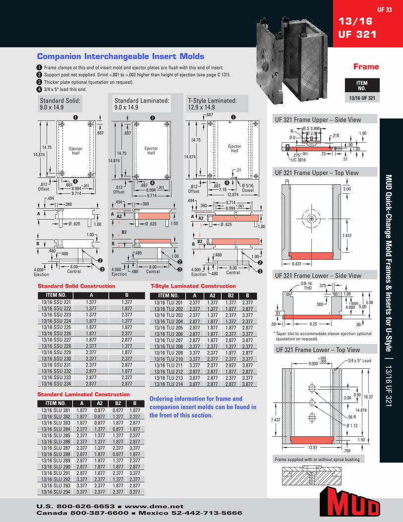
U.S. 800-626-6653 n www.dme.netCanada 800-387-6600 n Mexico 52-442-713-5666
13/16UF 321
Frame
ITEM NO.
13/16 UF 321StandardSolid:9.0x14.9
T-StyleLaminated:12.9x14.9
StandardLaminated:9.0x14.9
.360
Ø .625 1.00
A
.494
3
2
4.000 Ejection
.480 .480
8.00 Central
B
1.00
4
1
.687
14.75
14.874
±.001 8.994 9.714
Ejector Half
.812 Offset
.687
1.00
.360
Ø .625
A A2
.494
2
4.000 Ejection
.480
.480 8.00
Central
B
1.00
B2
3
1
.687
14.75
14.874
±.001 8.994 9.714
Ejector Half
.812 Offset
.687 4
8.994 9.714
±.001 .360
Ø .625
A A2
.494
1.00
1 .687
14.75
14.874
12.874 7.18
Ejector Half
.812 Offset
.687 Ø 5/16 Dowel
4
.31
2
4.000 Ejection
.480
.480 8.00
Central
B
1.00
B2
3
Companion Interchangeable Insert Molds1 Frameclampsatthisendofinsertmoldandejectorplatesareflushwiththisendofinsert. 2 Supportpostnotsupplied.Grind+.001to+.002higherthanheightofejection(seepageC131). 3 Thickerplateoptional(quotationonrequest).4 3/4x5°leadthisend.
* Taperslottoaccommodatesleeveejectionoptional(quotationonrequest).
UF321FrameUpper–SideView
UF321FrameUpper–TopView
UF321FrameLower–SideView
UF321FrameLower–TopView
R
UC 3816.275±.001
Ø S 3.990Ø 2.0 .218
.901.00
1.90
.51.73
Ø 0
2.00
7.437
6.437
.56 R
Ø 1.12
.750
3.003.50
14.874
1.50
16.37
+.002–.000 3/4 x 5° Lead
9.000
7.437
12.87
1.00
.90
5.005.90
4.000±.0005
.81
.50 8.25
.500
3/8-16THD .375
*
Framesuppliedwithorwithoutspruebushing
ITEM NO. A A2 B2 B13/16SLU281 1.877 0.877 0.877 1.87713/16SLU282 1.877 0.877 1.377 2.37713/16SLU283 1.877 0.877 1.877 2.87713/16SLU284 2.377 1.377 0.877 1.87713/16SLU285 2.377 1.377 1.377 2.37713/16SLU286 2.377 1.377 1.877 2.87713/16SLU287 2.377 1.377 2.377 3.37713/16SLU288 2.877 1.877 0.877 1.87713/16SLU289 2.877 1.877 1.377 2.37713/16SLU290 2.877 1.877 1.877 2.87713/16SLU291 2.877 1.877 2.377 3.37713/16SLU292 3.377 2.377 1.377 2.37713/16SLU293 3.377 2.377 1.877 2.87713/16SLU294 3.377 2.377 2.377 3.377
ITEM NO. A A2 B2 B13/16TLU201 2.377 1.377 1.377 2.37713/16TLU202 2.377 1.377 1.877 2.87713/16TLU203 2.377 1.377 2.377 3.37713/16TLU204 2.877 1.877 1.377 2.37713/16TLU205 2.877 1.877 1.877 2.87713/16TLU206 2.877 1.877 2.377 3.37713/16TLU207 2.877 1.877 2.877 3.87713/16TLU208 3.377 2.377 1.377 2.37713/16TLU209 3.377 2.377 1.877 2.87713/16TLU210 3.377 2.377 2.377 3.37713/16TLU211 3.377 2.377 2.877 3.87713/16TLU212 3.877 2.877 1.877 2.87713/16TLU213 3.877 2.877 2.377 3.37713/16TLU214 3.877 2.877 2.877 3.877
ITEM NO. A B13/16SSU221 1.377 1.37713/16SSU222 1.377 1.87713/16SSU223 1.377 2.37713/16SSU224 1.877 1.37713/16SSU225 1.877 1.87713/16SSU226 1.877 2.37713/16SSU227 1.877 2.87713/16SSU228 2.377 1.37713/16SSU229 2.377 1.87713/16SSU230 2.377 2.37713/16SSU231 2.377 2.87713/16SSU232 2.877 1.87713/16SSU233 2.877 2.37713/16SSU234 2.877 2.877
Standard Solid Construction
Standard Laminated Construction
T-Style Laminated Construction
Ordering information for frame and companion insert molds can be found in the front of this section.
UF 33M
UD Quick-Change M
old Frames &
Inserts for U-Style | 13/16 UF 321

U.S. 800-626-6653 n www.dme.netCanada 800-387-6600 n Mexico 52-442-713-5666
UF Quick-Change U-Style
Frame & Companion Insert Molds13/18
UF 321
Frame
ITEM NO.
13/18 UF 321 StandardSolid:9.0x16.9
Companion Interchangeable Insert Molds1 Frameclampsatthisendofinsertmoldandejectorplatesareflushwiththisendofinsert.2 Supportpostnotsupplied.Grind+.001to+.002higherthanheightofejection(seepageC131).3 Thickerplateoptional(quotationonrequest).4 3/4x5°leadthisend.
T-StyleLaminated:12.9x16.9
StandardLaminated:9.0x16.9
.360
Ø .625 1.00
A
.494
3
2
4.000 Ejection
.480 .480
8.00 Central
B
1.00
4
1
.687
16.75
16.874
±.001 8.994
9.714
Ejector Half
.812 Offset
.687
1.00
.360
Ø .625
A A2
.494
2
4.000 Ejection
.480
.480 8.00
Central
B
1.00 B2
3
1
.687
16.75
16.874
±.001 8.994
9.714
Ejector Half
.812 Offset
.687 4
8.994 9.714
±.001 .360
Ø .625
A A2
.494
1.00
2
4.000 Ejection
.480
.480 8.00
Central
B
1.00
B2
3
1 .687
16.75
16.874
12.874 7.18
Ejector Half
.812 Offset
.687 Ø 5/16 Dowel
4
.31
* Taperslottoaccommodatesleeveejectionoptional(quotationonrequest).
UF321FrameUpper–SideView
UF321FrameUpper–TopView
UF321FrameLower–SideView
UF321FrameLower–TopView
R
UC 3816.275±.001
Ø S 3.990Ø 2.0.218
.90
1.00
1.90.51.73
Ø 0
2.00
8.437
6.437
.56 R
Ø 1.12
.750
3.00
3.50
16.874
1.50
18.37
+.002–.000 3/4 x 5° Lead
9.000
8.437
12.87
1.00
.90
5.005.90
4.000±.0005
.81
.50 8.25
.500
3/8-16THD
.375
*
Framesuppliedwithorwithoutspruebushing
ITEM NO. A A2 B2 B13/18SLU281 1.877 0.877 0.877 1.87713/18SLU282 1.877 0.877 1.377 2.37713/18SLU283 1.877 0.877 1.877 2.87713/18SLU284 2.377 1.377 0.877 1.87713/18SLU285 2.377 1.377 1.377 2.37713/18SLU286 2.377 1.377 1.877 2.87713/18SLU287 2.377 1.377 2.377 3.37713/18SLU288 2.877 1.877 0.877 1.87713/18SLU289 2.877 1.877 1.377 2.37713/18SLU290 2.877 1.877 1.877 2.87713/18SLU291 2.877 1.877 2.377 3.37713/18SLU292 3.377 2.377 1.377 2.37713/18SLU293 3.377 2.377 1.877 2.87713/18SLU294 3.377 2.377 2.377 3.377
ITEM NO. A A2 B2 B13/18TLU201 2.377 1.377 1.377 2.37713/18TLU202 2.377 1.377 1.877 2.87713/18TLU203 2.377 1.377 2.377 3.37713/18TLU204 2.877 1.877 1.377 2.37713/18TLU205 2.877 1.877 1.877 2.87713/18TLU206 2.877 1.877 2.377 3.37713/18TLU207 2.877 1.877 2.877 3.87713/18TLU208 3.377 2.377 1.377 2.37713/18TLU209 3.377 2.377 1.877 2.87713/18TLU210 3.377 2.377 2.377 3.37713/18TLU211 3.377 2.377 2.877 3.87713/18TLU212 3.877 2.877 1.877 2.87713/18TLU213 3.877 2.877 2.377 3.37713/18TLU214 3.877 2.877 2.877 3.877
ITEM NO. A B13/18SSU221 1.377 1.37713/18SSU222 1.377 1.87713/18SSU223 1.377 2.37713/18SSU224 1.877 1.37713/18SSU225 1.877 1.87713/18SSU226 1.877 2.37713/18SSU227 1.877 2.87713/18SSU228 2.377 1.37713/18SSU229 2.377 1.87713/18SSU230 2.377 2.37713/18SSU231 2.377 2.87713/18SSU232 2.877 1.87713/18SSU233 2.877 2.37713/18SSU234 2.877 2.877
Standard Solid Construction
Standard Laminated Construction
T-Style Laminated Construction
Ordering information for frame and companion insert molds can be found in the front of this section.
UF 34M
UD Q
uick
-Cha
nge
Mol
d Fr
ames
& In
sert
s fo
r U-
Styl
e |
13/
18 U
F 32
1

U.S. 800-626-6653 n www.dme.netCanada 800-387-6600 n Mexico 52-442-713-5666
* Taperslottoaccommodatesleeveejectionoptional(quotationonrequest).
UF321FrameUpper–SideView
UF321FrameUpper–TopView
UF321FrameLower–SideView
UF321FrameLower–TopView
R
UC 3816.275±.001
Ø S 3.990Ø 2.0.218
.90
1.00
1.90
.51.73
Ø 0
2.00
9.437
7.18
6.437
.56 RØ 1.12
.750
3.00
3.50
18.874
1.50
20.37
+.002–.000 3/4 x 5° Lead
9.000
9.437
12.87
1.00
.90
5.005.90
4.000±.0005
.81
.50 8.25
.500
3/8-16THD
.375
*
Framesuppliedwithorwithoutspruebushing
13/20UF 321
Frame
ITEM NO.
13/20 UF 321StandardSolid:9.0x18.9
T-StyleLaminated:12.9x18.9
StandardLaminated:9.0x18.9
.360
Ø .625 1.00
A
.494
3 2
4.000 Ejection
.480 .480
8.00 Central
B
1.00
4
1
.687
18.75
18.874
±.001 8.994
9.714
Ejector Half
.812 Offset
.687
1.00
.360
Ø .625
A A2
.494
2 4.000 Ejection
.480
.480 8.00
Central
B
1.00
B2
3
1
.687
18.75
18.874
±.001 8.994
9.714
Ejector Half
.812 Offset
.687 4
8.994 9.714
±.001 .360
Ø .625
A A2
.494
1.00
2 4.000 Ejection
.480
.480 8.00
Central
B
1.00
B2
3
1 .687
18.75
18.874
12.874 7.18
Ejector Half
.812 Offset
.31
.687 Ø 5/16 Dowel
4
.31
Companion Interchangeable Insert Molds1 Frameclampsatthisendofinsertmoldandejectorplatesareflushwiththisendofinsert. 2 Supportpostnotsupplied.Grind+.001to+.002higherthanheightofejection(seepageC131). 3 Thickerplateoptional(quotationonrequest).4 3/4x5°leadthisend.
ITEM NO. A A2 B2 B13/20SLU281 1.877 0.877 0.877 1.87713/20SLU282 1.877 0.877 1.377 2.37713/20SLU283 1.877 0.877 1.877 2.87713/20SLU284 2.377 1.377 0.877 1.87713/20SLU285 2.377 1.377 1.377 2.37713/20SLU286 2.377 1.377 1.877 2.87713/20SLU287 2.377 1.377 2.377 3.37713/20SLU288 2.877 1.877 0.877 1.87713/20SLU289 2.877 1.877 1.377 2.37713/20SLU290 2.877 1.877 1.877 2.87713/20SLU291 2.877 1.877 2.377 3.37713/20SLU292 3.377 2.377 1.377 2.37713/20SLU293 3.377 2.377 1.877 2.87713/20SLU294 3.377 2.377 2.377 3.377
ITEM NO. A A2 B2 B13/20TLU201 2.377 1.377 1.377 2.37713/20TLU202 2.377 1.377 1.877 2.87713/20TLU203 2.377 1.377 2.377 3.37713/20TLU204 2.877 1.877 1.377 2.37713/20TLU205 2.877 1.877 1.877 2.87713/20TLU206 2.877 1.877 2.377 3.37713/20TLU207 2.877 1.877 2.877 3.87713/20TLU208 3.377 2.377 1.377 2.37713/20TLU209 3.377 2.377 1.877 2.87713/20TLU210 3.377 2.377 2.377 3.37713/20TLU211 3.377 2.377 2.877 3.87713/20TLU212 3.877 2.877 1.877 2.87713/20TLU213 3.877 2.877 2.377 3.37713/20TLU214 3.877 2.877 2.877 3.877
ITEM NO. A B13/20SSU221 1.377 1.37713/20SSU222 1.377 1.87713/20SSU223 1.377 2.37713/20SSU224 1.877 1.37713/20SSU225 1.877 1.87713/20SSU226 1.877 2.37713/20SSU227 1.877 2.87713/20SSU228 2.377 1.37713/20SSU229 2.377 1.87713/20SSU230 2.377 2.37713/20SSU231 2.377 2.87713/20SSU232 2.877 1.87713/20SSU233 2.877 2.37713/20SSU234 2.877 2.877
Standard Solid Construction
Standard Laminated Construction
T-Style Laminated Construction
Ordering information for frame and companion insert molds can be found in the front of this section.
UF 35M
UD Quick-Change M
old Frames &
Inserts for U-Style | 13/20 UF 321
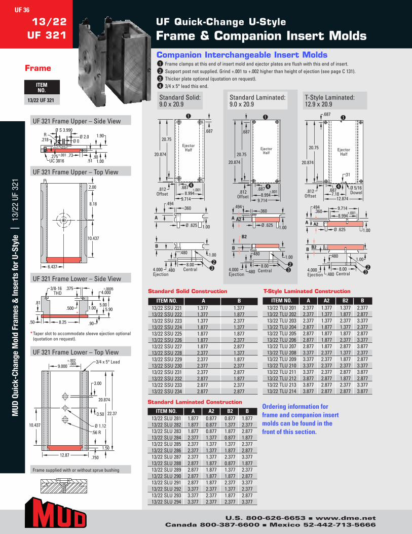
U.S. 800-626-6653 n www.dme.netCanada 800-387-6600 n Mexico 52-442-713-5666
UF Quick-Change U-Style
Frame & Companion Insert Molds13/22
UF 321
Frame
ITEM NO.
13/22 UF 321 StandardSolid:9.0x20.9
Companion Interchangeable Insert Molds1 Frameclampsatthisendofinsertmoldandejectorplatesareflushwiththisendofinsert.2 Supportpostnotsupplied.Grind+.001to+.002higherthanheightofejection(seepageC131).3 Thickerplateoptional(quotationonrequest).4 3/4x5°leadthisend.
T-StyleLaminated:12.9x20.9
StandardLaminated:9.0x20.9
.360
Ø .625 1.00
A
.494
3 2
4.000 Ejection
.480
.480 8.00
Central
B
1.00
4
1
.687
20.75
20.874
±.001 8.994
9.714
Ejector Half
.812 Offset
.687
1.00
.360
Ø .625A A2
.494
2 4.000 Ejection
.480
.480 8.00
Central
B
1.00
B2
3
1
.687
20.75
20.874
±.001 8.994
9.714
Ejector Half
.812 Offset
.687 4
8.994
9.714 ±.001 .360
Ø .625A A2
.494
1.00
2 4.000 Ejection
.480
.480 8.00
Central
B
1.00
B2
3
1 .687
20.75
20.874
12.874 7.18
Ejector Half
.812 Offset
.687 Ø 5/16 Dowel
4
.31
* Taperslottoaccommodatesleeveejectionoptional(quotationonrequest).
UF321FrameUpper–SideView
UF321FrameUpper–TopView
UF321FrameLower–SideView
UF321FrameLower–TopView
R
UC 3816.275±.001
Ø S 3.990Ø 2.0.218
.901.00
1.90
.51.73
Ø 0
2.00
8.18
10.437
6.437
.56 RØ 1.12
.750
3.00
3.50
20.874
1.50
22.37
+.002–.000 3/4 x 5° Lead
9.000
10.437
12.87
1.00
.90
5.005.90
4.000±.0005
.81
.50 8.25
.500
3/8-16THD
.375
*
Framesuppliedwithorwithoutspruebushing
ITEM NO. A A2 B2 B13/22SLU281 1.877 0.877 0.877 1.87713/22SLU282 1.877 0.877 1.377 2.37713/22SLU283 1.877 0.877 1.877 2.87713/22SLU284 2.377 1.377 0.877 1.87713/22SLU285 2.377 1.377 1.377 2.37713/22SLU286 2.377 1.377 1.877 2.87713/22SLU287 2.377 1.377 2.377 3.37713/22SLU288 2.877 1.877 0.877 1.87713/22SLU289 2.877 1.877 1.377 2.37713/22SLU290 2.877 1.877 1.877 2.87713/22SLU291 2.877 1.877 2.377 3.37713/22SLU292 3.377 2.377 1.377 2.37713/22SLU293 3.377 2.377 1.877 2.87713/22SLU294 3.377 2.377 2.377 3.377
ITEM NO. A A2 B2 B13/22TLU201 2.377 1.377 1.377 2.37713/22TLU202 2.377 1.377 1.877 2.87713/22TLU203 2.377 1.377 2.377 3.37713/22TLU204 2.877 1.877 1.377 2.37713/22TLU205 2.877 1.877 1.877 2.87713/22TLU206 2.877 1.877 2.377 3.37713/22TLU207 2.877 1.877 2.877 3.87713/22TLU208 3.377 2.377 1.377 2.37713/22TLU209 3.377 2.377 1.877 2.87713/22TLU210 3.377 2.377 2.377 3.37713/22TLU211 3.377 2.377 2.877 3.87713/22TLU212 3.877 2.877 1.877 2.87713/22TLU213 3.877 2.877 2.377 3.37713/22TLU214 3.877 2.877 2.877 3.877
ITEM NO. A B13/22SSU221 1.377 1.37713/22SSU222 1.377 1.87713/22SSU223 1.377 2.37713/22SSU224 1.877 1.37713/22SSU225 1.877 1.87713/22SSU226 1.877 2.37713/22SSU227 1.877 2.87713/22SSU228 2.377 1.37713/22SSU229 2.377 1.87713/22SSU230 2.377 2.37713/22SSU231 2.377 2.87713/22SSU232 2.877 1.87713/22SSU233 2.877 2.37713/22SSU234 2.877 2.877
Standard Solid Construction
Standard Laminated Construction
T-Style Laminated Construction
Ordering information for frame and companion insert molds can be found in the front of this section.
UF 36M
UD Q
uick
-Cha
nge
Mol
d Fr
ames
& In
sert
s fo
r U-
Styl
e |
13/
22 U
F 32
1

U.S. 800-626-6653 n www.dme.netCanada 800-387-6600 n Mexico 52-442-713-5666
* Taperslottoaccommodatesleeveejectionoptional(quotationonrequest).
UF321FrameUpper–SideView
UF321FrameUpper–TopView
UF321FrameLower–SideView
UF321FrameLower–TopView
RUC 3816.275 ±.001
Ø S 3.990Ø 2.0
.218
.90
1.00
1.90
.51.73
Ø 0
2.00
7.437
6.937
.56 R
Ø 1.12
.750
3.00 3.50
14.874
1.50
16.37
+.002–.000 3/4 x 5° Lead
10.000
7.437
13.87
1.00
.90
5.005.90
4.000±.0005
.81
.50 9.25
.500
3/8-16THD
.375
*
Framesuppliedwithorwithoutspruebushing
14/16UF 321
Frame
ITEM NO.
14/16 UF 321StandardSolid:10.0x14.9
T-StyleLaminated:13.9x14.9
StandardLaminated:10.0x14.9
.360
Ø .625 1.00
A
.494
3
2
4.000 Ejection
.480 .480
9.00 Central
B
1.00
4
1
.687
14.75
14.874
±.001 9.994
10.714
Ejector Half
.812 Offset
.687
1.00
.360
Ø .625
A A2
.494
2
4.000 Ejection
.480
.480 9.00
Central
B
1.00
B2
3
1
.687
14.75
14.874
±.001 9.994
10.714
Ejector Half
.812 Offset
.687 4
9.994 10.714
±.001 .360
Ø .625
A A2
.494
1.00
1 .687
14.75
14.874
13.874 7.68
Ejector Half
.812 Offset
.687 Ø 5/16 Dowel
4
.31
2 4.000 Ejection
.480
.480 9.00
Central
B
1.00
B2
3
Companion Interchangeable Insert Molds1 Frameclampsatthisendofinsertmoldandejectorplatesareflushwiththisendofinsert. 2 Supportpostnotsupplied.Grind+.001to+.002higherthanheightofejection(seepageC131). 3 Thickerplateoptional(quotationonrequest).4 3/4x5°leadthisend.
ITEM NO. A A2 B2 B14/16SLU281 1.877 0.877 0.877 1.87714/16SLU282 1.877 0.877 1.377 2.37714/16SLU283 1.877 0.877 1.877 2.87714/16SLU284 2.377 1.377 0.877 1.87714/16SLU285 2.377 1.377 1.377 2.37714/16SLU286 2.377 1.377 1.877 2.87714/16SLU287 2.377 1.377 2.377 3.37714/16SLU288 2.877 1.877 0.877 1.87714/16SLU289 2.877 1.877 1.377 2.37714/16SLU290 2.877 1.877 1.877 2.87714/16SLU291 2.877 1.877 2.377 3.37714/16SLU292 3.377 2.377 1.377 2.37714/16SLU293 3.377 2.377 1.877 2.87714/16SLU294 3.377 2.377 2.377 3.377
ITEM NO. A A2 B2 B14/16TLU201 2.377 1.377 1.377 2.37714/16TLU202 2.377 1.377 1.877 2.87714/16TLU203 2.377 1.377 2.377 3.37714/16TLU204 2.877 1.877 1.377 2.37714/16TLU205 2.877 1.877 1.877 2.87714/16TLU206 2.877 1.877 2.377 3.37714/16TLU207 2.877 1.877 2.877 3.87714/16TLU208 3.377 2.377 1.377 2.37714/16TLU209 3.377 2.377 1.877 2.87714/16TLU210 3.377 2.377 2.377 3.37714/16TLU211 3.377 2.377 2.877 3.87714/16TLU212 3.877 2.877 1.877 2.87714/16TLU213 3.877 2.877 2.377 3.37714/16TLU214 3.877 2.877 2.877 3.877
ITEM NO. A B14/16SSU221 1.377 1.37714/16SSU222 1.377 1.87714/16SSU223 1.377 2.37714/16SSU224 1.877 1.37714/16SSU225 1.877 1.87714/16SSU226 1.877 2.37714/16SSU227 1.877 2.87714/16SSU228 2.377 1.37714/16SSU229 2.377 1.87714/16SSU230 2.377 2.37714/16SSU231 2.377 2.87714/16SSU232 2.877 1.87714/16SSU233 2.877 2.37714/16SSU234 2.877 2.877
Standard Solid Construction
Standard Laminated Construction
T-Style Laminated Construction
Ordering information for frame and companion insert molds can be found in the front of this section.
UF 37M
UD Quick-Change M
old Frames &
Inserts for U-Style | 14/16 UF 321
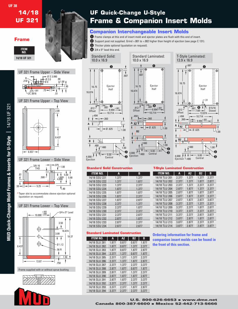
U.S. 800-626-6653 n www.dme.netCanada 800-387-6600 n Mexico 52-442-713-5666
UF Quick-Change U-Style
Frame & Companion Insert Molds14/18
UF 321
Frame
ITEM NO.
14/18 UF 321 StandardSolid:10.0x16.9
Companion Interchangeable Insert Molds1 Frameclampsatthisendofinsertmoldandejectorplatesareflushwiththisendofinsert.2 Supportpostnotsupplied.Grind+.001to+.002higherthanheightofejection(seepageC131).3 Thickerplateoptional(quotationonrequest).4 3/4x5°leadthisend.
T-StyleLaminated:13.9x16.9
StandardLaminated:10.0x16.9
.360
Ø .625 1.00
A
.494
3
2
4.000 Ejection
.480 .480
9.00 Central
B
1.00
.687 4
1
.687
16.75
16.874
±.001 9.994
10.714
Ejector Half
.812Offset
1.00
.360
Ø .625
A A2
.494
2 4.000 Ejection
.480
.480 9.00
Central
B
1.00
B2
3
1
.687
16.75
16.874
±.001 9.994
10.714
Ejector Half
.812 Offset
.687 4
9.994
10.714 ±.001 .360
Ø .625
A A2
.494
1.00
2
4.000 Ejection
.480
.480 9.00
Central
B
1.00
B2
3
1 .687
16.75
16.874
13.874 7.68
Ejector Half
.812 Offset
.687 Ø 5/16 Dowel
4
.31
* Taperslottoaccommodatesleeveejectionoptional(quotationonrequest).
UF321FrameUpper–SideView
UF321FrameUpper–TopView
UF321FrameLower–SideView
UF321FrameLower–TopView
R
UC 3816.275 ±.001
Ø S 3.990Ø 2.0.218
.901.00
1.90
.51.73
Ø 0
2.00
8.437
6.937
–.00010.000
13.87
3/4 x 5° Lead
.750
1.50
18.37
.56 R
Ø 1.12
3.00
3.50
16.874
8.437
+.002
.90
5.005.90
.81
.50 9.25
.500
3/8-16THD
.3751.00
4.000±.0005
*
Framesuppliedwithorwithoutspruebushing
ITEM NO. A A2 B2 B14/18SLU281 1.877 0.877 0.877 1.87714/18SLU282 1.877 0.877 1.377 2.37714/18SLU283 1.877 0.877 1.877 2.87714/18SLU284 2.377 1.377 0.877 1.87714/18SLU285 2.377 1.377 1.377 2.37714/18SLU286 2.377 1.377 1.877 2.87714/18SLU287 2.377 1.377 2.377 3.37714/18SLU288 2.877 1.877 0.877 1.87714/18SLU289 2.877 1.877 1.377 2.37714/18SLU290 2.877 1.877 1.877 2.87714/18SLU291 2.877 1.877 2.377 3.37714/18SLU292 3.377 2.377 1.377 2.37714/18SLU293 3.377 2.377 1.877 2.87714/18SLU294 3.377 2.377 2.377 3.377
ITEM NO. A A2 B2 B14/18TLU201 2.377 1.377 1.377 2.37714/18TLU202 2.377 1.377 1.877 2.87714/18TLU203 2.377 1.377 2.377 3.37714/18TLU204 2.877 1.877 1.377 2.37714/18TLU205 2.877 1.877 1.877 2.87714/18TLU206 2.877 1.877 2.377 3.37714/18TLU207 2.877 1.877 2.877 3.87714/18TLU208 3.377 2.377 1.377 2.37714/18TLU209 3.377 2.377 1.877 2.87714/18TLU210 3.377 2.377 2.377 3.37714/18TLU211 3.377 2.377 2.877 3.87714/18TLU212 3.877 2.877 1.877 2.87714/18TLU213 3.877 2.877 2.377 3.37714/18TLU214 3.877 2.877 2.877 3.877
ITEM NO. A B14/18SSU221 1.377 1.37714/18SSU222 1.377 1.87714/18SSU223 1.377 2.37714/18SSU224 1.877 1.37714/18SSU225 1.877 1.87714/18SSU226 1.877 2.37714/18SSU227 1.877 2.87714/18SSU228 2.377 1.37714/18SSU229 2.377 1.87714/18SSU230 2.377 2.37714/18SSU231 2.377 2.87714/18SSU232 2.877 1.87714/18SSU233 2.877 2.37714/18SSU234 2.877 2.877
Standard Solid Construction
Standard Laminated Construction
T-Style Laminated Construction
Ordering information for frame and companion insert molds can be found in the front of this section.
UF 38M
UD Q
uick
-Cha
nge
Mol
d Fr
ames
& In
sert
s fo
r U-
Styl
e |
14/
18 U
F 32
1

U.S. 800-626-6653 n www.dme.netCanada 800-387-6600 n Mexico 52-442-713-5666
* Taperslottoaccommodatesleeveejectionoptional(quotationonrequest).
UF321FrameUpper–SideView
UF321FrameUpper–TopView
UF321FrameLower–SideView
UF321FrameLower–TopView
R
UC 3816.275 ±.001
Ø S 3.990Ø 2.0
.218
.90
1.00
1.90.51.73
Ø 0
2.00
9.437
6.937
7.18
.56 RØ 1.12
.750
3.00
3.50
18.874
1.50
20.37
+.002–.000 3/4 x 5° Lead
10.000
9.437
13.87
1.00
.90
5.005.90
4.000±.0005
.81
9.25
.500
3/8-16THD .375
.50
*
Framesuppliedwithorwithoutspruebushing
14/20UF 321
Frame
ITEM NO.
14/20 UF 321StandardSolid:10.0x18.9
T-StyleLaminated:13.9x18.9
StandardLaminated:10.0x18.9
.360
Ø .625 1.00
A
.494
3 2
4.000 Ejection
.480 .480
9.00 Central
B
1.00
4
1
.687
18.75
18.874
±.001 9.994
10.714
Ejector Half
.812 Offset
.687
1.00
.360
Ø .625
A A2
.494
2 4.000 Ejection
.480
.480 9.00
Central
B
1.00
B2
3
1
.687
18.75
18.874
±.001 9.994
10.714
Ejector Half
.812 Offset
.687 4
9.994 10.714
±.001 .360
Ø .625
A A2
.494
1.00
2 4.000 Ejection
.480
.480 9.00
Central
B
1.00 B2
3
1 .687
18.75
18.874
13.874 7.68
Ejector Half
.812 Offset
.687 Ø 5/16 Dowel
4
.31
Companion Interchangeable Insert Molds1 Frameclampsatthisendofinsertmoldandejectorplatesareflushwiththisendofinsert. 2 Supportpostnotsupplied.Grind+.001to+.002higherthanheightofejection(seepageC131). 3 Thickerplateoptional(quotationonrequest).4 3/4x5°leadthisend.
ITEM NO. A A2 B2 B14/20SLU281 1.877 0.877 0.877 1.87714/20SLU282 1.877 0.877 1.377 2.37714/20SLU283 1.877 0.877 1.877 2.87714/20SLU284 2.377 1.377 0.877 1.87714/20SLU285 2.377 1.377 1.377 2.37714/20SLU286 2.377 1.377 1.877 2.87714/20SLU287 2.377 1.377 2.377 3.37714/20SLU288 2.877 1.877 0.877 1.87714/20SLU289 2.877 1.877 1.377 2.37714/20SLU290 2.877 1.877 1.877 2.87714/20SLU291 2.877 1.877 2.377 3.37714/20SLU292 3.377 2.377 1.377 2.37714/20SLU293 3.377 2.377 1.877 2.87714/20SLU294 3.377 2.377 2.377 3.377
ITEM NO. A A2 B2 B14/20TLU201 2.377 1.377 1.377 2.37714/20TLU202 2.377 1.377 1.877 2.87714/20TLU203 2.377 1.377 2.377 3.37714/20TLU204 2.877 1.877 1.377 2.37714/20TLU205 2.877 1.877 1.877 2.87714/20TLU206 2.877 1.877 2.377 3.37714/20TLU207 2.877 1.877 2.877 3.87714/20TLU208 3.377 2.377 1.377 2.37714/20TLU209 3.377 2.377 1.877 2.87714/20TLU210 3.377 2.377 2.377 3.37714/20TLU211 3.377 2.377 2.877 3.87714/20TLU212 3.877 2.877 1.877 2.87714/20TLU213 3.877 2.877 2.377 3.37714/20TLU214 3.877 2.877 2.877 3.877
ITEM NO. A B14/20SSU221 1.377 1.37714/20SSU222 1.377 1.87714/20SSU223 1.377 2.37714/20SSU224 1.877 1.37714/20SSU225 1.877 1.87714/20SSU226 1.877 2.37714/20SSU227 1.877 2.87714/20SSU228 2.377 1.37714/20SSU229 2.377 1.87714/20SSU230 2.377 2.37714/20SSU231 2.377 2.87714/20SSU232 2.877 1.87714/20SSU233 2.877 2.37714/20SSU234 2.877 2.877
Standard Solid Construction
Standard Laminated Construction
T-Style Laminated Construction
Ordering information for frame and companion insert molds can be found in the front of this section.
UF 39M
UD Quick-Change M
old Frames &
Inserts for U-Style | 14/20 UF 321
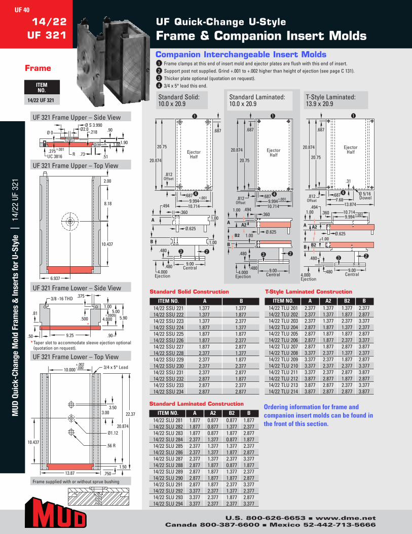
U.S. 800-626-6653 n www.dme.netCanada 800-387-6600 n Mexico 52-442-713-5666
UF Quick-Change U-Style
Frame & Companion Insert Molds14/22
UF 321
Frame
ITEM NO.
14/22 UF 321 StandardSolid:10.0x20.9
Companion Interchangeable Insert Molds1 Frameclampsatthisendofinsertmoldandejectorplatesareflushwiththisendofinsert.2 Supportpostnotsupplied.Grind+.001to+.002higherthanheightofejection(seepageC131).3 Thickerplateoptional(quotationonrequest).4 3/4x5°leadthisend.
T-StyleLaminated:13.9x20.9
StandardLaminated:10.0x20.9
20.75
20.874
10.714 9.994
.687
.494 .360
±.001
.687
.812 Offset
4.000 Ejection
1.00
Ø.625
.480
.480
1.00
9.00 Central
2 3
1
4
A
B
Ejector Half
Ejector Half
9.994 ±.001
1.00
20.75
20.874
.812 Offset
10.714
.360
Ø.625
.494
1.00
.480
.480
9.00 Central
.687
2 3
4
1
.687
A2 A
B
B2
4.000 Ejection
1.00 .494
.360
Ø.625 1.00
20.75
20.874
.812 Offset
13.874
9.00 Central
9.994 ±.001 10.714
.687
.31
7.68 Ø 5/16 Dowel
.480
.480
2 3
4
1
.687
A2 A
B B2
Ejector Half
4.000Ejection
UF321FrameUpper–SideView
UF321FrameUpper–TopView
UF321FrameLower–SideView
UF321FrameLower–TopView
Ø S 3.990Ø2.0
Ø 0
.73
.218
1.00
.90
.51R
1.90
UC 3816.275 ±.001
6.937
2.00
8.18
10.437
22.37
20.874
3.003.50
Ø1.12
10.437
10.000 3/4 x 5° Lead+.002-.000
13.87 .7501.50
.56 R
.81
.50 9.25
3/8 -16 THD
.500
1.00
±.00054.000
5.005.90
.90
*
.375
Framesuppliedwithorwithoutspruebushing
* Taperslottoaccommodatesleeveejectionoptional(quotationonrequest).
ITEM NO. A A2 B2 B14/22SLU281 1.877 0.877 0.877 1.87714/22SLU282 1.877 0.877 1.377 2.37714/22SLU283 1.877 0.877 1.877 2.87714/22SLU284 2.377 1.377 0.877 1.87714/22SLU285 2.377 1.377 1.377 2.37714/22SLU286 2.377 1.377 1.877 2.87714/22SLU287 2.377 1.377 2.377 3.37714/22SLU288 2.877 1.877 0.877 1.87714/22SLU289 2.877 1.877 1.377 2.37714/22SLU290 2.877 1.877 1.877 2.87714/22SLU291 2.877 1.877 2.377 3.37714/22SLU292 3.377 2.377 1.377 2.37714/22SLU293 3.377 2.377 1.877 2.87714/22SLU294 3.377 2.377 2.377 3.377
ITEM NO. A A2 B2 B14/22TLU201 2.377 1.377 1.377 2.37714/22TLU202 2.377 1.377 1.877 2.87714/22TLU203 2.377 1.377 2.377 3.37714/22TLU204 2.877 1.877 1.377 2.37714/22TLU205 2.877 1.877 1.877 2.87714/22TLU206 2.877 1.877 2.377 3.37714/22TLU207 2.877 1.877 2.877 3.87714/22TLU208 3.377 2.377 1.377 2.37714/22TLU209 3.377 2.377 1.877 2.87714/22TLU210 3.377 2.377 2.377 3.37714/22TLU211 3.377 2.377 2.877 3.87714/22TLU212 3.877 2.877 1.877 2.87714/22TLU213 3.877 2.877 2.377 3.37714/22TLU214 3.877 2.877 2.877 3.877
ITEM NO. A B14/22SSU221 1.377 1.37714/22SSU222 1.377 1.87714/22SSU223 1.377 2.37714/22SSU224 1.877 1.37714/22SSU225 1.877 1.87714/22SSU226 1.877 2.37714/22SSU227 1.877 2.87714/22SSU228 2.377 1.37714/22SSU229 2.377 1.87714/22SSU230 2.377 2.37714/22SSU231 2.377 2.87714/22SSU232 2.877 1.87714/22SSU233 2.877 2.37714/22SSU234 2.877 2.877
Standard Solid Construction
Standard Laminated Construction
T-Style Laminated Construction
Ordering information for frame and companion insert molds can be found in the front of this section.
UF 40M
UD Q
uick
-Cha
nge
Mol
d Fr
ames
& In
sert
s fo
r U-
Styl
e |
14/
22 U
F 32
1

U.S. 800-626-6653 n www.dme.netCanada 800-387-6600 n Mexico 52-442-713-5666
* Taperslottoaccommodatesleeveejectionoptional(quotationonrequest).
UF321FrameUpper–SideView
UF321FrameUpper–TopView
UF321FrameLower–SideView
UF321FrameLower–TopView
ØS 3.990Ø2.0
Ø 0 .218
1.501.37
.76
2.87
UC 5013.750 ±.001
1.15R
7.937
2.00
7.937
17.75
15.874
3.003.50
Ø1.127.937
11.000 3/4 x 5° Lead
.56 R
+.002-.000
15.87 .750
1.87
.81
.5010.00
1/2-13 THD
.750
1.50
±.00055.000
6.507.87
1.37
.470
*
Framesuppliedwithorwithoutspruebushing
16/18UF 321
Frame
ITEM NO.
16/18 UF 321StandardSolid:11.0x15.9
T-StyleLaminated:15.9x15.9
StandardLaminated:11.0x15.9
1
2
3
4
15.75 15.874
11.894 10.994
.687
.744
A
.450
±.001
.687
.812 Offset
B
5.000 Ejection
1.50
Ø .625
.600
.600 1.50
9.75 Central
Ejector Half
1
2 3
4
Ejector Half
10.994 ±.001
5.000 Ejection
15.75
15.874
.812 Offset
.687
11.894
1.50
.600
.600
B2
9.75 Central
.687
1.50 A2
.450
Ø .625
.744
A
B
1
4
Ejector Half
B
5.000 Ejection
15.75
15.874 .812
Offset
.687
1.50 B2
15.874
9.75 Central
A
1.50.744
.450
Ø .625A2
10.994 ±.001
11.894
.687
.31
8.68 Ø 5/16
.600
.600
2
3
Dowel
Companion Interchangeable Insert Molds1 Frameclampsatthisendofinsertmoldandejectorplatesareflushwiththisendofinsert. 2 Supportpostnotsupplied.Grind+.001to+.002higherthanheightofejection(seepageC131). 3 Thickerplateoptional(quotationonrequest).4 3/4x5°leadthisend.
ITEM NO. A A2 B2 B16/18SLU281 2.877 1.377 1.377 2.87716/18SLU282 2.877 1.377 1.877 3.37716/18SLU283 2.877 1.377 2.377 3.87716/18SLU284 3.377 1.877 1.377 2.87716/18SLU285 3.377 1.877 1.877 3.37716/18SLU286 3.377 1.877 2.377 3.87716/18SLU287 3.377 1.877 2.877 4.37716/18SLU288 3.877 2.377 1.377 2.87716/18SLU289 3.877 2.377 1.877 3.37716/18SLU290 3.877 2.377 2.377 3.87716/18SLU291 3.877 2.377 2.877 4.37716/18SLU292 4.377 2.877 1.877 3.37716/18SLU293 4.377 2.877 2.377 3.87716/18SLU294 4.377 2.877 2.877 4.37716/18SLU295 4.877 3.377 3.377 4.877
ITEM NO. A A2 B2 B16/18TLU201 2.877 1.377 1.377 2.87716/18TLU202 2.877 1.377 1.877 3.37716/18TLU203 2.877 1.377 2.377 3.87716/18TLU204 3.377 1.877 1.377 2.87716/18TLU205 3.377 1.877 1.877 3.37716/18TLU206 3.377 1.877 2.377 3.87716/18TLU207 3.377 1.877 2.877 4.37716/18TLU208 3.877 2.377 1.377 2.87716/18TLU209 3.877 2.377 1.877 3.37716/18TLU210 3.877 2.377 2.377 3.87716/18TLU211 3.877 2.377 2.877 4.37716/18TLU212 4.377 2.877 1.877 3.37716/18TLU213 4.377 2.877 2.377 3.87716/18TLU214 4.377 2.877 2.877 4.37716/18TLU215 4.877 3.377 3.377 4.877
ITEM NO. A B16/18SSU221 1.877 1.87716/18SSU222 1.877 2.37716/18SSU223 1.877 2.87716/18SSU224 1.877 3.37716/18SSU225 2.377 1.87716/18SSU226 2.377 2.37716/18SSU227 2.377 2.87716/18SSU228 2.377 3.37716/18SSU229 2.877 1.87716/18SSU230 2.877 2.37716/18SSU231 2.877 2.87716/18SSU232 2.877 3.37716/18SSU233 3.377 1.87716/18SSU234 3.377 2.37716/18SSU235 3.377 2.87716/18SSU236 3.377 3.377
Standard Solid Construction
Standard Laminated Construction
T-Style Laminated Construction
Ordering information for frame and companion insert molds can be found in the front of this section.
UF 41M
UD Quick-Change M
old Frames &
Inserts for U-Style | 16/18 UF 321
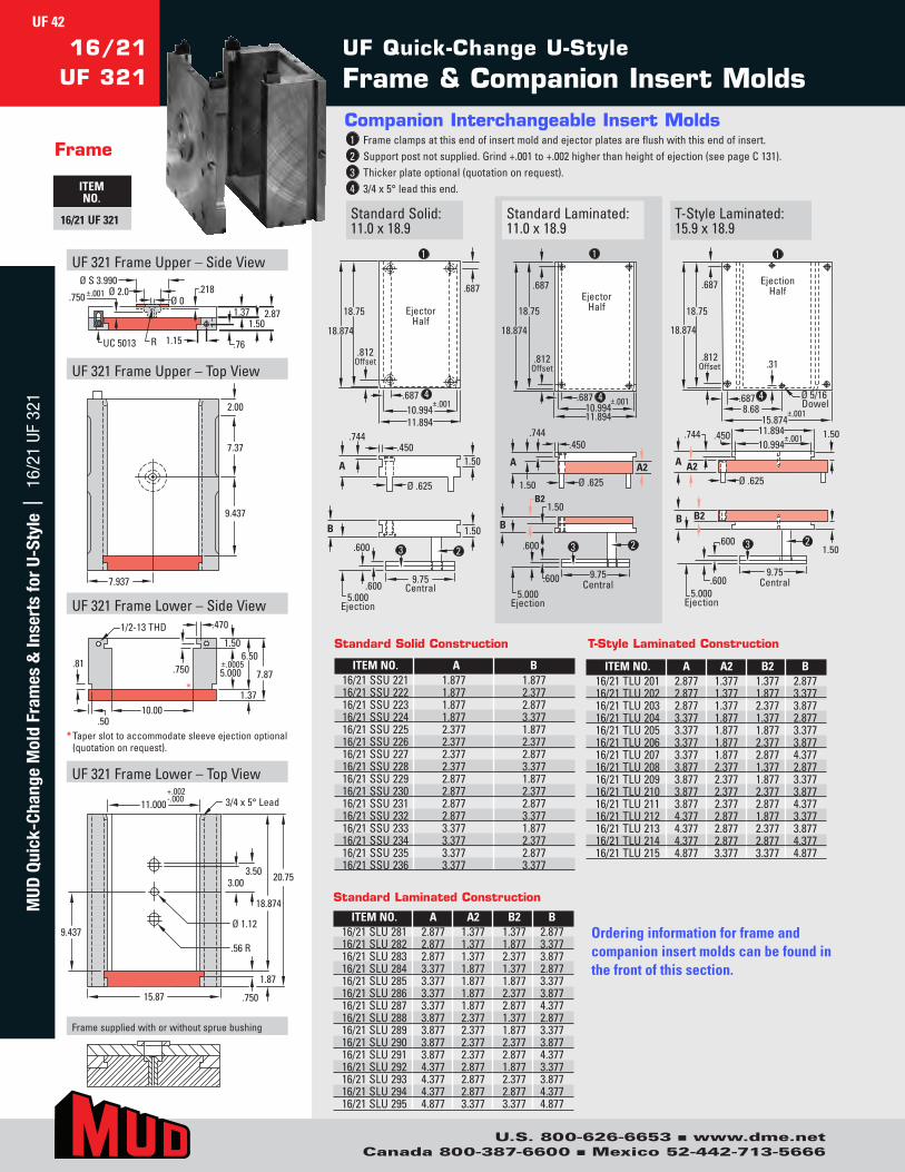
U.S. 800-626-6653 n www.dme.netCanada 800-387-6600 n Mexico 52-442-713-5666
UF Quick-Change U-Style
Frame & Companion Insert Molds16/21
UF 321
Frame
ITEM NO.
16/21 UF 321 StandardSolid:11.0x18.9
Companion Interchangeable Insert Molds1 Frameclampsatthisendofinsertmoldandejectorplatesareflushwiththisendofinsert.2 Supportpostnotsupplied.Grind+.001to+.002higherthanheightofejection(seepageC131).3 Thickerplateoptional(quotationonrequest).4 3/4x5°leadthisend.
T-StyleLaminated:15.9x18.9
StandardLaminated:11.0x18.9
Ejector Half
11.89410.994
.687 ±.001
.687
18.75
18.874
.812 Offset
A
.744 .450
1.50
Ø .625
B
5.000 Ejection
.600
.600
1.50
9.75 Central
2 3
1
4
Ejector Half
.687
18.75
18.874
.812 Offset
11.894 10.994
.687 ±.001
A A2
1.50
.450
Ø .625
.744
1
4
B
B2
5.000 Ejection
1.50
.600
.600
9.75 Central
3 2
A A2
B B2
Ø 5/16 Dowel
.744 .450
Ø .625
5.000 Ejection
9.75 Central
10.994
±.001
11.894
.600 1.50
1.50
.600
Ejection Half .687
18.75
18.874
.812 Offset
.687 8.68
15.874
.31
1
4
2 3
±.001
* Taperslottoaccommodatesleeveejectionoptional(quotationonrequest).
UF321FrameUpper–SideView
UF321FrameUpper–TopView
UF321FrameLower–SideView
UF321FrameLower–TopView
Ø S 3.990Ø 2.0
Ø 0
1.15
.218
1.501.37
.76
2.87
UC 5013
.750 ±.001
R
7.937
7.37
2.00
9.437
20.75
18.874
3.003.50
Ø 1.129.437
11.000 3/4 x 5° Lead
.56 R
+.002-.000
15.87 .750
1.87
.81
.5010.00
1/2-13 THD
.750
1.50
±.00055.000
6.50
7.87
1.37
.470
*
Framesuppliedwithorwithoutspruebushing
ITEM NO. A A2 B2 B16/21SLU281 2.877 1.377 1.377 2.87716/21SLU282 2.877 1.377 1.877 3.37716/21SLU283 2.877 1.377 2.377 3.87716/21SLU284 3.377 1.877 1.377 2.87716/21SLU285 3.377 1.877 1.877 3.37716/21SLU286 3.377 1.877 2.377 3.87716/21SLU287 3.377 1.877 2.877 4.37716/21SLU288 3.877 2.377 1.377 2.87716/21SLU289 3.877 2.377 1.877 3.37716/21SLU290 3.877 2.377 2.377 3.87716/21SLU291 3.877 2.377 2.877 4.37716/21SLU292 4.377 2.877 1.877 3.37716/21SLU293 4.377 2.877 2.377 3.87716/21SLU294 4.377 2.877 2.877 4.37716/21SLU295 4.877 3.377 3.377 4.877
ITEM NO. A A2 B2 B16/21TLU201 2.877 1.377 1.377 2.87716/21TLU202 2.877 1.377 1.877 3.37716/21TLU203 2.877 1.377 2.377 3.87716/21TLU204 3.377 1.877 1.377 2.87716/21TLU205 3.377 1.877 1.877 3.37716/21TLU206 3.377 1.877 2.377 3.87716/21TLU207 3.377 1.877 2.877 4.37716/21TLU208 3.877 2.377 1.377 2.87716/21TLU209 3.877 2.377 1.877 3.37716/21TLU210 3.877 2.377 2.377 3.87716/21TLU211 3.877 2.377 2.877 4.37716/21TLU212 4.377 2.877 1.877 3.37716/21TLU213 4.377 2.877 2.377 3.87716/21TLU214 4.377 2.877 2.877 4.37716/21TLU215 4.877 3.377 3.377 4.877
ITEM NO. A B16/21SSU221 1.877 1.87716/21SSU222 1.877 2.37716/21SSU223 1.877 2.87716/21SSU224 1.877 3.37716/21SSU225 2.377 1.87716/21SSU226 2.377 2.37716/21SSU227 2.377 2.87716/21SSU228 2.377 3.37716/21SSU229 2.877 1.87716/21SSU230 2.877 2.37716/21SSU231 2.877 2.87716/21SSU232 2.877 3.37716/21SSU233 3.377 1.87716/21SSU234 3.377 2.37716/21SSU235 3.377 2.87716/21SSU236 3.377 3.377
Standard Solid Construction
Standard Laminated Construction
T-Style Laminated Construction
Ordering information for frame and companion insert molds can be found in the front of this section.
UF 42M
UD Q
uick
-Cha
nge
Mol
d Fr
ames
& In
sert
s fo
r U-
Styl
e |
16/
21 U
F 32
1

U.S. 800-626-6653 n www.dme.netCanada 800-387-6600 n Mexico 52-442-713-5666
* Taperslottoaccommodatesleeveejectionoptional(quotationonrequest).
UF321FrameUpper–SideView
UF321FrameUpper–TopView
UF321FrameLower–SideView
UF321FrameLower–TopView
Ø S 3.990Ø 2.0
Ø 0
1.15
.218
1.501.37
.76
2.87
UC 5013
.750 ±.001
R
7.937
7.87
3.00
10.937
*
.81
.50 10.00
1/2-13 THD
.750
1.50
±.00055.000
6.507.87
1.37
.470
Framesuppliedwithorwithoutspruebushing
16/24UF 321
Frame
ITEM NO.
16/24 UF 321StandardSolid:11.0x21.9
T-StyleLaminated:15.9x21.9
StandardLaminated:11.0x21.9
Ejector Half
.687
21.75
21.874
.812 Offset
11.894 10.994
.687 ±.001
1
4
.744 .450
1.50
Ø .625
A
5.000 Ejection
.600
.600 1.50
9.75 Central
2 3
B
Ejector Half
.687
21.75 21.874
.812 Offset
11.894 10.994
.687 ±.001
.450
Ø .625
.744
1
4
A2 1.50
A
1.50
.600
.600 9.75
Central
3 2
B2
B
5.000 Ejection
.31
Ejector Half
Ø 5/16Dowel
.687
21.75
21.874
.812 Offset
.687 8.68
15.874
4
1
B2B
9.75 Central
.600 1.50
.600
2 3
5.000 Ejection
1.50
A2A
.744 .450
Ø .625
10.994 ±.001
11.894
Companion Interchangeable Insert Molds1 Frameclampsatthisendofinsertmoldandejectorplatesareflushwiththisendofinsert. 2 Supportpostnotsupplied.Grind+.001to+.002higherthanheightofejection(seepageC131). 3 Thickerplateoptional(quotationonrequest).4 3/4x5°leadthisend.
10.937
3/4 x 5° Lead11.000+.002-.000
15.87
23.75
21.874
3.003.50
Ø 1.12
.56 R
.750
1.87
ITEM NO. A A2 B2 B16/24SLU281 2.877 1.377 1.377 2.87716/24SLU282 2.877 1.377 1.877 3.37716/24SLU283 2.877 1.377 2.377 3.87716/24SLU284 3.377 1.877 1.377 2.87716/24SLU285 3.377 1.877 1.877 3.37716/24SLU286 3.377 1.877 2.377 3.87716/24SLU287 3.377 1.877 2.877 4.37716/24SLU288 3.877 2.377 1.377 2.87716/24SLU289 3.877 2.377 1.877 3.37716/24SLU290 3.877 2.377 2.377 3.87716/24SLU291 3.877 2.377 2.877 4.37716/24SLU292 4.377 2.877 1.877 3.37716/24SLU293 4.377 2.877 2.377 3.87716/24SLU294 4.377 2.877 2.877 4.37716/24SLU295 4.877 3.377 3.377 4.877
ITEM NO. A A2 B2 B16/24TLU201 2.877 1.377 1.377 2.87716/24TLU202 2.877 1.377 1.877 3.37716/24TLU203 2.877 1.377 2.377 3.87716/24TLU204 3.377 1.877 1.377 2.87716/24TLU205 3.377 1.877 1.877 3.37716/24TLU206 3.377 1.877 2.377 3.87716/24TLU207 3.377 1.877 2.877 4.37716/24TLU208 3.877 2.377 1.377 2.87716/24TLU209 3.877 2.377 1.877 3.37716/24TLU210 3.877 2.377 2.377 3.87716/24TLU211 3.877 2.377 2.877 4.37716/24TLU212 4.377 2.877 1.877 3.37716/24TLU213 4.377 2.877 2.377 3.87716/24TLU214 4.377 2.877 2.877 4.37716/24TLU215 4.877 3.377 3.377 4.877
ITEM NO. A B16/24SSU221 1.877 1.87716/24SSU222 1.877 2.37716/24SSU223 1.877 2.87716/24SSU224 1.877 3.37716/24SSU225 2.377 1.87716/24SSU226 2.377 2.37716/24SSU227 2.377 2.87716/24SSU228 2.377 3.37716/24SSU229 2.877 1.87716/24SSU230 2.877 2.37716/24SSU231 2.877 2.87716/24SSU232 2.877 3.37716/24SSU233 3.377 1.87716/24SSU234 3.377 2.37716/24SSU235 3.377 2.87716/24SSU236 3.377 3.377
Standard Solid Construction
Standard Laminated Construction
T-Style Laminated Construction
Ordering information for frame and companion insert molds can be found in the front of this section.
UF 43M
UD Quick-Change M
old Frames &
Inserts for U-Style | 16/24 UF 321

U.S. 800-626-6653 n www.dme.netCanada 800-387-6600 n Mexico 52-442-713-5666
UF Quick-Change U-Style
Frame & Companion Insert Molds16/27
UF 321
Frame
ITEM NO.
16/27 UF 321 StandardSolid:11.0x24.9
Companion Interchangeable Insert Molds1 Frameclampsatthisendofinsertmoldandejectorplatesareflushwiththisendofinsert.2 Supportpostnotsupplied.Grind+.001to+.002higherthanheightofejection(seepageC131).3 Thickerplateoptional(quotationonrequest).4 3/4x5°leadthisend.
T-StyleLaminated:15.9x24.9
StandardLaminated:11.0x24.9
5.000 Ejection
2 3
1
4
Ejector Half
.687
24.75
24.874
.812 Offset
11.894 10.994 .687 ±.001
.744 .450
Ø .625
.600
.600
1.50
9.75 Central
B
A 1.50
5.000 Ejection
2 3
1
4
Ejector Half
24.75
24.874
.812 Offset
.687
10.994 ±.001
11.894
.687
1.50
1.50
.600
.600 9.75 Central
B
.450
Ø .625
.744
A A2
B2
.31
2 3
1
4
Ejector Half
1.50
1.50
.744 .450
Ø .625
.812 Offset
15.874
9.75 Central
10.994 ±.001
11.894
.687 8.68
Ø 5/16Dowel
.600
.600
24.75
24.874
.687
B
A A2
B2
5.000 Ejection
* Taperslottoaccommodatesleeveejectionoptional(quotationonrequest).
UF321FrameUpper–SideView
UF321FrameUpper–TopView
UF321FrameLower–SideView
UF321FrameLower–TopView
1.15
.218
1.501.37
.76
2.87
UC 5013
.750 ±.001Ø S 3.990
Ø 2.0Ø 0
R
7.937
9.37
3.00
12.437
12.437
11.000 3/4 x 5° Lead+.002-.000
15.87
26.75
24.874
3.003.50
Ø 1.12
.56 R
.750
1.87
.81
.5010.00
1/2-13 THD
.750
1.50
±.00055.000
6.50
7.87
1.37
.470
*
Framesuppliedwithorwithoutspruebushing
ITEM NO. A A2 B2 B16/27SLU281 2.877 1.377 1.377 2.87716/27SLU282 2.877 1.377 1.877 3.37716/27SLU283 2.877 1.377 2.377 3.87716/27SLU284 3.377 1.877 1.377 2.87716/27SLU285 3.377 1.877 1.877 3.37716/27SLU286 3.377 1.877 2.377 3.87716/27SLU287 3.377 1.877 2.877 4.37716/27SLU288 3.877 2.377 1.377 2.87716/27SLU289 3.877 2.377 1.877 3.37716/27SLU290 3.877 2.377 2.377 3.87716/27SLU291 3.877 2.377 2.877 4.37716/27SLU292 4.377 2.877 1.877 3.37716/27SLU293 4.377 2.877 2.377 3.87716/27SLU294 4.377 2.877 2.877 4.37716/27SLU295 4.877 3.377 3.377 4.877
ITEM NO. A A2 B2 B16/27TLU201 2.877 1.377 1.377 2.87716/27TLU202 2.877 1.377 1.877 3.37716/27TLU203 2.877 1.377 2.377 3.87716/27TLU204 3.377 1.877 1.377 2.87716/27TLU205 3.377 1.877 1.877 3.37716/27TLU206 3.377 1.877 2.377 3.87716/27TLU207 3.377 1.877 2.877 4.37716/27TLU208 3.877 2.377 1.377 2.87716/27TLU209 3.877 2.377 1.877 3.37716/27TLU210 3.877 2.377 2.377 3.87716/27TLU211 3.877 2.377 2.877 4.37716/27TLU212 4.377 2.877 1.877 3.37716/27TLU213 4.377 2.877 2.377 3.87716/27TLU214 4.377 2.877 2.877 4.37716/27TLU215 4.877 3.377 3.377 4.877
ITEM NO. A B16/27SSU221 1.877 1.87716/27SSU222 1.877 2.37716/27SSU223 1.877 2.87716/27SSU224 1.877 3.37716/27SSU225 2.377 1.87716/27SSU226 2.377 2.37716/27SSU227 2.377 2.87716/27SSU228 2.377 3.37716/27SSU229 2.877 1.87716/27SSU230 2.877 2.37716/27SSU231 2.877 2.87716/27SSU232 2.877 3.37716/27SSU233 3.377 1.87716/27SSU234 3.377 2.37716/27SSU235 3.377 2.87716/27SSU236 3.377 3.377
Standard Solid Construction
Standard Laminated Construction
T-Style Laminated Construction
Ordering information for frame and companion insert molds can be found in the front of this section.
UF 44M
UD Q
uick
-Cha
nge
Mol
d Fr
ames
& In
sert
s fo
r U-
Styl
e |
16/
27 U
F 32
1
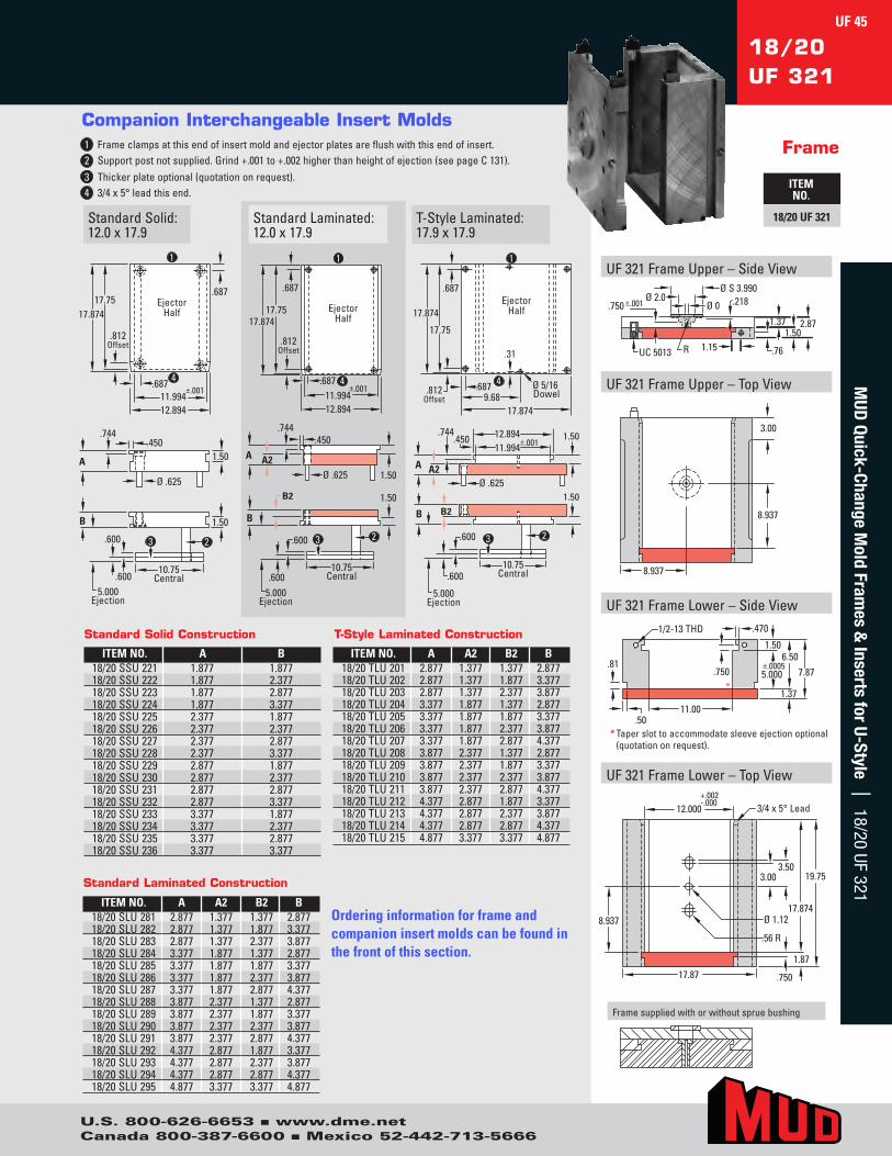
U.S. 800-626-6653 n www.dme.netCanada 800-387-6600 n Mexico 52-442-713-5666
* Taperslottoaccommodatesleeveejectionoptional(quotationonrequest).
UF321FrameUpper–SideView
UF321FrameUpper–TopView
UF321FrameLower–SideView
UF321FrameLower–TopView
Ø S 3.990Ø 2.0
Ø 0
R 1.15UC 5013
2.871.371.50
.76
.218.750 ±.001
8.937
8.937
3.00
17.87
8.937
19.75
17.874
3.003.50
Ø 1.12
.56 R
12.000 3/4 x 5° Lead+.002-.000
.750
1.87
.81
.5011.00
1/2-13 THD
.750
1.50
5.000
6.507.87
1.37
.470
*
±.0005
Framesuppliedwithorwithoutspruebushing
18/20UF 321
Frame
ITEM NO.
18/20 UF 321StandardSolid:12.0x17.9
T-StyleLaminated:17.9x17.9
StandardLaminated:12.0x17.9
Ejector Half
.687 17.75
17.874
.812 Offset
12.894 11.994
.687 ±.001
.744 .450
1.50
Ø .625
.600
.600
1.50
10.75 Central
5.000 Ejection
2 3
1
4
A
B
Ejector Half
17.75 17.874
.812 Offset
.687
11.994 ±.001
12.894
.687
1.50
1.50
.450
Ø .625
.744
.600
.600 10.75
Central
2 3
5.000 Ejection
A
B
A2
B2
1
4
.31
1.50
1.50
Ejector Half
.744 .450
Ø .625
17.75
17.874
.812 Offset
.687
17.874
10.75 Central
11.994 ±.00112.894
.687 9.68
Ø 5/16 Dowel
.600
.600
A
B
A2
B2
2 3
5.000 Ejection
4
1
Companion Interchangeable Insert Molds1 Frameclampsatthisendofinsertmoldandejectorplatesareflushwiththisendofinsert. 2 Supportpostnotsupplied.Grind+.001to+.002higherthanheightofejection(seepageC131). 3 Thickerplateoptional(quotationonrequest).4 3/4x5°leadthisend.
ITEM NO. A A2 B2 B18/20SLU281 2.877 1.377 1.377 2.87718/20SLU282 2.877 1.377 1.877 3.37718/20SLU283 2.877 1.377 2.377 3.87718/20SLU284 3.377 1.877 1.377 2.87718/20SLU285 3.377 1.877 1.877 3.37718/20SLU286 3.377 1.877 2.377 3.87718/20SLU287 3.377 1.877 2.877 4.37718/20SLU288 3.877 2.377 1.377 2.87718/20SLU289 3.877 2.377 1.877 3.37718/20SLU290 3.877 2.377 2.377 3.87718/20SLU291 3.877 2.377 2.877 4.37718/20SLU292 4.377 2.877 1.877 3.37718/20SLU293 4.377 2.877 2.377 3.87718/20SLU294 4.377 2.877 2.877 4.37718/20SLU295 4.877 3.377 3.377 4.877
ITEM NO. A A2 B2 B18/20TLU201 2.877 1.377 1.377 2.87718/20TLU202 2.877 1.377 1.877 3.37718/20TLU203 2.877 1.377 2.377 3.87718/20TLU204 3.377 1.877 1.377 2.87718/20TLU205 3.377 1.877 1.877 3.37718/20TLU206 3.377 1.877 2.377 3.87718/20TLU207 3.377 1.877 2.877 4.37718/20TLU208 3.877 2.377 1.377 2.87718/20TLU209 3.877 2.377 1.877 3.37718/20TLU210 3.877 2.377 2.377 3.87718/20TLU211 3.877 2.377 2.877 4.37718/20TLU212 4.377 2.877 1.877 3.37718/20TLU213 4.377 2.877 2.377 3.87718/20TLU214 4.377 2.877 2.877 4.37718/20TLU215 4.877 3.377 3.377 4.877
ITEM NO. A B18/20SSU221 1.877 1.87718/20SSU222 1.877 2.37718/20SSU223 1.877 2.87718/20SSU224 1.877 3.37718/20SSU225 2.377 1.87718/20SSU226 2.377 2.37718/20SSU227 2.377 2.87718/20SSU228 2.377 3.37718/20SSU229 2.877 1.87718/20SSU230 2.877 2.37718/20SSU231 2.877 2.87718/20SSU232 2.877 3.37718/20SSU233 3.377 1.87718/20SSU234 3.377 2.37718/20SSU235 3.377 2.87718/20SSU236 3.377 3.377
Standard Solid Construction
Standard Laminated Construction
T-Style Laminated Construction
Ordering information for frame and companion insert molds can be found in the front of this section.
UF 45M
UD Quick-Change M
old Frames &
Inserts for U-Style | 18/20 UF 321
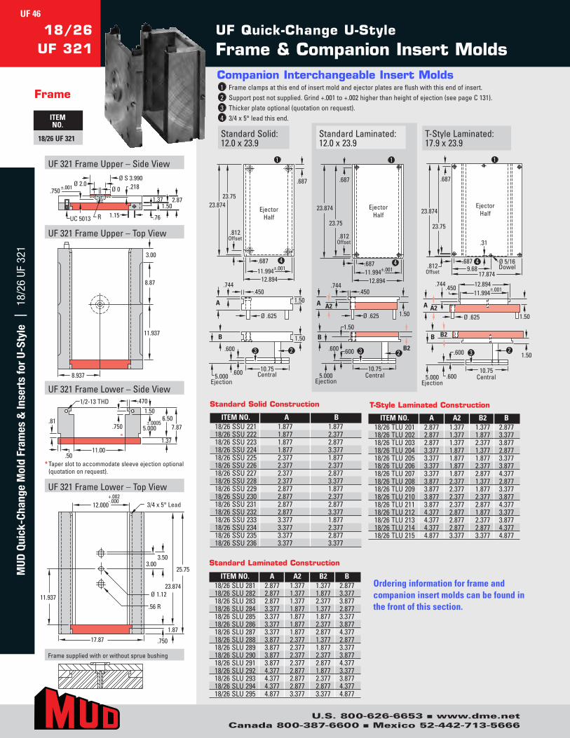
U.S. 800-626-6653 n www.dme.netCanada 800-387-6600 n Mexico 52-442-713-5666
UF Quick-Change U-Style
Frame & Companion Insert Molds18/26
UF 321
Frame
ITEM NO.
18/26 UF 321 StandardSolid:12.0x23.9
Companion Interchangeable Insert Molds1 Frameclampsatthisendofinsertmoldandejectorplatesareflushwiththisendofinsert.2 Supportpostnotsupplied.Grind+.001to+.002higherthanheightofejection(seepageC131).3 Thickerplateoptional(quotationonrequest).4 3/4x5°leadthisend.
T-StyleLaminated:17.9x23.9
StandardLaminated:12.0x23.9
23.75
12.894 11.994
23.874 Ejector
Half
.687
.744
A
.450
.687
.812 Offset
B
5.000 Ejection
1.50
Ø .625
.600
.600
1.50
10.75 Central
2 3
1
4 ±.001
23.75
23.874
12.894 11.994 .687
Ejector Half
±.001
.687
.812 Offset
A
B
5.000 Ejection
1.50 A2
.450
Ø .625
.744
1.50
.600 .600 B2
10.75 Central
2 3
1
4
23.75
23.874
.687
Ejector Half
A
1.50
1.50
.744 .450
Ø .625A2
B2B
5.000 Ejection
.812 Offset 17.874
10.75 Central
11.994 ±.001
12.894
.687 9.68
Ø 5/16
.600
.600
2 3
1
4
.31
Dowel
* Taperslottoaccommodatesleeveejectionoptional(quotationonrequest).
UF321FrameUpper–SideView
UF321FrameUpper–TopView
UF321FrameLower–SideView
UF321FrameLower–TopView
1.15UC 5013
2.871.371.50
.76
.218.750 ±.001
Ø S 3.990Ø 2.0
Ø 0
R
8.937
3.00
8.87
11.937
17.87
11.937
25.75
23.874
3.003.50
12.000 3/4 x 5° Lead+.002-.000
.750
1.87
Ø 1.12
.56 R
.81
.5011.00
1/2-13 THD
.750
1.50
±.00055.000
6.507.87
1.37
.470
*
Framesuppliedwithorwithoutspruebushing
ITEM NO. A A2 B2 B18/26SLU281 2.877 1.377 1.377 2.87718/26SLU282 2.877 1.377 1.877 3.37718/26SLU283 2.877 1.377 2.377 3.87718/26SLU284 3.377 1.877 1.377 2.87718/26SLU285 3.377 1.877 1.877 3.37718/26SLU286 3.377 1.877 2.377 3.87718/26SLU287 3.377 1.877 2.877 4.37718/26SLU288 3.877 2.377 1.377 2.87718/26SLU289 3.877 2.377 1.877 3.37718/26SLU290 3.877 2.377 2.377 3.87718/26SLU291 3.877 2.377 2.877 4.37718/26SLU292 4.377 2.877 1.877 3.37718/26SLU293 4.377 2.877 2.377 3.87718/26SLU294 4.377 2.877 2.877 4.37718/26SLU295 4.877 3.377 3.377 4.877
ITEM NO. A A2 B2 B18/26TLU201 2.877 1.377 1.377 2.87718/26TLU202 2.877 1.377 1.877 3.37718/26TLU203 2.877 1.377 2.377 3.87718/26TLU204 3.377 1.877 1.377 2.87718/26TLU205 3.377 1.877 1.877 3.37718/26TLU206 3.377 1.877 2.377 3.87718/26TLU207 3.377 1.877 2.877 4.37718/26TLU208 3.877 2.377 1.377 2.87718/26TLU209 3.877 2.377 1.877 3.37718/26TLU210 3.877 2.377 2.377 3.87718/26TLU211 3.877 2.377 2.877 4.37718/26TLU212 4.377 2.877 1.877 3.37718/26TLU213 4.377 2.877 2.377 3.87718/26TLU214 4.377 2.877 2.877 4.37718/26TLU215 4.877 3.377 3.377 4.877
ITEM NO. A B18/26SSU221 1.877 1.87718/26SSU222 1.877 2.37718/26SSU223 1.877 2.87718/26SSU224 1.877 3.37718/26SSU225 2.377 1.87718/26SSU226 2.377 2.37718/26SSU227 2.377 2.87718/26SSU228 2.377 3.37718/26SSU229 2.877 1.87718/26SSU230 2.877 2.37718/26SSU231 2.877 2.87718/26SSU232 2.877 3.37718/26SSU233 3.377 1.87718/26SSU234 3.377 2.37718/26SSU235 3.377 2.87718/26SSU236 3.377 3.377
Standard Solid Construction
Standard Laminated Construction
T-Style Laminated Construction
Ordering information for frame and companion insert molds can be found in the front of this section.
UF 46M
UD Q
uick
-Cha
nge
Mol
d Fr
ames
& In
sert
s fo
r U-
Styl
e |
18/
26 U
F 32
1
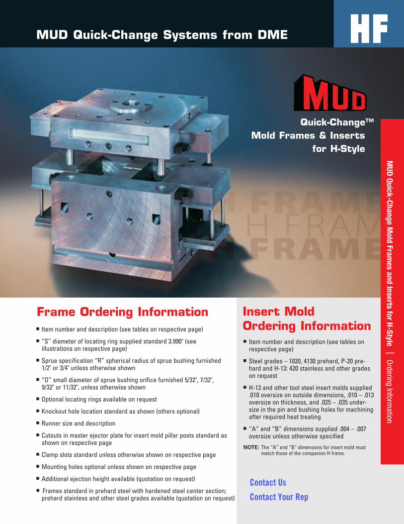
Frame Ordering Informationn Itemnumberanddescription(seetablesonrespectivepage)
n “S”diameteroflocatingringsuppliedstandard3.990"(seeillustrationsonrespectivepage)
n Spruespecification“R”sphericalradiusofspruebushingfurnished1/2"or3/4"unlessotherwiseshown
n “O”smalldiameterofspruebushingorificefurnished5/32",7/32",9/32"or11/32",unlessotherwiseshown
n Optionallocatingringsavailableonrequest
n Knockoutholelocationstandardasshown(othersoptional)
n Runnersizeanddescription
n Cutoutsinmasterejectorplateforinsertmoldpillarpostsstandardasshownonrespectivepage
n Clampslotsstandardunlessotherwiseshownonrespectivepage
n Mountingholesoptionalunlessshownonrespectivepage
n Additionalejectionheightavailable(quotationonrequest)
n Framesstandardinprehardsteelwithhardenedsteelcentersection;prehardstainlessandothersteelgradesavailable(quotationonrequest)
Insert MoldOrdering Informationn Itemnumberanddescription(seetableson
respectivepage)
n Steelgrades–1020,4130prehard,P-20pre-hardandH-13:420stainlessandothergradesonrequest
n H-13andothertoolsteelinsertmoldssupplied.010oversizeonoutsidedimensions,.010–.013oversizeonthickness,and.025–.035under-sizeinthepinandbushingholesformachiningafterrequiredheattreating
n “A”and“B”dimensionssupplied.004–.007oversizeunlessotherwisespecified
NOTE:The“A”and“B”dimensionsforinsertmoldmustmatchthoseofthecompanionHframe.
MUD Quick-Change Systems from DME
Quick-Change™ Mold Frames & Inserts
for H-Style
47M
UD Quick-Change M
old Frames and Inserts for H-Style | O
rdering Information
HF
Contact Us
Contact Your Rep
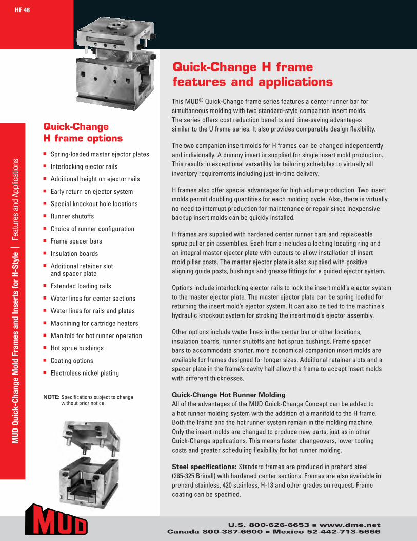
Quick-Change H frame features and applicationsThisMUD®Quick-Changeframeseriesfeaturesacenterrunnerbarforsimultaneousmoldingwithtwostandard-stylecompanioninsertmolds.Theseriesofferscostreductionbenefitsandtime-savingadvantagessimilartotheUframeseries.Italsoprovidescomparabledesignflexibility.
ThetwocompanioninsertmoldsforHframescanbechangedindependentlyandindividually.Adummyinsertissuppliedforsingleinsertmoldproduction.Thisresultsinexceptionalversatilityfortailoringschedulestovirtuallyallinventoryrequirementsincludingjust-in-timedelivery.
Hframesalsoofferspecialadvantagesforhighvolumeproduction.Twoinsertmoldspermitdoublingquantitiesforeachmoldingcycle.Also,thereisvirtuallynoneedtointerruptproductionformaintenanceorrepairsinceinexpensivebackupinsertmoldscanbequicklyinstalled.
Hframesaresuppliedwithhardenedcenterrunnerbarsandreplaceablespruepullerpinassemblies.Eachframeincludesalockinglocatingringandanintegralmasterejectorplatewithcutoutstoallowinstallationofinsertmoldpillarposts.Themasterejectorplateisalsosuppliedwithpositivealigningguideposts,bushingsandgreasefittingsforaguidedejectorsystem.
Optionsincludeinterlockingejectorrailstolocktheinsertmold’sejectorsystemtothemasterejectorplate.Themasterejectorplatecanbespringloadedforreturningtheinsertmold’sejectorsystem.Itcanalsobetiedtothemachine’shydraulicknockoutsystemforstrokingtheinsertmold’sejectorassembly.
Otheroptionsincludewaterlinesinthecenterbarorotherlocations,insulationboards,runnershutoffsandhotspruebushings.Framespacerbarstoaccommodateshorter,moreeconomicalcompanioninsertmoldsareavailableforframesdesignedforlongersizes.Additionalretainerslotsandaspacerplateintheframe’scavityhalfallowtheframetoacceptinsertmoldswithdifferentthicknesses.
Quick-ChangeHotRunnerMoldingAlloftheadvantagesoftheMUDQuick-ChangeConceptcanbeaddedtoahotrunnermoldingsystemwiththeadditionofamanifoldtotheHframe.Boththeframeandthehotrunnersystemremaininthemoldingmachine.Onlytheinsertmoldsarechangedtoproducenewparts,justasinotherQuick-Changeapplications.Thismeansfasterchangeovers,lowertoolingcostsandgreaterschedulingflexibilityforhotrunnermolding.
Steelspecifications:Standardframesareproducedinprehardsteel(285-325Brinell)withhardenedcentersections.Framesarealsoavailableinprehardstainless,420stainless,H-13andothergradesonrequest.Framecoatingcanbespecified.
Quick-Change H frame optionsn Spring-loadedmasterejectorplates
n Interlockingejectorrails
n Additionalheightonejectorrails
n Earlyreturnonejectorsystem
n Specialknockoutholelocations
n Runnershutoffs
n Choiceofrunnerconfiguration
n Framespacerbars
n Insulationboards
n Additionalretainerslotandspacerplate
n Extendedloadingrails
n Waterlinesforcentersections
n Waterlinesforrailsandplates
n Machiningforcartridgeheaters
n Manifoldforhotrunneroperation
n Hotspruebushings
n Coatingoptions
n Electrolessnickelplating
NOTE:Specificationssubjecttochangewithoutpriornotice.
HF 48
U.S. 800-626-6653 n www.dme.netCanada 800-387-6600 n Mexico 52-442-713-5666
MUD
Qui
ck-C
hang
e M
old
Fram
es a
nd In
sert
s fo
r H-
Styl
e |
Fea
ture
s an
d Ap
plic
atio
ns
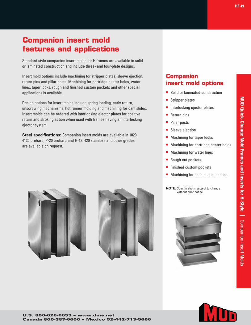
Companion insert mold features and applications
HF 49
StandardstylecompanioninsertmoldsforHframesareavailableinsolidorlaminatedconstructionandincludethree-andfour-platedesigns.
Insertmoldoptionsincludemachiningforstripperplates,sleeveejection,returnpinsandpillarposts.Machiningforcartridgeheaterholes,waterlines,taperlocks,roughandfinishedcustompocketsandotherspecialapplicationsisavailable.
Designoptionsforinsertmoldsincludespringloading,earlyreturn,unscrewingmechanisms,hotrunnermoldingandmachiningforcamslides.Insertmoldscanbeorderedwithinterlockingejectorplatesforpositivereturnandstrokingactionwhenusedwithframeshavinganinterlockingejectorsystem.
Steelspecifications:Companioninsertmoldsareavailablein1020,4130prehard,P-20prehardandH-13.420stainlessandothergradesareavailableonrequest.
Companioninsert mold optionsn Solidorlaminatedconstruction
n Stripperplates
n Interlockingejectorplates
n Returnpins
n Pillarposts
n Sleeveejection
n Machiningfortaperlocks
n Machiningforcartridgeheaterholes
n Machiningforwaterlines
n Roughcutpockets
n Finishedcustompockets
n Machiningforspecialapplications
NOTE:Specificationssubjecttochangewithoutpriornotice.
MUD
Quick-Change Mold Fram
es and Inserts for H-Style | Companion Insert M
olds
U.S. 800-626-6653 n www.dme.netCanada 800-387-6600 n Mexico 52-442-713-5666
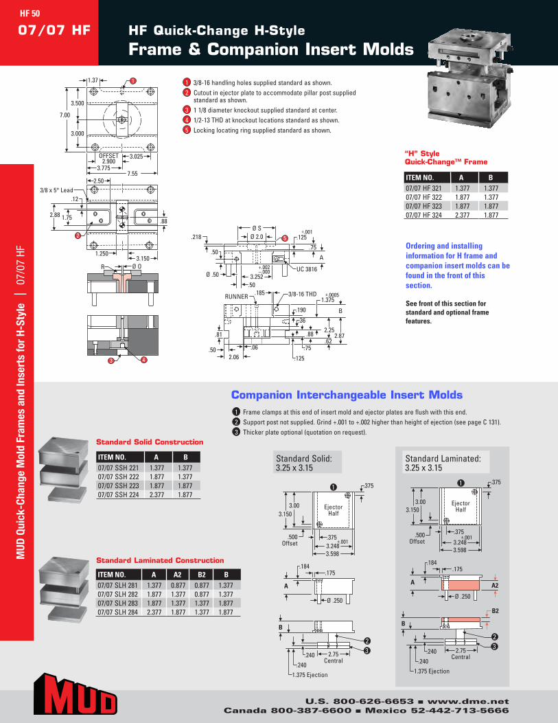
ITEM NO. A B07/07SSH221 1.377 1.37707/07SSH222 1.877 1.37707/07SSH223 1.877 1.87707/07SSH224 2.377 1.877
Standard Solid Construction
1 Frameclampsatthisendofinsertmoldandejectorplatesareflushwiththisend.2 Supportpostnotsupplied.Grind+.001to+.002higherthanheightofejection(seepageC131).3 Thickerplateoptional(quotationonrequest).
ITEM NO. A B07/07HF321 1.377 1.37707/07HF322 1.877 1.37707/07HF323 1.877 1.87707/07HF324 2.377 1.877
“H” Style Quick-Change™ Frame
3.500
3/8 x 5° Lead
3.000
2.88
7.553.775
3.1501.250
OFFSET2.900
3.025
1
2
3 4
7.00
1.37
5
Ø S.218 Ø 2.0
Ø .50
.75
3.252+.002–.000
.125±.001
A
UC 3816
.50
.50
R Ø O
3/8-16 THD.185RUNNER
.81
.502.06
.06
.190
.88
2.50
.12
1.75
B
±.0005
.125
.62.75
.88
.36
2.872.25
1.375
Ordering and installing information for H frame and companion insert molds can be found in the front of this section.
See front of this section for standard and optional frame features.
EjectorHalf
.375
3.003.150
.500Offset 3.248
3.598
±.001.375
1
1.375 Ejection
2.75Central
.175
A
.184
Ø .250
B
.240
.240
Ejector Half
.375
3.00 3.150
.500 Offset 3.248
3.598
±.001 .375
1.375 Ejection
2.75 Central
.175
A
.184
Ø .250
B
.240
.240
B2
A2
23
1
2 3
Ejector Half
.375
3.00 3.150
.500 Offset 3.248
3.598
±.001 .375
1
1.375 Ejection
2.75 Central
.175
A
.184
Ø .250
B
.240
.240
EjectorHalf
.375
3.003.150
.500Offset 3.248
3.598
±.001.375
1.375 Ejection
2.75Central
.175
A
.184
Ø .250
B
.240
.240
B2
A2
2 3
1
23
StandardSolid:3.25x3.15
StandardLaminated:3.25x3.15
Companion Interchangeable Insert Molds
3.500
3/8 x 5° Lead
3.000
2.88
7.553.775
3.1501.250
OFFSET2.900
3.025
1
2
3 4
7.00
1.37
5
Ø S.218 Ø 2.0
Ø .50
.75
3.252+.002–.000
.125±.001
A
UC 3816
.50
.50
R Ø O
3/8-16 THD.185RUNNER
.81
.502.06
.06
.190
.88
2.50
.12
1.75
B
±.0005
.125
.62.75
.88
.36
2.872.25
1.375
HF Quick-Change H-Style
Frame & Companion Insert Molds
1 3/8-16handlingholessuppliedstandardasshown.2 Cutoutinejectorplatetoaccommodatepillarpostsupplied
standardasshown.3 11/8diameterknockoutsuppliedstandardatcenter.4 1/2-13THDatknockoutlocationsstandardasshown.5 Lockinglocatingringsuppliedstandardasshown.
ITEM NO. A A2 B2 B07/07SLH281 1.377 0.877 0.877 1.37707/07SLH282 1.877 1.377 0.877 1.37707/07SLH283 1.877 1.377 1.377 1.87707/07SLH284 2.377 1.877 1.377 1.877
Standard Laminated ConstructionMUD
Qui
ck-C
hang
e M
old
Fram
es a
nd In
sert
s fo
r H-
Styl
e |
07/
07 H
FHF 50
U.S. 800-626-6653 n www.dme.netCanada 800-387-6600 n Mexico 52-442-713-5666
07/07 HF
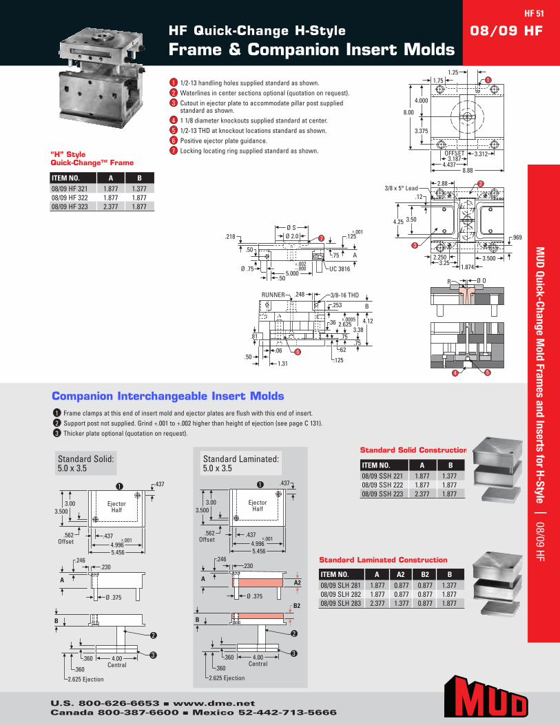
4.000
3/8 x 5° Lead
3.375
4.25
8.884.437
3.5003.25
1.874
OFFSET3.187
3.312
1
2
4 5
8.00
1.751.25
7
Ø S.218 Ø 2.0
Ø .75
.75
5.000+.002–.000
.125±.001
A
UC 3816
.50
.50
3/8-16 THD
B
±.0005
.248RUNNER
.81
.501.31
.06.125
.253
.75.62
.75
.36 4.123.38
2.625
2.250
.12
3.50
3.969
2.88
6
R Ø O
4.000
3/8 x 5° Lead
3.375
4.25
8.884.437
3.5003.25
1.874
OFFSET3.187
3.312
1
2
4 5
8.00
1.751.25
7
Ø S.218 Ø 2.0
Ø .75
.75
5.000+.002–.000
.125±.001
A
UC 3816
.50
.50
3/8-16 THD
B
±.0005
.248RUNNER
.81
.501.31
.06.125
.253
.75.62
.75
.36 4.123.38
2.625
2.250
.12
3.50
3.969
2.88
6
R Ø O
1 1/2-13handlingholessuppliedstandardasshown.2 Waterlinesincentersectionsoptional(quotationonrequest).3 Cutoutinejectorplatetoaccommodatepillarpostsupplied
standardasshown.4 11/8diameterknockoutssuppliedstandardatcenter.5 1/2-13THDatknockoutlocationsstandardasshown.6 Positiveejectorplateguidance.7 Lockinglocatingringsuppliedstandardasshown.
ITEM NO. A B08/09HF321 1.877 1.37708/09HF322 1.877 1.87708/09HF323 2.377 1.877
“H” Style Quick-Change™ Frame
ITEM NO. A B08/09SSH221 1.877 1.37708/09SSH222 1.877 1.87708/09SSH223 2.377 1.877
Standard Solid Construction
EjectorHalf
.437
3.003.500
.562Offset 4.996
5.456
±.001.437
2.625 Ejection
4.00Central
.230
A
.246
Ø .375
B
.360
.360
Ejector Half
.437
3.00 3.500
.562 Offset
4.996 5.456
±.001 .437
2.625 Ejection
4.00 Central
.230
A
.246
Ø .375
B
.360
.360
B2
A2
1
2
3
1
2
3
Ejector Half
.437
3.00 3.500
.562 Offset 4.996
5.456
±.001 .437
2.625 Ejection
4.00 Central
.230
A
.246
Ø .375
B
.360
.360
EjectorHalf
.437
3.003.500
.562Offset
4.9965.456
±.001.437
2.625 Ejection
4.00Central
.230
A
.246
Ø .375
B
.360
.360
B2
A2
1
2
3
1
2
3
StandardSolid:5.0x3.5
1 Frameclampsatthisendofinsertmoldandejectorplatesareflushwiththisendofinsert.2 Supportpostnotsupplied.Grind+.001to+.002higherthanheightofejection(seepageC131).3 Thickerplateoptional(quotationonrequest).
Companion Interchangeable Insert Molds
08/09 HFHF Quick-Change H-Style
Frame & Companion Insert Molds
StandardLaminated:5.0x3.5
ITEM NO. A A2 B2 B08/09SLH281 1.877 0.877 0.877 1.37708/09SLH282 1.877 0.877 0.877 1.87708/09SLH283 2.377 1.377 0.877 1.877
Standard Laminated Construction
HF 51M
UD Quick-Change M
old Frames and Inserts for H-Style | 08/09 HF
U.S. 800-626-6653 n www.dme.netCanada 800-387-6600 n Mexico 52-442-713-5666
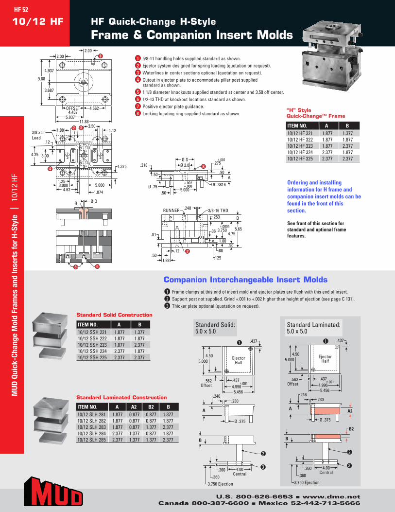
ITEM NO. A B10/12SSH221 1.877 1.37710/12SSH222 1.877 1.87710/12SSH223 1.877 2.37710/12SSH224 2.377 1.87710/12SSH225 2.377 2.377
Standard Solid Construction
1 Frameclampsatthisendofinsertmoldandejectorplatesareflushwiththisendofinsert.2 Supportpostnotsupplied.Grind+.001to+.002higherthanheightofejection(seepageC131).3 Thickerplateoptional(quotationonrequest).
4.937
3/8 x 5° Lead
3.687
4.25
11.885.937
5.0004.62 1.874
OFFSET4.437
4.562
1
5 6
9.88
2.002.00
8
Ø S.218 Ø 2.0
Ø .75
.90
5.000+.002–.000
.275±.001
AUC 3816
.50
.50
3/8-16 THD
B
±.0005
.248RUNNER
.81
.501.88
.12.125
.253
.90.88
1.00
.36 5.654.75
3.750
3.000
1.88
.12
3.00
4 1.375
1.25
3.50
7
32 1.12
R Ø O
Ejector Half
.437
4.50 5.000
.562 Offset 4.996
5.456
±.001 .437
.230
A
.246
Ø .375
3.750 Ejection
4.00 Central
B
.360
.360
B2
A2
EjectorHalf
.437
4.505.000
.562Offset 4.996
5.456
±.001.437
.230
A
.246
Ø .375
3.750 Ejection
4.00Central
B
.360
.360
1
2
3
1
2
3
EjectorHalf
.437
4.505.000
.562Offset 4.996
5.456
±.001.437
.230
A
.246
Ø .375
3.750 Ejection
4.00Central
B
.360
.360
B2
A2
Ejector Half
.437
4.50 5.000
.562 Offset 4.996
5.456
±.001 .437
.230
A
.246
Ø .375
3.750 Ejection
4.00 Central
B
.360
.360
1
2
3
1
2
3
StandardSolid:5.0x5.0
StandardLaminated:5.0x5.0
Companion Interchangeable Insert Molds
1 5/8-11handlingholessuppliedstandardasshown.2 Ejectorsystemdesignedforspringloading(quotationonrequest).3 Waterlinesincentersectionsoptional(quotationonrequest).4 Cutoutinejectorplatetoaccommodatepillarpostsupplied
standardasshown.5 11/8diameterknockoutssuppliedstandardatcenterand3.50offcenter.6 1/2-13THDatknockoutlocationsstandardasshown.7 Positiveejectorplateguidance.8 Lockinglocatingringsuppliedstandardasshown.
4.937
3/8 x 5°Lead
3.687
4.25
11.885.937
5.0004.62 1.874
OFFSET4.437
4.562
1
5 6
9.88
2.002.00
8
Ø S.218 Ø 2.0
Ø .75
.90
5.000+.002–.000
.275±.001
AUC 3816
.50
.50
3/8-16 THD
B
±.0005
.248RUNNER
.81
.501.88
.12.125
.253
.90.88
1.00
.36 5.654.75
3.750
3.000
1.88
.12
3.00
4 1.375
1.25
3.50
7
32 1.12
R Ø O
HF Quick-Change H-Style
Frame & Companion Insert Molds10/12 HF
Ordering and installing information for H frame and companion insert molds can be found in the front of this section.
See front of this section for standard and optional frame features.
ITEM NO. A B10/12HF321 1.877 1.37710/12HF322 1.877 1.87710/12HF323 1.877 2.37710/12HF324 2.377 1.87710/12HF325 2.377 2.377
“H” Style Quick-Change™ Frame
ITEM NO. A A2 B2 B10/12SLH281 1.877 0.877 0.877 1.37710/12SLH282 1.877 0.877 0.877 1.87710/12SLH283 1.877 0.877 1.377 2.37710/12SLH284 2.377 1.377 0.877 1.87710/12SLH285 2.377 1.377 1.377 2.377
Standard Laminated Construction
HF 52M
UD Q
uick
-Cha
nge
Mol
d Fr
ames
and
Inse
rts
for
H-St
yle
| 1
0/12
HF
U.S. 800-626-6653 n www.dme.netCanada 800-387-6600 n Mexico 52-442-713-5666
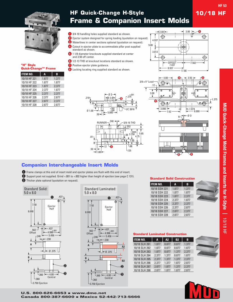
4.937
3/8 x 5° Lead
3.812
4.25
17.888.937
8.0007.621.874
OFFSET7.437
7.562
1
5 6
9.88
2.00 3.00
8
Ø S.218 Ø 2.0
Ø 1.00
.90
5.000+.002–.000
.275±.001
AUC 3816
.50
.50
3/8-16 THD
B
±.0005
.248RUNNER
.81
.501.88
.12.125
.253
.90.88
1.00
.36 5.654.75
3.750
3.000
4.88
3.00
.12
41.375
3.50
7
3 2
R Ø O
4.937
3/8 x 5° Lead
3.812
4.25
17.888.937
8.0007.621.874
OFFSET7.437
7.562
1
5 6
9.88
2.00 3.00
8
Ø S.218 Ø 2.0
Ø 1.00
.90
5.000+.002–.000
.275±.001
AUC 3816
.50
.50
3/8-16 THD
B
±.0005
.248RUNNER
.81
.501.88
.12.125
.253
.90.88
1.00
.36 5.654.75
3.750
3.000
4.88
3.00
.12
41.375
3.50
7
3 2
R Ø O
ITEM NO. A B10/18HF321 1.877 1.37710/18HF322 1.877 1.87710/18HF323 1.877 2.37710/18HF324 2.377 1.87710/18HF325 2.377 2.37710/18HF326 2.377 2.87710/18HF327 2.877 2.37710/18HF328 2.877 2.877
“H” Style Quick-Change™ Frame
Ejector Half
.437
7.50
8.000
.562 Offset 4.996
5.456
±.001 .437
.230
A
.246
Ø .375
3.750 Ejection
4.00 Central
B
.360
.360
B2
A2
EjectorHalf
.437
7.50
8.000
.562Offset 4.996
5.456
±.001.437
.230
A
.246
Ø .375
3.750 Ejection
4.00Central
B
.360
.360
1
2
3
1
2
3
ITEM NO. A B10/18SSH221 1.877 1.37710/18SSH222 1.877 1.87710/18SSH223 1.877 2.37710/18SSH224 2.377 1.87710/18SSH225 2.377 2.37710/18SSH226 2.377 2.87710/18SSH227 2.877 2.37710/18SSH228 2.877 2.877
Standard Solid Construction
EjectorHalf
.437
7.50
8.000
.562Offset 4.996
5.456
±.001.437
.230
A
.246
Ø .375
3.750 Ejection
4.00Central
B
.360
.360
B2
A2
Ejector Half
.437
7.50
8.000
.562 Offset 4.996
5.456
±.001 .437
.230
A
.246
Ø .375
3.750 Ejection
4.00 Central
B
.360
.360
1
2
3
1
2
3
StandardSolid:5.0x8.0
StandardLaminated:5.0x8.0
1 Frameclampsatthisendofinsertmoldandejectorplatesareflushwiththisendofinsert.2 Supportpostnotsupplied.Grind+.001to+.002higherthanheightofejection(seepageC131).3 Thickerplateoptional(quotationonrequest).
Companion Interchangeable Insert Molds
HF Quick-Change H-Style
Frame & Companion Insert Molds
1 3/4-10handlingholessuppliedstandardasshown.2 Ejectorsystemdesignedforspringloading(quotationonrequest).3 Waterlinesincentersectionsoptional(quotationonrequest).4 Cutoutinejectorplatetoaccommodatepillarpostsupplied
standardasshown.5 11/8diameterknockoutssuppliedstandardatcenter
and3.50offcenter.6 1/2-13THDatknockoutlocationsstandardasshown.7 Positiveejectorplateguidance.8 Lockinglocatingringsuppliedstandardasshown.
10/18 HF
ITEM NO. A A2 B2 B10/18SLH281 1.877 0.877 0.877 1.37710/18SLH282 1.877 0.877 0.877 1.87710/18SLH283 1.877 0.877 1.377 2.37710/18SLH284 2.377 1.377 0.877 1.87710/18SLH285 2.377 1.377 1.377 2.37710/18SLH286 2.377 1.377 1.877 2.87710/18SLH287 2.877 1.877 1.377 2.37710/18SLH288 2.877 1.877 1.877 2.877
Standard Laminated Construction
U.S. 800-626-6653 n www.dme.netCanada 800-387-6600 n Mexico 52-442-713-5666
MUD
Quick-Change Mold Fram
es and Inserts for H-Style | 10/18 HFHF 53
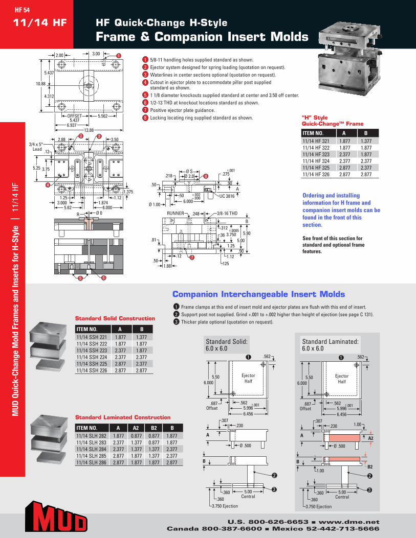
HF Quick-Change H-Style
Frame & Companion Insert Molds11/14 HF
4
5.25 3.75
1.375
3.0001.25
5.62
2.88 3.50
6.0001.874
1.12
32
3/4 x 5°Lead .12
OFFSET5.437
5.562
10.88
5.437
4.312
2.00
6.93713.88
3.00 1
Ø 0R
Ø SØ 2.0
6.000+.002–.000
.50A
Ø 1.00
.50
.218 .275
.90
±.001
UC 3816
8
3/8-16 THDRUNNER
.81
.248
.501.88
.12
.312
.90
5.905.00
B
.1251.12
1.25
.36±.0005
3.750
7
65
Ordering and installing information for H frame and companion insert molds can be found in the front of this section.
See front of this section for standard and optional frame features.
ITEM NO. A B11/14HF321 1.877 1.37711/14HF322 1.877 1.87711/14HF323 2.377 1.87711/14HF324 2.377 2.37711/14HF325 2.877 2.37711/14HF326 2.877 2.877
Ejector Half
.687 Offset
.562
6.000
.562 ±.001 5.996 6.456
5.50 Ejector Half
.687 Offset
.562
6.000
.562 ±.001 5.996 6.456
5.50
A A2
Ø .500
.230 1.00 .307
A
Ø .500
.230 .307
5.00 Central
1.00
B
.360 .360
3.750 Ejection
B2
5.00 Central
B
.360 .360
3.750 Ejection
1 1
2
3
2
3
Ejector Half
.687 Offset
.562
6.000
.562 ±.001 5.996 6.456
5.50 Ejector Half
.687 Offset
.562
6.000
.562 ±.001 5.996 6.456
5.50
A A2
Ø .500
.230 1.00 .307
A
Ø .500
.230 .307
5.00 Central
1.00
B
.360 .360
3.750 Ejection
B2
5.00 Central
B
.360 .360
3.750 Ejection
1 1
2
3
2
3
StandardSolid:6.0x6.0
StandardLaminated:6.0x6.0
1 Frameclampsatthisendofinsertmoldandejectorplatesareflushwiththisendofinsert.2 Supportpostnotsupplied.Grind+.001to+.002higherthanheightofejection(seepageC131).3 Thickerplateoptional(quotationonrequest).
Companion Interchangeable Insert Molds
1 5/8-11handlingholessuppliedstandardasshown.2 Ejectorsystemdesignedforspringloading(quotationonrequest).3 Waterlinesincentersectionsoptional(quotationonrequest).4 Cutoutinejectorplatetoaccommodatepillarpostsupplied
standardasshown.5 11/8diameterknockoutssuppliedstandardatcenterand3.50offcenter.6 1/2-13THDatknockoutlocationsstandardasshown.7 Positiveejectorplateguidance.8 Lockinglocatingringsuppliedstandardasshown. “H” Style
Quick-Change™ Frame
4
5.25 3.75
1.375
3.0001.25
5.62
2.88 3.50
6.0001.874
1.12
32
3/4 x 5°Lead .12
OFFSET5.437
5.562
10.88
5.437
4.312
2.00
6.93713.88
3.00 1
Ø 0R
Ø SØ 2.0
6.000+.002–.000
.50A
Ø 1.00
.50
.218 .275
.90
±.001
UC 3816
8
3/8-16 THDRUNNER
.81
.248
.501.88
.12
.312
.90
5.905.00
B
.1251.12
1.25
.36±.0005
3.750
7
65
ITEM NO. A B11/14SSH221 1.877 1.37711/14SSH222 1.877 1.87711/14SSH223 2.377 1.87711/14SSH224 2.377 2.37711/14SSH225 2.877 2.37711/14SSH226 2.877 2.877
Standard Solid Construction
ITEM NO. A A2 B2 B11/14SLH282 1.877 0.877 0.877 1.87711/14SLH283 2.377 1.377 0.877 1.87711/14SLH284 2.377 1.377 1.377 2.37711/14SLH285 2.877 1.877 1.377 2.37711/14SLH286 2.877 1.877 1.877 2.877
Standard Laminated ConstructionMUD
Qui
ck-C
hang
e M
old
Fram
es a
nd In
sert
s fo
r H-
Styl
e |
11/
14 H
F
U.S. 800-626-6653 n www.dme.netCanada 800-387-6600 n Mexico 52-442-713-5666
HF 54

HF Quick-Change H-Style
Frame & Companion Insert Molds11/18 HF
4
5.25 3.75
1.375
3.0007.62
4.88 3.50
8.0001.874
3 2
3/4 x 5° Lead
.12
OFFSET7.437
7.562
10.88
5.437
4.312
2.00
8.93717.88
3.00
Ø 0
Ø SØ 2.0
6.000+.002–.000
.50A
Ø 1.00
.50
.218 .275
.90
±.001
UC 3816
8
65
3/8-16 THDRUNNER
.81
.248
.501.88
.12
.312
.90
5.905.00
B
.1251.12
1.25
.36±.0005
3.750
7
1
R
4
5.25 3.75
1.375
3.0007.62
4.88 3.50
8.0001.874
3 2
3/4 x 5° Lead
.12
OFFSET7.437
7.562
10.88
5.437
4.312
2.00
8.93717.88
3.00
Ø 0
Ø SØ 2.0
6.000+.002–.000
.50A
Ø 1.00
.50
.218 .275
.90
±.001
UC 3816
8
65
3/8-16 THDRUNNER
.81
.248
.501.88
.12
.312
.90
5.905.00
B
.1251.12
1.25
.36±.0005
3.750
7
1
R
1 5/8-11handlingholessuppliedstandardasshown.2 Ejectorsystemdesignedforspringloading(quotationonrequest).3 Waterlinesincentersectionsoptional(quotationonrequest).4 Cutoutinejectorplatetoaccommodatepillarpostsupplied
standardasshown.5 11/8diameterknockoutssuppliedstandardatcenterand3.50offcenter.6 1/2-13THDatknockoutlocationsstandardasshown.7 Positiveejectorplateguidance.8 Lockinglocatingringsuppliedstandardasshown.
Ejector Half
.687 Offset
.562
8.000
.562 ±.001 5.996 6.456
7.50 Ejector Half
.687 Offset
.562
8.000
.562 ±.001 5.996 6.456
7.50
A A2
Ø .500
.230 1.00 .307
A
Ø .500
.230 .307
5.00 Central
1.00
B
.360 .360
3.750 Ejection
B2
5.00 Central
B
.360 .360
3.750 Ejection
1
2
3
1
2
3
Ejector Half
.687 Offset
.562
8.000
.562 ±.001 5.996 6.456
7.50 Ejector Half
.687 Offset
.562
8.000
.562 ±.001 5.996 6.456
7.50
A A2
Ø .500
.230 1.00 .307
A
Ø .500
.230 .307
5.00 Central
1.00
B
.360 .360
3.750 Ejection
B2
5.00 Central
B
.360 .360
3.750 Ejection
1
2
3
1
2
3
StandardSolid:6.0x8.0
1 Frameclampsatthisendofinsertmoldandejectorplatesareflushwiththisendofinsert.2 Supportpostnotsupplied.Grind+.001to+.002higherthanheightofejection(seepageC131).3 Thickerplateoptional(quotationonrequest).
Companion Interchangeable Insert Molds
StandardLaminated:6.0x8.0 ITEM NO. A B
Standard Solid Construction
ITEM NO. A A2 B2 B
Standard Laminated Construction
11/18SLH281 1.877 0.877 0.877 1.87711/18SLH282 2.377 1.377 0.877 1.87711/18SLH283 2.377 1.377 1.377 2.37711/18SLH284 2.877 1.877 1.377 2.37711/18SLH285 2.877 1.877 1.877 2.877
11/18SSH221 1.877 1.87711/18SSH222 2.377 1.87711/18SSH223 2.377 2.37711/18SSH224 2.877 2.37711/18SSH225 2.877 2.877
“H” Style Quick-Change™ Frame
ITEM NO. A B11/18HF321 1.877 1.87711/18HF322 2.377 1.87711/18HF323 2.377 2.37711/18HF324 2.877 2.37711/18HF325 2.877 2.877
MUD
Quick-Change Mold Fram
es and Inserts for H-Style | 11/18 HF
U.S. 800-626-6653 n www.dme.netCanada 800-387-6600 n Mexico 52-442-713-5666
HF 55
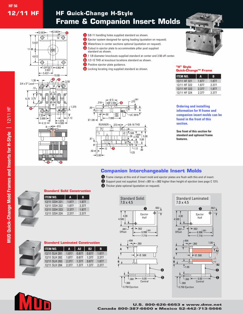
HF Quick-Change H-Style
Frame & Companion Insert Molds12/11 HF
OFFSET3.937
4.062
11.88
5.937
4.812
2.00
5.43710.88
2.00
Ø 0
1.375
3.000
4.12 4.500
1.25
4
6.25 3.75
1.874
1.38 3.5032
1.12
3/4 x 5° Lead
.12
5 6
Ø SØ 2.0
7.000
+.002–.000
.50A
Ø 1.00
.50
.218 .275
.90
±.001
UC 3816
8
3/8-16 THDRUNNER
.81
.373
.50
2.00
.12
.500
.90
5.905.00
B
.1251.12
1.25
.36±.0005
3.750
7
1
R
Ordering and installing information for H frame and companion insert molds can be found in the front of this section.
See front of this section for standard and optional frame features.
ITEM NO. A B12/11HF321 1.877 1.87712/11HF322 1.877 2.37712/11HF323 2.377 1.87712/11HF324 2.377 2.377
Ejector Half
.687 Offset
.562
4.500
.562 ±.001 6.996 7.716
4.00 Ejector
Half
.687 Offset
.562
4.500
.562 ±.001 6.996 7.716
4.00
A A2
Ø .500
.360 1.00 .494
A
Ø .500
.360 .494
6.00 Central
1.00
B
.360 .360
3.750 Ejection
B2
6.00 Central
B
.360 .360
3.750 Ejection
2
3
1
2
3
1
2
3
Ejector Half
.687 Offset
.562
4.500
.562 ±.001 6.996 7.716
4.00 Ejector
Half
.687 Offset
.562
4.500
.562 ±.001 6.996 7.716
4.00
A A2
Ø .500
.360 1.00 .494
A
Ø .500
.360 .494
6.00 Central
1.00
B
.360 .360
3.750 Ejection
B2
6.00 Central
B
.360 .360
3.750 Ejection
2
3
1
2
3
1
2
3
StandardSolid:7.0x4.5
StandardLaminated:7.0x4.5
Companion Interchangeable Insert Molds
1 5/8-11handlingholessuppliedstandardasshown.2 Ejectorsystemdesignedforspringloading(quotationonrequest).3 Waterlinesincentersectionsoptional(quotationonrequest).4 Cutoutinejectorplatetoaccommodatepillarpostsupplied
standardasshown.5 11/8diameterknockoutssuppliedstandardatcenterand3.50offcenter.6 1/2-13THDatknockoutlocationsstandardasshown.7 Positiveejectorplateguidance.8 Lockinglocatingringsuppliedstandardasshown.
“H” Style Quick-Change™ Frame
OFFSET3.937
4.062
11.88
5.937
4.812
2.00
5.43710.88
2.00
Ø 0
1.375
3.000
4.12 4.500
1.25
4
6.25 3.75
1.874
1.38 3.5032
1.12
3/4 x 5° Lead
.12
5 6
Ø SØ 2.0
7.000
+.002–.000
.50A
Ø 1.00
.50
.218 .275
.90
±.001
UC 3816
8
3/8-16 THDRUNNER
.81
.373
.50
2.00
.12
.500
.90
5.905.00
B
.1251.12
1.25
.36±.0005
3.750
7
1
R
1 Frameclampsatthisendofinsertmoldandejectorplatesareflushwiththisendofinsert.2 Supportpostnotsupplied.Grind+.001to+.002higherthanheightofejection(seepageC131).3 Thickerplateoptional(quotationonrequest).
ITEM NO. A A2 B2 B12/11SLH281 1.877 0.877 0.877 1.87712/11SLH282 1.877 0.877 1.377 2.37712/11SLH283 2.377 1.377 0.877 1.87712/11SLH284 2.377 1.377 1.377 2.377
Standard Laminated Construction
ITEM NO. A B12/11SSH221 1.877 1.87712/11SSH222 1.877 2.37712/11SSH223 2.377 1.87712/11SSH224 2.377 2.377
Standard Solid Construction
MUD
Qui
ck-C
hang
e M
old
Fram
es a
nd In
sert
s fo
r H-
Styl
e |
12/
11 H
F
U.S. 800-626-6653 n www.dme.netCanada 800-387-6600 n Mexico 52-442-713-5666
HF 56
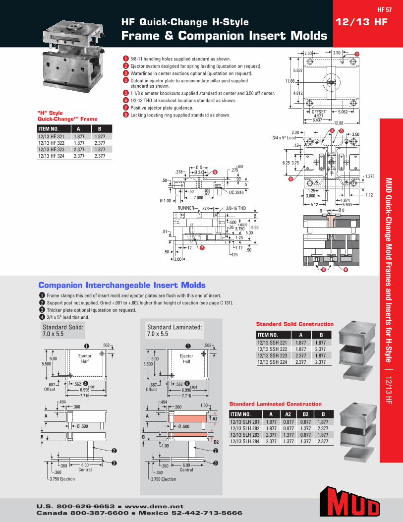
HF Quick-Change H-Style
Frame & Companion Insert Molds12/13 HF
OFFSET4.937
5.062
11.88
5.937
4.812
2.00
6.43712.88
2.50
Ø 0
1.375
3.000
5.12 5.500
1.25
4
6.25 3.75
1.874
2.38 3.5032
1.12
3/4 x 5° Lead
.12
5 6
Ø SØ 2.0
7.000
+.002–.000
.50A
Ø 1.00
.50
.218 .275
.90
±.001
UC 3816
8
3/8-16 THDRUNNER
.81
.373
.50
2.00
.12
.500
.90
5.905.00
B
.1251.12
1.25
.36±.0005
3.750
7
1
R
ITEM NO. A B12/13SSH221 1.877 1.87712/13SSH222 1.877 2.37712/13SSH223 2.377 1.87712/13SSH224 2.377 2.377
Standard Solid Construction
Ejector Half
.687 Offset
.562
5.500
.562 ±.001 6.996 7.716
5.00 Ejector
Half
.687 Offset
.562
5.500
.562 ±.001 6.996 7.716
5.00
A A2
Ø .500
.360 1.00 .494
6.00 Central
1.00
B
.360 .360
3.750 Ejection
B2
A
Ø .500
.360 .494
6.00 Central
B
.360 .360
3.750 Ejection
1
2
4
3
1
2
4
3
Ejector Half
.687 Offset
.562
5.500
.562 ±.001 6.996 7.716
5.00 Ejector
Half
.687 Offset
.562
5.500
.562 ±.001 6.996 7.716
5.00
A A2
Ø .500
.360 1.00 .494
6.00 Central
1.00
B
.360 .360
3.750 Ejection
B2
A
Ø .500
.360 .494
6.00 Central
B
.360 .360
3.750 Ejection
1
2
4
3
1
2
4
3
StandardSolid:7.0x5.5
Companion Interchangeable Insert Molds
StandardLaminated:7.0x5.5
1 Frameclampsthisendofinsertmoldandejectorplatesareflushwiththisendofinsert.2 Supportpostnotsupplied.Grind+.001to+.002higherthanheightofejection(seepageC131).3 Thickerplateoptional(quotationonrequest).4 3/4x5°leadthisend.
ITEM NO. A A2 B2 B12/13SLH281 1.877 0.877 0.877 1.87712/13SLH282 1.877 0.877 1.377 2.37712/13SLH283 2.377 1.377 0.877 1.87712/13SLH284 2.377 1.377 1.377 2.377
Standard Laminated Construction
1 5/8-11handlingholessuppliedstandardasshown.2 Ejectorsystemdesignedforspringloading(quotationonrequest).3 Waterlinesincentersectionsoptional(quotationonrequest).4 Cutoutinejectorplatetoaccommodatepillarpostsupplied
standardasshown.5 11/8diameterknockoutssuppliedstandardatcenterand3.50offcenter.6 1/2-13THDatknockoutlocationsstandardasshown.7 Positiveejectorplateguidance.8 Lockinglocatingringsuppliedstandardasshown.“H” Style
Quick-Change™ Frame
ITEM NO. A B12/13HF321 1.877 1.87712/13HF322 1.877 2.37712/13HF323 2.377 1.87712/13HF324 2.377 2.377
HF 57M
UD Quick-Change M
old Frames and Inserts for H-Style | 12/13 HF
U.S. 800-626-6653 n www.dme.netCanada 800-387-6600 n Mexico 52-442-713-5666
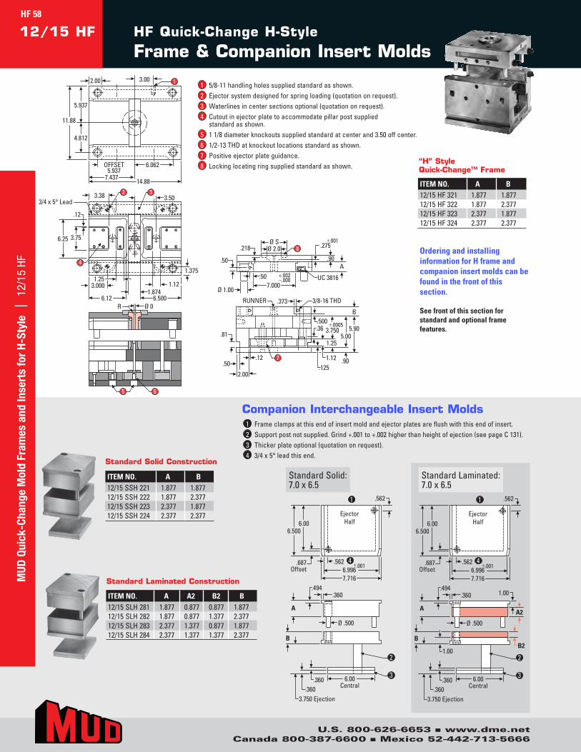
HF Quick-Change H-Style
Frame & Companion Insert Molds12/15 HF
OFFSET5.937
6.062
11.88
5.937
4.812
2.00
7.43714.88
3.00
Ø 0
5 6
Ø SØ 2.0
7.000
+.002–.000
.50A
Ø 1.00
.50
.218 .275
.90
±.001
UC 3816
8
3/8-16 THDRUNNER
.81
.373
.50
2.00
.12
.500
.90
5.905.00
B
.1251.12
1.25
.36±.0005
3.750
7
1.375
3.000
6.12 6.500
1.25
4
6.25 3.75
1.874
3.38 3.5032
1.12
3/4 x 5° Lead
.12
1
R
Ejector Half
.687 Offset
.562
6.500
.562 ±.001 6.996 7.716
6.00 Ejector
Half
.687 Offset
.562
6.500
.562 ±.001 6.996 7.716
6.00
A A2
Ø .500
.360 1.00 .494
6.00 Central
1.00
B
.360 .360
3.750 Ejection
B2
A
Ø .500
.360 .494
6.00 Central
B
.360 .360
3.750 Ejection
1
2
4
3
1
2
4
3
Ejector Half
.687 Offset
.562
6.500
.562 ±.001 6.996 7.716
6.00 Ejector
Half
.687 Offset
.562
6.500
.562 ±.001 6.996 7.716
6.00
A A2
Ø .500
.360 1.00 .494
6.00 Central
1.00
B
.360 .360
3.750 Ejection
B2
A
Ø .500
.360 .494
6.00 Central
B
.360 .360
3.750 Ejection
1
2
4
3
1
2
4
3
StandardSolid:7.0x6.5
StandardLaminated:7.0x6.5
Companion Interchangeable Insert Molds
OFFSET5.937
6.062
11.88
5.937
4.812
2.00
7.43714.88
3.00
Ø 0
5 6
Ø SØ 2.0
7.000
+.002–.000
.50A
Ø 1.00
.50
.218 .275
.90
±.001
UC 3816
8
3/8-16 THDRUNNER
.81
.373
.50
2.00
.12
.500
.90
5.905.00
B
.1251.12
1.25
.36±.0005
3.750
7
1.375
3.000
6.12 6.500
1.25
4
6.25 3.75
1.874
3.38 3.5032
1.12
3/4 x 5° Lead
.12
1
R
1 Frameclampsatthisendofinsertmoldandejectorplatesareflushwiththisendofinsert.2 Supportpostnotsupplied.Grind+.001to+.002higherthanheightofejection(seepageC131).3 Thickerplateoptional(quotationonrequest).4 3/4x5°leadthisend.
ITEM NO. A B12/15SSH221 1.877 1.87712/15SSH222 1.877 2.37712/15SSH223 2.377 1.87712/15SSH224 2.377 2.377
Standard Solid Construction
ITEM NO. A A2 B2 B12/15SLH281 1.877 0.877 0.877 1.87712/15SLH282 1.877 0.877 1.377 2.37712/15SLH283 2.377 1.377 0.877 1.87712/15SLH284 2.377 1.377 1.377 2.377
Standard Laminated Construction
Ordering and installing information for H frame and companion insert molds can be found in the front of this section.
See front of this section for standard and optional frame features.
1 5/8-11handlingholessuppliedstandardasshown.2 Ejectorsystemdesignedforspringloading(quotationonrequest).3 Waterlinesincentersectionsoptional(quotationonrequest).4 Cutoutinejectorplatetoaccommodatepillarpostsupplied
standardasshown.5 11/8diameterknockoutssuppliedstandardatcenterand3.50offcenter.6 1/2-13THDatknockoutlocationsstandardasshown.7 Positiveejectorplateguidance.8 Lockinglocatingringsuppliedstandardasshown.
ITEM NO. A B12/15HF321 1.877 1.87712/15HF322 1.877 2.37712/15HF323 2.377 1.87712/15HF324 2.377 2.377
“H” Style Quick-Change™ Frame
MUD
Qui
ck-C
hang
e M
old
Fram
es a
nd In
sert
s fo
r H-
Styl
e |
12/
15 H
FHF 58
U.S. 800-626-6653 n www.dme.netCanada 800-387-6600 n Mexico 52-442-713-5666

HF Quick-Change H-Style
Frame & Companion Insert Molds12/19 HF
OFFSET7.937
8.062
11.88
5.937
4.812
2.00
9.43718.88
3.00
Ø 0
5 6
Ø SØ 2.0
7.000
+.002–.000
.50A
Ø 1.00
.50
.218 .275
.90
±.001
UC 3816
8
3/8-16 THDRUNNER
.81
.373
.50
2.00
.12
.500
.90
5.905.00
B
.1251.12
1.25
.36±.0005
3.750
7
1.375
3.0008.12 8.500
4
6.25 3.75
1.874
5.38 3.5032
3/4 x 5° Lead
.12
1
R
ITEM NO. A B12/19SSH221 1.877 1.87712/19SSH222 1.877 2.37712/19SSH223 2.377 1.87712/19SSH224 2.377 2.377
Standard Solid Construction
Ejector Half
.687 Offset
.562
8.500
.562 ±.001 6.996 7.716
8.00
A A2
Ø .500
.360 1.00 .494
6.00 Central
1.00
B
.360 .360
3.750 Ejection
B2
Ejector Half
.687 Offset
.562
8.500
.562 ±.001 6.996 7.716
8.00
A
Ø .500
.360 .494
6.00 Central
B
.360 .360
3.750 Ejection
1
2
4
3
1
2
4
3
Ejector Half
.687 Offset
.562
8.500
.562 ±.001 6.996 7.716
8.00
A A2
Ø .500
.360 1.00 .494
6.00 Central
1.00
B
.360 .360
3.750 Ejection
B2
Ejector Half
.687 Offset
.562
8.500
.562 ±.001 6.996 7.716
8.00
A
Ø .500
.360 .494
6.00 Central
B
.360 .360
3.750 Ejection
1
2
4
3
1
2
4
3
StandardSolid:7.0x8.5
Companion Interchangeable Insert Molds
StandardLaminated:7.0x8.5
1 Frameclampsatthisendofinsertmoldandejectorplatesareflushwiththisendofinsert.2 Supportpostnotsupplied.Grind+.001to+.002higherthanheightofejection(seepageC131).3 Thickerplateoptional(quotationonrequest).4 3/4x5°leadthisend.
ITEM NO. A A2 B2 B12/19SLH281 1.877 0.877 0.877 1.87712/19SLH282 1.877 0.877 1.377 2.37712/19SLH283 2.377 1.377 0.877 1.87712/19SLH284 2.377 1.377 1.377 2.377
Standard Laminated Construction
1 5/8-11handlingholessuppliedstandardasshown.2 Ejectorsystemdesignedforspringloading(quotationonrequest).3 Waterlinesincentersectionsoptional(quotationonrequest).4 Cutoutinejectorplatetoaccommodatepillarpostsupplied
standardasshown.5 11/8diameterknockoutssuppliedstandardatcenter
and3.50offcenter.6 1/2-13THDatknockoutlocationsstandardasshown.7 Positiveejectorplateguidance.8 Lockinglocatingringsuppliedstandardasshown.
“H” Style Quick-Change™ Frame
ITEM NO. A B12/19HF321 1.877 1.87712/19HF322 1.877 2.37712/19HF323 2.377 1.87712/19HF324 2.377 2.377
MUD
Quick-Change Mold Fram
es and Inserts for H-Style | 12/19 HFHF 59
U.S. 800-626-6653 n www.dme.netCanada 800-387-6600 n Mexico 52-442-713-5666
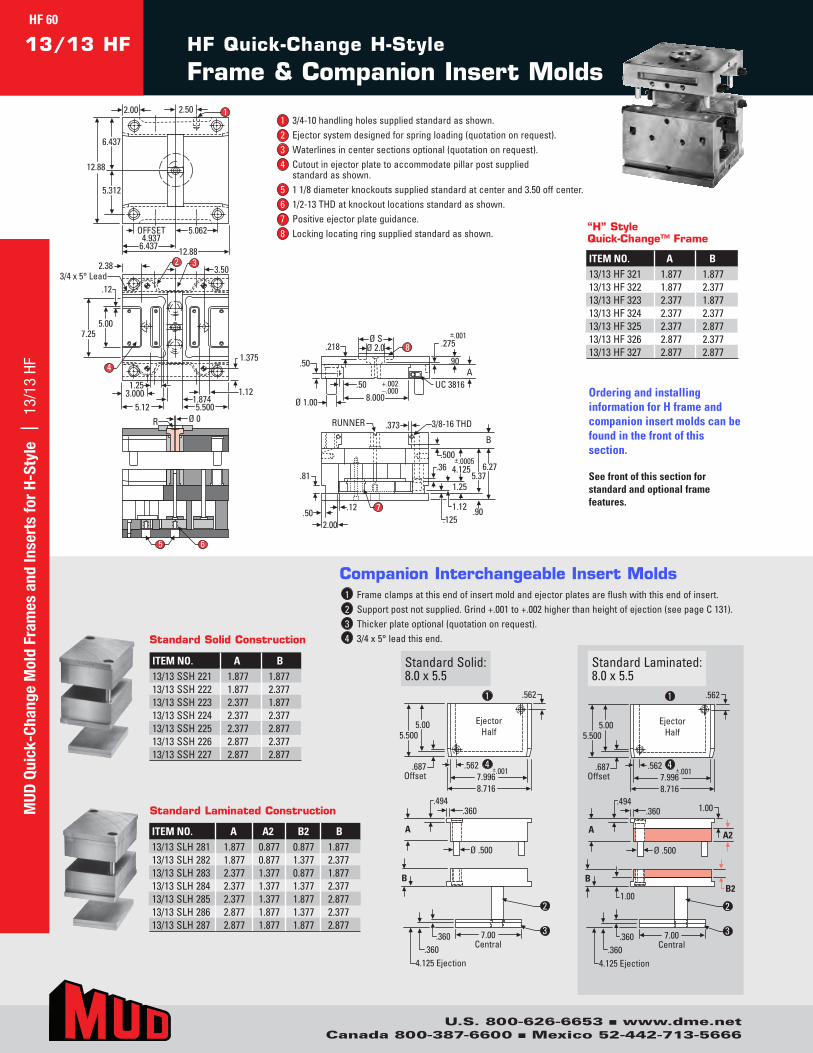
HF Quick-Change H-Style
Frame & Companion Insert Molds13/13 HF
OFFSET4.937
5.062
12.88
6.437
5.312
2.00
6.437 12.88
2.50
Ø 0
1.375
3.0005.12 5.500
1.25
4
7.255.00
1.874
2.38 3.5032
1.12
3/4 x 5° Lead .12
5 6
Ø SØ 2.0
8.000+.002–.000
.50A
Ø 1.00
.50
.218 .275
.90
±.001
UC 3816
8
3/8-16 THDRUNNER
.81
.373
.502.00
.12
.500
.90
6.275.37
B
.1251.12
1.25
.36±.0005
4.125
7
1
R
Ejector Half
.687 Offset
.562
5.500
.562 ±.001 7.996 8.716
5.00
A A2
Ø .500
.360 1.00 .494
7.00 Central
1.00
B
.360 .360
4.125 Ejection
B2
Ejector Half
.687 Offset
.562
5.500
.562 ±.001 7.996 8.716
5.00
A
Ø .500
.360 .494
7.00 Central
B
.360 .360
4.125 Ejection
1
2
4
3
1
2
4
3
Ejector Half
.687 Offset
.562
5.500
.562 ±.001 7.996 8.716
5.00
A A2
Ø .500
.360 1.00 .494
7.00 Central
1.00
B
.360 .360
4.125 Ejection
B2
Ejector Half
.687 Offset
.562
5.500
.562 ±.001 7.996 8.716
5.00
A
Ø .500
.360 .494
7.00 Central
B
.360 .360
4.125 Ejection
1
2
4
3
1
2
4
3
StandardSolid:8.0x5.5
StandardLaminated:8.0x5.5
Companion Interchangeable Insert Molds
OFFSET4.937
5.062
12.88
6.437
5.312
2.00
6.437 12.88
2.50
Ø 0
1.375
3.0005.12 5.500
1.25
4
7.255.00
1.874
2.38 3.5032
1.12
3/4 x 5° Lead .12
5 6
Ø SØ 2.0
8.000+.002–.000
.50A
Ø 1.00
.50
.218 .275
.90
±.001
UC 3816
8
3/8-16 THDRUNNER
.81
.373
.502.00
.12
.500
.90
6.275.37
B
.1251.12
1.25
.36±.0005
4.125
7
1
R
1 Frameclampsatthisendofinsertmoldandejectorplatesareflushwiththisendofinsert.2 Supportpostnotsupplied.Grind+.001to+.002higherthanheightofejection(seepageC131).3 Thickerplateoptional(quotationonrequest).4 3/4x5°leadthisend.
ITEM NO. A A2 B2 B13/13SLH281 1.877 0.877 0.877 1.87713/13SLH282 1.877 0.877 1.377 2.37713/13SLH283 2.377 1.377 0.877 1.87713/13SLH284 2.377 1.377 1.377 2.37713/13SLH285 2.377 1.377 1.877 2.87713/13SLH286 2.877 1.877 1.377 2.37713/13SLH287 2.877 1.877 1.877 2.877
Standard Laminated Construction
ITEM NO. A B13/13SSH221 1.877 1.87713/13SSH222 1.877 2.37713/13SSH223 2.377 1.87713/13SSH224 2.377 2.37713/13SSH225 2.377 2.87713/13SSH226 2.877 2.37713/13SSH227 2.877 2.877
Standard Solid Construction
Ordering and installing information for H frame and companion insert molds can be found in the front of this section.
See front of this section for standard and optional frame features.
1 3/4-10handlingholessuppliedstandardasshown.2 Ejectorsystemdesignedforspringloading(quotationonrequest).3 Waterlinesincentersectionsoptional(quotationonrequest).4 Cutoutinejectorplatetoaccommodatepillarpostsupplied
standardasshown.5 11/8diameterknockoutssuppliedstandardatcenterand3.50offcenter.6 1/2-13THDatknockoutlocationsstandardasshown.7 Positiveejectorplateguidance.8 Lockinglocatingringsuppliedstandardasshown.
“H” Style Quick-Change™ Frame
ITEM NO. A B13/13HF321 1.877 1.87713/13HF322 1.877 2.37713/13HF323 2.377 1.87713/13HF324 2.377 2.37713/13HF325 2.377 2.87713/13HF326 2.877 2.37713/13HF327 2.877 2.877
U.S. 800-626-6653 n www.dme.netCanada 800-387-6600 n Mexico 52-442-713-5666
MUD
Qui
ck-C
hang
e M
old
Fram
es a
nd In
sert
s fo
r H-
Styl
e |
13/
13 H
FHF 60
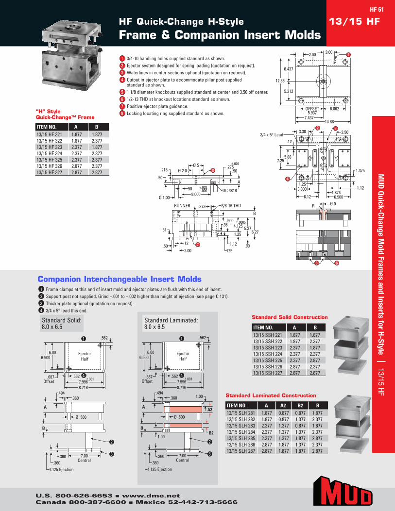
HF Quick-Change H-Style
Frame & Companion Insert Molds13/15 HF
Ø 0
1.375
3.000
6.12 6.500
1.254
7.255.00
1.874
3.38 3.5032
1.12
3/4 x 5° Lead .12
5 6
Ø SØ 2.0
8.000
+.002–.000
.50A
Ø 1.00
.50
.218.275
.90
±.001
UC 3816
8
3/8-16 THDRUNNER
.81
.373
.502.00
.12
.500
.90
6.275.37
B
.1251.12
1.25
.36±.0005
4.125
7
OFFSET5.937
6.062
12.88
6.437
5.312
2.00
7.43714.88
3.00 1
RØ 0
1.375
3.000
6.12 6.500
1.254
7.255.00
1.874
3.38 3.5032
1.12
3/4 x 5° Lead .12
5 6
Ø SØ 2.0
8.000
+.002–.000
.50A
Ø 1.00
.50
.218.275
.90
±.001
UC 3816
8
3/8-16 THDRUNNER
.81
.373
.502.00
.12
.500
.90
6.275.37
B
.1251.12
1.25
.36±.0005
4.125
7
OFFSET5.937
6.062
12.88
6.437
5.312
2.00
7.43714.88
3.00 1
R
Ejector Half
.687 Offset
.562
6.500
.562 ±.001 7.996 8.716
6.00
A A2
Ø .500
.360 1.00 .494
7.00 Central
1.00
B
.360 .360
4.125 Ejection
B2
Ejector Half
.687 Offset
.562
6.500
.562 ±.001 7.996 8.716
6.00
A
Ø .500
.360 .494
7.00 Central
B
.360 .360
4.125 Ejection
2
3
1
2
4
3
1
2
4
3
Ejector Half
.687 Offset
.562
6.500
.562 ±.001 7.996 8.716
6.00
A A2
Ø .500
.360 1.00 .494
7.00 Central
1.00
B
.360 .360
4.125 Ejection
B2
Ejector Half
.687 Offset
.562
6.500
.562 ±.001 7.996 8.716
6.00
A
Ø .500
.360 .494
7.00 Central
B
.360 .360
4.125 Ejection
2
3
1
2
4
3
1
2
4
3
StandardSolid:8.0x6.5
Companion Interchangeable Insert Molds
StandardLaminated:8.0x6.5
1 Frameclampsatthisendofinsertmoldandejectorplatesareflushwiththisendofinsert.2 Supportpostnotsupplied.Grind+.001to+.002higherthanheightofejection(seepageC131).3 Thickerplateoptional(quotationonrequest).4 3/4x5°leadthisend.
ITEM NO. A B13/15SSH221 1.877 1.87713/15SSH222 1.877 2.37713/15SSH223 2.377 1.87713/15SSH224 2.377 2.37713/15SSH225 2.377 2.87713/15SSH226 2.877 2.37713/15SSH227 2.877 2.877
Standard Solid Construction
ITEM NO. A A2 B2 B13/15SLH281 1.877 0.877 0.877 1.87713/15SLH282 1.877 0.877 1.377 2.37713/15SLH283 2.377 1.377 0.877 1.87713/15SLH284 2.377 1.377 1.377 2.37713/15SLH285 2.377 1.377 1.877 2.87713/15SLH286 2.877 1.877 1.377 2.37713/15SLH287 2.877 1.877 1.877 2.877
Standard Laminated Construction
1 3/4-10handlingholessuppliedstandardasshown.2 Ejectorsystemdesignedforspringloading(quotationonrequest).3 Waterlinesincentersectionsoptional(quotationonrequest).4 Cutoutinejectorplatetoaccommodatepillarpostsupplied
standardasshown.5 11/8diameterknockoutssuppliedstandardatcenterand3.50offcenter.6 1/2-13THDatknockoutlocationsstandardasshown.7 Positiveejectorplateguidance.8 Lockinglocatingringsuppliedstandardasshown.“H” Style
Quick-Change™ Frame
ITEM NO. A B13/15HF321 1.877 1.87713/15HF322 1.877 2.37713/15HF323 2.377 1.87713/15HF324 2.377 2.37713/15HF325 2.377 2.87713/15HF326 2.877 2.37713/15HF327 2.877 2.877
HF 61M
UD Quick-Change M
old Frames and Inserts for H-Style | 13/15 HF
U.S. 800-626-6653 n www.dme.netCanada 800-387-6600 n Mexico 52-442-713-5666
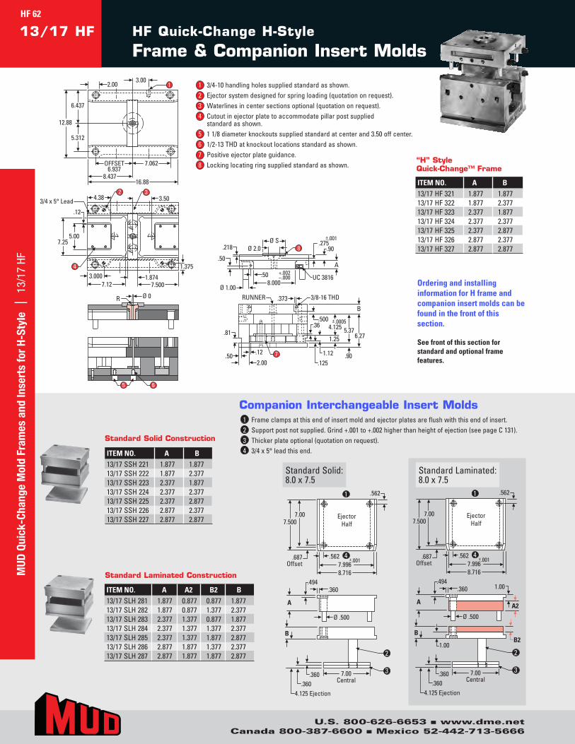
HF Quick-Change H-Style
Frame & Companion Insert Molds13/17 HF
Ø 0
1.3753.000
7.12 7.500
4
7.255.00
1.874
4.38 3.5032
3/4 x 5° Lead
.12
5 6
Ø SØ 2.0
8.000
+.002–.000
.50A
Ø 1.00
.50
.218.275
.90
±.001
UC 3816
8
3/8-16 THDRUNNER
.81
.373
.502.00
.12
.500
.90
6.275.37
B
.1251.12
1.25
.36±.0005
4.125
7
OFFSET6.937
7.062
12.88
6.437
5.312
2.00
8.43716.88
3.00
R
1
Ejector Half
.687 Offset
.562
7.500
.562 ±.001 7.996 8.716
7.00
A A2
Ø .500
.360 1.00 .494
7.00 Central
1.00
B
.360 .360
4.125 Ejection
B2
Ejector Half
.687 Offset
.562
7.500
.562 ±.001 7.996 8.716
7.00
A
Ø .500
.360 .494
7.00 Central
B
.360 .360
4.125 Ejection
1
2
4
3
1
2
4
3
Ejector Half
.687 Offset
.562
7.500
.562 ±.001 7.996 8.716
7.00
A A2
Ø .500
.360 1.00 .494
7.00 Central
1.00
B
.360 .360
4.125 Ejection
B2
Ejector Half
.687 Offset
.562
7.500
.562 ±.001 7.996 8.716
7.00
A
Ø .500
.360 .494
7.00 Central
B
.360 .360
4.125 Ejection
1
2
4
3
1
2
4
3
StandardSolid:8.0x7.5
StandardLaminated:8.0x7.5
Companion Interchangeable Insert Molds
Ø 0
1.3753.000
7.12 7.500
4
7.255.00
1.874
4.38 3.5032
3/4 x 5° Lead
.12
5 6
Ø SØ 2.0
8.000
+.002–.000
.50A
Ø 1.00
.50
.218.275
.90
±.001
UC 3816
8
3/8-16 THDRUNNER
.81
.373
.502.00
.12
.500
.90
6.275.37
B
.1251.12
1.25
.36±.0005
4.125
7
OFFSET6.937
7.062
12.88
6.437
5.312
2.00
8.43716.88
3.00
R
1
1 Frameclampsatthisendofinsertmoldandejectorplatesareflushwiththisendofinsert.2 Supportpostnotsupplied.Grind+.001to+.002higherthanheightofejection(seepageC131).3 Thickerplateoptional(quotationonrequest).4 3/4x5°leadthisend.ITEM NO. A B
13/17SSH221 1.877 1.87713/17SSH222 1.877 2.37713/17SSH223 2.377 1.87713/17SSH224 2.377 2.37713/17SSH225 2.377 2.87713/17SSH226 2.877 2.37713/17SSH227 2.877 2.877
Standard Solid Construction
ITEM NO. A A2 B2 B13/17SLH281 1.877 0.877 0.877 1.87713/17SLH282 1.877 0.877 1.377 2.37713/17SLH283 2.377 1.377 0.877 1.87713/17SLH284 2.377 1.377 1.377 2.37713/17SLH285 2.377 1.377 1.877 2.87713/17SLH286 2.877 1.877 1.377 2.37713/17SLH287 2.877 1.877 1.877 2.877
Standard Laminated Construction
Ordering and installing information for H frame and companion insert molds can be found in the front of this section.
See front of this section for standard and optional frame features.
1 3/4-10handlingholessuppliedstandardasshown.2 Ejectorsystemdesignedforspringloading(quotationonrequest).3 Waterlinesincentersectionsoptional(quotationonrequest).4 Cutoutinejectorplatetoaccommodatepillarpostsupplied
standardasshown.5 11/8diameterknockoutssuppliedstandardatcenterand3.50offcenter.6 1/2-13THDatknockoutlocationsstandardasshown.7 Positiveejectorplateguidance.8 Lockinglocatingringsuppliedstandardasshown.
ITEM NO. A B13/17HF321 1.877 1.87713/17HF322 1.877 2.37713/17HF323 2.377 1.87713/17HF324 2.377 2.37713/17HF325 2.377 2.87713/17HF326 2.877 2.37713/17HF327 2.877 2.877
“H” Style Quick-Change™ Frame
HF 62M
UD Q
uick
-Cha
nge
Mol
d Fr
ames
and
Inse
rts
for
H-St
yle
| 1
3/17
HF
U.S. 800-626-6653 n www.dme.netCanada 800-387-6600 n Mexico 52-442-713-5666
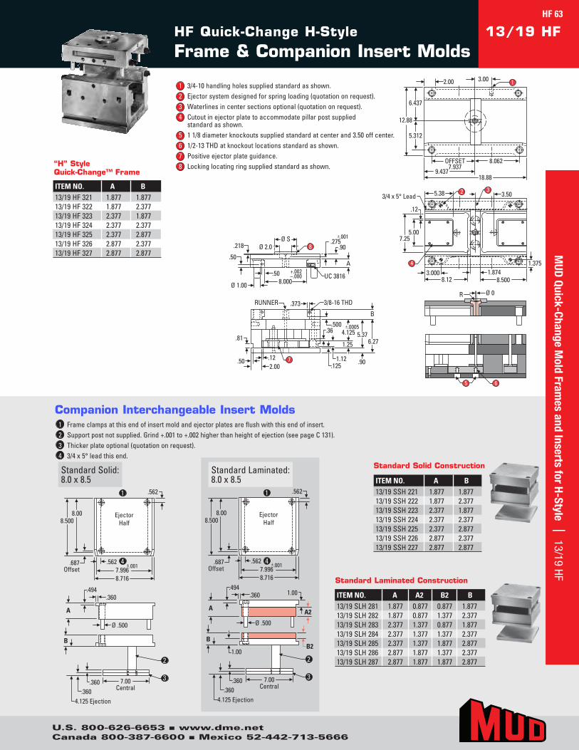
HF Quick-Change H-Style
Frame & Companion Insert Molds13/19 HF
Ø 0
1.3753.000
8.12 8.500
4
7.255.00
1.874
5.38 3.5032
3/4 x 5° Lead
.12
5 6
Ø SØ 2.0
8.000
+.002–.000
.50A
Ø 1.00
.50
.218.275
.90
±.001
UC 3816
8
3/8-16 THDRUNNER
.81
.373
.502.00.12
.500
.90
6.275.37
B
.1251.12
1.25
.36±.0005
4.125
7
OFFSET7.937
8.062
12.88
6.437
5.312
2.00
9.43718.88
3.00
R
1
Ø 0
1.3753.000
8.12 8.500
4
7.255.00
1.874
5.38 3.5032
3/4 x 5° Lead
.12
5 6
Ø SØ 2.0
8.000
+.002–.000
.50A
Ø 1.00
.50
.218.275
.90
±.001
UC 3816
8
3/8-16 THDRUNNER
.81
.373
.502.00.12
.500
.90
6.275.37
B
.1251.12
1.25
.36±.0005
4.125
7
OFFSET7.937
8.062
12.88
6.437
5.312
2.00
9.43718.88
3.00
R
1
Ejector Half
.687 Offset
.562
8.500
.562 ±.001 7.996 8.716
8.00
A A2
Ø .500
.360 1.00 .494
7.00 Central
1.00
B
.360 .360
4.125 Ejection
B2
Ejector Half
.687 Offset
.562
8.500
.562 ±.001 7.996 8.716
8.00
A
Ø .500
.360 .494
7.00 Central
B
.360 .360
4.125 Ejection
2
1
2
4
3
1
2
4
3
Ejector Half
.687 Offset
.562
8.500
.562 ±.001 7.996 8.716
8.00
A A2
Ø .500
.360 1.00 .494
7.00 Central
1.00
B
.360 .360
4.125 Ejection
B2
Ejector Half
.687 Offset
.562
8.500
.562 ±.001 7.996 8.716
8.00
A
Ø .500
.360 .494
7.00 Central
B
.360 .360
4.125 Ejection
2
1
2
4
3
1
2
4
3
StandardSolid:8.0x8.5
Companion Interchangeable Insert Molds
StandardLaminated:8.0x8.5
1 Frameclampsatthisendofinsertmoldandejectorplatesareflushwiththisendofinsert.2 Supportpostnotsupplied.Grind+.001to+.002higherthanheightofejection(seepageC131).3 Thickerplateoptional(quotationonrequest).4 3/4x5°leadthisend.
ITEM NO. A B13/19SSH221 1.877 1.87713/19SSH222 1.877 2.37713/19SSH223 2.377 1.87713/19SSH224 2.377 2.37713/19SSH225 2.377 2.87713/19SSH226 2.877 2.37713/19SSH227 2.877 2.877
Standard Solid Construction
ITEM NO. A A2 B2 B13/19SLH281 1.877 0.877 0.877 1.87713/19SLH282 1.877 0.877 1.377 2.37713/19SLH283 2.377 1.377 0.877 1.87713/19SLH284 2.377 1.377 1.377 2.37713/19SLH285 2.377 1.377 1.877 2.87713/19SLH286 2.877 1.877 1.377 2.37713/19SLH287 2.877 1.877 1.877 2.877
Standard Laminated Construction
1 3/4-10handlingholessuppliedstandardasshown.2 Ejectorsystemdesignedforspringloading(quotationonrequest).3 Waterlinesincentersectionsoptional(quotationonrequest).4 Cutoutinejectorplatetoaccommodatepillarpostsupplied
standardasshown.5 11/8diameterknockoutssuppliedstandardatcenterand3.50offcenter.6 1/2-13THDatknockoutlocationsstandardasshown.7 Positiveejectorplateguidance.8 Lockinglocatingringsuppliedstandardasshown.“H” Style
Quick-Change™ Frame
ITEM NO. A B13/19HF321 1.877 1.87713/19HF322 1.877 2.37713/19HF323 2.377 1.87713/19HF324 2.377 2.37713/19HF325 2.377 2.87713/19HF326 2.877 2.37713/19HF327 2.877 2.877 M
UD Quick-Change M
old Frames and Inserts for H-Style | 13/19 HF
U.S. 800-626-6653 n www.dme.netCanada 800-387-6600 n Mexico 52-442-713-5666
HF 63
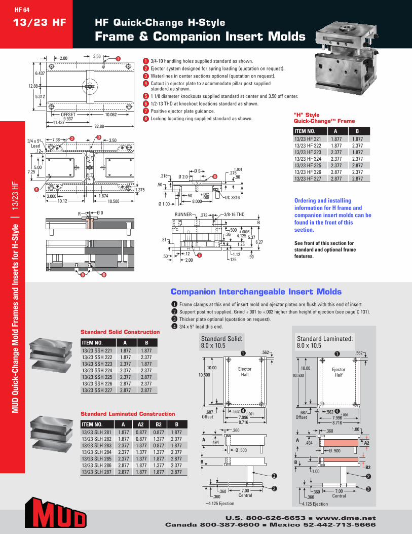
A A2
Ø .500
.360 1.00
.494
7.00 Central
1.00
B
.360 .360
4.125 Ejection
B2
Ejector Half
.687 Offset
.562
10.500
.562 ±.001 7.996 8.716
10.00
A
Ø .500
.360
.494
7.00 Central
B
.360 .360
4.125 Ejection
Ejector Half
.687 Offset
.562
10.500
.562 ±.001 7.996 8.716
10.00
1
2
4
3
1
2
4
3
A A2
Ø .500
.360 1.00
.494
7.00 Central
1.00
B
.360 .360
4.125 Ejection
B2
Ejector Half
.687 Offset
.562
10.500
.562 ±.001 7.996 8.716
10.00
A
Ø .500
.360
.494
7.00 Central
B
.360 .360
4.125 Ejection
Ejector Half
.687 Offset
.562
10.500
.562 ±.001 7.996 8.716
10.00
1
2
4
3
1
2
4
3
StandardSolid:8.0x10.5
StandardLaminated:8.0x10.5
1 Frameclampsatthisendofinsertmoldandejectorplatesareflushwiththisendofinsert.2 Supportpostnotsupplied.Grind+.001to+.002higherthanheightofejection(seepageC131).3 Thickerplateoptional(quotationonrequest).4 3/4x5°leadthisend.
Companion Interchangeable Insert Molds
HF Quick-Change H-Style
Frame & Companion Insert Molds13/23 HF
Ø 0
1.3753.000
10.12 10.500
4
7.255.00
1.874
7.38 3.50323/4 x 5°
Lead .12
5 6
Ø SØ 2.0
8.000
+.002–.000
.50A
Ø 1.00
.50
.218.275
.90
±.001
UC 3816
8
3/8-16 THDRUNNER
.81
.373
.502.00.12
.500
.90
6.275.37
B
.1251.12
1.25
.36±.0005
4.125
7
OFFSET9.937
10.062
12.88
6.437
5.312
2.00
11.43722.88
3.50
R
1
ITEM NO. A B13/23SSH221 1.877 1.87713/23SSH222 1.877 2.37713/23SSH223 2.377 1.87713/23SSH224 2.377 2.37713/23SSH225 2.377 2.87713/23SSH226 2.877 2.37713/23SSH227 2.877 2.877
Standard Solid Construction
ITEM NO. A A2 B2 B13/23SLH281 1.877 0.877 0.877 1.87713/23SLH282 1.877 0.877 1.377 2.37713/23SLH283 2.377 1.377 0.877 1.87713/23SLH284 2.377 1.377 1.377 2.37713/23SLH285 2.377 1.377 1.877 2.87713/23SLH286 2.877 1.877 1.377 2.37713/23SLH287 2.877 1.877 1.877 2.877
Standard Laminated Construction
Ordering and installing information for H frame and companion insert molds can be found in the front of this section.
See front of this section for standard and optional frame features.
1 3/4-10handlingholessuppliedstandardasshown.2 Ejectorsystemdesignedforspringloading(quotationonrequest).3 Waterlinesincentersectionsoptional(quotationonrequest).4 Cutoutinejectorplatetoaccommodatepillarpostsupplied
standardasshown.5 11/8diameterknockoutssuppliedstandardatcenterand3.50offcenter.6 1/2-13THDatknockoutlocationsstandardasshown.7 Positiveejectorplateguidance.8 Lockinglocatingringsuppliedstandardasshown.
ITEM NO. A B13/23HF321 1.877 1.87713/23HF322 1.877 2.37713/23HF323 2.377 1.87713/23HF324 2.377 2.37713/23HF325 2.377 2.87713/23HF326 2.877 2.37713/23HF327 2.877 2.877
“H” Style Quick-Change™ Frame
MUD
Qui
ck-C
hang
e M
old
Fram
es a
nd In
sert
s fo
r H-
Styl
e |
13/
23 H
F
U.S. 800-626-6653 n www.dme.netCanada 800-387-6600 n Mexico 52-442-713-5666
HF 64
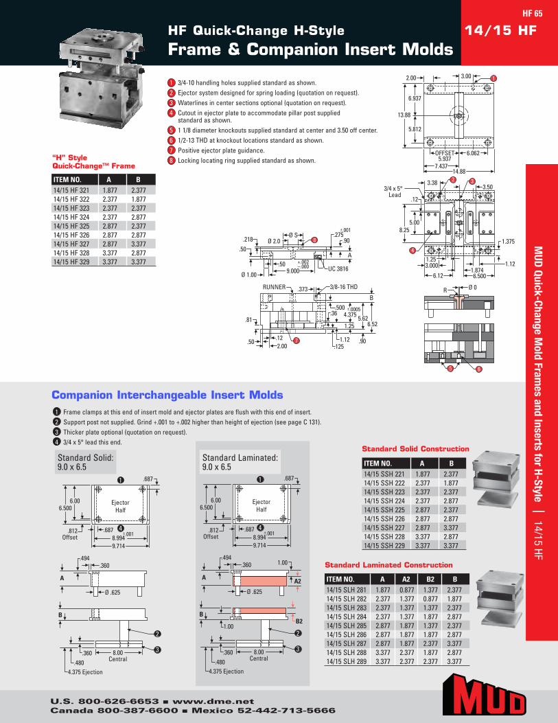
Ejector Half
.812 Offset
.687
6.500
.687 ±.001 8.994 9.714
6.00
A A2
Ø .625
.360 1.00 .494
8.00 Central
1.00
B
.360 .480
4.375 Ejection
B2
2
Ejector Half
.812 Offset
.687
6.500
.687 ±.001 8.994 9.714
6.00
A
Ø .625
.360 .494
8.00 Central
B
.360 .480
4.375 Ejection
1
2
4
3
1
2
4
3
Ejector Half
.812 Offset
.687
6.500
.687 ±.001 8.994 9.714
6.00
A A2
Ø .625
.360 1.00 .494
8.00 Central
1.00
B
.360 .480
4.375 Ejection
B2
2
Ejector Half
.812 Offset
.687
6.500
.687 ±.001 8.994 9.714
6.00
A
Ø .625
.360 .494
8.00 Central
B
.360 .480
4.375 Ejection
1
2
4
3
1
2
4
3
StandardSolid:9.0x6.5
StandardLaminated:9.0x6.5
1 Frameclampsatthisendofinsertmoldandejectorplatesareflushwiththisendofinsert.2 Supportpostnotsupplied.Grind+.001to+.002higherthanheightofejection(seepageC131).3 Thickerplateoptional(quotationonrequest).4 3/4x5°leadthisend.
Companion Interchangeable Insert Molds
HF Quick-Change H-Style
Frame & Companion Insert Molds14/15 HF
5 6
Ø SØ 2.0
9.000+.002–.000
.50A
Ø 1.00
.50
.218.275
.90
±.001
UC 3816
8
3/8-16 THDRUNNER
.81
.373
.502.00
.12
.500
.90
6.525.62
B
.1251.12
1.25
.36±.0005
4.375
7
OFFSET5.937
6.062
13.88
6.937
5.812
2.00
7.43714.88
3.00 1
Ø 0R
1.375
3.000
6.12 6.500
1.254
8.255.00
1.874
3.383.50
32
1.12
3/4 x 5°Lead
.12
ITEM NO. A B14/15SSH221 1.877 2.37714/15SSH222 2.377 1.87714/15SSH223 2.377 2.37714/15SSH224 2.377 2.87714/15SSH225 2.877 2.37714/15SSH226 2.877 2.87714/15SSH227 2.877 3.37714/15SSH228 3.377 2.87714/15SSH229 3.377 3.377
Standard Solid Construction
ITEM NO. A A2 B2 B14/15SLH281 1.877 0.877 1.377 2.37714/15SLH282 2.377 1.377 0.877 1.87714/15SLH283 2.377 1.377 1.377 2.37714/15SLH284 2.377 1.377 1.877 2.87714/15SLH285 2.877 1.877 1.377 2.37714/15SLH286 2.877 1.877 1.877 2.87714/15SLH287 2.877 1.877 2.377 3.37714/15SLH288 3.377 2.377 1.877 2.87714/15SLH289 3.377 2.377 2.377 3.377
Standard Laminated Construction
1 3/4-10handlingholessuppliedstandardasshown.2 Ejectorsystemdesignedforspringloading(quotationonrequest).3 Waterlinesincentersectionsoptional(quotationonrequest).4 Cutoutinejectorplatetoaccommodatepillarpostsupplied
standardasshown.5 11/8diameterknockoutssuppliedstandardatcenterand3.50offcenter.6 1/2-13THDatknockoutlocationsstandardasshown.7 Positiveejectorplateguidance.8 Lockinglocatingringsuppliedstandardasshown.“H” Style
Quick-Change™ Frame
ITEM NO. A B14/15HF321 1.877 2.37714/15HF322 2.377 1.87714/15HF323 2.377 2.37714/15HF324 2.377 2.87714/15HF325 2.877 2.37714/15HF326 2.877 2.87714/15HF327 2.877 3.37714/15HF328 3.377 2.87714/15HF329 3.377 3.377
MUD
Quick-Change Mold Fram
es and Inserts for H-Style | 14/15 HFHF 65
U.S. 800-626-6653 n www.dme.netCanada 800-387-6600 n Mexico 52-442-713-5666

Ejector Half
.812 Offset
.687
7.500
.687 ±.001 8.994 9.714
7.00
A A2
Ø .625
.360 1.00 .494
8.00 Central
1.00
B
.360 .480
4.375 Ejection
B2
Ejector Half
.812 Offset
.687
7.500
.687 ±.001 8.994 9.714
7.00
A
Ø .625
.360 .494
8.00 Central
B
.360 .480
4.375 Ejection
1
2
4
3
1
2
4
3
Ejector Half
.812 Offset
.687
7.500
.687 ±.001 8.994 9.714
7.00
A A2
Ø .625
.360 1.00 .494
8.00 Central
1.00
B
.360 .480
4.375 Ejection
B2
Ejector Half
.812 Offset
.687
7.500
.687 ±.001 8.994 9.714
7.00
A
Ø .625
.360 .494
8.00 Central
B
.360 .480
4.375 Ejection
1
2
4
3
1
2
4
3
StandardSolid:9.0x7.5
StandardLaminated:9.0x7.5
1 Frameclampsatthisendofinsertmoldandejectorplatesareflushwiththisendofinsert.2 Supportpostnotsupplied.Grind+.001to+.002higherthanheightofejection(seepageC131).3 Thickerplateoptional(quotationonrequest).4 3/4x5°leadthisend.
Companion Interchangeable Insert Molds
HF Quick-Change H-Style
Frame & Companion Insert Molds14/17 HF
5 6
Ø SØ 2.0
9.000+.002–.000
.50A
Ø 1.00
.50
.218.275
.90
±.001
UC 3816
8
3/8-16 THDRUNNER
.81
.373
.502.00
.12
.500
.90
6.525.62
B
.1251.12
1.25
.36±.0005
4.375
7
OFFSET6.937
7.062
13.88
6.937
5.812
2.00
8.43716.88
3.00 1
Ø 0R
1.375
3.0007.12 7.500
1.874
4
8.255.00
4.383.50
32
3/4 x 5°Lead
.12
5 6
Ø SØ 2.0
9.000+.002–.000
.50A
Ø 1.00
.50
.218.275
.90
±.001
UC 3816
8
3/8-16 THDRUNNER
.81
.373
.502.00
.12
.500
.90
6.525.62
B
.1251.12
1.25
.36±.0005
4.375
7
OFFSET6.937
7.062
13.88
6.937
5.812
2.00
8.43716.88
3.00 1
Ø 0R
1.375
3.0007.12 7.500
1.874
4
8.255.00
4.383.50
32
3/4 x 5°Lead
.12
ITEM NO. A B14/17SSH221 1.877 2.37714/17SSH222 2.377 1.87714/17SSH223 2.377 2.37714/17SSH224 2.377 2.87714/17SSH225 2.877 2.37714/17SSH226 2.877 2.87714/17SSH227 2.877 3.37714/17SSH228 3.377 2.87714/17SSH229 3.377 3.377
Standard Solid Construction
ITEM NO. A A2 B2 B14/17SLH281 1.877 0.877 1.377 2.37714/17SLH282 2.377 1.377 0.877 1.87714/17SLH283 2.377 1.377 1.377 2.37714/17SLH284 2.377 1.377 1.877 2.87714/17SLH285 2.877 1.877 1.377 2.37714/17SLH286 2.877 1.877 1.877 2.87714/17SLH287 2.877 1.877 2.377 3.37714/17SLH288 3.377 2.377 1.877 2.87714/17SLH289 3.377 2.377 2.377 3.377
Standard Laminated Construction
Ordering and installing information for H frame and companion insert molds can be found in the front of this section.
See front of this section for standard and optional frame features.
1 3/4-10handlingholessuppliedstandardasshown.2 Ejectorsystemdesignedforspringloading(quotationonrequest).3 Waterlinesincentersectionsoptional(quotationonrequest).4 Cutoutinejectorplatetoaccommodatepillarpostsupplied
standardasshown.5 11/8diameterknockoutssuppliedstandardatcenterand3.50offcenter.6 1/2-13THDatknockoutlocationsstandardasshown.7 Positiveejectorplateguidance.8 Lockinglocatingringsuppliedstandardasshown. “H” Style
Quick-Change™ Frame
ITEM NO. A B14/17HF321 1.877 2.37714/17HF322 2.377 1.87714/17HF323 2.377 2.37714/17HF324 2.377 2.87714/17HF325 2.877 2.37714/17HF326 2.877 2.87714/17HF327 2.877 3.37714/17HF328 3.377 2.87714/17HF329 3.377 3.377
MUD
Qui
ck-C
hang
e M
old
Fram
es a
nd In
sert
s fo
r H-
Styl
e |
14/
17 H
F
U.S. 800-626-6653 n www.dme.netCanada 800-387-6600 n Mexico 52-442-713-5666
HF 66
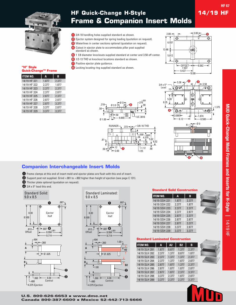
Ejector Half
.812 Offset
.687
8.500
.687 ±.001 8.994 9.714
8.00
A A2
Ø .625
.360 1.00 .494
8.00 Central
1.00
B
.360 .480
4.375 Ejection
B2
Ejector Half
.812 Offset
.687
8.500
.687 ±.001 8.994 9.714
8.00
A
Ø .625
.360 .494
8.00 Central
B
.360 .480
4.375 Ejection
1
2
4
3
1
2
4
3
Ejector Half
.812 Offset
.687
8.500
.687 ±.001 8.994 9.714
8.00
A A2
Ø .625
.360 1.00 .494
8.00 Central
1.00
B
.360 .480
4.375 Ejection
B2
Ejector Half
.812 Offset
.687
8.500
.687 ±.001 8.994 9.714
8.00
A
Ø .625
.360 .494
8.00 Central
B
.360 .480
4.375 Ejection
1
2
4
3
1
2
4
3
StandardSolid:9.0x8.5
StandardLaminated:9.0x8.5
1 Frameclampsatthisendofinsertmoldandejectorplatesareflushwiththisendofinsert.2 Supportpostnotsupplied.Grind+.001to+.002higherthanheightofejection(seepageC131).3 Thickerplateoptional(quotationonrequest).4 3/4x5°leadthisend.
Companion Interchangeable Insert Molds
HF Quick-Change H-Style
Frame & Companion Insert Molds14/19 HF
5 6
Ø SØ 2.0
9.000+.002–.000
.50A
Ø 1.00
.50
.218.275
.90
±.001
UC 3816
8
3/8-16 THDRUNNER
.81
.373
.502.00
.12
.500
.90
6.525.62
B
.1251.12
1.25
.36±.0005
4.375
7
OFFSET7.937
8.062
13.88
6.937
5.812
2.00
9.43718.88
3.00 1
Ø 0R
1.375
3.0008.12 8.500
1.874
4
8.255.00
5.383.50
32
3/4 x 5°Lead
.12
5 6
Ø SØ 2.0
9.000+.002–.000
.50A
Ø 1.00
.50
.218.275
.90
±.001
UC 3816
8
3/8-16 THDRUNNER
.81
.373
.502.00
.12
.500
.90
6.525.62
B
.1251.12
1.25
.36±.0005
4.375
7
OFFSET7.937
8.062
13.88
6.937
5.812
2.00
9.43718.88
3.00 1
Ø 0R
1.375
3.0008.12 8.500
1.874
4
8.255.00
5.383.50
32
3/4 x 5°Lead
.12
ITEM NO. A B14/19SSH221 1.877 2.37714/19SSH222 2.377 1.87714/19SSH223 2.377 2.37714/19SSH224 2.377 2.87714/19SSH225 2.877 2.37714/19SSH226 2.877 2.87714/19SSH227 2.877 3.37714/19SSH228 3.377 2.87714/19SSH229 3.377 3.377
Standard Solid Construction
ITEM NO. A A2 B2 B14/19SLH281 1.877 0.877 1.377 2.37714/19SLH282 2.377 1.377 0.877 1.87714/19SLH283 2.377 1.377 1.377 2.37714/19SLH284 2.377 1.377 1.877 2.87714/19SLH285 2.877 1.877 1.377 2.37714/19SLH286 2.877 1.877 1.877 2.87714/19SLH287 2.877 1.877 2.377 3.37714/19SLH288 3.377 2.377 1.877 2.87714/19SLH289 3.377 2.377 2.377 3.377
Standard Laminated Construction
1 3/4-10handlingholessuppliedstandardasshown.2 Ejectorsystemdesignedforspringloading(quotationonrequest).3 Waterlinesincentersectionsoptional(quotationonrequest).4 Cutoutinejectorplatetoaccommodatepillarpostsupplied
standardasshown.5 11/8diameterknockoutssuppliedstandardatcenterand3.50offcenter.6 1/2-13THDatknockoutlocationsstandardasshown.7 Positiveejectorplateguidance.8 Lockinglocatingringsuppliedstandardasshown.“H” Style
Quick-Change™ Frame
ITEM NO. A B14/19HF321 1.877 2.37714/19HF322 2.377 1.87714/19HF323 2.377 2.37714/19HF324 2.377 2.87714/19HF325 2.877 2.37714/19HF326 2.877 2.87714/19HF327 2.877 3.37714/19HF328 3.377 2.87714/19HF329 3.377 3.377
HF 67
U.S. 800-626-6653 n www.dme.netCanada 800-387-6600 n Mexico 52-442-713-5666
MUD
Quick-Change Mold Fram
es and Inserts for H-Style | 14/19 HF
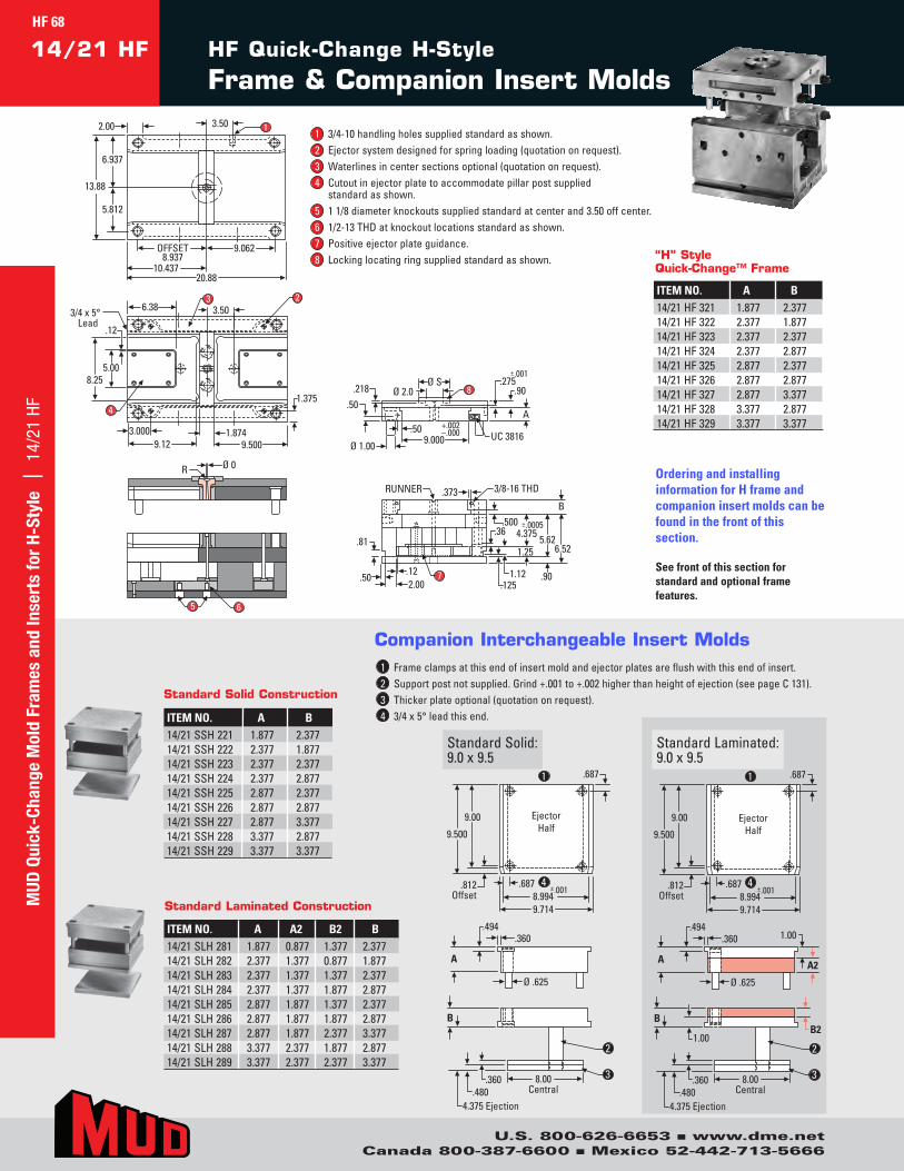
Ejector Half
.812 Offset
.687
9.500
.687 ±.001 8.994 9.714
9.00
A A2
Ø .625
.360 1.00 .494
8.00 Central
1.00
B
.360 .480
4.375 Ejection
B2
Ejector Half
.812 Offset
.687
9.500
.687 ±.001 8.994 9.714
9.00
A
Ø .625
.360 .494
8.00 Central
B
.360 .480
4.375 Ejection
1
2
4
3
1
2
4
3
Ejector Half
.812 Offset
.687
9.500
.687 ±.001 8.994 9.714
9.00
A A2
Ø .625
.360 1.00 .494
8.00 Central
1.00
B
.360 .480
4.375 Ejection
B2
Ejector Half
.812 Offset
.687
9.500
.687 ±.001 8.994 9.714
9.00
A
Ø .625
.360 .494
8.00 Central
B
.360 .480
4.375 Ejection
1
2
4
3
1
2
4
3
StandardSolid:9.0x9.5
StandardLaminated:9.0x9.5
1 Frameclampsatthisendofinsertmoldandejectorplatesareflushwiththisendofinsert.2 Supportpostnotsupplied.Grind+.001to+.002higherthanheightofejection(seepageC131).3 Thickerplateoptional(quotationonrequest).4 3/4x5°leadthisend.
Companion Interchangeable Insert Molds
HF Quick-Change H-Style
Frame & Companion Insert Molds14/21 HF
5 6
Ø SØ 2.0
9.000+.002–.000
.50A
Ø 1.00
.50
.218.275
.90
±.001
UC 3816
8
3/8-16 THDRUNNER
.81
.373
.502.00
.12
.500
.90
6.525.62
B
.1251.12
1.25
.36±.0005
4.375
7
OFFSET8.937
9.062
13.88
6.937
5.812
2.00
10.43720.88
3.50 1
Ø 0R
1.375
3.0009.12 9.500
1.874
4
8.255.00
6.38 3.503 2
3/4 x 5°Lead
.12
5 6
Ø SØ 2.0
9.000+.002–.000
.50A
Ø 1.00
.50
.218.275
.90
±.001
UC 3816
8
3/8-16 THDRUNNER
.81
.373
.502.00
.12
.500
.90
6.525.62
B
.1251.12
1.25
.36±.0005
4.375
7
OFFSET8.937
9.062
13.88
6.937
5.812
2.00
10.43720.88
3.50 1
Ø 0R
1.375
3.0009.12 9.500
1.874
4
8.255.00
6.38 3.503 2
3/4 x 5°Lead
.12
ITEM NO. A B14/21SSH221 1.877 2.37714/21SSH222 2.377 1.87714/21SSH223 2.377 2.37714/21SSH224 2.377 2.87714/21SSH225 2.877 2.37714/21SSH226 2.877 2.87714/21SSH227 2.877 3.37714/21SSH228 3.377 2.87714/21SSH229 3.377 3.377
Standard Solid Construction
ITEM NO. A A2 B2 B14/21SLH281 1.877 0.877 1.377 2.37714/21SLH282 2.377 1.377 0.877 1.87714/21SLH283 2.377 1.377 1.377 2.37714/21SLH284 2.377 1.377 1.877 2.87714/21SLH285 2.877 1.877 1.377 2.37714/21SLH286 2.877 1.877 1.877 2.87714/21SLH287 2.877 1.877 2.377 3.37714/21SLH288 3.377 2.377 1.877 2.87714/21SLH289 3.377 2.377 2.377 3.377
Standard Laminated Construction
Ordering and installing information for H frame and companion insert molds can be found in the front of this section.
See front of this section for standard and optional frame features.
1 3/4-10handlingholessuppliedstandardasshown.2 Ejectorsystemdesignedforspringloading(quotationonrequest).3 Waterlinesincentersectionsoptional(quotationonrequest).4 Cutoutinejectorplatetoaccommodatepillarpostsupplied
standardasshown.5 11/8diameterknockoutssuppliedstandardatcenterand3.50offcenter.6 1/2-13THDatknockoutlocationsstandardasshown.7 Positiveejectorplateguidance.8 Lockinglocatingringsuppliedstandardasshown. “H” Style
Quick-Change™ Frame
ITEM NO. A B14/21HF321 1.877 2.37714/21HF322 2.377 1.87714/21HF323 2.377 2.37714/21HF324 2.377 2.87714/21HF325 2.877 2.37714/21HF326 2.877 2.87714/21HF327 2.877 3.37714/21HF328 3.377 2.87714/21HF329 3.377 3.377
HF 68M
UD Q
uick
-Cha
nge
Mol
d Fr
ames
and
Inse
rts
for
H-St
yle
| 1
4/21
HF
U.S. 800-626-6653 n www.dme.netCanada 800-387-6600 n Mexico 52-442-713-5666
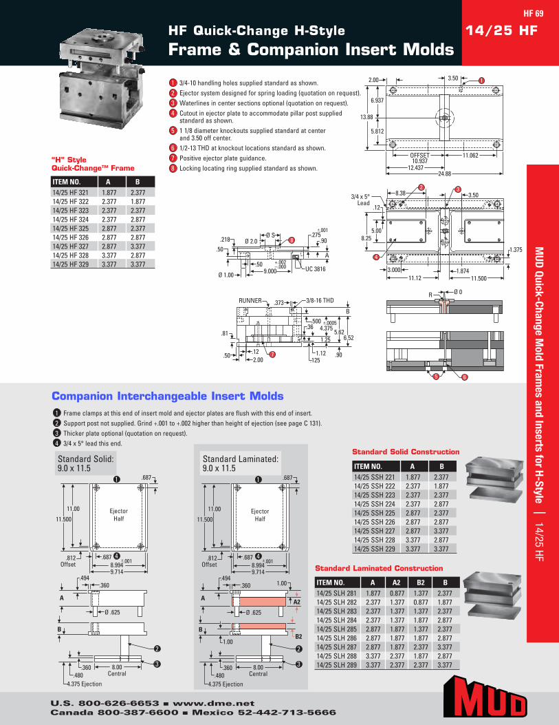
Ejector Half
.812 Offset
.687
11.500
.687 ±.001 8.994 9.714
11.00
A A2
Ø .625
.360 1.00 .494
8.00 Central
1.00
B
.360 .480
4.375 Ejection
B2
Ejector Half
.812 Offset
.687
11.500
.687 ±.001 8.994 9.714
11.00
A
Ø .625
.360 .494
8.00 Central
B
.360 .480
4.375 Ejection
1
2
4
3
1
2
4
3
Ejector Half
.812 Offset
.687
11.500
.687 ±.001 8.994 9.714
11.00
A A2
Ø .625
.360 1.00 .494
8.00 Central
1.00
B
.360 .480
4.375 Ejection
B2
Ejector Half
.812 Offset
.687
11.500
.687 ±.001 8.994 9.714
11.00
A
Ø .625
.360 .494
8.00 Central
B
.360 .480
4.375 Ejection
1
2
4
3
1
2
4
3
StandardSolid:9.0x11.5
StandardLaminated:9.0x11.5
1 Frameclampsatthisendofinsertmoldandejectorplatesareflushwiththisendofinsert.2 Supportpostnotsupplied.Grind+.001to+.002higherthanheightofejection(seepageC131).3 Thickerplateoptional(quotationonrequest).4 3/4x5°leadthisend.
Companion Interchangeable Insert Molds
HF Quick-Change H-Style
Frame & Companion Insert Molds14/25 HF
5 6
Ø SØ 2.0
9.000+.002–.000
.50A
Ø 1.00
.50
.218.275
.90
±.001
UC 3816
8
3/8-16 THDRUNNER
.81
.373
.502.00
.12
.500
.90
6.525.62
B
.1251.12
1.25
.36±.0005
4.375
7
OFFSET10.937
11.062
13.88
6.937
5.812
2.00
12.43724.88
3.50 1
Ø 0R
1.375
3.00011.12 11.500
1.874
4
8.255.00
8.38 3.5032
3/4 x 5°Lead
.12
ITEM NO. A B14/25SSH221 1.877 2.37714/25SSH222 2.377 1.87714/25SSH223 2.377 2.37714/25SSH224 2.377 2.87714/25SSH225 2.877 2.37714/25SSH226 2.877 2.87714/25SSH227 2.877 3.37714/25SSH228 3.377 2.87714/25SSH229 3.377 3.377
Standard Solid Construction
ITEM NO. A A2 B2 B14/25SLH281 1.877 0.877 1.377 2.37714/25SLH282 2.377 1.377 0.877 1.87714/25SLH283 2.377 1.377 1.377 2.37714/25SLH284 2.377 1.377 1.877 2.87714/25SLH285 2.877 1.877 1.377 2.37714/25SLH286 2.877 1.877 1.877 2.87714/25SLH287 2.877 1.877 2.377 3.37714/25SLH288 3.377 2.377 1.877 2.87714/25SLH289 3.377 2.377 2.377 3.377
Standard Laminated Construction
1 3/4-10handlingholessuppliedstandardasshown.2 Ejectorsystemdesignedforspringloading(quotationonrequest).3 Waterlinesincentersectionsoptional(quotationonrequest).4 Cutoutinejectorplatetoaccommodatepillarpostsupplied
standardasshown.5 11/8diameterknockoutssuppliedstandardatcenter
and3.50offcenter.6 1/2-13THDatknockoutlocationsstandardasshown.7 Positiveejectorplateguidance.8 Lockinglocatingringsuppliedstandardasshown.
“H” Style Quick-Change™ Frame
ITEM NO. A B14/25HF321 1.877 2.37714/25HF322 2.377 1.87714/25HF323 2.377 2.37714/25HF324 2.377 2.87714/25HF325 2.877 2.37714/25HF326 2.877 2.87714/25HF327 2.877 3.37714/25HF328 3.377 2.87714/25HF329 3.377 3.377
HF 69M
UD Quick-Change M
old Frames and Inserts for H-Style | 14/25 HF
U.S. 800-626-6653 n www.dme.netCanada 800-387-6600 n Mexico 52-442-713-5666
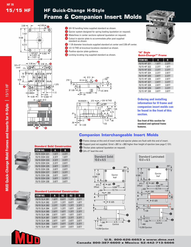
R Ø O
7.437
6.312
14.887.437
OFFSET5.937
6.062
1
14.88
2.00 3.00
1.375
3.000
6.00 6.500
1.25
4
9.005.50
1.874
3.38 3.50 32
1.12
3/4 x 5°Lead .12
65
8
Ø S.218 Ø 2.0
Ø 1.00
1.37
10.000+.002–.000
.750±.001
UC 3816
.50
.50
A
3/8-16 THD
B
±.0005
.373RUNNER
.81
.502.00
.12.125
.500
.901.37
1.50
.367.65
6.755.250
7
A2
1.00
1.00 B2
Ejector Half
.812 Offset
.687
6.500
.687 ±.001 9.994
10.714
5.88
A
Ø .625
.360 .494
8.75 Central
B
.360 .480
5.250 Ejection
Ejector Half
.812 Offset
.687
6.500
.687 ±.001 9.994
10.714
5.88
A
Ø .625
.360 .494
8.75 Central
B
.360 .480
5.250 Ejection
1
2
4
3
1
2
4
3
A2
1.00
1.00 B2
Ejector Half
.812 Offset
.687
6.500
.687 ±.001 9.994
10.714
5.88
A
Ø .625
.360 .494
8.75 Central
B
.360 .480
5.250 Ejection
Ejector Half
.812 Offset
.687
6.500
.687 ±.001 9.994 10.714
5.88
A
Ø .625
.360 .494
8.75 Central
B
.360 .480
5.250 Ejection
1
2
4
3
1
2
4
3
StandardSolid:10.0x6.5
StandardLaminated:10.0x6.5
1 Frameclampsatthisendofinsertmoldandejectorplatesareflushwiththisendofinsert.2 Supportpostnotsupplied.Grind+.001to+.002higherthanheightofejection(seepageC131).3 Thickerplateoptional(quotationonrequest).4 3/4x5°leadthisend.
Companion Interchangeable Insert Molds
R Ø O
7.437
6.312
14.887.437
OFFSET5.937
6.062
1
14.88
2.00 3.00
1.375
3.000
6.00 6.500
1.25
4
9.005.50
1.874
3.38 3.50 32
1.12
3/4 x 5°Lead .12
65
8
Ø S.218 Ø 2.0
Ø 1.00
1.37
10.000+.002–.000
.750±.001
UC 3816
.50
.50
A
3/8-16 THD
B
±.0005
.373RUNNER
.81
.502.00
.12.125
.500
.901.37
1.50
.367.65
6.755.250
7
HF Quick-Change H-Style
Frame & Companion Insert Molds15/15 HF
ITEM NO. A B15/15SSH221 1.877 2.37715/15SSH222 2.377 1.87715/15SSH223 2.377 2.37715/15SSH224 2.377 2.87715/15SSH225 2.877 2.37715/15SSH226 2.877 2.87715/15SSH227 2.877 3.37715/15SSH228 2.877 3.87715/15SSH229 3.877 3.37715/15SSH230 3.877 3.877
Standard Solid Construction
ITEM NO. A A2 B2 B15/15SLH281 1.877 0.877 1.377 2.37715/15SLH282 2.377 1.377 0.877 1.87715/15SLH283 2.377 1.377 1.377 2.37715/15SLH284 2.377 1.377 1.877 2.87715/15SLH285 2.877 1.877 1.377 2.37715/15SLH286 2.877 1.877 1.877 2.87715/15SLH287 2.877 1.877 2.377 3.37715/15SLH288 2.877 1.877 2.877 3.87715/15SLH289 3.877 2.877 2.377 3.37715/15SLH290 3.877 2.877 2.877 3.877
Standard Laminated Construction
Ordering and installing information for H frame and companion insert molds can be found in the front of this section.
See front of this section for standard and optional frame features.
1 3/4-10handlingholessuppliedstandardasshown.2 Ejectorsystemdesignedforspringloading(quotationonrequest).3 Waterlinesincentersectionsoptional(quotationonrequest).4 Cutoutinejectorplatetoaccommodatepillarpostsupplied
standardasshown.5 11/8diameterknockoutssuppliedstandardatcenterand3.50offcenter.6 1/2-13THDatknockoutlocationsstandardasshown.7 Positiveejectorplateguidance.8 Lockinglocatingringsuppliedstandardasshown.
ITEM NO. A B15/15HF321 1.877 2.37715/15HF322 2.377 1.87715/15HF323 2.377 2.37715/15HF324 2.377 2.87715/15HF325 2.877 2.37715/15HF326 2.877 2.87715/15HF327 2.877 3.37715/15HF328 2.877 3.87715/15HF329 3.877 3.37715/15HF330 3.877 3.877
“H” Style Quick-Change™ Frame
HF 70M
UD Q
uick
-Cha
nge
Mol
d Fr
ames
and
Inse
rts
for
H-St
yle
| 1
5/15
HF
U.S. 800-626-6653 n www.dme.netCanada 800-387-6600 n Mexico 52-442-713-5666
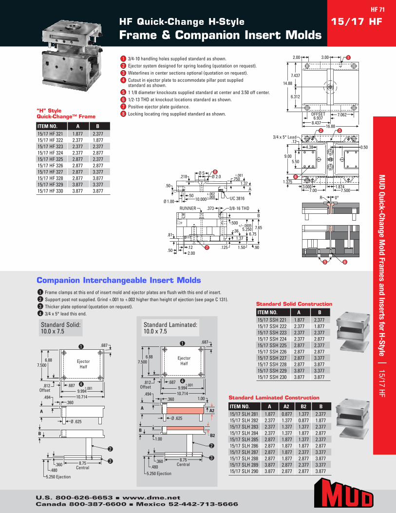
2.00 3.00
7.437
14.88
6.312
OFFSET 6.937
8.437 16.88
7.062
2 3
4.38 3.50
4
.12
9.00 5.50
1.375 3.000
7.00 7.500 1.874
R 0°
1
3/4 x 5° Lead
5 6
8Ø 2.0
Ø S
.50
.218
.50Ø 1.00 10.000
+.002 –.000 UC 3816
.7501.37
A
±.001
.81
.50.122.00
7 .125
RUNNER .373 3/8-16 THD
.500
.36
1.37
+/–.00055.250
1.50
6.75
.90
7.65
B
2.00 3.00
7.437
14.88
6.312
OFFSET6.937
8.43716.88
7.062
2 3
4.38 3.50
4
.12
9.005.50
1.3753.000
7.00 7.5001.874
R 0°
1
3/4 x 5° Lead
5 6
8Ø 2.0
Ø S
.50
.218
.50 Ø 1.00 10.000
+.002 –.000 UC 3816
.750 1.37
A
±.001
.81
.50 .12 2.00
7 .125
RUNNER .373 3/8-16 THD
.500
.36
1.37
+/–.0005 5.250
1.50
6.75
.90
7.65
B
Ejector Half
.812 Offset
7.500 6.88
.687 ±.001 9.994
10.714
A
Ø .625
.360 .494
B
8.75 Central
.360 .480
5.250 Ejection
.687
Ejector Half
.812 Offset
7.500 6.88
.687 ±.001 9.994
10.714
A
Ø .625
.360 .494
B
8.75 Central
.360 .480
5.250 Ejection
.687
A2
1.00
1.00 B2
1
2
4
3
1
2
4
3
Ejector Half
.812 Offset
7.500 6.88
.687 ±.001 9.994
10.714
A
Ø .625
.360 .494
B
8.75 Central
.360 .480
5.250 Ejection
.687
Ejector Half
.812 Offset
7.500 6.88
.687 ±.001 9.994
10.714
A
Ø .625
.360 .494
B
8.75 Central
.360 .480
5.250 Ejection
.687
A2
1.00
1.00 B2
1
2
4
3
1
2
4
3
StandardSolid:10.0x7.5
StandardLaminated:10.0x7.5
1 Frameclampsatthisendofinsertmoldandejectorplatesareflushwiththisendofinsert.2 Supportpostnotsupplied.Grind+.001to+.002higherthanheightofejection(seepageC131).3 Thickerplateoptional(quotationonrequest).4 3/4x5°leadthisend.
Companion Interchangeable Insert Molds
HF Quick-Change H-Style
Frame & Companion Insert Molds15/17 HF
ITEM NO. A B15/17SSH221 1.877 2.37715/17SSH222 2.377 1.87715/17SSH223 2.377 2.37715/17SSH224 2.377 2.87715/17SSH225 2.877 2.37715/17SSH226 2.877 2.87715/17SSH227 2.877 3.37715/17SSH228 2.877 3.87715/17SSH229 3.877 3.37715/17SSH230 3.877 3.877
Standard Solid Construction
ITEM NO. A A2 B2 B15/17SLH281 1.877 0.877 1.377 2.37715/17SLH282 2.377 1.377 0.877 1.87715/17SLH283 2.377 1.377 1.377 2.37715/17SLH284 2.377 1.377 1.877 2.87715/17SLH285 2.877 1.877 1.377 2.37715/17SLH286 2.877 1.877 1.877 2.87715/17SLH287 2.877 1.877 2.377 3.37715/17SLH288 2.877 1.877 2.877 3.87715/17SLH289 3.877 2.877 2.377 3.37715/17SLH290 3.877 2.877 2.877 3.877
Standard Laminated Construction
1 3/4-10handlingholessuppliedstandardasshown.2 Ejectorsystemdesignedforspringloading(quotationonrequest).3 Waterlinesincentersectionsoptional(quotationonrequest).4 Cutoutinejectorplatetoaccommodatepillarpostsupplied
standardasshown.5 11/8diameterknockoutssuppliedstandardatcenterand3.50offcenter.6 1/2-13THDatknockoutlocationsstandardasshown.7 Positiveejectorplateguidance.8 Lockinglocatingringsuppliedstandardasshown.
ITEM NO. A B15/17HF321 1.877 2.37715/17HF322 2.377 1.87715/17HF323 2.377 2.37715/17HF324 2.377 2.87715/17HF325 2.877 2.37715/17HF326 2.877 2.87715/17HF327 2.877 3.37715/17HF328 2.877 3.87715/17HF329 3.877 3.37715/17HF330 3.877 3.877
“H” Style Quick-Change™ Frame
MUD
Quick-Change Mold Fram
es and Inserts for H-Style | 15/17 HF
U.S. 800-626-6653 n www.dme.netCanada 800-387-6600 n Mexico 52-442-713-5666
HF 71
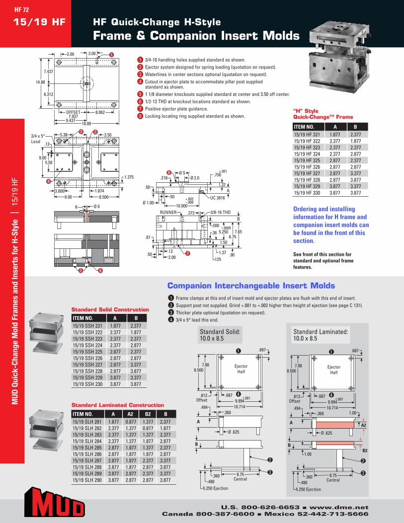
Ø S
14.88
7.437
6.312
2.00 3.00 1
OFFSET 7.937
8.062
9.437 18.88
3.50 3 2
5.38
4
9.00 5.50
.12
1.375
3.000 8.00 8.500
1.874
6 5
Ø 0R
Ø 2.0 .218
.50
10.000 +.002–.000Ø 1.00
.50 UC 3816
A 1.37
.750 ±.001
3/8-16 THDRUNNER .373
.81
8
.502.00.12
.500
.90
7.656.75
B
.1251.37
1.50
.36±.0005
5.250
3/4 x 5°Lead
7
Ejector Half
.812 Offset
8.500 7.88
.687 ±.001 9.994
10.714
A
Ø .625
.360 .494
B
2
8.75 Central
.360 .480
5.250 Ejection
.687
Ejector Half
.812 Offset
8.500 7.88
.687 ±.001 9.994
10.714
A
Ø .625
.360 .494
B
8.75 Central
.360 .480
5.250 Ejection
.687
A2
1.00
1.00 B2
1
2
4
3
1
2
4
3
Ejector Half
.812 Offset
8.500 7.88
.687 ±.001 9.994
10.714
A
Ø .625
.360 .494
B
2
8.75 Central
.360 .480
5.250 Ejection
.687
Ejector Half
.812 Offset
8.500 7.88
.687 ±.001 9.994
10.714
A
Ø .625
.360 .494
B
8.75 Central
.360 .480
5.250 Ejection
.687
A2
1.00
1.00 B2
1
2
4
3
1
2
4
3
StandardSolid:10.0x8.5
StandardLaminated:10.0x8.5
1 Frameclampsatthisendofinsertmoldandejectorplatesareflushwiththisendofinsert.2 Supportpostnotsupplied.Grind+.001to+.002higherthanheightofejection(seepageC131).3 Thickerplateoptional(quotationonrequest).4 3/4x5°leadthisend.
Companion Interchangeable Insert Molds
Ø S
14.88
7.437
6.312
2.00 3.00 1
OFFSET 7.937
8.062
9.437 18.88
3.50 3 2
5.38
4
9.00 5.50
.12
1.375
3.000 8.00 8.500
1.874
6 5
Ø 0R
Ø 2.0 .218
.50
10.000 +.002–.000Ø 1.00
.50 UC 3816
A 1.37
.750 ±.001
3/8-16 THDRUNNER .373
.81
8
.502.00.12
.500
.90
7.656.75
B
.1251.37
1.50
.36±.0005
5.250
3/4 x 5°Lead
7
HF Quick-Change H-Style
Frame & Companion Insert Molds15/19 HF
ITEM NO. A B15/19SSH221 1.877 2.37715/19SSH222 2.377 1.87715/19SSH223 2.377 2.37715/19SSH224 2.377 2.87715/19SSH225 2.877 2.37715/19SSH226 2.877 2.87715/19SSH227 2.877 3.37715/19SSH228 2.877 3.87715/19SSH229 3.877 3.37715/19SSH230 3.877 3.877
Standard Solid Construction
ITEM NO. A A2 B2 B15/19SLH281 1.877 0.877 1.377 2.37715/19SLH282 2.377 1.377 0.877 1.87715/19SLH283 2.377 1.377 1.377 2.37715/19SLH284 2.377 1.377 1.877 2.87715/19SLH285 2.877 1.877 1.377 2.37715/19SLH286 2.877 1.877 1.877 2.87715/19SLH287 2.877 1.877 2.377 3.37715/19SLH288 2.877 1.877 2.877 3.87715/19SLH289 3.877 2.877 2.377 3.37715/19SLH290 3.877 2.877 2.877 3.877
Standard Laminated Construction
Ordering and installing information for H frame and companion insert molds can be found in the front of this section.
See front of this section for standard and optional frame features.
1 3/4-10handlingholessuppliedstandardasshown.2 Ejectorsystemdesignedforspringloading(quotationonrequest).3 Waterlinesincentersectionsoptional(quotationonrequest).4 Cutoutinejectorplatetoaccommodatepillarpostsupplied
standardasshown.5 11/8diameterknockoutssuppliedstandardatcenterand3.50offcenter.6 1/2-13THDatknockoutlocationsstandardasshown.7 Positiveejectorplateguidance.8 Lockinglocatingringsuppliedstandardasshown.
ITEM NO. A B15/19HF321 1.877 2.37715/19HF322 2.377 1.87715/19HF323 2.377 2.37715/19HF324 2.377 2.87715/19HF325 2.877 2.37715/19HF326 2.877 2.87715/19HF327 2.877 3.37715/19HF328 2.877 3.87715/19HF329 3.877 3.37715/19HF330 3.877 3.877
“H” Style Quick-Change™ Frame
MUD
Qui
ck-C
hang
e M
old
Fram
es a
nd In
sert
s fo
r H-
Styl
e |
15/
19 H
F
U.S. 800-626-6653 n www.dme.netCanada 800-387-6600 n Mexico 52-442-713-5666
HF 72
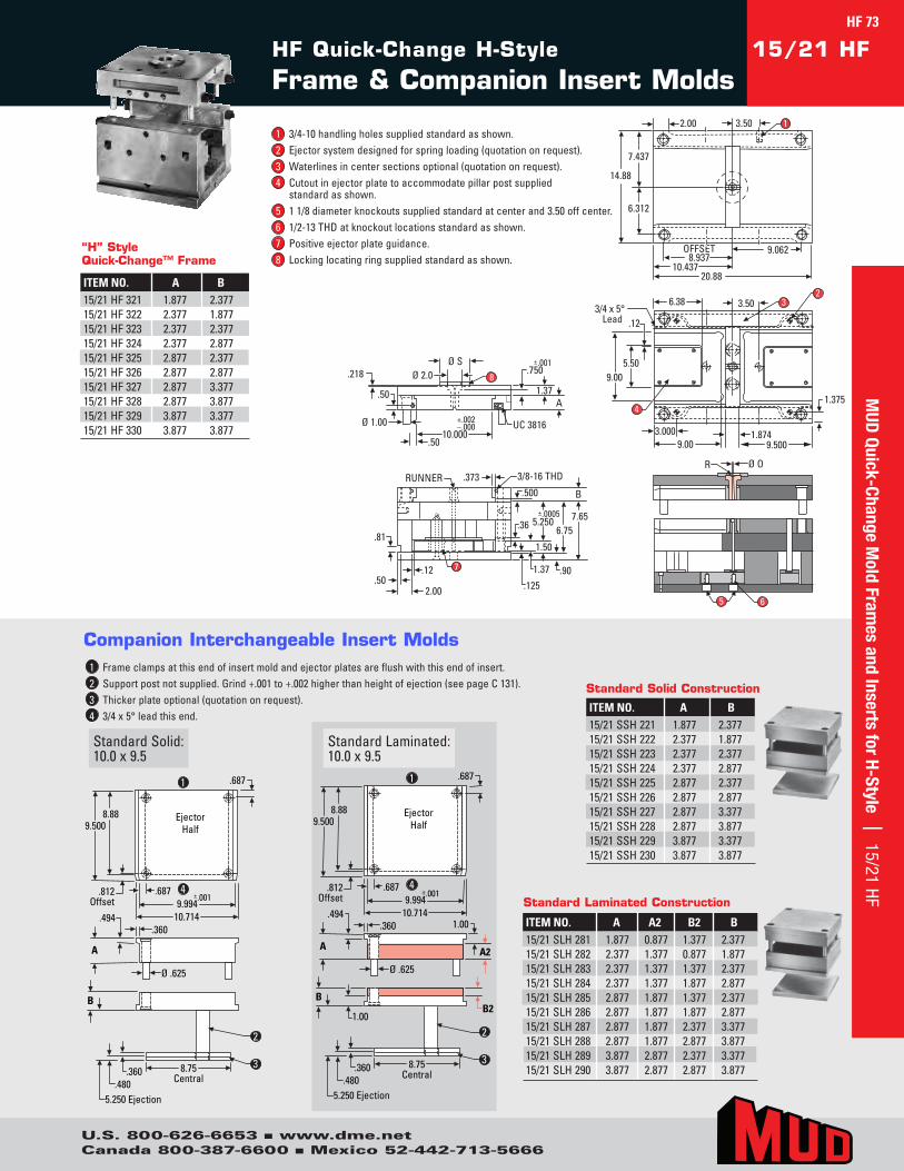
R Ø O
7.437
6.312
20.88 10.437
OFFSET 8.937
9.062
1
14.88
2.00 3.50
1.375
3.000 9.00 9.500
4
9.00 5.50
1.874
6.38 3.50 3 2
3/4 x 5°Lead .12
8
Ø S.218 Ø 2.0
Ø 1.00
1.37
10.000 +.002 –.000
.750±.001
UC 3816
.50
.50
A
3/8-16 THD
B
±.0005
.373RUNNER
.81
.502.00
.12.125
.500
.901.37
1.50
.367.65
6.755.250
7
6 5
R Ø O
7.437
6.312
20.8810.437
OFFSET8.937
9.062
1
14.88
2.00 3.50
1.375
3.000 9.00 9.500
4
9.00 5.50
1.874
6.38 3.50 3 2
3/4 x 5°Lead .12
8
Ø S.218 Ø 2.0
Ø 1.00
1.37
10.000 +.002 –.000
.750 ±.001
UC 3816
.50
.50
A
3/8-16 THD
B
±.0005
.373 RUNNER
.81
.50 2.00
.12 .125
.500
.90 1.37
1.50
.36 7.65
6.75 5.250
7
65
EjectorHalf
.812Offset
9.5008.88
.687 ±.0019.994
10.714
A
Ø .625
.360.494
B
8.75Central
.360.480
5.250 Ejection
.687
EjectorHalf
.812Offset
9.5008.88
.687 ±.0019.994
10.714
A
Ø .625
.360.494
B
8.75Central
.360.480
5.250 Ejection
.687
A2
1.00
1.00B2
1
2
4
3
1
2
4
3
EjectorHalf
.812Offset
9.5008.88
.687 ±.0019.994
10.714
A
Ø .625
.360.494
B
8.75Central
.360.480
5.250 Ejection
.687
EjectorHalf
.812Offset
9.5008.88
.687 ±.0019.994
10.714
A
Ø .625
.360.494
B
8.75Central
.360.480
5.250 Ejection
.687
A2
1.00
1.00B2
1
2
4
3
1
2
4
3
StandardSolid:10.0x9.5
StandardLaminated:10.0x9.5
1 Frameclampsatthisendofinsertmoldandejectorplatesareflushwiththisendofinsert.2 Supportpostnotsupplied.Grind+.001to+.002higherthanheightofejection(seepageC131).3 Thickerplateoptional(quotationonrequest).4 3/4x5°leadthisend.
Companion Interchangeable Insert Molds
HF Quick-Change H-Style
Frame & Companion Insert Molds15/21 HF
ITEM NO. A B15/21SSH221 1.877 2.37715/21SSH222 2.377 1.87715/21SSH223 2.377 2.37715/21SSH224 2.377 2.87715/21SSH225 2.877 2.37715/21SSH226 2.877 2.87715/21SSH227 2.877 3.37715/21SSH228 2.877 3.87715/21SSH229 3.877 3.37715/21SSH230 3.877 3.877
Standard Solid Construction
ITEM NO. A A2 B2 B15/21SLH281 1.877 0.877 1.377 2.37715/21SLH282 2.377 1.377 0.877 1.87715/21SLH283 2.377 1.377 1.377 2.37715/21SLH284 2.377 1.377 1.877 2.87715/21SLH285 2.877 1.877 1.377 2.37715/21SLH286 2.877 1.877 1.877 2.87715/21SLH287 2.877 1.877 2.377 3.37715/21SLH288 2.877 1.877 2.877 3.87715/21SLH289 3.877 2.877 2.377 3.37715/21SLH290 3.877 2.877 2.877 3.877
Standard Laminated Construction
1 3/4-10handlingholessuppliedstandardasshown.2 Ejectorsystemdesignedforspringloading(quotationonrequest).3 Waterlinesincentersectionsoptional(quotationonrequest).4 Cutoutinejectorplatetoaccommodatepillarpostsupplied
standardasshown.5 11/8diameterknockoutssuppliedstandardatcenterand3.50offcenter.6 1/2-13THDatknockoutlocationsstandardasshown.7 Positiveejectorplateguidance.8 Lockinglocatingringsuppliedstandardasshown.
ITEM NO. A B15/21HF321 1.877 2.37715/21HF322 2.377 1.87715/21HF323 2.377 2.37715/21HF324 2.377 2.87715/21HF325 2.877 2.37715/21HF326 2.877 2.87715/21HF327 2.877 3.37715/21HF328 2.877 3.87715/21HF329 3.877 3.37715/21HF330 3.877 3.877
“H” Style Quick-Change™ Frame
MUD
Quick-Change Mold Fram
es and Inserts for H-Style | 15/21 HFHF 73
U.S. 800-626-6653 n www.dme.netCanada 800-387-6600 n Mexico 52-442-713-5666
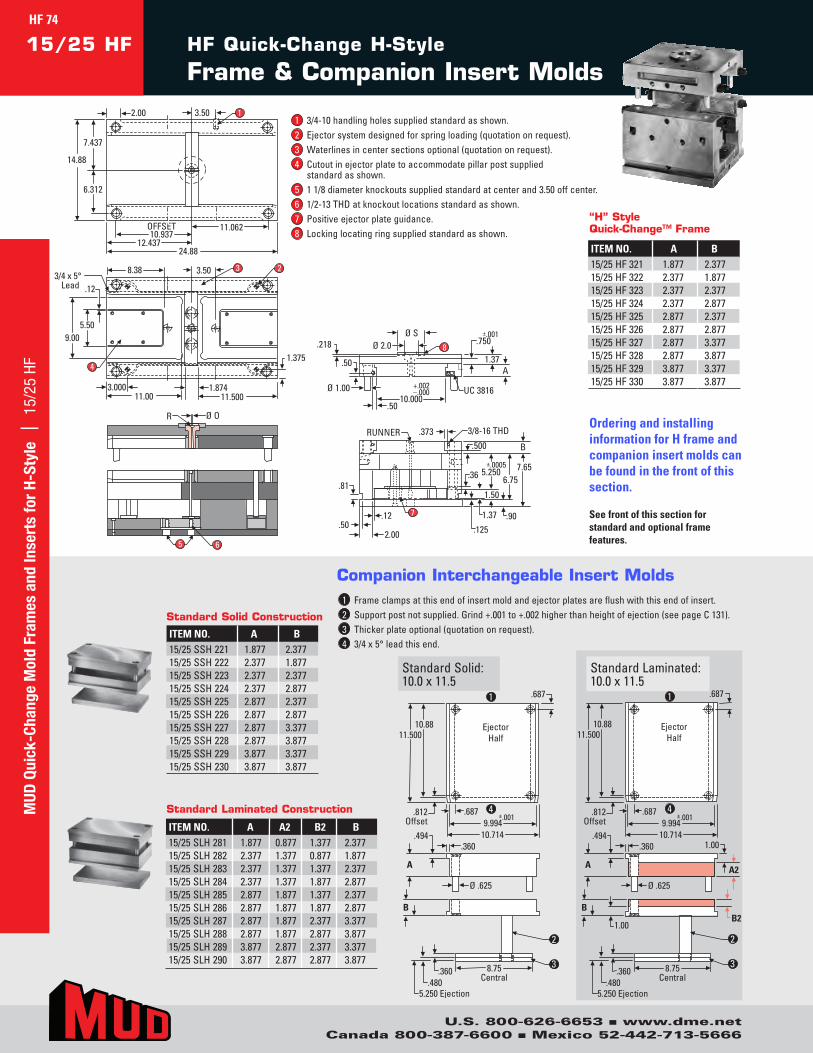
R Ø O
1.375
3.00011.00 11.500
4
9.005.50
1.874
8.38 3.50 3 23/4 x 5°
Lead .12
8
Ø S.218 Ø 2.0
Ø 1.00
1.37
10.000+.002–.000
.750±.001
UC 3816
.50
.50
A
3/8-16 THD
B
±.0005
.373RUNNER
.81
.502.00
.12.125
.500
.901.37
1.50
.367.65
6.755.250
7
65
7.437
6.312
24.8812.437
OFFSET10.937
11.062
1
14.88
2.00 3.50
Ejector Half
.812 Offset
11.500 10.88
.687 ±.0019.994
10.714
A
Ø .625
.360 .494
B
8.75 Central
.360 .480
5.250 Ejection
.687
Ejector Half
.812 Offset
11.500 10.88
.687 ±.001 9.994
10.714
A
Ø .625
.360 .494
B
8.75 Central
.360 .480
5.250 Ejection
.687
A2
1.00
1.00 B2
1
2
4
3
1
2
4
3
Ejector Half
.812 Offset
11.500 10.88
.687 ±.0019.994
10.714
A
Ø .625
.360 .494
B
8.75 Central
.360 .480
5.250 Ejection
.687
Ejector Half
.812 Offset
11.500 10.88
.687 ±.001 9.994
10.714
A
Ø .625
.360 .494
B
8.75 Central
.360 .480
5.250 Ejection
.687
A2
1.00
1.00 B2
1
2
4
3
1
2
4
3
StandardSolid:10.0x11.5
StandardLaminated:10.0x11.5
1 Frameclampsatthisendofinsertmoldandejectorplatesareflushwiththisendofinsert.2 Supportpostnotsupplied.Grind+.001to+.002higherthanheightofejection(seepageC131).3 Thickerplateoptional(quotationonrequest).4 3/4x5°leadthisend.
Companion Interchangeable Insert Molds
R Ø O
1.375
3.00011.00 11.500
4
9.005.50
1.874
8.38 3.50 3 23/4 x 5°
Lead .12
8
Ø S.218 Ø 2.0
Ø 1.00
1.37
10.000+.002–.000
.750±.001
UC 3816
.50
.50
A
3/8-16 THD
B
±.0005
.373RUNNER
.81
.502.00
.12.125
.500
.901.37
1.50
.367.65
6.755.250
7
65
7.437
6.312
24.8812.437
OFFSET10.937
11.062
1
14.88
2.00 3.50
HF Quick-Change H-Style
Frame & Companion Insert Molds15/25 HF
ITEM NO. A B15/25SSH221 1.877 2.37715/25SSH222 2.377 1.87715/25SSH223 2.377 2.37715/25SSH224 2.377 2.87715/25SSH225 2.877 2.37715/25SSH226 2.877 2.87715/25SSH227 2.877 3.37715/25SSH228 2.877 3.87715/25SSH229 3.877 3.37715/25SSH230 3.877 3.877
Standard Solid Construction
ITEM NO. A A2 B2 B15/25SLH281 1.877 0.877 1.377 2.37715/25SLH282 2.377 1.377 0.877 1.87715/25SLH283 2.377 1.377 1.377 2.37715/25SLH284 2.377 1.377 1.877 2.87715/25SLH285 2.877 1.877 1.377 2.37715/25SLH286 2.877 1.877 1.877 2.87715/25SLH287 2.877 1.877 2.377 3.37715/25SLH288 2.877 1.877 2.877 3.87715/25SLH289 3.877 2.877 2.377 3.37715/25SLH290 3.877 2.877 2.877 3.877
Standard Laminated Construction
Ordering and installing information for H frame and companion insert molds can be found in the front of this section.
See front of this section for standard and optional frame features.
1 3/4-10handlingholessuppliedstandardasshown.2 Ejectorsystemdesignedforspringloading(quotationonrequest).3 Waterlinesincentersectionsoptional(quotationonrequest).4 Cutoutinejectorplatetoaccommodatepillarpostsupplied
standardasshown.5 11/8diameterknockoutssuppliedstandardatcenterand3.50offcenter.6 1/2-13THDatknockoutlocationsstandardasshown.7 Positiveejectorplateguidance.8 Lockinglocatingringsuppliedstandardasshown.
ITEM NO. A B15/25HF321 1.877 2.37715/25HF322 2.377 1.87715/25HF323 2.377 2.37715/25HF324 2.377 2.87715/25HF325 2.877 2.37715/25HF326 2.877 2.87715/25HF327 2.877 3.37715/25HF328 2.877 3.87715/25HF329 3.877 3.37715/25HF330 3.877 3.877
“H” Style Quick-Change™ Frame
MUD
Qui
ck-C
hang
e M
old
Fram
es a
nd In
sert
s fo
r H-
Styl
e |
15/
25 H
F
U.S. 800-626-6653 n www.dme.netCanada 800-387-6600 n Mexico 52-442-713-5666
HF 74
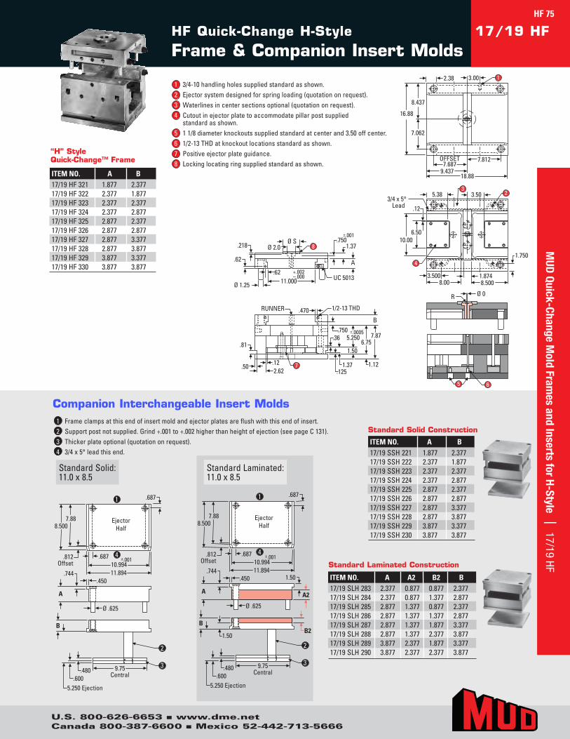
2.38 3.00
8.437
16.88
7.062
OFFSET7.687
9.43718.88
7.812
1
5 6
1/2-13 THDRUNNER
.81
.470
.502.62
.12
.750
1.12
7.876.75
B
.1251.37
1.50
.36±.0005
5.250
7
Ø 0R
1.750
3.5008.00 8.500
1.874
4
10.006.50
5.38 3.503
23/4 x 5°
Lead .12
Ø SØ 2.0
11.000+.002–.000
.62 A
Ø 1.25
.62
.218.750
1.37
±.001
UC 5013
8
Ejector Half
.812 Offset
8.500 7.88
.687 ±.001 10.994 11.894
A
Ø .625
.450 .744
B
9.75 Central
.480 .600
5.250 Ejection
.687
Ejector Half
.812 Offset
8.500 7.88
.687 ±.001 10.994 11.894
A
Ø .625
.450 .744
B
9.75 Central
.480 .600
5.250 Ejection
.687
A2
1.50
1.50 B2
1
2
4
3
1
2
4
3
Ejector Half
.812 Offset
8.500 7.88
.687 ±.001 10.994 11.894
A
Ø .625
.450 .744
B
9.75 Central
.480 .600
5.250 Ejection
.687
Ejector Half
.812 Offset
8.500 7.88
.687 ±.001 10.994 11.894
A
Ø .625
.450 .744
B
9.75 Central
.480 .600
5.250 Ejection
.687
A2
1.50
1.50 B2
1
2
4
3
1
2
4
3
StandardSolid:11.0x8.5
StandardLaminated:11.0x8.5
1 Frameclampsatthisendofinsertmoldandejectorplatesareflushwiththisendofinsert.2 Supportpostnotsupplied.Grind+.001to+.002higherthanheightofejection(seepageC131).3 Thickerplateoptional(quotationonrequest).4 3/4x5°leadthisend.
Companion Interchangeable Insert Molds
HF Quick-Change H-Style
Frame & Companion Insert Molds17/19 HF
ITEM NO. A B17/19SSH221 1.877 2.37717/19SSH222 2.377 1.87717/19SSH223 2.377 2.37717/19SSH224 2.377 2.87717/19SSH225 2.877 2.37717/19SSH226 2.877 2.87717/19SSH227 2.877 3.37717/19SSH228 2.877 3.87717/19SSH229 3.877 3.37717/19SSH230 3.877 3.877
Standard Solid Construction
ITEM NO. A A2 B2 B17/19SLH283 2.377 0.877 0.877 2.37717/19SLH284 2.377 0.877 1.377 2.87717/19SLH285 2.877 1.377 0.877 2.37717/19SLH286 2.877 1.377 1.377 2.87717/19SLH287 2.877 1.377 1.877 3.37717/19SLH288 2.877 1.377 2.377 3.87717/19SLH289 3.877 2.377 1.877 3.37717/19SLH290 3.877 2.377 2.377 3.877
Standard Laminated Construction
1 3/4-10handlingholessuppliedstandardasshown.2 Ejectorsystemdesignedforspringloading(quotationonrequest).3 Waterlinesincentersectionsoptional(quotationonrequest).4 Cutoutinejectorplatetoaccommodatepillarpostsupplied
standardasshown.5 11/8diameterknockoutssuppliedstandardatcenterand3.50offcenter.6 1/2-13THDatknockoutlocationsstandardasshown.7 Positiveejectorplateguidance.8 Lockinglocatingringsuppliedstandardasshown.
ITEM NO. A B17/19HF321 1.877 2.37717/19HF322 2.377 1.87717/19HF323 2.377 2.37717/19HF324 2.377 2.87717/19HF325 2.877 2.37717/19HF326 2.877 2.87717/19HF327 2.877 3.37717/19HF328 2.877 3.87717/19HF329 3.877 3.37717/19HF330 3.877 3.877
“H” Style Quick-Change™ Frame
MUD
Quick-Change Mold Fram
es and Inserts for H-Style | 17/19 HFHF 75
U.S. 800-626-6653 n www.dme.netCanada 800-387-6600 n Mexico 52-442-713-5666
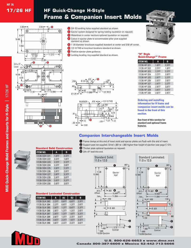
R 0°
2.38 3.50
8.437
16.88
7.062
OFFSET11.187
12.93725.88
11.312
2 3
8.88 3.50
4
.12
10.006.50
1.7503.500
11.50 12.0001.874
1
3/4 x 5° Lead
5 6
Ø 2.0Ø S 8
.62
.218
.62Ø 1.25
11.000+.002–.000 UC 5013
.7501.37
A
±.001
1/2-13 THD
B±.0005
.470RUNNER
.81
.502.62
.12 .125
.750
1.121.37
1.50
.36 7.876.75
5.250
7
Ejector Half
.812 Offset
12.000 11.38
.687 ±.001 10.994 11.894
A
Ø .625
.450 .744
B
9.75 Central
.480 .600
5.250 Ejection
.687
Ejector Half
.812 Offset
12.000 11.38
.687 ±.001 10.994 11.894
A
Ø .625
.450 .744
B
9.75 Central
.480 .600
5.250 Ejection
.687
A2
1.50
1.50 B2
1
2
4
3
1
2
4
3
Ejector Half
.812 Offset
12.000 11.38
.687 ±.001 10.994 11.894
A
Ø .625
.450 .744
B
9.75 Central
.480 .600
5.250 Ejection
.687
Ejector Half
.812 Offset
12.000 11.38
.687 ±.001 10.994 11.894
A
Ø .625
.450 .744
B
9.75 Central
.480 .600
5.250 Ejection
.687
A2
1.50
1.50 B2
1
2
4
3
1
2
4
3
StandardSolid:11.0x12.0
StandardLaminated:11.0x12.0
1 Frameclampsatthisendofinsertmoldandejectorplatesareflushwiththisendofinsert.2 Supportpostnotsupplied.Grind+.001to+.002higherthanheightofejection(seepageC131).3 Thickerplateoptional(quotationonrequest).4 3/4x5°leadthisend.
Companion Interchangeable Insert Molds
R 0°
2.38 3.50
8.437
16.88
7.062
OFFSET11.187
12.93725.88
11.312
2 3
8.88 3.50
4
.12
10.006.50
1.7503.500
11.50 12.0001.874
1
3/4 x 5°Lead
5 6
Ø 2.0Ø S 8
.62
.218
.62Ø 1.25
11.000+.002–.000 UC 5013
.7501.37
A
±.001
1/2-13 THD
B±.0005
.470RUNNER
.81
.502.62
.12 .125
.750
1.121.37
1.50
.36 7.876.75
5.250
7
HF Quick-Change H-Style
Frame & Companion Insert Molds17/26 HF
ITEM NO. A A2 B2 B17/26SLH283 2.377 0.877 0.877 2.37717/26SLH284 2.377 0.877 1.377 2.87717/26SLH285 2.877 1.377 0.877 2.37717/26SLH286 2.877 1.377 1.377 2.87717/26SLH287 2.877 1.377 1.877 3.37717/26SLH288 2.877 1.377 2.377 3.87717/26SLH289 3.877 2.377 1.877 3.37717/26SLH290 3.877 2.377 2.377 3.877
Standard Laminated Construction
ITEM NO. A B17/26SSH221 1.877 2.37717/26SSH222 2.377 1.87717/26SSH223 2.377 2.37717/26SSH224 2.377 2.87717/26SSH225 2.877 2.37717/26SSH226 2.877 2.87717/26SSH227 2.877 3.37717/26SSH228 2.877 3.87717/26SSH229 3.877 3.37717/26SSH230 3.877 3.877
Standard Solid Construction
Ordering and installing information for H frame and companion insert molds can be found in the front of this section.
See front of this section for standard and optional frame features.
1 3/4-10handlingholessuppliedstandardasshown.2 Ejectorsystemdesignedforspringloading(quotationonrequest).3 Waterlinesincentersectionsoptional(quotationonrequest).4 Cutoutinejectorplatetoaccommodatepillarpostsupplied
standardasshown.5 11/8diameterknockoutssuppliedstandardatcenterand3.50offcenter.6 1/2-13THDatknockoutlocationsstandardasshown.7 Positiveejectorplateguidance.8 Lockinglocatingringsuppliedstandardasshown.
ITEM NO. A B17/26HF321 1.877 2.37717/26HF322 2.377 1.87717/26HF323 2.377 2.37717/26HF324 2.377 2.87717/26HF325 2.877 2.37717/26HF326 2.877 2.87717/26HF327 2.877 3.37717/26HF328 2.877 3.87717/26HF329 3.877 3.37717/26HF330 3.877 3.877
“H” Style Quick-Change™ Frame
MUD
Qui
ck-C
hang
e M
old
Fram
es a
nd In
sert
s fo
r H-
Styl
e |
17/
26 H
FHF 76
U.S. 800-626-6653 n www.dme.netCanada 800-387-6600 n Mexico 52-442-713-5666
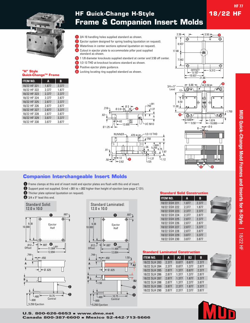
Ø SØ 2.0
12.000+.002–.000
.62 A
Ø 1.25
.62
.218.750
1.37
±.001
UC 5013
8
1/2-13 THDRUNNER
.81
.470
.502.62.12
.750
1.12
7.876.75
B
.1251.37
1.50
.36±.0005
5.250
7
OFFSET9.187
9.312
17.88
8.937
7.562
2.38
10.93721.88
3.50 1
1.750
3.5009.50 10.000
1.874
4
11.00
6.50
6.88 3.503
23/4 x 5°
Lead .12
5 6
Ø 0R
Ejector Half
.812 Offset
10.000 9.38
.687 ±.001 11.994 12.894
A
Ø .625
.450 .744
B
2
10.75 Central
.480 .600
5.250 Ejection
.687
Ejector Half
.812 Offset
10.000 9.38
.687 ±.001 11.994 12.894
A
Ø .625
.450 .744
B
10.75 Central
.480 .600
5.250 Ejection
.687
A2
1.50
1.50 B2
1
2
4
3
1
2
4
3
Ejector Half
.812 Offset
10.000 9.38
.687 ±.001 11.994 12.894
A
Ø .625
.450 .744
B
2
10.75 Central
.480 .600
5.250 Ejection
.687
Ejector Half
.812 Offset
10.000 9.38
.687 ±.001 11.994 12.894
A
Ø .625
.450 .744
B
10.75 Central
.480 .600
5.250 Ejection
.687
A2
1.50
1.50 B2
1
2
4
3
1
2
4
3
StandardSolid:12.0x10.0
StandardLaminated:12.0x10.0
1 Frameclampsatthisendofinsertmoldandejectorplatesareflushwiththisendofinsert.2 Supportpostnotsupplied.Grind+.001to+.002higherthanheightofejection(seepageC131).3 Thickerplateoptional(quotationonrequest).4 3/4x5°leadthisend.
Companion Interchangeable Insert Molds
HF Quick-Change H-Style
Frame & Companion Insert Molds18/22 HF
ITEM NO. A B18/22SSH221 1.877 2.37718/22SSH222 2.377 1.87718/22SSH223 2.377 2.37718/22SSH224 2.377 2.87718/22SSH225 2.877 2.37718/22SSH226 2.877 2.87718/22SSH227 2.877 3.37718/22SSH228 2.877 3.87718/22SSH229 3.877 3.37718/22SSH230 3.877 3.877
Standard Solid Construction
ITEM NO. A A2 B2 B18/22SLH283 2.377 0.877 0.877 2.37718/22SLH284 2.377 0.877 1.377 2.87718/22SLH285 2.877 1.377 0.877 2.37718/22SLH286 2.877 1.377 1.377 2.87718/22SLH287 2.877 1.377 1.877 3.37718/22SLH288 2.877 1.377 2.377 3.87718/22SLH289 3.877 2.377 1.877 3.37718/22SLH290 3.877 2.377 2.377 3.877
Standard Laminated Construction
1 3/4-10handlingholessuppliedstandardasshown.2 Ejectorsystemdesignedforspringloading(quotationonrequest).3 Waterlinesincentersectionsoptional(quotationonrequest).4 Cutoutinejectorplatetoaccommodatepillarpostsupplied
standardasshown.5 11/8diameterknockoutssuppliedstandardatcenterand3.50offcenter.6 1/2-13THDatknockoutlocationsstandardasshown.7 Positiveejectorplateguidance.8 Lockinglocatingringsuppliedstandardasshown.
ITEM NO. A B18/22HF321 1.877 2.37718/22HF322 2.377 1.87718/22HF323 2.377 2.37718/22HF324 2.377 2.87718/22HF325 2.877 2.37718/22HF326 2.877 2.87718/22HF327 2.877 3.37718/22HF328 2.877 3.87718/22HF329 3.877 3.37718/22HF330 3.877 3.877
“H” Style Quick-Change™ Frame
MUD
Quick-Change Mold Fram
es and Inserts for H-Style | 18/22 HFHF 77
U.S. 800-626-6653 n www.dme.netCanada 800-387-6600 n Mexico 52-442-713-5666
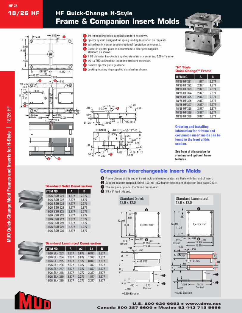
Ø SØ 2.0
12.000+.002–.000
.62A
Ø 1.25.62
.218 .750 1.37.001
UC 5013
8
1/2-13 THDRUNNER
.81
.470
.502.62.12
7.876.75
B
.1251.37
1.50
.36.0005
5.250
+–
7
.750
+–
1.12
OFFSET11.187
11.312
17.888.937
7.562
2.38
12.93725.88
3.50 1
12.000
4
11.006.50
1.7503.500
11.50
8.88
3.50
1.874
323/4 x 5˚
Lead .12
Ø 0R
65
Ejector Half11.3812.000
.812Offset 11.994
12.894
±.001.687
5.250 Ejection
10.75Central
.450
A
.744
Ø .625
B
.480.600
.687
Ejector Half 11.38
12.000
.812 Offset 11.994
12.894
±.001 .687
5.250 Ejection
10.75 Central
.450
A .744
Ø .625
B
.480 .600
.687
A2
B2
1.50
1.50
1
2
4
3
1
2
4
3
Ejector Half 11.38 12.000
.812 Offset 11.994
12.894
±.001 .687
5.250 Ejection
10.75 Central
.450
A
.744
Ø .625
B
.480 .600
.687
Ejector Half11.38
12.000
.812Offset 11.994
12.894
±.001.687
5.250 Ejection
10.75Central
.450
A .744
Ø .625
B
.480.600
.687
A2
B2
1.50
1.50
1
2
4
3
1
2
4
3
StandardSolid:12.0x12.0
StandardLaminated:12.0x12.0
1 Frameclampsatthisendofinsertmoldandejectorplatesareflushwiththisendofinsert.2 Supportpostnotsupplied.Grind+.001to+.002higherthanheightofejection(seepageC131).3 Thickerplateoptional(quotationonrequest).4 3/4x5°leadthisend.
Companion Interchangeable Insert Molds
Ø SØ 2.0
12.000+.002–.000
.62A
Ø 1.25.62
.218 .750 1.37.001
UC 5013
8
1/2-13 THDRUNNER
.81
.470
.502.62.12
7.876.75
B
.1251.37
1.50
.36.0005
5.250
+–
7
.750
+–
1.12
OFFSET11.187
11.312
17.888.937
7.562
2.38
12.93725.88
3.50 1
12.000
4
11.006.50
1.7503.500
11.50
8.88
3.50
1.874
323/4 x 5˚
Lead .12
Ø 0R
65
HF Quick-Change H-Style
Frame & Companion Insert Molds18/26 HF
ITEM NO. A B18/26SSH221 1.877 2.37718/26SSH222 2.377 1.87718/26SSH223 2.377 2.37718/26SSH224 2.377 2.87718/26SSH225 2.877 2.37718/26SSH226 2.877 2.87718/26SSH227 2.877 3.37718/26SSH228 2.877 3.87718/26SSH229 3.877 3.37718/26SSH230 3.877 3.877
Standard Solid Construction
ITEM NO. A A2 B2 B18/26SLH283 2.377 0.877 0.877 2.37718/26SLH284 2.377 0.877 1.377 2.87718/26SLH285 2.877 1.377 0.877 2.37718/26SLH286 2.877 1.377 1.377 2.87718/26SLH287 2.877 1.377 1.877 3.37718/26SLH288 2.877 1.377 2.377 3.87718/26SLH289 3.877 2.377 1.877 3.37718/26SLH290 3.877 2.377 2.377 3.877
Standard Laminated Construction
Ordering and installing information for H frame and companion insert molds can be found in the front of this section.
See front of this section for standard and optional frame features.
1 3/4-10handlingholessuppliedstandardasshown.2 Ejectorsystemdesignedforspringloading(quotationonrequest).3 Waterlinesincentersectionsoptional(quotationonrequest).4 Cutoutinejectorplatetoaccommodatepillarpostsupplied
standardasshown.5 11/8diameterknockoutssuppliedstandardatcenterand3.50offcenter.6 1/2-13THDatknockoutlocationsstandardasshown.7 Positiveejectorplateguidance.8 Lockinglocatingringsuppliedstandardasshown.
ITEM NO. A B18/26HF321 1.877 2.37718/26HF322 2.377 1.87718/26HF323 2.377 2.37718/26HF324 2.377 2.87718/26HF325 2.877 2.37718/26HF326 2.877 2.87718/26HF327 2.877 3.37718/26HF328 2.877 3.87718/26HF329 3.877 3.37718/26HF330 3.877 3.877
“H” Style Quick-Change™ Frame
MUD
Qui
ck-C
hang
e M
old
Fram
es a
nd In
sert
s fo
r H-
Styl
e |
18/
26 H
FHF 78
U.S. 800-626-6653 n www.dme.netCanada 800-387-6600 n Mexico 52-442-713-5666

1.7503.500
13.50 14.000
11.006.50
1.874
10.00 3.50
323/4 x 5°Lead
.12
Ø SØ 2.0
12.000+.002–.000
.62A
Ø 1.25.62
.218 .750 1.37.001
UC 5013
8
1/2-13 THDRUNNER
.81
.470
.502.62.12
7.876.75
B
.1251.37
1.50
.36.0005
5.250
OFFSET13.187
13.312
17.888.937
7.562
2.38
14.93729.88
3.50 1
4
Ø 0
5
R
6
+–
7
.750
+–
1.12
.88
Ejector Half13.38
14.000
.812Offset 11.994
12.894
±.001.687
5.250 Ejection
10.75Central
.450
A
.744
Ø .625
B
.480.600
.687
Ejector Half 13.38
14.000
.812 Offset 11.994
12.894
±.001 .687
5.250 Ejection
10.75 Central
.450
A .744
Ø .625
B
.480 .600
.687
A2
B2
1.50
1.50
1
2
4
3
1
2
4
3
Ejector Half 13.38
14.000
.812 Offset 11.994
12.894
±.001 .687
5.250 Ejection
10.75 Central
.450
A
.744
Ø .625
B
.480 .600
.687
Ejector Half13.38
14.000
.812Offset 11.994
12.894
±.001.687
5.250 Ejection
10.75Central
.450
A .744
Ø .625
B
.480.600
.687
A2
B2
1.50
1.50
1
2
4
3
1
2
4
3
StandardSolid:12.0x14.0
StandardLaminated:12.0x14.0
1 Frameclampsatthisendofinsertmoldandejectorplatesareflushwiththisendofinsert.2 Supportpostnotsupplied.Grind+.001to+.002higherthanheightofejection(seepageC131).3 Thickerplateoptional(quotationonrequest).4 3/4x5°leadthisend.
Companion Interchangeable Insert Molds
HF Quick-Change H-Style
Frame & Companion Insert Molds18/30 HF
ITEM NO. A B18/30SSH221 1.877 2.37718/30SSH222 2.377 1.87718/30SSH223 2.377 2.37718/30SSH224 2.377 2.87718/30SSH225 2.877 2.37718/30SSH226 2.877 2.87718/30SSH227 2.877 3.37718/30SSH228 2.877 3.87718/30SSH229 3.877 3.37718/30SSH230 3.877 3.877
Standard Solid Construction
ITEM NO. A A2 B2 B18/30SLH283 2.377 0.877 0.877 2.37718/30SLH284 2.377 0.877 1.377 2.87718/30SLH285 2.877 1.377 0.877 2.37718/30SLH286 2.877 1.377 1.377 2.87718/30SLH287 2.877 1.377 1.877 3.37718/30SLH288 2.877 1.377 2.377 3.87718/30SLH289 3.877 2.377 1.877 3.37718/30SLH290 3.877 2.377 2.377 3.877
Standard Laminated Construction
1 3/4-10handlingholessuppliedstandardasshown.2 Ejectorsystemdesignedforspringloading(quotationonrequest).3 Waterlinesincentersectionsoptional(quotationonrequest).4 Cutoutinejectorplatetoaccommodatepillarpostsupplied
standardasshown.5 11/8diameterknockoutssuppliedstandardatcenterand3.50offcenter.6 1/2-13THDatknockoutlocationsstandardasshown.7 Positiveejectorplateguidance.8 Lockinglocatingringsuppliedstandardasshown.
ITEM NO. A B18/30HF321 1.877 2.37718/30HF322 2.377 1.87718/30HF323 2.377 2.37718/30HF324 2.377 2.87718/30HF325 2.877 2.37718/30HF326 2.877 2.87718/30HF327 2.877 3.37718/30HF328 2.877 3.87718/30HF329 3.877 3.37718/30HF330 3.877 3.877
“H” Style Quick-Change™ Frame
MUD
Quick-Change Mold Fram
es and Inserts for H-Style | 18/30 HF
U.S. 800-626-6653 n www.dme.netCanada 800-387-6600 n Mexico 52-442-713-5666
HF 79
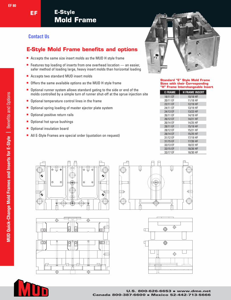
U.S. 800-626-6653 n www.dme.netCanada 800-387-6600 n Mexico 52-442-713-5666
EF E-Style
Mold Frame
Standard “E” Style Mold Frame Sizes with their Corresponding “H” Frame Interchangeable Insert
E-Style Mold Frame benefits and optionsn AcceptsthesamesizeinsertmoldsastheMUDHstyleframe
n Featurestoploadingofinsertsfromoneoverheadlocation—aneasier,safermethodofloadinglarge,heavyinsertmoldsthanhorizontalloading
n AcceptstwostandardMUDinsertmolds
n OffersthesameavailableoptionsastheMUDHstyleframe
n Optionalrunnersystemallowsstandardgatingtothesideorendofthemoldscontrolledbyasimpleturnofrunnershut-offatthesprueinjectionsite
n Optionaltemperaturecontrollinesintheframe
n Optionalspringloadingofmasterejectorplatesystem
n Optionalpositivereturnrails
n Optionalhotspruebushings
n Optionalinsulationboard
n AllE-StyleFramesarespecialorder(quotationonrequest)
EF 80M
UD Q
uick
-Cha
nge
Mol
d Fr
ames
and
Inse
rts
for
E-St
yle
| B
enef
its a
nd O
ptio
ns 18/11EF 10/18HF20/11EF 11/18HF22/11EF 12/19HF24/11EF 13/19HF24/13EF 13/23HF26/11EF 14/19HF26/12EF 14/21HF26/14EF 14/25HF28/11EF 15/19HF28/12EF 15/21HF28/14EF 15/25HF31/12EF 17/19HF31/15EF 17/26HF33/13EF 18/22HF33/15EF 18/26HF33/17EF 18/30HF
E FRAME H FRAME INSERT
Contact Us
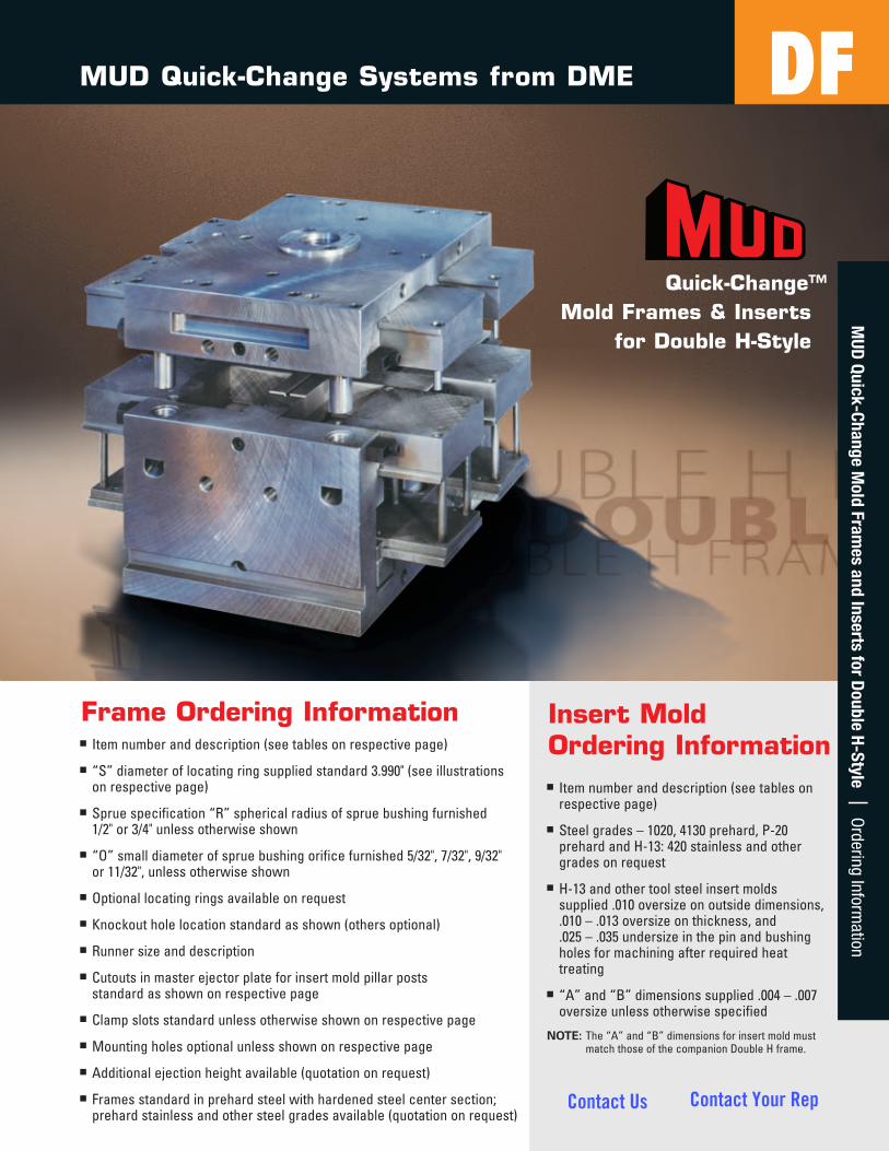
Frame Ordering Informationn Itemnumberanddescription(seetablesonrespectivepage)
n “S”diameteroflocatingringsuppliedstandard3.990"(seeillustrationsonrespectivepage)
n Spruespecification“R”sphericalradiusofspruebushingfurnished1/2"or3/4"unlessotherwiseshown
n “O”smalldiameterofspruebushingorificefurnished5/32",7/32",9/32"or11/32",unlessotherwiseshown
n Optionallocatingringsavailableonrequest
n Knockoutholelocationstandardasshown(othersoptional)
n Runnersizeanddescription
n Cutoutsinmasterejectorplateforinsertmoldpillarpostsstandardasshownonrespectivepage
n Clampslotsstandardunlessotherwiseshownonrespectivepage
n Mountingholesoptionalunlessshownonrespectivepage
n Additionalejectionheightavailable(quotationonrequest)
n Framesstandardinprehardsteelwithhardenedsteelcentersection;prehardstainlessandothersteelgradesavailable(quotationonrequest)
Insert Mold Ordering Informationn Itemnumberanddescription(seetableson
respectivepage)
n Steelgrades–1020,4130prehard,P-20prehardandH-13:420stainlessandothergradesonrequest
n H-13andothertoolsteelinsertmoldssupplied.010oversizeonoutsidedimensions,.010–.013oversizeonthickness,and.025–.035undersizeinthepinandbushingholesformachiningafterrequiredheattreating
n “A”and“B”dimensionssupplied.004–.007oversizeunlessotherwisespecified
NOTE:The“A”and“B”dimensionsforinsertmoldmustmatchthoseofthecompanionDoubleHframe.
MUD Quick-Change Systems from DME
Quick-Change™ Mold Frames & Inserts
for Double H-Style
MUD
Quick-Change Mold Fram
es and Inserts for Double H-Style | O
rdering Information
81
DF
Contact Us Contact Your Rep
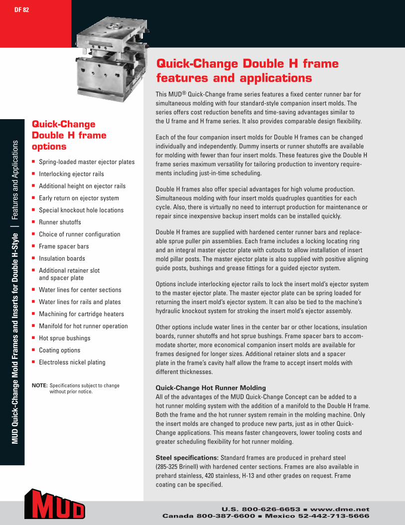
Quick-Change Double H frame features and applicationsThisMUD®Quick-Changeframeseriesfeaturesafixedcenterrunnerbarforsimultaneousmoldingwithfourstandard-stylecompanioninsertmolds.Theseriesofferscostreductionbenefitsandtime-savingadvantagessimilartotheUframeandHframeseries.Italsoprovidescomparabledesignflexibility.
EachofthefourcompanioninsertmoldsforDoubleHframescanbechangedindividuallyandindependently.Dummyinsertsorrunnershutoffsareavailableformoldingwithfewerthanfourinsertmolds.ThesefeaturesgivetheDoubleHframeseriesmaximumversatilityfortailoringproductiontoinventoryrequire-mentsincludingjust-in-timescheduling.
DoubleHframesalsoofferspecialadvantagesforhighvolumeproduction.Simultaneousmoldingwithfourinsertmoldsquadruplesquantitiesforeachcycle.Also,thereisvirtuallynoneedtointerruptproductionformaintenanceorrepairsinceinexpensivebackupinsertmoldscanbeinstalledquickly.
DoubleHframesaresuppliedwithhardenedcenterrunnerbarsandreplace-ablespruepullerpinassemblies.Eachframeincludesalockinglocatingringandanintegralmasterejectorplatewithcutoutstoallowinstallationofinsertmoldpillarposts.Themasterejectorplateisalsosuppliedwithpositivealigningguideposts,bushingsandgreasefittingsforaguidedejectorsystem.
Optionsincludeinterlockingejectorrailstolocktheinsertmold’sejectorsystemtothemasterejectorplate.Themasterejectorplatecanbespringloadedforreturningtheinsertmold’sejectorsystem.Itcanalsobetiedtothemachine’shydraulicknockoutsystemforstrokingtheinsertmold’sejectorassembly.
Otheroptionsincludewaterlinesinthecenterbarorotherlocations,insulationboards,runnershutoffsandhotspruebushings.Framespacerbarstoaccom-modateshorter,moreeconomicalcompanioninsertmoldsareavailableforframesdesignedforlongersizes.Additionalretainerslotsandaspacerplateintheframe’scavityhalfallowtheframetoacceptinsertmoldswithdifferentthicknesses.
Quick-ChangeHotRunnerMoldingAlloftheadvantagesoftheMUDQuick-ChangeConceptcanbeaddedtoahotrunnermoldingsystemwiththeadditionofamanifoldtotheDoubleHframe.Boththeframeandthehotrunnersystemremaininthemoldingmachine.Onlytheinsertmoldsarechangedtoproducenewparts,justasinotherQuick-Changeapplications.Thismeansfasterchangeovers,lowertoolingcostsandgreaterschedulingflexibilityforhotrunnermolding.
Steelspecifications:Standardframesareproducedinprehardsteel(285-325Brinell)withhardenedcentersections.Framesarealsoavailableinprehardstainless,420stainless,H-13andothergradesonrequest.Framecoatingcanbespecified.
Quick-Change Double H frame optionsn Spring-loadedmasterejectorplates
n Interlockingejectorrails
n Additionalheightonejectorrails
n Earlyreturnonejectorsystem
n Specialknockoutholelocations
n Runnershutoffs
n Choiceofrunnerconfiguration
n Framespacerbars
n Insulationboards
n Additionalretainerslotandspacerplate
n Waterlinesforcentersections
n Waterlinesforrailsandplates
n Machiningforcartridgeheaters
n Manifoldforhotrunneroperation
n Hotspruebushings
n Coatingoptions
n Electrolessnickelplating
NOTE:Specificationssubjecttochangewithoutpriornotice.
DF 82M
UD Q
uick
-Cha
nge
Mol
d Fr
ames
and
Inse
rts
for
Dou
ble
H-St
yle
| F
eatu
res
and
Appl
icat
ions
U.S. 800-626-6653 n www.dme.netCanada 800-387-6600 n Mexico 52-442-713-5666
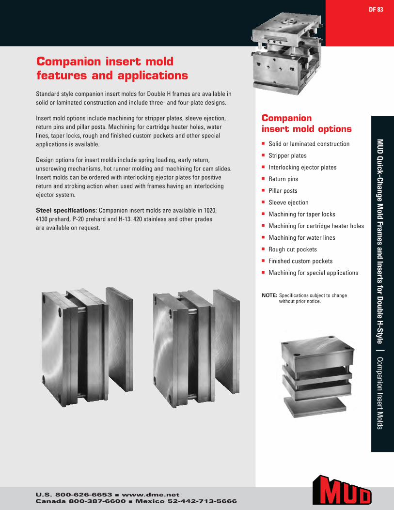
Companion insert mold features and applicationsStandardstylecompanioninsertmoldsforDoubleHframesareavailableinsolidorlaminatedconstructionandincludethree-andfour-platedesigns.
Insertmoldoptionsincludemachiningforstripperplates,sleeveejection,returnpinsandpillarposts.Machiningforcartridgeheaterholes,waterlines,taperlocks,roughandfinishedcustompocketsandotherspecialapplicationsisavailable.
Designoptionsforinsertmoldsincludespringloading,earlyreturn,unscrewingmechanisms,hotrunnermoldingandmachiningforcamslides.Insertmoldscanbeorderedwithinterlockingejectorplatesforpositivereturnandstrokingactionwhenusedwithframeshavinganinterlockingejectorsystem.
Steelspecifications:Companioninsertmoldsareavailablein1020,4130prehard,P-20prehardandH-13.420stainlessandothergradesareavailableonrequest.
Companioninsert mold optionsn Solidorlaminatedconstruction
n Stripperplates
n Interlockingejectorplates
n Returnpins
n Pillarposts
n Sleeveejection
n Machiningfortaperlocks
n Machiningforcartridgeheaterholes
n Machiningforwaterlines
n Roughcutpockets
n Finishedcustompockets
n Machiningforspecialapplications
NOTE:Specificationssubjecttochangewithoutpriornotice.
DF 83M
UD Quick-Change M
old Frames and Inserts for D
ouble H-Style | Companion Insert M
olds
U.S. 800-626-6653 n www.dme.netCanada 800-387-6600 n Mexico 52-442-713-5666
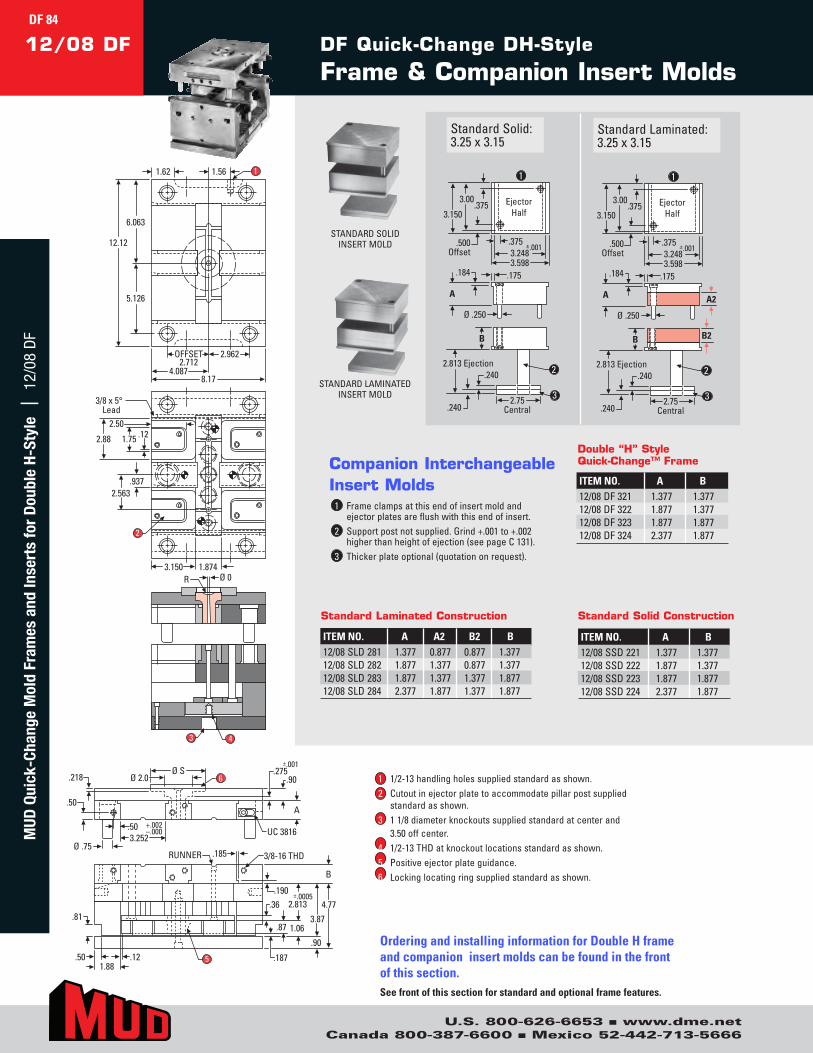
U.S. 800-626-6653 n www.dme.netCanada 800-387-6600 n Mexico 52-442-713-5666
DF Quick-Change DH-Style
Frame & Companion Insert Molds12/08 DF
StandardSolid:3.25x3.15
StandardLaminated:3.25x3.15
1 Frameclampsatthisendofinsertmoldandejectorplatesareflushwiththisendofinsert.
2 Supportpostnotsupplied.Grind+.001to+.002higherthanheightofejection(seepageC131).
3 Thickerplateoptional(quotationonrequest).
Companion Interchangeable Insert Molds
STANDARDSOLIDINSERTMOLD
STANDARDLAMINATEDINSERTMOLD
Ejector Half
.500 Offset
.375 3.150
.375 ±.001 3.248 3.598
3.00
A A2
Ø .250
.175 .184
2.75 Central
B
.240
.240
2.813 Ejection
B2
Ejector Half
.500 Offset
.375 3.150
.375 ±.001 3.248 3.598
3.00
A
Ø .250
.175 .184
2.75 Central
B
.240
.240
2.813 Ejection
3
1
2
3
1
2
3
Ejector Half
.500 Offset
.375 3.150
.375 ±.001 3.248 3.598
3.00
A A2
Ø .250
.175 .184
2.75 Central
B
.240
.240
2.813 Ejection
B2
Ejector Half
.500 Offset
.375 3.150
.375 ±.001 3.248 3.598
3.00
A
Ø .250
.175 .184
2.75 Central
B
.240
.240
2.813 Ejection
3
1
2
3
1
2
3
OFFSET2.712
2.962
4.0878.17
6.063
5.126
12.12
1.62 1.56 1
3/8 x 5°Lead
2.88
2.50
2.563
3.150 1.874
1.75 .12
.937
2
Ø 0R
3 4
3.252+.002–.000
.50A
.275.90
±.001
6.218
Ø .75
Ø 2.0
.50 UC 3816
Ø S
3/8-16 THDRUNNER
.81
.185
1.88.50 .12
.190
.90
4.773.87
B
.187
.36
1.06.87
±.00052.813
5
OFFSET2.712
2.962
4.0878.17
6.063
5.126
12.12
1.62 1.56 1
3/8 x 5°Lead
2.88
2.50
2.563
3.150 1.874
1.75 .12
.937
2
Ø 0R
3 4
3.252+.002–.000
.50A
.275.90
±.001
6.218
Ø .75
Ø 2.0
.50 UC 3816
Ø S
3/8-16 THDRUNNER
.81
.185
1.88.50 .12
.190
.90
4.773.87
B
.187
.36
1.06.87
±.00052.813
5
ITEM NO. A B12/08DF321 1.377 1.37712/08DF322 1.877 1.37712/08DF323 1.877 1.87712/08DF324 2.377 1.877
Double “H” Style Quick-Change™ Frame
ITEM NO. A A2 B2 B12/08SLD281 1.377 0.877 0.877 1.37712/08SLD282 1.877 1.377 0.877 1.37712/08SLD283 1.877 1.377 1.377 1.87712/08SLD284 2.377 1.877 1.377 1.877
Standard Laminated Construction
ITEM NO. A B12/08SSD221 1.377 1.37712/08SSD222 1.877 1.37712/08SSD223 1.877 1.87712/08SSD224 2.377 1.877
Standard Solid Construction
1 1/2-13handlingholessuppliedstandardasshown.2 Cutoutinejectorplatetoaccommodatepillarpostsupplied
standardasshown.3 11/8diameterknockoutssuppliedstandardatcenterand
3.50offcenter.4 1/2-13THDatknockoutlocationsstandardasshown.5 Positiveejectorplateguidance.6 Lockinglocatingringsuppliedstandardasshown.
Ordering and installing information for Double H frame and companion insert molds can be found in the front of this section.See front of this section for standard and optional frame features.
DF 84M
UD Q
uick
-Cha
nge
Mol
d Fr
ames
and
Inse
rts
for
Dou
ble
H-St
yle
| 1
2/08
DF
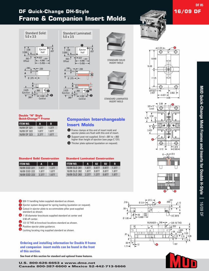
U.S. 800-626-6653 n www.dme.netCanada 800-387-6600 n Mexico 52-442-713-5666
DF Quick-Change DH-Style
Frame & Companion Insert Molds16/09 DF
StandardSolid:5.0x3.5
StandardLaminated:5.0x3.5
1 Frameclampsatthisendofinsertmoldandejectorplatesareflushwiththisendofinsert.
2 Supportpostnotsupplied.Grind+.001to+.002higherthanheightofejection(seepageC131).
3 Thickerplateoptional(quotationonrequest).
Companion Interchangeable Insert Molds
STANDARDSOLIDINSERTMOLD
STANDARDLAMINATEDINSERTMOLD
OFFSET2.937 3.062
4.4378.88
8.000
7.125
16.00
2.25 1
3/8 x 5°Lead
.12
2.88
3.50
.937
4.25
3.437
3.121.8743.500
3
2
Ø 0R
4 5
5.000+.002–.000
.50A
.500 1.12±.001
7.218
Ø 1.00
Ø 2.0
.50 UC 3816
Ø S
3/8-16 THDRUNNER
.81
.248
1.71.50
.12
.253
5.06
B
.187
1.121.12
.36±.0005
2.625
6
1.313.93
OFFSET2.937 3.062
4.4378.88
8.000
7.125
16.00
2.25 1
3/8 x 5°Lead
.12
2.88
3.50
.937
4.25
3.437
3.121.8743.500
3
2
Ø 0R
4 5
5.000+.002–.000
.50A
.500 1.12±.001
7.218
Ø 1.00
Ø 2.0
.50 UC 3816
Ø S
3/8-16 THDRUNNER
.81
.248
1.71.50
.12
.253
5.06
B
.187
1.121.12
.36±.0005
2.625
6
1.313.93
A A2
Ø .375
.230 .246
Ejector Half
.562 Offset
.4373.500
.437
3.00
±.001 4.996 5.456
4.00 Central
B
.360
.360
2.625 Ejection
B2
A
Ø .375
.230 .246
Ejector Half
.562 Offset
.437 3.500
.437
3.00
±.001 4.996 5.456
4.00 Central
B
.360
.360
2.625 Ejection
1
2
3
1
2
3
ITEM NO. A B16/09SSD221 1.877 1.37716/09SSD222 1.877 1.87716/09SSD223 2.377 1.877
Standard Solid Construction
A A2
Ø .375
.230 .246
Ejector Half
.562 Offset
.4373.500
.437
3.00
±.001 4.996 5.456
4.00 Central
B
.360
.360
2.625 Ejection
B2
A
Ø .375
.230 .246
Ejector Half
.562 Offset
.437 3.500
.437
3.00
±.001 4.996 5.456
4.00 Central
B
.360
.360
2.625 Ejection
1
2
3
1
2
3
ITEM NO. A B16/09DF321 1.877 1.37716/09DF322 1.877 1.87716/09DF323 2.377 1.877
Double “H” Style Quick-Change™ Frame
ITEM NO. A A2 B2 B16/09SLD281 1.877 0.877 0.877 1.37716/09SLD282 1.877 0.877 0.877 1.87716/09SLD283 2.377 1.377 0.877 1.877
Standard Laminated Construction
1 5/8-11handlingholessuppliedstandardasshown.2 Ejectorsystemdesignedforspringloading(quotationonrequest).3 Cutoutinejectorplatetoaccommodatepillarpostsupplied
standardasshown.4 11/8diameterknockoutssuppliedstandardatcenterand
3.50offcenter.5 1/2-13THDatknockoutlocationsstandardasshown.6 Positiveejectorplateguidance.7 Lockinglocatingringsuppliedstandardasshown.
Ordering and installing information for Double H frame and companion insert molds can be found in the front of this section.See front of this section for standard and optional frame features.
DF 85M
UD Quick-Change M
old Frames and Inserts for D
ouble H-Style | 16/09 DF
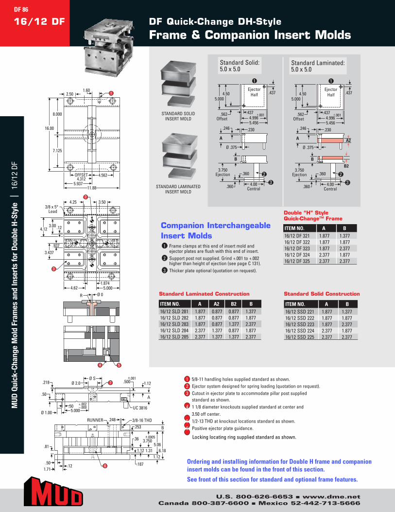
U.S. 800-626-6653 n www.dme.netCanada 800-387-6600 n Mexico 52-442-713-5666
A A2
Ø .375
.230 .246
Ejector Half
.562 Offset
.4375.000
.437
4.50
±.001 4.996 5.456
4.00 Central
B
.360
.360
3.750 Ejection
B2
A
Ø .375
.230 .246
Ejector Half
.562 Offset
.437 5.000
.437
4.50
±.001 4.996 5.456
4.00 Central
B
.360
.360
3.750 Ejection
1
2
3
1
2
3OFFSET
4.3124.562
5.93711.88
8.000
7.125
16.00
2.501.60
1
3/8 x 5°Lead
.12
4.25 3.50
3.00
.937
4.12
3.437
4.621.874
5.000
3
2
Ø 0R
5.000+.002–.000
.50A
.500 1.12±.001
7.218
Ø 1.00
Ø 2.0
.50 UC 3816
Ø S
4 5
3/8-16 THDRUNNER
.81
.248
1.71.50
.12
.253
5.061.31 6.18
B
.187
1.121.12
.36 ±.00053.750
6
ITEM NO. A B16/12SSD221 1.877 1.37716/12SSD222 1.877 1.87716/12SSD223 1.877 2.37716/12SSD224 2.377 1.87716/12SSD225 2.377 2.377
Standard Solid Construction
ITEM NO. A A2 B2 B16/12SLD281 1.877 0.877 0.877 1.37716/12SLD282 1.877 0.877 0.877 1.87716/12SLD283 1.877 0.877 1.377 2.37716/12SLD284 2.377 1.377 0.877 1.87716/12SLD285 2.377 1.377 1.377 2.377
Standard Laminated Construction
ITEM NO. A B16/12DF321 1.877 1.37716/12DF322 1.877 1.87716/12DF323 1.877 2.37716/12DF324 2.377 1.87716/12DF325 2.377 2.377
Double “H” Style Quick-Change™ Frame
A A2
Ø .375
.230 .246
Ejector Half
.562 Offset
.4375.000
.437
4.50
±.001 4.996 5.456
4.00 Central
B
.360
.360
3.750 Ejection
B2
A
Ø .375
.230 .246
Ejector Half
.562 Offset
.437 5.000
.437
4.50
±.001 4.996 5.456
4.00 Central
B
.360
.360
3.750 Ejection
1
2
3
1
2
3
OFFSET4.312
4.562
5.93711.88
8.000
7.125
16.00
2.501.60
1
3/8 x 5°Lead
.12
4.25 3.50
3.00
.937
4.12
3.437
4.621.874
5.000
3
2
Ø 0R
5.000+.002–.000
.50A
.500 1.12±.001
7.218
Ø 1.00
Ø 2.0
.50 UC 3816
Ø S
4 5
3/8-16 THDRUNNER
.81
.248
1.71.50
.12
.253
5.061.31 6.18
B
.187
1.121.12
.36 ±.00053.750
6
DF Quick-Change DH-Style
Frame & Companion Insert Molds16/12 DF
StandardSolid:5.0x5.0
StandardLaminated:5.0x5.0
1 Frameclampsatthisendofinsertmoldandejectorplatesareflushwiththisendofinsert.
2 Supportpostnotsupplied.Grind+.001to+.002higherthanheightofejection(seepageC131).
3 Thickerplateoptional(quotationonrequest).
Companion Interchangeable Insert Molds
STANDARDSOLIDINSERTMOLD
STANDARDLAMINATEDINSERTMOLD
1 5/8-11handlingholessuppliedstandardasshown.2 Ejectorsystemdesignedforspringloading(quotationonrequest).3 Cutoutinejectorplatetoaccommodatepillarpostsupplied
standardasshown.4 11/8diameterknockoutssuppliedstandardatcenterand
3.50offcenter.5 1/2-13THDatknockoutlocationsstandardasshown.6 Positiveejectorplateguidance.
7 Lockinglocatingringsuppliedstandardasshown.
Ordering and installing information for Double H frame and companion insert molds can be found in the front of this section.
See front of this section for standard and optional frame features.
DF 86M
UD Q
uick
-Cha
nge
Mol
d Fr
ames
and
Inse
rts
for
Dou
ble
H-St
yle
| 1
6/12
DF
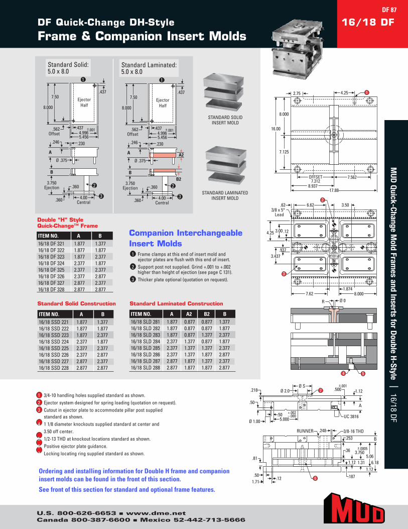
U.S. 800-626-6653 n www.dme.netCanada 800-387-6600 n Mexico 52-442-713-5666
OFFSET7.312
7.562
8.93717.88
8.000
7.125
16.00
2.75 4.25 1
Ø 0R
5.000+.002–.000
.50A
.500 1.12±.001
7.218
Ø 1.00
Ø 2.0
.50 UC 3816
Ø S
3/8 x 5°Lead
.12
6.62.62 3.50
3.00
.937
4.25
3.437
7.621.874
8.000
3
2
4 5
3/8-16 THDRUNNER
.81
.248
1.71.50
.12
.253
5.061.31 6.18
B
.187
1.121.12
.36 ±.00053.750
6
A A2 Ø .375
.230 .246
Ejector Half
.562 Offset
.437
8.000
.437
7.50
±.001 4.996 5.456
4.00 Central
B
.360
.360
3.750 Ejection
B2
A
Ø .375
.230 .246
Ejector Half
.562 Offset
.437
8.000
.437
7.50
±.001 4.996 5.456
4.00 Central
B
.360
.360
3.750 Ejection
1
2
3
1
2
3
A A2 Ø .375
.230 .246
Ejector Half
.562 Offset
.437
8.000
.437
7.50
±.001 4.996 5.456
4.00 Central
B
.360
.360
3.750 Ejection
B2
A
Ø .375
.230 .246
Ejector Half
.562 Offset
.437
8.000
.437
7.50
±.001 4.996 5.456
4.00 Central
B
.360
.360
3.750 Ejection
1
2
3
1
2
3
DF Quick-Change DH-Style
Frame & Companion Insert Molds16/18 DF
StandardSolid:5.0x8.0
StandardLaminated:5.0x8.0
1 Frameclampsatthisendofinsertmoldandejectorplatesareflushwiththisendofinsert.
2 Supportpostnotsupplied.Grind+.001to+.002higherthanheightofejection(seepageC131).
3 Thickerplateoptional(quotationonrequest).
Companion Interchangeable Insert Molds
STANDARDSOLIDINSERTMOLD
STANDARDLAMINATEDINSERTMOLD
ITEM NO. A B16/18DF321 1.877 1.37716/18DF322 1.877 1.87716/18DF323 1.877 2.37716/18DF324 2.377 1.87716/18DF325 2.377 2.37716/18DF326 2.377 2.87716/18DF327 2.877 2.37716/18DF328 2.877 2.877
Double “H” Style Quick-Change™ Frame
ITEM NO. A B16/18SSD221 1.877 1.37716/18SSD222 1.877 1.87716/18SSD223 1.877 2.37716/18SSD224 2.377 1.87716/18SSD225 2.377 2.37716/18SSD226 2.377 2.87716/18SSD227 2.877 2.37716/18SSD228 2.877 2.877
Standard Solid Construction
ITEM NO. A A2 B2 B16/18SLD281 1.877 0.877 0.877 1.37716/18SLD282 1.877 0.877 0.877 1.87716/18SLD283 1.877 0.877 1.377 2.37716/18SLD284 2.377 1.377 0.877 1.87716/18SLD285 2.377 1.377 1.377 2.37716/18SLD286 2.377 1.377 1.877 2.87716/18SLD287 2.877 1.877 1.377 2.37716/18SLD288 2.877 1.877 1.877 2.877
Standard Laminated Construction
1 3/4-10handlingholessuppliedstandardasshown.2 Ejectorsystemdesignedforspringloading(quotationonrequest).3 Cutoutinejectorplatetoaccommodatepillarpostsupplied
standardasshown.4 11/8diameterknockoutssuppliedstandardatcenterand
3.50offcenter.5 1/2-13THDatknockoutlocationsstandardasshown.6 Positiveejectorplateguidance.7 Lockinglocatingringsuppliedstandardasshown.
Ordering and installing information for Double H frame and companion insert molds can be found in the front of this section.
See front of this section for standard and optional frame features.
DF 87M
UD Quick-Change M
old Frames and Inserts for D
ouble H-Style | 16/18 DF

U.S. 800-626-6653 n www.dme.netCanada 800-387-6600 n Mexico 52-442-713-5666
OFFSET5.187
5.437
6.93713.88
9.750
8.375
19.50
2.00 3.00 1
Ø 0R
6.000+.002–.000
.50A
.500 1.12±.001
7.218
Ø 1.25
Ø 2.0
.50 UC 3816
Ø S
4 5
3/8 x 5°Lead
.123.75
.9373.937
5.25
5.621.874
6.000
3
2 3.505.25
3/8-16 THDRUNNER
.81
.248
2.38.50 .12
.312
5.061.31 6.18
B
.187
1.121.12
.36 ±.00053.750
6
OFFSET5.187
5.437
6.93713.88
9.750
8.375
19.50
2.00 3.00 1
Ø 0R
6.000+.002–.000
.50A
.500 1.12±.001
7.218
Ø 1.25
Ø 2.0
.50 UC 3816
Ø S
4 5
3/8 x 5°Lead
.123.75
.9373.937
5.25
5.621.874
6.000
3
2 3.505.25
3/8-16 THDRUNNER
.81
.248
2.38.50 .12
.312
5.061.31 6.18
B
.187
1.121.12
.36 ±.00053.750
6
StandardSolid:6.0x6.0
StandardLaminated:6.0x6.0
1 Frameclampsatthisendofinsertmoldandejectorplatesareflushwiththisendofinsert.
2 Supportpostnotsupplied.Grind+.001to+.002higherthanheightofejection(seepageC131).
3 Thickerplateoptional(quotationonrequest).
Companion Interchangeable Insert Molds
STANDARDSOLIDINSERTMOLD
STANDARDLAMINATEDINSERTMOLD
DF Quick-Change DH-Style
Frame & Companion Insert Molds20/14 DF
A A2 Ø .500
.230 1.00.307
Ejector Half
.687 Offset
.562 6.000
.562
5.50
±.001 5.996 6.456
5.00 Central
B
.360
.360
1.00
3.750 Ejection
B2
A
Ø .500
.230 .307
Ejector Half
.687 Offset
.562 6.000
.562
5.50
±.001 5.996 6.456
5.00 Central
B
.360
.360
3.750 Ejection
1
2
3
1
2
3
ITEM NO. A B20/14SSD222 1.877 1.87720/14SSD223 2.377 1.87720/14SSD224 2.377 2.37720/14SSD225 2.877 2.37720/14SSD226 2.877 2.877
Standard Solid Construction
ITEM NO. A A2 B2 B20/14SLD282 1.877 0.877 0.877 1.87720/14SLD283 2.377 1.377 0.877 1.87720/14SLD284 2.377 1.377 1.377 2.37720/14SLD285 2.877 1.877 1.377 2.37720/14SLD286 2.877 1.877 1.877 2.877
Standard Laminated Construction
ITEM NO. A B20/14DF322 1.877 1.87720/14DF323 2.377 1.87720/14DF324 2.377 2.37720/14DF325 2.877 2.37720/14DF326 2.877 2.877
Double “H” Style Quick-Change™ Frame
A A2 Ø .500
.230 1.00.307
Ejector Half
.687 Offset
.562 6.000
.562
5.50
±.001 5.996 6.456
5.00 Central
B
.360
.360
1.00
3.750 Ejection
B2
A
Ø .500
.230 .307
Ejector Half
.687 Offset
.562 6.000
.562
5.50
±.001 5.996 6.456
5.00 Central
B
.360
.360
3.750 Ejection
1
2
3
1
2
3
1 3/4-10handlingholessuppliedstandardasshown.2 Ejectorsystemdesignedforspringloading(quotationonrequest).3 Cutoutinejectorplatetoaccommodatepillarpostsupplied
standardasshown.4 11/8diameterknockoutssuppliedstandardatcenterand
3.50offcenter.5 1/2-13THDatknockoutlocationsstandardasshown.6 Positiveejectorplateguidance.7 Lockinglocatingringsuppliedstandardasshown.
Ordering and installing information for Double H frame and companion insert molds can be found in the front of this section.
See front of this section for standard and optional frame features.
DF 88M
UD Q
uick
-Cha
nge
Mol
d Fr
ames
and
Inse
rts
for
Dou
ble
H-St
yle
| 2
0/14
DF
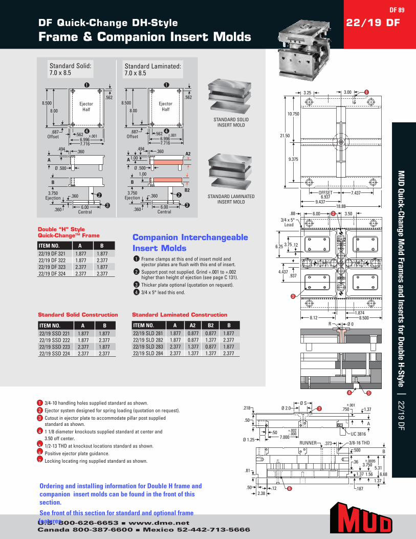
U.S. 800-626-6653 n www.dme.netCanada 800-387-6600 n Mexico 52-442-713-5666
OFFSET6.937
7.437
9.43718.88
10.750
9.375
21.50
3.25 3.00 1
Ø 0R
4 5
3/4 x 5°Lead
.12
.88 6.00 3.50
3.75
.937
6.25
4.437
3
2
8.121.874
8.500
7.000+.002–.000
.50A
.750 1.37±.001
7.218
Ø 1.25
Ø 2.0
.50 UC 3816
Ø S
.81
.50
3/8-16 THDRUNNER .373
2.38.12
.500
5.311.56 6.68
B
.187
1.371.37
.36 ±.00053.750
6
StandardSolid:7.0x8.5
StandardLaminated:7.0x8.5
1 Frameclampsatthisendofinsertmoldandejectorplatesareflushwiththisendofinsert.
2 Supportpostnotsupplied.Grind+.001to+.002higherthanheightofejection(seepageC131).
3 Thickerplateoptional(quotationonrequest).4 3/4x5°leadthisend.
Companion Interchangeable Insert Molds
STANDARDSOLIDINSERTMOLD
STANDARDLAMINATEDINSERTMOLD
DF Quick-Change DH-Style
Frame & Companion Insert Molds22/19 DF
A A2
Ø .500
.360 .494
1.00
Ejector Half
.687 Offset
.5628.500
.562
8.00
±.001 6.996 7.716
6.00 Central
B
.360
.360
1.00
3.750 Ejection
B2
A
Ø .500
.360 .494
Ejector Half
.687 Offset
.562 8.500
.562
8.00
±.001 6.996 7.716
6.00 Central
B
.360
.360
3.750 Ejection
1
2
4
3
1
2
4
3
ITEM NO. A B22/19SSD221 1.877 1.87722/19SSD222 1.877 2.37722/19SSD223 2.377 1.87722/19SSD224 2.377 2.377
Standard Solid Construction
ITEM NO. A A2 B2 B22/19SLD281 1.877 0.877 0.877 1.87722/19SLD282 1.877 0.877 1.377 2.37722/19SLD283 2.377 1.377 0.877 1.87722/19SLD284 2.377 1.377 1.377 2.377
Standard Laminated Construction
ITEM NO. A B22/19DF321 1.877 1.87722/19DF322 1.877 2.37722/19DF323 2.377 1.87722/19DF324 2.377 2.377
Double “H” Style Quick-Change™ Frame
A A2
Ø .500
.360 .494
1.00
Ejector Half
.687 Offset
.5628.500
.562
8.00
±.001 6.996 7.716
6.00 Central
B
.360
.360
1.00
3.750 Ejection
B2
A
Ø .500
.360 .494
Ejector Half
.687 Offset
.562 8.500
.562
8.00
±.001 6.996 7.716
6.00 Central
B
.360
.360
3.750 Ejection
1
2
4
3
1
2
4
3
1 3/4-10handlingholessuppliedstandardasshown.2 Ejectorsystemdesignedforspringloading(quotationonrequest).3 Cutoutinejectorplatetoaccommodatepillarpostsupplied
standardasshown.4 11/8diameterknockoutssuppliedstandardatcenterand
3.50offcenter.5 1/2-13THDatknockoutlocationsstandardasshown.6 Positiveejectorplateguidance.7 Lockinglocatingringsuppliedstandardasshown.
Ordering and installing information for Double H frame and companion insert molds can be found in the front of this section.
See front of this section for standard and optional frame features.
DF 89M
UD Quick-Change M
old Frames and Inserts for D
ouble H-Style | 22/19 DF
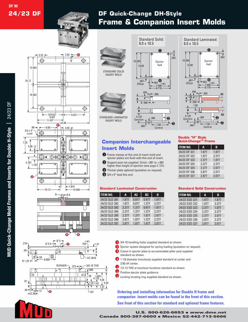
U.S. 800-626-6653 n www.dme.netCanada 800-387-6600 n Mexico 52-442-713-5666
4 5
8.000+.002–.000
.50 A
.750 1.37±.001
7.218
Ø 1.25
Ø 2.0
.50 UC 3816
Ø S
OFFSET8.937
9.437
11.43722.88
12.062
10.562
24.12
3.25 3.50 1
3/4 x 5°Lead
.12
.88 8.00 3.50
5.00
1.187
7.25
5.187
3
2
10.121.874
10.500
Ø 0R
.81
.50
3/8-16 THDRUNNER .373
2.38.12
.500
1.37
5.566.93
B
.187
1.25 1.43
.36 ±.00054.125
6
StandardSolid:8.0x10.5
StandardLaminated:8.0x10.5
1 Frameclampsatthisendofinsertmoldandejectorplatesareflushwiththisendofinsert.
2 Supportpostnotsupplied.Grind+.001to+.002higherthanheightofejection(seepageC131).
3 Thickerplateoptional(quotationonrequest).4 3/4x5°leadthisend.
Companion Interchangeable Insert Molds
DF Quick-Change DH-Style
Frame & Companion Insert Molds24/23 DF
STANDARDSOLIDINSERTMOLD
STANDARDLAMINATEDINSERTMOLD
A A2
Ø .500
.360 .494
1.00
Ejector Half
.687 Offset
.562 10.500
.562
10.00
±.001 7.996 8.716
7.00 Central
B
.360
.360
1.00
4.125 Ejection
B2
A Ø .500
.360 .494
Ejector Half
.687 Offset
.562 10.500
.562
10.00
±.001 7.996 8.716
7.00 Central
B
.360
.360
4.125 Ejection
1
2
4
3
1
2
4
3
ITEM NO. A A2 B2 B24/23SLD281 1.877 0.877 0.877 1.87724/23SLD282 1.877 0.877 1.377 2.37724/23SLD283 2.377 1.377 0.877 1.87724/23SLD284 2.377 1.377 1.377 2.37724/23SLD285 2.377 1.377 1.877 2.87724/23SLD286 2.877 1.877 1.377 2.37724/23SLD287 2.877 1.877 1.877 2.877
Standard Laminated Construction
A A2
Ø .500
.360 .494
1.00
Ejector Half
.687 Offset
.562 10.500
.562
10.00
±.001 7.996 8.716
7.00 Central
B
.360
.360
1.00
4.125 Ejection
B2
A Ø .500
.360 .494
Ejector Half
.687 Offset
.562 10.500
.562
10.00
±.001 7.996 8.716
7.00 Central
B
.360
.360
4.125 Ejection
1
2
4
3
1
2
4
3
ITEM NO. A B24/23DF321 1.877 1.87724/23DF322 1.877 2.37724/23DF323 2.377 1.87724/23DF324 2.377 2.37724/23DF325 2.377 2.87724/23DF326 2.877 2.37724/23DF327 2.877 2.877
Double “H” Style Quick-Change™ Frame
ITEM NO. A B24/23SSD221 1.877 1.87724/23SSD222 1.877 2.37724/23SSD223 2.377 1.87724/23SSD224 2.377 2.37724/23SSD225 2.377 2.87724/23SSD226 2.877 2.37724/23SSD227 2.877 2.877
Standard Solid Construction
1 3/4-10handlingholessuppliedstandardasshown.2 Ejectorsystemdesignedforspringloading(quotationonrequest).3 Cutoutinejectorplatetoaccommodatepillarpostsupplied
standardasshown.4 11/8diameterknockoutssuppliedstandardatcenterand
3.50offcenter.5 1/2-13THDatknockoutlocationsstandardasshown.6 Positiveejectorplateguidance.7 Lockinglocatingringsuppliedstandardasshown.
Ordering and installing information for Double H frame and companion insert molds can be found in the front of this section.
See front of this section for standard and optional frame features.
DF 90M
UD Q
uick
-Cha
nge
Mol
d Fr
ames
and
Inse
rts
for
Dou
ble
H-St
yle
| 2
4/23
DF
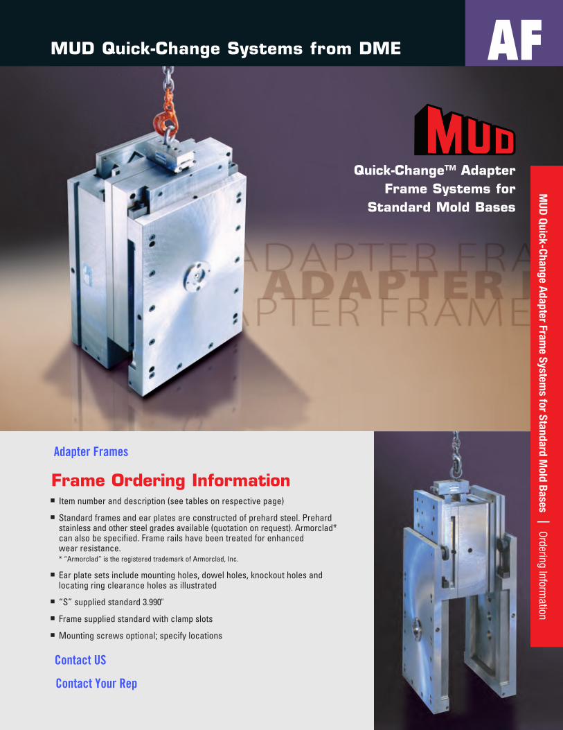
91
Quick-Change™ Adapter Frame Systems for
Standard Mold Bases
Frame Ordering Informationn Itemnumberanddescription(seetablesonrespectivepage)
n Standardframesandearplatesareconstructedofprehardsteel.Prehardstainlessandothersteelgradesavailable(quotationonrequest).Armorclad*canalsobespecified.Framerailshavebeentreatedforenhancedwearresistance.* “Armorclad”istheregisteredtrademarkofArmorclad,Inc.
n Earplatesetsincludemountingholes,dowelholes,knockoutholesandlocatingringclearanceholesasillustrated
n “S”suppliedstandard3.990"
n Framesuppliedstandardwithclampslots
n Mountingscrewsoptional;specifylocations
AFMUD Quick-Change Systems from DME
MUD
Quick-Change Adapter Frame System
s for Standard Mold Bases | O
rdering Information
Contact US
Adapter Frames
Contact Your Rep
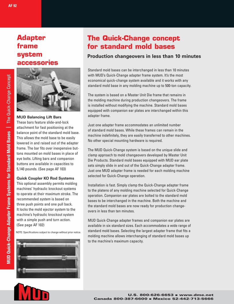
Adapter frame system accessories
MUD Balancing Lift BarsThesebarsfeatureslide-and-lockattachmentforfastpositioningatthebalancepointofthestandardmoldbase.Thisallowsthemoldbasetobeeasilyloweredinandraisedoutoftheadapterframe.Thebarfitsoverinexpensivebut-tonsmountedonmoldbasesinplaceofeyebolts.Liftingbarsandcompanionbuttonsareavailableincapacitiesto5,140pounds.(SeepageAF103)
Quick Coupler KO Rod SystemsThisoptionalassemblypermitsmoldingmachines’hydraulicknockoutsystemstooperateattheirmaximumstroke.Therecommendedsystemisbasedonthreepushpointsandonepullback.Itlocksthemoldejectorsystemtothemachine’shydraulicknockoutsystemwithasimplepushandturnaction.(SeepageAF102)
NOTE:Specificationssubjecttochangewithoutpriornotice.
The Quick-Change concept for standard mold basesProduction changeovers in less than 10 minutes
Standardmoldbasescanbeinterchangedinlessthan10minuteswithMUD’sQuick-Changeadapterframesystem.It’sthemosteconomicalquick-changesystemavailableanditworkswithanystandardmoldbaseinanymoldingmachineupto500-toncapacity.
ThesystemisbasedonaMasterUnitDieframethatremainsinthemoldingmachineduringproductionchangeovers.Theframeisinstalledwithoutmodifyingthemachine.Standardmoldbasesequippedwithcompanionearplatesareinterchangedwithinthisadapterframe.
Justoneadapterframeaccommodatesanunlimitednumberofstandardmoldbases.Whiletheseframescanremaininthemachineindefinitely,theyareeasilytransferredtoothermachines.Nootherspecialmountinghardwareisrequired.
TheMUDQuick-ChangesystemisbasedontheuniqueslideandclampapproachtomoldchangeoversdevelopedbyMasterUnitDieProducts.StandardmoldbasesequippedwithMUDearplatesetssimplyslideinandoutoftheQuick-Changeadapterframe.JustoneMUDadapterframeisneededforeachmoldingmachineselectedforQuick-Changeoperation.
Installationisfast.SimplyclamptheQuick-ChangeadapterframetotheplatensofanymoldingmachineselectedforQuick-Changeoperation.Companionearplatesareboltedtothestandardmoldbasestobeinterchangedinthemachine.Boththemachineandthestandardmoldbasesarenowreadyforproductionchange-oversinlessthantenminutes.
MUDQuick-Changeadapterframesandcompanionearplatesareavailableinsixstandardsizes.Eachaccommodatesawiderangeofstandardmoldbases.Selectingthelargestadapterframethatfitsamoldingmachineallowsinterchangingofstandardmoldbasesuptothemachine’smaximumcapacity.
MUD
Qui
ck-C
hang
e Ad
apte
r Fr
ame
Syst
ems
for
Stan
dard
Mol
d Ba
ses
| T
he Q
uick
-Cha
nge
Conc
ept
AF 92
U.S. 800-626-6653 n www.dme.netCanada 800-387-6600 n Mexico 52-442-713-5666
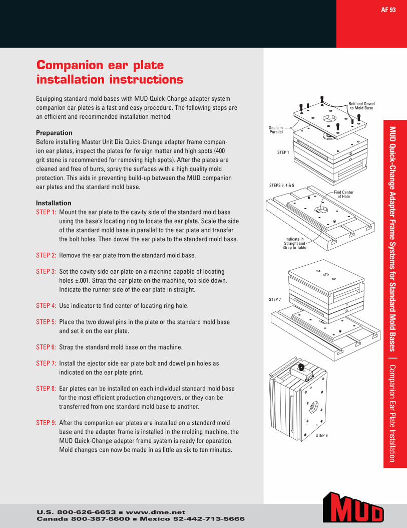
Companion ear plate installation instructionsEquippingstandardmoldbaseswithMUDQuick-Changeadaptersystemcompanionearplatesisafastandeasyprocedure.Thefollowingstepsareanefficientandrecommendedinstallationmethod.
PreparationBeforeinstallingMasterUnitDieQuick-Changeadapterframecompan-ionearplates,inspecttheplatesforforeignmatterandhighspots(400gritstoneisrecommendedforremovinghighspots).Aftertheplatesarecleanedandfreeofburrs,spraythesurfaceswithahighqualitymoldprotection.Thisaidsinpreventingbuild-upbetweentheMUDcompanionearplatesandthestandardmoldbase.
InstallationSTEP1: Mounttheearplatetothecavitysideofthestandardmoldbase
usingthebase’slocatingringtolocatetheearplate.Scalethesideofthestandardmoldbaseinparalleltotheearplateandtransfertheboltholes.Thendoweltheearplatetothestandardmoldbase.
STEP2:Removetheearplatefromthestandardmoldbase.
STEP3: Setthecavitysideearplateonamachinecapableoflocatingholes±.001.Straptheearplateonthemachine,topsidedown.Indicatetherunnersideoftheearplateinstraight.
STEP4:Useindicatortofindcenteroflocatingringhole.
STEP5: Placethetwodowelpinsintheplateorthestandardmoldbaseandsetitontheearplate.
STEP6: Strapthestandardmoldbaseonthemachine.
STEP7: Installtheejectorsideearplateboltanddowelpinholesasindicatedontheearplateprint.
STEP8: Earplatescanbeinstalledoneachindividualstandardmoldbaseforthemostefficientproductionchangeovers,ortheycanbetransferredfromonestandardmoldbasetoanother.
STEP9:Afterthecompanionearplatesareinstalledonastandardmoldbaseandtheadapterframeisinstalledinthemoldingmachine,theMUDQuick-Changeadapterframesystemisreadyforoperation.Moldchangescannowbemadeinaslittleassixtotenminutes.
Scale inParallel
Bolt and Dowelto Mold Base
STEP 1
Find Centerof Hole
STEPS 3, 4 & 5
Indicate inStraight and
Strap to Table
STEP 7
STEP 9
AF 93M
UD Quick-Change Adapter Frame System
s for Standard Mold Bases | Com
panion Ear Plate Installation
U.S. 800-626-6653 n www.dme.netCanada 800-387-6600 n Mexico 52-442-713-5666
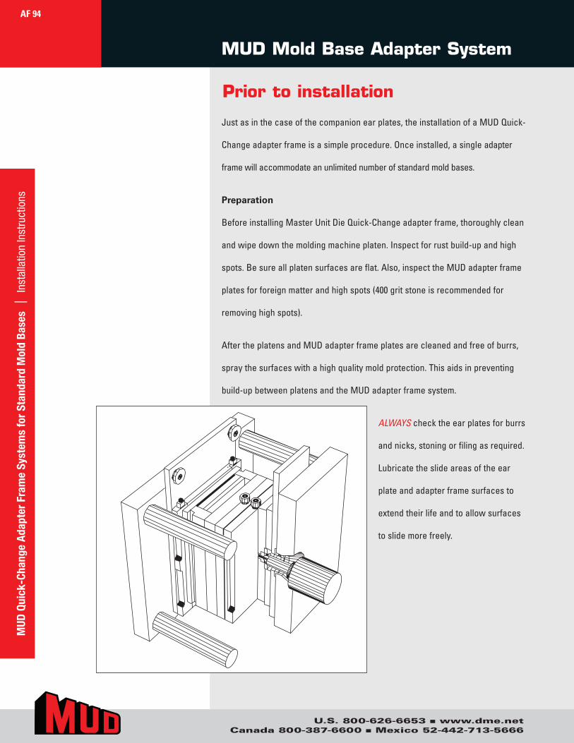
Prior to installation
Justasinthecaseofthecompanionearplates,theinstallationofaMUDQuick-
Changeadapterframeisasimpleprocedure.Onceinstalled,asingleadapter
framewillaccommodateanunlimitednumberofstandardmoldbases.
Preparation
BeforeinstallingMasterUnitDieQuick-Changeadapterframe,thoroughlyclean
andwipedownthemoldingmachineplaten.Inspectforrustbuild-upandhigh
spots.Besureallplatensurfacesareflat.Also,inspecttheMUDadapterframe
platesforforeignmatterandhighspots(400gritstoneisrecommendedfor
removinghighspots).
AftertheplatensandMUDadapterframeplatesarecleanedandfreeofburrs,
spraythesurfaceswithahighqualitymoldprotection.Thisaidsinpreventing
build-upbetweenplatensandtheMUDadapterframesystem.
ALWAYSchecktheearplatesforburrs
andnicks,stoningorfilingasrequired.
Lubricatetheslideareasoftheear
plateandadapterframesurfacesto
extendtheirlifeandtoallowsurfaces
toslidemorefreely.
MUD Mold Base Adapter System
AF 94
U.S. 800-626-6653 n www.dme.netCanada 800-387-6600 n Mexico 52-442-713-5666
MUD
Qui
ck-C
hang
e Ad
apte
r Fr
ame
Syst
ems
for
Stan
dard
Mol
d Ba
ses
| I
nsta
llatio
n In
stru
ctio
ns
U.S. 800-626-6653 n www.dme.netCanada 800-387-6600 n Mexico 52-442-713-5666
Cavity Side InstallationSTEP1: Installthecavitysideadapterframeinthe
moldingmachine,usingclampsorboltingdirectlythroughtheclampplateoftheframe.Thecavitysideadapterframeisalignedbythelocatingring.
Rotatetheadapterframetoaverticalpositionbyusingalevelontheinsideoftheearplateretainerrail.Besurethemountingboltsorclampsaretight.
STEP2: Determinethattheadapterframecompanionearplatesaremountedonthestandardmoldbaseasdetailedintheearplateinstallationinstructions.
Ejector Side InstallationSTEP3: Withtheearplatesinstalledonthestandard
moldbase,slideitintotheejectorsideoftheadapterframepriortoinstallationinthemoldingmachine.Nowclampthestandardmoldbaseintheadapterframeusingtheclampsontheendoftheframe.
STEP4: Measurethetotalshutheightoftheearplates,standardmoldbaseandadapterframe.Adjustthemachineplatensopenanadditional1/16"to3/16"toallowtheassemblytoslidebetweentheplatensandintothecavitysideoftheadapterframe.
STEP5: LifttheejectorhalfoftheadapterframewiththestandardmoldbaseinstalledusingaMUDbalancedliftingbar.Slidethestandardmoldbaseandejectorhalfadapterframeintothecavityhalfadapterframealreadyinstalledinthemachine(Step1).
STEP6: Closethemachinetoclampthemoldhalvestogether.
STEP7: Clampthestandardmoldbaseadapterframeejectorhalftothemachineplaten.
STEP8: Toremovetheearplateequippedstandardmoldbasefromtheadapterframe,unclampthefour(4) earplateholddownclampslocatedonthetopsoftheadapterframerails.Thenopenthemachineapproximately1/16"to3/16".
STEP9: Ifboltsaretobeusedthroughtheadapterframeclampplate,removethestandardmoldbasefromtheframeandinstallthebolts.
STEP10: Iftheadapterframeisboltedthroughtheclampplatetotheplaten,theclamps(Step7)cannowberemoved.
STEP11: THEMUDQuick-Changeadapterframeisnowreadytoacceptanunlimitednumberofstandardmoldbasesequippedwithcompanionearplates.
Installation instructions
AF 95M
UD Quick-Change Adapter Fram
e Systems for Standard M
old Bases | Installation Instructions

U.S. 800-626-6653 n www.dme.netCanada 800-387-6600 n Mexico 52-442-713-5666
12/18AF 010
AF 96
AF Quick-Change Adapter
Frame & Companion Ear Plates
.218.900
.750+.002–.0008.000
Ø 5.49Ø S
Ø 3.25
.375.375
1.0 x 10° Lead 3/4 x 5° Lead
UC 38162.00
24.37
18.37
16.874
.7501.50 11.87
1/2 –13 THD
MBAR 375–18
5.937
14.44
3.50TYP
8.437
9.94
Ø 1.12
Ø 1.75
Ø 1.12
Ø 1.56
1.000
3.375 TYP
1.500 TYP
TYP 1/2 SHCS (28)
8.000 TYP
6.000 TYP
3.375 TYP
Ø 1/2 Dowel(16)
3.50 TYP
5.000 TYP
3/4 x 5° Lead
.36 7.994
.750
Ø 3.993
4.357
8.714
8.437
16.874
.369
.218 .900
.750 +.002 –.0008.000
Ø 5.49Ø S
Ø 3.25
.375 .375
1.0 x 10° Lead 3/4 x 5° Lead
UC 3816 2.00
24.37
18.37
16.874
.750 1.50 11.87
1/2 –13 THD
MBAR 375–18
5.937
14.44
3.50 TYP
8.437
9.94
Ø 1.12
Ø 1.75
Ø 1.12
Ø 1.56
1.000
3.375TYP
1.500TYP
TYP 1/2 SHCS(28)
8.000TYP
6.000TYP
3.375TYP
Ø 1/2 Dowel(16)
3.50TYP
5.000TYP
3/4 x 5° Lead
.36 7.994
.750
Ø 3.993
4.357
8.714
8.437
16.874
.369
ITEM NO. DESCRIPTION
Ordering and installing information for adapter frame and companion ear plates can be found in the front of this section.
Extendednozzleisrequiredtoextendtheadditionalthicknessoftheearplateandbackplateofthemoldbaseadapterassembly.
12/18AF010 AdapterFrame12/18AEP011 EarPlateSet12/18AEP022 EarPlateSetw/oMountingHoles
MUD
Qui
ck-C
hang
e Ad
apte
r Fr
ame
Syst
ems
for
Stan
dard
Mol
d Ba
ses
| 1
2/18
AF
010
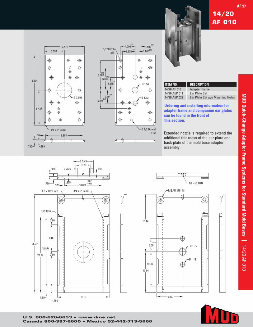
U.S. 800-626-6653 n www.dme.netCanada 800-387-6600 n Mexico 52-442-713-5666
14/20AF 010
.218 .900
.750 +.002 –.000 10.000
Ø 5.49Ø S
Ø 3.25
.375 .375
1.0 x 10° Lead 3/4 x 5° Lead
UC 3816
2.00
26.37
18.874
13.87
2.00
Ø 1.12
Ø 1.56
1.0003.375TYP
1.500TYP
TYP 1/2 SHCS(28)
8.000TYP
6.000TYP
3.375TYP
Ø 1/2 Dowel(16)
3.50TYP
5.000TYP
3/4 x 5° Lead
.36 9.994
Ø 3.993
5.357
10.714
9.437
18.874
7.18
20.37
1/2 –13 THD
MBAR 375–18
6.937
15.44
3.50 TYP
9.437
10.94
Ø 1.12
Ø 1.75
4.000TYP
.750 1.50
.750 .369
.218.900
.750+.002–.00010.000
Ø 5.49Ø S
Ø 3.25
.375.375
1.0 x 10° Lead 3/4 x 5° Lead
UC 3816
2.00
26.37
18.874
13.87
2.00
Ø 1.12
Ø 1.56
1.000 3.375 TYP
1.500 TYP
TYP 1/2 SHCS (28)
8.000 TYP
6.000 TYP
3.375 TYP
Ø 1/2 Dowel(16)
3.50 TYP
5.000 TYP
3/4 x 5° Lead
.36 9.994
Ø 3.993
5.357
10.714
9.437
18.874
7.18
20.37
1/2 –13 THD
MBAR 375–18
6.937
15.44
3.50TYP
9.437
10.94
Ø 1.12
Ø 1.75
4.000 TYP
.7501.50
.750 .369
ITEM NO. DESCRIPTION
Ordering and installing information for adapter frame and companion ear plates can be found in the front of this section.
Extendednozzleisrequiredtoextendtheadditionalthicknessoftheearplateandbackplateofthemoldbaseadapterassembly.
14/20AF010 AdapterFrame14/20AEP011 EarPlateSet14/20AEP022 EarPlateSetw/oMountingHoles
AF 97M
UD Quick-Change Adapter Fram
e Systems for Standard M
old Bases | 14/20 AF 010
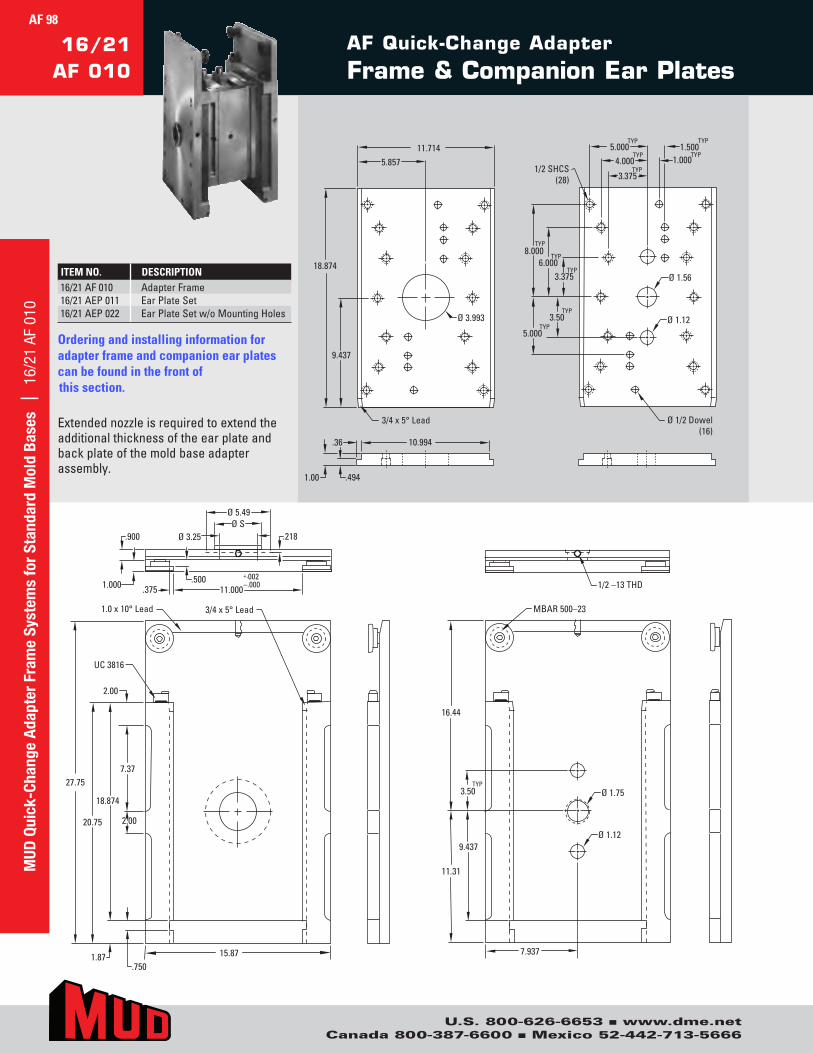
U.S. 800-626-6653 n www.dme.netCanada 800-387-6600 n Mexico 52-442-713-5666
AF Quick-Change Adapter
Frame & Companion Ear Plates16/21
AF 010
ITEM NO. DESCRIPTION
Ordering and installing information for adapter frame and companion ear plates can be found in the front of this section.
Extendednozzleisrequiredtoextendtheadditionalthicknessoftheearplateandbackplateofthemoldbaseadapterassembly.
16/21AF010 AdapterFrame16/21AEP011 EarPlateSet16/21AEP022 EarPlateSetw/oMountingHoles
AF 98M
UD Q
uick
-Cha
nge
Adap
ter
Fram
e Sy
stem
s fo
r St
anda
rd M
old
Base
s |
16/
21 A
F 01
0
.218.900
1.000+.002–.00011.000
Ø 5.49Ø S
Ø 3.25
.500.375
1.0 x 10° Lead 3/4 x 5° Lead
UC 3816
2.00
27.75
18.874
.7501.87 15.87
1/2 –13 THD
MBAR 500–23
7.937
16.44
3.50TYP
9.437
11.31
Ø 1.12
Ø 1.75
7.37
20.75 2.00
Ø 1.12
Ø 1.56
1.000
3.375TYP
1.500TYP
TYP
1/2 SHCS(28)
8.000TYP
6.000TYP
3.375TYP
Ø 1/2 Dowel(16)
3.50TYP
5.000TYP
3/4 x 5° Lead
.36 10.994
1.00
5.85711.714
9.437
18.874
.494
4.000TYP
5.000TYP
Ø 3.993
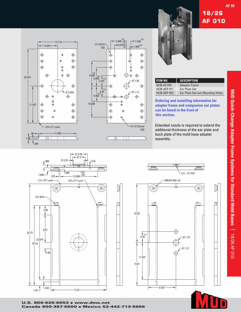
U.S. 800-626-6653 n www.dme.netCanada 800-387-6600 n Mexico 52-442-713-5666
18/26AF 010
1/2 –13 THD
MBAR 500–23
8.937
18.93
3.50 TYP
11.937
13.81
Ø 1.12
Ø 1.75
Ø 1.12
Ø 1.56
1.0003.375TYP
1.500TYP
TYP 1/2 SHCS(36)
8.000TYP
6.000TYP
3.375TYP
Ø 1/2 Dowel(20)
5.000TYP
10.000TYP
3/4 x 5° Lead
.36 11.994
1.00
Ø 3.993
6.35712.714
11.937
23.874
.494
5.000TYP
.218 .900
1.000 +.002 –.000 12.000
Ø 5.49Ø S
Ø 3.25
.500 .375
1.0 x 10° Lead 3/4 x 5° Lead
UC 3816
32.75
23.874
.750 1.87 17.87
8.87
25.75
3.50TYP
2.00
3.00
1/2 –13 THD
MBAR 500–23
8.937
18.93
3.50TYP
11.937
13.81
Ø 1.12
Ø 1.75
Ø 1.12
Ø 1.56
1.000 3.375 TYP
1.500 TYP
TYP 1/2 SHCS (36)
8.000 TYP
6.000 TYP
3.375 TYP
Ø 1/2 Dowel(20)
5.000 TYP
10.000 TYP
3/4 x 5° Lead
.36 11.994
1.00
Ø 3.993
6.357 12.714
11.937
23.874
.494
5.000 TYP
.218.900
1.000+.002–.00012.000
Ø 5.49Ø S
Ø 3.25
.500.375
1.0 x 10° Lead 3/4 x 5° Lead
UC 3816
32.75
23.874
.7501.87 17.87
8.87
25.75
3.50 TYP
2.00
3.00
ITEM NO. DESCRIPTION
Ordering and installing information for adapter frame and companion ear plates can be found in the front of this section.
Extendednozzleisrequiredtoextendtheadditionalthicknessoftheearplateandbackplateofthemoldbaseadapterassembly.
18/26AF010 AdapterFrame18/26AEP011 EarPlateSet18/26AEP022 EarPlateSetw/oMountingHoles
AF 99M
UD Quick-Change Adapter Fram
e Systems for Standard M
old Bases | 18/26 AF 010
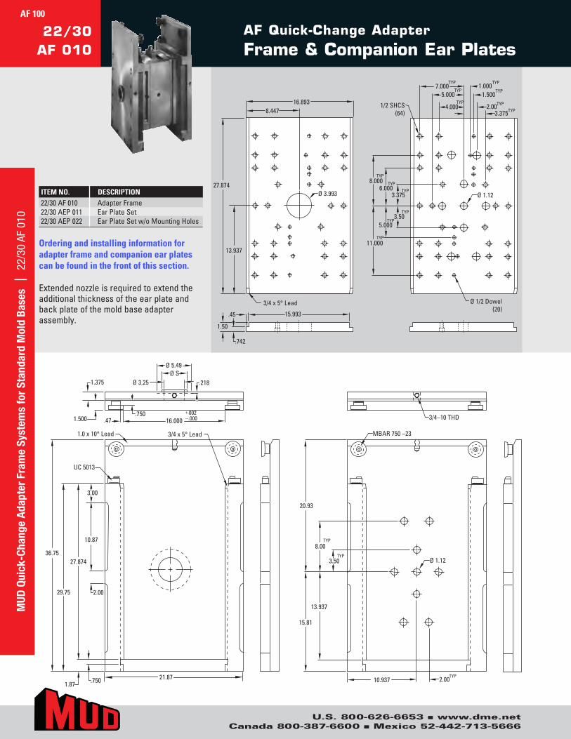
U.S. 800-626-6653 n www.dme.netCanada 800-387-6600 n Mexico 52-442-713-5666
AF Quick-Change Adapter
Frame & Companion Ear Plates
3/4–10 THD
MBAR 750 –23
10.937
20.93
3.50 TYP
13.937
15.81
Ø 1.12
Ø 1.12
3.3754.000
TYP 1.500
TYP
TYP 1/2 SHCS
(64)
8.000TYP
6.000TYP
3.375TYP
Ø 1/2 Dowel(20)
5.000TYP
11.000TYP
3/4 x 5° Lead
.45 15.993
1.50
Ø 3.993
8.44716.893
13.937
27.874
.742
5.000TYP
.2181.375
1.500+.002–.00016.000
Ø 5.49Ø S
Ø 3.25
.750.47
1.0 x 10° Lead 3/4 x 5° Lead
UC 5013
3.00
36.7527.874
.7501.8721.87
10.87
2.0029.75
3.50TYP
8.00 TYP
2.00 TYP
2.00TYP
1.000TYP
7.000TYP
3/4–10 THD
MBAR 750 –23
10.937
20.93
3.50TYP
13.937
15.81
Ø 1.12
Ø 1.12
3.375 4.000
TYP 1.500
TYP
TYP 1/2 SHCS
(64)
8.000 TYP
6.000 TYP
3.375 TYP
Ø 1/2 Dowel(20)
5.000 TYP
11.000 TYP
3/4 x 5° Lead
.45 15.993
1.50
Ø 3.993
8.447 16.893
13.937
27.874
.742
5.000 TYP
.2181.375
1.500+.002–.00016.000
Ø 5.49Ø S
Ø 3.25
.750.47
1.0 x 10° Lead 3/4 x 5° Lead
UC 5013
3.00
36.7527.874
.7501.8721.87
10.87
2.0029.75
3.50 TYP
8.00TYP
2.00TYP
2.00 TYP
1.000 TYP
7.000 TYP
ITEM NO. DESCRIPTION
Ordering and installing information for adapter frame and companion ear plates can be found in the front of this section.
Extendednozzleisrequiredtoextendtheadditionalthicknessoftheearplateandbackplateofthemoldbaseadapterassembly.
22/30AF010 AdapterFrame22/30AEP011 EarPlateSet22/30AEP022 EarPlateSetw/oMountingHoles
22/30AF 010
MUD
Qui
ck-C
hang
e Ad
apte
r Fr
ame
Syst
ems
for
Stan
dard
Mol
d Ba
ses
| 2
2/30
AF
010
AF 100
3/4–10 THD
MBAR 750 –23
10.937
20.93
3.50TYP
13.937
15.81
Ø 1.12
Ø 1.12
3.3754.000
TYP 1.500
TYP
TYP 1/2 SHCS
(64)
8.000TYP
6.000TYP
3.375TYP
Ø 1/2 Dowel(20)
5.000TYP
11.000TYP
3/4 x 5° Lead
.45 15.993
1.50
Ø 3.993
8.44716.893
13.937
27.874
.742
5.000TYP
.218 1.375
1.500 +.002 –.000 16.000
Ø 5.49Ø S
Ø 3.25
.750 .47
1.0 x 10° Lead 3/4 x 5° Lead
UC 5013
3.00
36.75 27.874
.750 1.87 21.87
10.87
2.00 29.75
3.50TYP
8.00TYP
2.00TYP
2.00TYP
1.000TYP
7.000TYP
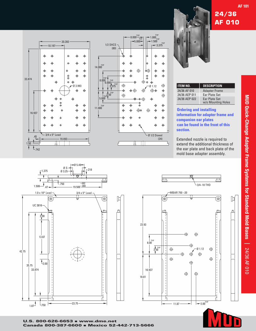
U.S. 800-626-6653 n www.dme.netCanada 800-387-6600 n Mexico 52-442-713-5666
AF 101
24/36AF 010
3/4–10 THD
MBAR 750 –20
11.87
23.93
3.50 TYP
16.937
18.81
Ø 1.12
Ø 1.12
1.500TYP
1/2 SHCS(80)
8.000TYP
6.000TYP
3.375TYP
Ø 1/2 Dowel(24)
11.000TYP
3/4 x 5° Lead.4519.493
1.50
Ø 3.993
10.19720.393
16.937
33.874
.742
5.000TYP
.218 1.375
1.500 +.002 –.000 19.500
Ø 5.49Ø S
Ø 3.25
.750 .47
1.0 x 10° Lead 3/4 x 5° Lead
UC 3816
3.00
42.75
33.874
.750 1.87 23.75
13.87
2.00 35.75
3.50TYP
8.00 TYP
2.00 TYP
3.375TYP
1.000TYP
8.000TYP
5.000TYP
14.000TYP
3/4–10 THD
MBAR 750 –20
11.87
23.93
3.50TYP
16.937
18.81
Ø 1.12
Ø 1.12
1.500 TYP
1/2 SHCS (80)
8.000 TYP
6.000 TYP
3.375 TYP
Ø 1/2 Dowel(24)
11.000 TYP
3/4 x 5° Lead .45 19.493
1.50
Ø 3.993
10.197 20.393
16.937
33.874
.742
5.000 TYP
.2181.375
1.500+.002–.00019.500
Ø 5.49Ø S
Ø 3.25
.750.47
1.0 x 10° Lead 3/4 x 5° Lead
UC 3816
3.00
42.75
33.874
.7501.8723.75
13.87
2.0035.75
3.50 TYP
8.00TYP
2.00TYP
3.375 TYP
1.000 TYP
8.000 TYP
5.000 TYP
14.000 TYP
MUD
Quick-Change Adapter Frame System
s for Standard Mold Bases | 24/36 AF 010
ITEM NO. DESCRIPTION
Ordering and installing information for adapter frame and companion ear plates can be found in the front of this section.
Extendednozzleisrequiredtoextendtheadditionalthicknessoftheearplateandbackplateofthemoldbaseadapterassembly.
24/36AF010 AdapterFrame24/36AEP011 EarPlateSet24/36AEP022 EarPlateSet
w/oMountingHoles
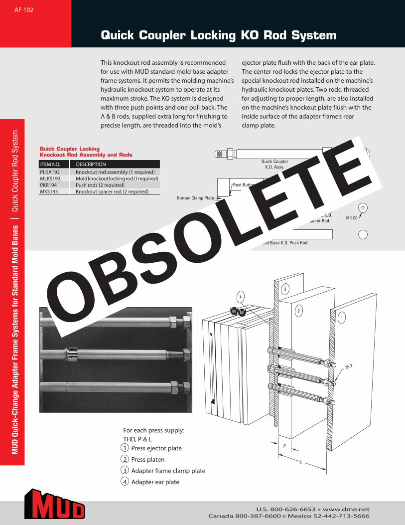
U.S. 800-626-6653 ■ www.dme.netCanada 800-387-6600 ■ Mexico 52-442-713-5666
Quick Coupler Locking KO Rod System
This knockout rod assembly is recommended for use with MUD standard mold base adapter frame systems. It permits the molding machine’s hydraulic knockout system to operate at its maximum stroke. The KO system is designed with three push points and one pull back. The A & B rods, supplied extra long for finishing to precise length, are threaded into the mold’s
ejector plate flush with the back of the ear plate. The center rod locks the ejector plate to the special knockout rod installed on the machine’s hydraulic knockout plates. Two rods, threaded for adjusting to proper length, are also installed on the machine’s knockout plate flush with the inside surface of the adapter frame’s rear clamp plate.
B – X
Mold Base K.O. Spacer Rod
Mold Base K.O. Push Rod
A – X
Mold Base K.O. Locking Rod
Quick Coupler K.O. Assy.
Rest Buttons
X
Bottom Clamp Plate Ear Plate
Adapter Assy
Ø 1.00
THD
12
3
4
Rest Buttons
B – X
Mold Base K.O. Spacer Rod
Mold Base K.O. Push Rod
A – X
Mold Base K.O.Locking Rod
Quick CouplerK.O. Assy.
Rest Buttons
X
Bottom Clamp PlateEar Plate
Adapter Assy
Ø 1.00
THD
12
3
4
Rest Buttons
For each press supply:THD, P & L1 Press ejector plate
2 Press platen
3 Adapter frame clamp plate
4 Adapter ear plate
Quick Coupler Locking Knockout Rod Assembly and Rods
ITEM NO. DESCRIPTIONPLKA192 Knockout rod assembly (1 required)MLKS193 Mold knockout locking rod (1 required)PKR194 Push rods (2 required)MKS195 Knockout spacer rod (2 required)
AF 102M
UD Q
uick
-Cha
nge
Adap
ter
Fram
e Sy
stem
s fo
r St
anda
rd M
old
Base
s |
Qui
ck C
oupl
er R
od S
yste
m
OBSOLETE
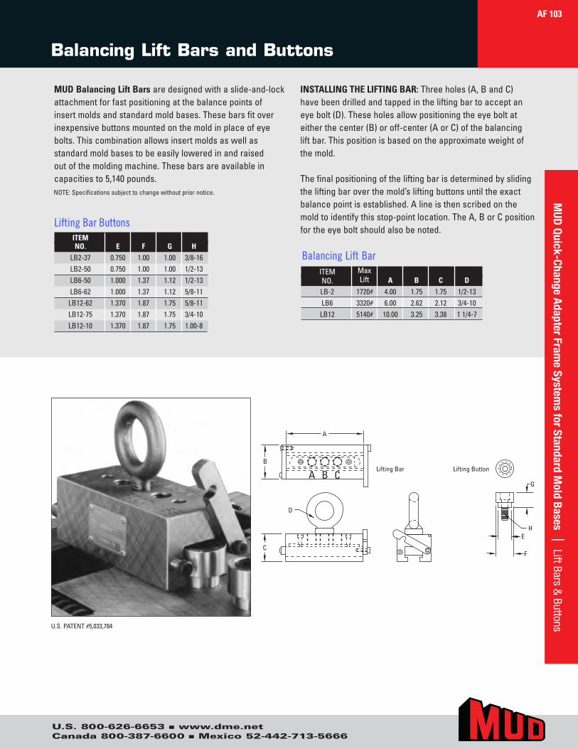
U.S. 800-626-6653 n www.dme.netCanada 800-387-6600 n Mexico 52-442-713-5666
Balancing Lift Bars and Buttons
INSTALLING THE LIFTING BAR:Threeholes(A,BandC)havebeendrilledandtappedintheliftingbartoacceptaneyebolt(D).Theseholesallowpositioningtheeyeboltateitherthecenter(B)oroff-center(AorC)ofthebalancingliftbar.Thispositionisbasedontheapproximateweightofthemold.
Thefinalpositioningoftheliftingbarisdeterminedbyslidingtheliftingbaroverthemold’sliftingbuttonsuntiltheexactbalancepointisestablished.Alineisthenscribedonthemoldtoidentifythisstop-pointlocation.TheA,BorCpositionfortheeyeboltshouldalsobenoted.
U.S.PATENT#5,033,784
A
B
A B CLifting Bar Lifting Button
C
D
G
HE
F
ITEMNO.
MaxLift A B C D
LB-2 1720# 4.00 1.75 1.75 1/2-13LB6 3320# 6.00 2.62 2.12 3/4-10LB12 5140# 10.00 3.25 3.38 11/4-7
Balancing Lift Bar
ITEMNO. E F G H
LB2-37 0.750 1.00 1.00 3/8-16LB2-50 0.750 1.00 1.00 1/2-13LB6-50 1.000 1.37 1.12 1/2-13LB6-62 1.000 1.37 1.12 5/8-11
LB12-62 1.370 1.87 1.75 5/8-11LB12-75 1.370 1.87 1.75 3/4-10LB12-10 1.370 1.87 1.75 1.00-8
MUD Balancing Lift Barsaredesignedwithaslide-and-lockattachmentforfastpositioningatthebalancepointsofinsertmoldsandstandardmoldbases.Thesebarsfitoverinexpensivebuttonsmountedonthemoldinplaceofeyebolts.Thiscombinationallowsinsertmoldsaswellasstandardmoldbasestobeeasilyloweredinandraisedoutofthemoldingmachine.Thesebarsareavailableincapacitiesto5,140pounds.NOTE:Specificationssubjecttochangewithoutpriornotice.
Lifting Bar Buttons
MUD
Quick-Change Adapter Frame System
s for Standard Mold Bases | Lift Bars &
ButtonsAF 103
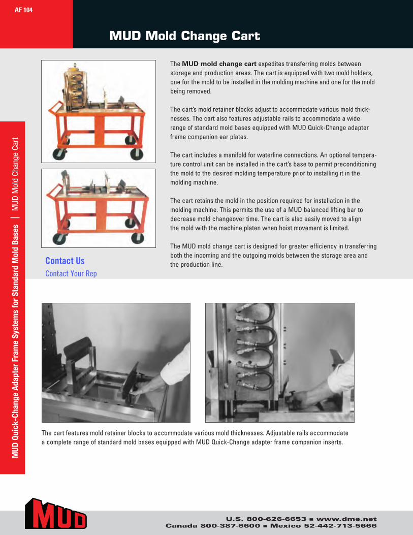
U.S. 800-626-6653 n www.dme.netCanada 800-387-6600 n Mexico 52-442-713-5666
MUD Mold Change Cart
TheMUD mold change cartexpeditestransferringmoldsbetweenstorageandproductionareas.Thecartisequippedwithtwomoldholders,oneforthemoldtobeinstalledinthemoldingmachineandoneforthemoldbeingremoved.
Thecart’smoldretainerblocksadjusttoaccommodatevariousmoldthick-nesses.ThecartalsofeaturesadjustablerailstoaccommodateawiderangeofstandardmoldbasesequippedwithMUDQuick-Changeadapterframecompanionearplates.
Thecartincludesamanifoldforwaterlineconnections.Anoptionaltempera-turecontrolunitcanbeinstalledinthecart’sbasetopermitpreconditioningthemoldtothedesiredmoldingtemperaturepriortoinstallingitinthemoldingmachine.
Thecartretainsthemoldinthepositionrequiredforinstallationinthemoldingmachine.ThispermitstheuseofaMUDbalancedliftingbartodecreasemoldchangeovertime.Thecartisalsoeasilymovedtoalignthemoldwiththemachineplatenwhenhoistmovementislimited.
TheMUDmoldchangecartisdesignedforgreaterefficiencyintransferringboththeincomingandtheoutgoingmoldsbetweenthestorageareaandtheproductionline.
Thecartfeaturesmoldretainerblockstoaccommodatevariousmoldthicknesses.AdjustablerailsaccommodateacompleterangeofstandardmoldbasesequippedwithMUDQuick-Changeadapterframecompanioninserts.
MUD
Qui
ck-C
hang
e Ad
apte
r Fr
ame
Syst
ems
for
Stan
dard
Mol
d Ba
ses
| M
UD M
old
Chan
ge C
art
AF 104
Contact UsContact Your Rep
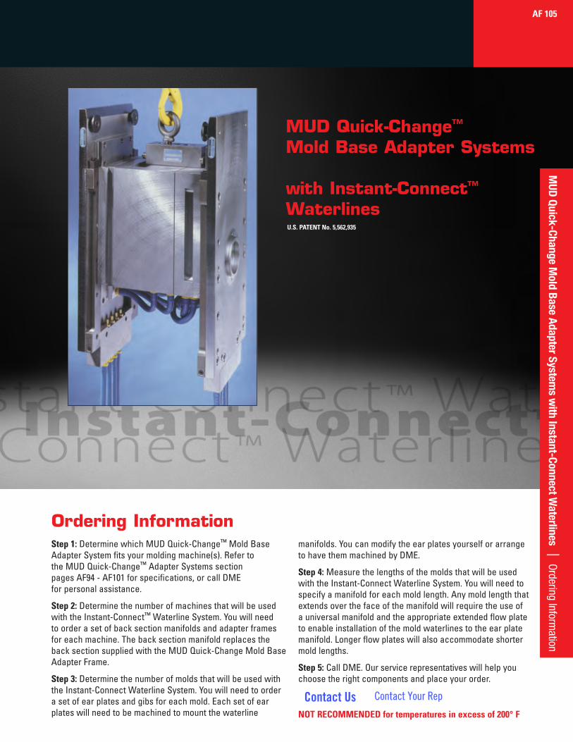
MUD Quick-Change™
Mold Base Adapter Systems
with Instant-Connect™ Waterlines
Step 1:DeterminewhichMUDQuick-Change™MoldBaseAdapterSystemfitsyourmoldingmachine(s).RefertotheMUDQuick-Change™AdapterSystemssectionpagesAF94-AF101forspecifications,orcallDMEforpersonalassistance.
Step 2:DeterminethenumberofmachinesthatwillbeusedwiththeInstant-Connect™WaterlineSystem.Youwillneedtoorderasetofbacksectionmanifoldsandadapterframesforeachmachine.ThebacksectionmanifoldreplacesthebacksectionsuppliedwiththeMUDQuick-ChangeMoldBaseAdapterFrame.
Step 3:DeterminethenumberofmoldsthatwillbeusedwiththeInstant-ConnectWaterlineSystem.Youwillneedtoorderasetofearplatesandgibsforeachmold.Eachsetofearplateswillneedtobemachinedtomountthewaterline
Ordering Information
U.S. PATENT No. 5,562,935
AF 105M
UD Quick-Change Mold Base Adapter System
s with Instant-Connect W
aterlines | Ordering Inform
ation
manifolds.YoucanmodifytheearplatesyourselforarrangetohavethemmachinedbyDME.
Step 4:MeasurethelengthsofthemoldsthatwillbeusedwiththeInstant-ConnectWaterlineSystem.Youwillneedtospecifyamanifoldforeachmoldlength.Anymoldlengththatextendsoverthefaceofthemanifoldwillrequiretheuseofauniversalmanifoldandtheappropriateextendedflowplatetoenableinstallationofthemoldwaterlinestotheearplatemanifold.Longerflowplateswillalsoaccommodateshortermoldlengths.
Step 5:CallDME.Ourservicerepresentativeswillhelpyouchoosetherightcomponentsandplaceyourorder.
Contact Us Contact Your Rep
NOT RECOMMENDED for temperatures in excess of 200° F
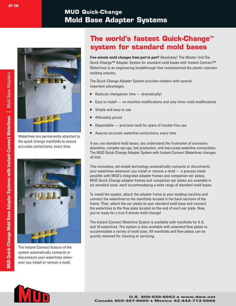
The world’s fastest Quick-Change™ system for standard mold basesFive-minute mold changes from part to part?Absolutely!TheMasterUnitDieQuick-Change™AdapterSystemforstandardmoldbaseswithInstant-Connect™Waterlinesisanengineeringbreakthroughthatrevolutionizedtheplasticinjectionmoldingindustry.
TheQuick-ChangeAdapterSystemprovidesmolderswithseveralimportantadvantages:
n Reduceschangeovertime—dramatically!
n Easytoinstall—nomachinemodificationsandonlyminormoldmodifications
n Simpleandeasytouse
n Affordablypriced
n Dependable—precision-builtforyearsoftrouble-freeuse
n Assuresaccuratewaterlineconnections,everytime
Ifyouusestandardmoldbases,youunderstandthefrustrationofexcessivedowntime,complexset-ups,lostproduction,andinaccuratewaterlineconnections.TheMUDQuick-ChangeAdapterSystemwithInstant-ConnectWaterlineschangesallthat.
Thisinnovative,yetsimpletechnologyautomaticallyconnectsordisconnectsyourwaterlineswheneveryouinstallorremoveamold—aprocessmadepossiblewithMUD’sintegratedadapterframesandcompanionearplates.MUDQuick-Changeadapterframesandcompanionearplatesareavailableinsixstandardsizes,eachaccommodatingawiderangeofstandardmoldbases.
Toinstallthesystem,attachtheadapterframetoyourmoldingmachineandconnectthewaterlinestothemanifoldslocatedinthebacksectionsoftheframe.Then,attachtheearplatestoyourstandardmoldbaseandconnectthewaterlinestotheflowplatelocatedontheendofeachearplate.Now,you’rereadyforatrue5-minutemoldchange!
TheInstant-ConnectWaterlineSystemisavailablewithmanifoldsfor4,6,and10waterlines.Thesystemisalsoavailablewithextendedflowplatestoaccommodateavarietyofmoldsizes.Allmanifoldsandflowplatescanbequicklyremovedforcleaningorservicing.
Waterlinesarepermanentlyattachedtothequickchangemanifoldstoassureaccurateconnections,everytime.
TheInstant-Connectfeatureofthesystemautomaticallyconnectsordisconnectsyourwaterlineswhen-everyouinstallorremoveamold.
MUD Quick-Change
Mold Base Adapter Systems
U.S. 800-626-6653 n www.dme.netCanada 800-387-6600 n Mexico 52-442-713-5666
AF 106M
UD Q
uick
-Cha
nge
Mol
d Ba
se A
dapt
er S
yste
ms
with
Inst
ant-
Conn
ect W
ater
lines
|
Mol
d Ba
se A
dapt
ers
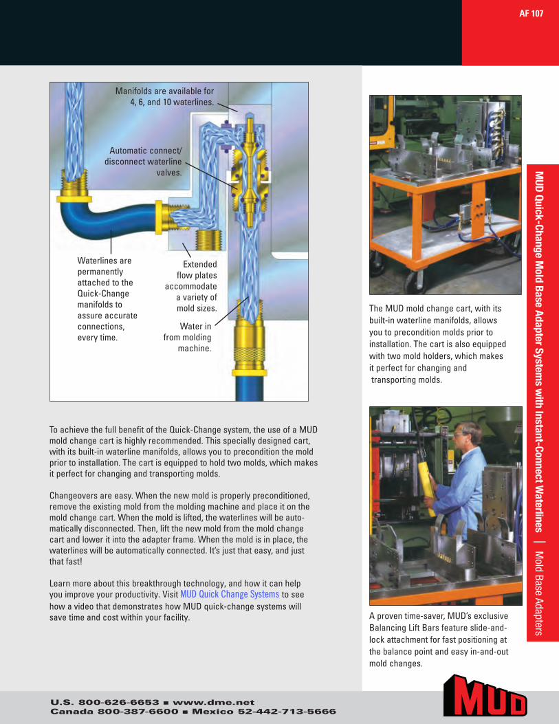
Aproventime-saver,MUD’sexclusiveBalancingLiftBarsfeatureslide-and-lockattachmentforfastpositioningatthebalancepointandeasyin-and-outmoldchanges.
ToachievethefullbenefitoftheQuick-Changesystem,theuseofaMUDmoldchangecartishighlyrecommended.Thisspeciallydesignedcart,withitsbuilt-inwaterlinemanifolds,allowsyoutopreconditionthemoldpriortoinstallation.Thecartisequippedtoholdtwomolds,whichmakesitperfectforchangingandtransportingmolds.
Changeoversareeasy.Whenthenewmoldisproperlypreconditioned,removetheexistingmoldfromthemoldingmachineandplaceitonthemoldchangecart.Whenthemoldislifted,thewaterlineswillbeauto-maticallydisconnected.Then,liftthenewmoldfromthemoldchangecartandloweritintotheadapterframe.Whenthemoldisinplace,thewaterlineswillbeautomaticallyconnected.It’sjustthateasy,andjustthatfast!
Learnmoreaboutthisbreakthroughtechnology,andhowitcanhelpyouimproveyourproductivity.VisitMUD Quick Change Systems toseehowavideothatdemonstrateshowMUDquick-changesystemswillsavetimeandcostwithinyourfacility.
TheMUDmoldchangecart,withitsbuilt-inwaterlinemanifolds,allowsyoutopreconditionmoldspriortoinstallation.Thecartisalsoequippedwithtwomoldholders,whichmakesitperfectforchangingandtransportingmolds.
AF 107M
UD Quick-Change Mold Base Adapter System
s with Instant-Connect W
aterlines | Mold Base Adapters
U.S. 800-626-6653 n www.dme.netCanada 800-387-6600 n Mexico 52-442-713-5666
WaterlinesarepermanentlyattachedtotheQuick-Changemanifoldstoassureaccurateconnections,everytime.
Extendedflowplates
accommodateavarietyofmoldsizes.
Waterinfrommolding
machine.
Automaticconnect/disconnectwaterline
valves.
Manifoldsareavailablefor4,6,and10waterlines.

L
Face of Manifold
LP
Face of Manifold
Back Section
PG – 37SPN – 37
BSP – 37ORP – 37
ORCS – 37
CFBS – 37CEPM – 37OEPC – 37ORCS – 37
ORP – 37
EPP – 37
SPN – 37PG – 37
Ear Plate ManifoldAssembly
Frame Back SectionAssembly
StandardManifold
Back Section
PG – 37SPN – 37
BSP – 37ORP – 37
ORCS – 37
CFBS – 37CEPM – 37OEPC – 37ORCS – 37
ORP – 37
EPP – 37
SPN – 37PG – 37
Ear Plate ManifoldAssembly
Frame Back SectionAssembly
ExtendedFlow Plate
UniversalManifold
BL – 37ORBL – 37
4-Coupler Instant-Connect™ Waterline SystemFits 12/18 and 14/20 Mold Base Adapter Systems
12/1814/20
L
Face of Manifold
LP
Face of Manifold
Back Section
PG – 37SPN – 37
BSP – 37ORP – 37
ORCS – 37
CFBS – 37CEPM – 37OEPC – 37ORCS – 37
ORP – 37
EPP – 37
SPN – 37PG – 37
Ear Plate ManifoldAssembly
Frame Back SectionAssembly
StandardManifold
Back Section
PG – 37SPN – 37
BSP – 37ORP – 37
ORCS – 37
CFBS – 37CEPM – 37OEPC – 37ORCS – 37
ORP – 37
EPP – 37
SPN – 37PG – 37
Ear Plate ManifoldAssembly
Frame Back SectionAssembly
ExtendedFlow Plate
UniversalManifold
BL – 37ORBL – 37
ITEM NO. DESCRIPTIONEPM-FP-374 StandardManifold
ITEM NO. DESCRIPTIONEPM-374 UniversalManifold
*Topandbottomclampplatesofmoldbasemusthavepocketmachinedtoaccepttheseextendedflowplates.
L = Centerline P = Centerline Universal Manifold Universal Manifold withMold Base Adapter Mold Base of Ear Plate to of Ear Plate to Standard with Straight Extended Flow Plate
Ear Plate Length Face of Manifold Extended Flow Plate Manifold Flow Plate 3.37 5.37 7.3714.00" 7.03 • •
*18.75" 9.40 *7.00 •12/18AEP011
*22.75" 11.40 *7.00 •*26.75" 13.40 *7.00 •
16.00" 8.03 • •*20.75" 10.40 *8.00 •
14/20AEP011*24.75" 12.40 *8.00 •*28.75" 14.40 *8.00 •
AF 108M
UD Q
uick
-Cha
nge
Mol
d Ba
se A
dapt
er S
yste
ms
with
Inst
ant-
Conn
ect W
ater
lines
|
12/1
8 14
/20
U.S. 800-626-6653 n www.dme.netCanada 800-387-6600 n Mexico 52-442-713-5666
4 Coupler Instant-Connect Waterline System
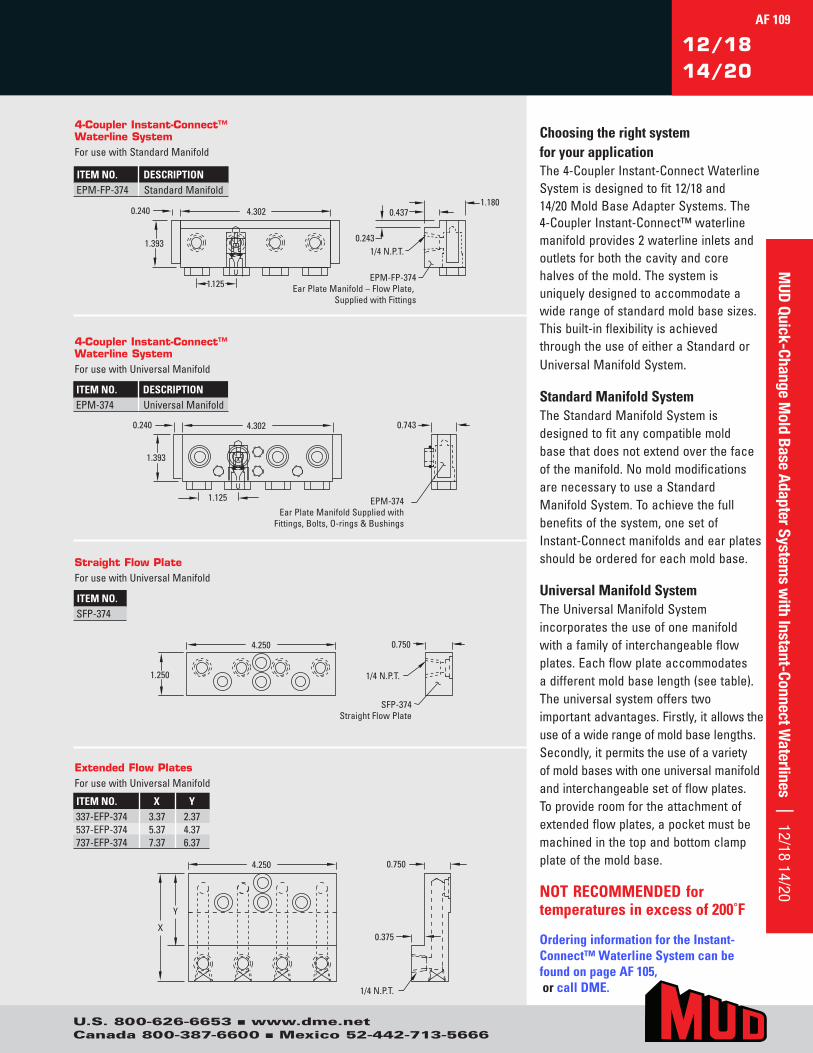
12/1814/20
0.240 4.302
1.125
1.393
0.743
EPM-374Ear Plate Manifold Supplied with
Fittings, Bolts, O-rings & Bushings
4.250
X
Y
1/4 N.P.T.
0.375
0.750
0.240 4.302
1.125
1.393
1.1800.437
0.243 1/4 N.P.T.
EPM-FP-374 Ear Plate Manifold – Flow Plate,
Supplied with Fittings
4.250
1.250 1/4 N.P.T.
0.750
SFP-374Straight Flow Plate
0.240 4.302
1.125
1.393
0.743
EPM-374 Ear Plate Manifold Supplied with
Fittings, Bolts, O-rings & Bushings
4.250
X
Y
1/4 N.P.T.
0.375
0.750
0.240 4.302
1.125
1.393
1.1800.437
0.2431/4 N.P.T.
EPM-FP-374Ear Plate Manifold – Flow Plate,
Supplied with Fittings
4.250
1.250 1/4 N.P.T.
0.750
SFP-374Straight Flow Plate
0.240 4.302
1.125
1.393
0.743
EPM-374Ear Plate Manifold Supplied with
Fittings, Bolts, O-rings & Bushings
4.250
X
Y
1/4 N.P.T.
0.375
0.750
0.240 4.302
1.125
1.393
1.1800.437
0.2431/4 N.P.T.
EPM-FP-374Ear Plate Manifold – Flow Plate,
Supplied with Fittings
4.250
1.250 1/4 N.P.T.
0.750
SFP-374 Straight Flow Plate
0.240 4.302
1.125
1.393
0.743
EPM-374Ear Plate Manifold Supplied with
Fittings, Bolts, O-rings & Bushings
4.250
X
Y
1/4 N.P.T.
0.375
0.750
0.240 4.302
1.125
1.393
1.1800.437
0.2431/4 N.P.T.
EPM-FP-374Ear Plate Manifold – Flow Plate,
Supplied with Fittings
4.250
1.250 1/4 N.P.T.
0.750
SFP-374Straight Flow Plate
4-Coupler Instant-Connect™Waterline SystemForusewithUniversalManifold
4-Coupler Instant-Connect™Waterline SystemForusewithStandardManifold
Straight Flow PlateForusewithUniversalManifold
ITEM NO.SFP-374
ITEM NO. DESCRIPTIONEPM-FP-374 StandardManifold
ITEM NO. DESCRIPTIONEPM-374 UniversalManifold
Extended Flow PlatesForusewithUniversalManifold
ITEM NO. X Y337-EFP-374 3.37 2.37537-EFP-374 5.37 4.37737-EFP-374 7.37 6.37
Choosing the right system for your applicationThe4-CouplerInstant-ConnectWaterlineSystemisdesignedtofit12/18and14/20MoldBaseAdapterSystems.The4-CouplerInstant-Connect™waterlinemanifoldprovides2waterlineinletsandoutletsforboththecavityandcorehalvesofthemold.Thesystemisuniquelydesignedtoaccommodateawiderangeofstandardmoldbasesizes.Thisbuilt-inflexibilityisachievedthroughtheuseofeitheraStandardorUniversalManifoldSystem.
Standard Manifold SystemTheStandardManifoldSystemisdesignedtofitanycompatiblemoldbasethatdoesnotextendoverthefaceofthemanifold.NomoldmodificationsarenecessarytouseaStandardManifoldSystem.Toachievethefullbenefitsofthesystem,onesetofInstant-Connectmanifoldsandearplatesshouldbeorderedforeachmoldbase.
Universal Manifold SystemTheUniversalManifoldSystemincorporatestheuseofonemanifoldwithafamilyofinterchangeableflowplates.Eachflowplateaccommodatesadifferentmoldbaselength(seetable).Theuniversalsystemofferstwoimportantadvantages.Firstly,itallowstheuseofawiderangeofmoldbaselengths.Secondly,itpermitstheuseofavarietyofmoldbaseswithoneuniversalmanifoldandinterchangeablesetofflowplates.Toprovideroomfortheattachmentofextendedflowplates,apocketmustbemachinedinthetopandbottomclampplateofthemoldbase.
NOT RECOMMENDED for temperatures in excess of 200˚F
Ordering information for the Instant-Connect™ Waterline System can be found on page AF 105, or call DME.
AF 109
U.S. 800-626-6653 n www.dme.netCanada 800-387-6600 n Mexico 52-442-713-5666
MUD Quick-Change M
old Base Adapter Systems w
ith Instant-Connect Waterlines | 12/18 14/20
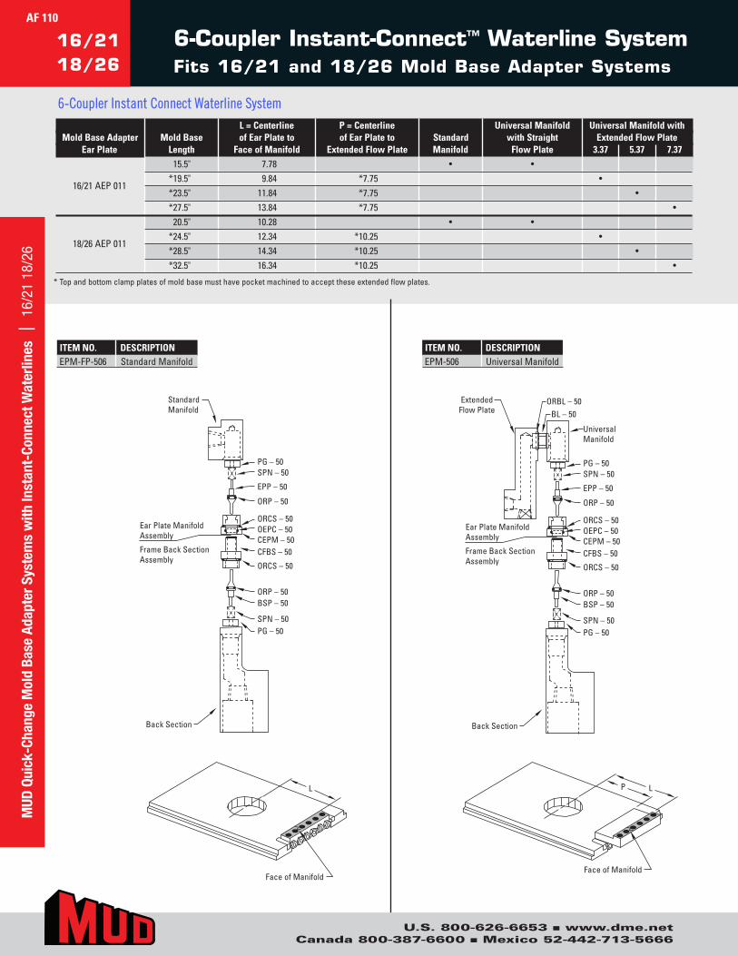
6-Coupler Instant-Connect™ Waterline SystemFits 16/21 and 18/26 Mold Base Adapter Systems
16/2118/26
L
Face of Manifold
LP
Back Section
PG – 50SPN – 50
BSP – 50ORP – 50
ORCS – 50
CFBS – 50CEPM – 50OEPC – 50ORCS – 50
ORP – 50
EPP – 50
SPN – 50PG – 50
Ear Plate ManifoldAssembly
Frame Back SectionAssembly
StandardManifold
Back Section
PG – 50SPN – 50
BSP – 50ORP – 50
ORCS – 50
CFBS – 50CEPM – 50OEPC – 50ORCS – 50
ORP – 50
EPP – 50
SPN – 50PG – 50
Ear Plate ManifoldAssembly
Frame Back SectionAssembly
ExtendedFlow Plate
UniversalManifold
BL – 50ORBL – 50
Face of Manifold
L
Face of Manifold
LP
Back Section
PG – 50SPN – 50
BSP – 50ORP – 50
ORCS – 50
CFBS – 50CEPM – 50OEPC – 50ORCS – 50
ORP – 50
EPP – 50
SPN – 50PG – 50
Ear Plate ManifoldAssembly
Frame Back SectionAssembly
StandardManifold
Back Section
PG – 50SPN – 50
BSP – 50ORP – 50
ORCS – 50
CFBS – 50CEPM – 50OEPC – 50ORCS – 50
ORP – 50
EPP – 50
SPN – 50PG – 50
Ear Plate ManifoldAssembly
Frame Back SectionAssembly
Extended Flow Plate
UniversalManifold
BL – 50ORBL – 50
Face of Manifold
L
Face of Manifold
LP
Back Section
PG – 50SPN – 50
BSP – 50ORP – 50
ORCS – 50
CFBS – 50CEPM – 50OEPC – 50ORCS – 50
ORP – 50
EPP – 50
SPN – 50PG – 50
Ear Plate ManifoldAssembly
Frame Back SectionAssembly
StandardManifold
Back Section
PG – 50SPN – 50
BSP – 50ORP – 50
ORCS – 50
CFBS – 50CEPM – 50OEPC – 50ORCS – 50
ORP – 50
EPP – 50
SPN – 50PG – 50
Ear Plate ManifoldAssembly
Frame Back SectionAssembly
ExtendedFlow Plate
UniversalManifold
BL – 50ORBL – 50
Face of Manifold
ITEM NO. DESCRIPTIONEPM-FP-506 StandardManifold
ITEM NO. DESCRIPTIONEPM-506 UniversalManifold
* Topandbottomclampplatesofmoldbasemusthavepocketmachinedtoaccepttheseextendedflowplates.
L = Centerline P = Centerline Universal Manifold Universal Manifold withMold Base Adapter Mold Base of Ear Plate to of Ear Plate to Standard with Straight Extended Flow Plate
Ear Plate Length Face of Manifold Extended Flow Plate Manifold Flow Plate 3.37 5.37 7.3715.5" 7.78 • •
*19.5" 9.84 *7.75 •16/21AEP011
*23.5" 11.84 *7.75 •*27.5" 13.84 *7.75 •
20.5" 10.28 • •*24.5" 12.34 *10.25 •
18/26AEP011*28.5" 14.34 *10.25 •*32.5" 16.34 *10.25 •
AF 110
U.S. 800-626-6653 n www.dme.netCanada 800-387-6600 n Mexico 52-442-713-5666
MUD
Qui
ck-C
hang
e M
old
Base
Ada
pter
Sys
tem
s w
ith In
stan
t-Co
nnec
t Wat
erlin
es
| 16
/21
18/2
6
6-Coupler Instant Connect Waterline System

16/2118/26
0.240 7.302
1.250
1.643
1/4 N.P.T.
0.563
0.875
1/4 N.P.T.
0.875
SFP-506Straight Flow Plate
0.240 7.302
1.250
1.643
0.993
EPM-506Ear Plate Manifold Supplied with
Fittings, Bolts, O-rings & Bushings
7.250
1.375
7.250
X
Y
1.493 0.500
0.246 1/4 N.P.T.
EPM-FP-506 Ear Plate Manifold – Flow Plate,
Supplied with Fittings0.240 7.302
1.250
1.643
1/4 N.P.T.
0.563
0.875
1/4 N.P.T.
0.875
SFP-506Straight Flow Plate
0.240 7.302
1.250
1.643
0.993
EPM-506 Ear Plate Manifold Supplied with
Fittings, Bolts, O-rings & Bushings
7.250
1.375
7.250
X
Y
1.4930.500
0.2461/4 N.P.T.
EPM-FP-506Ear Plate Manifold – Flow Plate,
Supplied with Fittings0.240 7.302
1.250
1.643
1/4 N.P.T.
0.563
0.875
1/4 N.P.T.
0.875
SFP-506 Straight Flow Plate
0.240 7.302
1.250
1.643
0.993
EPM-506Ear Plate Manifold Supplied with
Fittings, Bolts, O-rings & Bushings
7.250
1.375
7.250
X
Y
1.4930.500
0.2461/4 N.P.T.
EPM-FP-506Ear Plate Manifold – Flow Plate,
Supplied with Fittings
0.240 7.302
1.250
1.643
1/4 N.P.T.
0.563
0.875
1/4 N.P.T.
0.875
SFP-506Straight Flow Plate
0.240 7.302
1.250
1.643
0.993
EPM-506Ear Plate Manifold Supplied with
Fittings, Bolts, O-rings & Bushings
7.250
1.375
7.250
X
Y
1.4930.500
0.2461/4 N.P.T.
EPM-FP-506Ear Plate Manifold – Flow Plate,
Supplied with Fittings
Choosing the right system for your applicationThe6-CouplerInstant-ConnectWaterlineSystemisdesignedtofit16/21and18/26MoldBaseAdapterSystems.The6-CouplerInstant-Connect™waterlinemanifoldprovides3waterlineinletsandoutletsforboththecavityandcorehalvesofthemold.Thesystemisuniquelydesignedtoaccommodateawiderangeofstandardmoldbasesizes.Thisbuilt-inflexibilityisachievedthroughtheuseofeitheraStandardorUniversalManifoldSystem.
Standard Manifold SystemTheStandardManifoldSystemisdesignedtofitanycompatiblemoldbasethatdoesnotextendoverthefaceofthemanifold.Nomoldmodifica-tionsarenecessarytouseaStandardManifoldSystem.Toachievethefullbenefitsofthesystem,onesetofInstant-Connectmanifoldsandearplatesshouldbeorderedforeachmoldbase.
Universal Manifold SystemTheUniversalManifoldSystemincorporatestheuseofonemanifoldwithafamilyofinterchangeableflowplates.Eachflowplateaccommodatesadifferentmoldbaselength(seetable).Theuniversalsystemofferstwoimportantadvantages.Firstly,itallowstheuseofawiderangeofmoldbaselengths.Secondly,itpermitstheuseofavarietyofmoldbaseswithoneuniversalmanifoldandinterchangeablesetofflowplates.Toprovideroomfortheattachmentofextendedflowplates,apocketmustbemachinedinthetopandbottomclampplateofthemoldbase.
NOT RECOMMENDED for temperatures in excess of 200˚F
Ordering information for the Instant-Connect™ Waterline System can be found on page AF 105, or call DME.
ITEM NO. DESCRIPTIONEPM-FP-506 StandardManifold
ITEM NO. DESCRIPTIONEPM-506 UniversalManifold
6-Coupler Instant-Connect™Waterline SystemForusewithStandardManifold
6-Coupler Instant-Connect™ Waterline SystemForusewithUniversalManifold
Extended Flow PlatesForusewithUniversalManifold
ITEM NO. X Y337-EFP-506 3.37 2.06537-EFP-506 5.37 4.06737-EFP-506 7.37 6.06
Straight Flow PlateForusewithUniversalManifold
ITEM NO.SFP-506
AF 111
U.S. 800-626-6653 n www.dme.netCanada 800-387-6600 n Mexico 52-442-713-5666
MUD Quick-Change M
old Base Adapter Systems w
ith Instant-Connect Waterlines | 16/21 18/26
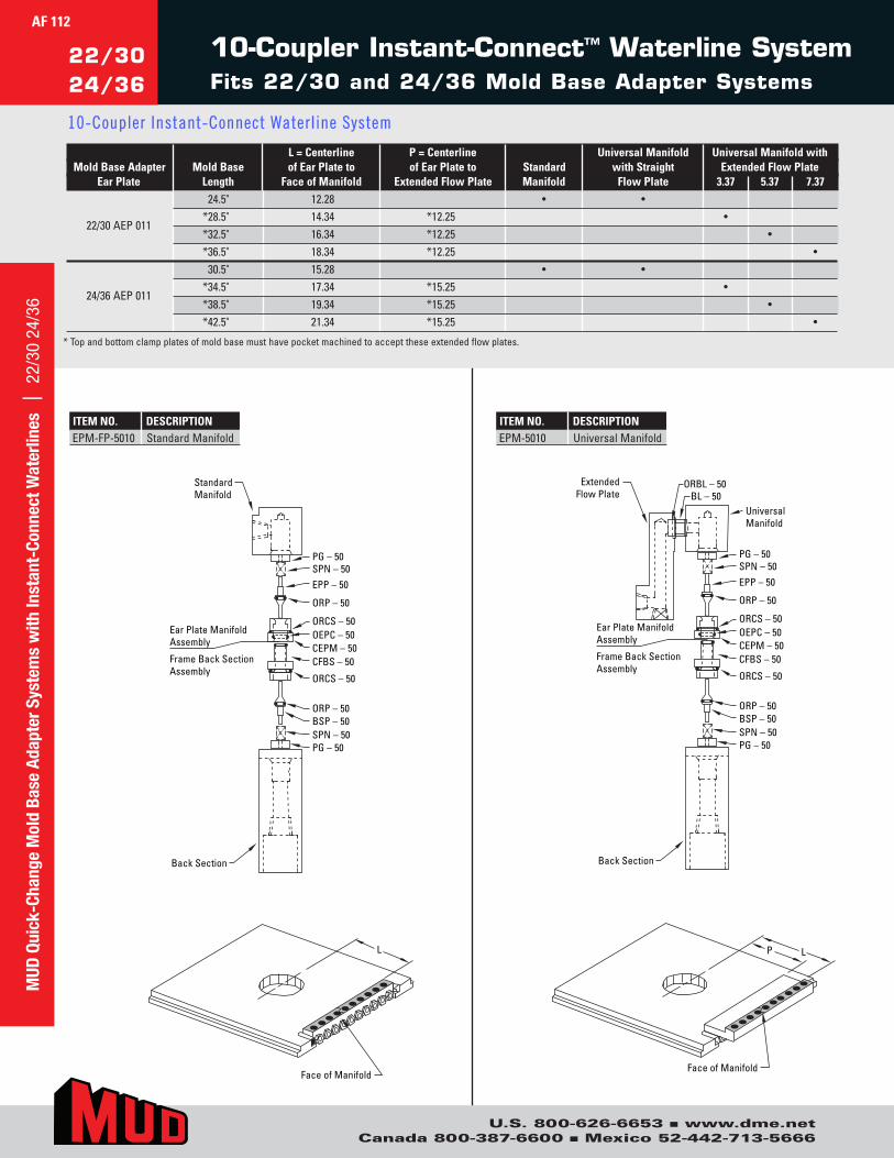
AF 112
22/3024/36
L
Face of Manifold
LP
Back Section
PG – 50SPN – 50BSP – 50ORP – 50
ORCS – 50
CFBS – 50CEPM – 50
ORCS – 50
ORP – 50
EPP – 50SPN – 50PG – 50
Ear Plate ManifoldAssembly
Frame Back SectionAssembly
OEPC – 50
StandardManifold
Face of Manifold
Back Section
PG – 50SPN – 50BSP – 50ORP – 50
ORCS – 50
CFBS – 50CEPM – 50
ORCS – 50
ORP – 50
EPP – 50SPN – 50PG – 50
Ear Plate ManifoldAssembly
Frame Back SectionAssembly
OEPC – 50
ExtendedFlow Plate
UniversalManifold
BL – 50ORBL – 50
10-Coupler Instant-Connect™ Waterline SystemFits 22/30 and 24/36 Mold Base Adapter Systems
ITEM NO. DESCRIPTIONEPM-FP-5010 StandardManifold
ITEM NO. DESCRIPTIONEPM-5010 UniversalManifold
* Topandbottomclampplatesofmoldbasemusthavepocketmachinedtoaccepttheseextendedflowplates.
L = Centerline P = Centerline Universal Manifold Universal Manifold withMold Base Adapter Mold Base of Ear Plate to of Ear Plate to Standard with Straight Extended Flow Plate
Ear Plate Length Face of Manifold Extended Flow Plate Manifold Flow Plate 3.37 5.37 7.3724.5" 12.28 • •
*28.5" 14.34 *12.25 •22/30AEP011
*32.5" 16.34 *12.25 •*36.5" 18.34 *12.25 •
30.5" 15.28 • •*34.5" 17.34 *15.25 •
24/36AEP011*38.5" 19.34 *15.25 •*42.5" 21.34 *15.25 •
MUD
Qui
ck-C
hang
e M
old
Base
Ada
pter
Sys
tem
s w
ith In
stan
t-Co
nnec
t Wat
erlin
es
| 22
/30
24/3
6
U.S. 800-626-6653 n www.dme.netCanada 800-387-6600 n Mexico 52-442-713-5666
10-Coupler Instant-Connect Waterline System
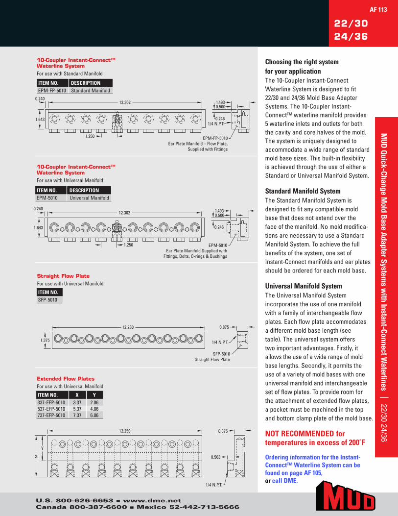
22/3024/36
0.5001.493
0.2461/4 N.P.T.
EPM-FP-5010Ear Plate Manifold – Flow Plate,
Supplied with Fittings
12.3020.240
1.643
1.250
EPM-5010Ear Plate Manifold Supplied with
Fittings, Bolts, O-rings & Bushings
1.250
12.3020.240
1.643
12.250
1.375
0.875
1/4 N.P.T.
SFP-5010 Straight Flow Plate
0.875
0.563
1/4 N.P.T.
12.250
X
Y
0.5001.493
0.246
0.5001.493
0.2461/4 N.P.T.
EPM-FP-5010Ear Plate Manifold – Flow Plate,
Supplied with Fittings
12.3020.240
1.643
1.250
EPM-5010Ear Plate Manifold Supplied with
Fittings, Bolts, O-rings & Bushings
1.250
12.3020.240
1.643
12.250
1.375
0.875
1/4 N.P.T.
SFP-5010Straight Flow Plate
0.875
0.563
1/4 N.P.T.
12.250
X
Y
0.5001.493
0.246
Choosing the right system for your applicationThe10-CouplerInstant-ConnectWaterlineSystemisdesignedtofit22/30and24/36MoldBaseAdapterSystems.The10-CouplerInstant-Connect™waterlinemanifoldprovides5waterlineinletsandoutletsforboththecavityandcorehalvesofthemold.Thesystemisuniquelydesignedtoaccommodateawiderangeofstandardmoldbasesizes.Thisbuilt-inflexibilityisachievedthroughtheuseofeitheraStandardorUniversalManifoldSystem.
Standard Manifold SystemTheStandardManifoldSystemisdesignedtofitanycompatiblemoldbasethatdoesnotextendoverthefaceofthemanifold.Nomoldmodifica-tionsarenecessarytouseaStandardManifoldSystem.Toachievethefullbenefitsofthesystem,onesetofInstant-Connectmanifoldsandearplatesshouldbeorderedforeachmoldbase.
Universal Manifold SystemTheUniversalManifoldSystemincorporatestheuseofonemanifoldwithafamilyofinterchangeableflowplates.Eachflowplateaccommodatesadifferentmoldbaselength(seetable).Theuniversalsystemofferstwoimportantadvantages.Firstly,itallowstheuseofawiderangeofmoldbaselengths.Secondly,itpermitstheuseofavarietyofmoldbaseswithoneuniversalmanifoldandinterchangeablesetofflowplates.Toprovideroomfortheattachmentofextendedflowplates,apocketmustbemachinedinthetopandbottomclampplateofthemoldbase.
NOT RECOMMENDED for temperatures in excess of 200˚F
Ordering information for the Instant-Connect™ Waterline System can be found on page AF 105, or call DME.
0.5001.493
0.2461/4 N.P.T.
EPM-FP-5010Ear Plate Manifold – Flow Plate,
Supplied with Fittings
12.3020.240
1.643
1.250
EPM-5010 Ear Plate Manifold Supplied with
Fittings, Bolts, O-rings & Bushings
1.250
12.302 0.240
1.643
12.250
1.375
0.875
1/4 N.P.T.
SFP-5010Straight Flow Plate
0.875
0.563
1/4 N.P.T.
12.250
X
Y
0.500 1.493
0.246
ITEM NO. DESCRIPTIONEPM-5010 UniversalManifold
10-Coupler Instant-Connect™Waterline SystemForusewithStandardManifold
10-Coupler Instant-Connect™Waterline SystemForusewithUniversalManifold
0.500 1.493
0.246 1/4 N.P.T.
EPM-FP-5010 Ear Plate Manifold – Flow Plate,
Supplied with Fittings
12.302 0.240
1.643
1.250
EPM-5010Ear Plate Manifold Supplied with
Fittings, Bolts, O-rings & Bushings
1.250
12.3020.240
1.643
12.250
1.375
0.875
1/4 N.P.T.
SFP-5010Straight Flow Plate
0.875
0.563
1/4 N.P.T.
12.250
X
Y
0.5001.493
0.246
ITEM NO. DESCRIPTIONEPM-FP-5010 StandardManifold
Extended Flow PlatesForusewithUniversalManifold
ITEM NO. X Y337-EFP-5010 3.37 2.06537-EFP-5010 5.37 4.06737-EFP-5010 7.37 6.06
Straight Flow PlateForusewithUniversalManifold
ITEM NO.SFP-5010
U.S. 800-626-6653 n www.dme.netCanada 800-387-6600 n Mexico 52-442-713-5666
AF 113M
UD Quick-Change Mold Base Adapter System
s with Instant-Connect W
aterlines | 22/30 24/36
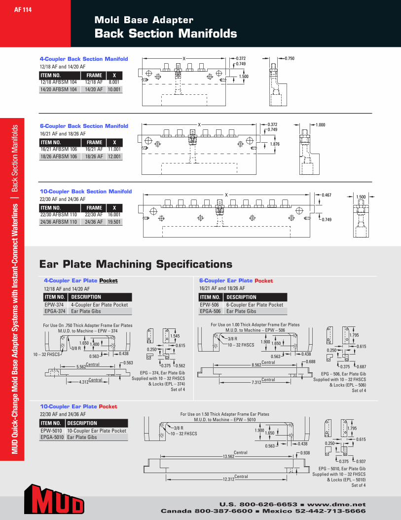
Mold Base Adapter Back Section Manifolds
0.7500.3720.749
1.500
X
1.0000.3720.749
1.876
X
1.5000.467
0.749
X
0.7500.3720.749
1.500
X
1.0000.3720.749
1.876
X
1.5000.467
0.749
X
0.7500.3720.749
1.500
X
1.0000.3720.749
1.876
X
1.5000.467
0.749
X
0.438
1.4001.650
10 – 32 FHSCS3/8 R
For Use On .750 Thick Adapter Frame Ear PlatesM.U.D. to Machine – EPW – 374
0.5635.562
4.312Central
Central
1.545
0.6150.250
0.375 0.562
EPG – 374, Ear Plate GibSupplied with 10 – 32 FHSCS
& Locks (EPL – 374)Set of 4
0.438
1.900 1.65010 – 32 FHSCS3/8 R
For Use on 1.00 Thick Adapter Frame Ear PlatesM.U.D. to Machine – EPW – 506
1.795
0.6150.250
0.6870.375
EPG – 506, Ear Plate GibSupplied with 10 – 32 FHSCS
& Locks (EPL – 506)Set of 4
0.4380.563
1.900 1.65010 – 32 FHSCS3/8 R
For Use on 1.50 Thick Adapter Frame Ear PlatesM.U.D. to Machine – EPW – 5010
1.795
0.6150.250
0.9370.375
EPG – 5010, Ear Plate GibSupplied with 10 – 32 FHSCS
& Locks (EPL – 5010)Set of 4
0.93813.562
12.312Central
Central
0.6888.562
7.312Central
Central0.563
0.563
Ear Plate Machining Specifications
0.438
1.4001.650
10 – 32 FHSCS3/8 R
For Use On .750 Thick Adapter Frame Ear PlatesM.U.D. to Machine – EPW – 374
0.5635.562
4.312Central
Central
1.545
0.6150.250
0.375 0.562
EPG – 374, Ear Plate GibSupplied with 10 – 32 FHSCS
& Locks (EPL – 374)Set of 4
0.438
1.900 1.65010 – 32 FHSCS3/8 R
For Use on 1.00 Thick Adapter Frame Ear PlatesM.U.D. to Machine – EPW – 506
1.795
0.6150.250
0.6870.375
EPG – 506, Ear Plate GibSupplied with 10 – 32 FHSCS
& Locks (EPL – 506)Set of 4
0.4380.563
1.900 1.65010 – 32 FHSCS3/8 R
For Use on 1.50 Thick Adapter Frame Ear PlatesM.U.D. to Machine – EPW – 5010
1.795
0.6150.250
0.9370.375
EPG – 5010, Ear Plate GibSupplied with 10 – 32 FHSCS
& Locks (EPL – 5010)Set of 4
0.93813.562
12.312Central
Central
0.6888.562
7.312Central
Central0.563
0.563
0.438
1.4001.650
10 – 32 FHSCS3/8 R
For Use On .750 Thick Adapter Frame Ear PlatesM.U.D. to Machine – EPW – 374
0.5635.562
4.312Central
Central
1.545
0.6150.250
0.375 0.562
EPG – 374, Ear Plate GibSupplied with 10 – 32 FHSCS
& Locks (EPL – 374)Set of 4
0.438
1.900 1.65010 – 32 FHSCS3/8 R
For Use on 1.00 Thick Adapter Frame Ear PlatesM.U.D. to Machine – EPW – 506
1.795
0.6150.250
0.6870.375
EPG – 506, Ear Plate GibSupplied with 10 – 32 FHSCS
& Locks (EPL – 506)Set of 4
0.4380.563
1.900 1.65010 – 32 FHSCS3/8 R
For Use on 1.50 Thick Adapter Frame Ear PlatesM.U.D. to Machine – EPW – 5010
1.795
0.6150.250
0.9370.375
EPG – 5010, Ear Plate GibSupplied with 10 – 32 FHSCS
& Locks (EPL – 5010)Set of 4
0.93813.562
12.312Central
Central
0.6888.562
7.312Central
Central0.563
0.563
4-Coupler Ear Plate Pocket
12/18AFand14/20AFITEM NO. DESCRIPTIONEPW-374 4-CouplerEarPlatePocketEPGA-374 EarPlateGibs
Pocket6-Coupler Ear Plate 16/21AFand18/26AF
ITEM NO. DESCRIPTIONEPW-506 6-CouplerEarPlatePocketEPGA-506 EarPlateGibs
10-Coupler Ear Plate Pocket 22/30AFand24/36AF
ITEM NO. DESCRIPTIONEPW-5010 10-CouplerEarPlatePocketEPGA-5010 EarPlateGibs
4-Coupler Back Section Manifold12/18AFand14/20AF
ITEM NO. FRAME X12/18AFBSM104 12/18AF 8.001 14/20AFBSM104 14/20AF 10.001
6-Coupler Back Section Manifold16/21AFand18/26AF
ITEM NO. FRAME X16/21AFBSM106 16/21AF 11.001 18/26AFBSM106 18/26AF 12.001
10-Coupler Back Section Manifold22/30AFand24/36AF
ITEM NO. FRAME X22/30AFBSM110 22/30AF 16.001 24/36AFBSM110 24/36AF 19.501
MUD
Qui
ck-C
hang
e M
old
Base
Ada
pter
Sys
tem
s w
ith In
stan
t-Co
nnec
t Wat
erlin
es
| Bac
k Se
ctio
n M
anifo
lds
AF 114
U.S. 800-626-6653 n www.dme.netCanada 800-387-6600 n Mexico 52-442-713-5666
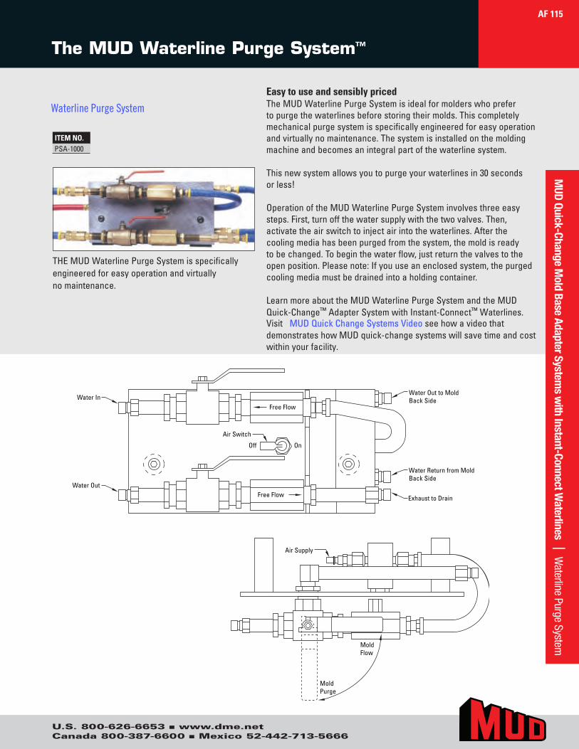
U.S. 800-626-6653 n www.dme.netCanada 800-387-6600 n Mexico 52-442-713-5666
Easy to use and sensibly pricedTheMUDWaterlinePurgeSystemisidealformolderswhoprefertopurgethewaterlinesbeforestoringtheirmolds.Thiscompletelymechanicalpurgesystemisspecificallyengineeredforeasyoperationandvirtuallynomaintenance.Thesystemisinstalledonthemoldingmachineandbecomesanintegralpartofthewaterlinesystem.
Thisnewsystemallowsyoutopurgeyourwaterlinesin30secondsorless!
OperationoftheMUDWaterlinePurgeSysteminvolvesthreeeasysteps.First,turnoffthewatersupplywiththetwovalves.Then,activatetheairswitchtoinjectairintothewaterlines.Afterthecoolingmediahasbeenpurgedfromthesystem,themoldisreadytobechanged.Tobeginthewaterflow,justreturnthevalvestotheopenposition.Pleasenote:Ifyouuseanenclosedsystem,thepurgedcoolingmediamustbedrainedintoaholdingcontainer.
LearnmoreabouttheMUDWaterlinePurgeSystemandtheMUDQuick-Change™AdapterSystemwithInstant-Connect™Waterlines.Visit MUD Quick Change Systems Video seehowavideothatdemonstrateshowMUDquick-changesystemswillsavetimeandcostwithinyourfacility.
THEMUDWaterlinePurgeSystemisspecificallyengineeredforeasyoperationandvirtuallynomaintenance.
Free Flow
Free Flow
Off On
Air Switch
Water In
Water Out
Water Out to MoldBack Side
Water Return from MoldBack Side
Exhaust to Drain
Air Supply
MoldPurge
MoldFlow
The MUD Waterline Purge System™
ITEM NO.PSA-1000
AF 115M
UD Quick-Change Mold Base Adapter System
s with Instant-Connect W
aterlines | Waterline Purge System
Waterline Purge System
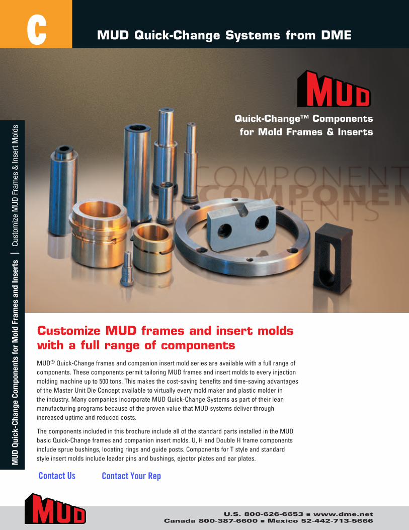
U.S. 800-626-6653 n www.dme.netCanada 800-387-6600 n Mexico 52-442-713-5666
Quick-Change™ Components for Mold Frames & Inserts
MUD®Quick-Changeframesandcompanioninsertmoldseriesareavailablewithafullrangeofcomponents.ThesecomponentspermittailoringMUDframesandinsertmoldstoeveryinjectionmoldingmachineupto500tons.Thismakesthecost-savingbenefitsandtime-savingadvantagesoftheMasterUnitDieConceptavailabletovirtuallyeverymoldmakerandplasticmolderintheindustry.ManycompaniesincorporateMUDQuick-ChangeSystemsaspartoftheirleanmanufacturingprogramsbecauseoftheprovenvaluethatMUDsystemsdeliverthroughincreaseduptimeandreducedcosts.
ThecomponentsincludedinthisbrochureincludeallofthestandardpartsinstalledintheMUDbasicQuick-Changeframesandcompanioninsertmolds.U,HandDoubleHframecomponentsincludespruebushings,locatingringsandguideposts.ComponentsforTstyleandstandardstyleinsertmoldsincludeleaderpinsandbushings,ejectorplatesandearplates.
Customize MUD frames and insert molds with a full range of components
MUD Quick-Change Systems from DME
116
CM
UD Q
uick
-Cha
nge
Com
pone
nts
for
Mol
d Fr
ames
and
Inse
rts
| C
usto
miz
e M
UD F
ram
es &
Inse
rt M
olds
Contact Us Contact Your Rep
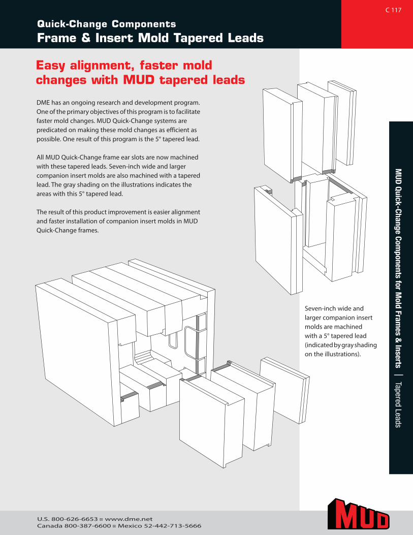
Quick-Change Components
Frame & Insert Mold Tapered Leads
DME has an ongoing research and development program. One of the primary objectives of this program is to facilitate faster mold changes. MUD Quick-Change systems are predicated on making these mold changes as efficient as possible. One result of this program is the 5° tapered lead.
All MUD Quick-Change frame ear slots are now machined with these tapered leads. Seven-inch wide and larger companion insert molds are also machined with a tapered lead. The gray shading on the illustrations indicates the areas with this 5° tapered lead.
The result of this product improvement is easier alignment and faster installation of companion insert molds in MUD Quick-Change frames.
Easy alignment, faster mold changes with MUD tapered leads
C 117
Seven-inch wide and larger companion insert molds are machined with a 5° tapered lead (indicated by gray shading on the illustrations).
U.S. 800-626-6653 ■ www.dme.netCanada 800-387-6600 ■ Mexico 52-442-713-5666
MUD
Quick-Change Components for M
old Frames &
Inserts | Tapered Leads
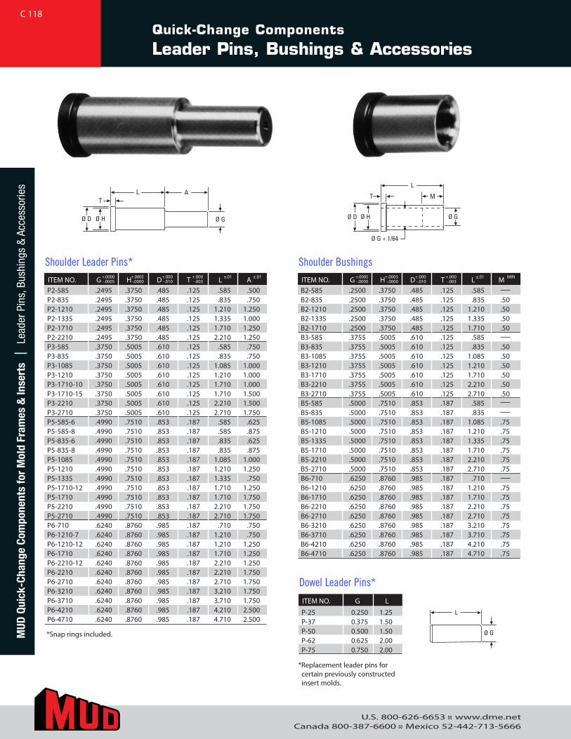
U.S. 800-626-6653 ■ www.dme.netCanada 800-387-6600 ■ Mexico 52-442-713-5666
Quick-Change Components
Leader Pins, Bushings & Accessories
AL
Ø D
T
Ø H Ø G
M
L
Ø D
T
Ø H
Ø G + 1/64
Ø G
.875L
Ø D
T
Ø H Ø G
L
Ø HØ D
Ø G
L
Ø D Ø G
L
Ø G
SPACER REMOVE SNAP RINGPRIOR TO PIN ANDBUSHING REMOVAL
AL
Ø D
T
Ø H Ø G
M
L
Ø D
T
Ø H
Ø G + 1/64
Ø G
* Replacement leader pins for certain previously constructed insert molds.
ITEM NO. G H D T L AP2-585 .2495 .3750 .485 .125 .585 .500P2-835 .2495 .3750 .485 .125 .835 .750P2-1210 .2495 .3750 .485 .125 1.210 1.250P2-1335 .2495 .3750 .485 .125 1.335 1.000P2-1710 .2495 .3750 .485 .125 1.710 1.250P2-2210 .2495 .3750 .485 .125 2.210 1.250P3-585 .3750 .5005 .610 .125 .585 .750P3-835 .3750 .5005 .610 .125 .835 .750P3-1085 .3750 .5005 .610 .125 1.085 1.000P3-1210 .3750 .5005 .610 .125 1.210 1.000P3-1710-10 .3750 .5005 .610 .125 1.710 1.000P3-1710-15 .3750 .5005 .610 .125 1.710 1.500P3-2210 .3750 .5005 .610 .125 2.210 1.500P3-2710 .3750 .5005 .610 .125 2.710 1.750P5-585-6 .4990 .7510 .853 .187 .585 .625P5-585-8 .4990 .7510 .853 .187 .585 .875P5-835-6 .4990 .7510 .853 .187 .835 .625P5-835-8 .4990 .7510 .853 .187 .835 .875P5-1085 .4990 .7510 .853 .187 1.085 1.000P5-1210 .4990 .7510 .853 .187 1.210 1.250P5-1335 .4990 .7510 .853 .187 1.335 .750P5-1710-12 .4990 .7510 .853 .187 1.710 1.250P5-1710 .4990 .7510 .853 .187 1.710 1.750P5-2210 .4990 .7510 .853 .187 2.210 1.750P5-2710 .4990 .7510 .853 .187 2.710 1.750P6-710 .6240 .8760 .985 .187 .710 .750P6-1210-7 .6240 .8760 .985 .187 1.210 .750P6-1210-12 .6240 .8760 .985 .187 1.210 1.250P6-1710 .6240 .8760 .985 .187 1.710 1.250P6-2210-12 .6240 .8760 .985 .187 2.210 1.250P6-2210 .6240 .8760 .985 .187 2.210 1.750P6-2710 .6240 .8760 .985 .187 2.710 1.750P6-3210 .6240 .8760 .985 .187 3.210 1.750P6-3710 .6240 .8760 .985 .187 3.710 1.750P6-4210 .6240 .8760 .985 .187 4.210 2.500P6-4710 .6240 .8760 .985 .187 4.710 2.500
Shoulder Leader Pins*+.0000-.0005
+.0005-.0000
+.000-.010
+.000-.003
±.01 ±.01 ITEM NO. G H D T L MB2-585 .2500 .3750 .485 .125 .585 B2-835 .2500 .3750 .485 .125 .835 .50B2-1210 .2500 .3750 .485 .125 1.210 .50B2-1335 .2500 .3750 .485 .125 1.335 .50B2-1710 .2500 .3750 .485 .125 1.710 .50B3-585 .3755 .5005 .610 .125 .585 B3-835 .3755 .5005 .610 .125 .835 .50B3-1085 .3755 .5005 .610 .125 1.085 .50B3-1210 .3755 .5005 .610 .125 1.210 .50B3-1710 .3755 .5005 .610 .125 1.710 .50B3-2210 .3755 .5005 .610 .125 2.210 .50B3-2710 .3755 .5005 .610 .125 2.710 .50B5-585 .5000 .7510 .853 .187 .585 B5-835 .5000 .7510 .853 .187 .835 B5-1085 .5000 .7510 .853 .187 1.085 .75B5-1210 .5000 .7510 .853 .187 1.210 .75B5-1335 .5000 .7510 .853 .187 1.335 .75B5-1710 .5000 .7510 .853 .187 1.710 .75B5-2210 .5000 .7510 .853 .187 2.210 .75B5-2710 .5000 .7510 .853 .187 2.710 .75B6-710 .6250 .8760 .985 .187 .710 B6-1210 .6250 .8760 .985 .187 1.210 .75B6-1710 .6250 .8760 .985 .187 1.710 .75B6-2210 .6250 .8760 .985 .187 2.210 .75B6-2710 .6250 .8760 .985 .187 2.710 .75B6-3210 .6250 .8760 .985 .187 3.210 .75B6-3710 .6250 .8760 .985 .187 3.710 .75B6-4210 .6250 .8760 .985 .187 4.210 .75B6-4710 .6250 .8760 .985 .187 4.710 .75
Shoulder Bushings+.0005-.0000
+.0005 -.0000
+.000-.010
+.000-.003
±.01 MIN
ITEM NO. G L
P-25 0.250 1.25P-37 0.375 1.50P-50 0.500 1.50P-62 0.625 2.00P-75 0.750 2.00
Dowel Leader Pins*
C 118M
UD Q
uick
-Cha
nge
Com
pone
nts
for
Mol
d Fr
ames
& In
sert
s |
Lea
der P
ins,
Bus
hing
s &
Acc
esso
ries
*Snap rings included.
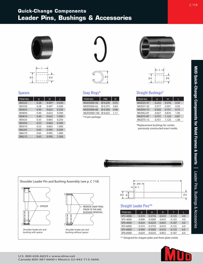
U.S. 800-626-6653 ■ www.dme.netCanada 800-387-6600 ■ Mexico 52-442-713-5666
** Designed for stripper plate and three-plate molds.
ITEM NO. G H D T LSP3-4000 0.374 0.3755 0.610 0.125 4.0SP5-4000 0.499 0.5005 0.610 0.125 4.0SP6-4000 0.624 0.6255 0.853 0.187 4.0SP3-6000 0.374 0.3755 0.610 0.125 6.0SP5-6000 0.499 0.5005 0.610 0.125 6.0SP6-6000 0.624 0.6255 0.853 0.187 6.0
Straight Leader Pins**
ITEM NO. G H LMUD25-37 0.252 0.376 0.50MUD37-50 0.377 0.501 0.50MUD50-75 0.502 0.751 0.75MUD62-87 0.627 0.876 1.00MUD75-87 0.751 1.125 0.87MUD75-13 0.751 1.125 1.38
Straight Bushings*
Shoulder Leader Pin and Bushing Assembly (see p. C 118)
Shoulder leader pin and bushing with spacer
Shoulder leader pin and bushing without spacer
.875L
Ø D
T
Ø H Ø G
L
Ø HØ D
Ø G
L
Ø D Ø G
L
Ø G
SPACER REMOVE SNAP RINGPRIOR TO PIN ANDBUSHING REMOVAL
.875L
Ø D
T
Ø H Ø G
L
Ø HØ D
Ø G
L
Ø D Ø G
L
Ø G
SPACER REMOVE SNAP RINGPRIOR TO PIN ANDBUSHING REMOVAL
.875L
Ø D
T
Ø H Ø G
L
Ø HØ D
Ø G
L
Ø D Ø G
L
Ø G
SPACER REMOVE SNAP RINGPRIOR TO PIN ANDBUSHING REMOVAL
.875L
Ø D
T
Ø H Ø G
L
Ø HØ D
Ø G
L
Ø D Ø G
L
Ø G
SPACER REMOVE SNAP RINGPRIOR TO PIN ANDBUSHING REMOVAL
ITEM NO. PIN DMUD5000-50 Ø 0.250 0.55MUD5000-62 Ø 0.375 0.69MUD5000-86 Ø 0.500 0.96MUD5000-100 Ø 0.625 1.11
Snap Rings*
.875L
Ø D
T
Ø H Ø G
L
Ø HØ D
Ø G
L
Ø D Ø G
L
Ø G
SPACER REMOVE SNAP RINGPRIOR TO PIN ANDBUSHING REMOVAL
.875L
Ø D
T
Ø H Ø G
L
Ø HØ D
Ø G
L
Ø D Ø G
L
Ø G
SPACER REMOVE SNAP RINGPRIOR TO PIN ANDBUSHING REMOVAL
*Replacement bushings for certain previously constructed insert molds.
ITEM NO. G D LSB2525 0.28 0.497 0.250SB2550 0.28 0.497 0.500SB3825 0.40 0.622 0.250SB3850 0.40 0.622 0.500SB3810 0.40 0.622 1.000SB5025 0.53 0.863 0.250SB5050 0.53 0.863 0.500SB5010 0.53 0.863 1.000SB6205 0.65 0.995 0.500SB6210 0.65 0.995 1.000SB6215 0.65 0.995 1.500
Spacers
Quick-Change Components
Leader Pins, Bushings & Accessories
C 119M
UD Quick-Change Com
ponents for Mold Fram
es & Inserts | Leader Pins, Bushings &
Accessories
*10 per package
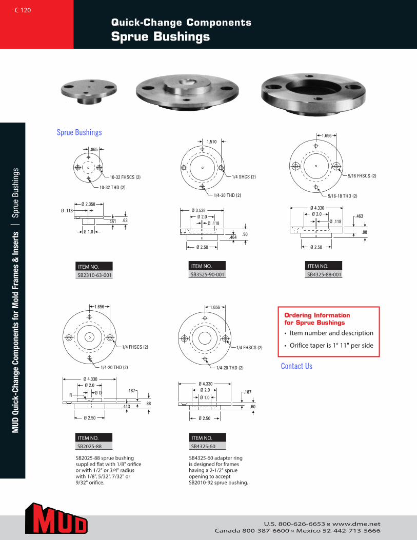
U.S. 800-626-6653 ■ www.dme.netCanada 800-387-6600 ■ Mexico 52-442-713-5666
Quick-Change Components
Sprue Bushings
Ø 4.330
Ø 2.50
Ø 2.0
Ø .118 .463
.88
1.656
5/16 FHSCS (2)
5/16-18 THD (2)
Ø 4.330
Ø 2.50
Ø 2.0
Ø O .187
.88
1.656
.413
1/4 FHSCS (2)
1/4-20 THD (2)
Ø 3.538
Ø 2.50
Ø 2.0 Ø .118
.90
1.510
.464
1/4 SHCS (2)
1/4-20 THD (2)
Ø 2.358
Ø 1.0
Ø .118
.63
.865
.451
10-32 FHSCS (2)
10-32 THD (2)
R Ø 4.330
Ø 2.50
Ø 2.0
Ø .118 .463
.88
1.656
5/16 FHSCS (2)
5/16-18 THD (2)
Ø 4.330
Ø 2.50
Ø 2.0
Ø O .187
.88
1.656
.413
1/4 FHSCS (2)
1/4-20 THD (2)
Ø 3.538
Ø 2.50
Ø 2.0 Ø .118
.90
1.510
.464
1/4 SHCS (2)
1/4-20 THD (2)
Ø 2.358
Ø 1.0
Ø .118
.63
.865
.451
10-32 FHSCS (2)
10-32 THD (2)
R
Ø 4.330
Ø 2.50
Ø 2.0
Ø .118 .463
.88
1.656
5/16 FHSCS (2)
5/16-18 THD (2)
Ø 4.330
Ø 2.50
Ø 2.0
Ø O .187
.88
1.656
.413
1/4 FHSCS (2)
1/4-20 THD (2)
Ø 3.538
Ø 2.50
Ø 2.0 Ø .118
.90
1.510
.464
1/4 SHCS (2)
1/4-20 THD (2)
Ø 2.358
Ø 1.0
Ø .118
.63
.865
.451
10-32 FHSCS (2)
10-32 THD (2)
R
Ø 4.330
Ø 2.50
Ø 2.0
Ø .118 .463
.88
1.656
5/16 FHSCS (2)
5/16-18 THD (2)
Ø 4.330
Ø 2.50
Ø 2.0
Ø O .187
.88
1.656
.413
1/4 FHSCS (2)
1/4-20 THD (2)
Ø 3.538
Ø 2.50
Ø 2.0 Ø .118
.90
1.510
.464
1/4 SHCS (2)
1/4-20 THD (2)
Ø 2.358
Ø 1.0
Ø .118
.63
.865
.451
10-32 FHSCS (2)
10-32 THD (2)
R
Ø 2.00
Ø O
Ø 1.0
R
.62 .92
Ø 4.330
Ø 2.50
Ø 2.0
Ø 1.0.187
.60
1.656
1/4 FHSCS (2)
1/4-20 THD (2)
RØ 1.25
Ø O
.62
LL
Ø .625
Ø OR
Ø 2.00
Ø 1.0
.62
Ordering Information for Sprue Bushings
• Item number and description
• Orifice taper is 1° 11" per side
SB4325-60 adapter ring is designed for frames having a 2-1/2" sprue opening to accept SB2010-92 sprue bushing.
ITEM NO.
SB2310-63-001
ITEM NO.
SB3525-90-001
ITEM NO.
SB4325-88-001
ITEM NO.
SB2025-88
ITEM NO.
SB4325-60
SB2025-88 sprue bushing supplied flat with 1/8" orifice or with 1/2" or 3/4" radius with 1/8", 5/32", 7/32" or 9/32" orifice.
C 120M
UD Q
uick
-Cha
nge
Com
pone
nts
for
Mol
d Fr
ames
& In
sert
s |
Spr
ue B
ushi
ngs
Sprue Bushings
Contact Us
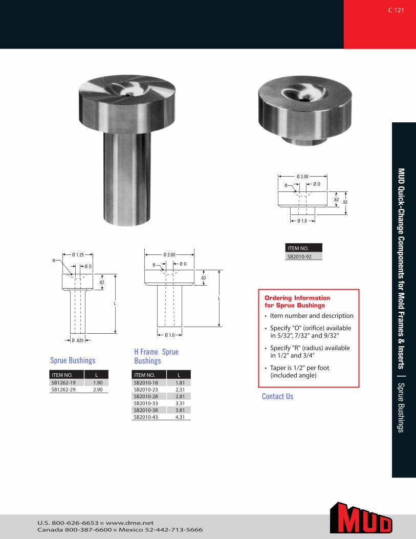
U.S. 800-626-6653 ■ www.dme.netCanada 800-387-6600 ■ Mexico 52-442-713-5666
Ø 2.00
Ø O
Ø 1.0
R
.62 .92
Ø 4.330
Ø 2.50
Ø 2.0
Ø 1.0.187
.60
1.656
1/4 FHSCS (2)
1/4-20 THD (2)
RØ 1.25
Ø O
.62
LL
Ø .625
Ø OR
Ø 2.00
Ø 1.0
.62
Ø 2.00
Ø O
Ø 1.0
R
.62 .92
Ø 4.330
Ø 2.50
Ø 2.0
Ø 1.0.187
.60
1.656
1/4 FHSCS (2)
1/4-20 THD (2)
RØ 1.25
Ø O
.62
LL
Ø .625
Ø OR
Ø 2.00
Ø 1.0
.62
Ø 2.00
Ø O
Ø 1.0
R
.62 .92
Ø 4.330
Ø 2.50
Ø 2.0
Ø 1.0.187
.60
1.656
1/4 FHSCS (2)
1/4-20 THD (2)
RØ 1.25
Ø O
.62
LL
Ø .625
Ø OR
Ø 2.00
Ø 1.0
.62
ITEM NO. LSB1262-19 1.90SB1262-29 2.90
Sprue Bushings
ITEM NO. LSB2010-18 1.81SB2010-23 2.31SB2010-28 2.81SB2010-33 3.31SB2010-38 3.81SB2010-43 4.31
H Frame Sprue Bushings
Ordering Information for Sprue Bushings
• Item number and description
• Specify "O" (orifice) available in 5/32", 7/32" and 9/32"
• Specify "R" (radius) available in 1/2" and 3/4"
• Taper is 1/2" per foot (included angle)
ITEM NO.
SB2010-92
C 121M
UD Quick-Change Com
ponents for Mold Fram
es & Inserts | Sprue Bushings
Contact Us
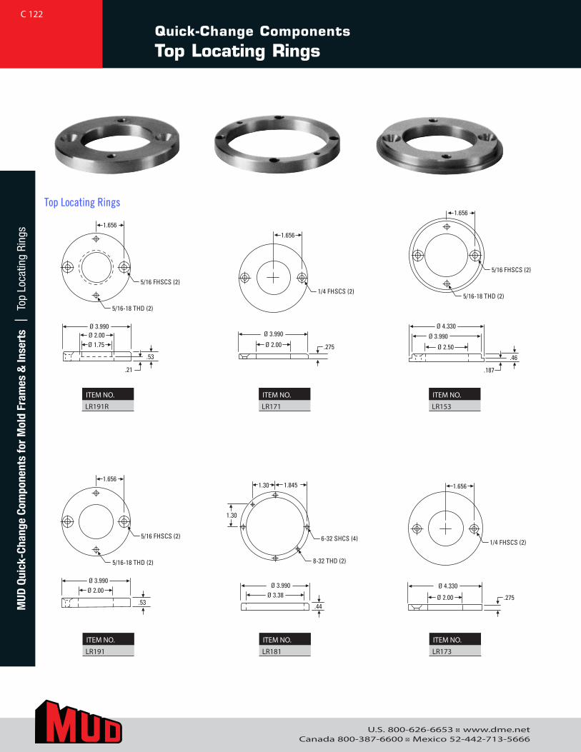
U.S. 800-626-6653 ■ www.dme.netCanada 800-387-6600 ■ Mexico 52-442-713-5666
Quick-Change Components
Top Locating Rings
Ø 4.330
Ø 2.00 .275
1.656
1/4 FHSCS (2)
Ø 3.990Ø 3.38
.44
1.30
1.30 1.845
8-32 THD (2)
6-32 SHCS (4)
Ø 3.990Ø 2.00
.53
1.656
5/16-18 THD (2)
5/16 FHSCS (2)
Ø 3.990Ø 2.00
.53
1.656
Ø 1.75
5/16-18 THD (2)
5/16 FHSCS (2)
.21
Ø 3.990
Ø 2.00 .275
1.656
1/4 FHSCS (2)
1.656
5/16-18 THD (2)
5/16 FHSCS (2)
Ø 4.330Ø 3.990
.46
Ø 2.50
.187
ITEM NO.
LR191R
ITEM NO.
LR171
ITEM NO.
LR153
ITEM NO.
LR191
ITEM NO.
LR181
ITEM NO.
LR173
C 122M
UD Q
uick
-Cha
nge
Com
pone
nts
for
Mol
d Fr
ames
& In
sert
s |
Top
Loc
atin
g Ri
ngs
Top Locating Rings
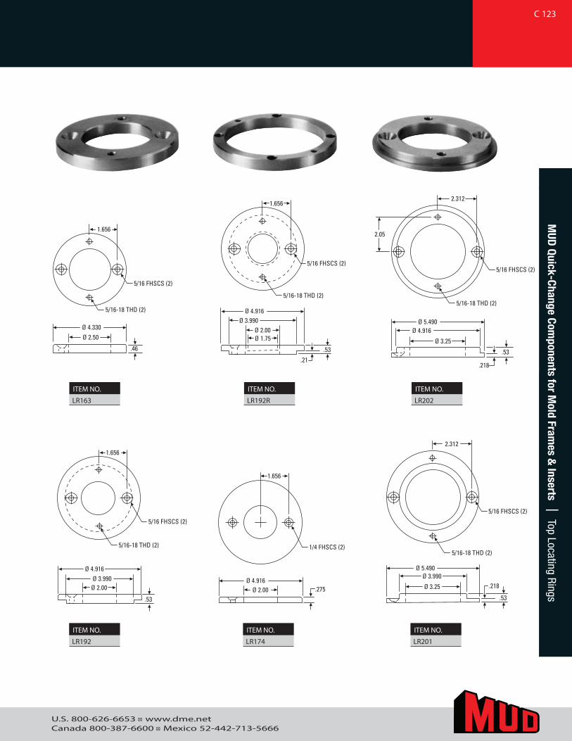
U.S. 800-626-6653 ■ www.dme.netCanada 800-387-6600 ■ Mexico 52-442-713-5666
Ø 5.490Ø 3.990
Ø 3.25 .218
.53
2.312
5/16 FHSCS (2)
Ø 4.916Ø 2.00 .275
1.656
1/4 FHSCS (2)
Ø 3.990Ø 4.916
Ø 2.00
.53
1.656
5/16-18 THD (2)
5/16 FHSCS (2)
Ø 4.330Ø 2.50
.46
1.656
5/16-18 THD (2)
5/16 FHSCS (2)
Ø 4.916
Ø 2.00Ø 3.990
Ø 1.75
.21
.53
1.656
5/16 FHSCS (2)
2.312
5/16-18 THD (2)
5/16 FHSCS (2)
Ø 5.490Ø 4.916
.53
Ø 3.25
.218
5/16-18 THD (2)
2.05
5/16-18 THD (2)Ø 5.490
Ø 3.990
Ø 3.25 .218
.53
2.312
5/16 FHSCS (2)
Ø 4.916Ø 2.00 .275
1.656
1/4 FHSCS (2)
Ø 3.990Ø 4.916
Ø 2.00
.53
1.656
5/16-18 THD (2)
5/16 FHSCS (2)
Ø 4.330Ø 2.50
.46
1.656
5/16-18 THD (2)
5/16 FHSCS (2)
Ø 4.916
Ø 2.00Ø 3.990
Ø 1.75
.21
.53
1.656
5/16 FHSCS (2)
2.312
5/16-18 THD (2)
5/16 FHSCS (2)
Ø 5.490Ø 4.916
.53
Ø 3.25
.218
5/16-18 THD (2)
2.05
5/16-18 THD (2)
Ø 5.490Ø 3.990
Ø 3.25 .218
.53
2.312
5/16 FHSCS (2)
Ø 4.916Ø 2.00 .275
1.656
1/4 FHSCS (2)
Ø 3.990Ø 4.916
Ø 2.00
.53
1.656
5/16-18 THD (2)
5/16 FHSCS (2)
Ø 4.330Ø 2.50
.46
1.656
5/16-18 THD (2)
5/16 FHSCS (2)
Ø 4.916
Ø 2.00Ø 3.990
Ø 1.75
.21
.53
1.656
5/16 FHSCS (2)
2.312
5/16-18 THD (2)
5/16 FHSCS (2)
Ø 5.490Ø 4.916
.53
Ø 3.25
.218
5/16-18 THD (2)
2.05
5/16-18 THD (2)
ITEM NO.
LR163
ITEM NO.
LR192R
ITEM NO.
LR202
ITEM NO.
LR192
ITEM NO.
LR174
ITEM NO.
LR201
C 123M
UD Quick-Change Com
ponents for Mold Fram
es & Inserts | Top Locating Rings
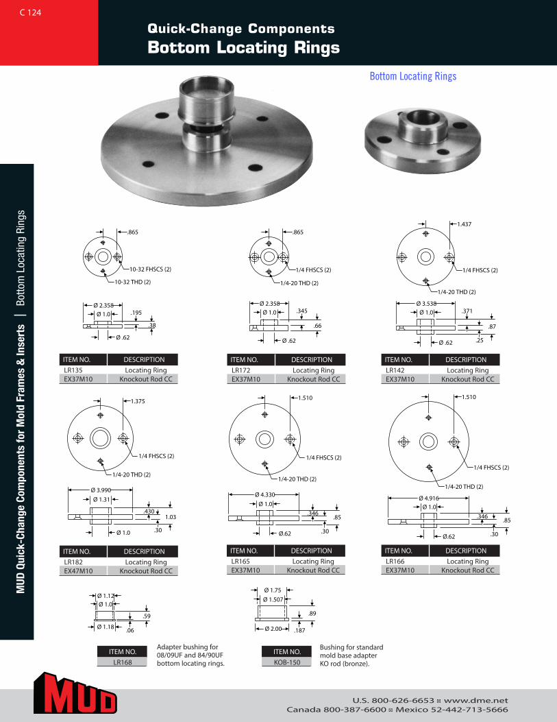
U.S. 800-626-6653 ■ www.dme.netCanada 800-387-6600 ■ Mexico 52-442-713-5666
Ø 2.358.195
.38
Ø 1.0
Ø .62
.345
.66
Ø 2.358Ø 1.0
Ø .62
.371
.25
.87
Ø 3.538Ø 1.0
Ø .62
Ø 1.12
.06
.59
Ø 1.18
Ø 1.0
Ø 1.75
.187
.89
Ø 2.00
Ø 1.507
.430
.30
1.03
Ø 3.990Ø 1.31
Ø 1.0
.346
.30
.85
Ø 4.330Ø 1.0
Ø.62
.346
.30
.85
Ø 4.916Ø 1.0
Ø.62
.865
10-32 FHSCS (2)
10-32 THD (2)
.865
1/4 FHSCS (2)
1/4-20 THD (2)
1.437
1/4 FHSCS (2)
1/4-20 THD (2)
1.510
1/4 FHSCS (2)
1/4-20 THD (2)
1.510
1/4 FHSCS (2)
1/4-20 THD (2)
1.375
1/4 FHSCS (2)
1/4-20 THD (2)
ITEM NO. DESCRIPTIONLR166 Locating RingEX37M10 Knockout Rod CC
ITEM NO. DESCRIPTIONLR165 Locating RingEX37M10 Knockout Rod CC
ITEM NO. DESCRIPTIONLR182 Locating RingEX47M10 Knockout Rod CC
ITEM NO. DESCRIPTIONLR142 Locating RingEX37M10 Knockout Rod CC
ITEM NO. DESCRIPTIONLR172 Locating RingEX37M10 Knockout Rod CC
Ø 2.358.195
.38
Ø 1.0
Ø .62
.345
.66
Ø 2.358Ø 1.0
Ø .62
.371
.25
.87
Ø 3.538Ø 1.0
Ø .62
Ø 1.12
.06
.59
Ø 1.18
Ø 1.0
Ø 1.75
.187
.89
Ø 2.00
Ø 1.507
.430
.30
1.03
Ø 3.990Ø 1.31
Ø 1.0
.346
.30
.85
Ø 4.330Ø 1.0
Ø.62
.346
.30
.85
Ø 4.916Ø 1.0
Ø.62
.865
10-32 FHSCS (2)
10-32 THD (2)
.865
1/4 FHSCS (2)
1/4-20 THD (2)
1.437
1/4 FHSCS (2)
1/4-20 THD (2)
1.510
1/4 FHSCS (2)
1/4-20 THD (2)
1.510
1/4 FHSCS (2)
1/4-20 THD (2)
1.375
1/4 FHSCS (2)
1/4-20 THD (2)
ITEM NO. DESCRIPTIONLR135 Locating RingEX37M10 Knockout Rod CC
ITEM NO.LR168
ITEM NO.KOB-150
Adapter bushing for 08/09UF and 84/90UF bottom locating rings.
Bushing for standard mold base adapter KO rod (bronze).
Quick-Change Components
Bottom Locating Rings
C 124M
UD Q
uick
-Cha
nge
Com
pone
nts
for
Mol
d Fr
ames
& In
sert
s |
Bot
tom
Loc
atin
g Ri
ngs
Bottom Locating Rings
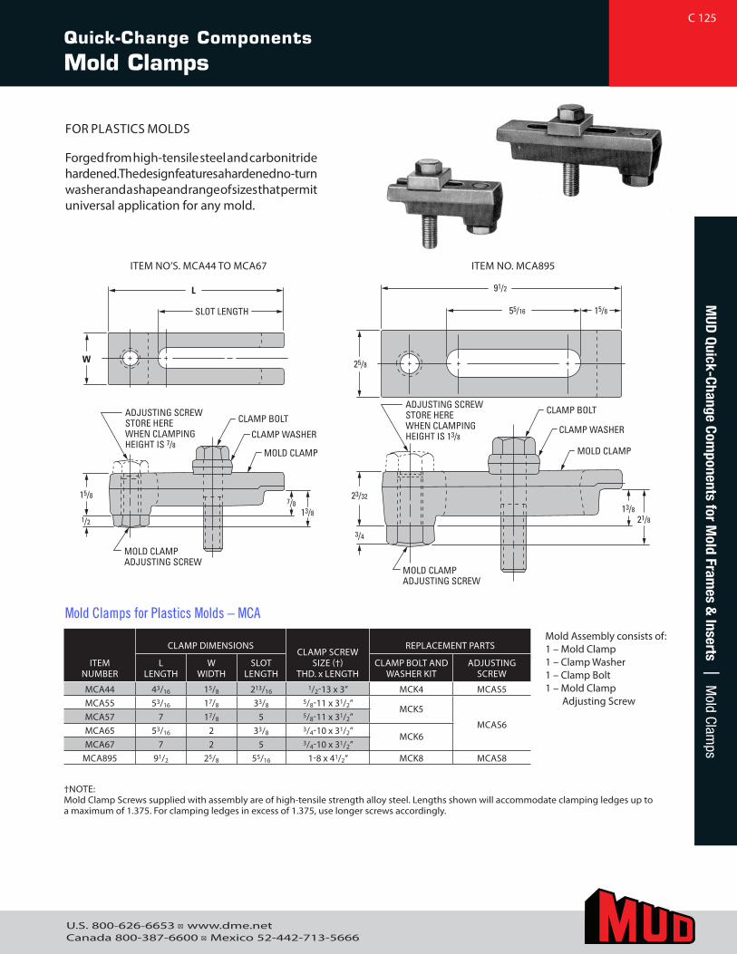
U.S. 800-626-6653 ■ www.dme.netCanada 800-387-6600 ■ Mexico 52-442-713-5666
Quick-Change Components
Mold Clamps
MUD
Quick-Change Components for M
old Frames &
Inserts | Mold Clam
ps
FOR PLASTICS MOLDS
Forged from high-tensile steel and carbonitride hardened. The design features a hardened no-turn washer and a shape and range of sizes that permit universal application for any mold.
L
W
SLOT LENGTH 55/16 15/8
91/2
25/8
23/32
3/4
13/821/8
15/8
MOLD CLAMPADJUSTING SCREW
ADJUSTING SCREWSTORE HEREWHEN CLAMPINGHEIGHT IS 7/8
CLAMP BOLT
CLAMP WASHER
MOLD CLAMP
1/2
MOLD CLAMPADJUSTING SCREW
ADJUSTING SCREWSTORE HEREWHEN CLAMPINGHEIGHT IS 13/8
CLAMP BOLT
CLAMP WASHER
MOLD CLAMP
7/813/8
†NOTE: Mold Clamp Screws supplied with assembly are of high-tensile strength alloy steel. Lengths shown will accommodate clamping ledges up to a maximum of 1.375. For clamping ledges in excess of 1.375, use longer screws accordingly.
ITEMNUMBER
CLAMP DIMENSIONSCLAMP SCREW
SIZE (†) THD. x LENGTH
REPLACEMENT PARTS
LLENGTH
WWIDTH
SLOT LENGTH
CLAMP BOLT AND WASHER KIT
ADJUSTING SCREW
MCA44 43/16 15/8 213/16 1/2-13 x 3” MCK4 MCAS5MCA55 53/16 17/8 33/8 5/8-11 x 31/2”
MCK5
MCAS6MCA57 7 17/8 5 5/8-11 x 31/2”MCA65 53/16 2 33/8 3/4-10 x 31/2”
MCK6MCA67 7 2 5 3/4-10 x 31/2”
MCA895 91/2 25/8 55/16 1-8 x 41/2” MCK8 MCAS8
ITEM NO’S. MCA44 TO MCA67 ITEM NO. MCA895
Mold Assembly consists of:1 – Mold Clamp1 – Clamp Washer1 – Clamp Bolt1 – Mold Clamp
Adjusting Screw
Mold Clamps for Plastics Molds – MCA
C 125
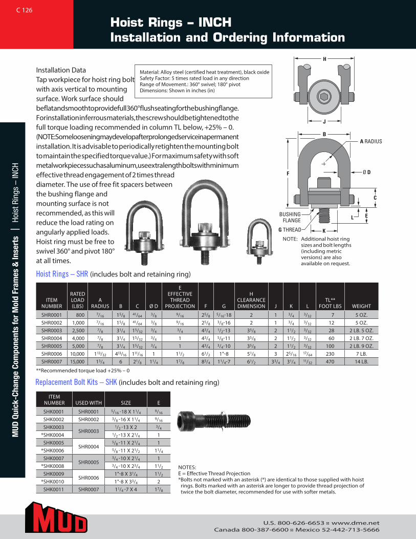
U.S. 800-626-6653 ■ www.dme.netCanada 800-387-6600 ■ Mexico 52-442-713-5666
Hoist Rings – INCH Installation and Ordering Information
MUD
Qui
ck-C
hang
e Co
mpo
nent
s fo
r M
old
Fram
es &
Inse
rts
| H
oist
Rin
gs –
INCH
ITEMNUMBER
RATED LOAD(LBS)
ARADIUS B C Ø D
EEFFECTIVE
THREADPROJECTION F G
HCLEARANCEDIMENSION J K L
TL**FOOT LBS WEIGHT
SHR0001 800 7/16 15/8 41/64 3/8 9/16 25/8 5/16-18 2 1 3/4 3/32 7 5 OZ.SHR0002 1,000 7/16 15/8 41/64 3/8 9/16 25/8 3/8-16 2 1 3/4 3/32 12 5 OZ.SHR0003 2,500 7/8 31/4 15/32 3/4 3/4 43/4 1/2-13 35/8 2 11/2 3/32 28 2 LB. 5 OZ.SHR0004 4,000 7/8 31/4 15/32 3/4 1 43/4 5/8-11 35/8 2 11/2 3/32 60 2 LB. 7 OZ.SHR0005 5,000 7/8 31/4 15/32 3/4 1 43/4 3/4-10 35/8 2 11/2 3/32 100 2 LB. 9 OZ.SHR0006 10,000 113/32 413/16 111/16 1 11/2 61/2 1"-8 51/8 3 25/16 17/64 230 7 LB.SHR0007 15,000 13/4 6 21/8 11/4 17/8 83/4 11/4-7 61/2 33/4 31/4 11/32 470 14 LB.
ITEMNUMBER USED WITH SIZE E
SHK0001 SHR0001 5/16 -18 X 11/4 9/16
SHK0002 SHR0002 3/8 -16 X 11/4 9/16
SHK0003SHR0003
1/2 -13 X 2 3/4
*SHK0004 1/2 -13 X 21/4 1SHK0005
SHR00045/8 -11 X 21/4 1
*SHK0006 5/8 -11 X 21/2 11/4
SHK0007SHR0005
3/4 -10 X 21/4 1*SHK0008 3/4 -10 X 23/4 11/2
SHK0009SHR0006
1"-8 X 31/4 11/2
*SHK0010 1"-8 X 33/4 2SHK0011 SHR0007 11/4 -7 X 4 17/8
**Recommended torque load +25% – 0
Replacement Bolt Kits – SHK (includes bolt and retaining ring)
NOTES: E = Effective Thread Projection* Bolts not marked with an asterisk (*) are identical to those supplied with hoist
rings. Bolts marked with an asterisk are longer to provide thread projection of twice the bolt diameter, recommended for use with softer metals.
Installation DataTap workpiece for hoist ring bolt with axis vertical to mounting
NOTE: Additional hoist ring sizes and bolt lengths (including metric versions) are also available on request.
H
J
Ø D
G THREAD
BUSHING FLANGE
B
F
C
L E
K
A RADIUS
surface. Work surface should be flat and smooth to provide full 360° flush seating for the bushing flange. For installation in ferrous materials, the screw should be tightened to the full torque loading recommended in column TL below, +25% – 0. (NOTE: Some loosening may develop after prolonged service in a permanent installation. It is advisable to periodically retighten the mounting bolt to maintain the specified torque value.) For maximum safety with soft metal workpieces such as aluminum, use extra length bolts with minimum effective thread engagement of 2 times thread diameter. The use of free fit spacers between the bushing flange and mounting surface is not recommended, as this will reduce the load rating on angularly applied loads. Hoist ring must be free to swivel 360° and pivot 180° at all times.
Hoist Rings – SHR (includes bolt and retaining ring)
Material: Alloy steel (certified heat treatment), black oxideSafety Factor: 5 times rated load in any directionRange of Movement.: 360° swivel; 180° pivot Dimensions: Shown in inches (in)
C 126
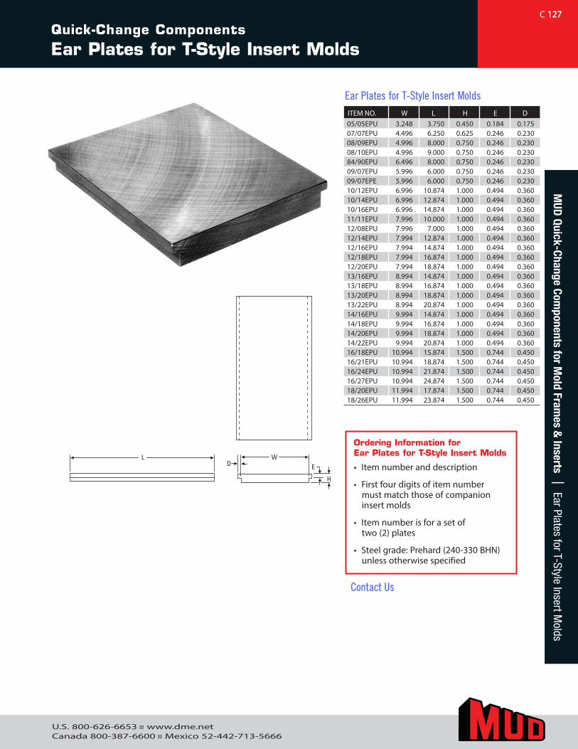
U.S. 800-626-6653 ■ www.dme.netCanada 800-387-6600 ■ Mexico 52-442-713-5666
127
L WD E
H
Ordering Information forEar Plates for T-Style Insert Molds
• Item number and description
• First four digits of item numbermust match those of companioninsert molds
• Item number is for a set oftwo (2) plates
• Steel grade: Prehard (240-330 BHN)unless otherwise specified
ITEM NO. W L H E D05/05EPU 3.248 3.750 0.450 0.184 0.17507/07EPU 4.496 6.250 0.625 0.246 0.23008/09EPU 4.996 8.000 0.750 0.246 0.23008/10EPU 4.996 9.000 0.750 0.246 0.23084/90EPU 6.496 8.000 0.750 0.246 0.23009/07EPU 5.996 6.000 0.750 0.246 0.23009/07EPE 5.996 6.000 0.750 0.246 0.23010/12EPU 6.996 10.874 1.000 0.494 0.36010/14EPU 6.996 12.874 1.000 0.494 0.36010/16EPU 6.996 14.874 1.000 0.494 0.36011/11EPU 7.996 10.000 1.000 0.494 0.36012/08EPU 7.996 7.000 1.000 0.494 0.36012/14EPU 7.994 12.874 1.000 0.494 0.36012/16EPU 7.994 14.874 1.000 0.494 0.36012/18EPU 7.994 16.874 1.000 0.494 0.36012/20EPU 7.994 18.874 1.000 0.494 0.36013/16EPU 8.994 14.874 1.000 0.494 0.36013/18EPU 8.994 16.874 1.000 0.494 0.36013/20EPU 8.994 18.874 1.000 0.494 0.36013/22EPU 8.994 20.874 1.000 0.494 0.36014/16EPU 9.994 14.874 1.000 0.494 0.36014/18EPU 9.994 16.874 1.000 0.494 0.36014/20EPU 9.994 18.874 1.000 0.494 0.36014/22EPU 9.994 20.874 1.000 0.494 0.36016/18EPU 10.994 15.874 1.500 0.744 0.45016/21EPU 10.994 18.874 1.500 0.744 0.45016/24EPU 10.994 21.874 1.500 0.744 0.45016/27EPU 10.994 24.874 1.500 0.744 0.45018/20EPU 11.994 17.874 1.500 0.744 0.45018/26EPU 11.994 23.874 1.500 0.744 0.450
Ear Plates for T-Style Insert Molds
C 127
Quick-Change Components
Ear Plates for T-Style Insert Molds
MUD
Quick-Change Components for M
old Frames &
Inserts | Ear Plates for T-Style Insert Molds
Contact Us
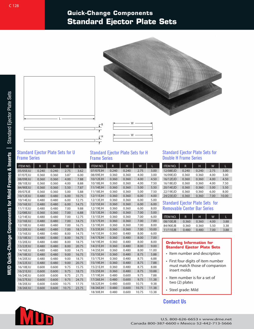
U.S. 800-626-6653 ■ www.dme.netCanada 800-387-6600 ■ Mexico 52-442-713-5666
Quick-Change Components
Standard Ejector Plate Sets
L
WR
WH
ITEM NO. R H W L05/05EJU 0.240 0.240 2.75 3.6207/07EJU 0.360 0.360 3.87 6.0008/09EJU 0.360 0.360 4.00 7.8808/10EJU 0.360 0.360 4.00 8.8884/90EJU 0.360 0.360 5.50 7.8709/07EJE 0.360 0.360 5.00 5.8810/12EJU 0.480 0.480 6.00 10.7510/14EJU 0.480 0.480 6.00 12.7510/16EJU 0.480 0.480 6.00 14.7511/11EJU 0.480 0.480 7.00 9.8812/08EJU 0.360 0.360 7.00 6.8812/14EJU 0.480 0.480 7.00 12.7512/16EJU 0.480 0.480 7.00 14.7512/18EJU 0.480 0.480 7.00 16.7512/20EJU 0.480 0.480 7.00 18.7513/16EJU 0.480 0.480 8.00 14.7513/18EJU 0.480 0.480 8.00 16.7513/20EJU 0.480 0.480 8.00 18.7513/22EJU 0.480 0.480 8.00 20.7514/16EJU 0.480 0.480 9.00 14.7514/18EJU 0.480 0.480 9.00 16.7514/20EJU 0.480 0.480 9.00 18.7514/22EJU 0.480 0.480 9.00 20.7516/18EJU 0.600 0.600 9.75 15.7516/21EJU 0.600 0.600 9.75 18.7516/24EJU 0.600 0.600 9.75 21.7516/27EJU 0.600 0.600 9.75 24.7518/20EJU 0.600 0.600 10.75 17.7518/26EJU 0.600 0.600 10.75 23.75
Standard Ejector Plate Sets for U Frame Series
ITEM NO. R H W L07/07EJH 0.240 0.240 2.75 3.0008/09EJH 0.360 0.360 4.00 3.0010/12EJH 0.360 0.360 4.00 4.5010/18EJH 0.360 0.360 4.00 7.5011/14EJH 0.360 0.360 5.00 5.5011/18EJH 0.360 0.360 5.00 7.5012/11EJH 0.360 0.360 6.00 4.0012/13EJH 0.360 0.360 6.00 5.0012/15EJH 0.360 0.360 6.00 6.0012/19EJH 0.360 0.360 6.00 8.0013/13EJH 0.360 0.360 7.00 5.0013/15EJH 0.360 0.360 7.00 6.0013/17EJH 0.360 0.360 7.00 7.0013/19EJH 0.360 0.360 7.00 8.0013/23EJH 0.360 0.360 7.00 10.0014/15EJH 0.360 0.480 8.00 6.0014/17EJH 0.360 0.480 8.00 7.0014/19EJH 0.360 0.480 8.00 8.0014/21EJH 0.360 0.480 8.00 9.0014/25EJH 0.360 0.480 8.00 11.0015/15EJH 0.360 0.480 8.75 5.8815/17EJH 0.360 0.480 8.75 6.8815/19EJH 0.360 0.480 8.75 7.8815/21EJH 0.360 0.480 8.75 8.8815/25EJH 0.360 0.480 8.75 10.8817/19EJH 0.480 0.600 9.75 7.8817/26EJH 0.480 0.600 9.75 11.3818/22EJH 0.480 0.600 10.75 9.3818/26EJH 0.480 0.600 10.75 11.3818/30EJH 0.480 0.600 10.75 13.38
Standard Ejector Plate Sets for H Frame Series
ITEM NO. R H W L08/10EJB 0.360 0.360 4.00 3.8884/90EJB 0.360 0.360 5.50 3.3811/11EJB 0.480 0.480 7.00 3.88
Standard Ejector Plate Sets for Removable Center Bar Series
ITEM NO. R H W L12/08EJD 0.240 0.240 2.75 3.0016/09EJD 0.360 0.360 4.00 3.0016/12EJD 0.360 0.360 4.00 4.5016/18EJD 0.360 0.360 4.00 7.5020/14EJD 0.360 0.360 5.00 5.5022/19EJD 0.360 0.360 6.00 8.0024/23EJD 0.360 0.360 7.00 10.00
Standard Ejector Plate Sets for Double H Frame Series
Ordering Information forStandard Ejector Plate Sets
• Item number and description
• First four digits of item numbermust match those of companioninsert molds
• Item number is for a set oftwo (2) plates
• Steel grade: Mild
C 128M
UD Q
uick
-Cha
nge
Com
pone
nts
for
Mol
d Fr
ames
& In
sert
s |
Sta
ndar
d Ej
ecto
r Pla
te S
ets
Contact Us
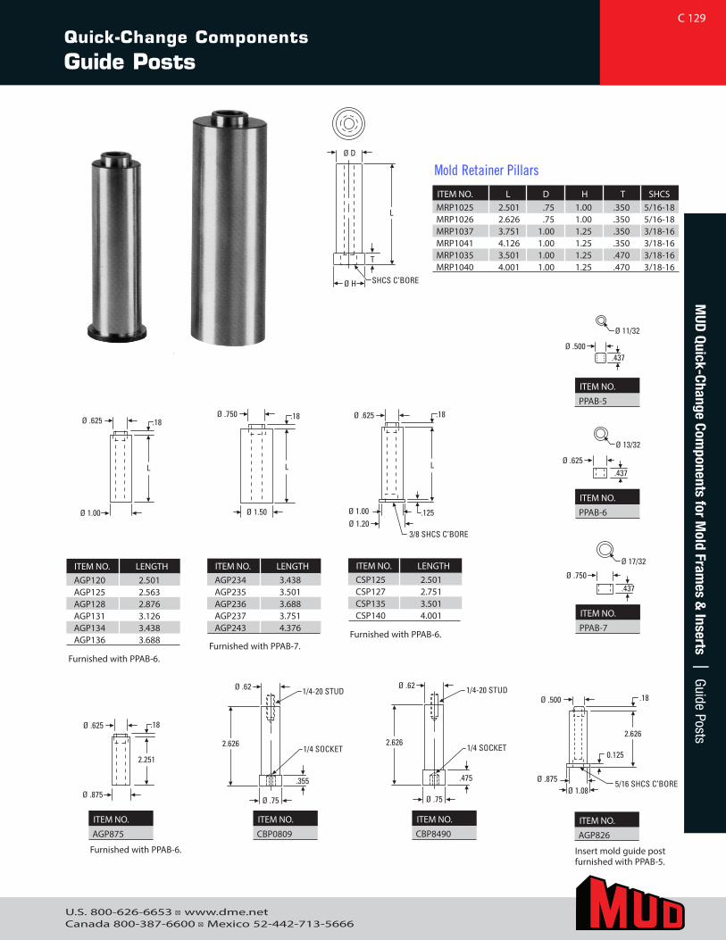
U.S. 800-626-6653 ■ www.dme.netCanada 800-387-6600 ■ Mexico 52-442-713-5666
ITEM NO. LENGTHAGP120 2.501AGP125 2.563AGP128 2.876AGP131 3.126AGP134 3.438AGP136 3.688
Furnished with PPAB-6.
ITEM NO. LENGTHAGP234 3.438AGP235 3.501AGP236 3.688AGP237 3.751AGP243 4.376
ITEM NO. LENGTHCSP125 2.501CSP127 2.751CSP135 3.501CSP140 4.001
Ø D
L
Ø H SHCS C’BORE
T
Ø 11/32
Ø .500.437
Ø 13/32
Ø .625.437
Ø 17/32
Ø .750
.437
Ø 1.00
Ø .625 .18
L
Ø .875
Ø .625 .18
2.251
Ø .75
Ø .62
2.626
.355
1/4 SOCKET
1/4-20 STUD
Ø .75
Ø .62
2.626
.475
1/4 SOCKET
1/4-20 STUD
Ø 1.085/16 SHCS C’BOREØ .875
.18Ø .500
0.125
2.626
Ø 1.50
Ø .750 .18
L
Ø 1.20Ø 1.00
Ø .625 .18
.125
3/8 SHCS C’BORE
L
ITEM NO. L D H T SHCSMRP1025 2.501 .75 1.00 .350 5/16-18MRP1026 2.626 .75 1.00 .350 5/16-18MRP1037 3.751 1.00 1.25 .350 3/18-16MRP1041 4.126 1.00 1.25 .350 3/18-16MRP1035 3.501 1.00 1.25 .470 3/18-16MRP1040 4.001 1.00 1.25 .470 3/18-16
Mold Retainer Pillars
ITEM NO.
PPAB-5
ITEM NO.
PPAB-6
ITEM NO.
PPAB-7
ITEM NO.
AGP826
ITEM NO.
CBP8490
ITEM NO.
CBP0809
ITEM NO.
AGP875
Furnished with PPAB-7.Furnished with PPAB-6.
Insert mold guide post furnished with PPAB-5.
Furnished with PPAB-6.
C 129
Quick-Change Components
Guide Posts
MUD
Quick-Change Components for M
old Frames &
Inserts | Guide Posts
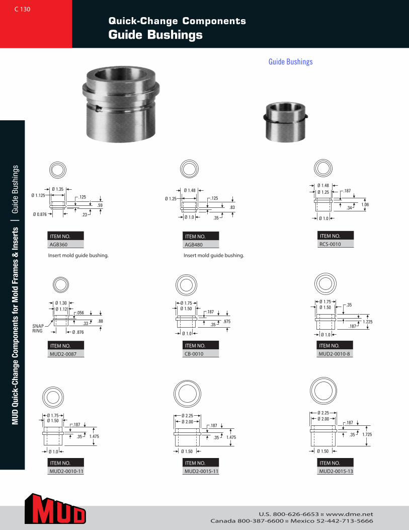
U.S. 800-626-6653 ■ www.dme.netCanada 800-387-6600 ■ Mexico 52-442-713-5666
Quick-Change Components
Guide Bushings
.23
.59
.125
Ø 1.35Ø 1.125
Ø 0.876.35
.83
.125
Ø 1.48
Ø 1.25
Ø 1.0
.341.06
.187Ø 1.48Ø 1.25
Ø 1.0
.1871.225
.35Ø 1.75Ø 1.50
Ø 1.0
.187
.975.35
Ø 1.75Ø 1.50
Ø 1.0
.187
1.475.35
Ø 1.75Ø 1.50
Ø 1.0
.187
1.475.35
Ø 2.25Ø 2.00
Ø 1.50
.187
1.725.35
Ø 2.25Ø 2.00
Ø 1.50
.056
.88.33
Ø 1.30Ø 1.12
Ø .876SNAPRING
ITEM NO.
AGB360ITEM NO.
AGB480
ITEM NO.
RCS-0010
ITEM NO.
MUD2-0010-8
ITEM NO.
CB-0010 ITEM NO.
MUD2-0087
ITEM NO.
MUD2-0010-11
ITEM NO.
MUD2-0015-11
ITEM NO.
MUD2-0015-13
Insert mold guide bushing. Insert mold guide bushing.
C 130M
UD Q
uick
-Cha
nge
Com
pone
nts
for
Mol
d Fr
ames
& In
sert
s |
Gui
de B
ushi
ngs
Guide Bushings
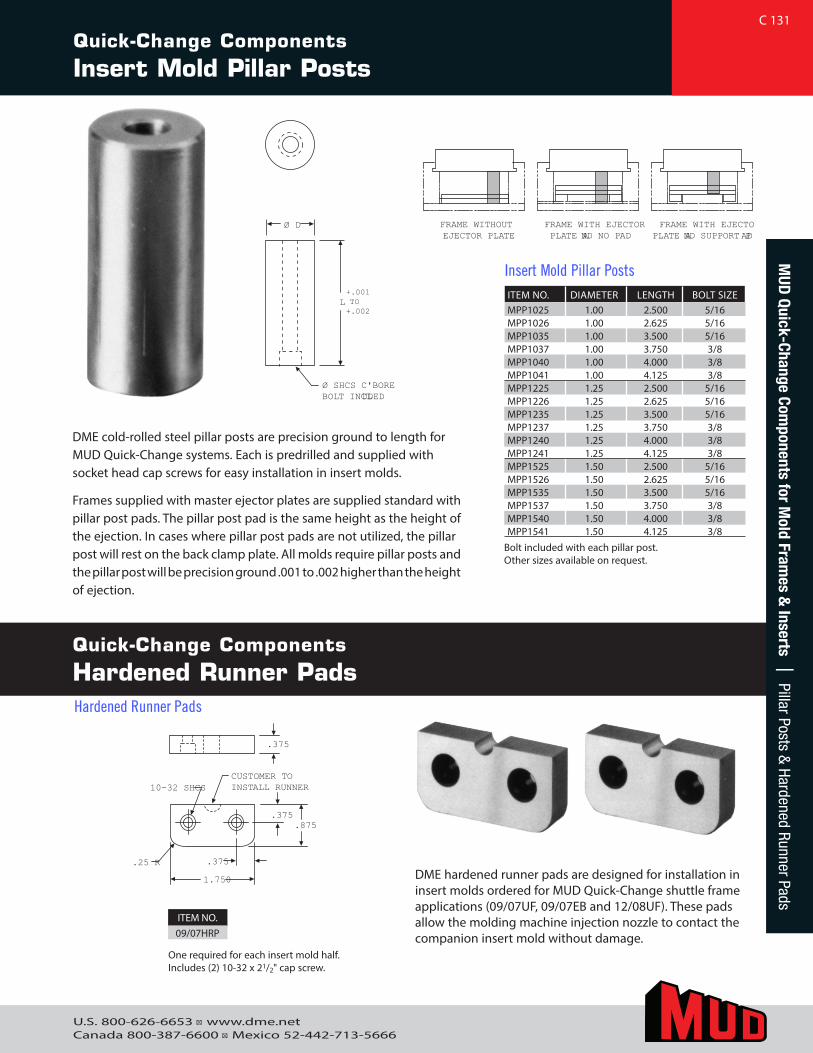
U.S. 800-626-6653 ■ www.dme.netCanada 800-387-6600 ■ Mexico 52-442-713-5666
Quick-Change Components
Insert Mold Pillar Posts
Quick-Change Components
Hardened Runner Pads
ITEM NO. DIAMETER LENGTH BOLT SIZE MPP1025 1.00 2.500 5/16MPP1026 1.00 2.625 5/16MPP1035 1.00 3.500 5/16MPP1037 1.00 3.750 3/8MPP1040 1.00 4.000 3/8MPP1041 1.00 4.125 3/8MPP1225 1.25 2.500 5/16MPP1226 1.25 2.625 5/16MPP1235 1.25 3.500 5/16MPP1237 1.25 3.750 3/8MPP1240 1.25 4.000 3/8MPP1241 1.25 4.125 3/8MPP1525 1.50 2.500 5/16MPP1526 1.50 2.625 5/16MPP1535 1.50 3.500 5/16MPP1537 1.50 3.750 3/8MPP1540 1.50 4.000 3/8MPP1541 1.50 4.125 3/8
Insert Mold Pillar Posts
FRAME WITHOUT EJECTOR PLATE
FRAME WITH EJECTOR PLATE AND NO PAD
FRAME WITH EJECTOPLATE AND SUPPORT PAD
.375
Ø D
Ø SHCS C'BOREBOLT INCLUDED
CUSTOMER TO INSTALL RUNNER 10-32 SHCS
.25 R .375
.375
1.750
.875
L +.001TO +.002
FRAME WITHOUT EJECTOR PLATE
FRAME WITH EJECTOR PLATE AND NO PAD
FRAME WITH EJECTOPLATE AND SUPPORT PAD
.375
Ø D
Ø SHCS C'BORE BOLT INCLUDED
CUSTOMER TO INSTALL RUNNER 10-32 SHCS
.25 R .375
.375
1.750
.875
L +.001 TO +.002
FRAME WITHOUT EJECTOR PLATE
FRAME WITH EJECTOR PLATE AND NO PAD
FRAME WITH EJECTOPLATE AND SUPPORT PAD
.375
Ø D
Ø SHCS C'BORE BOLT INCLUDED
CUSTOMER TO INSTALL RUNNER 10-32 SHCS
.25 R .375
.375
1.750
.875
L +.001 TO +.002
DME cold-rolled steel pillar posts are precision ground to length for MUD Quick-Change systems. Each is predrilled and supplied with socket head cap screws for easy installation in insert molds.
Frames supplied with master ejector plates are supplied standard with pillar post pads. The pillar post pad is the same height as the height of the ejection. In cases where pillar post pads are not utilized, the pillar post will rest on the back clamp plate. All molds require pillar posts and the pillar post will be precision ground .001 to .002 higher than the height of ejection.
Bolt included with each pillar post. Other sizes available on request.
One required for each insert mold half. Includes (2) 10-32 x 21/2" cap screw.
DME hardened runner pads are designed for installation in insert molds ordered for MUD Quick-Change shuttle frame applications (09/07UF, 09/07EB and 12/08UF). These pads allow the molding machine injection nozzle to contact the companion insert mold without damage.
ITEM NO.09/07HRP
C 131M
UD Quick-Change Com
ponents for Mold Fram
es & Inserts | Pillar Posts &
Hardened Runner Pads
Hardened Runner Pads
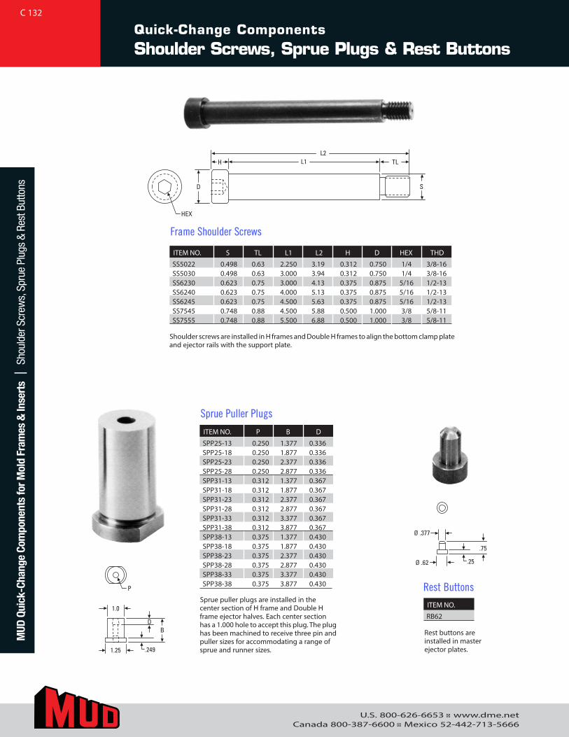
U.S. 800-626-6653 ■ www.dme.netCanada 800-387-6600 ■ Mexico 52-442-713-5666
Quick-Change Components
Shoulder Screws, Sprue Plugs & Rest Buttons
ITEM NO. S TL L1 L2 H D HEX THD
SS5022 0.498 0.63 2.250 3.19 0.312 0.750 1/4 3/8-16SS5030 0.498 0.63 3.000 3.94 0.312 0.750 1/4 3/8-16SS6230 0.623 0.75 3.000 4.13 0.375 0.875 5/16 1/2-13SS6240 0.623 0.75 4.000 5.13 0.375 0.875 5/16 1/2-13SS6245 0.623 0.75 4.500 5.63 0.375 0.875 5/16 1/2-13SS7545 0.748 0.88 4.500 5.88 0.500 1.000 3/8 5/8-11SS7555 0.748 0.88 5.500 6.88 0.500 1.000 3/8 5/8-11
H
HEX
D
L1L2
TL
S
Ø .377
Ø .62 .25
.75
1.0
1.25 .249
DB
P
H
HEX
D
L1L2
TL
S
Ø .377
Ø .62 .25
.75
1.0
1.25 .249
DB
P
H
HEX
D
L1L2
TL
S
Ø .377
Ø .62 .25
.75
1.0
1.25 .249
DB
P
Frame Shoulder Screws
ITEM NO.
RB62
Rest Buttons
Shoulder screws are installed in H frames and Double H frames to align the bottom clamp plate and ejector rails with the support plate.
Sprue puller plugs are installed in the center section of H frame and Double H frame ejector halves. Each center section has a 1.000 hole to accept this plug. The plug has been machined to receive three pin and puller sizes for accommodating a range of sprue and runner sizes.
Rest buttons are installed in master ejector plates.
ITEM NO. P B D
SPP25-13 0.250 1.377 0.336SPP25-18 0.250 1.877 0.336SPP25-23 0.250 2.377 0.336SPP25-28 0.250 2.877 0.336SPP31-13 0.312 1.377 0.367SPP31-18 0.312 1.877 0.367SPP31-23 0.312 2.377 0.367SPP31-28 0.312 2.877 0.367SPP31-33 0.312 3.377 0.367SPP31-38 0.312 3.877 0.367SPP38-13 0.375 1.377 0.430SPP38-18 0.375 1.877 0.430SPP38-23 0.375 2.377 0.430SPP38-28 0.375 2.877 0.430SPP38-33 0.375 3.377 0.430SPP38-38 0.375 3.877 0.430
Sprue Puller Plugs
C 132M
UD Q
uick
-Cha
nge
Com
pone
nts
for M
old
Fram
es &
Inse
rts
| S
houl
der S
crew
s, S
prue
Plu
gs &
Res
t But
tons
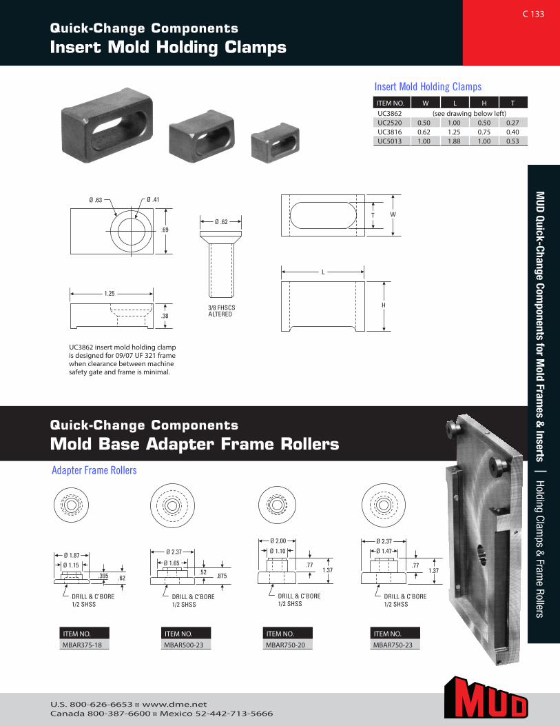
U.S. 800-626-6653 ■ www.dme.netCanada 800-387-6600 ■ Mexico 52-442-713-5666
UC3862 insert mold holding clamp is designed for 09/07 UF 321 frame when clearance between machine safety gate and frame is minimal.
.50
DRILL & C’BORE10-32 SHCS Ø .41
.38
.75
.69
.383/8 FHSCS ALTERED
Ø .63
Ø .62 W
H
T
L
1.25
.50
DRILL & C’BORE10-32 SHCS Ø .41
.38
.75
.69
.383/8 FHSCS ALTERED
Ø .63
Ø .62 W
H
T
L
1.25
.395 .62
Ø 1.87Ø 1.15
DRILL & C’BORE1/2 SHSS
.52 .875
Ø 2.37
Ø 1.65
DRILL & C’BORE1/2 SHSS
.771.37
Ø 2.00
Ø 1.10
DRILL & C’BORE1/2 SHSS
.771.37
Ø 2.37Ø 1.47
DRILL & C’BORE1/2 SHSS
.395 .62
Ø 1.87Ø 1.15
DRILL & C’BORE1/2 SHSS
.52 .875
Ø 2.37
Ø 1.65
DRILL & C’BORE1/2 SHSS
.771.37
Ø 2.00
Ø 1.10
DRILL & C’BORE1/2 SHSS
.771.37
Ø 2.37Ø 1.47
DRILL & C’BORE1/2 SHSS
.395 .62
Ø 1.87Ø 1.15
DRILL & C’BORE1/2 SHSS
.52 .875
Ø 2.37
Ø 1.65
DRILL & C’BORE1/2 SHSS
.771.37
Ø 2.00
Ø 1.10
DRILL & C’BORE1/2 SHSS
.771.37
Ø 2.37Ø 1.47
DRILL & C’BORE1/2 SHSS
.395 .62
Ø 1.87Ø 1.15
DRILL & C’BORE1/2 SHSS
.52 .875
Ø 2.37
Ø 1.65
DRILL & C’BORE1/2 SHSS
.771.37
Ø 2.00
Ø 1.10
DRILL & C’BORE1/2 SHSS
.771.37
Ø 2.37Ø 1.47
DRILL & C’BORE1/2 SHSS
Quick-Change Components
Mold Base Adapter Frame Rollers
ITEM NO.
MBAR375-18
ITEM NO.
MBAR500-23
ITEM NO.
MBAR750-20
ITEM NO.
MBAR750-23
C 133M
UD Quick-Change Com
ponents for Mold Fram
es & Inserts | Holding Clam
ps & Fram
e RollersQuick-Change Components
Insert Mold Holding Clamps
ITEM NO. W L H T UC3862 (see drawing below left) UC2520 0.50 1.00 0.50 0.27 UC3816 0.62 1.25 0.75 0.40 UC5013 1.00 1.88 1.00 0.53
Insert Mold Holding Clamps
Adapter Frame Rollers
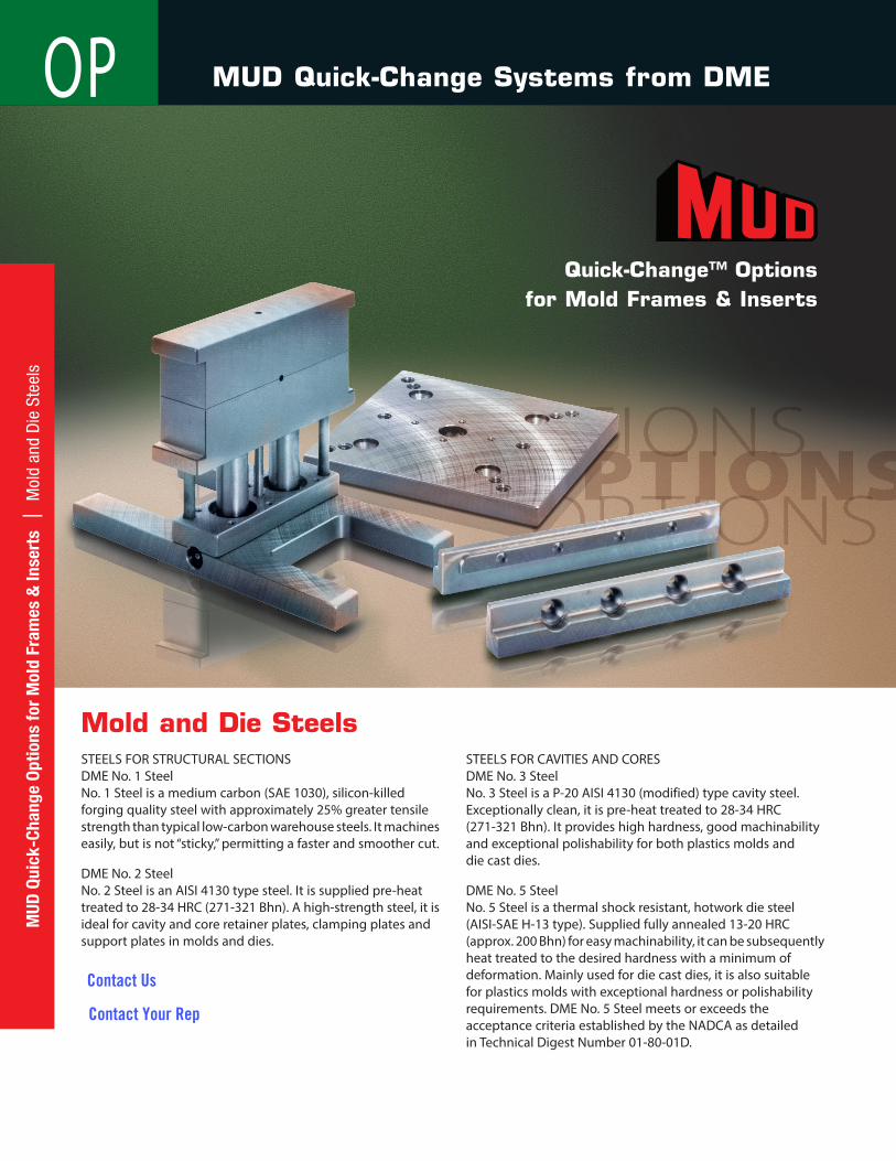
Quick-Change™ Options for Mold Frames & Inserts
STEELS FOR STRUCTURAL SECTIONSDME No. 1 SteelNo. 1 Steel is a medium carbon (SAE 1030), silicon-killed forging quality steel with approximately 25% greater tensile strength than typical low-carbon warehouse steels. It machines easily, but is not “sticky,” permitting a faster and smoother cut.
DME No. 2 SteelNo. 2 Steel is an AISI 4130 type steel. It is supplied pre-heat treated to 28-34 HRC (271-321 Bhn). A high-strength steel, it is ideal for cavity and core retainer plates, clamping plates and support plates in molds and dies.
STEELS FOR CAVITIES AND CORESDME No. 3 SteelNo. 3 Steel is a P-20 AISI 4130 (modified) type cavity steel. Exceptionally clean, it is pre-heat treated to 28-34 HRC (271-321 Bhn). It provides high hardness, good machinability and exceptional polishability for both plastics molds and die cast dies.
DME No. 5 SteelNo. 5 Steel is a thermal shock resistant, hotwork die steel (AISI-SAE H-13 type). Supplied fully annealed 13-20 HRC (approx. 200 Bhn) for easy machinability, it can be subsequently heat treated to the desired hardness with a minimum of deformation. Mainly used for die cast dies, it is also suitable for plastics molds with exceptional hardness or polishability requirements. DME No. 5 Steel meets or exceeds the acceptance criteria established by the NADCA as detailed in Technical Digest Number 01-80-01D.
Mold and Die Steels
MUD Quick-Change Systems from DME
134
OPM
UD Q
uick
-Cha
nge
Optio
ns fo
r M
old
Fram
es &
Inse
rts
| M
old
and
Die
Ste
els
Contact Us
Contact Your Rep
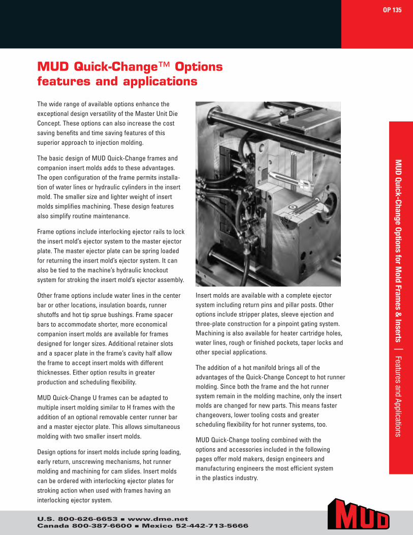
U.S. 800-626-6653 ■ www.dme.netCanada 800-387-6600 ■ Mexico 52-442-713-5666
The wide range of available options enhance the exceptional design versatility of the Master Unit Die Concept. These options can also increase the cost saving benefits and time saving features of this superior approach to injection molding.
The basic design of MUD Quick-Change frames and companion insert molds adds to these advantages. The open configuration of the frame permits installa-tion of water lines or hydraulic cylinders in the insert mold. The smaller size and lighter weight of insert molds simplifies machining. These design features also simplify routine maintenance.
Frame options include interlocking ejector rails to lock the insert mold’s ejector system to the master ejector plate. The master ejector plate can be spring loaded for returning the insert mold’s ejector system. It can also be tied to the machine’s hydraulic knockout system for stroking the insert mold’s ejector assembly.
Other frame options include water lines in the center bar or other locations, insulation boards, runner shutoffs and hot tip sprue bushings. Frame spacer bars to accommodate shorter, more economical companion insert molds are available for frames designed for longer sizes. Additional retainer slots and a spacer plate in the frame’s cavity half allow the frame to accept insert molds with different thicknesses. Either option results in greater production and scheduling flexibility.
MUD Quick-Change U frames can be adapted to multiple insert molding similar to H frames with the addition of an optional removable center runner bar and a master ejector plate. This allows simultaneous molding with two smaller insert molds.
Design options for insert molds include spring loading,early return, unscrewing mechanisms, hot runner molding and machining for cam slides. Insert molds can be ordered with interlocking ejector plates for stroking action when used with frames having an interlocking ejector system.
Insert molds are available with a complete ejector system including return pins and pillar posts. Other options include stripper plates, sleeve ejection and three-plate construction for a pinpoint gating system. Machining is also available for heater cartridge holes, water lines, rough or finished pockets, taper locks and other special applications.
The addition of a hot manifold brings all of the advantages of the Quick-Change Concept to hot runner molding. Since both the frame and the hot runner system remain in the molding machine, only the insert molds are changed for new parts. This means faster changeovers, lower tooling costs and greater scheduling flexibility for hot runner systems, too.
MUD Quick-Change tooling combined with the options and accessories included in the following pages offer mold makers, design engineers and manufacturing engineers the most efficient system in the plastics industry.
MUD Quick-Change™ Optionsfeatures and applications
OP 135M
UD Quick-Change Options for M
old Frames &
Inserts | Features and Applications
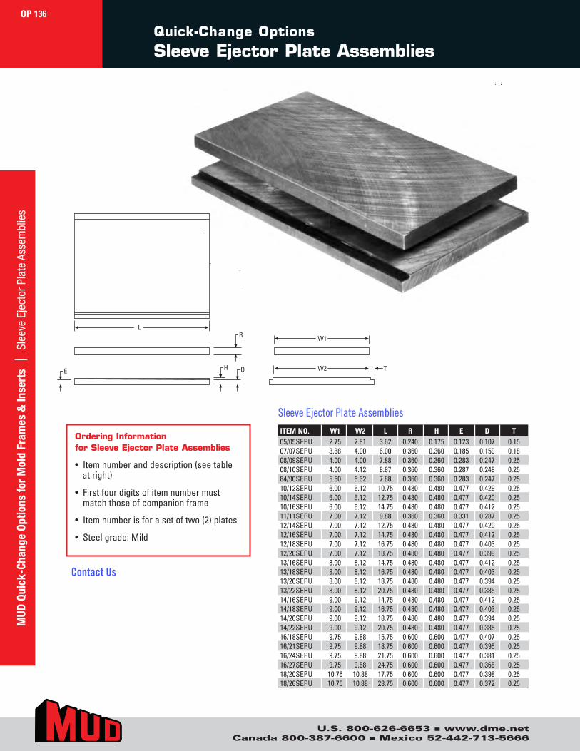
U.S. 800-626-6653 ■ www.dme.netCanada 800-387-6600 ■ Mexico 52-442-713-5666
Quick-Change Options
Sleeve Ejector Plate Assemblies
ITEM NO. W1 W2 L R H E D T05/05SEPU 2.75 2.81 3.62 0.240 0.175 0.123 0.107 0.1507/07SEPU 3.88 4.00 6.00 0.360 0.360 0.185 0.159 0.1808/09SEPU 4.00 4.00 7.88 0.360 0.360 0.283 0.247 0.2508/10SEPU 4.00 4.12 8.87 0.360 0.360 0.287 0.248 0.2584/90SEPU 5.50 5.62 7.88 0.360 0.360 0.283 0.247 0.2510/12SEPU 6.00 6.12 10.75 0.480 0.480 0.477 0.429 0.2510/14SEPU 6.00 6.12 12.75 0.480 0.480 0.477 0.420 0.2510/16SEPU 6.00 6.12 14.75 0.480 0.480 0.477 0.412 0.2511/11SEPU 7.00 7.12 9.88 0.360 0.360 0.331 0.287 0.2512/14SEPU 7.00 7.12 12.75 0.480 0.480 0.477 0.420 0.2512/16SEPU 7.00 7.12 14.75 0.480 0.480 0.477 0.412 0.2512/18SEPU 7.00 7.12 16.75 0.480 0.480 0.477 0.403 0.2512/20SEPU 7.00 7.12 18.75 0.480 0.480 0.477 0.399 0.2513/16SEPU 8.00 8.12 14.75 0.480 0.480 0.477 0.412 0.2513/18SEPU 8.00 8.12 16.75 0.480 0.480 0.477 0.403 0.2513/20SEPU 8.00 8.12 18.75 0.480 0.480 0.477 0.394 0.2513/22SEPU 8.00 8.12 20.75 0.480 0.480 0.477 0.385 0.2514/16SEPU 9.00 9.12 14.75 0.480 0.480 0.477 0.412 0.2514/18SEPU 9.00 9.12 16.75 0.480 0.480 0.477 0.403 0.2514/20SEPU 9.00 9.12 18.75 0.480 0.480 0.477 0.394 0.2514/22SEPU 9.00 9.12 20.75 0.480 0.480 0.477 0.385 0.2516/18SEPU 9.75 9.88 15.75 0.600 0.600 0.477 0.407 0.2516/21SEPU 9.75 9.88 18.75 0.600 0.600 0.477 0.395 0.2516/24SEPU 9.75 9.88 21.75 0.600 0.600 0.477 0.381 0.2516/27SEPU 9.75 9.88 24.75 0.600 0.600 0.477 0.368 0.2518/20SEPU 10.75 10.88 17.75 0.600 0.600 0.477 0.398 0.2518/26SEPU 10.75 10.88 23.75 0.600 0.600 0.477 0.372 0.25
Sleeve Ejector Plate Assemblies
Ordering Information for Sleeve Ejector Plate Assemblies
• Item number and description (see tableat right)
• First four digits of item number mustmatch those of companion frame
• Item number is for a set of two (2) plates
• Steel grade: Mild
L
W1
W2 T
R
HE D
OP 136M
UD Q
uick
-Cha
nge
Optio
ns fo
r M
old
Fram
es &
Inse
rts
| S
leev
e Ej
ecto
r Pla
te A
ssem
blie
s
Contact Us
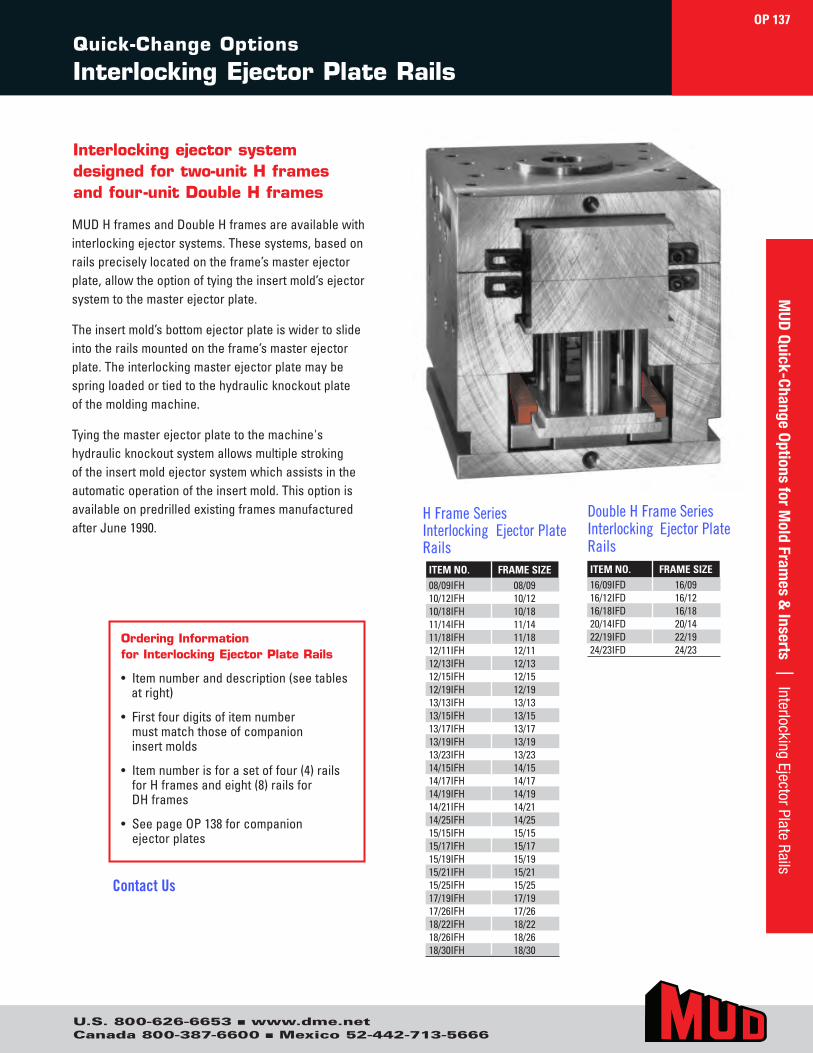
U.S. 800-626-6653 ■ www.dme.netCanada 800-387-6600 ■ Mexico 52-442-713-5666
Interlocking ejector system designed for two-unit H frames and four-unit Double H frames
ITEM NO. FRAME SIZE08/09IFH 08/0910/12IFH 10/1210/18IFH 10/1811/14IFH 11/1411/18IFH 11/1812/11IFH 12/1112/13IFH 12/1312/15IFH 12/1512/19IFH 12/1913/13IFH 13/1313/15IFH 13/1513/17IFH 13/1713/19IFH 13/1913/23IFH 13/2314/15IFH 14/1514/17IFH 14/1714/19IFH 14/1914/21IFH 14/2114/25IFH 14/2515/15IFH 15/1515/17IFH 15/1715/19IFH 15/1915/21IFH 15/2115/25IFH 15/2517/19IFH 17/1917/26IFH 17/2618/22IFH 18/2218/26IFH 18/2618/30IFH 18/30
H Frame Series Interlocking Ejector Plate Rails
Ordering Information for Interlocking Ejector Plate Rails
• Item number and description (see tablesat right)
• First four digits of item numbermust match those of companioninsert molds
• Item number is for a set of four (4) railsfor H frames and eight (8) rails forDH frames
• See page OP 138 for companionejector plates
MUD H frames and Double H frames are available with interlocking ejector systems. These systems, based on rails precisely located on the frame’s master ejector plate, allow the option of tying the insert mold’s ejector system to the master ejector plate.
The insert mold’s bottom ejector plate is wider to slide into the rails mounted on the frame’s master ejector plate. The interlocking master ejector plate may be spring loaded or tied to the hydraulic knockout plate of the molding machine.
Tying the master ejector plate to the machine's hydraulic knockout system allows multiple stroking of the insert mold ejector system which assists in the automatic operation of the insert mold. This option is available on predrilled existing frames manufactured after June 1990.
ITEM NO. FRAME SIZE16/09IFD 16/0916/12IFD 16/1216/18IFD 16/1820/14IFD 20/1422/19IFD 22/1924/23IFD 24/23
Double H Frame Series Interlocking Ejector Plate Rails
OP 137
Quick-Change Options
Interlocking Ejector Plate Rails
MUD
Quick-Change Options for Mold Fram
es & Inserts | Interlocking Ejector Plate Rails
Contact Us
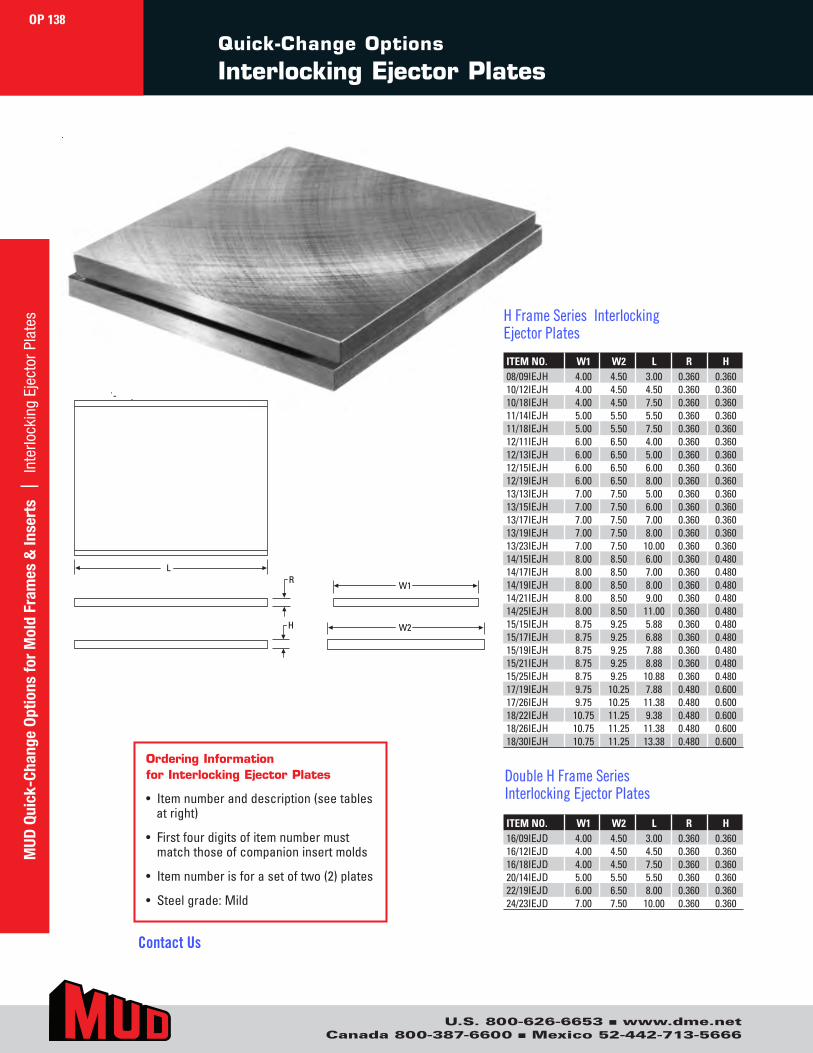
U.S. 800-626-6653 ■ www.dme.netCanada 800-387-6600 ■ Mexico 52-442-713-5666
Quick-Change Options
Interlocking Ejector Plates
LR
H
W1
W2
ITEM NO. W1 W2 L R H08/09IEJH 4.00 4.50 3.00 0.360 0.36010/12IEJH 4.00 4.50 4.50 0.360 0.36010/18IEJH 4.00 4.50 7.50 0.360 0.36011/14IEJH 5.00 5.50 5.50 0.360 0.36011/18IEJH 5.00 5.50 7.50 0.360 0.36012/11IEJH 6.00 6.50 4.00 0.360 0.36012/13IEJH 6.00 6.50 5.00 0.360 0.36012/15IEJH 6.00 6.50 6.00 0.360 0.36012/19IEJH 6.00 6.50 8.00 0.360 0.36013/13IEJH 7.00 7.50 5.00 0.360 0.36013/15IEJH 7.00 7.50 6.00 0.360 0.36013/17IEJH 7.00 7.50 7.00 0.360 0.36013/19IEJH 7.00 7.50 8.00 0.360 0.36013/23IEJH 7.00 7.50 10.00 0.360 0.36014/15IEJH 8.00 8.50 6.00 0.360 0.48014/17IEJH 8.00 8.50 7.00 0.360 0.48014/19IEJH 8.00 8.50 8.00 0.360 0.48014/21IEJH 8.00 8.50 9.00 0.360 0.48014/25IEJH 8.00 8.50 11.00 0.360 0.48015/15IEJH 8.75 9.25 5.88 0.360 0.48015/17IEJH 8.75 9.25 6.88 0.360 0.48015/19IEJH 8.75 9.25 7.88 0.360 0.48015/21IEJH 8.75 9.25 8.88 0.360 0.48015/25IEJH 8.75 9.25 10.88 0.360 0.48017/19IEJH 9.75 10.25 7.88 0.480 0.60017/26IEJH 9.75 10.25 11.38 0.480 0.60018/22IEJH 10.75 11.25 9.38 0.480 0.60018/26IEJH 10.75 11.25 11.38 0.480 0.60018/30IEJH 10.75 11.25 13.38 0.480 0.600
H Frame Series Interlocking Ejector Plates
ITEM NO. W1 W2 L R H16/09IEJD 4.00 4.50 3.00 0.360 0.36016/12IEJD 4.00 4.50 4.50 0.360 0.36016/18IEJD 4.00 4.50 7.50 0.360 0.36020/14IEJD 5.00 5.50 5.50 0.360 0.36022/19IEJD 6.00 6.50 8.00 0.360 0.36024/23IEJD 7.00 7.50 10.00 0.360 0.360
Double H Frame Series Interlocking Ejector Plates
Ordering Information for Interlocking Ejector Plates
• Item number and description (see tablesat right)
• First four digits of item number mustmatch those of companion insert molds
• Item number is for a set of two (2) plates
• Steel grade: Mild
OP 138M
UD Q
uick
-Cha
nge
Optio
ns fo
r M
old
Fram
es &
Inse
rts
| I
nter
lock
ing
Ejec
tor P
late
s
Contact Us
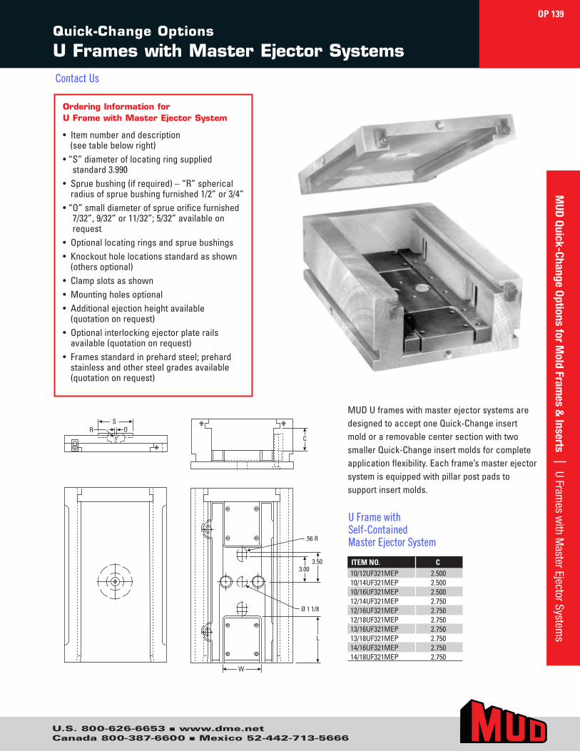
U.S. 800-626-6653 ■ www.dme.netCanada 800-387-6600 ■ Mexico 52-442-713-5666
Quick-Change Options
U Frames with Master Ejector Systems
Ordering Information for U Frame with Master Ejector System
• Item number and description(see table below right)
• “ S” diameter of locating ring suppliedstandard 3.990
• Sprue bushing (if required) – “R” sphericalradius of sprue bushing furnished 1/2” or 3/4”
• “ O” small diameter of sprue orifice furnished7/32”, 9/32” or 11/32”; 5/32” available onrequest
• Optional locating rings and sprue bushings• Knockout hole locations standard as shown
(others optional)• Clamp slots as shown• Mounting holes optional• Additional ejection height available
(quotation on request)• Optional interlocking ejector plate rails
available (quotation on request)• Frames standard in prehard steel; prehard
stainless and other steel grades available(quotation on request)
SR O
C
W
Ø 1 1/8
.56 R
3.00
L
3.50 ITEM NO. C10/12UF321MEP 2.50010/14UF321MEP 2.50010/16UF321MEP 2.50012/14UF321MEP 2.75012/16UF321MEP 2.75012/18UF321MEP 2.75013/16UF321MEP 2.75013/18UF321MEP 2.75014/16UF321MEP 2.75014/18UF321MEP 2.750
MUD U frames with master ejector systems are designed to accept one Quick-Change insert mold or a removable center section with two smaller Quick-Change insert molds for complete application flexibility. Each frame’s master ejector system is equipped with pillar post pads to support insert molds.
U Frame with Self-Contained Master Ejector System
OP 139M
UD Quick-Change Options for M
old Frames &
Inserts | U Frames w
ith Master Ejector System
s
Contact Us
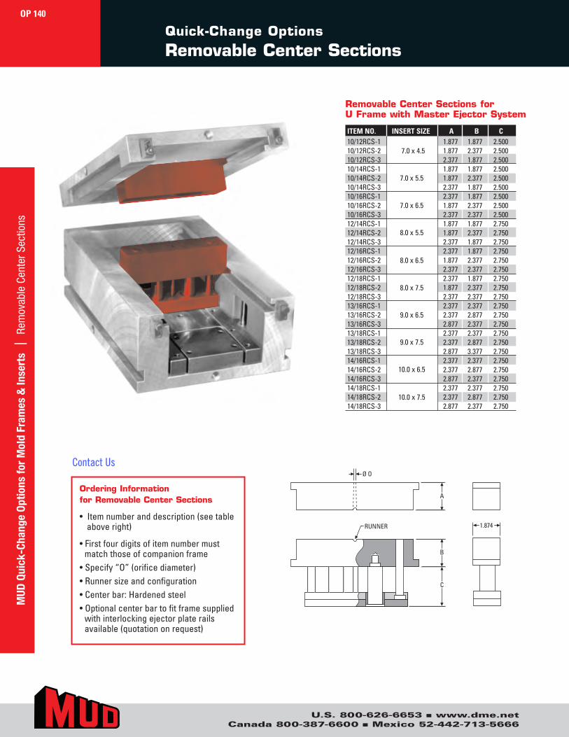
U.S. 800-626-6653 ■ www.dme.netCanada 800-387-6600 ■ Mexico 52-442-713-5666
Quick-Change Options
Removable Center Sections
1.874
Ø O
A
B
C
RUNNER
ITEM NO. INSERT SIZE A B C10/12RCS-1 1.877 1.877 2.50010/12RCS-2 1.877 2.377 2.50010/12RCS-3 2.377 1.877 2.50010/14RCS-1 1.877 1.877 2.50010/14RCS-2 1.877 2.377 2.50010/14RCS-3 2.377 1.877 2.50010/16RCS-1 2.377 1.877 2.50010/16RCS-2 1.877 2.377 2.50010/16RCS-3 2.377 2.377 2.50012/14RCS-1 1.877 1.877 2.75012/14RCS-2 1.877 2.377 2.75012/14RCS-3 2.377 1.877 2.75012/16RCS-1 2.377 1.877 2.75012/16RCS-2 1.877 2.377 2.75012/16RCS-3 2.377 2.377 2.75012/18RCS-1 2.377 1.877 2.75012/18RCS-2 1.877 2.377 2.75012/18RCS-3 2.377 2.377 2.75013/16RCS-1 2.377 2.377 2.75013/16RCS-2 2.377 2.877 2.75013/16RCS-3 2.877 2.377 2.75013/18RCS-1 2.377 2.377 2.75013/18RCS-2 2.377 2.877 2.75013/18RCS-3 2.877 3.377 2.75014/16RCS-1 2.377 2.377 2.75014/16RCS-2 2.377 2.877 2.75014/16RCS-3 2.877 2.377 2.75014/18RCS-1 2.377 2.377 2.75014/18RCS-2 2.377 2.877 2.75014/18RCS-3 2.877 2.377 2.750
7.0 x 4.5
7.0 x 5.5
7.0 x 6.5
8.0 x 5.5
8.0 x 6.5
8.0 x 7.5
9.0 x 6.5
9.0 x 7.5
10.0 x 6.5
10.0 x 7.5
Removable Center Sections forU Frame with Master Ejector System
Ordering Information for Removable Center Sections
• Item number and description (see tableabove right)
• First four digits of item number mustmatch those of companion frame
• Specify “O” (orifice diameter)• Runner size and configuration• Center bar: Hardened steel• Optional center bar to fit frame supplied
with interlocking ejector plate railsavailable (quotation on request)
OP 140M
UD Q
uick
-Cha
nge
Optio
ns fo
r M
old
Fram
es &
Inse
rts
| R
emov
able
Cen
ter S
ectio
ns
Contact Us
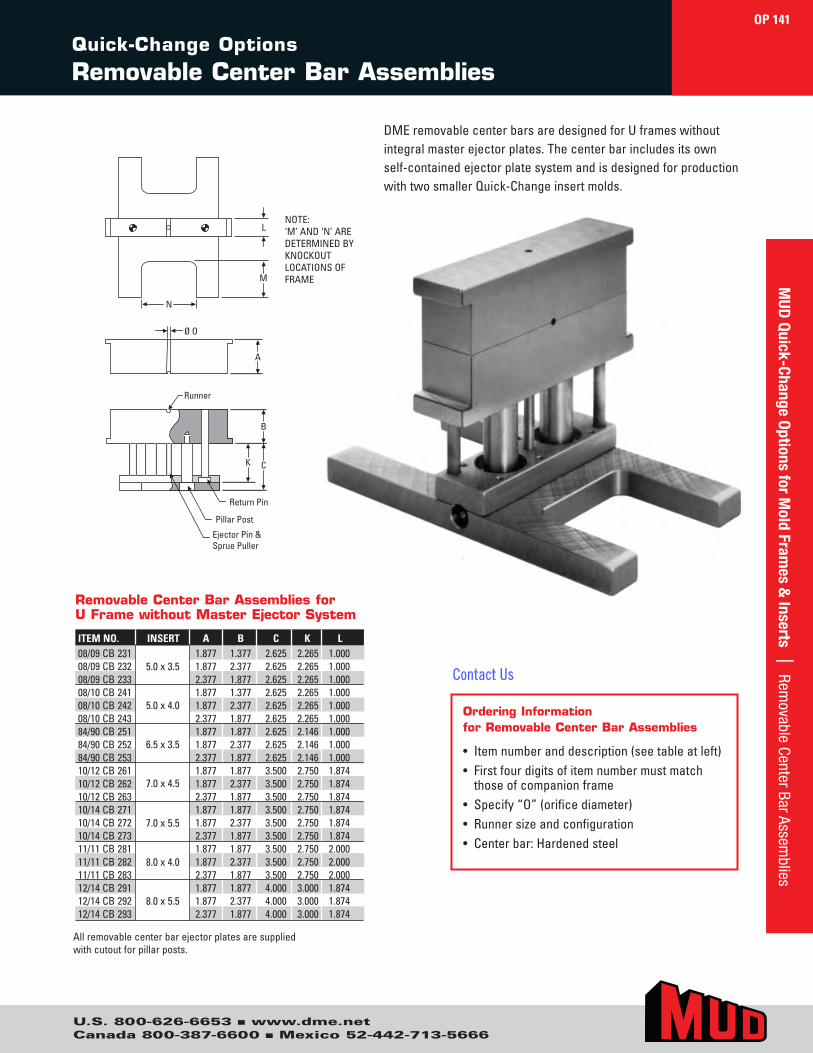
U.S. 800-626-6653 ■ www.dme.netCanada 800-387-6600 ■ Mexico 52-442-713-5666
Ordering Information for Removable Center Bar Assemblies
• Item number and description (see table at left)• First four digits of item number must match
those of companion frame• Specify “O” (orifice diameter)• Runner size and configuration• Center bar: Hardened steel
DME removable center bars are designed for U frames without integral master ejector plates. The center bar includes its own self-contained ejector plate system and is designed for production with two smaller Quick-Change insert molds.
ITEM NO. INSERT A B C K L08/09 CB 231 1.877 1.377 2.625 2.265 1.00008/09 CB 232 1.877 2.377 2.625 2.265 1.00008/09 CB 233 2.377 1.877 2.625 2.265 1.00008/10 CB 241 1.877 1.377 2.625 2.265 1.00008/10 CB 242 1.877 2.377 2.625 2.265 1.00008/10 CB 243 2.377 1.877 2.625 2.265 1.00084/90 CB 251 1.877 1.877 2.625 2.146 1.00084/90 CB 252 1.877 2.377 2.625 2.146 1.00084/90 CB 253 2.377 1.877 2.625 2.146 1.00010/12 CB 261 1.877 1.877 3.500 2.750 1.87410/12 CB 262 1.877 2.377 3.500 2.750 1.87410/12 CB 263 2.377 1.877 3.500 2.750 1.87410/14 CB 271 1.877 1.877 3.500 2.750 1.87410/14 CB 272 1.877 2.377 3.500 2.750 1.87410/14 CB 273 2.377 1.877 3.500 2.750 1.87411/11 CB 281 1.877 1.877 3.500 2.750 2.00011/11 CB 282 1.877 2.377 3.500 2.750 2.00011/11 CB 283 2.377 1.877 3.500 2.750 2.00012/14 CB 291 1.877 1.877 4.000 3.000 1.87412/14 CB 292 1.877 2.377 4.000 3.000 1.87412/14 CB 293 2.377 1.877 4.000 3.000 1.874
5.0 x 3.5
5.0 x 4.0
6.5 x 3.5
7.0 x 4.5
7.0 x 5.5
8.0 x 4.0
8.0 x 5.5
Removable Center Bar Assemblies for U Frame without Master Ejector System
All removable center bar ejector plates are supplied with cutout for pillar posts.
A
M
N
L
B
CK
Runner
Ejector Pin &Sprue Puller
Pillar Post
Return Pin
Ø O
NOTE: ‘M’ AND ‘N’ ARE DETERMINED BY KNOCKOUT LOCATIONS OF FRAME
OP 141
Quick-Change Options
Removable Center Bar Assemblies
MUD
Quick-Change Options for Mold Fram
es & Inserts | Rem
ovable Center Bar Assemblies
Contact Us

U.S. 800-626-6653 ■ www.dme.netCanada 800-387-6600 ■ Mexico 52-442-713-5666
4.00Central
B
.360.360
2.625 Ejection
B2
2
3
AA2
Ø .375
.230.246
1
.562Offset
.437
4.0003.88
.4374.9965.456
EjectorHalf
4.00Central
B
.360.360
2.625 Ejection
2
3
A
Ø .375
.230.246
.750
.750
1
.562Offset
.437
4.0003.88
.4374.9965.456
EjectorHalf
±.001 ±.001
Quick-Change Options
Center Bar Insert Molds
Ordering Information for Center Bar Insert Molds
• Item number (see tables above)• Steel grades: 1020, 4130 prehard, P-20 prehard and H-13;
420 stainless and other grades on request• H-13 and other tool steel insert molds supplied .010 oversize
on outside dimension, .010 to .013 oversize on thickness,and .025 to .035 undersize in pin and bushing holes formachining after required heat treating
• “ A” & “B” dimensions supplied .004 to .007 oversize unlessotherwise specified
• “ A” and “B” dimensions for insert mold must match those ofthe removable center bar
4.00Central
B
.360.360
2.625 Ejection
B2
2
3
AA2
Ø .375
.230.246
1
.562Offset
.437
4.0003.88
.4374.9965.456
EjectorHalf
4.00Central
B
.360.360
2.625 Ejection
2
3
A
Ø .375
.230.246
.750
.750
1
.562Offset
.437
4.0003.88
.4374.9965.456
EjectorHalf
±.001 ±.001
5.50Central
B
.360.360
2.625 Ejection
B2
2
3
AA2
Ø .375
.230.246
1
.562Offset
.437
3.5003.38
.4376.4966.956
EjectorHalf
5.50Central
B
.360.360
2.625 Ejection
2
3
A
Ø .375
.230.246
1
.562Offset
.437
3.5003.38
.4376.4966.956
EjectorHalf
±.001 ±.001
.750
.750
5.50Central
B
.360.360
2.625 Ejection
B2
2
3
AA2
Ø .375
.230.246
1
.562Offset
.437
3.5003.38
.4376.4966.956
EjectorHalf
5.50Central
B
.360.360
2.625 Ejection
2
3
A
Ø .375
.230.246
1
.562Offset
.437
3.5003.38
.4376.4966.956
EjectorHalf
±.001 ±.001
.750
.750
Standard Solid: 5.0 x 4.0
ITEM NO. A B08/10SSB221 1.877 1.37708/10SSB222 1.877 2.37708/10SSB223 2.377 1.877
Standard Solid Construction
ITEM NO. A A2 B2 B08/10SLB281 1.877 0.877 0.877 1.37708/10SLB282 1.877 0.877 1.377 2.37708/10SLB283 2.377 1.377 0.877 1.877
Standard Laminated Construction
ITEM NO. A B84/90SSB221 1.877 1.87784/90SSB222 1.877 2.37784/90SSB223 2.377 1.877
Standard Solid Construction
ITEM NO. A A2 B2 B84/90SLB281 1.877 0.877 0.877 1.87784/90SLB282 1.877 0.877 1.377 2.37784/90SLB283 2.377 1.377 0.877 1.877
Standard Laminated Construction
1 Frame clamps at this end of insert mold and ejector plates4 are flush with this end of insert.
2 Support post not supplied. Grind +.001 to +.002 higher than height of ejection.
3 Thicker plate optional (quotation on request).
Standard Interchangeable Insert Molds
Standard Laminated: 5.0 x 4.0
Standard Solid: 6.5 x 3.5
Standard Laminated: 6.5 x 3.5
OP 142M
UD Q
uick
-Cha
nge
Optio
ns fo
r M
old
Fram
es &
Inse
rts
| C
ente
r Bar
Inse
rt M
olds
Contact Us
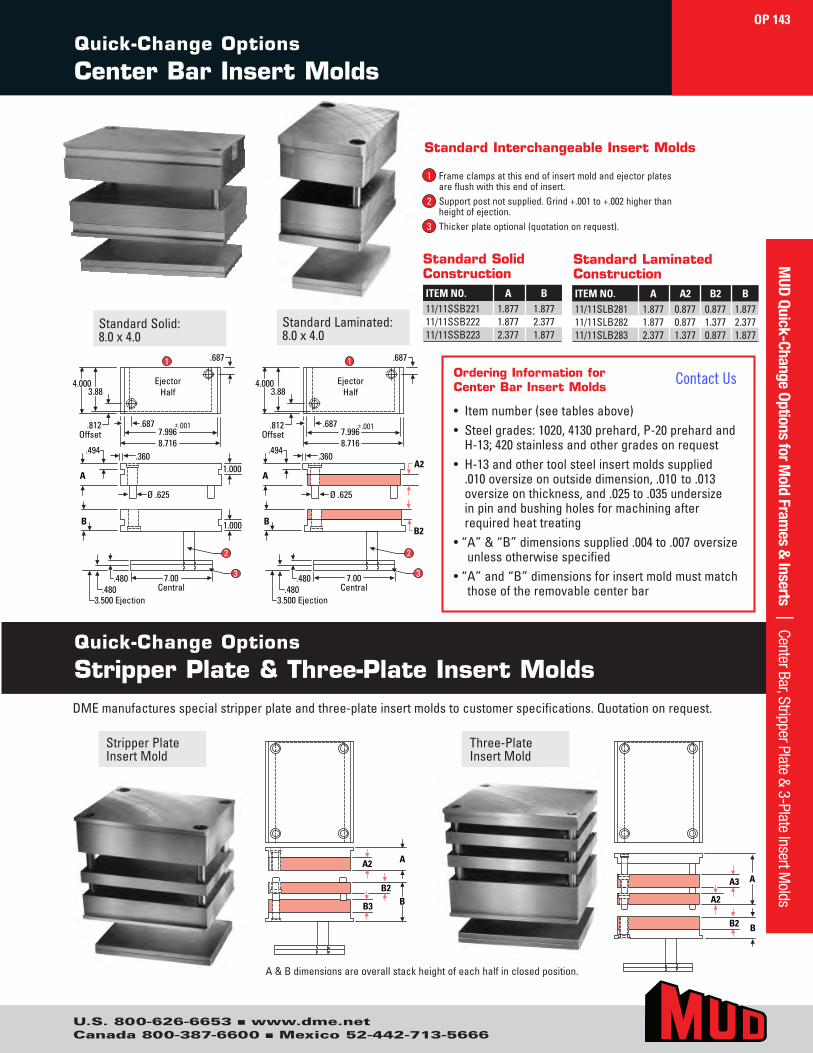
U.S. 800-626-6653 ■ www.dme.netCanada 800-387-6600 ■ Mexico 52-442-713-5666
Quick-Change Options
Center Bar Insert Molds
A
A2
A3
B2 BB
B2
B3
A2 A
A
A2
A3
B2 BB
B2
B3
A2 A
AA2
Ø .625
.360.494
1
.812Offset
.687
4.0003.88
.6877.9968.716
EjectorHalf
7.00Central
B
.480.480
3.500 Ejection
B2
2
3
A
Ø .625
.360.494
1
.812Offset
.687
4.0003.88
.6877.9968.716
EjectorHalf
7.00Central
B
.480.480
3.500 Ejection
2
3
±.001 ±.001
1.000
1.000
AA2
Ø .625
.360.494
1
.812Offset
.687
4.0003.88
.6877.9968.716
EjectorHalf
7.00Central
B
.480.480
3.500 Ejection
B2
2
3
A
Ø .625
.360.494
1
.812Offset
.687
4.0003.88
.6877.9968.716
EjectorHalf
7.00Central
B
.480.480
3.500 Ejection
2
3
±.001 ±.001
1.000
1.000
A & B dimensions are overall stack height of each half in closed position.
ITEM NO. A B11/11SSB221 1.877 1.87711/11SSB222 1.877 2.37711/11SSB223 2.377 1.877
Standard Solid Construction
ITEM NO. A A2 B2 B11/11SLB281 1.877 0.877 0.877 1.87711/11SLB282 1.877 0.877 1.377 2.37711/11SLB283 2.377 1.377 0.877 1.877
Standard Laminated Construction
DME manufactures special stripper plate and three-plate insert molds to customer specifications. Quotation on request.
Quick-Change Options
Stripper Plate & Three-Plate Insert Molds
Standard Solid: 8.0 x 4.0
Standard Laminated: 8.0 x 4.0
Stripper Plate Insert Mold
Three-Plate Insert Mold
Ordering Information for Center Bar Insert Molds
• Item number (see tables above)• Steel grades: 1020, 4130 prehard, P-20 prehard and
H-13; 420 stainless and other grades on request• H-13 and other tool steel insert molds supplied
.010 oversize on outside dimension, .010 to .013 oversize on thickness, and .025 to .035 undersize in pin and bushing holes for machining after required heat treating
• “ A” & “B” dimensions supplied .004 to .007 oversizeunless otherwise specified
• “ A” and “B” dimensions for insert mold must matchthose of the removable center bar
1 Frame clamps at this end of insert mold and ejector plates4 are flush with this end of insert.
2 Support post not supplied. Grind +.001 to +.002 higher than height of ejection.
3 Thicker plate optional (quotation on request).
Standard Interchangeable Insert Molds
OP 143M
UD Quick-Change Options for Mold Fram
es & Inserts | Center Bar, Stripper Plate & 3-Plate Insert M
olds
Contact Us
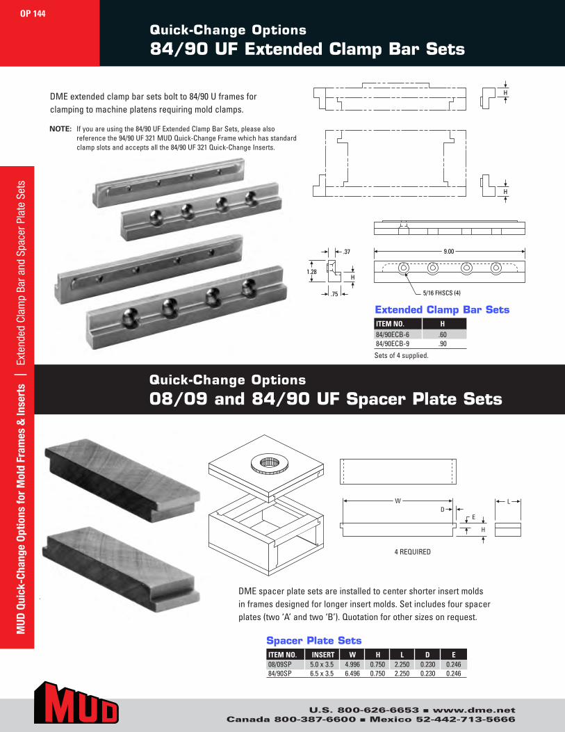
U.S. 800-626-6653 ■ www.dme.netCanada 800-387-6600 ■ Mexico 52-442-713-5666
LWD
H
ELWD
H
E
H
H
9.00
5/16 FHSCS (4)
H1.28
.37
.75
H
H
9.00
5/16 FHSCS (4)
H1.28
.37
.75
DME spacer plate sets are installed to center shorter insert molds in frames designed for longer insert molds. Set includes four spacer plates (two ‘A’ and two ‘B’). Quotation for other sizes on request.
4 REQUIRED
Quick-Change Options
08/09 and 84/90 UF Spacer Plate Sets
ITEM NO. H84/90ECB-6 .6084/90ECB-9 .90
Extended Clamp Bar Sets
ITEM NO. INSERT W H L D E08/09SP 5.0 x 3.5 4.996 0.750 2.250 0.230 0.24684/90SP 6.5 x 3.5 6.496 0.750 2.250 0.230 0.246
Spacer Plate Sets
DME extended clamp bar sets bolt to 84/90 U frames for clamping to machine platens requiring mold clamps.
NOTE: If you are using the 84/90 UF Extended Clamp Bar Sets, please also reference the 94/90 UF 321 MUD Quick-Change Frame which has standard clamp slots and accepts all the 84/90 UF 321 Quick-Change Inserts.
Quick-Change Options
84/90 UF Extended Clamp Bar Sets
OP 144M
UD Q
uick
-Cha
nge
Optio
ns fo
r M
old
Fram
es &
Inse
rts
| E
xten
ded
Clam
p Ba
r and
Spa
cer P
late
Set
s
Sets of 4 supplied.
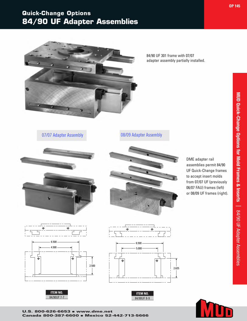
U.S. 800-626-6653 ■ www.dme.netCanada 800-387-6600 ■ Mexico 52-442-713-5666
Quick-Change Options
84/90 UF Adapter Assemblies
ITEM NO.84/90UF 7-7
ITEM NO.84/90UF 8-9
DME adapter rail assemblies permit 84/90 UF Quick-Change frames to accept insert molds from 07/07 UF (previously 06/07 FAU) frames (left) or 08/09 UF frames (right).
6.500
5.000
2.625
6.500
4.500
2.500
6.500
5.000
2.625
6.500
4.500
2.500
84/90 UF 301 frame with 07/07 adapter assembly partially installed.
07/07 Adapter Assembly 08/09 Adapter Assembly
OP 145M
UD Quick-Change Options for M
old Frames &
Inserts | 84/90 UF Adapter Assemblies
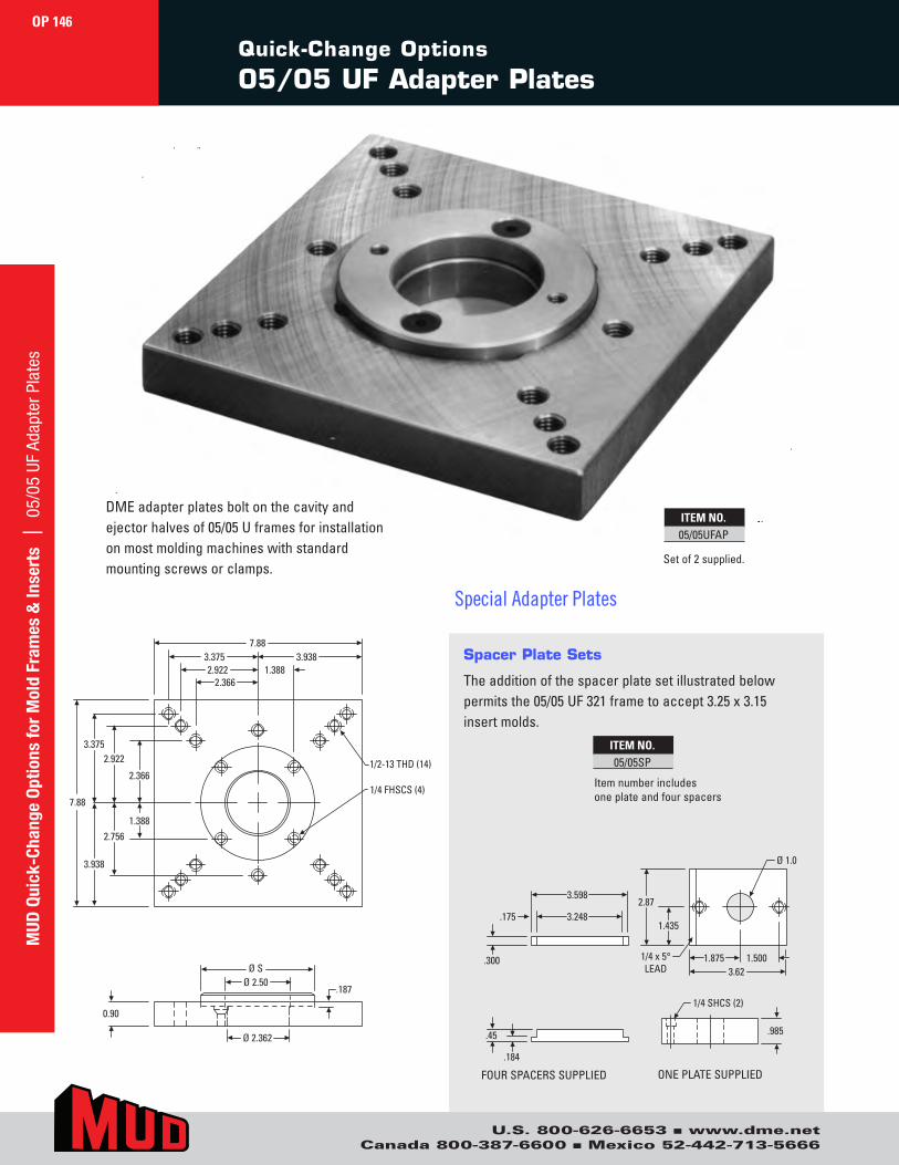
Spacer Plate Sets
The addition of the spacer plate set illustrated below permits the 05/05 UF 321 frame to accept 3.25 x 3.15 insert molds.
.45
.184
.300
.175 3.248
3.598
.985
1/4 SHCS (2)
1.875 3.62
1.500
2.87
Ø 1.0
1/4 x 5°LEAD
1.435
Ø S Ø 2.50
Ø 2.362
.187
0.90
7.88 3.375
3.375
3.938
2.922
2.756
2.366
1.388
2.922 1.388
1/2-13 THD (14)
1/4 FHSCS (4)
2.366
7.88
3.938
.45
.184
.300
.175 3.248
3.598
.985
1/4 SHCS (2)
1.875 3.62
1.500
2.87
Ø 1.0
1/4 x 5°LEAD
1.435
Ø S Ø 2.50
Ø 2.362
.187
0.90
7.88 3.375
3.375
3.938
2.922
2.756
2.366
1.388
2.922 1.388
1/2-13 THD (14)
1/4 FHSCS (4)
2.366
7.88
3.938
ITEM NO.05/05SP
DME adapter plates bolt on the cavity and ejector halves of 05/05 U frames for installation on most molding machines with standard mounting screws or clamps.
ITEM NO.05/05UFAP
Set of 2 supplied.
Item number includes one plate and four spacers
FOUR SPACERS SUPPLIED ONE PLATE SUPPLIED
Quick-Change Options
05/05 UF Adapter Plates
OP 146
U.S. 800-626-6653 ■ www.dme.netCanada 800-387-6600 ■ Mexico 52-442-713-5666
MUD
Qui
ck-C
hang
e Op
tions
for
Mol
d Fr
ames
& In
sert
s |
05/
05 U
F Ad
apte
r Pla
tes
Special Adapter Plates
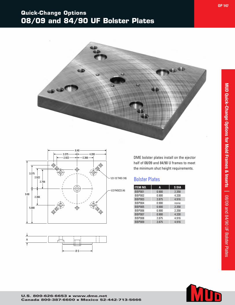
U.S. 800-626-6653 ■ www.dme.netCanada 800-387-6600 ■ Mexico 52-442-713-5666
Quick-Change Options
08/09 and 84/90 UF Bolster Plates
ITEM NO. A S DIABBP001 0.900 2.358BBP002 0.900 4.330BBP003 2.875 4.916BBP004 0.900 noneBBP005 0.900 2.358BBP006 0.900 2.358BBP007 0.900 4.330BBP008 2.875 4.916BBP009 2.875 4.916
DME bolster plates install on the ejector half of 08/09 and 84/90 U frames to meet the minimum shut height requirements.
Bolster Plates
Ø S
A
8.403.375 4.2002.922 2.366
3.375
5.000
2.922
2.366
2.756
9.00
1/2-13 THD (10)
1/2 FHSCS (4)
OP 147M
UD Quick-Change Options for M
old Frames &
Inserts | 08/09 and 84/90 UF Bolster Plates
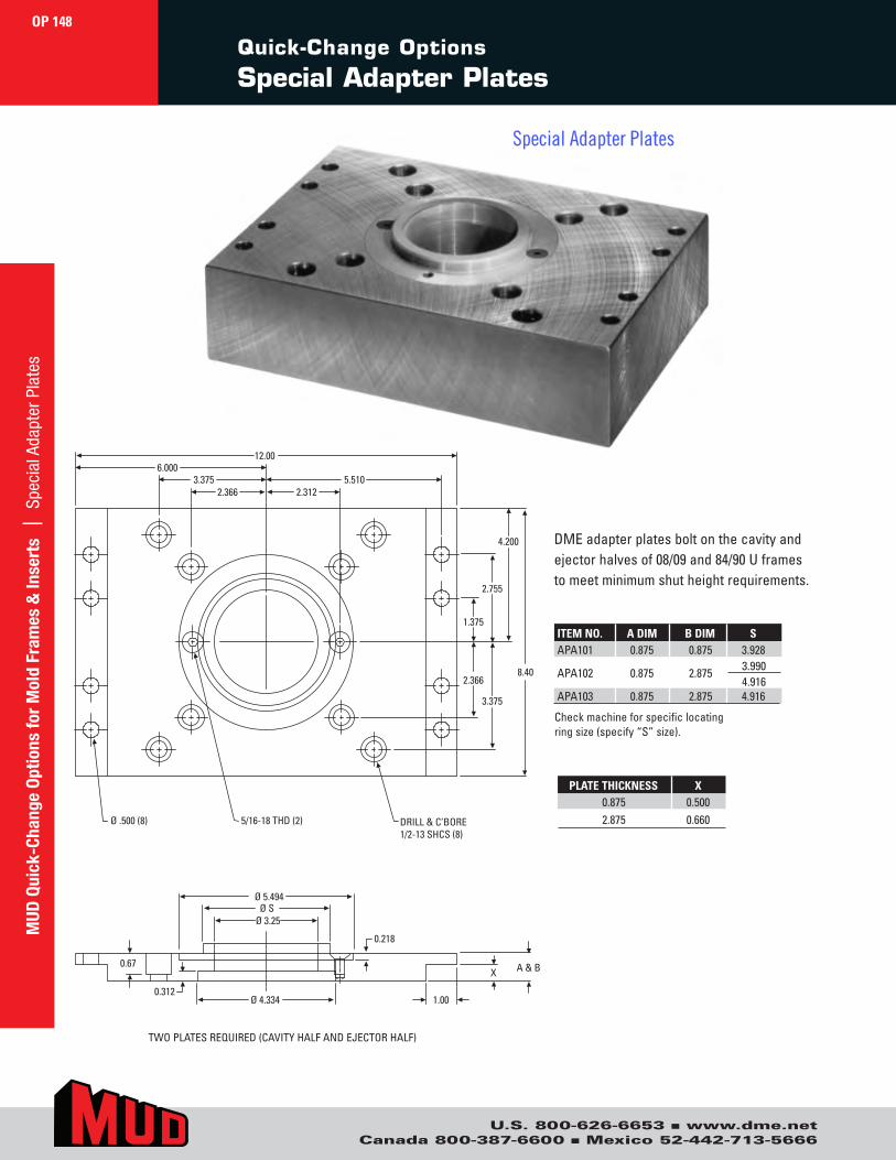
U.S. 800-626-6653 ■ www.dme.netCanada 800-387-6600 ■ Mexico 52-442-713-5666
Quick-Change Options
Special Adapter Plates
DME adapter plates bolt on the cavity and ejector halves of 08/09 and 84/90 U frames to meet minimum shut height requirements.
Check machine for specific locating ring size (specify “S” size).
TWO PLATES REQUIRED (CAVITY HALF AND EJECTOR HALF)
ITEM NO. A DIM B DIM S APA101 0.875 0.875 3.928
APA102 0.875 2.875
APA103 0.875 2.875 4.916
3.9904.916
12.00
3.375
4.200
2.755
3.375
DRILL & C’BORE1/2-13 SHCS (8)
5/16-18 THD (2)Ø .500 (8)
1.375
2.366
X
0.218
0.67
0.312
A & B
2.366 2.312
Ø SØ 5.494
Ø 3.25
Ø 4.334 1.00
6.000
8.40
5.510
PLATE THICKNESS X0.875 0.5002.875 0.660
OP 148M
UD Q
uick
-Cha
nge
Optio
ns fo
r M
old
Fram
es &
Inse
rts
| S
peci
al A
dapt
er P
late
s
Special Adapter Plates
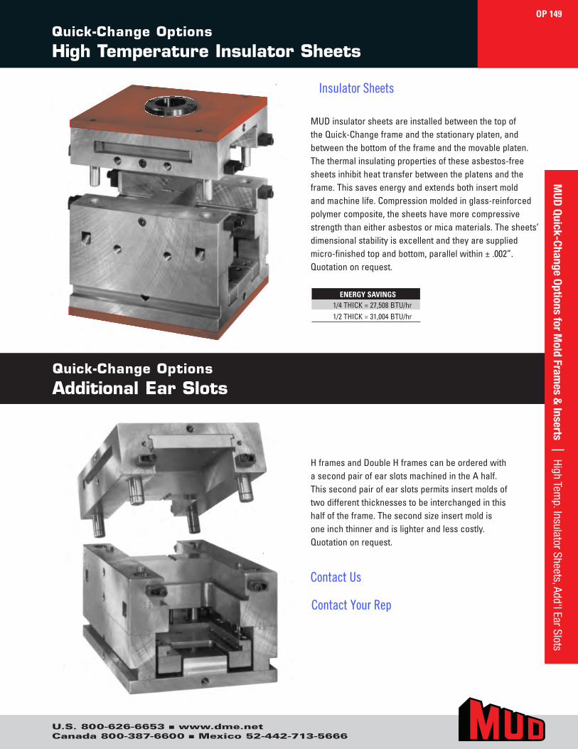
U.S. 800-626-6653 ■ www.dme.netCanada 800-387-6600 ■ Mexico 52-442-713-5666
H frames and Double H frames can be ordered with a second pair of ear slots machined in the A half. This second pair of ear slots permits insert molds of two different thicknesses to be interchanged in this half of the frame. The second size insert mold is one inch thinner and is lighter and less costly. Quotation on request.
MUD insulator sheets are installed between the top of the Quick-Change frame and the stationary platen, and between the bottom of the frame and the movable platen. The thermal insulating properties of these asbestos-free sheets inhibit heat transfer between the platens and the frame. This saves energy and extends both insert mold and machine life. Compression molded in glass-reinforced polymer composite, the sheets have more compressive strength than either asbestos or mica materials. The sheets’ dimensional stability is excellent and they are supplied micro-finished top and bottom, parallel within ± .002”. Quotation on request.
Quick-Change Options
Additional Ear Slots
ENERGY SAVINGS1/4 THICK = 27,508 BTU/hr1/2 THICK = 31,004 BTU/hr
Quick-Change Options
High Temperature Insulator Sheets
OP 149M
UD Quick-Change Options for M
old Frames &
Inserts | High Temp. Insulator Sheets, Add'l Ear Slots
Insulator Sheets
Contact Us
Contact Your Rep
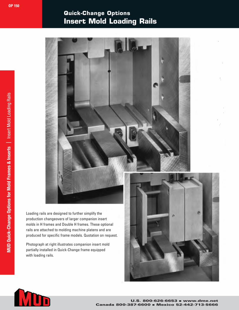
U.S. 800-626-6653 ■ www.dme.netCanada 800-387-6600 ■ Mexico 52-442-713-5666
Quick-Change Options
Insert Mold Loading Rails
Loading rails are designed to further simplify the production changeovers of larger companion insert molds in H frames and Double H frames. These optional rails are attached to molding machine platens and are produced for specific frame models. Quotation on request.
Photograph at right illustrates companion insert mold partially installed in Quick-Change frame equipped with loading rails.
OP 150M
UD Q
uick
-Cha
nge
Optio
ns fo
r M
old
Fram
es &
Inse
rts
| I
nser
t Mol
d Lo
adin
g Ra
ils
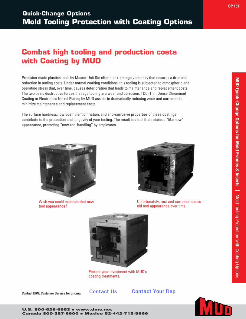
Quick-Change Options
Mold Tooling Protection with Coating Options
Protect your investment with MUD’s coating treatments.
Unfortunately, rust and corrosion cause old tool appearance over time.
Wish you could maintain that new tool appearance?
Contact DME Customer Service for pricing.
OP 151
U.S. 800-626-6653 ■ www.dme.netCanada 800-387-6600 ■ Mexico 52-442-713-5666
MUD
Quick-Change Options for Mold Fram
es & Inserts | M
old Tooling Protection with Coating O
ptions
Combat high tooling and production costs with Coating by MUD
Precision-made plastics tools by Master Unit Die offer quick-change versatility that ensures a dramatic reduction in tooling costs. Under normal working conditions, this tooling is subjected to atmospheric and operating stress that, over time, causes deterioration that leads to maintenance and replacement costs. The two basic destructive forces that age tooling are wear and corrosion. TDC (Thin Dense Chromium) Coating or Electroless Nickel Plating by MUD assists in dramatically reducing wear and corrosion to minimize maintenance and replacement costs.
The surface hardness, low coefficient of friction, and anti-corrosive properties of these coatings contribute to the protection and longevity of your tooling. The result is a tool that retains a “like new” appearance, promoting “new-tool handling” by employees.
Contact Us Contact Your Rep
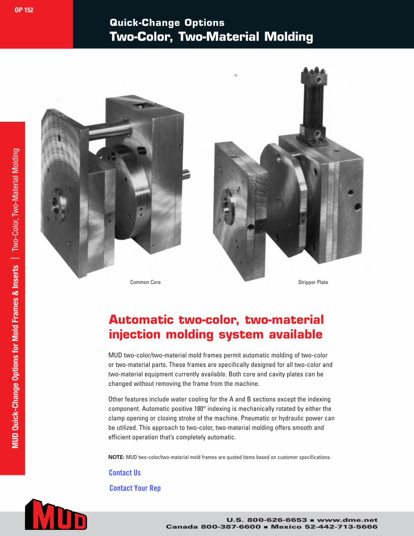
U.S. 800-626-6653 ■ www.dme.netCanada 800-387-6600 ■ Mexico 52-442-713-5666
MUD
Qui
ck-C
hang
e Op
tions
for
Mol
d Fr
ames
& In
sert
s |
Tw
o-Co
lor,
Two-
Mat
eria
l Mol
ding
OP 152
Quick-Change Options
Two-Color, Two-Material Molding
Common Core Stripper Plate
Automatic two-color, two-material injection molding system available
MUD two-color/two-material mold frames permit automatic molding of two-color or two-material parts. These frames are specifically designed for all two-color and two-material equipment currently available. Both core and cavity plates can be changed without removing the frame from the machine.
Other features include water cooling for the A and B sections except the indexing component. Automatic positive 180° indexing is mechanically rotated by either the clamp opening or closing stroke of the machine. Pneumatic or hydraulic power can be utilized. This approach to two-color, two-material molding offers smooth and efficient operation that’s completely automatic.
NOTE: MUD two-color/two-material mold frames are quoted items based on customer specifications.
Contact Us
Contact Your Rep
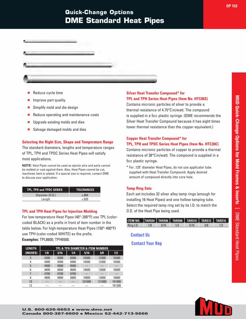
U.S. 800-626-6653 ■ www.dme.netCanada 800-387-6600 ■ Mexico 52-442-713-5666
OP 153M
UD Quick-Change Options for M
old Frames &
Inserts | DM
E Standard Heat PipesQuick-Change Options
DME Standard Heat Pipes
Silver Heat Transfer Compound* for TPL and TPH Series Heat Pipes (Item No. HTC06S)Contains micronic particles of silver to provide a thermal resistance of 4.75°Cin/watt. The compound is supplied in a 5cc plastic syringe. (DME recommends the Silver Heat Transfer Compound because it has eight times lower thermal resistance than the copper equivalent.)
Copper Heat Transfer Compound* for TPL, TPH and TPDC Series Heat Pipes (Item No. HTC30C)Contains micronic particles of copper to provide a thermal resistance of 38°Cin/watt. The compound is supplied in a 5cc plastic syringe.
* For .125" diameter Heat Pipes, do not use applicator tube supplied with Heat Transfer Compound. Apply desired amount of compound directly into core hole.
Tamp Ring SetsEach set includes 32 silver alloy tamp rings (enough for installing 16 Heat Pipes) and one hollow tamping tube. Select the required tamp ring set by its I.D. to match the O.D. of the Heat Pipe being used.
Selecting the Right Size, Shape and Temperature RangeThe standard diameters, lengths and temperature ranges of TPL, TPH and TPDC Series Heat Pipes will satisfy most applications.
NOTE: Heat Pipes cannot be used as ejector pins and parts cannot be molded or cast against them. Also, Heat Pipes cannot be cut, machined, bent or plated. If a special size is required, contact DME to discuss your application.
TPL and TPH Heat Pipes for Injection MoldingFor low-temperature Heat Pipes (40°-200°F) use TPL (color-coded BLACK) as a prefix in front of item number in the table below. For high-temperature Heat Pipes (150°-400°F) use TPH (color-coded WHITE) as the prefix. Examples: TPL8600; TPH6500.
ITEM NO. TARS04 TARS06 TARS08 TARS10 TARS12 TARS16Ring I.D. 1/8 3/16 1/4 5/16 3/8 1/2
LENGTH TPL & TPH DIAMETER & ITEM NUMBER (INCHES) 1/8 3/16 1/4 5/16 3/8 1/2
3 4300 6300 8300 10300 12300 163004 4400 6400 8400 10400 12400 164005 4500 6500 8500 — — —6 4600 6600 8600 10600 12600 166007 4700 6700 8700 — — —8 4800 6800 8800 10800 12800 16800
10 — — — 101000 121000 16100012 — — — — — 161200
TPL, TPH and TPDC SERIES TOLERANCES
Diameter (O.D.) ±.004Length ±.020
■ Reduce cycle time
■ Improve part quality
■ Simplify mold and die design
■ Reduce operating and maintenance costs
■ Upgrade existing molds and dies
■ Salvage damaged molds and dies
Contact Us
Contact Your Rep
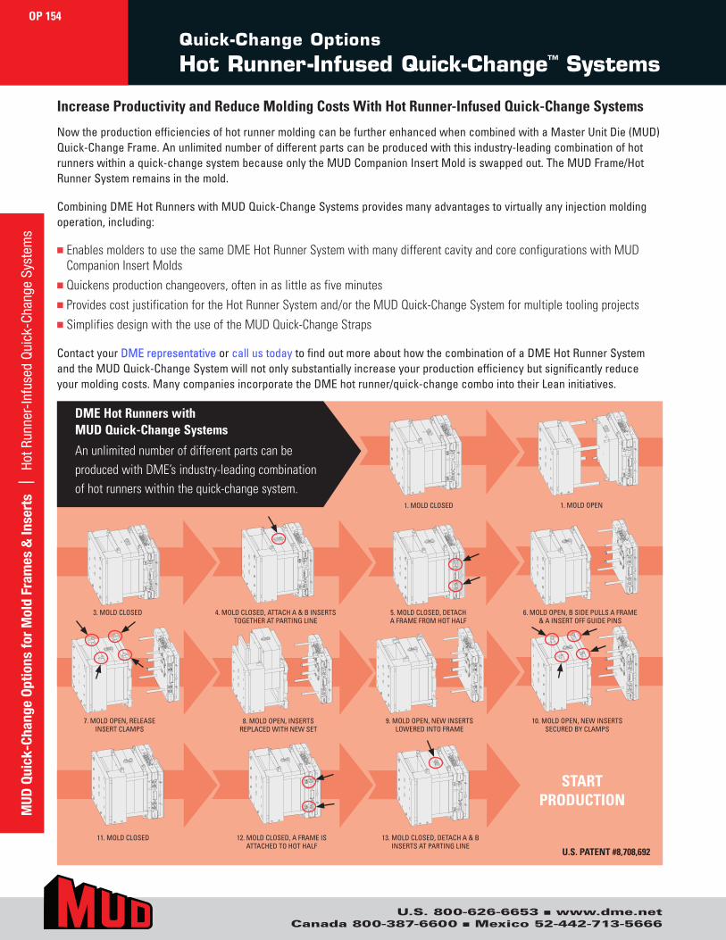
U.S. 800-626-6653 ■ www.dme.netCanada 800-387-6600 ■ Mexico 52-442-713-5666
MUD
Qui
ck-C
hang
e Op
tions
for
Mol
d Fr
ames
& In
sert
s |
Hot
Run
ner-
Infu
sed
Qui
ck-C
hang
e Sy
stem
s
Now the production efficiencies of hot runner molding can be further enhanced when combined with a Master Unit Die (MUD) Quick-Change Frame. An unlimited number of different parts can be produced with this industry-leading combination of hot runners within a quick-change system because only the MUD Companion Insert Mold is swapped out. The MUD Frame/Hot Runner System remains in the mold.
Combining DME Hot Runners with MUD Quick-Change Systems provides many advantages to virtually any injection molding operation, including:
■ Enables molders to use the same DME Hot Runner System with many different cavity and core configurations with MUDCompanion Insert Molds
■ Quickens production changeovers, often in as little as five minutes■ Provides cost justification for the Hot Runner System and/or the MUD Quick-Change System for multiple tooling projects■ Simplifies design with the use of the MUD Quick-Change Straps
Contact your DME representative or call us today to find out more about how the combination of a DME Hot Runner System and the MUD Quick-Change System will not only substantially increase your production efficiency but significantly reduce your molding costs. Many companies incorporate the DME hot runner/quick-change combo into their Lean initiatives.
Increase Productivity and Reduce Molding Costs With Hot Runner-Infused Quick-Change Systems
DME Hot Runners with MUD Quick-Change Systems
An unlimited number of different parts can be produced with DME’s industry-leading combination of hot runners within the quick-change system.
1. MOLD CLOSED 1. MOLD OPEN
5. MOLD CLOSED, DETACH A FRAME FROM HOT HALF
3. MOLD CLOSED 4. MOLD CLOSED, ATTACH A & B INSERTS TOGETHER AT PARTING LINE
9. MOLD OPEN, NEW INSERTS LOWERED INTO FRAME
8. MOLD OPEN, INSERTS REPLACED WITH NEW SET
13. MOLD CLOSED, DETACH A & B INSERTS AT PARTING LINE
11. MOLD CLOSED 12. MOLD CLOSED, A FRAME IS ATTACHED TO HOT HALF
03 04 06
08 10
13
05
07 09
1211
01 02
Quick-Change Options
Hot Runner-Infused Quick-Change™ Systems
OP 154
6. MOLD OPEN, B SIDE PULLS A FRAME & A INSERT OFF GUIDE PINS
7. MOLD OPEN, RELEASE INSERT CLAMPS
10. MOLD OPEN, NEW INSERTS SECURED BY CLAMPS
START PRODUCTION
U.S. PATENT #8,708,692