mp series (user manual for communication) - autonics
TRANSCRIPT

© Copyright Reserved Autonics Co., Ltd. i

ii © Copyright Reserved Autonics Co., Ltd.

Preface
© Copyright Reserved Autonics Co., Ltd. iii
Preface
Thank you for purchasing an Autonics product.
Please familiarize yourself with the information contained in the Safety Precautions section before using this product.
This user manual contains information about the product and its proper use, and should be kept in a place where it will be easy to access.
User Manual Guide
iv © Copyright Reserved Autonics Co., Ltd.
User Manual Guide
Please familiarize yourself with the information in this manual before using the product. This manual provides detailed information on the product's features. It does not offer any
guarantee concerning matters beyond the scope of this manual. This manual may not be edited or reproduced in either part or whole without permission. A user manual is not provided as part of the product package.
Visit our web site (www.autonics.com) to download a copy. The manual's content may vary depending on changes to the product's software and other
unforeseen developments within Autonics, and is subject to change without prior notice. Upgrade notice is provided through out homepage.
We contrived to describe this manual more easily and correctly. However, if there are any corrections or questions, please notify us these on our homepage.
Communication Protocol
© Copyright Reserved Autonics Co., Ltd. v
Communication Protocol
MP5 Series is accepted to Modbus RTU Protocol.
Users should be aware that it does not support a broadcast command.
User Manual Symbols
vi © Copyright Reserved Autonics Co., Ltd.
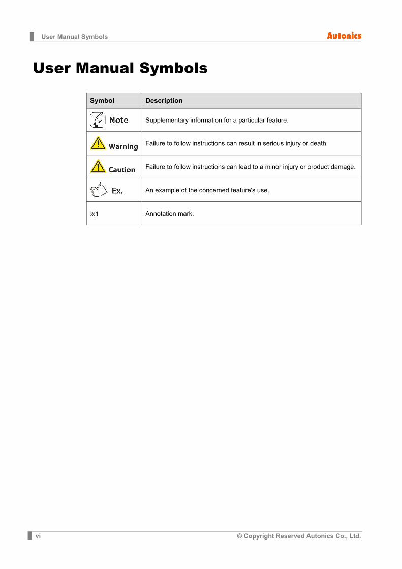
User Manual Symbols
Symbol Description
Supplementary information for a particular feature.
Failure to follow instructions can result in serious injury or death.
Failure to follow instructions can lead to a minor injury or product damage.
An example of the concerned feature's use.
※1 Annotation mark.
Safety Precautions
© Copyright Reserved Autonics Co., Ltd. vii
Safety Precautions
Following these safety precautions will ensure the safe and proper use of the product and help prevent accidents, as well as minimizing possible hazards.
Safety precautions are categorized as Warnings and Cautions, as defined below:
Warning Failure to follow the instructions may lead to a serious injury
or accident.
Caution Failure to follow the instructions may lead to a minor injury
or accident.
Fail-safe device must be installed when using the unit with machinery that may cause
serious injury or substantial economic loss. (e.g. nuclear power control, medical equipment, ships, vehicles, railways, aircraft, combustion apparatus, safety equipment, crime/disaster prevention devices, etc.) Failure to follow this instruction may result in fire, personal injury, or economic loss.
Install on a device panel to use. Failure to follow this instruction may result in electric shock or fire.
Do not connect, repair, or inspect the unit while connected to a power source. Failure to follow this instruction may result in electric shock or fire.
Check 'Connections' before wiring. Failure to follow this instruction may result in fire.
Do not disassemble or modify the unit. Failure to follow this instruction may result in electric shock or fire.
When connecting the power/measurement input and relay output, use AWG 24(0.20mm2) to
AWG 15(1.65mm2) cable and tighten the terminal screw with a tightening torque of 0.98 to 1.18N·m. Use proper cables for the rated load current. Failure to follow this instruction may result in fire or malfunction due to contact failure.
Use the unit within the rated specifications. Failure to follow this instruction may result in fire or product damage.
Use dry cloth to clean the unit, and do not use water or organic solvent. Failure to follow this instruction may result in electric shock or fire.
Do not use the unit in the place where flammable/explosive/corrosive gas, humidity, direct sunlight, radiant heat, vibration, impact, or salinity may be present. Failure to follow this instruction may result in fire or explosion.
Keep metal chip, dust, and wire residue from flowing into the unit. Failure to follow this instruction may result in fire or product damage.
The specifications of communication manual are subject to change and some models may be discontinued without notice.

Safety Precautions
viii © Copyright Reserved Autonics Co., Ltd.
Table of Contents
© Copyright Reserved Autonics Co., Ltd. ix
Table of Contents
Preface ................................................................................................................................... iii User Manual Guide ................................................................................................................. iv Communication Protocol ......................................................................................................... v User Manual Symbols ............................................................................................................. vi Safety Precautions ................................................................................................................. vii Table of Contents..................................................................................................................... ix
1 Modbus RTU Protocol .............................................................................. 11
1.1 Read coil status (Func 01–01H) .................................................................................... 11
1.2 Read input status (Func 02–02H) ................................................................................. 12
1.3 Read holding registers (Func 03–03H) ......................................................................... 13
1.4 Read input registers (Func 04–04H) ............................................................................. 14
1.5 Force single coil (Func 05–05H) ................................................................................... 15
1.6 Preset single registers (Func 06–06H) .......................................................................... 16
1.7 Preset multiple registers (Func 16–10H) ....................................................................... 17
1.8 Exception response-error code ..................................................................................... 18
2 Modbus Mapping Table ............................................................................ 19
2.1 Read coil status (Func 01) / Force single coil (Func 05) ............................................... 19
2.2 Read input status (Func 02) .......................................................................................... 19
2.3 Read input registers (Func 04) ...................................................................................... 19
2.4 Read holding registers (Func03) / Preset single registers (Func 06) / Preset multiple registers (Func 16) ........................................................................................................ 21
2.4.1 Comparative value settings and peak value check group.......................... 21 2.4.2 Parameter 1 group ..................................................................................... 21 2.4.3 Parameter 2 group ..................................................................................... 22 2.4.4 Parameter 3 group ..................................................................................... 23

Table of Contents
x © Copyright Reserved Autonics Co., Ltd.
1 Modbus RTU Protocol
© Copyright Reserved Autonics Co., Ltd. 11
1 Modbus RTU Protocol
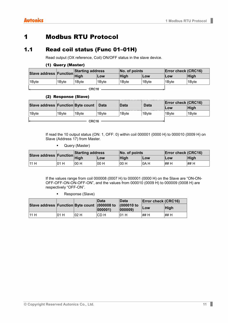
1.1 Read coil status (Func 01–01H) Read output (OX reference, Coil) ON/OFF status in the slave device.
(1) Query (Master)
Slave address Function Starting address No. of points Error check (CRC16) High Low High Low Low High
1Byte 1Byte 1Byte 1Byte 1Byte 1Byte 1Byte 1Byte
(2) Response (Slave)
Slave address Function Byte count Data Data Data Error check (CRC16) Low High
1Byte 1Byte 1Byte 1Byte 1Byte 1Byte 1Byte 1Byte
If read the 10 output status (ON: 1, OFF: 0) within coil 000001 (0000 H) to 000010 (0009 H) on Slave (Address 17) from Master.
Query (Master)
Slave address Function Starting address No. of points Error check (CRC16) High Low High Low Low High
11 H 01 H 00 H 00 H 00 H 0A H ## H ## H
If the values range from coil 000008 (0007 H) to 000001 (0000 H) on the Slave are “ON-ON-OFF-OFF-ON-ON-OFF-ON”, and the values from 000010 (0009 H) to 000009 (0008 H) are respectively “OFF-ON”.
Response (Slave)
Slave address Function Byte count Data (000008 to 000001)
Data (000010 to 000009)
Error check (CRC16)
Low High
11 H 01 H 02 H CD H 01 H ## H ## H
CRC16
CRC16
1 Modbus RTU Protocol
12 © Copyright Reserved Autonics Co., Ltd.
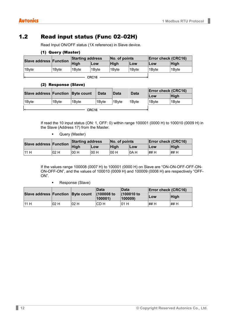
1.2 Read input status (Func 02–02H) Read Input ON/OFF status (1X reference) in Slave device.
(1) Query (Master)
Slave address Function Starting address No. of points Error check (CRC16) High Low High Low Low High
1Byte 1Byte 1Byte 1Byte 1Byte 1Byte 1Byte 1Byte
(2) Response (Slave)
Slave address Function Byte count Data Data Data Error check (CRC16) Low High
1Byte 1Byte 1Byte 1Byte 1Byte 1Byte 1Byte 1Byte
If read the 10 input status (ON: 1, OFF: 0) within range 100001 (0000 H) to 100010 (0009 H) in the Slave (Address 17) from the Master.
Query (Master)
Slave address Function Starting address No. of points Error check (CRC16) High Low High Low Low High
11 H 02 H 00 H 00 H 00 H 0A H ## H ## H
If the values range 100008 (0007 H) to 100001 (0000 H) on Slave are “ON-ON-OFF-OFF-ON-ON-OFF-ON”, and the values of 100010 (0009 H) and 100009 (0008 H) are respectively “OFF-ON”.
Response (Slave)
Slave address Function Byte count Data (100008 to 100001)
Data (100010 to 100009)
Error check (CRC16)
Low High
11 H 02 H 02 H CD H 01 H ## H ## H
CRC16
CRC16
1 Modbus RTU Protocol
© Copyright Reserved Autonics Co., Ltd. 13
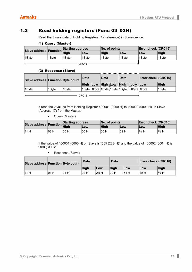
1.3 Read holding registers (Func 03–03H) Read the Binary data of Holding Registers (4X reference) in Slave device.
(1) Query (Master)
Slave address Function Starting address No. of points Error check (CRC16) High Low High Low Low High
1Byte 1Byte 1Byte 1Byte 1Byte 1Byte 1Byte 1Byte
(2) Response (Slave)
Slave address Function Byte count Data Data Data Error check (CRC16)
High Low High Low High Low Low High 1Byte 1Byte 1Byte 1Byte 1Byte 1Byte 1Byte 1Byte 1Byte 1Byte 1Byte
If read the 2 values from Holding Register 400001 (0000 H) to 400002 (0001 H), in Slave (Address 17) from the Master.
Query (Master)
Slave address Function Starting address No. of points Error check (CRC16) High Low High Low Low High
11 H 03 H 00 H 00 H 00 H 02 H ## H ## H
If the value of 400001 (0000 H) on Slave is “555 (22B H)” and the value of 400002 (0001 H) is “100 (64 H)”.
Response (Slave)
Slave address Function Byte count Data Data Error check (CRC16)
High Low High Low Low High 11 H 03 H 04 H 02 H 2B H 00 H 64 H ## H ## H
CRC16
CRC16
1 Modbus RTU Protocol
14 © Copyright Reserved Autonics Co., Ltd.
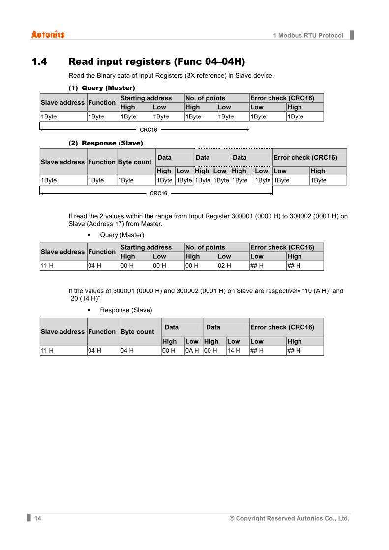
1.4 Read input registers (Func 04–04H) Read the Binary data of Input Registers (3X reference) in Slave device.
(1) Query (Master)
Slave address Function Starting address No. of points Error check (CRC16) High Low High Low Low High
1Byte 1Byte 1Byte 1Byte 1Byte 1Byte 1Byte 1Byte
(2) Response (Slave)
Slave address Function Byte count Data Data Data Error check (CRC16)
High Low High Low High Low Low High 1Byte 1Byte 1Byte 1Byte 1Byte 1Byte 1Byte 1Byte 1Byte 1Byte 1Byte
If read the 2 values within the range from Input Register 300001 (0000 H) to 300002 (0001 H) on Slave (Address 17) from Master.
Query (Master)
Slave address Function Starting address No. of points Error check (CRC16) High Low High Low Low High
11 H 04 H 00 H 00 H 00 H 02 H ## H ## H
If the values of 300001 (0000 H) and 300002 (0001 H) on Slave are respectively “10 (A H)” and “20 (14 H)”.
Response (Slave)
Slave address Function Byte count Data Data Error check (CRC16)
High Low High Low Low High 11 H 04 H 04 H 00 H 0A H 00 H 14 H ## H ## H
CRC16
CRC16
1 Modbus RTU Protocol
© Copyright Reserved Autonics Co., Ltd. 15
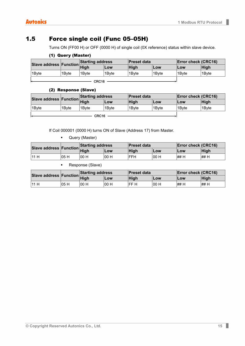
1.5 Force single coil (Func 05–05H) Turns ON (FF00 H) or OFF (0000 H) of single coil (0X reference) status within slave device.
(1) Query (Master)
Slave address Function Starting address Preset data Error check (CRC16) High Low High Low Low High
1Byte 1Byte 1Byte 1Byte 1Byte 1Byte 1Byte 1Byte
(2) Response (Slave)
Slave address Function Starting address Preset data Error check (CRC16) High Low High Low Low High
1Byte 1Byte 1Byte 1Byte 1Byte 1Byte 1Byte 1Byte
If Coil 000001 (0000 H) turns ON of Slave (Address 17) from Master.
Query (Master)
Slave address Function Starting address Preset data Error check (CRC16) High Low High Low Low High
11 H 05 H 00 H 00 H FFH 00 H ## H ## H
Response (Slave)
Slave address Function Starting address Preset data Error check (CRC16) High Low High Low Low High
11 H 05 H 00 H 00 H FF H 00 H ## H ## H
CRC16
CRC16
1 Modbus RTU Protocol
16 © Copyright Reserved Autonics Co., Ltd.
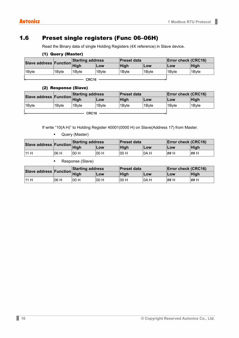
1.6 Preset single registers (Func 06–06H) Read the Binary data of single Holding Registers (4X reference) in Slave device.
(1) Query (Master)
Slave address Function Starting address Preset data Error check (CRC16) High Low High Low Low High
1Byte 1Byte 1Byte 1Byte 1Byte 1Byte 1Byte 1Byte
(2) Response (Slave)
Slave address Function Starting address Preset data Error check (CRC16) High Low High Low Low High
1Byte 1Byte 1Byte 1Byte 1Byte 1Byte 1Byte 1Byte
If write “10(A H)” to Holding Register 40001(0000 H) on Slave(Address 17) from Master.
Query (Master)
Slave address Function Starting address Preset data Error check (CRC16) High Low High Low Low High
11 H 06 H 00 H 00 H 00 H 0A H ## H ## H
Response (Slave)
Slave address Function Starting address Preset data Error check (CRC16) High Low High Low Low High
11 H 06 H 00 H 00 H 00 H 0A H ## H ## H
CRC16
CRC16
1 Modbus RTU Protocol
© Copyright Reserved Autonics Co., Ltd. 17
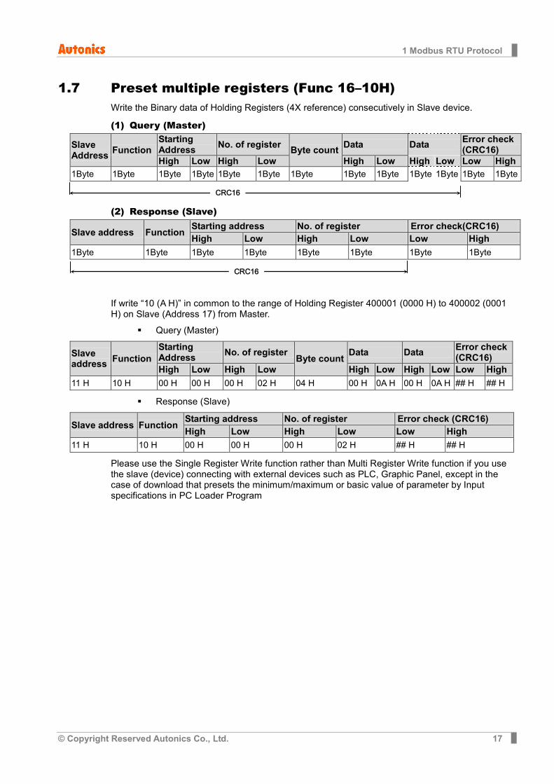
1.7 Preset multiple registers (Func 16–10H) Write the Binary data of Holding Registers (4X reference) consecutively in Slave device.
(1) Query (Master)
Slave Address Function
Starting Address No. of register Byte count Data Data Error check
(CRC16) High Low High Low High Low High Low Low High
1Byte 1Byte 1Byte 1Byte 1Byte 1Byte 1Byte 1Byte 1Byte 1Byte 1Byte 1Byte 1Byte
(2) Response (Slave)
Slave address Function Starting address No. of register Error check(CRC16) High Low High Low Low High
1Byte 1Byte 1Byte 1Byte 1Byte 1Byte 1Byte 1Byte
If write “10 (A H)” in common to the range of Holding Register 400001 (0000 H) to 400002 (0001 H) on Slave (Address 17) from Master.
Query (Master)
Slave address Function
Starting Address No. of register Byte count Data Data Error check
(CRC16) High Low High Low High Low High Low Low High
11 H 10 H 00 H 00 H 00 H 02 H 04 H 00 H 0A H 00 H 0A H ## H ## H
Response (Slave)
Slave address Function Starting address No. of register Error check (CRC16) High Low High Low Low High
11 H 10 H 00 H 00 H 00 H 02 H ## H ## H
Please use the Single Register Write function rather than Multi Register Write function if you use the slave (device) connecting with external devices such as PLC, Graphic Panel, except in the case of download that presets the minimum/maximum or basic value of parameter by Input specifications in PC Loader Program
CRC16
CRC16
1 Modbus RTU Protocol
18 © Copyright Reserved Autonics Co., Ltd.
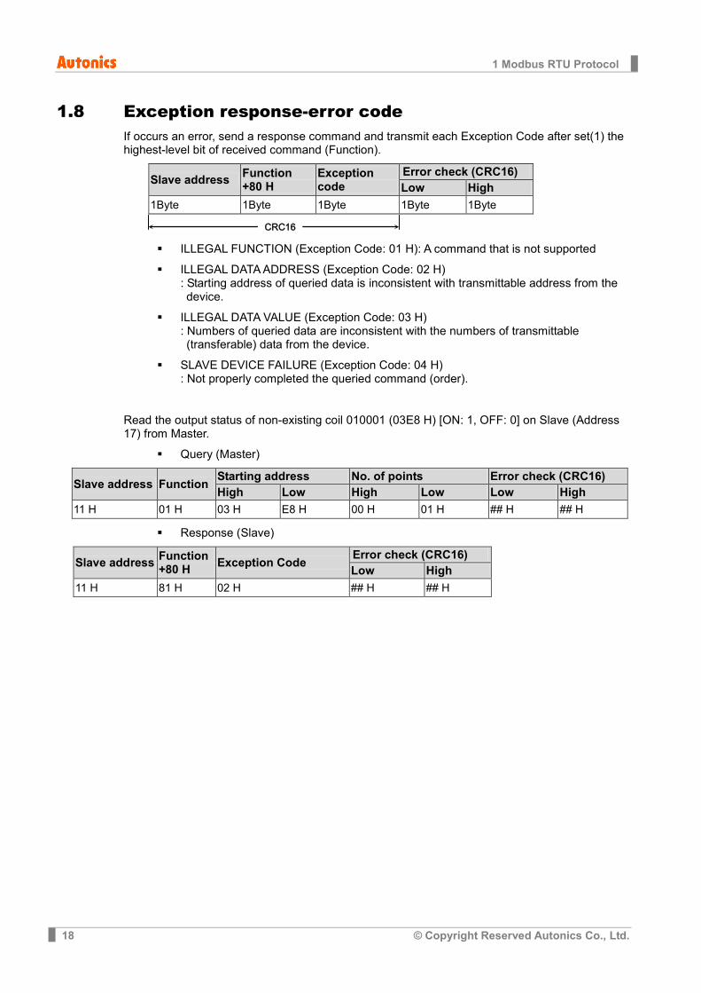
1.8 Exception response-error code If occurs an error, send a response command and transmit each Exception Code after set(1) the highest-level bit of received command (Function).
Slave address Function +80 H
Exception code
Error check (CRC16) Low High
1Byte 1Byte 1Byte 1Byte 1Byte
ILLEGAL FUNCTION (Exception Code: 01 H): A command that is not supported
ILLEGAL DATA ADDRESS (Exception Code: 02 H) : Starting address of queried data is inconsistent with transmittable address from the device.
ILLEGAL DATA VALUE (Exception Code: 03 H) : Numbers of queried data are inconsistent with the numbers of transmittable (transferable) data from the device.
SLAVE DEVICE FAILURE (Exception Code: 04 H) : Not properly completed the queried command (order).
Read the output status of non-existing coil 010001 (03E8 H) [ON: 1, OFF: 0] on Slave (Address 17) from Master.
Query (Master)
Slave address Function Starting address No. of points Error check (CRC16) High Low High Low Low High
11 H 01 H 03 H E8 H 00 H 01 H ## H ## H
Response (Slave)
Slave address Function +80 H Exception Code Error check (CRC16)
Low High 11 H 81 H 02 H ## H ## H
CRC16
2 Modbus Mapping Table
© Copyright Reserved Autonics Co., Ltd. 19
2 Modbus Mapping Table
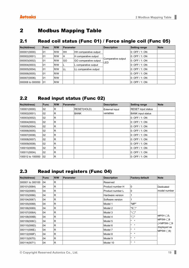
2.1 Read coil status (Func 01) / Force single coil (Func 05) No(Address) Func R/W Parameter Description Setting range Note
000001(0000) 01 R/W HH HH comparative output
Comparative output LED
0: OFF / 1: ON
000002(0001) 01 R/W H H comparative output 0: OFF / 1: ON
000003(0002) 01 R/W GO GO comparative output 0: OFF / 1: ON
000004(0003) 01 R/W L L comparative output 0: OFF / 1: ON
000005(0004) 01 R/W LL LL comparative output 0: OFF / 1: ON
000006(0005) 01 R/W 0: OFF / 1: ON
000007(0006) 01 R/W 0: OFF / 1: ON
000008 to 000050 01 R/W 0: OFF / 1: ON
2.2 Read input status (Func 02) No(Address) Func R/W Parameter Description Setting range Note
100001(0000) 02 R RESET(HOLD) External input variables
RESET input status
100002(0001) 02 R BANK BANK input status
100003(0002) 02 R 0: OFF / 1: ON
100004(0003) 02 R 0: OFF / 1: ON
100005(0004) 02 R 0: OFF / 1: ON
100006(0005) 02 R 0: OFF / 1: ON
100007(0008) 02 R 0: OFF / 1: ON
100008(0007) 02 R 0: OFF / 1: ON
100009(0008) 02 R 0: OFF / 1: ON
100010(0009) 02 R 0: OFF / 1: ON
100011(000A) 02 R 0: OFF / 1: ON
100012 to 100050 02 R 0: OFF / 1: ON
2.3 Read input registers (Func 04) No(Address) Func R/W Parameter Description Factory default Note
300001 to 300100 04 R Reserved
300101(0064) 04 R Product number H 0 Dedicated model number 300102(0065) 04 R Product number L 0
300103(0066) 04 R Hardware version 1
300104(0067) 04 R Software version 1
300105(0068) 04 R Model 1 "MP"
MP5Y-□5, MP5W-□8 (※MP5W-□9 displayed as MP5W-□8)
300106(0069) 04 R Model 2 "5□"
300107(006A) 04 R Model 3 "-□"
300108(006B) 04 R Model 4 "□"
300109(006C) 04 R Model 5 " "
300110(006D) 04 R Model 6 " "
300111(006E) 04 R Model 7 " "
300112(006F) 04 R Model 8 " "
300113(0070) 04 R Model 9 " "
300114(0071) 04 R Model 10 " "
2 Modbus Mapping Table
20 © Copyright Reserved Autonics Co., Ltd.
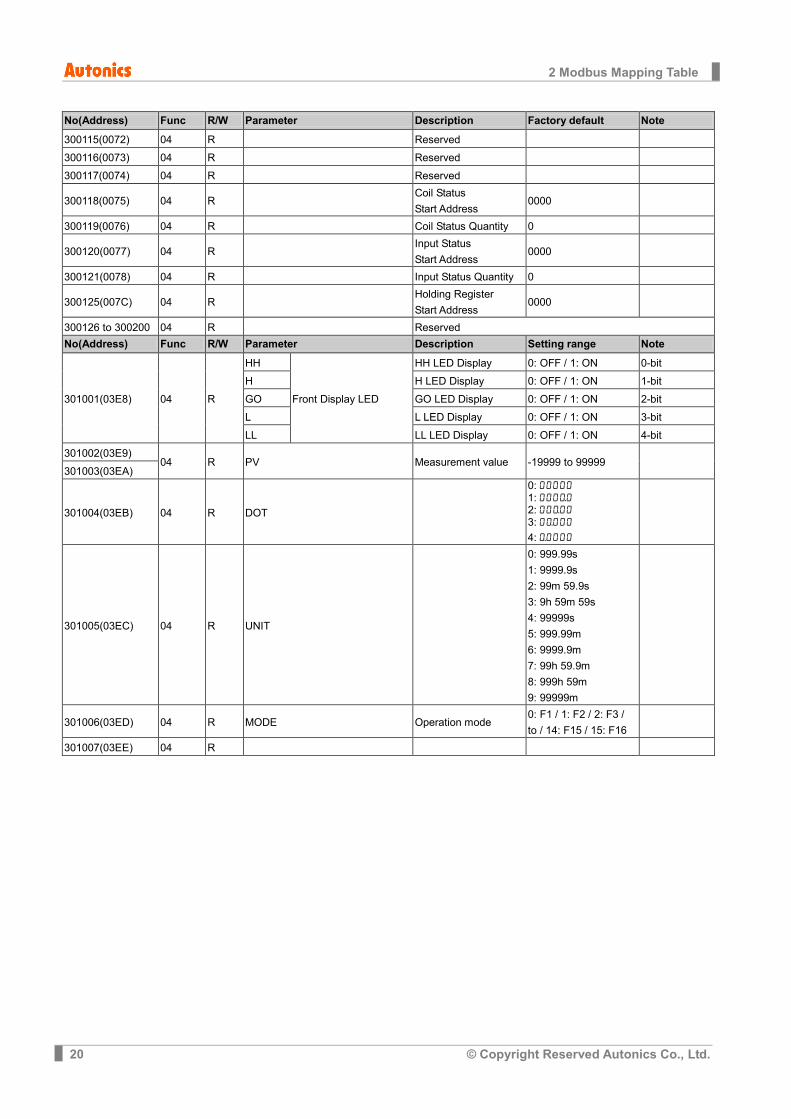
No(Address) Func R/W Parameter Description Factory default Note
300115(0072) 04 R Reserved
300116(0073) 04 R Reserved
300117(0074) 04 R Reserved
300118(0075) 04 R Coil Status Start Address
0000
300119(0076) 04 R Coil Status Quantity 0
300120(0077) 04 R Input Status Start Address
0000
300121(0078) 04 R Input Status Quantity 0
300125(007C) 04 R Holding Register Start Address
0000
300126 to 300200 04 R Reserved No(Address) Func R/W Parameter Description Setting range Note
301001(03E8) 04 R
HH
Front Display LED
HH LED Display 0: OFF / 1: ON 0-bit
H H LED Display 0: OFF / 1: ON 1-bit
GO GO LED Display 0: OFF / 1: ON 2-bit
L L LED Display 0: OFF / 1: ON 3-bit
LL LL LED Display 0: OFF / 1: ON 4-bit
301002(03E9) 04 R PV Measurement value -19999 to 99999
301003(03EA)
301004(03EB) 04 R DOT
0: 00000 1: 000)0
2: 00)00 3: 0)000 4: )0000
301005(03EC) 04 R UNIT
0: 999.99s 1: 9999.9s 2: 99m 59.9s 3: 9h 59m 59s 4: 99999s 5: 999.99m 6: 9999.9m 7: 99h 59.9m 8: 999h 59m 9: 99999m
301006(03ED) 04 R MODE Operation mode 0: F1 / 1: F2 / 2: F3 / to / 14: F15 / 15: F16
301007(03EE) 04 R
2 Modbus Mapping Table
© Copyright Reserved Autonics Co., Ltd. 21
2.4 Read holding registers (Func03) / Preset single registers (Func 06) / Preset multiple registers (Func 16)
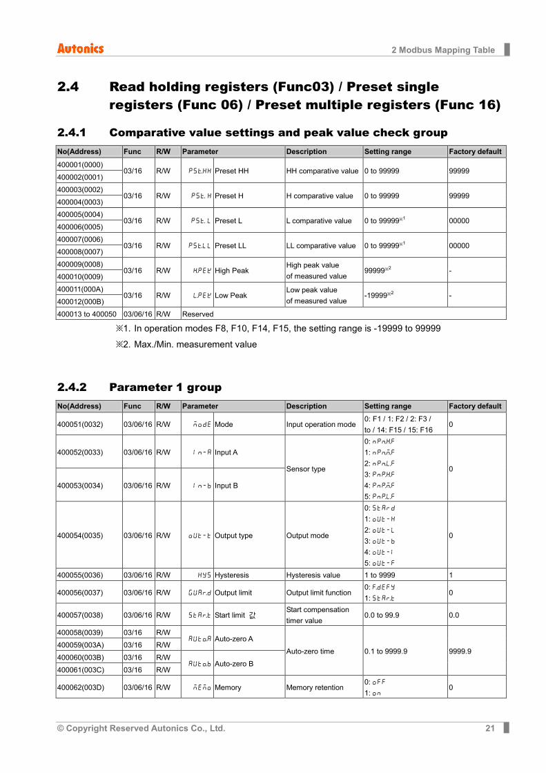
2.4.1 Comparative value settings and peak value check group No(Address) Func R/W Parameter Description Setting range Factory default
400001(0000) 03/16 R/W PStHH Preset HH HH comparative value 0 to 99999 99999
400002(0001)
400003(0002) 03/16 R/W PSt H Preset H H comparative value 0 to 99999 99999
400004(0003)
400005(0004) 03/16 R/W PSt L Preset L L comparative value 0 to 99999※1 00000
400006(0005)
400007(0006) 03/16 R/W PStLL Preset LL LL comparative value 0 to 99999※1 00000
400008(0007)
400009(0008) 03/16 R/W hPEK High Peak
High peak value of measured value
99999※2 - 400010(0009)
400011(000A) 03/16 R/W lPEK Low Peak
Low peak value of measured value
-19999※2 - 400012(000B)
400013 to 400050 03/06/16 R/W Reserved
※1. In operation modes F8, F10, F14, F15, the setting range is -19999 to 99999 ※2. Max./Min. measurement value
2.4.2 Parameter 1 group No(Address) Func R/W Parameter Description Setting range Factory default
400051(0032) 03/06/16 R/W MODE Mode Input operation mode 0: F1 / 1: F2 / 2: F3 / to / 14: F15 / 15: F16
0
400052(0033) 03/06/16 R/W IN-A Input A
Sensor type
0: NPnhF 1: NPnmF 2: NPnlF 3: PNphF 4: PNpmF 5: PNplF
0
400053(0034) 03/06/16 R/W IN-B Input B
400054(0035) 03/06/16 R/W OUT-T Output type Output mode
0: STARD 1: OUT-H 2: OUT-L 3: OUT-B 4: OUT-I 5: OUT-F
0
400055(0036) 03/06/16 R/W HYS Hysteresis Hysteresis value 1 to 9999 1
400056(0037) 03/06/16 R/W GUArD Output limit Output limit function 0: fDEFY 1: STArT
0
400057(0038) 03/06/16 R/W STArT Start limit 값 Start compensation timer value
0.0 to 99.9 0.0
400058(0039) 03/16 R/W AUToA Auto-zero A
Auto-zero time 0.1 to 9999.9 9999.9 400059(003A) 03/16 R/W
400060(003B) 03/16 R/W AUToB Auto-zero B
400061(003C) 03/16 R/W
400062(003D) 03/06/16 R/W MEMO Memory Memory retention 0: OFF 1: ON
0
2 Modbus Mapping Table
22 © Copyright Reserved Autonics Co., Ltd.
No(Address) Func R/W Parameter Description Setting range Factory default
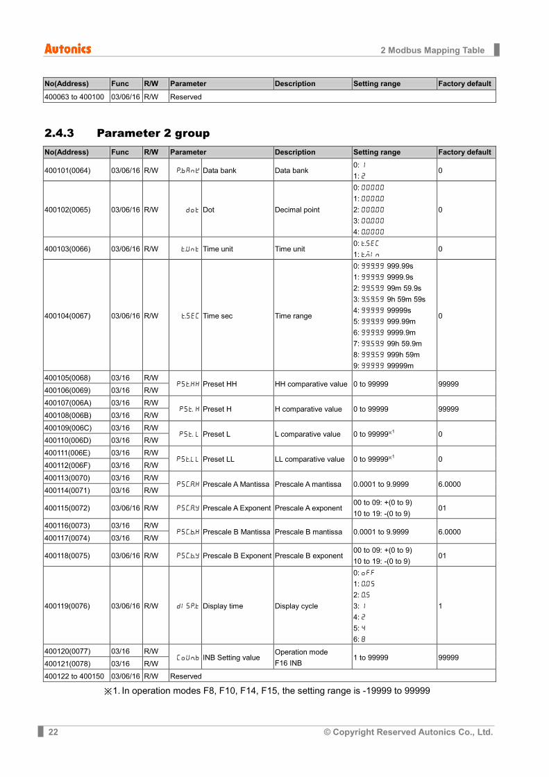
400063 to 400100 03/06/16 R/W Reserved
2.4.3 Parameter 2 group No(Address) Func R/W Parameter Description Setting range Factory default
400101(0064) 03/06/16 R/W pBANK Data bank Data bank 0: 1 1: 2
0
400102(0065) 03/06/16 R/W DOT Dot Decimal point
0: 00000
1: 000)0
2: 00)00 3: 0)000 4: )0000
0
400103(0066) 03/06/16 R/W tUNT Time unit Time unit 0: tSEC 1: tMIN
0
400104(0067) 03/06/16 R/W tSEC Time sec Time range
0: 99(99 999.99s 1: 999(9 9999.9s 2: 9(5(9 99m 59.9s 3: (5(59 9h 59m 59s 4: 99999 99999s 5: 99(99 999.99m 6: 999(9 9999.9m 7: 9(5(9 99h 59.9m 8: 99(59 999h 59m 9: 99999 99999m
0
400105(0068) 03/16 R/W PStHH Preset HH HH comparative value 0 to 99999 99999
400106(0069) 03/16 R/W
400107(006A) 03/16 R/W PSt H Preset H H comparative value 0 to 99999 99999
400108(006B) 03/16 R/W
400109(006C) 03/16 R/W PSt L Preset L L comparative value 0 to 99999※1 0
400110(006D) 03/16 R/W
400111(006E) 03/16 R/W PStLL Preset LL LL comparative value 0 to 99999※1 0
400112(006F) 03/16 R/W
400113(0070) 03/16 R/W PScaH Prescale A Mantissa Prescale A mantissa 0.0001 to 9.9999 6.0000
400114(0071) 03/16 R/W
400115(0072) 03/06/16 R/W PScaY Prescale A Exponent Prescale A exponent 00 to 09: +(0 to 9) 10 to 19: -(0 to 9)
01
400116(0073) 03/16 R/W PScbH Prescale B Mantissa Prescale B mantissa 0.0001 to 9.9999 6.0000
400117(0074) 03/16 R/W
400118(0075) 03/06/16 R/W PScbY Prescale B Exponent Prescale B exponent 00 to 09: +(0 to 9) 10 to 19: -(0 to 9)
01
400119(0076) 03/06/16 R/W DISpT Display time Display cycle
0: OFF 1: )05 2: )5 3: 1 4: 2
5: 4 6: 8
1
400120(0077) 03/16 R/W COUnB INB Setting value
Operation mode F16 INB
1 to 99999 99999 400121(0078) 03/16 R/W
400122 to 400150 03/06/16 R/W Reserved
※1. In operation modes F8, F10, F14, F15, the setting range is -19999 to 99999
2 Modbus Mapping Table
© Copyright Reserved Autonics Co., Ltd. 23
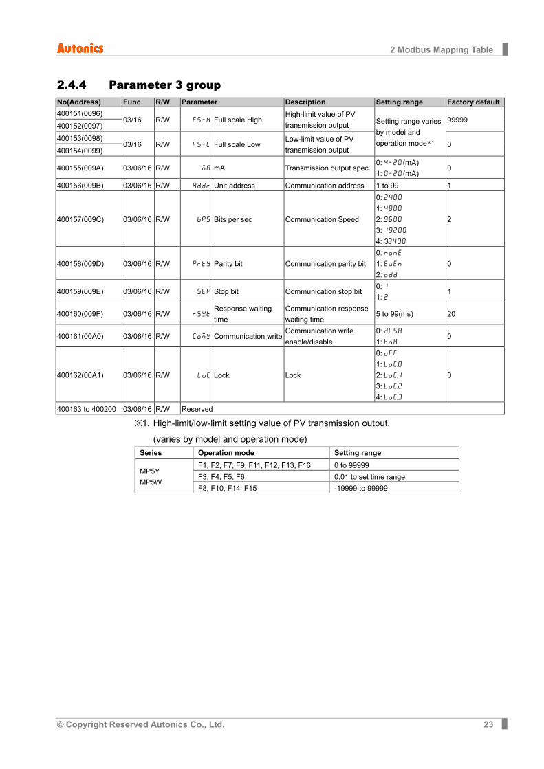
2.4.4 Parameter 3 group No(Address) Func R/W Parameter Description Setting range Factory default 400151(0096)
03/16 R/W FS-H Full scale High High-limit value of PV transmission output Setting range varies
by model and operation mode※1
99999 400152(0097)
400153(0098) 03/16 R/W FS-L Full scale Low
Low-limit value of PV transmission output
0 400154(0099)
400155(009A) 03/06/16 R/W MA mA Transmission output spec. 0: 4-20(mA) 1: 0-20(mA)
0
400156(009B) 03/06/16 R/W ADDR Unit address Communication address 1 to 99 1
400157(009C) 03/06/16 R/W BPS Bits per sec Communication Speed
0: 2400 1: 4800
2: 9600 3: 19200 4: 38400
2
400158(009D) 03/06/16 R/W PRTY Parity bit Communication parity bit 0: NONE 1: EVEN 2: ODD
0
400159(009E) 03/06/16 R/W STP Stop bit Communication stop bit 0: 1 1: 2
1
400160(009F) 03/06/16 R/W RSwT Response waiting time
Communication response waiting time
5 to 99(ms) 20
400161(00A0) 03/06/16 R/W COmW Communication write Communication write enable/disable
0: DISA 1: ENA
0
400162(00A1) 03/06/16 R/W LOC Lock Lock
0: OFF 1: LOc0 2: LOc1 3: LOc2 4: LOc3
0
400163 to 400200 03/06/16 R/W Reserved
※1. High-limit/low-limit setting value of PV transmission output. (varies by model and operation mode)
Series Operation mode Setting range
MP5Y MP5W
F1, F2, F7, F9, F11, F12, F13, F16 0 to 99999 F3, F4, F5, F6 0.01 to set time range F8, F10, F14, F15 -19999 to 99999

2 Modbus Mapping Table
24 © Copyright Reserved Autonics Co., Ltd.
MCP-MPC1-V1.0-1801US