gp-xbc (rs232) - autonics
TRANSCRIPT

© Copyright Reserved Autonics Co., Ltd. iii
GP-XBC (RS232)
Solution Guide

ii © Copyright Reserved Autonics Co., Ltd.
© Copyright Reserved Autonics Co., Ltd. 3
Preface
Thank you very much for selecting Autonics products.
Please familiarize yourself with the information in this manual and in the product manuals before using them.
This solution guide contains information about a specific architecture solution and does not replace any specific product documentation.
This document does not attempt to describe the entire solution architecture and configuration but only introduce some basics procedures. Customization of this solution can be made by the users in respect of safety laws and regulations.
4 © Copyright Reserved Autonics Co., Ltd.
Document Guide
This manual provides procedure steps for a particular solution architecture. It does not offer any guarantee concerning matters beyond the scope of this manual.
This manual may not be edited or reproduced in either part or whole without written permission of Autonics.
This manual is not provided as part of the product package. Please visit our home-page (www.autonics.com) to download a copy.
The content of this manual may vary depending on updates of the product software and others unforeseen developments within Autonics. It is subject to change without prior notice. Upgrade notices are published through our homepage.
We contrived to describe this manual the easiest and more accurate way. However, if there are any corrections required or questions, please notify us these remarks on our homepage.
© Copyright Reserved Autonics Co., Ltd. 5
Document Symbols
Symbol Description
Additional information about a particular feature.
Failure to follow instructions can result in serious injury or death.
Failure to follow instructions can lead to a minor injury or product damage.
An example of the concerned feature's use.
※1 Annotation mark.
6 © Copyright Reserved Autonics Co., Ltd.
Document Version History
Date Version Author Description
December 17th 2016 v1.0 기술지원팀 - YCG Document creation
August 8th 2017 v2.0 기술지원팀 - GTE
Document revision and template update Add several sections
September 18th
2017 v2.0.1 기술지원팀 - GTE Minor text updates
© Copyright Reserved Autonics Co., Ltd. 7
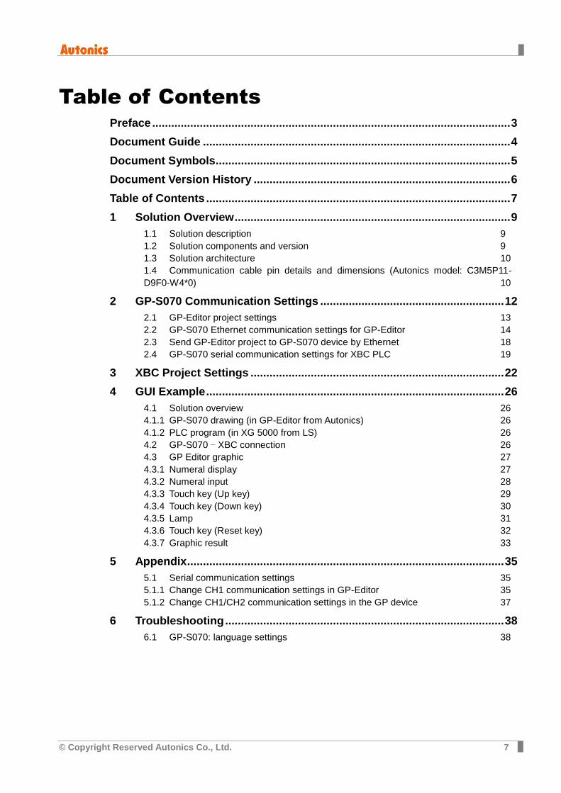
Table of Contents
Preface ................................................................................................................. 3
Document Guide ................................................................................................. 4
Document Symbols............................................................................................. 5
Document Version History ................................................................................. 6
Table of Contents ................................................................................................ 7
1 Solution Overview ....................................................................................... 9
1.1 Solution description 9
1.2 Solution components and version 9
1.3 Solution architecture 10
1.4 Communication cable pin details and dimensions (Autonics model: C3M5P11-
D9F0-W4*0) 10
2 GP-S070 Communication Settings .......................................................... 12
2.1 GP-Editor project settings 13
2.2 GP-S070 Ethernet communication settings for GP-Editor 14
2.3 Send GP-Editor project to GP-S070 device by Ethernet 18
2.4 GP-S070 serial communication settings for XBC PLC 19
3 XBC Project Settings ................................................................................ 22
4 GUI Example .............................................................................................. 26
4.1 Solution overview 26
4.1.1 GP-S070 drawing (in GP-Editor from Autonics) 26
4.1.2 PLC program (in XG 5000 from LS) 26
4.2 GP-S070 – XBC connection 26
4.3 GP Editor graphic 27
4.3.1 Numeral display 27
4.3.2 Numeral input 28
4.3.3 Touch key (Up key) 29
4.3.4 Touch key (Down key) 30
4.3.5 Lamp 31
4.3.6 Touch key (Reset key) 32
4.3.7 Graphic result 33
5 Appendix .................................................................................................... 35
5.1 Serial communication settings 35
5.1.1 Change CH1 communication settings in GP-Editor 35
5.1.2 Change CH1/CH2 communication settings in the GP device 37
6 Troubleshooting ........................................................................................ 38
6.1 GP-S070: language settings 38

8 © Copyright Reserved Autonics Co., Ltd.
1 Solution Overview
© Copyright Reserved Autonics Co., Ltd. 9
1 Solution Overview
1.1 Solution description
Autonics GP-S070-T9D6 device from the GP/LP series is a 7.0 inch LCD color touch panel with build-in serial connection through RS-422 and RS-232C ports. It is a standalone screen with custom OS and dedicated graphic editor software to create up to 500 graphic pages.
Thanks to its characteristic, it can be added on top of any existing automation architecture with different type of serial connection and can monitor different devices parameters or statuses and key Setting Values or Present Values, facilitating access to data that was not in the previous architecture.
This solution brings the following benefits to your current installation:
Allows to monitor in real time PLC & devices status and feedback values
Allows a convenient control of the different parameters and setting values
Allows a fast and clear notification of the different alarms
This solution is optimized because:
Can be simply added on top of your current installation
Very small dimension so can be installed close to the controlling device for or local control
Internal graphics and control functions for standalone application without need of server or OS licensing.
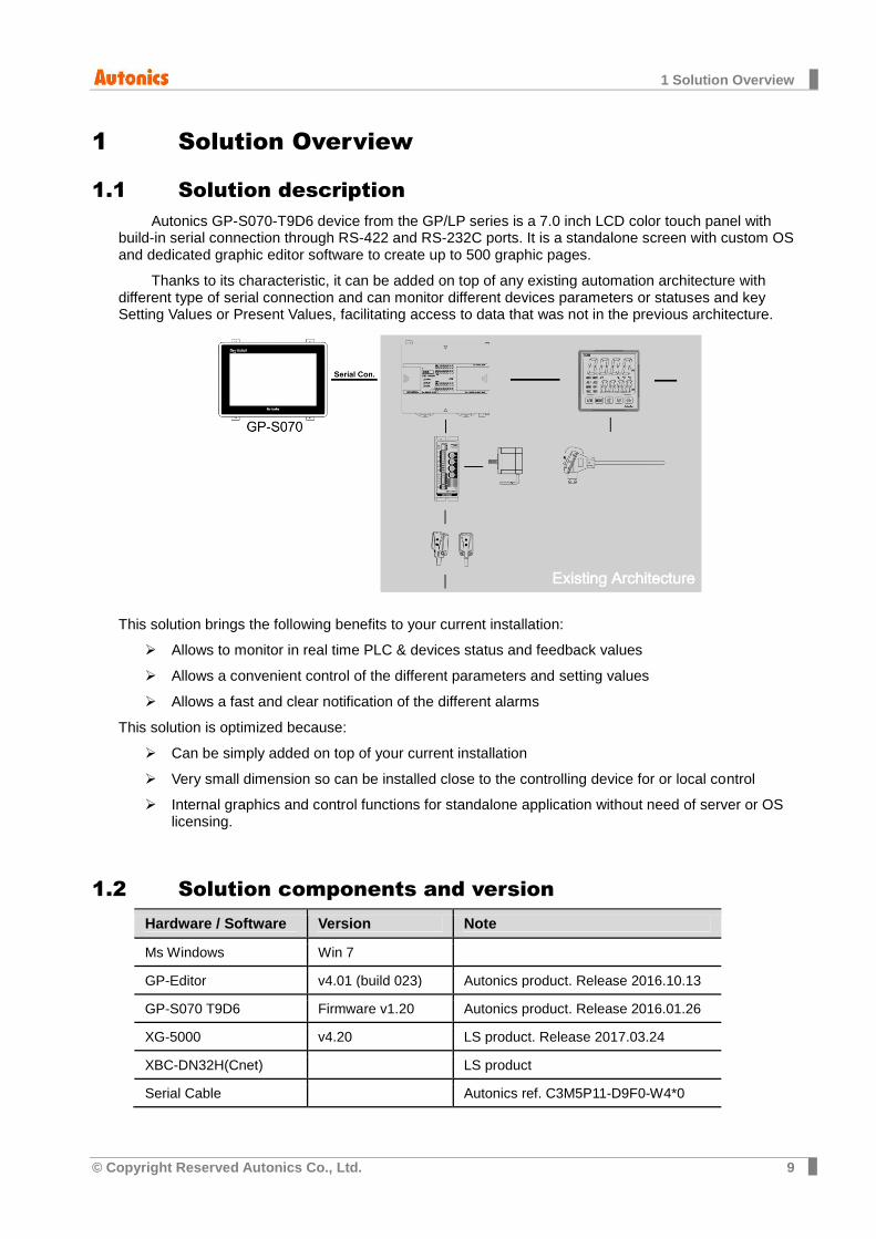
1.2 Solution components and version
Hardware / Software Version Note
Ms Windows Win 7
GP-Editor v4.01 (build 023) Autonics product. Release 2016.10.13
GP-S070 T9D6 Firmware v1.20 Autonics product. Release 2016.01.26
XG-5000 v4.20 LS product. Release 2017.03.24
XBC-DN32H(Cnet) LS product
Serial Cable Autonics ref. C3M5P11-D9F0-W4*0
1 Solution Overview
10 © Copyright Reserved Autonics Co., Ltd.
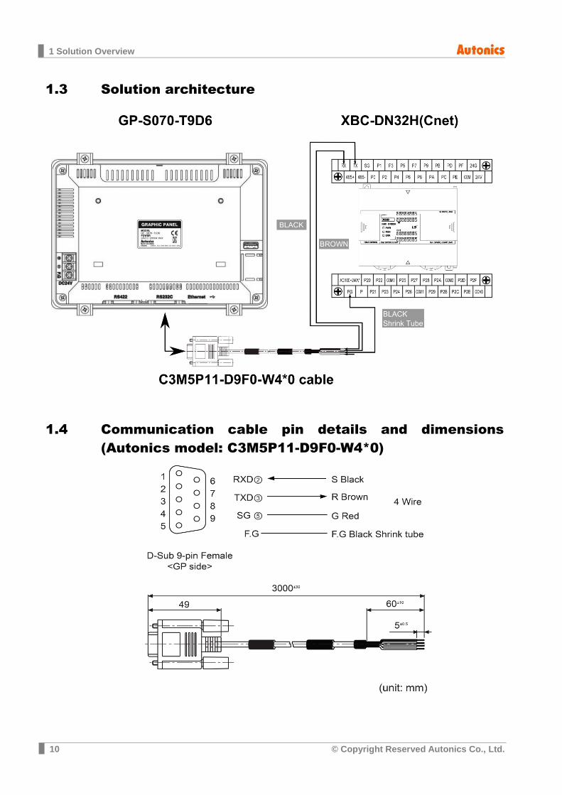
1.3 Solution architecture
1.4 Communication cable pin details and dimensions
(Autonics model: C3M5P11-D9F0-W4*0)

1 Solution Overview
© Copyright Reserved Autonics Co., Ltd. 11
2 GP-S070 Communication Settings
12 © Copyright Reserved Autonics Co., Ltd.
2 GP-S070 Communication Settings
The GP device should be set to use its RS232C port and to control data registers of a XBC type device.
So we need:
- to create a GP-Editor project with XBC connection and different graphical components to interact with the XBC registers
- to set communication parameters of the GP device to allow a connection with the PC and GP-Editor
- to send the GP-Editor project to the GP device
- to check the serial communication settings of the GP connection with the XBC PLC.
Remarks: In this document, we will use an Ethernet connection to download the GP-Editor project to the GP
device, please refer to the ‘GP-Editor Download Manual’ if you want to use another method (serial connection or USB connection).
2 GP-S070 Communication Settings
© Copyright Reserved Autonics Co., Ltd. 13
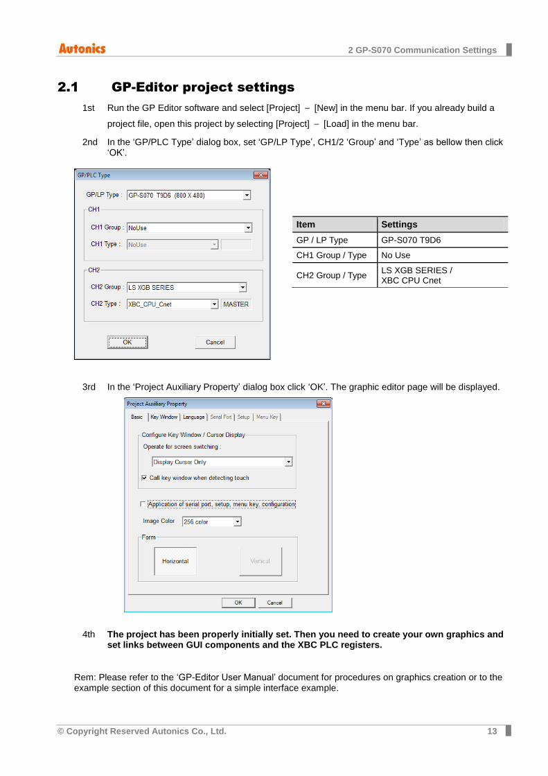
2.1 GP-Editor project settings
Run the GP Editor software and select [Project] – [New] in the menu bar. If you already build a 1st
project file, open this project by selecting [Project] – [Load] in the menu bar.
In the ‘GP/PLC Type’ dialog box, set ‘GP/LP Type’, CH1/2 ‘Group’ and ‘Type’ as bellow then click 2nd‘OK’.
In the ‘Project Auxiliary Property’ dialog box click ‘OK’. The graphic editor page will be displayed. 3rd
The project has been properly initially set. Then you need to create your own graphics and 4thset links between GUI components and the XBC PLC registers.
Rem: Please refer to the ‘GP-Editor User Manual’ document for procedures on graphics creation or to the example section of this document for a simple interface example.
Item Settings
GP / LP Type GP-S070 T9D6
CH1 Group / Type No Use
CH2 Group / Type LS XGB SERIES / XBC CPU Cnet
2 GP-S070 Communication Settings
14 © Copyright Reserved Autonics Co., Ltd.
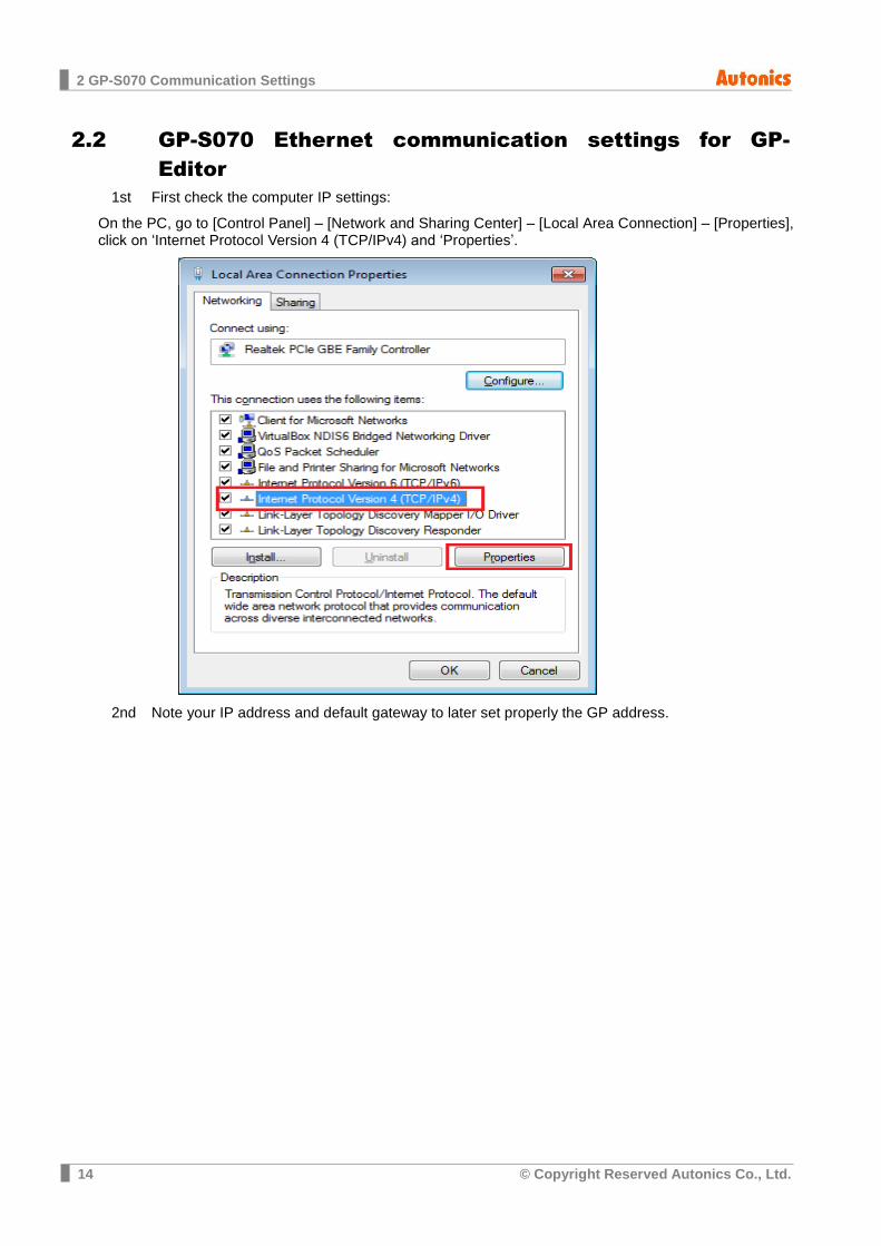
2.2 GP-S070 Ethernet communication settings for GP-
Editor
First check the computer IP settings: 1st
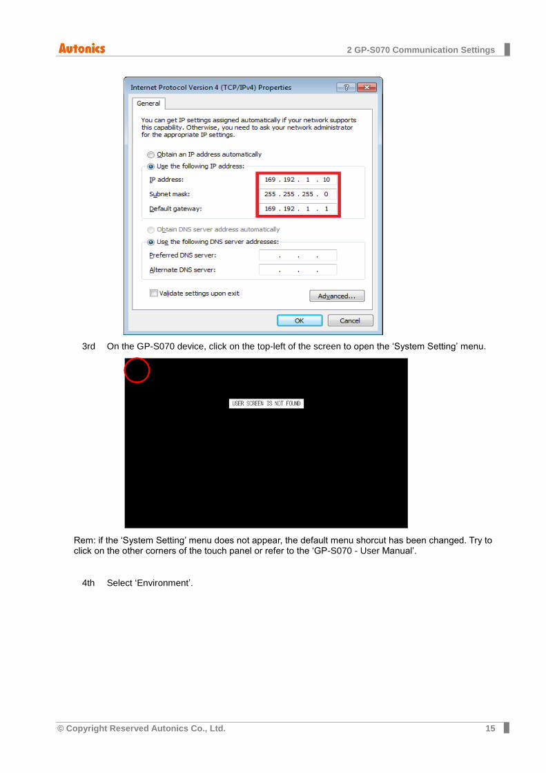
On the PC, go to [Control Panel] – [Network and Sharing Center] – [Local Area Connection] – [Properties], click on ‘Internet Protocol Version 4 (TCP/IPv4) and ‘Properties’.
Note your IP address and default gateway to later set properly the GP address. 2nd
2 GP-S070 Communication Settings
© Copyright Reserved Autonics Co., Ltd. 15
On the GP-S070 device, click on the top-left of the screen to open the ‘System Setting’ menu. 3rd
Rem: if the ‘System Setting’ menu does not appear, the default menu shorcut has been changed. Try to click on the other corners of the touch panel or refer to the ‘GP-S070 - User Manual’.
Select ‘Environment’. 4th

2 GP-S070 Communication Settings
16 © Copyright Reserved Autonics Co., Ltd.
Select ‘Local Ethernet’. 5th
Set the Ethernet settings as below: 6th
Items Settings Comment
IP Address 169.192.1.12 With last digit unique number on the network
Station 255.255.255.0 Same that the PC
Device 169.192.1.1 Same that the PC

2 GP-S070 Communication Settings
© Copyright Reserved Autonics Co., Ltd. 17
Click on ‘CLOSE’ to validate the changes. 7th
2 GP-S070 Communication Settings
18 © Copyright Reserved Autonics Co., Ltd.
2.3 Send GP-Editor project to GP-S070 device by Ethernet
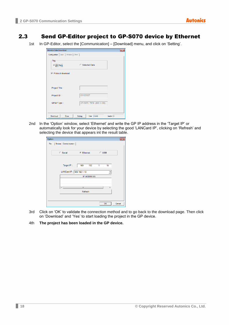
In GP-Editor, select the [Communication] – [Download] menu, and click on ‘Setting’. 1st
In the ‘Option’ window, select ‘Ethernet’ and write the GP IP address in the ‘Target IP’ or 2ndautomatically look for your device by selecting the good ‘LANCard IP’, clicking on ‘Refresh’ and selecting the device that appears int the result table.
Click on ‘OK’ to validate the connection method and to go back to the download page. Then click 3rdon ‘Download’ and ‘Yes’ to start loading the project in the GP device.
The project has been loaded in the GP device. 4th
2 GP-S070 Communication Settings
© Copyright Reserved Autonics Co., Ltd. 19
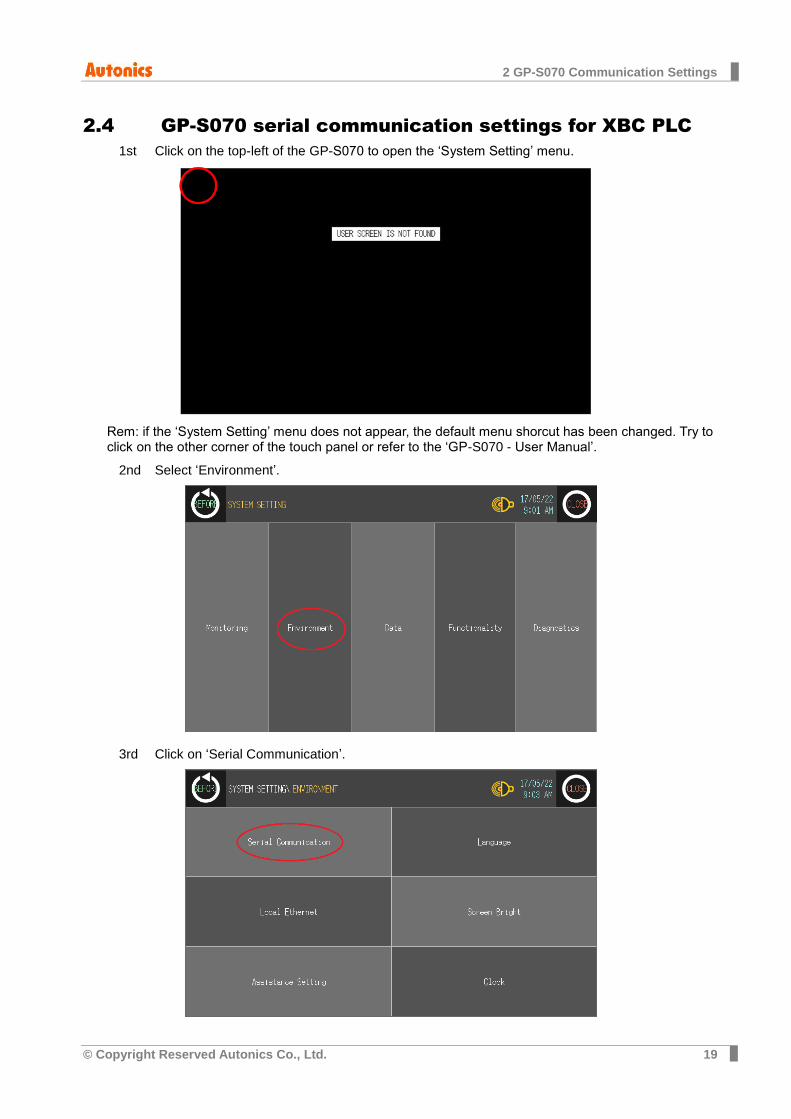
2.4 GP-S070 serial communication settings for XBC PLC
Click on the top-left of the GP-S070 to open the ‘System Setting’ menu. 1st
Rem: if the ‘System Setting’ menu does not appear, the default menu shorcut has been changed. Try to click on the other corner of the touch panel or refer to the ‘GP-S070 - User Manual’.
Select ‘Environment’. 2nd
Click on ‘Serial Communication’. 3rd
2 GP-S070 Communication Settings
20 © Copyright Reserved Autonics Co., Ltd.
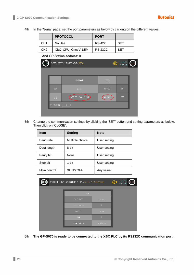
In the ‘Serial’ page, set the port parameters as below by clicking on the different values. 4th
PROTOCOL PORT
CH1 No Use RS-422 SET
CH2 XBC_CPU_Cnet V 1.5M RS-232C SET
And GP Station address: 0
Change the communication settings by clicking the ‘SET’ button and setting parameters as below. 5thThen click on ‘CLOSE’.
Item Setting Note
Baud rate Multiple choice User setting
Data length 8-bit User setting
Parity bit None User setting
Stop bit 1-bit User setting
Flow control XON/XOFF Any value
The GP-S070 is ready to be connected to the XBC PLC by its RS232C communication port. 6th

2 GP-S070 Communication Settings
© Copyright Reserved Autonics Co., Ltd. 21

3 XBC Project Settings
22 © Copyright Reserved Autonics Co., Ltd.
3 XBC Project Settings
Run XG5000 and select [Project] – [New Project] in the menu bar. Enter project name and 1st
select CPU type ‘XGB’-‘XGB-XBCH’ in the ‘New Project’ dialog box. Click ‘OK’.
In the project tree, under [Network Configuration] – [Unspecified Network], double-click on the 2nd
‘NewPLC [B0S0 Internal Cnet]’ device.
3 XBC Project Settings
© Copyright Reserved Autonics Co., Ltd. 23
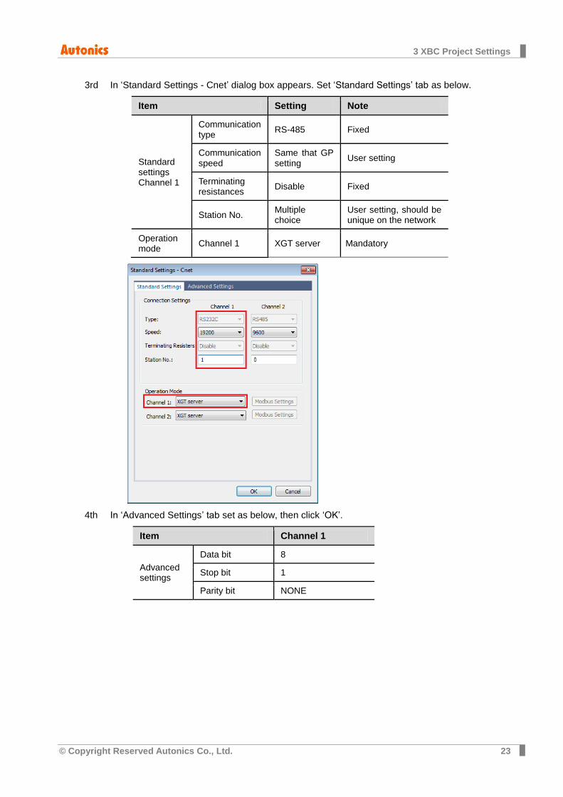
In ‘Standard Settings - Cnet’ dialog box appears. Set ‘Standard Settings’ tab as below. 3rd
Item Setting Note
Standard settings Channel 1
Communication type
RS-485 Fixed
Communication speed
Same that GP setting
User setting
Terminating resistances
Disable Fixed
Station No. Multiple choice
User setting, should be unique on the network
Operation mode
Channel 1 XGT server Mandatory
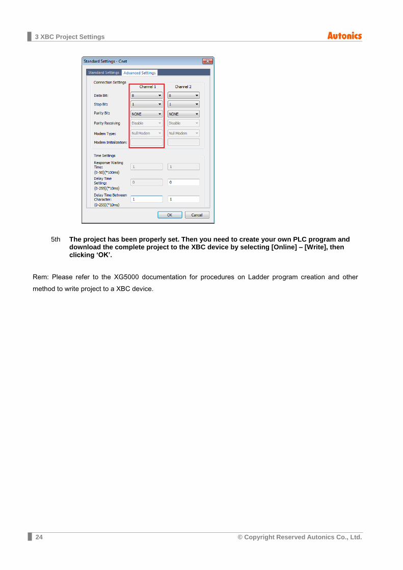
In ‘Advanced Settings’ tab set as below, then click ‘OK’. 4th
Item Channel 1
Advanced settings
Data bit 8
Stop bit 1
Parity bit NONE
3 XBC Project Settings
24 © Copyright Reserved Autonics Co., Ltd.
The project has been properly set. Then you need to create your own PLC program and 5th
download the complete project to the XBC device by selecting [Online] – [Write], then clicking ‘OK’.
Rem: Please refer to the XG5000 documentation for procedures on Ladder program creation and other
method to write project to a XBC device.

3 XBC Project Settings
© Copyright Reserved Autonics Co., Ltd. 25
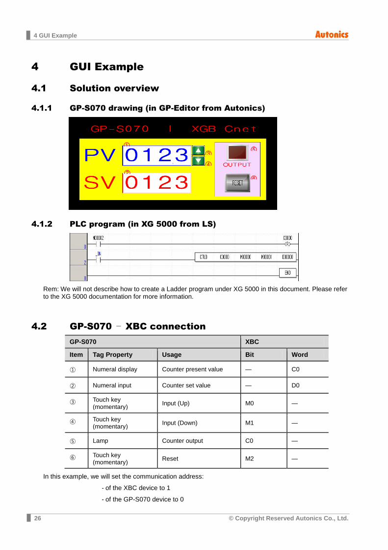
4 GUI Example
26 © Copyright Reserved Autonics Co., Ltd.
4 GUI Example
4.1 Solution overview
4.1.1 GP-S070 drawing (in GP-Editor from Autonics)
4.1.2 PLC program (in XG 5000 from LS)
Rem: We will not describe how to create a Ladder program under XG 5000 in this document. Please refer to the XG 5000 documentation for more information.
4.2 GP-S070 – XBC connection
GP-S070 XBC Item Tag Property Usage Bit Word
① Numeral display Counter present value — C0
② Numeral input Counter set value — D0
③ Touch key (momentary)
Input (Up) M0 —
④ Touch key (momentary)
Input (Down) M1 —
⑤ Lamp Counter output C0 —
⑥ Touch key (momentary)
Reset M2 —
In this example, we will set the communication address:
- of the XBC device to 1
- of the GP-S070 device to 0
⑥
④ ②
③ ①
⑤
4 GUI Example
© Copyright Reserved Autonics Co., Ltd. 27
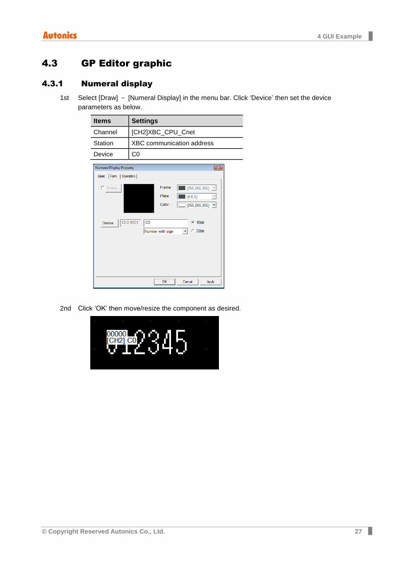
4.3 GP Editor graphic
4.3.1 Numeral display
Select [Draw] – [Numeral Display] in the menu bar. Click ‘Device’ then set the device 1st
parameters as below.
Items Settings
Channel [CH2]XBC_CPU_Cnet
Station XBC communication address
Device C0
Click ‘OK’ then move/resize the component as desired. 2nd
4 GUI Example
28 © Copyright Reserved Autonics Co., Ltd.
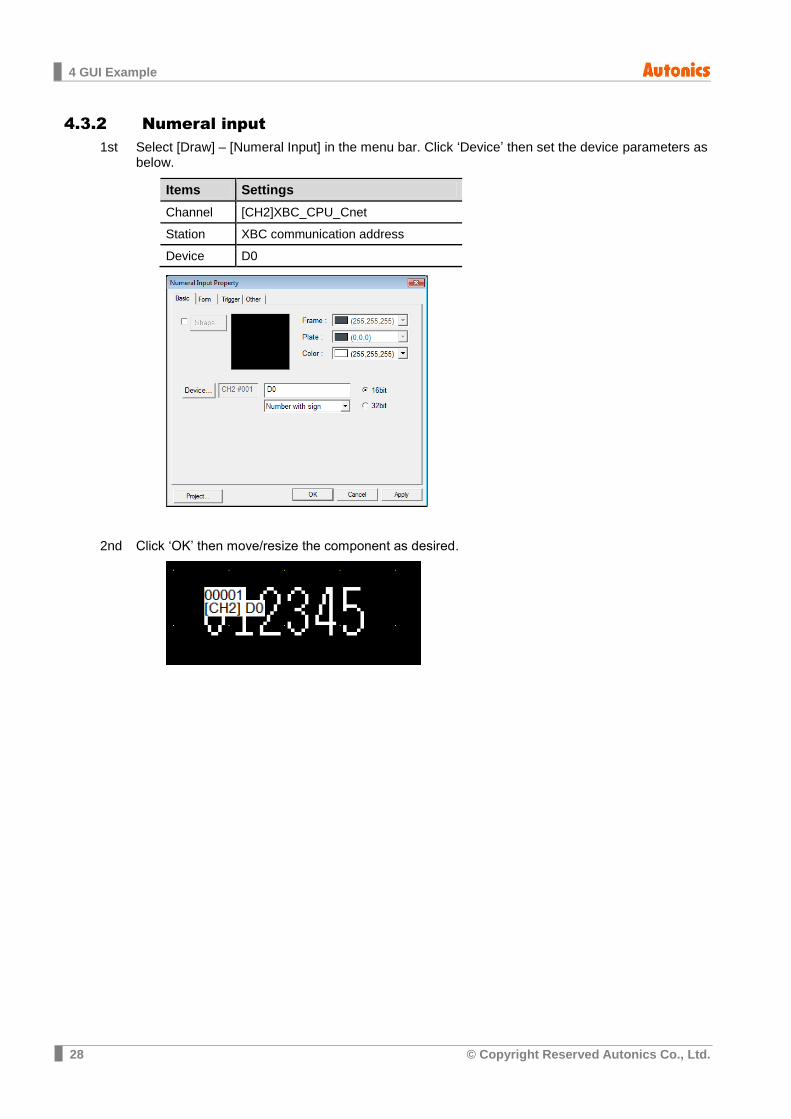
4.3.2 Numeral input
Select [Draw] – [Numeral Input] in the menu bar. Click ‘Device’ then set the device parameters as 1stbelow.
Items Settings
Channel [CH2]XBC_CPU_Cnet Station XBC communication address Device D0
Click ‘OK’ then move/resize the component as desired. 2nd
4 GUI Example
© Copyright Reserved Autonics Co., Ltd. 29
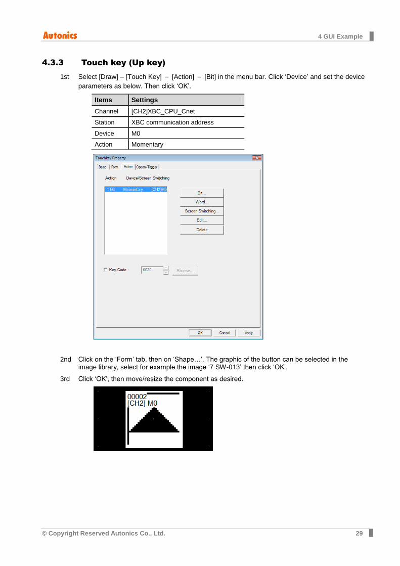
4.3.3 Touch key (Up key)
Select [Draw] – [Touch Key] – [Action] – [Bit] in the menu bar. Click ‘Device’ and set the device 1st
parameters as below. Then click ‘OK’.
Items Settings
Channel [CH2]XBC_CPU_Cnet
Station XBC communication address
Device M0
Action Momentary
Click on the ‘Form’ tab, then on ‘Shape…’. The graphic of the button can be selected in the 2ndimage library, select for example the image ‘7 SW-013’ then click ‘OK’.
Click ‘OK’, then move/resize the component as desired. 3rd
4 GUI Example
30 © Copyright Reserved Autonics Co., Ltd.
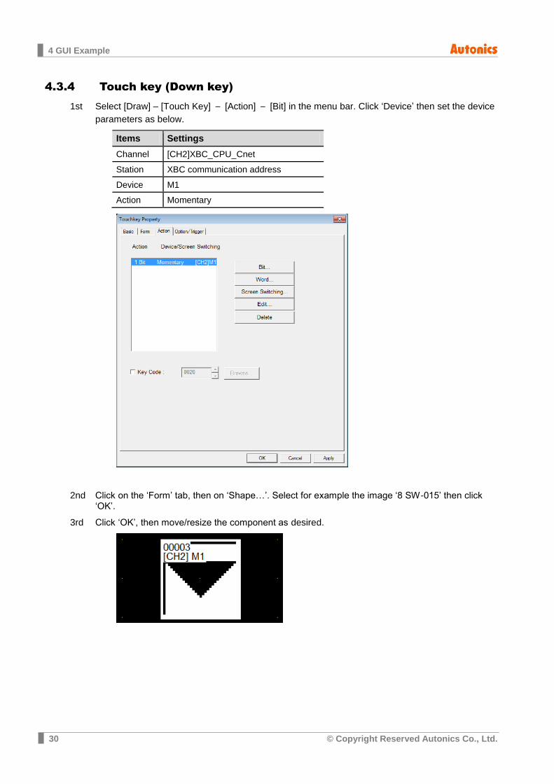
4.3.4 Touch key (Down key)
Select [Draw] – [Touch Key] – [Action] – [Bit] in the menu bar. Click ‘Device’ then set the device 1st
parameters as below.
Items Settings
Channel [CH2]XBC_CPU_Cnet
Station XBC communication address
Device M1
Action Momentary
Click on the ‘Form’ tab, then on ‘Shape…’. Select for example the image ‘8 SW-015’ then click 2nd‘OK’.
Click ‘OK’, then move/resize the component as desired. 3rd
4 GUI Example
© Copyright Reserved Autonics Co., Ltd. 31
4.3.5 Lamp
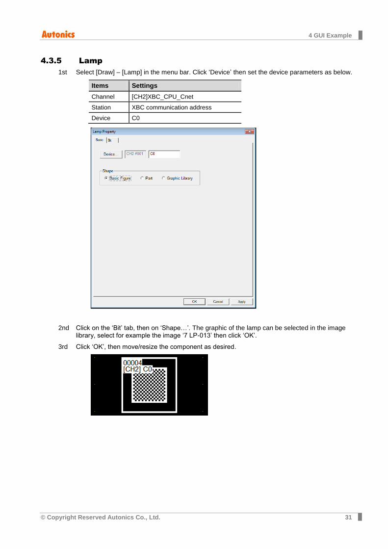
Select [Draw] – [Lamp] in the menu bar. Click ‘Device’ then set the device parameters as below. 1st
Items Settings
Channel [CH2]XBC_CPU_Cnet
Station XBC communication address
Device C0
Click on the ‘Bit’ tab, then on ‘Shape…’. The graphic of the lamp can be selected in the image 2ndlibrary, select for example the image ‘7 LP-013’ then click ‘OK’.
Click ‘OK’, then move/resize the component as desired. 3rd
4 GUI Example
32 © Copyright Reserved Autonics Co., Ltd.
4.3.6 Touch key (Reset key)
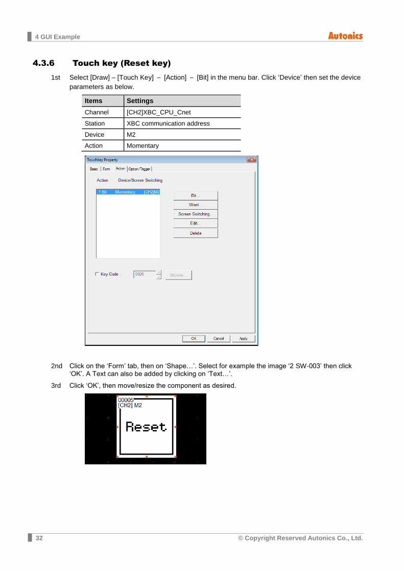
Select [Draw] – [Touch Key] – [Action] – [Bit] in the menu bar. Click ‘Device’ then set the device 1st
parameters as below.
Items Settings
Channel [CH2]XBC_CPU_Cnet
Station XBC communication address
Device M2
Action Momentary
Click on the ‘Form’ tab, then on ‘Shape…’. Select for example the image ‘2 SW-003’ then click 2nd‘OK’. A Text can also be added by clicking on ‘Text…’.
Click ‘OK’, then move/resize the component as desired. 3rd
4 GUI Example
© Copyright Reserved Autonics Co., Ltd. 33
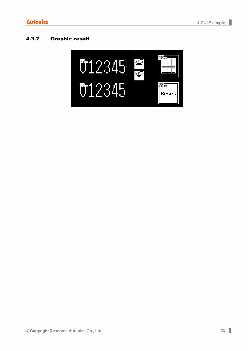
4.3.7 Graphic result

4 GUI Example
34 © Copyright Reserved Autonics Co., Ltd.
5 Appendix
© Copyright Reserved Autonics Co., Ltd. 35
5 Appendix
5.1 Serial communication settings
The serial communication parameters can be set in GP-Editor or directly on the GP device.
The following table shows which port can be set by using the 2 differents methods.
Item Setting in GP Editor
Setting in GP-S070 device
CH1 comm. setting Available Available
CH2 comm. setting Unavailable Available
5.1.1 Change CH1 communication settings in GP-Editor
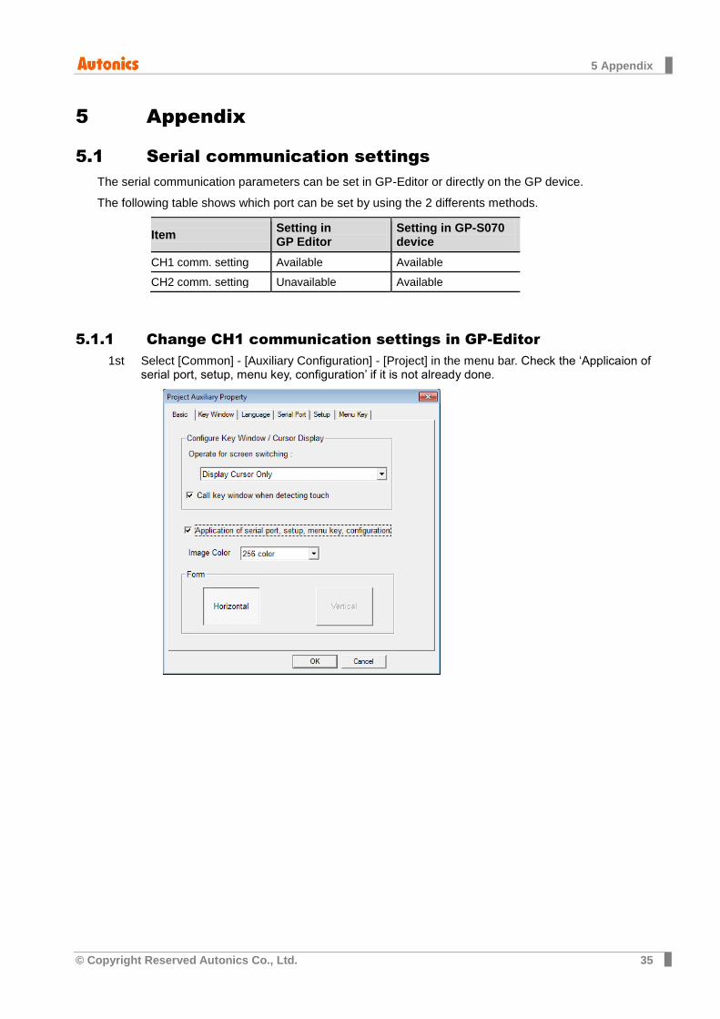
Select [Common] - [Auxiliary Configuration] - [Project] in the menu bar. Check the ‘Applicaion of 1stserial port, setup, menu key, configuration’ if it is not already done.
5 Appendix
36 © Copyright Reserved Autonics Co., Ltd.
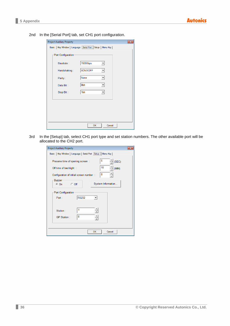
In the [Serial Port] tab, set CH1 port configuration. 2nd
In the [Setup] tab, select CH1 port type and set station numbers. The other available port will be 3rdallocated to the CH2 port.
5 Appendix
© Copyright Reserved Autonics Co., Ltd. 37
5.1.2 Change CH1/CH2 communication settings in the GP device
Please refer to the ‘2.4 GP-S070 communication settings’ procedure.
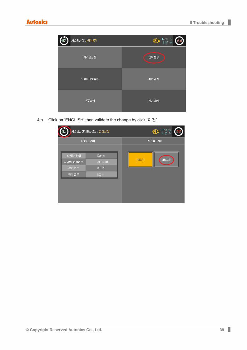
6 Troubleshooting
38 © Copyright Reserved Autonics Co., Ltd.
6 Troubleshooting
6.1 GP-S070: language settings
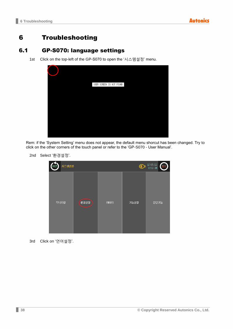
Click on the top-left of the GP-S070 to open the ‘시스템설정’ menu. 1st
Rem: if the ‘System Setting’ menu does not appear, the default menu shorcut has been changed. Try to click on the other corners of the touch panel or refer to the ‘GP-S070 - User Manual’.
Select ‘환경설정’. 2nd
Click on ‘언어설정’. 3rd
6 Troubleshooting
© Copyright Reserved Autonics Co., Ltd. 39
Click on ‘ENGLISH’ then validate the change by click ‘이전’. 4th

6 Troubleshooting
40 © Copyright Reserved Autonics Co., Ltd.