most- often - needed - world radio history
TRANSCRIPT
Most - Often - Needed
1964VOLUME TV -22
Televisions
$PRICE
Servicing Information
Compiled by
M. N. BEITMAN
SUPREME PUBLICATIONS

Most -often - Needed
1964Volume TV -22
Ie evisi nServicing Information
Compiled by
M. N. BEITMAN
SUPREME PUBLICATIONS
© by Supreme Publications, 1963. Material copyrighted, reproduction prohibited.
10MEO
9B
V-512 BY7A
CONNECTIN PLLAGACE r/p
OF VT VIAWHEN NEEDED
y -B5A55
: w°
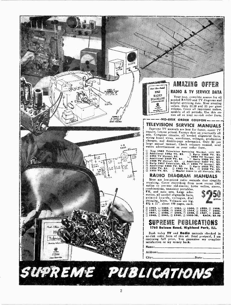
AMAZING OFFERRADIO & TV SERVICE DATA
Your best, complete source for allneeded RADIO and TV diagrams andhelpful servicing data. Most amazingvalues. Only $2.50 and $3 per giantvolume. Cover all important makes,models of all periods. Use this en-tire ad as your no -risk order form.
1------NO-RISK ORDER COUPON ----1TELEVISION SERVICE MANUALS
Supreme TV manuals are best for faster, easier TVrepairs. Lowest priced. Factory data on practically allsets. Complete circuits, all needed alignment facts,wiring board views, waveforms, voltages, productionchanges, and double -page schematics. Only $3 perlarge annual manual. Check volumes wanted, sendentire advertisement as your order form.
New 1963 Television Servicing Manual, only $3.Additional 1962 TV, $3. Early 1962 TV. $3.1961 TV Manual, $3. 1960 TV Manual. $3.Additional 1959 TV. $3. Early 1959 TV, $3.1958 TV Manual, $3. O Additional 1957 TV, $3.Early 1957 Television, $3. 0 1956 TV Manual. $3.Additional 1955 TV, $3. Early 1955 TV. $3.1954 TV, $3. 0 1953 TV, $3. 0 1952 TV, 53.1951 TV, $3. Master Index to all Manuals. 25.t
RADIO DIAGRAM MANUALSHere are low-priced radio manuals that simplify
repairing. Cover everything from most recent 1963radios to pre-war old-timers; home radios, stereo,combinationut transstor portables,FM, and auto sets. Large ache QTatnatics, all needed alignment facts,printed boards, voltages, dial 5ostringing, hints. Volumes are big,81/2 z 11", about 190 pages, each.O 1963, 0 1962, 0 1961, 0 1960, 0 1959, 0 1958,O 1957, 0 1956, 0 1955, 0 1954, 0 1953, 0 1952,. 1951, 0 1950, 0 1949, 0 1948, 0 1947, 0 1946,O 1942, 0 1941, 0 1940, 1926-38, EACH, $2.50
SUPREME PUBLICATIONS1760 Balsam Road, Highland Park, ILL.
Rush today TV and Radio manuals checked inno -risk order form of this ad. Send postpaid, I amenclosing full price. Yoh guarantee my completesatisfaction or my money back.Name
Address
City
2
VOLUME TV -22, MOST -OFTEN -NEEDED 1964 TELEVISION SERVICING INFORMATION
ADMIRALMODEL IDENTIFICATION CHART
Model Chassis Model Chassis Model Chassis
P9002C 16A4C P9009C 16A4C P9109C 16B4CUP9002C 16UA4C UP9009C 16UA4C UP9109C 16UB4CP9002D 16A4D P9009D 16A4D AA9100C 1684CUP9002D 16UA4D UP9009D 16UA4D AAU9100C 16UB4C
P9004C 16A4C P9100C 16B4C AA9900C 16A4C
UP9004C 16UA4C UP9100C 16UB4C AAU9900C 16UA4C
P9004D 16A4D P9101C 16B4C AA99000 16A4D
UP9004D 16UA4D UP9101C 16UB4C AAU9900D 16UA4D
P9005C 16A4C P9102C 16B4C AA9903C 16A4C
UP9005C 16UA4C UP9102C 16UB4C AAU9903C 16UA4CP9005D 16A4D P9103C 16B4C AA9903D 16A4D
UP9005D 16UA4D UP9103C 16UB4C AAU9903D 16UA4D
Model Chassis
PS9002PS9004PS9005PS9009
SAA9900SAA9903SAA9913
16F4U16F4U16F4U16F4U16F4U16F4U16F4U
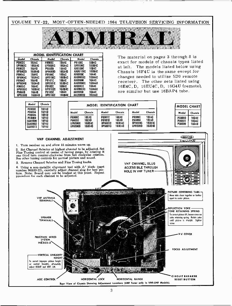
The material on pages 3 through 8 isexact for models of chassis types listedat left. The models listed below usingChassis 16F4U is the same except forchanges needed to utilize 5D9 remotereceiver. The other sets listed using16E4C, D, 16EU4C,D, 16G4U (remote),are similar but use 16BAP4 tube.
MODEL IDENTIFICATION CHART
Model Chassis Model Chassis Model Chassis
P6000CP6000DUP6000CUP6000D
16E4C16E4D16UE4C16UE4D
P6001CP6001DUP6001CUP6001D
16E4C16E4D16UE4C16UE4D
P6009CP6009DUP6009CUP6009D
16E4C16E4D16UE4C16UE4D
VHF CHANNEL ADJUSTMENT
1. Turn receiver on and allow 15 minutes warm up.2. Set Channel Selector at highest channel to be adjusted. SetFine Tuning control at center of tuning rotating itone third turn counter -clockwise from full clockwise rotation.See other tuning controls for normal picture and sound.3. Remove Channel Selector and Fine Tuning knobs.4. Using a non-metallic alignment tool with" blade (partnumber 98B30-22), carefully adjust channel slug for best pic-ture. Note: Sound may not be loudest at this point. Repeatprocedure .for each channel to be adjusted.
VHF ANTENNATERMINALS
SPEAKERTERMINALS
PRECISION WIREDSYSTEM
14E353-2
VERTICAL LINEARITYHEIGHT
To correct improper picture height
or vertical linearity, alternately
adjust HEIGHT and VERT. LIN.
AGC CONTROL
MODEL CHART
Model Chassis
PS6000 166411PS6001 1664UPS6009 16G4Ú
DELUXE
VHF CHANNEL SLUGACCESSIBLE THROUGHHOLE IN VHF TUNER
PICTURE CENTERING TABS -Move tabs closer together or farther
apart to center picture.
DEFLECTION YOKEYOKE RETAINING SPRING
To correct picture tilt, loosen screw on
yoke retaining spring. Rotate yoke
until picture is straight. Tighten
screw.
HORIZONTAL LOCK HORIZONTAL RANGE
Rear View of Chassis Showing Adjustment Locations (UHF Tuner only in VHF -UHF Models).
H V COVER
FOCUS ADJUSTMENT
CIRCUIT BREAKERRESET BUTTON
3
VOLUME TV -22, MOST -OFTEN -NEEDED 1964
ADMIRAL Chassis 16A4C, -D, 16UA4C, -D,
AGC CONTROL ADJUSTMENT
The AGC control is an AGC threshold control which is usedsolely to adjust the receiver for optimum operation under allsignal conditions.
Note: This control is set at the factory and will not normallyrequire field readjustment.
Improper AGC control adjustment can result in picturebending, tearing (overloading) or buzz in the sound. However,these same conditions can also be caused by other troubles inthe set.
If adjustment is required, it should be made exactly as in-structed.1. Turn set on and allow 15 minutes to warm up.2. Turn Channel Selector to strongest station in the area.3. Turn Contrast and Brightness controls fully to the right.4. Very slowly turn AGC control to the left, just to the pointwhere picture is weak (loses contrast).5. Adjust Horizontal Lock (at rear of set) and Vertical Holdcontrol (at side of set) for steady picture, without bending ofvertical lines at top of picture.6. Very slowly turn AGC control to the right, until picturejust begins to bend, tear, shift, or buzz is heard in sound. Thenvery slowly turn the AGC control to the left, to the point atwhich picture bending, tearing, shifting and buzz is removed.7. Make final adjustment by turning AGC control approxi-mately 10 degrees to the left.8. Recheck at maximum contrast on all channels. Pictureshould not overload and should reappear immediately afterchanging channels.
IMPORTANT: AGC adjustment should always be made onthe strongest TV station received.
HORIZONTAL LOCK ADJUSTMENT
Make adjustment if picture "slips sideways" or "tears"when switching channels. Adjustment is made by rotatingflexible shaft extending from rear of set. Adjust as follows:
1. Allow a few minutes for set to warm up. Tune in weakeststation, set Brightness and Contrast controls for normal Pic-ture. Important: Before proceeding, be sure that AGC controlhas been adjusted according to instructions in this manual.
2. Reduce Contrast to minimum. Very slowly turn HorizontalLock adjustment to the right or left until picture is in sync.Interrupt the television signal by switching Channel Selectoroff and on channel. Picture should remain in sync. If picturebends or loses sync, adjust the Horizontal Lock so that pictureremains in sync and bending of vertical lines does not appearat top of picture. Check adjustment on all channels; if neces-sary, repeat procedure.
IMPORTANT: If adjustment cannot be made using theHorizontal Lock control, it will be necessary to make Hori-zontal Range adjustment as instructed below.
HORIZONTAL RANGE ADJUSTMENT
The Horizontal Range control is set at the factory andseldom requires readjustment. Adjustment need only be madeif 6FQ7 tube (V403) has been replaced and the picture can-not be locked -in with the Horizontal Lock adjustment or ifthe Horizontal Lock adjustment has insufficient range (adjust-ment only possbile at extreme end rotation). Note: HorizontalRange adjustment is accessible after removing cabinet back.
Caution: Before proceeding with adjustment, be sure thatthe picture will sync vertically, as lack of both vertical andhorizontal sync indicates sync circuit trouble. Lack of onlyhorizontal sync generally indicates trouble in the horizontalsync (phase detector) circuit. Adjust as follows:
i
TELEVISION SERVICING INFORMATION
etc., Service Information, Continued
1. Remove cabinet back. Connect interlock cord.
2. Allow a few minutes for set to warm up. Tune in weakeststation, set Brightness and Contrast controls for a normalpicture. Important: Before proceeding, be sure that the AGCcontrol has been adjusted according to instructions in thismanual.3. Using a piece of hook-up wire, short test point "R" (junc-tion of R443, R444 and C417) to chassis ground. See figure Bfor test point locations.
4. Connect a .22 mf, 400 volt capacitor from test point "S"(junction of horizontal lock coil L401 and resistor R446,15,000 ohms) to chassis ground. Caution: To avoid B+ shock,turn receiver off when making this connection.
5. With picture in vertical sync, set Horizontal Range controlat point where picture is in horizontal sync and almost re-mains stationary with tendency to shift to left or right.
6. Remove the .22 mf capacitor from the horizontal lock coil.Set horizontal lock coil at point where picture is in horizontalsync and almost remains stationary with tendency to shift toleft or right.
7. Remove wire short from test point "R". Set Channel Selec-tor to weakest station. Switch Channel Selector on and offchannel, picture should remain in horizontal sync. If necessary,adjust horizontal lock coil slightly to bring picture in sync.
IMPROVING FOCUS
The picture tube of these receivers utilizes electrostaticfocus in connection with a three position focus adjustment.
For obtaining best overall sharpness of pictures, focus ad-justment should be checked at installation and when servicing.Once focus adjustment is properly made, no further need forreadjustment is required.
From rear view of chassis on front page, note that there arethree focus (pin) connections at bottom rear of chassis, pointsshown as "A", "B" and "C" on schematic. To make adjust-ment, connect plug-in focus lead to either of the three focuspins, whichever provides best focus at central area of picturetube. Important: Focus adjustment should be made with con-trols set for picture with normal contrast and brightness.
Caution: High B+ potential is present at focus terminals.
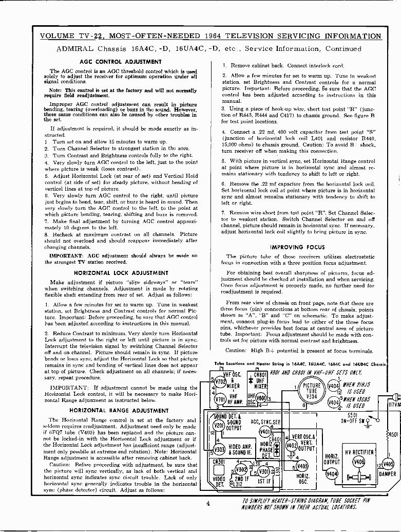
Tube Locations and Heater String in 16A4C, 16UA4C, 16B4C and 16UB4C Chassis
VHF OSC. ow ANC 08801 /N VI/11W ONLY.
& # UHF
MIXER MIXER
VHF UHF
RF AMP. OSC.
/SOUND DELSOUND AGC,SYNC.SEP.
OUTPUT AIw4
5
CR301
VIDEO
VET.
3
VIDEO AMP.
& SOUND IF.
CR40HORIZ
PHASE
L311 4
5Ip2ND IF 1ST IF
í'L312
11HEA' 21/15
12 IS USED
51YHEN 13085
/S USEO
HORIZ.
OUTPUT
HV RECTIFIER
DAM
117VM
R501
1
PER
4 TO S/NPL/FY HEATER-STN/NC DIAGRAM, TUBE SOCKET P/N
NUMBERS NOT SHOO IN THE/8 ACTUAL LOCATIONS.
VOLUME TV -22, MOST -OFTEN -NEEDED 1964 TELEVISION SERVICING INFORMATION
ADMIRAL Chassis 16A4C, -D, 16UA4C, -D, etc., Alignment InformationIF AMPLIFIER ALIGNMENT
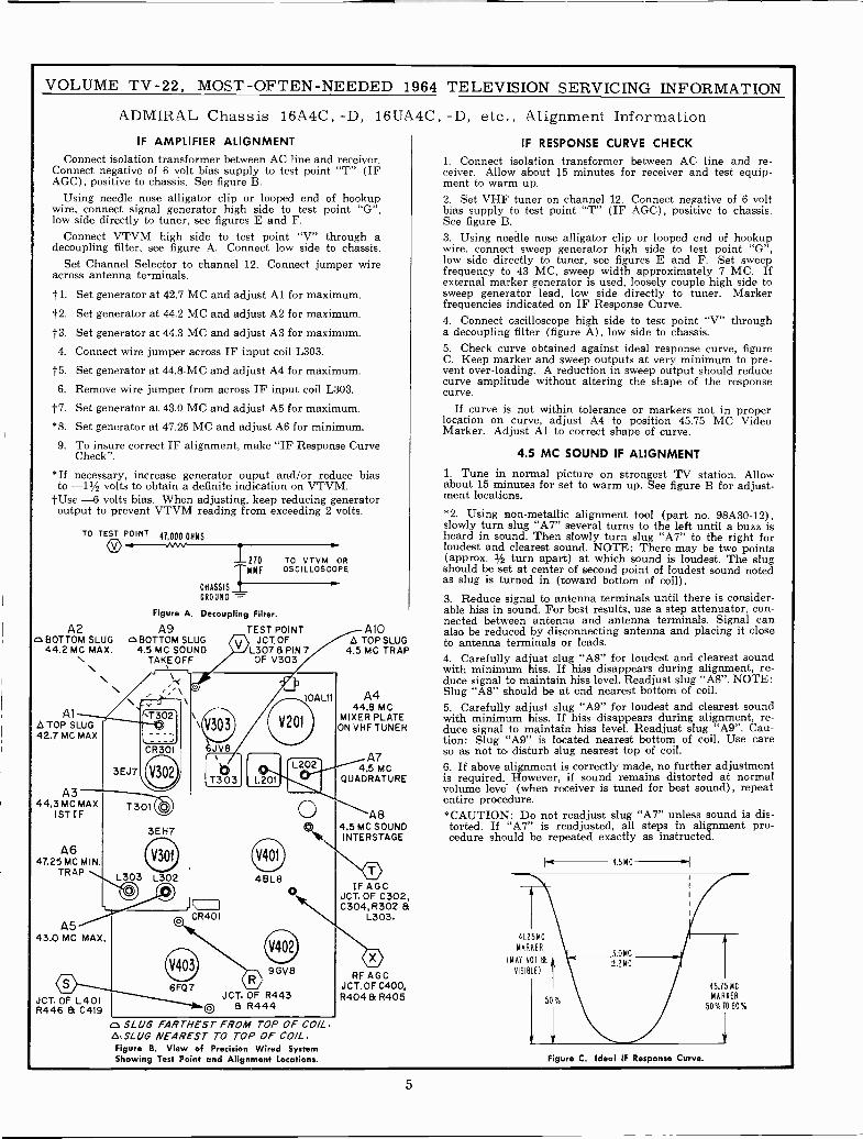
Connect isolation transformer between AC line and receiver.Connect negative of 6 volt bias supply to test point "T" (IFAGC), positive to chassis. See figure B.
Using needle nose alligator clip or looped end of hookupwire, connect signal generator high side to test point "G",low side directly to tuner, see figures E and F.
Connect VTVM high side to test point "V" through adecoupling filter, see figure A. Connect low side to chassis.
Set Channel Selector to channel 12. Connect jumper wireacross antenna terminals.
1-1. Set generator at 42.7 MC and adjust Al for maximum.
f2. Set generator at 44.2 MC and adjust A2 for maximum.
-1.3. Set generator at 44.3 MC and adjust A3 for maximum.
4. Connect wire jumper across IF input coil L303.
1t5. Set generator at 44.8 -MC and adjust A4 for maximum.
6. Remove wire jumper from across IF input coil L303.
1-7. Set generator at 43.0 MC and adjust A5 for maximum.
Set generator at 47.25 MC and adjust A6 for minimum.
9. To insure correct IF alignment, make "IF Response CurveCheck".
*If necessary, increase generator ouput and/or reduce biasto -11/2 volts to obtain a definite indication on VTVM.
f Use -6 volts bias. When adjusting, keep reducing generatoroutput to prevent VTVM reading from exceeding 2 volts.
*8.
TO TEST POINT 41,000 OHMS0
CHASSIS
GROUND -
Figure A. Decoupling Filter.
A2 A9o BOTTOM SLUG cs BOTTOM SLUG44.2 MC MAX. 4.5 MC SOUND
TAKEOFF
AlATOP SLUG42.7 MC MAX
A344,3 MC MAX
1ST IF
A647.25 MC MIN.
TRAP
\
oTEST POINTJCT. OF
L3078 PIN 7OF V303
\1302
CR301
3EJ7
T301 03EH7
oL303 L302
O
A543.0 MC MAX.
©JCT.OF L401R446 & C419
0
o6,1V8
IT303
1\1=1]CR401
6FQ7
V401
48L8O
o 9GV8
JCT, OF R4439 R444
10AL1t
CI SLUG FARTHEST FROM TOP OF COIL.A.SLUG NEAREST TO TOP OF COIL.Figure B. View of Precision Wired SystemShowing Test Point and Alignment Locations.
21O TO VTVM OROSCILLOSCOPE
410A TOP SLUG
4.5 MC TRAP
A444.8 MC
MIXER PLATEON VHF TUNER
A74,5 MC
QUADRATURE
A84.5 MC SOUNDI NTERSTAGE
eIFAGC
JCT. OF C302,C304,R302 &
L303.
oRF AGC
JCT.OF C400,R4048¡R405
IF RESPONSE CURVE CHECK
1. Connect isolation transformer between AC line and re-ceiver. Allow about 15 minutes for receiver and test equip-ment to warm up.2. Set VHF tuner on channel 12. Connect negative of 6 voltbias supply to test point "T" (IF AGC), positive to chassis.See figure B.3. Using needle nose alligator clip or looped end of hookupwire, connect sweep generator high side to test point "G",low side directly to tuner, see figures E and F. Set sweepfrequency to 43 MC, sweep width approximately 7 MC. Ifexternal marker generator is used, loosely couple high side tosweep generator lead, low side directly to tuner. Markerfrequencies indicated on IF Response Curve.4. Connect oscilloscope high side to test point "V" througha decoupling filter (figure A), low side to chassis.5. Check curve obtained against ideal response curve, figureC. Keep marker and sweep outputs at very minimum to pre-vent over -loading. A reduction in sweep output should reducecurve amplitude without altering the shape of the responsecurve.
If curve is not within tolerance or markers not in properlocation on curve, adjust A4 to position 45.75 MC VideoMarker. Adjust Al to correct shape of curve.
4.5 MC SOUND IF ALIGNMENT
1. Tune in normal picture on strongest TV station. Allowabout 15 minutes for set to warm up. See figure B for adjust-ment locations.
*2. Using non-metallic alignment tool (part no. 98A30-12),slowly turn slug "A7" several turns to the left until a buzz isheard in sound. Then slowly turn slug "A7" to the right forloudest and clearest sound. NOTE: There may be two points(approx. 1/2 turn apart) at which sound is loudest. The slugshould be set at center of second point of loudest sound notedas slug is turned in (toward bottom of coil).3. Reduce signal to antenna terminals until there is consider-able hiss in sound. For best results, use a step attenuator, con-nected between antenna and antenna terminals. Signal canalso be reduced by disconnecting antenna and placing it closeto antenna terminals or leads.4. Carefully adjust slug "A8" for loudest and clearest soundwith minimum hiss. If hiss disappears during alignment, re-duce signal to maintain hiss level. Readjust slug "A8". NOTE:Slug "AS" should be at end nearest bottom of coil.5. Carefully adjust slug "A9" for loudest and clearest soundwith minimum hiss. If hiss disappears during alignment, re-duce signal to maintain hiss level. Readjust slug "A9". Cau-tion: Slug "A9" is located nearest bottom of coil. Use careso as not to disturb slug nearest top of coil.6. If above alignment is correctly made, no further adjustmentis required. However, if sound remains distorted at normalvolume level (when receiver is tuned for best sound), repeatentire procedure.*CAUTION: Do not readjust slug "A7" unless sound is dis-torted. If "A7" is readjusted, all steps in alignment pro-cedure should be repeated exactly as instructed.
4I.2 5 M C
MARKER
(MAT NOT BE
VISIBLE)
4.5 MC ,.I
Figure C. Ideal IF Response Curve.
45.15 MC
MARKER
50%T0 60%
5
VOLUME TV -22, MOST -OFTEN -NEEDED 1964 TELEVISION SERVICING INFORMATION
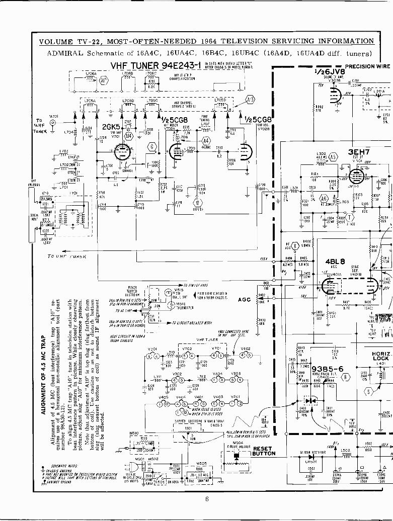
ADMIRAL Schematic of 16A4C, 16UA4C, 16B4C, 16UB4C (16A4D, 16UA4D diff. tuners)
VHF TUNER 94E243-1 INAF ERSETCHAWSSISORITH FIX
LETTER 'C'MODELNUMBER.r- -- ----
L706A L706B L706C
I
UHF ZFSTRIPCHAXNELi POSITION
M701ToUHF
TUNER. L704
L703rDaO
G701Á27
L702 C10Í
C702
ANTENNA
VHF 61028 27
L701
0710 7701
51.5MEG
0721
.0047 MF
1.500
L705Di
2 6.
- -1 A 1/25CG8 TUNING
2GK5 VHF MIKER L707..r>na V702A 0105 - -
L705A
VHF AMP
C704 V701
15
T C705GIMMICKC706
10ÓÁ5 -
0708=- 41I3.6
272R -J-C71T ¡) IC719
R101 R102- iN 1000 I
1000
1 1100- 41K 1.2R - 0I
I(ióáó Z ) IiÓÓÓ IiT6 O_ 11000+
¡1'q 2.2K
L708gs7 L709 44:814 Ci10
II
L J
To UHF TUNER
ry11.1
" V..º áwpw pco g
Gl w w pNÓÓ w 60btA~ m0Ñ w w
o
-'01
r,
Ca
aN;~wym-.1Ñ$
11, qwOw
Oy O
3S~Ood
1.>yS° Q wpp m
ODCe
Ñm caÓÑÑ
E1rNtti
w e a0 0 O 0
E..1 trl Z 1.-1.wAº'C. .ñ m 1
R501TAPPED I
LECTROHN I
Nall NUN10AIISETS-57.0 IN 1/UNIP 0NN/CAF3 I
T0 AC [/Nf
ala lN NUN 10 A I/ SETS I
Sin IN NUNIPONWWI
L705B L705C000
L_NSOI C/NCU/T IN TIM/6084 CHASSIS.
V301
1 820
TO PIN 10T 1405
M5I 51651F
DIAL LICHT
M516THERMISTER
C711
16.8
'PILOT LICHT CIRCUIT IN
1684 616184 CHASSIS.
TO CINCU/T811EAAfN M504.
VHF TUNER
i
1/25CG811VHF OSC
V7028
AGC
0/01 CONNECTED NENEIN RE- UNE SETS.
rV702L310
0323 Tí311820 11,000
L311V302
VHF CHANNELSTRIPS 2 THRU 13
072911000
L3120 5 000
C324 C325 C3261820 1820
V405 V404 V401
1V701 I V402
0© - 001728
000
304 V30300 00V403 V201
00 00_ 00 00 0000
M510r R510 I I
: 75 1.5M6',, I L -+ C57.004T iL. - - - - J r
M501 M502 I
14 I
1.SCHEMATIC NOTES.' íC501 - M505
1
CHASSIS WOAD TBÓÓv I0i
I L ----Ji PANT NOT NOUN7f0 ON PNEC/SION NINEO STSTfM 117 VAC 10510 i ¡ I 15 -u1.5 NEG.
4CAN/NfCNOUNDTW/TNSETT/NCOfCONTNO[S.
t5TNATTSLYI,KL OJOMR208 502 I(A041NFt1 ,,
N11EN 1JG85 /S USEN
rNNEN 2/1115 /S USED.
TAPPED LECTRONM 101604 h 181111
r - - - 1 CHASSIS.
1
R501 13
5 I
46a,POM/NNUNIOA/l SUS
IOWSSa.PSN/NNUNIZONN N./CNf
2 M504
i
l PRECISION WIRE1/26JV8
SOUND 3380 P Cool
7S1' 13 U.00INF
JSR
2
*20222K
02Ói - - - -L201Á
4.5 1 -5%
433.00 11C (a3
1ST IFv301 my
I:000-,0720 1
6301 L301 C303
O )ooa-{30 15 v5% $11301 5% p0 Í
1000 47,25NC1
18K
R`2
1001
040368K
i
i
CIRCUIT BREAKER RESETii I BUTTON
_C302
or Ci> R406Í
ACC
o
R414A "ow
8.2 NEC. 5.6 NEC.
8fP
83048.2K5%
830521
C)5
p 820
E C304 R302O1122MF 150K
IF ACC
-C401.001MF1 K
4BL 8ACC SYNC
R307
15K
R410
886
MY"
C203
825%.
I
111308220
V
/
-0402-- :0047
-'SrM. NMI- ..,.
> norR40T 0409
R408330
8.20 151100
110V
VERT.
70VHORIZT
If I(ijilÍ'¡'i
Mtl1\1
0440 Il
ZiÑKCIóü HORIZ.
E+15 1442 5% O K
¡3n3 g.
9385-6 lt4711 NORI2.PHASE DEi. ;9ÓÓ i dox
CR40 R ,ne 'II1* ~439 :443 444
680K 680A INEC
1D0% F 1010%01NF
51LIC0R RCTIFIERN CR501
0503
.001N1KV
1éVSOUi If!-9
_0420ON P
R502 myY
L502 1000
'00
Q 1,o
C5046 1sa4B C5040250NF 200NF 50NF200V 150V 1500
If
6
GMCM
, Yzo1B or .....4.....4 0Y - i 1 lilt n 0_-+ I 0200 i 110Y - -
I=S'6F .2 I 4205 C201 JI."I." 4704 18 - IL202 10041
0204 R2035 X
AZ0R201,
I
.001MF 3901- -- - _ J
F-- i420 1 C208560K 1.02MFC205
- .004iMF R204 TOBVBpOST-5.6K JCT Of 14551 (477
VOLUME TV -22, MOST -OFTEN -NEEDED 1964 TELEVISION SERVICING INFORMATION
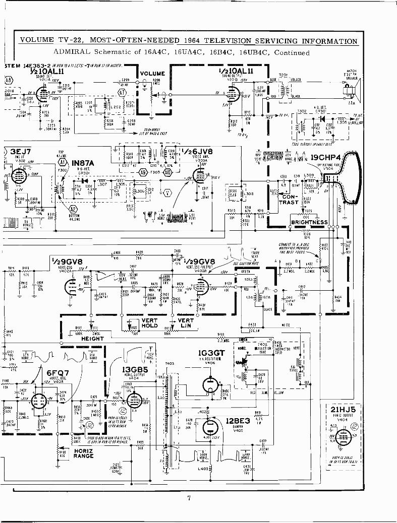
ADMIRAL Schematic of 16A4C, 16UA4C, 16B4C, 16UB4C, Continued
STEM 14E353-2 /NNUNI01/ISETS: -7/NNUNl10N Nl6NEN.
y210AL11 VOLUMEQ8
SOUND DELv2v2099,ay C209 n R208
C 210 .01914T.001 N F
3E3J7y 2NDwe
V302 my
01,2 8 /i BV
4309 1 C308 '
56
1.0047mF L-
310/01NF10%
_t._ ____ -
HÓRi2.
-4-
4311220
TOP
42.714
1302IN87A
VID. DET.
CR301
BOTTOM
44.2MC
r -1111 11 /26JV8I I47i "II Ie641y11
VIDEO AMP.1
jRUlOTS% 1{( j 5%I V303Y
I C317 47 +¡- C315 4.7,10% I 930L - - -( py }T 303
L3051 Í6382 I I =L306 4312
TI6X II
115.6
__--J L _--I43133.94
yy yypp y,IMIB 11' 3.5Y
LUJ" LUJ XORI2. Ii6'K(1i'mM3'4f
V- 54ERTT
8
.O1 M F
210 LA 11SOUND OUTPUT 1 T201
v20113 WY BLUE Í I BLACK
I62n Id I
.005 ME l I II_ I
1330 3,4KVRED I ¡ 'BLACK
+_ __ J
T302
A.4,%%, 145Y> 70 Pi 1---
474
/55
IW
VID. DET.CR301
C311 03124.7 6.85% 10%
M2013"K5" PM
SPEAKER
3.2n
1 TO J6T.
OfL305 11510,(30
LI-------T507 CIRCUIT /NEWT SETS
+
80VHOW./
C318 0319
0 IF -1
$5.64
-- 6.8 0.1
I`L1308 I'IR25RÍ71 ON-I_ -_J TRAST
R3184315 4,74 4319
;K 48 4.74R325 Lima BRIGHTNESS
71224 O B 00 0
19CHP4I
L309
424
114 PICTURE TUBE, iV304
OY
3
A414 4416
8447.N4,414
4446
154
R4492.2MEG.
C4231047MF
4!_ e
0410
'10% 1- /29GV8C407 VERT. OSO /O0TPUT
V402B Il
_v1,006
1/29GV8VERT.OSC
JIY NV4024
.pa2FVEAT.
NEC. C(5
4421 .0047NF2204
-r11Y1
-1-C415T041NF
rz~~li o ®I 4411 '6411
6804 2MEC.
HEIGHTO
6FQ7HORIZ, OSC.
1114 V403
r_ r_-1-1"1.11
IT 31440412.I
C425
.0047 NF
4453I ME6.
A460 334,1Ca26 Y404/S/JCBS
I KINSETS/WI -
4450
5% T 2 110HN/6HEN.
OEM 0_ A4fR459 C476/SB70/N1UN/011/SETS,
680K /SS60/N RIM /7OHH/CNEH. 4455
ÓONF
44251RV R428
"v...1004,IWC408 4427OOINFI 100414V
1W
4®R422
750
VERTHOLD
6412
i00
R436
82K
71344
-700R452
1106NORF.i
13GB540412.09iPUT
V40416460
O,iKV
10%
R451275X
150
6.71,2 J l/OY
HORIZRANGE
3,9
R454IK
3W
7403
1G3GTH.V.RECfIFIEi
V406
64.a:Ia
5.5ñ:lá
ij
)1
l7
7
78.80 L402
0428140
7.10 544
2
4,101 /854
4456
274IW.
/50V
4429
100
-4-15000VE7
SEE 001/011 NOTECR126n
REO
1.0
4430'220,1
-R326824
3
CONNECT TO 4,8 01 CYH/CNEYEN PNOY/OES
THE BEST FOCUS.
A4431 B 8432 C
2.1 NEC. 2.2 NEC.
TEL
:16.20 1C411O 4INF1KV
BLACK
HITE
C4(I 2
.047MFiKV
%,4**2 NE6. .6EM lo
ráozI BO/E. !REFLECTION
( } YOKE
I
1
Ibin
4458'114E6
VERTTHERMISTORCOLO
-B 293KV
RED BLUE
611 11 8ITOTAL 6
IBL
J5YELLOW
1 7
110413
R4334704 N4F
I1KV
A43556,8
S4434z 68K
1111111~Ela
461
12BE3DAMPER
V405
0430
caz71-.22NF
600VT
56K
2n
L
5008
s 'X0R 12.
L403
"- T1.4 KY
N0R12.
0431
i1"vT
.03341E1KV
r21HJ5 ¡HORIZ.OUTPUT
V404
0404 /S 7/H0/N SETS HUN 101 TI
-
7
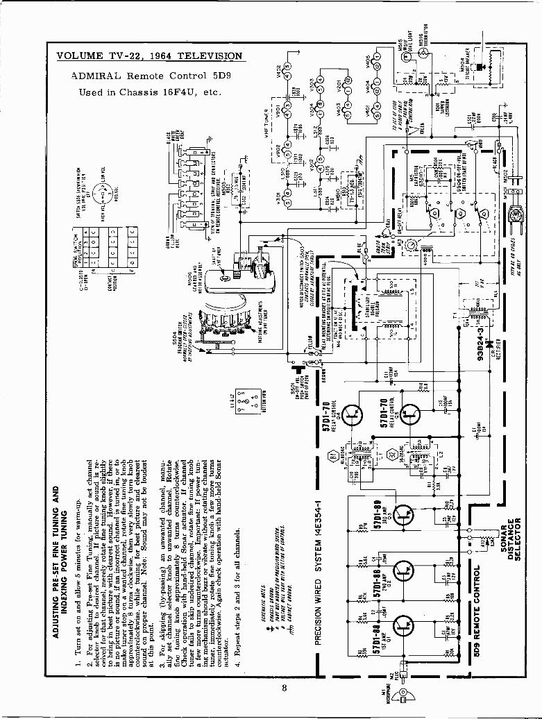
Cb
AD
JUS
TIN
G P
RE
-SE
T F
INE
TU
NIN
G A
ND
IND
EX
ING
PO
WE
R T
UN
ING
1.T
urn
set o
n an
d al
low
5 m
inut
es f
or w
arm
-up.
2.Fo
r ad
just
ing
Pre-
set F
ine
Tun
ing,
man
ually
set
cha
nnel
sele
ctor
kno
b to
des
ired
cha
nnel
.If
pic
ture
or
soun
d is
re-
ceiv
ed f
or th
at c
hann
el, m
erel
y ro
tate
fin
e tu
ning
kno
b sl
ight
lyto
bri
ng in
bes
t pic
ture
with
cle
ares
t sou
nd. H
owev
er, i
f th
ere
is n
o pi
ctur
e or
sou
nd, i
f an
inco
rrec
t cha
nnel
is tu
ned
in, o
r to
mak
e tu
ner
stop
on
a w
ante
d ch
anne
l, ro
tate
fin
e tu
ning
kno
bap
prox
imat
ely
8 tu
rns
cloc
kwis
e, th
en v
ery
slow
ly tu
rn k
nob
coun
terc
lock
wis
e, w
hile
tuni
ng f
or b
est p
ictu
re a
nd c
lear
est
soun
d on
pro
per
chan
nel.
Not
e: S
ound
may
not
be
loud
est
at th
is p
oint
.3.
For
ski
ppin
g (b
y-pa
ssin
g) a
n un
wan
ted
chan
nel,
man
u-al
ly s
et c
hann
el s
elec
tor
knob
to u
nwan
ted
chan
nel.
Rot
ate
fine
tuni
ng k
nob
appr
oxim
atel
y 8
turn
s co
unte
rclo
ckw
ise.
Che
ck o
pera
tion
with
han
d-he
ld S
onar
act
uato
r.If
cha
nnel
tune
r fa
ils to
ski
p un
desi
red
chan
nel,
rota
te f
ine
tuni
ng k
nob
a fe
w m
ore
turn
s co
unte
rclo
ckw
ise.
Im
port
ant:
If p
ower
tun-
ing
mec
hani
sm s
houl
d bu
zz o
r vi
brat
e w
ithou
t rot
atin
g ch
anne
ltu
ner,
imm
edia
tely
rot
ate
fine
tuni
ng k
nob
a fe
w m
ore
turn
sco
unte
rclo
ckw
ise.
Aga
in c
heck
ope
ratio
n w
ith h
and-
held
Son
arac
tuat
or.
4. R
epea
t ste
ps 2
and
3 f
or a
ll ch
anne
ls.
SC
NE
NA
7/C
107
f S.
CH
AS
SIS
0N
0UN
0f
Pill
tor
NO
UN
IEO
ON
PgE
CLS
/011
/019
MIE
N.
)W
OE
N/L
L M
AN
YN
/7N
SE
TI/N
OO
fCO
NLI
OLS
.Ir
k C
AB
/NE
T 6
701/
NO
.
r-P
RE
CIS
ION
WIR
ED
SY
ST
EM
14E
354-
1
i
M1
IM
ICR
OP
HO
NE
M2
PLU
G
1R2
33K 57
D1-
881S
T A
MP
01
RI
^MF
10K
IOV
.47
84¡
RS
R8
5.66
l 475
5.6K
C2 I -
-.57
D1-
88`(
--.0
5NF
2ND
AM
P.0
5MF
02
5D9
RE
MO
TE
CO
NT
RO
LO
8.55
SO
NA
Rim
~m
DIS
TA
NC
ES
ELE
CT
OR
¡27K 57
D1-
883R
O A
MP
38.2
5 C
3r-
.1
51:
R11
4 O
I10á
._
.V".
3.3
2i_r
KL2
LI 5
12
0 0 0
2g
3
40
0
BO
TT
OM
VIE
W 5501
giO
N -
OF
T -
VO
L.P
US
H S
WIT
CH
PA
RT
OF
RO
OD
57D
1-10
RE
LAY
CO
NT
RO
L04
57D
1-70
RE
LAY
CO
NT
RO
L05
C12
100M
F
55
C7
IOO
MF
15V
BR
OW
N
Cli
r100
MF
15V
S50
4P
RO
GR
AM
SW
ITC
H
1051
/111
. OP
EN
-C
LOS
ED
Sr
/MO
E//N
C10
11/S
7HIN
7S
II
o IND
EX
ING
AD
JUS
TM
EN
TS
ON
VH
F T
UN
ER
C -
CLO
SE
D0
-OP
EN
A
CO
NT
AC
T
PO
SIT
ION
S50
6 S
WIT
CH
PO
IY IO
N2
34
CC
C
c1Clc
o
o
BR
OW
N
Y[L
ION
8101
M50
6C
ER
A 8
0X A
NO
MO
TO
R A
SS
EM
BLY S
HA
FT
OF
VH
F T
UN
ER
-V
IEW
F T
ER
MIN
AL
ST
RIP
AN
D C
ON
NE
CT
OR
SO
N R
EM
OT
E C
ON
TR
OL
RE
CE
IVE
R.
I-
-Á5Ó35
: .T
57Í 5
NE
C.
1105
02 1
.104
7N
FI
_JT
TT
III
SW
ITC
H 5
506
SH
OW
N IN
HIG
H
VO
L 14
41 P
OS
ITIO
NO
FF
RIC
H Y
OO
L
BLA
CA
E
F-1
-1 r
17I r,
1-1-
11N
RA
Y
EE
M
..
45
67
1III
Ili1
0
MO
TO
R D
ISC
ON
NE
CT
SW
ITC
H S
503
-10
7746
75 N
ON
NA
LLr
OP
EN
,n
TE
LL
ON
CLO
SE
D IT
AIN
A/U
HE
TH
RU
ST
l3
RE
LA
Y M
OU
NT
ING
BR
AC
KE
T A
T W
V A
C P
OT
EN
IAL1
DE
PE
ND
ING
ON
PO
ITIO
N O
F A
C P
LUG
.
FUN
CT
ION
RE
LA
YM
4A
RIL
ME
CN
O.S
1 AI
I"1"
IBfI
ST
:1'
7'121
4I
DO
UB
LE
IF
UL
AU
M
II
1130
01Ip
eIS
I
l
i I
L5_
a
TI
rR,
9313
24-3
:54g
46oñ
LAU
I
I4
CR
IL
-r- --
L_J
RE
CT
IFIE
RB
LA.
rBLA
CK
O 7
M50
I M50
2III
YA
Cto
CY
CL
ES
It O
NLY
-
I BLU
E
Q
L311
000
C324
1820
=82
0M
510
iR
510
i
I75
-1.5
EC
-
.I
C51
01.0
047
j-77
L- - _ -
C32
5C
326
=82
0
11/0
70-
7fN
NS7N/P
,,,G
RA
YB
M3
0-OFFRELAY_
r --
--1
A50
3
VH
F T
UN
ER
1V
301
IV
902
V90
1I
00L3
'0I
0000
100
C32
3
1931
=82
011
000
V30
2
0929
TI0
00
00
L31-
0 V
© 0
V40
2
192810
00
304
V30
3
V40
3V
201
000®
V40
1V
404
V40
5
00 0
0 00
'70
1110
E C
10S
_i _
/ AU
O/0
CA
BLE
I
07}E
NO
NY
OL
I
24I
1C
ON
/NO
[N7L
B20
WII
68A
CA
PR
ÍST
OR
630R
0_7
CR
EE
NI
28
o31
20W
I
IIIG
SR
504
R50
14
tI
005
22K
TA
PP
ED
:5
cI
IME
I
LEC
TR
OX
X10W
l
a,T
_I 1
506
ON
-O
FF
-V
OL.
M50
4S
WIT
CH
6n1
C50
1C
IRC
UIT
BA
EA
KE
R
J22
MF
I611
1
ÍTE
6008
CiO M
F-F
---1
1.4.
OH
KV
M51
5#5
1FD
IAL
LIG
HT
M51
6_
TH
ER
MIS
TO
R
VOLUME TV -22, MOST -OFTEN -NEEDED 1964 TELEVISION SERVICING INFORMATION
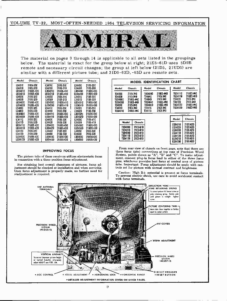
The material on pages 9 through 14 is applicable to all sets listed in the groupingsbelow. The material is exact for the group below at right; 21E5 -61D uses 5D9Bremote and necessary circuit changes; the group at left below (21D5, 21UD5) aresimilar with a different picture tube; and 21D5 -62D, -63D are remote sets.
Model Chassis Model Chassis Model Chassis
13401C 21D5 -32C 13421C 2105-31C 13449C 21D5 -33C134010 2105-320 134210 2105-310 134490 2105-33D103401C 211105-42C 1113421C 21U05 -41C LU3449C 21095-43CLU3401D 21095-420 1034210 21005-410 LU34490 21005-43013402C 2105-32C 13435C 2105-31C 13451C 2105-33CL34020 2105-320 134350 2105-31D 134510 2105330LU3402C 21UD5-42C LU3435C 21UD5-41C LU3451C 21005-43C1034020 21005-42D 1U34350 21005-410 1034510 21UD5-43D13403C 2105-32C 134411 2105-331 L3452C 2105-331L34030 2105-329 134410 2105-330 134520 2105-330LU3403C 21005-421 1034411 211105-431 LU3452C 21005-4311034030 21005-420 1113441D 21005-430 1034520 21005-43013411p 2105-32C 13442C 2105-33C L3455C 2105-41C134110 2105-32D 134420 2105-33D 134550 2105-41011134111 21005-421 LU3442C 21005-431 1034551 21005-431LU3411D 21005-420 103442D 21005-430 1034550 211105-43013412C 2105-32C 134451 2105-33C 13469C 2105-331L34120 2105-320 L3445D 2105-33D 134690 2105-330LU3412C 21005-421 1034451 211105-431 1034691 21UD5-43C1034120 21005-420 1034450 21005-430 1034699 21UD5-430
IMPROVING FOCUS
The picture tube of these receivers utilizes electrostatic focusin connection with a three position focus adjustment.
For obtaining best overall sharpness of pictures, focus ad-justment should be checked at installation and when servicing.Once focus adjustment is properly made, no further need forreadjustment is required.
VHF ANTENNATERMINALS
PRECISION WIREDSYSTEM
14E305-13.
VERTICAL LINEARITY
To correct improper picture heightor vertical linearity, alternatelyadjust HEIGHT and VERT. UN.
AGC CONTROL ADJUSTMENT
MODEL IDENTIFICATION CHART
Model Chassis Model Chassis Model Chassis
73400CT34009TU34001TU34000T3401C134010TU34011
21E5.31 -C
21E5-3402111E5 -44C
210E5-44121E5 -34C
21E5-34-021UE5-441
TÚ3401'0T3404CT3404DTU3404CTU34040134111T34110
210E5.41-021E5-34121E5.34021ÚE5 -44C
210E5-44021E5 -34C
21E5-390
10341111034110T3412C134120TU3412CTU34120
210E5.44C21UE5-44021E5 -31C
21E5-34021ÚE5.44C210E5.44D
Model Chassis
Model Chassis1534010 2105-62D
TS3400D 21E5 -61D 194020 21 D5-620TS3401D 21E5 -61D LS34030 21D5 -62DTS3404D 21E5-610 LS34110 2105-620TS3411D 21E5 -61D LS3412D 2105-620TS3412D 21E5 -61D LS3421D 2105-630
LS3435D 2105-630
From rear view of chassis on front page, note that there arethree focus (pin) connections at top rear of Precision WiredSystem, points shown as "A", "B" and "C". To make adjust-ment, connect plug-in focus lead to either of the three focuspins, whichever provides best focus at central area of picturetube. Important: Focus adjustment should be made with con-trols set for picture with normal contrast and brightness.
Caution: High B+ potential is present at focus terminals.To prevent electric shock, use care to avoid accidental contactwith focus terminals.
DEFLECTION YOKEYOKE RETAINING SPRING
To tarred picture tilt, loosen strew on
yoke retaining spring. Rotate yoke
until picture is straight. Tighten
svew.
PICTURE CENTERING TABSMove tabs closer together or farther
apart to tenter picture,
HV COVER
* WIDTH ADJUSTMENT
PRECISION WIREDSYSTEM
14E257-13
* HORIZONTALS*HORIZONTAL RANGE *RESET BUTTON
*DETAILED ADJUSTMENT INFORMATION GIVEN ON OTHER PAGES.
CIRCUIT BREAKER
9
VOLUME TV -22, MOST -OFTEN -NEEDED 1964 TELEVISION SERVICING INFORMATION
ADMIRAL Chassis Types 21D5++, 21E5++, 21ÚD5++, 21UE5++, Service Information
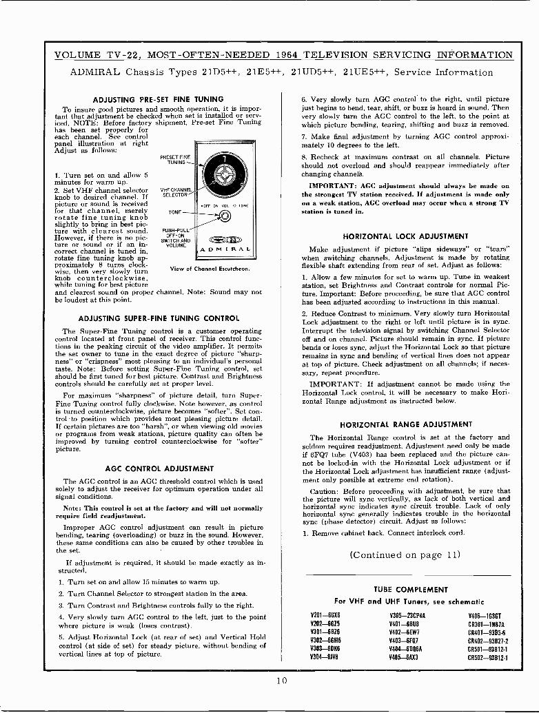
ADJUSTING PRE-SET FINE TUNING 6. Very slowly turn AGC control to the right, until pictureTo insure good pictures and smooth operation, it is impor- just begins to bend, tear, shift, or buzz is heard in sound. Then
tant that adjustment be checked when set is installed or serv- very slowly turn the AGC control to the left, to the point aticed. NOTE: Before factory shipment, Pre-sethas been set properly foreach channel. See control
Fine Tuning which picture bending, tearing, shifting and buzz is removed.
7. Make final adjustment by turning AGC control approxi-panel illustration at right mately 10 degrees to the left.Adjustas follows:
PRESET FINE----
--1
- 8. Recheck at maximum contrast on all channels. PictureTUNING should not overload and should reappear immediately after
1. Turn set on and allow 5 OINK changing channels.minutes for warm up -irNii
2. Set VHF channel selector VHF CHANNELIMPORTANT: AGC adjustment should always be made on
knob to desired channel. If SELECTOR ----- the strongest TV station received. If adjustment is made onlypicture or sound is received OFF ON VOL 0 TONE on a weak station, AGC overload may occur when a strong TVfor that channel, merely TONE station is tuned in.rotate fine tuning knobslightly to bring in best pic-ture with clearest sound. PUSH-PUL4
O
However, if there is no pic- SWITCH ANDture or sound or if an in- VOLUMEcorrect channel is tuned in,rotate fine tuning knob ap-
HORIZONTAL LOCK ADJUSTMENT
Make adjustment if picture "slips sideways" or "tears"when switching channels. Adjustment is made by rotating
~£aaADM IRAL
proximately 8 turns clock- flexible shaft extending from rear of set. Adjust as follows:wise, then very slowly turn View of Channel Escutcheon.
knob counterclockwise,while tuning for best picture
1. Allow a few minutes for set to warm up. Tune in weakeststation, set Brightness and Contrast controls for normal Pic -
and clearest sound on proper channel. Note: Sound may not tare. Important: Before proceeding, be sure that AGC controlbe loudest at this point- has been adjusted according to instructions in this manual.
ADJUSTING SUPER -FINE TUNING CONTROL2. Reduce Contrast to minimum. Very slowly turn HorizontalLock adjustment to the right or left until picture is in sync.
The Super -Fine Tuning control is a customer operating Interrupt the television signal by switching Channel Selectorcontrol located at front panel of receiver. This control func- off and on channel. Picture should remain in sync. If picturetions in the peaking circuit of the video amplifier. It permits bends or loses sync, adjust the Horizontal Lock so that picturethe set owner to tune in the exact degree of picture "sharp- remains in sync and bending of vertical lines does not appearness" or "crispness" most pleasing to an individual's personal at top of picture. Check adjustment on all channels; if neces-taste. Note: Before setting Super -Fine Tuning control, setshould be first tuned for best picture. Contrast and Brightness sary, repeat procedure.controls should be carefully set at proper level. IMPORTANT: If adjustment cannot be made using the
For maximum "sharpness" of picture detail, turn Super- Horizontal Lock control, it will be necessary to make Hori-Fine Tuning control fully clockwise. Note however, as control zontal Range adjustment as instructed below.is turned counterclockwise, picture becomes "softer". Set con-trol to position which provides most pleasing picture detail.If certain pictures are too "harsh", or when viewing old movies HORIZONTAL RANGE ADJUSTMENTor programs from weak stations, picture quality can often beimproved by turning control counterclockwise for "softer" The Horizontal Range control is set at the factory andpicture. seldom requires readjustment. Adjustment need only be made
if 6FQ7 tube (V403) has been replaced and the picture can-
CONTROL ADJUSTMENTbe locked -in with the Horizontal Lock adjustment or ifnotAGC
the Horizontal Lock adjustment has insufficient range (adjust -The AGC control is an AGC threshold control which is used ment only possible at extreme end rotation).
solely to adjust the receiver for optimum operation under all Caution: Before proceeding with adjustment, be sure thatsignal conditions- the picture will sync vertically, as lack of both vertical and
Note: This control is set at the factory and will not normally horizontal sync indicates sync circuit trouble. Lack of onlyrequire field readjustment. horizontal sync generally indicates trouble in the horizontal
sync (phase detector) circuit. Adjust as follows:Improper AGC control adjustment can result in picture
bending, tearing (overloading) or buzz in the sound. However,these same conditions can also be caused by other troubles inthe set.
1. Remove cabinet back. Connect interlock cord.
(Continued on page 11)If adjustment is required, it should be made exactly as in-
structed.
1. Turn set on and allow 15 minutes to warm up.
2. Turn Channel Selector to strongest station in the area. TUBE COMPLEMENT
3. Turn Contrast and Brightness controls fully to the right. For VHF and UHF Tuners, see schematic
4. Very slowly turn AGC control to the left, just to the point V201-6GX6 V305-23CP4A V406-1G3GT
where picture is weak (loses contrast). V202-6GZ5 V401 -6B116 CR301-1N67A
5. Adjust Horizontal Lock (at rear of set) and Vertical HoldV302-6126 V403-6FQ1 CR402-938276
control (at side of set) for steady picture, without bending ofV303-6DK6 V403--6FQ7 CR501-93922-2V303 -6D%6 V404-6DQ6A CR501-93812-1
vertical lines at top of picture. V304-6JV1 V405-6AX3 CR502-93612-1
10
VOLUME TV -22, MOST -OFTEN -NEEDED 1964 TELEVISION SERVICING INFORMATION
ADMIRAL Chassis Types 21D5, 21E5, 21UD5, 21UE5, Service Information, Continued
2. Allow a few minutes for set to warm up. Tune in weakeststation, set Brightness and Contrast controls for a normal pic-ture. Important: Before proceeding, be sure that the AGC con-trol has been adjusted according to instructions in this manual.
3. Using a piece of hook-up wire, short test point "R" (pin 2of V403, 6FQ7 tube) to chassis ground.4. Connect a .22 mf, 400 volt capacitor from test point "S"(junction of horizontal lock coil L401 and resistor R443, 12,000ohms) to chassis ground. Caution: To avoid B+ shock, turnreceiver off when making this connection.
5. With picture in vertical sync, set Horizontal Range controlat point where picture is in horizontal sync and almost re-mains stationary with tendency to shift to left or right.
6. Remove the .22 mf capacitor from the horizontal lock coil.Set horizontal lock coil at point where picture is in horizontalsync and almost remains stationary with tendency to shift toleft or right.7. Remove wire short from test point "R" (pin 2 of V403,6FQ7 tube).8. Set Channel Selector to weakest station. Switch ChannelSelector on and off channel, picture should remain in hori-zontal sync. If necessary, adjust horizontal lock coil slightlyto bring picture in sync.
WIDTH ADJUSTMENT
Width adjustment is made at the factory and generally doesnot require field adjustment. However, if raster is too wide(picture information is cut off) or if raster does not com-pletely fill viewing area of picture tube, adjust width asfollows:
1. Remove cabinet back. Connect interlock cord. Turn receiveron and allow a few minutes for warm up.2. Tune in channel with normal picture. Set brightness andcontrast controls to maximum (fully clockwise).3. Location of width adjustment (connector) lead is shown inRear View of chassis, front page. Note that there are twowidth (pin) connections at top rear of Precision Wired Sys-tem, shown as pins 1 and 2 on chassis and in schematic.
To reduce raster width, connect lead to pin 2. To increaseraster width, connect lead to pin 1.
Caution: High B+ potential is present at width adjustmentpin terminals. To prevent electric shock, use care to avoidaccidental contact with pin terminals.
V7o02*HFOSC
&
V902 MIXER
VóRDVHFV901
'CR301 VIDEO
DET i
1
4.5 MC SOUND IF ALIGNMENT
1. Tune in normal picture on strongest TV station. Allowabout 15 minutes for set to warm up. See figure B for adjust-ment locations.
*2. Using non-metallic alignment tool (part no. 98A30-12),slowly turn slug' "A9" several turns to left until a buzz isheard in sound. Then slowly turn slug "A9" to the right forloudest and clearest sound. NOTE: There may be two points(approx. 1/2 turn apart) at which sound is loudest. The slugshould be set at center off second point of loudest sound notedas slug is turned in (toward bottom of coil).
3. Reduce signal to antenna terminals until there is consider-able hiss in sound. For best results, use a step attenuator, con-nected between antenna and antenna terminals. Signal canalso be reduced by disconnecting antenna and placing it closeto antenna terminals or leads.
4. Carefully adjust slug "A10" for loudest and clearest soundwith minimum hiss. If hiss disappears during alignment, re-duce signal to maintain hiss level. Readjust slug "A10".NOTE: Slug "A10" should be at end of coil nearest bottomof coil.
5. Carefully adjust slug "All" for loudest and clearest soundwith minimum hiss. If hiss disappears during alignment, re-duce signal to maintain hiss level. Readjust slug "All". Cau-tion: Slug "All" is located nearest bottom of coil. Use careso as not to disturb slug nearest top of coil.6. If above alignment is correctly made, no further adjustmentis required. However, if sound remains distorted at normalvolume level (when receiver is tuned for best sound), repeatentire procedure.
* CAUTION: Do not readjust slug "A9" unless sound is dis-torted. If "A9" is readjusted, all steps in alignment pro-cedure should be repeated exactly as instructed.
ALIGNMENT OF 4.5 MC TRAP
Alignment of 4.5 MC (beat interference) trap "Al2" re-quires use of a hexagonal non-metallic alignment tool (partnumber 98A30-12).
To align 4.5 MC trap "Al2", tune in television station withbeat interference pattern in picture. While closely observingpicture, adjust slug "Al2" for minimum interference pattern.
Note that adjustment "Al2" is top slug (slug farthest frombottom of coil). Use caution so as not to disturb bottom slug(slug nearest bottom of coil) as sound IF alignment will beaffected.
UHF CONVERSION KIT AVAILABLE
UHF conversion kit is available for conversion of VHF onlymodels to receive all UHF channels. All necessary parts andcomplete instructions are included in the kit. No special toolsor brackets are required.
UHF MIXER 4801410 CAW /14//F-UNF SETS ONLY} CR801T # Y701 A10 4701 /1 SETS 1/TN SUFF/X LETTER C"
UHFOSC 'F 490/ 410 4902 /1 SETS f/T/ SUFF/X LETTER D"
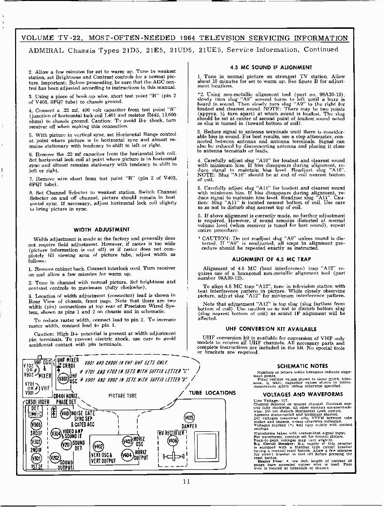
CR401 HORIZ, PICTURE TUBE/ TUBE LOCATIONS
PHASE DT\NOISE CATE
SYNC SEP
& GATED ACC
VIDEO AMP&SOUND IF
SOUND
DET
I I
I I
I I
NÓSC
O HóRlzVERT OUTPUT
404OUTPUT
VERT OSC fl
SCHEMATIC NOTESNumbers or letters inside hexagons Indicate align-
ment points.Fixed resistor values shown in ohms ±10% toler-
ance, 1 watt; capacitor values shown in micro-microfarads ±20% unless otherwise specified.
VOLTAGES AND WAVEFORMSLine Voltage: 117.Channel Selector on unused channel. Contrast con-trol fully clockwise, all other controls counterclock-wise. Do not disturb Horizontal Lock control.Antenna disconnected and terminals shorted.DC voltages measured with VTVM between tubesocket and chassis, unless otherwise indicated.Voltages marked (') will vary widely with controlsettings.Waveforms taken with transmitted signal input.For waveforms, controls set for normal picture.Peak -to -peak voltages may vary slightly.B+ Circuit Breaker: B+ supply of this receiveris equipped with a thermal type circuit breakerhaving a manual reset button. Allow a few minutesfor circuit breaker to cool off before pressing thereset button.
Heater Fuse: A one inch length of number 26gauge bare annealed copper wire is used. Fusewire is located at underside of chassis.
11
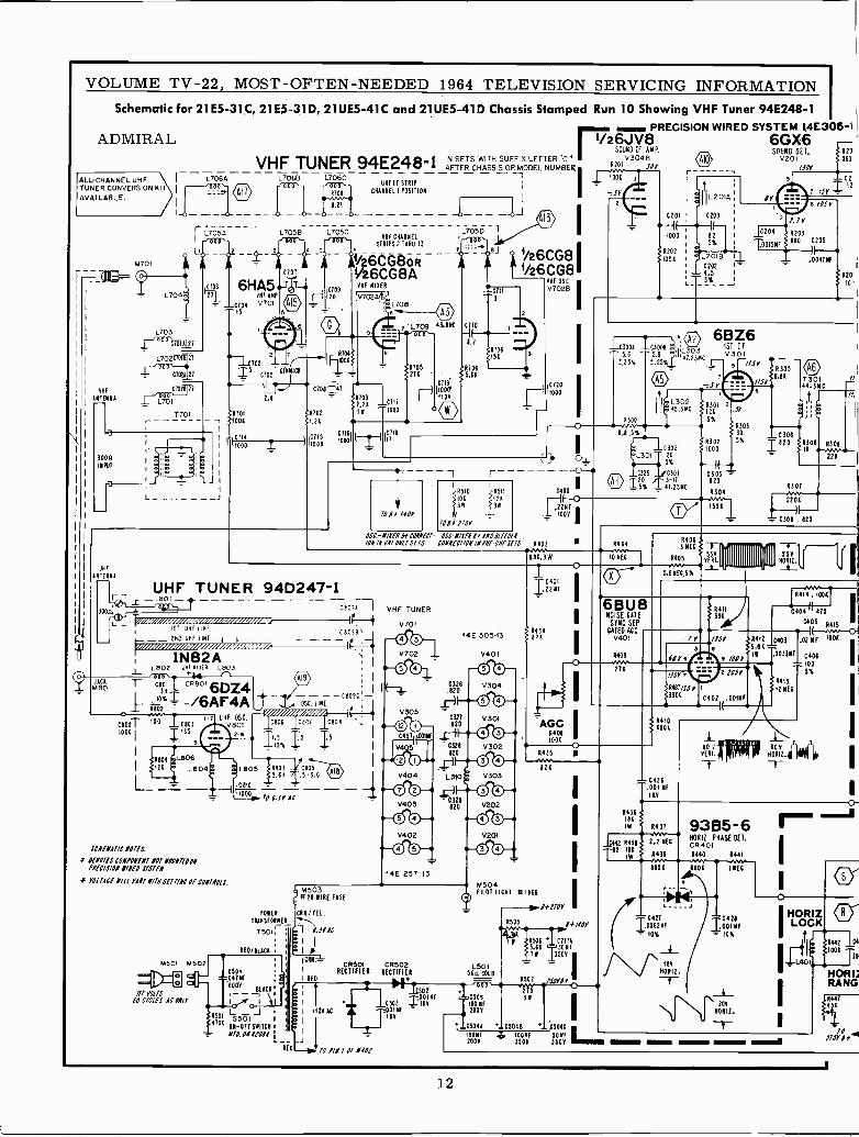
VOLUME TV -22, MOST-OFTEN-NEEDED 1964 TELEVISION SERVICING INFORMATIONSchematic for 21E5 -31C, 21E5 -31D, 21 UE5-41 C and 21 UE5-41 D Chassis Stamped Run 10 Showing VHF Tuner 94E248-1
PRECISION WIRED SYSTEM 14E305-11/26JV8 6GX6ADMIRAL
ALL -CHANNEL UHFTUNER CONVERSION KIAVAILABLE.
VHF
ANTENNA
1300nINPUT
UN O
ANTENNA
M701
L706A- -_ - L7060 L706C - - - - - - - - - - - - -1UHF IF STRIP
CHANNEL I POSITION
r L7052
C103
L704a1 I'27
L703r 000 C701A 27
L702C7018 27
C702A 27
029 21
L701
T701
L705B
-21
6HA5VMF AMP
V701
CTOT
L705CVHF CHANNEL-*MO
STRIPS 2 THRU 13
1i/26CG8oRt/z6CG8A
X709VHF MIXER
120 V702AIf.L7086s
z A701
I5702_ F-IIOOR
C7O5CINN CA
11 JC117
8701 '6702 ++ 1000
51001 f 1.21
11005040 Z (1%1050 iáóóllEIlIT e
UHF TUNERt1
1'1
JACAM801
ISO too UNE
_ _ 2MC IMF LINE -8 1_ _
1N82AL802 NN r'IiP L803
T 6eTl CAeol6L iO3` I -/6AF4A1 Al02
6w2T i00I '6e031000 I 135
R00
1281
Leo6
L804
L
7 UHF OSC.s/800
SCNfNeI/C N07fS.'
F OE107ESCONPONEN/ 107 1101472901PNEC/S/01 /LNfO S1S7EN.
>F YO1TA1f Y/LL nip N/7N 37-77/#1 Of CON74013.
M501 M502
//I YO/IS60 CYCLES AC OILY
C708T- 17
2.4
94D247 -I
t
L709 43.8
L7050 l
1.21706ISA
R705 R7062711 t 5,61
C718.r-)(IOOPI 110V
10 e'1I0Y
00,
I>R510
5101'3M
100r 1I0Y
8511
I2A:13111
SOUND OF AMP. 500/01VHF TUNER 94E248-1 IN SETS WITH SUFFIX LETTER "C0
AFTER CHASSIS OR MODEL NUMBER A201v3 JOYAb v201
/500I 1 fOÓ
- SY
t/26CG8 I1/26CG8
05C-N/1ENOfCONNECT- OSC.N/1fNe, ONO e1fE0fN/0N /N YNFONLT SITS. CONNfCT/01/ /NYNf-ONFSfTS.
C eC3. I VHF TUNER
v701
{P
I
I
C009C1 IFZ
OSC.LIRE
106 C0C7
I;o% IS I5
L805 1903 C8055.6A 5-3.0
10
Celt _-T06..IY AC --
PONER
TRANSFORMER
7501.
RE0/11.Á0A
05010/1NF
«600V BLACA.---r
M5031126 WIRE FUSE
CM/TEL.
I63YAC
ICRM.CR501 CR502
REO
RECTIFIER RECTIFIER
V305
14E 257-13
4501 L I 1
4
'II I 112Y AC AL
70S501 I
NAA)I
ON-OFf SNITCH A- 1/70.011P01.4--J
R 0 70 P/N 1 Of M(O7
;001
001C503f =5021AY
NO
IAYN
14E 30513
V401
O
éiáó
©
A A H IC321120
VHF OSC
V702B
C720
11000
6403
6.86.3W
i
-0328820
10
-0329820
R434821
M504PILOT LICHT A 1166
1.50150n COLO
C506
100NF2001
1504810011F
200V
AGCRONI°OA
0435
826
Ee>~110Y
1111-1110Y
11506 I C217A5.66 30Nf7N 350V
0502 truer
'7..0504B .. C504C100NF 501113506 3500
3
C201
1000
0202IOTA
C300Á 030065.6 5.6
0,25% _.25%_
rnv10 NEC.
6BU8NOISE CATE
SYNC SEPCOED ACC
V401
R409-211
IL201A
0203
IF -825%
L2018 11C202 '-4.5
47.25NC
45 ,3 MC
1204
6BZ61ST 1FV301
0305 =020
.0015NF
A20
560
CO
7 :SY
6 /05Y
8203680 C205
R305
22010,J
1501
1 - = C309 , 820
)004TNF
R405Mnr
5.6ME6,S
- C426.001110
SY
R436181
IW
CM2 R138-t82 186
I IW
8431
2.2 NEC
R439
I04270062NF
- 10%
1811
TAII.
T I J_
1 pIIIIIIIIIIIIIIIqillll
7 r 1/eor3._ 0
2 10SY
1120
10'
//i
N30e4NVMMH
221
i
l0404 ITO
CtlSA4Í--M%wo
R412 0403 02 NF 1001
5.06 --II .0033NF C406
..100
8413
12 NEC
80- V- MIT 60YPERT. HORA.T
93B5-640111 PHASE DET.CR4011440 1441.w6806 IOU
i
5%
R
6120I HOR Z a
001 NF LOCKI0x
11 A442 64Ij 106A ^¡9L4011
113
HORI;
IRANG0417
451
170Yef.4
12
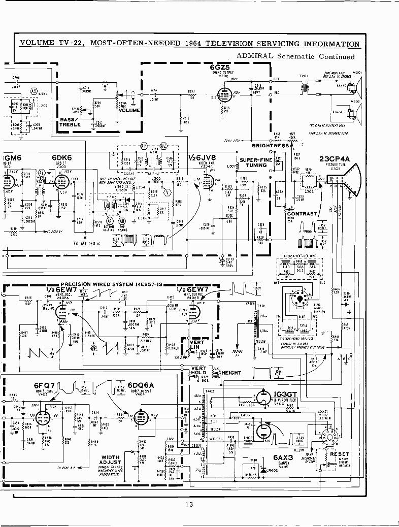
VOLUME TV -22, MOST -OFTEN -NEEDED 1964 TELEVISION SERVICING INFORMATION
ADMIRAL Schematic Continued
0208
.01MF
0'4.5
- ItIIL 202
5%
0207
r --J52065604
C209.041M1
i
621085 MEG
BASS/C212TREBLE =0033 MF
921043 MOG
VOLUME
VIM ~II 181~11 444. - -6GZ5
SOUND OUTPUT so.8E.mofosIS( 17201V 202
E
1'201 ONE 3.0. YC 57(44181
I4213
4212MEGI
iGM64D IF302
220
6DK63RD IFV303
JY
C309 6318 R3I3820 .005MF 150
431214
0312
1000
C313
820 E 4314 Ü 472 BOTTOM TOP
43.8 MC 42.011C
150
1007
4215220
O
-L.00SMF110Y 11.41411 o RED
I4336 R327
476 1004/OV+ ?IOY
BRIGHTNESSA
1/26JV8 SUPER -FINEVIDEO AMP.V304Á L3071, TUNING
L -CC307.47 - - -C317,4.7 - - - - 9801
1887 0811874. 817146E L305 4319 :1Y ---i 1008 6328
//TN SAKI IDEO DEI.150 \'
VIDEO T, tr.
4316-_76301_
2.261303
e}I IC I4.3Tlox
TO 8t- 140 v.3.56VERT.
y3156.8
10%
I IIIIII11 I
L306
3.56HORIZ.-9_
431726 '.
4318476
7r-..00321498
60 O
C320
.005 MF
43120
5.842W R323
4324476
R322
564
5.171
4416.w1506
3944176
.015 MF146.10%/i _j17
R I_ PRECISION WIRED SYSTEM 14E257-131/2 6EW71 OV
VE RT. OSC. VERT. . 64F117406 IM
V402Á L1486 111Y
a09=o0IMF
6416684
50V
C412
1507
C410
T039MF10%
94191.8 MEG
.0Í0F
8420NV,1006
4421
126
C41411R422
0021 MF,826I.
VERY
VERT._t_
4424
2.7 MEG
6423 -74138201
001MF
11/26EW7
C415VERT. OUTPUT '
V402B 185 V
.00681411.644 *-/8Y
2,5 ,..^
9
S 6425-2.2MECIf
2504 MIN:
Mal MIVERTLIN
i
4421 + C217C1500 ..18815000:1
II 6443126
6F Q7NORIZ. OSC.V403
I044333I.15Y
2
C431I.047MF
L
2430 4444
00221006
Mf
7006
507 C432
11*71,
94451100
%
IV820
9446226
-f-456
-\40R12.
44482055%
C433
I"'
10 150Y 84
C434
_ -- - e1304 12 -14.5MC
9315 C316 Í é 64311819006
5%7- I1 `5%T
I15V 6DQ6A,140612. HORIZ.OUTPUT- V404
6451
0047
64498_4
I504450IMEG
WIDTHADJUST
CONNECT 10 /087NH/7817!8 C/YES
7807181/0M8
-35Y5
-C-
115 Y
C436
.047MF
R45212638
64695.66
WW
2
7í0Y
6454
o
VERT 4429
HQLDR428 5 E300 4
174034324
5é
8,711
HEIGHT
CREE
251
f 6325 IC322
27
C324
41
326
336
63271006
<4332 9329, 4206 ,._156 .-
.--.Mv._ 8300V
-8-12.115L8-
L308-C323:22MF
CONTRASTR330256
i
12509
T
218.,
8.54RED ====L403
aBLUE
8.44 1 C443L 7
YE LLO39
3.64
4¿
GREEN
1806
44551504
44563306
R4532.2MEG
C4201.041MFI144
1.917:94
WHT.-TEL.
.274
2r
C439
.018MF1.666
5%
L402
III 111111
6.4n AC
180 0.84 YC 57(/.(85 0510
1008 3.1n VI 57(48(85 05(0
23CP4APICTURE TUBE
V305
2
14561101111._f_
1
VERT
456
1'402 AVERT. OE F. 206E
= 5 4460 8 =1
PLO
17401816 VIEW
REO
-T
i81143314 02B 4- 0- 412 0E1.206E 396
10 6
M202
R4641.56 C530
.04717E819
70.81167 10 4.8 086811/CHEYEI P101/OES 81571OCHS
H.Y. RECTIFIER
V406 4462
216 IW
C419.022 MF
10%
A
64314706
B C
SOCKET17402IOC VIEW
«wo
-3.769
H0612.
C440
40R466,í4
.5.4.857
6AX3DAMPER
=CR402V405
YELLOW r--70 //V
i
SECONOAVII'
Of 15111I -'1
RESET44505
VF,,,,CI6CUIT
""' 846Á4E6LO_ __I
13
VOLUME TV -22, MOST -OFTEN -NEEDED 1964 TELEVISION SERVICING INFORMATION
ADMIRAL Chassis Types 21D5, 21E5, 21UD5, 21UE5, Alignment Data, Continued
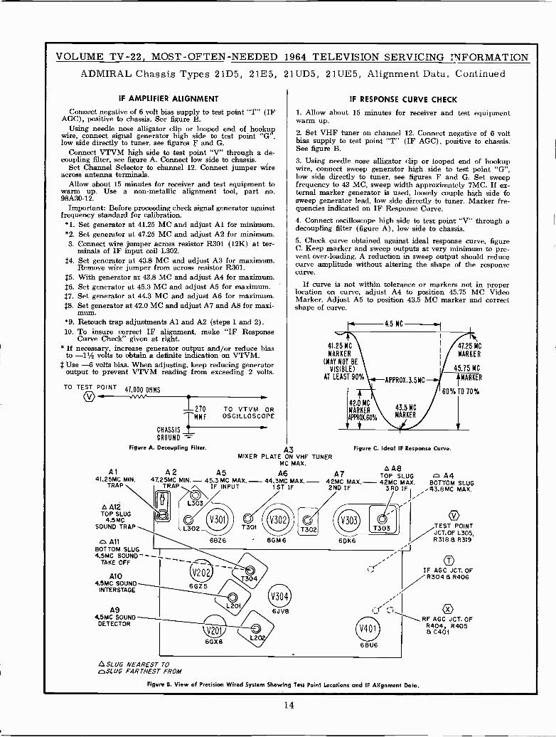
IF AMPLIFIER ALIGNMENT
Connect negative of 6 volt bias supply to test point "T" (IFAGC), positive to chassis. See figure B.
Using needle nose alligator clip or looped end of hookupwire, connect signal generator high side to test point "G",low side directly to tuner, see figures F and G.
Connect VTVM high side to test point "V" through a de -coupling filter, see figure A. Connect low side to chassis.
Set Channel Selector to channel 12. Connect jumper wireacross antenna terminals.
Allow about 15 minutes for receiver and test equipment towarm up. Use a non-metallic alignment tool, part no.98A30-12.
Important: Before proceeding check signal generator againstfrequency standard for calibration.*1. Set generator at 4L25 MC and adjust Al for minimum.*2. Set generator at 47.25 MC and adjust A2 for minimum.3. Connect wire jumper across resistor R301 (12K) at ter-
minals of IF input coil L302.$4. Set generator at 43.8 MC and adjust A3 for maximum.
Remove wire jumper from across resistor R301.$5. With generator at 43.8 MC and adjust A4 for maximum.$6. Set generator at 45.3 MC and adjust A5 for maximum.$7. Set generator at 44.3 MC and adjust A6 for maximum.$8. Set generator at 42.0 MC and adjust A7 and A8 for maxi-
mum.*9. Retouch trap adjustments Al and A2 (steps 1 and 2).10. To insure correct IF alignment, make "IF Response
Curve Check" given at right.* If necessary, increase generator output and/or reduce bias
to -11/2 volts to obtain a definite indication on VTVM.$ Use -6 volts bias. When adjusting, keep reducing generator
output to prevent VTVM reading from exceeding 2 volts.
TO TEST POINT47,000 OHMS
1270 TO VTVM OROSCILLOSCOPEIMMF
CHASSIS
GROUND =-
Figure A. Decoupling Filter.
Al A2 A541.25MC MIN. 47.25MC MIN.- 45.3 MC MAX
TRAP i TRAP n IF INPUT
á Al2TOP SLUG
4.5MCSOUND TRAP
o AllBOTTOM SLUG4.5MC SOUND--
TAKE OFF I
A104.5MC SOUND
INTERSTAGE
A94.5MC SOUND
DETECTOR
,,SLUG NEAREST TOc.SLUG FARTHEST FROM
UL302
6BZ6 6GM6
IF RESPONSE CURVE CHECK
1. Allow about 15 minutes for receiver and test equipmentwarm up.
2. Set VHF tuner on channel 12. Connect negative of 6 voltbias supply to test point "T" (IF AGC), positive to chassis.See figure B.
3. Using needle nose alligator clip or looped end of hookupwire, connect sweep generator high side to test point "G",low side directly to tuner, see figures F and G. Set sweepfrequency to 43 MC, sweep width approximately 7MC. If ex-ternal marker generator is used, loosely couple high side fosweep generator lead, low side directly to tuner. Marker fre-quencies indicated on IF Response Curve.4. Connect oscilloscope high side to test point "V" through adecoupling filter (figure A), low side to chassis.5. Check curve obtained against ideal response curve, figureC. Keep marker and sweep outputs at very minimum to pre-vent over -loading. A reduction in sweep output should reducecurve amplitude without altering the shape of the responsecurve.
If curve is not within tolerance or markers not in properlocation on curve, adjust A4 to position 45.75 MC VideoMarker. Adjust A5 to position 43.5 MC marker and correctshape of curve.
r«,-4.5 MC
41.25 MC
MARKER
(MAY NOT BEVISIBLE)
AT LEAST 90%
A3MIXER PLATE ON VHF TUNER
MC MAX.
A6- 44.3MC MAX. -
I ST IF
V202
6GZ5
V201
6GX6
T301
6JV8
T' 2J
47.25 MC
MARKER
45.75 MC
}MARKER
60%T0 70%
Figure C. Ideal IF Response Curve.
áA8A7 TOP SLUG o A4
42MC MAX.- 42MC MAX. BOTTOM SLUG2ND IF 3RD IF .43.8MC MAX.
T303 J
6DK6
6BU6
Figure B. View of Precision Wired System Showing Test Point Locations and IF Alignment Data.
TEST POINTJCT.OF L305,R3188 R3l9
OIF AGC JCT. OFR304 a R406
oRF AGC JCT. OF
R404, R405a C401
14
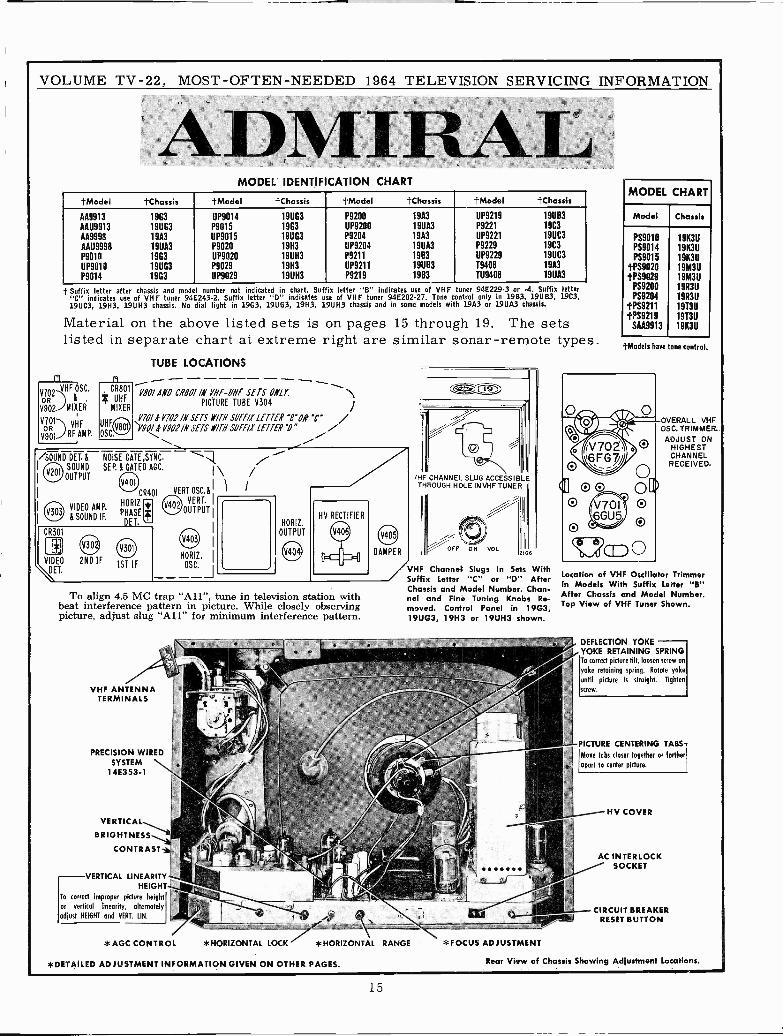
VOLUME TV -22, MOST -OFTEN -NEEDED 1964 TELEVISION SERVICING INFORMATION
ADMIRAI:MODEL IDENTIFICATION CHART
}Model }Chassis }Model }Chassis }Model }Chassis }Model }Chassis
AA9913 1963 11P9014 191163 P9200 19A3 UP9219 19UB3
AAU9913 191103 P9015 1903 UP9200 19UA3 P9221 19C3
AA9998 19A3 UP9015 191103 P9204 19A3 UP9221 19UC3
AAU9998 19UA3 P9020 19H3 UP9204 19UA3 P9229 19C3
P9010 1963 UP9020 19UH3 P9211 1983 UP9229 1911C3
UP9010 191163 P9029 19H3 UP9211 191183 19408 19A3
P9014 1903 UP9029 19UH3 P9219 19B3 1119408 19UA3
t Suffix letter after chassis and mod I number not indicated in chart. Suf ix letter "B" indicates use of VHF tuner 94E229.3 or -4. Suffix letter"C" indicates use of VHF tuner 94E243-2. Suffix letter "D" indicates u e of VHF tuner 94E202-27. Tone control only in 19B3, 19UB3, 1903,19UC3, 19H3, 19UH3 chassis. No dial light in 19G3, 19U53, 19H3, 19UH3 chassis and in some models with 19A3 or 1911A3 chassis.
Material on the above listed sets is on pages 15 through 19. The setslisted in separate chart at extreme right are similar sonar -remote types.
VHF OSC.VGTR2 &
V902 MIXER
VT01) VHF
V901 RF AMP.
rv
TUBE LOCATIONS
VÁ0/ AM CRBOI IN VHF-UNF SETS ONLY.PICTURE TUBE V304
%
V70/ 811702 /N SETS 117TH SOFF/X LETTER "B' O "C')19018 Y.902 /II SETS PM SUFFIX LETTER "0" //
/SOUND DEI. á NOISE CATE,SYNC.
Alltr SOUND SEP. á GATED AGC.
OUTPUT eAl
VIDEO AMP.
&SOUND IF.
CR301
CR401
HORIZ
PHASE
DET.
VIDEO 2ND IF 1ST IF\ET.
i
I\VERT OSC. á 1
VERT. I
D2OUTPUTI
HORIZ. I
OSC.
HORIZ.
OUTPUT
To align 4.5 MC trap "All", tune in television station withbeat interference pattern in picture. While closely observingpicture, adjust slug "All" for minimum interference pattern.
VHF ANTENNATERMINALS
PRECISION WIREDSYSTEM
14E353-1
VERTICAL
BRIGHTNESS
CONTRAST
VERTICAL LINEARITYHEIGHT
To correct improper picture height
or vertical linearity, alternately
adjust HEIGHT and VERT. UN.
*AGC CONTROL *HORIZONTAL LOCK
DAMPER
/HF CHANNEL SLUG ACCESSIBLETHROUGH HOLE IN VHF TUNER
0N VOL106
/VHF Channel Slugs In Sets WithSuffix Letter "C" or "D" AfterChassis and Model Number. Chan-nel and Fine Tuning Knobs Re-moved. Control Panel in 19G3,19UG3, 19H3 or 19UH3 shown.
*HORIZONTAL RANGE *FOCUS ADJUSTMENT
*DETAILED ADJUSTMENT INFORMATION GIVEN ON OTHER PAGES.
MODEL CHART
Model Chassis
PS901DPS9014PS9015
tPS9020tPS9029
PS9200PS9204
tPS921199219
SAA9913
191(311
19K3U19K3Ú19M3U19M3U19R311
19R311
191311
19T3Ú191(311
}Models have tone control.
OVERALL VHFOSC. TRIMMER.
ADJUST ONHIGHESTCHANNELRECEIVED.
Location of VHF Oscillator TrimmerIn Models With Suffix Letter "B"After Chassis and Model Number.Top View of VHF Tuner Shown.
DEFLECTION YOKEYOKE RETAINING SPRINGTo correct picture tilt, loosen screw on
yoke retaining spring. Rotate yoke
until picture is straight. Tighten
screw.
PICTURE CENTERING TABS -
Move tabs closer together or further
sport to center picture.
HV COVER
AC INTERLOCKSOCKET
CIRCUIT BREAKERRESET BUTTON
Rear View of Chassis Showing Adjustment Locations.
15
0000000 TOSHAFT OF TUNER
F 00'27I
10002 1
I L910 I CONNECTS ONLY IN
--= ' AiT I CHANNEL POSITION
5901 SHOWN?H
CHANNEL 1(110111
80SIT10N
VNE
ANTENNA.
T
L9094 L9098C928
1 .001NF
VHF TUNER 94E202-27S902 L9044 1 190413 L904C
SWITCH REARVIEW ORB ¡ 000,- 666,-2 3 4 5 6
- C904
27
"ISO30
-C9`2
21903 C923
L902 OT
I 7901
)H"C9061.8-7
R90147K
C905
1000
0908100
A G9IIA 1/26008 0R33
.. r 1/2 6CG8A
-.C59-13).5
VHF MIXER
- V9Q2A
111903f 2.7K
C926
3
¿ 1/SY
7 L905
í1002 í220K
R915
14211
1' IC907000
NT A(( CT 01CI00. 8103 C 8105 t
UHF TUNER 94D204-7_L801 -
1ST UHF LINE
-- 211D UHF LINE _1
VOLUME TV -22, MOST -OFTEN -NEEDED 1964 TELEVISION SERVICING INFORMATION
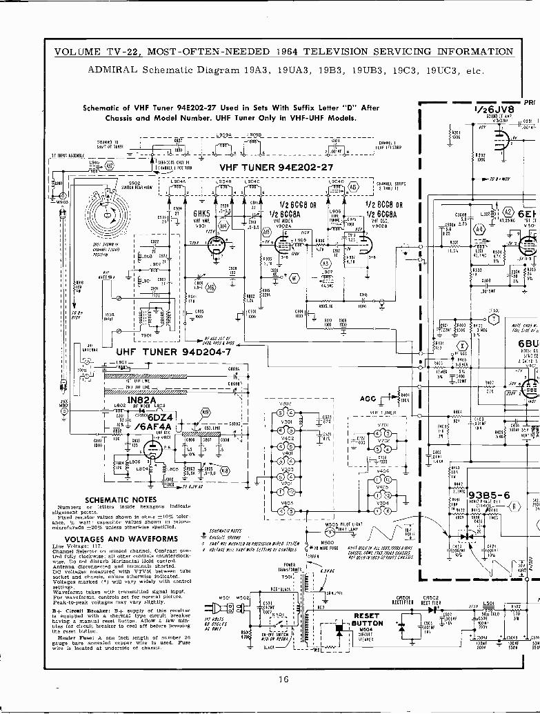
ADMIRAL Schematic Diagram 19A3, 19UÁ3, 19B3, 19UB3, 19C3, 19UC3, etc.
Schematic of VHF Tuner 94E202-27 Used in Sets With Suffix Letter "D" AfterChassis and Model Number. UHF Tuner Only in VHF -UHF Models.
TF INPUT ASSEMBLY
C90977I
CBOlBBN
- F, ,:-/ ---M8Ó1 Leoz
1UHFN812Aso3I I V302
T C801 CRao16DZ4
- #0X= /6AF4AA602
OSC. LIBE
oT
OHf OSC. /I/////I//I/I/ I0802 I
100 _13803 I 7 V801
TI1807 C808 q
1000 I 11355--- 2-6 1.IÓ% IS 15
1
L
I fZA L804Pe : L805 SR803 C805 IAR1
II
- ----C809C-
L 5.811 T,5-3.0 0Ií%
-00810 - _-1100011.TO 0.3V AC
SCHEMATIC NOTESNumbers or letters inside hexagons indicate
alignment points.Fixed resistor values shown in ohms ±10% toler-
ance, X4 watt; capacitor values shown in micro-microfarads ±20% unless otherwise specified.
VOLTAGES AND WAVEFORMSLine Voltage: 117.Channel Selector on unused channel. Contrast con-trol fully clockwise; all other controls counterclock-wise. Do not disturb Horizontal Hold control.Antenna disconnected and terminals shorted.DC voltages measured with VTVM between tubesocket and chassis, unless otherwise indicated.Voltages marked () will vary widely with controlsettings.Waveforms taken with transmitted signal input.For waveforms, controls set for normal picture.Peak -to -peak voltages may vary slightly.B+ Circuit Breaker: B-- supply of this receiveris equipped with a thermal type circuit breakerhaving a manual reset button. Allow a few min-utes for circuit breaker to cool off before pressingthe reset button.
Heater Fuse: A one inch length of number 26gauge bare annealed copper wire is used. Fusewire is located at underside of chassis.
R906
4.7K
L9040
1906FINE 1/2 6CG8A17
TUNING - C925 VHF OSC.__-; -1000 V9025950
1C9131.25
1 CHANNEL I
; (UHF IF) STRIP
--,® CHANNEL STRIPS2 THRH 13
9 J
1/2 6C08 OR
L907-Y6pW.-44.3MC
09121
C9N I (1000
SCHEMATIC NOTES
4- CHASSIS (80130FÁ87 NOT .NOUN7E0 OHEREC/S/0N 13E0 SYSTEM
A° YOUACE M/li YANY 4118 SETT/NC Of COMTNOLS.
PONER
TRANSFORMER
7501,
REOLBLACR ;
M501 M502
ILT 9011500 MIESAC OW
R501ON -Off SWITCH 1
070. OM 81011.CIRCUIT
1
1 II BREAKER
vVv I
BLACK 1--- ]
-RED -J
R905.1K
4910 C929
1000 1000
3
ZB220 I
IC324
2
A901 I3
AGG 1 7> Á4o4
moK
VHF TUNER
M50518
P47 ILOTLAMPLIGHT
* %
M50026 WIRE FUSE
CREEN
V70I I
MS05 USED If ALL 1991191/81119111IICHASSIS; SONE79A5,/9/1ÁS CHASSIS
MOT USEO /N /90108 /90(1 CHASSIS.
GRN./TEL.
I RED
r +RESET
1
- BUTTON- 1 - I
M504
L
/R2011008
i/26JV8OSUNO IF AMP.
V3038 C
0
201
13 001
IY
10 HOY
iV6EF141.2511C ISO 11
v 501
Li01 030442.7NC 4.1K
5%
1303.0015NF -
IF ACC
4400 44020
®150K 3 NEC
R401T150
o RF A CC
44054403 5.6 NEC
12 MEG 50.
5% = 221MF
94081111
3W
0304=20
5%
4305245%
NOTf (105 Mi
10/1 S/Of 0T a,
6E11.1NOISE CA
SYNC SE
6 GATED A
V401
7300 2
5 %
0403=---.001 NF
111V
}`tR440I8K
71w
R442
2.2X~"93B5-6A441 NORII PHASE DET
8R CR441IW R439 R443 444
1lC453 w 00421
062Mf O01MFIOY IID%
/101'
1422390010%
C
CR501 CR502 7RECTIFIER RECTIFIER
ZTfYL5O1
Rso2
502 50n COLD 210OO1NF C506 3W
C503 Z1RV 100MF
a001NF
,-005- 200V
sT111YI 15045 '046 -,C5041
10010 1- 10010 5011
2002 350V 3501
16
s71s ctoº TONE VOLUME
.0114F , 62080
1 ÓÓÍSNF3100
C212 R212[. 1---- r^,r -/-, A20e1{a..__ :41209 w
p`
i SNFC.Í ' = ti 331 0114F
' C2011 -ItL202{1ÓÓt ` - #-C211 ,
I
L20181 q Or
C803 =i C206 í Í09Y2 Sr
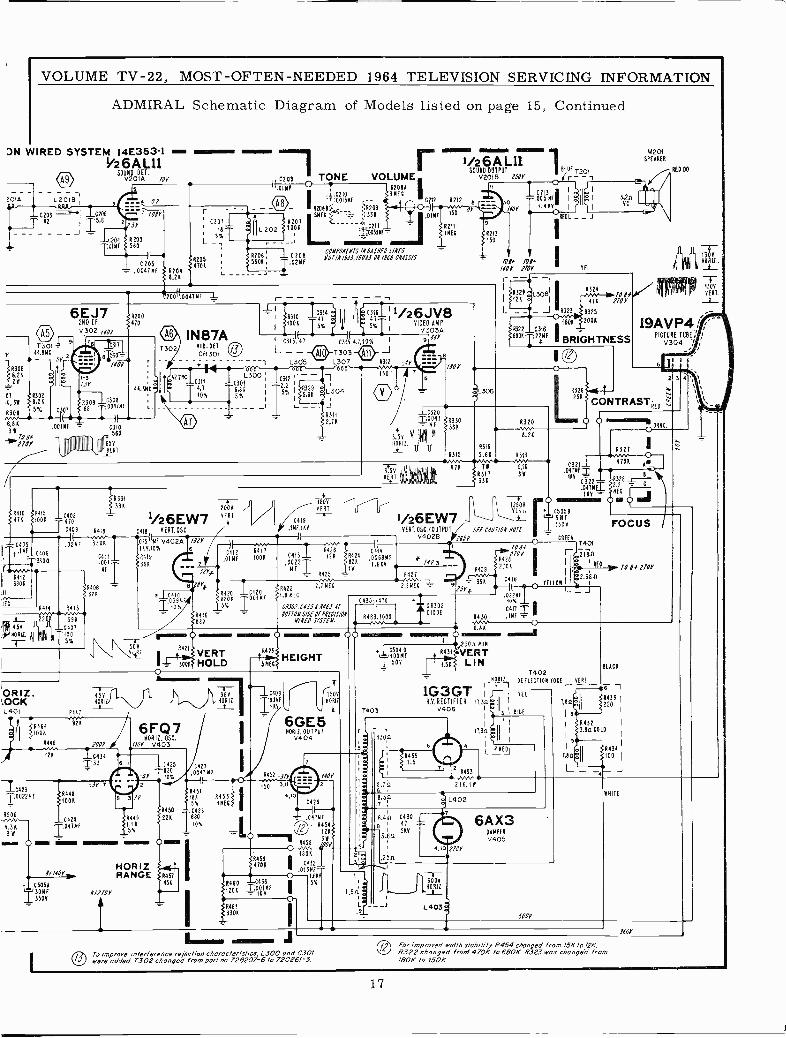
VOLUME TV -22, MOST -OFTEN -NEEDED 1964 TELEVISION SERVICING INFORMATION
ADMIRAL Schematic Diagram of Models listed on page 15, Continued
DN WIRED SYSTEM 14E353-1 ama'26AL11
SOUND DET.V201A 100
2010
J t2 T5.61C204 8203
r TOW 560
n
L 5%T
/~ íe205 8206;C20S 4701
5606
- .004/60 f 8204r7 8.21
0204I.02NF
-ii0033N
r
CONPONENTS /PUSHED LIKES1111/119.4.1,19101 OR 1969 CNASS/S
1/26A L11SOUND OUTPUT
V20113 250V
150 0
421114EC 8243
150
0,.0047' NF L
7301y 44.8110
Or
Itl8.20
07,1,311
A308
6.813t lollPlor
6EJ72NO IFV 302 140r
1317
e 560
loor
A309 1C30868 '¡0047NF
I I.00180 -
R200470
C58Ó
Pill 1111 IIII E°T
N.3NC
1
L
2.7
IN 87Av10.OET
CR301
C311
4,7
40%
iR310
T4714á11 1rIiC31111/26JVe100K
5% 1 5X I VIVE303A
1 6313f(47 ¡- t31'S 4.i,10% I9 994'
L - - tpl}7303 jj J-1 L305 L307 6312 ;4Y :
L300C301
6.865%
C312.2.11y5% I
33BKL304
JR311
2,7R
150
T3.58N0RI2.
±C320
e
":;401'
1 BIDE 7201(r - - ,
ÓÓ5 NFi I
4.418 I
REOL __
/004 1pl/404' P10Y
I R321,I
121(
TEL
M201SPEAKER
RE0 DO
- -I
13081- -6322 C316
68011-122NF
6324 loll471 1704
8323 A325
1801 2001
BRIGHTNESS
1
:L306
10041 <SR330
uuaNú 7586
8319
6315 15.61
8320rr
1300x0812..
T1304
VERT.
19AVP4; ;
PICTURE TUBE/ 4V304 ' i
R3265.(-{- ,y25K
CONTRASTgED
8.21
R410 $6415471 1001
C405{.INf C406
3300
FVVNr84126806
11
IECR414
.02x4
6413
rn 22
11,45v 11
`a
396-C401
1005%
ORIZ..00KL40 I
á1f1 R4641006
1/ 'I21
1R33133K 200V /
1/26EW74418
330001
NE iR406 -821
c418 rERT.05C
01510 V402A118.10%
A419
396
9
fi1039xC 10X
0418.111F,160
1-iVERT
426
.01140 100K 04131 8126.0022T
NFA425
R420 -10420tR422 2.7 C
8206 `(:OOiÑF <1B MEG
5% 1 14.701,C435 d NI6l AI4410 - 90I10N SIDE OIPIfC/S/ON681 N/qE0 SYSIEI.
C<12 R417
3SVVERT
12500O
40[11.
FOCUS05059
SffCAUIlONN07 350V FOCUS
O o
03211.047NFT t6Y
C322.047N1116 -
~R327O
4701 Am
2328
EC. j
CREER
C414 1.. /00f 7401
0088NF * A42110Y r2160-4Y3 2106R
I1
1.6AY
A42TR929
y Af0 ' 10 04 P70r
^"^^ 39KC416
I
S2.36 0O rElloA2.2NE6. T º SY ( I-
i413_1(11,0_,.Op%F
0!N0417
. -o
,W41UII41
476 7 9.11
1317 38336
1/26EW7VER1.05C./OUTPUT
V4028
6483,1000
= CR302DIODE
R430
\\51, 421
s OVERT 1°413
HEIGHT3000 HOLD 5450
ROM 110112L . HO 12 ToJ- J- 1111
C423 `8448002240
Í{ 1001
05060424
4.31 `T¡' 047 1
311 l
826
Z1144414 1414114
If f404
C50513011F3501
6FQ7N0R I . 05C.
1004 /K ME V403IC434
33
:Sr 7
4lOf2l0Y
6 10425120
-IV to
0427.0047140
12 A4515181 A453
1
5% 14E0
tttt1450 C416
8449 UK 1680.1158.
l0t
HORIZRANGE
A48!3306
1504NORI2
66E840412.
V40OIPUl04
4452 d1r /40rIso 3,11 `_ 2
O
.1 0504 0
7403
5ª
T100NF500
430?1
IJ
8431
1.51
6.88
1250A xlll.VERT
LIN
4aaa4
= N0Al2_
1G3GTH.V.RECTIFIER 11.3n
V406
4
R4
11.3n
278,16
L402
4.1012/a
L403
7402DEFLECTION 000 VERT
9'l .6 -1
6A X3046418V405
.2004'
BUM
1431,80 11 122031
Ia I
I 8432 I
1
3.80 Co
103
II
SR434I
TAO Íi00
L _ ._NHITE
For improved width slob/lily 6454 changed from /5K/o /2K.To improve interference rejection characteristics, L300 and C30/
i9'? R322 changed from' 4706 to 6606. 6323 was changed fromwere added. T302 changed from port no.728207-6 /0 720261-3. /806 to /506.
1659'
17
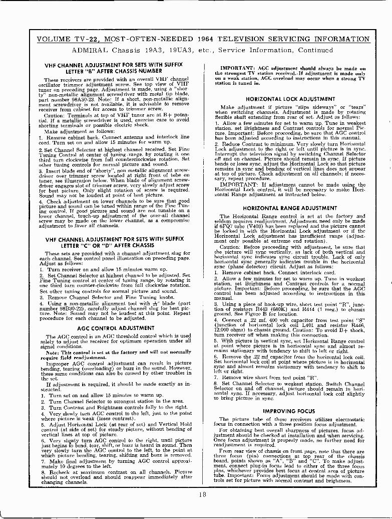
VOLUME TV -22, MOST -OFTEN -NEEDED 1964 TELEVISION SERVICING INFORMATIONADMIRAL Chassis 19A3, 19UA3, etc., Service
VHF CHANNEL ADJUSTMENT FOR SETS WITH SUFFIXLETTER "B" AFTER CHASSIS NUMBER
These receivers are provided with an overall VHF channeloscillator trimmer adjustment screw. See top view of VHFtuner on preceding page. Adjustment is made, using a "shor-ty" non-metallic alignment screwdriver with metal tip blade,part number 98A30-23. Note: If a short, non-metallic align-ment screwdriver is not available, it is advisable to removereceiver from cabinet for access to trimmer screw.
Caution: Terminals at top of VHF tuner are at B+ poten-tial. If a metallic screwdriver is used, exercise care to avoidshorting terminals or possible electric shock.
Make adjustment as follows:1. Remove cabinet back. Connect antenna and interlock linecord. Turn set on and allow 15 minutes for warm up.2. Set Channel Selector at highest channel received. Set FineTuning Control at center of tuning range, by rotating it onethird turn clockwise from full counterclockwise rotation. Setother tuning controls for normal picture and sound.3. Insert blade end of "shorty", non-metallic alignment screw-driver over trimmer screw located at right front of tube ontuner, see illustration below. When blade of alignment screw-driver engages slot of trimmer screw, very slowly adjust screwfor best picture. Only slight rotation of screw is required.Sound may not be loudest at point of best picture.4. Check adjustment on lower channels to be sure that goodpicture and sound can be tuned within range of the Fine Tun-ing control. If good picture and sound are not tunable on alower channel, touch-up adjustment of the over-all channelscrew may be made on the lower channel, as a compromiseadjustment to favor all channels.
VHF CHANNEL ADJUSTMENT FOR SETS WITH SUFFIXLETTER "C" OR "D" AFTER CHASSIS
These sets are provided with a channel adjustment slug foreach channel. See control panel illustration on preceding page.Adjust as follows:1. Turn receiver on and allow 15 minutes warm up.2. Set Channel Selector at highest channel to be adjusted. SetFine Tuning control at center of tuning range, by rotating itone third turn counter -clockwise from full clockwise rotation.Set other tuning controls for normal picture and sound.3. Remove Channel Selector and Fine Tuning knobs.4. Using a non-metallic alignment tool with A" blade (partnumber 98B30-22), carefully adjust channel slug for best pic-ture. Note: Sound may not be loudest at this point. Repeatprocedure for each channel to be adjusted.
AGC CONTROL ADJUSTMENT
The AGC control is an AGC threshold control which is usedsolely to adjust the receiver for optimum operation under allsignal conditions.
Note: This control is set at the factory and will not normallyrequire field readjustment.
Improper AGC control adjustment can result in picturebending, tearing (overloading) or buzz in the sound. However,these same conditions can also be caused by other troubles inthe set.
If adjustment is required, it should be made exactly as in-structed.1. Turn set on and allow 15 minutes to warm up.2. Turn Channel Selector to strongest station in the area.3. Turn Contrast and Brightness controls fully to the right.4. Very slowly turn AGC control to the left, just to the pointwhere picture is weak (loses contrast).5. Adjust Horizontal Lock (at rear of set) and Vertical Holdcontrol (at side of set) for steady picture, without bending ofvertical lines at top of picture.6. Very slowly turn AGC control to the right, until picturejust begins fo bend, tear, shift, or buzz is heard in sound. Thenvery slowly turn the AGC control to the left, to the point atwhich picture bending, tearing, shifting and buzz is removed.7. Make final adjustment by turning AGC control approxi-mately 10 degrees to the left.8. Recheck at maximum contrast on all channels. Pictureshould not overload and should reappear immediately afterchanging channels.
Information, Continued
IMPORTANT: AGC adjustment should always be made onthe strongest TV station received. If adjustment is made onlyon a weak station, AGC overload may occur when a strong TVstation is tuned in.
HORIZONTAL LOCK ADJUSTMENT
Make adjustment if picture "slips sideways" or "tears"when switching channels. Adjustment is made by rotatingflexible shaft extending from rear of set. Adjust as follows:1. Allow a few minutes for set to warm up. Tune in weakeststation, set Brightness and Contrast controls for normal Pic-ture. Important: Before proceeding, be sure that AGC controlhas been adjusted according to instructions in this manual.2. Reduce Contrast to minimum. Very slowly turn HorizontalLock adjustment to the right or left until picture is in sync.Interrupt the television signal by switching Channel Selectoroff and on channel. Picture should remain in sync. If picturebends or loses sync, adjust the Horizontal Lock so that pictureremains in sync and bending of vertical lines does not appearat top of picture. Check adjustment on all channels; if neces-sary, repeat procedure.
IMPORTANT: If adjustment cannot be made using theHorizontal Lock control, it will be necessary to make Hori-zontal Range adjustment as instructed below.
HORIZONTAL RANGE ADJUSTMENT
The Horizontal Range control is set at the factory andseldom requires readjustment. Adjustment need only be madeif 6FQ7 tube (V403) has been replaced and the picture cannotbe locked -in with the Horizontal Lock adjustment or if theHorizontal Lock adjustment has insufficient range (adjust-ment only possible at extreme end rotation).
Caution: Before proceeding with adjustment, be sure thatthe picture will sync vertically, as lack of both vertical andhorizontal sync indicates sync circuit trouble. Lack of onlyhorizontal sync generally indicates trouble in the horizontalsync (phase detector) circuit. Adjust as follows:1. Remove cabinet back. Connect interlock cord.2. Allow a few minutes for set to warm up. Tune in weakeststation, set Brightness and Contrast controls for a normalpicture. Important: Before proceeding, be sure that the AGCcontrol has been adjusted according to instructions in thismanual.3. Using a piece of hook-up wire, short test point "R", junc-tion of resistors R443 (680K) and R444 (1 meg.) to chassisground. See Figure B for location.4. Connect a .22 mf, 400 volt capacitor from test point "S"(junction of horizontal lock coil L401 and resistor R446,12,000 ohms) to chassis ground. Caution: To avoid B+ shock,turn receiver off when making this connection.5. With picture in vertical sync, set Horizontal Range controlat point where picture is in horizontal sync and almost re-mains stationary with tendency to shift to left or right.6. Remove the .22 mf capacitor from the horizontal lock coil.Set horizontal lock coil at point where picture is in horizontalsync and almost remains stationary with tendency to shift toleft or right.7. Remove wire short from test point "R".8. Set Channel Selector to weakest station. Switch ChannelSelector on and off channel, picture should remain in hori-zontal sync. If necessary, adjust horizontal lock coil slightlyto bring picture in sync.
IMPROVING FOCUSThe picture tube of these receivers utilizes electrostatic
focus in connection with a three position focus adjustment.For obtaining best overall sharpness of pictures, focus ad-
justment should be checked at installation and when servicing.Once focus adjustment is properly made, no further need forreadjustment is required.
From rear view of chassis on front page, note that there arethree focus (pin) connections at top rear of the chassisboard, points shown as "A", "B" and "C". To make adjust-ment, connect plug-in focus lead to either of the three focuspins, whichever provides best focus at central area of picturetube. Important: Focus adjustment should be made with con-trols set for picture with normal contrast and brightness.
18
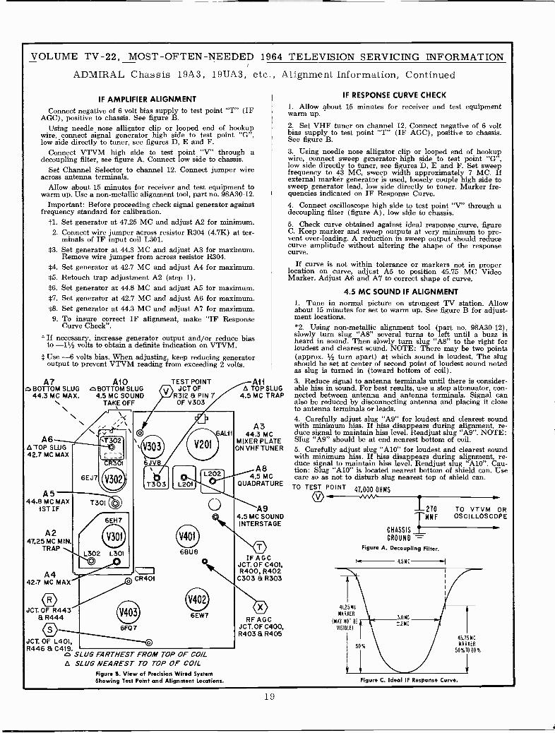
VOLUME TV -22, MOST -OFTEN -NEEDED 1964 TELEVISION SERVICING INFORMATION
ADMIRAL Chassis 19A3, 19UÁ3, etc., Alignment Information, Continued
IF AMPLIFIER ALIGNMENTConnect negative of 6 volt bias supply to test point "T" (IF
AGC), positive to chassis. See figure B.Using needle nose alligator clip or looped end of hookup
wire, connect signal generator high side to test point "G",low side directly to tuner, see figures D, E and F.
Connect VTVM high side to test point "V" through adecoupling filter, see figure A. Connect low side to chassis.
Set Channel Selector to channel 12. Connect jumper wireacross antenna terminals.
Allow about 15 minutes for receiver and test equipment towarm up. Use a non-metallic alignment tool, part no. 98A30-12.
Important: Before proceeding check signal generator againstfrequency standard for calibration.
t1. Set generator at 47.25 MC and adjust A2 for minimum.2. Connect wire jumper across resistor R304 (4.7K) at ter-
minals of IF input coil L301.*3. Set generator at 44.3 MC and. adjust A3 for maximum
Remove wire jumper from across resistor R304.*4. Set generator at 42.7 MC and adjust A4 for maximum.*5. Retouch trap adjustment A2 (step 1).*6. Set generator at 44.8 MC and adjust A5 for maximum*7. Set generator at 42.7 MC and adjust A6 for maximum.*8. Set generator at 44.3 MC and adjust A7 for maximum.9. To insure correct IF alignment, make "IF Response
Curve Check".
t If necessary, increase generator output and/or reduce biasto -11/2 volts to obtain a definite indication on VTVM.
* Use -6 volts bias. When adjusting, keep reducing generatoroutput to prevent VTVM reading from exceeding 2 volts.
oBOTT7 A1OM SLUG o BOTTOMSLUG
44.3 MC MAX. 4.5 MC SOUNDTAKE OFF
A6ATOP SLUG42.7 MC MAX
A544.8 MC MAX
1STIF
A247.25 MC MIN.
TRAP
A442.7 MC MAX
JCT.OF R443& R444
JCT. OF L401,R446 & C419.
\
6EJ7
.,*. \VT302J
CR3 e
oT301
6EH7
V301
L302 L301
TEST POINT©JCT OFR312 & PIN 7OF V303
O
6JV8
6AL11
V201
L202T303 L201
CR401
6FQ 7
O
o6BU8
6EW7
o SLUG FARTHEST FROM TOP OF COILA SLUG NEAREST TO TOP OF COIL
Figure S. View of Precision Wired SystemShowing Test Point and Alignment Locations.
AliA TOP SLUG
4.5 MC TRAP
A344.3 MC
MIXER PLATEON VHF TUNER
A84.5 MC
QUADRATURE
A94.5 MC SOUNDINTERSTAGE
oIF AGC
JCT. OF C401,R400, R402C303 & R303
oRF AGC
JCT.OF C400,R403 & R405
IF RESPONSE CURVE CHECK
1. Allow about 15 minutes for receiver and test equipmentwarm up.
2. Set VHF tuner on channel 12. Connect negative of 6 voltbias supply to test point "T" (IF AGC), positive to chassis.See figure B.
3. Using needle nose alligator clip or looped end of hookupwire, connect sweep generator. high side to test point "G",low side directly to tuner, see figures D, E and F. Set sweepfrequency to 43 MC, sweep width approximately 7 MC. Ifexternal marker generator is used, loosely couple high side tosweep generator lead, low side directly to tuner. Marker fre-quencies indicated on IF Response Curve.4. Connect oscilloscope high side to test point "V" through adecoupling filter (figure A), low side to chassis.5. Check curve obtained against ideal response curve, figureC. Keep marker and sweep outputs at very minimum to pre-vent over -loading. A reduction in sweep output should reducecurve amplitude without altering the shape of the responsecurve.
If curve is not within tolerance or markers not in properlocation on curve, adjust A5 to position 45.75 MC VideoMarker. Adjust A6 and A7 to correct shape of curve.
4.5 MC SOUND IF ALIGNMENT1. Tune in normal picture on strongest TV station. Allowabout 15 minutes for set to warm up. See figure B for adjust-ment locations.*2. Using non-metallic alignment tool (part no. 98A30-12),slowly turn slug "A8" several turns to left until a buzz isheard in sound. Then slowly turn slug "A8" to the right forloudest and clearest sound. NOTE: There may be two points(approx. 1/2 turn apart) at which sound is loudest. The slugshould be set at center of second point of sound notedas slug is turned in (toward bottom of coil).3. Reduce signal to antenna terminals until there is consider-able hiss in sound. For best results, use a step attenuator, con-nected between antenna and antenna terminals. Signal canalso be reduced by disconnecting antenna and placing it closeto antenna terminals or leads.4. Carefully adjust slug "A9" for loudest and clearest soundwith minimum hiss. If hiss disappears during alignment, re-duce signal to maintain hiss level. Readjust slug "A9". NOTE:Slug "A9" should be at end nearest bottom of coil.5. Carefully adjust slug "A10" for loudest and clearest soundwith minimum hiss. Iff hiss disappears during alignment, re-duce signal to maintain hiss level. Readjust slug "A10". Cau-tion: Slug "A10" is located nearest bottom of shield can. Usecare so as not to disturb slug nearest top of shield can.TO TEST POINT 47000 OHMS
-.11--VVVV`
41.25 MC
MARKER
(MAY NOT BE
VISIBLE)
CHASSIS
GROUND ---Figure A. Decoupling Filter.
TO VTVM OROSCILLOSCOPE
4.5148
1 2701WMF
45.75 MCMARKER
50%T0 80%
Figure C. Ideal IF Response Curve.
19
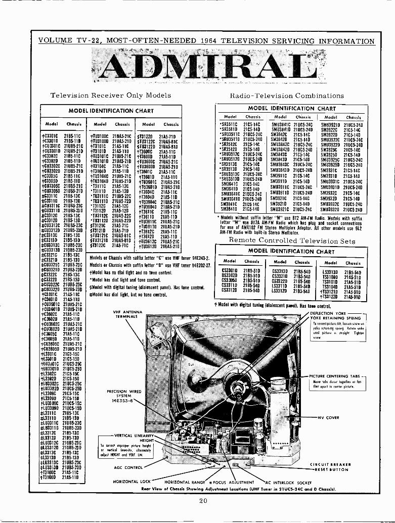
VOLUME TV -22, MOST -OFTEN-NEEDED 1964 TELEVISION SERVICING INFORMATION
ADMITelevision Receiver Only Models
MODEL IDENTIFICATION CHART
Model Chassis
tC3301C 21B5 -11C
tC3301D 2165-11D}CU3301C 21UB5-21CtCU33010 21085-210tC3302C 21B5 -11C
tC3302D 2185-11D}CU3301C 210B5 -21CtCU3302D 21085-210tC3305C 21B5 -11C
tC330511 21B5-110}CU3305C 21UB5-21C
tCU33050 21UB5-211)#C3311 C 21 B5 -13C
#C3311 D 2165-130#CU3311C 210B5 -23C*CU3311D 21UB5-230*C3312C 21B5 -13C#C3312D 2165-130#CU3312C 21U85 -23C*CU33120 21005-230
'*C3313C 21B5 -13C
#C33130 21B5-130*CU3313C 21U65 -23C#CU33130 2111115-230
*C3321C 2165-13C*C33210 21B5 -13D
#C03321C 21UB5-23C#CU33210 21085-23D*C3322C 21B5 -13C
#C33220 2165-13D#CU3322C 210115-23C#CU3322D 21U85-230}C3601C 2105-11C
tC36010 2105-11DtCU3601C 211105-21C
tCU3601D 21UA5-21DtC3602C 2105-11C
tC3602D 21A5-110
tCU3602C 21UA5-21CtCU3602D 21005-210tC3605C 21A5 -11C
tC36050 21A5-110
tCU3605C 21 UA5-21C
tCU3605D 21UA5-21D}1.3301C 2105-15C}L3301D 2105-150tLU3301C 21UC5-25C}LU33010 21UC5-250
1L3302C 2105-15CtL3302D 2105-150}LU3302C 21UC5-25C
1-1033020 211105-250113309C 2105-15C1-1.33091) 2105-150}LU3309C 211IC5-15C1LU3309D 21UC5-150#L3311C 2165-13C*133110 21B5-130#LU3311C 21UB5-23C#L033110 21U85-230*L3312C 2185-13C#133120 2185-130#LU3312C 21UB5-23C#1033120 21UB5-230ch13313C 21B5 -13C#133130 2165-13D#LU3313C 21U85 -23C#11133130 21UB5-23D
tT3100C 2105-11C1.131000 21A5-110
Model Chassis Model Chassis
}TU3100C 21UA5-21C.H11310011 21UA5-21D
031220§T113122C
2105-11021UA5-81C
tT3101C 21A5 -11C §T0312211 21UA5-81DtT3101D 2105-110 1.13600C 2105-11CtTU3101C 21005-21C }T36000 2105-110t11131010 21005-210 11113600C 21005-21CtT3104C 21A5 -11C 111.136000 21DA5-21D}T31040 2105-110 tT3601C 21A5 -11C}TU3104C 21UA5-21C tT3601 D 2105-110t1031040 210A5 -21D tTU3601C 21UA5-21C13111C 21A5 -12C 1.111360111 2111105-21D
T3111D 2105-120 tT3604C 2105-11CTU3111C 21UA5-22C }T36041) 2105-110TU31110 21005-220 tTU3604C 21UA5-21CT3112C 21A5 -12C t11136040 21005-210T3112D 2105-120 113611C 21A5 -11CTU3112C 21UA5-22C t436111) 2105-110TU311211 21UA5-220 tTU3611C 21UA5-21C§T3121C 2105-11C tTU36110 210A5-210§1312111 21A5 -71D tT3612C 2105-11C§103121C 21UA5-81C t136120 2105-11D§T03121 I) 21005-81D tT03612C 21UA5-21C§T3122C 2105-71C 1-1036120 21005-210
Models or Chassis with suffix letter "C" use VHF tuner 94E243-2.
Models or Chassis with suffix letter "0" use VHF tuner 94E202-21.
}Model has no dial light and no tone control.
Model has dial light and tone control.
§Model with digital tuning (dialescent panel). Has tone control.
*Model has dial light, but no tone control.
VHF ANTENNATERMINALS
PRECISION WIREDSYSTEM
14E353-6
VERTICAL LINEARITYHEIGHT
To correct improper picture height
or vertical linearity, alternately
adjust HEIGHT and VERT. IIN.
AGC CONTROL
Radio -Television Combinations
MODEL IDENTIFICATION CHARTModel Chassis Model Chassis Model Chassis
SR3511C 2105-14C SMU3841C 211105-24C SMU3921D 211105-240'SR35110 2105-140 SM1138410 21UC5-24D SM3922C 2105-14CSR03511C 21UC5-24C SM3842C 2105-14C SM3922D 2105-14DSRU35110 21UC5-24D SM3842D 2105-140 SMU3922C 21UC5-24CSR3511C 2105-14C SMU3842C 21UC5-24C SMU39220 21UC5-24DSR3512D 2105-140 SMU3842D 211105-240 SM3925C 2105-14CSRU3512C 21UC5-24C SM3843C 2105-14C SM39250 2105-140SRU3512D 21UC5-24D SM3843D 2105-14D SMU3925C 21UC5-24CSR3513C 2105-14C SMU3843C 21UC5-24C SMU3925D 21UC5-24DSR35130 2105-140 SMU3843D 21UC5-240 SM3931C 2105-14CSRU3513C 21UC5-24C SM3911C 2105-14C SM3931D 2105-14U'SRU3513D 211.105-240
SM3911D 2105-140 SMU3931C 21UC5-24CSM3641C 2105-14CSM3641D 2105-140 SMU3911C 21UC5-24C SMU3931D 21UC5-240
SMU3641C 21UC5-24C SMU39110 21UC5-240 SM3932C 2105-14C
SM1136410 21UC5-24D SM3921C 2105-14C SM3932D 1105-140SM3841C 2105-14C SM39210 2105-140 SMU3932C 21UC5-24CSM38410 2105-140 SMU3921C 21UC5-24C SMU3932D 21UC5-240
* Models without suffix letter "M" use 872 AM -FM Radio. Models with suffixletter "M" use 872A AM -FM Radio which has plug and socket connectionsfor use of AMX102 FM Stereo Multiplex Adaptor. All other models use 912AM -FM Radio with built-in Stereo Multiplex.
Remote Controlled Television SetsMODEL IDENTIFICATION CHART
Model Chassis Model Chassis Model Chassis
CS3301D 2185-51D CS3313D 2185-540 LS33130 2185-540CS3302D 2185-510 CS3321D 2185-540 TS3100D 2105-510CS3305D 21B5-510 CS3322D 2185-540 TS3101D 2105-510CS3311D 2185-540 LS3311D 2185-540 TS3104D 21A5-510CS3312D 2165-540 LS331211 2165-540 }TS3121D 2105-910
1-1531220 21A5-910
t Model with digital tuning (dialescent panel). Has tone control.
DEFLECTION YOKEYOKE RETAINING SPRING
To correct picture tilt, loosen screw on
yoke retaining spring. Rotate yoke
until picture is straight. Tighten
screw.
PICTURE CENTERING TABS
Move tabs closer together or far'Cher apart to center picture.
HV COVER
CIRCUIT BREAKERRESET BUTTON
HORIZONTAL LOCK - HORIZONTAL RANGE * FOCUS ADJUSTMENT "AC INTERLOCK SOCKET
Rear View of Chassis Showing Adjustment Locations (UHF Tuner in 21UC5-24C and D Chassis).
20
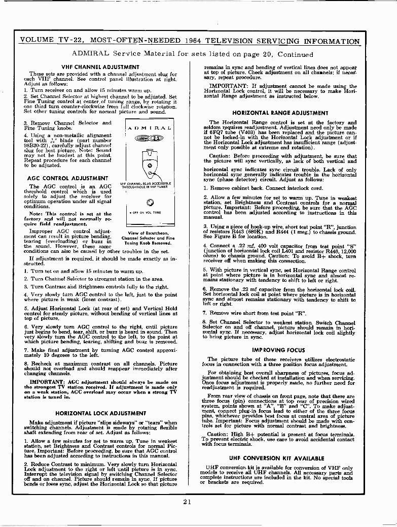
VOLUME TV -22, MOST -OFTEN -NEEDED 1964 TELEVISION SERVICING INFORMATION
ADMIRAL Service Material for sets listed on page 20, ContinuedVHF CHANNEL ADJUSTMENT remains in sync and bending of vertical lines does not appear
These sets are provided with a channel adjustment slug for at top of picture. Check adjustment on all channels; if neces-each VHF channel. See control panel illustration at right. sary, repeat procedure.Adjust as follows: IMPORTANT: If adjustment cannot be made using the1. Turn receiver on and allow 15 minutes warm up. Horizontal Lock control, it will be necessary to make Hori-2. Set Channel Selector at highest channel to be adjusted. Set zontal Range adjustment as instructed below.Fine Tuning control at center of tuning range, by rotating itone third turn counter -clockwise from full clockwise rotation.Set other tuning controls for normal picture and sound. HORIZONTAL RANGE ADJUSTMENT
3. Remove Channel Selector and The Horizontal Range control is set at the factory andFine Tuning knobs. ADM IRAL seldom requires readjustment. Adjustment need only be made
Using a non-metallic alignment4.toolwith ' " (part number
toolwith
-A"bladeefully
C-~® if 6FQ7 tube (V403) has been replaced and the picture can-not be locked -in with the Horizontal Lock adjustment or ifthe Horizontal Lock adjustment has insufficient range (adjust -adjust channel
slug for best picture. Note: Soundmay not be loudest at this point.Repeat procedure for each channelto be adjusted.
AGC CONTROL ADJUSTMENT
¡. ment only possible at extreme end rotation).
Caution: Before proceeding with adjustment, be sure thatthe picture will sync vertically, as lack of both vertical andhorizontal sync indicates sync circuit trouble. Lack of onlyhorizontal sync generally indicates trouble in the horizontalsync (phase detector) circuit. Adjust as follows:
o
VHF CHANNEL SLUG ACCESSIBLEThe AGC control is an AGC THROUGH
threshold control which is usedsolely to adjust the receiver for
HOLE IN VHF TUNER 1. Remove cabinet back. Connect interlock cord.
2. Allow a few minutes for set to warm up. Tune in weakestoptimum operation under all signalconditions. 0 station, set Brightness and Contrast controls for a normal
picture. Important: Before proceeding, be sure that the AGCNote: This control is set at the
factory and will not normally re-quire field readjustment.
OFF ON VOL TONE control has been adjusted according to instructions in thismanual.
3. Using a piece of hook-up wire, short test point "R", junctionImproper AGC control adjust- View of Escutcheon, of resistors R443 (680K) and R444 (1 meg.) to chassis ground.ment can result in picture bending, Channel Selector and Fine See Figure B for location.tearing (overloading) or buzz in Tuning Knob Removed.the sound. However, these same 4. Connect a .22 mf, 400 volt capacitor from test point "S"conditions can also be caused by other troubles in the set. (function of horizontal lock coil L401 and resistor R446, 12,000
If adjustment is required, it should be made exactly as in-strutted.
ohms) to chassis ground. Caution: To avoid B+ shock, turnreceiver off when making this connection.
1. Turn set on and allow 15 minutes to warm up. 5. With picture in vertical sync, set Horizontal Range controlat point where picture is in horizontal sync and almost re -2. Turn Channel Selector to strongest station in the area. mains stationary with tendency to shift to left or right.
3. Turn Contrast and Brightness controls fully to the right. 6. Remove the .22 mf capacitor from the horizontal lock coil.4. Very slowly turn AGC control to the left, just to the pointwhere picture is weak (loses contrast).
Set horizontal lock coil at point where picture is in horizontalsync and almost remains stationary with tendency to shift toleft or right.
5. Adjust Horizontal Lock (at rear of set) and Vertical Holdcontrol for steady picture, without bending of vertical lines attop of picture.
7. Remove wire short from test point "R".
8. Set Channel Selector to weakest station. Switch Channel6. Very slowly turn AGC control to the right, until picture Selector on and off channel, picture should remain in hori-just begins to bend, tear, shift, or buzz is heard in sound. Then zontal sync. If necessary, adjust horizontal lock coil slightlyvery slowly turn the AGC control to the left, to the point at to bring picture in sync.which picture bending, tearing, shifting and buzz is removed.7. Make final adjustment by turning AGC control approxi-mately 10 degrees to the left.
IMPROVING FOCUS
The picture tube of these receivers utilizes electrostatic8. Recheck at maximum contrast on all channels. Picture focus in connection with a three position focus adjustment.should not overload and should reappear immediately afterchanging channels. For obtaining best overall sharpness of pictures, focus ad-
justment should be checked at installation and when servicing.IMPORTANT: AGC adjustment should always be made on Once focus adjustment is properly made, no further need for
the strongest TV station received. If adjustment is made only readjustment is required.on a weak station, AGC overload may occur when a strong TVstation is tuned in. From rear view of chassis on front page, note that there are
three focus (pin) connections at top rear of precision wiredsystem, points shown at "A", "B" and "C". To make adjust -
HORIZONTAL LOCK ADJUSTMENT ment, connect plug-in focus lead to either of the three focuspins, whichever provides best focus at central area of picture
Make adjustment if picture "slips sideways" or "tears" when tube. Important: Focus adjustment should be made with con -switching channels. Adjustment is made by rotating flexible trola set for picture with normal contrast and brightness.shaft extending from rear of set. Adjust as follows: Caution: High B+ potential ispresent at focus terminals.1. Allow a few minutes for set to warm up. Tune in weakest To prevent electric shock, use care to avoid accidental contactstation, set Brightness and Contrast controls for normal Pic- with focus terminals.ture. Important: Before proceeding, be sure that AGC ccntrolhas been adjusted according to instructions in this manual. UHF CONVERSION KIT AVAILABLE2. Reduce Contrast to minimum. Very slowly turn HorizontalLock adjustment to the right or left until picture is in sync. UHF conversion kit is available for conversion of VHF onlyInterrupt the television signal by switching Channel Selector models to receive all UHF channels. All necessary parts andoff and on channel. Picture should remain in sync. If picture complete instructions are included in the kit. No special toolsbends or loses sync, adjust the Horizontal Lock so that picture or brackets are required.
21
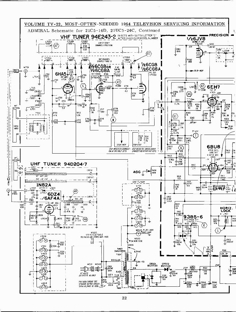
VHF
ATOM NA
300aINPUT
UHF,A TEMNA
JACKM801
VOLUME TV -22, MOST -OFTEN -NEEDED 1964 TELEVISION SERVICING INFORMATIONADMIRAL Schematic
M701
L706A
r L705AI
L704
L703000 C7Ó11,
L702C1018
C702A
CN2B 27
L701
T701
2
for 2105-14D, 21UC5-24C, ContinuedVHF TUNER 94E243-2 AFTER C AISSIS ORFMODEL NUMBER
21 VHF AMP
V701
L706B L706CUHF IF STRIP
CHANNEL I POSITION
L705B L705CVHF CHANNEL
50
000
6
STRIPS 2 THRU 1300
í/26CG8oR FINE A1/26CG8A ANI"
C709
20
R704
C108=41
4702
1.20
110000115
VHF MIXER 8105 ----V7024,o--_-
óL`0.
9
1111032,21
C 716
10001
UHF TUNER 94D204-7
CBC98- 2110 UHF LINE
1
- _//VIII//l/I/II//!1///ll ;%/,{ - - -1 \L L802 U eiYCR L803 1
1N82A
T cecl cp8016°x T -/6AF4A + C 809 1-- OSC. LINE
Rfioz ill///101//d-CBozT i°° 10803 '°"véó C806 ceo, I ceoe ;
1000I
1'35 2-6T1.5
ISTs
_ s014
8804 .1.5106128
L804
V302
O 0
L805 TR803 C80S5.68 5-3.0
Celo
1000ro 6.iV AC
V301 aO 0
V402
O 0V401
O 0V 03
O 0V201
O 0V403
0323
304 1820
C3241822
1 1
1c717 1119
T1000 11000
4
10V0
111i° O
M520117Y AC RECEPTACLE
FOR RADIO AHD STEREO AMPLIFIERo
o
TO 1;1110Y
íA510 CF511z>10K 12K;3M í3W
106/1708
OSC-M/XENN+CONNECT- OSC-N/XENN+ AND OLEf1EN/08/I VHF ONLY SETS CONNECTLON/NYNF-UNF SETS .
VNF TUNER
V701
O 0V702
O 0 CiÓÓÓ
V404
O ®V405
0®
POWER
TRAM SFOMMEA_
7501,
RED/BLACB
M501 M502C501041MF
'BUOY BLACK 1
1 55018 TV ON v [ a r
FOR S1018 CIRCUIT SEE TJ501
-"--047
0! Ó FF > I I
470 1 0TV 4 I
55018SPEAKER OUTPUT CIRCUIT ON 8
SIOIA 8 A, PART OF R108.fÁA0101 _'
_KEOLµv _ J
V304
M505 PILOT LICHT1*1141 LAMP
M50026 MIRE FUSE
CREE
{:SYAC
1
1
, RN./TEL
I RE0
i
i
C300A !255.8±25
4eA44e~ PRECISION i/º6JV8
SOUND IF AMP,V3038 , C201
±001001
42021001
1. TO I NOY
.00181
C 2,02 L-2 014-
e
,4r
4.55%
03008 L302 _ 1 i V 6 E H75.6^' 47.1511C 151 IF
V301 /60Y
13018 830445.15 158MC 5%
A30311
0303
!t1301A C302 rOtSMF41 -11".25C T5xC301 IF ACCT1o,sx
tt T
1401 R400 R402=22NF 1508 3 MEC.- - 5Y,
R401150
4403
0 RF ACC
R4055.6 NEC
12MEC SY.
5% 1228,
R4086.8034
11401
0103= OD1MF
1RV
C30420
5%
830524
5%
e 656
306
510
43088.2128
8307 A3
151,3M
R308
6.B A
311TO II--Ir.1JOY
6BU8NOISE CATE.SYNC SEP
3 CATEO ACCV401
1JOY
11110 R4
418 10
CGSe .IMF
SOY e e /00
?JOY o
V0Y
T¿¿C04
R409S.001 MI 55V5.68?? VFRI.T
1106R412
680K
45VHOR12 ll
E
04
33
2
-7112
i
L
1.4KV
#R440
IBA1 iM
844211 -+vv/ -4
2.2MEC
8441
IBAIW R439
6408
9385-6H0812 PHASE VT
CR401R443
6801 1010C428
00?MFI fox062MF
1010%
HORIZ.LOCK
N L401
C422_390010%
20- Y
1101112
swam ~a- ;Omium
CR501 CR502RECTIFIER AECTIFI A
17SYL5)1
R502-IBLLT VOLTS
60 CYCLES AC ONLY
170
C502 SOn COID 270001NF C506 31
C503 1fAY MF+ 001MF 200YT,Xv1 CSOIA .L5048 CSObt
IOONF .i 100MFf150MF
2008 - 3504 350Y
10423I.0022MF
R506
4.36.58 0~
--)0M1
C5053508
22
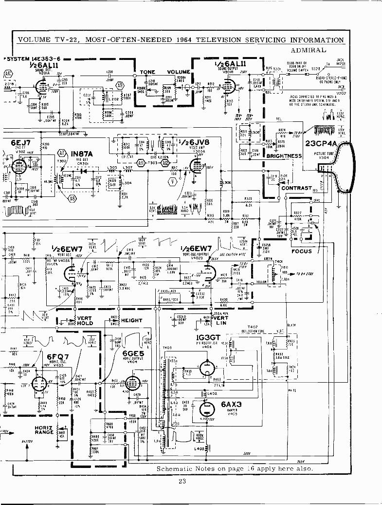
VOLUME TV -22, MOST -OFTEN -NEEDED 1964 TELEVISION SERVICING INFORMATIONADMIRAL
SYSTEM 14E353-6 1.~4440Vº6AL11
50V2000AT.
.2018
-_ IC20615.6
-C204 $ 4203'0181 3 560
70Y
C 205$1205$4701
.00416F A2048.21
- 41007I004TNF L
I(.01MF
12011001
OTONE
op
I 10210001511F
111 56E4 }}}621
SMEC. 173108
02111003311 T
amiumm1206; 1 C2085601. ,02MF
6EJ7ONO IF
V 302 (my
itiI-3Jr
4309 163080301 68 00418
-1( T )1
00114F T 0310560
654/EATiiiiIIINNIIhIIU1
1:041MF
1' 41®
efl7or
R200
470
44.360
1302INS -7A
410 DOTCR301
_42.7110311
4.7
10%
C312 '-6.8 I R32910% 5.64
VOLUME420116I36E0
;r,OC212 R212
1r14314 : II It1ó011RI1 1/2 6 J V 8-, 1RÓÓ6
T5%
f 1 5%T VIDEO AMP1 V3034
CS13{(47 C3Í3 4,7,10% 19 UV
L - - T3o3 ÁIJ
L305 2301 8312 ;4
150
L304
4311
2.76
14708T 0
J C409 R418vv .0287 330K
0411.001 -
ME
RICO
826
4413
398_C401
100
5%
11 331 -4-334 2000
VERT1/26EW70414 VERT.OSC /818
0151 MF V402Á110,10%
1391396
J_3.50VERT. 111,1 aoN1.U11
0115.1120.0
/80
6
1/26A L11SOUND OUTPUT
V2018 1sor'BLUE
5501B PART OF9208 ON -017
T20 55018í VOLUME SNITCH(rI
TV
JACKm201
RADIO-STEREO-PH0N0
OR PH0N0 ONLY
JACK
_ _ J M202JACKS CONNECTED TO PINS N125 tr
6126 ON SPEAKER SYSTEM. SEE RADIO
OR THE STEREO AMP. SCHEMATIC.
TEL.
43247011
471 170Y
4323 8325
2008
BRIGHTNESS
"2306
C320100470E1
3.5V110611. u u
1C41 2
,018 F
-.11Y0
6 8Ys C410
0398F,10%
4417M1001
R420 104208206 T001MF_5% 1
4416611
1442251.8 NEC
1800VERT
C419
.18F,160
)1 nvC413 126 0421
5126
.0022 T 821MF _1_
6425
2.111E0
0414.0068MF1.668
033058K
R315
432041-+N1
6.26
4319
5.61 4313
319 R326
20 j25K
A1AAN47 "AI
111 ill 'I'II I NI
130VR0912._L
130V
VERT.
23CP4A, :,
PICTURE 1U80
V304 !
CONTRAST
3
FMMMMMMMM11M'
6327
CORNC.
I41Vwv 4M^.v ---- C3211---.1707.---416 16
R31C9,31$1 .0470F1 7
1331 110 R3828 ---11-C322-.04702
REC.41 4. (SImili'-\ 1250Y
oVERT. 05058
1/26EW7 ,a4 FocusYERT.OSC./OUTPUT Serf C/07/0Y8nIf
V4028 165Y CHEW
3
4421*-/fY22w iISY
4429
391
04351 1110
6463,1000"1-`,10311
4430
C416
1(
T401
rJ- 12180
I IfO/f110YrE41081 ; I236nj
g ® 44®\OOR1 VERT 8423
e - 3000 HOLD s7e63HEIGHT
o
O
ISv ^ 36v e -1C408HOAil RT TO.INf
444111A
8?
446 100
126 0434133
JY 76441100A
6FQ7NOR IL OSC.
Á0Y 0403
C42S C427
8Y 1700%.0047 ME
4451Iv 16K 6453
5% 16E06450 0426
0424 4449 221 8801.11 I 10%5%
HORIZRANGE
I
I4452
ISO
6GE500417.40
040T PUT
V
-J7Y3,11
4,10
7
150VNORIZ
00.j C5040
I0011F504
1403
431
1.56
6.88
Y250n--VERTLIN
1G3GTNV RECTIFIER 9730
v406
z 432n
0429
= ,047NF4454
1210 ma'R458 /00Y
/Y0
}RO11SS
05
801
6440 C436
1201 11KV6F
R481
3301
ó MF
.6RV
5%
á
a
94551,5
8.7 0
11.3n
8463w 2 71,16
T402DEFLECTION TOME VERT
Ten
1.8n
81401
I
220R433 1
84323.8n CO 0
1
R434
100 1
8.5p L402
4
1.90
.4n C430139
SKY
3.60
25n0,10 708
6AX304NPER
v405
T600460410
L403il
SOY
i141TE
365V
Schematic Notes on page 16 apply here also.
23
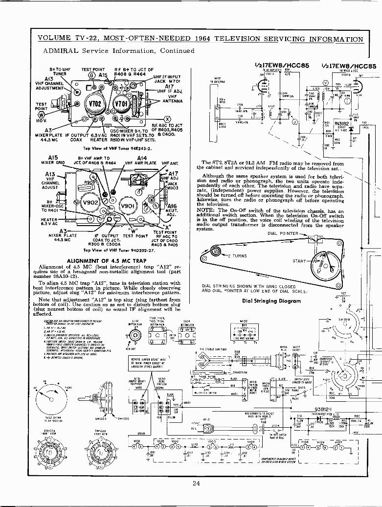
VOLUME TV -22, MOST -OFTEN -NEEDED 1964 TELEVISION SERVICING INFORMATION
ADMIRAL Service Information, Continued
B+TO UHFTUNER
A13VHF CHANNELADJUSTMENT
TESTPOINT
110V.
A3MIXER PLATE
44.3 MC
A15MIXER GRID
A13VHF
CHANNELADJUST
B+MIXER-OSCTO R401
HEATER6.3 V AC
TEST POINT
AlR F 8+TO JCT OFR408 & R464
UHFIF INPUTJACK M701
AllUHF IF ADJ.
VHFANTENNA
RF AGC TO JCTOSC-MI ER B+.TO OF 15403,15405
IF OUTPUT 6.3V AC R401 IN VHF SETS.TO & 0400.COAX HEATER R510 IN VHF -UHF SETS.
Top View of VHF Tuner 94E243-2.
&I- VHF AMP TO Ai4JCT. OF R408 & R464 .VHF AMP PLATE VHF ANT.
® V902
A3MIXER PLATE
44.3 MC
*Ai 7UHF ADJ
*JACKM903
A16NEUT.ADJ.
TEST POINTIF OUTPUT TEST POINT RF AGC TO
COAX TO JCT. JCT OF C400R300 & C300A R403 & R405
Top View of VHF Tuner 94D202-27.
ALIGNMENT OF 4.5 MC TRAPAlignment of 4.5 MC (beat interference) trap "Al2" re-
quires use of a hexagonal non-metallic alignment tool (partnumber 98A30-12).
To align 4.5 MC trap "Al2", tune in television station withbeat interference pattern in picture. While closely observingpicture, adjust slug "Al2" for minimum interference pattern.
Note that adjustment "Al2" is top slug (slug farthest frombottom of coil). Use caution so as not to disturb bottom slug(slug nearest bottom of coil) as sound IF alignment will beaffected.
(AO//0N US! NN 15010101 11413700711 10 0015l0/SN0CN0N 01Y1070 /0f /fSl l005(0l07
1. 1171 10.1 MCP,ANl1/SSKC.5.012f55 07MF00/Sf Sf!C/f/f0: A/[ 0f5/51005
/1P N117,100. AU CAPAC//015:N 0/CN0l1140S.W &W/WI SWITCH 51/00 5/010 /0 AH /GS///0N
/1801/51012/ C0V181f1 C[OCNIfS!/70 51/111141 11145011NA7/C S1101 SIl/CM 5fC/IONS I0f 5X01000SCNFNAI/C. NfCN1N/CA( MIS 10401/11 101N4C710N %75.
S. Y0[7ACC5 ABfNlISOAIO 0/7M /I.AYAC /N(U7
1 4- Of1Olf5 CHASSIS 1100N0.
5102 0(011
IN 1N POSITION
5W1024FRONT YIEW
5W102Á
SW10213FRONT VIEW
L112BOTTOM YIE1
RED OOT
11021103,T105, T106BOTION 41(
REMOVE JUMPER SOCKET 11131
TO INSERT POWER SOCKET OF
0110102 FM STEREO ADAPTOR
M131JUMPER SOCKET
REARVIEW
WRITE
51.0028
CNEEN
MI30PLUG
PIN VIEW
TIO4BOTTOM VIEW
(14/ r!NITE
® IOW
YELLOW
V101 7:V105 6102
M101FM ANIEMMA
300nINPUT
\.
RISKCRE
LI00
1OMNF,10%
10 110,10%
1/217EW8/HCC85FM RE AMPLIfIE* (101
1/101A4.75105
IOMMF,S%C105
TIONMI
1.5%
o
1C106 IOMNf+T
CI01 R102/2
1-152%
I/217EW8/HCC85FM MISER 10SC
R10/ 3
33A
V1018
--CI12-IMM
5% A107iN3182015101 IMEO
R101- ---[10 IOMECt
DI9/ <R10eCIII01
2200 T.1176
TheThe 8T2, 8T2A or 9L2 AM- FM radio may be removed fromthe cabinet and serviced independently of the television set..
Although the same speaker system is used for both televi-sion and radio or phonograph, the two units operate inde-pendently of each other. The television and radio have sepa-rate, (independent) power supplies. However, the televisionshould be turned off before operating the radio or phonograph.Likewise, turn the radio or phonograph off before operatingthe television.NOTE: The On -Off switch of the television chassis, has anadditional switch section. When the television On -Off switchis in the off position, the voice coil winding of the televisionaudio output transformer is disconnected from the speakersystem.
DIAL POINTER_
LIZO900
DIAL STRINGING SHOWN WITH GANG CLOSEDAND DIAL POINTER AT LOW END OF DIAL SCALE.
Dial Stringing Diagram
M102
1114
r- COO"I Clie 0119 I
IOO 100 NW
7E771"67-1 )
M6 STEREO MAIMC150
.041- - - -, 6004
o
M106 M107PIJO SOCKET
CI61
r.olo5 CO1NlC7f0IAKV 70SM117 0
OFSJOP
SPICY $10.1 9ow:IOW 70 MO,'
REDS103
L156 PROND.047
Mi.RADIO
NITS CONNECTS TO SOCKETM520 11 TY MODELS
MI12PLUS
5104o c
V103 VI04 -I
LIII004
ON -OFF WITCH
PART OF R151
RI
RIOT
3KSN
o
`PXOSO
roIR17201
2706
93612-1R151
SILICON RECTIFIER L113R152
R,2W calo92ao 0o moa,3W 40
Cfai Clal (1511 C1511 OISBC047 `.02 2504 2504 T 2 DNT
105
5108 5109 VIOT
100C151 C152 C153 0154 , 6155 I 2W
T°L - -_T_ _311 0_1 _ CIeSIS01I0AMfSSN
L
DO ©O ©O_ 1
J
24
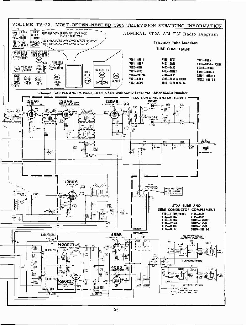
Al
14
66
VOLUME TV -22, MOST -OFTEN -NEEDED19
V702VHF OSC.
OR
V902 MIXER
VT01) VHFOR
9901 .RF AMP.
MI A1/8 CR801 IN 'HP -NY SETS ON/f \PICTURE TUBE V304
970/1 V701 /N SETS NTH SW/71 LETTER -ro#'c" /-V90/ * V9O2/N SETS Y/T1/1///SOEE/X LETTER D" i
1964 TELEVISION SERVICING INFORMATION
ADMIRAL 8T2A AM -FM Radio Diagram
Television Tube Locations
/SOUND DEI. &SOUND
I OUTPUT
CR301
(IJlJVIDEO
T.
NOISE GATE,SYNC.S
SEP. & GATED AGC.
CR401
VIDEO AMP.HORIZ
&SOUND IF. PDEHATSE
.
2ND IF 1ST IF
VERTOSC.& \tVERT.
OUTPUT
/
HORIZ.
OUTPUT
HORIZ. DAMPER
OSC.
101 O
tlClls24
r zB-FN 1ST IF 96Y
V102
i
TUBE COMPLEMENT
Y201-6AL11 V403-6FO7 V901-8HK5V301-6EH7 V404-6GE5 V902-6CG8 or 6CG8AV302 -6E11 Y405 -64X3 CR301-1N87AV303-611(8 V406-1G3GT CR401-9305.6V304-23CP4A Y701 -611A5 CR501-93812-1V401-68118 V702-6CG8 or 6CG8A CR502-93012-1V402-6EW7 V801 --60Z4 or 6AF4A
Schematic of 8T2A AM -FM Radio Used In Sets With Suffix Letter "M" After Model Number.PRECISION WIRED SYSTEM 14E369-1 0-'
12BA633Y IN
1N542FN 1141104 6 AN DETECTOR OY AM
16 RATIO6120
VI 04 X104 1CR102 CI25900
Mill ©X1030 OY IN z 33Y1Nr - - 330NM1
/TYAN C-----4 -JYANc
OYAN rr I 54r.á -u r-. 'I I --13'321:F1N542 .0
.--+I IN RATIO OEI.
603 1I2
96Y I
/YT
L=11
6110$62z --CI16
.01
961
..RIII1390
12133T01
12B A6 J6Y lN2110 11 & AM IF 6TYANV103
6112
100
T.01
0121
RI15
10
1109NM ROD
ANTENNA I-114 \I CREER
I C10JC
I
A1ie
J1
s -
12BE6AM NIVER 1052
05 /TYAN
OP fit1129 :6Y 67YAN
100_/Y
8130
1130022 A
42 112
11030,r ®12131
TOI
T105
2132
8131 12134390 X01
.05,50V
4133
- 2.2N0C
4194
I NEC.
4132
1 NEC
CI33105
116
3906
i
i
R119
686 21241 1560NNF
LEFT CHANNEL
M132MULTIPLEX 512640OOCNE1,LUC VIEW
-CI60
BASS/TREBLE
rAñSi 1II 1.5410
¡z2OEZ7l "7916163
RIGHT CHANNEL PREAMP0033
1NNE1154
41suLDDDNE$S,C61 v107A1 6
2102
0164,005
C165.005 II
4155
396015
3 NEC6166
T39NMF
LOUDNESS 120EZ7LEFT CHANNEL PREAMP C199
910781 0033
BASS/TREBLE -R1511
f.SNft
I74
81604101
161
101
0115
"10 0171
01 01
BALANCE
45B5 RICHE CHANNEL
AUDIO OUTPUT RICHE CHANNEL I - --1109 -v1013 10 r
R168 OY
4165163 IMEC
391
FJOiXir
9 6170100
10Y
Al2W
C1560
tsV
600E
I REA
L_
45B5 p0122
AUDIO OUTPUT LEFT 1.419CHANNEL
0109
16
REO
BLUE
2127
soy
0123
&61
INSERT MULTI PLUG OF
MAX 102 FM STEREO
MULTIPLEX ADAPTOR
I
I S101AFC 5NITC
8T2A TUBE ANDSEMI -CONDUCTOR COMPLEMENT
Y101-17E18/HCC85 V108-4505Y102 -128A5 Y109-4585Y103-12BA6 CR101-1N31120104-12846 CR102-1N542V105-12BE6 CR103-1N542Y101 -20E71 CR109-93812.1
ITF
Í44117PLUG
PIN
VvFW
RIO
YELLOW
BOAC
RED 00T
610 DOT
T0O Tiff T165OfE010010211101101110 SUE 11011E15
0109
4E00014,16VAC
6120HOOTER
RIOT CHANNEL SPEAKERS
CIII,1
4.16R1C
M121WOOFER
MI25 LEFT CHANNEL SPEAKERS
PIN IN lv 400110.CONNECT TO 18201 N202
M126..,_.211 TV RECEIVER 2011510PIN
M1221116111
Mí23TEETER
25
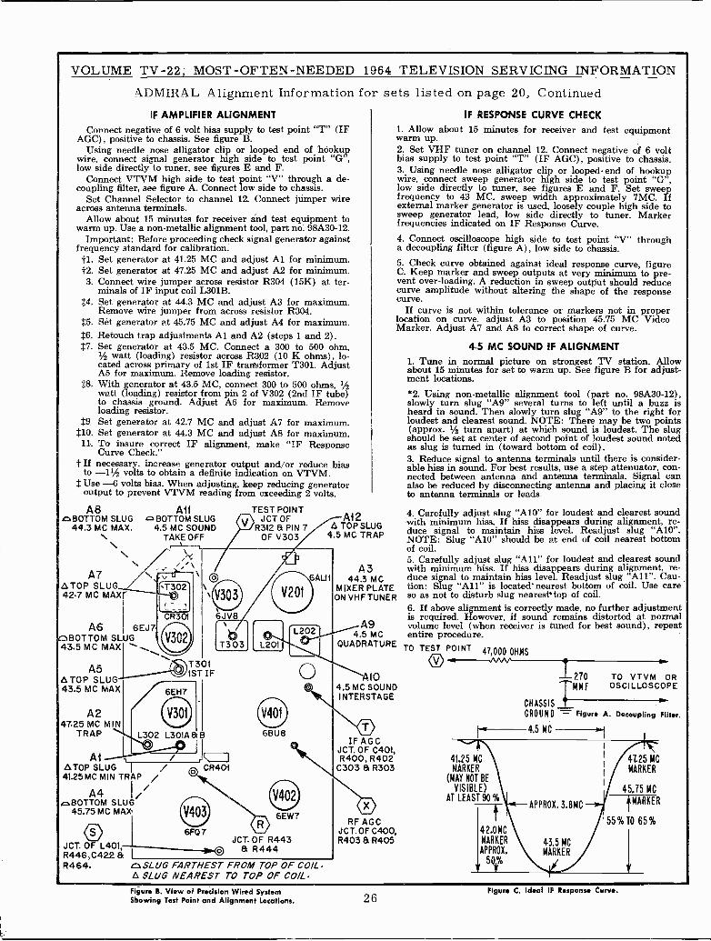
VOLUME TV -22, MOST -OFTEN -NEEDED 1964
ADMIRAL Alignment Information for
IF AMPLIFIER ALIGNMENTConnect negative of 6 volt bias supply to test point "T" (IF
AGC), positive to chassis. See figure B.Using needle nose alligator clip or looped end of hookup
wire, connect signal generator high side to test point "G",low side directly to tuner, see figures E and F.
Connect VTVM high side to test point "V" through a de -coupling filter, see figure A. Connect low side to chassis.
Set Channel Selector to channel 12. Connect jumper wireacross antenna terminals.
Allow about 15 minutes for receiver ánd test equipment towarm up. Use a non-metallic alignment tool, part no: 98A30-12.
Important: Before proceeding check signal generator againstfrequency standard for calibration.
Set generator at 41.25 MC and adjust Al for minimum.f2. Set generator at 47.25 MC and adjust A2 for minimum.3. Connect wire jumper across resistor R304 (15K) at ter-
minals of IF input coil L301B.t4. Set generator at 44.3 MC and adjust A3 for maximum.
Remove wire jumper from across resistor R304.$5. Set generator at 45.75 MC and adjust A4 for maximum.t6. Retouch trap adjustments Al and A2 (steps 1 and 2).$7. Set generator at 43.5 MC. Connect a 300 to 500 ohm,
1/2 watt (loading) resistor across R302 (10 K ohms), lo-cated across primary of 1st IF transformer T301. AdjustAS for maximum. Remove loading resistor.
$8. With generator at 43.5 MC, connect 300 to 500 ohms, 1/2watt (loading) resistor from pin 2 of V302 (2nd IF tube)to chassis ground. Adjust A6 for maximum. Removeloading resistor.
$9. Set generator at 42.7 MC and adjust A7 for maximum.$10. Set generator at 44.3 MC and adjust A8 for maximum.11. To insure correct IF alignment, make "IF Response
Curve Check."i If necessary, increase generator output and/or reduce bias
to --11/2 volts to obtain a definite indication on VTVM.$ Use -6 volts bias. When adjusting, keep reducing generator
output to prevent VTVM reading from exceeding 2 volts.
A8szBOTTOM SLUG
44.3 MC MAX.
\A7
ATOP SLUG42.7 MC MAX
Ailc BOTTOM SLUG
4.5 MC SOUNDTAKE OFF
A6 6EJ7nBOTTOM SLUG43.5 MC MAX
A5ATOP SLUG43.5 MC MAX
A247.25 MC MIN
TRAP
AiATOP SLUG
1/
41.25 MC MIN TRAP /
A4®BOTTOM SLUG
45.75 MC MAX
JCT. OF L401,R446,C422 &R464.
/
TEST POINTJCT OF
R3I2a PIN 7OF V303
JCT. OF R443& R444
412A TOP SLUG
4.5 MC TRAP
TELEVISION SERVICING INFORMATION
sets listed on page 20, Continued
ca SLUG FARTHEST FROM TOP OF COILA SLUG NEAREST TO TOP OF COIL
IF RESPONSE CURVE CHECK
1. Allow about 15 minutes for receiver and test equipmentwarm up.2. Set VHF tuner on channel 12. Connect negative of 6 voltbias supply to test point "T" (IF AGC), positive to chassis.3. Using needle nose alligator clip or looped- end of hookupwire, connect sweep generator high side to test point "G",low side directly to tuner, see figures E and F. Set sweepfrequency to 43 MC, sweep width approximately 7MC. Ifexternal marker generator is used, loosely couple high side tosweep generator lead, low side directly to tuner. Markerfrequencies indicated on IF Response Curve.
4. Connect oscilloscope high side to test point "V" througha decoupling filter (figure A), low side to chassis.
5. Check curve obtained against ideal response curve, figureC. Keep marker and sweep outputs at very minimum to pre-vent over -loading. A reduction in sweep output should reducecurve amplitude without altering the shape of the responsecurve.
If curve is not within tolerance or markers not in properlocation on curve, adjust A3 to position 45.75 MC VideoMarker. Adjust A7 and A8 to correct shape of curve.
4.5 MC SOUND IF ALIGNMENT1. Tune in normal picture on strongest TV station. Allowabout 15 minutes for set to warm up. See figure B for adjust-ment locations.
*2. Using non-metallic alignment tool (part no. 98A30-12),slowly turn slug "A9" several turns to left until a buzz isheard in sound. Then slowly turn slug "A9" to the right forloudest and clearest sound. NOTE: There may be two points(approx. 1/2 turn apart) at which sound is loudest. The slugshould be set at center of second point of loudest sound notedas slug is turned in (toward bottom of coil).3. Reduce signal to antenna terminals until there is consider-able hiss in sound. For best results, use a step attenuator, con-nected between antenna and antenna terminals. Signal canalso be reduced by disconnecting antenna and placing it closeto antenna terminals or leads.
A344.3 MC
MIXER PLATEON VHF TUNER
A94.5 MC
QUADRATURE
104.5 MC SOUNDI NTERSTAGE
IF AGCJCT. OF C401,R400, R402
C303 & R303
RF AGCJCT. OF C400,R403 a R405
4. Carefully adjust slug "A10" for loudest and clearest soundwith minimum hiss. If hiss disappears during alignment, re-duce signal to maintain hiss level. Readjust slug "Al0".NOTE: Slug "A10" should be at end of coil nearest bottomof coil.5. Carefully adjust slug "All" for loudest and clearest soundwith minimum hiss. If hiss disappears during alignment, re-duce signal to maintain hiss level. Readjust slug "All". Cau-tion: Slug "All" is located' nearest bottom of coil. Use careso as not to disturb slug nearesttop of coil.6. If above alignment is correctly made, no further adjustmentis required. However, if sound remains distorted at normalvolume level (when receiver is tuned for best sound), repeatentire procedure.
TO TEST POINT 47,000 OHMS
41.25 MCMARKER
(HAY NOT BE
VISIBLE)AT LEAST 90%
1 210TMMF
TO VTVM OROSCILLOSCOPE
CHASSIS 1'
GROUND Figure A. Decoupling Filter.
4725 MCMARKER
45.75 MC
MARKER
55%TO 65%
Figure B. View of Precision Wired SystemShowing Test Point and Alignment Locations. 26
Figure C. Ideal IF Response Curve.
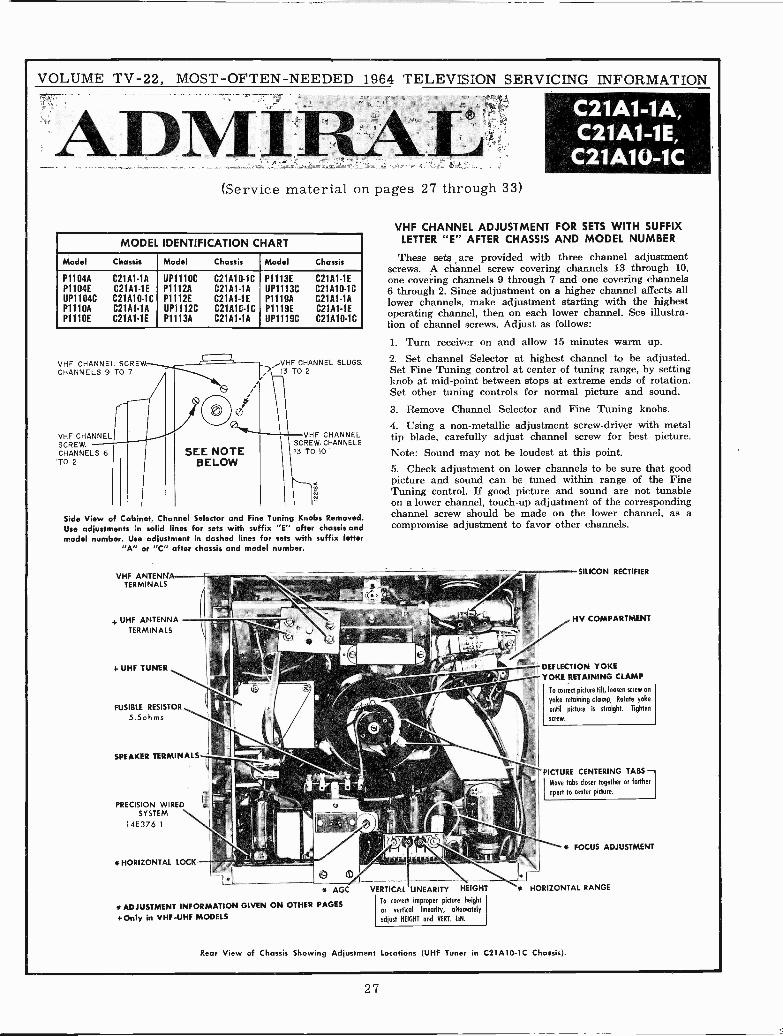
VOLUME TV -22, MOST -OFTEN -NEEDED 1964 TELEVISION SERVICING INFORMATION
ADMIN.AL(Service material on pages 27 through 33)
MODEL IDENTIFICATION CHART
Model Chassis Model Chassis Model Chassis
P1104AP1104EUP1104CP1110AP1110E
C21A1-1AC21A1-1EC21A10-1CC21A1-1AC21A1.1E
UP1110CP1112AP1112EUP1112CP1113A
C21A10.1CC21A1-1AC21A1-1EC21A10.1CC21A1-1A
P1113EUP1113CP1119AP1119EUP1119C
C21A1-1EC21A10.1CC21A1-1AC21A1-1EC21A10-1c
VHF CHANNEL SCREW. VHF CHANNEL SLUGSCHANNELS 9 TO 7 13 TO 2
VHF CHANNELSCREW.CHANNELS 6TO 2
oilSEE NOTE
BELOW
VHF CHANNELSCREW. CHANNELS13 TO 10
Side View of Cabinet, Channel Selector and Fine Tuning Knobs Removed.Use adjustments in solid lines for sets with suffix "E" after chassis andmodel number. Use adjustment in dashed lines for sets with suffix letter
"A" or "C" after chassis and model number.
VHF ANTENNATERMINALS
4. UHF ANTENNATERMINALS
+ UHF TUNER
FUSIBLE RESISTOR
5.5ohms
SPEAKER TERMINALS
PRECISION WIREDSYSTEM
14E376-1
* HORIZONTAL LOCK
* AGC
ADJUSTMENT INFORMATION GIVEN ON OTHER PAGES+Only in VHF -UHF MODELS
C21A1-1A,C21A1-1E,
C21A10-1C
VHF CHANNEL ADJUSTMENT FOR SETS WITH SUFFIXLETTER "E" AFTER CHASSIS AND MODEL NUMBER
These sets are provided with three channel adjustmentscrews. A channel screw covering channels 13 through 10,one covering channels 9 through 7 and one covering channels6 through 2. Since adjustment on a higher channel affects alllower channels, make adjustment starting with the highestoperating channel, then on each lower channel. See illustra-tion of channel screws. Adjust as follows:
1. Turn receiver on and allow 15 minutes warm up.2. Set channel Selector at highest channel to be adjusted.Set Fine Tuning control at center of tuning range, by settingknob at mid -point between stops at extreme ends of rotation.Set other tuning controls for normal picture and sound.3. Remove Channel Selector and Fine Tuning knobs.4. Using a non-metallic adjustment screw -driver with metaltip blade, carefully adjust channel screw for best picture.Note: Sound may not be loudest at this point.5. Check adjustment on lower channels to be sure that goodpicture and sound can be tuned within range of the FineTuning control. If good picture and sound are not tunableon a lower channel, touch-up adjustment of the correspondingchannel screw should be made on the lower channel, as acompromise adjustment to favor other channels.
VERTICAL LINEARITY HEIGHT
To correct improper picture height
or vertical linearity, alternately
adjust HEIGHT and VERT. LIN.
SILICON RECTIFIER
HV COMPARTMENT
DEFLECTION YOKEYOKE RETAINING CLAMP
To correct picture tilt, loosen screw on
yoke retaining clamp, Rotate yoke
until picture is straight. Tighten
screw.
PICTURE CENTERING TABSI Move tabs closer together or farther
apart to center picture.
* FOCUS ADJUSTMENT
* HORIZONTAL RANGE
Rear View of Chassis Showing Adjustment Locations (UHF Tuner in C21A10-1C Chassis).
27
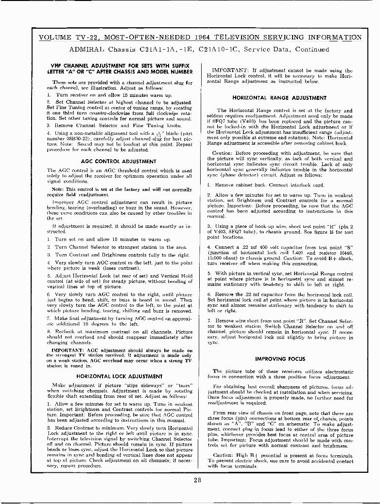
VOLUME TV -22, MOST -OFTEN -NEEDED 1964 TELEVISION SERVICING INFORMATION
ADMIRAL Chassis C21A1-1A, -1E, C21A10-1C, Service Data, Continued
VHF CHANNEL ADJUSTMENT FOR SETS WITH SUFFIXLETTER "A" OR "C" AFTER CHASSIS AND MODEL NUMBER
These sets are provided with a channel adjustment slug foreach channel, see illustration. Adjust as follows:1. Turn receiver on and allow 15 minutes warm up.2. Set Channel Selector at highest channel to be adjusted.Set Fine Tuning control at center of tuning range, by rotatingit one third turn counter -clockwise from full clockwise rota-tion. Set other tuning controls for normal picture and sound.3. Remove Channel Selector and Fine Tuning knobs.4. Using a non-metallic alignment tool with a .N" blade (partnumber 98B30-22). carefully adjust channel slug for best pic-ture. Note: Sound may not be loudest at this point. Repeatprocedure for each channel to be adjusted.
AGC CONTROL ADJUSTMENT
The AGC control is an AGC threshold control which is usedsolely to adjust the receiver for optimum operation under allsignal conditions.
Note: This control is set at the factory and will not normallyrequire field readjustment.
Improper AGC control adjustment can result in picturebending, tearing (overloading) or buzz in the sound. However,these same conditions can also be caused by other troubles inthe set.
If adjustment is required, it should be made exactly as in-structed.1. Turn set on and allow 15 minutes to warm up.2. Turn Channel Selector to strongest station in the area.3. Turn Contrast and Brightness controls fully to the right.4. Very slowly turn AGC control to the left, just to the pointwhere picture is weak (loses contrast).5. Adjust Horizontal Lock (at rear of set) and Vertical Holdcontrol (at side of set) for steady picture, without bending ofvertical lines at top of picture.6. Very slowly turn AGC control to the right, until picturejust begins to bend, shift, or buzz is heard in sound. Thenvery slowly turn the AGC control to the left, to the point atwhich picture bending, tearing, shifting and buzz is removed.7. Make final adjustment by turning AGC control an approxi-ate additional 10 degrees to the left.8. Recheck at maximum contrast on all channels. Pictureshould not overload and should reappear immediately afterchanging channels.
IMPORTANT: AGC adjustment should always be made onthe strongest TV station received. If adjustment is made onlyon a weak station, AGC overload may occur when a strong TVstation is tuned in.
HORIZONTAL LOCK ADJUSTMENT
Make adjustment if picture "slips sideways" or "tears"when switching channels. Adjustment is made by rotatingflexible shaft extending from rear of set. Adjust as follows:1. Allow a few minutes for set to warm up. Tune in weakeststation, set Brightness and Contrast controls for normal Pic-ture. Important: Before proceeding, be sure that AGC controlhas been adjusted according to instructions in this manual.2. Reduce Contrast to minimum. Very slowly turn HorizontalLock adjustment to the right or left until picture is in sync.Interrupt the television signal by switching Channel Selectoroff and on channel. Picture should remain in sync. If picturebends or loses sync, adjust the Horizontal Lock so that pictureremains in sync and bending of vertical lines does not appearat top of picture. Check adjustment on all channels; if neces-sary, repeat procedure.
IMPORTANT: If adjustment cannot be made using theHorizontal Lock control, it will be necessary to make Hori-zontal Range adjustment as instructed below.
HORIZONTAL RANGE ADJUSTMENT
The Horizontal Range control is set at the factory andseldom requires readjustment. Adjustment need only be madeif 8FQ7 tube (V403) has been replaced and the picture can-not be locked -in with the Horizontal Lock adjustment or ifthe Horizontal Lock adjustment has insufficient range (adjust-ment only possible at extreme end rotation). Note: HorizontalRange adjustment is accessible after removing cabinet back.
Caution: Before proceeding with adjustment, be sure thatthe picture will sync vertically, as lack of both vertical andhorizontal sync indicates sync circuit trouble. Lack of onlyhorizontal sync generally indicates trouble in the horizontalsync (phase detector) circuit. Adjust as follows:
1. Remove cabinet back. Connect interlock cord.
2. Allow a few minutes for set to warm up. Tune in weakeststation, set Brightness and Contrast controls for a normalpicture. Important: Before proceeding, be sure that the AGCcontrol has been adjusted according to instructions in thismanual.
3. Using a piece of hook-up wire, short test point "R" (pin 2of V403, 8FQ7 tube), to chassis ground. See figure B for testpoint locations.
4. Connect a .22 mf 400 volt capacitor from test point "S"(junction of horizontal lock coil L401 and resistor R446,15,000 ohms) to chassis ground. Caution: To avoid B+ shock,turn receiver off when making this connection.
5. With picture in vertical sync, set Horizontal Range controlat point where picture is in horizontal sync and almost re-mains stationary with tendency to shift to left or right.
6. Remove the .22 mf capacitor from the horizontal lock coil.Set horizontal lock coil at point where picture is in horizontalsync and almost remains stationary with tendency to shift toleft or right.
7. Remove wire short from test point "R". Set Channel Selec-tor to weakest station. Switch Channel Selector on and offchannel, picture should remain in horizontal sync. If neces-sary, adjust horizontal lock coil slightly to bring picture insync.
IMPROVING FOCUS
The picture tube of these receivers utilizes electrostaticfocus in connection with a three position focus adjustment.
For obtaining best overall sharpness of pictures, focus ad-justment should be checked at installation and when servicing.Once focus adjustment is properly made, no further need forreadjustment is required.
From rear view of chassis on front page, note that there arethree focus (pin) connections at bottom rear of,, chassis, pointsshown as "A", "B" and "C" on schematic. To make adjust-ment, connect plug-in focus lead to either of the three focuspins, whichever provides best focus at central area of picturetube. Important: Focus adjustment should be made with con-trols set for picture with normal contrast and brightness.
Caution: High B+ potential is present at focus terminals.To prevent electric shock, use care to avoid accidental contactwith focus terminals.
28
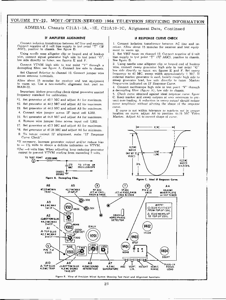
VOLUME TV -22, MOST -OFTEN -NEEDED 1964 TELEVISION SERVICING INFORMATIONADMIRAL Chassis C21A1-1A, -1E, C21A10-1C, Alignment Data, Continued
IF AMPLIFIER ALIGNMENT
Connect isolation transformer between AC line and receiver.Connect negative of 6 volt bias supply to test point "T" (IFAGC), positive to chassis. See figure B.
Using needle nose alligator clip or looped end of hookupwire, connect signal generator high side to test point "G",low side directly to tuner, see figures E and F.
Connect VTVM high side to test point "V" through adecoupling filter, see figure A. Connect low side to chassis.
Set Channel Selector to channel 12. Connect jumper wireacross antenna terminals.Allow about 15 minutes for receiver and test equipmentto warm up. Use a non-metallic alignment tool, part no.98A30-12.
Important: Before proceeding check signal generator againstfrequency standard for calibration.j1. Set generator at 42.7 MC and adjust Al for maximum.4-2. Set generator at 44.2 MC and adjust A2 for maximum.4-3. Set generator at 44.3 MC and adjust A3 for maximum.4. Connect wire jumper across IF input coil L302.
f5. Set generator at 44.8 MC and adjust A4 for maximum.6. Remove wire jumper from across input coil L302.
4-7. Set generator at 42.7 MC and adjust A5 for maximum.*8. Set generator at 47.25 MC and adjust A6 for minimum.9. To insure correct IF alignment, make "IF Response
Curve Check".*If necessary, increase generator output and/or reduce biasto - 11/2 volts to obtain a definite indication on VTVM.I -Use -6 volts bias. When adjusting, keep reducing generatoroutput to prevent VTVM reading from exceeding 2 volts.
TO TEST POINT41,000 OHMS
O270
CHASSIS
CROUMD -
Figure A. Decoupling Filter.
TMMFTO VTVM OROSCILLOSCOPE
A647.25 MC MIN
TRAP
A344.3 MC MAX
1st IF
A2dBOTTOM SLUG44.2 MC MAX
2nd IF
AlTOP SLUG
42.7 MC MAX2nd IF
oPIN 7ofV303
MOm TOP SLUG4.5 MC TRAP
A542.7 MCMAX
IF INPUT
ORF AGC
JCT,ot C401,R404 a R405
IF RESPONSE CURVE CHECK
1. Connect isolation transformer between AC line and re-ceiver. Allow about 15 minutes for receiver and test equip-ment to warm up.2. Set VHF tuner on channel 12. Connect negative of 6 voltbias supply to test point "T" (IF AGC). positive to chassis.See figure B.3. Using needle nose alligator clip or looped end of hookupwire. connect sweep generator high side to test point "G-low side directly to tuner, see figures E and F. Set sweepfrequency to 4:3 MC. sweep width approximately 7 MC. Ifexternal marker generator is used, loosely couple high side tosweep generator lead, low side directly to tuner. Markerfrequencies indicated on IF Response Curve.4. Connect oscilloscope high side to test point "V" througha decoupling filter (figure A). low side to chassis.5. Check curve obtained against ideal response curve. figureC. Keep marker and sweep outputs at very minimum to pre-vent over -loading. A reduction in sweep output should reducecurve amplitude without altering the shape of the responsecurve.
If curve is not within tolerance or markers not in properlocation on curve, adjust A4 to position 45.75 MC VideoMarker. Adjust Al to correct shape of curve.
41.25 MC
MARKER
(MAY NOT BE
VISIBLE)
OIF AGC
JCT.of R302,R406C302 a C304
4.5MC
Figure C. Ideal IF Response Curve.
PIN 2 ofV403
A444.8 MC
MIXER PLATEon VHF TUNER
0 L3o2
V301 4BZ6
i-T 01
O40K6
CR301VIDEO DET.
T302
8J 8
L301
12AL1f
',L201
I I l ,iT303f¡
L202
CR401 aHORIZ PHASE
DETECTOR
NOTE'OSLUG TFROM TOP OF
A SLUG NEARS STTO TOP OF COIL.
17J28
8F07 6GH8 C 8 A
A9 A8GIBOTTOM SLUG
4.5 MC SOUNDTAKE OFF
A74.5MC SOUND 4,5 MCINTERSTAGE OUADRATURE
liil'''ldhliilAGC VERT.
LIN.
33GY7
HEIGHT HORIZ.RANGE
Figure B. View of Precision Wired System Showing Test Point and Alignment Locations.
PLUG-INFOCUSLEAD
45.15 MC
MARKER
50%1060%
29
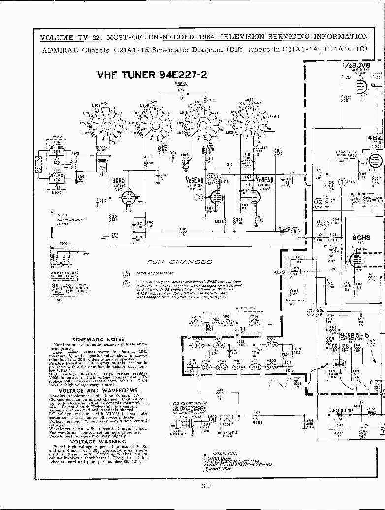
VOLUME TV -22, MOST -OFTEN -NEEDED 1964 TELEVISION SERVICING INFORMATION
ADMIRAL Chassis C21A1-1E Schematic Diagram (Diff. tuners in C21A1-1A, C21A10-1C)
M952r 9902 ,
.75-1.5NEC.
_1.50V-
75-1.5NE6.
C903
I470 I
M953
T90í
i1
ÍCá
VHF TUNER 94E227-2
L901L902 8
7
L903 ` 84
L904 r7 ' L910
L905 - T o L911
CH42
M950BO/CT /N NONOPOIE"
ANTENNA
T902
LI
J
CONNECT TO RECEIVER
ANTENNA TERMINALS
1901
I TNECS
0901 I M9514700 .i HELM1.518 183810-3
L906CHAN.
13
GIMMICK
0905
.47
LC920I 10
12
3685VHF AMPV90I/
55
2Ly
09044,70
1000
L907L908 6
5
1090711000
0921T1000
GIMMICK
0910
1.6
L916L917 6
8 L918
L915 L922L923 001193
7
8 L924 ,i a
0 CHAN.9
9 L919M L925
3- 3!to o
L920 Í L926
n
L912CHAN.
13 0908L914
1/2 6EA8VHF MIXERV902A
12
L921CHAN.
13
C911
"15C912
44,8MC =11L928
RUN CHANGESStart of production.
ro improve range of vertical hold control, R422 changed from750,000 ohms to 1,2 megohms, C405 changed from 470 mmfto 220mm f. C406 changed from 560 mmf lo 1200mmfR436 changed from 150,000 ohms lo 47,000 ohms.8413 changed from 470,000 ohms to 660, 000 ehms.
SCHEMATIC NOTESNumbers or letters inside hexagons indicate align-
ment points.Fixed resistor values shown in ohms 1- 10%
tolerance, % watt; capacitor values shown in micro-microfarads ± 20% unless otherwise specified.Fusible Resistor: B-- supply of this receiver isprotected with a 5.5 ohm fusible resistor, part num-ber 61B48-1.High Voltage Rectifier: High voltage rectifierV405 is located in high voltage compartment. Toreplace V405, remove chassis from cabinet. Opencover of high voltage compartment.
10
1/26EA8VHF OSC.
V902B
09101.20
VHF TUNER--- ---V304
rIV901 V902 I
0 01 TT815930 © 0 0 0 1 _!JIy00 0916
V402 530100 00 L312©
3.30
0913,1000
ii
i
i
i
rI
r-I 1ÁI
R402.1OAGGI
moK11 11
1820 1820 Ié2áC331 V404 V403 V401 V201 V303
.001MF 00 00 00 ®0 00
VOLTAGE AND WAVEFORMS 9501
Isolation transformer used. Line Voltage: 117.Channel Selector on unused channel. Contrast con-trol fully clockwise; all other controls counterclock-wise. Do not disturb Horizontal Lock control.Antenna disconnected and terminals shorted.DC voltages measured with VTVM between tubesocket and chassis, unless otherwise indicated.Voltages marked (°) will vary widely with controlsettings.Waveforms taken with transmitted signal input.For waveforms, controls set for normal picture.Peak -to -peak voltages may vary slightly.
VOLTAGE WARNINGPulsed high voltage is present at cap of V405,
and pins 4 and 5 of V404. Use suitable test equip-ment at these points. Servicing receiver out ofcabinet involves a shock hazard. Use polarized line(cheater) cord and plug, part number 89C 121-2.
2150
NOTE.' Plitt OD SOCAfT OFI/NE CONO /Sf0[AN/IED.3114113,9P/11002147,51.0NO7 S/Of OF/ITYAC L/N(
M501 M502 1,503
C117910
60 CYCLE CMS
C501
600Y
1 S501 I
L _JON -ÓÑ
620éITCH
8502
5.50RISIBLE
I 1
1
1 R403
0328
L311182°
C37129
820
"Nr7
SCNEIARC NOTES:
-i-01Á55/S 6100NDi o417#01 10NNTf/ ON C1801/// BOARD.#YOOABf I/!l 8Á18/87N SETT/NC OFCONTROlS.
ACABINET BNODNO.
C502....11-110.1410
Y
- eMa®
C301
.ÓO
A904rrr6.8 NEC
fR438471
C303
8.85%
l/28JV85000 II AMP.
V3038 laTsr T3 I.
8202221
L30242.7 MC
140818 NEC
R405
5.6 NEC
±C401
I22NF
OESY
Ser
IF ACC
OY
1301
t I
C30 130210302
I22601501 12500
121
2
4BZ1ST IFV301
5
2
43 5
5%
6GH8ACC
jr, V4015
04030o1Hf
I1V
R407
4110 0418Y 100
93B5-6110012.0 ASE DET.
CR4011443 R444
0420 0421022Mf 001MF
10% J 10%
CR501
.001MF118
05041
208R
N
/4
30
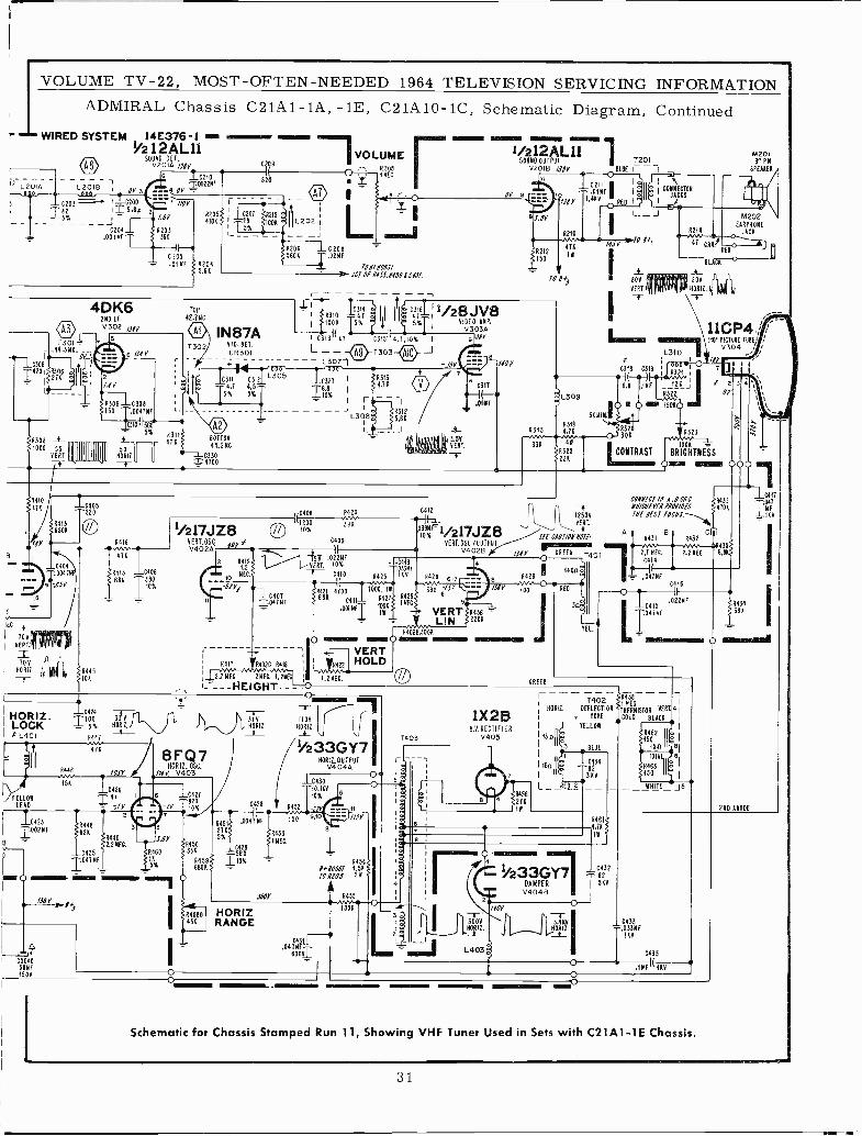
IVOLUME TV -22, MOST -OFTEN -NEEDED 1964 TELEVISION SERVICING INFORMATION
ADMIRAL Chassis C21A1-1A, -1E, C21A10-1C, Schematic Diagram, ContinuedWIRED SYSTEM 14E376-1 -
1/2 12ÁL11BO V
7 VOLUMEDE 1,
v201Á )9BY
III O 182086 27210 2 lI wEC
13002289---2
0203 --- 10200 7 1/OY
S¿
rI¡-
tITS%_
2/.9Y 42051;-,-18071R215^IIL2o2INK
yr1
.001 YfT .R39Ó 5% j 1 + R
I333 i 4TK
1 C 05- .0143 R20456K
R206 1 C2085606 1.02119
TOO BOOSTf JCT 0f 0155,9159! C1i).
1301_44.3NC_ _
uoá s 1T820I2i716 $ p1 2
---II /., Y
4DK62110 IfV 302 Aft
#308 -W-1000 55
VERT.
9
IEC
70VVERT
TOW
H0912
5
6
9309 10308I50 2.004119
1too i55á
2205
12445108
101
5%_A__ -HÓ912.
9416v.v47K
S 941 C40610
sir!-LC40TTOITMF
4311470
TOP
42.760
1302IN87A
$10. CET.
CR301
11 lI
job9
L% I1I IfI165I;1/28JV8V303A
G3uii47 1315ii4.1i10%i 9s9Y
L - - 0-T3o3 J- L3071
0311 0312L305
C327 IA313
4,1 4.5-T 6,8 4.71
sx s% I I1oY,I 1 -
BOTTOM
44.2NC
C330=4700
L308
IV00 39Kr1/217JZ8 10%
YEAT.OSC "I f C409
V402A11II,
1...,....----1,-....'sTyV .022NfR41915VERT. 10% T03391
NEC. Y - C430 R425 116V R428
111421 470074 M2T
390 */S%co - R42
.O6NfT 11WAINK
VERT R436111 jut LIN 220$
940213300K
A3125.9$
__J
-,152'
111,1 4,1,441( ;I
6 7317
.0169
VÉÍÍT.
-F
2212 II150
101
C412
Dóx`1/217JZ8*261. OSO /032253
V4028
0 4- mom O4
iiVERT
¡ 9411 rA402C A418 11mn HOLD¡_2LTREC 21EC. US
i 1.211E6.
1- - - - HEIGHT- ---O
HORIZ.LOCKSL401
C tfl
JTELLO8
423
1002693
151
_C424
R44
47X
ROIL1.
R448 3826
124492.2NEC.
0425-10476F
T403
8FQ7HORI .OSC.
/NY V403
6 1é 027
10%
31V 110YHORIz.
4
2765%
(BOY
HORIZRANGE
-11N- 2:
1233GY71106,1211Z UT
V404Á
1C430
8452
o4 0439
6004
10%
R454B"B0051 12561
701105
A R455 K
O+
r
4
1X2BH.V.RECTIFIER
0405
4315! Y
33X
lily
45627K1
- - 41K1K1K11/212ÁL11 M201
SOUND OUTPUT T201 3'PNv2018 /51Y 08LUE Í i SHARER
rH l021
=-.886911 ill 1
OOMNE6T0R'OY 6¡-ÍiOY 1.4KV RED I I
JACKS
= L309
51011A3í84,794Wwr
R32522K
12593VERT.
Sff CI07/OB007f
GRES
L -J
47 18
310_; I /IYC31i19
8.8 .INF i_ 122 J
Rwww1 O 15060 I
8320
0 301
CONTRAST
T40200912. DEFLECTION
7 YOKE
I 'FELLOW
18All3 BLUE
I IRA II _8434
3KV
I-_REQg
0
B 2 3
R323
BRIGHTNESS-
OY
w
M202EARPHONE
3606
ED
11GP4.,110' Flom TUBE; 1
V304 j
4
000
1011f1110 4,1001 2435MB/CBfY(B(BOY/OfS 4106lBf BEST f010S.--..4.
A Cn11431
8A432 F4ww--11435{
2.1 NEC. 2.29E1 6.
C41-I(4
.047MF+( 6
.0220F
R458 -111E1
YEAL 41
70LO815TOBLACK- 1
TOT*
8463150
2290 AKODE
C411
ÑF16V
i
11
4 7616
4N
1/23DAMPER
3GY7 432
5YV4048
-rHÚ6114 Ó339F.9_ 1611
0435
.18F(1KV
Schematic for Chassis Stamped Run 11, Showing VHF Tuner Used in Sets with C21A1-1E Chassis.
31.
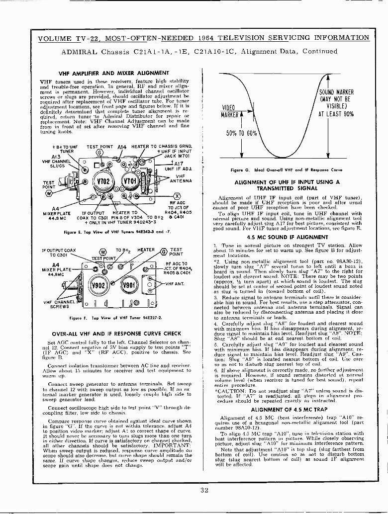
VOLUME TV -22, MOST -OFTEN -NEEDED 1964 TELEVISION SERVICING INFORMATION
ADMIRAL
VHF
VHF tunersand troublement is permanent.screws or slugsrequired afteradjustmentdefinitely determinedqúired, returnreplacement.from in fronttuning knobs.
t B+ TOTUNER
AlaVHF CHANNEL
SLUGS
TESTPOINT
©
A4MIXER PLATE
44.8 MC
Figure
IF OUTPUT COAXTO C301
A4MIXER PLATE
44.8MC
1f
AMPLIFIER
used-free
replacementlocations,
Note:of
UHF
_
El;,_I1E
COAX
Chassis C21A1-1A,
AND MIXER ALIGNMENTin these receivers, feature
operation. In general, RF andHowever, individual channel
are provided, should oscillatorof VHF oscillator tube.
see front page and figuresthat complete tuner alignment
tuner to Admiral DistributorVHF Channel Adjustment
set after removing VHF channel
TEST POINT A14 HEATER TO
-1E, C21A
high stabilitymixer align-
oscillatoradjustment be
For tunerbelow. If it is
is re-for repair orcan be made
and fine
CHASSIS GRND.t UHF IF INPUT
JACK M701
tA17IF ADJ.
VHF:. ANTENNALI
10-1C, Alignment Data, Continued
VIDEO
SOUND
(MAY
AT LEAST
r
MARKER
NOT BE
VISIBLE)
90%MARKER
50% TO 60%
r-p e' nn 7Q® O O o 0 te,
o , Y702 MI _'j OIOqQe
a1
o<l"'
Figure G. Ideal Over-all VHF and IF Response
ALIGNMENT OF UHF IF INPUT USINGTRANSMITTED SIGNAL
Alignment of UHF IF input coil (part ofshould be made if UHF reception is poor andcauses of poor UHF reception have been checked.
To align UHF IF input coil, tune in UHFnormal picture and sound. Using non-metallic alignmentvery carefully adjust slug A17 for best picture, consistentgood sound. For VHF tuner adjustment locations,
4.5 MC SOUND IF ALIGNMENT
1. Tune in normal picture on strongest TVabout 15 minutes for set to warm up. See figurement locations.*2. Using non-metallic alignment tool (part no.slowly turn slug "A7" several turns to left untilheard in sound. Then slowly turn slug "A7" toloudest and clearest sound. NOTE: There may(approx. 1/2 turn apart) at which sound is loudest.should be set at center of second point of loudestas slug is turned in (toward bottom of coil).3. Reduce signal to antenna terminals until thereable hiss in sound. For best results, use a step attenuator,nected between antenna and antenna terminals.also be reduced by disconnecting antenna and placingto antenna terminals or leads.4. Carefully adjust slug "AS" for loudest andwith minimum hiss. If hiss dissappears duringduce signal to maintain hiss level. Readjust slugSlug "A8" should be at end nearest bottom of5. Carefully adjust slug "A9" for loudest andwith minimum hiss. If hiss disappears duringduce signal to maintain hiss level. Readjust slugtion: Slug "A9" is located nearest bottom ofso as not to disturb slug nearest top of coil.6. If above alignment is correctly made, no furtheris required. However, if sound remains distortedvolume level (when receiver is tuned for bestentire procedure.*CAUTION: Do not readjust slug "A7" unlesstorted. If "A7" is readjusted, all steps in alignmentcedure should be repeated exactly as instructed.
ALIGNMENT OF 4.5 MC TRAP
Alignment of 4.5 MC (beat interference) trapquires use of a hexagonal non-metallic alignmentnumber 98Aá0-12).
To align 4.5 MC trap "A10", tune in televisionbeat interference pattern in picture. While closelypicture, adjust slug "A10" for minimum interference
Note that adjustment "A10" is top slug (slugbottom of coil). Use caution so as not to disturbslug (slug nearest bottom of coil) as soundwill be affected.
Curve
A
VHF tuner),after usual
channel withtool
withsee figure E.
station. AllowB for adjust -
98A30-12),a buzz is
the right forbe two points
The slugsound noted
is consider -con-
Signal canit close
clearest soundalignment, re -"AS". NOTE:
coil.clearest soundalignment, re-
"A9". Cau-coil. Use care
adjustmentat normal
sound), repeat
sound is dis-pro -
"A10" re-tool (part
station withobserving
pattern.farthest from
bottomIF alignment
' 1z- ©RF AGC
TO JCT.OFR404, R405
B+2 a C401
and -7,
/, TESTv POINT
RF AGC TOJCT. OF R404,
IF OUTPUT HEATER TOTO C301 PIN 8 OF V304 TO
t ONLY IN VHF TUNER 94D243-3
E. Top View of VHF Tuners 94E243-3
O TO B+2 HEATER
TEST POINT
ouO
1 'i 0O 8405 a 0401' VHF ANT.
CHECK
on chan-test points "T
chassis. See
and receiver.equipment to
Set sweepIf an ex-
high side to
through de-
curve shownadjust A4
shape of curve.than one turn
checked,
amplitude onremain the
output and/or
lVHF CHANNEL .'
SCREWS
Figure
OVER -ALL
Set AGC controlnel 12. Connect(IF AGC) andfigure B.
Connect isolationAllow about 15warm up.
Connect sweepto channel 12 withternal markersweep generator
Connect oscilloscopecoupling filter,
Compare responsein figure "G".to position videoIt should neverin either direction.all other channelsWhen sweep outputscope should alsosame. If curvescope gain until
.:11:5
,.¡¡ pp
41 lE0 oo
F. Top View of VHF Tuner 94E227-2.
VHF AND IF RESPONSE CURVE
fully to the left. Channel Selectornegative of 3V bias supply to"X" (RF AGC), positive to
transformer between AC lineminutes for receiver and test
generator to antenna terminals.sweep output as low as possible.
generator is used, loosely couplelead.
high side to test point "V"low side to chassis.
curve obtained against idealIf the curve is not within tolerance,
marker; adjust Al to correctbe necessary to turn slugs more
If curve is satisfactory on channelshould be satisfactory. IMPORTANT:is reduced, response curve
decrease, but curve shape shouldshape changes, reduce sweep
shape does not change.
32
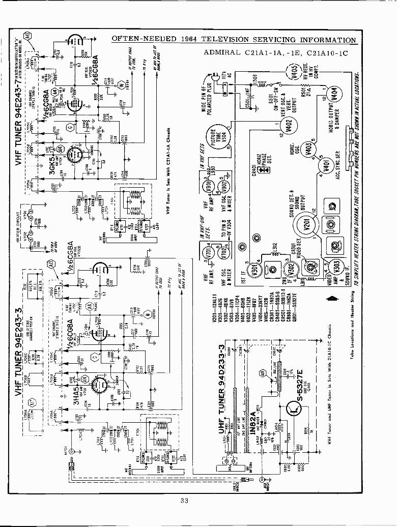
CA
BLE
M80
2
VH
F
NT
EN
NA
M70
1
L70
L703
r 00
0C
701A
27
L702
t701
Oa
-61
02
C70
221
1701
R11
077
01
64.5
1151
0721
410
1.5K
V
VH
F T
UN
ER
94E
243-
3L7
06A
L706
BL7
06C
UH
F IF
ST
RIP
CH
AM
NE
L1 P
OS
ITIO
N
-
LJ
3
3HÁ
5V
HF
AM
P
C70
4V
701
^15
R71
21
L705
8L7
05C
L7050
VH
F C
HA
NN
EL
aoo
-'000
ST
RIP
S 2
TH
RU
130
45
4:4/
22:
1".1
19-2
:-
--_aa
6CG
8A7w
"M6
A1
VH
F M
IAE
RL7
07V
702A
6109
20
7R
70
C70
6
IS1
F -
1100
K
6105
GIM
MIC
KK
-Tit)
R70
1475
(VD
4_C
714
;17 óL
708
C70
8141
RIO 2.25
T02
1 W
R 1.25
Í 110
00
17.-
71L7
09'4
4.8
NC
8705
2.28
C71
7
1{00
Ó^i
000
110Y
-O
110V
B+
C 7
I0
H 8.2
0711
16.8
HE
AT
ER
CIR
CU
IT
lV70
2V
700
C73
IC
72/
000
Tr0
00
TO
1/N
4O
f Y30
4
1/26
CG
8AV
HF
OS
C.
V70
28
1
R7I
4.8
5 67201
1000
/F O
OT
PO
I CO
AX
.
TO
630
/
TO
845
1F A
OC
TO
JC
T O
F84
04 6
140
5
11-1
- Le
UH
F
AN
TE
NN
A
UH
F T
UN
ER
94D
233-
3-R
801
C80
9A
151
UH
F L
INE
-08
888,
_ 21
0 U
HF
LIN
E-t
660
1N82
A18
02U
HF
MIX
ER
L803
M80
1T
C80
1C
R80
-33
T1C
8021
0%S
L804
1000
R80
28.
85
R80
3
6.88
TC
803
1000
R80
4
11(
OSC
.L
INE
6800
6
C80
6I1
.5 a%
S -
5327
EU
HF
OS
C
Q80
1
VH
F T
uner
and
UH
F T
uner
in S
ets
With
21A
10 -
ICC
hass
is
V20
1-12
AL1
1V
301-
-4B
Z6
V30
2 -4
0K6
V30
3 -8
1V8
V30
4-11
CP
4V
401-
6GH
8V
402
-171
Z8
V40
3-B
FQ
7V
404-
33G
Y7
V40
5 -1
X28
CR
301-
1 N
87A
CR
401-
9365
.6C
R50
1-93
B12
-1C
RB
01-1
N82
A08
01-S
5327
E
VH
F
RF
AM
P.
VH
F O
SC
.
& M
IXE
R
L703
Lr 0
00 .0
701
27
1702
C70
2N 2
7
VIII
0702
7A
NT
EN
NA
L701
8710
1701
300a
ti.S
AV
INP
UT
I
VH
F T
UN
ER
94E
243-
7 IN
S
AF
TE
R C
HA
SS
ISO
RT
H IM
OD
EL
10.
23
3GK
5V
HF
AM
P
0704
V70
1IS
5
1705
8L7
05C
OS
6IN
MIC
A
0708
47
1701
- 1
415
LJ
3.6
6004
I11
o0D
VH
F C
HA
NN
EL
ST
RIP
S 2
TH
RU
13
1/26
CG
8AV
HF
MIX
ER
V70
2A44
.8M
CA
4
::170
8 4A
R70 2.25
1111
1-4
RvO
i225
1100
0IIOV
-o
VH
F T
uner
is S
ets
With
C21
A1-
1A C
hass
is
IN
VH
F -
US
EV
HF
SE
TS
.R
F A
MP
TO
PIN
8V
HF
OS
C.
OF
V30
4&
MIX
ER
-TIM
VH
F S
ET
S
00 r
--
L930
PIC
TU
RE
TU
BE
V30
4
WID
E P
INOF
PO
LAR
IZE
D P
LUG 11
7V
AC
1ST
IF
2ND
IF 4
L311
VID
EO
AM
P
&
SO
UN
D IF
.
CR
301
VID
EO
DE
T.
CR
401
HO
RIZ
PH
AS
E--
- D
ET
.
AC
C, S
YN
C. S
EP
.
C50
11F
.1M
F
S50
1O
N -
OF
F -
SW
VE
RT
OS
C. &
VE
RT
.
OU
TP
UT
R50
121
A
HO
RIZ
. OU
TP
UT
&D
AM
PE
R
L705
D
FIN
EA
TU
NIN
G
L707 00
0'-
C
aoo
10
8.2
VIII
080
.V
7028
;/2sc
G8a
IF 0
11P
lOT
CO
AX
.T
O13
01.
TO
Bt1
,IF
/0 T
O J
CT
. Of
11.0
0,11
10.Y
(V40
5)
HV
RE
CT
.
IN H
VC
ON
PT
.
Tub
eLo
catio
ns a
nd H
eate
r S
trin
gT
O S
/NP
L/F
T H
EA
TE
R S
TR
E' U
/AC
BA
M, T
UB
E S
OO
XE
T P
/H 1
/AV
ER
S A
RE
RO
T S
HO
O"
/I W
WI L
OC
AT
ION
S
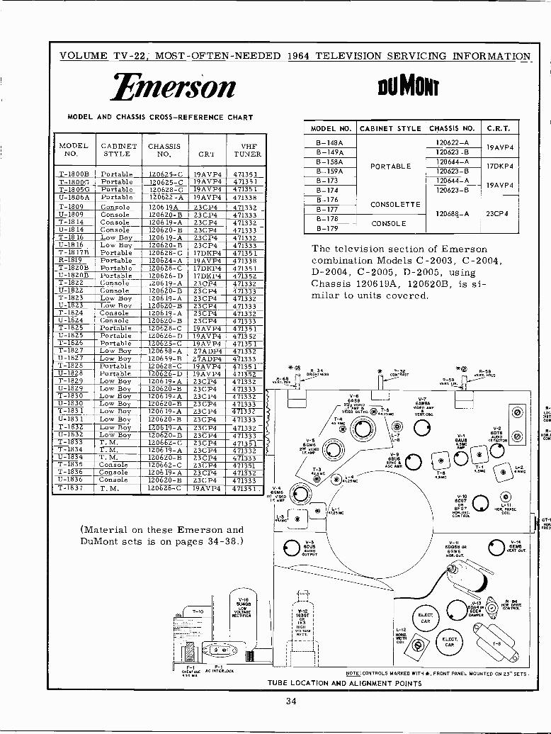
VOLUME TV -22; MOST -OFTEN -NEEDED 1964 TELEVISION SERVICING INFORMATION
EmersonMODEL AND CHASSIS CROSS-REFERENCE CHART
MODELNO.
CABINETSTYLE
CHASSISNO. CRT
VHFTUNER
T -1800B Portable 120625-C 19AVP4 471351T -1800G Portable 120625-C 19AVP4 471351T -1805G Portable 120628-C 19AVP4 471351U -18Á6A Portable 120622 -A 19AVP4 471338T-1809 Console 1206 19A 23CP4 471332U-1809 Console 120620-B 23CP4 471333T-18 14 Console 1206 19-A 23CP4 471332U-1814 Console 120620-B 23CP4 471333T-1816 Low Boy 120619-A 23CP4 471332U-1816 Low Boy 120620-B 23CP4 471333T -1817B Portable 120628-C 17DKP4 471351R-1819 Portable 120624-A 19AVP4 471338T -1820B Portable 120628-C 17DKP4 471351U -1820B Portable 120626-D 17DKP4 471352T-1822 Console 120619-A 23CP4 471332U-1822 Console 120620-B 23CP4 471333T-1823 Low Boy 1206 19-A 23CP4 471332U-1823 Low Boy 120620-B 23CP4 471333T-1824 Console 120619-A 23CP4 47133211-1824 Console 120620-B 23CP4 471333T-1825 Portable 120628-C 19AVP4 47135111-1825 Portable 120626-D 19AVP4 471352T-1826 Portable 120625-C 19AVP4 471351T-1827 Low Boy 120658-A 27ADP4 47133211-1827 Low Boy 120659-B 27ADP4 471333T-1828 Portable 120628-C 19AVP4 47135111-1828 Portable 120626-D 19AVP4 471352T-1829 Low Boy 120619-A 23CP4 47133211-1829 Low Boy 120620-B 23CP4 471333T-1830 Low Boy 120619-A 23CP4 47133211-1830 Low Boy 120620-B 23CP4 471333T-183 1 Low Boy 1206 19-A 23CP4 471332U-183 1 1 Low Boy 120620-B 23CP4 471333T-1832 Low Boy 120619-A 23CP4 471332U-1832 Low Boy 120620-B 23CP4 471333T-1833 T. M. 120662-C 23CP4 471351T-1834 T. M. 1206 19-A 23CP4 47133211-1834 T. M. 120620-B 23CP4 471333T-1835 Console 120662-C 23CP4 471351T-1836 Console 120619-A 23CP4 47133211-1836 Console 120620-B 23CP4 471333T-1837 T. M. 120628-C 19AVP4 471351
(Material on these Emerson andDuMont sets is on pages 34-38.)
V -1B
DU4G6O
VOLTAGERECTIFIER
V F AC INTERCNEM U E LOCK450 YA
V-466616
IL VIDEOLE AMP
L-343.150
ou M ONr
MODEL NO. CABINET STYLE CHASSIS NO. C.R.T.
B -148A 120622-A19AVP4
B -149A 120623-BB -158A 120644-A
PORTABLE 17DKP4B-159Á 120623-BB-173 120644-A
19AVP4B-174 120623-BB-176
CONSOL ETTEB-177
120688-A 23CP4B-178
CONSOLEB-179
The television section of Emersoncombination Models C-2003, C-2004,D-2004, C-2005, D-2005, usingChassis 120619A, 120620B, is si-milar to units covered.
V-6SASS
3 9i VIDEOF. AMP. A
VIDEO DETEC.
/T143MD
®V -S
6GM6ºM VIDEO
LE AMP
V-3SCUDAUDIO
OUTPUT
ylay -,\
i 1631GT
1
I ORÍK3
I HI00VOLTAGE
HECT.
V-76AWBA
VIDEO AMP
V EReT 03C
®
* _R_32 *O R-58VERL HOLD
R-69 ,,..-----VERT. LN.
T-64.65E
V-2
V-1 AUDIOBAU6 DETECTOResMc O®AYP
O T-14.SYC (l
V-106CG7
OR L-11.6F07 MOR PHASE
000.050. COIL.CONTROL
11 CT -1NOR
FRED
L-24.5YZ
V-116906E1 ORBOWSNON. OUT.
44.25MC
L-7L-9
V -SSBUB
DYNE 6AGE AMP.
L-12momWIDTHCOIL
v-+46EM5
VERT O^JT.
NOR-64ORNECONTROL
NOTE: CONTROLS MARKED WITH *, FRONT PANEL MOUNTED ON 23." SETS.
TUBE LOCATION AND ALIGNMENT POINTS
R-LOGDISTCON
R -NOR. I
LON'
34
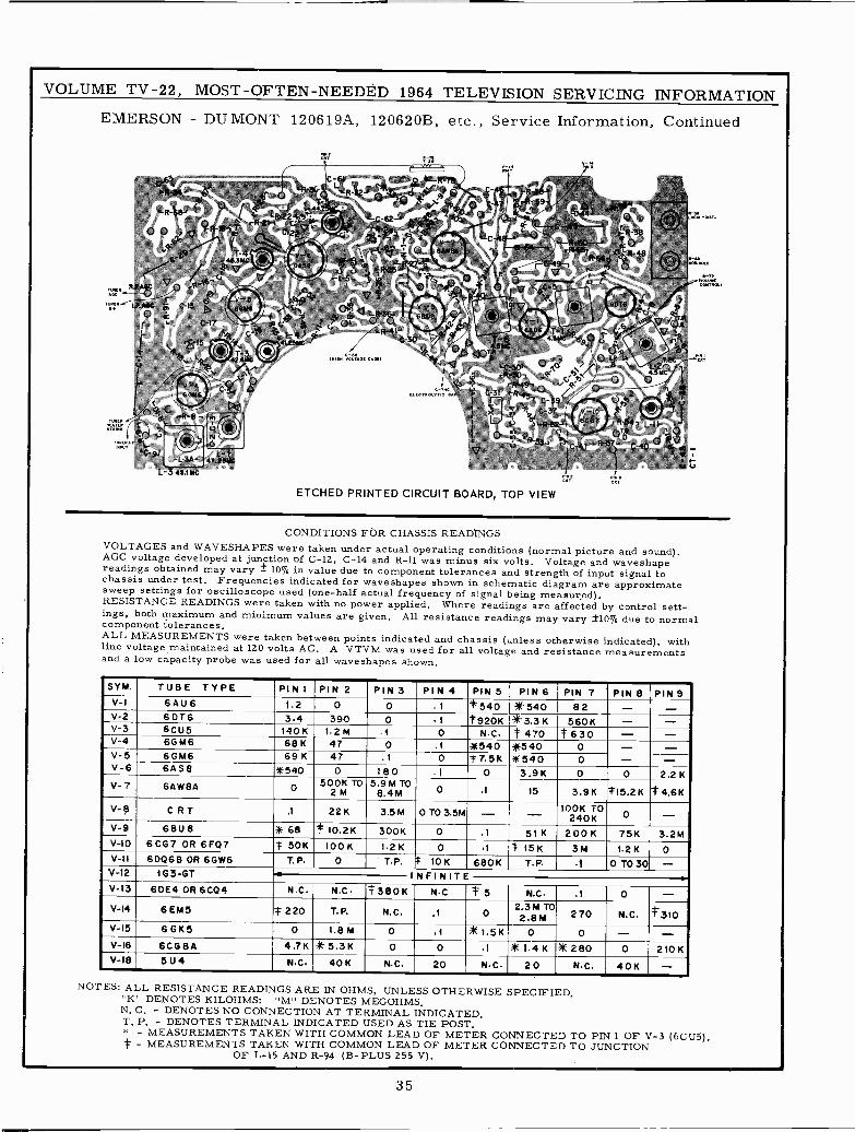
VOLUME TV -22, MOST-OFTEN-NEEDÉD 1964 TELEVISION SERVICING INFORMATION
EMERSON - DUMONT 120619A, 120620B, etc., Service Information, Continued
ETCHED PRINTED CIRCUIT BOARD, TOP VIEW
CONDITIONS FOR CHASSIS READINGSVOLTAGES and WAVESHAPES were taken under actual operating conditions (normal picture and sound).AGC voltage developed at junction of C-12, C-14 and R-11 was minus six volts. Voltage and waveshapereadings obtained may vary ± 10% in value due to component tolerances and strength of input signal tochassis under test. Frequencies indicated for waveshapes shown in schematic diagram are approximatesweep settings for oscilloscope used (one-half actual frequency of signal being measured).RESISTANCE READINGS were taken with no power applied. Where readings are affected by control sett-ings, both maximum and minimum values are given. All resistance readings may vary ±10% due to normalcomponent tolerances.ALL MEASUREMENTS were taken between points indicated and chassis (unless otherwise indicated), withline voltage maintained at 120 volts AC. A VTVM was used for all voltage and resistance measurementsand a low capacity probe was used for all waveshapes shown.
SYM. TUBE TYPE TPIN 1 PIN 2 PIN 3 PIN 4 PIN 5 PIN 6 PIN T PIN 8 PIN 9
V -I 6 A U 6 1 . 2 0 0 1 *540 *540 82 - -V-2 6DT6 3.4 390 0 1 *920K *3.3K 560K - -V-3 6CU5 140K 1.2M .1 0 NC #470 t630 - -V-4 6GM6 68K 47 0 .1 *540 *540 0 - -V-5 6GM6 69K 47 .1 0 #7.5K 11E540 0 - -V-6 6AS8 111540 0 180 I 0 3.9K 0 0 2.2KV-7 6AW8A 0 500K TO
2 M5.9M TO
$.4M 0 .1 15 3.9K #15.2K *4.6KV-8 C R T .1 22K 3.5M O T0 3.5M - - 100K TO
240K O
V-9 68U8 ill 68 *10.2K 300K 0 .1 51K 200K 75K 3.2MV-10 6CG7 OR 6FQ7 * 50K 100 1.2K 0 .1 * 15K 3M 1.2K 0V-Il 6006E1 OR 6GW6 T.P. 0 T.P. # 10K 680K T.P. 1 0 T030 -
V-12 163-0T .0 INFINITE -V-13 6DE4OR6CQ4 N.C. N.C t380K NC #S N.C .1 0 -V-14 GEMS t 220 T.P. N.C. .1 0 2.3M TO
2 .8 M 270 N.C. #310V-15 6GK5 O 1.8M 0 .1 *1.5K 0 0 - -V-16 6CG8A 4.7K *5.3K 0 0 .1 iIE 1.4 K* 280 0 210KV-18 5U4 N.C. 40K N.C. 20 NC 20 NC 40K -
NOTES: ALL RESISTANCE READINGS ARE IN OHMS, UNLESS OTHERWISE SPECIFIED."K" DENOTES KILOHMS: "M" DENOTES MEGOHMS,N. C. - DENOTES NO CONNECTION AT TERMINAL INDICATED.T. P. - DENOTES TERMINAL INDICATED USED AS TIE POST.* - MEASUREMENTS TAKEN WITH COMMON LEAD OF METER CONNECTED TO PIN 1 OF V-3 (6CU5).t - MEASUREMENTS TAKEN WITH COMMON LEAD OF METER CONNECTED TO JUNCTION
OF L-15 AND R-94 (B -PLUS 255 V).
35
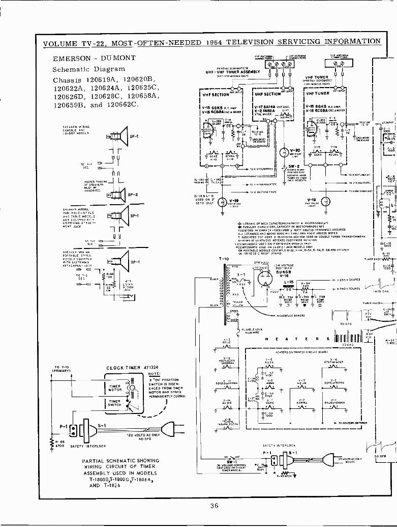
VOLUME TV -22, MOST -OFTEN -NEEDED 1964 TELEVISION SERVICING INFORMATION
EMERSON - DU MONTSchematic DiagramChassis 120619A, 120620B,120622A, 120624A, 120625C,120626D, 120628C, 120658A,120659B, and 120662C.
SPEAKER WIRING,CONSOLE ANDLO -BOY MODELS
TO T-2 7y u
SEC. =
PROPER PHASINGOF SPEAKERSMUST BEOBSERVED.
SPEAKER WIRING,PORTABLE -STYLEAND TABLE MODELSNOT EQUIPPED WITHLISTENING ATTACH-MENT JACK
TOT-2SEC
SPEAKEP WIRINGPORTABLE STYLEMODELS EOUI PPE°W ,TH LISTENINGATTACHMENT JACK
TO T -1O(PRIMARY)
TO T-2SEC.
SP -1
SP -2
SP -1
SP -1
J-1LISTENATTACH.JACK
CLOCK TIMER 471324NOTE
IN "ON" POSITIONSWITCH IS DISEN-GAGED FROM TIMERMOTOR AND STAYSPERMANENTLY CLOSED.
TIMERSWITCH
120 VOLTS
S-,
/110 C AC ONLY
60 CPSR-86
III
O.III
470K SAFETY INTERLOCK
PARTIAL SCHEMATIC SHOWINGWIRING CIRCUIT OF TIMERASSEMBLY USED IN MODELS
T-1800B,T-1800G 0T -1806A1AND T-1826
PARTIAL SCHEMATICOF
UHF - VHF TUNER ASSEMBLY(UTE-VME MODELS ONLT)
V-15 66K5 R.F.AMP. IV-16 8CG8AosC.B MIXER I
9
L
i¡:F.n
r---- ANTINPDTI UHF SECTION
IV -17 6AF4A iI X -Y 11482A v- IT
MIXER S
6AF4A LEIB a J
-©
O 1 TOR 811TUxERB1
(1-181Y (L-19)'}. .
. J45.0MC1:1 EILCx.'¡L
TO V-4 PIM41xFATERI
IL -18 B L -IR)USED ON 19"SETS ONLY
V-19
T-10
RED .70V(AC)
F-1RED
FUSE
RED
UNIBLE LINKIRE
V-36CU5
6C04,6DV-13E4OR6DA4A
DN % DFE
SW -1ON VOLUME CONTROLNOT U6E0 On CLOCK -
TIMER MODELS)
TO C 291TUNERAGCI
V-º0UHF PILOT
LIGHT
CdÑÉCT0R3
VHF TUNER(PARTIAL SCHEMATIC)
VHF MODELS 0111.11r----IVHF TUNER
ILUCATEDIN51 E
CMRMOOEL511
V-15 68115 R.F.AMP, I
V -I6 6CG8AOBC.BMIXERI
,6CGBA
V-19
V-16
-1». TO R9IITUNERB1
TO V 4 PIN IHTRJ
TO 291T1111ERAGCI
* CERAMIC OR MICA CAPACITORS,CAPACITY IN PICOFARADS(p 1
* TUBULAR CAPACITORS,CAPACITY IN MICROFARADS( MF)RESISTORS IN OHMS (0 1000) AND i WATT UNLESS OTHERWISE SPECIFIEDALL CERAMICS AND MICAS SOOV,ALLTUBULARS 400V. UNLESS NOTEDT INDICATES TOP CORE B INDICATES BOTTOM CORE IN DOUBLE TUNED TRANSFORMERSARROWS AT CONTROLS INDICATE CLOCKWISE ROTATION
()COMPONENTS USED ON IT OR 19 INCH MODELS ONLY C -I2*COMPONENTS USED ON 230R 27 INCH MODELS ONLY 11000
ON PORTABLE MODELS CONTROLS R -32,R-34, R -58,R -59,R -6B ARE LOCATED -
ON PRINTED CIRCUIT BOARD. R-91220
270 V lA CTUNER 800.
LOW VOLTAGERECTIFIER
o 5U4GBV -I8
r
R -B8200
260V
L-15
7
C -73A C -74A C -73B
T '10'1 I l(5Óv I 30no o
HEATER S
-6255V SOURCE r
+240 V SOURCE
I30 CPS
IIII II
II
30CPS
V-66ASB
HEATERS ON PRINTED CIRCUIT BOARD
V-106F07oR6CGT
5
V-9 V-268 UB 6DT6oR60T6A
V-7BARBA
V-16AU6oR6AWA
3
000l
TOTS CPS
TUNER A6CO
T2 61 IdC-2vÍ_
6'0V
R -SS'5 MEO ¡
O NEATE83 OM ',rung
J
SAFETY INTERLOCK
P-1 S-1
*D_73l C047T
600V
120 VOLTS AC ONLYD CPS
30 CPB
36
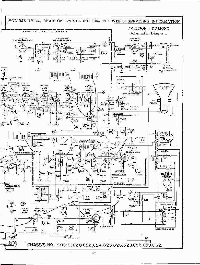
I R -5B tI,SMEG
VERTICAL HOLD
R-59.500 K
kERTICAL LINEARITY..
I
VOLUME TV -22, MOST -OFTEN -NEEDED 1964 TELEVISION SERVICING INFORMATION
I VIDEOF AMPV-4SOWS I2
PRINTED CIRCUIT BOAR D
4.5MC AMPV-1 6AU6oR6AU6A
122
PART OF PATTERN
AC
110C-0IS0
' R-13470
I.F.AGCT. P.
O ro -cl
L-4
AUDIO DETECTORV-2 6DT6oR6DTBA
T-1I RRo
GREEN Dot O,
R-2470
+135 V
2ND VIDEOI F AMP
V-5
3RD VIDEOAMP
V -6A6ASB 22
1-4
C-191 470
;-14- R-11 C-1747 68KDC,¿) -¿<7,+135
LOY - -
130V
13`0
}
SYNC6AGCAMP20 V-13,V-8
6BUBap,
+135 V
R-385 MEGLOCAL - DISTANCE
470 K
100Ó
1 t Iv
C-45-.0639 ^
oIf1
----__.._ I I
l
Í I
W° 2.2 MEG °
I
240 v
220KR-60
IW
10,000 1 I
j45 +I
vERTOSC
V -7B6AW8A
-30V
30 CPS
EMERSON - DU MONTSchematic DiagramAUDIO OUTPUT
V-3 6CÚ5
L-2101000
c -u fl Ir C2OV 1 MREEN D0 I
-551501
2.
,inv .R-72V V> 58°
C-7 1 R-410,000 3300
T-5
9(5VP -P
-`
DETECTORVIDEO
DETECTORV -6B
135 V
6AS863.7 V Fl
!y1;1,-
R-7 IMEGI 4706 I VOLUME
R-6 C-10 -I
-10.000
I
R-21 R-22470 1500 R-24 - L-7
6800 90U
+135 V 02400
5V ZV
"7'-P+P
7675CPS
PHASECOtlPARATOR
IC -31y R-451 / R-491
e2 I.__
pfYE6.
C-32 11 1I +82 R-4 1 R-50 ` 8.50
,MEG ` 100K C-37000 ilOOv I
ROOK R82K4 -
. +Ir
;Í 10+240V +135V IC -35
I 1000
THOR.OSC.e CONTROL
_1P- V-106F07oR6CG7 6oV(` /_I 4'5V
R-56 PI P
óóávso"IC-3B 56 '.R_
I V
+290V..7875 CPS -
IIOVP -P
II III
30 CPS
VIDEOAMPLIFIERV- 7A
6AW8A
SO
T. P.
2 J / 00MH
530UH, 140V
0.3V TO3.3 VR-2715
C-001000 I
C -5T R-741.2 MEG
+BOOST
+240V -
+BOOST
+3500 74
C -73C +43°ooMFv Í
1
+1350 w-- _-jADJUST FOR OPTIMUM FOCUS
31 /
IC -6147
R-32300
00 CONTRAST
+135V2 R-33
10K(LOCATEDOn BOARD)
BRIGHTNESSR 34 +135V5006
1
C 00.' 1000
R-78
392R-29 6000K 3gIT T5W
T+C1óvFR - 9
15K , 12W
OR.HOLD
"1;o C -4e Izev_
7 87 5 CPS
30 CPS
117-: I
}R-682.59E6VERTICAL SIZE
4
.04--x
, 475170V
8.50R-32 R-551200 1006
33ÓO
+ 240V
/C7003 110-15OPFo ,KYTT v/R-82C-400047
010
100-30V
6-81 06806 TO
4V
_ 4R B530
HORIZONTAL DRIVE
7875 CPS
2 TO SPEAKER'S/
i 7yI
+1350SOURCE i I
II
II
+ 255 V 1 4
TO POINTSX V ON RE-MOTE CONTROL
(REMOTE MODEL R-1819ONLY 1
PICTURE TUBEV-6
1
M-1 CCENTERINGASSEMBLY
II o
I
VOLTT-7 11(º<>
HIGHRECTIFIER
IG3GT
n Q 0R1KViII R-110
R-69I8V 1 226 A?1P}P® ° I
%:41,1
30V C-50- R-70-^T 27=
C-730oYFT
BLUE
235V T - B IbMOTO14V+ +240V +2550
30 CPS
HORIZONTALOUTPUTV -II
6D06800 66W6R-83
4 l00
4'5 VR, -P
R105-85
2W
+240V
1.86
350 V
3455
70e 6
' nL -12 21211
u° girs
L____
30 CPS
11500
6004-1160E4
OR6DA4ADAMPER
6 8 0 V
5 255V
P -Pi R -8TTOOK
+ 3500SOURCE
R-88120K
+8005T.JSOURCE
R-891306
L-1310 UH
C69
C-68- 02E C-70100 x .
V = ID00y
' HORIZONTAL COILS
67 E_
44 ,SKvI
680LO
C-76.047
L-14 iVERTICAL
COILS
DEFLECTION YOKE
CHASSIS NO. 120619, 6209622,624,625,626,628,658,659,662.
37
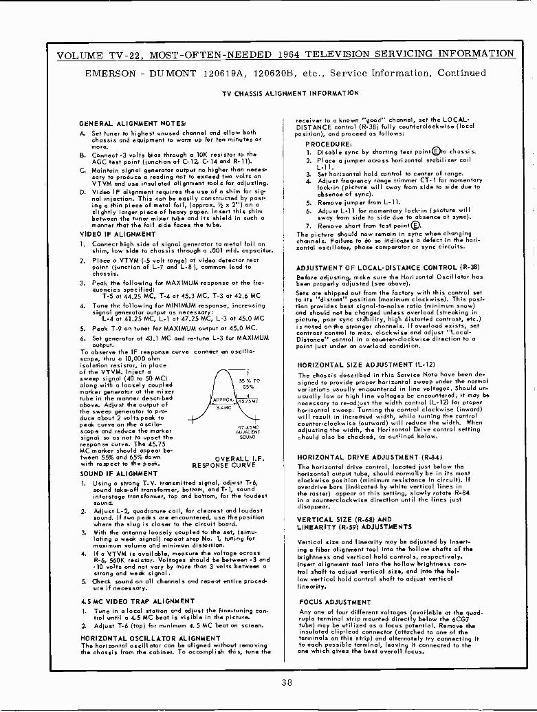
VOLUME TV -22, MOST -OFTEN -NEEDED 1964 TELEVISION SERVICING INFORMATION
EMERSON - DUMONT 120619A, 120620B, etc., Service Information, Continued
TV CHASSIS ALIGNMENT INFORMATION
GENERAL ALIGNMENT NOTES:A. Set tuner to highest unused channel and allow both
chassis and equipment to warm up for ten minutes ormore.
B. Connect -3 volts bias through a 10K resistor to theAGC test point (junction of C-12, C-14 and R-11).
C. Maintain signal generator output no higher than neces-sary to produce a reading not to exceed two volts onVTVM and use insulated alignment tools for adjusting.
D. Video IF alignment requires the use of a shim for sig-nal injection. This can be easily constructed by past-ing a thin piece of metal foil, (approx. %2 x 2") on aslightly larger piece of heavy paper. Insert this shimbetween the tuner mixer tube and its shield in such amanner that the foil side faces the tube.
VIDEO IF ALIGNMENT1. Connect high side of signal generator to metal foil on
shim, low side to chassis through a .001 mfd. capacitor.2. Place a VTVM (-5 volt range) at video detector test
point (junction of L-7 and L-8), common lead tochassis.
3, Peak the following for MAXIMUM response at the fre-quencies specified:
T-5 at 44.25 MC, T-4 at 45.3 MC, T-3 at 42.6 MC4. Tune the following for MINIMUM response, increosing
signal generator output as necessary:L-4 at 41.25 MC, L-1 at 47.25 MC, L-3 at 45.0 MC
5. Peak T-9 on tuner for MAXIMUM output at 45.0 MC.
6. Set generator at 43.1 MC and re -tune L-3 for MAXIMUMoutput.
To observe the IF response curve connect an oscillo-scope, thru a 10,000 ohmisolation resistor, in placeof the VTVM. Inject asweep signal (40 to 50 MC)along with a loosely coupledmarker generator at the mixertube in the manner describedabove. Adjust the output ofthe sweep generator to pro-duce about 2 volts peak topeak curve on the oscilo -scope and reduce the markersignal so as not to upset theresponse curve. The 45.75MC marker should appear be-tween 55% and 65% downwith respect to the peak.
SOUND IF ALIGNMENT1. Using a strong T.V. transmitted signal, adjust T-6,
sound take -off transformer, bottom, and T- 1, soundinterstage transformer, top and bottom, for the loudestsound.
2. Adjust L-2, quadroture coil, for clearest and loudestsound. If two peaks are encountered, use the positionwhere the slug is closer to the circuit board.
3. With the antenna loosely coupled to the set, (simu-lating a weak signal) repeat step No. 1, tuning formaximum volume and minimum distortion.
4. If a VTVM is available, measure the voltage acrossR-6, 560K resistor. Voltages should be between -3 and-10 volts and not vary by more than 3 volts between astrong and weak signal.
5. Check sound on all channels and repeat entire proced-ure if necessary.
55 % TO65%
45.75 MC
47.2 5MCADJACENT
SOUND
OVERALL I.F.RESPONSE CURVE
4.5 MC VIDEO TRAP ALIGNMENT1. Tune in a local station and adjust the fine-tuning con-
trol until a 4.5 MC beat is visible in the picture.2. Adjust T-6 (top) for minimum 4.5 MC beat on screen.
HORIZONTAL OSCILLATOR ALIGNMENTThe horizontal oscillator con be aligned without removingthe chassis from the cabinet. To accomplish this, tune the
receiver to a known "good" channel, set the LOCAL -DISTANCE control (R-38) fully counterclockwise (localposition), and proceed as follows:
PROCEDURE:1. Disable sync by shorting test point EOto chassis.2. Place a jumper across horizontal stabilizer coil
L-11.3. Set horizontal hold control to center of range.4. Adjust frequency range trimmer CT -1 for momentary
lock -in (picture will sway from side to side due toabsence of sync).
5. Remove jumper from L-11.6. Adjust L-11 for momentary lock -in (picture will
sway from side to side due to absence of sync).7. Remove short from test point®.
The picture should now remain in sync when changingchannels. Failure to do so indicates a defect in the hori-zontal oscillator, phase comparator or sync circuits.
ADJUSTMENT OF LOCAL -DISTANCE CONTROL (R-38)Before adjusting, make sure the Horizontal Oscillator hasbeen properly adjusted (see above).Sets are shipped out from the factory with this control setto its "distant" position (maximum clockwise). This posi-tion provides best signal-to-noise ratio (minimum snow)and should not be changed unless overload (streaking inpicture, poor sync stability, high distorted contrast, etc.)is noted on the stronger channels. If overload exists, setcontrast control to max. clockwise and adjust "Local -Distance" control in a counter -clockwise direction to apoint just under an overload condition.
HORIZONTAL SIZE ADJUSTMENT (L-12)The chassis described in this Service Note have been de-signed to provide proper horizontal sweep under the normalvariations usually encountered in line voltages. Should un-usually low or high line voltages be encountered, it may benecessary to re -adjust the width control (L-12) for properhorizontal sweep. Turning the control clockwise (inward)will result in increased width, while turning the controlcounter -clockwise (outward) will reduce the width. Whenadjusting the width, the Horizontal Drive control settingshould also be checked, as outlined below.
HORIZONTAL DRIVE ADJUSTMENT (R-84)The horizontal drive control, located just below thehorizontal output tube, should normally be in its mostclockwise position (minimum resistance in circuit). Ifoverdrive bars (indicated by white vertical lines inthe raster) appear at this setting, slowly rotate R-84in a counterclockwise direction until the lines justdisappear.
VERTICAL SIZE (R.68) ANDLINEARITY (R-59) ADJUSTMENTS
Vertical size and linearity may be adjusted by insert-ing a fiber alignment tool into the hollow shafts of thebrightness and vertical hold controls, respectively,Insert alignment tool into the hollow brightness con-trol shaft to adjust vertical size, and into the hol-low vertical hold control shaft to adjust verticalI inearity.
FOCUS ADJUSTMENT
Any one of four different voltages (available at the quad-ruple terminal strip mounted directly below the 6CG7tube) may be utilized as a focus potential. Remove theinsulated clip -lead connector (attached to one of theterminals on this strip) and alternately try connecting itto each possible terminal, leaving it connected to theone which gives the best overall focus.
38
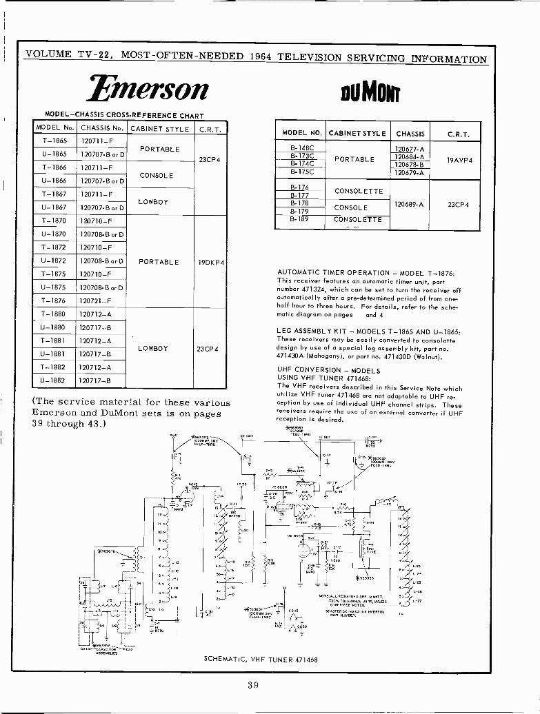
VOLUME TV -22, MOST -OFTEN -NEEDED 1964 TELEVISION SERVICING INFORMATION
EmersonMODEL-CHASSIS CROSS-REFERENCE CHART
MODEL No. CHASSIS No. CABINET STYLE C.R.T.
T-1865 120711-FPORTABLE
U-1865 120707-B or D23CP4
T-1866 120711-FCONSOLE
U-1866 120707-B or D
T-1867 120711-FLOWBOY
U-1867 120707-B or D
T-1870 120710-F
U-1870 120708-B or D
T-1872 120710-F
U-1872 120708-B or D PORTABLE 19DKP4
T-1875 120710-F
U-1875 120708-B or D
T-1876 120721-F
T-1880 120712-A
U-1880 120717-B
T-1881 120712-ALOWBOY 23CP4
U-1881 120717-B
T-1882 120712-A
U-1882 120717-B
(The service material for these variousEmerson and DuMont sets is on pages39 through 43.)
9.2
39
-
L -J +9639 2 L --JL41 PA TOECA2ASSEMBLIES
-]
TIBN]SO
AUG
T
3063002IOOOMMF, DMVFEED-THRU
L-IB
-19
13.9135V
tFTP
nu MoNr
MODEL NO. CABINET STYLE CHASSIS C.R.T.
B -148C 120677-AB -173C PORTABLE 120684-A 19AVP4B -174C 120678-BB -175C 120679-A
13-176CONSOLETTE8-177
B-178 120689-A 23CP4B-179 CONSOLE
B-189 CONSOLETTE
AUTOMATIC TIMER OPERATION - MODEL T-1876:This receiver features an automatic timer unit, partnumber 471324, which can be set to turn the receiver offautomatically after a pre -determined period of from one-half hour to three hours. For details, refer to the sche-matic diagram on pages and 4
LEG ASSEMBLY KIT - MODELS T-1865 AND U-1865:These receivers may be easily converted to consolettedesign by use of a special leg assembly kit, part no.471430A (Mahogany), or part no. 471430D (Walnut).
UHF CONVERSION - MODELSUSING VHF TUNER 471468:The VHF receivers described in this Service Note whichutilize VHF tuner 471468 are not adaptable to UHF re-ception by use of individual UHF channel strips. Thesereceivers require the use of an external converter if UHFreception is desired.
*S63 953FFEEA-ED-THNU
C -
*963002 6GKSIOOOMM GMV -FEE-THRU 3
A
OUT
SCHEMATIC, VHF TUNER 471468
L-22
N]50
C -IS ?963002r1 IOOOMMF GMViFEEO-THRU
*963955
NOTE:ALL RESISTORS ARE 1/2 WATT,
*10V. TOLERANCE JNITS, UNLESSOTHERWISE NOTED.
*ASTERISK INDICATES EMERSONPART NUMBER.
L-21
L-25
L-26
39
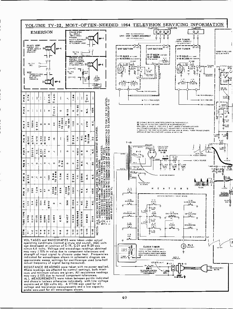
VOLUME TV -22, MOST -OFTEN -NEEDED 1964 TELEVISION_ SERVICING INFORMATION IHE ANEENM" A TENNA ENX"CONNfCTORS ÉONXÉCTORS CONÑfCTORS
EMERSON SPEAKER WIRING
I'SPEAKER WIRINGCONSOLE ANDLO -BOY MODELSUSING TWOSPEAKERS
TO T-2SEC.
NOTE:PROPER PHASINGOF SPEAKERSMUST BEOBSERVED
L_
SP -1
SP -2
ALL MODELSUSING A SINGLESPEAKER.
(EXCEPT PORTABLESWITH LISTENINGATTACHMENT JACK)
TO T-2SEC.
SPEAKER WIRINGPORTABLE STYLEMODELS EQUIPPEDWITH LISTENINGATTACHMENT JACK x
I
TO T-2SEC.
8P-1
SP -1
J -ILISTENATTACHJACK
ozI I i lY
1+-
Y
1.I4-
:m I
-
I
O
FO
ii-+I
co
=a
o I l ¡ I O
Y
Mi
-e_O 10
31E
O
Oto
OH
oO z
Y
O
tiZR
NN
YLo00
nMD
l D
44-
O O O ..'f
YOY n
Ñ NO
~
YY pF O
O
O' O ^OrN
YZ
M5
O.
O
I.nijF
Y
IEj
F
O
ai1
O
EO
ilE
O
10
IE1
a NI
Y
m
Y
g* 1-N-
V
Z
ij ON N. N
nZpauOOoY
w-H-
i*
;*7
IO .
Y'
O
an
-44-
p U
zG
- .O - 0 - . O ~
anO, o O
Yn
4F
O ON
q2'
oan*
O'
p - O
q'E1j
S aW m
pI-
In11
YNW
Yt0n41-
áH-
YO
Rmf
41-
Uz
V
Z
m=IT.
5cONO fJ. a aOONNN3C 2
nFY Y
n-NF
Y
O-UZ
LL
F Oa
-Z'Y
nQM
leOV M
MaM
anale
Owp[O
O
41-
2f
UZ NN
-H-
ÚZ
MIdÑWm
~
mItJ10
IOE-OLO
nz:EU10
b17
IO
NZC7
N
0nQ10
dp
3Qb
f¢V
N<N
=Oto
TO3OE O
141'oto
M.w
100
u10
M
Wm
aIE)
1Nm > >
FO
>a>
n>
G)
>r>
m
>WI
>o>
->
)1..,
>
aÍ>
m
>
? N
.VoJvLL
o>LL,OOp.-UZZáD,00
W1-
00LL WW
U ÚÚw W wzzZZp0UU
O KROt WI -WWw ~tnFfQO= U_awwO OwLLLL
ZHOOv) 00J2Q<<4
ZQQZWLLe
ILI 00WJJ
wwZZZ=NI-OZOw WZZpQáU(j
Z Z ULu R'p01-1-
N- {.. i?33 Z- ZQWW
ZZYYM)W=U1-FNwoow..4wJz1-ZZaZlnwwi"Fwi_OOrreá.L>Oww7Da:zzww00áá0tYO I 1
oZ
VOLTAGES and WAVESHAPES were taken under actualoperating conditions (normal picture and sound . AGC volt-age developed at junction of C-19, C-21 and R-20 wasminus 4.6 volts. Voltage and woveshape readings obtainedmay vary ± 10% in value due to component tolerances andstrength of input signal to chassis under test. Frequenciesindicated for woveshapes shown in schematic diagram oreapproximate sweep settings for oscilloscope used (one-halfactual frequency of signal being measured).RESISTANCE READINGS were token with no power applied.Where readings are affected by control settings, both maxi-mum and minimum values are given. All resistance readingsmay vary ±10% due to normal component tolerances.ALL MEASUREMENTS were taken between points indicatedand chassis (unless otherwise indicated),. with line voltagemaintained at 120 volts AC. A VTVM was used for allvoltage and resistance measurements and a low capacityprobe was used for all waveshapes shown.
UHF- VHF TUNER ASSEMBLYIOHF-VHE 1100EL5 Ox Ul
r ----VHF SECTION"
INPu
V -1S 6GK5 R E AMP I
V-16 6CG8Aosc a WEER I
45OMC
- 6CGBA
T -I0
E-----{' UHF SEC TION"«TI«Rmj
V-17 6024 UHF OSE.xK
TAL-º
HIKER1N82A
I 65249.t05 _J
TOR 017u NFRIMI
JJ
O V I PIN4IMEAT2RI
0 411 TUNER AGCI
VHF TUNER(PARTIAL SCHEMATIC)I v. M00115 ONLTI
IMF TUNERUT
V -IS 6610 R i AMP I
V-16 6CG8A osc eM I KE R I
45.0MCT
I __ \ . _, 013, INPIC -161
ONBoaxú
)
GCG
OE- TO R-sTTUNEROEI
TO V -I PIN4INrrl
TOC 411NNER"GCE
r_ CERAMIC OR MICA CAPACITORS,CAPACITY IN PICOFARADSIpFI* TUBULAR CAPACITORS,CAPACITT IN MICROFARADS I MF)RESISTORS IN OHMS 1 K 10001 AND j WATT UNLESS OTHERWISE SPECIFIEDALL CERAMICS AND MICAS 500V,ALLTUBULARS 400V UNLESS NOTEDT INDICATES TOP CORE B INDICATES BOTTOM CORE IN DOUBLE TUNED TRANSFORMERSARROWS AT CONTROLS INDICATE CLOCKWISE ROTATION
2700EAC1
V-136C04,6DE4
`USE
USIBLE LINK
LOW VOLTAGERECTIFIER
5U4G8V-18
L-iS
T; " T`;oo T`jooB
CIMMEIJSE RODE.
H E A T E R S
HEATERS ON PRINTED CIRCUIT BOARD
5875 CPS255 V SOURCE
IREFER TO FIELD MOINOTE ON PAGE
-19000
Tu.R DP
620VIP- R
43.1MCI}
-4.20L-5JR -I9ISO
=C-20t000
22ÓT
+240 V SOURCE +135 V
V-6 V-10GASB 6GH8OR6GHBA
5
CLOCK TIMERTIMER (O'i I (USED. C«A5S151207E1041X1MO TO ` N O T E: IN .ON' POSITION SWITCH
1
IS DISENGAGED FROM TIMER MOTOR
TINlN b EF AND STAYS PERMANENTLY CLOSED.
srrtcN e- í J Ir[RtoÑ AFETvcM
i I23" SETS ONLY)P
ON O,, \M +-1LJLINCR..ON VOLUME CONTROL\ C-BOL
IMm Ui[D OM CLEC K- 047MM. ~MN loor
TUNER ADC
C- 11R-462VT 1.
11 MEG
50VeP -G
()CPS
TO HEATERS ON TUNER
PL -1DIAL Lie.
R-492.2MEG
*1350
PICTUROPTIMIZER
I 30cPc
i
L-.20 OLTSACONLYw n
R-5022E
40
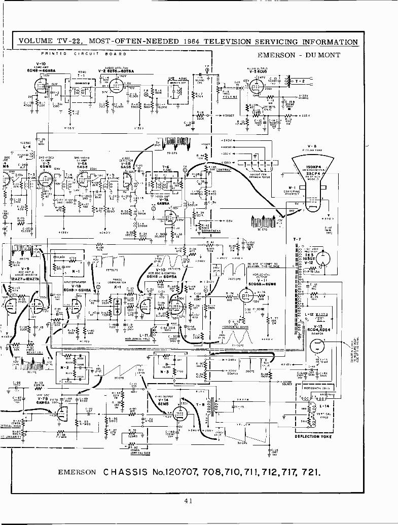
-33
VOLUME TV -22, MOST -OFTEN -NEEDED 1964 TELEVISION SERVICING INFORMATION
-1 EMERSON - DU MONT
;DEOMP.
Ñ61280
900V
PRINTED CIRCUIT BOARD
V-IO I4 541 AMP AUDIO DETECTOR TP AUDIO OUTPUT
661188 oft6GH$A 4.5 MG V-26DT6oR6DT8A V-3 6CU5
2V
4700
91300 T-1L1
O
BµÓum our 41 ' T
220 100ÓT - 390C-5 0-4
TO ,000 5300560
..C-2641.25MC sÓfIV
1.- 4
Ca 3
1.9PF
IP'.I E7 '.A1E9y
30 CPS
R-52100 K
2ND VIDEOE. AMP.
V-566416 1240
V-9AGC AMP B
NOISE INVERTER
12AZ7oR12AZTA
+135V 4135V
30 CPS
300 VIDEOI.F. AMPV -6A6048 22BV
020 - 1.9V T..E 1 OV - 4 --- =JR-4723
48.21 C-32 L-6 - VIDEOIAMP
C-27 C-28 .11-7111560 l000yR -z7 TR 8AW8A
+135V +240 V
10.000 4TOn
SYNC SEPARATOR
V -1B6GH8 0H 6GH8A
Í 170 ; 110,,9L320 I SOK
""Ir -.1 35V
..,,..
IIR3 R4 FS7 L`33N ONESNOISE
10ÓÓ
C049-67
1.5RMEG-BI
RTICAL ROLO
50011NT. LINEARITY
R - B322041W
V E RT OSC
V -7B ITV TO6AW8A 33V..
820
N-2200
150 fp <6 00
oo\\(1c 36
53ÓUH
C-Il 1220
OI .2,5}R-9
IMfGVOIUMF
+BOOST
12 MEO
+2400
+1350SOURCE
5
+2550C -14C + i704wóv T SW
v11
+BOOST
+350 V 86
+1350 ---111-7.1.7.1D5.5..
+1350R-42500KBRIGHTNESS
oR-41
730 477 {7Ñ 67002670021R-95
2W
1240V 800 -+ 240 V +240 V
.lP-PI (P -P1 +240V
V.10 7675CPS 14OV
HOR.OSC.BCONTROL(P -P1
6GH8 OR 6GH8A F
IR+240V
R39K JZ56K9 TP
lC -
1WC-58 R-74
521CODK
7075
PHASE
TP COMPARATOR
X11 4-63IMEG
TC.ozzBC4í
2p2 Y 6
4706.
1320R-81 I0I0033011 7 R-64
1204
3351 47ÓET
30 CPS
L-11HORIZONTAL HOLD
-L
~}11922.SMEGVERTICAL SIZE
.0047
R-]0
12iV I170
C-56I1O,000
33R-)10K1
VERT. OUTPUT
V-146E115 3
7875 CES
100 -370
OPTIMUM ROCAS
70VP -P
30 CPS
DO NOT ATTEMPT TOMEASURE THIS VOLTAGE
HORIZONTALOUTPUTV -I1
6DO6Ba, 6GW6
R-76
O3.30
TO C 160
30HORIZONTAL DRIVE
140
)D]SCPS
o
C -14D+ +240 V +255V I
lOOMETR
1200V
._
D+3500SOURCE
TC 173
30CP3
GREEN
YELLOR
+240 V
M -ICENTERINGASSEMBLY
V-8PICTURE TUBE
19DKP4 E,
23C P4ON 23 i0011L
MODELS
1+350 V
21 KVMIN.
BRT.I
T- 7
+255V
II o
IL-12 WIDTH
ILJV-13
6C04.6DE4DAMPER
-F BOOSTSOURCE
HORIZONTAL COILS
T ºse 3Kvl
I 330
1390
L-14 Í
VERTICAL ICOILS
DEFLECTION YOKE
EMERSON CHASSIS No.120707, 708,710,711,712,717, 7 21.
41
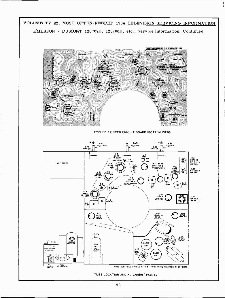
VOLUME TV -22, MOST -OFTEN -NEEDED 1964 TELEVISION SERVICING INFORMATION
EMERSON - DUMONT 120707B, 120708B, etc., Service Information, Continued
NUMERALS PRICEDIM TUNE 6YMNOLN ROPER TO
ETCHED PRINTED CIRCUIT BOARD (BOTTOM VIEW).
*0 R-42..0 BRIGHTNESS.
R-92VERT.SRE
* R-43 '0 R-81CONTRAST .n VERL NOLD
R-82VERT. LM.
VHF TUNER
V-185U4GB
LOWVOLTAGE
RECTIFIER
V-460M6
le VIDEOI.F. AMP
L-343.1 MC
V-665M6
ºD4 VIDEOI.F. AMP
F-1 P-1CHEMFUS AC INTERLOCK450 MA
V-36CU6AUDIO
OUTPUT
V-121 1K3
VHIGHOLTAGERECT.
V-66A88
314 VIDEOI.F. AMP.
VIDEO DETEC. 4423MC
45.3 MC
L-7
1-8
V-912AZ7
ADC AMP 6NOISE INVERTER
1-4N.º6MC
L-1IT.ºR Mc
V-76AWBA
VIDEO AMP
VERT 06C.
o
L-12
MOTHCOIL
V-1 60148RAMC AMP
V-2SYNC SEPARATOR 6076
UDETECTOR.
T-64.sMC
oO (O7-11.6MC \
V-1060118
OOR.OSC. CONTROL
L-24.6MC
CO
V,-1160068 OR6GW6NOR. OUT.
06¿/-13
04 co6004
DAMPER
V-146E815
VERT. OUT,
6-75,NOR DRIVECONTROL
NOTE:CONTROLS MARKED WITH*, FRONT PANEL MOUNTED ON 231 SETS.
TUBE LOCATION AND ALIGNMENT POINTS
R-51PICTUREOPTIMIZERCONTROL
R-57NOISE LOKCONTROL
1-11006.401.0CONTROL COIL
42
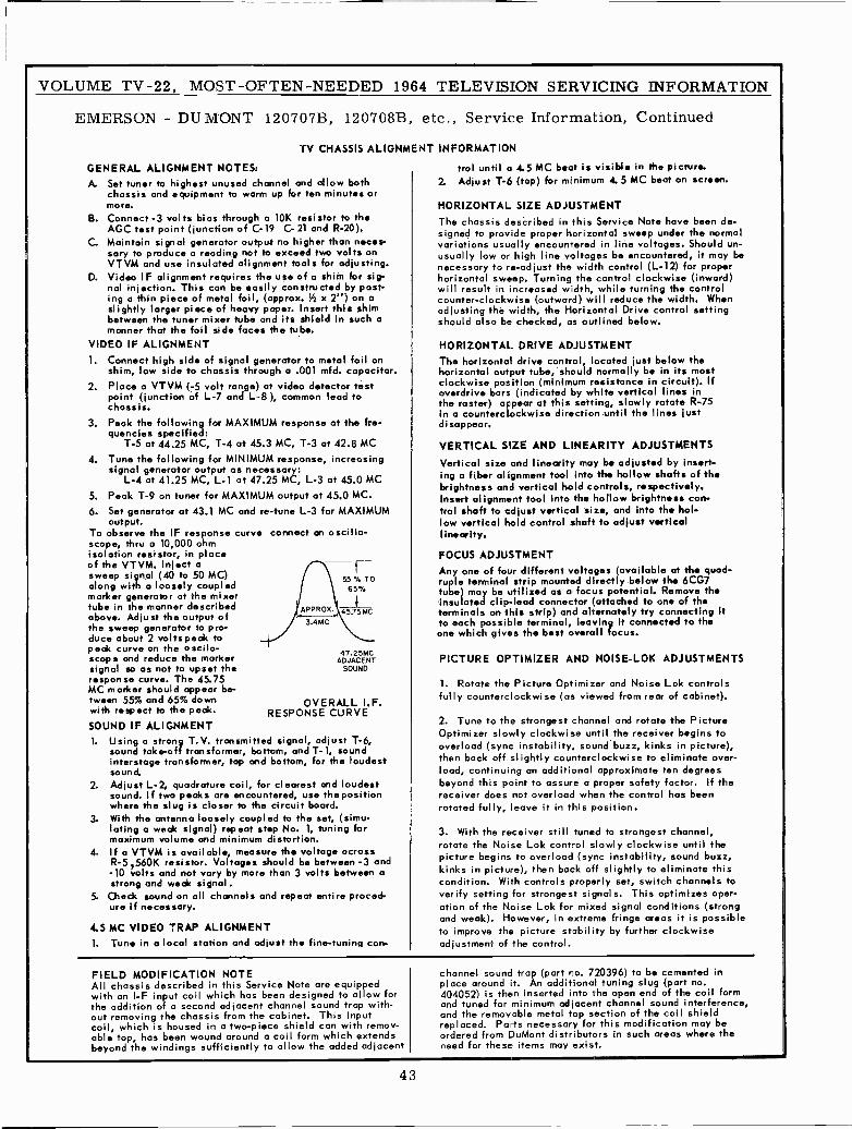
VOLUME TV -22, MOST -OFTEN -NEEDED 1964 TELEVISION SERVICING INFORMATION
EMERSON - DUMONT 120707B, 120708B, etc., Service Information, Continued
TV
GENERAL ALIGNMENT NOTES:A. Set tuner to highest unused channel and allow both
chassis and equipment to warm up for ten minutes orTOM.
B. Connect -3 volts bias through a 10K resistor to theAGC test point (junction of C-19 C- 21 and R-20).
C. Maintain signal generator output no higher than neces-sary to produce a reading not to exceed two volts onVTVM and use insulated alignment tools for adjusting.
D. Video IF alignment requires the use of a shim for sig-nal injection. This can be easily constructed by post-ing a thin piece of metal foil, (approx. Y x 2") on aslightly larger piece of heavy paper. Insert this shimbetween the tuner mixer tube and its shield in such amanner that the foil side faces the tube.
VIDEO IF ALIGNMENT1. Connect high side of signal generator to metal foil on
shim, low side to chassis through a .001 mfd. capacitor.2. Place a VTVM (-5 volt range) at video detector test
point (junction of L-7 and L-8 ), common lead tochassis.
3. Peak the following for MAXIMUM response at the fre-quencies specified:
T-5 at 44.25 MC, T-4 at 45.3 MC, T-3 at 42.8 MC4. Tune the following for MINIMUM response, increosing
signal generator output as necessary:L-4 at 41.25 MC, L-1 at 47.25 MC, L-3 at 45.0 MC
5. Peak T-9 on tuner for MAXIMUM output at 45.0 MC.
6. Set generator at 43.1 MC and re -tune L-3 for MAXIMUMoutput.
To observe the IF response curve correct an oscillo-scope, thru a 10,000 ohmisolation resistor, in placeof the VTVM. Inject asweep signal (40 to 50 MC)along with a loosely coupledmarker generator at the mixertube in the manner describedabove. Adjust the output ofthe sweep generator to pro-duce about 2 volts peak topeak curve on the oscilo -scope and reduce the markersignal so as not to upset theresponse curve. The 45.75MC marker should appear be-tween 55% and 65% downwith respect to the peak.SOUND IF ALIGNMENT1. Using a strong T.V. transmitted signal, adjust T-6,
sound take -off transformer, bottom, and T-1, soundinterstage transformer, top and bottom, for the loudestsound.
2. Adjust L-2, quadrature coil, for clearest and loudestsound. If two peaks are encountered, use the positionwhere the slug is closer to the circuit board.
3. With the antenna loosely coupled to the set, (simu-lating a weak signal) repeat step No. 1, tuning formaximum volume and minimum distortion.
4. If a VTVM is available, measure the voltage acrossR-5 ,560K resistor. Voltages should be between -3 and-10 volts and not vary by more than 3 volts between astrong and weak signal.
5. Check sound on all channels and repeat entire proced-ure if necessary.
55 V. TO65X
APPROX
3.4MC
45.75 MC
47.25MCADJACENT
SOUND
OVERALL I.F.RESPONSE CURVE
4.5 MC VIDEO TRAP ALIGNMENT1. Tune in a local station and adjust the fine-tuning con -
CHASSIS ALIGNMENT INFORMATION
trol until a 4.5 MC beat is visible in the picture.2. Adjust T-6 (top) for minimum 4.5 MC bent on screen.
HORIZONTAL SIZE ADJUSTMENTThe chassis described in this Service Note have been de-signed to provide proper horizontal sweep under the normalvariations usually encountered in line voltages. Should un-usually low or high line voltages be encountered, it may benecessary to re -adjust the width control (L-12) for properhorizontal sweep. Turning the control clockwise (inward)will result in increased width, while turning the controlcounter -clockwise (outward) will reduce the width. Whenadjusting the width, the Horizontal Drive control settingshould also be checked, as outlined below.
HORIZONTAL DRIVE ADJUSTMENTThe horizontal drive control, located just below thehorizontal output tube, should normally be in its mostclockwise position (minimum resistance in circuit). Ifoverdrive bars (indicated by white vertical lines inthe raster) appear at this setting, slowly rotate R-75in a counterclockwise direction until the lines justdisappear.
VERTICAL SIZE AND LINEARITY ADJUSTMENTSVertical size and linearity may be adjusted by insert-ing a fiber alignment tool into the hollow shafts of thebrightness and vertical hold controls, respectively.Insert alignment tool into the hollow brightness con-trol shaft to adjust vertical size, and into the hol-low vertical hold control shaft to adjust verticallinearity.
FOCUS ADJUSTMENTAny one of four different voltages (available at the quad-ruple terminal strip mounted directly below the 6CG7tube) may be utilized as a focus potential. Remove theinsulated clip -lead connector (attached to one of theterminals on this strip) and alternately try connecting itto each possible terminal, leaving it connected to theone which gives the best overall focus.
PICTURE OPTIMIZER AND NOISE-LOK ADJUSTMENTS
1. Rotate the Picture Optimizer and Noise Lok controlsfully counterclockwise (os viewed from rear of cabinet).
2. Tune to the strongest channel and rotate the PictureOptimizer slowly clockwise until the receiver begins tooverload (sync instability, sound buzz, kinks in picture),then back off slightly counterclockwise to eliminate over-load, continuing an additional approximate ten degreesbeyond this point to assure a proper safety factor. If thereceiver does not overload when the control has beenrotated fully, leave it in this position.
3. With the receiver still tuned to strongest channel,rotate the Noise Lok control slowly clockwise until thepicture begins to overload (sync instability, sound buzz,kinks in picture), then back off slightly to eliminate thiscondition. With controls properly set, switch channels toverify setting for strongest signals. This optimizes oper-ation of the Noise Lok for mixed signal conditions (strongand weak). However, in extreme fringe areas it is possibleto improve the picture stability by further clockwiseadjustment of the control.
FIELD MODIFICATION NOTEAll chassis described in this Service Note are equippedwith an I -F input coil which has been designed to allow forthe addition of a second adjacent channel sound trap with-out removing the chassis from the cabinet. This inputcoil, which is housed in a two-piece shield can with remov-able top, has been wound around a coil form which extendsbeyond the windings sufficiently to allow the added adjacent
channel sound trap (part ro. 720396) to be cemented inplace around it. An additional tuning slug (part no.404052) is then inserted into the open end of the coil formand tuned for minimum adjacent channel sound interference,and the removable metal top section of the coil shieldreplaced. Parts necessary for this modification may beordered from DuMont distributors in such areas where theneed for these items may exist.
43
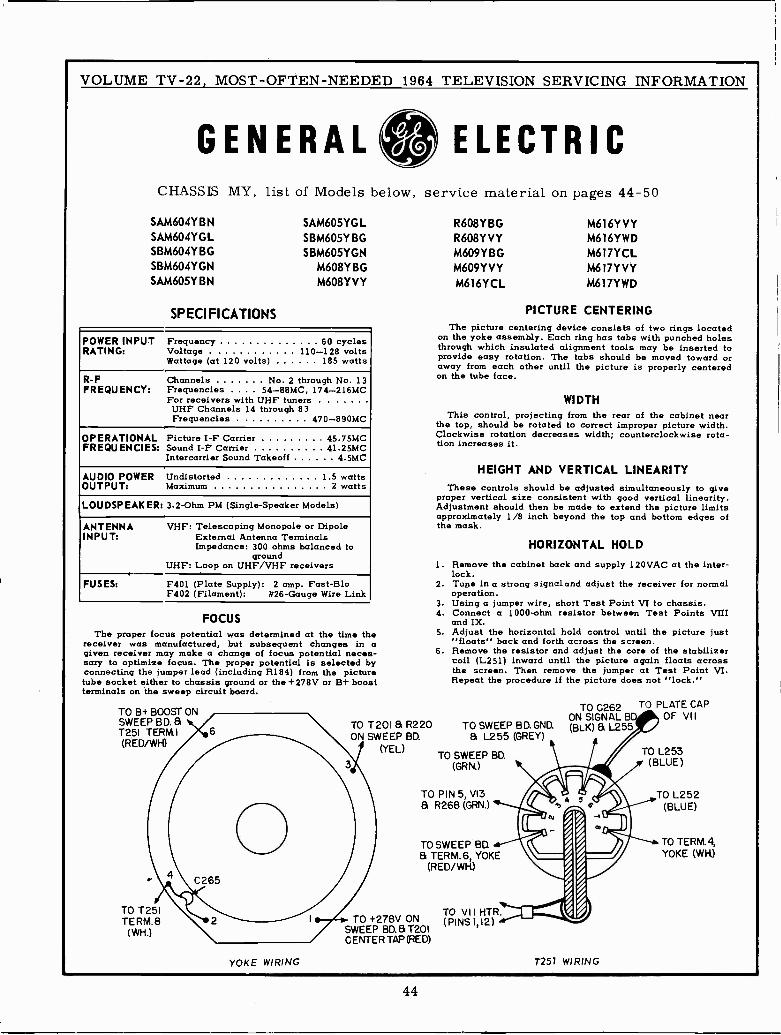
VOLUME TV -22, MOST -OFTEN -NEEDED 1964 TELEVISION SERVICING INFORMATION
GENERAL ELECTRICCHASSIS MY, list of Models below, service material on pages 44-50
SAM604YBN SAM605YGL R608YBG M616YVYSAM604YGL SBM605Y BG R608YVY M616YWDSBM604Y BG SBM605YGN M609YBG M617YCLSBM604YGN M608YBG M609YVY M617YVYSAM605YBN M608YVY M616YCL M617YWD
SPECIFICATIONS
POWER INPUT Frequency 60 cyclesRATING: Voltage . 110-128 volts
Wattage (at 120 volts) 185 watts
R -F Channels No. 2 through No. 13FREQUENCY: Frequencies .... 54-88MC, 174-216MC
For receivers with UHF tunersUHF Channels 14 through 83Frequencies . 470-890MC
OPERATIONAL Picture I -F Carrier 45.75MCFREQUENCIES: Sound I -F Carrier 41.25MC
Intercarrier Sound Takeoff 4 5MC
AUDIO POWER Undistorted 1 5 wattsOUTPUT: Maximum 2 watts
LOUDSPEAKER: 3.2 -Ohm PM (Single -Speaker Models)
ANTENNA VHF: Telescoping Monopole or DipoleINPUT: External Antenna Terminals
Impedance: 300 ohms balanced toground
UHF: Loop on UHF/VHF receivers
FUSES: F401 (Plate Supply): 2 amp. Fast-BloF402 (Filament): #26 -Gauge Wire Link
FOCUSThe proper focus potential was determined at the time the
receiver was manufactured, but subsequent changes in agiven receiver may make a change of focus potential neces-sary to optimize focus. The proper potential is selected byconnecting the jumper lead (including R184) from the picturetube socket either to chassis ground or the+278V or B+ boostterminals on the sweep circuit board.
TO B+ BOOST -ONSWEEP BD. &1251 TERM)(RED/WH)
TO T251TERM.8
(WH.)
YOKE WIRING
PICTURE CENTERINGThe picture centering device consists of two rings located
on the yoke assembly. Each ring has tabs with punched holesthrough which insulated alignment tools may be inserted toprovide easy rotation. The tabs should be moved toward oraway from each other until the picture is properly centeredon the tube face.
WIDTHThis control, projecting from the rear of the cabinet near
the top, should be rotated to correct improper picture width.Clockwise rotation decreases width; counterclockwise rota-tion increases it.
HEIGHT AND VERTICAL LINEARITYThese controls should be adjusted simultaneously to give
proper vertical size consistent with good vertical linearity.Adjustment should then be made to extend the picture limitsapproximately 1/8 inch beyond the top and bottom edges ofthe mask.
1.
HORIZONTAL HOLD
Remove the cabinet back and supply 120VAC at the inter-lock.
2. Tune in a strong signal and adjust the receiver for normaloperation.
3. Using a jumper wire, short Test Point VI to chassis.4. Connect a 1000 -ohm resistor between Test Points VIII
and IX.5. Adjust the horizontal hold control until the picture just
"floats" back and forth across the screen.6. Remove the resistor and adjust the core of the stabilizer
coil (L251) inward until the picture again floats acrossthe screen. Then remove the jumper at Test Point VI.Repeat the procedure if the picture does not "lock."
TO T201 a R220 TO SWEEP BD. GND.ON SWEEP BD. a L255 (GREY)
(YEL)TO SWEEP BD.
(GRN.)
TO PIN 5, VI3& R268 (GRN.)
TO SWEEP BD& TERM.6, YOKE
(RED/WH)
TO +278V ONTO VI I HTR.
SWEEP BD. &T201(PINS 1,12)
CENTER TAP (RED)
TO C262ON SIGNAL B(BLK) L255
T251 WIRING
TO PLATE CAPOF VII
TO L253(BLUE)
TO L252(BLUE)
TO TERM.4,YOKE (WH)
44
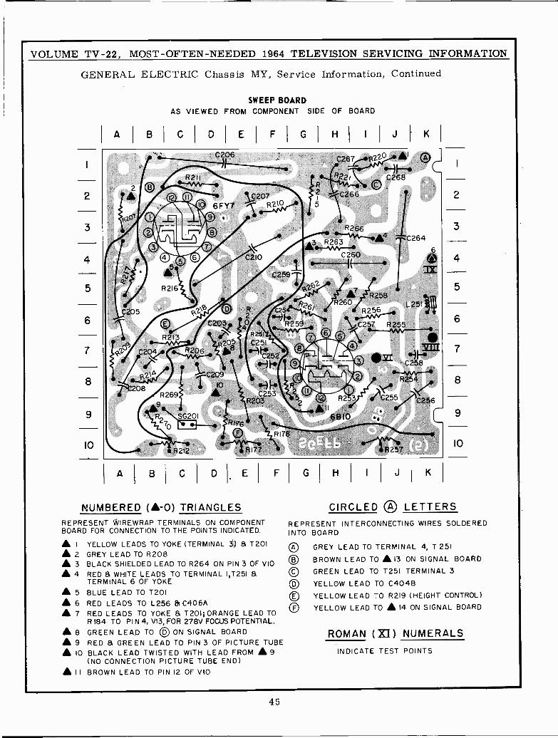
VOLUME TV -22, MOST -OFTEN -NEEDED 1964 TELEVISION SERVICING INFORMATION
GENERAL ELECTRIC Chassis MY, Service Information, Continued
2
3
4
5
6
7
8
9
10
A B
SWEEP BOARDAS VIEWED FROM COMPONENT SIDE OF BOARD
C I DI E FIGI HI I J I K I
C2O5
0206
R211
- ® 55207
aR 216
©R213
C20ST
R2A208
R269
A9SG2O1
C210
02
C2O3 40,
28
R 212
R 251
C251
f-C253
R2O3
R176,
O R178
R177
R252
C261,--6.2,01-'41/AI VRZ2l C26 8
2©
C2665
R266
A3 4.R26
C26O--1E--`C2591
262
7 R258g26j R26O
6C25N RR2_.R259 C27 R25
C258
R2
C264
6
R2 3
.II6B1O
`5%eC25C256
1R257
C
A B C D F
NUMBERED (A-0) TRIANGLESREPRESENT *IRE WRAP TERMINALS ON COMPONENTBOARD FOR CONNECTION TO THE POINTS INDICATED.
A I YELLOW LEADS TO YOKE (TERMINAL 3) 8 T2O1
A 2 GREY LEAD TO R2O8A 3 BLACK SHIELDED LEAD TO R264 ON PIN 3 OF VIOA 4 RED 8 WHITE LEADS TO TERMINAL I,T251 8
TERMINAL 6 OF YOKEA 5 BLUE LEAD TO T2O1A 6 RED LEADS TO L256 81 C4O6AA 7 RED LEADS TO YOKE 8 T2O1; ORANGE LEAD TO
R 184 TO PIN 4, V13, FOR 278V FOCUS POTENTIAL.
A 8 GREEN LEAD TO OD ON SIGNAL BOARDA 9 RED 8 GREEN LEAD TO PIN 3 OF PICTURE TUBE
10 BLACK LEAD TWISTED WITH LEAD FROM A 9(NO CONNECTION PICTURE TUBE END)
A I I BROWN LEAD TO PIN 12 OF VIO
G H J I K
2
3
4
5
6
7
8
9
10
CIRCLED ® LETTERSREPRESENT INTERCONNECTING WIRES SOLDEREDINTO BOARD
©©©
GREY LEAD TO TERMINAL 4, T 251
BROWN LEAD TO A 13 ON SIGNAL BOARDGREEN LEAD TO T251 TERMINAL 3
YELLOW LEAD TO C4O4B
YELLOW LEAD TO R2I9 (HEIGHT CONTROL)
YELLOW LEAD TO A 14 ON SIGNAL BOARD
ROMAN (XI) NUMERALSINDICATE TEST POINTS
45
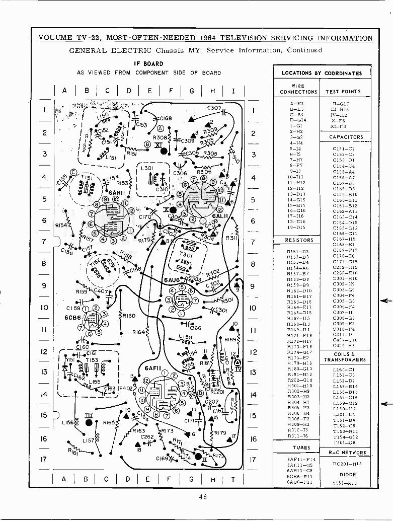
VOLUME TV -22, MOST -OFTEN -NEEDED 1964 TELEVISION SERVÍCING INFORMATION
GENERAL ELECTRIC Chassis MY, Service Information, Continued
1
2
3
4
5
6
7
8
9
10
12
13
14
IF BOARD
AS VIEWED FROM COMPONENT SIDE OF BOARD
B C I D E
rG
I ?''.1,54>,12 i
R308
H I I
frioC1681C153 TO
152i
A t 3 RgO9
42
g`,COr151 54(±),, ,5 RI53d/ /h6ARII
Rí54
Ris>
Cys
('! 305
If!L301
IC 4
IyC158
\ /
RI59
CI59
6CB6
C I 60r 7yC161 --i
111`CI62l i 1 131 L155 I
l C163 1F402-- ---F--J15 D
LIb6
16
17
A B C
R163C262
C169yti
RCP01
10
14
15
R179
16
17
LOCATIONS BY COORDINATES
WIRECONNECTIONS TEST POINTS
A-E2 II -017B-E 3 III-B15C-A4 IV-I12D-G14 X-F61-G1 XI-F32H23-G2 CAPACITORS4-H45-I4 C151-C26-I5 C152-C27-H7 C153-D18-F7 C154-C49-19 C155-A4
10-111 C156-A711-H12 C157-B812-I12 C158-D813-D13 C159-B1014-G15 C160-B1115-H15 C161-B1216-G16 C162-A1317-I16 C163-C1418-E16 0164-D1519-D15 C165-G13
0166-G11RESISTORS C167-I15
0168-ElR151-D3 C169-F17R152-B3 C170-E6R153-D4 C171-G15R154-A6 C202-H15R157-B7 C262-E16R158-D8 C301-H10R159-B9 C302-H9R160-D10 C303-G9R161-B17 C304-F6R163-D16 C305-G6R164-E11 C306-F4R165-D15 C307-I1R167-I15 C308-G3R168-I13 C309-F2R169-I1 1 0310-F4R171-F16 C311-I5R172-H17 C407-010R173-F16 C409-H6R174-G17 COILS &R175-E7 TRANSFORMERSR179-H16R180-G13 L1ó0-C1R181-H12 L151-C3R202-G14 L152-D2R301-H10 L155-B14R302-H9 L156-B15R303-H2 L157-016R304-H7 L159-G12R305-H3 L160-I12R306-H4 L301-E4R308-F2 T151-B4R309-H2 T152-C8R310-I3 T153-B13R311-I6 T154-G12
T301-G8TUBES
R-C NETWORK-1
6AF11-F146AL11-G5 RC201-H136AR11-C660B6-B11 DIODE
6AU6-F10 Y151-A13
46
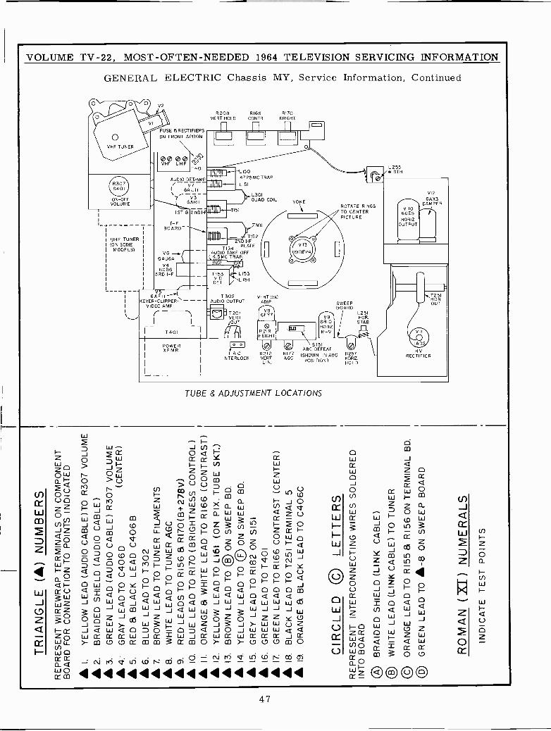
TR
IAN
GLE
(A
) N
UM
BE
RS
RE
PR
ES
EN
T W
IRE
WR
AP
TE
RM
INA
LS O
N C
OM
PO
NE
NT
BO
AR
D F
OR
CO
NN
EC
TIO
N T
O P
OIN
TS
IND
ICA
TE
D
I.Y
ELL
OW
LE
AD
(A
UD
IO C
AB
LE)T
O R
307
VO
LUM
E 2
.B
RA
IDE
D S
HIE
LD (
AU
DIO
CA
BLE
) 3
.G
RE
EN
LE
AD
(A
UD
IO C
AB
LE)
R30
7 V
OLU
ME
4.
GR
AY
LE
AD
TO
C40
6 D
(CE
NT
ER
)
5.
RE
D &
BLA
CK
LE
AD
C40
6B 6
.B
LUE
LE
AD
TO
T30
2 7
.B
RO
WN
LE
AD
TO
TU
NE
R F
ILA
ME
NT
S 8
.W
HIT
E L
EA
D T
O T
UN
ER
AG
C 9
.R
ED
LE
AD
S T
O R
I56
S R
170(
B+
278V
)A
O.
BLU
E L
EA
D T
O R
I70
(BR
IGH
TN
ES
S C
ON
TR
OL)
II.
OR
AN
GE
á W
HIT
E L
EA
D T
O R
I66
(CO
NT
RA
ST
) 1
2.Y
ELL
OW
LE
AD
TO
LI6
1 (O
N P
IX. T
UB
E S
KT
.) 1
3.B
RO
WN
LE
AD
TO
© O
N S
WE
EP
BD
. 1
4.Y
ELL
OW
LE
AD
TO
OF
ON
SW
EE
P B
D.
® 1
5.G
RE
Y L
EA
D T
O R
182
ON
515
1 1
6.G
RE
EN
LE
AD
TO
T40
1 1
7.G
RE
EN
LE
AD
TO
RI6
6 C
ON
TR
AS
T (
CE
NT
ER
) 1
8.B
LAC
K L
EA
D T
O T
25I T
ER
MIN
AL
5®
19.
OR
AN
GE
a B
LAC
K L
EA
D T
O C
406C
CIR
CLE
D ®
LE
TT
ER
SR
EP
RE
SE
NT
INT
ER
CO
NN
EC
TIN
G W
IRE
S S
OLD
ER
ED
INT
O B
OA
RD
® B
RA
IDE
D S
HIE
LD (
LIN
K C
AB
LE)
© W
HIT
E L
EA
D (
LIN
K C
AB
LE)
TO
TU
NE
R
© O
RA
NG
E L
EA
D T
O R
I55
S R
I56
ON
TE
RM
INA
L B
D.
OD
GR
EE
N L
EA
D T
O A
-8 O
N S
WE
EP
BO
AR
D
RO
MA
N (
XI)
NU
ME
RA
LSIN
DIC
AT
E T
ES
T P
OIN
TS
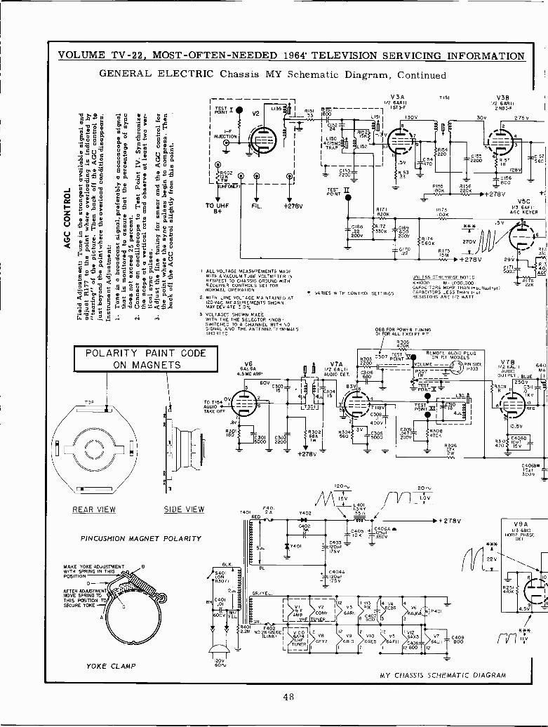
VOLUME TV -22, MOST -OFTEN -NEEDED 1964' TELEVISION SERVICING INFORMATION
GENERAL ELECTRIC Chassis MY Schematic Diagram, Continued
LC.G r tl C N m ° BtlaG Ó al 1> 1
« w i°. 0 °tT Ú Ó C B° tF1 3 0 0
.14;1"-.90. q 0 0 .
Ú a 1Á 0U C
M.tl U aow7 p
O w dÓ U ' tl Q 0 0
oC Ó 0 0. ° >tl°+ ° >.m °" q
móóó Qxa aÁ ámwT BJC p y jA p °OC> 0 ,15 m.tl tl 0 r"j° mm sJ [' a 0:4
o .2,tl w tiO B m B 7 C
m0. 0
e3É mmotl óp-,B aNOa c°
tim amc 3 .. Ñ$ ó j p70.0 tlZ1Nmui.««0
:1)11,1>:000Uó dymo rao ,óéxeúá'rm
b 000tl @ o 5 ood úóa `ó, y C 0 0 Ñ p 0
a:111j.1, P
q
r V 1 Ú 1 xÚtl
o1«f% tl: ti Ñ cs.
TESTPOINT
1-FINJECTION
1114L¡12K2 OO ---7W
U FOHNLYI-
TO UHFB+
VFIL.
R151 2T5'1 1-- 33 1800
+278V
I ALL VOLTAGE MEASUREMENTS MADEWITH A VACUUM TUBE VOLTMETER INRESPECT TO CHASSIS GROUND WITHRECEIVER CONTROLS SET FORNORMAL OPERATION
2 WITH LINE VOLTAGE MAINTAINED AT120 VAC. MEASUREMENTS SHOWNMAY DEVIATE _10% -
3. VOLTAGES SHOWN MADEWITH THE THE SELECTOR KNOB -SWITCHED TO A CHANNEL WITH NOSIGNAL AND THE ANTENNA TERMIBALSSHORTED
POLARITY PAINT CODEON MAGNETS
TOP
I 1
REAR VIEW
101154 °YAUDIOTAKE OFF
SIDE VIEW
PINCUSHION MAGNET POLARITY
MAKE YOKE ADJUSTMENTWITH SPRING IN THISPOSITION
AFTER ADJUSTMENTMOVE SPRING TOTHIS POSITION TOSECURE YOKE
YOKE CLAMP
V66AU6A
4.5 MC AMP
7.8V
R301180
BLK
120V60U
C301
CI52
4TR725M1L150OáW
m}
I AP
TESTPOINT
V3A1/2 6ARII
1ST I -F
R171820K IOOK
VARIES WITH CONTROL SETTINGS
V7A1/2 6ALIIAUDIO DET.
1 6304I. IS
LT3o1J
R30268K1w
- +278V
120",
R1745608 270V
R175I +278V 29V
130V
T 151
R154220
.5V C154_1.470
8153
V381/2 6ARII
2 NDI-F
130V 275V
--5%-
CI55 612200
_L
R173 1/3 6AF
- T 0156 1R155 R156 1800IBOK 220K
+278V= V5C
IIAGC KEYER
C157560
UNLESS OTHERWISE NOTEDK.1000 M.1,000,000CAPACITORS MORE THAN I- yyf(uol=pflCAPACITORS LESS THAN I -ufRESISTORS ARE I/2 WATT
.068 FOR POWER TUNING
.01 FOR ALL EXCEPT P T
R305470K
TEST REMOTE AUDIO PLUGR303 0307 POINT Ye ON P.T MODELS2200 UME-
1
- °PINPI703SIDE
C306 -680 M
TEST6 = = POINTX =
L301,},
15VL401
F401 I.3HYT401 2 A Y402 55n /
RED - _ . I.
0309.047200V
120 ti-4--1.0V
C SK I 10
fC405K + 125uf
. C403 -Z Y401 120yf -
175V
BL1C404A
120ufI175V
GR./YEL
R30627K2W
+278V
GR.R401 F4022.2M NO26GAUGEr
(LINK)
1
L
I vI V2112
V3 PIX
I R -F CONY I 6ARIIAMVHF TUNER _ 1 8 BO
6ÁF4 IUHF
TUNER,
12
VB
6FY7
V6
6AU64.,7
4 V46CB6
3 3
2 121 V12
V9 VIO V5 6AX36810
7
6GE5 6AFII C40
)P401
12 800 12
V7 10409ALII 800
0171500
°' R175 33(
RI 7622K
R1740AGC
V76B 640MA
I/2 6ALIIAUDIO
OUTPUT BLUE IT250V
81309N11
C311OI1/I IKV
10.5V
R310llC4060110 y f
470 15 V
***
22V
UU
C4068mISyf I300V
V9A1/3 6810
HORIZ PHASEDET
*)1*I1V
MY CHASSIS SCHEMATIC DIAGRAM
`0
48
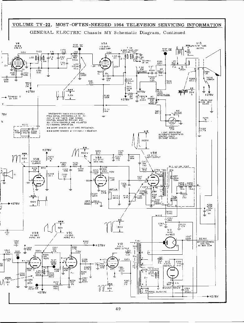
VOLUME TV -22, MOST-OFTEN-NEEDED 1964 TELEVISION SERVICING INFORMATION
GENERAL ELECTRIC Chassis MY Schematic Diagram, Continued
V462 B6
3RD I -F
0V
R159150
CI58800
150V
_, TERMINAL 5ON T251
78V
TESTPOINT
1155T153 9151 IOuh L156
G159 690
RI6010K2W
+278V
44MCRES3.6.n.
L15730046
12.4-
/***I
2.5V
R1613900
WAVESHAPES TAKEN WITH A NOISE -FREE SIGNAL PRODUCING -I.5 TO -3VAGC AT VHF TUNER. FINE TUNINGCONTROL ADJUSTED FOR MAX. AG C.ALL OTHER CONTROLS ARE ADJUSTED
RG 201 FOR NORMAL OPERATION.
*W SCOPE SYNCED AT 1/2 VERT. FREQUENCY.16201 ¿¡C201BI C20IA1470K5 470 ^ 5000
1
Lj
J
ti --1 +278 V0
025147
R2531.5M
I`"52OK
C25275
**W
18V
V5B1/3 6AFI I
CLIPPER
-18V
V5A1/3 6ÁF11VIDEO AMP
120
L159470.44
R164
OW4500
216622
TO PIN 1OF V6
R166 C167
25K4.1 00V
LI60CONTRAST 20041)
060 ti6n
TESTPOINT
eR1688200
R1671.5M
V13*KiE PICTURE TUSE
? 19DEP410
1161 I
IOuh + 7'000,2 n 15
iR169j150K
v.'. f+2 8V }4Ó0ÑR180 6165 _+ BRIGHTNESSIOOK 18K C406CA NO
+278V3W T 300V GRFORDAsFOR
MODELS
R18í68K
R17915K
***SCOPE SYNCED AT I/2 HORIZ. FREQUENCY.
+278V
R20347K
R20422 K
**
300 V
R205 R20668K 100KM N1 itC203 1 2204800 ^ 3300
C202100
5
V98 + V9C1/3 6610 / I/3 6810
HORIZ. MV. HORIZ M.V.
1000C253
/IE
12254 /J C257
TEST =820 205VPOINT
62555KIWS%
TEST-. 5V p01NT
SR25456K
i-2255
5000
C256
I2ÓV=PaSÑ
+278 V
R26I47K
150V
-55V
R20947K
R210681(
* *
V8AI/2 6FY7VERT. OSC
1 C207BooIKV
c206C205 0560039 600V 1IOVI KV
10
9
6211I,2M
VERT. LINR2I2
R207 3,4 M
680K
VERT R208HOLD I
I'
R26227K
+278V
3,11
63R264
R2470K1 = 470
R26012 K
COSO
R257 91025 9 -1-60Óv_
IM 59HORIZ.HOLD
C259 -37V5000
6215KK)K
C208.027TC
R21 R2146BO3K 47K
1
1100V
1
260V
1
OIZ1 LJ
618322K
LIGHT -DEPENDENTAUTOMATIC BRIGHTNESSCONTROL (ABC)ON SOME MODELS
V881/2 6FY7
`VERT OUTPUT
10C .0152
I KV ¡-DE FLECTION YOKE2I6
Ws5 275V T2011 RED
58 4603
I/62171
: VERTMI a L201A
I M -.53u1 i m2.8n
37` RD I I
24048 ++ I'
100uf278V n ó I
.C2095VT 820 1
uI
' 39002 R 219 I
1500 I
HEIGHT
6
9Eí4
30V
HORIZ HORIZ1254A 2 12548
eon 00012+n 12n.
C2652.9n
47vERT 2KV
wc l9
YL 1.3_a
3 4
6
6184 \IM
FOCUSJUMPER
+278V
SPARK GAP-SG 201
8270M
f.762692 M
R26647. OK
T251
VIO6 30
HORIZIZ OUTPUT -9-
L253'000'----ryñOuh
4,10
90- V
12n
2 150V 4
226125n
047400VIE-
R265
óe
£R2202200HITE
-C267
22685K
VIIIA D2
H.V RECT.
1.082IR 221
33 K
L252OROOuh v22n 6AX3
DAMPER
HORIZ. BLANKING
C263130-4KV ^
2
R2672200
650V 12264T iéó01'
-2266
20 KVIITH BRIGHTNESS
CONTROLAT MAX. CCW
10.1-278V
49
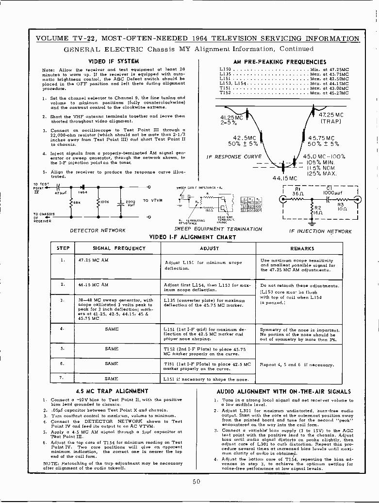
VOLUME TV -22, MOST -OFTEN -NEEDED 1964 TELEVISION SERVICING INFORMATIONGENERAL ELECTRIC Chassis MY
VIDEO IF SYSTEMNote: Allow the receiver and test equipment at least 20minutes to warm up. If the receiver is equipped with auto-matic brightness control, the ABC Defeat switch should beplaced in the OFF position and left there during alignmentprocedure.
1. Set the channel selector to Channel 9, the fine tuning andvolume to minimum positions (fully counterclockwise)and the contrast control to the clockwise extreme.
2. Short the VHF antenna terminals together and leave themshorted throughout video alignment.
3. Connect an oscilloscope to Test Point III through a22,000 -ohm resistor (which should not be more than 2-1/2inches away from Test Point III) and short Test Point IIto chassis.
4. Inject signals from a properly -terminated AM signal gen-erator or sweep generator, through the network shown, tothe I -F injection point on the tuner.
5. Align the receiver to produce the response curve illus-trated.
TO TEST
1(POINT a t14 4vuut
TO CHASSISOFRECEIVER
4IN64
68K
1,00.
uuI2oo
DETECTOR NETWORK
0
TO VTVM
Alignment Information, Continued
SWEEP CABLE
AM PRE -PEAKING FREQUENCIESL150 .... Min. at 47.25MCL135 Max. at 45.75MCL151 Max. at 42.50MC
Max. at 44.15MCMax. at 43.00MC
T152 Max. at 45.20MC
L153, L154T151
41.25MC2-5%,
42.5MC50% ± 5%
IF RESPONSE CURVE
MPEDANCE Z.
iWMson
HEAD -ENDR. = TERMINATING TERMINALSRESISTANCE CT 5100
SWEEP EQUIPMENT TERMINATION
RI
50n 5611 120(1
72(1 8217 .0f1
9211 IOC loon
VIDEO I -F ALIGNMENT CHART
47.25 MC(TRAP)
45.75 MC50% ± 5%
45.0 MC -100%- 105% MIN.- 115% NOM.
125% MAX.44.15 MC
RI----CI---
3611 I000uuf
R 3"-tion
L
IF INJECTION NETWORK
STEP SIGNAL FREQUENCY ADJUST REMARKS
1. 47.25 MC AM Adjust L150 for minimum scopedeflection.
Use maximum scope sensitivityand smallest possible signal forthe 47.25 MC AM adjustments.
2. 44.15 MC AM Adjust first L154, then L153 for max-imum scope deflection.
Do not retouch these adjustments.(L153 core must be flushwith top of coil when L154is peaked.)3. 38-48 MC sweep generator, with
scope calibrated 3 volts peak topeak for 2 inch deflection; mark-ers at 41.25, 42.5, 44.15, 45 &45.75 MC
L135 (converter plate) for maximumdeflection of the 45.75 MC marker.
4. SAME L151 (1st I -F grid) for maximum de-flection of the 42.5 MC marker andproper nose shaping.
Symmetry of the nose is important.No portion of the nose should beout of symmetry by more than 3%.
5. SAME T152 (2nd I -F Plate) to place 45.75MC Marker properly on the curve.
Repeat 4, 5 and 6 if necessary.6. SAME T151 (1st I -F PIate) to place 42.5 MCmarker properly on the curve.
7. SAME L151 if necessary to shape the nose.
4.5 MC TRAP ALIGNMENT
1. Connect a -10V bias to Test Point II, with the positivebias lead grounded to chassis.
2. .05µf capacitor between Test Point X and chassis.3. Turn contrast control to maximum, volume to minimum.4. Connect the DETECTOR NETWORK shown to Test
Point IV and feed its output 4a an AC VTVM.5. Apply a 4.5 MC AM signal through a 5ppf capacitor at
TOst Point III.6. Adjust the top core of T154 for minimum reading on Test
Point IV. Two core positions will give an apparentminimum indication, the correct one is nearer the topend of the coil form.
NOTE: Retouching of the trap adjustment may be necessaryafter alignment of the audio takeoff.
J
AUDIO ALIGNMENT WITH ON -THE -AIR SIGNALS1. Tune in a strong local signal and set receiver volume to
a low audible level.2. Adjust L301 for maximum undistorted, buzz -free audio
output. Start with the core at the outermost position awayfrom the printed board and tune for the second "peak"encountered on the way into the coil form.
3. Connect a variable bias supply (3 to 15V) to the AGCtest point with the positive lead to the chassis. Adjustbias until audio signal distorts on peaks slightly, thenadjust core of L301 to curb distortion. Repeat this pro-cedure several times at increased bias levels until maxi-mum clarity of audio is obtained.
4. Adjust the bottom core of T154, repeating the bias ad-vances in step 3, to achieve the optimum setting fornoise -free performance at low signal levels.
50
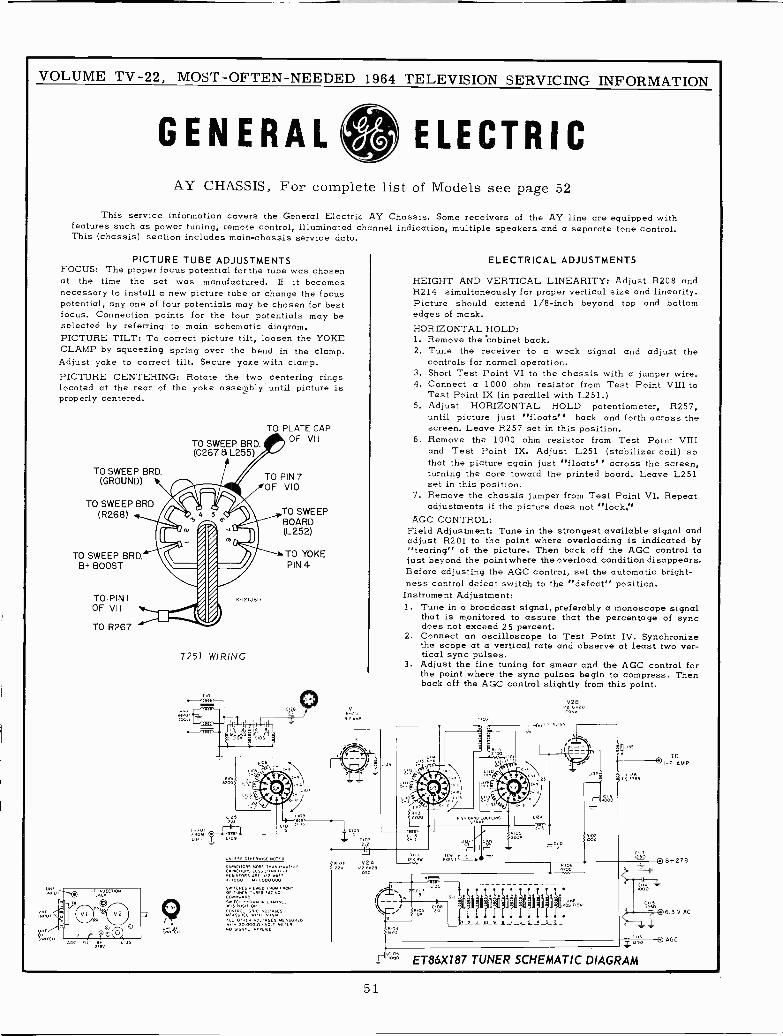
VOLUME TV -22, MOST -OFTEN -NEEDED 1964 TELEVISION SERVICING INFORMATION
GENERAL ELECTRICAY CHASSIS, For complete list of Models see page 52
This service information covers the General Electric AY Chassis. Some receivers of the AY line are equipped withfeatures such as power tuning, remote control, illuminated channel indication, multiple speakers and a separate tone control.This (chassis) section includes main -chassis service data.
PICTURE TUBE ADJUSTMENTSFOCUS: The proper focus potential for the tube was chosenat the time the set was manufactured. If it becomesnecessary to install a new picture tube or change the focuspotential, any one of four potentials may be chosen for bestfocus. Connection points for the four potentials may beselected by referring to main schematic diagram.PICTURE TILT: To correct picture tilt, loosen the YOKECLAMP by squeezing spring over the bend in the clamp.Adjust yoke to correct tilt. Secure yoke with clamp.PICTURE CENTERING: Rotate the two centering ringslocated at the rear of the yoke assergbly until picture isproperly centered.
TO SWEEP BRD.(GROUND)
TO SWEEP BRD(R268)
TO SWEEP BRD.8+ BOOST
TO PIN IOF VII
TO R267
TO SWEEP BRD.(C267 & L255)
M -121J617
T251 WIRING
Ov<(55 O.N(NW15( 50*1.0
CºwC 1065W5 í(F551.66..(x . .....i . p
. 50005
i.
5wi<w(5 Viw(O FOOL. O.w00(OF Tux. mc5
117,1=."'""^"""1eV141VOS O.n(n VO s0(5 u 0
+o sáéié.áii(ów(+(º
TO PLATE CAPOF VII
TO PIN 7OF VIO
TO SWEEPBOARD(L252)
TO YOKEPIN 4
6.5VI
VI64 FLO
g yti'3bI 502
2.1
2AWe"'
ELECTRICAL ADJUSTMENTS
HEIGHT AND VERTICAL LINEARITY: Adjust R208 andR214 simultaneously for proper vertical size and linearity.Picture should extend 1/8 -inch beyond top and bottomedges of mask.HORIZONTAL HOLD:1. Remove the Cabinet back.2. Tune the receiver to a weak signal and adjust the
controls for normal operation.3. Short Test Point VI to the chassis with a jumper wire.4. Connect a 1000 ohm resistor from Test Point VIII to
Test Point IX (in parallel with L251.)5. Adjust HORIZONTAL HOLD potentiometer, R257,
until picture just "floats" back and forth across thescreen. Leave R257 set in this position.
6. Remove the 1000 ohm resistor from Test Point VIIIand Test Point IX. Adjust L251 (stabilizer coil) sothat the picture again just "floats" across the screen,turning the core toward the printed board. Leave L251set in this position.
7. Remove the chassis jumper from Test Point VI. Repeatadjustments if the picture does not "lock.'
AGC CONTROL:Field Adjustment: Tune in the strongest available signal andadjust R201 to the point where overloading is indicated by"tearing" of the picture. Then back off the AGC control tojust beyond the point where the overload condition disappears.Before adjusting the AGC control, set the automatic bright-ness control defeat switch to the "defeat" position.
Instrument Adjustment:1. Tune in a broadcast signal, preferably a monoscope signal
that is monitored to assure that the percentage of syncdoes not exceed 25 percent.
2. Connect an oscilloscope to Test Point IV. Synchronizethe scope at a vertical rate and observe at least two ver-tical sync pulses.
3. Adjust the fine tuning for smear and the AGC control forthe point where the sync pulses begin to compress. Thenback off the AGC control slightly from this point.
LI
7128t/2 6
CONV
1.125
LIS
1.130-C 3
,." ,003 S
ió
1N111MM01v-
TO
°I -F AMP
2f0 o
t'Z000
Iii ET86X187 TUNER SCHEMATIC DIAGRAM
6+276
6.3 V AC
Q AGC
51
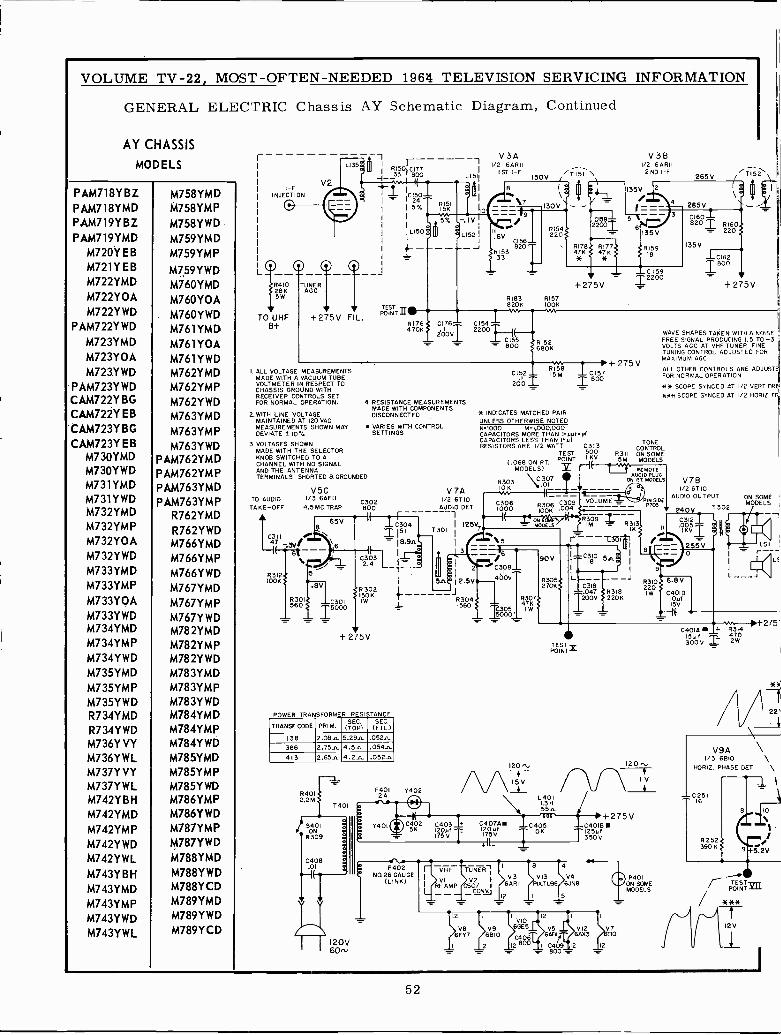
VOLUME TV -22, MOST -OFTEN -NEEDED 1964 TELEVISION SERVICING INFORMATION
GENERAL ELECTRIC Chassis AY Schematic Diagram, Continued
AY CHASSIS
MODELS
PAM718YBZPAM718YMDPAM719YBZPAM719YMD
M720Y EBM721YEBM722YMD
M722Y0AM722YWD
PAM722YWD
M723YMDM723YOAM723YWD
PAM723YWDCAM722Y BGCAM722Y EBCAM723Y BGCAM723Y EB
M730YMDM730YWDM731YMDM731YWDM732YMDM732YMPM732Y0AM732YWDM733YMD
M733YMPM733Y0AM733YWDM734YMDM734YMPM734YWD
M735YMDM735YMPM735YWDR734YMDR734YWDM736Y VYM736YWLM737Y VYM737YWLM742Y B H
M742YMD
M742YMPM742YWDM742YWL
M743YBHM743YMDM743YMPM743YWDM743YWL
M758YMDM758YMP
M758Y W D
M759YMDM759YMP
M759YWDM760YMD
M760YOAM760YWDM761YMDM761 YOAM761YWDM762YMDM762YMPM762YWDM763YMD
M763YMPM763YWD
PAM762YMDP AM762YM P
PAM763YMDP AM763YM P
R762YMD
R762YWDM766YMDM766YMP
M766YWD
M767YMDM767YMPM767YWDM782YMDM782YMPM782YWDM783YMDM783YMPM783Y WDM784YMDM784YMPM784Y WD
M785YMDM785YMPM785Y WDM786YMPM786YWDM787YMPM787YWD
M788YMD
M788YWDM788YCDM789YMDM789YWD
M789YCD
FV2
INJECTION
L
TO UHF8+
L135 Ri50'C177 ---I_33 800 [1511
+275V F L.
-T151 \
1a
CI501 1 \9 17
III5T RSKI 10
ivTR154IL150$ L1521 116y z2o#-(-_- I C156
L -J tR153820
47KRI76i } 33 *
TESTPOINT II
R176 C176 -470K
2ooVT
V 3A1/2 6ARII
1ST I -F130V
R183820K..
CI541zzoo1
C 15(5- 800
R157100K
V381/2 6ARII2ND I -F
265V TI52
265V
ci60820 R220160-
135V
1 C162600
V+275V
R 1526806
I. ALL VOLTAGE MEASUREMENTSMADE WITH A VACUUM TUBEVOLTMETER IN RESPECT TOCHASSIS GROUND WITHRECEIVER CONTROLS SETFOR NORMAL OPERATION.
2. WITH LINE VOLTAGEMAINTAINED AT 120 VACMEASUREMENTS SHOWN MAYDEVIATE ± 10
3. VOLTAGES SHOWNMADE WITH THE SELECTORKNOB SWITCHED TO ACHANNEL WITH NO SIGNALAND THE ANTENNATERMINALS SHORTED 8 GROUNDED
TO AUDIOTAKE -OFF
RIOOK312
V5C1/3 6AFII
4.5 MC TRAP
5
.BVVR301 C301560 -T 5000
C302BOO
4 RESISTANCE MEASUREMENTSMADE WITH COMPONENTSDISCONNECTED
VARIES WITH CONTROLSETTINGS
V 7A1/2 6710
AUDIO DE
( IrC304
I151- I8.9.C3032.4
R 302150KIW
+275V
R RESISTANCE
TRANSF CODE PRIM.SEC.
(TOP)SEC.(FIL.)
138 2.08. 5.29. .052íL366 2.75.1. 4.5.1 .054.n413 2.65. 4.2.,L .05211
R4012.2M
T401
120V60'
I=
F401 Y4022A
F402NO.26 GAUGE
(LINK)
T301 i12
3
EI2.5
JR30560
R304
C403
4---VOLUME - PINSIDE
T 1000 OON6 004 - P7o3240V T302
SV7 (_ MóyEY( R3M9
R3K3 ÓÓSII
IKVT5 r-T361T 1
I e` -_-_ 255V-- '6 90V C380 5.2 C308^ I g
4ÓOV L ----- R310V2706S C318 220
6.8V047 R 318
T200V 22oKIW C400'D
1 IsvR307471(105 I W
120
15
1
175 V20uf
1
V781/2 6T 10
AUDIO OUTPUT
TESTPOINTg
L4011.3 H55.
C4070. _.0405201 106
V5ÁF11
120Iv
+275VC40181111125uf350V
1 C40r9 12
600
P401ON SOMEMODELS
C152RI5815M
200
+ 275VI C157T BOO
H INDICATES MATCHED PAIRUNLESS OTHERWISE NOTEDK1000 M^1,000,000CAPACITORS MORE THAN I.uuf-pfCAPACITORS LESS THAN I`4íRESISTORS ARE I/2 WATT C3I3
TEST 500
(.068 ON P.T.POINT I KV
MODELS)
R303 N30710K y 01
R311
WAVE SHAPES TAKEN WITH A NOISEFREE SIGNAL PRODUCING 1.5 TO -3VOLTS AGC AT VHF TUNER FINETUNING CONTROL ADJUSTED FORMAXIMUM AGC.
ALL OTHER CONTROLS ARE ADJUSTEFOR NORMAL OPERATION
41* SCOPE SYNCED AT I/O VERT FRE***SCOPE SYNCED AT I/O HORIZ. FR
TONECONTROLON SOMEMODELS
REMOTEAUDIO PLUG
P.T. MODELS
ON SOMEMODELS
-SI
I
I
+ 275901A + R3I4ISuf300V
4Z 2W70
V9AI/3 6810
HORIZ. PHASE DET
52
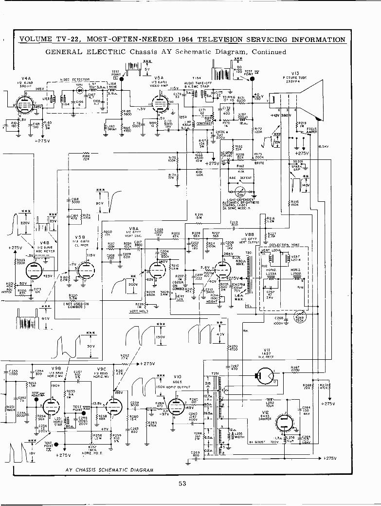
VOLUME TV -22, MOST -OFTEN -NEEDED 1964 TELEVISION SERVICING INFORMATION
GENERAL ELECTRIC Chassis AY Schematic
TESTPOINT ¡
V4A VIDEO DETECTOR1/2 6JN8YI5LIST lLI583 RD I -F I 1011113.6, 144MCI45V
+275V
220V
+275V I/2 6JN8AGC KEYER
R20140KAGC
,NTROL
- 5V
V4B
R203 23306
50V
R206K
C173ION
+23V
L154C 166
6
C1674.7
C1684.7 1- I
I
V.nR 16622K
C1695000
CI64 R 174470 } 470K
V 5 B1/3 6AFII
CLIPPER
90V
Ipqqi4
*8%
5V
V5A/3 6AFII
VIDEO AMP
II
R185 7.3VN.
3900
C178_1_ R184L160 R165
10
560uh 4700
7154AUDIO TAKE -OFF
I I5V 84.5MC TRAP
2 C179 3n
110
.5VC I7O5000IKV
Diagram, Continued68*
20WO TESOINTT rz
P
3,
125V
L16143011h
C171
R1692511
CONTRAST
R1751006
RI671563W
R1684500
IOW+275V
C175-22 TO PIN RI71
OF V5 8200YA
V13PICTURE TUBE
C17215
400 L16230011h
R170 12n_IM
C40IC !501
I300V
RI81RI79 IOOK22K
V8A C203R200 I/O 6FY7 .0039 R202156 VERT OSC. KV 47K
.1-C202
18001 K_L C204 -
C209 .056III 600V
8217 R224 3217150K IOOK 3900
l
115V
7V3/ - I
11802.2My{
-C2531000
R251680K
C2575
9E3E3E
95V
IC2541820
R2531.5 M
TESTPOINT
3
1/3 6810HORIZ.MV
90V
R2203.3MV.
7
C206200i(
R 21815M
800
200V
I NOT USED ONCOMBOS )
R226 1IM -VERT. HOLD
R20968
tRI82<33K
NOGRNO R228FORABC
cx.
I I
6 3
tI2V 380V
{R172120K 4/x),
R17322K 200K
BRITE7162VA47K
ABC DEFEAT
LIGHT --DEPENDENTAUTOMATIC BRIGHTNESSCONTROL (A 8C(ON SOME MODELS
C2131 00
R2161.2M
25V
4
R219IM
FOCUSZ JUMPER
+275V
SG 201.ySPARKGAP -
)f3F
145V
1
R50K215
R222566
R2O11KIO
.l,40 VR210 2.8VI.5 M 4 31
23/`
R207t C207R2100/ .
2V 9 7IM SS .022
/40V(820K= ON = /
CGOMBO)R2122 212t2225 1208 47K í j'¡'3900ii680N 248
ERT 1500R214
L I N.HEIGHT
1C20B.015
IKV
265V 720BLUE c430,
MAX. S
275V1 R205 J±C4078820 ^_100,42W 75V,
1.6,MAX.
YEL
V8BI/O 6FY7
VERT OUTPUT
R2272.7M
r - DEFLECTION YOKE_
I VERT L20141. 7
1
It
II3
RED
HORIZ. HORIZ.L253A L253B
VERTL20 I8
C26247
2KV
V9B /
50V
C2579105%
R25515 K
4 I 6
V9CI/3 6810HORIZ. M
TESTPOINT
C255000T R254
56K 2 1251HORIZ.
C256 STAB. 80n.I200y
18V
TESTPOINT
Ix
+275V
C258.0068200V
13.5V 5/
R25868K
+7V
R257IMES
HORIZ. HOLD
R262 /27K /vo,/ >+ 275V
R26I /476/
/
155V
7
R2599105%
C2595000
R26015K
C263082
iE3E3E*X-7-7
150V1405
V106GE5
150V HORIZ OUTPUT
R2641\470
3,11- -37V
R2634706
AY CHASSIS SCHEMATIC DIAGRAM
4
LR270i 4700
W
VIIIAD2
H.V. RECT
C268.1
6
R/W
J
18.5 KV
T251
315,12.7n
R265 s
2 IM w95n145V {
C260 26.5..047400V
R266tt
2 W YL.5n
C 269800
0.2n_i_
-C267470
:7
P1
512n
lit L255ili WIDTH
aooL252101111
V126 A X3
DAMPER
R2672200..V.
_C2641304KV
=1.7A.
8+ BOOST 720VL256 cozlg51011h TI.6KV
R27470K2
+275V
+275V
53
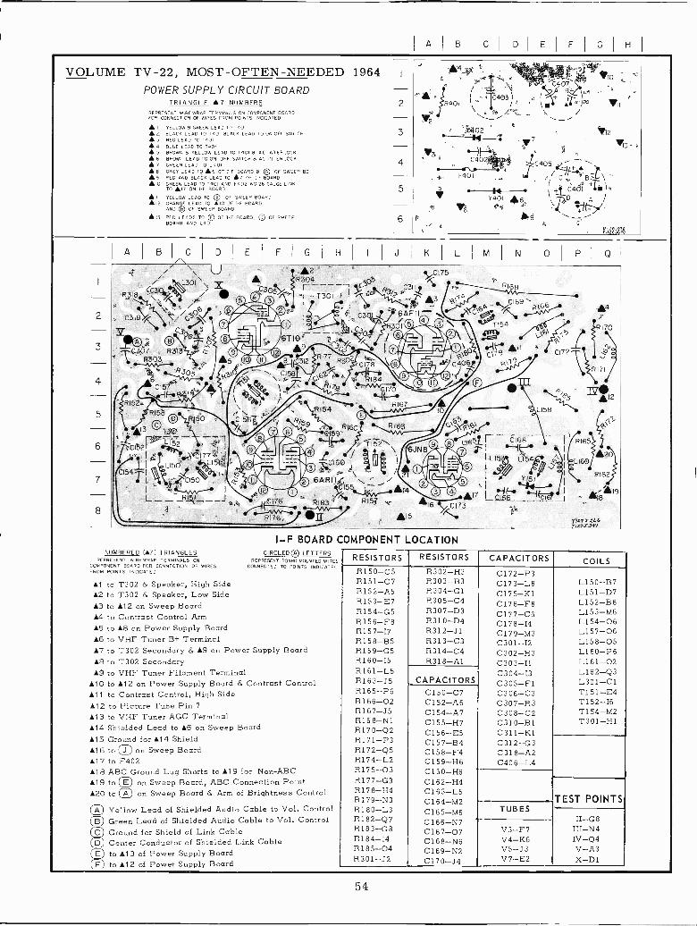
H
VOLUME TV -22, MOST -OFTEN -NEEDED 1964POWER SUPPLY CIRCUIT BOARD
TRIANGLE 7 NUMBERSREPRESENT WIRE WRAP TERMINALS ON COMPONENT BOARDFOR CONNECTION OF WIPES FROM POINTS INDICATED
23456]89
10
YELLOWS GREEN LEAD TO T401BLACK LEAD TO T401 BLACK BEAD TO ON OFF SWITCHRED TO 16101
BLUE -EAO TC ToolBROWN B YELLOW LEAD TO T401 8 AC INTERLOCKBPOWN LEAD TO ON OFF SWITCH 8 AC INTERLOCKGREEN LEAD TO L401GREY LEAD TO 5 OF I -F SOARD 8 CI OF SWEEP BDRED ANC, SLACK LEAD TO 7 OF I -F BOARDGREEN LEAD TO 7901 AND F402 NO 26 GAUGE LINKTO LIT ON I -F BOARD
A YELLOW LEAD TO QB OF SWEEP BOARD12 ORANGE LEAD TO A10 OF I -F BOARDAND QH OF SWEEP BOARD
13 RED 'LEADS TO OE OF I -F BOARD, © OF SWEEPBOARD. AND L401
NUMBERED (A7) TRIANGLESREPRESENT WIREWRAP TERMINALS ON
COMPONENT BOARD FOR CONNECTION OF WIRESFROM POINTS INDICATED
6T10"9
4
6
R160C159
(1-1F.
\-;C160
I \ /1C155/14RIB
Y636AR1
R157
£4
yNC402
^ -F401
5
,17yC173
,15Al
I -F BOARD COMPONENT LOCATIONCIRCLED® LETTERS
REPRESENT BOARD MOUNTED WIRESCONNECTED TO POINTS INDICATED
Al to T302 & Speaker, High Side£2 to T302 & Speaker, Low Side£3 to 112 on Sweep Board14 to Contrast Control Arm15 to 18 on Power Supply Board16 to VHF Tuner B+ Terminal17 to T302 Secondary & A9 on Power Supply Board18 to T302 Secondary0.9 to VHF Tuner Filament Terminal
ál to 112 on Power Supply Board & Contrast Control11 to Contrast Control, High Side£12 to Picture Tube Pin 7113 to VHF Tuner AGC Terminal114 Shielded Lead to A6 on Sweep Board115 Ground for 114 Shield£16 to JO on Sweep Board17 to F402£18 ABC Ground Lug Shorts to 119 for Non -ABC119 to OE on Sweep Board, ABC Connection Point120 to on Sweep Board & Arm of Brightness Control
OA Yellow Lead of Shielded Audio Cable to Vol. Control© Green Lead of Shielded Audio Cable to Vol. Control© Ground for Shield of Link CableOD Center Conductor of Shielded Link CableO to 113 of Power Supply Board1E) to 112 of Power Supply Board
14
e7
7401
s6As
9
06d Í- 7168
TL154
Y15f
ao
VI
123
1C405 - C 8 \
+T ' + C401 1D A
11-c >/
CI72
7'i1yT;4Lrl2%ssy/
RESISTORS RESISTORS CAPACITORS COILSR150-05 R302-H3 C172-P3R151-C7 R303-B3 C173-L8 L150-B7R152-A5 R304-G1 C175-K1 L151-D7R153-E7 R305-C4 C176-F8 L152-B6R154-G5 R307-D3 C177-C6 L153-M6R156-F8 R310-D4 C178-I4 L154-06R157-17 R312-J1 C179-M3 L157-06R158-B5 R313-C3 C301-I2 L158-05R159-G5 R314-C4 C302-H3 L160-P6R160-I5 R318-Al C303-I1 L161-02R161-L5 C304-I3 L162-Q3R163-J5 CAPACITORS C305-F1 L301-C1R165-P6 C150-C7 C306-C3 T151-E4R166-02 C152-A6 C307-R3 T152-I6R167-J5 C154-A7 C308-C2 T154-M2R168-N1 C155-H7 C310-B1 T301-H1R170-Q2 C156-E5 C311-K1R171-P3 C157-B4 C312-G3R172-Q5 C158-F4 C318-A2R174-L2 C159-H6 C406-L4R175-03 C160-H6R177-G3 C162-H4R178-H4 C163-L5R179-N3 c164-M2 TEST POINTS-
TUBESR180-L3 C165-M6R182-Q7 C166-N7 II-G8'
V3-F7RI83-G8 C167-07 III-N4R184-I4 C168-N6 V4-K6 IV-Q4R185-04 C169-N2 V5-J3 V-A3R301-J2 C170-J4 V7-E2 X-Dl
54
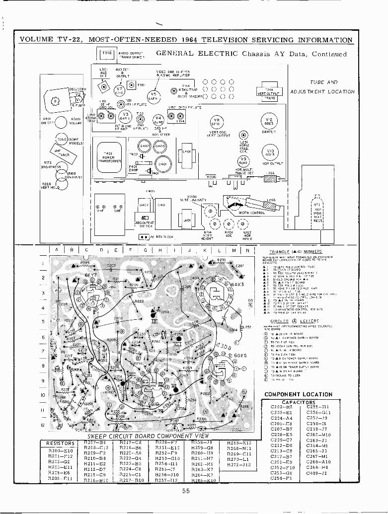
VOLUME TV -22, MOST -OFTEN -NEEDED 1964 TELEVISION SERVICING INFORMATION
S401ON -OFF
RI73BRIGHTNESS
OSC/CONY
R -F AMP
R309VOLUME
(SOMEMODELS)
\RI69,_.,CONTRAST
R226I
VERT. HOLD
2
3
4
5
A
T302 AUDIO OUTPUTTRANSFORMER
L301 AUD. DEIAUD. 6DET OUTPUT
L151 T151
ST -F 1ST I -F PLATERI OIL
~ T152uso O O V34725MC 6ARII OTRAPI
ST 6 2ND 2NDI -F AMP I -F PLATE 3RD I -F
6AGC KEYER
GENERAL ELECTRIC Chassis AY Data, Continued
LI53 3RD I -F PLATE
o eL154
CI) 0 OD 0VHF UHF
uC403
C407
ABC DEFEATSWITCH
I I
C401
AC INTERLOCK
R208VERT LINEARITY
L401
VERT 055.VERT OUTPUT
L251HORIZ.STAB.COIL
I I
7201VERT OUTPUT
TRANS.
DAMPER
HOR. OUTPUT
HOR. MULTI.PHASE DET L255U
m
A
WIDTH CONTROL
` 1 0 I i m j I 0 Il\,---o \,_/ \ /R2I4 ` R201 R257
VERT ACC HOR.HEIGHT HOLD
TUBE AND
ADJUSTMENT LOCATION
1-A\
VIIIAD2HIGHVOLTRECT
B I C I D E F G H
Rw- C203- I\6FYT
C204
R223
R202
R2I1.Ru,ti::
R222
ys - QC253
6 R205 -iit'C207 21 I 4-5-:
7 _Cj09 2
0 C217 lf Tt O8
9
lo
12
R217 ("R220 R210217C213 C251
ii
2
a1417' C269
IJ
0_9(1 C256R262
6R255 4
260`'' ' C2rR258
I
C257
27$ ..250 ©
T2Rm0 f
Q 36B10
's-- 06* ..-zs5QF'{t206:R266A,16R2Ó8 257 {R
R2LiN "" A HOR OLD';z
CIRCUIT BOARD COMPONENT VIEW
L252C26
eGE5
2
B p
C260
8
TRIANGLE (-O) NUMBERSREPRESENT WIRE WRAP TERMINALS ON COMPONENTBOARD FOR CONNECTION OF WIRES. TO POINTSINDICATED.
A I TO A RT HOLD CONTROL (END) 2. TO F ON I.F BOARD 3. TO T201 YELLHW LEAD STOKE 3 T. TO YOKE 6 AND P.N OF T251 5. SHIELD GROUND PTA A 6
6. TO Ala TN F BOARDTO T251 PIN 5 S 1 255
B. TC ROTE PIN B T20 RED LEAD9 TOT2CI BLUE LEADIO TH PINT OF CRT B SH:ELDW'RE FOR CRT PIN3A . HRIGHTNE55 CS.ARATL LOW SIDE I2 ro 3 ON I -F OARS
13 TO PIN 3 OF CRT SOCKET19 TO PIN B OF CRT SOURER
A I5. TO BRIGHTNESS CONTROL HIGH SIDEIR. TO Pill 6 OF CRT SOCKET
CIRCLED QA LETTERSREPRESENT INTERCONNECTING WIRES SOLDEREDINTO BOARD
©A TO 20 ON I -F HOARD
© TO A II ON POWER SUPPLY BOARD
© TO PIN 7 OF T251
OD TO HEIGHT CONTROL HIGH SIDE
© TO A 19 ON E BOARD
© TO PIN N ON 1251© TO A R ON POWER SUPPLY BOARDO TO A 2 ON POWER SUPPLY BOARS© TO A 3 ON POWER SUPPLY BOARD© TO 16 ON -F BOARD
©( To GROUND TO L255
© To PIN OF T251
COMPONENT LOCATION
RESISTORS
R200-E 10R201-F12R202-G2R203-E1 1R205-E6R206-E1 1
R207-B6R208-C12R209-F2R210-B8R211-E2R212-D7R215-C9R216 -B10
R217-C8R218-B6R220-A8R222-G4R223-B5R224-C8R225-C1R227-B10
R228-F7R251-E10R252-F9R253-G10R254-111R255-17R256-J10R257-I12
R258-38R259-G8R260-H8R261-H7R262-H6R263-K7R264-K7R265-K.0
R266-K12R268-N11R269-C11R270-L1R272-J12
CAPACITORSC202-H2 C255-I11C203-E1 C256-G11C204-A4 C257-J9C206 -E8 C258-I6C207-B7 C259-J7C208-E5 C260-M10C209-C7 C263-J3C212-D8 0264-M6C213-C9 C265-J3C217-B7 0267-M1C251-E9 C268-A10C252-F10 C269-H4C253-G6 C409-J2C254-F6
I K L I M I N
`4
R7D.5~ C267
C409 /6 47
T265«7\/® '..
Añ3
\© lO'
1 -
\e`©/ © o% ...
55
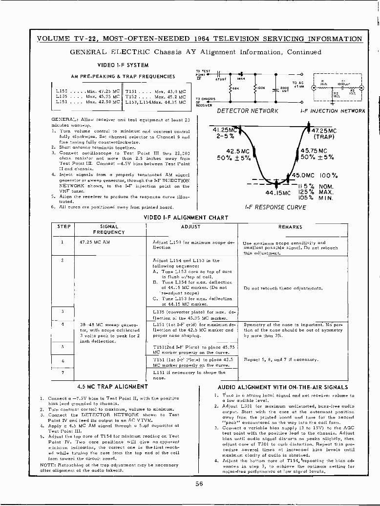
VOLUME TV -22, MOST -OFTEN -NEEDED 1964 TELEVISION SERVICING INFORMATION
GENERAL ELECTRIC Chassis AY Alignment Information, Continued
VIDEO I -F SYSTEMTO TEST --7IAM PRE -PEAKING & TRAP FREQUENCIES POINTIIT
--47 NO 1864
rRI CI I
To Ac I 3611 IOoOuufVTVM (Y`
L150 Min. 47.25 MCL135 .... Max. 45.75 MCL151 Max. 42.50
T151 .... Max. 43.0 MCT152 .... Max. 45.2 MC To cHAssls
68K OOK 2000 f -l-.uuf
R2 100 I---1.... MC L153, L154.Max. 44.15 MC OfRECEIVER
NETWORK
GENERAL: Allow receiver and test equipment at least 20minutes warm-up.
DETECTOR I -F INJECTION NETWORK
1. Turn volume control to minimum and contrast controlfully clockwise. Set channel selector to Channel 9 andfine tuning fully counterclockwise.
2. Short antenna terminals together.3. Connect oscilloscope to Test Point III thru 22,000
ohms resistor not more than 2.5 inches away fromTest Point III. Connect -4.5V bias between Test PointII and chassis.
4. Inject signals from a properly terminated AM signalMCor sweep generator, through the I -F INJECTION
NETWORK shown, to the I -F injection point on theVHF tuner.
5. Align the receiver to produce the response curve illus-trated.
6. All cores are positioned away from printed board.
VIDEO I -F ALIGNMENT
4I.25M- 47.25 MC
4Z.55.75 MC
50 % + 0 %o t 5%
100generator
115 % NOM.44.I5MC 125% MAX.
105% M I N.
I -F RESPONSE CURVE
CHART
STEP SIGNALFREQUENCY
ADJUST REMARKS
1 47.25 MC AM Adjust L150 for minimum scope de-flection
Use maximum scope sensitivity andsmallest possible signal. Do not retouchthis adjustment.
2 Adjust L154 and L153 in thefollowing sequence:A. Tune L153 core so top of core
is flush w/top of coil.B. Tune L154 for max. deflection
of 44.15 MC marker. (Do not're -adjust scope)
C. Tune L153 for max. deflectionof 44.15 MC marker.
Do not retouch these adjustments.
3 L135 (converter plate) for max. de-flection of the 45.75 MC marker.
4 38-48 MC sweep genera-tor, with scope calibrated3 volts peak to peak for 2inch deflection.
L151 (1st I -F grid) for maximum de-flection of the 42.5 MC marker andproper nose shaping.
Symmetry of the nose is important. Nó'por-tion of the nose should be out of symmetryby more than 3%.
5 T151(2nd I -F Plate) to place 45.75MC marker properly on the curve.
6 T151 (1st I -F Plate) to place 42.5MC marker properly on the curve.
Repeat 5, 6, and 7 if necessary.
7 L151 if necessary to shape thenose.
4.5 MC TRAP ALIGNMENT
1. Connect a -7.5V bias to Test Point II, with the positivebias lead grounded to chassis.
2. Turn contrast control to maximum, volume to minimum.3. Connect the DETECTOR NETWORK shown to Test
Point IV and feed its output to an AC VTVM.4. Apply a 4.5 MC AM signal through a 500f capacitor at
Test Point III.5. Adjust the top core of T154 for minimum reading on Test
Point IV. Two core positions will give an apparentminimum indication, the correct one is the first reach-ed while turning the core from the top end of the coilform toward the circuit board.
NOTE: Retouching of the trap adjustment may be necessaryafter alignment of the audio takeoff.
AUDIO ALIGNMENT WITH ON -THE -AIR SIGNALS1. Tune in a strong local signal and set receiver volume to
a low audible level.2. Adjust L301 for maximum undistorted, buzz -free audio
output. Start with the core at the outermost positionaway from the printed board and tune for the secondCPeakc encountered on the way into the coil form.
3. Connect a variable bias supply (3 to 15V) to the AGCtest point with the positive lead to the chassis. Adjustbias until audio signal distorts on peaks slightly, thenadjust core of T301 to curb distortion. Repeat this pro -cedure several times at increased bias levels untilmaximum clarity of audio is obtained.
4. Adjust the bottom core of T154, 'repeating the bias ad -vances in step 3, to achieve the optimum setting fornoise -free performance at low signal levels.
56
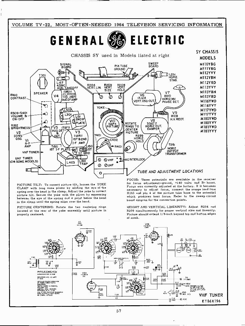
VOLUME TV -22, MOST -OFTEN -NEEDED 1964 TELEVISION SERVICING INFORMATION
RI60CONTRAST
GENERAL
/I\SPEAKER
I;
R309 -S401 IVOLUME t3-ON -OFF
RI62BRIGHTNESS
V2CONY.
OSC. VIR -FAMP
ELECTRICCHASSIS SY used in Models listed at right
SIGNALBOARD
Lí574.5MCAUD. TAKEOFF
VHF TUNER-
UHF TUNER(ON SOME MODELS)
TI50ST I -F PLA
V3IIARII
1ST 92NDI -F AMP
E g))))) 1STI -F GRID
LI60TRAP
PIX TUBEGROUND
/VIO'IIAP4
PIX TUB
0402
R401
SWEEPBOARD
( V617JZ8
VERT.OSC-OUT
L251HORIZ.STAB.
V78810
HORIZ.MV.PHASE DET.
ROTATE ( 33GT7RINGS TO HORIZ OUT.CENTER ` DAMPERPICTURE \
R259HORIZ.
HOLD
ID VHF ±29AC INTER=
0 OUHF
PICTURE TILT: To correct picture tilt, loosen the YOKECLAMP with long nose pliers by sliding the eye of thespring over the bend in the clamp. Adjust the yoke to correctpicture tilt. Secure the yoke with the pliers by squeezingbetween the eye of the spring and a point below the bendin the clamp until the spring slips over the bend.PICTURE CENTERING: Rotate the two centering ringslocated at the rear of the yoke assembly until picture isproperly centered.
10
oat
u0n
0 27
UNLESS OTHERWISE NOTED
CAPACITORS ARE IN MME
RESISTORS ARE 1/2 WATT11.1000
FNTBC FROMSWITCHES VIEWEDAGOOWNWAROSWITCH SHOWN IN CHANNEL4.13 POSITIONCONTROL VOLTAGES
20,OOORI VD5 METEqUREDNO SIGNAL APPLIED
VI3G11S
R -F ARP
NIDO V2A4100 1/2 SEAR
OS<.
1
InGH SSTÑAPOUPLI
V9IX2B
H.V. RECT.
T251HORIZ.
OUTPUTTRANSFORMER
SY CHASSIS
MODELS
M110YBGM111YBGM112YVYM112YBNMl12YRDM113YVYM113YBNM113YRDM116YWDM116YVYMl 17YWDMl17YVYM180YWDM180YVYM181YWDM181YVY
TUBE AND ADJUSTMENT LOCATIONS
FOCUS: Three potentials are available in the receiverfor focus adjustment-ground, +140 volts and B+ boost.Focus was correctly adjusted at the factory. If it becomesnecessary to adjust focus, connect the orange lead fromR165 and pin 4 of the picture tube base to the potentialwhich produces best focus. Refer to the sweep circuitboard diagram for the connection points.
HEIGHT AND VERTICAL LINEARITY: Adjust R204 andR209 simultaneously for proper vertical size and linearity.Picture should extend 1/8 -inch beyond top and bottom edgesof mask.
V28In
CONYO
ALI
COSx 1000
ÓUT I]] 6!1 A0<.
000
00 450
áú
OI-FT AMP.
}140VNO E
T
AETHS W TT15i
LSN T IZLCC<SGxALE
L
A. A.C.
o AG
VHF TUNERET86X196
57
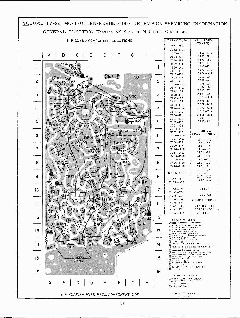
VOLUME TV -22, MOST -OFTEN -NEEDED 1964 TELEVISION SERVICING INFORMATION
GENERAL ELECTRIC Chassis SY Service Material, Continued
10
11
12
13
14
15
16
I -F BOARD COMPONENT LOCATIONS
A I B
iY 09 ,-\, 302 \. y
C3p8 \I .\\ s'/ L 151
247-)- C3 5
L'179F1I R3, RI 5_®®
C3 ®X 0 2 M C403/ © `'-",c,131, 0 /0 _ 0 C406
R--
-2---/r__ ,r.--
ó-I- --- 0 çJ L. I®® \0 /
R's3\ © 0 -}. O5 0
R T 50 iIRIIO \?( A(C/ O® R 0I W )°,% ' R168;.__:.
C1670
C I DIE F
R172_
G
RI56
H
R403
C \ RI67
L403 '
A B C D E F
CI66 ,/Ci76
G
I -F BOARD VIEWED FROM COMPONENT SIDE
H
1
2
3
4
5
6
7
8
9
10
11
12
13
14
15
16
CAPACITORS
C151-E14C152-D14C153-F8C154-G7C156-F7C157-H4C159-F4C161-B2C162-B2C163-C2C164-C2C166-G13C167-B13C168-A5C170-B3C172-G6C173-A3C174-E9C176-G14C177-F13C200-B5C301-C6C302-D6C303-C6C304-E6C305-D9C306-AlC307-Al2C308-B8C309-B7C310-A10C311-A13C403-D10C405-H9C406-H10C410-E10
RESISTORS
R151-H11R152-D13R153-E11R154-F9R155-G5R156-G3R157-E4R158-F4R159-E2R163-E1R167-B14
RESISTORS(CONT° D)
R168-H1 3R169-B3R170-B4R171-B4R172-E6R173-E13R174-G12R200-A6R201-A5R301-C7R302-B6R303-E5R304-D9R305-B11R306-B7R307-Al2R308-A11R310-C12R311-B13R402-C13R403-A14
COILS &TRANSFORMERS
L150-F'12L151-F8L153-F7L154-F6L156-G4L157-C2L158-C1L159-D2L160-F14L301-D7L30 -2-B8L403-C15T150-D12
DIODE
Y151-G6
COMPACTRONS
11AR11-F1215BD11-D617BF11-B9
CIRCLED Q LETTERS15 o5.511,
ELLOW
INTERCONNECTING
p LEAD TO OD ON FRONT CONTROL BOARD
© YELLOW LEAD TO PIN 7 OF PICTURE TUBE
© YELL. LEAD TO REELECTION YOUD E TUBE© RED
TELE DO
OF
CONTROL BOARD
EEP BOARD
© GREENS 000 TO 0 ON SWEEP BOARD
0 RED LEAD TO
©
DEFLECTION ORE
O R To on/ r0000 CONTRO BARDC)
AL O00CABLELEOOTTO©ONTR5 OLTA RDYELLOW 0 TTO ©O FRONT 80000p SE DNLEAD(ON SWEEP BOARD
B ADTO PIN Io TORE
p GREEK AUDIO CABLE LEAD@ON FRONT CONTROL BOARD© ORANGE LEAD M 0 ON POWER SUPPLY BOARDOR REDTO © ON SWEEP BOARDQ RED BEAD TO TUNER e
© DEC © ON POWER 5 RD
0 B TUNER OUTPUT
©WO BLUE LEAD TO FROM POWER SUPPLY BOARD
33 CABLE SNIELD FROM TUNER 1-P OUTPUT
TRIANGLE (-0) NUMBERSREPRESENT WIRE WRAP LS ON COMPONENT
R CONNECTION OF wiRES TO POINTS
YELLOWTO TO TECR 2 LEAD RE
O T3013 REO LEAD TO 2301
ROMAN ($[) NUMERALSINDICATE TEST POINTS
58
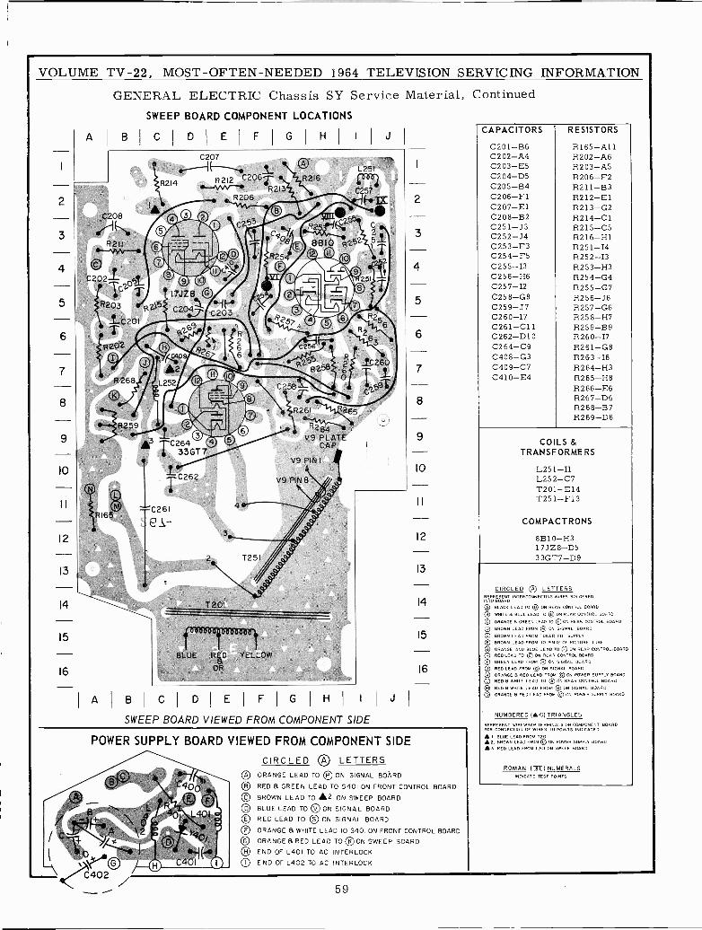
VOLUME TV -22, MOST -OFTEN -NEEDED 1964 TELEVISION SERVICING INFORMATION
GENERAL ELECTRIC Chassis SY Service Material, ContinuedSWEEP BOARD COMPONENT LOCATIONS
A 8 C D I E FIGIN I
C208
akeR211-~,-
©C202-G20
R203 1R2\
iC201T
R202
10
12
13
14
15
16
R 268
R259
C207er-------1 tR214 R212 206T R2I6
--~,-~ R213
,........---..--R206
jiv TC264t 33GT7
TC262
C261
T 201
BLUE RED YELLOW
OR
o
R26I't'.,265R2
V9 PLATECAP
V9 PIN I
V9 PIN8
AIBIC D EIFIG H I I J
SWEEP BOARD VIEWED FROM COMPONENT SIDE
2
3
4
5
6
7
8
9
IO
12
13
14
15
16
POWER SUPPLY BOARD VIEWED FROM COMPONENT SIDE
CIRCLED ® LETTERSOA ORANGE LEAD TO © ON SIGNAL BOARDQB RED 8 GREEN LEAD TO 5401 ON FRONT CONTROL BOARD
© BROWN LEAD TO £2 ON SWEEP BOARDOD BLUE LEAD TO DON SIGNAL BOARDOE RED LEAD TO SO ON SIGNAL BOARD
OF ORANGE 8 WHITE LEAD TO S401 ON FRONT CONTROL BOARD
© ORANGE a RED LEAD TO QK ON SWEEP BOARD
OH END OF L401 TO AC INTERLOCKlO END OF L402 TO AC INTERLOCK
59
CAPACITORS
C201 -B6C202 -A4C203 -E5C204 -D5C205 -B4C206 -F1C207 -E1C208 -B2C251 -J3C252 -J4C253 -F3C254 -F5C255 -I3C256 -H6C257 -I2C258 -G8C259 -J7C260-17C261 -C11C262 -D10C264 -C9C408 -G3C409 -C7C410 -E4
RESISTORS
R165 -A11R202 -A6R203 -A5R206 -F2R211 -B3R212 -E1R213 -G2R214 -C1R215-05R216 -H1R251 -I4R252 -I3R253 -H3R254 -G4R255 -G7R256 -J6R257 -G6R258 -H7R259 -B9R260-17R261 -G8R263 -I6R264 -H3R265 -H8R266 -E6R267 -D6R268 -B7R269 -D6
COILS &TRANSFORMERS
L251 -I1L252 -C7T2.01 -E14T251 -F13
COMPACTRONS
8B10 -H3173Z8 -D533GT7-D9
CIRCLED QA LETTERSREPRESENT INTERCONNECTING WIRES SOLDEREDINTO BOARD
p BLACK LEAD TO © ON REAR CONTROL BOARD
QB WHITE B BLUE LEAD TO QB ON REAR CONTROL BOARD
© ORANGE B GREEN LEAD TO ©ON REAR CONTROL BOARD
0 BROWN LEAD FROM QM ON SIGNAL BOARD
© BROWN LEAD FROM TUNER FIL SUPPLY© BROWN LEAD FROM TO PIN 12 OF PICTURE TUBE
© ORANGE AND BLUE LEAD TO OF ON REAR CONTROL.BOARDQH RECLEAN) TO © ON REAR CONTROL BOARD
) GREEN LEAD FROM OR ON SIGNAL BOARD
Q RED LEAD FROM QG ON SIGNAL BOARDQ ORANGE B RED LEAD FROM © ON POWER SUPPLY BOARD© RED B WHITE LEAD TO WON REAR CONTROL BOARD© RED B WHITE LEAD FROM OO ON SIGNAL BOARDON ORANGE B RED LEAD FROM © ON POWER SUPPLY BOARD
NUMBERED (Á-0) TRIANGLES
REPRESENT WIREWRAP TERMINALS ON COMPONENT BOARDFOR CONNECTION OF WIRES TA POINTS INDICATED
I, BLUE LEAD FROM T20í£2. BROWN LEAD FROM © ON POWER SUPPLY BOARD£3. RED LEAD FROM T201 ON SWEEP BOARD
ROMAN IBEI NUMERALSINDICATE TEST POINTS
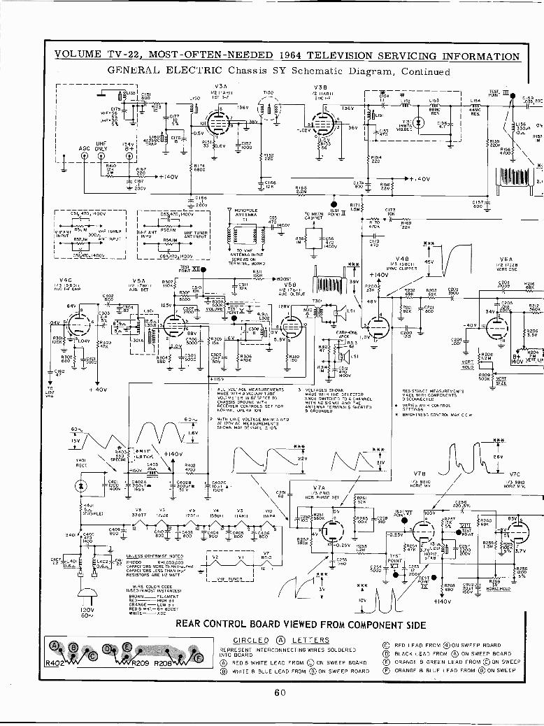
VOLUME TV -22, MOST -OFTEN -NEEDED 1964 TELEVISION SERVICING INFORMATIONGENERAL ELECTRIC Chassis SY Schematic Diagram, Continued
I- V3A
1L135i
BÓ0}
75 '11 11:13^ ¡B
0VMFC156
I TCIpUHF 3k ~-I
SXX_1
134VB+
r C51 470,1400V 11I 1 f I
IVHF ANT RSI,IM VHF TUNER
(INPUT 300nR52,I11 ANT INPUT-77-1
L--9524L70,140DV
V4C113 156011AUD I -F AMP
930280084V
LI6047.25MC
TRAP
LI50
10
-0.5V176115
1RI5133
61740068
+140V
I/O IIARII
C166
Z 200V
1- CC5-31'jI'_..Wo,,1400V
UHF ANT 853.1M UHF TUNERINPUT ANT INPUT
R54,IM
L C54,470 ,1400V
PONTXff
V5A R307I/2 17BF11 330KAUD. SET
C304e
C3032.4
282
6/ 6 5%ÍR301 ..51.04VTOOK R303
TOLI57044
6302só°oó680
CI6247
47K
+140V
S
BQ1
ISV
R403330
Y401 \_ `+PECIALRECT.
5401
IL3OI A
125VC3O7 VOLUMEL301 7 27001
8300 1ÓK
6800
J
1ST 0-F
V3 B y TEST 7150 I/2 IIARII IC154
# I POINT2N0I-F I 1.1 L152 LIS3 I L154
136V
`7 136V,
C152=1000
MONOPOLEANTENNA
TI
TO VHFANTENNA INPUTSCREWS ON
TERMINAL BOARD
C31I¡` IOK
71 373 9 1= 500K
L__
2 5A. I3018
C401 + C402A + C4028 .4 C402C
iáóóv T?65V 25ÓVIM T ÍSÓV A.
--1688V
2C306500Ó
8304680
C30515000
R311150K
R305 I151(
Á4750V
+115V
TEST;POINT = 4.9n
L302
C554701400V
BOOST
V
I C308I I
R306470K
10V %.
81682.2MVIN
IL151
1'470
RI54220
C174 1. R158800 T 22M1
RI71TEST 1.58
TO METAL POINTCABINET
IMS 470II T 1400V
V5 BI/O 178FI1AUD. OUTPUT
128V
5.8V
I ALL VOLTAGE MEASUREMENTSMADE WITH A VACUUM TUBEVOLTMETER IN RESPECT TOCHASSIS GROUND WITHRECEIVER CONTROLS SET FORNORMAL OPERATION
60.s. 2 WITH LINE VOLTAGE MAINTAINEDAT 120V AC MEASUREMENTSSHOWN MAY DEVIATE ?10%
T30
310 ll
0
R310
0173IOK
Y151IN87A
VID. DET.
1+ 140V
44MCRES
RISE220K
R1564700
C800Z157-
c.Ó33 20C
LI56 ON33088
IOnR157IM
*:
8170 R169470K 22K
C170470 88*
V48 45V*** 1/3 ISBDIIIT SYNC CLIPPER
I +140V
39V± R200
920233K R268N 02 R20368K 3900M VV
48V1lrrl
R201 IC20182K 800
C20020 -
LS I
3
EARPHONE I1JACK I.0V`r
R313 7
432
FY6815L(^ILSI
R314IM
C3124701400V
3 VOLTAGES SHOWNMADE WITH THE SELECTORKNOB SWITCHED TO 4 CHANNELWITH NO SIGNAL AND THEANTENNA TERMINALS SHORTED9 GROUNDED
*8*
22V
R401V8 V6 V5 V4 V3 VIO
(FUSIBLE) 33677 17J28 178E11 158511 I18811 IIAP4
120V60".
C409800
12
C8 0003 IO I 8Ó0 I Vol I 810
V7UNLESS OTHERWISE NOTED I V2 VI I 8810
C22 81000 N1,OD0,000 I
CAPACITORS MORE THAN 18P3pi12 1CAPACITORS LESS THAN 1,1-_-1 I
RESISTORS ARE 1/2 WATTL VHF TUNER j
WIRE COLOR CODE(USED IN MOST INSTANCES)
BROWN_ FILAMENTRED HIGH B+ORANGE-LOW B+RED B WHT.- 8+ BOOSTWHITE- AGC
C251 L
8
68 ^V7A /
1/3 6810HOR. PHASE DET/ R26I
82 K
*
3V
V
e
% i-0.25V R253
1.2M
560
vLw
IOV
V6AI/O 17JZ8VERT OSC.
ÁÓ39 R21668K
34V2001
-40V,10
C206_
.001
[ R2081.2M
VERTHOLD
RESISTANCE MEASUREMENTSMADE WITH COMPONENTSDISCONNECTED
VARIES WITH CONTROLSETTINGS
* BRIGHTNESS CONTROL MAX CC W
R209500K VERT
SIZE
R 212S6^O,K
2R2063.3M
_ R204
0V Vf 168T. LIN
26V
V7B / V7C1/3 8810
TESTPOINT
08 9110085 T0WV
-0.25V3¡
TESTPOINT
_C253.12200r .V
TESTS 89.POINT R2M9
3X6R26880 2083 -
C4025
150VI+
IZ-
HOR.HOLD.
+140V
I/3 8810HORIZ. M.V.
/8C20 5%256( .
103V
162606.---TPOINEST i
1%27584 21C2577VL251
T220oHOIZ. 2STAR I
00V
R258
85V
17V
REAR CONTROL BOARD VIEWED FROM COMPONENT SIDE
CIRCLED AO LETTERSREPRESENT INTERCONNECTING WIRES SOLDEREDINTO BOARD
QA RED & WHITE LEAD FROM © ON SWEEP BOARDO WHITE B BLUE LEAD FROM OB ON SWEEP BOARD
oR402" R209 R20W0
200
© RED LEAD FROM ®ON SWEEP BOARDQD BLACK LEAD FROM 0 ON SWEEP BOARDOE ORANGE B GREEN LEAD FROM ©ON SWEEPQF ORANGE B BLUE LEAD FROM © ON SWEEP
60
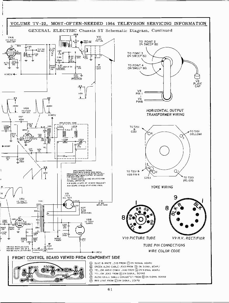
VOLUME TV -22, MOST -OFTEN -NEEDED 1964 TELEVISION SERVICING INFORMATION
GENERAL ELECTRIC Chassis SY Schematic Diagram, ContinuedV4A
1/3 158011VIDEO AMP
II
R17
2 84V ICI63T 5
'10140V
.OV
0172110011
101V i
+140V4
LIST3.8.6.
TO C162ON V4C
CI6110
L159470
RI59'.
33002W
111111111
C1645 i5Y,
C165
200V
R (6025K,STOP AT 3K
CONTRAST
* *-f-I 65V POÑTnz
E'008L158180Uh
í6.2n
1
\k. 1
"7 1
RI63\20 1222K 138 1
R161150K
750VV682 I7JZB
VERT OUT
C206,400V
<I2K1W
- BOOST
C207
40071(
R 214
1600V
+1- 40V
BLUE T20
125V 320'
I
I.B R00
1
-14V` I37V6,7 ..3.3
-14V1
\ 1 DII
\ C171470/
\ I\
>V
R21IIM
C208T027200V
O11IW
YELLR
RÍ62 --=BRIG20011HTNESS
110V
DEFLECTION YOKE
I
i
L201A L2018
J
I ^I
0
6
L2538 L253A
0263472KV
J
\ .//"V8A
1/2 33017HOR.OUTPUT
T251
VIOIIAP4
PICTURE
1
3 14R16510011
WAVE SHAPES SHOWNTAKEN WITH A NOISE FREE SIGNAL
PRODUCING -2.5 TO 3.0 VOLTS AGC AT TESTPOINT II. FINE TUNING CONTROL ADJUSTEDFOR MAXIMUM AGC.ALL OTHER CONTROLS ARE ADJUSTED FORNORMAL OPERATIONH R SCOPE SYNCED AT 1/2 VERT FREQUENCY***SCOPE SYNCED AT I/2 HORIZ. FREO
V9I X28
M.V. RECT.
300n.
C26024V \
5000, - N 10,---4
9.11 26V
;R263 R2641011 S680K 8
L C259 - A f" 470
L
Ion
28n
R266470
R269 R2671500 1500IW JS IIW
1.4.6.9 II KV
2,5,8S R270
2.7nWIRERESISTANCE
39021
3KV
B #FOR MAX. WIDTH, NO CUTS C 261
FOR MED WIDTH CUT AT A 71- -FOR MIN. WIDTH, CUT AT A88. WHR7/GCO;-.1000V
C264.0027T
BOOST+ 400V
4
2
VS BI/2 33077DAMPER
L2523 Ah
AT MINBRIGHTNESS
>+140V
FRONT CONTROL BOARD VIEWED FROM COMPONENT SIDE
TO POINT 2ON SWEEP BD.
TO POINT 3ON SWEEP BD.
TO POINT 4ON SWEEP BD.
TO T251
0261
TO T25I 81V8B PIN 4
HORIZONTAL OUTPUTTRANSFORMER WIRING
C263
YOKE WIRING
V9PLATECAP
TO T201(YELLOW)
TO T201(RD./OR)
V10 PICTURE TUBE V9 H.V. RECTIFIER
TUBE PIN CONNECTIONS
WIRE COLOR CODE
® BLUE WHITE LEAD FROM ®ON SIGNAL BOARD© GREEN AUDIO CABLE LEAD FROM OO ON SIGNAL BOARD© YELLOW AUDIO CABLE LEAD FROM ON SIGNAL BOARD
OD YELLOW LEAD FROM AO ON SIGNAL BOARD
OE AUDIO CABLE SHIELD CONDUCTOR FROM OK ON SIGNAL BOARD
OF RED LEAD FROM JO ON SIGNAL BOARD
61
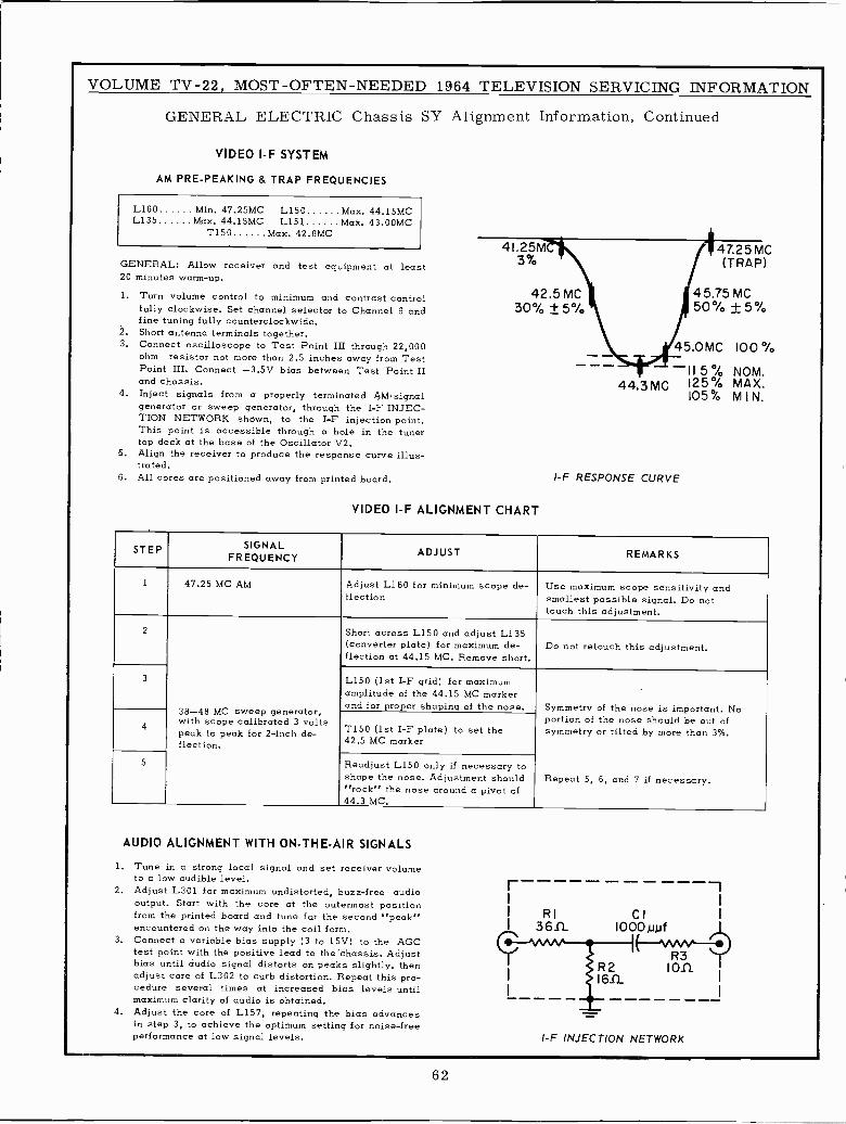
VOLUME TV -22, MOST -OFTEN -NEEDED 1964 TELEVISION SERVICING INFORMATION
GENERAL ELECTRIC Chassis SY Alignment Information, Continued
VIDEO I -F SYSTEM
AM PRE -PEAKING & TRAP FREQUENCIES
L160 Min. 47.25MC L150 Max. 44.15MCL135 Max. 44.15MC L151 Max. 43.00MC
T150 Max. 42.8MC
GENERAL: Allow receiver and test equipment at least20 minutes warm-up.
1. Turn volume control to minimum and contrast controlfully clockwise. Set channel selector to Channel 9 andfine tuning fully counterclockwise.
2. Short antenna terminals together.3. Connect oscilloscope to Test Point III through 22,000
ohm resistor not more than 2.5 inches away from TestPoint III. Connect -3.5V bias between Test Point IIand chassis.
4. Inject signals from a properly terminated PsMsignalgenerator or sweep generator, through the I -F INJEC-TION NETWORK shown, to the I -F injection point.This point is accessible through a hole in the tunertop deck at the base of the Oscillator V2.
5. Align the receiver to produce the response curve illus-trated.
6. All cores are positioned away from printed board.
41.25M3%
42.5 MC30% ± 5%
VIDEO I -F ALIGNMENT CHART
47.25 MC(TRAP)
45.75 MC50% ±5%
45.0MC 100
-115% NOM.44.3 MC 125 % MAX.
105% MIN.
1-F RESPONSE CURVE
STEP SIGNALFREQUENCY ADJUST REMARKS
1 47.25 MC AM Adjust L160 for minimum scope de-flection
Use maximum scope sensitivity andsmallest possible signal. Do nottouch this adjustment.
2
38-48 MC sweep generator,with scope calibrated 3 voltspeak to peak for 2 -inch de-flection.
Short across L150 and adjust L135(converter plate) for maximum de-flection at 44.15 MC. Remove short.
Do not retouch this adjustment.
3 L150 (1st I -F grid) for maximumamplitude of the 44.15 MC markerand for proper shaping of the nose. Symmetry of the nose is important. No
portion of the nose should be out ofsymmetry or tilted by more than 3%.
Repeat 5, 6, and 7 if necessary.
4 T150 (1st I -F plate) to set the42.5 MC marker
5 Readjust L150 only if necessary toshape the nose. Adjustment should"rock" the nose around a pivot of44.3 MC.
AUDIO ALIGNMENT WITH ON -THE -AIR SIGNALS
1. Tune in a strong local signal and set receiver volumeto a low audible level.
2. Adjust L301 for maximum undistorted, buzz -free audiooutput. Start with the core at the outermost positionfrom the printed board and tune for the second "peak"encountered on the way into the coil form.
3. Connect a variable bias supply (3 to 15V) to the AGCtest point with the positive lead to the'chassis. Adjustbias until audio signal distorts on peaks slightly, thenadjust core of L302 to curb distortion. Repeat this pro-cedure several times at increased bias levels untilmaximum clarity of audio is obtained.
4. Adjust the core of L157, repeating the bias advancesin step 3, to achieve the optimum setting for noise -freeperformance at low signal levels.
r -1I I
I RI CI I
I 36J1 IOOOIuuf
9 \ " R3
I 161)..l on
I I
I -F INJECTION NETWORK
62
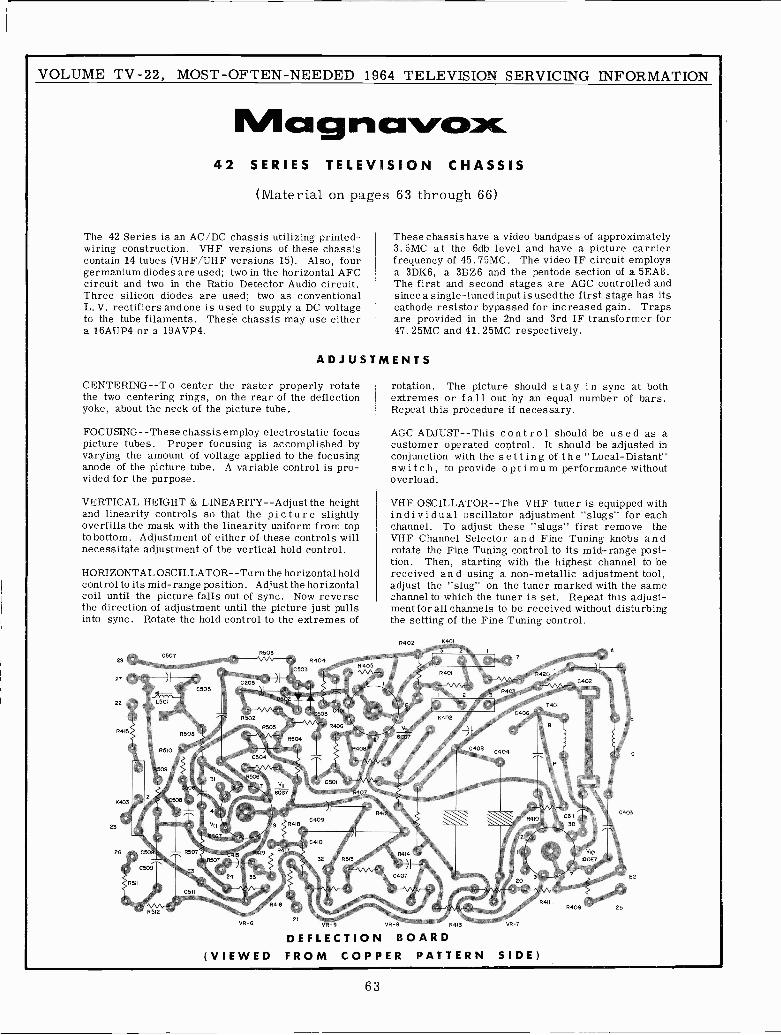
VOLUME TV -22, MOST -OFTEN -NEEDED 1964 TELEVISION SERVICING INFORMATION
MCe g h CrVs:»X42 SERIES TELEVISION CHASSIS
(Material on pages 63 through 66)
The 42 Series is an AC/DC chassis utilizing printed -wiring construction. VHF versions of these chassiscontain 14 tubes (VHF/UHF versions 15). Also, fourgermanium diodes are used; two in the horizontal AFCcircuit and two in the Ratio Detector Audio circuit.Three silicon diodes are used; two as conventionalL. V. rectifiers andone is used to supply a DC voltageto the tube filaments. These chassis may use eithera 16AUP4 or a 19AVP4.
ADJUST
CENTERING --To center the raster properly rotatethe two centering rings, on the rear of the deflectionyoke, about the neck of the picture tube.
FOCUSING --These chassis employ electrostatic focuspicture tubes. Proper focusing is accomplished byvarying the amount of voltage applied to the focusinganode of the picture tube. A variable control is pro-vided for the purpose.
VERTICAL HEIGHT & LINEARITY --Adjust the heightand linearity controls so that the picture slightlyoverfills the mask with the linearity uniform from topto bottom. Adjustment of either of these controls willnecessitate adjustment of the vertical hold control.
HORIZONTAL OSCILLATOR --Turn the horizontal holdcontrol to its mid -range position. Adjust the horizontalcoil until the picture falls out of sync. Now reversethe direction of adjustment until the picture just pullsinto sync. Rotate the hold control to the extremes of
These chassis have a video bandpass of approximately3. 5MC at the 6db level and have a picture carrierfrequency of 45.75MC. The video IF circuit employsa 3DK6, a 3BZ6 and the pentode section of a 5EA8.The first and second stages are AGC controlled andsince a single -tuned input is used the first stage has itscathode resistor bypassed for increased gain. Trapsare provided in the 2nd and 3rd IF transformer for47. 25MC and 41.25MC respectively.
MENTS
rotation. The picture should stay in sync at bothextremes or fall out by an equal number of bars.Repeat this procedure if necessary.
AGC ADJUST-This control should be used as acustomer operated control. It should be adjusted inconjunction with the setting of the "Local -Distant"switch, to provide optimum performance withoutoverload.
VHF OSCILLATOR --The VHF tuner is equipped withindividual oscillator adjustment "slugs" for eachchannel. To adjust these "slugs" first remove theVHF Channel Selector and Fine Tuning knobs androtate the Fine Tuning control to its mid -range posi-tion. Then, starting with the highest channel to bereceived and using a non-metallic adjustment tool,adjust the "slug" on the tuner marked with the samechannel to which the tuner is set. Repeat this adjust-ment for all channels to be received without disturbingthe setting of the Fine Tuning control.
R402
VR-6 VR-9 VR-B R413 VR-7
DEFLECTION BOARD(VIEWED FROM COPPER PATTERN SIDE)
63
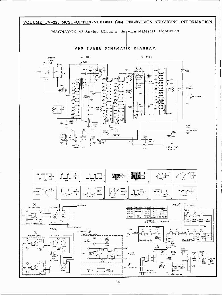
VOLUME TV -22, MOST -OFTEN -NEEDED 1964 TELEVISION SERVICING INFORMATION
MAGNAVOX 42 Series Chassis, Service
VHF TUNER SCHEMATIC
ANTENNA VI 201(5
300º.
Material, Continued
DIAGRAM
V2 5 C G 8
CM' INPUT '
KID2
[470 470
C10810
-/
3
-8_Y
112CIO¡ Z/ \ LOI3 ó IIóT102\j 1 .R107i1\ I
L012
/ LPI3 - r LG 13 _5.13« B - 3 ó
LOII 7,1-1
T101
F--.
LA12
LAII
LAID
0
P
LP12
1.1.11LGII- LPIO
LOI2
L6p
Tfi
RIDfi
-_,_-10K
r^/\MaRilo
GIIB3^LO10 NLO 9 HLOB -4-M
0
RII3B K
gll2IOK 1
CII]000
LA 9
LAg
LP]
0108-00
DrLP9LPB
LP7
L09
L68
I
`T
22pN
-_-
L07 !-iL06
LOS MOUTPUT
LABI>LP6
ICÁLG6 1I004.ó M
L04
103q10I
64.]N-L105 R102
- ' 47K LP4LP6
-
LG6LO4L133iseLA
R9 1000
T C34
0 L03 M
L02 -N
2
LP3
LP 2 L02I. FINV2
9HE
6G0 T.LI08 -M].iK t gIO
YK I
0q
15
LAI3i = 1- v2 vl c0107
T40UNFI L UNF2
O
5O
01060 0O
O AGCR106500
CIIB
LIOT4 5 3 4
122
= =- - CIII = OB2
I--
CI20 - 021IOOO 1F 10001 T000
i123000 I
119-=5" =- UHF IF B1
- INPUTDUHF= 8+
H2 HEATER HI V\VCONNECTIONS aK
LOW OH- SET 140 V
111¡¡¡III
6VP-P
60tiA
1L J`I{
IfOVIP-Pi r S.WA,
6
IIfLIIJ
1w( wl rp P80.
C
lIIII I1 I.IIII3_i.P P
I
11113°'-760ti
0
II
35VP-P.IIII'jjj\\\
ÓVRP
13]30,
F
/j,//'
609,
-P/IG
190_Í-P 'y/1
BOti
II J
VBOti
p 115TSOti
//p15750\.
fffLLL JJJLLLIp-p60M1i
.'-1i
1 114V}V15750ti
M
^I/
r
/// TI/ 13V0.P
IS]60r`L
N
HI H2OFILAMENTS VHF TUNER VHF TUNER
ANTENNA BOARD VHF TUNER 042-03 340033-1 16AUP4 D USE
r 1 H2 H 142-03 - I6AUP4 C OMIT . OJA-IS
1.2K I
U42-02 340034-1 I9AVP4 B USE V3 V4 V5
i VI V2 V42-02 19AVP4 A OMIT
VHF 30 I:
2GN5 5C68CHASSIS
UHFTUNER
PICTURETUBE
ANT.BOARD R ON TUNER 3 4 3 4 4 5
CI.2K I
` LOCAL -DISTANCE SW J0B1
ONF UHFTU ERENTStONVHFONLY C610 _C609
2200T2200
T
_C608T2200
I
_C6132200
1
1ACC B+ - -- IF OUTPUTIJA31(B2) VIS VII
JB-30V9 VIO VI2 V13 V8 V7 - V6
FILAMENTS C J8-31 JA -I6 5
ANTENNA BOARD e I 4 5 5 4 4 5 2 7 5 4 3 4 4 5 6 485ANTENNA BOARD VHF TUNER r ----- 0611 F C606
0612
F-I 1
02 HII C I
22001l /3607 OOZ700CI 1.2K I
INTI
ui PW-I6y5W
PWi6P3AITVHF 3303 ¡
I 00O O ANTENNA
I ( (Ti
I
~ G00
24115 5CG85.6K,IW
IC6184700 t0603C 1
1.2K - RI511.2K Oro 0
RIS3I
I
I
I- FUSE3A
C602R601 pyM D602 CH=015-10W
AGC B+B+(UHFI
IVHF 330S2
S3
I
I
TUVHF
NER C BI
(62) I IíXT _C601 , C603 + C6O4A
UHF TUNEflI R52 ANT.L 1.2K c- IMFD
D601 =_0614.OIUF oM d200
1.2K
C
UHF 330j I
fILB+ ANTENNA BOARDBOARDr
IIi1OF VRAON
R 4]OK 45KV700ÍÚF
350V 300V
-
L -O
0 OC
UHFO+I
IC I
2224 I
O O} TUNER i AC50 117V60 C/S = _LL_ 2K J CABINET GROUND
64
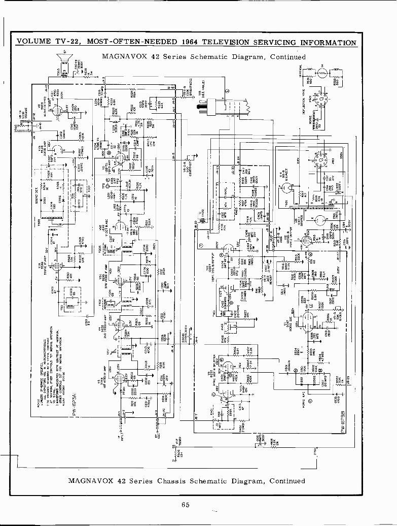
1550011
VO
LUM
E
BI
R80
1.51
(
BE
VH
FT
UN
ER
275V
IFIN
PU
T
RF
-AGCO
f-
C6I
6íSMFO
300V
R60
882
K2W
NO
TE
S
I. U
NLE
SS
OT
HE
RW
ISE
SP
EC
IFIE
D,
ALL
CA
PA
CIT
OR
S A
RE
INM
ICR
OM
ICR
OF
AR
AO
S.
2.00
VO
LTA
GE
S M
EA
SU
RE
D W
ITH
WP
M, C
ON
TR
AS
TA
T M
AX
IMU
M, O
TH
ER
CO
NT
RO
LS F
OR
NO
RM
AL
OP
ER
AT
ION
.N
OS
IGN
AL.
&W
AV
EF
OR
MS
ME
AS
UR
ED
WIT
H C
ON
TR
AS
T A
T M
AX
IMU
M,
OT
HE
R C
ON
TR
OLS
SE
T F
OR
NO
RM
AL
OP
ER
AT
ION
.4.
UN
E V
OLT
AG
E12
05 A
C.
PW-1
6P3A
1
JA -
1
JA
-3
V3
3DK
61S
T V
IDE
O IF
AM
P
7
1355
T20
1
V7A
SE
AR
SO
UN
D IF
AM
P 3
0
C30
347
_V 2
iC
3030
V,
10á
T30
1
r-.
1 L
7
R30
333
K
1R
301
_C30
2147
11
^88
II
J1
tC
305
sí.4
700
L
SO
UN
D' D
ET
.07
8S
EA
RA
UD
IO A
MP
C30
745
VS
MF
D25
V
R30
747
ME
G
JA -
I0
C30
9O
IMF
D
C31
0IO
MF
D25
VR
308
IOO
K
VB
SA
OS
AU
DIO
OU
TP
UT
JA -
13
35V
6
10.5
0
=18
309
[ 270 IW
V4
3626
2ND
VID
EO
IFA
MP
6 35
V--
--.
7V
PT
201' 2
I
'R
204
33K
R20
1 02
22R
202
II
22K
220
68
C20
1
2200 R214
BBOK
C20
2T12
011
1R20
3C
203
IK
4700
E
C2I
122
13IM
FD
10K
25V
C22
422
00
JA -
4
135V
V
1202
VS
A
:1 -
471_
,
--S
EA
R4T
.25
3RD
VID
EO
IF A
MP
1 I C
204
I40V
+68
1
-7y
2 r-
- 3
1305
LRZOB
fRzo
5C
2061
5068
130V
2200
R20
6C205
1 22
6R209
2200
-M-IK
Z47
0_1
1500
IK
1--
.1.7
0
C22
1C
210
R2I
2
I47°
°T
2M
iD22
0K
-13
0V
1203
V58
ÓL
25M
CD
ET
85E
A8
AB
C
II
V
`JT
I 1887
Iqt
J,T L--_
_
160V
L205
BV
2001
1
_C22
3-2
.50
VR
-5IM
EG
C20
9A
RC
4700
R21
122
06
10
TP
2
L201
O-
®IO
OU
HC
213
047
MF
D
R21
54.
76 212
L202
40U
N
R21
64.
76
T20
44S
MC
TR
.
V6
MO
V12
BV
7AV
IDE
O A
MP
®(- 21
7`3
,97
C 22L2
038R
222K
0 :IV
YR
V 2
= 8
135
y_
4022
0i3M
FD
216
6BO
K6B
8l yy
2W
K1
.-11
1021
12.-
1110
2112
I80K
R21
7
3WC
219C
219
SM
FD
R22
7,t)
300V
1.71
1[
820(
(TI
IOW
lM
n
C311
6700
600V
2205
C22
040 30
0VR
226
OW
'
5JA
-17
L204
IBO
UH
C21
RD
FO
CQ
C 2
2MF
DH
t -
R22
568
11
JA7
JA -
8
-7
C60
4C30
MF
D,3
00V -i
V9
-r-
-a-
6401
C6C
G7
- -
SY
NC
. SE
P. B
SP
LAT
TE
R
IM
F .O
ID^
330
1_
45V
200
1000
I_^
1I
C40
1-,,/
/
6 C
E1
3.D
IM
L__
R01
2.42
ME
G
K J
C41
3-47
PW-1
6P3B
I
'M R40
2
MO
RI Z
. AF
C
4700
R4 47
0
1R40
310
K
81R
4.2K
I20
V20
6
IR42
.205
Inv0
C50
1.0
01M
FD
X D
501
$R50
1
2050
2
C50
2.0
D1M
FD
R50
333
K1W
106
R50
210
K
C30
422
00
JB-4 R8
6402
4754
0
L?J
T40
1
VIO
100E
7V
ER
Y. O
SC
. S O
UT
PU
T
Ltu
JC
403
IIOV
JJ06
8MF
D
C40
2®
.004
7MF
D
{R42
0'4
7K
VII
6067
NO
RIZ
OG
C15
00
,-1(
1iN
+I
7(M
EG
.033 M
FD
R50
43s
47M
EG
C51
0150
JB-2
9
18S
V
20V
R409
SMEG
8 C40
42M
FD
5500
R4I
1IM
EG
C40
6.0
47M
FD
C40
5-6
V03
3M
FD
R41
0L
2ME
R41
233
K
9413
I ME
G
VR
-704
0]K
ÉIX
T .O
IMF
O
260V
JB-2
2
J9-2
0 IIT
402
VR
-2-A
S0
CO
NT
RA
ST
J8-2
3
R41
5A
.022
I'
II
22K
ME
D47
K
50-
I
I
K40
3
I
L3_
JJ8
-330
9ºs
v.W
-nn
11ó
B-z
aR
417
R41
9C
412
P41
400
8#R
416
470K
220K
,0O
Ó680 -7MFD -
47K
VR
-4C410
IW12
5VIM
EG
R41
8 -
IMF
D
.k
lay:
6000
1
C409
CIM
FD
JB-2
5JB-2_
_JB
-32
VE
RT
R.
PD,*
MF
BV
C50
8V
220
0 R
508
38.
8K
R50
712
0K
R50
6IK V
R-3
0739
00
50K
KN
OW
VR
-6IM
EG
VLI
N
220R
5126
C50
904
7M
FD C50
8
151090
.211
L5M
_
RS
0910
K
R5I
322
0K
JB-2
6
R5I
1 (7
68
225V
J8-2
7
r --F
'V
R-2
-BIM
E6
V12
1200
6-B
HO
RIZ
OU
TP
UT
A
JA -
9
VR
-I-B
IOO
KB
RIG
HT
NE
SS
-V
IS(S
EE
TA
BLE
)
1501
VI3
P12
AF
3D
AM
PE
R
48
8R
515
10 1W
C51
5IO
MF
DR
316
R51
9 30
0V12
KC
516
5.86
2W.IM
FD F
CS
I9C
514
MF
D30
V
014
102-
BN
.V.R
EC
T
ISK
V
R5I
7
482
3
R51
84.
7K2
IW
7 6
6 9111
El
II.0
330518
CS
20T
F
28
MP
S3K
VJ6
0'1
L502
WID
TH
SO
T
T30
3 0604
830
MF
D:
300V
R60
5
3
VE
RT
ICA
L
3 4 v
DE
FLE
CT
ION
YO
KE
MO
RI2
.P
601
4
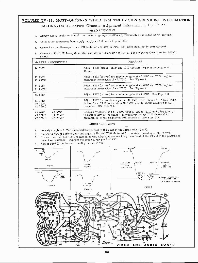
VOLUME TV -22, MOST -OFTEN -NEEDED 1964 TELEVISION SERVICING INFORMATIONMAGNAVOX 42 Series Chassis Alignment Information, Continued
VIDEO ALIGNMENT
1. Always use an isolation transformer when aligning and allow approximately 30 minutes warm-up time.
2. Using a low impedance' bias supply, apply a -2.0 volts to point JA3.
3. Connect an oscilloscope thru a 10K isolátion resistor to TP2. Set scope gain for 3V peak -to -peak.
4. Connect a 40MC IF Sweep Generator and Marker Generator to TP-1. Set the Sweep Generator for 10MCsweep.
MARKER FREQUENCIES REMARKS
44. OMC Adjust T102 (Mixer Plate) and T202 (Bottom) for maximum gain at44. OMC.
47. 5MC47.25MC
Adjust T202 (bottom) for maximum gain at 47. 5MC and T202 (top) formaximum attenuation of 47.25MC. See Figure 1.
41. OMC41.25MC
Adjust T203 (bottom) for maximum gain at 41. OMC and T203 (top) formaximum attenuation of 41.25MC. See Figure 2.
45. 8MC Adjust T202 (bottom) for maximum gain at 45. 8MC. See Figure 3.
43. 3MC45. 75MC42.75MC
Adjust T102 for maximum gain at 43. 3MC. See Figure 4. Adjust T203(bottom) and T201 to maintain 45. 75MC and 42. 75MC markers at 50%response. See Figure 5.
45. OMC 43. 5MC45. 75MC 41.25MC42. 75MC 47. 25MC
Recheck 47. 25MC and 41.25MC Traps. Adjust T102 and T201 jointlyto remove any tilt or peaks. If necessary adjust T203 (bottom) tomaintain 45. 75MC marker at 50% response. See Figure 5.
AUDIO ALIGNMENT
1. Loosely couple a 4. 5MC2. Connect a VTVM across3. Connect two matched 10011
these two resistors. Connect4. Adjust T302 (Top) for zero
(unmodulated) signal to the plateC307 and adjust T301 and T302
resistors across C207 andthe probe to the pin 3 of
reading on the VTVM.
of the 12BY7 tube (Pin 7).(bottom) for maximum reading on the VTVM.
connect the ground lead of the VTVM to the junction ofK301.
TRI 0%47.25 MC' 41.25 MC
47.25MC
47.5 MC
45,8 MCSET AT 6DB 45,75 MC 92.75 MC SET AT en
Figure 1 Figure 350% So
LIMITS ± 10% LIMITS ! 10%
TR245 MC REF. 43,5 MC
41.25 T203MC
41,0 MC
95% REF924 10% VALLEY MAXIMUM WITH
BALANCED PEAKS.
Figure 2
8227
43.3 MC
Figure 4
5 º R226 +`
10% ROUND TOP MAXIMUM.
Figure 5
CVO
zo .
;DI Ke a0
z04
L 202 ..
. `..
iff 0220
... .R I
.._.. 20 . ..!_L_ . R229
05 5
C21ºat
VIDEO AND KS AUDIO BOARD
66
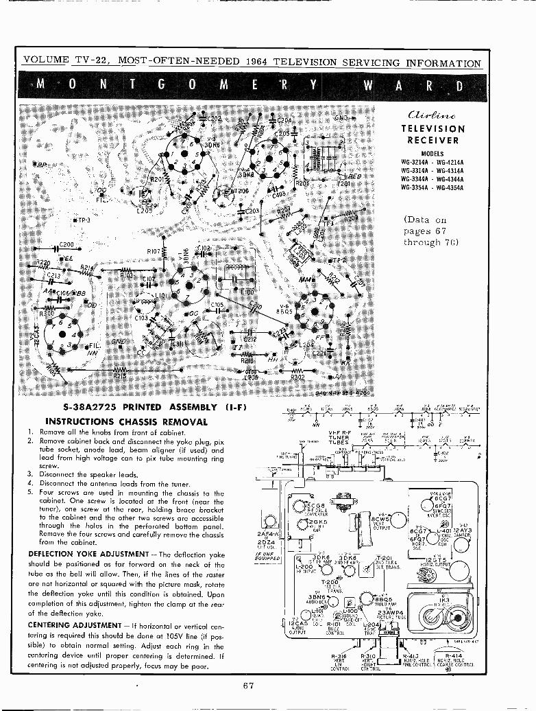
VOLUME TV -22, MOST -OFTEN -NEEDED 1964 TELEVISION SERVICING INFORMATION
r-~-mm;1I f
i 1: I
3 4:5 j4 I
L___ R£DR206 + :T201
'ZA03
^-0200 CI--+ D,102 . =z Nwt <
R107
r£E 'm ', ¡ ' 1--.y1[--.,, Rzl 1....,C213 R
<L107 4 3.`2-í.¡ -I F^r .: S 1 ;' ,-A/{.t106 BB 5 f 3D0!
( ` , l lOf;1 + bI +Í$é9 : : c105:::: G,:..-1-4.11,7111
-C103 `B
S ry^s
L #:I 34 FIL. >, #yfi:. C314 f+' i 2` 2 L204FF1Z1a :: :4"..r::::': :; CZ::NN L _ -'# # %
R1$ HH
S -38A2725 PRINTED ASSEMBLY (I -F)
INSTRUCTIONS CHASSIS REMOVAL1. Remove all the knobs from front of cabinet.2. Remove cabinet back and disconnect the yoke plug, pix
tube socket, anode lead, beam aligner (if used) andlead from high voltage can to pix tube mounting ringscrew.
3. Disconnect the speaker leads.4. Disconnect the antenna leads from the tuner.5. Four screws are used in mounting the chassis to the
cabinet. One screw is located at the front (near thetuner), one screw at the rear, holding brace bracketto the cabinet and the other two screws are accessiblethrough the holes in the perforated bottom panel.Remove the four screws and carefully remove the chassisfrom the cabinet.
DEFLECTION YOKE ADJUSTMENT - The deflection yokeshould be positioned as far forward on the neck of thetube as the bell will allow. Then, if the lines of the rasterare not horizontal or squared with the picture mask, rotatethe deflection yoke until this condition is obtained. Uponcompletion of this adjustment, tighten the clamp at the rearof the deflection yoke.
CENTERING ADJUSTMENT - If horizontal or vertical cen-tering is required this should be done at 105V line (if pos-sible) to obtain normal setting. Adjust each ring in thecentering device until proper centering is determined. If
centering is not adjusted properly, focus may be poor.
TELEVISIONRECEIVER
MODELS
WG-3214A - WG-4214AWG-3314A - WG-4314A
WG-3344A - WG-4344AWG-3354A - WG-4354A
(Data onpages 67through 70)
R.401 BCWS 12CÁ5 38N6 8B05 30K6 3D1(6 6CU RIMO/ 6CGIOR6F0/
FINE TUNING
2AF4-AOP
2DZ4 ¡-UHF OSC.
IF UHFEQUIPPED
NN
VHF TUNING
VHF R -F1TUNERTUBES
9 I J t 3 5 9 5 l11
VHF n r a -E OSC á IP. CONVERTER,
26115 5CG8
5BauCONTRAST Rail BRIGHTNESS
oN MVO I I r I¡- viRTac:i HUBO.-+-- r7L-J
R
ISCG8OSE. &
CONVERTER
i2GK5//VHF RF
AMP.
-43DK6 3DK6
1ST I -F AMP 2ND I -F AMPL-200I -F INPUT
T-2001ST P.I.F.
Al TRANS3BN61 188Q5
AUDIO DET. I ;pI y i VIDEO AMP.
6L -1ÓI /,-L-100-1 23AWP4O QUAD. (YJ)1 SOUND PICTURE TUBE
V-2 GRID ,- TAKE -OFF12CA5 COIL R -I01 COIL L-204
AUDIO BUZZ 4.SMC`OUTPUT CONTROL TRAP
V -N
8CW5VERT.OUTPUT
T -20I2ND P.I.ENDET TRANS
T040# Sóó3V D0
V -I2
12AY3
5
E
12GT5
V -7A & V-78
6CG7o
6FQ7SYNC.SEP.
dVERT.OSC.
V -I2V-96 C G I y-L-40I 12 AY 3
OR
UHORIZDAMPER
6FQ7 OSC.HORIZ. COILOSC.
V -I0
12GT5HORIZ. OUTPUT
II -` 54B t N99-9101II UV
R-316 R 310 R-413 R-414VERT. VERT. I HORIZ. HOLD HORIZ. HOLDLIN. HEIGHT FINE CONTROL COARSE CONTROL
CONTROL CONTROL
67
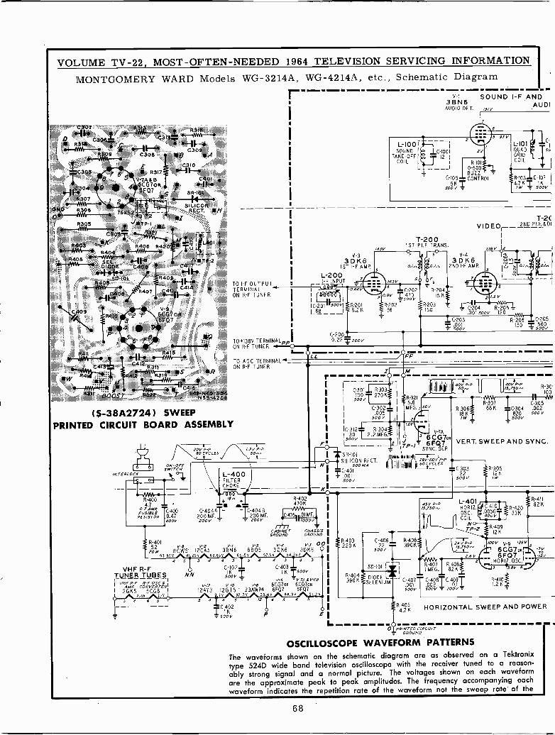
NN
VOLUME TV -22, MOST -OFTEN -NEEDED 1964 TELEVISION SEMONTGOMERY WARD Models WG-3214A, WG-4214A, etc.,
`.4,.,:..g:;::;;:y:li r C309
C308 iRg
C3108"'Iic4o1
SF-lH14
SILICONRECT. .H ::
*1«.
`r
r-
TO I -F OUTPUTTERMINALON R -F TUNER
TO+138V TERMINALPPION R -F TUNER
TO AGC TERMINALON R -F TUNER
(5-38A2724) SWEEPPRINTED CIRCUIT BOARD ASSEMBLY
INTERLOCK
ON -OFFSw/TCN
ANN R-4004.7 '
0.7 AMRC-400p,,
és/1B óR 0.47400V
203 P -P /.2V P -P60 CYCLES 60.v_
L-400FILTERCHOKE
+ M +
C -404A TC-404 B200 MF. I200 MF.200V - 200V
_ L_
R-401V-6 V-2 V-/ V-5
sow 8CW5' 12CA5 3BN6 880593.85V A61_25VA88.65VA 65_.SV/
VHF R -F4
TUNER TUBES1-
VHF AF CONVERTER' V-/2 V-/0 V-6 6GG7OR 6CG7OR
I 20115 5CG8 '12ÁY3 12GT5' 23AWP4 6FQ7 6FQ7
2.4V 7.IV I .7V 32.3V 38.6V 44.9V 51.23
3 4 4 5 5 a 4 5 1 12 4 5 4 5
C-402I
o 0
5ooV P E
CAB/NETGROUND
V-43DK6
7.5 V A 54
` o
--
3DK6Sr1 I-F AMP.
L-200I -F INPUT 7
IIC -201 R201L68---1 8.2K
i
i .005oOV 3
I IC-312T R-304I V -7A
F!isóóv ! 2.2MEG. 2¡o 3 6CG7oR
p 6 FQ7SYNC. SEP.
OI M F.
l0( óóV'
CHASSISGROUND
3 4 4 3 5 4 4 3
C -102T C -'0r31500V
soot/ 1V-9 V -7A 6 V -7B
V-3 003DK6 OSV4 3
C-2000.22 .T- 2oov
SERVICING INFORMATIONSchematic Diagram
V -I S OUND I -F AND3BN6 AUDIAUDIO DE T. 13/V
7
L -I001I
SOUND I - C-1001 1,vTAKE -OFF I _ 12 I
COIL I I R-101
L --__I 0-5001-
C-105 CONTROL
500V 1
97V
L101QUAD.GRIDCOIL
CI
50
R -I03 C -I 7
4.7KI IK1 w - 500V
T-200/43v 151 PI.F TRANS.
Sa V-43DK60./,. 0./ 2ND I -F AMP.
5
VIDEOI-
0-203150
/36 V 4
i C204 R-205.001soov 120
1,C-203001
- 500V
T -2C2ND P.I.F.8DI
R-206 C-205I 5 0 T 500.en-v---
I M
C 3011, R-303150T270K
500V(
C-302
Ti
I
R 3215.6
MEG.,
111111444 -1.70: -
DV
I SR-IOI y- elwrR r-29v-NOV .0 SILICON RECT. P -P
500 MA 60 CYCLES-1_I 9.C-401f
1, .001500V
I -
SD -101
DIODE LSELENIUM
R-30618 K/w
R-3076811
40VP-P-P15,750ti R-30'
100
C-305C-304 .002T820500V
500 V
VERT. SWEEP AND SYNC.
C-303 R-30522 1211
500V 1W
L-401 HORIZ. C -410Z R-420OSC. Dó56T 33KCOIL 1
N R-401TP812K
C -406I R-4061 -22 T 390K IIVP-P loov
50oV I15,'SO.
I
d''';11.".-4071R-40812.6
1 R-407 R -40BI MEG. 82 K
3 C -407T C-408TC-409T ft -410001 .002 J. 0.1 11 z 11500V
5007 - 200V :
R-4054.7K
45V P -P/5,750 e.
171______r
HORIZONTAL SWEEP AND POWER
73 ;ZINCED CIRCUITGROUND- GROUND
OSCILLOSCOPE WAVEFORM PATTERNSThe waveforms shown on the schematic diagram are as observed on a Tektronix
type 524D wide band television oscilloscope with the receiver tuned to a reason-ably strong signal and a normal picture. The voltages shown on each waveformare the approximate peak to peak amplitudes. The frequency accompanying eachwaveform indicates the repetition rate of the waveform not the sweep rate of the
68
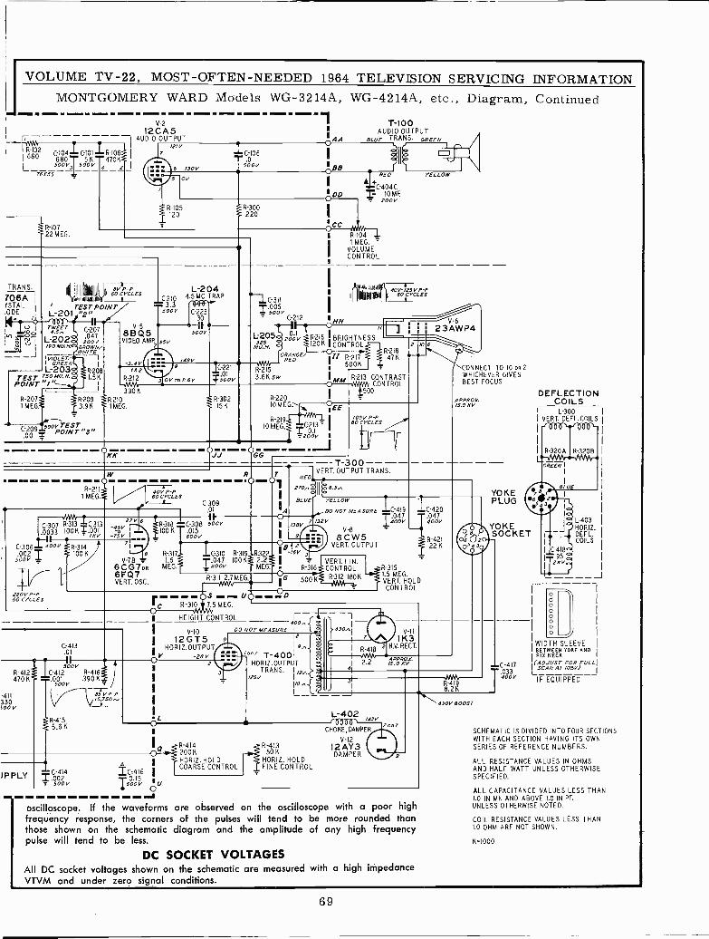
VOLUME TV -22, MOST -OFTEN -NEEDED 1964 TELEVISION SERVICING INFORMATIONMONTGOMERY WARD
V-212CA5G-- - I AUDIO OUTPUT
1R-10,2/21V
68 C-104 C-101 R-106 I
680 T 56 47061 500V3 500V 4 2 I
76X55
R-10722 MEG.
6 1J0 V
OV
Models
1C-106.01
500V
WG-3214A, WG-4214A, etc., Diagram, Continued
IAA
oI
BB
O
R-105120
TRANS.
706AYSTALODE 1
III+ )VIII IWBIIIiI üI B 60 CYCLESÍVVf
r 011 11181111818' 4
BV P -P
TEST PO/NTL-201 "2
U10'LoaoU/9OWN/
5o1.5KPO/NT
-20709 1R-210IMEG.9K IMEG.
-3.4V182
R-212
3308
C-20915o0PONTST "3".0015
813Q5VIDEO AMP.
7
C-2103.3 '131:0°1-99
50oV
L-2044.5 MC TRAP
95V
01/ro 8.6
C-22330
° le500V
R-300220
C-3 IIT.005_ 500V
Cw212
L-205325
200VaMU. H. 1.
['ORANGE/REO
3.6K5R-25
W
/4BV9 IC -221
0so1ov
cc
aHH
T-100AUDIO OUTPUT
BLUE TRANS. GREEN
á
=RED
+C-404C0 MF.- 200V
R-1041 MEG. '
VOLUMECONTROL
,'WdIUIIIIdMIV
uY1plln1a
YELLOW
40V -/25V P -P60 C YCLES
R-216 !BRIGHTNESS120K ICONTROL
II R -2I75006
R-30215K
8-220IOMEG"-
R -2I9IO MEG
11 23
8-21847K
R-213 CONTRASTCONTROL
500
2 /0 6
y 1EE
0-21 I
2001V 1KK-- JJ OGG -
- R-211
1 MEG.
3R SC313
0033 100K =.001/Kv
C-306 400V R-314ill'2 100K
50oV
220V P -P60 CYCLES
27V-45V
eV -7B -
6CG70B6FQ7VERT. OSC.
40V P -P60 CYCLES
C309.01
6 t"r3181C-308 !OOV100K .015
600 V
R-311 1C-3101,C-3101.5 T047
MEG. 1 zOOV
Rp
OA
/05V P -P yyy60 CYCLES
- - - T-300---RED
-1VERT. OUTPUT TRANS.
270.,á1I6.5.,
BLUE' YELLOW
DO NOT MEASURE 049
7138V= /32V 1.04400V
V-89 8CW5
VERT. OUTPUT2
R -3I9 R322 i B -16V j100K1 2.21 -
MEG. R-316
1G 500KR-311 2.7-VVvMEG-
VERT. LIN.CONTROL
8-312 180K
R-412470 K
-411330
V
DPPLY
l
C.-413.01
500VC -4I2 R-4161.001 390 Kv
500V
85VP-Ps.lso...
R-4155.6 K
C-4141.002500
óO R-315 MEG.
1 HEIGHT CONTROL
V-IOI 12GT5
HORIZ.OUTPUTóV -28V
L
1C-420
T047400V
R-42122 K
R-3151.5 MEG.VERT. HOLDCONTROL
DO NOT MEASURE12
19.,07 T-4001
HORIZ.OUTPUTTRANS. I {
zsv I SI
tó430.,
4
R-418 2
T*' APPROX.2.2
V-11771K3H.V. RECT.
',CONNECT TO 10062WHICHEVER GIVESBEST FOCUS
APPROX./5.0KV
.
=C:416
-170.151100.P,nU
-d
8-4142006HORIZ HOLDCOARSE CONTROL
R-41350 K
HOWL. HOLDFINE CONTROL
L-40214sv'6000` 20.7
CHOKE,DAMPER
V-12
12AY3DAMPER
oscilloscope. If the waveforms are observed on the oscilloscope with a poor highfrequency response, the corners of the pulses will tend to be more rounded thanthose shown on the schematic diagram and the amplitude of any high frequencypulse will tend to be less.
DC SOCKET VOLTAGESAll DC socket voltages shown on the schematic are measured with a high impedanceVTVM and under zero signal conditions.
R -4I98.2K
430V BOOST
YOKEPLUG
YOKESOCKET
C-417
T-
033400V
DEFLECTIONCOILS
L-300VERT. DEFL.COILS
L-403H08IZ.DEFL.COILS
oooo
ooo
WIDTHYOKESLEEVEANO
PIN NECK
ISCAN(ADJUSTAT /FOSVJOR FOLLI
IF EQUIPPED
SCHEMATIC IS DIVIDED INTO FOUR SECTIONSWITH EACH SECTION HAVING ITS OWNSERIES OF REFERENCE NUMBERS.
ALL RESISTANCE VALUES IN OHMSAND HALF WATT UNLESS OTHERWISESPECIFIED.
ALL CAPACITANCE VALUES LESS THAN1.0 IN MF AND ABOVE 1.0 IN PF.UNLESS OTHERWISE NOTED.
COIL RESISTANCE VALUES LESS THAN1.0 OHM ARE NOT SHOWN.
K=1000
69
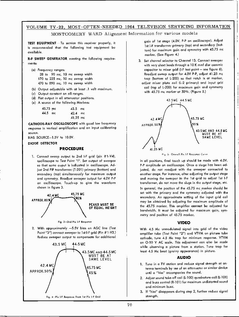
VOLUME TV -22, MOST -OFTEN -NEEDED 1964 TELEVISION SERVICING INFORMATIONMONTGOMERY WARD Alignment Information for various models
TEST EQUIPMENT - To service this receiver properly, itgain of 1st stage (4.0V. P -P on oscilloscope). Adjust
is recommended that the following test equipment be 1st I -F transformer primary (top) and secondary (bot-
available.torn) for maximum gain and symmetry with 45.75 mcmarker. (See Figure 4.)
R -F SWEEP GENERATOR meeting the following require-ments:
3. Set channel selector to Channel 13. Connect sweeperwith very short leads through a 10 K mmf disc ceramic
(a) Frequency ranges: capacitor to mixer grid (I -F test point - see figure 6).
38 to 90 mc, 10 mc sweep width Readjust sweep output for 4.0V P -P, adjust 41.25 mc
170 to 225 mc, 10 mc sweep width trap (bottom of L-200) so that notch is at marker,470 to 890 mc, 10 mc sweep width adjust mixer plate coil (L-2 primary) and input grid
(b) Output adjustable with at least .1 volt maximum. coil (top of L-200) for maximum gain and symmetry
(c) Output constant on all ranges. with 45.75 mc marker at 50%. (Figure 5.)
(d) Flat output in all attenuator positions.(e) A source of the following Markers:
43.5 MC 44.5 MC
45.75 mc 43.5 mc
44.5 mc 42.4 mc
41.25 mc 42.4 MC 45.75 MC
CATHODE-RAY OSCILLOSCOPE with good low frequency APPROX.50% 50%response in vertical amplification and an input calibrating
source.43.5 MC AND 44.5 MC
MUST BE ATBIAS SOURCE -1.5V to 10.0V. SAME LEVEL
DIODE DETECTOR
PROCEDURE 41.25 MC
1. Connect sweep output to 2nd I -F grid (pin #1-V4),Fig. 5 --Overall Pix I -F Response Curve
gscilloscope to Test Point "I". Set output of sweeper In all positions, final touch up should be made with 4.0V.so that some ouput is indicated in oscilloscope. Ad- P -P amplitude on oscilloscope. Once a stage his been ad-just 2nd PIF transformer (T-201) primary (bottom) and lusted, do not readjust with the sweeper connected tosecondary (top) simultaneously for maximum output another stage. For instance, after adjusting the output stageand symmetry. Readjust sweeper output for 4.0V P -P and moving the sweeper to the 1st grid to adjust 1st I -F
on oscilloscope. Touch-up to give the waveform transformer, do not move the slugs in the output stage, etc.shown in figure 3. In general, the position of the 45.75 mc _marker should be
42.4 MC 45.75 MC set with the primary and the symmetry adjusted with thesecondary. An approximate setting of the input grid coil90%
APPROX.80% may be obtained by adjusting for maximum amplitude ofPEAKS MUST BEOF EQUAL HEIGHT
the 45.75 marker. This amplifier cannot be adjusted forbandwidth. It must be adjusted for maximum gain, sym-metry and position of 45.75 marker.
Fig. 3 -2nd Pix I -F Response VIDEO2. With approximately -5.5V bias on AGC line (Test With 4.5 Mc unmodulated signal into grid of the video
Point "3") connect sweeper to 1st I -F grid (Pin #1-V3.) amplifier tube (Test Point "2") and VTVM on picture tubeReduce sweeper output to compensate for additional cathode, tune 4.5 Mc trap for minimum response. VTVM
43.5 MC 44.5 MCon 0-10 V AC scale. This adjustment can also be madewhile observing a picture from a station. Tune trap for
43.5 MC AND 44.5 MC least 4.5 Mc beat (grainy appearance) in picture.MUST BE ATSAME LEVEL AUDIO
42.4 MC 1. Tune in a TV station and reduce signal strength at an.45.75 MC tenna terminals by use of an attenuator or similar device
APPROX.50% 45% until a "hiss" accompanies the sound.
2. Adjust sound take -off coil (L-100) quadrature coil (L-101)and buzz control (R-101) for maximum undistorted sound
and minimum buzz.
3. If "hiss" disappears during step 2, further reduce signal
Fig. 4-Pix I -F Response From 1st Pix I -F Grid strength.
70
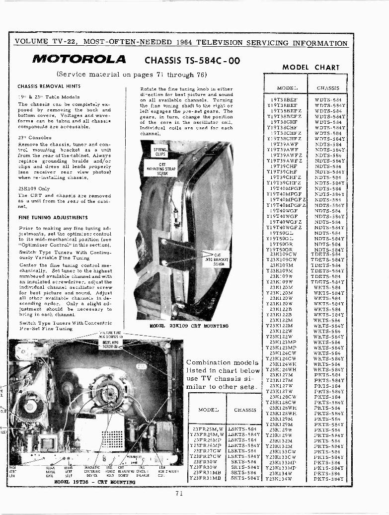
VOLUME TV -22, MOST -OFTEN -NEEDED 1964 TELEVISION
R604
VERT
LIN
MOTOROLA CHASSIS TS -584C - 00(Service material
CHASSIS REMOVAL HINTS
19" & 23" Table ModelsThe chassis can be completely ex-posed by removing the back andbottom covers. Voltages and wave-forms can be taken and all chassiscomponents are accessable.
23" ConsolesRemove the chassis, tuner and con-trol mounting bracket as a unitfrom the rear of the cabinet. Alwaysreplace grounding braids and/orclips and dress all leads properly(see receiver rear view photos)when re -installing chassis.
23K109 OnlyThe CRT and chassis are removedas a unit from the rear of the cabi-net.
FINE TUNING ADJUSTMENTS
Prior to making any fine tuning ad-justments, set the optimizer controlto its mid -mechanical position (see"Optimizer Control" in this section).Switch Type Tuners With Continu-ously Variable Fine TuningCenter the fine tuning control me-chanically. Set tuner to the highestnumbered available channel and withan insulated screwdriver, adjust theindividual channel oscillator screwfor best picture and sound. Adjustall other available channels in de-scending order. Only a slight ad-justment should be necessary tobring in each channel.Switch Type Tuners With ConcentricPre -Set Fine Tuning
R114A R114B
NOISE VERT
GATE SIZE
PICTURE TUBE
MTG SCREWS 141
BEZEL MTG
CREW (84
on pages 71 through 76)
4MAGNETIC L501 CRT
CENTERING HORIZ RETAINING CIRCUITDEVICE HOLD SCREW BREAKER
Rotate the fine tuning knob in eitherdirection for best picture and soundon all available channels. Turningthe fine tuning shaft to the right orleft engages the pre-set gears. Thegears, in turn, change the positionof the core in the oscillator coil.Individual coils are used for eachchannel.
MODEL 19138 - CRT MOUNTING
MODEL 23K109 CRT MOUNTING
L504
HORIZ WIDTHCOIL
SERVICING INFORMATION
Combination modelslisted in chart belowuse TV chassis si-milar to other sets.
MODEL CHASSIS
23FR25M,W LSKTS-584Y23FR25M, W LSKTS-584?
23FR26MP LSKTS-584Y23FR26MP LSKTS-584Y
23FR27CW LSKTS-584Y23FR27CW LSKTS-584Y
23FR30W SKTS-584Y23FR30W SKTS-584Y
23FR31MB SKTS-584Y23FR31MB SKTS-584Y
MODEL CHART
MODEL CHASSIS
19T38BEFY 19T3 8BEF
19T38BEFZY19T38BEFZ
19T38CHFY19T38CHF
1 9T3 8CHF ZY19T38CHFZ
19T39AWFY19T39AWF
19T39AWFZY19T39AWFZ
19T39CHFY19T39CHF
19T39CHFZY19T39CHFZ
19T40MPGFY19T40MPGF
19T40MPGFZY 19T40MPGF Z
1 9T4O WGFY19T4OWGF
1 9T40 WGF ZY19T40WGFZ
1 9T5OGLY19T50GL
1 9T5OGRY19T50GR
23K109CWY23K109CW
23K109MY23K109M
23K109WY23K109W
23K1 20MY23K1 20M
23K1 20 WY23K1 EO W
23K1 22BYZ3K1 22B
23K1 22MYZ3K1 22M
23K1 22WY23K122W
23K1 23 MPY 23K1 23 MP
23K1 24CWY23K1 24CW
23K1 24WHY23K1 24WH
23K1 27MY23K1 27M
23K1 27WY 23K1 27 W
23K1 28C WY23K1 28CW
-23K1 28WHY23K1 28WH
23K1 29MY23K129M
23K1 29WY23K1 29W
23K132MY 23K13 2M
23K133CWY23K133CW
23K133MPY23K133MP
23K1 34WY23K134W
WDTS-584WDTS-584YWDTS-584WDTS-5 84YWDTS-584WDTS-584YW DTS- 5 84WDTS-584YNDTS-584NDTS- 5 84YNDTS-584NDTS-584YNDTS- 5 84NDTS-584YNDTS-584NDTS-584YNDTS-584NDTS-584YNDTS-584NDTS-584YNDTS-584NDTS-584YNDTS-584NDTS-584YNDTS-584NDTS-584YNDTS- 5 84NDTS-584Y
TDETS-584TDETS-5 84YTDETS-584TDETS-5 84YTDETS-584TDETS-584Y
WKTS-584WKTS-5 84YWKTS-584WKTS-5 84YWKTS-584WKTS-584YWKTS-584WKTS-584YWKTS-584WKTS-584YWKTS-584WKTS-584YWKTS-584WKTS-5 84YWKTS- 5 84WKTS-584YPKTS-584PKTS-584YPKTS-584PKTS-584YPKTS- 5 84PKTS-5 84YPKTS-584PKTS-584YPKTS-584PKTS-584YPKTS- 5 84PKTS- 5 84YPKTS-584PKTS- 5 84YPKTS-584PKTS-584YPKTS-584PKTS-584YPkTS-5 84PKTS-584Y
71
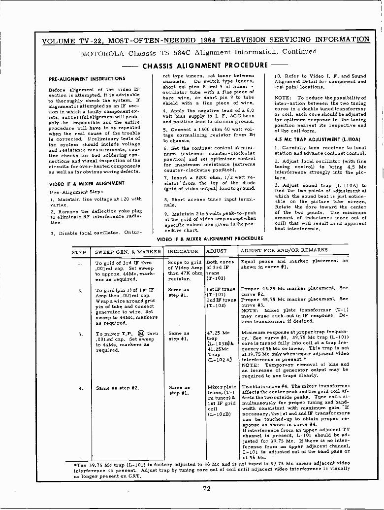
VOLUME TV -22, MOST -OFTEN -NEEDED 1964 TELEVISION SERVICING INFORMATION
MOTOROLA
PRE -ALIGNMENT INSTRUCTIONS
Chassis TS -584C Alignment Information,
CHASSIS ALIGNMENT PROCEDURE
Before alignment of the video IFsection is attempted, it'is advisableto thoroughly check the system. Ifalignment is attempted on an IF sec-tion in which a faulty component ex-ists, successful alignment will prob-ably be impossible and the entireprocedure will have to be repeatedwhen the real cause of the troubleis corrected. Preliminary tests ofthe system should include voltageand resistance measurements, rou-tine checks for bad soldering con-nections and visual inspection of thecircuits for over -heated componentsas well as for obvious wiring defects.
VIDEO IF & MIXER ALIGNMENT
Pre -Alignment Steps1. Maintain line voltage at 120 withvariac.2. Remove the deflection yoke plugto eliminate RF interference radia-tion.
3, Disable local oscillator, Ontur-
ret type tuners, set tuner betweenchannels. On switch type tuners,short out pins 8 and 9 of mixer -oscillator tube with a fine piece ofbare wire, or short pin 9 to tubeshield with a fine piece of wire.4. Apply the negative lead of a 6.0volt bias supply to I. F. AGC bussand positive lead to chassis ground.5. Connect a 1500 ohm 60 watt vol-tage normalizing resistor from B+to chassis.6. Set the contrast control at mini-mum (extreme counter -clockwiseposition) and set optimizer controlfor maximum resistance (extremecounter- clockwise position).7. Insert a 8200 ohm, 1/2 watt re-sistor' from the top of the diode(grid of video output) loadto ground.
8. Short across tuner input termi-nals.
9. Maintain 2 to 5 volts peak -to -peakat the grid of video amp except whenspecific values are given inthe pro-cedure chart.
VIDEO IF & MIXER ALIGNMENT PROCEDURE
Continued
10. Refer to Video I. F. and SoundAlignment Detail for component andtest point locations.
NOTE: To reduce the possibility ofinter -action between the two tuningcores in a double tunedtransformeror coil, each core should be adjustedfor optimum response in the tuningposition nearest its respective endof the coil'form.
4.5 MC TRAP ADJUSTMENT (L -110A)
1. Carefully tune receiver to localstation and advance contrast control.2. Adjust local oscillator (with finetuning control) to bring 4.5 Mcinterference strongly into the pic-ture.3. Adjust sound trap (L -110A) tofind the two points of adjustment atwhich the sound beat is just notice-able on the picture tube screen.Rotate the sore toward the centerof the two points. Use minimumamount of inductance (core out ofcoil) that will result in no apparentbeat interference.
STEP SWEEP GEN. & MARKER INDICATOR ADJUST ADJUST FOR AND/OR REMARKS
2.
3.
4.
To grid of 3rd IF thru,001mf cap. Set sweepto approx. 44Mc, mark-ers as required.
To grid (pin 1) of 1st IFAmp thru ,001mf cap.Wrap a wire around gridpin of tube and connectgenerator to wire. Setsweep to 44Mc, markersas required.
To mixer T.P. ® thru.001mf cap. Set sweepto 44Mc, markers asrequired.
Same as step #2.
Scope to gridof Video Ampthru 47K ohmresistor.
Same asstep #1.
Same asstep #1.
Same asstep #1.
Both coresof 3rd IFtrans(T-103)
1st IF trans(T-101)2nd IF trans(T-102)
47.25 Mctrap(L -103B)&41.25 McTrap(L -102A)
Mixer platetrans, (T-1on tuner) &1st IF gridcoil(L -102B)
Equal peaks and marker placement asshown in curve #1.
Proper 42.25 Mc marker placement. Seecurve #2.Proper 45.75 Mc marker placement. Seecurve #3.NOTE: Mixer plate transformer (T-1)may cause suck -out in IF response. De -tune transformer if desired.
Minimum response at proper trap frequen-cy. ' See curve #3. 39.75 Mc trap (L-101)core is turned fully into coil at a trap fre-quency of 36 Mc or lower. This trap is setat 39.75 Mc onlywhenupper adjacent videointerference is present.*NOTE: Temporary removal of bias andan increase of generator output may berequired to see traps clearly.
To obtain curve #4. The mixer transformeraffects the center peak and the grid coil af-fects the two outside peaks. Tune coils si-multaneously for proper tuning and band-width consistant with maximum gain. Ifnecessary, the 1st and 2nd IF transformerscan be touched -up to obtain proper re-sponse as shown in curve #4.If interference from an upper adjacent TVchannel is present, L-101 should be ad-justed for 39.75 Mc. If there is no inter-ference from an upper adjacent channel,L-101 is adjusted out of the band pass orat 36 Mc.
*The 39.75 Mc trap (L-101) is factory adjusted to 36 Mc and is not tuned to 39.75 Mc unless adjacent videointerference is present. Adjust trap by tuning core out of coil until adjacent video interference is visuallyno longer present on CRT.
72
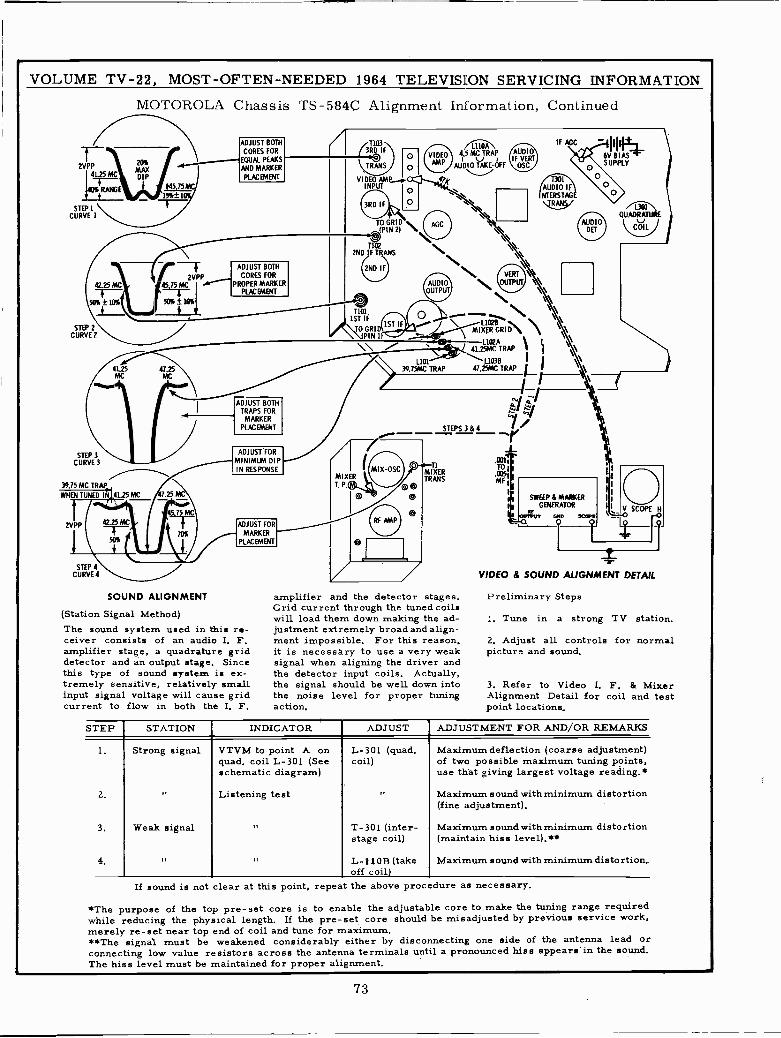
2VPP41.25 MC
STEP ICURVE 1
VOLUME TV -22, MOST -OFTEN -NEEDED 1964 TELEVISION SERVICING INFORMATION
MOTOROLA Chassis TS -584C Alignment Information, Continued
T20%MAXDIP
$5.75
/2VPP42. 45 7 5 MC
5016±1016 50F±10f6
STEP 2CURVE2
STEP 3CURVE 3
39.75 MC TRAP_
WHEN TUNED IN
t 1
2VPP
I
STEP 4CURVE 4
4M.CC5 47.25
41.25 MC .25 MC\
75 MC
42.25 MC
50%
f
ADJUST BOTHCORES FOR
EQUAL PEAKS
AND MARKER
PLACEMENT
ADJUST BOTHCORES FOR
PROPER MARKERPLACEMENT
ADJUST BOTHTRAPS FOR
MARKERPLACEMENT
ADJUST FORMINIMUM DIPIN RESPONSE
ADJUST FOR
70% MARKER/ PLACEMENT
SOUND ALIGNMENT
(Station Signal Method)The sound system used in this re-ceiver consists of an audio I. F.amplifier stage, a quadrature griddetector and an output stage. Sincethis type of sound system is ex-tremely sensitive, relatively smallinput signal voltage will cause gridcurrent to flow in both the I. F.
3RD IF
TO GRID(PIN 21 N
VIDEOAMP
LIIOA4.5 MC TRAPv
AUDIO OFF
2ND IF TRANS
2ND IF
1ST IF
TO GRID1ST IF
IPIN
MIX-OSCMIXERT. P.
AUDIOIF VERT
OSC
AUDIODET
N. \\\\AXED ` \ \\\\
\41.25MC TRAP
L102A1 \ \
``
0
\47.5AICT RAP f \\
I 7
AUDIOOUTPUT
L10139.75MC TRAP
r
- yeh-----/1.
1
.0051
M1
STEPS 3 & 4
MIXERTRANS
amplifier and the detector stages.Grid current through the tuned coilswill load them down making the ad-justment extremely broad and align-ment impossible. For this reason,it is necessary to use a very weaksignal when aligning the driver andthe detector input coils. Actually,the signal should be well down intothe noise level for proper tuningaction.
SWEEP & MARKERGENERATORa
L301
QUADRATURE
\COILI
VIDEO & SOUND ALIGNMENT DETAIL
Preliminary Steps
1. Tune in a strong TV station.
2. Adjust all controls for normalpicture and sound.
3. Refer to Video I. F. & MixerAlignment Detail for coil and testpoint locations.
STEP STATION INDICATOR ADJUST ADJUSTMENT FOR AND/OR REMARKS
1. Strong signal VTVM to point A on L-301 (quad. Maximum deflection (coarse adjustment)quad. coil L-301 (Seeschematic diagram)
coil) of two possible maximum tuning points,use that giving largest voltage reading.*
2. Listening test Maximum sound with minimum distortion(fine adjustment).
3. Weak signal ,' T-301 (inter-stage coil)
Maximum sound with minimum distortion(maintain hiss level).**
4. L- I LOB (takeoff coil)
Maximum sound with minimum distortion..
If sound is not clear at this point, repeat the above procedure as necessary.
*The purpose of the top pre-set core is to enable the adjustable core to make the tuning range requiredwhile reducing the physical length. If the pre-set core should be misadjusted by previous service work,merely re -set near top end of coil and tune for maximum.**The signal must be weakened considerably either by disconnecting one side of the antenna lead orconnecting low value resistors across the antenna terminals until a pronounced hiss appears in the sound.The hiss level must be maintained for proper alignment.
73
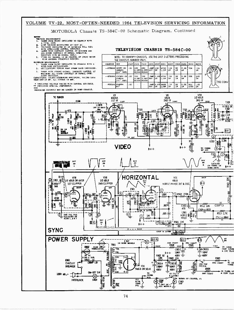
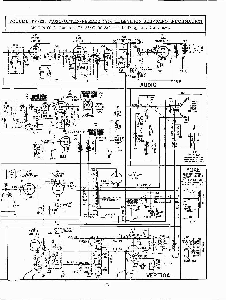
VOLUME TV -22, MOST -OFTEN -NEEDED 1964 TELEVISION SERVICING INFORMATIONMOTOROLA Chassis TS -584C-00 Schematic Diagram, Continued
11108AUDIO T=E -OFF
N3.9_ 5.61 I
s
V8A
1/2 6BL8AUDIO IF
6 35V
.: L3N7501 Pá 2
m 1"
z
/ tü
L
T301
- i t **1 ov6,4 I
No (óM103.50. - N750
135V
-
V9
6 DT6
AUDIO DEI100V
5
7
i6
m
$ e 18 óT-5. 5V
L
E303
OI 1K
1301
T3021E
1
L(©
J ***R
C308.0015
VIO
6GK6
AUDIO OUTPUT
7 275V
á3
52
MOT INcBesus °C
1C309
8ói
Y
6vPP
L1051106 1107
.7 C114C1151 12..
4.7 T3.9 I "'
' 1 650V V5H
***72109OPTIMIZER
5K
u 8AÁ-1A1111. IIIIhtl141'
2 Q..óoc
L109Inf.6,40/0 2
^ 8.2KR111 47K -
m É
JI U
V6
6GK6VIDEO OUTPUT
3-9 7 *195V 11041-u-- 1111- 145V-e2 LL..--4 e
IIr-1 N vj' ¿ N150 j
U 9. JYC TRAP
intrau ull0a1r...II . n
-_1/2 681.18 OR 6HS8
R115 220K4 MY
1< 11w 5 270V
12 19 IL-g_I
7
B+ -f- ir3
AGC
60V
150V
YPP
180VPP
V
R117 33K
6
pp9 O-
CO
V12 V1315ov r- 62068 6AL3 OR 6AF3PPa HORIZ OUTPUT DAMPER
C513005 R504 470
--I` MM1"5
é-B++
R507 1SEE
C503
CHART -.i.- .1
- 1503
ó ÍC
B++
T501
8
706.s..D
R508 In
1W
AUDIO
C201(.05
B+
V14
3A3 OR 3AW3HV RECT
1650PP
V
YEL
*40V
R510 22K 1W
RED
5000
8
BLU
19XP4
6 19X5423 AHP423ARP423CRP4
8R1 CHART
en
C
!B+
FOCUS LEADCONNECT TO ONE OFTHREE TAPS GIVINGBEST OVERALL FOCUS
YOKETHIS PART VARIESREPLACE WITH OHIOVALUE70 - 3EV (19" 114')
82 or 100 360(23" 90`168 - 2/Y (23" 114')
4 RED
3202.5KV
N1500Pos
7 A
3... C
CC PULSEp3..
2,ACC PULSE B++/...5.2L5
.1
v1,cE
N 116.8K90 CHA89I8 f INDIVIDUAL ACOIHOSENTB
3
IN SOEE rumsSEE CHART
8000 \I (C507 R516
THIS LEAD ONLY I
500VC506 .
18K L504WIDTH
1Wo
BLUE
27ti1(
V00MOT IN ALL
2700
V8B1/2 6BL8
VERT OSC
- - (23" 90°)I CHASSIS
*36V
>ry Ñ
F V
8 ZU 1
Lx
P iFj O *cc*
mI
70VPA
K
V15 150006GK6 PP
* * VERT OUTPUTv T601C6051(.01 47.606)11.2412.114_41_~ C6021 I.033 w BL16,
TWITS & P 15 I R603 47KONLYli 'OK,'"I- 1_.-J
gYQ_
a{
r,R613 2.2K R609 56K
C610.047
R1K 00
_`01 .0031_ C601 22K
C6O7T C608 T\ R610SER
CHART
2
5
9.8V
7
27V
VP
11gR605 150
1a62v1141
100MAP
TC603220
SEE CHART
GRN
B++
2O
120- STOP
R604
270V
VERTICAL
MODELS
OYO
L 701
JUNPRE LEAD
75
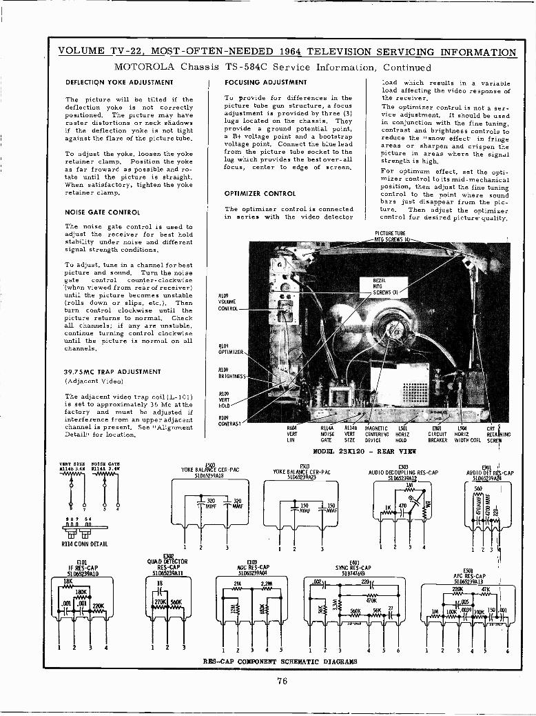
VOLUME TV -22, MOST -OFTEN -NEEDED 1964 TELEVISION SERVICING INFORMATIONMOTOROLA Chassis
DEFLECTION YOKE ADJUSTMENT
The picture will be tilted if thedeflection yoke is not correctlypositioned, The picture may haveraster distortions or neck shadowsif the deflection yoke is not tightagainst the flare of the picture tube.
To adjust the yoke, loosen the yokeretainer clamp, Position the yokeas far froward as possible and ro-tate until the picture is straight,When satisfactory, tighten the yokeretainer clamp.
NOISE GATE CONTROL
The noise gate control is used toadjust the receiver for best holdstability under noise and differentsignal strength conditions.
To adjust, tune in a channel for bestpicture and sound. Turn the noisegate control counter- clockwise(when viewed from rear of receiver)until the picture becomes unstable(rolls down or slips, etc,). Thenturn control clockwise until thepicture returns to normal. Checkall channels; if any are unstable,continue turning control clockwiseuntil the picture is normal on allchannels.
39.75MC TRAP ADJUSTMENT(Adjacent Video)
The adjacent video trap coil (L- 101)is set to approximately 36 Mc at thefactory and must be adjusted ifinterference from an upper adjacentchannel is present. See .AlignmentDetail! for location.
VERT SIZE NOISE GATE1114B 3.48 R114A 3.41
TrnRE7 S4nnn nn
R114 CONN DETAIL
IF RES -CAP51065239A10
TS -584C Service Information, ContinuedFOCUSING ADJUSTMENT
To provide for differences in thepicture tube gun structure, a focusadjustment is provided by three (3)lugs located on the chassis, Theyprovide a ground potential point,a B+ voltage point and a bootstrapvoltage point. Connect the blue leadfrom the picture tube socket to thelug which provides the best over-allfocus, center to edge of screen.
OPTIMIZER CONTROL
The optimizer control is connectedin series with the video detector
R109
VOLUME
CONTROL
I{í09OPTIMIZER
R109
BRIGHTNESS
R109
VERT
HOLD
R109
CONTRAST
YOKE BALANCÉ CER-PAC51D65239A18
E302QUAD DETECTOR
RES -CAP51065239A11
AGC R03ES -CAP51D65239A04
R604
VERT
LIN
R114B
VERT
SIZE
load which results in a variableload affecting the video response ofthe receiver.The optimizer control is not a ser-vice adjustment. It should be usedin conjunction with the fine tuning,contrast and brightness controls toreduce the "snow effect. in fringeareas or sharpen and crispen thepicture in areas where the signalstrength is high.For optimum effect, set the opti-mizer control to its mid -mechanicalposition, then adjust the fine tuningcontrol to the point where soundbars just disappear from the pic-ture. Then adjust the optimizercontrol for desired picture quality.
PICTURE TUBE
MTG SCREWS 14
MAGNETIC
CENTERING
DEVICE
L501 E801
HORIZ CIRCUITHOLD BREAKER
MODEL 231120 - REAR VIEW
E503YOKE BALANCE CER-PAC
51D65239A23
2M 2.2M
--
E303AUDIO DECOUPLING RES -CAP
51065239Al2
SYNC REDS -CAP518747693
-ANYi 470KT^'^'se-ua
1 2 3 4 5 2 3
RES-CAP COMPONENT SCHEMATIC DIAGRAMS
L504
HORIZWIDTH COIL
AUDIO DET1 RCS -CAP51D65239A24
E501AFC RES -CAP51 D65239A13
76
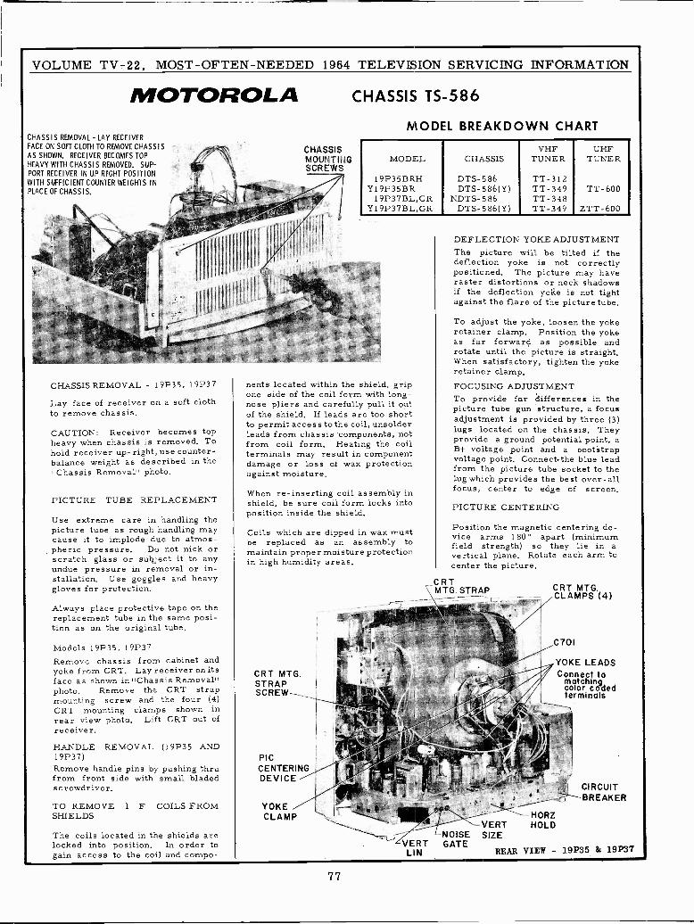
VOLUME TV -22, MOST -OFTEN -NEEDED 1964 TELEVISION SERVICING INFORMATION
MOTOROLACHASSIS REMOVAL- LAY RECEIVERFACE ON SOFT CLOTH TO REMOVE CHASSIS
AS SHOWN. RECEIVER BECOMES TOPHEAVY WITH CHASSIS REMOVED. SUP-PORT RECEIVER IN UP RIGHT POSITIONWITH SUFFICIENT COUNTER WEIGHTS INPLACE OF CHASSIS,
CHASSIS REMOVAL - 19P35, 19P37
Lay face of receiver on a soft clothto remove chassis.
CAUTION: Receiver becomes topheavy when chassis is removed. Tohold receiver up -right, use counter-balance weight as described in the"Chassis Removal" photo.
PICTURE TUBE REPLACEMENT
Use extreme care in handling thepicture tube as rough handling maycause it to implode due to atmos-pheric pressure. Do not nick orscratch glass or subject it to anyundue pressure in removal or in-stallation. Use goggles and heavygloves for protection,
Always place protective tape on thereplacement tube in the same posi-tion as on the original tube.
Models 19P35, 19P37Remove chassis from cabinet andyoke from CRT. Lay receiver on itsface as shown in ',Chassis Removal)photo. Remove the CRT strapmounting screw and the four (4)CRT mounting clamps shown inrear view photo. Lift CRT out ofreceiver.
HANDLE REMOVAL (19P35 AND19P37)Remove handle pins by pushing thrufrom front side with small bladedscrewdriver.
TO REMOVE I F COILS FROMSHIELDS
The coils located in the shields arelocked into position, In order togain access to the coil and compo-
CHASSISMOUNTINGSCREWS
CHASSIS TS -586
MODEL BREAKDOWN CHART
VHF UHFMODEL CHASSIS TUNER TUNER
19P35BRH DTS-586 TT -312Y19P35BR DTS-586(Y) TT -349 TT -600
19P37BL,GR NDTS-586 TT -348YI9P37BL,GR DTS-586(Y) TT -349 ZTT-600
nents located within the shield, gripone side of the coil form with long -nose pliers and carefully pull it outof the shield. If leads are too shortto permit access to the coil, unsolderleads from chassis 'components, notfrom coil form, Heating the coilterminals may result in componentdamage or loss of wax protectionagainst moisture.
When re-inserting coil assembly inshield, be sure coil form locks intoposition inside the shield.
Coils which are dipped in wax mustbe replaced as an assembly tomaintain proper moisture protectionin high humidity areas.
CRT MTG.STRAPSCREW---__
PICCENTERINGDEVICE
YOKECLAMP
VERTLIN
DEFLECTION YOKE ADJUSTMENTThe picture will be tilted if thedeflection yoke is not correctlypositioned, The picture may haveraster distortions or neck shadowsif the deflection yoke is not tightagainst the flare of the picture tube.
To adjust the yoke, loosen the yokeretainer clamp. Position the yokeas far forward as possible androtate until the picture is straight.When satisfactory, tighten the yokeretainer clamp.FOCUSING ADJUSTMENTTo provide for differences in thepicture tube gun structure, a focusadjustment is provided by three (3)lugs located on the chassis. Theyprovide a ground potential point, aB+ voltage point and a bootstrapvoltage point, Connect the blue leadfrom the picture tube socket to thelug which provides the best over-allfocus, center to edge of screen.
PICTURE CENTERING
Position the magnetic centering de-vice arms 180° apart (minimumfield strength) so they lie in avertical plane. Rotate each arm tocenter the picture.
CRTMTG. STRAP CRT MTG.
CLAMPS (4)
YOKE LEADSConnect tol ' colonco9ded
as . terminals
CIRCUITBREAKER
--HORZ-VERT HOLD
NOISE SIZEGATE
REAR VIEW - 19P35 & 19P37
77
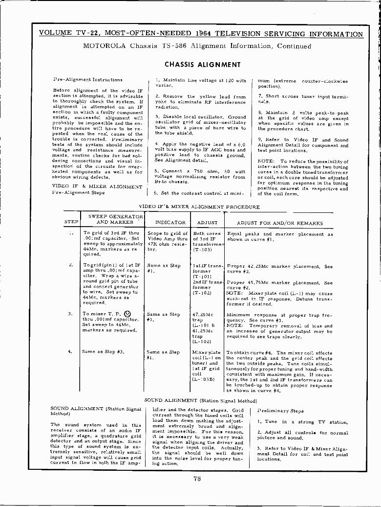
VOLUME TV -22, MOST -OFTEN -NEEDED 164 TELEVISION SERVICING INFORMATION
MOTOROLA Chassis TS -586 Alignment Information, Continued
Pre -Alignment Instructions
Before alignment of the video IFsection is attempted, it is advisableto thoroughly check the system. Ifalignment is attempted on an IFsection in which a faulty -componentexists, successful alignment willprobably be impossible and the en-tire procedure will have to be re-peated when the real cause of thetrouble is corrected. Preliminarytests of the system should includevoltage and resistance measure-ments, routine checks for bad sol-dering connections and visual in-spection of the circuits for over-heated components as well as forobvious wiring defects.
VIDEO IF & MIXER ALIGNMENTPre -Alignment Steps
CHASSIS ALIGNMENT
1. Maintain line voltage at 120 withvariac.
2. Remove the yellow lead fromyoke to eliminate RF interferenceradiation.
3. Disable local oscillator. Groundoscillator grid of mixer -oscillatortube with a piece of bare wire tothe tube shield.
4. Apply the negative lead of a 6.0volt bias supply to IF AGC buss andpositive lead to chassis ground.See Alignment detail.
5. Connect a 750 ohm, 60 wattvoltage normalizing resistor fromB+to chassis.
6. Set the contrast control at mini-
mum (extreme counter -clockwiseposition).
7. Short across tuner input termi-nals.
8. Maintain 2 volts peak -to -peakat the grid of video amp exceptwhen specific values are given inthe procedure chart.
9. Refer to Video IF and SoundAlignment Detail for component andtest point locations.
NOTE: To reduce the possibility ofinter -action between the two tuningcores in a double tunedtransformeror coil, each core should be adjustedfor optimum response in the tuningposition nearest its respective endof the coil form.
VIDEO IF"& MIXER ALIGNMENT PROCEDURE
STEPSWEEP GENERATOR
AND MARKER INDICATOR ADJUST ADJUST FOR AND/OR REMARKS
2.
3.
4.
To grid of 3rd IF thru.001mf capacitor. Setsweep to approximately44Mc, markers as re-quired.
To grid (pin l) of 1st IFamp thru .001mf capa-citor. Wrap a wire a-round grid pin of tubeand connect generatorto wire. Set sweep to44Mc, markers asrequired.
To mixer T. P.thru .001mf capacitor.Set sweep to 44Mc,markers as required.
Same as Step #3,
SOUND ALIGNMENT (Station SignalMethod)
The sound system used in thisreceiver consists of an audio IFamplifier stage, a quadrature griddetector and an output stage. Sincethis type of sound system is ex-tremely sensitive, relatively smallinput signal voltage will cause gridcurrent to flow in both the IF amp -
Scope to grid ofVideo Amp thru47K ohm resis-tor.
Same as Step#1.
Same as Step#1.
Same as Step#1.
Both coresof 3rd IFtransforme(T-103)
r
1 st IF trans-former(T-101)2nd IF transformer(T-102)
47.25Mctrap(L-101 &41.25Mctrap(L- 102)
Mixer platecoil (L-1 ontuner) and1st IF gridcoil(L -103B)
Equal peaks and marker placement asshown in curve #1.
Proper 42. 25Mc marker placement. Seecurve #2.
Proper 45.75Mc marker placement. Seecurve #2.NOTE: Mixerplate coil (L-1) may causesuck -out in IF response. Detune trans-former if desired.
Minimum response at proper trap fre-quency. See curve #3.NOTE: Temporary removal of bias andan increase of generator output may berequired to see traps clearly.
To obtain curve #4. The mixer coil affectsthe center peak and the grid coil affectsthe two outside peaks. Tune coils simul-taneously for proper tuning and band -widthconsistent with maximum gain. If neces-sary, the 1st and 2nd IF transformers canbe touched -up to obtain proper responseas shown in curve #4.
SOUND ALIGNMENT (Station Signal Method)
lifier and the detector stages. Gridcurrent through the tuned coils willload them down making the adjust-ment extremely broad and align-ment impossible. For this reason,it is necessary to use a very weaksignal when aligning the driver andthe detector input coils. Actually,the signal should be well downinto the noise level for proper tun-ing action.
Preliminary Steps
1. Tune in a strong TV station.
2. Adjust all controls for normalpicture and sound.
3. Refer to Video IF &Mixer Align-ment Detail for coil and test pointlocations.
78
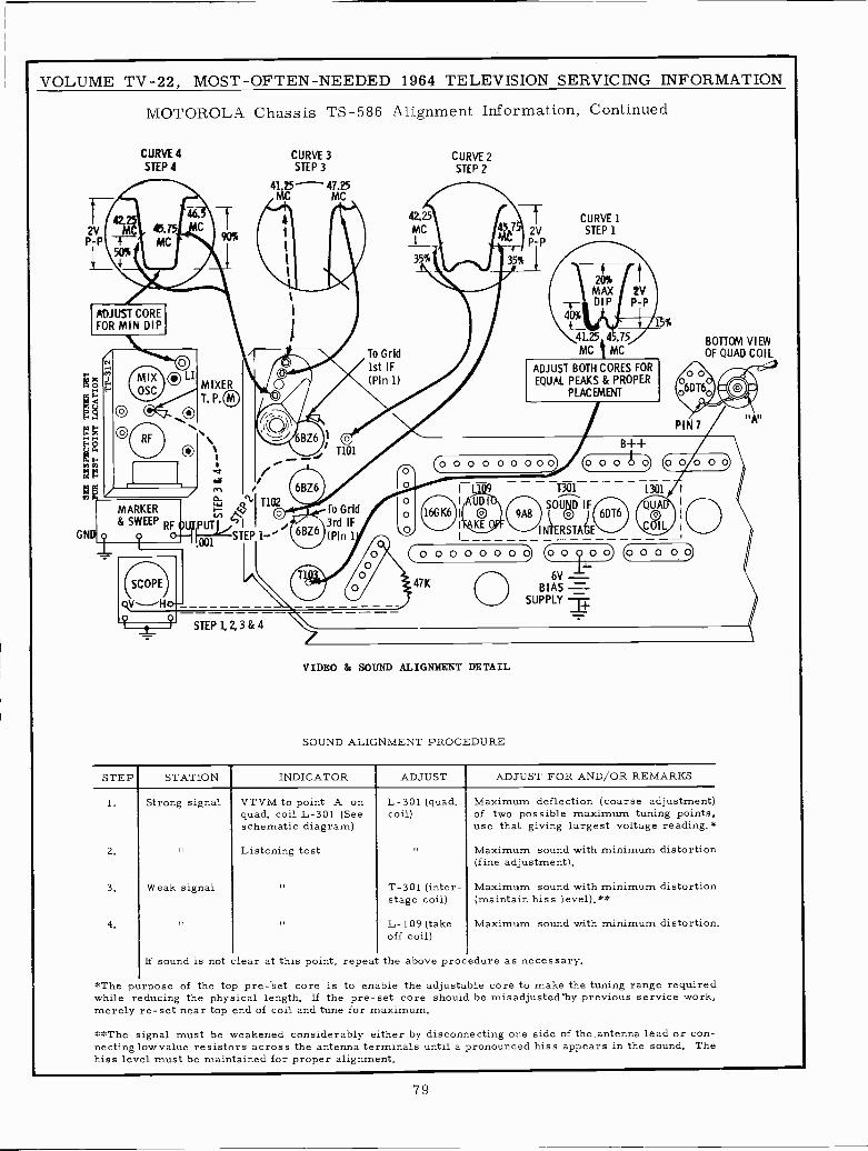
VOLUME TV -22, MOST -OFTEN -NEEDED 1964 TELEVISION SERVICING INFORMATION
MOTOROLA Chassis TS -586 Alignment Information, Continued
CURVE 4
STEP 4
2VP -P
ADJUST COREFOR MIN DIP
GND
MIXOSC
MIXERT. P.
CURVE 3STEP 3
41.25 ^ 47.25MC MC
© oO e t%
; ,/ <.i i 6BZ6 O
I L T301 L301 I /
MARKER Ñ 1102to Grid o AUDI SOUD IF I
0 ) 6DT6 I
& SWEEP RF 0LSTEP i-' BZ6 (PinlF1 j
KE ®INTERSTAGE !
q oD1o oooooooc. @oQoo) @oo o 'ó 6V
l_1
SCOPE 47K BIAS _qVHo- __ SUPPLY zp q STEP1,2,3&4 /
To Grid1st IF(Pin 1)
42.25MC
CURVESTEP 2
CURVE 12V STEP 1P -P
40%
4- 1- .25 4 .75
MC t MC
20%MAX 2VDIP P -P
ADJUST BOTH CORES FOREQUAL PEAKS & PROPER
PLACEMENT
IB++o C000be) 00000
BOTTOM VIEWOF QUAD COIL
QUA'
COIL
VIDEO & SOUND ALIGNMENT DETAIL
SOUND ALIGNMENT PROCEDURE
STEP
1.
Z.
3.
4.
STATION INDICATOR ADJUST ADJUST FOR AND/OR REMARKS
Strong signal
Weak signal
VTVM to point A onquad, coil L-301 (Seeschematic diagram)
Listening test
L-301 (quad.coil)
T-301 (inter -stage coil)
L-109 (takeoff coil)
Maximum deflection (coarse adjustment)of two possible maximum tuning points,use that giving largest voltage reading.*
Maximum sound with minimum distortion(fine adjustment),
Maximum sound with minimum distortion(maintain hiss level),**
Maximum sound with minimum distortion.
If sound is not clear at this point, repeat the above procedure as necessary.
*The purpose of the top pre-set core is to enable the adjustable core to make the tuning range requiredwhile reducing the physical length. If the pre-set core should be misadjusted'by previous service work,merely re -set near top end of coil and tune for maximum.
**The signal must be weakened considerably either by disconnecting one side of the antenna lead or con-necting low value resistors across the antenna terminals until a pronounced hiss appears in the sound. Thehiss level must be maintained for proper alignment.
79
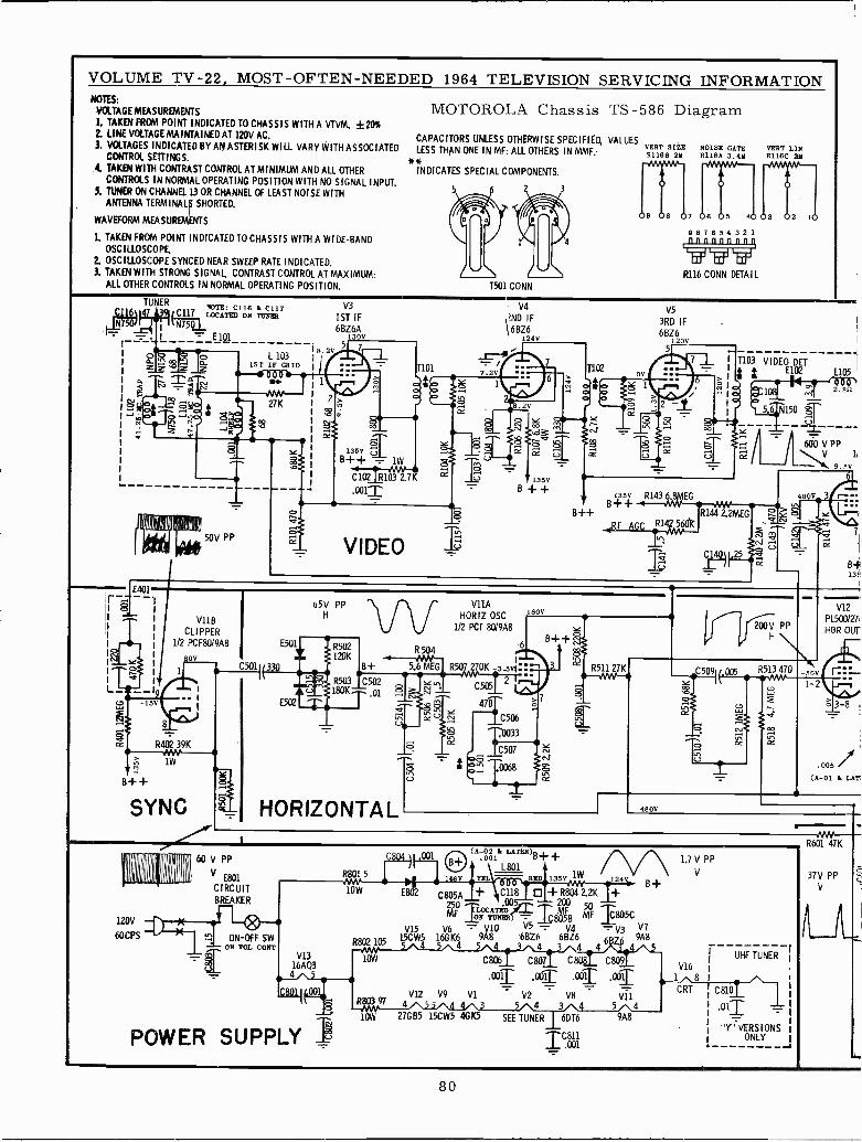
VOLUME TV -22, MOST -OFTEN -NEEDED 1964 TELEVISION SERVICING INFORMATIONNOTES:
VOLTAGE MEASUREMENTS
L TAKEN FROM POINT INDICATED TO CHASSIS WITH A VTVM. 120%2. LINE VOLTAGE MAINTAINED AT 120V AC.
3. VOLTAGES INDICATED BY AN ASTERISK WILL VARY WITH ASSOCIATEDCONTROL SETTINGS.
4. TAKEN WITH CONTRAST CONTROL AT MINIMUM AND ALL OTHERCONTROLS IN NORMAL OPERATING POSITION WITH NO SIGNAL INPUT.
5. TUNER ON CHANNEL 13 OR CHANNEL OF LEAST NOISE WITHANTENNA TERMINALIS SHORTED.
WAVEFORM MEASUREMENTS
1. TAKEN FROM POINT INDICATED TO CHASSIS WITH A WI DE -BANDOSCILLOSCOPE.
2. OSCILLOSCOPE SYNCED NEAR SWEEP RATE INDICATED.3. TAKEN WITH STRONG SIGNAL, CONTRAST CONTROL AT MAXIMUM;
ALL OTHER CONTROLS IN NORMAL OPERATING POSITION.
MOTOROLA Chassis TS -586 Diagram
CAPACITORS UNLESS OTHERW I SE SPECIFIED, VALUESLESS THAN ONE IN MF; ALL OTHERS IN MME VERT SIZE
81168 28**INDICATES SPECIAL COMPONENTS.
1501 CONN
NOISE GATER116A 3.49
9 8 7 6 4 3 2 1innnnnnnnq
tfgR116 CONN DETAIL
VERT LINR116C 29
TUNERNOTE: C116 I. C117
C117 LOCATED ON TUNER
- E 1Q1
L 1031ST IF GRID
1111.112:1111.112:1111.112:
N27K
2f
50V PP
V3
1ST IF6BZ6A
130V
18.2V5
m
1
7101
a
135V UTB++ 1W
C102 R103 7K
.0011
V4
'ND IF6BZ6
124V
7
VIDEO
J
7
6
1102
8 2
oo
ES
135V
B + +
V5
3RD IF6BZ6
20V5
7
6
2
ó
T103 VIDEO DET
i = E102
1 1
l 1
I- -
B++++ f13sv R1436.8MEG
B V
IRF AGC R14
5 6 N150 óUT
L105
2.852
600 V PP\ V 11
9.5V
4800
3R144 2.2MEG 118"V N
UC 25
6
B+13:'
E401
V11 B
CLI PPER1/2 PCF80/9A8
80V
L`15V
1_
R402 39K
1W
B++
C501
65V PPH
SYNC HORIZONTAL
V11A
HORIZ OSC1/2 PCF 80/9A8
470
C506
11033'C507oTO 0068
6
160V
YB++ c'
cl
200V PPH \
R511 27K--JVW-
V12
PL500/21,
HOR OUT
*C5091¡,005455 140 -sv
1` -2LL
0 3"8
ó
T .005/(A-01 I. LAT
480V
120V
60CPS
60 V PP
V E801
CIRCUITBREAKER
ON -OFF SWON VOL CONT
V1316ÁQ3
8POWER SUPPLY T
R801 5
o1 (A.001k LATER)B + +B+L801
TEL .. D 135V 1W
1.7 V PP
V24
8lOW E802 C805A + C118 + R8Q4 2.2K +
00 ry200
MO NK7ÁVRllii ,805B MF Tc805CV15 V6 -'V10 V5 ..-V4 V3 Vi
R802105 15CW5 16GK6 9A8 68Z6 6BZ6 6: 9A84 4 4 4
C806 C807 C808 C809
ooT AT .0011012 V9 Vl V2 V8
4 5 4 310W 27GB5 15CW5 4GK5 SEE TUNER 6DT6 9A8
.TV11
5 4
10141UHF TUNER
V16
1 8
CRT C810
.011
"Y" VERSIONSONLY
8
R601 47K
37V PPV
80
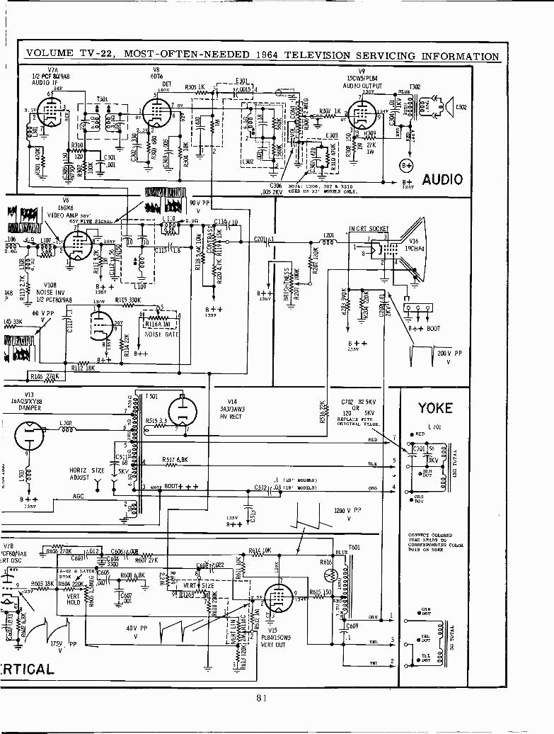
VOLUME TV -22, MOST -OFTEN -NEEDED 1964 TELEVISION SERVICING INFORMATIONV7A
112 PCF 8019A8AUDIO IF
56V6
3.5Y r2
1301
! i 1
Id0 091I OV1
2.3L-- -- -JR310
120 C301- g 1.001
V86DT6
5
2
DET16 0R305Aw
í,i1K
00154 0....I. .
---- `----1 - 17 OV -----IZO
6 m
Sz
oc.,Y U
'i TaJ ' IoljT 2 .0.
1 2
L302
I I
I I
I
I
V9
15CW51PL84
AUDIO OUTPUT 1302130V BLUE
R307 1KOV
E 303
21W7K
v Ir
`aI
M1? -1
7
39
>Ó Y24V
9 5c
L106
2.611
ViOB
?A8 NOISE INV
11
V6
16G K6
VIDEO AMP 30V65V WITH SIGNAL
7
L107 _l.v 7
2
60 V P P _bl3K y
c.I I
105V
110111 ,11,61I
10
L -B+ + L109135V
130V R115 K
1
30
Bl+
9
J1L 110
C306 NOTE: C306, 307 & R310.005 2KV USED ON 23" MODELS ONLY.
E302
B+0 AUDIO124
90V PPV
5.215 11
In
5_61
0116A IM
NOISE GATE
B++
iR14644K
R112 18K
B++135V
IN CRT SOCKETL201
--/006`8,
V1316AQ3/XY88
DAMPER
B ++135V
L 502
HORIZ SIZEADJUST
AGC T
ÓO5 á
C5115zá68
1,5KVNam
V14
3A3/3AW3
HV RECT
R517 6.8K
3
2
V16
19CHP4
Y
r
B++135V
C702 82 5KV
12008 5KVREPLACE WITHORIGINAL VALUE.
R
OLE
B++ BOOT
200VPPV
480 BOOT+ + +.1 (23" MODELS)
G5121(.03 (19" MODELS)
2
135V
B++
1200 VV PP
ORG
V7B
,CF80/9A8:RT OSC
606 lOKC603I10123 I.00BL_,,,--
0221 44V
9 R603 18K-23V
Y
Iz
A-02 & LATER 605R608 6 8K
wR604 220K 1 .047270K
VERTHOLD
175V pPV
:RTICAL
1,001
40V PPV
8Ñ}3T$j VERT SIZE
9!511.6/_ Y7y ¡
I J I `x V15I rL w 12 PL84115CW5L áfo
. VERT OUT
13.M
0
2
3
9
34V
1601*BLUE
R616
T1®GdR61R61 150
RBIC:n-2,51;
O 1
C609
YE
YEL
YOKEL 701
RED
VI
CONNECT COLOREDYOKE LEADS TOCORRESPONDING COLORDOTS ON YOKE
GRN DOT
YEL DOT
YEL DOT
b
11011.1.,
81
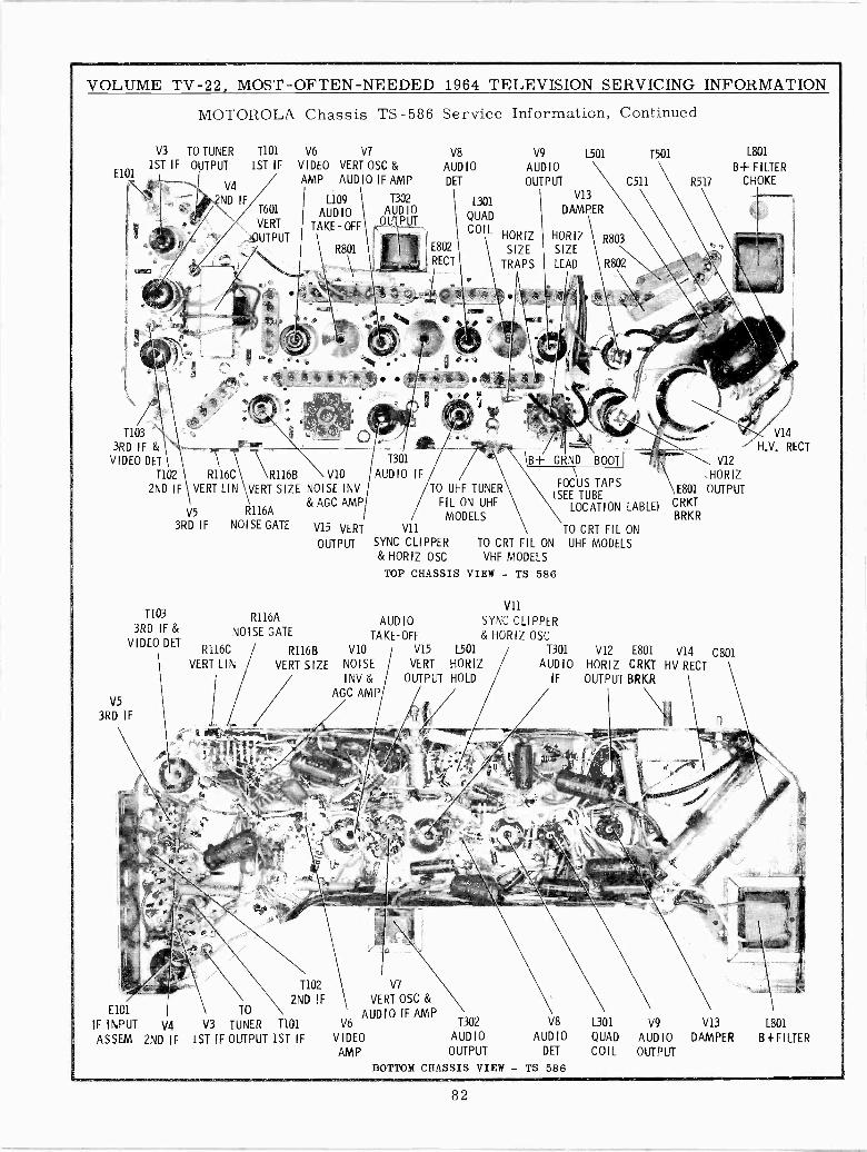
VOLUME TV -22, MOST -OFTEN -NEEDED 1964 TELEVISION SERVICING INFORMATION
MOTOROLA Chassis TS -586 Service Information, Continued
V3 TO TUNER T101 V6 V7
E1011ST IF OUTPUT 1ST IF VIDEO VERT OSC &
V4AMP AUDIO IF AMP
N L109 I 1302
AUDIO AUDIO
TAKE -OFF QUTPUT
R801
T103
3RD IF & -VIDEO DET
T102 R116C R116B V10
2ND IF 1 VERT LIN !\VERT SIZE NOISE INV
V5 R116A& AGC AMP
3RD IF NOISE GATE
T103
3RD IF &VIDEO DET
V5
3RD IF
R116A
NOISE GATE
V15 VERT
OUTPUT
V8 V9 L501 1501 L801
AUDIO AUDIO B+FILTERDET OUTPUT C511 R517 CHOKE
L301V13
QUADDAMPER
COILHORIZ HORIZ
SIZE SIZE
TRAPS LEAD
TO UHF TUNERFIL ON UHF
MODELSV11 \ TO CRT FIL ON
SYNC CLIPPER TO CRT FIL ON UHF MODELS& HORIZ OSC VHF MODELS
TOP CHASSIS VIEW - TS 586
\B+ GRND BOOT
FOCUS TAPS(SEE TUBE
LOCATION LABLE)
V11
AUDIO SYNC CLIPPERTAKE -OFF & HORIZ OSC
V12
,HORIZE801 OUTPUT
CRKTBRKR
R116C R116B V10 V15 L501 1301 V12 E801 V14 C801VERT LIN VERT SIZE NOISE VERT HORIZ / AUDIO HORIZ CRKT HV RECT
INV & OUTPUT HOLD IF OUTPUT BRKRAGC AMP
T102
2ND IFE101 TO
IF INPUT v4 V3 TUNER T101
ASSEM 2ND IF 1ST IF OUTPUT 1ST IF
V7
VERT OSC &
V6AUDIO IF AMP
T302 V8
VIDEO AUDIO AUDIO
AMP OUTPUT DET
BOTTOM CHASSIS VIEW - TS 586
L301
QUAD
COIL
V9
AUDIOOUTPUT
V13
DAMPER
V14
RECT
L801
B+FILTER
82
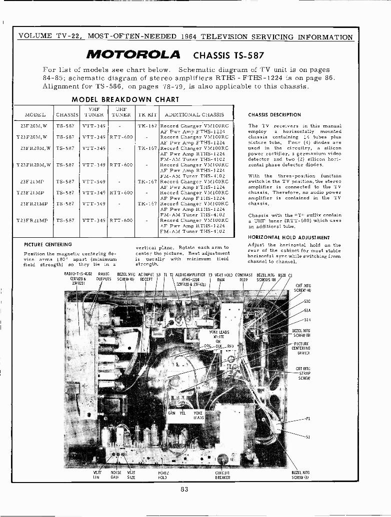
VOLUME TV -22, MOST -OFTEN -NEEDED 1964 TELEVISION SERVICING INFORMATION
MOTOROLA CHASSIS TS -587
For list of models see chart below. Schematic diagram of TV unit is on pages84-85; schematic diagram of stereo amplifiers RTHS - FTHS-1224 is on page 86.Alignment for TS -586, on pages 78-79, is also applicable to this chassis.
MODEL BREAKDOWN CHART
MODEL CHASSISVHF
TUNERUHF
TUNER TK KIT ADDITIONAL CHASSIS
23F20M,W TS -587 VTT-349 TK-1 67 Record Changer VM100RCAF Pwr Amp FTHS-1224
Y 23 F 20 M, W TS -587 VTT-349 RTT- 600 Record Changer VM100RCAF Pwr Amp FTHS-1224
23FR20M; W TS -587 VTT-349 TK-167 Record Changer VM100RCAF Pwr Amp RTHS-1224FM -AM Tuner THS-4102
Y23FR20M, W TS -587 VTT-349 RTT- 600 Record Changer VM100RCAF Pwr Amp RTHS-1 224FM -AM Tuner THS-4102
23F21 MP TS -587 VTT-349 TK-167 Record Changer VM100RCAF Pwr Amp FTHS- 1 224
Y 23 F 21 MP TS -587 VTT-349 RTT- 600 Record Changer VM100RCAF Pwr Amp FTHS-1224
23FR21 MP TS -587 VTT-349 TK-167 Record Changer VM100RCAF Pwr Amp RTHS-1224FM -AM Tuner THS-4102
Y23FR21 MP TS -587 VTT-349 RTT- 600 Record Changer VM100RCAF Pwr Amp RTHS-1224FM -AM Tuner THS-4102
PICTURE CENTERING
Position the magnetic centering de-vice arms 180° apart (minimumfield strength) so they lie in a
vertical plane. Rotate each arm tocenter the picture. Best adjustmentis usually with minimum fieldstrength.
RADIO-THS-4102 RADIO BEZEL MTG AC INPUT S3 TI T2 AUDIOAMPLIFIER T3 VERT HOLD(23FR20 & OUTPUTS SCREW (8) RECEPT RTHS-1224 R604
23FR21) (23FR20 & 23FR21)
VERT
LIN
NOISE VERT
GATE SIZEHORIZHOLD
CIRCUITBREAKER
CHASSIS DESCRIPTION
The TV receivers in this manualemploy a horizontally mountedchassis containing 14 tubes pluspicture tube. Four (4) diodes areused in the circuitry, a siliconpower rectifier, a germanium videodetector and two (2) silicon hori-zontal phase detector diodes.
With the three -position functionswitch in the TV position, the stereoamplifier is connected to the TVchassis. Therefore, no audio poweramplifier is contained in the TVchassis.
Chassis with the ,'Y" suffix containa UHF tuner (RTT-600) which usesan additional tube.
HORIZONTAL HOLD ADJUSTMENT
Adjust the horizontal hold on therear of the cabinet for most stablehorizontal sync while switching fromchannel to channel.
CONTRAST BEZEL MTG
R119 SCREWS 181
CRT MTG
SCREW (41
SIC
BEZEL MTG
SCREW (81
PICTURECENTERING
DEVICE
CRT MTG
STRAP
SCREW
BEZEL MTG
SCREW 18)
83
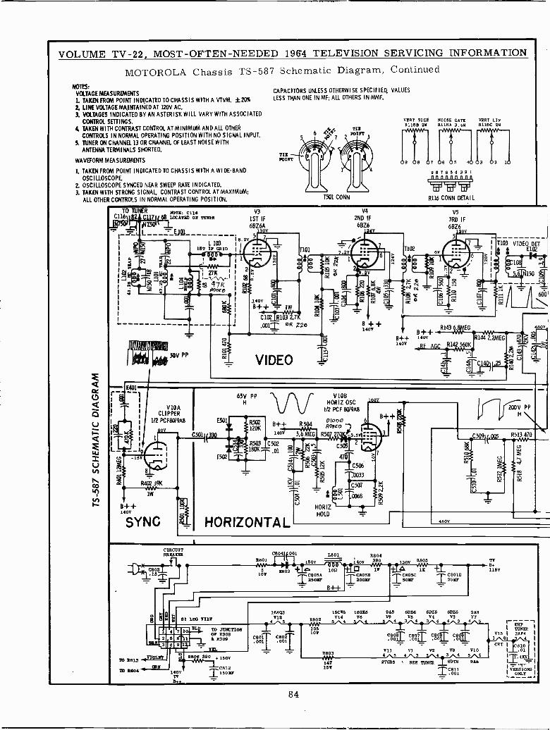
VOLUME TV -22, MOST -OFTEN -NEEDED 196'4 TELEVISION SERVICING INFORMATION
MOTOROLA Chassis TS -587 Schematic Diagram, ContinuedNOTES:
VOLTAGE MEASUREMENTS1. TAKEN FROM POINT INDICATED TO CHASSIS WITH A VTVM, ±20%2. LINE VOLTAGE MAINTAINED AT 120V AC,
3. VOLTAGES INDICATED BY AN ASTERISK WILL VARY WITH ASSOCIATEDCONTROL SETTINGS.
4. TAKEN WITH CONTRAST CONTROL AT MINIMUM AND ALL OTHERCONTROLS IN NORMAL OPERATING POSITION WITH NO SIGNAL INPUT.
5. TUNER ON CHANNEL 13 OR CHANNEL OF LEAST NOISE WITH
ANTENNA TERMINALS SHORTED.
WAVEFORM MEASUREMENTS
1. TAKEN FROM POINT INDICATED TO CHASSIS WITH A WI DE -BAND
OSCILLOSCOPE.2. OSCILLOSCOPE SYNCED NEAR SWEEP RATE INDICATED.3. TAKEN WITH STRONG SIGNAL, CONTRAST CONTROL AT MAXIMUM;
ALL OTHER CONTROLS IN NORMAL OPERATING POSITION.
CAPACITORS UNLESS OTHERWISE SPECIFIED, VALUESLESS THAN ONE IN MF; ALL OTHERS IN MMF.
1501 CONN
VERT SIZE NOISE GATE01186 29 R116A 3.49
R116 CONN DETAIL
VERT LINR118C 29
TO
9111I1501
NOTE: C118LOCATED ON TUNER
L 10318T I8 GRID
i 27K 1
47K6100E 0
r - -
{
L`
50V PP
V10ACLIPPER
1/2 PCF80/9A8
C501
B++1400
R402 39KMM1W
SYNC
E501
V3
1ST IF6BZ6A
30V
8.2V5
á?j40V ÚB++ - 1W
C10-4-111131111
.001T CA 220
12'
65V PPH
120KB++140V
R503 C502180K .01
V4
2ND IF6BZ6
7.2V
V10BHORIZ OSC
1/2 PCF 8019A8
T102
r11-hd3I'?$8
o
B + + R143 ¢ 81G 480V4
OV
V5
3RD IF6BZ6
5
T103 VIDEOlTtN150
600\I I
1400
DIOoE 6 B++R ADYEm
4
5.6 MEG R50 1 I, -3 svl""g C505
HORIZONTAL 480V
eC509I¡.005
200V PP
R513 470
CIRCUITRREATOR
C803
V h14
C804 001 R8048801 1500 140V 390 130V R805
1802 + G -1082 1.11 lE 115V
108 850Y! T2óóyPI50YP T250
L.801
B++
4
5
7
81 LUG VIEW
JUST,3
71 1813 0I2
To 1604 -11ORN
6 9
M. 7O JUNCTIONO8 R308
R309
TE{.P
1400TVBt+
18.6 390,. 1500
C812T15018r
18AQ3 15C85 16016 9A8 61306 6BZ6 6826 9A8V12 V14 V6 V9 V5 V4 V3 V7
A8024 5 3 4 5 4 3
C801 C802.001 .001
105100 C800
Y11A803 4 5 4
147 27085 ,
158
TY
4 3 4
Cg[1 C8008
-7.-:111-LL00
4 3
08009
4- 5
I TUNER1V3581 2094
-,CRT I 0810Y1 V2
3 ' 4
V83 4 5
Y104
1 .01I 4
SEE TUNER 817T6
0811.00 1
9A8 ! 1TTN-VERSIONS
I ONLY
84
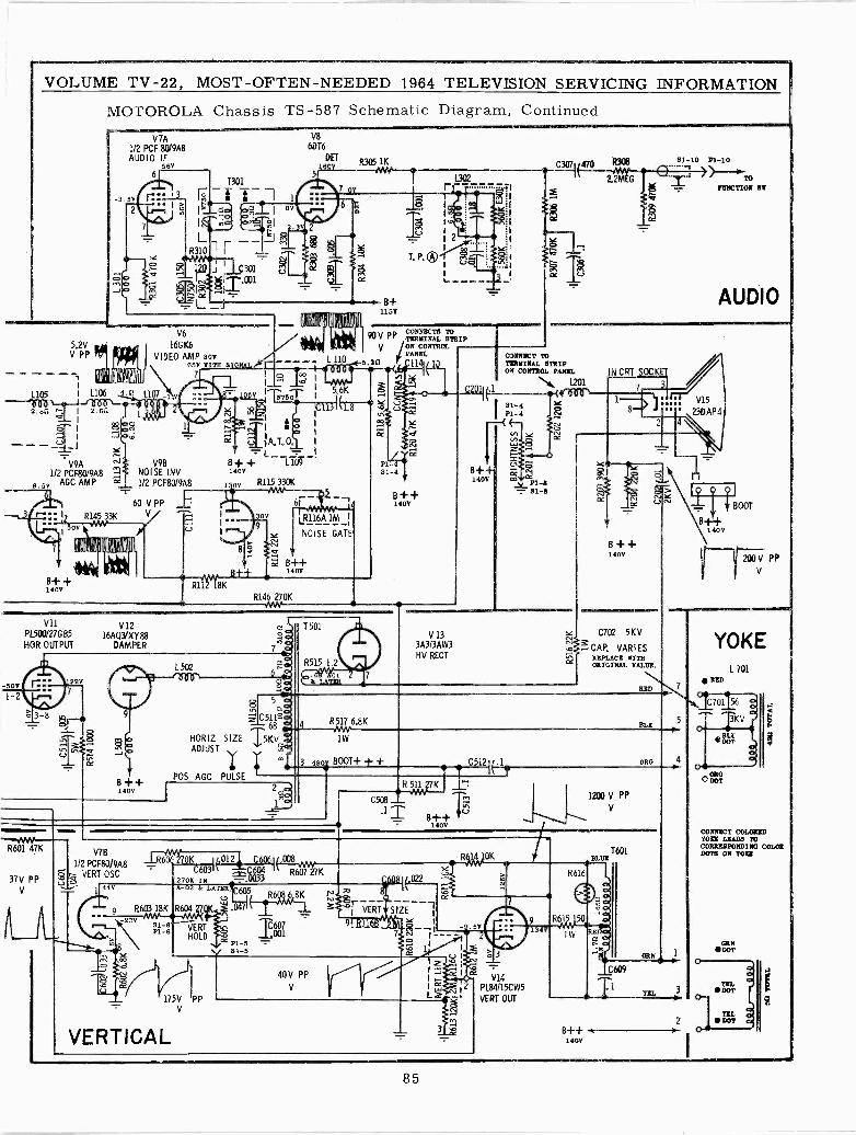
VOLUME TV -22, MOST -OFTEN -NEEDED 1964 TELEVISION SERVICING INFORMATION
MOTOROLA Chassis TS -587 Schematic Diagram, Continued
_ U
V9A1/2 PCF80/9A8
9.5V AGC AMP
7
R145 33K
11911116' IATIP1111
JI
V 7A
312 PCF 80/9A8AUDIO IF
56V6
-3.5V .7:12
10
V6
16G K6
VIDEO AMP 30V65V WITH S
7
M J NOISEBINV1/2 PCF80/9A8
60 VPP V/ ^
I/ U Y
140V
R115 330K
o
8 o
H++
9
V8
6DT6
5
2
DET100V
1 Gr
R305 1KáMM--1 __e_92_1 470
L302 - 2. G
3 i1
6
1111111101 11411
" a1`
613116A 1M
NOISE GATE
EC B++140V
T. P. ®
B+115V
2
CJ
:7CI
R
. Y
Y
90 V PPcONNECTB mTEREINAI. STRIP
R146 270K
V /ON CONTROL
I( PANELI 11, .ID
-50V
1-2
V11
PL500/27G 85
HOR OUTPUT
3
R601 47K
37V PPV
V1216AQ3'XY88
DAMPER
B++140V
V78
1/2 PCF80/9A8-§1- VERT OSCU .
1( 440 A -oz & LATEA 7¡ 605R608 6 SK
9 P.603 18K R604 27 K W .047
SIm-6-6'
VERT TÓ1HOLD
L50'2
'TOT'
N c7 ña
T50
R515 1.201
k LATER
V 133A3/3AW3HV RECT
SZZ
C2011 .1
1
Sl-lo P1-10
)""*TOTUNCTIOR St
AUDIO
ODRNECT TOTERMINAL STRIPOW CONTROL PANEL
L201
B++140V
Y I C702 5KV
OC
CAP. VARIESREPLACE WITHORIGINAL VALUE.
BOOT
FT -00 V PPV
5 aóGó
C5618190
HORIZ SIZE ,5KVADJUST
m
POS AGC PULSE+++
m
R517 6.8KM1"
1W
3 480y BOOT+ + + C512I(.1
J.RbOE 270K I/.012 C4061 ,008C603 C604 R607
'270E 18 -.000033
P1-5 -21-5
175V PP
V
VERTICAL
40V PPV
7K
Ñ
R 521 27K
C508 _.11
B++140V
1200 V PP
V
ORG
081 02I VERT SIZE
'. g.916J1hi
Y 1
CC
OK
1
uY ó3.p . N _IJI ,-- I
cc
I 9` 12 PL84/15CW5L VERT OUT
1W
1601BLUE
C609
1
B+ -I-1400
YOKEL 701
RED
C701 56
3KV
ORGDOT
CONNECT COLOREDTORE LEADS TOCORRESPONDING COLORDOTS ON YORE
GRN DOT
TEL DDOT
TEL DOT
85
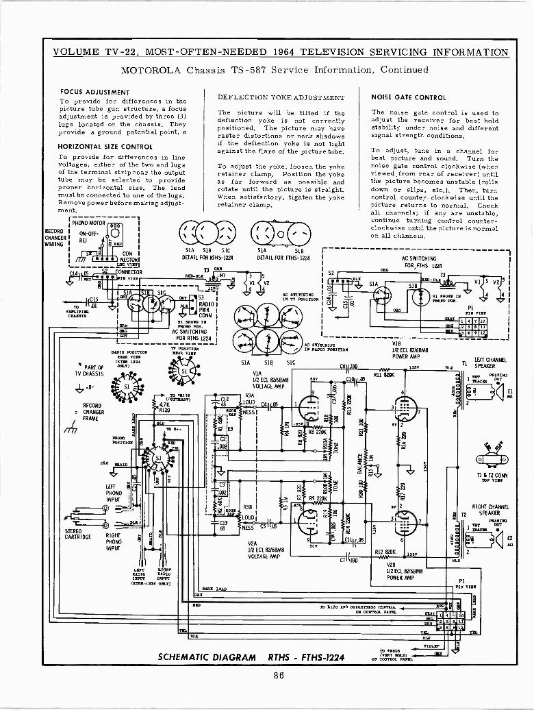
VOLUME TV -22, MOST -OFTEN -NEEDED 1964 TELEVISION SERVICING INFORMATION
MOTOROLA Chassis TS -587 Service Information, Continued
FOCUS ADJUSTMENTTo provide for differences in thepicture tube gun structure, a focusadjustment is provided by three (3)lugs located on the chassis. Theyprovide a ground potential point, a
HORIZONTAL SIZE CONTROL
To provide for differences in linevoltages, either of the two end lugsof the terminal strip near the outputtube may be selected to provideproper horizontal size. The leadmust be connected to one of the lugs.Remove power before making adjust-ment.
rPHONO MOTOR .rr.
RECORD
CHANGER
WIRING
ON -OFF-
REJ
LI
051HT
RID
S
MOM
~C15
01AEPLIYISHCHASSIS
CONf lei NECTORLUG VIEW
CONNECTOR
' N VIEW
DEFLECTION YOKE ADJUSTMENT
The picture will be tilted if thedeflection yoke is not correctlypositioned. The picture may haveraster distortions or neck shadowsif the deflection yoke is not tightagainst the flare of the picture tube.
To adjust the yoke, loosen the yokeretainer clamp. Position the yokeas far forward as possible androtate until the picture is straight.When satisfactory, tighten the yokeretainer clamp.
S1A SIB SICDETAIL FOR RTHS-1224
13 NNRED-BLI _1_ 6G
ailb ORE 153jees I RADIOF PWRJ CONN
31 SHOWN INERN PHONO POS.ORG AC SWITCHINGGRY
FOR RTHS 1224
l_ 11o]I
RADIO POSITIONREAR VIII(RTES 1224
PART OF ONLY)
TV CHASSIS
RECORD
CHANGER
FRAME
PHOIIOPOSITIO
BLU BRAID
LEFT
PHONO
INPUT
STEREO
CARTRIDGE
TV POSITIONREAR VIEW
TO 41110(COMMIT)
4.7KR120
9
RIGHTPHONO
INPUT
BLU
TO 14...
ID
S1A SIBDETAIL FOR FTHS-1224
VI V2
4 4
S2
AC BNI /CHI NGIS TV POSITION
Sae11.51A SIB. S C
VIA1/2 ECL 82/6BM8VOLTAGE AMP
1 C12R3A
68 LOUD C4I105oll
BDOI NESS
LIFT B OHSHAD 0 RADIOINPUT INPUT(EWE -1224 ONLY)
TAP
NOISE GATE CONTROL
The noise gate control is used toadjust the receiver for best holdstability under noise and differentsignal strength conditions.
AC SNITCHINGIN RADIO POSITION
13I330
.61V j8
0V
(
E7
z R8 220K
CC
Sl ; 6o0E
3
BARE LEAD
R3B
LOUD
NESS C5 .05
o
R9 220K
8
To adjust, tune in a channel forbest picture and sound. Turn thenoise gate control clockwise (whenviewed from rear of receiver) untilthe picture becomes unstable (rollsdown or slips, etc.). Then, turncontrol counter -clockwise until thepicture returns to normal. Checkall channels; if any are unstable,continue turning control counter-clockwise until the picture is normalon all channels.
65
V2A1/2 ECL 82/6BM8
VOLTAGE AMP
9
) z
50V
C11II25
C7I(330
AC SWITCHING
FOR,FTHS 1224
V18
1/2 ECL 82/6BM8POWER AMP
R111 820K
IV 2
BY 2
3i
6
R12 820K
135V
135V
LEFT CHANNELTi
SPEAKERBLU
o IDT, PRA DING
q 1 TRACER yEl"Dv b : ( Nn
9 2
9
as
a
V28112 ECL 82/68M8POWER AMP
BLU
TI 8 T2 CONNTOP VIEW
RIGHT CHANNELT2 SPEAKER
PHASINGDOT
lIRA= aosié2
PIPIN VIEW
CRIS
RED TO 8170 AND BRIGHTNESS CONTROLON CONTROL PAREN. GRA
RID 9
ORG
YEL
B LO
BEE
Q.BLU
7 10 'm
lf17
SCHEMATIC DIAGRAM RTHS - FTHS-1224
YBTro Aims(VE LLD)
ON CONTROL PANEL
nl
11
VII.
E2
60
86
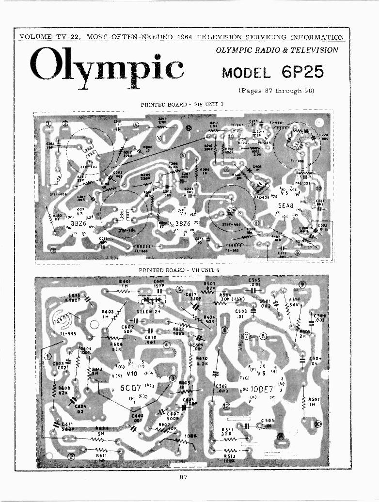
VOLUME TV -22, MOST -OFTEN -NEEDED 1964 TELEVISION SERVICING INFORMATION
OLYMPIC RADIO & TELEVISION
Olympic MODEL 6P25(Pages 87 through 90)
PRINTED BOARD - PIF UNIT 1
---- #letC] b5 DoS
1!KK Di!¡ ._,W *Al El"'
_..._CS6IpP.1.
+`T 1i i?t -J67 é
:4 ti C521t f_,li 5'/
\.C ? ?!\-`1\1WS
Pt -26'_711 -?64
V06924\\\ 11-1 2/ ill
tWOL) .te1 -_ .,
'l ratSig()// V (,6
`rec -;zs '7G))
{ SEA87 (P)
f ' (m) (62)
t:13,-4Ai /CO.'S tt(49
leg
..----/Trirrf\-- -tt-6iE
PRINTED BOARD - VE UNIT 4
CEBfi'.; 05011501125 J pd---- C
3301A 35Ó,(1 K)--1O503 5f° l[ ;24111
oCE03002
+o!125
611% saer . w As
5M
C515(í ?1
K*B7111 li
7
tbr \ ef '.l11` yYo.,_..,... `
-------- . '-_
-0--0501 ..0 a2 T
C5o3.01
C50750 Ca
(K) (P)9 1
NSF456K
.L 5504`
T
87
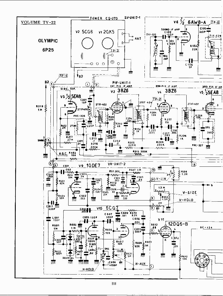
VOLUME TV -22
OLYMPIC
6P25
R2191M
3SOOIL
82
2
TP-11
TUNER CS -.373 SV-UNIT-1
V2 5CG5 VI 2GK5
0 0 0 @ O
V6 % 6AW8-ASOUND IF AMP 3 C105
330Pi TIF-527 1tP
ANTR 1011 00K
SINO. SEP.
8-_J
VS 5EA8C201
Dio,
12TIF406I
PRC-326
- ,
8402 2701( 1220P L22
I
I I
////s I-11>R217
2.7 P4 C401.01 ON
\ A.a.C. 811,1
I ' 4133
G213 um 11.1 %/li C202
R216 7' .2
2208
PIF-UNIT-1LST PIX _IF AMP
v3 3BZ6
C204.005
R202 mg'68 ""
'1.
C 10320P
2ND PIX IF AMP
V4 3BZ6P
3RD PIX IF AM
V5,'25EA8
I 1ÓK9I r--I
I I I
.005
200I I
' I- - - - - I
PRC-327
,® C501 V9 10DE7
C515001
iR50182K
640450K
C 617 '////330
G 601sus 150P
R6011M
002
R51456K
6
A
C504.04
C502.003
VH-U NIT -2
6511 30K
C509I'503 .003
01 8513
í504100 K
6 C50815K R505 60
2M
C610" VI()VI
.001
C605 100P
R6031 M
I Mk/C60250P
i I
I I
R622 I I 661500K
I 1M
SELEN 24
6
660410oKR6051K
G604
MU ,02
1660615K
6510//. 330
6C G7 M/1.C6 07 i C609 8610- .001 8.2K
6507 1M
C505
500P C608.001 T
3
H -HOLD/
TL -
N
tl
995
R60740K
100KR621
5M
C6064000P
06115D0P
/ 660982K
R61111
H-AUX
2
2M
V11
861268
2 5
1
65081.2M
V-SIZE
V-HOLD
12DQ6-B
C 612' MEN
05
DC -134
1661310K
88
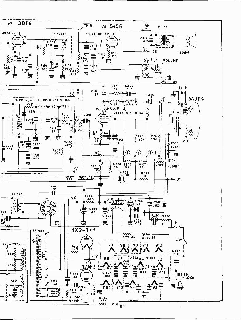
V7 3DT6
101190 DET
0101.005
RttSO
RIDS I pr20K 560K
R10º100
T1-998 R 211 T L-1996 71-264
Q220
--
r C208,005
11187A
iR210111K C220
005
C<i2ir .001i
8T-157<1-
DEFSLYOK _-
1150
aim C210um SP
TL -26 S
T1-267
C211MISP
JTP-5
Ib
va 5A05 CO 7T-145
SOUND OUT PUT
ICI it001c
R1,08390K
C1 12; ,005
C 3011
C101SP
83056K
030420P
11-266 2111-405
82 16080-1
B1 VOLUME2
C3'5
V6f6AW8-AVIDEO AMP. 11-267
#3011M
#30268
R214100K
c507.02
-oQ PICTURE
1)(2-B v12
R615 3.9 2
V/W1r-
R40120 K
0O\J `J..
R 303 R30-^N6 - R31K 20K 5K
C20i R206
0
1K
II- 1/V1/b
B2B1 b
a
R520100K
(20K)
BRI'T
-*-a B1
C 702 .002
.0.
-----03 R702
H.VI
l V5 T1-503 V 4 71303 V3 i' iI C222IV13 I
12AF3 _ t4OD
C214 C.215
C221¡ 005 005005 l/1r ,// %//-- - - -C'I- -- - - - -
31 NE
R6114Fcós
9
40K
CRT; V10 -V1 rV2TTl-6
__LiI
I
H -SIZE R616 j1Tl 983 47K --- -
N1AA,'-"1"- 4 89
16AUP4
H.V
SW\
E ÓCK
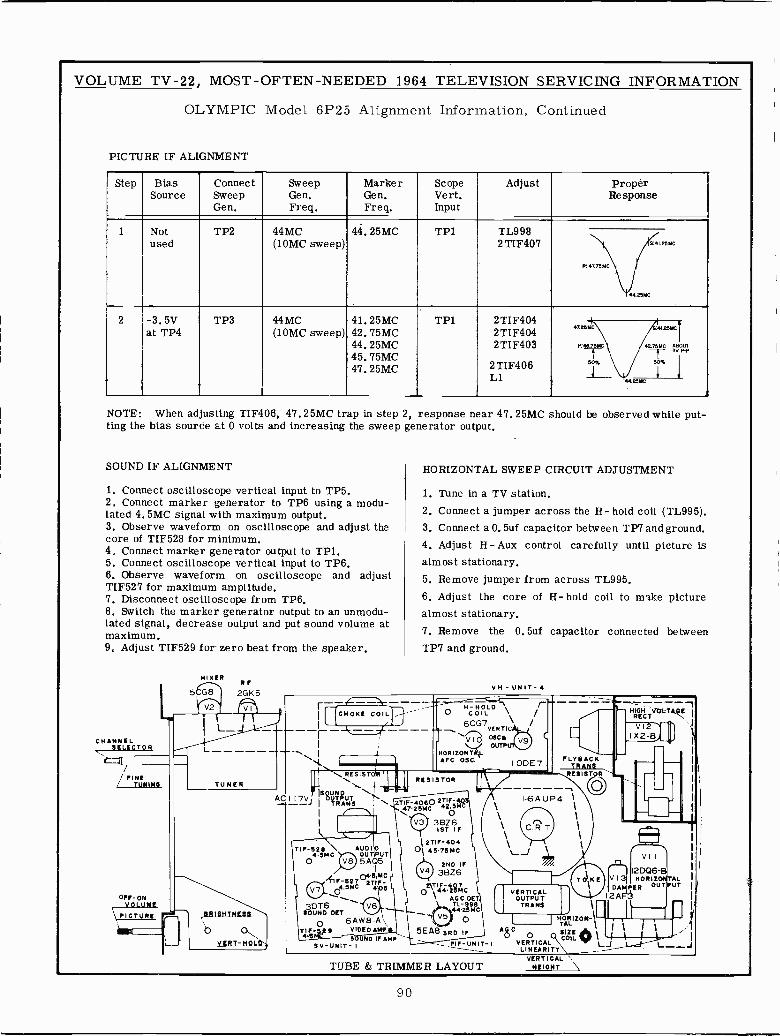
VOLUME TV -22, MOST -OFTEN -NEEDED 1964 TELEVISION SERVICING INFORMATION
OLYMPIC Model 6P25 Alignment Information, Continued
PICTURE IF ALIGNMENT
Step Bias Connect Sweep Marker Scope AdjustSource Sweep Gen. Gen. Vert.
Gen. Freq. Freq. Input
1 Notused
TP2 44MC(10MC sweep)
44.25MC TP1 TL9982 TIF407
2 -3.5V TP3 44MC 41.25MC TP1 2TIF404at TP4 (10MC sweep) 42. 75MC 2TIF404
44.25MC 2TIF40345. 75MC47.25MC 2 TIF406
L1
ProperResponse
47.25MC
P:T C 42.75MCSV P
50%50%I
I
44.25MC
NOTE: When adjusting TIF406, 47.25MC trap in step 2, response near 47.25MC should be observed while put-ting the bias source at 0 volts and increasing the sweep generator output.
SOUND IF ALIGNMENT
1. Connect oscilloscope vertical input to TP5.2. Connect marker generator to TP6 using a modu-lated 4.5MC signal with maximum output.3. Observe waveform on oscilloscope and adjust thecore of TIF528 for minimum.4. Connect marker generator output to TP1.5. Connect oscilloscope vertical input to TP6.6. Observe waveform on oscilloscope and adjustTIF527 for maximum amplitude.7. Disconnect oscilloscope from TP6.8. Switch the marker generator output to an unmodu-lated signal, decrease output and put sound volume atmaximum.9. Adjust TIF529 for zero beat from the speaker.
MIXERR
5CG8 2GK5
CHANNELSELECTOR
FINE/ TUMIMS
OFF -ONVOLUME
PICTURE
HORIZONTAL SWEEP CIRCUIT ADJUSTMENT
1. Tune in a TV station.2. Connect a jumper across the H- hold coil (TL995).3. Connect a O. 5uf capacitor between TP7 and ground.4. Adjust H- Aux control carefully until picture isalmost stationary.5. Remove jumper from across TL995.6. Adjust the core of H- hold coil to make picturealmost stationary.7. Remove the 0.5uf capacitor connected betweenTP7 and ground.
VH - UNIT- 4
AC117Vj
TIF-528
o4.5MC
AUDIOU PUT5AQ5
'IIF-5270STIF-04.5MC 2 41105
30T6SOUND DET
O 6AW8-A\TIF- 9 VIDEO AMP
UNO IF AMP5V -UNIT -1
TUBE & TRIMMER LAYOUT
IODE7
I -6A UP4
RESISTOR
2TIF-4060 2TIF-44 25MC 4205^
V3 3BZ61ST IF
1 2TIF-40401 45.75MC
2ND IFV4 38Z6
2\TIF-4º7._0 VERTICALAGC.DET OUTPUT
TL -996 TRANS44.25MC
0 I TR120N-15E A8 DRD IF A8C o SCOILIZE 0 1 ' 1
PIF- UNIT- 1 VERTICAL L../ 1.........JLINEARITY
`.HEIGHT
.44444111
- HIGH VO1,299ERECT \ V12 `
IX2-B/ i
FLV U ACETRANS
RESISTOR.
12DQ6--V 13 HORIZ TALDA PER OUT UT
12A
90
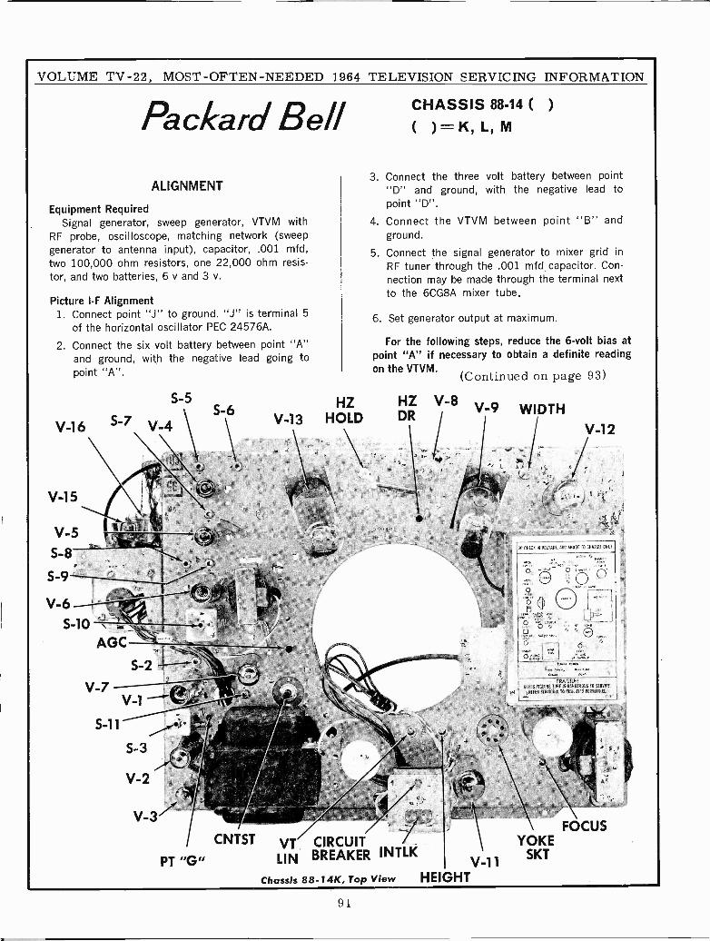
VOLUME TV -22, MOST -OFTEN -NEEDED 1964 TELEVISION SERVICING INFORMATION
Packard Bell
ALIGNMENT
Equipment RequiredSignal generator, sweep generator, VTVM with
RF probe, oscilloscope, matching network (sweepgenerator to antenna input), capacitor, .001 mfd,two 100,000 ohm resistors, one 22,000 ohm resis-tor, and two batteries, 6 y and 3 v.
Picture I -F Alignment1. Connect point "J" to ground. "J" is terminal 5
of the horizontal oscillator PEC 24576A.
2. Connect the six volt battery between point "A"and ground, with the negative lead going topoint "A".
S-5S-6
V-16 S-7 V-4
V-15
V-5S-8
,
,V-6 'I
S -10
AGC
S-3
V-2
V-3
HZV-13 HOLD
CNTST VT CIRCUIT
PT "G" LIN BREAKER INTLKV,11
HEIGHT
CHASSIS 88-14 ( )
( )=K, L, M
3. Connect the three volt battery between point"D" and ground, with the negative lead topoint "D".
4. Connect the VTVM between point "B" andground.
5. Connect the signal generator to mixer grid inRF tuner through the .001 mfd capacitor. Con-nection may be made through the terminal nextto the 6CG8A mixer tube.
6. Set generator output at maximum.
For the following steps, reduce the 6 -volt bias atpoint "A" if necessary to obtain a definite readingon the VTVM. (Continued on page 93)
HZ V-8 V-9DR
Chassis 88-14K, Top View
WIDTH
V-12
10 CNEiR NI VOIUGE ARC A1100E 10 CR03513 ONi E.
FRAGILE!GU, F :ORE IS DANGEROUS 10 SERVICE.
REFER COMM TO DUIUEIED PERS00001
FOCUSYOKE
SKT
91
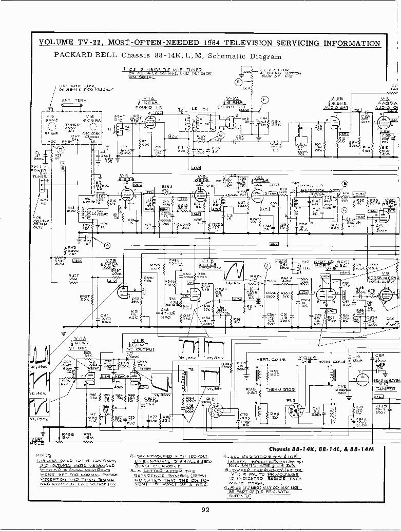
VOLUME TV -22, MOST -OFTEN -NEEDED 1364 TELEVISION SERVICING INFORMATION
PACKARD BELL
-UHF INPUT JACK.ON 8&-14Ká88' 1414 ONLY
ANT. TERM.
1v15 V16
1
I 6,91/..'f. TUNER A--`, I6C6,54,1i
1.,,,_, A5AY 1IRF AI.P g: O4SC3p.COCYIIY
L. A~_ In 6-i_-- I.F. JI--'a.47 1
2o0V1PL-I.I =POWER
UHFTUNER
--
6.3V
ON89_14K448-14 MONLY.
0.0HZ,49ov
VT 140V.
V7.> 290v.
VERT.HOLD
PIT1M
2141000
4.5.,c3NebCc
5-2 o
ILiI C4
IA111111p000000 75
t
4711
C2
1,47044NN
45.75 MC.I LEIF5%
NPO
v- 4
Chassis 88-14K, L, M, Schematic Diagramt C 2 15 INSIDE THE VHF TUNER
ON 86-14K$: 88-1414. AND OUTSIDEON 86-14L.
V -I A6 EAS
SOUND I.F6 L.43 7J
7
R3OOK
150
53 LE 54
143.1
I
L-
R439K
D
R 51199K
C7X C8KT1200 T 216
46V
100 CLIP ON FORALIGNING 60T1ONSLUG OF L-2
:IOOKS
IV -2A3 6 BNB
ND DE
2
6
1ÓK
22K
20 u:1L3
y- ESz G SHE
AUDIO AMR
7
8
1IRZv
VOL
C15OK
R78i.4
2oX
9
1-91ZI2
d7o R9w220K
C 16Y7.022400v.
R268,
V W1^
V-36AOSA
AUDI OIFT3S4
RIIW47016
ésú$25y. T
1312
261
6 NI?126v
816 21216
L4 4264c. 217
218ISO
- Cg IK3iR45
33D07W.
áá r 1256,1&PM
R 4711.514
R456
VIIA6EW7
VT osc.R8I33K
C69.0047600v
2.R79M,
R4563M
NA"
56
C24IK
R 9T270K
1 11411V.
Cd7- IMFD
100V.
C26-
I125WI
RIB b470
Le 11__
4591K I136Y IC2K8w
(2229{ 120KC27
IK Z`
-7
éó2456
L6_ººJ
12 5
Ñ1¡c
áóTe
C3b3a04c 194
2
C295_R23$ IK
1206
L759
R255470
031K
2
R 26Y120
C55'IK
5Y16
w
51L 9
DETECTOR ASV102956
L_R29 C'36
1: JL
C37;á9 y.
-0.6
LIÍ UH -C 4IT zoo2
3
K
R 61
AGC
RSO100K
R53U82K
VIIB6EW7
v7 OUTPUT2 74
6002.
R93211646.8
C 71.022...
66OoV
COó
6
2209K
075dó0v
R62 28438M. IM
i071
12855MVTMT k_uN.R83
M. -R9II-SMMVW
C480.4 7-10%
N PO
V -I BI 6 048
SYNC. SER
25647040 220K
19v.
C5,gN__
1607e
Ilo.svl
51 ~75e539 # 00476001%
--11C54 R59O1 186004 K
V
2ó yHLIS
VT 854
X- I
512
3900 -1-z/ L166',FQ7 OR 6CN
Io$IZ.-R64H I hS 226VVvi
TM.S 67oK R66 «\_--- `AA 6600
R63H R65N3300 47K
_C5614001
161.4004
c 5S
200,4
1.25v
0534I K1070
6
8
- 0595%NPo
RG7 41óóí8c2uo S 5,{
11_66v.I
0466
R71IOOK
C6360oV
R72470K
V96D068 oR6GNIHOR17. OUTPUT
C64470 C60
1669 N PO25K
zNz C651iDR i0%
T40Gv
C66600V:Z.
L51858581330C64DyBeov
)) 1W i 1004{S25v
47o7KC.ÍSTZOO
T3
VERT. COILSR95t C-604700 'el 6
VTD8v
:77OK
R9222K
3300.04C787
e
2962.301
C79.033 410002
T 107c
Y O 1.6...EL -I8 HORA COILA
0852044SK
L I 9I24N
9
C53.1GOONCB5.02
6BA3o 6AY3AV 12
DAMPER
Sb'
R994705w
1C84A50111
T350v.
C13D100,145504
NOTESI.- UNLESS NOTED TO THE CONTRARY,
D -C VOLTAGES WERE MEASUREDWITH NO 515NAL. CONTROLSWERE SET FOR NORMAL PICTURERECEPTION ANO THEN 'SIGNAL.9746 REMOVED. LINE VOLTAGE:H-3V.
2.19KV. MEASURED WITH IRO VOLTLINE NORMAL 81V4NALy* ZEROBEAM C URREr-4T.
3.. A LETTER AFTER TH EREFERENCE 3YMSOL(89W)INDICATES THAT THE COMFb-.NENT 16 PART OF A P.F.C,
Chassis 88-14K, 88-14L, & 88-14M4._ALL RESISTORS W 4 10%
UNLE55 SPECIFIED. EXCEPTION:REC. UNITS ARE W 4 cogo
5 SWEEP FREQUENCY (HE ORVT.) 4 P14 TO PK VOLTAGEIS INDICATED BESIDE EACHWAVE FORM,
6.. R-55 (4.7 MEG.) MAYOR MAY NOTSE PART OF THE P.E.C. WITHSUFFIX "U'.
92
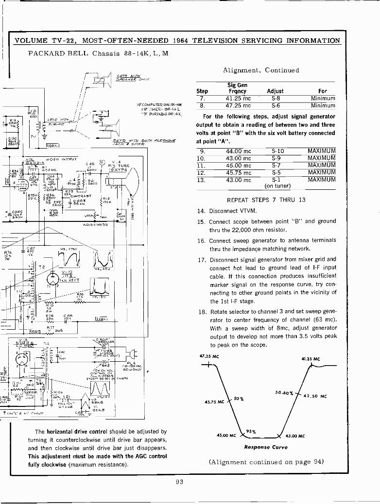
VOLUME TV -22, MOST -OFTEN -NEEDED 1964 TELEVISION SERVICING INFORMATION
PACKARD BELL Chassis 88-14K, L, M
,I6o7W.
C 13C2044.350V.
2BWR34
7
C2101
6oOv.
ST,e/PE
1266v. i
SETS W/rf,.5PE4KE2 OVLy
1TCOMPUTER DIALe8-14149" TIMER +88-14L
19' PORT49LE88&14K
5ET5 WiTN BorN E4PVNO,t/EACK $' SP/'R.
V7A VIDEO OUTPUT6 A A C 45 Vj_.4...
`L S11 .1 PIX TUBE4.501.4C 600V I 9 AY P4 /
1
r--1 / \ca4 195%4.N 99w L14I 1 R41
_-- 1yP .ÑO Iso/.N ,e I6Bo0
--- 60oy+--. L'___12 3 4 \ /
c R39
P25K767B0ó
z5 CRONTAOTR42
9% 22372oIO))s1` 56
C46T..4N
120K,L C84C
o4f- Í3SOV
R74IOK7W
:248Sor
N8, ITgY.
!fV -to1G3.
H.V. RECT2
BI W.
R75i.22 wR76 C68
2 334 10K
B21G4TNEZ9
Hz.,48v
H2. 13v.
I446v. 1
v3 CIRCUIrSU4G T4 `swK
R10*22 5W-3
cm? 37c12.á
I
swW ON VOL
GONTROL ON
VT>12vV26868
VI1H1 2848
PL. 4110- 120 VAC60,5 ON LY
R)
2
The horizontal drive control should be adjusted byturning it counterclockwise until drive bar appears,and then clockwise until drive bar just disappears.This adjustment must be made with the AGC controlfully clockwise (maximum resistance).
Alignment, Continued
Sig GenStep Frqncy Adjust For
7. 41.25 me S-8 Minimum8. 47.25 mc S-6 Minimum
For the following steps, adjust signal generatoroutput to obtain a reading of between two and threevolts at point "B" with the six volt battery connectedat point "A".
9. 44.00 mc S-10 MAXIMUM10. 43.00 mc S-9 MAXIMUM11. 45.00 mc S-7 MAXIMUM12. 45.75 mc S-5 MAXIMUM13. 43.00 mc S-1 MAXIMUM
(on tuner)
REPEAT STEPS 7 THRU 13
14. Disconnect VTVM.
15. Connect scope between point "B" and groundthru the 22,000 ohm resistor.
16. Connect sweep generator to antenna terminalsthru the impedance matching network.
17. Disconnect signal generator from mixer grid andconnect hot lead to ground lead of I -F input
cable. If this connection produces insufficientmarker signal on the response curve, try con-necting to other ground points in the vicinity ofthe 1st I -F stage.
18. Rotate selector to channel 3 and set sweep gene-rator to center frequency of channel (63 mc).With a sweep width of 8mc, adjust generatoroutput to develop not more than 3.5 volts peakto peak on the scope.
47.25 MC
95%45.00 MC 43.00 MC
41.25 MC
Response Curve
(Alignment continued on page 94)
93
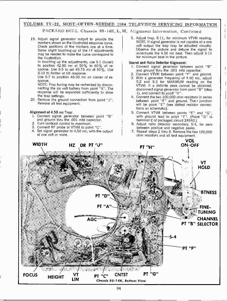
VOLUME TV -22, MOST -OFTEN -NEEDED 1964 TELEVISION SERVICING INFORMATION
PACKARD BELL Chassis 88-14K, L, M,
19. Adjust signal generator output to provide themarkers shown on the illustrated response curve.Check positions of the markers one at a time.Some slight touching -up of the I -F adjustmentsmay be needed to make the curve correspond tothe illustration.In touching up the adjustments, use S-1 (tuner)to position 42.50 mc at 50% to 60% of re-sponse. Use S-5 to set 45.75 mc at 50%. UseS-10 to flatten or tilt response.Use S-7 to position 45.00 mc on corner of re-sponse.NOTE: Trap tuning may be rechecked by discon-necting the six volt battery from point "A". Theresponse will be expanded sufficiently to showthe trap settings.
20. Remove the ground connection from pointRemove all test equipment.
Alignment of 4.50 mc Trap:1. Connect signal generator between point
and ground thru the .001 mfd capacitor.2. Turn contrast control to maximum.3. Connect RF probe of VTVM to point "C".4. Set signal generator to 4.50 mc, with the output
at one volt or more.
WIDTH
FOCUS
HZ DR PT "J"
HEIGHTVTLIN
1' -
Alignment Information, Continued5. Adjust trap, S-11, for minimum VTVM reading.
NOTE: If signal generator is not capable of a onevolt output the trap may be adjusted visually.Observe the picture and detune the signal toaccentuate the 4.50 mc beat. Then adjust S-11for minimum beat in the picture.
Sound and Ratio Detector Alignment:1. Connect signal generator between point "B"
and ground thru the .001 mfd capacitor.2. Connect VTVM between point "F" and ground.3. With a generator frequency of 4.50 mc, adjust
S-2 and S-3 for MAXIMUM reading on theVTVM. If a definite peak cannot be obtained,disconnect signal generator from point "B" (step1), and connect to point "H".
4. Connect the two 100,000 ohm resistors in seriesbetween point "F" and ground. Their junctionwill be point "E" (see dotted resistor connec-tions on schematic).
5. Connect VTVM between points "E" and "G",with ground lead to point "E". (Point "G" isterminal 2 of packaged circuit 24540.)
6. Adjust ratio detector secondary, S-4, for zerobetween positive and negative peaks.
7. Repeat steps 2 thru 6. Remove the two 100,000ohm resistors and all test equipment.
VOLON -OFFPT "H"
4;i'= _--?
PT "C" CNTST PT 'G"Chassis 8B -74K, Bottom View
S-4
VTHOLD
BTNESS
,r. 'FINE -I TUNING
CHANNELPT "B" SELECTOR
PT "F"
94
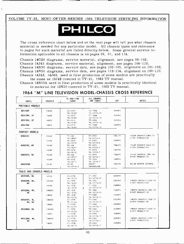
VOLUME TV -22, MOST -OFTEN -NEEDED 1964 TELEVISION SERVICING INFORMATION
ePHILCOThe cross reference chart below and on the next page will tell you what chassismaterial is needed for any particular model. All chassis types and referenceto pages for such material are listed directly below. Some general service in-formation applicable to all chassis is on pages 96, 97, and 114.Chassis 14G20 diagrams, service material, alignment, see pages 98-102;Chassis 14J45 diagrams, service material, alignment, see pages 106-110;Chassis 14N30 diagrams, service data, see pages 103-105, alignment on 101-102;Chassis 14N50 diagrams, service data, see pages 112-114, alignment on 109-110.Chassis 14J42, 14J43, used in first production of some models are practically
the same as 13J42 covered in TV -21, 1963 TV manual.Chassis 14N50A used in first production of some models is practically identical
to material for 13N50 covered in TV -21, 1963 TV manual.
1964 "M" LINE TELEVISION MODEL -CHASSIS CROSS REFERENCE13 POSITION ALL CHANNEL
MODEL CHASSIS TUNER UHF TUNER CRT NOTES
PORTABLE MODELS
M2610BR 14G20 TT -127C TT -139B I6ASP4
76.13163 76.12715.12
M2612WH, GY 14020 TT.127C TT -139B 16ASP4
76.13163 76.12715.12
M2614BU, GY I4G20 TT.127C TT -1398 16ASP4
76-13163 76.12715.12
M2616GD 14020 TT.127C TT -1398 I6ASP4
76.13163 76.12715.12
COMPACT MODELS
M3822GD 14J43 TT -129 TT -136A 19BLP4 14J43 CHASSIS USED IN
76.13027 76-12715.6 FIRST PRODUCTION
I4J45 TT -1278 TT -136A I9DFP4
76.13112 76.12715.6
M3824BK, WH 14J43 TT -129 TT -137A I9BLP4 14J43 CHASSIS USED IN
76-13027 76.12715.7 FIRST PRODUCTION
14J45 TT -127B TT -137A 19DFP4
76.13112 76-12715.7
M3826CH, WA 14J43 TT -129 TT.137A 19BLP4 14J43 CHASSIS USED IN
76-13027 76.12715.7 FIRST PRODUCTION
14J45 TT.127B TT.137A 19DFP4
76.13112 76.12715.7
M3828RWH 14J42 TT -83 STRIP' 19BLP4 RC.68 REMOTE CONTROL
76.12718-2 CONVERSION
TABLE AND CONSOLE MODELS
M4350MR, WA 14N50 TT -1278 TT.138C 23DQP4
76-13112 76.12715.11
M4500MR, MA, 14N50A 11.127D TT.138C 23BVP4 14N50A CHASSIS USED IN
WA 76.13155 76.12715.11 FIRST PRODUCTION
14N50 11.1278 TT.138C 23DQP4
76-13112 76.12715-11
M4502WA, MR, 14N50A TT -127D TT.138C 23BVP4 14N50A CHASSIS USED IN
MA 76-13155 76.12715-11 FIRST PRODUCTION
14N50 11-1278 TT.I38C 2300P4
76.13112 76.12715.11
M4504MR, BL, 14N50A TT.127D TT -138C 23BVP4 14N50A CHASSIS USED IN
MA, WA 76.13155 76-12715-11 FIRST PRODUCTION
14N50 TT -127B TT.138C 23D0P4
76.13112 76.12715.11
M4508MB, MA 14N50A TT -127D TT.138C 23BVP4 14N50A CHASSIS USED IN
76-13155 76.12715-11 FIRST PRODUCTION
I4N50 TT.127B TT.138C 2300P4
76.13112 76.12715.11
M4512MB, MA, 14N50A 11.127D TT-I38C 23BVP4 14N50A CHASSIS USED IN
WA 76.13155 76.12715.11 FIRST PRODUCTION
14N50 11-1278 TT.138C 23DQP4
76-13112 76.12715.11
95
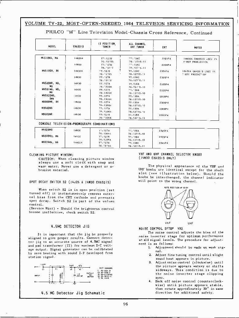
VOLUME TV -22, MOST -OFTEN -NEEDED 1964 TELEVISION SERVICING INFORMATION
CLEANING
SPOT
turnednalspotcontrol.e(Servicebecome
alignedtor
andage
by
station
PHILCO "AA" Line Television Model -Chassis Cross Reference, Continued
and
the
-
sig-
to
MODEL CHASSIS13 POSITION,
TUNER-ALL CHANNELUHF TUNER CRT NOTES
M45I8WA, MA
M4519GR, BK
M4590MR, MA,WA
M459IWA, MB,MA
M4592SMB,
SWA
M9300MR, BK
M9500WA
M9502MR
14N504
14N50
14N504
14N50
14N30
14N30
14N30
14N30
14N30
14N30
TT.127D76.13155TT -1278
76.13112
TT -127D
76.13155TT.127B76.13112TT -127A
76-13064TT.127A76.13064TT -127A
76.13064TT -127A
76.13064TT -127A
76-13064TT -127A
76.13064
TT.138C76.12715.11TT -138C
76.12715.11 1
TT.138C76.12715.11TT.138C76-12715.11
T7.139476.12715.10TT.139A76.12715.10TT -139A
76.12715.10TT.139476.12715.10TT -139A
76.12715-10TT -139A
76.12715.10
23BVP4
23DQP4
23BVP4
23D0P4
23DSP4
23DSP4
23DSP4
23DSP4
23DSP4
23DSP4
14N504 CHASSIS USED INFIRST PRODUCTION
14N504 CHASSIS USED INFIRST PRODUCTION
CONSOLE TELEVISION -PHONOGRAPH COMBINATIONS
M4928MB
M4930MB, WA
M4934MA, WA
14N30
14N30
14N504
TT.127A76.13064TT -127A
76.13064TT -127D
76.13155
TT -139A
76.12715.10TT.139A76-12715-10TT -138C
76.12715.11
23DSP4
23DSP4
23BVP4
PICTURE
CAUTION:alwayswarm water.brasive
DECAY
When switchoff)
bias fromdecay.
Hint)ineffective,
It isto give
jig topad transformeroutput.
zero beatingsignal.
I.2PF.1V I
CI
INPUT
0
WINDOW:
When cleaning pictureuse a soft cloth' with
Never use a detergentmaterial.
SWITCH S2 (14J25 & I4N30
S2 is in openit instantaneously removes
the CRT cathodeSwitch S2 is part of
- Should the brightnesscheck switch
4.5MC DETECTOR JIG
important that the jigproper results. Connect
an accurate source of(T1) for maximum
Signal generator can bewith sound I -F developed
IN60 STN
VHF AND UHF CHANNEL
window (I4N30 CHASSIS ONLY)
soap andor a- The physical
UHF knobs are identicalslot (see illustrationknobs be interchanged,
CHASSIS)will point to the
NOTE
position (setexter-
and prevents 41the volume
controlS2.
1rVHF
NOISE CONTROL SETUP
be properlyThe noise control
detec-noise inverter stageat all signal levels.
4.5MC signalD -C volt-
ment is as follows:
calibrated1. Adjustment
fromnal.
2. Adjust fine
sound beat3. Adjustnoise
the picturePART NUMBERS
sideways.CI 30-1221-21 YC2 30-1238-3R166-2478340 the noiseDI 34-6022-2TI 32-4449 SYfC
° 4. Back offwise) untilthen rotatedirection
appearance
wrong
POSITION
noise
for
SELECTOR
exceptbelow).
the
channel.
OF SLOT
KNOBS
of the VHFfor the shaft
Should thechannel indicator
il,t
UHF
VR2
adjustsfor optimum
The procedure
should
tuningappearscontrolappears
This conditioninverter
controlpictureapproximately
additional
the bias ofperformancefor adjust
be made on weak
control until slight
in picture.(clockwise) untilwatery or shifts
is duestage clipping
(counterclock-appears stable,
30° in samesafety.
T1
á
1
DI RI
OUTPUTC2 TDOOI MF METER
-21.L _ _ J
4.5 MC Detector Jig Schematic
96
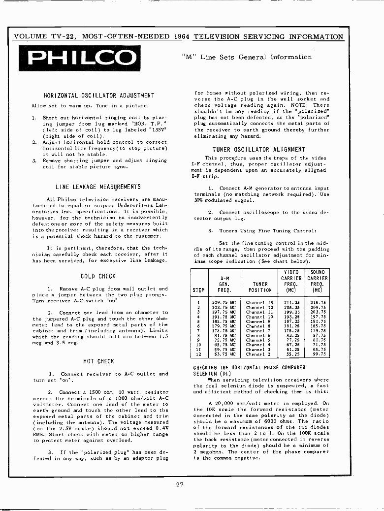
VOLUME TV -22, MOST -OFTEN -NEEDED 1964 TELEVISION SERVICING INFORMATION
PH I LCOHORIZONTAL OSCILLATOR ADJUSTMENT
Allow set to warm up. Tune in a picture.
1. Short out horizontal ringing coil by plac-ing jumper from lug marked "HOR. T.P."(left side of coil) to lug labeled "135V"(right side of coil).
2. Adjust horizontal hold control to correcthorizontal line frequency(to stop picture)it will not be stable.
3. Remove shorting jumper and adjust ringingcoil for stable picture sync.
LINE LEAKAGE MEASUREMENTS
All Philco television receivers are manu-factured to equal or surpass Underwriters Lab-oratories Inc. specifications. It is possible,
however, for the technician to inadvertentlydefeatoneor more of the safety measures builtinto the receiver resulting in a receiver which
is a potential shock hazard to the customer.
It is pertinent, therefore, that the tech-nician carefully check each receiver, after ithas been serviced. for excessive line leakage.
COLD CHECK
1. Remove A -C plug from wall outlet andplace a jumper between the two plug prongs.Turn receiver A -C switch "on"
2. Connect one lead from an ohmmeter tothe jumpered A -C plug and touch the other ohm-meter lead to the exposed metal parts of thecabinet and trim (including antenna). Limitswhich the reading should fall are between 1.5meg and 3.5 meg.
HOT CHECK
1. Connect receiver to A -C outlet andturn set "on".
2. Connect a 1500 ohm, 10 watt, resistoracross the terminals of a 1000 ohm/volt A -Cvoltmeter. Connect one lead of the meter toearth ground and touch the other lead to theexposed metal parts of the cabinet and trim(including the antenna). The voltage measured(on the 2.5V scale) should not exceed 0.4VRMS. Start check with meter on higher rangeto protect meter against overload.
3. If the "polarized plug" has been de-feated in any way, such as by an adaptor plug
"M" Line Sets General Information
for homes without polarized wiring, then re-verse the A -C plug in the wall socket andcheck voltage reading again. NOTE: Thereshouldn't be any reading if the "polarized"plug has not been defeated, as the "polarized"plug automatically connects the metal parts of
the receiver to earth ground thereby furthereliminating any hazard.
TUNER OSCILLATOR ALIGNMENT
This procedure uses the traps of the videoI -F channel, thus, proper oscillator adjust-ment is dependent upon an accurately alignedI -F strip.
1. Connect A -M generator to antenna inputterminals (no matching network required). Use30% modulated signal.
2. Connect oscilloscope to the video de-tector output lug.
3. Tuners Using Fine Tuning Control:
Set the fine tuning control in the mid-dle of its range, then proceed with the paddingof each channel oscillator adjustment for min-imum scope indication (See chart below).
STEP
A -M
GEN.
FREQ.
TUNERPOSITION
VIDEO
CARRIERFREQ.
(MC)
SOUND
CARRIERFREQ.
(MC).
1 209.75 MC Channel 13 211.25 215.752 203.75 MC Channel 12 205.25 209.753 197.75 MC Channel 11 199.25 203.754 191.75 MC Channel 10 193.25 197.755 185.75 MC Channel 9 187.25 191.756 179.75 MC Channel 8 181.25 185.757 173.75 MC Channel 7 175.25 179.758 81.75 MC Channel 6 83.25 87.759 75.75 MC Channel 5 77.25 81.7510 65.75 MC Channel 4 67.25 71.7511 59.75 MC Channel 3 61.25 65.7512 53.75 MC Channel 2 55.25 59.75
CHECKING THE HORIZONTAL PHASE COMPARERSELENIUM (DI)
When servicing television receivers wherethe dual selenium diode is suspected, a fastand efficient method of checking them is this:
A 20,000 ohm/volt meter is employed. Onthe 10K scale the forward resistance (meterconnected in the same polarity as the diode)should be a maximum of 6000 ohms. The. ratioof the forward resistances of the two diodesshould be less than 2 to 1. On the 100K scalethe back resistance (meter connected in reversepolarity to the diode) should be a minimum of2 megohms. The center of the phase compareris the common negative.
97
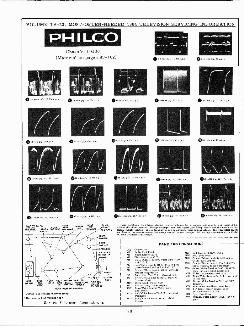
VOLUME TV -22, MOST -OFTEN -NEEDED 1964 TELEVISION SERVICING INFORMATION
PH I LCOChassis 14G20
(Material on pages 98-102)
© 100 volts, p/p, 15,750 c. p.s. 0 80 volts p/p, 15, 750 c. p. s,
Í(0 40 volts p/p, 60 c. p.s.
0 8 volts p/p, 15, 750 c p. s.
025 volts p/p, 15, 750 c. p. s.
O60 votts p/p, 60 c. p. s.
0 12 volts p/p, 15, 750 c. p.s.
090 volts p/p. 15, 750 c, p. s.
30Z4 OR 3AF4A 17JZ8. I6ASP4 6GH8UHF OSC. 4CS6 VERT s
(UHF ONLY) GAO 5A SND. DISC. OSQUOU% CRT SYNGSEPAUD. OUT.
36 KSR.F. AMP
SHGBOSC.
MIXER
IOJYBVID. OUT.AGC GATE
178E3DAMPER
21GYSHOR. OUT.
INTERLOCK
163 OR IK3HV RECT.*
to-
o] *--F
FIL.RES SILICON
4E117 4EJ7 8F07 OR DUAL SE L. / RECT.
1ST tF, 2ND áSG. PHASE COMP FUSEPHILCOM33-1366-8
REAR VIEW OF CHASSIS
Dotted lines indicate filament string
This tube in high voltage cage
Series Filament Connections
© 80 volts p/p, 60 c. p. s.
040 volts p/p, 60 o.p. s.
015 volts p/p, 15,750 c. p. s.
A
Am.
0350 volts p/p. 15, 750 c. p. s.
r4r,.,)
3. 5 volts p/p, 15, 750 c. p. s.
Asi~sIsmnvrrr.._
0 50 volts p/p, 60 c. P.S.
01150 volts p/p, 60 c. p. s.
0 8 volts p/p, 15, 750 c. p, s.
® 60 volts p/p, 15, 750 c. p. s.
IRIA.11~4110111111011
0 3.5 volts p/p, 60 c. p. s.
0 50 volts p/p, 15, 750 c. p. s.
060 volts p/p, 60 c. P. s.
030 volts p/p, 15, 750 c. p. s.
016 volts p/p, 15, 750 c. p. s.
These waveforms were taken with the receiver adjusted for an approximate peak -to -peak output of 3.5volts at the video detector. Voltage readings taken with raster just filling screen and all controls set fornormal picture viewing. The voltages given are approximate peak -to -peak values. The frequencies shownare those of the waveforms-not the sweep rate of the oscilloscope. All readings were taken with a ModelES -550B Precision oscilloscope.
PANEL LUG CONNECTIONS
Lug ConnectionMl Audio Test PointM2 White Lead to Bl-2M3 Blue Lead to A. O. T.M4 Video Output, Yellow/White lead to Pin
7 of C. R. T.MS Red/White Lead to B1-5, 145V B -plusM6 Green/White Lead to Pin 6 of CRTM7 Orange/White Lead to B1-3, vertical
retrace suppressionM8 Sound Det. Test Point, Ground LinkM9 Brown/White Lead to B2-1, start of
filament chainM10 White Lead, Tuner AGCMll Yellow Lead, Tuner B -plusM12 Blue/White Lead to Yoke, AGC
Gate PulseM13 Red/White Lead of V.O.T., Vertical
FeedbackM14 Blue/White Lead to VR6-1, Width
Control
M15 Red Lead to H. O. T. Pin 7M16 AGC Test PointM18 Orange/White Leads to M28 and to
C44B, 135V B -plusM19 Orange/White Lead to Pin 4 of CRT,
300V, optional focus connectionM20 Green/White Lead to C44C, 100V B -
plus, optional focus connectionM21 Video 2nd detector test pointM22 Blue/White Lead of V. 0. T., vertical
output plateM23 Brown/White Lead to Pin 1 of CRT,
filamentM24 Horizontal Oscillator Test PointM25 I -F Input, center conductor of
shielded tuner I -F linkM27 Sync Test PointM28 Orange/White Lead to M18, 135V B -
plus
98
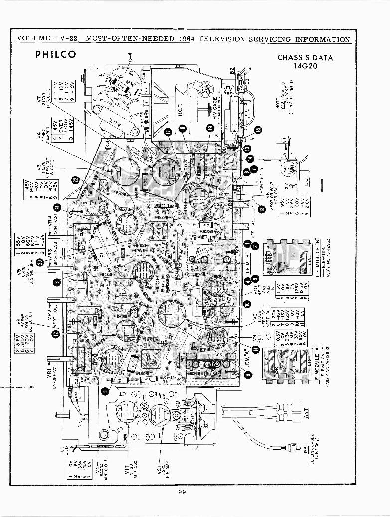
2 5 6 7
OV
6V13
5VI4
5V OV
VI
6AQ
5AA
UD
IO O
UT
.
V1T
5HG
8M
IX. O
SC
.
V 2
T-
3GK
5R
.F. A
MP
,
I.F.
LIN
K
2C
I6T
VC
2TC
IAT
v5
P3
AN
T.
l F L
INK
CA
BLE
(U, H
.FO
nly)
CI6
AT
CIB
T
2 5 6 7
3.6V
320V
70V
OV
VR
I-O
N-O
FF
-VO
L
wn
271}
áa>
2Y"`
tis1I
.F S
H É
LD
f111
0111
1111
1111
111
C40 C
4I LI4
L13
NII
O11
1111
1NN
11
L15
V2
4CS
6S
OU
ND
DE
TE
CT
OR
V9
4EH
71s
t.V
ID,
I.F.
2 3 6 7 8 9
0.3V OV
0.3V O
V13
7V50
VO
V
VR
2V
ER
T H
OLD
V6
17JZ
8V
ER
T. O
SC
.-V
ER
T. O
UT
.
2 6 7 8
20V
-16
V-1
6V13
5V OV
-13V O
V
V5
6GH
8S
ND
.I.
F.&
SY
NC
. SE
P.
2 3 6 7 9
55V OV
60V
60V
1.1
V-1
.6V
VR
3II
VR
4(B
RIG
HT
NE
SS
CO
NT
RA
ST
mn
zse.
:_
Fkl
6
2 3 6 7 8 9
I
1E M
.'S
V10
©4E
J72n
d.V
ID.
yI.F
.2
1_16
...
11N
111
1.3V O
V1.
3V OV
125V
125V O
V1N
1iN
1A)l
N1I
IN
1 2 3 6 7 8 9
VE
RT
S Z
EV
ER
T, L
IN
I.E M
OD
ULE
"A
"I
F. M
OD
ULE
"8"
ELE
VA
TIO
NE
LEV
AT
ION
AS
S'Y
. NO
76-
1295
2A
SS
'Y N
O 7
6-12
953
I45V
90V
-3V
OV
OV
67V
43V
V3
10JY
8V
IDE
O O
UT
.B
GA
TE
RA
DIA
TIO
NS
HIE
LD
HO
RIZ
HO
LD
V8
8FQ
7O
R 8
CG
7N
OR
. OS
C,
2 3 6 7 8
95V OV
2.8V
100V
-8V
2.8V
32±
V4
V7
17B
E3
2 G
Y5
AM
PE
RH
OR
. OU
T.
4 I4
5V7
OV
ER
500V
0I4
5V
3 5 7 9
II 5V
-I9V
II 5 -I9V
GII
H.V
. CA
GE
( T
OP
HA
LF R
EM
OV
ED
)
U,H
F3
ON
LY
NO
TE
:
GII
C48
LO
CA
TE
DO
N Y
OK
E.
(PIN
2 T
O P
IN II
)
B2 5
C44
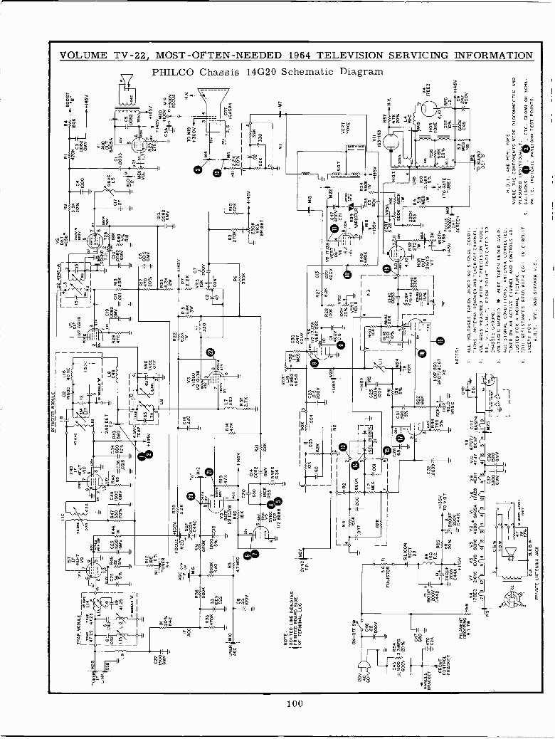
TU
M25
IFi
LIN
K
:G5B
120V
AC 60
1
L9
C27
1500
GM
V I
TR
AP
MO
DU
LEm
y
[-T
RA
PT
RA
PLi
447
.25
47.2
5
AG
C
TU
NE
R ¡
M10
AG
C
IK 20%
R42
680K
R33
470K
33
IIOO
VC
22
I C8 22
TIO
OV
1ST
IF4E
H7
V9
R12
180
MII
10%
TU
NE
R8+
AT
.P o
vn
MI6
{663
0BO
K
R5
4.7M
EG
NO
TE
:D
OT
TE
D L
INE
IND
ICA
TE
SP
RIN
TE
D B
OA
RD
SID
EI
OF
TE
RM
INA
L LU
GS
YN
Cr7
T.P
.
LIO
DE
TE
CT
OR
MO
DU
LEr
1.8
2ND
IFm
w4E
J77
VIO
FO
CU
S ó
100V
M2Ó=
+5µ
F
680K
ON
-O
FF
SW
C47
6801
HA
ND
EB
RA
CK
ET
1470
160µ
F+B
H
200V
-16
IIC
44D
0+F
.C.
R55
FR
ON
T/,-
)C
ON
TR
OL
240
F68
BRACKET
- 20
0V20
%C
44A
FIL
AM
EN
T+
145V
DR
OP
PIN
G90
7W
FI
T2C
44C
00V
1200
1CI5
2 20V
R
V3
ºov
R19
1/G
AT
2 oJ
Y+
av 1
47K
R40
9 -L
ey V5
SY
NC
SE
P1/
2 6G
H8
C20 68
0
150K
R35
EN
44
+14
5V
C14
.008
2R
21I
vw
GM
V22
11
1.5M
EG
R34
D2
L16
IN60
C40
MC
V5
I
SIF
A "
:12
1/2
6GH
8
1.5:
;I
e0v6
1
ic90K3
TIO
K,0
0500
4I I0
15I
150
#8.2
6T L--
-5--
-J
2N
2--
--r.82
7
I2
il ee
v1P
N00
1AEY
- -0-
IL8 CH
8
L7 330
R37
2.71
(
OV
.I.20
068
0KI
IN
I
2ME
LSE
LD
IOD
EJ
I
82J
ii00
1D
I-T
L---
----
7--
-6 I C
2668
_S
ILIC
ON
RE
CT
D3
4--¡¡240µF
1.2008
= C
448
6
C30
.047
400V I(
2 zo
v 1/
2 17
JZ8
T20
0VY
I3vE
RT
OS
CR
27C
1310
R28
8.2K
022
I/2 1
7J28
+13
5V:M
28N
01
IOOK
400V
VERT
0 047
I 5A22r
400V
OU
T4
400V
=C
I8 T
_IO
OK
VR
2V
GC
21V
.O.T
20%
6,J
___
8 13
30
VE
RT
{V
_iev
R39
`°"°
+14
5VHOLD =-
tK
9V
AR
IST
OR
R24
I
C25
MS
I'R
1 -n
!1N
3I
M18
055
6801
1
.003
9IO
K+
135V
50V
{+
135V
IOO
V T
i Ll l
I
I
Il
Ohx
3 a
I 14
1I
0%22
Koa
-xs
pll/T
1311
M24
'I
H.O
.T.
5%L/
.5K
R17
470
20%
R23
8.2K 2W
+14
5VR
72.
2K
VR
3C
7IR
K20
0V
tI(
CO
NT
330K
V2
GE
T4C
S6°
3400
320V
7o
R9
3.3K
20%
1 C
411
000
CID
IC17
127
- .0
082
T G
MV
R3
yyR
IO27
0K?
p82K
,.'+
145V
250K
VR
3B
RIG
HT
RI
R4
BO
OS
T
470K
C3
1501
18"
.008
2TG
M,/
+14
54
AU
DQ
UA
DO
UT
6ÁÓ
5AL5
1A
UD
=T
P I ME
GV
OL
CI
-.00
33
+I 5
V
+14
5VM
20
654+
100V
o+M
3001
94
4F
OC
US
TO
M19
+30
0V
47
314
360
32V
611
,
b3
I
021
39K
I
I
22K
'r330
i
I2--
--J
1.16
2.2K
20%--
-1
R52
68K
VE
RT
LIN
2 M
EG
VR
58R50
1.5
ME
G
TP
.T
100
4(6
HOR
C32
z.ev
.003
9-R
44N
OR
OS
C+135V
750 60K
8F07/8C57
TO
V.O
.T5%
HO
RV
8-
HOLD -_
VR5C
R58
V8
V4
V7
V3
VS
V2
VI
V6
V9
VIO
BFQ7/
CRT
178E
321
GY
5IO
JYB
6GH
84C
S6°
6A
05A
17JZ
8 4E
H7
4EJ7
8CG
7 I6
AS
P4
4 11
8
4
BIR.
BLK 8 W
PRIVATE LISTENING JACK
614
4 C37
C38
3300
1500
GM
VT
7`G
MV
C49
001
-
NOTES:
VERT
0033
SIZ
E6
5,9
37,'I
I(
ºv
3v
1I
ns-to
R4-
ns1
3.9K
4,10
32ti2
20K
I
z-ns
330K
= 2
702
R53
R51
C48
I33
0I
HO
R
IW=
'MI4
,,..1
15"'
S
I
I09G
I
OU
T_
21G
Y5
L-_J
V7
VR
5AR
I6
3K
WID
TH
VR
6 F
OC
US
{,J5
4419
+14
5V+
300V S
CR
ET EN'
I.A
LL V
OLT
AG
ES
TA
KE
N U
ND
ER
NO
SIG
NA
L C
ON
DI -
TIO
NS
. AN
TE
NN
A R
EM
OV
ED
AN
D-
TU
NE
R O
FF
CH
AN
NE
L.2.
VO
LTA
GE
S M
EA
SU
RE
D W
ITH
A "
PR
EC
ISIO
N M
OD
EL
88. V
. T.V
.M."
, FR
OM
PO
INT
IND
ICA
TE
D T
OC
HA
SS
IS G
RO
UN
D.
3.V
OLT
AG
ES
MA
RK
ED
*W
ER
E T
AK
EN
UN
DE
R A
VE
R-
AG
E S
IGN
AL
CO
ND
ITIO
NS
, AN
TE
NN
A C
ON
NE
CT
ED
.T
UN
ER
ON
AN
AC
TIV
E C
HA
NN
EL
AN
D C
ON
TR
OLS
AD
-JU
ST
ED
FO
R A
NO
RM
AL
PIC
TU
RE
.4.
CO
IL R
ES
IST
AN
CE
S R
EA
D W
ITH
CO
ILIN
CIR
CU
ITE
XC
EP
T F
OR
-
A.O
.T.
SE
C. A
ND
SP
EA
KE
R V
.C.
680K
IW S.6
1I6
0M
EG
5KV
W
T5%
"A"
(TO
GA
TE
TU
BE
I
NI
VII
VE
RT
YO
KE
163-
113
R56
º6.
811
20%
3.3
ME
GR
8
2 6
CRT
16Á5P4 M7
RS
7
D0% L4 RF
C
HO
RY
OK
E4,
10
600V
C45
TO
SO
UN
DD
ET
"B
'
H V
.
H.V
.
7 RF
CL2
1 V4
17E
1E3
C9
+14
5V
047
400V
H.O
.T. A
ND
HO
R. Y
OK
EW
HE
RE
TH
E C
OM
PO
NE
NT
S W
ER
E D
ISC
ON
NE
CT
ED
AN
DM
EA
SU
RE
D IN
DIV
IDU
ALL
Y.
5.
BALLOONS
. © .
ET
C. S
HO
WN
ON
SC
HE
.M
AT
IC,
IND
ICA
TE
WA
VE
FO
RM
TE
ST
PO
INT
S.
t^"
l 1 o
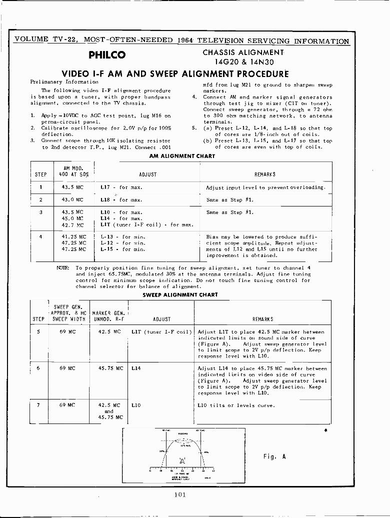
VOLUME TV -22, MOST -OFTEN -NEEDED 1964 TELEVISION SERVICING INFORMATION
PHILCO CHASSIS ALIGNMENT14G20 & 14N30
VIDEO I -F AM AND SWEEP ALIGNMENT PROCEDUREPreliminary Information
mfd from lug M21 to ground to sharpen sweepThe following video I -F alignment procedure markers.
is based upon a tuner, with proper bandpass 4. Connect AM and marker signal generatorsalignment, connected to the TV chassis. through test jig to mixer (C1T on tuner).
Connect sweep generator, through a 72 ohm1. Apply -10VDC to AGC test point, lug M16 on to 300 ohm matching network, to antenna
perma-circuit panel. terminals.2. Calibrate oscilloscope for 2.0V p/p for 100% 5. (a) Preset L-12, L-14, and L-18 so that top
deflection. of cores are 1/8 -inch out of coils.3. Connect scope through 10K isolating resistor (b) Preset L-13, L-15, and L-17 so that top
to 2nd detector T.P., lug M21. Connect .001 of cores are even with top of coils.
AM ALIGNMENT CHART
STEP
AM MOD.
400 AT 50% ADJUST REMARKS
1 43.5 MC L17 - for max. Adjust input level to prevent overloading.
2 43.0 MC L18 - for max. Same as Step #1.
3 43.5 MC45.0 MC
42.7 MC
L10 - for max.
L14 - for max.
LIT (tuner I -F coil) - for max.
Same as Step #1.
4 41.25 MC47.25 MC47.25 MC
L-13 - for min.
L-12 - for min.
L-15 - for min.
Bias may be lowered to produce suffi-cient scope amplitude. Repeat adjust -ments of L12 and L15 until no furtherimprovement is obtained.
i'UlF: To properly position fine tuning for sweep alignment, set tuner to channel 4and inject 65.75MC, modulated 30% at the antenna terminals. Adjust fine tuningcontrol for minimum scope indication. Do not touch fine tuning control forchannel selector for balance of alignment.
SWEEP ALIGNMENT CHART
STEP
SWEEP GEN.APPROX. 8 MC
SWEEP WIDTHMARKER GEN.UNMOD. R -F ADJUST REMARKS
5 69 MC 42.5 MC LIT (tuner I -F coil) Adjust LIT to place 42.5 MC marker betweenindicated limits on sound side of curve(Figure A). Adjust sweep generator levelto limit scope to 2V p/p deflection. Keepresponse level with L10.
6 69 MC 45.75 MC L14 Adjust L14 to place 45.75 MC marker betweenindicated limits on video side of curve(Figure A). Adjust sweep generator levelto limit scope to 2V p/p deflection. Keepresponse level with L10.
7 69 MC 42.5 MCand
45.75 MC
L10 L10 tilts or levels curve.
Fig. A
fotl E` 1-
RESPOMSE WAVE
101
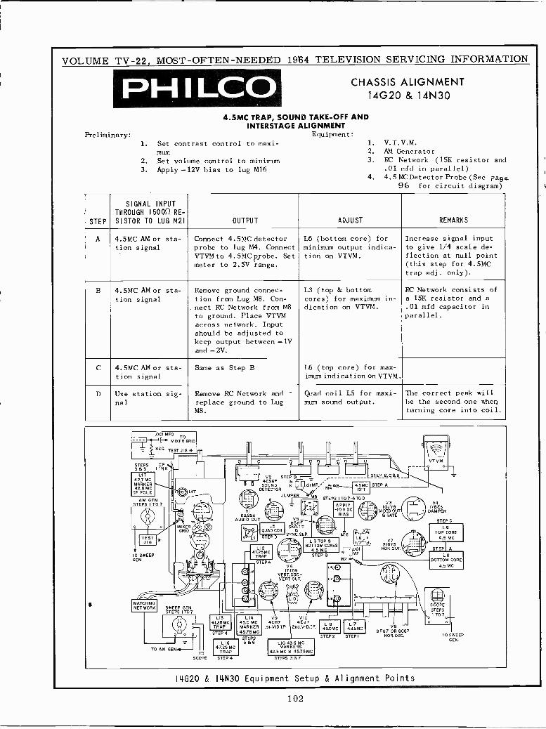
VOLUME TV -22, MOST -OFTEN -NEEDED 19164 TELEVISION SERVICING INFORMATION
P I -I I I_D CHASSIS ALIGNMENT14G20 & 14N30
4.5MC TRAP, SOUND TAKE -OFF ANDINTERSTAGE ALIGNMENT
Preliminary: Equipment:
1. Set contrast control to maxi- 1. V.T.V.M.
mum 2. AM Generator
2. Set volume control to minimum 3. RC Network (15K resistor and
3. Apply -12V bias to lug M16 .01 mfd in parallel)4. 4.5 MC Detector Probe(See page
96 for circuit diagram)
STEP
SIGNAL INPUTTHROUGH 160052 RE -
SISTOR TO LUG M21 OUTPUT ADJUST REMARKS
A 4.5MC AM or sta-tion signal
Connect 4.5MC detectorprobe to lug M4. ConnectVTVM to 4.5MC probe. Setmeter to 2.5V range.
L6 (bottom core) forminimum output indica-tion on VTVM.
Increase signal inputto give 1/4 scale de-flection at null point(this step for 4.5MCtrap adj. only).
B 4.5MC AM or sta-
tion signal
Remove ground connec-tion from Lug M8. Con-
.nect RC Network from M8to ground. Place VTVMacross network. Inputshould he adjusted tokeep output between -1Vand -2V.
L3 (top & bottomcores) for maximum in-dication on VTVM.
RC Network consists ofa 15K resistor and a.01 mfd capacitor inparallel.
C 4.5MC AM or sta-tion signal
Same as Step B L6 (top core) for max-imam indication on VTVM.
D Use station sig-nal
Remove RC Network and -
replace ground to LugM8.
Quad coil LS for maxi-mum sound output.
The correct peak willbe the second one whenturning core into coil.
.001 MFD
-Ii1(. MIXER GRID
82a TEST JIG J
'r
I
yQ
v C
p VTVMSTEPS IF365 LINK I-
LIT42.7 MC ` II
V2 STEP 9 _ STEP BC6D_J4C56'á0 ETE IK .OI MF/ 4.5MCSETSTEP A42.5 MC
CIF OILE M LIT DETECTOR A DET
AM GEN, aJUMPER MB STEPS IT07-ATOD
STEPS ITD7 . _ APPLYV3
IOJYBV4
CIVI __CI5A-" L3 -IOVDC
BIASSVIDEO OUT
6 GATE
178E3DAMPER
AUDAO OUT V5 STEP C
q o MIXERlGHF
L5 SNpI.E 5 I L6GRID QUAD COIL C. ,. 111 TOP CORE
TJEI ' 3' LSSYNC. SEP.
STEPDLTOM
MI6L6,1 V7e4.5 MC
GT VIPBOTTOM CORES4.5 MC HOR.OUT STEP A
TO SWEEP47.25MC
TRAP y STEP B MFM21
Valell L6GEN. 1 1 STEP4
BOTTOM CORE
I' 1l 4.5 MC
' /VERTOSC-
_. VERT.OUT CO*
140 Illn C9 ~1MATCHINGNET WORK SWEEP
I1_
SSTEPSCOPESTEPS 1 T7 I TO7. L 3 L 4 V9 VIO
41.25MC 45.0 MC 4EH7 4EJ7 LIB L 7 0..-
o-' TRAP MARKER Is1.VID.IF. 2nd.VID.IF. 43AMC 43 5M V8
O STEP 4 45.75 MC 8F070R 8CG7TO SWEEP
L15STEPS386 LIO 43.5 MC
STEP2 STEPI HOR OSC.GEN.
TO AM GERM--TO
47.25 MCTRAP
MARKERS42.5 MC 8 45.75 MC
SCOPE STEP 4 STEPS 387
14020 & I4N30 Equipment Setup & Alignment Points
102
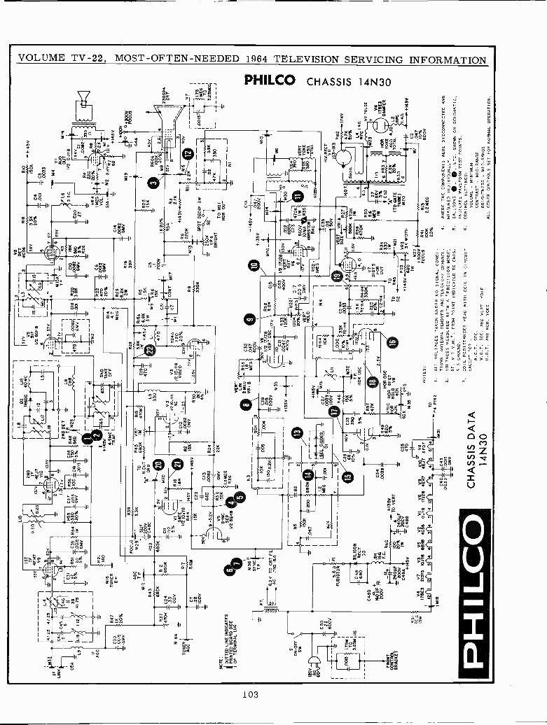
LIO
r1.
8R
18R
IO
341
.25
47.2
5IF
LIN
K
G5A1L9
IFA
GC
L13
46
135V
6 2
1,3
1ST
IF4E
H7
V9 9
500
4V
0.21
1
1 7Y
SR
51 -
C35
?R
54
1IL
ISny
L12
11.3
25I
T5%
ZZ
GM
V20
0015
4 IK
-=
T-J
.-1C¿
47
C300015
GM
V
MIR
A
TU
NE
RA
GC
C45 8
R47
IK 20%
R21 18
0M
16T
UN
ER-:
-8+ A
GC
T. P
.M
I2_a_
R43
R37
680K
470K
1C24
TÍÓ
ÓV
0.20
2ND
IF13
2V4E
J777
VIO
913
3V
n2 1,
3
R55
1I C
3733
0.0
015
20%
GM
V
1.2 R56
121
3R
48 T
NM
28C
XrV
YY
100
C41
-5%
#58
0 -
1003
31
D2
L16
IN60
C40
MC
Y::I
PLI
71.
5::
Lie
71
-
240
DE
T-
Le
rI-
f -
141
,L7,
+I4
5V11
63
4.54
01T
RA
PL--2
6311
TS
HO
AK
EO
FF
- 3
r--
I
3V
2
L3
-,2
4C86
115
15
I6n
I5
2_
lL
-4
-i`r
MIS
AM
1541
'1
I._
-._1
1)-1
-i
7'
I
I1
CIB
R20
.00
218
K
470
-t`'G
MV
2Í T
`.00
13.
8KT
BM
V 3
860
1
~J
11
LJ=
-_R
26B
N2
7 O
V
570 9I
F1/
2 60
48
3 57
V
RI4
4.7
ME
G
R12
BB
OK
NOTE:
DO
TT
ED
LIN
E IN
DIC
AT
ES
PR
INT
ED
BO
AR
D S
IDE
IO
F T
ER
MIN
AL
LUG
120V
6Ó/L
L
SIO
N -
OF
FS
W
C 5
0
Tó2002V
l=
1.75
MT
O3.
25M
FR
ON
TC
ON
TR
OL
BR
AC
KE
T
N8
R 6
120
11K
)W
C7
22
1100
8
F.
C48
D
16Ó
MF
+20
0V
1a+µi
C48
4 +N
3V
R17 56M
FO
CU
S =
M28+
54F
R23
ZC
49C
680K
CII 50
15%
GT
vi
1!2
ÍÓ.1
Y8
R39
3.3K
R44
1454
SYPCe__.
T.P
.
6.3V
TO
CR
T F
ILA
CP
INS
168
0F
US
ISS
.6T
OR
15K
5001
1
9 -5
.2V
VS
SY
NC
SE
P=
I/266
X8
rN
5
I4I
I501
(I
6B
OK
1.0
47T
2¿
I r--
-T
200
I
1.z
SI
161
-
I
2 M
EG
IEID
IOD
ES
J1
626
T.
DI
G
C22
680
R38
ISO
K
R45
TO
6806
H.O
UT
GR
ID
+14
5V
R15
470K
).
C13
.008
2R
24
GM
V22
K
1.8
ME
GR
36 N3 L---
---,
:82
2
5
L533
0
7-
V3
- 1/
2101
78N
I.C12
-.25
SR
23
1.00
82BK
- G
MV
1<30 2K
f5%
.005
90K
-43
004¡
IVM
35
--_J
+13
5V
CI9
4701
V3
1/2
10.1
18V
IDE
O
SIL
ICO
NR
EC
TD
3
.6N
1643
F.C
. R60
100
20% IW
+13
5V+
aT
O V
ER
T
,r24
0LLF
L20
0V=
C48
8
C34
.003
9.¡.
C25
470
V4
V7
V3
VS
V2
VI
V6
V9
yyI1
ppV
817
8E3
2101
510
JY8
WH
O 4
CS
6I0
.1Y
8I7
J28
4EX
74E
J78F
07
IM18
PHIL
CO
C40
C43
.003
3100
GM
V13
1.
VE
RY
ock
LIN
21A
EG
VR
IB
e
56K
=R
ISA
IW +
1450
6.9K
LIS
WM
9-
470
53V
720 8
-.25
V=
7
R53
1.8
ME
G
C33
I
3901
1..
5%
+14
5V
C 2
7-
1M15
.003
9K
IOV
R46
IIM
151(
5%
147K
R24
A22
09
20%
C32
.047
400V
C51
'T27
11
R22
470
20%
I C6
ZO
MIV
R29
8.2K 2W
R19
39K
R5
1.5K
VR
815
K
C5
_
V V
.3.
3K20
%04 T00
1C
3.0
033
890
-M4
VI
L6áj
TM
14
3.S
n1/
2 10
.118
ID
34V
C20
T27
C14
¡O
OB
GIA
V
°av H
.C
NT
MIT
BO
A
TV
I/2 7
JZ8
R32
VE
RT
OS
C _
178.
21<
R9
3309 C15 It
C21
.033
4.00
0047
T12
ÓK
400V
1-_
1001
1V
R51
C17
20%
0015
ÑÓ
LDI ON
O
I'
RI -
N4
I
I0K;
i10
0i2
a%M
32i
21-N
45,
T. P
.11
00H
ON
OS
C- ' 7
LII
411Y
.2.8
V
:5
4 --
--,
N4
33K
C3
-N4
82-N
4
f$$S
SO
I(3
6I1
,5K
1.5
IR3-
N4`
R4
-N41
-
_4,1
01
i330
K1
BI
^py
0y1
215
W.
1__.
,,zC
2-N
4 J
OU
T?R
34 330
TO
1W=
TO
1145
-'-M
2152
1
58V
1.12
6-:_
6
VR
4I M
EG
VO
L.
GIA
-L
R25 15K
1506
R4
'
220
20%
_ M
2 2.
8087 82
419
11'
4414
5V
ilk4
604
r!_1
00_
M81
OO
K2`
620
R3
660'
271(
R6
+14
5V
M 1
1f 2
20K S
PO
T D
EC
AY
SW
506S
2V
R6
BR
IGH
TT
O M
21H
ON
OU
T
CIA
+14
5V ..
+135V
200V
16.2
4
4
2CR
TP4
31
M5
NO
VR
II2.
2K12
F -
--__
N7
--tt
_ _,
- --
-II A
0151
SM
É6
I
47K
2T
330
3IT
1T32
5ME
G¡
2.J
N1
1/2
17.1
26va
ss13
OU
T
UV
6
_
-170
IMÉ
6
OV
9
600V
4706
S60
V1W
10M
AR
35V
AR
IS70
NR
40
61/'
5.9
iC39 .05
I 50V
9
MIO
,
390
VE
RT
10 0 $2
9ÓY
OK
E
450T
0E+
135V
R49
620
5%
1M31
CH
AS
SIS
DA
TA
14N
30
HO
N O
SC
VR
I CH
OR
BF
07M
OR
HO
LD V
C40
K
60K
VR
5M
35
NO
TE
S:
VE
RT
VBIA
37,1
1o
115V
500K
470
K
470K
IIW
+14
5V. R
0i4
v31
13W
IDT
H
1W92
74+
300V
1F
OC
US
'
TO
P4
PIN
2I.
ALL
VO
LTA
GE
S T
AK
EN
UN
DE
R N
O S
IGN
AL
CO
ND
IT
ION
S. A
NT
EN
NA
RE
MO
VE
D A
ND
TU
NE
R O
FF
CH
AN
NE
L.2.
VO
LTA
GE
S M
EA
SU
RE
D W
ITH
A "
PR
EC
ISIO
N M
OD
EL
88, V
. T.V
.M."
. FR
OM
PO
INT
IND
ICA
TE
D T
O C
HA
S-
SIS
GR
OU
ND
.3.
CO
IL R
ES
IST
AN
CE
S R
EA
D W
ITH
CO
ILIN
CIR
CU
ITE
XC
EP
T F
OR
A.0
.7. S
EC
.V
.O.T
. SE
C. A
ND
VE
RT
. YO
KE
H.O
.T. A
ND
HO
R. Y
OK
E
R50
5.6
ME
GIW
R41
100K
20%
11L0
.T.
8115
1,V 5% C52
"A'
(TO
GA
TE
TU
CE
)42
0
NJ
R13
2.2
ME
G
H.V
.RE
CT
VII 3-16
3R
62 M17
KV
4.76
PO
%
RF
C 1
.411
NV
PU
LSE
C2
.047 10
%60
0V
4.W
HE
RE
TH
E C
OM
PO
NE
NT
S W
ER
E D
ISC
ON
NE
CT
ED
AN
DM
EA
SU
RE
DINDIVIDUALLY.
5.
BALLOONS O . .
ET
C. S
HO
WN
ON
SC
HE
MA
TIC
.IN
DIC
AT
E W
AV
EF
OR
M T
ES
T P
OIN
TS
.6.
CO
NT
RO
L S
ET
TIN
GS
:V
OLU
ME
.M
INIM
UM
CO
NT
RA
ST
MID
-R
AN
GE
BR
IGH
TN
ES
S M
IDR
AN
GE
ALL
OT
HE
R C
ON
TR
OLS
SE
T F
OR
NO
RM
AL
OP
ER
AT
ION
.
Z (A) o
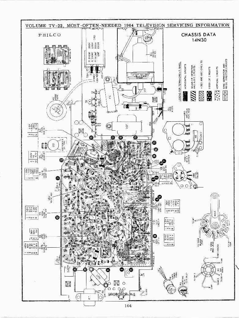
O IA
2 3 6 8 9
145V
92V
0.9V
2.8V
131
V13
4 V
C.R
I FIL
(\
00
CLI
OA
IF M
OD
ULE
A'
11P T
UN
ER
PO
WE
RC
AB
LE
P3 SH
OR
TIN
GP
LUG
(VH
F. O
NLY
)
TO
84-
2
TO
B4-
5F
PIT
O 8
4-4
CA
BLE
T
3 7 8
VIO
4EJ7
2 N
O V
.IF,
1.2V
1.2
V13
2 V
133
V
V5
6GH
8S
OU
ND
SF
.,S
YN
C. S
EP
TO
M7
VR
2N
OIS
E A
DJ.
IF M
OD
ULE
7JZ
8V
ER
T. O
SC
VE
RT
. OU
TU
T.
4 6 7 e 10
30V
130V
-17V
-17V
I35V
-17
V
V3
IOJY
BV
IDE
O O
UT
.,N
OIS
E IN
V
VE
RT
.V
ER
T.
HO
RS
IZE
v L
INA
UX
2 3 6 7 8
90V
0.1
V2.
8V11
0-7
.5V
2.8V
V8
142V
HV
142V V4-
--R69
DA
MP
ER
R65
CO
MP
ON
EN
TS
ON
YO
KE
3 5 7 9
115V
-16.
5V11
5V-
16.5
V
V7
21G
Y5
MO
R. O
UT
.
P2
AN
OD
ELE
AD
ifl1
1111
1111
1101
1ih
yi''t
llül'I
m
1111
1111
1111
1111
111
I.F. M
OO
ULE
"A
55V
). (
)I19
.®
©7
c :
i_1a
eV
132-
-, -
--1i
-r--
(1-
e;
i74
'I3
5V 8
A11
i 2-'
"III
145V
/Ial
.}1
1 o11C
L7V
íG10
1::;
B3
`//
I/,
tj4
.'°..
Ñt_
U`
LoB
tj'
iE.N
,G
9A.
1413 I
I111
11N
IIII
Ii
I.F M
OD
ULE
"B
8FO
7N
OR
. OS
C
VR
4U
PT
ON
,"V
OLU
ME
VR
6B
RIG
HT
,C
ON
TR
AS
T CL6
50V
-.25
V3
57V
2-
7.5V
558
V4
657
V3
53V
6 769
V OV
7 91.
0V-5
.2V
7 8 9
-25V 72
V53
V
7 10
VI
V2
i0.1
184C
S6
AU
DIO
OU
T.,
SO
UN
DG
AT
EDET.
V9
OE
H7
1ST
. V.I.
F.
1 3 7 8
0.4V
0.4V
135
V50
V
TO
YO
KE
BLA
CK
LEA
D
TO
YO
KE
RE
D L
EA
D
TO
M27
,1.1
29,0
40
VR
3WIDTH
VR
5H
ON
. HO
LD,
VE
RT
. HO
LD
-171
=L.C.
n 24
0MF
d 24
0MF
160M
F5M
F
LEG
EN
D F
OR
PE
RM
A-C
IRC
UIT
PA
NE
L
HO
RIZ
ON
TA
L C
IRC
UIT
S
SO
UN
D I.
F. D
ET
EC
TO
RA
ND
AU
DIO
CIR
CU
ITS
i"i F1. II
I
VID
EO
AN
D A
GC
CIR
CU
ITS
VID
EO
I.F
. CIR
CU
ITS
VE
RT
ICA
L C
IRC
UIT
S
SY
NC
SE
PA
RA
TO
R A
ND
NO
ISE
INV
ER
TE
R C
IRC
UIT
S
VII
IG3/IK3
HV
RE
C.
200V
200V
200
V20
0V
o o
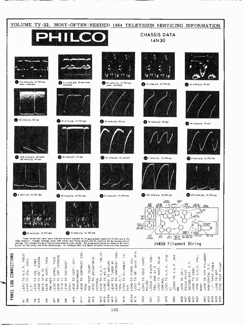
PANEL LUG CONNECTIONS
MI
LEAD TO A.O.T.
(RED)
M2
LEAD TO VOL. CONT.
C.T.
M4
LEAD TO VOL. CONT.
M5
LEAD TO CRT SCREEN
GRID (PIN 3)
M6
LEAD TO VERT. YOKE
AND M24
M7
LEAD TO HORZ. YOKE
MS
LEAD TO CRT CATHODE
(PIN 7)
M9
LEAD TO CONTRAST
CONT.
MIO
LEAD TO VERT. OUT.
TRANSFORMER
MI1
LEAD TO CONTRAST CON-
TROL
M12
AGC TEST POINT
M13
LEAD TO BRIGHTNESS
CONTROL
M14
LEAD TO A.O.T.
(BLUE)
M15
LEAD TO B2.3
M15A
JUMPER TO GROUND
M16
LEAD TO TUNER B+
MI7
LEAD TO CONTRAST CON-
TROL C.T.
M18
LEAD TO FILAMENT IN-
PUT
MISA
LEAD TO TUNER AGC
M19
LEAD TO CRT GRID (PIN
2.
6)
M20
LEAD TO YOKE (GATE
PULSE)
M21
LEADS TO WIDTH CON.
TROL AND S1-2
M22
LEAD TO VERT. HOLD
CONTROL
M23
LEAD TO H.O.T.
(PIN
5)
M24
LEADS TO V.O.T. AND
M6
M26
LEAD TO B2.1
M27
FOCUS POINT
M28
SECOND DET. T.P.
M29
LEAD TO C48C
M30
LEAD TO V.O.T. PRI-
MARY
M31
LEAD TO CRT FILAMENT
M32
HORIZONTAL T.P.
M33
I.F INPUT CABLE
M35
LEAD TO M26
M36
SYNC TEST POINT
e o e o
f
e e e
o
e64,
wt o o P; o
1
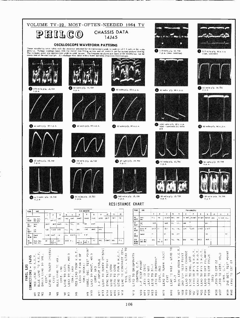
VOLUME TV -22, MOST -OFTEN -NEEDED 1964 TV
P1122t0 CHASSIS DATA
OSCILLOSCOPE WAVEFORM PATTERNSThese waveforms were taken with the receiver adjusted for an approximate peak -to -peak out of 2.5 volts at the videodetector. Voltage readings taken with the raster just filling screen and all controls set for normal picture viewing.The voltages given are approximate peak -to -peak values. The frequencies shown are those of the waveforms, not thesweep rate of the oscilloscope. All readings were taken with a Model ES -550B Precision Oscilloscope.
© 100 volts pip, 15, 750
77(0 45 volts p/p, 60 C.p.s.
® 15 volts pip, 15, 750
0 4.5 volts p/p. 15,750
0 60 volts p/p, 15, 750
O80 volts pip, 60 c.o.s.
18 volts pip, 15,750
(r/® 91 volts pip, 15,750
© 60 volts pip, 60 c. p. s.
77(0 45 volts pip, 60 c.p. s.
® 20 volts pip, 15, 750
0 560 volts p/p. 15,750
RESISTANCE CHART
TUBE USE PIN MOM
I 2 3 4 5 8 7 6 9 10 11 12
VI
6JZ63ua. Out.eat Bete
FIL.MEG 0
1000 11611 I Ito 2006. tomo ova 3900 2860 I ovo FIL.
V2
6Fí7No,,tot.
286n 1.800 2200 FIL. FIL. 396 906 axon
V3
6E117
letvIF
220 31060 ttn FIL. FIL. ON0. 1Icn 306. GNo.
V4
6CS6Beene[live
5.50 5600 FIL, FIL. 00000 116 3. Sn
V5
6Jz6Vert. Oea,Vert. Bit.
on 2.65EG n
INF. 1060 FIL. 1.3MEG n
1.3MEG n
llln Ott. 25060 (510. FIL.
O2.5 volts pip, 15, 750c. p. s. (max. contrast)
0 43 volts pip, 60 c.p.s.
~Ma 0111~~M.
__ 3 . I.,__.
® 2.5 volts pip, 60 c. p. s.(max. contrast)
O43 volts pip, 15, 750
0 1000 volts p/p, 60 c.p. s.total - sawtooth 220 volts ® 62 volts pip, 60 0.P. a.p/P
® 50 volts pip, 15, 750
® 36 volts pip, 15.750
50 volts pip, 15,750
® 20 volts pip, 15,750
TUBE USE PIN NUMBERS
I 2 3 4 5 6 7 8 9 10 I I 12
V6
66Y5Vu,t.
Get.FIL. INF. I0.S60 GNO, INF. 10.560 10.50 I0.560 60060 GNO. 10.500 FIL.
876EJ7
2navi
loon 100n FIL. FIL. Ono eao,
V8
6G88Sound IF
B N.1.3760 00 1360 FIL. FIL. 1360 2200 3.96. 2.6,40
V9
68E38.80. FIL. 00 I. INF. 106 FIL.
VIS6138/66118
VIa. Out.W. Sen.
al0. 1.7MEG n
lz6n FIL. FIL. Q10. 900 296. IsNn
F- co 0 LL. O O 1nin F- J J 0 0 a J7 0 0 + J O O +7 O > O 2 > co F- 2 W -- 1.-2- . a > cr.) J Z- < O . E Z F- LaJ m -
CO O F- W O a F- O- W F- N a W O= I O F- Z F- O N OC O= a Y tY 0 U Z aJ F- O 7 Z tn W Z W U O ZCe) p a F- O W U> w O O U 2 W F-J Z O a lLi < O F- In L/17W O a W J O W O O' a 0 0 aZ - W J F- F- 1--11-1- 1-/- W O W I- F- Z
Q F- J Z Z co Z Z J a Y Z -d U W W O O^ LL1 0 0 0 0 W O N O Ow O J w U a U 7 U a a U O J>- K a U LiZ W J CC W J W W W owZ cc co CD J CO J J X S J -C=7U
F-
O
2
O O ZLn -U aó óO Oa aW WJ J
O O
~ 1-F-W I- I- F- Z 1-
0 V) U 0 O F- O W O Z< (i) U a Z O 0002 to JW W F- a W >- 2 0 a 7 O OJ Z t/t - J O F- ^ 2 2 2 J U 2 a
F- F- a f a a U - O N -LS
F- Z O U 1n<0 M W W L.0 F- 0U - U r F- W IX F- F- En
- U O N to , Z O Z ro W V7 F- O Z Z Z F- F- F- tY F- W F-F- CC a tn N - Z J N Z X W . F- CC
CO J U m U W F- I OF -0(O000000- 00 0> U 0U O F- a .O 00(1)0000 o O 20200000000 00 F- oJ m F- F- W F- F- F- F- F- F- F- F- r J - F- F- F- F- F- F- F- O F- F- F- W 1-O N Z F- Z Cl > - Z O005700 000000 - O^ W O O p O O O O tL 0 0 0 0F- U a U LL a a a a U a U a m 7 0 a a a a a a a cº a a U o a
W .20202020 W W J Z W W W W W W Lai W W Z WJ - J J J J J J Q) N J J J J J J J ..J J N J
Cl 0,1 V tn tO N 03 a) O^ N (.) V tf) tO t` (3) O- N Cr") O If) tD N CO a) - - NNNNN N N N N N(v) (*) o) 0') m M (r) Ir) M Q
7 f f I f E 7 7 2 2 2 2 f 7 2 7o -(1') Q tl) tO t` co
106
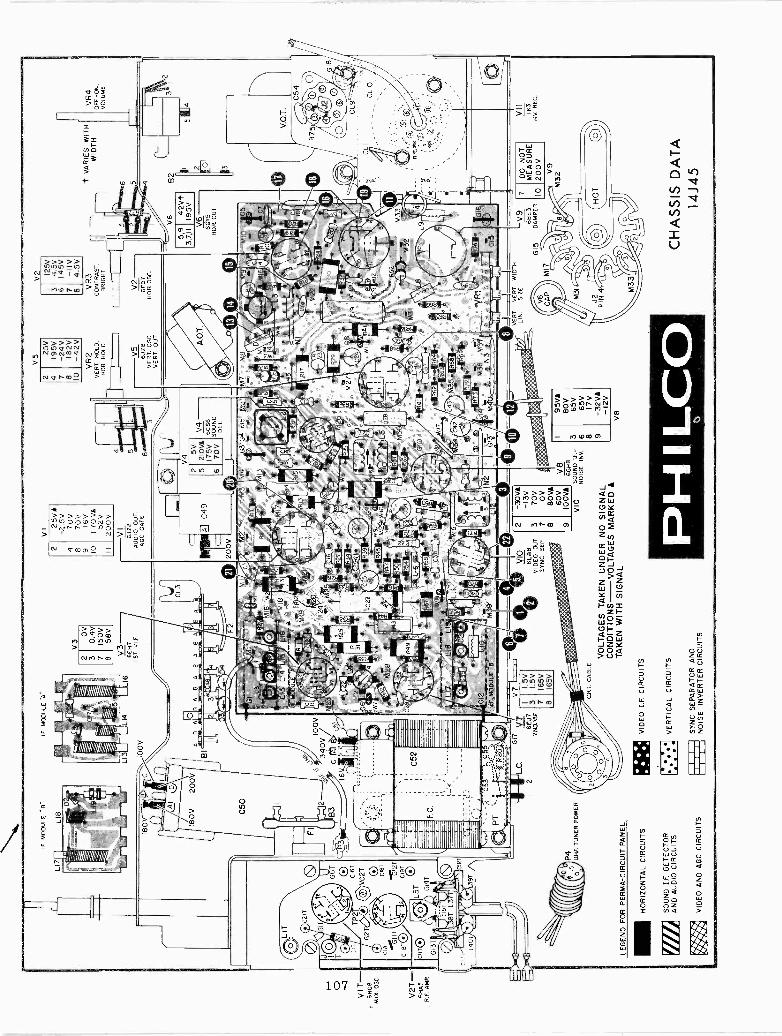
VIT-
6HG
8M
IX O
SC
.
V2T
-6H
55R
.F. A
MP
.
i
TP
2
G2T
C/v
L5T G
14TC
16T
C2T C
IBT
.lJl2
TC
19T
IM
OD
ULE
"B
"
LIB
LI9
P4
UH
F. T
UN
ER
PO
WE
R
LEG
EN
D F
OR
PE
RM
A-C
IRC
UIT
PA
NE
L
HO
RIZ
ON
TA
L C
IRC
UIT
S
SO
UN
D I.
F. D
ET
EC
TO
RA
ND
AU
DIO
CIR
CU
ITS
111
r::1
,V
IDE
O A
ND
AG
C C
IRC
UIT
S
I.F. M
OD
ULE
..A
.
CjI
00V
100V
340V
/
. .
WM
MW
I
OV
0.4V
150V
58V
V3
6EH
7IS
T V
IE.
3 M28
LI7
_LIS
LI
íg1=
+ 0
D.<
i
1.5V
I.5 V
165V
165V
V1 25
VA
-2.5
V17
0V17
0V 16V
170
VA
152V
200V
VI
6.17
8A
UD
IOOUT.
AD
C G
AT
E
916
NL
M8
M19
FI :
M20
M4
M25
© vo
6L88
VID
EO
OUT.-
SY
NC
. SE
P
2 3 7 8 9
-30V
A-1
3V70
VO
V80
V1
60V
1o0V
A
VIO
5V21
0VA
175V
70V
V8
6588
SO
UN
D IF
. -N
OIS
E IN
V.
CR
T. C
AB
LE
VO
LTA
GE
S T
AK
EN
UN
DE
R N
O S
IGN
AL
CO
ND
ITIO
NS
VO
LTA
GE
S M
AR
KE
DA
TA
KE
N W
ITH
SIG
NA
L
VID
EO
I.F
. CIR
CU
ITS
VE
RT
ICA
L C
IRC
UIT
S
SY
NC
SE
PA
RA
TO
R A
ND
NO
ISE
INV
ER
TE
R C
IRC
UIT
S
V4
6C56
SO
UN
DS
ET
,
3 6 e 9
95V
A80
V65
V65
V17
V-3
2VA
- 12
V
V8
25V
195V
-24V
182V
-42V
V5
6JZ
8V
ER
T. O
SC
.V
ER
T. O
UT
.
125V
4.5V
145V
-II
V4.
5V
V2
6F07
HO
R O
SC
.
V6
9-4
ZV
íII
195V
V6
6GY
5H
OR
OU
T.
MIO
JG
5
lda
jC7
M 3
3M
321
:M31
')
VE
RT
V E
RT
LIN
.S
IZE
RH
IÇC
O
V9
68E
3G
15D
AM
PE
R
+ V
AR
IES
WIT
HW
IDT
H
7 10
DO
NO
TM
EA
SU
RE
200V V9
M32
CH
AS
SIS
DA
TA
14J4
5
VR
4O
FF
-O
N,
VO
LUM
E
CL
10
VII IK3
M.V
. RE
C.
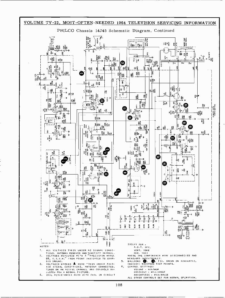
VOLUME TV -22, MOST -OFTEN -NEEDED 1964 TELEVISION SERVICING INFORMATION
PHILCO Chassis 14J45 Schematic Diagram, Continued
9
t {I82(=-{o"
Iz$
L
NOTES:
1. ALL VOLTAGES TAKEN UNDER NO SIGNAL CONDI-TIONS. ANTENNA REMOVED AND TUNER OFF CHANNEL.
2. VOLTAGES MEASURED WITH A "PRECISION MODEL88, V.T.V.M." FROM POINT INDICATED TO CHAS-SIS GROUND.
3. VOLTAGES MARKED A WERE TAKEN UNDER AVER-AGE SIGNAL CONDITIONS, ANTENNA CONNECTED.TUNER ON AN ACTIVE CHANNEL AND CONTROLS AD-JUSTED FOR A NORMAL PICTURE.
4. COIL RESISTANCES READ WITH COIL IN CIRCUIT
oR
>Y= I,1__ g`s
sHu11;
YÉ-In YIi
I -m
.1{u
11-® --fe
L
«
J
EXCEPT FORA.O.T.
VERT. YOKEHOR. YOKE
WHERE THE COMPONENTS WERE DISCONNECTED ANDMEASURED INDIVIDUALLY.
5. BALLOONS O. O. ETC. SHOWN ON SCHEMATIC.INDICATE WAVEFORM TEST POINTS.
6. CONTROL SETTINGS:VOLUME - MINIMUMCONTRAST - MID -RANGEBRIGHTNESS MID -RANGE
ALL OTHER CONTROLS SET FOR NORMAL OPERATION.
SEC.
tai
-
108
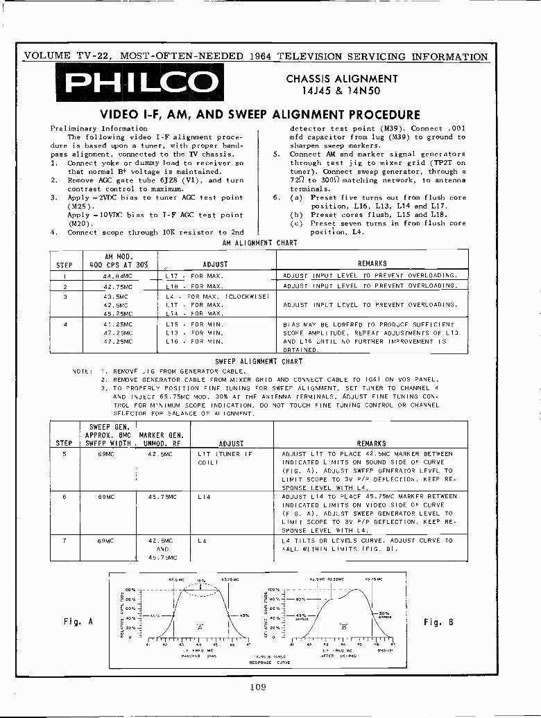
VOLUME TV -22, MOST -OFTEN -NEEDED 1964 TELEVISION SERVICING INFORMATION
PH I LCDCÑASSS
VIDEO I -F, AM, AND SWEEPPreliminary Information
The following video I -F alignment proce-dure is based upon a tuner, with proper band-pass alignment, connected to the TV chassis.1. Connect yoke or dummy load to receiver so
that normal B+ voltage is maintained.2. Remove AGC gate tube 6JZ8 (V1), and turn
contrast control to maximum.3. Apply - 2VDC bias to tuner AGC test point
(M25).Apply -10VDC bias to I -F AGC test point(M20).
4. Connect scope through 10K resistor to 2nd
AM ALIGNMENT
SSISALIGNMENT
N M
ALIGNMENT PROCEDUREdetector test point (M39). Connect .001mfd capacitor from lug (M39) to ground tosharpen sweep markers.
5. Connect AM and marker signal generatorsthrough test jig to mixer grid (TP2T ontuner). Connect sweep generator, through a7252 to 300() matching network, to antennaterminals.
6. (a) Preset five turns out from flush coreposition, L16, L13, L14 and L17.
(b) Preset cores flush, L15 and L18.(c) Preset seven turns in from flush core
position, L4.
CHART
STEP
AM MOD.
400 CPS AT 30% ADJUST REMARKS
1 44.84MC L17 - FOR MAX. ADJUST INPUT LEVEL TO PREVENT OVERLOADING.
2 42.75MC L18 - FOR MAX. ADJUST INPUT LEVEL TO PREVENT OVERLOADING.
3 43.5MC
42.5MC45.25MC
L4 - FOR MAX. (CLOCKWISE)
LIT - FOR MAX.
L14 - FOR MAX.
ADJUST INPUT LEVEL TO PREVENT OVERLOADING.
4 41.25MC47.25MC47.25MC
L15 - FOR MIN.
L13 - FOR MIN.
L16 - FOR MIN.
BIAS MAY BE LOWERED TO PRODUCE SUFFICIENTSCOPE AMPLITUDE. REPEAT ADJUSTMENTS OF L13AND L16 UNTIL NO FURTHER IMPROVEMENT ISOBTAINED.
SWEEP ALIGNMENT CHARTNOTE: I. REMOVE JIG FROM GENERATOR CABLE.
2. REMOVE GENERATOR CABLE FROM MIXER GRID AND CONNECT CABLE TO (G6) ON VOS PANEL.3. TO PROPERLY POSITION FINE TUNING FOR SWEEP ALIGNMENT, SET TUNER TO CHANNEL 4
AND INJECT 65.75MC MOD. 30% AT THE ANTENNA TERMINALS. ADJUST FINE TUNING CON-TROL FOR MINIMUM SCOPE INDICATION. DO NOT TOUCH FINE TUNING CONTROL OR CHANNELSELECTOR FOR BALANCE OF ALIGNMENT.
STEP
SWEEP GEN.APPROX. 8MCSWEEP WIDTH
MARKER GEN.UNMOD. RF ADJUST REMARKS
5 69MC 42.5MC LIT (TUNER IFCOIL)
ADJUST LIT TO PLACE 42.5MC MARKER BETWEENINDICATED LIMITS ON SOUND SIDE OF CURVE(FIG. A). ADJUST SWEEP GENERATOR LEVEL TOLIMIT SCOPE TO 3V P/P DEFLECTION. KEEP RE-SPONSE LEVEL WITH L4.
6 69MC 45.75MC L14 ADJUST LI4 TO PLACE 45.75MC MARKER BETWEENINDICATED LIMITS ON VIDEO SIDE OF CURVE(FIG. A). ADJUST SWEEP GENERATOR LEVEL TOLIMIT SCOPE TO 3V P/P DEFLECTION. KEEP RE-SPONSE LEVEL WITH L4.
7 69MC 42.5MCAND
45.75MC
L4 L4 TILTS OR LEVELS CURVE. ADJUST CURVE TOFALL WITHIN LIMITS (FIG. B).
42.5
=%7MC 159/. 45.75 MC 42.'S
100%
MC 43
--32M 45.75
- - -
MC
Fig' A
¡ 80 % -
W
20% -
a
-0554
? 80 % -
-45% 40 °w-
20% -1
- 80 %
-AU%-o,
-50 roPO %
Fig. .B1
1' 11 11`Illli'I'l'I'I41 42 43 44 45 46 41 41 42 43 44 45 96 47
I FRED MC I FREO MC SA61-93,
PADDING BIAS rajas B 141450 AFTER DE -PAD
RESPONSE CURVE
109
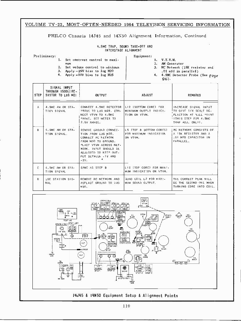
VOLUME TV -22, MOST -OFTEN -NEEDED 1964 TELEVISION SERVICING INFORMATION
PHILCO Chassis 14J45 and 14N50
4.5MC TRAP, SOUNDINTERSTAGE ALIGNMENT
Preliminary:1. Set contrast control to maxi-
mum2. Set volume control to minimum3. Apply -25V bias to lug M204. Apply -10V bias to lug M25
Alignment Information, Continued
TAKE -OFF AND
Equipment:1. V.T.V.M.2. AM Generator3. RC Network (15K resistor and
.01 mfd in parallel)4. 4.5MC Detector Probe (See Page
96).
STEP
SIGNAL INPUTTHROUGH (500.(2 RE -
SISTOR TO LUG M21 OUTPUT ADJUST REMARKS
A 4.5MC AM OR STA.TION SIGNAL
CONNECT 4.5MC DETECTORPROBE TO LUG M29. CON-NECT VTVM TO 4.9MCPROBE. SET METER TO2.5V RANGE.
L12 (BOTTOM CORE) FORMINIMUM OUTPUT INDICA.TION ON VTVM.
INCREASE SIGNAL INPUTTO GIVE 1/4 SCALE DE-FLECTION AT NULL POINT(THIS STEP FOR 4.5MCTRAP ADJ. ONLY).
B 4.5MC AM OR STA-
TION SIGNAL.REMOVE GROUND CONNEC-TION FROM LUG M30.CONNECT RC NETWORKFROM M30 TO GROUND.PLACE VTVM ACROSS NET-WORK. INPUT SHOULD BEADJUSTED TO KEEP OUT-PUT BETWEEN -1V AND-2V.
d
L5 (TOP & BOTTOM CORES)FOR MAXIMUM INDICATIONON VTVM.
RC NETWORK CONSISTS OFA 15K RESISTOR AND A.01 MFD CAPACITOR INPARALLEL.
C 4.5MC AM OR STA-TION SIGNAL
SAME AS STEP B,MUM
L12 (TOP CORE) FOR MAXI-INDICATION ON VTVM.
D USE STATION SIG-NAL
REMOVE RC NETWORK ANDREPLACE GROUND TO LUGM30.
QUAD COIL L2 FOR MAXI.MUM SOUND OUTPUT.
THE CORRECT PEAK WILLBE THE SECOND ONE WHENTURNING CORE INTO COIL.
STEPS 3 B 6 alSTEP 4 45.75MC STEP 4 STEP 4 VT.VM.
LI3 MARKER LI5 L16
GEN
47.25MCTRAP
L1445.25MC
41.25MCTRAP
47.25MCTRAP \\BE .D '----' -'-1 STEPAT00 \TO inn--_/
tez A *APPLY STEP-25VDC V1
6JZB-
,F(A)STEPS
6E07t OO OO C APPLY 8)TEST
STEP 3B5STEPS i TO 7STEP ITD7
M20QUA
LIT42.5 MC
STEP OHOV3
/OAM GEN
42.5 MCMARKER
6EH7 / V6/ 6GY5
O G6,STEPS IT07
AppLyRolfly V4 /
STEOPS 10. 43%C 2V'CSTEPS --1 TO4
------- =- 42.5 MCAPPLY
I-IDV OC
LS TOP /® 4585MCMARKERS STEPS ATOD M29 BOTTOM
q.TTO 30I¿Y*
TP2T
STEP 3B7V7
VIM6EJT6LB8
V56J28
.01 151(
SWEEPGEN ® O
M39 ooIII
VB6GH8 V9
6BE3D
SCOPE
iIAfAfA
STEPS ITO 7 LI2 LI2O¿ÉN
LI]44.8MC
L1842.75MC U '0?.^"11
(BOTTOM_CORE)
(TOPCORE)
STEP I STEP 2 SCOPE 4.5MC 4.5MCSTEP A STEP C
wormTO
AM GEN STEPS I T0°71TO
SWEEPGEN
I4J45 & I4N50 Equipment Setup & Alignment Points
110
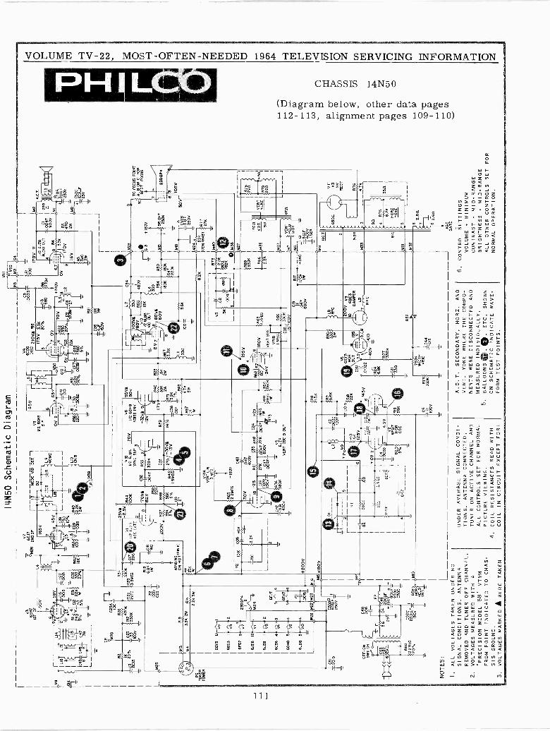
I4N50 Schematic Diagram
l
T.P
. M20
V3
6EX
T1S
T IF C
25A
1 =
100
R2
R26
N %33
Tóó
lsTDV
RI2
47oK
330K
MS
M3
04
V7
_--
T.P
.B
EJ7
-SO
SE
ND
IFL4,-
-
C22 T 20%
186
I1.
516
606
VID
. DE
T. -
I
165V
t^}i'
iD
42I
4.17
;I
I
,ñ1
5-5
LIB
;
e 16
5Vr
L18
'1
40M
c
3
TgC
3y L
1.
C29
R49
.001S
tizW
K
1111
k,M
39
10 H.8
65V
V8
1/2
6GH
8S
IF )V 2
3 65
V`
T.0
1
LS
6C06
DIS
C 2
10V
a R
IB17
5V35
íK5
20%
CS
.003
3^
103
416
S8éD
.270
6
7 O
V
6 43
2270
V
1:51
,705
4°V
qg
20%
- C9
n+ L
22Í Oase
}yia
Z2T
T5%
R21
6,0
170V
I1/
2
VI
61,2
8A
UD
IOC
UT
I C
I
280r
lll_
4A
047
n
8R
4M
I`
OV
67__
_3.
3K.T
C50
8
170V
}473
0I
T50
V2W
-0M
21 - +l Ó
ÓLL
FT
25V
1
-
V
1390
R34
33R
3933
00A
EG
3.3M
EG
TU
NE
RP
OW
ER
25
1
M13
RI5
33K
2W
RI4
2.1
.3
6075
12-(
1-
613E
314
-r4-
G_
6F07
5 Z
i23
50P
4
A8
6/28
12V
i i M
34?
6J28
I-V
5I2
6CS
64
3
6GH
8
61.8
8
S4
5-"-
44V
2 5
6E17
4
6EH
75-
ti4
L___
6626
0 22
BIS
6.86 IW
220
20
WIN
DIN
GON
HO
(MN
61
.T.
R7
276
IW
VI
I/O 6
1,28
AG
C G
AT
E
200V
-25V
A-2
.5V
R44
VIO
IOO
KI/2
6L8
870
V
2SYNC
SEP///3---
- Ip
_170
VA
35
5 .2
Y32
V00
47 3
306
R27
6411
(H_
70/
5%B
%j.5
112/
2[ _
133Ó
V6
C16
A
1000
5O
K15
V8
95V
61/
2 65
118
1306
NO
ISE
INV
/ 1
-326
69-1
26
R59
1 E
817
6
C2U
U6F
F
II
Z15
0Y3W
R40
R25
33K
1.56
371
2W2W
-C38
í3.9
KT
ool
R57
IK IW
5%
.13
4.7K
5W
¡- -
L7C
34
I
-
I
,-)P
,'%OV
3 eb,0
14Ó
0V1
Li/2
26lB
e15
6
VID
OU
T
0 V
780
6660
V7
i3.3
R6
K
.1LI
I33
010
0- T5.
6K
M29
L6 330 R54
R50
I80K
IBM
1R47
2201
4M
S
813
+18
0V
166
I
BR
2506
IGH
T7C
i
VR
IAV
ER
T L
W3
ME
G
R63
H1B
OV
2.2M
EG
C43
30V
047
L
5'15
018
.26
CII
OÓIS
+200V
OF
F -
ON
SW
ITC
H
NOTES:
= FI 5.
6 D3
M23
MI6
250V
FDT
C48
005
-+1-
-2
+18
0 V
TRIO--
p4 C49UFti
+ 1
6ÓV
+B
OLL
F-
T «
DT
CS
OC
li
200LLF
1506
Tl
-
R80
2.2M
EG
20 A
2J
N
T01
8
42 400V
IÑ
11. r--2
+
OK
D
<1(
.110
H
MO
R
HOL-
1.
ALL VOLTAGES TAKEN UNDER NO
SIGNAL CONDITIONS. ANTENNA
REMOVED AND TUNER OFF CHANNEL.
2.
VOLTAGES MEASURED WITH A
PRECISION MODEL 88' VTVM
FROM POINT INDICATED TO CHAS-
SIS GROUND.
3. VOLTAGES MARKED
AWERE TAKEN
M J
400V
10 -
25
R6C
I7
ppF
q R
48
I111
2zW
97`6
0 V
22K
R29
0ÍW
R23
}636
==
V5
-ti1
80K
6J28
VE
RT
OS
C 8
OU
T
641
íR64
1 E
wJ
67=
100/
-24V
1936
i
N3
I
156
L -
130V
SqM
EG
VE
RT
SIZ
E
VR
IBM
EG
R66
TC
3B,
3375
K
VI I
FI
..- 1
250V
1M24 50
5lI
8.26
TT
CO
NT
RA
ST
}R
77I
27N
-I II
673
M40
=
II$
IV
225
0047
TK
(I
2Ñ3_
- i2
- J
b
M 3
6=
1M27
33Ó
KI
170n
668
M3S
V.O
T.
2.T
ek-O
9n
N
'1-1
,2H
8268
06.0
611 I7
OV
2
C24
131:
T.P
.OM
9
2ME
CI
}IS
OK
8264
.I
-ª04
_ 51
}_-
IC2
Tgú
T00
1
-Í1V
4.5V
I8
1003
9
662 07
HO
RO
SC
UNDER AVERAGE SIGNAL CONDI-
TIONS. ANTENNA CONNECTED.
TUNER. ON ACTIVE CHANNEL AND
ALL CONTROLS SET FOR NORMAL
PICTURE VIEWING.
4.
COIL RESISTANCES READ WITH
COIL IN CIRCUIT EXCEPT FOR:
619
56K
C6
TIO
OV
1.56 6K 226 145v
VS
6005
XO
RO
UT
C2o
.002
2-4
0V 4
J0R
246.
86
5,9
R
047
R7
_M
6
IZW
N+
340
+S
LLF
600V
I
TC
SÉ
ÁMB
¡ ac
2
TO
FO
CU
S P
OIN
TIK
} A
, B O
R C
FO
RB
ES
T F
OC
US
74
23D
0P4
6 3 105V
50V-
VE
RT
YO
KE
22Ó
450
R79
220
87n
195
í333
ÓK
7506
WID
TH
R74
:V
R C
ÓÍB
T
3,7,
200V V9
068
E3
DA
MP
ER
R52
R F
C
A.O.T. SECONDARY, HORZ. AND
VERT. YOKE WHERE THE COMPO-
NENTS WERE DISCONNECTED AND
MEASURED INDIVIDUALLY.
5.
BALLOONS O . ©. ETC. SHOWN
ON SCHEMATIC INDICATE WAVE-
FORM TEST POINTS.
9.5n
33
n
31
85on
3 923
VII
163
RV
RE
CT
R7
4R
75I
5
1861
#062
IY
OK
E I
M32
1,e
2 81
F 1
16 3
.621
AG
CG
AT
E
3521
I
6.
CONTROL SETTINGS
VOLUME
-MINIMUM
CONTRAST -
MID -RANGE
BRIGHTNESS
-MID -RANGE
ALL OTHER CONTROLS SET FOR
NORMAL OPERATION.
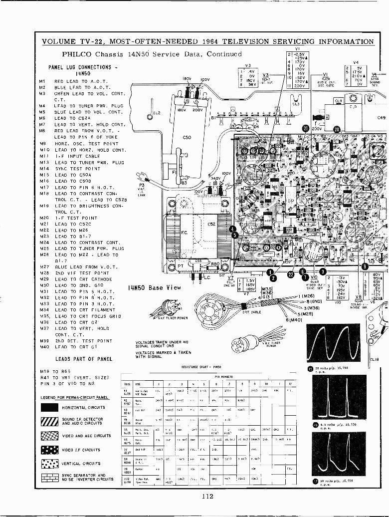
VOLUME TV -22, MOST -OFTEN -NEEDED 1964 TELEVISION
PHILCO Chassis 14N50 Service Data, Continued
PANEL LUG CONNECTIONS -
14N50
MI RED LEAD TO A.O.T.M2 BLUE LEAD TO A.O.T.M3 GREEN LEAD TO VOL. CONT.
C.T.
M4 LEAD TO TUNER PWR. PLUGM5 BLUE LEAD TO VOL. CONT.M6 LEAD TO C52AM7 LEAD TO VERT. HOLD CONT.M8 RED LEAD FROM V.O.T. -
LEAD TO PIN 6 OF YOKEM9 HORZ. OSC. TEST POINTM10 LEAD TO HORZ. HOLD CONT.MII I -F INPUT CABLE
MI3 LEAD TO TUNER PWR. PLUGMI4 SYNC TEST POINTM15 LEAD TO C50AM16 LEAD TO C5ODM17 LEAD TO PIN 6 H.O.T.M18 LEAD TO CONTRAST CON-
TROL C.T. - LEAD TO C528M19 LEAD TO BRIGHTNESS CON-
TROL C.T.I.F TEST POINTLEAD TO C52CLEAD TO M26
M20
M21
M22M23M24
M25
M26
LEAD TO B1-7LEAD TO CONTRAST CONT.LEAD TO TUNER PWR. PLUGLEAD TO M22 . LEAD TOB1.7
M27 BLUE LEAD FROM V.O.T.M28 2ND VIF TEST POINTM29 LEAD TO CRT CATHODEM30 LEAD TO GND. G10M31 LEAD TO PIN 5 H.O.T.M32 LEAD TO PIN 8'H.O.T.M33 LEAD TO PIN 3 H.O.T.M34 LEAD TO CRT FILAMENTM35, LEAD TO CRT FOCUS GRIDM36 LEAD TO CRT G2M37 LEAD TO VERT. HOLD
CONT. C.T.M39 2ND DET. TEST POINTM40 LEAD TO CRT GI
LEADS PART OF PANEL
M19 TO R65R41 TO VRI (VERT. SIZE)PIN 3 OF VIO TO N2
LEGEND FOR PERMA-CIRCUIT PANEL
HORIZONTAL CIRCUITS
SOUND I.F. DETECTORAND AUDIO CIRCUITS-/ VIDEO AND AGC CIRCUITS
VIDEO I.F. CIRCUITS
VERTICAL CIRCUITS
SYNC SEPARATOR ANDNOISE INVERTER CIRCUITS
180V IOOV
180V 200V
P3V.N.F.
I.F.
LINK
1 2
14X50 Base View
3
HF. TUNER POWER
VOLTAGES TAKEN UNDER NOSIGNAL CONDITIONS
VOLTAGES MARKED A TAKENWITH SIGNAL
V3
1
278
wR80
C.GI7 . . . r0©
6EJ7 I 1.5V
2ND.VIF 7 165V8 I65v
.4VOV
150V58 V
V36E57
1ST V.I.F.
SERVICING INFORMATIONVI
RESISTANCE CHART - 141150
Gi2#z- ZEE
IIM35V7 SM36
4IIG13t. ., ' `CRT. CABLE
V.H.F. TUNERPOWER
2
4689lo
II
-2.5V-25V 1170V
OV170V
16V152V170V1
200V
16 -w2-
MI81
M1 9012
VI6JZB
AUDIO OUT.AGC GATE
C C38
V0VIDEO OUT,SYNC. SEP.
1 (M26)
8 (GND)
3 (M36)
5(M29)
6(M40)
NUMBERS
TUBE USE I 2 3 4 5 6 7 B 9 10 II ID
VIWEB
Audio OutAso Beta
FIL. 1.1MEGO
1050 1130 IIKn 20011 2005 I 41 39011 285 106 FIL.
V26FQ7
ow:.les.
2600 I. 0340 8200 FIL. FIL. 39K 905 8200
636EH7
1st VIF 240 310110 240 FI, FIL. CHO. 1100 305n (110.
V4
6156%mune
Dies5.50 5Ho0 FIL. FIL. 80000 110 3.50
V56JZB
Vert. O.K....IA. 00 2.6MEGO
INF. 1000 FIL. 1.3MEGO
1.3MEGO
1150 15110. 25050 GNP. FI,
V66075
A.A.Oso.
FIL. INF. 10.5110 GNP. 1010. 10.550 10.500 IO.S50 ó805n GND. 10.0110 FIL.
V76EJ7
Sod VIF 100n 1000' FIL. FIL. CND. 030.
VB6014
50000 IF3 N.I.
3750 on 1360 FIL. FIL. 1300 2200 3.650 2.6340
V9
6BE30e.y., FIL. on lOK INF. 105 FIL.
VIO6L88
Video Out.Sync Sep.
CND. 1.7MEGO
1211n FIL. FIL. GOO. 900 2900 1500
2
347e
V425
67
5V17 5V210V A
70VOV
-13V-30VA70V
195V-24V182V
VIO
020 volts p/p, 15, 750
V4-6CS6SOUNDDET.
C49
03 G4 M5 I
M26r
80V95VA65V
658 V
-Í2V6Ga V8
SOUND F.-NOISE INV.
9.5 volts p/p, 15, 750
® 50 volts p/p, 15,750
L18
Gjé
(
112
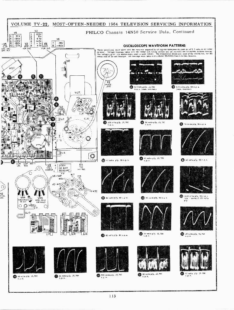
-V56J Z8
ERT. OSC.ERT. OUT.
VOLUME TV -22, MOST -OFTEN -NEEDED 1964 TELEVISION SERVICING INFORMATION
V5
246810
30V195V-24 V180V
-25V
M
i
C 3C
M
V26F07
HOR. OSC.
V2
23678
125V0V
4.5V14 5V-I I V4.5V
M36 M37N3 T
42'F -ON,JOL.
G65HOP. OUT.
VERT VERT WIDTHLIN. SIZE
0 50 volts p/p, 15, 750c. p. S.
V968E3
DAMPER
V6
79
195V-40V
47
PHILCO Chassis 14N50 Service Data, Continued
B2
200VDO NOTMEASURE
V9V6 CAP
M31
CL9r'
VIII K3
H.V. REC.
® 91 volts p/p, 15, 750c.p.s.
LOSCILLOSCOPE WAVEFORM PATTERNS
These waveforms were taken with the receiver adjusted for an approximate peak -to -peak out of 2.5 volts at the videodetector. Voltage readings taken with the raster just filling screen and all controls set for normal picture viewing.The voltages given are approximate peak -to -peak values. The frequencies shown are those of the waveforms, not thesweep rate of the oscilloscope. All readings were taken with a Model ES -550B Precision Oscilloscope.
ANODELEAD
© 100 volts pip, 15,750
43 volts pip, 60 c. p. a.
0 80 volts pip, 60 c.p.s.
0 62 volts p/p. 60 c. p. s.
II0 560 volts p/p, 15, 750
® 2.5 volts pip, 15,750{max. contrast)
0 60 volts pip, 15,750
0 43 volts p/p, 15, 750
Malt gY/1Piiir~,
® 2,5 volts pip, 60 c. p. s.(max. contrast)
/7(45 volts pip. 60 c p e.
nr15 volts pip, 15,750
0 36 volts pip, 15, 750s . p. e.
0 60 volts p/p, 60 c.p.a.
77(O45 volts pip, 60 c.p. s.
0 1000 volts pip, 60 c.p.a.total - sawtooth 220 voltsp/p
0 18 volts p/p, 15, 750
® 20 volts pip, 15, 750
113
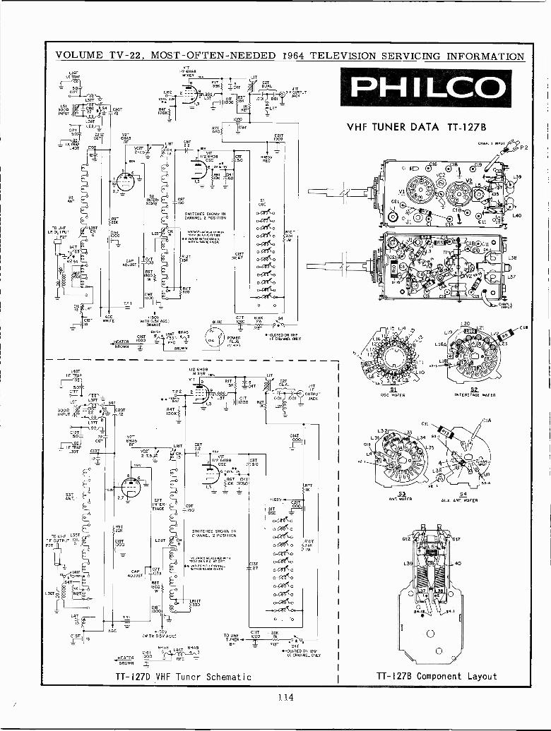
VOLUME TV -22, MOST -OFTEN -NEEDED T964 TELEVISION SERVICING INFORMATIONL39T
I.F. TRAP
1 50-C12T
3ÓÓ 1INPUT
L67T
L38T
Crrr =s.0 cok., V2T
CHAS
I.F.TR4P RF L18T= L407' «I
Vil1/2 6HG8
MIXER Iwv
T.P2 2
C20T72 IOOK
R4T
53ANT.
TO UHFLE OUTPUT
P2T
L41T
AGCWHITE
EATER
BROWN
CIBT1000
+150VI WITH 0.5V AGO) BLUE 000
ORANGE
CSTISO
1000
TIAT
1/2V11468 C3TOSC 5.0
6 -ay.-4x
1 1067 L_G14T
SWITCHES SHOWN INCHANNEL 2 POSITION
MTAO...IMO 1,11O1-0.5Y A_WOAT
4 iiiÑlü x6É áÑ
RIOT156
330
6008 CHAS000 5 4 4 31000 = -gil
BROWN
POWERPLUG
(U H FI
LIT
O
CUT 6
COTDUAL
C21T1000
+165VRED
RIOT
JITF.OUTPUT
JACK
-CLOSED ON UHFIF. CHANNEL ONLY
L40T 1/2 6HG8I.F. TRAP MIXER WOO LIT
VR
= SOCI7T
LOT IT391 ¡ S4T
3000INPUT
L37T la
C12T5.0 7.2- V2T
CAT 6HÁ5
I.F. TRAPRI
= L39T CIOj
i120T=..7.2
SOTANT.
TO UHF L35TI.E OUTPUT CH.P2T
L36T
L4TCH.13
CIBTII1I8AGC
T.P.2 2
R4TIOOK
LI8VC2T I
OV
SOTINTER -STAGE
LOST :_ C1i
GIRT1000
+150V(WITH 0.5V AGE/
C9T150
1/2 H08 13TOSC S.O
6 -ºv ñ iv
)I
R6TIC14TOK -1.8.0
COTDUAL
001
SWITCHES SHOWN INCHANNEL 2 POSITION
-4.4V 4xa. C<T4EDC 9rITl wxiEs wlTx cVxa
RI IT330
6HG8L4AT
C16T 5 4 q6HA5 3
HEATER 1000 = RFCBROWN
C13T27
TO UHF 1000 IIT WK tTUNER. .n. O HO
RIOT 541TI -CLOSED ON UHF
I.F. CHANNEL ONLY
8+
TT-'I27D VHF Tuner Schematic
JITI.f.
OUTPUTJACK
RK
RIOT33KIW
PHILCOVHF TUNER DATA TT -127B
OSC WAFER
.51ANT WAFER
1_19
L20
INTERSTAG WAFER
S4AUX. ANT WAFER
TT -127B Component Layout
3
C18
114
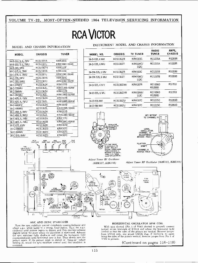
VOLUME TV -22, MOST -OFTEN -NEEDED 1964 TELEVISION SERVICING INFORMATION
RCA VICTORMODEL AND CHASSIS INFORMATION
MODEL CHASSIS TUNER
34-B-222, 5, 6, 7MV KCS136YA KRK103C
34-B-222, 5, 6, 7MU KCS136YJ KRK104CI66AK
34-B-245, 6RS KCS136ZN KRK113F
34-C-275, 6, 7MV KCS136YA KRK103C
34-C-275, 6, 7M U KCS136YJ KRK104CI66AK
34-C-355, 6MV KCS136YA KR K103C
34-C-355, 6MU KCS136YJ -KRK104C/66AK
34-C-376MV KCS136ZK KRK107B
34-C-376MU KCS136ZL KRK108B/66AM
34-C-394MV KCS136ZK KRK107B
34 -C -394M U KCS136ZL KRK1086/66AM
34-C-425, 6, 7MV KCS136ZK KRK107B
34-C-425, 6, 7MU KCS136ZL KRK108B/66AM
34-C-446MV KCS136ZK KRK107B
34 -C -446M U KCS136ZL KRK108B/66AM
34-C-450, 8, 9MV KCS136ZK KRK107B
34-C-450, 8, 9MU KCS136ZL KRK108B/66AM
34-C-465, 6, 7MV KCS136ZA KRK107C
34-C-465, 6, 7MU KCS136ZB KRK108C/66AM
34-C-475, 6MV KCS136ZK KRK107B
34-C-496MV KCS136ZD KRK107C
34-C-504MV KCS136ZD KRK107C
34-C-510, 8MV KCS136ZD KRK107C
R231
T 101AUDIO OUTPUTTRANSFORMER ,/[
RI22VERT HOLD
RIZO RI29 RI53BRIG/HTNESS/ HORHOLD /IZ /TONE
U]LJl `7-"
TP203+4m
7201
7503BEMT
VERT 050A OUTPUT
INSTRUMENT MODEL AND CHASSIS INFORMATION
RADIO
MODEL NO. CHASSIS TV TUNER TUNERAMPL.
CHASSIS
34-D-535, 6 MV KCS136ZR KRK103C RC1215A RS203B
34-D-535, 6 MU KCS136ZT KRK104C/ RC1215A RS203B
112C
34 -DX -535, 6 MV KCS136ZR KRK103C RC1215B RS203B
34 -DX -535, 6 MU KCS136ZT KRK104C/112C
RC1215B RS203B
34-D-555, 6 MV KCS136ZAA KRK107B RC1206D RS193J
RS200D
34-D-555, 6 MU KCS136ZAB KRK108B/1120
RC1206D RS193J
RS200D
34-D-576 MV KCS136ZU KRK107C RC1215C RS20313
34-D-584 MV KCS136ZU KRK107C RC1215C RS203B
OSCILLATOR-fib ADJUSTMENTS
(CHANNEL 1386 ONLY)
)O
SET FINE TUNINGTO CENTER OF ITSRANGE. PULLOUTON FINE TUNING KNOB.TURN CLOCKWISE AMINIMUM Of 3 TURNS,THEN I -I/2 TURNSCOUNTERCLOCKWISE.
Adjust Tuner RF Oscillator(KRKI07, KRKI08)
T2071206
Tpeo2 2ND PIE I -F 1ST PIG I -F
_ L TRANS PLAEE TRANS.
6Ew613R0 PIK FF
850UNDT202 0 aSOUND DET ZDAIET.
1ST GRID TRANS A1sly01O
LJ
-T203SOUND OCT.SRD GRID.ITRANS.
TERM C T205I -F AGC.
AGC AND SYNC STABILIZERTurn the sync stabilizer control completely counterclockwise and
adjust a.g.c. while tuned to a strong, local+station. Turn the a.g.c.clockwise until picture begins to distort, and then counterclockwiseslightly below the point where the distortion is eliminated. Advancethe sync stabilizer fully clockwise and rotate the horizontal holdcounterclockwise Until horizontal sync is lost. Then slowly sync thepicture again. If the picture tends to distort or ""hang-up"' beforelocking in, retard the sync stabilizer control until this condition iscorrected.
204
J102YOKEOCKE
F101FUSE
VIO36AY3
DAMPERF102FUSE28 4WD.FI03FUSE28AWG
F104FUSE
SET DETENTTO CHANNEL 13
LOCALOSCILLATOR
CHANNEL 13ADJUSTMENT
ACCESS HOLE
FLATTEDSHAFT
CHANNEL 6ACCESS HOLE
1
Adjust Tuner RF Oscillator (KRK103, KRK104)
V1016JB6H ORI7.OUTPUT
IN3194
T104POWERTRANS.
91023A3
H.V.RECT
HORIZONTAL OSCILLATOR SINE COILWith sync shorted (Pin 1 of V502 shorted to ground) connect
jumper across terminals of L501A and adjust the horizontal holdcontrol so that the sides of the picture are vertical. Remove jumperfrom L501A only, and adjust L501A slug, if necessary, to again .bring the sides of the picture vertical. Remove jumper from Pin 1 ofV502 to ground.
(Continued on pages 116-118)
115
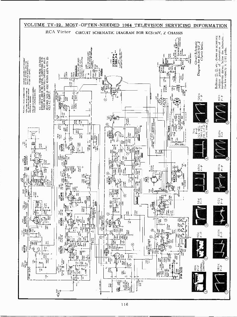
A0S
OFF
TR
AN
S
PW 2
00
0101
202
V20
14T
202
v202
6HF8
50V
ND
0EC
6GX
6io
3
T6
MIO S
SO
Yx0
0Er.
41iT
AY
140
coux
n
8202
MO
W
905
AA
0108
3906
C21
2T
G80
R10í
92.0
69
r 6cA
04U
ST
RIO
St1
52T
OV
.L6
.w
IÓ3
1ii'
0001
15LY
cIO
51
CLo
'_T
loM
F'
W1Ó
7=C
RO
c R
102
4170
v.
20 H
470
q1S
S
T20
4iS
TP
1x-F
1205
T20
>T
208
OM
IDT
R.
6BT
L61
ST
PLA
TE
TL
6GM
6?F
° á'
GE
W6
?V _
:.N(5
214
3uú
«L1
0!.ii
t iT
MP
[15
TP
N1
P
IF
2ND
Plx
1s-
SR
O 0
12G
TP
201
P¡2
6V.2
5..
201
1,a,
_eo
yT
s`Ie
ovG
.
5º.á
]5 3
13 T
rO3R
o'SO
TT
c"ó
?S13
9v.
<21
/m
y *,..
r.,2
06
50V
.I.
C23
!_
MY
111.
.R
210
care
R21
..
'L
I1,'
S
tc 18
06v.:
10
C221
etlf
ov
5 g
25]2
1
113-
101
C3
=10
]TO
m00
28H
2 00
1il~
1
0008
ToV
201
V10
1
3<00
8-T
MR
1Man
I-...
..
0
TO
O?
1560
lll
I414
'
ái00
11R
1o90
°6R
b3cb
9S
ON
520
S6O
°¡20
2
M1
GG
AG
GN
PB
--
000
I 9DT
2205
r-
.115
0K
.WI
B L
3]R
'In'
vC
2DS
yP
OC
o.pp
l=O
JO
o.T
=H
400
1x O
P
TO
VP
la A
T 0
31 10oY
TW
°TT
R.
RIDS
2100
1 v
C10
9x0
.22
oYx
-758
1-6G
Y6
:GC
xi0
z1K
1R
504
0li9
DDI
IRI10-1.
it 1a
T'
82)0
0T
OP
W3o
oP m
TO
5611
7:71
-55
1, I
Ro1
01E
4.
6514
F E
E
SY
NC
.
é0 -
:4i
4 R
585
5G00
6CG
7--6
FQT
14.1
1 05
C.
5625
eT1
A C
SB
MO
AN
3500
3S0N
4530
R54
7 C
3111
Ron
I°°
0 b0
54.O
SO
2so
n-
10=
N N
y+c
O,5 G
I330
°I1
ox
PW 5
00 60 V
.P
-P
NO
RM
AL
CO
NT
RA
ST
280V
.P
-P
00
SsN
EW
AV
E-T
O 0
2
NOR1Z NOLG
40v,
P -
P
1300
V.
P -
P
30
6ÉM
7[IR
05L
SS
2
8533
230
6J B
6,»
11,1
;11
/02.
OU
TP
UT
35 V
.P
-P
190V
.P
-P
l0óar
0131
Oaf
10
call
.001
=.2
404+
uos
T
2
3A3
NV
RC
CT
.
OM
RO
JJ
v201
6HF8
00E
0 A
MP
0218
1422
0
NCG
N[I=
Nt
650V
,P
- P
280V
,P
-P
o QIN
f1
T 1
03
VE
R01
12 P
OT
UW
TT
RA
NS
0119
0I
1001
21
R11
.-11
00
VE
RF
u
0EOSUR[3
WI HV
BR
IGH
TN
ES
SC
ON
TR
OL
FU
LLY
CO
UN
TE
R-
CLO
G/C
MS
1Íi
RE
515A
210E
VA
WE
SIN
pIR
0.1
000
1AH
LCIA
NC
E W
AU
SS
LE
SS
T4A
N 1
10A
ND
AB
OV
E M
MM
E. U
NLE
SS
OT
HE
RW
ISE
1NpUTE0.
DIR
EC
TIO
NA
RR
OW
S A
T C
ON
TR
OL
IND
NA
TE
SC
LOC
KW
ISE
RO
TA
TIO
N.
J
70 V
,P
-P
12V
, NE
G,
58 V
, PO
S.
PIX
, OU
T O
FV
ER
T, S
YN
C.
220V
.P
-P
VO
LTA
GE
S R
UM
OR
ED
WR
H V
0.T
OH
NT
ST
AN
O W
ITH
NO
s14
NA
L 01
PO
T, A
ND
SH
OU
LD H
OLD
1121
8120
r W
ITH
SU
PP
LY.
VO
LT A
.C. S
UP
PLY
.
ALL
VO
LTA
GE
S E
XC
EP
T P
EA
K -
TO
-P
EA
K V
OLT
AG
ES
ME
AS
UR
ED
UN
DE
R N
O S
IGN
AL
CO
ND
ITIO
NS
WIT
HT
UN
ER
AN
TE
NN
A T
ER
MIN
ALS
SH
OR
TE
D A
T B
ALU
N.
RE
AD
ING
S S
HO
ULD
HO
LD W
ITH
IN ±
20%
WIT
H 1
20V
OLT
A.C
. SU
PP
LY.
1.1.
112.
3. D1i
cT
RA
ST
-ez
xxe-
3110
0
R24
1F
t At
'rr
J,02
RE
AR
01(
0
OCIOS
II
x1
r C
YS
-VS
800M
T
270V
.
220K
Run
200K
BRIGHTNESS
IS P
OIN
T G
RO
UN
DE
DIN
MO
DE
LS W
ITH
OU
TA
UT
OM
AT
IC B
RIG
HT
NE
SS
CO
NT
RO
L
1N
OT
E:
5151
AN
D 0
149
US
ED
ON
LY IN
MO
DE
LS W
ITH
AU
TO
MA
TIC
BR
IGH
TN
ES
S01
51C
ON
TR
OL
150K
R14
9=
CD
R4G
IC E
VÉ
CO
NT
RO
L
4210
V.
SR10
215
1444
P. V
IEW
#101
.HA
E11
91;
1001
411
70
23B
KP4
t23
9LP4
NR
HIN
Et
CA
PP
ED
-N
ON
-FR
ITT
ER
NN
CA
PPE
D -
FRIT
TE
R
T10
4
F10
!25
AW
G
1355
104
.G
-;21
.211
- J1
03 p--
; t12 aiñ++.TToLílNArwN'
RI0
4140
.111
2.2M
[6.
110
V. 6
0+,
PO
WE
R S
OP
PY
Cir
cuit
Sche
mat
ic32
0v.
Dia
gram
for
KC
S136
Y, Z
P -
PC
hass
is S
erie
s.
Bal
loon
s (:
, Q
, etc
., sh
own
on s
chem
atic
150V
.in
dica
tepo
ints
ofob
serv
atio
nof
the
P -
Pw
avef
orm
s sh
own
belo
w th
e sc
hem
atic
..
Use
low
cap
acity
X (
10)
prob
e.
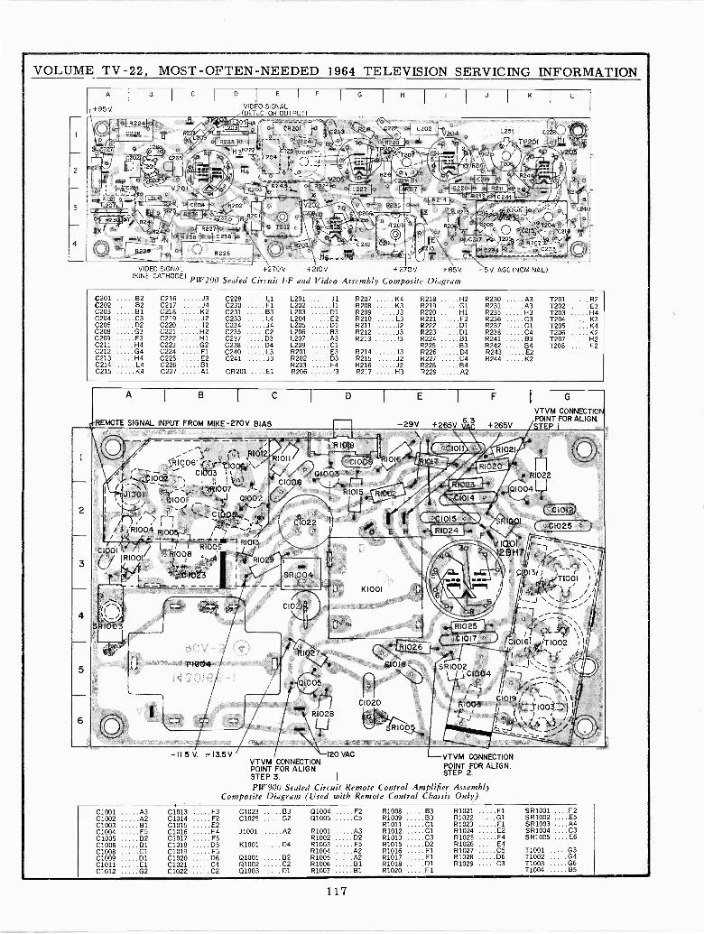
VOLUME TV -22, MOST -OFTEN -NEEDED 1964 TELEVISION SERVICING INFORMATION
A I 8 I C I 0 I E I F I GI
H I I I J I KI
L
+95V. VIDEO SIGNALi(DETICTOR OUTPUT)
F - .... .... .. :.®a. . ®'..p
- .TL20.pL2031 i o. CR201 (o
o°821 2 L202 . L201 $ O1 C226 tt23 '
0 2,.c.1 -412 C22V204
°Oc . R223 I0ro °&224ÍH 0 30 R220 . 1 n 3 ..1- R2,01 " ¡,(
I0227 Coo .. 8222 i 4 Tp2 a,
V 201 -
2 . R24.` el R22110 .J C223 O `- 17 p C220 _I
821' n--n L20p ` .a j- K R212 YC241 t °
.vP C204 "1.. R2i4
20 n t3 L207 1 R2O2) ..
1
R2 27 8235 6, z ° R213, os
8o
b C2p40: . = ' p C B C208: 9 pótR *- °'' R2301oY B2R20t R241 O T203 ' Íi \ oYO oi,209X R242° M o T202 r.
1
;., 5 oR20Q
. 1° ( 021; - _e e214T rV {¡.1 .. ... p ..=.i, 7..
C217 ;.ó. T203,.y -1`o d',i'
q
,O. r.O R228 _% R226
°'c2t2
, pa r
Hg H6 °
fC20 r ° _r-_- _ a R_za7'--- i°
q t a C234 ° . g C231,d... _, .._ . .. C .F
VIDEO SIGNAL +270V. +210`J +270V. +85V. -5V. AGC (NOMINAL)(KINE CATHODE) PW200 Sealed Circuit !-F and Video Assembly Composite Diagram
C201 B2 C216 J3 C228 Ll L201 J1 R207 K4 R218 H2 R230 A3 T201 B2C202 B2 C217 J4 C230 Fl L202 11 R208 K3 R219 .... 01 R231 A3 T202 E3C203 81 C218 K2 C231 B3 L203 D1 R209 J3 R220 H1 R235 H3 T203 H4C204 C3 C219 J2 C233 L4 L204 E2 R210 L3 R221 F2 R236 C3 T204 K3C205 D2 C220 12 C234 J4 L205 D1 R211 J2 R222 D1 R237 Cl 1205 K4C208 G3 C221 H2 C235 C2 L206 83 R212 J3 R223 D1 R238 C4 T206 K2C209 F3 C222 H1 C237 D3 L207 A3 R213 13 R224 B1 R241 83 T207 H2C211 H4 C223 G2 C238 D4 L209 Cl R225 83 R242 84 T208 F2C212 G4 C224 Fl C240 L3 R201 E3 R214 13 R226 D4 R243 E2C213 H4 C225 E2 C241 J3 R202 D3 R215 J2 R227 C4 R244 K2C214 L4 C226 81 R203 F4 R216 J2 R228 84C215 K4 C227 Al CR201 ....E1 R206 13 R217 H3 R229 A2
REMOTE SIGNAL INPUT FROM MIKE 270V BIAS
G
VTVM CONNECTIOPOINT FOR ALIGN.-29V +265V yAC +265V STEP I- ---- -----
/ I RI018 /R1021 ( j)/ / ', ; R10Í2/ R1006 (`Fl 1 `a- 1 100l¡ ."_- CI003 11.C I002', -
RI011--i,--i---I--r',____
aCt00901003
R1016 1,- / .ar \ /' RI020R1022- I I I' i
I/ á-_\ N ;_-, :,110Ó7 / t- C I008o R 1015
I I1023 Q1004J1001
010 01 "L Q1002R100
., 1 ` 1014 " /_2 f-
II \ 1 Z :.'', C1Ó05>-I , c 1015 c`
CIOt
/ Í1 1' ' tr ;s-.....?I` ! i R1004
C1022 Í S1001 °C1025 ).. s R1024t 005r¡ tr'7 0 E H
" A F C1001
} 4 +- r ,- - t -/ri¡+ L J¡ t RI008I T/ RIo0810QI `T.
1RI013I
RIOI
I'- V1001 lr-
! 1,--2-7.2-7-7,26H7 e' 2 -/ 1 1l..l IR,Ii'/I `,-i I I 'C 1023
I `1
SRI004
IU.\
I L , l i t, r) \ \ 1
g Z o 01311!,.TI001 \1
Il. . i-+_ ------ -L --- rK1001 u 6 / j' ,it4
;;/: /C C7 r CI021° gJ 1 --
SR1003 ú ii " RI025 -+ /% í \Í
L.--%r
) I t- -1-"in. T1004 hv'R10\27
QI005n-H
: C 1017 5'R1026
C1016 ,-/T1002 j< c. ; ( CI018 SRI002 -\ -t Il
o jC1004 - _- Jrl. I.:7tí-\
7 D.,., \\
O' 3
C1020
286
. . t t CI019 tr \ tiR@003 f' 1' 1, TI003.} It
RIOÓ {---ii : _i//'I2_/ ' !
-11.5 V. -13.5 V 120 VAC VTVM CONNECTIONVTVM CONNECTION POINT FOR ALIGN.POINT FOR ALIGN. STEP 2.STEP 3. I
PW900 Sealed Circuit Remote Control Amplifier AssemblyComposite Diagram (Used with Remote Control Chassis Only)
C1001 A3 C1013 F3 C1023 83 Q1004 F2 R1008 B3 R1021 Fl SR1001 ....F2C1002 A2 C1014 F2 C1025 G2 Q1005 C5 R1009 B3 R1022 01 SR1002 ....E5C1003 B1 C1015 E2 R1011 Cl 81023 Fl SR1003 ....A4C1004 F5 C1016 F4 J1001 A2 R1001 A3 R1012 Cl R1024 E2 SR1004 ....C3C1005 B2 C1017 F5 R1002 D2 R1013 C3 R1025 F4 SR1005 ....E6C1006 B1 C1018 05 K1001 D4 R1003 F5 R1015 D2 R1026 E4C1008 Cl C1019 F5 R1004 A2 R1016 El R1027 C5 T1001 G3C1009 D1 C1020 D6 01001 B2 R1005 A2 R1017 El R1028 D6 T1002 G4C1011 El C1021 C4 Q1002 C2 R1006 131 R1018 D1 R1029 C3 11003 G6C1012 G2 C1022 C2 Q1003 D1 R1007 81 R1020 Fl 11004 85
117
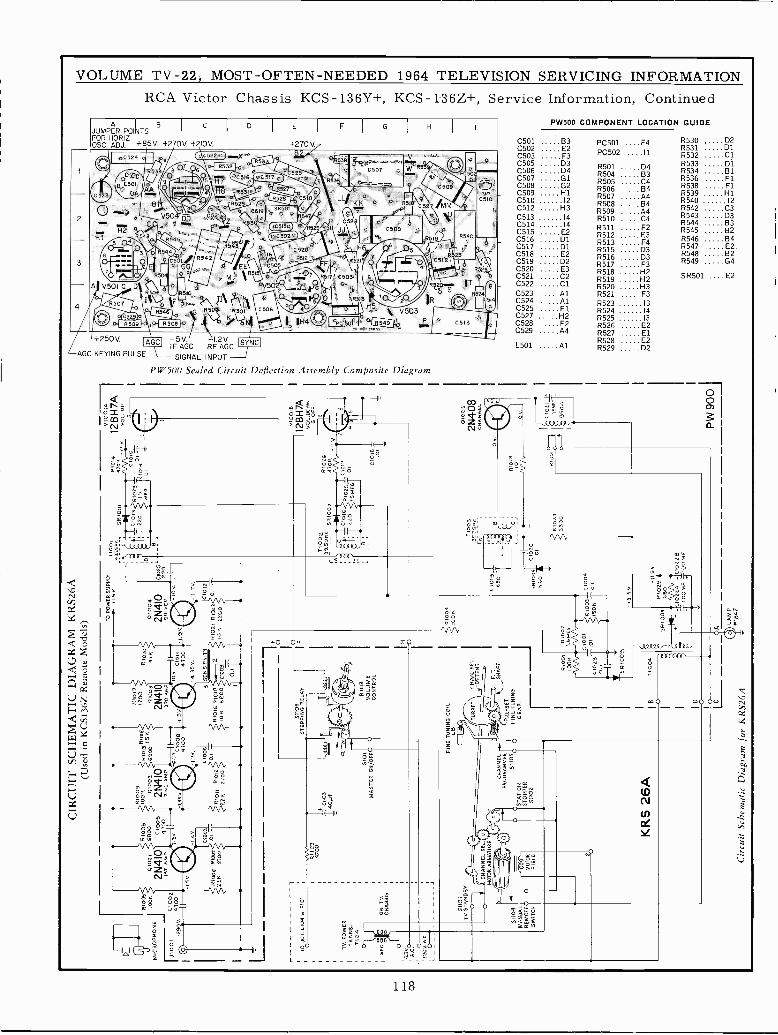
R10
05
MIC
RO
PH
ON
E11
000 0J
I001
J41
002
I
° O-2
90V
.I
CIR
CU
IT S
CH
EM
AT
IC D
IAG
RA
M K
RS2
6A(U
sed
in K
CS1
36Z
Rem
ote
Mod
els)
R10
0801
001
6800
2N41
01S
T A
MP
.
5 0100
6 01
007
220
2700
0100
541
00
4V
C10
03.0
1
RI0
09IO
OK
0101
3
.B
0100
268
55
2N41
07
-NO
AM
P
R10
1712
00
5505
3
2N4I
03R
D A
MP
1101
,6
1011
0,01
22s
2100
1.7
C10
08-4
547
00
C10
06O
.l
Rlo
2o47
11
10
4.35
v.O
D
3 S
EN
Sal
VIT
Y
R10
16 R
1010
-2
10 N
6000
C10
03
0.1
TO
PO
WE
R S
UP
PLY
7100
15V
4325
00
0100
4
2N4I
0D
RIV
ER
R10
21 R
1022
10 N
2200
D
1025
220
0 1 T
0012
0.1
TO
O J
CT
.L10
4 6
F10
1I
TV
. PO
WE
RT
RA
NS.
1104
5E0
6.30
0A
C. O
R10
01
C 1
01R
1023
220
I5
ME
G.
R10
144T
OK
CIO
15
0014
C"
-¡-
5/10
,717
112
BH
7AV
OL.
UP
3,
5110
5S
TE
PP
ING
RE
LAY
R11
047
00
ON
TV
.C
HA
SS
IS
C11
03
I40y
f
5101
MA
ST
ER
ON
/OF
FO
R10
3V
OLU
ME
CO
NT
RO
L
T10
0235
.50
KC
5810
02
Az
R10
2647
00
CIO 22
0R
IO15
SM
EG
IO
C10
1
v.
3100
10
12B
H7A
VO
L. D
OW
N&
OF
F
CIO
10 .01-
rr
1200
.0.0
.O-
5110
1T
V S
TA
ND
BY
5110
4M
AN
UA
LR
EM
OT
EO
SW
ITC
HOU
CH
AN
NE
L5E
5° JGC O
MO
TO
R A
RM
AT
UR
E
FIN
E T
UN
ING
CO
ILLO
MO
TO
RF
IE L
O
ST
AT
ION
ST
OP
PE
R01
102
CH
AN
NE
L-
PR
OG
RA
MM
ER
5110
3o o
KR
S 26
A
CH
AN
. SE
L.
DE
TE
NT
F.T
SH
AF
T
PR
E-S
ET
FIN
E T
UN
ING
GE
AR
R10
01W
OK
0102
30.
1 I1F
1002
1.6M
E6
C10
01.0
1
0100
410
0K 1910
0SO
T
i5 R
100
-b
1100
4
Io o
lo
Cir
cuit
Sche
mat
ic D
iagr
am f
or K
RS2
6A
5510
04
003
r35.
75<NC
---,
C10
1J6E
0 T
5R10
0i
CIS
'N60
0
0004
0.1
5V
0
0
5
0100
5
2N40
8C
HA
El
0102
730
0
R10
25
Vlo
/ IJD
Iri --
r nnnnnn
o Ñ
Ñ Ñ
Ñ Ñ
Ñb0
0V V
1AW
C10
211
ism
FT
'
950n
II
n..
2.
-m+D> 1-.
-115
0R
168
029O
4
-010
2a
0102
20
OA OLAMP
ft1A
d]
PW
900
nnnnnnnnnn
NV
INN
NV
IVIN
VIN
NN
N1+
1+1-
+F
+I-
1+1+
NF
+O
t0O
0V01
(nA
W
00M
ON
Nó0
ÑA
A
nnnnnnonnn
YV
IVIN
NllI
V1V
INV
lNOW0p00V001lpilWÑ
1_ 2 0 L) 0 0mfTIW
NI-
-NI-
AW
WN
W
AAAAAAAAAAAAAAAAA AAAAAAAA
ÑUItTNNVIVI IRVIVINVINNVIVIVI
V1U
1V1V
IUIN
NIR
NN
NN
NN
NN
1-+
1-+
r'F+
1-F
+F
+F
+1-
+00
0000
0UJODVOINAW I+Ot000VTUIWNt'
pVO
OO
Vm
UtA
I-+
ORiFnR7--- 1=221001m1nDWDWnWO
NNP+NWAW
WW
NN
WW
WA
WN
AA
AA
AA
WA
ó m
mm
nn
0.
N r
F+ Á
A A
A A
A A
A A
A A
A A
A A
A A
AN
VIV
tut u
tVIV
1NW
NN
NN
N V
1NV
líO
WV
OIÑ
AW
ÑO
IOO
POIÁ
WÑ
I--'O
G)WR1W WWOn-2TmW0n00
N N A
N W
W
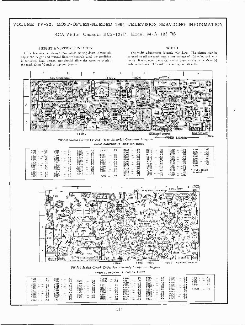
VOLUME TV -22, MOST -OFTEN -NEEDED 1964 TELEVISION SERVICING INFORMATION
RCA Victor Chassis KCS-137P, Model 94 -A -123 -RS
HEIGHT & VERTICAL LINEARITY WIDTH
If the blanking bar changed size while moving down, alternately The width adjustments is made with L101. The picture may beadjust the height and vertical linearity controls until the condition adjusted to fill the mask with a line voltage of 108 volts, and withis corrected. Final vertical size should allow the raster to overlap normal line voltage, the raster should overscan the mask about %
the mask about 5/8 inch at op and bottom. inch on each side. "Normal" line voltage is 120 volts.
A I B I CI
D E I FI
G
AGC NOMINAL) +I00V. +180V. 270V.
..- -- -- íC3=áC23 -b a,C2 Iº oR226
. .a R 22 8 Q206 C e a ~. TC38 R238 N!
iT20Z`f O O ¡R R227 8 42 132R(^2308Eao T203 ye }aX^°C240 0.t`Osia 21 tlTO2027ao Z_I_ .a< ,r
a "1 "35 r9o R 2U1Dtl
(r.'"1y
R214 10
4 o !. Vp_2.7_ I e.2 R10 17C 'Iii..". 2 %V.(.`.',tl ',:
C219..-.<..
... : V º=`, .0. tl ,tl
2- tl , r : . I _y R 18 ie 507 ¡'ci ÍI
'201.\ e
r2
a,v203
pp +.. /H qi7:. , , Q--/ .- Ii ` "' -- ._ oii i 1I.204 kx 2
¡w--._t 7-- i 1 ¢¢ 1
---,3 5- = 1:f , " - I r-+t Lá i
3.1 i. 6 2 '
,
oC227
o e3 or. f
TP201` V204 ." "7 " t7.._ : tl2+ PtVp+
228 L201C
-C20ó
' ' Q/ c228'1." L202 \ al cam e4 Io Jo ' hT ii° o__i R24
P203+2 0 V. DETECJOR OUT T KINE CATHOD.
! VIDEO+í02V.
PW200 Sealed Circuit I -F and Video Assembly Composite Diagram SIGNAL
PW200 COMPONENT LOCATION GUIDE
C201 G2 C216 81 C228 A3 CR201 ....E3 R202 F2 R215 B3 R227 Fl T201 G2
C202 G2 C217 B1 C230 D3 R203 El R216 133 R228 01 T202 El
C203 G3 C218 B2 C233 Al fL201 B3 R204 Cl R217 C2 R229 G2 T203 Cl
C204 F2 C219 82 C234 B1 L202 C3 R206 81 R218 C2 R230 01 T204 AlC205 E2 C220 82 C235 F3 L203 F3 R207 Al R219 D3 R232 01 1205 B1
C208 D2 C221 C2 C237 F1 L204 E3 R208 B2 C3 R235 C2 T206 B3
C209 El C222 C3 C238 F1 L205 E3 R209 B1 8221 D2 R236 F1 T207 C3
C211 Cl C223 D2 C240 A2 L206 G2 R210 A2 8222 E3 R237 F3 T208 E3
C212 D1 C224 D3 *C241 B2 L207 G2 R211 B2 R223 F3 R238 FlC213 Cl C225 E3 *C242 Dl L209 F3 R212 B2 R224 G3 R242 01 *Under Board
C214 Al C226 G3 C243 C2 R213 B1 R225 F2 R243 E2 tPrintedC215 Al C227 G3 R201 El R214 C2 R226 Fl *R244 B2
AI
B IC
ID. E
I
F I G +2 .SIGNAL INPUT
rNc -12V RFAGC 10V. LE AGC
4. /afiC 513
.PC501 - ,1. :+ ¡ J R0® R509
n e C506 K o C529
I
a.5I4
º
V503
R524 , R Z. p!¡/.iSr R52
R51 ` ' p 4I 5 t
5
{,. R RI: 5 ..
II.
1. v50 .
. \ \ ..'- !T-
as4'S23C512
3
.
C503o 5_ .`2
R521, 'S12
t R515EC59
R504'..R1
__CSOS Í Ci _
.6
'1
tY C4 - rrr.R542: H6 0520 .. R 544p 3 4
z 4".
R 5
R540R55
CSDB
-
Y'A _ i V501='
C56 ®y\\' a01 :_ C510U, ..
u c o c t G,C527
IMM 518II..
C509 I
526 +` o
°'
SR. I?..CSNJ 1 `. a . M n. i. i - 1
I n .
c W1i53T,.,,'<t A-
'4 8 I r..
`Tjr% L UPC, ..
,
C507 . . j 7n!
534
b.:yU'..
t/.,'
-'.522° J504 u C524 .'. :.
..
+270V. +160V. +I.0 V. +27.V AGC KEYING PULSE
PW500 Sealed Circuit Deflection Assembly Composite Diagram
PW500 COMPONENT LOCATION GUIDE
C501 Fl C513 Al PC501 Cl R510 Fl R523 A2 R532 E3 R546 FlC502 D2 C514 Al C523 G3 PC502 A3 R511 D2 R524 Al R533 E3 R547 D2
C503 Cl C515 D2 C524 G3 R512 D2 R525 A2 R534 F3 R548 G2
C505 D2 C516 E3 C525 D3 R501 El R513 Cl R526 D2 R536 C3 R549 B1
C506 D1 C517 D3 C526 63 R504 F1 R515 E2 R527 D3 R537 C3
C507 C3 C518 D3 C527 B3 R505 El R516 E2 R520 81 R540 A2 SR501 02
C508 B2 C519 E2 C528 C2 R506 Fl R517 Cl R528 D3 R542 F2
C509 A3 C520 D2 C529 G1 R507 G1 R518 B3 R529 E3 R543 E2
C510 A3 C521 E2 L501 G3 R508 Fl R519 B2 R530 E2 R544 F2
C512 A2 C522 E3 R509 01 R521 C2 R531 E3 R545 F2
119
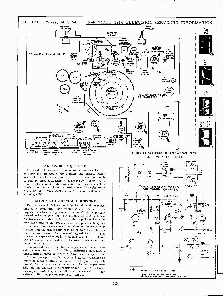
VOLUME TV -22, MOST-OFTEN-NEEDED 1964 TELEVISION SERVICING INFORMATIONSWITCH VOLUME
Chassis Rear View KCSI37P
J,Lr----1 FILTERq4 OKCHE- i
- 1,
R133PASEARLE
SURGELIMITER
T103VERTICALOUTPUT
TRANSFORMEN
V703 WENT
VENT. OSE.a
OUTPUT/
TERM 'C'I -F AGC
/V201S.M.
HOPIS
T207T - - 2ND PO(1-PMT P151 -F TRANS.
PLATE TRANS.
CENTERINMAGNET
1ST PI% V2031-F GRID 4626
I SZIL01.12
v5024AV.SYNCAMP P301
GOY.ARC
R121 3102 SI W TE COILVERT PCIOI INTERLOCK /VSp\LINEARITY ___ .CG7/
apTEN%
r i
I I
0° URTC.\-- __==.-i-------JRHO 2-R122 R129 ° R121J 8120, CRAG
BRIGHTNESS VERTICAL HORIZONTAL HEIGHT NOISE ARCHOLD HOLD STABILIZER
AGG CONTROL ADJUSTMENTPerform the following routine test: Adjust the receiver and antenna
to obtain the best picture from a strong, local station. Quicklyswitch off channel and back, and if the picture distorts and bends,or does not reappear immediately, rotate the AGC control R119,counterclockwise and then clockwise until picture bend occurs. Thenslowly retard the control until the bend is gone. The noise controlshould be turned counterclockwise to the end of rotation beforeadjusting AGC.
HORIZONTAL OSCILLATOR ADJUSTMENTTurn the horizontal hold control R129 clockwise until the picture
falls out of sync, then slowly counterclockwise. The number ofdiagonal black bars sloping dównward to the left will be graduallyreduced, and when only 1 to 3 bars are obtained, slight additionalcounterclockwise rotation of the control should pull the picture intosync. The picture should remain in sync for approximately 1/2 turnof additional counterclockwise rotation. Continue counterclockwiserotation until the picture again falls out of sync, then rotate thecontrol slowly clockwise. The number of diagonal black bars slopingdown to the right will be gradually reduced, and when only 1 to 3bars are obtained, slight additional clockwise rotation should pullthe picture into sync.
If above conditions are not obtained, adjustment of the sine wavecoil may be required (L501A on PW500 deflection board). Removecabinet back as shown in Figure 2. Attach short jumpers acrossL501A and from pin 1 of V502 to ground. Adjust horizontal holdcontrol to obtain a picture with sides vertical (picture may driftslowly). Momentarily remove and re -attach L501A jumper whileadjusting sine coil slug (use nonmetallic tool) until the alternateshorting and unshorting of the coil causes not more than a slightsideways shift of the picture. Remove all jumpers,
C24
"1
R107
7202SOUND SET
IST GRID T201TRANSFORMER SOUND
TAKEOFFTRANS n011
MAC TRAPC(B0TTOM)
0
3 RD AT TP20331-F
TRANS.
INDICATES BLANK PINOR LOCATING KEY
VIOL170611NOWIZ.OUTPUT
V10317A%4/I7D1MDAMPER
LNNMIOTHCAL
J101TOKE
SOCKET
CIRCUIT SCHEMATIC DIAGRAM FORKRK102L VHF TUNER
C26
.4444
Cñ6
Ti
ANTENNAMATCHING
TRANSFORMER
TUNER ASSEMBLY-TMA 34 AVHF TUNER KRK102L-T----
1 L6
r CPR 101
L_c--.-PRoz-J
LT L° I
COIL sTRmCNANN[LS 2 TNRU Li------ J
V2A V2.6CG8A L11 L. ;; 6CG8A
MIXER ` iú
oait) 1tia
OK
RTLIO O.TK
R
I C16T62
2^CW4 Oócáe±
12 1/\ i ióoo
46-- ---°-°f: ''AK TYI
O PILGTGNT
á92K
T á4T'V \A, . 27GV.
RESISTANCE VALVES IN OHMS. K -1000
CAPACITANCE VALUES LESS THAN I IN MF.I4 ABOVE IN MMF. UNLESS OTHERWISE INDICATED.
120
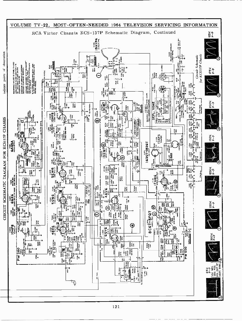
2240
56
A C 2
33 IS
RA
GC PC
IOIB
61
4 I R
12
O r
I
NO
ISK
ST
A61
1.J.1
L___ R
139
27oV
5600
TO
PW
200
PT
O P
W 2
00E
.
C 1
19S
MF
C51
1201
A60
1100
TA
K.G
FF
TR
0201
2x K
C2.
1411
.5
l3S
MC
Tap
s
04-6
6
CIR
CU
IT S
CH
EM
AT
IC D
IAG
RA
M F
OR
KC
S137
P C
HA
SSIS
indi
cate
poi
nts
ofob
serv
atio
n
0201
A02
02
IOH
FBS
OIT
INO
OE
T.
66X
6S
OU
1ND
ES
T,
GO
0N0I
-161
110
TR
.sD
UN
D D
ET
tIS
TA
0010
SR
D G
RID
TR
.
AiW
iE c
l .Oq
5
2o3
486
15T
TP
x:-F
IST
. PIX
IfPLATSTR.
4 10
6V T
ID
1
zu c
ola?
TX
110
410
i
C24
1S
4oR
212
C21
0s R
24G
K .0
01S
OK
Icz
1 ¿
CC
.01
=I
haIE
L°_
J
0LU
3101
MF
s
204
390K
111G
0
RR102bK
61
IOOOA3
I
i50
Clll
4270
N
Too
I.w
lE
R15
9T
`á47
K -
2W
GA
Q5A
AU
DIO
OU
TP
UT
TIO
I
3,3.
.34
PIE
SP
EA
KE
RIO
2W
05
5GM
T2o
,1 W
66
5ET
toe
2N0.
PIX
300.
PIX
. CR
2q2N
DP
I%I-
FT
P2
3R0.
PI%
[-F
1-F
TR
.2N
DO
E7.
1F. T
R.
5..2
136.
0215
SA
HC
0..L
GSOP
142
C51
023
220N
JN
DE
Efl
eOD
V50
2
CS
OG
v >
6
8 50
.003
3 -R
616.
l22
0NR
506
R51
023
03 I
C52
9-Y
e0
Mil.
.001
Tfl5
46R
SÓ
K39
0
R 5
4147
00 3W
1151
6 05
204l
3SO
K19
60K
2521
2100
5cs
e00
1
PW
500
259
HO
R IZ
HO
LD
65V
.P
-P
1OV
. NE
G.
55V
. PO
S.
PIX
. OU
T O
FV
ER
T. S
YN
C.
0515
2505
L501
6S
INE
WA
VE
1.50
1$N
OM
Z. F
RE
O
VI02
163G
T-I
83G
T1L
v ac
CT
.
R13
)2
V10
9
17A
Y3
1110
2
y101
1311
4131
14.1
21
=al
9
DA
MP
ER
2105
51..2
Mu
-H
CH
O65
0
592
v...
oJJ
OL
LU
v R
T.
RM
Sr-
u-.
ÑÑ
F-5
001¡
T 1
I
A5
21R
.OM
E 2
70K
470
KI
9R12
11V
ME
Vw
G.Ñ
É16
R
12/
--
L---
--M
OO
-P
CIO
ICV
ER
T.L
IN.
RO
SIS
TA
RC
C V
ALU
ES
IN 0
1111
5.5.
1000
CA
PA
CIT
AN
CE
VA
LOR
O L
OS
S T
HA
NIIN
0F,
I AN
O A
SO
Vr
IN 1
.01,
..1.3
53O
050E
IND
ICA
TE
D.
DIR
EC
TIO
N O
F A
RR
OW
S A
T C
ON
TR
OLE
IND
ICA
TE
S C
LOC
KW
ISE
RO
TA
TIO
N.
VO
LTA
GE
S M
EA
50*0
RIT
O 0
00V
ON
MY
R-
AN
D W
ITN
NO
SIG
NA
L IN
PV
TI
AN
D 5
1100
1111
001
10 6
1101
NI l
oW
MN
10 V
. AC
. SV
PK
Y.
M V
OLT
AG
ES
540
1000
0 W
ITH
I M
EO
.1I
4 W
AT
T 0
E51
3100
14 S
ER
IES
WI1
011
E1E
13 P
RO
SE
.
2T0
V.
TR
IOT
305
L -
N/R
A
3
CIOG1R113
010C
.001
19
= o
05F
,10,
000
V.
ME
AS
UR
ED
WR
ITE
55 C
oNT
R.
FIA
LY C
OU
NT
ER
-C10
0IV
CLO
CK
W15
r.
L°
P10
1P
IN V
IEW
J 10
1R
EA
RV
IEW
1111
0LO
OK
0RIS
IITN
ES
S
27O
V.
DE
FL.
YO
KE
3R[
VO
T. C
OIL
611
61,
066
s RE
C.B
LK
RE IO
OM
FT
CH
OK
EC
120A
TT
SR
--}}
_IS
OM
FP
EO
T.
;T.=
I
2104
2105
v101
0101
VI4
2501
V50
3
Í
V10
3V
101
NI4
6E6
SG
MF
SE
5E01
0NF
E 6
G%
6A
Q0
SA
6476
. ID
EM
T11
213
1769
6
C22
5'1.
-S
1110
111
202
[2!0
TS
43
43
014
36
T
4700
.2
2 41
00 >
=C
O20
42
He
C1
Pw
zoo
-Pw
Soo
I
T2
R21
5C
112
150
.004
7
4AV
6.5
03 0
913
SYNC.
.047
390
C50
2 R
549
0010
011
1.11
02.
CI1
5D
10 q
OS
2200
1.20
456
M2
-N
5702
.T
OP
w50
0E
CO
RN
q1B
RA
CK
ET
R10
62.
2 M
EN
1.20
912
02-1
6V
2OIB
010-
022-
010
IOH
F8
TD
)m
yV
IDE
O A
MR
R22
1LO
GS 5
R1o
C22
5 33
027
2-N
1_10
325
0 M
O -
11R
ED
-S
RN
-9M
9 21u
R22
152
29R
x14
.011
410
3600
16
C20
112
FqL
SHIELD
2501
21
C0
PC
502
R52
4C
513
VÉ
WP7
SI
UT
52.0
0[1
p3-
12K
.Oli
SD
Y. 9
RS
I9S
C)I
R53
5 C
S..2
1091
E4.
OP
24J
IOO
K1.
.001
51
-23v
-IF
-2-5
-II
ós21
lVv
0505
05x5
C30
904
1152
3
R52
0(22
MC
1R
SIS
.047
0022
.015
2-N
220K
{©
/
b T
01
11.2
.10/
10.
C12
102
2T
v105
,V
SO
2 5C
54T
19A
YP
L4.
0 50
07
1250
V.
5101
CIS
O (
SM
.4 O
NLY
).4
101
.--I
1,C
HE
13f
S2
.4p
.021
1 *1
0U
fO
FT
-eN
6WIT
Nfi
eV ts
.nov.<o-rTa60r-e
C11
9AL1
04.'R
EC
TT
nli
LI0
531
T.1
V10
519
AY
P4
KIN
ES
CO
PE
5102
PO
LAR
IZE
D IN
TLR
LOC
K(L
AR
G1
1(08
4)
Cir
cuit
Sche
mat
icfo
r K
CS1
37P
Cha
ssis
175V
.P
-P
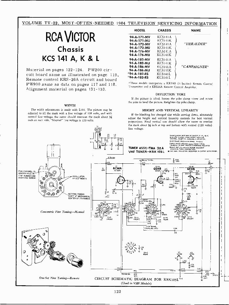
VOLUME TV -22, MOST -OFTEN -NEEDED 1964 TELEVISION SERVICING INFORMATION
RCA VICTORChassis
KCS141A,K&LMaterial on pages 122-124. PW200 cir-cuit board same as illustrated on page 119.Remote control KRS-26A circuit and boardPW900 same as data on pages 117 and 118.Alignment material on pages 131-133.
WIDTHThe width adjustments is made with L101. The picture may be
adjusted to fill the mask with a line voltage of 108 volts,. and withnormal line voltage, the raster should overscan the mask about ginch on each side. "Normal" line voltage is 120 volts.
FOR CHANNEL 13,,CENTER HOLE IN 12
FINE TUNING CAMOVER ADJ. SCREW
OSCILLATORADJUSTMENTS
SET FINE TUNINGSHAFT AT MECHANICALCENTER OF ITS RANGE
Concentric Fine Tuning-Manual
One -Set Fine Tuning-Remote
ANTELANDMATTRANS.
C227
O TO -BV.
27
LF.
L3 TRAP
l 00CSIO _ t
AI 6CW4I472 RE AMR
L11O L21L10
51-DFRONT
MODEL CHASSIS NAME
94 -A -171 -MV KCS141A94 -A -171 -MU KCS141K94 -A -172 -MV KCS141A "HERALDER"94 -A -172 -MU KCS141K94 -A -176 -MV KCS141A94 -A -176 -MU KCS141K94 -A -183 -MV KCS141A94 -A -183 -MU KCS141K94 -A -186 -MV KCS141A "CAMPAIGNER"94 -A -186 -MU KCS141K
*94 -A -182 -RS KCS141L*94 -A -183 -RS KCS141L
*These models incorporate a KRT4B (3 button) Remote ControlTransmitter and a KRS26A Remote Control Amplifier.
DEFLECTION YOKEIf .the picture is tilted, loosen the yoke clamp screw and rotate
the yoke to level the picture. Retighten the yoke clamp.
HEIGHT AND VERTICAL LINEARITYIf the blanking bar changed size while moving down, alternately
adjust the height and vertical linearity controls for best verticalproportions. Final vertical size should allow the raster to overlapthe mask about 5,á inch at top and bottom with normal (120 volts)line voltage.
TUNER ASSY.-TMA 32AVHF TUNER-KRK 103L
13
2
31.32
L13 5I -CFRONT
6-2v. To -4V.
NI -BANDCOUPLING ADJ1.54 1.341,
L3T1L3B
I 13 I1oTa
gét0 S("1/ c 1 C19
T 8T
S 5496 S1 -C
REAR
FRONT *REAR SECTIONS OF SWITCH SI -A, -B, -C4-0, ARE VIEWED FROM FRONT WITH THECONTROL SHAFT IN CHANNEL 2 POSITION.RESISTANCE VALUES IN OHMS. 2.1000CAPACITANCE VALUES LESS THAN I DIMEt4 ABOVE IN MME UNLESS OTHERWISE INDICATED.BLACK DOT IN SWITCH ROTOR SEGMENTINDICATES THOU CONNECTION.
e OSE ICON ISOLATION RESISTOR IN SERIES WITH PROBE.
C92.033
V2 -A
6EA8 LIIMIXER Á nTi!1-E
103V. 6 R96 1000
L4L4B12
L4y11
L501
L5éL5
L53 -
V2 -B
GEMSOSC. RIO
8200
eI12v.
_016 5600
12
T
r47'3 C14
L55 I 10L54
025 51-AFRONT
V1 V26CW4 6EA8
10r12 514L5B
4-T'eT`r_ cvTcec
O9 C22aT R11
. -tt000SDYNO-96. 75N
CIRCUIT SCHEMATIC DIAGRAM FOR KRK103L° T(Used in VHF Models)
,c020211
000 R92144 Et+
_09110 210V
T.047
122
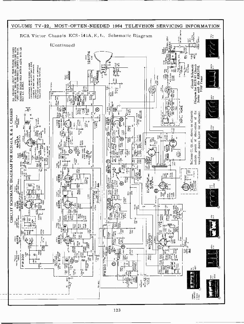
T20
; AS
OU
ND
TA
KE
-O
FF
TR
AN
S.
V20
4A.
6HF
850
000
CIR
CU
IT S
CH
EM
AT
IC D
IAG
RA
M F
OR
KC
S141
A, K
& L
CH
ASS
IST
202
SO
UN
D 0
E1.
.1S
T G
RID
TR
AN
S
P W
200 C
2p4
SG
-1.2V.2
+9+
V
c2o1
1"R
y0o5
llf--
.
1ó7
iI
(207
114
?80
1I
1C20
6
C20
21-
0202
310
p15
r-IC
237
S R
20I
-270
¡ 01
347,
V20
202
036
G50
00I0
EN
T
50U
ND
DE
T i
I ST
AU
DIÓ
RO
4R1D
TR
AN
9.
6HZ
6
-1.5
V
5
LT4.
7 _
JC
20B
31-y
v2.
Sv
.OI
(209
1--
R20
3T.0
01 T
5560
=47
00
W10
R10
31
ME
G.
VL.I
6AQ
5PS
AU
DIO
OU
TP
UT
CI -
3Gl
2
R16
1 1
4162
413!
1L4
4N.
+8
3908
?M
EG
. BO
OS
T R
102
T
R15
969
0!
+21
0V.
-4
PW
500
E
+21
6 v.
TIO
141
J010
OU
TP
UT
TR
AN
S.
BLU
+07
0*..
I I(1
19B
10 M
FD
ALL
VO
LTA
GE
S E
XC
EP
T P
EA
K -
TO
-P
EA
K V
OLT
AG
ES
ME
AS
UR
ED
UN
DE
R N
O S
IGN
AL
CO
ND
ITIO
NS
WIT
HT
UN
ER
AN
TE
NN
A T
ER
MIN
ALS
SH
OR
TE
D A
T B
ALU
N.
RE
AD
ING
S S
HO
ULD
HO
LD W
ITH
IN 1
-20%
WIT
H 1
20V
OLT
A.C
. SU
PP
LY.
RE
SIS
TA
NC
E V
ALU
ES
MO
RN
S. K
.100
0C
AP
AC
ITA
NC
E V
ALU
ES
LE
SS
TN
N I
IN M
81(
AB
OV
E IN
MM
E U
NLE
SS
OT
NE
RW
ISE
IND
ICA
TE
D.
DIR
EC
TIO
N O
F A
RR
OW
S A
T C
ON
TR
OLS
IND
ICA
TE
S C
LOC
KW
ISE
RO
TA
TIO
N.
1204
-1S
T P
IK1
-
GR
IDTRANS.
C23}4TRAP
4T
C 240 R2
Pi
W10
156
1515O
T
cCIZ
Y-T
(j210
- T
205
143i
RÁ
5P/8
2 4
Í53T
1(.
2154
[2,0
008
+.B
y.-
'4I
110
SR
210
It 5E
,C
2411
.-!'Z
'''''';
2100
1 T
I.001
1115
:-=
0 r
Z47
.25M
CC
0421
TR
AP
C21
1 -r
.01
0011
(
V20
3T
2O6
6B86
15T
PLA
TC
TR
AN
S.
S PIK 1-F 1P 201
-
5 41
10V
.1
R24
4R
215
1G
BO
O
C22
0 R
216
0211
001
12
820
5-02
111.
R21
2R
217
5KIR
50K
820
RF
. AG
CC
103_
1_Y
213
LC29
1500
1.0
01Lz
01-
6GM
62N
DP
I{ K
EW
L3
4255
9-
5204
2Ró
VI%
_V
205
1aR
s.6E
W6
TR
AT
P20
2 3R
D P
IA.I-
F
R2l
e68
00 41
5a1
75*.
1
0200
jFC
R 2
01T
TR
AN
S 2
120U
E
I1
(224
C2
T s
Ts
6=
19pK
0201
BT
201B
L20
G58
200
íeK
436
4-H
6H F
84.
5/6,
E.3
90Y
EL-
YE
L-B
WL
1220
9MU
-HR
.V
IDE
O A
MT
R`A
MU
-1.1
5R
222
V10
-R
EO
-I3
1., 9
1AV
.
330
,D
1022
320
SS
R2g
tC2z
z 82
21IS
"250
51Ó
8315
D}
-IÁ
0474
704
-g"
-L2
02
L20á
R23
72.
lMU
-N 1
0K
R22
3
r-V
202
0201
35.0
0C
23U
-L,
64A
6 60
03 _
.004
1;
NO
RM
AL
CO
NT
RA
ST
ST
RO
NG
SIG
NA
L
701
-Z)
0,11
,1I
11 A
3__
_ -
JP
CIO
IA
35
TO
N,
OK
IS H
4
PW
5001
°D
6
41C
226
1_3.
022
4112
v.
2351
.00I
g±I-
-oP
CS
MF
D1
TO
OW
500
K
NIM
M4
OF
R50
0 -I
SIS
GJ
C22
1
R24
210
01
4
C10
5
70 V
_
6KÁ
822
K6
I9T
NV
501/
3i(S
OG
6K A
8A
g9IG
ICb
1508
R51
5-.0
033
SY
NC
.
V' R
50T
l22
0K1
ME
G.
ME
CC
C50
5T
24R
510
)1
R5,
50:
C52
90
ME
G21
0
GT
CpI
ID
R50
1
r- _
,l L
21K
8504
I4'
GG
0501
180K
-21
0VIR
120
1553
.003
3LI
SK
l0
0jR
543
PC
1018
8505
4f2
KS
YN
CR
552$
6 ,
ST
BIL
5600
ME
G
0451
.1.
PWiO
OP
R51
690
V.\J
J21
0:
R54
5£IO
K
050;
100
t 054
412
2 K
(--
6851
505
33
332
R55
0 F
lail
C53
31
8211
1110
8100
22)I
251
2 L
IC50
422
0KIi
R51
1
68K
6E1V
ER
T17
r3rt
szz
BK
RK
s13
6É
RM
RiiT
vER
r ou
rwr
- I
51X
RP
UT
IT
RA
NS
R11
1
11a
oV,
R51
900
6810
1.(
V11
22 R
R$
C5
.000
222s
5 °
BI.0
e Y
EL
330o
CIO
B
ME
4_C
521
FC
502"
120K
410
Tóé
rill
1-O
5-
2lK
}°4
T20
01REO
Spp
Cói
Rs2+
RS
IB :.
1.0
022
1000
Q C
512
39
R52
oSE
'_50
27.1
-4
z.27
,511
80:
rME
6:.0
047
+19
v.
zzO
Kr
0101
1~
Ó9
RS
23
It85
40R
=10
0a39K
210
MFD
1107
30 K
CONiRAST
21R
110
3 B
RI4
HT
NC
SS
=N
0N
Ke3
U
8122
pv11
,O
KE
G2r
OV
.i9
I PC
IOIC
VE
=1p
lpR
145
LI
1ME
216
.00
0Nl
R14
G1
'EIG
HT
410K
9503
4700
4G
CG
7/6F
Q7
0001
2 O
NE
.
+28
2 V
.B
5602
Rá2
8 85
214jK
3922
Mor
t±52
p`+
41-j1
CS
I05
30 4
101
4Ñ12
025
00C
520
105
6 T
/030
.r
58501
C519 8531
C511
1.00
1 n0
1 0
0
600
P -
PV
ER
T
a5-P
VE
RT
II
x2(4
525O
T.L
K05
00l
R53
6-3
60=
390
N `
G52
920
'
410
TR
53G
CR
5 05
26¡7
5,*.
I./1L
SO
IAr
Te
II'=
SIN
E10
VSO
I1.0
01v5
03W
AV
EN
OR
1B
Ñ^
1.6
rO1
FR
EQ
.
spy
VA
A
1129
I
+nn
4,0,
132I
WIO
4ug
£ 6500
.P
-P
40V
P -
P
OMAt
TM
1M11
101.
»
6,18
6N
OR
12. O
UT
PU
T
! 812
405
0V
ER
T. L
IN
1pí2
,
V10
5
19A
YP4
*102
IG31
Gr-
/T
RA
N a
Hi8
yv77
.V
EI
T
18.9
60
NE
G.
NIN
E
K.'
51G3
000
1133
e
1.2
C8ó
i11
0
03
i2F
=/L
lo1
6ÁY
3
5}f
'°T
"D
AM
PE
R
1211
.022
IR
IGA
-T39
(Um
., O
NLY
)T
.I z
w I
IS
UP
PR
ES
SO
RT
2T01
6I
CO
NN
EC
TIO
N-
L
011M
U N
nrr
1102
8.2
NU
M
(110
-650
I3 IT
2r0
V.
0018
2L1
06
4R2T
1L10
115
0 R
12G
150
I-R
EO
-BLK
Chi
p
- J
OE
FL.
YO
KE
Bal
loon
s ®
i , Q
, etc
., sh
own
on s
chem
atic
indi
cate
poi
nts
ofob
serv
atio
nof
the
wav
efor
ms
show
n be
low
the
sche
mat
ic.
2705
P -
P
,105
I
...,..
61vR
J101
RE
AR
VIE
W
Ñlv
i0
vE
w
FI0
1G
11B
PO
WÉ
RrR
<xp
KE
4A'9
"" R
ED
RE
DW
RT
-:
,I2
1V.
r0K
4C
119A
IllO
IR
UT
F10
24,
.
284'
YF
103
O28
AW
G
Cir
cuit
Sche
mat
icD
iagr
am f
or K
CS1
41 C
hass
isSe
ries
with
the
KR
K10
3LV
HF
Tun
er
2250
P -
P
RE
D
8
AC
BR
SA
RIO
G2.
5ME4.-
1200
60-
-R
OW
ER
509
91.0F
s1F
ON-OFF SWITCH
.041
.047 51
02IN
TE
RLO
CK
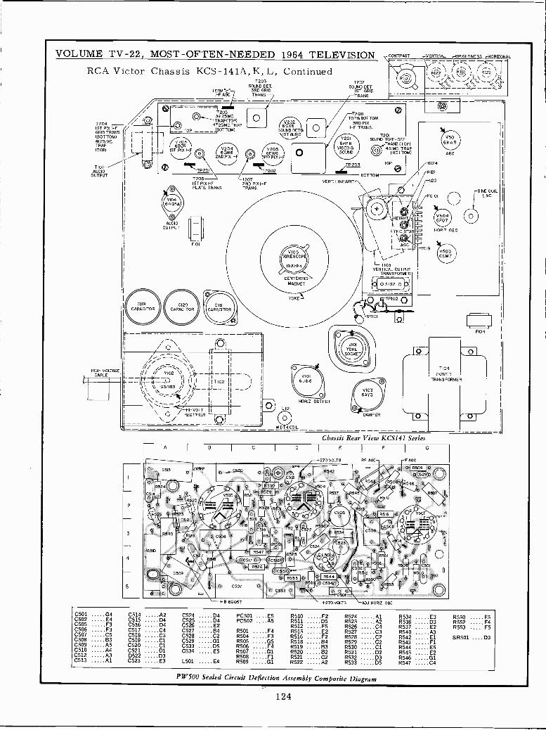
VOLUME TV -22, MOST -OFTEN -NEEDED 1964 TELEVISION
RCA Victor Chassis KCS-141A, K, L, Continued
/// / ClT204 /IST PIX I -F / I I
GRID TRANS --i -I-(BOTTOM/ I
41.25MC.I i I
I
TRAP
TIOIAUDIO
OUTPUT
HIGH VOLTAGECABLE
CI19CAPACITOR
t -
TERM "C-F ABC
T205a_ 39.25MC.TRAP(TOP)
4Z25MC.TRAPTOP ---_ (POTTOM)
I 6BZ6J 1ST PIX I -F
AUDIOOUTPUT
/V204\/ 6GM62NDPIX I -F
.1P201
T206 '-12071ST PIX I -F 2ND PIX I -FPLATE TRANS. TRANS.
1203SOUND CET.
3RD GRIDTRANS
o6GX6
SOUND DETBIS\ T A11D10
/ V20516EW63RD PIX I -F
F101
01R'--Il1,/,-,---:-.:-":,';\ I Ii- \ \ I
% / /% VI02 \\ ,,'1 --µ.-- r-\ -44t- I jl (I'II' T102I\ \\ IG3/IB3 // sill_7'--J--,t_---
\'..'------1..5,\\\ \\ //
.I71 Il`%i`\\ / I -VOLT Ijfj\/ RECTIFIER "r -T
k©/
//
O LIOI
WIDTH COIL
VERTICAL BRIGHTNESS HORIZONALr \ /^ JR1ÍÓ \I RI29
/ ` %.\ \ )-4I
y
HORIZ.OSC
1202SOUND DET.
IST GRIDTRANS
1208TOP& BOTTOM
3RD PIXI -F TRANS.
V2016HF8
VIDEO &SOUND
VERT. LINEARITY
HORIZ. OUTPUT
1201SOUND TAKE -OFF
TRANS(TOP)O 4.5MC. TRAP
(BOTTOM)
TOP
BOTTOM
FO rk\\ NEIGHTS y
IYNC.STAI
\ \ L-r-7103VERTICAL OUTPUT
TRANSFORMER
IC7 0 5102 0)Lh___ 1
Chassis Rear View KCS141 Series
270 VOLTS
R542
504
R537
LL
124
RI21
120
-IFAGC
O.{ R509 }O
C(4529)3
0 R546_.e.
SINE COIL
C501 G4 C514 A2C502 E4 C515 D4C505 F3 C516 D4C506 F3 C517 C4C507 C5 C518 C3C508 B3 C519 ClC509 A5 C520 ClC510 A4 C521 D1C512 A3 D522 D3C513 Al C523 E3
C524 D4 PC501 . E5C525 D4 PC502 .A5C526 E2C527 B4 R501 F4C528 C2 R504 F3C529 G1 R505 G5C533 D5 R506 F4C534 E5 R507 G1
R508 F1L501 E4 R509 G1
R510 F2 R524 AlR511 05 R525 A2R512 F5 R526 C4R515 E2 R527 C3R516 F2 R528 C2R518 B4 R529 C2R519 B3 R530 C1R520 B2 R531 D2R521 C2 R532 D3R522 A2 R533 05
R534 E3 R550 F5R536 D3 R552 F4R537 E2 R553 F5R540 A3R542 El SR501 ....D3R543 F1R544 E5R545 E2R546 G1R547 C4
PW500 Sealed Circuit Deflection Assembly Composite Diagram
124
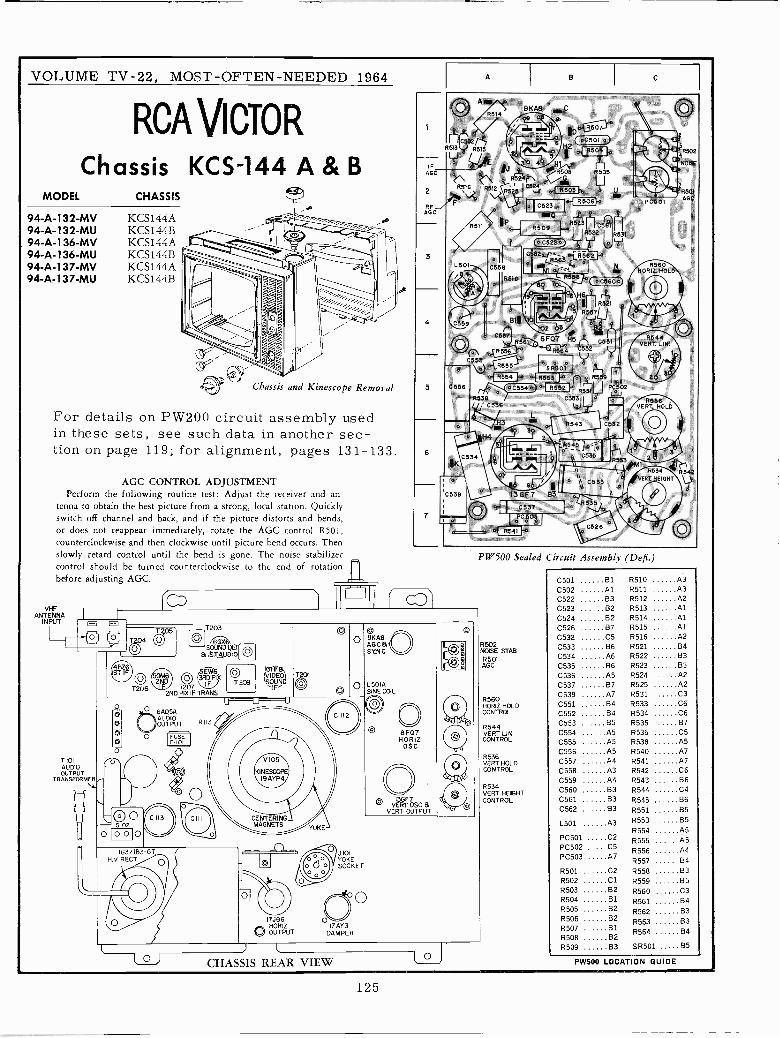
VOLUME TV -22, MOST -OFTEN-NEEDED 1964
RCA Vicio RChassis KCS-144 A & B
MODEL CHASSIS
94 -A -132 -MV KCS144A94 -A -132 -MU KCS144B94 -A -136 -MV KCS144A94 -A -136 -MU KCS144B94 -A -137 -MV KCS144A94 -A -137 -MU KCS144B
Chassis and Kinescope Removal
For details on PW200 circuit assembly usedin these sets, see such data in another sec-tion on page 119; for alignment, pages 131-133.
AGC CONTROL ADJUSTMENTPerform the following routine test: Adjust the receiver and an-
tenna to obtain the best picture from a strong, local station. Quicklyswitch off channel and back, and if the picture distorts and bends,or does not reappear immediately, rotate the AGC control R501,counterclockwise and then clockwise until picture bend occurs. Thenslowly retard control until the bend is gone. The noise stabilizercontrol should be turned counterclockwise to the end of rotationbefore adjusting AGC.
VHFANTENNA
INPUT
T 101AUDIOOUTPUT
TRANSFORMER,L
0T206
163/IB3-6TH.V RECT
D
5 101YOKESOCKET
17JB6 O`HORIZ 17AY3
V OUTPUT DAMPER
8KÁ8.AGC&SYNC
L501ÁSINE COIL
8FQ7HORIZ0SC
O VERT Esc aVERT OUTPUT
) l
CHASSIS REAR VIEW
oC501 a
IMOR501AGC
C560oH6 r,...''. r RS21
pry
R S57
a9 Bt `© ' c55r BfQ7 H5 R567 C51
R556 R564 CSS2
e
Cn5 l 5R5o1V R553 l
o{ R554 E0 0{ g653o , R569
C556
.o
aC554c RS52'i R53 PC502
R538 C333IJ
' C.36
PC501
R544VERT LIN.
5536VERT. HOLD
C334` _ I l r .
oao R533,M1
C539 13 GF7 83
óCó05
PW500 Sealed Circuit Assembly (Dell.)
R502NOISE STABR501AGC
R560HORIZ HOLDCONTROL
R544VERT LINCONTROL
R536VERT HOLDCONTROL
R534VERT HEIGHTCONTROL
C501 81 R510 A3
C502 Al R511 A3
C522 83 R512 A2
C523 B2 R513 AlC524 . B2 R514 AlC526 87 R515 AlC532 C5 R516 A2
0533 B6 R521 B4
C534 A6 R522 83C535 B6 R523 83C536 A5 R524 A2
C537 B7 R525 A2
C539 A7 R531 C3
C551 84 R533 C6C552 84 R534 C6
C553 85 R535 870554 A5 R536 C5C555 AS R538 A5
C556 A5 R540 A7
C557 A4 R541 A7
C558 A3 R542 C6C559 A4 R543 B6
C560 B3 R544 C4C561 83 R545 86C562 B3 R551 B5
L501 A3 R553 85R554 A5
PC501 C2 R555 A5PC502 C5 R556 A4PC503 A7
R557 B4
R501 C2 R558 03R502 Cl R559 85R503 82 R560 C3R504 B1 R561 B4R505 B2 R562 B3R506 B2 R563 63R507 BI
R564 B4R508 B2R509 B3 SR501 B5
PW500 LOCATION GUIDE
125
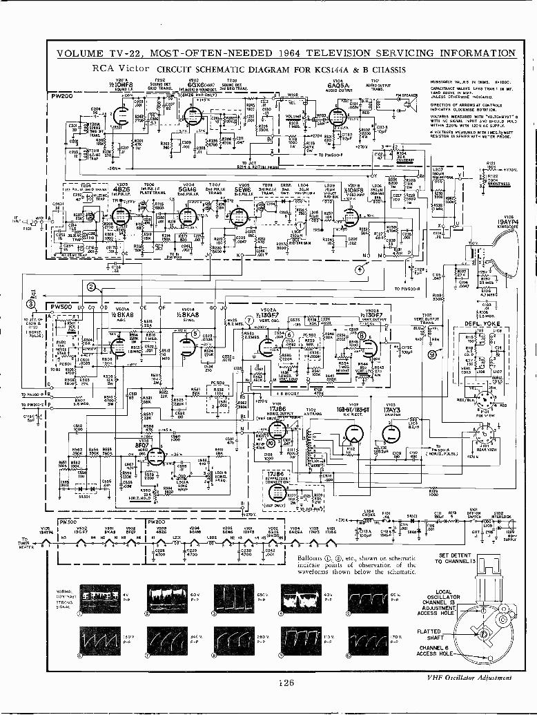
TODD 0104 1101 RESISTANCE VALUES IN OHMS. 0.1000.VL1OHF8 SOUNDDET 6GX6IVHF) SOUN00ET. AuoloouTPUTTRANS.
W200 +.130v. ---1(6H26 UHFONLY)
0205 1
3 .001
0$023
VOLUME TV -22, MOST -OFTEN -NEEDED 1964 TELEVISION SERVICING INFORMATION
RCA Victor CIRCUIT SCHEMATIC DIAGRAM FOR I{CS144A & B CHASSISV201Á T202 0202
6AQSAAUDIO OUTPUT
PM SPEAK,'
C204St -.1P 2
T201ASOUNDTAKEOFFTRANS.
R201
C203 i4T2018 7235I2 4.5 MC 270
y_.. TRAP
SOUND I.F. 6RI0 TRANS. 1St AUDIO a SOUND DET. 3rd GRIDTRANS.
4270Yw
r -- T204---1 0203pI St Pm. IF.GRID TEASE' 46Z6I C23 41.35543; 1M.PIK.I.F.
47 TRAP
C240II TPI
5
F WI01 Al IINRI- P101
22
C214
nI
.r711123 .22
`1 17W500 úo c Oó V601A
4 IA --31 V28KA8CJCT. O1O9 8F 8601 1
AGC
CIIO 1 I K IA.
TO P
TO PW200-2 p
TO7UNE8HEATER
R509I2K2W
R5075.6 MEG.
R201470IW
7200SSt.PIK. LF.PLATE TRAN6.
514 R.i6220K 1 MEG
1W
8613LS KS
C502.001
05111062W_
R62222K
1255733K
V2045GM62nd.PIK.I.F.
72072nd PIK. I.E
TRANS.o
K T.
0219150
R220 -It-15600 -
KO .001
+2700 R10I
R119eW
47KW
V205 7206 CR201 L2045EW6 3rd.MK.I.F. 2nd. 36FI11
3rd.PIP.LF. TRANS. DOT. YEL:YEL-5ML
-
F V501 GO JOV28KA8
SYNC.
RS1210MEG.
65504W +1+5Y11
65601000V503
8FQ71R654 8555 NORIZ390K 560K 06 050.
8551 855210014 10016
0554
1500I - 1
L -
100
;M1 50.501
PW SOOVIDS 1 V502
19AYP4 130 F7IH3
t 1 4 5
LNORMALCONTRAST
STRONGSIGNAL
C555.001
6557470
}R558 I120K00556
I.0360560
25KNORIO. HOLD
-TN 200VE01 vE03 V203EKAE 8f07 I 4626
114 142 III 045 NI L201
4 4 5 3 4
130V.P -P
02281 ]4700L
36 V.
R53182K
C523 q.0033+25Y.rv
R524270K
C6270
R525
C532-.0012".
PC 502r-- I 05321?;
ÉÉ
TC531 1 105622 '°°2 i >390K
02 I
C558470
*200Y.
V5 O2A
1136E7VERY OSO. IC535
.015
rapa. 8C634.033
L20972PNVIoL67-RED -INK
tiü0'
1 Rm536i053533KrJD022
65381.0024
+270Y. 3-P- 12 I
V201B
)410H F8VIDEO AMO0o v.
9
R534C533 6362 1
1MEG.0.541 HE=ONT00K
I T N1066ÓKº 0M V RT HÓLD I 11r-_ -_ RÍ -28
40544000T 43.21
i2'oVV1o1
17J86 7102NORI2.0UTPUT H.VT0.ANS.
(VHF ONLY) .....r
C539015
N -42O Íclo9i6'
64%TT1 I
R5616µ
F19
C ÓÍOF
45.1411,4---áLOGIA 2 F5,0,1p.
R WAVE
SINE
C1061000
ROSS22011 L- 3
13W
riiJéi
sSUPPRESSOR 1
I CONNÍCTION`
Bt ;
vi(UNF ONLY)
+270V.L _ - -- -
5
R104
WÑTRA5T
YR226
620682007w
390yHORN-WN1
1C227ERN T100
90
V5028Vz13GF71FRT.OVTPUT
O
R544
RTOVE LI
V102
1G3GGT/183-GTN.V. SECT
+2700
V204 V206 V201 V202 V104 V103 V101SOM6 SEW6 1014F8 6006 I 6AQSA VATS 17J66
L202 H2 143 144 5516626)16
3 40229
60V.P -P
340V.P -P
3 5 4 3 4 1 4 30230 C242
I4700 IDDi
J
650VP -P
280 V.P -P
4
R228iBK2W
56002921W
TO PW500-R
Ví03
17AY3DAMPER
L1025.2101 CI09
C61H OK04E F..4A11
611 EL
t L113A C112ÁI100PF IB0PFi
CAPACITANCE 101WE5 LESS THAN 1 IN MF.I AND ABOVE IN MMF.UNLESS OTHERWISE INDICATED.
DIRECTION OF ARROWS AT CONTROLSINDICATES CLOCKWISE ROTATION.
VOLTAGES MEASURED WITH VOLTOHMYST 8WITH NO SIGNAL INPUT AND SHOULD HOLDWITHIN 320% WITH 120V. AC SUPPLY.
if VOLTAGES MEASURED WITH 1MEG.y2 WATTRESISTOR IN SERIES WITH METER PROBE.
L207180>rH y5R06ORY.6R9.
000
32303900
"..R232(1 MEG
C124.22T --
T103VERT. OUTPUT
TRANS.
8.20404
0 V.
C104.0047
RED/BLK.7
-PV :100-A
TO00-Á
( HORI2. PULSE)
R1291000
V105
19AYP4KINESCOPE
RI21
270V.
R1222006RRIO6TNE55
ti 46 P101 5PIN VIEW
.1101REAR VIEW
5101C111 0113 OFF -ON 0102
50101 1S0KF 5 SWRCN INTERLOCK
1 Ci16 LI09
5R .I.001
1
6 CtlBjl 1200.
.1 I}.1 I1_ FOSUPPLY
Balloons 10, ®, etc., shown on schematicindicate points of observation of thewaveforms shown below the schematic.
40v.P -P
110 V.
P -P
60V.P -P
170V.P -P
SET DETENTTO CHANNEL 13
LOCALOSCILLATOR
CHANNEL 13ADJUSTMENT
ACCESS HOLE
FLATTEDSHAFT
CHANNEL 6ACCESS HOLE
126VHF Oscillator Adjustment
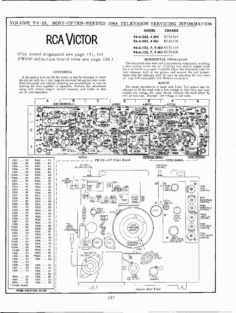
VOLUME TV -22, MOST -OFTEN -NEEDED 1964 TELEVISION SERVICING INFORMATION
MODEL CHASSIS
RCA VICTOR(For sound alignment see page 131; forPW500 deflection board view see page 136.)
CENTERING
If the picture does not fill the screen, it may be necessary to centerthe picture with the 2 disc magnets mounted behind the yoke cover.Both horizontal and vertical centering are accomplished at once byrotating the discs together or separately. Perform this adjustmentalong with vertical height, vertical linearity, and width, as theyare all interdependent.
A BAGC (NOMINAL)
C201 F2 R204 .... ClC202 02 R206 .... 81C203 F3 R207 .... AlC204 F2 R208 .... B2C205 E2 R209 .... B1
*C208 D2 R210 .... A2*C209 El R211 .... B2
C212 D1 R212 .... B2C213 Cl R213 B1....C214 A1 R214 .... C2
R215 .... B38216 .... B3R217 .... C28218 .... C2R219 . . . . D3R221 .... D2R222 .... E3R223 .... F3R224 .... G3R225 .... F1
R226 .... FIR227 .... F1
R228 .... G18229 .... G2R230 .... G1R232 .... 01R235 .... C2R236 .... F1
R237 .... F3R238 .... F1
R242 .... G1L202 C3 R243 .... E2
L203 E3 *R245 .... Dl
L204 E3 T201 .... G2L205 E3L206 G2 1202 ElL207 G2 T203 ClL209 F3 T204 Al
T205 81R201 El 1206 B3R202 E2 T207 C3R203 El T2G8 D3
* Under Board
C215 .... Al
C216 .... B2
C217 .... B1
C218 .... B2
C219 .... B2
C220 .... 82
C221 .... C2
C223 .... D2
C224 ....- D3
C225 .... E3
C226 .... G3
C227C228 .... A3
*C229 .... B3
*C230 .... D3
C235 .... F2
C237 .... Fl
C238 .... F1
*C242 .... D1
*C245 .... E2
*C246 .... D2
CR201 ... E3
PW200 LOCATION GUIDE
VHFANTENNA
INPUT
94-A-083, 4 MV KCS143A94-A-083, 4 MU KCS143B
94-A-102, 7, 9 MV KCS143A94-A-102, 7, 9 MU KCS143B
HORIZONTAL OSCILLATORThe horizontal sine wave coil is adjusted by temporarily attaching
a short jumper across the coil (L50IA) and another jumper fromPin 2 of 8KA8 to ground. Carefully adjust the horizontal hold forleast sideways drift of the picture and remove the coil jumper.Again stop the sideways drift (if any) by adjusting the sine wavecoil slug with nonmetallic tool. Remove all jumpers.
WIDTHThe width adjustments is made with L101. The picture may be
adjusted to fill the mask with a line voltage of 108 volts, and withnormal line voltage, the raster should overscan the mask about 5/8inch on each side. 'Normal" line voltage is 120 volts.
C1
4ae,rr,.'iR2141g `1R23S; e V 021"
223 R
+270V
ON/OFF-VOLUME CONTROL
PW200-I-F, Video Board
E+160V.
IF
+270V
20
VIDEO SIGNAL
CONTRASTCONTROL
G
L_1
T 101AUDIOOUTPUT
TRANSFORMER-
T205
0
48Z61ST IF
T206
5GM2NDIF
T203
eGX6 T202SOUND O
AU&ISTDO
O5EW63RDPIX
T207 IF2ND PIX IF TRANS
`T 208
O
OoO
oO
oO
O
OAUDIOOUTPUT
.
OSID2o
O O O O
O FUSE1,F-101
/ \
R113
U
153/ 163 -ITH.V RECT
IO HERVIDEO
SOUND IF
U
O
T201
YOKE
17JB6HORIZ
O OUTPUT
/ 101YOKESOCKET
Off .17AY3
DAMPER
8KA8AGC&SYN
L501ÁSINE COIL
C
8FQ7HORIZOSC
OVERT OSC &
VERT OUTPUT
~ O
a/ry.6o
Chassis Rear View
Mug
R 501AG CCONTROL
R571BRIGHTNESSCONTROL
R560HORIZ HOLDCONTROL.
R544VERT LINCONTROL
R536VERT HOLDCONTROL
R534VERT HEIGHTCONTROL
127
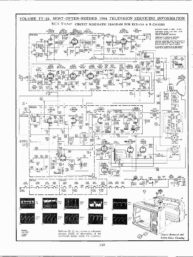
VOLUME TV -22, MOST -OFTEN -NEEDED 1964 TELEVISION SERVICING INFORMATION
RCA Victor CIRCUIT SCHEMATIC DIAGRAM FOR KCS143A & B CHASSISV201Á 1202 V202 7203
1,210HF8 SOUND DET. 6GX6(VHF) SOUND PET
SOUND LE GRID TRANS. IKAUDI5650UNODET 31d GRID TRANS.
PW 2-00 2ºK -.1(6/4 ONLY)-- 26 ONF
f iD .ITS.
C20456 _3Y.
r1
1204'
I
1st PIK.I.F.GRID T0..
1
v Iwim A
PI01 v *IVNF90214
.5% IUNFSO VIc,0211,
PW200z I P
V2034BZ6
182FIR,I.F.
I TPI
R209' 56
1000
T205147.25MC C216- C217LTAAP .WI= .00IIjO
R501506AGC
C5521OÍ 0
I R551
R553C1061000
r30T .39
0D v50IAY28KA8
AGO
205.001
C209680 401 020
1.01
T2061st. PIA. I.F.PLATE TRANS
R51522K
5GM6and. PIG, I.F.
12072nd PIS. I.0
TRANS.K
OF V501B D
Yz8KA8SYNC.
R509 15111 'pdfi3' 1.2ME0. I
12K V60.TXOLO Zi B20K12K 2W{
PC 502 NIO560K= OM2WTRS3I i R532 ' r -- - - - RÍ28- -
10551 R522 F 82FIL 110K Ip 1 4 +R 00oST
R510 82 6521 47K 1 Í'.Y 31 FB 14700 396 ÚK 1 C5311 2562
+2705V101 5102 V103
R657 cszz21 39aK 17J86 7102 163'GT/1B3'6T 17AY3L---' H0R12.0UTIUT N.V.TRANS. N.V.RECT. DAMPRR
39K_
100 T Oa (VHF ONLY) . ,`.,
Be v
R524270K
TO Jc1R214 6 R2170BI-F62001
iC223 C24.C222 401 6801'
R22150 0047 470
KO Áo1
W102_
TEL
V104 T101
6AQ5A. Au010
AUDIO OUTPUT
C1I3D200F
70 PW500 P
CR201 L204 L2092nd. 3601 7204DET. YEL:YLL:BIU. VIOLET
REDBLR
} II1533 I CS34O 50.12.2ME6. 8 .033
C 37 i R539 T
.0082 13 6015. 1-y
0538.2535 I 21_00241
L2205 _
R702 TCñ3c
12700
14101 F/48VIDEO AMR
R5341 MEG.
HEIGHT
SPEAKE
610430KCO BAST
0.228
OW _T
C112C
-11o0PF
1I
L12,r 01261
------.....'1'427130.B'J T '
z9wlI (UHF
R'I
4 L___ J101-PIN L1045101
-$22700 CHOKE FI01 Cnl RI1S OFFON 5102- ,4A SR101 15W<M/A INTERLOCKPW500 --- IrW2OO ---- 27000.FD VEL
v502 V501 VS03
0116 T0116 LI09
19AYP4 ! 15057 6KA6 BFQ I 4826 5GM6 SEWS IOHFIS BÓX6I V104 0103
BApSA lAV3 I]JB6 + CII3A CII2A OUISRHK lOUl Otl] [II 120V
H2 NI H5 Ns I NI L201 L202 M2 N3 H4 NS(6H26)N6IIIOOyF i50PF _ .I T .I 80T 1 1- SUPPLY
RESISTANCE VALUES IN OHMS. 11.1000.
CAPACITANCE WLUES LESS THAN 1 IN MP.I MID ABOVE IN MMF.UNLESS OTHERWISE INDICATED.
DIRECTION OF ARROWS AT CONTROLSINDICATES CLOCKWISE ROTATION.
VOLTAGES MEASURED WITH WLTOHMYSTWITH NO SIGNAL INPUT AND SHOULD HOLDWITHIN 220% WITH 120V. AC SUPPLY.
M VOLTAGES MEASURED WITH IMEG.I WATTRESISTOR IN SERIES WITH METER PROBE.
L207180yNsur-BRK
1105VERT. OUTPUT
TRANS.C
510IIe YEL
r--1 15I 2 1 R571 B2 1
20oKNRIGNTNF35
PART OF I
PW500
3
V105
19AYP4KINESCOPE
DE FL. YOKEr 105 L108 2
REO/BLS.
ToPW50O-A
( HORI2. PULSE)
6 P101PIN VIEW
6"RIREAR VIEW
270 V.
TO 6 1
TUNERHEATERS
NORMALCONTRAST
STRONGSIGNAL
I C555S00
_ 5R50
47K º6 v. N º
+260 v C360 R10'
V503 1000 C 47 3 010'8F071 6
auo .a4R554 0555 OM2 0.561 470K
390VK- 56011 7 -71.o_20 v. --.66KC4T.n ..
ó59 4701t
R556 Fp 5 3e L5018Z120K
I 2200 : 4s.Y II HORIZ.
- C005C556
3LS NIÉ ZS FREp.
Z.G56 R561NJI - R560
23 WAVF
25KNORI2.HOL0
4 5 9 q 4 5 3 4 3 4C228 022s4700 14700L1_---
130V.P -P
60V.P -P
340V,P -P
650VP -P
280 V.P -P
r 17JB6 1I I EUPIRESSOR I
I COON CTION,_
5 4 3 40230 C242
14700
Balloons Qi , ®, etc., shown on schematicindicate points of observation of thewaveforms shown below the schematic.
40V.P -P
110 V.
P -P
4 5 4
81291000
60V.P -P
170V.P -P
Chassis Removal andSafety Glass Cleaning
128
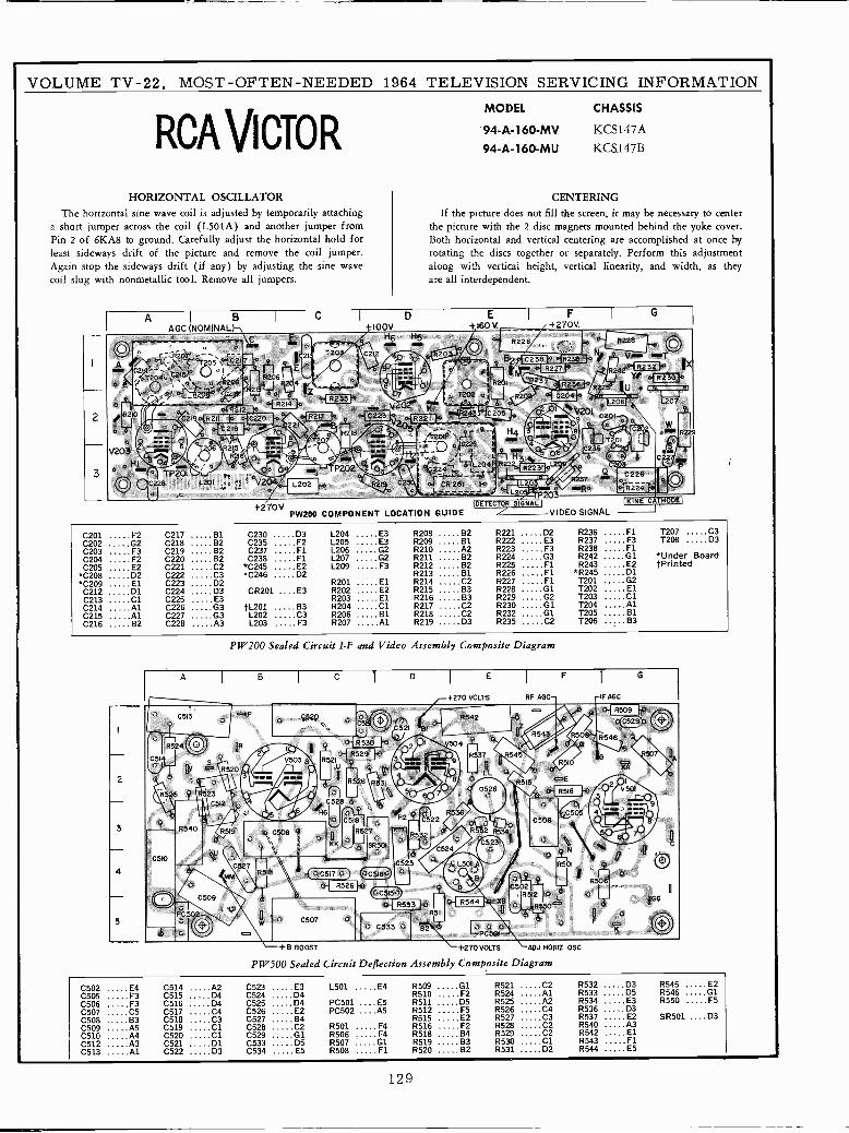
VOLUME TV -22, MOST -OFTEN -NEEDED 1964 TELEVISION SERVICING INFORMATION
HORIZONTALThe horizontal sine wave
a short jumper across thePin 2 of 6KA8 to ground.least sideways drift ofAgain stop the sidewayscoil slug with nonmetallic
RCA VICTOR
OSCILLATORcoil is adjusted by
coil (L501A) andCarefully adjust
the picture and removedrift (if any) by adjusting
tool. Remove all
temporarilyanother
the horizontalthe
jumpers.
jumper
coilthe sine
attachingfrom
hold forjumper.
wave
MODEL CHASSIS
94A -160 -MU KCS.147B
CENTERINGIf the picture does not fill the screen, it may be necessary to center
the picture with the 2 disc magnets mounted behind the yoke cover.Both horizontal and vertical centering are accomplished at once byrotating the discs together or separately. Perform this adjustmentalong with vertical height, vertical linearity, and width, as theyare all interdependent.
A I B I
cI
DI E 1 F I
G
AGC(NOMINAL) I00V. +160V. +270V.ff
Q. , ,^ qi ¡^-. B228 O:y
... Nr--:.1-21. ppR226 V T.C21 . tif+'- L R238A <01117,41-2N-CCI
gT205iC211. .:
E414 M.e ¡T2o. R2510 x si R2
og,I.1,', 4ÍR214lo V a ... ..2 ,{R21U
12
021 R211
.1R221
C205 V20IG220 . 45217 p ! 4223
'4up . .1219
Z 7 : Qg-º_
R le H4 i8w.s e RT2s
T2Ó6 215V203
1r20E1 ri iY : -. . . l/Y, q,lcvg
6 I g 121' '`iL 1
°17211V ,e 4.s H C2 5 T
C
q M ./'\ '` P202 221 bIL2041C35 O >. R22
0228TP201
L201
o J _V204 L202 .... -: Cr'y u7 CR201 W
..oR224''` C228 O:e
._ L20" ...o ... ... .. .
DETECTOR SIGNALI 171'Idi:[T]+270V /PW200 COMPONENT LOCATION GUIDE VIDEO SIGNAL
C201 F2C202 G20203 F3C204 F2C205 E2
*C208 D2*C209 El
C212 D1C213 C1C214 AlC215 AlC216 B2
C217 131
C218 82C219 B2C220 B2C221 C2C222 C3C223 D2C224 D3C225 E3C226 G3C227 G3C228 A3
C230 D3 L204 E3 R208 B2 R221 D2 R236 Fl T207 C3
C235 F2 L205 E3 R209 B1 R222 E3 R237 F3 T208 D3
C237 F1 L206 G2 R210 A2 R223 F3 R238 FlC238 F1 L207 G2 R211 B2 R224 G3 R242 01 *Under Board
*C245 E2 L209 F3 R212 B2 R225 Fl R243 E2 tPrinted*C246 D2 R213 B1 R226 Fl *R245 D1
R201 El R214 C2 R227 ......F1 T201 G2
CR201 ....E3 R202 E2 R215 B3 R228 G1 7202 ElR203 E1 R216 B3 R229 G2 T203 Cl
tL201 83 R204 Cl R217 C2 R230 G1 T204 AlL202 C3 R206 B1 R218 C2 R232 Cl T205 131
L203 F3 R207 Al R219 D3 R235 C2 7206 83
PW200 Sealed Circuit I -F and Video Assembly Composite Diagram
A IB I C
1D I E I F I G
+270 VOLTS RF AGC -IF AGC
c:P aa\ ' R®1
C513 J G520 0..
....' .,
rVPY\
! R542110 ,0321 -181 Rso
C51
R524iGlll tlR/ `. R330' ;' QI Y504,
R329
..,/R537`' J '
R546
G '507
2
Y c. R520.l,,
V503 8
3
R521
u`i¡(
8y
R528 R53 ,
R510
11515 ,aE I
. :..
tN l'SS 5 ... . 23
-
. C5 6 . , .. 50i1
,...-'H6
C528
nC518 H2
r 1
{y Rá338522 .
0'
0508
90503 4
3 R540 v 1i it~ A+
5519 C508 Q" . S J OKK11527
0 SR
. 11532'0 ii .r `
R 52 lasd1
Y 7iC323 4 (
"C524
-C510 . '3 C323 ` L301, 5501 04 M
327
i7. ;i
RSIB QCStB, 0 1'. LEM ' 'ap B 5 2 R506
C509 RSIR:... ..I 11544 `' oGG
ppu
.ü.PC502O C507 0
a, R511
5 W® 1: 0533 '0 L. 0 qü c 82
PC +8 BOOST +270 VOLTS ADJ HORIZ OSC
PW500 Sealed Circuit Deflection Assembly Composite Diagram
C502 E4 C514 A2 C523 E3 L501 E4 R509 G1 R521 C2 R532 D3 R545 E2
C505 F3 C515 D4 C524 .....D4 R510 F2 R524 Al R533 D5 R546 01
C506 F3 C516 D4 C525 D4 PC501 ....ES R511 D5 R525 A2 R534 E3 R550 F5
C507 C5 C517 C4 C526 E2 PC502 ....AS R512 F5 R526 C4 R536 D3
C508 63 C518 C3 C527 B4 R515 E2 R527 C3 R537 E2 SR501 ....D3C509 A5 C519 Cl C528 C2 R501 F4 R516 F2 R528 C2 R540 A3
C510 A4 C520 Cl C529 G1 R506 F4 R518 B4 R529 02 R542 ElC512 A3 C521 D1 C533 05 R507 Cl R519 83 R530 Cl R543 FlC513 Al C522 D3 C534 E5 R508 F1 R520 B2 R531 D2 R544 E5
129
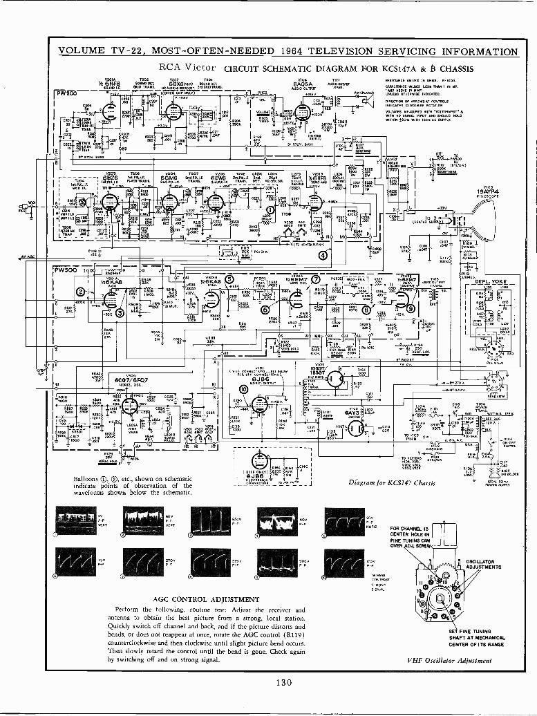
Wool
VOLUME TV -22, MOST -OFTEN -NEEDED 1964 TELEVISION SERVICING INFORMATION
RCA Victor CIRCUIT SCHEMATIC DIAGRAM FOR KCS147A & $ CHASSISV201A 1202 V202 1203
92 614F8 6011ND DEr 6GX6(vNF) FOUND DFESOUND LF. GRID TRANS. _1St106 FOUNODET 3rd ORIDTRANs,
PW200 6v l(6N26 UNFONLY) ` E1 _WID2
.001
'
S_ _ _
CM OYFL.--- -I 1 7 rt.-8 -1
C212 VOLWL=MEIJ211lYlID03I=00f))P201
I R1MFG.IIOÑN
7390K 1 º 4
III1;;9 I
82
0203 T206
r 1204 66Z6 PLATEA1 IIT.PM.I.R I iSLPIK..F.
GRID TR.1 1P1 i 1
I ;b R105...
PI01 I 0214M VHF11.0 .-4sl UNF 11.5 o C2D¡_ R209 '
RFAOC
I e IOD- 1 :147,2516C e218- e21 I
LTPAP A012 .001Iio
r3 j O D0
I.1.0:116000
12627 R5733906 390K
ÓK1--12MS100 rN4
o66TR32B SR601 RESW2 CS 7 C5í9 2
I
I1600 T 00,
R12925K
IIDEIT HOLD 3
R5116F F 00
MY
J
.047
6A0Q5AAUDIO OUTPUT
+2150BLUEll
1101AUDIO OUTPUT
TRAME.
MI193)R105 T IOYP
4WyY °it_ P
B 270V. BUSS
4
V204 1207 V205 T2OM C0.201 L2046GM6 2.04 P12.1.1 6EW6 316008.1.E and. 36011224.1212.1.5. TRANS. 3r6PM.LF. TRANS. DOT. YEL-YEL-BLS
4 _ *160vr-
7` R646 IOT N 05018
6KA8 }22K C600y26 A8
AGOK-
9 ' R.0] 0.609 0.615 332 y26 1 ME 4.
ll+720.,
S R909Sj ,1pME0, iío3 © MEa41 T 902
fBOV. ...111 8544_3O6K 22K2V
V5046CQ7/6FQ7
000.12. OSC.
63320.529 473GOK
24709
*10.50 -LSOIA
SINEWAVE
104
85403 2
2W' C515y 853382^
AI
R637 _CSE6e I
601V501 V503 6001.xSW6E1471 67
5 e 3E
H6 N]
Balloons QQ 2Q, etc., shown on schematicindicate points of observation of thewaveforms shown below the schematic.
4P -P
VERT
75VP -P
600.P -P
VERT
270,,P -P
82
520,22011 0507 1
L20972PNV10LeFRED -MK
OS
IR122121E0VE0.T.Ip1.D
02018
)16HF8VIDEO AMR
*1090
W IMO
( VHF CONNECTIÓÑi9..,saE 86L4WFOR cONNECTIoNe)1
N6J B 6 PUT
S0.131470K
-Ci15TIDDD
1*1400
C116 ozFó0472 L101
1_ W1=Tx
132 6 (} OK
CI21L10 3
281,022
A--só"DL
4f454]OK
-,3ü0DA,
CIC 10730
RESISTANCE VALUES IN OHMS. 6.1000.CAPACITANCE MOUES LESS THAN 1 IN MF.I AND ABOVE IN MMF.UNLESS OTHERWISE INDICATED.
DIRECTION OF ARROWS AT CONTROLSINDICATES CLOCKWISE ROTATION.
WITAOE5 MEASURED WITH WLTOHMYST OWITH NO SIGNAL INPUT AND SHOULD HOLDWITHIN 320% WITH 1202AC SUPPLY.
- - - TOW BOWÑ -1
OYR226
EMtMYiRY O8200 1é12t8]Y 2w
O4X-WxE C217 6Éá S0.A
IW100
II
.xsVXJTOX
(NEATE0. SUPPLY) ¡'8y2'
s43j43/0V
0.5231 R54033Kí 270
VIÓ211B36T/ 6
1000H.2 RECT.
7
oT,02.V. R133
Tits 17
r 1
I
1
61
1
I R186 K184 0140 I
( UHF ONLY) 3W° 4701W
T.1iI
,N6UPPB6soR =
L CONNRCTION TDJwWN T J
6500P -P
2250.P -P
40VP -P
9000P -P
AGC CONTROL ADJUSTMENTPerform the following, routine test: Adjust the receiver and
antenna to obtain the best picture from a strong, local station.Quickly switch off channel and back, and if the picture distorts andbends, or does not reappear at once, rotate the AGC control (R119)counterclockwise and then clockwise until slight picture bend occurs.Then slowly retard the control until the bend is gone. Check againby switching off and on strong signal.
036AY3
DAMPER
CI710/09 - .044710067
ill R117>33001
VERT.OVTPViTRANS.
4 YELYEL
1*
00N Om,I1
NF
R1242 850
VERT. LIN.
68 8005T
L
i --OF 270V.
-1.21+ 270 V
V10519AYP4KINESCOPE
L9 1.108 1107
0Ó_ü0
VIL., GZN.
0.20/60(.
PIN VIEW
54
J101REARVIEW
L104 C118 1104CHOKE F101
50 PowER
= 4A YF TRANS.
( C120A dII9A * 139 160AF e
BRIO,1 0F RECL IC' 92 a
TO V OS 1 PER.
PIN 8X LO-o0.Kr
6.SV A.0F102 BRN. o
N28AWG á1Vo-- MIT0HEATERS--qíNWG--
VIO4 0201,V202,V203,V204,V205
I
R1062.2
MEG,
J
RED
1
6101
58 00F
0117047
5102INTERLOCK
Diagram for KCSI47 Chassis Pool i 5ú0.w
60V
NORIZ
1700P -P
NORMALCONTRAST
STRONGSIGNAL
FOR CHANNEL 13CENTER HOLE INFINE TUNING CAMOVER DJ. SCREW ---
OSCILLATORADJUSTMENTS
FINE TUNINGSHAFT AT MECHANICALCENTER OF ITS RANGE
VHF Oscillator Adjustment
130
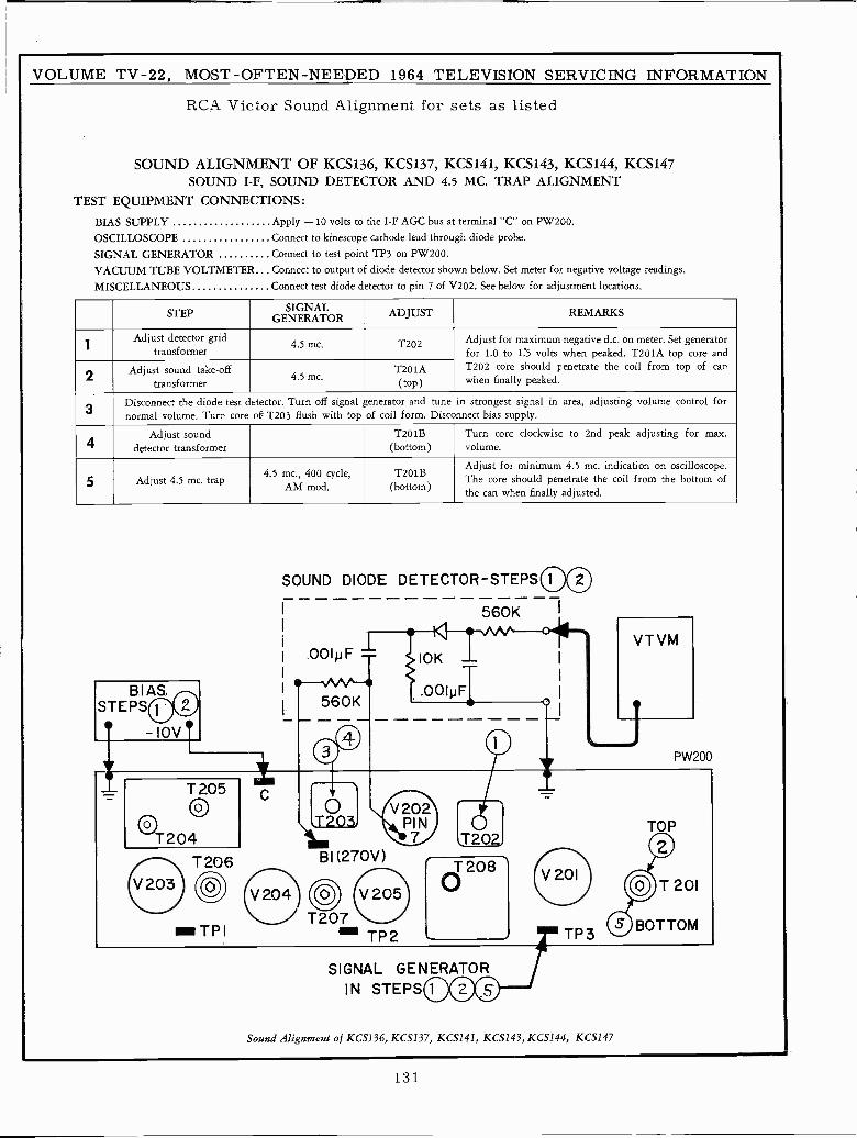
VOLUME TV -22, MOST -OFTEN -NEEDED 1964 TELEVISION SERVICING INFORMATION
RCA Victor Sound Alignment for sets as listed
SOUND ALIGNMENT OF KCS136, KCS137, KCS141, KCS143, KCS144, KCS147SOUND I -F, SOUND DETECTOR AND 4.5 MC. TRAP ALIGNMENT
TEST EQUIPMENT CONNECTIONS:
BIAS SUPPLY Apply -10 volts to the I -F AGC bus at terminal "C" on PW200.
OSCILLOSCOPE Connect to kinescope cathode lead through diode probe.
SIGNAL GENERATOR Connect to test point TP3 on PW200.
VACUUM TUBE VOLTMETER Connect to output of diode detector shown below. Set meter for negative voltage readings.
MISCELLANEOUS Connect test diode detector to pin 7 of V202. See below for adjustment locations.
STEP SIGNALGENERATOR ADJUST REMARKS
Adjust detector gridtransformer
4.5 mc. T202 Adjust for maximum negative d.c. on meter. Set generatorfor 1.0 to 1.5 volts when peaked. T201A top core and
2Adjust sound take -off
transformer4.5 mc.
T201A(top)
T202 core should penetrate the coil from top of canwhen finally peaked.
3Disconnect the diode test detector. Turn off signal generator and tune in strongest signal in area, adjusting volume control fornormal volume. Turn core of T203 flush with top of coil form. Disconnect bias supply.
4Adjust sound
detector transformerT201B
(bottom)Turn core clockwise to 2nd peak adjusting for max.volume.
5 Adjust 4.5 mc. trap4.5 mc., 400 cycle,
AM mod.T201B
(bottom)
Adjust for minimum 4.5 mt. indication on oscilloscope.The core should penetrate the coil from the bottom ofthe can when finally adjusted.
SOUND DIODE DETECTOR-STEPSOO
560KI
I
.001p F- 10K -. I
I
VTVM
BIAS I .00IpFSTEPS' -lav
©Oj PW200
TTT205
C
-_0
o0 V202
PINr
ToT204 7 j20Z.
T206 BI(270V)
V203 0V2O4 OO V2a5
T207m TPI - TP2
T208®
V201©T201
Q BOTTOMTP3
SIGNAL GENERATORIN STEPS COO.
Sound Alignment of KCS136, KCS137, KCS141, KCS143, KCS144, KCS147
131
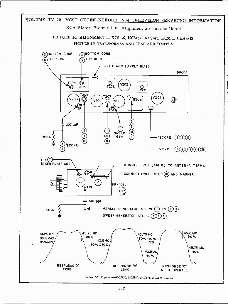
VOLUME TV -22, MOST -OFTEN -NEEDED 1964 TELEVISION SERVICING INFORMATION
RCA Victor Picture I. F. Alignment for sets as listed
PICTURE I -F ALIGNMENT - KCS136, KCS137, KCS141, KCS144 CHASSISPICTURE I -F TRANSFORMER AND TRAP ADJUSTMENTS
BOTTOM CORE ()BOTTOM CORETOP CORE TOP CORE
L11
MIXER PLATE COIL
50>t
41.25 MC98% MAX.85%MIN.
RESPONSE "A"T208
I F AGC ( APPLY BIAS )
PW200
000000000
CONNECT PAD (FIG.8) TO ANTENNA TERMS.
CONNECT SWEEP STEP (10) AND MARKER
KRK 103,104,107,108
1500pp.F
4111 --MARKER GENERATOR STEPS
SWEEP GENERATOR STEPS
45.75 MC85%
42.5 MC70% ±10%
45.75 MC70% +10%
-5%
RESPONSE "B"LINK
42.5 MC40%
45.0MC90%
RESPONSE "C"RF-IF OVERALL
Picture 1-F Alignment-KCS136, KCS137, KCS141, KCS144 Chassis
45.75 MC45%
132
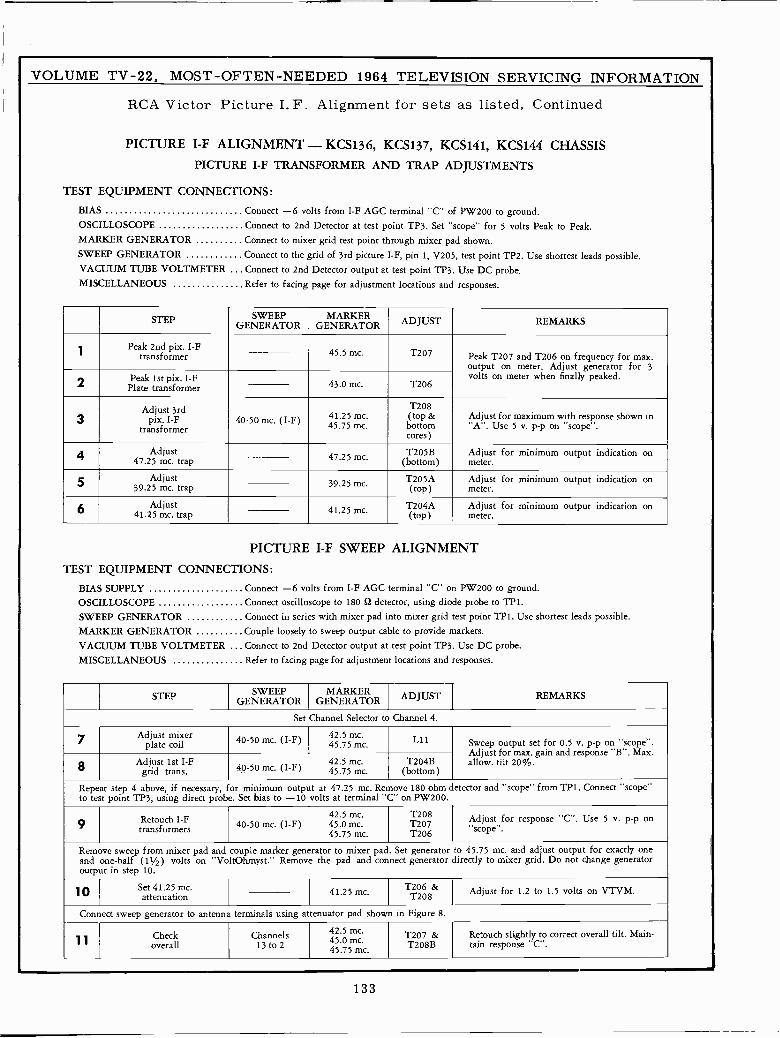
VOLUME TV -22, MOST -OFTEN -NEEDED 1964 TELEVISION SERVICING INFORMATION
RCA Victor Picture I.F. Alignment for sets as listed, Continued
PICTURE I -F ALIGNMENT - KCS136, KCS137, KCS141, KCS144 CHASSISPICTURE I -F TRANSFORMER AND TRAP ADJUSTMENTS
TEST EQUIPMENT CONNECTIONS:
BIAS Connect -6 volts from I -F AGC terminal "C" of PW200 to ground.OSCILLOSCOPE Connect to 2nd Detector at test point TP3. Set "scope" for 5 volts Peak to Peak.MARKER GENERATOR Connect to mixer grid test point through mixer pad shown.SWEEP GENERATOR Connect to the grid of 3rd picture I -F, pin 1, V205, test point TP2. Use shortest leads possible.VACUUM TUBE VOLTMETER Connect to 2nd Detector output at test point TP3. Use DC probe.MISCELLANEOUS Refer to facing page for adjustment locations and responses.
STEP SWEEPGENERATOR
MARKERGENERATOR ADJUST REMARKS
1Peak 2nd pix. I -F
transformer 45.5 mc. T207 Peak T207 and T206 on frequency for max.output on meter. Adjust generator for 3volts on meter when finally peaked.
2 Peak 1st pix. I -FPlate transformer 43.0 mc. T206
3Adjust 3rd
pix. I -Ftransformer
40-50 mc. (I -F) 41.25 mc.45.75 mc.
T208(top &bottomcores)
Adjust for maximum with response shown in"A". Use 5 v. p -p on "scope'.
Adjust47.25 mc. trap 47.25 mc. T205B
(bottom)Adjust for minimum output indication onmeter.
5 Adjust39.25 mc. trap 39.25 mt. T205A
(top)Adjust for minimum output indication onmeter.
6 Adjust41.25 mc. trap 41.25 mc. T204A
(top)Adjust for minimum output indication onmeter.
PICTURE I -F SWEEP ALIGNMENT
TEST EQUIPMENT CONNECTIONS:
BIAS SUPPLY Connect -6 volts from I -F AGC terminal "C" on PW200 to ground.OSCILLOSCOPE Connect oscilloscope to 180 Q detector, using diode probe to TP1.
SWEEP GENERATOR Connect in series with mixer pad into mixer grid test point TP1. Use shortest leads possible.MARKER GENERATOR Couple loosely to sweep output cable to provide markers.
VACUUM TUBE VOLTMETER ... Connect to 2nd Detector output at test point TP3. Use DC probe.MISCELLANEOUS Refer to facing page for adjustment locations and responses.
STEP SWEEPGENERATOR
MARKERGENERATOR ADJUSTJ REMARKS
Set Channel Selector to Channel 4.
7 Adjust mixerplate coil 40-50 mc. (I -F) 42.5 mc.
45.75 mc. Lii Sweep output set for 0.5 v. p -p on "scope".Adjust for max. gain and response "B". Max.allow. tilt 20%.8 Adjust 1st I -F
grid trans. 40-50 mc. (I -F)42.5 mc.45.75 mc.
T204B(bottom)
Repeat step 4 above, if necessary, for minimum output at 47.25 mc. Remove 180 ohm detector and "scope" from TP1. Connect "scope"to test point TP3, using direct probe. Set bias to -10 volts at terminal "C" on PW200.
9 Retouch I -Ftransformers 40-50 mc. (I -F)
42.5 mc.45.0 mc.45.75 mc.
T208T207T206
Adjust for response "C". Use 5 V. p -p on"scope'.
Remove sweep from mixer pad and couple marker generator to mixer pad. Set generator to 45.75 mc. and adjust output for exactly oneand one-half (11/2) volts on "VoltOhmyst." Remove the pad and connect generator directly to mixer grid. Do not change generatoroutput in step 10.
10 Set 41.25 mc.attenuation 41.25 mc. T206 &
T208 Adjust for 1.2 to 1.5 volts on VTVM.
Connect sweep generator to antenna terminals using attenuator pad shown in Figure 8.
1 1Check
overallChannels
13 to 2
42.5 mc.45.0T207mc.45.75 mc.
&T208B
Retouch slightly to correct overall tilt. Main -tain response "C".
133
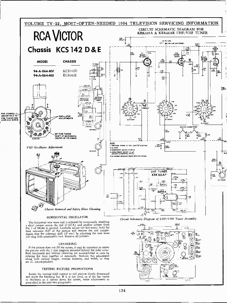
FOR CHANNEL rte,CENTER HOLE INFINE TUNING CAMOVER A DJ. SCRE W
VOLUME TV -22, MOST -OFTEN -NEEDED 1964 TELEVISION SERVICING INFORMATION
RCA Vicio RChassis KCS 142 D & E
MODEL CHASSIS
94 -A -064 -MV KCS142D94 -A -064 -MU KCS142E
A201002
OSCILLATORADJUSTMENTS
SET FINE TUNINGSHAFT AT MECHANICALCENTER OF ITS RANGE
VHF Oscillator Adjustment
470
EG
SS REAR
Chassis Removal and Safety Glass Cleaning
C92.033yf
L-NOTES
I. SWITCHES SHOWN IN THE (UHFIU"POSITION2.x=10003. RESISTANCE VALUES IN OHMS
4 CAPACITANCE VALUES IN yyfUNLESS OTHERWISE NOTED
5.8f VOLTAGE READINGS TAKEN WITH NO SIGNAL
CIRCUIT SCHEMATIC DIAGRAM FORKRK105A & KRK66AR UHF/VHF TUNER
"CS
10004
RI4TH
-1.5 10-2.50.
TP-I .I USE LOW CAP PROBE) CIE____---_-- iG1,--- - -Z L301
VI IISV.3HA5 I
RF AMP., 3
T
.6R
L20
L2
L2
R2IOO K
C14 CI20_ 1_ 10004F
140V.
02A5KE8MIXER
LS
52 FRONT
C9I.04Tyf
t í 1I51 UHF TUNER
1 KRK66APL 9 3
L~
HORIZONTAL OSCILLATOR
The horizontal sine wave coil is adjusted by temporarily attachinga short jumper across the coil (L501A) and another jumper fromPin 2 of 8KA8 to ground. Carefully adjust the horizontal hold forleast sideways drift of the picture and remove the coil jumper.Again stop the sideways drift (if any) by adjusting the sine wavecoil slug with nonmetallic tool. Remove all jumpers.
CENTERINGIf the picture does not fill the screen, it may be necessary to center
the picture with the 2 disc -magnets mounted behind the yoke cover.Both horizontal and vertical centering are accomplished at once byrotating the discs together or separately. Perform this adjustmentalong with vertical height, vertical linearity, and width, as theyare all interdependent.
TESTING PICTURE PROPORTIONS
Rotate the vertical hold control to roll picture slowly downwardand study the blanking bar. If it is not level, or if the bar variesin thickness as it moves down the screen, make adjustments asprescribed in the next two paragraphs.
3AF4 A
--
tFJ14ÓV
100
L48
HEATER CONNECTIONSVI V2
100
-
P93 MK
Circuit Schematic Diagram of UHF/VHF Tuner Assembly
5KE8sc.
L31
TÜNÉ
L39SI FRONT
R948200
Bf
13
04 FRONT
134
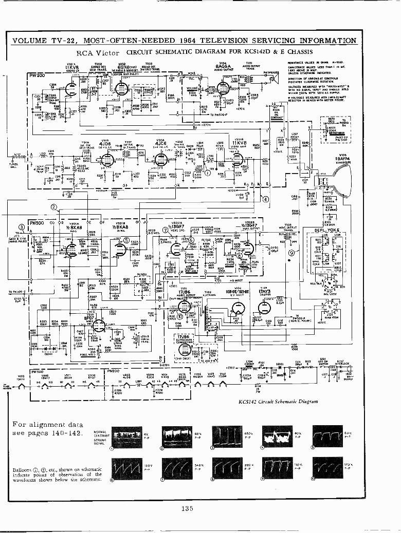
VOLUME TV -22, MOST -OFTEN -NEEDED 1964 TELEVISION SERVICING INFORMATION
RCA Victor CIRCUIT SCHEMATIC DIAGRAM FOR KCS142D & E CHASSIS
WIO1
Í KV8 SOUND óE202021A1202 T203
1 6GX6(VHF) SOUNDORSow,I GRID TRANS. IrtADg06 iOUMDOR 3N GRID TRANS.
1 YWQ 17Fr6
--í(6N2{UHTDNLv)---, wyo2Í' --
I
IA
TETHER
41ONO. I T204A (e
4125 MC ¡ffºº
TRAP
2039
C204
i
72010SOUNDTARE -WETEAMS
12015 12364.5 MC noTRAP
RI19
2WK
GAQ5AAUDIO OUTPUT
C1130- 200F
TO PW500P
2705.
1210 470C214
Lrs :o_ 6
x1239.3
0203
IfT2 PI 4J D6TFI
Ift V% TP2ORlOTMNA 16t PIA.I.F. LF.TRANA
I4i1° 000
C262G6
I5 R
24 200
1204947.25 MC 1-3TRAP
C217
C IF1
1;120
102111 1C2 I
139 1470
2700,RI'
62
OF
V2044JC6
2nd
a 03
T208 1.2042nd P1cLP. TRANS. CR201
36P.
241 2,26Q0'
cnSl 0S_
L203PI 250P0
0222 R221< -0223 5011
R219 560 2i3
rSp T.D097 4T'l: I -36GG
OK
1.2052.7,100'D
L2094706
1101AUDIO OUTPUT
TRAWS.
CII3 B10)00
4270V
PM SPEAK
32 1
YO
R104
3wCONTRAST
RESISTANCE VALUES IN OHMS. 0.1000.
CAPACITANCE GLUES LESS THAN I IN MF.I AND ABOVE IN MM,UNLESS OTHERWISE INDICATED.
DIRECTION OF ARROWS AT CONTROLSINDICATES CLOCKWISE ROTATION.
VOLTAGES MEASURED WITH VOLTOHMYST BWITH NO SIGNAL INPUT AND SHOULD HOLDWITHIN 2207. WITH 1205 AC SUPPLY.
* VOLTAGES MEASURED WITH I AIEG P2 WATTRESISTOR IN SERIES WITH METER PROBE.
L207
V2018 n330MN
1Í KV8R227 R228u
6
VIDEO AMP R225Y "KSKti 2W00
S6KK
co Y 9
6 R231
R229}335
0226 261.0047
11Ro Po N0 a0-J42X7V.
CI120 *15N0 CI05 -
.047-
*270 V.
4tbTP3
R2a4
V
470K
4PW500 CO 00 V5010 OE OF vsotl 00 JO
3 IA V28GKA8 S48YKA8
TO C}R616
JCT. I R504i22K
Cx109 6 CItO I(X0112.PUlSA) f K
} RSO31 SOR
.A_OC
RbO S.
I27K
-"7-121.110.H R 1622OL 1 MEO.IwIóó}r-C-Il
1.8 N /112MEG.
11110
05091212W
lo
TO PW200-2 IPO
01:00 40 I6,1F
0106191004
I-AM.--,
0552MOOIR533390K
85104700
3W
8611'
1012W
0554100
8654 0.566390K 31m .v+
I C653 _ _ _ _ C5561500 .001
.-II- L _NJX IU'T1. 50.501 1
L1 5O 007 BKAB
H4 H3 H2
51
0521391K
0.5224711
73510657K
0455
PVS03
8F07BoRa
P432., Ok
6
3
R
100
C6601000
P.
C567y cmT .01
}1.556 * 1.569120K = 2200 = 40556 13010
1.056 30504
SINE1.560 2
WAVE
251 .W
B 1 I 5 4 5
N0R12.HOLD
0523=
1524270K
C624270
5502V213G F7
8625 t t) VERLOSC.8.2 MEO.
1.111633ü10 C62.2MED 8 .M
C 32-.0012
2533
R631PC502 >--,I,,;-1r- - -
M82K I 1 Q --
11-'IICOFy03 E
90K
52I I4270V.
v,,,,,l
V102
2°1' 17J86 noz 163{rT/1&iíiTB2 I (pup 0111.10
L-'-- HORIZ.OUTWT O.VTRAN3. O.V.RECT.°j ÑÓrnuwv I I
-r-GW200
8027 I
V2038027 4JC6 IIKVB
(6ÑZ6)6A05A
N6 H5 I HI L201 H2 H3 N4 06 N6I
N
CSGI 470
R561 -a
6w
PC 503
37 r 0.538 1
.0082 13 6BK 1 ¡3B.
I 05382201 LR535 1 2 _2Jf 11M[G.
RS36R641 NSNG=ONT
N10R` ÓWKr M VERT=0ló 1 TOUR 620K
xo1zFROG.
5 41075
RIM47
RI104700
01061000
iidssI SUPPRESSOR 1I CONN CTION-_
(UWE ONLY)L__- -
For alignment datasee pages 140- 142.
4 I 4cne
I 14700-1'1---- -
V204 5201 0202 5104
NORMALCONTRAST
STRONGSIGNAL
Balloons ®, ®, etc., shown on schematicindicate points of observation of thewaveforms shown below the schematic.
4V.
P
130VP -P
C22914700
60V.P -P
340V.P -P
+B BOOST
vso28Vz13GF7
I VART.ouTPUT
c1639 I K.015
Lod 4t1.CI12C
103
17AY3
r-
01083301
1103VERT. OUTPUT
TRANS.
SLUÓ
II
TEL
REO
"` "' L103N 8.2PN
9
a 1102 -8.20 ''09C-11100
' R6>o ---Í I i
I K P1V1
500
:IBE
R571
2¿02000XT
PART OF IPW500
510519AYP4KINESCOPE
DEFL. YOKEI--- -106 1.108 -I
R1156
I
Ieo 51 I
I RII6 1114I
COLD 82~ I
121173 I
150VERT. 7 I
COIIS 1107 I
Iq0.1Z.
L _ -COILS _I
REO/BLK
PWlTO
WA( 00RI2. PUWE)
01211000
E PIOtPIN VIEW
.1101REAR VIEW
if01FIOI CIII R113 OFF.ON i102
EÑOKE 44 5R101 I30PF 6 swam INTERLOCK
270Y.
°°',.CIIG 11D5
17ÁV3 17JÉ6 4 C113A CIIRA_ G610E OUI 0117 C119j 1205.
1100y8 1045,1 .1 T I_ 60^1 1_ dUPP Y
KCS142 Circuit Schematic Diagram
650 0P -P
280V.P -P
405.P -P
110V.P -P
60V.P -P
170 V.
P -P
135
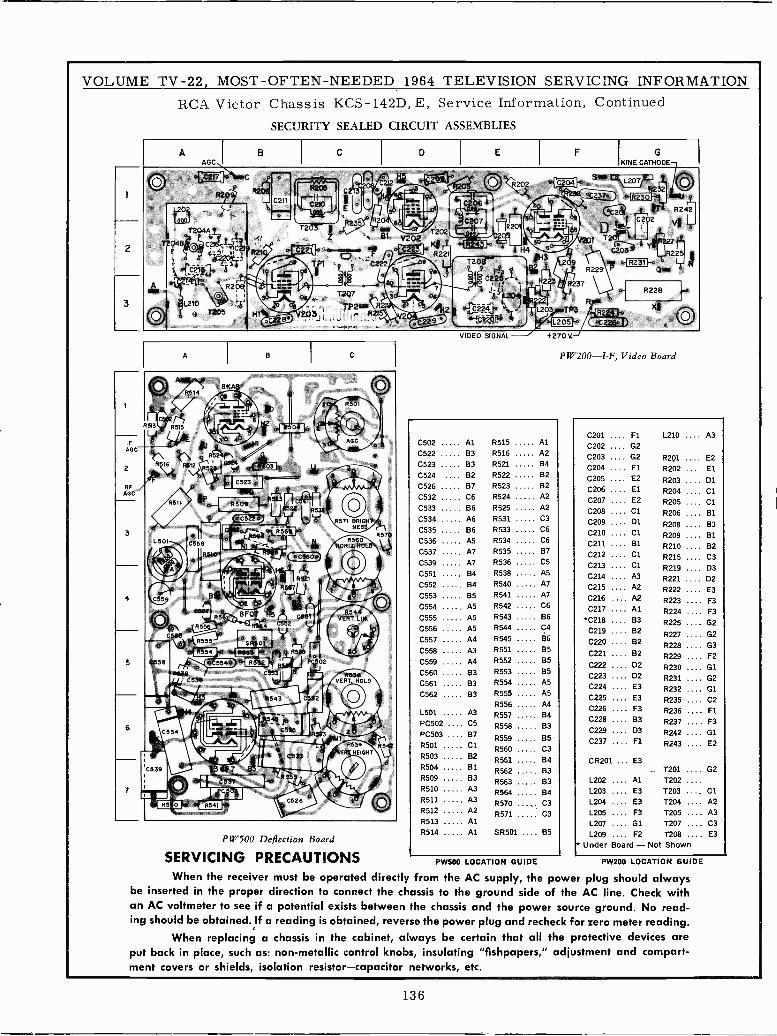
VOLUME TV -22, MOST -OFTEN -NEEDED 1964 TELEVISION SERVICING INFORMATIONRCA Victor Chassis KCS-142D,E, Service Information, Continued
SECURITY SEALED CIRCUIT ASSEMBLIES
AAGC
A
B
CoCS2LO)
C
T207 gR2t
B I C
8244VERT. LIM.
111514VERT. HOLD
PW500 Deflection Board
SERVICING PRECAUTIONS
an
ing should be obtained. If a reading is obtained, reverse the power plug and recheck for zero meter reading.When replacing a chassis in the cabinet, always be certain that all the protective devices are
put back in place, such as: non-metallic control knobs, insulating "fishpapers," adjustment and compart-ment covers or shields, isolation resistor-capacitor networks, etc.
D
1202V 02 ,-- .. o- df 1 T
H4=
R221s. C203T20a44
FY 73 'R229 °R231Q y
XX iiggss Q j. R237o- R228
22'. a224 `..: L203 TP3 . '
":75311°p °lL205}. ^C22M
E F G
0570
0548
VIDEO SIGNAL +270 V.
PW200-I-F, Video Board
C201 .... Fl L210 .... A3C502 Al R515 Al
C202 .... G2C522 83 R516 A2 C203 .... G2 R201 .... E2C523 B3 R521 84 C204 .... FI R202 ... ElC524 B2 R522 82 C205 .... E2 R203 .... D1C526 B7 R523 B2 C206 .... El R204 .... C1C532 C6 R524 A2 C207 .... E2 R205 .... C1C533 B6 R525 A2 C208 .... C1 R206 .... B1C534 A6 R531 C3 C209 .... Dl R208 .... B3C535 B6 R533 C6 C210 .... CI R209 .... BIC536 A5 R534 C6 C211 .... 61 R210 82C537 Al R535 87 C212 .... C1 R215
....
C3C539 A7 R536 C5 C213 .... C1 R219
....
.... D3C551 B4 R538 A5 C214 .... A3 R221 .... D2C552 B4 R540 A7 C215 .... A2 R222 .... E3C553 B5 R541 A7 0216 .... A2 R223 .... F3C554 A5 R542 C6 C217 .... A1 R224 .... F3C555 A5 R543 B6 ''C218 .... B3 R225 .... G2C556 A5 R544 C4 C219 .... B2 R227 G2C557
C558
A4
A3
R545
R551
86
B5C220 ....C221 ....
82
B2R228
R229
....
.... G3
F2C559 A4 R552 85 C222 .... D2 R230
....
G1C560 83 R553 85 C223 .... D2 R231
....
G2C561 B3 R554 A5 C224 .... E3 R232
....
G1C562 83 R555
R556
A5
A4C225 .... E3 R235
....
.... C2
L501 A3 R557 B4C226 .... F3 R236 .... Fl
PC502 ... 05 R558 83C228 .... 83 R237 .... F3
PC503 ..R501
137
ClR559
R560
85C3
C229 ....C237 ....
03F1
R242
R243
.... G1
.... E2
R503 B2 R551 64 CR201 ... E3R504 B1 R562 B3 T201 .... G2R509 83 R563 B3 L202 Al T202 ....R510 A3 R564 134 1.203 E3 T203 .... CIR511 A3 R570 ,. C3 L204 E3 T204 .... A2R512 A2 R571 C3 L205 F3 T205 .... A3R513 Al L207 01 T207 .... C3R514 Al SR501 .... B5 L209 .... F2 T208 .... E3
Under Board - Not Shown
PW500 LOCATION GUIDE PW200 LOCATION GUIDE
When the receiver must be operated directly from the AC supply, the power plug should alwaysbe inserted in the proper direction to connect the chassis to the ground side of the AC line. Check with
AC voltmeter to see if a potential exists between the chassis and the power source ground. No read-
136
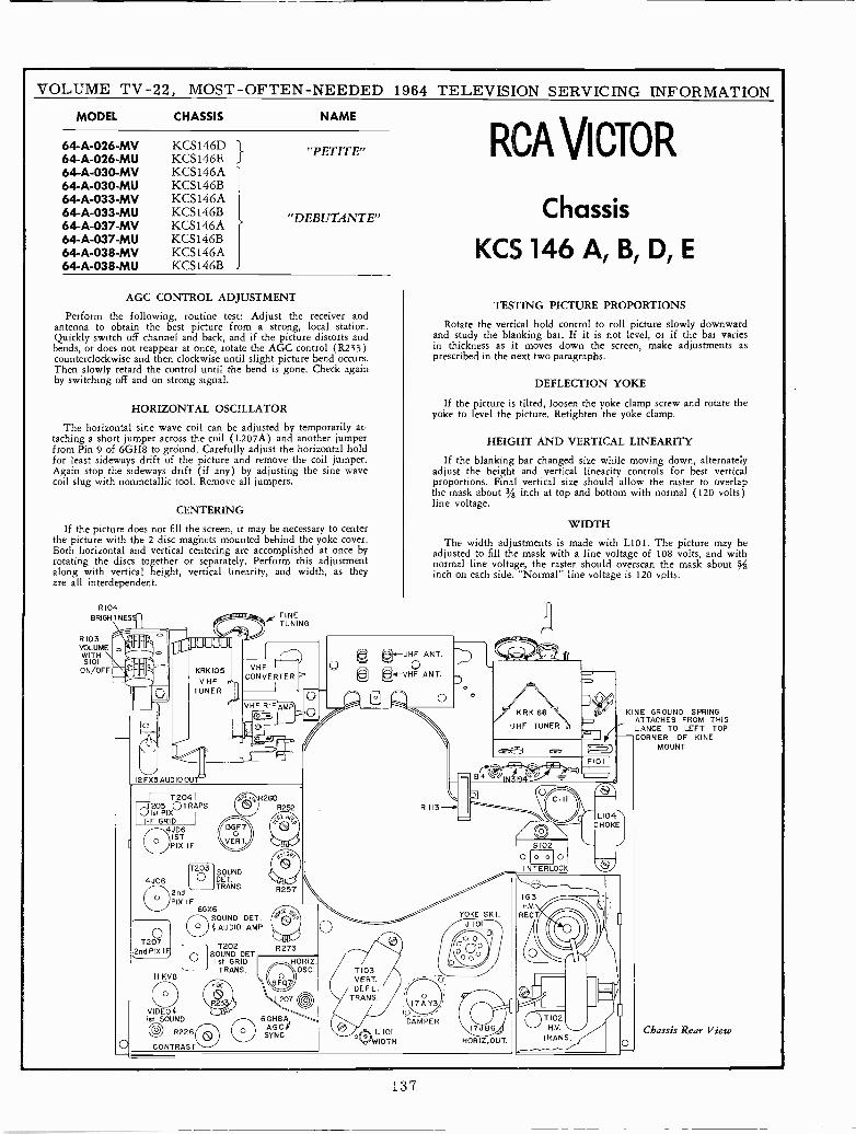
VOLUME TV -22, MOST -OFTEN -NEEDED 1964 TELEVISION SERVICING INFORMATION
MODEL CHASSIS NAME
64 -A -026 -MV64 -A -026 -MU64 -A -030 -MV64 -A -030 -MU64 -A -033 -MV64 -A -033 -MU64 -A -037 -MV64 -A -037 -MU64 -A -038 -MV64 -A -038 -MU
KCS 146DKCS146EKCS146AKCS146BKCS146AKCS146BKCS146AKCS146BKCS146AKCS146B
} "PETITE"
"DEBUTANTE"
AGC CONTROL ADJUSTMENT
Perform the following, routine test: Adjust the receiver andantenna to obtain the best picture from a strong, local station.Quickly switch off channel and back, and if the picture distorts andbends, or does not reappear at once, rotate the AGC control (R233)counterclockwise and then clockwise until slight picture bend occurs.Then slowly retard the control until the bend is gone. Check againby switching off and on strong signal.
HORIZONTAL OSCILLATOR
The horizontal sine wave coil can be adjusted by temporarily at-taching a short jumper across the coil (L207A) and another jumperfrom Pin 9 of 6GH8 to grdund. Carefully adjust the horizontal holdfor least sideways drift of the picture and remove the coil jumper.Again stop the sideways drift (if any) by adjusting the sine wavecoil slug with nonmetallic tool. Remove all jumpers.
CENTERING
If the picture does not fill the screen, it may be necessary to centerthe picture with the 2 disc magnets mounted behind the yoke cover.Both horizontal and vertical centering are accomplished at once byrotating the discs together or separately. Perform this adjustmentalong with vertical height, vertical linearity, and width, as theyare all interdependent.
R104BRIGHTNES
R103VOLUMEWITHS101
ON/OFF
12FX5AUDI000
T2041.J205 Q TRAPS
V 1st PIXI -F GRID
JD6
G ISTPIX IF
oT207
2nd PIX IF
11 KV8
VIDEO(Ist SOUND
10 R226CONTRAST
ir FINETUNING
VHF R-FAMP
SOUNDDET.TRANS.
T202SOUND DET.
1st GRIDTRANS.
260R252
aE0. i°6
6GH8AAGC?SYNC
HORIZ.\OSC.
RCA VICTOR
Chassis
KCS 146 A, B, D, E
TESTING PICTURE PROPORTIONS
Rotate the vertical hold control to roll picture slowly downwardand study the blanking bar.. If it is not level, or if the bar variesin thickness as it moves down the screen, make adjustments asprescribed in the next two paragraphs.
DEFLECTION YOKE
If the picture is tilted, loosen the yoke clamp screw and rotate theyoke to level the picture. Retighten the yoke clamp.
HEIGHT AND VERTICAL LINEARITY
If the blanking bar changed size while moving down, alternatelyadjust the height and vertical linearity controls for best verticalproportions. Final vertical size should allow the raster to overlapthe mask about 3/8 inch at top and bottom with normal (120 volts)line voltage.
WIDTH
The width adjustments is made with L101. The picture may beadjusted to fill the mask with a line voltage of 108 volts, and withnormal line voltage, the raster should overscan the mask about 3/ginch on each side. "Normal" line voltage is 120 volts.
I7AY3
DAMPER
L IOIWIDTH
YOKE SKT.J 101
HORIZ.OUT.
KRK 66 \UHF TUNER
KINE GROUND SPRINGATTACHES FROM THISLANCE TO LEFT TOPCORNER OF KINE
MOUNT.
Chassis Rear View
137
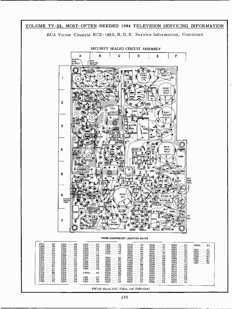
VOLUME TV -22, MOST -OFTEN -NEEDED 1964 TELEVISION SERVICING INFORMATION
RCA Victor Chassis KCS-146A, B, D, E, Service Information, Continued
6R22PART OFL208
SECURITY SEALED CIRCUIT ASSEMBLY
AMIXERGRIDOUTPUT
B
A,.Á X204,1 or -1.52_2P.R274j"_.r 1 5^;
t / i5 C216,,,. C
r._ R z 1? -e Z -'i
: 1
'" _ul,II/,}9}1
270VCVI
R279MOUNTEDTO L210
C
7 C2 3 C211
20. Ce{R207.
D
R260VERT.LIN.
E
R257HEIGHT
Dº4aw 77.. Ay
RY43 R2501 4\t^RZ04
eC240 .'s. } R25m", ' e
R256 AV/o R2 `7C207C212 I ' s,í
114 tH3e- C202
R226CONTRAST
R232
9 ; 10
PW200 COMPONENT LOCATION GUIDE
F
`eAM C231
236
SETSINEOSC.
RF
AGC
C201 B7 C223 B2 C250 135 L205 AS R216 A3 R238 F7 R260 D1 SR201 ....E4C202 B5 C224 B3 C251 D4 L206 C6 R218 A5 R239 E7 R261 ClC203 A7 C225 B3 C252 E4 L207 F6 R219 B4 R240 F7 R262 El T201 A7C204 B7 C226 A4 C253 F5 L208 A6 R220 A5 R241 E7 R264 D6 T202 C5C206 B6 C227 A4 C254 F4 L210 .A1 R221 A6 R242 F7 R265 D4 T203 C3C207 C4 C228 A6 C255 E6 R222 A7 R243 D3 R267 D4 T204 81C208 C4 C231 F7 C256 E6 R201 B5 R223 A6 R244 D6 R268 E5 T205 AlC210 C4 C233 D7 C257 F6 R202 B7 R224 B7 R245 D6 R269 E5 1206 63C211 C2 C234 E4 C258 E6 R203 C5 R226 C7 R246 D6 R270 F5 T207 A4C212 C3 C235 D6 C259 A2 R204 B3 R227 B6 R248 D6 R271 F5C213 B7 C237 05 C260 A3 R205 B6 R228 C5 R249 05 R272 D4C216 Al C240 03 C262 E2 R206 B4 R229 C6 R250 D3 R273 E4C217 B1 C241 D2 R207 C2 R230 C7 R252 E2 R274 D3C218 B2 C242 Cl CR201 ....A5 R208 B6 R232 05 R253 E2 R275 F6C219 Cl C243 D2 R210 B2 R233 C6 R255 E2 R276 E6C220 Cl C245 D3 L201 Cl R211 Cl R235 C7 R256 C3 R277 E3C221 C2 C246 D6 L203 AS R212 Al R236 E7 R257 E3 R278 F5C222 B1 C249 D4 L204 A5 R215 A3 R237 E7 R258 E3 R279 Al
PW200 Board (I -F, Video, and Defection)
138
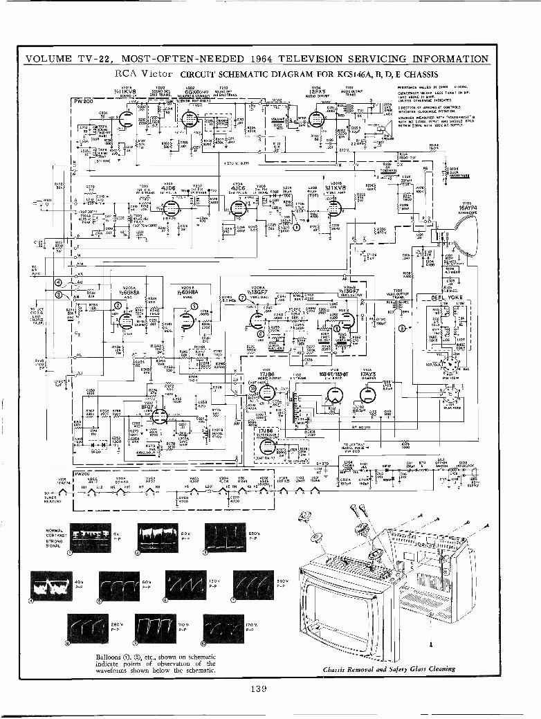
VOLUME TV -22, MOST -OFTEN -NEEDED 1964 TELEVISION SERVICING INFORMATIONRCA Victor CIRCUIT SCHEMATIC DIAGRAM FOR KCS146A, B, D, E CHASSIS
V201A T202 0202 7203
1/zlIKVB s0UN0DET 6GX6(40Rn SDUxOOELFOUNLF. GRID TRANS.LAYpIOyfWM00FT3MGUDTRRNd.
PW20D T(BN2iYNFONLY) jiff W102-
C206//_15
C
I 52µ 1
ISov. C12 íVE.- tY41 3 21 --- 2105 1 I- 1IR! I I -C2q VO-;12:1L=ME
.001
2R204 0.G 6 I3808 I
OC
ó 1
T201ASOUNDTRAE -OFF
TRANSTOP) 57D52
-1 3`2201
T201WSDN_¡} 1.201 `1W
8202{ TA1TEAM. 270 --112ÁP
R203r1.2083Fp5A`JI.001 C201
T.01
7 r--
2132` 0 V2o]5620 I R279 T208 T207120li+ plK 4J D6 Im pl
ORIONANS Is1PIR.I.A TIILR.T0.AKMSITp2C219+ `
wlol I q L210 a>o e50
01231
TORFAGC
TO JCLC109 &
0110
PULSE)
R1185100
ITOPCORE)T204A
41T25MC
I
2233+500A=C 3
C2501000
0251IOU
1q222 R2122 22M
220447.25 MC 1-3 +TRAP
(PATTOMCORE/ 0.2,0
C221 27
V2054V26GH8A
AOC
FLU32680.269
6 `K-
52521000
7N NJ II7
PW200VIOS I 131F1 6GH8A BFÓEAYP4
N11 M12 H9 100 417 H8
R27.2274 331
47 _.iwl
V2078F07
..rH. CI_I
1400.12.7101.0
TO 5 1
TUNERHEATERS
NORMALCONTRAST
STRONGSIGNAL
o
TrriT
400.P -P
4 5
9V.P -P
280V.P -P
5 4
ROY.P -P
C223I4ro
V2058V26GH8A
SYNC
.10033'
9
22482702
270 V. RUSS
02044JC6 2TeoIK L204
21M PI%.I.F. I.f.TRANS CO201 ]
12.FX5AUDIO OUTPUT
2zfu
IIDID, _Bw.00l2-
RED
810182
L20847501
OPN TP3 Lp20 1 0.2216
600
V206V213GF7 1
31210. 7 VERT0S0, j1'GOüi
.222K II IS
C FG202 k42K 0C243 R259 l AD2x
.00lS6 13 6BK IW.4r.
R253I 22 pp¿1
2201I 1.R267
5R. 2' N1110.
~p255 II
390K1.2ME0 gilt
R60K 8301VE0.T.HOLD
fv0' 0 A50 ..
I025
6 1 401OI Te _ 17J66 2102
H0R12.0UTPUT N.V.TMNS.
(owe 09L17
3NO0.12.
2 II MED.
ON
V2012
»I1KV8020 AMP
<JDB 9JC6 IÑ V8
6 1201 N5 24
40259
I47"
60V.P -P
110V.P -P
Balloons ®Q , ®, etc., shown on schematicindicate points of observation of thewaveforms shown below the schematic.
611
32WI9K 1
L - T0 310141N5164270
0119
40202 1 104 V10S V1014011.i 11725I7AY3 I7J56
5 4 3 4 I S 5C260
I4700
V102
636T/IBSGTN.V. RENT.
I (UHF ONLY)
5'00.P -P
170V.P -P
340V.P -P
2101AUDIO OUTPUT
TRANS.
RSB229
K
R222
1104
JACK
NESISTMICE VALUES IN OHMS. 101000.
CAPACITANCE MRLLES LESS THAN I IN Mi.I AND ABOVE IN MM,UNLESS OTHERWISE INDICATED.
DIRECTION OF ARROWS AT CONTROLSINDICATES CLOCKWISE ROTATION.
VOLTAGES MEASURED WITH .VOLTOHMYST. BWITH NO SIGNAL INPUT AND SHOULD HOLDWITHIN 420% WITH 1200 AC SUPPLY.
IBOK'133
c v ullRR3o r- - J 7>470K I C1
_ _J 42
v. 0112I5PP
0103
17ÁA o ER
8228}10022
x22277
8229I MEO.
1103VERT.OUTPUT
TRANS,still TEL
REU GRN
5104200N
V105
16AYP4KINESCOPE
1`'e4C031
i0vñSTW.047
99Rno4 11130,0,9
L10212PH 1" 9ZÓ
S4 8005T
TDJCT.'AN'HORIz. RASE
PW 200
4.7 MEET
C103.01 -
1005LS Moo
DEFL. YOKEr 105 1108
60Í (E
REO/9
D6 L107
1100.12.-COILS
5101P N VIEW
.1101REAR VIEW
5101
, CM101(E'FIOI .III 0.115 OFF.ON 51024A SRI01 15D5P 5 SWITCH INTERLOCK
G115 C, 110829
4J.C113A C112AT001 00,
c117 CI18jI I2Av.IqoPF I50PFI - .1 T .I Il f0
1 1 suiPLY
`k IiIÍiH
111111RR1
-
Chassis Removal and Safety Glass Cleaning
139
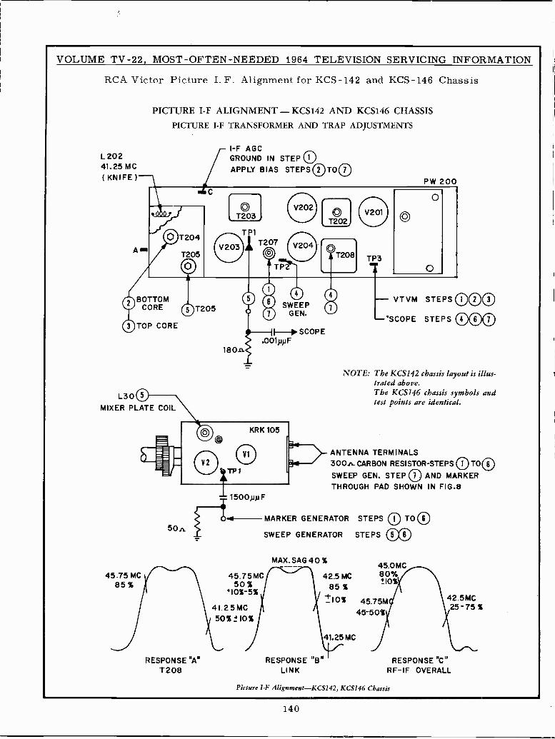
VOLUME TV -22, MOST -OFTEN -NEEDED 1964 TELEVISION SERVICING INFORMATION
RCA Victor Picture I. F. Alignment for KCS-142 and KCS-146 Chassis
PICTURE I -F ALIGNMENT - KCS142 AND KCS146 CHASSISPICTURE I -F TRANSFORMER AND TRAP ADJUSTMENTS
L 20241.25 MC( KNIFE )
BOTTOMCORE OT205
TOP CORE
L30MIXER PLATE COIL
45.75 MC85 %
50n
RESPONSE "A"T208
I -F AGCGROUND IN STEP iOAPPLY BIAS STEPS 1OT007
SWEEPGEN.
.11-> SCOPE.001pp F
180n
1500ptt F
45.75 MC50 %
{10%-5%
41.2 5 MC50% 10%
T202
TP3
PW 200
0O
O
- VTVM STEPS lO 1003
-SCOPE STEPS 00
NOTE: The KCS142 chassis layout is illus-trated above.The KCS146 chassis symbols andtest points are identical.
ANTENNA TERMINALS300n CARBON RESISTOR -STEPS 0 TO©SWEEP GEN. STEP 1O AND MARKERTHROUGH PAD SHOWN IN FIG.B
MARKER GENERATOR STEPS 01 TO 06
SWEEP GENERATOR STEPS
MAX. SAG 40 %
42.5 MC85 %
_10%
RESPONSE"B"LINK
41.25 MC
0045.0 MC80%±10%
45.75M45-50%
42.5MC25-75%
RESPONSE "C"RF-IF OVERALL
Picture I -F Alignment-KCS142, KCS146 Chassis
140
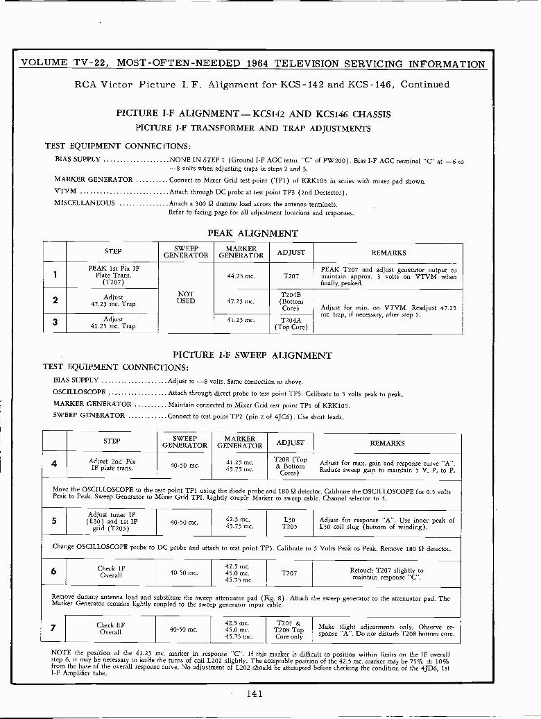
VOLUME TV -22, MOST -OFTEN -NEEDED 1964 TELEVISION SERVICING INFORMATION
RCA Victor Picture I. F. Alignment for KCS-142 and KCS-146, Continued
PICTURE I -F ALIGNMENT - KCS142 AND KCS146 CHASSISPICTURE I -F TRANSFORMER AND TRAP ADJUSTMENTS
TEST EQUIPMENT CONNECTIONS:BIAS SUPPLY NONE IN STEP 1 (Ground I -F AGC term. "C" of PW200). Bias I -F AGC terminal "C" at -6 to
-8 volts when adjusting traps in steps 2 and 3.
MARKER GENERATOR Connect to Mixer Grid test point (TP1) of KRK105 in series with mixer pad shown.VTVM Attach through DC probe at test point TP3 (2nd Dectector).
MISCELLANEOUS Attach a 300 12 dummy load across the antenna terminals.Refer to facing page for all adjustment locations and responses.
PEAK ALIGNMENT
STEP SWEEPGENERATOR
MARKERGENERATOR ADJUSTJ REMARKS
1PEAK 1st Pix IF
Plate Trans.(T207)
NOTUSED
44.25 mc. T207PEAK T207 and adjust generator output tomaintain approx. 3 volts on VTVM whenfinally peaked.
2 Adjust47.25 mc. Trap 47.25 mc.
T204B(BottomCore) Adjust for min. on VTVM. Readjust 47.25
mc. trap, if necessary, after step 5.3 Adjust41.25 mc. Trap
41.25 mc. T204A(Top Core)
PICTURE I -F SWEEP ALIGNMENTTEST EQUIPMENT CONNECTIONS:
BIAS SUPPLY Adjust to -8 volts. Same connection as above.
OSCILLOSCOPE Attach through direct probe to test point TP3. Calibrate to 5 volts peak to peak.MARKER GENERATOR Maintain connected to Mixer Grid test point TP1 of KRK105.SWEEP GENERATOR Connect to test póint TP2 (pin 2 of 4JC6). Use short leads.
STEP SWEEPGENERATOR
MARKERGENERATOR ADJUST REMARKS
4 Adjust 2nd PixIF plate trans. 40-50 mc. 41.25 mc.
45.75 mc.
T208 (Top& Bottom
Cores)
Adjust for max. gain and response curve "A".Reduce sweep gain to maintain 5 V. P. to P.
Move the OSCILLOSCOPE to the test point TP1 using the diode probe and 180 9 detec or. Calibrate the OSCILLOSCOPE for 0.5 voltsPeak to Peak. Sweep Generator to Mixer Grid TPI. Lightly couple Marker to sweep cable. Channel selector to 4.
5Adjust tuner IF(L30) and 1st IF
grid (T205)40-50 mc. 42.5 mc.
45.75 mc.L30
T205Adjust for response "A". Use inner peak ofL30 coil slug (bottom of winding).
Change OSCILLOSCOPE probe to DC probe and attach to test point TP3. Calibrate to 5 Volts Peak to Peak. Remove 180 12 detector.
6 Check IFOverall 40-50 mc.
42.5 mc.45.0 mc.45.75 mc.
T207 Retouch T207 slightly tomaintain response "C".
Remove dummy antenna load and substitute the sweep attenuator pad (Fig. 8). Attach the sweep generator to the attenuator pad. TheMarker Generator remains lightly coupled to the sweep generator input cable.
7 Check RFOverall 40-50 mc.
42.5 mc.45.0 mc.45.75 mc.
T207 &T208TopCore only
Make slight adjustments only. Observe re-sponse "A". Do not disturb T208 bottom core.
NOTE the position of the 41.25 mc. marker in response "C". If this marker is difficult to position within limits on the IF overallstep 6, it may be necessary to knife the turns of coil L202 slightly. The acceptable position of the 42.5 mc. marker may be 75% ± 10%from the base of the overall response curve. No adjustment of L202 should be attempted before checking the condition of the 4JD6, 1stI -F Amplifier tube.
141
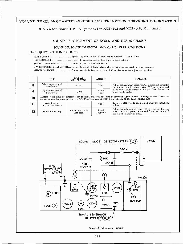
VOLUME TV -22, MOST -OFTEN -NEEDED 1964 TELEVISION SERVICING INFORMATION
RCA Victor Sound I. F. Alignment for KCS-142 and KCS-146, Continued
SOUND I -F ALIGNMENT OF KCS142 AND KCS146 CHASSIS
SOUND I -F, SOUND DETECTOR AND 4.5 MC. TRAP ALIGNMENT
TEST EQUIPMENT CONNECTIONS:
BIAS SUPPLY Apply -10 volts to the I -F AGC bus at terminal "C" on PW200.OSCILLOSCOPE Connect to kinescope cathode lead through diode detector.
SIGNAL GENERATOR Connect to test point TP3 on PW200.
VACUUM TUBE VOLTMETER Connect to output of diode detector shown. Set meter for negative voltage readings.
MISCELLANEOUS Connect test diode detector to pin 7 of V202. See below for adjustment locations.
STEP SIGNALGENERATOR ADJUST REMARKS
8 Adjust detector gridtransformer 4.5 mc. T202 Adjust for maximum negative DC on meter. Set generator
for 1.0 to 1.5 volts when peaked. T201A top core and
9 Adjust sound take -offtransformer 4.5 mc.
T201A T202 core should penetrate the coil from top of canwhen finally peaked.
1 O Disconnect the diode test detector. Turn off signal generator and tune in strongest signal in area, adjusting volume control fornormal volume (approx. 1/4 turn from C.C.W.). Turn core of T203 flush with top of coil form. Remove bias.
1 1Adjust sound T203 Turn core clockwise to 2nd peak adjusting for maximum
detector transformer volume.
j 2 Adjust 4.5 mc. trap 4.5 mc., 400 cycle,AM mod.
T201B(bottom)
Adjust for minimum 4.5 mc. indication on oscilloscope.The core should penetrate the coil from the bottom ofthe can when finally adjusted.
SOUND DIODE DETECTOR -STEPS 00Í i
I
I 560 K !
V T VM
.00IpF - 10K -.00IpFT560K .
BIASBIAS
o -10 V. o
_ _
O 0 PW200
,T203.V202
IN7 O j V201 OP
ID T201
O T204 T202BI
(270V)ID
T205 OOV203 O V204
OT208
TP3BOTTOM
T207
SIGNAL GENERATORIN STEPS000
Sound I -F Alignment of KCS142
142
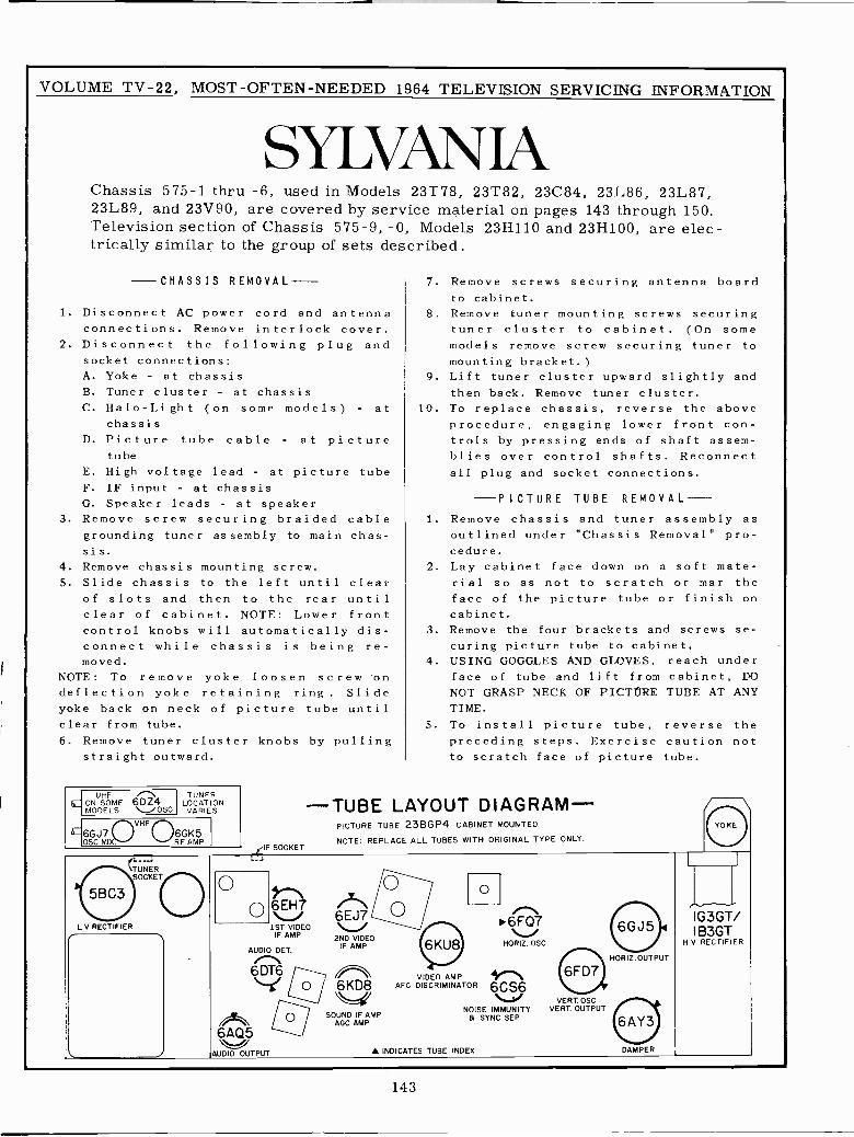
VOLUME TV -22, MOST -OFTEN -NEEDED 1964 TELEVISION SERVICING INFORMATION
SYLVAN JAChassis 575-1 thru -6, used in Models 23T78, 23T82, 23C84, 23L86, 23L87,23L89, and 23V90, are covered by service material on pages 143 through 150.Television section of Chassis 575-9, -0, Models 23H110 and 23H100, are elec-trically similar to the group of sets described.
-CHASSIS REMOVAL
1. Disconnect AC power cord and antennaconnections. Remove interlock cover.
2. Disconnect the following plug andsocket connections:A. Yoke - at chassisB. Tuner cluster - at chassisC. Halo -Light (on some models) - at
chassisD. Picture tube cable - at picture
tube
E. High voltage lead - at picture tubeF. IF input - at chassisG. Speaker leads - at speaker
3. Remove screw securing braided cablegrounding tuner assembly to main chas-sis.
4. Remove chassis mounting screw.5. Slide chassis to the left until clear
of slots and then to the rear untilclear of cabinet. NOTE: Lower frontcontrol knobs will automatically dis-connect while chassis is being re-moved.
NOTE: To remove yoke loosen screw ondeflection yoke retaining ring. Slideyoke back on neck of picture tube untilclear from tube.
6. Remove tuner cluster knobs by pullingstraight outward.
tzlUHF \ON SOME 60Z4MODELS \--"OSC
TUNERLOCAT ONVARIES
EVHF
6GJ7OSO MIX.
6GK5RF AMP
TUNERSOCKET
L V RECTIFIERr
ylF SOCKET._J
ooAUDIO DET.
6 DT66KD8
o SOUND IF AMPAGC AMP
6AQ5AUDIO OUTPUT
7. Remove screws securing antenna boardto cabinet.
8. Remove tuner mounting screws securingtuner cluster to cabinet. (On somemodels remove screw securing tuner tomounting bracket.)
9. Lift tuner cluster upward slightly andthen back. Remove tuner cluster.
10. To replace chassis, reverse the aboveprocedure, engaging lower front con-trols by pressing ends of shaft assem-blies over control shafts. Reconnectall plug and socket connections.
PICTURE TUBE REMOVAL1. Remove chassis and tuner assembly as
outlined under "Chassis Removal" pro-cedure.
2. Lay cabinet face down on a soft mate-rial so as not to scratch or mar theface of the picture tube or finish oncabinet.
3. Remove the four brackets and screws se-curing picture tube to cabinet.
4. USING GOGGLES AND GLOVES, reach underface of tube and lift from cabinet, DONOT GRASP NECK OF PICTÚRE TUBE AT ANYTIME.
5. To install picture tube, reverse thepreceding steps. Exercise caution notto scratch face of picture tube.
-TUBE LAYOUT DIAGRAM-PICTURE TUBE 23BGP4 CABINET MOUNTED
NOTE: REPLACE ALL TUBES WITH ORIGINAL TYPE ONLY.
6E 7\-/ 6EJ7
1ST VIDEOIF AMP 2ND VIDEO
IF AMP
o
6FQ7HORIZ. OSC
VIDEO AMPAFC DISCRIMINATOR
VERT. OSCNOISE IMMUNITY VERT. OUTPUT
a SYNC SEP
A INDICATES TUBE INDEX
j/
HORIZ.OUT PUT
DAMPER
p_IG3GT/B3GT
H V RECTIFIER
143
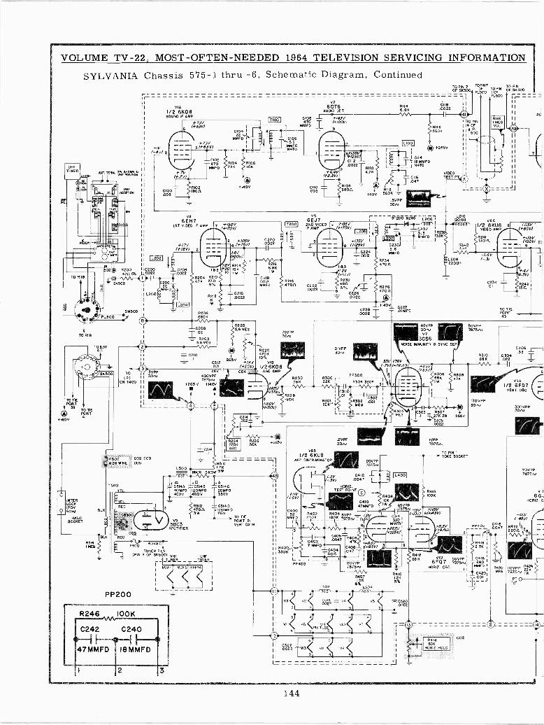
VOLUME TV -22, MOST -OFTEN -NEEDED 1964 TELEVISION SERVICING INFORMATION
SYLVANIA Chassis 575-1 thru -6, Schematic Diagram, Continued
UHFTUNER
TO RIIB
POINT
/ 38TO TIE® POINT
+140041
CTITER
LOCO120V
O 60NHA
SÓ(ÉT
R514
ANT. TER
UHFADAPTOR
M
R20047105%
$2502
PL500
BLK
o
F503 = CO2,CO3026 WIRE 1,= C05^;lvL.¢:.SR.:,.'.
r1
-IV(-4V)
02000022
VIAI/2 6KD8SOUND IF AMP
+73V6
63V)
3 1+63V)
CI02870
MMFD+.7V
(+.7 V)
81020100 18010.005
V46 E H7 +/sav1ST VIDEO IF AMP 7
,,,35V)/ 9 +105V+17V - - "
8 (+75V)(+18V) - - -
r0104 1
R104 #106
10204 183.0022 j
R2o4 R21047K 2211
L2041
+0V+2010
15 0214
II C208R2205.6 MEG
I I .22 75V301vII R208
I 5.6MEG ..0._ \R222
C210-'-
4706
265VC212 +1.4V VIB001 (+20V) 1/26KD8
TOV 3V"2KV i AGO AMP
IPI II 301v 400VPP 02307875rvON T400 I1 g 56K
11+265 V +140J
I I V V
a55V)
II R2288 150K
L +150V+150V)
11
III
11 TII
111224 6226
II 220K 566 +2650
0516 AGC
'1
R510
C220 1.f
R2I66.8 KIW
C218.0012MMFD
TO PIN 7OF SK500
112001
V2601.6
AUDIO GET.
CI08470 -r
MMFO
V56EJ7280 VIDEOIF AMP
#218470(1 0222
.0022
R508 18 23413
+ATSoO 0514A C5148 ,-_C514C40MFD I20MFD 20MF0T 4000 T00V 350V
PP200
3 547 0414D4700 10 Ti IOOMFD3W 250
PO TIEV9 POINT5863
VERT. CATO.RECTIFIER
A.C.
TUNER FILO.(PIN 3 OF SK500) VHF
TUNER
6GJ
L
R246 I00K
C242 C240
47MMFD 18MMFD
2 3
UHFTUNER
1
+143V(+/20V)
6+/3=
ff/25V
83 -.2V
(+1.IV)
2IVPP
PP 300
R304 3302
R30Y 0012I MED
0681/2 6KU8
AFC DISCRIMINATOR 2875.0707501
47MMFDC400
(32 R402MMFD 2700
rL 1
iI
C406 0406I 0dÓ2 '7 47K .,,1271MMFD - 0408
330K Í 0054 .047 IL__..-_.__1
20VPPII - 78751v
-'1/V1(R4011,5K
R1146.8K
-I I
0118 I I
0022 II
r--- -- ® +265V
I wC114.118 MMFD
L J N470
V DEOTEST PTO
TORN?OF TORN
PL500 I0FPL500
C2305.6MMFD
023447010
R40810KIW
220UH
022701MFD
r --r- 85VPP30r0V7
6086NOISE IMMUNITY 8 SYNC SEP
R306 R3086WK 47K
65VPP787501 _I3V
C314330
MMFD+225V+225V)
#4101.2K5%
rI
I
1!
1
0022 035
I
II- - ------___
(-I3V1
1341E682
IVPP7875rv
TO PIN 1
YOKE SOCKET
> R416> 1002
6(4143V)+145V
+8.5V(+8.50
RIIBI MEGVOL.
TO PIN I
OF SK 500
V6A1/2 6KU8 9
VIDEO AMP
130VPP30,1
ir----II
TO TIEPOINT43
+115V(+80V)
+135V(/00V) 2£
+.4V0510
0 30633
.304022
PP402 C41600473,
_
04182.7K
V 10
6F07 7875tpv1101112. OSO:
5414500
HARIZ. HOLD
CO2
C418680
MMFD
C420D01
2
V8A1/2 6FD7
VERT.OSC
300VPP
20VPP78750
VIP
6G<;HOR12.
-45V(-45V)
144
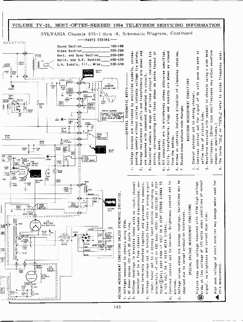
,iH00
-N
II I II II
I
II
r
-,00000
o
VOLTAGE MEASUREMENT CONDITIONS UNLESS OTHERWISE SPECIFIED.
I. Voltages measured to chassis using VTVM.
2. AC power source 120 volt 60 cycle line.
3. Voltage readings
in brackets taken with no input; channel
selector set to a free channel, antenna disconnected, an-
tenna terminals shorted together and grounded to chassis.
4. Voltage readings not
in brackets taken with a
strong signal
input; tuner set to a strong local station developing ap-
proximately -7 volt on AGC Buss. NOTE: AGC VOLTAGE AT TEST
POINT® WILL VARY FROM -7 VOLT ON
A VERY STRONG SIGNAL TO
A +20 VOLT ON
A VERY WEAK SIGNAL.
5. Contrast control set to maximum. Brightness control set to
minimum.
6. Voltage values shown are average readings. Variations may be
observed due to normal production tolerances.
SPECIAL VOLTAGE MEASUREMENT CONDITIONS
x21,Picture tube anode voltage measured with VTVM high voltage
9.1Vprobe at line voltage of
120 volts under conditions of normal
signal ,
no brightness and correct scan size.
®High peak voltage of short duration may damage meter used for
this measurement.
I.
Voltage
ponding
2. Average
000,
II
<0`
c.n O O :D
Ñ o o a O F
W o O W a
N O O N COco
GENERAL SCHEMATIC NOTES
sources are indicated by encircled symbols, corres -
symbols without circles indicate voltage tie points.
resistances of coils and transformers are shown and
are measured with component connected
in circuit.
3. Encircled numbers on edge of printed circuit indicate tie
points, corresponding with those shown on parts layout of
printed board.
4. All capacitors are
in microfarads unless otherwise specified.
5. Coils, transformers, plugs and sockets are shown as viewed
from the bottom.
6. Arrows on controls indicate direction of clockwise rotation.
7. Shaded areas indicate code changes.
WAVEFORM MEASUREMENT CONDITIONS
I.
Channel selector set to strong channel.
2. Contrast control set for signal of 65 volt peak to peak at
yellow lead of picture tube.
3. Waveforms measured with respect to chassis using a wide band
oscilloscope. (Other type oscilloscopes may alter waveform
shapes or amplitudes.)
4. The terms "30,5 or "7875.5 refer to scope frequency used.
I II II III
1 p UJ.
am
CA O v
O O 1
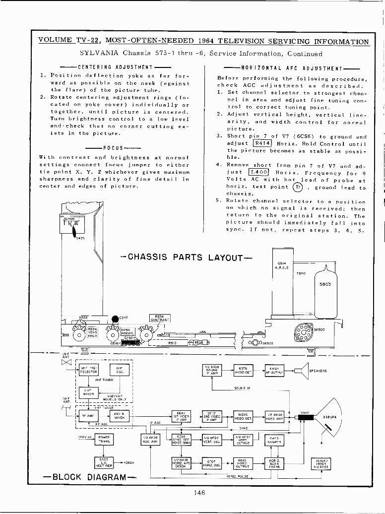
VOLUME TV -22, MOST -OFTEN -NEEDED 1964 TELEVISION SERVICING INFORMATION
SYLVANIA Chassis 575-1 thru -6, Service Information, Continued
CENTERING ADJUSTMENT
1. Position deflection yoke as far for-ward as possible on the neck (againstthe flare) of the picture tube.
2. Rotate centering adjustment rings (lo-cated on yoke cover) individually ortogether, until picture is centered.Turn brightness control to a low leveland^check that no corner cutting ex-ists in the picture.
FOCUS
With contrast and brightness at normalsettings connect focus jumper to eithertie point X, Y, Z whichever gives maximumsharpness and clarity of fine detail incenter and edges of picture.
- UHF -ANT.
><1 r-
HORIZONTAL AFC ADJUSTMENT
Before performing the following procedure,check AGC adjustment as described.1. Set channel selector to strongest chan-
nel in area and adjust fine tuning con-trol to correct tuning point.
2. Adjust vertical height, vertical line-arity, and width control for normalpicture.
3. Short pin 7 of V7 (6CS6) to ground andadjust R414 Horiz. Hold Control untilthe picture becomes as stable as possi-ble.
4. Remove short from pin 7 of V7 and ad-just L4O0 Horiz. Frequency for 9
Volts AC with hot lead of probe athoriz. test point , ground lead tochassis.
Rotate channel selector to a positionon which no signal is received; thenreturn to the original station. Thepicture should immediately fall intosync. If not, repeat steps 3, 4, 5.
5.
-CHASSIS PARTS LAYOUT-
0247
UHF PRE -SELECTOR
VHFANT. LH
RF AMP
I t RF AG
UHFOSC.
UHF TUNER
UHFMIXER
L
120V AC
VHF/UHFMODELS ONLY
VHF TUNER 7
í260V
-BLOCK DIAGRAM -
F AGC
6EH71ST VIDEO -o
F AMP
6CS6SYNC SEPNOISE IM MU
1/2 6KU8HORIZ. AFC
DISCR.
1/2 6K08SOUNDIF AMP
60T6AUDIO DET
SOUND IF
6A05AF OUTPUT
6EJ72ND VIDEO
IF AMP
I/O 6FD7VERT OSC
6FQ7HORIZ. OSC
INDUSVIDEO DET.
I/O 6FD7VERY.
OUTPUT
66,15HORIZ.
OUTPUT
HORIZ. PULSE
1/2 6KU8VIDEO AMP.
6ÁY3DAMPER
HORIZ.SCANTRANS
(SPEAKERS
YOKE
238GP4
IG3GT/IB3GT
H.V. RECT.
146
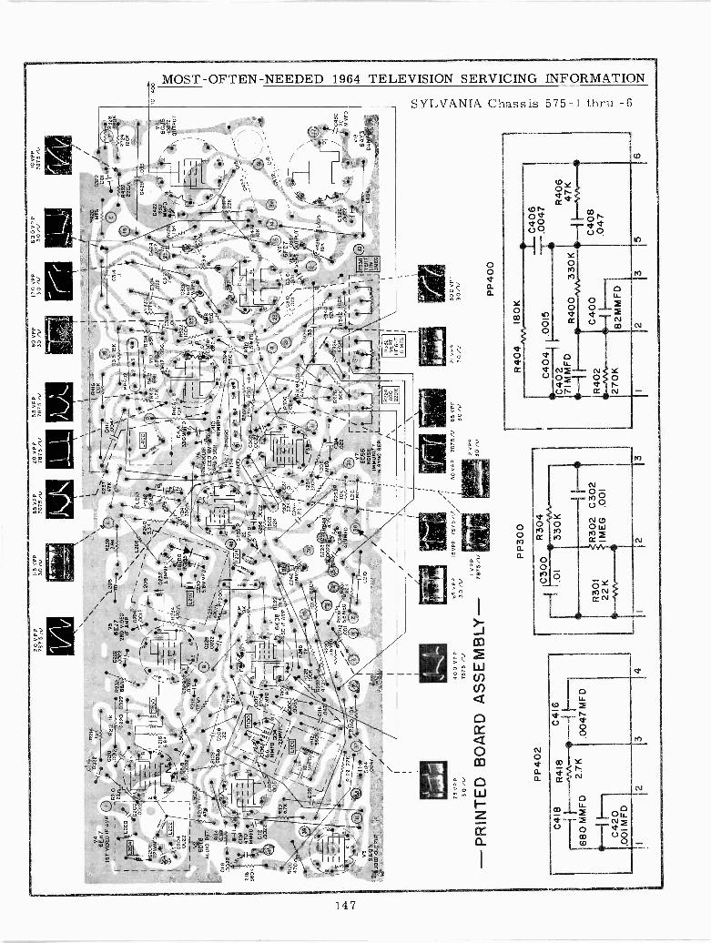
20 V
PP
IS V
PP
65V
PP
20 V
PP
7875
iv30
1178
75N
7875
N55
VP
P60
VP
P13
0 V
PP
600
VP
P78
75 N
30 N
30 A
l30
NII0
VP
P78
75nl
Va
6E14
71S
T V
IDE
O IF
AM
P
1'02
0622
MM
FG
"('.
I04 00
22__
V2
6DT
6S
OD
IO D
ET
.
0114
6.8K
GIIB .0
022
-~-
c ó6
~R
I16
T47
0 FD
!!56
0K M
My
2216
0022
y/-.
R
210
0218
0212
IK
TT
122.
{L.N
0012
---.
Vw
-,.y
R23
2:L2
00 I
YC
220
0022
SS
A/ -
g. '
"C2
00 002
0214
I5K
R12
047
0/1.
0202
1
0112
.002
2
l
7
2-
F5/
.,.4/
V3
6A
05A
UD
IO O
UT
PU
T
011M
O\
\\
VS
L208
8238
0222
6EJ7
---'o
1-y
3.9K
.,..0
;1`.
2ND
2NF
AM
P.
\ \r`
._vN
i_-.
.I
5_02
24
i<L2
01{.
0012
/18-
++
/12
05
' ; ¡
IT20
0I_
\,
_-6/
R21
6 L
8/
C232
13.1
.---
"// 6
.BK
//3,
3MM
FD
N F
1.-1
_ _
_R
234
rJ.,
0022
fL5
040,
20`
I
7%
i7G
h¿
.I--
5020
0
1.50
2R
218
5 //
/,..
:.:12
07 H
}I
r
4qO
a,1
9 )
G22
6 S
b"`M
----
-M...
FD
-l
G222
6-/%
-47
0A P
P2`
00+
--/
J,R
108/
8800
-02
08.2
2
¡¡
F,5
.F\
Rá0
6
IT10
01
i\.
--.v
V.-
y' 1
/CI0
2Tr_
210H
f87
017
-.2,
./5
6 /
%
MM
FO'r
____
}r
MM
FDj
**1
rQ-u
a, _
/V
I
/rL
\^2.
2MM
FD
/ jR
102L
" J
%gp
KO
gMPR
S6K
31
,,,./.
......
....7
.J
tClo
D le
oe
/I
.005
,
L210
R24
28.r1
T`i
22 R
300
228
C24
6
¡R
eIB
MM
Fp,
C12
PF
/M
MF
Dt
R11
2/
ISO
K7
R20
6O
K
/\T
C/C
316
R22
2' i
75V
PP
30
-41-
0124
.004
7/
220
2`0
022¿
, Ra7
K.._
24
5.6M
EG
'-R
208
G24
18O
1R
25i
,, ^p
15.6
M'E
G83
31...
.1
103
223
47M
MF
D'--
wV
\
400
VP
P78
75 N
65 V
PP
- P
RIN
TE
D B
OA
RD
AS
SE
MB
LY -
PP
402
C418
R418
C41
6
K I
-68
0 M
MF
D.0
047M
FD
C420
.001
M F
D
30 Al
I
15V
PP
VPP
7875
/V
7875
11 /
V M
O, n
w"
V
PP300
R30
12
228
4 ,C
+, -
-11
\I
11\
R41
:\
R31
4R
410
VIO
33K
`I.2
K68
K62
07+
r_
R0R
12 O
SC
TC
C31
8_
R40
8,8
7'
`.01
IOK
R3
2I
C32
0,
/ -:-
61
120K
V6S
I\\-
).N
i
__28
.:.-.
M/0
056
¿r¿
% C
324
6KU
643
\1\
I
1
/\
R31
9{R
316
VID
EO
AM
P7i
t4
C30
8II
IKA
FG
DIS
CO
.04
103/
.022
\I M
EG
\
ISM
Oil
1
\I
I
L04
14330MMFD
R30Tf
C305
-27K
R310 68K
y¡I5
- 4t\
7 1i
}51
68K
6\F4/
R308
,. z
.I.
41._
.
220K
rR3o
5
yME
G_
I/
:02
14/
R2
.a22
/
L212
r>
F'-a
°°`-
-.v7
I/
I6C56
/7 1
I/
II
B S
YN
C S
EP
. /1.
- /I
\
I50
VP
P
WI2
VPP
30 /U
C300
R304
1.01
330K
R30
1R
302
22K
ME
GI
I-.
C302
.001
23
7875 N
85 vPP
30 /
R224
ACC
220K
4TM
MF
D `
2 R
324.
1
407
0040
0'_,
,71
3 F
SK
560
K5 /T
F,3
52
R31
2-Z
-1\..
:i...5
+I
6
O9/
#$.14 O
vsn
)-03
1003
1662
07.,.
\0I\1
DJo
`vE
RT
? t p
uT
0304
022. C31
2.047
R42
0M
EG
C32
21.
--N
W--
y.0
01
O -
.-.il
.-w
H 3
gkR
422
R32
8.
220n
1203
C42
2V
IP.
330
4f3
p 6G
ú5M
MF
DO
R¢.
_i\
GÚ
TP
UT
- -
8
l.
0306
\i`
.33 \
R34
oR
326
820K
1\
470K
IR34
r 2
100-
Ki
1 , 11II J
R33
2V
ER
TH
EIG
HT
5 M
EG
21 V
PP
30N
300
VP
P30
/V
R33
8S
OR
T
3ME
0
PP
400
85 -
\5 a2á
22K
L406
14 I S9'
C52
2 \
FI
I_/ T
C43
000
22\
6j7
j MM
FD
V13
6AY
314
04DAMPER,,,,.
R40
4W.1
80K
+C
406
C40
4 1.
0015
L -.00
47C
402
IR
406
71M
MF
DR
400
330K
4.
R40
2C
400
C40
8.0
4727
0K82
MM
FD
23
5
TO
T40
0
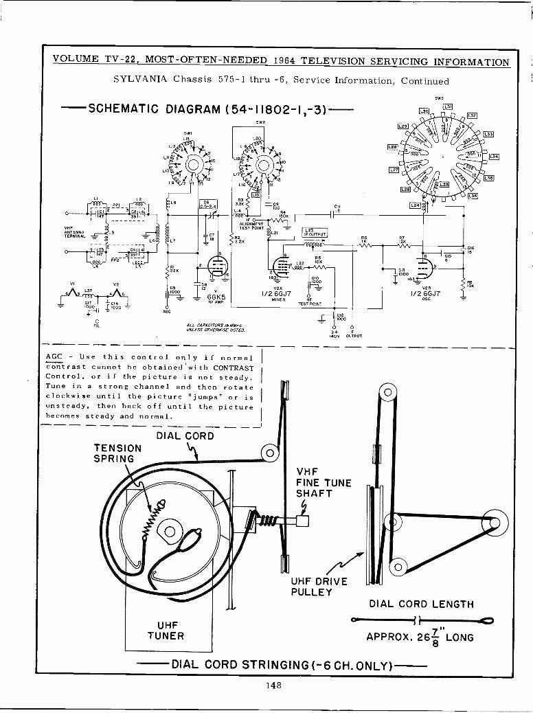
VOLUME TV -22, MOST -OFTEN -NEEDED 1964 TELEVISION SERVICING INFORMATION
VHFANTENNATERMINAL
SYLVANIA Chassis 575-1 thru -6, Service Information, Continued
SCHEMATIC DIAGRAM (54-11802-1,-3)
LI L2
L4 L5
V2
4 3L37
4 5
C171000 1000 -
FIL.
SW2
SWIL13
L12
LII
LIO
L9
8
9
10
R4150K
IFALIGNMENTTEST POINT o =
R22.21<
C5
C8
1
OS
I12VI
- 6G K5RF AMP
AGC
ALL CAPACITORS INAIMFOUNLESS OTHERWISE NOTED
AGC - Use this control only if normalcontrast cannot he obtained with CONTRASTControl, or if the picture is not steady.Tune in a strong channel and then rotateclockwise until the picture "jumps" or is
unsteady, then back off until the picturebecomes steady and normal.
DIAL CORDTENSIONSPRING
L21L23IF OUTPUT
881080
R5L22 10K
000 r--//\-183 CIO
11;:KLVEA
I/26GJ7 oMIXER RF
TEST POINT
I---11C12_L 1000
O oB+ IF
140V OUTPUT
VHFFINE TUNESHAFT
/a"'UHF DRIVEPULLEY
1L301
MI
IL24I
R7126
~1C13IoO
183_
V2B
I/2 6GJ7osc
SW3
IL32I
CI615
IOK
DIAL CORD LENGTH
APPROX. 26 8 LONG
DIAL CORD STRINGING (-6 CH.ONLY)
EEO
148
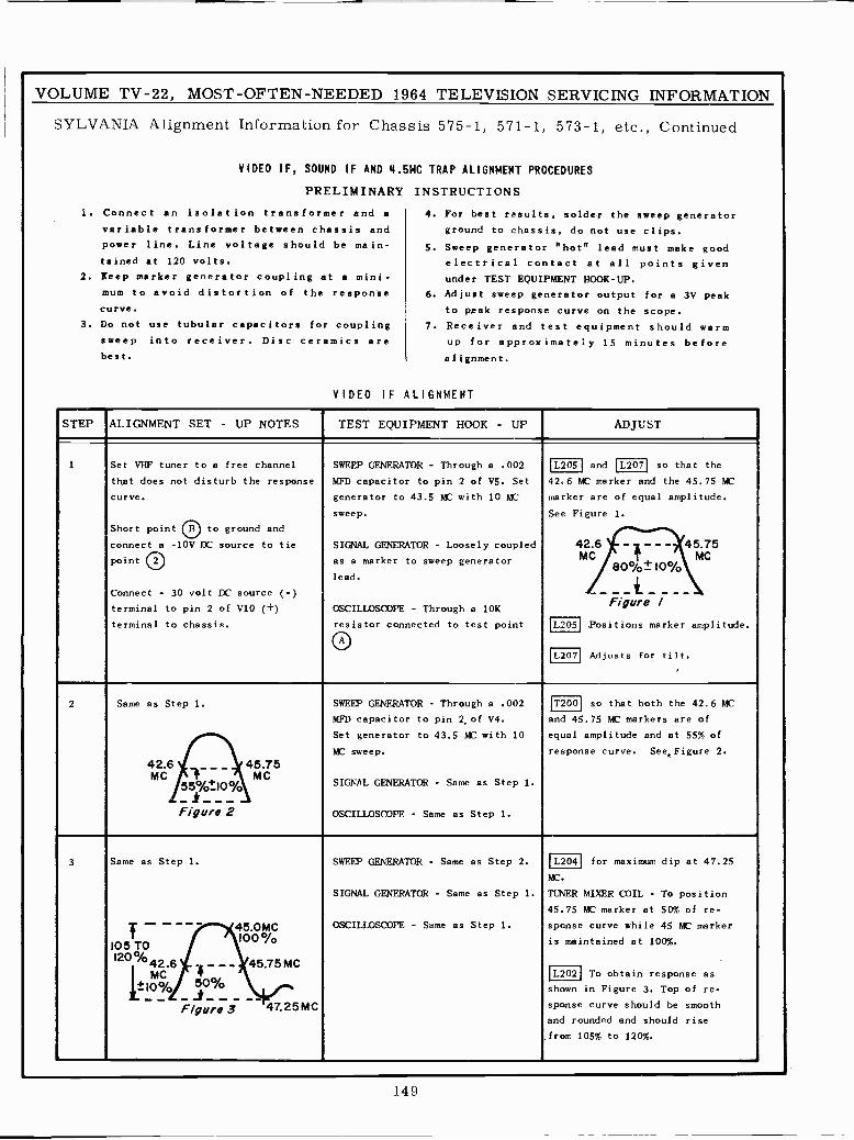
VOLUME TV -22, MOST -OFTEN -NEEDED 1964 TELEVISION SERVICING INFORMATION
SYLVA.NIA Alignment Information for Chassis 575-1, 571-1, 573-1, etc., Continued
VIDEO IF, SOUND IF AND 4.5MC TRAP ALIGNMENT PROCEDURES
1.
PRELIMINARY
Connect an isolation transformer and a
variable transformer between chassis and
INSTRUCTIONS
4. For best results, solder the sweep generator
ground to chassis, do not use clips.power
tained
line. Line voltage should
at 120 volts.
be main- 5. Sweep generator "hot" lead must make good
electrical contact at all points given2. Keep marker generator coupling at a mini- under TEST EQUIPMENT HOOK-UP.
mum to avoid distortion of thecurve.
response 6. Adjust sweep generator output for a 3V peak
to peak response curve on the scope.3. Do not use tubular capacitors for coupling 7. Receiver and test equipment should warm
sweep
best.
into receiver. Disc ceramics are up for approximately 15 minutes beforealignment.
VIDEO IF ALIGNMENT
STEP ALIGNMENT SET - UP NOTES TEST EQUIPMENT HOOK - UP ADJUST
.
Set VHF tuner to a free channel
that does not disturb the response
curve,
Short point O to ground and
connect a -10V DC source to tie
point 2
Connect - 30 volt DC source (-)
terminal to pin 2 of V10 (+)
terminal to chassis.
SWEEP GENERATOR - Through a .002
MFD capacitor to pin 2 of V5. Set
generator to 43.5 MC with 10 MC
sweep.
SIGNAL GENERATOR - Loosely coupled
as a marker to sweep generator
lead.
OSCILLOSCOPE - Through a 10K
resistor connected to test point
L205 and L207 so that the
42.6 MC marker and the 45.75 MC
marker are of equal amplitude.
See Figure 1.
42.6 - 45.75MC MC
80%±10%
- - - - -Figure /
L205 Positions marker amplitude.
L207 Adjusts for tilt.
2 Same as Step 1. SWEEP GENERATOR - Through a .002
MFD capacitor to pin 2,of V4.
Set generator to 43.5 MC with 10
MC sweep.
SIGNAL GENERATOR - Same as Step 1.
OSCILLOSCOPE - Same as Step I.
T200 so that both the 42.6 MC
and 45.75 MC markers are of
equal amplitude and at 55% of
response curve. See,Figure 2.
42.6 45.75MC
555101:109/0 MC
Figure 2
3 Same as Step 1.
- _
SWEEP GENERATOR - Same as Step 2.
SIGNAL GENERATOR - Same as Step 1.
OSCILLOSCOPE - Same as Step 1.
L204 for maximum dip at 47.25
MC.
TUNER MIXER COIL - To position
45.75 MC marker at 50% of re-
sponse curve while 45 MC marker
is maintained at 100%.
45.0 M CT
105 TO100%
120%42.645.75MC
MC0
-
1±10% 5Ó %oáá _i___ e
Figure 3 47,25 MC
L2021 To obtain response as
shown in Figure 3. Top of re -
sponse curve should be smooth
and rounded and should rise
from 105% to 120%.
149
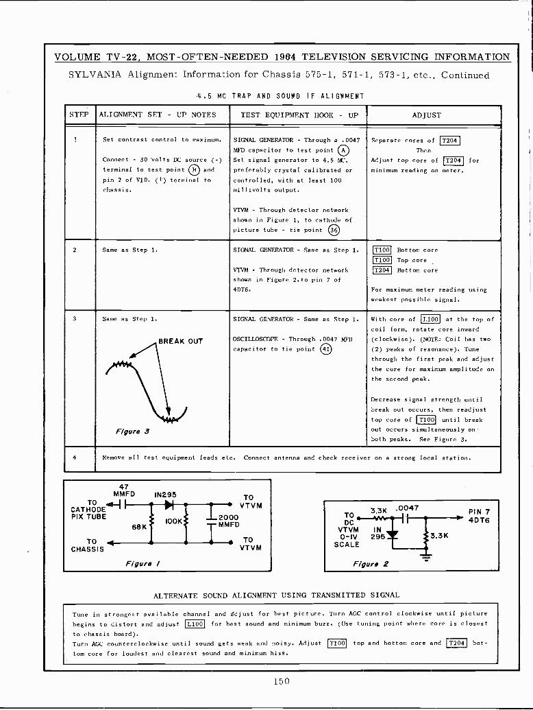
VOLUME TV -22, MOST -OFTEN -NEEDED 1964 TELEVISION SERVICING INFORMATION
SYLVANIA Alignment Information for Chassis 575-1, 571-1, 573-1, etc., Continued
4.5 MC TRAP AND SOUND IF ALIGNMENT
STEP ALIGNMENT SET - UP NOTES TEST EQUIPMENT HOOK - UP ADJUST
t Set contrast control to maximum.
Connect - 30 volts DC source (-)
terminal to test point O and
pin 2 of V10. (+) terminal to
chassis.
SIGNAL GENERATOR - Through a .0047
MFD capacitor to test point OA
Set signal generator to 4.5 MC,
preferably crystal calibrated or
controlled, with at least 100
millivolts output.
VTVM - Through detector network
shown in Figure 1, to cathode of
picture tube - tie point 36
Separate cores of T204
Then
Adjust top core of T204 for
minimum reading on meter.
2 Same as Step 1. SIGNAL GENERATOR - Same as Step 1.
VTVM - Through detector network
shown in Figure 2.to pin 7 of
4DT6.
[T100 Bottom core
IT100I Top core
I12041 Bottom core
For maximum meter reading using
weakest possible signal.
3 Same as Step 1.
BREAK OUT
Figure 3
SIGNAL GENERATOR - Same as Step 1.
OSCILLOSCOPE - Through .0047 MFD
capacitor to tie point 41
With core of L100 at the top of
coil form, rotate core inward
(clockwise). (NOTE: Coil has two
(2) peaks of resonance). Tune
through the first peak and adjust
the core for maximum amplitude on
the second peak.
Decrease signal strength until
break out occurs, then readjust
top core of T100 until break
out occurs simultaneously on
both peaks. See Figure 3.
4 Remove all test equipment leads etc. Connect antenna and check receiver on a strong local station.
ALTERNATE SOUND ALIGNMENT USING TRANSMITTED SIGNAL
Tune in strongest available channel and adjust for best picture. Turn AGC control clockwise until picture
begins to distort and adjust
to chassis board).
Turn AGC counterclockwise until sound gets weak and noisy. Adjust
tom core for loudest and clearest sound and minimum hiss.
L100 for best sound and minimum buzz. (Use tuning point where core is closest
T100 top and bottom core and T204 bot-
150
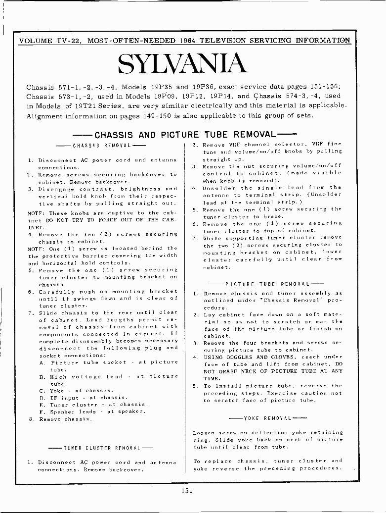
VOLUME TV -22, MOST -OFTEN -NEEDED 1964 TELEVISION SERVICING INFORMATION
SYLVAN JAChassis 571-1, -2, -3, -4, Models 19P35 and 19P36, exact service data pages 151-156;Chassis 573-1, -2, used in Models 19P09, 19P12, 19P14, and Chassis 574-3, -4, usedin Models of 19T21 Series, are very similar electrically and this material is applicable.Alignment information on pages 149-150 is also applicable to this group of sets.
CHASSIS AND PICTURE TUBE REMOVALCHASSIS REMOVAL
1. Disconnect AC power cord and antennaconnections.
2. Remove screws securing backcover tocabinet. Remove backcover.
3. Disengage contrast, brightness andvertical hold knob from their respec-tive shafts by pulling straight out.
NOTE: These knobs are captive to the cab-inet DO NOT TRY TO FORCE OUT OF THE CAB-INET.4. Remove the two (2) screws securing
chassis to cabinet.NOTE: One (1) screw is located behind thethe protective harrier covering the widthand horizontal hold controls.5. Remove the one (1) screw securing
tuner cluster to mounting bracket onchassis.
6. Carefully push on mounting bracketuntil it swings down and is clear oftuner cluster.
7. Slide chassis to the rear until clearof cabinet. Lead lengths permit re-moval of chassis from cabinet withcomponents connected in circuit. If
complete disassembly becomes necessarydisconnect the following plug andsocket connections:A. Picture tube socket - at picture
tube.
B. High voltage lead - at picturetube.
C. Yoke - at chassis.
D. IF input - at chassis.E. Tuner cluster - at chassis.
F. Speaker leads - at speaker.
8. Remove chassis.
TUNER CLUSTER REMOVAL -
1. Disconnect AC power cord and antennaconnections. Remove backcover.
2. Remove VHF channel selector, VHF finetune and volume/on/off knobs by pulling
straight up.3. Remove the nut securing volume/on/off
control to cabinet, (made visiblewhen knob is removed).
4. Unsolder the single lead from theantenna to terminal strip. (Unsolderlead at the terminal strip.)
5. Remove the one (1) screw securing thetuner cluster to brace.
6. Remove the on,e (1) screw securingtuner cluster to top of cabinet.
7. While supporting tuner cluster removethe two (2) screws securing cluster tomounting bracket on cabinet, lowercluster carefully until clear fromcabinet.
PICTURE TUBE REMOVAL
1. Remove chassis and tuner assembly asoutlined under "Chassis Removal" pro-cedure.
2. Lay cabinet face down on a soft mate-rial so as not to scratch or mar theface of the picture tube or finish oncabinet.
3. Remove the four brackets and screws se-curing picture tube to cabinet.
4. USING GOGGLES AND GLOVES, reach underface of tube and lift from cabinet, DONOT GRASP NECK OF PICTURE TUBE AT ANYTIME.
5. To install picture tube, reverse thepreceding steps. Exercise caution notto scratch face of picture tube.
-YOKE REMOVAL
Loosen screw on deflection yoke retainingring. Slide yoke back on neck of picturetube until clear from tube.
To replace chassis, tuner cluster andyoke reverse the preceding procedures.
151
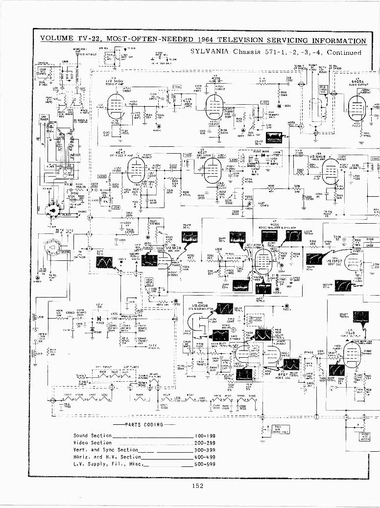
VOLUME TV -22, MOST -OFTEN -NEEDED 1964 TELEVISION SERVICING INFORMATION
c-1MONO -POLE
L808
f0 cneANT. ; <.TO
152
SYLVANIA Chassis 571-1, -2, -3, -4, Continued-I.-2 VAII.ONLY 04De 304FP
6-F
L
W Y ;.D 10 C.4
516 1 -2, 4 ONLY
C52.1 470
MMFD
R5 6.5-IMEG
S40 MATSMEG
1
PR
6502.5-4ME
VÑI WYTgx
62003305%
BK502NE2H R
P/L
TO RII8TO TIE TO TIEPT 12 PT
TO TIEPOINT
9
INR-LOGK120060
TOIPI
ON 1400
L
VIA
1/2 5KD8SOUND IF AMP
-1V(-.4V1 2
*73V
((+637)
í73V
1C102-870MMFD
V44EH7
1ST VIDEO IF AM
I1.7V(*18V) 2
IL2021I
0200 t 1 02040022 -.-.0022
C206'
MMFD
L200 5X
#150VP^(+13511
--_L +1031/#75V1
02166.851 v
=Cz18.0012 6218
4700 1222.0022
0212IKIW
MMFCIO/B
47D
V24DT6
40063 CET.
*443V22011
V(+2.8V)
#10866000
TO PIN 7OF S6500
01146.86
Lf 0112
140V 5806 -I.SVPP3010
V54EJ7
IF AMP TÑlY5v1 i
9 #43578 (#125V1
L
02240012
163*1.2VY+A/V)
232
62266206 .0022 =6606
82205.6 MEG
265 V
5050E p. ,C65144 C5148 65146
TSOMFD IOOMFO 20MF0
C500 +"501 3501 T350V
1 0512 J17 C514D47003W 25V
Z02224706
75VPP300
G212 16/54V COI 8oa (*20V) g223 '1/2 5K082KV I 22K.:1 AGC AMP 0010
400VPP R230 R300PP300
78750fI4pV
9 56K 22K R304 330K
r- 51108 3G65T 3024 -7 9GwPIN 3 I 5 3 4 1 %I PaV TUBE ¡ ¡ PP400
TOPIN34L_--._-_--'----J TOPIN4.- IÍI
50500
---==12====_=o O===JJ=
II 17403 I]GJS 13F07 4656 6405 4EJ7 4E01 4006 8707 I00U6 SNDB4 L502 6 C504
4
#1507*150V)
168I/21OKU8
Arc DISCRIMINATOR
6302 0012I MEG
20VPP78750
2-1.3V 6412(-.311 .0047 T
MMFD 2706r4 l
IVPP787510
HORIZ.TEST PT.
R2344700
.0022 1
® +265V
al{.r-18MMF0J N{]0
56200 10295120 UN
ÓPF917TOPIN TO PIN I
PL 00 OFOF 50500
PL500 r
ReMEGM
VOL.
v6Á
6Á05AAUDIO OUTPUT
+25576(*255V)
í13V(043V)
422(#221
C12iI .1
012047011
I/210KU8 9 +4457VIDEO AMP /IRON)
333300 íL
02340236 éL208 OI470(1 220UN
V7
4CS6NOISE IMMUNITY 6 SYNC SEP
33V +78V(-7V)(47805
0408106IW
II 00051282
IL
6520I W22
PARTS CODING -
4TÑ6I)047047T1
20750J
76750 -R407 194102.76 5%K5%
C522 0524 C52610022 .00221 1.0022
Sound Section 100-199
Video Section 200-299
Vert. and Sync Section 300-399
Horiz. and H.V. Section 400-499
L.V. Supply, Fil,, Misc. 500-599
85VPP30N
3 1
0416IOOK
65VPP7675,0
4376 (11*1430)
78SOVPP7510
8310686
130vOPP
BIDII35V C23B
et ó
- - - 1C2361.0022
POTO3 TIEINT4
15MEG
#123V6 (*/23V)
V8A1/2 13F07
VERT OSC
300155300
PP402 04160047
6412 V9 550PP 16418 1SBK 8FQ7 7675,0 880RORIZ OSO. TMMF01ij 1
64201T.D01
4414500
00012. HOLD
-115V(-115W
20VPP78750
017GJ5
HORIZ OUTPUT
-451(-45v)
7875R420110VPP R4295605 0 220
WP1
62447FNA,
0308
0022
1 310
#148V7FF148V,
R426
R42818K
R03050K
WIDTH
i
152
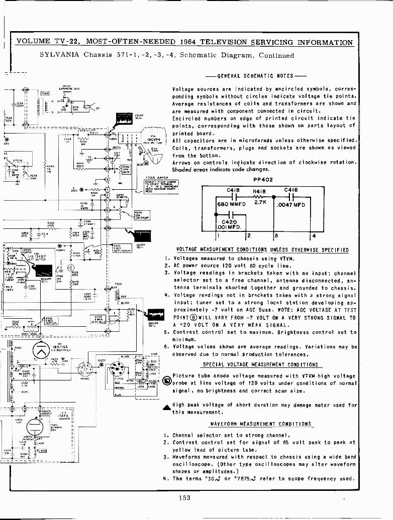
VOLUME TV -22, MOST -OFTEN -NEEDED 1964 TELEVISION SERVICING INFORMATION
SYLVANIA Chassis 571-1, -2, -3, -4, Schematic Diagram, Continued
II012411:0047
>R122>22K
65V
42
WITti P,200
I GB
MMFD \I\8246L J 100K
*265V
¡Tin]
35100EARPHONE JACK
GPI
-W150,-T212_IBOUM
0244 -NV \r-22 R250
WK
182487K7W
+265V(*265V) v.6
1/2 13FD7ERT OUTPUT
AWSW
8318 0316I MEO 0022
R342IOOK
8340 8205.
C426823ÑED
84324.7K
WI
C42B033
5265V(*265V)
0432O18
0322
2 K
83383 MEGVEBT LIN.
X11
1a3/IG3HV RECTIFIER
7 R4344]K 17KV
- 9 1
IL406I
043020MMFO55v
LTO
POINT
R254 '02206
R260IOK
0246 LINFO
TMMFD
1.02411= 47MMFD
8324 G320
113203906
R3'9120 N
VI2 Ii
17AY3 11
DAMPER
R3343MEG I
VERT HOLD I
265v
8256K
WITS
83325 MEGVERT. HEIGHT
0300
BLACK
PL 400
65VPP3000
BLUE
RJ-
-\V13
I9CVP4PICTURE TUBE /
KV!2KV
FOCUS JUMPER
-GENERAL SCHEMATIC NOTES ----
Voltage sources are indicated by encircled symbols, corres-
ponding symbols without circles indicate voltage tie points.
Average resistances of coils and transformers are shown and
are measured with component connected in circuit.
Encircled numbers on edge of printed circuit indicate tie
points, corresponding with those shown on parts layout of
printed board.
All capacitors are in microfarads unless otherwise specified.
Coils, transformers, plugs and sockets are shown as viewed
from the bottom.
Arrows on controls indicate direction of clockwise rotation.
Shaded areas indicate code changes.
CONNECT FOCUS JUMPERTO ETHER TERMINAL
6N/E6 MAAXI06 MUM SHARPR-
R25825KCONTRAST
300,
R336
M.7fr
EG
30 rrvPP
TOSE
L300VERT
ELEC.COILS
L302
OEFLEG.COI SI
ORANGE I
LOOR
PP402
C418 R4I8 C4I6
680 MMFD 2.7K .0047M
C420.001 MFD
2 3 4
VOLTAGE MEASUREMENT CONDITIONS UNLESS OTHERWISE SPECIFIED
I. Voltages measured to chassis using VTVM.
2. AC power source 120 volt 60 cycle line.
3. Voltage readings in brackets taken with no input; channel
selector set to a free channel, antenna disconnected, an-
tenna terminals shorted together and grounded to chassis.
4. Voltage readings not in brackets taken with a strong signal
input; tuner set to a strong local station developing ap-
proximately -7 volt on AGC Buss. NOTE: AGC VOLTAGE AT TEST
POINT® WILL VARY FROM -7 VOLT ON A VERY STRONG SIGNAL TOA +20 VOLT ON A VERY WEAK SIGNAL.
5. Contrast control set to maximum. Brightness control set to
minimum.
6. Voltage values shown are average readings. Variations may be
observed due to normal production tolerances.
SPECIAL VOLTAGE MEASUREMENT CONDITIONS
Picture tube anode voltage measured with VTVM high voltage
Oprobe at line voltage of 120 volts under conditions of normal
signal , no brightness and correct scan size.
"High peak voltage of short duration may damage meter used for
this measurement.
.WAVEFORM MEASUREMENT CONDITIONS
I. Channel selector set to strong channel.
2. Contrast control set for signal of 65 volt peak to peak at
yellow lead of picture tube.
3. Waveforms measured with respect to chassis using a wide band
oscilloscope. (Other type oscilloscopes may alter waveform
shapes or amplitudes.)
4. The terms "30,5 or "7875,j refer to scope frequency used.
153
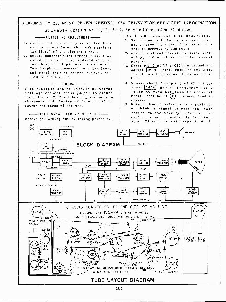
VOLUME TV -22, MOST -OFTEN -NEEDED 1964 TELEVISION SERVICING INFORMATION
SYLVANIA Chassis 571-1, -2, -3, -4, Service Information, Continued
check AGC adjustment as described.1. Set channel selector to strongest chan-
nel in area and adjust fine tuning con-trol to correct tuning point.
2. Adjust vertical height, vertical line-arity, and width control for normalpicture.
3. Short pin 7 of V7 (4CS6) to ground andadjust R414 Horiz. Hold Control untilthe picture becomes as stable as possi-ble.
4. Remove short from pin 7 of V7 and ad -
CENTERING ADJUSTMENT
1. Position deflection yoke as far for-ward as possible on the neck (againstthe flare) of the picture tube. .
2. Rotate centering adjustment rings (lo-cated on yoke cover) individually ortogether, until picture is centered.Turn brightness control to a low leveland check that no corner cutting ex-ists in the picture.
FOCUSWith contrast and brightness at normalsettings connect focus jumper to eithertie point X, Y, Z whichever gives maximumsharpness and clarity of fine detail incenter and edges of picture.
HORIZONTAL AFC ADJUSTMENTBefore performing the following procedure,
UHFANT.><ZI E --
UHF PRE -SELECTOR
UHFOSO.
UHF TUNER
UHFMIXER
ANT. L_._H r -I
VHF/UHFMODELS ONLY
VHF TUNER
RF AMP
RF AGC
+140V
+265V
120V AC SOURCE
TUNER LOCATIONVARIES
5
5HG8 ( UHF4 OSC
OSC/MIXE
3AF4®OR
3DZ4
4` GK5OR I
3GW5 r6AQ5ARFAMP ttii/AUDIO
k 4 OUTPUT
OSO AMIXER
7
__J
just L400 Horiz. Frequency for 9
Volts AC with hot lead of probe athoriz. test point , ground lead tochassis.
5. Rotate channel selector to a positionon which no signal is received; thenreturn to the original station. Thepicture should immediately fall intosync. If not, repeat steps 3, 4, 5.
1/2 5KD8SOUNDIF AMP
4DT6AUDIO DET.
BLOCK DIAGRAM
IF AGC
I/2 5X08AGC AMP
SOUND IF
6405AF OUTPUT
4EH71ST VIDEO -!r
IF AMP
4CS6SYNC SEPNOISE IM MU
I/2IOKUBHORIZ. AEG
DISCR.
4EJ72ND VIDEO
IF AMP
I/213FD7VERT. OSO
8F07HORIZ. OSO
IN295VIDEO DET.
I/213FD7VERT.
OUTPUT
17GJ5HORIZ.
OUTPUT
HORIZ. PULSE
1/2 IOKUBVIDEO AMP.
17AY3
DAMPER
HORIZ.SCAN
TRANS
CHASSIS CONNECTED TO ONE SIDE OF AC LINEPICTURE TUBE I9CVP4 CABINET MOUNTED
NOTE: REPLACE ALL TUBES WITH ORIGINAL TYPE ONLY.
4EH7
4AUDIO
DET 4DT6A 5KD8
4EJ74
2ND VIDEOIF AMP
1ST VIDEOIF AMP
3
45
IOKU8
VIDEO AMP/AFCDISCRIMINATOR 4CS6
FINISH VERT OSC/SOUND IF AMP NOISE IMMUNITY/
OUTPUT
AGC AMP SYNC SEP-HEAVY LINE FOLLOWS SERIES FILAMENT SEQUENCE
--`PICTURE TUBE
HORIZ OS
I3FD7
A INDICATES TUBE INDEX
TUBE LAYOUT DIAGRAM
START
4
HORIZ.OUTPUT
17AY35
DAMPER
SPEAKERS
YOKE
19CVP4
IG3GT/I B3GT
H.V. RECT.
/
IG3GT/IB3GTH.V. RECTIFIER
154
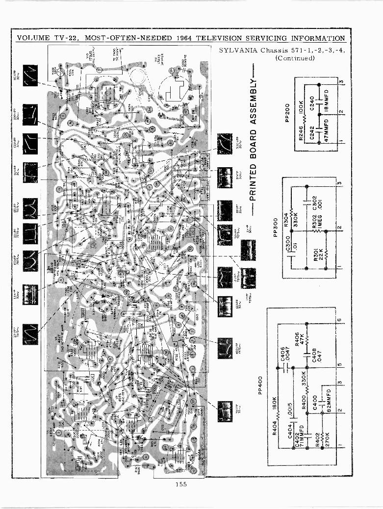
20 V
PP
7875
,1.
5V P
P30
,65
VP
P78
75,
20V
PP
55V
PP
7875
,78
75,
60 V
PP
30,
130V
PP
30,
600
VP
P30
,11
0 V
PP
30,
y4N
4E11
7o0
2I5
TV
IDE
O !
PA
MP
%(T
¡s
1.
L201
Á/C
200
%`
üIII
/C20
0100
221
R21
00
$214
15K
'JC
2p18
_
\ 12.
R21
2II<
C22
0 .0
022
.-gT
`8\
--
R2'
6-
68K
i22M
MF
-
[020
21_
_. 6
.I
:.
F/./
T20
01
R23
2
0204
R2404
.002
27K
L502
...--
--L5
0400
262
08
, 22
/Y,
R10
8'-i
f__
__...
6170
V2
40T
6f_
_.9.
,.. -
.77F
43
F''.
2I
AU
DIO
DE
T,
01f0
8 4H
F0y
_._
\1
0022
15
_2I
'R
I16
T
fr*2
12(?
-.0
022
'5601
-C11
22\6
+41
7__/
56G
IIOr
MM
FOR
IIO*
AC
5.x w
RI1
46.
8K
CI
0120 70
n
7\12
__\
--O
I`
,45/
:R
12J
a- I-
-vT
h.-
10V
311
36H
i'!}
3T/
aGK
6A05
A,0
047
I
'A
U01
0 O
UT
PU
T/
4,7K
/
75 V
PP
300v
PP
40005
20.0
022 82
1847
0n
.Zr
.2 0022
022
4,.0
012
4.z_
L
\rF
416/ R
234
470,
2I.
0226
\\
\1
\o
\I
IDK
U9
\R
416
4EJ7
\ \V
IDE
OIS
OR
. \
'^I.M
713
2ND
VID
EO
IF A
MP
AR
23]1
11-.
.,2_,
....,\
____
_~...
./
O--
.,uti\
4]K
G41
2\I
R35
'SK
' N 0
047
,N,
L208
R238
/}
\`^\
1
\ 3.9
KP
P40
2
3.30
MF
0232
Oa
5.6M
M0U
FD
N29
5/.0
022
`50
200/
``\
420
1020
71
R10
4G
02 2
2KT
T4
yg]O
MM
FD
/FS
~F
4P
P20
0I
0104
' ,T/.-
-v.
. .22
/I
! 6R
I06
TM
Fd
7__
..._
IOK
-23
8/fl2
30 2
26M
F0
56K
7fO
DI!
R10
28 S
D F
DA
MP
AG
G A
MP
ISIi
\ 9
/R248 31
ft 7K
D0
II35 40
0 V
PP
7875
,
0R24
1'2
40r`
330
1,3.
35
\I
J
` .//
R420 K
03I0
tI
Ili
R31
4\
i8
3K
:I'
--'-
\ _I
\ I
23 4
.%
,°.
---'/
K--
-?$
`/I,
1732
.
\R
412
68K
27H
\i -
\--
-I G
---
/C
524
.002
2\
R40
8 _
]"03
1803
22Galo
I-1
01
//04
10 0
M
/le1-
-16
5 (.
20K
680
1
R40
7:27
6"::4
40]
4TM
MFD
{{{.
......
..
E
1
28M
(MF
D2
7K
IE-1
)VB
v9\
4/''
R3I
813
FD
7 8f
O7
C30
6 M
11cG
VE
RT
OS
0 /
G32
600
RIZ
4:'.0
22
VE
RT
.OU
TP
UT
.002
2O
SC
)
PP
40ti_
600
22¡l,
(,_-
R2W
OK
,^,.-
6yB
K
7.61
1:\
220i
IF
C22
'\ --
-24
630
F.
K
IBM
MF
D
2944
305-
-i_._
y"/
'J'1
1725
402
14-0
22R
i31
C24
8220K
I -1,
122H
t47
MM
F0
R25
0O
KI0
O,
yh4.
7K I
IL40
01
0210
65 V
PP
30,
R40
418
0K
C40
41I
.001
5C402 MF
D
R40
2
270K
R40
033
0K
C40
0
82M
MF
D
2
C40
6.0
047 R "
406
4-+
vv--
C40
8.0
47
/ VP
P78
75,/
VT
0212
I4C
S610
000
601$
E IM
MU
NIT
YI
@S
YN
C S
EP
A
R22
422
0KA
GO
I50
VP
P78
75 ,
I/O
.2V
PP
30,
P P
300
85 V
PP
30,
.11g
156
0K 6
L_I_
r__
_R312
\15
ME
G
9 "/
C31
8.0
022
C31
01
21
C306 .33
R4 IBb6
'.'Z
"0I`
0342
4306
KIO
OK
0316 00
1'_
fR
3331
460
VE
RT
LIN
2IV
PP
3000
-PR
INT
ED
C30
0R
304
.01
330K
R30
122
KR
302
C30
2I M
EG
,001
300
VP
P30
00
BO
AR
D
328
0322
o/
R a?ol
E-!
T
----
V.-
Ytr
--v.
-,24
22 t
R32
922
0 rt
1200
VIO
1732
520
RI2
. OU
TP
UT
I9
TO
T40
0T
IE P
OIN
T 7
vl2
I7A
Y3
DA
MP
ER
/4'
1
FF
'^\
17
'F
,Iy.
¡11
.406
1U
l C
430
O\
60M
MF
D
055
.002
2
0404
AS
SE
MB
LY-
(-) o. ~
o JI w
PP
200
R24
6 ^A
NIO
OK
C24
2C
240
4°H
1--
-1/-
147
MM
FD
IBM
MF
D
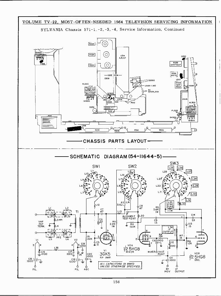
VOLUME TV -22, MOST -OFTEN -NEEDED 19.64 TELEVISION SERVICING INFORMATION
SYLVANIA Chassis 571-1, -2, -3, -4, Service Information, Continued
SK400
C426
L500
I R258 I
R256
I R334 I
PL500
SK500
R5(56
C514A,B,C,D
-SIDE VIEC508
5C500
C512 C506SC502 C510
L. I
TI02 .9)6 R510 R508 R514
R258CONTRAST
R256BRITE
ACINTERLOCK
R506
R334VERTHOLD
C250
3
C151000
VHFANT
TERM.
VI
4
I000
1
FIL.
SCHEMATIC DIAGRAM (54-11644-5)
CHASSIS PARTS LAYOUT
LI L2
L 7
r C3
Cl 12
L3 PPI
L5PP2
L6
C1710001
L9
L8
TI
7
LIO
V2RI22K
CI851000
SWILII
CI9 )1000
6 C201000
OFIL. AGC
C515
C847
L20
SW2
L16e4
R3 4330rt
L13 oIF
ALIGNMENTTEST POINT
VI
3GK5RF AMP.
ALL CAPACITORS IN MMFDUNLESS OTHERWISE SPEC/F/ED.
SW3L26I
L29 ®..
IL25
L23/
L22
L21
R55.6 K
IW
L34IF
OUTPUTR6- 9 15K
- CIO 1000
MIXER O TESTPOINT
CII(1000
L321
O OB+ IF
140V OUTPUT
ISM
L29
C14
3.9
CI315
R810K
3
V28
I/2 5HG8OS C.
156
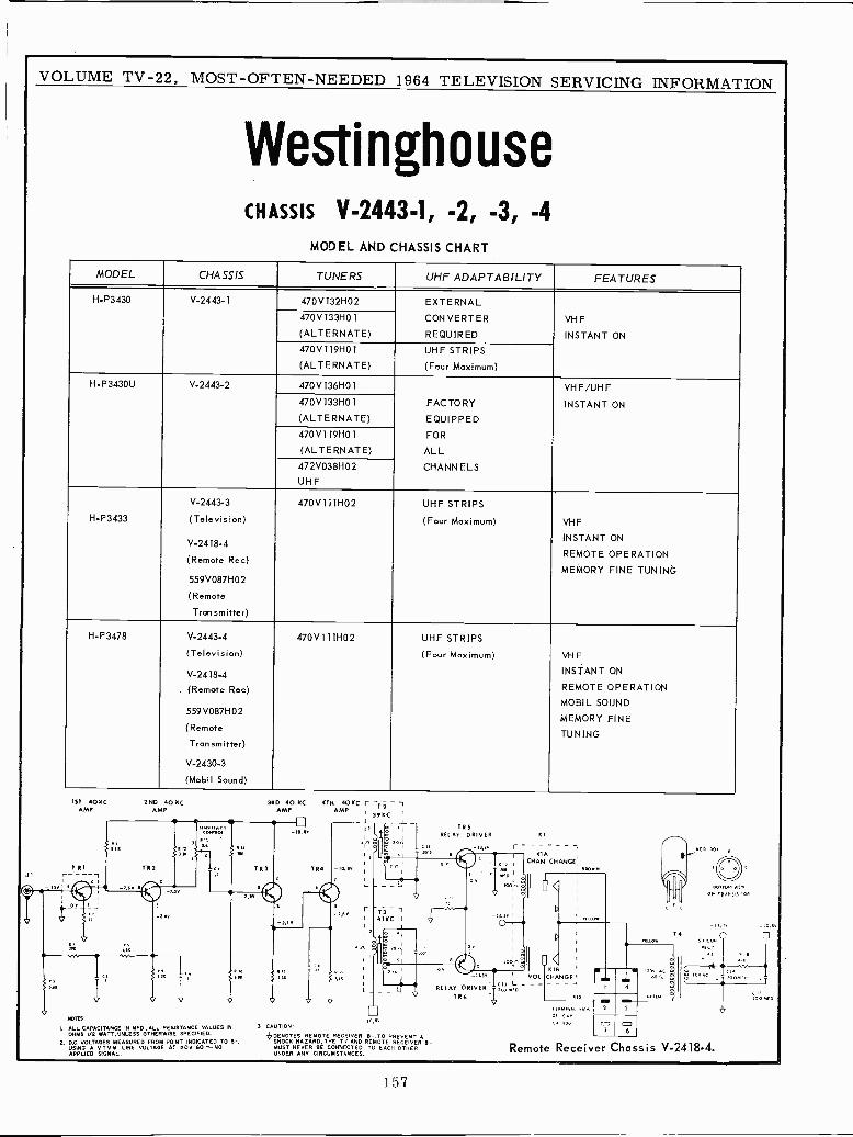
VOLUME TV -22, MOST -OFTEN -NEEDED 1964 TELEVISION SERVICING INFORMATION
WestinghouseCHASSIS
MODEL
V-2443-1,AND CHASSIS
-2,CHART
-3, -4
MODEL CHASSIS TUNERS UHF ADAPTABILITY FEATURES
H -P3430 V-2443-1 470V132H02 EXTERNAL
470V133H01
(ALTERNATE)CONVERTER
REQUIRED
VHF
INSTANT ON
470V119H01
(ALTERNATE)UHF STRIPS
(Four Maximum)
H-P3430U V-2443-2 470V136H01 VHF/UHF470V133H01
(ALTERNATE)FACTORY
EQUIPPED
INSTANT ON
470V119H01
(ALTERNATE)FOR
ALL
472V038H02
UHFCHANNELS
H -P3433
V-2443.3
(Television)
V-2418-4
(Remote Rec)
559V087H02
(Remote
Tran smitter)
470V111H02 UHF STRIPS
(Four Maximum) VHF
INSTANT ON
REMOTE OPERATION
MEMORY FINE TUNING
H -P3478 V-2443-4
(Television)
V-2418-4
(Remote Rec)
559V087H02
(Remote
Transmitter)
V-2430-3
(Mobil Sound)
470V111H02 UHF STRIPS
(Four Maximum) VHF
INSTANT ON
REMOTE OPERATION
MOBIL SOUND
MEMORY FINE
TUNING
1ST 401IC 2ND 40 KC 3RD 40 KC 4TH 40KCAMP AMP AMP AMP
vr -T5 - 1
39KC I
Lt[ [ ^
TR5REIAT DRIVER K1
r 1olr o
TR1 7R2 T 12 -lo. evrP
T
r I
K1ACHAN CHANGE
SRO
J
r Mo'ov
I 1 noC - ISr [ Pv P
4.111
_r.sv77
av
s `41KC I
-13,1vnlww01
V to-I1. io.ev
n I
Ia
T 4wM S.M a0I I,A/1LII
t I
0 1 »iiov
I
u
OII^ '_ ' are
I0
lüii nv
IL r VOlK 1
CHANGE 11111- ov .T
sM i I l J RELAY DRIVER tx oT R 6 .eo ro
9vl
y
NOTES: to
IN MED.. ALL RESISTANCE VALUES IN 3 CAUTION I
"
ev Ca aoo
EBO
10
A
bI
I. ALL CAPACITANCEOHMS I/2 WATT,UNLESS OTHERWISE SPECIFIED. bOExOTES REMOTE RECEIVER 6 TO PREVENT A
2. OC. VOLTAGES MEASURED FROM POINT INDICATED TO B-. SHOCK NA ZARO, IHE Tv AND REMOTE RECEIVER B-USING A VTVM LIME VOLTAGE AT 120V 60~x0 MUST NEVER BE CONIVCTED TO EACH OTHER Remote Receiver Chassis V-2418-4.APPLIED SIGNAL. UNDER ANY CIRCUMSTIUMSTSNCES.
157
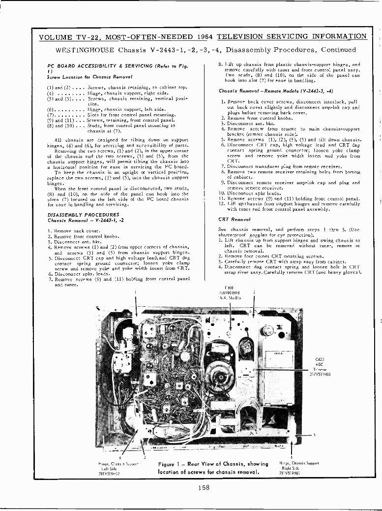
VOLUME TV -22, MOST -OFTEN -NEEDED 1964 TELEVISION SERVICING INFORMATION
WESTINGHOUSE Chassis V-2443-1, -2, -3, -4, Disassembly Procedures, Continued
PC BOARD ACCESSIBILITY & SERVICING (Refer to Fig.1)Screw Location for Chassis Removal
(1) and (2) Screws, chassis retaining, to cabinet top.(4) Hinge, chassis support, right side.(3) and (5). . Screws, chassis retaining, vertical posi-
tion.(6) Hinge, chassis support, left side.(7) Slots for front control panel mounting.(9) and (11) Screws, retaining, front control panel.(8) and (10) Studs, front control panel mounting to
chassis at (7).
All chassis are designed for tilting down on supporthinges, (4) and (6), for servicing and accessibility of parts.
Removing the two screws, (1) and (2), in the upper cornerof the chassis and the two screws, (3) and (5), from thechassis support hinges, will permit tilting the chassis intoa horizontal position for ease in servicing the PC board.
To keep the chassis in an upright or vertical position,replace the two screws, (3) and (5), into the chassis supporthinges.
When the front control panel is disconnected, two studs,(8) and (10), on the side of the panel can hook into theslots (7) located on the left side of the PC board chassisfor ease in handling and servicing.
DISASSEMBLY PROCEDURESChassis Removal - V-2443-1, -2
1. Remove back cover.2. Remove front control knobs.3. Disconnect ant. bkt.4. Remove screws (1) and (2) from upper corners of chassis,
and screws (3) and (5) from chassis support hinges.5. Disconnect CRT cap and high voltage leadíand CRT dag
contact spring ground connector; loosen yoke clampscrew and remove yoke and yoke width insert from CRT.
6. Disconnect spkr. leads.7. Remove screws (9) and (11) holding front control panel
and tuner.1
8. Lift up chassis from plastic chassis -support hinges, andremove carefully with tuner and front control panel assy.Two studs, (8) and (10), on the side of the panel canhook into slot (7) for ease in handling.
Chassis Removal -Remote Models (V-2443-3, -4)
1. Remove back cover screws, disconnect interlock, pullout back cover slightly and disconnect amp-lok cap andplugs before removing back cover.
2. Remove front control knobs.3. Disconnect ant. bkt.4. Remove screw from remote to main chassis -support
bracket (remote chassis side).5. Remove screws (1), (2), (3), (5) and tilt down chassis.6. Disconnect CRT cap, high voltage lead and CRT dag
contact spring ground connector; loosen yoke clampscrew and remove yoke width insert and yoke fromCRT.
7. Disconnect transducer plug from remote receiver.8. Remove two remote receiver retaining bolts from bottom
of cabinet.9. Disconnect remote receiver amp-lok cap and plug and
remove remote receiver.10. Disconnect spkr leads.11. Remove screws (9) and (11) holding front control panel.12. Lift up chassis from support hinges and remove carefully
with tuner and front control panel assembly.
CRT Removal
See chassis removal, and perform steps 1 thru 5. (Useshatterproof goggles for eye protection).1. Lift chassis up from support hinges and swing chassis to
left. CRT can be removed without tuner, remote orchassis removal.
2. Remove four corner CRT mounting screws.3. Carefully remove CRT with strap assy from cabinet.4. Disconnect dag contact spring and loosen bolt in CRT
strap rivet assy. Carefully remove CRT (use heavy gloves).
F400
758V001H10A. Slo-Blo
;gs.rp" g .r,+Jrtratw+.._..,.ifi1....
6 5
Hinge, Chassis SupportLeft Side
781V519H02
...2-41~1".211k.:- .i
2
Figure 1 - Rear View of Chassis, showinglocation of screws for chassis removal.
C420
AGC
Trimmer217V511 H03
3
4
Hinge, Chassis SupportRight Side
781V519H01
158
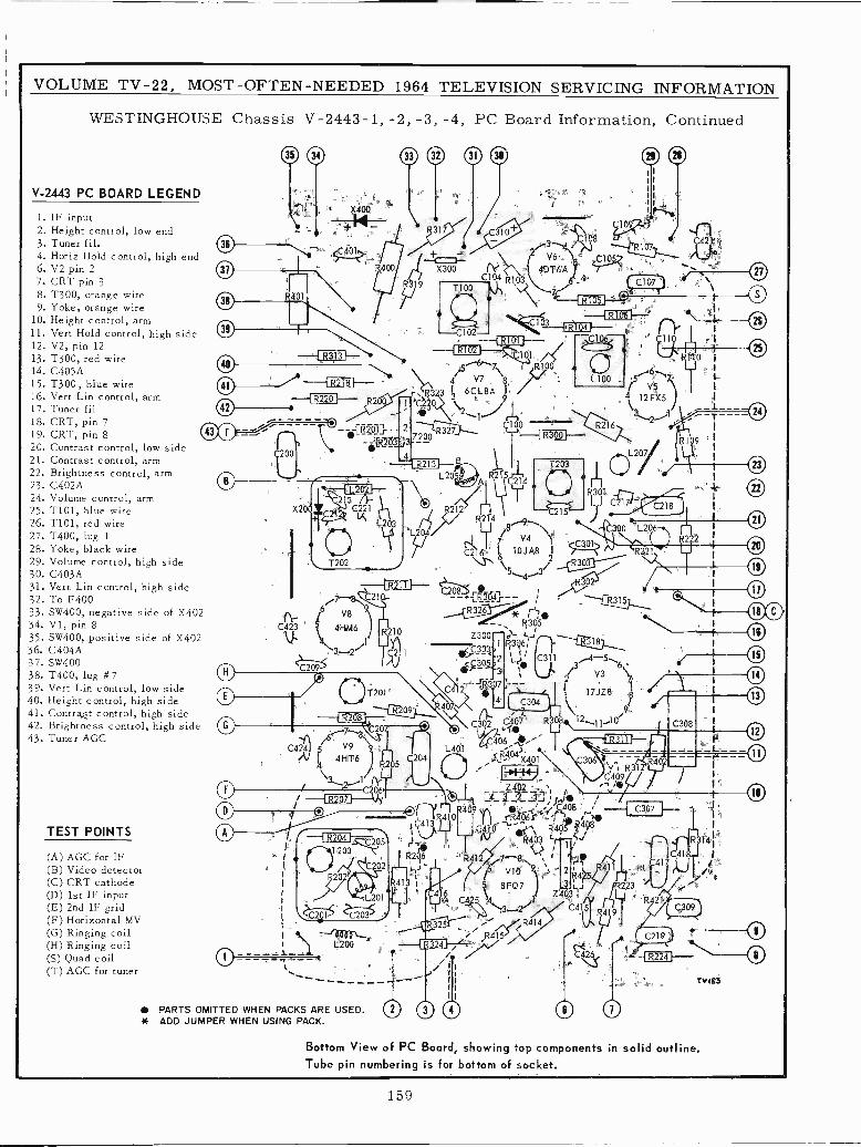
VOLUME TV -22, MOST -OFTEN -NEEDED 1964 TELEVISION SERVICING INFORMATION
WESTINGHOUSE Chassis V-2443-1, -2, -3, -4, PC Board Information, Continued
V-2443 PC BOARD LEGEND
1. IF input2. Height control, low end3. Tuner fil.4. Horiz Hold control, high end6. V2 pin 27. CRT pin 38. T300, orange wire9. Yoke, orange wire
10. Height control, arm11. Vert Hold control, high side12. V2, pin 1213. T300, red wire14. C405A15. T300, blue wire16. Vert Lin control, arm17. Tuner fil18. CRT, pin 719. CRT, pin 820. Contrast control, low side21. Contrast control, arm22. Brightness control, arm23. C402A24. Volume control, arm25. T101, blue wire26. T101, red wire27. T400, lug 1
28. Yoke, black wire29. Volume control, high side30. C403A31. Vert Lin control, high side32. To F40033. SW400, negative side of X40234. V1, pin 835. SW400, positive side of X40236. C404A37. SW40038. T400, lug #739. Vert Lin control, low side40. Height control, high side41. Contrasgt control, high side42. Brightness control, high side43. Tuner AGC
TEST POINTS
(A) AGC for IF(B) Video detector(C) CRT cathode(D) 1st IF input(E) 2nd IF grid(F) Horizontal MV(G) Ringing coil(H) Ringing coil(S) Quad coil(T) AGC for tuner
41 f-R218r-~-{ R220 I-- R200
C109
08
/2 v6>,} R107
Y6 C, 10 >Í% r, 1 4uT6A Y 4 "27C R103\\.......C107 d ',
7''''
C102--OM-- C101-
6--.71 (R1004 V7 8 /'v
r. R323 3 6CL8A9
FC100
R327 °- R 001--
T {8t-1-,
T203L205StAJJ
I R2?4
C2159L¡04 70 V4'/5./ CC301
C2`r i6 IOJAB I T --Z
/7^6 Y88. 9
C423 541-1,1416- R210
U. \4,...
C211
0 As./
O /T9
r7 /6g\ 20ÍC424 5 V9 9
44i -n-6) 5 C 204
\3 1f*Nr.
/`2-."/ ^-1 R207C 06
O ppORif4-11#0O
/`1 R2041-20511 U' 4
2R3035,4,3/R032J
R326
R305
2fl8$r364'+f-r*
Z300 `
C303'
<T 305
2 ¡R307
T200 r,4 R2(16
i II-1-1
L201
\?.C2S15 C203'5
\*).. L2
PARTS OMITTED WHEN PACKS ARE USED.* ADD JUMPER WHEN USING PACK.
R216
R315
18
3-5 ~6C311
2 V37
17JZ8 p
A,9
C302 51 407 R308 12..".11-'1° l -J
406,....e,'"<14043
X401
R3d61
1
.. \z4
i -4-a._ -...1J .,i404 rRÓbI'/ f ,`
CÓ ~ +l^, R405 ?498R403 1 ?j
1
,ri?
16 V10 9'5 8FQ7 '\ Z4O3
54.",3_,2/ C415C415
*" R414
R415
R314
-1 R224 }---
TVi£3
Bottom View of PC Board, showing top components in solid outline.Tube pin numbering is for bottom of socket.
O
159
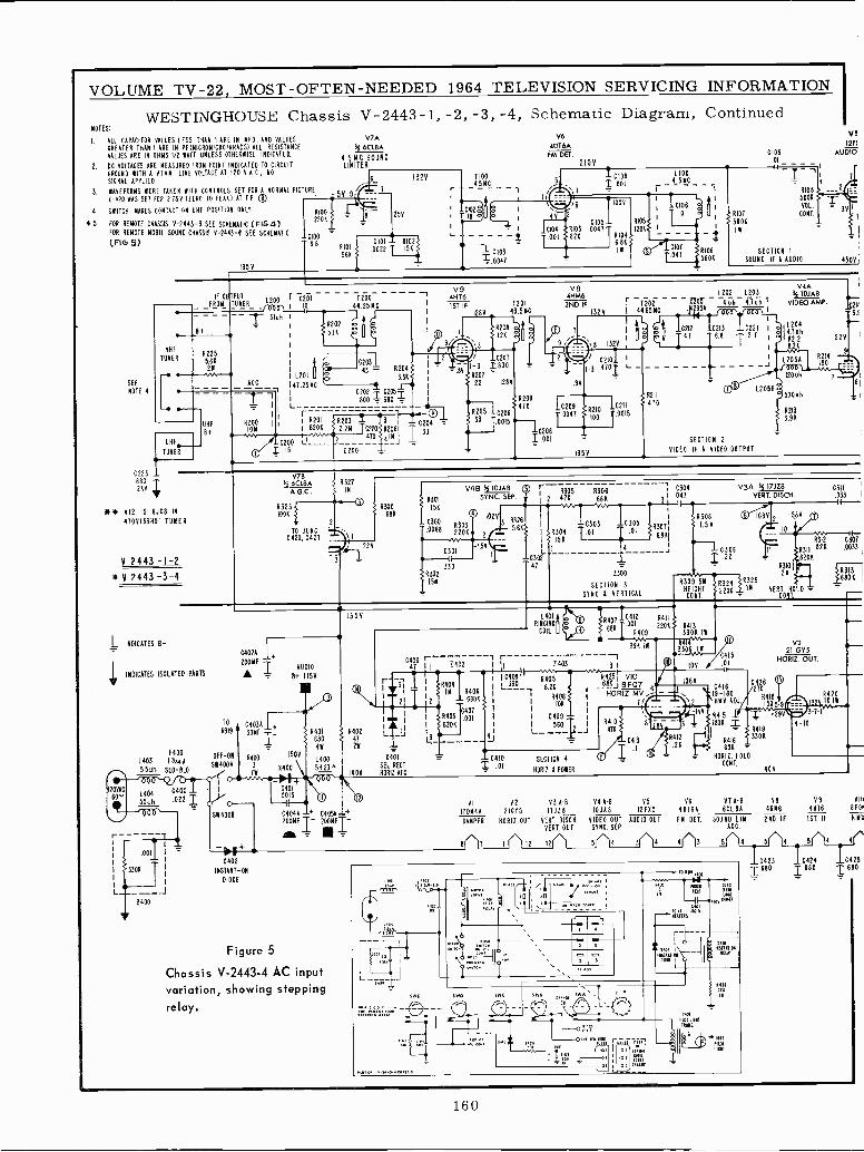
VOLUME TV -22, MOST -OFTEN -NEEDED 1964 TELEVISION SERVICING INFORMATION
WESTINGHOUSE Chassis V-2443-1,-2,-3,-4, Schematic Diagram, ContinuedNOTES:
I. ALL CAPACITOR VALUES LESS THAN I ARÉ IN NED, ANO VALUES V7A
GREATER THAN I ARE IN PF(MICRONICROFARABS) ALL RESISTANCE k 6CLAAVALUES ARE IN OHMS 1/2 WATT UNLESS OTHERNISE INDICATED
4.5 MC SOUND2. DC VOLTAGES ARE MEASURED FROM POINT INDICATED TO CIRCUIT LIMITER
GROUND WITH A ATAN. LINE VOLTAGE AT 120 V.A.C., NO
SIGNAL APPLIED. 6_ 1324
3. WAVEFORMS WERE TAKEN WITH CONTROLS SET FOR A NORMAL PIC UNE.
0-420 VAS SET FOR 275V (ZERO TO PEAK) AT T.P. ®.
4. SWITCH RAKES CONTACT ON UHF POSITION ONLY RI00 15. FOR REMOTE CHASSIS 0-2443-3 SEE SCHEMATIC (FIG4)
2208
FOR REMOTE MOBIL SOUND CHASSIS V-2443-4 SEE SCHEMATIC _0100(FIG 5) 6.8 C101 - RI02
1/9
25V
SEE
NOTE 4
0225
RIO)
SERI
T35 V
00221 15K
T10045MC
-CM2 $ I
IB á
` tC103
=.0047
V64DT6AFM DET.
2101/
h\
I9Y
CHJ4
001
T
C109
1100
1.001 4.5MC2C108
IOS
RI03 .Ó0471 120K<
820 6 86 íIN (f1
L 1
, 1 C106 t.T
,
10 á RIOT
- 560K
_i1C(07
R
1.0475I 606
06
1.0I
V912F)
AUÍ
R108 ---4 =__
500KVOL.
CONT.
SECTION 1
SOUND IF & AUDIO 450A
IF OUTPUT
8+
VHF 8225TUNER 5.6K
IIIr-2W
1-.
UHFTUNER
680
2KV T
UHF
6+
FROML200 r C201TUNER -70001 ,
if-- .3)uh I
I <R202>5.1K
T20044.25 MC
I
1C203143R204
I L201
47.25MC
I.
C202 C2053r
L800I
680IACC
T1,I
I
r R01RIÚOM I i Í B20K SR203
i2.2N Too
.N }C200 L! ___ Y Oro
I IS Z200
R206íC2044
4)Ní I.33
V9 VB411T6 4HM6
1ST IF T201 2ND IF r43.5MC
T202
12,31, _ 132V I 44.65MC
}I ttR208 1 d- 00T Í Il
S 12K / ," 9 ill '',11 1321/ I
10207 r _ 0210 I
8Y1-3 I_ 800 = "R207 #
1.3 470/ 1.-
22 128V
4H
R205 1020633 T.0015
8209470
C208I .001
.8V
1C2o9
10047
R2I0 16100 7.0211015
135V
1202 L203
9OT 5
74 7h 4.7uhT
C212 C213 C22I I
4.7 6.8 2.7 I
R231-- 12050
500uh410
V4AIf 101A8
VIDEO AMP.
L204I4.7uh
62IC
120uh
SECTION 2
VIDEO IF L VIDEO OUTPUT
R2)3
3.9 K
224
1150
2H3.1
NF Nt 412 IS 6JC8 IN
47041331101 TUNER
Y 2443 -1-2Nf V 2443 -3-4
1 INDICATES 8-
V7B33 6CLBA R327Á.a.l IN
R3231TOOK
TO JUNG0420, 0427
2
22V
31
/ R301
R300 156
C300
.0068
V4B If 101A8
R303220K
0301
8302330
15M
SYNC. SEP.
1024
2
.5V
383265.6K
_C347
R30S R306416 68K
R304158
C303 C305
T.O1 D)R307
6.8
2300
SECTION 3
SYNC & VERTICAL
C304 V3A 15 17128047
5R308I.S M
TC226
R30 5M
HE CHTC NT.
VERT. DISCH.
10801, -584
10
C311f -
R312 C3Ó7
R31182K .0033
820K
R310¡A IR313
y6324i 2N
6806
220K 4,- YE0.COÑT LO
II
INDICATES ISOLATED PARTS
TO
R319
F400OFF -ON
L403 13/4A5114004
I
55uh SLO-51.0
120YAC
60^'S404
0400 1
55uh .022 IO
SW4008
i
I
.001
ODOR
0400
C402Á 1+200MF
AUDIO
B+ ITSY
C40311.30MF
1_R400 1504
W0400
+-.X402
INSTANT -ON
DIODE
C401
0015
6401
46
14005823^
1350
R40247
(40V
C4044 + C4054-+2-FÍ- 2FT-
C4064 2402
-31IAL --L
R 01
SEL ECT
XORI AFC
(
i R404I IN 14406
2 ._680K
I C407I ' 11403
.001I 8206
4 ----- J
1401RINGING
COIL
lSR468K 07 IC412001220RR411
S{
3413+j .409 3306 III
39K Iw Ram'330U1
i11403 31
GORIIR405 Á425¡ VIO
`390-34.02R564
.2K . r - F R 8
I R408 I HORIKJ078Z
MV
10K 1 I 7;\2I C409 - 14Y
L--560 1_1R410 8
4763
1100
1060
-0401 SECTION 4
HORIZ & PONER
C4ü
i
R412
1.26
C415.01
041619-160HMV ADJ
V221 GY5
HORIZ. OUT.
02126
11918
15051
8415 I -2941806 I
33ÓK
6ÓR41K
110410. HOLDCONT.1
404
VI 42 43 Al 44 Al 45 46 ATA -B 48 49 VIII
170N44 21615 IWJ18 10148 12F95 40184 eel 84 411116 41126 8F01
DAMPER HORI2.0UT VERT. DISCH. VIDEO OUT AUDIO OUT FM. OFT. SOUND LIM. 2ND. IF 1ST. IF HMV
VERT. OUT SYNC. SEP. ACC.
8 7
Figure 5
Chassis V-2443-4 AC inputvariation, showing steppingrelay.
12 12 I 5 3 4 4 3 5 4 5 4 5 4 4
TM rAT i iFS,il
NUMi
IIIu1
tIWTI LINT
Id TINS.
`wTLINT
rnT
C423 C424 0425i680 T 180 T 680
160
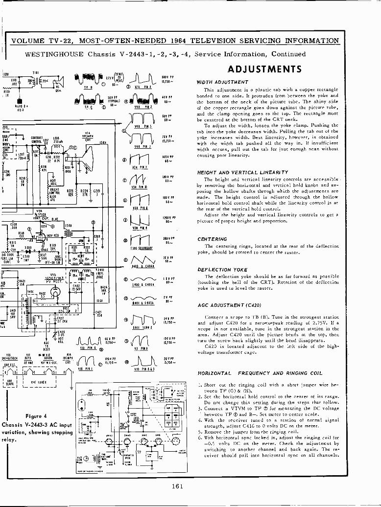
1100
IK
VOLUME TV -22, MOST -OFTEN -NEEDED 1964 TELEVISION SERVICING INFORMATION
WESTINGHOUSE Chassis V-2443-1, -2, -3, -4,
AUDIO 8+1150
1101ZERO
v u 2.í5V P
TO
EAK V6008 PP
lllliP 9
O 60--15,750
T © VON PIN 2
SSA PP(TYPICAL)
T.P. C© 60-.
203=,119--) i 1 ONTRAST 1206SNC
i 'CONTROL C6.8 250uh
000 \-JIG
1 L R21715 11201
131 .1 COIN R2228_ _ . 720uhóV
10216390
821668
39
1R218
4.18
.22 8.28
R219
100K
V141904144
CRTISNV
©4J
8221
1806
BRIGHT
R82KCONTROL
82204TK
R224 C21927K .1
V3839 17.128
VERT. OUT. BLUE
C308.068
8318150 6
R31518
-216 -316 500K ' C310IERT.LIN I+1Nf
CONT. -
-14Y
X300
8
R319
ISAAC 391
6317JONC.
5.6K 8400OFF -ON SYI
T300
1111
6RN1
R31 83221x
C309.1
15V518 ISs6
ó;i /81452K5
4AER
IC419100
5110
403Ruh
12401
V15 ' 2 I9nÓ IDEfL
1030/193 I NO4RIZIYOKE
HV RECT. L JC422
15-31VHET400 84( . 1 3.32213v rµ
8424t506 f
168423
2.28 .1! 2i
--I
¡ 1C42127 21V
_C421039
L
613
3Af46/30Z4
rURF OSC.--;4n31
UHF
LTUNER
VII3015
RF ANP.
r-i3
ACTO
R323
i1.NRV126CO6A
VIII NIX-OSC.
1
1
I VHF TUNER I
C4203-25
YIN
1901 14
CRT.
Figure 4
Chassis V-2443-3 AC inputvariation, showing steppingrelay.
VIO PIN 6
AIO PIN I
[1
60V PP15,150-
olAwaílsY49 PIN 2
048 PIN 3
048 PIN 3
V3A PIN 2
638 PIN 10
03B PIN 6
938 PIN 4
T300 SECONDARY
® / \/ VX400 & C4044
408 PP
60~
608 PP60 .
TOY PP
15,150-,
160Y PP
60
Service Information, Continued
ADJUSTMENTSWIDTH ADJUSTMENT
This adjustment is a plastic tab with a copper rectanglebonded to one side. It protrudes from between the yoke andthe bottom of the neck of the picture tube. The shiny sideof the copper rectangle goes down against the picture tube,and the clamp opening goes to the top. The rectangle mustbe centered at the bottom of the CRT neck.
To adjust the width, loosen the yoke clamp. Pushing thetab into the yoke decreases width. Pulling the tab out of theyoke increases width. Best linearity, however, is obtainedwith the width tab pushed all the way in. If insufficientwidth occurs, pull out the tab for just enough scan withoutcausing poor linearity.
HEIGHT AND VERTICAL LINEARITY180Y PP
60... The height and vertical linearity controls are accessibleby removing the horizontal and vertical hold knobs and ex-posing the hollow shafts through which the adjustments are
160V PP made. The height control is adjusted through the hollow60 V horizontal hold control shaft while the linearity control is at
the rear of the vertical hold control.Adjust the height and vertical linearity controls to get a
60- picture of proper height and proportion.1200V PP
2800 PP CENTERING6O...
The centering rings, located at the rear of the deflectionyoke, should be rotated to center the raster.
20V PP60...
e / I.6Y PP
1400 6 C405660.0
I00V PP15,750", ®
2 V PP
8401 1 C4034 CO
0401 TERN 2
82 PIN 9
DEFLECTION YOKEThe deflection yoke should be as far forward as possible
(touching the bell of the CRT). Rotation of the deflectionyoke is used to level the raster.
AGC ADJUSTMENT (C420)
P4A pp Connect a scope to TB (B). Tune in the strongest station15,750- and adjust C420 for a zero -to -peak reading of 2.75V. If a
scope is not available, tune in the strongest station in thearea. Adjust C420 until the picture bends at the top, thenturn the screw back slightly until the bend disappears.
C420 is located adjacent to the left side of the high -voltage transformer cage.
100 V PP
15,150 -
20 PP
15,150-,
03 a0.1úi'19 . .':."18illi
a66
., 4-
.áa ,swAI
swi. awe
a..1 ` ___ I,_Itf-, weº swc 5155Swat.
__AO __*
iLOi
LCXI
MIlpili6 5K
11111551'
DOEO
.«w.*.
+na ID 010D NI IIIII
HORIZONTAL FREQUENCY AND RINGING COIL
1. Short out the ringing coil with a short jumper wire be-tween TP (G) & (H).
2. Set the horizontal hold control to the center of its range.Do not change this setting during the steps that follow.
3. Connect a VTVM to TP m for measuring the DC voltagebetween TP Q and B-. Set meter to center scale.
4. With the receiver tuned to a station of normal signalstrength, adjust C416 to 0 volts DC on the meter.
5. Remove the jumper from the ringing coil.6. With horizontal sync locked in, adjust the ringing coil for
-0.5 volts DC on the meter. Check the adjustment byswitching to another channel and back again. The re-ceiver should pull into horizontal sync on all channels.
161
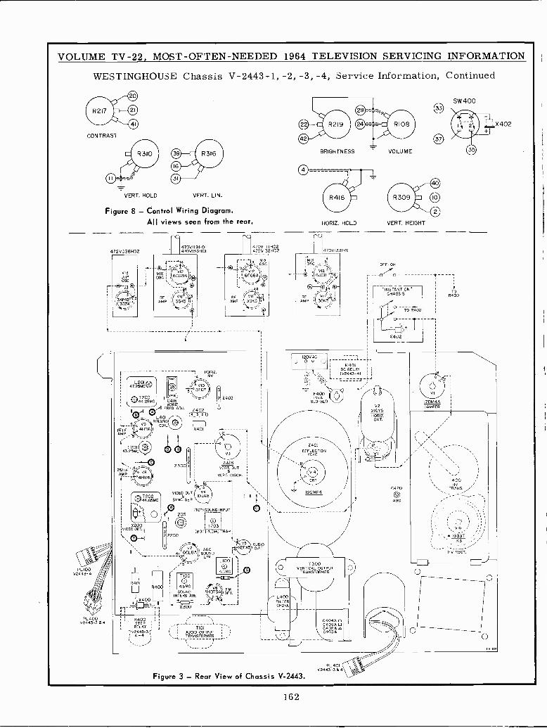
VOLUME TV -22, MOST -OFTEN -NEEDED 1964 TELEVISION SERVICING INFORMATION
WESTINGHOUSE Chassis V-2443-1, -2, -3, -4, Service Information, Continued
CONTRAST
PL100V2443-4
PL400V2443-3 ó 4
VERT. HOLD VERT. LIN.
Figure 8 - Control Wiring Diagram.All views seen from the rear.
472V038402
47.2L 201
5MC0T20044.25MC
(- --1T45
C418HOR Z.
FREO. ADJ.
L401RINGING
4--ª o V9 COIL10I.F.AMP
T20143.25MC
AMP
X200VIDEO GET.
R401400
X40_0
i Pi
K400STEPRELAY
4 02443-31'B-4
HORIZ.iq MV
0403
0402(4 3 20
VIDEO OUT.
SY NC. SE P.
B
L205
7100
4.5MC
SOUNDINTERSTAGE
X401112
17JZ8GOAT. OUT.
VERT. DISC H.
(TOP)GOONS INPUT
OT203
MOT) 4.5MC TRAP
-5c3oo
L100
4.5MC-
TI0)AUDIO OUTPUTTRANSFORMERi T `
FMDET.
470V1 IJ 1402470V132H02
r4OSCMtX
1
AUDIOOUT.
/ L400FILTERCHOKE
BRIGHTNESS VOLUME
HORIZ. HOLD
470V133H01
MIXOSE
ü
o --D4íRF
AMP
120VAC_) 9 9 'J
4401DC RELAY(V2443-4)
F400IN.A
SLO-BLO
0401DEFLECTION
YOKE
f.
I9CMP4
T300VERTICAL OUTPUT
TRANSFORMER
Figure 3 - Rear View of Chassis V-2443.PL 401
V2443-3 64
4400
X402
VERT. HEIGHT
OFF -ON
P
"INSTANT ONCHASSIS
C420
AGG
170M4ÁDAMPER
SW400
TOR400
HV RECT.
162
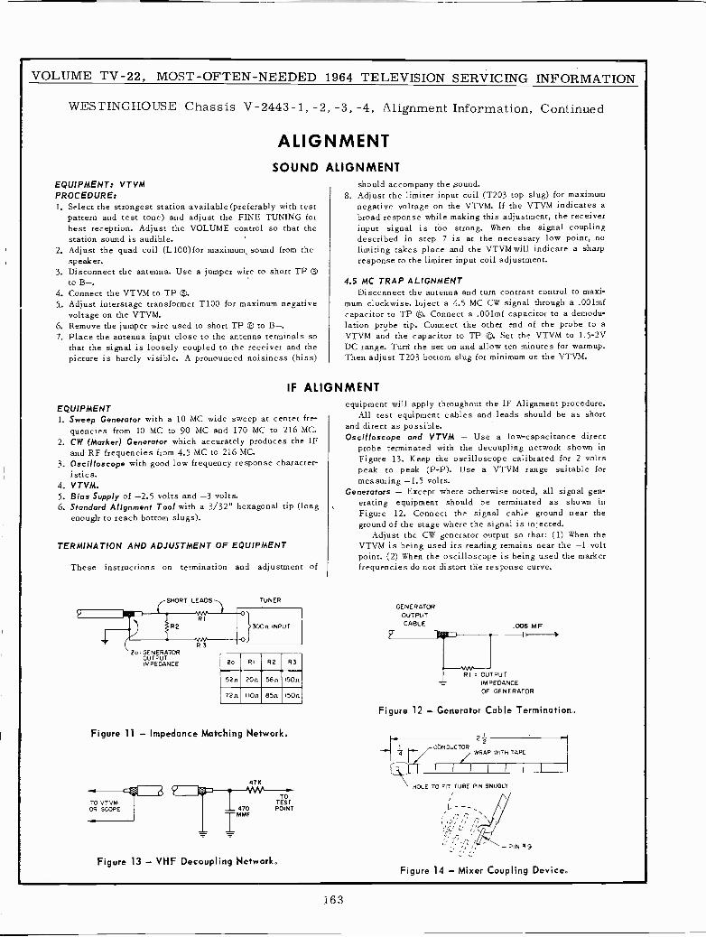
VOLUME TV -22, MOST -OFTEN -NEEDED 1964 TELEVISION SERVICING INFORMATION
WESTINGHOUSE Chassis V-2443-1, -2, -3, -4, Alignment Information, Continued
ALIGNMENTSOUND ALIGNMENT
EQUIPMENT: VTVMPROCEDURE:1. Select the strongest station available (preferably with test
pattern and test tone) and adjust the FINE TUNING forbest reception. Adjust the VOLUME control so that thestation sound is audible.
2. Adjust the quad coil (L100)for maximum, sound from thespeaker.
3. Disconnect the antenna. Use a jumper wire to short TPto B-.
4. Connect the VTVM to TP ®.5.. Adjust interstage transformer T100 for maximum negative
voltage on the VTVM.6. Remove the jumper wire used to short TP ® to B-.7. Place the antenna input close to the antenna terminals so
that the signal is loosely coupled to the receiver and thepicture is barely visible. A pronounced noisiness (hiss)
IF
should accompany the .sound.8. Adjust the limiter input coil (T203 top slug) for maximum
negative voltage on the VTVM. If the VTVM indicates abroad response while making this adjustment, the receiverinput signal is too strong. When the signal couplingdescribed in step 7 is at the necessary low point, nolimiting takes place and the VTVM will indicate a sharpresponse to the limiter input coil adjustment.
4.5 MC TRAP ALIGNMENTDisconnect the antenna and turn contrast control to maxi-
mum clockwise. Inject a 4.5 MC CW signal through a .001mfcapacitor to TP ®. Connect a .001mf capacitor to a demodu-lation probe tip. Connect the other end of the probe to aVTVM and the capacitor to TP D. Set the VTVM to 1.5-2VDC range. Turd the set on and allow ten minutes for warmup.Then adjust T203 bottom slug for minimum on the VTVM.
ALIGNMENT
EQUIPMENT1. Sweep Generator with a 10 MC wide sweep at center fre-
quencies from 10 MC to 90 MC and 170 MC to 216 MC.2. CW (Marker) Generator which accurately produces the IF
and RF frequencies from 4.5 MC to 216 MC.3. Oscilloscope with good low frequency response character-
istics.4. VTVM.5. Bias Supply of -2.5 volts and -3 volts.6. Standard Alignment Tool with a 3/32" hexagonal tip (long
enough to reach bottom slugs).
TERMINATION AND ADJUSTMENT OF EQUIPMENT
These instructions on termination and adjustment of
SHORT LEADS TUNER
R2
SO e GENERATOROUTPUTIMPEDANCE
R3
INPUT
O
equipment will apply throughout the IF Alignment procedure.All test equipment cables and leads should be as short
and direct as possible.Oscilloscope and VTVM - Use a low -capacitance direct
probe terminated with the decoupling network shown inFigure 13. Keep the oscilloscope calibrated for 2 voltspeak to peak (P -P). Use a VTVM range suitable formeasuring -1.5 volts.
Generators - Except where otherwise noted, all signal gen-erating equipment should be terminated as shown inFigure 12. Connect the signal cable ground near theground of the stage where the signal is injected.
Adjust the CW generator output so that: (1) When theVTVM is being used its reading remains near the -1 voltpoint. (2) When the oscilloscope is being used the markerfrequencies do not distort the response curve.
GENERATOROUTPUTCABLE .005 MF
20 RI R2 R3
RI = OUTPUT52n 120n 56n 150n IMPEDANCE
OF GENERATOR72n IOn 85n 150n
Figure 11 - Impedance Matching Network,
TO VTVMOR SCOPE
47K
TOTEST
470 POINT
IMMF
Figure 13 - VHF Decoupling Network.
Figure 12 - Generator Cable Termination.
CONDUCTOR
221
WRAP WITH TAPE
HOLE TO FIT TUBE PIN SNUGLY
Figure 14 - Mixer Coupling Device.
163
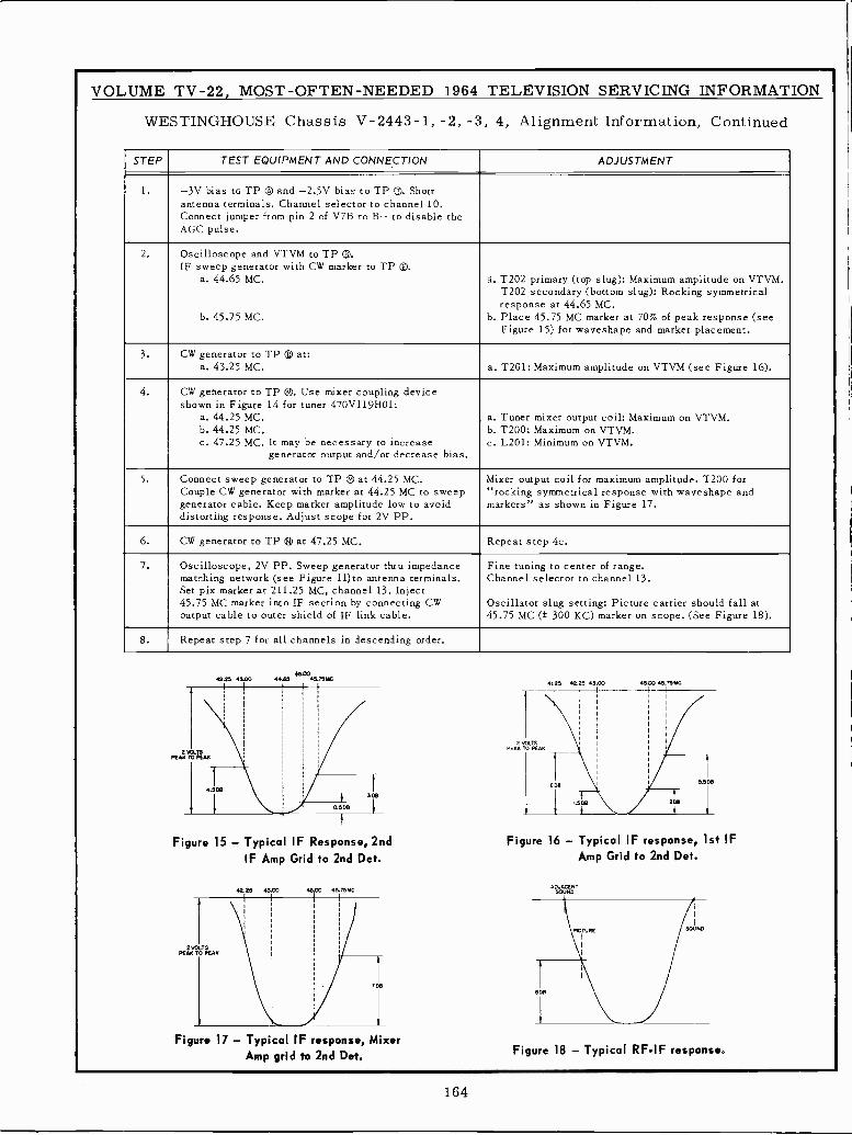
VOLUME TV -22, MOST -OFTEN -NEEDED 1964 TELEVISION SERVICING INFORMATION
WESTINGHOUSE Chassis V-2443-1, -2, -3, 4, Alignment Information, Continued
STEP TEST EQUIPMENT AND CONNECTION ADJUSTMENT
-3V bias to TP ® and -2.5V bias to TP T. Shortantenna terminals. Channel selector to channel 10.Connect jumper from pin 2 of V7B to B- to disable theAGC pulse.
2. Oscilloscope and VTVM to TP ®.IF sweep generator with CW marker to TP Z.
a. 44.65 MC.
b. 45.75 MC.
á. T202 primary (top slug): Maximum amplitude on VTVM.T202 secondary (bottom slug): Rocking symmetricalresponse at 44.65 MC.
b. Place 45.75 MC marker at 70% of peak response (seeFigure 15) for waveshape and marker placement.
3. CW generator to TP ® at:a. 43.25 MC. a. T201: Maximum amplitude on VTVM (see Figure 16).
4. CW generator to TP ®. Use mixer coupling deviceshown in Figure 14 for tuner 470V119H01:
a. 44.25 MC.b. 44.25 MC.c. 47.25 MC. It may be necessary to increase
generator output and/or decrease bias.
a. Tuner mixer output coil: Maximum on VTVM.b. T200: Maximum on VTVM.c. L201: Minimum on VTVM.
5. Connect sweep generator to TP IF at 44.25 MC.Couple CW generator with marker at 44.25 MC to sweepgenerator cable. Keep marker amplitude low to avoiddistorting response. Adjust scope for 2V PP.
Mixer output coil for maximum amplitude. T200 for"rocking symmetrical response with waveshape andmarkers" as shown in Figure 17.
6. CW generator to TP ® at 47.25 MC. Repeat step 4c.
7. Oscilloscope, 2V PP. Sweep generator thru impedancematching network (see Figure 11)to antenna terminals.Set pix marker at 211.25 MC, channel 13. Inject45.75 MC marker into IF section by connecting CWoutput cable to outer shield of IF link cable.
Fine tuning to center of range.Channel selector to channel 13.
Oscillator slug setting: Picture carrier should fall at45.75 MC (± 300 KC) marker on scope. (See Figure 18).
8. Repeat step 7 for all channels in descending order.
4225 45.0045m
44.61 45 75M
2 VOLTSPEAK 10 PEAK
4.508
0.508
3D8
Figure 15 - Typical IF Response, 2ndIF Amp Grid to 2nd Det.
42.25 45.00 46.00 45 1551C
2 VOUSPEAK TO PEAK
708
Figure 17 - Typical IF response, MixerAmp grid to 2nd Det.
Figure 16 - Typical IF response, 1st IFAmp Grid to 2nd Det.
ADJACENTSOUND
Figure 18 - Typical RFIF response.
164
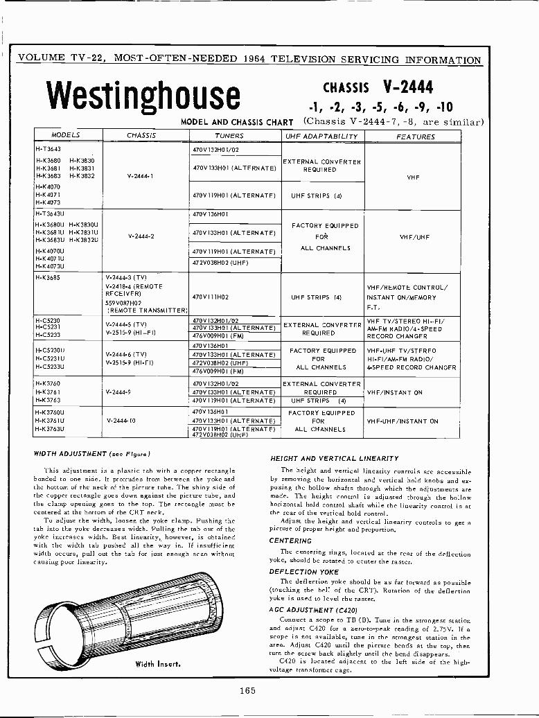
VOLUME TV -22, MOST -OFTEN -NEEDED 1964 TELEVISION SERVICING INFORMATION
WestinghouseMODEL
CHASSIS V-2444-1 -2, -3, -5, -6, -9, -10
AND CHASSIS CHART (Chassis V-2444-7, -8, are similar)MODELS CHASSIS TUNERS UHF ADAPTABILITY FEATURES
H -T3643 470V132H01/02
H -K3680 H -K3830H -K3681 H -K3831H -K3683 H -K3832 V-2444-1
470V133H01 (ALTERNATE)EXTERNAL CONVERTER
REQUIREDVHF
H -K4070H -K4071H -K4073
470V119H01 (ALTERNATE) UHF STRIPS (4)
H-T3643U 470V136H01
H-K3680U H-K3830UH-K3681U H-K3831UH-K3683U H-K3832U
V-2444-2 470V133H01 (ALTERNATE)FACTORY EQUIPPED
FOR VHF/UHF
H-K4070U 470V119H01 (ALTERNATE) ALL CHANNELS
H-K4071UH-K4073U
472V038H02 (UHF)
H -K3685 V-2444-3 (TV)V-2418-4 (REMOTERECEIVER)
559V087H02(REMOTE TRANSMITTER)
470V111H02 UHF STRIPS (4)
VHF/REMOTE CONTROL/
INSTANT ON/MEMORY
F.T.
H-05230 470V132H01/02 VHF TV/STEREO HI-FI/H-05231 V-2444-5 (TV) 470V133H01 (ALTERNATE) EXTERNAL CONVERTER
AM -FM RAD10/4-SPEEDH-05233 V-2515-9 (HI-FI) 476V009H01 (FM) REQUIRED RECORD CHANGER
470 V 136H011-1-C5230U
V-2444-6 (TV) 470V133H01 (ALTERNATE)FACTORY EQUIPPED
FOR
VHF -UHF TV/STEREOHIFI/AM-FM RADIO/H-C5231U
V-2515.9 (HI-FI) 472V038H02 (UHF)ALL CHANNELS 4 -SPEED RECORD CHANGERH-C5233U
476V009H01 (FM)
H -K3760 470V132H01/02 EXTERNAL CONVERTERH -K3761 V-2444-9 470V133H01 (ALTERNATE) REQUIRED VHF/INSTANT ONH -K3763 470V119H01 (ALTERNATE) UHF STRIPS (4)
H-K3760U 470V136H01 FACTORY EQUIPPEDH-K3761U V-2444-10 470V133H01 (ALTERNATE) FOR VHF-UHF/INSTANT ONH-K3763U 470V119H01 (ALTERNATE)
472V038H02 (UHF)ALL CHANNELS
WIDTH
Thisbondedthethethecentered
Totabyokewithwidthcausing
In
ADJUSTMENT (see Figure)HEIGHT AND VERTICAL LINEARITY
adjustment is a plastic tab with a copper rectangle The height and vertical linearity controls are accessibleto one side. It protrudes from between the yoke and by removing the horizontal and vertical hold knobs and ex -
bottom of the neck of the picture tube. The shiny side of posing the hollow shafts through which the adjustments arecopper rectangle goes down against the picture tube, and made. The height control is adjusted through the hollowclamp opening goes to the top. The rectangle must be horizontal hold control shaft while the linearity control is at
at the bottom of the CRT neck. the rear of the vertical hold control.adjust the width, loosen the yoke clamp. Pushing the Adjust the height and vertical linearity controls to get a
into the yoke decreases width. Pulling the tab out of the picture of proper height and proportion.increases width. Best linearity, however, is obtained CENTERINGthe width tab pushed all the way in. IE insufficient
The centering rings, located at the rear of the deflectionoccurs, pull out the tab for just enough scan without gpoor linearity. yoke, should be rotated to center the raster.
DEFLECTION YOKEThe deflection yoke should be as far forward as possiblei-, = (touching the bell of the CRT). Rotation of the deflection
yoke is used to level the raster.
- ConnectAGC ADJUSTMENT (C420)
a scope to TB (B). Tune in the strongest stationÍand adjust C420 for a zero -to -peak reading of 2.75V. If ascope is not available, tune to the strongest station rn the- : f area. Adjust C420 until the picture bend's at the top, thenturn the screw back slightly until the bend disappears.
Insert. C420 is located adjacent to the left side of the high -voltage transformer cage.
165
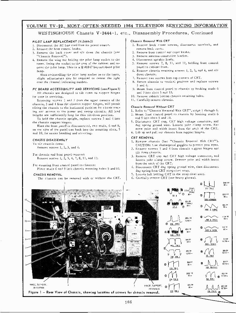
VOLUME TV -22, MOST -OFTEN -NEEDED 1964 TELEVISION SERVICING INFORMATION
WESTINGHOUSE Chassis V-2444-1, etc., Disassembly Procedures, Continued
PILOT LAMP REPLACEMENT (V.2444-3)1. Disconnect the AC line cord from its power source.2. Remove the front control knobs.3. Remove the back cover and tilt down the chassis (see
"Chassis Removal").4. Remove the wing nut holding the pilot lamp socket to the
tuner. Swing the socket to the rear of the cabinet and re-move the pilot lamp. This is a ® #1847 bayonet -base pilotlamp.
When re -installing the pilot lamp socket on to the tuner,slight adjustments may be required to center the lightover the channel indicating number.
PC BOARD ACCESSIBILITY AND SERVICING (see Figure 1)All chassis are designed to tilt down on support hinges
for ease in servicing.Removing screws 1 and 2 from the upper corners of the
chassis, 3 and 4 from the chassis support hinges, will permittilting the chassis to the horizontal positionfor circuit trac-ing and access to the power and sweep circuits. All leadlengths are sufficiently long for this tilt -down position.
To hold the chassis upright, replace screws 3 and 4 intothe chassis support hinges.
When the front panel is disconnected, two studs, 6 and 9,on the side of the panel can hook into the mounting slots, 5and 10, for easier handling and servicing.
CHASSIS DISASSEMBLYTo tilt chassis down:
Remove screws 1, 2, 3, and 4.
For chassis and front panel removal:Remove screws 1, 2, 3, 4, 7, 8, 11, and 12.
For mounting front control panel to chassis:Place studs 6 and 9 into chassis mounting holes 5 and 10.
CHASSIS REMOVALThe chassis can be removed with or without the CRT.
z
HINGE, SUPPORT,
781 V519H04- HINGE, SUPPORT,
781 V519H03
Figure 1 - Rear View of Chassis, showing location of screws for chassis removal.
Chassis Removal With CRT1. Remove back cover screws, disconnect interlock, and
remove back cover.2. Remove front control and tuner knobs.3. Remove antenna connection bracket.4. Disconnect speaker leads.5. Remove screws 7, 8, 11, and 12, holding front control
panel to cabinet front.6. Remove chassis retaining screws 1, 2, 3, and 4, and tilt
down chassis.7. Remove two screws from top corners of CRT.8. Return chassis to vertical position and replace screws
3 and 4.9. Mount front control panel to chassis by hooking studs 6
and 9 into slots 5 and 10.10. Remove cabinet bottom chassis retaining bolts.11. Carefully remove chassis.
Chassis Removal Without CRT1. Refer to "Chassis Removal With CRT", steps 1 through 6.2. Mount front control panel to chassis by hooking studs 6
and 9 into slots 5 and 10.3. Disconnect CRT cap, CRT high voltage connector, and
dag spring ground wire. Loosen yoke clamp screw. Re-move yoke and width insert from the neck of the CRT.
4. Lift up and pull out chassis from support hinges.
CRT REMOVAL1. Remove chassis (See "Chassis Removal With CRT").
CAUTION: Use shatterproof goggles to protect your eyes.2. Remove screws 3 and 4 from chassis support hinges and
tilt down chassis.3. Remove CRT cap and CRT high voltage connector, and
loosen yoke clamp screw. Remove yoke and width insertfrom the neck of the CRT.
4. Disconnect CRT dag spring ground wire, then disconnectdag spring from CRT strap rivet assy.
5. Loosen bolt holding CRT in the strap rivet assy.6. Carefully remove CRT (use heavy gloves).
/ITOENO\ V31 PIN 4
191/910 2.75 V_PEAK60®
illotorki 15V PP(TYPICAL)
T.P.C ®60-.
3605 PPJ v Il 15,150-
,21) VTI PIN
45Y PP(1)60^-V4B PIN2
1500 SECONOANY
® / V V2400 1 C4041
520V PP60-
120V PP
60
224 PP
® fV. 11Ó PP
14006C405Á
® \ 2V PP11401 1 C4031 80-
12 V50V PP
N4 NM 2
15,750-
Y46 YPIN 3
rn841 P14 3
VEA PIN 2
1 ,
Y3Á PIN 10
ASE PIN 6
451! PP
IS,150-
508 PP
10-
2608 PP
011
Y2 PIN 6
SOP PP
15,7SO-
j\..l
IBYPP
PIS PIN 165
VIO PIN I
15,155 -
1004PP15,150-.
538 PPBOY PP60- 15,150+
VIO PIN 6
166
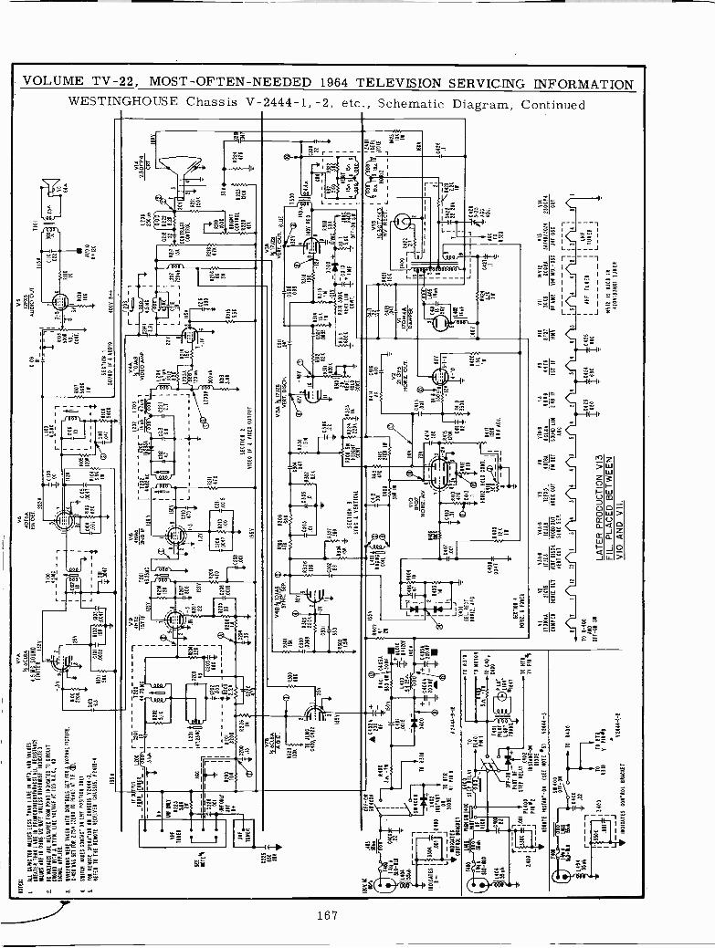
NO
TE
S:
IA
LL C
AP
AC
ITO
R V
ALU
ES
LE
SS
TH
AN
I AR
E IN
MF
D, A
NO
VA
LUE
S
GR
EA
TE
R T
HA
N 1
AR
E IN
PE
IMIC
RO
MIC
RO
FA
AA
DS
I ALL
RE
SIS
TA
NC
EM
LUE
S A
RE
IN O
HM
S I/
O W
AT
T U
NLE
SS
OT
HE
RW
ISE
IMO
ICA
TE
O
2.B
C V
OLT
AG
ES
AR
E M
EA
SU
RE
D F
RO
A P
OIN
T IN
DIC
AT
ED
TO
CIR
CU
ITC
RW
MD
WIT
H A
RM
. LIN
E V
OLT
AG
E A
T 1
26. V
.A.C
.,N
O
SIG
NA
L A
PP
LIE
D.
IW
AV
EF
OR
MS
WE
RE
TA
KE
N W
ITH
CO
NT
RO
LS S
ET
FO
R A
NO
RM
AL
PIC
TU
RE
.
C-4
20 W
AS
SE
T F
OR
2.7
5V (
ZE
RO
TO
PE
AR
I AT
T.P
. 1).
4.S
WIT
CH
MA
KE
S C
ON
TA
CT
ON
Of P
OS
ITIO
N O
NLY
.
5.F
OR
RE
MO
TE
OP
ER
AT
ION
OM
CH
AS
SIS
V24
44.3
,R
EF
ER
TO
TH
E R
EM
OT
E R
EC
EIV
ER
CH
AS
SIS
, V24
18-4
SE
E
NO
TE
0225
180
OE
A
¢O1.
AC
NO
S
VN
f
TU
NE
A
135
V
V7A
33 b
CLB
A
4111
40C S
OU
ND 13
2V
IF O
UT
PU
TL2
0r
C20
1T
200
_ _F
RO
MT
UN
ER
_ío00
10
11.25NC
31uh
e.
_S
.IKU
TA
OIR
TlA
Í52
25 2115
UHF
TU
NE
R
55uh
F40
0 A
SL0
NLO
O,2
2W
i
I110
1-
_S
Suh
C228
001
UX
FO
NLY
UHf
N+
AC
C
-1 1
I
pIj
L
R/0
011
I
120
011
v'C200
R226
i .i5
IN
17.2
5Mcó
.-T
C03
IC2o
2
1.eo
DÑ
203
22N
w.
21'0
V9
4ST
61S
T F
128V
2
01
e
7100
4.5
MC
V6
40T
6ÁF
M D
OT
.
225
CI0
8L1
00
1,'4
1.L
.001
r -
4_S
NC
- _
1121
1
C10
5105
RI0
3.0
047T
_120K
3T
ÚÓ
I<
820
I
R10
4S*-
-7_
C11
16.
8K G
w
T20
143
.25M
C
R20
8 Lá
712
1
Y,7
1C20
71-
3$8
00
R22
072
128V
4HM
6V
B
TN
D IF
130
rT
202
44.8
5110
11-¡
e9
130Y
1.2V
0210
I -S
4T0T
0I
Y/7
0dS
_
83R
335
.001
5
0208
TO
Odi
3RI0
0i.
T00
115
R20 IM
11---1I
I
4.33
TC
20d
zC
10t
t .00
1
135V
E
I
0106
ri0
IpI
^ j
C10
7R
ITA
T.o
iH
ot
C10
801
A10
7
560K
IW
RIO
S
500K
VO
L.
CO
NT
.
SE
CT
ION
1
SO
UN
DIF
& A
UD
IO
VS
I2F
%5
AU
DIO
OUT.
R10
9
100
40V
8
R 1
10
AU
10
94.1
20
7101
L202
L203
95_
AIlu
hta
uh
C21
2C
2I3
C221
=8.
8T
2.7
OE
'1
SE
CT
ION
2
VID
EO
IFL
VID
EO
OU
TP
UT
L205
8
V4A O
1Á8
VID
EO
AM
P.
L204
4.T
uh
82Á
2
L205
Á00
012
0u
500u
h
R2I
33.
9K
5214
150
r-4
=4
-i
0 D
-719
:4.
511C
II'
tttttt
D4ó
D
I
22V
I
4 M
CI
C21
8
IC
IS
IL207
oR217
2_
4_ _
.. 1
20nh
é15
1 <
piR
AS
T
CONTROL
VI4
L206
2300
1425
0 uh
CR
T
822222
8.2K
.moo
16
C21
6
1390
R21
5
3.3
K
- R21
68K 3W
20VIJ
{ R
221
150K
R2I
8,4.
7KR
219
+Z
OO
SB
RIG
HT
CO
NT
RO
L
"R22
047
R
37
R22
312
0K
41
5224
20I7
K
V79
6CLB
A
R32
3
IOO
Kpp Í!0
'gÍit
135Y
25
0300
5300
'.00624
220K
.h
V4B
IO1AB
R30
1S
YN
C. S
EP
ISf
85V
C30
1 !--
A30
233
0
1.51
1
OF
F O
RS
WI 0
AA
C40
2A 2
+o-
-A
100
2MF
T¡
R40
1C
RO
ON
3A -
7W
TI
150
8,0
411
30M
F41
---w
.-.-
--11
---1
(C
401
"I+
!III.
7-7
.0015
L400
T- 1+120
523
"-
140V
W40
01
IND
ICA
TE
S33
0K,
-
1-1
1402
.001
1940
0IN
ST
AN
TN
ST
AN
T
--_J
ON
TH
ER
IND
ICA
TE
SD
IOD
EA
l PIN
N
CO
NT
RO
L IA
AC
AE
T
TO
R3I
804
00
V 2
444-
9-10
+C
404Á
-120
4W0
NF \
+C
405Á
_-F
^ IM
F-
401Q
jl _
PU
SN
TS
W 1
00S
TE
P R
ÉLA
Y
OF
MS
5104
OF
F -
ON
_r-
--1
PA
RT
OF
SO
ON
i'0P
L 00
ST
EP
RE
LAY
040
0
2400
II
#IN
ST
AN
T-
NL
__J
PIN
2D
IOD
E
RE
MO
TE
INS
TA
NT
-O
N(S
EE
NO
TE
#I
V24
44-3
TO
PL
401
PIN
I
TO
A31
9
TO
MO
TO
R
TO
040
1,X
400
PI1
01LI
GH
T
%19
47
TO Al P
INNT
R
#8
5W 4
00O
FF
-O
N o--}
--Z
TO
l
A40
0
C12
0
/{I`
i01A
I
1
.001
1 0
40A
31O
1V
OP
IÍN#9
IND
ICA
TE
S C
ON
TR
OL
BR
AC
KE
T24
44+
2
-3Y
R30
5R
306
1105K
BeK
V3A
I1Z
B03
11V
ER
T. D
ISC
S,
.04T
V3 17
Z8
VE
ST
_ O
UT
. BLU
E
R32
610
1
135V IN
04
C30
A
TC
O03
_C30
5
148K
R32
7
+T
k
39K
SE
CT
ION
3
ST
NC
A V
ER
TIC
AL
L4I
AI N
CI C
I C
O'C
I
C40
8í R
404
47
R40
3
II
L_J
0401
SO
L. R
EC
T.
HO
RIZ
. AF
C
SE
CT
ION
4
IAR
IO. L
PO
WE
R
IN
_C40
7-"
.001
C40
Á_
0047
131V
T300
14d
áll`
IDO
8 I40V AEO
041^
R31
2C
301
-1 V
F
C30
6II
Rl1
182
1.0
033R
SN
K?R
I3M
5_8
8R
318
;.22
8201
$O
CT
30o
+yy
I$Y
AG
3w
lA
3101
R31
3R
318
01 1
*C3~
R31
i,IU
NC
.H
S50
R;p
RR325
VIII
8801
VERT.LIN Z INF
5.61
400
Hf1
6NT
G o
no I
NR
OID
_-
CO
T.
_-
OF
F -
ON
SW
CONi.
CO
NT
.
.10.
13.1
8NOC
ST
42V
-48V
.-J
1C41
2R
111
{T
.001 00N409
/71
Y 2
ió1
11Y
.39
K II
C30
506
8
VIO
IIO
V8F
07/R
OR
12. M
VR
<13
V
1G11
4
7 j i
\2
180
Alle
I1
1505
-8
C41
0
tV>
p20R
-4
.01
R41
0NJV
3
{
;K3
R11
2C
812
%33
0R
TT
RIO
T
HO
RIZ
. HO
LD C
ON
T.
R41
7
R1
8113
Q-=
8 m
-I
120K
05
II
HM
VA
OJ.
12E
-}--
111
R41
4C
416
a141
0
V2
21 G
Y5
HO
RIZ
. OU
T.
415
001
A-1
0
981
C41
7
R31
11
0
r--
17+
00 I_ R
122
2.1
V1775//
I(
041®
?A51
1IH
VO
RE
CT
3L
140
DA
MP
ER
13 =
1
CR
N1
S62
ÓR
SA
VE S
AT
15^
IS^
o
319n
N
OA
l2
4:-1
3
CS
Nr
ÍÍuh
I80
2 Ji
r -
2222
AV
2i5
8124
3.3K 2W
C42
1T
VI
IT O
RO
DA
MP
ER
17
TO
R-4
00A
ND
OF
F -
01 S
W
J14
203-
25A
CC
AC
C
-
TO
AD
J.
R32
3
Y2
V3A
-AA
NA
-N
V5
V9
AT
A -
A18
V9
VIO
VII
'#11
2V
13V
I4
216T
5M
il-
IOJA
AI2
FX
540
T84
AC
CR
A41
1N8
RA
TA
F07
36E
5A
CC
RA
34F
48/3
021
23D
CP
4
NO
RIO
. OU
TP
ER
T O
ISC
H.
VID
EO
OU
TA
UD
IO O
UT
FN
5E
7S
OU
ND
LIN
.2
NO
. IF
1ST
IF17
a-1
AF
AM
P.
VH
F N
IX: O
SC
UH
F O
SC
CR
T
VE
RT
OU
TS
TN
C S
EP
.H
OC
1212
I5
13
14
35
15
45
44
5¡3
4A
5i
34
i8
LAT
ER
PR
OD
UC
TIO
N V
13F
IL. P
LAC
ED
BE
TW
EE
NV
IO A
ND
VII.
C42
3C
A21
CA
25
1680
T s
eoT
e8o
VH
FT
UN
ER
L *V12
ISA
UC
AIN
4101
1331
101
TU
NE
R
ÍU
HF
TU
NE
R
J L.___J
0322
097
,#1
21D1
OE
FL
OR
E
ON
IN
61V
_C42
e
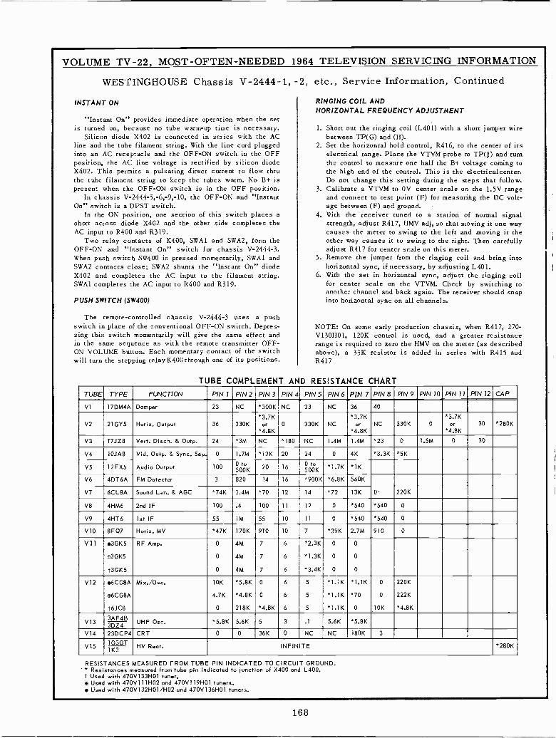
VOLUME TV -22, MOST -OFTEN -NEEDED 1964 TELEVISION SERVICING INFORMATION
WESTINGHOUSE Chassis V-2444-1, -2, etc., Service Information, Continued
INSTANT ON RINGING COIL ANDHORIZONTAL FREQUENCY ADJUSTMENT
"Instant On" provides immediate operation when the setis turned on, because no tube warm-up time is necessary. 1. Short out the ringing coil (L401) with a short jumper wire
Silicon diode X402 is connected in series with the AC between TP(G) and (H).line and the tube filament string. With the line cord plugged 2. Set the horizontal hold control, R416, to the center of itsinto an AC receptacle and the OFF -ON switch in the OFF electrical range. Place the VTVM probe to TP(J) and turnposition, the AC line voltage is rectified by silicon diode the control to measure one half the B+ voltage coming toX402. This permits a pulsating direct current to flow thru the high end of the control. This is the electricalcenter.the tube filament string to keep the tubes warm. No B+ is Do not change this setting during the steps that follow.present when the OFF -ON switch is in the OFF position. 3. Calibrate a VTVM to OV center scale on the 1.5V range
In chassis V-2444-5,-6,-9,-10, the OFF -ON and "Instant and connect to test point (F) for measuring the DC volt -On" switch is a DPST switch. age between (F) and ground.
In the ON position, one section of this switch places a 4. With the receiver tuned to a station of normal signalshort across diode X402 and the other side completes the strength, adjust R417, HMV adj, so that moving it one wayAC input to R400 and R319. causes the meter to swing to the left and moving it the
Two relay contacts of K400, SWA1 and SWA2, form the other way causes it to swing to the right. Then carefullyOFF -ON and "Instant On" switch for chassis V-2444-3. adjust R417 for center scale on this meter.When push switch SW400 is pressed momentarily, SWA1 and 5. Remove the jumper from the ringing coil and bring intoSWA2 contacts close; SWA2 shunts the "Instant On" diode horizontal sync, if necessary, by adjusting L401.X402 and completes the AC input to the filament string. 6. With the set in horizontal sync, adjust the ringing coilSWA1 completes the AC input to R400 and R319. for center scale on the VTVM. Check by switching to
another channel and back again. The receiver should snapPUSH SWITCH (SW400) into horizontal sync on all channels.
The remote -controlled chassis V-2444-3 uses a pushswitch in place of the conventional OFF -ON switch. Depres- NOTE: On some early production chassis, when R417, 270 -sing this switch momentarily will give the same effect and V130H01, 120K control is used, and a greater resistancein the same sequence as with the remote transmitter OFF- range is required to zero the HMV on the meter (as describedON VOLUME button. Each momentary contact of the switch above), a 33K resistor is added in series with R415 andwill turn the stepping relay K400 through one of its positions. R417
TUBE COMPLEMENT AND RESISTANCE CHART
TUBE TYPE FUNCTION PIN 1 PIN 2 PIN 3 PIN 4 PIN 5 PIN 6 PIN 7 PIN 8 FIN 9 PIN 10 PIN 11 PIN 12 CAP
VI 17DM4A Damper 23 NC *300K NC 23 NC 36 40
*3.7K *3.7K *3.7KV2 21GY5 Horiz. Output 36 330K or 0 330K NC or NC 330K 0 or 30 *280K
*4.8K *4.8K *4.8K
V3 17JZ8 Vert. Disch. & Outp. 24 *3M NC *180 NC 1.4M 1.4M *23 0 1.5M 0 30
V4 10JAB Vid. Outp. & Sync. Sep. 0 1.7M * 12K 20 24 0 4K *3.3K *5K
V5 12FX5 Audio Output 100 OOK 20 160 toSOOK *1.7K *1K
V6 4DT6A FM Detector 3 820 14 16 *900K *6.8K 560K
V7 6CL8A Sound Lim. & AGC *74K 3.4M *70 12 14 *72 13K 0 220K
V8 4HM6 2nd IF 100 .4 100 11 12 0 *540 *540 0
V9 4HT6 1st IF 55 1M 55 10 11 0 *540 *540 0
V10 8FQ7 Horiz. MV *47K 170K 910 10 7 *39K 2.7M 910 0
V11 3GK5 RF Amp. 0 4M 7 6 *2.3K 0 0
o3GK5 0 4M 7 6 *1.3K 0 0
t3GK5 0 4M 7 6 *3.4K 0 0
V12 6CG8A Mix./Osc. 10K *5.8K 0 6 5 *1.1K *1.1K 0 220K
a6CG8A 4.7K *4.8K 0 6 5 *1.1K *70 0 222K
t6JC8 0 218K *4.8K 6 5 *1.1K 0 10K *4.8K
V133AF4B
UHF Osc. *5.8K 5.6K 5 3 .1 5.6K *5.8K3DZ4V14 23DCP4 CRT 0 0 36K 0 NC NC 180K 3
V15 HV Rect. INFINITE *280K7K3GT
RESISTANCES MEASURED FROM TUBE PIN INDICATED TO CIRCUIT GROUND.* Resistances measured from tube pin indicated to junction of X400 and L400.t Used with 470V133H01 tuner.a Used with 470V111H02 and 470V119H01 tuners. Used with 470V132H01/H02 and 470V136H01 tuners.
168
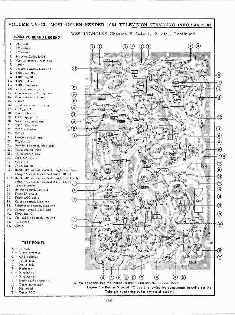
VOLUME TV -22, MOST -OFTEN -NEEDED 1964 TELEVISION SERVICING INFORMATION
V-2444 PC BOARD LEGEND
1. VI pin 82. AC switch3. AC switch4. Junction C400, L4035. Vert lin control, high end6. C403A7. Volume control, high end8. Yoke, lug #109. T400, lug #1
10. T101, red wire11. T101, blue wire12. Volume control, arm13. Contrast control, high end14. Contrast control, arm15. C402A16. Brightness control, arm17. CRT, pin 718. Tuner filament19. CRT cap, pin 820. Vert lin control, arm'21. T300, blue wire22. T300, red wire23. C405A24. Height control, arm25. V2, pin 1226. Vert hold control, high side27. Yoke, orange wire28. T300, orange wire29. CRT cap, pin 330. V2, pin 231. T400, lug #832. Horiz MV adjust control/ high
using 270V130H05 control R417,32A. Horiz MV adjust control, high
using 270V130H01 control R417,33. Tuner filament34. Height control, low end35. Tuner IF output36. Tuner AGC cable37. Height control, high end38. Brightness control, high end39. Contrast control, low end
40. T400, lug #741. Vertical lin Control, low end42. AC switch43. C404A
A-B -C-D-E-F-G-H-
-M-S -T -
TEST POINTS
IF AGCVideo detectorCRT cathode1st IF grid3rd IF gridHoriz MVRinging coilRinging coilHoriz hold control adj.Tuner mixer gridFM soundTuner AGC
WESTINGHOUSE Chassis V-2444-1, -2, etc., Continued
X40
C401
R401
41
939
38
MUM
R3 7
R400 +X300
R319
CR313Í -
end (later180K)end (early
120K) O
R2181----- R220 }--R20Ó
oR2011---
--111203}-
8323
1~l
C
--{ L202 I--C213 71,
C22.1
L203; L204
7_ C210 '
Y8
C42 5411M6 R210il/4I
oo
OO
oT201
--- R208 ---.
07
C 24 5/ V9 -\99v4
4HT6 tj2a5 C204
\2C2401,
//1-'--1 R207 F- u6 R206 al,
"/ Q //+R410 R409
14 06
% R20 l I
l
T100
10
C189
III
C108 ? t Cg:
/ V65 Rla7
1 446T 6A`
) \C104R10d' _. á C107'\%k'7 \
y
.
Y;->` C110 } y`
`c.' 81
4 V7 8"
3 6CL8A 9 ./
R100
R104
CZ
C1.06
L100
C100 _{R300J --
L205
R24SCgk
70b
/ +'C310
R216
YR301
R214 I1218,,C2 6 7 va a. 1 C3Ó0
Rlq
ó 10JA8 ?Ell`'yíR327 .q--i R326I---
R305
/ V5.
12FX53`2Jl
C5Z
T203
C41 R3°71 -----"x
R209 R4Ó7\
;T200
IU
112
201
o
(
,.,CC/LR4RC406 ?302U
L401
!X401EEL
I
R412 g_fz4L201Y ¡e
C203 -i
\ 8 F0 7
325 1
C425
1_200Pc ,
m
//
L207
ID
9
l2'_11IOr
C416-V1-1/C4
R419C411
11
110
1
I:
T--R109
L206
R221
R402
C307
417.
C4 8 R31á4
421C30&
R223
-f R2.24 i'!> - -..
* 33K RESISTOR=EARLY PRODUCTION USING R416 (270V130HOI,CONTROL)
Figure 7 - Bottom View of PC Board, showing top components in solid outline.Tube pin numbering is for bottom of socket.
12
13
14
15
16
0018
19
20
21
22
23
25
24
=CI
169
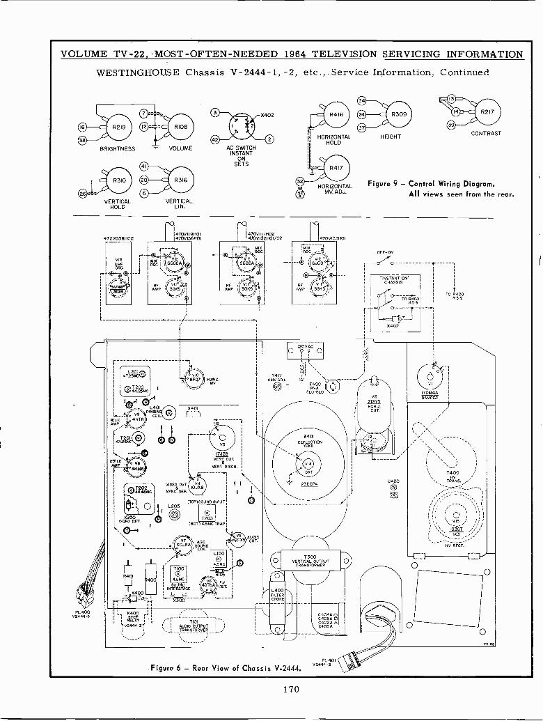
VOLUME TV -22, -MOST-OFTEN-NEEDED 1964 TELEVISION SERVICING INFORMATION
WESTINGHOUSE Chassis V-2444-1, -2, etc., . Service Information, Continued
PL400V2444v'
BRIGHTNESS
VERTICALHOLD
472V038H02
I-
47.25MCL201 o
120143.25MC
25 I.F.AMP
X200VIDEO DET.
I`
FL]401
L401RINSING
COIL
VERTICALLIN.
470V119H01470V136H01
HORIZ.MV
AC SWITCHINSTANT
ONSETS
{ --"4 MIX'S. OSC
VIDEO OUT
SYNC. SEP.
L205
4
LqI400
X400I
fFíp,
TI00
4.5MC
X401
17JZ8PERT. OUT.
6VERT. DISCS.
(TOM SOUND INPUT
T203(DOT I4.5MC TRAP
SOUNDINTERSTAGE
AGC1SLOMD
1100
4.5MC
R105
FMDET.
o
AUDIOOUT.
HORIZONTAL HEIGHTHOLD
HORIZONTALMV. ADJ.
CONTRAST
Figure 9 - Control Wiring Diagram.All views seen from the rear.
470V133H01
R4I7HMV ADJ. -_- - F400
PASLO-BLO
2401DEFLECTION
YOKE
r.,
23DCP4
1
7300O VERTICAL OUTPUT
TRANSFORMER
/L4TER00/ FIL
CHOKE
u i Ksz
5 V2444-3 rT101
AUDIO OUTPUTTRANSFORMER
T
C404Á OC405Á
C4Óo
3 A
Figure 6 - Rear View of Chassis V-2444.PL. 401
V2444-3
OFF -ON
"INSTANT ONCHASSIS
o- +TO RR319400
X402
TO R400R 319
C420
AGCADJ.
VI
17DM44DAMPER
T400 /Hy
TRANS.
VI5
IG3GT
HV RECT.'
N
o
TV105
170
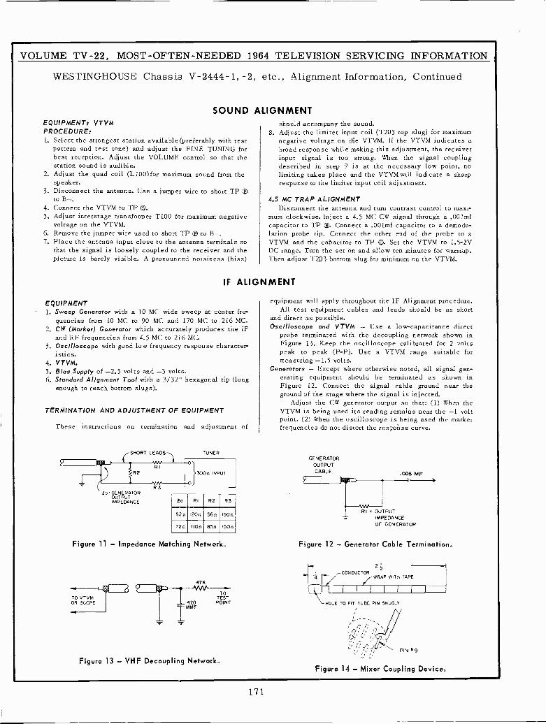
VOLUME TV -22, MOST -OFTEN -NEEDED 1964 TELEVISION SERVICING INFORMATION
WESTINGHOUSE Chassis V-2444-1, -2, etc., Alignment Information, Continued
SOUNDEQUIPMENT: VTVMPROCEDURE:1. Select the strongest station available(preferably with test
pattern and test tone) and adjust the FINE TUNING forbest reception. Adjust the VOLUME control so that thestation sound is audible.
2. Adjust the quad coil (L100)for maximum sound from thespeaker.
3. Disconnect the antenna. Use a jumper wire to short TPto B-.
4. Connect the VTVM to TP ®.5. Adjust interstage transformer T100 for maximum negative
voltage on the VTVM.6. Remove the jumper wire used to short TP ® to B-.7. Place the antenna input close to the antenna terminals so
that the signal is loosely coupled to the receiver and thepicture is barely visible. A pronounced noisiness (hiss)
ALIGNMENTshould accompany the sound.
8. Adjust the limiter input coil (T203 top slug) for maximumnegative voltage on tfie VTVM. If the VTVM indicates abroad response while making this adjustment, the receiverinput signal is too strong. When the signal couplingdescribed in step 7 is at the necessary low point, nolimiting takes place and the VTVM will indicate a sharpresponse to the limiter input coil adjustment.
4.5 MC TRAP ALIGNMENTDisconnect the antenna and turn contrast control to maxi-
mum clockwise. Inject a 4.5 MC CW signal through a .001mfcapacitor to TP ®. Connect a .001mf capacitor to a demodu-lation probe tip. Connect the other end of the probe to aVTVM and the capacitor to TP ©. Set the VTVM to 1.5-2VDC range. Turn the set on and allow ten minutes for warmup.Then adjust T2,03 bottom slug for minimum on the VTVM.
IF ALIGNMENT
EQUIPMENT1. -Sweep Generator with a 10 MC wide sweep at center fre-
quencies from 10 MC to 90 MC and 170 MC to 216 MC.2. CW (Marker) Generator which accurately produces the IF
and RF frequencies from 4.5 MC to 216 MC.3. Oscilloscope with good low frequency response character-
istics.4. VTVM.5. Bias Supply of -2.5 volts and -3 volts.6, Standard Alignment Tool with a 3/32" hexagonal tip (long
enough to reach bottom slugs).
TERMINATION AND ADJUSTMENT OF EQUIPMENT
These instructions on termination and adjustment of
(SHORT.M.RI
R2
R3
TUNER
O
300n INPUT
O
o r GENERATOROUTPUTIMPEDANCE to RI R2 R3
52n 120n 56n 150n
72n IOn 85n 150n
Figure 11 - Impedance Matching Network.
47K
TO VTVM TESOT
OR SCOPE 470 POINT
IMMF
Figure 13 - VHF Decoupling Network.
equipment will apply throughout the IF Alignment procedure.All test equipment cables and leads should be as short
and direct as possible.Oscilloscope and VTVM - Use a low -capacitance direct
probe terminated with the decoupling network shown inFigure 13. Keep the oscilloscope calibrated for 2 voltspeak to peak (P -P). Use a VTVM range suitable formeasuring -1.5 volts.
Generators - Except where otherwise noted, all signal gen-erating equipment should be terminated as shown inFigure 12. Connect the signal cable ground near theground of the stage where the signal is injected.
Adjust the CW generator output so that: (1) When theVTVM is being used its reading remains near the -1 voltpoint. (2) When the oscilloscope is being used the markerfrequencies do not distort the response curve.
GENERATOROUTPUTCABLE
OUTPUTIMPEDANCEOF GENERATOR
Figure 12 - Generator Cable Termination.
,CÓNDUCTOR2
z
qI
/ WRAP WITH TAPE
\--HOLE TO FIT TUBE PIN SNUGLY
Figure 14 - Mixer Coupling Device.
171
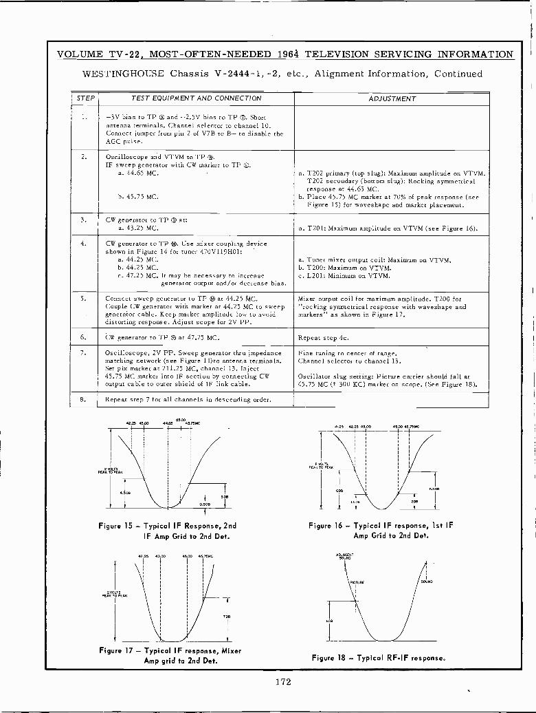
VOLUME TV -22, MOST -OFTEN -NEEDED 1964 TELEVISION SERVICING INFORMATION
WESTINGHOUSE Chassis V-2444-1, -2, etc., Alignment Information, Continued
STEP TEST EQUIPMENT AND CONNECTION ADJUSTMENT
1. -3V bias to TP ® and -2.5V bias to TP Q. Shortantenna terminals. Channel selector to channel 10.Connect jumper from pin 2 of V7B to B- to disable theAGC pulse.
2. Oscilloscope and VTVM to TP G.IF sweep generator with CW marker to TP G.
a. 44.65 MC.
b. 45.75 MC.
a. T202 primary (top slug): Maximum amplitude on VTVM.T202 secondary (bottom slug): Rocking symmetricalresponse at 44.65 MC.
b. Place 45.75 MC marker at 70% of peak response (seeFigure 15) for waveshape and marker placement.
3. CW generator to TP ® at:a. 43.25 MC. a. T201: Maximum amplitude on VTVM (see Figure 16).
4. CW generator to TP G. Use mixer coupling deviceshown in Figure 14 for tuner 470V119H01:
a. 44.25 MC.b. 44.25 MC.c. 47.25 MC. It may be necessary to increase
generator output and/or decrease bias.
a. Tuner mixer output coil: Maximum on VTVM.b. T200: Maximum on VTVM.c. L201: Minimum on VTVM.
5. Connect sweep generator to TP 9 at 44.25 MC.Couple CW generator with marker at 44.25 MC to sweepgenerator cable. Keep marker amplitude low to avoiddistorting response. Adjust scope for 2V PP.
Mixer output coil for maximum amplitude. T200 for"rocking symmetrical response with waveshape andmarkers" as shown in Figure 17.
6. CW generator to TP 9 at 47.25 MC. Repeat step 4c.
7. Oscilloscope, 2V PP. Sweep generator thru impedancematching network (see Figure 11)to antenna terminals.Set pix marker at 211.25 MC, channel 13. Inject45.75 MC marker into IF section by connecting CWoutput cable to outer shield of IF link cable.
Fine tuning to center of range.Channel selector to channel 13.
Oscillator slug setting: Picture carrier should fall at45.75 MC (± 300 KC) marker on scope. (See Figure 18).
8. Repeat step 7 for all channels in descending order.
4225 43.00 M 45A0.6545.TSMC
41.25 921 J 1 92.!3 43.00 45.03
2
r 1
I
2 VOLTSPEAK TO
I
I
PEAK
PEAK TO PEAK4.505I I606 5.5DB
3 DO
r +2DB
t
Figure 15 - Typical IF Response, 2nd Figure 16 - Typical IF response, 1st IFIF Amp Grid to 2nd Det. Amp Grid to 2nd Det.
42.25 43.00 45.00 45 75M ADJACENTSOUND
PEAR TOPEANIPICTURE SOUND
705BOB
1
Figure 17 - Typical IF response, MixerAmp grid to 2nd Det. Figure 18 - Typical RFIF response.
172
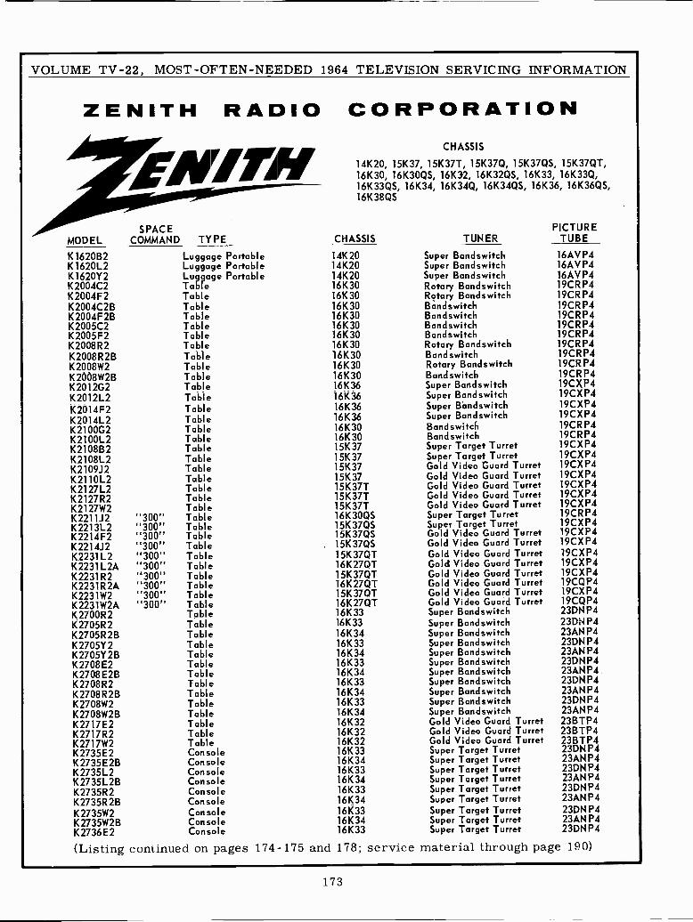
VOLUME TV -22, MOST -OFTEN -NEEDED 1964 TELEVISION SERVICING INFORMATION
ZENITH RADIO CORPORATION
MODELSPACE
COMMAND TYPE
K1620B2 Luggage PortableK1620L2 Luggage PortableK1620Y2 Luggage PortableK2004C2 TableK2004F2 TableK2004C2B TableK2004F2B TableK2005C2 TableK2005F2 TableK2008R2 TableK2008R2B TableK2008W2 TableK2008W2B TableK2012G2 TableK2012L2 TableK2014F2 TableK2014L2 TableK2100G2 TableK2100L2 TableK2108B2 TableK2108L2 TableK2109J2 TableK2110L2 TableK2127L2 TableK2127R2 TableK2127W2 TableK2211J2 "300" TableK2213L2 "300" TableK2214F2 "300" TableK2214J2 "300" TableK2231L2 "300" TableK2231L2A "300" TableK2231R2 "300" TableK2231R2A "300" TableK2231W2 "300" TableK2231W2A "300" TableK2700R2 TableK2705R2 TableK2705R2B TableK2705Y2 TableK2705Y2B TableK2708E2 TableK2708E2B TableK2708R2 TableK2708R2B TableK2708W2 TableK2708W2B TableK2717E2 TableK2717R2 TableK2717W2 TableK2735E2 ConsoleK2735E2B ConsoleK2735L2 ConsoleK2735L2B ConsoleK2735R2 ConsoleK2735R2B ConsoleK2735W2 ConsoleK2735W2B Con soleK2736E2 Console
(Listing continued on pages 174-175
CHASSIS
14K20, 15K37, 15K37T, 15K37Q, 15K37QS, 15K37QT,16K30, 16K300S, 16K32, 16K32QS, 16K33, 16K33Q,16K33QS, 16K34, 16K34Q, 16K34QS, 16K36, 16K36QS,16K38QS
CHASSIS TUNERPICTURE
TUBE
14K20 Super Bandswitch 16AVP414K20 Super Bandswitch 16AVP414K20 Super Bandswitch 16AVP416K30 Rotary Bandswitch 19CRP4161(30 Rotary Bandswitch 19CR P416K30 Bandswitch 19CRP416K30 Bandswitch 19CRP416K30 Bandswitch 19CRP416K30 Bandswitch 19CR P416K30 Rotary Bandswitch 19CRP416K 30 Band switch 19CRP416K30 Rotary Bandswitch 19CRP416K30 Bandswitch 19CRP416K36 Super Band switch 19CXP416K36 Super Band switch 19CXP416K36 Super Bandswitch 19CXP416K36 Super Bandswitch 19CXP416K30 Bandswitch 19CRP416K30 Band switch 19CRP4151(37 Super Target Turret 19CXP4151(37 Super Target Turret 19CXP415K37 Gold Video Guard Turret 19CXP415K37 Gold Video Guard Turret 19CXP415K37T Gold Video Guard Turret 19CXP415K37T Gold Video Guard Turret 19CXP415K37T Gold Video Guard Turret 19CXP416K3OQS Super Target Turret 19CRP415K37QS Super Target Turret 19CXP415K37QS Gold Video Guard Turret 19CXP415K37QS Gold Video Guard Turret 19CXP415K37QT Gold Video Guard Turret 19CXP416K27QT Gold Video Guard Turret 19CXP415K37QT Gold Video Guard Turret 19CXP416K27QT Gold Video Guard Turret 19CQ P415K37QT Gold Video Guard Turret 19CXP416K27QT Gold Video Guard Turret 19CQP416K33 Super Bandswitch 23DNP416K33 Super Bandswitch 23Di4 P416K34 Super Bandswitch 23AN P416K33 Super Bandswitch 23DNP416K34 Super Bandswitch 23AN P416K33 Super Bandswitch 23DN P416K34 Super Bandswitch 23AN P416K33 Super Bandswitch 23DN P416K 34 Super Bandswitch 23AN P416K33 Super Bandswitch 23DN P4161(34 Super Bandswitch 23ANP416K32 Gold Video Guard Turret 23BTP416K32 Gold Video Guard Turret 23BTP416K32 Gold Video Guard Turret 23BTP416K33 Super Target Turret 23DNP416K34 Super Target Turret 23AN P416K33 Super Target Turret 23DNP416K34 Super Target Turret 23ANP416K33 Super Target Turret 23DNP416K34 Super Target Turret 23AN P4
16K33 Super Target Turret 23DNP416K34 Super Target Turret 23AN P416K33 Super Target Turret 23DN P4
and 178; service material through page 190)
173
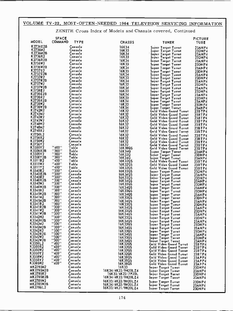
VOLUME TV -22, MOST -OFTEN-NEEDED 1964 TELEVISION SERVICING INFORMATION
ZENITH Cross Index of Models and Chassis covered, ContinuedSPACE
MODEL COMMAND TYPE CHASSIS TUNERK2736E2B Console 16K34 Super Target TurretK2736M2 Console 16K33 Super Target TurretK2736M2B Console 16K34 Super Target TurretK2736R2 Console 16K33 Super Target TurretK2736R2B Console 16K34 Super Target TurretK2736W2 Console 16K33 Super Target TurretK2736W2B Console 16K34 Super Target TurretK2737E2 Console 16K33 Super Target TurretK2737E2B Console 16K34 Super Target TurretK2737R2 Console 16K33 Super Target TurretK2737R2B Console 16K34 Super Target TurretK2737W2 Console 16K33 Super Target TurretK2737W2B Console 16K34 Super Target TurretK2738E2 Console 16K33 Super Target TurretK2738E2B Console 16K34 Super Target TurretK2738R2 Console 16K33 Super Target TurretK2738R2B Console 16K34 Super Target TurretK2738W2 Console 16K33 Super Target TurretK2738W2B Console 16K34 Super Target TurretK2742H2 Console 16K32 Gold Video Guard TurretK2742M2 Console 16K32 Gold Video Guard TurretK2742R2 Console 16K32 Gold Video Guard TurretK2742W2 Console 16K32 Gold Video Guard TurretK2748H2 Console 16K32 Gold Video Guard TurretK2748M2 Console 16K32 Gold Video Guard TurretK2748R2 Console 16K32 Gold Video Guard TurretK2756L2 Console 16K32 Gold Video Guard TurretK2756R2 Console 16132 Gold Video Guard TurretK2756W2 Console 16K32 Gold Video Guard TurretK2756Y2 Console 16K32 Gold Video Guard TurretK3300Y2 "400" Table 16K38QS Gold Video Guard TurretK3308R2B "300" Table 16K34Q Super Target TurretK3308Y2 "300" Table 16K33Q Super Target TurretK3308Y2B "300" Table 16K34Q Super Target TurretK3311R2 "400" Table 16K32QS Gold Video Guard TurretK3311W2 "400" Table 16K32QS Gold Video Guard TurretK3311Y2 "400" Table 16K32QS Gold Video Guard TurretK3340E2 "300" Console 16K33QS Super Target TurretK3340E2B "300" Console 16K34QS Super Target TurretK3340R2 "300" Console 16K33QS Super Target TurretK3340R2B "300" Console 16K34QS Super Target TurretK3340W2 "300" Console 16K33QS Super Target TurretK3340W2B "300" Console 16K34QS Super Target TurretK3341H2 "300" Console 16K33QS Super Target TurretK3341H2B "300" Console 16K34QS Super Target TurretK3341M2 "300" Console 16K33QS Super Target TurretK3341M2B "300" Console 16K34QS Super Target TurretK3341R2 "300" Console 16K33QS Super Target TurretK3341R2B "300" Console 16K34QS Super Target TurretK3341W2 "300" Console 16K33QS Super Target TurretK3341W2B "300" Console 16K34QS Super Target TurretK3342H2 "300" Console 16K33QS Super Target TurretK3342H2B "300" Console 16K34QS Super Target TurretK3342M2 "300" Console 16K33QS Super Target TurretK3342M2B ''300" Console 16K34QS Super Target TurretK3342R2 "300" Console 16K33QS Super Target TurretK3342R2B "300" Console 16K34QS Super Target TurretK3342W2 "300" Console 16K33QS Super Target TurretK3342W2B "300" Console 1613405 Super Target TurretK3350L2 "400" Console 16K32QS Gold Video Guard TurretK3350R2 "400" Console 16K32QS Gold Video Guard TurretK3350W2 "400" Console 16K32QS Gold Video Guard TurretK3350Y2 "400" Console 16K32QS Gold Video Guard TurretK3358W2 "400" Console 16K38QS Gold Video Guard TurretK3358Y2 "400" Console 16K38QS Gold Video Guard TurretK3385H2 "400" Console 16K38QS Gold Video Guard TurretMK2785M2 Console 16133 Super Target TurretMK2785M2B Console 16K34/4K22/9H2OLZ4 Super Target TurretMK2785R2 Console 16K33/4K22/7F20L Super Target TurretMK2785R2B Console 16K34/4K22/9H20LZ4 Super Target TurretMK2785W2 Console 16K33/4K22/9H2OLZ4 Super Target TurretMK2785W2B Console 16K34/4K22/9H2OLZ4 Super Target TurretMK2786L2 Console 16K33/4K21/9H20LZ4 Super Target Turret
PICTURETUBE
23AN P423DN P423AN P423DNP423AN P423DNP423AN P423DN P423AN P423DNP423AN P423DN P423ANP423DN P423AN P423DNP423ANP423DN P423AN P423BTP423BTP423BTP423BTP423BTP423BTP423BTP423BTP423BTP423BTP423BTP423BTP423AN P423DNP423AN P423BTP423BTP423BTP423DNP423AN P423DN P423AN P423DN P423AN P423DN P423AN P423DNP423AN P423DNP423ANP423DN P423AN P423DN P423ANP423DN P423AN P423DN P423AN P423DNP423AN P423BTP423BTP423BTP423BTP423AFP423AFP423AFP423DN P423ANP423DNP423ANP423DN P423ANP423DN P4
174
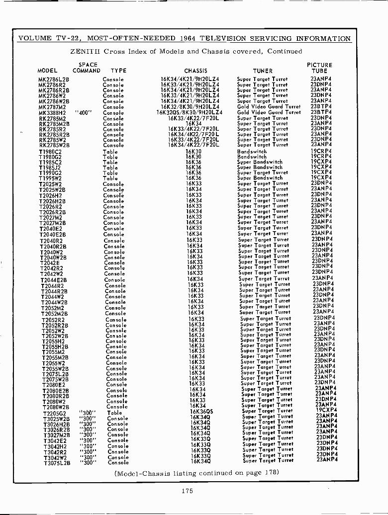
VOLUME TV -22, MOST -OFTEN -NEEDED 1964 TELEVISION SERVICING INFORMATION
ZENITH Cross Index of Models and Chassis covered, Continued
SPACE PICTUREMODEL COMMAND TYPE CHASSIS TUNER TUBE
MK2786L2B Console 16K34/4K21/9H2OLZ4 Super Target Turret 23ANP4MK2786R2 Console 16K33/4K21/9H2OLZ4 Super Target Turret 23DNP4MK2786R2B Console 16K34/4K21/9H2OLZ4 Super Target Turret 23ANP4MK2786W2 Console 16K33/4K21/9H2OLZ4 Super Target Turret 23DNP4MK2786W2B Console 16K34/4K21/9H2OLZ4 Super Target Turret 23ANP4MK2787M2 Console 16K32/8K30/9H2OLZ4 Gold Video Guard Turret 23BTP4MK3388H2 "400" Console 16K32QS/8K30/9H2OLZ4 Gold Video Guard Turret 23BTP4RK2785M2 Console 16K33/4K22/7F20L Super Target Turret 23DNP4RK2785M2B Console 16K34 Super Target Turret 23ANP4RK2785R2 Console 16K33/4K22/7F20L Super Target Turret 23DNP4RK2785R2B Console 16K34/4K22/7F20 L Super Target Turret 23ANP4RK2785W2 Console 16K33/4K22/7F20L Super Target Turret 23DNP4RK2785W2B Console 16K34/4K22/7F20L Super Target Turret 23ANP4T1980C2 Table 16K30 Bandswitch 19CRP4T1980G2 Table 16K30 Bandswitch 19CR P4T1985C2 Table 16K36 Syper Bandswitch 19CXP4T1985J2 Table 16K36 Super Bandswitch 19CXP4T1990G2 Table 16K36 Super Target Turret 19CXP4T1995W2 Table 16K36 Super Bandswitch 19CXP4T2025W2 Console 16K33 Super Target Turret 23DNP4T2025W2B Console 16K34 Super Target Turret 23ANP4T2026H2 Console 16K33 Super Target Turret 23DNP4T2026H2B Con sole 16K34 Super Target Turret 23ANP4T2026R2 Console 16K33 Super Target Turret 23DNP4T2026R2B Console 16K34 Super Target Turret 23ANP4T2027M2 Console 16K33 Super Target Turret 23DNP4T2027M2B Console 16K34 Super Target Turret 23ANP4T2040E2 Console 16K33 Super Target Turret 23DN P4
T2040E2B Console 16K34 Super Target Turret 23ANP4
T2040R2 Console 16K33 Super Target Turret 23DNP4T2040R2B Con sole 16K34 Super Target Turret 23ANP4T2040W2 Console 16K33 Super Target Turret 23DNP4T2040W2B Console 16K34 Super Target Turret 23AN P4
T2042E Console 16K33 Super Target Turret 23DNP4T2042R2 Console 16K33 Super Target Turret 23DNP4
T2042W2 Console 16K33 Super Target Turret 23DNP4
T2044E2B Console 16K34 Super Target Turret 23ANP4
T2044R2 Console 16K33 Super Target Turret 23DNP4T2044R2B Console 16K34 Super Target Turret 23ANP4T2044W2 Con sole 16K33 Super Target Turret 23DNP4
T2044W2B Console 16K34 Super Target Turret 23ANP4
T2052M2 Console 16K33 Super Target Turret 23DNP4
T2052M2B Console 16K34 Super Target Turret 23ANP4
T2052R2 Console 16K33 Super Target Turret 23DNP4T2052R2B Console 16K34 Super Target Turret 23ANP4T2052W2 Console 16K33 Super Target Turret 23DNP4T2052W2B Console 16K34 Super Target Turret 23ANP4T2055H2 Console 16K33 Super Target Turret 23DNP4T 2055H 2 B Console 16K34 Super Target Turret 23ANP4T2055M2 Con sole 16K33 Super Target Turret 23DNP4
T2055M2B Con sole 16K34 Super Target Turret 23ANP4
T2055W2 Console 16K33 Super Target Turret 23DNP4
T2055W2B Console 16K34 Super Target Turret 23ANP4T2075L2B Console 16K34 Super Target Turret 23AN P4
T2075W2B Console 16K34 Super Target Turret 23ANP4
T2080E2 Console 16K33 Super Target Turret 23DNP4
T2080E2B Console 16K34 Super Target Turret 23ÁN P4
T2080R2B Console 16K34 Super Target Turret 23ÁN P4
T2080W2 Console 16K33 Super Target Turret 23DN P4
T2080W2B Console 16K34 Super Target Turret 23ÁN P4
T2205G2T3025W2BT3026H2BT3026R2BT3027M2BT3042E2T3042H2T3042R2T3042W2T3075L2B
"300""300""300""300""300""300""300""300""300""300"
TableConsoleConsoleConsoleConsoleConsoleConsoleConsoleConsoleConsole
16K36QS16K34Q16K34Q16K34Q16K34Q16K33Q16K33Q16K33Q16K33Q16K34Q
Super Target TurretSuper Target TurretSuper Target TurretSuper Target TurretSuper Target TurretSuper Target TurretSuper Target TurretSuper Target TurretSuper Target TurretSuper Target Turret
19CXP423ÁN P423ÁN P423ÁN P423ÁN P423DNP423DNP423DNP423DNP423ÁN P4
(Model -Chassis listing continued on page 178)
175
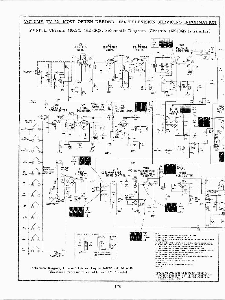
VOLUME TV -22, MOST -OFTEN -NEEDED 1964 TELEVISION SERVICING INFORMATION
ZENITH Chassis 16K32, 16K32QS, Schematic Diagram (Chassis 16K38QS is similar)
TI
I C
TO IF gTPU jjONTOMER
YYfN
ISO
AGO-TO TONER
TO HEATERSON TUNER
6 ENT/Er IVY
v1GENT/ErIN3
VS6EJT/EFINI
ono
GISPIx
23BTP4
VeUVAS
V76BN6
VRANOS
VIOGUAU
vl4GATT
LI
6EH73
/EFI831ST I.F.
,
41
H2
1 TIU
C,
IYF±y'
jl C512%I,YYF
II T ?]%
-IL,10N
i LLt ---JI
021E0
22
M1 -i
V2.4V
6EH7/ÉF183 6EJ71ÉFI84 6- I/2V6JT8 r COO
2ND LF.
6A3RD I.F.VIDEO AMP. BLN ILT 1Jn CM I sFo--,-TO
TS
61 R6oww
220
1457
210%
511101 100
'eeoK
1ICm001
,10%
610'
/
o 7 1115
VlU =TI OOT
BMiMAI
/MY
I WO 0022 INMYF ±10% ±10%
121-x 001' zzo+o%
11o%6N
265v
26 V
2
265V
xi Ly 7
113
3300±o%
265V
C3
j ly 6B V7 ITO (NOTIN
603205 I' 002G SNITCH
2
1/2 6JT8 6BN6 %STEIREAYINj pMÉGSOUND LIMITER SOUND DISC.1
ON SWYÓDTAAEOFF COIL
T6
100
CAB 3.11114F /467I1±5% TT
i3 BLUI LII -116511 # ÍBLN
L4'tk6RN
20 VAC.IN ERLOCK
SWITCH ONVW
VOLUME CONTROL
5281V11'0111°'15 USED ON1683205 ONLY
RIO
50BUtE
C31
IF----
265V
CI32 C33OYYF 4,0tram NW
0%
15I75KC_ EGRAY OR SLR
TI
D
R27
BLN(/REDUNa/BRN
OR
BROKEN FOR YODELINS ONLY
FILAMENTFUSE LINO
IOCOPPELOOPRW
OFINENON ANA
RED
3064L.V. RECT.
NI. Lai R O
Y
TEL
URN 1Ó .,RFD
= 4002
5061 2654
CASE
4O004
15 V
5.75 KC.
C512x5YYF
C35' I
ÁI 1
OROS
610%
265V.
O 6BQ5SOUND OUTPUT
10
RITI ORRIB
VOLUIYEO ME
OV
J1Y
COT
265V
LU C6
003
TSWW1 II, O1O
1100
R19
265V
C22C
aov
320V1575KC.L
CIS CI6
YYF1.T I
YYf
I L6
n
+.y I
YYF CI T I
'TT Imu
1
BLK -J
LJ^`', iOMi/706.1 ±10%
23A RSl3911 asC MFDk!10°/ t 350 .2K
ID%L}y zMI,oVIDEO PEAS 265VFRONT
o
330
105
T6
l.3-:Nil;
V
L_I C21
ATIMYF+S%_J007
S2 5
±10
+10
IJ/2
ISO±10%
Cal.01
V9 I.6HS8A.G.C.B
SYNC.CLI .
60 V60n,
Is600
SOR±10%
1226
10%
278±10%
l8l_
2
1/21OVERT.
CON0Y 110
J0Y 6
40r1720
= IBOOYEG ±10%
4011
[I9.--II
/05
R22
210 V6011,L
23
BON ?10
150V
A.6
8.2
1EG10%
VITA1/2 6GH8 OR 6KD8
HORIZ. CONTROL
330M=+10%
3300±10%
265V
!10%
1207
C40
II0031
NOR
+10 %
1208
±10%
265V
COO 46
3O%R2172MEG
±10%
VIIBI/26GH8 OR 6KD8
HORIZ. OSC.
f,o 8 DISCH.I =YOM% 6 00V
IYE6 -6BY R C58 _ - 2206
411% _ IIU r .700 3150 ±I0%47IMF
1900±10%
C522x001±10%
-I
C531,0MIFF
10011
710%
10
-E
121
±10
CS0 33±lo%
EG
6V
J-11°1005
265V
460V
R28
160001
xISIT±10%
025±10%
w
-1-220 V15.75
Y 12
_1sJ8sHORIZ. OUTPUT
FC62
917
NC
1507
100
R2N
}Wg W±10%
265 V
0%
012
URN
R4BGSMEVERT T
ÑIEÁNO
R
ROJO
LREWISTANCEREI 111
2JnI
-RO/WN
C6=
R30
12
nor.
ter 6DA
OF+
C65
º3115%
265V VIOL
I- SOCKET AND WIRING FOR 1663205
SWITCH 011
STRE LAEPO
PEYOTECONTROLTRANSPRE
. PLUG U ED WITH S SNSOS,5 see,. REMOTE CONTROLCMA 5613
Schematic Diagram, Tube and Trimmer Layout 16K32 and 16K32QS(Waveforms Representative of Other IIKA, Chassis).
150K±10%
-1-16 5V15.75 KC
__t_
110023:
ALL VOLTAGES MEASURED FRd CHASSIS TO POINTS IIMICATED.
ALL SOLTADOS ARE D.C. UNLESS OTHERWISE SPECIFIED.
ALL D.C. VOLTAGES TO BE MEASURED WITH A YACUUI TUBE VOLTMETER HUM II Ergs.INPUT RESISTANCE.
ALL VOLTAGE MEASUREMENTS TO BE INK WITS NO SIGNAL PRESENT. HORINI SETTINGOF CONTROLS AND CHARNEL SELECTOR SET TO CHANNEL 2 UNLESS OTMERRISE SPECIFIED.
ALL CAPACITOR VALUES IN MICROFARAOS UNLESS OTMENVISE SPECIFIED.
ALL CAPACITOR CAPACITY TOLERANCE T20S UNLESS OTHERWISE D060ITIEO.
ALL RESISTORS ARE T201 TOLERANCE, CARBON, I/2 WATT UNLESS OTHERWISE SPECIFIED.
RESISTANCE IEAOUREMENTS SHOWN WITH COIL DISCONNECTED FROM CIRCUIT.
COIL RESISTANCES HOT GIVEN ARE LINDEN ORE DIM.
cATNODE GAT TORE 2X0 ANODE SOLTASE TO BE MEASURED WITH ELECTROSTATIC OR DOGMIN. OHM PER MT NIGH FOLIADO METER.
ARROW] OH POTENTIMIETERS MEDICATE CLOCSWINE ROTATION.
ALIGIDIENT POINTS:
CIRCLED LETTERS IRRIGATE ALIGNMENT LEO TEST POINTS.
CRASS IS-}
PICTURE NNE SECOND ANODE TOLEAOE To BE WARMED WITH ELECTROSTATICAILOYOLTIETER AIM SRId1TNES3 AND CUNTRA]T CONTROL] FULL CO'NTER.CLOCNNISE.
CO = CAPACITOR VALUE ]ELECTED FOR 61111111114 YORE RINGING. VARIES NITNINA RANGE OF VT «61 TO 72 all (] N.S., TIORI. WHEN NECESSARY. REPLACE
NITN Exact VALUE FOUND IN TONE.
176
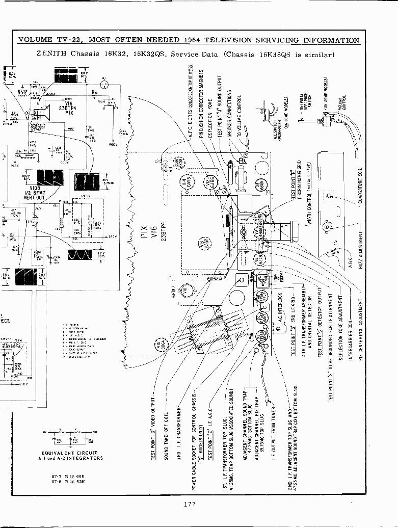
TE
ST
PO
INT
°D
" V
IDE
O O
UT
PU
T
SO
UN
D T
AK
E -
OF
F C
OIL
3RD
I.F. T
RA
NS
FO
RM
ER
PO
WE
R C
AB
LE S
OC
KE
T F
OR
CO
NT
RO
L C
HA
SS
IS
("Q
" M
OD
ELS
ON
LY)
TE
ST
PO
INT
"E
"I.
F. A
.G.C
.
0064
I
-- $
<--
6FM
7
-fry
Ó11
.
'sl
1ST
.I.
F. T
RA
NS
FO
RM
ER
TO
P S
LUG
.
41.2
5MG
. TR
AP
BO
TT
OM
SLU
G (
AS
SO
CIA
TE
D S
OU
ND
)
AD
JAC
EN
T C
HA
NN
EL
SO
UN
D T
RA
P-
47.2
5MC
.S
LUG
AD
JAC
EN
TT
CH
AN
NE
L P
IX T
RA
P39
.75M
C.T
OP
SLU
G
I. F
. OU
TP
UT
FR
OM
TU
NE
R-'
2 N
D,
I.F. T
RA
NS
FO
RM
ER
TO
P S
LUG
AN
D47
.25
MC
. AD
JAC
EN
T S
OU
ND
TR
AP
CO
IL B
OT
TO
M S
LUG
A.C
.INT
ER
LOC
K
TE
ST
PO
INT
"G
" 3R
D I.
F. G
RID
-
4TH
I.F
. TR
AN
SF
OR
ME
R A
SS
EM
BLY
-
AN
D C
RY
ST
AL
DE
TE
CT
OR
TE
ST
PO
INT
"C"
DE
TE
CT
OR
OU
TP
UT
/
TE
ST
PO
INT
"F
" T
O B
E G
RO
UN
DE
D F
OR
I.F
. ALI
GN
ME
NT
DE
FLE
CT
ION
YO
KE
AD
JUS
TM
EN
T
INT
ER
CA
RR
IER
CO
IL'
A.G
.C.
PIX
CE
NT
ER
ING
AD
JUS
TM
EN
TB
UZ
Z A
DJU
ST
ME
NT
o
"1s
t IF -
1°. -
2.5/
12°.
:"
PIX
V16
23B
TP4
VI3
',2A
S2)
VI I_;
6G
H8\
"6K
D8/
'vV
l4k6
AY
3;
' VI2
J B
6
TE
ST
PO
INT
°P
"
DIS
CR
IMIN
AT
OR
GR
ID
IDT
H C
ON
TR
OL
(ME
TA
L S
LEE
VE
)
QU
AD
RA
TU
RE
CO
IL
A. F
.C. D
IOD
ES
(SO
LDE
RE
D O
N T
OP
OF
CH
AS
S
PIN
CU
SH
ION
CO
RR
EC
TO
R M
AG
NE
TS
DE
FLE
CT
ION
YO
KE
TE
ST
PO
INT
»J»
SO
UN
D O
UT
PU
T
SP
EA
KE
R C
ON
NE
CT
ION
S
TO
VO
LUM
E C
ON
TR
OL
A.C
.SW
ITC
H
(PU
SH-PUSH)
(ON
SO
ME
MO
DE
LS)
ON
(P
ULL
)O
FF
(P
US
H)
SW
ITC
H
(ON
SO
ME
MO
DE
LS)
VO
LUM
EC
ON
TR
OL
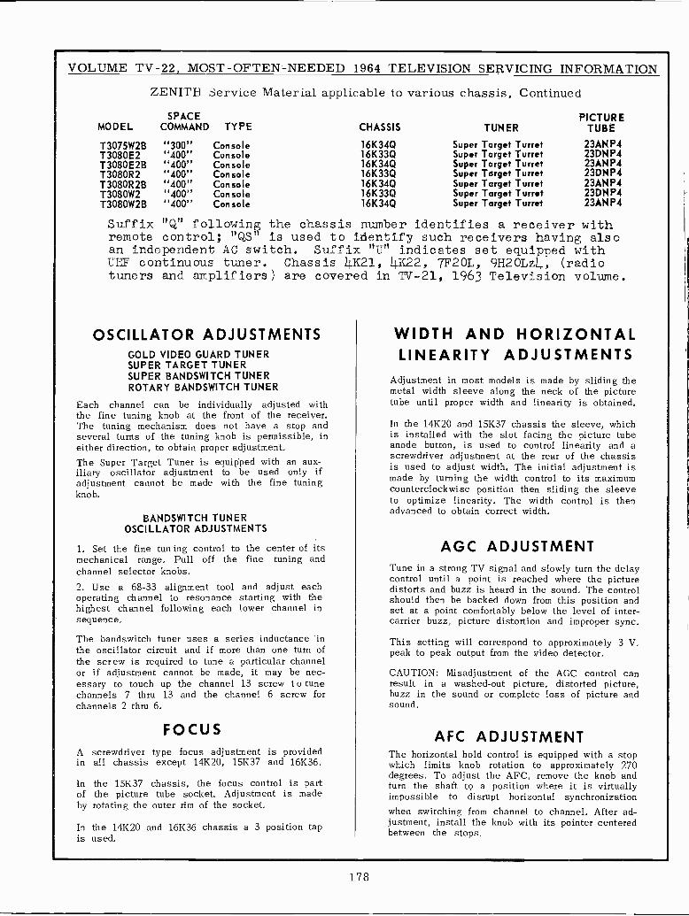
VOLUME TV -22, MOST -OFTEN -NEEDED 1964 TELEVISION SERVICING INFORMATION
ZENITH Service Material applicable to various chassis, Continued
SPACE PICTUREMODEL COMMAND TYPE CHASSIS TUNER TUBE
T3075W2B "300" Console 16K34Q Super Target Turret 23ANP4T3080E2 "400" Console 16K33Q Super Target Turret 23DNP4T3080E2B "400" Console 16K34Q Super Target Turret 23ANP4T3080R2 "400" Console 16K33Q Super Target Turret 23DNP4T3080R2B "400" Console 16K34Q Super Target Turret 23ANP4T3080W2 "400" Console 16K33Q Super Target Turret 23DNP4T3080W2B "400" Console 16K34Q Super Target Turret 23ANP4
Suffix "Q" following the chassis number identifies a receiver withremote control; "QS' is used to identify such receivers having alsoan independent AC switch. Suffix "U" indicates set equipped withUHF continuous tuner. Chassis L.K21, 11K22, 7F20L, 9H2OLz4, (radiotuners and amplifiers) are covered in TV -21, 1963 Television volume.
OSCILLATOR ADJUSTMENTSGOLD VIDEO GUARD TUNERSUPER TARGET TUNERSUPER BANDSWITCH TUNERROTARY BANDSWITCH TUNER
Each channel can be individually adjusted withthe fine tuning knob at the front of the receiver.The tuning mechanism does not have a stop andseveral turns of the tuning knob is permissible, ineither direction, to obtain proper adjustment.The Super Target Tuner is equipped with an aux-iliary oscillator adjustment to be used only ifadjustment cannot be made with the fine tuningknob.
BANDSWITCH TUNEROSCILLATOR ADJUSTMENTS
1. Set the fine tuning control tomechanical range. Pull off thechannel selector knobs.2. Use a 68-33 alignment tooloperating channel to resonancehighest channel following eachsequence,
the center of itsfine tuning and
and adjust eachstarting with thelower channel in
The bandswitch tuner uses a series inductance inthe oscillator circuit and if more than one turn ofthe screw is required to tune a particular channelor if adjustment cannot be made, it may be nec-essary to touch up the channel 13 screw t o tunechannels 7 thru 13 and the channel 6 screw forchannels 2 thru 6,
FOCUSA screwdriver type focus adjustment is providedin all chassis except 14K20, 15K37 and 16K36.
In the 15K37 chassis, the focus control is partof the picture tube socket. Adjustment is madeby rotating the outer rim of the socket
In the 14K20 and 16K36 chassis a 3 position tapis used,
WIDTH AND HORIZONTALLINEARITY ADJUSTMENTS
Adjustment in most models is made by sliding themetal width sleeve along the neck of the picturetube until proper width and linearity is obtained.
In the 14K20 and 15K37 chassis the sleeve, whichis installed with the slot facing the picture tubeanode button, is used to control linearity and ascrewdriver adjustment at the rear of the chassisis used to adjust width. The initial adjustment ismade by turning the width control to its maximumcounterclockwise position then sliding the sleeveto optimize linearity. The width control is thenadvanced to obtain correct width.
AGC ADJUSTMENTTune in a strong TV signal and slowly turn the delaycontrol until a point is reached where the picturedistorts and buzz is heard in the sound. The controlshould then be backed down from this position andset at a point comfortably below the level of inter -carrier buzz, picture distortion and improper sync.
This setting will correspond to approximately 3 V.peak to peak output from the video detector.
CAUTION: Misadjustment of the AGC control canresult in a washed-out picture, distorted picture,buzz in the sound or complete loss of picture andsound.
AFC ADJUSTMENTThe horizontal hold control is equipped with a stopwhich limits knob rotation to approximately 270degrees, To adjust the AFC, remove the knob andturn the shaft to a position where it is virtuallyimpossible to disrupt horizontal synchronizationwhen switching from channel to channel, After ad-justment, install the knob with its pointer centeredbetween the stops.
178
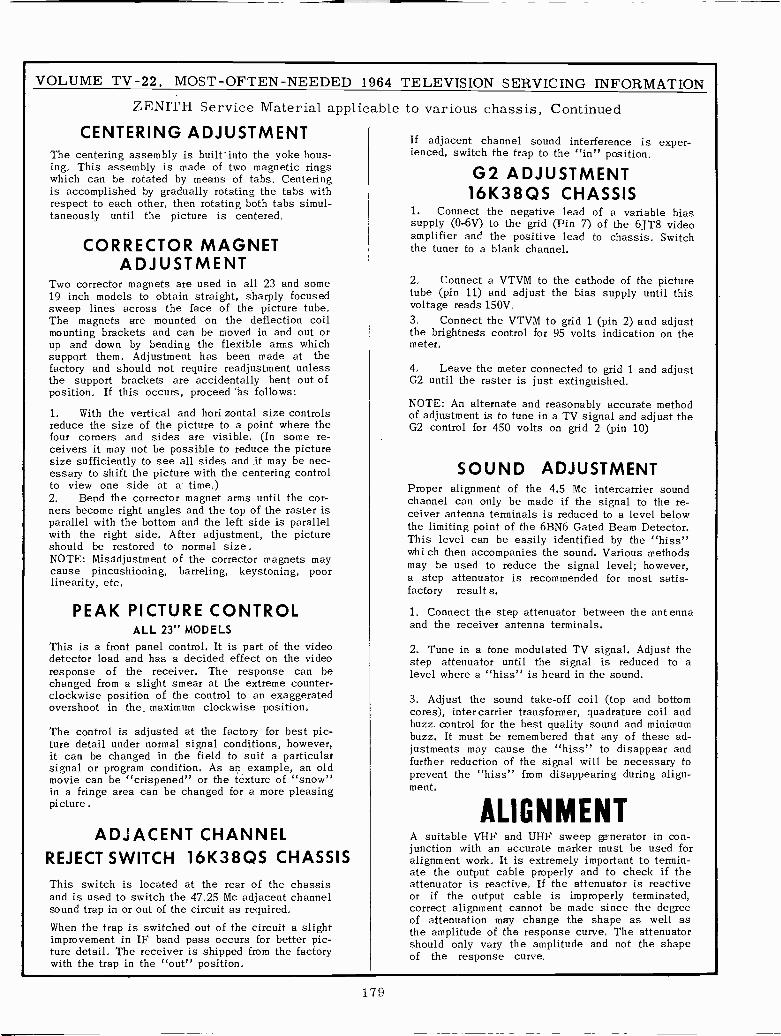
VOLUME TV -22, MOST -OFTEN -NEEDED 1964 TELEVISION SERVICING INFORMATION
ZENITH Service Material applicable to various chassis, Continued
CENTERING ADJUSTMENT If adjacent channel sound interference is exper-The centering assembly is built'into the yoke hous- ienced, switch the trap to the "in" position.ing. This assembly is made of two magnetic ringswhich can be rotated by means of tabs, Centering G2 ADJUSTMENTis accomplished by gradually rotating the tabs with 16K38QS CHASSISrespect to each other, then rotating both tabs simul-taneously until the picture is centered, 1. Connect the negative lead of a variable bias
supplypp y (0-6V) to the grid (Pin 7) of the 6JT8 videoamplifier and the positive lead to chassis. Switch
CORRECTOR MAGNET the tuner to a blank channel.ADJUSTMENT
Two corrector magnets are used in all 23 and some 2. Connect a VTVM to the cathode of the picture19 inch models to obtain straight, sharply focused tube (pin 11) and adjust the bias supply until thissweep lines across the face of the picture tube, voltage reads 150V,The magnets are mounted on the deflection coil 3. Connect the VTVM to grid 1 (pin 2) and adjustmounting brackets and can be moved in and out or the brightness control for 95 volts indication on theup and down by bending the flexible arms whichsupport them, Adjustment has been made at the
meter,
factory and should not require readjustment unless 4, Leave the meter connected to grid 1 and adjustthe support brackets are accidentally bent out ofposition, If this occurs, proceed 'ás follows:
G2 until the raster is just extinguished,
NOTE: An alternate and reasonably accurate method1, With the vertical and hori zontal size controls of adjustment is to tune in a TV signal and adjust thereduce the size of the picture to a point where thefour corners and sides are visible, (In some re-ceivers it may not be possible to reduce the picturesize sufficiently to see all sides and it may be nec-essary to shift the picture with the centering control
G2 control for 450 volts on grid 2 (pin 10)
SOUND ADJUSTMENTto view one side at a time,) Proper alignment of the 4.5 Mc intercarrier sound2. Bend the corrector magnet arms until the cor- channel can only be made if the signal to the re-ners become right angles and the top of the raster is ceiver antenna terminals is reduced to a level belowparallel with the bottom and the left side is parallel the limiting point of the 6BN6 Gated Beam Detector.with the right side. After adjustment, the picture This level can be easily identified by the "hiss"should be restored to normal size . whi ch then accompanies the sound. Various methodsNOTE: Misadjustment of the corrector magnets may may be used to reduce the signal level; however,cause pincushioning, barreling, keystoning, poor
a step attenuator is recommended for most satis -linearity, etc,
PEAK PICTURE CONTROLfactory results.
1. Connect the step attenuator between the antennaALL 23" MODELS and the receiver antenna terminals.
This is a front panel control, It is part of the video 2. Tune in a tone modulated TV signal, Adjust thedetector load and has a decided effect on the video step attenuator until the signal is reduced to aresponse of the receiver. The response can bechanged from a slight smear at the extreme counter-
level where a "hiss" is heard in the sound.
clockwise position of the control to an exaggerated 3. Adjust the sound take -off coil (top and bottomovershoot in the, maximum clockwise position. cores), inter carrier transformer, quadrature coil and
buzz control for the best quality sound and minimumThe control is adjusted at the factory for best pic- buzz. It must be remembered that any of these ad-ture detail under normal signal conditions, however,it can be changed in the field to suit a particular justments may cause the "hiss" to disappear and
further reduction of the signal will be necessary tosignal or program condition. As an example, an old"crispened" "snow" prevent the from disappearing during"hiss" align -movie can be or the texture of
ment.in a fringe area can be changed for a more pleasingpicture.
ALIGNMENTADJACENT CHANNEL A suitable VHF and UHF sweep generator in con-
junction with an accurate marker must be used forREJECT SWITCH 16K38QS CHASSIS alignment work, It is extremely important to termin-
ate the output cable properly and to check if theThis switch is located at the rear of the chassis attenuator is reactive, If the attenuator is reactiveand is used to switch the 47.25 Mc adjacent channel or if the output cable is improperly terminated,sound trap in or out of the circuit as required, correct alignment cannot be made since the degree
of attenuation may change the shape as well asWhen the trap is switched out of the circuit a slightimprovementthein IF band pass occurs for better pic- amplitude of the response curve. The attenuator
ture detail, The receiver is shipped from the factorywith the trap in the "out" position,
should only vary the amplitude and not the shapeof the response curve.
179
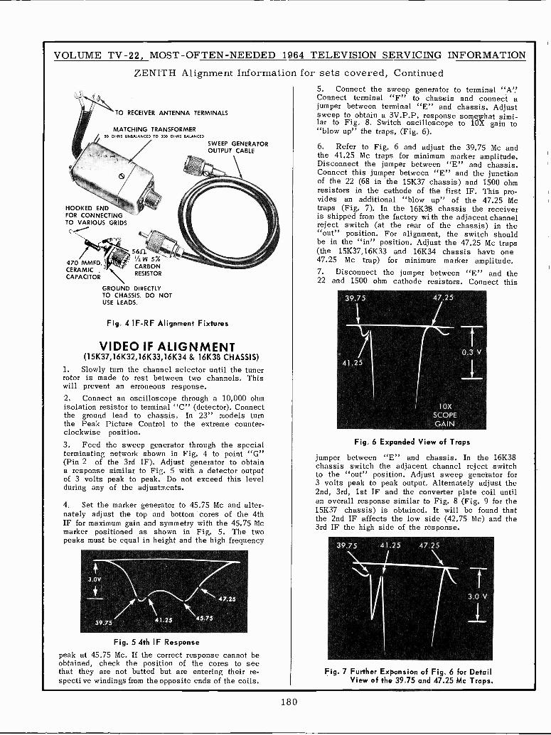
VOLUME TV -22, MOST -OFTEN -NEEDED 1964 TELEVISION SERVICING INFORMATION
ZENITH Alignment Information for sets covered, Continued5. Connect the sweep generator to terminal "A'.'
"F"TO RECEIVER ANTENNA TERMINALS
Connect terminal to chassis and connect ajumper between terminal "E" and chassis. Adjustsweep to obtain a 3V.P.P. response somewhat simi-lar to Fig. 8. Switch oscilloscope to 10X gain to
MATCHING TRANSFORMER "blow up" the traps, (Fig. 6).50 OHMS UNBALANCED i0 300 OHMS BALANCED
SWEEP GENERATOR 6. Refer to Fig. 6 and adjust the 39.75 Mc andOUTPUT CABLE the 41.25 Mc traps for minimum marker amplitude.
¡ Disconnect the jumper between "E" and chassis.Connect this jumper between "E" and the junction
Xof the 22 (68 in the 15K37 chassis) and 1500 ohmresistors in the cathode of the first IF. This pro -y vides an additional "blow up" of the 47.25 Mc
HOOKED END .; i - traps (Fig. 7). In the 16K3$ chassis the receiverFOR CONNECTING is shipped from the factory wi th the adjacent channelTO VARIOUS GRIDS reject switch (at the rear of the chassis) in the
"out" position. For alignment, the switch shouldbe in the "in" position. Adjust the 47.25 Mc traps(the 15K37,16K33 and 16K34 chassis have one
''''......N......................_,./470 MMFD '+++h, 47.25 Mc trap) for minimum marker amplitude,
C56f2Ae>CERAMIC
RESISTOR 7. Disconnect the jumper between "E" and theCAPACITOR
\22 and 1500 ohm cathode resistors. Connect this
GROUND DIRECTLYTO CHASSIS. DO NOT 39.75 47.25USE LEADS.
Fig. 4 IF-RF Alignment Fixtures 1
VIDEO IF ALIGNMENT 1V
(15K37,16K32,16K33,16K34 & 16K38 CHASSIS) / 0.341.25
1. Slowly turn the channel selector until thetunerIrotor is made to rest between two channels, Thiswill prevent an erroneous response.2. Connect an oscilloscope through a 10,000 ohmisolation resistor to terminal "C" (detector). Connect 10Xthe ground lead to chassis. In 23" models turn SCOPEthe Peak Picture Control to the extreme counter-clockwise position.
GAIN
3. Feed the sweep generator through the special Fig. 6 Expanded View of Trapsterminating network shown in Fig. 4 to point "G" jumper between "E" and chassis. In the 16K38(Pin 2 of the 3rd IF). Adjust generator to obtain chassis switch the adjacent channel reject switcha response similar to Fig, 5 with a detector output to the "out" position. Adjust sweep generator forof 3 volts peak to peak. Do not exceed this level 3 volts peak to peak output. Alternately adjust theduring any of the adjustments. 2nd, 3rd, 1st IF and the converter plate coil until4. Set the marker generator to 45.75 Mc and alter- an overall response similar to Fig. 8 (Fig. 9 for thenately adjust the top and bottom cores of the 4th 15K37 chassis) is obtained. It will be found thatIF for maximum gain and symmetry with the 45.75 Mc the 2nd IF affects the low side (42.75 Mc) and themarker positioned as shown in Fig. 5. The twopeaks must be equal in height and the high frequency
3rd IF the high side of the response.
39.75 41.25 47.25
3.0V
/NIT....,7 ----.."NN... 47.25
N.,
3.0 V
41.25 \45.7539.75
Fig. 5 4th IF Response
peak at 45.75 Mc. If the correct response cannot beobtained, check the position of the cores to seethat they are not butted but are entering their re- Fig. 7 Further Expansion of Fig. 6 for Detailspecti ve windings from the opposite ends of the coils. View of the 39.75 and 47.25 Mc Traps.
180
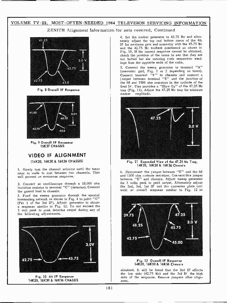
VOLUME TV -22, MOST -OFTEN -NEEDED 1964 TELEVISION SERVICING INFORMATION
ZENITH Alignment Information for sets covered, Continued4. Set the marker generator to 45.75 Mc and alter -
41.25 nately adjust the top and bottom cores of the 4thIF for maximum gain and symmetry with the 45.75 Mcand the 42.75 Mc markers positioned as shown inFig. 10. If the correct response cannot be obtained,/ Tcheck the position of the cores to see that they are
3.0 V not butted but are entering their respective wind-/ ings from the opposite ends of the coils.
45.75 5. Connect the sweep generator to terminal "A"(convertergrid, Fig. 1 or 2 depending on tuner)./1)\\/ Connect terminal "F" to chassis and connect a
42.75 jumper between terminal "E" and the junction of45.0 the 68 and 1500 ohm resistors in the cathode of the
first IF. This provides a "Blow Up" of the 47.25 McFig. 8 Overall IF Response trap (Fig. 11). Adjust the 47.25 Mc trap for minimum
marker amplitude.
241.25 3.0V
45.75
I47.25
42.7s 3.0 V45.0
Fig. 9 Overall IF Response151(37 CHASSIS
VIDEO IF ALIGNMENT(14K20, 161(30 & 16K36 CHASSIS) Fig. 11 Expanded View of the 47.25 Mc Trap,
14K20, 161(30 & 161(36 Chassis1. Slowly turn the channel selector until the tunerrotor is made to rest between two channels. This 6. Disconnect the j umper between "E" and the 68will prevent an erroneous response. and 1500 ohm cathode resistors. Con nect this jumper
between "E" and chassis. Adjust sweep generator2. Connect an oscilloscope through a 10,000 ohm for 3 volts peak to peak output. Alternately adjustisolation resistor to terminal "C" (detector). Connect the 2nd, 3rd, 1st IF and the converter plate coilthe ground lead to chassis. until an overall response similar to Fig. 12 is
3. Feed the sweep generator through the specialterminating network as shown in Fig. 4 to point "G"(Pin 1 of the 3rd IF). Adjust generator to obtaina response similar to Fig. 12. Do not exceed the3 volt peak to peak detector output during any of/the followi ng adj ustments. \
39.75 47.25
41.25Nr.%. 3.0 V
45.75
1 42.75.7'.--3.0V U 45.00
42.75 - -4-45.75 Fig. 12 Overall IF Response14K20, 16K30 & 16K36 Chassis
obtained. It will be found that the 2nd IF affectsthe low side (42.75 Mc) and the 3rd IF the high
Fig. 10 4th IF Response side of the response. Remove jumpers after align -141(20, 16130 & 161(36 CHASSIS ment.
181
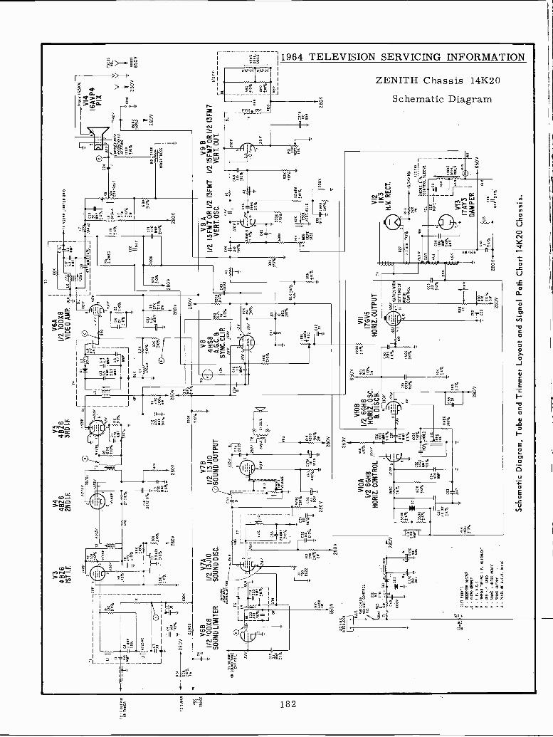
TO O
R I
FTU
ON
ER
UT
PUT
TO
TJN
ER
TO
TUNER
V3
V4
V5
4$Z
64B
Z6
4BZ
61S
T L
F.
2ND
LE
3RD
I.F
.
LI CI
--cC
=1-
MY
Fcz 1
i 2 K
01
1.51
1-
110%
±10
%
001
RE
%
280V
"
52K
680K
710%
118
2YE
G0.
2
015
8A
-1/
210
DX
81/
23J
0S
OU
ND
LIM
ITE
RS
OU
ND
DIS
C.
6111
1/,.
T2
rI
TO
50M
MF
OH
SOU
ND
TA
KE
OFF
CO
IL JRY
C29
RÍLF
±5%
T6
IL9
j LK
650
V
INT
ER
LO
CK
Ill BLU
E SY
ITC
HV
OLU
ME
CO
NO
NT
RO
LR
IO
150
FI
ION
SE
C49
280V
GRAT
623
21.11.
-1
BLI
-T--
.
280V
90JV
=S
E2
-c3
7iY
Yn7
DS
bvbó
v
95
R12 33
855
10%
2W
76
280V
033
20Y
Mti
±10
%
CIO
.001
210%
1/21
3JJ1
0S
OU
ND
OU
TP
UT
C39
9701
,
t151
0%
Ti1
0P/
10%
-¡-
030
l-1-
IS,
_280Y
280V
TE
ST
POIN;'.
C -
D@
BT
OR
061
1/85
- V
SO
EO
811
31tIT
T
F -
GR
80M
0 tU
RIN
G I.
F. A
LIG
NN
EM
T0
- )R
O 1
.F. G
MN
- S
GU
MO
. Tow
n K
AT
E7
- S
OU
NO
OU
TF
IT(
A'.-
PLA
TE
IF A
.F.C
. woo
f
280V
VIO
A±
10%
1/2
6GH
8,H
OR
IZ.
CO
NT
RO
L
3308
3308
noN
>
R29
ISO
,±
10%
IYE
G-6
019
1802
±0%
C52
2K00
131
0%C
53
059
470
NS
F
C56
1000 si
F±
10%
C57
1001
,
±10
%
ED
DO
T
55
±10
% VIO
B1/
2 66
H8
HO
RIZ
. OS
C.
8 D
ISC
H.
6f2/
01
10M
EG
'±
10%
C59 00
33±
10%
±10
%
280V
KI
BA
R
710%
31,
ION
±10
%
L3
TS
V6A
r,
I10
0N
1
IVID
EO
AM
P.
BLK
L6/y
AIC
F6i
rLO
90U
N0L
IYIT
ER
6R10
J5 -
YY
FMMF
-1 V8
4HS
8A
.G.C
. aS
YN
C.C
LIP
.76
6/5
011
Óq5
510%
/osvL
1135n
c19
v
L1
971Y
DE
R 5
%J
190u
A//O
V
R5
I1K
±10
%21
1 2805
8.26
IM 715%
N2N
±10
VII
17G
V5
HO
RIZ
. OU
TPU
T
100
5/6
05-5
516
VA
RIE
S W
ITH
V1i
SE
TT
ING
OF
10W
IDT
HC
ON
TR
OL
9,5
280V
TI
'2,2
1180
C23
50
C2.
}66
5aA
I
rRB
3D8
CO
XT
RA
ST
1F
R7 .SN
t10% s
±10
%6.
91,
I V
AN
/ES
%T
NB
RIG
HT
NE
SS
SE
TT
/N6
TO
OK
±10
%
R9
BR
IGH
TN
ES
S
280V
TO
N.1
656V
.
V4
IA
IVP
4P
I X
FO
CU
SA
OL.
i,,Y
Y Y
280V
65Ó
Y
V9A
V9B
1/2
15F
M7
OR
1/2
13F
M7
1/2
I5F
M7
OR
1/2
13F
M7
VE
RT
.OS
C.
VE
RT
. OU
T.
C99
CS
T
.018
±10
%
C45 II
6802
2 i Y
.M..±
10%
±10
%40
0
565
mfi1
0%28
0V.
Ó5
±10
%
828
±10
%
1.81
1E6
8.1o
%
3306
412
1KH
.V. R
EC
T.
R28
C66
165
EV
. N.V
.
I/O 3
10
ro/Z.LIN.
¡cot
/TR
OT
. SLE
EV
E
BLK
097
±10
%
Sch
emat
ic D
iagr
am, T
ube
and
Trim
mer
Lay
out a
nd S
igna
l Pat
h C
hart
14K
20 C
hass
is.
X0R
12.
DE
FL.
CO
ILS
-©R
29
- 65
0 5
LIC3TB
T00 SOV
280V
I/2 T
10
BL
LRE
D
1
VE
RT
RE
FL.
CO
ILS
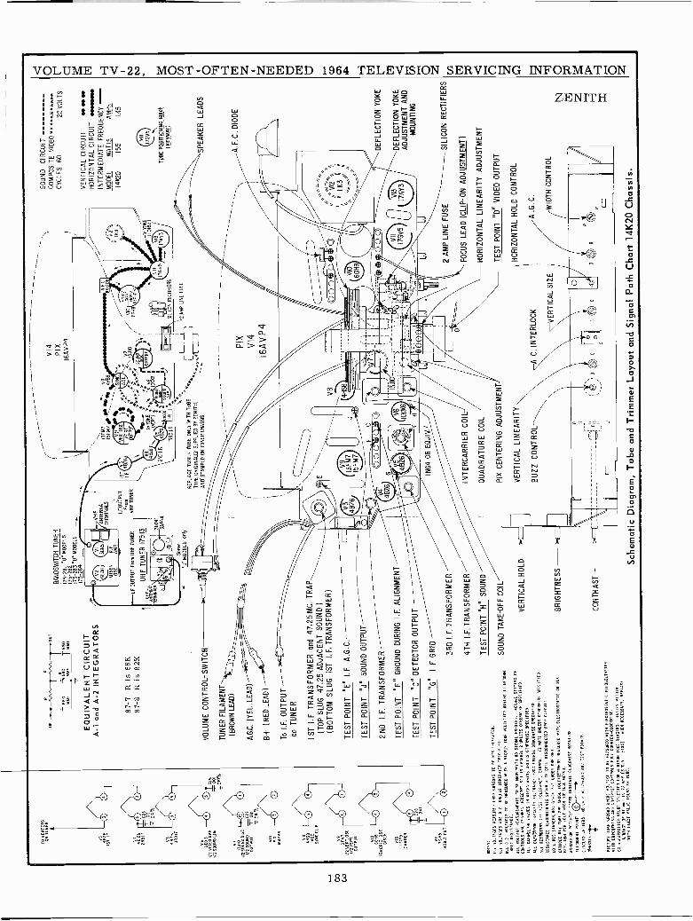
'L O
N T
UN
ER
1111 4826
4426
3ROIF
V6
NM
II/2
VID
EO
AM
P.
I/2 S
OU
ND
1340
I/O S
OU
ND
DIS
C1/
2 S
OU
ND
OU
TP
UT v9
SE
NT
/2 V
ER
T.OSC.
1/2
VE
RT
.O
UT
PU
T
YID
fitI/2
40O
DI
SC
D15Cx.
IMO
DA
MP
ER
TC
D,
415
4061
0 D
UI
O0
26
EW
ES
:A
LL V
OLT
AG
ES
ME
AS
UR
ED
TR
W C
HA
SS
IS T
O P
OIN
TS
INT
ICA
TE
D.
All
TE
LTA
CT
S A
RE
D.C
. UN
LES
S O
TN
ER
NIS
T S
PE
EIF
IFD
ALL
D.C
. VO
LTA
GE
S T
O B
E N
EA
SU
R1O
"IT
N 4
VA
CU
UM
TU
BE
YO
LTIIE
IER
RA
VIN
GII
"EG
OIS
T
,wou
l RE
SIS
TA
NC
E.
All
VO
LTA
GE
NF
AS
UR
EW
"TS
-O
BE
NW
.AIT
R N
O S
IGN
AL
PR
ES
EN
T.
"061
51 S
ET
TIN
G O
F
CO
NT
RO
LS A
ND
E^A
NN
FL
SE
LEC
NIR
AT
TO
CH
AN
NE
L2
UN
LES
S O
TN
ER
NIS
ESPECIFIED.
ALL
CA
PA
CIT
OR
VA
LUE
S IN
MIC
RO
. AN
AO
S U
NLE
SS
OT
NF
RN
.ISE
SP
EC
IFIE
D.
ALL
CA
PA
CIT
OR
CA
PA
CI T
V IT
IEN
AN
CI T
OO
L U
NLE
SS
OT
INR
NIS
E S
PE
CIF
IED
ALL
RE
SE
ITO
RS
AR
T ':
O: T
OLT
2AR
C-.
CO
RS
ON
.1/
2 W
AIT
UN
LES
S O
TH
ER
WIS
E S
PE
CIF
IED
.
NF
SIS
TS
NC
E :I
EA
SU
RIG
EN
IS S
III x
,IT
T C
OIL
DIS
CO
NN
EC
TE
D F
RO
M C
IRC
UIT
.
CO
IL R
ES
ISIA
WO
ES
.'AO
I GLE
N 1
,1U
ND
ER
ON
E 0
101.
CA
TH
OD
E R
AT
TO
NE
211
T A
NO
DE
VD
LTA
GrT
SI M
EA
SU
RE
D W
ITH
ELE
CT
RO
ST
AI I
C O
R E
ON
NO
T. 0
11.1
PE
R T
OLL
HIG
H V
OLT
ICE
TE
TE
R.
AR
BO
N!
ON
PG
UN
T!'¡
I RS
SK
AT
E L
LDC
NN
ISE
NO
TA
TIO
N.
ALI
C4U
NN
T P
OIN
T\`T
CIR
CLE
D L
ET
TE
RS
1H
01. ,
Al I
/:NW
NE
'AN
C T
ES
T P
OIN
TS
.
PIC
TU
RI U
ST
SE
CO
ND
AN
OD
E V
SL'
AG
E T
O R
E M
EA
SU
RE
D N
ITS
ELE
CT
RO
ST
AT
IC T
IIOV
OLT
NE
TE
R
PITH
NBIUMTNEsí ANO CONTIIST CONTROLS FULL COUNTER -CLOCKWISE.
CA
.C
AP
AC
ITO
R V
IM S
TLE
CIE
T F
OR
111
NIIW
TO
NE
RIN
GIN
G.
SA
NIE
S"LENIN
LUN
GE
OF
NT
r1
TO
71
NN
E IS
2.1
1.!ID
S)
NO
ES
NE
CE
SS
AR
Y. R
EP
LAC
E
NIT
S E
NA
CT
V.L
LOE
AD
UN
E IN
YOKE.-
--nn
.--v
n.--
»our
Bt°
Ttc
°
EQ
UIV
ALE
NT
CIR
CU
ITA
-1 c
od A
-2 IN
TE
GR
AT
OR
S
87-7
R is
68K
87-8
R is
82K
BA
ND
SW
ITC
H T
UN
ER
175-
281
"U' M
OD
ELS
175.
282
175.
283"
U' M
OD
ELS
175-
264
V14
PIX
16A
VP
4
VH
F,
GEA"
3GK5
I(rA
NT
EN
NA
MIX
Ek
R.F
. T
ER
MIN
ALS
+IS
FM
7f-C
~ 4
MS
C.
AM
P.
V9
----
-.,
wW
,-
I.F.O
UT
PU
TIR
V3
VR
R)S
#ts
AS
GC
tV
7...-
----
-/
HOR
Frmn
If. 4BZ6
LF.O
UT
PU
T F
rom
UH
F T
UN
ER
VH
F T
UN
ER
PyE
)**
}* .*
*r .1
3J10
\Z
6G
O:
UN
F-
UH
F T
UN
ER
175
-13
. :"
""j s
Dux
D,S
i i
-II.
Im
asP
lo,N
,WS
AF
4AI.F
4826
.yy
55G
O`'Y
omR
e .
I
Il48
26..v
m60
*.,,
,,"'1
,34
51.0
OET ¡ ux
rc.
SIL
ICO
N R
EC
TIF
IER
S
Som
e
'U' M
OD
ELS
onl
VO
LUM
E C
ON
TR
OL
-SW
ITC
H
TU
NE
R F
ILA
ME
NT
(BR
OW
N L
EA
D)
A.G
C. (
YE
L.LE
AD
)
B+
( R
ED
LE
AD
)
To
I.F. O
UT
PU
T-
on T
UN
ER
1ST
I.F
. TR
AN
SF
OR
ME
R a
nd 4
7.25
MC
. TR
AP
(TO
P S
LUG
47,
25 A
DJA
CE
NT
SO
UN
D)
(BO
TT
OM
SLU
G 1
ST
I.F
. TR
AN
SF
OR
ME
R)
TE
ST
PO
INT
"E
" I.F
. A.G
.C.
TE
ST
PO
INT
"J"
SO
UN
D O
UT
PU
T
2ND
I.F
. TR
AN
SF
OR
ME
R
TE
ST
PO
INT
'IF"
GR
OU
ND
DU
RIN
G I.
F. A
LIG
NM
EN
T
TE
ST
PO
INT
'C"
DE
TE
CT
OR
OU
TP
UT
-
TE
ST
PO
INT
11G
"I.F
. GR
ID
3RD
I.F
. TR
AN
SF
OR
ME
R
4TH
I.F
. TR
AN
SF
OR
ME
R
TE
ST
PO
INT
11H
" S
OU
ND
SO
UN
D T
AK
E -
OF
F C
OIL
VE
RT
ICA
L H
OLD
BR
IGH
TN
ES
S
CO
NT
RA
ST
114
RE
PLA
CE
TU
NE
R T
UB
E O
NLY
WIT
H T
UB
Ek
TY
PE
OR
IGIN
ALL
Y S
UP
PLI
ED
BY
ZE
NIT
H.
658
ST
AM
PE
D O
N T
UN
ER
CH
AS
SIS
..
4BZ6
113F
M7
15F
M7
J
IN64
OR
EQ
UIV
.
INT
ER
CA
RR
IER
CO
IL
QU
AD
RA
TU
RE
CO
IL
PIX
CE
NT
ER
ING
AD
JUS
TM
EN
T
VE
RT
ICA
L LI
NE
AR
ITY
BU
ZZ
CO
NT
RO
L
L
2 A
MP
LIN
E F
US
E
PIX
V14
I6A
VP4
A.C
. IN
TE
RLO
CK
000 (V
IO6G
H'
SO
UN
D C
IRC
UIT
CO
MP
OS
ITE
VID
EO
CY
CLE
S 6
012
0V
OL
TS
VE
RT
ICA
L C
IRC
UIT
**w
,»H
OR
IZO
NT
AL
CIR
CU
IT M
w.w
INT
ER
ME
DIA
TE
FR
EQ
UE
NC
YM
OD
EL
WA
TT
SA
MP
S
14K
2015
5L4
5
VII
76V
5
TIM
EP
OS
ITIO
NIN
G G
UID
E_
IRE
YW
_AY
)
SP
EA
KE
R L
EA
DS
A.F
.C. D
IOD
E
DE
FLE
CT
ION
YO
KE
DE
FLE
CT
ION
YO
KE
AD
JUS
TM
EN
T A
ND
MO
UN
TIN
G
2 A
MP
LIN
E F
US
ES
ILIC
ON
RE
CT
IFIE
RS
FO
CU
S L
EA
D (
CLI
P -
ON
AD
JUS
TM
EN
T)
HO
RIZ
ON
TA
L LI
NE
AR
ITY
AD
JUS
TM
EN
T
TE
ST
PO
INT
"D
" V
IDE
O O
UT
PU
T
r -H
OR
IZO
NT
AL
HO
LD C
ON
TR
OL
A .G
. C.
WID
TH
CO
NT
RO
L
Sch
emat
ic D
iagr
am, T
ube
and
Trim
mer
Lay
out a
nd S
igna
l Pat
h C
hart
14K
20 C
hass
is.
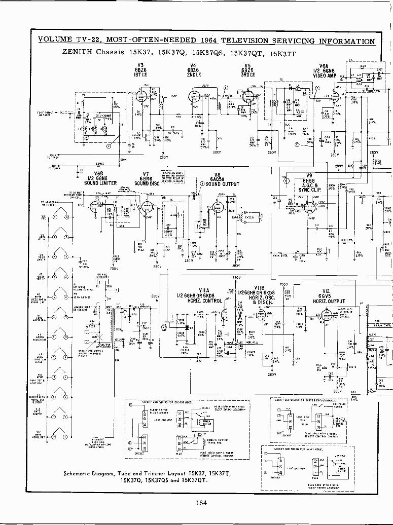
VOLUME TV -22, MOST -OFTEN -NEEDED 1964 TELEVISION SERVICING INFORMATIONZENITH Chassis 15K37, 15K37Q, 15K37QS, 15K37QT, 15K37T
V3 V46826 6826
2ÑDÍS F.
ITO IF OUTPUT f(CON TUNER
brIY T
9 C05120101W2%10
LIt
(`(T
T2SY
L21~ L1I ¿1 LC3
25011 .ro TUNER
AOTO TUNER
TO HEATERSON TUNER
6826END IF
256826
3RD IF
V66558
VIDEO AMP R50UM0 LIP.
AtSOUND DISC
VBSAOSA
SOUND OUT
V96XS9
SYNC CLIP8 A6C
6FYTVERT OUT RVERT OSC.
VII6558 OR EK D8
00010. 052.R OISCR
VIOEATS
DRAPER
1112
6525HOR12.0UT
ON Sóú 0 TENDOFF COIL
32V
1
1
K
690
IS/V
21V
68 s510%
R2
/3l
I
2805
225E5
4IS V6B
V7 2 'TOKYUTING SWITCH L__1/2 66N8 6BN6
IONNSTEP RELAY INSOUND LIMITER SOUND DISC.
a--,w umss
I20 SAC.INTERLOCK
SWITCH ON GL GRAY
VOLUME CONTROL - -
RIO
SOON 1533705
JUMPER WIREOW 15K310T SIB
521
R24
11200
ARAS
53
T12
GRAY REO
OR
OLE
OR BL /NPAY RRN
EO
BROKER FOR MOO LS150713 .15070S 8ISKS TT
FILAMENTFUSE LINK
I I/O" LOOP OF X24 AW6COPPER WIRE
RIO
750BUZZ RII
210%
ROL 6118 Co5Bwt
200V tUORO
URN
r
C41B02000
045280400V,
280V
470
685
263RD I.F.
TS
01
T6
V6A IOOK -1
1/2 6GN8VIDEO AMP. BLK LT ''^
51,4NNFYxYF I
I
L51 IOSV
15.5ALIRI
PO U I } 9 L 6TtIYY 23%-J60OOVMr Y Yµ
Cu 3Ó 78 010.000%
v.l
LISlTT10% NNF
BLK
no 7.-w.
P!10
0 SF I ,10%R
2805
6AQ5ASOUND OUTPUT
LC16T033
10%
6 f.
IS
!lox
OA
T 350V
NS276
O%2W
2805
2805 50K
ROS
210%- -.470K
T
C35
2805
`11:1,
R16 V96HS8
i A.G.C. 6 I '8%1SYNC.CLIP. Áo RI ENOT1AI9
= O%
035
.01
RI126Y
YEG 'I 265
á9%10,46Y TE0
N461011110% Y `IT0
= 150Y
050V
301'
1055
746V
C31 R19
1
MEG210%
UK 010%I VA
RIN }ION
1S
10%1.85E!
7
680K
R205
MEG68K 1 VERL210% 512E
MR
VITA1/2 6GH8 OR 6KD8
HORIZ. CONTROL
IYEG 3.0Y9
2805
VIIBI/26GH8 OR 6KD8
16Y
f,8
HORIZ.OSdDISCH.C.
350K310%
330K±10%
C{2%.0012.10 .1
210%
220K800%
CSO
.047
C215500
jC%CSI470 SYYF CS3
220012 MEG
MIÓ% 210%
=MME 6 735V210%
C55
Ip470MIT
000%
100E210%
1101,
6
7005
i2R0%
211
00337 1-T210%
l
073 LI
11016/J IWT2
56046
210%
MOIL HOLD
CS6T.DI
L.001S 1t0%
15K
310%
566 y.C5I3210% =.I
2805
V126GV5
HORIZ.OUTPUT
-55
IOU ,9
0,4
TI
2V
VARIES NIONSETTING1NOT
6053,7, CONTROL
R29
3.9.9 W.w. !10%
C61ADI = 19A210%
LI3 IRA
15.50
22A
[6nC450SÑ21r-tWIDTH
PURPLE25YIC60
- 033 IévT010%3W
C62.1
210%
280V RON 280V
SOCKET AND WIRING FOR 15K370T MODEL
SLEEP SWITCHPLUG R SOCKET
50CKET
L
LEAD ENO WEN
PLUG
PLUG USED WITH S-57210RS -TT SLEEP SWITCH ASSEMBLY
REMOTES.PRI CO.NTROL
TRAN
PLUG USED WITH S-56093REMOTE CONTROL CHASSIS J
Schematic Diagram, Tube and Trimmer Layout 15K37, 15K37T,15K37Q, 15K37QS and 15K37QT.
ISOK
r SOCKET AND WIRING FOR 15K370 R ISK31o5 MODELS !10%
aaNT SWITCI ONTUNER
L
LORO OnoVIEW
PLUG
REMOTECONTROLTRANSPRI
PLUG USED WITH S.56893REMOTE CONTROL CRASSIS
SOCKET ANO WIRING FOR ISK3TT MODEL
LEAD END VOW
SOCKET
LPLUG USED WITH 0.30110SLEEP SWITCH ASSEMBLY
J
184
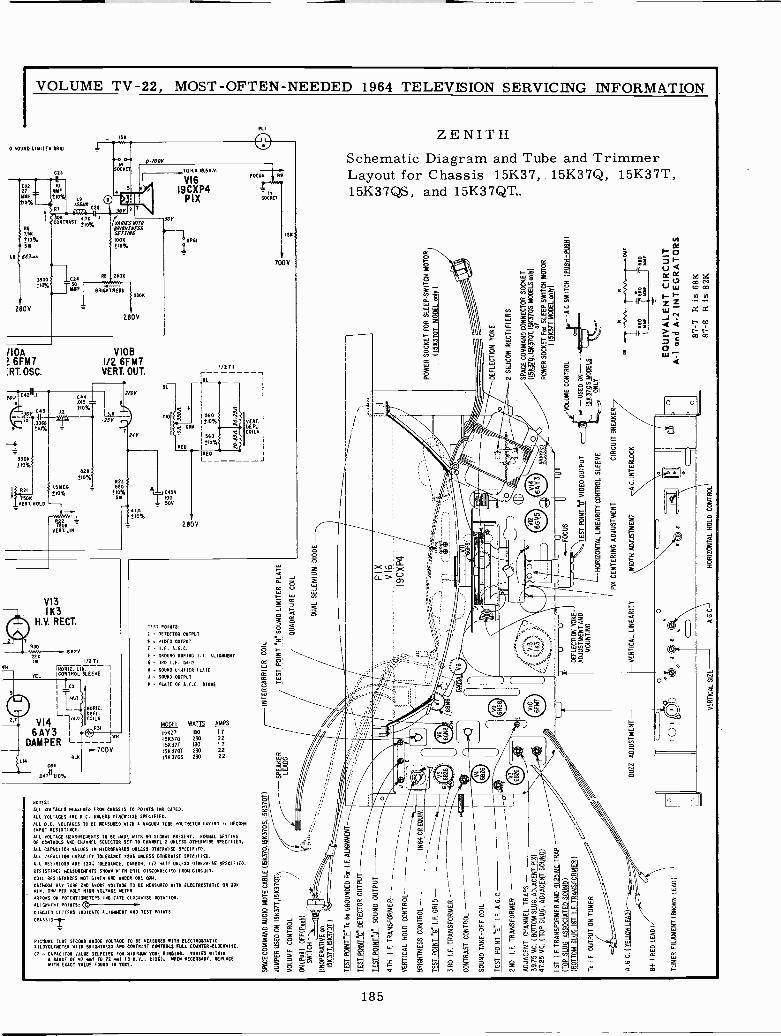
VOLUME TV -22, MOST -OFTEN -NEEDED 1964 TELEVISION SERVICING INFORMATION
0 SOUND LIMITER 6010
C23
. n
IF YUFCOO NI
YYF= 10%0%-_IR7
FCÓÑT 1ST i10%86750±10%SW
LB 663yM
3400il0%
280V
IIOA6FM7
:RT.OSC.
0-1008
4N/f5Y/1N91/6N11(5S5(71116
'1011
280V
VIOBI/2 6FM7VERT. OUT.
POC42 .1
013
OY ÓÓ68110%
3306110%
1508-VERY. MOLD
CAA.015 =
10%A2
N
wYnT
628
RL
HOY
-PSY .-,
8231.511E6 = 680
710% ±10%5W
1558YERL LIN.
±10%
VI3IK3
H.V. RECT.
0
226IOU
TEL
I/O TII
riO812. LIN. -ICONTROL SLEEVE
2,7
ICR
140
VI4 L 1"°6AY3 I
DAMPER L-
RORIE.DE FL.COILS
BUI
064
017n±10%
V JYN700V
TO
TO 11.0. 58.0.
I9CXP4PIX
yb SP61
1
4
Q 61
EDRED
+.CASA10050V
nn1.10%
2808
1/2711
iL
050 POINTS:
- DETECTOR OUTPUT
VIDEO OUTPUT
560 44p%! áSBVERT.
+tlDLS
PLI
FOCU R!
...PPPfff-
INSOCRET
1
560 1±10%
REDL
GROUND DURING I.F. All NT
- SRO I.F. GRIP- SOUND LI.VI TER (LATE
- SOUND OUTPUT
- PLATE OF A.F.C. DIODE
MODEL WATTS AMPS
10837 180 1.7
156370 230 2.2
15K371 180 1.7
158 3717T 230 221583705 230 22
NOTES:
ALL VOLTAGES MEASURED FROM CHASSIS TO POINTS INDICATED.
ALL VOLTAGES ARE D.C. UNLESS 0TIL81115E SPECIFIED.
ALL D.C. VOLTAGES TO BE REASONED WITH A VACUUM TUBE VOLTMETER NAYINO II 160181INPUT RESISTANCE.
AIL VOLTAGE MEASUREIYMTS TO BE mADE WITH NO SIGNAL PRESENT. NORMAL SETTINGOF CONTROLS 660 CHANNEL SELECTOR SET TO CBANNTL 2 UNLESS OTHERWISE SPECIFIED.
ALL CAPACITOR VALUES IN MICROFARADS UNLESS OTHERWISE SPECIFIED.
ALL CAPACITOR CAPACITY TOLERANCE 77206 AIRLESS OTHERWISE SPECIFIED.
ALL RESISTORS ARE 0201 TOLERANCE, CARBON. I/2 WATT UNLESS OTHERWISE SPECIFIED.
RESISTANCE MEASUREMENTS SNOWS WITH COIL OISCDNNECT.0 FROM CIRCUIT.
COIL RESISTANCES NOT GIVEN ARE UNDER ONE 0181.
CATHODE RAT 0000 END ANODE VOLTAGE TO BE MEASURES WITH ELECTROSTATIC OR 200NI N. 0700 PER VOLT SION VOLTAGE INTER.
ARROWS ON PDTENTIOMETEPS INDICATE CLOCKWISE ROTATION.
WOW., POINrs;CIRCLED LETTERS INDICATE ALIGNMENT ANO TEST POINTS.
LIMSSISI-
PIC1URE TUBE SECOND ANODE VOLTAGE TO BE MEASURED WIT11 ELECTROSTATICKIL0Y0CTFNTER 6118 BRIGHTNESS AND CONTRAST CONTROLS FULL COUNTER -CLOCKWISE.
CT a CAPACITOR VALUE SELECTED FOR MINIMUM TORE RINSING. VARIES WITNINA RANGE OF 67 vat TO 72 441 (3 N.Y., 0106). MIEN NECESSARY, REPLACEWITH ENACT VALUE FOUND 14 YOKE.
J
70011
ZENITHSchematic Diagram and Tube and TrimmerLayout for Chassis 15K37, . 15K37Q, 15K37T,15K37QS, and 15K37QT..
CFI
O
a
jK H _11! aÑ 2hHco2ya
185
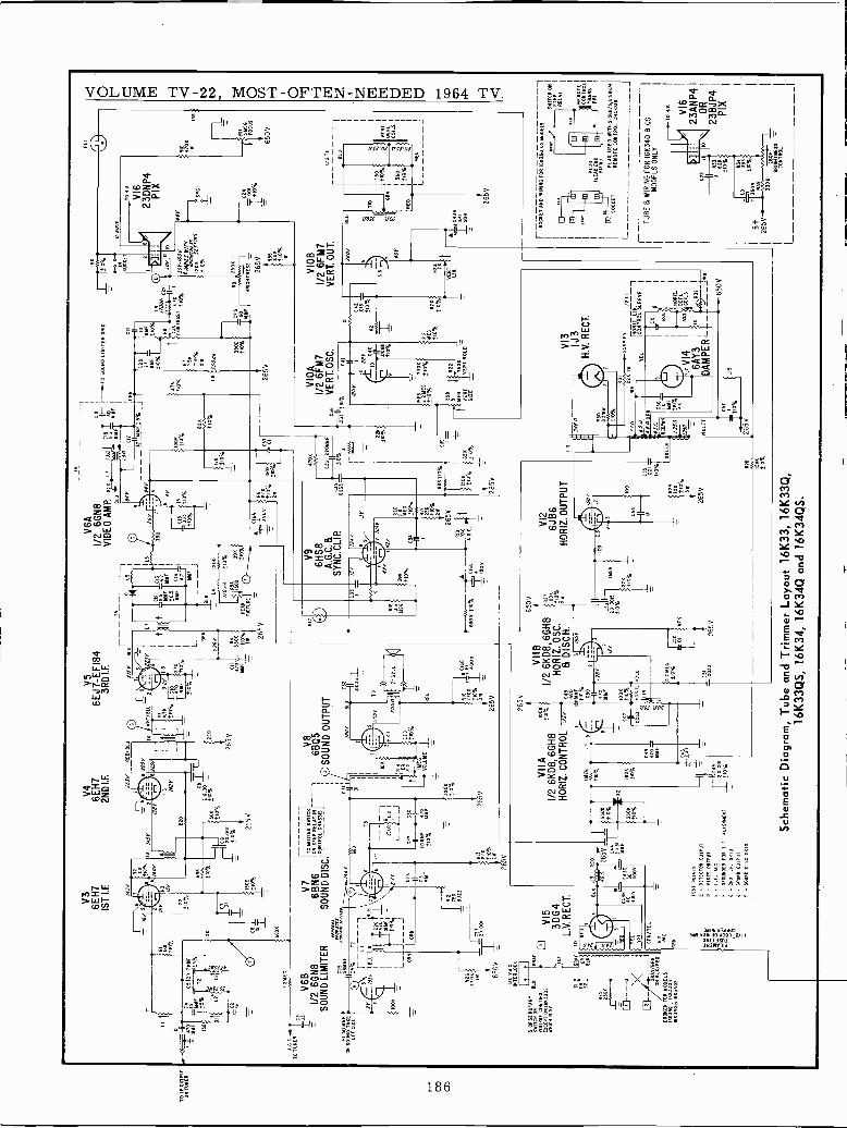
TD
I B
F T
OO
HE
RU
TPU
rO
CO
KG
CT
O T
UN
ER
2.25
00
TO
SO
YY
FC
N G
OU
RD
TA
KE
OF
F C
OIL
V3
6EH
71S
T L
E
V4
6EH
72N
D I.
F.
26JV
RE
O/B
Lu
MY
t6J
r -T
S
'J1
1
1220
265V
6EJ7
5 ÉF
184
3RD
I.F
.T
5
.B
0%
Yi
! 0%
I'
41-I
_.%
_L
--M
Y J
IB
LK
-U
1200
170.
.E21
0%
+¿
$1lÓ
O39
Y
PE
AK
1/
PIC
TU
RE
ÑLS , I L
6
6r_
_--.
_.V6A
1/2
6GN
8I
91
050U
N0L
IMIT
ER
GR
IDV
IDE
O A
MR
GLN
ILT
1!4
]SY
YF
~"T
BLV
Y_-
-. Y
Yi
"'-'7
1T-C
.55
CIT
-IORN
L-__
111Y
Mt_
lS7_
J
330
sá0
L ;I
I%
265
V
Pe
1 ó1
i5
T ID
%
C
15
V 6
BV
7r,
o M
UT
ING
SM
ITC
N
1/2
6GN
86G
N8
6BN
6C
OR
TX
OLM
NA
5515
,S
OU
ND
LIM
ITE
RS
OU
ND
DIS
C.
C25
ewF
Px
unuP
RS
MM
F
15%
T1
3
_/JS
YB
LU
bOK
II
5109
52
RO
TA
RY
OLA
BR
UT
SN
ITC
H 0
NV
OLA
RE
CO
NT
RO
L
M61
06 0
52
]]OS_
L_ 0N
I1KR26
i'
65C
VT
120
V.A
C.
INT
ER
LOC
K
IMF
I
OR
r/46
Y
028
s33D
G4
L.V
. RE
CT
.R
AT
12
OR
OR
D
SL
R25
2OOK
o-_- /
0Ñ B
iY/%
NE
O
Bfi1
,EF
OR
MO
O L
S30
1úK
330
16x3
4021
6K34
05
)
F 3
BLK
RE
D
ST
EL
rT
EL
I VD
11.
12I
L_C
25C
30
205S
FOTO
710%
MM
F
2TK
210%
2M
265V
C31 D
I1.
3906
20%
265V
6805
SO
UN
D O
UT
PU
T
R14
RI ISEG
VO
LUM
E
/00Y
BL
C
o311
61
T9
212
J1.
ED
RIB
0168
ro%Y
Í00V
13M
265V
1117
IY
uY
V9
6HS
8A
.G.C
. 8S
YN
C. C
LIP
.
C33
/JV
/24V
CM
=-%
9i-J
WO
K ±
10
265V
R19
110
KA
DD
.
LR
ED
4en
265± 11
40
9Ú3C
Y M
MF
6111
1/T
EL
Vti'
C
6RM
VIIA
1/2
6KD
8, 6
GN
8H
OR
IZ. C
ON
TR
OL
1.7/
OK
0%
1710
330K %
TE
ST
PO
INr9
:C
- D
ET
EC
TO
R O
UT
PU
T
D -
VID
EO
OU
TP
UT
E-
LP. A
GE
F-
OR
WN
DE
D R
OB
I.E
. ALI
O00
NT
G-
3RD
I.R
. 041
0J
- 50
0X0
OU
TP
UT
P-
SO
UN
D D
ISC
GR
ID
2
10E
8
210%
IRON
9
210%
c40
4703
MO
W
265V
C49
=MMF
210%
HH
4To
YYi
f o%
9E6
tISR 2ro%
210%
27K
:10%
Le
C20
T21
1IM
F21
0%
2504
5
265V
3900
±10
%
C21 iÓ
YY
F
!10%
15
L9 1702
0 C
22
;: K
.I
0%
9b%
50C
2
0-60
0Y
TO
N.V
J0V
-100
V2H
L9/E
5Y
VIy
JNyS
120M
6/µ
É%
T/.I
G21
0%
1C21
R9
2509
I30
YY
FB
RI6
xiM
E5S 26
5V SIÜ
ÓK
1210
%Ir
40
V16
23P
DIX
1SP
81
Í{°%
smI/2
16F
M7
t36
220YYi
CO
BV
ER
T. O
SC
.13
5os
3=20
Al
053
1210
%
6BK
!IO%
265V
650V
VIIB
1/2
6KD
8,6G
H8
HO
RIZ
. OS
C.
90%
8 D
ISC
H.
0 1
1006
Sp%
C45
2 K
%00
1
210
ái
=00
33
61lo
or
lt3T
DI
47K
265'
o
1
6JB
6H
OR
IZ. O
UT
PU
T
rp%
,Sx2
R.
39
713
C55
I--
2 X
O05
010%
22K
910%
B3
/50 i
1,00
'HI-
.Q
C55 00
1 r
±10
%
R$9 lox
210%
311
265V
OR
E
L
izar
R23
0305
tp%
O21
0%
-G/
658
R2
51
ME
G75
011
I
VE
RE
VE
RLN
OLD
SIZ
E _
C42
T
ME
G
210%
10%
VIO
B1/
2 6F
M7
VE
RT
OU
T.
2460 11
308t
WM
z7
3,
770
NO
B
6.51
2
104
OR
IJ0
AE
0/R
Ti
1 51
VIO
LET
110
VI3 IJ3
H.V
. RE
CT
.
Ir6.
206V
NV
IO2
TN
rIpN
12LI
N.
CO
NT
RO
L S
LEE
VE
TE
L
z6A
Y3
DA
MP
ER
ICx
I
NO
RI2
.
/no
wa
D1,
1s
E(
5RB
D
51
= 1
0%31
265V
LIS
650V
265V
SK
1R
II
650V
SOB
110%
Sch
emat
ic D
iagr
am, T
ube
and
Trim
mer
Lay
out 1
6K33
, 16K
33Q
,16
K33
QS
, 16K
34, 1
6K34
Q a
nd 1
6K34
QS
.
1- S
OC
KE
T A
NO
WIR
ING
MR
161
1310
,05
MO
DE
LS
0 a
OC
R E
T
I LE
AP
fND
fl
VIE
rI
SW
ITC
H O
RS
TE
PR
ELA
Y
RE
MO
TE
CO
NT
RO
LT
RA
NS
PR
I
PLU
S U
ED
VIT
OS
-588
73,5
.514
74R
EM
OT
E C
ON
TR
OL
CN
AS
515
L_J
rT
UB
E 6
WIR
ING
FO
R 1
6534
0 6
OS
---
1M
OD
ELS
ON
LY
V16
23A
NP
4O
R23
BJP
4P
IX
L
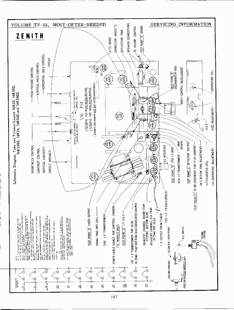
TO
AT
ER
SO
NHE T
UN
ER
VB
tENi/EiIB]
6EN
1%E
FIE
]
6AT
N3
O0
O0
OW
O0
O0
O0
O0
O0
O0
O0
O0
O0
SOBS:
AIL VO. TACES NEASUIIED FRON CHASSIS TO POINTS INDICATED.
ALL VD'.TAGES ARE D.C. UNLESS OTHERWISE SPECIFIED.
All D.C. VOLTAGES TO SE MEASURED WITH A VACUUM TUBE VOLTMETER
HAVING II
0750N11 INPUT RESISTANCE.
ALL VOLTAGE MEASUREMENTS TO BE MADE WIN NO SIOMAL PRESENT.
MORIAL SETTING OF CONTROLS AND CHANNEL SELECTOR SET TO
CHARNEL B UNLESS OTNENSISE SPECIFIED.
ALL CAPACITORS VALUES IN MICROPARAOS UNLESS OTHERWISE SPECIFIED.
ALL CAPACITOR CAPACITY TOLERANCE 020% UNLESS OTHERWISE
SPECIFIED.
ALL RESISTORS ARE 1000 TOLERANCE, CARBON.
IIO
WATT UNLESS
OTNERWISE SPECIFIED.
RESISTANCE MEASUREMENTS
SH
OW
N W
ITH
COIL DISCONNECTED FROM
CIRCUIT.
COIL RESISTANCES NOT GIVEN ARE UNDER ONE 0101.
CATHODE RAT TUBE 2N0 ANODE VOLTAGE TO SE MEASURED
RI T
x
ELECTROSTATIC OR OUR MIN.
0155
PER VOLT NIGH VOLTAGE METER.
ARROWS ON POTENTIOMETERS INDICATE CLOCKWISE ROTATIOII.
ALIGNMENT
PO
IxiS
IOCIRCLED L'TTERS INDICATE ALIGNMENT AND TEST POINTS
CHASSIS
PICTURE TUBE SECOND ANODE VOLTAGE
TOBE MEASURED WITM
ELECTROSTATIC NIL0V0LTMETER RITO BRIONTRESS AND CONTRAST
CONTROLS FULL COUNTER -CLOCKWISE.
CS CAPACITOR VALUE SELECTED FOR MINIMUM YORE RINGING.
VARIES WITNIN A RANGE OF VV V1 TO VE NS (] R.V..
01).
VEIN NECESSARY. REPLACE WITH ENACT VALUE
FOUND IM VOLE. T
ES
T P
OIN
T "
D"
VID
EO
OU
TP
UT
SO
UN
D T
AK
E-O
FF
CO
IL
3RD
I.F. T
RA
NS
FO
RM
ER
PO
WE
R C
AB
LE S
OC
KE
T F
OR
CO
NT
RO
L C
HA
SS
IS
("Q
" M
OD
ELS
ON
LY)
TE
ST
PO
INT
RE
" I.F
. A.G
.C.
1ST
.I.
F. T
RA
NS
FO
RM
ER
TO
P S
LUG
.
41.2
5MC
. TR
AP
BO
TT
OM
SLU
G (
AS
SO
CIA
TE
D S
OU
ND
)
VO
LUM
E C
ON
TR
OL
US
ED
ON
16K
33Q
S M
OD
ELS
onl
y
AD
JAC
EN
T C
HA
NN
EL
SO
UN
D T
RA
P-1
4725
MC
. BO
TT
OM
SLU
G
AD
JAC
EN
T C
HA
NN
EL
PIX
TR
AP
39.7
5MC
.TO
P S
LUG
I.F. O
UT
PU
T F
RO
M T
UN
ER
-
2ND
I.F
. TR
AN
SF
OR
ME
RA
.C.S
WIT
CH
I PU
SH
-P
US
H)
A.C
. SW
ITC
H
VO
LUM
EC
ON
TR
OL
Sch
emat
ic D
iagr
am, T
ube
and
Trim
mer
Lay
out 1
6K33
, 16K
33Q
,16
K33
QS
, 16K
34, 1
6K34
Q a
nd 1
6K34
QS
.
BR
IGH
TN
ES
S C
ON
TR
OL
CO
NT
RA
ST
CO
NT
RO
L
VE
RT
ICA
L LI
NE
AR
ITY
CIR
CU
IT B
RE
AK
ER
PE
AK
PIC
TU
RE
CO
NT
RO
L
VE
RT
ICA
L H
OLD
CO
NT
RO
L
-HO
RIZ
ON
TA
L H
OLD
CO
NT
RO
L
FO
CU
S
111
I
_el
I
'V
ER
TIC
AL
SIZ
E A
DJU
ST
AB
LEI
----
\P
EA
K P
ICT
UR
E C
ON
TR
OL
UT
HR
OU
GH
HO
LLO
W S
HA
FT
"-V
ER
TIC
AL
SIZ
E
V16
PIX
23D
NP4
FO
R I6
K33
,16K
33Q
,16K
33Q
S.
VIS
23A
NP4
FO
R 1
6K34
,16K
340,
16K
340S
.
3D64
)(
23D
NP
4 A
ND
23A
NP
4 A
RE
NO
T IN
TE
RC
HA
NG
EA
BLE
)
EF
I8 H
A.C
. IN
TE
RLO
CK
TE
ST
PO
INT
"G
" 3R
D I.
F. G
RID
4TH
I.F
. TR
AN
SF
OR
ME
RIN
64O
AE
OU
IV.
TE
ST
PO
INT
"C"
DE
TE
CT
OR
OU
TP
UT
/
TE
ST
P01
NT
"F
" T
O B
E G
RO
UN
DE
D F
OR
I.F
. ALI
GN
ME
NT
-
DE
FLE
CT
ION
YO
KE
AD
JUS
TM
EN
T
INT
ER
CA
RR
IER
CO
IL
PIX
CE
NT
ER
ING
AD
JUS
TM
EN
T
V12
TE
ST
PO
INT
BP
D
DIS
CR
IMIN
AT
OR
GR
ID
'WID
TH
CO
NT
RO
L(M
ET
AL
SLE
EV
E)
A.G
.C.-
BU
R A
DJU
ST
ME
NT
LQU
AD
RA
TU
RE
CO
IL
A.F
.C. D
IOD
E
CO
RR
EC
TO
R M
AG
NE
TS
/DE
FLE
CT
ION
YO
KE
SP
EA
KE
R C
ON
NE
CT
ION
S
TO
VO
LUM
E C
ON
TR
OL
TE
ST
PO
INT
"J"
SO
UN
D
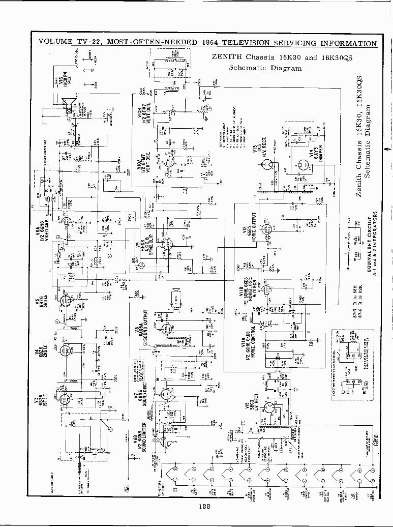
VI,V
2 O
N T
UN
ER
L
AG
ET
UN
ER
V3
6826
1ST
LE
V4
68Z
62N
DLE
V5
68Z
63R
D 1
.F.
/301
'54
56R
ED
/DW
Ái
2.2Y
ES
.610
E
32v
SIN
90%
1213
21'
Row
720%
AS
S6E 210%
CR
..0w
!_1o
_áT
mX
yI'S
E
S65
Eo%
270
%
2500
068
V7
Il101
0T?M
A 0
00/T
OO
!1/
2 6G
N8
68N
610
0 S
TE
PR
ELA
Y IN
I
_ _
1
SO
UN
D L
IMIT
ER
SO
UN
D D
ISC
.`.
9111
W Y
YP
C26
.,5
MIN
TM
SW
ND
iAllE
TO
HE
AT
ER
SO
P
TS
ILT
Ir*`
s_,
ON
TU
NE
R/
)}v
BW
f51
IDLE
1
Cal
iiO
ro°A
(IY
Yi
1
iIFiF
F -
-°Jl
6M
L_
C25
001 10
%
IZO
1'3
CINTERLOCK
SI S
WIT
CH
AN
O
TO
WN
E C
ON
TR
0. N
3U
SE
D O
N M
OD
EL
-
I6N
3005
ON
LY.
RO
TA
RY
SN
ITC
H
ON
VO
LUM
EC
ON
TR
OL
R2.
US
SE
O O
N E
R30
1-1
R29
020 G
MT
/7oI
D T
K%
RE
MB
RM
IEN
FO
R M
ooI.
1663
005
ON
,
SP
AT
OR
YI"
/.20(
00N
I11E
AN
fi
21LAYf9i
EUSE L1XE
ss
10
RIO
E30
C61
/22
pxTOOI
.º)
E2M
X
Zpy
f11
1_
2500
V15
5BC
3LV
. RE
CT
.
63 V
AC
OR
TE
L
C43
11
4000
YY
FI
220
250V
6Á05
AS
OU
ND
OU
TP
UT
250V
iq%
áóüI
WIT
IE
N-
3
250V
3.9
RN
XE
G
SIO
%
2}}1
000
503
VIIA
VIIB
1/2
6GH
8,6K
D8
1/2
6GH
98,6
KD
8DIS
CH
.H
OR
IZ. C
ON
TR
OL0
1,10
0H
OR
IZ. O
SC
.
s.06
b }
YMF
191,
TR
%D
C51
2
110%
12
35
C98
20.0
0151
00
YE
S
210%
1505
T10
%
CM 9)0
=
TA 60
00 R26 0E
214
CS
3
r-
V6A
00R
1/2
6GN
8i
vAC
lot
'-
VID
EO
AM
P. O
ttL.
.L.4
1C
6iY
Y'
IT
OS
OU
YD
urtE
p6xD
YYE
,C
IT!
250V
6HS
8A
.G.C
. 8S
YN
C.C
LIP
.
V12
6GE
5H
OR
IZ. O
UT
PU
T
100
!'0v
3.O
Ea%
S
Ti
G30
AV
IV
250V
VIO
A1/
2 6F
M7
VE
RT
. OS
C.
402
.251
, 100
C.5
CS
RT
OS
12-0
-_.
01
R2T GIN
iA
IWA
T3W
5309
5 R29
CO
O
AN
AA
lo%
v0
NN
rSI/
)IW
ars
S2
T/M
600
001
0%
R9
L 25
06
6R16xTNE5f1
TO
HV
VI6
19C
R P
4P
IX
2500
VIO
B1/
2 6F
M7
axV
ER
T. O
UT
.25
00
ST
P01
0TS
:
- D
ET
EC
TO
R O
UT
PU
T
YIO
TO
OU
TP
UT
- G
RW
M «
MIN
G I.
T. A
l1O
1NE
RT
- IR
O I.
P. N
OD
30U
110
LIx1
iER
PLA
TE
SW
XO
OIIL
PU
i
V13 I K
3
H.V
. RE
CT
.
9WW
=10
/113
OR
R20
250V
2SO
R
IS
OC
KE
T 0
10 W
IRIN
G T
OR
165
300$
500
61
Fite
SO
CK
ET
LEN
D E
ND
VIE
W PLU
S
SW
ITC
H O
N
ST
RE
LAY
RE
MO
TE
CO
NT
RO
L
PLU
GU
ED
WIT
H5.
5669
3R
EM
OT
E C
ON
TR
OL
CH
AS
SIS
LJ
IIn
Sn
CS)
)S YYf
250V
.
22
56
9I9.
5 E
HN
.V
1115
511
01 V D
DA
Li C
ON
TR
OL
ICE
\f
bnF
/
I
V14
L11
wn
`S
6AY
3'
---
DA
MP
ER
-Is 60
0V
TE
L
87-7
R is
68K
87-8
R is
82K
I1'
our
Geo
Í6l0
600
1Y
F1'
-LT
EQ
UIV
ALE
NT
CIR
CU
ITA
l and
A-2
INT
EG
RA
TO
RS
FOC
US
AD
J.
1T
DO
OST
600V
I/2 T
9r
Zen
ith C
hass
is 1
6K30
, 16K
3OQ
SSc
hem
atic
Dia
gram
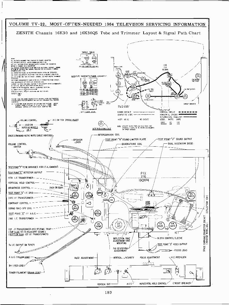
11-211-1-1
VOLUME TV -22, MOST -OFTEN -NEEDED 1964 TELEVISION SERVICING INFORMATION
ZENITH Chassis 16K30 and 16K3OQS Tube and Trimmer Layout & Signal Path Chart
NOTES:
ALL VOLTAGES :FASURED ER011 CN1SSIS TO POINTS INDICATED.
ALL VOLTAGES ARE D.L. UNIE3S OTNE0ISF. SPECIFIED.ALL D.C. VOLTAGES TO NE 441(00D NATO A VACUUM TUNE YOLOAEIERHAVING II WRENN INPUT RESISTANCE.ILL VOLTAGE IECSINIENENTS TO It WDE WITH 00 SIGNAL PRESENT., NODML
0E00110 OF CONTROLS IRO CHANNEL SELECTOR SET TO CUANNEL R USTESS
OTHERWISE SPEC1FIED.
ALL CAPACITOR VALUES IN NICR0FAR0D5 UNLESS 0111ER0ISE SPECIFIED.
ALL CAPACITOR CAPACITY TOLERANCE !SOS UNLESS OTHERWISE SPECIFIED.
ALL RESISTORS ARE !NOS TOLERANCE. CARBON. I/2 WATT UNLESS 011101111140
SPECIFIED.RESISTANCE IEARUREINNTS SHAM 01111 COIL OISCOINECTEO ERON CIRCUIT.
COIL RESISTANCES NOT GIVEN ARE UNDER ONE DIM.
CATHODE RAT TUNE AND ANODE HOSTAGE TO BE MEASURED VITO ELECTROSTATIC01 200 NIA. Ow PER VOLT NIGH VOLTAGE NEVER.
A HROVS ON POTENTIOMETER INDICATE CLOCIONISE NATATION.
AL100A00T POINTS.
CIRCLED LETTERS INDICATE ALILsf0T AND TEST POINTS.
CHASSIS
PICTURE TUSO 200 ANODE VOLTAGE TO BE MEASURED +ITN ELECTROSTATICNIl0Y0LTIESER WITH SRIOMTMSS AND CONTRAST CONTROLS FULL COUNTER-
CLACTWIRE.
CA 'v01M10 GRANGE OFECTCsf5 TO
72FOR NNE
V.V. TIES).OE .I VARIES
NECESSARY REPLACE «ITN ENACT VALUE FOUND,. TONE.
TARGET TAKER
VI V2
¡' 661cs ócc6
J R.i MI%ERI AMP. OSC.
175-451 TNRU 175-499INCL
MINIATURE BANDSWITCH TUNER (SOME 400ELs1
VOLUME CONTROL IA C SWITCH (PUSH -PUSH)
USED ON
16K3O OS MODELS
ONLY
SPACE COMMAND AUDIO MUTE CABLE (16K300S)
VOLUME CONTROLSWITCH
TEST POINT1FTO BE GROUNDED FOR I.F. ALIGNMENT
TEST POINT"C" DETECTOR OUTPUT
4TH I.F. TRANSFORMER
VERTICAL HOLD CONTROL
BRIGHTNESS CONTROL-
TEST POINT WON I.F. GRID
3RD I.F. TRANSFORMER
CONTRAST CONTROL-SOUND TAKE -OFF COIL -
TEST POINT "E" I.F. A.G.C.
2ND I.F. TRANSFORMER -
1ST I.F. TRANSFORMER AND 47.25MC. TRA( TOP SLUG 47.25 ADJACENT SOUND)(BOTTOM SLUG 1ST I.F. TRANSFORMER)
To I.F. OUTPUT ON TUNER
A G.0 (YELLOW LEAD)
B+ (RED LEAD)
TUNER FILAMENT (BROWN LEAD)
175201 MU 175-226 INC,I75-227 THEW 175-250 INCL.175-251 01011175-262 INCI175-263 72100175 -MO INCL
-SLEADSR
IN64 OR EQUIV.
SACS
TUBE POSITIONING GUIDE
-11111
ijIl `. VRECTIFIER
NO C ADDENDS BOTOSUMO AND PICTURE
SOUND CIRCUIT
COMPOSITE VIDEO 000000000.N.0E000000
VOLTS 120 AC 60 CYCLES
0(9 REPLACE TUNER NOE ONLY WITH TUBE TYPEORIGINALLY SUPPLIED BY ZENITH AND STAMPEDON TUNER CHASSIS.
INTERCARRIER COIL
TEST POINT'HN SOUND LIMITER PLATE
QUADRATURE COIL
DEFLECTION YOKEADJUSTMENT AND
MOUNTING
PIX CENTERINGADJUSTMENT
BUZZ ADJUSTMENT- F -VERTICAL LINEARITY
VERTICAL SIZE A G C
6086118
LOW WLTAITERECTIFIER
To YONE 110(71072
CIRCUIT BREAMER
MNOt _VERTICAL CIRCUIT
HORIZONTAL CIRCUIT ERNNNMENDNENeDwINTERMEDIATE FREQUENCY
MODEL WATTS AAMPS
16230 IRS I651623005 236 2.15
TEST POINT 0J" SOUND OUTPUT
DUAL SELENIUM DIODE.
WIDTH CONTROL SLEEVE
TEST POINT ODE VIDEO OUTPUT
GL a N.-FOCUS LEAD
FOCUS ADJUSTMENT
non n
A.C. INTERLOCK
HORIZONTAL HOLD CONTROL-' CIRCUIT BREAKER /
189
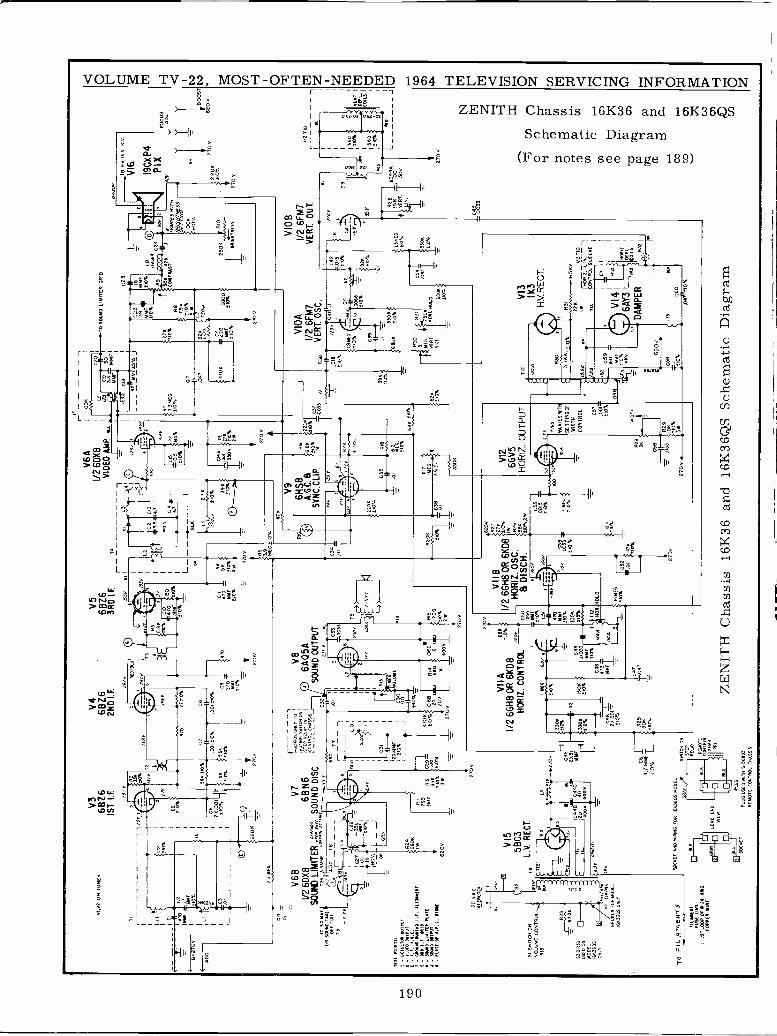
OI.V
2 O
N T
UN
ER
Ti LI
V3
V 4
V5
6816
6BZ
66B
Z6
IST
I.F
2ND
IF.
3RD
LF.
rIS
IYnt
Y
"O%
B127DY
/GC
:i° LI
CO
ffW
F0%
.05
2 24
100
6821
5
1W
rlót
DO
S
fIY T
211
8r
RE
OIB
W
If,
1f
2100
%
63
511.
SO
SC
76B
cs.0
01 ia
%.0
0!«0
%i0
01Il
tOY
.>
;I.50
i56.
-
21D
%S
IOt
'"9 Í jl
-m
%-
2700
2700
o
R3
IL
T0
V6A
1/26
DX
8V
IDE
O A
MP
.
i10
TM
MF
0%
155
M.)
p5K
MF
Sin
SI0
14W
TS
RZ
V6B
V7
V26
DX
86B
N6
SO
UN
D L
IMIT
ER
=1
SO
UN
D D
ISC
.T
O 5
0 41
41E
`C
263M
>R' t
E
93 Y
041
5004
1DC
01L0
Tu
1n1E5i.
06r
T5
-f.tr
IFO
r}L
5,B
L
I.OU
I
234 O
R
TE
ST
PO
INT
S:
C-
0010
0100
04T
Ni
000
WY
/97
- M
I= 0
101.
0 I.I
. *01
0410
51F
- 30
0 I.I
. 411
0-
304.
0 LI
WIT
EO
FIStt
; - 5
000
=T
NT
TE
0! 0
.9.1
. 010
00
SI 5
0410
00 O
NV
OLU
ME
CO
NT
RO
LM
3
3361
133
US
ED
OR
MO
DE
L16
1136
05O
NLY
R23
1200
0414
1T06
LOC
.
620V V
1552
58C
3L.
V. R
EC
T.
0J
oweu
em6u
BR
OK
EN
FO
R M
OD
EL
0036
05 O
NLY
TO
f3LR
ME
NT
S
',LA
ME
NT
FU
SE
LIN
O12
21 L
OO
P 0
2424
MI6
CO
PP
ER
WIR
E
T M
HO
WIR
ING
FO
R 1
6336
05 M
OD
EL
CR
OP
2700
.233
605
ON
LY T
O1
6 3.
0709
ON
1
iSY
EP
RE
LAY
INI
I`fiO
NT
RO
L (x
0551
5
100 C05
-120
5
MM
FH
6Á05
AS
OU
ND
OU
TP
UT
2.41
4
VIT
AI/2
6GH
8OR
6K
D8
HO
RIZ
CO
NT
RO
L
330.
1Í10
% 025
0.1M
/4M
>%
50.
210%
T1
WS
TC
N O
N
ST
EP
RE
LAY
RE
MO
TE
CO
NT
RO
L',D
AR
PR
1
61.0
0
PLU
G 1
55E
O W
IN S
.568
93
RE
MO
TE
CO
NT
RO
L 04
5595
1503
0101
007
T+
0.7
2700
270
6e0
01.
=27
001
R5
13.9
+MEG
41 I
Inv
02_5
.5
20.5
BLX 5
OT
O
Ito21
01
3º03
oB
o 330
10%
0
TS r -
- -
- -
a0K
C0
1
I)4
CA
5O
'
ÑA
iM
MF
2700
CM
TO
SW
RO
LIM
ITE
R G
RID
L--
-O
YM
MF
IS%
J
3.35
2E0
010Y
.
0/00
216 0%
B2
A
Y2Ó
101
.
C23
=22
4C
=M
MF
FSa%
2a
co: .
31"
R8
7.5K
0t
SW
nD
270
v
0
NW
2T
gV
qA6p
/ES
gWIT
HS
ET
T/H
GS
S
a0K
010%
2501
1 R
10
M10
T41
655
V9
6H13
A.6
.9S
YN
C.C
LIP
.
C3R
.01
2113
%
Ra
6.BN
22(R
c
'610
%12
101
W-ói3
01
t0.
IOar
e
w0 D
I
7004
82M
010%
635
RIB
.01
iF4
2109
.
R17
I ME
O
LO C
.
330K
601U
%
10%
396
'10%
C38 El
01e
210%
VID
A1/
2 6F
M7
VE
RT
.OSC
.
LBM
EG
210% 03
9
VIO
B1/
2 6F
M7
VE
RT
. OU
T.
U2
=m
YC
<1
SID
%
EE
000
60_1
ox-
B2K
7Eax
1=
6600
110%
20
101
06V
6Ri
SIZ
E
R21 500
0030 MOLO 60
620V
VIIB
27K
I/2 6
GH
8 0R
6K
D8
1".
- H
OR
IZ. O
SC
.R
26
G50
eD
ISC
H.
áóxz
W10
0 F
iaL
C51
2r-
6NT
0vr
Sq% 10
06 012
XO
R. H
OLD -o6
ov
'.Iar
uoi
110
000
VI2
6GV
5H
OR
IZ. O
UT
PU
T
59 .53
VA
RIE
S %
TT
N
5E 1
1106
0FW
IDT
H
CO
NT
RO
L 057
.001
=51
0%
WO
..-_.
1C
56
A33
IÓK9
2100
3W
T12
la-
-9Y
LO
ME
O.
tax
3306
110%
Sn R
30
3.3W
.
^ IL1lt
e21
0%
VI3 IK3
H.V
. RE
CT
.
031
226
ITT
Jta
Y
.`-D
059
GR
NK
VI4
Ff
TI*
Q
.D
AM
PE
R ÍM
<E
,
620v
-
IC58
L13
060
.041
74I2
10%
16.5
30
ITIO
wR
á.T
17J
NT
NO
L 60
6000
,
I
10 0
II¡
NM
IO
FL
OILS
0__
ZE
NIT
H C
hass
is 1
6K36
and
16K
36Q
S Sc
hem
atic
Dia
gram
Pr
TO
11V
165
K.V,
VI6
.
19C
X P
4P
I X
FO
CU
S60
.0
0.
-VIB
00S
T2T
OV
620v
220K
2700
2100
12 a
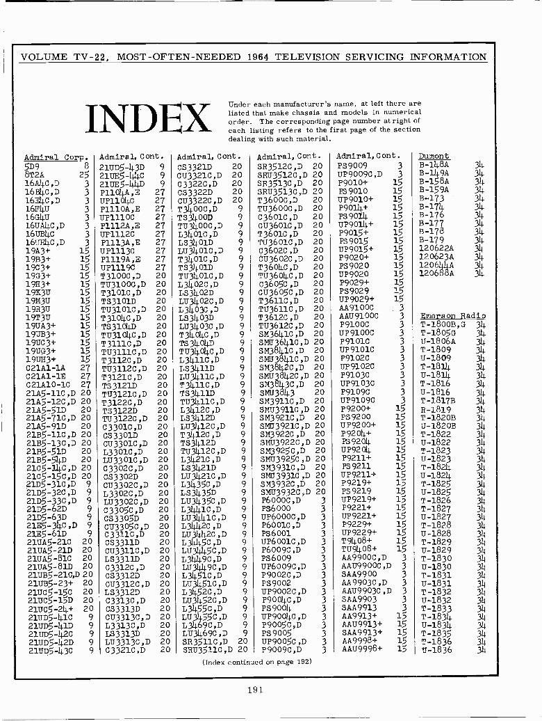
VOLUME TV -22, MOST -OFTEN -NEEDED 1964 TELEVISION SERVICING INFORMATION
INDEXAdmiral Corp.5D9 8
8T2A 2516A4c,D 316B4C,D 316FJ1C,D 316F4Ú 316G4U 316UA4C,D 3
16uB4c 316UFJ1C,D 3
19A3+ 1519B3+ 1519c3+ 1519G19x3+
1519K3Ú 1519M3u 1519R3u 1519T3u 1519uA3+ 1519ÚB3+ 1519UO3+ 1519ÚG3+ 151913x3+ 15C21A1-1A 27C21A1-1E 27C21A10-1C 2721A5-11C,D 2021A5-12C,D 2021A5 -51D 2021A5-71C,D 2021A5 -91D 2021B5-11C,D 2021B5-13C,D 2021B5 -51D 2021B5 -54D 202105-14C,D 202105-15C,D 2021D5-31C,D 921D5-32C,D 921D5-33C,D 921D5 -62D 9
21D5 -63D 921E5-34C,D 9
21E5 -61D 921UA5-21C 2021UA5-21D 2021UA5-81C 2021UÁ5 -81D 2021ÚB5-21C,D 2021ÚB5-23+ 2021UC5-150 2021UC5-15D 2021UC5-24+ 2021UD5-41C 921UD5-41D 921UD5-42C 921UD5-42D 921uD5-43c 9
Admiral, Cont.
21UD5-43D 921UE5-4.4C 921u.E5-1111D 9P1104A,E 27UP1104C 27P1110A,E 27UP1110C 27P1112A,E 27UP1112C 27P1113A,E 27UP1113C 27P1119A,E 27UP1119C 27T3100C,D 20TU3100C,D 20T3101C,D 20TS3101D 20TU3101C,D 20T3104C,D 20TS3104D 20TU3104C,D 20T3111C,D 20TU3111C,D 20T3112C,D 20TU3112C,D 20T3121C,D 20TS3121D 20TU3121C,D 20T3122C,D 20TS3122D 20TU3122C,D 20C3301C,D 20CS3301D 20CU3301C,D 20L3301C,D 20LU3301C,D 20C3302C,D 20CS3302D 20CU3302C,D 20L3302C,D 20LU3302C,D 20C3305C,D 20CS3305D 20CU3305C,D 20C3311C,D 20CS3311D 20CU3311C,D 20LS3311D 20C3312C,D 20CS3312D 20CU3312C,D 20LS3312D 20C3313C,D 20CS3313D 20CU3313C,D 20L3313C,D 20LS3313D 20LU3313C,D 20C3321C,D 20
Under each manufacturer's name, at left there arelisted that make chassis and models in numericalorder. The corresponding page number at right ofeach listing refers to the first page of the sectiondealing with such material.
Admiral, Cont. Admiral, Cont.
CS3321D 20 SR3512C,D 20CU3321C,D 20 sRU3512C,D 20C3322C,D 20 SR3513C,D 20CS3322D 20 SRU3513C,D 20CU3322C,D 20 T3600C,D 20T3400C,D 9 TU3600C,D 20TS3400D 9 C3601C,D 20TU3400C,D 9 CU3601C,D 20L3401C,D 9 T3601C,D 20LS3401D 9 TU3601C,D 20LU3401C,D 9 C3602C,D 20T3401C,D 9 CU3602C,D 20TS3401D 9 T3604C,D 20TU3401C,D 9 TU3604C,D 20L3402C,D 9 C3605C,D 20LS3402D 9 CU3605C,D 20LU3402C,D 9 T3611C,D 20L3403C,D 9 TU3611C,D 20LS3403D 9 T3612C,D 20LU3403C,D 9 TU3612C,D 20T3404C,D 9 SM3641C,D 20TS3404D 9 SMIT3641C,D 20TU3404C,D 9 SM38 1C,D 20L3411C,D 9 SMU341C,D 20Ls3411D 9 SM3842c,D 20LU3411C,D 9 SMU39842C,D 20T3411C,D 9 SM3843C,D 20TS3411D 9 SMU3843 20TU3411C,D 9 SM3911C,D 20L3412C,D 9 SMU3911C,D 20LS3412D 9 SM3921C,D 20LU3412C,D 9 SMU3921C,D 20T3412C,D 9 SM3922C,D 20TS3412D 9 SMU3922c,D 20TU3412C,D 9 5M3925C,D 20L3421C,D 9 SMU3925C,D 20LS3421D 9 SM3931C,D 20LU3421C ,D 9 SMU3931C ,D 20
L3435C,D 9 SM3932C,D 20
LS3435D 9 SMU3932C,D 20
Lu3435C,D 9 P6000c,D 3
L31011C,D 9 PS6000 3LU3441C,D 9 UP6000C,D 3
L3442C,D 9 P6001C,D 3LU3442C,D 9 PS6001 3L3415C,D 9 UP6001C,D 3
LU31015C,D 9 P6009C,D 3
L3449c,D 9 Ps6o09 3Lu3449c,D 9 uP6009c,D 3
L3451c,D 9 P9002C,D 3
LU3451C,D 9 PS9002 3L3452C,D 9 UP9002C,D 3LU3452C,D 9 P9004C,D 3
L3455C,D 9 PS9004 3LU3455C,D 9 UP9004C,D 3
L3469C,D 9 P9005C,D 3
LU3469C,D 9 PS9005 3SR3511C,D 20 UP9005C,D 3SRU3511C,D 20 P9009C,D 3
(Index continued on page 192)
Admiral, Cont.PS9009 3UP9009C,D 3P9010+ 15PS 9010 15UP9010+ 15P9014+ 15PS9014 15UP9014+ 15P9015+ 15R39015 15UP9015+ 15P9020+ 15PS9020 15ÚP9020 15P9029+ 15PS9029 15UP9029+ 15AA9100C 3AAU9100C 3P9100C 3UP9100C 3P91o1C 3UP91o1C 3P9102C 3UP91o2C 3P9103c 3UP9103C 3P9109C 3uP9109C 3P9200+ 15PS9200 15UP9200+ 15P9204+ 15R39204 15UP9204. 15P9211+ 15R39211 15UP9211+ 15P9219+ 15PS9219 15UP9219+ 15P9221+ 15ÚP9221+ 15P9229+ 15UP9229+ 15T9408+ 15TU9408+ 15AA9900C,D 3AAU9900C,D 3
SAA9900 3AA9903c,D 3AAU9903C,D 3
SAA9903 3SAA9913 3AA9913+ 15AAU9913+ 15SAA9913+ 15AA9998+ 15AAU9998+ 15
DumontB -148A 34B -149A 348-158A 34B -159A 34
syi71 34B-176 34B-177 34B-178B-179 34120622A 34120623A 34120644A 34120688A 34
Emerson RadioT-1800B,G 34T -1805G 34U -1806A 34T-1809 34u-1809 34T-1814 34u-1814 34T-1816 34U-1816 34T-18178 34R-1819 34T -1820B 34u -1820B 34T-1822 34u-1822 34T-1823 34u-1823 34T-1824 314
13-1824 34T-1825 34
u-1825 314
T-1826 34T-1827 34U-1827 34T-1828 34
u-1828 314
T-1829 34U-1829 34T-180 3413-1830 34T -18u-18311
314j
T-1832 34u-1832 3)4T-1833 34T-1834 34U-1834 34T-1835 34T-1836 34U-1836 34
191
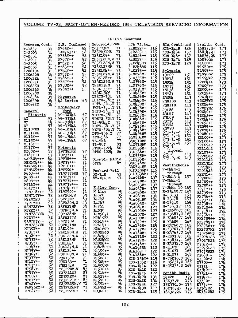
Z6T
SLI ZHgg££xW tiLI zxSB££x tiLt ++95££x tiLt ++o5££x t(Lt ++zti££x tiLt ++I17££x ITLI
tiLt ++Iiɣx Ix
tiLI ++90(131 9A00E£x
SLt ++090£1 9L1 s9r>,.SLo£L
5LI 5315L0£1 SLt ++Ztp£1 NA 113WL3o£L 5LI SZ+930£1 5LI 99M530£L SLI 3WL9L93a+1 la ++98L93iZ1
£LI si9'90191, £LI 51,`0£319t £Li +t`L£x51 £LI L'L£x5t £LI OZxt7L
521 Víitit-Sox
LZI a£1TL-5051
LZI V£í(L-9011 tl£i ant -Sox 17£1 a3t1I-5O51
Z3I It11t-SOx
ZZT xI1Tt:-SOx 331 t-SOx Vttl 511 +Z9£1-SOx 511 +]C9£I-SOx ¿El +1499tV16 3z1 ++£81Vt16 331 su3gtVt16 331 +W9LtV116 ZZt +WZLIVtIb 3Z1 +WILIVti6 63I +W091Vt16 SZI +WL£IV176 521 +W9£tVt16
96 ++o0£6W 96 ++9365114 96 ++t65 96 ++o65114 96 ++61511W 96 ++91517W 56 ++31511i 56 +1,19o5tiel
56 ++t(o5tm 56 ++30511W 56 ++oo517W 56 ++o5£11W 56 HMugZg£W 56 ++93g£W 56 HMti3g£141
56 xgi7Zg£W 56 aO339£W 56 a09199W 56 ++tT193W
IL MOLZHd£zx IL dW93Hd£3x IL M`WSzud£2x £g dWlzHd£91. £g +03Hd£3A £g dWI3d3x 19 M`WOzd£zx IL Mt1£tx£2 IL ++£ix£3 IL W9£Ix£2 IL M'1462131£9
IL ++93131£2 IL M'WLztx£3 IL ++t(GI3i£3 IL dW£ZIx£? IL M`INiZZtx£z IL M'Wo3tx£3 IL +6o1x£? IL sw1£Hd£3
35 ++L39LH 35 ++L39LWVa 35 ++AZ9LW z5 ++xI9LW 35 ++7,09LW z5 ++L65211 z5 ++x85LW 35 ++x071Yd 35 ++.A-21L11v.'
35 ++LL£LW ?5 ++x9£LW 35 ++xS£LW 25 ++x11£LH 35 ++Ati£LY1
25 ++x££LW 35 ++7,2£LW 25 ++LI£LW 35 ++Lo£LW 35 aMA£3LWVa
oTpsg ImuBZ
S91 n'££250 -H 591 n'I£350-H 591 11'0£95O -H 591 £Lotix-H 591 tLottx-H 591 oL01ix-H S91 n'3£901 -H 591 n'I£g£x-H 591 tI'o£g£x-H 591 n'£9L£x-H 591 n'I9L01-H 59t 11'09L£x-H
5LI ++58L3)iH 591 58901-H 531 +413£IV16 56 ++Z19314 IL Mo£Hd£Z 35 ++x2LWVo tiLt ++59L25114
2rI++812,22 S91 n'£89£x-H L31 +W6oIV116 56 Hg019314 IL MOL311d£3 z5 ++x£3L14
tILI 7LZx -TILT ++311L231
591 n'Ig9£x-H 591 n'og9£x-H 591 11`£ti9£1-H
L3t +WLOtV1i6 L31 +IZOtVtl6 LZI +1,118oVt16
56 V'oSNtlt 56 oNtj1 56 511r1i
IL dW9zHd£3 IL M`Y15zud£9 £g dWI2Hd£3
35 aMLZZLIVd 25 ++Lz3LW 35 ++x22LWV0
la++L£L3x £LI ++912211 9
591 Oti9£L-H LSt 9L-K,,,,,ti£I
L51 ££ti£d-H
at +14C901/16 AW119oVt16
L£t £(?Vt19
56 £17rtit 56 212n1 56
£g M'Wo2H1£3 19 dWT3d £3 £g M'W03d£2
35 aaxizLW a Oz 35 axLW
35 ++A61LWVd
£Lt ++LTLZx
£LI ++9oL331
L51 n'0£t(£d-H 591 0I-i(t1t(2-A
gEnoaqn L£I +i+IL£OVt19
L£t +14££OVtl9
8030tTC 56 T'I W IL +s05L61L
IL +++0116l21 IL +++6£161L
35 ++xgILWVd t(t( ++xL191rt tIi-(
++A919W daop ootTud
£LI ++5oL331 L£I +W0£0V19 IL +++g£L61L in +++6091,1 I-t(tih¿-A £Lt 3uo0L231 LSI tl-£44¿-A LEI +W930Vt19 16 WI1f1-98 LL ++L£d6u 1111 +++909H £LI ++I£39x M9noaq4 511 +W9£5X01£ 16 31111-88 LL HHH5£d6u 10i +++90914 £LI zr17i39x £LI 3dtit331
511 +145£5Xat1£ IIsq-PasxoBd IL +005L61 1111 +++509Wgs 1-£ t¡tfz-A
9'I£i99x esnoq2uTseM 511 AWtI8Sat1£ 511 AW9L5a1£ 1.9 53,i9 IL +++0171,6T
IL +++6£161 I(1( +++50911Y5£Lt
nn+++t1o9rAgS
SLI Z`J50Z91
£LI ++LztZx
en 0-'6-5L5 1-119-5L5
511 +I955at1£ StI +14555a11 5tt +W9£5Q17£
oTPBu oTdtud10
173Zi-SH1H
IL +++9£161 LL ++L£aói
1711 +++1109WV9 LS ++xIgIW
£Lt 3IOtIZx qoaq t -5L5 511 +Y15£Sa1i£
99 99 17231-SHLd
LL HHHS£dót L5 ++A081W LS ++ALtIW atoao4oyl
£LI ++g013x 151 1-'1-12.5 511 AWBISOtl£
51I AWOtSOtI£ £8 L85-sL L5 ++L91IW
£Lt ++OOtZx 151 z- I-115 Stt nWtroSptt£
LL 985-51 LL
L9 v1511-JM LS ++A£IIW
5LI ++gozL 151 1i-£-ILS Tc...,-L( 51I Ar9617oti£
985-sLx LL x'985-sLa
L9 Vt7t7£17-0M
L9 v1111 -OM LS ++LZI1W L5 JSLIIIW
5LI ++ Lo31 SLI ++55o31
£1TI o6A£z £11 z8L£z
511 +W9LtIOt1£
511 +1,152.0 -tie
IL A't185-s1xM IL x`t1gS-91aM
L9 Vtit3t1-0M
L9 V115££-JM L5 JHLoii LS xs
SLI ++95o3L 5LI ++tltlozl
5L1 ++z1loZ1
£ílt gLL£3 £ 68£3 ctn. Lg'I£3
511 +WL9tlOt1£ 511 +W991ipíl 511 +W5917017£
IL L`ti85-S1 IL xti85-s1aaL IL 115-s1aL
L 9 V1I1i££-oM L9 Vtlt££-JM L9 VtTC3£-oM
nil xw 15 IN
oTa4oeld 5L1 ++ot(0Z1 £tTL 98'I£Z 511 +Y16St1Oti£ IL
x`g5-SLiI9 pasM tsaeue0
SLI +z+L9Zo31
SLI V45303,1 £LI ++titozx £LI 4.+310331 £LI 4-1-9003:1 £LI ++oo9x £LI ++t100351
51.1 3+56631
£11t Oi1H£Z £tft OOIH£9 £tit t180£3
151 119161 151
9£-d6151I
151 5£dót 151 t1ldót
151 Ztd61
511 +idgStlOt1£ 511 +IdoStiOti£
511 +W9ífOt1£ 511 +W9311pti£
+i,153t1Oti£
511 4.,060-% 511 +W9L£OtI£ 511 +W95£o11£ 5t1 +W55£O1£
IL x'195-9Lxd IL A 1I85-S1aN IL A1185-91xs1 IL tlg5-S1xsZ IL Mti£tx£Zx IL ++££Tx£3x IL IdZ£Tx£3x IL M`W69Ix`r3x IL ++93Ix£9A
á.ietuoB4uoW
se ae £9 T S 3ti
t1£ 0Z99031 ya659oZt yV859oZ1
tic 0939021 t1£ c(939021 11£ 052903I 11£ Vt12903t ti£ VZ39o31
YOAuu28jn1
35 ++L69LW 35 ++x88LW 35 ++ALgLW 35 ++L98LW
5Lt 30066I1 151 60d61 511 +4419L3Ot1£ IL M`WL3úi£3A 35 ++A58LW ti£ 903903I 5Lt ++58611 BTuB Ids 511 ++5L301£ IL ++tT¿u£ZL 35 ++AtiBLW 11£ V6T9031 5LI ++09611 511 SH9tI3111£ IL dW£ZIH£ZA 35 ++A£gLW 1.¡,.' 5ooz-a £LI ++039tH 631 SLt7t-sox 51T su5h2gíi£ IL M`W331x£ZA 35 ++1.381.14tl£ 5003-0 £LI 5b9£319I 631 VL1t-sox 511 ++L39St1£ IL M'W03t}i£9x 35 ++.4L9LW tl£ tiooZ-a
£LI 1b`9£29t L£1 +91it-5031 511 ++993ati£ IL +6otx£32. 95 ++A99LW ti£ 17003-0
£LI +Wti£3191 LIT V911t-SOx 511 ++5920£ IL EN-Ea/11'3x 35 ++A£9LWVd tqt. £009-0 £LI +Zj'E£x9I 51t ++333H17£ IL Mo£ud£3A 25 ++x£9Lx ti£ L£gI-L 531 Utitlr_-SOx
4uo0 'q4TueZ penuTluoO'VOH vuDp'sloao4oW
XSQUI penupwO dJ quop'uosaecad a040TA VOH
panu?IuoD
NOI.LVU1I2I03NI ONIDIA2i3S NOISIA3'i31, V961 Q3Q33N-N31,30-1,SOIIII ZZ-Ai. 3U1If1rI0A

r
, -.:%X'1
,,
Another
Supreme Publications
Service Manual