morphology and structure of highly crystalline polyaniline films
TRANSCRIPT
AIR ENGINE
T.K.I.E.T. WARANANAGAR Page 1 MECHANICAL ENGG DEPT.
ACKNOWLEDGEMENT
It gives me an immense pleasure to present a report on the successful
completion of my seminar entitled “air engine” .I express my deep sense of gratitude
to my guide for his valuable guidance rendered i all phases of seminar. I think of his
whole hearted assistance, advice and expert guidance towards making my seminar
success.
My special thank to respected Principal Dr. A. V. Anekar and Head of the
Department Prof. N. S. Hanmapure for their keen interest, encourage and excellent
support.
I would also like to express my thank to all of other Staff members of college
who helped us directly & indirectly during the completion of this seminar.
Date: SINCERELY,
Place: Warananagar MR. RAVINDRA JAGANNATH SUTAR
AIR ENGINE
T.K.I.E.T. WARANANAGAR Page 2 MECHANICAL ENGG DEPT.
INDEX
SR.NO
CONTENTS
PAGE NO.
1.
INTRODUCTION
5
2.
DESCRIPTION OF MECHANICAL
COMPONENTS
7
3.
STUDY OF THE COMPRESSED AIR ENGINE
AND ITS WORKING
24
4.
DESIGN OF COMPONENTS
27
5.
CASE STUDY
29
6.
ADVANTAGES
30
7.
DISADVANTAGES
30-31
8.
APPLICATION
31
9.
CONCLUSION
32
10.
REFERENCES
33
AIR ENGINE
T.K.I.E.T. WARANANAGAR Page 3 MECHANICAL ENGG DEPT.
LIST OF FIGURE
FIG.NO CONTENTS PAGE NO.
1 COMPRESSED AIR ENGINE 6
2 CRANK SHAFT 8
3 CAM NOMENCLUTURE 11 & 13
4 PRESSURE ANGLE 12
5 CAM SHAFT TERMINOLOGY 13
6 PISTON 14
7 CYLINDER 15
8 CUTAWAY OF BALL BEARING & ROLLER BEARING 16
9 BALL & ROLLER THRUST BEARING 16
10 CUTAWAY VIEW OF SPHERICAL ROLLER THRUST
BEARING & RADIAL TAPERED ROLLER BEARING
17
11 BEARING SUPPORT 17
12 BALL BEARING 18
13 CONNECTING ROD 19
14 VALVE 21
15 TIMING GEAR 22
16 NOZZLE 23
17 WORKING OF AIR ENGINE 24
18 CAMSHAFT GEAR 28
19 VALVE TIMING DIAGRAM 28
AIR ENGINE
T.K.I.E.T. WARANANAGAR Page 4 MECHANICAL ENGG DEPT.
ABSTRACT
This paper is reports on the review of compressed air engine for the design and
development of single cylinder engine which can be run by the compressed air.
Current four strokes single cylinder engine (bikes/moped) can be run on the
compressed air with a few modifications that are the main objective of the study.
Compressed air filled by electricity using a compressor.
The electricity requirement for compressing air has to be considered while computing
overall efficiency. Nevertheless the compressed air vehicle will contribute to reducing
a air pollution and tend to zero pollution level and promoting great environment. Main
advantage of this engine is that no hydrocarbon fuel required means no combustion
process is take place.
Today the whole world is in search of alternative fuel, to fulfill the need of
fossil fuel because in coming years there will be scarcity of fossil fuel. There are
couples of option of alternative fuel such as solar power, tidal power, geo-thermal
power, etc. and one of them is Compressed Air. The important condition for the
alternative fuel is it should be renewable and eco-friendly. In India only 52.5% of
rural house have access to electricity and 93.1% in urban house. Overall 35.5% of
total Indian population doesn’t have electricity access to their home. Compressed Air
Engine is a better option to produce power to run automobile, generators etc. This
paper contains design and dynamic analysis of a light weight single stroke compressed
air engine it does not required any of the fossil fuels like petrol, diesel, CNG, LPG,
hydrogen etc. to run engine and no power is required to start up engine only
compressed air valve is to be opened. It works on compressed pressure air and hence
is pollution free and 100% eco-friendly.
Keywords- Compressed air engine, zero pollution, air fuel, eco-friendly
engine, single stroke engine
AIR ENGINE
T.K.I.E.T. WARANANAGAR Page 5 MECHANICAL ENGG DEPT.
Chapter 1. Introduction
1.1. Compressed Air Engine Basics:
A Compressed-air engine is a pneumatic actuator that creates useful work by
compressed air. A compressed-air vehicle is powered by an air engine, using
compressed air, which is stored in a tank. Instead of mixing fuel with air and burning
it in the engine to drive pistons with hot expanding gases, compressed air vehicles
(CAV) use the expansion of compressed air to drive their pistons.
They have existed in many forms over the past two centuries, ranging in size
from hand held turbines up to several hundred horsepower. For example, the first
mechanically-powered submarine, the 1863 Plongeur, used a compressed air engine.
the laws of physics dictate that uncontained gases will fill any given space. The easiest
way to see this in action is to inflate a balloon. The elastic skin of the balloon holds
the air tightly inside, but the moment you use a pin to create a hole in the balloon's
surface, the air expands outward with so much energy that the balloon explodes.
Compressing a gas into a small space is a way to store energy. When the gas expands
again, that energy is released to do work. That's the basic principle behind what makes
an air car go. Some types rely on pistons and cylinders, others use turbines. Many
compressed air engines improve their performance by heating the incoming air, or the
engine itself. Some took this a stage further and burned fuel in the cylinder or turbine,
forming a type of internal combustion engine.
One manufacturer claims to have designed an engine that is 90 percent
efficient. Compressed air propulsion may also be incorporated in hybrid systems, e.g.,
battery electric propulsion and fuel tanks to recharge the batteries. This kind of system
is called hybrid-pneumatic electric propulsion. Additionally, regenerative braking can
also be used in conjunction with this system.
1.2. History: (a) The first compressed-air vehicle was devised by Bompas, a patent for a locomotive
being taken out in England in 1828. There were two storage tanks between the frames,
with conventional cylinders and cranks. It is not clear if it was actually built. (Knight,
1880)
(b) The first recorded compressed-air vehicle in France was built by the Frenchmen
Andraud and Tessie of Motay in 1838. A car ran on a test track at Chaillot on the 9th
July 1840, and worked well, but the idea was not pursued further.
AIR ENGINE
T.K.I.E.T. WARANANAGAR Page 6 MECHANICAL ENGG DEPT.
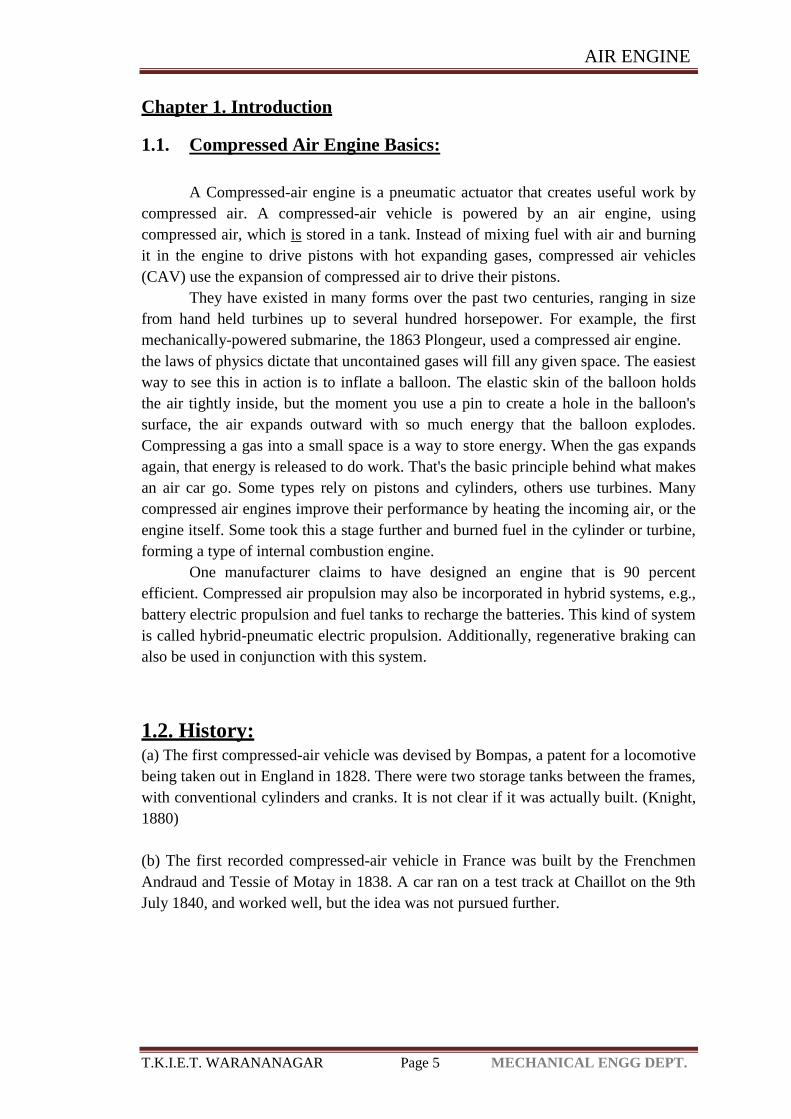
Compressed-Air Engine
Fig: 1.1
(c) In 1848 Barin von Rathlen constructed a vehicle which was reported to have been
driven from Putney to Wandsworth (London) at an average speed of 10 to 12 mph.
(d) At the end of 1855, a constructor called Julienne ran some sort of vehicle at Saint-
Denis in France, driven by air at 25 atmospheres (350 psi), for it to be used in coal
mines.
(e) Compressed air locomotives were use for haulage in 1874 while the Simplon
tunnel was being dug. An advantage was that the cold exhaust air aided the ventilation
of the tunnel.
(f) Louis Mékarski built a standard gauge self-contained tramcar which was tested in
February 1876 on the Courbevoie-Etoile Line of the Paris Tramways Nord (TN),
where it much impressed the current president and minister of transport Maréchal de
MacMahon. The tramcar was also shown at the exhibition of 1878 as it seemed to be
an ideal transport method, quiet, smooth, without smoke, fire or the possibility of
boiler explosion.
(g) The compressed-air locos were soon withdrawn due to a number of accidents,
possibly caused by icing in the pipes of the brakes, which were also worked by
compressed air.
(h) In Louis Mékarski built a standard gauge self-contained tramcar which was tested
in February 1876 on the Courbevoie-Etoile Line of the Paris Tramways Nord (TN),
where it much impressed the current president and minister of transport Maréchal de
MacMahon.
AIR ENGINE
T.K.I.E.T. WARANANAGAR Page 7 MECHANICAL ENGG DEPT.
The tramcar was also shown at the exhibition of 1878 as it seemed to be an ideal
transport method, quiet, smooth, without smoke, fire or the possibility of boiler
explosion.
Chapter 2:
2.1. Description of Mechanical Components
2.2. Study of the Compressed Air Engine and its Working
2. Description of Components of Compressed Air Engine:
Various Mechanical parts used in engine are:
1. Crank shaft
2. Camshaft
3. Piston cylinder
4. Valves
5. Connecting rod
6. Roller bearing
7. Timing gear
8. Nozzle
2.1. Description of Mechanical Parts:
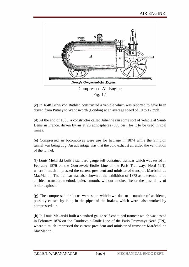
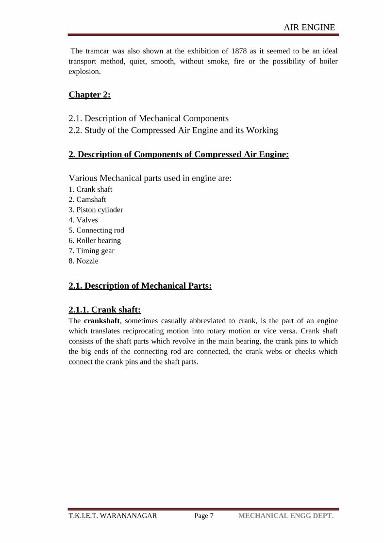
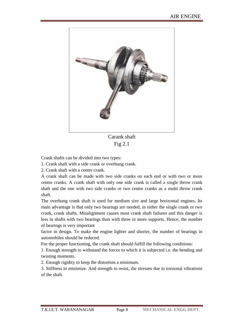
2.1.1. Crank shaft:
The crankshaft, sometimes casually abbreviated to crank, is the part of an engine
which translates reciprocating motion into rotary motion or vice versa. Crank shaft
consists of the shaft parts which revolve in the main bearing, the crank pins to which
the big ends of the connecting rod are connected, the crank webs or cheeks which
connect the crank pins and the shaft parts.
AIR ENGINE
T.K.I.E.T. WARANANAGAR Page 8 MECHANICAL ENGG DEPT.
Carank shaft
Fig 2.1
Crank shafts can be divided into two types: 1. Crank shaft with a side crank or overhung crank.
2. Crank shaft with a centre crank.
A crank shaft can be made with two side cranks on each end or with two or more
centre cranks. A crank shaft with only one side crank is called a single throw crank
shaft and the one with two side cranks or two centre cranks as a multi throw crank
shaft.
The overhung crank shaft is used for medium size and large horizontal engines. Its
main advantage is that only two bearings are needed, in either the single crank or two
crank, crank shafts. Misalignment causes most crank shaft failures and this danger is
less in shafts with two bearings than with three or more supports. Hence, the number
of bearings is very important
factor in design. To make the engine lighter and shorter, the number of bearings in
automobiles should be reduced.
For the proper functioning, the crank shaft should fulfill the following conditions:
1. Enough strength to withstand the forces to which it is subjected i.e. the bending and
twisting moments.
2. Enough rigidity to keep the distortion a minimum.
3. Stiffness to minimize. And strength to resist, the stresses due to torsional vibrations
of the shaft.
AIR ENGINE
T.K.I.E.T. WARANANAGAR Page 9 MECHANICAL ENGG DEPT.
4. Sufficient mass properly distributed to see that it does not vibrate critically at the
speeds at which it is operated.
5. Sufficient projected areas of crank pins and journals to keep down the bearing
pressure to a value dependent on the lubrication available.
6. Minimum weight, especially in aero engines.
The crank shafts are made much heavier and stronger than necessary from the
strength point of view so as to meet the requirements of rigidity and vibrations.
Therefore, the weight cannot be reduced appreciably by using a material with a very
high strength. The material to be selected will always depend upon the method of
manufacture i.e. cast, forged, or built up. Built up crank shafts are sometimes used in
aero engines where light weight is very important.
In industrial engines, 0.35 carbon steel of ultimate tensile strength 500 to 525
MPa and 0.45 carbon steel of ultimate tensile strength of about 627 to 780 MPa are
commonly used. In transport engines, alloy steel e.g. manganese steel having ultimate
strength of about 784 to 940 MPa is generally used. In aero engines, nickel chromium
steel having ultimate tensile strength of about 940 to 1100 MPa is generally used.
Failure of crank shaft may occur at the position of maximum bending; this may
be at the centre of the crank or at either end. In such a condition the failure is due to
bending and the pressure in the cylinder is maximal. Second, the crank may fail due to
twisting, so the connecting rod needs to be checked for shear at the position of
maximal twisting. The pressure at this position is the maximal pressure, but only a
fraction of maximal pressure.
2.1.2. Camshaft:-
A camshaft is a shaft to which a cam is fastened or of which a cam forms an
integral part. The relationship between the rotation of the camshaft and the rotation of
the crankshaft is of critical importance. Since the valves control the flow of the
air/fuel mixture intake and exhaust gases, they must be opened and closed at the
appropriate time during the stroke of the piston. For this reason, the camshaft is
connected to the crankshaft either directly, via a gear mechanism, or indirectly via a
belt or chain called a timing belt or timing chain.The camshaft not only opens and
closes your valves to let air in and out, but determines when and for how long the
valves remain open. With this in mind, let’s talk about what happens as the engine
spins. What follows next is a basic explanation of four-cycle engine operation,
described in relation to the four valve events. For each rotation of the cam, we have
four valve events. The crankshaft rotates twice for each revolution of the camshaft, so
four valve events happen for every two revolution of the engine in four stroke engine.
AIR ENGINE
T.K.I.E.T. WARANANAGAR Page 10 MECHANICAL ENGG DEPT.
Event 1 - Intake valves opening
The camshaft opens the intake valve, and the piston moves down the cylinder. As the
pressure drops in the cylinder, the air starts moving past the intake valve to fill the
cylinder. This period of the engine cycle is known as the intake stroke.
Event 2 - Intake valves closing
At some point, usually after the piston reaches the bottom of the intake stroke, the
intake valve closes. The piston moves up the cylinder, beginning the compression
stroke and compressing the fuel/air mixture within. At some point, usually before the
piston reaches the top of the compression stroke, the spark plug ignites the mixture,
causing it to burn and expand rapidly. The crankshaft has rotated once at this point.
Event 3 – Exhaust valves opening
After the piston reaches the top of the compression stroke, pressure from the burning,
expanding mixture pushes the piston back down the cylinder. The exhaust valve starts
to open, usually before the piston is all the way down, allowing some of the burnt
gasses to exit the cylinder. This is commonly referred to as the blow down phase. The
piston begins to move back up, forcing the rest of the hot gas out of the cylinder.
Event 3 – Exhaust valves closing
As the piston moves back up the cylinder, the exhaust valve remains open, usually
until slightly after the piston reaches the top of the cylinder. We refer to this as the
exhaust stroke. As the piston reaches the top again, the intake valve begins to open
again, often before the exhaust valve is fully closed, and the whole cycle begins anew.
The period when both valves are open simultaneously is referred to as “overlap.” The
crankshaft has now gone around twice.
AIR ENGINE
T.K.I.E.T. WARANANAGAR Page 11 MECHANICAL ENGG DEPT.
Cam Nomenclature;-
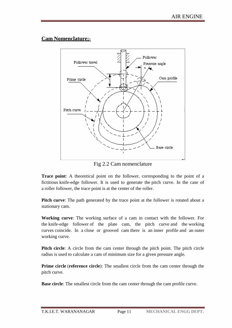
Fig 2.2 Cam nomenclature
Trace point: A theoretical point on the follower, corresponding to the point of a
fictitious knife-edge follower. It is used to generate the pitch curve. In the case of
a roller follower, the trace point is at the center of the roller.
Pitch curve: The path generated by the trace point at the follower is rotated about a
stationary cam.
Working curve: The working surface of a cam in contact with the follower. For
the knife-edge follower of the plate cam, the pitch curve and the working
curves coincide. In a close or grooved cam there is an inner profile and an outer
working curve.
Pitch circle: A circle from the cam center through the pitch point. The pitch circle
radius is used to calculate a cam of minimum size for a given pressure angle.
Prime circle (reference circle): The smallest circle from the cam center through the
pitch curve.
Base circle: The smallest circle from the cam center through the cam profile curve.
AIR ENGINE
T.K.I.E.T. WARANANAGAR Page 12 MECHANICAL ENGG DEPT.
Stroke or throw: The greatest distance or angle through which the follower moves or
rotates.
Follower displacement: The position of the follower from a specific zero or rest
position (usually its the position when the follower contacts with the base circle of the
cam) in relation to time or the rotary angle of the cam.
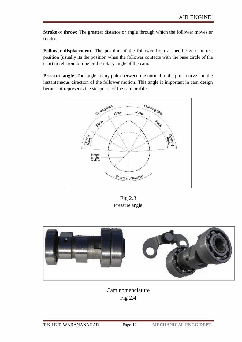
Pressure angle: The angle at any point between the normal to the pitch curve and the
instantaneous direction of the follower motion. This angle is important in cam design
because it represents the steepness of the cam profile.
Fig 2.3
Pressure angle
Cam nomenclature
Fig 2.4
AIR ENGINE
T.K.I.E.T. WARANANAGAR Page 13 MECHANICAL ENGG DEPT.
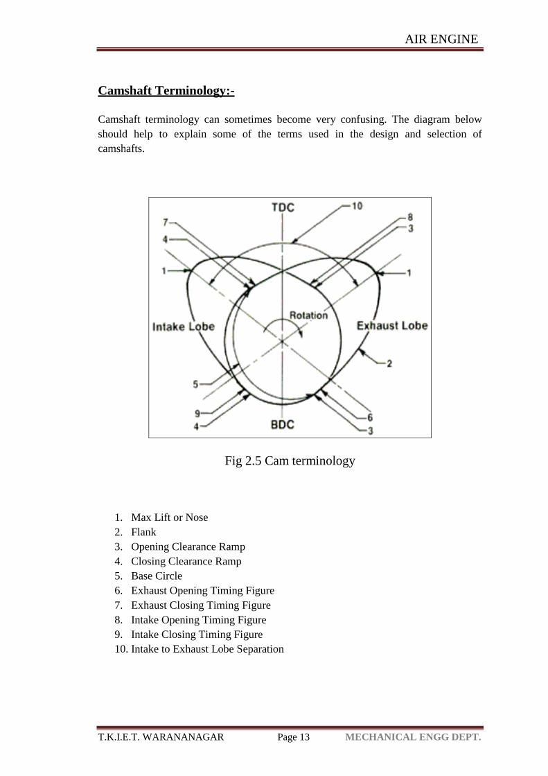
Camshaft Terminology:-
Camshaft terminology can sometimes become very confusing. The diagram below
should help to explain some of the terms used in the design and selection of
camshafts.
Fig 2.5 Cam terminology
1. Max Lift or Nose
2. Flank
3. Opening Clearance Ramp
4. Closing Clearance Ramp
5. Base Circle
6. Exhaust Opening Timing Figure
7. Exhaust Closing Timing Figure
8. Intake Opening Timing Figure
9. Intake Closing Timing Figure
10. Intake to Exhaust Lobe Separation
AIR ENGINE
T.K.I.E.T. WARANANAGAR Page 14 MECHANICAL ENGG DEPT.
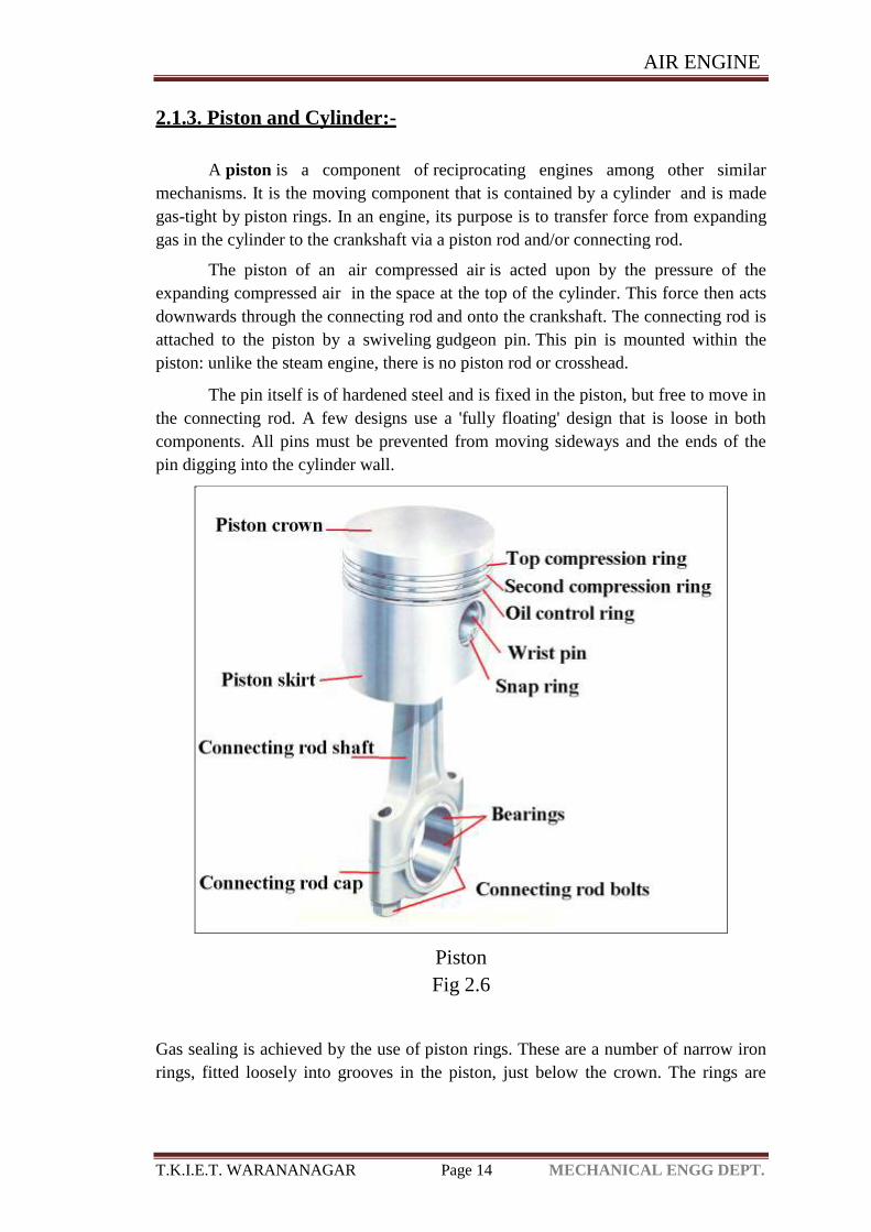
2.1.3. Piston and Cylinder:-
A piston is a component of reciprocating engines among other similar
mechanisms. It is the moving component that is contained by a cylinder and is made
gas-tight by piston rings. In an engine, its purpose is to transfer force from expanding
gas in the cylinder to the crankshaft via a piston rod and/or connecting rod.
The piston of an air compressed air is acted upon by the pressure of the
expanding compressed air in the space at the top of the cylinder. This force then acts
downwards through the connecting rod and onto the crankshaft. The connecting rod is
attached to the piston by a swiveling gudgeon pin. This pin is mounted within the
piston: unlike the steam engine, there is no piston rod or crosshead.
The pin itself is of hardened steel and is fixed in the piston, but free to move in
the connecting rod. A few designs use a 'fully floating' design that is loose in both
components. All pins must be prevented from moving sideways and the ends of the
pin digging into the cylinder wall.
Piston
Fig 2.6
Gas sealing is achieved by the use of piston rings. These are a number of narrow iron
rings, fitted loosely into grooves in the piston, just below the crown. The rings are
AIR ENGINE
T.K.I.E.T. WARANANAGAR Page 15 MECHANICAL ENGG DEPT.
split at a point in the rim, allowing them to press against the cylinder with a light
spring pressure. Two types of ring are used: the upper rings have solid faces and
provide gas sealing; lower rings have narrow edges and a U-shaped profile, to act as
oil scrapers. There are many proprietary and detail design features associated with
piston rings.
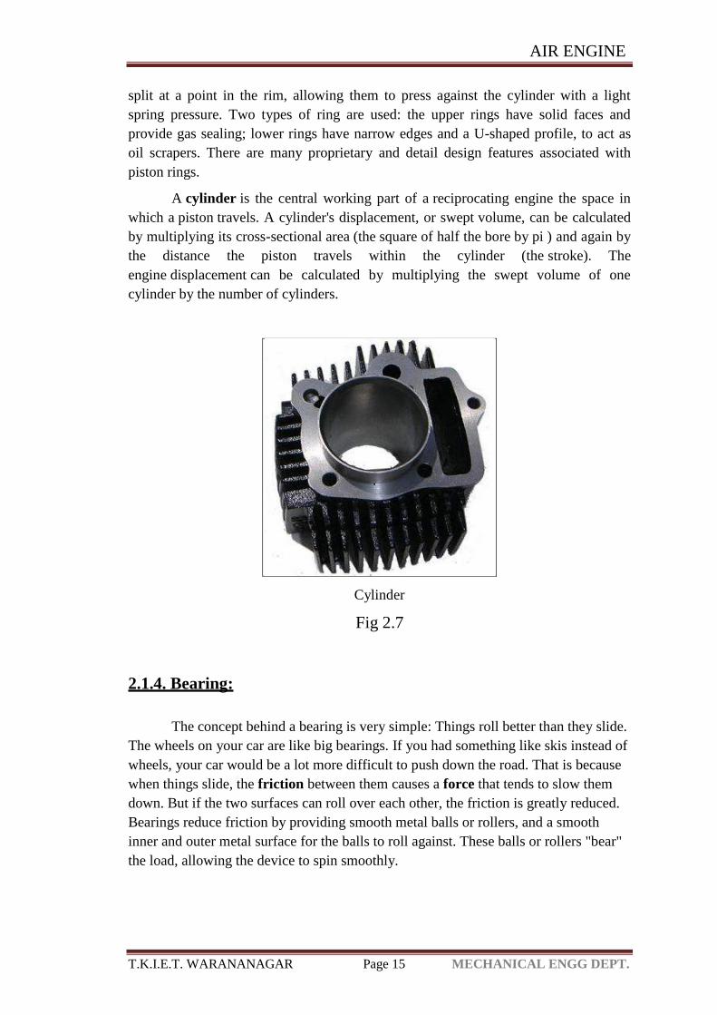
A cylinder is the central working part of a reciprocating engine the space in
which a piston travels. A cylinder's displacement, or swept volume, can be calculated
by multiplying its cross-sectional area (the square of half the bore by pi ) and again by
the distance the piston travels within the cylinder (the stroke). The
engine displacement can be calculated by multiplying the swept volume of one
cylinder by the number of cylinders.
Cylinder
Fig 2.7
2.1.4. Bearing:
The concept behind a bearing is very simple: Things roll better than they slide.
The wheels on your car are like big bearings. If you had something like skis instead of
wheels, your car would be a lot more difficult to push down the road. That is because
when things slide, the friction between them causes a force that tends to slow them
down. But if the two surfaces can roll over each other, the friction is greatly reduced.
Bearings reduce friction by providing smooth metal balls or rollers, and a smooth
inner and outer metal surface for the balls to roll against. These balls or rollers "bear"
the load, allowing the device to spin smoothly.

AIR ENGINE
T.K.I.E.T. WARANANAGAR Page 16 MECHANICAL ENGG DEPT.
Working of a Bearing:
As one of the bearing races rotates it causes the balls to rotate as well. Because
the balls are rolling they have a much lower coefficient of friction than if two flat
surfaces were rotating on each other.Ball bearings tend to have lower load capacity for
their size than other kinds of rolling-element bearings due to the smaller contact area
between the balls and races. However, they can tolerate some misalignment of the
inner and outer races. Compared to other rolling-element bearings, the ball bearing is
the least expensive, primarily because of the low cost of producing the balls used in
the bearing.
Types of Bearings:
There are many types of bearings, each used for different purposes. These
include ball bearings, roller bearings, ball thrust bearings, roller thrust bearings and
tapered roller thrust bearings.
Cut away view of a ball bearing Cut away view of a roller bearing
Ball thrust bearing Roller thrust bearing
AIR ENGINE
T.K.I.E.T. WARANANAGAR Page 17 MECHANICAL ENGG DEPT.
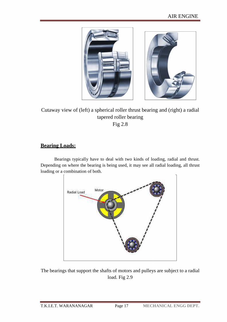
Cutaway view of (left) a spherical roller thrust bearing and (right) a radial
tapered roller bearing
Fig 2.8
Bearing Loads:
Bearings typically have to deal with two kinds of loading, radial and thrust.
Depending on where the bearing is being used, it may see all radial loading, all thrust
loading or a combination of both.
The bearings that support the shafts of motors and pulleys are subject to a radial
load. Fig 2.9
AIR ENGINE
T.K.I.E.T. WARANANAGAR Page 18 MECHANICAL ENGG DEPT.
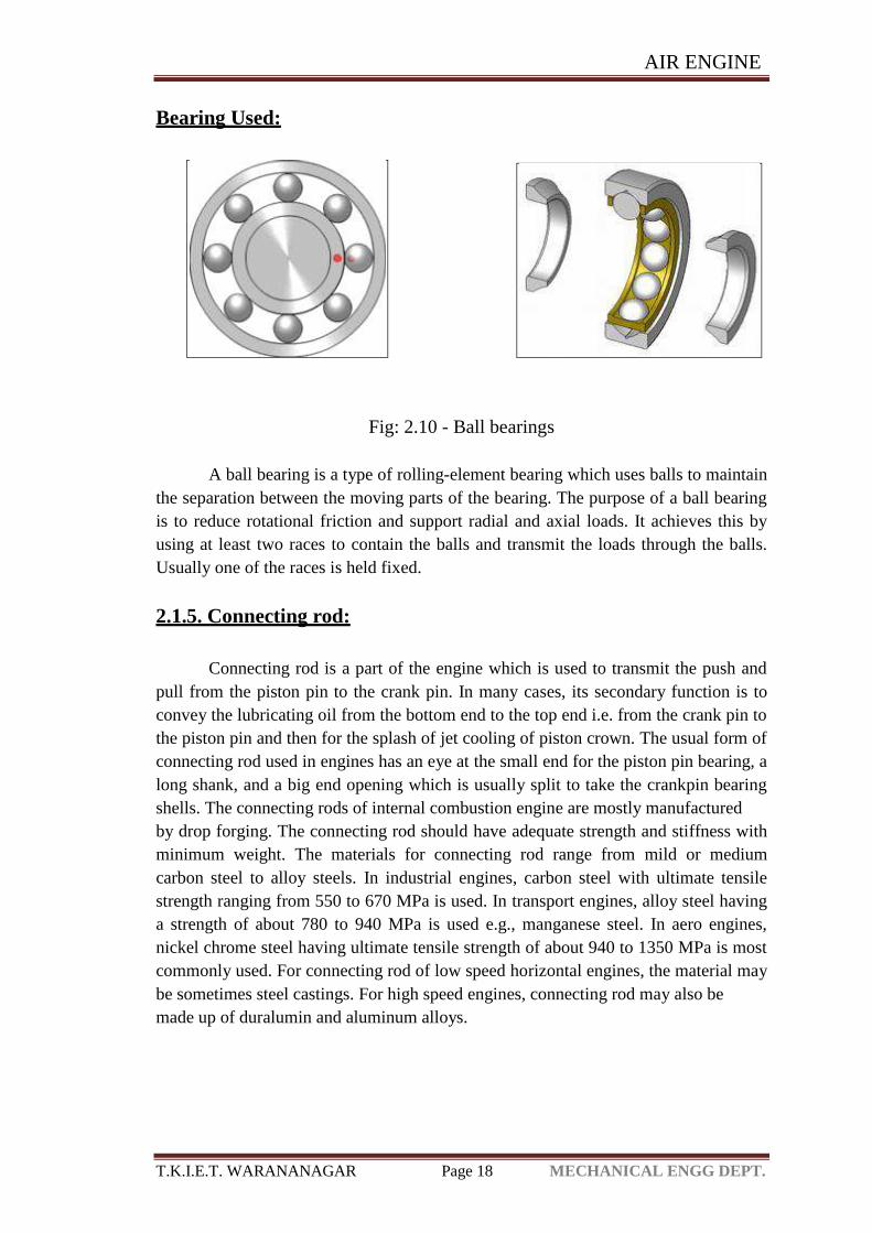
Bearing Used:
Fig: 2.10 - Ball bearings
A ball bearing is a type of rolling-element bearing which uses balls to maintain
the separation between the moving parts of the bearing. The purpose of a ball bearing
is to reduce rotational friction and support radial and axial loads. It achieves this by
using at least two races to contain the balls and transmit the loads through the balls.
Usually one of the races is held fixed.
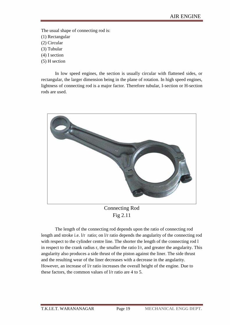
2.1.5. Connecting rod:
Connecting rod is a part of the engine which is used to transmit the push and
pull from the piston pin to the crank pin. In many cases, its secondary function is to
convey the lubricating oil from the bottom end to the top end i.e. from the crank pin to
the piston pin and then for the splash of jet cooling of piston crown. The usual form of
connecting rod used in engines has an eye at the small end for the piston pin bearing, a
long shank, and a big end opening which is usually split to take the crankpin bearing
shells. The connecting rods of internal combustion engine are mostly manufactured
by drop forging. The connecting rod should have adequate strength and stiffness with
minimum weight. The materials for connecting rod range from mild or medium
carbon steel to alloy steels. In industrial engines, carbon steel with ultimate tensile
strength ranging from 550 to 670 MPa is used. In transport engines, alloy steel having
a strength of about 780 to 940 MPa is used e.g., manganese steel. In aero engines,
nickel chrome steel having ultimate tensile strength of about 940 to 1350 MPa is most
commonly used. For connecting rod of low speed horizontal engines, the material may
be sometimes steel castings. For high speed engines, connecting rod may also be
made up of duralumin and aluminum alloys.
AIR ENGINE
T.K.I.E.T. WARANANAGAR Page 19 MECHANICAL ENGG DEPT.
The usual shape of connecting rod is:
(1) Rectangular
(2) Circular
(3) Tubular
(4) I section
(5) H section
In low speed engines, the section is usually circular with flattened sides, or
rectangular, the larger dimension being in the plane of rotation. In high speed engines,
lightness of connecting rod is a major factor. Therefore tubular, I-section or H-section
rods are used.
Connecting Rod
Fig 2.11
The length of the connecting rod depends upon the ratio of connecting rod
length and stroke i.e. l/r ratio; on l/r ratio depends the angularity of the connecting rod
with respect to the cylinder centre line. The shorter the length of the connecting rod l
in respect to the crank radius r, the smaller the ratio l/r, and greater the angularity. This
angularity also produces a side thrust of the piston against the liner. The side thrust
and the resulting wear of the liner decreases with a decrease in the angularity.
However, an increase of l/r ratio increases the overall height of the engine. Due to
these factors, the common values of l/r ratio are 4 to 5.
AIR ENGINE
T.K.I.E.T. WARANANAGAR Page 20 MECHANICAL ENGG DEPT.
The stresses in the connecting rod are set up by a combination of forces. The
various forces acting on the connecting rod are:
1. The combined effect of gas pressure on the piston and the inertia of the
reciprocating parts.
2. Friction of the piston rings and of the piston.
3. Inertia of the connecting rod.
4. The friction of the two end bearings i.e. of the piston pin bearing and the crank pin
bearing.
2.1.6. Valves:-
In four stroke the "Poppet Valve" performed the opening of
the cylinder to inlet or exhaust manifold at the correct moment. Generally the face of
valve is ground at 45 degree but in same cases it is ground at 30 degree also. It is not
important to have a same angle of face in inlet and exhaust valve of same engines. To
make it in right order, the valve may be reground after some use. There is some
margin provided to avoid sharp edges. The groove, retain the valve spring which aids
in keeping the valve pressed against the seat when closed and thus seal
the combustion space tightly. In close position, the valve face, fits the accurately
matched ground seat in the cylinder block. Generally replaceable ring inserts are used
for exhaust valve seat. The inlet valves are made from plain nickel, nickel chrome or
chrome molybdenum. Where as exhaust valves are made from nickel chrome, silicon
chrome steel, high speed steel, stainless steel, high nickel chrome, tungsten steel and
cobalt chrome steel.
A poppet valve (also called mushroom valve is a valve typically used to
control the timing and quantity of gas flow into an engine. It consists of a hole,
usually round or oval, and a tapered plug, usually a disk shape on the end of a shaft
also called a valve stem. The shaft guides the plug portion by sliding through a valve
guide.
AIR ENGINE
T.K.I.E.T. WARANANAGAR Page 21 MECHANICAL ENGG DEPT.
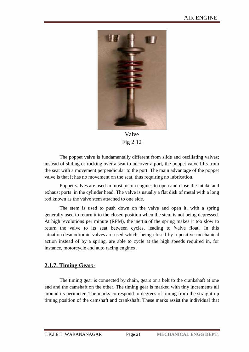
Valve
Fig 2.12
The poppet valve is fundamentally different from slide and oscillating valves;
instead of sliding or rocking over a seat to uncover a port, the poppet valve lifts from
the seat with a movement perpendicular to the port. The main advantage of the poppet
valve is that it has no movement on the seat, thus requiring no lubrication.
Poppet valves are used in most piston engines to open and close the intake and
exhaust ports in the cylinder head. The valve is usually a flat disk of metal with a long
rod known as the valve stem attached to one side.
The stem is used to push down on the valve and open it, with a spring
generally used to return it to the closed position when the stem is not being depressed.
At high revolutions per minute (RPM), the inertia of the spring makes it too slow to
return the valve to its seat between cycles, leading to 'valve float'. In this
situation desmodromic valves are used which, being closed by a positive mechanical
action instead of by a spring, are able to cycle at the high speeds required in, for
instance, motorcycle and auto racing engines .
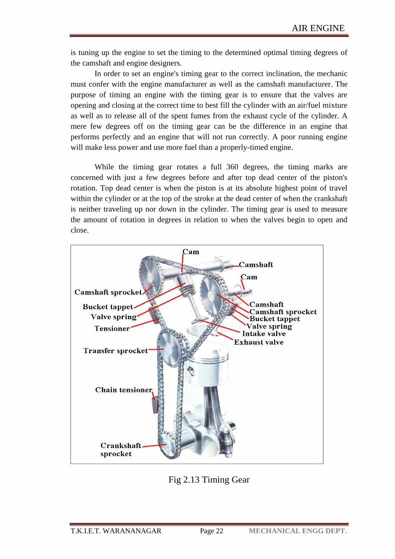
2.1.7. Timing Gear:-
The timing gear is connected by chain, gears or a belt to the crankshaft at one
end and the camshaft on the other. The timing gear is marked with tiny increments all
around its perimeter. The marks correspond to degrees of timing from the straight-up
timing position of the camshaft and crankshaft. These marks assist the individual that
AIR ENGINE
T.K.I.E.T. WARANANAGAR Page 22 MECHANICAL ENGG DEPT.
is tuning up the engine to set the timing to the determined optimal timing degrees of
the camshaft and engine designers.
In order to set an engine's timing gear to the correct inclination, the mechanic
must confer with the engine manufacturer as well as the camshaft manufacturer. The
purpose of timing an engine with the timing gear is to ensure that the valves are
opening and closing at the correct time to best fill the cylinder with an air/fuel mixture
as well as to release all of the spent fumes from the exhaust cycle of the cylinder. A
mere few degrees off on the timing gear can be the difference in an engine that
performs perfectly and an engine that will not run correctly. A poor running engine
will make less power and use more fuel than a properly-timed engine.
While the timing gear rotates a full 360 degrees, the timing marks are
concerned with just a few degrees before and after top dead center of the piston's
rotation. Top dead center is when the piston is at its absolute highest point of travel
within the cylinder or at the top of the stroke at the dead center of when the crankshaft
is neither traveling up nor down in the cylinder. The timing gear is used to measure
the amount of rotation in degrees in relation to when the valves begin to open and
close.
Fig 2.13 Timing Gear
AIR ENGINE
T.K.I.E.T. WARANANAGAR Page 23 MECHANICAL ENGG DEPT.
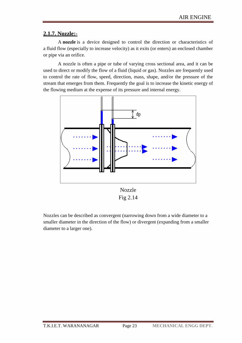
2.1.7. Nozzle:-
A nozzle is a device designed to control the direction or characteristics of
a fluid flow (especially to increase velocity) as it exits (or enters) an enclosed chamber
or pipe via an orifice.
A nozzle is often a pipe or tube of varying cross sectional area, and it can be
used to direct or modify the flow of a fluid (liquid or gas). Nozzles are frequently used
to control the rate of flow, speed, direction, mass, shape, and/or the pressure of the
stream that emerges from them. Frequently the goal is to increase the kinetic energy of
the flowing medium at the expense of its pressure and internal energy.
Nozzle
Fig 2.14
Nozzles can be described as convergent (narrowing down from a wide diameter to a
smaller diameter in the direction of the flow) or divergent (expanding from a smaller
diameter to a larger one).
AIR ENGINE
T.K.I.E.T. WARANANAGAR Page 24 MECHANICAL ENGG DEPT.
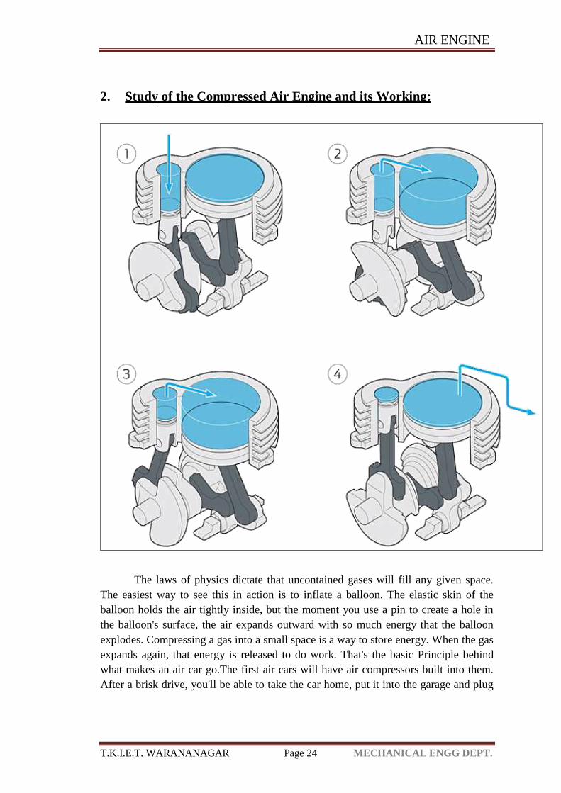
2. Study of the Compressed Air Engine and its Working:
The laws of physics dictate that uncontained gases will fill any given space.
The easiest way to see this in action is to inflate a balloon. The elastic skin of the
balloon holds the air tightly inside, but the moment you use a pin to create a hole in
the balloon's surface, the air expands outward with so much energy that the balloon
explodes. Compressing a gas into a small space is a way to store energy. When the gas
expands again, that energy is released to do work. That's the basic Principle behind
what makes an air car go.The first air cars will have air compressors built into them.
After a brisk drive, you'll be able to take the car home, put it into the garage and plug
AIR ENGINE
T.K.I.E.T. WARANANAGAR Page 25 MECHANICAL ENGG DEPT.
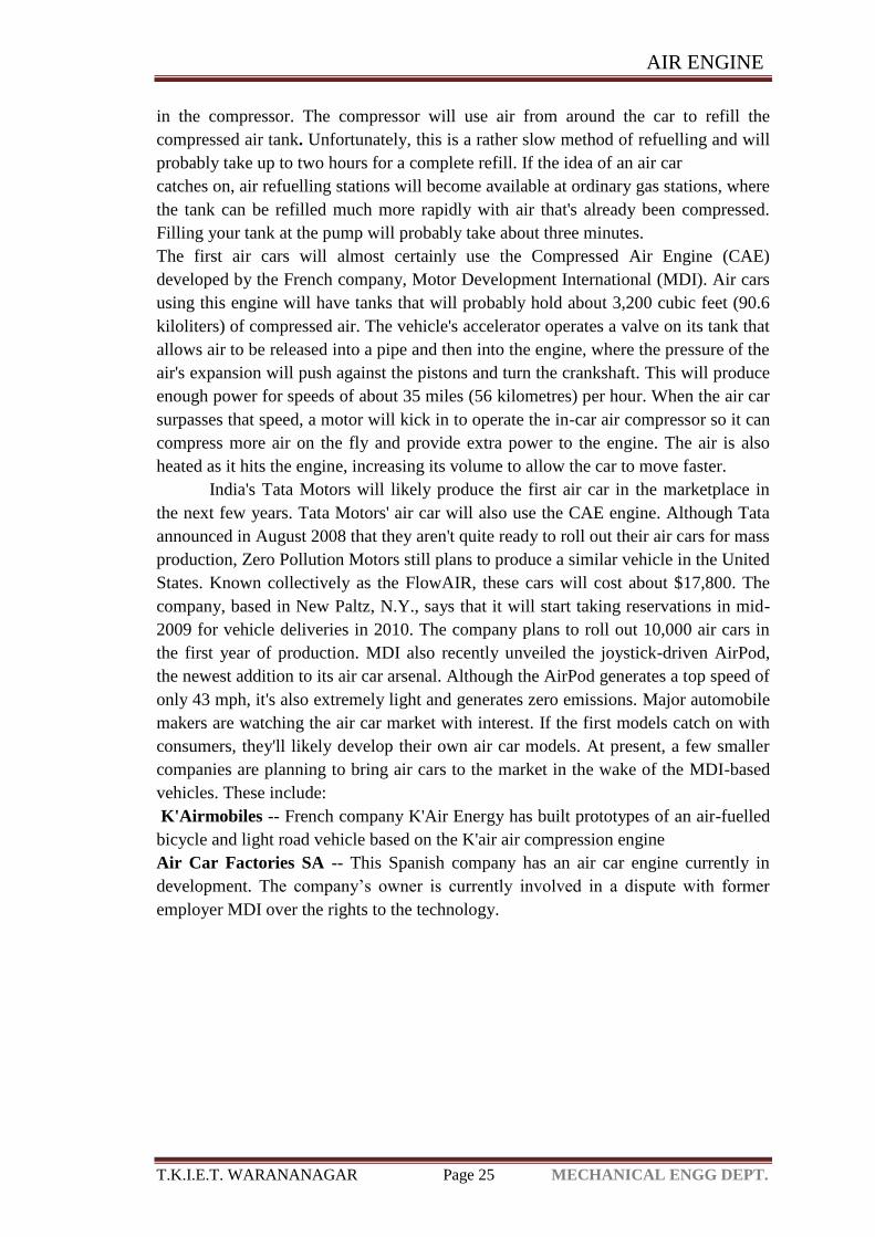
in the compressor. The compressor will use air from around the car to refill the
compressed air tank. Unfortunately, this is a rather slow method of refuelling and will
probably take up to two hours for a complete refill. If the idea of an air car
catches on, air refuelling stations will become available at ordinary gas stations, where
the tank can be refilled much more rapidly with air that's already been compressed.
Filling your tank at the pump will probably take about three minutes.
The first air cars will almost certainly use the Compressed Air Engine (CAE)
developed by the French company, Motor Development International (MDI). Air cars
using this engine will have tanks that will probably hold about 3,200 cubic feet (90.6
kiloliters) of compressed air. The vehicle's accelerator operates a valve on its tank that
allows air to be released into a pipe and then into the engine, where the pressure of the
air's expansion will push against the pistons and turn the crankshaft. This will produce
enough power for speeds of about 35 miles (56 kilometres) per hour. When the air car
surpasses that speed, a motor will kick in to operate the in-car air compressor so it can
compress more air on the fly and provide extra power to the engine. The air is also
heated as it hits the engine, increasing its volume to allow the car to move faster.
India's Tata Motors will likely produce the first air car in the marketplace in
the next few years. Tata Motors' air car will also use the CAE engine. Although Tata
announced in August 2008 that they aren't quite ready to roll out their air cars for mass
production, Zero Pollution Motors still plans to produce a similar vehicle in the United
States. Known collectively as the FlowAIR, these cars will cost about $17,800. The
company, based in New Paltz, N.Y., says that it will start taking reservations in mid-
2009 for vehicle deliveries in 2010. The company plans to roll out 10,000 air cars in
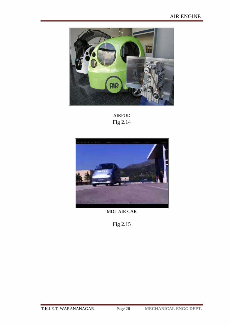
the first year of production. MDI also recently unveiled the joystick-driven AirPod,
the newest addition to its air car arsenal. Although the AirPod generates a top speed of
only 43 mph, it's also extremely light and generates zero emissions. Major automobile
makers are watching the air car market with interest. If the first models catch on with
consumers, they'll likely develop their own air car models. At present, a few smaller
companies are planning to bring air cars to the market in the wake of the MDI-based
vehicles. These include:
K'Airmobiles -- French company K'Air Energy has built prototypes of an air-fuelled
bicycle and light road vehicle based on the K'air air compression engine
Air Car Factories SA -- This Spanish company has an air car engine currently in
development. The company’s owner is currently involved in a dispute with former
employer MDI over the rights to the technology.
AIR ENGINE
T.K.I.E.T. WARANANAGAR Page 26 MECHANICAL ENGG DEPT.
AIRPOD
Fig 2.14
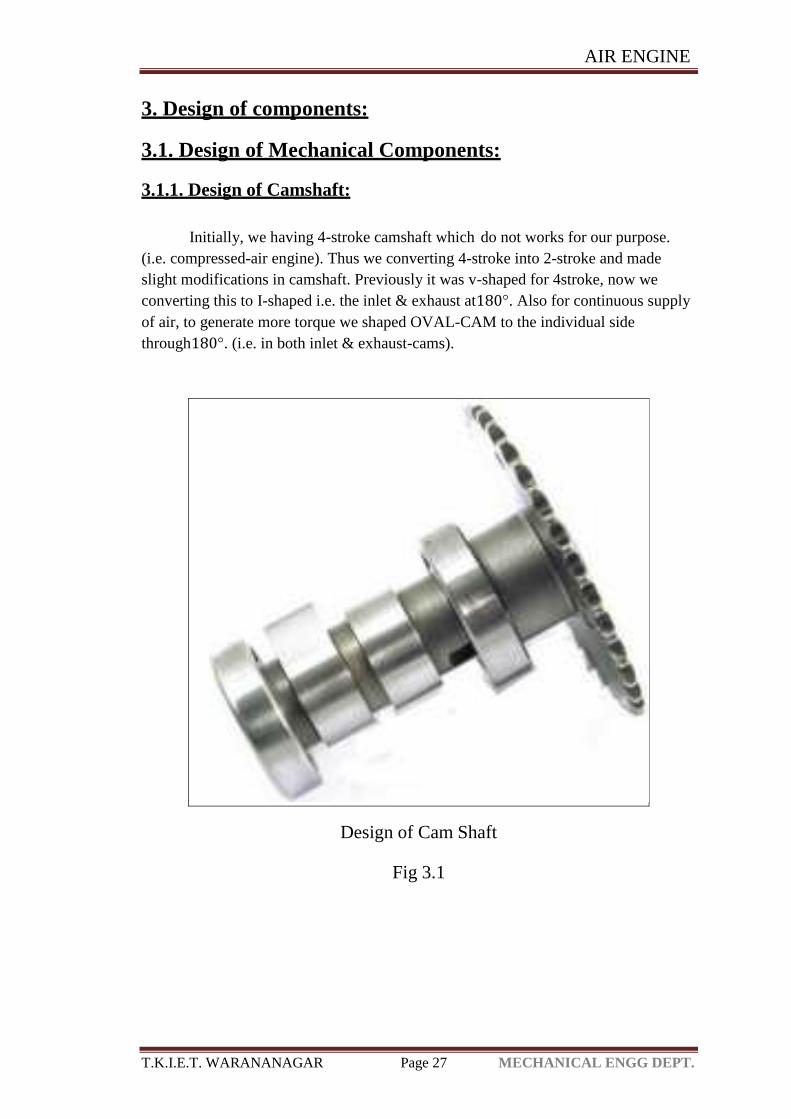
MDI AIR CAR
Fig 2.15
AIR ENGINE
T.K.I.E.T. WARANANAGAR Page 27 MECHANICAL ENGG DEPT.
3. Design of components:
3.1. Design of Mechanical Components:
3.1.1. Design of Camshaft:
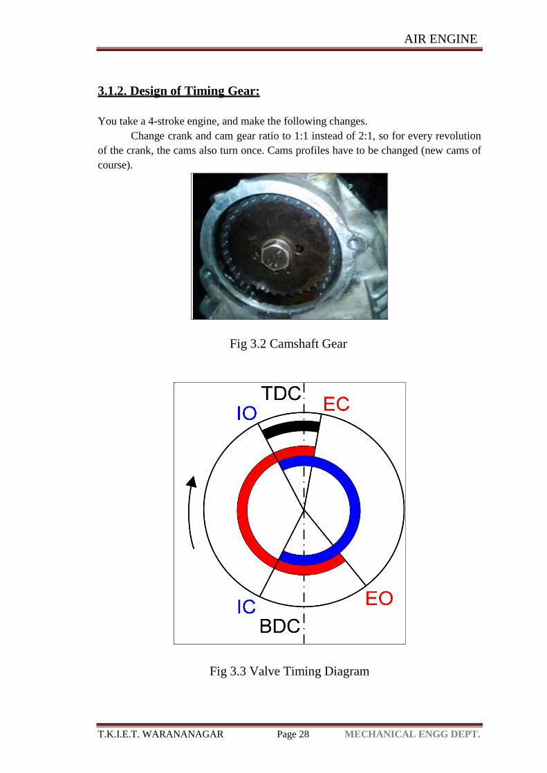
Initially, we having 4-stroke camshaft which do not works for our purpose.
(i.e. compressed-air engine). Thus we converting 4-stroke into 2-stroke and made
slight modifications in camshaft. Previously it was v-shaped for 4stroke, now we
converting this to I-shaped i.e. the inlet & exhaust at180°. Also for continuous supply
of air, to generate more torque we shaped OVAL-CAM to the individual side
through180°. (i.e. in both inlet & exhaust-cams).
Design of Cam Shaft
Fig 3.1
AIR ENGINE
T.K.I.E.T. WARANANAGAR Page 28 MECHANICAL ENGG DEPT.
3.1.2. Design of Timing Gear:
You take a 4-stroke engine, and make the following changes.
Change crank and cam gear ratio to 1:1 instead of 2:1, so for every revolution
of the crank, the cams also turn once. Cams profiles have to be changed (new cams of
course).
Fig 3.2 Camshaft Gear
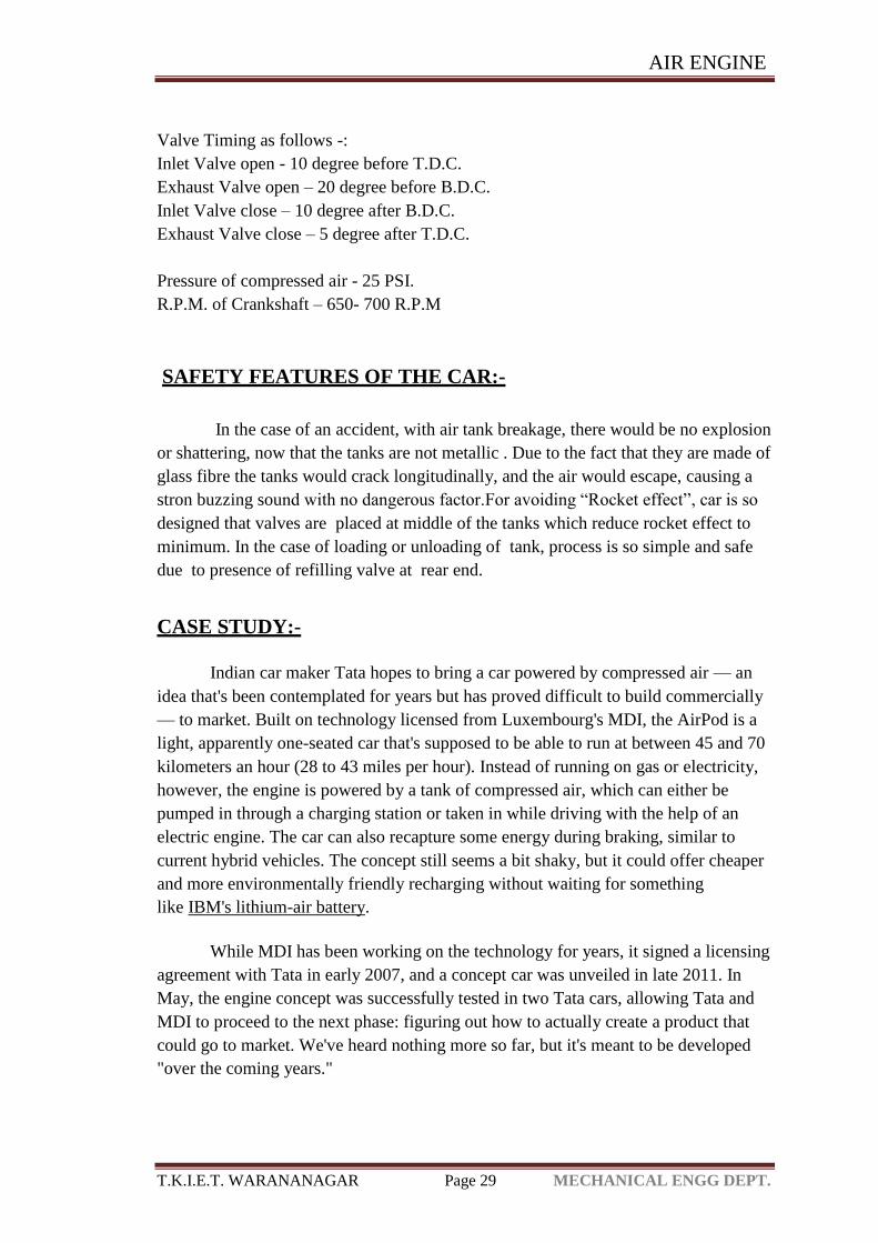
Fig 3.3 Valve Timing Diagram
AIR ENGINE
T.K.I.E.T. WARANANAGAR Page 29 MECHANICAL ENGG DEPT.
Valve Timing as follows -:
Inlet Valve open - 10 degree before T.D.C.
Exhaust Valve open – 20 degree before B.D.C.
Inlet Valve close – 10 degree after B.D.C.
Exhaust Valve close – 5 degree after T.D.C.
Pressure of compressed air - 25 PSI.
R.P.M. of Crankshaft – 650- 700 R.P.M
SAFETY FEATURES OF THE CAR:-
In the case of an accident, with air tank breakage, there would be no explosion
or shattering, now that the tanks are not metallic . Due to the fact that they are made of
glass fibre the tanks would crack longitudinally, and the air would escape, causing a
stron buzzing sound with no dangerous factor.For avoiding “Rocket effect”, car is so
designed that valves are placed at middle of the tanks which reduce rocket effect to
minimum. In the case of loading or unloading of tank, process is so simple and safe
due to presence of refilling valve at rear end.
CASE STUDY:-
Indian car maker Tata hopes to bring a car powered by compressed air — an
idea that's been contemplated for years but has proved difficult to build commercially
— to market. Built on technology licensed from Luxembourg's MDI, the AirPod is a
light, apparently one-seated car that's supposed to be able to run at between 45 and 70
kilometers an hour (28 to 43 miles per hour). Instead of running on gas or electricity,
however, the engine is powered by a tank of compressed air, which can either be
pumped in through a charging station or taken in while driving with the help of an
electric engine. The car can also recapture some energy during braking, similar to
current hybrid vehicles. The concept still seems a bit shaky, but it could offer cheaper
and more environmentally friendly recharging without waiting for something
like IBM's lithium-air battery.
While MDI has been working on the technology for years, it signed a licensing
agreement with Tata in early 2007, and a concept car was unveiled in late 2011. In
May, the engine concept was successfully tested in two Tata cars, allowing Tata and
MDI to proceed to the next phase: figuring out how to actually create a product that
could go to market. We've heard nothing more so far, but it's meant to be developed
"over the coming years."
AIR ENGINE
T.K.I.E.T. WARANANAGAR Page 30 MECHANICAL ENGG DEPT.
4. Advantages:
Main advantages of Compressed Air Engine (C.A.E.) are:
1. Major advantage of using compressed engine is that a pure compressed air vehicle
produces no pollution at the tailpipe.
2. Use of renewable fuel.
3. Compressed-air technology reduces the cost of vehicle production by about 20%,
because there is no need to build a cooling system, fuel tank, Ignition Systems
or silencers.
4. Air, on its own, is non-flammable.
5. The engine can be massively reduced in size.
6. The engine runs on cold or warm air, so can be made of lower strength light weight
material such as aluminium, plastic, low friction teflon or a combination.
7. Low manufacture and maintenance costs as well as easy maintenance.
8. The air tank may be refilled more often and in less time than batteries can be
recharged, with re-filling rates comparable to liquid fuels.
9. Lighter vehicles cause less damage to roads, resulting in lower maintenance cost.
10. The price of filling air powered vehicles is significantly cheaper than petrol, diesel
or biofuel. If electricity is cheap, then compressing air will also be relatively cheap.
5. Disadvantages:
Compressed Air Engine (C.A.E.) has some disadvantages, which are:
1. Less power output
2. Probability of air leakage.
3. Tanks get very hot when filled rapidly. SCUBA tanks are sometimes immersed in
water to cool them down when they are being filled. That would not be possible with
tanks in a car and thus it would either take a long time to fill the tanks, or they would
have to take less than a full charge, since heat drives up the pressure
4. Biggest disadvantage is the energy needed to compress the air is greater than the
energy stored
5. At the supply station, compressing the air heats it, and if then directly transferred in
a heated state to the vehicle storage tanks will then cool and reduce the pressure. If
cooled before transfer, the energy in this heat will be lost unless sophisticated low
grade heat utilization is employed
6. Within the vehicle, expansion and consequent pressure reduction in the throttle or
engine chills the air, reducing its effective pressure. Addition of ambient heat will
increase this pressure and this addition leads to a more complex propulsion system.
AIR ENGINE
T.K.I.E.T. WARANANAGAR Page 31 MECHANICAL ENGG DEPT.
7. Passenger compartment heating is more difficult since the propulsion system does
not provide a source of waste heat. Some form of heat pump, or more likely, an
electric heater would be required.
Safety features of the car-
In the case of an accident, with air tank breakage, there would be no explosion or
shattering, now that the tanks are not metallic . Due to the fact that they are made of
glass fibre the tanks would crack longitudinally, and the air would escape, causing a
strong buzzing sound with no dangerous factor. For avoiding “Rocket effect”, car is so
designed that valves are placed at middle of the tanks which reduce rocket effect to
minimum. In the case of loading or unloading of tank, process is so simple and safe
due to presence of refilling valve at rear end.
6. Applications:
The compressed air engine can be used in many vehicles. Some of its
applications to be used as engine for vehicles are:
(a) Mopeds
Jem Stansfield, an English inventor has been able to convert a regular scooter to a
compressed air moped. This has been done by equipping the scooter with a
compressed air engine and air tank.
(b) Buses
MDI makes MultiCATs vehicle that can be used as buses or trucks. RATP has also
already expressed an interest in the compressed-air pollution-free bus.
(c) Locomotives
Compressed air locomotives have been historically used as mining locomotives and in
various areas.
(d) Trams
Various compressed-air-powered trams were trailed, starting in 1876 and has been
successfully implemented in some cases.
(e) Watercraft and aircraft
Currently, no water or air vehicles exist that make use of the air engine. Historically
compressed air engines propelled certain torpedoes.
AIR ENGINE
T.K.I.E.T. WARANANAGAR Page 32 MECHANICAL ENGG DEPT.
Chapter 4. Conclusion
The model designed by us is a small scale working model of the compressed
air engine. When scaled to higher level it can be used for driving automobiles
independently or combined (hybrid) with other engines like I.C. engines.
Compressed air technology allows for engines that are both non-polluting and
economical.
Unlike electric and hydrogen powered vehicles compressed air vehicles are
not expensive and do not have limiting driving range.
Compressed air vehicles are easy to get around in cities and have performance
rate that stands up to current standards.
AIR ENGINE
T.K.I.E.T. WARANANAGAR Page 33 MECHANICAL ENGG DEPT.
5. References:
1. Haisheng Chen et al. “Air fuelled zero emission road transportation: A
comparative study” ,Applied Energy 88 (2011), 24 June 2010, pp: 337–342
2. Amir Fazeli et al. “A novel compression strategy for air hybrid engines”
Applied Energy 88 (2011) ,8 March 2011,pp:2955–2966
3. Ulf Bossel “Thermodynamic Analysis of Compressed Air Vehicle Propulsion”
European Fuel Cell Forum,Morgenacherstrasse 2F CH-5452
Oberrohrdorf/Switzerland, April 2, 2009
4. J.Gary Wood et al. “Design of a low pressure air engine for third world use”
17th Annual Intersociety Energy Conversion Los Angeles, California August,
1982.
5. S.S. Rattan ,“Theory of Machines”, Tata McGraw Hill Education Private
Limited, Third Edition, pp. 437-441.
6. G.D. Rai, “Non-Conventional Energy Sources”, Khanna Publishers, Fourth
Edition, pp. 784-786.
7. Abhishek La. “Design and Dynamic Analysis of Single Stroke Compressed Air
Engine”. renewable energy research vol.3, no.2, 2013.
8. Prof. b. s. patel, mr r s barot & karan shah, “air powered engine” , National
Conference on Recent Trends in Engineering & Technology , vol.2, no.4 ,
2011.
9. Kato, Yuki*, Hayashi, “ Study on Development of Compressed Air Car for a
Practical use” technical paper, Volume / JP2005-3006191, Page Numbers, 2005.
10. Haliburton, M.-S. Pure Energy Systems News, Engineair’s Ultra- Efficient
Rotary Compressed- Air_Motor/ accessed June, 2008.