modeling, analysis and reliability of seismically excited structures: computational issues
TRANSCRIPT
January 2, 2009 19:4 WSPC/IJCM-j050 00167
International Journal of Computational MethodsVol. 5, No. 4 (2008) 483–511c© World Scientific Publishing Company
MODELING, ANALYSIS AND RELIABILITYOF SEISMICALLY EXCITED STRUCTURES:
COMPUTATIONAL ISSUES
MICHALIS FRAGIADAKIS
Institute of Structural Analysis Seismic ResearchSchool of Civil Engineering
National Technical University of AthensZografou Campus, Athens 15780, Greece
University of Thessaly, Department of Civil EngineeringPedion Areos, 38334 Volos, Greece
MANOLIS PAPADRAKAKIS
Institute of Structural Analysis Seismic ResearchSchool of Civil Engineering
National Technical University of AthensZografou Campus, Athens 15780, Greece
Received 6 August 2008Revised 8 October 2008
A critical review of the current state of the art of the computing practices adopted by theearthquake engineering community is presented. Advanced computational tools are nec-essary for estimating the demand on seismically excited structures. Such computationalmethodologies can provide valuable information on a number of engineering parameterswhich have been proven essential for earthquake the engineering practice. The discus-sion extends from the finite element modeling of earthquake-resistant structures and theanalysis procedures currently used to future developments considering the calculationof uncertainty and methodologies which rely on sophisticated computational methods.The objective is to provide a common ground of collaboration between the earthquakeengineering and computational mechanics communities in an effort to mitigate futureearthquake losses.
Keywords: Structural analysis; modeling; nonlinear analysis; earthquake engineering;time history analysis; uncertainty; fiber element.
1. Introduction
The design and the analysis of structures excited by earthquakes require the useof efficient computational methods to estimate the demand and provide the engi-neer with a useful insight into the structure’s dynamic response. Current practice
483
January 2, 2009 19:4 WSPC/IJCM-j050 00167
484 M. Fragiadakis & M. Papadrakakis
in earthquake engineering reacts slowly to the progress achieved in the field of com-putational mechanics, although it is clear that some steps forward have been madeduring the last few years for the design of safe and economical structures. A partialexplanation for this time lag is that often simple tools when combined with engi-neering judgment may be more reliable and robust than more sophisticated toolsthat require excessive input information, computing time and expert knowledge.For example, for the nonlinear analysis of a simple portal frame, it is often prefer-able to use lumped plasticity beam–column elements rather than a higher orderfinite element simulation with a more consistent constitutive relationship, sincethe latter approach may not provide substantially better results. Furthermore, theuncertainty inherent in the physics of the problem is sometimes much larger thanthe inaccuracies introduced through modeling. In the authors’ opinion, simplifiedmodeling is sufficient when low level information is sought, e.g. displacements, whilewhen other parameters, e.g. curvatures or drifts, are required or more complicatedresponse phenomena (e.g. concrete cracking or local buckling) are to be modeled,a more sophisticated tool must be utilized. Nevertheless, there are many problemswhere the use of high level computing tools is essential.
The seismic assessment of a structure is a multidisciplinary task, since the load-ing is uncertain and is coupled with the structural properties, which are also uncer-tain. Furthermore, strong earthquakes last only a few seconds and have large returnintervals, but they may impose large inelastic deformations that may cause eventhe collapse of a significant number of structures in an area. More frequent eventsmay not cause structural damage but can potentially produce damage to the non-structural parts of a building system and therefore also have significant economicconsequences. The above characteristic requires a special socioeconomic treatmentof the problem, influencing both the design process and the analysis approach tobe adopted. Therefore, computing tools and numerical methods must be combinedin order to (i) assess the capacity for given loading and properties of the structure,(ii) select the simulation strategy, and (iii) handle the system uncertainties. Theobjective of this paper is to critically review the computational methods that arecurrently adopted by the earthquake engineering community, by pointing out theirlimitations and proposing methodologies for improving the engineering practice.
2. Modeling and Assessment of Buildings
Traditionally the seismic design is performed assuming linear elastic analysis, whileusually the structural assessment of existing structures requires nonlinear analy-sis tools. Recent guidelines (e.g. FEMA-356 [2000]) suggest the use of nonlinearanalysis procedures as an essential ingredient for the analysis of seismically excitedstructures. Such analysis methods provide a highly efficient framework for the designand the assessment, since they allow more direct (high level) design criteria and lesssimplifying assumptions [Lagaros et al. (2006)]. Despite the maturity of the finiteelement (FE) method, the seismic assessment of buildings is performed primarily
January 2, 2009 19:4 WSPC/IJCM-j050 00167
Modeling, Analysis and Reliability of Structures Under Seismic Loading 485
with linear finite elements (e.g. beams or rods), while two- and three-dimensionalfinite elements are rarely utilized. Examples of the latter practice are the works ofCofer et al. [2002] and Spiliopoulos and Lykidis [2006].
There are two major sources of nonlinear behavior: material and geometric non-linearity. In the remainder of this paper the discussion will focus on material nonlin-earity, which is considered the primary source of damage for low and medium-risebuilding structures. Geometric nonlinearity, when necessary, can be successfullyaccommodated with the corotational approach [Argyris et al. (1979)], which offerssignificant advantages in terms of implementation in a FE analysis software [Felippa(2000)]. The FE simulation for the nonlinear material response of beam–columnmembers falls into two categories: concentrated plasticity and distributed plastic-ity. In concentrated plasticity, the plastic deformations are “lumped” at the endsof a linear-elastic element and are based on the moment–rotation relationships ofthe end sections for a given axial force. On the other hand, distributed plasticitybeam–column elements allow plastic hinges to form at any location along the mem-ber, while inelasticity is monitored in terms of stresses and strains, thus accountingfor the axial–moment interaction. Several commercial software packages are avail-able and usually each follows a different formulation that the user/engineer mustbe aware of in order to obtain reliable demand estimates.
2.1. Concentrated plasticity elements
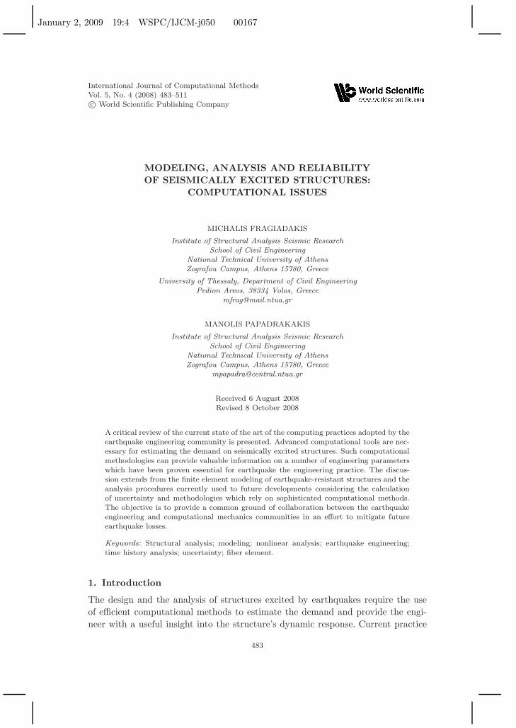
Concentrated plasticity is commonly adopted and currently is the approach sug-gested by various US guidelines [ATC-40 (1996); FEMA-356 (2000)]. The first con-centrated plasticity beam elements were the parallel model of Clough and Johnston[1966] and the series model of Giberson [1967]. Preceding developments were basedon the series model aiming at including the interaction of axial force and bend-ing moment at the element ends (Fig. 1) [Argyris et al. (1982); Lai et al. (1984);Hilmy and Abel (1985); Powell and Chen (1986)]. Further developments on lumped
Fig. 1. Finite element mesh requirements for the inelastic analysis of a portal frame with a horizon-tal force. The lumped plasticity formulation requires three elements and four rotational springs,the displacement-based formulation 15 beam elements and 30 Gauss integration sections, and theforce-based formulation three beam elements and six Gauss–Lobatto integration sections.
January 2, 2009 19:4 WSPC/IJCM-j050 00167
486 M. Fragiadakis & M. Papadrakakis
plasticity elements were focused on the implementation of cyclic laws. Models thatintroduce cyclic stiffness degradation and pinching have been proposed. Such mod-els either modify the path of the reloading branch [Clough and Benuska (1967);Clough and Johnston (1966)] or introduce “pinching” [Takeda et al. (1970);Banon et al. (1981); Song and Pincheira (2000); Ibarra et al. (2005)]. Apart from lin-ear or piecewise linear models, smooth hysteretic models have also been developed[Wen (1976); Ozdemir (1976); Sivaselvan and Reinhorn (2000)] in order to provide acontinuous change of stiffness for the nonlinear springs. Discussion on the propertiesof functions appropriate for smooth hysteretic moment–rotation relationships hasbeen presented by Iwan [1978].
Lumped plasticity beam–column elements reduce the computational cost andmemory requirements and provide better numerical stability. Since the constitutivelaws are expressed in terms of moment–rotations, more complex phenomenologi-cal relationships can be adopted compared to distributed plasticity elements wherestress–strain relationships are used instead. This allows one to simulate compli-cated responses provided that the springs are appropriately calibrated, which isnot always a trivial task. However, the concentrated plasticity approach relies onsimplifying assumptions, by restricting the region where inelastic deformations takeplace or by separating the axial–moment interaction from the element behavior,and thus the springs are calibrated assuming constant axial force during dynamicanalysis. Furthermore, by keeping constant the properties of the springs during theanalysis, further limitations are introduced into the applicability of those elements.For example, according to FEMA-356 [2000], the yield rotation of the end sectionsis calculated assuming double curvature along the element, but this may changeduring the nonlinear response history analysis. Anagnostopoulos [1981] presenteda parametric investigation showing that under monotonic loading the response isvery sensitive to the parameters of the springs, while Dides and de la Llera [2005]showed that for typical multistory structures the response is influenced by the ratioof the beam-to-column stiffness. It has to be mentioned that such models usuallylead to better response estimates for steel rather than for concrete structures. Priorto adopting lumped plasticity modeling, one must also be aware of the inabilityof lumped plasticity to capture the response under softening behavior (e.g. rein-forced concrete structures). Also, when one is setting up the mathematical model,the properties of the end sections do not coincide with the properties of the wholemember, which is the assembly of two springs and an elastic part connected in series.
2.2. Distributed plasticity elements
Distributed plasticity beam–column elements offer a more accurate description ofthe inelastic behavior, since they allow inelastic deformations to be developed any-where within the member (Fig. 1). In practice this is not exactly true, as the cal-culations are performed numerically and therefore the strains are evaluated at theintegration sections. Today these elements are also known as “fiber” elements, since
January 2, 2009 19:4 WSPC/IJCM-j050 00167
Modeling, Analysis and Reliability of Structures Under Seismic Loading 487
usually the sections are divided into horizontal and vertical layers forming smallareas, known as “fibers,” where the strain and the stiffness parameters are evaluated.
The first distributed plasticity elements did not follow the concept of fibers andalso neglected the coupling between axial force and bending moment. Soleimaniet al. [1979], Meyer et al. [1983] and Darvall and Mendis [1985] worked on a modelwhere inelastic deformations move from the end sections to the interior of the ele-ment during the loading history. They used an “effective length factor” to calculatethe curvature at the end sections of the element. Takayanagi and Schnobrich [1979]divided the element into subelements, each represented by a nonlinear spring con-nected in series.
Elements based on the classical FE theory use cubic Hermitian shape functions[Bazant and Bhat (1977); Owen and Hinton (1980); Hellesland and Scordelis (1981);Mari and Scordelis (1984)]. They are known in the literature as “displacement-based” or “stiffness-based” elements and their shortcoming is that they require afine mesh of beam–column elements at the sections where inelastic deformations areexpected to be high. This is necessary because the cubic shape functions assume alinear distribution of the curvature along the element which is not correct when theelement end sections have yielded. In order to overcome this deficiency Mahasuver-achai and Powell [1982] proposed the use of flexibility-dependent shape functionsthat are continuously updated during analysis, but their element was tailored topipeline elements where the primary source of nonlinearity is geometric.
The concept of flexibility-dependent shape functions was extended by Kaba andMahin [1984] and was later improved by Zeris and Mahin [1988]. These elementsassume that the element is divided into equally spaced sections that consist of fibers,while Zeris and Mahin [1988] improved the element state determination phase, i.e.the iterative process of enforcing the assumed force distribution along the element.This improvement allows the element to produce accurate predictions in the case ofsoftening behavior or, in other words, when the postyield deformation path enters asegment with negative slope (softening). This formulation is also known as “force-based” or “flexibility-based.” Following the previous concept, Spacone et al. [1996]introduced a general, mixed-type [Zienkiewicz et al. (2006)], fiber-based, beam–column element. This element always maintains both the force and the deformationequilibrium at the integration sections and converges to a state that satisfies theconstitutive laws within a specified tolerance. Furthermore, contrary to previousflexibility-based elements, the whole process is adjusted to be compatible with gen-eral purpose FE codes which are based on the direct stiffness method [Neuenhoferand Filippou (1997)]. The beam–column element of Spacone et al. [1996] is consid-ered the most accurate and robust distributed plasticity beam–column formulationin the literature and has been found suitable for a wide range of applications.
Compared to lumped plasticity, the main shortcoming of distributed plasticityelements is that they require more computing resources (Fig. 1). Moreover, theseelements are sensitive to the material law to be adopted and therefore it is moredifficult to be calibrated with experimental results. Numerical instabilities may be
January 2, 2009 19:4 WSPC/IJCM-j050 00167
488 M. Fragiadakis & M. Papadrakakis
encountered if criteria that introduce abrupt loss of capacity are adopted in order topredict collapse. On the other hand, distributed plasticity elements do not requirea special calibration process and can be easily adopted for sections that consistof different materials since they use stress–strain relationships suitable for eachfiber material. Thus, the tedious process of calibrating the moment–rotation lawof a section for a given geometry and axial force is avoided, making this modelingapproach more suitable and generic for RC structures.
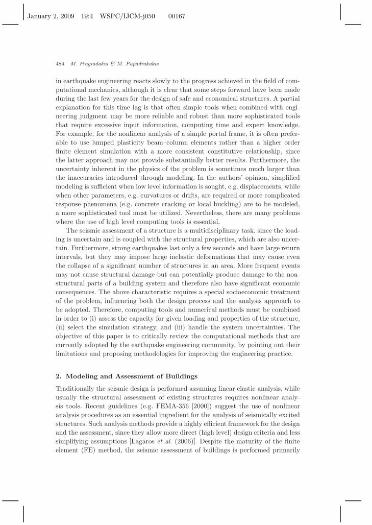
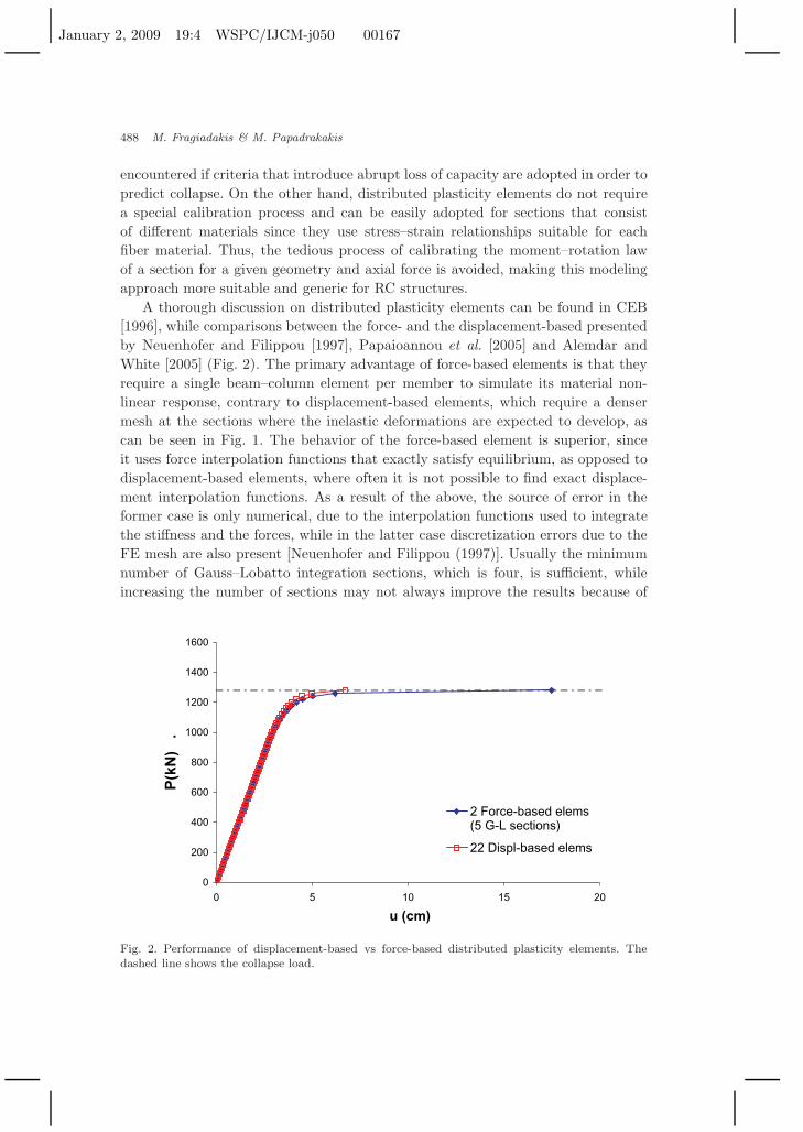
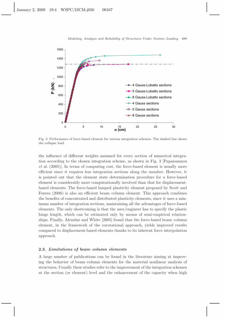
A thorough discussion on distributed plasticity elements can be found in CEB[1996], while comparisons between the force- and the displacement-based presentedby Neuenhofer and Filippou [1997], Papaioannou et al. [2005] and Alemdar andWhite [2005] (Fig. 2). The primary advantage of force-based elements is that theyrequire a single beam–column element per member to simulate its material non-linear response, contrary to displacement-based elements, which require a densermesh at the sections where the inelastic deformations are expected to develop, ascan be seen in Fig. 1. The behavior of the force-based element is superior, sinceit uses force interpolation functions that exactly satisfy equilibrium, as opposed todisplacement-based elements, where often it is not possible to find exact displace-ment interpolation functions. As a result of the above, the source of error in theformer case is only numerical, due to the interpolation functions used to integratethe stiffness and the forces, while in the latter case discretization errors due to theFE mesh are also present [Neuenhofer and Filippou (1997)]. Usually the minimumnumber of Gauss–Lobatto integration sections, which is four, is sufficient, whileincreasing the number of sections may not always improve the results because of
0
200
400
600
800
1000
1200
1400
1600
0 5 10 15 20
u (cm)
P(k
N)
.
2 Force-based elems(5 G-L sections)
22 Displ-based elems
Fig. 2. Performance of displacement-based vs force-based distributed plasticity elements. Thedashed line shows the collapse load.
January 2, 2009 19:4 WSPC/IJCM-j050 00167
Modeling, Analysis and Reliability of Structures Under Seismic Loading 489
0
200
400
600
800
1000
1200
1400
1600
0 5 10 15 20 25 30u (cm)
P (
kN)
.
4 Gauss-Lobatto sections
5 Gauss-Lobatto sections
8 Gauss-Lobatto sections
4 Gauss sections
5 Gauss sections
8 Gauss sections
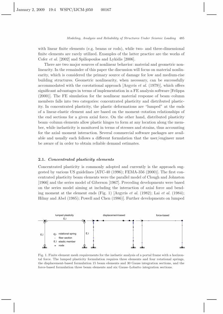
Fig. 3. Performance of force-based element for various integration schemes. The dashed line showsthe collapse load.
the influence of different weights assumed for every section of numerical integra-tion according to the chosen integration scheme, as shown in Fig. 3 [Papaioannouet al. (2005)]. In terms of computing cost, the force-based element is usually moreefficient since it requires less integration sections along the member. However, itis pointed out that the element state determination procedure for a force-basedelement is considerably more computationally involved than that for displacement-based elements. The force-based lumped plasticity element proposed by Scott andFenves (2006) is also an efficient beam–column element. This approach combinesthe benefits of concentrated and distributed plasticity elements, since it uses a min-imum number of integration sections, maintaining all the advantages of force-basedelements. The only shortcoming is that the user/engineer has to specify the plastichinge length, which can be estimated only by means of semi-empirical relation-ships. Finally, Alemdar and White [2005] found that the force-based beam–columnelement, in the framework of the corotational approach, yields improved resultscompared to displacement-based elements thanks to its inherent force interpolationapproach.
2.3. Limitations of beam–column elements
A large number of publications can be found in the literature aiming at improv-ing the behavior of beam–column elements for the material nonlinear analysis ofstructures. Usually these studies refer to the improvement of the integration schemesat the section (or element) level and the enhancement of the capacity when high
January 2, 2009 19:4 WSPC/IJCM-j050 00167
490 M. Fragiadakis & M. Papadrakakis
shear forces are present or when a member is likely to fail due to insufficient shearcapacity (e.g. underreinforced concrete members). Other contributions aim at tack-ling less frequent problems, such as localization issues. It has to be pointed outthat this discussion refers primarily to distributed plasticity elements, since lumpedplasticity elements are by nature approximate and also can accommodate specialbehaviors if a pertinent calibration procedure is followed.
The first category aims at reducing the cost of analysis and improving its effi-ciency. The computational cost is a function of the product of the number ofintegration sections and section fibers. In order to integrate along the longitu-dinal axis of the member, numerical integration can be successfully adopted ifthe force-based element is chosen, since the distribution of the forces is known.This issue has been discussed by Saje et al. [1997]. The integration of thesection stiffness is usually performed with low order schemes because of discon-tinuities in the distribution of stresses in the section. Thus the common prac-tice is to adopt the midpoint rule, resulting in a large number of integrationpoints/fibers in the section. This procedure introduces a small numerical erroreven for linear stress distribution where the quadratic terms of the elastic stiff-ness matrix cannot be evaluated exactly. In order to avoid this shortcoming,section force–deformation relationships can be adopted [McGuire et al. (2000);El-Tawil and Deierlein (1998)]. However this practice may not be a robust alter-native for sections composed of several materials and of arbitrary geometry. Alter-natively, Rotter [1985] and Fafitis [2001] proposed the use of Green’s function totransform the double integrals into line integrals along the compressive perimeterof the concrete section, while Rasheed and Dinno [1994] and Izzuddin et al. [2002]performed the integration analytically by dividing the section into subdomains. Thefirst approach introduces numerical integration errors, while both approaches aresuitable only for monotonic loading.
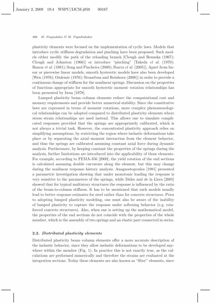
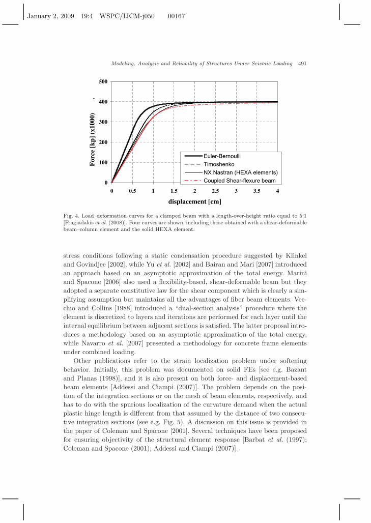
The most important limitation of beam–column elements is their inability tocapture the response of members subjected to a strong shear component. In two-dimensional (e.g. plate or shell elements) and three-dimensional (solid elements)FEs, the shear stresses are directly calculated from the shape functions, but in lin-ear beam–column elements there is no shear strain (Euler–Bernouli beam) or it isassumed constant along the element (Timoshenko beam). A comprehensive reviewof the progress made throughout the past few years can be found in the paper byCeresa et al. [2007], where several different approaches to the problem are discussedand interestingly enough most of them refer to the case of reinforced concrete struc-tures. Petrangeli et al. [1999] proposed a flexibility-based, shear-deformable beamelement where the strains εx and γxy are obtained from the formulation of theelement, while the transverse strain εy is calculated through lateral equilibriumbetween steel and concrete fibers. If the components of the two-dimensional straintensor are known, a biaxial material law can then be adopted. A similar concept hasbeen adopted by Saritas and Filippou [2004] and Fragiadakis et al. [2008] for theanalysis of steel frames, where the transverse strain was adopted by assuming plane
January 2, 2009 19:4 WSPC/IJCM-j050 00167
Modeling, Analysis and Reliability of Structures Under Seismic Loading 491
0
100
200
300
400
500
0 0.5 1 1.5 2 2.5 3 3.5 4
displacement [cm]
For
ce [
kp]
(x10
00)
.
Euler-Bernoulli
Timoshenko
NX Nastran (HEXA elements)
Coupled Shear-flexure beam
Fig. 4. Load–deformation curves for a clamped beam with a length-over-height ratio equal to 5:1[Fragiadakis et al. (2008)]. Four curves are shown, including those obtained with a shear-deformablebeam–column element and the solid HEXA element.
stress conditions following a static condensation procedure suggested by Klinkeland Govindjee [2002], while Yu et al. [2002] and Bairan and Mari [2007] introducedan approach based on an asymptotic approximation of the total energy. Mariniand Spacone [2006] also used a flexibility-based, shear-deformable beam but theyadopted a separate constitutive law for the shear component which is clearly a sim-plifying assumption but maintains all the advantages of fiber beam elements. Vec-chio and Collins [1988] introduced a “dual-section analysis” procedure where theelement is discretized to layers and iterations are performed for each layer until theinternal equilibrium between adjacent sections is satisfied. The latter proposal intro-duces a methodology based on an asymptotic approximation of the total energy,while Navarro et al. [2007] presented a methodology for concrete frame elementsunder combined loading.
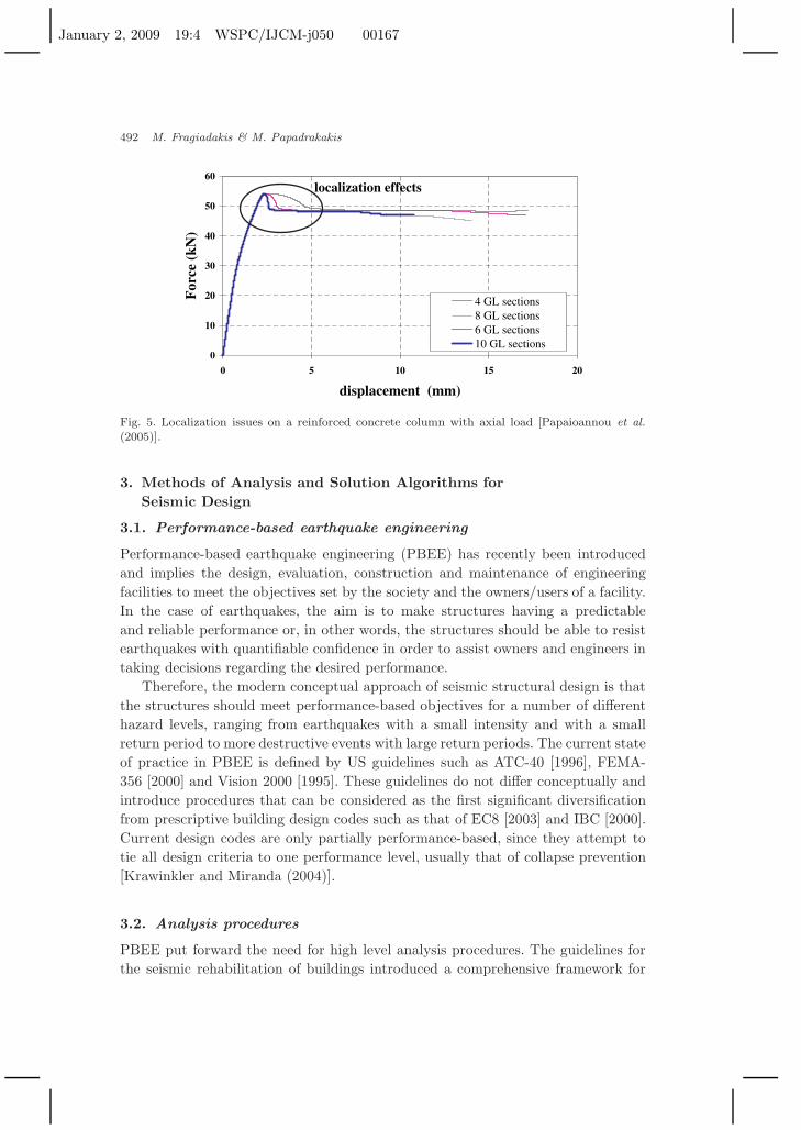
Other publications refer to the strain localization problem under softeningbehavior. Initially, this problem was documented on solid FEs [see e.g. Bazantand Planas (1998)], and it is also present on both force- and displacement-basedbeam elements [Addessi and Ciampi (2007)]. The problem depends on the posi-tion of the integration sections or on the mesh of beam elements, respectively, andhas to do with the spurious localization of the curvature demand when the actualplastic hinge length is different from that assumed by the distance of two consecu-tive integration sections (see e.g. Fig. 5). A discussion on this issue is provided inthe paper of Coleman and Spacone [2001]. Several techniques have been proposedfor ensuring objectivity of the structural element response [Barbat et al. (1997);Coleman and Spacone (2001); Addessi and Ciampi (2007)].
January 2, 2009 19:4 WSPC/IJCM-j050 00167
492 M. Fragiadakis & M. Papadrakakis
0
10
20
30
40
50
60
0 5 10 15 20
displacement (mm)
For
ce (
kN)
4 GL sections8 GL sections6 GL sections10 GL sections
localization effects
Fig. 5. Localization issues on a reinforced concrete column with axial load [Papaioannou et al.(2005)].
3. Methods of Analysis and Solution Algorithms forSeismic Design
3.1. Performance-based earthquake engineering
Performance-based earthquake engineering (PBEE) has recently been introducedand implies the design, evaluation, construction and maintenance of engineeringfacilities to meet the objectives set by the society and the owners/users of a facility.In the case of earthquakes, the aim is to make structures having a predictableand reliable performance or, in other words, the structures should be able to resistearthquakes with quantifiable confidence in order to assist owners and engineers intaking decisions regarding the desired performance.
Therefore, the modern conceptual approach of seismic structural design is thatthe structures should meet performance-based objectives for a number of differenthazard levels, ranging from earthquakes with a small intensity and with a smallreturn period to more destructive events with large return periods. The current stateof practice in PBEE is defined by US guidelines such as ATC-40 [1996], FEMA-356 [2000] and Vision 2000 [1995]. These guidelines do not differ conceptually andintroduce procedures that can be considered as the first significant diversificationfrom prescriptive building design codes such as that of EC8 [2003] and IBC [2000].Current design codes are only partially performance-based, since they attempt totie all design criteria to one performance level, usually that of collapse prevention[Krawinkler and Miranda (2004)].
3.2. Analysis procedures
PBEE put forward the need for high level analysis procedures. The guidelines forthe seismic rehabilitation of buildings introduced a comprehensive framework for
January 2, 2009 19:4 WSPC/IJCM-j050 00167
Modeling, Analysis and Reliability of Structures Under Seismic Loading 493
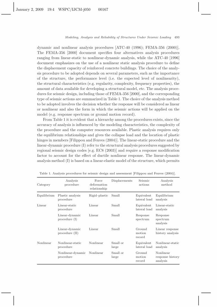
dynamic and nonlinear analysis procedures [ATC-40 (1996); FEMA-356 (2000)].The FEMA-356 [2000] document specifies four alternatives analysis proceduresranging from linear-static to nonlinear-dynamic analysis, while the ATC-40 [1996]document emphasizes on the use of a nonlinear static analysis procedure to definethe displacement capacity of reinforced concrete buildings. The choice of the analy-sis procedure to be adopted depends on several parameters, such as the importanceof the structure, the performance level (i.e. the expected level of nonlinearity),the structural characteristics (e.g. regularity, complexity, frequency properties), theamount of data available for developing a structural model, etc. The analysis proce-dures for seismic design, including those of FEMA-356 [2000], and the correspondingtype of seismic actions are summarized in Table 1. The choice of the analysis methodto be adopted involves the decision whether the response will be considered as linearor nonlinear and also the form in which the seismic actions will be applied on themodel (e.g. response spectrum or ground motion record).
From Table 1 it is evident that a hierarchy among the procedures exists, since theaccuracy of analysis is influenced by the modeling characteristics, the complexity ofthe procedure and the computer resources available. Plastic analysis requires onlythe equilibrium relationships and gives the collapse load and the location of plastichinges in members [Filippou and Fenves (2004)]. The linear-static procedure and thelinear-dynamic procedure (I) refer to the structural analysis procedures suggested byregional seismic design codes [e.g. EC8 (2003)] and require a response modificationfactor to account for the effect of ductile nonlinear response. The linear-dynamicanalysis method (I) is based on a linear-elastic model of the structure, which permits
Table 1. Analysis procedures for seismic design and assessment [Filippou and Fenves (2004)].
Analysis Force Displacements Seismic AnalysisCategory procedure deformation actions method
relationship
Equilibrium Plastic analysis Rigid–plastic Small Equivalent Equilibriumprocedure lateral load analysis
Linear Linear-static Linear Small Equivalent Linear-staticprocedure lateral load analysis
Linear-dynamic Linear Small Response Responseprocedure (I) spectrum spectrum
analysis
Linear-dynamic Linear Small Ground Linear responseprocedure (II) motion history analysis
record
Nonlinear Nonlinear-static Nonlinear Small or Equivalent Nonlinear-staticprocedure large lateral load analysis
Nonlinear-dynamic Nonlinear Small or Ground Nonlinearprocedure large motion response history
record analysis
January 2, 2009 19:4 WSPC/IJCM-j050 00167
494 M. Fragiadakis & M. Papadrakakis
the use of vibration properties (frequencies and mode shapes), and in a simplifiedsolution with a modal representation of the dynamic response. The linear-dynamicprocedure (II) is also linear-elastic but the seismic loading is more realisticallyapplied with a ground motion record. A step towards increased accuracy is the useof nonlinear, static or dynamic, analysis procedures. Nonlinear static analysis, alsoknown as pushover, offers significant advantages compared to elastic methods butstill cannot substitute for dynamic response history analysis, especially for problemswhere modes other than the first contribute to the response.
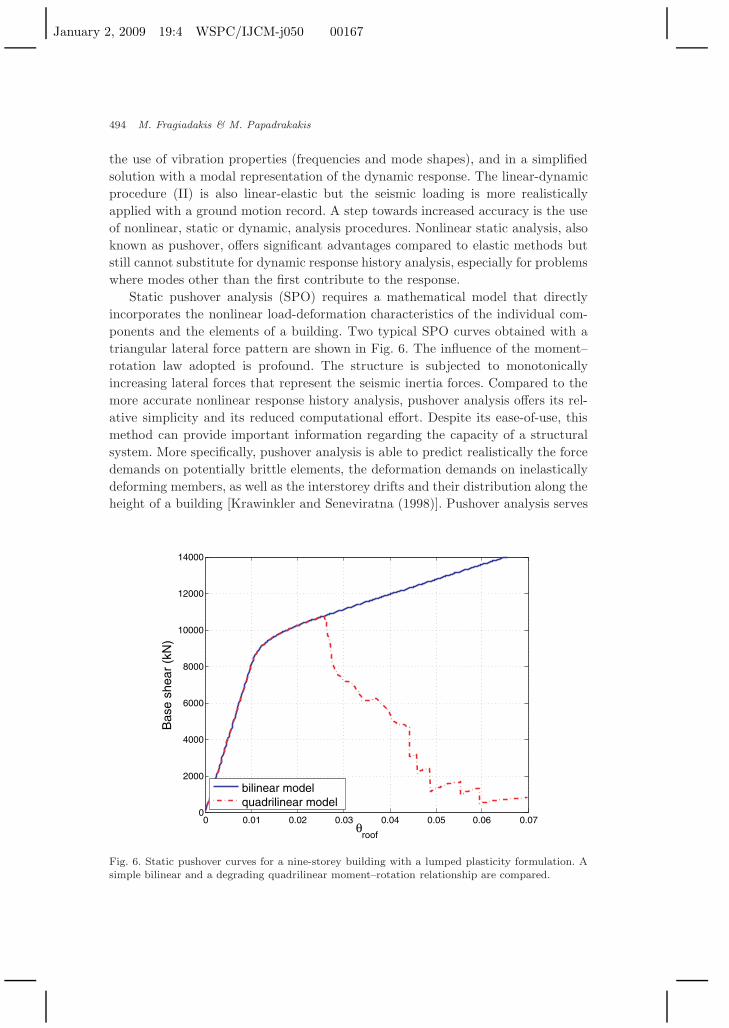
Static pushover analysis (SPO) requires a mathematical model that directlyincorporates the nonlinear load-deformation characteristics of the individual com-ponents and the elements of a building. Two typical SPO curves obtained with atriangular lateral force pattern are shown in Fig. 6. The influence of the moment–rotation law adopted is profound. The structure is subjected to monotonicallyincreasing lateral forces that represent the seismic inertia forces. Compared to themore accurate nonlinear response history analysis, pushover analysis offers its rel-ative simplicity and its reduced computational effort. Despite its ease-of-use, thismethod can provide important information regarding the capacity of a structuralsystem. More specifically, pushover analysis is able to predict realistically the forcedemands on potentially brittle elements, the deformation demands on inelasticallydeforming members, as well as the interstorey drifts and their distribution along theheight of a building [Krawinkler and Seneviratna (1998)]. Pushover analysis serves
0 0.01 0.02 0.03 0.04 0.05 0.06 0.070
2000
4000
6000
8000
10000
12000
14000
θroof
Bas
e sh
ear
(kN
)
bilinear modelquadrilinear model
Fig. 6. Static pushover curves for a nine-storey building with a lumped plasticity formulation. Asimple bilinear and a degrading quadrilinear moment–rotation relationship are compared.
January 2, 2009 19:4 WSPC/IJCM-j050 00167
Modeling, Analysis and Reliability of Structures Under Seismic Loading 495
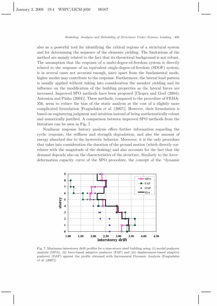
also as a powerful tool for identifying the critical regions of a structural systemand for determining the sequence of the elements yielding. The limitations of themethod are mainly related to the fact that its theoretical background is not robust.The assumption that the response of a multi-degree-of-freedom system is directlyrelated to the response of an equivalent single-degree-of-freedom (SDOF) system,is in several cases not accurate enough, since apart from the fundamental mode,higher modes may contribute to the response. Furthermore, the lateral load patternis usually applied without taking into consideration the member yielding and itsinfluence on the modification of the building properties as the lateral forces areincreased. Improved SPO methods have been proposed [Chopra and Goel (2004);Antoniou and Pinho (2004)]. These methods, compared to the procedure of FEMA-356, seem to reduce the bias of the static analysis at the cost of a slightly morecomplicated formulation [Fragiadakis et al. (2007)]. However, their formulation isbased on engineering judgment and intuition instead of being mathematically robustand numerically justified. A comparison between improved SPO methods from theliterature can be seen in Fig. 7.
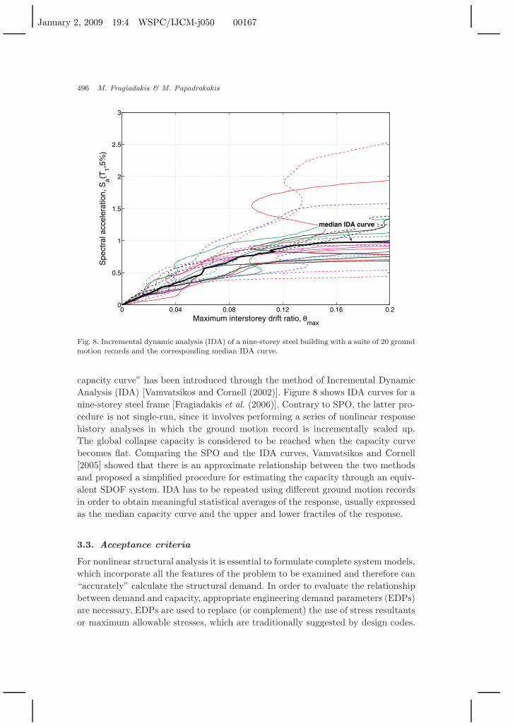
Nonlinear response history analysis offers further information regarding thecyclic response, the stiffness and strength degradation, and also the amount ofenergy absorbed due to the hysteretic behavior. Moreover, it is the only procedurethat takes into consideration the duration of the ground motion (which directly cor-relates with the magnitude of the shaking) and also accounts for the fact that thedemand depends also on the characteristics of the structure. Similarly to the force–deformation capacity curve of the SPO procedure, the concept of the “dynamic
0
1
2
3
4
5
6
7
8
9
1.00 1.50 2.00 2.50 3.00 3.50 4.00 4.50interstorey drift
stor
ey
MPA
FAP
DAP
IDA
Fig. 7. Maximum interstorey drift profiles for a nine-storey steel building using: (i) modal pushoveranalysis (MPA), (ii) force-based adaptive pushover (FAP) and (iii) displacement-based adaptivepushover (DAP) against the profile obtained with Incremental Dynamic Analysis [Fragiadakiset al. (2007)].
January 2, 2009 19:4 WSPC/IJCM-j050 00167
496 M. Fragiadakis & M. Papadrakakis
0 0.04 0.08 0.12 0.16 0.20
0.5
1
1.5
2
2.5
3
Maximum interstorey drift ratio, θmax
Spe
ctra
l acc
eler
atio
n, S
a(T1,5
%)
median IDA curve
Fig. 8. Incremental dynamic analysis (IDA) of a nine-storey steel building with a suite of 20 groundmotion records and the corresponding median IDA curve.
capacity curve” has been introduced through the method of Incremental DynamicAnalysis (IDA) [Vamvatsikos and Cornell (2002)]. Figure 8 shows IDA curves for anine-storey steel frame [Fragiadakis et al. (2006)]. Contrary to SPO, the latter pro-cedure is not single-run, since it involves performing a series of nonlinear responsehistory analyses in which the ground motion record is incrementally scaled up.The global collapse capacity is considered to be reached when the capacity curvebecomes flat. Comparing the SPO and the IDA curves, Vamvatsikos and Cornell[2005] showed that there is an approximate relationship between the two methodsand proposed a simplified procedure for estimating the capacity through an equiv-alent SDOF system. IDA has to be repeated using different ground motion recordsin order to obtain meaningful statistical averages of the response, usually expressedas the median capacity curve and the upper and lower fractiles of the response.
3.3. Acceptance criteria
For nonlinear structural analysis it is essential to formulate complete system models,which incorporate all the features of the problem to be examined and therefore can“accurately” calculate the structural demand. In order to evaluate the relationshipbetween demand and capacity, appropriate engineering demand parameters (EDPs)are necessary. EDPs are used to replace (or complement) the use of stress resultantsor maximum allowable stresses, which are traditionally suggested by design codes.
January 2, 2009 19:4 WSPC/IJCM-j050 00167
Modeling, Analysis and Reliability of Structures Under Seismic Loading 497
According to FEMA-356 [2000], the actions can be either force- or deformation-controlled, depending on the capacity of the members to deform inelastically. Thecapacity of force-controlled members should be assessed using formulas based onstress resultants [e.g. EC2 (2000), EC3 (1993)], while for deformation-controlledactions an appropriate EDP must be chosen.
EDPs may be interstorey drifts, inelastic deformations or section rotations, flooraccelerations and velocities, etc. Alternatively, cumulative damage parameters suchas the hysteretic energy dissipation or the Park–Ang index [Park and Ang (1985)]can be adopted. The particular choice depends on the performance objective and thetype of problem examined, while usually parameters for which appropriate thresholdvalues can be easily obtained are preferred. Any of the analysis procedures in Table 1can be adopted to calculate the demand in terms of the chosen EDP.
Allowable values for acceptance criteria can be found in the codes/guidelines[FEMA-356 (2000); EC8 (2003)] and usually refer to values that have been specifiedusing laboratory test results supplemented by engineering judgment of the variouscode/guideline development teams. Alternatively, one can adopt empirical formulasbased on regression analysis over experimental data [e.g. Panagiotakos and Fardis(2001); Lam et al. (2003)] or more elaborate approaches such as the CAE methodof Perus et al. [2006], where Neural Networks are trained with experimental data.
3.4. Solution of equilibrium equations
3.4.1. Static procedures
According to the sixth column of Table 1, the analysis methods adopted for seismicdesign and assessment of structures vary from linear-static to nonlinear response his-tory analysis. The solution of nonlinear problems often involves numerical difficul-ties and requires increased computational effort compared to linear-static problems.During the last 20 years, significant progress has been made in the solution of highlynonlinear problems that lead to the development of robust solution algorithms, suchas the dynamic relaxation method [Papadrakakis (1981)], the displacement controlmethod [Batoz and Dhatt (1979)], the line search algorithm [Matthies and Strang(1979)], the constant work method [Bathe and Dvorkin (1983)] or the arc-lengthmethod [Crisfield (1980)]. These algorithms are able to trace equilibrium paths ofhighly nonlinear problems that consist of the snap-through and snap-back types oflimit points. In earthquake engineering, when the response of building structures isexamined, the equilibrium path, visualized by the force–deformation plot of a char-acteristic degree of freedom, usually has an upper limit point that is followed by apostyield branch, which often has a negative slope. The softening is usually due tomaterial laws (e.g. concrete), or other effects such as the fracturing of connectionsin steel structures and second order effects. The use of a displacement-control algo-rithm is usually sufficient for SPO of buildings and bridges.
Moreover, for regular building structures of low-to-medium height, second ordereffects are not expected to influence the capacity significantly, although for these
January 2, 2009 19:4 WSPC/IJCM-j050 00167
498 M. Fragiadakis & M. Papadrakakis
cases, P − ∆ effects may become important near collapse, where the displacedstructure cannot carry its own weight due to the damage of the lateral-load-resistingsystem. In order to monitor this effect, a fully geometric nonlinear formulation canbe adopted (for example based on the corotational formulation); alternatively, asimpler, noniterative approach such as that of Wilson and Habibullah [1987] can beimplemented to consider the effect of lateral loads.
3.4.2. Dynamic procedures
Among the procedures in Table 1, nonlinear response history analysis is the mosttime-consuming analysis method, since the integration is performed in the timedomain. Moreover, this procedure is considered as “exact” and provides the refer-ence solution for the remaining methods of the Table. Although Newton–Raphsoniterations are also required in every time step, in the dynamic case the compu-tational treatment of nonlinearities is less problematic due to the favorable effectof the mass term in the effective stiffness matrix. For seismic problems, almostalways implicit integration schemes and in particular the Newmark algorithm arepreferred. These algorithms are unconditionally stable for linear response and allowa relatively large time step in nonlinear cases where the response is dominated bythe first, usually few, modes of vibration. Moreover, the ground motion records aretypically discretized in time steps of 0.005 or 0.01 seconds, and therefore using anexplicit integration scheme (e.g. the central difference method), which requires avery dense time step in order to ensure stability, is not efficient.
The accurate nonlinear dynamic analysis of a FE model may present great diffi-culties, thus requiring knowledge and judgment to assure a stable and accurate solu-tion. Bathe and Cimento [1980] reported that slow convergence and/or divergenceof the solution are frequently encountered for such problems. Divergence is usuallyobserved when stiffening/softening of the force–deformation relationship occurs. Apossible remedy for this case would be to resume the analysis from the last con-verged time step and proceed with a smaller time step using also the initial stiffnessmatrix, or to use more sophisticated energy-conserving integration algorithms forthe solution of the dynamic equilibrium equations [e.g. Armero (2006)].
For seismic analysis problems, the numerical integration of the nonlinear equa-tion of motion is affected by various sources of energy dissipation. Energy is dissi-pated by (i) nonlinear restoring forces, (ii) energy radiation, (iii) structural dampingand (iv) numerical damping.
Under high values of deformation, the hysteretic behavior of materials resultsin energy dissipation. Depending on the modeling approach, the hysteretic energyabsorption often is not accurately represented, since material models fail to pro-duce “pinched” hysteresis loops. This situation is commonly observed on fiber ele-ments that use uniaxial stress–strain relationships. Perhaps the most common rem-edy is the use of lumped plasticity elements with peak-oriented moment–rotation
January 2, 2009 19:4 WSPC/IJCM-j050 00167
Modeling, Analysis and Reliability of Structures Under Seismic Loading 499
relationships [Ibarra et al. (2005)]. However, such relationships require informationregarding energy dissipation and pinching, which is not easily available.
Numerical models almost always represent damping with a linear viscous model.Usually Rayleigh damping is adopted, resulting in a damping matrix proportionalto the mass and the initial stiffness matrix, thus taking advantage of their sparseand banded form. This approach aims to achieve a constant value of damping forall modes of interest, which is consistent with many field observations. In order todetermine the coefficients for Rayleigh damping, two modes that specify a rangeof frequencies where damping is on average constant have to be determined. Formedium-rise buildings, typically the first and fourth modes are assumed. In order tospecify damping values for more than two modes, Caughey damping may be usedinstead [Chopra (1995)]. Rayleigh damping has been proven to be very efficient forlinear problems, due to the modal nature of the response. However, according toHall [2006], for nonlinear problems it has been reported to produce unrealisticallyhigh restoring forces. In the latter case, Hall [2006] suggests an efficient procedurein order to impose bounds on the restoring forces.
When the response depends primarily on the low modes of vibration, it is oftenadvantageous to enforce some form of numerical dissipation to damp out the highermodes that are not sufficiently represented by the FE mesh. For example, the New-mark algorithm introduces numerical dissipation that increases by increasing γ iffor a fixed time step we set β = (γ + 1
2 )2/4 and γ > 0.5. Furthermore, accordingto Hilber et al. [1977], the Houbolt and Wilson integration methods are consid-ered better since they do not affect the lower modes too strongly. Moreover, Hilberet al. [1977] demonstrated the unfavorable algorithmic dissipation of the Newmarkfamily and introduced the concept of α-dissipation and a corresponding new familyof algorithms that exhibit improved performance in terms of numerical dampingcompared to the Newmark and the Wilson method.
4. Reliability of Structures Under Seismic Loading
4.1. Modeling uncertainties
Reliability analysis is an essential ingredient of structural mechanics that assistsengineers in considering several possible sources of uncertainty and calculating theprobability that a structure or a structural member will not meet the purpose forwhich it was designed. Such methods provide a consistent framework for includinganalysis observations and measurements of the physical properties of a structuralsystem (e.g. material, geometry) or loading conditions (e.g. earthquakes, wind), thusreplacing empirical approaches that vary the uncertain parameters to their upper (orlower) bounds to gain insight into the sensitivity of the response [Schueller (2007)].In nature, various types of uncertainties need to be dealt with. In general they aredistinguished to those originating from the inherent randomness of the problem andthose introduced from our insufficient knowledge of the system or problem properties
January 2, 2009 19:4 WSPC/IJCM-j050 00167
500 M. Fragiadakis & M. Papadrakakis
such as modeling errors. The first source is termed “aleatory” or “randomness” andcannot be reduced owing to the nature of the problem. Uncertainty due to modelingerrors is referred as “epistemic” or just as “uncertainty” and can be reduced as ourknowledge of the properties of the problem is improved. In earthquake engineering,seismic loading is inherently random and therefore it is aleatory and is the sourceof uncertainty where emphasis is given, although epistemic uncertainty is receivingincreasing attention [Wen et al. (2003)]. Experience has shown that the record-to-record variability is larger compared to that of modeling, however, as the limitstate increases and consequently under large inelastic deformations (and ductilitydemands) modeling uncertainty may become equally important. Moreover, it is notadvisable to consider as random variables only the parameters that according toengineering judgment are believed to be more influential (e.g. earthquake loading),since the obtained response will not be affected by the “less important” parameters,which for some problems are often proven to have a significant effect on the outcomeof analysis.
In earthquake engineering, usually the uncertainties considered as random vari-ables refer to the mechanical properties of the structure and to physical or intrinsicuncertainties such as seismic loading. A study of the sources of uncertainty thathave significant impact on building structures in seismic regions can be found inthe works of Porter et al. [2002] and Melchers [2002]. Since the entire spectrumof uncertainties is not known, the parameters chosen to be the problem randomvariables provide a reasonable and possible to deal in our analysis approximation.Regarding epistemic uncertainties (e.g. the properties of a structural system) it isbelieved that as our “knowledge” is improved, their effect on the variation of theresponse will be minimal. Engineering practice has shown that our “knowledge”improves either with more experimental tests, as in the case of structural proper-ties (e.g. geometry, member size, Young’s modulus, material strength, damping),or with more accurate FE models. Practice has revealed that the experimentalmeasurements are subject to uncontrollable random effects and are almost alwayssufficient only for the mean and the standard deviation, while a more refined FEmodel will affect only the discretization error. The above discussion leads to the con-clusion that as our knowledge and our tools are improved, epistemic uncertaintiescan reduce the variation of the response but never to the extent that a probabilisticanalysis can be replaced by a more refined deterministic model.
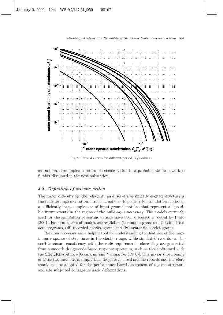
Environmental loads, such as seismic actions, are considered aleatory since theycannot be reduced. The estimation of seismic risk is performed by means of prob-abilistic seismic hazard analysis (PSHA) and results in hazard curves, i.e. themean annual frequency of an intensity measure (IM) (e.g. peak ground accelera-tion or spectral acceleration). A set of typical hazard curves can be seen in Fig. 9.Although the PSHA process contains an aleatoric (magnitude, location, etc.) and anepistemic part (depending on the procedure adopted for the analysis) [Abrahamsonand Bommer (2005)] for structural engineers, this type of uncertainty is considered
January 2, 2009 19:4 WSPC/IJCM-j050 00167
Modeling, Analysis and Reliability of Structures Under Seismic Loading 501
Fig. 9. Hazard curves for different period (T1) values.
as random. The implementation of seismic action in a probabilistic framework isfurther discussed in the next subsection.
4.2. Definition of seismic action
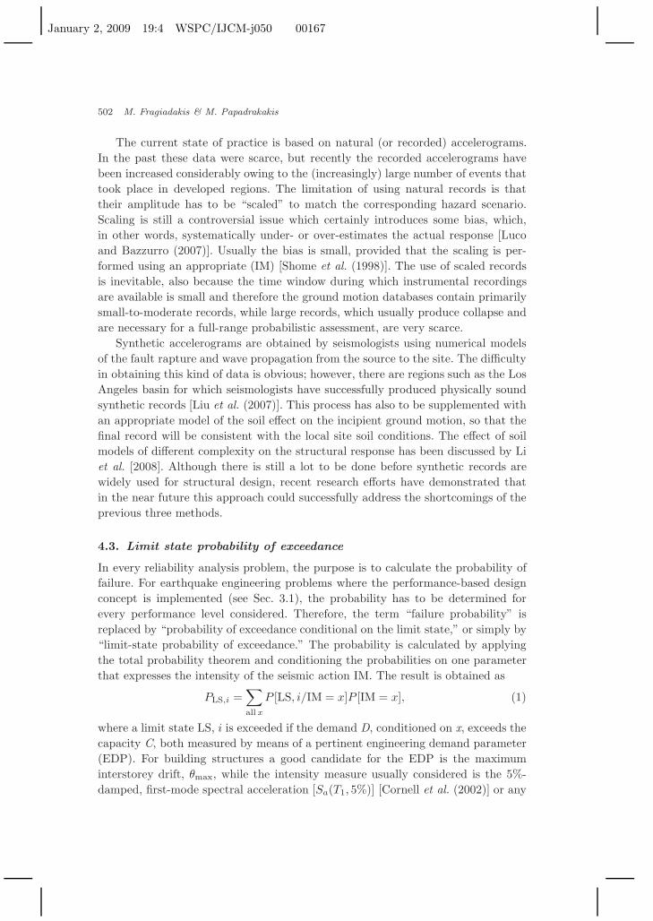
The major difficulty for the reliability analysis of a seismically excited structure isthe realistic implementation of seismic actions. Especially for simulation methods,a sufficiently large sample size of input ground motions that represent all possi-ble future events in the region of the building is necessary. The models currentlyused for the simulation of seismic actions have been discussed in detail by Pinto[2001]. Four categories of models are available: (i) random processes, (ii) simulatedaccelerograms, (iii) recorded accelerograms and (iv) synthetic accelerograms.
Random processes are a helpful tool for understanding the features of the max-imum response of structures in the elastic range, while simulated records can beused to ensure consistency with the code requirements, since they are generatedfrom a smooth design-code-based response spectrum, such as those obtained withthe SIMQKE software [Gasparini and Vanmarcke (1976)]. The major shortcomingof these two methods is simply that they are not real seismic records and thereforeshould not be adopted for the performance-based assessment of a given structureand site subjected to large inelastic deformations.
January 2, 2009 19:4 WSPC/IJCM-j050 00167
502 M. Fragiadakis & M. Papadrakakis
The current state of practice is based on natural (or recorded) accelerograms.In the past these data were scarce, but recently the recorded accelerograms havebeen increased considerably owing to the (increasingly) large number of events thattook place in developed regions. The limitation of using natural records is thattheir amplitude has to be “scaled” to match the corresponding hazard scenario.Scaling is still a controversial issue which certainly introduces some bias, which,in other words, systematically under- or over-estimates the actual response [Lucoand Bazzurro (2007)]. Usually the bias is small, provided that the scaling is per-formed using an appropriate (IM) [Shome et al. (1998)]. The use of scaled recordsis inevitable, also because the time window during which instrumental recordingsare available is small and therefore the ground motion databases contain primarilysmall-to-moderate records, while large records, which usually produce collapse andare necessary for a full-range probabilistic assessment, are very scarce.
Synthetic accelerograms are obtained by seismologists using numerical modelsof the fault rapture and wave propagation from the source to the site. The difficultyin obtaining this kind of data is obvious; however, there are regions such as the LosAngeles basin for which seismologists have successfully produced physically soundsynthetic records [Liu et al. (2007)]. This process has also to be supplemented withan appropriate model of the soil effect on the incipient ground motion, so that thefinal record will be consistent with the local site soil conditions. The effect of soilmodels of different complexity on the structural response has been discussed by Liet al. [2008]. Although there is still a lot to be done before synthetic records arewidely used for structural design, recent research efforts have demonstrated thatin the near future this approach could successfully address the shortcomings of theprevious three methods.
4.3. Limit state probability of exceedance
In every reliability analysis problem, the purpose is to calculate the probability offailure. For earthquake engineering problems where the performance-based designconcept is implemented (see Sec. 3.1), the probability has to be determined forevery performance level considered. Therefore, the term “failure probability” isreplaced by “probability of exceedance conditional on the limit state,” or simply by“limit-state probability of exceedance.” The probability is calculated by applyingthe total probability theorem and conditioning the probabilities on one parameterthat expresses the intensity of the seismic action IM. The result is obtained as
PLS,i =∑all x
P [LS, i/IM = x]P [IM = x], (1)
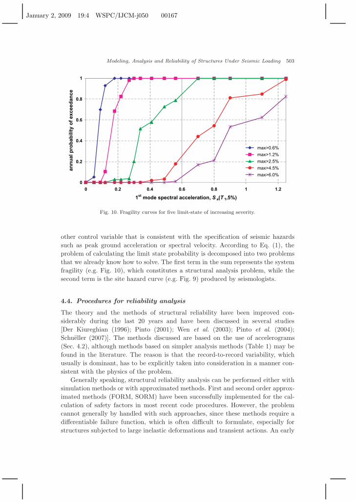
where a limit state LS, i is exceeded if the demand D, conditioned on x, exceeds thecapacity C, both measured by means of a pertinent engineering demand parameter(EDP). For building structures a good candidate for the EDP is the maximuminterstorey drift, θmax, while the intensity measure usually considered is the 5%-damped, first-mode spectral acceleration [Sa(T1, 5%)] [Cornell et al. (2002)] or any
January 2, 2009 19:4 WSPC/IJCM-j050 00167
Modeling, Analysis and Reliability of Structures Under Seismic Loading 503
0
0.2
0.4
0.6
0.8
1
0 0.2 0.4 0.6 0.8 1 1.2
1st mode spectral acceleration, S a(T 1,5%)
ann
ual
pro
bab
ility
of
exce
edan
ce
max>0.6%
max>1.2%
max>2.5%
max>4.5%
max>6.0%
Fig. 10. Fragility curves for five limit-state of increasing severity.
other control variable that is consistent with the specification of seismic hazardssuch as peak ground acceleration or spectral velocity. According to Eq. (1), theproblem of calculating the limit state probability is decomposed into two problemsthat we already know how to solve. The first term in the sum represents the systemfragility (e.g. Fig. 10), which constitutes a structural analysis problem, while thesecond term is the site hazard curve (e.g. Fig. 9) produced by seismologists.
4.4. Procedures for reliability analysis
The theory and the methods of structural reliability have been improved con-siderably during the last 20 years and have been discussed in several studies[Der Kiureghian (1996); Pinto (2001); Wen et al. (2003); Pinto et al. (2004);Schueller (2007)]. The methods discussed are based on the use of accelerograms(Sec. 4.2), although methods based on simpler analysis methods (Table 1) may befound in the literature. The reason is that the record-to-record variability, whichusually is dominant, has to be explicitly taken into consideration in a manner con-sistent with the physics of the problem.
Generally speaking, structural reliability analysis can be performed either withsimulation methods or with approximated methods. First and second order approx-imated methods (FORM, SORM) have been successfully implemented for the cal-culation of safety factors in most recent code procedures. However, the problemcannot generally by handled with such approaches, since these methods require adifferentiable failure function, which is often difficult to formulate, especially forstructures subjected to large inelastic deformations and transient actions. An early
January 2, 2009 19:4 WSPC/IJCM-j050 00167
504 M. Fragiadakis & M. Papadrakakis
attempt to use FORM for seismic problems can be found in the work of Zhang andDer Kiureghian [1994], where the seismic loading is considered deterministically.Response surface methods can also be seen as approximated methods. These meth-ods rely on approximating the failure function with a surface obtained through anal-ysis. Since this is not a trivial task for performance-based earthquake engineeringproblems, this approach is usually combined with other computational tools. Insteadof a response surface, Neural Networks have also been successfully adopted toobtain inexpensive estimates of the limit state function [Papadrakakis et al. (1996);Nie and Ellingwood (2004); Lagaros and Fragiadakis (2007)].
FORM and other reliability analysis methods have been used to develop FEsoftware for the direct calculation of the performance-based limit state probabili-ties. For example, Haukaas and Der Kiureghian [2004] extended the OpenSees FEplatform [McKenna and Fenves (2001)] with the finite element reliability analy-sis (FERA) method, which allows the direct calculation of the response sensitiv-ities and probabilities. The most important property of the resulting software isthat the parameters of the FE problem are specified probabilistically (with theirmean, standard deviation and distribution) and response statistics can be calcu-lated with sufficient accuracy after a few simulations. In the opinion of the authors,the main shortcoming of this approach lies in the implementation of the seismicactions. The accuracy and the efficiency of these algorithms are controlled by themethod used to calculate the response sensitivities. Two approaches are availablefor obtaining response sensitivities: finite difference methods and the direct dif-ferentiation method (DDM). The former approach reruns the analysis with per-turbed parameter values to estimate the sensitivities of the response, while thelatter approach is more accurate and requires less simulations at the expense ofderiving and implementing analytically the sensitivity equations within the FEanalysis. A number of recent publications [Scott et al. (2004); Conte et al. (2004);Barbato and Conte (2005)] have been devoted to the efficient calculation of responsesensitivities employing fiber elements (Sec. 2.2) that can be used for the reliabilityassessment of building structures [e.g. Haukaas and Scott (2006)].
Monte Carlo simulation (MCS) methods appear to be the only approach togetting accurate solutions for complex problems that involve nonlinearity, manyrandom variables, or large variations of the uncertain parameters [Bergman et al.(1997)]. The major advantage of MCS is that accurate solutions can be obtainedalmost for every problem, while the main disadvantage is the computational cost,which depends on the values of the required probabilities. If the sampling error interms of the coefficient of variation of the estimated demand exceedance probability,pf , lies within a given limit, δ0, the required sample size is
N =1
pfδ20
. (2)
For example, if pf is 10−2 and the desired accuracy is δ0 = 10%, the numberof simulations required is N = 1000. For earthquake engineering problems the
January 2, 2009 19:4 WSPC/IJCM-j050 00167
Modeling, Analysis and Reliability of Structures Under Seismic Loading 505
probabilities sought [Eq. (1)] are typically large compared to other problems instructural mechanics and thus the cost of MCS is manageable for contemporary PCs.Variance reduction techniques such as importance sampling, directional simulation,antithetic variates, adaptive sampling or Latin hypercube simulation (LHS) havebeen proposed in order to reduce the numerical effort and increase the efficiency.The disadvantage of these methods is that they require prior knowledge of thebehavior of the structure in order to determine the most effective sampling region.However, for many practical problems the sampling region is clearly identifiable orcan be located using optimization procedures [Schueller (2007)].
A variant of the importance sampling method that has been used in earthquakeengineering is the “deaggregation” method. Instead of a large number of groundmotions, only records with given magnitude M and distance R that contributemost to the limit state probability are chosen [Wen (2001)]. The selection process isbased on an appropriate attenuation law and the IM considered is usually the spec-tral acceleration corresponding to a given probability of exceedance. This methodobviously depends on the intelligent selection of the seismic parameters, the struc-ture and the limit state considered, and therefore is not applicable to the generalcase.
Following severe economic losses caused by earthquakes in the United Statesand Japan, a reliability-based and performance-oriented design procedure has beendeveloped as part of the SAC/FEMA Joint Venture for Steel Buildings project[FEMA-350 (2000)]. The theoretical basis of this method has been provided byCornell et al. [2002]. The basic assumptions of this approach are briefly summarizedbelow:
• Instead of the “load” and “resistance” terms, widely used in probabilistic assess-ment, the more generic terms “demand” and “capacity” are adopted. For theith limit state both capacity Ci and demand Di are assumed to be lognormallydistributed.
• The dynamic capacity curve, obtained either with IDA or with regression in theEDP–IM plane [see Eq. (1)], can be approximated with a relationship of the formEDP = α IMb, or simply Di = α(sa)b.
• The hazard curve is expressed in the form ν(Sa) = Pr(Sa ≥ sa) = k0(sa)−k. Ifthis is not possible, a linear local fit of the hazard curve around sa has to beperformed.
Following those assumption, Eq. (1) can be analytically calculated as
PLS,i = PDi≥Ci = ν(sa(Ci)) exp[12
k2
b2(β2
C + β2D)
], (3)
where βC and βD denote the dispersion, which is approximately equal to the coef-ficient of variation of the capacity and the demand, respectively. The limitationsof the method in essence depend on the validity of the above assumptions, while
January 2, 2009 19:4 WSPC/IJCM-j050 00167
506 M. Fragiadakis & M. Papadrakakis
this approach offers a reasonable approximation of the limit state probabil-ity with a relatively small number of nonlinear response history analyses. TheSAC/FEMA method has been the basis for a reliability-based design code for-mat and currently serves as the basis for future implementation of seismic hazardsin performance-based earthquake engineering, as further discussed in the paper ofHamburger et al. [2003].
5. Concluding Remarks
A critical overview of the current state of the art of the computing practices forthe assessment of structural performance under seismic actions has been presented.From the preceding discussion it is clear that earthquake engineering is a multidis-ciplinary field that requires a deep knowledge of a wide range of subjects in orderto obtain efficiently the structural response under extreme seismic loading. In pre-computer times the seismic problems were treated as linear-elastic and the assess-ment procedure was transformed into an equivalent static analysis problem with adeterministic lateral load pattern. Today, as our understanding of earthquakes hasimproved, the engineers have to combine sophisticated computational tools in orderto select the proper modeling formulation, the method of analysis, the correspond-ing solution algorithm, and also handle the system’s uncertainties. On the otherhand, the computational mechanics community has successfully addressed most ofthese issues through problems that often appear in various fields of the engineeringscience. Computing tools essential for the seismic assessment of building structureshave been discussed on the basis of their advantages and limitations.
References
Abrahamson, N. A. and Bommer, J. J. [2005] Probability and uncertainty in seismic hazardanalysis, Earthq. Spectra 21(2), 603–607.
Addessi, D. and Ciampi, V. [2007] A regularized force-based beam element with a damage-plastic section constitutive law, Int. J. Numer. Meth. Eng. 70(5), 610–629.
Alemdar, B. N. and White, D. W. [2005] Displacement, flexibility and mixed beam–columnfinite element formulations for distributed plasticity analysis, J. Struct. Eng. 131(12),1811–1819.
Anagnostopoulos, S. [1981] Inelastic beams for seismic ananlysis of structrures, J. Struct.Eng. 107(7), 1297–1311.
Antoniou, S. and Pinho, R. [2004] Development and verification of a displacement-basedadaptive pushover procedure, J. Earthq. Eng. 8(5), 643–661.
Argyris, J. H., Hilpert, O., Malejannakis, G. A. and Scharpf, D. W. [1979] On the geomet-rical stiffness of a beam in space — a consistent v. w. approach, Comput. Meth. Appl.Mech. Eng. 20(1), 105–131.
Argyris, J. H., Boni, B., Hindenlang, U. and Kleiber, M. [1982] Finite element analysisof two- and three-dimensional elasto-plastic frames — the natural approach, Comput.Meth. Appl. Mech. Eng. 110(11), 221–248.
Armero, F. [2006] Energy-dissipative momentum-conserving time-stepping algorithms forfinite strain multiplicative plasticity, Comput. Meth. Appl. Mech. Eng. 195(37–40),4862–4889.
January 2, 2009 19:4 WSPC/IJCM-j050 00167
Modeling, Analysis and Reliability of Structures Under Seismic Loading 507
ATC-40, Seismic Evaluation and Retrofit of Concrete Buildings (Applied TechnologyCouncil, California Seismic Safety Commission, Redwood City, California, USA, 1996).
Bairan, G. J. M. and Mari, A. R. [2007] Shear–bending–torsion interaction in structuralconcrete members: A nonlinear coupled sectional approach, Arch. Comput. Meth. Eng.14(3), 249–278.
Banon, H., Biggs, J. and Irvine, M. [1981] Seismic damage in reinforced concrete frames,J. Struct. Eng. 107(9), 1713–1729.
Barbat, A. H., Oller, S., Onate, E. and Hanganu, A. [1997] Viscous damage model forTimoshenko beam structures, Int. J. Solids Struct. 34(30), 3953–3976.
Barbato, M. and Conte, J. P. [2005] Finite element response sensitivity analysis: A com-parison between force-based and displacement-based frame element models, Comput.Meth. Appl. Mech. Eng. 194(12–16), 1479–1512.
Bathe, K. J. and Cimento, A. P. [1980] Some practical procedures for the solution ofnonlinear finite element equations, Comput. Meth. Appl. Mech. Eng. 22(1), 59–85.
Bathe, K. J. and Dvorkin, E. N. [1983] On the automatic solution of non-linear finiteelement equations, Comput. Struct. 17(5–6), 871–879.
Batoz, J. L. and Dhatt, G. [1979] Incremental displacement algorithms for non-linearproblems, Int. J. Numer. Meth. Eng. 26, 1262–1267.
Bazant, S. and Bhat, P. [1977] Prediction of hysteresis in reinforced concrete members,J. Struct. Eng. 103(1), 151–167.
Bazant, Z. P. and Planas, J. Fracture and Size Effect in Concrete and Other Quasi-BrittleMaterials (CRC, 1998).
Bergman, L. A. et al. [1997] A state-of-the-art report on computational stochastic mechan-ics, Prob. Eng. Mech. 12(4), 197–321.
Comitee Euro-International du Beton CEB. RC frames under earthquake loading: Stateof the art report (1996).
Ceresa, P., Petrini, L. and Pinho, R. [2007] Flexure–shear fiber beam–column elements formodeling frame structures under seismic loading — state of the art, J. Earthq. Eng.11(1), 46–88.
Chopra, A. K. [1995] Dynamics of Structures (Prentice-Hall, New York).Chopra, A. K. and Goel, R. K. [2004] A modal pushover analysis procedure to estimate
seismic demands for unsymmetric-plan buildings, Earthq. Eng. Struct. Dyn. 33(8),903–927.
Clough, R. and Benuska, L. [1967] Nonlinear earthquake behavior of tall buildings, J. Mech.Eng. 11(4), 129–198.
Clough, R. W. and Johnston, S. B. [1966] Effect of stiffness degradation on earthquakeductility requirements, in Proc. Japan Earthq. Eng. Symp., pp. 227–232.
Cofer, W. F., Zhang, Y. and McLean, D. I. [2002] A comparison of current computer anal-ysis methods for seismic performance of reinforced concrete members, Finite Elementsin Analysis and Design 38(9), 835–861.
Coleman, J. and Spacone, E. [2001] Localization issues in force-based frame elements,J. Struct. Eng. 127(11), 1257–1265.
Conte, J. P., Barbato, M. and Spacone, E. [2004] Finite element response sensitivity anal-ysis using force-based frame models, Int. J. Numer. Meth. Eng. 59(13), 1781–1820.
Cornell, C. A., Jalayer, F., Hamburger, R. O. and Foutch, D. A. [2002] Probabilistic basisfor 2000 SAC Federal Emergency Management Agency steel moment frame guidelines,J. Struct. Eng. 129(4), 526–533.
Crisfield, M. A. [1980] Fast incremental/iterative solution procedure that handles “snap-through,” Comput. Struct. 13(1–3), 55–62.
Darvall, L. P. and Mendis, P. [1985] Elastic–plastic-softening analysis of plane frames, J.Struct. Eng. 11(4), 8871–888.
January 2, 2009 19:4 WSPC/IJCM-j050 00167
508 M. Fragiadakis & M. Papadrakakis
Der Kiureghian, A. [1996] Structural reliability methods for seismic safety assessment: Areview, Eng. Struct. 18(6), 412–424.
Dides, M. A. and de la Llera, J. C. [2005] A comparative study of concentrated plasticitymodels in dynamic analysis of building structures, Earthq. Eng. Struct. Dyn. 34(8),1005–1026.
EC2 [2000] Eurocode 2. Design of Concrete Structures. Part 1: General Rules and Rulesfor Buildings (European Committee for Standardisation, Brussels, Belgium).
EC3 [1993] Eurocode 3: Design of Steel Structures. Part 1.1: General Rules for Buildings(European Committee for Standardisation, Brussels, Belgium).
EC8 [2003] Eurocode 8: Design of Structures for Earthquake Resistance (European Com-mittee for Standardisation, Brussels, Belgium), draft No. 6 edition.
El-Tawil, S. and Deierlein, G. G. [1998] Stress-resultant plasticity for frame structures,J. Eng. Mech. 124(12), 1360–1370.
Fafitis, A. [2001] Interaction surfaces of reinforced-concrete sections in biaxial bending,J. Struct. Eng. 127(7), 840–846.
Felippa, C. [2000] Stat. J. 126(12), 1224–1231.FEMA-350 [2000] Recommended Seismic Design Criteria for New Steel Moment-Frame
Buildings (Federal Emergency Management Agency, Washington DC).FEMA-356 [2000] Prestandard and Commentary for the Seismic Rehabilitation of Build-
ings (Federal Emergency Management Agency, Washington DC).Filippou, F. C. and Fenves, G. L. [2004] Methods of analysis for earthquake-resistant
structures, in Earthquake Engineering: From Engineering Seismology to Performance-Based Engineering.
Fragiadakis, M., Vamvatsikos, D. and Papadrakakis, M. [2006] Evaluation of the influenceof vertical irregularities on the seismic performance of a nine-storey steel frame, Earthq.Eng. Struct. Dyn. 35(12), 1489–1509.
Fragiadakis, M., Ioannidou, D. and Papadrakakis, M. [2007] Assessment of nonlinear staticanalysis procedures in the framework of performance-based design, in 8th Nat. Cong.Mechanics (HSTAM2007) (Patras, Greece, June 12–17, 2007).
Fragiadakis, M., Papachristidis, A. and Papadrakakis, M. [2008] Seismic assessment offrame structures with a beam–column element based on the natural mode method, inProc. 6th Int. Cong. Computational Mechanics (GRACM 08) (Thessaloniki, Greece).
Gasparini, D. A. and Vanmarcke, E. H. [1976] Simulated earthquake motions compatiblewith prescribed response spectra. Technical report, Department of Civil Engineering,Massachusetts Institute of Technology.
Giberson, M. F. [1967] The response of nonlinear multi-storey structures subjected toearthquake excitation (Earthquake Engineering Research Laboratory).
Hall, J. F. [2006] Problems encountered with the use (or misuse) of Rayleigh damping,Earthq. Eng. Struct. Dyn. 35(5), 525–545.
Hamburger, R. O., Foutch, D. A. and Cornell, C. A. [2003] Translating research to practice:FEMA/SAC performance-based design procedures, Earthq. Spectra 19(2), 255–267.
Haukaas, T. and Der Kiureghian, A. [2004] Finite element reliability and sensitivitymethods for performance-based engineering. Pacific Earthquake Engineering ResearchCenter, Berkeley, California; Research Report UCB/EERC-2003/14.
Haukaas, T. and Scott, M. H. [2006] Shape sensitivities in the reliability analysis of non-linear frame structures, Comput. Struct. 84(15–16), 964–977.
Hellesland, J. and Scordelis, A. [1981] Analysis of RC bridge columns under imposeddeformations, in IABSE Colloquium (Delft, Netherlands), pp. 545–559.
Hilber, H., Hughes, T. J. R. and Taylor, R. L. T. [1977] Improved numerical dissipationfor time integration algorithms in structural dynamics, Earthq. Eng. Struct. Dyn. 5,283–292.
January 2, 2009 19:4 WSPC/IJCM-j050 00167
Modeling, Analysis and Reliability of Structures Under Seismic Loading 509
Hilmy, S. I. and Abel, J. F. [1985] Strain-hardening concentrated plasticity model fornonlinear dynamic analysis of steel buildings. Pages 305–314.
Ibarra, L. F., Medina, R. A. and Krawinkler, H. [2005] Hysteretic models that incorporatestrength and stiffness deterioration, Earthq. Eng. Struct. Dyn. 34(12), 1489–1511.
IBC [2000] International Building Code (IBC) (International Code Council, Falls Church,VA, USA).
Iwan, W. [1978] Application of nonlinear analysis techniques.Izzuddin, B. A., Siyam A. A. F. M. and Smith, D. L. [2002] An efficient beam–column
formulation for 3D reinforced concrete frames, Comput. Struct. 80(7–8), 659–676.Kaba, S. and Mahin, S. A. [1984] Refined modeling of reinforced concrete columns for seis-
mic analysis, in Refined Modeling of Reinforced Concrete Columns for Seismic Analysis.Klinkel, S. and Govindjee, S. [2002] Using finite strain 3D material models in beam and
shell elements, Eng. Comput. 19(7–8), 902–921.Krawinkler, H. and Miranda, E. [2004] Performance-based earthquake engineering, in
Earthquake Engineering: From Engineering Seismology to Performance-Based Engi-neering.
Krawinkler, H. and Seneviratna, G. D. P. K. [1998] Pros and cons of a pushover analysisof seismic performance evaluation, Eng. Struct. 20(4–6), 452–464.
Lagaros, N. D. and Fragiadakis, M. [2007] Fragility assessment of steel frames using neuralnetworks, Earthq. Spectra 23(4), 735–752.
Lagaros, N. D., Fragiadakis, M., Papadrakakis, M. and Tsompanakis, Y. [2006] Structuraloptimization: A tool for evaluating seismic design procedures, Eng. Struct. 28, 1623–1633.
Lai, S.-S., Will, G. T. and Otani, S. [1984] Model for inelastic biaxial bending of concretemembers, J. Struct. Eng. 110(11), 2563–2584.
Lam, S. S. E., Wu, B., Wong, Y. L., Wang, Z. Y., Liu, Z. Q. and Li, C. S. [2003] Driftcapacity of rectangular reinforced concrete columns with low lateral confinement andhigh-axial load, J. Struct. Eng. 129(6), 733–742.
Li, W., Assimaki, D. and Fragiadakis, M. [2008] Site response modeling uncertainty in“rupture-to-rafters” ground motion simulations, in 14th World Conf. Earthquake Engi-neering (14WCEE) (Beijing, China; Oct. 12–17, 2008).
Liu, P. C., Archuleta, R. J. and Hartzell, S. H. [2007] Prediction of broadband ground-motion time histories: Hybrid low/high-frequency method with correlated randomsource parameters, Bull. Seismol. Soc. Am. 96, 2118–2130.
Luco, N. and Bazzurro, P. [2007] Does amplitude scaling of ground motion records resultin biased nonlinear structural drift responses? Earthq. Eng. Struct. Dyn. 36(13), 1813–1835.
Mahasuverachai, M. and Powell, G. H. [1982] Inelastic analysis of piping and tubularstructures, in Inelastic Analysis of Piping and Tubular Structures.
Mari, A. and Scordelis, A. [1984] Nonlinear geometric material and time-dependent anal-ysis of three-dimensional reinforced and prestressed concrete frames. Research report:SESM Report 82/12.
Marini, A. and Spacone, E. [2006] Analysis of reinforced concrete elements including sheareffects, ACI Struct. J. 103(5), 645–655.
Matthies, H. and Strang, G. [1979] Solution of nonlinear finite element equations, Int. J.Numer. Meth. Eng. 14(11), 1613–1626.
McGuire, W., Gallagher, R. H. and Ziemian, R. D. [2000] Matrix Structural Analysis (JohnWiley & Sons, New York).
McKenna, F. and Fenves, G. L. [2001] The OpenSees Command Language Manual, edn.1.2.
January 2, 2009 19:4 WSPC/IJCM-j050 00167
510 M. Fragiadakis & M. Papadrakakis
Melchers, R. E. [2002] Structural Reliability Analysis and Prediction (John Wiley).Meyer, C., Roufailel, M. S. and Arzoumanidis, S. G. [1983] Analysis of damaged concrete
frames for cyclic loads, Earthq. Eng. Struct. Dyn. 11, 207–228.Navarro, G. J., Miguel, S. P., Fernandez, P. M. A. and Filippou, F. C. [2007] A 3D numeri-
cal model for reinforced and prestressed concrete elements subjected to combined axial,bending, shear and torsion loading, Eng. Struct. 29(12), 3404–3419.
Neuenhofer, A. and Filippou, F. C. [1997] Evaluation of nonlinear frame finite-elementmodels, J. Struct. Eng. 123(7), 958–966.
Nie, J. and Ellingwood, B. R. [2004] A new directional simulation method for systemreliability. Part II: Application of neural networks, Prob. Eng. Mech. 19(4), 437–447.
Owen, D. R. J. and Hinton, E. [1980] Finite Elements in Plasticity: Theory and Practice(Pineridge, Swansea).
Ozdemir, H. [1976] Nonlinear Transient Dynamic Analysis of Yielding Structures. PhDthesis, Department of Civil and Environmental Engineering, Stanford University.
Panagiotakos, T. B. and Fardis, M. N. [2001] Deformations of reinforced concrete membersat yielding and ultimate, ACI Struct. J. 98(2), 135–148.
Papadrakakis, M. [1981] Method for the automatic evaluation of the dynamic relaxationparameters, Comput. Meth. Appl. Mech. Eng. 25(1), 35–48.
Papadrakakis, M., Papadopoulos, V. and Lagaros, N. D. [1996] Structural reliability ana-lyis of elastic–plastic structures using neural networks and Monte Carlo simulation,Comput. Meth. Appl. Mech. Eng. 136(1–2), 145–163.
Papaioannou, I., Fragiadakis, M. and Papadrakakis, M. [2005] Inelastic analysis of framedstructures using the fiber approach, in Proc. 5th Int. Cong. Computational Mechanics(GRACM 05) (Limasol, Cyprus, 2005).
Park, Y. J. and Ang, A. H.-S. [1985] Mechanistic seismic damage model for reinforcedconcrete, J. Struct. Eng. 111, 722–739.
Perus, I., Poljansek, K. and Fajfar, P. [2006] Flexural deformation capacity of rectangularRC columns determined by the CAE method, Earthq. Eng. Struct. Dyn. 35(12), 1453–1470.
Petrangeli, M., Pinto, P. E. and Ciampi, V. [1999] Fibre element for cyclic bending andshear of RC structures. I: Theory, J. Eng. Mech. 125(9), 1001.
Pinto, P. E. [2001] Reliability methods in earthquake engineering, Prog. Struct. Eng.Mater. 3, 76–85.
Pinto, P. E., Giannini, R. and Franchin, P. [2004] Seismic Reliability Analysis of Structures(IUSS, Pavia).
Porter, K. A., Beck, J. L. and Shaikhutdinov, R. V. [2002] Sensitivity of building lossestimates to major uncertain variables, Earthq. Spectra 18(4), 719–743.
Powell, G. H. and Chen, P. F. [1986] 3D beam–column element with generalized plastichinges, J. Eng. Mech. 112(7), 627–641.
Rasheed, H. A. S. and Dinno, K. S. [1994] Efficient nonlinear analysis of RC sections,Comput. Struct. 53(3), 613–623.
Rotter, J. M. [1985] Rapid exact inelastic biaxial bending analysis, J. Struct. Div. 111,2659–2674.
Saje, M., Planinc, I., Turk, G. and Vratanar, B. [1997] A kinematically exact finite ele-ment formulation of planar elastic–plastic frames, Comput. Meth. Appl. Mech. Eng.144(1–2), 125–151.
Saritas, A. and Filippou, F. C. [2004] Modeling of shear yielding members for seismicenergy dissipation, in Proc. 13th World Conf. Earthquake Engineering (Vancouver,BC, Canada).
January 2, 2009 19:4 WSPC/IJCM-j050 00167
Modeling, Analysis and Reliability of Structures Under Seismic Loading 511
Schueller, G. I. [2007] On the treatment of uncertainties in structural mechanics and anal-ysis, Comput. Struct. 85(5–6), 235–243.
Scott, M. H. and Fenves, G. L. [2006] Plastic hinge integration methods for force–basedbeam–column elements, J. Struct. Eng. 132(2), 244–252.
Scott, M. H., Franchin, P., Fenves, G. L. and Filippou, F. C. [2004] Response sensitivityfor nonlinear beam–column elements, J. Struct. Eng. 130(9), 1281–1288.
Shome, N., Cornell, C. A., Bazzurro, P. and Carballo, J. E. [1998] Earthquakes, records,and nonlinear responses, Earthq. Spectra 14(3), 469–500.
Sivaselvan, M. V. and Reinhorn, A. M. [2000] Hysteretic models for deteriorating inelasticstructures, J. Eng. Mech. 126(6), 633–640.
Soleimani, D., Popov, E. P. and Bertero, V. V. [1979] Nonlinear beam model for R/Cframe analysis, in 7th ASCE Conf. Electronic Computations, (St. Louis, 1979).
Song, J. and Pincheira, J. A. [2000] Spectral displacement demands of stiffness- andstrength-degrading systems, Earthq. Spectra 16(4), 817–851.
Spacone, E., Filippou, F. C. and Taucer, F. F. [1996] Fibre beam–column model for non-linear analysis of R/C frames. Part I: Formulation, Earthq. Eng. Struct. Dyn. 25(7),711–725.
Spiliopoulos, K. V. and Lykidis, G. Ch. [2006] An efficient three-dimensional solid finiteelement dynamic analysis of reinforced concrete structures, Earthq. Eng. Struct. Dyn.35(2), 137–157.
Takayanagi, T. and Schnobrich, W. [1979] Non-linear analysis of coupled wall systems,Earthq. Eng. Struct. Dyn. 7, 1–22.
Takeda, T., Sozen, M. A. and Nielsen, N. N. [1970] Reinforced concrete response to simu-lated earthquakes, J. Struct. Div. 96(12), 2557–2573.
Vamvatsikos, D. and Cornell, C. A. [2005] Direct estimation of seismic demand and capac-ity of multi-degree-of-freedom systems through incremental dynamic analysis of singledegree of freedom approximation, J. Struct. Eng. 131(4), 589–599.
Vamvatsikos, D. and Cornell, C. A. [2002] Incremental dynamic analysis, Earthq. Eng.Struct. Dyn. 31(3), 491–514.
Vecchio, F. J. and Collins, M. P. [1988] Predicting the response of reinforced concretebeams subjected to shear using the modified compression field theory, ACI Struct. J.85(3), 258–268.
SEAOC Vision 2000 [1995] Performance-Based Structural Engineering (Structural Engi-neers Association of California).
Wen, Y. K. [1976] Method for random vibration of hysteretic systems, ASCE J. Eng.Mech. Div. 102(2), 249–263.
Wen, Y. K. [2001] Reliability and performance-based design, Struct. Safety 23(4), 407–428.Wen, Y. K., Ellingwood, B. R., Veneziano, D. and Bracci, J. [2003] Uncertainty modeling
in earthquake engineering, Report FD-2, Mid-America Earthquake Center.Wilson, E. L. and Habibullah, A. [1987] Static and dynamic analysis of multi-storey includ-
ing p-delta effects, Earthq. Spectra 3(2), 289–298.Yu, W., Volovoi, V. V., Hodges, D. H. and Hong, X. [2002] Validation of the variational
asymptotic beam sectional analysis, AIAA J. 40(10), 2105–2112.Zeris, A. and Mahin, S. A. [1988] Analysis of reinforced concrete beam–columns under
uniaxial excitation, J. Struct. Eng. 114(4), 804–820.Zhang, Y. and Der Kiureghian, A. [1994] First-excursion probability of uncertain struc-
tures, Prob. Eng. Mech. 9(1–2), 135–143.Zienkiewicz, O. C., Taylor, R. L. and Zhu, J. Z. [2006] The Finite Element Method
(Elsevier).

January 2, 2009 19:4 WSPC/IJCM-j050 00167