microchip development systems ordering guide - rs
TRANSCRIPT
© 2005 Microchip Technology Inc. DS30177T
Microchip Development SystemsOrdering Guide
June 2005
Note the following details of the code protection feature on Microchip devices:
• Microchip products meet the specification contained in their particular Microchip Data Sheet.
• Microchip believes that its family of products is one of the most secure families of its kind on the market today, when used in the intended manner and under normal conditions.
• There are dishonest and possibly illegal methods used to breach the code protection feature. All of these methods, to our knowledge, require using the Microchip products in a manner outside the operating specifications contained in Microchip’s Data Sheets. Most likely, the person doing so is engaged in theft of intellectual property.
• Microchip is willing to work with the customer who is concerned about the integrity of their code.
• Neither Microchip nor any other semiconductor manufacturer can guarantee the security of their code. Code protection does not mean that we are guaranteeing the product as “unbreakable.”
Code protection is constantly evolving. We at Microchip are committed to continuously improving the code protection features of ourproducts. Attempts to break Microchip’s code protection feature may be a violation of the Digital Millennium Copyright Act. If such actsallow unauthorized access to your software or other copyrighted work, you may have a right to sue for relief under that Act.
Information contained in this publication regarding deviceapplications and the like is provided only for your convenienceand may be superseded by updates. It is your responsibility toensure that your application meets with your specifications.MICROCHIP MAKES NO REPRESENTATIONS OR WAR-RANTIES OF ANY KIND WHETHER EXPRESS OR IMPLIED,WRITTEN OR ORAL, STATUTORY OR OTHERWISE,RELATED TO THE INFORMATION, INCLUDING BUT NOTLIMITED TO ITS CONDITION, QUALITY, PERFORMANCE,MERCHANTABILITY OR FITNESS FOR PURPOSE.Microchip disclaims all liability arising from this information andits use. Use of Microchip’s products as critical components inlife support systems is not authorized except with expresswritten approval by Microchip. No licenses are conveyed,implicitly or otherwise, under any Microchip intellectual propertyrights.
DS30177T-page ii
Trademarks
The Microchip name and logo, the Microchip logo, Accuron, dsPIC, KEELOQ, microID, MPLAB, PIC, PICmicro, PICSTART, PRO MATE, PowerSmart, rfPIC, and SmartShunt are registered trademarks of Microchip Technology Incorporated in the U.S.A. and other countries.
AmpLab, FilterLab, Migratable Memory, MXDEV, MXLAB, PICMASTER, SEEVAL, SmartSensor and The Embedded Control Solutions Company are registered trademarks of Microchip Technology Incorporated in the U.S.A.
Analog-for-the-Digital Age, Application Maestro, dsPICDEM, dsPICDEM.net, dsPICworks, ECAN, ECONOMONITOR, FanSense, FlexROM, fuzzyLAB, In-Circuit Serial Programming, ICSP, ICEPIC, Linear Active Thermistor, MPASM, MPLIB, MPLINK, MPSIM, PICkit, PICDEM, PICDEM.net, PICLAB, PICtail, PowerCal, PowerInfo, PowerMate, PowerTool, rfLAB, rfPICDEM, Select Mode, Smart Serial, SmartTel, Total Endurance and WiperLock are trademarks of Microchip Technology Incorporated in the U.S.A. and other countries.
SQTP is a service mark of Microchip Technology Incorporated in the U.S.A.
All other trademarks mentioned herein are property of their respective companies.
© 2005, Microchip Technology Incorporated, Printed in the U.S.A., All Rights Reserved.
Printed on recycled paper.
© 2005 Microchip Technology Inc.
Microchip received ISO/TS-16949:2002 quality system certification for its worldwide headquarters, design and wafer fabrication facilities in Chandler and Tempe, Arizona and Mountain View, California in October 2003. The Company’s quality system processes and procedures are for its PICmicro® 8-bit MCUs, KEELOQ® code hopping devices, Serial EEPROMs, microperipherals, nonvolatile memory and analog products. In addition, Microchip’s quality system for the design and manufacture of development systems is ISO 9001:2000 certified.
Table of Contents
INTRODUCTION ........................................................................................................................1
About Microchip Development Tools .......................................................................................................... 2Microchip Technology Service and Support ................................................................................................ 2Microchip Internet Connections ................................................................................................................... 3
SOFTWARE ...............................................................................................................................5
MPLAB® Integrated Development Environment (IDE) ................................................................................ 6MPLAB® IDE Visual Device Initializer Software .......................................................................................... 7Application Maestro™ Software .................................................................................................................. 8MPLAB® C18 C Compiler ........................................................................................................................... 9MPLAB® C30 C Compiler ......................................................................................................................... 10dsPIC30F DSP Library .............................................................................................................................. 11dsPIC30F Math Library ............................................................................................................................. 12dsPIC30F Peripheral Library ..................................................................................................................... 13dsPIC30F Soft Modem Library .................................................................................................................. 14dsPIC30F Speech Recognition Library ..................................................................................................... 15dsPIC30F Noise Suppression Library ....................................................................................................... 16dsPIC30F Acoustic Echo Cancellation Library .......................................................................................... 17dsPIC® DSC Symmetric Key Embedded Encryption Library .................................................................... 18dsPIC® DSC Asymmetric Key Embedded Encryption Library .................................................................. 19dsPIC30F Speech Encoding/Decoding Library ......................................................................................... 20dsPICworks™ Data Analysis and DSP Software ...................................................................................... 21Digital Filter Design/Digital Filter Design Lite ............................................................................................ 22CMX-MicroNet™ for dsPIC30F Devices ................................................................................................... 23CMX-RTX™ for dsPIC30F Devices .......................................................................................................... 24CMX-Scheduler™ for dsPIC® DSC Devices ............................................................................................. 25CMX-Tiny+™ for dsPIC30F Devices ........................................................................................................ 26FilterLab® Active Filter Software Design Tool ........................................................................................... 27Total Endurance™ Software Model .......................................................................................................... 28KEELOQ® Security ICs License CD ........................................................................................................... 29
HARDWARE ............................................................................................................................31
MPLAB® ICD 2 In-Circuit Debugger ......................................................................................................... 32MPLAB® ICD 2 Accessories ..................................................................................................................... 33PICSTART® Plus Development Programmer ........................................................................................... 34PICkit™ 1 Flash Starter Kit ....................................................................................................................... 35rfPIC® Development Kit 1 ......................................................................................................................... 36PIC10F2XX Programmers/Adapters ......................................................................................................... 37Signal Analysis PICtail™ Daughter Board ................................................................................................ 38Ethernet PICtail™ Daughter Board ........................................................................................................... 39PICkit™ 2 Starter Kit ................................................................................................................................. 40
© 2005 Microchip Technology Inc. DS30177T-page iii
Development Systems Ordering Guide
EMULATION ............................................................................................................................41
MPLAB® ICE 2000 Modular In-Circuit Emulator ....................................................................................... 42MPLAB® ICE 4000 Modular In-Circuit Emulator ....................................................................................... 43MPLAB® ICE 2000/4000 Replacement Accessories ................................................................................ 44Ordering Information ................................................................................................................................. 45
PROGRAMMING .....................................................................................................................47
MPLAB® PM3 Universal Device Programmer .......................................................................................... 48In-Circuit Serial Programming™ (ICSP™) Socketfor PRO MATE® II Device Programmer ...................... 49Programmer Adapter Kits and Accessories .............................................................................................. 50
PICmicro® MCU DEMO BOARDS AND KITS ........................................................................51
PICDEM™ Demonstration Boards ............................................................................................................ 52PICDEM™ 2 Plus Demonstration Board ................................................................................................... 53PICDEM™ 4 Demonstration Board ........................................................................................................... 54PICDEM™ 18R Demonstration Kit ........................................................................................................... 55PICDEM™ Mechatronics Demonstration Kit ............................................................................................. 56PICDEM™ MC Development Board ......................................................................................................... 57PICDEM™ MC LV Development Board .................................................................................................... 58PICDEM™ HPC Explorer Board ............................................................................................................... 59PICDEM™ USB Demonstration Kit ........................................................................................................... 60PICDEM™ FS USB Demonstration Board ................................................................................................ 61PICDEM™ LCD Demonstration Board ..................................................................................................... 62PICDEM™ Z 2.4 GHz Demonstration Kit .................................................................................................. 63PICDEM™ CAN-LIN Demonstration Boards ............................................................................................ 64PICDEM™ LIN Demonstration Kit ............................................................................................................ 65PICDEM.net™ Demonstration/Evaluation Board ...................................................................................... 66Low-Power Solutions Demonstration Board ............................................................................................. 67
dsPIC® DSC DEVELOPMENT BOARDS, KITS .....................................................................69
dsPICDEM™ Starter Development Board ................................................................................................ 70dsPICDEM™ 28-Pin Starter Development Board ..................................................................................... 71dsPICDEM™ 1.1 General Purpose Development Board .......................................................................... 72dsPICDEM™ 2 Development Board ......................................................................................................... 73dsPICDEM™ MC1 Motor Control Development Board ............................................................................. 74dsPICDEM.net™ 1 and dsPICDEM.net™ 2 Connectivity Development Boards ...................................... 75
DS30177T-page iv © 2005 Microchip Technology Inc.
Table of Contents
ANALOG AND MIXED-SIGNAL DEMO BOARDS AND KITS ...............................................77
PICDEM™ MSC1 Demonstration Kit ........................................................................................................ 78PICDEM™ MSC1 Daughter Boards ......................................................................................................... 79MCP41XXX/42XXX Digital Potentiometer Evaluation Board .................................................................... 80MXDEV® 1 Analog Evaluation System Driver Board ................................................................................ 81MXDEV® 1 MCP3XXX Single/Dual ADC Evaluation System Daughter Board Kit .................................... 82MXDEV® 1 MCP3XXX Quad/Octal ADC Evaluation System Daughter Board Kit .................................... 83Fan Controllers and Serial Temperature Sensor Demo Boards ............................................................... 84MCP2510 CAN Developer’s Kit ................................................................................................................ 85MCP250XX CAN I/O Expander Developer’s Kit ....................................................................................... 86MCP2120/2150 Infrared Developer’s Kit ................................................................................................... 87SEEVAL® 32 Serial EEPROM Evaluation System Designer’s Kit ............................................................ 8813.56 MHz Anticollision microID® Developer’s Kit for MCRF355 and MCRF360 ..................................... 8913.56 MHz Anticollision microID® Developer’s Kit for MCRF355, MCRF360 and MCRF45X .................. 90Interface Products ..................................................................................................................................... 91Linear Products ......................................................................................................................................... 91Linear Products (Cont.) ............................................................................................................................. 92Mixed-Signal Products .............................................................................................................................. 92Power Management Products ................................................................................................................... 93Power Management Products (Cont.) ....................................................................................................... 93Thermal Management Products ................................................................................................................ 94Thermal Management Products (Cont.) .................................................................................................... 94Analog Software Tools .............................................................................................................................. 95
KEELOQ® SECURITY ICs EVALUATION KIT .........................................................................97
KEELOQ® Security ICs Evaluation Kit II ..................................................................................................... 98
BATTERY MANAGEMENT .....................................................................................................99
PowerSmart® Battery Management Evaluation Kits for 2, 3 and 4 Series Cell Lithium Ion/Polymer Chemistries ............................................................................................................ 100PowerSmart® Battery Management Monitor Evaluation Kit for 1 and 2 Series Cell Lithium Ion/Polymer Chemistries ............................................................................................................ 101
CROSS REFERENCE ...........................................................................................................103
Index.......................................................................................................................................141
Worldwide Sales and Service ..............................................................................................146
© 2005 Microchip Technology Inc. DS30177T-page v

Development Systems Ordering Guide
NOTES:
DS30177T-page vi © 2005 Microchip Technology Inc.
This section contains the following major topics:
About Microchip Development Tools ...........................................................................................2Microchip Technology Service and Support ................................................................................2Microchip Internet Connections...................................................................................................3
INTRODUCTION
© 2005 Microchip Technology Inc. DS30177T-page 1
Development Systems Ordering Guide
About Microchip Development ToolsWith more than 300,000 development tools installed worldwide, Microchip is well known for the seamless integration of their tools with the intuitive MPLAB® Integrated Development Environment (IDE), for the breadth of products that cover all stages of the product development cycle, and for the highest level of support and service. Microchip’s development tools provide faster time to market and lower total system cost for engineers, clearly offering a competitive advantage to using Microchip silicon solutions.
This ordering guide covers several new development tools, including the PICkit™ 2 Flash Starter Kit, the PICDEM™ Z 2.4GHz Demonstration Kit, the PICDEM Full-Speed USB Demonstration Board and the PICDEM HPC Explorer Board. For more detailed and current information, please visit Microchip’s web site at www.microchip.com.
Microchip Technology Service and SupportQuality
Microchip Development Systems is continuously improving design and manufacturing processes to ensure high quality products.
Warranty
Development system products are warranted against defects for one (1) year (90 days for products that we normally sell for $500 or less (USD), excluding promotional pricing).
Upgrades
Software upgrades are available free-of-charge from the Microchip web site (www.microchip.com). Hardware enhancements are also available free-of-charge or at a nominal fee. Contact your local distributor for more information.
Service
Prompt system service is essential as customers depend on our systems to design and program PICmicro® Microcontrollers and dsPIC® Digital Signal Controllers (DSC). Defective components are typically replaced within 48 hours. Microchip’s Service Center in Tempe, Arizona serves customers in the US and Canada. Our European Service Center in Dublin provides service to customers in Europe, the Middle East and Africa. The Far East sales offices provide these services directly.
DS30177T-page 2 © 2005 Microchip Technology Inc.
Introduction
Microchip Internet Connections
On-Line SupportMicrochip provides many avenues of on-line support on the Microchip web site at:
www.microchip.com
Users may download files for the latest development tools, data sheets, application notes, user’s manuals, articles and sample programs. Microchip-specific business information is also available, including contact information for all Microchip sales offices and distributors.
The MPLAB® Integrated Development Environment (IDE) software can be downloaded free-of-charge. MPLAB IDE includes a project manager, assembler/linker and simulator debugger for embedded system development. Additional tools are available for purchase for device programming, in-circuit debugging, and C compiling. MPLAB IDE is the development environment for most of the Microchip development tools listed in this guide.
Development tools, Microchip PICmicro® MCU devices, dsPIC® DSC devices, Analog/Interface and Memory devices are available on the web site for purchase with a credit card and delivery in the U.S., Canada or Europe.
The following are some of the many services available on the web site:
• Latest data sheets, application notes and user manuals
• Device errata• Technical support section with FAQs• Device programming specifications• Latest file updates for demonstration and
evaluation kits• Design tips• Subscription to Microchip Change Notification
service for silicon and development tools• Microchip consultant program member listing• Third party tools contacts• Web seminars• Listing of field seminars and upcoming events• Conferences for products, development systems,
technical information and more• University Corner• Latest Microchip press releases• Job postings• Links to other useful web sites related to Microchip
products
© 2005 Microchip Technology Inc. DS30177T-page 3

Development Systems Ordering Guide
NOTES:
DS30177T-page 4 © 2005 Microchip Technology Inc.
This section contains the following major topics:
MPLAB® Integrated Development Environment (IDE) ................................................................6MPLAB® IDE Visual Device Initializer Software..........................................................................7Application Maestro™ Software..................................................................................................8MPLAB® C18 C Compiler ...........................................................................................................9MPLAB® C30 C Compiler .........................................................................................................10dsPIC30F DSP Library .............................................................................................................. 11dsPIC30F Math Library .............................................................................................................12dsPIC30F Peripheral Library .....................................................................................................13dsPIC30F Soft Modem Library ..................................................................................................14dsPIC30F Speech Recognition Library .....................................................................................15dsPIC30F Noise Suppression Library .......................................................................................16dsPIC30F Acoustic Echo Cancellation Library..........................................................................17dsPIC® DSC Symmetric Key Embedded Encryption Library....................................................18dsPIC® DSC Asymmetric Key Embedded Encryption Library ..................................................19dsPIC30F Speech Encoding/Decoding Library .........................................................................20dsPICworks™ Data Analysis and DSP Software ......................................................................21Digital Filter Design/Digital Filter Design Lite ............................................................................22CMX-MicroNet™ for dsPIC30F Devices ...................................................................................23CMX-RTX™ for dsPIC30F Devices ..........................................................................................24CMX-Scheduler™ for dsPIC® DSC Devices.............................................................................25CMX-Tiny+™ for dsPIC30F Devices.........................................................................................26FilterLab® Active Filter Software Design Tool ...........................................................................27Total Endurance™ Software Model...........................................................................................28KEELOQ® Security ICs License CD ...........................................................................................29
SOFTWARE
© 2005 Microchip Technology Inc. DS30177T-page 5
Development Systems Ordering Guide
FREE
MPLAB® Integrated Development Environment (IDE)
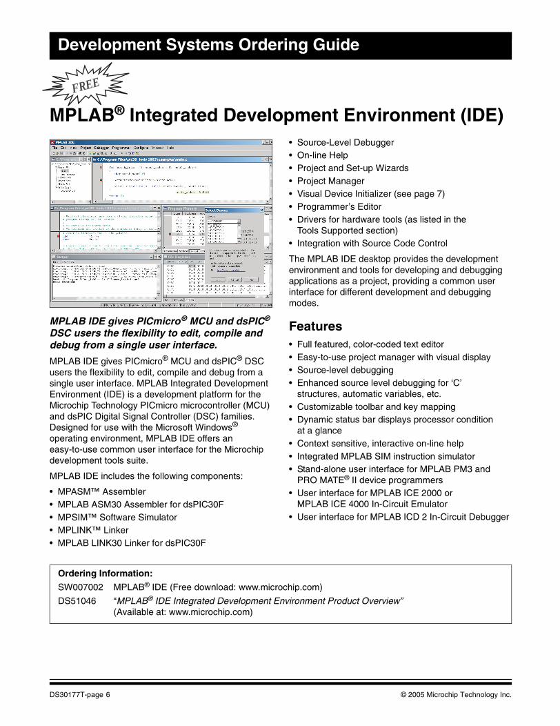
MPLAB IDE gives PICmicro® MCU and dsPIC® DSC users the flexibility to edit, compile and debug from a single user interface.
MPLAB IDE gives PICmicro® MCU and dsPIC® DSC users the flexibility to edit, compile and debug from a single user interface. MPLAB Integrated Development Environment (IDE) is a development platform for the Microchip Technology PICmicro microcontroller (MCU) and dsPIC Digital Signal Controller (DSC) families. Designed for use with the Microsoft Windows® operating environment, MPLAB IDE offers an easy-to-use common user interface for the Microchip development tools suite.
MPLAB IDE includes the following components:
• MPASM™ Assembler• MPLAB ASM30 Assembler for dsPIC30F• MPSIM™ Software Simulator• MPLINK™ Linker• MPLAB LINK30 Linker for dsPIC30F
• Source-Level Debugger• On-line Help• Project and Set-up Wizards• Project Manager• Visual Device Initializer (see page 7)• Programmer’s Editor• Drivers for hardware tools (as listed in the
Tools Supported section)• Integration with Source Code Control
The MPLAB IDE desktop provides the development environment and tools for developing and debugging applications as a project, providing a common user interface for different development and debugging modes.
Features• Full featured, color-coded text editor• Easy-to-use project manager with visual display• Source-level debugging• Enhanced source level debugging for ‘C’
structures, automatic variables, etc.• Customizable toolbar and key mapping• Dynamic status bar displays processor condition
at a glance• Context sensitive, interactive on-line help• Integrated MPLAB SIM instruction simulator• Stand-alone user interface for MPLAB PM3 and
PRO MATE® II device programmers• User interface for MPLAB ICE 2000 or
MPLAB ICE 4000 In-Circuit Emulator• User interface for MPLAB ICD 2 In-Circuit Debugger
Ordering Information:
SW007002 MPLAB® IDE (Free download: www.microchip.com)
DS51046 “MPLAB® IDE Integrated Development Environment Product Overview” (Available at: www.microchip.com)
DS30177T-page 6 © 2005 Microchip Technology Inc.
Software
FREE
MPLAB® IDE Visual Device Initializer Software
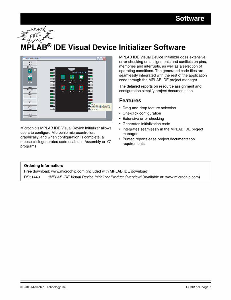
Microchip’s MPLAB IDE Visual Device Initializer allows users to configure Microchip microcontrollers graphically, and when configuration is complete, a mouse click generates code usable in Assembly or ‘C’ programs.
MPLAB IDE Visual Device Initializer does extensive error checking on assignments and conflicts on pins, memories and interrupts, as well as a selection of operating conditions. The generated code files are seamlessly integrated with the rest of the application code through the MPLAB IDE project manager.
The detailed reports on resource assignment and configuration simplify project documentation.
Features• Drag-and-drop feature selection• One-click configuration• Extensive error checking• Generates initialization code• Integrates seamlessly in the MPLAB IDE project
manager• Printed reports ease project documentation
requirements
Ordering Information:
Free download: www.microchip.com (included with MPLAB IDE download)
DS51443 “MPLAB IDE Visual Device Initializer Product Overview” (Available at: www.microchip.com)
© 2005 Microchip Technology Inc. DS30177T-page 7
Development Systems Ordering Guide
FREE
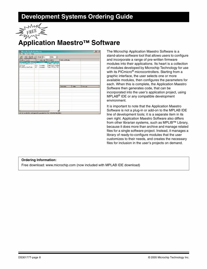
Application Maestro™ SoftwareThe Microchip Application Maestro Software is a stand-alone software tool that allows users to configure and incorporate a range of pre-written firmware modules into their applications. Its heart is a collection of modules developed by Microchip Technology for use with its PICmicro® microcontrollers. Starting from a graphic interface, the user selects one or more available modules, then configures the parameters for each. When this is complete, the Application Maestro Software then generates code, that can be incorporated into the user’s application project, using MPLAB® IDE or any compatible development environment.
It is important to note that the Application Maestro Software is not a plug-in or add-on to the MPLAB IDE line of development tools; it is a separate item in its own right. Application Maestro Software also differs from other librarian systems, such as MPLIB™ Library, because it does more than archive and manage related files for a single software project. Instead, it manages a library of ready-to-configure modules that the user customizes to their needs, and creates the necessary files for inclusion in the user’s projects on demand.
Ordering Information:
Free download: www.microchip.com (now included with MPLAB IDE download)
DS30177T-page 8 © 2005 Microchip Technology Inc.
Software
MPLAB® C18 C CompilerThe MPLAB C18 is a full-featured ANSI-compliant C compiler for the Microchip Technology PIC18CXXX family of PICmicro® MCUs. MPLAB C18 is fully compatible with Microchip’s MPLAB IDE, allowing source level debugging with both the MPLAB ICE and the MPLAB SIM Simulator. MPLAB C18 provides a convenient, project-oriented development environment that reduces development time.
MPLAB C18 allows code for the PIC18CXXX family to be written in the high-level ‘C’ language, using powerful PICmicro MCU libraries, enabling the developer to devote more time to the application and less time to the details of the processor.
MPLAB C18 was designed explicitly for the PIC18CXXX family and allows the use of a software stack for maximum RAM reusability.
MPLAB C18 provides user-configurable interrupt support for saving and restoring context during interrupt handling. Libraries are provided for multiple memory models. Libraries, precompiled objects and linker scripts can be included in MPLAB C18 projects, along with ‘C’ and Assembly source files, for use with MPLAB C18 make and build functions.
The MPLAB C18 ANSI-compliant C compiler comes complete with the MPLAB IDE. The IDE allows you to move quickly between different development and debugging modes. For example, you can quickly advance from software debugging with the MPLAB SIM Simulator to hardware debugging with MPLAB ICE.
MPLAB C18 has implemented extensions to the ‘C’ language to provide specific support for Microchip’s PICmicro MCU environment.
MPLAB C18 will run on any 486 or better PC, as a native 32-bit Windows® 95 or Windows NT® executable.
MPLAB C18 C Compiler Contents
• MPLAB® C18 C Compiler Software• MPLAB® IDE Software and Documentation CD• “MPLAB® C18 C Compiler User’s Guide” and
“MPLAB® C18 C Compiler Libraries” and “MPLAB® C18 C Compiler Getting Started” Manuals
Ordering Information:
SW006011 MPLAB® C18 C Compiler
A 60-day full-featured demo/student edition is available from the Microchip web site at www.microchip.com.
© 2005 Microchip Technology Inc. DS30177T-page 9
Development Systems Ordering Guide
MPLAB® C30 C Compiler
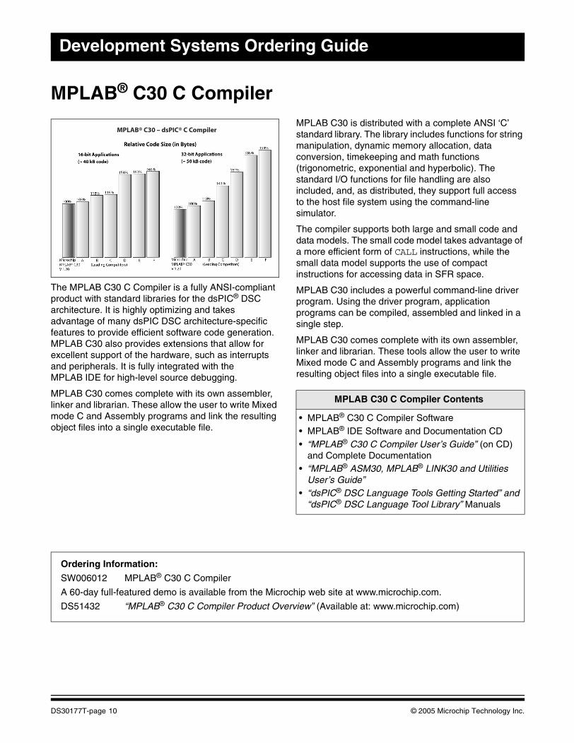
The MPLAB C30 C Compiler is a fully ANSI-compliant product with standard libraries for the dsPIC® DSC architecture. It is highly optimizing and takes advantage of many dsPIC DSC architecture-specific features to provide efficient software code generation. MPLAB C30 also provides extensions that allow for excellent support of the hardware, such as interrupts and peripherals. It is fully integrated with the MPLAB IDE for high-level source debugging.
MPLAB C30 comes complete with its own assembler, linker and librarian. These allow the user to write Mixed mode C and Assembly programs and link the resulting object files into a single executable file.
MPLAB C30 is distributed with a complete ANSI ‘C’ standard library. The library includes functions for string manipulation, dynamic memory allocation, data conversion, timekeeping and math functions (trigonometric, exponential and hyperbolic). The standard I/O functions for file handling are also included, and, as distributed, they support full access to the host file system using the command-line simulator.
The compiler supports both large and small code and data models. The small code model takes advantage of a more efficient form of CALL instructions, while the small data model supports the use of compact instructions for accessing data in SFR space.
MPLAB C30 includes a powerful command-line driver program. Using the driver program, application programs can be compiled, assembled and linked in a single step.
MPLAB C30 comes complete with its own assembler, linker and librarian. These tools allow the user to write Mixed mode C and Assembly programs and link the resulting object files into a single executable file.
MPLAB® C30 – dsPIC® C Compiler
MPLAB C30 C Compiler Contents
• MPLAB® C30 C Compiler Software• MPLAB® IDE Software and Documentation CD• “MPLAB® C30 C Compiler User’s Guide” (on CD)
and Complete Documentation• “MPLAB® ASM30, MPLAB® LINK30 and Utilities
User’s Guide”• “dsPIC® DSC Language Tools Getting Started” and
“dsPIC® DSC Language Tool Library” Manuals
Ordering Information:
SW006012 MPLAB® C30 C Compiler
A 60-day full-featured demo is available from the Microchip web site at www.microchip.com.
DS51432 “MPLAB® C30 C Compiler Product Overview” (Available at: www.microchip.com)
DS30177T-page 10 © 2005 Microchip Technology Inc.
Software
FREE
dsPIC30F DSP LibraryThe dsPIC30F DSP Library provides a set of speed-optimized functions for the most common digital signal processing applications. The DSP Library provides significant performance savings over equivalent functions coded in ‘C’ and allows developers to dramatically shorten their development time.
The DSP Library is written predominantly in Assembly language and makes extensive use of the dsPIC30F DSC instruction set and hardware resources, including X and Y memory addressing, modulo addressing, bit-reversed addressing, 9.31 saturation and REPEAT and DO loops. It provides functions for vector, matrix, filtering, transform and window operations.
Features• 49 total functions• Full compliance with the Microchip dsPIC30F C30
Compiler, Assembler and Linker
• Simple user interface – just one library file and one header file
• Functions are both ‘C’ and Assembly callable• FIR filtering functions include support for Lattice,
Decimating, Interpolating and LMS filters• IIR filtering functions include support for Canonic,
Transposed Canonic and Lattice filters• FIR and IIR functions may be used with the filter files
generated by the dsPIC® DSC Digital Filter Design Tool
• Transform functions include support for in-place and out-of-place DCT, FFT and IFFT transforms
• Window functions include support for Bartlett, Blackman, Hamming, Hanning and Kaiser windows
• Support for Program Space Visibility• Complete function profile information, including
register usage, cycle count and function size information
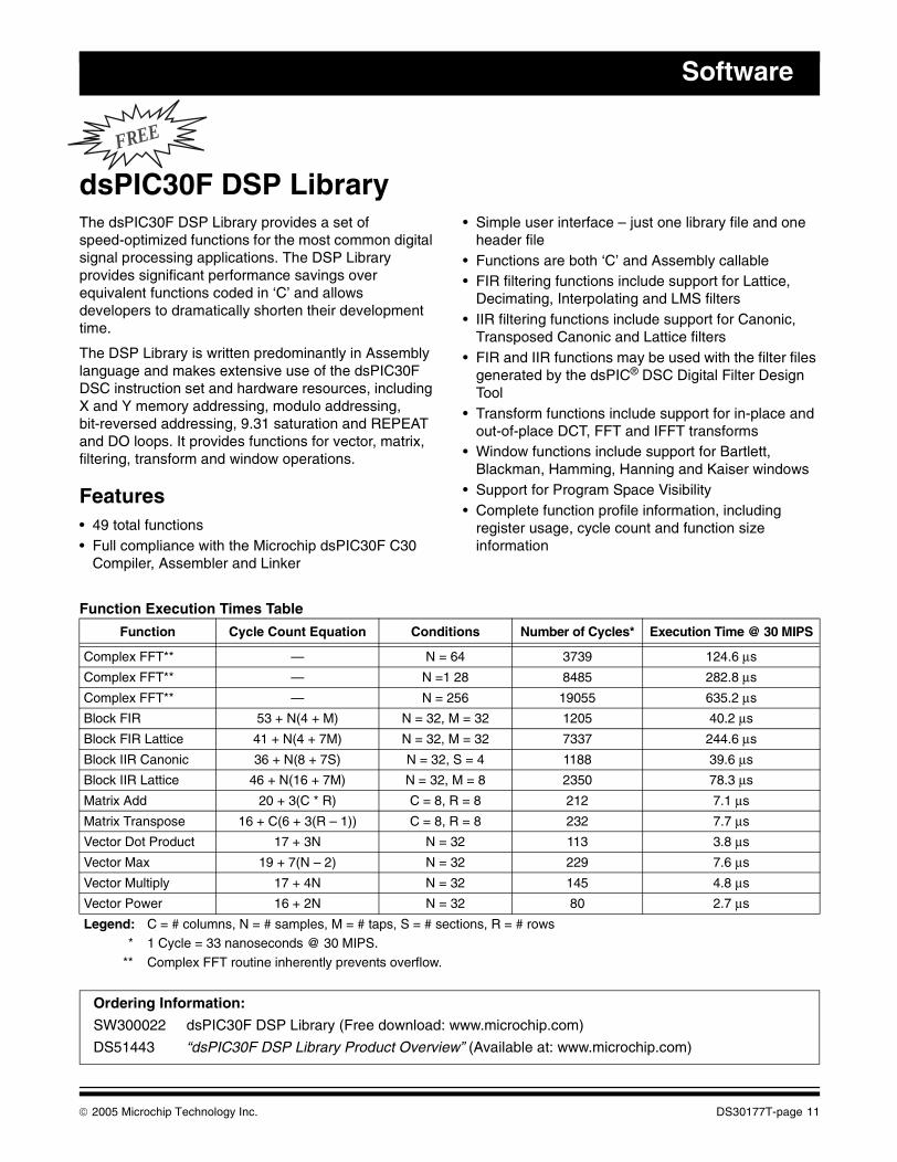
Function Execution Times Table
Function Cycle Count Equation Conditions Number of Cycles* Execution Time @ 30 MIPS
Complex FFT** — N = 64 3739 124.6 μs
Complex FFT** — N =1 28 8485 282.8 μs
Complex FFT** — N = 256 19055 635.2 μs
Block FIR 53 + N(4 + M) N = 32, M = 32 1205 40.2 μs
Block FIR Lattice 41 + N(4 + 7M) N = 32, M = 32 7337 244.6 μs
Block IIR Canonic 36 + N(8 + 7S) N = 32, S = 4 1188 39.6 μs
Block IIR Lattice 46 + N(16 + 7M) N = 32, M = 8 2350 78.3 μs
Matrix Add 20 + 3(C * R) C = 8, R = 8 212 7.1 μs
Matrix Transpose 16 + C(6 + 3(R – 1)) C = 8, R = 8 232 7.7 μs
Vector Dot Product 17 + 3N N = 32 113 3.8 μs
Vector Max 19 + 7(N – 2) N = 32 229 7.6 μs
Vector Multiply 17 + 4N N = 32 145 4.8 μs
Vector Power 16 + 2N N = 32 80 2.7 μs
Legend: C = # columns, N = # samples, M = # taps, S = # sections, R = # rows* 1 Cycle = 33 nanoseconds @ 30 MIPS.
** Complex FFT routine inherently prevents overflow.
Ordering Information:
SW300022 dsPIC30F DSP Library (Free download: www.microchip.com)
DS51443 “dsPIC30F DSP Library Product Overview” (Available at: www.microchip.com)
© 2005 Microchip Technology Inc. DS30177T-page 11
Development Systems Ordering Guide
FREE
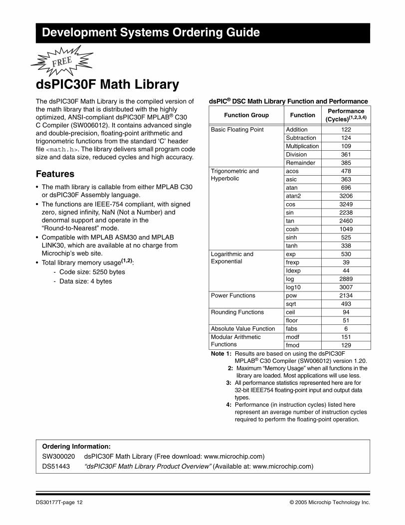
dsPIC30F Math LibraryThe dsPIC30F Math Library is the compiled version of the math library that is distributed with the highly optimized, ANSI-compliant dsPIC30F MPLAB® C30 C Compiler (SW006012). It contains advanced single and double-precision, floating-point arithmetic and trigonometric functions from the standard ‘C’ header file <math.h>. The library delivers small program code size and data size, reduced cycles and high accuracy.
Features• The math library is callable from either MPLAB C30
or dsPIC30F Assembly language.• The functions are IEEE-754 compliant, with signed
zero, signed infinity, NaN (Not a Number) and denormal support and operate in the “Round-to-Nearest” mode.
• Compatible with MPLAB ASM30 and MPLAB LINK30, which are available at no charge from Microchip’s web site.
• Total library memory usage(1,2):- Code size: 5250 bytes- Data size: 4 bytes
dsPIC® DSC Math Library Function and Performance
Function Group FunctionPerformance
(Cycles)(1,2,3,4)
Basic Floating Point Addition 122Subtraction 124Multiplication 109Division 361Remainder 385
Trigonometric and Hyperbolic
acos 478asic 363atan 696atan2 3206cos 3249sin 2238tan 2460cosh 1049sinh 525tanh 338
Logarithmic and Exponential
exp 530frexp 39Idexp 44log 2889log10 3007
Power Functions pow 2134sqrt 493
Rounding Functions ceil 94floor 51
Absolute Value Function fabs 6Modular Arithmetic Functions
modf 151fmod 129
Note 1: Results are based on using the dsPIC30F MPLAB® C30 Compiler (SW006012) version 1.20.
2: Maximum “Memory Usage” when all functions in the library are loaded. Most applications will use less.
3: All performance statistics represented here are for 32-bit IEEE754 floating-point input and output data types.
4: Performance (in instruction cycles) listed here represent an average number of instruction cycles required to perform the floating-point operation.
Ordering Information:
SW300020 dsPIC30F Math Library (Free download: www.microchip.com)
DS51443 “dsPIC30F Math Library Product Overview” (Available at: www.microchip.com)
DS30177T-page 12 © 2005 Microchip Technology Inc.
Software
FREE
dsPIC30F Peripheral LibraryThe dsPIC30F Peripheral Library provides a set of functions for setting up and controlling the operation of all the peripheral modules available in the dsPIC30F devices, as well as functions for interfacing with an external LCD. The Peripheral Library serves as a convenient layer of abstraction over the specific details of the peripherals and their associated control and status registers.
The dsPIC30F Peripheral Library supports the following hardware peripheral modules:
• Timers• Input Capture• Output Compare• Quadrature Encoder Interface (QEI)• Motor Control PWM• I/O Ports and External Interrupts• Reset• UART• SPI™• I2C™• Data Converter Interface (DCI)• 10-Bit A/D Converter• 12-Bit A/D Converter• CAN
Functions for controlling an external LCD through configurable I/O port pins are also provided
Features• For each individual device from the dsPIC30F family,
there is a file that includes functions corresponding to peripherals present in that particular device.
• ‘C’ include files enable the user to take advantage of predefined constants for passing parameters to various library functions. There is an include file for each peripheral module.
• Since the functions are in the form of precompiled libraries, they may be called from a user application program written in either MPLAB® C30 or dsPIC30F Assembly language.
• ‘C’ source code is also included so users can customize the functions to suit specific application requirements.
• Predefined constants in ‘C’ include files eliminate the need to refer to details and structure of Special Function Registers, while initializing peripherals or checking status bits.
Resource Requirements
Program Memory
The Peripheral Library functions have been optimized for reduced program memory usage. Since the functions are in the form of libraries, the actual program memory requirements depend on the functions being called by the application, as well as on the specific dsPIC30F device being used.
Data Memory
The vast majority of the functions do not use RAM at all. Each of the remaining functions uses less than 10 bytes of RAM.
Ordering Information:
SW300021 dsPIC30F Peripheral Library (Free download: www.microchip.com)
DS51443 “dsPIC30F Peripheral Library Product Overview” (Available at: www.microchip.com)
© 2005 Microchip Technology Inc. DS30177T-page 13
Development Systems Ordering Guide
dsPIC30F Soft Modem LibraryThe Microchip Soft Modem Library is composed of ITU-T compliant algorithms for V.21, V.22, V.22bis, V.23, V.32 and V.32bis modem recommendations. Bell standard 103 is also included in this library.
V.21, V.23 and Bell 103 are Frequency Shift Keying (FSK) modems. V.32, V.32bis and V.22bis are Quadrature Amplitude Modulated (QAM) modems. V.22 is a Quadrature Phase Shift Keyed (QPSK) modem. V.21, V.22, V.22bis, V.32 and V.32bis are all 2-wire, full-duplex modems. V.23 is a full-duplex modem when it operates with a 75 bps backwards channel.
V.22bis includes fallback to V.22, V.23 and V.21 standards. V.32bis optionally falls back to V.22bis, V.22, V.23 and V.21 standards.
FeaturesThe data modem library is provided in two basic software packages:
• V.22bis/V.22, which is offered free with full source code
• V.32bis/V.32, which is offered in a tiered pricing structure with full source code
The library currently supports single-channel data pump implementations.
Both libraries are supported with fallback data pump modulations down to V.21. Each data modem library is provided with a respective library archive containing all the data pump object code modules required to link to the user’s application. Hardware component drivers, such as UART and Data Converter Interface for DAA/AFE I/O, are provided in Assembly source code for linking with the user’s application.
ITU-T Recommendation V.42 is provided with each library. V.42 contains a High-Level Data Link Control (HDLC) protocol, referred to as Link Access Procedure for Modems (LAPM) and defines error correcting protocols for modems.
All data pump modulations are developed in ASM30 Assembly code, yielding optimal code size and execution time. The AT, V.42 and Data Pump APIs are based on C30 C language.
Electronic documentation accompanies the modem library to help you become familiar with and implement the library functions. A comprehensive “Soft Modem User’s Guide” describes the required APIs for the AT, V.42 and data pump layers.
Ordering Information:
SW300003-EVAL dsPIC30F V.32bis Soft Modem Library Software License (Evaluation Copy)
SW300002 dsPIC30F V.22bis Soft Modem Library (Free download: www.microchip.com)
SW300003 dsPIC30F V.32bis Soft Modem Library Software License (Up to 5K units)
SW300004 dsPIC30F V.32bis Soft Modem Library Software License (5K to 25K units)
SW300005 dsPIC30F V.32bis Soft Modem Library Software License (25K to 100K units)
DS70126 “dsPIC30F Soft Modem Library Product Overview” (Available at: www.microchip.com)
DS30177T-page 14 © 2005 Microchip Technology Inc.
Software
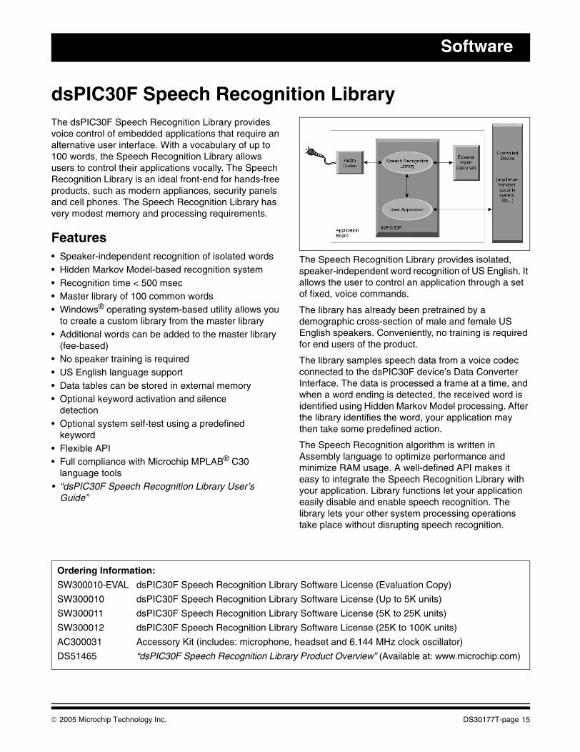
dsPIC30F Speech Recognition LibraryThe dsPIC30F Speech Recognition Library provides voice control of embedded applications that require an alternative user interface. With a vocabulary of up to 100 words, the Speech Recognition Library allows users to control their applications vocally. The Speech Recognition Library is an ideal front-end for hands-free products, such as modern appliances, security panels and cell phones. The Speech Recognition Library has very modest memory and processing requirements.
Features• Speaker-independent recognition of isolated words• Hidden Markov Model-based recognition system• Recognition time < 500 msec• Master library of 100 common words• Windows® operating system-based utility allows you
to create a custom library from the master library• Additional words can be added to the master library
(fee-based)• No speaker training is required• US English language support • Data tables can be stored in external memory• Optional keyword activation and silence
detection• Optional system self-test using a predefined
keyword• Flexible API• Full compliance with Microchip MPLAB® C30
language tools• “dsPIC30F Speech Recognition Library User’s
Guide”
The Speech Recognition Library provides isolated, speaker-independent word recognition of US English. It allows the user to control an application through a set of fixed, voice commands.
The library has already been pretrained by a demographic cross-section of male and female US English speakers. Conveniently, no training is required for end users of the product.
The library samples speech data from a voice codec connected to the dsPIC30F device’s Data Converter Interface. The data is processed a frame at a time, and when a word ending is detected, the received word is identified using Hidden Markov Model processing. After the library identifies the word, your application may then take some predefined action.
The Speech Recognition algorithm is written in Assembly language to optimize performance and minimize RAM usage. A well-defined API makes it easy to integrate the Speech Recognition Library with your application. Library functions let your application easily disable and enable speech recognition. The library lets your other system processing operations take place without disrupting speech recognition.
Ordering Information:
SW300010-EVAL dsPIC30F Speech Recognition Library Software License (Evaluation Copy)
SW300010 dsPIC30F Speech Recognition Library Software License (Up to 5K units)
SW300011 dsPIC30F Speech Recognition Library Software License (5K to 25K units)
SW300012 dsPIC30F Speech Recognition Library Software License (25K to 100K units)
AC300031 Accessory Kit (includes: microphone, headset and 6.144 MHz clock oscillator)
DS51465 “dsPIC30F Speech Recognition Library Product Overview” (Available at: www.microchip.com)
© 2005 Microchip Technology Inc. DS30177T-page 15
Development Systems Ordering Guide
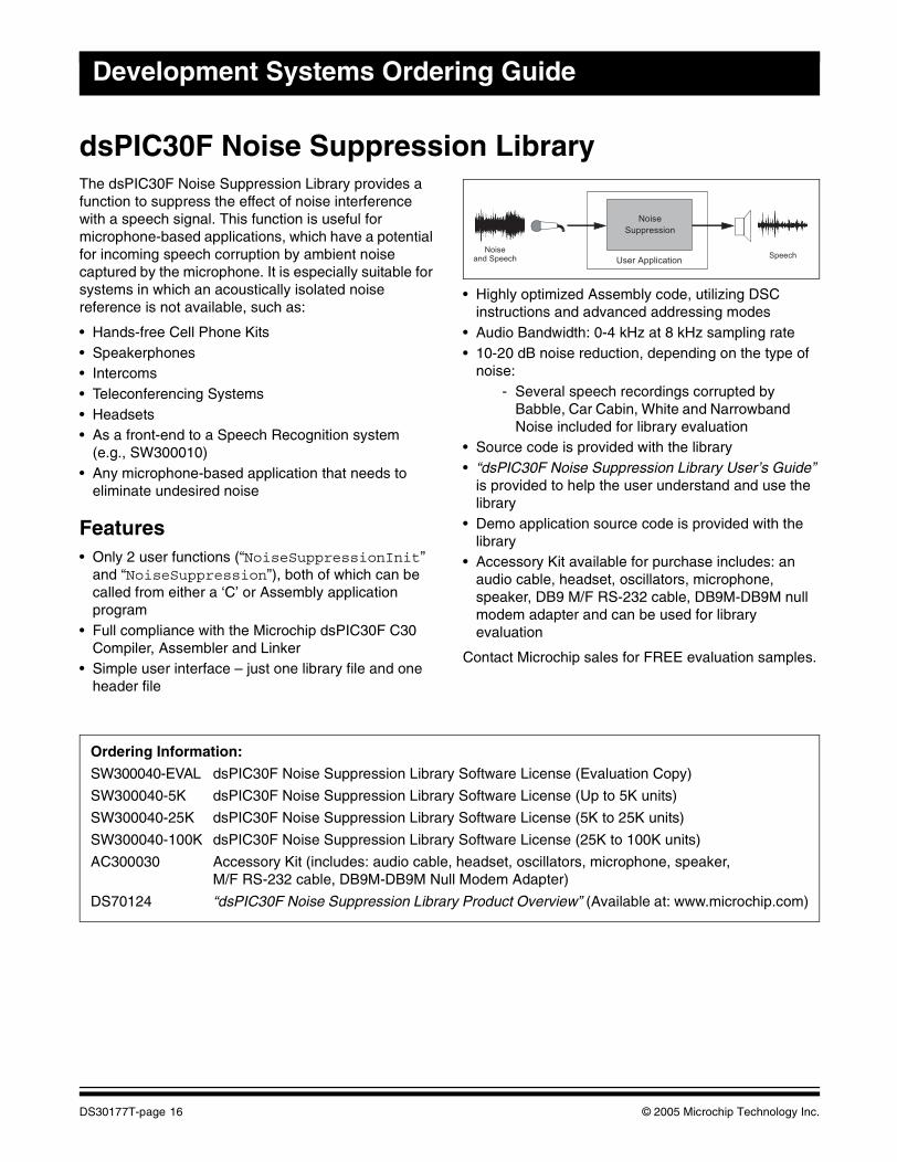
dsPIC30F Noise Suppression LibraryThe dsPIC30F Noise Suppression Library provides a function to suppress the effect of noise interference with a speech signal. This function is useful for microphone-based applications, which have a potential for incoming speech corruption by ambient noise captured by the microphone. It is especially suitable for systems in which an acoustically isolated noise reference is not available, such as:
• Hands-free Cell Phone Kits• Speakerphones• Intercoms• Teleconferencing Systems• Headsets• As a front-end to a Speech Recognition system
(e.g., SW300010)• Any microphone-based application that needs to
eliminate undesired noise
Features• Only 2 user functions (“NoiseSuppressionInit”
and “NoiseSuppression”), both of which can be called from either a ‘C’ or Assembly application program
• Full compliance with the Microchip dsPIC30F C30 Compiler, Assembler and Linker
• Simple user interface – just one library file and one header file
• Highly optimized Assembly code, utilizing DSC instructions and advanced addressing modes
• Audio Bandwidth: 0-4 kHz at 8 kHz sampling rate• 10-20 dB noise reduction, depending on the type of
noise: - Several speech recordings corrupted by
Babble, Car Cabin, White and Narrowband Noise included for library evaluation
• Source code is provided with the library• “dsPIC30F Noise Suppression Library User’s Guide”
is provided to help the user understand and use the library
• Demo application source code is provided with the library
• Accessory Kit available for purchase includes: an audio cable, headset, oscillators, microphone, speaker, DB9 M/F RS-232 cable, DB9M-DB9M null modem adapter and can be used for library evaluation
Contact Microchip sales for FREE evaluation samples.
Noiseand Speech Speech
Noise
Suppression
User Application
Ordering Information:
SW300040-EVAL dsPIC30F Noise Suppression Library Software License (Evaluation Copy)
SW300040-5K dsPIC30F Noise Suppression Library Software License (Up to 5K units)
SW300040-25K dsPIC30F Noise Suppression Library Software License (5K to 25K units)
SW300040-100K dsPIC30F Noise Suppression Library Software License (25K to 100K units)
AC300030 Accessory Kit (includes: audio cable, headset, oscillators, microphone, speaker, M/F RS-232 cable, DB9M-DB9M Null Modem Adapter)
DS70124 “dsPIC30F Noise Suppression Library Product Overview” (Available at: www.microchip.com)
DS30177T-page 16 © 2005 Microchip Technology Inc.

Software
dsPIC30F Acoustic Echo Cancellation LibraryThe dsPIC30F Acoustic Echo Cancellation (AEC) Library provides a function to eliminate echoes generated in the acoustic path between a speaker and a microphone. This function is useful for speech and telephony applications in which a speaker and a microphone are located in close proximity to each other and therefore, susceptible to signals propagating from the speaker to the microphone resulting in a perceptible and distracting echo effect at the far end. It is especially suitable for these applications:
• Hands-free Cell Phone Kits• Speakerphones• Intercoms• Teleconferencing Systems
For hands-free phones intended to be used in compact environments, such as a car, this library is fully compliant with the G.167 standard for acoustic echo cancellation.
Features• Only 2 user functions
(“AcousticEchoCancellerInit” and “AcousticEchoCanceller”), both of which can be called from either a ‘C’ or Assembly application program
• Full compliance with the Microchip dsPIC30F C30 C Compiler, Assembler and Linker simple user interface – just one library file and one header file
• Highly optimized Assembly code, utilizing DSC instructions and advanced addressing modes
• Echo cancellation for 16, 32 or 64 ms echo delays or ‘tail lengths’ (configurable)
• Fully tested for compliance with G.167 specifications for in-car applications
• Audio Bandwidth: 0-4 kHz at 8 kHz sampling rate• Convergence Rate: Up to 43 dB/sec., typically > 30
dB/sec.• Echo Cancellation: Up to 50 dB, typically > 40 dB• Can be used together with the Noise Suppression
(NS) Library, since the same processing block size (10 ms) is used
• “dsPIC30F Acoustic Echo Cancellation Library User’s Guide” is provided to help the user understand and use the library
• Demo application source code is provided with the library. Accessory kit available for purchase includes: an audio cable, headset, oscillators, microphone, speaker, DB9 M/F RS-232 cable and DB9M-DB9M Null Modem Adapter and can be used for library evaluation
• Contact Microchip sales for FREE evaluation samples
∑ +
-
Acoustic Echo
Cancellation
FAR END NEAR END
Far EndSpeech
Far EndSpeech
Near EndSpeech
Near EndSpeech
Receive Path
AdaptiveFilter
Send Path
User Application
Echo
Ordering Information:
SW300060-EVAL dsPIC30F Acoustic Echo Cancellation Library Software License (Evaluation Copy)
SW300060-5K dsPIC30F Acoustic Echo Cancellation Library Software License (Up to 5K units)
SW300060-25K dsPIC30F Acoustic Echo Cancellation Library Software License (5K to 25K units)
SW300060-100K dsPIC30F Acoustic Echo Cancellation Library Software License (25K to 100K units)
AC300030 Accessory Kit (includes: audio cable, headset, oscillators, microphone, speaker, M/F RS-232 cable, DB9M-DB9M Null Modem Adapter)
DS70123 “dsPIC30F Acoustic Echo Cancellation Library Product Overview” (Available at: www.microchip.com)
© 2005 Microchip Technology Inc. DS30177T-page 17
Development Systems Ordering Guide
dsPIC® DSC Symmetric Key Embedded Encryption LibraryMicrochip offers a reliable security solution for embedded applications built on the dsPIC30F platform. This solution is provided by means of two libraries – Symmetric Key and Asymmetric Key Embedded Encryption Libraries. The Symmetric Key Library features the following:
• Hash Functions:- SHA-1 Secure Hash Standard- MD5 Message Digest
• Symmetric Key Encryption/Decryption Functions:- Advanced Encryption Standard (AES)- Triple Data Encryption Algorithm
(Triple-DES)• Random Number Generator Functions:
- Deterministic Random Bit Generator ANSI X9.82
Features• C-callable library functions developed in
MPLAB® ASM30• Assembly language• Optimized for speed, code size and RAM usage:
- RAM usage below 60 bytes• Library functions extensively tested for
adherence to applicable standards• Symmetric Key Encryption/Decryption functions
support multiple modes of operation:- Electronic Code Book (ECB) mode- Cipher Block Chaining with Message
Authentication (CBC-MAC) mode- Counter (CTR) mode- Combined CBC-MAC and Counter (CCM)
mode• A comprehensive “dsPIC30F Embedded
Encryption Libraries User’s Guide” describing the required APIs for the library functions
• Several examples of use are provided for each library function
Ordering Information:
SW300050-EVAL dsPIC® DSC Symmetric Key Embedded Encryption Library Software License (Evaluation Copy)
SW300050-5K dsPIC® DSC Symmetric Key Embedded Encryption Library Software License (Up to 5K units)
SW300050-25K dsPIC® DSC Symmetric Key Embedded Encryption Library Software License (5K to 25K units)
SW300050-100K dsPIC® DSC Symmetric Key Embedded Encryption Library Software License (25K to 100K units)
DS70128 “dsPIC® DSC Symmetric Key Embedded Encryption Library Product Overview” (Available at: www.microchip.com)
DS30177T-page 18 © 2005 Microchip Technology Inc.
Software
dsPIC® DSC Asymmetric Key Embedded Encryption LibraryMicrochip offers a reliable security solution for embedded applications built on the dsPIC30F platform. This solution is provided by means of two libraries – Symmetric Key and Asymmetric Key Embedded Encryption Libraries. The Asymmetric Key Library implements the following:
• Public Key Encryption/Decryption Functions:- RSA (1024 and 2048-bit)
• Key Agreement Protocol:- Diffie-Hellman (1024 and 2048-bit)
• Signing and Verification:- DSA (1024-bit)- RSA (1024 and 2048-bit)
• Hash and Message Digest Functions:- SHA-1, MD5
• Random Number Generator (RNG):- ANSI X9.82
Features• C-callable library functions developed in
MPLAB ASM30 Assembly language• Optimized for speed, code size and RAM usage:
- RAM usage below 100 bytes• Library functions extensively tested for
adherence to applicable standards• A comprehensive “dsPIC30F Embedded
Encryption Libraries User’s Guide” describing the required APIs for the library functions
• Several examples of use provided for each library function
Typical ApplicationsThe algorithms supported by this library have emerged as the defacto standard for many large scale, secured applications, like web access, e-mail, secure XML transactions and Virtual Private Networks (VPN). These algorithms are also recommended by most Internet Engineering Task Force (IETF) Standards, Federal Information Processing Standards (FIPS) and IPSec Standards. Some typical applications for this library include:
• Mobile and wireless devices, PDAs• Secure banking• Secure web transactions:
- Secure Socket Layer (SSL)- Transport Layer Security (TLS)- Secure Multi-purpose Internet Mail
Extensions (S/MIME)- ZigBee™ technology and other monitoring
and control applications• Smart card readers• Friend/foe identification• Peripherals interoperating with TCG and NGSCB
personal computers
The Trusted Computing Group (TCG) and related Microsoft® Next Generation Secure Computing Base (NGSCB) both specify RSA and Triple-DES. AES, Triple DES and other symmetric solutions are featured in the dsPIC30F Symmetric Key Embedded Encryption Library (SW300050).
Ordering Information:
SW300055-EVAL dsPIC® DSC Asymmetric Key Embedded Encryption Library Software License (Evaluation Copy)
SW300055-5K dsPIC® DSC Asymmetric Key Embedded Encryption Library Software License (Up to 5K units)
SW300055-25K dsPIC® DSC Asymmetric Key Embedded Encryption Library Software License (5K to 25K units)
SW300055-100K dsPIC® DSC Asymmetric Key Embedded Encryption Library Software License (25K to 100K units)
DS70127 “dsPIC® DSC Asymmetric Key Embedded Encryption Library Product Overview” (Available at: www.microchip.com)
© 2005 Microchip Technology Inc. DS30177T-page 19
Development Systems Ordering Guide
NEW
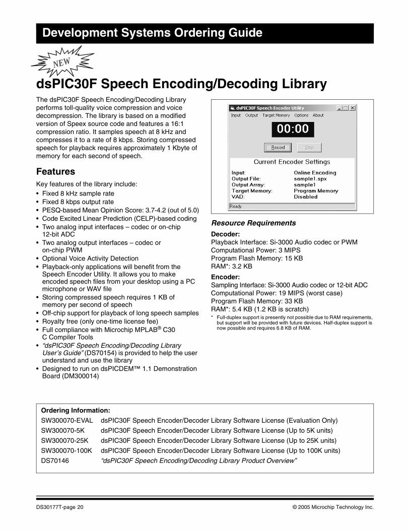
dsPIC30F Speech Encoding/Decoding LibraryThe dsPIC30F Speech Encoding/Decoding Library performs toll-quality voice compression and voice decompression. The library is based on a modified version of Speex source code and features a 16:1 compression ratio. It samples speech at 8 kHz and compresses it to a rate of 8 kbps. Storing compressed speech for playback requires approximately 1 Kbyte of memory for each second of speech.
FeaturesKey features of the library include:• Fixed 8 kHz sample rate • Fixed 8 kbps output rate • PESQ-based Mean Opinion Score: 3.7-4.2 (out of 5.0)• Code Excited Linear Prediction (CELP)-based coding• Two analog input interfaces – codec or on-chip
12-bit ADC• Two analog output interfaces – codec or
on-chip PWM• Optional Voice Activity Detection• Playback-only applications will benefit from the
Speech Encoder Utility. It allows you to make encoded speech files from your desktop using a PC microphone or WAV file
• Storing compressed speech requires 1 KB of memory per second of speech
• Off-chip support for playback of long speech samples• Royalty free (only one-time license fee)• Full compliance with Microchip MPLAB® C30
C Compiler Tools• “dsPIC30F Speech Encoding/Decoding Library
User’s Guide” (DS70154) is provided to help the user understand and use the library
• Designed to run on dsPICDEM™ 1.1 Demonstration Board (DM300014)
Resource Requirements Decoder:Playback Interface: Si-3000 Audio codec or PWMComputational Power: 3 MIPSProgram Flash Memory: 15 KBRAM*: 3.2 KB
Encoder:Sampling Interface: Si-3000 Audio codec or 12-bit ADCComputational Power: 19 MIPS (worst case)Program Flash Memory: 33 KBRAM*: 5.4 KB (1.2 KB is scratch)* Full-duplex support is presently not possible due to RAM requirements,
but support will be provided with future devices. Half-duplex support is now possible and requires 6.8 KB of RAM.
Ordering Information:
SW300070-EVAL dsPIC30F Speech Encoder/Decoder Library Software License (Evaluation Only)
SW300070-5K dsPIC30F Speech Encoder/Decoder Library Software License (Up to 5K units)
SW300070-25K dsPIC30F Speech Encoder/Decoder Library Software License (Up to 25K units)
SW300070-100K dsPIC30F Speech Encoder/Decoder Library Software License (Up to 100K units)
DS70146 “dsPIC30F Speech Encoding/Decoding Library Product Overview”
DS30177T-page 20 © 2005 Microchip Technology Inc.
Software
FREE
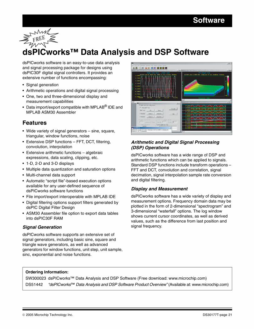
dsPICworks™ Data Analysis and DSP SoftwaredsPICworks software is an easy-to-use data analysis and signal processing package for designs using dsPIC30F digital signal controllers. It provides an extensive number of functions encompassing:
• Signal generation• Arithmetic operations and digital signal processing• One, two and three-dimensional display and
measurement capabilities• Data import/export compatible with MPLAB® IDE and
MPLAB ASM30 Assembler
Features• Wide variety of signal generators – sine, square,
triangular, window functions, noise• Extensive DSP functions – FFT, DCT, filtering,
convolution, interpolation• Extensive arithmetic functions – algebraic
expressions, data scaling, clipping, etc.• 1-D, 2-D and 3-D displays• Multiple data quantization and saturation options• Multi-channel data support• Automatic “script file”-based execution options
available for any user-defined sequence of dsPICworks software functions
• File import/export interoperable with MPLAB IDE• Digital filtering options support filters generated by
dsPIC Digital Filter Design• ASM30 Assembler file option to export data tables
into dsPIC30F RAM
Signal Generation
dsPICworks software supports an extensive set of signal generators, including basic sine, square and triangle wave generators, as well as advanced generators for window functions, unit step, unit sample, sinc, exponential and noise functions.
Arithmetic and Digital Signal Processing (DSP) Operations
dsPICworks software has a wide range of DSP and arithmetic functions which can be applied to signals. Standard DSP functions include transform operations – FFT and DCT, convolution and correlation, signal decimation, signal interpolation sample rate conversion and digital filtering.
Display and Measurement
dsPICworks software has a wide variety of display and measurement options. Frequency domain data may be plotted in the form of 2-dimensional “spectrogram” and 3-dimensional “waterfall” options. The log window shows current cursor coordinates, as well as derived values, such as the difference from last position and signal frequency.
Ordering Information:
SW300023 dsPICworks™ Data Analysis and DSP Software (Free download: www.microchip.com)
DS51442 “dsPICworks™ Data Analysis and DSP Software Product Overview” (Available at: www.microchip.com)
© 2005 Microchip Technology Inc. DS30177T-page 21
Development Systems Ordering Guide
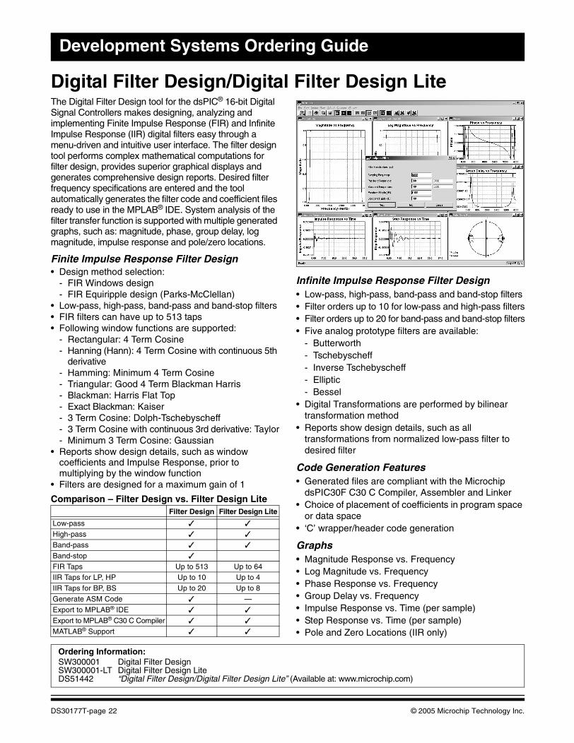
Digital Filter Design/Digital Filter Design LiteThe Digital Filter Design tool for the dsPIC® 16-bit Digital Signal Controllers makes designing, analyzing and implementing Finite Impulse Response (FIR) and Infinite Impulse Response (IIR) digital filters easy through a menu-driven and intuitive user interface. The filter design tool performs complex mathematical computations for filter design, provides superior graphical displays and generates comprehensive design reports. Desired filter frequency specifications are entered and the tool automatically generates the filter code and coefficient files ready to use in the MPLAB® IDE. System analysis of the filter transfer function is supported with multiple generated graphs, such as: magnitude, phase, group delay, log magnitude, impulse response and pole/zero locations.
Finite Impulse Response Filter Design• Design method selection:
- FIR Windows design- FIR Equiripple design (Parks-McClellan)
• Low-pass, high-pass, band-pass and band-stop filters• FIR filters can have up to 513 taps• Following window functions are supported:
- Rectangular: 4 Term Cosine- Hanning (Hann): 4 Term Cosine with continuous 5th
derivative- Hamming: Minimum 4 Term Cosine- Triangular: Good 4 Term Blackman Harris- Blackman: Harris Flat Top- Exact Blackman: Kaiser- 3 Term Cosine: Dolph-Tschebyscheff- 3 Term Cosine with continuous 3rd derivative: Taylor- Minimum 3 Term Cosine: Gaussian
• Reports show design details, such as window coefficients and Impulse Response, prior to multiplying by the window function
• Filters are designed for a maximum gain of 1
Comparison – Filter Design vs. Filter Design Lite
Infinite Impulse Response Filter Design• Low-pass, high-pass, band-pass and band-stop filters• Filter orders up to 10 for low-pass and high-pass filters• Filter orders up to 20 for band-pass and band-stop filters• Five analog prototype filters are available:
- Butterworth - Tschebyscheff- Inverse Tschebyscheff- Elliptic- Bessel
• Digital Transformations are performed by bilinear transformation method
• Reports show design details, such as all transformations from normalized low-pass filter to desired filter
Code Generation Features• Generated files are compliant with the Microchip
dsPIC30F C30 C Compiler, Assembler and Linker• Choice of placement of coefficients in program space
or data space• ‘C’ wrapper/header code generation
Graphs• Magnitude Response vs. Frequency• Log Magnitude vs. Frequency• Phase Response vs. Frequency• Group Delay vs. Frequency• Impulse Response vs. Time (per sample) • Step Response vs. Time (per sample)• Pole and Zero Locations (IIR only)
Filter Design Filter Design Lite
Low-pass ✓ ✓
High-pass ✓ ✓
Band-pass ✓ ✓
Band-stop ✓
FIR Taps Up to 513 Up to 64IIR Taps for LP, HP Up to 10 Up to 4
IIR Taps for BP, BS Up to 20 Up to 8
Generate ASM Code ✓ —
Export to MPLAB® IDE ✓ ✓
Export to MPLAB® C30 C Compiler ✓ ✓
MATLAB® Support ✓ ✓
Ordering Information:SW300001 Digital Filter DesignSW300001-LT Digital Filter Design LiteDS51442 “Digital Filter Design/Digital Filter Design Lite” (Available at: www.microchip.com)
DS30177T-page 22 © 2005 Microchip Technology Inc.
Software
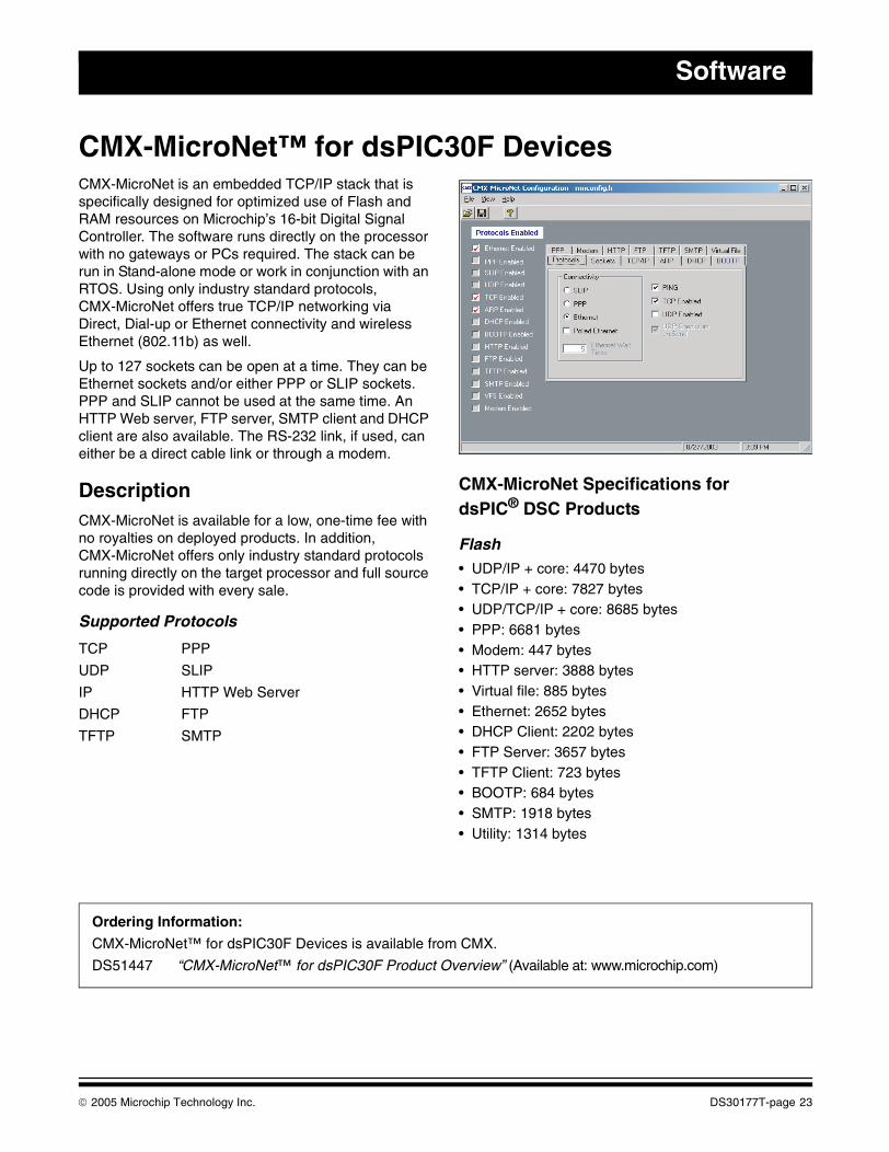
CMX-MicroNet™ for dsPIC30F DevicesCMX-MicroNet is an embedded TCP/IP stack that is specifically designed for optimized use of Flash and RAM resources on Microchip’s 16-bit Digital Signal Controller. The software runs directly on the processor with no gateways or PCs required. The stack can be run in Stand-alone mode or work in conjunction with an RTOS. Using only industry standard protocols, CMX-MicroNet offers true TCP/IP networking via Direct, Dial-up or Ethernet connectivity and wireless Ethernet (802.11b) as well.
Up to 127 sockets can be open at a time. They can be Ethernet sockets and/or either PPP or SLIP sockets. PPP and SLIP cannot be used at the same time. An HTTP Web server, FTP server, SMTP client and DHCP client are also available. The RS-232 link, if used, can either be a direct cable link or through a modem.
DescriptionCMX-MicroNet is available for a low, one-time fee with no royalties on deployed products. In addition, CMX-MicroNet offers only industry standard protocols running directly on the target processor and full source code is provided with every sale.
Supported Protocols
CMX-MicroNet Specifications fordsPIC® DSC Products
Flash• UDP/IP + core: 4470 bytes• TCP/IP + core: 7827 bytes• UDP/TCP/IP + core: 8685 bytes• PPP: 6681 bytes• Modem: 447 bytes• HTTP server: 3888 bytes• Virtual file: 885 bytes• Ethernet: 2652 bytes• DHCP Client: 2202 bytes• FTP Server: 3657 bytes• TFTP Client: 723 bytes• BOOTP: 684 bytes• SMTP: 1918 bytes• Utility: 1314 bytes
TCP PPP
UDP SLIP
IP HTTP Web Server
DHCP FTP
TFTP SMTP
Ordering Information:
CMX-MicroNet™ for dsPIC30F Devices is available from CMX.
DS51447 “CMX-MicroNet™ for dsPIC30F Product Overview” (Available at: www.microchip.com)
© 2005 Microchip Technology Inc. DS30177T-page 23
Development Systems Ordering Guide
CMX-RTX™ for dsPIC30F DevicesIn some cases, well-structured linear programming is sufficient for a product. In most cases, however, programmers appreciate not having to worry about structuring their code to perform all necessary tasks in a timely manner. This is where CMX-RTX can help. CMX-RTX allows tasks (pieces of code that do specific duties) to run quasi-concurrently. This means that tasks will seem to run all at the same time – doing many specific jobs simultaneously.
CMX-RTX takes the worry and headaches out of real-time programming. The software lets embedded programmers concentrate on the overall application as it takes care of the little details. Finish projects faster and more efficiently with CMX-RTX.
Some RTOS software offers only cooperative scheduling, which means that the running task has to call the scheduler to perform a task switch. Others offer time slicing, where each task runs for a certain period of time, at which point, a task switch takes place no matter what. Others claim to be fully preemptive, but do not allow any interrupt to cause a preemption. All of these models will fail at one point or another.
CMX-RTX allows a task of higher priority that is able to run (whether starting or resuming) to preempt the lower priority running task. This will cause the scheduler to save the context of the running (lower priority) task and restore the context of the higher priority task so that it is now running. A truly preemptive RTOS allows interrupts to cause an immediate task switch. This means that the interrupts now have the added ability of using the RTOS’s functions.
Features• The smallest footprint• The fastest context switch times• The lowest interrupt latency times• True preemption• Scheduler and interrupt handler written in
Assembly for speed and optimization• Optional cooperative and time-slicing scheduling• Nested interrupts• All functions contained in a library• Interrupt callable functions• Scalability• Free source code provided• Integrated with CMX-MicroNet™ for optional
networking connectivity
CMX-RTX Specifications fordsPIC® DSC Products
Flash• All CMX Functions: 3696 bytes• CMX Initialize Module: 936 bytes• CMX Assembly Module (scheduler): 645 bytes• RAM, Each Task Control Block: 28 bytes• Min. Context Switch:
- 92 cycles (starting a task)- 137 cycles (resuming a task)
• CMX functions are contained in a library, thus reducing code size, if not referenced
Ordering Information:
SW300031 CMX-RTX™ for dsPIC30F Devices
DS51435 “CMX-RTX™ for dsPIC30F Product Overview” (Available at: www.microchip.com)
DS30177T-page 24 © 2005 Microchip Technology Inc.
Software
FREE
CMX-Scheduler™ for dsPIC® DSC DevicesCMX-Scheduler is the result of a special collaboration between CMX and Microchip. Available in object code only, CMX-Scheduler is available for FREE to embedded systems designers using the dsPIC® digital signal controllers. CMX-Scheduler is specially designed for developers whose designs do not require a full blown RTOS and/or who are wondering if a kernel might help their application. The perfect entry-level kernel, CMX-Scheduler is intuitive to use and easy to implement.
CMX-Scheduler offers many growth paths for future designs. User applications developed with the CMX-Scheduler kernel are upwardly compatible with the popular CMX-Tiny+™ or CMX-RTX™ RTOSes. CMX-Scheduler also is tightly integrated with the unique CMX-MicroNet™ TCP/IP stack for those applications that require networking connectivity.
CMX-Scheduler software and documentation is delivered in electronic format and is freely licensed for unlimited product usage on the dsPIC DSC devices.
Features• FREE for use on any dsPIC DSC device• Easy to learn and use• Truly preemptive kernel• Supports up to five tasks• Fast performance• Free bug fixes and updates• No royalties on shipped products• Compatible with CMX-Tiny+ and CMX-RTX• Complete electronic documentation• Integrated with CMX-MicroNet for optional
networking connectivity
CMX-Scheduler Specifications fordsPIC® DSC Products• All CMX Functions: 972 bytes• CMX Initialize Module: 153 bytes• CMX Assembly Module: 567 bytes• RAM, Each Task Control Block: 11 bytes• Flash, Each Task Control Block: 5 bytes:
- Min. Context Switch: 81 cycles (starting a task)
- 102 cycles (resuming a task)• CMX functions are contained in a library, thus
reducing code size, if not referenced
Functionality• K_Task_Create – creates a task• K_Task_Start – starts a task• K_Task_Wake – wakes a task• K_Task_Wait – has a task wait with/without a
time-out• K_Task_Kill – Deletes a task• K_Task_Coop_Sched – performs a cooperative
task switch• K_Event_Wait – waits on an event• K_Event_Signal – signals an event from a task• K_Event_Signal – signals an event from an
interrupt
Ordering Information:
SW300030 CMX-Scheduler™ for dsPIC® DSC Devices (Free download: www.cmx.com/microchip)
DS51439 “CMX-Scheduler™ for dsPIC® DSC Devices Product Overview” (Available at: www.microchip.com)
© 2005 Microchip Technology Inc. DS30177T-page 25
Development Systems Ordering Guide
CMX-Tiny+™ for dsPIC30F DevicesIn some cases, well-structured linear programming is sufficient for a product. In most cases, however, programmers appreciate not having to worry about structuring their code to perform all necessary tasks in a timely manner. This is where CMX-Tiny+ can help. CMX-Tiny+ allows tasks (pieces of code that do specific duties) to run quasi-concurrently. This means that tasks will seem to run all at the same time – doing many specific jobs simultaneously.
CMX-Tiny+ takes the worry and headaches out of real-time programming. The software lets the embedded programmer concentrate on the overall application while taking care of the little details. Finish projects faster and more efficiently with CMX-Tiny+.
Some RTOS software offers only cooperative scheduling, which means that the running task has to call the scheduler to perform a task switch. Others offer time slicing in which each task runs for a certain period of time, at which point, a task switch takes place no matter what. Others claim to be fully preemptive, yet do not allow any interrupt to cause a preemption. All of these models will fail at one point or another.
CMX-Tiny+ allows a task of higher priority that is able to run (whether starting or resuming) to preempt the lower priority running task. This will cause the scheduler to save the context of the running (lower priority) task and restore the context of the higher priority task so that it is now running.
A truly preemptive RTOS allows interrupts to cause an immediate task switch. This means that the interrupts now have the added ability of using the RTOS’s functions.
In addition, CMX-Tiny+ has been especially designed to offer such a small Flash/RAM footprint that it can be used with only the on-board Flash/RAM of the dsPIC DSC as a single chip solution. Based upon a scaled down version of the popular CMX-RTX™, CMX-Tiny+ retains most of the power of CMX-RTX, as well as the more frequently used functions.
Features• Extremely small Flash/RAM footprint• Truly preemptive RTOS• Low-power mode supported• Full source code with every purchase• Free technical support and updates• Low, economical pricing• No royalties on shipped products• Backward compatible with CMX-Scheduler™• Integrated with CMX-MicroNet™ for optional
networking connectivity
CMX-Tiny+ Specifications fordsPIC® DSC Products
Flash• All CMX Functions: 2304 bytes• CMX Initialize Module: 249 bytes• CMX Assembly Module (scheduler): 570 bytes• RAM, Each Task Control Block: 13 bytes• Flash, Each Task Control Block: 6 bytes• Min. Context Switch:
- 71 cycles (starting a task)- 121 cycles (resuming a task)
• CMX functions are contained in a library, thus reducing code size, if not referenced
Ordering Information:
SW300032 CMX-Tiny+™ for dsPIC30F Devices
DS51436 “CMX-Tiny+™ for dsPIC30F Product Overview” (Available at: www.microchip.com)
DS30177T-page 26 © 2005 Microchip Technology Inc.
Software
FREE
FilterLab® Active Filter Software Design Tool
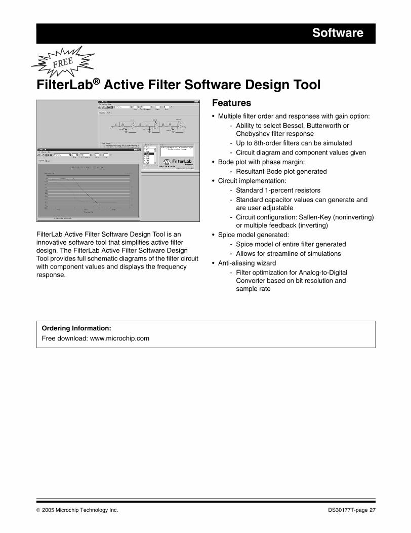
FilterLab Active Filter Software Design Tool is an innovative software tool that simplifies active filter design. The FilterLab Active Filter Software Design Tool provides full schematic diagrams of the filter circuit with component values and displays the frequency response.
Features• Multiple filter order and responses with gain option:
- Ability to select Bessel, Butterworth or Chebyshev filter response
- Up to 8th-order filters can be simulated- Circuit diagram and component values given
• Bode plot with phase margin:- Resultant Bode plot generated
• Circuit implementation:- Standard 1-percent resistors - Standard capacitor values can generate and
are user adjustable- Circuit configuration: Sallen-Key (noninverting)
or multiple feedback (inverting)• Spice model generated:
- Spice model of entire filter generated- Allows for streamline of simulations
• Anti-aliasing wizard- Filter optimization for Analog-to-Digital
Converter based on bit resolution and sample rate
Ordering Information:
Free download: www.microchip.com
© 2005 Microchip Technology Inc. DS30177T-page 27
Development Systems Ordering Guide
FREE
Total Endurance™ Software ModelMicrochip’s revolutionary Total Endurance Software Model provides electronic system designers with unprecedented visibility into serial EEPROM-based applications. This advanced software model (with a very friendly user interface) eliminates time and guesswork from serial EEPROM-based designs by accurately predicting the device’s performance and reliability within a user-defined application environment. Design trade-off analysis, which formerly consumed days or weeks, can now be performed in minutes – with a level of accuracy that delivers a truly robust design.
With Microchip’s Total Endurance Software Model, users may input the following application parameters:
• Serial EEPROM device type• Bytes to be written per cycle• Cycling mode – byte or page• Data pattern type – random or worst-case• Temperature in °C• Erase/Write cycles per day• Application lifetime or target PPM level
The model will respond with FIT rate, PPM level, application life and plot of the PPM level versus number of cycles. The model is available in both MS-DOS® and Windows® versions.
Features• Automatic or manual recalculation• Real-time update of data• Full screen or windowed graphical view• Hypertext on-screen help• Key or slide bar entry of parameters• On-screen editing of parameters• Single click copy of plot to clipboard• Numeric export to delimited text file• On-disk Total Endurance tutorial
Ordering Information:
Free download: www.microchip.com
DS30177T-page 28 © 2005 Microchip Technology Inc.
Software
KEELOQ® Security ICs License CDThe KEELOQ Security ICs License CD contains application notes, decoder software and the KEELOQ Security ICs Software Toolkit. Also included are data sheets, development tools documentation and MPLAB® IDE software.
The KEELOQ Security ICs Software Toolkit is a tool that is designed to be used by a system developer to debug code. The toolkit allows the user to receive transmissions from the KEELOQ Security ICs Evaluation Kit II (DM303006).
The KEELOQ Security ICs decoder software is typically used as the starting point of a decoder design. The software is fully described in the application notes accompanying the software.
Ordering Information:
DS40038 KEELOQ® Security ICs License CD Available from Microchip at: [email protected] (Americas and Canada),[email protected] (Europe) or [email protected] (Far East.
© 2005 Microchip Technology Inc. DS30177T-page 29

Development Systems Ordering Guide
NOTES:
DS30177T-page 30 © 2005 Microchip Technology Inc.
This section contains the following major topics:
MPLAB® ICD 2 In-Circuit Debugger..........................................................................................32MPLAB® ICD 2 Accessories .....................................................................................................33PICSTART® Plus Development Programmer............................................................................34PICkit™ 1 Flash Starter Kit........................................................................................................35rfPIC® Development Kit 1..........................................................................................................36PIC10F2XX Programmers/Adapters .........................................................................................37Signal Analysis PICtail™ Daughter Board ................................................................................38Ethernet PICtail™ Daughter Board ...........................................................................................39PICkit™ 2 Starter Kit .................................................................................................................40
HARDWARE
© 2005 Microchip Technology Inc. DS30177T-page 31
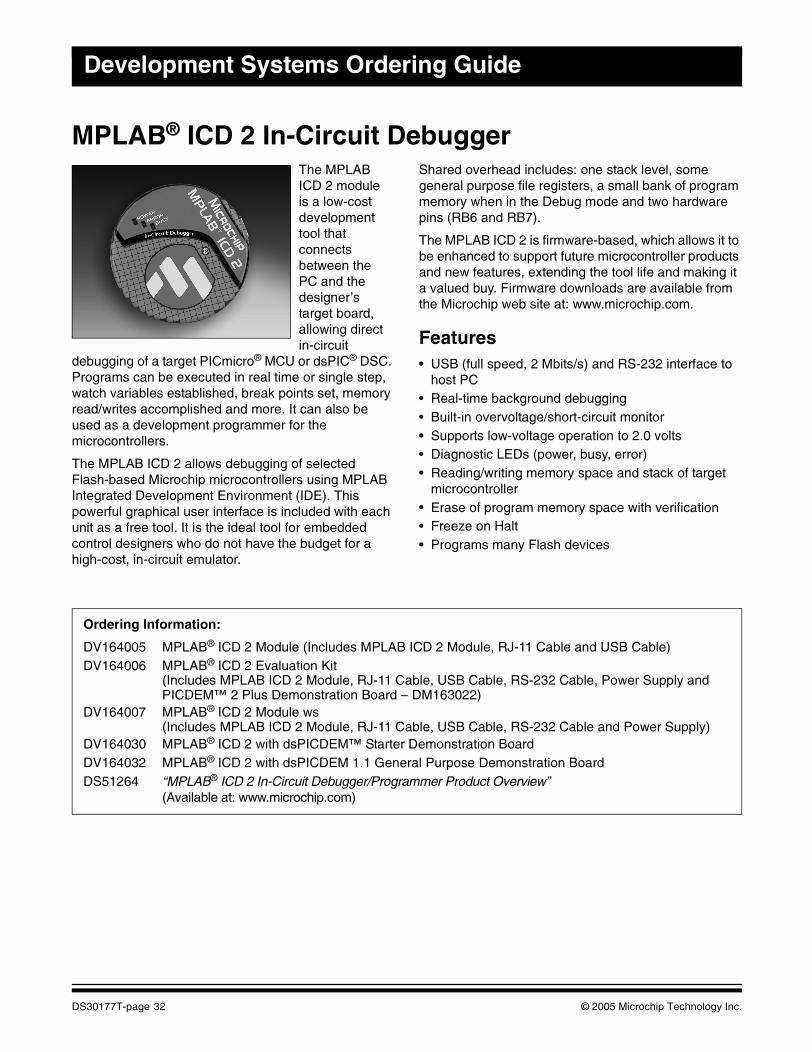
Development Systems Ordering Guide
MPLAB® ICD 2 In-Circuit DebuggerThe MPLAB ICD 2 module is a low-cost development tool that connects between the PC and the designer’s target board, allowing direct in-circuit
debugging of a target PICmicro® MCU or dsPIC® DSC. Programs can be executed in real time or single step, watch variables established, break points set, memory read/writes accomplished and more. It can also be used as a development programmer for the microcontrollers.
The MPLAB ICD 2 allows debugging of selected Flash-based Microchip microcontrollers using MPLAB Integrated Development Environment (IDE). This powerful graphical user interface is included with each unit as a free tool. It is the ideal tool for embedded control designers who do not have the budget for a high-cost, in-circuit emulator.
Shared overhead includes: one stack level, some general purpose file registers, a small bank of program memory when in the Debug mode and two hardware pins (RB6 and RB7).
The MPLAB ICD 2 is firmware-based, which allows it to be enhanced to support future microcontroller products and new features, extending the tool life and making it a valued buy. Firmware downloads are available from the Microchip web site at: www.microchip.com.
Features• USB (full speed, 2 Mbits/s) and RS-232 interface to
host PC• Real-time background debugging• Built-in overvoltage/short-circuit monitor• Supports low-voltage operation to 2.0 volts• Diagnostic LEDs (power, busy, error)• Reading/writing memory space and stack of target
microcontroller• Erase of program memory space with verification• Freeze on Halt• Programs many Flash devices
Ordering Information:
DV164005 MPLAB® ICD 2 Module (Includes MPLAB ICD 2 Module, RJ-11 Cable and USB Cable)DV164006 MPLAB® ICD 2 Evaluation Kit
(Includes MPLAB ICD 2 Module, RJ-11 Cable, USB Cable, RS-232 Cable, Power Supply andPICDEM™ 2 Plus Demonstration Board – DM163022)
DV164007 MPLAB® ICD 2 Module ws(Includes MPLAB ICD 2 Module, RJ-11 Cable, USB Cable, RS-232 Cable and Power Supply)
DV164030 MPLAB® ICD 2 with dsPICDEM™ Starter Demonstration BoardDV164032 MPLAB® ICD 2 with dsPICDEM 1.1 General Purpose Demonstration BoardDS51264 “MPLAB® ICD 2 In-Circuit Debugger/Programmer Product Overview”
(Available at: www.microchip.com)
DS30177T-page 32 © 2005 Microchip Technology Inc.
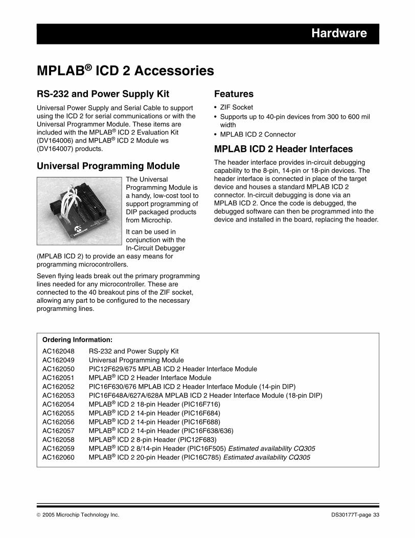
Hardware
MPLAB® ICD 2 Accessories
RS-232 and Power Supply KitUniversal Power Supply and Serial Cable to support using the ICD 2 for serial communications or with the Universal Programmer Module. These items are included with the MPLAB® ICD 2 Evaluation Kit (DV164006) and MPLAB® ICD 2 Module ws (DV164007) products.
Universal Programming ModuleThe Universal Programming Module is a handy, low-cost tool to support programming of DIP packaged products from Microchip.
It can be used in conjunction with the In-Circuit Debugger
(MPLAB ICD 2) to provide an easy means for programming microcontrollers.
Seven flying leads break out the primary programming lines needed for any microcontroller. These are connected to the 40 breakout pins of the ZIF socket, allowing any part to be configured to the necessary programming lines.
Features• ZIF Socket• Supports up to 40-pin devices from 300 to 600 mil
width• MPLAB ICD 2 Connector
MPLAB ICD 2 Header InterfacesThe header interface provides in-circuit debugging capability to the 8-pin, 14-pin or 18-pin devices. The header interface is connected in place of the target device and houses a standard MPLAB ICD 2 connector. In-circuit debugging is done via an MPLAB ICD 2. Once the code is debugged, the debugged software can then be programmed into the device and installed in the board, replacing the header.
Ordering Information:
AC162048 RS-232 and Power Supply KitAC162049 Universal Programming ModuleAC162050 PIC12F629/675 MPLAB ICD 2 Header Interface ModuleAC162051 MPLAB® ICD 2 Header Interface ModuleAC162052 PIC16F630/676 MPLAB ICD 2 Header Interface Module (14-pin DIP)AC162053 PIC16F648A/627A/628A MPLAB ICD 2 Header Interface Module (18-pin DIP)AC162054 MPLAB® ICD 2 18-pin Header (PIC16F716)AC162055 MPLAB® ICD 2 14-pin Header (PIC16F684)AC162056 MPLAB® ICD 2 14-pin Header (PIC16F688)AC162057 MPLAB® ICD 2 14-pin Header (PIC16F638/636)AC162058 MPLAB® ICD 2 8-pin Header (PIC12F683)AC162059 MPLAB® ICD 2 8/14-pin Header (PIC16F505) Estimated availability CQ305AC162060 MPLAB® ICD 2 20-pin Header (PIC16C785) Estimated availability CQ305
© 2005 Microchip Technology Inc. DS30177T-page 33
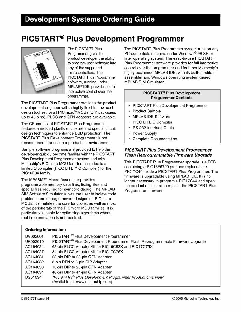
Development Systems Ordering Guide
PICSTART® Plus Development ProgrammerThe PICSTART Plus Programmer gives the product developer the ability to program user software into any of the supported microcontrollers. The PICSTART Plus Programmer software, running under MPLAB® IDE, provides for full interactive control over the programmer.
The PICSTART Plus Programmer provides the product development engineer with a highly flexible, low-cost design tool set for all PICmicro® MCUs (DIP packages, up to 40 pins). PLCC and QFN adapters are available.
The CE-compliant PICSTART Plus Programmer features a molded plastic enclosure and special circuit design techniques to enhance ESD protection. The PICSTART Plus Development Programmer is not recommended for use in a production environment.
Sample software programs are provided to help the developer quickly become familiar with the PICSTART Plus Development Programmer system and with Microchip’s PICmicro MCU families. Included is a limited C compiler (PICC LITE™ C Compiler) for the PIC16F84 family.
The MPASM™ Macro Assembler provides programmable memory data files, listing files and special files required for symbolic debug. The MPLAB SIM Software Simulator allows the user to isolate code problems and debug firmware designs on PICmicro MCUs. It simulates the core functions, as well as most of the peripherals of the PICmicro MCU families. It is particularly suitable for optimizing algorithms where real-time emulation is not required.
The PICSTART Plus Programmer system runs on any PC-compatible machine under Windows® 98 SE or later operating system. The easy-to-use PICSTART Plus Programmer software provides for full interactive control over the programmer and features Microchip’s highly acclaimed MPLAB IDE, with its built-in editor, assembler and Windows operating system-based MPLAB SIM Simulator.
PICSTART Plus Development Programmer Flash Reprogrammable Firmware Upgrade
This PICSTART Plus Programmer upgrade is a PCB containing a PIC18F6720 part and replaces the PIC17C44 inside a PICSTART Plus Programmer. The firmware is upgradable using MPLAB IDE. It is no longer necessary to program a PIC17C44 and open the product enclosure to replace the PICSTART Plus Programmer firmware.
PICSTART® Plus Development Programmer Contents
• PICSTART Plus Development Programmer• Product Sample• MPLAB IDE Software• PICC LITE C Compiler• RS-232 Interface Cable• Power Supply• Complete Documentation
Ordering Information:
DV003001 PICSTART® Plus Development ProgrammerUK003010 PICSTART® Plus Development Programmer Flash Reprogrammable Firmware UpgradeAC164024 68-pin PLCC Adapter Kit for PIC16C92X and PIC17C75XAC164027 84-pin PLCC Adapter Kit for PIC17C76XAC164031 28-pin DIP to 28-pin QFN AdapterAC164032 8-pin DFN to 8-pin DIP AdapterAC164033 18-pin DIP to 28-pin QFN AdapterAC164034 40-pin DIP to 44-pin QFN AdapterDS51034 “PICSTART® Plus Development Programmer Product Overview”
(Available at: www.microchip.com)
DS30177T-page 34 © 2005 Microchip Technology Inc.
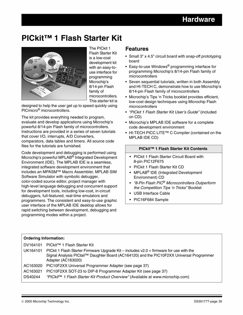
Hardware
PICkit™ 1 Flash Starter KitThe PICkit 1 Flash Starter Kit is a low-cost development kit with an easy-to-use interface for programming Microchip’s8/14-pin Flash family of microcontrollers. This starter kit is
designed to help the user get up to speed quickly using PICmicro® microcontrollers.
The kit provides everything needed to program, evaluate and develop applications using Microchip’s powerful 8/14-pin Flash family of microcontrollers. Instructions are provided in a series of seven tutorials that cover I/O, interrupts, A/D Converters, comparators, data tables and timers. All source code files for the tutorials are furnished.
Code development and debugging is performed using Microchip’s powerful MPLAB® Integrated Development Environment (IDE). The MPLAB IDE is a seamless, integrated software development environment that includes an MPASM™ Macro Assembler, MPLAB SIM Software Simulator with symbolic debugger, color-coded source editor, project manager with high-level language debugging and concurrent support for development tools, including low-cost, in-circuit debuggers, full-featured, real-time emulators and programmers. The consistent and easy-to-use graphic user interface of the MPLAB IDE desktop allows for rapid switching between development, debugging and programming modes within a project.
Features• Small 3" x 4.5" circuit board with snap-off prototyping
board• Easy-to-use Windows® programming interface for
programming Microchip’s 8/14-pin Flash family of microcontrollers
• Seven sequential tutorials, written in both Assembly and HI-TECH C, demonstrate how to use Microchip’s 8/14-pin Flash family of microcontrollers
• Microchip’s Tips ‘n Tricks booklet provides efficient, low-cost design techniques using Microchip Flash microcontrollers
• “PICkit 1 Flash Starter Kit User’s Guide” (included on CD)
• Microchip’s MPLAB IDE software for a complete code development environment
• HI-TECH PICC LITE™ C Compiler (contained on the MPLAB IDE CD)
PICkit™ 1 Flash Starter Kit Contents
• PICkit 1 Flash Starter Circuit Board with 8-pin PIC12F675
• PICkit 1 Flash Starter Kit CD• MPLAB® IDE (Integrated Development
Environment) CD• “8-Pin Flash PIC® Microcontrollers Outperform
the Competition Tips ‘n Tricks” Booklet• USB Interface Cable
• PIC16F684 Sample
Ordering Information:
DV164101 PICkit™ 1 Flash Starter KitUK164101 PICkit 1 Flash Starter Firmware Upgrade Kit – includes v2.0 + firmware for use with the
Signal Analysis PICtail™ Daughter Board (AC164120) and the PIC10F2XX Universal Programmer Adapter (AC163020)
AC163020 PIC10F2XX Universal Programmer Adapter (see page 37)AC163021 PIC10F2XX SOT-23 to DIP-8 Programmer Adapter Kit (see page 37)DS40244 “PICkit™ 1 Flash Starter Kit Product Overview” (Available at www.microchip.com)
© 2005 Microchip Technology Inc. DS30177T-page 35
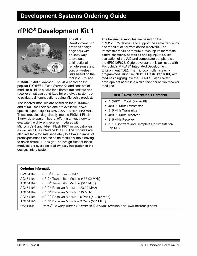
Development Systems Ordering Guide
rfPIC® Development Kit 1The rfPIC Development Kit 1 provides design engineers with an easy way to evaluate unidirectional, remote sense and control wireless links based on the rfPIC12F675 and
rfRXD0420/0920 devices. The kit is based on the popular PICkit™ 1 Flash Starter Kit and consists of modular building blocks for different transmitters and receivers that can be utilized for prototype systems or to evaluate different options using Microchip products.
The receiver modules are based on the rfRXD0420 and rfRXD0920 devices and are available in two options supporting 315 MHz ASK and 433 MHz ASK. These modules plug directly into the PICkit 1 Flash Starter development board, offering an easy way to evaluate the different receiver modules with Microchip’s 8 and 14-pin Flash PIC® microcontrollers, as well as a USB interface to a PC. The modules are also available for sale separately to allow a number of prototypes based on the same module without having to do an actual RF design. The design files for these modules are available to allow easy integration of the designs into a system.
The transmitter modules are based on the rfPIC12F675 devices and support the same frequency and modulation formats as the receivers. The transmitter modules feature button inputs for remote control functions, as well as analog input to allow evaluation of the A/D and comparator peripherals on the rfPIC12F675. Code development is achieved with Microchip’s MPLAB® Integrated Development Environment (IDE). The microcontroller is easily programmed using the PICkit 1 Flash Starter Kit, with modules plugging into the PICkit 1 Flash Starter development board in a similar manner as the receiver modules.
rfPIC® Development Kit 1 Contents
• PICkit™ 1 Flash Starter Kit• 433.92 MHz Transmitter• 315 MHz Transmitter• 433.92 MHz Receiver• 315 MHz Receiver• rfPIC Software and Complete Documentation
(on CD)
Ordering Information:
DV164102 rfPIC® Development Kit 1AC164101 rfPIC® Transmitter Module (433.92 MHz)AC164102 rfPIC® Transmitter Module (315 MHz)AC164103 rfPIC® Receiver Module (433.92 MHz)AC164104 rfPIC® Receiver Module (315 MHz)AC164105 rfPIC® Receiver Module – 5 Pack (433.92 MHz)AC164106 rfPIC® Receiver Module – 5 Pack (315 MHz)DS51409 “rfPIC® Development Kit 1 Product Overview” (Available at: www.microchip.com)
DS30177T-page 36 © 2005 Microchip Technology Inc.
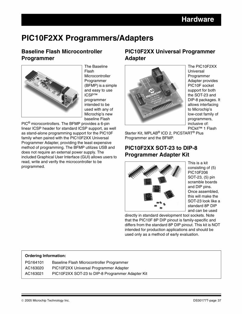
Hardware
PIC10F2XX Programmers/Adapters
Baseline Flash Microcontroller Programmer
The Baseline Flash Microcontroller Programmer (BFMP) is a simple and easy to use ICSP™ programmer intended to be used with any of Microchip’s new baseline Flash
PIC® microcontrollers. The BFMP provides a 6-pin linear ICSP header for standard ICSP support, as well as stand-alone programming support for the PIC10F family when paired with the PIC10F2XX Universal Programmer Adapter, providing the least expensive method of programming. The BFMP utilizes USB and does not require an external power supply. The included Graphical User Interface (GUI) allows users to read, write and verify the microcontroller to be programmed.
PIC10F2XX Universal Programmer Adapter
The PIC10F2XX Universal Programmer Adapter provides PIC10F socket support for both the SOT-23 and DIP-8 packages. It allows interfacing to Microchip’s low-cost family of programmers, inclusive of: PICkit™ 1 Flash
Starter Kit, MPLAB® ICD 2, PICSTART® Plus Programmer and the BFMP.
PIC10F2XX SOT-23 to DIP-8 Programmer Adapter Kit
This is a kit consisting of (5) PIC10F206 SOT-23, (5) pin scramble boards and DIP pins. Once assembled, this will make the SOT-23 look like a standard 8P DIP and can be used
directly in standard development tool sockets. Note that the PIC10F 8P DIP pinout is family-specific and differs from the standard 8P DIP pinout. This kit is NOT intended for production applications and should be used only as a method of early evaluation.
Ordering Information:
PG164101 Baseline Flash Microcontroller ProgrammerAC163020 PIC10F2XX Universal Programmer AdapterAC163021 PIC10F2XX SOT-23 to DIP-8 Programmer Adapter Kit
© 2005 Microchip Technology Inc. DS30177T-page 37
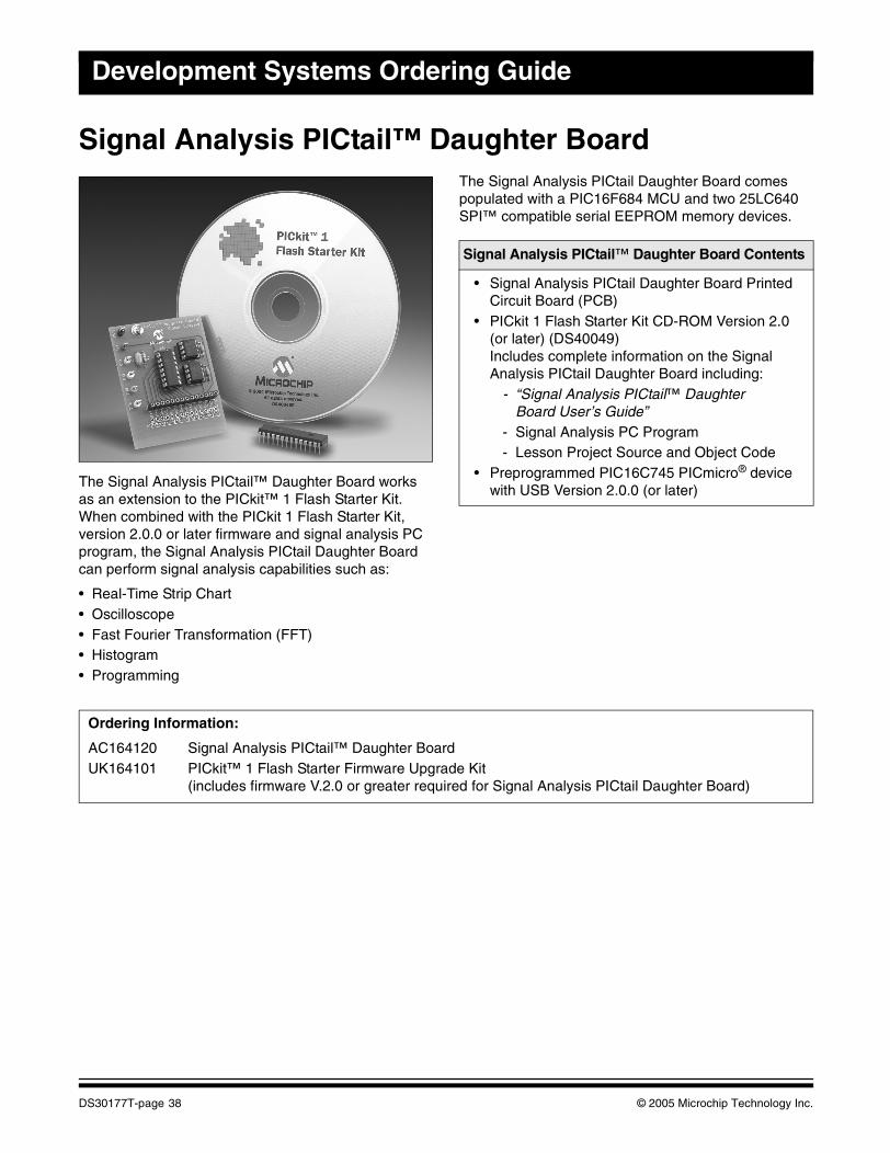
Development Systems Ordering Guide
Signal Analysis PICtail™ Daughter Board
The Signal Analysis PICtail™ Daughter Board works as an extension to the PICkit™ 1 Flash Starter Kit. When combined with the PICkit 1 Flash Starter Kit, version 2.0.0 or later firmware and signal analysis PC program, the Signal Analysis PICtail Daughter Board can perform signal analysis capabilities such as:
• Real-Time Strip Chart• Oscilloscope• Fast Fourier Transformation (FFT)• Histogram• Programming
The Signal Analysis PICtail Daughter Board comes populated with a PIC16F684 MCU and two 25LC640 SPI™ compatible serial EEPROM memory devices..
Signal Analysis PICtail™ Daughter Board Contents
• Signal Analysis PICtail Daughter Board Printed Circuit Board (PCB)
• PICkit 1 Flash Starter Kit CD-ROM Version 2.0 (or later) (DS40049)Includes complete information on the Signal Analysis PICtail Daughter Board including:
- “Signal Analysis PICtail™ Daughter Board User’s Guide”
- Signal Analysis PC Program- Lesson Project Source and Object Code
• Preprogrammed PIC16C745 PICmicro® device with USB Version 2.0.0 (or later)
Ordering Information:
AC164120 Signal Analysis PICtail™ Daughter BoardUK164101 PICkit™ 1 Flash Starter Firmware Upgrade Kit
(includes firmware V.2.0 or greater required for Signal Analysis PICtail Daughter Board)
DS30177T-page 38 © 2005 Microchip Technology Inc.
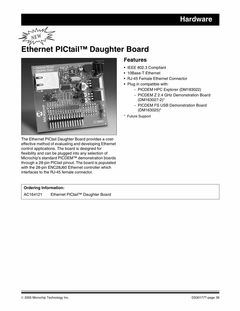
Hardware
NEW
Ethernet PICtail™ Daughter Board
The Ethernet PICtail Daughter Board provides a cost-effective method of evaluating and developing Ethernet control applications. The board is designed for flexibility and can be plugged into any selection of Microchip’s standard PICDEM™ demonstration boards through a 28-pin PICtail pinout. The board is populated with the 28-pin ENC28J60 Ethernet controller which interfaces to the RJ-45 female connector.
Features• IEEE 802.3 Compliant• 10Base-T Ethernet• RJ-45 Female Ethernet Connector• Plug in compatible with:
- PICDEM HPC Explorer (DM183022)- PICDEM Z 2.4 GHz Demonstration Board
(DM163027-2)* - PICDEM FS USB Demonstration Board
(DM163025)*
* Future Support
Ordering Information:
AC164121 Ethernet PICtail™ Daughter Board
© 2005 Microchip Technology Inc. DS30177T-page 39
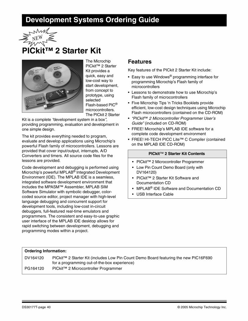
Development Systems Ordering Guide
NEW
PICkit™ 2 Starter KitThe Microchip PICkit™ 2 Starter Kit provides a quick, easy and low-cost way to start development, from concept to prototype, using selected Flash-based PIC® microcontrollers. The PICkit 2 Starter
Kit is a complete “development system in a box”, providing programming, evaluation and development in one simple design.
The kit provides everything needed to program, evaluate and develop applications using Microchip’s powerful Flash family of microcontrollers. Lessons are provided that cover input/output, interrupts, A/D Converters and timers. All source code files for the lessons are provided.
Code development and debugging is performed using Microchip’s powerful MPLAB® Integrated Development Environment (IDE). The MPLAB IDE is a seamless, integrated software development environment that includes the MPASM™ Assembler, MPLAB SIM Software Simulator with symbolic debugger, color-coded source editor, project manager with high-level language debugging and concurrent support for development tools, including low-cost in-circuit debuggers, full-featured real-time emulators and programmers. The consistent and easy-to-use graphic user interface of the MPLAB IDE desktop allows for rapid switching between development, debugging and programming modes within a project.
FeaturesKey features of the PICkit 2 Starter Kit include:
• Easy to use Windows® programming interface for programming Microchip’s Flash family of microcontrollers
• Lessons to demonstrate how to use Microchip’s Flash family of microcontrollers
• Five Microchip Tips 'n Tricks Booklets provide efficient, low-cost design techniques using Microchip Flash microcontrollers (contained on the CD-ROM)
• “PICkit™ 2 Microcontroller Programmer User’s Guide” (included on CD-ROM)
• FREE! Microchip’s MPLAB IDE software for a complete code development environment
• FREE! HI-TECH PICC Lite™ C Compiler (contained on the MPLAB IDE CD-ROM)
.
PICkit™ 2 Starter Kit Contents
• PICkit™ 2 Microcontroller Programmer• Low Pin Count Demo Board (only with
DV164120)• PICkit™ 2 Starter Kit Software and
Documentation CD• MPLAB® IDE Software and Documentation CD• USB Interface Cable
Ordering Information:
DV164120 PICkit™ 2 Starter Kit (includes Low Pin Count Demo Board featuring the new PIC16F690 for a programming out-of-the-box experience)
PG164120 PICkit™ 2 Microcontroller Programmer
DS30177T-page 40 © 2005 Microchip Technology Inc.
This section contains the following major topics:
MPLAB® ICE 2000 Modular In-Circuit Emulator .......................................................................42MPLAB® ICE 4000 Modular In-Circuit Emulator .......................................................................43MPLAB® ICE 2000/4000 Replacement Accessories ................................................................44Ordering Information .................................................................................................................45
EMULATION
© 2005 Microchip Technology Inc. DS30177T-page 41
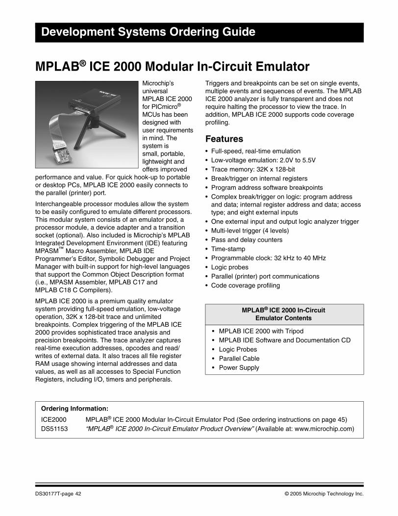
Development Systems Ordering Guide
MPLAB® ICE 2000 Modular In-Circuit EmulatorMicrochip’s universal MPLAB ICE 2000 for PICmicro® MCUs has been designed with user requirementsin mind. The system issmall, portable, lightweight and offers improved
performance and value. For quick hook-up to portable or desktop PCs, MPLAB ICE 2000 easily connects to the parallel (printer) port.
Interchangeable processor modules allow the system to be easily configured to emulate different processors. This modular system consists of an emulator pod, a processor module, a device adapter and a transition socket (optional). Also included is Microchip’s MPLAB Integrated Development Environment (IDE) featuring MPASM™ Macro Assembler, MPLAB IDE Programmer’s Editor, Symbolic Debugger and Project Manager with built-in support for high-level languages that support the Common Object Description format (i.e., MPASM Assembler, MPLAB C17 and MPLAB C18 C Compilers).
MPLAB ICE 2000 is a premium quality emulator system providing full-speed emulation, low-voltage operation, 32K x 128-bit trace and unlimited breakpoints. Complex triggering of the MPLAB ICE 2000 provides sophisticated trace analysis and precision breakpoints. The trace analyzer captures real-time execution addresses, opcodes and read/writes of external data. It also traces all file register RAM usage showing internal addresses and data values, as well as all accesses to Special Function Registers, including I/O, timers and peripherals.
Triggers and breakpoints can be set on single events, multiple events and sequences of events. The MPLAB ICE 2000 analyzer is fully transparent and does not require halting the processor to view the trace. In addition, MPLAB ICE 2000 supports code coverage profiling.
Features• Full-speed, real-time emulation• Low-voltage emulation: 2.0V to 5.5V• Trace memory: 32K x 128-bit• Break/trigger on internal registers• Program address software breakpoints• Complex break/trigger on logic: program address
and data; internal register address and data; access type; and eight external inputs
• One external input and output logic analyzer trigger• Multi-level trigger (4 levels)• Pass and delay counters• Time-stamp• Programmable clock: 32 kHz to 40 MHz• Logic probes• Parallel (printer) port communications• Code coverage profiling
MPLAB® ICE 2000 In-Circuit Emulator Contents
• MPLAB ICE 2000 with Tripod• MPLAB IDE Software and Documentation CD• Logic Probes• Parallel Cable• Power Supply
Ordering Information:
ICE2000 MPLAB® ICE 2000 Modular In-Circuit Emulator Pod (See ordering instructions on page 45)DS51153 “MPLAB® ICE 2000 In-Circuit Emulator Product Overview” (Available at: www.microchip.com)
DS30177T-page 42 © 2005 Microchip Technology Inc.
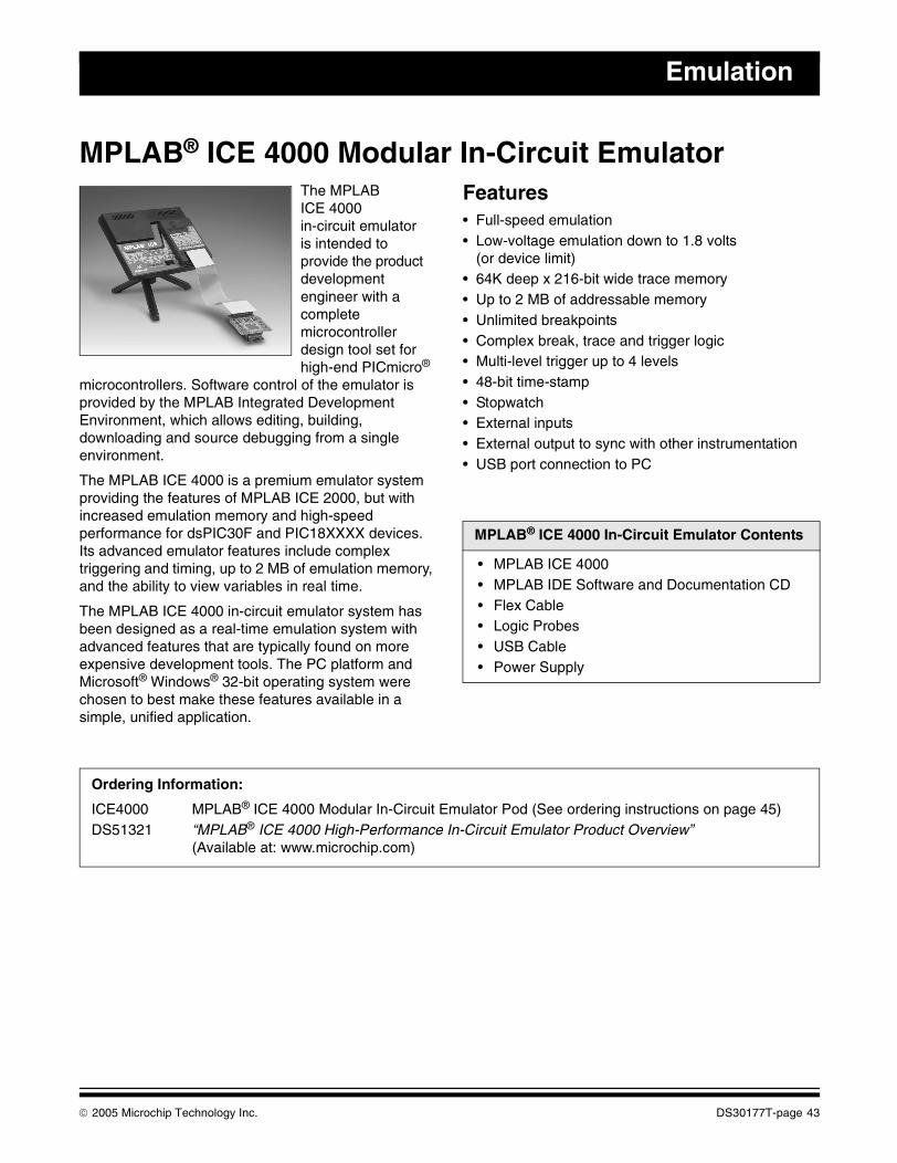
Emulation
MPLAB® ICE 4000 Modular In-Circuit EmulatorThe MPLAB ICE 4000in-circuit emulator is intended to provide the product development engineer with a complete microcontroller design tool set for high-end PICmicro®
microcontrollers. Software control of the emulator is provided by the MPLAB Integrated Development Environment, which allows editing, building, downloading and source debugging from a single environment.
The MPLAB ICE 4000 is a premium emulator system providing the features of MPLAB ICE 2000, but with increased emulation memory and high-speed performance for dsPIC30F and PIC18XXXX devices. Its advanced emulator features include complex triggering and timing, up to 2 MB of emulation memory, and the ability to view variables in real time.
The MPLAB ICE 4000 in-circuit emulator system has been designed as a real-time emulation system with advanced features that are typically found on more expensive development tools. The PC platform and Microsoft® Windows® 32-bit operating system were chosen to best make these features available in a simple, unified application.
Features• Full-speed emulation• Low-voltage emulation down to 1.8 volts
(or device limit)• 64K deep x 216-bit wide trace memory• Up to 2 MB of addressable memory• Unlimited breakpoints• Complex break, trace and trigger logic• Multi-level trigger up to 4 levels• 48-bit time-stamp• Stopwatch• External inputs• External output to sync with other instrumentation• USB port connection to PC
MPLAB® ICE 4000 In-Circuit Emulator Contents
• MPLAB ICE 4000• MPLAB IDE Software and Documentation CD• Flex Cable• Logic Probes• USB Cable• Power Supply
Ordering Information:
ICE4000 MPLAB® ICE 4000 Modular In-Circuit Emulator Pod (See ordering instructions on page 45)DS51321 “MPLAB® ICE 4000 High-Performance In-Circuit Emulator Product Overview”
(Available at: www.microchip.com)
© 2005 Microchip Technology Inc. DS30177T-page 43
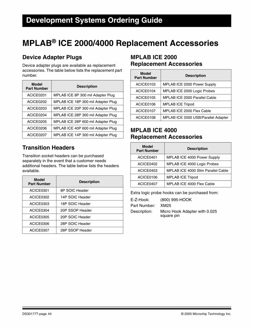
Development Systems Ordering Guide
MPLAB® ICE 2000/4000 Replacement Accessories
Device Adapter PlugsDevice adapter plugs are available as replacement accessories. The table below lists the replacement part number.
Transition HeadersTransition socket headers can be purchased separately in the event that a customer needs additional headers. The table below lists the headers available.
MPLAB ICE 2000Replacement Accessories
MPLAB ICE 4000Replacement Accessories
Extra logic probe hooks can be purchased from:
E-Z-Hook: (800) 995-HOOKPart Number: XM25Description: Micro Hook Adapter with 0.025
square pin
ModelPart Number Description
ACICE0201 MPLAB ICE 8P 300 mil Adapter Plug
ACICE0202 MPLAB ICE 18P 300 mil Adapter Plug
ACICE0203 MPLAB ICE 20P 300 mil Adapter Plug
ACICE0204 MPLAB ICE 28P 300 mil Adapter Plug
ACICE0205 MPLAB ICE 28P 600 mil Adapter Plug
ACICE0206 MPLAB ICE 40P 600 mil Adapter Plug
ACICE0207 MPLAB ICE 14P 300 mil Adapter Plug
ModelPart Number Description
ACICE0301 8P SOIC Header
ACICE0302 14P SOIC Header
ACICE0303 18P SOIC Header
ACICE0304 20P SSOP Header
ACICE0305 20P SOIC Header
ACICE0306 28P SOIC Header
ACICE0307 28P SSOP Header
ModelPart Number Description
ACICE0103 MPLAB ICE 2000 Power Supply
ACICE0104 MPLAB ICE 2000 Logic Probes
ACICE0105 MPLAB ICE 2000 Parallel Cable
ACICE0106 MPLAB ICE Tripod
ACICE0107 MPLAB ICE 2000 Flex Cable
ACICE0108 MPLAB ICE 2000 USB/Parallel Adapter
ModelPart Number Description
ACICE0401 MPLAB ICE 4000 Power Supply
ACICE0402 MPLAB ICE 4000 Logic Probes
ACICE0403 MPLAB ICE 4000 Slim Parallel Cable
ACICE0106 MPLAB ICE Tripod
ACICE0407 MPLAB ICE 4000 Flex Cable
DS30177T-page 44 © 2005 Microchip Technology Inc.
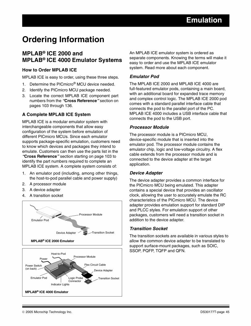
Emulation
Ordering Information
MPLAB® ICE 2000 andMPLAB® ICE 4000 Emulator Systems
How to Order MPLAB ICE
MPLAB ICE is easy to order, using these three steps.
1. Determine the PICmicro® MCU device needed.2. Identify the PICmicro MCU package needed.3. Locate the correct MPLAB ICE component part
numbers from the “Cross Reference” section onpages 103 through 136.
A Complete MPLAB ICE System
MPLAB ICE is a modular emulator system with interchangeable components that allow easy configuration of the system before emulation of different PICmicro MCUs. Since each emulator supports package-specific emulation, customers need to know which devices and packages they intend to emulate. Customers can then use the parts list in the “Cross Reference” section starting on page 103 to identify the part numbers required to complete an MPLAB ICE system. A complete system consists of:
1. An emulator pod (including, among other things,the host-to-pod parallel cable and power supply)
2. A processor module3. A device adapter4. A transition socket
An MPLAB ICE emulator system is ordered as separate components. Knowing the terms will make it easy to order and use the MPLAB ICE emulator system. Read more about each component.
Emulator Pod
The MPLAB ICE 2000 and MPLAB ICE 4000 are full-featured emulator pods, containing a main board, with an additional board for expanded trace memory and complex control logic. The MPLAB ICE 2000 pod comes with a standard parallel interface cable that connects the pod to the parallel port of the PC. MPLAB ICE 4000 includes a USB interface cable that connects the pod to the USB port.
Processor Module
The processor module is a PICmicro MCU, device-specific module that is inserted into the emulator pod. The processor module contains the emulator chip, logic and low-voltage circuitry. A flex cable extends from the processor module and is connected to the device adapter at the target application.
Device Adapter
The device adapter provides a common interface for the PICmicro MCU being emulated. This adapter contains a special device that provides an oscillator clock, allowing the user to accurately emulate the RC characteristics of the PICmicro MCU. The device adapter provides emulation support for standard DIP and PLCC styles. For emulation support of other packages, customers will need a transition socket in addition to the device adapter.
Transition Socket
The transition sockets are available in various styles to allow the common device adapter to be translated to support surface-mount packages, such as SOIC, SSOP, PQFP, TQFP and QFN.
Emulator Pod
Processor Module
Device Adapter Transition Socket
MPLAB® ICE 2000 Emulator
Device Adapter
Transition Socket
Processor Module
Emulator Pod
Indicator Lights
Logic ProbeConnector
Power Switch(on back)
Power
Host-to-Pod
Flex Circuit Cable
MPLAB® ICE 4000 Emulator
© 2005 Microchip Technology Inc. DS30177T-page 45

Development Systems Ordering Guide
NOTES:
DS30177T-page 46 © 2005 Microchip Technology Inc.
This section contains the following major topics:
MPLAB® PM3 Universal Device Programmer...........................................................................48In-Circuit Serial Programming™ (ICSP™) Socket for PRO MATE® II Device Programmer .....49Programmer Adapter Kits and Accessories ..............................................................................50
PROGRAMMING
© 2005 Microchip Technology Inc. DS30177T-page 47
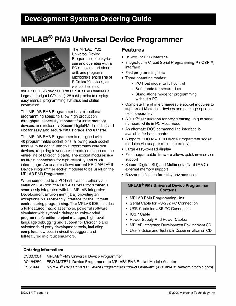
Development Systems Ordering Guide
MPLAB® PM3 Universal Device ProgrammerThe MPLAB PM3 Universal Device Programmer is easy-to-use and operates with a PC or as a stand-alone unit, and programs Microchip’s entire line of PICmicro® devices, as well as the latest
dsPIC30F DSC devices. The MPLAB PM3 features a large and bright LCD unit (128 x 64 pixels) to display easy menus, programming statistics and status information.
The MPLAB PM3 Programmer has exceptional programming speed to allow high production throughput, especially important for large memory devices, and includes a Secure Digital/Multimedia Card slot for easy and secure data storage and transfer.
The MPLAB PM3 Programmer is designed with 40 programmable socket pins, allowing each socket module to be configured to support many different devices, requiring fewer socket modules to support the entire line of Microchip parts. The socket modules use multi-pin connectors for high reliability and quick interchange. An adapter allows current PRO MATE® II Device Programmer socket modules to be used on the MPLAB PM3 Programmer.
When connected to a PC-host system, either via a serial or USB port, the MPLAB PM3 Programmer is seamlessly integrated with the MPLAB Integrated Development Environment (IDE) providing an exceptionally user-friendly interface for the ultimate control during programming. The MPLAB IDE includes a full-featured macro assembler, powerful software simulator with symbolic debugger, color-coded programmer’s editor, project manager, high-level language debugging and support for Microchip and selected third party development tools, including compilers, low-cost in-circuit debuggers and full-featured in-circuit emulators.
Features• RS-232 or USB interface• Integrated In Circuit Serial Programming™ (ICSP™)
interface• Fast programming time• Three operating modes:
- PC Host mode for full control- Safe mode for secure data- Stand-Alone mode for programming
without a PC• Complete line of interchangeable socket modules to
support all Microchip devices and package options (sold separately)
• SQTPSM serialization for programming unique serial numbers while in PC Host mode
• An alternate DOS command-line interface is available for batch control
• Supports PRO MATE II Device Programmer socket modules via adapter (sold separately)
• Large easy-to-read display• Field upgradeable firmware allows quick new device
support• Secure Digital (SD) and Multimedia Card (MMC)
external memory support• Buzzer notification for noisy environments
MPLAB® PM3 Universal Device Programmer Contents
• MPLAB PM3 Programming Unit• Serial Cable for RS-232 PC Connection• USB Cable for USB PC Connection• ICSP Cable• Power Supply And Power Cables• MPLAB Integrated Development Environment CD• User’s Guide and Technical Documentation on CD
Ordering Information:
DV007004 MPLAB® PM3 Universal Device ProgrammerAC164350 PRO MATE® II Device Programmer to MPLAB® PM3 Socket Module AdapterDS51444 “MPLAB® PM3 Universal Device Programmer Product Overview” (Available at: www.microchip.com)
DS30177T-page 48 © 2005 Microchip Technology Inc.
Programming
In-Circuit Serial Programming™ (ICSP™) Socketfor PRO MATE® II Device ProgrammerMicrochip offers an ICSP kit that can be used with Microchip’s PRO MATE II Device Programmer. Together, these two tools allow you to implement ICSP with minimal effort and use the ICSP capability of Microchip’s PICmicro® MCUs.
In-System Programming is a technique where a programmable device is programmed after the device is placed in a circuit board. ICSP is an enhanced ISP technique implemented in Microchip’s PICmicro OTP and Flash MCUs. Using only two I/O pins to serially input and output data makes ICSP easy-to-use and less intrusive on the normal operation of the MCU.
The In-Circuit Serial Programming Socket module is a complete kit, including connectors, cables and required interface boards to allow a development engineer to implement ICSP with the PRO MATE II Device Programmer.
ICSP™ Socket for PRO MATE® II Device Programmer Contents
• ICSP Socket• Cable• Power Supply• Complete Documentation
Ordering Information:
AC004004 ICSP Socket Module
© 2005 Microchip Technology Inc. DS30177T-page 49
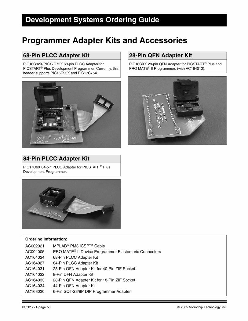
Development Systems Ordering Guide
Programmer Adapter Kits and Accessories
68-Pin PLCC Adapter KitPIC16C92X/PIC17C75X 68-pin PLCC Adapter for PICSTART® Plus Development Programmer. Currently, this header supports PIC16C92X and PIC17C75X.
84-Pin PLCC Adapter KitPIC17C6X 84-pin PLCC Adapter for PICSTART® Plus Development Programmer.
28-Pin QFN Adapter KitPIC16CXX 28-pin QFN Adapter for PICSTART® Plus and PRO MATE® II Programmers (with AC164012).
Ordering Information:
AC002021 MPLAB® PM3 ICSP™ CableAC004005 PRO MATE® II Device Programmer Elastomeric ConnectorsAC164024 68-Pin PLCC Adapter KitAC164027 84-Pin PLCC Adapter KitAC164031 28-Pin QFN Adapter Kit for 40-Pin ZIF SocketAC164032 8-Pin DFN Adapter KitAC164033 28-Pin QFN Adapter Kit for 18-Pin ZIF SocketAC164034 44-Pin QFN Adapter KitAC163020 6-Pin SOT-23/8P DIP Programmer Adapter
DS30177T-page 50 © 2005 Microchip Technology Inc.
This section contains the following major topics:
PICDEM™ Demonstration Boards ............................................................................................52PICDEM™ 2 Plus Demonstration Board...................................................................................53PICDEM™ 4 Demonstration Board...........................................................................................54PICDEM™ 18R Demonstration Kit............................................................................................55PICDEM™ Mechatronics Demonstration Kit.............................................................................56PICDEM™ MC Development Board .........................................................................................57PICDEM™ MC LV Development Board ....................................................................................58PICDEM™ HPC Explorer Board ...............................................................................................59PICDEM™ USB Demonstration Kit...........................................................................................60PICDEM™ FS USB Demonstration Board................................................................................61PICDEM™ LCD Demonstration Board......................................................................................62PICDEM™ Z 2.4 GHz Demonstration Kit..................................................................................63PICDEM™ CAN-LIN Demonstration Boards.............................................................................64PICDEM™ LIN Demonstration Kit.............................................................................................65PICDEM.net™ Demonstration/Evaluation Board ......................................................................66Low-Power Solutions Demonstration Board..............................................................................67
PICmicro® MCU DEMO BOARDS
© 2005 Microchip Technology Inc. DS30177T-page 51
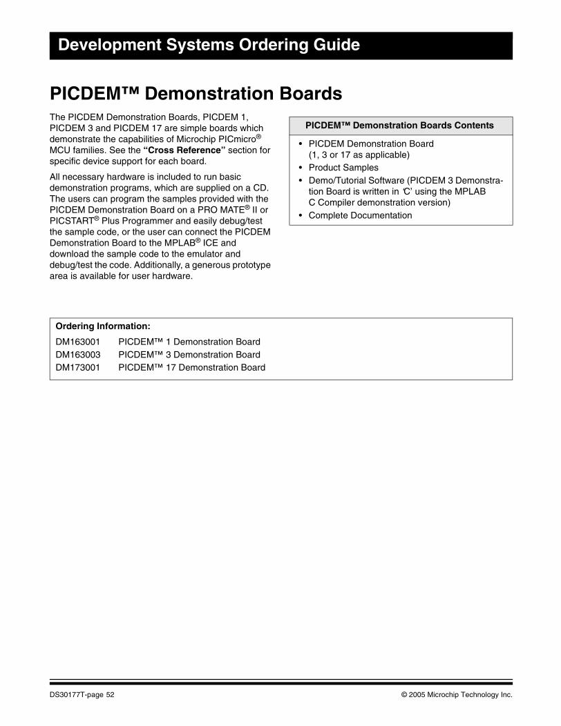
Development Systems Ordering Guide
PICDEM™ Demonstration BoardsThe PICDEM Demonstration Boards, PICDEM 1, PICDEM 3 and PICDEM 17 are simple boards which demonstrate the capabilities of Microchip PICmicro® MCU families. See the “Cross Reference” section for specific device support for each board.
All necessary hardware is included to run basic demonstration programs, which are supplied on a CD. The users can program the samples provided with the PICDEM Demonstration Board on a PRO MATE® II or PICSTART® Plus Programmer and easily debug/test the sample code, or the user can connect the PICDEM Demonstration Board to the MPLAB® ICE and download the sample code to the emulator and debug/test the code. Additionally, a generous prototype area is available for user hardware.
PICDEM™ Demonstration Boards Contents
• PICDEM Demonstration Board (1, 3 or 17 as applicable)
• Product Samples• Demo/Tutorial Software (PICDEM 3 Demonstra-
tion Board is written in ‘C’ using the MPLAB C Compiler demonstration version)
• Complete Documentation
Ordering Information:
DM163001 PICDEM™ 1 Demonstration BoardDM163003 PICDEM™ 3 Demonstration BoardDM173001 PICDEM™ 17 Demonstration Board
DS30177T-page 52 © 2005 Microchip Technology Inc.
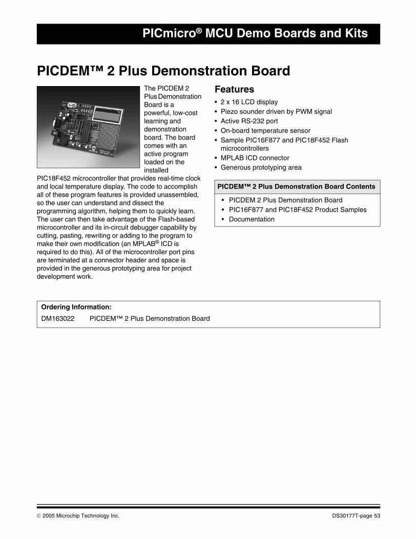
PICmicro® MCU Demo Boards and Kits
PICDEM™ 2 Plus Demonstration BoardThe PICDEM 2 Plus Demonstration Board is a powerful, low-cost learning and demonstration board. The board comes with an active program loaded on the installed
PIC18F452 microcontroller that provides real-time clock and local temperature display. The code to accomplish all of these program features is provided unassembled, so the user can understand and dissect the programming algorithm, helping them to quickly learn. The user can then take advantage of the Flash-based microcontroller and its in-circuit debugger capability by cutting, pasting, rewriting or adding to the program to make their own modification (an MPLAB® ICD is required to do this). All of the microcontroller port pins are terminated at a connector header and space is provided in the generous prototyping area for project development work.
Features• 2 x 16 LCD display• Piezo sounder driven by PWM signal• Active RS-232 port• On-board temperature sensor• Sample PIC16F877 and PIC18F452 Flash
microcontrollers• MPLAB ICD connector• Generous prototyping area
PICDEM™ 2 Plus Demonstration Board Contents
• PICDEM 2 Plus Demonstration Board• PIC16F877 and PIC18F452 Product Samples• Documentation
Ordering Information:
DM163022 PICDEM™ 2 Plus Demonstration Board
© 2005 Microchip Technology Inc. DS30177T-page 53
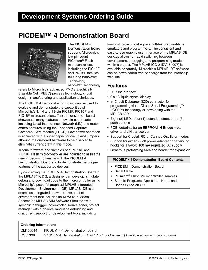
Development Systems Ordering Guide
PICDEM™ 4 Demonstration BoardThe PICDEM 4 Demonstration Board supports Microchip’s low pin count PICmicro® Flash microcontrollers, including the PIC16F and PIC18F families featuring nanoWatt Technology. nanoWatt Technology
refers to Microchip’s advanced PMOS Electrically Erasable Cell (PEEC) process technology, circuit design, manufacturing and application techniques.
The PICDEM 4 Demonstration Board can be used to evaluate and demonstrate the capabilities of Microchip’s 8, 14 and 18-pin PIC12F, PIC16F and PIC18F microcontrollers. The demonstration board showcases many features of low pin count parts, including Local Interconnect Network (LIN) and motor control features using the Enhanced Capture/Compare/PWM module (ECCP). Low-power operation is achieved with a super capacitor circuit and jumpers allowing the on-board hardware to be disabled to eliminate current draw in this mode.
Tutorial firmware and samples of a PIC16F and PIC18F Flash microcontroller are included to assist the user in becoming familiar with the PICDEM 4 Demonstration Board and to demonstrate the unique features of the supported devices.
By connecting the PICDEM 4 Demonstration Board to the MPLAB® ICD 2, a designer can develop, simulate, debug and download code to the microcontroller using Microchip’s powerful graphical MPLAB Integrated Development Environment (IDE). MPLAB IDE is a seamless, integrated software development environment that includes an MPASM™ Macro Assembler, MPLAB SIM Software Simulator with symbolic debugger, color-coded source editor, project manager with high-level language debugging and concurrent support for development tools, including
low-cost in-circuit debuggers, full-featured real-time emulators and programmers. The consistent and easy-to-use graphic user interface of the MPLAB IDE desktop allows for rapid switching between development, debugging and programming modes within a project. The MPLAB ICD 2 (DV164007) is available separately. Microchip’s MPLAB IDE software can be downloaded free-of-charge from the Microchip web site.
Features• RS-232 interface• 2 x 16 liquid crystal display • In-Circuit Debugger (ICD) connector for
programming via In-Circuit Serial Programming™ (ICSP™) technology or developing with the MPLAB ICD 2
• Eight (8) LEDs, four (4) potentiometers, three (3) push buttons
• PCB footprints for an EEPROM, H-Bridge motor driver and LIN transceiver
• Support for Crystal, RC or Canned Oscillator modes• Support for either 9-volt power adapter or battery, or
hooks for a 5-volt, 100 mA regulated DC supply• Generous prototyping area and header for expansion
PICDEM™ 4 Demonstration Board Contents
• PICDEM 4 Demonstration Board• Serial Cable• PICmicro® Flash Microcontroller Samples• Sample Programs, Application Notes and
User’s Guide on CD
Ordering Information:
DM163014 PICDEM™ 4 Demonstration BoardDS51339 “PICDEM 4 Demonstration Board Product Overview” (Available at: www.microchip.com)
DS30177T-page 54 © 2005 Microchip Technology Inc.
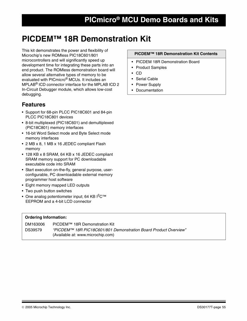
PICmicro® MCU Demo Boards and Kits
PICDEM™ 18R Demonstration KitThis kit demonstrates the power and flexibility of Microchip’s new ROMless PIC18C601/801 microcontrollers and will significantly speed up development time for integrating these parts into an end product. The ROMless demonstration board will allow several alternative types of memory to be evaluated with PICmicro® MCUs. It includes an MPLAB® ICD connector interface for the MPLAB ICD 2 In-Circuit Debugger module, which allows low-cost debugging.
Features• Support for 68-pin PLCC PIC18C601 and 84-pin
PLCC PIC18C801 devices• 8-bit multiplexed (PIC18C601) and demultiplexed
(PIC18C801) memory interfaces• 16-bit Word Select mode and Byte Select mode
memory interfaces• 2 MB x 8, 1 MB x 16 JEDEC compliant Flash
memory• 128 KB x 8 SRAM, 64 KB x 16 JEDEC compliant
SRAM memory support for PC downloadable executable code into SRAM
• Start execution on-the-fly, general purpose, user-configurable, PC downloadable external memory programmer host software
• Eight memory mapped LED outputs• Two push button switches• One analog potentiometer input; 64 KB I2C™
EEPROM and a 4-bit LCD connector
PICDEM™ 18R Demonstration Kit Contents
• PICDEM 18R Demonstration Board• Product Samples• CD• Serial Cable• Power Supply• Documentation
Ordering Information:
DM163006 PICDEM™ 18R Demonstration KitDS39579 “PICDEM™ 18R PIC18C601/801 Demonstration Board Product Overview”
(Available at: www.microchip.com)
© 2005 Microchip Technology Inc. DS30177T-page 55
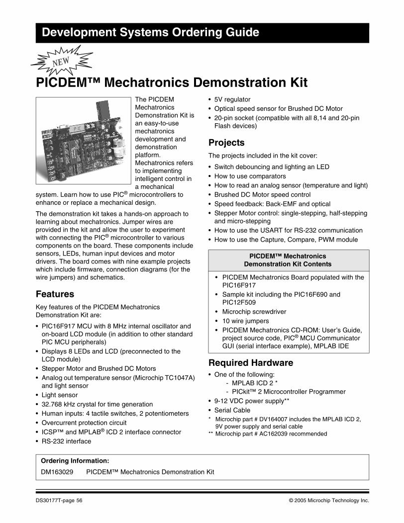
Development Systems Ordering Guide
NEW
PICDEM™ Mechatronics Demonstration KitThe PICDEM Mechatronics Demonstration Kit is an easy-to-use mechatronics development and demonstration platform. Mechatronics refers to implementing intelligent control in a mechanical
system. Learn how to use PIC® microcontrollers to enhance or replace a mechanical design.
The demonstration kit takes a hands-on approach to learning about mechatronics. Jumper wires are provided in the kit and allow the user to experiment with connecting the PIC® microcontroller to various components on the board. These components include sensors, LEDs, human input devices and motor drivers. The board comes with nine example projects which include firmware, connection diagrams (for the wire jumpers) and schematics.
FeaturesKey features of the PICDEM Mechatronics Demonstration Kit are:
• PIC16F917 MCU with 8 MHz internal oscillator and on-board LCD module (in addition to other standard PIC MCU peripherals)
• Displays 8 LEDs and LCD (preconnected to the LCD module)
• Stepper Motor and Brushed DC Motors• Analog out temperature sensor (Microchip TC1047A)
and light sensor• Light sensor• 32.768 kHz crystal for time generation• Human inputs: 4 tactile switches, 2 potentiometers• Overcurrent protection circuit• ICSP™ and MPLAB® ICD 2 interface connector• RS-232 interface
• 5V regulator• Optical speed sensor for Brushed DC Motor• 20-pin socket (compatible with all 8,14 and 20-pin
Flash devices)
ProjectsThe projects included in the kit cover:
• Switch debouncing and lighting an LED• How to use comparators• How to read an analog sensor (temperature and light)• Brushed DC Motor speed control• Speed feedback: Back-EMF and optical• Stepper Motor control: single-stepping, half-stepping
and micro-stepping• How to use the USART for RS-232 communication• How to use the Capture, Compare, PWM module
Required Hardware• One of the following:
- MPLAB ICD 2 *- PICkit™ 2 Microcontroller Programmer
• 9-12 VDC power supply**• Serial Cable* Microchip part # DV164007 includes the MPLAB ICD 2,
9V power supply and serial cable** Microchip part # AC162039 recommended
PICDEM™ Mechatronics Demonstration Kit Contents
• PICDEM Mechatronics Board populated with the PIC16F917
• Sample kit including the PIC16F690 and PIC12F509
• Microchip screwdriver• 10 wire jumpers• PICDEM Mechatronics CD-ROM: User’s Guide,
project source code, PIC® MCU Communicator GUI (serial interface example), MPLAB IDE
Ordering Information:
DM163029 PICDEM™ Mechatronics Demonstration Kit
DS30177T-page 56 © 2005 Microchip Technology Inc.
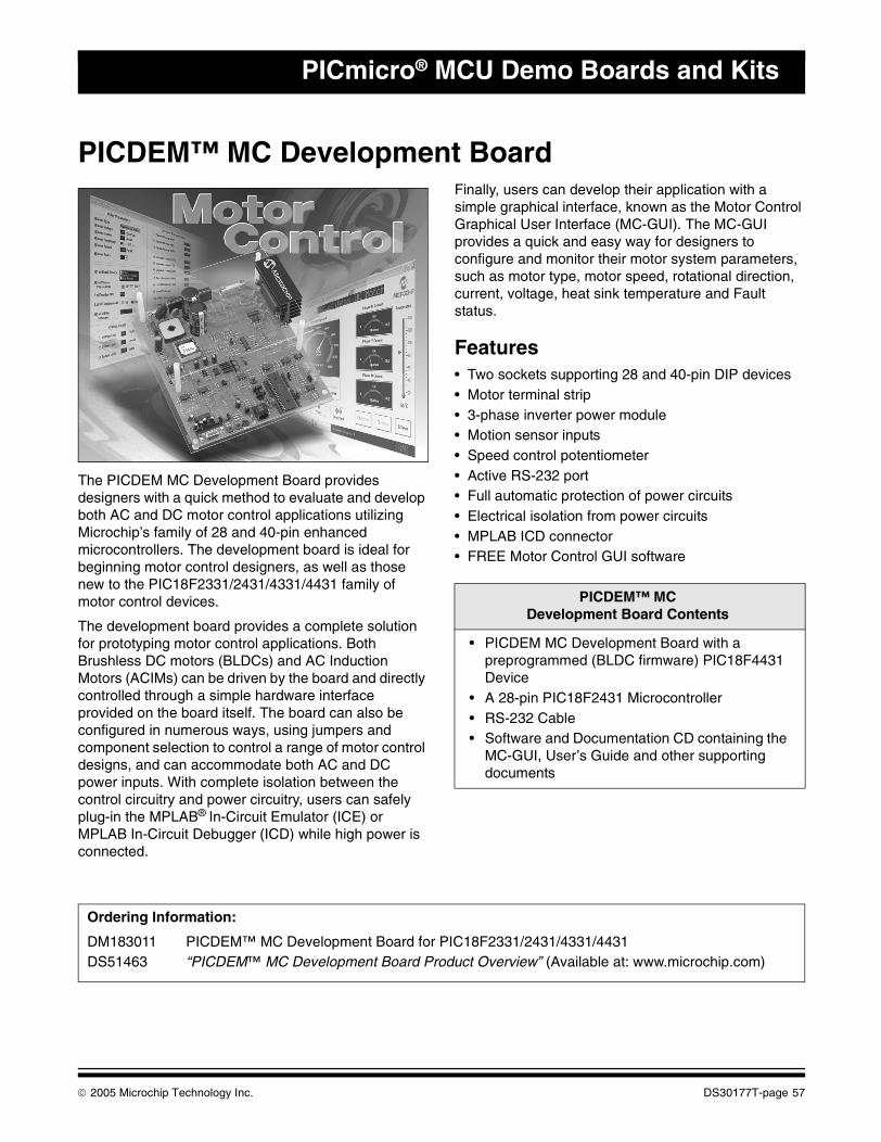
PICmicro® MCU Demo Boards and Kits
PICDEM™ MC Development Board
The PICDEM MC Development Board provides designers with a quick method to evaluate and develop both AC and DC motor control applications utilizing Microchip’s family of 28 and 40-pin enhanced microcontrollers. The development board is ideal for beginning motor control designers, as well as those new to the PIC18F2331/2431/4331/4431 family of motor control devices.
The development board provides a complete solution for prototyping motor control applications. Both Brushless DC motors (BLDCs) and AC Induction Motors (ACIMs) can be driven by the board and directly controlled through a simple hardware interface provided on the board itself. The board can also be configured in numerous ways, using jumpers and component selection to control a range of motor control designs, and can accommodate both AC and DC power inputs. With complete isolation between the control circuitry and power circuitry, users can safely plug-in the MPLAB® In-Circuit Emulator (ICE) or MPLAB In-Circuit Debugger (ICD) while high power is connected.
Finally, users can develop their application with a simple graphical interface, known as the Motor Control Graphical User Interface (MC-GUI). The MC-GUI provides a quick and easy way for designers to configure and monitor their motor system parameters, such as motor type, motor speed, rotational direction, current, voltage, heat sink temperature and Fault status.
Features• Two sockets supporting 28 and 40-pin DIP devices• Motor terminal strip• 3-phase inverter power module• Motion sensor inputs• Speed control potentiometer• Active RS-232 port• Full automatic protection of power circuits• Electrical isolation from power circuits• MPLAB ICD connector• FREE Motor Control GUI software
PICDEM™ MCDevelopment Board Contents
• PICDEM MC Development Board with a preprogrammed (BLDC firmware) PIC18F4431 Device
• A 28-pin PIC18F2431 Microcontroller• RS-232 Cable• Software and Documentation CD containing the
MC-GUI, User’s Guide and other supporting documents
Ordering Information:
DM183011 PICDEM™ MC Development Board for PIC18F2331/2431/4331/4431DS51463 “PICDEM™ MC Development Board Product Overview” (Available at: www.microchip.com)
© 2005 Microchip Technology Inc. DS30177T-page 57
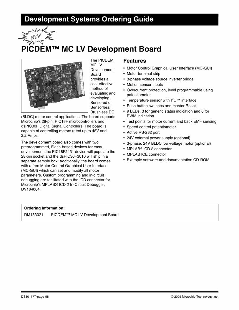
Development Systems Ordering Guide
NEW
PICDEM™ MC LV Development BoardThe PICDEM MC LV Development Board provides a cost-effective method of evaluating and developing Sensored or Sensorless Brushless DC
(BLDC) motor control applications. The board supports Microchip’s 28-pin, PIC18F microcontrollers and dsPIC30F Digital Signal Controllers. The board is capable of controlling motors rated up to 48V and 2.2 Amps.
The development board also comes with two preprogrammed, Flash-based devices for easy development: the PIC18F2431 device will populate the 28-pin socket and the dsPIC30F3010 will ship in a separate sample box. Additionally, the board comes with a free Motor Control Graphical User Interface (MC-GUI) which can set and modify all motor parameters. Custom programming and in-circuit debugging are facilitated with the ICD connector for Microchip’s MPLAB® ICD 2 In-Circuit Debugger, DV164004.
Features• Motor Control Graphical User Interface (MC-GUI)• Motor terminal strip• 3-phase voltage source inverter bridge• Motion sensor inputs• Overcurrent protection, level programmable using
potentiometer• Temperature sensor with I2C™ interface• Push button switches and master Reset• 9 LEDs, 3 for generic status indication and 6 for
PWM indication• Test points for motor current and back EMF sensing• Speed control potentiometer• Active RS-232 port• 24V external power supply (optional)• 3-phase, 24V BLDC low-voltage motor (optional)• MPLAB® ICD 2 connector• MPLAB ICE connector• Example software and documentation CD-ROM
Ordering Information:
DM183021 PICDEM™ MC LV Development Board
DS30177T-page 58 © 2005 Microchip Technology Inc.
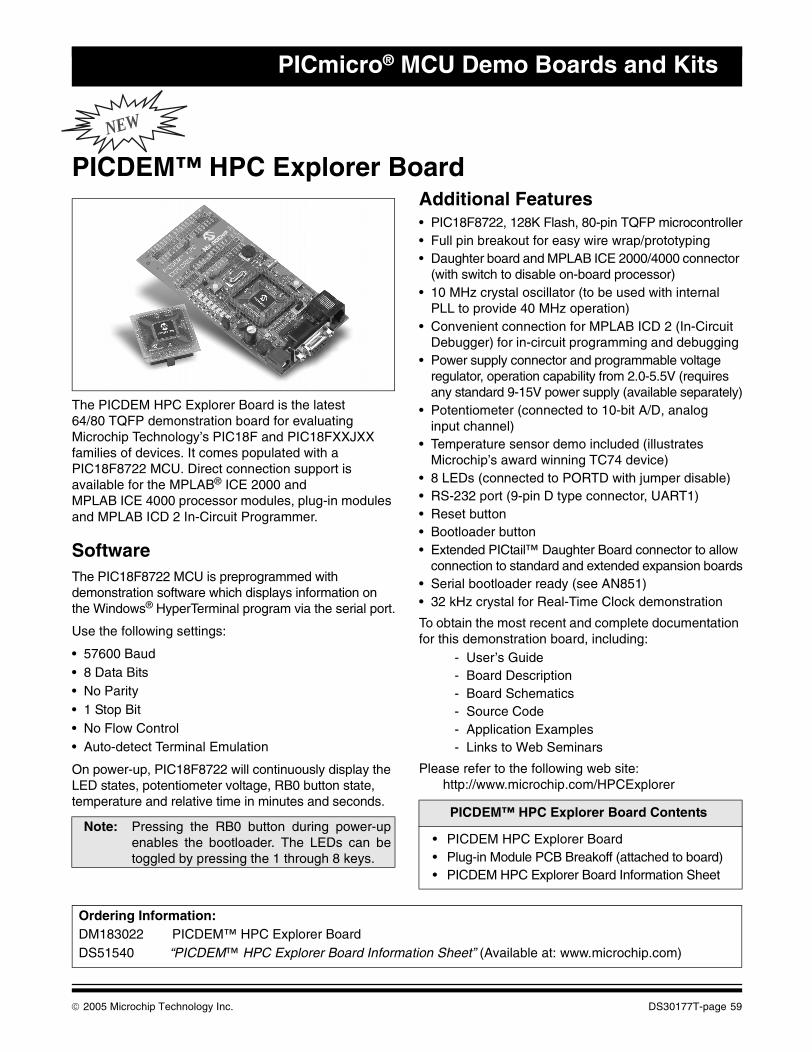
PICmicro® MCU Demo Boards and Kits
NEW
PICDEM™ HPC Explorer Board
The PICDEM HPC Explorer Board is the latest 64/80 TQFP demonstration board for evaluating Microchip Technology’s PIC18F and PIC18FXXJXX families of devices. It comes populated with a PIC18F8722 MCU. Direct connection support is available for the MPLAB® ICE 2000 and MPLAB ICE 4000 processor modules, plug-in modules and MPLAB ICD 2 In-Circuit Programmer.
SoftwareThe PIC18F8722 MCU is preprogrammed with demonstration software which displays information on the Windows® HyperTerminal program via the serial port.
Use the following settings:
• 57600 Baud• 8 Data Bits• No Parity• 1 Stop Bit• No Flow Control• Auto-detect Terminal Emulation
On power-up, PIC18F8722 will continuously display the LED states, potentiometer voltage, RB0 button state, temperature and relative time in minutes and seconds.
Additional Features• PIC18F8722, 128K Flash, 80-pin TQFP microcontroller• Full pin breakout for easy wire wrap/prototyping• Daughter board and MPLAB ICE 2000/4000 connector
(with switch to disable on-board processor)• 10 MHz crystal oscillator (to be used with internal
PLL to provide 40 MHz operation) • Convenient connection for MPLAB ICD 2 (In-Circuit
Debugger) for in-circuit programming and debugging • Power supply connector and programmable voltage
regulator, operation capability from 2.0-5.5V (requires any standard 9-15V power supply (available separately)
• Potentiometer (connected to 10-bit A/D, analog input channel)
• Temperature sensor demo included (illustrates Microchip’s award winning TC74 device)
• 8 LEDs (connected to PORTD with jumper disable) • RS-232 port (9-pin D type connector, UART1) • Reset button • Bootloader button • Extended PICtail™ Daughter Board connector to allow
connection to standard and extended expansion boards• Serial bootloader ready (see AN851) • 32 kHz crystal for Real-Time Clock demonstration
To obtain the most recent and complete documentation for this demonstration board, including:
- User’s Guide- Board Description- Board Schematics- Source Code- Application Examples- Links to Web Seminars
Please refer to the following web site: http://www.microchip.com/HPCExplorer
Note: Pressing the RB0 button during power-upenables the bootloader. The LEDs can betoggled by pressing the 1 through 8 keys.
PICDEM™ HPC Explorer Board Contents
• PICDEM HPC Explorer Board• Plug-in Module PCB Breakoff (attached to board)• PICDEM HPC Explorer Board Information Sheet
Ordering Information:DM183022 PICDEM™ HPC Explorer BoardDS51540 “PICDEM™ HPC Explorer Board Information Sheet” (Available at: www.microchip.com)
© 2005 Microchip Technology Inc. DS30177T-page 59
Development Systems Ordering Guide
PICDEM™ USB Demonstration KitThe PICDEM USB Demonstration Kit from Microchip demonstrates a PICmicro® microcontroller (PIC16C765) communicating to a PC using the USB port.
A traditional mouse, keyboard or joystick can be connected to the USB port on a computer using the preprogrammed board supplied in the kit.
Features• Status LEDs• Out-of-the-box working demo• Generous prototyping area• PS-Port• Gameport
PICDEM™ USB Demonstration Kit Contents
• PICDEM USB Demonstration Board with Large Prototype Area
• USB, Serial, PS-2 and Gameport Connectors• USB Support Firmware and Example Code• Documentation
Ordering Information:
DM163010 PICDEM™ USB Demonstration Kit
DS30177T-page 60 © 2005 Microchip Technology Inc.
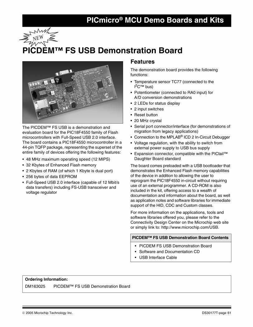
PICmicro® MCU Demo Boards and Kits
NEW
PICDEM™ FS USB Demonstration Board
The PICDEM™ FS USB is a demonstration and evaluation board for the PIC18F4550 family of Flash microcontrollers with Full-Speed USB 2.0 interface. The board contains a PIC18F4550 microcontroller in a 44-pin TQFP package, representing the superset of the entire family of devices offering the following features:
• 48 MHz maximum operating speed (12 MIPS)• 32 Kbytes of Enhanced Flash memory• 2 Kbytes of RAM (of which 1 Kbyte is dual port)• 256 bytes of data EEPROM• Full-Speed USB 2.0 interface (capable of 12 Mbit/s
data transfers) including FS-USB transceiver and voltage regulator
FeaturesThe demonstration board provides the following functions:
• Temperature sensor TC77 (connected to the I2C™ bus)
• Potentiometer (connected to RA0 input) for A/D conversion demonstrations
• 2 LEDs for status display• 2 input switches • Reset button• 20 MHz crystal • Serial port connector/interface (for demonstrations of
migration from legacy applications)• Connection to the MPLAB® ICD 2 In-Circuit Debugger• Voltage regulation, with the ability to switch from
external power supply to USB bus supply• Expansion connector, compatible with the PICtail™
Daughter Board standard
The board comes preloaded with a USB bootloader that demonstrates the Enhanced Flash memory capabilities of the device in addition to allowing the user to reprogram the PIC18F4550 in-circuit without requiring use of an external programmer. A CD-ROM is also included in the kit, offering access to a wealth of documentation and information about the board, as well as application notes and software libraries for immediate support of the HID, CDC and Custom classes.
For more information on the applications, tools and software libraries offered you, please refer to the Connectivity Design Center on the Microchip web site or simply link to: http://www.microchip.com/USB.
PICDEM™ FS USB Demonstration Board Contents
• PICDEM FS USB Demonstration Board• Software and Documentation CD• USB Interface Cable
Ordering Information:
DM163025 PICDEM™ FS USB Demonstration Board
© 2005 Microchip Technology Inc. DS30177T-page 61
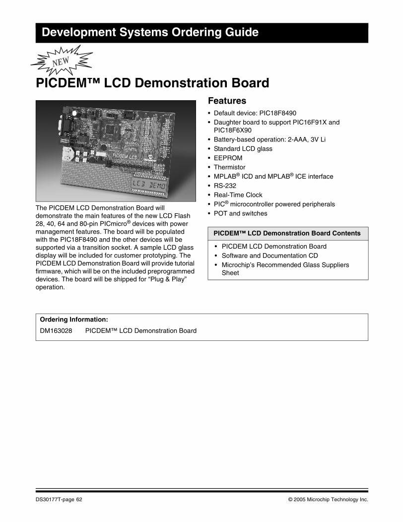
Development Systems Ordering Guide
NEW
PICDEM™ LCD Demonstration Board
The PICDEM LCD Demonstration Board will demonstrate the main features of the new LCD Flash 28, 40, 64 and 80-pin PICmicro® devices with power management features. The board will be populated with the PIC18F8490 and the other devices will be supported via a transition socket. A sample LCD glass display will be included for customer prototyping. The PICDEM LCD Demonstration Board will provide tutorial firmware, which will be on the included preprogrammed devices. The board will be shipped for “Plug & Play” operation.
Features• Default device: PIC18F8490 • Daughter board to support PIC16F91X and
PIC18F6X90• Battery-based operation: 2-AAA, 3V Li • Standard LCD glass• EEPROM• Thermistor• MPLAB® ICD and MPLAB® ICE interface• RS-232• Real-Time Clock• PIC® microcontroller powered peripherals• POT and switches
PICDEM™ LCD Demonstration Board Contents
• PICDEM LCD Demonstration Board • Software and Documentation CD• Microchip’s Recommended Glass Suppliers
Sheet
Ordering Information:
DM163028 PICDEM™ LCD Demonstration Board
DS30177T-page 62 © 2005 Microchip Technology Inc.
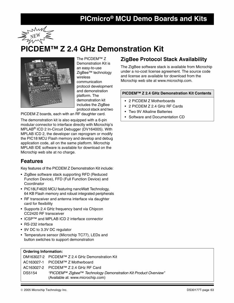
PICmicro® MCU Demo Boards and Kits
NEW
PICDEM™ Z 2.4 GHz Demonstration KitThe PICDEM™ Z Demonstration Kit is an easy-to-use ZigBee™ technology wireless communication protocol development and demonstration platform. The demonstration kit includes the ZigBee protocol stack and two
PICDEM Z boards, each with an RF daughter card.
The demonstration kit is also equipped with a 6-pin modular connector to interface directly with Microchip’s MPLAB® ICD 2 In-Circuit Debugger (DV164005). With MPLAB ICD 2, the developer can reprogram or modify the PIC18 MCU Flash memory and develop and debug application code, all on the same platform. Microchip MPLAB IDE software is available for download on the Microchip web site at no charge.
FeaturesKey features of the PICDEM Z Demonstration Kit include:
• ZigBee software stack supporting RFD (Reduced Function Device), FFD (Full Function Device) and Coordinator
• PIC18LF4620 MCU featuring nanoWatt Technology, 64 KB Flash memory and robust integrated peripherals
• RF transceiver and antenna interface via daughter card for flexibility
• Supports 2.4 GHz frequency band via Chipcon CC2420 RF transceiver
• ICSP™ and MPLAB ICD 2 interface connector• RS-232 interface• 9V DC to 3.3V DC regulator• Temperature sensor (Microchip TC77), LEDs and
button switches to support demonstration
ZigBee Protocol Stack AvailabilityThe ZigBee software stack is available from Microchip under a no-cost license agreement. The source code and license are available for download from the Microchip web site at www.microchip.com.
PICDEM™ Z 2.4 GHz Demonstration Kit Contents
• 2 PICDEM Z Motherboards• 2 PICDEM Z 2.4 GHz RF Cards• Two 9V Alkaline Batteries• Software and Documentation CD
Ordering Information:DM163027-2 PICDEM™ Z 2.4 GHz Demonstration KitAC163027-1 PICDEM™ Z MotherboardAC163027-2 PICDEM™ Z 2.4 GHz RF CardDS5154 “PICDEM™ Zigbee™ Technology Demonstration Kit Product Overview”
(Available at: www.microchip.com)
© 2005 Microchip Technology Inc. DS30177T-page 63
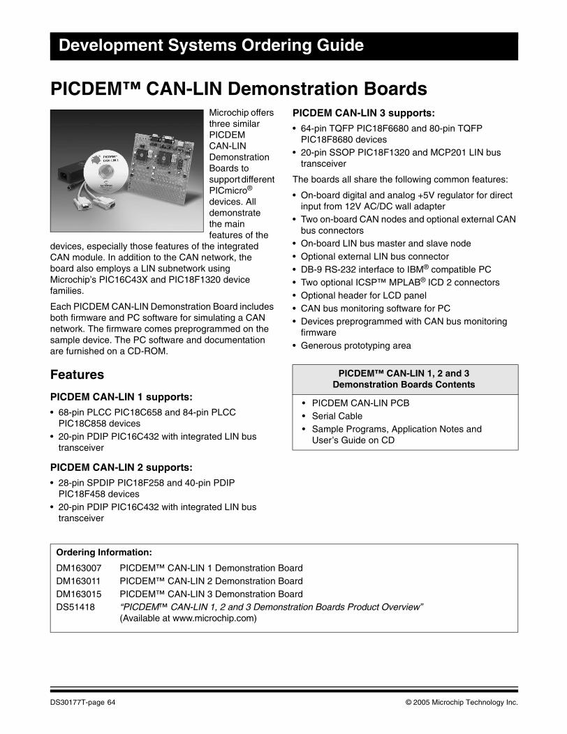
Development Systems Ordering Guide
PICDEM™ CAN-LIN Demonstration BoardsMicrochip offers three similar PICDEMCAN-LIN Demonstration Boards to support different PICmicro®
devices. All demonstrate the main features of the
devices, especially those features of the integrated CAN module. In addition to the CAN network, the board also employs a LIN subnetwork using Microchip’s PIC16C43X and PIC18F1320 device families.
Each PICDEM CAN-LIN Demonstration Board includes both firmware and PC software for simulating a CAN network. The firmware comes preprogrammed on the sample device. The PC software and documentation are furnished on a CD-ROM.
Features
PICDEM CAN-LIN 1 supports:
• 68-pin PLCC PIC18C658 and 84-pin PLCC PIC18C858 devices
• 20-pin PDIP PIC16C432 with integrated LIN bus transceiver
PICDEM CAN-LIN 2 supports:
• 28-pin SPDIP PIC18F258 and 40-pin PDIP PIC18F458 devices
• 20-pin PDIP PIC16C432 with integrated LIN bus transceiver
PICDEM CAN-LIN 3 supports:
• 64-pin TQFP PIC18F6680 and 80-pin TQFP PIC18F8680 devices
• 20-pin SSOP PIC18F1320 and MCP201 LIN bus transceiver
The boards all share the following common features:
• On-board digital and analog +5V regulator for direct input from 12V AC/DC wall adapter
• Two on-board CAN nodes and optional external CAN bus connectors
• On-board LIN bus master and slave node• Optional external LIN bus connector• DB-9 RS-232 interface to IBM® compatible PC• Two optional ICSP™ MPLAB® ICD 2 connectors• Optional header for LCD panel• CAN bus monitoring software for PC• Devices preprogrammed with CAN bus monitoring
firmware• Generous prototyping area
PICDEM™ CAN-LIN 1, 2 and 3Demonstration Boards Contents
• PICDEM CAN-LIN PCB• Serial Cable• Sample Programs, Application Notes and
User’s Guide on CD
Ordering Information:
DM163007 PICDEM™ CAN-LIN 1 Demonstration BoardDM163011 PICDEM™ CAN-LIN 2 Demonstration BoardDM163015 PICDEM™ CAN-LIN 3 Demonstration BoardDS51418 “PICDEM™ CAN-LIN 1, 2 and 3 Demonstration Boards Product Overview”
(Available at www.microchip.com)
DS30177T-page 64 © 2005 Microchip Technology Inc.
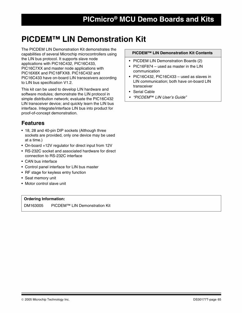
PICmicro® MCU Demo Boards and Kits
PICDEM™ LIN Demonstration KitThe PICDEM LIN Demonstration Kit demonstrates the capabilities of several Microchip microcontrollers using the LIN bus protocol. It supports slave node applications with PIC16C432, PIC16C433, PIC16C7XX and master node applications with PIC16X8X and PIC18FXX8. PIC16C432 and PIC16C433 have on-board LIN transceivers according to LIN bus specification V1.2.
This kit can be used to develop LIN hardware and software modules; demonstrate the LIN protocol in simple distribution network; evaluate the PIC16C432 LIN transceiver device; and quickly learn the LIN bus interface. Integrate/interface LIN bus into product for proof-of-concept demonstration.
Features• 18, 28 and 40-pin DIP sockets (Although three
sockets are provided, only one device may be used at a time.)
• On-board +12V regulator for direct input from 12V• RS-232C socket and associated hardware for direct
connection to RS-232C interface• CAN bus interface• Control panel interface for LIN bus master• RF stage for keyless entry function• Seat memory unit • Motor control slave unit
PICDEM™ LIN Demonstration Kit Contents
• PICDEM LIN Demonstration Boards (2)• PIC16F874 – used as master in the LIN
communication• PIC16C432, PIC16C433 – used as slaves in
LIN communication; both have on-board LIN transceiver
• Serial Cable• “PICDEM™ LIN User’s Guide”
Ordering Information:
DM163005 PICDEM™ LIN Demonstration Kit
© 2005 Microchip Technology Inc. DS30177T-page 65
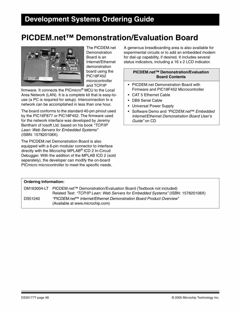
Development Systems Ordering Guide
PICDEM.net™ Demonstration/Evaluation BoardThe PICDEM.net Demonstration Board is an Internet/Ethernet demonstration board using the PIC18F452 microcontroller and TCP/IP
firmware. It connects the PICmicro® MCU to the Local Area Network (LAN). It is a complete kit that is easy-to-use (a PC is required for setup). Interconnection to a network can be accomplished in less than one hour.
The board conforms to the standard 40-pin pinout used by the PIC16F877 or PIC18F452. The firmware used for the network interface was developed by Jeremy Bentham of Iosoft Ltd. based on his book “TCP/IP Lean: Web Servers for Embedded Systems” (ISBN: 157820108X).
The PICDEM.net Demonstration Board is also equipped with a 6-pin modular connector to interface directly with the Microchip MPLAB® ICD 2 In-Circuit Debugger. With the addition of the MPLAB ICD 2 (sold separately), the developer can modify the on-board PICmicro microcontroller to meet the specific needs.
A generous breadboarding area is also available for experimental circuits or to add an embedded modem for dial-up capability, if desired. It includes several status indicators, including a 16 x 2 LCD indicator..
PICDEM.net™ Demonstration/EvaluationBoard Contents
• PICDEM.net Demonstration Board with Firmware and PIC18F452 Microcontroller
• CAT 5 Ethernet Cable• DB9 Serial Cable• Universal Power Supply• Software Demo and “PICDEM.net™ Embedded
Internet/Ethernet Demonstration Board User’s Guide” on CD
Ordering Information:
DM163004-LT PICDEM.net™ Demonstration/Evaluation Board (Textbook not included)Related Text: “TCP/IP Lean: Web Servers for Embedded Systems” (ISBN: 157820108X)
DS51240 “PICDEM.net™ Internet/Ethernet Demonstration Board Product Overview” (Available at www.microchip.com)
DS30177T-page 66 © 2005 Microchip Technology Inc.
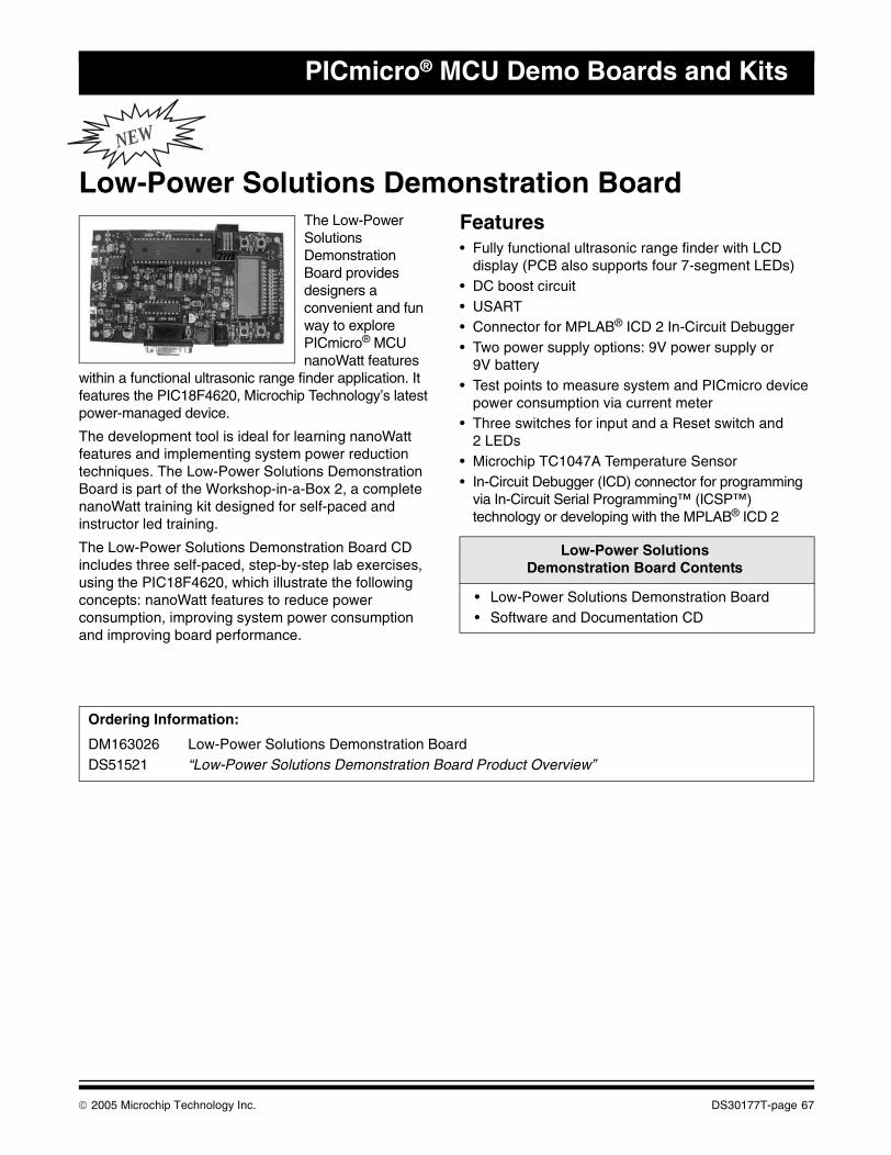
PICmicro® MCU Demo Boards and Kits
NEW
Low-Power Solutions Demonstration BoardThe Low-Power Solutions Demonstration Board provides designers a convenient and fun way to explore PICmicro® MCU nanoWatt features
within a functional ultrasonic range finder application. It features the PIC18F4620, Microchip Technology’s latest power-managed device.
The development tool is ideal for learning nanoWatt features and implementing system power reduction techniques. The Low-Power Solutions Demonstration Board is part of the Workshop-in-a-Box 2, a complete nanoWatt training kit designed for self-paced and instructor led training.
The Low-Power Solutions Demonstration Board CD includes three self-paced, step-by-step lab exercises, using the PIC18F4620, which illustrate the following concepts: nanoWatt features to reduce power consumption, improving system power consumption and improving board performance.
Features• Fully functional ultrasonic range finder with LCD
display (PCB also supports four 7-segment LEDs)• DC boost circuit• USART• Connector for MPLAB® ICD 2 In-Circuit Debugger• Two power supply options: 9V power supply or
9V battery• Test points to measure system and PICmicro device
power consumption via current meter• Three switches for input and a Reset switch and
2 LEDs• Microchip TC1047A Temperature Sensor• In-Circuit Debugger (ICD) connector for programming
via In-Circuit Serial Programming™ (ICSP™) technology or developing with the MPLAB® ICD 2
.
Low-Power Solutions Demonstration Board Contents
• Low-Power Solutions Demonstration Board• Software and Documentation CD
Ordering Information:
DM163026 Low-Power Solutions Demonstration BoardDS51521 “Low-Power Solutions Demonstration Board Product Overview”
© 2005 Microchip Technology Inc. DS30177T-page 67

Development Systems Ordering Guide
NOTES:
DS30177T-page 68 © 2005 Microchip Technology Inc.
This section contains the following major topics:
dsPICDEM™ Starter Development Board.................................................................................70dsPICDEM™ 28-Pin Starter Development Board .....................................................................71dsPICDEM™ 1.1 General Purpose Development Board ..........................................................72dsPICDEM™ 2 Development Board .........................................................................................73dsPICDEM™ MC1 Motor Control Development Board.............................................................74dsPICDEM.net™ 1 and dsPICDEM.net™ 2 Connectivity Development Boards ......................75
dsPIC® DSC DEVELOPMENT BOARDS, KITS
© 2005 Microchip Technology Inc. DS30177T-page 69
Development Systems Ordering Guide
dsPICDEM™ Starter Development BoardThe low-cost dsPICDEM™ Starter Development Board allows the user to easily validate a development tool setup using the dsPIC30F. It has a power supply regulator, crystal oscillator, MPLAB® ICD header, serial port, LEDs, push buttons, potentiometer and a prototyping area. In addition, all pins on the dsPIC® DSC device are brought out to a terminal block for access.
Features• 5V power supply split at the regulator to provide a
separate, decoupled analog supply voltage, useful in designs taking advantage of the 12-bit A/D Converter.
• Analog peripherals including an MCP41010 digital potentiometer used as a DAC to generate signals, and a MCP6022 to provide output filtering for the DAC and an input filter for the 12-bit A/D. The filter cutoff frequencies are set to 4 kHz to allow telephone quality signals.
The dsPICDEM Starter Development Board is delivered with a demo application that uses the digital potentiometer to generate audio tones. This output can be connected into the 12-bit ADC for measurement.
dsPICDEM™ Starter Development Board Contents
• dsPICDEM Starter Development Board• Documentation
Ordering Information:
DM300016 dsPICDEM™ Starter Development BoardDV164030 MPLAB® ICD 2 with dsPICDEM™ Starter Development BoardDS51430 “dsPICDEM™ Starter Development Board Product Overview” (Available at www.microchip.com)
DS30177T-page 70 © 2005 Microchip Technology Inc.
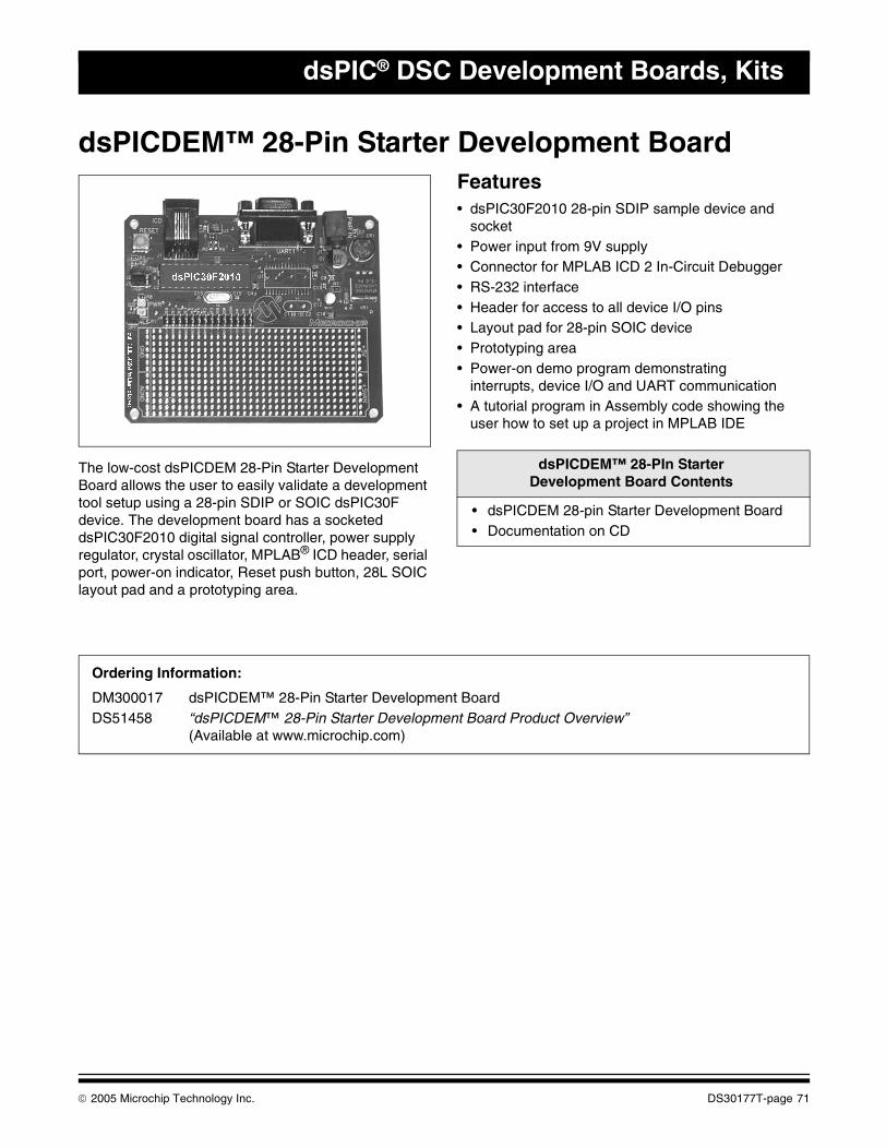
dsPIC® DSC Development Boards, Kits
dsPICDEM™ 28-Pin Starter Development Board
The low-cost dsPICDEM 28-Pin Starter Development Board allows the user to easily validate a development tool setup using a 28-pin SDIP or SOIC dsPIC30F device. The development board has a socketed dsPIC30F2010 digital signal controller, power supply regulator, crystal oscillator, MPLAB® ICD header, serial port, power-on indicator, Reset push button, 28L SOIC layout pad and a prototyping area.
Features• dsPIC30F2010 28-pin SDIP sample device and
socket• Power input from 9V supply• Connector for MPLAB ICD 2 In-Circuit Debugger• RS-232 interface• Header for access to all device I/O pins• Layout pad for 28-pin SOIC device• Prototyping area• Power-on demo program demonstrating
interrupts, device I/O and UART communication• A tutorial program in Assembly code showing the
user how to set up a project in MPLAB IDE
dsPICDEM™ 28-PIn Starter Development Board Contents
• dsPICDEM 28-pin Starter Development Board• Documentation on CD
Ordering Information:
DM300017 dsPICDEM™ 28-Pin Starter Development BoardDS51458 “dsPICDEM™ 28-Pin Starter Development Board Product Overview”
(Available at www.microchip.com)
© 2005 Microchip Technology Inc. DS30177T-page 71
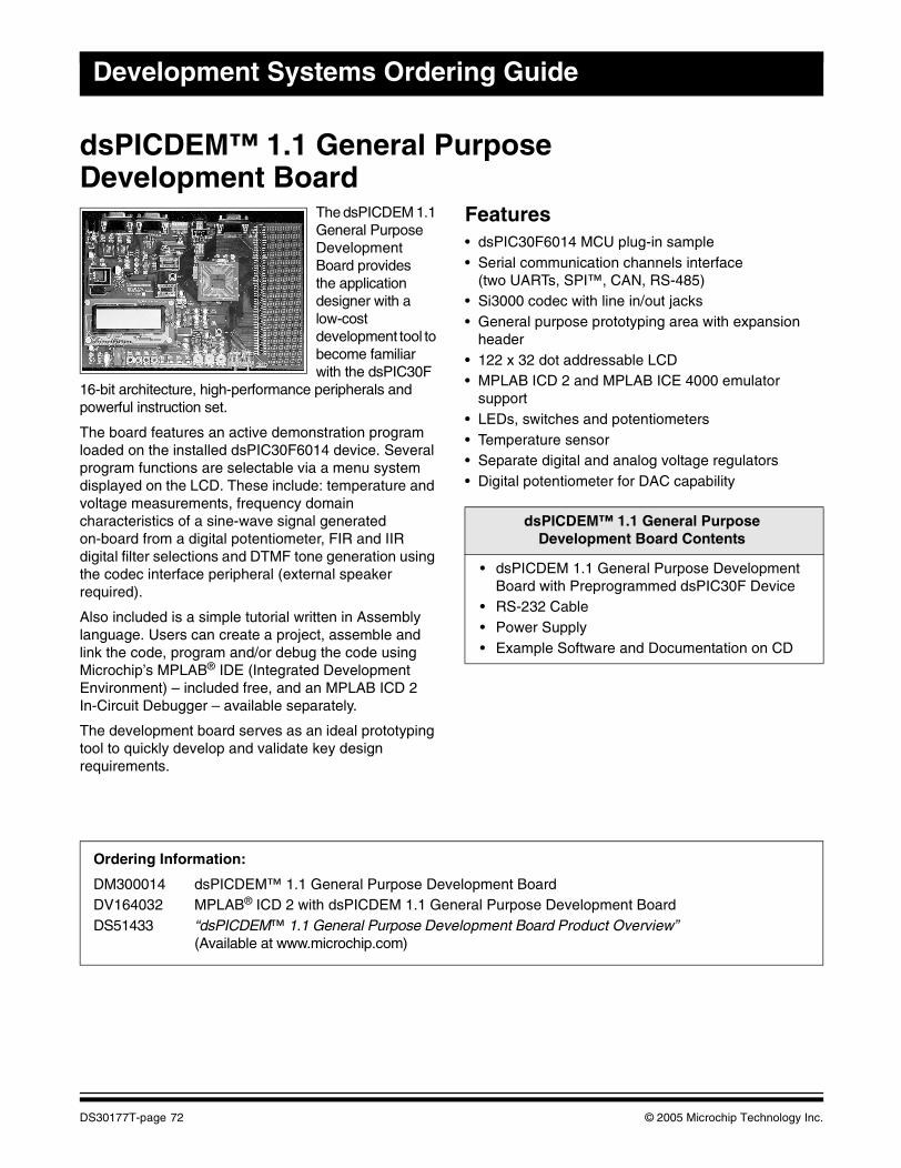
Development Systems Ordering Guide
dsPICDEM™ 1.1 General Purpose Development Board
The dsPICDEM 1.1 General Purpose Development Board providesthe application designer with a low-cost development tool to become familiar with the dsPIC30F
16-bit architecture, high-performance peripherals and powerful instruction set.
The board features an active demonstration program loaded on the installed dsPIC30F6014 device. Several program functions are selectable via a menu system displayed on the LCD. These include: temperature and voltage measurements, frequency domain characteristics of a sine-wave signal generated on-board from a digital potentiometer, FIR and IIR digital filter selections and DTMF tone generation using the codec interface peripheral (external speaker required).
Also included is a simple tutorial written in Assembly language. Users can create a project, assemble and link the code, program and/or debug the code using Microchip’s MPLAB® IDE (Integrated Development Environment) – included free, and an MPLAB ICD 2 In-Circuit Debugger – available separately.
The development board serves as an ideal prototyping tool to quickly develop and validate key design requirements.
Features• dsPIC30F6014 MCU plug-in sample• Serial communication channels interface
(two UARTs, SPI™, CAN, RS-485)• Si3000 codec with line in/out jacks• General purpose prototyping area with expansion
header• 122 x 32 dot addressable LCD• MPLAB ICD 2 and MPLAB ICE 4000 emulator
support• LEDs, switches and potentiometers• Temperature sensor• Separate digital and analog voltage regulators• Digital potentiometer for DAC capability
dsPICDEM™ 1.1 General PurposeDevelopment Board Contents
• dsPICDEM 1.1 General Purpose Development Board with Preprogrammed dsPIC30F Device
• RS-232 Cable• Power Supply• Example Software and Documentation on CD
Ordering Information:
DM300014 dsPICDEM™ 1.1 General Purpose Development BoardDV164032 MPLAB® ICD 2 with dsPICDEM 1.1 General Purpose Development BoardDS51433 “dsPICDEM™ 1.1 General Purpose Development Board Product Overview”
(Available at www.microchip.com)
DS30177T-page 72 © 2005 Microchip Technology Inc.
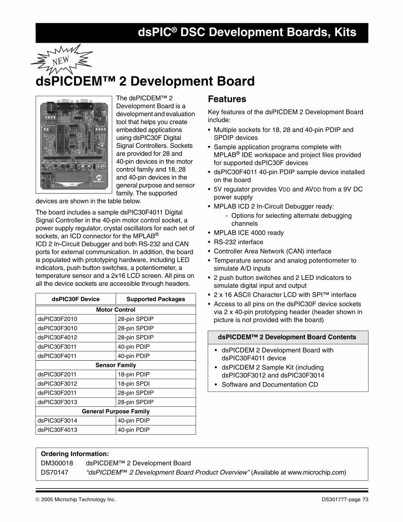
dsPIC® DSC Development Boards, Kits
NEW
dsPICDEM™ 2 Development BoardThe dsPICDEM™ 2 Development Board is a development and evaluation tool that helps you create embedded applications using dsPIC30F Digital Signal Controllers. Sockets are provided for 28 and 40-pin devices in the motor control family and 18, 28 and 40-pin devices in the general purpose and sensor family. The supported
devices are shown in the table below.
The board includes a sample dsPIC30F4011 Digital Signal Controller in the 40-pin motor control socket, a power supply regulator, crystal oscillators for each set of sockets, an ICD connector for the MPLAB® ICD 2 In-Circuit Debugger and both RS-232 and CAN ports for external communication. In addition, the board is populated with prototyping hardware, including LED indicators, push button switches, a potentiometer, a temperature sensor and a 2x16 LCD screen. All pins on all the device sockets are accessible through headers.
FeaturesKey features of the dsPICDEM 2 Development Board include:
• Multiple sockets for 18, 28 and 40-pin PDIP and SPDIP devices
• Sample application programs complete with MPLAB® IDE workspace and project files provided for supported dsPIC30F devices
• dsPIC30F4011 40-pin PDIP sample device installed on the board
• 5V regulator provides VDD and AVDD from a 9V DC power supply
• MPLAB ICD 2 In-Circuit Debugger ready:- Options for selecting alternate debugging
channels• MPLAB ICE 4000 ready• RS-232 interface• Controller Area Network (CAN) interface• Temperature sensor and analog potentiometer to
simulate A/D inputs• 2 push button switches and 2 LED indicators to
simulate digital input and output• 2 x 16 ASCII Character LCD with SPI™ interface• Access to all pins on the dsPIC30F device sockets
via 2 x 40-pin prototyping header (header shown in picture is not provided with the board)
dsPIC30F Device Supported Packages
Motor Control
dsPIC30F2010 28-pin SPDIP
dsPIC30F3010 28-pin SPDIP
dsPIC30F4012 28-pin SPDIP
dsPIC30F3011 40-pin PDIP
dsPIC30F4011 40-pin PDIP
Sensor Family
dsPIC30F2011 18-pin PDIP
dsPIC30F3012 18-pin SPDI
dsPIC30F2011 28-pin SPDIP
dsPIC30F3013 28-pin SPDIP
General Purpose Family
dsPIC30F3014 40-pin PDIP
dsPIC30F4013 40-pin PDIP
dsPICDEM™ 2 Development Board Contents
• dsPICDEM 2 Development Board with dsPIC30F4011 device
• dsPICDEM 2 Sample Kit (including dsPIC30F3012 and dsPIC30F3014
• Software and Documentation CD
Ordering Information:DM300018 dsPICDEM™ 2 Development BoardDS70147 “dsPICDEM™ 2 Development Board Product Overview” (Available at www.microchip.com)
© 2005 Microchip Technology Inc. DS30177T-page 73
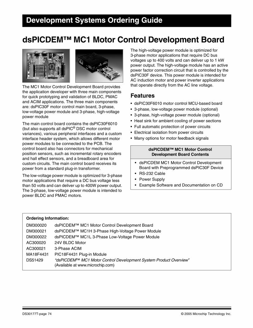
Development Systems Ordering Guide
dsPICDEM™ MC1 Motor Control Development Board
The MC1 Motor Control Development Board provides the application developer with three main components for quick prototyping and validation of BLDC, PMAC and ACIM applications. The three main components are: dsPIC30F motor control main board, 3-phase, low-voltage power module and 3-phase, high-voltage power module
The main control board contains the dsPIC30F6010 (but also supports all dsPIC® DSC motor control variances), various peripheral interfaces and a custom interface header system, which allows different motor power modules to be connected to the PCB. The control board also has connectors for mechanical position sensors, such as incremental rotary encoders and hall effect sensors, and a breadboard area for custom circuits. The main control board receives its power from a standard plug-in transformer.
The low-voltage power module is optimized for 3-phase motor applications that require a DC bus voltage less than 50 volts and can deliver up to 400W power output. The 3-phase, low-voltage power module is intended to power BLDC and PMAC motors.
The high-voltage power module is optimized for 3-phase motor applications that require DC bus voltages up to 400 volts and can deliver up to 1 kW power output. The high-voltage module has an active power factor correction circuit that is controlled by the dsPIC30F device. This power module is intended for AC induction motor and power inverter applications that operate directly from the AC line voltage.
Features• dsPIC30F6010 motor control MCU-based board• 3-phase, low-voltage power module (optional)• 3-phase, high-voltage power module (optional)• Heat sink for ambient cooling of power sections• Full automatic protection of power circuits• Electrical isolation from power circuits• Many options for motor feedback signals
dsPICDEM™ MC1 Motor ControlDevelopment Board Contents
• dsPICDEM MC1 Motor Control Development Board with Preprogrammed dsPIC30F Device
• RS-232 Cable• Power Supply• Example Software and Documentation on CD
Ordering Information:
DM300020 dsPICDEM™ MC1 Motor Control Development BoardDM300021 dsPICDEM™ MC1H 3-Phase High-Voltage Power ModuleDM300022 dsPICDEM™ MC1L 3-Phase Low-Voltage Power ModuleAC300020 24V BLDC Motor AC300021 3-Phase ACIM MA18F4431 PIC18F4431 Plug-in ModuleDS51429 “dsPICDEM™ MC1 Motor Control Development System Product Overview”
(Available at www.microchip.com)
DS30177T-page 74 © 2005 Microchip Technology Inc.
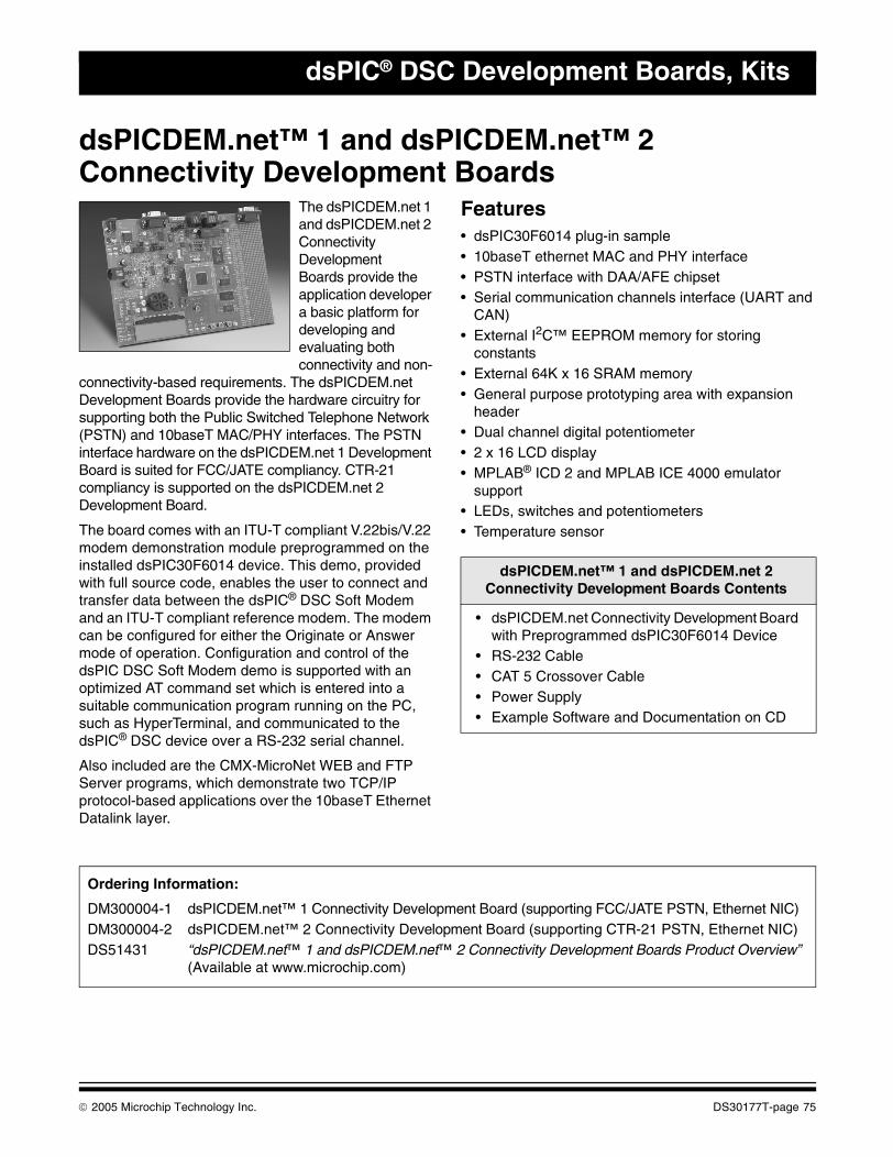
dsPIC® DSC Development Boards, Kits
dsPICDEM.net™ 1 and dsPICDEM.net™ 2Connectivity Development Boards
The dsPICDEM.net 1 and dsPICDEM.net 2 Connectivity DevelopmentBoards provide the application developer a basic platform for developing and evaluating both connectivity and non-
connectivity-based requirements. The dsPICDEM.net Development Boards provide the hardware circuitry for supporting both the Public Switched Telephone Network (PSTN) and 10baseT MAC/PHY interfaces. The PSTN interface hardware on the dsPICDEM.net 1 Development Board is suited for FCC/JATE compliancy. CTR-21 compliancy is supported on the dsPICDEM.net 2 Development Board.
The board comes with an ITU-T compliant V.22bis/V.22 modem demonstration module preprogrammed on the installed dsPIC30F6014 device. This demo, provided with full source code, enables the user to connect and transfer data between the dsPIC® DSC Soft Modem and an ITU-T compliant reference modem. The modem can be configured for either the Originate or Answer mode of operation. Configuration and control of the dsPIC DSC Soft Modem demo is supported with an optimized AT command set which is entered into a suitable communication program running on the PC, such as HyperTerminal, and communicated to the dsPIC® DSC device over a RS-232 serial channel.
Also included are the CMX-MicroNet WEB and FTP Server programs, which demonstrate two TCP/IP protocol-based applications over the 10baseT Ethernet Datalink layer.
Features• dsPIC30F6014 plug-in sample• 10baseT ethernet MAC and PHY interface• PSTN interface with DAA/AFE chipset• Serial communication channels interface (UART and
CAN)• External I2C™ EEPROM memory for storing
constants• External 64K x 16 SRAM memory• General purpose prototyping area with expansion
header• Dual channel digital potentiometer• 2 x 16 LCD display• MPLAB® ICD 2 and MPLAB ICE 4000 emulator
support• LEDs, switches and potentiometers• Temperature sensor
dsPICDEM.net™ 1 and dsPICDEM.net 2Connectivity Development Boards Contents
• dsPICDEM.net Connectivity Development Board with Preprogrammed dsPIC30F6014 Device
• RS-232 Cable• CAT 5 Crossover Cable• Power Supply• Example Software and Documentation on CD
Ordering Information:
DM300004-1 dsPICDEM.net™ 1 Connectivity Development Board (supporting FCC/JATE PSTN, Ethernet NIC)DM300004-2 dsPICDEM.net™ 2 Connectivity Development Board (supporting CTR-21 PSTN, Ethernet NIC)DS51431 “dsPICDEM.net™ 1 and dsPICDEM.net™ 2 Connectivity Development Boards Product Overview”
(Available at www.microchip.com)
© 2005 Microchip Technology Inc. DS30177T-page 75

Development Systems Ordering Guide
NOTES:
DS30177T-page 76 © 2005 Microchip Technology Inc.
This section contains the following major topics:
PICDEM™ MSC1 Demonstration Kit ........................................................................................78PICDEM™ MSC1 Daughter Boards..........................................................................................79MCP41XXX/42XXX Digital Potentiometer Evaluation Board ....................................................80MXDEV® 1 Analog Evaluation System Driver Board ................................................................81MXDEV® 1 MCP3XXX Single/Dual ADC Evaluation System Daughter Board Kit ....................82MXDEV® 1 MCP3XXX Quad/Octal ADC Evaluation System Daughter Board Kit ....................83Fan Controllers and Serial Temperature Sensor Demo Boards ................................................84MCP2510 CAN Developer’s Kit ................................................................................................85MCP250XX CAN I/O Expander Developer’s Kit........................................................................86MCP2120/2150 Infrared Developer’s Kit...................................................................................87SEEVAL® 32 Serial EEPROM Evaluation System Designer’s Kit.............................................8813.56 MHz Anticollision microID® Developer’s Kit for MCRF355 and MCRF360 .....................8913.56 MHz Anticollision microID® Developer’s Kit for MCRF355, MCRF360 and MCRF45X ..... 90Interface Products .......................................................................................................................... 91Linear Products .............................................................................................................................. 91Mixed-Signal Products ................................................................................................................... 92Power Management Products........................................................................................................ 93Thermal Management Products..................................................................................................... 94Analog Software Tools ................................................................................................................... 95
ANALOG AND MIXED-SIGNALDEMO BOARDS AND KITS
© 2005 Microchip Technology Inc. DS30177T-page 77
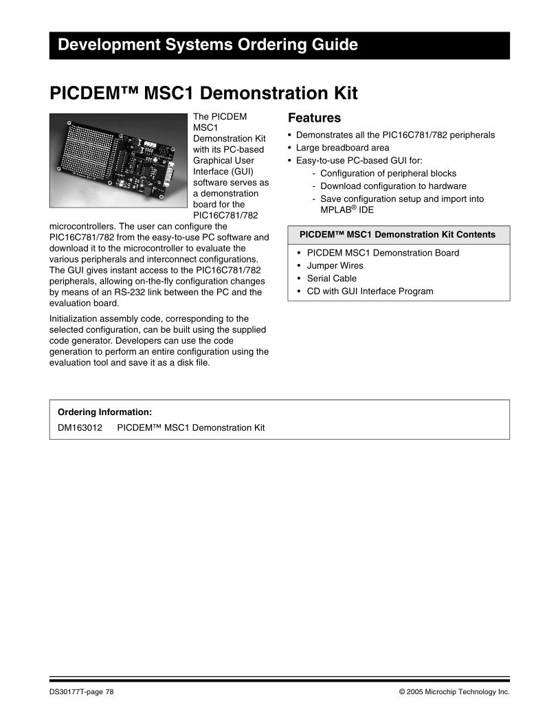
Development Systems Ordering Guide
PICDEM™ MSC1 Demonstration KitThe PICDEM MSC1 Demonstration Kit with its PC-based Graphical User Interface (GUI) software serves as a demonstration board for the PIC16C781/782
microcontrollers. The user can configure the PIC16C781/782 from the easy-to-use PC software and download it to the microcontroller to evaluate the various peripherals and interconnect configurations. The GUI gives instant access to the PIC16C781/782 peripherals, allowing on-the-fly configuration changes by means of an RS-232 link between the PC and the evaluation board.
Initialization assembly code, corresponding to the selected configuration, can be built using the supplied code generator. Developers can use the code generation to perform an entire configuration using the evaluation tool and save it as a disk file.
Features• Demonstrates all the PIC16C781/782 peripherals• Large breadboard area• Easy-to-use PC-based GUI for:
- Configuration of peripheral blocks- Download configuration to hardware- Save configuration setup and import into
MPLAB® IDE
PICDEM™ MSC1 Demonstration Kit Contents
• PICDEM MSC1 Demonstration Board• Jumper Wires• Serial Cable• CD with GUI Interface Program
Ordering Information:
DM163012 PICDEM™ MSC1 Demonstration Kit
DS30177T-page 78 © 2005 Microchip Technology Inc.
Analog and Mixed-Signal Demo Boards and Kits
PICDEM™ MSC1 Daughter BoardsThe following daughter boards, available separately, demonstrate additional capabilities of the PIC16C781/782 microcontrollers.
PICDEM™ MSC1 Switch Mode Power Supply (SMPS) Daughter Board
The PICDEM™ MSC1 Switch Mode Power Supply (SMPS) Daughter Board, in combination with the PICDEM MSC1 Demonstration Board, is a complete demonstration and evaluation kit for designing Switch mode power supplies using the PIC16C781/782. The daughter board can be configured for the following Switch mode power supply topologies:
• Boost: Output voltage greater than the supply voltage• Buck: Output voltage less than the supply voltage• Buck-Boost: Output voltage less than or greater than
the supply voltage• Invert: Negative output voltages
PICDEM™ MSC1 Infrared (IR) Driver Daughter Board
The PICDEM™ MSC1 Infrared (IR) Driver Daughter Board, in combination with the PICDEM MSC1 Demonstration Board, serves as a demonstration and evaluation kit for designing a high-power, IR remote control transmitter using the PIC16C782. The daughter board, in combination with the included IR receiver, implements both receive and transmit sections of a Pulse-Width Modulation (PWM) IR remote control system.
PICDEM™ MSC1 Delta-Sigma ADC Daughter Board
The PICDEM™ MSC1 Delta-Sigma ADC Daughter Board, in combination with the PICDEM MSC1 Demonstration Board, serves as a demonstration and evaluation kit for designing high-resolution, Delta-Sigma Analog-to-Digital Converters using the PIC16C781/782. The daughter board has the following features:
• All the components required to implement an 8 to 16-bit Delta-Sigma ADC
• An RCA connector for connecting an external sensor• A generous prototyping area for building signal
conditioning circuitry• An on-board temperature sensor for a demonstration
input to the ADC
PICDEM™ MSC1 Flow Rate Sensor Daughter Board
The PICDEM™ MSC1 Flow Rate Sensor Daughter Board, in combination with the PICDEM MSC1 Demonstration Board, is a complete demonstration kit for a high sensitivity, hot-wire anemometer styled flow rate sensor using the PIC16C782.
PICDEM™ MSC1 Daughter Boards Contents
• PICDEM MSC1 Daughter Board• Complete Documentation
Ordering Information:
AC163001 PICDEM MSC1 Switch Mode Power Supply (SMPS) Daughter BoardAC163002 PICDEM MSC1 Infrared (IR) Driver Daughter BoardAC163003 PICDEM MSC1 Delta-Sigma ADC Daughter BoardAC163004 PICDEM MSC1 Flow Rate Sensor Daughter Board
© 2005 Microchip Technology Inc. DS30177T-page 79
Development Systems Ordering Guide
MCP41XXX/42XXX Digital Potentiometer Evaluation BoardThe MCP41XXX/42XXX Evaluation Board is a demonstration and evaluation tool for Microchip Technology’s MCP41XXX/42XXX digital potentiometers. The MCP41XXX/42XXX Evaluation Board is designed to be used in conjunction with the MXDEV® Evaluation System. When connected to the driver board with the included microcontroller installed, this evaluation board allows for the programming and evaluation of the MCP41XXX/42XXX digital potentiometer in a variety of applications.
Some of the applications that can be used for evaluation of the MCP41XXX/42XXX digital potentiometers include an offset circuit, low-pass filter and gain circuits. A removable prototype area is available for quick-turn circuit evaluation. Evaluation of other operations, such as daisy chain, shutdown and Reset, are also available. Software tools for the digital potentiometer and ADC are also provided for evaluation.
MCP41XXX/42XXX Digital PotentiometerEvaluation Board Contents
• MCP41XXX/42XXX Evaluation Board• Removable Prototype Board• MCP41XXX/42XXX Samples and
Reprogrammable Microchip Flash PICmicro® MCU
• MXLAB® IDE ADC Software• RS-232 Cable• 9V DC Power Supply• Documentation, including the “MCP42XXX
Evaluation Board User’s Guide”
Ordering Information:
DV42XXX MCP41XXX/42XXX Digital Potentiometer Evaluation Board
DS30177T-page 80 © 2005 Microchip Technology Inc.
Analog and Mixed-Signal Demo Boards and Kits
MXDEV® 1 Analog Evaluation System Driver BoardThe MXDEV 1 Analog Evaluation System gives system designers the ability to control Microchip stand-alone analog devices, acquire data and then analyze the data using strip-charts, histograms and Fast Fourier Transforms (FFTs). User-friendly data analysis software is included with the device-specific daughter boards.
The evaluation system consists of two parts: a driver board, which performs the data analysis and connects to a PC for subsequent analysis and display and a daughter board, which plugs into the driver board and contains the device to be evaluated. Device-specific software is included.
In addition to the ability of the driver board to work with device-specific daughter boards, users can create their own daughter boards based on their own design requirements. In addition, a prototype area on the driver board is available for user-designed circuits that could be used in place of the daughter boards.
The MXDEV 1 Analog Evaluation System Driver Board contains three different PICmicro® microcontroller sockets (28-pin, 18-pin and 8-pin), so that users can choose the PICmicro MCU most suited to their application. It also includes an LCD display, an LED display socket, SRAM for data storage and an RS-232 interface. The LCD display can display information, such as configuration data and acquisition data from the daughter board.
The daughter board kits contain the device to be evaluated and a PIC16F876 Flash microcontroller containing device-specific code. The microcontroller then plugs into one of the sockets on the DVMCPA. Code is also provided that shows how to interface the PIC16C54 and the PIC12C509 with the ADC.
MXDEV® 1 Analog Evaluation SystemDriver Board Contents
• Driver Board• Microcontroller Samples• RS-232 Cable• MXLAB® IDE ADC Software• Two Power Supplies• Documentation, including the “Analog
Evaluation System Driver Board User’s Guide”
Ordering Information:
DVMCPA MXDEV® 1 Analog Evaluation System Driver Board
© 2005 Microchip Technology Inc. DS30177T-page 81
Development Systems Ordering Guide
MXDEV® 1 MCP3XXX Single/Dual ADCEvaluation System Daughter Board KitThe MXDEV 1 MCP3XXX Single/Dual ADC Evaluation System Daughter Board Kit supports the following devices: MCP3001, MCP3002, MCP3201, MCP3202 and MCP3301.
This kit includes jumper-selectable options for maximum flexibility. Choices include:
• Selection of the signal source between the on-board potentiometer and an external source.
• Selection of the ADC reference voltage between the on-board VREF and an external source.
• Selection between single-ended and pseudo-differential inputs (depending on the device being evaluated).
There is a prototype area on the board for additional circuitry as needed.
MXDEV® 1 MCP3XXX Single/Dual ADCEvaluation System Daughter Board Kit Contents
• MXDEV 1 MCP3XXX Single/Dual ADC Daughter Board
• Filter Boards• Samples for all Supported A/D Converts and
Preprogrammed PICmicro® MCU for use in the Driver Board
• Adapter Plugs• MXLAB® IDE ADC Software• Documentation, including the “MCP3XXX A/D
Converter Evaluation Kit User’s Guide”
Ordering Information:
DV3201A MXDEV® 1 MCP3XXX Single/Dual ADC Evaluation System Daughter Board Kit
DS30177T-page 82 © 2005 Microchip Technology Inc.
Analog and Mixed-Signal Demo Boards and Kits
MXDEV® 1 MCP3XXX Quad/Octal ADC Evaluation System Daughter Board KitThe MXDEV 1 MCP3XXX Quad/Octal ADC Evaluation System Daughter Board Kit supports the following devices: MCP3004, MCP3008, MCP3204, MCP3208, MCP3302 and MCP3304.
This kit includes jumper-selectable options for maximum flexibility. Choices include:
• Selection of the signal source between the on-board potentiometer and an external source.
• Selection of the ADC reference voltage between the on-board VREF and an external source.
• Selection between single-ended and pseudo-differential inputs (depending on the device being evaluated).
There is a prototype area on the board for additional circuitry as needed.
MXDEV® 1 MCP3XXX Quad/OctalEvaluation System Daughter Board Kit Contents
• MCP3XXX Quad/Octal Daughter Board• Filter Boards• Samples for all Supported A/D Converts and
Preprogrammed PICmicro® MCU for use in the Driver Board
• Adapter Plugs• MXLAB® IDE ADC Software• Documentation, including the “MCP3XXX A/D
Converter Evaluation Kit User’s Guide”
Ordering Information:
DV3204A MXDEV® 1 MCP3XXX Quad/Octal ADC Evaluation System Daughter Board Kit
© 2005 Microchip Technology Inc. DS30177T-page 83
Development Systems Ordering Guide
Fan Controllers and Serial Temperature Sensor Demo BoardsTC642EV – Evaluation Kit for BrushlessDC Fan Controllers
The TC642EV is a complete evaluation kit for evaluating and prototyping brushless DC fan control circuits using Microchip’s TC642, TC646, TC647, TC648 and TC649 BDC fan controllers. The fan speed control signal can be provided by an external sensor or voltage signal, or from the on-board potentiometer. Minimum speed setting and auto-shutdown threshold are conveniently set by a potentiometer. Jumper blocks allow the user to quickly configure the output stage and input signal source and scaling. Test points provide easy access for instrument readings at critical nodes. A user prototyping area is provided for dedicated circuitry or other user specific circuits.
TC642DEMO – Fan Controller Demo Board for TC642/646/647/648/649
This Fan Controller Demo Board allows the user to quickly prototype fan control circuits based on Microchip’s PWM fan control ICs (TC642, TC646, TC647, TC648 or TC649). This 1.5" by 2.0" board’s versatile sensor input and output driver circuitry allows the Fan Controller Demo Board to be used with virtually any brushless DC fan and standard thermistor. An optional LED status indicator gives a visual indication of a fan Fault condition (open stator, blocked rotor or overtemperature Fault detection). It uses through-hole components for easy user modification.
TC650DEMO – Fan Controller Demo Board for TC650/651This 1.0" x 1.0" Fan Controller Demo Board allows the user to quickly prototype fan control circuits based on Microchip’s TC650 or TC651 PWM Fan Control ICs. The board can interface with virtually any brushless DC fan. A red LED status indicator gives visual indication of a fan Fault condition (open stator or blocked rotor) and a green LED status indicator gives a visual indication of an overtemperature alert (temperature is 10°C higher than the high temperature limit).
TC652DEMO – Fan Controller Demo Board for TC652/653This 1.0" x 1.2" Fan Controller Demo Board allows the user to quickly prototype fan control circuits based on Microchip’s TC652 or TC653 PWM fan control ICs. The board can interface with virtually any brushless DC fan. A red LED status indicator gives visual indication of a fan Fault condition (open stator or blocked rotor) and a green LED status indicator gives a visual indication of an overtemperature alert (temperature is 10°C higher than the high temperature limit).
TC74DEMO – Serial Digital Temperature Sensor Demo Board
The TC74DEMO Board allows the user to evaluate the functionality of the tiny TC74 thermal sensor and perform comparative evaluation against other thermal management solutions. This 0.75" by 2.5" PC board is an ideal solution for identifying the temperature profile of applications like datacom, telecom and PC equipment. The easy-to-use software provides a visual representation of temperature profile and can interface with any PC.
Ordering Information:TC642EV TC642EV Evaluation Kit for Brushless DC Fan ControllersDS51252 “TC642EV Evaluation Kit for Brushless DC Fan Controllers TC64X Product Overview”TC642DEMO TC642DEMO Fan Controller Demo Board for TC642/646/647/648/649DS51251 “TC642DEMO Fan Control Module for TC64X Family Product Overview”TC650DEMO TC650DEMO Fan Controller Demo Board for TC650/651TC652DEMO TC652DEMO Fan Controller Demo Board for TC652/653DS51254 “TC650DEMO and TC652DEMO Fan Controller Demo Boards for TC650/1/2/3 Product Overview”TC74DEMO TC74DEMO Serial Digital Temperature Sensor Demo BoardDS51253 “TC74DEMO Serial Thermal Sensor Demo Board for TC74 Product Overview”
DS30177T-page 84 © 2005 Microchip Technology Inc.
Analog and Mixed-Signal Demo Boards and Kits
MCP2510 CAN Developer’s KitThe MCP2510 CAN Developer’s Kit is a multi-function tool that speeds implementation of the MCP2510 stand-alone CAN controller by offering functions for controlling its feature set.
In addition, this tool can be used to demonstrate basic CAN input/output functionality and monitor bus activity on the user’s CAN bus. It is ideal for new CAN users that want to understand how CAN may be used for network communication.
MCP2510 CAN Developer’s Kit Contents
• MCP2510 Target Board• User Interface Software
(runs under Windows® 95/98)• PC Parallel Port Interface Cable• Power Supply• Documentation, including “MCP2510
Development Kit User’s Guide”
Ordering Information:
DV251001 MCP2510 CAN Developer’s Kit
© 2005 Microchip Technology Inc. DS30177T-page 85
Development Systems Ordering Guide
MCP250XX CAN I/O Expander Developer’s KitThe MCP250XX CAN I/O Expander Developer’s Kit includes everything needed to create a CAN-based system using Microchip’s CAN I/O expander family. It can be used to evaluate, demonstrate and develop CAN nodes using these CAN I/O expanders. The Demonstration mode has an MCP25050 that is configured prior to shipping and is programmed to manipulate analog inputs via potentiometers, PWM outputs via a piezoelectric buzzer and an incandescent lamp, and digital inputs via push button switches. CAN messages can be sent and received between the master node and the demonstration node via the PC-user interface or via the input/output functionality discussed above. Users can also set up a watch window to display the message traffic as they manipulate the inputs and outputs. In this manner, the users can see a working network being demonstrated with one of the nodes being an MCP25050 CAN I/O expander device.
Another function of the developer’s kit is that the PC, with included software, can be used to emulate an MCP250XX device. This mode is used to manipulate the registers of the MCP250XX devices in order to evaluate all of the different functionality and configurations of the device family. After users are comfortable with a configuration, they can then prototype their own CAN node. An unconfigured MCP250XX device is supplied with prototyping area, also included on the target board. A header is provided to enable oscilloscope access to the I/O pins for development and troubleshooting. Once prototyping is complete, the kit can be used to program up the device configuration in much the same manner that Microchip PICmicro® MCUs are programmed.
Features• Speeds understanding of CAN I/O expander family• Provides ability to prototype user-defined CAN node• Enables programming of device default
configuration directly from developer’s kit• Allows connection of external CAN networks• Software watch window can be used as a basic CAN
bus monitor
MCP250XX CAN I/O ExpanderDeveloper’s Kit Contents
• Target Board with Three CAN Nodes Connected via a CAN Bus
• MCP250XX Product Samples• PC Software to Interface to the Target Board• PC Parallel Port Interface Cable• Power Supply• Complete Documentation
Ordering Information:
DV250501 MCP250XX CAN I/O Expander Developer’s KitDS51260 “MCP25020/25025/25050/25055 CAN I/O Expanders Developer’s Kit Product Overview”
(Available at www.microchip.com)
DS30177T-page 86 © 2005 Microchip Technology Inc.
Analog and Mixed-Signal Demo Boards and Kits
MCP2120/2150 Infrared Developer’s KitThe MCP2120/2150 Infrared Developer’s Kit includes everything needed to create a system that communicates using infrared wireless communication. It educates the designer on the IR communications technology and IrDA® protocol and can then be used to integrate these technologies into the designer’s product allowing proof of concept.
The kit includes Microchip’s revolutionary MCP2150 Infrared Communications Controller supporting the IrDA Standard. It can be set up to communicate with other IrDA devices, like PDAs and mobile phones, as well. Host interface can be selected as a UART (DB-9) to a PC using Hyperlink, or as a Master controller/ASIC to the header. The boards also offer two types of transceivers: the component version (which is a lower cost but complicated) or the integrated version (which is simple but higher cost). The kit demonstrates two PCs communicating with each other via IR.
MCP2120/2150 Infrared Developer’s Kit Contents
• Two MCP2120 IR Nodes• One MCP2150 IR Node• Product Samples• Serial Cables• Universal Power Supply• Documentation
Ordering Information:
DM163008 MCP2120/2150 Infrared Developer’s KitDS51257 “MCP2120/2150 Infrared Products Developer’s Kit Product Overview”
(Available at www.microchip.com)
© 2005 Microchip Technology Inc. DS30177T-page 87
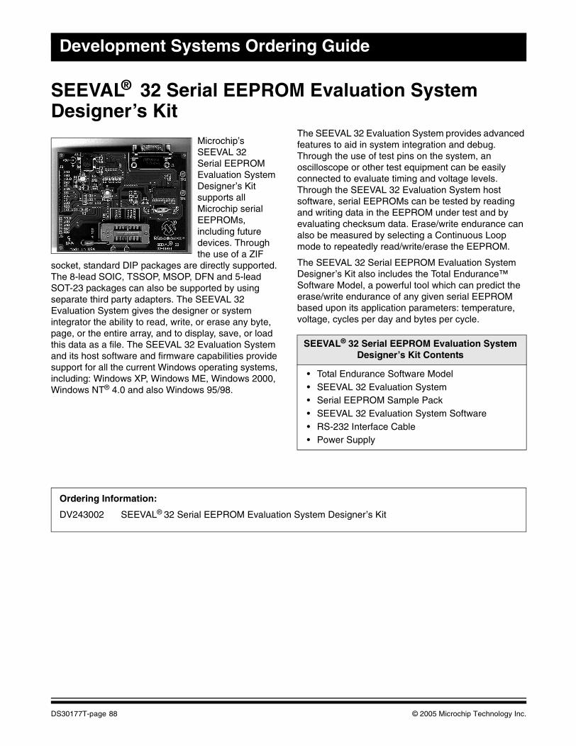
Development Systems Ordering Guide
SEEVAL® 32 Serial EEPROM Evaluation System Designer’s Kit
Microchip’s SEEVAL 32Serial EEPROM Evaluation System Designer’s Kit supports all Microchip serial EEPROMs, including future devices. Through the use of a ZIF
socket, standard DIP packages are directly supported. The 8-lead SOIC, TSSOP, MSOP, DFN and 5-lead SOT-23 packages can also be supported by using separate third party adapters. The SEEVAL 32 Evaluation System gives the designer or system integrator the ability to read, write, or erase any byte, page, or the entire array, and to display, save, or load this data as a file. The SEEVAL 32 Evaluation System and its host software and firmware capabilities provide support for all the current Windows operating systems, including: Windows XP, Windows ME, Windows 2000, Windows NT® 4.0 and also Windows 95/98.
The SEEVAL 32 Evaluation System provides advanced features to aid in system integration and debug. Through the use of test pins on the system, an oscilloscope or other test equipment can be easily connected to evaluate timing and voltage levels. Through the SEEVAL 32 Evaluation System host software, serial EEPROMs can be tested by reading and writing data in the EEPROM under test and by evaluating checksum data. Erase/write endurance can also be measured by selecting a Continuous Loop mode to repeatedly read/write/erase the EEPROM.
The SEEVAL 32 Serial EEPROM Evaluation System Designer’s Kit also includes the Total Endurance™ Software Model, a powerful tool which can predict the erase/write endurance of any given serial EEPROM based upon its application parameters: temperature, voltage, cycles per day and bytes per cycle.
SEEVAL® 32 Serial EEPROM Evaluation SystemDesigner’s Kit Contents
• Total Endurance Software Model• SEEVAL 32 Evaluation System• Serial EEPROM Sample Pack• SEEVAL 32 Evaluation System Software• RS-232 Interface Cable• Power Supply
Ordering Information:
DV243002 SEEVAL® 32 Serial EEPROM Evaluation System Designer’s Kit
DS30177T-page 88 © 2005 Microchip Technology Inc.
Analog and Mixed-Signal Demo Boards and Kits
13.56 MHz Anticollision microID® Developer’s Kit for MCRF355 and MCRF360The 13.56 MHz microID Developer’s Kit is an easy-to-use tool for design engineers at all skill levels. This kit includes all the hardware, software, reference designs and samples required to get started in 13.56 MHz RFID designs.
This kit is intended to demonstrate basic operation of the high-performance MCRF355 tagging chip and basic design of a simple RFID reader.
microID® MCRF355 and MCRF360Developer’s Kit Contents
• 13.56 MHz Anticollision Reader• Contact Programmer• Two Power Supplies• Two RS-232 Cables• rfLAB™ 13.56 Software Interface (runs under
Windows® 95/98, Windows 2000, Windows XP)• Socketed Tags• Flexible, Preprogrammed Performa™ tags by
Checkpoint Systems Inc.• Samples in DIP Form• Documentation, including a complete “microID
RFID Products 13.56 MHz RFID System Design Guide” (Application Notes, Reference Designs and Tutorials)
Ordering Information:
DV103003 13.56 MHz Anticollision microID® Developer’s Kit for MCRF355 and MCRF360PG103003 microID® Contact Programmer Kit for MCRF355 and MCRF360
(This programmer is also included in the DV103006)
© 2005 Microchip Technology Inc. DS30177T-page 89
Development Systems Ordering Guide
13.56 MHz Anticollision microID® Developer’s Kit for MCRF355, MCRF360 and MCRF45XThe 13.56 MHz microID Developer’s Kit is a high-speed, long range, easy-to-use tool for design engineers at all skill levels. This kit includes all the hardware, software, reference designs and samples required to get started in high-performance 13.56 MHz RFID designs.
This kit is designed to demonstrate all 13.56 MHz RFID devices, including MCRF355/360 and MCRF450/451/452/455 and to provide a basic platform for high-performance RFID reader design.
i
microID® MCRF355, MCRF360 and MCRF45X Developer’s Kit Contents
• 13.56 MHz Read/Write Interrogator• Contact Programmer for MCRF355/360• Two Power Supplies• Two RS-232 Cables• rfLAB™ 13.56 Software Interface (runs under
Windows® 95/98, Windows 2000, Windows XP)• Socketed Tags• Flexible, Preprogrammed Performa™ tags by
Checkpoint Systems Inc.• Samples in DIP Form• Documentation including a complete “microID
RFID Products 13.56 MHz RFID System Design Guide” (Application Notes, Reference Designs and Tutorials)
Ordering Information:
DV103006 13.56 MHz Anticollision microID® Developer’s Kit for MCRF355, MCRF360, MCRF45XPG103003 microID® Contact Programmer Kit for MCRF355 and MCRF360
(This programmer is also included in the DV103006)
DS30177T-page 90 © 2005 Microchip Technology Inc.
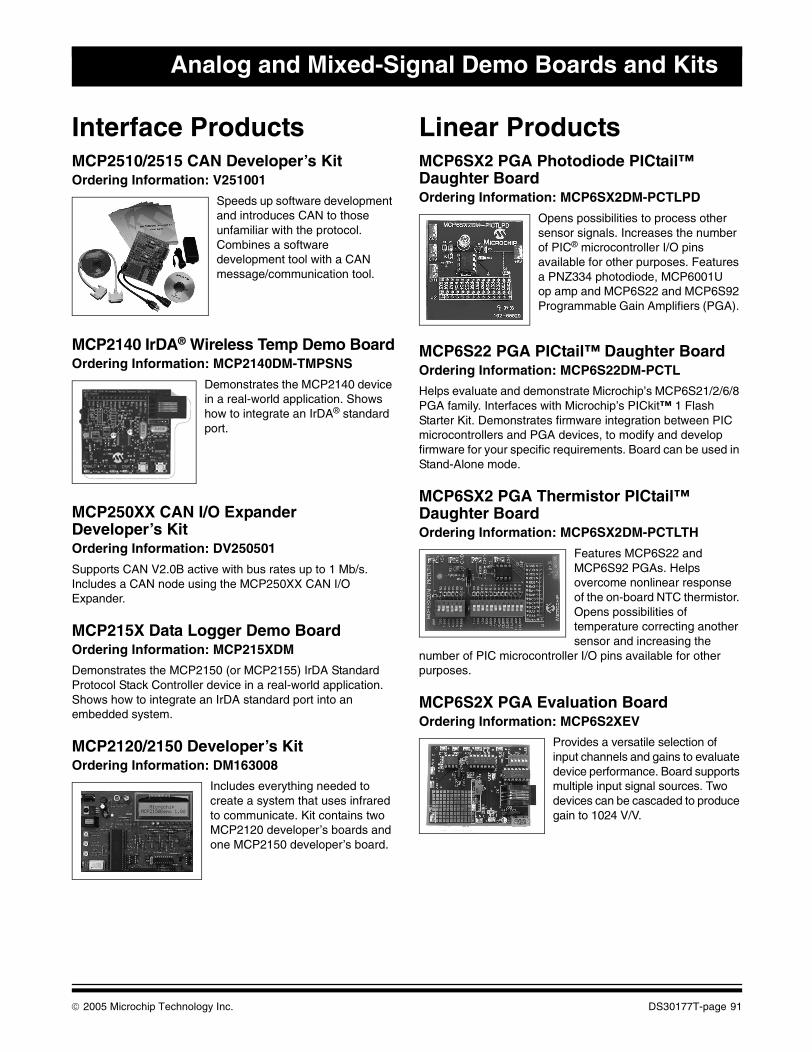
Analog and Mixed-Signal Demo Boards and Kits
Interface ProductsMCP2510/2515 CAN Developer’s KitOrdering Information: V251001
Speeds up software development and introduces CAN to those unfamiliar with the protocol. Combines a software development tool with a CAN message/communication tool.
MCP2140 IrDA® Wireless Temp Demo BoardOrdering Information: MCP2140DM-TMPSNS
Demonstrates the MCP2140 device in a real-world application. Shows how to integrate an IrDA® standard port.
MCP250XX CAN I/O Expander Developer’s KitOrdering Information: DV250501
Supports CAN V2.0B active with bus rates up to 1 Mb/s. Includes a CAN node using the MCP250XX CAN I/O Expander.
MCP215X Data Logger Demo BoardOrdering Information: MCP215XDM
Demonstrates the MCP2150 (or MCP2155) IrDA Standard Protocol Stack Controller device in a real-world application. Shows how to integrate an IrDA standard port into an embedded system.
MCP2120/2150 Developer’s KitOrdering Information: DM163008
Includes everything needed to create a system that uses infrared to communicate. Kit contains two MCP2120 developer’s boards and one MCP2150 developer’s board.
Linear ProductsMCP6SX2 PGA Photodiode PICtail™ Daughter BoardOrdering Information: MCP6SX2DM-PCTLPD
Opens possibilities to process other sensor signals. Increases the number of PIC® microcontroller I/O pins available for other purposes. Features a PNZ334 photodiode, MCP6001U op amp and MCP6S22 and MCP6S92 Programmable Gain Amplifiers (PGA).
MCP6S22 PGA PICtail™ Daughter BoardOrdering Information: MCP6S22DM-PCTL
Helps evaluate and demonstrate Microchip’s MCP6S21/2/6/8 PGA family. Interfaces with Microchip’s PICkit™ 1 Flash Starter Kit. Demonstrates firmware integration between PIC microcontrollers and PGA devices, to modify and develop firmware for your specific requirements. Board can be used in Stand-Alone mode.
MCP6SX2 PGA Thermistor PICtail™ Daughter BoardOrdering Information: MCP6SX2DM-PCTLTH
Features MCP6S22 and MCP6S92 PGAs. Helps overcome nonlinear response of the on-board NTC thermistor. Opens possibilities of temperature correcting another sensor and increasing the
number of PIC microcontroller I/O pins available for other purposes.
MCP6S2X PGA Evaluation BoardOrdering Information: MCP6S2XEV
Provides a versatile selection of input channels and gains to evaluate device performance. Board supports multiple input signal sources. Two devices can be cascaded to produce gain to 1024 V/V.
© 2005 Microchip Technology Inc. DS30177T-page 91
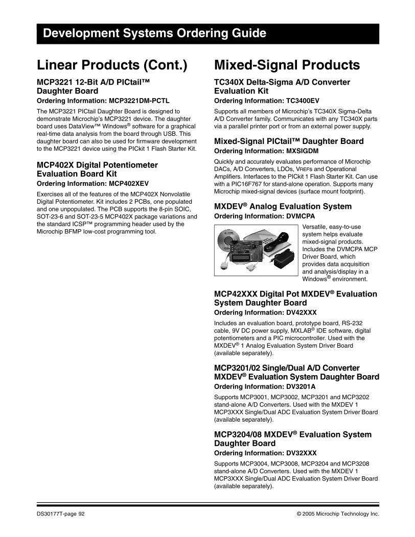
Development Systems Ordering Guide
Linear Products (Cont.)MCP3221 12-Bit A/D PICtail™ Daughter BoardOrdering Information: MCP3221DM-PCTL
The MCP3221 PICtail Daughter Board is designed to demonstrate Microchip’s MCP3221 device. The daughter board uses DataView™ Windows® software for a graphical real-time data analysis from the board through USB. This daughter board can also be used for firmware development to the MCP3221 device using the PICkit 1 Flash Starter Kit.
MCP402X Digital Potentiometer Evaluation Board KitOrdering Information: MCP402XEV
Exercises all of the features of the MCP402X Nonvolatile Digital Potentiometer. Kit includes 2 PCBs, one populated and one unpopulated. The PCB supports the 8-pin SOIC, SOT-23-6 and SOT-23-5 MCP402X package variations and the standard ICSP™ programming header used by the Microchip BFMP low-cost programming tool.
Mixed-Signal ProductsTC340X Delta-Sigma A/D Converter Evaluation Kit Ordering Information: TC3400EV
Supports all members of Microchip’s TC340X Sigma-DeltaA/D Converter family. Communicates with any TC340X parts via a parallel printer port or from an external power supply.
Mixed-Signal PICtail™ Daughter BoardOrdering Information: MXSIGDM
Quickly and accurately evaluates performance of Microchip DACs, A/D Converters, LDOs, VREFs and Operational Amplifiers. Interfaces to the PICkit 1 Flash Starter Kit. Can use with a PIC16F767 for stand-alone operation. Supports many Microchip mixed-signal devices (surface mount footprint).
MXDEV® Analog Evaluation SystemOrdering Information: DVMCPA
Versatile, easy-to-use system helps evaluate mixed-signal products. Includes the DVMCPA MCP Driver Board, which provides data acquisition and analysis/display in a Windows® environment.
MCP42XXX Digital Pot MXDEV® Evaluation System Daughter BoardOrdering Information: DV42XXX
Includes an evaluation board, prototype board, RS-232 cable, 9V DC power supply, MXLAB® IDE software, digital potentiometers and a PIC microcontroller. Used with the MXDEV® 1 Analog Evaluation System Driver Board (available separately).
MCP3201/02 Single/Dual A/D Converter MXDEV® Evaluation System Daughter BoardOrdering Information: DV3201A
Supports MCP3001, MCP3002, MCP3201 and MCP3202 stand-alone A/D Converters. Used with the MXDEV 1 MCP3XXX Single/Dual ADC Evaluation System Driver Board (available separately).
MCP3204/08 MXDEV® Evaluation System Daughter BoardOrdering Information: DV32XXX
Supports MCP3004, MCP3008, MCP3204 and MCP3208 stand-alone A/D Converters. Used with the MXDEV 1 MCP3XXX Single/Dual ADC Evaluation System Driver Board (available separately).
DS30177T-page 92 © 2005 Microchip Technology Inc.
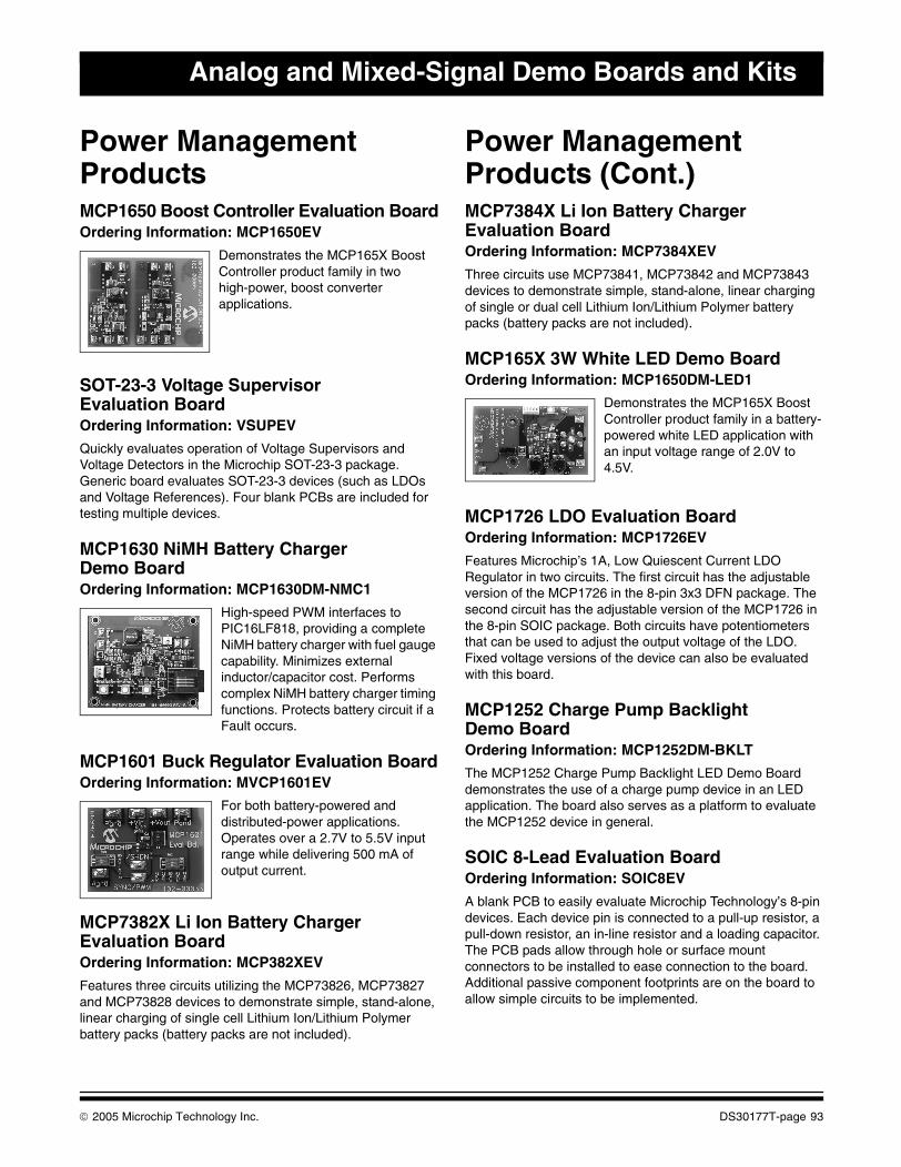
Analog and Mixed-Signal Demo Boards and Kits
Power Management ProductsMCP1650 Boost Controller Evaluation BoardOrdering Information: MCP1650EV
Demonstrates the MCP165X Boost Controller product family in two high-power, boost converter applications.
SOT-23-3 Voltage Supervisor Evaluation BoardOrdering Information: VSUPEV
Quickly evaluates operation of Voltage Supervisors and Voltage Detectors in the Microchip SOT-23-3 package. Generic board evaluates SOT-23-3 devices (such as LDOs and Voltage References). Four blank PCBs are included for testing multiple devices.
MCP1630 NiMH Battery Charger Demo BoardOrdering Information: MCP1630DM-NMC1
High-speed PWM interfaces to PIC16LF818, providing a complete NiMH battery charger with fuel gauge capability. Minimizes external inductor/capacitor cost. Performs complex NiMH battery charger timing functions. Protects battery circuit if a Fault occurs.
MCP1601 Buck Regulator Evaluation BoardOrdering Information: MVCP1601EV
For both battery-powered and distributed-power applications. Operates over a 2.7V to 5.5V input range while delivering 500 mA of output current.
MCP7382X Li Ion Battery Charger Evaluation BoardOrdering Information: MCP382XEV
Features three circuits utilizing the MCP73826, MCP73827 and MCP73828 devices to demonstrate simple, stand-alone, linear charging of single cell Lithium Ion/Lithium Polymer battery packs (battery packs are not included).
Power Management Products (Cont.)MCP7384X Li Ion Battery Charger Evaluation BoardOrdering Information: MCP7384XEV
Three circuits use MCP73841, MCP73842 and MCP73843 devices to demonstrate simple, stand-alone, linear charging of single or dual cell Lithium Ion/Lithium Polymer battery packs (battery packs are not included).
MCP165X 3W White LED Demo BoardOrdering Information: MCP1650DM-LED1
Demonstrates the MCP165X Boost Controller product family in a battery-powered white LED application with an input voltage range of 2.0V to 4.5V.
MCP1726 LDO Evaluation BoardOrdering Information: MCP1726EV
Features Microchip’s 1A, Low Quiescent Current LDO Regulator in two circuits. The first circuit has the adjustable version of the MCP1726 in the 8-pin 3x3 DFN package. The second circuit has the adjustable version of the MCP1726 in the 8-pin SOIC package. Both circuits have potentiometers that can be used to adjust the output voltage of the LDO. Fixed voltage versions of the device can also be evaluated with this board.
MCP1252 Charge Pump Backlight Demo BoardOrdering Information: MCP1252DM-BKLT
The MCP1252 Charge Pump Backlight LED Demo Board demonstrates the use of a charge pump device in an LED application. The board also serves as a platform to evaluate the MCP1252 device in general.
SOIC 8-Lead Evaluation BoardOrdering Information: SOIC8EV
A blank PCB to easily evaluate Microchip Technology’s 8-pin devices. Each device pin is connected to a pull-up resistor, a pull-down resistor, an in-line resistor and a loading capacitor. The PCB pads allow through hole or surface mount connectors to be installed to ease connection to the board. Additional passive component footprints are on the board to allow simple circuits to be implemented.
© 2005 Microchip Technology Inc. DS30177T-page 93
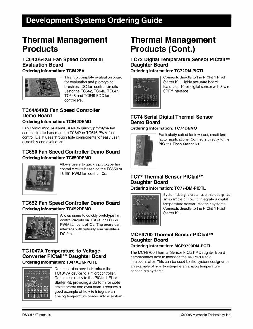
Development Systems Ordering Guide
Thermal Management ProductsTC64X/64XB Fan Speed Controller Evaluation BoardOrdering Information: TC642EV
This is a complete evaluation board for evaluation and prototyping brushless DC fan control circuits using the TC642, TC646, TC647, TC648 and TC649 BDC fan controllers.
TC64/64XB Fan Speed Controller Demo BoardOrdering Information: TC642DEMO
Fan control module allows users to quickly prototype fan control circuits based on the TC642 or TC646 PWM fan control ICs. It uses through hole components for easy user assembly and evaluation.
TC650 Fan Speed Controller Demo BoardOrdering Information: TC650DEMO
Allows users to quickly prototype fan control circuits based on the TC650 or TC651 PWM fan control ICs.
TC652 Fan Speed Controller Demo BoardOrdering Information: TC652DEMO
Allows users to quickly prototype fan control circuits on TC652 or TC653 PWM fan control ICs. The board can interface with virtually any brushless DC fan.
TC1047A Temperature-to-Voltage Converter PICtail™ Daughter BoardOrdering Information: 1047ADM-PCTL
Demonstrates how to interface the TC1047A device to a microcontroller. Connects directly to the PICkit 1 Flash Starter Kit, providing a platform for code development and evaluation. Provides a good example of how to integrate an analog temperature sensor into a system.
Thermal Management Products (Cont.)TC72 Digital Temperature Sensor PICtail™ Daughter BoardOrdering Information: TC72DM-PICTL
Connects directly to the PICkit 1 Flash Starter Kit. Highly accurate board features a 10-bit digital sensor with 3-wire SPI™ interface.
TC74 Serial Digital Thermal Sensor Demo Board Ordering Information: TC74DEMO
Particularly suited for low-cost, small form factor applications. Connects directly to the PICkit 1 Flash Starter Kit.
TC77 Thermal Sensor PICtail™ Daughter BoardOrdering Information: TC77-DM-PICTL
System designers can use this design as an example of how to integrate a digital temperature sensor into their systems. Connects directly to the PICkit 1 Flash Starter Kit.
MCP9700 Thermal Sensor PICtail™ Daughter BoardOrdering Information: MCP9700DM-PCTL
The MCP9700 Thermal Sensor PICtail™ Daughter Board demonstrates how to interface the MCP9700 to a microcontroller. This can be used by the system designer as an example of how to integrate an analog temperature sensor into systems.
DS30177T-page 94 © 2005 Microchip Technology Inc.
Analog and Mixed-Signal Demo Boards and Kits
Analog Software ToolsFilterLab® Active Filter Design SoftwareThe FilterLab® Active Filter Design Software tool simplifies active filter design. Available at no cost, the FilterLab Active Filter Design Software tool provides full schematic diagrams of the filter circuit with component values and displays the frequency response.
SPICE Software ModelsModeling is the heart of any SPICE simulation system and Microchip provides a variety of model libraries. This library and service is another example of how Microchip leads the way in analog simulation and modeling.
For more information, visit the Microchip web site at:www.microchip.com/analogtools
© 2005 Microchip Technology Inc. DS30177T-page 95

Development Systems Ordering Guide
NOTES:
DS30177T-page 96 © 2005 Microchip Technology Inc.
This section contains the following major topics:
KEELOQ® Security ICs Evaluation Kit II .....................................................................................98
KEELOQ® SECURITY ICsEVALUATION KIT
© 2005 Microchip Technology Inc. DS30177T-page 97
Development Systems Ordering Guide
KEELOQ® Security ICs Evaluation Kit IIThe KEELOQ Security ICs Evaluation Kit II provides the opportunity to evaluate KEELOQ Security ICs code hopping technology quickly and easily without having to make a large capital investment. The evaluation kit contains all the hardware and software necessary to implement a fully functional remote control system and demonstrate all operating modes of the following devices: HCS101, HCS200, HCS201, HCS300, HCS301, HCS320, HCS360, HCS361, HCS362, HCS365 and HCS370 encoders.
The kit can also be used to program and demonstrate the encoder functionality of the HCS410, HCS412 and HCS473 transponders (transcoders).
KEELOQ® Security ICs Evaluation Kit II Contents
• Programmer and Decoder Demonstration Board• Two KEELOQ Security ICs Transmitter Demo
Boards• Sample Kit Containing Various KEELOQ Security
ICs Encoder and Decoder Samples• KEELOQ Security ICs Data Product CD
Ordering Information:
DM303006 KEELOQ® Security ICs Evaluation Kit II
DS30177T-page 98 © 2005 Microchip Technology Inc.
This section contains the following major topics:
PowerSmart® Battery Management Evaluation Kits for 2, 3 and 4 Series Cell Lithium Ion/Polymer Chemistries ...............................................................................................................100PowerSmart® Battery Management Monitor Evaluation Kit for 1 and 2 Series Cell Lithium Ion/Polymer Chemistries ...............................................................................................................101
BATTERY MANAGEMENT
© 2005 Microchip Technology Inc. DS30177T-page 99
Development Systems Ordering Guide
PowerSmart® Battery Management Evaluation Kits for 2, 3 and 4 Series Cell Lithium Ion/Polymer ChemistriesThe PowerSmart Battery Management Evaluation Kits for Lithium Ion/Polymer chemistries provide the opportunity to evaluate a Microchip battery management solution for Lithium-based battery packs. The evaluation kits contain all of the hardware and software necessary to implement a functional SmartBattery pack with a primary and secondary safety circuit and a LED State-of-Charge display. The kit can be used to configure and demonstrate functionality of the PS501 Battery Manager IC.
PowerSmart® Battery ManagementEvaluation Kits for Lithium Ion/Polymer
Chemistries Contents
• Battery Manager Module for Lithium Ion/Polymer Battery Packs
• PowerInfo™ 2 Configuration Interface• USB Cable• RS-232 Cable• Power Supply• Battery Management PC Software CD
Ordering Information:
PS5162EV PowerSmart® Battery Management Evaluation Kit for Lithium Ion/Polymer Chemistries (2-cell)PS5163EV PowerSmart® Battery Management Evaluation Kit for Lithium Ion/Polymer Chemistries (3-cell)PS5164EV PowerSmart® Battery Management Evaluation Kit for Lithium Ion/Polymer Chemistries (4-cell)
DS30177T-page 100 © 2005 Microchip Technology Inc.
Battery Management
PowerSmart® Battery Management Monitor Evaluation Kit for 1 and 2 Series Cell Lithium Ion/Polymer ChemistriesThe PowerSmart Battery Management Evaluation Kit for Lithium Ion/Polymer chemistries provides the opportunity to evaluate a Microchip battery monitor solution for one or two series cell Lithium-based battery packs. The evaluation kit contains all of the hardware and software necessary to incorporate a functional fuel gauge and safety module into a battery pack. The kit can be used to configure and demonstrate functionality of the PS700 Battery Monitor IC.
PowerSmart® Battery ManagementEvaluation Kit for 1 and 2 Series Cell
Lithium Ion/Polymer Chemistries Contents
• Battery Monitor Evaluation Board (PS7070) for 1 and 2 Series Cell Lithium Ion/Polymer Battery Packs
• PowerInfo™ 2 Configuration Interface (PS051)• USB Cable• Battery Management PC Software CD
Ordering Information:
PS7070EV PowerSmart® Battery Management Evaluation Kit for 1 and 2 Series Cell Lithium Ion/PolymerChemistries
© 2005 Microchip Technology Inc. DS30177T-page 101
Development Systems Ordering Guide
NOTES:
DS30177T-page 102 © 2005 Microchip Technology Inc.
This section contains the following major topics:
Development Systems Cross Reference Table.......................................................................104
CROSS REFERENCE
© 2005 Microchip Technology Inc. DS30177T-page 103
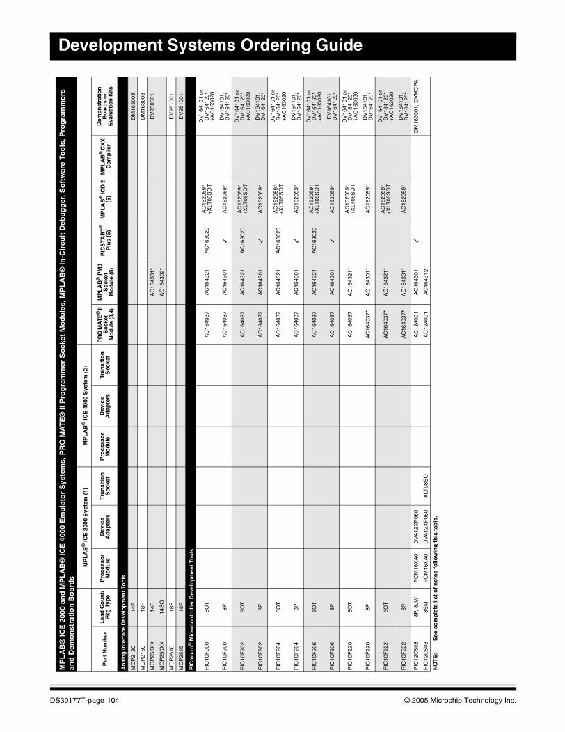
Development Systems Ordering Guide
MPL
AB
® IC
E 2
000
and
MP
LA
B®
ICE
400
0 E
mu
lato
r S
yste
ms,
PR
O M
AT
E®
II P
rog
ram
mer
So
cket
Mo
du
les,
MP
LA
B®
In-C
ircu
it D
ebu
gg
er, S
oft
war
e To
ols
, Pro
gra
mm
ers
and
Dem
on
stra
tio
n B
oar
ds
MP
LA
B®
ICE
200
0 S
yste
m (
1)M
PL
AB
® IC
E 4
000
Sys
tem
(2)
Par
t N
um
ber
Lea
d C
ou
nt/
Pkg
Typ
eP
roce
sso
r M
od
ule
Dev
ice
Ad
apte
rsTr
ansi
tio
n
So
cket
Pro
cess
or
Mo
du
leD
evic
e A
dap
ters
Tran
siti
on
S
ock
etP
RO
MA
TE®
II
So
cket
M
odu
le (3
,4)
MP
LA
B®
PM
3S
ock
etM
od
ule
(8)
PIC
STA
RT
®
Plu
s (5
)M
PL
AB
® IC
D 2
(6
)M
PL
AB
® C
XX
C
om
pile
r
Dem
onst
ratio
n
Bo
ard
s o
r E
valu
atio
n K
its
An
alo
g In
terf
ace
Dev
elo
pm
ent
Too
ls
MC
P21
2014
PD
M16
3008
MC
P21
5018
PD
M16
3008
MC
P25
0XX
14P
AC
1643
01*
DV
2505
01
MC
P25
0XX
14S
OA
C16
4302
*
MC
P25
1018
PD
V25
1001
MC
P25
1518
PD
V25
1001
PIC
mic
ro®
Mic
roco
ntr
olle
r D
evel
op
men
t To
ols
PIC
10F
200
6OT
AC
1640
37A
C16
4321
AC
1630
20A
C16
2059
*+
XLT
06S
OT
DV
1641
01 o
r D
V16
4120
* +
AC
1630
20
PIC
10F
200
8PA
C16
4037
AC
1643
01✓
AC
1620
59*
DV
1641
01,
DV
1641
20*
PIC
10F
202
6OT
AC
1640
37A
C16
4321
AC
1630
20A
C16
2059
*+
XLT
06S
OT
DV
1641
01 o
r D
V16
4120
* +
AC
1630
20
PIC
10F
202
8PA
C16
4037
AC
1643
01✓
AC
1620
59*
DV
1641
01,
DV
1641
20*
PIC
10F
204
6OT
AC
1640
37A
C16
4321
AC
1630
20A
C16
2059
*+
XLT
06S
OT
DV
1641
01 o
r D
V16
4120
* +
AC
1630
20
PIC
10F
204
8PA
C16
4037
AC
1643
01✓
AC
1620
59*
DV
1641
01,
DV
1641
20*
PIC
10F
206
6OT
AC
1640
37A
C16
4321
AC
1630
20A
C16
2059
*+
XLT
06S
OT
DV
1641
01 o
r D
V16
4120
* +
AC
1630
20
PIC
10F
206
8PA
C16
4037
AC
1643
01✓
AC
1620
59*
DV
1641
01
DV
1641
20*
PIC
10F
220
6OT
AC
1640
37A
C16
4321
*A
C16
2059
*+
XLT
06S
OT
DV
1641
01 o
r D
V16
4120
*+
AC
1630
20
PIC
10F
220
8PA
C16
4037
*A
C16
4301
*A
C16
2059
*D
V16
4101
, D
V16
4120
*
PIC
10F
222
6OT
AC
1640
37*
AC
1643
21*
AC
1620
59*
+X
LT06
SO
T
DV
1641
01 o
r D
V16
4120
*+
AC
1630
20
PIC
10F
222
8PA
C16
4037
*A
C16
4301
*A
C16
2059
*D
V16
4101
, D
V16
4120
*
PIC
12C
508
8P, 8
JWP
CM
16X
A0
DV
A12
XP
080
AC
1240
01A
C16
4301
✓D
M16
3001
, DV
MC
PA
PIC
12C
508
8SM
PC
M16
XA
0D
VA
12X
P08
0X
LT08
SO
AC
1240
01A
C16
4312
NO
TE:
See
co
mp
lete
list
of
no
tes
follo
win
g t
his
tab
le.
DS30177T-page 104 © 2005 Microchip Technology Inc.

Cross Reference
PIC
mic
ro®
Mic
roco
ntr
olle
r D
evel
op
men
t To
ols
(co
nti
nu
ed)
PIC
12C
508A
8P, 8
JWP
CM
16X
A0
DV
A12
XP
080
AC
1240
01A
C16
4301
✓D
M16
3001
, DV
MC
PA
PIC
12C
508A
8SM
PC
M16
XA
0D
VA
12X
P08
0X
LT08
SO
AC
1240
01A
C16
4312
PIC
12C
508A
8SN
PC
M16
XA
0D
VA
12X
P08
0X
LT08
SO
AC
1640
26A
C16
4302
PIC
12C
508A
8MF
PC
M16
XA
0D
VA
12X
P08
0X
LT08
DF
N o
rX
LT08
DF
N2
AC
1240
01+
AC
1640
32A
C16
4301
+A
C16
4032
AC
1640
32
PIC
12C
509
8P, 8
JWP
CM
16X
A0
DV
A12
XP
080
AC
1240
01A
C16
4301
✓D
M16
3001
, DV
MC
PA
PIC
12C
509
8SM
PC
M16
XA
0D
VA
12X
P08
0X
LT08
SO
AC
1240
01A
C16
4312
PIC
12C
509A
8P, 8
JWP
CM
16X
A0
DV
A12
XP
080
AC
1240
01A
C16
4301
✓D
M16
3001
, DV
MC
PA
PIC
12C
509A
8SM
PC
M16
XA
0D
VA
12X
P08
0X
LT08
SO
AC
1240
01A
C16
4312
PIC
12C
509A
8SN
PC
M16
XA
0D
VA
12X
P08
0X
LT08
SO
AC
1640
26A
C16
4302
PIC
12C
509A
8MF
PC
M16
XA
0D
VA
12X
P08
0X
LT08
DF
N o
rX
LT08
DF
N2
AC
1240
01+
AC
1640
32A
C16
4301
+A
C16
4032
AC
1640
32
PIC
12C
671
8P, 8
JWP
CM
12X
A0
DV
A12
XP
081
AC
1240
01A
C16
4301
✓
PIC
12C
671
8SM
PC
M12
XA
0D
VA
12X
P08
1X
LT08
SO
AC
1240
01A
C16
4312
PIC
12C
671
8MF
PC
M12
XA
0D
VA
12X
P08
1X
LT08
DF
N o
rX
LT08
DF
N2
AC
1240
01+
AC
1640
32A
C16
4301
+A
C16
4032
AC
1640
32
PIC
12C
672
8P, 8
JWP
CM
12X
A0
DV
A12
XP
081
AC
1240
01A
C16
4301
✓
PIC
12C
672
8SM
PC
M12
XA
0D
VA
12X
P08
1X
LT08
SO
AC
1240
01A
C16
4312
PIC
12C
672
8MF
PC
M12
XA
0D
VA
12X
P08
1X
LT08
DF
N o
rX
LT08
DF
N2
AC
1240
01+
AC
1640
32A
C16
4301
+A
C16
4032
AC
1640
32
PIC
12C
E51
88P
, 8JW
PC
M16
XA
0D
VA
12X
P08
0A
C12
4001
AC
1643
01✓
PIC
12C
E51
88S
MP
CM
16X
A0
DV
A12
XP
080
XLT
08S
OA
C12
4001
AC
1643
12
PIC
12C
E51
88S
NP
CM
16X
A0
DV
A12
XP
080
XLT
08S
OA
C16
4026
AC
1643
02
PIC
12C
E51
98P
, 8JW
PC
M16
XA
0D
VA
12X
P08
0A
C12
4001
AC
1643
01✓
PIC
12C
E51
98S
MP
CM
16X
A0
DV
A12
XP
080
XLT
08S
OA
C12
4001
AC
1643
12
PIC
12C
E51
98S
NP
CM
16X
A0
DV
A12
XP
080
XLT
08S
OA
C16
4026
AC
1643
02
PIC
12C
E67
38P
, 8JW
PC
M12
XA
0D
VA
12X
P08
1A
C12
4001
AC
1643
01✓
PIC
12C
E67
48P
, 8JW
PC
M12
XA
0D
VA
12X
P08
1A
C12
4001
AC
1643
01✓
PIC
12F
508
8PP
CM
16X
A0
DV
A12
XP
080
AC
1240
01A
C16
4301
✓A
C16
2059
*D
M16
3014
, D
V16
4101
, D
V16
4120
*
PIC
12F
508
8SN
PC
M16
XA
0D
VA
12X
P08
0X
LT08
SO
AC
1640
26A
C16
4302
AC
1620
59*
+X
LT08
SO
PIC
12F
508
8ST
PC
M16
XA
0D
VA
12X
P08
0A
C16
4306
PIC
12F
508
8MS
PC
M16
XA
0D
VA
12X
P08
0
MP
LA
B®
ICE
200
0 an
d M
PL
AB
® IC
E 4
000
Em
ula
tor
Sys
tem
s, P
RO
MA
TE
® II
Pro
gra
mm
er S
ock
et M
od
ule
s, M
PL
AB
® In
-Cir
cuit
Deb
ug
ger
, So
ftw
are
Too
ls, P
rog
ram
mer
s an
d D
emo
nst
rati
on
Bo
ard
s
MP
LA
B®
ICE
200
0 S
yste
m (
1)M
PL
AB
® IC
E 4
000
Sys
tem
(2)
Par
t N
um
ber
Lea
d C
ou
nt/
Pkg
Typ
eP
roce
sso
r M
od
ule
Dev
ice
Ad
apte
rsTr
ansi
tio
n
So
cket
Pro
cess
or
Mo
du
leD
evic
e A
dap
ters
Tran
siti
on
S
ock
etP
RO
MA
TE®
II
Soc
ket
Mo
dule
(3,4
)
MP
LA
B®
PM
3S
ock
etM
od
ule
(8)
PIC
STA
RT
®
Plu
s (5
)M
PL
AB
® IC
D 2
(6
)M
PL
AB
® C
XX
C
om
pile
r
Dem
onst
ratio
n
Boa
rds
or
Eva
luat
ion
Kits
NO
TE:
See
co
mp
lete
list
of
no
tes
follo
win
g t
his
tab
le.
© 2005 Microchip Technology Inc. DS30177T-page 105
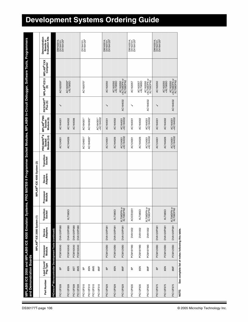
Development Systems Ordering Guide
PIC
mic
ro®
Mic
roco
ntr
olle
r D
evel
op
men
t To
ols
(co
nti
nu
ed)
PIC
12F
509
8PP
CM
16X
A0
DV
A12
XP
080
AC
1240
01A
C16
4301
✓A
C16
2059
*D
M16
3014
, D
V16
4101
, D
V16
4120
*
PIC
12F
509
8SN
PC
M16
XA
0D
VA
12X
P08
0X
LT08
SO
AC
1640
26A
C16
4302
AC
1620
59*
+X
LT08
SO
PIC
12F
509
8ST
PC
M16
XA
0D
VA
12X
P08
0A
C16
4306
PIC
12F
509
8MS
PC
M16
XA
0D
VA
12X
P08
0
PIC
12F
510
8PA
C12
4001
*A
C16
4301
*A
C16
2070
*D
V16
4101
, D
V16
4120
*
PIC
12F
510
8SN
AC
1640
26*
AC
1643
02*
PIC
12F
510
8MS
PIC
12F
510
8MF
AC
1643
01*
+A
C16
4032
PIC
12F
629
8PP
CM
12X
B0
DV
A12
XP
081
AC
1240
01A
C16
4301
✓A
C16
2050
DM
1630
14,
DV
1641
01,
DV
1641
20*
PIC
12F
629
8SN
PC
M12
XB
0D
VA
12X
P08
1X
LT08
SO
AC
1640
26A
C16
4302
AC
1620
50+
XLT
08S
O
PIC
12F
629
8MF
PC
M12
XB
0D
VA
12X
P08
1X
LT08
DF
N o
rX
LT08
DF
N2
AC
1240
01+
AC
1640
32A
C16
4301
+A
C16
4032
AC
1640
32A
C16
2050
+X
LT08
DF
N o
rX
LT08
DF
N2
PIC
12F
635
8PP
CM
16Y
M0
DV
A10
02A
CIC
E02
01A
C12
4001
AC
1643
01✓
AC
1620
57D
M16
3014
, D
V16
4101
, D
V16
4120
*
PIC
12F
635
8SN
PC
M16
YM
0D
VA
1002
XLT
08S
OA
C16
4026
AC
1643
02A
C16
2057
+X
LT08
SO
PIC
12F
635
8MF
PC
M16
YM
0D
VA
1002
XLT
08D
FN
or
XLT
08D
FN
2A
C12
4001
+A
C16
4032
AC
1643
01+
AC
1640
32A
C16
4032
AC
1620
50+
XLT
08D
FN
or
XLT
08D
FN
2
PIC
12F
675
8PP
CM
12X
B0
DV
A12
XP
081
AC
1240
01A
C16
4301
✓A
C16
2050
DM
1630
14,
DV
1641
01,
DV
1641
20*
PIC
12F
675
8SN
PC
M12
XB
0D
VA
12X
P08
1X
LT08
SO
AC
1640
26A
C16
4302
AC
1620
50+
XLT
08S
O
PIC
12F
675
8MF
PC
M12
XB
0D
VA
12X
P08
1X
LT08
DF
N o
rX
LT08
DF
N2
AC
1240
01+
AC
1640
32A
C16
4301
+A
C16
4032
AC
1640
32A
C16
2050
+X
LT08
DF
N o
rX
LT08
DF
N2
MP
LA
B®
ICE
200
0 an
d M
PL
AB
® IC
E 4
000
Em
ula
tor
Sys
tem
s, P
RO
MA
TE
® II
Pro
gra
mm
er S
ock
et M
od
ule
s, M
PL
AB
® In
-Cir
cuit
Deb
ug
ger
, So
ftw
are
Too
ls, P
rog
ram
mer
s an
d D
emo
nst
rati
on
Bo
ard
s
MP
LA
B®
ICE
200
0 S
yste
m (
1)M
PL
AB
® IC
E 4
000
Sys
tem
(2)
Par
t N
um
ber
Lea
d C
ou
nt/
Pkg
Typ
eP
roce
sso
r M
od
ule
Dev
ice
Ad
apte
rsTr
ansi
tio
n
So
cket
Pro
cess
or
Mo
du
leD
evic
e A
dap
ters
Tran
siti
on
S
ock
etP
RO
MA
TE®
II
So
cket
M
odu
le (3
,4)
MP
LA
B®
PM
3S
ock
etM
od
ule
(8)
PIC
STA
RT
®
Plu
s (5
)M
PL
AB
® IC
D 2
(6
)M
PL
AB
® C
XX
C
om
pile
r
Dem
onst
ratio
n
Bo
ard
s o
r E
valu
atio
n K
its
NO
TE:
See
co
mp
lete
list
of
no
tes
follo
win
g t
his
tab
le.
DS30177T-page 106 © 2005 Microchip Technology Inc.
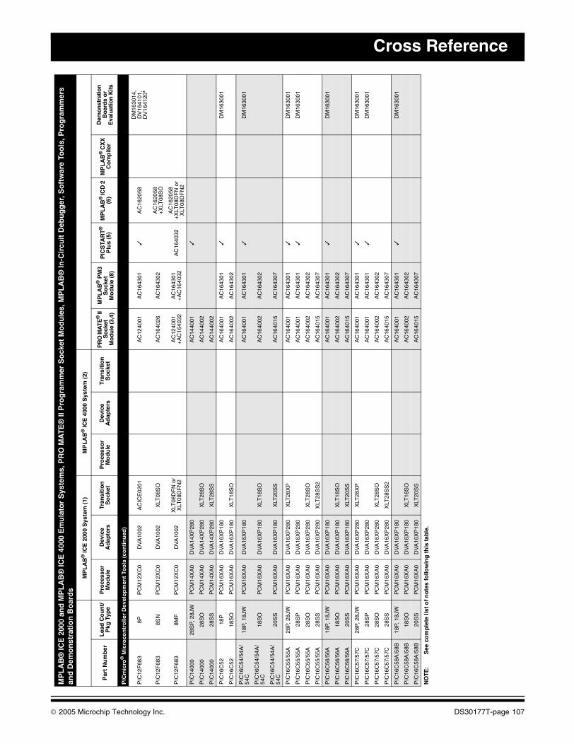
Cross Reference
PIC
mic
ro®
Mic
roco
ntr
olle
r D
evel
op
men
t To
ols
(co
nti
nu
ed)
PIC
12F
683
8PP
CM
12X
C0
DV
A10
02A
CIC
E02
01A
C12
4001
AC
1643
01✓
AC
1620
58D
M16
3014
, D
V16
4101
, D
V16
4120
*
PIC
12F
683
8SN
PC
M12
XC
0D
VA
1002
XLT
08S
O
AC
1640
26A
C16
4302
AC
1620
58+
XLT
08S
O
PIC
12F
683
8MF
PC
M12
XC
0D
VA
1002
XLT
08D
FN
or
XLT
08D
FN
2A
C12
4001
+
AC
1640
32A
C16
4301
+
AC
1640
32A
C16
4032
AC
1620
58+
XLT
08D
FN
or
XLT
08D
FN
2
PIC
1400
028
SP,
28J
WP
CM
14X
A0
DV
A14
XP
280
AC
1440
01✓
PIC
1400
028
SO
PC
M14
XA
0D
VA
14X
P28
0X
LT28
SO
AC
1440
02
PIC
1400
028
SS
PC
M14
XA
0D
VA
14X
P28
0X
LT28
SS
AC
1440
02
PIC
16C
5218
PP
CM
16X
A0
DV
A16
XP
180
AC
1640
01A
C16
4301
✓D
M16
3001
PIC
16C
5218
SO
PC
M16
XA
0D
VA
16X
P18
0X
LT18
SO
AC
1640
02A
C16
4302
PIC
16C
54/5
4A/
54C
18P,
18J
WP
CM
16X
A0
DV
A16
XP
180
AC
1640
01A
C16
4301
✓D
M16
3001
PIC
16C
54/5
4A/
54C
18S
OP
CM
16X
A0
DV
A16
XP
180
XLT
18S
OA
C16
4002
AC
1643
02
PIC
16C
54/5
4A/
54C
20S
SP
CM
16X
A0
DV
A16
XP
180
XLT
20S
SA
C16
4015
AC
1643
07
PIC
16C
55/5
5A28
P, 2
8JW
PC
M16
XA
0D
VA
16X
P28
0X
LT28
XP
AC
1640
01A
C16
4301
✓D
M16
3001
PIC
16C
55/5
5A28
SP
PC
M16
XA
0D
VA
16X
P28
0A
C16
4001
AC
1643
01✓
DM
1630
01
PIC
16C
55/5
5A28
SO
PC
M16
XA
0D
VA
16X
P28
0X
LT28
SO
AC
1640
02A
C16
4302
PIC
16C
55/5
5A28
SS
PC
M16
XA
0D
VA
16X
P28
0X
LT28
SS
2A
C16
4015
AC
1643
07
PIC
16C
56/5
6A18
P, 1
8JW
PC
M16
XA
0D
VA
16X
P18
0A
C16
4001
AC
1643
01✓
DM
1630
01
PIC
16C
56/5
6A18
SO
PC
M16
XA
0D
VA
16X
P18
0X
LT18
SO
AC
1640
02A
C16
4302
PIC
16C
56/5
6A20
SS
PC
M16
XA
0D
VA
16X
P18
0X
LT20
SS
AC
1640
15A
C16
4307
PIC
16C
57/5
7C28
P, 2
8JW
PC
M16
XA
0D
VA
16X
P28
0X
LT28
XP
AC
1640
01A
C16
4301
✓D
M16
3001
PIC
16C
57/5
7C28
SP
PC
M16
XA
0D
VA
16X
P28
0A
C16
4001
AC
1643
01✓
DM
1630
01
PIC
16C
57/5
7C28
SO
PC
M16
XA
0D
VA
16X
P28
0X
LT28
SO
AC
1640
02A
C16
4302
PIC
16C
57/5
7C28
SS
PC
M16
XA
0D
VA
16X
P28
0X
LT28
SS
2A
C16
4015
AC
1643
07
PIC
16C
58A
/58B
18P,
18J
WP
CM
16X
A0
DV
A16
XP
180
AC
1640
01A
C16
4301
✓D
M16
3001
PIC
16C
58A
/58B
18S
OP
CM
16X
A0
DV
A16
XP
180
XLT
18S
OA
C16
4002
AC
1643
02
PIC
16C
58A
/58B
20S
SP
CM
16X
A0
DV
A16
XP
180
XLT
20S
SA
C16
4015
AC
1643
07
MP
LA
B®
ICE
200
0 an
d M
PL
AB
® IC
E 4
000
Em
ula
tor
Sys
tem
s, P
RO
MA
TE
® II
Pro
gra
mm
er S
ock
et M
od
ule
s, M
PL
AB
® In
-Cir
cuit
Deb
ug
ger
, So
ftw
are
Too
ls, P
rog
ram
mer
s an
d D
emo
nst
rati
on
Bo
ard
s
MP
LA
B®
ICE
200
0 S
yste
m (
1)M
PL
AB
® IC
E 4
000
Sys
tem
(2)
Par
t N
um
ber
Lea
d C
ou
nt/
Pkg
Typ
eP
roce
sso
r M
od
ule
Dev
ice
Ad
apte
rsTr
ansi
tio
n
So
cket
Pro
cess
or
Mo
du
leD
evic
e A
dap
ters
Tran
siti
on
S
ock
etP
RO
MA
TE®
II
Soc
ket
Mo
dule
(3,4
)
MP
LA
B®
PM
3S
ock
etM
od
ule
(8)
PIC
STA
RT
®
Plu
s (5
)M
PL
AB
® IC
D 2
(6
)M
PL
AB
® C
XX
C
om
pile
r
Dem
onst
ratio
n
Boa
rds
or
Eva
luat
ion
Kits
NO
TE:
See
co
mp
lete
list
of
no
tes
follo
win
g t
his
tab
le.
© 2005 Microchip Technology Inc. DS30177T-page 107
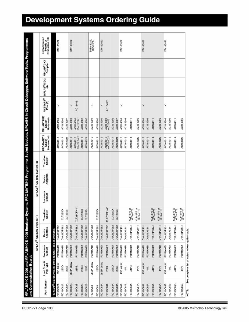
Development Systems Ordering Guide
PIC
mic
ro®
Mic
roco
ntr
olle
r D
evel
op
men
t To
ols
(co
nti
nu
ed)
PIC
16C
62A
28P,
28J
WP
CM
16X
B1
DV
A16
XP
282
AC
1640
12A
C16
4301
✓D
M16
3022
PIC
16C
62A
28S
OP
CM
16X
B1
DV
A16
XP
282
XLT
28S
OA
C16
4017
AC
1643
02
PIC
16C
62A
28S
SP
CM
16X
B1
DV
A16
XP
282
XLT
28S
SA
C16
4021
AC
1643
07
PIC
16C
62B
28S
P, 2
8JW
PC
M16
XE
1D
VA
16X
P28
2A
C16
4012
AC
1643
01✓
DM
1630
22
PIC
16C
62B
28M
LP
CM
16X
E1
DV
A16
XP
282
XLT
28Q
FN
4*A
C16
4012
+A
C16
4031
AC
1643
01+
AC
1640
31A
C16
4031
PIC
16C
62B
28S
OP
CM
16X
E1
DV
A16
XP
282
XLT
28S
OA
C16
4017
AC
1643
02
PIC
16C
62B
28S
SP
CM
16X
E1
DV
A16
XP
282
XLT
28S
SA
C16
4021
AC
1643
07
PIC
16C
6328
SP,
28J
WP
CM
16X
B1
DV
A16
XP
282
AC
1640
12A
C16
4301
✓D
M16
3022
,D
VM
CP
A
PIC
16C
6328
SO
PC
M16
XB
1D
VA
16X
P28
2X
LT28
SO
AC
1640
17A
C16
4302
PIC
16C
63A
28S
P, 2
8JW
PC
M16
XE
1D
VA
16X
P28
2A
C16
4012
AC
1643
01✓
DM
1630
22
PIC
16C
63A
28M
LP
CM
16X
E1
DV
A16
XP
282
XLT
28Q
FN
4*A
C16
4012
+A
C16
4031
AC
1643
01+
AC
1640
31A
C16
4031
PIC
16C
63A
28S
OP
CM
16X
E1
DV
A16
XP
282
XLT
28S
OA
C16
4017
AC
1643
02
PIC
16C
63A
28S
SP
CM
16X
E1
DV
A16
XP
282
XLT
28S
SA
C16
4021
AC
1643
07
PIC
16C
64A
40P,
40J
WP
CM
16X
B1
DV
A16
XP
401
AC
1640
12A
C16
4301
✓D
M16
3022
PIC
16C
64A
44L
PC
M16
XB
1D
VA
16X
L441
AC
1640
13A
C16
4309
PIC
16C
64A
44P
QP
CM
16X
B1
DV
A16
PQ
441
XLT
44P
T o
r X
LT44
PT
3A
C16
4014
AC
1643
11
PIC
16C
64A
44P
TP
CM
16X
B1
DV
A16
PQ
441
XLT
44P
T o
r X
LT44
PT
3A
C16
4020
AC
1643
05
PIC
16C
65A
40P,
40J
WP
CM
16X
B1
DV
A16
XP
401
AC
1640
12A
C16
4301
✓D
M16
3022
PIC
16C
65A
44L
PC
M16
XB
1D
VA
16X
L441
AC
1640
13A
C16
4309
PIC
16C
65A
44P
QP
CM
16X
B1
DV
A16
PQ
441
XLT
44P
T o
r X
LT44
PT
3A
C16
4014
AC
1643
11
PIC
16C
65A
44P
TP
CM
16X
B1
DV
A16
PQ
441
XLT
44P
T o
r X
LT44
PT
3A
C16
4020
AC
1643
05
PIC
16C
65B
40P,
40J
WP
CM
16X
E1
DV
A16
XP
401
AC
1640
12A
C16
4301
✓D
M16
3022
PIC
16C
65B
44L
PC
M16
XE
1D
VA
16X
L441
AC
1640
13A
C16
4309
PIC
16C
65B
44P
QP
CM
16X
E1
DV
A16
PQ
441
XLT
44P
T o
r X
LT44
PT
3A
C16
4014
AC
1643
11
PIC
16C
65B
44P
TP
CM
16X
E1
DV
A16
PQ
441
XLT
44P
T o
r X
LT44
PT
3A
C16
4020
AC
1643
05
MP
LA
B®
ICE
200
0 an
d M
PL
AB
® IC
E 4
000
Em
ula
tor
Sys
tem
s, P
RO
MA
TE
® II
Pro
gra
mm
er S
ock
et M
od
ule
s, M
PL
AB
® In
-Cir
cuit
Deb
ug
ger
, So
ftw
are
Too
ls, P
rog
ram
mer
s an
d D
emo
nst
rati
on
Bo
ard
s
MP
LA
B®
ICE
200
0 S
yste
m (
1)M
PL
AB
® IC
E 4
000
Sys
tem
(2)
Par
t N
um
ber
Lea
d C
ou
nt/
Pkg
Typ
eP
roce
sso
r M
od
ule
Dev
ice
Ad
apte
rsTr
ansi
tio
n
So
cket
Pro
cess
or
Mo
du
leD
evic
e A
dap
ters
Tran
siti
on
S
ock
etP
RO
MA
TE®
II
So
cket
M
odu
le (3
,4)
MP
LA
B®
PM
3S
ock
etM
od
ule
(8)
PIC
STA
RT
®
Plu
s (5
)M
PL
AB
® IC
D 2
(6
)M
PL
AB
® C
XX
C
om
pile
r
Dem
onst
ratio
n
Bo
ard
s o
r E
valu
atio
n K
its
NO
TE:
See
co
mp
lete
list
of
no
tes
follo
win
g t
his
tab
le.
DS30177T-page 108 © 2005 Microchip Technology Inc.
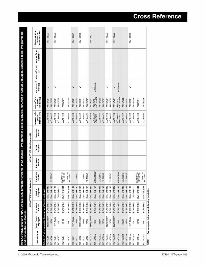
Cross Reference
PIC
mic
ro®
Mic
roco
ntr
olle
r D
evel
op
men
t To
ols
(co
nti
nu
ed)
PIC
16C
6628
SP,
28J
WP
CM
16X
E1
DV
A16
XP
282
AC
1640
12A
C16
4301
✓D
M16
3022
PIC
16C
6628
SO
PC
M16
XE
1D
VA
16X
P28
2X
LT28
SO
AC
1640
17A
C16
4302
PIC
16C
6740
P, 4
0JW
PC
M16
XE
1D
VA
16X
P40
1A
C16
4012
AC
1643
01✓
DM
1630
22
PIC
16C
6744
LP
CM
16X
E1
DV
A16
XL4
41A
C16
4013
AC
1643
09
PIC
16C
6744
PQ
PC
M16
XE
1D
VA
16P
Q44
1X
LT44
PT
or
XLT
44P
T3
AC
1640
14A
C16
4311
PIC
16C
6744
PT
PC
M16
XE
1D
VA
16P
Q44
1X
LT44
PT
or
XLT
44P
T3
AC
1640
20A
C16
4305
PIC
16C
7118
P, 1
8JW
PC
M16
XF
0D
VA
16X
P18
0A
C16
4010
AC
1643
01✓
DM
1630
01
PIC
16C
7118
SO
PC
M16
XF
0D
VA
16X
P18
0X
LT18
SO
AC
1640
10A
C16
4302
PIC
16C
7228
SP,
28J
WP
CM
16X
B1
DV
A16
XP
282
AC
1640
12A
C16
4301
✓D
M16
3022
PIC
16C
7228
SO
PC
M16
XB
1D
VA
16X
P28
2X
LT28
SO
AC
1640
17A
C16
4302
PIC
16C
7228
SS
PC
M16
XB
1D
VA
16X
P28
2X
LT28
SS
AC
1640
21A
C16
4307
PIC
16C
72A
28S
P, 2
8JW
PC
M16
XE
1D
VA
16X
P28
2A
C16
4012
AC
1643
01✓
DM
1630
22
PIC
16C
72A
28M
LP
CM
16X
E1
DV
A16
XP
282
XLT
28Q
FN
4*A
C16
4012
+A
C16
4031
AC
1643
01+
AC
1640
31A
C16
4031
PIC
16C
72A
28S
OP
CM
16X
E1
DV
A16
XP
282
XLT
28S
OA
C16
4017
AC
1643
02
PIC
16C
72A
28S
SP
CM
16X
E1
DV
A16
XP
282
XLT
28S
SA
C16
4021
AC
1643
07
PIC
16C
73A
28S
P, 2
8JW
PC
M16
XB
1D
VA
16X
P28
2A
C16
4012
AC
1643
01✓
DM
1630
22
PIC
16C
73A
28S
OP
CM
16X
B1
DV
A16
XP
282
XLT
28S
OA
C16
4017
AC
1643
02
PIC
16C
73B
28S
P, 2
8JW
PC
M16
XE
1D
VA
16X
P28
2A
C16
4012
AC
1643
01✓
DM
1630
22
PIC
16C
73B
28M
LP
CM
16X
E1
DV
A16
XP
282
XLT
28Q
FN
4*A
C16
4012
+A
C16
4031
AC
1643
01+
AC
1640
31A
C16
4031
PIC
16C
73B
28S
OP
CM
16X
E1
DV
A16
XP
282
XLT
28S
OA
C16
4017
AC
1643
02
PIC
16C
73B
28S
SP
CM
16X
E1
DV
A16
XP
282
XLT
28S
SA
C16
4021
AC
1643
07
PIC
16C
74A
40P,
40J
WP
CM
16X
B1
DV
A16
XP
401
AC
1640
12A
C16
4301
✓D
M16
3022
PIC
16C
74A
44L
PC
M16
XB
1D
VA
16X
L441
AC
1640
13A
C16
4309
PIC
16C
74A
44P
QP
CM
16X
B1
DV
A16
PQ
441
XLT
44P
T o
r X
LT44
PT
3A
C16
4014
AC
1643
11
PIC
16C
74A
44P
TP
CM
16X
B1
DV
A16
PQ
441
XLT
44P
T o
r X
LT44
PT
3A
C16
4020
AC
1643
05
MP
LA
B®
ICE
200
0 an
d M
PL
AB
® IC
E 4
000
Em
ula
tor
Sys
tem
s, P
RO
MA
TE
® II
Pro
gra
mm
er S
ock
et M
od
ule
s, M
PL
AB
® In
-Cir
cuit
Deb
ug
ger
, So
ftw
are
Too
ls, P
rog
ram
mer
s an
d D
emo
nst
rati
on
Bo
ard
s
MP
LA
B®
ICE
200
0 S
yste
m (
1)M
PL
AB
® IC
E 4
000
Sys
tem
(2)
Par
t N
um
ber
Lea
d C
ou
nt/
Pkg
Typ
eP
roce
sso
r M
od
ule
Dev
ice
Ad
apte
rsTr
ansi
tio
n
So
cket
Pro
cess
or
Mo
du
leD
evic
e A
dap
ters
Tran
siti
on
S
ock
etP
RO
MA
TE®
II
Soc
ket
Mo
dule
(3,4
)
MP
LA
B®
PM
3S
ock
etM
od
ule
(8)
PIC
STA
RT
®
Plu
s (5
)M
PL
AB
® IC
D 2
(6
)M
PL
AB
® C
XX
C
om
pile
r
Dem
onst
ratio
n
Boa
rds
or
Eva
luat
ion
Kits
NO
TE:
See
co
mp
lete
list
of
no
tes
follo
win
g t
his
tab
le.
© 2005 Microchip Technology Inc. DS30177T-page 109

Development Systems Ordering Guide
PIC
mic
ro®
Mic
roco
ntr
olle
r D
evel
op
men
t To
ols
(co
nti
nu
ed)
PIC
16C
74B
40P,
40J
WP
CM
16X
E1
DV
A16
XP
401
AC
1640
12A
C16
4301
✓D
M16
3022
PIC
16C
74B
44L
PC
M16
XE
1D
VA
16X
L441
AC
1640
13A
C16
4309
PIC
16C
74B
44P
QP
CM
16X
E1
DV
A16
PQ
441
XLT
44P
T o
r X
LT44
PT
3A
C16
4014
AC
1643
11
PIC
16C
74B
44P
TP
CM
16X
E1
DV
A16
PQ
441
XLT
44P
T o
r X
LT44
PT
3A
C16
4020
AC
1643
05
PIC
16C
7628
SP,
28J
WP
CM
16X
E1
DV
A16
XP
282
AC
1640
12A
C16
4301
✓D
M16
3022
PIC
16C
7628
SO
PC
M16
XE
1D
VA
16X
P28
2X
LT28
SO
AC
1640
17A
C16
4302
PIC
16C
7740
P, 4
0JW
PC
M16
XE
1D
VA
16X
P40
1A
C16
4012
AC
1643
01✓
DM
1630
22
PIC
16C
7744
LP
CM
16X
E1
DV
A16
XL4
41A
C16
4013
AC
1643
09
PIC
16C
7744
PQ
PC
M16
XE
1D
VA
16P
Q44
1X
LT44
PT
or
XLT
44P
T3
AC
1640
14A
C16
4311
PIC
16C
7744
PT
PC
M16
XE
1D
VA
16P
Q44
1X
LT44
PT
or
XLT
44P
T3
AC
1640
20A
C16
4305
PIC
16C
432
20P,
20J
WP
CM
16Y
B0
DV
A16
XP
201
AC
1640
29A
C16
4301
DM
1630
05
PIC
16C
432
20S
SP
CM
16Y
B0
DV
A16
XP
201
XLT
20S
S1
AC
1640
29A
C16
4307
DM
1630
07, D
M16
3011
PIC
16C
433
18P,
18J
WP
CM
16Y
C0
DV
A16
XP
185
AC
1640
30A
C16
4301
DM
1630
05
PIC
16C
433
18S
OP
CM
16Y
C0
DV
A16
XP
185
XLT
18S
OA
C16
4030
AC
1643
07
PIC
16C
505
14P,
14J
WP
CM
16X
A0
DV
A16
XP
140
AC
1240
01A
C16
4301
✓
PIC
16C
505
14S
LP
CM
16X
A0
DV
A16
XP
140
XLT
14S
OA
C16
4026
AC
1643
02
PIC
16C
554
18P,
18J
WP
CM
16X
C0
DV
A16
XP
180
AC
1640
10A
C16
4301
✓D
M16
3001
PIC
16C
554
18S
OP
CM
16X
C0
DV
A16
XP
180
XLT
18S
OA
C16
4010
AC
1643
02
PIC
16C
554
20S
SP
CM
16X
C0
DV
A16
XP
180
XLT
20S
SA
C16
4018
AC
1643
07
PIC
16C
557
28P
AC
1640
01A
C16
4301
PIC
16C
557
28S
OA
C16
4002
AC
1643
02
PIC
16C
558
18P,
18J
WP
CM
16X
C0
DV
A16
XP
180
AC
1640
10A
C16
4301
✓D
M16
3001
PIC
16C
558
18S
OP
CM
16X
C0
DV
A16
XP
180
XLT
18S
OA
C16
4010
AC
1643
02
PIC
16C
558
20S
SP
CM
16X
C0
DV
A16
XP
180
XLT
20S
SA
C16
4018
AC
1643
07
PIC
16C
620/
620A
18P,
18J
WP
CM
16X
C0
DV
A16
XP
180
AC
1640
10A
C16
4301
✓D
M16
3001
PIC
16C
620/
620A
18S
OP
CM
16X
C0
DV
A16
XP
180
XLT
18S
OA
C16
4010
AC
1643
02
PIC
16C
620/
620A
20S
SP
CM
16X
C0
DV
A16
XP
180
XLT
20S
SA
C16
4018
AC
1643
07
MP
LA
B®
ICE
200
0 an
d M
PL
AB
® IC
E 4
000
Em
ula
tor
Sys
tem
s, P
RO
MA
TE
® II
Pro
gra
mm
er S
ock
et M
od
ule
s, M
PL
AB
® In
-Cir
cuit
Deb
ug
ger
, So
ftw
are
Too
ls, P
rog
ram
mer
s an
d D
emo
nst
rati
on
Bo
ard
s
MP
LA
B®
ICE
200
0 S
yste
m (
1)M
PL
AB
® IC
E 4
000
Sys
tem
(2)
Par
t N
um
ber
Lea
d C
ou
nt/
Pkg
Typ
eP
roce
sso
r M
od
ule
Dev
ice
Ad
apte
rsTr
ansi
tio
n
So
cket
Pro
cess
or
Mo
du
leD
evic
e A
dap
ters
Tran
siti
on
S
ock
etP
RO
MA
TE®
II
So
cket
M
odu
le (3
,4)
MP
LA
B®
PM
3S
ock
etM
od
ule
(8)
PIC
STA
RT
®
Plu
s (5
)M
PL
AB
® IC
D 2
(6
)M
PL
AB
® C
XX
C
om
pile
r
Dem
onst
ratio
n
Bo
ard
s o
r E
valu
atio
n K
its
NO
TE:
See
co
mp
lete
list
of
no
tes
follo
win
g t
his
tab
le.
DS30177T-page 110 © 2005 Microchip Technology Inc.
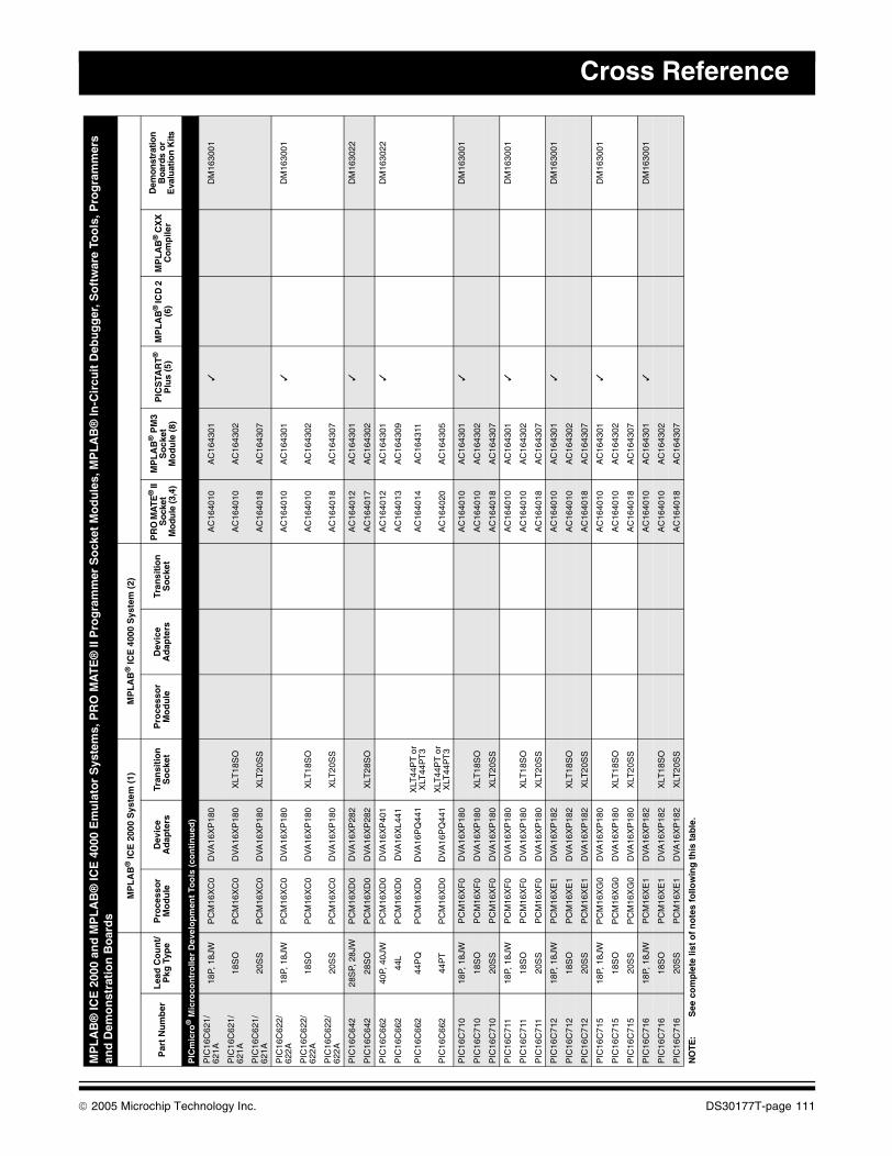
Cross Reference
PIC
mic
ro®
Mic
roco
ntr
olle
r D
evel
op
men
t To
ols
(co
nti
nu
ed)
PIC
16C
621/
621A
18P,
18J
WP
CM
16X
C0
DV
A16
XP
180
AC
1640
10A
C16
4301
✓D
M16
3001
PIC
16C
621/
621A
18S
OP
CM
16X
C0
DV
A16
XP
180
XLT
18S
OA
C16
4010
AC
1643
02
PIC
16C
621/
621A
20S
SP
CM
16X
C0
DV
A16
XP
180
XLT
20S
SA
C16
4018
AC
1643
07
PIC
16C
622/
622A
18P,
18J
WP
CM
16X
C0
DV
A16
XP
180
AC
1640
10A
C16
4301
✓D
M16
3001
PIC
16C
622/
622A
18S
OP
CM
16X
C0
DV
A16
XP
180
XLT
18S
OA
C16
4010
AC
1643
02
PIC
16C
622/
622A
20S
SP
CM
16X
C0
DV
A16
XP
180
XLT
20S
SA
C16
4018
AC
1643
07
PIC
16C
642
28S
P, 2
8JW
PC
M16
XD
0D
VA
16X
P28
2A
C16
4012
AC
1643
01✓
DM
1630
22
PIC
16C
642
28S
OP
CM
16X
D0
DV
A16
XP
282
XLT
28S
OA
C16
4017
AC
1643
02
PIC
16C
662
40P,
40J
WP
CM
16X
D0
DV
A16
XP
401
AC
1640
12A
C16
4301
✓D
M16
3022
PIC
16C
662
44L
PC
M16
XD
0D
VA
16X
L441
AC
1640
13A
C16
4309
PIC
16C
662
44P
QP
CM
16X
D0
DV
A16
PQ
441
XLT
44P
T o
r X
LT44
PT
3A
C16
4014
AC
1643
11
PIC
16C
662
44P
TP
CM
16X
D0
DV
A16
PQ
441
XLT
44P
T o
r X
LT44
PT
3A
C16
4020
AC
1643
05
PIC
16C
710
18P,
18J
WP
CM
16X
F0
DV
A16
XP
180
AC
1640
10A
C16
4301
✓D
M16
3001
PIC
16C
710
18S
OP
CM
16X
F0
DV
A16
XP
180
XLT
18S
OA
C16
4010
AC
1643
02
PIC
16C
710
20S
SP
CM
16X
F0
DV
A16
XP
180
XLT
20S
SA
C16
4018
AC
1643
07
PIC
16C
711
18P,
18J
WP
CM
16X
F0
DV
A16
XP
180
AC
1640
10A
C16
4301
✓D
M16
3001
PIC
16C
711
18S
OP
CM
16X
F0
DV
A16
XP
180
XLT
18S
OA
C16
4010
AC
1643
02
PIC
16C
711
20S
SP
CM
16X
F0
DV
A16
XP
180
XLT
20S
SA
C16
4018
AC
1643
07
PIC
16C
712
18P,
18J
WP
CM
16X
E1
DV
A16
XP
182
AC
1640
10A
C16
4301
✓D
M16
3001
PIC
16C
712
18S
OP
CM
16X
E1
DV
A16
XP
182
XLT
18S
OA
C16
4010
AC
1643
02
PIC
16C
712
20S
SP
CM
16X
E1
DV
A16
XP
182
XLT
20S
SA
C16
4018
AC
1643
07
PIC
16C
715
18P,
18J
WP
CM
16X
G0
DV
A16
XP
180
AC
1640
10A
C16
4301
✓D
M16
3001
PIC
16C
715
18S
OP
CM
16X
G0
DV
A16
XP
180
XLT
18S
OA
C16
4010
AC
1643
02
PIC
16C
715
20S
SP
CM
16X
G0
DV
A16
XP
180
XLT
20S
SA
C16
4018
AC
1643
07
PIC
16C
716
18P,
18J
WP
CM
16X
E1
DV
A16
XP
182
AC
1640
10A
C16
4301
✓D
M16
3001
PIC
16C
716
18S
OP
CM
16X
E1
DV
A16
XP
182
XLT
18S
OA
C16
4010
AC
1643
02
PIC
16C
716
20S
SP
CM
16X
E1
DV
A16
XP
182
XLT
20S
SA
C16
4018
AC
1643
07
MP
LA
B®
ICE
200
0 an
d M
PL
AB
® IC
E 4
000
Em
ula
tor
Sys
tem
s, P
RO
MA
TE
® II
Pro
gra
mm
er S
ock
et M
od
ule
s, M
PL
AB
® In
-Cir
cuit
Deb
ug
ger
, So
ftw
are
Too
ls, P
rog
ram
mer
s an
d D
emo
nst
rati
on
Bo
ard
s
MP
LA
B®
ICE
200
0 S
yste
m (
1)M
PL
AB
® IC
E 4
000
Sys
tem
(2)
Par
t N
um
ber
Lea
d C
ou
nt/
Pkg
Typ
eP
roce
sso
r M
od
ule
Dev
ice
Ad
apte
rsTr
ansi
tio
n
So
cket
Pro
cess
or
Mo
du
leD
evic
e A
dap
ters
Tran
siti
on
S
ock
etP
RO
MA
TE®
II
Soc
ket
Mo
dule
(3,4
)
MP
LA
B®
PM
3S
ock
etM
od
ule
(8)
PIC
STA
RT
®
Plu
s (5
)M
PL
AB
® IC
D 2
(6
)M
PL
AB
® C
XX
C
om
pile
r
Dem
onst
ratio
n
Boa
rds
or
Eva
luat
ion
Kits
NO
TE:
See
co
mp
lete
list
of
no
tes
follo
win
g t
his
tab
le.
© 2005 Microchip Technology Inc. DS30177T-page 111

Development Systems Ordering Guide
PIC
mic
ro®
Mic
roco
ntr
olle
r D
evel
op
men
t To
ols
(co
nti
nu
ed)
PIC
16C
717
18P,
18J
WP
CM
16X
N1
DV
A18
XP
180
AC
1640
10A
C16
4301
✓D
M16
3001
PIC
16C
717
18S
OP
CM
16X
N1
DV
A18
XP
180
XLT
18S
OA
C16
4010
AC
1643
02
PIC
16C
717
20S
SP
CM
16X
N1
DV
A18
XP
180
XLT
20S
SA
C16
4018
AC
1643
07
PIC
16C
745
28S
P, 2
8JW
PC
M16
XQ
1D
VA
16X
P28
2A
C16
4012
AC
1643
01✓
DM
1630
10
PIC
16C
745
28S
OP
CM
16X
Q1
DV
A16
XP
282
XLT
28S
OA
C16
4017
AC
1643
02
PIC
16C
765
40P,
40J
WP
CM
16X
Q1
DV
A16
XP
401
AC
1640
12A
C16
4301
✓D
M16
3010
PIC
16C
765
44L
PC
M16
XQ
1D
VA
16X
L441
AC
1640
13A
C16
4309
PIC
16C
765
44P
TP
CM
16X
Q1
DV
A16
PQ
441
XLT
44P
T o
r X
LT44
PT
3A
C16
4020
AC
1643
05
PIC
16C
770
20P,
20J
WP
CM
16X
N1
DV
A16
XP
200
AC
1640
28A
C16
4301
✓D
M16
3001
PIC
16C
770
20S
OP
CM
16X
N1
DV
A16
XP
200
XLT
20S
O1
AC
1640
28A
C16
4302
PIC
16C
770
20S
SP
CM
16X
N1
DV
A16
XP
200
XLT
20S
S1
AC
1640
18A
C16
4307
PIC
16C
771
20P,
20J
WP
CM
16X
N1
DV
A16
XP
200
AC
1640
28A
C16
4301
✓D
M16
3001
PIC
16C
771
20S
OP
CM
16X
N1
DV
A16
XP
200
XLT
20S
O1
AC
1640
28A
C16
4302
PIC
16C
771
20S
SP
CM
16X
N1
DV
A16
XP
200
XLT
20S
S1
AC
1640
18A
C16
4307
PIC
16C
773
28S
P, 2
8JW
PC
M16
XL0
DV
A16
XP
282
AC
1640
12A
C16
4301
✓D
M16
3022
PIC
16C
773
28S
OP
CM
16X
L0D
VA
16X
P28
2X
LT28
SO
AC
1640
17A
C16
4302
PIC
16C
773
28S
SP
CM
16X
L0D
VA
16X
P28
2X
LT28
SS
AC
1640
21A
C16
4307
PIC
16C
774
40P,
40J
WP
CM
16X
L0D
VA
16X
P40
1A
C16
4012
AC
1643
01✓
DM
1630
22
PIC
16C
774
44L
PC
M16
XL0
DV
A16
XL4
41A
C16
4013
AC
1643
09
PIC
16C
774
44P
QP
CM
16X
L0D
VA
16P
Q44
1X
LT44
PT
or
XLT
44P
T3
AC
1640
14A
C16
4311
PIC
16C
774
44P
TP
CM
16X
L0D
VA
16P
Q44
1X
LT44
PT
or
XLT
44P
T3
AC
1640
20A
C16
4305
PIC
16C
781
20P,
20J
WP
CM
16X
W0
DV
A16
XP
202
AC
1640
28A
C16
4301
✓D
M16
3012
PIC
16C
781
20S
OP
CM
16X
W0
DV
A16
XP
202
XLT
20S
O1
AC
1640
28A
C16
4302
PIC
16C
781
20S
SP
CM
16X
W0
DV
A16
XP
202
XLT
20S
S1
AC
1640
18A
C16
4307
PIC
16C
782
20P,
20J
WP
CM
16X
W0
DV
A16
XP
202
AC
1640
28A
C16
4301
✓D
M16
3012
PIC
16C
782
20S
OP
CM
16X
W0
DV
A16
XP
202
XLT
20S
O1
AC
1640
28A
C16
4302
PIC
16C
782
20S
SP
CM
16X
W0
DV
A16
XP
202
XLT
20S
S1
AC
1640
18A
C16
4307
PIC
16C
923
64S
PP
CM
16X
J0D
VA
16X
P64
0A
C16
4025
PIC
16C
923
64P
TP
CM
16X
J0D
VA
16P
Q64
0X
LT64
PT
1A
C16
4023
AC
1643
19
PIC
16C
923
68L,
68C
LP
CM
16X
J0D
VA
16X
L680
AC
1640
22A
C16
4308
AC
1640
24D
M16
3003
MP
LA
B®
ICE
200
0 an
d M
PL
AB
® IC
E 4
000
Em
ula
tor
Sys
tem
s, P
RO
MA
TE
® II
Pro
gra
mm
er S
ock
et M
od
ule
s, M
PL
AB
® In
-Cir
cuit
Deb
ug
ger
, So
ftw
are
Too
ls, P
rog
ram
mer
s an
d D
emo
nst
rati
on
Bo
ard
s
MP
LA
B®
ICE
200
0 S
yste
m (
1)M
PL
AB
® IC
E 4
000
Sys
tem
(2)
Par
t N
um
ber
Lea
d C
ou
nt/
Pkg
Typ
eP
roce
sso
r M
od
ule
Dev
ice
Ad
apte
rsTr
ansi
tio
n
So
cket
Pro
cess
or
Mo
du
leD
evic
e A
dap
ters
Tran
siti
on
S
ock
etP
RO
MA
TE®
II
So
cket
M
odu
le (3
,4)
MP
LA
B®
PM
3S
ock
etM
od
ule
(8)
PIC
STA
RT
®
Plu
s (5
)M
PL
AB
® IC
D 2
(6
)M
PL
AB
® C
XX
C
om
pile
r
Dem
onst
ratio
n
Bo
ard
s o
r E
valu
atio
n K
its
NO
TE:
See
co
mp
lete
list
of
no
tes
follo
win
g t
his
tab
le.
DS30177T-page 112 © 2005 Microchip Technology Inc.
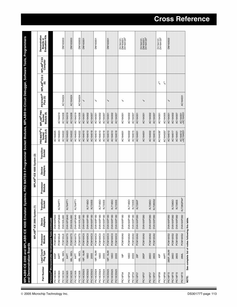
Cross Reference
PIC
mic
ro®
Mic
roco
ntr
olle
r D
evel
op
men
t To
ols
(co
nti
nu
ed)
PIC
16C
924
64S
PP
CM
16X
J0D
VA
16X
P64
0A
C16
4025
PIC
16C
924
64P
TP
CM
16X
J0D
VA
16P
Q64
0X
LT64
PT
1A
C16
4023
AC
1643
19
PIC
16C
924
68L,
68C
LP
CM
16X
J0D
VA
16X
L680
AC
1640
22A
C16
4308
AC
1640
24D
M16
3003
PIC
16C
925
64P
TP
CM
16X
T0
DV
A16
PQ
640
XLT
64P
T1
AC
1640
23A
C16
4319
PIC
16C
925
68L,
68C
LP
CM
16X
T0
DV
A16
XL6
80A
C16
4022
AC
1643
08A
C16
4024
DM
1630
03
PIC
16C
926
64P
TP
CM
16X
T0
DV
A16
PQ
640
XLT
64P
T1
AC
1640
23A
C16
4319
PIC
16C
926
68L,
68C
LP
CM
16X
T0
DV
A16
XL6
80A
C16
4022
AC
1643
08A
C16
4024
DM
1630
03
PIC
16C
E62
318
P, 1
8JW
PC
M16
XC
0D
VA
16X
P18
0A
C16
4010
AC
1643
01✓
DM
1630
01
PIC
16C
E62
318
SO
PC
M16
XC
0D
VA
16X
P18
0X
LT18
SO
AC
1640
10A
C16
4302
PIC
16C
E62
320
SS
PC
M16
XC
0D
VA
16X
P18
0X
LT20
SS
AC
1640
18A
C16
4307
PIC
16C
E62
418
P, 1
8JW
PC
M16
XC
0D
VA
16X
P18
0A
C16
4010
AC
1643
01✓
DM
1630
01
PIC
16C
E62
418
SO
PC
M16
XC
0D
VA
16X
P18
0X
LT18
SO
AC
1640
10A
C16
4302
PIC
16C
E62
420
SS
PC
M16
XC
0D
VA
16X
P18
0X
LT20
SS
AC
1640
18A
C16
4307
PIC
16C
E62
518
P, 1
8JW
PC
M16
XC
0D
VA
16X
P18
0A
C16
4010
AC
1643
01✓
DM
1630
01
PIC
16C
E62
518
SO
PC
M16
XC
0D
VA
16X
P18
0X
LT18
SO
AC
1640
10A
C16
4302
PIC
16C
E62
520
SS
PC
M16
XC
0D
VA
16X
P18
0X
LT20
SS
AC
1640
18A
C16
4307
PIC
16F
5418
PP
CM
16X
A0
DV
A16
XP
180
AC
1640
01A
C16
4301
✓D
V16
4101
, D
M16
3001
, D
V16
4120
*
PIC
16F
5418
SO
PC
M16
XA
0D
VA
16X
P18
0X
LT18
SO
AC
1640
02A
C16
4302
PIC
16F
5420
SS
PC
M16
XA
0D
VA
16X
P18
0X
LT20
SS
AC
1640
15A
C16
4307
PIC
16F
5728
PP
CM
16X
A0
DV
A16
XP
280
XLT
28X
PA
C16
4001
AC
1643
01
PIC
16F
5728
SP
PC
M16
XA
0D
VA
16X
P28
0A
C16
4001
AC
1643
01✓
DV
1641
01,
DM
1630
01,
DV
1641
20*
PIC
16F
5728
SO
PC
M16
XA
0D
VA
16X
P28
0X
LT28
SO
AC
1640
02A
C16
4302
PIC
16F
5728
SS
PC
M16
XA
0D
VA
16X
P28
0X
LT28
SS
2A
C16
4015
AC
1643
07
PIC
16F
5940
PA
C16
4038
*A
C16
4301
✓*
DV
1641
01,
DV
1641
20*
PIC
16F
5944
PT
AC
1640
20*
AC
1643
05✓
*
PIC
16F
7228
SP,
28J
WP
CM
16X
S2
DV
A16
XP
282
AC
1640
12A
C16
4301
✓D
M16
3022
PIC
16F
7228
SO
PC
M16
XS
2D
VA
16X
P28
2X
LT28
SO
AC
1640
17A
C16
4302
PIC
16F
7228
SS
PC
M16
XS
2D
VA
16X
P28
2X
LT28
SS
AC
1640
21A
C16
4307
PIC
16F
7228
ML
PC
M16
XS
2D
VA
16X
P28
2X
LT28
QF
N4*
AC
1640
12+
AC
1640
31A
C16
4301
+A
C16
4031
AC
1640
31
MP
LA
B®
ICE
200
0 an
d M
PL
AB
® IC
E 4
000
Em
ula
tor
Sys
tem
s, P
RO
MA
TE
® II
Pro
gra
mm
er S
ock
et M
od
ule
s, M
PL
AB
® In
-Cir
cuit
Deb
ug
ger
, So
ftw
are
Too
ls, P
rog
ram
mer
s an
d D
emo
nst
rati
on
Bo
ard
s
MP
LA
B®
ICE
200
0 S
yste
m (
1)M
PL
AB
® IC
E 4
000
Sys
tem
(2)
Par
t N
um
ber
Lea
d C
ou
nt/
Pkg
Typ
eP
roce
sso
r M
od
ule
Dev
ice
Ad
apte
rsTr
ansi
tio
n
So
cket
Pro
cess
or
Mo
du
leD
evic
e A
dap
ters
Tran
siti
on
S
ock
etP
RO
MA
TE®
II
Soc
ket
Mo
dule
(3,4
)
MP
LA
B®
PM
3S
ock
etM
od
ule
(8)
PIC
STA
RT
®
Plu
s (5
)M
PL
AB
® IC
D 2
(6
)M
PL
AB
® C
XX
C
om
pile
r
Dem
onst
ratio
n
Boa
rds
or
Eva
luat
ion
Kits
NO
TE:
See
co
mp
lete
list
of
no
tes
follo
win
g t
his
tab
le.
© 2005 Microchip Technology Inc. DS30177T-page 113
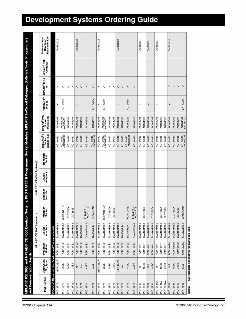
Development Systems Ordering Guide
PIC
mic
ro®
Mic
roco
ntr
olle
r D
evel
op
men
t To
ols
(co
nti
nu
ed)
PIC
16F
7328
SP,
28J
WP
CM
16X
S2
DV
A16
XP
282
AC
1640
12A
C16
4301
✓✓
*D
M16
3022
PIC
16F
7328
ML
PC
M16
XS
2D
VA
16X
P28
2X
LT28
QF
N4*
AC
1640
12+
AC
1640
31A
C16
4301
+A
C16
4031
AC
1640
31✓
*
PIC
16F
7328
SO
PC
M16
XS
2D
VA
16X
P28
2X
LT28
SO
AC
1640
17A
C16
4302
✓*
PIC
16F
7328
SS
PC
M16
XS
2D
VA
16X
P28
2X
LT28
SS
AC
1640
21A
C16
4307
✓*
PIC
16F
7440
PP
CM
16X
S2
DV
A16
XP
401
AC
1640
12A
C16
4301
✓✓
*D
M16
3022
PIC
16F
7444
LP
CM
16X
S2
DV
A16
XL4
41A
C16
4013
AC
1643
09✓
*
PIC
16F
7444
PT
PC
M16
XS
2D
VA
16P
Q44
1X
LT44
PT
or
XLT
44P
T3
AC
1640
20A
C16
4305
✓*
PIC
16F
7444
ML
PC
M16
XS
2D
VA
16X
L441
XLT
44Q
FN
2A
C16
4012
+A
C16
4034
AC
1643
22A
C16
4034
✓*
PIC
16F
7628
SP,
28J
WP
CM
16X
S2
DV
A16
XP
282
AC
1640
12A
C16
4301
✓✓
*D
M16
3022
PIC
16F
7628
ML
PC
M16
XS
2D
VA
16X
P28
2X
LT28
QF
N4*
AC
1640
12+
AC
1640
31A
C16
4301
+A
C16
4031
AC
1640
31✓
*
PIC
16F
7628
SO
PC
M16
XS
2D
VA
16X
P28
2X
LT28
SO
AC
1640
17A
C16
4302
✓*
PIC
16F
7628
SS
PC
M16
XS
2D
VA
16X
P28
2X
LT28
SS
AC
1640
21A
C16
4307
✓*
PIC
16F
7740
P, 4
0JW
PC
M16
XS
2D
VA
16X
P40
1A
C16
4012
AC
1643
01✓
✓*
DM
1630
22
PIC
16F
7744
LP
CM
16X
S2
DV
A16
XL4
41A
C16
4013
AC
1643
09✓
*
PIC
16F
7744
ML
PC
M16
XS
2D
VA
16X
L441
XLT
44Q
FN
2A
C16
4012
+A
C16
4034
AC
1643
22A
C16
4034
✓*
PIC
16F
7744
PT
PC
M16
XS
2D
VA
16P
Q44
1X
LT44
PT
or
XLT
44P
T3
AC
1640
20A
C16
4305
✓*
PIC
16F
8318
PP
CM
16X
H1
DV
A16
XP
180
AC
1640
10A
C16
4301
✓D
M16
3001
PIC
16F
8318
SO
PC
M16
XH
1D
VA
16X
P18
0X
LT18
SO
AC
1640
10A
C16
4302
PIC
16F
8418
PP
CM
16X
H1
DV
A16
XP
180
AC
1640
10A
C16
4301
✓D
M16
3001
PIC
16F
8418
SO
PC
M16
XH
1D
VA
16X
P18
0X
LT18
SO
AC
1640
10A
C16
4302
PIC
16F
84A
18P
PC
M16
XH
1D
VA
16X
P18
0A
C16
4010
AC
1643
01✓
DM
1630
01
PIC
16F
84A
18S
OP
CM
16X
H1
DV
A16
XP
180
XLT
18S
OA
C16
4010
AC
1643
02
PIC
16F
84A
20S
SP
CM
16X
H1
DV
A16
XP
180
XLT
20S
SA
C16
4018
AC
1643
07
PIC
16F
8718
PP
CM
16Y
G0
DV
A16
XP
186
AC
1640
10A
C16
4301
✓✓
DM
1630
14
PIC
16F
8718
SO
PC
M16
YG
0D
VA
16X
P18
6X
LT18
SO
AC
1640
10A
C16
4302
✓
PIC
16F
8720
SS
PC
M16
YG
0D
VA
16X
P18
6X
LT20
SS
AC
1640
18A
C16
4307
✓
PIC
16F
8728
ML
PC
M16
YG
0D
VA
16X
P18
6X
LT28
QF
N3
AC
1640
10+
AC
1640
33A
C16
4301
+A
C16
4031
AC
1640
33✓
MP
LA
B®
ICE
200
0 an
d M
PL
AB
® IC
E 4
000
Em
ula
tor
Sys
tem
s, P
RO
MA
TE
® II
Pro
gra
mm
er S
ock
et M
od
ule
s, M
PL
AB
® In
-Cir
cuit
Deb
ug
ger
, So
ftw
are
Too
ls, P
rog
ram
mer
s an
d D
emo
nst
rati
on
Bo
ard
s
MP
LA
B®
ICE
200
0 S
yste
m (
1)M
PL
AB
® IC
E 4
000
Sys
tem
(2)
Par
t N
um
ber
Lea
d C
ou
nt/
Pkg
Typ
eP
roce
sso
r M
od
ule
Dev
ice
Ad
apte
rsTr
ansi
tio
n
So
cket
Pro
cess
or
Mo
du
leD
evic
e A
dap
ters
Tran
siti
on
S
ock
etP
RO
MA
TE®
II
So
cket
M
odu
le (3
,4)
MP
LA
B®
PM
3S
ock
etM
od
ule
(8)
PIC
STA
RT
®
Plu
s (5
)M
PL
AB
® IC
D 2
(6
)M
PL
AB
® C
XX
C
om
pile
r
Dem
onst
ratio
n
Bo
ard
s o
r E
valu
atio
n K
its
NO
TE:
See
co
mp
lete
list
of
no
tes
follo
win
g t
his
tab
le.
DS30177T-page 114 © 2005 Microchip Technology Inc.
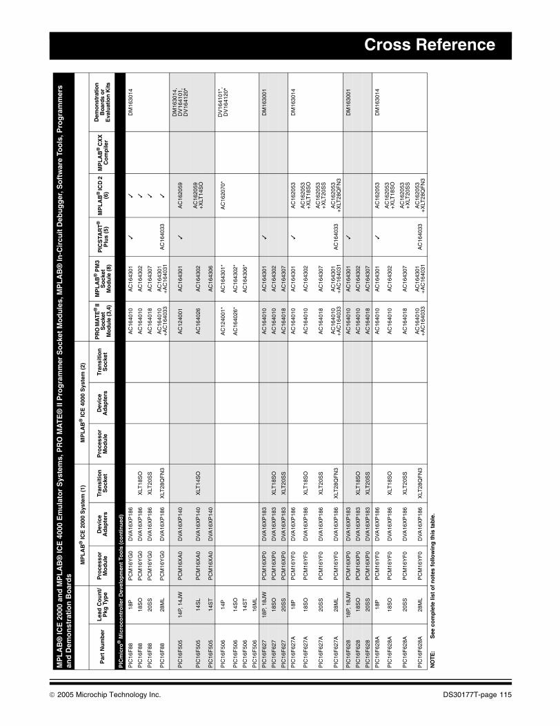
Cross Reference
PIC
mic
ro®
Mic
roco
ntr
olle
r D
evel
op
men
t To
ols
(co
nti
nu
ed)
PIC
16F
8818
PP
CM
16Y
G0
DV
A16
XP
186
AC
1640
10A
C16
4301
✓✓
DM
1630
14
PIC
16F
8818
SO
PC
M16
YG
0D
VA
16X
P18
6X
LT18
SO
AC
1640
10A
C16
4302
✓
PIC
16F
8820
SS
PC
M16
YG
0D
VA
16X
P18
6X
LT20
SS
AC
1640
18A
C16
4307
✓
PIC
16F
8828
ML
PC
M16
YG
0D
VA
16X
P18
6X
LT28
QF
N3
AC
1640
10+
AC
1640
33A
C16
4301
+A
C16
4031
AC
1640
33✓
PIC
16F
505
14P,
14J
WP
CM
16X
A0
DV
A16
XP
140
AC
1240
01A
C16
4301
✓A
C16
2059
DM
1630
14,
DV
1641
01,
DV
1641
20*
PIC
16F
505
14S
LP
CM
16X
A0
DV
A16
XP
140
XLT
14S
OA
C16
4026
AC
1643
02A
C16
2059
+
XLT
14S
O
PIC
16F
505
14S
TP
CM
16X
A0
DV
A16
XP
140
AC
1643
06
PIC
16F
506
14P
AC
1240
01*
AC
1643
01*
AC
1620
70*
DV
1641
01*,
D
V16
4120
*
PIC
16F
506
14S
OA
C16
4026
*A
C16
4302
*
PIC
16F
506
14S
TA
C16
4306
*
PIC
16F
506
16M
L
PIC
16F
627
18P,
18J
WP
CM
16X
P0
DV
A16
XP
183
AC
1640
10A
C16
4301
✓D
M16
3001
PIC
16F
627
18S
OP
CM
16X
P0
DV
A16
XP
183
XLT
18S
OA
C16
4010
AC
1643
02
PIC
16F
627
20S
SP
CM
16X
P0
DV
A16
XP
183
XLT
20S
SA
C16
4018
AC
1643
07
PIC
16F
627A
18P
PC
M16
YF
0D
VA
16X
P18
6A
C16
4010
AC
1643
01✓
AC
1620
53D
M16
3014
PIC
16F
627A
18S
OP
CM
16Y
F0
DV
A16
XP
186
XLT
18S
OA
C16
4010
AC
1643
02A
C16
2053
+
XLT
18S
O
PIC
16F
627A
20S
SP
CM
16Y
F0
DV
A16
XP
186
XLT
20S
SA
C16
4018
AC
1643
07A
C16
2053
+
XLT
20S
S
PIC
16F
627A
28M
LP
CM
16Y
F0
DV
A16
XP
186
XLT
28Q
FN
3A
C16
4010
+A
C16
4033
AC
1643
01+
AC
1640
31A
C16
4033
AC
1620
53
+X
LT28
QF
N3
PIC
16F
628
18P,
18J
WP
CM
16X
P0
DV
A16
XP
183
AC
1640
10A
C16
4301
✓D
M16
3001
PIC
16F
628
18S
OP
CM
16X
P0
DV
A16
XP
183
XLT
18S
OA
C16
4010
AC
1643
02
PIC
16F
628
20S
SP
CM
16X
P0
DV
A16
XP
183
XLT
20S
SA
C16
4018
AC
1643
07
PIC
16F
628A
18P
PC
M16
YF
0D
VA
16X
P18
6A
C16
4010
AC
1643
01✓
AC
1620
53D
M16
3014
PIC
16F
628A
18S
OP
CM
16Y
F0
DV
A16
XP
186
XLT
18S
OA
C16
4010
AC
1643
02A
C16
2053
+
XLT
18S
O
PIC
16F
628A
20S
SP
CM
16Y
F0
DV
A16
XP
186
XLT
20S
SA
C16
4018
AC
1643
07A
C16
2053
+
XLT
20S
S
PIC
16F
628A
28M
LP
CM
16Y
F0
DV
A16
XP
186
XLT
28Q
FN
3A
C16
4010
+A
C16
4033
AC
1643
01+
AC
1640
31A
C16
4033
AC
1620
53
+X
LT28
QF
N3
MP
LA
B®
ICE
200
0 an
d M
PL
AB
® IC
E 4
000
Em
ula
tor
Sys
tem
s, P
RO
MA
TE
® II
Pro
gra
mm
er S
ock
et M
od
ule
s, M
PL
AB
® In
-Cir
cuit
Deb
ug
ger
, So
ftw
are
Too
ls, P
rog
ram
mer
s an
d D
emo
nst
rati
on
Bo
ard
s
MP
LA
B®
ICE
200
0 S
yste
m (
1)M
PL
AB
® IC
E 4
000
Sys
tem
(2)
Par
t N
um
ber
Lea
d C
ou
nt/
Pkg
Typ
eP
roce
sso
r M
od
ule
Dev
ice
Ad
apte
rsTr
ansi
tio
n
So
cket
Pro
cess
or
Mo
du
leD
evic
e A
dap
ters
Tran
siti
on
S
ock
etP
RO
MA
TE®
II
Soc
ket
Mo
dule
(3,4
)
MP
LA
B®
PM
3S
ock
etM
od
ule
(8)
PIC
STA
RT
®
Plu
s (5
)M
PL
AB
® IC
D 2
(6
)M
PL
AB
® C
XX
C
om
pile
r
Dem
onst
ratio
n
Boa
rds
or
Eva
luat
ion
Kits
NO
TE:
See
co
mp
lete
list
of
no
tes
follo
win
g t
his
tab
le.
© 2005 Microchip Technology Inc. DS30177T-page 115
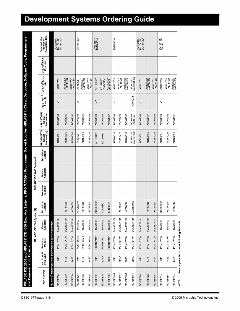
Development Systems Ordering Guide
PIC
mic
ro®
Mic
roco
ntr
olle
r D
evel
op
men
t To
ols
(co
nti
nu
ed)
PIC
16F
630
14P
PC
M16
YD
0D
VA
16X
P14
1A
C12
4001
AC
1643
01✓
AC
1620
52D
M16
3014
, D
V16
4101
, D
V16
4120
*
PIC
16F
630
14S
LP
CM
16Y
D0
DV
A16
XP
141
XLT
14S
OA
C16
4026
AC
1643
02A
C16
2052
+
XLT
14S
O
PIC
16F
630
14S
TP
CM
16Y
D0
DV
A16
XP
141
XLT
14S
SA
C16
4026
AC
1643
06A
C16
2052
+
XLT
14S
S
PIC
16F
636
14P
PC
M16
YM
0D
VA
1002
AC
ICE
0207
AC
1240
01A
C16
4301
✓A
C16
2057
DV
1641
20*
PIC
16F
636
14S
LP
CM
16Y
M0
DV
A10
02X
LT14
SO
AC
1640
26A
C16
4302
AC
1620
57
+X
LT14
SO
PIC
16F
636
14S
TP
CM
16Y
M0
DV
A10
02X
LT14
SS
AC
1640
26A
C16
4306
AC
1620
57
+X
LT14
SS
PIC
16F
639
20P
PC
M16
YM
0*D
VA
1002
AC
ICE
0203
AC
1640
39*
AC
1643
01✓
*A
C16
2066
*D
V16
4101
*,
DM
1630
14
PIC
16F
639
20S
OP
CM
16Y
M0*
DV
A10
02X
LT20
SO
1A
C16
4039
*A
C16
4302
AC
1620
66*
+X
LT20
SO
1
PIC
16F
639
20S
SP
CM
16Y
M0*
DV
A10
02X
LT20
SS
1A
C16
4307
AC
1620
66*
+X
LT20
SS
1
PIC
16F
648A
18P
PC
M16
YF
0D
VA
16X
P18
6A
C16
4010
AC
1643
01✓
AC
1620
53D
M16
3014
PIC
16F
648A
18S
OP
CM
16Y
F0
DV
A16
XP
186
XLT
18S
OA
C16
4010
AC
1643
02A
C16
2053
+
XLT
18S
O
PIC
16F
648A
20S
SP
CM
16Y
F0
DV
A16
XP
186
XLT
20S
SA
C16
4018
AC
1643
07A
C16
2053
+
XLT
20S
S
PIC
16F
648A
28M
LP
CM
16Y
F0
DV
A16
XP
186
XLT
28Q
FN
3A
C16
4010
+A
C16
4033
AC
1643
01+
AC
1640
31A
C16
4033
AC
1620
53
+X
LT28
QF
N3
PIC
16F
676
14P
PC
M16
YD
0D
VA
16X
P14
1A
C12
4001
AC
1643
01✓
AC
1620
52D
M16
3014
, D
V16
4101
, D
V16
4120
*
PIC
16F
676
14S
LP
CM
16Y
D0
DV
A16
XP
141
XLT
14S
OA
C16
4026
AC
1643
02A
C16
2052
+
XLT
14S
O
PIC
16F
676
14S
TP
CM
16Y
D0
DV
A16
XP
141
XLT
14S
SA
C16
4026
AC
1643
06A
C16
2052
+
XLT
14S
S
PIC
16F
684
14P
PC
M16
YK
0D
VA
1002
AC
ICE
0207
AC
1240
01A
C16
4301
✓A
C16
2055
DV
1641
01,
DV
1641
20*
PIC
16F
684
14S
LP
CM
16Y
K0
DV
A10
02X
LT14
SO
A
C16
4026
AC
1643
02A
C16
2055
+
XLT
14S
O
PIC
16F
684
14S
TP
CM
16Y
K0
DV
A10
02X
LT14
SS
A
C16
4026
AC
1643
06A
C16
2055
+
XLT
14S
S
MP
LA
B®
ICE
200
0 an
d M
PL
AB
® IC
E 4
000
Em
ula
tor
Sys
tem
s, P
RO
MA
TE
® II
Pro
gra
mm
er S
ock
et M
od
ule
s, M
PL
AB
® In
-Cir
cuit
Deb
ug
ger
, So
ftw
are
Too
ls, P
rog
ram
mer
s an
d D
emo
nst
rati
on
Bo
ard
s
MP
LA
B®
ICE
200
0 S
yste
m (
1)M
PL
AB
® IC
E 4
000
Sys
tem
(2)
Par
t N
um
ber
Lea
d C
ou
nt/
Pkg
Typ
eP
roce
sso
r M
od
ule
Dev
ice
Ad
apte
rsTr
ansi
tio
n
So
cket
Pro
cess
or
Mo
du
leD
evic
e A
dap
ters
Tran
siti
on
S
ock
etP
RO
MA
TE®
II
So
cket
M
odu
le (3
,4)
MP
LA
B®
PM
3S
ock
etM
od
ule
(8)
PIC
STA
RT
®
Plu
s (5
)M
PL
AB
® IC
D 2
(6
)M
PL
AB
® C
XX
C
om
pile
r
Dem
onst
ratio
n
Bo
ard
s o
r E
valu
atio
n K
its
NO
TE:
See
co
mp
lete
list
of
no
tes
follo
win
g t
his
tab
le.
DS30177T-page 116 © 2005 Microchip Technology Inc.
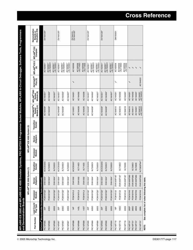
Cross Reference
PIC
mic
ro®
Mic
roco
ntr
olle
r D
evel
op
men
t To
ols
(co
nti
nu
ed)
PIC
16F
685
20P
PC
M16
YQ
0*D
VA
1004
*A
CIC
E02
03A
C16
4039
*A
C16
4301
*A
C16
2061
*D
V16
4120
*
PIC
16F
685
20S
OP
CM
16Y
Q0*
DV
A10
04*
XLT
20S
O1
AC
1640
39*
AC
1643
02*
AC
1620
61*
+X
LT20
SO
1
PIC
16F
685
20S
SP
CM
16Y
Q0*
DV
A10
04*
XLT
20S
S1
AC
1643
07*
AC
1620
61*
+X
LT20
SS
1
PIC
16F
687
20P
PC
M16
YQ
0*D
VA
1004
*A
CIC
E02
03A
C16
4039
*A
C16
4301
*A
C16
2061
*D
V16
4120
*
PIC
16F
687
20S
OP
CM
16Y
Q0*
DV
A10
04*
XLT
20S
O1
AC
1640
39*
AC
1643
02*
AC
1620
61*
+X
LT20
SO
1
PIC
16F
687
20S
SP
CM
16Y
Q0*
DV
A10
04*
XLT
20S
S1
AC
1643
07*
AC
1620
61*
+X
LT20
SS
1
PIC
16F
688
14P
PC
M16
YL0
DV
A10
02A
CIC
E02
07A
C12
4001
AC
1643
01✓
AC
1620
56D
V16
4101
, D
V16
4120
*
PIC
16F
688
14S
LP
CM
16Y
L0D
VA
1002
XLT
14S
O
AC
1640
26A
C16
4302
AC
1620
56
+X
LT14
SO
PIC
16F
688
14S
TP
CM
16Y
L0D
VA
1002
XLT
14S
S
AC
1640
26A
C16
4306
AC
1620
56
+X
LT14
SS
PIC
16F
689
20P
PC
M16
YQ
0*D
VA
1004
*A
CIC
E02
03A
C16
4039
*A
C16
4301
*A
C16
2061
*D
V16
4120
*
PIC
16F
689
20S
OP
CM
16Y
Q0*
DV
A10
04*
XLT
20S
O1
AC
1640
39*
AC
1643
02*
AC
1620
61*
+X
LT20
SO
1
PIC
16F
689
20S
SP
CM
16Y
Q0*
DV
A10
04*
XLT
20S
S1
AC
1643
07*
AC
1620
61*
+X
LT20
SS
1
PIC
16F
690
20P
PC
M16
YQ
0*D
VA
1004
*A
CIC
E02
03A
C16
4039
*A
C16
4301
*A
C16
2061
*D
V16
4120
*
PIC
16F
690
20S
OP
CM
16Y
Q0*
DV
A10
04*
XLT
20S
O1
AC
1640
39*
AC
1643
02*
AC
1620
61*
+X
LT20
SO
1
PIC
16F
690
20S
SP
CM
16Y
Q0*
DV
A10
04*
XLT
20S
S1
AC
1643
07*
AC
1620
61*
+X
LT20
SS
1
PIC
16F
716
18P
PC
M16
YJ0
DV
A16
XP
187
AC
1640
10A
C16
4301
✓A
C16
2054
DM
1630
01
PIC
16F
716
18S
OP
CM
16Y
J0D
VA
16X
P18
7X
LT18
SO
AC
1640
10A
C16
4302
AC
1620
54
+X
LT18
SO
PIC
16F
716
20S
SP
CM
16Y
J0D
VA
16X
P18
7X
LT20
SS
AC
1640
18A
C16
4307
AC
1620
54
+X
LT20
SS
PIC
16F
737
28S
PP
CM
16Y
H0
DV
A18
XP
280
AC
1640
12A
C16
4301
✓✓
PIC
16F
737
28S
OP
CM
16Y
H0
DV
A18
XP
280
XLT
28S
OA
C16
4017
AC
1643
02✓
PIC
16F
737
28S
SP
CM
16Y
H0
DV
A18
XP
280
XLT
28S
SA
C16
4021
AC
1643
07✓
PIC
16F
737
28M
LP
CM
16Y
H0
DV
A18
XP
280
XLT
28Q
FN
4*A
C16
4012
+A
C16
4031
AC
1643
01+
AC
1640
31A
C16
4031
✓
MP
LA
B®
ICE
200
0 an
d M
PL
AB
® IC
E 4
000
Em
ula
tor
Sys
tem
s, P
RO
MA
TE
® II
Pro
gra
mm
er S
ock
et M
od
ule
s, M
PL
AB
® In
-Cir
cuit
Deb
ug
ger
, So
ftw
are
Too
ls, P
rog
ram
mer
s an
d D
emo
nst
rati
on
Bo
ard
s
MP
LA
B®
ICE
200
0 S
yste
m (
1)M
PL
AB
® IC
E 4
000
Sys
tem
(2)
Par
t N
um
ber
Lea
d C
ou
nt/
Pkg
Typ
eP
roce
sso
r M
od
ule
Dev
ice
Ad
apte
rsTr
ansi
tio
n
So
cket
Pro
cess
or
Mo
du
leD
evic
e A
dap
ters
Tran
siti
on
S
ock
etP
RO
MA
TE®
II
Soc
ket
Mo
dule
(3,4
)
MP
LA
B®
PM
3S
ock
etM
od
ule
(8)
PIC
STA
RT
®
Plu
s (5
)M
PL
AB
® IC
D 2
(6
)M
PL
AB
® C
XX
C
om
pile
r
Dem
onst
ratio
n
Boa
rds
or
Eva
luat
ion
Kits
NO
TE:
See
co
mp
lete
list
of
no
tes
follo
win
g t
his
tab
le.
© 2005 Microchip Technology Inc. DS30177T-page 117
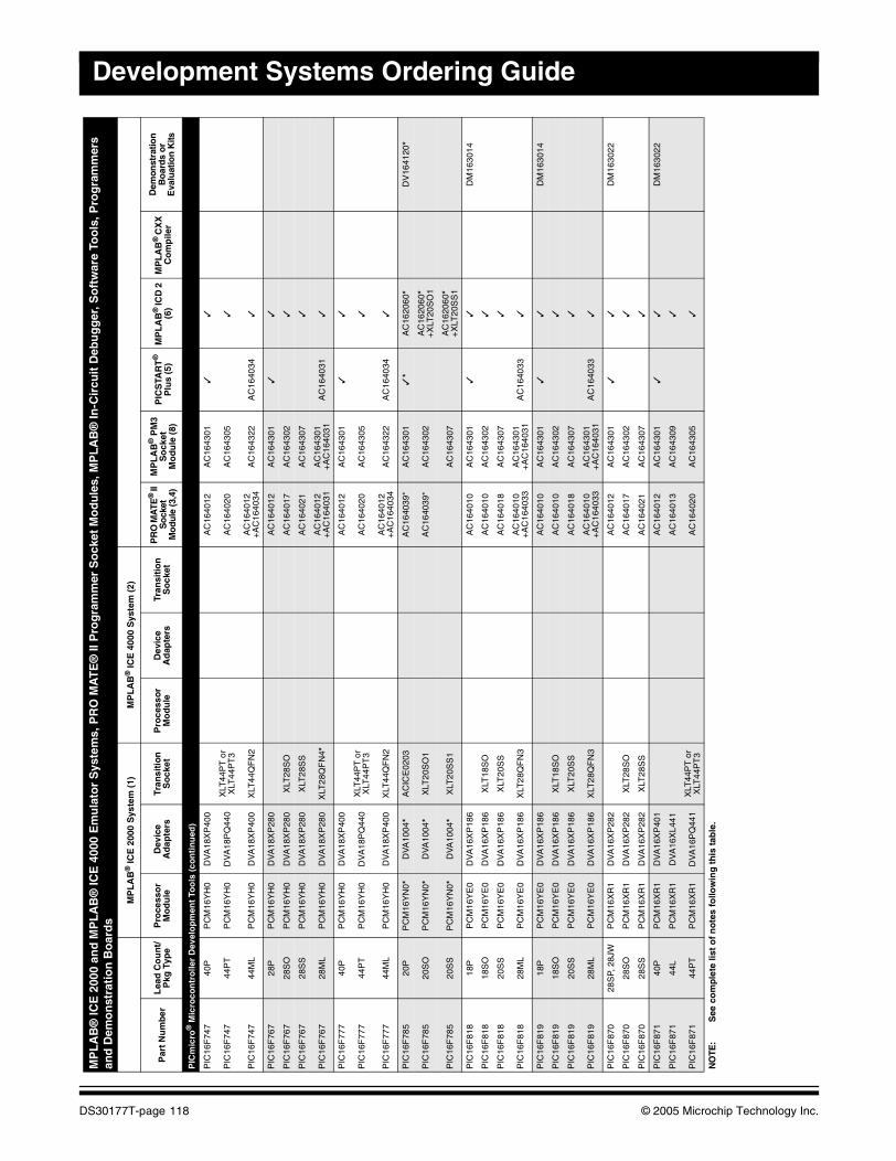
Development Systems Ordering Guide
PIC
mic
ro®
Mic
roco
ntr
olle
r D
evel
op
men
t To
ols
(co
nti
nu
ed)
PIC
16F
747
40P
PC
M16
YH
0D
VA
18X
P40
0A
C16
4012
AC
1643
01✓
✓
PIC
16F
747
44P
TP
CM
16Y
H0
DV
A18
PQ
440
XLT
44P
T o
r X
LT44
PT
3A
C16
4020
AC
1643
05✓
PIC
16F
747
44M
LP
CM
16Y
H0
DV
A18
XP
400
XLT
44Q
FN
2A
C16
4012
+A
C16
4034
AC
1643
22A
C16
4034
✓
PIC
16F
767
28P
PC
M16
YH
0D
VA
18X
P28
0A
C16
4012
AC
1643
01✓
✓
PIC
16F
767
28S
OP
CM
16Y
H0
DV
A18
XP
280
XLT
28S
OA
C16
4017
AC
1643
02✓
PIC
16F
767
28S
SP
CM
16Y
H0
DV
A18
XP
280
XLT
28S
SA
C16
4021
AC
1643
07✓
PIC
16F
767
28M
LP
CM
16Y
H0
DV
A18
XP
280
XLT
28Q
FN
4*A
C16
4012
+A
C16
4031
AC
1643
01+
AC
1640
31A
C16
4031
✓
PIC
16F
777
40P
PC
M16
YH
0D
VA
18X
P40
0A
C16
4012
AC
1643
01✓
✓
PIC
16F
777
44P
TP
CM
16Y
H0
DV
A18
PQ
440
XLT
44P
T o
r X
LT44
PT
3A
C16
4020
AC
1643
05✓
PIC
16F
777
44M
LP
CM
16Y
H0
DV
A18
XP
400
XLT
44Q
FN
2A
C16
4012
+A
C16
4034
AC
1643
22A
C16
4034
✓
PIC
16F
785
20P
PC
M16
YN
0*D
VA
1004
*A
CIC
E02
03A
C16
4039
*A
C16
4301
✓*
AC
1620
60*
DV
1641
20*
PIC
16F
785
20S
OP
CM
16Y
N0*
DV
A10
04*
XLT
20S
O1
AC
1640
39*
AC
1643
02A
C16
2060
* +
XLT
20S
O1
PIC
16F
785
20S
SP
CM
16Y
N0*
DV
A10
04*
XLT
20S
S1
AC
1643
07A
C16
2060
* +
XLT
20S
S1
PIC
16F
818
18P
PC
M16
YE
0D
VA
16X
P18
6A
C16
4010
AC
1643
01✓
✓D
M16
3014
PIC
16F
818
18S
OP
CM
16Y
E0
DV
A16
XP
186
XLT
18S
OA
C16
4010
AC
1643
02✓
PIC
16F
818
20S
SP
CM
16Y
E0
DV
A16
XP
186
XLT
20S
SA
C16
4018
AC
1643
07✓
PIC
16F
818
28M
LP
CM
16Y
E0
DV
A16
XP
186
XLT
28Q
FN
3A
C16
4010
+A
C16
4033
AC
1643
01+
AC
1640
31A
C16
4033
✓
PIC
16F
819
18P
PC
M16
YE
0D
VA
16X
P18
6A
C16
4010
AC
1643
01✓
✓D
M16
3014
PIC
16F
819
18S
OP
CM
16Y
E0
DV
A16
XP
186
XLT
18S
OA
C16
4010
AC
1643
02✓
PIC
16F
819
20S
SP
CM
16Y
E0
DV
A16
XP
186
XLT
20S
SA
C16
4018
AC
1643
07✓
PIC
16F
819
28M
LP
CM
16Y
E0
DV
A16
XP
186
XLT
28Q
FN
3A
C16
4010
+A
C16
4033
AC
1643
01+
AC
1640
31A
C16
4033
✓
PIC
16F
870
28S
P, 2
8JW
PC
M16
XR
1D
VA
16X
P28
2A
C16
4012
AC
1643
01✓
✓D
M16
3022
PIC
16F
870
28S
OP
CM
16X
R1
DV
A16
XP
282
XLT
28S
OA
C16
4017
AC
1643
02✓
PIC
16F
870
28S
SP
CM
16X
R1
DV
A16
XP
282
XLT
28S
SA
C16
4021
AC
1643
07✓
PIC
16F
871
40P
PC
M16
XR
1D
VA
16X
P40
1A
C16
4012
AC
1643
01✓
✓D
M16
3022
PIC
16F
871
44L
PC
M16
XR
1D
VA
16X
L441
AC
1640
13A
C16
4309
✓
PIC
16F
871
44P
TP
CM
16X
R1
DV
A16
PQ
441
XLT
44P
T o
r X
LT44
PT
3A
C16
4020
AC
1643
05✓
MP
LA
B®
ICE
200
0 an
d M
PL
AB
® IC
E 4
000
Em
ula
tor
Sys
tem
s, P
RO
MA
TE
® II
Pro
gra
mm
er S
ock
et M
od
ule
s, M
PL
AB
® In
-Cir
cuit
Deb
ug
ger
, So
ftw
are
Too
ls, P
rog
ram
mer
s an
d D
emo
nst
rati
on
Bo
ard
s
MP
LA
B®
ICE
200
0 S
yste
m (
1)M
PL
AB
® IC
E 4
000
Sys
tem
(2)
Par
t N
um
ber
Lea
d C
ou
nt/
Pkg
Typ
eP
roce
sso
r M
od
ule
Dev
ice
Ad
apte
rsTr
ansi
tio
n
So
cket
Pro
cess
or
Mo
du
leD
evic
e A
dap
ters
Tran
siti
on
S
ock
etP
RO
MA
TE®
II
So
cket
M
odu
le (3
,4)
MP
LA
B®
PM
3S
ock
etM
od
ule
(8)
PIC
STA
RT
®
Plu
s (5
)M
PL
AB
® IC
D 2
(6
)M
PL
AB
® C
XX
C
om
pile
r
Dem
onst
ratio
n
Bo
ard
s o
r E
valu
atio
n K
its
NO
TE:
See
co
mp
lete
list
of
no
tes
follo
win
g t
his
tab
le.
DS30177T-page 118 © 2005 Microchip Technology Inc.
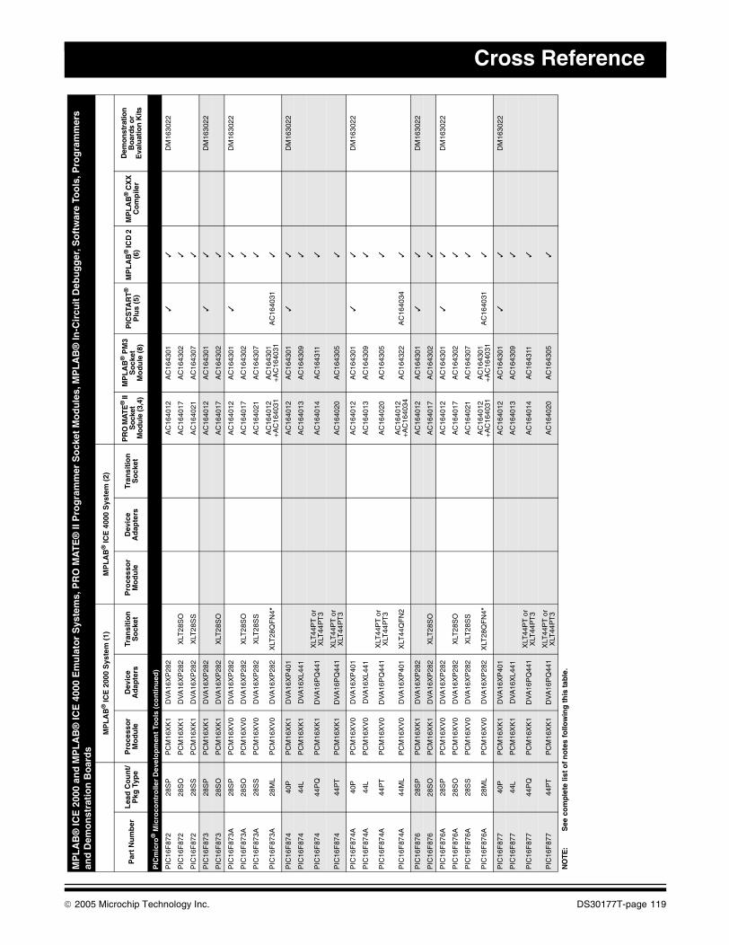
Cross Reference
PIC
mic
ro®
Mic
roco
ntr
olle
r D
evel
op
men
t To
ols
(co
nti
nu
ed)
PIC
16F
872
28S
PP
CM
16X
K1
DV
A16
XP
282
AC
1640
12A
C16
4301
✓✓
DM
1630
22
PIC
16F
872
28S
OP
CM
16X
K1
DV
A16
XP
282
XLT
28S
OA
C16
4017
AC
1643
02✓
PIC
16F
872
28S
SP
CM
16X
K1
DV
A16
XP
282
XLT
28S
SA
C16
4021
AC
1643
07✓
PIC
16F
873
28S
PP
CM
16X
K1
DV
A16
XP
282
AC
1640
12A
C16
4301
✓✓
DM
1630
22
PIC
16F
873
28S
OP
CM
16X
K1
DV
A16
XP
282
XLT
28S
OA
C16
4017
AC
1643
02✓
PIC
16F
873A
28S
PP
CM
16X
V0
DV
A16
XP
282
AC
1640
12A
C16
4301
✓✓
DM
1630
22
PIC
16F
873A
28S
OP
CM
16X
V0
DV
A16
XP
282
XLT
28S
OA
C16
4017
AC
1643
02✓
PIC
16F
873A
28S
SP
CM
16X
V0
DV
A16
XP
282
XLT
28S
SA
C16
4021
AC
1643
07✓
PIC
16F
873A
28M
LP
CM
16X
V0
DV
A16
XP
282
XLT
28Q
FN
4*A
C16
4012
+A
C16
4031
AC
1643
01+
AC
1640
31A
C16
4031
✓
PIC
16F
874
40P
PC
M16
XK
1D
VA
16X
P40
1A
C16
4012
AC
1643
01✓
✓D
M16
3022
PIC
16F
874
44L
PC
M16
XK
1D
VA
16X
L441
AC
1640
13A
C16
4309
✓
PIC
16F
874
44P
QP
CM
16X
K1
DV
A16
PQ
441
XLT
44P
T o
r X
LT44
PT
3A
C16
4014
AC
1643
11✓
PIC
16F
874
44P
TP
CM
16X
K1
DV
A16
PQ
441
XLT
44P
T o
r X
LT44
PT
3A
C16
4020
AC
1643
05✓
PIC
16F
874A
40P
PC
M16
XV
0D
VA
16X
P40
1A
C16
4012
AC
1643
01✓
✓D
M16
3022
PIC
16F
874A
44L
PC
M16
XV
0D
VA
16X
L441
AC
1640
13A
C16
4309
✓
PIC
16F
874A
44P
TP
CM
16X
V0
DV
A16
PQ
441
XLT
44P
T o
r X
LT44
PT
3A
C16
4020
AC
1643
05✓
PIC
16F
874A
44M
LP
CM
16X
V0
DV
A16
XP
401
XLT
44Q
FN
2A
C16
4012
+A
C16
4034
AC
1643
22A
C16
4034
✓
PIC
16F
876
28S
PP
CM
16X
K1
DV
A16
XP
282
AC
1640
12A
C16
4301
✓✓
DM
1630
22
PIC
16F
876
28S
OP
CM
16X
K1
DV
A16
XP
282
XLT
28S
OA
C16
4017
AC
1643
02✓
PIC
16F
876A
28S
PP
CM
16X
V0
DV
A16
XP
282
AC
1640
12A
C16
4301
✓✓
DM
1630
22
PIC
16F
876A
28S
OP
CM
16X
V0
DV
A16
XP
282
XLT
28S
OA
C16
4017
AC
1643
02✓
PIC
16F
876A
28S
SP
CM
16X
V0
DV
A16
XP
282
XLT
28S
SA
C16
4021
AC
1643
07✓
PIC
16F
876A
28M
LP
CM
16X
V0
DV
A16
XP
282
XLT
28Q
FN
4*A
C16
4012
+A
C16
4031
AC
1643
01+
AC
1640
31A
C16
4031
✓
PIC
16F
877
40P
PC
M16
XK
1D
VA
16X
P40
1A
C16
4012
AC
1643
01✓
✓D
M16
3022
PIC
16F
877
44L
PC
M16
XK
1D
VA
16X
L441
AC
1640
13A
C16
4309
✓
PIC
16F
877
44P
QP
CM
16X
K1
DV
A16
PQ
441
XLT
44P
T o
r X
LT44
PT
3A
C16
4014
AC
1643
11✓
PIC
16F
877
44P
TP
CM
16X
K1
DV
A16
PQ
441
XLT
44P
T o
r X
LT44
PT
3A
C16
4020
AC
1643
05✓
MP
LA
B®
ICE
200
0 an
d M
PL
AB
® IC
E 4
000
Em
ula
tor
Sys
tem
s, P
RO
MA
TE
® II
Pro
gra
mm
er S
ock
et M
od
ule
s, M
PL
AB
® In
-Cir
cuit
Deb
ug
ger
, So
ftw
are
Too
ls, P
rog
ram
mer
s an
d D
emo
nst
rati
on
Bo
ard
s
MP
LA
B®
ICE
200
0 S
yste
m (
1)M
PL
AB
® IC
E 4
000
Sys
tem
(2)
Par
t N
um
ber
Lea
d C
ou
nt/
Pkg
Typ
eP
roce
sso
r M
od
ule
Dev
ice
Ad
apte
rsTr
ansi
tio
n
So
cket
Pro
cess
or
Mo
du
leD
evic
e A
dap
ters
Tran
siti
on
S
ock
etP
RO
MA
TE®
II
Soc
ket
Mo
dule
(3,4
)
MP
LA
B®
PM
3S
ock
etM
od
ule
(8)
PIC
STA
RT
®
Plu
s (5
)M
PL
AB
® IC
D 2
(6
)M
PL
AB
® C
XX
C
om
pile
r
Dem
onst
ratio
n
Boa
rds
or
Eva
luat
ion
Kits
NO
TE:
See
co
mp
lete
list
of
no
tes
follo
win
g t
his
tab
le.
© 2005 Microchip Technology Inc. DS30177T-page 119
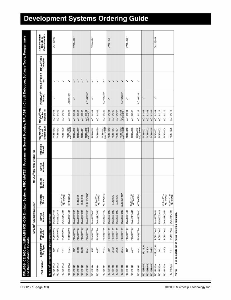
Development Systems Ordering Guide
PIC
mic
ro®
Mic
roco
ntr
olle
r D
evel
op
men
t To
ols
(co
nti
nu
ed)
PIC
16F
877A
40P
PC
M16
XV
0D
VA
16X
P40
1A
C16
4012
AC
1643
01✓
✓D
M16
3022
PIC
16F
877A
44L
PC
M16
XV
0D
VA
16X
L441
AC
1640
13A
C16
4309
✓
PIC
16F
877A
44P
TP
CM
16X
V0
DV
A16
PQ
441
XLT
44P
T o
r X
LT44
PT
3A
C16
4020
AC
1643
05✓
PIC
16F
877A
44M
LP
CM
16X
V0
DV
A16
XP
401
XLT
44Q
FN
2A
C16
4012
+A
C16
4034
AC
1643
22A
C16
4034
✓
PIC
16F
913
28P
PC
M16
YP
0*D
VA
18X
P28
0A
C16
4012
AC
1643
01✓
*✓
*D
V16
4120
*
PIC
16F
913
28S
OP
CM
16Y
P0*
DV
A18
XP
280
XLT
28S
OA
C16
4017
AC
1643
02✓
*
PIC
16F
913
28S
SP
CM
16Y
P0*
DV
A18
XP
280
XLT
28S
SA
C16
4021
AC
1643
07✓
*
PIC
16F
913
28M
LP
CM
16Y
P0*
DV
A18
XP
280
XLT
28Q
FN
4*A
C16
4012
+
AC
1640
31A
C16
4301
+A
C16
4031
AC
1640
31*
✓*
PIC
16F
914
40P
PC
M16
YP
0*D
VA
18X
P40
0A
C16
4012
AC
1643
01✓
*✓
*D
V16
4120
*
PIC
16F
914
44P
TP
CM
16Y
P0*
DV
A18
PQ
440
XLT
44P
T o
r X
LT44
PT
3A
C16
4020
AC
1643
05✓
*
PIC
16F
914
44M
LP
CM
16Y
P0*
DV
A18
XP
400
XLT
44Q
FN
2A
C16
4012
+
AC
1640
34A
C16
4322
AC
1640
34*
✓*
PIC
16F
916
28P
PC
M16
YP
0*D
VA
18X
P28
0A
C16
4012
AC
1643
01✓
*✓
DV
1641
20*
PIC
16F
916
28S
OP
CM
16Y
P0*
DV
A18
XP
280
XLT
28S
OA
C16
4017
AC
1643
02✓
PIC
16F
916
28S
SP
CM
16Y
P0*
DV
A18
XP
280
XLT
28S
SA
C16
4021
AC
1643
07✓
PIC
16F
916
28M
LP
CM
16Y
P0*
DV
A18
XP
280
XLT
28Q
FN
4*A
C16
4012
+
AC
1640
31A
C16
4301
+
AC
1640
31A
C16
4031
*✓
PIC
16F
917
40P
PC
M16
YP
0*D
VA
18X
P40
0A
C16
4012
AC
1643
01✓
*✓
DV
1641
20*
PIC
16F
917
44P
TP
CM
16Y
P0*
DV
A18
PQ
440
XLT
44P
T o
r X
LT44
PT
3A
C16
4020
AC
1643
05✓
PIC
16F
917
44M
LP
CM
16Y
P0*
DV
A18
XP
400
XLT
44Q
FN
2A
C16
4012
+
AC
1640
34A
C16
4322
AC
1640
34*
✓
PIC
16H
V54
018
P, 1
8JW
AC
1640
01A
C16
4301
✓
PIC
16H
V54
018
SO
AC
1640
02A
C16
4302
PIC
16H
V54
020
SS
AC
1640
15A
C16
4307
PIC
17C
42A
40P,
40J
WP
CM
17X
A0
DV
A17
XP
401
AC
1740
01A
C16
4301
✓D
M16
3001
PIC
17C
42A
44L
PC
M17
XA
0D
VA
17X
L441
AC
1740
02A
C16
4317
PIC
17C
42A
44P
QP
CM
17X
A0
DV
A17
PQ
441
XLT
44P
T o
r X
LT44
PT
3A
C17
4004
AC
1643
16
PIC
17C
42A
44P
TP
CM
17X
A0
DV
A17
PQ
441
XLT
44P
T o
r X
LT44
PT
3A
C17
4005
AC
1643
15
MP
LA
B®
ICE
200
0 an
d M
PL
AB
® IC
E 4
000
Em
ula
tor
Sys
tem
s, P
RO
MA
TE
® II
Pro
gra
mm
er S
ock
et M
od
ule
s, M
PL
AB
® In
-Cir
cuit
Deb
ug
ger
, So
ftw
are
Too
ls, P
rog
ram
mer
s an
d D
emo
nst
rati
on
Bo
ard
s
MP
LA
B®
ICE
200
0 S
yste
m (
1)M
PL
AB
® IC
E 4
000
Sys
tem
(2)
Par
t N
um
ber
Lea
d C
ou
nt/
Pkg
Typ
eP
roce
sso
r M
od
ule
Dev
ice
Ad
apte
rsTr
ansi
tio
n
So
cket
Pro
cess
or
Mo
du
leD
evic
e A
dap
ters
Tran
siti
on
S
ock
etP
RO
MA
TE®
II
So
cket
M
odu
le (3
,4)
MP
LA
B®
PM
3S
ock
etM
od
ule
(8)
PIC
STA
RT
®
Plu
s (5
)M
PL
AB
® IC
D 2
(6
)M
PL
AB
® C
XX
C
om
pile
r
Dem
onst
ratio
n
Bo
ard
s o
r E
valu
atio
n K
its
NO
TE:
See
co
mp
lete
list
of
no
tes
follo
win
g t
his
tab
le.
DS30177T-page 120 © 2005 Microchip Technology Inc.
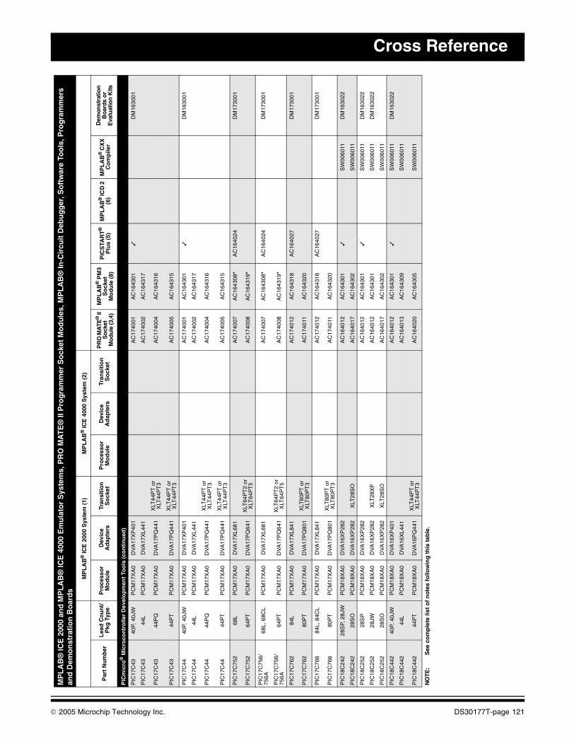
Cross Reference
PIC
mic
ro®
Mic
roco
ntr
olle
r D
evel
op
men
t To
ols
(co
nti
nu
ed)
PIC
17C
4340
P, 4
0JW
PC
M17
XA
0D
VA
17X
P40
1A
C17
4001
AC
1643
01✓
DM
1630
01
PIC
17C
4344
LP
CM
17X
A0
DV
A17
XL4
41A
C17
4002
AC
1643
17
PIC
17C
4344
PQ
PC
M17
XA
0D
VA
17P
Q44
1X
LT44
PT
or
XLT
44P
T3
AC
1740
04A
C16
4316
PIC
17C
4344
PT
PC
M17
XA
0D
VA
17P
Q44
1X
LT44
PT
or
XLT
44P
T3
AC
1740
05A
C16
4315
PIC
17C
4440
P, 4
0JW
PC
M17
XA
0D
VA
17X
P40
1A
C17
4001
AC
1643
01✓
DM
1630
01
PIC
17C
4444
LP
CM
17X
A0
DV
A17
XL4
41A
C17
4002
AC
1643
17
PIC
17C
4444
PQ
PC
M17
XA
0D
VA
17P
Q44
1X
LT44
PT
or
XLT
44P
T3
AC
1740
04A
C16
4316
PIC
17C
4444
PT
PC
M17
XA
0D
VA
17P
Q44
1X
LT44
PT
or
XLT
44P
T3
AC
1740
05A
C16
4315
PIC
17C
752
68L
PC
M17
XA
0D
VA
17X
L681
AC
1740
07A
C16
4308
*A
C16
4024
DM
1730
01
PIC
17C
752
64P
TP
CM
17X
A0
DV
A17
PQ
641
XLT
64P
T2
or
XLT
64P
T5
AC
1740
08A
C16
4319
*
PIC
17C
756/
756A
68L,
68C
LP
CM
17X
A0
DV
A17
XL6
81A
C17
4007
AC
1643
08*
AC
1640
24D
M17
3001
PIC
17C
756/
756A
64P
TP
CM
17X
A0
DV
A17
PQ
641
XLT
64P
T2
or
XLT
64P
T5
AC
1740
08A
C16
4319
*
PIC
17C
762
84L
PC
M17
XA
0D
VA
17X
L841
AC
1740
12A
C16
4318
AC
1640
27D
M17
3001
PIC
17C
762
80P
TP
CM
17X
A0
DV
A17
PQ
801
XLT
80P
T o
r X
LT80
PT
3A
C17
4011
AC
1643
20
PIC
17C
766
84L,
84C
LP
CM
17X
A0
DV
A17
XL8
41A
C17
4012
AC
1643
18A
C16
4027
DM
1730
01
PIC
17C
766
80P
TP
CM
17X
A0
DV
A17
PQ
801
XLT
80P
T o
r X
LT80
PT
3A
C17
4011
AC
1643
20
PIC
18C
242
28S
P, 2
8JW
PC
M18
XA
0D
VA
16X
P28
2A
C16
4012
AC
1643
01✓
SW
0060
11D
M16
3022
PIC
18C
242
28S
OP
CM
18X
A0
DV
A16
XP
282
XLT
28S
OA
C16
4017
AC
1643
02S
W00
6011
PIC
18C
252
28S
PP
CM
18X
A0
DV
A16
XP
282
AC
1640
12A
C16
4301
✓S
W00
6011
DM
1630
22
PIC
18C
252
28JW
PC
M18
XA
0D
VA
16X
P28
2X
LT28
XP
AC
1640
12A
C16
4301
SW
0060
11D
M16
3022
PIC
18C
252
28S
OP
CM
18X
A0
DV
A16
XP
282
XLT
28S
OA
C16
4017
AC
1643
02S
W00
6011
PIC
18C
442
40P,
40J
WP
CM
18X
A0
DV
A16
XP
401
AC
1640
12A
C16
4301
✓S
W00
6011
DM
1630
22
PIC
18C
442
44L
PC
M18
XA
0D
VA
16X
L441
AC
1640
13A
C16
4309
SW
0060
11
PIC
18C
442
44P
TP
CM
18X
A0
DV
A16
PQ
441
XLT
44P
T o
r X
LT44
PT
3A
C16
4020
AC
1643
05S
W00
6011
MP
LA
B®
ICE
200
0 an
d M
PL
AB
® IC
E 4
000
Em
ula
tor
Sys
tem
s, P
RO
MA
TE
® II
Pro
gra
mm
er S
ock
et M
od
ule
s, M
PL
AB
® In
-Cir
cuit
Deb
ug
ger
, So
ftw
are
Too
ls, P
rog
ram
mer
s an
d D
emo
nst
rati
on
Bo
ard
s
MP
LA
B®
ICE
200
0 S
yste
m (
1)M
PL
AB
® IC
E 4
000
Sys
tem
(2)
Par
t N
um
ber
Lea
d C
ou
nt/
Pkg
Typ
eP
roce
sso
r M
od
ule
Dev
ice
Ad
apte
rsTr
ansi
tio
n
So
cket
Pro
cess
or
Mo
du
leD
evic
e A
dap
ters
Tran
siti
on
S
ock
etP
RO
MA
TE®
II
Soc
ket
Mo
dule
(3,4
)
MP
LA
B®
PM
3S
ock
etM
od
ule
(8)
PIC
STA
RT
®
Plu
s (5
)M
PL
AB
® IC
D 2
(6
)M
PL
AB
® C
XX
C
om
pile
r
Dem
onst
ratio
n
Boa
rds
or
Eva
luat
ion
Kits
NO
TE:
See
co
mp
lete
list
of
no
tes
follo
win
g t
his
tab
le.
© 2005 Microchip Technology Inc. DS30177T-page 121
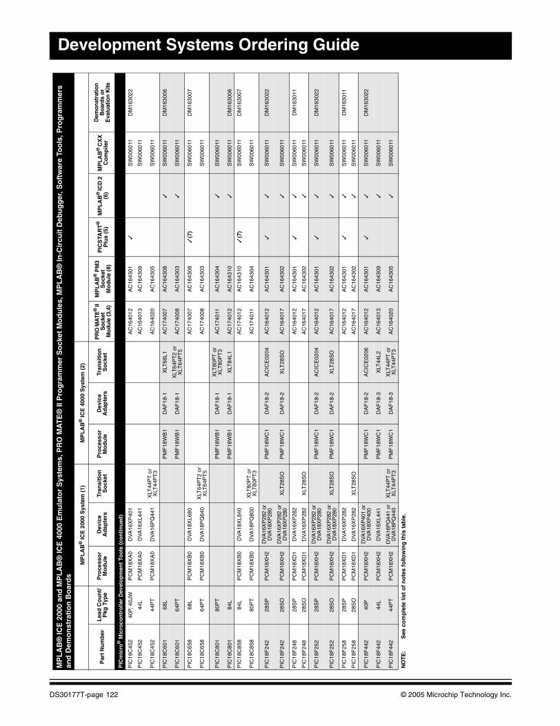
Development Systems Ordering Guide
PIC
mic
ro®
Mic
roco
ntr
olle
r D
evel
op
men
t To
ols
(co
nti
nu
ed)
PIC
18C
452
40P,
40J
WP
CM
18X
A0
DV
A16
XP
401
AC
1640
12A
C16
4301
✓S
W00
6011
DM
1630
22
PIC
18C
452
44L
PC
M18
XA
0D
VA
16X
L441
AC
1640
13A
C16
4309
SW
0060
11
PIC
18C
452
44P
TP
CM
18X
A0
DV
A16
PQ
441
XLT
44P
T o
r X
LT44
PT
3A
C16
4020
AC
1643
05S
W00
6011
PIC
18C
601
68L
PM
F18
WB
1D
AF
18-1
XLT
68L1
AC
1740
07A
C16
4308
✓S
W00
6011
DM
1630
06
PIC
18C
601
64P
TP
MF
18W
B1
DA
F18
-1X
LT64
PT
2 or
X
LT64
PT
5A
C17
4008
AC
1643
03✓
SW
0060
11
PIC
18C
658
68L
PC
M18
XB
0D
VA
18X
L680
AC
1740
07A
C16
4308
✓(7
)S
W00
6011
DM
1630
07
PIC
18C
658
64P
TP
CM
18X
B0
DV
A18
PQ
640
XLT
64P
T2
or
XLT
64P
T5
AC
1740
08A
C16
4303
SW
0060
11
PIC
18C
801
80P
TP
MF
18W
B1
DA
F18
-1X
LT80
PT
or
XLT
80P
T3
AC
1740
11A
C16
4304
✓S
W00
6011
PIC
18C
801
84L
PM
F18
WB
1D
AF
18-1
XLT
84L1
AC
1740
12A
C16
4310
✓S
W00
6011
DM
1630
06
PIC
18C
858
84L
PC
M18
XB
0D
VA
18X
L840
AC
1740
12A
C16
4310
✓(7
)S
W00
6011
DM
1630
07
PIC
18C
858
80P
TP
CM
18X
B0
DV
A18
PQ
800
XLT
80P
T o
r X
LT80
PT
3A
C17
4011
AC
1643
04S
W00
6011
PIC
18F
242
28S
PP
CM
18X
H2
DV
A16
XP
282
orD
VA18
XP
280
PM
F18
WC
1D
AF
18-2
AC
ICE
0204
AC
1640
12A
C16
4301
✓✓
SW
0060
11D
M16
3022
PIC
18F
242
28S
OP
CM
18X
H2
DV
A16
XP
282
orD
VA18
XP
280
XLT
28S
OP
MF
18W
C1
DA
F18
-2X
LT28
SO
AC
1640
17A
C16
4302
✓S
W00
6011
PIC
18F
248
28S
PP
CM
18X
D1
DV
A16
XP
282
AC
1640
12A
C16
4301
✓✓
SW
0060
11D
M16
3011
PIC
18F
248
28S
OP
CM
18X
D1
DV
A16
XP
282
XLT
28S
OA
C16
4017
AC
1643
02✓
SW
0060
11
PIC
18F
252
28S
PP
CM
18X
H2
DV
A16
XP
282
orD
VA18
XP
280
PM
F18
WC
1D
AF
18-2
AC
ICE
0204
AC
1640
12A
C16
4301
✓✓
SW
0060
11D
M16
3022
PIC
18F
252
28S
OP
CM
18X
H2
DV
A16
XP
282
orD
VA18
XP
280
XLT
28S
OP
MF
18W
C1
DA
F18
-2X
LT28
SO
AC
1640
17A
C16
4302
✓S
W00
6011
PIC
18F
258
28S
PP
CM
18X
D1
DV
A16
XP
282
AC
1640
12A
C16
4301
✓✓
SW
0060
11D
M16
3011
PIC
18F
258
28S
OP
CM
18X
D1
DV
A16
XP
282
XLT
28S
OA
C16
4017
AC
1643
02✓
SW
0060
11
PIC
18F
442
40P
PC
M18
XH
2D
VA
16X
P40
1 or
DVA
18X
P40
0P
MF
18W
C1
DA
F18
-2A
CIC
E02
06A
C16
4012
AC
1643
01✓
✓S
W00
6011
DM
1630
22
PIC
18F
442
44L
PC
M18
XH
2D
VA
16X
L441
PM
F18
WC
1D
AF
18-3
XLT
44L2
AC
1640
13A
C16
4309
✓S
W00
6011
PIC
18F
442
44P
TP
CM
18X
H2
DV
A16
PQ
441
orD
VA18
PQ
440
XLT
44P
T o
r X
LT44
PT
3P
MF
18W
C1
DA
F18
-3X
LT44
PT
or
XLT
44P
T3
AC
1640
20A
C16
4305
✓S
W00
6011
MP
LA
B®
ICE
200
0 an
d M
PL
AB
® IC
E 4
000
Em
ula
tor
Sys
tem
s, P
RO
MA
TE
® II
Pro
gra
mm
er S
ock
et M
od
ule
s, M
PL
AB
® In
-Cir
cuit
Deb
ug
ger
, So
ftw
are
Too
ls, P
rog
ram
mer
s an
d D
emo
nst
rati
on
Bo
ard
s
MP
LA
B®
ICE
200
0 S
yste
m (
1)M
PL
AB
® IC
E 4
000
Sys
tem
(2)
Par
t N
um
ber
Lea
d C
ou
nt/
Pkg
Typ
eP
roce
sso
r M
od
ule
Dev
ice
Ad
apte
rsTr
ansi
tio
n
So
cket
Pro
cess
or
Mo
du
leD
evic
e A
dap
ters
Tran
siti
on
S
ock
etP
RO
MA
TE®
II
So
cket
M
odu
le (3
,4)
MP
LA
B®
PM
3S
ock
etM
od
ule
(8)
PIC
STA
RT
®
Plu
s (5
)M
PL
AB
® IC
D 2
(6
)M
PL
AB
® C
XX
C
om
pile
r
Dem
onst
ratio
n
Bo
ard
s o
r E
valu
atio
n K
its
NO
TE:
See
co
mp
lete
list
of
no
tes
follo
win
g t
his
tab
le.
DS30177T-page 122 © 2005 Microchip Technology Inc.
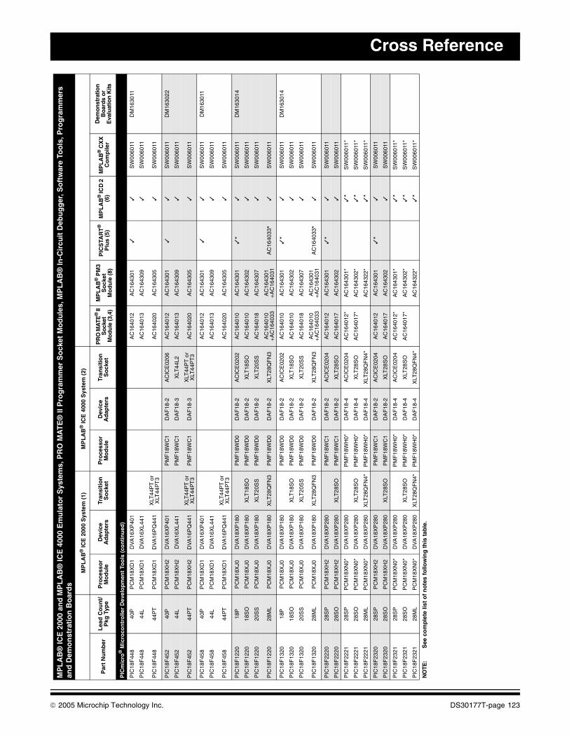
Cross Reference
PIC
mic
ro®
Mic
roco
ntr
olle
r D
evel
op
men
t To
ols
(co
nti
nu
ed)
PIC
18F
448
40P
PC
M18
XD
1D
VA
16X
P40
1A
C16
4012
AC
1643
01✓
✓S
W00
6011
DM
1630
11
PIC
18F
448
44L
PC
M18
XD
1D
VA
16X
L441
AC
1640
13A
C16
4309
✓S
W00
6011
PIC
18F
448
44P
TP
CM
18X
D1
DV
A16
PQ
441
XLT
44P
T o
r X
LT44
PT
3A
C16
4020
AC
1643
05✓
SW
0060
11
PIC
18F
452
40P
PC
M18
XH
2D
VA
16X
P40
1P
MF
18W
C1
DA
F18
-2A
CIC
E02
06A
C16
4012
AC
1643
01✓
✓S
W00
6011
DM
1630
22
PIC
18F
452
44L
PC
M18
XH
2D
VA
16X
L441
PM
F18
WC
1D
AF
18-3
XLT
44L2
AC
1640
13A
C16
4309
✓S
W00
6011
PIC
18F
452
44P
TP
CM
18X
H2
DV
A16
PQ
441
XLT
44P
T o
r X
LT44
PT
3P
MF
18W
C1
DA
F18
-3X
LT44
PT
or
XLT
44P
T3
AC
1640
20A
C16
4305
✓S
W00
6011
PIC
18F
458
40P
PC
M18
XD
1D
VA
16X
P40
1A
C16
4012
AC
1643
01✓
✓S
W00
6011
DM
1630
11
PIC
18F
458
44L
PC
M18
XD
1D
VA
16X
L441
AC
1640
13A
C16
4309
✓S
W00
6011
PIC
18F
458
44P
TP
CM
18X
D1
DV
A16
PQ
441
XLT
44P
T o
r X
LT44
PT
3A
C16
4020
AC
1643
05✓
SW
0060
11
PIC
18F
1220
18P
PC
M18
XJ0
DV
A18
XP
180
PM
F18
WD
0D
AF
18-2
AC
ICE
0202
AC
1640
10A
C16
4301
✓*
✓S
W00
6011
DM
1630
14
PIC
18F
1220
18S
OP
CM
18X
J0D
VA
18X
P18
0X
LT18
SO
PM
F18
WD
0D
AF
18-2
XLT
18S
OA
C16
4010
AC
1643
02✓
SW
0060
11
PIC
18F
1220
20S
SP
CM
18X
J0D
VA
18X
P18
0X
LT20
SS
PM
F18
WD
0D
AF
18-2
XLT
20S
SA
C16
4018
AC
1643
07✓
SW
0060
11
PIC
18F
1220
28M
LP
CM
18X
J0D
VA
18X
P18
0X
LT28
QF
N3
PM
F18
WD
0D
AF
18-2
XLT
28Q
FN
3A
C16
4010
+A
C16
4033
AC
1643
01+
AC
1640
31A
C16
4033
*✓
SW
0060
11
PIC
18F
1320
18P
PC
M18
XJ0
DV
A18
XP
180
PM
F18
WD
0D
AF
18-2
AC
ICE
0202
AC
1640
10A
C16
4301
✓*
✓S
W00
6011
DM
1630
14
PIC
18F
1320
18S
OP
CM
18X
J0D
VA
18X
P18
0X
LT18
SO
PM
F18
WD
0D
AF
18-2
XLT
18S
OA
C16
4010
AC
1643
02✓
SW
0060
11
PIC
18F
1320
20S
SP
CM
18X
J0D
VA
18X
P18
0X
LT20
SS
PM
F18
WD
0D
AF
18-2
XLT
20S
SA
C16
4018
AC
1643
07✓
SW
0060
11
PIC
18F
1320
28M
LP
CM
18X
J0D
VA
18X
P18
0X
LT28
QF
N3
PM
F18
WD
0D
AF
18-2
XLT
28Q
FN
3A
C16
4010
+A
C16
4033
AC
1643
01+
AC
1640
31A
C16
4033
*✓
SW
0060
11
PIC
18F
2220
28S
PP
CM
18X
H2
DV
A18
XP
280
PM
F18
WC
1D
AF
18-2
AC
ICE
0204
AC
1640
12A
C16
4301
✓*
✓S
W00
6011
PIC
18F
2220
28S
OP
CM
18X
H2
DV
A18
XP
280
XLT
28S
OP
MF
18W
C1
DA
F18
-2X
LT28
SO
AC
1640
17A
C16
4302
✓S
W00
6011
PIC
18F
2221
28S
PP
CM
18X
N0*
DV
A18
XP
280
PM
F18
WH
0*D
AF
18-4
AC
ICE
0204
AC
1640
12*
AC
1643
01*
✓*
SW
0060
11*
PIC
18F
2221
28S
OP
CM
18X
N0*
DV
A18
XP
280
XLT
28S
OP
MF
18W
H0*
DA
F18
-4X
LT28
SO
AC
1640
17*
AC
1643
02*
✓*
SW
0060
11*
PIC
18F
2221
28M
LP
CM
18X
N0*
DV
A18
XP
280
XLT
28Q
FN
4*P
MF
18W
H0*
DA
F18
-4X
LT28
QF
N4*
AC
1643
22*
✓*
SW
0060
11*
PIC
18F
2320
28S
PP
CM
18X
H2
DV
A18
XP
280
PM
F18
WC
1D
AF
18-2
AC
ICE
0204
AC
1640
12A
C16
4301
✓*
✓S
W00
6011
PIC
18F
2320
28S
OP
CM
18X
H2
DV
A18
XP
280
XLT
28S
OP
MF
18W
C1
DA
F18
-2X
LT28
SO
AC
1640
17A
C16
4302
✓S
W00
6011
PIC
18F
2321
28S
PP
CM
18X
N0*
DV
A18
XP
280
PM
F18
WH
0*D
AF
18-4
AC
ICE
0204
AC
1640
12*
AC
1643
01*
✓*
SW
0060
11*
PIC
18F
2321
28S
OP
CM
18X
N0*
DV
A18
XP
280
XLT
28S
OP
MF
18W
H0*
DA
F18
-4X
LT28
SO
AC
1640
17*
AC
1643
02*
✓*
SW
0060
11*
PIC
18F
2321
28M
LP
CM
18X
N0*
DV
A18
XP
280
XLT
28Q
FN
4*P
MF
18W
H0*
DA
F18
-4X
LT28
QF
N4*
AC
1643
22*
✓*
SW
0060
11*
MP
LA
B®
ICE
200
0 an
d M
PL
AB
® IC
E 4
000
Em
ula
tor
Sys
tem
s, P
RO
MA
TE
® II
Pro
gra
mm
er S
ock
et M
od
ule
s, M
PL
AB
® In
-Cir
cuit
Deb
ug
ger
, So
ftw
are
Too
ls, P
rog
ram
mer
s an
d D
emo
nst
rati
on
Bo
ard
s
MP
LA
B®
ICE
200
0 S
yste
m (
1)M
PL
AB
® IC
E 4
000
Sys
tem
(2)
Par
t N
um
ber
Lea
d C
ou
nt/
Pkg
Typ
eP
roce
sso
r M
od
ule
Dev
ice
Ad
apte
rsTr
ansi
tio
n
So
cket
Pro
cess
or
Mo
du
leD
evic
e A
dap
ters
Tran
siti
on
S
ock
etP
RO
MA
TE®
II
Soc
ket
Mo
dule
(3,4
)
MP
LA
B®
PM
3S
ock
etM
od
ule
(8)
PIC
STA
RT
®
Plu
s (5
)M
PL
AB
® IC
D 2
(6
)M
PL
AB
® C
XX
C
om
pile
r
Dem
onst
ratio
n
Boa
rds
or
Eva
luat
ion
Kits
NO
TE:
See
co
mp
lete
list
of
no
tes
follo
win
g t
his
tab
le.
© 2005 Microchip Technology Inc. DS30177T-page 123
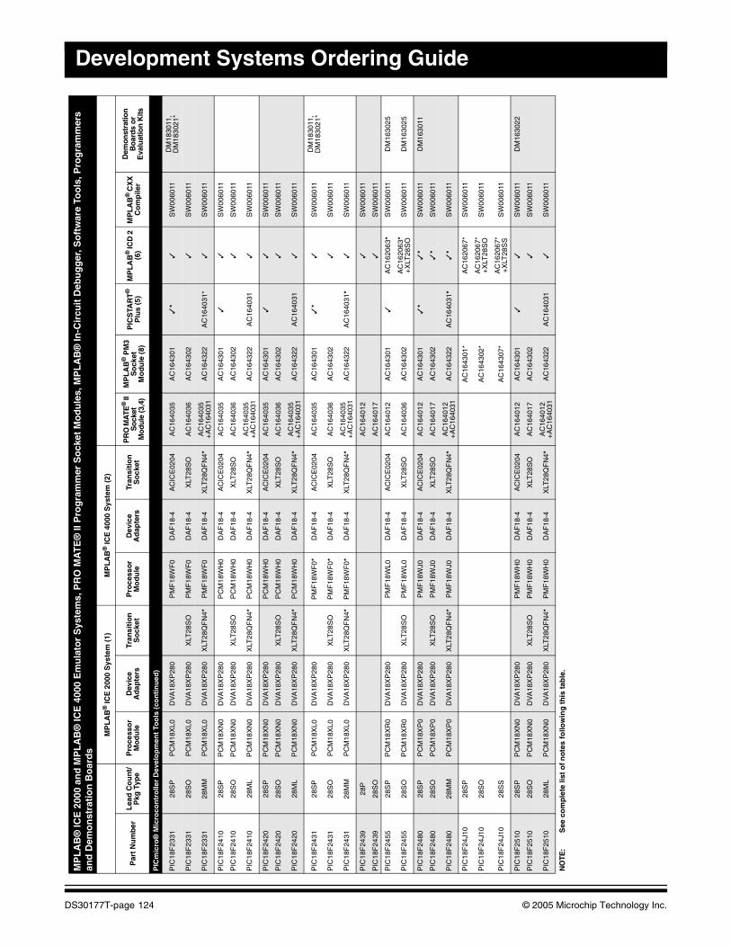
Development Systems Ordering Guide
PIC
mic
ro®
Mic
roco
ntr
olle
r D
evel
op
men
t To
ols
(co
nti
nu
ed)
PIC
18F
2331
28S
PP
CM
18X
L0D
VA
18X
P28
0P
MF
18W
F0
DA
F18
-4A
CIC
E02
04A
C16
4035
AC
1643
01✓
*✓
SW
0060
11D
M18
3011
, D
M18
3021
*
PIC
18F
2331
28S
OP
CM
18X
L0D
VA
18X
P28
0X
LT28
SO
PM
F18
WF
0D
AF
18-4
XLT
28S
OA
C16
4036
AC
1643
02✓
SW
0060
11
PIC
18F
2331
28M
MP
CM
18X
L0D
VA
18X
P28
0X
LT28
QF
N4*
PM
F18
WF
0D
AF
18-4
XLT
28Q
FN
4*A
C16
4035
+
AC
1640
31A
C16
4322
AC
1640
31*
✓S
W00
6011
PIC
18F
2410
28S
PP
CM
18X
N0
DV
A18
XP
280
PC
M18
WH
0D
AF
18-4
AC
ICE
0204
AC
1640
35A
C16
4301
✓✓
SW
0060
11
PIC
18F
2410
28S
OP
CM
18X
N0
DV
A18
XP
280
XLT
28S
OP
CM
18W
H0
DA
F18
-4X
LT28
SO
AC
1640
36A
C16
4302
✓S
W00
6011
PIC
18F
2410
28M
LP
CM
18X
N0
DV
A18
XP
280
XLT
28Q
FN
4*P
CM
18W
H0
DA
F18
-4X
LT28
QF
N4*
AC
1640
35
+A
C16
4031
AC
1643
22A
C16
4031
✓S
W00
6011
PIC
18F
2420
28S
PP
CM
18X
N0
DV
A18
XP
280
PC
M18
WH
0D
AF
18-4
AC
ICE
0204
AC
1640
35A
C16
4301
✓✓
SW
0060
11
PIC
18F
2420
28S
OP
CM
18X
N0
DV
A18
XP
280
XLT
28S
OP
CM
18W
H0
DA
F18
-4X
LT28
SO
AC
1640
36A
C16
4302
✓S
W00
6011
PIC
18F
2420
28M
LP
CM
18X
N0
DV
A18
XP
280
XLT
28Q
FN
4*P
CM
18W
H0
DA
F18
-4X
LT28
QF
N4*
AC
1640
35
+A
C16
4031
AC
1643
22A
C16
4031
✓S
W00
6011
PIC
18F
2431
28S
PP
CM
18X
L0D
VA
18X
P28
0P
MF
18W
F0*
DA
F18
-4A
CIC
E02
04A
C16
4035
AC
1643
01✓
*✓
SW
0060
11D
M18
3011
, D
M18
3021
*
PIC
18F
2431
28S
OP
CM
18X
L0D
VA
18X
P28
0X
LT28
SO
PM
F18
WF
0*D
AF
18-4
XLT
28S
OA
C16
4036
AC
1643
02✓
SW
0060
11
PIC
18F
2431
28M
MP
CM
18X
L0D
VA
18X
P28
0X
LT28
QF
N4*
PM
F18
WF
0*D
AF
18-4
XLT
28Q
FN
4*A
C16
4035
+
AC
1640
31A
C16
4322
AC
1640
31*
✓S
W00
6011
PIC
18F
2439
28P
AC
1640
12✓
SW
0060
11
PIC
18F
2439
28S
OA
C16
4017
✓S
W00
6011
PIC
18F
2455
28S
PP
CM
18X
R0
DV
A18
XP
280
PM
F18
WL0
DA
F18
-4A
CIC
E02
04A
C16
4012
AC
1643
01✓
AC
1620
63*
SW
0060
11D
M16
3025
PIC
18F
2455
28S
OP
CM
18X
R0
DV
A18
XP
280
XLT
28S
OP
MF
18W
L0D
AF
18-4
XLT
28S
OA
C16
4036
AC
1643
02A
C16
2063
*+
XLT
28S
OS
W00
6011
DM
1630
25
PIC
18F
2480
28S
PP
CM
18X
P0
DV
A18
XP
280
PM
F18
WJ0
DA
F18
-4A
CIC
E02
04A
C16
4012
AC
1643
01✓
*✓
*S
W00
6011
DM
1630
11
PIC
18F
2480
28S
OP
CM
18X
P0
DV
A18
XP
280
XLT
28S
OP
MF
18W
J0D
AF
18-4
XLT
28S
OA
C16
4017
AC
1643
02✓
*S
W00
6011
PIC
18F
2480
28M
MP
CM
18X
P0
DV
A18
XP
280
XLT
28Q
FN
4*P
MF
18W
J0D
AF
18-4
XLT
28Q
FN
4*A
C16
4012
+
AC
1640
31A
C16
4322
AC
1640
31*
✓*
SW
0060
11
PIC
18F
24J1
028
SP
AC
1643
01*
AC
1620
67*
SW
0060
11
PIC
18F
24J1
028
SO
AC
1643
02*
AC
1620
67*
+X
LT28
SO
SW
0060
11
PIC
18F
24J1
028
SS
AC
1643
07*
AC
1620
67*
+X
LT28
SS
SW
0060
11
PIC
18F
2510
28S
PP
CM
18X
N0
DV
A18
XP
280
PM
F18
WH
0D
AF
18-4
AC
ICE
0204
AC
1640
12A
C16
4301
✓✓
SW
0060
11D
M16
3022
PIC
18F
2510
28S
OP
CM
18X
N0
DV
A18
XP
280
XLT
28S
OP
MF
18W
H0
DA
F18
-4X
LT28
SO
AC
1640
17A
C16
4302
✓S
W00
6011
PIC
18F
2510
28M
LP
CM
18X
N0
DV
A18
XP
280
XLT
28Q
FN
4*P
MF
18W
H0
DA
F18
-4X
LT28
QF
N4*
AC
1640
12
+A
C16
4031
AC
1643
22A
C16
4031
✓S
W00
6011
MP
LA
B®
ICE
200
0 an
d M
PL
AB
® IC
E 4
000
Em
ula
tor
Sys
tem
s, P
RO
MA
TE
® II
Pro
gra
mm
er S
ock
et M
od
ule
s, M
PL
AB
® In
-Cir
cuit
Deb
ug
ger
, So
ftw
are
Too
ls, P
rog
ram
mer
s an
d D
emo
nst
rati
on
Bo
ard
s
MP
LA
B®
ICE
200
0 S
yste
m (
1)M
PL
AB
® IC
E 4
000
Sys
tem
(2)
Par
t N
um
ber
Lea
d C
ou
nt/
Pkg
Typ
eP
roce
sso
r M
od
ule
Dev
ice
Ad
apte
rsTr
ansi
tio
n
So
cket
Pro
cess
or
Mo
du
leD
evic
e A
dap
ters
Tran
siti
on
S
ock
etP
RO
MA
TE®
II
So
cket
M
odu
le (3
,4)
MP
LA
B®
PM
3S
ock
etM
od
ule
(8)
PIC
STA
RT
®
Plu
s (5
)M
PL
AB
® IC
D 2
(6
)M
PL
AB
® C
XX
C
om
pile
r
Dem
onst
ratio
n
Bo
ard
s o
r E
valu
atio
n K
its
NO
TE:
See
co
mp
lete
list
of
no
tes
follo
win
g t
his
tab
le.
DS30177T-page 124 © 2005 Microchip Technology Inc.
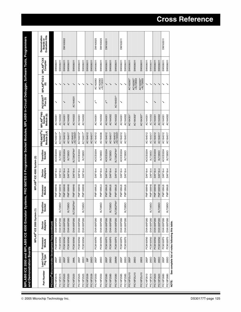
Cross Reference
PIC
mic
ro®
Mic
roco
ntr
olle
r D
evel
op
men
t To
ols
(co
nti
nu
ed)
PIC
18F
2515
28S
PP
CM
18X
N0
DV
A18
XP
280
PM
F18
WH
0D
AF
18-4
AC
ICE
0204
AC
1640
12*
AC
1643
01✓
✓S
W00
6011
PIC
18F
2515
28S
OP
CM
18X
N0
DV
A18
CP
280
XLT
28S
OP
MF
18W
H0
DA
F18
-4X
LT28
SO
AC
1640
17*
AC
1643
02✓
SW
0060
11
PIC
18F
2520
28S
PP
CM
18X
N0
DV
A18
XP
280
PM
F18
WH
0D
AF
18-4
AC
ICE
0204
AC
1640
12A
C16
4301
✓✓
SW
0060
11D
M16
3022
PIC
18F
2520
28S
OP
CM
18X
N0
DV
A18
XP
280
XLT
28S
OP
MF
18W
H0
DA
F18
-4X
LT28
SO
AC
1640
17A
C16
4302
✓S
W00
6011
PIC
18F
2520
28M
LP
CM
18X
N0
DV
A18
XP
280
XLT
28Q
FN
4*P
MF
18W
H0
DA
F18
-4X
LT28
QF
N4*
AC
1640
12
+A
C16
4031
AC
1643
22A
C16
4031
✓S
W00
6011
PIC
18F
2525
28S
PP
CM
18X
N0
DV
A18
XP
280
PM
F18
WH
0D
AF
18-4
AC
ICE
0204
AC
1640
12*
AC
1643
01✓
✓S
W00
6011
PIC
18F
2525
28S
OP
CM
18X
N0
DV
A18
XP
280
XLT
28S
OP
MF
18W
H0
DA
F18
-4X
LT28
SO
AC
1640
17*
AC
1643
02✓
SW
0060
11
PIC
18F
2539
28P
AC
1640
12✓
SW
0060
11
PIC
18F
2539
28S
OA
C16
4017
✓S
W00
6011
PIC
18F
2550
28S
PP
CM
18X
R0
DV
A18
XP
280
PM
F18
WL0
DA
F18
-4A
CIC
E02
04A
C16
4012
AC
1643
01✓
*A
C16
2063
SW
0060
11D
M16
3025
PIC
18F
2550
28S
OP
CM
18X
R0
DV
A18
XP
280
XLT
28S
OP
MF
18W
L0D
AF
18-4
XLT
28S
OA
C16
4036
AC
1643
02A
C16
2063
+X
LT28
SO
SW
0060
11D
M16
3025
PIC
18F
2580
28S
PP
CM
18X
P0
DV
A18
XP
280
PM
F18
WJ0
DA
F18
-4A
CIC
E02
04A
C16
4012
AC
1643
01✓
*✓
SW
0060
11D
M16
3011
PIC
18F
2580
28S
OP
CM
18X
P0
DV
A18
XP
280
XLT
28S
OP
MF
18W
J0D
AF
18-4
XLT
28S
OA
C16
4017
AC
1643
02✓
SW
0060
11
PIC
18F
2580
28M
MP
CM
18X
P0
DV
A18
XP
280
XLT
28Q
FN
4*P
MF
18W
J0D
AF
18-4
XLT
28Q
FN
4*A
C16
4012
+
AC
1640
31A
C16
4322
AC
1640
31*
✓S
W00
6011
PIC
18F
2585
28S
PP
CM
18X
P0
DV
A18
XP
280
PM
F18
WJ0
DA
F18
-4A
CIC
E02
04A
C16
4012
AC
1643
01✓
✓S
W00
6011
DM
1630
11
PIC
18F
2585
28S
OP
CM
18X
P0
DV
A18
XP
280
XLT
28S
OP
MF
18W
J0D
AF
18-4
XLT
28S
OA
C16
4017
AC
1643
02✓
SW
0060
11
PIC
18F
25J1
028
SP
AC
1643
01*
AC
1620
67*
SW
0060
11
PIC
18F
25J1
028
SO
AC
1643
02*
AC
1620
67*
+X
LT28
SO
SW
0060
11
PIC
18F
25J1
028
SS
AC
1643
07*
AC
1620
67*
+X
LT28
SS
SW
0060
11
PIC
18F
2610
28S
PP
CM
18X
N0
DV
A18
XP
280
PM
F18
WH
0D
AF
18-4
AC
ICE
0204
AC
1640
12A
C16
4301
✓✓
SW
0060
11
PIC
18F
2610
28S
OP
CM
18X
N0
DV
A18
XP
280
XLT
28S
OP
MF
18W
H0
DA
F18
-4X
LT28
SO
AC
1640
17A
C16
4302
✓S
W00
6011
PIC
18F
2620
28S
PP
CM
18X
N0
DV
A18
XP
280
PM
F18
WH
0D
AF
18-4
AC
ICE
0204
AC
1640
12A
C16
4301
✓✓
SW
0060
11
PIC
18F
2620
28S
OP
CM
18X
N0
DV
A18
XP
280
XLT
28S
OP
MF
18W
H0
DA
F18
-4X
LT28
SO
AC
1640
17A
C16
4302
✓S
W00
6011
PIC
18F
2680
28S
PP
CM
18X
P0
DV
A18
XP
280
PM
F18
WJ0
DA
F18
-4A
CIC
E02
04A
C16
4012
AC
1643
01✓
✓S
W00
6011
DM
1630
11
PIC
18F
2680
28S
OP
CM
18X
P0
DV
A18
XP
280
XLT
28S
OP
MF
18W
J0D
AF
18-4
XLT
28S
OA
C16
4017
AC
1643
02✓
SW
0060
11
MP
LA
B®
ICE
200
0 an
d M
PL
AB
® IC
E 4
000
Em
ula
tor
Sys
tem
s, P
RO
MA
TE
® II
Pro
gra
mm
er S
ock
et M
od
ule
s, M
PL
AB
® In
-Cir
cuit
Deb
ug
ger
, So
ftw
are
Too
ls, P
rog
ram
mer
s an
d D
emo
nst
rati
on
Bo
ard
s
MP
LA
B®
ICE
200
0 S
yste
m (
1)M
PL
AB
® IC
E 4
000
Sys
tem
(2)
Par
t N
um
ber
Lea
d C
ou
nt/
Pkg
Typ
eP
roce
sso
r M
od
ule
Dev
ice
Ad
apte
rsTr
ansi
tio
n
So
cket
Pro
cess
or
Mo
du
leD
evic
e A
dap
ters
Tran
siti
on
S
ock
etP
RO
MA
TE®
II
Soc
ket
Mo
dule
(3,4
)
MP
LA
B®
PM
3S
ock
etM
od
ule
(8)
PIC
STA
RT
®
Plu
s (5
)M
PL
AB
® IC
D 2
(6
)M
PL
AB
® C
XX
C
om
pile
r
Dem
onst
ratio
n
Boa
rds
or
Eva
luat
ion
Kits
NO
TE:
See
co
mp
lete
list
of
no
tes
follo
win
g t
his
tab
le.
© 2005 Microchip Technology Inc. DS30177T-page 125
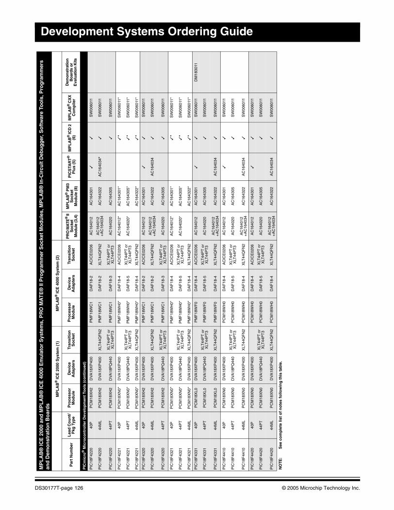
Development Systems Ordering Guide
PIC
mic
ro®
Mic
roco
ntr
olle
r D
evel
op
men
t To
ols
(co
nti
nu
ed)
PIC
18F
4220
40P
PC
M18
XH
2D
VA
18X
P40
0P
MF
18W
C1
DA
F18
-2A
CIC
E02
06A
C16
4012
AC
1643
01✓
✓S
W00
6011
PIC
18F
4220
44M
LP
CM
18X
H2
DV
A18
XP
400
XLT
44Q
FN
2P
MF
18W
C1
DA
F18
-2X
LT44
QF
N2
AC
1640
12+
AC
1640
34A
C16
4322
AC
1640
34*
✓S
W00
6011
PIC
18F
4220
44P
TP
CM
18X
H2
DV
A18
PQ
440
XLT
44P
T o
r X
LT44
PT
3P
MF
18W
C1
DA
F18
-3X
LT44
PT
or
XLT
44P
T3
AC
1640
20A
C16
4305
✓S
W00
6011
PIC
18F
4221
40P
PC
M18
XN
0*D
VA
18X
P40
0P
MF
18W
H0*
DA
F18
-4A
CIC
E02
06A
C16
4012
*A
C16
4301
*✓
*S
W00
6011
*
PIC
18F
4221
44P
TP
CM
18X
N0*
DV
A18
PQ
440
XLT
44P
T o
r X
LT44
PT
3P
MF
18W
H0*
DA
F18
-5X
LT44
PT
or
XLT
44P
T3
AC
1640
20*
AC
1643
05*
✓*
SW
0060
11*
PIC
18F
4221
44M
LP
CM
18X
N0*
DV
A18
XP
400
XLT
44Q
FN
2P
MF
18W
H0*
DA
F18
-4X
LT44
QF
N2
AC
1643
22*
✓*
SW
0060
11*
PIC
18F
4320
40P
PC
M18
XH
2D
VA
18X
P40
0P
MF
18W
C1
DA
F18
-2A
CIC
E02
06A
C16
4012
AC
1643
01✓
✓S
W00
6011
PIC
18F
4320
44M
LP
CM
18X
H2
DV
A18
XP
400
XLT
44Q
FN
2P
MF
18W
C1
DA
F18
-2X
LT44
QF
N2
AC
1640
12+
AC
1640
34A
C16
4322
AC
1640
34✓
SW
0060
11
PIC
18F
4320
44P
TP
CM
18X
H2
DV
A18
PQ
440
XLT
44P
T o
r X
LT44
PT
3P
MF
18W
C1
DA
F18
-3X
LT44
PT
or
XLT
44P
T3
AC
1640
20A
C16
4305
✓S
W00
6011
PIC
18F
4321
40P
PC
M18
XN
0*D
VA
18X
P40
0P
MF
18W
H0*
DA
F18
-4A
CIC
E02
06A
C16
4012
*A
C16
4301
*✓
*S
W00
6011
*
PIC
18F
4321
44P
TP
CM
18X
N0*
DV
A18
PQ
440
XLT
44P
T o
r X
LT44
PT
3P
MF
18W
H0*
DA
F18
-5X
LT44
PT
or
XLT
44P
T3
AC
1640
20*
AC
1643
05*
✓*
SW
0060
11*
PIC
18F
4321
44M
LP
CM
18X
N0*
DV
A18
XP
400
XLT
44Q
FN
2P
MF
18W
H0*
DA
F18
-4X
LT44
QF
N2
AC
1643
22*
✓*
SW
0060
11*
PIC
18F
4331
40P
PC
M18
XL0
DV
A18
XP
400
PM
F18
WF
0D
AF
18-4
AC
ICE
0206
AC
1640
12A
C16
4301
✓✓
SW
0060
11D
M18
3011
PIC
18F
4331
44P
TP
CM
18X
L0D
VA
18P
Q44
0X
LT44
PT
or
XLT
44P
T3
PM
F18
WF
0D
AF
18-5
XLT
44P
T o
r X
LT44
PT
3A
C16
4020
AC
1643
05✓
SW
0060
11
PIC
18F
4331
44M
LP
CM
18X
L0D
VA
18X
P40
0X
LT44
QF
N2
PM
F18
WF
0D
AF
18-4
XLT
44Q
FN
2A
C16
4012
+A
C16
4034
AC
1643
22A
C16
4034
✓S
W00
6011
PIC
18F
4410
40P
PC
M18
XN
0D
VA
18X
P40
0P
CM
18W
H0
DA
F18
-4A
CIC
E02
06A
C16
4012
AC
1643
01✓
✓S
W00
6011
PIC
18F
4410
44P
TP
CM
18X
N0
DV
A18
PQ
440
XLT
44P
T o
r X
LT44
PT
3P
CM
18W
H0
DA
F18
-5X
LT44
PT
or
XLT
44P
T3
AC
1640
20A
C16
4305
✓S
W00
6011
PIC
18F
4410
44M
LP
CM
18X
N0
DV
A18
XP
400
XLT
44Q
FN
2P
CM
18W
H0
DA
F18
-4X
LT44
QF
N2
AC
1640
12
+A
C16
4034
AC
1643
22A
C16
4034
✓S
W00
6011
PIC
18F
4420
40P
PC
M18
XN
0D
VA
18X
P40
0P
CM
18W
H0
DA
F18
-4A
CIC
E02
06A
C16
4012
AC
1643
01✓
✓S
W00
6011
PIC
18F
4420
44P
TP
CM
18X
N0
DV
A18
PQ
440
XLT
44P
T o
r X
LT44
PT
3P
CM
18W
H0
DA
F18
-5X
LT44
PT
or
XLT
44P
T3
AC
1640
20A
C16
4305
✓S
W00
6011
PIC
18F
4420
44M
LP
CM
18X
N0
DV
A18
XP
400
XLT
44Q
FN
2P
CM
18W
H0
DA
F18
-4X
LT44
QF
N2
AC
1640
12
+A
C16
4034
AC
1643
22A
C16
4034
✓S
W00
6011
MP
LA
B®
ICE
200
0 an
d M
PL
AB
® IC
E 4
000
Em
ula
tor
Sys
tem
s, P
RO
MA
TE
® II
Pro
gra
mm
er S
ock
et M
od
ule
s, M
PL
AB
® In
-Cir
cuit
Deb
ug
ger
, So
ftw
are
Too
ls, P
rog
ram
mer
s an
d D
emo
nst
rati
on
Bo
ard
s
MP
LA
B®
ICE
200
0 S
yste
m (
1)M
PL
AB
® IC
E 4
000
Sys
tem
(2)
Par
t N
um
ber
Lea
d C
ou
nt/
Pkg
Typ
eP
roce
sso
r M
od
ule
Dev
ice
Ad
apte
rsTr
ansi
tio
n
So
cket
Pro
cess
or
Mo
du
leD
evic
e A
dap
ters
Tran
siti
on
S
ock
etP
RO
MA
TE®
II
So
cket
M
odu
le (3
,4)
MP
LA
B®
PM
3S
ock
etM
od
ule
(8)
PIC
STA
RT
®
Plu
s (5
)M
PL
AB
® IC
D 2
(6
)M
PL
AB
® C
XX
C
om
pile
r
Dem
onst
ratio
n
Bo
ard
s o
r E
valu
atio
n K
its
NO
TE:
See
co
mp
lete
list
of
no
tes
follo
win
g t
his
tab
le.
DS30177T-page 126 © 2005 Microchip Technology Inc.
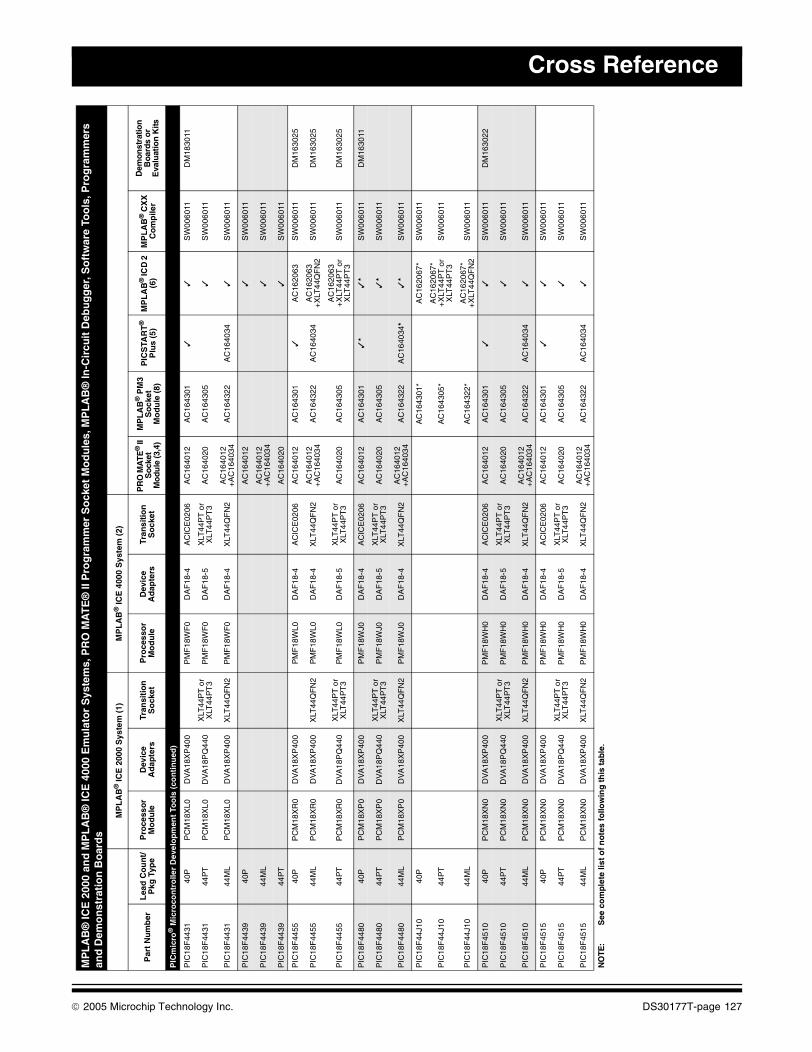
Cross Reference
PIC
mic
ro®
Mic
roco
ntr
olle
r D
evel
op
men
t To
ols
(co
nti
nu
ed)
PIC
18F
4431
40P
PC
M18
XL0
DV
A18
XP
400
PM
F18
WF
0D
AF
18-4
AC
ICE
0206
AC
1640
12A
C16
4301
✓✓
SW
0060
11D
M18
3011
PIC
18F
4431
44P
TP
CM
18X
L0D
VA
18P
Q44
0X
LT44
PT
or
XLT
44P
T3
PM
F18
WF
0D
AF
18-5
XLT
44P
T o
r X
LT44
PT
3A
C16
4020
AC
1643
05✓
SW
0060
11
PIC
18F
4431
44M
LP
CM
18X
L0D
VA
18X
P40
0X
LT44
QF
N2
PM
F18
WF
0D
AF
18-4
XLT
44Q
FN
2A
C16
4012
+A
C16
4034
AC
1643
22A
C16
4034
✓S
W00
6011
PIC
18F
4439
40P
AC
1640
12✓
SW
0060
11
PIC
18F
4439
44M
LA
C16
4012
+A
C16
4034
✓S
W00
6011
PIC
18F
4439
44P
TA
C16
4020
✓S
W00
6011
PIC
18F
4455
40P
PC
M18
XR
0D
VA
18X
P40
0P
MF
18W
L0D
AF
18-4
AC
ICE
0206
AC
1640
12A
C16
4301
✓A
C16
2063
SW
0060
11D
M16
3025
PIC
18F
4455
44M
LP
CM
18X
R0
DV
A18
XP
400
XLT
44Q
FN
2P
MF
18W
L0D
AF
18-4
XLT
44Q
FN
2A
C16
4012
+
AC
1640
34A
C16
4322
AC
1640
34A
C16
2063
+X
LT44
QF
N2
SW
0060
11D
M16
3025
PIC
18F
4455
44P
TP
CM
18X
R0
DV
A18
PQ
440
XLT
44P
T o
r X
LT44
PT
3P
MF
18W
L0D
AF
18-5
XLT
44P
T o
r X
LT44
PT
3A
C16
4020
AC
1643
05A
C16
2063
+X
LT44
PT
or
XLT
44P
T3
SW
0060
11D
M16
3025
PIC
18F
4480
40P
PC
M18
XP
0D
VA
18X
P40
0P
MF
18W
J0D
AF
18-4
AC
ICE
0206
AC
1640
12A
C16
4301
✓*
✓*
SW
0060
11D
M16
3011
PIC
18F
4480
44P
TP
CM
18X
P0
DV
A18
PQ
440
XLT
44P
T o
r X
LT44
PT
3P
MF
18W
J0D
AF
18-5
XLT
44P
T o
r X
LT44
PT
3A
C16
4020
AC
1643
05✓
*S
W00
6011
PIC
18F
4480
44M
LP
CM
18X
P0
DV
A18
XP
400
XLT
44Q
FN
2P
MF
18W
J0D
AF
18-4
XLT
44Q
FN
2A
C16
4012
+
AC
1640
34A
C16
4322
AC
1640
34*
✓*
SW
0060
11
PIC
18F
44J1
040
PA
C16
4301
*A
C16
2067
*S
W00
6011
PIC
18F
44J1
044
PT
AC
1643
05*
AC
1620
67*
+X
LT44
PT
or
XLT
44P
T3
SW
0060
11
PIC
18F
44J1
044
ML
AC
1643
22*
AC
1620
67*
+X
LT44
QF
N2
SW
0060
11
PIC
18F
4510
40P
PC
M18
XN
0D
VA
18X
P40
0P
MF
18W
H0
DA
F18
-4A
CIC
E02
06A
C16
4012
AC
1643
01✓
✓S
W00
6011
DM
1630
22
PIC
18F
4510
44P
TP
CM
18X
N0
DV
A18
PQ
440
XLT
44P
T o
r X
LT44
PT
3P
MF
18W
H0
DA
F18
-5X
LT44
PT
or
XLT
44P
T3
AC
1640
20A
C16
4305
✓S
W00
6011
PIC
18F
4510
44M
LP
CM
18X
N0
DV
A18
XP
400
XLT
44Q
FN
2P
MF
18W
H0
DA
F18
-4X
LT44
QF
N2
AC
1640
12
+A
C16
4034
AC
1643
22A
C16
4034
✓S
W00
6011
PIC
18F
4515
40P
PC
M18
XN
0D
VA
18X
P40
0P
MF
18W
H0
DA
F18
-4A
CIC
E02
06A
C16
4012
AC
1643
01✓
✓S
W00
6011
PIC
18F
4515
44P
TP
CM
18X
N0
DV
A18
PQ
440
XLT
44P
T o
r X
LT44
PT
3P
MF
18W
H0
DA
F18
-5X
LT44
PT
or
XLT
44P
T3
AC
1640
20A
C16
4305
✓S
W00
6011
PIC
18F
4515
44M
LP
CM
18X
N0
DV
A18
XP
400
XLT
44Q
FN
2P
MF
18W
H0
DA
F18
-4X
LT44
QF
N2
AC
1640
12+
AC
1640
34A
C16
4322
AC
1640
34✓
SW
0060
11
MP
LA
B®
ICE
200
0 an
d M
PL
AB
® IC
E 4
000
Em
ula
tor
Sys
tem
s, P
RO
MA
TE
® II
Pro
gra
mm
er S
ock
et M
od
ule
s, M
PL
AB
® In
-Cir
cuit
Deb
ug
ger
, So
ftw
are
Too
ls, P
rog
ram
mer
s an
d D
emo
nst
rati
on
Bo
ard
s
MP
LA
B®
ICE
200
0 S
yste
m (
1)M
PL
AB
® IC
E 4
000
Sys
tem
(2)
Par
t N
um
ber
Lea
d C
ou
nt/
Pkg
Typ
eP
roce
sso
r M
od
ule
Dev
ice
Ad
apte
rsTr
ansi
tio
n
So
cket
Pro
cess
or
Mo
du
leD
evic
e A
dap
ters
Tran
siti
on
S
ock
etP
RO
MA
TE®
II
Soc
ket
Mo
dule
(3,4
)
MP
LA
B®
PM
3S
ock
etM
od
ule
(8)
PIC
STA
RT
®
Plu
s (5
)M
PL
AB
® IC
D 2
(6
)M
PL
AB
® C
XX
C
om
pile
r
Dem
onst
ratio
n
Boa
rds
or
Eva
luat
ion
Kits
NO
TE:
See
co
mp
lete
list
of
no
tes
follo
win
g t
his
tab
le.
© 2005 Microchip Technology Inc. DS30177T-page 127
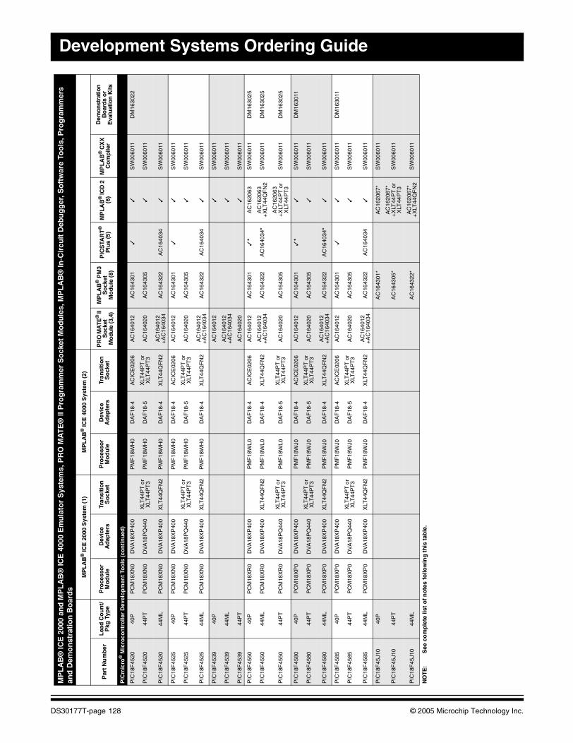
Development Systems Ordering Guide
PIC
mic
ro®
Mic
roco
ntr
olle
r D
evel
op
men
t To
ols
(co
nti
nu
ed)
PIC
18F
4520
40P
PC
M18
XN
0D
VA
18X
P40
0P
MF
18W
H0
DA
F18
-4A
CIC
E02
06A
C16
4012
AC
1643
01✓
✓S
W00
6011
DM
1630
22
PIC
18F
4520
44P
TP
CM
18X
N0
DV
A18
PQ
440
XLT
44P
T o
r X
LT44
PT
3P
MF
18W
H0
DA
F18
-5X
LT44
PT
or
XLT
44P
T3
AC
1640
20A
C16
4305
✓S
W00
6011
PIC
18F
4520
44M
LP
CM
18X
N0
DV
A18
XP
400
XLT
44Q
FN
2P
MF
18W
H0
DA
F18
-4X
LT44
QF
N2
AC
1640
12
+A
C16
4034
AC
1643
22A
C16
4034
✓S
W00
6011
PIC
18F
4525
40P
PC
M18
XN
0D
VA
18X
P40
0P
MF
18W
H0
DA
F18
-4A
CIC
E02
06A
C16
4012
AC
1643
01✓
✓S
W00
6011
PIC
18F
4525
44P
TP
CM
18X
N0
DV
A18
PQ
440
XLT
44P
T o
r X
LT44
PT
3P
MF
18W
H0
DA
F18
-5X
LT44
PT
or
XLT
44P
T3
AC
1640
20A
C16
4305
✓S
W00
6011
PIC
18F
4525
44M
LP
CM
18X
N0
DV
A18
XP
400
XLT
44Q
FN
2P
MF
18W
H0
DA
F18
-4X
LT44
QF
N2
AC
1640
12+
AC
1640
34A
C16
4322
AC
1640
34✓
SW
0060
11
PIC
18F
4539
40P
AC
1640
12✓
SW
0060
11
PIC
18F
4539
44M
LA
C16
4012
+A
C16
4034
✓S
W00
6011
PIC
18F
4539
44P
TA
C16
4020
✓S
W00
6011
PIC
18F
4550
40P
PC
M18
XR
0D
VA
18X
P40
0P
MF
18W
L0D
AF
18-4
AC
ICE
0206
AC
1640
12A
C16
4301
✓*
AC
1620
63S
W00
6011
DM
1630
25
PIC
18F
4550
44M
LP
CM
18X
R0
DV
A18
XP
400
XLT
44Q
FN
2P
MF
18W
L0D
AF
18-4
XLT
44Q
FN
2A
C16
4012
+
AC
1640
34A
C16
4322
AC
1640
34*
AC
1620
63+
XLT
44Q
FN
2S
W00
6011
DM
1630
25
PIC
18F
4550
44P
TP
CM
18X
R0
DV
A18
PQ
440
XLT
44P
T o
r X
LT44
PT
3P
MF
18W
L0D
AF
18-5
XLT
44P
T o
r X
LT44
PT
3A
C16
4020
AC
1643
05A
C16
2063
+X
LT44
PT
or
XLT
44P
T3
SW
0060
11D
M16
3025
PIC
18F
4580
40P
PC
M18
XP
0D
VA
18X
P40
0P
MF
18W
J0D
AF
18-4
AC
ICE
0206
AC
1640
12A
C16
4301
✓*
✓S
W00
6011
DM
1630
11
PIC
18F
4580
44P
TP
CM
18X
P0
DV
A18
PQ
440
XLT
44P
T o
r X
LT44
PT
3P
MF
18W
J0D
AF
18-5
XLT
44P
T o
r X
LT44
PT
3A
C16
4020
AC
1643
05✓
SW
0060
11
PIC
18F
4580
44M
LP
CM
18X
P0
DV
A18
XP
400
XLT
44Q
FN
2P
MF
18W
J0D
AF
18-4
XLT
44Q
FN
2A
C16
4012
+
AC
1640
34A
C16
4322
AC
1640
34*
✓S
W00
6011
PIC
18F
4585
40P
PC
M18
XP
0D
VA
18X
P40
0P
MF
18W
J0D
AF
18-4
AC
ICE
0206
AC
1640
12A
C16
4301
✓✓
SW
0060
11D
M16
3011
PIC
18F
4585
44P
TP
CM
18X
P0
DV
A18
PQ
440
XLT
44P
T o
r X
LT44
PT
3P
MF
18W
J0D
AF
18-5
XLT
44P
T o
r X
LT44
PT
3A
C16
4020
AC
1643
05✓
SW
0060
11
PIC
18F
4585
44M
LP
CM
18X
P0
DV
A18
XP
400
XLT
44Q
FN
2P
MF
18W
J0D
AF
18-4
XLT
44Q
FN
2A
C16
4012
+A
C16
4034
AC
1643
22A
C16
4034
✓S
W00
6011
PIC
18F
45J1
040
PA
C16
4301
*A
C16
2067
*S
W00
6011
PIC
18F
45J1
044
PT
AC
1643
05*
AC
1620
67*
+X
LT44
PT
or
XLT
44P
T3
SW
0060
11
PIC
18F
45J1
044
ML
AC
1643
22*
AC
1620
67*
+X
LT44
QF
N2
SW
0060
11
MP
LA
B®
ICE
200
0 an
d M
PL
AB
® IC
E 4
000
Em
ula
tor
Sys
tem
s, P
RO
MA
TE
® II
Pro
gra
mm
er S
ock
et M
od
ule
s, M
PL
AB
® In
-Cir
cuit
Deb
ug
ger
, So
ftw
are
Too
ls, P
rog
ram
mer
s an
d D
emo
nst
rati
on
Bo
ard
s
MP
LA
B®
ICE
200
0 S
yste
m (
1)M
PL
AB
® IC
E 4
000
Sys
tem
(2)
Par
t N
um
ber
Lea
d C
ou
nt/
Pkg
Typ
eP
roce
sso
r M
od
ule
Dev
ice
Ad
apte
rsTr
ansi
tio
n
So
cket
Pro
cess
or
Mo
du
leD
evic
e A
dap
ters
Tran
siti
on
S
ock
etP
RO
MA
TE®
II
So
cket
M
odu
le (3
,4)
MP
LA
B®
PM
3S
ock
etM
od
ule
(8)
PIC
STA
RT
®
Plu
s (5
)M
PL
AB
® IC
D 2
(6
)M
PL
AB
® C
XX
C
om
pile
r
Dem
onst
ratio
n
Bo
ard
s o
r E
valu
atio
n K
its
NO
TE:
See
co
mp
lete
list
of
no
tes
follo
win
g t
his
tab
le.
DS30177T-page 128 © 2005 Microchip Technology Inc.
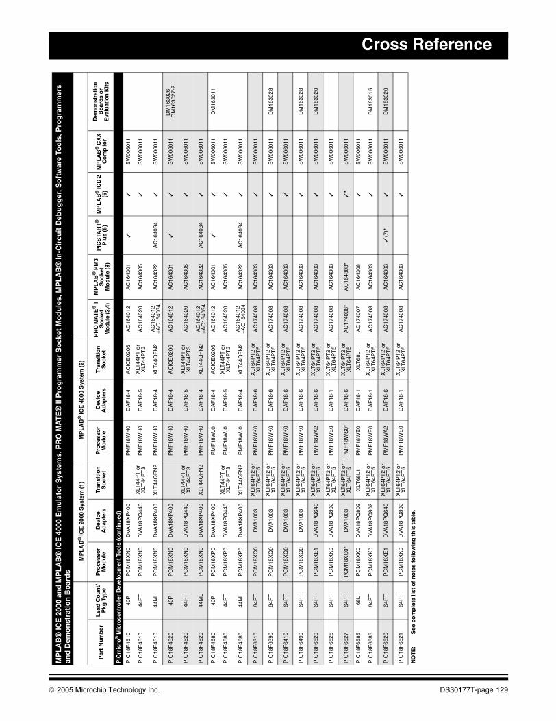
Cross Reference
PIC
mic
ro®
Mic
roco
ntr
olle
r D
evel
op
men
t To
ols
(co
nti
nu
ed)
PIC
18F
4610
40P
PC
M18
XN
0D
VA
18X
P40
0P
MF
18W
H0
DA
F18
-4A
CIC
E02
06A
C16
4012
AC
1643
01✓
✓S
W00
6011
PIC
18F
4610
44P
TP
CM
18X
N0
DV
A18
PQ
440
XLT
44P
T o
r X
LT44
PT
3P
MF
18W
H0
DA
F18
-5X
LT44
PT
or
XLT
44P
T3
AC
1640
20A
C16
4305
✓S
W00
6011
PIC
18F
4610
44M
LP
CM
18X
N0
DV
A18
XP
400
XLT
44Q
FN
2P
MF
18W
H0
DA
F18
-4X
LT44
QF
N2
AC
1640
12+
AC
1640
34A
C16
4322
AC
1640
34✓
SW
0060
11
PIC
18F
4620
40P
PC
M18
XN
0D
VA
18X
P40
0P
MF
18W
H0
DA
F18
-4A
CIC
E02
06A
C16
4012
AC
1643
01✓
✓S
W00
6011
DM
1630
26,
DM
1630
27-2
PIC
18F
4620
44P
TP
CM
18X
N0
DV
A18
PQ
440
XLT
44P
T o
r X
LT44
PT
3P
MF
18W
H0
DA
F18
-5X
LT44
PT
or
XLT
44P
T3
AC
1640
20A
C16
4305
✓S
W00
6011
PIC
18F
4620
44M
LP
CM
18X
N0
DV
A18
XP
400
XLT
44Q
FN
2P
MF
18W
H0
DA
F18
-4X
LT44
QF
N2
AC
1640
12+
AC
1640
34A
C16
4322
AC
1640
34✓
SW
0060
11
PIC
18F
4680
40P
PC
M18
XP
0D
VA
18X
P40
0P
MF
18W
J0D
AF
18-4
AC
ICE
0206
AC
1640
12A
C16
4301
✓✓
SW
0060
11D
M16
3011
PIC
18F
4680
44P
TP
CM
18X
P0
DV
A18
PQ
440
XLT
44P
T o
r X
LT44
PT
3P
MF
18W
J0D
AF
18-5
XLT
44P
T o
r X
LT44
PT
3A
C16
4020
AC
1643
05✓
SW
0060
11
PIC
18F
4680
44M
LP
CM
18X
P0
DV
A18
XP
400
XLT
44Q
FN
2P
MF
18W
J0D
AF
18-4
XLT
44Q
FN
2A
C16
4012
+A
C16
4034
AC
1643
22A
C16
4034
✓S
W00
6011
PIC
18F
6310
64P
TP
CM
18X
Q0
DV
A10
03X
LT64
PT
2 or
X
LT64
PT
5P
MF
18W
K0
DA
F18
-6X
LT64
PT
2 or
X
LT64
PT
5A
C17
4008
AC
1643
03✓
SW
0060
11
PIC
18F
6390
64P
TP
CM
18X
Q0
DV
A10
03X
LT64
PT
2 or
X
LT64
PT
5P
MF
18W
K0
DA
F18
-6X
LT64
PT
2 or
X
LT64
PT
5A
C17
4008
AC
1643
03✓
SW
0060
11D
M16
3028
PIC
18F
6410
64P
TP
CM
18X
Q0
DV
A10
03X
LT64
PT
2 or
X
LT64
PT
5P
MF
18W
K0
DA
F18
-6X
LT64
PT
2 or
X
LT64
PT
5A
C17
4008
AC
1643
03✓
SW
0060
11
PIC
18F
6490
64P
TP
CM
18X
Q0
DV
A10
03X
LT64
PT
2 or
X
LT64
PT
5P
MF
18W
K0
DA
F18
-6X
LT64
PT
2 or
X
LT64
PT
5A
C17
4008
AC
1643
03✓
SW
0060
11D
M16
3028
PIC
18F
6520
64P
TP
CM
18X
E1
DV
A18
PQ
640
XLT
64P
T2
or
XLT
64P
T5
PM
F18
WA
2D
AF
18-6
XLT
64P
T2
or
XLT
64P
T5
AC
1740
08A
C16
4303
✓S
W00
6011
DM
1830
20
PIC
18F
6525
64P
TP
CM
18X
K0
DV
A18
PQ
802
XLT
64P
T2
or
XLT
64P
T5
PM
F18
WE
0D
AF
18-1
XLT
64P
T2
or
XLT
64P
T5
AC
1740
08A
C16
4303
✓S
W00
6011
PIC
18F
6527
64P
TP
CM
18X
S0*
DV
A10
03X
LT64
PT
2 or
X
LT64
PT
5P
MF
18W
S0*
DA
F18
-6X
LT64
PT
2 or
X
LT64
PT
5A
C17
4008
*A
C16
4303
*✓
*S
W00
6011
PIC
18F
6585
68L
PC
M18
XK
0D
VA
18P
Q80
2X
LT68
L1P
MF
18W
E0
DA
F18
-1X
LT68
L1A
C17
4007
AC
1643
08✓
SW
0060
11
PIC
18F
6585
64P
TP
CM
18X
K0
DV
A18
PQ
802
XLT
64P
T2
or
XLT
64P
T5
PM
F18
WE
0D
AF
18-1
XLT
64P
T2
or
XLT
64P
T5
AC
1740
08A
C16
4303
✓S
W00
6011
DM
1630
15
PIC
18F
6620
64P
TP
CM
18X
E1
DV
A18
PQ
640
XLT
64P
T2
or
XLT
64P
T5
PM
F18
WA
2D
AF
18-6
XLT
64P
T2
or
XLT
64P
T5
AC
1740
08A
C16
4303
✓(7
)*✓
SW
0060
11D
M18
3020
PIC
18F
6621
64P
TP
CM
18X
K0
DV
A18
PQ
802
XLT
64P
T2
or
XLT
64P
T5
PM
F18
WE
0D
AF
18-1
XLT
64P
T2
or
XLT
64P
T5
AC
1740
08A
C16
4303
✓S
W00
6011
MP
LA
B®
ICE
200
0 an
d M
PL
AB
® IC
E 4
000
Em
ula
tor
Sys
tem
s, P
RO
MA
TE
® II
Pro
gra
mm
er S
ock
et M
od
ule
s, M
PL
AB
® In
-Cir
cuit
Deb
ug
ger
, So
ftw
are
Too
ls, P
rog
ram
mer
s an
d D
emo
nst
rati
on
Bo
ard
s
MP
LA
B®
ICE
200
0 S
yste
m (
1)M
PL
AB
® IC
E 4
000
Sys
tem
(2)
Par
t N
um
ber
Lea
d C
ou
nt/
Pkg
Typ
eP
roce
sso
r M
od
ule
Dev
ice
Ad
apte
rsTr
ansi
tio
n
So
cket
Pro
cess
or
Mo
du
leD
evic
e A
dap
ters
Tran
siti
on
S
ock
etP
RO
MA
TE®
II
Soc
ket
Mo
dule
(3,4
)
MP
LA
B®
PM
3S
ock
etM
od
ule
(8)
PIC
STA
RT
®
Plu
s (5
)M
PL
AB
® IC
D 2
(6
)M
PL
AB
® C
XX
C
om
pile
r
Dem
onst
ratio
n
Boa
rds
or
Eva
luat
ion
Kits
NO
TE:
See
co
mp
lete
list
of
no
tes
follo
win
g t
his
tab
le.
© 2005 Microchip Technology Inc. DS30177T-page 129
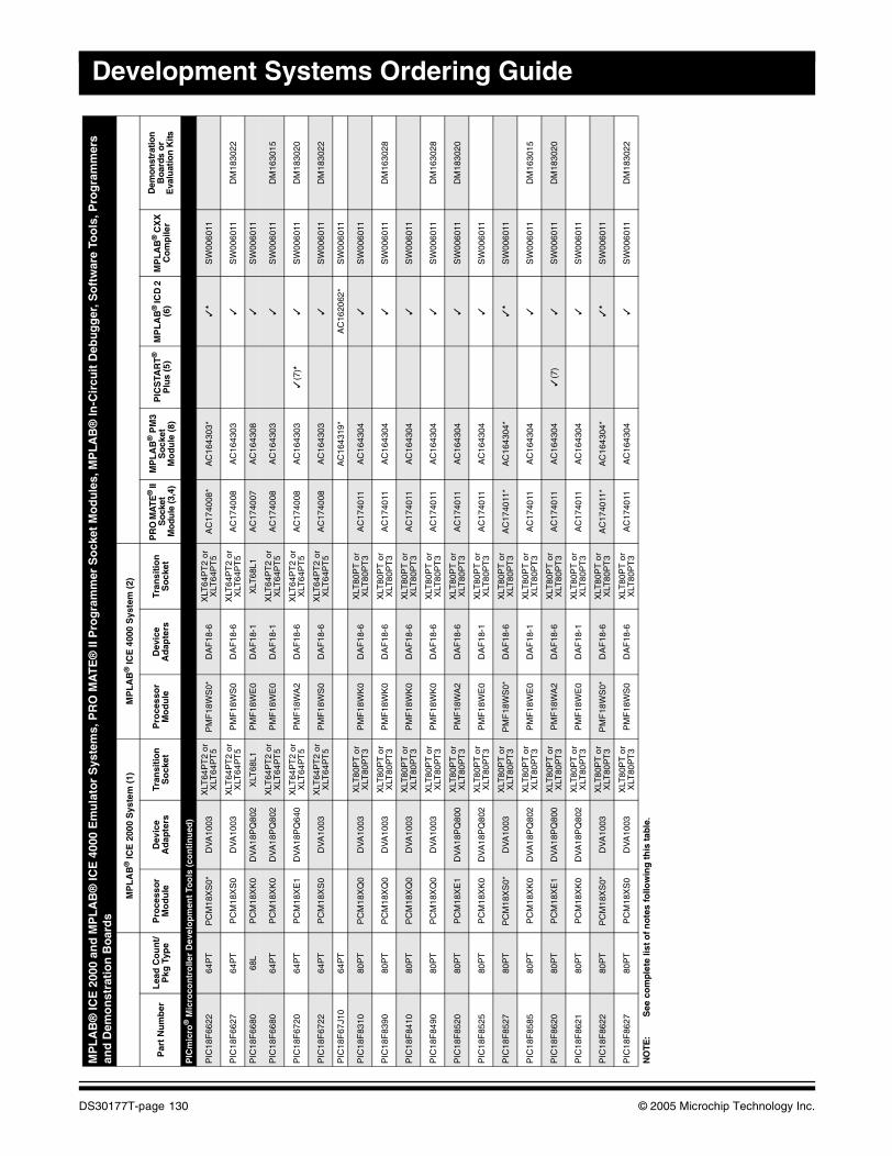
Development Systems Ordering Guide
PIC
mic
ro®
Mic
roco
ntr
olle
r D
evel
op
men
t To
ols
(co
nti
nu
ed)
PIC
18F
6622
64P
TP
CM
18X
S0*
DV
A10
03X
LT64
PT
2 or
X
LT64
PT
5P
MF
18W
S0*
DA
F18
-6X
LT64
PT
2 or
X
LT64
PT
5A
C17
4008
*A
C16
4303
*✓
*S
W00
6011
PIC
18F
6627
64P
TP
CM
18X
S0
DV
A10
03X
LT64
PT
2 or
X
LT64
PT
5P
MF
18W
S0
DA
F18
-6X
LT64
PT
2 or
X
LT64
PT
5A
C17
4008
AC
1643
03✓
SW
0060
11D
M18
3022
PIC
18F
6680
68L
PC
M18
XK
0D
VA
18P
Q80
2X
LT68
L1P
MF
18W
E0
DA
F18
-1X
LT68
L1A
C17
4007
AC
1643
08✓
SW
0060
11
PIC
18F
6680
64P
TP
CM
18X
K0
DV
A18
PQ
802
XLT
64P
T2
or
XLT
64P
T5
PM
F18
WE
0D
AF
18-1
XLT
64P
T2
or
XLT
64P
T5
AC
1740
08A
C16
4303
✓S
W00
6011
DM
1630
15
PIC
18F
6720
64P
TP
CM
18X
E1
DV
A18
PQ
640
XLT
64P
T2
or
XLT
64P
T5
PM
F18
WA
2D
AF
18-6
XLT
64P
T2
or
XLT
64P
T5
AC
1740
08A
C16
4303
✓(7
)*✓
SW
0060
11D
M18
3020
PIC
18F
6722
64P
TP
CM
18X
S0
DV
A10
03X
LT64
PT
2 or
X
LT64
PT
5P
MF
18W
S0
DA
F18
-6X
LT64
PT
2 or
X
LT64
PT
5A
C17
4008
AC
1643
03✓
SW
0060
11D
M18
3022
PIC
18F
67J1
064
PT
AC
1643
19*
AC
1620
62*
SW
0060
11
PIC
18F
8310
80P
TP
CM
18X
Q0
DV
A10
03X
LT80
PT
or
XLT
80P
T3
PM
F18
WK
0D
AF
18-6
XLT
80P
T o
r X
LT80
PT
3A
C17
4011
AC
1643
04✓
SW
0060
11
PIC
18F
8390
80P
TP
CM
18X
Q0
DV
A10
03X
LT80
PT
or
XLT
80P
T3
PM
F18
WK
0D
AF
18-6
XLT
80P
T o
r X
LT80
PT
3A
C17
4011
AC
1643
04✓
SW
0060
11D
M16
3028
PIC
18F
8410
80P
TP
CM
18X
Q0
DV
A10
03X
LT80
PT
or
XLT
80P
T3
PM
F18
WK
0D
AF
18-6
XLT
80P
T o
r X
LT80
PT
3A
C17
4011
AC
1643
04✓
SW
0060
11
PIC
18F
8490
80P
TP
CM
18X
Q0
DV
A10
03X
LT80
PT
or
XLT
80P
T3
PM
F18
WK
0D
AF
18-6
XLT
80P
T o
r X
LT80
PT
3A
C17
4011
AC
1643
04✓
SW
0060
11D
M16
3028
PIC
18F
8520
80P
TP
CM
18X
E1
DV
A18
PQ
800
XLT
80P
T o
r X
LT80
PT
3P
MF
18W
A2
DA
F18
-6X
LT80
PT
or
XLT
80P
T3
AC
1740
11A
C16
4304
✓S
W00
6011
DM
1830
20
PIC
18F
8525
80P
TP
CM
18X
K0
DV
A18
PQ
802
XLT
80P
T o
r X
LT80
PT
3P
MF
18W
E0
DA
F18
-1X
LT80
PT
or
XLT
80P
T3
AC
1740
11A
C16
4304
✓S
W00
6011
PIC
18F
8527
80P
TP
CM
18X
S0*
DV
A10
03X
LT80
PT
or
XLT
80P
T3
PM
F18
WS
0*D
AF
18-6
XLT
80P
T o
r X
LT80
PT
3A
C17
4011
*A
C16
4304
*✓
*S
W00
6011
PIC
18F
8585
80P
TP
CM
18X
K0
DV
A18
PQ
802
XLT
80P
T o
r X
LT80
PT
3P
MF
18W
E0
DA
F18
-1X
LT80
PT
or
XLT
80P
T3
AC
1740
11A
C16
4304
✓S
W00
6011
DM
1630
15
PIC
18F
8620
80P
TP
CM
18X
E1
DV
A18
PQ
800
XLT
80P
T o
r X
LT80
PT
3P
MF
18W
A2
DA
F18
-6X
LT80
PT
or
XLT
80P
T3
AC
1740
11A
C16
4304
✓(7
)✓
SW
0060
11D
M18
3020
PIC
18F
8621
80P
TP
CM
18X
K0
DV
A18
PQ
802
XLT
80P
T o
r X
LT80
PT
3P
MF
18W
E0
DA
F18
-1X
LT80
PT
or
XLT
80P
T3
AC
1740
11A
C16
4304
✓S
W00
6011
PIC
18F
8622
80P
TP
CM
18X
S0*
DV
A10
03X
LT80
PT
or
XLT
80P
T3
PM
F18
WS
0*D
AF
18-6
XLT
80P
T o
r X
LT80
PT
3A
C17
4011
*A
C16
4304
*✓
*S
W00
6011
PIC
18F
8627
80P
TP
CM
18X
S0
DV
A10
03X
LT80
PT
or
XLT
80P
T3
PM
F18
WS
0D
AF
18-6
XLT
80P
T o
r X
LT80
PT
3A
C17
4011
AC
1643
04✓
SW
0060
11D
M18
3022
MP
LA
B®
ICE
200
0 an
d M
PL
AB
® IC
E 4
000
Em
ula
tor
Sys
tem
s, P
RO
MA
TE
® II
Pro
gra
mm
er S
ock
et M
od
ule
s, M
PL
AB
® In
-Cir
cuit
Deb
ug
ger
, So
ftw
are
Too
ls, P
rog
ram
mer
s an
d D
emo
nst
rati
on
Bo
ard
s
MP
LA
B®
ICE
200
0 S
yste
m (
1)M
PL
AB
® IC
E 4
000
Sys
tem
(2)
Par
t N
um
ber
Lea
d C
ou
nt/
Pkg
Typ
eP
roce
sso
r M
od
ule
Dev
ice
Ad
apte
rsTr
ansi
tio
n
So
cket
Pro
cess
or
Mo
du
leD
evic
e A
dap
ters
Tran
siti
on
S
ock
etP
RO
MA
TE®
II
Soc
ket
Mo
dule
(3,4
)
MP
LA
B®
PM
3S
ock
etM
od
ule
(8)
PIC
STA
RT
®
Plu
s (5
)M
PL
AB
® IC
D 2
(6
)M
PL
AB
® C
XX
C
om
pile
r
Dem
onst
ratio
n
Boa
rds
or
Eva
luat
ion
Kits
NO
TE:
See
co
mp
lete
list
of
no
tes
follo
win
g t
his
tab
le.
DS30177T-page 130 © 2005 Microchip Technology Inc.
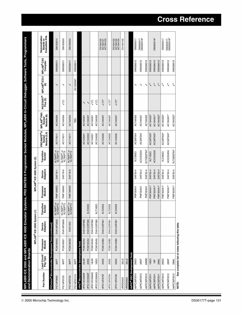
Cross Reference
PIC
mic
ro®
Mic
roco
ntr
olle
r D
evel
op
men
t To
ols
(co
nti
nu
ed)
PIC
18F
8680
80P
TP
CM
18X
K0
DV
A18
PQ
802
XLT
80P
T o
r X
LT80
PT
3P
MF
18W
E0
DA
F18
-1X
LT80
PT
or
XLT
80P
T3
AC
1740
11A
C16
4304
✓S
W00
6011
DM
1630
15
PIC
18F
8720
80P
TP
CM
18X
E1
DV
A18
PQ
800
XLT
80P
T o
r X
LT80
PT
3P
MF
18W
A2
DA
F18
-6X
LT80
PT
or
XLT
80P
T3
AC
1740
11A
C16
4304
✓(7
)✓
SW
0060
11D
M18
3020
PIC
18F
8722
80P
TP
CM
18X
S0
DV
A10
03X
LT80
PT
or
XLT
80P
T3
PM
F18
WS
0D
AF
18-6
XLT
80P
T o
r X
LT80
PT
3A
C17
4011
AC
1643
04✓
SW
0060
11D
M18
3022
PIC
18F
87J1
080
PT
TB
DA
C16
2062
*S
W00
6011
rfP
IC®
Mic
roco
ntr
olle
r D
evel
op
men
t To
ols
rfPIC
12C
509A
F20
JWP
CM
16X
A0
DV
A12
XP
080
AC
1240
01A
C16
4301
✓
rfPIC
12C
509A
F20
SS
PC
M16
XA
0D
VA
12X
P08
0X
LT20
SS
AC
1240
02A
C16
4307
✓
rfPIC
12C
509A
G18
JWP
CM
16X
A0
DV
A12
XP
080
AC
1240
01A
C16
4301
✓(7
)
rfPIC
12C
509A
G18
SO
PC
M16
XA
0D
VA
12X
P08
0X
LT18
SO
AC
1240
02A
C16
4302
✓(7
)
rfP
IC12
F67
5F20
SS
PC
M12
XB
0D
VA
12X
P08
1X
LT20
SS
AC
1240
02A
C16
4307
✓(7
)*D
V16
4102
AC
1641
01A
C16
4103
rfP
IC12
F67
5H20
SS
PC
M12
XB
0D
VA
12X
P08
1X
LT20
SS
AC
1240
02A
C16
4307
✓(7
)*
rfP
IC12
F67
5K20
SS
PC
M12
XB
0D
VA
12X
P08
1X
LT20
SS
AC
1240
02A
C16
4307
✓(7
)*D
V16
4102
AC
1641
02A
C16
4104
rfR
XD
0420
32LQ
DV
1641
02
rfR
XD
0920
32LQ
dsP
IC®
DS
C D
evel
op
men
t To
ols
dsP
IC30
F20
1028
SO
PM
F30
XA
1D
AF
30-4
XLT
28S
OA
C30
F00
4A
C16
4302
✓S
W00
6012
DM
3000
17
dsP
IC30
F20
1028
SP
PM
F30
XA
1D
AF
30-4
AC
ICE
0204
AC
30F
004
AC
1643
01✓
SW
0060
12D
M30
0017
D
M30
0018
*
dsP
IC30
F20
1028
MM
PM
F30
XA
1D
AF
30-4
XLT
28Q
FN
4*
AC
1643
22✓
SW
0060
12
dsP
IC30
F20
1118
SO
PM
F30
XA
1*D
AF
30-4
XLT
18S
OA
C30
F00
5*A
C16
4302
*✓
*S
W00
6012
dsP
IC30
F20
1118
PP
MF
30X
A1*
DA
F30
-4A
CIC
E02
02A
C30
F00
5*A
C16
4301
*✓
*S
W00
6012
DM
3000
18*
dsP
IC30
F20
1128
ML
PM
F30
XA
1*D
AF
30-4
AC
1643
22*
✓*
SW
0060
12
dsP
IC30
F20
1228
SO
PM
F30
XA
1*D
AF
30-4
XLT
28S
OA
C30
F00
4*A
C16
4302
*✓
*S
W00
6012
DM
3000
17
dsP
IC30
F20
1228
SP
PM
F30
XA
1*D
AF
30-4
AC
ICE
0204
AC
30F
004*
AC
1643
01*
✓*
SW
0060
12D
M30
0017
, D
M30
0018
*
dsP
IC30
F20
1228
ML
PM
F30
XA
1*D
AF
30-4
XLT
28Q
FN
4*A
C16
4322
*✓
*S
W00
6012
MP
LA
B®
ICE
200
0 an
d M
PL
AB
® IC
E 4
000
Em
ula
tor
Sys
tem
s, P
RO
MA
TE
® II
Pro
gra
mm
er S
ock
et M
od
ule
s, M
PL
AB
® In
-Cir
cuit
Deb
ug
ger
, So
ftw
are
Too
ls, P
rog
ram
mer
s an
d D
emo
nst
rati
on
Bo
ard
s
MP
LA
B®
ICE
200
0 S
yste
m (
1)M
PL
AB
® IC
E 4
000
Sys
tem
(2)
Par
t N
um
ber
Lea
d C
ou
nt/
Pkg
Typ
eP
roce
sso
r M
od
ule
Dev
ice
Ad
apte
rsTr
ansi
tio
n
So
cket
Pro
cess
or
Mo
du
leD
evic
e A
dap
ters
Tran
siti
on
S
ock
etP
RO
MA
TE®
II
Soc
ket
Mo
dule
(3,4
)
MP
LA
B®
PM
3S
ock
etM
od
ule
(8)
PIC
STA
RT
®
Plu
s (5
)M
PL
AB
® IC
D 2
(6
)M
PL
AB
® C
XX
C
om
pile
r
Dem
onst
ratio
n
Boa
rds
or
Eva
luat
ion
Kits
NO
TE:
See
co
mp
lete
list
of
no
tes
follo
win
g t
his
tab
le.
© 2005 Microchip Technology Inc. DS30177T-page 131
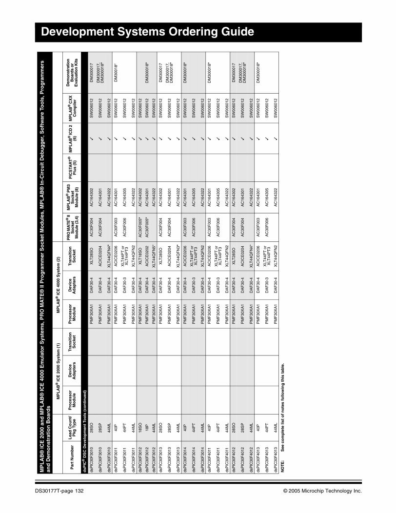
Development Systems Ordering Guide
dsP
IC®
DS
C D
evel
op
men
t To
ols
(co
nti
nu
ed)
dsP
IC30
F30
1028
SO
PM
F30
XA
1D
AF
30-4
XLT
28S
OA
C30
F00
4A
C16
4302
✓S
W00
6012
DM
3000
17
dsP
IC30
F30
1028
SP
PM
F30
XA
1D
AF
30-4
AC
ICE
0204
AC
30F
004
AC
1643
01✓
SW
0060
12D
M30
0017
, D
M30
0018
*
dsP
IC30
F30
1044
ML
PM
F30
XA
1D
AF
30-4
XLT
44Q
FN
4*A
C16
4322
✓S
W00
6012
dsP
IC30
F30
1140
PP
MF
30X
A1
DA
F30
-4A
CIC
E02
06A
C30
F00
3A
C16
4301
✓S
W00
6012
DM
3001
8*
dsP
IC30
F30
1144
PT
PM
F30
XA
1D
AF
30-3
XLT
44P
T o
r X
LT44
PT
3A
C30
F00
6A
C16
4305
✓S
W00
6012
dsP
IC30
F30
1144
ML
PM
F30
XA
1D
AF
30-4
XLT
44Q
FN
2A
C16
4322
✓S
W00
6012
dsP
IC30
F30
1218
SO
PM
F30
XA
1D
AF
30-4
XLT
18S
OA
C30
F00
5*A
C16
4302
✓S
W00
6012
dsP
IC30
F30
1218
PP
MF
30X
A1
DA
F30
-4A
CIC
E02
02A
C30
F00
5*A
C16
4301
✓S
W00
6012
DM
3000
18*
dsP
IC30
F30
1244
ML
PM
F30
XA
1D
AF
30-4
XLT
44Q
FN
5*A
C16
4322
✓S
W00
6012
dsP
IC30
F30
1328
SO
PM
F30
XA
1D
AF
30-4
XLT
28S
OA
C30
F00
4A
C16
4302
✓S
W00
6012
DM
3000
17
dsP
IC30
F30
1328
SP
PM
F30
XA
1D
AF
30-4
AC
ICE
0204
AC
30F
004
AC
1643
01✓
SW
0060
12D
M30
0017
, D
M30
0018
*
dsP
IC30
F30
1344
ML
PM
F30
XA
1D
AF
30-4
XLT
44Q
FN
3*A
C16
4322
✓S
W00
6012
dsP
IC30
F30
1440
PP
MF
30X
A1
DA
F30
-4A
CIC
E02
06A
C30
F00
3A
C16
4301
✓S
W00
6012
DM
3000
18*
dsP
IC30
F30
1444
PT
PM
F30
XA
1D
AF
30-3
XLT
44P
T o
r X
LT44
PT
3A
C30
F00
6A
C16
4305
✓S
W00
6012
dsP
IC30
F30
1444
ML
PM
F30
XA
1D
AF
30-4
XLT
44Q
FN
2A
C16
4322
✓S
W00
6012
dsP
IC30
F40
1140
PP
MF
30X
A1
DA
F30
-4A
CIC
E02
06A
C30
F00
3A
C16
4301
✓S
W00
6012
DM
3000
18*
dsP
IC30
F40
1144
PT
PM
F30
XA
1D
AF
30-3
XLT
44P
T o
r X
LT44
PT
3A
C30
F00
6A
C16
4305
✓S
W00
6012
dsP
IC30
F40
1144
ML
PM
F30
XA
1D
AF
30-4
XLT
44Q
FN
2A
C16
4322
✓S
W00
6012
dsP
IC30
F40
1228
SO
PM
F30
XA
1D
AF
30-4
XLT
28S
OA
C30
F00
4A
C16
4302
✓S
W00
6012
DM
3000
17
dsP
IC30
F40
1228
SP
PM
F30
XA
1D
AF
30-4
AC
ICE
0204
AC
30F
004
AC
1643
01✓
SW
0060
12D
M30
0017
, D
M30
0018
*
dsP
IC30
F40
1244
ML
PM
F30
XA
1D
AF
30-4
XLT
44Q
FN
4*A
C16
4322
✓S
W00
6012
dsP
IC30
F40
1340
PP
MF
30X
A1
DA
F30
-4A
CIC
E02
06A
C30
F00
3A
C16
4301
✓S
W00
6012
DM
3000
18*
dsP
IC30
F40
1344
PT
PM
F30
XA
1D
AF
30-3
XLT
44P
T o
r X
LT44
PT
3A
C30
F00
6A
C16
4305
✓S
W00
6012
dsP
IC30
F40
1344
ML
PM
F30
XA
1D
AF
30-4
XLT
44Q
FN
2A
C16
4322
✓S
W00
6012
MP
LA
B®
ICE
200
0 an
d M
PL
AB
® IC
E 4
000
Em
ula
tor
Sys
tem
s, P
RO
MA
TE
® II
Pro
gra
mm
er S
ock
et M
od
ule
s, M
PL
AB
® In
-Cir
cuit
Deb
ug
ger
, So
ftw
are
Too
ls, P
rog
ram
mer
s an
d D
emo
nst
rati
on
Bo
ard
s
MP
LA
B®
ICE
200
0 S
yste
m (
1)M
PL
AB
® IC
E 4
000
Sys
tem
(2)
Par
t N
um
ber
Lea
d C
ou
nt/
Pkg
Typ
eP
roce
sso
r M
od
ule
Dev
ice
Ad
apte
rsTr
ansi
tio
n
So
cket
Pro
cess
or
Mo
du
leD
evic
e A
dap
ters
Tran
siti
on
S
ock
etP
RO
MA
TE®
II
So
cket
M
odu
le (3
,4)
MP
LA
B®
PM
3S
ock
etM
od
ule
(8)
PIC
STA
RT
®
Plu
s (5
)M
PL
AB
® IC
D 2
(6
)M
PL
AB
® C
XX
C
om
pile
r
Dem
onst
ratio
n
Bo
ard
s o
r E
valu
atio
n K
its
NO
TE:
See
co
mp
lete
list
of
no
tes
follo
win
g t
his
tab
le.
DS30177T-page 132 © 2005 Microchip Technology Inc.
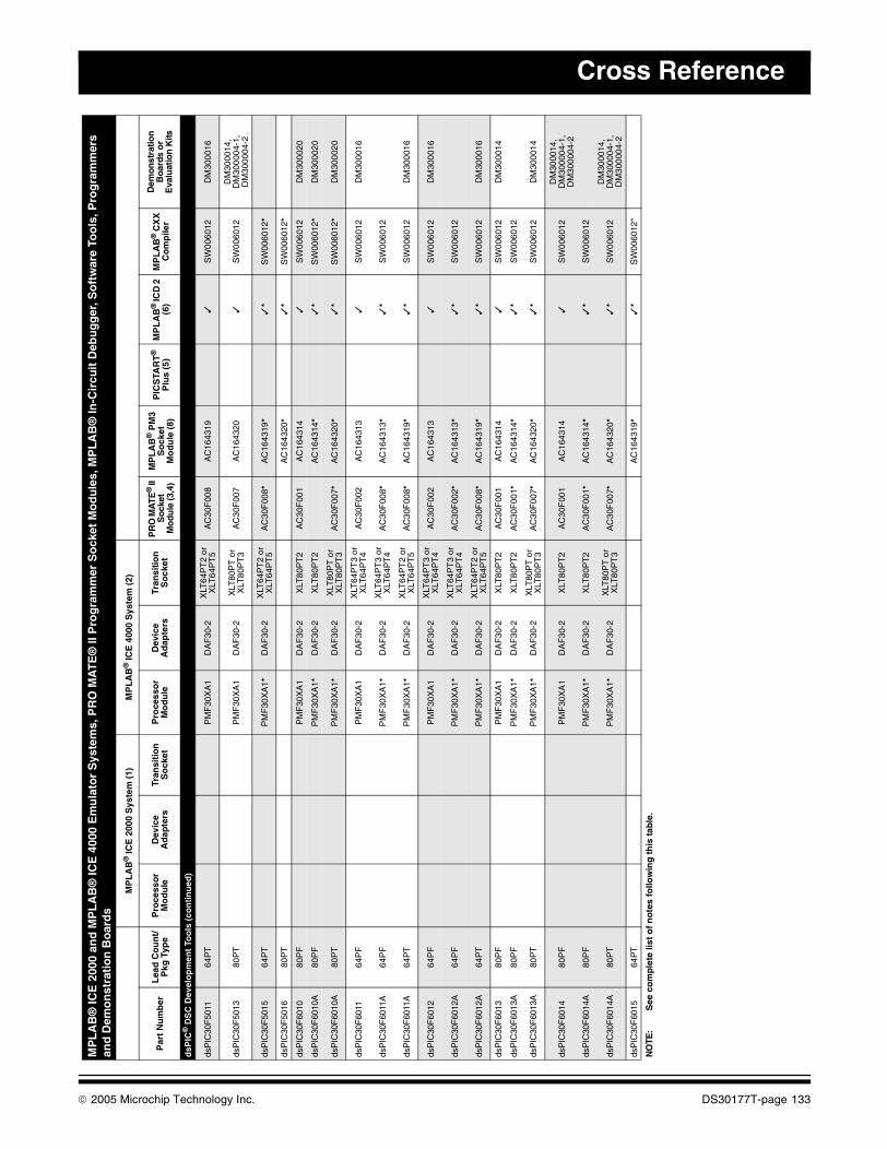
Cross Reference
dsP
IC®
DS
C D
evel
op
men
t To
ols
(co
nti
nu
ed)
dsP
IC30
F50
1164
PT
PM
F30
XA
1D
AF
30-2
XLT
64P
T2
or
XLT
64P
T5
AC
30F
008
AC
1643
19✓
SW
0060
12D
M30
0016
dsP
IC30
F50
1380
PT
PM
F30
XA
1D
AF
30-2
XLT
80P
T o
r X
LT80
PT
3A
C30
F00
7A
C16
4320
✓S
W00
6012
DM
3000
14,
DM
3000
04-1
,D
M30
0004
-2
dsP
IC30
F50
1564
PT
PM
F30
XA
1*D
AF
30-2
XLT
64P
T2
or
XLT
64P
T5
AC
30F
008*
AC
1643
19*
✓*
SW
0060
12*
dsP
IC30
F50
1680
PT
AC
1643
20*
✓*
SW
0060
12*
dsP
IC30
F60
1080
PF
PM
F30
XA
1D
AF
30-2
XLT
80P
T2
AC
30F
001
AC
1643
14✓
SW
0060
12D
M30
0020
dsP
IC30
F60
10A
80P
FP
MF
30X
A1*
DA
F30
-2X
LT80
PT
2A
C16
4314
*✓
*S
W00
6012
*D
M30
0020
dsP
IC30
F60
10A
80P
TP
MF
30X
A1*
DA
F30
-2X
LT80
PT
or
XLT
80P
T3
AC
30F
007*
AC
1643
20*
✓*
SW
0060
12*
DM
3000
20
dsP
IC30
F60
1164
PF
PM
F30
XA
1D
AF
30-2
XLT
64P
T3
or
XLT
64P
T4
AC
30F
002
AC
1643
13✓
SW
0060
12D
M30
0016
dsP
IC30
F60
11A
64P
FP
MF
30X
A1*
DA
F30
-2X
LT64
PT
3 or
X
LT64
PT
4A
C30
F00
8*A
C16
4313
*✓
*S
W00
6012
dsP
IC30
F60
11A
64P
TP
MF
30X
A1*
DA
F30
-2X
LT64
PT
2 or
X
LT64
PT
5A
C30
F00
8*A
C16
4319
*✓
*S
W00
6012
DM
3000
16
dsP
IC30
F60
1264
PF
PM
F30
XA
1D
AF
30-2
XLT
64P
T3
or
XLT
64P
T4
AC
30F
002
AC
1643
13✓
SW
0060
12D
M30
0016
dsP
IC30
F60
12A
64P
FP
MF
30X
A1*
DA
F30
-2X
LT64
PT
3 or
X
LT64
PT
4A
C30
F00
2*A
C16
4313
*✓
*S
W00
6012
dsP
IC30
F60
12A
64P
TP
MF
30X
A1*
DA
F30
-2X
LT64
PT
2 or
X
LT64
PT
5A
C30
F00
8*A
C16
4319
*✓
*S
W00
6012
DM
3000
16
dsP
IC30
F60
1380
PF
PM
F30
XA
1D
AF
30-2
XLT
80P
T2
AC
30F
001
AC
1643
14✓
SW
0060
12D
M30
0014
dsP
IC30
F60
13A
80P
FP
MF
30X
A1*
DA
F30
-2X
LT80
PT
2A
C30
F00
1*A
C16
4314
*✓
*S
W00
6012
dsP
IC30
F60
13A
80P
TP
MF
30X
A1*
DA
F30
-2X
LT80
PT
or
XLT
80P
T3
AC
30F
007*
AC
1643
20*
✓*
SW
0060
12D
M30
0014
dsP
IC30
F60
1480
PF
PM
F30
XA
1D
AF
30-2
XLT
80P
T2
AC
30F
001
AC
1643
14✓
SW
0060
12D
M30
0014
,D
M30
0004
-1,
DM
3000
04-2
dsP
IC30
F60
14A
80P
FP
MF
30X
A1*
DA
F30
-2X
LT80
PT
2A
C30
F00
1*A
C16
4314
*✓
*S
W00
6012
dsP
IC30
F60
14A
80P
TP
MF
30X
A1*
DA
F30
-2X
LT80
PT
or
XLT
80P
T3
AC
30F
007*
AC
1643
20*
✓*
SW
0060
12D
M30
0014
, D
M30
0004
-1,
DM
3000
04-2
dsP
IC30
F60
1564
PT
AC
1643
19*
✓*
SW
0060
12*
MP
LA
B®
ICE
200
0 an
d M
PL
AB
® IC
E 4
000
Em
ula
tor
Sys
tem
s, P
RO
MA
TE
® II
Pro
gra
mm
er S
ock
et M
od
ule
s, M
PL
AB
® In
-Cir
cuit
Deb
ug
ger
, So
ftw
are
Too
ls, P
rog
ram
mer
s an
d D
emo
nst
rati
on
Bo
ard
s
MP
LA
B®
ICE
200
0 S
yste
m (
1)M
PL
AB
® IC
E 4
000
Sys
tem
(2)
Par
t N
um
ber
Lea
d C
ou
nt/
Pkg
Typ
eP
roce
sso
r M
od
ule
Dev
ice
Ad
apte
rsTr
ansi
tio
n
So
cket
Pro
cess
or
Mo
du
leD
evic
e A
dap
ters
Tran
siti
on
S
ock
etP
RO
MA
TE®
II
Soc
ket
Mo
dule
(3,4
)
MP
LA
B®
PM
3S
ock
etM
od
ule
(8)
PIC
STA
RT
®
Plu
s (5
)M
PL
AB
® IC
D 2
(6
)M
PL
AB
® C
XX
C
om
pile
r
Dem
onst
ratio
n
Boa
rds
or
Eva
luat
ion
Kits
NO
TE:
See
co
mp
lete
list
of
no
tes
follo
win
g t
his
tab
le.
© 2005 Microchip Technology Inc. DS30177T-page 133
Development Systems Ordering Guide
MPL
AB
® IC
E 2
000
and
MP
LA
B®
ICE
400
0 E
mu
lato
r S
yste
ms,
PR
O M
AT
E®
II P
rog
ram
mer
So
cket
Mo
du
les,
MP
LA
B®
In-C
ircu
it D
ebu
gg
er, S
oft
war
e To
ols
, Pro
gra
mm
ers
and
Dem
on
stra
tio
n B
oar
ds
- N
OT
ES
NO
TES
1:M
PLA
B®
ICE
200
0 po
d av
aila
ble
sepa
rate
ly. (
ICE
2000
)2:
MP
LAB
® IC
E 4
000
pod
avai
labl
e se
para
tely
. (IC
E40
00)
3:P
RO
MA
TE
® II
Pro
gram
mer
uni
t (no
long
er a
vaila
ble)
. (D
V00
7003
)4:
Opt
iona
l In-
Circ
uit S
eria
l Pro
gram
min
g™ (
ICS
P™
) S
ocke
t for
PR
O M
AT
E®
II a
vaila
ble
sepa
rate
ly. (
AC
0040
04)
5:P
ICS
TAR
T®
Plu
s (D
V00
3001
)6:
MP
LAB
® IC
D 2
In-C
ircui
t Deb
ugge
r. C
onfig
urat
ions
are
:(D
V16
4005
) IC
D 2
mod
ule,
US
B c
able
and
ICD
cab
le.
(DV
1640
06)
ICD
2 m
odul
e, U
SB
cab
le, I
CD
cab
le, s
eria
l cab
le, P
ICD
EM
™ 2
Plu
s an
d po
wer
sup
ply.
(DV
1640
07)
ICD
2 m
odul
e, U
SB
cab
le, I
CD
cab
le, s
eria
l cab
le a
nd p
ower
sup
ply;
(DV
1640
30)
ICD
2 m
odul
e, U
SB
cab
le, I
CD
cab
le, s
eria
l cab
le a
nd d
sPIC
DE
M™
Sta
rter
Dem
o B
oard
;(A
C16
2049
) IC
D 2
Uni
vers
al P
rogr
amm
ing
Mod
ule;
(AC
1620
51)
ICD
or
ICD
2 2
8/40
PD
IP H
eade
r In
terf
ace
Boa
rd.
7:C
usto
m a
dapt
er r
equi
red;
not
ava
ilabl
e fr
om M
icro
chip
. See
“R
eadm
e” fo
r P
ICS
TAR
T®
Plu
s.8:
MP
LAB
® P
M3
Pro
gram
mer
Uni
t ava
ilabl
e se
para
tely
. (D
V00
7004
). IC
SP
™ fu
nctio
n is
bui
lt-in
with
MP
LAB
® P
M3
Pro
gram
mer
.(A
C16
4350
) M
PLA
B®
PM
3 A
dapt
er fo
r P
RO
MA
TE
® II
Soc
ket m
odul
es.
* N
ew p
rodu
ct o
r fu
ture
sup
port
. Con
tact
Mic
roch
ip w
eb s
ite a
t ww
w.m
icro
chip
.com
for
avai
labi
lity.
✓S
uppo
rted
with
bas
ic c
onfig
urat
ion.
If a
par
t num
ber
is li
sted
in th
e co
lum
n, th
at p
art i
s re
quire
d an
d av
aila
ble
sepa
rate
ly.
DS30177T-page 134 © 2005 Microchip Technology Inc.
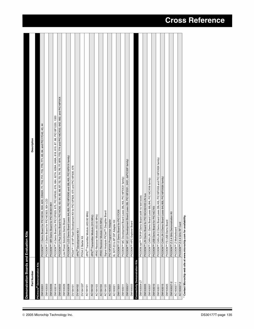
Cross Reference
Demo
nst
rati
on
Bo
ard
s an
d E
valu
atio
n K
its
Par
t N
um
ber
Des
crip
tio
n
PIC
mic
ro®
Dem
on
stra
tio
n K
its
DM
1630
01P
ICD
EM
™ 1
Dem
o B
oard
for
PIC
16C
5X, 5
5X, 6
2X, C
E62
X, 7
1, 7
10, 7
11, 7
15, 7
70, 7
71, 8
3, 8
4, a
nd P
IC17
C42
, 43,
44
DM
1630
03P
ICD
EM
™ 3
Dem
o B
oard
for
PIC
16C
923,
924
LC
D
DM
1630
06P
ICD
EM
™ 1
8R D
emo
Boa
rd fo
r P
IC18
C60
1/80
1
DM
1630
14P
ICD
EM
™ 4
Dem
o B
oard
for
PIC
12F
629,
675
, PIC
16F
630,
676
, 684
, 627
A, 6
28A
, 648
A, 8
18, 8
19, 8
7, 8
8, P
IC18
F12
20, 1
320
DM
1630
22P
ICD
EM
™ 2
Plu
s D
emo
Boa
rd fo
r P
IC16
C62
, 63,
64,
65,
66,
67,
72,
73,
74,
76,
77,
87X
, 773
, 774
and
PIC
18C
XX
2, 6
42, 6
62, a
nd P
IC18
FX
XX
DM
1630
26Lo
w-P
ower
Sol
utio
ns D
emo
Boa
rd
DM
1630
28P
ICD
EM
™ L
CD
Dem
o B
oard
(us
es 6
4L/8
0L P
IC18
FX
X90
and
28L
/40L
PIC
16F
91X
fam
ily)
DV
1641
01P
ICki
t™ 1
8/1
4P F
lash
Dev
elop
men
t Kit
for
PIC
12F
629,
675
and
PIC
16F
630,
676
DV
1641
02rf
PIC
® D
evel
opm
ent K
it 1
DV
1641
20*
PIC
kit 2
Sta
rter
Kit
AC
1641
01rf
PIC
® T
rans
mitt
er M
odul
e (4
33.9
2 M
Hz)
AC
1641
02rf
PIC
® T
rans
mitt
er M
odul
e (3
15 M
Hz)
AC
1641
03rf
RX
D R
ecei
ver
Mod
ule
(433
.92
MH
z)
AC
1641
04rf
RX
D R
ecei
ver
Mod
ule
(315
MH
z)
AC
1641
20S
igna
l Ana
lysi
s P
ICta
il™ D
augh
ter
Boa
rd
AC
1630
20P
IC10
F2X
X P
rogr
amm
er A
dapt
er
AC
1630
216L
SO
T-23
to 8
P D
IP A
dapt
er K
it
DM
1730
01P
ICD
EM
™ 1
7 D
emo
Boa
rd fo
r P
IC17
CX
X
DM
1830
11P
ICD
EM
™ M
C D
evel
opm
ent B
oard
(us
es 2
8L/4
0L P
IC18
FX
X31
fam
ily)
DM
1830
21*
PIC
DE
M™
MC
LV
Dev
elop
men
t Boa
rd (
uses
28L
PIC
18F
2331
, 243
1, d
sPIC
30F
fam
ily)
DM
1830
22P
ICD
EM
™ H
PC
Exp
lore
r B
oard
Co
nn
ecti
vity
Dem
on
stra
tio
n K
its
DM
1630
04-L
TP
ICD
EM
.net
™ T
CP
/IP D
emo
Boa
rd (
with
no
text
boo
k)
DM
1630
05P
ICD
EM
™ L
IN D
emo
Boa
rd fo
r P
IC16
C43
2/43
3 LI
N b
us
DM
1630
07P
ICD
EM
™ C
AN
-LIN
1 D
emo
Boa
rd (
uses
68L
/84L
PIC
18C
XX
8 fa
mily
)
DM
1630
10P
ICD
EM
™ U
SB
Dem
o B
oard
for
PIC
16C
7X5
DM
1630
11P
ICD
EM
™ C
AN
-LIN
2 D
emo
Boa
rd (
uses
28L
/40L
PIC
18F
XX
8 an
d P
IC18
FX
X8X
fam
ily)
DM
1630
15P
ICD
EM
™ C
AN
-LIN
3 D
emo
Boa
rd (
uses
64L
/80L
PIC
18F
XX
8X fa
mily
)
DM
1630
25P
ICD
EM
™ F
S U
SB
Dem
o B
oard
DM
1630
27-2
PIC
DE
M™
Z 2
.4 G
Hz
Dem
onst
ratio
n K
it
AC
1630
27-1
PIC
DE
M™
Z M
othe
rboa
rd
AC
1630
27-2
PIC
DE
M™
Z 2
.4 G
Hz
RF
Car
d
* C
on
tact
Mic
roch
ip w
eb s
ite
at w
ww
.mic
roch
ip.c
om
fo
r av
aila
bili
ty.
© 2005 Microchip Technology Inc. DS30177T-page 135
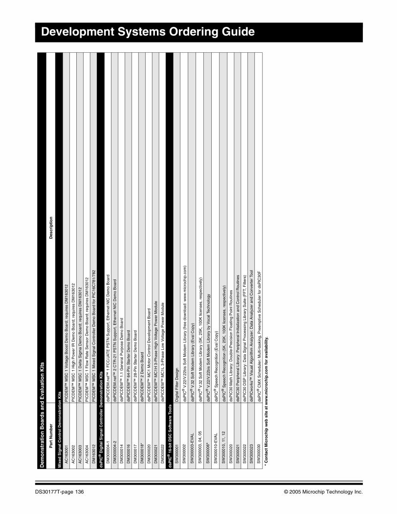
Development Systems Ordering Guide
tMix
ed S
ign
al C
on
tro
l Dem
on
stra
tio
n K
its
AC
1630
01P
ICD
EM
™ M
SC
1 V
olta
ge B
oost
Dem
o B
oard
; req
uire
s D
M16
3012
AC
1630
02P
ICD
EM
™ M
SC
1 H
igh
Pow
er IR
Dem
o B
oard
; req
uire
s D
M16
3012
AC
1630
03P
ICD
EM
™ M
SC
1 D
elta
Sig
ma
Dem
o B
oard
; req
uire
s D
M16
3012
AC
1630
04P
ICD
EM
™ M
SC
1 F
low
Rat
e S
enso
r D
emo
Boa
rd; r
equi
res
DM
1630
12
DM
1630
12P
ICD
EM
™ M
SC
1 M
ixed
Sig
nal C
ontr
olle
r D
emo
Boa
rd fo
r P
IC16
C78
1/78
2
dsP
IC®
Dig
ital S
ign
al C
on
tro
ller
Dem
on
stra
tio
n K
its
DM
3000
04-1
dsP
ICD
EM
.net
™ 1
FC
C/J
AT
E P
ST
N S
uppo
rt, E
ther
net N
IC D
emo
Boa
rd
DM
3000
04-2
dsP
ICD
EM
.net
™ 2
CT
R-2
1 P
ST
N S
uppo
rt, E
ther
net N
IC D
emo
Boa
rd
DM
3000
14ds
PIC
DE
M™
1.1
Gen
eral
Pur
pose
Dem
o B
oard
DM
3000
16ds
PIC
DE
M™
64-
Pin
Sta
rter
Dem
o B
oard
DM
3000
17ds
PIC
DE
M™
28-
Pin
Sta
rter
Dem
o B
oard
DM
3000
18*
dsP
ICD
EM
™ 2
Dem
o B
oard
DM
3000
20ds
PIC
DE
M™
MC
1 M
otor
Con
trol
Dev
elop
men
t Boa
rd
DM
3000
21ds
PIC
DE
M™
MC
1H 3
-Pha
se H
igh
Vol
tage
Pow
er M
odul
e
DM
3000
22ds
PIC
DE
M™
MC
1L 3
-Pha
se L
ow V
olta
ge P
ower
Mod
ule
dsP
IC®
16-
bit
DS
C S
oft
war
e To
ols
SW
3000
01D
igita
l Filt
er D
esig
n
SW
3000
02ds
PIC
® V
.22/
V.2
2bis
Sof
t Mod
em L
ibra
ry (
free
dow
nloa
d: w
ww
.mic
roch
ip.c
om)
SW
3000
03-E
VA
Lds
PIC
® V
.32
Sof
t Mod
em L
ibra
ry (
Eva
l Cop
y)
SW
3000
03, 0
4, 0
5ds
PIC
® V
.32
Sof
t Mod
em L
ibra
ry (
5K, 2
5K, 1
00K
lice
nses
, res
pect
ivel
y)
SW
3000
06*
dsP
IC®
V.2
2/V
.22b
is S
oft M
odem
Lib
rary
by
Voc
al T
echn
olog
y
SW
3000
10-E
VA
Lds
PIC
® S
peec
h R
ecog
nitio
n (E
val C
opy)
SW
3000
10, 1
1, 1
2ds
PIC
® S
peec
h R
ecog
nitio
n (5
K, 2
5K, 1
00K
lice
nses
, res
pect
ivel
y)
SW
3000
20ds
PIC
30 M
ath
Libr
ary:
Dou
ble-
Pre
cisi
on F
loat
ing
Poi
nt R
outin
es
SW
3000
21ds
PIC
30 P
erip
hera
l Lib
rary
: Per
iphe
ral I
nitia
lizat
ion
and
Con
trol
Rou
tines
SW
3000
22ds
PIC
30 D
SP
Lib
rary
: Dat
a S
igna
l Pro
cess
ing
Libr
ary
Sui
te (
FF
T, F
ilter
s)
SW
3000
23ds
PIC
wor
ks™
Vis
ual A
lgor
ithm
Ana
lyze
r: D
ata
Ana
lyze
r an
d C
onve
rter
Too
l
SW
3000
30ds
PIC
® C
MX
Sch
edul
er: M
ulti-
task
ing,
Pre
empt
ive
Sch
edul
er fo
r ds
PIC
30F
Dem
on
stra
tio
n B
oar
ds
and
Eva
luat
ion
Kits
Par
t N
um
ber
Des
crip
tio
n
* C
on
tact
Mic
roch
ip w
eb s
ite
at w
ww
.mic
roch
ip.c
om
fo
r av
aila
bili
ty.
DS30177T-page 136 © 2005 Microchip Technology Inc.
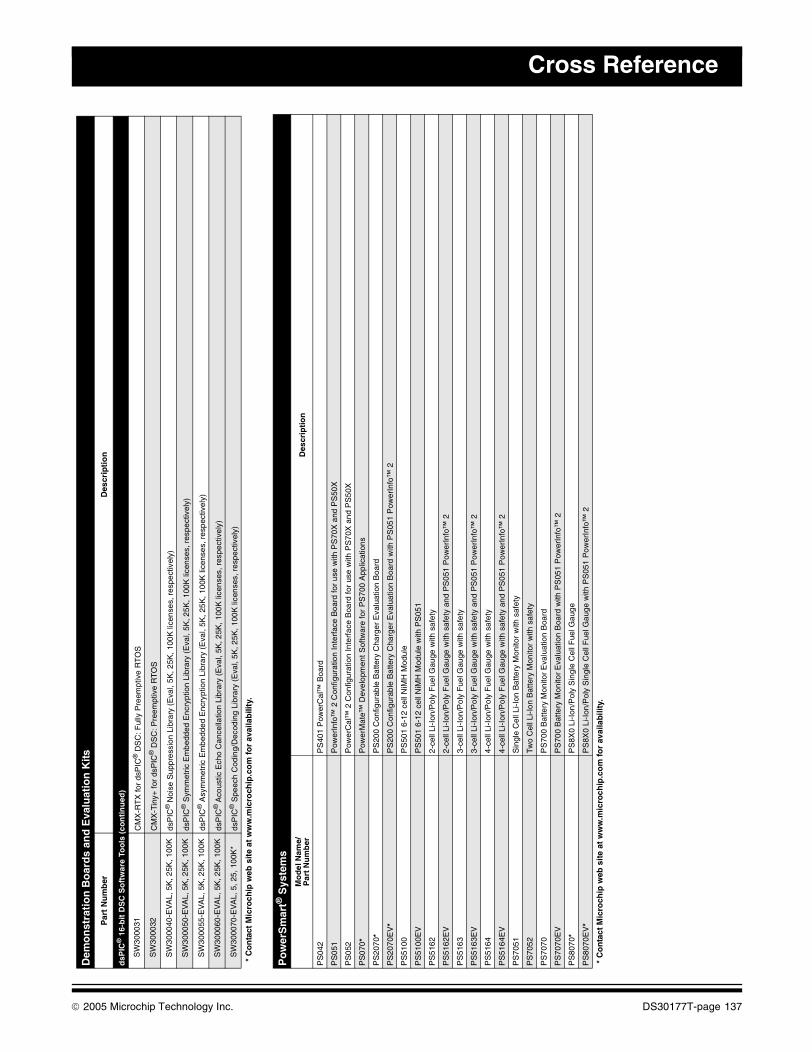
Cross Reference
t
dsP
IC®
16-
bit
DS
C S
oft
war
e To
ols
(co
nti
nu
ed)
SW
3000
31C
MX
-RT
X fo
r ds
PIC
® D
SC
: Ful
ly P
reem
ptiv
e R
TO
S
SW
3000
32C
MX
-Tin
y+ fo
r ds
PIC
® D
SC
: Pre
empt
ive
RT
OS
SW
3000
40-E
VA
L, 5
K, 2
5K, 1
00K
dsP
IC®
Noi
se S
uppr
essi
on L
ibra
ry (
Eva
l, 5K
, 25K
, 100
K li
cens
es, r
espe
ctiv
ely)
SW
3000
50-E
VA
L, 5
K, 2
5K, 1
00K
dsP
IC®
Sym
met
ric E
mbe
dded
Enc
rypt
ion
Libr
ary
(Eva
l, 5K
, 25K
, 100
K li
cens
es, r
espe
ctiv
ely)
SW
3000
55-E
VA
L, 5
K, 2
5K, 1
00K
dsP
IC®
Asy
mm
etric
Em
bedd
ed E
ncry
ptio
n Li
brar
y (E
val,
5K, 2
5K, 1
00K
lice
nses
, res
pect
ivel
y)
SW
3000
60-E
VA
L, 5
K, 2
5K, 1
00K
dsP
IC®
Aco
ustic
Ech
o C
ance
llatio
n Li
brar
y (E
val,
5K, 2
5K, 1
00K
lice
nses
, res
pect
ivel
y)
SW
3000
70-E
VA
L, 5
, 25,
100
K*
dsP
IC®
Spe
ech
Cod
ing/
Dec
odin
g Li
brar
y (E
val,
5K, 2
5K, 1
00K
lice
nses
, res
pect
ivel
y)
Po
wer
Sm
art®
Sys
tem
sM
od
el N
ame/
Par
t N
um
ber
Des
crip
tio
n
PS
042
PS
401
Pow
erC
al™
Boa
rd
PS
051
Pow
erIn
fo™
2 C
onfig
urat
ion
Inte
rfac
e B
oard
for
use
with
PS
70X
and
PS
50X
PS
052
Pow
erC
al™
2 C
onfig
urat
ion
Inte
rfac
e B
oard
for
use
with
PS
70X
and
PS
50X
PS
070*
Pow
erM
ate™
Dev
elop
men
t Sof
twar
e fo
r P
S70
0 A
pplic
atio
ns
PS
2070
*P
S20
0 C
onfig
urab
le B
atte
ry C
harg
er E
valu
atio
n B
oard
PS
2070
EV
*P
S20
0 C
onfig
urab
le B
atte
ry C
harg
er E
valu
atio
n B
oard
with
PS
051
Pow
erIn
fo™
2
PS
5100
PS
501
6-12
cel
l NiM
H M
odul
e
PS
5100
EV
PS
501
6-12
cel
l NiM
H M
odul
e w
ith P
S05
1
PS
5162
2-ce
ll Li
-Ion
/Pol
y F
uel G
auge
with
saf
ety
PS
5162
EV
2-ce
ll Li
-Ion
/Pol
y F
uel G
auge
with
saf
ety
and
PS
051
Pow
erIn
fo™
2
PS
5163
3-ce
ll Li
-Ion
/Pol
y F
uel G
auge
with
saf
ety
PS
5163
EV
3-ce
ll Li
-Ion
/Pol
y F
uel G
auge
with
saf
ety
and
PS
051
Pow
erIn
fo™
2
PS
5164
4-ce
ll Li
-Ion
/Pol
y F
uel G
auge
with
saf
ety
PS
5164
EV
4-ce
ll Li
-Ion
/Pol
y F
uel G
auge
with
saf
ety
and
PS
051
Pow
erIn
fo™
2
PS
7051
Sin
gle
Cel
l Li-I
on B
atte
ry M
onito
r w
ith s
afet
y
PS
7052
Two
Cel
l Li-I
on B
atte
ry M
onito
r w
ith s
afet
y
PS
7070
PS
700
Bat
tery
Mon
itor
Eva
luat
ion
Boa
rd
PS
7070
EV
PS
700
Bat
tery
Mon
itor
Eva
luat
ion
Boa
rd w
ith P
S05
1 P
ower
Info
™ 2
PS
8070
*P
S8X
0 Li
-Ion
/Pol
y S
ingl
e C
ell F
uel G
auge
PS
8070
EV
*P
S8X
0 Li
-Ion
/Pol
y S
ingl
e C
ell F
uel G
auge
with
PS
051
Pow
erIn
fo™
2
* C
on
tact
Mic
roch
ip w
eb s
ite
at w
ww
.mic
roch
ip.c
om
fo
r av
aila
bili
ty.
Dem
on
stra
tio
n B
oar
ds
and
Eva
luat
ion
Kits
Par
t N
um
ber
Des
crip
tio
n
* C
on
tact
Mic
roch
ip w
eb s
ite
at w
ww
.mic
roch
ip.c
om
fo
r av
aila
bili
ty.
© 2005 Microchip Technology Inc. DS30177T-page 137
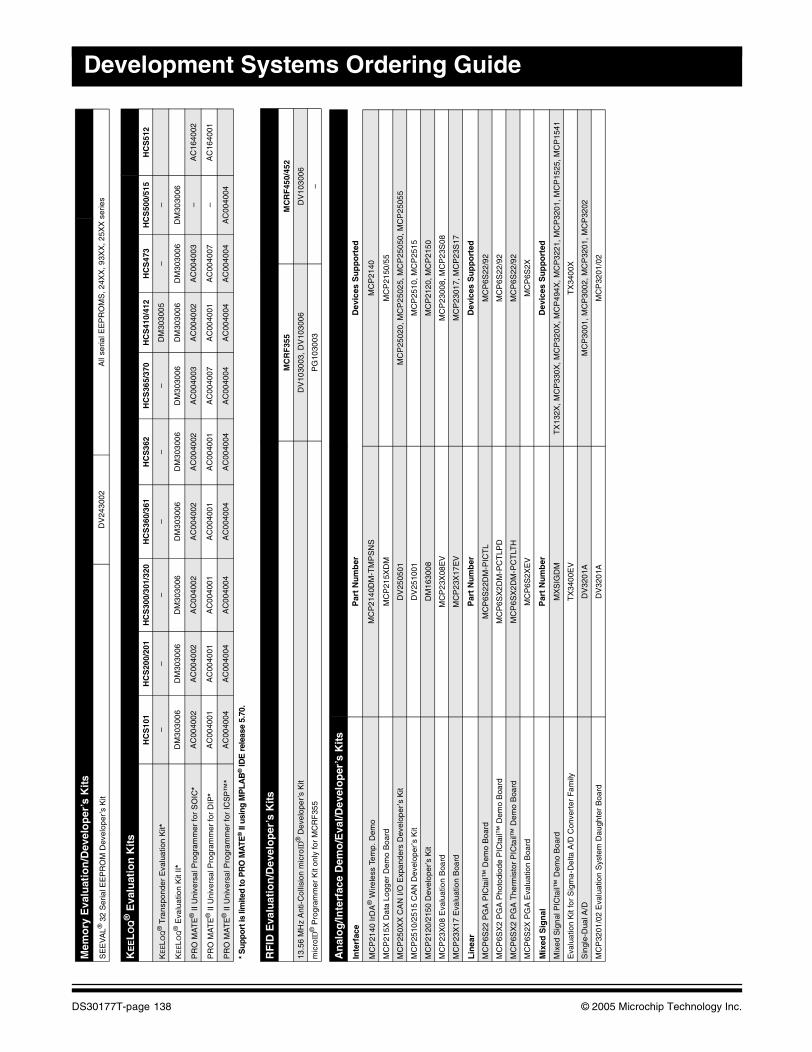
Development Systems Ordering Guide
tMem
ory
Eva
luat
ion
/Dev
elo
per
’s K
its
SE
EV
AL®
32
Ser
ial E
EP
RO
M D
evel
oper
’s K
itD
V24
3002
All
seria
l EE
PR
OM
S, 2
4XX
, 93X
X, 2
5XX
ser
ies
KE
EL
OQ
® E
valu
atio
n K
itsH
CS
101
HC
S20
0/20
1H
CS
300/
301/
320
HC
S36
0/36
1H
CS
362
HC
S36
5/37
0H
CS
410/
412
HC
S47
3H
CS
500/
515
HC
S51
2
KE
ELO
Q®
Tra
nspo
nder
Eva
luat
ion
Kit*
––
––
––
DM
3030
05–
–
KE
ELO
Q®
Eva
luat
ion
Kit
II*D
M30
3006
DM
3030
06D
M30
3006
DM
3030
06D
M30
3006
DM
3030
06D
M30
3006
DM
3030
06D
M30
3006
PR
O M
AT
E®
II U
nive
rsal
Pro
gram
mer
for
SO
IC*
AC
0040
02A
C00
4002
AC
0040
02A
C00
4002
AC
0040
02A
C00
4003
AC
0040
02A
C00
4003
–A
C16
4002
PR
O M
AT
E®
II U
nive
rsal
Pro
gram
mer
for
DIP
*A
C00
4001
AC
0040
01A
C00
4001
AC
0040
01A
C00
4001
AC
0040
07A
C00
4001
AC
0040
07–
AC
1640
01
PR
O M
AT
E®
II U
nive
rsal
Pro
gram
mer
for
ICS
P™
*A
C00
4004
AC
0040
04A
C00
4004
AC
0040
04A
C00
4004
AC
0040
04A
C00
4004
AC
0040
04A
C00
4004
* S
uppo
rt is
lim
ited
to P
RO
MA
TE® II
usi
ng M
PLA
B® ID
E r
elea
se 5
.70.
RF
ID E
valu
atio
n/D
evel
op
er’s
Kits
MC
RF
355
MC
RF
450/
452
13.5
6 M
Hz
Ant
i-Col
lisio
n m
icro
ID®
Dev
elop
er’s
Kit
DV
1030
03, D
V10
3006
DV
1030
06
mic
roID
® P
rogr
amm
er K
it on
ly fo
r M
CR
F35
5P
G10
3003
–
An
alo
g/In
terf
ace
Dem
o/E
val/D
evel
op
er’s
Kits
Inte
rfac
eP
art
Nu
mb
erD
evic
es S
up
po
rted
MC
P21
40 Ir
DA
® W
irele
ss T
emp.
Dem
oM
CP
2140
DM
-TM
PS
NS
MC
P21
40
MC
P21
5X D
ata
Logg
er D
emo
Boa
rdM
CP
215X
DM
MC
P21
50/5
5
MC
P25
0XX
CA
N I/
O E
xpan
ders
Dev
elop
er’s
Kit
DV
2505
01M
CP
2502
0, M
CP
2502
5, M
CP
2505
0, M
CP
2505
5
MC
P25
10/2
515
CA
N D
evel
oper
’s K
itD
V25
1001
MC
P25
10, M
CP
2515
MC
P21
20/2
150
Dev
elop
er’s
Kit
DM
1630
08M
CP
2120
, MC
P21
50
MC
P23
X08
Eva
luat
ion
Boa
rdM
CP
23X
08E
VM
CP
2300
8, M
CP
23S
08
MC
P23
X17
Eva
luat
ion
Boa
rdM
CP
23X
17E
VM
CP
2301
7, M
CP
23S
17
Lin
ear
Par
t N
um
ber
Dev
ices
Su
pp
ort
ed
MC
P6S
22 P
GA
PIC
tail™
Dem
o B
oard
MC
P6S
22D
M-P
ICT
LM
CP
6S22
/92
MC
P6S
X2
PG
A P
hoto
diod
e P
ICta
il™ D
emo
Boa
rdM
CP
6SX
2DM
-PC
TLP
DM
CP
6S22
/92
MC
P6S
X2
PG
A T
herm
isto
r P
ICta
il™ D
emo
Boa
rdM
CP
6SX
2DM
-PC
TLT
HM
CP
6S22
/92
MC
P6S
2X P
GA
Eva
luat
ion
Boa
rdM
CP
6S2X
EV
MC
P6S
2X
Mix
ed S
ign
alP
art
Nu
mb
erD
evic
es S
up
po
rted
Mix
ed S
igna
l PIC
tail™
Dem
o B
oard
MX
SIG
DM
TX
132X
, MC
P33
0X, M
CP
320X
, MC
P49
4X, M
CP
3221
, MC
P32
01, M
CP
1525
, MC
P15
41
Eva
luat
ion
Kit
for
Sig
ma-
Del
ta A
/D C
onve
rter
Fam
ilyT
X34
00E
VT
X34
00X
Sin
gle-
Dua
l A/D
DV
3201
AM
CP
3001
, MC
P30
02, M
CP
3201
, MC
P32
02
MC
P32
01/0
2 E
valu
atio
n S
yste
m D
augh
ter
Boa
rdD
V32
01A
MC
P32
01/0
2
DS30177T-page 138 © 2005 Microchip Technology Inc.
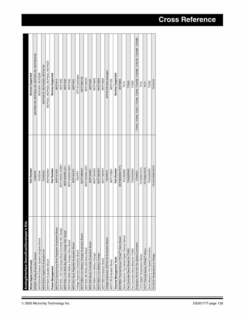
Cross Reference
tMix
ed S
ign
al (
con
tin
ued
)P
art
Nu
mb
erD
evic
es S
up
po
rted
MX
DE
V A
nalo
g E
valu
atio
n S
yste
mD
VM
CP
AM
CP
3001
/02,
MC
P30
04,/0
8, M
CP
3201
/02,
MC
P32
04/0
8
MC
P32
04/0
8 E
vlua
tion
Sys
tem
Dau
ghte
r B
oard
DV
3204
AM
CP
3204
, MC
P32
08
MC
P42
XX
X D
igita
l Pot
Eva
luat
ion
Kit
DV
42X
XX
MC
P42
010,
MC
P42
050,
MC
P42
100
MC
P40
2X E
valu
atio
n B
oard
MC
P40
2XE
VM
CP
4021
, MC
P40
22, M
CP
4023
, MC
P40
24
Po
wer
Man
agem
ent
Par
t N
um
ber
Dev
ices
Su
pp
ort
ed
MC
P16
12 S
ynch
rono
us B
uck
Reg
ulat
or E
valu
atio
n B
oard
MC
P16
12E
VM
CP
1612
MC
P16
30 +
12V
Dua
l Out
put B
uck
Con
vert
er R
ef. D
esig
nM
CP
1630
RD
-DD
BK
1M
CP
1630
MC
P16
30 L
i-Ion
Mul
ti B
ay B
atte
ry C
harg
er R
ef. D
esig
nM
CP
1630
RD
-LIC
1M
CP
1630
MC
P16
30 N
iMH
Bat
tery
Cha
rger
Dem
o B
oard
MC
P16
30D
M-N
MC
1M
CP
1630
MC
P16
01 B
uck
Reg
ulat
or E
valu
atio
n B
oard
MC
P16
01E
VM
CP
1601
Vol
tage
Sup
ervi
sor
Eva
luat
ion
Boa
rdV
SU
PE
VS
OT-
23 p
acka
ges
MC
P73
86X
Li-I
on B
atte
ry C
harg
er E
valu
atio
n B
oard
MC
P73
86X
EV
MC
P73
861/
62
MC
P16
5X 3
W W
hite
LE
D D
emo
Boa
rdM
CP
1650
DM
-LE
D1
MC
P16
50/5
1
MC
P16
50 B
oost
Con
trol
ler
Eva
luat
ion
Boa
rdM
CP
1650
EV
MC
P16
50
MC
P73
84X
Li-I
on B
atte
ry C
harg
erM
CP
7384
XE
VM
CP
7384
X
MC
P73
82X
Li-I
on B
atte
ry C
harg
erM
CP
7382
XE
VM
CP
7382
X
MC
P73
855
Eva
luat
ion
Boa
rdM
CP
7385
5EV
MC
P73
855
Vol
tage
Sup
ervi
sor
SO
T23
-5/6
Eva
luat
ion
Boa
rdV
SU
PE
V2
SO
T23
-5/6
-lead
pac
kage
s
MC
P17
26 E
valu
atio
n B
oard
MC
P17
26E
VM
CP
1726
Th
erm
al M
anag
emen
t To
ols
Par
t N
um
ber
Dev
ices
Su
pp
ort
ed
MC
P98
00 T
herm
al S
enso
r P
ICta
il™ D
emo
Boa
rdM
CP
9800
DM
-PC
TL
MC
P98
00
Dem
o B
oard
for
Tin
y S
eria
l Dig
ital T
herm
al S
enso
rT
C74
DE
MO
TC
74
Fan
Con
trol
ler
Dem
o B
oard
for
TC
652
TC
652D
EM
OT
C65
2
Fan
Con
trol
ler
Dem
o B
oard
for
TC
650
TC
650D
EM
OT
C65
0
Eva
luat
ion
Kit
for
the
Fan
Spe
ed C
ontr
olle
rsT
C64
2EV
TC
642,
TC
646,
TC
647,
TC
648,
TC
649,
TC
642B
, TC
646B
, TC
647B
, TC
648B
, TC
649B
TC
72 D
igita
l Tem
pera
ture
Sen
sor
TC
72D
M-P
ICT
LT
C72
TC
77 T
herm
al S
enso
r P
ICta
il™ D
emo
TC
77D
M-P
ICT
LT
C77
Dem
o B
oard
for
Fan
Spe
ed C
ontr
olle
rsT
C64
2DE
MO
TC
642
TC
1047
A T
empe
ratu
re to
Vol
tage
TC
1047
AD
M-P
ICT
LT
C10
47A
An
alo
g/In
terf
ace
Dem
o/E
val/D
evel
op
er’s
Kits
© 2005 Microchip Technology Inc. DS30177T-page 139

Development Systems Ordering Guide
NOTES:
DS30177T-page 140 © 2005 Microchip Technology Inc.
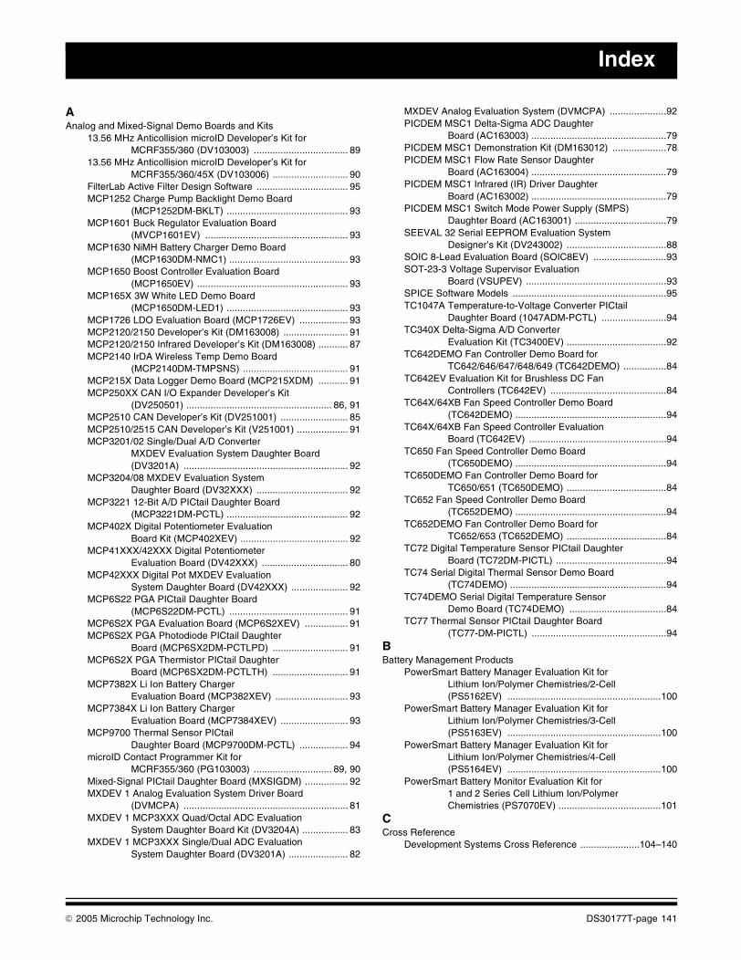
Index
AAnalog and Mixed-Signal Demo Boards and Kits
13.56 MHz Anticollision microID Developer’s Kit for MCRF355/360 (DV103003) ................................... 89
13.56 MHz Anticollision microID Developer’s Kit for MCRF355/360/45X (DV103006) ............................ 90
FilterLab Active Filter Design Software .................................. 95MCP1252 Charge Pump Backlight Demo Board
(MCP1252DM-BKLT) ............................................. 93MCP1601 Buck Regulator Evaluation Board
(MVCP1601EV) ..................................................... 93MCP1630 NiMH Battery Charger Demo Board
(MCP1630DM-NMC1) ............................................ 93MCP1650 Boost Controller Evaluation Board
(MCP1650EV) ........................................................ 93MCP165X 3W White LED Demo Board
(MCP1650DM-LED1) ............................................. 93MCP1726 LDO Evaluation Board (MCP1726EV) .................. 93MCP2120/2150 Developer’s Kit (DM163008) ........................ 91MCP2120/2150 Infrared Developer’s Kit (DM163008) ........... 87MCP2140 IrDA Wireless Temp Demo Board
(MCP2140DM-TMPSNS) ....................................... 91MCP215X Data Logger Demo Board (MCP215XDM) ........... 91MCP250XX CAN I/O Expander Developer’s Kit
(DV250501) ...................................................... 86, 91MCP2510 CAN Developer’s Kit (DV251001) ......................... 85MCP2510/2515 CAN Developer’s Kit (V251001) ................... 91MCP3201/02 Single/Dual A/D Converter
MXDEV Evaluation System Daughter Board (DV3201A) ............................................................. 92
MCP3204/08 MXDEV Evaluation System Daughter Board (DV32XXX) .................................. 92
MCP3221 12-Bit A/D PICtail Daughter Board (MCP3221DM-PCTL) ............................................. 92
MCP402X Digital Potentiometer Evaluation Board Kit (MCP402XEV) ........................................ 92
MCP41XXX/42XXX Digital Potentiometer Evaluation Board (DV42XXX) ................................ 80
MCP42XXX Digital Pot MXDEV Evaluation System Daughter Board (DV42XXX) ..................... 92
MCP6S22 PGA PICtail Daughter Board (MCP6S22DM-PCTL) ............................................ 91
MCP6S2X PGA Evaluation Board (MCP6S2XEV) ................ 91MCP6S2X PGA Photodiode PICtail Daughter
Board (MCP6SX2DM-PCTLPD) ............................ 91MCP6S2X PGA Thermistor PICtail Daughter
Board (MCP6SX2DM-PCTLTH) ............................ 91MCP7382X Li Ion Battery Charger
Evaluation Board (MCP382XEV) ........................... 93MCP7384X Li Ion Battery Charger
Evaluation Board (MCP7384XEV) ......................... 93MCP9700 Thermal Sensor PICtail
Daughter Board (MCP9700DM-PCTL) .................. 94microID Contact Programmer Kit for
MCRF355/360 (PG103003) ............................. 89, 90Mixed-Signal PICtail Daughter Board (MXSIGDM) ................ 92MXDEV 1 Analog Evaluation System Driver Board
(DVMCPA) ............................................................. 81MXDEV 1 MCP3XXX Quad/Octal ADC Evaluation
System Daughter Board Kit (DV3204A) ................. 83MXDEV 1 MCP3XXX Single/Dual ADC Evaluation
System Daughter Board (DV3201A) ...................... 82
MXDEV Analog Evaluation System (DVMCPA) .....................92PICDEM MSC1 Delta-Sigma ADC Daughter
Board (AC163003) ..................................................79PICDEM MSC1 Demonstration Kit (DM163012) ....................78PICDEM MSC1 Flow Rate Sensor Daughter
Board (AC163004) ..................................................79PICDEM MSC1 Infrared (IR) Driver Daughter
Board (AC163002) ..................................................79PICDEM MSC1 Switch Mode Power Supply (SMPS)
Daughter Board (AC163001) ..................................79SEEVAL 32 Serial EEPROM Evaluation System
Designer’s Kit (DV243002) .....................................88SOIC 8-Lead Evaluation Board (SOIC8EV) ...........................93SOT-23-3 Voltage Supervisor Evaluation
Board (VSUPEV) ....................................................93SPICE Software Models .........................................................95TC1047A Temperature-to-Voltage Converter PICtail
Daughter Board (1047ADM-PCTL) ........................94TC340X Delta-Sigma A/D Converter
Evaluation Kit (TC3400EV) .....................................92TC642DEMO Fan Controller Demo Board for
TC642/646/647/648/649 (TC642DEMO) ................84TC642EV Evaluation Kit for Brushless DC Fan
Controllers (TC642EV) ...........................................84TC64X/64XB Fan Speed Controller Demo Board
(TC642DEMO) ........................................................94TC64X/64XB Fan Speed Controller Evaluation
Board (TC642EV) ...................................................94TC650 Fan Speed Controller Demo Board
(TC650DEMO) ........................................................94TC650DEMO Fan Controller Demo Board for
TC650/651 (TC650DEMO) .....................................84TC652 Fan Speed Controller Demo Board
(TC652DEMO) ........................................................94TC652DEMO Fan Controller Demo Board for
TC652/653 (TC652DEMO) .....................................84TC72 Digital Temperature Sensor PICtail Daughter
Board (TC72DM-PICTL) .........................................94TC74 Serial Digital Thermal Sensor Demo Board
(TC74DEMO) ..........................................................94TC74DEMO Serial Digital Temperature Sensor
Demo Board (TC74DEMO) ....................................84TC77 Thermal Sensor PICtail Daughter Board
(TC77-DM-PICTL) ..................................................94BBattery Management Products
PowerSmart Battery Manager Evaluation Kit for Lithium Ion/Polymer Chemistries/2-Cell (PS5162EV) .........................................................100
PowerSmart Battery Manager Evaluation Kit for Lithium Ion/Polymer Chemistries/3-Cell (PS5163EV) .........................................................100
PowerSmart Battery Manager Evaluation Kit for Lithium Ion/Polymer Chemistries/4-Cell (PS5164EV) .........................................................100
PowerSmart Battery Monitor Evaluation Kit for 1 and 2 Series Cell Lithium Ion/Polymer Chemistries (PS7070EV) ......................................101
CCross Reference
Development Systems Cross Reference ......................104–140
© 2005 Microchip Technology Inc. DS30177T-page 141
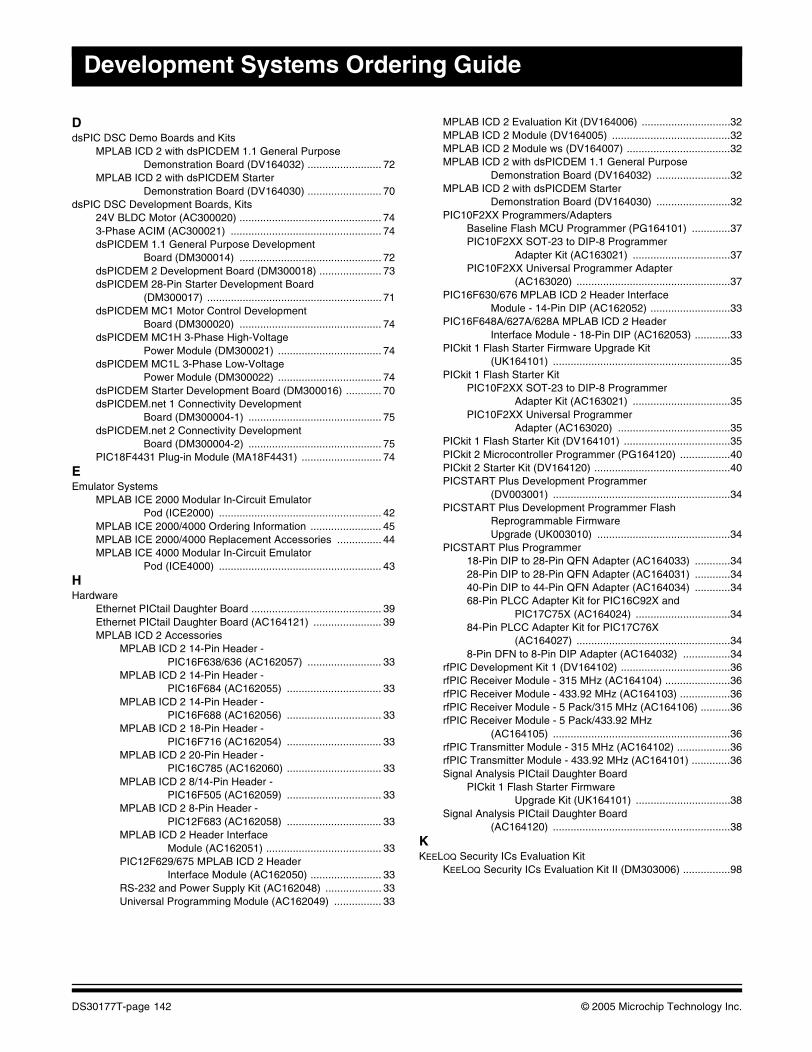
Development Systems Ordering Guide
DdsPIC DSC Demo Boards and Kits
MPLAB ICD 2 with dsPICDEM 1.1 General Purpose Demonstration Board (DV164032) ......................... 72
MPLAB ICD 2 with dsPICDEM Starter Demonstration Board (DV164030) ......................... 70
dsPIC DSC Development Boards, Kits24V BLDC Motor (AC300020) ................................................ 743-Phase ACIM (AC300021) ................................................... 74dsPICDEM 1.1 General Purpose Development
Board (DM300014) ................................................ 72dsPICDEM 2 Development Board (DM300018) ..................... 73dsPICDEM 28-Pin Starter Development Board
(DM300017) ........................................................... 71dsPICDEM MC1 Motor Control Development
Board (DM300020) ................................................ 74dsPICDEM MC1H 3-Phase High-Voltage
Power Module (DM300021) ................................... 74dsPICDEM MC1L 3-Phase Low-Voltage
Power Module (DM300022) ................................... 74dsPICDEM Starter Development Board (DM300016) ............ 70dsPICDEM.net 1 Connectivity Development
Board (DM300004-1) ............................................. 75dsPICDEM.net 2 Connectivity Development
Board (DM300004-2) ............................................. 75PIC18F4431 Plug-in Module (MA18F4431) ........................... 74
EEmulator Systems
MPLAB ICE 2000 Modular In-Circuit Emulator Pod (ICE2000) ....................................................... 42
MPLAB ICE 2000/4000 Ordering Information ........................ 45MPLAB ICE 2000/4000 Replacement Accessories ............... 44MPLAB ICE 4000 Modular In-Circuit Emulator
Pod (ICE4000) ....................................................... 43HHardware
Ethernet PICtail Daughter Board ............................................ 39Ethernet PICtail Daughter Board (AC164121) ....................... 39MPLAB ICD 2 Accessories
MPLAB ICD 2 14-Pin Header - PIC16F638/636 (AC162057) ......................... 33
MPLAB ICD 2 14-Pin Header - PIC16F684 (AC162055) ................................ 33
MPLAB ICD 2 14-Pin Header - PIC16F688 (AC162056) ................................ 33
MPLAB ICD 2 18-Pin Header - PIC16F716 (AC162054) ................................ 33
MPLAB ICD 2 20-Pin Header - PIC16C785 (AC162060) ................................ 33
MPLAB ICD 2 8/14-Pin Header - PIC16F505 (AC162059) ................................ 33
MPLAB ICD 2 8-Pin Header - PIC12F683 (AC162058) ................................ 33
MPLAB ICD 2 Header Interface Module (AC162051) ....................................... 33
PIC12F629/675 MPLAB ICD 2 Header Interface Module (AC162050) ........................ 33
RS-232 and Power Supply Kit (AC162048) ................... 33Universal Programming Module (AC162049) ................ 33
MPLAB ICD 2 Evaluation Kit (DV164006) ..............................32MPLAB ICD 2 Module (DV164005) ........................................32MPLAB ICD 2 Module ws (DV164007) ...................................32MPLAB ICD 2 with dsPICDEM 1.1 General Purpose
Demonstration Board (DV164032) .........................32MPLAB ICD 2 with dsPICDEM Starter
Demonstration Board (DV164030) .........................32PIC10F2XX Programmers/Adapters
Baseline Flash MCU Programmer (PG164101) .............37PIC10F2XX SOT-23 to DIP-8 Programmer
Adapter Kit (AC163021) .................................37PIC10F2XX Universal Programmer Adapter
(AC163020) ....................................................37PIC16F630/676 MPLAB ICD 2 Header Interface
Module - 14-Pin DIP (AC162052) ...........................33PIC16F648A/627A/628A MPLAB ICD 2 Header
Interface Module - 18-Pin DIP (AC162053) ............33PICkit 1 Flash Starter Firmware Upgrade Kit
(UK164101) ............................................................35PICkit 1 Flash Starter Kit
PIC10F2XX SOT-23 to DIP-8 Programmer Adapter Kit (AC163021) .................................35
PIC10F2XX Universal Programmer Adapter (AC163020) ......................................35
PICkit 1 Flash Starter Kit (DV164101) ....................................35PICkit 2 Microcontroller Programmer (PG164120) .................40PICkit 2 Starter Kit (DV164120) ..............................................40PICSTART Plus Development Programmer
(DV003001) ............................................................34PICSTART Plus Development Programmer Flash
Reprogrammable Firmware Upgrade (UK003010) .............................................34
PICSTART Plus Programmer18-Pin DIP to 28-Pin QFN Adapter (AC164033) ............3428-Pin DIP to 28-Pin QFN Adapter (AC164031) ............3440-Pin DIP to 44-Pin QFN Adapter (AC164034) ............3468-Pin PLCC Adapter Kit for PIC16C92X and
PIC17C75X (AC164024) ................................3484-Pin PLCC Adapter Kit for PIC17C76X
(AC164027) ....................................................348-Pin DFN to 8-Pin DIP Adapter (AC164032) ................34
rfPIC Development Kit 1 (DV164102) .....................................36rfPIC Receiver Module - 315 MHz (AC164104) ......................36rfPIC Receiver Module - 433.92 MHz (AC164103) .................36rfPIC Receiver Module - 5 Pack/315 MHz (AC164106) ..........36rfPIC Receiver Module - 5 Pack/433.92 MHz
(AC164105) ............................................................36rfPIC Transmitter Module - 315 MHz (AC164102) ..................36rfPIC Transmitter Module - 433.92 MHz (AC164101) .............36Signal Analysis PICtail Daughter Board
PICkit 1 Flash Starter Firmware Upgrade Kit (UK164101) ................................38
Signal Analysis PICtail Daughter Board (AC164120) ............................................................38
KKEELOQ Security ICs Evaluation Kit
KEELOQ Security ICs Evaluation Kit II (DM303006) ................98
DS30177T-page 142 © 2005 Microchip Technology Inc.
Index
PPICmicro MCU Demo Boards and Kits
Low-Power Solutions Demonstration Board (DM163026) ........................................................... 67
PICDEM 1 Demonstration Board (DM163001) ...................... 52PICDEM 17 Demonstration Board (DM173001) .................... 52PICDEM 18R Demonstration Kit (DM163006) ....................... 55PICDEM 2 Plus Demonstration Board (DM163022) .............. 53PICDEM 3 Demonstration Board (DM163003) ...................... 52PICDEM 4 Demonstration Board (DM163014) ...................... 54PICDEM CAN-LIN 1 Demonstration Board
(DM163007) ........................................................... 64PICDEM CAN-LIN 2 Demonstration Board
(DM163011) ........................................................... 64PICDEM CAN-LIN 3 Demonstration Board
(DM163015) ........................................................... 64PICDEM FS USB Demonstration Board
(DM163025) ........................................................... 61PICDEM HPC Explorer Board (DM183022) ........................... 59PICDEM LCD Demonstration Board (DM163028) ................. 62PICDEM LIN Demonstration Kit (DM163005) ........................ 65PICDEM MC Development Board (DM183011) ..................... 57PICDEM MC LV Development Board (DM183021) ............... 58PICDEM Mechatronics Demonstration Kit
(DM163029) ........................................................... 56PICDEM USB Demonstration Kit (DM163010) ...................... 60PICDEM Z 2.4 GHz Demonstration Kit (DM163027-2) .......... 63PICDEM Z 2.4 GHz RF Card (AC163027-2) .......................... 63PICDEM Z Motherboard (AC163027-1) ................................. 63PICDEM.net Demonstration/Evaluation Board
(DM163004-LT) ...................................................... 66Programmer Systems
28-Pin QFN Adapter Kit for 18-Pin ZIF Socket (AC164033) ............................................................ 50
28-Pin QFN Adapter Kit for 40-Pin ZIF Socket (AC164031) ............................................................ 50
44-Pin QFN Adapter Kit (AC164034) ..................................... 5068-Pin PLCC Adapter Kit (AC164024) ................................... 506-Pin SOT-23/8P DIP Programmer Adapter
(AC163020) ............................................................ 5084-Pin PLCC Adapter Kit (AC164027) ................................... 508-Pin DFN Adapter Kit (AC164032) ....................................... 50ICSP Socket Module (AC004004) .......................................... 49MPLAB PM3 ICSP Cable (AC002021) .................................. 50MPLAB PM3 Universal Device Programmer
(DV007004) ............................................................ 48PRO MATE II Device Programmer Elastomeric
Connectors (AC004005) ........................................ 50PRO MATE II Device programmer to MPLAB PM3
Socket Module Adapter (AC164350) ..................... 48SSoftware Tools
CMX-RTX for dsPIC30F Devices (SW300031) ...................... 24CMX-Scheduler for dsPIC DSC Devices (SW300030) .......... 25CMX-Tiny+ for dsPIC30F Devices (SW300032) .................... 26Digital Filter Design (SW300001) ........................................... 22Digital Filter Design Lite (SW300001-LT) ............................... 22dsPIC DSC Asymmetric Key Embedded Encryption
Library Software License - 25K to 100K Units (SW300055-100K) ............................... 19
dsPIC DSC Asymmetric Key Embedded Encryption Library Software License - 5K to 25K Units (SW300055-25K) ...................................19
dsPIC DSC Asymmetric Key Embedded Encryption Library Software License - Evaluation Copy (SW300055-EVAL) .................................................19
dsPIC DSC Asymmetric Key Embedded Encryption Library Software License - Up to 5K Units (SW300055-5K) .......................................19
dsPIC DSC Symmetric Key Embedded Encryption Library Software License - 25K to 100K Units (SW300050-100K) ...............................18
dsPIC DSC Symmetric Key Embedded Encryption Library Software License - 5K to 25K Units (SW300050-25K) ...................................18
dsPIC DSC Symmetric Key Embedded Encryption Library Software License - Evaluation Copy (SW300050-EVAL) .................................................18
dsPIC DSC Symmetric Key Embedded Encryption Library Software License - Up to 5K Units (SW300050-5K) .......................................18
dsPIC30F Acoustic Echo Cancellation LibraryAccessory Kit (AC300030) .............................................17
dsPIC30F Acoustic Echo Cancellation Library Software License - 25K to 100K Units (SW300060-100K) ..................................................17
dsPIC30F Acoustic Echo Cancellation Library Software License - 5K to 25K Units (SW300060-25K) ....................................................17
dsPIC30F Acoustic Echo Cancellation Library Software License - Evaluation Copy (SW300060-EVAL) .................................................17
dsPIC30F Acoustic Echo Cancellation Library Software License - Up to 5K Units (SW300060-5K) ......................................................17
dsPIC30F DSP Library (SW300022) ......................................11dsPIC30F Math Library (SW300020) ......................................12dsPIC30F Noise Suppression Library
Accessory Kit (AC300030) .............................................16dsPIC30F Noise Suppression Library Software License -
25K to 100K Units (SW300040-100K) ....................16dsPIC30F Noise Suppression Library Software License -
5K to 25K Units (SW300040-25K) ..........................16dsPIC30F Noise Suppression Library Software License -
Evaluation Copy (SW300040-EVAL) ......................16dsPIC30F Noise Suppression Library Software License -
Up to 5K Units (SW300040-5K) ..............................16dsPIC30F Peripheral Library (SW300021) .............................13dsPIC30F Speech Encoder/Decoder Library Software
License - Evaluation Copy (SW300070-EVAL) ......20dsPIC30F Speech Encoder/Decoder Library Software
License - Up to 100K Units (SW300070-100K) ......20dsPIC30F Speech Encoder/Decoder Library Software
License - Up to 25K Units (SW300070-25K) ..........20dsPIC30F Speech Encoder/Decoder Library Software
License - Up to 5K Units (SW300070-5K) ..............20dsPIC30F Speech Recognition Library
Accessory Kit (AC300031) .............................................15dsPIC30F Speech Recognition Library Software
License - 25K to 100K Units (SW300012) ..............15dsPIC30F Speech Recognition Library Software
License - 5K to 25K Units (SW300011) ..................15
© 2005 Microchip Technology Inc. DS30177T-page 143
Development Systems Ordering Guide
dsPIC30F Speech Recognition Library Software License - Evaluation Copy (SW300010-EVAL) ................................................ 15
dsPIC30F Speech Recognition Library Software License - Up to 5K Units (SW300010) ................... 15
dsPIC30F V.22bis Soft Modem Library (SW300002) ............. 14dsPIC30F V.32bis Soft Modem Library Software
License - 25K to 100K Units (SW300005) ............. 14dsPIC30F V.32bis Soft Modem Library Software
License - 5K to 25K Units (SW300004) ................. 14dsPIC30F V.32bis Soft Modem Library Software License -
Evaluation Copy (SW300003-EVAL) ..................... 14dsPIC30F V.32bis Soft Modem Library Software
License - Up to 5K Units (SW300003) ................... 14dsPICworks Data Analysis and DSP Software
(SW300023) ........................................................... 21FilterLab Active Filter Software Design Tool .......................... 27KEELOQ Security ICs License CD (DS40038) ........................ 29MPLAB C18 C Compiler (SW006011) ..................................... 9MPLAB C30 C Compiler (SW006012) ................................... 10MPLAB IDE (SW007002) ......................................................... 6Total Endurance Software Model ........................................... 28
DS30177T-page 144 © 2005 Microchip Technology Inc.
Index
NOTES:
© 2005 Microchip Technology Inc. DS30177T-page 145
DS30177T-page 146 © 2005 Microchip Technology Inc.
AMERICASCorporate Office2355 West Chandler Blvd.Chandler, AZ 85224-6199Tel: 480-792-7200 Fax: 480-792-7277Technical Support: http://support.microchip.comWeb Address: www.microchip.com
AtlantaAlpharetta, GA Tel: 770-640-0034 Fax: 770-640-0307
BostonWestborough, MA Tel: 774-760-0087 Fax: 774-760-0088
ChicagoItasca, IL Tel: 630-285-0071 Fax: 630-285-0075
DallasAddison, TX Tel: 972-818-7423 Fax: 972-818-2924
DetroitFarmington Hills, MI Tel: 248-538-2250Fax: 248-538-2260
KokomoKokomo, IN Tel: 765-864-8360Fax: 765-864-8387
Los AngelesMission Viejo, CA Tel: 949-462-9523 Fax: 949-462-9608
San JoseMountain View, CA Tel: 650-215-1444Fax: 650-961-0286
TorontoMississauga, Ontario, CanadaTel: 905-673-0699 Fax: 905-673-6509
ASIA/PACIFICAustralia - SydneyTel: 61-2-9868-6733 Fax: 61-2-9868-6755
China - BeijingTel: 86-10-8528-2100 Fax: 86-10-8528-2104
China - ChengduTel: 86-28-8676-6200 Fax: 86-28-8676-6599
China - FuzhouTel: 86-591-8750-3506 Fax: 86-591-8750-3521
China - Hong Kong SARTel: 852-2401-1200 Fax: 852-2401-3431
China - ShanghaiTel: 86-21-5407-5533 Fax: 86-21-5407-5066China - ShenyangTel: 86-24-2334-2829Fax: 86-24-2334-2393
China - ShenzhenTel: 86-755-8203-2660 Fax: 86-755-8203-1760
China - ShundeTel: 86-757-2839-5507 Fax: 86-757-2839-5571
China - QingdaoTel: 86-532-502-7355 Fax: 86-532-502-7205
ASIA/PACIFICIndia - BangaloreTel: 91-80-2229-0061 Fax: 91-80-2229-0062
India - New DelhiTel: 91-11-5160-8631Fax: 91-11-5160-8632
Japan - KanagawaTel: 81-45-471- 6166 Fax: 81-45-471-6122
Korea - SeoulTel: 82-2-554-7200 Fax: 82-2-558-5932 or 82-2-558-5934
Malaysia - PenangTel:011-604-646-8870Fax:011-604-646-5086
Philippines - ManilaTel: 011-632-634-9065Fax: 011-632-634-9069
SingaporeTel: 65-6334-8870 Fax: 65-6334-8850
Taiwan - KaohsiungTel: 886-7-536-4818Fax: 886-7-536-4803
Taiwan - TaipeiTel: 886-2-2500-6610 Fax: 886-2-2508-0102
Taiwan - HsinchuTel: 886-3-572-9526Fax: 886-3-572-6459
EUROPEAustria - WeisTel: 43-7242-2244-399Fax: 43-7242-2244-393Denmark - BallerupTel: 45-4450-2828 Fax: 45-4485-2829
France - MassyTel: 33-1-69-53-63-20 Fax: 33-1-69-30-90-79
Germany - IsmaningTel: 49-89-627-144-0 Fax: 49-89-627-144-44
Italy - Milan Tel: 39-0331-742611 Fax: 39-0331-466781
Netherlands - DrunenTel: 31-416-690399 Fax: 31-416-690340
England - BerkshireTel: 44-118-921-5869Fax: 44-118-921-5820
WORLDWIDE SALES AND SERVICE
04/20/05