methods and techniques for intelligent navigation and manipulation for bomb disposal and rescue...
TRANSCRIPT

Methods and techniques for intelligent navigationand manipulation for bomb disposal and rescue
operationsCarlos Beltran-Gonzalez
Lira-LabUniversity of Genova
Italy
Antonios GasteratosAngelos Amanatiadis
Dimitrios ChrysostomouDemocritus University of Thrace
XanthiGreece
Roberto GuzmanROBOTNIK
ValenciaSpain
Andras TothLorand SzollosiAndras Juhasz
Peter GalambosUniversity of Technology and Economics
BudapestHungary
Abstract —Handing a teleoperated robotic mechanism demands special skills
and involves particular problems. Especially in cases of robots dealingwith rescue operations or bomb disposal. In such cases any lost incommunications might arise unpredictable results. Also either a bombor a survivor need attentional handling. In this paper we describeautomatic methods and techniques developed on a multifunctionalteleoperated robot. These intend to assist both the robot and thehuman operator in accomplishing their mission towards rescue orbomb disposal.
Keywords: robotics, teleoperation, rescue, hazardous
I. INTRODUCTION
This paper presents autonomous/semiautonomous roboticsand adaptive behaviours developed in the RESCUER project1.The project will deliver a teleoperated mobile robot designedfor operation in a full range of operations in hazardous envi-ronments. This system will include multifunctional tools, twosimultaneously working robot arms with dextrous grippers, astereo head, smart sensors for ordnance, for human detectionand for the assessment of the environment, autonomous vehicleand advanced information and communication facilities thatwill lead to improvement of the emergency risk management.Fig. 1 depicts the two main components of the RESCUERsystem: the Mobile Control Unit (MCU), this is a van car-rying the three human operators and all the teleoperationequipment (two exoscheletons, an Immersion Cyberglove, ahead mounted display, and a two finger master gripper), andthe Mobile Mechatronic Unit (MMU), that is a mobile robotequiped with an active stereo head, a two finger gripper, aBarrett Hand and two articulated robot manipulators.
The general idea of the RESCUER system is that the Com-mander and the Driver2 will teleoperate the robot via a securewireless connection. Teleoperation in such communicationsconditions is an open research problem. Classic research inteleoperation deals with situations where the parameters of
1European Commission 6th Framework Programme project IST-2003-511492
2These are the two humans controlling the MMU
(a)
(b)
Fig. 1. The components of the RESCUER system, (a) the Mobile ControlUnit (MCU) containing the human operators, and (b) a picture of the designof the Mobile Mechatronic Unit (MMU)
the communication can be somehow modelled (see [1], [2]for surveys). More recently, the appearance of Internet haspopularized the teleoperation of remote robots through packetswitched networks [3] creating the so called reasearch fieldof Internet based teleoperation. In packet switched networks,however, the teleoperation of remote devices faces new diffi-culties. The communication channel is shared with many otherconnections and the data flow is divided in many small datapackets that can be routed in different ways to the destination.
We have proposed to use the same switched networktechnologies for the RESCUER system. The motivations forselecting such communications technology were the low pricesof hardware components and the existence of robust andopen software tools. However, this means that we face the
Proceedings of the 2007 IEEEInternational Workshop on Safety, Security and Rescue RoboticsRome, Italy, September 2007
978-1-4244-1569-4/07/$25.00 2007 IEEE.
complications of using such technologies in a teleoperationscenario, but with the additional complication of having a mo-bile robot that can move into areas where the communicationsmight be totally lost (e.g. inside a building or behind a wall).Moreover, due to the movement of the robot, there will bevariations in the quality of the signals with changes in channelbandwidth and channel quality. All these conditions make thewireless connections to suffer delays, jitter, packet lost, and,occasionally, total lost of the connection.
So far, one of the solution researchers have proposed to dealwith such problems is to implement some kind of autonomyin the remote robotic system. This autonomy usually has twomain purposes: (i) improve the control of the system thusfacilitating the work of the human, (ii) avoid the lost or damageof the remote robot. In this line of research, we are imple-menting some autonomy in the MMU in the form of auto-matic/semiautomatic robotics and adaptive behaviours. Thesealgorithms contribute to what we call automatic intelligence;this being a set of techniques, methods, and algorithms thatfacilitate the control and use of the MMU in the particularlyhard working conditions of the RESCUER system.
In the following sections we describe the concrete imple-mentations of the proposed control approaches. In section II-Athe UG(University of Genova) team describes the current stateof development of the Dexterous Grasping System (DGS).In section II-B the DUTH(University of Thrace) team de-scribes the automatic algorithms implemented in the StereoVision Head (SVH). In section II-C ROBOTNIK describesthe techniques used for the stepping back of the rover in caseof communications interruption. Finally, in section III-A theBUTE(Budapest University of Technology and Economics)team describes the control of the Two Fingers Gripper (2FG).
II. AUTONOMOUS/SEMIAUTONOMOUS ROBOTICS
A. Dexterous Grasping Subsystem
The DGS (Dexterous Grasping Subsystem) is the group ofsoftware and hardware components that control the BarrettHand . The hardware components are: (i) the Cyberglove(master), and (ii) the Barrett Hand (slave). Regarding thesensor capabilities of the Barrett Hand, there are two types ofsensors installed: internal and external. The internal sensors arefactory built strain gauges installed in the hand’s fingers. Thereis one of these sensors for each finger and they can measurethe differential tension of the tendons driving the hand’s joints.
The external sensors are FSR (Force Sensing Resistors).The idea is to provide the possibility of using different typesof FSR technologies. However, for the first prototype of theDGS we have chosen the sensor model A201 manufactured byTekscan. The A201 sensors are small flexible printed circuit,which can be easily installed on any surface. These sensorscan measure forces between two surfaces and are durableenough to stand up to most environments, moreover a morerobust version for hazardous environments is available fromthe manufacturer at a much higher price.
We want to give the possibility of having a high density ofFSR sensors on the Barret Hand’s surface and the possibility
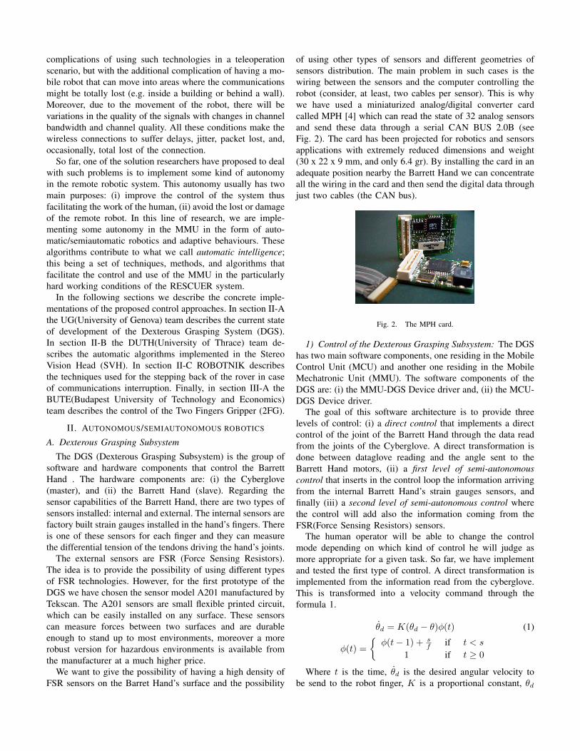
of using other types of sensors and different geometries ofsensors distribution. The main problem in such cases is thewiring between the sensors and the computer controlling therobot (consider, at least, two cables per sensor). This is whywe have used a miniaturized analog/digital converter cardcalled MPH [4] which can read the state of 32 analog sensorsand send these data through a serial CAN BUS 2.0B (seeFig. 2). The card has been projected for robotics and sensorsapplications with extremely reduced dimensions and weight(30 x 22 x 9 mm, and only 6.4 gr). By installing the card in anadequate position nearby the Barrett Hand we can concentrateall the wiring in the card and then send the digital data throughjust two cables (the CAN bus).
Fig. 2. The MPH card.
1) Control of the Dexterous Grasping Subsystem: The DGShas two main software components, one residing in the MobileControl Unit (MCU) and another one residing in the MobileMechatronic Unit (MMU). The software components of theDGS are: (i) the MMU-DGS Device driver and, (ii) the MCU-DGS Device driver.
The goal of this software architecture is to provide threelevels of control: (i) a direct control that implements a directcontrol of the joint of the Barrett Hand through the data readfrom the joints of the Cyberglove. A direct transformation isdone between dataglove reading and the angle sent to theBarrett Hand motors, (ii) a first level of semi-autonomouscontrol that inserts in the control loop the information arrivingfrom the internal Barrett Hand’s strain gauges sensors, andfinally (iii) a second level of semi-autonomous control wherethe control will add also the information coming from theFSR(Force Sensing Resistors) sensors.
The human operator will be able to change the controlmode depending on which kind of control he will judge asmore appropriate for a given task. So far, we have implementand tested the first type of control. A direct transformation isimplemented from the information read from the cyberglove.This is transformed into a velocity command through theformula 1.
θd = K(θd − θ)φ(t) (1)
φ(t) =
φ(t− 1) + sf if t < s
1 if t ≥ 0
Where t is the time, θd is the desired angular velocity tobe send to the robot finger, K is a proportional constant, θd
is the desired angle read from the dataglove, θ is the currentangle of the robotic hand finger (read from the finger encoder),φ(t) is a smoothing adaptation function, s is a convenienttime threshold (computed empirically to provide a smoothalignment of the glove and the robotic hand when startingthe system) and f is the sampling frequency of the dataglovein Hz.
This control is implemented using the realtime control modeof the Barrett Hand. In other words, the control is closedthrough the local computer and not in the internal DSP (DigitalSignal Processor) installed on the hand. This has the advantagethat we can implement via software whatever control law wewant providing the capability of changing the control law inrun time if needed.
B. Stereo Vision Head
1) Image Stabilization: The RESCUER’s stereo head apartfrom the video input that will provide to the operator (througha Head Mounted Display (HMD)), it will perform also opticalmeasurements that will be utilized for the navigation as well.Such image processing algorithms require image sequences,free of high frequency unwanted movements, in order toexport the optimal results. Image stabilization is the processwhich removes the undesirable position fluctuations of a videosequence improving, therefore, its visual quality. Particularly,this is useful in various applications such as localization, map-ping, motion coding, video compression and feature tracking.The most important here is that unless image stabilization isperformed, the Commander will suffer from image waviness.
The proposed stabilization system is hardware dependentand is consisted of a compact inertial sensor (MTi provided byXsens) for detecting the stereo head pan and tilt movements.Two PID controllers (IBL-2403-CAN provided by Technosoft)compensate the pan and tilt movement of the stereo headapplying opposite moving commands to the servo motors. Thesensor measurements are used as feedback in a closed loop,to control the stereo head movements, one for each degree offreedom, respectively. Furthermore, we apply a Kalman filterthat utilizes a number of past sensor measurements and, thus,the algorithm is adaptive to moving profiles of the MMU.
2) Vergence Control: Vergence angle is the angle betweenthe two optical axes of the cameras. In general, the control ofthe vergence angle relies on the distance from the cameras tothe fixation point. Successfully, control of the vergence anglecan easily affect applications for tracking, gaze holding, depthestimation and 3D scene reconstruction. Numerous algorithmshave been proposed, in order to calculate and control thevergence angle of various stereo robot heads. Many binoculardisparity cues implementations have been used in order tosuccessfully control the vergence angle, while correlationbased techniques [5], [6] are limited.
However, many of these algorithms need a precise andaccurate calibration of the stereo pair, something that wedefinitely want to avoid in semiautonomous robots running inoutdoors environments where there are hardly any means tocorrect the precision of the calibration, in case that it is needed.
Thus, we are using an algorithm which does not rely thatmuch on the camera calibration data. The algorithm utilizesthe correlation index of the two images to control the vergenceangle. Because the correlation index is a global characteristic,there is no need for accurate calibration of the cameras.Moreover, the calculation of disparity maps of the images isavoided, which significantly decreases the computational time,providing at the same time slightly better results.
The algorithm uses as input the two images taken from thestereo head and calculates the Zero Mean Normalized CrossCorrelation (ZNCC):
ZNCC = 1−
∑(u,v)∈W
(I1(u, v)− I1)(I2(u, v)− I2)√ ∑(u,v)∈W
(I1(u, v)− I1)2
∑(u,v)∈W
(I2(u, v)− I2)2
(2)where I1 is the left image and I2 is the right one, while I1
and I2 are the mean values of the gray levels of the images,and W is the image Window. This correlation measure obtainsvalues in the interval [0, 2], where 0 corresponds to identicalimages. Because the mean values are considered, the ZNCCshows great invariance in gain and offset variations.
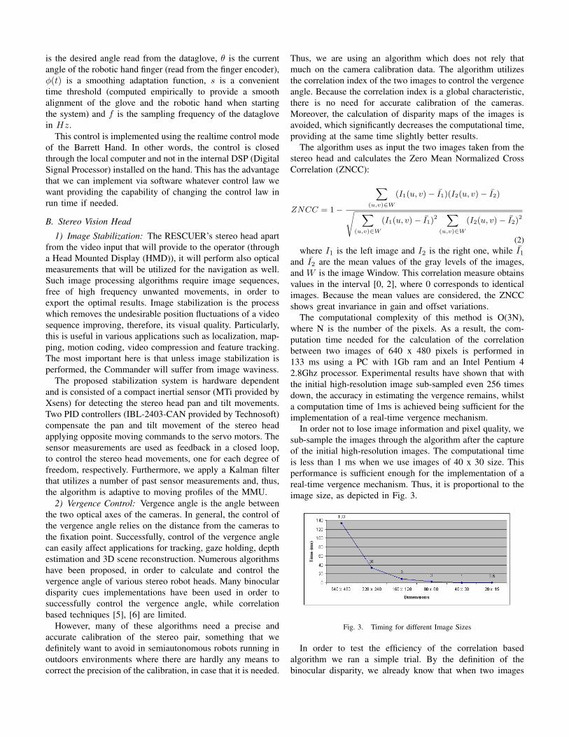
The computational complexity of this method is O(3N),where N is the number of the pixels. As a result, the com-putation time needed for the calculation of the correlationbetween two images of 640 x 480 pixels is performed in133 ms using a PC with 1Gb ram and an Intel Pentium 42.8Ghz processor. Experimental results have shown that withthe initial high-resolution image sub-sampled even 256 timesdown, the accuracy in estimating the vergence remains, whilsta computation time of 1ms is achieved being sufficient for theimplementation of a real-time vergence mechanism.
In order not to lose image information and pixel quality, wesub-sample the images through the algorithm after the captureof the initial high-resolution images. The computational timeis less than 1 ms when we use images of 40 x 30 size. Thisperformance is sufficient enough for the implementation of areal-time vergence mechanism. Thus, it is proportional to theimage size, as depicted in Fig. 3.
Fig. 3. Timing for different Image Sizes
In order to test the efficiency of the correlation basedalgorithm we ran a simple trial. By the definition of thebinocular disparity, we already know that when two images
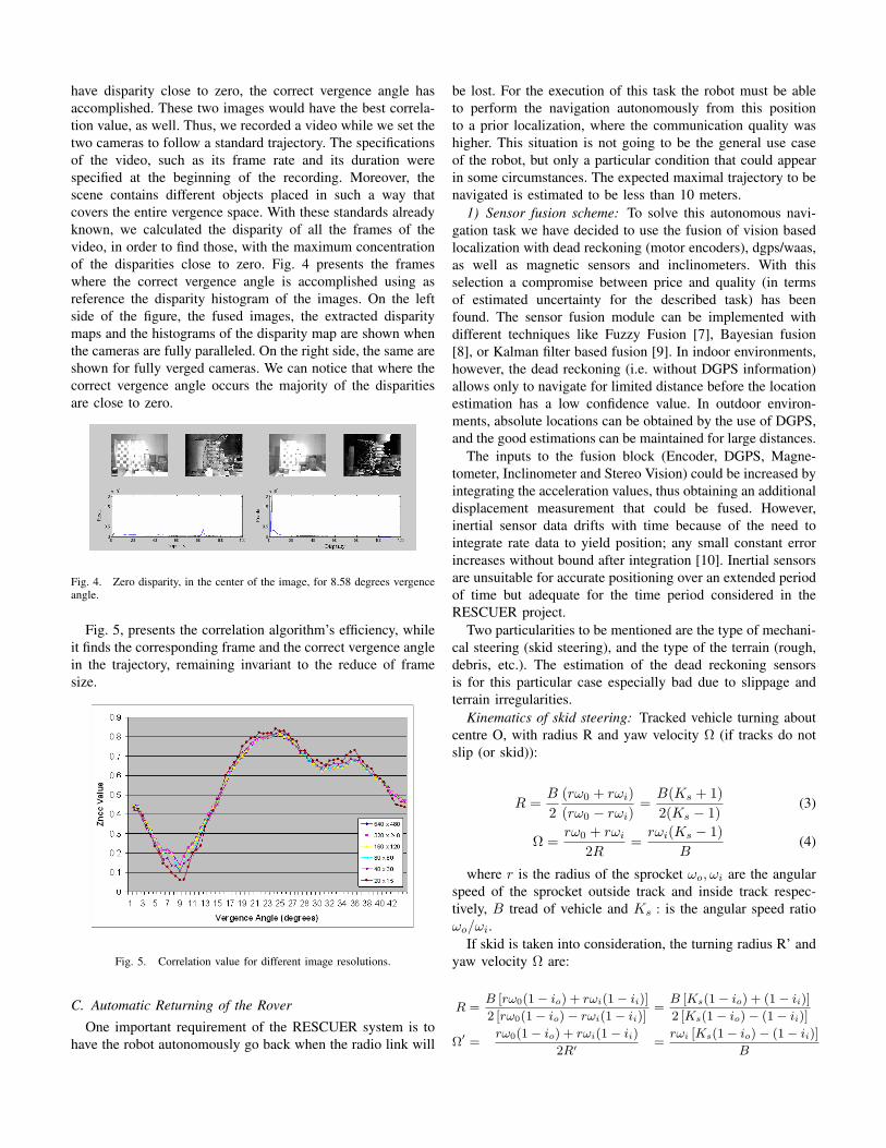
have disparity close to zero, the correct vergence angle hasaccomplished. These two images would have the best correla-tion value, as well. Thus, we recorded a video while we set thetwo cameras to follow a standard trajectory. The specificationsof the video, such as its frame rate and its duration werespecified at the beginning of the recording. Moreover, thescene contains different objects placed in such a way thatcovers the entire vergence space. With these standards alreadyknown, we calculated the disparity of all the frames of thevideo, in order to find those, with the maximum concentrationof the disparities close to zero. Fig. 4 presents the frameswhere the correct vergence angle is accomplished using asreference the disparity histogram of the images. On the leftside of the figure, the fused images, the extracted disparitymaps and the histograms of the disparity map are shown whenthe cameras are fully paralleled. On the right side, the same areshown for fully verged cameras. We can notice that where thecorrect vergence angle occurs the majority of the disparitiesare close to zero.
Fig. 4. Zero disparity, in the center of the image, for 8.58 degrees vergenceangle.
Fig. 5, presents the correlation algorithm’s efficiency, whileit finds the corresponding frame and the correct vergence anglein the trajectory, remaining invariant to the reduce of framesize.
Fig. 5. Correlation value for different image resolutions.
C. Automatic Returning of the Rover
One important requirement of the RESCUER system is tohave the robot autonomously go back when the radio link will
be lost. For the execution of this task the robot must be ableto perform the navigation autonomously from this positionto a prior localization, where the communication quality washigher. This situation is not going to be the general use caseof the robot, but only a particular condition that could appearin some circumstances. The expected maximal trajectory to benavigated is estimated to be less than 10 meters.
1) Sensor fusion scheme: To solve this autonomous navi-gation task we have decided to use the fusion of vision basedlocalization with dead reckoning (motor encoders), dgps/waas,as well as magnetic sensors and inclinometers. With thisselection a compromise between price and quality (in termsof estimated uncertainty for the described task) has beenfound. The sensor fusion module can be implemented withdifferent techniques like Fuzzy Fusion [7], Bayesian fusion[8], or Kalman filter based fusion [9]. In indoor environments,however, the dead reckoning (i.e. without DGPS information)allows only to navigate for limited distance before the locationestimation has a low confidence value. In outdoor environ-ments, absolute locations can be obtained by the use of DGPS,and the good estimations can be maintained for large distances.
The inputs to the fusion block (Encoder, DGPS, Magne-tometer, Inclinometer and Stereo Vision) could be increased byintegrating the acceleration values, thus obtaining an additionaldisplacement measurement that could be fused. However,inertial sensor data drifts with time because of the need tointegrate rate data to yield position; any small constant errorincreases without bound after integration [10]. Inertial sensorsare unsuitable for accurate positioning over an extended periodof time but adequate for the time period considered in theRESCUER project.
Two particularities to be mentioned are the type of mechani-cal steering (skid steering), and the type of the terrain (rough,debris, etc.). The estimation of the dead reckoning sensorsis for this particular case especially bad due to slippage andterrain irregularities.
Kinematics of skid steering: Tracked vehicle turning aboutcentre O, with radius R and yaw velocity Ω (if tracks do notslip (or skid)):
R =B
2(rω0 + rωi)(rω0 − rωi)
=B(Ks + 1)2(Ks − 1)
(3)
Ω =rω0 + rωi
2R=
rωi(Ks − 1)B
(4)
where r is the radius of the sprocket ωo, ωi are the angularspeed of the sprocket outside track and inside track respec-tively, B tread of vehicle and Ks : is the angular speed ratioωo/ωi.
If skid is taken into consideration, the turning radius R’ andyaw velocity Ω are:
R =B [rω0(1− io) + rωi(1− ii)]
2 [rω0(1− io)− rωi(1− ii)]=
B [Ks(1− io) + (1− ii)]
2 [Ks(1− io)− (1− ii)]
Ω′ =rω0(1− io) + rωi(1− ii)
2R′ =rωi [Ks(1− io)− (1− ii)]
B
For a given vehicle over a particular terrain, io and ii dependon the thrusts Fo and Fi.
If we plot the values of radius without and with slip R/R’vs the speed ratio Ks, the value of R’/R is always greater than1, which means that the effect of track skid is to increase theturning radius.
The longitudinal slip could be estimated by means ofthe onboard inertial sensors, and deduced by comparing theexpected response of the rover dynamic model with the valuesobtained by the accelerometers. In the case of RESCUER, themaximal linear speed is going to be about 1 m/s, i.e. 3.6 Km/h,so the slip values io and ii will be very small and the simplifiedmodel can be used.
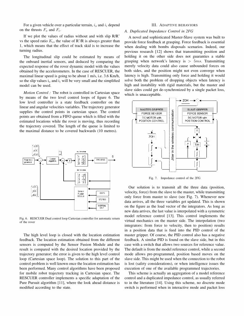
Motion Control : The robot is controlled in Cartesian spaceby means of the two level control loops of figure 6. Thelow level controller is a state feedback controller on thelinear and angular velocities variables. The trajectory generatorsupplies the control points in cartesian space. The controlpoints are obtained from a FIFO queue which is filled with theestimated locations while the rover is moving, thus recordingthe trajectory covered. The length of the queue is limited tothe maximal distance to be covered backwards (10 metres).
Fig. 6. RESCUER Dual control loop Cartesian controller for automatic returnof the rover
The high level loop is closed with the location estimationfeedback. The location estimation obtained from the differentsensors is computed by the Sensor Fusion Module and theresult is compared with the desired location provided by thetrajectory generator; the error is given to the high level controlloop (Cartesian space loop). The solution to this part of thecontrol problem is well known once the location estimation hasbeen performed. Many control algorithms have been proposedfor mobile robot trajectory tracking in Cartesian space. TheRESCUER controller implements a specific adaptation of thePure Pursuit algorithm [11], where the look ahead distance ismodified according to the state.
III. ADAPTIVE BEHAVIORS
A. Duplicated Impedance Control in 2FG
A novel and sophisticated Master-Slave system was built toprovide force feedback at grasping. Force feedback is essentialwhen dealing with bombs disposals scenarios. Indeed, ourprevious research [12] shows that transmitting position andholding it on the other side does not guaranties a stablegrasping when network’s latency is > 5ms. Transmittingmerely velocity data could also cause unbounded forces onboth sides, and the position might not even converge whenlatency is high. Transmitting only force and holding it wouldsolve both the problem of dropping objects when latency ishigh and instability with rigid materials, but the master andslave sides could get de-synchronized by a single packet loss,which is unacceptable.
Fig. 7. Impedance control of the 2FG
Our solution is to transmit all the three data (position,velocity, force) from the slave to the master, while transmittingonly force from master to slave (see Fig. 7). Whenever newdata arrives, all the three variables get updated. This is shownon the figure as the load vector of the integrators. As long asnew data arrives, the last value is interpolated with a symmetricmodel reference control [13]. This control implements thevirtual mechanics on the master side. The interpolation (twointegrators: from force to velocity, then to position) resultsin a position data that is feed into the PID control of themaster gripper. Of course, the PID control also has a negativefeedback. A similar PID is found on the slave side, but in thiscase with a switch that allows two sources for reference value.The default is from the model reference control, while a secondmode allows pre-programmed, position based moves on theslave side. This might be used when the connection to the robotis lost (safety considerations), or when intelligence issues theexecution of one of the available programmed trajectories.
This scheme is actually an aggregation of a model referencecontrol and a duplicated impedance control, as usually referredto in the literature [14]. Using this scheme, no discrete modeswitch is performed when in interactive mode and packet loss
increases. Instead, the system smoothly moves from a forcefeedback system to a controlled force grasp-and-hold systemand vice versa. The transmission of position and velocitydata ensure that the master and slave parts always remainsynchronized, while the zero-order hold of the force results ina constant reacting force on the master side when packets arelost. The slave side always holds the last force data received(with the correction of model reference control and the PIDposition controller), so objects will not get dropped or brokenwhen packets are lost. Another benefit of this setup is that thetwo sides can operate fully asynchronously, with any delay,albeit increase in delay will result in decrease of the operator’srealistic force sense.
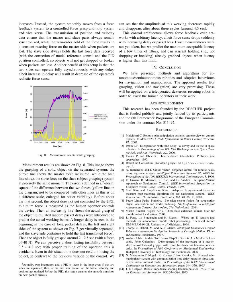
Fig. 8. Measurement results while grasping
Measurement results are shown on Fig. 8. This image showsthe grasping of a solid object on the separated system: thepurple line shows the master force measured, while the blueline shows the slave force on the slave (object grasping) systemat precisely the same moment. The error is defined in L2-norm:square of the difference between the two forces (yellow line onthe diagram; not to be compared with other lines as this is ona different scale, enlarged for better visibility). Before aboutthe first second, the object does not get contacted by the 2FG;minimum force is measured as the human operator controlsthe device. Then an increasing line shows the actual grasp ofthe object. Simulated random packet delays were introduced topredict the actual working better. A longer delay is seen in thebegining; in the case of long packet delays, the left and rightsides of the system as shown on Fig. 7 get virtually separated,and the slave side continues to hold the last transmitted force3.Then the object is fully grasped around 2 - 2.5 sec (with a forceof 40 N). We can perceive a short-lasting instability between3.5 - 4.2 sec; with proper training of the operator, this isavoidable. Even in this situation, it does not result in losing theobject, in contract to the previous version of the control. We
3Actually, two integrators and a PID is there in the loop even if the twosides are separated; then, at the first new packet, all the force, velocity, andposition get updated before the PID; this setup ensures the smooth transitionon new packet arrivals.
can see that the amplitude of this weaving decreases rapidlyand disappears after about three cycles (around 4.5 sec).
This control architecture allows force feedback over net-works with arbitrary latency, albeit force sense drops suddenlywith increasing delay or packet loss. Exact measurements werenot yet taken, but we predict the maximum acceptable latencyof a few times of 10ms, and can warrant holding (i.e., notdropping or breaking) already grabbed objects when latencyis higher than this limit.
IV. CONCLUSION
We have presented methods and algorithms for au-tonomous/semiautonomous robotics and adaptive behavioursfor navigation and manipulation. The apposed results (forgrasping, vision and navigation) are very promising. Thesewill be applied on a teleoperated dexterous rescuing robot inorder to assist the human operators in their work.
ACKNOWLEDGMENT
This research has been founded by the RESCUER projectthat is funded publicly and jointly funded by its participantsand the 6th Framework Programme of the European Commis-sion under the contract No. 511492.
REFERENCES
[1] Melchiorri C. Robotic telemanipulation systems: An overview on controlaspects. In SYROCO’03, IFAC Symposium on Robot Control, Wroclaw,PL, 2003.
[2] Penin L.F. Teleoperation with time delay - a survey and its use in spacerobotics. In Proceedings of the 6th ESA Workshop on Adv. Space Tech.for Rob. and Aut. Noordwijk, NL, 2000.
[3] Fiorini P. and Oboe R. Internet-based telerobotics: Problems andapproaches, 1997.
[4] RobotCub Consortium. Robotcub project. http://www.robotcub.org/.
[5] A. Bernardino and J. Santos-Victor. Vergence control for robotic headsusing log-polar images. Intelligent Robots and Systems’ 96, IROS 96,Proceedings of the 1996 IEEE/RSJ International Conference on, 3, 1996.
[6] E. Grosso, R. Manzotti, R. Tiso, and G. Sandini. A Space-VariantApproach to Oculomotor Control. IEEE International Symposium onComputer Vision, Coral Gables, Florida, 1995.
[7] Sinn Kim and Jong-Hwan Kim. Adaptive fuzzy-network-based c-measure map-matching algorithm for car navigation system. IEEETransactions On Industrial Electronics, Vol. 48, No. 2., 2001.
[8] Pedro Lima Pedro Pinheiro. Bayesian sensor fusion for cooperativeobject localization and world modeling. 8th Conference on IntelligentAutonomous Systems, Amsterdam, The Netherlands, 2004.
[9] Martin Buehler Evgeni Kiriy. Three-state extended kalman filter formobile robot localization. 2002.
[10] J.; Feng, L.; Borenstein and H. Everett. Where am i? sensors andmethods for autonomous mobile robot positioning. Technical ReportUM-MEAM-94-21, University of Michigan., 1994.
[11] Thorpe C. Hebert, M. and A. T. Stentz. Intelligent Unmanned GroundVehicles: Autonomous Navigation Research at Carnegie Mellon. Kluw-erAcademic Publishers., 1997.
[12] Andras Juhasz Andras Toth Janos Puspoki Gusztav Arz Miklos Bolear-aczki, Peter Galambos. Development of the prototype of a master-slave servolelectrical gripper with force feedback for telemanipulationtasks. In Proceedings of Fifth Conference on Mechanical Engineering.Budapest University of Technology and Economics, 2006.
[13] N. Matsumoto T. Idogaki K. Kosuge T. Itoh Otsuka, M. Bilateral tele-manipulator system with communication time delay based on forcesum-driven virtual internal model. In Proceedings of the IEEE InternationalConference on Robotics and Automation, pages 344–350, 1995.
[14] J. E. Colgate. Robust impedance shaping telemanipulation. IEEE Tran.on Robotics and Automation, 9(4):374–384, 1993.