mechanical properties of graphyne monolayers: a first-principles study
TRANSCRIPT

This journal is c the Owner Societies 2012 Phys. Chem. Chem. Phys.
Cite this: DOI: 10.1039/c2cp42387a
Mechanical properties of graphyne monolayers: a first-principles study
Qing Peng,*aWei Ji
band Suvranu De
b
Received 13th July 2012, Accepted 8th August 2012
DOI: 10.1039/c2cp42387a
We investigated the mechanical properties of graphyne monolayers using first-principles
calculations based on the Density Functional Theory. Graphyne has a relatively low in-plane
Young’s modulus (162 N m�1) and a large Poisson ratio (0.429) compared to graphene. It can
sustain large nonlinear elastic deformations up to an ultimate strain of 0.2 followed by strain
softening until failure. The single bond is more vulnerable to rupture than the triple bond and
aromatic bond, although it has a shorter bond length (0.19 A shorter) than the aromatic bond.
A rigorous continuum description of the elastic response is formulated by expanding the elastic
strain energy density in a Taylor series in strain truncated after the fifth-order term. We obtained
a total of fourteen nonzero independent elastic constants which are components of tensors up to
the tenth order. Pressure effects on the second-order elastic constants, in-plane Young’s modulus,
and Poisson ratio are predicted. This study implies that graphyne-based surface acoustic wave
sensors and waveguides may be synthesized by introducing precisely controlled local strains on
graphyne monolayers.
1 Introduction
Present in all known life forms, carbon forms the basis of
life on Earth. Carbon has various hybridized states (sp, sp2,
and sp3) and can form diverse bonding, with ability to bind to
itself and to nearly all elements. As a consequence, carbon
has numerous allotropes,1,2 such as graphene,3 fullerenes,4
carbon nanotubes,5 nanorings,6 and nanobuds.7 Synthesis and
discovery of new carbon phases with high stability, novel
bonding characteristics, unique properties and applications will
be an ongoing effort for theoretical, synthetic and material
scientists.2 As a new form of non-natural carbon allotrope
related to graphite/graphene, graphyne (Fig. 1) has been the
subject of interest due to its unique structure and intriguing
electronic, optical and mechanical properties,8,9 and promising
nanoelectronics and energy storage applications.10 A very
recent study indicates that graphyne is potentially superior to
graphene in directional electrical conductivity.11
Graphyne possesses a remarkable planar network consisting
of only benzene and alkyne units. The characteristic of this
planar layered structure is the coexistence of sp2 and sp
hybridized carbon atoms, comprising aromatic benzene rings
and weakly antiaromatic 12-membered rings.12,13 Different
from graphene/graphite, there are three types of C–C bonds
in graphyne: C(sp2)–C(sp2) for the central aromatic ring
(1.43 A), C(sp2)–C(sp) connecting the adjacent CQC and
CRC bonds (1.41 A), and C(sp)–C(sp) for the linked triple
bonds (1.22 A). It has been pointed out that insertion of
the –CRC– unit into each single bond of a molecule can
form an expanded system and does not alter the molecule
symmetry.14 The graphyne monolayer has the same hexagonal
symmetry (P6m) as graphene. Graphyne can be viewed as
constructed from graphene by replacing one-third of the C–C
bonds with CRC linkages. It is predicted to have high
temperature stability.
Graphyne was first proposed in 1987 by Baughman et al.15
Despite some attempts,16,17 the synthesis of graphyne has not
yet been reported. Most recently, experimental success has
been achieved in the synthesis of graphdiyne which is a
substructure of graphyne.18,19 Lacking experimental data,
knowledge of the properties of this promising and interesting
carbon allotrope depends on theoretical predictions. As for
Fig. 1 Left: graphyne monolayer. Right: graphyne molecule.
aDepartment of Mechanical, Aerospace and Nuclear Engineering,Rensselaer Polytechnic Institute, Troy, NY 12180, USA.E-mail: [email protected]; Tel: +1 518-279-6669
bDepartment of Mechanical, Aerospace and Nuclear Engineering,Rensselaer Polytechnic Institute, Troy, NY 12180, USA
PCCP Dynamic Article Links
www.rsc.org/pccp PAPER
Dow
nloa
ded
by R
enss
elae
r Po
lyte
chni
c In
stitu
te o
n 01
Sep
tem
ber
2012
Publ
ishe
d on
10
Aug
ust 2
012
on h
ttp://
pubs
.rsc
.org
| do
i:10.
1039
/C2C
P423
87A
View Online / Journal Homepage

Phys. Chem. Chem. Phys. This journal is c the Owner Societies 2012
electronic properties, Narita et al. reported the optimized
lattice length (6.86 A), binding energy (7.95 eV per atom),
and band gap (0.52 eV).8 Kondo et al. calculated the band gap
of graphyne (0.89 eV) at the extended Huckel level.20 Long
et al. investigated the electronic structure and charge mobility
of graphdiyne sheets and nanoribbons, which have a band gap
of 0.46 eV.21 Zhou et al. analyzed the nature of bonding and
energy band structure of graphyne and its BN analog called
‘‘BN-yne’’.22 Their work showed that the band gap can be
modulated by changing the size of the hexagonal ring and the
length of the carbon chain. It is found that the high mobility
of doped lithium and high energy storage capacity make
graphyne a promising candidate for the anode material in
battery applications.23 Pan et al. explored the configurations
and electronic properties of graphyne and graphdiyne nano-
ribbons with armchair and zigzag edges.24 As for mechanical
properties, a classical molecular dynamics study has shown
that unlike graphene, the fracture strain and stress of graphyne
depend significantly on the direction of the applied strain and
the alignment with carbon triple-bond linkages.25 Kang et al.
reported in-plane stiffness of the graphyne monolayer as
166 N m�1 and Poisson’s ratio of 0.417.9
There are some promising applications and recent develop-
ment of the 2D materials, including high frequency field-effect
transistors,26 graphene-based spintronics,27 ferromagnetics,28
antiferromagnetics,29 and nanoelectronics.30 Due to monoatomic
thickness, these 2D monolayers are more likely to experience
strain states during their applications, for example, mismatch
strain and substrate surface corrugation.30,31 Therefore,
knowledge of mechanical properties of graphyne is highly
desired. Several previous studies have shown that 2D mono-
layers present large nonlinear elastic deformation during the
tensile strain up to the ultimate strength of the material
followed by strain softening until fracture.32–35 We expect that
the graphyne behaves in a similar manner.
Under large deformation, the strain energy density need to
be expanded in a Taylor series to include quadratic and higher
order terms in strain. The higher order terms account for both
nonlinearity and strain softening of the elastic deformation.
They can also express other anharmonic properties of 2D nano-
structures including phenomena such as thermal expansion,
phonon–phonon interaction, etc.36 Despite the importance, the
high order non-linear elastic properties of the 2D graphyne are
still unknown.
The goal of this paper is to study the mechanical behaviors
at large strains and find an accurate continuum description of
the elastic properties of graphyne from ab initio density
functional theory calculations. The total energies of the
system, forces on each atom, and stresses on the simulation
boxes are directly obtained from DFT calculations. The
response of graphyne under the nonlinear deformation and
fracture is studied, including ultimate strength and ultimate
strain. The high order elastic constants are obtained by fitting
the stress–strain curves to analytical stress–strain relationships
that belong to the continuum formulation.33 Our results of
continuum formulation could also be useful in finite element
modeling of the multiscale calculations of mechanical proper-
ties of graphyne at the continuum level. The remainder of the
paper is organized as follows: Section 2 presents the basic
nonlinear elastic theory applied to 2D hexagonal structures.
The computational details of DFT calculations are in Section 3.
The results and analysis are in Section 4, followed by conclu-
sions in Section 5.
2 Nonlinear elasticity theory
We consider a primitive unit cell containing 12 atoms in one
plane, with periodic boundary conditions. The undeformed
reference configuration is shown in Fig. 2, with lattice vectors
Hi, i= 1, 2, 3. When macroscopically homogeneous deformation
with gradient tensor F37 is applied, the lattice vectors of the
deformed graphyne are hi = FHi. The Lagrangian strain38 is
defined as h = 12(FTF � I), where I is the identity tensor. For
hyperelastic materials, the strain energy density has the functional
form F = F(Z) and the components of the symmetric second
Piola–Kirchhoff stress tensor (S) can be expressed as
Sij ¼@F@Zij
: ð1Þ
Using Taylor’s series expansion up to the fifth order, the
above relationship may be written as
Sij ¼ CijklZkl þ1
2!CijklmnZklZmn þ
1
3!CijklmnopZklZmnZop
þ 1
4!CijklmnopqrZklZmnZopZqr:
ð2Þ
Einstein’s summation convention has been employed for
repeating indices which range from 1 to 3. Herein C denotes
each higher-order elastic modulus tensor; the rank of each tensor
corresponds to the number of subscripts. The second-order
elastic constants (SOEC) Cijkl, third-order elastic constants
(TOEC), Cijklmn, fourth-order elastic constants (FOEC),Cijklmnop,
and fifth-order elastic constants (FFOEC), Cijklmnopqr, are
given by the components of the fourth-, sixth-, eighth-, and
tenth-rank tensors, respectively.
Using the conventional Voigt notation39 for subscripts:
11 - 1, 22 - 2, 33 - 3, 23 - 4, 31 - 5, and 12 - 6.
Please note that for strain Z4 = 2Z23, Z5 = 2Z31, Z6 = 2Z12.Eqn (2) can be rewritten as
SI ¼ CIJZJ þ1
2!CIJKZJZK þ
1
3!CIJKLZJZKZL
þ 1
4!CIJKLMZJZKZLZM : ð3Þ
where the upper case indices are from 1 to 6.
Fig. 2 Atomic structure of a graphyne monolayer in the primitive
unit cell (12 atoms) in the undeformed reference configuration.
Dow
nloa
ded
by R
enss
elae
r Po
lyte
chni
c In
stitu
te o
n 01
Sep
tem
ber
2012
Publ
ishe
d on
10
Aug
ust 2
012
on h
ttp://
pubs
.rsc
.org
| do
i:10.
1039
/C2C
P423
87A
View Online

This journal is c the Owner Societies 2012 Phys. Chem. Chem. Phys.
We modeled the monolayer graphyne as a two-dimensional
(2D) structure and assume that the deformed state of the
monolayer graphyne is such that the contribution of bending
to the strain energy density is negligible, compared to the
in-plane strain contribution. This assumption is reasonable
since the radius of curvature of out-of-plane deformation is
significantly larger than the in-plane inter-atomic distance.
The stress state of monolayer graphyne under those assumptions
can be assumed to be 2D and we only consider the in-plane stress
and strain components for these kinds of structures.
For a general deformation state the number of independent
components of the second, third, fourth and fifth order elastic
tensors is 21, 56, 126, and 252, respectively. However, there
are only fourteen independent elastic constants need to be
explicitly considered due to the symmetries of the atomic
lattice point group D6h which consists of a six-fold rotational
axis and six mirror planes.35
The fourteen independent elastic constants of graphyne are
determined by a least-squares fit to stress–strain results from
DFT based first-principles studies in two steps, detailed in our
previous work.34 In the first step, we use a least-squares fit to
five stress-strain responses. Five relationships between stress
and strain are necessary because there are five independent
FFOECs. We obtain the stress–strain relationships by simu-
lating the following deformation states: uniaxial strain in the
zigzag direction; uniaxial strain in the armchair direction; and
biaxial strain. From the first step, the components of SOEC,
TOEC, FOEC are over-determined (i.e., the number of linearly
independent variables is greater than the number of constraints),
and the FFOECs are well-determined (the number of linearly
independent variables is equal to the number of constraints).
Under such circumstances, the second step is needed: least-square
solution to these over- and well-determined linear equations.
3 Density functional theory calculations
The stress–strain relationship of graphyne under the desired
deformation configurations is characterized via first-principles
calculations with the density-functional theory (DFT). DFT
calculations were carried out with the Vienna Ab-initio Simula-
tion Package (VASP)40–43 which is based on the Kohn–Sham
Density Functional Theory (KS-DFT)44,45 with the generalized
gradient approximations as parameterized by Perdew, Burke
and Ernzerhof (PBE) for exchange–correlation functions.46 The
electrons explicitly included in the calculations are the (2s22p2)
electrons. The core electrons (1s2) are replaced by the projector
augmented wave (PAW) and pseudo-potential approach.47,48
A plane-wave cutoff of 400 eV is used in all the calculations.
The calculations are performed at zero temperature.
The criterion to stop the relaxation of the electronic degrees
of freedom is set by the total energy change to be smaller
than 0.000001 eV. The optimized atomic geometry was
achieved by minimizing Hellmann–Feynman forces acting on
each atom until the maximum forces on the ions were smaller
than 0.01 eV A�1.
The atomic structures of all the deformed and undeformed
configurations are obtained by fully relaxing a 12-atom-unit
cell where all atoms were placed in one plane. The simulation
invokes periodic boundary conditions for the two in-plane
directions while the displacement to the out-of-plane direction
is forbidden.
The irreducible Brillouin Zone was sampled with a Gamma-
centered 11 � 11 � 1 k-mesh. Such large k-mesh was used to
reduce the numerical errors caused by the strain of the systems.
The initial charge densities were taken as a superposition of
atomic charge densities. There was a 11 A thick vacuum region
to reduce the inter-layer interaction to model the single layer
system. The results of the calculations are independent of the
precise value of the out-of-plane thickness, so there is no
physical interpretation attached to the quantity.
The VASP simulation calculates the true or Cauchy stresses,
s, which for monolayer graphyne must be expressed as a 2D
force per length with units of N m�1 by taking the product of
the Cauchy stresses (with units of N m�2) and the super-cell
thickness of 11 A. The Cauchy stresses are related to the
second Piola–Kirchhoff (PK2) stresses S as
S = JF�1s(F�1)T (4)
where J = det(F).
4 Results and analysis
4.1 Atomic structure
We first optimize the equilibrium lattice constant for mono-
layer graphyne. The total energy as a function of lattice
spacing is obtained by specifying nine lattice constants varying
from 6.5 A to 7.3 A, with full relaxations of all the atoms.
A least-square fit of the energy vs. lattice constant with a
fourth-order polynomial function yields the equilibrium lattice
constant as 6.889 A. The result is in good agreement with
previous DFT calculations.9,22
The most energetically favorable structure is set as the
strain-free structure in this study and the atomic structure,
as well as the primitive cell is shown in Fig. 2. Specifically, the
bond length of the triple bond between atoms B and C
(marked in Fig. 1) is 1.223 A. The largest bond length is the
aromatic bond between atom D and atom E, which is 1.426 A,
slightly longer than that of a pristine graphene sheet (1.425 A)
due to the presence of the acetylene groups. The single bond
between atoms A and B (symmetrically C and D) is 1.407 A,
shorter than the typical value of 1.47 A. The contraction of the
single bonds is due to the charge transfer from the benzene
ring to the acetylene group.22
4.2 Strain energy
When the strains are applied, all the atoms are allowed full
freedom of motion within their plane. A quasi-Newton algorithm
is used to relax all atoms into equilibrium positions within the
deformed unit cell that yields the minimum total energy for the
imposed strain state of the super cell.
Both compression and tension are considered with Lagrangian
strains ranging from �0.1 to 0.3 with an increment of 0.02 in
each step for all three cases. We define strain energy per atom
Es = (Etot � E0)/n, where Etot is the total energy of the
strained system, E0 is the total energy of the strain-free system,
and n = 12 is the number of atoms in the unit cell. Fig. 3
shows the Es as a function of strain in uniaxial armchair,
Dow
nloa
ded
by R
enss
elae
r Po
lyte
chni
c In
stitu
te o
n 01
Sep
tem
ber
2012
Publ
ishe
d on
10
Aug
ust 2
012
on h
ttp://
pubs
.rsc
.org
| do
i:10.
1039
/C2C
P423
87A
View Online
Phys. Chem. Chem. Phys. This journal is c the Owner Societies 2012
uniaxial zigzag and biaxial deformation. Es is found to be
anisotropic with the strain direction. Es is non-symmetrical for
compression (Z o 0) and tension (Z > 0) for all three cases.
This non-symmetry indicates the anharmonicity of the mono-
layer graphyne structures.
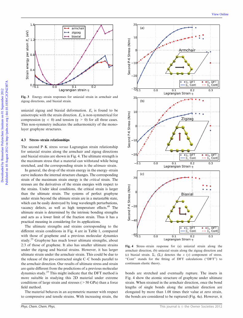
4.3 Stress–strain relationships
The second P–K stress versus Lagrangian strain relationship
for uniaxial strains along the armchair and zigzag directions
and biaxial strains are shown in Fig. 4. The ultimate strength is
the maximum stress that a material can withstand while being
stretched, and the corresponding strain is the ultimate strain.
In general, the drop of the strain energy in the energy–strain
curve indicates the internal structure changes. The corresponding
strain of the maximum strain energy is the critical strain. The
stresses are the derivatives of the strain energies with respect to
the strains. Under ideal conditions, the critical strain is larger
than the ultimate strain. The systems of perfect graphyne
under strain beyond the ultimate strain are in a metastable state,
which can be easily destroyed by long wavelength perturbations,
vacancy defects, as well as high temperature effects.49 The
ultimate strain is determined by the intrinsic bonding strengths
and acts as a lower limit of the fraction strain. Thus it has a
practical meaning in considering for its applications.
The ultimate strengths and strains corresponding to the
different strain conditions in Fig. 4 are in Table 1, compared
with those of graphene and a previous molecular dynamics
study.25 Graphyne has much lower ultimate strengths, about
2/3 of those of graphene. It also has smaller ultimate strains
under the zigzag and biaxial strains. However, it has larger
ultimate strain under the armchair strain. This could be due to
the release of the pre-contracted single C–C bonds parallel to
the armchair direction. Our results of ultimate stress and strain
are quite different from the predictions of a previous molecular
dynamics study.25 This might indicate that the DFT method is
more suitable in studying this 2D material under extreme
conditions of large strain and stresses (>50 GPa) than a force
field method.
The material behaves in an asymmetric manner with respect
to compressive and tensile strains. With increasing strain, the
bonds are stretched and eventually rupture. The insets in
Fig. 4 show the atomic structure of graphyne under ultimate
strain. When strained in the armchair direction, once the bond
lengths of single bonds along the armchair direction are
elongated by more than 1.08 times their value at zero strain,
the bonds are considered to be ruptured (Fig. 4a). However, it
Fig. 3 Energy–strain responses for uniaxial strain in armchair and
zigzag directions, and biaxial strain.
Fig. 4 Stress–strain response for (a) uniaxial strain along the
armchair direction, (b) uniaxial strain along the zigzag direction and
(c) biaxial strain. S1 (S2) denotes the x (y) component of stress.
‘‘Cont’’ stands for the fitting of DFT calculations (‘‘DFT’’) to
continuum elastic theory.
Dow
nloa
ded
by R
enss
elae
r Po
lyte
chni
c In
stitu
te o
n 01
Sep
tem
ber
2012
Publ
ishe
d on
10
Aug
ust 2
012
on h
ttp://
pubs
.rsc
.org
| do
i:10.
1039
/C2C
P423
87A
View Online

This journal is c the Owner Societies 2012 Phys. Chem. Chem. Phys.
is the aromatic bond between atoms D and E that ruptures
when the structure is loaded in the zigzag direction (Fig. 4b).
All the single bonds rupture when loaded in the biaxial
direction (Fig. 4c). Our results show that the single bond is
more vulnerable to rupture than the triple bond and aromatic
bond, although it has shorter bond length (0.19 A shorter)
than the aromatic bond.
4.4 Elastic constants
The elastic constants are critical parameters in finite element
analysis models for determining mechanical properties of
materials. Our results of these elastic constants provide an
accurate continuum description of the elastic properties of
graphyne from ab initio density functional theory calculations.
They are suitable for incorporation into numerical methods
such as the finite element technique.
The second elastic constants model the linear elastic response.
The higher (>2) order elastic constants are important to
characterize the nonlinear elastic response of graphyne using
a continuum description. These can be obtained using a least
squares fit of the DFT data and are reported in Table 2.
Corresponding values for graphene are also shown.
The in-plane Young’s modulus Ys and Poison’s ratio nmay be
obtained from the following relationships: Ys = (C211 � C2
12)/C11
and n = C12/C11. Our results of Ys = 162.1 (N m�1) and n =0.429 are comparable with previous ab initio prediction (Ys =
166 (N m�1) and n= 0.417).9 The in-plane Young’s modulus of
graphyne is quite small (47%) compared to graphene, which
indicates that the graphyne is very soft. The small in-plane
Young’s modulus could be understood by two facts. First the
average coordination number of an atom in graphyne is 2.5,
less than that in graphene, which is 3.0. As a consequence, the
number of bonds in graphyne is fewer than that in graphene.
Second, the in-plane atomic mass density and the electronic
charge density of graphyne are smaller (0.77 times) than those
of graphene.
However, graphyne has a Poisson’s ratio which is twice as
large as graphene. Recall that a perfectly incompressible
material has a Poisson’s ratio of 0.5. Hence, graphyne is
observed to conserve volume well under uniaxial strain.
Knowledge of higher order elastic constants is very useful to
understand the anharmonicity. Especially, third-order elastic
constants are important in understanding the nonlinear elasticity
of materials such as changes in acoustic velocities due to finite-
strain. With third-order elastic moduli, we can study the effect of
the second-order elastic moduli on the pressure p acting in the
plane of the graphyne monolayer. Explicitly, when pressure is
applied, the pressure dependent second-order elastic moduli (C11,
C12, C22) can be obtained fromC11,C12, C22, C111, C112, C222, Ys,
n, as formulated in ref. 34.
The second-order elastic moduli of graphyne are seen to
increase linearly with the applied pressure (Fig. 5). Poisson’s
ratio also increases monotonically with the increase of
pressure. C11 is not symmetrical to C22 any more. Only when
P = 0, C11 = C22 = C11. This anisotropy could be the
outcome of anharmonicity.
Graphyne monolayers exhibit instability under large
tension. All stress–strain curves in the previous section show
that graphyne will soften when the strain is larger than the
ultimate strain. From the view of electron bonding, this is due
to the bond weakening and breaking. This softening behavior
is determined by the TOECs and FFOECs in the continuum
Table 1 Ultimate strengths (Sam,S
zm,S
bm) in units of N m�1 and
ultimate strains (Zam, Zzm, Zbm) under uniaxial strain (armchair andzigzag) and biaxial of graphyne from DFT calculations, comparedwith graphene and previous molecular dynamics (MD) study
Graphyne Graphyne(MD)25 Graphene50
Sam 17.84 14.34a 28.56
Zam 0.2 0.08 0.18
Szm 18.83 31.97a 30.36
Zzm 0.2 0.12 0.22
Sbm 20.64 — 32.01
Zbm 0.18 — 0.22
a The value is converted from original data (in units of GPa) obtained
with ‘‘Energy minimization’’ using the 3.20 A thickness assumed in
ref. 25.
Table 2 Nozero independent components for the SOEC, TOEC,FOEC and FFOEC tensor components (in units of N m�1), Poisson’sratio n and in-plane Young’s modulus Ys of graphyne from DFTcalculations, compared with graphene
Graphyne Graphene50 Graphene35
a 6.889 2.468 2.446Ys 162.1 344.6 348n 0.429 0.179 0.169C11 198.7 356.0 358.1C12 85.3 63.7 60.4C111 �890.9 �3120.9 �2817C112 �872.6 �471.7 �337.1C222 �1264.2 �2978.1 �2693.3C1111 �7966 19 980 13 416.2C1112 4395 2706 759C1122 8662 2843 2582.8C2222 1154 16 568 10 358.9C11 111 89 000 �81 498 �31 383.8C11 112 �10 393 �13 378 �88.4C11 122 �26 725 �12 852 �12 960.5C12 222 15 495 �28 504 �13 046.6C22 222 14 262 �79 311 �33 446.7
Fig. 5 Second-order elastic moduli and Poisson ratio as a function of
the pressure.
Dow
nloa
ded
by R
enss
elae
r Po
lyte
chni
c In
stitu
te o
n 01
Sep
tem
ber
2012
Publ
ishe
d on
10
Aug
ust 2
012
on h
ttp://
pubs
.rsc
.org
| do
i:10.
1039
/C2C
P423
87A
View Online

Phys. Chem. Chem. Phys. This journal is c the Owner Societies 2012
aspect. The negative values of TOECs and FFOECs ensure the
softening of the graphyne monolayer under large strain.
The hydrostatic terms (C11, C22, C111, C222, and so on) of
graphyne monolayers are smaller than those of graphene,
consistent with the conclusion that the graphyne is ‘‘softer’’.
The shear terms (C12, C112, C1122, etc.) in general are larger than
those of graphene, which contributes to its less compressibility.
4.5 Promising applications
In the graphyne monolayer, there are non-zero in-plane
Young’s modulus and shear deformations. Hence, it is possible
to generate sound waves with different velocities depending on
the deformation mode. Sound waves generating biaxial defor-
mations (compressions) are compressional or p-waves. Sound
waves generating shear deformations are shear or s-waves. The
sound velocities of these two types of waves are calculated from
the second-order elastic moduli and mass density using the
following relations:
vp ¼
ffiffiffiffiffiffiffiffiffiffiffiffiffiffiffiffiffiffiffiffiffiffiffiffiffiffiffiffiffiffiffiffiffiffiffiffiffiffi~Ysð1� ~nÞ
rmð1þ ~nÞð1� 2~nÞ
s; ð5Þ
vs ¼
ffiffiffiffiffiffiffiffi~C12
rm
s: ð6Þ
The dependence of np and ns on pressure (biaxial stress) is plottedin Fig. 6. Both np and ns monotonically increase with increase in
pressure. Thus they can be tuned by introducing the biaxial strain
through the stress–strain relationship shown in Fig. 4c.
The compressional to shear wave velocity ratio (np/ns) is avery useful parameter in the determination of the materials
mechanical properties. It depends only on Poisson’s ratio as
vp
vs¼
ffiffiffiffiffiffiffiffiffiffiffiffiffiffiffiffiffiffiffiffiffiffiffiffiffiffiffiffiffi1
~nð1þ ~n2
1� 2~nÞ
r: ð7Þ
The ratio of np/ns monotonically increases with the increase
of pressure as shown in Fig. 6.
Note that a sound velocity gradient could be achieved by
introducing stress into a graphyne monolayer, which could
lead to refraction of sound wavefronts in the direction of lower
sound speed, causing the sound rays to follow a curved path.51
The radius of curvature of the sound path is inversely propor-
tional to the gradient. Also a negative sound speed gradient
could be achieved by a negative strain gradient. This tunable
sound velocity gradient can be used to form a sound frequency
and ranging channel, which is the functional mechanism of
waveguides and surface acoustic wave (SAW) sensors.52,53
Thus, graphyne-based nano-devices of SAW sensors, filters
and waveguides may be synthesized by introducing local
strains for next generation electronics.
5 Conclusions
We studied the mechanical response of a graphyne monolayer
under various strains using DFT based first-principles calcula-
tions. The bond lengths of the single, triple, and aromatic bonds
are 1.407 A, 1.223 A, and 1.426 A, respectively. The single bond
is more vulnerable to rupture than the triple bond and aromatic
bond, although it has shorter bond length than the aromatic
bond. Graphyne monolayers exhibit nonlinear elastic deforma-
tion up to an ultimate strain of 0.2, followed by strain softening
until failure. The deformation and failure behavior and the
ultimate strength are anisotropic. The ultimate strength in
biaxial strain is about 2.81 N m�1 and 1.81 N m�1 larger than
that in the armchair and zigzag directions, respectively.
We found an accurate continuum description of the elastic
properties of graphyne by explicitly determining the fourteen
independent components of high order (up to fifth order)
elastic constants from the fitting of the stress–strain curves
obtained from DFT calculations. These data are useful in
developing a continuum description which is suitable for
incorporation into a finite element analysis model for its
applications on a large scale.
Pressure effects on the second-order elastic constants,
in-plane Young’s modulus, and Poisson ratio are predicted.
Graphyne is observed to have a relatively low in-plane
Young’s modulus (162 N m�1) and a large Poisson ratio
(0.429) compared to graphene. Another interesting observa-
tion is that local variations of pressure, introduced by external
stress, could be used to modulate the velocity of sound waves
in graphyne. Hence, graphyne-based nanodevices or SAW
sensors and waveguides could be synthesized by introducing
local strain for next generation electronic devices.
Acknowledgements
We thank Dr Zhongfang Chen for helpful discussions. The
authors would like to acknowledge the generous financial support
from the Defense Threat Reduction Agency (DTRA) Grant #
BRBAA08-C-2-0130, the U.S. Nuclear Regulatory Commission
Faculty Development Program under contract # NRC-38-08-950,
and U.S. Department of Energy (DOE) Nuclear Energy Univer-
sity Program (NEUP) Grant # DE-NE0000325.
References
1 F. Diederich and M. Kivala, Adv. Mater., 2010, 22, 803.2 A. Hirsch, Nat. Mater., 2010, 9, 868.
Fig. 6 p-wave and s-wave velocities, and compressional to shear
wave velocity ratio np/ns as a function of in-plane pressure.
Dow
nloa
ded
by R
enss
elae
r Po
lyte
chni
c In
stitu
te o
n 01
Sep
tem
ber
2012
Publ
ishe
d on
10
Aug
ust 2
012
on h
ttp://
pubs
.rsc
.org
| do
i:10.
1039
/C2C
P423
87A
View Online

This journal is c the Owner Societies 2012 Phys. Chem. Chem. Phys.
3 K. S. Novoselov, A. K. Geim, S. V. Morozov, D. Jiang, Y. Zhang,S. V. Dubonos, I. V. Grigorieva and A. A. Firsov, Science, 2004,306, 666.
4 H. W. Kroto, J. R. Heath, S. C. Obrien, R. F. Curl andR. E. Smalley, Nature, 1985, 318, 162.
5 S. Iijima, Nature, 1991, 354, 56.6 X. Y. Kong, Y. Ding, R. Yang and Z. L. Wang, Science, 2004,303, 1348.
7 A. G. Nasibulin, P. V. Pikhitsa, H. Jiang, D. P. Brown,A. V. Krasheninnikov, A. S. Anisimov, P. Queipo, A. Moisala,D. Gonzalez, G. Lientschnig, A. Hassanien, S. D. Shandakov,G. Lolli, D. E. Resasco, M. Choi, D. Tomanek andE. I. Kauppinen, Nat. Nanotechnol., 2007, 2, 156.
8 N. Narita, S. Nagai, S. Suzuki and K. Nakao, Phys. Rev. B:Condens. Matter Mater. Phys., 1998, 58, 11009.
9 J. Kang, J. Li, F. Wu, S.-S. Li and J.-B. Xia, J. Phys. Chem. C,2011, 115, 20466.
10 K. Srinivasu and S. K. Ghosh, J. Phys. Chem. C, 2012, 116,5951–5956.
11 D. Malko, C. Neiss, F. Vines and A. Goerling, Phys. Rev. Lett.,2012, 108, 086804.
12 K. Tahara, T. Yoshimura, M. Sonoda, Y. Tobe and R. V. Williams,J. Org. Chem., 2007, 72, 1437–1442.
13 J. Juselius and D. Sundholm, Phys. Chem. Chem. Phys., 2001, 3,2433–2437.
14 R. Chauvin, Tetrahedron: Lett., 1995, 36, 397.15 R. H. Baughman, H. Eckhardt and M. Kertesz, J. Chem. Phys.,
1987, 87, 6687.16 J. M. Kehoe, J. H. Kiley, J. J. English, C. A. Johnson,
R. C. Petersen and M. M. Haley, Org. Lett., 2000, 2, 969.17 T. Yoshimura, A. Inaba, M. Sonoda, K. Tahara, Y. Tobe and
R. V. Williams, Org. Lett., 2006, 8, 2933.18 G. Li, Y. Li, H. Liu, Y. Guo, Y. Li and D. Zhu, Chem. Commun.,
2010, 46, 3256.19 G. Li, Y. Li, X. Qian, H. Liu, H. Lin, N. Chen and Y. Li, J. Phys.
Chem. C, 2011, 115, 2611.20 M. Kondo, D. Nozaki, M. Tachibana, T. Yumura and K. Yoshizawa,
Chem. Phys., 2005, 312, 289.21 M. Long, L. Tang, D. Wang, Y. Li and Z. Shuai, ACS Nano, 2011,
5, 2593.22 J. Zhou, K. Lv, Q. Wang, X. S. Chen, Q. Sun and P. Jena, J. Chem.
Phys., 2011, 134, 174701.23 H. Zhang, M. Zhao, X. He, Z. Wang, X. Zhang and X. Liu,
J. Phys. Chem. C, 2011, 115, 8845.24 L. D. Pan, L. Z. Zhang, B. Q. Song, S. X. Du and H. J. Gao, Appl.
Phys. Lett., 2011, 98, 173102.25 S. W. Cranford and M. J. Buehler, Carbon, 2011, 49, 4111.
26 Y. M. Lin, C. Dimitrakopoulos, K. A. Jenkins, D. B. Farmer,H. Y. Chiu, A. Grill and P. Avouris, Science, 2010, 327, 662.
27 Y. Ma, Y. Dai, M. Guo and B. Huang, Phys. Rev. B: Condens.Matter Mater. Phys., 2012, 85, 235448.
28 Y. Ma, Y. Dai, M. Guo, C. Niu, Y. Zhu and B. Huang, ACS Nano,2012, 6, 1695–1701.
29 Y. Ma, Y. Dai, M. Guo, C. Niu, J. Lu and B. Huang, Phys. Chem.Chem. Phys., 2011, 13, 15546–15553.
30 Y. Ma, Y. Dai, W. Wei, C. Niu, L. Yu and B. Huang, J. Phys.Chem. C, 2011, 115, 20237–20241.
31 Z. H. Aitken and R. Huang, J. Appl. Phys., 2010, 107, 123531.32 Q. Peng and S. De, Physica E (Amsterdam), 2012, 44, 1662–1666.33 Q. Peng, A. R. Zamiri, W. Ji and S. De, Acta Mech., 2012, 707, 714.34 Q. Peng, W. Ji and S. De, Comput. Mater. Sci., 2012, 56, 11.35 X. Wei, B. Fragneaud, C. A. Marianetti and J. W. Kysar, Phys.
Rev. B: Condens. Matter Mater. Phys., 2009, 80, 205407.36 C. Lee, X. Wei, J. W. Kysar and J. Hone, Science, 2008, 321, 385.37 M. Crisfield, Non-Linear Finite Element Analysis of Solids and
Structures, John Wiley & Sons, New York, 1991, p. 18.38 J. Lubliner, Plasticity Theory, Dover Publications, New York, 2008.39 J. F. Nye, Physical Properties of Crystals, Oxford Science Publica-
tions, Oxford, 1995.40 G. Kresse and J. Hafner, Phys. Rev. B: Condens. Matter Mater.
Phys., 1993, 47, 558.41 G. Kresse and J. Hafner, Phys. Rev. B: Condens. Matter Mater.
Phys., 1994, 49, 14251.42 G. Kresse and J. Furthuller, Phys. Rev. B: Condens. Matter Mater.
Phys., 1996, 54, 11169.43 G. Kresse and J. Furthuller, Comput. Mater. Sci., 1996, 6, 15.44 P. Hohenberg and W. Kohn, Phys. Rev., 1964, 136, B864.45 W. Kohn and L. J. Sham, Phys. Rev., 1965, 140, A1133.46 J. Perdew, K. Burke and M. Ernzerhof, Phys. Rev. Lett., 1996,
77, 3865.47 P. E. Blochl, Phys. Rev. B: Condens. Matter Mater. Phys., 1994, 50,
17953–17979.48 R. O. Jones and O. Gunnarsson, Rev. Mod. Phys., 1989, 61,
689–746.49 M. Topsakal, S. Cahangirov and S. Ciraci, Appl. Phys. Lett., 2010,
96, 091912.50 Q. Peng, W. Ji and S. De, J. Mech. Phys. Solids, 2012, submitted.51 F. Everest, The Master Handbook of Acoustics, McGraw-Hill,
New York, 2001.52 E. R. Benes, R. Groschl, F. Seifert and A. Pohl, IEEE Trans.
Sonics Ultrason., 1998, 45, 1314–1330.53 R. Weigel, D. P. Morgan, J. M. Owens, A. Ballato, K. M. Lakin,
K. Hashimoto and C. C. W. Ruppel, IEEE Trans. MicrowaveTheory Tech., 2002, 50, 738–749.
Dow
nloa
ded
by R
enss
elae
r Po
lyte
chni
c In
stitu
te o
n 01
Sep
tem
ber
2012
Publ
ishe
d on
10
Aug
ust 2
012
on h
ttp://
pubs
.rsc
.org
| do
i:10.
1039
/C2C
P423
87A
View Online