measurement of residual stresses in nuclear-grade zircaloy-4(r) tubes—effect of heat treatment
TRANSCRIPT
Measurement of Residual Stresses in Nuclear-gradeZircaloy-4(R) Tubes—Effect of Heat Treatment
J. Rasty & X. Le & M. Baydogan & J.F. Cárdenas-García
Received: 3 August 2005 /Accepted: 18 September 2006 / Published online: 30 January 2007# Society for Experimental Mechanics 2007
Abstract Nuclear-grade Zircaloy-4(R) tubes are producedby a unique manufacturing process known as pilgering,which leaves the material in a work-hardened statecontaining a pattern of residual stresses. Moreover, suchtubes exhibit elastic anisotropy as a result of the pilgeringprocess. Therefore, standard equations originally proposedby Sachs (Z Met Kd, 19: 352–357, 1927; Sachs, Espey, IronAge, 148: 63–71, 1941). for isotropic materials do not applyin this situation. Voyiadjis et al. (Exp Mech, 25: 145–147,1985) proposed a set of equations for treating elasticallyanisotropic materials, but we have determined that there arediscrepancies in their equations. In this paper, we presentthe derivation for a set of new equations for treatingelastically anisotropic materials, and the application ofthese equations to residual stress measurements in Zr-4(R)tubes. To this end, through thickness distribution of residualstress components in as-received and heat treated (500°C)Zr-4(R) tubes was measured employing the Sachs’ boring-out technique in conjunction with electrochemical machin-ing as the means of material removal, and our newequations. For both as-received and the heat treated
materials, the axial and tangential residual stresses weresignificantly higher than the radial and shear residualstresses. The largest residual stress was the tangential stresscomponent in the as-received material, showing a tensilevalue at the outer surface and a compressive value at theinner surface. At high values of von Mises equivalentstress, the principal directions of residual stress coincidedwith the principal axes of the tube for the as-receivedmaterial, as well as for the material heat treated at 500°C.
Keywords Electrochemical machining . Residual stress .
Sachs’ boring-out . Zircaloy-4(R) . Light-waternuclear reactors
Nomenclatureσz, sq, σrand tzq
Axial, tangential, radial and shear stresses,respectively
Eq, Er,Gzθ
Young’s modulus in the tangential and radialdirections and shear modulus along zθ plane,respectively
�, θ Axial and tangential strain parameters,respectively
nzq Poisson’s ratio representing the ratio ofstrain in the θ direction to strain in the zdirection
ez, eθ andgzq
Axial, tangential and shear strains,respectively
e1, e2 ande3
Strains measured by the gages 1, 2 and 3 oftri-element strain rosette, respectively
σeq von Mises equivalent stressσ1,2 Maximum and minimum principal stresses,
respectivelya The angle between the principal directions
and the principal axes of the tubem�
Metal removal rate
Experimental Mechanics (2007) 47: 185–199DOI 10.1007/s11340-006-9009-5
J. Rasty (*, SEM member) :X. LeMechanical Engineering Department, Texas Tech University,Lubbock, TX, USAe-mail: [email protected]
M. BaydoganDepartment of Metallurgy and Materials Engineering,Istanbul Technical University,Istanbul, Turkey
J.F. Cárdenas-García (SEM member)Department of Engineering,The University of Texas at Brownsville,80 Fort Brown,Brownsville, TX, USA
c ConstantA Atomic weightI Applied currentZ Valence of the dissolving ionsf Faraday’s constant (96.486 C)m Mass of the tubeδ Density of the tube materialV Volume of the tubeL Length of the tubet Electrochemical machining timea Inside radius of the tubeb Original outside radius of the tuber Instantaneous outside radius of the tubeF Axial forceρ Radial position
Introduction
Zircaloy-4(R) tubes are commonly used in light-waternuclear reactors as the cladding material for the nuclearfuel. Its low thermal neutron capture cross section and goodthermal conductivity, when accompanied with its highcorrosion resistance and mechanical strength, make thismaterial one of the most suitable alternatives for serving asa barrier between the uranium dioxide fuel pellets and thecooling water inside the reactor.
Zircaloy-4(R) tubes are produced by a cold workingoperation known as cold pilgering, which leaves thematerial in a work-hardened state containing a pattern ofresidual stresses. These stresses may be the cause of suchfailures as stress corrosion cracking, and excessive distor-tion. Knowledge of the magnitude and distribution of theresidual stresses, is therefore of paramount significance inensuring the safe operation of light-water reactors. Mea-surements of residual stresses in a tube can be satisfactorilyperformed by using the Sachs’ boring-out technique and itsassociated equations [1, 2]. This technique is based on theprinciple of removing incremental layers of materialcontaining residual stresses, and measuring the resultingstrains as the material adjusts its shape in order to maintainthe equilibrium of forces. Material removal can be initiatedfrom the inside or from the outside of the tube by usingappropriate machining process. Corresponding strainchange is then measured on the opposite side of the tube.Since excessive removal of the material may cause thesystem to break down, material removal can be achieved upto a certain depth through the tube’s wall, which also meansthe stress information can be collected up to that point.Nevertheless the whole stress pattern could be obtained if thestrain data collected from the inside and from the outside arecombined such that they complement each other.
Although different machining processes can be utilizedfor material removal, non-contact methods such as electro-chemical machining or electropolishing, which do notinduce further stresses into the tube offer an excellentsolution to this problem.
Although in its original form the Sachs’ boring-outtechnique satisfies the requirements for the measurement ofresidual stresses in a cylindrical body, it is only applicablewhen the tube is isotropic such that elastic properties inaxial, radial and tangential directions are the same and hasan axisymmetric residual stress distribution, i.e. the princi-pal directions of residual stresses coincide with theprincipal axis of the tube. There are, however, some caseswhere the tube shows cylindrical anisotropy and henceusage of the Sachs’ equations is not valid. Cylindricalanisotropy is defined as different elastic properties in alldirections. Cylindrical orthotropy is a special type ofanisotropy where principal axis of the anisotropy corre-sponds to the axial, radial and tangential axis of the tube.Voyiadjis et al. [3] extended the boring-out equations forapplication to cases where the material exhibits cylindricalorthotropy. In addition, their analysis considers the shearstresses developed during manufacturing of the tube. Thepilgering process is an example of such a process whichproduced shear stresses by twisting the tube about its axis.When such shearing stresses are present, the principal axesof the residual stress distribution are not parallel to theprincipal axes of the tube. These equations are available formaterial removal from both the inside and the outside.
Various experimental techniques such as X-ray diffrac-tion [4], neutron diffraction [5] and Sachs’ boring-out [6–8]have been utilized for measuring residual stresses inZirconium-based tubes or plates. Since zirconium alloysshow a certain amount of anisotropy in their thermal ormechanical properties, most of the previous work has beenfocused in determining the degree of anisotropy and itspossible causes. Hartley and Hammer [6] calculated theangle between the principal stresses and the tube axis forZircaloy-4(R) tubes and found that the largest principalstress of the tube in the as-received condition is nearlyparallel to the tube’s axis from the inner surface tohalfway through the tube’s wall. In that work, they alsoobserved that annealing at 600 and 800°C significantlyreduces the principal stresses while causing a change inthe orientation of stresses in the as-received condition.Rasty [7], determined that the principal axes of the residualstresses are parallel to the tube’s axes when the von Misesequivalent stress reaches the yield strength of Zircaloy-4(R). Mohamadian et al. [8] investigated the residual stressdistribution for Zircaloy-2 tubes and concluded thatmaximum compressive and maximum tensile stresses occurat the inner surface and at about 50% of the tube thickness,respectively.
186 Exp Mech (2007) 47: 185–199
The present work mainly aims to present the residualstress distribution in Zircaloy-4(R) tubes evaluated by theSachs’ boring-out technique using electrochemical machin-ing for material removal from the outer surface of the tube.
Determination of Residual Stresses
For determining the residual stress distribution in cylindri-cally anisotropic materials utilizing the Sachs’ boring-outtechnique, Voyiadjis et al. [3] suggested a set of equationsbased on existing equations for through-thickness distribu-tion of radial and tangential stresses [9]. As mentionedearlier, their work contained equations for material removalfrom both the inner surface as well as the outer surface of acylinder. Although the approach in deriving the equationspresented in their paper is valid, it is our contention thatthere are discrepancies in the tangential and radial stressequations for material removal from the outer surface, aspresented in their paper [3]. We have re-derived theseequations in Appendix A, and the final equations fordetermination of residual stress distribution throughout thethickness of a cylindrically anisotropic tube, in the case ofmaterial removal from the outer surface, are presentedbelow:
sr Uð Þ ¼ �E0q
1� U2k
2kUk�1
� �qi ð1:1Þ
σθ Uð Þ ¼
E0θU
2 1� U2k
2kUk
� �dθidU
� �þ θi
2� k � k þ 2ð ÞU 2k
2kUkþ1
� �� �ð1:2Þ
σz Uð Þ ¼ �E0z � 1� U2
2
� �U
dφi
dU
� �þ φi
� �ð1:3Þ
tzθ Uð Þ ¼ �Gzθ � 1� U 4
4
� �dgzθdU
� �þ 1
Ugzθ
� �ð1:4Þ
where U ¼ ar , k ¼
ffiffiffiffiffiEθEr
q, and E
0θ¼ Eθ
1�vzθ vθz
As can be seen in equations (1.1)–(1.4), the term kinvolves Young’s modulus in the tangential and radialdirections. Zircaloy-4(R) shows a special case of orthotropyin which the Young’s modulus in the tangential direction isequal to that in the axial direction Eq ¼ Ezð Þ, which alsoleads to nqz ¼ nzq [10]. On the other hand, Young’smodulus in the radial direction was assumed to be equalto that in the axial direction in the absence of a directdetermination. The strain parameters φ, θ, and the shear
strain gzq, can be computed using the measured strain data(e1, e2 and e3) obtained from the tri-element rosette straingage utilizing equations (2.1)–(2.3), while the shear modu-lus, Gzq, was calculated from equation (2.4), utilizing theexperimentally measured Young’s modulus and Poisson’sratio. The subscript “i” for φ and θ parameters in equations(1.1)–(1.3) denotes strains measured at the “inner” surface.
φ ¼ ez þ veθ ¼ e2 þ v e1 þ e3 � e2ð Þ ð2:1Þ
q ¼ eq þ nez ¼ e1 þ e3 � e2 1� nð Þ ð2:2Þ
gzq ¼ e1 � e3 ð2:3Þ
Gzq ¼ E
2 1þ nð Þ ð2:4Þ
Axial (ez) and tangential eqð Þ strains used in equations (2.1)and (2.2), can be easily obtained from equations (3.1) and(3.2) [11], using the strains measured by a tri-elementrosette strain gage.
ez ¼ e2 ð3:1Þ
eq ¼ e1 þ e3 � e2 ð3:2ÞThe von Mises equivalent stress distribution, the maximumand minimum principal stresses and the angle between theprincipal axis of the tube and principal stress directions canbe calculated by equations (4)–(6), respectively.
seq ¼ffiffiffi2
p
2sz � sqð Þ2 þ sq � srð Þ2 þ sr � szð Þ2
h i1=2ð4Þ
σ1;2 ¼ σz þ σθ
2
�
ffiffiffiffiffiffiffiffiffiffiffiffiffiffiffiffiffiffiffiffiffiffiffiffiffiffiffiffiffiffiffiffiffiffiffiσz � σθ
2
2þ τ2zθ
rð5Þ
tan 2a ¼ 2tzqsz � sq
ð6Þ
Experimental Procedure
Zircaloy-4(R) tubes having a nominal chemical composi-tion of (wt.%) 1.4 Sn, 0.12 O, 0.2 Fe, 0.1 Cr and balance Zrwere used in this investigation. Segments of Zircaloy-4(R)tubing, 38.1 mm long were cut on a slow speed water-cooled metallurgical grinding wheel from a length of tubinghaving a nominal outside diameter 10.92 mm and a wallthickness of 0.635 mm. Some of the specimens were
Exp Mech (2007) 47: 185–199 187
annealed at 500°C for 1 h in a vacuum furnace with electricresistance heating elements operating at 1.6×10⁻⁶ mbar.Upon completion of annealing time, the annealed speci-mens were cooled to room temperature.
The Young’s modulus in the axial direction, Poisson’sratio and other mechanical properties of Zircaloy-4(R)specimens were measured directly by compression testson as-received and annealed materials (Table 1).
Material removal was performed on the outer surface viaelectrochemical machining process. This requires an appro-
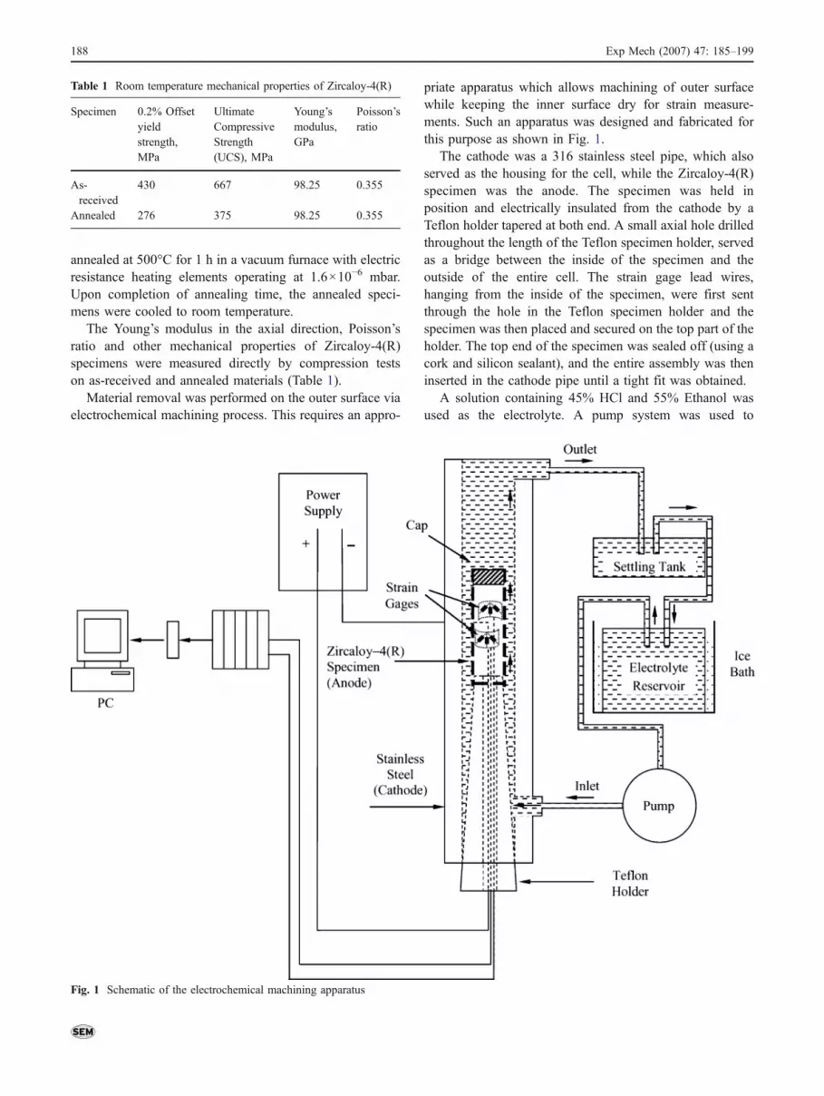
priate apparatus which allows machining of outer surfacewhile keeping the inner surface dry for strain measure-ments. Such an apparatus was designed and fabricated forthis purpose as shown in Fig. 1.
The cathode was a 316 stainless steel pipe, which alsoserved as the housing for the cell, while the Zircaloy-4(R)specimen was the anode. The specimen was held inposition and electrically insulated from the cathode by aTeflon holder tapered at both end. A small axial hole drilledthroughout the length of the Teflon specimen holder, servedas a bridge between the inside of the specimen and theoutside of the entire cell. The strain gage lead wires,hanging from the inside of the specimen, were first sentthrough the hole in the Teflon specimen holder and thespecimen was then placed and secured on the top part of theholder. The top end of the specimen was sealed off (using acork and silicon sealant), and the entire assembly was theninserted in the cathode pipe until a tight fit was obtained.
A solution containing 45% HCl and 55% Ethanol wasused as the electrolyte. A pump system was used to
Fig. 1 Schematic of the electrochemical machining apparatus
Table 1 Room temperature mechanical properties of Zircaloy-4(R)
Specimen 0.2% Offsetyieldstrength,MPa
UltimateCompressiveStrength(UCS), MPa
Young’smodulus,GPa
Poisson’sratio
As-received
430 667 98.25 0.355
Annealed 276 375 98.25 0.355
188 Exp Mech (2007) 47: 185–199
circulate the electrolyte through the cell at a flow rate of660 ml/min. The outcoming electrolyte containing corro-sion products was first passed through a settling tank beforereturning to the original reservoir for recirculation. A bathof cold water around the main reservoir was used tomaintain the electrolyte at room temperature.
A current of 1.5 A and a voltage of 4.0 V were applied tothe cell by a constant–current DC power supply while anelectrolytic solution was continuously being passed around theoutside of the tube. The current was kept constant throughoutthe entire test ensuring constant material removal rate.
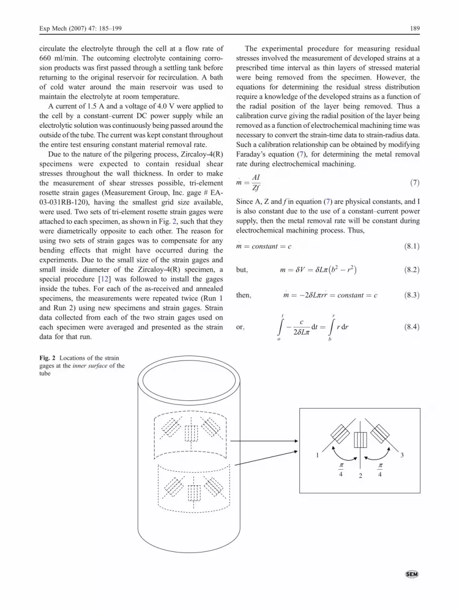
Due to the nature of the pilgering process, Zircaloy-4(R)specimens were expected to contain residual shearstresses throughout the wall thickness. In order to makethe measurement of shear stresses possible, tri-elementrosette strain gages (Measurement Group, Inc. gage # EA-03-031RB-120), having the smallest grid size available,were used. Two sets of tri-element rosette strain gages wereattached to each specimen, as shown in Fig. 2, such that theywere diametrically opposite to each other. The reason forusing two sets of strain gages was to compensate for anybending effects that might have occurred during theexperiments. Due to the small size of the strain gages andsmall inside diameter of the Zircaloy-4(R) specimen, aspecial procedure [12] was followed to install the gagesinside the tubes. For each of the as-received and annealedspecimens, the measurements were repeated twice (Run 1and Run 2) using new specimens and strain gages. Straindata collected from each of the two strain gages used oneach specimen were averaged and presented as the straindata for that run.
The experimental procedure for measuring residualstresses involved the measurement of developed strains at aprescribed time interval as thin layers of stressed materialwere being removed from the specimen. However, theequations for determining the residual stress distributionrequire a knowledge of the developed strains as a function ofthe radial position of the layer being removed. Thus acalibration curve giving the radial position of the layer beingremoved as a function of electrochemical machining time wasnecessary to convert the strain-time data to strain-radius data.Such a calibration relationship can be obtained by modifyingFaraday’s equation (7), for determining the metal removalrate during electrochemical machining.
m� ¼ AI
Zfð7Þ
Since A, Z and f in equation (7) are physical constants, and Iis also constant due to the use of a constant–current powersupply, then the metal removal rate will be constant duringelectrochemical machining process. Thus,
m� ¼ constant ¼ c ð8:1Þ
but; m ¼ dV ¼ dLp b2 � r2� � ð8:2Þ
then; m� ¼ �2dLprr
� ¼ constant ¼ c ð8:3Þ
or;
Z t
o
� c
2dLpdt ¼
Zr
b
r dr ð8:4Þ
4
π
4
π
1
2
3
Fig. 2 Locations of the straingages at the inner surface of thetube
Exp Mech (2007) 47: 185–199 189
which upon integration yields
� c
2dLpt ¼ r2 � b2
2ð8:5Þ
or; r2 ¼ � c
dLpt þ b2 ð8:6Þ
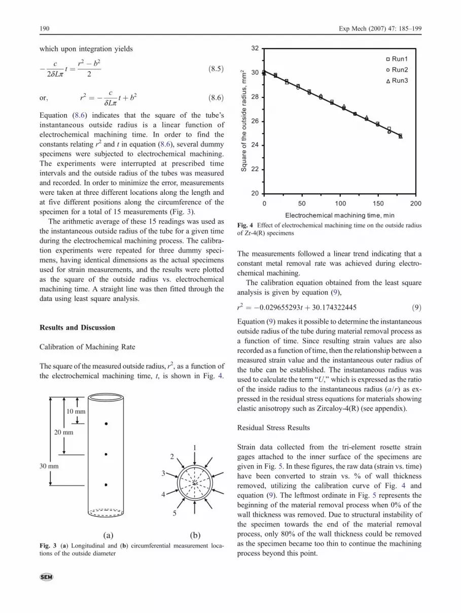
Equation (8.6) indicates that the square of the tube’sinstantaneous outside radius is a linear function ofelectrochemical machining time. In order to find theconstants relating r2 and t in equation (8.6), several dummyspecimens were subjected to electrochemical machining.The experiments were interrupted at prescribed timeintervals and the outside radius of the tubes was measuredand recorded. In order to minimize the error, measurementswere taken at three different locations along the length andat five different positions along the circumference of thespecimen for a total of 15 measurements (Fig. 3).
The arithmetic average of these 15 readings was used asthe instantaneous outside radius of the tube for a given timeduring the electrochemical machining process. The calibra-tion experiments were repeated for three dummy speci-mens, having identical dimensions as the actual specimensused for strain measurements, and the results were plottedas the square of the outside radius vs. electrochemicalmachining time. A straight line was then fitted through thedata using least square analysis.
Results and Discussion
Calibration of Machining Rate
The square of the measured outside radius, r2, as a function ofthe electrochemical machining time, t, is shown in Fig. 4.
The measurements followed a linear trend indicating that aconstant metal removal rate was achieved during electro-chemical machining.
The calibration equation obtained from the least squareanalysis is given by equation (9),
r2 ¼ �0:029655293t þ 30:174322445 ð9ÞEquation (9) makes it possible to determine the instantaneousoutside radius of the tube during material removal process asa function of time. Since resulting strain values are alsorecorded as a function of time, then the relationship between ameasured strain value and the instantaneous outer radius ofthe tube can be established. The instantaneous radius wasused to calculate the term “U,” which is expressed as the ratioof the inside radius to the instantaneous radius (a/r) as ex-pressed in the residual stress equations for materials showingelastic anisotropy such as Zircaloy-4(R) (see appendix).
Residual Stress Results
Strain data collected from the tri-element rosette straingages attached to the inner surface of the specimens aregiven in Fig. 5. In these figures, the raw data (strain vs. time)have been converted to strain vs. % of wall thicknessremoved, utilizing the calibration curve of Fig. 4 andequation (9). The leftmost ordinate in Fig. 5 represents thebeginning of the material removal process when 0% of thewall thickness was removed. Due to structural instability ofthe specimen towards the end of the material removalprocess, only 80% of the wall thickness could be removedas the specimen became too thin to continue the machiningprocess beyond this point.
10 mm
20 mm
30 mm
12
3
5
4
(a) (b)Fig. 3 (a) Longitudinal and (b) circumferential measurement loca-tions of the outside diameter
20
22
24
26
28
30
32
0 50 100 150 200
Electrochemical machining time, min
Sq
ua
re o
f th
e o
uts
ide
ra
diu
s,
mm
2
Run1
Run2
Run3
Fig. 4 Effect of electrochemical machining time on the outside radiusof Zr-4(R) specimens
190 Exp Mech (2007) 47: 185–199
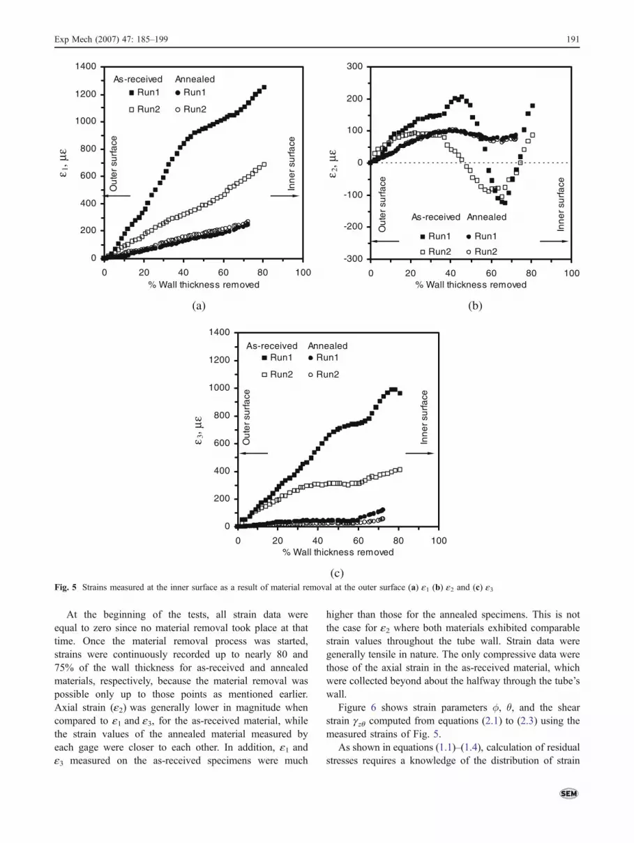
At the beginning of the tests, all strain data wereequal to zero since no material removal took place at thattime. Once the material removal process was started,strains were continuously recorded up to nearly 80 and75% of the wall thickness for as-received and annealedmaterials, respectively, because the material removal waspossible only up to those points as mentioned earlier.Axial strain (e2) was generally lower in magnitude whencompared to e1 and e3, for the as-received material, whilethe strain values of the annealed material measured byeach gage were closer to each other. In addition, e1 ande3 measured on the as-received specimens were much
higher than those for the annealed specimens. This is notthe case for e2 where both materials exhibited comparablestrain values throughout the tube wall. Strain data weregenerally tensile in nature. The only compressive data werethose of the axial strain in the as-received material, whichwere collected beyond about the halfway through the tube’swall.
Figure 6 shows strain parameters �, θ, and the shearstrain gzq computed from equations (2.1) to (2.3) using themeasured strains of Fig. 5.
As shown in equations (1.1)–(1.4), calculation of residualstresses requires a knowledge of the distribution of strain
0
200
400
600
800
1000
1200
1400
0 20 40 60 80 100% Wall thickness removed
ε 1, μ
ε
Run1 Run1
Run2 Run2
As-received Annealed
Ou
ter
surf
ace
Inn
er
surf
ace
-300
-200
-100
0
100
200
300
0 20 40 60 80 100% Wall thickness removed
ε 2, μ
ε
Run1 Run1
Run2 Run2
As-received Annealed
Ou
ter
surf
ace
Inn
er
surf
ace
(a) (b)
0
200
400
600
800
1000
1200
1400
0 20 40 60 80 100% Wall thickness removed
ε 3, μ
ε
Run1 Run1
Run2 Run2
As-received Annealed
Ou
ter
surf
ace
Inn
er
surf
ace
(c) Fig. 5 Strains measured at the inner surface as a result of material removal at the outer surface (a) e1 (b) e2 and (c) e3
Exp Mech (2007) 47: 185–199 191
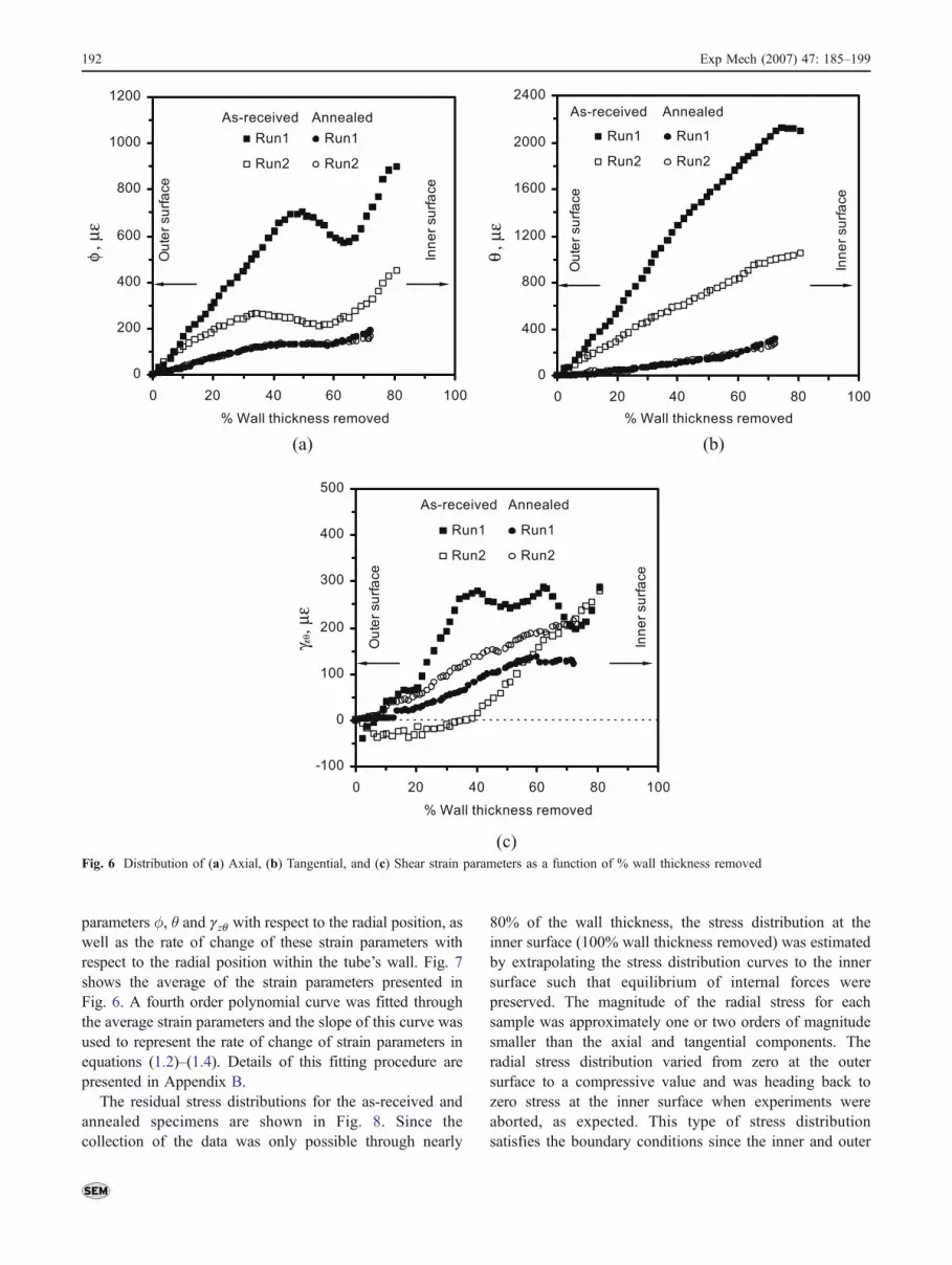
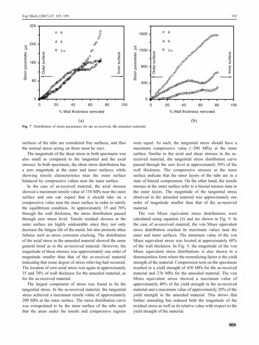
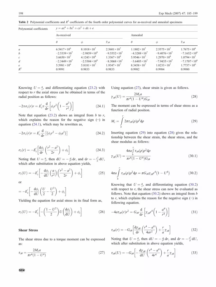
parameters �, θ and gzq with respect to the radial position, aswell as the rate of change of these strain parameters withrespect to the radial position within the tube’s wall. Fig. 7shows the average of the strain parameters presented inFig. 6. A fourth order polynomial curve was fitted throughthe average strain parameters and the slope of this curve wasused to represent the rate of change of strain parameters inequations (1.2)–(1.4). Details of this fitting procedure arepresented in Appendix B.
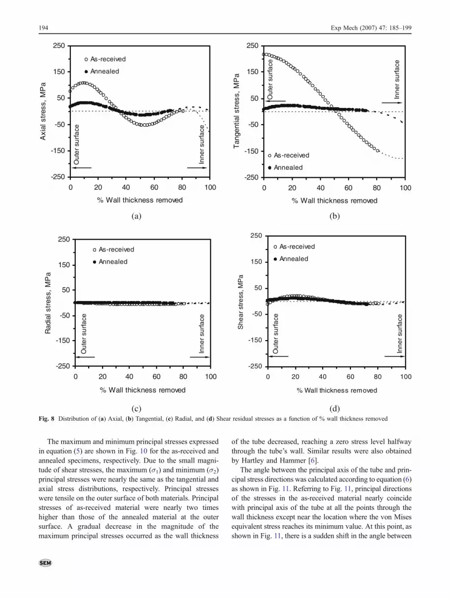
The residual stress distributions for the as-received andannealed specimens are shown in Fig. 8. Since thecollection of the data was only possible through nearly
80% of the wall thickness, the stress distribution at theinner surface (100% wall thickness removed) was estimatedby extrapolating the stress distribution curves to the innersurface such that equilibrium of internal forces werepreserved. The magnitude of the radial stress for eachsample was approximately one or two orders of magnitudesmaller than the axial and tangential components. Theradial stress distribution varied from zero at the outersurface to a compressive value and was heading back tozero stress at the inner surface when experiments wereaborted, as expected. This type of stress distributionsatisfies the boundary conditions since the inner and outer
0
200
400
600
800
1000
1200
0 20 40 60 80 100
% Wall thickness removed
, με
φ
, με
γ
, με
θ
Run1 Run1
Run2 Run2
As-received Annealed
Ou
ter
su
rfa
ce
Inn
er
su
rfa
ce
0
400
800
1200
1600
2000
2400
0 20 40 60 80 100
% Wall thickness removed
Run1 Run1
Run2 Run2
As-received Annealed
Ou
ter
su
rfa
ce
Inn
er
su
rfa
ce
(a) (b)
-100
0
100
200
300
400
500
0 20 40 60 80 100
% Wall thickness removed
Run1 Run1
Run2 Run2
As-received Annealed
Ou
ter
su
rfa
ce
Inn
er
su
rfa
ce
(c)
zθ
Fig. 6 Distribution of (a) Axial, (b) Tangential, and (c) Shear strain parameters as a function of % wall thickness removed
192 Exp Mech (2007) 47: 185–199
surfaces of the tube are considered free surfaces, and thusthe normal stress acting on them must be zero.
The magnitude of the shear stress in both specimens wasalso small as compared to the tangential and the axialstresses. In both specimens, the shear stress distribution hasa zero magnitude at the outer and inner surfaces, whileshowing tensile characteristics near the outer surfacebalanced by compressive values near the inner surface.
In the case of as-received material, the axial stressesshowed a maximum tensile value of 110 MPa near the outersurface and one can expect that it should take on acompressive value near the inner surface in order to satisfythe equilibrium condition. At approximately 35 and 70%through the wall thickness, the stress distribution passedthrough zero stress level. Tensile residual stresses at theouter surface are highly undesirable since they not onlydecrease the fatigue life of the metal, but also promote otherfailures such as stress corrosion cracking. The distributionof the axial stress in the annealed material showed the samegeneral trend as in the as-received material. However, themagnitude of these stresses was approximately one order ofmagnitude smaller than that of the as-received materialindicating that some degree of stress relieving had occurred.The location of zero axial stress was again at approximately35 and 70% of wall thickness for the annealed material, asfor the as-received material.
The largest component of stress was found to be thetangential stress. In the as-received material, the tangentialstress achieved a maximum tensile value of approximately200 MPa at the outer surface. The stress distribution curvewas extrapolated to be the inner surface of the tube suchthat the areas under the tensile and compressive regions
were equal. As such, the tangential stress should have amaximum compressive value (−200 MPa) at the innersurface. Similar to the axial and shear stresses in the as-received material, the tangential stress distribution curvepassed through the zero level at approximately 50% of thewall thickness. The compressive stresses at the innersurface indicate that the inner layers of the tube are in astate of biaxial compression. On the other hand, the tensilestresses at the outer surface refer to a biaxial tension state inthe outer layers. The magnitude of the tangential stressobserved in the annealed material was approximately oneorder of magnitude smaller than that of the as-receivedmaterial.
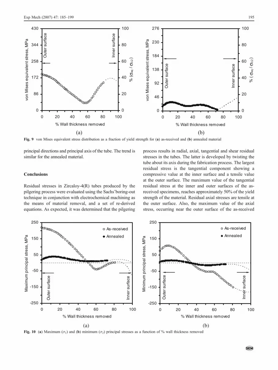
The von Mises equivalent stress distributions werecalculated using equation (4) and are shown in Fig. 9. Inthe case of as-received material, the von Mises equivalentstress distribution reached its maximum values near theouter and inner surfaces. The minimum value of the vonMises equivalent stress was located at approximately 60%of the wall thickness. In Fig. 9, the magnitude of the vonMises equivalent stress distributions is also shown in adimensionless form where the normalizing factor is the yieldstrength of the material. Compression tests on the specimensresulted in a yield strength of 430 MPa for the as-receivedmaterial and 276 MPa for the annealed material. The vonMises equivalent stress showed a maximum value ofapproximately 40% of the yield strength in the as-receivedmaterial and a maximum value of approximately 20% of theyield strength in the annealed material. This shows thatfurther annealing has reduced both the magnitude of theresidual stress as well as its relative value with respect to theyield strength of the material.
0
80
160
240
320
0 20 40 60 80 100
% Wall thickness removed
Str
ain
pa
ram
ete
r, μ
εθ
φ
γ θ z
θ
φ
γ θ z
Ou
ter
surf
ace
Inn
er
surf
ace
0
400
800
1200
1600
0 20 40 60 80 100
% Wall thickness removed
Str
ain
pa
ram
ete
r, μ
ε
Ou
ter
surf
ace
Inn
er
surf
ace
(a) (b) Fig. 7 Distribution of strain parameters for (a) as-received, (b) annealed materials
Exp Mech (2007) 47: 185–199 193
The maximum and minimum principal stresses expressedin equation (5) are shown in Fig. 10 for the as-received andannealed specimens, respectively. Due to the small magni-tude of shear stresses, the maximum (σ1) and minimum (σ2)principal stresses were nearly the same as the tangential andaxial stress distributions, respectively. Principal stresseswere tensile on the outer surface of both materials. Principalstresses of as-received material were nearly two timeshigher than those of the annealed material at the outersurface. A gradual decrease in the magnitude of themaximum principal stresses occurred as the wall thickness
of the tube decreased, reaching a zero stress level halfwaythrough the tube’s wall. Similar results were also obtainedby Hartley and Hammer [6].
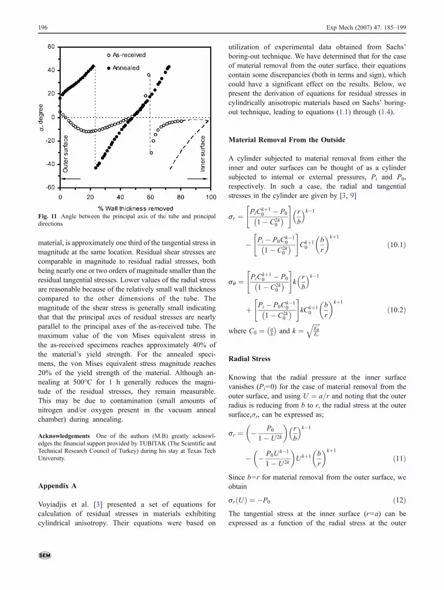
The angle between the principal axis of the tube and prin-cipal stress directions was calculated according to equation (6)as shown in Fig. 11. Referring to Fig. 11, principal directionsof the stresses in the as-received material nearly coincidewith principal axis of the tube at all the points through thewall thickness except near the location where the von Misesequivalent stress reaches its minimum value. At this point, asshown in Fig. 11, there is a sudden shift in the angle between
-250
-150
-50
50
150
250
0 20 40 60 80 100
% Wall thickness removed
Axi
al s
tres
s, M
Pa
As-received
AnnealedO
ute
r su
rfa
ce
Inn
er
surf
ace
-250
-150
-50
50
150
250
0 20 40 60 80 100
% Wall thickness removed
Tan
gent
ial s
tres
s, M
Pa
As-received
Annealed
Ou
ter
surf
ace
Inn
er
surf
ace
(a) (b)
-250
-150
-50
50
150
250
0 20 40 60 80 100
% Wall thickness removed
Rad
ial s
tres
s, M
Pa
As-received
Annealed
Ou
ter
surf
ace
Inn
er
surf
ace
-250
-150
-50
50
150
250
0 20 40 60 80 100
% Wall thickness removed
Sh
ea
r st
ress
, MP
aAs-received
Annealed
Ou
ter
surf
ace
Inn
er
surf
ace
(c) (d) Fig. 8 Distribution of (a) Axial, (b) Tangential, (c) Radial, and (d) Shear residual stresses as a function of % wall thickness removed
194 Exp Mech (2007) 47: 185–199
principal directions and principal axis of the tube. The trend issimilar for the annealed material.
Conclusions
Residual stresses in Zircaloy-4(R) tubes produced by thepilgering process were evaluated using the Sachs’boring-outtechnique in conjunction with electrochemical machining asthe means of material removal, and a set of re-derivedequations. As expected, it was determined that the pilgering
process results in radial, axial, tangential and shear residualstresses in the tubes. The latter is developed by twisting thetube about its axis during the fabrication process. The largestresidual stress is the tangential component showing acompressive value at the inner surface and a tensile valueat the outer surface. The maximum value of the tangentialresidual stress at the inner and outer surfaces of the as-received specimens, reaches approximately 50% of the yieldstrength of the material. Residual axial stresses are tensile atthe outer surface. Also, the maximum value of the axialstress, occurring near the outer surface of the as-received
-250
-150
-50
50
150
250
0 20 40 60 80 100
% Wall thickness removed
Ma
xim
um
pri
nci
pa
l str
ess
, MP
a
As-received
Annealed
Ou
ter
surf
ace
Inn
er
surf
ace
-250
-150
-50
50
150
250
0 20 40 60 80 100
% Wall thickness removed
Min
imu
m p
rin
cip
al s
tre
ss, M
Pa
As-received
Annealed
Ou
ter
surf
ace
Inn
er
surf
ace
(a) (b) Fig. 10 (a) Maximum (σ1) and (b) minimum (σ2) principal stresses as a function of % wall thickness removed
0
86
172
258
344
430
0 20 40 60 80 100
% Wall thickness removed
vo
n M
ise
s e
qu
iva
len
t str
ess, M
Pa
0
20
40
60
80
100
% (σ e
q / σ 0
.2 )O
ute
r su
rfa
ce
Inn
er
su
rfa
ce
0
46
92
138
184
230
276
0 20 40 60 80 100
% Wall thickness removed
vo
n M
ise
s e
qu
iva
len
t str
ess, M
Pa
0
20
40
60
80
100
% (
σ eq
/ σ 0
.2 )
Ou
ter
su
rfa
ce
Inn
er
su
rfa
ce
(a) (b)
Fig. 9 von Mises equivalent stress distribution as a fraction of yield strength for (a) as-received and (b) annealed material
Exp Mech (2007) 47: 185–199 195
material, is approximately one third of the tangential stress inmagnitude at the same location. Residual shear stresses arecomparable in magnitude to residual radial stresses, bothbeing nearly one or two orders of magnitude smaller than theresidual tangential stresses. Lower values of the radial stressare reasonable because of the relatively small wall thicknesscompared to the other dimensions of the tube. Themagnitude of the shear stress is generally small indicatingthat that the principal axes of residual stresses are nearlyparallel to the principal axes of the as-received tube. Themaximum value of the von Mises equivalent stress inthe as-received specimens reaches approximately 40% ofthe material’s yield strength. For the annealed speci-mens, the von Mises equivalent stress magnitude reaches20% of the yield strength of the material. Although an-nealing at 500°C for 1 h generally reduces the magni-tude of the residual stresses, they remain measurable.This may be due to contamination (small amounts ofnitrogen and/or oxygen present in the vacuum annealchamber) during annealing.
Acknowledgements One of the authors (M.B) greatly acknowl-edges the financial support provided by TUBITAK (The Scientific andTechnical Research Council of Turkey) during his stay at Texas TechUniversity.
Appendix A
Voyiadjis et al. [3] presented a set of equations forcalculation of residual stresses in materials exhibitingcylindrical anisotropy. Their equations were based on
utilization of experimental data obtained from Sachs’boring-out technique. We have determined that for the caseof material removal from the outer surface, their equationscontain some discrepancies (both in terms and sign), whichcould have a significant effect on the results. Below, wepresent the derivation of equations for residual stresses incylindrically anisotropic materials based on Sachs’ boring-out technique, leading to equations (1.1) through (1.4).
Material Removal From the Outside
A cylinder subjected to material removal from either theinner and outer surfaces can be thought of as a cylindersubjected to internal or external pressures, Pi and P0,respectively. In such a case, the radial and tangentialstresses in the cylinder are given by [3, 9]
sr ¼ PiCkþ10 � P0
1� C2k0
� �" #
r
b
k�1
� Pi � P0Ck�10
1� C2k0
� �" #
Ckþ10
b
r
� �kþ1
ð10:1Þ
sq ¼ PiCkþ10 � P0
1� C2k0
� �" #
kr
b
k�1
þ Pi � P0Ck�10
1� C2k0
� �" #
kCkþ10
b
r
� �kþ1
ð10:2Þ
where C0 ¼ ab
� �and k ¼
ffiffiffiffiffiEqEr
q
Radial Stress
Knowing that the radial pressure at the inner surfacevanishes (Pi=0) for the case of material removal from theouter surface, and using U ¼ a=r and noting that the outerradius is reducing from b to r, the radial stress at the outersurface,σr, can be expressed as;
sr ¼ � P0
1� U 2k
� �r
b
k�1
� � P0Uk�1
1� U 2k
� �Ukþ1 b
r
� �kþ1
ð11Þ
Since b=r for material removal from the outer surface, weobtain
sr Uð Þ ¼ �P0 ð12ÞThe tangential stress at the inner surface (r=a) can beexpressed as a function of the radial stress at the outer
Fig. 11 Angle between the principal axis of the tube and principaldirections
196 Exp Mech (2007) 47: 185–199
surface (b=r), by replacing (r /b) in equation (10.2) with (a /r) and noting that Pi=0 and U ¼ a=r, one can write
sq ¼ � P0Uk�1k
1� U2k
� �þ � P0Uk�1k
1� U2k
� �Ukþ1 1
Ukþ1ð13Þ
The tangential stress at the inner surface due to a radialstress at the outer surface can be obtained as;
sq ¼ � 2P0Uk�1k
1� U 2kð14Þ
Before the material is removed, σr (U)=−P0 at the outersurface according to equation (12), after the material isremoved, the internal pressure required to cancel thetangential surface strain is equal to radial stress at the orig-inal surface (σr (U) = P0). The tangential stress at the innersurface as a function of radial stress at the outer surface istherefore given by:
sq ¼ � 2kUk�1
1� U 2ksr Uð Þ ð15Þ
The tangential stress can also be expressed in terms of thestrains measured at the inner surface as
sq ¼ E0q eq þ nzqezð Þ ¼ E
0qqi ð16Þ
Combining equations (15) and (16) yields the radial stress,
sr Uð Þ ¼ �E0q
1� U2k
2kUk�1
� �qi ð17Þ
The requirement of equilibrium in the radial direction isgoverned by the tangential stress equation as a function ofthe radial position through the tube wall as follows:
Tangential Stress
sq ¼ @
@rrsr ð18Þ
To obtain the tangential stress as a function of U, equation(18) first needs to be written in terms of U by noting thatU ¼ a=r;
@U ¼ � a
r2@r ð19:1Þ
Thus, from equation (18),
@r ¼ � r2
a@U ð19:2Þ
sq ¼ � @
@UUsr ð19:3Þ
Inserting equation (17) into equation (19.3) gives thefollowing expressions which need to be differentiated withrespect to U,
sq Uð Þ ¼ � @
@UU �E
0q
1� U2k
2kUk�1
� �qi
� �ð20:1Þ
sq Uð Þ ¼ �E0q
dqidU
U 2k � 1
2kUk�2
� �þ qi
d
dU
U 2k � 1
2kUk�2
� �� �ð20:2Þ
The term U2k�12kUk�2
can be differentiated with respect to U as
follows:
d
dU
U2k � 1
2kUk�2
� �
¼ 2kU 2k�1� �
2kUk�2� �� k � 2ð Þ 2kUk�3
� �U 2k � 1� � �
4k2U 2k�4
ð21:1Þ
d
dU
U2k � 1
2kUk�2
� �¼ k þ 2ð ÞU2k þ k � 2
2kUk�1ð21:2Þ
Inserting the derived term given in equation (21.2) intoequation (20.2), the tangential stress in its final form is,
σθ Uð Þ ¼
E0θU
2 1� U2k
2kUk
� �dθidU
� �þ θi
2� k � k þ 2ð ÞU 2k
2kUkþ1
� �� �ð22Þ
Axial Stress
The axial stress can simply be written as:
sz ¼ F
pr2 1� U 2ð Þ ð23Þ
Considering the basic elasticity equations and the distribu-tion of axial stress, equation (23) becomes,
σz ¼
Rrb
2πσz ρð Þρdρπr2 1� U2ð Þ ¼ E
0zφi ð23:1Þ
Zr
b
2πσz ρð Þρdρ ¼ E0zφiπr
2 1� U2� � ð23:2Þ
Exp Mech (2007) 47: 185–199 197
Knowing U ¼ ar , and differentiating equation (23.2) with
respect to r the axial stress can be obtained in terms of theradial position as follows:
�2πσz rð Þr ¼ E0zπ
d
drφir
2 1� a2
r2
� �� �ð24:1Þ
Note that equation (23.2) shows an integral from b to r,which explains the reason for the negative sign (−) inequation (24.1), which may be rewritten as,
�2σz rð Þr ¼ E0z
d
drφir
2 � φia2
� � � ð24:2Þ
σz rð Þ ¼ �E0z
dφi
dr
r2 � a2
2r
� �þ φi
� �ð24:3Þ
Noting that U ¼ ar , then dU ¼ � a
r2 dr, and dr ¼ � r2
a dU ,which after substitution in above equation yields,
σz Uð Þ ¼ �E0z � dφi
dU
a
r2
r2 � a2
2r
� �þ φi
� �ð25Þ
or
¼ �E0z � dφi
dU
U
2� U 3
2
� �þ φi
� �
Yielding the equation for axial stress in its final form as,
σz Uð Þ ¼ �E0z � 1� U2
2
� �U
dφi
dU
� �þ φi
� �ð26Þ
Shear Stress
The shear stress due to a torque moment can be expressedas:
tzq ¼ 2Mza
pr4 1� U4ð Þ ð27Þ
Using equation (27), shear strain is given as follows.
gzq Uð Þ ¼ 2Mza
pr4 1� U 4ð ÞGzqð28Þ
The moment can be expressed in terms of shear stress as afunction of radial position.
Mz ¼Zr
b
2ptzq rð Þr2dr ð29Þ
Inserting equation (29) into equation (28) gives the rela-tionship between the shear strain, the shear stress, and theshear modulus as follows:
gzq Uð Þ ¼4pa
Rrb
tzq rð Þr2drpr4 1� U4ð ÞGzq
ð30:1Þ
4paZr
b
tzq rð Þr2dr ¼ pGzqgzqr4 1� U4� � ð30:2Þ
Knowing that U ¼ ar , and differentiating equation (30.2)
with respect to r, the shear stress can now be evaluated asfollows. Note that equation (30.2) shows an integral from bto r, which explains the reason for the negative sign (−) infollowing equation.
�4atzq rð Þr2 ¼ Gzqd
drgzqr
4 1� a4
r4
� �� �ð31Þ
tzq rð Þ ¼ �Gzqdgzqdr
r4 � a4
4ar2
� �þ r
agzq
� �ð32Þ
Noting that U ¼ ar , then dU ¼ � a
r2 dr, and dr ¼ � r2
a dU ,which after substitution in above equation yields,
tzq Uð Þ ¼ �Gzq � dgzqdU
r4 � a4
4r4
� �þ r
agzq
� �ð33Þ
Table 2 Polynomial coefficients and R2 coefficients of the fourth order polynomial curves for as-received and annealed specimens
Polynomial coefficients y ¼ ax4 þ bx3 þ cx2 þ dxþ e
As-received Annealed
θ � gzq θ � gzq
a 6.5417×10⁶ 8.1018×10⁷ 2.5601×10⁷ 1.1802×10⁷ 2.5575×10⁷ 1.7675×10⁶
b −2.5339×10⁷ −2.9859×10⁸ −9.5552×10⁷ −4.3288×10⁷ −9.4076×10⁷ −7.1652×10⁶
c 3.6650×10⁷ 4.1243×10⁸ 1.3367×10⁸ 5.9546×10⁷ 1.2970×10⁸ 1.0794×10⁷
d −2.3449×10⁷ −2.5304×10⁸ −8.3068×10⁷ −3.6405×10⁷ −7.9435×10⁷ −7.1707×10⁶
e 5.5981×10⁶ 5.8181×10⁷ 1.9347×10⁷ 8.3458×10⁷ 1.8233×10⁷ 1.7737×10⁶
R2 0.9991 0.9833 0.9833 0.9982 0.9984 0.9980
198 Exp Mech (2007) 47: 185–199

yielding the shear stress equation in its final form as,
tzq Uð Þ ¼ �Gzq � 1� U 4
4
� �dgzqdU
� �þ 1
Ugzq
� �ð34Þ
Appendix B
Strain parameters �, θ, and the shear strain gzq and theirderivatives with respect to U are used in equations (1.1)–(1.4)to evaluate the residual stresses. To calculate the derivativesof strain parameters with respect to U, the variation of thestrain parameters as a function of U was first determined byfitting a fourth order polynomial curve through the datapoints. After the equation of the curve was determined, thederivatives of these curves were used in equations (1.1)–(1.4)to calculate the residual stresses. Table 2 shows the poly-nomial coefficients and R2 coefficients for the fitted curves.
References
1. Sachs GZ (1927) Der Nachweis innerer spannungen in stagen undrohren (Evidence of Residual Stresses in Rod and Tubes). Z MetKd 19:352–357, (in German).
2. Sachs G, Espey G (1941) The measurement of residual stress inmetal. Iron Age 148:63–71.
3. Voyiadjis GZ, Kiousis PD, Hartley CS (1985) Analysis of residualstresses in cylindrically anisotropic materials. Exp Mech 25:145–147.
4. Guillen R, Cossu C, François M, Girard E (1998) Texture andresidual-stresses analysis in Zircaloy-4 cylindrical samples. J NuclMater 255:174–179.
5. Carr DG, Ripley MI, Holden TM, Brown DW, Vogel SC (2004)Residual stress measurements in a Zircaloy-4 weld by neutrondiffraction. Acta Mater 52:4083–4091.
6. Hartley CS, Hammer JJ (1985) Measurement of residual stressesin Zircaloy tubes. In: McQuenn HJ, Bailon J-P, Dickson JI, JonasJJ, Akben MG (eds) Proceedings of the 7th internationalconference on the strength of metals and alloys. Montreal,Canada, pp 293–298.
7. Rasty J (1987) Experimental and finite element study of residualstresses in Zircaloy-4(R) and OFHC copper tubes. Ph.D. Disser-tation, Louisiana State University.
8. Mohamadian HP, Mirshams AR, Cunningham ME (1991) Effectsof residual stresses on the fracture toughness of Zircaloy-2 tubes.In: Ruud C (ed) Practical applications of residual stress technol-ogy. ASM International Conference Proceedings, Indianapolis,Indiana, pp 11–17.
9. Lekhnitskii SG (1968) Anisotropic plates, 2nd edn. Gordon andBreach, New York.
10. Eisenberg MA, Hartley CS, Lee H-C, Yen CF (1980) Influence oftexture on the analysis of thermoelstic elastic/plastic anistropy andthe initial yielding of zircaloy tubes. J Nucl Mater 88:138–151.
11. Riley WF, Sturges LD, Morris DH (1999) Mechanics of materials,fifth edn. Wiley, New York, p. 132.
12. Anonymous (1983) How to install a strain gage in a small, deephole. Epsilonics, The Measurement Group Journal for StressAnalysts III(1):7.
Exp Mech (2007) 47: 185–199 199