me 407 – mechatronics
TRANSCRIPT

ME 407 Mechatronics
Page | 1
ME 407 – MECHATRONICS
MODULE VI
Robotic vision system - Image acquisition: Vidicon, charge coupled device (CCD) and
charge injection device (CID) cameras.
Image processing techniques: histogram processing: sliding, stretching, equalization and
thresholding.
Case studies of Mechatronics systems: Automatic camera, Bar code reader, Pick and
place robot, Automatic car park barrier system, Automobile engine management system.
ROBOTIC VISION SYSTEM
Robot vision (machine vision) may be defined as the process of extracting, characterising
and interpreting information from images of a three dimensional world.
In human vision system, eyes sense the images and brain analyses the information and takes
action on the basis of analysis.
Similarly in robotic vision system, visual sensing of information is done after forming an
image of the object and information is analysed to make a useful decision about its content.
Robotic vision (machine vision) system thus needs both visual sensing and interpretive
capabilities.
Image sensing device may consist of vidicon camera or a charge coupled device (CCD)
camera or charge injection device (CID) camera. Image sensing device receives light through a
lens system and converts this light into electrical signals.
Micro-computers are used to refine and analyse these electrical signals to provide an
interpretation of the object.
Machine vision system is ideally suited for in-process gauging and provides timely
corrective actions to control the process.
Machine vision systems are used for functions like gauging of dimensions, identification of
shapes, measurement of distances, determining orientation of parts, quantifying motion,
detecting surface shading etc.
A big advantage of machine vision systems is that they can be designed to operate for
wavelength in ultraviolet and infrared ranges to which human eye is insensitive.
It is a noncontact measuring technique and thus suited for fragile work pieces and which
would distort under measuring force and would get contaminated by touch.
STEPS IN MACHINE VISION PROCESS
The machine vision system involves following four basic steps :
o Image formation
o Processing of image in a form suitable for analysis by computer
o Defining and analysing the characteristics of image
o Interpretation of image and decision making.

ME 407 Mechatronics
Page | 2
IMAGE ACQUISITION (IMAGE FORMATION)
Image acquisition is the creation of digital images, typically from a physical scene.
The first link in the vision chain is the camera. It plays the role of robotic eye or the sensor.
The visual information is converted in to electric signals in the camera and when sampled
spatially and quantized, these signals give a digital image in real time by a process is called
digitizing.
Lighting for camera: Back lighting is suited when an image is required to obtain maximum
image contrast. Front lighting is used when certain key features on the surface of the object
are to be inspected.
Lighting for Camera
An image sensor like vidicon camera, CCD or CID camera is used to generate the electronic
signal representing the image.
The image sensor collects light from the scene through a lens and using a photosensitive
target, converts it into electronic signal.
Most image sensors generate signals representing two-dimensional arrays (scans of the
entire image).
VIDICON CAMERA
Vidicon Camera
ME 407 Mechatronics
Page | 3
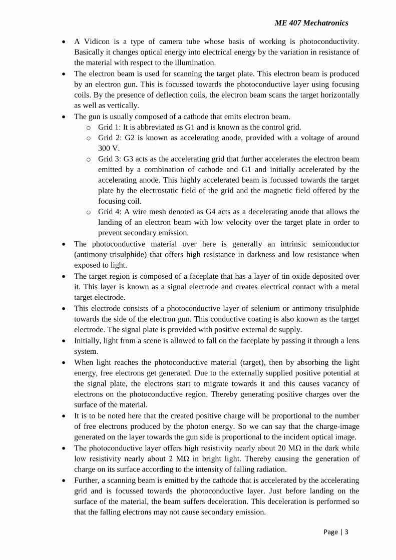
A Vidicon is a type of camera tube whose basis of working is photoconductivity.
Basically it changes optical energy into electrical energy by the variation in resistance of
the material with respect to the illumination.
The electron beam is used for scanning the target plate. This electron beam is produced
by an electron gun. This is focussed towards the photoconductive layer using focusing
coils. By the presence of deflection coils, the electron beam scans the target horizontally
as well as vertically.
The gun is usually composed of a cathode that emits electron beam.
o Grid 1: It is abbreviated as G1 and is known as the control grid.
o Grid 2: G2 is known as accelerating anode, provided with a voltage of around
300 V.
o Grid 3: G3 acts as the accelerating grid that further accelerates the electron beam
emitted by a combination of cathode and G1 and initially accelerated by the
accelerating anode. This highly accelerated beam is focussed towards the target
plate by the electrostatic field of the grid and the magnetic field offered by the
focusing coil.
o Grid 4: A wire mesh denoted as G4 acts as a decelerating anode that allows the
landing of an electron beam with low velocity over the target plate in order to
prevent secondary emission.
The photoconductive material over here is generally an intrinsic semiconductor
(antimony trisulphide) that offers high resistance in darkness and low resistance when
exposed to light.
The target region is composed of a faceplate that has a layer of tin oxide deposited over
it. This layer is known as a signal electrode and creates electrical contact with a metal
target electrode.
This electrode consists of a photoconductive layer of selenium or antimony trisulphide
towards the side of the electron gun. This conductive coating is also known as the target
electrode. The signal plate is provided with positive external dc supply.
Initially, light from a scene is allowed to fall on the faceplate by passing it through a lens
system.
When light reaches the photoconductive material (target), then by absorbing the light
energy, free electrons get generated. Due to the externally supplied positive potential at
the signal plate, the electrons start to migrate towards it and this causes vacancy of
electrons on the photoconductive region. Thereby generating positive charges over the
surface of the material.
It is to be noted here that the created positive charge will be proportional to the number
of free electrons produced by the photon energy. So we can say that the charge-image
generated on the layer towards the gun side is proportional to the incident optical image.
The photoconductive layer offers high resistivity nearly about 20 MΩ in the dark while
low resistivity nearly about 2 MΩ in bright light. Thereby causing the generation of
charge on its surface according to the intensity of falling radiation.
Further, a scanning beam is emitted by the cathode that is accelerated by the accelerating
grid and is focussed towards the photoconductive layer. Just before landing on the
surface of the material, the beam suffers deceleration. This deceleration is performed so
that the falling electrons may not cause secondary emission.
ME 407 Mechatronics
Page | 4
So a low-velocity scanning electron beam reaches the target plate. Thus the electrons
from the beam start depositing on the surface of the material in order to neutralize the
vacancy of electron created in it. This resultantly produces an electric current.
Only the sufficient amount of electrons that are needed to neutralize the positive charge
will be utilized. However, the remaining electrons that were not collected at the plate
will travel a reverse path due to the presence of positive grids.
Thus we can say that the scanning current is proportional to the deposited electrons and
so to the brightness of the incident light. This causes the video signal as the output across
the load resistor.
The scanning of every single element of the target is performed at a regular interval of
around 40 ms. Thus is a stored action.
This charge on the plate remains the same till the time each pixel gets neutralized
thereby enhancing the sensitivity of the tube.
Advantages:
Light weight
Small size
Longer life
Low power consumption
SOLID STATE CAMERA (DIGITAL CAMERA)
These are commonly used in machine vision systems. These employ charge coupled device
(CCD) or charge injected device (CID)image sensors.
They contain matrix or linear array of small, accurately spaced photo sensitive elements
fabricated on silicon chips using integrated circuit technology.
Each detector converts the light falling on it through the camera lens, in to analog electric
signal corresponding to light intensity.
The entire image is thus broken down in to an array of individual picture elements(pixels).
Typical matrix array solid state cameras may have 256×256 detector elements per array.
Solid state cameras are smaller, rugged and their sensors do not wear out with use. They
exhibit less image distortion because of accurate placement of the photo detectors.
CCD and CID differ primarily in how the voltages are extracted from the sensors
CHARGE COUPLED DEVICE (CCD) CAMERA
In this technology, the image is projected by video camera on to the CCD which detects,
stores and reads out the accumulated charge generated by the light on each portion of the
image.
Light detection occurs through the absorption of light on a photo conductive substrate (eg:
silicon)
Charges accumulate under positive control electrodes in isolated wells due to voltages
applied to the central electrodes.
Each isolated well represents one pixel which can be transferred to output storage register by
varying the voltage on the metal control electrode.

ME 407 Mechatronics
Page | 5
Charge Coupled Device
In a digital camera the traditional photographic film is replaced by a Charge Coupled Device
(CCD).
A CCD is a mosaic of tiny light sensitive detectors called pixels or 'photosites'.
The pixels are arranged as a flat rectangular surface onto which an
image is projected using a camera or telescope lens.
Working of CCD Camera
Each pixel accumulates an electrical charge depending on the amount of light falling upon it.
When an image is captured, the electrical charge from each pixel is measured and converted
to a number (digitized) by the electronic circuits within the camera.
These numbers are transmitted to a computer (immediately or at some later time) where they
are used to control the brightness of points on the computer screen (screen pixels), thus
reproducing the original image projected onto the CCD.
CHARGE INJECTION DEVICE (CID) CAMERA
CID camera is a type of image capturing device which utilizes an image sensor to register
visible light as an electronic signal. These CID cameras do not use photo – chemical film to
capture stills or video, instead the electronic signal is recorded to either a remotely
connected device or an internal memory.
ME 407 Mechatronics
Page | 6
When the camera‟s record function is initiated, the camera‟s lens focuses light through the
camera aperture, light filters and on onto the electronic image sensor. The image sensor is
arranged in a grid pattern with each individual square called as pixel. The image sensor
cannot determine the colour of the light recorded. Colours can be identified by the use of a
colour filter, which allows only one colour of light from the visible spectrum into each pixel.
In CID , array of photosensitive capacitor elements are arranged. Each pixel of the CID
image sensor is arranged over two intersecting capacitors. After the intensity of the light is
read, it is stored on the sensor.
Unlike Charge Coupled Device (CCD) cameras which transfer collected charge out of the
pixel during readout (and hence erase the image stored on the sensor), charge does not
transfer from site to site in the CID array.
Instead, a displacement current proportional to the stored signal charge is read when charge
"packets" are shifted between capacitors within individually selected pixels.
Since the image stays on the sensor, a displacement current equal to the signal on the sensor
is created.
The displacement current is read when the charge is shifted between capacitors, and is then
amplified and converted to a voltage.
This voltage is the camera output which is created as a video signal. Since the image is still
on the CID image sensor, this image is non-destructive.
IMAGE PROCESSING
An image is an array or a matrix of square pixels (picture elements) arranged in columns and
rows.
Images are obtained using various image acquisition devices like cameras.
The series of voltage levels available on detectors representing light intensities over the area
of the image.
An analog to digital converter is used to convert analog voltage of each detector into digital
value.
After acquiring the images they are stored in computer memory as digitized image.
Acquired images will be having errors during their acquisition.
If we remove these errors we will get clear images. The removal of errors for making the
image more bright and clear is done by image processing.
A camera may typically form an image 30 times per sec. At each time interval the entire
image has to be captured and frozen for processing by an image processor.
Image processing is a method to convert an image in to digital form and perform some
operations on it, in order to get an enhanced image or to extract some useful
information from it.
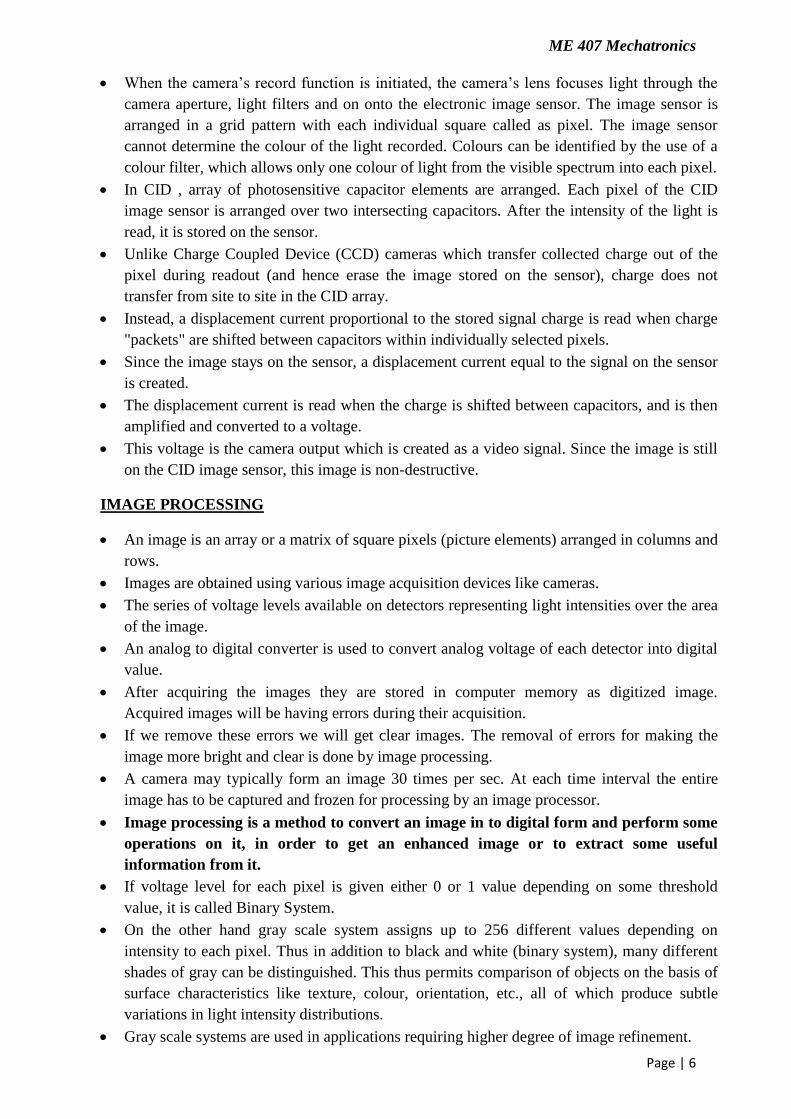
If voltage level for each pixel is given either 0 or 1 value depending on some threshold
value, it is called Binary System.
On the other hand gray scale system assigns up to 256 different values depending on
intensity to each pixel. Thus in addition to black and white (binary system), many different
shades of gray can be distinguished. This thus permits comparison of objects on the basis of
surface characteristics like texture, colour, orientation, etc., all of which produce subtle
variations in light intensity distributions.
Gray scale systems are used in applications requiring higher degree of image refinement.
ME 407 Mechatronics
Page | 7
For simple inspection tasks, binary system may serve the purpose.
It may be appreciated that gray-scale system requires huge storage processing capability It
is, therefore, essential that some means be used to reduce the amount of data to be
processed.
Gray Scale Image
HISTOGRAM PROCESSING
Histogram is a graphical representation showing a visual impression of the distribution of
data. It is nothing but a graph that shows frequency of occurrence of data.
The histogram of a digital image with gray levels in the range [0, L-1] is a discrete function
h(rk) = nk,
Where,
rk is the k th gray level and
nk is the number of pixels in the image having gray level rk.
L=maximum value of gray level (eg.256).
Important types of histogram processing are:
o Histogram equalization
o Contrast Stretching
o Thresholding
o Histogram sliding
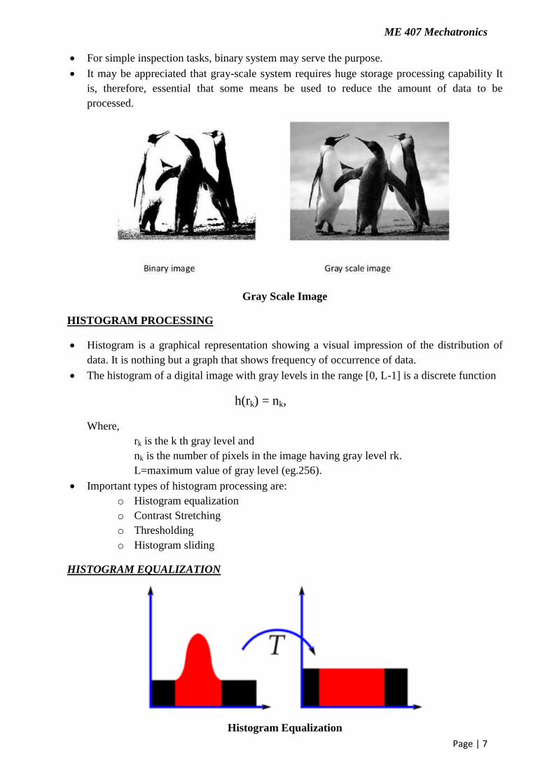
HISTOGRAM EQUALIZATION
Histogram Equalization
ME 407 Mechatronics
Page | 8
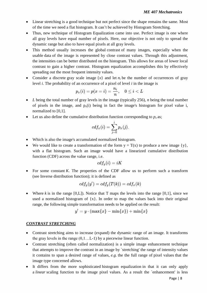
Linear stretching is a good technique but not perfect since the shape remains the same. Most
of the time we need a flat histogram. It can‟t be achieved by Histogram Stretching.
Thus, new technique of Histogram Equalization came into use. Perfect image is one where
all gray levels have equal number of pixels. Here, our objective is not only to spread the
dynamic range but also to have equal pixels at all gray levels.
This method usually increases the global contrast of many images, especially when the
usable data of the image is represented by close contrast values. Through this adjustment,
the intensities can be better distributed on the histogram. This allows for areas of lower local
contrast to gain a higher contrast. Histogram equalization accomplishes this by effectively
spreading out the most frequent intensity values.
Consider a discrete gray scale image {x} and let ni be the number of occurrences of gray
level i. The probability of an occurrence of a pixel of level i in the image is
L being the total number of gray levels in the image (typically 256), n being the total number
of pixels in the image, and px(i) being in fact the image's histogram for pixel value i,
normalized to [0,1].
Let us also define the cumulative distribution function corresponding to px as;
Which is also the image's accumulated normalized histogram.
We would like to create a transformation of the form y = T(x) to produce a new image {y},
with a flat histogram. Such an image would have a linearized cumulative distribution
function (CDF) across the value range, i.e.
For some constant K. The properties of the CDF allow us to perform such a transform
(see Inverse distribution function); it is defined as
Where k is in the range [0,L]). Notice that T maps the levels into the range [0,1], since we
used a normalized histogram of {x}. In order to map the values back into their original
range, the following simple transformation needs to be applied on the result:
CONTRAST STRETCHING
Contrast stretching aims to increase (expand) the dynamic range of an image. It transforms
the gray levels in the range (0,1…L-1) by a piecewise linear function.
Contrast stretching (often called normalization) is a simple image enhancement technique
that attempts to improve the contrast in an image by `stretching' the range of intensity values
it contains to span a desired range of values, e.g. the the full range of pixel values that the
image type concerned allows.
It differs from the more sophisticated histogram equalization in that it can only apply
a linear scaling function to the image pixel values. As a result the `enhancement' is less
ME 407 Mechatronics
Page | 9
harsh. (Most implementations accept a gray level image as input and produce another gray
level image as output.)
Before the stretching can be performed it is necessary to specify the upper and lower pixel
value limits over which the image is to be normalized. Often these limits will just be the
minimum and maximum pixel values that the image type concerned allows.
For example for 8-bit gray level images the lower and upper limits might be 0 and 255. Call
the lower and the upper limits a and b respectively.
The simplest sort of normalization then scans the image to find the lowest and highest pixel
values currently present in the image. Call these c and d.
Then each pixel P is scaled using the following function:
Values below 0 are set to 0 and values about 255 are set to 255.
The problem with this is that a single outlying pixel with either a very high or very low
value can severely affect the value of c or d and this could lead to very unrepresentative
scaling. Therefore a more robust approach is to first take a histogram of the image, and then
select c and d at, say, the 5th and 95th percentile in the histogram (that is, 5% of the pixel in
the histogram will have values lower than c, and 5% of the pixels will have values higher
than d). This prevents outliers affecting the scaling so much.
Another common technique for dealing with outliers is to use the intensity histogram to find
the most popular intensity level in an image (i.e. the histogram peak) and then define a cutoff
fraction which is the minimum fraction of this peak magnitude below which data will be
ignored.
The intensity histogram is then scanned upward from 0 until the first intensity value with
contents above the cutoff fraction. This defines c. Similarly, the intensity histogram is then
scanned downward from 255 until the first intensity value with contents above the cutoff
fraction. This defines d.
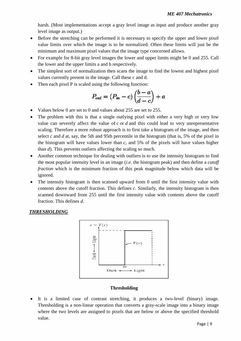
THRESHOLDING
Thresholding
It is a limited case of contrast stretching, it produces a two-level (binary) image.
Thresholding is a non-linear operation that converts a gray-scale image into a binary image
where the two levels are assigned to pixels that are below or above the specified threshold
value.
ME 407 Mechatronics
Page | 10
Thresholding creates binary images from grey-level ones by turning all pixels below some
threshold to zero and all pixels above that threshold to one.
If S(x, y) is a threshold version of f (x, y) at some threshold „m‟. S is equal to 1 if
f (x ,y) ≥ m and zero otherwise.
HISTOGRAM SLIDING
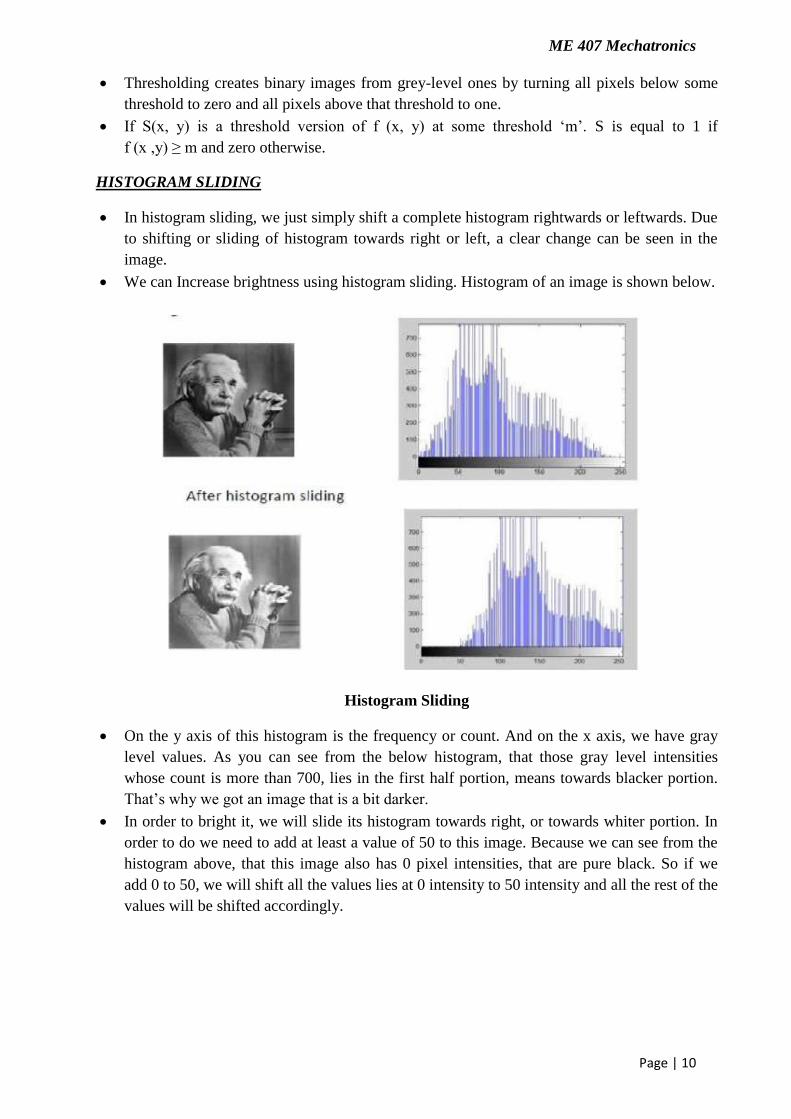
In histogram sliding, we just simply shift a complete histogram rightwards or leftwards. Due
to shifting or sliding of histogram towards right or left, a clear change can be seen in the
image.
We can Increase brightness using histogram sliding. Histogram of an image is shown below.
Histogram Sliding
On the y axis of this histogram is the frequency or count. And on the x axis, we have gray
level values. As you can see from the below histogram, that those gray level intensities
whose count is more than 700, lies in the first half portion, means towards blacker portion.
That‟s why we got an image that is a bit darker.
In order to bright it, we will slide its histogram towards right, or towards whiter portion. In
order to do we need to add at least a value of 50 to this image. Because we can see from the
histogram above, that this image also has 0 pixel intensities, that are pure black. So if we
add 0 to 50, we will shift all the values lies at 0 intensity to 50 intensity and all the rest of the
values will be shifted accordingly.
ME 407 Mechatronics
Page | 11
CASE STUDIES OF MECHATRONIC SYSTEMS
AUTOMOBILE ENGINE MANAGEMENT SYSTEM
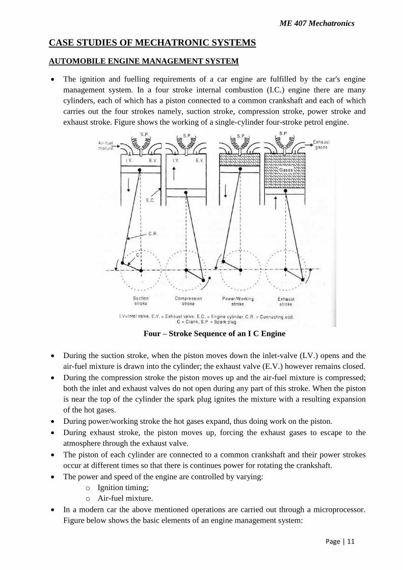
The ignition and fuelling requirements of a car engine are fulfilled by the car's engine
management system. In a four stroke internal combustion (I.C.) engine there are many
cylinders, each of which has a piston connected to a common crankshaft and each of which
carries out the four strokes namely, suction stroke, compression stroke, power stroke and
exhaust stroke. Figure shows the working of a single-cylinder four-stroke petrol engine.
Four – Stroke Sequence of an I C Engine
During the suction stroke, when the piston moves down the inlet-valve (LV.) opens and the
air-fuel mixture is drawn into the cylinder; the exhaust valve (E.V.) however remains closed.
During the compression stroke the piston moves up and the air-fuel mixture is compressed;
both the inlet and exhaust valves do not open during any part of this stroke. When the piston
is near the top of the cylinder the spark plug ignites the mixture with a resulting expansion
of the hot gases.
During power/working stroke the hot gases expand, thus doing work on the piston.
During exhaust stroke, the piston moves up, forcing the exhaust gases to escape to the
atmosphere through the exhaust valve.
The piston of each cylinder are connected to a common crankshaft and their power strokes
occur at different times so that there is continues power for rotating the crankshaft.
The power and speed of the engine are controlled by varying:
o Ignition timing;
o Air-fuel mixture.
In a modern car the above mentioned operations are carried out through a microprocessor.
Figure below shows the basic elements of an engine management system:
ME 407 Mechatronics
Page | 12
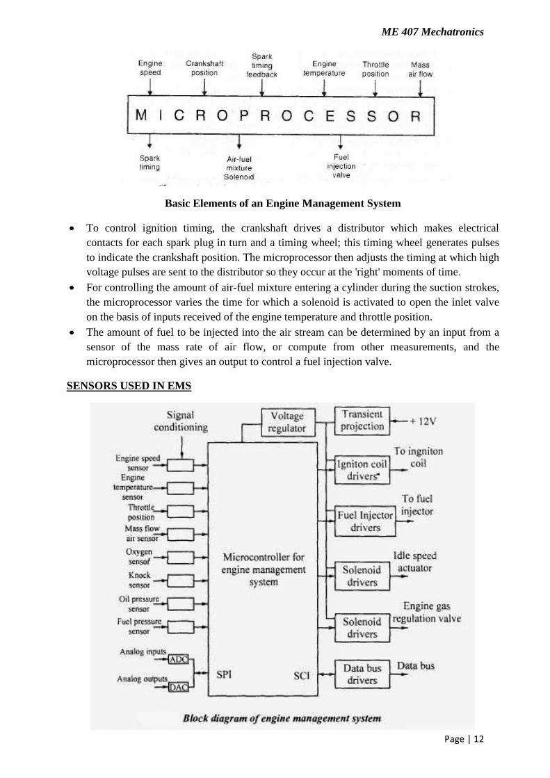
Basic Elements of an Engine Management System
To control ignition timing, the crankshaft drives a distributor which makes electrical
contacts for each spark plug in turn and a timing wheel; this timing wheel generates pulses
to indicate the crankshaft position. The microprocessor then adjusts the timing at which high
voltage pulses are sent to the distributor so they occur at the 'right' moments of time.
For controlling the amount of air-fuel mixture entering a cylinder during the suction strokes,
the microprocessor varies the time for which a solenoid is activated to open the inlet valve
on the basis of inputs received of the engine temperature and throttle position.
The amount of fuel to be injected into the air stream can be determined by an input from a
sensor of the mass rate of air flow, or compute from other measurements, and the
microprocessor then gives an output to control a fuel injection valve.
SENSORS USED IN EMS
ME 407 Mechatronics
Page | 13
Electronic Control Unit: It controls more than one electric systems and subsystems in a
motor vehicle. It helps in regulating and maintaining the amount of fuel
and air the engine need to increase horsepower.
Fuel Injector Sequential: It‟s a type of multi-port injection system in which injection valve
will open just before the cylinder intake valve opens. It has the fast response time when the
driver makes a quick change.
Air Flow Sensor: An air flow meter is a device that measures the actual speed of the air
flowing through the engine in different segments.
Air Temperature Sensor: It helps to measure the air density for fuel mixture control and to
trim the air flow ratio according to the airflow density.
Throttle Position Sensor: This sensor is used to monitor the throttle position of a car. This
sensor moves with the throttle and sends a voltage signal to the computer. This indicating
throttle angle and speed of movement. The computer uses this data to measure engine load,
adjust timing, fuel delivery etc.
Temperature Sensor: Temperature sensors include analog and digital sensor ICs designed
for temperature monitoring of a system.
Oxygen Sensor: It measures the proportion of oxygen to fuel in the engine.
Idle Air Control Valve: The idle air control valve is also known as idle speed control
valve; regulates the idle speed of the engine.
MAP Sensor: This sensor measures air pressure which tells engine the current altitude of a
vehicle.
Knock Sensor: The Knock Sensor detects engine knock and sends a voltage signal to the
engine and the engine uses that signal to control the timing.
Engine Speed Sensor: An engine speed sensor is attached to crankshaft of car's engine and
it indicate the speed that crankshaft is spinning. This information is beneficial to control
both the ignition timing and EMS.
Engine Oil Sensor: It measures the oil pressure inside the engine and gives an alert in case
of any problem with oil pressure.
Crankshaft Sensor: It is used to monitor the position and rotational speed of crankshaft and
these information will be used by the EMS to control the ignition system timing and other
engine parameters.
Camshaft Sensor: The Camshaft sensor determines which cylinder is firing to establish
injector synchronization and coil firing sequence in DIS systems then only crankshaft sensor
set ignition timing, supply the signal and measure the speed.
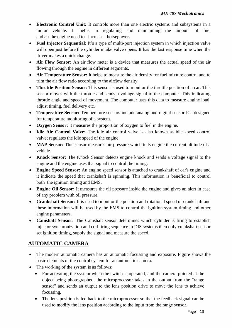
AUTOMATIC CAMERA
The modern automatic camera has an automatic focussing and exposure. Figure shows the
basic elements of the control system for an automatic camera.
The working of the system is as follows:
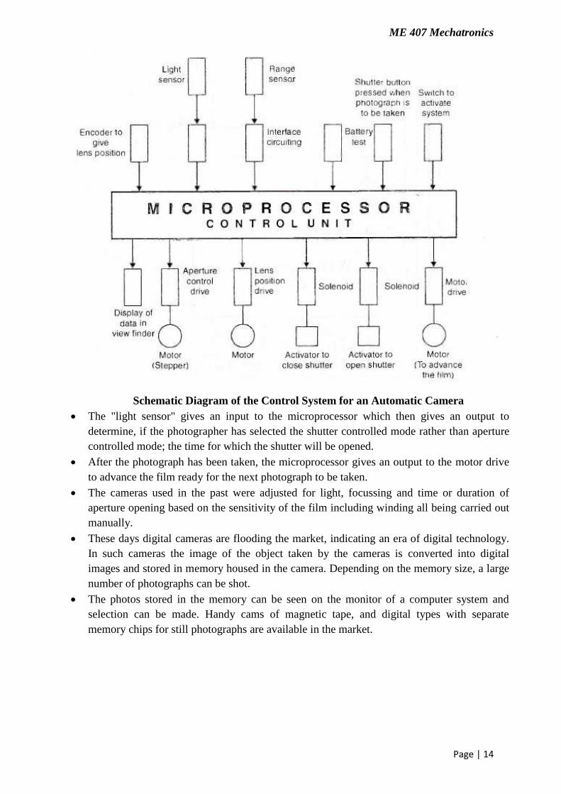
For activating the system when the switch is operated, and the camera pointed at the
object being photographed, the microprocessor takes in the output from the "range
sensor" and sends an output to the lens position drive to move the lens to achieve
focussing.
The lens position is fed back to the microprocessor so that the feedback signal can be
used to modify the lens position according to the input from the range sensor.
ME 407 Mechatronics
Page | 14
Schematic Diagram of the Control System for an Automatic Camera
The "light sensor" gives an input to the microprocessor which then gives an output to
determine, if the photographer has selected the shutter controlled mode rather than aperture
controlled mode; the time for which the shutter will be opened.
After the photograph has been taken, the microprocessor gives an output to the motor drive
to advance the film ready for the next photograph to be taken.
The cameras used in the past were adjusted for light, focussing and time or duration of
aperture opening based on the sensitivity of the film including winding all being carried out
manually.
These days digital cameras are flooding the market, indicating an era of digital technology.
In such cameras the image of the object taken by the cameras is converted into digital
images and stored in memory housed in the camera. Depending on the memory size, a large
number of photographs can be shot.
The photos stored in the memory can be seen on the monitor of a computer system and
selection can be made. Handy cams of magnetic tape, and digital types with separate
memory chips for still photographs are available in the market.
ME 407 Mechatronics
Page | 15
PICK AND PLACE ROBOT
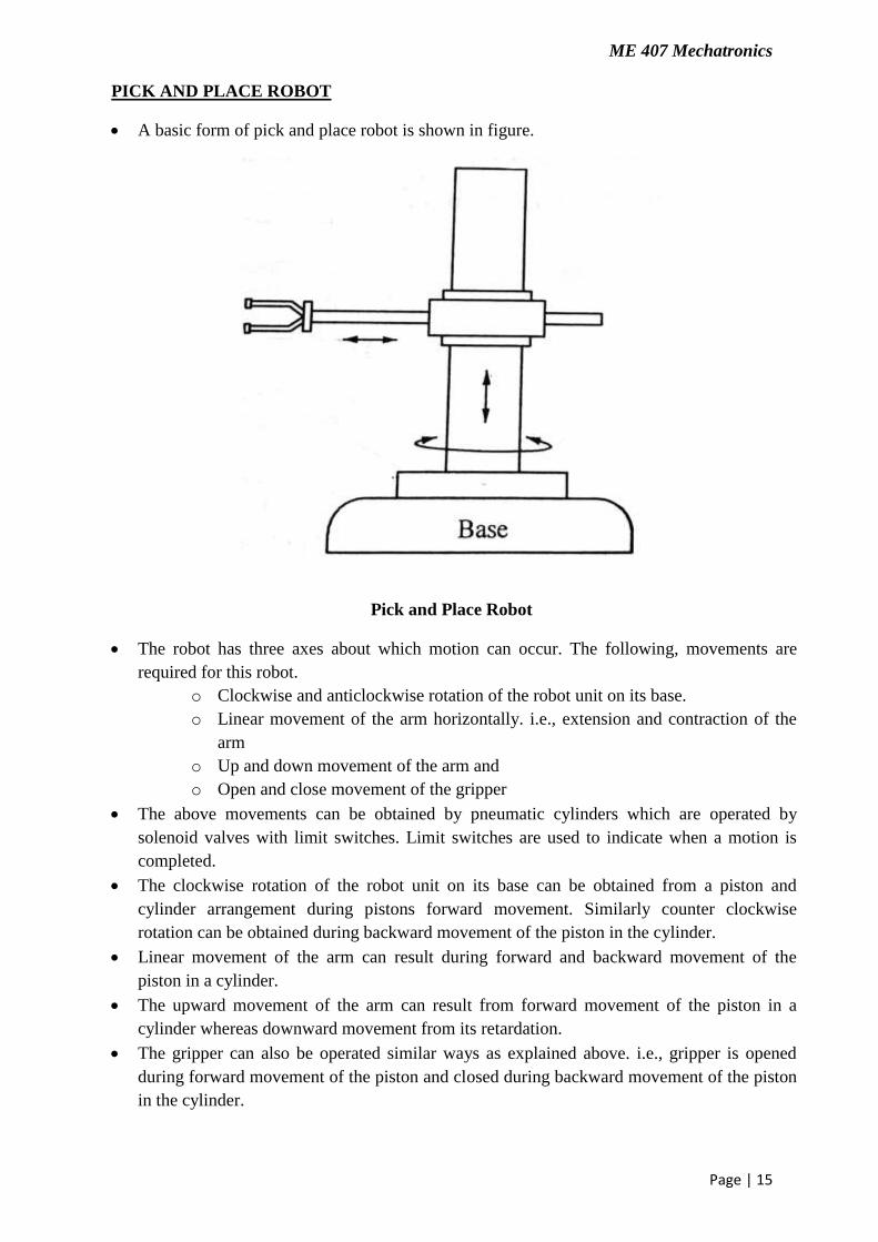
A basic form of pick and place robot is shown in figure.
Pick and Place Robot
The robot has three axes about which motion can occur. The following, movements are
required for this robot.
o Clockwise and anticlockwise rotation of the robot unit on its base.
o Linear movement of the arm horizontally. i.e., extension and contraction of the
arm
o Up and down movement of the arm and
o Open and close movement of the gripper
The above movements can be obtained by pneumatic cylinders which are operated by
solenoid valves with limit switches. Limit switches are used to indicate when a motion is
completed.
The clockwise rotation of the robot unit on its base can be obtained from a piston and
cylinder arrangement during pistons forward movement. Similarly counter clockwise
rotation can be obtained during backward movement of the piston in the cylinder.
Linear movement of the arm can result during forward and backward movement of the
piston in a cylinder.
The upward movement of the arm can result from forward movement of the piston in a
cylinder whereas downward movement from its retardation.
The gripper can also be operated similar ways as explained above. i.e., gripper is opened
during forward movement of the piston and closed during backward movement of the piston
in the cylinder.
ME 407 Mechatronics
Page | 16
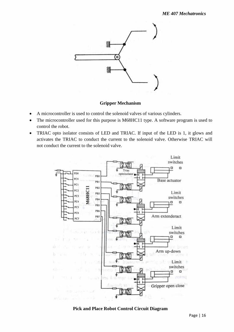
Gripper Mechanism
A microcontroller is used to control the solenoid valves of various cylinders.
The microcontroller used for this purpose is M68HC11 type. A software program is used to
control the robot.
TRIAC opto isolator consists of LED and TRIAC. If input of the LED is 1, it glows and
activates the TRIAC to conduct the current to the solenoid valve. Otherwise TRIAC will
not conduct the current to the solenoid valve.
Pick and Place Robot Control Circuit Diagram
ME 407 Mechatronics
Page | 17
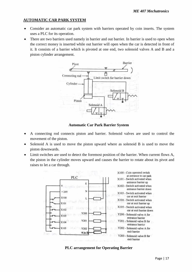
AUTOMATIC CAR PARK SYSTEM
Consider an automatic car park system with barriers operated by coin inserts. The system
uses a PLC for its operation.
There are two barriers used namely in barrier and out barrier. In barrier is used to open when
the correct money is inserted while out barrier will open when the car is detected in front of
it. It consists of a barrier which is pivoted at one end, two solenoid valves A and B and a
piston cylinder arrangement.
Automatic Car Park Barrier System
A connecting rod connects piston and barrier. Solenoid valves are used to control the
movement of the piston.
Solenoid A is used to move the piston upward where as solenoid B is used to move the
piston downwards.
Limit switches are used to detect the foremost position of the barrier. When current flows A,
the piston in the cylinder moves upward and causes the barrier to rotate about its pivot and
raises to let a car through.
PLC arrangement for Operating Barrier

ME 407 Mechatronics
Page | 18
When the barrier hits the limit switch, it will turn on the timer to give a required time delay.
After that time delay, the solenoid B is activated which brings the barrier downward by
operating piston in the cylinder. This principle is used for both the barriers.
Ladder Program for PLC System
BARCODE READER
Barcodes are simply a set of symbols used to represent alpha-numeric information instead of
seeing a number “1”, or letter “A”, you would see a series of black and white bars in various
combinations and in different widths.
Barcode
These are used to encode data. The data encoded in such bars can be decoded again to
represent it in human readable form.
Barcode reader is an electronic device, which can read an output printed barcodes to a
computer. It consists of light source, a lens and a light sensor translating optical impulses
into electrical ones. Most of the barcode readers contain decoder circuitry to analyse the
barcodes image data provided by the sensor and sending the barcode‟s content to the
scanner‟s output port.
ME 407 Mechatronics
Page | 19
A bar code consists of a series of parallel, adjacent bars and spaces. Symbologies are used to
encode small strings of character data into a printed symbol.
A bar code reader decodes a bar code by scanning a light source across the bar code and
measuring the intensity of light reflected back by the white spaces. The pattern of reflected
light is detected with a photodiode which produces an electronic signal that exactly matches
the printed bar code pattern. This signal is then decoded back to the original data by
electronic circuit.
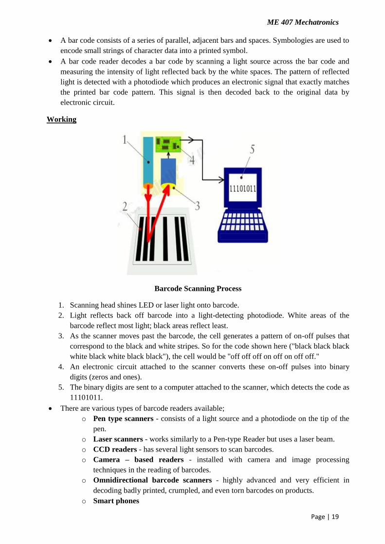
Working
Barcode Scanning Process
1. Scanning head shines LED or laser light onto barcode.
2. Light reflects back off barcode into a light-detecting photodiode. White areas of the
barcode reflect most light; black areas reflect least.
3. As the scanner moves past the barcode, the cell generates a pattern of on-off pulses that
correspond to the black and white stripes. So for the code shown here ("black black black
white black white black black"), the cell would be "off off off on off on off off."
4. An electronic circuit attached to the scanner converts these on-off pulses into binary
digits (zeros and ones).
5. The binary digits are sent to a computer attached to the scanner, which detects the code as
11101011.
There are various types of barcode readers available;
o Pen type scanners - consists of a light source and a photodiode on the tip of the
pen.
o Laser scanners - works similarly to a Pen-type Reader but uses a laser beam.
o CCD readers - has several light sensors to scan barcodes.
o Camera – based readers - installed with camera and image processing
techniques in the reading of barcodes.
o Omnidirectional barcode scanners - highly advanced and very efficient in
decoding badly printed, crumpled, and even torn barcodes on products.
o Smart phones

ME 407 Mechatronics
Page | 20
Advantages:
Accuracy of data input
Aid for effective management of resources and inventories
Cost efficient
Real time data collection
Labour savings by avoiding manual system
Measurement of work in progress though out the factory
More accurate dispatch
Rapid access to total production costs
Disadvantages:
Barcode scanner or reader works with computers.
Barcodes do not have read/write capabilities.
It requires optical line of sight (LOS) scanning.
It is labour intensive as it requires to be scanned individually.
It is susceptible to environmental damage.
Applications:
Retail applications: Supermarket, Countet mounted Bar code scanner, Universal Product
code, Price and description information, Ware housing
Heath care application: Drugs, device, instruments, Identification of expiry date, Blood
banking