me8781 mechatronics laboratory manual
TRANSCRIPT

SRM VALLIAMMAI ENGINEERING COLLEGE
(An Autonomous Institution)
SRM NAGAR, KATTANKULATHUR – 603 203
ME8781 MECHATRONICS LABORATORY MANUAL
(Seventh Semester B.E/B.Tech Students for the Academic Year 2021-2022)
R2017
Prepared By
Faculty Members
Department of Mechanical Engineering
(Private Circulation Only)
SRM VALLIAMMAI ENGINEERING COLLEGE,
SRM NAGAR,
KATTANKULATHUR-603203

Department of Mechanical Engineering
Instructions to the students
The following instructions must be followed by the students in their laboratory classes.
1. Students are expected to be punctual to the lab classes. If they are late, they will be
considered absent for that particular session.
2. Students should strictly maintain the dress code (i.e.) they have to wear the lab uniform
with black shoes.
3. Students must bring their observation note, record note (completed with previous
experiment) and the calculator to every lab class without fail.
4. Students are advised to come with full preparation for their lab sessions by
a. Reading the detailed procedure of the experiment from the laboratory manual.
b. Completion of observation note book (i.e.) Aim, Apparatus required, Formula
(with description), least count calculation, diagrams and the tabular column
should be written in the observation note before entering into the laboratory.
5. Data enter in the observation note book must be by pen only.
6. Students must get attestations immediately for their observed readings.
7. Students are advised to get their results evaluated in the observation note book on the
same day of that experiment.
8. Class assessment marks for each experiment is based only on their performance in the
laboratory.
9. Record note has to be completed then and there and get corrected when the students are
coming or the next lab class.
10. Students must strictly maintain silence during lab classes.
11. If any of the students is absent for the lab class for genuine reasons, he/she will be
permitted to do the experiment during the repetition class only.
12. Students are advised to perform their experiments under safety care.
13. If any student is found causing damage to the lab equipments, he/she shall replace the
same with a new.
Department of Mechanical Engineering VII Semester Mechanical Engineering
ME8781- MECHATRONICS LABORATORY
SYLLABUS
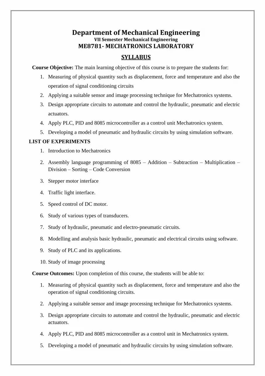
Course Objective: The main learning objective of this course is to prepare the students for:
1. Measuring of physical quantity such as displacement, force and temperature and also the
operation of signal conditioning circuits
2. Applying a suitable sensor and image processing technique for Mechatronics systems.
3. Design appropriate circuits to automate and control the hydraulic, pneumatic and electric
actuators.
4. Apply PLC, PID and 8085 microcontroller as a control unit Mechatronics system.
5. Developing a model of pneumatic and hydraulic circuits by using simulation software.
LIST OF EXPERIMENTS
1. Introduction to Mechatronics
2. Assembly language programming of 8085 – Addition – Subtraction – Multiplication –
Division – Sorting – Code Conversion
3. Stepper motor interface
4. Traffic light interface.
5. Speed control of DC motor.
6. Study of various types of transducers.
7. Study of hydraulic, pneumatic and electro-pneumatic circuits.
8. Modelling and analysis basic hydraulic, pneumatic and electrical circuits using software.
9. Study of PLC and its applications.
10. Study of image processing
Course Outcomes: Upon completion of this course, the students will be able to:
1. Measuring of physical quantity such as displacement, force and temperature and also the
operation of signal conditioning circuits.
2. Applying a suitable sensor and image processing technique for Mechatronics systems.
3. Design appropriate circuits to automate and control the hydraulic, pneumatic and electric
actuators.
4. Apply PLC, PID and 8085 microcontroller as a control unit in Mechatronics system.
5. Developing a model of pneumatic and hydraulic circuits by using simulation software.
Department of Mechanical Engineering
VII Semester Mechanical Engineering
ME8781- MECHATRONICS LABORATORY
Course Information Sheet
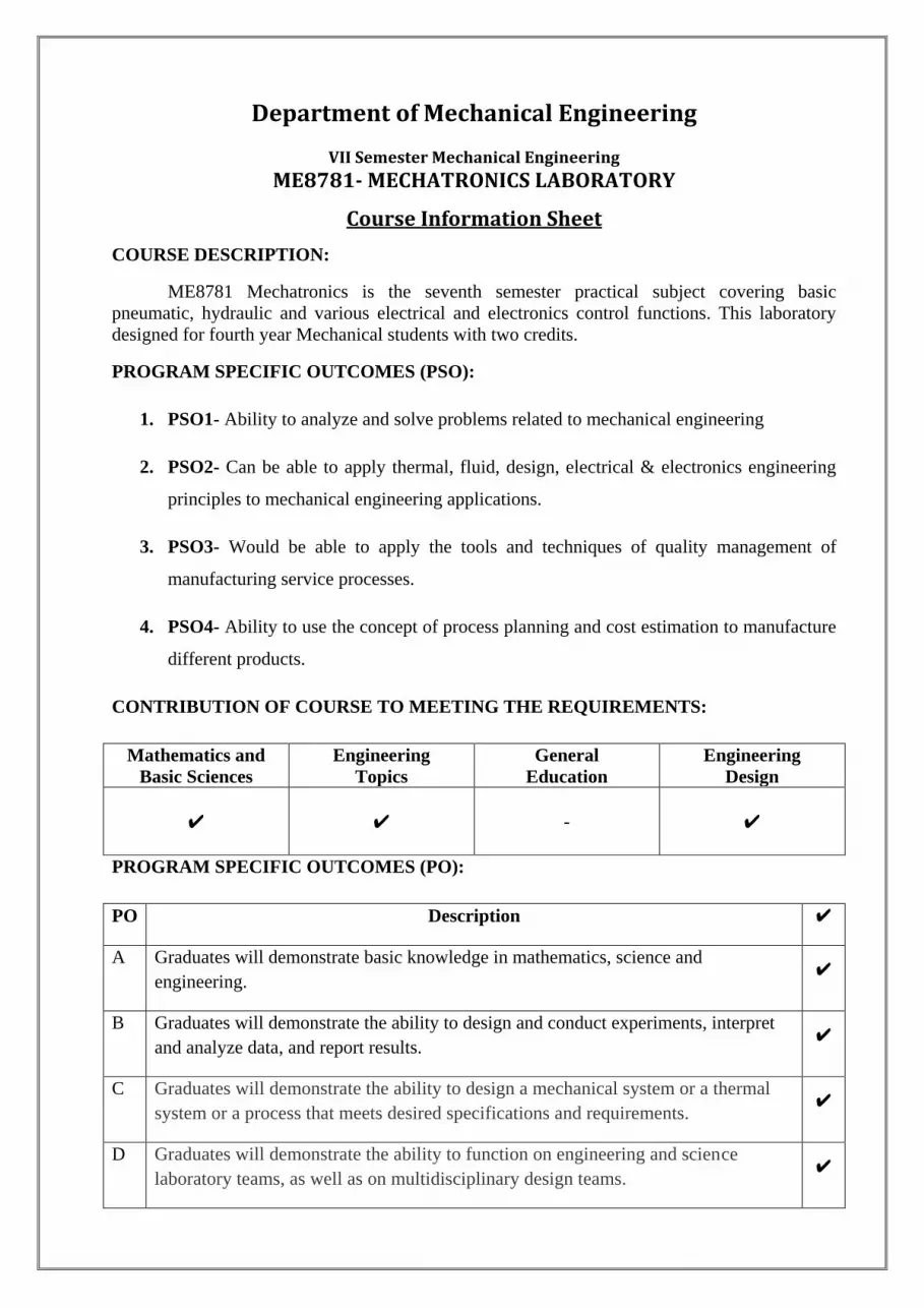
COURSE DESCRIPTION:
ME8781 Mechatronics is the seventh semester practical subject covering basic
pneumatic, hydraulic and various electrical and electronics control functions. This laboratory
designed for fourth year Mechanical students with two credits.
PROGRAM SPECIFIC OUTCOMES (PSO):
1. PSO1- Ability to analyze and solve problems related to mechanical engineering
2. PSO2- Can be able to apply thermal, fluid, design, electrical & electronics engineering
principles to mechanical engineering applications.
3. PSO3- Would be able to apply the tools and techniques of quality management of
manufacturing service processes.
4. PSO4- Ability to use the concept of process planning and cost estimation to manufacture
different products.
CONTRIBUTION OF COURSE TO MEETING THE REQUIREMENTS:
Mathematics and
Basic Sciences
Engineering
Topics
General
Education
Engineering
Design
✔
✔ - ✔
PROGRAM SPECIFIC OUTCOMES (PO):
PO Description ✔
A Graduates will demonstrate basic knowledge in mathematics, science and
engineering. ✔
B Graduates will demonstrate the ability to design and conduct experiments, interpret
and analyze data, and report results. ✔
C Graduates will demonstrate the ability to design a mechanical system or a thermal
system or a process that meets desired specifications and requirements. ✔
D Graduates will demonstrate the ability to function on engineering and science
laboratory teams, as well as on multidisciplinary design teams. ✔

E Graduates will demonstrate the ability to identify, formulate and solve mechanical
engineering problems. -
F Graduates will demonstrate an understanding of their professional and ethical
responsibilities. -
G Graduates will be able to communicate effectively in both verbal and written forms. ✔
H Graduates will have the confidence to apply engineering solutions in global and
societal contexts. -
I Graduates should be capable of self-education and clearly understand the value of
lifelong learning. ✔
J Graduates will be broadly educated and will have an understanding of the impact of
engineering on society and demonstrate awareness of contemporary issues. -
K Graduates will be familiar with modern engineering software tools and equipment to
analyze mechanical engineering problems. ✔
L Competent enough to succeed in National level competitive examinations in the
field of Mechanical Engineering. -
M Ability to be a successful Entrepreneur in the fields of Mechanical, Automobile,
Mechatronics Engineering and Industrial Automation. ✔
co
PO PSO
1 2 3 4 5 6 7 8 9 10 11 12 1 2 3 4
1 3 2 3
2 3 3 3
3 3 3 3
4 3 3 2 3
5 3 2 2 2 3

INDEX
EXPT
NO DATE NAME OF THE EXPERIMENT SIGN.
- Introduction to Mechatronics
Experiments on Using 8051 & 8085
1 Addition-Subtraction-Multiplication-Division-Sorting-
Code conversion using 8085 Assembly language
programming
2 Stepper motor interface with 8051 Microcontroller kit
3 Traffic light interface with 8051 microcontroller kit
Speed Control of Dc Motor
4 Speed Control Of Dc Drives Using PID Controller
Interfacing Unit
Study Experiments
5 Study of various types of transducers
Experiments on Pneumatic Trainer Kit
6
Design and Testing of Pneumatic Circuits to Control the
Speed of the Cylinder By Meter In And Meter Out Valve
Circuit
Design and Testing of Pneumatic Circuits Impulse pilot
operation of single acting cylinder.
Design and Testing of Pneumatic Circuits Operation of
double acting cylinder with AND & OR logic circuit
Design and Testing of Pneumatic Circuits Single cycle
automation of double acting cylinder using limit switch
Design and Testing of Pneumatic Circuits Single cycle
automation of multiple cylinder in sequence (A+B+A-B-)
Experiments on Electro-Pneumatic Trainer Kit
7 Design and Testing of Electro-Pneumatic Circuits
Operation of single and double acting cylinder using
single solenoid valve
Design and Testing of Electro-Pneumatic Circuits
Operation of double acting cylinder using double
solenoid valve.
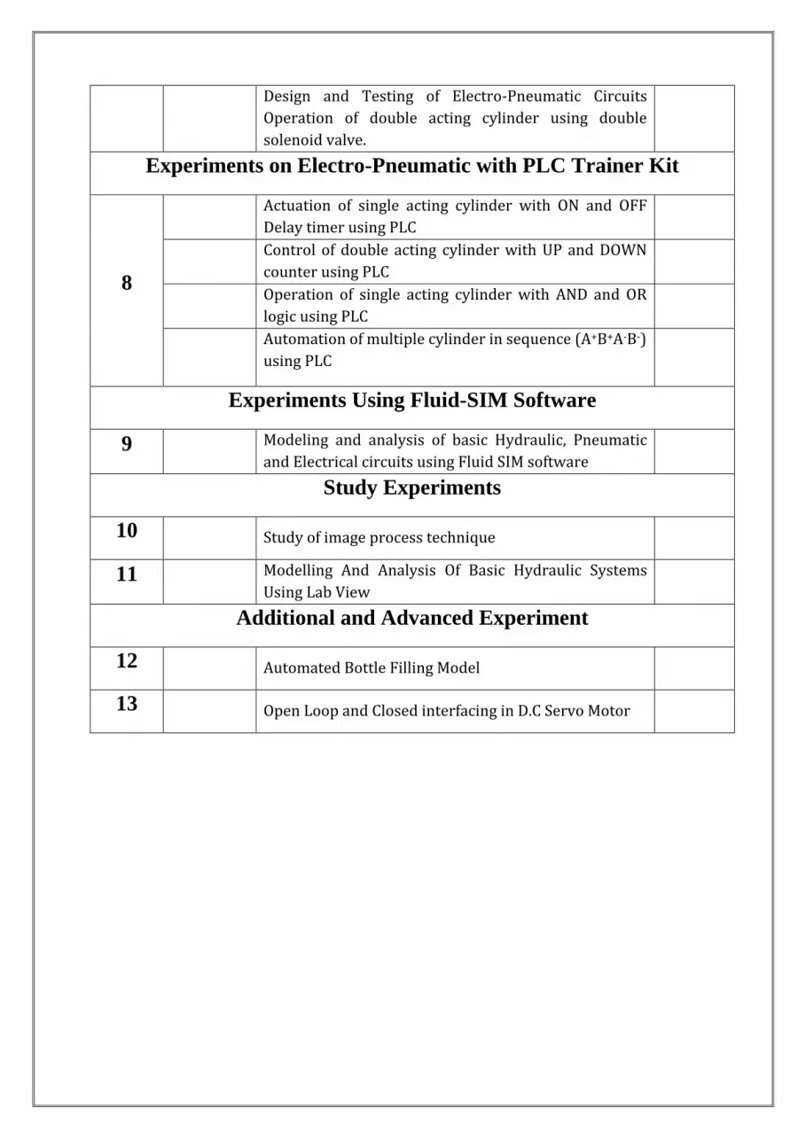
Experiments on Electro-Pneumatic with PLC Trainer Kit
8
Actuation of single acting cylinder with ON and OFF
Delay timer using PLC
Control of double acting cylinder with UP and DOWN
counter using PLC
Operation of single acting cylinder with AND and OR
logic using PLC
Automation of multiple cylinder in sequence (A+B+A-B-)
using PLC
Experiments Using Fluid-SIM Software
9 Modeling and analysis of basic Hydraulic, Pneumatic
and Electrical circuits using Fluid SIM software
Study Experiments
10 Study of image process technique
11 Modelling And Analysis Of Basic Hydraulic Systems
Using Lab View
Additional and Advanced Experiment
12 Automated Bottle Filling Model
13 Open Loop and Closed interfacing in D.C Servo Motor

INTRODUCTION TO MECHATRONICS
Aim: To study about the important features, about Mechatronics system.
Introduction to Mechatronics System:
Mechatronics is a word originated in Japan in 1980s to denote the combination of
technologies which go together to produce industrial needs. Mechatronics is one of the new and
existing fields on the engineering landscape, subsuming parts of traditional engineering fields
and requiring a broader approach to the design of system that we can formally call as
Mechatronics system.
Today many industries improving their product though automation which is based on the
inter connection between the electronics control systems and mechanical engineering. Such
control systems generally use microprocessors as controllers and have electrical sensors
extracting information from mechanical inputs through electrical actuators to mechanical
systems.
It can be considered to be application of computer based digital control techniques
through electronic and electric interface to mechanical engineering problems. Success ful design
of mechatronics can lead to products that are extremely attractive to customer in quality cost-
effectiveness.
GRAPHICAL REPRESENTATION OF MECHATRONICS:
MECHATRONICS
ELECTRONIC ENGINEERING ELECTRICAL ENGINEERING
CONTROL ENGINEERING COMPUTER TECHNOLOGY

Mechatronics is the synergistic integration of Mechanics and Mechanical Engineering,
Electronics, Computer Technology, and IT to produce or enhance products and systems.
Mechatronics brings together areas of technology involving sensors and measurement
systems, drive and actuation systems, analysis of the behaviour of systems microprocessor
systems. The integration across the traditional boundaries of mechanical engineering, electrical
engineering, electronics and control engineering has to occur at earliest stages of the design
process if cheaper, more reliable; more flexible systems are to be developed.
ELEMENTS OF MECHATRONICS SYSTEMS:
Actuators and sensors
Signals and conditioning
Digital logic systems
Software and data acquisition systems
Computers and display devices
APPLICATIONS OF MECHATRONICS ENGINEERING:
Electronic home appliances
Electronic entertainment products
Engine systems (Cars)
Large scale applications
PNEUMATICS AND HYDRAULIC SYSTEMS
Most of mechatronics systems work based on motion or action by means of sort. This
motion or actuation caused either by torque or force form which displacement and acceleration
can be obtained. To obtain this force or acceleration, actuators are mainly used. Actuator is a
device which provides enough force needed to stat the mechatronics systems. At the same,
power should be supplied to the actuator to activate it. The power supplied to actuators might be
any one of the following forms such as compressed air, pressurized fluid, electric power and
mechanical power. If compressed air supplied to the system, it is called as pneumatic system.
But if pressurized fluid is supplied to flow the system it is called as hydraulic system.

BASIC ELEMENTS OF PNEUMATIC SYSTEM:
Compressor and motor
Pressure relief valve and check valve
Cooler, filter and water trap
Air receiver
Directional control valves
Actuator or pneumatic cylinder
BASIC ELEMENTS OF HYDRAULIC SYSTEM:
Reservoir (Or air tank)
Pump
Prime mover
Valves
Actuator
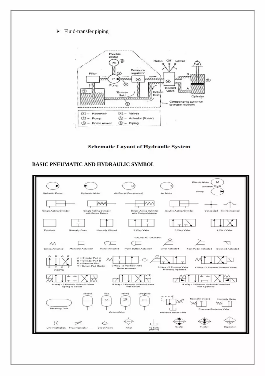
Fluid-transfer piping
BASIC PNEUMATIC AND HYDRAULIC SYMBOL
ADDITION-SUBTRACTION-MULTIPLICATION-DIVISION-SORTING-CODE
CONVERSION
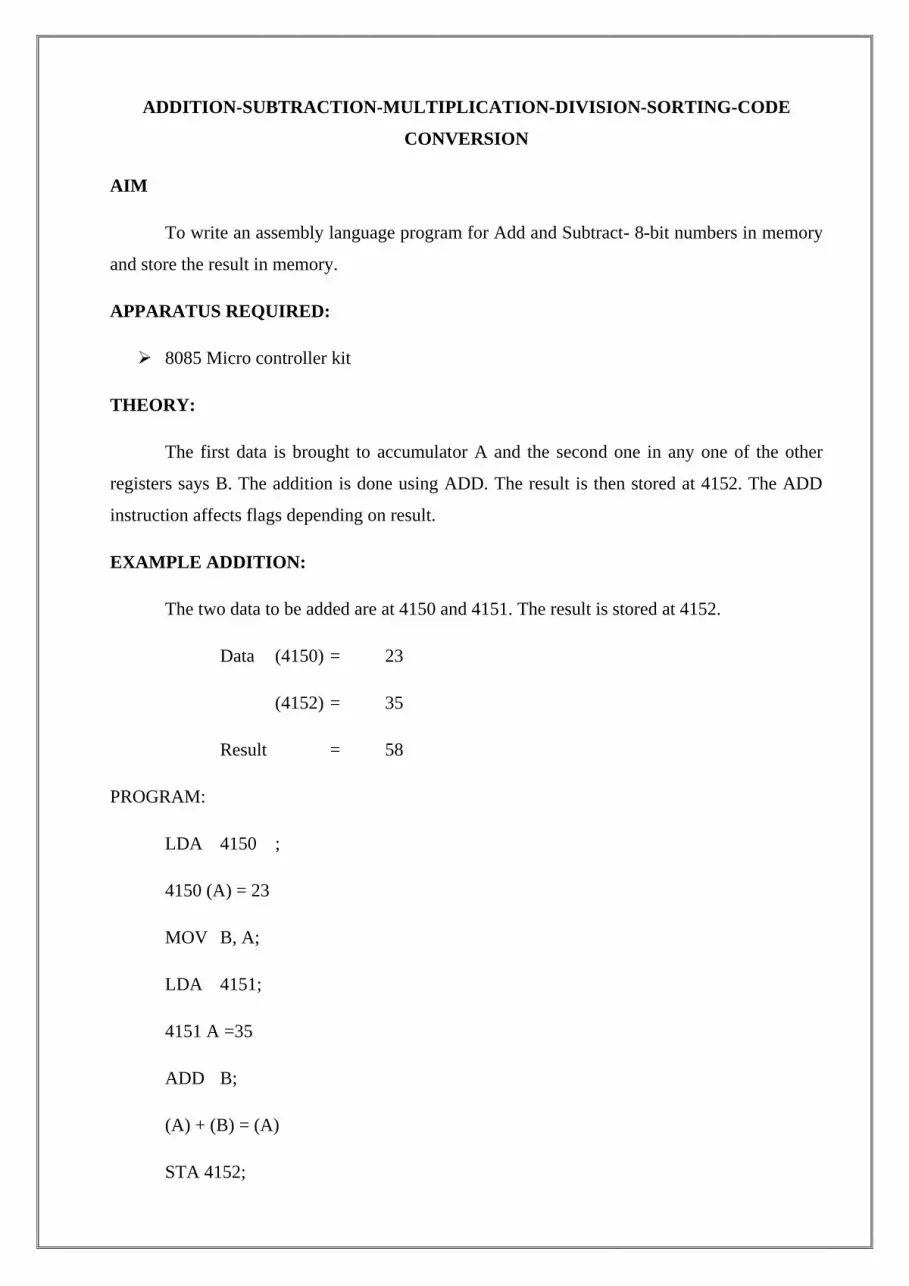
AIM
To write an assembly language program for Add and Subtract- 8-bit numbers in memory
and store the result in memory.
APPARATUS REQUIRED:
8085 Micro controller kit
THEORY:
The first data is brought to accumulator A and the second one in any one of the other
registers says B. The addition is done using ADD. The result is then stored at 4152. The ADD
instruction affects flags depending on result.
EXAMPLE ADDITION:
The two data to be added are at 4150 and 4151. The result is stored at 4152.
Data (4150) = 23
(4152) = 35
Result = 58
PROGRAM:
LDA 4150 ;
4150 (A) = 23
MOV B, A;
LDA 4151;
4151 A =35
ADD B;
(A) + (B) = (A)
STA 4152;
(A) 4152 = 58
HLT
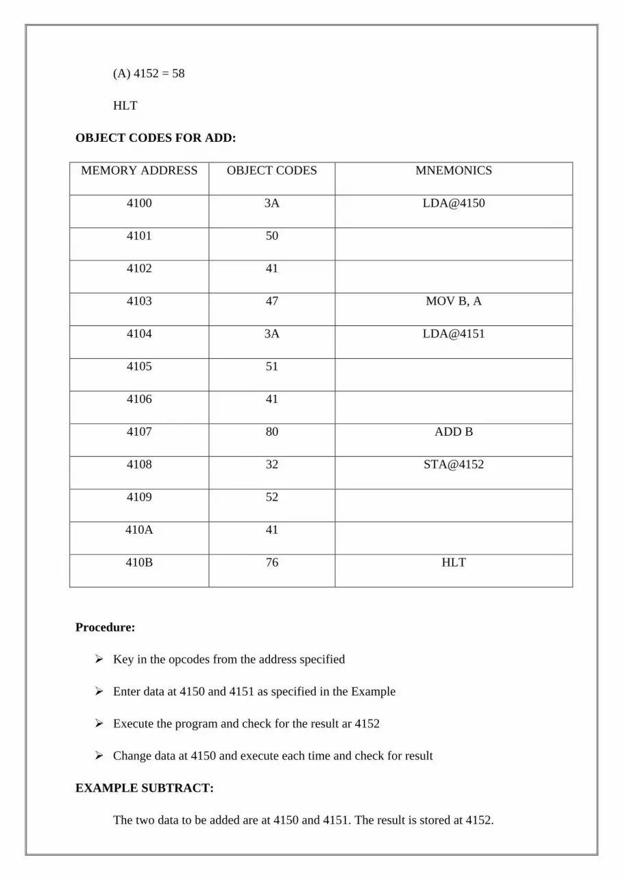
OBJECT CODES FOR ADD:
MEMORY ADDRESS OBJECT CODES MNEMONICS
4100 3A LDA@4150
4101 50
4102 41
4103 47 MOV B, A
4104 3A LDA@4151
4105 51
4106 41
4107 80 ADD B
4108 32 STA@4152
4109 52
410A 41
410B 76 HLT
Procedure:
Key in the opcodes from the address specified
Enter data at 4150 and 4151 as specified in the Example
Execute the program and check for the result ar 4152
Change data at 4150 and execute each time and check for result
EXAMPLE SUBTRACT:
The two data to be added are at 4150 and 4151. The result is stored at 4152.

Data (4150) = 49
(4152) = 24
Result = 25
OBJECT CODES FOR SUBTRACT:
MEMORY ADDRESS OBJECT CODES MNEMONICS
4100 21 LXI H. 4150
4101 50
4102 41
4103 7E MOV A, M
4104 23 INX H
4105 96 SUB M
4106 23 INX H
4107 77 MOV K, A
4108 76 HLT
Procedure:
Key in the opcodes from the address specified
Enter data at 4150 and 4151 as specified in the Example
Execute the program and check for the result ar 4152
Change data at 4150 and execute each time and check for result
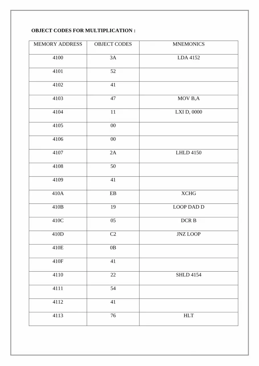
OBJECT CODES FOR MULTIPLICATION :
MEMORY ADDRESS OBJECT CODES MNEMONICS
4100 3A LDA 4152
4101 52
4102 41
4103 47 MOV B,A
4104 11 LXI D, 0000
4105 00
4106 00
4107 2A LHLD 4150
4108 50
4109 41
410A EB XCHG
410B 19 LOOP DAD D
410C 05 DCR B
410D C2 JNZ LOOP
410E 0B
410F 41
4110 22 SHLD 4154
4111 54
4112 41
4113 76 HLT

PROCEDURE:
Key in the opcodes from the address specified.
Enter data at 4150 and 4153 for execution
Execute the program and check for the result at 4154 and 4155
Change data at 4250 and 4151 and execute each time and check result
OBJECT CODES FOR DIVISION :
MEMORY ADDRESS OBJECT CODES MNEMONICS
4100 3A LDA 4150
4101 50
4102 41
4103 47 MOV B,A
4104 3A LDA 4151
4105 51
4106 41
4107 0E MVI C, 00
4108 00
4109 B8 CMP B
410A DA JC LOOP
410B 13
410C 41
410D 90 LOOP1 : SUB B
410E 0C INR C
410F B8 CMP B
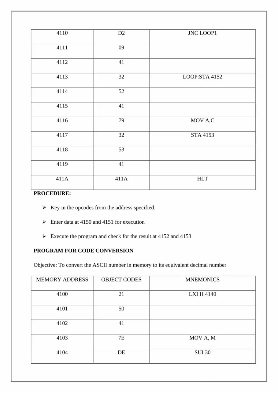
4110 D2 JNC LOOP1
4111 09
4112 41
4113 32 LOOP:STA 4152
4114 52
4115 41
4116 79 MOV A,C
4117 32 STA 4153
4118 53
4119 41
411A 411A HLT
PROCEDURE:
Key in the opcodes from the address specified.
Enter data at 4150 and 4151 for execution
Execute the program and check for the result at 4152 and 4153
PROGRAM FOR CODE CONVERSION
Objective: To convert the ASCII number in memory to its equivalent decimal number
MEMORY ADDRESS OBJECT CODES MNEMONICS
4100 21 LXI H 4140
4101 50
4102 41
4103 7E MOV A, M
4104 DE SUI 30

4105 30
4106 FE CPI 0A
4107 0A
4108 DA JC LOOP
4109 0D
410A 41
410B 3E MVI A,FF
410C FF
410D 23 LOOP INX H
410E 77 MOV M, A
410F 76 HLT
RESULT:
Thus the Add ,Subtract, multiplication, Division and code convection- 8-bit numbers in
memory and store the result in memory are verified.
VIVA QUESTIONS AND ANSWERS
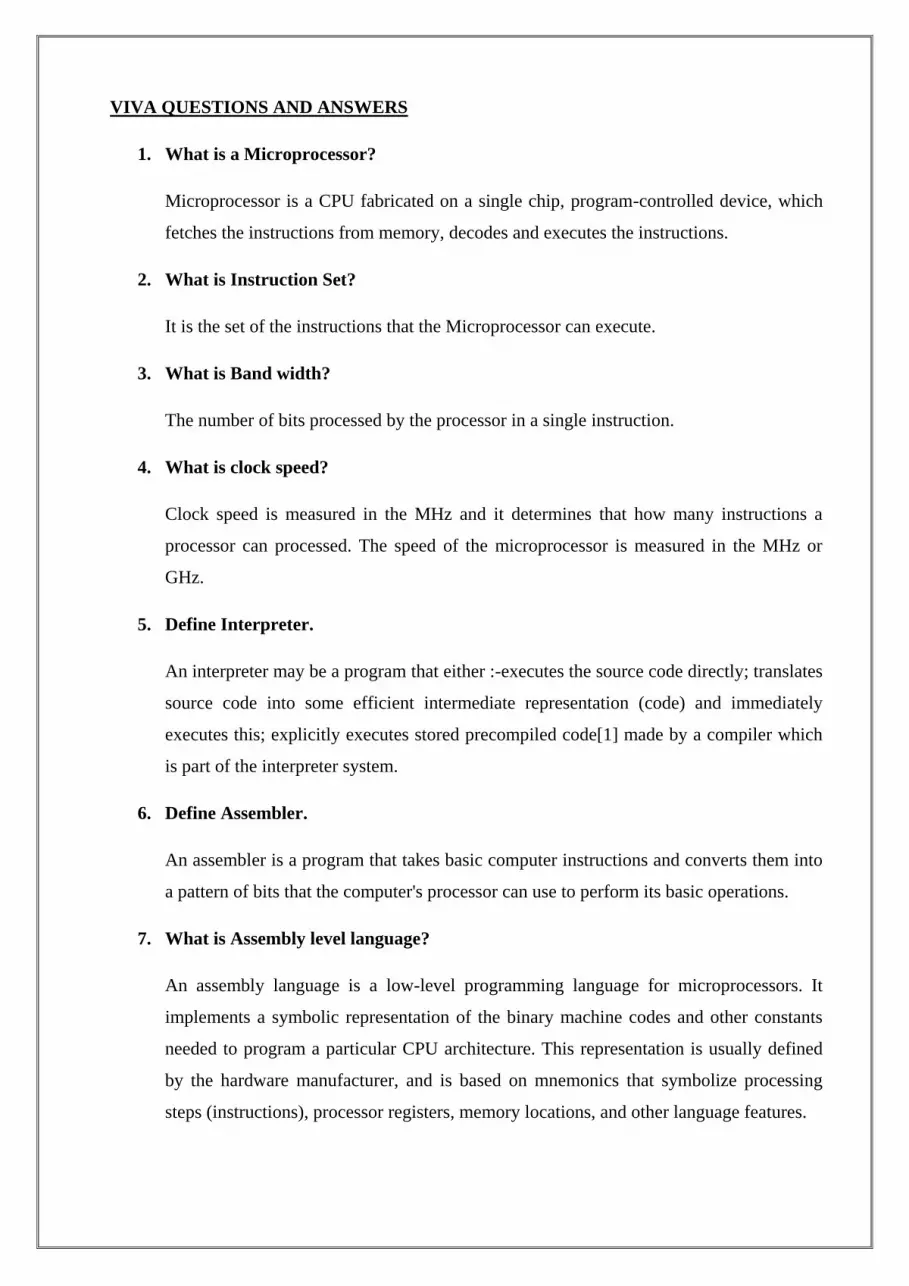
1. What is a Microprocessor?
Microprocessor is a CPU fabricated on a single chip, program-controlled device, which
fetches the instructions from memory, decodes and executes the instructions.
2. What is Instruction Set?
It is the set of the instructions that the Microprocessor can execute.
3. What is Band width?
The number of bits processed by the processor in a single instruction.
4. What is clock speed?
Clock speed is measured in the MHz and it determines that how many instructions a
processor can processed. The speed of the microprocessor is measured in the MHz or
GHz.
5. Define Interpreter.
An interpreter may be a program that either :-executes the source code directly; translates
source code into some efficient intermediate representation (code) and immediately
executes this; explicitly executes stored precompiled code[1] made by a compiler which
is part of the interpreter system.
6. Define Assembler.
An assembler is a program that takes basic computer instructions and converts them into
a pattern of bits that the computer's processor can use to perform its basic operations.
7. What is Assembly level language?
An assembly language is a low-level programming language for microprocessors. It
implements a symbolic representation of the binary machine codes and other constants
needed to program a particular CPU architecture. This representation is usually defined
by the hardware manufacturer, and is based on mnemonics that symbolize processing
steps (instructions), processor registers, memory locations, and other language features.
8. What are Mnemonics?
Mnemonics are instructions or commands to perform a
particular operation given by user to microprocessor e.g MOV
MIV ADD SUB IMUL.
9. What is a bus?
Information is transferred between units of the microcomputer by collections of
conductors called buses.
There will be one conductor for each bit of information to be passed,
e.g., 16 lines for a 16 bit address bus. There will be address, control, and data buses.
10. Distinguish between Microprocessor & Microcontroller.
The microprocessor is a digital integrated circuit device that can be programmed
with a series of instructions to perform specified functions on data.
But micro controller is a computer on a chip which has memory, input, output on
the chip itself.
So, micro processor can perform only few functions but micro controller can
perform so many functions.

STEPPER MOTOR INTERFACING WITH 8051 MICRO CONTROLLER FOR
CLOCKWISE ROTATION
AIM
To write an assembly language program for driving the stepper motor in clockwise
direction.
APPARATUS REQUIRED:
Stepper motor
8051 Micro controller kit #SD 4100 - Enter
PROGRAM:
MEMORY ADDRESS OBJECT CODES MNEMONICS
4100 7C MOV R4. #FF
4101 FF
4102 90 START: MOV DPTR, #LOOK UP
4103 41
4104 14
4105 78 MOV R0, #04
4106 04
4107 E0 JO: MOVX A, @DPTR
4108 C0 PUSH DPH
4109 83
410A C0 PUSH DPH
410B 82
410C 90 MOV DPTR #FFCOH
410D FF

410E C0
410F F0 MOVX @ DPTR, A
4110 DC DJNZ R4, CALL
4111 06
4112 80 HLT: SJMP HLT
4113 FE
4114 09 LOOK UP: DB 09H, 05H, 06H, 0AH
4115 05
4116 06
4117 0A
4118 7A
4119 03
411A 79 DLY2: MOV R1, #FFH
411B FF
411C 7B DLY1: MOV R1, #FFH
411D FF
411E DB DLY: DJNZ R3, DLY
411F FE
4120 D9 DJNZ R1, DLY1
4121 FA
4122 DA DJNZ R2, DLY2
4123 F6
4124 D0 POP DPL

4125 82
4126 D0 POP DPH
412 83
4128 A3 INC DPTR
4129 D8 DJNZ R0, J0
412A DC
412B 80 SJMP START
412C D5
412D END
RESULT:
Thus the stepper motor was driven in clockwise direction.
VIVA QUESTIONS AND ANSWERS
1. What is zener voltage?
In the reverse direction, the diode conducts very little when the voltage is below the breakdown
value. This critical limiting value of reverse voltage is known as zener voltage.
2. Name three output characteristics of transistor configuration.
a. Saturation region b. Active region c. Cut-off region.
3. What is a microprocessor?
A microprocessor is a multipurpose, programmable, clock driven, registers – based electronic
device that reads binary instructions from a storage device called memory, accepts binary data as
input and processes data according to those instructions, and provides results as output.
4. What are the four components of a programmable machine?
A typical programmable machine can be represented with four components. a. Microprocessor b.
Memory c. Input d. Output.
5. Define the terms. a) Bus b) RAM c) ROM.
BUS – A group of lines used to transfer bits between the microprocessor and other components
of the computer system. RAM – Random Access Memory. Data is stored in a read / write
memory. ROM – Read only Memory. A memory that stores binary information permanently.
The information can be read from this memory but cannot be altered.
6. What the types of languages used?
The types of languages used are, a. Machine language b. Assembly language c. Low – level
language d. High – level language.
7. What is a machine language?
The binary medium of communication with a computer through a designed set of instructions
specific to each computer.
8. What is a assembly language?
A medium of communication with a computer in which programs are written in mnemonics. An
assembly language is specific to a given computer.

9. What is low – level language?
A medium of communication that is machine – dependent or specific to a given computer. The
machine and the assembly language of a computer are considered low – level languages.
Programs written in these languages are not transferable to different types of machines.
10. What is a high – level language?
A medium of communication that is independent of a given computer. Programs are written in
English – lie words, and they can be executed on a machine using a translator (a compiler or an
interpreter).

TRAFFIC LIGHT CONTROLLER INTERFACING WITH 8051/8085 MICRO
CONTROLLER
AIM
To write an assembly language program for Microcontroller based traffic light system.
APPARATUS REQUIRED:
Traffic Light Controller
8051 Micro controller kit
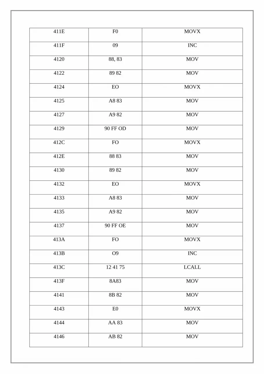
PROGRAM:
MEMORY ADDRESS OBJECT CODES MNEMONICS
4100 74 80 MOV
4102 90 FF OF MOV
4105 FO MOVX
4106 7C 04 MOV
4108 90 41 9B MOV
410B AA 83 MOV
410D AB 82 MOV
410F 90 41 8F MOV
4112 A8 83 MOV
4114 A9 82 MOV
4116 EO MOVX
4117 A8 83 MOV
4119 A9 82 MOV
411B 90 FF OC MOV
411E F0 MOVX
411F 09 INC
4120 88, 83 MOV
4122 89 82 MOV
4124 EO MOVX
4125 A8 83 MOV
4127 A9 82 MOV
4129 90 FF OD MOV
412C FO MOVX
412E 88 83 MOV
4130 89 82 MOV
4132 EO MOVX
4133 A8 83 MOV
4135 A9 82 MOV
4137 90 FF OE MOV
413A FO MOVX
413B O9 INC
413C 12 41 75 LCALL
413F 8A83 MOV
4141 8B 82 MOV
4143 E0 MOVX
4144 AA 83 MOV
4146 AB 82 MOV

4148 90 FF OC MOV
414B FO MOVX
414C OB INC
414D 8A 83 MOV
414F 8B 82 MOV
4151 EO MOVX
4152 AA 83 MOV
4154 AB 82 MOV
4156 90 FF OD MOV
4159 FO MOVX
415A OB INC
415B 8A 83 MOV
815D 8B 82 MOV
415 F EO MOVX
4160 AA 83 MOV
4162 AB 82 MOV
4164 90 FF 0E MOV
4167 FO MOVX
4168 OB INC
4169 12 41 82 LCALL
416C 88 83 MOV
416E 89 82 MOV
4170 DC A4 DJNZ

4172 12 41 06 LCALL
4175 7D 12 MOV
4177 7E FF MOV
4179 7F FF MOV
417B DF FE MOV
417D DE FA DJNZ
417F DD F6 DJNZ
4181 22 RET
4182 7D 12 MOV
4184 7E FF MOV
4186 7F FF MOV
4188 DF FE DJNZ
418A DE FA DJNZ
418C DD F6 DJNZ
418E 22 RET
418F 44 27 12 DB
4192 92 2B 10 DB
4195 84 9D 10 DB
4198 84 2E 48 DB
419B 48 27 12 DB
419E 92 4B 10 DB
41A1 84 9D 20 DB
41A4 04 2E 49 END

RESULT:
Thus the based traffic light system studied.
VIVA QUESTIONS AND ANSWERS
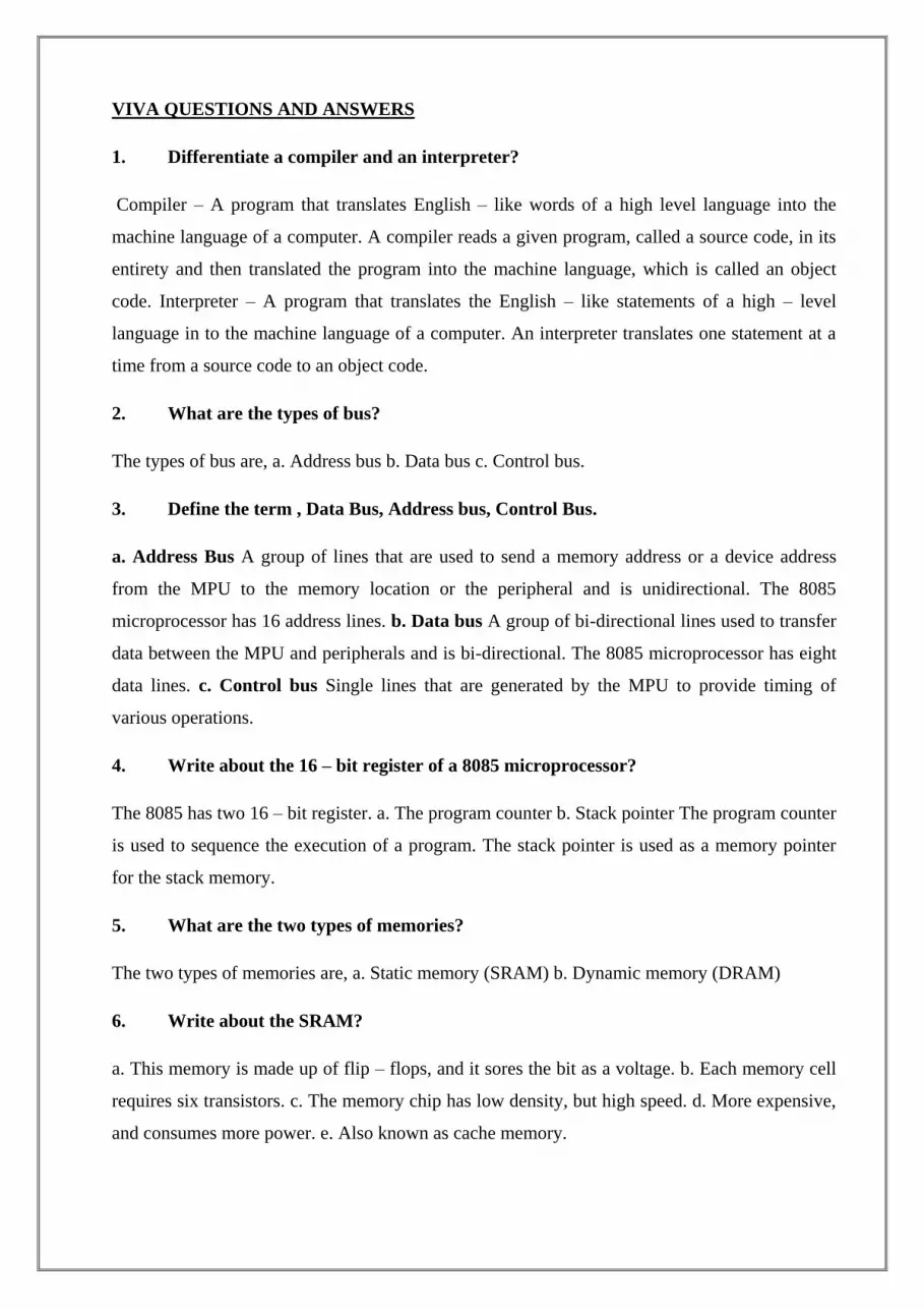
1. Differentiate a compiler and an interpreter?
Compiler – A program that translates English – like words of a high level language into the
machine language of a computer. A compiler reads a given program, called a source code, in its
entirety and then translated the program into the machine language, which is called an object
code. Interpreter – A program that translates the English – like statements of a high – level
language in to the machine language of a computer. An interpreter translates one statement at a
time from a source code to an object code.
2. What are the types of bus?
The types of bus are, a. Address bus b. Data bus c. Control bus.
3. Define the term , Data Bus, Address bus, Control Bus.
a. Address Bus A group of lines that are used to send a memory address or a device address
from the MPU to the memory location or the peripheral and is unidirectional. The 8085
microprocessor has 16 address lines. b. Data bus A group of bi-directional lines used to transfer
data between the MPU and peripherals and is bi-directional. The 8085 microprocessor has eight
data lines. c. Control bus Single lines that are generated by the MPU to provide timing of
various operations.
4. Write about the 16 – bit register of a 8085 microprocessor?
The 8085 has two 16 – bit register. a. The program counter b. Stack pointer The program counter
is used to sequence the execution of a program. The stack pointer is used as a memory pointer
for the stack memory.
5. What are the two types of memories?
The two types of memories are, a. Static memory (SRAM) b. Dynamic memory (DRAM)
6. Write about the SRAM?
a. This memory is made up of flip – flops, and it sores the bit as a voltage. b. Each memory cell
requires six transistors. c. The memory chip has low density, but high speed. d. More expensive,
and consumes more power. e. Also known as cache memory.

7. What is flash memory?
The flash memory must be erased either in its entirely or at the sector level. The memory chips
can be erased and programmed at least a million times. The power supply requirement for
programming these chips 2was around 12V, but now chips are available that can be programmed
using a power supply as low as 1.8 V. Hence, this memory is ideally suited for low – power
systems.
8. What are the interfacing devices?
The bus drivers increase the current driving capacity of the buses, the decoder decodes the
address to identify the output port, and the latch holds data output for display. These devices are
called interfacing devices. The interfacing devices are semiconductor chips that are needed to
connect peripherals to the bus system.
9. Write about buffer?
The buffer is a logic circuit that amplifies the current or power. It has one input line and one
output line. The logic level of the output is the same as that of the input, logic 1 input provides 1
output. The buffer is used primarily to increase the driving capability of a logic circuit. It is also
known as driver.
10. Define looping?
The programming technique used to instruct the microprocessor to repeat tasks is called looping.
A loop is set up by instructing the microprocessor to change the sequence of execution and
perform the task again. This process is accomplished by using Jump instructions.
SPEED CONTROL OF DC DRIVES USING PID CONTROLLER INTERFACING UNIT
AIM
To control the speed of the DC motor using PID controller interfacing unit.
THEORY
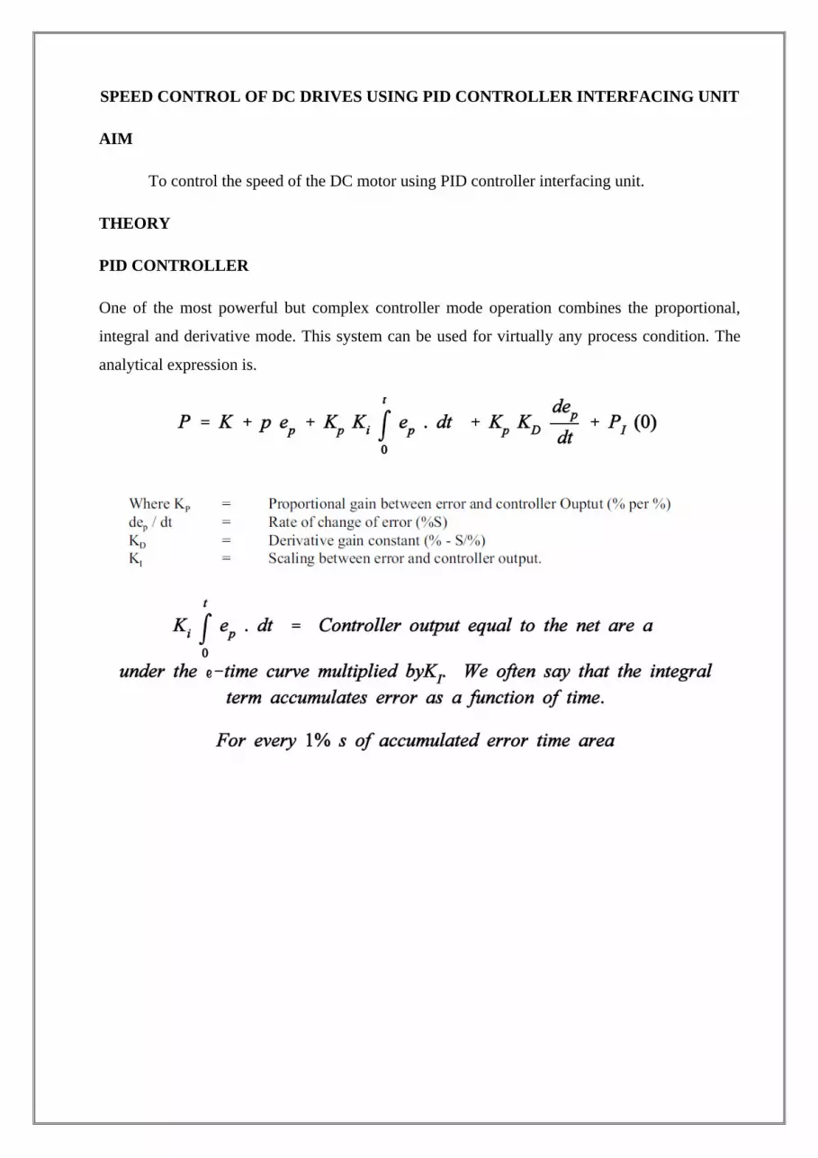
PID CONTROLLER
One of the most powerful but complex controller mode operation combines the proportional,
integral and derivative mode. This system can be used for virtually any process condition. The
analytical expression is.

The mode eliminates the offset of the proportional mode and still provides fast response. The
three mode controller action exhibits proportional, integral and derivative action.
PROCEDURE
Switch ON the power button.
User will see the following message.
Welcome to Vi Microsystems
Digital PID Controller
Select the PID Algorithm
INC-NORMAL PID DEC-
SQUARE ROOT
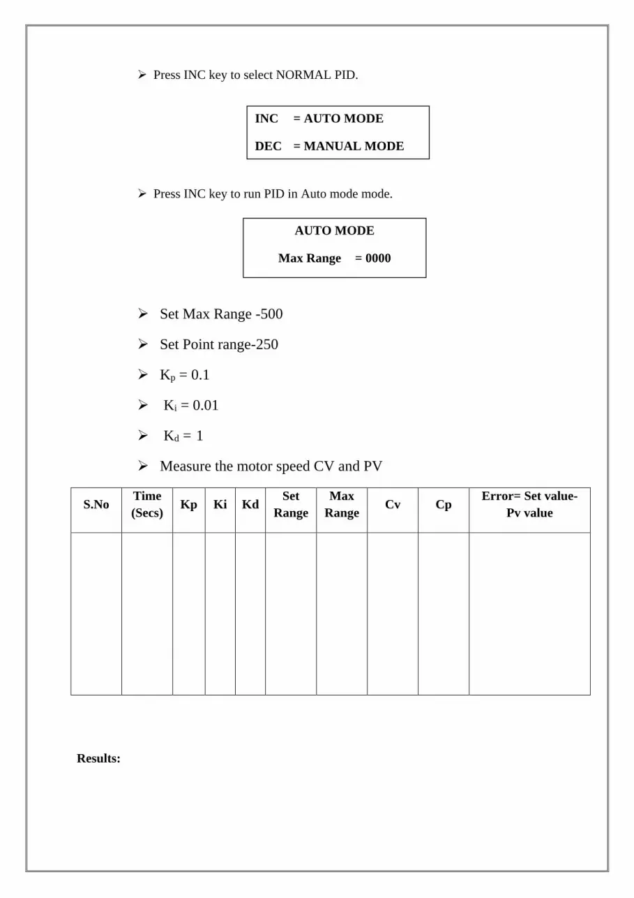
Press INC key to select NORMAL PID.
Press INC key to run PID in Auto mode mode.
Set Max Range -500
Set Point range-250
Kp = 0.1
Ki = 0.01
Kd = 1
Measure the motor speed CV and PV
S.No Time
(Secs) Kp Ki Kd
Set
Range
Max
Range Cv Cp
Error= Set value-
Pv value
Results:
INC = AUTO MODE
DEC = MANUAL MODE
AUTO MODE
Max Range = 0000
P.Ramu,M.E, Asst. Professor, Department of Mechanical Engineering_SRM-VEC
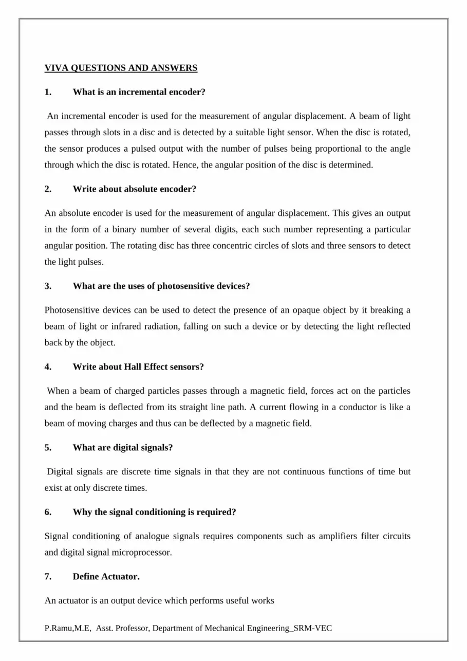
VIVA QUESTIONS AND ANSWERS
1. What is an incremental encoder?
An incremental encoder is used for the measurement of angular displacement. A beam of light
passes through slots in a disc and is detected by a suitable light sensor. When the disc is rotated,
the sensor produces a pulsed output with the number of pulses being proportional to the angle
through which the disc is rotated. Hence, the angular position of the disc is determined.
2. Write about absolute encoder?
An absolute encoder is used for the measurement of angular displacement. This gives an output
in the form of a binary number of several digits, each such number representing a particular
angular position. The rotating disc has three concentric circles of slots and three sensors to detect
the light pulses.
3. What are the uses of photosensitive devices?
Photosensitive devices can be used to detect the presence of an opaque object by it breaking a
beam of light or infrared radiation, falling on such a device or by detecting the light reflected
back by the object.
4. Write about Hall Effect sensors?
When a beam of charged particles passes through a magnetic field, forces act on the particles
and the beam is deflected from its straight line path. A current flowing in a conductor is like a
beam of moving charges and thus can be deflected by a magnetic field.
5. What are digital signals?
Digital signals are discrete time signals in that they are not continuous functions of time but
exist at only discrete times.
6. Why the signal conditioning is required?
Signal conditioning of analogue signals requires components such as amplifiers filter circuits
and digital signal microprocessor.
7. Define Actuator.
An actuator is an output device which performs useful works

P.Ramu,M.E, Asst. Professor, Department of Mechanical Engineering_SRM-VEC
8. Classify actuator based on motion.
1. Linear motion
2. Rotary Motion
3. Flow Control valve
9. When is cascade control Needed?
The need for cascade control will occur when a final control element experiences signal overlap
i.e. when a trip valve mechanism is still held down , but the output signal has to been used and
requires removal
10. Write down the principles of cascade control.
volve separate supply bus for each group

P.Ramu,M.E, Asst. Professor, Department of Mechanical Engineering_SRM-VEC
STUDY OF LINEAR VARIABLE DIFFERENTIAL TRANSFORMER
AIM
Measurement of displacement using LVDT.
APPARATUS REQUIRED:
LVDT Kit
Multi-meter
Connecting wires
PROCEDURE:
Connect the sensor module on the corresponding place
Switch on the power supply
Connect LVDT output to the voltmeters terminals
The core in initially brought to null position
By varying zero setting change the voltmeter reading to zero value
First turn the nut in clockwise direction to move core inwards i.e left of null position and
take respective voltage readings on the voltmeter.
If required adjust the span setting to change the voltmeter reading
Now run nut in anticlockwise direction to move the core towards right of null point and
again take respective voltage reading from voltmeter.
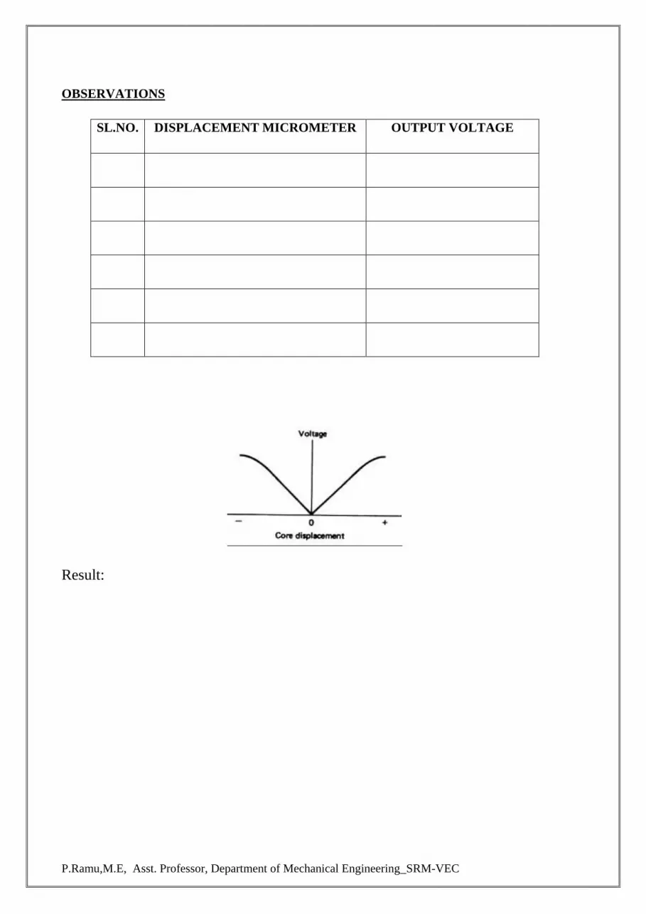
Plot the graph from the observations taken.
P.Ramu,M.E, Asst. Professor, Department of Mechanical Engineering_SRM-VEC
OBSERVATIONS
SL.NO. DISPLACEMENT MICROMETER OUTPUT VOLTAGE
Result:

P.Ramu,M.E, Asst. Professor, Department of Mechanical Engineering_SRM-VEC
STUDY OF STRAIN GAUGE
AIM
Measurement of strain for the applied load using given strain gauge trainer.
APPARATUS REQUIRED:
Strain cantilever
Multi-meter
Connecting wires
PROCEDURE:
Connect the sensor module on the corresponding place
Switch on the power supply
Connect strains output +ve and -ve to the output to the voltmeters terminals
constant voltage source are given as 5V. give some time to stabilize the instrument
reading.
By varying zero setting change the voltmeter reading to zero value
Now apply weight at the cantilever beam
Note down the readings in strain's corresponding voltage display on the trainer.
If required adjust the span setting to change the voltmeter reading
Tabulate the reading and plot the graph for applied load and the output voltage.

P.Ramu,M.E, Asst. Professor, Department of Mechanical Engineering_SRM-VEC
OBSERVATIONS
SL.NO. Applied Load Displayed output voltage
Result:
P.Ramu,M.E, Asst. Professor, Department of Mechanical Engineering_SRM-VEC
STUDY OF TEMPERATURE TRANSDUCER
AIM
Measurement temperature of the temperature transducer and verify the performance with
output voltage.
APPARATUS REQUIRED:
Water bath
Thermometer
RTD sensor
Multi-meter
Connecting wires
PROCEDURE:
Connect the sensor module on the corresponding place
Switch on the power supply
Initially keep the RTD switch in o- open -to check resistance between the RTD. Set the
value of 1.4- 1.6 v (using zero setting) with room temp using thermometer
Then keep the RTD switch in c - close mode, Place the sensor in water bath and insert
both RTD and thermo meter in water bath.
Switch on the heater, for every 5 deg increment, note down the output reading using
voltmeter.
Increase the temperature and note down the respective voltage readings by using
voltmeter.
If required adjust the span setting to change the voltmeter reading
Plot the graph between temperature (thermometer) and the observations taken in terms of
output (voltage).

P.Ramu,M.E, Asst. Professor, Department of Mechanical Engineering_SRM-VEC
OBSERVATIONS
SL.NO. Temperature-Thermometer in deg Output voltage in Volt
Result:
P.Ramu,M.E, Asst. Professor, Department of Mechanical Engineering_SRM-VEC
STUDY OF PRESSURE TRANSDUCER
AIM
Measurement of applied pressure to the pressure transducer and verify the performance
with output voltage.
APPARATUS REQUIRED:
Pressure tank
Foot pump
Sensor
Pressure gauge
Multi-meter
Connecting wires
PROCEDURE:
Connect the sensor module on the corresponding place(Right side of the board)
Switch on the power supply.
Foot pump is to give pressure to the tank and the pressure inside in the tank is displayed
in the pressure gauge mounted on the tank.
Connect Pressure transducer's output +ve and -ve to the voltmeter's +ve and -ve
terminals.
By varying Zero setting change the voltmeter reading in to Zero value.
Give some pressure using foot pump, and note down the respective voltage readings by
using voltmeter.
If required adjust the span setting to change the voltmeter reading (Max reading).
Plot the graph between applied pressure and the observations taken (voltage).

P.Ramu,M.E, Asst. Professor, Department of Mechanical Engineering_SRM-VEC
OBSERVATIONS
SL.NO. Applied Pressure Output voltage in Volt
Result:

P.Ramu,M.E, Asst. Professor, Department of Mechanical Engineering_SRM-VEC
STUDY OF SPEED TRANSDUCER
AIM
Measurement of speed of the PMDC motor using tacho generator transducer and verify
the performance with displayed speed on the display.
APPARATUS REQUIRED:
PMDC motor
Sensor
Multi-meter
Connecting wires
PROCEDURE:
Connect the sensor module on the corresponding place(Right side of the board)
Switch on the power supply.
Connect Speed transducer's output +ve and -ve to the Speed display's +ve and - ve
terminals.
By varying Zero setting change the voltmeter reading in to Zero value.
Control voltage is varying from 0-12 V. This value can be verified across the motor.
The op-amp based PWM generator and MOSFET based power driver along tacho
generator feedback to get the speed output in terms of voltage.
If required adjust the span setting to change the voltmeter reading (Max reading).
Plot the graph between speed in RPM and the tacho generator output voltage.
P.Ramu,M.E, Asst. Professor, Department of Mechanical Engineering_SRM-VEC
OBSERVATIONS
SL.NO. Speed in RPM Output voltage in Volt
Result:

P.Ramu,M.E, Asst. Professor, Department of Mechanical Engineering_SRM-VEC
VIVA QUESTIONS AND ANSWERS
1. What are the two basic types of the displacement and the position transducers?
The two basic types are,
1. Contact sensors
2. Non contact sensors.
2. Write about the strain – gauged element?
The electrical resistance strain gauge is a metal wire, metal foil strip, or a strip of semiconductor
material, which is wafer – like and can be stuck onto surfaces like a postage stamp.
3. Write about the gauge factors for different types of strain gauges?
The gauge factor of metal wire or foil strain gauges with the metals generally used is about 2.0.
Silicon p – and n – type semiconductor strain gauges have gauge factors of about + 100 or more
for p- type silicon and – 100 or more for n – type silicon.
4. Define gauge factor. The gauge factor is defined as the ratio of per unit change in
resistance to per unit change in length. Gauge factor Gf= ΔR/R ΔL/L
5. Define LVDT?
The Linear Variable Differential Transformer consists of three coils symmetrically spaced along
an insulated tube. The central coil is the primary coil and the other two are identical secondary
coils, which are connected in series in such a way that their outputs oppose each other.
6. Determine the working Principle of LVDT?
When there is an alternating voltage input to the primary coil, alternating e.m.f.s are induced in
the secondary coils. With the magnetic core central, the amount of magnetic material in each of
the secondary coil is the same.
7. What are the uses of LVDT?
The uses are as follows. a. Widely used as primary transducers for monitoring displacements. b.
Also used as secondary transducers in the measurement of force, weight and pressure.
8. Write about inductive proximity switch?

P.Ramu,M.E, Asst. Professor, Department of Mechanical Engineering_SRM-VEC
Inductive proximity switch consists of a coil wound round a core. When the end of the coil is
close to a metal object is inductance changes. This change can be monitored by its effect on a
resonant circuit and the change used to trigger a switch. It can only be used for the detection of
metal objects and is best with ferrous metals.
9. What is an encoder?
An encoder is a device that provides a digital output as a result of a linear or angular
displacement
10. What are the two types of position encoders?
The two types of position encoders are, a. Incremental encoders b. Absolute encoders.

P.Ramu,M.E, Asst. Professor, Department of Mechanical Engineering_SRM-VEC
EXPERIMENTS USING PNEUMATIC TRAINER KIT

Department of Mechanical Engineering_SRM-VEC
Ex. No:

Department of Mechanical Engineering_SRM-VEC
Ex. No: Date :
DESIGN AND TESTING OF PNEUMATIC CIRCUITS TO CONTROL
THE SPEED OF THE CYLINDER BY METER IN AND METER OUT
VALVE CIRCUIT
AIM:
To control the speed of double acting cylinder using Meter In and Meter Out valve
circuit in Basic Pneumatic Training Kit
APPARATUS REQUIRED:
Air service unit (Power Source unit)
FRL Unit
Double acting cylinder
3/2 push button spring return DCV
5/2 single pilot DCV
Connecting Tubes
PROCEDURE:
Design and draw circuit diagram as per the given application.
Connect the FRL unit to the main air supply.
The various components are connected as per circuit.
Block the valve operation if necessary.
Check the leakage of air supply and correct it.
Open the valve and operate the cylinder.
RESULT:
Thus the speed of double acting cylinder was controlled using Metering In and Metering
Out circuit in Pneumatic Trainer Kit.
Department of Mechanical Engineering_SRM-VEC
Viva Questions
1. Define Mechatronics.
The term Mechatronics is used for the integration of microprocessor control system,
electrical systems and mechanical systems. Mechatronics is defined as the integration of
precision mechanical & electronic control for the development of smart products & process.
2. What is a system? Give an example.
A system can be considered as a box, which has an input, and an output and where it is not
concerned with what goes on inside the box but only the relationship between the output and the
input. Example: A motor may be thought of as a system, which has as its input electric power
and as output the rotation of a shaft.
3. What is a measurement system?
A measurement system can be considered as a black box, which is used for making
measurements. It has as its input the quantity being measured and its output the value of that
quantity.
4. Write about the sensor and give an example.
A sensor, which responds to the quantity being measured by giving as its output a signal which
is related to the quantity. Example: A thermocouple is a temperature sensor. The input to the
sensor is a temperature and the output is an e.m.f. which is related to the temperature value.
5. Write about the signal conditioner?
A signal conditioner takes the signal from the sensor and manipulates it in to a condition, which
is suitable for either display, or in the case of a control system, for use to exercise control.
6. What are the elements of the closed loop control system?
The various elements of a closed loop control system are, a. Comparison element b. Control
element c. Correction element d. Process element e. Measurement element
7. What are the two types of feedback loop?

Department of Mechanical Engineering_SRM-VEC
The two types of feedback loop are, a. Positive feedback loop b. Negative feed back loop. "The
feedback is said to be negative/positive feedback when the signal; which is feedback,
subtracts/adds from the input value. It is required to control a system. The control elements
decide what action to take when it receives an error signal".
8. What are the types of control elements?
There are two types of control elements. They are a. Hard – wired systems b. Programmable
systems.
9. Write about the Mechatronics approach in a micro-processor – controlled washing
machine?
In the microprocessor-controlled washing machine, a mechanical system has become integrated
with electronic controls. As a consequence, a bulky mechanical system is replaced by a much
more compact microprocessor system, which is readily adjustable to give a greater variety of
programs.
10. What is the larger scale application of Mechatronics?
A larger scale application of Mechatronics is a Flexible Manufacturing engineering System
(FMS) involving computer – controlled machines, robots, automatic material conveying and
overall supervisory control.

Department of Mechanical Engineering_SRM-VEC
Ex. No:

Department of Mechanical Engineering_SRM-VEC
Ex. No: Date :
DESIGN AND TESTING OF PNEUMATIC CIRCUITS IMPULSE PILOT
OPERATION OF SINGLE ACTING CYLINDER
AIM:
To operate a single acting cylinder using an impulse pilot valve in pneumatic trainer kit
APPARATUS REQUIRED:
Air service unit (Power Source unit)
FRL Unit
Single acting cylinder
3/2 push button spring return DCV
3/2 Pilot operated spring return DCV.
Connecting Tubes
PROCEDURE:
Design and draw circuit diagram as per the given application.
Connect the FRL unit to the main air supply.
The various components are connected as per circuit.
Block the valve operation if necessary.
Check the leakage of air supply and correct it.
Open the valve and operate the cylinder.
RESULT:
Thus the single acting cylinder was operated an impulse pilot valve in Pneumatic Trainer
kit.

Department of Mechanical Engineering_SRM-VEC
Viva Questions
1. What is pneumatic direction control valve?
Pneumatic direction control valve is used to control the direction of air path. These
Valves have generally two, three, four (or) five ports: These ports are designated as P:
Compressor line port R: Exhaust port (T is case of hydraulics) A, B: Working ports
connected to actuator.
2. What is the use of Time Delay Valves?
Pneumatic time delay valves are used to delay operations where time based sequences
are required.
3. What is a fast exhaust valve?
A fast exhaust valve is used to vent cylinder quickly. It is primary used with spring return
(single acting) pneumatic cylinders.
4. Differentiate between hydraulic and pneumatic systems?
The working fluid of hydraulic system is water (or) oil (or) any liquid. The working fluid
of pneumatic circuit is air Hydraulic systems are designed for heavy loads where as
pneumatic systems are designed for low (or) medium loads.
5. What is the function of pneumatic circuit using quick exhaust valve?
By quickly exhausting the air from the cylinder, the cylinder speed can be exhausted.
6. What is Time delay circuit?
In certain applications, the impulse to the main direction control valve may have to be
delayed to pre-determined time for different operational reasons. A pneumatic time delay
valve may be used in such cases. A pneumatic circuit using this time delay valve is
known as time delay circuit.
7. What is the use of compressor?
A compressor is a machine which compresses air (or) any other gas from atmospheric
pressure to a desired higher pressure level.
Department of Mechanical Engineering_SRM-VEC
8. Define FRL unit.
Air is not clean and hence contamination may result in pneumatic circuit. Also, due to
time fluctuations, the receiver air pressure does not remain constant. Also, some parts of
the Pneumatic system have to be lubricated for proper maintenance. For cleaning the air,
regulating the pressure of air and lubricating pneumatic parts, three units 'Filter -
Pressure Regulator - Lubricator' (Trio unit) are put together and this combined unit - Trio
unit - is called FRL unit.
9. Name two basic types of compressors?
1. Positive displacement compressors
2. Dynamic (Turbo) compressors.
10. Differentiate between single acting and double acting compressors.
In a single acting compressor, the compression takes place 011 one side of the
piston for each revolution of crank shaft.
In a double acting cylinder, compression takes place on both faces of the piston
giving two compression strokes for each revolution of the crankshaft.

Department of Mechanical Engineering_SRM-VEC
Ex. No:

Department of Mechanical Engineering_SRM-VEC
Ex. No: Date :
DESIGN AND TESTING OF PNEUMATIC CIRCUITS OPERATION OF
DOUBLE ACTING CYLINDER WITH AND & OR LOGIC CIRCUIT
AIM:
To operate a double acting cylinder using AND & OR logic circuit in Pneumatic Trainer
Kit
APPARATUS REQUIRED:
Air service unit (Power Source unit)
FRL Unit
Double acting cylinder
3/2 push button spring return DCV
3/2 single pilot spring return DCV
AND/OR logic valve
Connecting Tubes
PROCEDURE:
Design and draw circuit diagram as per the given application.
Connect the FRL unit to the main air supply.
The various components are connected as per circuit.
Block the valve operation if necessary.
Check the leakage of air supply and correct it.
Open the valve and operate the cylinder.
RESULT:
Thus the double acting cylinder using AND & OR logic circuit was operated in
Pneumatic Trainer kit.

Department of Mechanical Engineering_SRM-VEC
Viva Questions:
Viva Questions
1. Define kinematic pair.
The two links or elements are joined together to form a pair. If the relative motion between them
is completely or successfully constrained, the pair is known as kinematic pair.
2. When is cascade control needed?
The need for cascade control will occur when a final control element experiences signal overlap
ie; when a trip valve mechanism is still held down, but the output signal has been use and
requires removal.
3. List the features of synchronous motor.
controlled easily
4. What is a stepper motor?
A stepper motor is a rotating machine which converts a DC voltage pulse into a series of
discrete rotational steps. Each step position is an equilibrium position without further excitation;
this makes it ideally suitable for the use with digital control
5. What is stepper motor?
A stepper motor is a device which transforms electrical pulses into equal increments of rotary
shaft motion called steps.
6. What is servomotor?
The motors used in automatic control systems or in servomechanism are called servomotors.
They are used to convert electrical signal into angular motion.
7. What is synchro?
A synchro is a device used to convert an angular motion to an electrical signal or vice versa.
8. At what conditions SPDT, DPST an DPDT switches are used?

Department of Mechanical Engineering_SRM-VEC
a. SPDT (Single Pole, Double Throw): When we require ON and OFF operation as the circuit is
actuated, SPDT is used. b. DPST (Double Pole, Single Throw): When we need to turn two
separate circuits ON and OFF simultaneously with a single switch, DPST is used. c. DPDT
(Double Pole, Double Throw): When a switch is turned ON and OFF between N and O with
double pole switches, DPDT is used.
9. What are the factors to be considered for selecting solenoids?
a. The size of the mechanical load. b. The movement distance of plunger. c. The type of
electrical connections. d. The type of value of current and voltage.
10. What is the principle of relay?
Relay is used for many control functions and essentially an electro-mechanical switch. It uses
basic switching principles and solenoid actuation.

Department of Mechanical Engineering_SRM-VEC
Ex. No:

Department of Mechanical Engineering_SRM-VEC
Ex. No: Date :
DESIGN AND TESTING OF PNEUMATIC CIRCUITS SINGLE
CYCLE AUTOMATION OF DOUBLE ACTING CYLINDER
USING LIMIT SWITCH
AIM:
To operate automatic operation of double acting cylinder in a single cycle using limit
switch in Pneumatic Trainer Kit.
APPARATUS REQUIRED:
Double acting cylinder
3/2 Roller Operated Spring Return DCV
5/2 Pilot Operated DCV
FRL unit
Connecting Tubes
PROCEDURE:
Design and draw circuit diagram as per the given application.
Connect the FRL unit to the main air supply.
The various components are connected as per circuit.
Block the valve operation if necessary.
Check the leakage of air supply and correct it.
Open the valve and operate the cylinder.
RESULT:
Thus the single cycle automation of double acting cylinder was operated by using limit
switch in Pneumatic Trainer Kit.

Department of Mechanical Engineering_SRM-VEC
Viva Questions
1. What is a Fluid Power System?
A system that transmits and controls power through use of a pressurized fluid within an
enclosed circuit.
2. Define Pascal's -Law.
A pressure applied to a confined fluid at rest is transmitted with equal intensity
throughout the fluid.
3. Define back Pressure.
The pressure encountered on the return side of a fluid system.
4. State the Bernoulli’s principle?
If the flow rate in the system is constant, then the total energy in the system will also be
constant irrespective of the variation in the cross section of the fluid passages.
5. Define Accumulator.
A container in which liquid is stored under pressure as a source of fluid power.
6. Explain non-separator type gas loaded accumulator?
In this type, the gas is filled at the top and the heavy oil at the bottom of the shell. There
is no separator between the gas and oil and thus the pressurized gas pushes the oil
directly.
7. What is the function of accumulator?
Accumulator is used as an auxiliary power source. It is a device which stores the
potential energy of the fluid. The stored potential energy in the accumulator acts as a
quick secondary source of power and does useful work as required by the system.
8. What is the use of bleed-off circuit?
Bleed off circuit is used to .control the flow of fluid in both directions of flow (or) on a
Specific line and limits speed in only one direction of the cylinder travel.
9. What is a sequencing circuit?
Process control pneumatics is also called as sequencing. It means performing number of
actions one after another which follows each other in a simple order or with an order
determined by sensors.
10. What is pneumatic direction control valve?
Pneumatic direction control valve is used to control the direction of air path. These
Valves have generally two, three, four (or) five ports: These ports are designated as P:
Compressor line port R: Exhaust port (T is case of hydraulics) A, B: Working ports
connected to actuator.

Department of Mechanical Engineering_SRM-VEC
Ex. No:

Department of Mechanical Engineering_SRM-VEC
Ex. No: Date :
DESIGN AND TESTING OF PNEUMATIC CIRCUITS SINGLE CYCLE
AUTOMATION OF MULTIPLE CYLINDERS IN SEQUENCES (A+B+B-A-)
AIM:
To operate single cycle automation of multiple cylinders in sequences A+B+B-A- in
Pneumatic Trainer Kit.
APPARATUS REQUIRED:
Double acting cylinder
Single acting cylinder
3/2 Roller Operated Spring Return DCV
5/2 single Pilot Operated DCV
3/2 pilot operated DCV
FRL unit
Connecting Tubes
PROCEDURE:
Design and draw circuit diagram as per the given application.
Connect the FRL unit to the main air supply.
The various components are connected as per circuit.
Block the valve operation if necessary.
Check the leakage of air supply and correct it.
Open the valve and operate the cylinder.
RESULT:
Thus the single cycle automation of multiple cylinders operated sequence (A+B+B-A-)in
Pneumatic Trainer Kit.

Department of Mechanical Engineering_SRM-VEC
Viva Questions
1. List some of the applications of Mechatronics?
1. Home Appliances: Washing machine, Bread machines etc 2. Automobile: Electrical fuel
injection, Antilock brake system 3. Aircraft: Flight control, Navigation system 4. Automated
Manufacturing
2. What are the components of Mechatronics System?
1. Actuators 2. Sensors 3. Signal Conditioning units 4. Digital control devices 5. Graphical
Displays
3. What is meant by a system in Mechatronics?
The System is the group of physical component combined to perform a specific function. Any
Mechatronics devices consists of systems
4. What are the main applications of Mechatronics?
Washing machines, dish washers, micro ovens, cameras, camcorders, robots, automatic
conveyors, computer-controlled machines
5. Obtain the basic functions of control systems.
1. To minimize the error between the actual and desired output 2. To minimize the time response
to load changes in the system
6. What are the types of control system?
7. List down the requirements of control systems.
Department of Mechanical Engineering_SRM-VEC
8. Give an example for open loop system and closed loop systems.
1. Closed loop system – Automatic water level controller 2. open loop system - Electric fire
9. What are the basic elements of feedback system?
10. What is meant by sequential control what are the two modes in it? A system
operating with sequential control is one where a set of prescribed operations are performed in
sequence. The modes are,
– based mode
– based mode

Department of Mechanical Engineering_SRM-VEC
EXPERIMENTS ON ELECTRO-PNEUMATICS TRAINER
KIT
Department of Mechanical Engineering_SRM-VEC
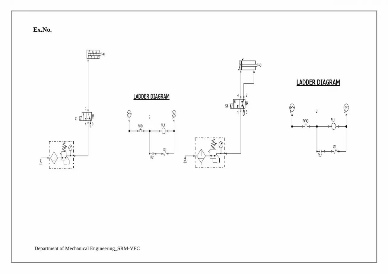
Ex.No.

Department of Mechanical Engineering_SRM-VEC
Ex. No: Date :
DESIGN AND TESTING OF ELECTRO-PNEUMATIC CIRCUITS
OPERATION OF SINGLE AND DOUBLE ACTING CYLINDER USING
SINGLE SOLENOID VALVE
AIM:
To operate single and double acting cylinder using the single solenoid valve in Electro
Pneumatic Trainer Kit.
APPARATUS REQUIRED:
Single and double acting cylinders
Input / Output Relay Box
3/2 Solenoid operated spring return DCV
5/2 Solenoid operated spring return DCV
FRL unit
Connecting Tubes
PROCEDURE:
Design and draw circuit diagram as per the given application.
Connect the FRL unit to the main air supply.
The various components are connected as per circuit.
Block the valve operation if necessary.
Check the leakage of air supply and correct it.
Open the valve and operate the cylinder.
RESULT:
Thus the single and double acting cylinder was operated using the single solenoid valve
in Electro Pneumatic Trainer Kit.

Department of Mechanical Engineering_SRM-VEC
Viva Questions
1. Mention the various components of a hydraulic system.
2. What is called a pneumatic system?
System using gas for power transmission are called pneumatic systems and industrial system are
usually based on air.
3. List down the components of pneumatic system.
4. What is the purpose of using filters in the hydraulic systems?
Filters are used to prevent dirt or dust entering important elements of hydraulic system like
valves, seals, etc. Filters are used to remove very finer particles.
5. What are the types of pumps used as energy source in a hydraulic system?
1. Gear Pumps 2. Vane Pumps 3. Piston pumps

Department of Mechanical Engineering_SRM-VEC
6. What are the factors to be considered for selecting compressors?
The type of air compressor is selected dependent on quality of air, pressure and cleanliness
7. What are the uses of air receiver?
An air receiver is used to store high pressure air and provide constant supply of air pressure in
the pneumatic system regardless of varying and fluctuating consumption. It is used for the
emergency supply of air to the system in case of power failure.
8. State the purpose of providing air dryers.
The aim is to reduce the temperature of the air to a dew point which ensures that the water in the
air condenses and drops out easily.
9. State the function of a control valve.
The primary function of the control valve is to direct and regulate the flow of fluid from an
energy source to various loading devices. Normally the control valves are used for the purpose
of sensing, processing ,and controlling. They are used for:
10. Define the term degrees of freedom.
The minimum number of independent displacement required to specify the system completely is
called degrees of freedom

Department of Mechanical Engineering_SRM-VEC
Ex. No:
Department of Mechanical Engineering_SRM-VEC
Ex. No: Date :
DESIGN AND TESTING OF ELECTRO-PNEUMATIC CIRCUITS
OPERATION OF DOUBLE ACTING CYLINDER USING DOUBLE
SOLENOID VALVE
AIM:
To operate double acting cylinder using double solenoid valve in Electro Pneumatic
Trainer Kit.
APPARATUS REQUIRED:
Double acting cylinder
Input / Output Relay Box
5/2 Double solenoid operated DCV
FRL unit
Connecting Tubes
PROCEDURE:
Design and draw circuit diagram as per the given application.
Connect the FRL unit to the main air supply.
The various components are connected as per circuit.
Block the valve operation if necessary.
Check the leakage of air supply and correct it.
Open the valve and operate the cylinder.
RESULT:
Thus the double acting cylinder was operated using the double solenoid valve in Electro
Pneumatic Trainer Kit.

Department of Mechanical Engineering_SRM-VEC
Viva Questions
1. What are the types of loops?
Loops can be classified in to two groups. They are, a. Continuous loop b. Conditional loop.
2. Write about the continuous loop?
A continuous loop is a set up by using the unconditional jump instruction. A program with a
continuous loop does not stop repeating the tasks until the system is reset.
3. Write about the conditional loop?
A conditional loop is set up by the conditional jump instructions. The instructions check flags
(Zero, Carry etc.,) and repeat the specified tasks if the conditions are satisfied. These loops
usually include counting and indexing.
4. What are the instructions of a 8085 instruction set for data transfer from memory
to the microprocessor?
The 8085 instruction set includes three memory transfer instructions. They are, a.MOV R,M :
Move from Memory to Register b.LDAX B/D : Load Accumulator Indirect c.LDA 16 – bit :
Load Accumulator Direct
5. What are the instructions of a 8085 instruction set for data transfer from
microprocessor to the memory?
The 8085 instruction set includes three memory transfer instruction. They are, a. MOV. R,M :
Move from Memory to Register b. STAX B / D : Store Accumulator Indirect c. STA 16 – bit :
Store Accumulator Direct d. MVI M, 8 – bit : Load 8 – bit data in memory.
6. What are the opcodes related to rotating the accumulator bits?
The opcodes related to rotating the accumulator bits are, a. RLC – Rotate Accumulator Left
through Carry b. RAL – Rotate Accumulator Left c. RRC – Rotate Accumulator Right through
Carry d. RAR – Rotate Accumulator Right
7. What is dynamic debugging?
After the steps have been completed in the process of static debugging, and if the program still
does not produce the expected output, attempt is made to debug the program by observing the
execution of instructions. This is called dynamic debugging.

Department of Mechanical Engineering_SRM-VEC
8. What are the tools used for dynamic debugging?
The tools used for dynamic debugging are, a. Single step b. Register examine c. Break point.
9. Write about single step?
The single step key on a keyboard allows to execute one instruction at a time, and to observe the
results following each instruction. Generally, a single-step facility is built with a hard-wired
logic circuit. When the single step key is pushed, addresses and codes are observed as they are
executed.
10. What are the advantages of single step?
With the single step technique, it is able to spot, a. Incorrect addresses b. Incorrect jump
locations for loops c. Incorrect data or missing codes.
Department of Mechanical Engineering_SRM-VEC
EXPERIMENT ON ELECTRO-PNEUMATIC WITH PLC

Department of Mechanical Engineering_SRM-VEC
Department of Mechanical Engineering_SRM-VEC
Ex. No: Date :
ACTUATION OF SINGLE ACTING CYLINDER WITH ON AND OFF
DELAY TIMER USING PLC
AIM:
To simulate the single acting cylinder with ON and OFF delay timer in Electro
Pneumatic with PLC Trainer Kit.
APPARATUS REQUIRED:
Single acting cylinder
PLC
Versa Pro Software
Input / Output Relay Box
3/2 Solenoid operated DCV
FRL unit
Connecting Tubes
PROCEDURE:
Draw the circuit diagram.
Provide +24V and -24V from PLC trainer to panel
Open the versa pro software in desktop
Interface PLC with PC using RS2332 cable.
Write a ladder diagram
Output of PLC (Q1) is direct connecting to input of solenoid coil.
Following the opening procedure of versa pro software.
Check the ladder diagram.
Connect the air supply to FRL unit.
Run the PLC
Some delay the cylinder should be activated
RESULT:
Thus the actuation of single acting cylinder with ON and OFF delay timer was done
using Electro Pneumatic with PLC Trainer Kit.

Department of Mechanical Engineering_SRM-VEC
Viva Questions
1. What is meant by automation?
Automation of a process plant (or) a flow line is done by means of specially
designed machinery and equipments, which represent the highest level of
automation. Chemical processing and automated assembly lines are
examples of such automation.
2. What are the salient features of "Low cost Automation".
In most of the industrial plants, centralized compressed air supply will exist.
Hence, simple automation of machining sequences (or) material handling
can be done without much expense. Low cost automation is attempted
without going for a major alteration of the existing set up. Low cost
automation enhances productivity. The sequencing pneumatic circuit is an
example of "Low cost Automation"
3. Name two types of control systems?
1. Open loop control system
2. Closed loop control system.
4. Explain Fluidic Logic Control?
In many plants, closed loop control is achieved by electronic devices based
on I different logic functions such as AND, OR, NOT and MEMORY.
Logic controls can be defined as design of control system based on
reasoning arising out of deductive principle. However, the electronic control
system is not only control system used in industries. If the pneumatic control
system using low pressure air is used to achieve the above logic control
functions, then it is known as fluidic Logic Control.
Department of Mechanical Engineering_SRM-VEC
5. How pump cavitation is identified?
Cavitation is the inability of a pump to draw a full charge of oil either
because of air leaks or restrictions in the inlet line. When a pump starts to
cavitate, its noise level increases and it may become very hot around the
shaft and front bearing. Other symptoms of cavitation are erratic movement
of cylinders, difficulty in building up full pressure, and a milky appearance
of the oil.
6. What is air receiver?
Air receiver is a large cylindrical vessel used to store high pressure air from
the compressor. Large surface area of the receiver dissipates the heat of
compression (heat in the compressed air) to the surrounding atmosphere. It
will have safety relief valve, pressure indicator and temperature switches.
7. Define open channel flow.
Flow of liquid with a free surface (i.e., surface exposed to atmosphere)
through any passage is known as open channel flow. The liquid flowing
through any closed passage without touching the top can also treated as
open channels.
8. What are the various types of flow in open channels?
The flow in open channel is classified into the following types:
(a) Steady and unsteady flow
(b)Uniform and non- uniform flow
(c) Laminar and turbulent flow
(d)Subcritical, critical and supercritical flow.
9. What is meant by fluidics?
Fluidics is the branch of science which deals with Liquids, Gaseous systems,
components, design, and applications of above in the industries to perform
useful work.
Department of Mechanical Engineering_SRM-VEC
10. What is Low Cost Automation?
There are five stages of manufacturing process for automation namely 1.
Loading 2. Clamping 3. Machining 4. Unclamping 5. Unloading. The cost
involved in loading and unloading stages is very high. So, in semi
automation, these two states are done manually and other stages are
automated. Semi automation can be profitably being incorporated in
manufacturing industries. This type of automation is called "Low Cost
Automation" Also, in many industries, automation is done in selected areas
to enhance the productivity. Material handling and machine sequence are
examples of such type of automation.

Department of Mechanical Engineering_SRM-VEC

Department of Mechanical Engineering_SRM-VEC
Ex. No: Date :
CONTROL OF DOUBLE ACTING CYLINDER WITH UP AND DOWN
COUNTER USING PLC
AIM:
To simulate the double acting cylinder with UP and DOWN counter using Electro
Pneumatic with PLC Trainer Kit.
APPARATUS REQUIRED:
Double acting cylinder
PLC
Versa Pro Software
Input / Output Relay Box
5/2 Solenoid operated DCV
FRL unit
Connecting Tubes
PROCEDURE:
Draw the circuit diagram.
Provide +24V and -24V from PLC trainer to panel
Open the versa pro software in desktop
Interface PLC with PC using RS2332 cable.
Write a ladder diagram
Output of PLC (Q1) is direct connecting to input of solenoid coil.
Following the opening procedure of versa pro software.
Check the ladder diagram.
Connect the air supply to FRL unit.
Run the PLC
Some count the cylinder should be activated
RESULT:
Thus the actuation of double acting cylinder with UP and DOWN counter was done
using Electro Pneumatic with PLC Trainer Kit.

Department of Mechanical Engineering_SRM-VEC
Viva Questions
1. Write about the conditional loop?
A conditional loop is set up by the conditional jump instructions. The instructions check
flags (Zero, Carry etc.,) and repeat the specified tasks if the conditions are satisfied.
These loops usually include counting and indexing
2. How will you interface the I/O devices?
I/O devices can be interfaced using two techniques. They are,
Peripheral – mapped I/O
Memory – mapped I/O
3. What are A/D and D/A converter?
The electronic signal that translates the analog signal into digital signal is called analog
to digital (A/D) converter. The electronic signal that translates the digital signal into
analog signal is called digital to analog (D/A) converter.
4. What is a PLC?
A programmable Logic Controller (PLC) is defined as a digital electronic device that
uses a programmable memory to store instructions and to implement functions such as
logic, sequencing, timing, counting and arithmetic in order to control machines and
processes.
5. What is main advantage of PLC?
PLC’s have great advantage that it is possible to modify a control system without having
to rewire the connections to the input and output devices
6. Write about the architecture of a PLC?
It consists essentially of a central processing unit (CPU), memory and input/output
circuitry. The CPU controls and processes all the operations within the PLC. It is
supplied with a clock with a frequency between 1 and 8 MHz. It also has a bus system,
memory and input/output units, a system ROM for permanent storage, RAM for the users
program and temporary buffers.
Department of Mechanical Engineering_SRM-VEC
7. What is ladder programming?
The ladder programming involves each program task being specified as though a
rung of a ladder. Thus such a rung could specify that the state of switches A and B, the
inputs, be examined and if A and B are both closed then a solenoid, the output is
energized.
8. How are programs entered?
Programs are entered into the input / output unit from a panel, which can vary
from small keyboards with liquid crystals to those using a visual display unit (VDU) with
keyboard and screen display. Alternatively, the programs can be entered into the system
by means of a link to a PC.
9. What are the features of PLC as a controller?
They are rugged and designed to withstand vibrations, temperature, humidity and
noise.
The interfacing for inputs and outputs is inside the controller.
They are easily programmed and have an easily understood programming
language
10. Write about the input / output channels?
The input/output channels provide signal conditioning and isolation functions so that
sensors and actuators can be generally directly connected to them without the need for
other circuitry. Common input voltages are 5 V and 24V. Common output voltages are
24 V and 240 V

Department of Mechanical Engineering_SRM-VEC

Department of Mechanical Engineering_SRM-VEC
Ex. No: Date :
OPERATION OF SINGLE ACTING CYLINDER WITH AND & OR
LOGIC USING PLC
AIM:
To simulate the single acting cylinder with AND & OR logic using Electro Pneumatic
with PLC Trainer Kit.
APPARATUS REQUIRED:
Single acting cylinder
PLC
Versa Pro Software
Input / Output Relay Box
3/2 Solenoid operated DCV
FRL unit
Connecting Tubes
PROCEDURE:
Draw the circuit diagram.
Provide +24V and -24V from PLC trainer to panel
Open the versa pro software in desktop
Interface PLC with PC using RS2332 cable.
Write a ladder diagram
Output of PLC (Q1) is direct connecting to input of solenoid coil.
Following the opening procedure of versa pro software.
Check the ladder diagram.
Connect the air supply to FRL unit.
Run the PL
When two input (1i & 2i) are high, the output is high (For AND gate)
When any one input (1i & 2i) is high, the output is high (For OR gate)
RESULT:
Thus the double acting cylinder with AND & OR logic was done using Electro
Pneumatic with PLC Trainer Kit.

Department of Mechanical Engineering_SRM-VEC
Viva Questions
1. Write about the relay?
With the relay type, the signal from the PLC output is used to operate a relay and so is
able to switch currents of the order of a few amperes in an external circuit. The relay
isolates the PLC from the external circuit and can be used for both D.C. and A.C.
switching. Relays are, however, relatively slow to operate.
2. What are opto isolators?
Opto isolators are used with transistor switches to provide isolation between the external
circuit and the PLC. They are also used to provide isolation.
3. What are the methods used for input / output processing?
There are two methods used for input / output processing. They are
a. Continuous updating
b. Mass input/output copying.
4. What is continuous updating?
This involves the CPU scanning the input channels as they occur in the program
instructions. Each input point is examined individually and its effect on the program
determined. Each input is scanned with a 3 ms delay, before the program has the
instruction for a logic operation to be executed and an output to occur. This process is
called continuous updating.
5. What is the disadvantage of continuous updating?
Because of the 3 ms delay in the continuous updating on each input, the time taken to
examine several hundred input/output points can become comparatively long.
6. Write about the mass input/output copying?
To allow a more rapid execution of a program, a specific area of RAM is used as a buffer
store between the control logic and the input/output unit. At the start of each program
cycle the CPU scans all the inputs and copies their status into the input/output address in
RAM. At the end of each program cycle all the outputs are transferred from RAM to the
output channels. The outputs are latched so that they retain their status until the next
updating

Department of Mechanical Engineering_SRM-VEC
7. What is a LATCH circuit?
The term latch circuit is used for the circuit used to carry out such an operation. It is a
self – maintaining circuit in that, after being energized, it maintains that state until
another input is received. It remembers its last state.
8. Define the term point and delay–on?
The term point is used for a data point and so is a timing, marker (internal relay) or
counter element. Thus, the 16 points for timers means that there are 16 timer circuits. The
term delay on is used to indicate that this type of timer waits for a fixed delay period
before turning on.
9. Write about timer circuit?
A timer circuit is specified by stating the interval to be times and the conditions or events
that are to start and / or stop the timer. They are commonly regarded as delays with coils
which, when energized, result in the closing or opening of input contacts after some
preset time.
10. Write about internal relays?
The term internal relay, auxiliary relay or marker is used for what can be considered as
an internal relay in the PLC. These behave like relays with their associated contacts, but
in reality are not actual relays with their associated by the software of the PLC. Internal
relays are often used when there are programs with multiple input conditions.

Department of Mechanical Engineering_SRM-VEC
Department of Mechanical Engineering_SRM-VEC
Ex. No: Date :
AUTOMATION OF MULTIPLE CYLINDERS IN SEQUENCE (A+B+A-B-)
USING PLC
AIM:
To operate single cycle automation of multiple cylinders in sequence (A+B+A-B-) using
Electro Pneumatic with PLC Trainer Kit.
APPARATUS REQUIRED:
Single and double acting cylinders
PLC
Versa Pro Software
Input / Output Relay Box
5/2 Solenoid operated DCV
2/2 Solenoid operated DCV
FRL unit
Connecting Tubes
PROCEDURE:
Draw the circuit diagram.
Provide +24V and -24V from PLC trainer to panel
Open the versa pro software in desktop
Interface PLC with PC using RS2332 cable.
Write a ladder diagram
Both output of PLC (Q1, Q2, Q3 and Q4) is direct connecting to input of solenoid
coil.
Following the opening procedure of versa pro software.
Check the ladder diagram.
Connect the air supply to FRL unit.
Run the PLC
Observe the working of double acting cylinder is automatic reciprocating using
the circuit A+B+A-B
RESULT:
Thus the single cycle automatic of multiple cylinder is operated in sequence (A+B+A-B)
was done using Electro Pneumatic with PLC Trainer Kit.

Department of Mechanical Engineering_SRM-VEC
Viva Questions
1. Write about counters?
Counters are used when there is a need to count a specified number of contact operations.
Example – where items pass along a conveyor into boxes, and when the specified
number of items has passed into a box the next item is diverted into another box.
2. What is an up counter?
An up counter would count up to the preset value i.e., events are added until the number
reaches the set value. When the set value is reached the counters contact changes state.
3. What is a down counter?
Down counter means that the computer counts down from the preset value to zero i.e.,
events are subtracted from the set value. When zero is reached the counters contact
changes state.
4. Write about shift register?
The term shift register is used because the bits can be shifted along by one bit when there
is a suitable input to the register.
5. What are the inputs of shift register?
There are three inputs of shift register. They are,
a. One to load data into the first element of the register (OUT).
b. One as the shift command (SFT).
c. One for resetting (RST).
6. What is the criteria need for the selection of a PLC?
Input/output capacity is required.
Types of inputs/outputs are required.
Size of memory required.
Speed and power is required for the CPU.

Department of Mechanical Engineering_SRM-VEC
8. What are the advantages of the microprocessor controlled system?
The microprocessor controlled system can cope easily with giving precision and
programmed control. The system is much more flexible. This improvement in flexibility is a
common characteristic of Mechatronics systems when compared with traditional systems.
9. What is the advantage of using PLC solution over mechanical solution?
A PLC solution could involve the arrangement with the given ladder program. This would
have the advantage over the rotating cam of having off and on times which can be adjusted
by purely changing the timer preset values in the program whereas a different cam is needed
if the times have to be changed with the mechanical solution
10. What is the use of PLC in automatic car park system?
An illustration of the use of a PLC in the coin operated barriers for a car park. The in-barrier
is to open when the correct money is inserted in the collection box and the out – barrier is to
open when a car is detected at the car park side of the barrier.
Department of Mechanical Engineering_SRM-VEC
EXPERIMENTS ON FLUID SIM SOFTWARE

Department of Mechanical Engineering_SRM-VEC
Ex. No:
Department of Mechanical Engineering_SRM-VEC
Ex. No: Date :
SIMULATION OF BASIC PNEUMATIC, HYDRAULIC AND
ELECTRICAL CIRCUITS USING FLUID-SIM SOFTWARE
AIM:
To simulate the Pneumatic, Hydraulic and Electrical circuit with single acting,
double acting cylinders by manual and automatic mode using pneumatic simulation software
(Fluid-SIM).
REQUIREMENTS:
Personal Computer
FLUID SIM (Pneumatic and Hydraulic) Software’s
PROCEDURE:
SIMULATION OF PNEUMATIC CIRCUITS
Open the software in the personal computer.
Select the new file in it.
Click on the supply elements and then select, copy, paste the compressor.
Click the attenuator and then select copy, paste the single and double acting cylinder.
Then select, copy, paste the required components as per the given application 3/2, 5/2
single and double solenoid valve etc.
Select the air supply unit.
Connect all the components.
Start and operate the single, double acting cylinders.
SIMULATION OF HYDRAULIC CIRCUITS
Open the software in the personal computer.
Select the new file in it.
Click on the supply elements and then select, copy, paste the pump and tanks.
Click the attenuator and then select copy, paste the single and double acting cylinder.
Then select, copy, paste the required components as per the given application 3/2, 5/2
single and double solenoid valve.
Connect all the components
Start and operate the single, double acting cylinders.
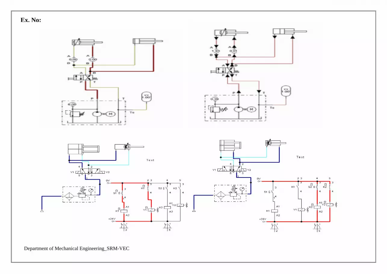
Department of Mechanical Engineering_SRM-VEC
Ex. No:

Department of Mechanical Engineering_SRM-VEC
SIMULATION OF ELECTRICAL CIRCUITS
Open the software in the personal computer.
Select the new file in it.
Click on the supply elements and then select, copy, paste the power supply (24 V and
0V) unit, compressor and pump and tanks.
Click the attenuator and then select copy, paste the single and double acting cylinder.
Then select, copy, paste the required components as per the given application 3/2, 5/2
single and double solenoid valve, electrical switches and relay etc.
Connect all the components
Start and operate the single, double acting cylinders.
RESULT:
Thus the Pneumatic, Hydraulic and Electrical circuit for single acting and double
acting cylinder was simulated using FLUIDSIM software.
Department of Mechanical Engineering_SRM-VEC
Viva Questions
1. Give an example for event-based and time–based sequential control.
-based Water Heater
-based Domestic washing machine
2. What is the purpose of a sensor?
Sensor is used for an element which produces a signal relating to the quantity being measured.
I.e., an electrical resistance temperature element, the quantity being measured is temperature and
the sensor transforms an input of temperature into a change in resistance.
3. Define transducer?
The term transducer is often used in place of the term sensor. Transducer is defined as elements
that when subject to some physical change experience a related change. Thus, sensors are
transducers.
4. What are the terms that define the performance of the transducers?
1. Range and span
2. Error
3. Accuracy
4. Sensitivity
5. Hysteresis error
6. Non – linearity error
7. Repeatability / reproducibility
8. Stability
9. Dead band / time
10. Resolution
11. Output impedance.

Department of Mechanical Engineering_SRM-VEC
5. Define static characteristics?
The static characteristics are the values given when the steady – state conditions occur. i.e., the
values given when the transducer has settled down after having received some input.
6. Define dynamic characteristics?
The dynamic characteristics refer to the behavior between the time that the input value changes
and the times that the value given by the transducer settles down to the steady – state value.
Dynamic characteristics are stated in terms of the response of the transducer to inputs in
particular forms.
7. What are the terms that you can find from the dynamic characteristics?
1. Response time.
2. Time constant.
3. Rise time
4. Settling time.
8. What is a displacement sensor?
Displacement sensors are concerned with the measurement of the amount by which some object
has been moved
9. What is a position sensor?
Position sensors are concerned with the determination of the position of some object with
reference to some reference point.
10. What is a proximity sensor?
Proximity sensors are a form of position sensor and are used to determine when an object has
moved to within some particular critical distance of the sensor
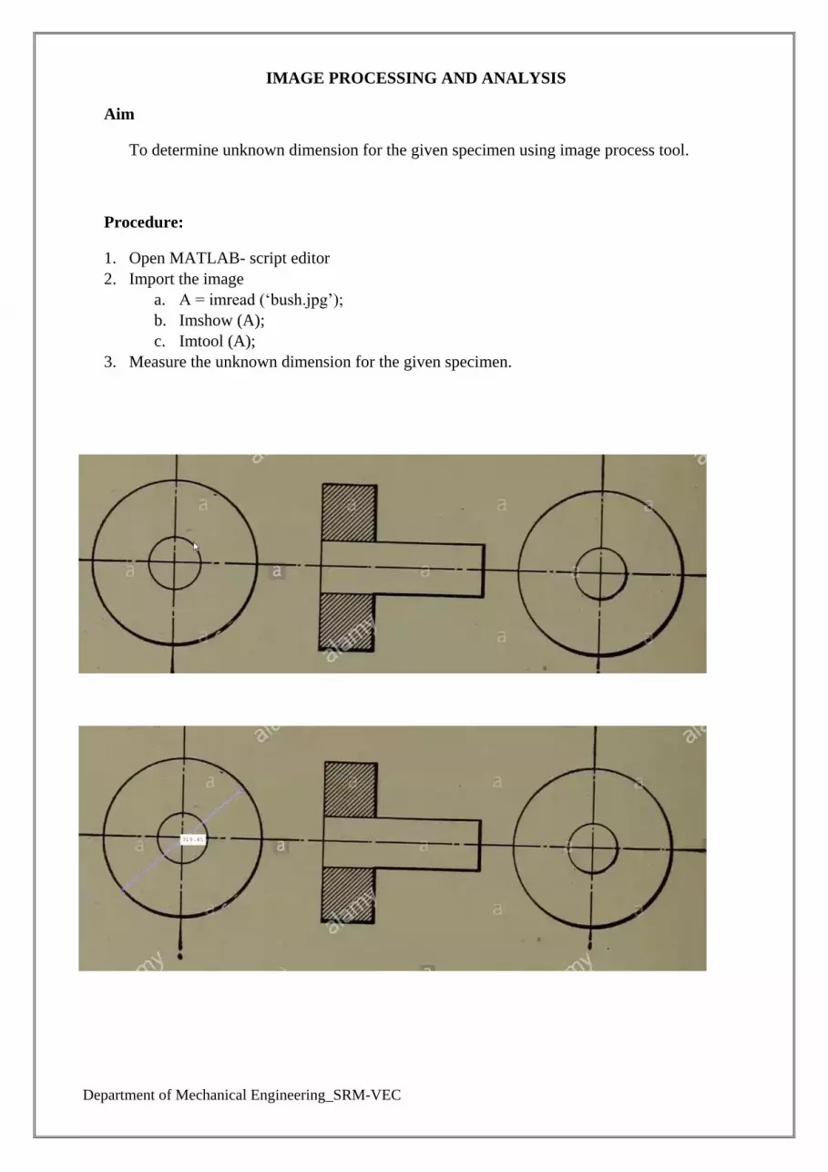
Department of Mechanical Engineering_SRM-VEC
IMAGE PROCESSING AND ANALYSIS
Aim
To determine unknown dimension for the given specimen using image process tool.
Procedure:
1. Open MATLAB- script editor
2. Import the image
a. A = imread (‘bush.jpg’);
b. Imshow (A);
c. Imtool (A);
3. Measure the unknown dimension for the given specimen.

Department of Mechanical Engineering_SRM-VEC
Result:
Department of Mechanical Engineering_SRM-VEC
Viva Questions
1. Define Image.
An Image may be defined as a two dimensional function f (x,y) where x & y are spatial
(plane) coordinates, and the amplitude of f at any pair of coordinates (x,y) is called
intensity or gray level of the image at that point. When x,y and the amplitude values of f
are all finite, discrete quantities we call the image as Digital Image.
2. Define Image Sampling.
Digitization of spatial coordinates (x,y) is called Image Sampling. To be suitable for
computer processing, an image function f(x,y) must be digitized both spatially and in
magnitude.
3. Define Quantization.
Digitizing the amplitude values is called Quantization. Quality of digital image is
determined to a large degree by the number of samples and discrete gray levels used in
sampling and quantization.
4. What is Dynamic Range?
The range of values spanned by the gray scale is called dynamic range of an image.
Image will have high contrast, if the dynamic range is high and image will have dull
washed out gray look if the dynamic range is low.
5. Define Mach band effect.
The spatial interaction of Luminance from an object and its surround creates a
Phenomenon called the mach band effect.
6. Define Brightness.
Brightness of an object is the perceived luminance of the surround. Two objects with
different surroundings would have identical luminance but different brightness.
7. Define Tapered Quantization.
If gray levels in a certain range occur frequently while others occurs rarely, the
quantization levels are finely spaced in this range and coarsely spaced outside of it. This
method is sometimes called Tapered Quantization.
8. What do you meant by Gray level?
Gray level refers to a scalar measure of intensity that ranges from black to grays and
finally to white.

Department of Mechanical Engineering_SRM-VEC
9. Define Resolutions.
Resolution is defined as the smallest number of discernible detail in an image. Spatial
resolution is the smallest discernible detail in an image and gray level resolution refers to
the smallest discernible change is gray level.
10. What do you meant by Zooming of digital images?
Zooming may be viewed as over sampling. It involves the creation of new pixel locations
and the assignment of gray levels to those new locations.

Department of Mechanical Engineering_SRM-VEC
MODELLING AND ANALYSIS OF BASIC HYDRAULIC SYSTEMS
USING LAB VIEW
Aim:
To actuate the hydraulic cylinder and find out the force vs. Pressure and find
out speed vs. Discharge
Apparatus required
Oil tank, single-phase motor, gear pump, pressure relief valve, 4/3 double solenoid
valve, flow control valve, double acting cylinder, load cell, and data actuation card
than lab view software.
Procedure for force vs. Pressure
Switch on the electrical power supply with motor.
Switch on the power supply to the control unit.
Open the lab view software in the system.
Inter face hydraulic trainer with system using RS-232.
Open the force. Go to operate, click the run. Than power on (below).
Now extend the system by pressing the up button.
Load cell indicate the force value in the monitor.
Now adjust the pressure regulator and set the maximum pressure as
25kg/cm2.
Retract the cylinder.
Once again forward the cylinder; you have adjusted the pressure in pressure
regulator.
You have seen the force value in monitoring.
Repeat the force value for different pressure.
Procedure speed vs. Discharge
Now regulate the flow control valve, contract the system by pressing down
position. After seen monitor in velocity cm/sec.

Department of Mechanical Engineering_SRM-VEC
Now adjust the flow control valves and set the maximum flow, to find the
up and velocity.
Repeat the velocity values for different flows
STUDY REPORT:
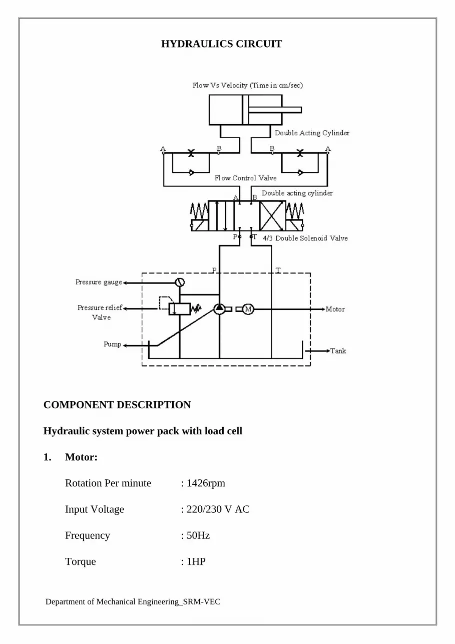
Department of Mechanical Engineering_SRM-VEC
HYDRAULICS CIRCUIT
COMPONENT DESCRIPTION
Hydraulic system power pack with load cell
1. Motor:
Rotation Per minute : 1426rpm
Input Voltage : 220/230 V AC
Frequency : 50Hz
Torque : 1HP

Department of Mechanical Engineering_SRM-VEC
2. Pump:
Working Maximum Pressure : 100 Kg./cm2
Usable Pressure : 50 Kg/cm2
3. Manifold:
4/3 Manifold
4. Direction Control Valve
Operating Voltage : 24 V DC
5. Pressure Gauge:
Maximum Working Pressure Kg./cm2
Usable Pressure : 50 Kg/cm2
6. Tank:
Total Capacity 40 Lts.
Rectangular Shape
7. Double Acting Cylinder:
Stroke Length : 150mm
Cylinder Piston Dia : 40mm
8. Flow Control Valve:
15 ltr. Per Min.
9. Load Cell:
Maximum Kg : 500Kg
Types : Strain Gauge

Department of Mechanical Engineering_SRM-VEC
Force : Bi Direction
Single conditioner output: 0-5V DC
Data Acquiescing System:
ADµC 841 Micro Controllers:
62 KB Flash Memories
8 Channel 12 Bit ADC
2 Channel 12 Bit DAC
TABULATION FORCE VS. PRESSURE
S.No. Pressure in
GM/CM2
Displayed Force
in KG
Calculated
Force in KG % of Error

Department of Mechanical Engineering_SRM-VEC
TABULATION SPEED VS. DISCHARGE
S.No.
Velocity in UP
(Speed in
cm.sec)
Velocity in
Down (Speed in
cm.sec)
Discharge in Up
(Flow in
Lit/Sec)
Discharge in
Down (Flow in
Lit/Sec)
Department of Mechanical Engineering_SRM-VEC
Viva Question:
1. Define Hydraulics.
The engineering science pertaining to liquid pressure and flow.
2. How pumps are classified?
Positive displacement pumps
Hydrodynamic (or) Non-positive displacement pumps.
3. Write about positive displacement pumps?
Positive displacement pumps have the internal working elements which
make a very, close fit together so that there is very little leakage (or)
slippage between them. This type of pumps ejects a fixed quantity of liquid
into the hydraulic system per revolution of the' pump shaft.
4. Define Axial Piston pump.
A pump having multiple pistons disposed with their axes parallel to shaft
axis
5. Define Radial Piston pump.
A pump having multiple pistons disposed radically to the shaft axis,
actuated by an eccentric element.
6. Define Gear pump.
A pump having two or more intermeshing gears or lobed members enclosed
in housing.
7. Define Vane pump.
A pump having multiple radial vanes within a supporting rotor.
8. Define Viscosity .
A measure of the internal friction or the resistance to fluid flow.
9. Define Motor.
A device which converts .fluid power into mechanical power. It usually
delivers Torque and rotary motion to a shaft.

Department of Mechanical Engineering_SRM-VEC
10. How velocity of the hydraulic actuator is calculated?
Velocity of the hydraulic actuator = Input flow rate Area of piston.

Department of Mechanical Engineering_SRM-VEC
EXPERIMENT OF BOTTLE FILLING MODULE
AIM:
To study the PLC control process of bottle filling Module
Apparatus Required:
Bottle filling module
Power supply
Personal Computer
Procedure:
Check initially the tank level is to be high.
Check the bottles are empty before starting the process.
Check the PLC is stop mode at starting.
Switch ON the power supply.
Connect the RS 232 cable for communicating the PC to PLC.
Click to open the file EXPERIMENT OF BOTTLE FILLING MODULE.
CONCLUTION:
Thus the Bottle filling system was studied.

Department of Mechanical Engineering_SRM-VEC
Open Loop Systems

Department of Mechanical Engineering_SRM-VEC
Ex. No: Closed Loop Systems

Department of Mechanical Engineering_SRM-VEC
SERVO CONTROLLER INTERFACING FOR DC MOTOR USING PLC
AIM:
To study the performance of servomotor control for open & closed loop system.
PROCEDURE:
Install the winpro ladder and panatrem software to PC.
Open the winpro ladder software.
Switch on the PLC trainer.
Connect the PLC and servo controller kit.
Click file button then click new project.
Give a project name then click OK.
Now double click system configuration then double click I/O configuration.
A new window will open as shown below.
Now set the counting mode as A/B.
Then set A phase as X0 and mask as X2 then click OK.
Again double click I/O configuration and click output setup.
Mark Y1 and Y2 and set PS00 as Y0=PLS: Y1=DIR and click OK.

Department of Mechanical Engineering_SRM-VEC
Click contact icon and click in working space.
Give address as X3.
Click function icon and click near the contact in working space.
A new window will open. Type 140 and click OK.
Set Ps as 0, SR as any number with prefix R and WR SR as any number with
prefix R then click OK.
Click project on the menu bar and click servo program table and click new table.

Department of Mechanical Engineering_SRM-VEC
Give any table name and give the SR, SR should be the SR of function. Then
click OK.
A new window will open. Clicks add and give speed between 1 to 100000.
Make changes as shown in below and click OK.

Department of Mechanical Engineering_SRM-VEC
Again click add and make changes as shown in below.
Connect the patch cord as shown in circuit diagram.
Click PLC and click run.
RESULT:
Thus the performance of servomotor control for close loop system is studied.

Department of Mechanical Engineering_SRM-VEC