mateus krepsky ludwich on time-deterministic
TRANSCRIPT
Mateus Krepsky Ludwich
ON TIME-DETERMINISTIC MULTICOREVIRTUALIZATION TECHNIQUES
Tese submetida ao Programa de Pos-Graduacao em Ciencia da Computacaoda Universidade Federal de Santa Cata-rina para a obtencao do Grau de Doutorem Ciencia da Computacao.Orientador: Antonio Augusto Frohlich,Prof. Dr.
Florianopolis
2018
Ficha de identificação da obra elaborada pelo autor, através do Programa de Geração Automática da Biblioteca Universitária da UFSC.
Ludwich, Mateus Krepsky On Time-deterministic Multicore VirtualizationTechniques / Mateus Krepsky Ludwich ; orientador,Antônio Augusto Fröhlich, 2018. 205 p.
Tese (doutorado) - Universidade Federal de SantaCatarina, Centro Tecnológico, Programa de PósGraduação em Ciência da Computação, Florianópolis,2018.
Inclui referências.
1. Ciência da Computação. 2. Virtualização. 3.Modelagem de Interferência. 4. Tempo RealMulticore. 5. Escalonamento Composto. I. Fröhlich,Antônio Augusto. II. Universidade Federal de SantaCatarina. Programa de Pós-Graduação em Ciência daComputação. III. Título.


To my grandfather Egon Arno Krepsky,in memoriam.

ACKNOWLEDGMENTS
First and foremost I would like to thank Jesus Christ, which isGod, for his active presence in my live. I would like to thank my motherEleonora K. Krepsky Ludwich, my father Adriano Brognoli Ludwich,and my brother Tiago Krepsky Ludwich for hearing my complaintsand for their words of encouragement. I would like to thank my friendsJonas Godtsfriedt, Rodrigo Bruch, and Thiago Possenti for more thantwenty years of friendship. I would like to thank my family, in especialmy cousins Andrei Krepsky de Melo, and Daniel Ludwich for their longstand friendship.
I would like to thank my colleagues and friends at LISHA, espe-cially Joao Gabriel Reis, and Davi Resner for the conversations aboutwork, science, and how the machines are going to take over. :) I wouldlike to thank also Rodrigo Meurer for accepting the challenge of inte-grating Linux with a hypervisor under construction.
I would like to thank Professor Sebastian Fischmeister for wel-coming me during my stay at the University of Waterloo. I would alsoto thank Professor Borzoo Bonakdarpour for the conversations aboutformal methods, and for stressing the importance of defining conceptsin order, before using them.
I would like to thank Professor Giovani Gracioli for the prolificdiscussions about multicore and real-time systems.
I would like to especially thank Guto (A.K.A. Professor AntonioAugusto Frohlich), my advisor, for the innumerous conversations aboutmy research, science, and other themes; and for giving me the oppor-tunity of learning, teaching (as teaching assistant for the AdvancedOperating System course), and researching for more than a decade atLISHA. May the hunger for knowledge of the dining philosophers neverend!
This research was supported by the Brazilian Federal Agencyfor Coordination for the Improvement of Higher Education Personnel(CAPES), “CAPES DS” grant, and supported in part by “CAPES/D-FAIT” grant.

On Time-deterministic“A wizard is never late. Nor is he early;he arrives precisely when he means to.”(Peter Jackson et al., The Fellowship ofthe Ring, 2001).Multicore“...single-chip systems with multiple cores...”(Hennessy and Patterson, Computer Ar-chitecture - A Quantitative Approach, 2012)Virtualization Techniques“All problems in computer science can besolved by another level of indirection.” (DavidWheeler apud Diomidis Spinellis, Beauti-ful Code: Leading Programmers ExplainHow They Think, 2007).


RESUMO
A complexidade crescente dos sistemas de tempo real aliada aos avancosnas tecnologias de processadores esta proporcionando o uso de ar-quiteturas multiprocessadas tambem no domınio de tempo real embar-cado. Como consequencia, funcionalidades que eram implementadasutilizando-se hardware dedicado agora estao sendo implementadas poruma colecao de tarefas executando em um sistema operacional de temporeal. A mudanca de hardware dedicado para multiprocessadores, osquais compartilham tanto memoria como Entrada e Saıda (do ingles,Input/Output - I/O), levanta questoes complexas sobre o isolamentoespacial e temporal de tarefas. Neste cenario, maquinas virtuais execu-tando sobre um hypervisor representam uma solucao bem estabelecidacom respeito ao isolamento espacial, uma vez que cada maquina virtualutiliza o seu proprio espaco de enderecamento e e protegida das demaispor meio de uma Unidade de Gerenciamento de Memoria (do ingles,Memory Management Unit - MMU). Isolamento temporal, entretanto,tem sido alvo de intensa pesquisa ultimamente. Escalonamento temporeal, tratamento de interrupcao multinıvel e troca de contexto comprecisao de ciclo sao exemplos de tecnicas incorporadas neste cenario.Entretanto, isolamento temporal ainda nao foi completamente explo-rado, assim como diversos aspectos de arquiteturas multiprocessadastem sido insuficientemente investigados.Este trabalho investiga o impacto de interferencia temporal que umdomınio pode causar em outro enquanto executando em um cenarioonde memoria Cache de Ultimo Nıvel (do ingles, Last-level Cache -LLC) e interconexoes (de memoria e de I/O) sao compartilhadas. Um sis-tema de criticalidade mista e levado em consideracao o qual e compostopor dois nıveis de criticalidade: LO (baixo / nao crıtico) e HI (alto/ temporalmente crıtico). Sao considerados dois tipos de domınios,domınios-HI que executam tarefas temporalmente crıticas (tarefas-HI )e domınios-LO que executam tarefas nao crıticas (tarefas-LO). Em umdeterminado instante do tempo, o sistema pode operar em modo LOou modo HI, dependendo da interferencia temporal que e percebida.Enquanto o sistema esta operando em modo LO, ambas as tarefas-LOe tarefas-HI podem executar. Enquanto o sistema esta operando emmodo HI, todas as tarefas-LO sao suspensas e somente tarefas-HI saopermitidas a executar. Um mecanismo para ligar e desligar dispositivosde I/O e empregado para reduzir a interferencia causada por contencao

nas interconexoes. A semantica do desligamento de dispositivos de-pende da classe do dispositivo e se ele e fısico ou virtual. Por exemplo,enquanto o desligamento de uma Unidade Central de ProcessamentoFısica (do ingles, Physical Central Processing Unit - PCPU) implica emalterar os nıveis de tensao e corrente eletrica enviados ao dispositivo,o desligamento de uma Unidade Central de Processamento Virtual (doingles, Virtual Central Processing Unit - VCPU) pode significar apenassuspender a thread do hypervisor utilizada para implementar a VCPU
em questao.Este trabalho introduz uma abordagem de modelagem que captura osrequisitos de processamento e I/O de tarefas periodicas de um sistemaoperacional convidado (as quais compoem um domınio) e as abstraiem um Modelo de Recursos de Domınio (do ingles, Domain ResourceModel - DRM). Um DRM define as reservas de recursos (I/O e processa-mento) disponıveis a um domınio como tambem o perıodo de recargadestas reservas. Escalonabilidade de domınio e entao definida compara-ndo a demanda gerada pelas tarefas do sistema operacional convidadocom a reserva que e provida pelo DRM. Escalonabilidade de sistemae definida compondo a reserva de todos os DRMs em conjunto e veri-ficando se a plataforma de hardware subjacente e capaz de atende-la.E assumido que os requisitos dos domınios-HI sao sempre conhecidos,enquanto os requisitos dos domınios-LO podem ser conhecidos ou nao.Tambem e assumido que a topologia fısica empregada (composta porprocessadores, dispositivos de I/O e suas interconexoes) e conhecida.E conhecida tambem a alocacao fısica, isto e, quais domınios utilizamquais recursos.A abordagem de modelagem proposta possui duas fases principais, umaem tempo de projeto e outra em tempo de execucao. Durante a fase deprojeto, domınios-HI e domınios-LO conhecidos executam e os even-tos relacionados ao overhead sao medidos, como o numero de faltasna LLC e o tempo de contencao nas interconexoes. Tais informacoessao utilizadas para inflar os requisitos das tarefas de sistema opera-cional convidado e para computar DRMs cientes de overhead. Durantetempo de execucao, novos domınios podem ser admitidos no sistemadesde que eles nao rompam com a escalonabilidade de domınios-HI emmodo HI nem com a escalonabilidade de sistema. Durante tempo deexecucao, informacao relacionada ao overhead e continuamente mon-itorada e usada para inflar a reserva dos domınios e na execucao detestes de escalonabilidade destes. Sempre que e detectado que algumdomınio-HI se tornara nao escalonavel em modo LO, o sistema muda demodo LO para modo HI evitando que domınios-HI percam deadlines.
O sistema muda de volta para modo LO sempre que a interferencia de-cresce a ponto de domınios-HI serem escalonaveis novamente em modoLO.A abordagem de modelagem proposta, baseada no DRM, foi avaliadaem domınios com requisitos de processamento e I/O distintos e comnıveis de criticalidade distintos. As avaliacoes abordam nao apenastempo de projeto, como tambem simulam mudancas em tempo de ex-ecucao, mostrando como a admissao de novos domınios pode impactarna escalonabilidade. A abordagem proposta foi avaliada de acordo comdecisoes de escalonamento frente a mudancas na quantidade de inter-ferencia percebida como o numero de faltas na LLC e mudancas natopologia fısica na medida em que dispositivos eram ligados ou desli-gados. A abordagem proposta foi tambem avaliada quanto ao uso derecursos fısicos. Comparando a abordagem proposta com o modelo deRecursos Periodicos de Multiprocessados (do ingles, Multiprocessor Pe-riodic Resource - MPR), a abordagem proposta apresenta uma maiordemanda por PCPUs, pois ela utiliza PCPUs para implementar nao so-mente VCPUs de execucao como tambem VCPUs que tratam operacoesde I/O. No entanto, ao comparar decisoes de escalonamento, a abor-dagem proposta apresenta melhores resultados que MPR uma vez quea abordagem proposta e ciente de overhead e pode escolher desligardomınios-LO evitando que domınios-HI percam deadlines em modoHI.Palavras-chave: Virtualizacao, Modelagem de Interferencia, I/O, LLC,Tempo Real, Multicore, Escalonamento Composto

RESUMO EXPANDIDO
IntroducaoA complexidade crescente dos sistemas de tempo real aliada aos
avancos nas tecnologias de processadores esta proporcionando o uso dearquiteturas multiprocessadas tambem no domınio de tempo real em-barcado. Como consequencia, funcionalidades que eram implementadasutilizando-se hardware dedicado agora estao sendo implementadas poruma colecao de tarefas executando em um sistema operacional de temporeal. A mudanca de hardware dedicado para multiprocessadores, osquais compartilham tanto memoria como Entrada e Saıda (do ingles,Input/Output - I/O), levanta questoes complexas sobre o isolamentoespacial e temporal de tarefas. Neste cenario, maquinas virtuais execu-tando sobre um hypervisor representam uma solucao bem estabelecidacom respeito ao isolamento espacial, uma vez que cada maquina virtualutiliza o seu proprio espaco de enderecamento e e protegida das demaispor meio de uma Unidade de Gerenciamento de Memoria (do ingles,Memory Management Unit - MMU). Isolamento temporal, entretanto,tem sido alvo de intensa pesquisa ultimamente. Escalonamento temporeal, tratamento de interrupcao multinıvel e troca de contexto comprecisao de ciclo sao exemplos de tecnicas incorporadas neste cenario.Entretanto, isolamento temporal ainda nao foi completamente explo-rado, assim como diversos aspectos de arquiteturas multiprocessadastem sido insuficientemente investigados.Objetivos
Este trabalho investiga o impacto da interferencia temporal queum domınio pode causar em outro enquanto executando em um cenarioonde memoria Cache de Ultimo Nıvel (do ingles, Last-level Cache - LLC)e interconexoes (de memoria e de I/O) sao compartilhadas. Deste modo,este trabalho pretende responder as seguintes perguntas de pesquisa:(i) Como o compartilhamento de recursos interfere com comportamentotemporal de tarefas em um hypevisor multicore? (ii) Como quantificara extensao dessa interferencia? (iii) Quais tecnicas podem ser utilizadaspara reduzir essa interferencia ou mante-la dentro de limites conheci-dos? (iv) Como tal interferencia pode ser utilizada para alimentar ummodelo do sistema de forma que possa ser possıvel testar a escalonabil-idade de tarefas e a viabilidade de domınios? (v) Como tais testes deescalonabilidade cientes de interferencia podem ser utilizados em umaestrategia (em tempo de projeto e execucao) a qual garanta que tarefas
temporalmente crıticas nunca percam um deadline? Portanto, o princi-pal objetivo deste trabalho e demostrar que a abordagem de modelagemproposta a qual e ciente de interferencia e os testes de escalonabili-dade propostos combinados em uma estrategia de tempo de projeto eexecucao asseguram que tarefas de sistemas operacionais convidadostemporalmente crıticas nunca percam um deadline em um ambientevirtualizado multicore embarcado no qual recursos sao compartilhados.Metodologia
Os seguintes passos foram seguidos para demonstrar que o ob-jetivo deste trabalho foi alcancado. (i) Apresentar os tipos de inter-ferencia de LLC e interconexao. (ii) Discutir como tecnicas existentespodem ser utilizadas no cenario de virtualizacao multicore embarcado.(iii) Desenvolver um modelo ciente de interferencia juntamente com umteste de analise de escalonabilidade composto (nıveis virtual e fısico).(iv) Elaborar uma estrategia de tempo de projeto e execucao que utilizaas tecnicas apresentadas e o modelo proposto para assegurar a escalon-abilidade de tarefas de sistema operacional convidado temporalmentecrıticas. (v) Avaliar a estrategia proposta utilizando domınios sinteticoscom conjunto de tarefas distintos em uma topologia encontrada em umaarquitetura multicore usual.
Neste trabalho sao considerados dois tipos de domınios, domınios-HI que executam tarefas temporalmente crıticas (tarefas-HI ) e domınios-LO que executam tarefas nao crıticas (tarefas-LO). Em um determi-nado instante do tempo, o sistema pode operar em modo LO ou modoHI, dependendo da interferencia temporal que e percebida. Enquantoo sistema esta operando em modo LO, ambas as tarefas-LO e tarefas-HI podem executar. Enquanto o sistema esta operando em modo HI,todas as tarefas-LO sao suspensas e somente tarefas-HI sao permitidasa executar.Resultados e Discussao
A abordagem de modelagem proposta, baseada no Modelo deRecursos de Domınio (do ingles, Domain Resource Model - DRM), foiavaliada em domınios com requisitos de processamento e I/O distintos ecom nıveis de criticalidade distintos. As avaliacoes abordam nao apenastempo de projeto, como tambem simulam mudancas em tempo de ex-ecucao, mostrando como a admissao de novos domınios pode impactarna escalonabilidade. A abordagem proposta foi avaliada de acordo comdecisoes de escalonamento frente a mudancas na quantidade de inter-ferencia percebida como o numero de faltas na LLC e mudancas natopologia fısica na medida em que dispositivos eram ligados ou desli-gados. A abordagem proposta foi tambem avaliada quanto ao uso de
recursos fısicos. Comparando a abordagem proposta com o modelo deRecursos Periodicos de Multiprocessados (do ingles, Multiprocessor Pe-riodic Resource - MPR), a abordagem proposta apresenta uma maiordemanda por CPUs fısicas, pois ela utiliza CPUs fısicas para implemen-tar nao somente CPUs virtuais de execucao como tambem CPUs virtu-ais que tratam operacoes de I/O. No entanto, ao comparar decisoes deescalonamento, a abordagem proposta apresenta melhores resultadosque MPR uma vez que a abordagem proposta e ciente de overhead epode escolher desligar domınios-LO evitando que domınios-HI percamdeadlines em modo HI.Consideracoes Finais
Baseado nos resultados obtidos e possıvel concluir que o objetivoprincipal deste trabalho foi alcancado uma vez que, utilizando-se aabordagem proposta, e garantido que HI-tasks sempre cumpram seusdeadlines, como e demonstrado pelos testes de escalonabilidade.
Ate onde foi possıvel identificar, este trabalho e o primeiro queapresenta uma abordagem para avaliar a escalonabilidade de tarefas desistema operacional convidado e para computar os requisitos de domınioconsiderando o compartilhamento de memoria e Input/Output (I/O).Espera-se que a abordagem proposta possa ajudar projetistas de sis-temas a avaliar se uma dada plataforma e capaz de suportar requisitosde tempo real e como tarefas de sistema operacional convidado podemser distribuıdas entre domınios distintos.
A abordagem proposta foi avaliada apenas analiticamente, uti-lizando cenarios que simulam execucoes praticas em uma plataformareal. Por um lado a eficacia e eficiencia das tecnicas apresentadas nestetrabalho ja foram demonstradas em cenarios nao virtualizados, comodemostrado no capıtulo de revisao do estado da arte, e espera-se quesejam mantidas em ambientes virtualizados. Por outro lado, ate ondefoi possıvel identificar, nao existe atualmente um unico hypervisor queimplemente todas as tecnicas necessarias para a implementacao do pro-posto neste trabalho, como escalonamento composto de criticalidademista, desligamento e religamento de dispositivos fısicos e virtuais etratamento de interrupcao multinıvel temporalmente determinıstico.O sistema operacional Embedded Parallel Operating System (EPOS)contempla a maioria das tecnicas necessarias porem, em seu estado at-ual, nao possui um suporte completo a virtualizacao. Uma extensaodo EPOS, denominada de HyperEPOS foi planejada no contexto destetrabalho. Uma versao preliminar do projeto do HyperEPOS e apresen-tada no apendice A, e uma adaptacao do sistema operacional Linuxpara rodar sobre o HyperEPOS e descrita em (MEURER; LUDWICH;

FRoHLICH, 2016). Os mecanismos para suportar tratamento de in-terrupcoes de forma temporalmente determinıstica em uma plataformafısica sao apresentados em (LUDWICH; FRoHLICH, 2015) e em (LUDWICH
et al., 2014). Em estagios iniciais desta pesquisa avaliaram o escalon-ador do EPOS de acordo com correcao funcional e sao apresentados em(LUDWICH; FRoHLICH, 2013) e (LUDWICH; FRoHLICH, 2012). O mesmoescalonador que foi utilizado na ocasiao para escalonar tarefas de sis-tema operacional, pode ser utilizado no escalonamento de CPUs virtuaisno HyperEPOS.
Palavras-chave: Virtualizacao, Modelagem de Interferencia,I/O, LLC, Tempo Real, Multicore, Escalonamento Composto
ABSTRACT
The growing complexity of real-time systems and the advances in pro-cessor technology are enabling the use of multicore architectures alsoin the real-time embedded system domain. As a consequence, featuresthat used to be implemented using dedicated hardware are now beingimplemented by a collection of tasks running on a Real-time Operat-ing System (RTOS). The shift from dedicated hardware to multicoreprocessors, which share both I/O and memory, raises complex issuesabout the spatial and temporal isolation of tasks. In this scenario, Vir-tual Machines atop a hypervisor is a well-established solution with re-spect to spatial isolation, since each Virtual Machine (VM) uses its ownaddress space and are protected from each other by ordinary MMUs.Temporal isolation, however, has been a subject of intense researchlately. Real-time scheduling, multi-level interrupt handling, and cycle-accurate context switching are examples of techniques incorporated inthis scenario. However, temporal isolation has not been fully exploredyet, and several aspects of multicore architectures have been poorlyinvestigated.This work investigates the impact of temporal interference that a do-main can cause on another while running in a scenario where Last-levelCache (LLC) and interconnects (memory and I/O) are shared. It istaken into account a mixed criticality system, composed of two levelsof criticality LO (non-critical) and HI (time-critical). Two types ofdomains are considered, HI-domains that run time-critical tasks (HI-tasks), and LO-domains that run non-critical tasks (LO-tasks). In agiven moment of time, the system can operate either in LO or HI modedepending on the perceived temporal interference. While the systemis operating in LO mode, both LO-tasks and HI-tasks can execute.While the system is running in HI mode, all LO-tasks are suspended,and only HI-tasks are allowed to run. A mechanism of powering ONand OFF I/O devices is employed to reduce the interference causedby the interconnect contention. The semantics of powering OFF de-vices depends on the device class, and on either the device is physicalor virtual. For instance, while the powering OFF of a Physical Cen-tral Processing Unit (PCPU) means to change the voltage and electriccurrent levels that are sent to the device, the powering OFF of a Vir-tual Central Processing Unit (VCPU) means to suspend the hypervisorthread employed to implement such a VCPU.

This work introduces a modeling approach, which captures the process-ing and I/O requirements of periodic guest Operating System (OS) tasksthat compose a domain and abstracts them into a Domain ResourceModel (DRM). A DRM defines the resource (CPU and I/O) budgetsavailable to a domain as well the replenishment periods of such bud-gets. Domain schedulability is then defined by comparing the demandgenerated by the guest OS tasks to the budget supplied by the DRM.System schedulability is defined by composing the budget of all DRMstogether, and by checking whether the underlying physical platform isable to attend them. It is assumed that requirements ofHI-domains arealways known, while the requirements of LO-domains can be known ornot. It is also assumed that the employed physical topology (composedby processors, I/O devices, and their interconnections) is known. Thephysical allocation it is also known (i.e. whiches domains use whichesresources).The proposed modeling approach has two main phases, one at designtime and other at runtime. During the design phase, HI-domains andknown LO-domains execute and overhead related events are measured,such as the number of LLC misses, and the interconnect contentiontime. Such information is used to inflate the requirements of guest OS
tasks and to compute overhead-aware DRMs. During runtime, new do-mains might be admitted in the system as long they do not disrupt theschedulability of HI-domains in HI mode neither the system schedula-bility. During runtime, overhead information is monitored continuouslyand used to inflate the budget of domains and to run scheduling testof domains. Whenever is detected that some HI-domain will becomeunschedulable in LO mode, there is a HI to LO mode switch, prevent-ing HI-domains from missing deadlines. The system switches backto LO mode whenever the interference decreases and HI-domains areschedulable again in LO mode.The proposed modeling approach, based on DRM, was evaluated fordomains with distinct processing and I/O requirements, and distinctcriticality levels. The evaluations comprise not only design time re-quirements but simulate changes in the runtime scenario, showing howthe admission of new domains can impact with the schedulability. Theproposed approach was evaluated according to scheduling decisions fac-ing changes in the perceived interference such as the number of LLC
misses, and changes in the physical topology as devices were poweredON and OFF. The proposed approach was evaluated also regardingthe use of physical resources. Comparing the proposed approach withthe Multiprocessor Periodic Resource (MPR) modeling, it presents a

higher PCPU demand since it uses PCPUs for implementing not onlyexecution VCPUs but also for implementing VCPUs that handle I/O op-erations. However, while comparing scheduling decisions, the proposedapproach presents better results than MPR since the proposed approachis overhead-aware and can choose to power OFF LO domains avoidingdeadline misses of HI-domains in HI mode.Keywords: Virtualization, Interference Modeling, I/O, LLC, Real-Time, Multicore, Compositional Scheduling

LIST OF FIGURES
Figure 1 Mapping physical pages to cache locations (GRACIOLI,2014). . . . . . . . . . . . . . . . . . . . . . . . . . . . . . . . . . . . . . . . . . . . . . . . . . . . . . . . . . . . . 57
Figure 2 Interrupt handling by an ISR. . . . . . . . . . . . . . . . . . . . . . . . . . 60
Figure 3 Interrupt handling by an IST. . . . . . . . . . . . . . . . . . . . . . . . . . 60
Figure 4 Evaluated Queuing Petri Net (QPN) model. Adaptedfrom (NOORSHAMS et al., 2014). . . . . . . . . . . . . . . . . . . . . . . . . . . . . . . . . . . 66
Figure 5 Domain Resources Mapping. . . . . . . . . . . . . . . . . . . . . . . . . . . . 100
Figure 6 Interference due to contention caused by I/O device. . . . 103
Figure 7 Power off dynamics. . . . . . . . . . . . . . . . . . . . . . . . . . . . . . . . . . . . 106
Figure 8 Interrupt Serviced by Hypervisor (ISbyH). . . . . . . . . . . . . . . 108
Figure 9 Interrupt Servicing VCPU (ISVCPU). . . . . . . . . . . . . . . . . . . . 109
Figure 10 Semaphore Observer. . . . . . . . . . . . . . . . . . . . . . . . . . . . . . . . . . . 111
Figure 11 Semaphore Observed::notify. . . . . . . . . . . . . . . . . . . . . . . . . . . . 112
Figure 12 Semaphore Observer::updated. . . . . . . . . . . . . . . . . . . . . . . . . . 113
Figure 13 Interference due to cache line eviction caused by anotherPCPU. . . . . . . . . . . . . . . . . . . . . . . . . . . . . . . . . . . . . . . . . . . . . . . . . . . . . . . . . . . . . 115
Figure 14 Interference due to cache line eviction caused by I/O de-vice. . . . . . . . . . . . . . . . . . . . . . . . . . . . . . . . . . . . . . . . . . . . . . . . . . . . . . . . . . . . . . 116
Figure 15 Division of WTUHIi . . . . . . . . . . . . . . . . . . . . . . . . . . . . . . . . . . . . 153
Figure 16 Schedulability Analysis DRM vs. global EDF (gEDF). . . . 154
Figure 17 Base topology. Known-LO-domains case. . . . . . . . . . . . . . . 155
Figure 18 Runtime scenario, Known-LO-domains case. . . . . . . . . . . . 165
Figure 19 AV Gmiss over time (known LO-domains case). . . . . . . . . 166
Figure 20 PCPU demand. Known-LO-domains case. . . . . . . . . . . . . . . 168
Figure 21 Fraction of schedulable domains. (known LO-domainscase). . . . . . . . . . . . . . . . . . . . . . . . . . . . . . . . . . . . . . . . . . . . . . . . . . . . . . . . . . . . . 169
Figure 22 VCPU class. . . . . . . . . . . . . . . . . . . . . . . . . . . . . . . . . . . . . . . . . . . . . 192
Figure 23 Domain class. . . . . . . . . . . . . . . . . . . . . . . . . . . . . . . . . . . . . . . . . . 193
Figure 24 Hypercall invocation. . . . . . . . . . . . . . . . . . . . . . . . . . . . . . . . . . . 201
Figure 25 VCPU processing messages. . . . . . . . . . . . . . . . . . . . . . . . . . . . . 202
Figure 26 Concurrent Observer. . . . . . . . . . . . . . . . . . . . . . . . . . . . . . . . . . . 202
Figure 27 Concurrent Observed::notify. . . . . . . . . . . . . . . . . . . . . . . . . . . . 202
Figure 28 Concurrent Observer::update. . . . . . . . . . . . . . . . . . . . . . . . . . . 203

LIST OF TABLES
Table 1 limn→∞ SICPrp(n) for different replacement policies (AXER
et al., 2014). . . . . . . . . . . . . . . . . . . . . . . . . . . . . . . . . . . . . . . . . . . . . . . . . . . . . . . 55
Table 2 Comparison of approaches for modeling temporal inter-ference. . . . . . . . . . . . . . . . . . . . . . . . . . . . . . . . . . . . . . . . . . . . . . . . . . . . . . . . . . . 74
Table 3 Comparison of approaches for detecting temporal inter-ference. . . . . . . . . . . . . . . . . . . . . . . . . . . . . . . . . . . . . . . . . . . . . . . . . . . . . . . . . . . 79
Table 4 Comparison of approaches for dealing with I/O virtualiza-tion. . . . . . . . . . . . . . . . . . . . . . . . . . . . . . . . . . . . . . . . . . . . . . . . . . . . . . . . . . . . . . 88
Table 5 Comparison of approaches for dealing with interrupts vir-tualization.. . . . . . . . . . . . . . . . . . . . . . . . . . . . . . . . . . . . . . . . . . . . . . . . . . . . . . . 92
Table 6 Comparison of approaches for dealing with memory vir-tualization.. . . . . . . . . . . . . . . . . . . . . . . . . . . . . . . . . . . . . . . . . . . . . . . . . . . . . . . 98
Table 7 Generated DRM. . . . . . . . . . . . . . . . . . . . . . . . . . . . . . . . . . . . . . . . . 153
Table 8 Base topology insertion and servicing rates. Known-LO-domains case. Units in bytes per seconds (B/s). . . . . . . . . . . . . . . . . . . 156
Table 9 Original design-time domain requirements. Known-LO-domains case. Units in seconds (s). . . . . . . . . . . . . . . . . . . . . . . . . . . . . . . . 158
Table 10 Physical allocation. Domains known at design time. Known-LO-domains case. . . . . . . . . . . . . . . . . . . . . . . . . . . . . . . . . . . . . . . . . . . . . . . . . 159
Table 11 Interconnect contention overhead (in seconds). Known-LO-domains case. . . . . . . . . . . . . . . . . . . . . . . . . . . . . . . . . . . . . . . . . . . . . . . . . 159
Table 12 LLC miss values and overhead (in seconds). Known-LO-domains case. . . . . . . . . . . . . . . . . . . . . . . . . . . . . . . . . . . . . . . . . . . . . . . . . . . . . 159
Table 13 Inflated Dom1 (sum of all tasks) budgets. Known-LO-domains case. . . . . . . . . . . . . . . . . . . . . . . . . . . . . . . . . . . . . . . . . . . . . . . . . . . . . 160
Table 14 DRMs. Known-LO-domains case. . . . . . . . . . . . . . . . . . . . . . . . 161
Table 15 Non-inflated requirements of new domains. Known-LO-domains case. . . . . . . . . . . . . . . . . . . . . . . . . . . . . . . . . . . . . . . . . . . . . . . . . . . . . 162
Table 16 Updated physical allocation. All domains (known LO-domains case). . . . . . . . . . . . . . . . . . . . . . . . . . . . . . . . . . . . . . . . . . . . . . . . . . . . 163
Table 17 Comparison of hypervisors, including the proposed one(HyperEPOS). . . . . . . . . . . . . . . . . . . . . . . . . . . . . . . . . . . . . . . . . . . . . . . . . . . . 200

LIST OF ACRONYMS
AMC Adaptive Mixed-Criticality
API Application Programming Interface
APIC Advanced Peripheral Interrupt Controller
AVET Average Execution Time
BE Best-effort
BFD Best-fit Decreasing
CAP Cache Partitioning
CC Correlation Coefficient
CCP Complete Cache Partitioning
CCS Complete Cache Sharing
cEDF clustered EDF
COTS Commercial off-the-shelf
CPN Colored Petri Net
CPI Cycle per Instruction
CPS Cyber-Physical System
CPU Central Processing Unit
CRPMD Cache-Related Preemption or Migration Delay
DID Direct Interrupt Delivery
DMA Direct Memory Access
DMPR Deterministic Multiprocessor Periodic Resource
DRAM Dynamic Random-access Memory
DRM Domain Resource Model
DSM Distributed Shared Memory
DP Dynamic Priority
DVT Domain Virtual Time
EDF Earliest Deadline First
EDF-VD EDF-Virtual Deadline
EDF-VD-TM EDF-Virtual Deadline-Task Mode
EPT Extended Page Table
EPOS Embedded Parallel Operating System
FFD First-fit Decreasing
FFSB Flexible File System Benchmark
FIFO First-in First-out
FJP Fixed Job Priority
FPGA Field-programmable Gate Array
FSB Front Side Bus
FTP Fixed Task Priority
gDM global DM
gEDF global EDF
GPFN Guest Page Frame Number
GPOS General Purpose Operating System
GPP Guest Physical Page
GSPN Generalized Stochastic Petri Net
gRM global RM
HPC Hardware Performance Counters
HPP Host Physical Page
HRT Hard Real-time
HVM Hybrid Virtual Machine
IDC Inter Domain Communication
I/O Input/Output
IOMMU Input/Output Memory Management Unit
IOVCPU Input/Output Virtual Central Processing Unit
IPI Interprocessor Interrupt
ISR Interrupt Servicing Routine
IST Interrupt Servicing Thread
ISVCPU Interrupt Servicing VCPU
ISbyH Interrupt Serviced by Hypervisor
KVM Kernel-based Virtual Machine
LAPIC Local APIC
LLC Last-level Cache
LLF Least Laxity First
LP Linear Programming
LRU Least Recently Used
MAE Mean Absolute Error
MC Mixed-Criticality
MFN Machine Frame Number
ML Machine Learning
MMU Memory Management Unit
MPEG Moving Picture Experts Group
MPIOV Multi-Processor I/O Virtualization
MPR Multiprocessor Periodic Resource
NIC Network Interface Card
NTB Non Transparent Bridge
NPB NAS Parallel Benchmark
NPT Nested Page Table
NUMA Nonuniform Memory Access
OS Operating System
PC Personal Computer
PCH Platform Controller Hub
PCI Peripheral Component Interconnect
PCIe PCI Express
PCI-X PCI eXtended
PCPU Physical Central Processing Unit
PD Performance Degradation
pDM partitioned DM
pEDF partitioned EDF
PF Physical Function
p-gate Peripheral Gate
PIBS Priority Inheritance Bandwidth-preserving Server
PLRU Pseudo-LRU
PN Petri Net
PMU Performance Monitoring Unit
pRM partitioned RM
PTP Page Table Prefetching
PUART Physical UART
QoS Quality-of-Service
QPN Queuing Petri Net
RM Rate Monotonic
RMI Remote Method Invocation
RMSE Root Mean Squared Error
RRSE Root Relative Squared Error
RT Real-time
RTOS Real-time Operating System
RVI Rapid Virtualization Indexing
SBF Supply Bound Function
SLAT Second Level Address Translation
SMP Symmetric Multiprocessor
SPT Shadow Page Table
SR-IOV Single-Root Input/Output Virtualization
SRT Soft Real-time
SS Sporadic Server
ST System Time
SICPr State-Induced Cache Predictability
TCP Transmission Control Protocol
TDMA Time Division Multiplexed Access
TLB Translation Lookaside Buffer
TSC Time Stamp Counter
UART Universal Asynchronous Receiver Transmitter
UML Unified Modeling Language
UMA Uniform Memory Access
USB Universal Serial Bus
VCI VM Contention Intensity
vColoring Virtual Coloring
VCPU Virtual Central Processing Unit
VCS VM Contention Sensitivity
VDT Virtual Device Thread
VF Virtual Function
vLLC Virtual LLC
VM Virtual Machine
VMCS Virtual Machine Control Structure
VMM Virtual Machine Monitor
VNIC Virtual NIC
VUART Virtual UART
WCT Wall-clock Time
WCET Worst Case Execution Time
WCRD Worst Case Resource Demand
WCRT Worst Case Response Time
WFD Worst-fit Decreasing
WSS Work Set Size
LIST OF SYMBOLS
Ω Set of criticality levels. . . . . . . . . . . . . . . . . . . . . . . . . . . . . . 122
ωS System criticality. . . . . . . . . . . . . . . . . . . . . . . . . . . . . . . . . . . 122
R Set of virtual I/O device classes. . . . . . . . . . . . . . . . . . . . . 122
Γ Set of I/O operations. . . . . . . . . . . . . . . . . . . . . . . . . . . . . . . . 122
τ i The ith guest OS task. . . . . . . . . . . . . . . . . . . . . . . . . . . . . . . 123
T i Period of τ i. . . . . . . . . . . . . . . . . . . . . . . . . . . . . . . . . . . . . . . . . 123
Di Relative deadline of τ i. . . . . . . . . . . . . . . . . . . . . . . . . . . . . . 123
ωi Criticality level of τ i. . . . . . . . . . . . . . . . . . . . . . . . . . . . . . . . 123
CωSi VCPU budget of τ i. . . . . . . . . . . . . . . . . . . . . . . . . . . . . . . . . . 123
Rv,ωS ,γi Virtual I/O device budget of τ i. . . . . . . . . . . . . . . . . . . . . . 123
D A domain. . . . . . . . . . . . . . . . . . . . . . . . . . . . . . . . . . . . . . . . . . . 123
fv Resource unit to time unit mapping function. . . . . . . . 124
DLOi Artificially tightened deadline for the LO mode. . . . . 124
δLOtoHI LO to HI mode switch overhead. . . . . . . . . . . . . . . . . . . . 124
ωD Domain criticality. . . . . . . . . . . . . . . . . . . . . . . . . . . . . . . . . . . 125
τ Domain task set. . . . . . . . . . . . . . . . . . . . . . . . . . . . . . . . . . . . 125
UωSτΘ Total VCPU utilization of a Domain. . . . . . . . . . . . . . . . . 125
UωSτΘ Total virtual I/O device utilization of a Domain. . . . . 125
WDUωSτ Whole domain utilization. . . . . . . . . . . . . . . . . . . . . . . . . . . 125
M A Domain Resource Model. . . . . . . . . . . . . . . . . . . . . . . . . . 126
ωM Criticality of M. . . . . . . . . . . . . . . . . . . . . . . . . . . . . . . . . . . . 126
Π VCPU period of M. . . . . . . . . . . . . . . . . . . . . . . . . . . . . . . . . . 126
Λv,γ Virtual I/O device period of M. . . . . . . . . . . . . . . . . . . . . 126
ΘωS VCPU budget of M. . . . . . . . . . . . . . . . . . . . . . . . . . . . . . . . . 126
Ξv,ωS ,γ Virtual I/O device budget of M. . . . . . . . . . . . . . . . . . . . . 126
mωS Number of VCPUs in M. . . . . . . . . . . . . . . . . . . . . . . . . . . . . 126
nv,ωS ,γ Number of virtual I/O devices in M. . . . . . . . . . . . . . . . . 126
sbfΘ VCPU Supply Bound Function.. . . . . . . . . . . . . . . . . . . . . . 129
sbfΞ Virtual I/O device Supply Bound Function. . . . . . . . . . 130
LV Set of bandwidth levels. . . . . . . . . . . . . . . . . . . . . . . . . . . . . 130
cl2lv(ω, lv) Criticality level to bandwidth level function. . . . . . . . . 130
pe Processing element. . . . . . . . . . . . . . . . . . . . . . . . . . . . . . . . . . 131
λγ,lvpe Processing element insertion rate. . . . . . . . . . . . . . . . . . . . 131
PE Set of processing elements.. . . . . . . . . . . . . . . . . . . . . . . . . . 131
me Memory element. . . . . . . . . . . . . . . . . . . . . . . . . . . . . . . . . . . . 131
µγ,lvme Memory element servicing rate. . . . . . . . . . . . . . . . . . . . . . 131
ME Set of memory elements. . . . . . . . . . . . . . . . . . . . . . . . . . . . . 131
inter Interconnect element. . . . . . . . . . . . . . . . . . . . . . . . . . . . . . . . 131
λγ,lvinter Interconnect element insertion rate. . . . . . . . . . . . . . . . . . 131
µγ,lvinter Interconnect element servicing rate. . . . . . . . . . . . . . . . . . 131
INTER Set of interconnect elements.. . . . . . . . . . . . . . . . . . . . . . . . 131
Top(ωS) Physical topology. . . . . . . . . . . . . . . . . . . . . . . . . . . . . . . . . . . 132
PhyAlloc(pe)Physical allocation relation.. . . . . . . . . . . . . . . . . . . . . . . . . 133
WωΘi(t) VCPU workload upper bound. . . . . . . . . . . . . . . . . . . . . . . . 134
Ni Number of jobs that occur in the time interval a, b. . 134
εωΘi(t) VCPU carry-in demand. . . . . . . . . . . . . . . . . . . . . . . . . . . . . . 134
W v,ω,γΞi (t) Virtual I/O device workload upper bound. . . . . . . . . . . 134
εv,ω,γΞi (t) Virtual I/O device carry-in demand. . . . . . . . . . . . . . . . . 134
Ak Length of interval a, r. . . . . . . . . . . . . . . . . . . . . . . . . . . . . . . 135
Dk Length of interval r, b. . . . . . . . . . . . . . . . . . . . . . . . . . . . . . 135
IωΘi Total VCPU demand in the interval a, b. . . . . . . . . . . . . 135
Iv,ω,γΞi Total virtual I/O device demand in the interval a, b. 135
IωΘ1,i Total type-1 VCPU demand in the interval a, b. . . . . . 135
Iv,ω,γΞ1,i Total type-1 virtual I/O device demand in the intervala, b. . . . . . . . . . . . . . . . . . . . . . . . . . . . . . . . . . . . . . . . . . . . . . . . . . . . 135
IωΘ2,i Total type-2 VCPU demand in the interval a, b. . . . . . 135
Iv,ω,γΞ2,i Total type-2 virtual I/O device demand in the intervala, b. . . . . . . . . . . . . . . . . . . . . . . . . . . . . . . . . . . . . . . . . . . . . . . . . . . . 135
IωΘi,1 Total type-1 VCPU demand upper bound. . . . . . . . . . . . 135
Iv,ω,γΞi,1 Total type-1 virtual I/O device demand upper bound.135
IωΘi,2 Total type-2 VCPU demand upper bound. . . . . . . . . . . . 135
Iv,ω,γΞi,2 Total type-2 virtual I/O device demand upper bound.136
IωΘi,2 Total type-2 VCPU demand upper bound discountingcarry-in demand.. . . . . . . . . . . . . . . . . . . . . . . . . . . . . . . . . . . . . . . 136
Iv,ω,γΞi,2 Total type-2 virtual I/O device demand upper bounddiscounting carry-in demand.. . . . . . . . . . . . . . . . . . . . . . . . . . . 136
DEMΘ VCPU Worst Case Resource Demand upper bound. . . 137
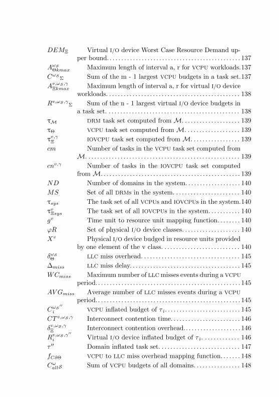
DEMΞ Virtual I/O device Worst Case Resource Demand up-per bound. . . . . . . . . . . . . . . . . . . . . . . . . . . . . . . . . . . . . . . . . . . . . . 137
AωSΘkmax Maximum length of interval a, r for VCPU workloads.137
CωSΣ Sum of the m - 1 largest VCPU budgets in a task set.137
Av,ωS ,γΞkmax Maximum length of interval a, r for virtual I/O device
workloads. . . . . . . . . . . . . . . . . . . . . . . . . . . . . . . . . . . . . . . . . . . . . . 138
Rv,ωS ,γΣ Sum of the n - 1 largest virtual I/O device budgets in
a task set. . . . . . . . . . . . . . . . . . . . . . . . . . . . . . . . . . . . . . . . . . . . . . 138
τM DRM task set computed from M. . . . . . . . . . . . . . . . . . . . 139
τΘ VCPU task set computed from M. . . . . . . . . . . . . . . . . . . 139
τv,γΞ IOVCPU task set computed from M. . . . . . . . . . . . . . . . . 139
cm Number of tasks in the VCPU task set computed fromM. . . . . . . . . . . . . . . . . . . . . . . . . . . . . . . . . . . . . . . . . . . . . . . . . . . . . 139
cnv,γ Number of tasks in the IOVCPU task set computedfrom M. . . . . . . . . . . . . . . . . . . . . . . . . . . . . . . . . . . . . . . . . . . . . . . . 139
ND Number of domains in the system. . . . . . . . . . . . . . . . . . . 140
MS Set of all DRMs in the system. . . . . . . . . . . . . . . . . . . . . . . 140
τsys The task set of all VCPUs and IOVCPUs in the system.140
τvΞsys The task set of all IOVCPUs in the system. . . . . . . . . . . 140
gv Time unit to resource unit mapping function. . . . . . . . 140
ϕR Set of physical I/O device classes. . . . . . . . . . . . . . . . . . . . 140
Xv Physical I/O device budged in resource units providedby one element of the v class. . . . . . . . . . . . . . . . . . . . . . . . . . . 140
δωSΘ LLC miss overhead. . . . . . . . . . . . . . . . . . . . . . . . . . . . . . . . . . 145
∆miss LLC miss delay. . . . . . . . . . . . . . . . . . . . . . . . . . . . . . . . . . . . . . 145
WCmiss Maximum number of LLC misses events during a VCPU
period. . . . . . . . . . . . . . . . . . . . . . . . . . . . . . . . . . . . . . . . . . . . . . . . . . 145
AV Gmiss Average number of LLC misses events during a VCPU
period. . . . . . . . . . . . . . . . . . . . . . . . . . . . . . . . . . . . . . . . . . . . . . . . . . 145
CωS′′
i VCPU inflated budget of τ i. . . . . . . . . . . . . . . . . . . . . . . . . . 145
CT v,ωS ,γ Interconnect contention time. . . . . . . . . . . . . . . . . . . . . . . . 146
δv,ωS ,γΞ Interconnect contention overhead.. . . . . . . . . . . . . . . . . . . 146
Rv,ωS ,γ′′
i Virtual I/O device inflated budget of τ i. . . . . . . . . . . . . 146
τ ′′ Domain inflated task set. . . . . . . . . . . . . . . . . . . . . . . . . . . . 147
fCδΘ VCPU to LLC miss overhead mapping function. . . . . . . 148
CωallS Sum of VCPU budgets of all domains. . . . . . . . . . . . . . . . 148


CONTENTS
1 INTRODUCTION . . . . . . . . . . . . . . . . . . . . . . . . . . . . . . . . . 391.1 RESEARCH QUESTIONS AND GOALS . . . . . . . . . . . . . . . . . 401.2 ASSUMPTIONS AND SCOPE . . . . . . . . . . . . . . . . . . . . . . . . . . 411.3 METHODOLOGY . . . . . . . . . . . . . . . . . . . . . . . . . . . . . . . . . . . . . 411.4 CONTRIBUTIONS . . . . . . . . . . . . . . . . . . . . . . . . . . . . . . . . . . . . 441.5 STRUCTURE OF THE DOCUMENT . . . . . . . . . . . . . . . . . . . 442 BACKGROUND . . . . . . . . . . . . . . . . . . . . . . . . . . . . . . . . . . 472.1 REQUIREMENTS FOR VIRTUALIZATION . . . . . . . . . . . . . 472.2 MULTIPROCESSOR REAL-TIME SCHEDULING . . . . . . . . 492.3 MEMORY . . . . . . . . . . . . . . . . . . . . . . . . . . . . . . . . . . . . . . . . . . . . 522.3.1 Cache Mapping . . . . . . . . . . . . . . . . . . . . . . . . . . . . . . . . . . . . 522.3.2 Cache Replacement Policies . . . . . . . . . . . . . . . . . . . . . . . . 532.3.3 Types of Interference . . . . . . . . . . . . . . . . . . . . . . . . . . . . . . 552.3.4 Page Coloring . . . . . . . . . . . . . . . . . . . . . . . . . . . . . . . . . . . . . . 572.3.5 Virtualization . . . . . . . . . . . . . . . . . . . . . . . . . . . . . . . . . . . . . . 582.4 I/O . . . . . . . . . . . . . . . . . . . . . . . . . . . . . . . . . . . . . . . . . . . . . . . . . . 592.4.1 Interrupt Handling . . . . . . . . . . . . . . . . . . . . . . . . . . . . . . . . . 592.4.2 Virtualization . . . . . . . . . . . . . . . . . . . . . . . . . . . . . . . . . . . . . . 613 RELATED WORK . . . . . . . . . . . . . . . . . . . . . . . . . . . . . . . . 633.1 INTERFERENCE MODELING . . . . . . . . . . . . . . . . . . . . . . . . . 633.1.1 Discussion . . . . . . . . . . . . . . . . . . . . . . . . . . . . . . . . . . . . . . . . . 733.2 INTERFERENCE DETECTION AND PREDICTION . . . . . 753.2.1 Discussion . . . . . . . . . . . . . . . . . . . . . . . . . . . . . . . . . . . . . . . . . 783.3 I/O . . . . . . . . . . . . . . . . . . . . . . . . . . . . . . . . . . . . . . . . . . . . . . . . . . 793.3.1 Discussion . . . . . . . . . . . . . . . . . . . . . . . . . . . . . . . . . . . . . . . . . 873.4 INTERRUPTS . . . . . . . . . . . . . . . . . . . . . . . . . . . . . . . . . . . . . . . . 893.4.1 Discussion . . . . . . . . . . . . . . . . . . . . . . . . . . . . . . . . . . . . . . . . . 923.5 MEMORY . . . . . . . . . . . . . . . . . . . . . . . . . . . . . . . . . . . . . . . . . . . . 933.5.1 Discussion . . . . . . . . . . . . . . . . . . . . . . . . . . . . . . . . . . . . . . . . . 974 PROPOSED TECHNIQUES USAGE . . . . . . . . . . . . . . . 994.1 DETECTING INTERFERENCE . . . . . . . . . . . . . . . . . . . . . . . . 994.2 I/O . . . . . . . . . . . . . . . . . . . . . . . . . . . . . . . . . . . . . . . . . . . . . . . . . . 1024.3 INTERRUPTS . . . . . . . . . . . . . . . . . . . . . . . . . . . . . . . . . . . . . . . . 1084.4 MEMORY . . . . . . . . . . . . . . . . . . . . . . . . . . . . . . . . . . . . . . . . . . . . 1144.4.1 Domain-oriented Page-coloring . . . . . . . . . . . . . . . . . . . . . 1174.4.2 VCPU-oriented Page-coloring . . . . . . . . . . . . . . . . . . . . . . . 1174.4.3 Guest OS task-oriented Page-coloring . . . . . . . . . . . . . . 118
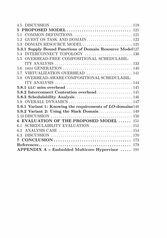
4.5 DISCUSSION . . . . . . . . . . . . . . . . . . . . . . . . . . . . . . . . . . . . . . . . . 1195 PROPOSED MODEL . . . . . . . . . . . . . . . . . . . . . . . . . . . . . . 1215.1 COMMON DEFINITIONS . . . . . . . . . . . . . . . . . . . . . . . . . . . . . . 1215.2 GUEST OS TASK AND DOMAIN . . . . . . . . . . . . . . . . . . . . . . . 1225.3 DOMAIN RESOURCE MODEL . . . . . . . . . . . . . . . . . . . . . . . . . 1255.3.1 Supply Bound Functions of Domain Resource Model1275.4 INTERCONNECT TOPOLOGY . . . . . . . . . . . . . . . . . . . . . . . . 1305.5 OVERHEAD-FREE COMPOSITIONAL SCHEDULABIL-
ITY ANALYSIS . . . . . . . . . . . . . . . . . . . . . . . . . . . . . . . . . . . . . . . 1335.6 DRM GENERATION . . . . . . . . . . . . . . . . . . . . . . . . . . . . . . . . . . . 1405.7 VIRTUALIZATION OVERHEAD . . . . . . . . . . . . . . . . . . . . . . . 1415.8 OVERHEAD-AWARE COMPOSITIONAL SCHEDULABIL-
ITY ANALYSIS . . . . . . . . . . . . . . . . . . . . . . . . . . . . . . . . . . . . . . . 1445.8.1 LLC miss overhead . . . . . . . . . . . . . . . . . . . . . . . . . . . . . . . . . 1455.8.2 Interconnect Contention overhead . . . . . . . . . . . . . . . . . . 1455.8.3 Schedulability Analysis . . . . . . . . . . . . . . . . . . . . . . . . . . . . . 1465.9 OVERALL DYNAMICS . . . . . . . . . . . . . . . . . . . . . . . . . . . . . . . . 1475.9.1 Variant 1: Knowing the requirements of LO-domains1485.9.2 Variant 2: Using the Slack Domain . . . . . . . . . . . . . . . . . 1495.10 DISCUSSION . . . . . . . . . . . . . . . . . . . . . . . . . . . . . . . . . . . . . . . . . 1506 EVALUATION OF THE PROPOSED MODEL . . . . . . 1516.1 SCHEDULABILITY EVALUATION . . . . . . . . . . . . . . . . . . . . . 1516.2 ANALYSIS CASE . . . . . . . . . . . . . . . . . . . . . . . . . . . . . . . . . . . . . 1546.3 DISCUSSION . . . . . . . . . . . . . . . . . . . . . . . . . . . . . . . . . . . . . . . . . 1707 CONCLUSION . . . . . . . . . . . . . . . . . . . . . . . . . . . . . . . . . . . . 173References . . . . . . . . . . . . . . . . . . . . . . . . . . . . . . . . . . . . . . . . . . . 179APPENDIX A -- Embedded Multicore Hypervisor . . . . . 191
39
1 INTRODUCTION
The growing complexity of real-time embedded systems is de-manding more processing power due to the evolution and integrationof features. In an automotive environment, for instance, new safetyfunctionalities like “automatic emergency breaking” and “night viewassist” must read and fuse data from sensors, process video streams,and rise warnings when an obstacle is detected on the road under real-time constraints (MOHAN et al., 2011). Allied to that the continuousevolution of processor technology, together with its decreasing cost, hasenabled multicore architectures to be also used in the real-time embed-ded system domain (CHO; RAVINDRAN; JENSEN, 2006; DAVIS; BURNS,2011). As consequence, features that used to be implemented usingdedicated hardware are now being implemented in software. The usualapproach in this case could be to implement such features as tasksto be managed by an RTOS. However, infotainment subsystems (e.g.video player, games and web browsing) usually are too complex to bemodeled in the context of critical applications (as tasks of an RTOS)and are better served by conventional OSes, such as Linux, mainly be-cause the level of human interaction they demand and the intensiveuse of I/O devices. At the same time, conventional OSes are not ableto guarantee the stringent time-requirement of critical tasks. Besides,such critical tasks must not suffer interference from other tasks neitherspatially (reading data that should not be accessed or corrupting datastructures from others) nor temporally (changing the time behavior ofa task and making it losing its deadlines).
In this scenario, VMs atop a hypervisor is a well established so-lution with respect to spatial isolation, since each VM uses its ownaddress space and is protected from each other by ordinary MemoryManagement Unit (MMU)s. The use of hypervisors instead of multitaskalone allows for code reuse, particularly on the infotainment side wherenon-real time operating system and applications can be used with noneor small modifications.
While spatial isolation is a well solved problem, temporal isola-tion has not been fully explored in the context of virtualized systems,and several architectural aspects of it have been poorly investigated.One of the faced problems is how to ensure temporal isolation betweendistinct VMs in a hypervisor taking into account that all VMs run on thesame physical hardware. Even in multicore architectures, where VMscan execute in distinct processors there is still interference due to shar-
40
ing of resources. I/O operations such as Direct Memory Access (DMA)transactions that copy data from the device to the main memory orvice-versa, which are triggered by a task running on a VM can causeinterference on tasks running on another VM. The interference can becaused by contention in the case a task on a VM wishes to access themain memory which is done through the memory interconnect but thememory interconnect is already being used by an I/O device performinga DMA for a task on another VM. Additionally, in a multicore processorthe LLC is shared between cores, so a task running on a VM can evictcache lines used by tasks running on another VM. That can happeneither due to intercore interference: a task access memory and evictcache lines used by tasks running on another VM or due to I/O inter-ference: an I/O device performing DMA which was issued by a task ona VM evicts cache lines used by tasks running on another VM. Workstargeting I/O temporal interference usually don’t target multicore nei-ther virtualization (PELLIZZONI et al., 2008; MALKA et al., 2015). Otherworks focus on real-time virtualization (including multicore) but not onarchitectural aspects such memory or I/O (XI et al., 2014; NELSON et al.,2014; HEISER; LESLIE, 2010; BECKERT et al., 2014). There is still worksthat focus on real-time multicore but are not applied to virtualization(GRACIOLI; FRoHLICH, 2013).
1.1 RESEARCH QUESTIONS AND GOALS
This work investigates the impact that shared resources have onthe temporal behavior of tasks running on guest OSes in the contextof embedded multicore virtualized platforms. The shared resourcesaddressed by this work are the Last-level Cache (LLC) (shared by allCPUs) and the memory and I/O buses of a system (shared by CPUsand I/O devices). As such, this work intends to answer the followingresearch questions: (i) How the sharing of resources interferes with thetemporal behavior of tasks in a multicore hypervisor? (ii) How to quan-tify the extent of such interference? (iii) What are the techniques thatcan be used to reduce such interference and keep it bounded? (iv) Howsuch interference can feed a model of the system in order to check tasksschedulability and domain feasibility? (v) How such interference-awareschedulability tests can be used in a (design and runtime) strategy thatensures that temporally critical guest OS tasks never miss a deadline?Therefore, the main goal of this work is to demonstrate that theproposed interference-aware modeling approach and schedul-

41
ing tests combined in a design time and runtime strategy canensure that temporally critical guest OS tasks never miss adeadline in an embedded multicore virtualized platform withshared resources.
1.2 ASSUMPTIONS AND SCOPE
Regarding the physical platform where the hypervisor runs, thiswork focuses on Symmetric Multiprocessor (SMP) (homogeneous mul-ticore) in which all PCPU have identical processing capacity. Regard-ing the interconnect, the proposed modeling approach assumes thatthe physical topology is known. It focuses on physical topologies thatpresent a single main memory. Regarding the interference, this worktakes into account the LLC but does not take into account potential in-terferences inside the main memory that come from mapping physicaladdresses to the same Dynamic Random-access Memory (DRAM) bank.Differently from the LLC properties such as associativity, used in thiswork, the mapping of physical addresses to DRAM banks is usually notpublicly available (YUN et al., 2014). It assumes that the LLC miss rateis available at runtime. Additionally, the proposed approach assumesthat the time critical guest OS tasks requirements are known.
1.3 METHODOLOGY
The following steps were devised to demonstrate that the goalof this work is reached.
1. To present the types of LLC and interconnect interferences.
2. To discuss how existent techniques can be employed in the em-bedded multicore virtualized scenario.
3. To develop an interference-aware model along with composite(physical and virtual) schedulability analysis tests.
4. To devise a design time and runtime strategy that uses the pre-sented techniques and the proposed model to ensure the schedu-lability of time-critical guest OS tasks.
5. To evaluate the proposed strategy using synthetic domains andtask sets in a topology that follows a usual multicore architecture.

42
Among the presented techniques are:
• Bus load monitoring, and selective powering-OFF of devices usedby non-critical domains or the powering-OFF of non-critical do-mains themselves to deal with I/O sharing interference.
• Interrupt Servicing Thread (IST)-like mechanism: to bound thetime of interrupt handling.
• Page-coloring: to deal with LLC interference.
• Real-time Mixed-Criticality (MC) scheduling algorithms: to sched-ule VCPUs among the system PCPUs.
• Composite scheduling, scheduling of guest OS tasks virtual pro-cessing elements, and virtual processing elements on physical pro-cessing elements.
The proposed model takes into account two levels of criticality,LO (non-critical), andHI (time-critical), two operations for I/O devices(“read” and “write”), and multiple I/O device classes.
The proposed design time and runtime strategy, which uses theproposed model and the selected techniques, was evaluated analyticallyby simulating practical executions. Such approach was selected insteadof practical experiments since, as far was possible to identify, no sin-gle hypervisor implements all the required techniques discussed in thiswork, composite MC real-time scheduling, powering ON and OFF physi-cal and virtual devices, page-coloring, and time-deterministic multilevelinterrupt handling.
This work was developed in the Software/Hardware IntegrationLaboratory (LISHA) in Universidade Federal de Santa Catarina andis build upon research conducted in the lab over the last two decadesand supervised by Professor Antonio Augusto Frohlich. The worksthat had direct influence on this work and their respective authors, inchronological order were:
• First version of EPOS with support for kernel mode (FRoHLICH,2001).
• Power management interface and mechanism for embedded sys-tems components (HOELLER;WANNER; FRoHLICH, 2006), (HOELLER,2007).
• Multicore support for EPOS (FRoHLICH; LISHA, 2010).
43
• An embedded operating system API for monitoring hardwareevents in multicore processors (GRACIOLI; FRoHLICH, 2011).
• Implementation and evaluation of page coloring cache partition-ing on real-time multicore systems (GRACIOLI; FRoHLICH, 2013),(GRACIOLI, 2014).
• Real-time multicore support for EPOS (GRACIOLI, 2014).
• Evaluation of I/O interference on component reconfiguration (REIS;
FRoHLICH; JR., 2015), (REIS, 2016).
Regarding the literature review, it started in a more ad-hoc waysearching for seminal papers on virtualization, papers regarding inter-ference, and papers published by the group (LISHA). For each paperread, it was identified not only the references but the papers that madecitations to the paper read. Afterwards, a more systematic review wasemployed targeting more “recent” papers (from 2012 to 2016). Someof the employed search strings were
• “virtualization”, or “hypervisor” and “real-time”
• “I/O”, and “virtualization”, and “real-time”, and “mixed criti-cality”, or “determinism”, or “predictable”
• “performance counter”, and “virtualization”
Some of the inclusion criteria were
• Papers focusing on multicore
• Papers focusing on embedded systems
Some of the exclusion criteria were
• Papers targeting performance instead of time-determinism
• Papers focusing mostly on storage, or cloud virtualization
The search was conducted using the following digital libraries andsearch engines
• IEEEXplore
• ACM DL
• Cite Seer X
• Science Direct
The final selection of papers was a merge between the ad-hoc selectionand the papers identified by the search describe above.
44
1.4 CONTRIBUTIONS
Contributions of this work are
• Discussion of bus load monitoring and selective powering-off ofdevices and domains to cope with I/O interference.
• Introduction of a mechanism to bound the time of interrupt han-dling and its refactoring as a design pattern.
• Discussion of page-coloring to deal with LLC interference on vir-tualized platforms.
• Quantification of time overhead caused by private and shared LLC
cache memories.
• Quantification of I/O overhead caused by contention on intercon-nects.
• Introduction of a model that captures such overheads and can beused for computing domain and whole-system processing and I/O
requirements.
• Introduction of schedulability analysis for this model on the vir-tual and physical levels: guest OS tasks on domains, and domainvirtual resources on the platform physical resources.
• Introduction of a strategy for using the proposed model to ensurethe deadlines of HI-tasks are always met.
The ideas discussed on this work intend to serve as guidelinesfor the design and implementation of a time-deterministic multicorehypervisor. Furthermore, the model presented in this work is expectedto help system designers checking the feasibility of their task sets giventheir requirements and target platform.
1.5 STRUCTURE OF THE DOCUMENT
The remaining of this document is organized as follows:Chapter 2 reviews fundamental concepts concerning this work
including the requirements for virtualization, multiprocessor real-timescheduling, and memory and I/O hierarchies. It also reviews the mainvirtualization approaches for I/O, and memory subsystems.
45
Chapter 3 reviews related work, which is divided into five groups.The first group presents approaches for interference modeling. Thesecond group presents approaches for interference detection and pre-diction. The third to fifth groups discuss techniques for making I/O,interrupts, and memory time-deterministic, respectively. In that chap-ter are presented techniques already employed on hypervisors and alsotechniques usually employed on RTOSes but that can be potentiallyextended for virtualized platforms.
Chapter 4 presents the first part of this thesis proposal, a setof guidelines on how techniques for interference detection and handlingcan be used for ensuring time-deterministic virtualization. The chapterinvestigates aspects of I/O, interrupts, and memory by the physical andvirtual point-of-view.
Chapter 5 presents the second part of thesis proposal, a modelingapproach that captures the processing and I/O requirements of guest OS
tasks and that computes domain requirements, and the whole systemrequirements. That chapter also presents scheduling tests for overhead-free and overhead-aware scenarios. Such tests take into account the vir-tual and physical levels, two levels of criticality, and distinct classes ofI/O devices. After presenting how to build domain models and schedu-lability tests, the chapter presents how they can be used in a designand runtime strategy that ensures HI-tasks never miss their deadlines.
Chapter 6 presents the evaluation of the proposed modeling ap-proach and strategy. First the proposed scheduling tests are evalu-ated for distinct domains and guest OS tasks. Then, it is presented ananalysis case that mimics an real system execution and the proposedapproach is compared with the MPR approach.
Chapter 7 presents the final conclusions of this work, points outthis work limitations, and the envisioned future works.

46

47
2 BACKGROUND
This Chapter reviews some of the base concepts used in laterchapters of this document. Section 2.1 reviews the formal require-ments for system virtualization introduced by Popek and Goldberg intheir seminal paper (POPEK; GOLDBERG, 1974). Section 2.2 reviewsmultiprocessor architecture and real-time scheduling concepts. Sec-tion 2.3 reviews concepts related to memory hierarchy including cachemapping, cache replacement policies, and which are the types of cacheinterference. Section 2.4 reviews concepts regarding I/O, and interrupthandling. Additionally, Sections 2.3 and 2.4 review virtualization ap-proaches for memory and I/O. By no means is this a comprehensivereview of these subjects. Instead, this chapter tries to give a generaloverview of the presented topics, zooming in on the specific conceptsmentioned in further chapters of this document.
2.1 REQUIREMENTS FOR VIRTUALIZATION
Popek and Goldberg present formal requirements that can beused to verify whether a third generation computer architecture sup-ports for virtualization (POPEK; GOLDBERG, 1974). By third genera-tion computer architecture the authors mean architectures that supportfor memory addressing using relocation register (base address and sizeof a block of memory), supervisor and user modes, and trap mecha-nisms that change the control of the program to a specific point upto the execution of certain instructions. They define Virtual MachineMonitor (VMM) (A.K.A hypervisor) as a control software that managesVMs where user software runs.
According to them, instructions in a third generation computercan be classified in privileged, sensitive, and innocuous. A privilegedinstruction is an instruction that causes a trap and is executed by thecontrol software (the VMM). A sensitive instruction is control sensitiveif it changes the amount of memory available or affects the processormode without going through the memory trap sequence. A behaviorsensitive instruction is an instruction whose execution depends on thevalue of the relocation-bounds register (R) or on the processor mode(M). A function that is not sensitive is innocuous. Using such instruc-tion classification, according to the Theorem 1 of the paper, a givenarchitecture is virtualizable if the set of sensitive instructions for that

48
computer is a subset of the set of privileged instructions.A VMM must satisfy tree properties, named: efficiency, resource
control, and equivalence. The efficiency property states that all in-nocuous instructions are executed by the hardware directly, with nointervention at all on the part of the control program. The resourcecontrol property states that it must be impossible for an arbitrary pro-gram to affect the system resources, i.e. memory, available to it. Theallocator of the control program (a VMM module) is to be invokedupon any attempt. The equivalence property states that any programK executing with a control program resident performs in a manner in-distinguishable from the case when the control program did not existand K had whatever freedom of access to privileged instructions thatthe programmer had intended.
The authors also present the concept of recursively virtualizableand the Theorem 2 of the paper states that a conventional third gen-eration computer is recursively virtualizable if it is: (a) virtualizable,and (b) a VMM without any timing dependencies can be constructedfor it.
Finally the authors relax criteria for virtualization and the The-orem 3 of the paper defines that an Hybrid Virtual Machine (HVM) maybe constructed for any conventional third generation machine in whichthe set of user sensitive instructions is a subset of the set of privilegedinstructions. Where user sensitive is either a user control sensitive (acontrol sensitive instruction executed at user mode) instruction or auser behavior sensitive (a behavior sensitive instruction executed atuser mode) instruction. Additionally, the authors state that in theHVM monitor, all instructions in the virtual supervisor mode will beinterpreted.
The paper defines in a formal manner the requirements for clas-sifying a system as virtualizable and represents a seminal work for thearea. However, the authors model take into account as resource onlymemory. Therefore, there are no resource-bounded nor time-criticalprograms in their model. Additionally, their formal proof assumes thatI/O instructions and interrupts do not exist.
Despite more than forty years have passed since Popek and Gold-berg work, as Chapter 3 aims to show, memory hierarchy and I/O arestill the less explored aspects in current hypervisor solutions.

49
2.2 MULTIPROCESSOR REAL-TIME SCHEDULING
This section reviews concepts regarding real-time scheduling inmultiprocessor architecture. First, it recalls the definitions of multi-processor architecture and its sub-classifications according to memoryorganization. Then, it presents real-time computing concepts, definesschedulability, and presents the gEDF algorithm, which is used in thiswork, along with a scheduling test for gEDF.
A classic multiprocessor architecture is composed by two or moreprocessors, and a shared main memory. When such processors aregrouped together in the same encapsulation the architecture may berefereed as multicore. A multiprocessor architecture is typically usedfor parallel and concurrent programming (ANDREWS, 1999). The mul-tiprocessor architecture, especially the multicore architecture is focusof this work. Another kind of architecture is the multicomputer archi-tecture composed by two or more processors, each processor having itsown memory, and communicating to each other by exchanging messages(ANDREWS, 1999). Such architecture is mainly used for distributed pro-gramming and does not belong to the scope of this work.
The multiprocessor architecture can be further classified, accord-ing to its memory organization, into SMP and Distributed Shared Mem-ory (DSM) (HENNESSY; PATTERSON, 2012). In the SMP organization,each processor is relatively closed to each other and the time each onetakes to access the shared memory is the same. Because of that, SMP
is also refereed as Uniform Memory Access (UMA) (HENNESSY; PAT-
TERSON, 2012). In despite of that, each SMP processor can have oneof more level of private cache, and that is the case of several multicoreprocessors such as the Intel Core i7 family. In the DSM organization,each processor can contain memory and I/O that is grouped togetherinto a node. Processor nodes, communicate to each other by using aninterconnect located in the same chip as the processor nodes. In sucha case, the memory is still shared since the address space is shared,but is also distributed among the nodes (hence the DSM term). Sinceprocessors in a DSM organization are relatively far from each other, thetime for accessing memory can vary depending on where is located thetarget processor node memory. Because of that, the DSM organizationit is also referred as Nonuniform Memory Access (NUMA) (HENNESSY;
PATTERSON, 2012). This work focuses on multiprocessors using theSMP organization and with identical processing capacity.
One of the main characteristics of real-time computing is thatthe correctness of a computation depends not only on the value of the
50
generated result but also on the time the generated result was produced.The result must be generated within a specific time known as deadline.Therefore, even if a result has a correct value, it might be incorrect fromthe real-time point of view if obtained after the specified deadline. Insuch situation, one says that a deadline miss has occurred. Real-timesystems, are commonly composed of tasks that perform a specific real-time computation. Regarding the severity of a deadline miss, a real-time task can be classified into hard, firm, and soft. The deadline missin a hard real-time task represents a negative quality-of-service after thedeadline, meaning a catastrophic event such as the loss of human livesor an economical disaster. The deadline miss in a firm real-time taskrepresents quality-of-service decreasing to zero after the deadline, thesystem might still operate but the value obtained from the computationwill be useless. The deadline miss in a soft real-time task representsquality-of-service that gradually decreases after the deadline, and thevalue obtained from the computation, despite having a worse quality,might be still useful (SHIN; RAMANATHAN, 1994). A system that iscomposed by more than one type of task regarding deadline severity isclassified as a multi or Mixed-Criticality (MC) system (VESTAL, 2007).This work focuses on MC systems executing in a virtualized platform.Two levels of criticality are envisioned, one HI and another LO. Assuch, HI-tasks referrer to hard real-time tasks, while LO-tasks referrerto soft real-time tasks or tasks that executed according to a best-effortpolicy.
One of the most employed models for describing a real-time taskit the “tree-parameter” model, denoted as (Ti, Ei, Di). In such a modela sporadic task τi has a lower bound value for period (Ti) that specifiesthe minimum time between two distinct occurrences of a task (knownas job). Whenever Ti denotes not the minimum but the exact timebetween jobs, the task is refereed as periodic. Each job has a relativedeadline (Di) that specifies the time the job has to complete after itis released. Failing to do so incurs in a deadlines miss. The otherparameter, Ei is the upper bound in which the job is expected to com-plete its computation once is released, known as Worst Case ExecutionTime (WCET) (BARUAH; BERTOGNA; BUTTAZZO, 2015).
A set of tasks that are expected to run in the same platformis known as task set or task system. A task set is feasible if exists acorrect (all deadlines are met) schedule (sequence of jobs execution) forevery collection of jobs in the task system. A task set is schedulableif all deadlines are met by the scheduling algorithm (which constructsschedules online during the system execution). Additionally, schedul-
51
ing tests inform at design time (offline) whether a given task set canbe scheduled by a specific scheduling algorithm, based on the num-ber of tasks in the set and their parameters (BARUAH; BERTOGNA;
BUTTAZZO, 2015). This work focuses on scheduling virtual process-ing elements on physical resources, and guest OS tasks on such virtualprocessing elements in a multiprocessor (both physical and virtual)platform. Furthermore, it introduces scheduling tests for such systemsin the presence of architectural-related overheads.
Tasks in a task set are scheduled according to their priorities,from the tasks of higher priority to the tasks of lower priority. Taskssets and their respective scheduling algorithms can be classified ac-cording to how task priority is assigned. There are three main classes,Fixed Task Priority (FTP), Fixed Job Priority (FJP), and Dynamic Pri-ority (DP). In FTP, the priority is assigned to the task and all jobs ofthat task will have the same priority. One example of FTP schedulingalgorithm is the Rate Monotonic (RM), which defines the task of higherpriority as the one with the smaller period. In the FJP, the priorityis assigned to the job of a task and does not change within that jobexecution. One example of FJP scheduling algorithm is the EarliestDeadline First (EDF), which defines as the highest priority job the onethat is closer to its deadline. In DP, the priority of a job can changeduring its execution. One example of DP scheduling algorithm is theLeast Laxity First (LLF), in which the job that has the least laxity (hasmore computation to perform in relation to its deadline) as the one ofhighest priority. The laxity of a job remains the same while the jobis executing and increases as the job is not executing (e.g. because ithas being preempted) (BARUAH; BERTOGNA; BUTTAZZO, 2015). Thiswork focuses on FJP scheduling algorithms for intra-domain schedul-ing. More precisely, on the gEDF scheduling algorithm, a EDF versionfor multiprocessor platforms in which every task can run on any pro-cessor, thus being “globally” scheduled. Such scheduling is suitable forthis work proposal since, as explained in Chapter 5, all tasks inside thesame domain share the same criticality.
Several scheduling tests have being proposed for gEDF. Mostly ofthem are refereed as sufficient meaning that they reject all unschedu-lable task sets but can also reject some task sets that are schedulablewhile executing the gEDF algorithm in a running system. Equation2.1 presents the condition used in the scheduling test for gEDF pro-posed by (GOOSSENS; FUNK; BARUAH, 2003). However, instead of theoriginal notation the notation used is the one presented in (BARUAH;
BERTOGNA; BUTTAZZO, 2015).
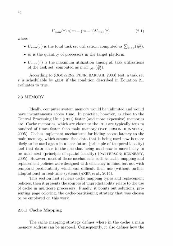
52
Usum(τ) 6 m− (m− 1)Umax(τ) (2.1)
where
• Usum(τ) is the total task set utilization, computed as∑τi∈τ (EiTi ).
• m is the quantity of processors in the target platform.
• Umax(τ) is the maximum utilization among all task utilizationsof the task set, computed as maxτi∈τ (EiTi ).
According to (GOOSSENS; FUNK; BARUAH, 2003) test, a task setτ is schedulable by gEDF if the condition described in Equation 2.1evaluates to true.
2.3 MEMORY
Ideally, computer system memory would be unlimited and wouldhave instantaneous access time. In practice, however, as close to theCentral Processing Unit (CPU) faster (and more expensive) memoriesare. Cache memories, which are closer to the CPU are typically tens tohundred of times faster than main memory (PATTERSON; HENNESSY,2005). Caches implement mechanisms for hiding access latency to themain memory, which assume that data that is being used now is morelikely to be used again in a near future (principle of temporal locality)and that data close to the one that being used now is more likely tobe used next (principle of spatial locality) (PATTERSON; HENNESSY,2005). However, most of these mechanisms such as cache mapping andreplacement policies were designed with efficiency in mind but not withtemporal predictability which can difficult their use (without furtheradaptations) in real-time systems (AXER et al., 2014).
This section first reviews cache mapping types and replacementpolicies, then it presents the sources of unpredictability relate to the useof cache in multicore processors. Finally, it points out solutions, pre-senting page coloring, the cache-partitioning strategy that was chosento be employed on this work.
2.3.1 Cache Mapping
The cache mapping strategy defines where in the cache a mainmemory address can be mapped. Consequently, it also defines how the
53
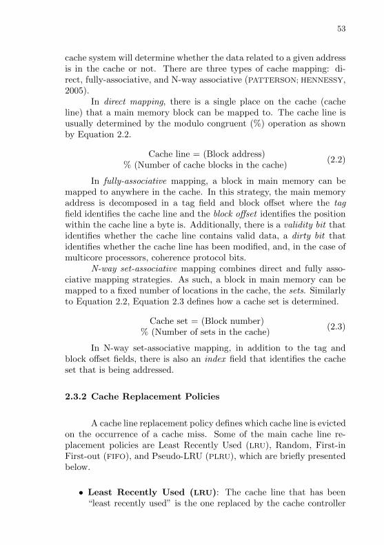
cache system will determine whether the data related to a given addressis in the cache or not. There are three types of cache mapping: di-rect, fully-associative, and N-way associative (PATTERSON; HENNESSY,2005).
In direct mapping, there is a single place on the cache (cacheline) that a main memory block can be mapped to. The cache line isusually determined by the modulo congruent (%) operation as shownby Equation 2.2.
Cache line = (Block address)% (Number of cache blocks in the cache)
(2.2)
In fully-associative mapping, a block in main memory can bemapped to anywhere in the cache. In this strategy, the main memoryaddress is decomposed in a tag field and block offset where the tagfield identifies the cache line and the block offset identifies the positionwithin the cache line a byte is. Additionally, there is a validity bit thatidentifies whether the cache line contains valid data, a dirty bit thatidentifies whether the cache line has been modified, and, in the case ofmulticore processors, coherence protocol bits.
N-way set-associative mapping combines direct and fully asso-ciative mapping strategies. As such, a block in main memory can bemapped to a fixed number of locations in the cache, the sets. Similarlyto Equation 2.2, Equation 2.3 defines how a cache set is determined.
Cache set = (Block number)% (Number of sets in the cache)
(2.3)
In N-way set-associative mapping, in addition to the tag andblock offset fields, there is also an index field that identifies the cacheset that is being addressed.
2.3.2 Cache Replacement Policies
A cache line replacement policy defines which cache line is evictedon the occurrence of a cache miss. Some of the main cache line re-placement policies are Least Recently Used (LRU), Random, First-inFirst-out (FIFO), and Pseudo-LRU (PLRU), which are briefly presentedbelow.
• Least Recently Used (LRU): The cache line that has been“least recently used” is the one replaced by the cache controller
54
(AL-ZOUBI; MILENKOVIC; MILENKOVIC, 2004).
• Random: Chooses the cache line to be replaced randomly fromall cache lines in the set (AL-ZOUBI; MILENKOVIC; MILENKOVIC,2004).
• FIFO: Replaces the cache lines in a sequential order, which afterthe first round, will replace the oldest line in the set. Each cacheset has a circular counter which points to the next cache lineto be replaced and the counter is updated on every cache miss(AL-ZOUBI; MILENKOVIC; MILENKOVIC, 2004).
• PLRU: Employs approximations of the LRU mechanism to speedup operations and reduce the complexity of implementation. Dueto approximations, the least recently accessed cache line is not al-ways the location to be replaced. There are several different meth-ods to implement PLRU. Two examples are the Most RecentlyUsed (MRU)-based Pseudo-LRU (PLRUm) and the Tree-basedPseudo-LRU (PLRUt). See (AL-ZOUBI; MILENKOVIC; MILENKOVIC,2004) for an explanation of these two methods.
Distinct cache line replacement policies have different predictabil-ity. Axer et al. have compared the four aforementioned cache policies,according to predictability (AXER et al., 2014). Before present theirfindings, a definition of cache predictability is presented. The source ofunpredictability in caches is the state of the cache (formed by the valuesin the cache) at the moment it start to perform a sequence of memoryaccesses. On one hand, an unpredictable cache line replacement pol-icy will present a completely distinct number of deadline misses for thesame sequence of memory accesses, depending on the cache initial state.On the other hand, a complete predictable cache line replacement policywill present the same number of deadline misses every time it performsa given sequence of memory access regardless of the initial state of thecache. Equation 2.4 defines State-Induced Cache Predictability (SICPr)that is a measure of how predictable a cache replacement policy is.
SICPrp(n) := minq1,q2∈Qp
mins∈Bn
Mp(q1, s)
Mp(q2, s)(2.4)
Where:
• p is the cache replacement policy;
• n is the length of a sequence of memory accesses;

55
Table 1: limn→∞ SICPrp(n) for different replacement policies (AXER
et al., 2014).
2 3 4 5 6 7 8
LRU 1 1 1 1 1 1 1FIFO 1
213
14
15
16
17
18
PLRU 1 - 0 - - - 0RANDOM 0 0 0 0 0 0 0
• Qp is the set of cache states;
• Bn is the set of sequences of memory accesses of length n;
• Mp(q, s) number of misses of policy p accessing sequence s start-ing in cache state q.
The quotient given byMp(q1, s)Mp(q2, s)
in the Equation 2.4 works as a
quality measure for predictability. The minimal value of such a quo-tient will be obtained when the fraction’s numerator and denominatorrepresent the number of cache misses is the best case worst case sce-narios, respectively. If the number of cache misses in the worst caseis much bigger than the number of cache misses in the best case, suchquotient will be near to zero. Therefore, as close such quotient is from1 the better, in the case it is exactly 1 means that there is not differencein the number of misses in the worst and best case and the policy istotally predictable. As a consequence, SICPrp(n) is one value over theinterval [0, 1] and as close to 1, more predictable the cache replacementpolicy is.
Reineke and Grund have studied the limn→∞ SICPrp(n) thatinvestigates the behavior of cache replacement policies when the se-quence of memory access tends to infinite. Their tool named “Relacs”can compute limn→∞ SICPrp(n) for several cache replacement policies(REINEKE; GRUND, 2013). Table 1 present the results for LRU, FIFO,PLRU and random policies with associativities ranging from 2 to 8.
As the table indicates, LRU is the optimal policy and, therefore,the more robust to cache state. FIFO and PLRU are much more sensitiveto their state than LRU. Depending on its state, FIFO(k) may have upto k times as many misses. PLRU is only defined for powers of two. Atassociativity 2, PLRU and LRU coincide. In PLRU, for greater associa-tivities, the number of misses incurred by a sequence s starting in state

56
q1 cannot be bounded by the number of misses incurred by the samesequence s starting in another state q2 . For a truly random replace-ment, the state-induced cache predictability is 0 for all associativities(AXER et al., 2014).
2.3.3 Types of Interference
According to Gracioli, cache interference can be classified inthree types regarding their cause: intra-task, intra-core, and inter-core(GRACIOLI, 2014).
In intra-task interference a task evicts its own cache lines. Thatcan occur whenever two memory entries in the working set of a taskare mapped in the same cache set. One reason for that to happen ishaving the working set of a task larger than a specific cache level. Suchkind of interference also happens in single-core processors.
In intra-core interference, a task evicts cache lines from another(preempted) task. Intra-core interference, in this case, is also an inter-task interference caused whenever a running task evicts cached datafrom a preempted task. As a consequence, the preempted task willsuffer cache misses and an increase in its memory access time as soonit is rescheduled.
In inter-core interference, which is also a kind of inter-task in-terference, tasks running in different cores access the same cache lineon the shared level of cache. One task writes on the shared cache blockand the invalidation-based coherence algorithm causes an invalidationto establish ownership of that block. Then, another task attempts toread a modified word in that cache block, a miss occurs and the resul-tant block is transferred.
A consequence of time unpredictability caused by cache interfer-ence on real-time systems is the increasing of the WCET that becomesmore pessimistic which, in some cases, make the system implementa-tion impracticable (GRACIOLI, 2014; WILHELM et al., 2008). One cansuggest to disable the cache to eliminate the sources of unpredictabilityassociated with them. However, direct access to main memory wouldalso increase the WCET making it prohibitive in some cases. WCET
are much better with caches than without, even if neither data norinstructions are accessed twice (LIEDTKE; HAERTIG; HOHMUTH, 1997).
Therefore, instead of eliminating caches, two kinds of solutionshave been explored to make the use of cache more predictable for theiruse in real-time systems: cache locking and cache partitioning. Cache
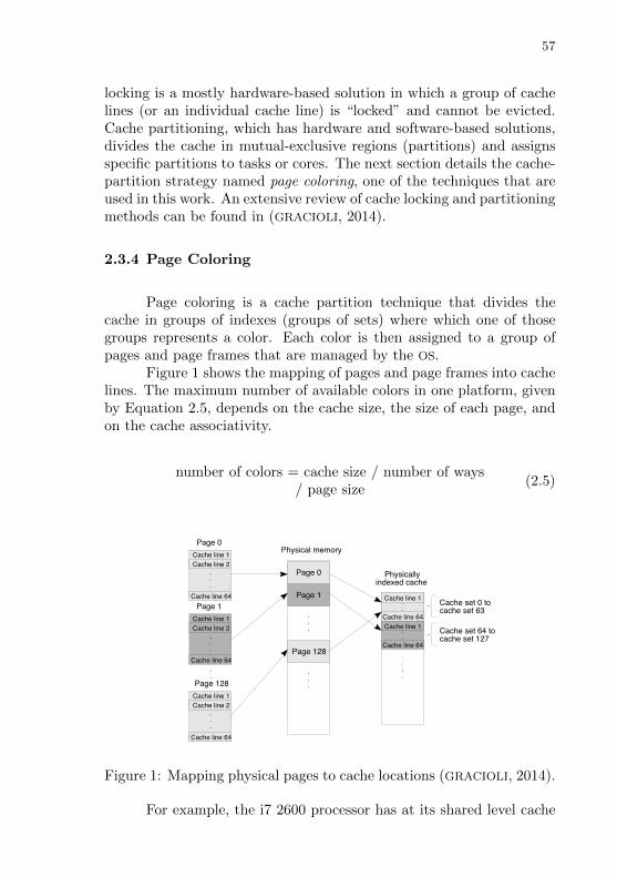
57
locking is a mostly hardware-based solution in which a group of cachelines (or an individual cache line) is “locked” and cannot be evicted.Cache partitioning, which has hardware and software-based solutions,divides the cache in mutual-exclusive regions (partitions) and assignsspecific partitions to tasks or cores. The next section details the cache-partition strategy named page coloring, one of the techniques that areused in this work. An extensive review of cache locking and partitioningmethods can be found in (GRACIOLI, 2014).
2.3.4 Page Coloring
Page coloring is a cache partition technique that divides thecache in groups of indexes (groups of sets) where which one of thosegroups represents a color. Each color is then assigned to a group ofpages and page frames that are managed by the OS.
Figure 1 shows the mapping of pages and page frames into cachelines. The maximum number of available colors in one platform, givenby Equation 2.5, depends on the cache size, the size of each page, andon the cache associativity.
number of colors = cache size / number of ways/ page size
(2.5)
Cache line 1
Cache line 2...
Cache line 64
Cache line 1
Cache line 2...
Cache line 64
Page 0
Page 1
.
.
Cache line 1
Cache line 2...
Cache line 64
Page 128
Physical memory
.
.
.
Page 0
Page 1
Page 128
Physicallyindexed cache
.
.
Cache line 64
Cache line 1
.
.
Cache line 64
Cache line 1
.
.
.
Cache set 0 tocache set 63
Cache set 64 tocache set 127
.
.
.
Figure 1: Mapping physical pages to cache locations (GRACIOLI, 2014).
For example, the i7 2600 processor has at its shared level cache

58
(L3) a 8MB 16 way associative cache. Taking into account a page sizeof 4KB, according to Equation 2.5 such processor will present 128 colorsavailable for page coloring (8M / 16 / 4K).
As can be noticed in Figure 1, a page color is given to every pageand, after the maximum number of available color is reach, the nextpage (e.g. page 128 in the figure) will get the color 0 again. Each linethat composes a color belongs to a distinct cache set and distinct colorswill use distinct groups of cache sets, therefore pages from differentcolors will not evict cache lines from one another.
2.3.5 Virtualization
Memory virtualization is usually performed by providing virtualMMU or virtualizing MMU’s page tables. The employed strategy isusually architecture-dependent and depends on whether para or full-virtualization is being employed and whether architectural support forvirtualization is available.
In the case of para-virtualization, where the guest OS kernelis modified, one strategy usually employed is to replace direct MMUinteraction by hypercalls that perform the MMU update. For para-virtualization the Xen, hypervisor uses the concept of pseudo-physicalmemory (CHISNALL, 2007). In such approach, the application at theguest OS uses virtual memory, guest OS uses pseudo-physical memory,and hypervisor uses machine memory. The guest OS uses the pseudo-physical memory to perform memory operations. From the point ofview of the guest OS, the “physical” memory is identified by Guest PageFrame Number (GPFN)s. GPFN have per-domain meaning and identifypseudo-physical memory frames. The actual physical memory is iden-tified by Machine Frame Number (MFN)s that have the same meaningwithin the hypervisor or any domain. The use of pseudo-physical mem-ory frames enables the guest OS have a contiguous vision of page frames,even if the underlying machine page frames are sparsely allocated andin any order. The hypervisor maintains a machine-to-pseudo-physicaltable which records the mapping from machine page frames to pseudo-physical ones. The domain maintains a pseudo-physical-to-machinetable which performs the inverse mapping.
In the case of full-virtualization, the guest OS perform memorymanagement as if it was not virtualized (i.e. it is not aware of the vir-tualization). To accomplish that, the hypervisor must somehow trapall pages updates and translate them in such a way the principle of re-

59
source control (POPEK; GOLDBERG, 1974) is not violated. One strategyfor page table virtualization is known as Shadow Page Table (SPT). InSPT, the guest has a copy of the page table in a set of pages marked bythe hypervisor as read-only. When the guest updates these, it causes afault, and control is transferred to the hypervisor. The hypervisor thentranslates the updates into a real page table and continues. SPT canbe aided by architectural support for virtualization as it is provided byIntel VT-x and AMD-V x86 extensions. While using SPT in the caseof the x86 (IA32) architecture, whenever the guest attempts to updatethe CR3 register, or modify the page tables, the CPU traps into thehypervisor and allows it to emulate the update.
Another virtualization strategy provided by architectural exten-sions is the Second Level Address Translation (SLAT). The SLAT imple-mentation of Intel is known as Extended Page Table (EPT) and AMD’sis known as Rapid Virtualization Indexing (RVI) (or Nested Page Ta-ble (NPT)). SLAT adds a higher level to the page table. Each guestis allowed to manipulate CR3 directly; however, the semantics of thisregister are modified. The guest sees a completely virtualized addressspace, and only sets up mappings within the range allocated by a hyper-visor. The hypervisor controls the MMU to manipulate the mappingsbut does not need to get involved while they are running as in software-managed SPT (CHISNALL, 2007).
2.4 I/O
This section reviews the usual approaches for interrupt handlingin non virtualized systems and explains how usually I/O and interruptsare virtualized.
2.4.1 Interrupt Handling
Traditionally, interrupt handling is performed by having an In-terrupt Servicing Routine (ISR) that is invoked every time an interruptoccurs to service. Servicing an interrupt usually combines a data trans-fer phase, followed by some processing and either actuation or event-signaling phases. As Figure 2 shows, for every interrupt occurrence,the interrupt reception, handling, and acknowledgment are executed inthe context of the running thread. In this way, ordinary ISRs “invade”the running thread, causing jitter and consuming time that, in some

60
cases, even compromise the job’s deadline.
Figure 2: Interrupt handling by an ISR.
Nevertheless, ordinary ISRs have the advantage of presentingvery low latency and a virtually constant servicing activation time.This characteristic is exploited by some RTOS, including Sloth (HOFER;
LOHMANN; SCHRODER-PREIKSCHAT, 2011), to ensure a predictable ex-ecution environment for embedded software. In Sloth, threads and in-terrupts are handled by an interrupt request arbitration unit. A threadcan be activated by a hardware interrupt or by another thread thatsets its IRQ bit. The hardware interrupt dispatching mechanism takesover the role of the scheduler. If needed, a task prologue can be exe-cuted during thread dispatching to handle context saving and restoring.Schemes like this fit well in some classes of embedded systems for whichevents can be fully modeled at design-time (such as OSEK (PORTAL,2008)). Each interrupt must be assigned a unique priority on the samescheme used by tasks and the latency of higher level interrupts or tasksmust be accounted in the execution time of lower priority ones. If twointerrupts happen at the same time, then the lowest priority one willexperience a latency that is much higher than that of the hardwareplatform. The possible accumulated delays quickly build up to unpre-dictable execution time for some tasks that are forced from a real-timecategory into a best-effort one (FOYO; MEJIA-ALVAREZ; NIZ, 2006).
A long-standing alternative to deal with the interference causedby ISRs on more complex systems, for which it is usually impossible tospecify a non-interfering model of interrupt triggering and task execu-tion, are Interrupt Service Threads (IST), shown in Figure 3. RTOS
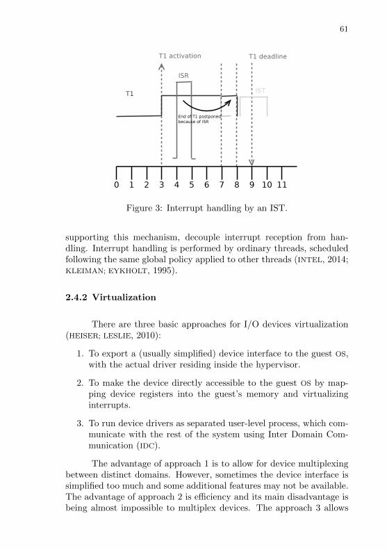
61
Figure 3: Interrupt handling by an IST.
supporting this mechanism, decouple interrupt reception from han-dling. Interrupt handling is performed by ordinary threads, scheduledfollowing the same global policy applied to other threads (INTEL, 2014;KLEIMAN; EYKHOLT, 1995).
2.4.2 Virtualization
There are three basic approaches for I/O devices virtualization(HEISER; LESLIE, 2010):
1. To export a (usually simplified) device interface to the guest OS,with the actual driver residing inside the hypervisor.
2. To make the device directly accessible to the guest OS by map-ping device registers into the guest’s memory and virtualizinginterrupts.
3. To run device drivers as separated user-level process, which com-municate with the rest of the system using Inter Domain Com-munication (IDC).
The advantage of approach 1 is to allow for device multiplexingbetween distinct domains. However, sometimes the device interface issimplified too much and some additional features may not be available.The advantage of approach 2 is efficiency and its main disadvantage isbeing almost impossible to multiplex devices. The approach 3 allows
62
for device multiplexing with the cost of additional context switches toimplement IDC.
In the case of para-virtualization Xen exports abstract deviceinterfaces to the guest OS. For example, instead of an SCSI deviceand an IDE device, an abstract block device that supports only twooperations (read and write) is exported. Xen employs a split devicedriver model where the front end of the device driver lies at a DomainU and the back end of the device driver lies at Domain 0. Events canbe used for communicating between device driver front and back ends.The front end will send to the back end requests events and the back endwill send to the front end response events. Additionally, I/O ring bufferusing shared memory can used for front and back end communicationin the case polling is employed. Alternatively, Xen can perform deviceemulation in the case of full-virtualization and unmodified guest OSses.For advertising device drivers to others domains, Domain 0 can use theXenStore data structure. XenStore is a tree-like data structure thatthe guest OS can transverse in order to discover device drivers theywish to use (CHISNALL, 2007).
In the case of full-virtualization hypervisors can use architecturalextensions such as Input/Output Memory Management Unit (IOMMU).Similarly to MMUs, devices initiate a DMA operation providing a vir-tual address (even not being aware the address is virtual), rather thana physical one, and the IOMMU translates the address into a physicaladdress. IOMMU can be used to prevent a device controlled by onedomain from interfering with another. Both AMD and Intel have pro-posed interfaces for IOMMU for x86 systems. Additionally, Intel (VT-d)provides for interrupt remapping. While working in conjunction withVT-x, VT-d can be used to assign interrupts to a virtual, rather thanphysical, CPU. Each interrupt is uniquely identified by its interruptnumber and originator ID (derived from the Peripheral Component In-terconnect (PCI) device ID) used to generate a mapping to a virtualCPU number.
63
3 RELATED WORK
This chapter presents the related work regarding aspects of tem-poral interference. Section 3.1 reviews works that focus mainly onmodeling temporal interference, including the computation of resourcesinterfaces, allocation, and scheduling of guest OS task, VCPUs, PCPUs,and domains. Section 3.2 reviews techniques used for deciding when thetemporal interference has reached a high level and some action needs tobe taken. Section 3.3 presents related work regarding how to deal withtemporal interference due to the interconnect contention. Section 3.4reviews what are the approaches for implementing time-deterministicinterrupt handling on virtualized platforms. Section 3.5 reviews thetechniques used for dealing with interference caused on the memory hi-erarchy, mainly at the LLC. By the end of each section, it is presentedthis work’s proposal to handle each one of these aspects.
3.1 INTERFERENCE MODELING
Gopalakrishnan et al. focus on Hard Real-time (HRT) commu-nication in multiple-hop bus-based networks (GOPALAKRISHNAN et al.,2004). The core of their idea is based on perceiving messages as schedu-lable elements that are periodically transmitted and have an associatedend-to-end deadline. Therefore, a message schedule is a route, and theauthors propose an off-line technique for synthesizing such routes.
Each message has a source host, a destination host, a period, atransmission time, and an end-to-end deadline. The end-to-end dead-line is the time the message has to reach its destination host. Thetransmission time divided by the message period defines the messageresource utilization requirement. A route (or path) consists of all hostsand all buses a message needs to follow in order to reach its destina-tion. For each message to be routed, is computed a set of effective paths(paths that contain neither cycles nor strict subset) that are capable ofmeeting the end-to-end deadline of the message.
The problem of routing generation is formulated as a Linear Pro-gramming (LP) problem, whose goal is to maximize the slack availableamong all buses while keeping some restrictions. The main restrictionis that for every message, for every effective path of that message, andfor every bus that belongs to that path, the message required utiliza-tion plus some slack must be smaller or equal to the bus utilization
64
bounds. That means each bus in the path must be able to fulfill thetransmission rate required by that fraction of the message. The vari-ables in the LP problem define a utilization factor (a value between0 and 1) that defines the fraction of the message resource utilizationrequirement for every bus that composes a message path. The solutionof the LP formulation assigns a value between 0 and 1 to every utiliza-tion factor showing how to route the fraction of the total traffic that amessage generates along a given path. Therefore, the solution to thelinear program is a solution to the multihop routing problem.
The off-line technique for synthesizing routes proposed by Gopalakr-ishnan et al. can deal with HRT requirements. It also is capable ofdealing with distinct resources, in a sense that each a host can rep-resent a distinct resource (e.g. memory controller, I/O device) that isconnected to an interconnect since each message can have a distinctdestination. However, knowing all messages and all message require-ments (which are derived from parameters such as message size andend-to-end deadline) beforehand might be unfeasible to obtain in prac-tice. Additionally, the model proposed by the authors assumes thatall hosts have equal capacity, that all messages are integer multiples ofpacket lengths, and that transmission times are synchronized.
Kim et al. propose a static estimation method for computing thewaiting time due to bus contention for every processing element. Themethod targets an iterative design space exploration approach wherethe developer can evaluate distinct buses topologies. The proposedmethod is based on queuing analysis, and it was developed for three busarbitration schemes: (i) fixed priority, (ii) round-robin, and (iii) two-level Time Division Multiplexed Access (TDMA) (KIM; IM; HA, 2005).
The method was evaluated according to accuracy while compar-ing it against trace-based simulation. The static estimation proposedby the authors is several orders of magnitude faster than a trace-drivensimulation while keeping the estimation error within 10% consistentlyin various communication architecture configurations.
While presenting an interesting method for static estimation,Kim et al. focus on design space exploration rather than using themodel to predict states of a real running system. Except for the num-ber of memory accesses (obtained from traces), everything is simulated(or statically-estimated). Furthermore, their method’s accuracy is com-pared with trace-driven simulation instead of with data collected on aphysical platform.
Noorshams et al. propose modeling I/O performance interferencein virtualized environments by using QPNs (NOORSHAMS et al., 2014).

65
An ordinary Petri Net (PN) consists of tokens, places, transitions, andarcs. Tokens lie in places. A transition can be fire if it is enabledconsuming the tokens from its input place and generating tokens to itsoutput place. Arcs connect places to transitions. QPNs extend PNs bydefining queuing places. A queuing place is a place that has a queuewhere the tokens wait to be serviced and a depository for tokens thathave completed their service at the queue. The time interval between atoken that has entered in the queue until the time the token goes to thedepository is known as servicing time. Additionally, a QPN is a typeof Generalized Stochastic Petri Net (GSPN) meaning that transitionscan either be immediate (firing at time zero after being enabled) ortimed, having a fire delay that follows an exponential probability dis-tribution. Furthermore, whenever more than one transition is enabledat the same time, the next transition to fire is randomly chosen basedon the transition firing weight (probability). Moreover, a QPN is alsoa Colored Petri Net (CPN), thus both tokens and transitions can havea color. Token colors enabled the tokens to be classified into groups,while transition colors can define different firing modes.
The approach has evaluated by using QPN to model a virtual-ized platform composed of the IBM System z mainframe and the IBMDS8700 storage system. Applications in IBM System z run inside Logi-cal Partitions , which is the equivalent to a domain. While IBM Systemz focuses on providing processor and memory resources, IBM DS8700focuses on providing storage. The evaluation was performed by run-ning the Flexible File System Benchmark (FFSB) that performs “read”and “write” operations of files while using a given number of threads.The authors have collected the response time for “read” and “write”operations and have built a single VM model using such values. Then,the authors have evaluated the model while simulating a scenario com-posed of two VMs. After that, the values obtained in the simulationwere compared to values obtained with measurements of practical ex-periments and the estimation error of the model was computed. Themean estimation error was of 8% for “read” operations and 11% forwrite operations.
The evaluated QPN model, shown in Figure 4 models “read” and“write” requests separately using token colors for distinguishing onetype of request from another. “Read” requests wait on the “ReadsWaiting” place, while write requests wait on the “Writes Waiting”palace. Such waiting places model requests that come from applica-tions running on the IBM System z mainframe. The servicing timeof “Reads Waiting” and “Writes Waiting” places is modeled using the
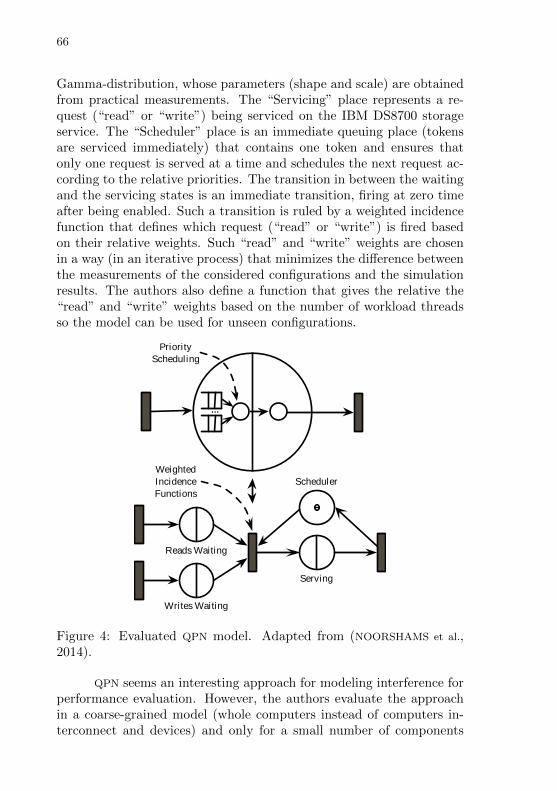
66
Gamma-distribution, whose parameters (shape and scale) are obtainedfrom practical measurements. The “Servicing” place represents a re-quest (“read” or “write”) being serviced on the IBM DS8700 storageservice. The “Scheduler” place is an immediate queuing place (tokensare serviced immediately) that contains one token and ensures thatonly one request is served at a time and schedules the next request ac-cording to the relative priorities. The transition in between the waitingand the servicing states is an immediate transition, firing at zero timeafter being enabled. Such a transition is ruled by a weighted incidencefunction that defines which request (“read” or “write”) is fired basedon their relative weights. Such “read” and “write” weights are chosenin a way (in an iterative process) that minimizes the difference betweenthe measurements of the considered configurations and the simulationresults. The authors also define a function that gives the relative the“read” and “write” weights based on the number of workload threadsso the model can be used for unseen configurations.
Serving
Reads Waiting
Scheduler
...
WeightedIncidenceFunctions
PriorityScheduling
Writes Waiting
Figure 4: Evaluated QPN model. Adapted from (NOORSHAMS et al.,2014).
QPN seems an interesting approach for modeling interference forperformance evaluation. However, the authors evaluate the approachin a coarse-grained model (whole computers instead of computers in-terconnect and devices) and only for a small number of components
67
(two computers only).Easwaran et al. introduce the MPR model that abstracts the
processing budget that a domain can collectively provide to a task setof a given domain. The models supported by their proposal are based onsporadic tasks τi = (Ti, Ci, Di) where Ti denotes the minimum releaseseparation between two jobs of the task, Ci denotes the WCET of a taskjob, and Di its relative deadline.
A MPR model is defined as µ = 〈Π,Θ,m′〉 where Π denotes thereplenishment period of the processing budget that the model collec-tively provides, which is denoted as Θ, given the model has m′ VCPUs.
A domain composed of a task set is schedulable by a MPR modelif, for all tasks of the domain, the model is capable of providing re-sources for the task worst case processing demand. The minimal re-source budget a MPR model can provide is specified by its Supply BoundFunction (SBF) that is defined according to Equation 3.1.
sbfµ(t) =
1st case : t′ < 0
0
2nd case : t′ > 0 ∧ x ∈ [1, y]⌊t′
Π
⌋Θ +max(0,m′x− (m′Π−Θ))
3rd case : t′ > 0 ∧ x /∈ [1, y]⌊t′
Π
⌋Θ +max(0,m′x− (m′Π−Θ))− (m′ − β)
(3.1)
where
• k = Θm′
• t′ = t− (Π− dke)
• α = bkc
• β = Θ−m′α
• x = (t′ −Πb t′
Πc)
• y = Π− α
The task worst case processing demand is defined by Equation3.2.
DEM(Ak +Dk,m′) = m′Ck +
n∑i=1
Ii,2 +∑
i:i∈L(m′−1)
(Ii,2 − Ii,2) (3.2)
68
where Dk − Ak is the time interval of duration t, and Ii and Ii arerelated to the total workload of the task during that interval.
Easwaran et al. describes an algorithm on how computing a MPR
model given a domain task set. The algorithm generates one task foreach VCPU in the model (m′) with processing budgets dimensioned toattend what shall be provided by the model (Θ).
Since there is no known algorithm for scheduling MPR models,Easwaran et al. also introduce an algorithm for converting a MPR
model to a task set. Finally, the whole system schedulability can beverified by using a scheduling algorithm such as gEDF for inter-domainscheduling.
Despite the prominent ideas on composite scheduling analysis onmulti-processed virtualized systems, Easwaran et al. do not investigatecache memory nor interconnect interferences.
Xu et al. introduce a method for computing the resource band-width requirement for each domain of a virtualized platform and forthe system as a whole (XU et al., 2013). The resource bandwidth is ex-pressed as the number of resource units (usually time) that are requiredeach given period. The authors extend the MPR model of Easwaran etal. (EASWARAN; SHIN; LEE, 2009) introducing the Deterministic Multi-processor Periodic Resource (DMPR) model. The idea of DMPR is thatevery domain will be composed of m full VCPUs and by one partialVCPU. A full VCPU is pinned to an exclusive PCPU so it will be alwaysavailable for executing guest OS tasks of the domain that it belongsto. A partial VCPU, on the other hand, shares one or more PCPUswith partial VCPUs of other domains. Therefore, a partial VCPU mightbe suspended and not be available at a given time interval. A partialVCPU is defined by a budget and period. The budget specifies howmany resources units the VCPU can provide to guest OS tasks. If theVCPU exhausts its budget within its period, the VCPU is suspended un-til the next period when its budget is replenished. VCPUs are scheduledby the hypervisor using clustered EDF (cEDF), with a cluster for eachfull VCPU (composed of one PCPU each) and a cluster with the remain-ing PCPUs (that are shared among the partial VCPUs of all domains).Within the domains, tasks are scheduled using gEDF. Tasks are speci-fied by their periods, WCET, and deadline. Combining period, WCET,and deadline of all tasks in the task set of the domain, a DMPR modelcan be computed for the domain. The model describes how many fullVCPUs the domain task set needs and what is the required bandwidthof the domain partial VCPU. Then, combining the models of all do-mains a DMPR model can be derived for the whole system. With that
69
information is possible to determine the minimal number of requiredPCPUs for scheduling the whole system.
First the authors present methods for computing a DMPR model(for the domain and for the system) taking into account an overhead-free scenario. After that, the events that can generate a Cache-RelatedPreemption or Migration Delay (CRPMD) are identified and two meth-ods are devised for computing DMPR models which are aware of thecache overhead: a task-centric approach and a hybrid approach. In theoverhead-free scenario a DMPR model for domain is feasible if and onlyif the demand of its task set is smaller or equal to what is suppliedby the domain. By summing the number of required full VCPUs ofeach domain and combining all partial VCPUs budgets of each domaina DMPR model for the whole system can be derived. Such model isfeasible if the number of PCPUs provided by the system is equal to thenumber of required PCPUs plus one.
In the paper, the authors take into account only private caches(i.e. a shared LLC cache is not taken into account) that could corre-spond to the inner cache levels (e.g. L1 or L2) of processors commonlyfound nowadays. Three kinds of events are related to CRPMD (i.e.events that will cause the eviction and further replacement of cachelines): (i) preemption of guest OS tasks within a domain, (ii) preemp-tion of VCPUs, and (iii) the completion of a VCPU (that occurs wheneverthe VCPU exhausts its budget). Based on these three events the task-centric approaches computes the maximum CRPMD each task of everydomain can suffer. The feasibility of the overhead-aware DMPR modelis computed by inflating the WCET of each task with the maximumCRPMD overhead and by using the same feasibility check used in theoverhead-free of the DMPR model.
The hybrid approach combines the task-centric approach withthe model-centric approach and it chooses the DMPR with the smallerminimal bandwidth between the two. In the model-centric approach,the WCET of each task is inflated with the overhead caused by tasks pre-emption only, as opposed to the task-centric approach that takes intoaccount also the preemption and completion events of VCPUs (namedVCPU stops events). In the model-centric approach, for each domain,the overhead caused by VCPU stops events is combined and subtractedfrom the resource supply of the domain resulting into what is calledeffective resource supply. The feasibility of the overhead-aware DMPR
model of a domain is computed by inflating the WCET of the domaintask set, by and using its effective resource supply, and by using thesame feasibility check used in the overhead-free of the DMPR model.
70
The authors have evaluated their DMPR modeling approach infour experiments. The first experiment compares DMPR with the MPR
and the authors show that for all employed task sets the DMPR mod-els require less resources then MPR models. The second and the thirdexperiments compare the hybrid and the task-centric DMPR computa-tion approaches. The second experiment evaluates the two approacheswhile changing the total task set utilization. The third experimentcompares how the two approaches perform for task sets with distinctsizes (number of tasks). In both experiments, the hybrid approach re-quires fewer resources than the task-centric approaches for most of thetask sets. The fourth experiment compares the hybrid and task-centricapproaches in theoretical and practical scenarios. For that the experi-ment chooses task sets that are unschedulable according to theory andin practice and measure the deadline miss ratio. The systems deployedfollowing the hybrid approach present a smaller deadline miss ratiothen the ones using the task-centric approach. The fourth experimentalso compares the overhead-free versions of MPR and DMPR in theoryand practice and show that task sets that are schedulable accordingto theory are not schedulable in practice scenarios, showing that bothmodels underestimate the CRPMD overhead.
While the approach proposed by the authors advances the anal-ysis of cache-related overhead in the scheduling of virtualized systems,it presents two main limitations. The first one is imposing that alldomains will have only one partial VCPU, all others VCPUs of everydomain need to have a dedicated PCPU each. The second limitationis that only private caches are investigated. The effects of cache-lineeviction caused by false sharing of a shared LLC are not taken intoaccount.
In the invited paper for ACM SIGBED Review of 2016, Phanet al., present the challenges for dealing with cache-related interferencein the context of virtualized systems where the LLC is shared amongthe PCPUs (PHAN; XU; LEE, 2016). The authors refer to virtualizedsystems as “two-level compositional systems”. Previously, Easwaran etal. have proposed methods for schedulability analysis of CPUs in thecontext of two-level compositional system: at the first level tasks arescheduled among VCPU and at the second level VCPUs are scheduledamong PCPUs (EASWARAN; SHIN; LEE, 2009). Easwaran et al. refer ascomponent a task set and its scheduling policy, which in virtualizationterminology can be denoted as a domain. Easwaran at al. have defineda method for computing how much resource a domain will need, whichthey refer to as “defining the interface of the component”. The interface

71
of all components can be further combined forming the interface ofthe whole system, which specifies how many physical resources (e.g.PCPUs) the system will be need for scheduling all task sets. In anotherwork, Xu et al. have extended their compositional analysis to deal withprivate caches only, including how to compute cache-aware componentinterfaces (XU et al., 2013). In ACM SIGBED paper, Phan et al. takeinto account CPUs, private, and shared LLC (PHAN; XU; LEE, 2016).First, the paper identifies the challenges that shared LLC brings tothe compositional schedulability analysis. Then, it delineates the ideaof cache scheduling. Finally, the paper delineates how cache-awarecomponent (and system) interfaces could be computed while using CPU
and cache scheduling.In the first part of the paper, the authors identify four main
challenges that shared LLC brings to the compositional schedulabilityanalysis: (i) concurrent cache accesses, (ii) cyclic dependency betweencomponents’ interfaces and tasks’ overheads, (iii) dynamic concurrentresource supply patterns, and (iv) interactions between the LLC andprivate caches. Regarding (i), since PCPUs access the LLC simultane-ously is difficult to estimate with precision when a cache miss will occur.In the worst-case, one must assume that every access to the LLC is acache miss, which is a very pessimistic assumption. Regarding (ii), oneof the key ideas of the compositional analysis is having independencebetween components in the sense they can be computed in isolation.However, it is not possible to know how often each VCPU of a domainwill be preempted if one does not have information about the VCPUsof other domains. Also it is not possible to know how often each VCPU
will exhaust its budget without knowing the VCPU budget (which is acyclic dependency). One solution is to define a VCPU period a priori,and make such information available to all other domains. The chal-lenge (iii), pointed out by the authors is not specific of cache sharingbut is related to PCPU sharing. A VCPU might not be available 100% ofthe time, therefore the resource supply changes dynamically accordingto how the VCPUs are scheduled. That must be taken into accountwhile computing the demand of each task and task set. Regarding (iv),the overhead scenarios are dependent on cache policies (e.g. inclusivevs. exclusive) implemented by each cache level.
In the second part of the paper, the authors present the ideaof treating cache as another schedulable dimension. To deal with thatproblem, the authors mention software-based approaches such as pagecoloring, and hardware-based approaches such as way-partitioning andIntel Cache Allocation Technology (CAS). The former approach (page
72
coloring), partitions the cache into disjoint groups of cache sets (thecache colors). The later approach (Intel CAS), provides the facility ofassigning portions of the LLC to a given core (specified by its cpuid).The authors point out that software approaches such as two-level page-coloring can present the disadvantage of making cache (re)allocationmore expensive since there is the management of colors at the host andguest levels. On the other hand, hardware based approaches despitebeing more efficient are limited to a smaller number of partitions whilecompared to software-based techniques. The authors point out that thedefinitive solution might be hybrid combining software and hardwareapproaches. The authors also mention static versus dynamic cachepartitioning and also suggest a hybrid approach. They point out as apotential solution to perform static allocation at the domain level anddynamic allocation at task level.
In the third part of the paper, the authors discuss extensionstowards cache-aware analysis for compositional systems with cachescheduling. Regarding the specification of components, the authorsidentify that might be necessary to specify the WCET of a task (orVCPU) as a function of the number of cache partition it has, insteadof using a single WCET value. They also propose use memory accesspattern and working set size, as a refinement to such a componentspecification as these two factors can greatly influence the overheads.
Being a position paper, that paper points out interesting chal-lenges but does not give definitive answer for any of them. Kim et al.(detailed in Section 3.5) already exploits the idea of defining tasks andVCPUs WCET as function of the number of cache partition (page colorsin the case) the task or VCPU has (KIM; RAJKUMAR, 2016). Addi-tionally, Cheng et al. (detailed in Section 3.2) also points out memoryaccess pattern and working set size as major factors regarding influenceon overheads (CHENG et al., 2016).
In the invited paper to ACM SIGBED, Lee et al., propose a sys-tem model that combines MC and compositional scheduling targetingopen systems (LEE et al., 2016). By open systems, the authors meanCyber-Physical System (CPS)s composed of components developed bydifferent vendors and later integrated to compose the whole system.The system model proposed by the authors encompasses two criticalitylevels: high (HI) and low (LO). Regarding the compositional aspect,a component can be composed of a set of components or a set of tasks,which suggests that the system model can be N-level. Regarding MC
in open systems, the authors propose two types of component isolationand the concept of component group. Components are weakly isolated
73
if HI-tasks in one component may affect the correctness of LO-tasksin other components. Components are strongly isolated if no tasks inone component may affect the correctness of tasks in other compo-nents. The authors propose that components designed in the samestandard (or vendors) to be grouped in the same group and that com-ponents designed by different standards to compose distinct groups.Additionally, the authors propose to use weak isolation within a groupand strong isolation between groups. The authors suggest extendingthe EDF-Virtual Deadline (EDF-VD) adding criticality-level, referredas task-mode (HI or LO). The envisioned algorithm is named EDF-Virtual Deadline-Task Mode (EDF-VD-TM). Finally, the authors pointout compositional methods for computing components’ interfaces andschedulability analysis of the proposed algorithm and the whole systemneeds to be further developed.
The system model proposed by Lee et al. is applicable for two-level virtualized systems. The inner level defines components composedof tasks, composing domains. The outer level defines a componentcomposed of domains, composing the whole system. Their work isstill at initial state and does not aim on targeting overhead caused bymemory nor I/O hierarchy.
3.1.1 Discussion
Table 2 summarizes the approaches presented by each relatedwork for modeling temporal interference. Column TD (Time-deterministic)identifies whether the approach focus on time determinism rather thanon performance. Column Inter. (Interconnect) identifies whether theapproach focus on I/O devices or interconnect. Column Mem. (Mem-ory) identifies whether the approach focus on memory hierarchy. Col-umn MC (Mixed-Criticality) identifies whether the approach supportsfor mixed-criticality. Column MP (Multiprocessor) identifies whetherthe approach deals with multiprocessing. Column Virt. (Virtualiza-tion) identifies whether the approach focus on virtualized systems.
Gopalakrishnan et al. focus on time-determinism and intercon-nect, proposing scheduling periodic messages among a bus hierarchy un-til the message reaches its destination (GOPALAKRISHNAN et al., 2004).In despite of the work of Gopalakrishnan et al. did not exploit that,messages period could potentially be related to transaction rate of I/O
devices and the presented interconnect network could be used to modelthe interconnect of physical machines. Their work, however, does not

74
Table 2: Comparison of approaches for modeling temporal interference.
Work TD Inter. Mem. MC MP Virt.
(GOPALAKRISHNAN et al., 2004) X X(KIM; IM; HA, 2005) X(NOORSHAMS et al., 2014) X X(EASWARAN; SHIN; LEE, 2009) X X X(XU et al., 2013) X X X X(PHAN; XU; LEE, 2016) X X X X(LEE et al., 2016) X X X XProposal X X X X X X
target memory hierarchy, nor mixed-criticality (all messages are HRT),nor multiprocessing, nor virtualization.
Kim et al. focus on interconnect of a physical machine anduses queuing theory to compute contention time of processing elements(KIM; IM; HA, 2005). Noorshams et al. goes further employing bothqueuing theory and PN to model the scheduling of requests (NOOR-
SHAMS et al., 2014). However, Kim and Noorshams focus mainly onperformance, instead of time-determinism. Noorshams et al. claims tofocus on virtualization since they use a virtualization platform as caseof study. However, they do not model two level of processing elements(physical and virtual) separately. They model the requests made byguest OS tasks on the physical level. Additionally, neither Kim norNoorshams focus on memory, MC, nor multiprocessing.
Easwaran et al. (EASWARAN; SHIN; LEE, 2009) focus on com-puting interface (computational requirements) of domains in a multi-processed virtualized system. Their work does not explore memory norinterconnect interference and targets a single criticality mode. How-ever, their seminal ideas on composite scheduling for multi-processedsystem were of high importance for works that have extended it suchas (XU et al., 2013) and the work of this thesis.
Xu et al., Phan et al., and Lee et al., focus on computing do-main interfaces and the whole system in a time-deterministic virtualizedplatform (XU et al., 2013), (PHAN; XU; LEE, 2016), (LEE et al., 2016). Ad-ditionally, Xu et al. takes into account the overhead caused by cachemisses on private caches. Phan et al. aims on extending Xu et al. inorder to take into account a shared LLC as well. Lee et al. does not fo-

75
cus on memory, instead it focus on components developed by differentvendors and that attend distinct mixed-criticality levels. Neither Xuet al., Phan et al., nor Lee et al focus on interconnect.
This work proposes employing queuing theory for computing thecontention time on physical interconnects. Such contention time is usedto compute domains and whole-system requirements in a similar waythat is proposed by Easwaran et al., Xu et al., Phan et al., and Leeet al. This work, however, also takes into account the interconnectand I/O devices (both in the host and guest levels). Additionally, asin Lee et al., this work focus on two level of criticality (HI and LO),computing two versions of the domain and system interfaces, one foreach criticality level.
3.2 INTERFERENCE DETECTION AND PREDICTION
Cheng et al. propose an approach for performance prediction onvirtualized multicore systems (CHENG et al., 2016). The authors claimtheir approach is contention-aware. However, “contention”, accordingto the authors, includes not only contention time waiting for accessan interconnect but also the time for repopulating evicted cache lines,and for accessing the main memory. The authors assume that the con-tention a VM suffers will cause the performance of that VM to degrade.Equation 3.3 (CHENG et al., 2016) defines the Performance Degrada-tion (PD) of a VM A (VM of interest) while executing simultaneouslywith another VM B.
PDAco−run/B =
CPIAco−run/B − CPIAalone
CPIAalone(3.3)
The metric used for performance measurement is Cycle per Instruction(CPI) of the VM, which is defined by the average CPI of all its VCPUs.
The proposed performance prediction approach uses two featuresfor performance prediction, VM Contention Sensitivity (VCS) and VMContention Intensity (VCI), which are defined in Equation 3.4 (CHENG
et al., 2016) and Equation 3.5 (CHENG et al., 2016), respectively.
V CSAbenchi =CPIAco−run/benchi − CPI
Aalone
CPIAalone(3.4)
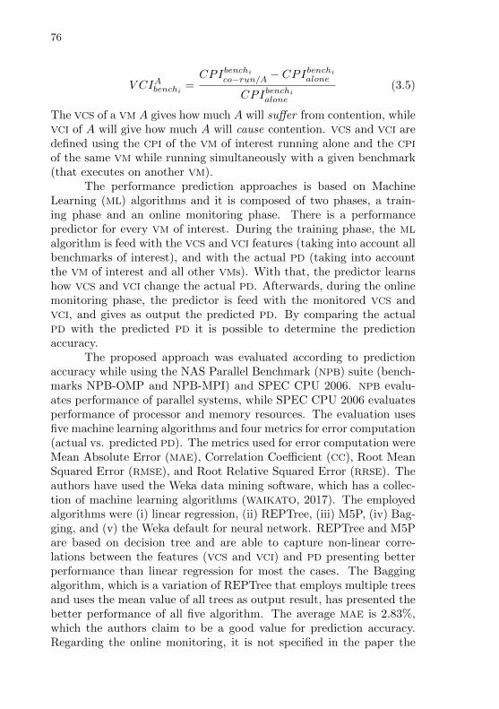
76
V CIAbenchi =CPIbenchico−run/A − CPI
benchialone
CPIbenchialone
(3.5)
The VCS of a VM A gives how much A will suffer from contention, whileVCI of A will give how much A will cause contention. VCS and VCI aredefined using the CPI of the VM of interest running alone and the CPI
of the same VM while running simultaneously with a given benchmark(that executes on another VM).
The performance prediction approaches is based on MachineLearning (ML) algorithms and it is composed of two phases, a train-ing phase and an online monitoring phase. There is a performancepredictor for every VM of interest. During the training phase, the ML
algorithm is feed with the VCS and VCI features (taking into account allbenchmarks of interest), and with the actual PD (taking into accountthe VM of interest and all other VMs). With that, the predictor learnshow VCS and VCI change the actual PD. Afterwards, during the onlinemonitoring phase, the predictor is feed with the monitored VCS andVCI, and gives as output the predicted PD. By comparing the actualPD with the predicted PD it is possible to determine the predictionaccuracy.
The proposed approach was evaluated according to predictionaccuracy while using the NAS Parallel Benchmark (NPB) suite (bench-marks NPB-OMP and NPB-MPI) and SPEC CPU 2006. NPB evalu-ates performance of parallel systems, while SPEC CPU 2006 evaluatesperformance of processor and memory resources. The evaluation usesfive machine learning algorithms and four metrics for error computation(actual vs. predicted PD). The metrics used for error computation wereMean Absolute Error (MAE), Correlation Coefficient (CC), Root MeanSquared Error (RMSE), and Root Relative Squared Error (RRSE). Theauthors have used the Weka data mining software, which has a collec-tion of machine learning algorithms (WAIKATO, 2017). The employedalgorithms were (i) linear regression, (ii) REPTree, (iii) M5P, (iv) Bag-ging, and (v) the Weka default for neural network. REPTree and M5Pare based on decision tree and are able to capture non-linear corre-lations between the features (VCS and VCI) and PD presenting betterperformance than linear regression for most the cases. The Baggingalgorithm, which is a variation of REPTree that employs multiple treesand uses the mean value of all trees as output result, has presented thebetter performance of all five algorithm. The average MAE is 2.83%,which the authors claim to be a good value for prediction accuracy.Regarding the online monitoring, it is not specified in the paper the

77
interval used for sampling CPI but the authors say that the generaloverhead of the monitoring was kept under 0.5% of CPU utilization.
While presenting interesting results, the approach presented byCheng et al. presents also some limitations. The paper does not focuson contention caused by I/O and network. It only focuses on contentionrelated to memory access. Besides that, the only metric used is CPI,which is mainly CPU-related. Memory related metrics such as cache ac-cesses, cache misses, time spent on memory interconnect are not used.Additionally, the paper does not mention how many PCPUs are usedon each experiment, thus it is not clear whether the employed bench-marks run on a single or more than one PCPU. The authors mentionthe possibility of updating the predictor online, retraining it with newvalues of VCS and VCI, whenever the prediction error trespass a giventhreshold. However, that is not explored in the paper. Another appli-cation mentioned but not explored is the use of the proposed approachfor designing a contention-aware VM schedule algorithm.
Scheffel et al. propose an approach for analyzing processes be-havior on multicore systems (SCHEFFEL; FRoHLICH, 2016). Their ap-proach uses a Bayesian network for building a specialist system that iscapable of telling, with a given probability, the type of the interferenceand the origin of the interference. By type of the interference, the au-thors mean whether the temporal interference is CPU bounded (causedby CPU intensive processes) or Cache-related (caused by processes thatcause LLC interference). By origin of interference, the authors meanwhether the temporal interference is caused by a process running (i)on the same CPU, (ii) on another CPU but on the same core, or (iii) onanother core. The distinction of CPU and core is made since a proces-sor based on the Intel hyperthreading technology is used. In that case,“same CPU” means the same hyperthread in the same core, and “an-other CPU on the same core” means another hyperthread on the samecore. The processor taken into account is of the Intel Core i7 family.Sharing the same core means sharing L1 and L2 caches. All cores sharethe L3 (the LLC).
The Bayesian network is built during a training phase where aprocess of interest that is both CPU and cache intensive runs in iso-lation during 10 seconds. After 10 seconds, an interference process(which causes either CPU or cache interference) is scheduled to run si-multaneously with the process of interest for another 40 seconds. Afterthose 40 seconds, the interference process is suspended and the processof interest runs until completion. During the training phase both theinputs and outputs of the specialist system are known. The inputs (or
78
features) are (i) the number of executed instructions, (ii) the numberof cache references, (iii) the number of cache-misses, whether there areother processes running on (iv) another core, (v) another CPU (but onthe same core), or (vi) within the same CPU. Such inputs where ob-tained using Hardware Performance Counters (HPC) implemented onthe processor’s Performance Monitoring Unit (PMU). The employedsampling rate was 200 ms. The outputs of the specialist system are (i)process(es) of interest running without interference, concurrent CPU-bounded process (causing CPU-related interference on the process ofinterest) (ii) running on the same CPU, (iii) running on another CPU
within the same core, (iv) running on another core, concurrent cache-intensive process (causing cache-related interference) (v) running onthe same CPU, (vi) running on another CPU within the same core, (vii)running on another core.
During the training phase the output is known since the con-current processes are executed in a controlled scenario. In fact, for thepaper experiments, all collected data is sampled in a controlled scenario(where the location and type of all process are known). The collecteddata is then divided (using the k-fold method) into training (1/6 of thesamples) and test (1/5 of the samples) data. By using this method, ispossible to compute the accuracy of the generated Bayesian networkthat, in the executed experiments, was of 98.56%.
The feature selection is manual and experimented-based. Forreaching an accuracy of 98.56%, the authors have employed the historyof the last two sampled number of instructions, and cache-references.Regarding instruction-related data, while comparing to Cheng et al.,the history of last two samples seams reasonable since Cheng et al. usesCPI, which already represents an average value.
3.2.1 Discussion
Table 3 summarizes the approaches presented by each relatedwork for detecting or predicting temporal interference. Column Inst.(Instructions) identifies whether the approach uses the number of ex-ecuted instructions during a period of time (or number of cycles) asinput for evaluation. Column Cache identifies whether the approachuses the number of cache references or the number of cache misses asinput for evaluation. Column Inter. (Interconnect) identifies whetherthe approach uses interconnect-related events as input for evaluation.Column MP (Multiprocessing) identifies whether the approach deals
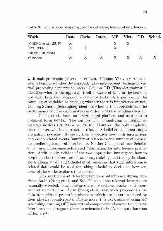
79
Table 3: Comparison of approaches for detecting temporal interference.
Work Inst. Cache Inter. MP Virt. TD Sched.
(CHENG et al., 2016) X X X(SCHEFFEL; X X XFROHLICH, 2016)
Proposal X X X X X X X
with multiprocessors (VCPUs or PCPUs). Column Virt. (Virtualiza-tion) identifies whether the approach takes into account readings of vir-tual processing elements counters. Column TD (Time-deterministic)identifies whether the approach itself is aware of time in the sense ofnot disturbing the temporal behavior of tasks while performing thesampling of variables or deciding whether there is interference or not.Column Sched. (Scheduling) identifies whether the approach uses theperformance counters information in order to take scheduling decision.
Cheng et al. focus on a virtualized platform and uses metricsobtained form VCPUs. The authors aim at analyzing contention atmemory devices (CHENG et al., 2016). However, the only employedmetric is CPI, which is instruction-related. Scheffel et al. do not targetvirtualized systems. However, their approach uses both instructionsand cache-related events (number of references and number of misses)for predicting temporal interference. Neither Cheng et al. nor Scheffelet al. uses interconnected-related information for interference predic-tion. Additionally, neither of the two approaches investigates how tokeep bounded the overhead of sampling, training, and taking decisions.Both Cheng et al. and Scheffel et al. envision that such interference-related data could be used for taking scheduling decisions, however,none of the works explores that point.
This work aims at detecting temporal interference during run-time. As in Cheng et al. and Scheffel et al., the relevant features aremanually selected. Such features are instructions, cache, and inter-connect related data. As in Cheng et al., this work proposes to usedata from virtual processing elements, which are in turn updated bytheir physical counterparts. Furthermore, this work aims at using MC
scheduling, turning OFF non-critical components whenever the currentinterference makes guest OS tasks exhausts their LO computation timewithin a job.

80
3.3 I/O
Missimer et al. present an approach for scheduling guest OS
tasks and guest-level I/O ISRs in the context of a mixed-criticality andvirtualized system (MISSIMER et al., 2016). The authors employ theLinux terminology referring to guest-level ISR as “bottom half” inter-rupt handler. The “top half” interrupt handler, on the other hand,represents the host-level and is handled by the hypervisor. Their ap-proach focuses on fixed-priority systems and uses Sporadic Server (SS)sfor scheduling guest OS tasks and Priority Inheritance Bandwidth-preserving Server (PIBS) for scheduling guest-level ISRs. There is noscheduling of VCPUs among PCPUs or virtual I/O devices among physi-cal I/O devices. Instead, all physical processing elements are partitionedamong domains (referred as sandbox ) statically.
A SS is defined by (C, T ), where C denotes a budget capacityand T is the server period. A SS can be implemented as a periodic taskthat servers sporadic guest OS tasks as long the server capacity is notempty. A PIBS is defined by U , which denotes utilization. A PIBS runson behalf of a SS and inherits both the priority and period of the SS.The system dynamics is the following. A guest OS task that wishes toperform an I/O operation makes such a request to the hypervisor andgets blocked waiting for the operation to complete. The hypervisor thenprograms the physical I/O device to perform the I/O operation. Whensuch an I/O operation completes its physical I/O device generates aninterrupt that is handled by the top half interrupt handler. The tophalf interrupt handler wakes the PIBS responsible for such interrupt.The PIBS handles the bottom half of the interrupt (e.g. by copyinginterrupt-related data from the host to the guest level) and wakes upthe guest OS task that is blocked waiting the I/O operation.
The authors approach combines SS and PIBS with Adaptive Mixed-Criticality (AMC) scheduling. In AMC scheduling system, both tasksand the whole system can have several criticality levels. In AMC, atask is defined as (Ti, Di, ~Ci, Li), where Ti represents the task period,Di represents the task deadline, Li represents the task criticality level,and ~Ci is a vector that represents the task computation time (one po-sition in the vector for each criticality level). The authors define twocriticality levels HI, which represents hi-criticality, and LO, which rep-resents low-criticality. Therefore, Li ∈ LO,HI. While applied to thesystem the criticality levels (also HI and LO) are referred as “modes”.
The authors extended SS to have a capacity vector ~C. In such a con-text, C(LO) denotes the server capacity while the system is in the LO
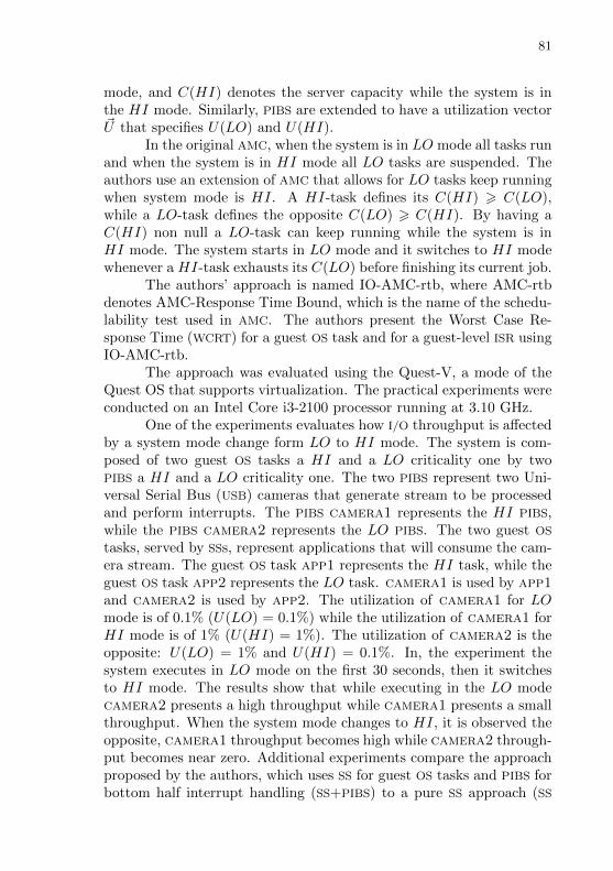
81
mode, and C(HI) denotes the server capacity while the system is inthe HI mode. Similarly, PIBS are extended to have a utilization vector~U that specifies U(LO) and U(HI).
In the original AMC, when the system is in LO mode all tasks runand when the system is in HI mode all LO tasks are suspended. Theauthors use an extension of AMC that allows for LO tasks keep runningwhen system mode is HI. A HI-task defines its C(HI) > C(LO),while a LO-task defines the opposite C(LO) > C(HI). By having aC(HI) non null a LO-task can keep running while the system is inHI mode. The system starts in LO mode and it switches to HI modewhenever a HI-task exhausts its C(LO) before finishing its current job.
The authors’ approach is named IO-AMC-rtb, where AMC-rtbdenotes AMC-Response Time Bound, which is the name of the schedu-lability test used in AMC. The authors present the Worst Case Re-sponse Time (WCRT) for a guest OS task and for a guest-level ISR usingIO-AMC-rtb.
The approach was evaluated using the Quest-V, a mode of theQuest OS that supports virtualization. The practical experiments wereconducted on an Intel Core i3-2100 processor running at 3.10 GHz.
One of the experiments evaluates how I/O throughput is affectedby a system mode change form LO to HI mode. The system is com-posed of two guest OS tasks a HI and a LO criticality one by twoPIBS a HI and a LO criticality one. The two PIBS represent two Uni-versal Serial Bus (USB) cameras that generate stream to be processedand perform interrupts. The PIBS camera1 represents the HI PIBS,while the PIBS camera2 represents the LO PIBS. The two guest OS
tasks, served by SSs, represent applications that will consume the cam-era stream. The guest OS task app1 represents the HI task, while theguest OS task app2 represents the LO task. camera1 is used by app1and camera2 is used by app2. The utilization of camera1 for LOmode is of 0.1% (U(LO) = 0.1%) while the utilization of camera1 forHI mode is of 1% (U(HI) = 1%). The utilization of camera2 is theopposite: U(LO) = 1% and U(HI) = 0.1%. In, the experiment thesystem executes in LO mode on the first 30 seconds, then it switchesto HI mode. The results show that while executing in the LO modecamera2 presents a high throughput while camera1 presents a smallthroughput. When the system mode changes to HI, it is observed theopposite, camera1 throughput becomes high while camera2 through-put becomes near zero. Additional experiments compare the approachproposed by the authors, which uses SS for guest OS tasks and PIBS forbottom half interrupt handling (SS+PIBS) to a pure SS approach (SS
82
used for both tasks and interrupt). Results show while using SS+PIBS,the application tasks complete their jobs in regular intervals. The pureSS approach, however, presented a higher jitter in the case of LO tasks.
While the approach innovates presenting how co-scheduling I/O
operations and tasks in a mixed-criticality system, it contains somelimitations. Because the approach performs a static partitioning ofPCPUs and physical I/O devices among the domains it does not dealwith the problem of shared physical processing elements. Additionally,the approach proposed by the authors does not intent to reduce orcontrol the interference caused by physical I/O devices it aims only atbeing aware of it. The PIBS approach for handling I/O devices solvesonly part of the problem allowing for I/O devices to be “scheduled”among tasks. However, it does not prevent an LO virtual I/O devicefrom receiving data (e.g. a virtual Network Interface Card (NIC)) thatcan cause contention on the interconnect even when the correspondentPIBS is not scheduled to run, ultimately affecting HI tasks.
Liu et al. presents a credit-based fairing scheduling algorithm forI/O virtualization named VCF. The idea of VCF is that every domaingets a number of I/O credits for executing I/O operations and thatthe hypervisor can dynamically redistribute such credits among thedomains. A domain that has more credits than it needs, can lendcredits to another domain that needs more credits (LIU; TONG; SHEN,2013).
VCF is based on the Xen structure of split device drivers whereeach driver is composed of a front-end that lies on a Domain U and bya back-end that lies on Domain 0. The guest OS running on a DomainU uses the front-end part of the driver to invoke I/O operations thatare delivered to the back-end part of the driver inside the Domain 0,which is the one that accesses the physical device and executes the I/O
operation. According to VCF, all Domains U receive I/O credits on eachtime interval ti. The initial distribution of credits if made accordingto the domain weight, higher the weight is, more credits it receives.After a t time still inside the time interval ti, an I/O monitor inside thehypervisor updates the number of allocated, consumed, and remainedcredits for every Domain U. It is assumed that during the interval ti,a Domain U will consume its credits uniformly. It is also assumed adomain will consume the number of credits it has consumed on the lasttime interval. Thus, is possible to estimate at time t how much credita Domain U will still need during ti. The number of remaining creditsin Domain U at time t is also taken into account. If is estimated int that Domain U will require more credits, the difference between the
83
credits the domain still needs and its remaining credits is borrowedfrom a bank of credit (named Bbank) inside the hypervisor. On theother hand, if the Domain U has at time t more credits it will need, theextra credits is deposited at Bbank to be lent to other domains. If thereis no credit to be lent and a domain has consumed all its I/O credits thedomain will need to wait until the next time interval when the creditsof all domains are replenished.
To evaluate VCF, the authors have conducted experiments usingthe httperf (MOSBERGER; JIN, 1998; MOSBERGER et al., 2017) bench-mark. On the experiments, Domains U act as clients making HTTPrequests. All Domains U, Domain 0 and Xen (version 4.1.2) are placedin the same physical machine, named PM1. Therefore, all DomainsU share the same physical NIC for making the HTTP requests. PM1is an Intel quad-core Xeon running at 2.40 GHz, equipped with 32GB RAM, and running the Ubuntu 12.04 64-bit Linux distributionas host OS. The same OS is used on the guest side. Another physi-cal machine, named PM2 has used as the HTTP server. PM2 is anIntel dual core running at 2.96 GHz, equipped with 2 GB RAM, andrunning Ubuntu 12.04. Three experiments were conducted, comparingthe original Xen scheduler (orig xen) to VCF. In all experiments, thevariable measured was the connection rate (number of connections persecond made with the server) of each domain, which the authors referto that as throughput. In all experiments, three Domains U were used.On the first experiment, all Domains U were set with the same weightand were evaluated to distinct HTTP request rates at the clients (Do-mains U). While using orig xen, throughput differs (up to 50% ofdifference) between Domains U. While using VCF Domains U presentsimilar throughput because VCF limits the request rate performed byeach Domain U. The second experiment, set distinct weight for all do-mains on the ratio 1:2:3, giving the highest weight to Domain 3 and thelowest weight to Domain 1. While using orig xen, domains presentsimilar throughput, since Xen discards such weight information. Whileusing VCF domains with a higher weight present a higher throughput.The third experiment, set the same weight for all domains but domainsperform HTTP requests using distinct rates using a 1:2:3 ratio. Whileusing orig xen, the throughput is related to the request rate. Whileusing VCF, the throughput is also proportional to the request rate butfollowing a limited variation imposed by the weight.
While a credit-based approach seems interesting for co-schedulingCPUs and I/O, the authors do not explain in details how I/O credits arespent. An example is given in the case of sending packets of known
84
size using the NIC. The size of the packet, which is known at the send-ing, is somehow co-related to the number of credits. However, it isnot explained how credits are decremented on receiving packets by theNIC, for example. The authors also do not describe what would be agood time interval for replenish credits (ti) neither when, during ti thecredits shall me monitored and redistributed (t). It is not describedhow the credit-based approach would work for multiple I/O devices,whether each domain would be a credit amount per device class of asingle credit amount for all devices.
Pellizzoni et al. propose an algorithm for computing the overalldelay suffered by a task due to interference caused by I/O peripheralsand an algorithm and infrastructure for coscheduling I/O transactionsand tasks in a Commercial off-the-shelf (COTS) platform (PELLIZZONI
et al., 2008).The authors propose an algorithm for computing an upper bound
on the cumulative delay suffered by a task due to fetches of evictedcache lines. Such cache lines are evicted due to peripheral transac-tions over a shared Front Side Bus (FSB). In order to compute thecumulative delay suffered by a task, the task control flow is dividedinto superblocks. Superblocks can include branches and loops but mustbe executed atomically. The cumulative delay is computed given theWCET of the superblock (obtained in the case there is no peripheral in-terference) and given the worst number of cache misses that can occurin that superblock. The proposed algorithm can give overly pessimisticresults, since it accounts for the worst case delay inflicted by all pe-ripherals in the execution time budget of each task. Additionally, theauthors propose a coscheduling algorithm for tasks and I/O and a sup-porting infrastructure for controlling I/O bus accesses. The goal of thecoscheduling is to maximize the amount of allowed peripheral trafficwhile guaranteeing all real-time tasks constraints. The infrastructureis composed of a Peripheral Gate (p-gate) and a Reservation Controller.The p-gate is a PCI/PCI eXtended (PCI-X) device that allows for control-ling peripheral access to the gate. The Reservation Controller controlsall p-gates and implements the coscheduling algorithm for tasks and I/O
in Field-programmable Gate Array (FPGA).Their proposal takes into account a mixed-criticality system sce-
nario, which is composed of safety critical tasks, mission critical tasks,and best effort or software real-time tasks. Safety critical tasks are HRT
tasks with high criticality such as flying control in the avionic domain.Mission critical tasks are also HRT tasks but have a lower criticality(when compared to safety critical). The authors propose to schedule
85
safety critical tasks blocking all I/O traffic except the one from periph-erals used by the task. For mission critical, the authors propose touse coscheduling of I/O and tasks. For best effort or software real-timetasks, the authors propose to let all p-gates open as long there is timefor it. The guaranteed real-time tasks (safety critical and mission criti-cal) are further scheduling according to a hard reservation mechanism,where the reservation for each task is equal to its time budget. Thatensures that a critical task will not miss its deadline as long as eachjob executes for no longer than the assigned budget.
The experiments for evaluating the proposal where conducted ona Intel Core2 CPU, using the Intel 975X system controller (chipset) andthe Reservation Controller implemented in the Xilinx ML505 board.
The first experiment, measured the increase in the executiontime of a task caused by peripheral interference. The experiment wascomposed of a traffic generator that produces write transactions to themain memory (and can vary the period and length of and transactions)and a task that generates a cache miss for each memory read. The taskallocates a memory buffer of double the size of the CPU level 2 cache(the LLC in the case), and then cyclically reads from the buffer, oneword for each 128-byte cache line. First they ran the task without thetraffic generator and measured execution time and number of cachemisses. Then, the traffic generator was turn on with maximum loadand they have measured an increase of 43.85% in execution time.
The second experiment evaluates an Moving Picture ExpertsGroup (MPEG) decoder that used hard reservation of resources andcould be seem as a mission critical HRT task. In this experiment wasalso used a higher priority task that preempts the MPEG decoder every1ms and replaces its cache contents. The code that executes within aperiod of the MPEG decoder was divided into 20 superblocks. For thatexperiment, it was measured the percentage of time that the p-gate isopen during the task reservation time. Regarding the experiment onthe MPEG decoder, the greedy algorithm allows for opening the p-gatesat 31.21% percent of the task reservation time and the predictive algo-rithm allows for opening at 36.65% of the time. The theoretical boundin this case is 40.85%.
The analysis of temporal interference caused by I/O peripheralsin real-time systems is essential in the embedded system scenario wherethe interaction with the environment is performed using I/O devices andthe paper proposes a method for computing it.
The goal of the coscheduling algorithm “maximize the amountof allowed peripheral traffic while guaranteeing all real-time tasks con-

86
straints” does not seem to fit the Real-time (RT) scenario. RegardingRT, the goal should not be “to maximize peripheral access”. It shouldbe “to guarantee that all tasks use the I/O when they need it and tokeep a bounded interference”. A way to accomplished that is incorpo-rating the I/O time in the execution time of tasks and coscheduling I/O
and CPU using an RT policy.Despite being feasible, the p-gate and Resource Controller ap-
proach require for dedicated hardware including customized PCI de-vices for implementing the p-gate and FPGA for the Resource Controller,which might not be the reality of all COTS. Despite using an Intel Core2 in for the experiments, which is a dual core processor, the authors’experiments use such processor as a single core processor not runningtasks simultaneously. Additionally, the approach proposed by Pelliz-zoni et al. only targets physical I/O devices not focusing on virtualizedplatforms.
Reis et al. presents an approach for time-deterministic reconfigu-ration of components in an embedded system scenario (REIS; FRoHLICH;
JR., 2015), (REIS, 2016). Their approach executes a the reconfigurationprocedure only when the OS is in idle state and if the reconfigurationmanager evaluates that there is enough slack time for the reconfigura-tion to occur. Additionally, their approach suggest to power OFF com-ponents including I/O devices used by non-critical tasks and the non-critical tasks themselves in order to “create” more slack time for the re-configuration to occur. That takes into account that the reconfigurationis required by a task of higher priority then the non-critical tasks usingthe I/O devices. In order to power OFF components, their approachrelies on the method proposed by Hoeller et al. that proposes keep-ing a tree of component dependencies, including execution threads andI/O devices (HOELLER; WANNER; FRoHLICH, 2006), (HOELLER, 2007).Similarly to Pellizzoni’s approach, powering OFF components also re-stricts the access that I/O devices have on the interconnect, managingthe contention time suffered by tasks. Furthermore, the powering OFFapproach does not require a dedicated hardware as the p-gate proposedby Pellizzoni et at. It only requires components to implement distinctoperation modes, including an OFF mode in which components ceasetheir operations. Similarly to Pellizzoni’s approach, Reis et al. do nottarget virtualized platforms.
Munch et al. present an approach for I/O virtualization, calledMulti-Processor I/O Virtualization (MPIOV), which focuses on mixed-criticality multiprocessed embedded real-time systems such as avionics(MuNCH et al., 2015). The idea of MPIOV is to separate one application
87
interface from another by using Non Transparent Bridge (NTB)s. Anapplication interface can be either a Physical Function (PF) or VirtualFunction (VF) of a PCI Express (PCIe) device that supports Single-RootInput/Output Virtualization (SR-IOV). Each application partition (theequivalent to a domain) will be mapped to its own application interface.The processor core where the application partition is executing will in-terface with its own NTB. Domain separation is achieved by configuringits NTB to allow transactions (from and to) the application interfaceassigned to that domain and to block all others transactions. Sinceseparation is NTB-based, MPIOV does not require the use of IOMMU.
The MPIOV approach was evaluated in a multiprocessor setup byexecuting DMA transactions (reads and writes) issued by two distinctdomains. The experiments measured transference time and rate fordistinct transaction sizes. The authors claim that is no virtual differ-ence between the two application interfaces evaluated neither for readnor write operations. Then, the results of one application interfacewhere compared while using MPIOV and while not using it (NTBs con-figured to not separate one application interface bus address space fromanother). The authors show that both for transference time and trans-ference rate the performance degradation while using MPIOV is 0.01 %being negligible.
The MPIOV approach seems interesting since it allows domainseparation without requiring IOMMU. However, MPIOV was not eval-uated according to separation (e.g. reduction of the contention time).It was only evaluated according to performance (transference time andrate).
3.3.1 Discussion
Table 4 summarizes the approaches presented by each relatedwork for dealing with I/O virtualization. Column Inter. (Intercon-nect) identifies whether the approach uses some technique to restrictaccess from the devices to the interconnect. Column Sched. (Schedul-ing) identifies whether the approach performs either CPU and I/O de-vices co-scheduling or I/O-aware scheduling. Column QoS (Quality-of-Service (QoS)) identifies whether distinct domains can access virtualdevices with distinct QoS (e.g. distinct transmission rates in the case ofa virtual NIC) or with distinct priorities (e.g. whenever two domains tryto use a shared I/O device, the I/O device is hand over to the domainof higher priority). Column SW (Software-based) identifies whether
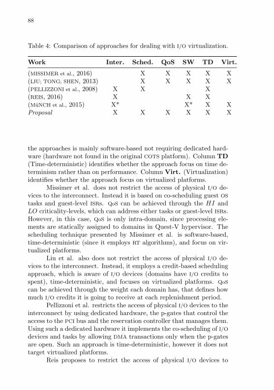
88
Table 4: Comparison of approaches for dealing with I/O virtualization.
Work Inter. Sched. QoS SW TD Virt.
(MISSIMER et al., 2016) X X X X X(LIU; TONG; SHEN, 2013) X X X X X(PELLIZZONI et al., 2008) X X X(REIS, 2016) X X X(MuNCH et al., 2015) X* X* X XProposal X X X X X X
the approaches is mainly software-based not requiring dedicated hard-ware (hardware not found in the original COTS platform). Column TD(Time-deterministic) identifies whether the approach focus on time de-terminism rather than on performance. Column Virt. (Virtualization)identifies whether the approach focus on virtualized platforms.
Missimer et al. does not restrict the access of physical I/O de-vices to the interconnect. Instead it is based on co-scheduling guest OS
tasks and guest-level ISRs. QoS can be achieved through the HI andLO criticality-levels, which can address either tasks or guest-level ISRs.However, in this case, QoS is only intra-domain, since processing ele-ments are statically assigned to domains in Quest-V hypervisor. Thescheduling technique presented by Missimer et al. is software-based,time-deterministic (since it employs RT algorithms), and focus on vir-tualized platforms.
Liu et al. also does not restrict the access of physical I/O de-vices to the interconnect. Instead, it employs a credit-based schedulingapproach, which is aware of I/O devices (domains have I/O credits tospent), time-deterministic, and focuses on virtualized platforms. QoS
can be achieved through the weight each domain has, that defines howmuch I/O credits it is going to receive at each replenishment period.
Pellizzoni et al. restricts the access of physical I/O devices to theinterconnect by using dedicated hardware, the p-gates that control theaccess to the PCI bus and the reservation controller that manages them.Using such a dedicated hardware it implements the co-scheduling of I/Odevices and tasks by allowing DMA transactions only when the p-gatesare open. Such an approach is time-deterministic, however it does nottarget virtualized platforms.
Reis proposes to restrict the access of physical I/O devices to
89
the interconnect by powering OFF such physical I/O devices, howeverit does not explores the co-scheduling of tasks and I/O devices. Itfocusing on time-deterministic operations in the context of componentsreconfiguration, and it does not focus on virtualized platforms.
Munch et al. does not restrict the access of physical I/O devicesto the interconnect in the sense of eliminating DMA transactions asin (PELLIZZONI et al., 2008) or (REIS, 2016). However, by configuringinterconnect bridges, it allows for a given domain (that is assigned to abridge) to filter transactions that do not use the VF designated to thatdomain. NTBs are available in COTS, therefore the MPIOV approach ismainly static. On the other hand, it relies on SR-IOV PCIe extension,not available in all physical I/O devices. Such an approach is time-deterministic and focuses virtualized platforms. However, it does notprovide QoS nor is integrated to a co-scheduling mechanism.
This work proposes powering OFF/ON physical I/O devices inorder to restrict their access to the interconnect. It proposes to use ded-icated VCPUs, named Input/Output Virtual Central Processing Unit(IOVCPU) for handling I/O access to the interconnect. An IOVCPU runson behalf of a virtual I/O device of a domain and can either retrieveDMA transaction data in the case of a “read” operation or to be usedfor issuing a new DMA transaction in the case of a “write” operation.IOVCPUs are co-scheduled with execution VCPUs following MC RT poli-cies. Following MC scheduling policies, IOVCPUs of non-critical domainsare suspended whenever the system is in HI criticality level, realizinga QoS control. In the practical point-of-view, IOVCPUs can also beused for ensuring that a domain cannot perform I/O operations usingparameters (e.g. bytes to be written) above what is agreed for thatdomain.
3.4 INTERRUPTS
Beckert et al. present an approach for reducing interrupt latencyon hypervisors (BECKERT et al., 2014). Interrupt latency, in this case,is defined by the elapsed time between the arrival of an interrupt in thehardware and the time it is started to be serviced in a specific hyper-visor domain, thus including the time to route the interrupt from thehypervisor to the guest OS in the domain. Usually in real-time hyper-visors, interrupts regarding one domain are serviced within the timeslot such domain has to execute. However, in the case an interruptarrives at the end of the time slot of a domain, it will be serviced only

90
when the domain is scheduled to run again, which in turns increaseinterrupt latency. The idea behind the approach proposed by Beckertet al. is to allow interrupts to be serviced in time slots of others do-mains as long their interference is kept to a maximum value that doesnot compromise the temporal isolation among partitions (domains).Their work employs the idea of “sufficient temporal independence” asoppose to total time isolation among domains. The idea is that thesystem is allowed to miss some deadlines as long the number of missesis bounded. A monitoring function, implemented at the hypervisor’sinterrupt mechanism evaluates at runtime whether an interrupt can behandled in the slot of another domain.
The approach of Beckert et al. is evaluated at a modified ver-sion of the uC/OS-MMU (of the uC family of microkernels) in anARM926ejs (ARMv5) processor running at 200MHz. The approachwas evaluated in three scenarios while generating 40% of interrupts atthe time of the appropriate domain and 60% outside the domain slot.There were generated a total of 15000 interrupts. In the first scenario,in which the monitoring is disabled the average latency was around2500us. In the second scenario, in which the monitoring is enabled, butsome interrupts are delayed (happened outside the slot of the domainand are handled only when the domain is scheduled again) the averagelatency was around 1200us (around 2 × of improvement compared tothe unmonitored case). In the third scenario, in which the monitoringis enabled and all interrupts can be handled either in the domain slot orusing the slot of others, the average domain was around 150us (around16 × of improvement compared to the unmonitored case). While theapproach has obtained promising results, it demands for an (off-line)analysis to ensure not only schedulability of tasks and interrupts withina partition but also to ensure that the interference caused by handlinginterrupts outside the partition does not break temporal independenceof such a partition. That, in turn, demands arrival functions for everyevent in the system.
Tu et al. propose an approach for delivering hardware interruptsto guest OSes named Direct Interrupt Delivery (DID). DID targets full-virtualization, not requiring modifications on the guest OS. The idea ofDID is to reduce the number of VM exits (avoiding involving the hyper-visor) while delivering interrupts. DID deliveries interrupts from SR-IOV
devices, virtual devices, and timers, directly to the target VM/domain.The DID approach relies on the Intel VT-x extensions, using a VirtualMachine Control Structure (VMCS) for each VM. Additionally, DID isimplemented on Linux Kernel-based Virtual Machine (KVM).
91
In the case of PCIe devices that support the SR-IOV extension, aVF of the device is assigned to a VM. In that way, that VM can issueoperations to the device directly (through the VF). Also via the VF,the device can interrupt the VM directly. In this case, the strategyemployed by DID is following. If the system is running on guest mode(according to the VT-x extensions) and an interrupt is generated by thedevice, the interrupt of the VF goes through the PCIe hierarchy, reachesthe IOMMU, and it is delivered to the Local APIC (LAPIC) of the targetVM. However, if the system is running on host mode, and an interruptis generated by the device, the hypervisor performs a virtual interruptinjection and then resumes the VM target of the interrupt. Such avirtual interrupt injection is performed by using a self InterprocessorInterrupt (IPI) where the PCPU sends an IPI to itself. By performingvirtual interrupt injection, which converts a virtual interrupt into aphysical one, all interrupts are forced to go through the Advanced Pe-ripheral Interrupt Controller (APIC). That avoids the priority inversionproblem that can happen when a lower-priority virtual interrupt mayoverride higher-priority directly delivered interrupt.
KVM abstracts each virtual device with a Virtual Device Thread(VDT). A VDT runs on host mode, checks for physical interrupts, trans-forms them into virtual device interrupts, and delivers them to the tar-get VM. In the case of virtual devices, the strategy employed by DID
is following. For all virtual devices, physical interrupts are convertedby the VDT into IPI-based virtual devices interrupts. Usually, VDTs runon a dedicate PCPU, separated from the VMs. Therefore, if the systemis running on guest mode, the VDT sends the virtual device interruptto the target VM by using an IPI. However, if the system is runningon host mode, the hypervisor accepts the IPI sent by the VDT on thebehalf of the VM, converts it into a virtual interrupt, and performs avirtual interrupt injection using a self IPI, as described previously.
In the case of timers interrupts, the strategy employed by DID isfollowing. A specific PCPU D is designated to store the timers set upby the hypervisor. When a VM M is scheduled to run on a PCPU C, thehypervisor install the timer(s) related to M on C LAPIC timer. WhenM is descheduled, its timer(s) are removed from C and installed on D.If the system is running on guest mode, a timer interrupt interruptsC directly. If the system is running on host mode, a timer interruptoccur onD, then the hypervisor creates a virtual interrupt and performsvirtual interrupt injection on M when M resumes its execution.
The DID approach was evaluated for several benchmarks whilerunning with DID and running without it (interrupts delivered by the

92
hypervisor). The Cyclictest benchmark, developed by the authors, eval-uates interrupt invocation latency, which is the time difference betweenthe interrupt arrival on the hypervisor and the time it start to beingserviced on the guest OS. The experiments show that, while using DID,the interrupt invocation latency decreases by 80% (from 14 us to 2.9us). Another benchmark used in the experiments, was the Iperf thatevaluates Transmission Control Protocol (TCP) throughput betweentwo machines. The results show that DID improves intra-machine TCP
throughput by up to 21%. Furthermore, the authors have evaluated DID
while using the Memcached, which is a key-value store server. As evalu-ation benchmark, the authors have emulated a “twitter-like” workload(140 characters). The results show that, while using DID, the through-put of a VM running Memcached was improved by a factor of 3 as aresult of reducing the VM exit rate from 97 K/s to less than 1 K/s.
While the experiments conducted using DID show promising re-sults, the approach targets performance instead of time-determinism.The authors claim that the approach does not need the Intel APICv(APIC virtualization). However, their approach relies on the Intel VT-xextensions, which are vendor-specific.
3.4.1 Discussion
Table 5 summarizes the approaches presented by each relatedwork for dealing with interrupt virtualization. Column TD (Time-deterministic) identifies whether the approach focus on time determin-ism (bound the interrupt handling time) rather than on performance.Column MC (Mixed-Criticality) identifies whether the approach sup-ports for mixed-criticality. Column SW (Software-based) identifieswhether the approaches is mainly software-based not requiring dedi-cated hardware (hardware not found in the original COTS platform).Column Virt. (Virtualization) identifies whether the approach focuson virtualized platforms.
Beckert et al. supports for time-determinism in the sense allinterrupt patterns are analyzed off-line and their impact on domainsis computed (BECKERT et al., 2014). However, their work toleratesbounded deadline losses, which is not suitable for HRT systems. Theirapproach uses a software-based implementation, changing the hypervi-sor to allow or deny interrupt interposing (the handling of the interruptin another domain slot). Their work only supports one criticality level.
Tu et al. focus on performance instead of time-determinism and
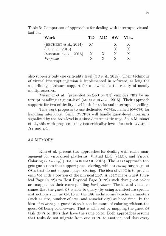
93
Table 5: Comparison of approaches for dealing with interrupts virtual-ization.
Work TD MC SW Virt.
(BECKERT et al., 2014) X* X X(TU et al., 2015) X X(MISSIMER et al., 2016) X X X XProposal X X X X
also supports only one criticality level (TU et al., 2015). Their techniqueof virtual interrupt injection is implemented in software, as long theunderlining hardware support for IPI, which is the reality of mostlymultiprocessors.
Missimer et al. (presented on Section 3.3) employs PIBS for in-terrupt handling at guest-level (MISSIMER et al., 2016). Their approachsupports for two criticality level both for tasks and interrupts handling.
This work proposes to use dedicated VCPUs, named IOVCPU forhandling interrupts. Such IOVCPUs will handle guest-level interruptssignalized by the host-level in a time-deterministic way. As in Missimeret al., this work proposes using two criticality levels for such IOVCPUs,HI and LO.
3.5 MEMORY
Kim et al. present two approaches for dealing with cache man-agement for virtualized platforms, Virtual LLC (vLLC), and VirtualColoring (vColoring) (KIM; RAJKUMAR, 2016). The vLLC approach tar-gets guest OSes that support page-coloring, while vColoring targets guestOSes that do not support page-coloring. The idea of vLLC is to provideeach VM with a portion of the physical LLC. A vLLC maps Guest Phys-ical Page (GPP)s to Host Physical Page (HPP)s such that guest colorsare mapped to their corresponding host colors. The idea of vLLC as-sumes that the guest OS is able to query (by using architecture specificinstructions such as CPUID in the x86 architecture) cache parameters(such as size, number of sets, and associativity) at boot time. In theidea of vColoring, a guest OS task can be aware of coloring without theguest OS being color-aware. That is achieved by mapping the guest OS
task GPPs to HPPs that have the same color. Both approaches assumethat tasks do not migrate from one VCPU to another, and that every
94
VCPU is pinned to a specific PCPU. Still, there can be more than oneVCPU competing for the same PCPU but only if these VCPUs belong todistinct VMs.
vLLC and vColoring were implemented in the Linux KVM hyper-visor. In the first set of experiments, the authors have evaluated vLLC
and vColoring in x86 and ARM platforms using a single guest OS taskand a single VM. The employed guest OSes were the Linux/RK (thatsupports page-coloring), a “vanilla” Linux (no page-coloring support),and MS Windows Embedded (also no page-coloring support). A guestOS task, named latency, traverses a randomly-ordered linked list (thetask’s working set), which has the size of half the LLC. The resultsshow that assigning more colors to the guest OS task reduces the taskexecution time. Such reduction on execution time reaches a plateauwhen the number of colors assigned to the task is enough to make thetask’s working set fit in the LLC entirely.
In the second set of experiments, only the vLLC approach wasevaluated and only in the x86 platform. The second set of experi-ments evaluated PARSEC benchmarks, except the dedup and facesimthat focus mainly on disk operations. In this set of experiments, eachPARSEC benchmark ran with three instances of the latency guest OS
task simultaneously. The idea was to use the latency guest OS taskto create interference on the benchmark and measure the benchmarkexecution time variation. Firstly, the benchmark and the instancesof latency ran in distinct VCPUs, then (on another execution) on thesame VCPU. When vLLC is enabled, all colors but one are assignedto the benchmark, while the instances of latency share the remainingone color. When vLLC is disabled, the benchmark and the instances oflatency share all colors. In the multiple VCPUs experiment, while vLLC
is disabled there is up to 30% of execution time increasing, versus upto 2% of execution increase time increasing while vLLC is enabled. Inthe single VCPU experiment, while vLLC is disabled the execution timeincreases up to 15%, versus unperceptive execution time increasing (formostly benchmarks) while vLLC is enabled.
In addition to the practical experiments, the authors have eval-uated their cache management scheme that defines how tasks are al-located to VCPUs, how colors are allocated to VCPUs, and how the re-plenishment budget of VCPUs is defined. Their approach is compared tosix other approaches that combine task-to-VCPU allocation and cache-to-task allocation heuristics. The employed task-to-VCPU allocationheuristics are Best-fit Decreasing (BFD), Worst-fit Decreasing (WFD),and First-fit Decreasing (FFD). The employed cache-to-task allocation
95
heuristics are Complete Cache Partitioning (CCP) (where each task hasa distinct set of colors), and Complete Cache Sharing (CCS) (where alltasks in the same VCPU share all colors). Therefore, the six approachesare, BFD+CCP, WFD+CCP, FFD+CCP, BFD+CCS, WFD+CCS,and FFD+CCS. Their approach outperforms six other approaches, re-sulting in a smaller VM total utilization.
While the approaches proposed by Kim et al. advance the state-of-the-art for cache management in virtualized systems, their approachespresent some limitations. The assumption of statically allocating eachguest OS task to a VCPU suggests that all tasks are single-threaded.By doing that, the authors can assume that a set of colors is assignedto a VCPU instead to the domain. Their approach also assumes thatevery VCPU is pinned to a specific PCPU. That, on the other hand,might be interesting since avoids eviction of cache lines due to VCPU
migration. Additionally, their experiments suggest that their approachwas not evaluated while executing two VMs (which distinct guest OSes)on the same host platform. With more then one VM, VCPUs wouldcompete for the same PCPUs potentially causing a higher number ofcache misses, especially while page-coloring was not employed.
Ma et al. present two approaches for dealing with cache man-agement for virtualized platforms, Cache Partitioning (CAP), and PageTable Prefetching (PTP) (MA et al., 2013). Both approaches were im-plemented in Linux KVM and evaluated while using an x86 host plat-form. In all considerations and for all evaluations, two VM instancesare taken into approach, one executing an RTOS and another executinga General Purpose Operating System (GPOS). The employed RTOS is aLinux patched with the Preempt-RT extension and focus on runningSoft Real-time (SRT) tasks. Each VM is pinned to a specific PCPU in adual-core processor.
CAP is based on page-coloring and performed statically. As KVM
is a hosted hypervisor, each VM runs as a process in the Linux host.Therefore, page-coloring has implemented by modifying the host oper-ating system’s memory page allocator.
PTP is a dynamical approach. It implements a periodic task thatruns on a dedicated core and its purpose is to make available on the LLC
the contents that are going to be needed by the RTOS. The PTP moduleruns on the core dedicated to the GPOS. Each time PTP module runson the host Linux, it gets the process id (PID) of the RTOS, locatesthe page table of the RTOS and reads it. Reading the page table ofthe RTOS will bring such pages to the LLC (and inner cache levels) ofthe core pinned to the GPOS. There is no mechanism to prevent the
96
guest OS tasks of the GPOS from evicting cache lines updated by PTP
while performing memory access. Still, the authors claim that PTP iseffective since it runs periodically.
The Cyclitest program, a Cache Load program, the CPU-SPEC-2006, and the Sysbench benchmarks were used for evaluating CAP andPTP approaches. The Cyclictest sets up a timer to run periodicallyand, each time it runs it reads a time stamp and computes the timedifference between the current and last sampled time stamp. Suchcomputed time interval (real interval) is compared to the time inter-val programmed on the timer (ideal interval). The difference betweenthe real internal and the ideal interval will give the local latency. ACache Load program, designed by the authors, runs on the GPOS andmoves data from one place to another in such way that it cases cacheinterference. The CPU-SPEC-2006 benchmark is composed of a set ofprograms that evaluate mostly CPU performance. The Sysbench is amemory intensive benchmark.
The approaches evaluation was conducted on an Intel i5 pro-cessor (two cores, four hyper threads) running at 2.67GHz and on acomputer equipped with 2 GB of main memory. The Intel i5 has 128KB of L1 cache, 1 MB of L2, and 8 MB of L3 (LLC) cache. The hostLinux kernel version was 2.6.33.4-rt 20. Each VM was pinned to run inone core and configured with 512 MB of main memory. Additionally,the authors have disabled USB support of the host machine to reducethe number of generated interrupts.
The CAP approach was evaluated on three experiments. Thefirst experiment executed Cyclictest on the RTOS and the Cache Loadprogram on the GPOS. CAP was set to give half of the LLC to eachVM. The experiment ran with and without (base case) CAP and thelatency of Cyclictest was measured. While using CAP, the maximumlatency is reduced by around 21% (222 us vs. 182 us). Additionally,CAP reduces the most frequent latency from a range from 66 to 85 us toa range from 31 to 70 us. The second experiment executed Cyclicteston the RTOS and the CPU-SPEC-2006 benchmark on the GPOS. It wasmeasured latency of Cyclictest and execution time of the benchmarkwhile changing the LLC ratio distribution. The latency measured byCyclictest decreases with the increasing of LLC allocated to the RTOS.It decreases about 40% when the ratio goes from 1/8 to 4/8 (half ofLLC allocated to the RTOS). Beyond that, the reduction on the la-tency is not expressive. From 4/8 to 7/8 the latency decreases about3% only. CPU-SPEC-2006 execution time increases when more LLC
is allocated to the RTOS but not much since the benchmark is mostly
97
CPU intensive. The third experiment executed Cyclictest on the RTOS
and the Sysbench benchmark on the GPOS. It was the execution timeof the benchmark (but not the latency of Cyclictest) while changingthe LLC ratio distribution. From 4/8 to 6/8 the execution time of thebenchmark increased by 3 times.
The PTP approach was evaluated on two experiments. The firstexperiment executed Cyclictest on the RTOS and the Cache Load pro-gram on the GPOS. The experiment ran with and without (base case)PTP and the latency of Cyclictest was measured. While using PTP,the maximum latency was reduced by around 56% (222 us vs. 142us). The second experiment ran Cyclictest on the RTOS and CPU-SPEC-2006 benchmark on the GPOS while changing the period thatPTP module executes. Increasing the period of PTP will cause the la-tency experienced by the RTOS to increase. For a PTP period of 200us, the maximum latency is 142 us. For a PTP period of 10 ms, themaximum latency is 209 us, which is near to the base case where noPTP is used (222 us). The performance of GPOS, the other hand, isinversely proportional to PTP period since PTP “steals” CPU cycles ofGPOS tasks.
In the presented experiments, while comparing PTP with CAP us-ing 4/8, PTP can reduce the maximum latency experienced by the RTOS
about 35% more than CAP. However, PTP caused higher performancedegradation on GPOS tasks.
While the CAP approach based on page-coloring is well acceptedand implemented by other works, the efficacy of the PTP approachseems questionable. There are no mechanisms to prevent the GPOS orthe RTOS from evicting cache lines updated by PTP while performingmemory accesses. Additionally, the choice of reading the page table ofthe RTOS instead of other data of the RTOS is not justified in the paper.Fetching page tables in any order is not the same as fetching the mostrecently used page tables or the most recently accessed addresses (thatis the Translation Lookaside Buffer (TLB) function). Furthermore, thecore that runs the RTOS has its own private TLB. The PTP approachwas not evaluated for more than one RTOS running simultaneously so itis not clear how it would scale. In fact, the approach was not evaluatedfor more then one RT guest OS task on that RTOS. Moreover, measuringtime-determinism only by using Cyclictest seems to be inadequate whileevaluating how much an RTOS is affected by cache interference sinceCyclictest does not perform memory operations. A better applicationto run on the RTOS would be running a program that reads and writesthe memory so it would be affected by cache interference directly.

98
Table 6: Comparison of approaches for dealing with memory virtual-ization.
Work Apr. TD Sched. Part. SW Virt.
(KIM; RAJKUMAR, 2016) vLLC X S X X(KIM; RAJKUMAR, 2016) vColoring X S X X(MA et al., 2013) CAP X S X X(MA et al., 2013) PTP X* X XProposal X X S X X
3.5.1 Discussion
Table 6 summarizes the approaches presented by each relatedwork for dealing with memory virtualization. Column Apr. (Ap-proach) identifies the approach name in the case of works that presentmore than one approach. Column TD (Time-deterministic) identifieswhether the approach focus on time determinism rather than on perfor-mance. Column Sched. (Scheduling) identifies whether the approachuses memory hierarchy information (e.g. number of cache misses) intoaccount for taking scheduling decisions. Column Part. (Partitioning)identifies the employed cache partitioning approach, which is eitherstatic (S), dynamic (D), or none (left in blank). A dynamic partitioningapproach in this case, means that a cache partition can be reassignedat runtime. Column SW (Software-based) identifies whether the ap-proaches is mainly software-based not requiring dedicated hardware(hardware not found in the original COTS platform). Column Virt.(Virtualization) identifies whether the approach focus on virtualizedplatforms.
Both vLLC and vColoring approaches proposed by Kim et al. aretime-deterministic, software-based and focus on virtualized systems.vLLC virtualizes the LLC statically, and vColoring performs page-coloringcache partitioning also statically. The CAP approach, proposed by Maet al. also uses page-coloring and performs the partitioning statically,and is time-deterministic. The PTP approach, on the other hand, doesnot perform partitioning, instead it employs a dedicated task on a ded-icated core to fetch page tables of the SRT domain periodically. Sincethere is no isolation between the LLC areas each domain is allowed touse, PTP is not time deterministic.
99
This work proposes on using a cache partitioning also based onpage-coloring, and also performed statically. It targets guests that areno color-aware thus the hypervisor handles the allocated colors. Thiswork envisions the color distribution by domain, VCPU, and guest OS
task as detailed in Chapter 4. During the modeling phase, HPC mea-sured events will be used for computing the required time budget ofguest OS tasks, and the whole system. Average values will be used forcomputing the requirements for the LO criticality level and worst-casevalues for computing the requirements for the HI criticality level.

100

101
4 PROPOSED TECHNIQUES USAGE
This chapter presents the first part of this work proposal. Itpresents a set of techniques and explains how they can be used forsupporting time-deterministic virtualization. It starts by focusing oninterference detection, then it investigates I/O aspects, interrupts, andmemory. For each one of these aspects, it presents the sources of tem-poral non-determinism that is usually modeled as some sort of interfer-ence. Also for each aspect, after showing the causes of the interference,it is explained a technique to mitigate the interference itself.
The main contribution of this chapter does not consist in thetechniques themselves, as many of them were introduced by relatedwork, but on their application in the time-deterministic virtualizationscenario.
4.1 DETECTING INTERFERENCE
Detecting interference can be divided in perceiving the existenceof the interference and deciding whether it is tolerable or “too high”to the point of disrupting the time requirements of critical tasks. Theinfrastructure for perceiving the interference depends on hardware andsoftware support.
Regarding hardware support, informational data can be providedper I/O device, per PCPU, per interconnect data, or no at all. An exam-ple of per I/O device data are the ones provided by statistic registers ofsome NICs that show the number of transmitted and received bytes. Anexample of per PCPU data are the core features provided by the pro-cessor PMU such as the number of accesses and misses to the fist level(L1) of cache, or the number of accesses and misses to the LLC causedby that processor. An example of per interconnect data are the uncorefeatures such as the number of uncore cycles that a given DRAM channelis occupied with read requests (INTEL, 2016b).
Regarding software support, interference is perceived per do-main, usually. In that case, it is desired to know which physical I/O de-vices and PCPUs are assigned to which domains. The Unified ModelingLanguage (UML) object diagram of Figure 5 illustrates the I/O devicesand CPUs a domain owns. As one can notice, the domain don’t own thephysical processing elements (physical I/O devices and PCPUs) directly.Instead, it owns the virtual counterpart of them: virtual processing

102
elements (virtual I/O devices and VCPUs). The virtual processing ele-ments, in turn, can be in use by the domain (active field set as true)or not in use by the domain (active field set as false).
Potentially, the assignment of virtual processing elements to adomain can occur before guest OS booting (e.g. at domain creation)or while the guest OS is running (which represents the hot plugging ofprocessing elements). This work takes into account the former caseonly since the dynamic creation of virtual processing elements wouldchange the load of their physical counterparts potentially disrupting thetime-requirements of critical domains. Similarly, the mapping betweenvirtual processing elements and physical processing elements can beperformed before guest OS booting or while the guest OS is running.A static (pre guest OS boot) mapping can be performed for physicalprocessing elements that are exclusive to a certain domain, which isthe case, for example, of PCPUs dedicated to a critical domain. Adynamic (while guest OS is running) mapping is performed for sharedphysical processing elements, for example, the assignment of a PCPU toa VCPU that occurs whenever the hypervisor schedules VCPUs. Anotherexample is a shared physical NIC: each domain will have its virtual NIC
(the virtual counterpart of the physical NIC) and the hypervisor willhandle which domain is using the physical NIC at a given time.
:Domain
:VDev_A
active : Boolean
: VDev_B
active : Boolean
:PDev_A :PDev_B
:VCPU
active : Boolean
:PCPU
Figure 5: Domain Resources Mapping.
In cases where there is no dedicated hardware support such asPMU events or per I/O device counters, alternative approaches can be
103
employed for interference detection. For example, having a profile ofthe execution time of virtual processing elements methods (previouslyobtained) and at guest OS runtime monitoring such execution times.The increasing of execution time could be perceived as interference.While perception of interference on the guest OS task granularity (in-stead of domains) is potentially interesting, it is usually unfeasible sinceit would require the hypervisor to be aware of such tasks complicatingits design and implementation.
Still regarding software support, the knowledge regarding inter-ference can be either from a global point-of-view or from a specificpoint-of-view. In the former case, one knows how much each domaincontributes to the general system load. In the latter case, one knowshow much some domains (usually the critical ones) are suffering frominterference caused by others. Regarding global knowledge, one could,for example, update for each virtual processing element how much itcontributes the general system load (e.g. how many bytes each virtualNIC has sent in the last minute) by using the resources mapping of Fig-ure 5. Regarding local knowledge, one could, for example, measure theLLC misses suffered by the PCPU that is in use by a critical domain.
Regardless of the technique used to perceive interference, oneneeds to judge whether the interference is acceptable or too high (risk-ing disrupting the time constraints of critical tasks). In general, twoapproaches can be employed: static thresholds or training techniques.Are examples of static thresholds:
• physical I/O device in use by a non-critical task is presenting ahigh throughput (N% of its maximum transmission rate)
• the cache miss ratio (misses/access) from the point-of-view of onePCPU used by a critical domain has increased more than N%
• the interconnect is operating at more than N% of its maximumtransmission rate
• a consecutive number of jobs of a critical task are presenting ajitter increasing of N% of the job execution time
Alternatively (or in conjunction with) using static thresholds, one canalso employ training techniques. Such techniques aim at learning whata normal behavior looks like and, afterwards, judging non-normal be-haviors as excessive interference. In the training phase critical do-mains are executed alone and the hypervisor collects data to define anormal behavior. Then, in a second moment, non-critical domains are
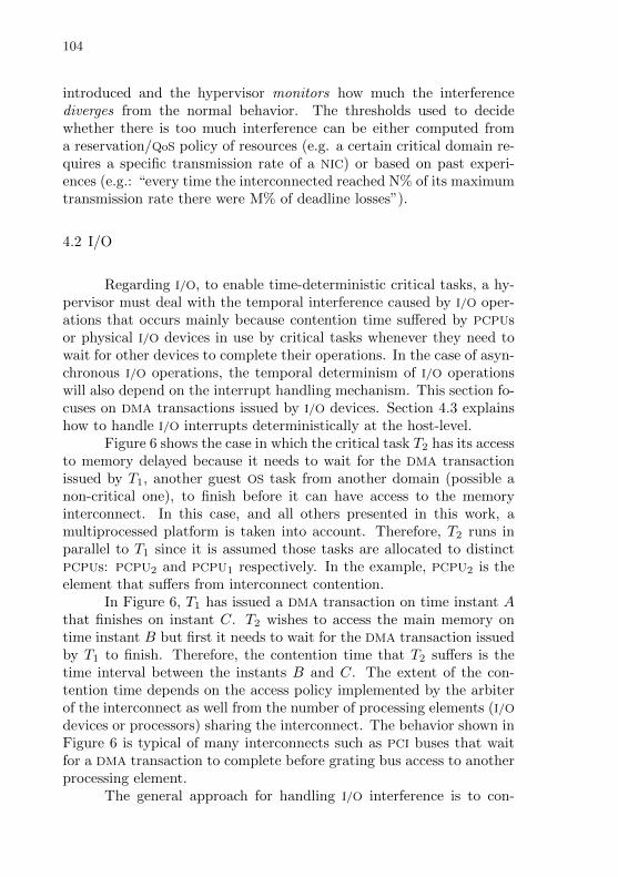
104
introduced and the hypervisor monitors how much the interferencediverges from the normal behavior. The thresholds used to decidewhether there is too much interference can be either computed froma reservation/QoS policy of resources (e.g. a certain critical domain re-quires a specific transmission rate of a NIC) or based on past experi-ences (e.g.: “every time the interconnected reached N% of its maximumtransmission rate there were M% of deadline losses”).
4.2 I/O
Regarding I/O, to enable time-deterministic critical tasks, a hy-pervisor must deal with the temporal interference caused by I/O oper-ations that occurs mainly because contention time suffered by PCPUsor physical I/O devices in use by critical tasks whenever they need towait for other devices to complete their operations. In the case of asyn-chronous I/O operations, the temporal determinism of I/O operationswill also depend on the interrupt handling mechanism. This section fo-cuses on DMA transactions issued by I/O devices. Section 4.3 explainshow to handle I/O interrupts deterministically at the host-level.
Figure 6 shows the case in which the critical task T2 has its accessto memory delayed because it needs to wait for the DMA transactionissued by T1, another guest OS task from another domain (possible anon-critical one), to finish before it can have access to the memoryinterconnect. In this case, and all others presented in this work, amultiprocessed platform is taken into account. Therefore, T2 runs inparallel to T1 since it is assumed those tasks are allocated to distinctPCPUs: PCPU2 and PCPU1 respectively. In the example, PCPU2 is theelement that suffers from interconnect contention.
In Figure 6, T1 has issued a DMA transaction on time instant Athat finishes on instant C. T2 wishes to access the main memory ontime instant B but first it needs to wait for the DMA transaction issuedby T1 to finish. Therefore, the contention time that T2 suffers is thetime interval between the instants B and C. The extent of the con-tention time depends on the access policy implemented by the arbiterof the interconnect as well from the number of processing elements (I/Odevices or processors) sharing the interconnect. The behavior shown inFigure 6 is typical of many interconnects such as PCI buses that waitfor a DMA transaction to complete before grating bus access to anotherprocessing element.
The general approach for handling I/O interference is to con-
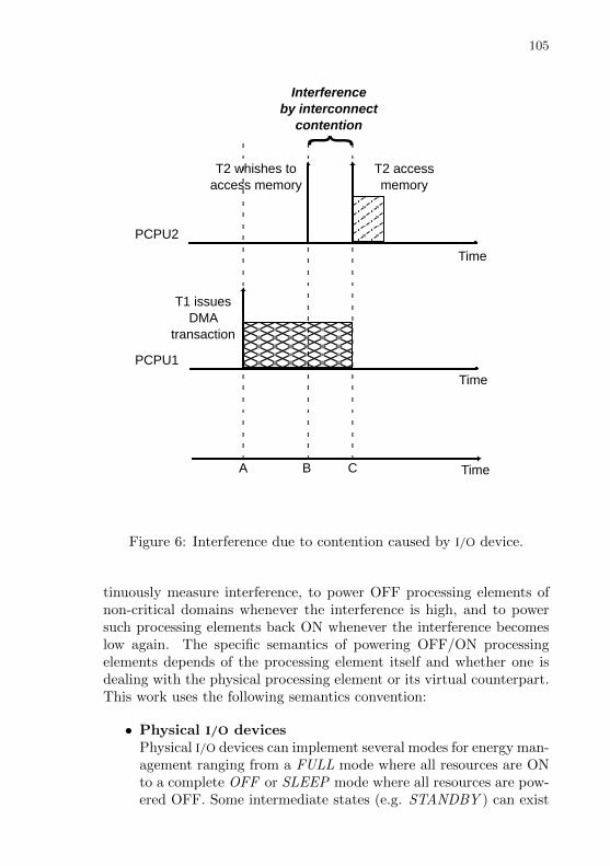
105
Time
T1 issuesDMA
transaction
T2 whishes toaccess memory
T2 accessmemory
Interferenceby interconnect
contention
PCPU2
A
Time
PCPU1
TimeB C
Figure 6: Interference due to contention caused by I/O device.
tinuously measure interference, to power OFF processing elements ofnon-critical domains whenever the interference is high, and to powersuch processing elements back ON whenever the interference becomeslow again. The specific semantics of powering OFF/ON processingelements depends of the processing element itself and whether one isdealing with the physical processing element or its virtual counterpart.This work uses the following semantics convention:
• Physical I/O devicesPhysical I/O devices can implement several modes for energy man-agement ranging from a FULL mode where all resources are ONto a complete OFF or SLEEP mode where all resources are pow-ered OFF. Some intermediate states (e.g. STANDBY ) can exist
106
as well. This work takes into account the two extremes (FULLand OFF). Therefore, powering a physical I/O device ON meansto bring it to FULL mode, while powering a physical I/O deviceOFF means to bring it to OFF mode.
• Virtual I/O devicesThe OFF/ON semantics for virtual I/O devices depends on theunderlining physical I/O device energy support as well on theoperation that one is using. For example, to power a virtual NIC
OFF could mean to suspend the guest OS tasks that are usingthe virtual NIC for sending frames. For the same virtual NIC, apower OFF could mean, for example, using some filtering on thephysical level discarding frames that are addressed to the domainthat had powered the virtual device OFF. Conversely, to powerthe same virtual NIC ON would mean to resume the guest OS
tasks that are waiting for sending frames and to stop filteringframes that target the domain that owns the virtual NIC.
• PCPUsThe OFF/ON semantics for PCPUs is the same than for physicalI/O devices. However, powering ON and OFF PCPUs in the vir-tualization context is less common and is not taken into accountin this work. Instead, the usual approach is to schedule anotherVCPU to a given PCPU instead of powering it OFF.
• VCPUsIn the context of this work, to power a VCPU OFF means to sus-pend its execution, allowing the underling PCPU to be reassignedto another VCPU. Conversely, to power a VCPU ON means toresume its execution so it will be able to be assigned to somePCPU. Such assignment will depend on the VCPU scheduling pol-icy implemented by the hypervisor and usually will not occurimmediately after the resume of the VCPU.
Additionally, the following rules are used in the case of sharedI/O devices (non-critical domains):
1. Powering OFF a virtual I/O device, will cause the aforementionedblocking and filtering policies (if any) to be enabled for the do-main that owns the virtual I/O device. In the case the physical I/Odevice assigned to the virtual I/O device being powered OFF isshared with others virtual I/O devices (from other domains), thephysical I/O device is kept ON. In the case the virtual I/O device
107
being powered OFF is the only user of its physical counterpart,the physical I/O device is also powered OFF.
2. Powering OFF a physical I/O device, will cause all its client virtualI/O devices to be powered OFF followed by the powering OFF ofthe physical I/O device itself.
3. Powering ON a virtual I/O device, will disable the blocking andfiltering policies. Additionally, if the virtual I/O device beingpowered ON is the first client of the given physical I/O deviceand the physical I/O device is OFF, it will power ON the physicalI/O device as well.
4. Powering ON a physical I/O device, will power the device ONwithout powering ON its client virtual I/O devices.
The UML communication diagram of Figure 7 shows the powerOFF/ON dynamics that is considered by this work. In the figure,the hypervisor has taken the decision of powering OFF three I/O de-vices simultaneously: V UART00 (a Virtual UART (VUART)), V NIC10
(a Virtual NIC (VNIC)), and PUART1 (a Physical UART (PUART)).Accordingly to Rule 1, the invocation of power(OFF ) on V NIC10 willpower OFF the virtual I/O device but will not power OFF PNIC0
since it is shared with V NIC20. Following the Rule 2, the invoca-tion of power(OFF ) on PUART1 will power OFF V UART10 andV UART20 then, it will power OFF of PUART1 itself. The invoca-tion of power(OFF ) on V UART00 will cause PUART0 to power OFF,accordingly to Rule 1. The worst case of interference caused by I/O
devices assigned to critical domains must be taken into account at de-sign time, therefore powering OFF an I/O device assigned to a criticaldomain at runtime aiming to reduce the interference is a design er-ror. Anyway, the powering OFF of an I/O device assigned to a criticaldomain can occur when the whole domains is being shut down.
As mentioned in the beginning of this section, the general ap-proach for handling I/O interference is to power OFF processing ele-ments of non-critical domains whenever the interference is high and,as interference reduces, to power processing elements back ON. Thespecific powering OFF/ON order can be obtained from a design phaseand coded statically or can be learned and changed as new domains areintroduced (on distinct executions of the whole system).
Following are examples of powering OFF/ON order. P stands forphysical I/O device, V for virtual I/O device, and U for VCPU. PDev-OFF/PDev-ON means to power physical I/O devices OFF/ON, VDev-

108
<<CDom>>
dom0 :Domain
<<MixDom>>
dom1 :Domain
<<NCDom>>
dom2 :Domain
v00 :VUART
p0 :PUART
:Hypervisor
v10 :VUART
p1 :PUART
v10 :VNICv20 :VUART
v20 :VNIC
p0 :PNIC
1: power_off
1.1: power_off
1.1.1: power_off
2: power_off3: power_off
3.1: power_off 3.2: power_off
Figure 7: Power off dynamics.
OFF/VDev-ON means to power virtual I/O devices OFF/ON, andVCPU-OFF/VCPU-ON means to power VCPUs OFF/ON. “On high”means the actions performed whenever the interference is judged toohigh , while “On low” means the actions performed whenever the in-terference becomes acceptable.
1. P-V-U order
• On high: PDev-OFF (implicit VDev-OFF), VCPU-OFF
• On low: VCPU-ON, PDev-ON, VDev-ON
2. U-V-P order
• On high: VCPU-OFF, VDev-OFF, PDev-OFF
• On low: PDev-ON, VDev-ON, VCPU-ON
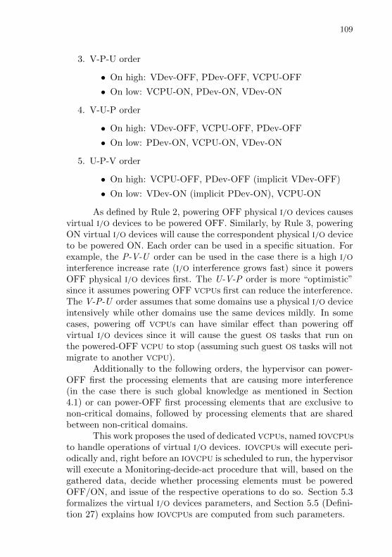
109
3. V-P-U order
• On high: VDev-OFF, PDev-OFF, VCPU-OFF
• On low: VCPU-ON, PDev-ON, VDev-ON
4. V-U-P order
• On high: VDev-OFF, VCPU-OFF, PDev-OFF
• On low: PDev-ON, VCPU-ON, VDev-ON
5. U-P-V order
• On high: VCPU-OFF, PDev-OFF (implicit VDev-OFF)
• On low: VDev-ON (implicit PDev-ON), VCPU-ON
As defined by Rule 2, powering OFF physical I/O devices causesvirtual I/O devices to be powered OFF. Similarly, by Rule 3, poweringON virtual I/O devices will cause the correspondent physical I/O deviceto be powered ON. Each order can be used in a specific situation. Forexample, the P-V-U order can be used in the case there is a high I/O
interference increase rate (I/O interference grows fast) since it powersOFF physical I/O devices first. The U-V-P order is more “optimistic”since it assumes powering OFF VCPUs first can reduce the interference.The V-P-U order assumes that some domains use a physical I/O deviceintensively while other domains use the same devices mildly. In somecases, powering off VCPUs can have similar effect than powering offvirtual I/O devices since it will cause the guest OS tasks that run onthe powered-OFF VCPU to stop (assuming such guest OS tasks will notmigrate to another VCPU).
Additionally to the following orders, the hypervisor can power-OFF first the processing elements that are causing more interference(in the case there is such global knowledge as mentioned in Section4.1) or can power-OFF first processing elements that are exclusive tonon-critical domains, followed by processing elements that are sharedbetween non-critical domains.
This work proposes the used of dedicated VCPUs, named IOVCPUsto handle operations of virtual I/O devices. IOVCPUs will execute peri-odically and, right before an IOVCPU is scheduled to run, the hypervisorwill execute a Monitoring-decide-act procedure that will, based on thegathered data, decide whether processing elements must be poweredOFF/ON, and issue of the respective operations to do so. Section 5.3formalizes the virtual I/O devices parameters, and Section 5.5 (Defini-tion 27) explains how IOVCPUs are computed from such parameters.
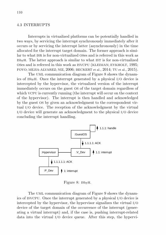
110
4.3 INTERRUPTS
Interrupts in virtualized platforms can be potentially handled intwo ways, by servicing the interrupt synchronously immediately after itoccurs or by servicing the interrupt latter (asynchronously) in the timeallocated for the interrupt target domain. The former approach is simi-lar to what ISR is for non-virtualized OSes and is referred in this work asISbyH. The latter approach is similar to what IST is for non-virtualizedOSes and is referred in this work as ISVCPU (KLEIMAN; EYKHOLT, 1995;FOYO; MEJIA-ALVAREZ; NIZ, 2006; BECKERT et al., 2014; TU et al., 2015).
The UML communication diagram of Figure 8 shows the dynam-ics of ISbyH. Once the interrupt generated by a physical I/O device isintercepted by the hypervisor, the virtualized version of the interruptimmediately occurs on the guest OS of the target domain regardless ofwhich VCPU is currently running (the interrupt will occur on the contextof the hypervisor). The interrupt is then handled and acknowledgedby the guest OS by given an acknowledgment to the correspondent vir-tual I/O device. The reception of the acknowledgment by the virtualI/O device will generate an acknowledgment to the physical I/O deviceconcluding the interrupt handling.
:V_Dev
:P_Dev
:Hypervisor
:GuestOS
1: interrupt
1.1.1.1.1: ACK
1.1: interrupt
1.1.1: handle
1.1.1.1: ACK
Figure 8: ISbyH.
The UML communication diagram of Figure 9 shows the dynam-ics of ISVCPU. Once the interrupt generated by a physical I/O device isintercepted by the hypervisor, the hypervisor signalizes the virtual I/O
device of the target domain of the occurrence of the interrupt (gener-ating a virtual interrupt) and, if the case is, pushing interrupt-relateddata into the virtual I/O device queue. After this step, the hypervi-
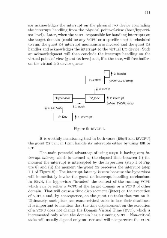
111
sor acknowledges the interrupt on the physical I/O device concludingthe interrupt handling from the physical point-of-view (host/hypervi-sor level). Later, when the VCPU responsible for handling interrupts onthe target domain (could be any VCPU or a specific one) is scheduledto run, the guest OS interrupt mechanism is invoked and the guest OS
handles and acknowledges the interrupt to the virtual I/O device. Suchan acknowledgment will then conclude the interrupt handling on thevirtual point-of-view (guest OS level) and, if is the case, will free bufferson the virtual I/O device queue.
:V_Dev
:P_Dev
:Hypervisor
:GuestOS
1: interrupt
1.1: push1.1.1: ACK
2: interrupt
3: handle
3.1: ACK
(when ISVCPU runs)
(when VCPU runs)
Figure 9: ISVCPU.
It is worthily mentioning that in both cases (ISbyH and ISVCPU)the guest OS can, in turn, handle its interrupts either by using ISR orIST.
The main potential advantage of using ISbyH is having zero in-terrupt latency which is defined as the elapsed time between (i) themoment the interrupt is intercepted by the hypervisor (step 1 of Fig-ure 8) and (ii) the moment the guest OS perceives the interrupt (step1.1 of Figure 8). The interrupt latency is zero because the hypervisorwill immediately invoke the guest OS interrupt handling mechanism.In ISbyH, the hypervisor “invades” the context of the running VCPU
which can be either a VCPU of the target domain or a VCPU of otherdomain. That will cause a time displacement (jitter) on the executionof VCPUs and, by consequence, on the guest OS tasks that run on it.Ultimately, such jitter can cause critical tasks to lose their deadlines.It is important to mention that the time displacement on the executionof a VCPU does not change the Domain Virtual Time (DVT), which isincremented only when the domain has a running VCPU. Non-criticaltasks will usually depend only on DVT and will not perceive the VCPU
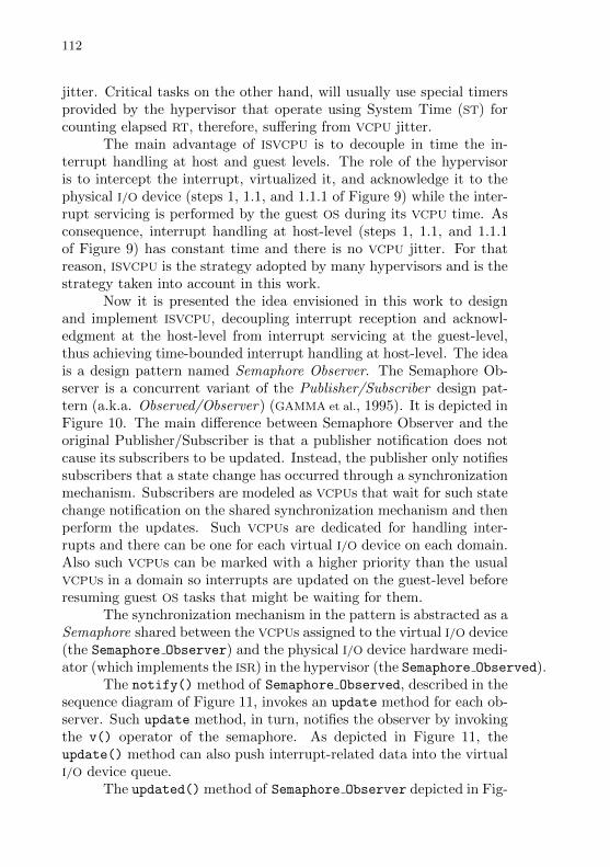
112
jitter. Critical tasks on the other hand, will usually use special timersprovided by the hypervisor that operate using System Time (ST) forcounting elapsed RT, therefore, suffering from VCPU jitter.
The main advantage of ISVCPU is to decouple in time the in-terrupt handling at host and guest levels. The role of the hypervisoris to intercept the interrupt, virtualized it, and acknowledge it to thephysical I/O device (steps 1, 1.1, and 1.1.1 of Figure 9) while the inter-rupt servicing is performed by the guest OS during its VCPU time. Asconsequence, interrupt handling at host-level (steps 1, 1.1, and 1.1.1of Figure 9) has constant time and there is no VCPU jitter. For thatreason, ISVCPU is the strategy adopted by many hypervisors and is thestrategy taken into account in this work.
Now it is presented the idea envisioned in this work to designand implement ISVCPU, decoupling interrupt reception and acknowl-edgment at the host-level from interrupt servicing at the guest-level,thus achieving time-bounded interrupt handling at host-level. The ideais a design pattern named Semaphore Observer. The Semaphore Ob-server is a concurrent variant of the Publisher/Subscriber design pat-tern (a.k.a. Observed/Observer) (GAMMA et al., 1995). It is depicted inFigure 10. The main difference between Semaphore Observer and theoriginal Publisher/Subscriber is that a publisher notification does notcause its subscribers to be updated. Instead, the publisher only notifiessubscribers that a state change has occurred through a synchronizationmechanism. Subscribers are modeled as VCPUs that wait for such statechange notification on the shared synchronization mechanism and thenperform the updates. Such VCPUs are dedicated for handling inter-rupts and there can be one for each virtual I/O device on each domain.Also such VCPUs can be marked with a higher priority than the usualVCPUs in a domain so interrupts are updated on the guest-level beforeresuming guest OS tasks that might be waiting for them.
The synchronization mechanism in the pattern is abstracted as aSemaphore shared between the VCPUs assigned to the virtual I/O device(the Semaphore Observer) and the physical I/O device hardware medi-ator (which implements the ISR) in the hypervisor (the Semaphore Observed).
The notify() method of Semaphore Observed, described in thesequence diagram of Figure 11, invokes an update method for each ob-server. Such update method, in turn, notifies the observer by invokingthe v() operator of the semaphore. As depicted in Figure 11, theupdate() method can also push interrupt-related data into the virtualI/O device queue.
The updated() method of Semaphore Observer depicted in Fig-
113
_observers*
1
Semaphore_Observer
+ update(d : Data)+ updated() : Data
Semaphore
+ p()+ v()
Semaphore_Observed
+ notify(d : Data)+ attach(observer : Semaphore_Observer)+ detach(observer : Semaphore_Observer)
Figure 10: Semaphore Observer.
ure 12, will invoke the p() operator of the semaphore and, if needed,will wait for the physical I/O device interrupt notification. As depictedin Figure 12, the updated() method can also retrieve interrupt-relateddata from the virtual I/O device queue.
A semaphore is essential for interrupt handling. Since a semaphorehas memory, interrupts notifications are never lost even if the frequencywith which interrupts are generated is almost the same than the fre-quency with which interrupts are serviced. In such a case, however,in order to prevent data loss (in the case there is data generation as-sociated with the interrupt occurrence) a larger buffer or a ring bufferstrategy should be employed.
It should be noted that the use of semaphores in SemaphoreObserver does not introduce priority inversion problems since they arenot being used to guard a critical section. Instead, they are used only tosynchronize the physical I/O device ISR with the corresponding ISVCPU,much in a Producer/Consumer way.
Regarding implementation, instead of using two kinds of VCPUs(an ordinary VCPU for executing guest OS tasks and an ISVCPU forupdating I/O events on the guest OS) one might wish to use a singleVCPU kind. However, in that case every VCPU in a domain would needto update I/O events as soon the VCPU is scheduled to run, beforerunning the guest OS tasks.
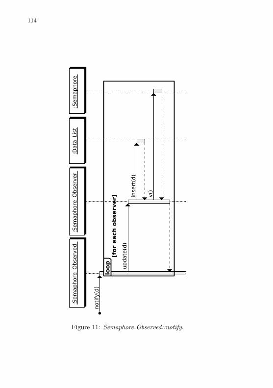
114
Figure 11: Semaphore Observed::notify.
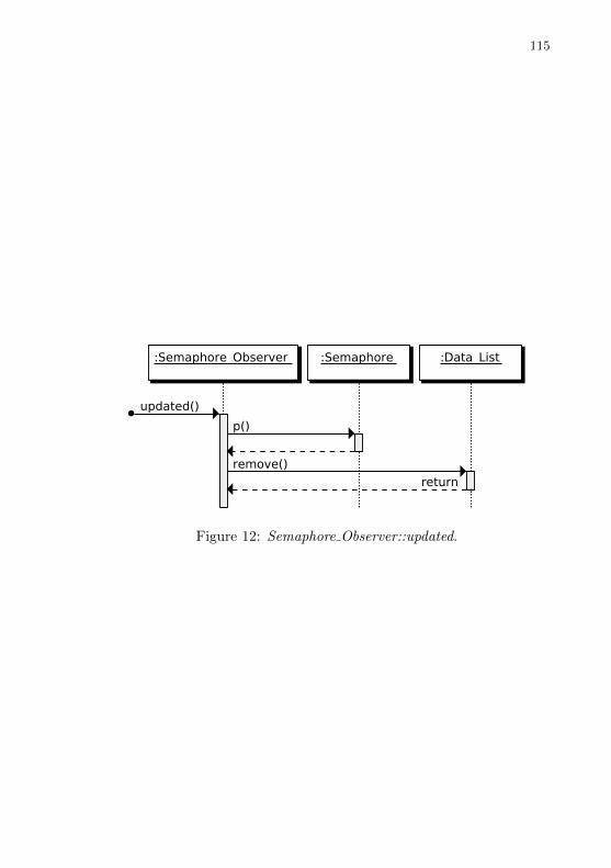
115
Figure 12: Semaphore Observer::updated.
116
4.4 MEMORY
Regarding the memory hierarchy, temporal interference will oc-cur mainly due to eviction of cache lines at the LLC that is sharedbetween all PCPUs. Figure 13 shows the case where the critical taskT2 suffers temporal interference caused by the execution of T1 a non-critical task that runs on another PCPU and has part of this page frames(physical memory) mapped to the same cache lines of T2. Figure 14shows a similar case in which the difference is that the non-critical taskT1 has issued a DMA transaction before accessing memory (which willthen cause the eviction of lines that are used by T2). The extent of theinterference will depend on the time for accessing the main memoryand replacing the evicted LLC lines.
In Figure 13 the LLC eviction interference is represented by thetime interval between the time instants C and D. In Figure 14, thesame kind of interference is observed between the time instants D andE.

117
LLC
Phy Mem
T2 runs
T1 runs
T2 will accessmemory
T2 is resumed
Cache Misson T2!
Interferenceby cache line eviction
Cache lineWhole cache line
is replaced
Mapped to the samecache line
Word
PCPU2
Time
Time
PCPU1
TimeA B C D
Figure 13: Interference due to cache line eviction caused by anotherPCPU.
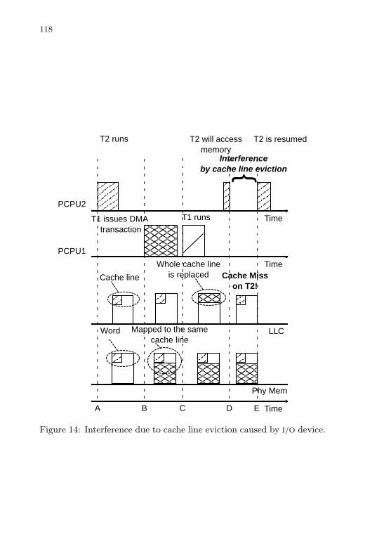
118
T1 issues DMA transaction
T1 runs
LLC
Phy Mem
T2 runs T2 will accessmemory
T2 is resumed
Cache Misson T2!
Interferenceby cache line eviction
Cache line
Whole cache lineis replaced
Mapped to the samecache line
PCPU2
Time
Time
PCPU1
TimeA B D EC
Word
Figure 14: Interference due to cache line eviction caused by I/O device.
119
The general idea for dealing with memory interference at LLC isby partitioning the cache using page-coloring. The reasoning behindthis idea is that partitions with distinct colors will not evict cachelines from one another, preventing the interference from happening.This work identifies three approaches for applying page-coloring onvirtualized platforms: oriented to the domain, VCPUs, and guest OS
tasks.
4.4.1 Domain-oriented Page-coloring
In the domain-oriented approach, the hypervisor will provideeach critical domain with an exclusive color; non-critical domains willall share the same color. The main advantage of this approach is thatit does not require any change on the guest OSes nor on the guest OS
tasks. However, having one single color per domain is a too coarsegranularity and will only be effective if all critical domains run a singletask each. If a critical domain runs two or more critical tasks, one taskwill potentially evict cache lines from the other, disrupting the isolationand causing temporal interference on one another.
4.4.2 VCPU-oriented Page-coloring
In VCPU-oriented page-coloring, a color is given to a VCPU orgroup of VCPUs. This approach combines together (i) page-coloring,(ii) VCPU masking or affinity (that defines on which PCPUs a VCPU isallowed to run), and (iii) clustered scheduling (clusters of PCPUs). Fivetypes of clusters are defined:
1. C-cluster is a cluster of size one (composed of one single PCPU)where each VCPU of the cluster has an exclusive color. As conse-quence of having size one, VCPUs in a C-cluster does not migrate,which helps preventing cache line eviction on inner-level caches(e.g. L1).
2. F-cluster is similar to a C-cluster regarding page-coloring, eachVCPU has an exclusive color. However, can have size N (whereN > 1).
3. D-cluster is an N -sized cluster with a cluster-exclusive color, i.e.:all VCPUs within the cluster share the same color but each D-cluster has its own exclusive color.
120
4. B-cluster is an N -sized cluster with a cluster-type color, i.e.: allVCPUs in all B-clusters share the same color.
5. N-cluster is an N -sized non-colored cluster. Having no colora guest OS task in an N-cluster can cause interference on anyother guest OS task since it does not respect the cache parti-tioning. That is the default of systems that do not implementpage-coloring.
The main advantage of this approach is that it does not requirechanges on guest OS tasks code. It might require the guest OS task tobe pinned to specific VCPUs so it can use that VCPU color. However,this approach requires the guest OS to be aware of colors.
A possible mechanism for implementing color-aware on the guestOS is the following. On the creation of VCPUs, before loading anydomain, PCPUs and VCPUs are organized into clusters according tothe five types described above. At boot time, the guest OS asks thehypervisor for a list of colors it is allowed to have. Such list will dependon how the VCPUs that belong to the guest OS domain are organized(how many clusters and their types). For example, if the guest OS
belongs to a domain composed of one C-cluster that has two VCPUsand by one D-cluster that has also two VCPUs, the hypervisor willgrant the guest OS three colors (one for each VCPU of the C-cluster andone for the two VCPUs of the D-cluster) plus a fourth color (a systemcolor) for the guest OS kernel. The guest OS must then have multiplepage frame lists, one for each, color. At creation time, critical tasksmust be pinned to VCPUs of C-clusters or F-clusters while non-criticaltasks must be pinned to VCPUs of other clusters types. The heap ofthe guest OS process will be created with the color correspondent tothe color of the VCPU it is pinned to.
4.4.3 Guest OS task-oriented Page-coloring
In the guest OS task-oriented page-coloring, each task is createdinforming the color it wishes to use. The guest OS will then create adedicated heap for the task, according the color availability in the guestOS. The main advantage of this approach is that it gives more control(guest OS task-granularity) to system designers. However, it requireschanges on both guest OS task and guest OS code. The mechanism issimilar to the one used on VCPU-oriented page coloring. At boot time,the guest OS will ask the hypervisor for a set of colors which are going to

121
be used for creating dedicated list of free page frames. At task creationtime, the guest OS task code needs to be modified in the sense the taskitself must inform the color it wishes to use. In all approaches: domain-oriented, VCPU-oriented, and guest OS task-oriented it is important tonotice that guest OS tasks will operate with guest-logical addresseswhile the colors are described in terms of host-physical addresses. Themapping of guest-logical addresses onto host-physical addresses mustbe handled by the hypervisor using mechanisms like SPTs.
4.5 DISCUSSION
The power OFF/ON techniques discussed in Section 4.2 arebased on the ones evaluated by (HOELLER, 2007) and (REIS, 2016),extending them in order to take into account also VCPUs and virtualI/O devices. While (HOELLER, 2007) and (REIS, 2016) have threadas the top-level unit of dependencies, in this work the domain is theone to play such a role. Furthermore, the domain interacts with thevirtual counterpart of a processing element and not with the physicalprocessing element directly. In other works “a domain is client of aphysical processing element that is represented by a virtual processingelement proxy.” instead of “a thread is a client of a physical processingelement”.
Mostly hypervisors adopt strategies similar to ISVCPU for han-dling interrupts. Xen uses the split device driver model for I/O de-vices and handles physical interrupts by mapping then onto eventsthat, when happen, invoke the interrupt handling mechanism at guestOS level by using callback functions previously registered by the guestOS (CHISNALL, 2007). Some approaches such as the one presented byBeckert et al. explore something in between the ISVCPU and ISbyH ap-proaches letting a interrupt be handled in the time slot of a domaindistinct from its target domain if there is time for that (BECKERT et
al., 2014). Their approach, however, demands for an off-line analysisto ensure that the interference caused by handling interrupts outsidethe domain does not break temporal independence of others. Such ananalysis, in turn, demands for arrival functions for every event in thesystem. The approach presented in this section still requires a lim-ited arrival of interrupts in order to keep the interference caused byinterrupts bounded. However, rather than focusing on static analysisof interrupts interactions it focuses on keeping the interrupt handlingtime constant at the host level. The idea of Semaphore Observer pre-
122
sented in this Section was first presented in the published paper: ProperHandling of Interrupts in Cyber-Physical Systems, In Proceedings ofthe 26th IEEE International Symposium on Rapid System Prototyp-ing (RSP 2015), 2015, pages 83-89, (LUDWICH; FRoHLICH, 2015).
Gracioli at al. have evaluated page-coloring while applied tomulti task systems (GRACIOLI; FRoHLICH, 2013), (GRACIOLI, 2014). Intheir approach each critical task can have a unique color while non-critical tasks can share the same color. This work extends their ap-proach, discussing the use of one or more exclusive colors to domainsin a virtualized platform.

123
5 PROPOSED MODEL
This chapter presents the second part of this work proposal. Itintroduces the proposed model that captures guest OS tasks require-ments regarding VCPUs and virtual I/O devices requirements. The guestOS tasks requirements will determine the computation of the domainrequirements, which is abstracted in the form of a DRM. Finally, thedomain requirements will compose the system requirements. By com-paring the system requirements with the resources provided by thephysical platform is possible to determine the feasibility of guest OS
tasks and domains. Each interference source informally presented inChapter 4 is formalized and feed into the model. Finally, interference-aware schedulability tests are devised, taking into account cache andI/O overheads.
Sections 5.1 to 5.3 introduce the proposed model that consists ofguest OS tasks and the concept of DRM. The formal concept of guestOS task captures the processing and I/O requirements of a guest OS
task. A DRM captures the VCPUs and virtual I/O devices budgets thatcan be provided to a domain as a whole. Section 5.4 introduces theconcept of interconnect topology that specifies how PCPUs, and physi-cal I/O devices are connected in a physical platform. Section 5.5 usesthe concepts presented in previous sections to discuss schedulability ofguest OS tasks by a DRM, how DRMs are combined to represent therequirements of the whole system, and whether the physical platformhas resources for scheduling them. Section 5.6 presents the proposedalgorithm for DRM generation. Section 5.7 formalizes the overheadcaused by the virtualization itself. Section 5.8 formalizes memory andI/O overheads presented on previous sections and discuss the schedul-ing condition taking those overheads into consideration. Section 5.9explains how the overhead-aware analysis can be used during runtime,in design and production phases, to take scheduling decisions encom-passing virtual and physical processing elements. Section 5.10 closesthe chapter discussing the proposed modeling approach.
5.1 COMMON DEFINITIONS
The following definitions are common to guest OS tasks, DRM,and the whole system.
Definition 1 (Criticality Level)
124
Ω = LO,HI
The concept of criticality level is applied for Guest OS tasks,DRM, and the system. Two levels of criticality are specified, LO denoteslow criticality andHI denotes high criticality. Regarding guest OS tasks(criticality level denoted by ωi), there are HI-tasks and LO-tasks. Theformer are used for representing critical tasks, while the latter are usedfor representing non-critical tasks. A task set of HI-tasks forms a HI-domain, which those requirements is modeled by a HI-criticality DRM.Conversely, a task set of LO-tasks forms a LO-domain, which thoserequirements is represented by a LO-criticality DRM. The criticalitylevel of a DRM is denoted by ωM. Regarding criticality level of thesystem (also known as system mode and denoted by ωS), when thesystem is in LO mode, both HI-tasks and LO-tasks execute. On theother hand, when the system is in HI mode, all LO-tasks are suspendedand only HI-tasks execute.
Definition 2 (Virtual I/O Device Class)R = x|x is a V irtual I/O class.
A virtual I/O device class represents the virtual counterpart ofa class of a physical I/O device such as NIC, Universal AsynchronousReceiver Transmitter (UART), and others. Instances of such classes areused by the domains to perform I/O operations.
Definition 3 (I/O Operation)Γ = rd, wr
Two I/O operations are modeled for virtual I/O devices, “read”(denoted by rd), and “write” (denoted by wr). The precise meaningof the operations depends on the I/O device class. For example, to avideo device “write” means writing data into the video device framebuffer, while for a NIC it means sending data through the link layer ofa network.
5.2 GUEST OS TASK AND DOMAIN
A guest OS task τi is modeled as an MC periodic task, accordingto Definition 4.
Definition 4 (Guest OS task)τi = (Ti, Di, ωi, C
ωi , R
v,ω,γi ) where
125
• Ti is the task period.
• Di is the task relative deadline.
• ωi ∈ Ω is the task criticality level.
• Cωi , where ω ∈ Ω, is the required budget of VCPU resource unitsfor the task to perform its computation within one period while thesystem is running in LO (ωS = LO) or HI (ωS = HI) criticalitylevel.
• Rv,ω,γi , where v ∈ R∧ ω ∈ Ω∧ γ ∈ Γ, denotes the required budgetof resource units of a virtual I/O device class v for the task toperform its computation within one period while the system isrunning in LO (ωS = LO) or HI (ωS = HI) criticality level,and while performing a “read” (γ = rd) or “write” (γ = wr)operation on the virtual I/O device.
Additionally,
1. if ωi = HICHIi > CLOi ∧Rv,HI,γi > Rv,LO,γi
2. if ωi = LOCHIi = 0 ∧Rv,HI,γi = 0
Some examples, given that v = 0 represents the class of virtualNIC, and v = 1 represents the class of virtual UART.:
• R1,HI,wr0 means the budget per period required by task τ0 to
perform “write” operations on a virtual UART while the systemis executing in HI mode.
• R0,LO,rd1 means the budget per period required by task τ1 to
perform “read” operations (i.e. receive packets) on a virtual NIC
while the system is executing in LO mode.
In the case of VCPUs, the employed resource unit is usually atime unit. In the case of virtual I/O devices the employed resource unitcan change from one class to another. However, to simplify the modelpresentation is assumed Rv,ω,γi is also specified in the same time unitas VCPUs. Additionally, is also assumed the existence of a functionfv : R′ → R that maps R′ specified in the usual resource units ofthe I/O device class (e.g. bytes per second) onto R specified in a timeunit. Therefore, Rv,ω,γi denotes the time spend by task τi while using
126
the resource of class v within a period. In the case of a “write/send”operation, Rv,ω,wri usually denotes the time the task needs to program
the device. In the case of a “read/receive” operation, Rv,ω,rdi usuallydenotes the time the task needs to retrieve some data computed bythe virtual I/O device. In the “read/receive” case, it is assumed aphysical interrupt on the physical I/O device has already occurred andthe hypervisor has signalized its virtual counterpart.
For HI-tasks, CLOi and Rv,LO,γi are obtained from the task’s
Average Execution Time (AVET), while CHIi and Rv,HI,γi are obtained
from the task’s WCET. For LO-tasks, CLOi and Rv,LO,γi are obtained
from the task’s AVET, while CHIi and Rv,HI,γi are zero by definition(since a LO-task is suspended whenever the system is in HI mode).
Regarding schedulability is assumed that
1. Di 6 Ti
2. Cωi +∑v∈R,γ∈ΓR
v,ωS ,γi 6 Di (∀ω ∈ Ω)
The criterion 1 is usual in real-time systems. The criterion 2states that all time, during the task’s period, the task spends eitherprocessing or performing I/O operations must feet inside its deadline.In the case of HI-tasks, regarding system transition from LO to HImode, it is usually assumed an artificially tightened deadline for theLO mode, according do Definition 5, such that DLO
i < Di.
Definition 5 (Artificially tightened deadline for the LO mode)
DLOi = Di − (CHIi +
∑v∈R,γ∈ΓR
v,HI,γi + δLOtoHI)
where
• δLOtoHI , presented later in Definition 28, is the hypervisor over-head for switching from the LO to HI mode.
DLOi assumes that the transition from LO to HI mode takes
time. Therefore, the idea is to create a slack that allows the taskto finish its current job before its actual deadline Di. For LO-tasksDLOi = Di always, since they do not run in HI mode. The strategies
used for deciding when criticality mode switches occur in the systemare described in Section 5.9.
The whole-task utilization takes into account the VCPU and vir-tual I/O device budgets and is given by Definition 6.
Definition 6 (Whole guest OS task utilization)
WTUωSi =
CHIi +∑v∈R,γ∈Γ R
v,ωS ,γi
T i
127
Tasks of the same criticality are grouped into a domain, whichis defined according to Definition 7.
Definition 7 (Domain)Dom = (ωD, τ) where
• ωD ∈ Ω is the domain criticality.
• τ is the domain task set composed of guest OS tasks such that∀τi ∈ τ : ωi = ωD.
The total utilization of a domain is defined for VCPUs and virtualI/O devices in Definition 8 and 9, respectively.
Definition 8 (Total VCPU Utilization of a Domain)
UωSτΘ =
∑τi∈τ
CωiTi
Definition 9 (Total virtual I/O device Utilization of a Domain)
Uv,ωS ,γτΞ =
∑τi∈τ
Rv,ω,γi
Ti
Additionally, the whole-domain utilization can be defined asshown in Definition 10.
Definition 10 (Whole Domain Utilization)
WDUωSτ =
∑τi∈τ
CωSi +
∑v∈R,γ∈Γ R
v,ωS ,γi
Ti
5.3 DOMAIN RESOURCE MODEL
A DRM models the processing and I/O budgets collectively pro-vided by all VCPUs and virtual I/O devices of a domain. A DRMM ismodeled according to Definition 11.
Definition 11 (DRM)M = 〈ωM,Π,ΘωS ,mωS ,Λv,γ ,Ξv,ωS ,γ , nv,ωS ,γ〉 where
• ωM ∈ Ω is the DRM criticality level. A HI-domain (HI-criticalitydomain) will contain only HI-tasks and its correspondent DRM
will have ωM = HI. A LO-domain (LO-criticality domain)will contain only LO-tasks and its correspondent DRM will haveωM = LO.
128
• Π is the budget replenishment period for all VCPUs in the DRM.
• ΘωS is the budget of resource units collectively provided by allVCPUs of that DRM in every Π time units while the system isrunning in LO (ωS = LO) or HI (ωS = HI) criticality level.
• mωS is the number of VCPUs that the DRM can provide for eachcriticality level. In practice, however, since the system is at agiven moment of time on either HI or LO mode, the actual num-ber of VCPUs allocated to a domain is determined as max(mHI ,mLO).
• Λv,γ is a two-dimensional vector of budget replenishment periodfor each class (indexed by v) and each operation (indexed by γ)of virtual I/O device in the DRM.
• Ξv,ωS ,γ represents the resource units collectively provided by allvirtual I/O devices of class v in that DRM every Λv,γ time unitswhile the system is running in LO (ω = LO) or HI (ω = HI)criticality level, and while performing a “read” (γ = rd) or “write”(γ = wr) operation.
• nv,ωS ,γ is vector (indexed by v, ωS , and γ) of the number ofvirtual I/O devices of each class, criticality level, and operationthat the DRM can provide. Similarly to the number of VCPUs, thenumber of virtual I/O devices allocated to a domain is chosen asmax(nv,HI,γ , nv,LO,γ).
Λv,γ indicates that each virtual I/O device will provide its re-sources periodically. This work proposes the concept of IOVCPU tomake this possible. An IOVCPU is a dedicated VCPU to handle “read”and “write” operations of a virtual I/O device. An IOVCPU responsi-ble for “read” can be realized by acting as a “Semaphore Observer”as described by Section 4.3. A “read”-IOVCPU would run periodically,handling interrupts generated by the physical I/O device, virtualizingsuch interrupts and passing them to the guest OS along with data re-lated to the interrupt when applicable. A “write”-IOVCPU will alsorun periodically, getting a “write” request made by the virtual I/O de-vice and programming the physical I/O device to perform the “write”operation (e.g. a DMA transaction). Also in the case of “write” op-erations the IOVCPU can check whether the parameters (e.g. bytes tobe written) passed to the virtual I/O device are in accordance to whatis provided to that domain. Ideally the I/O requirements of a guestOS task are known at design time for both HI and LO domains. In
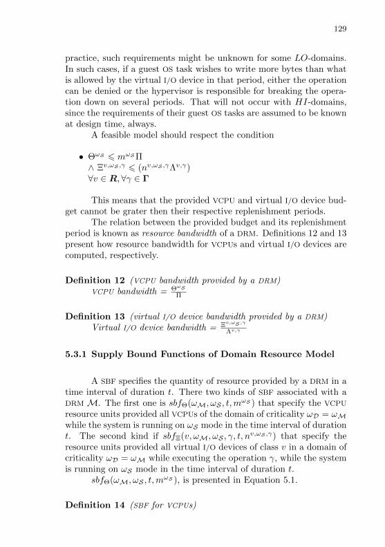
129
practice, such requirements might be unknown for some LO-domains.In such cases, if a guest OS task wishes to write more bytes than whatis allowed by the virtual I/O device in that period, either the operationcan be denied or the hypervisor is responsible for breaking the opera-tion down on several periods. That will not occur with HI-domains,since the requirements of their guest OS tasks are assumed to be knownat design time, always.
A feasible model should respect the condition
• ΘωS 6 mωS Π∧ Ξv,ωS ,γ 6 (nv,ωS ,γΛv,γ)∀v ∈ R,∀γ ∈ Γ
This means that the provided VCPU and virtual I/O device bud-get cannot be grater then their respective replenishment periods.
The relation between the provided budget and its replenishmentperiod is known as resource bandwidth of a DRM. Definitions 12 and 13present how resource bandwidth for VCPUs and virtual I/O devices arecomputed, respectively.
Definition 12 (VCPU bandwidth provided by a DRM)VCPU bandwidth = ΘωS
Π
Definition 13 (virtual I/O device bandwidth provided by a DRM)Virtual I/O device bandwidth = Ξv,ωS ,γ
Λv,γ
5.3.1 Supply Bound Functions of Domain Resource Model
A SBF specifies the quantity of resource provided by a DRM in atime interval of duration t. There two kinds of SBF associated with aDRMM. The first one is sbfΘ(ωM, ωS , t,m
ωS ) that specify the VCPU
resource units provided all VCPUs of the domain of criticality ωD = ωMwhile the system is running on ωS mode in the time interval of durationt. The second kind if sbfΞ(v, ωM, ωS , γ, t, n
v,ωS ,γ) that specify theresource units provided all virtual I/O devices of class v in a domain ofcriticality ωD = ωM while executing the operation γ, while the systemis running on ωS mode in the time interval of duration t.
sbfΘ(ωM, ωS , t,mωS ), is presented in Equation 5.1.
Definition 14 (SBF for VCPUs)

130
sbfΘ(ωM, ωS , t,mωS ) =
1st case : t′ < 0 ∨ ωM = LO ∧ ωS = HI
0
2nd case : t′ > 0 ∧ x ∈ [1, y]
∧ωM = HI ∧ ωS = HI⌊t′
Π
⌋ΘHI
+max(0,mωSx− (mωS Π−ΘHI))
3rd case : t′ > 0 ∧ x /∈ [1, y]
∧ωM = HI ∧ ωS = HI⌊t′
Π
⌋ΘHI
+max(0,mωSx− (mωS Π−ΘHI))
−(mωS − β)
4thcase : t′ > 0 ∧ x ∈ [1, y]
∧(ωM = HI ∨ ωM = LO)
∧ωS = LO⌊t′
Π
⌋ΘLO
+max(0,mωSx− (mωS Π−ΘLO))
5thcase : t′ > 0 ∧ x /∈ [1, y]
∧(ωM = HI ∨ ωM = LO)
∧ωS = LO⌊t′
Π
⌋ΘLO
+max(0,mωSx− (mωS Π−ΘLO))
−(mωS − β)
(5.1)where
• k = ΘωS
mωS
• t′ = t− (Π− dke)
• α = bkc
• β = ΘωS −mωSα
• x = (t′ −Πb t′
Πc)
• y = Π− α
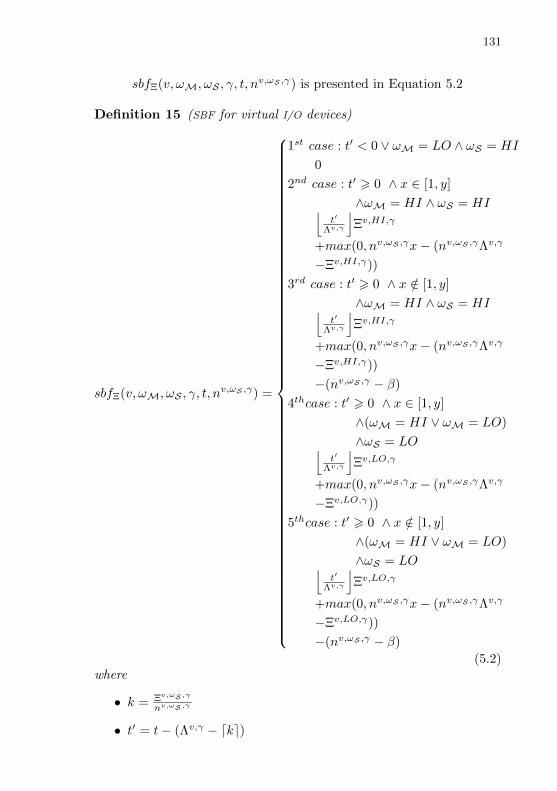
131
sbfΞ(v, ωM, ωS , γ, t, nv,ωS ,γ) is presented in Equation 5.2
Definition 15 (SBF for virtual I/O devices)
sbfΞ(v, ωM, ωS , γ, t, nv,ωS ,γ) =
1st case : t′ < 0 ∨ ωM = LO ∧ ωS = HI
0
2nd case : t′ > 0 ∧ x ∈ [1, y]
∧ωM = HI ∧ ωS = HI⌊t′
Λv,γ
⌋Ξv,HI,γ
+max(0, nv,ωS ,γx− (nv,ωS ,γΛv,γ
−Ξv,HI,γ))
3rd case : t′ > 0 ∧ x /∈ [1, y]
∧ωM = HI ∧ ωS = HI⌊t′
Λv,γ
⌋Ξv,HI,γ
+max(0, nv,ωS ,γx− (nv,ωS ,γΛv,γ
−Ξv,HI,γ))
−(nv,ωS ,γ − β)
4thcase : t′ > 0 ∧ x ∈ [1, y]
∧(ωM = HI ∨ ωM = LO)
∧ωS = LO⌊t′
Λv,γ
⌋Ξv,LO,γ
+max(0, nv,ωS ,γx− (nv,ωS ,γΛv,γ
−Ξv,LO,γ))
5thcase : t′ > 0 ∧ x /∈ [1, y]
∧(ωM = HI ∨ ωM = LO)
∧ωS = LO⌊t′
Λv,γ
⌋Ξv,LO,γ
+max(0, nv,ωS ,γx− (nv,ωS ,γΛv,γ
−Ξv,LO,γ))
−(nv,ωS ,γ − β)
(5.2)where
• k = Ξv,ωS ,γ
nv,ωS ,γ
• t′ = t− (Λv,γ − dke)
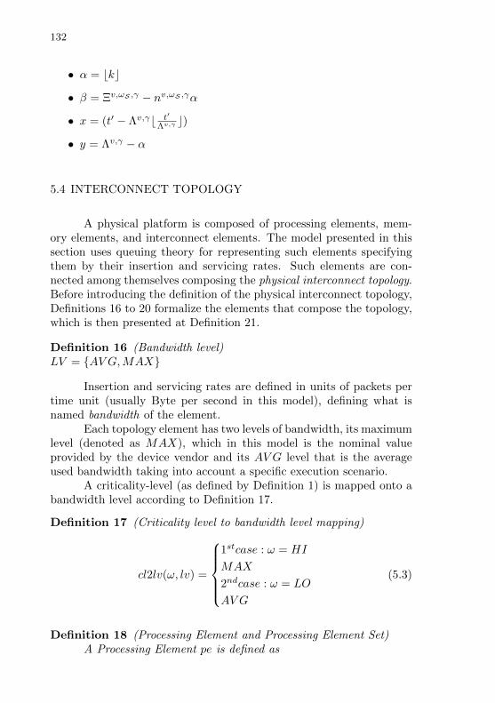
132
• α = bkc
• β = Ξv,ωS ,γ − nv,ωS ,γα
• x = (t′ − Λv,γb t′
Λv,γ c)
• y = Λv,γ − α
5.4 INTERCONNECT TOPOLOGY
A physical platform is composed of processing elements, mem-ory elements, and interconnect elements. The model presented in thissection uses queuing theory for representing such elements specifyingthem by their insertion and servicing rates. Such elements are con-nected among themselves composing the physical interconnect topology.Before introducing the definition of the physical interconnect topology,Definitions 16 to 20 formalize the elements that compose the topology,which is then presented at Definition 21.
Definition 16 (Bandwidth level)LV = AV G,MAX
Insertion and servicing rates are defined in units of packets pertime unit (usually Byte per second in this model), defining what isnamed bandwidth of the element.
Each topology element has two levels of bandwidth, its maximumlevel (denoted as MAX), which in this model is the nominal valueprovided by the device vendor and its AV G level that is the averageused bandwidth taking into account a specific execution scenario.
A criticality-level (as defined by Definition 1) is mapped onto abandwidth level according to Definition 17.
Definition 17 (Criticality level to bandwidth level mapping)
cl2lv(ω, lv) =
1stcase : ω = HI
MAX
2ndcase : ω = LO
AV G
(5.3)
Definition 18 (Processing Element and Processing Element Set)A Processing Element pe is defined as

133
pe = (λγ,lvpe )where
• λγ,lvpe denotes the pe insertion rate while executing the I/O opera-tion γ (see Definition 3) at the lv (see Definition 16) bandwidthlevel.
Additionally,PE is the set of all PCPUs and physical I/O devices in the system.
Definition 19 (Memory Element and Memory Element Set)A Memory Element me is defined asme = (µγ,lvme )where
• µγ,lvme denotes the servicing rate of me while servicing the γ oper-ation at the lv bandwidth level.
Additionally,ME is the set of all memory elements in the system. Usually it
represents a single main memory. Therefore, |ME| = 1.
Definition 20 (Interconnect Element and Interconnect Element Set)A Interconnect Element inter is defined asinter = (λγ,lvinter, µ
γ,lvinter) denoting insertion rate and servicing rate
of inter for γ operation and lv level, respectively.Additionally,INTER is the set of all interconnect elements in the system.
Given those definitions, a physical interconnect topology is pre-sented by Definition 21.
Definition 21 (Physical Interconnect Topology)A physical interconnect topology is defined as
Top(ωS) =
1stcase : ωS = HI
GHI
2ndcase : ωS = LO
GLO
(5.4)
where
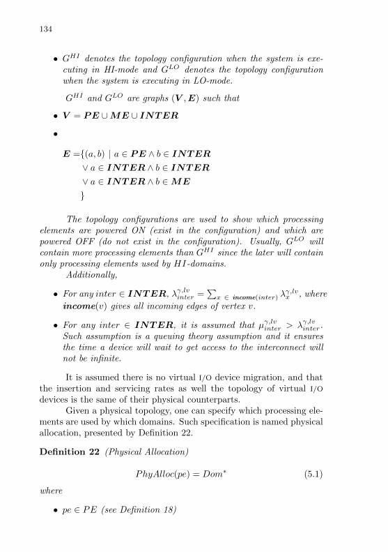
134
• GHI denotes the topology configuration when the system is exe-cuting in HI-mode and GLO denotes the topology configurationwhen the system is executing in LO-mode.
GHI and GLO are graphs (V ,E) such that
• V = PE ∪ME ∪ INTER
•
E =(a, b) | a ∈ PE ∧ b ∈ INTER∨ a ∈ INTER ∧ b ∈ INTER∨ a ∈ INTER ∧ b ∈ME
The topology configurations are used to show which processingelements are powered ON (exist in the configuration) and which arepowered OFF (do not exist in the configuration). Usually, GLO willcontain more processing elements than GHI since the later will containonly processing elements used by HI-domains.
Additionally,
• For any inter ∈ INTER, λγ,lvinter =∑x ∈ income(inter) λ
γ,lvx , where
income(v) gives all incoming edges of vertex v.
• For any inter ∈ INTER, it is assumed that µγ,lvinter > λγ,lvinter.Such assumption is a queuing theory assumption and it ensuresthe time a device will wait to get access to the interconnect willnot be infinite.
It is assumed there is no virtual I/O device migration, and thatthe insertion and servicing rates as well the topology of virtual I/O
devices is the same of their physical counterparts.Given a physical topology, one can specify which processing ele-
ments are used by which domains. Such specification is named physicalallocation, presented by Definition 22.
Definition 22 (Physical Allocation)
PhyAlloc(pe) = Dom∗ (5.1)
where
• pe ∈ PE (see Definition 18)
135
• Dom∗ is a list of domains (see Definition 7) that use pe.
HI-domains have exclusive access to their processing elements(|PhyAlloc(pe)| = 1), while LO-domains share processing elements.Memory and interconnect elements are assumed to be shared by alldomains.
5.5 OVERHEAD-FREE COMPOSITIONAL SCHEDULABILITY ANAL-YSIS
This section presents the schedulability conditions for the DRM
model. As will be explained, a task set of a domain can be scheduledby a DRM model if the worst case demand of its tasks is always inferiorto what is provided by the DRM, which is given by its SBFs. Beforeintroducing the schedulability condition, this section first defines theworst case demand of tasks. The resources (processing and I/O) demandof a task is defined by its own demand plus the interference caused byother tasks. It is important to mention that in this section, the terminterference is merely the time a task does not run because other tasksof higher priority are using the resources. Interference due to cache andI/O sharing is introduced on Section 5.8.
With the aforementioned notion of interference in mind, the firststep is to find an upper bound for it. This work extends the method-ology used by (BERTOGNA; CIRINEI; LIPARI, 2005) and (EASWARAN;
SHIN; LEE, 2009), which states that the interference a task τi can causein a task τk cannot be higher than the workload upper bound of τi ina time interval of length t, where t = b − a. Such methodology as-sumes that there is a job of τk that has b as deadline, denoted as τ bk .In addition, is assumed that τ bk loses its deadline. Thus, the whole ideais that if the interference is always lower than this bound, then tk isschedulable. The methodology also assumes an execution pattern inwhich τ bk and jobs of τi compete with each other, while one is runningthe other is not. Therefore, the workload upper bound assumes timesin which τk is running and times in which τi is running. The methodol-ogy proposed by (BERTOGNA; CIRINEI; LIPARI, 2005) targets the gEDF
scheduling algorithm for multiprocessor platforms. The methodologyproposed by (EASWARAN; SHIN; LEE, 2009) extends the methodologyproposed by (BERTOGNA; CIRINEI; LIPARI, 2005) for a virtualized sce-nario and it is also based on gEDF. This work extends the methodologyproposed by (EASWARAN; SHIN; LEE, 2009) taking into account not onlyprocessing but I/O, and taking into account a MC scenario. Being an ex-
136
tension of (BERTOGNA; CIRINEI; LIPARI, 2005) and (EASWARAN; SHIN;
LEE, 2009), this work also uses gEDF as the intra-domain schedulingalgorithm, which reflects on the proposed scheduling tests presentedthis section and Section 5.8. gEDF is suitable for this work proposalsince, inside the same domain, all tasks will share the same physicalresources and will have the same criticality.
This work proposes two notions of workload bound of task τiin a time interval of length t, where t = b − a. The VCPU workloadbound (WΘi) and the virtual I/O device workload bound (WΞi), whichare defined in Equation 5.2 and Equation 5.5, respectively.
WωΘi(t) = NiC
ωi + εωΘi(t) (5.2)
where
• Ni is defined in Equation 5.3 and denotes the number of jobs ofτi that start after (or at) a and finish before (or at) b.
• εωΘi(t) is the carry-in demand generated by a job that has startedbefore a and finishes during the interval b − a. εωΘi(t) is definedin Equation 5.4.
Ni = b t−Di
Tic+ 1 (5.3)
εωΘi(t) = min(Cωi ,max(0, NiTi)) (5.4)
W v,ω,γΞi (t) = NiR
v,ω,γi + εv,ω,γΞi (t) (5.5)
where
• εv,ω,γΞi (t) is the carry-in demand generated by a job that hasstarted before a and finishes during the interval b− a. εv,ω,γΞi (t) isdefined in Equation 5.6.
εv,ω,γΞi (t) = min(Rv,ω,γi ,max(0, NiTi)) (5.6)
The interval [a, b] in which the workload bound is computed fol-lows the Definition 23.
Definition 23 (Workload Execution Pattern)Given the execution Interval = [a, b] where a and b are two points
in time, expressed in some time unit (usually a sub-multiple of second).
137
Such interval is divided into two parts, (a, r] and (r, b]), where rrepresents the release time of the job τ bk.
It is assumed that in instant “a” there is at least one idle process-ing element and that in the interval (a, b] there are no idle processingelements.
Additionally,
• Ak (given by r − a) is the length of the interval (a, r],
• Dk (given by b− r) is the length of the interval (r, b]).
For VCPU workloads Ak can be expressed as AωΘk to match withWω
Θi. Conversely, for virtual I/O device workloads Ak can be expressedas Av,ω,γΞk to match with W v,ω,γ
Ξi . However, whenever is possible to inferfrom the context, just Ak is used to simplify the notation.
The total demand (or total workload) in this [a, b] interval isdenoted by IωΘi (VCPU demand) or by Iv,ω,γΞi (I/O device demand). Thetotal demand can be divided in times where τk is running that aredefined as type-1 intervals, represented by IωΘ1,i and Iv,ω,γΞ1,i , and timeswhere τk is not running that are defined as type-2 intervals, representedby IωΘ2,i and Iv,ω,γΞ2,i .
The total type-1 demand IωΘi,1 and Iv,ω,γΞi,1 are respectively bounded
by IωΘi,1 and Iv,ω,γΞi,1 . Equation 5.7 and Equation 5.8 define those bounds.
IωΘi,1 = Ck (5.7)
Iv,ω,γΞi,1 = Rv,ω,γk (5.8)
The upper bounds for type-1 demand is straightforward andstates that τ bk cannot execute more than its required CPU and I/O devicebudgets.
The total type-2 demand IωΘi,2 and Iv,ω,γΞi,2 are respectively bounded
by IωΘi,2 and Iv,ω,γΞi . Equation 5.9 and Equation 5.10 define thosebounds.
IωΘi,2 =
1stcase : ∀i 6= k
min(WωΘi(Ak +Dk), Ak +Dk − Cωk )
2ndcase : i = k
min(WωΘk(Ak +Dk)− Cωk , Ak)
(5.9)

138
Iv,ω,γΞi,2 =
1stcase : ∀i 6= k
min(W v,ω,γΞi (Ak +Dk), Ak +Dk −Rv,ω,γk )
2ndcase : i = k
min(W v,ω,γΞk (Ak +Dk)−Rv,ω,γk , Ak)
(5.10)
In the first case (i 6= k) of Equations 5.9 and 5.10, the firstargument of the minimal function states that the interference cannotbe bigger than the workload upper bound. In addition, the secondargument of min states that interference does not need to be biggerthan total interval (Ak + Dk) minus the execution time of τk itselfsince it is already taken into account on type-1 intervals. In the secondcase (i = k) of Equations 5.9 and 5.10, the execution time of τk issubtracted of the workload upper bound (first argument of min). Inthe second argument of min, the maximum time τk will not execute itsthe time interval previous of τ bk release (i.e. (a, r] that has Ak length).
Terms IωΘi,2 and Iv,ω,γΞi are defined by Equation 5.11 and Equation
5.12. Their definition is similar definition to IωΘi,2 and Iv,ω,γΞi , however,they discount the carry-in demand.
IωΘi,2 =
1stcase : ∀i 6= k
min(WωΘi(Ak +Dk)− εωΘi(Ak +Dk), Ak +Dk − Cωk )
2ndcase : i = k
min(WωΘi(Ak +Dk)− Cωk − εωΘk(Ak +Dk), Ak)
(5.11)
Iv,ω,γΞi =
1stcase : ∀i 6= k
min(W v,ω,γΞi (Ak +Dk)− εv,ω,γΞi (Ak +Dk), Ak +Dk −Rv,ω,γk )
2ndcase : i = k
min(W v,ω,γΞi (Ak +Dk)−Rv,ω,γk − εv,ω,γΞi (Ak +Dk), Ak)
(5.12)
Upper bound on the Worst Case Resource Demand (WCRD) ofa task in the interval (a, b]

139
DEMΘ(ωk, ωS , Ak +Dk,mωS ) = mωSCωk +
n∑i=1
IωΘi,2
+∑
i:i∈L(mωS−1)
(IωΘi,2 − IωΘi,2)
(5.13)
DEMΞ(v, ωk, ωS , γ, Ak +Dk, nv,ωS ,γ) = nv,ωS ,γRv,ω,γk +
n∑i=1
Iv,ω,γΞi,2
+∑
i:i∈L(nv,ωS ,γ−1)
(Iv,ω,γΞi,2 − Iv,ω,γΞi,2 )
(5.14)
A precondition for a domain to be schedulable by a given DRM isthat the total domain utilization is smaller than the resource bandwidthprovided by the DRM, as presented by Definition 24.
Definition 24 (Domain Schedulability Precondition)UωSτΘ < ΘωS
Π ∧ Uv,ωS ,γτΞ < Ξv,ωS ,γ
Λv,γ
For scheduling analysis purposes, the time interval of length Akcan be bound to a maximum value. Definition 25 presents how to com-pute this bound for VCPUs and Definition 26 presents how to computethis bound to virtual I/O devices.
Definition 25 (Maximum AωSΘk)
AωSΘkmax =
CωS Σ+mωSCωSk +B−Dk( ΘωS
Π −UωSτΘ )
ΘωSΠ −UωS
τΘ
where
• CωSΣ =
∑i:i∈L(mωS−1) C
ωSi
is the sum of the (mωS − 1) largest VCPU budgets in the task set.
• B = ΘωS
Π [2 + 2(Π− ΘωS
mωS )]
Definition 26 (Maximum Av,ωS ,γΞk )
Av,ωS ,γΞkmax =
Rv,ω,γΣ +n′v,γRv,ω,γk +B−Dk( Ξv,ωS ,γΛv,γ −Uv,ωS ,γ
τΞ )Ξv,ωS ,γ
Π −Uv,ωS ,γτΞ

140
Akmax comes from a more pessimistic version for WCRD than theone defined by Equation 5.13 and Equation 5.14.
Finally, domain schedulability can be verified using Theorem 1.
Theorem 1 (Domain Schedulability)A domain D composed of mωS VCPUs, nv,ωS ,γ virtual I/O de-
vices, and a periodic task set τ is schedulable under gEDF using theDRM M if the precondition described by Definition 24 is satisfied and:
• ∀τk ∈ τ,
• ∀Ak(AωΘk or Av,ω,γΞk ) ∈ [0, Akmax),
• ∀ωS ∈ Ω,
• ∀v ∈ R,∀γ ∈ Γ:
DEMΘ(ωk, ωS , AωΘk +Dk,m
ωS ) 6 sbfΘ(ωM, ωS , t,mωS )
(T1)
∧ DEMΞ(v, ωk, ωS , γ, Av,ω,γΞk +Dk, n
v,ωS ,γ) 6 sbfΞ(v, ωM, ωS , γ, t, nv,ωS ,γ)
The reasoning behind Akmax is that if there is some Ak for whichthe verification condition of Theorem 1 is violated, then such an Ak issmaller than Akmax. Therefore, one needs to check for schedulabilityuntil Akmax.
After defining all DRMs the system is expected to have (one foreach domain), one needs to check whether the underlining physicalplatform is capable of providing the required resources. The idea is totransform each DRMM into a task set τM as detailed in Definition 27and then check whether that task set is schedulable.
Definition 27 (Transformation of a DRM into a task set)
• Given M = 〈ωM,Π,ΘωS ,mωS ,Λv,γ ,Ξv,ωS ,γ , nv,ωS ,γ〉
• Given the usual period task definition τi = (Ti, Ei, Di) (period,execution time, deadline).
• τM = τΘ ∪ τv,γΞ (∀v ∈ R,∀γ ∈ Γ)

141
• Compute τΘ by
τ1 = ... = τk = (Π, b cΘcmc+ 1,Π)
τk+1 = (Π, b cΘcmc+ Z − kbZ
kc,Π)
τk+2 = ... = τcm = (Π, b cΘcmc,Π)
where:
– cΘ = max(ΘLO,ΘHI)
– cm = max(mLO,mHI)
– Z = cΘ− cmb cΘcmc– k = bZc
• Compute τv,γΞ (∀v ∈ R,∀γ ∈ Γ) by
τ1 = ... = τk = (Λv,γ , bcΞv,γ
cnv,γc+ 1,Λv,γ)
τk+1 = (Λv,γ , b cΞv,γ
nv,ωS ,γc+ Z − kbZ
kc,Λv,γ)
τk+2 = ... = τcnv,γ = (Λv,γ , bcΞv,γ
cnv,γc,Λv,γ)
where:
– cΞv,γ = max(Ξv,LO,γ ,Ξv,HI,γ)
– cnv,γ = max(nv,LO,γ , nv,HI,γ)
– Z = cΞv,γ − cnv,γb cΞv,γ
cnv,γ c– k = bZc
The task set τΘ defines all VCPUs of a domain. The τΘ task setwill be composed of cm = max(mLO,mHI) tasks. Since the systemis running in either LO or HI mode, there are no distinct VCPUs foreach criticality level, instead the level that presents more units in theDRM is chosen. Similarly, task sets of type τv,γΞ will define the IOVCPUsfor each v class and γ operation. There will be v · γ task sets of thetypeτv,γΞ , each one with size cnv,γ = max(nv,LO,γ , nv,HI,γ).
Theorem 2 (System Schedulability)

142
• Given that the system is composed of ND domains, and that MSis the set of all of their respective DRMs.
• τsys = ∪(τM)∀M∈MS represents the task set of the whole system.
• Given τvΞsys as the set of all IOVCPU task sets (indexed by I/O
device class v).
• Given a function gv : R→ R′ that maps time units onto the usualresource units of the I/O device class (e.g. bytes per second).
• Given the set of all physical I/O device ϕR classes that has a 1 to1 correspondence with R.
• Given that the budget provided by a physical I/O device class v(in the usual resource units of the I/O device class) is nv,ωS ,γXv.
The system is schedulable by the underling physical platform if
1. τsys is schedulable by the platform PCPUs
2. and ∀v ∈ ϕR :∑τi∈τvΞsys
g(Ei) 6 nv,ωS ,γXv
Condition 1 of Theorem 2 ensures the schedulability of all VCPUsand IOVCPUs in the system. Condition 2 of Theorem 2 ensures thatthe required budget of all virtual I/O devices will not be grater thenthe provided by their physical counterparts.
5.6 DRM GENERATION
This section introduces the proposed algorithms for generating aDRM that is able to schedule a given domain. The proposed algorithmfor DRM generation is Algorithm 1, which uses the Algorithm 2 as itscore.
The inputs for Algorithm 1 are the domain task set (τ), thedomain criticality (ωD), the DRM VCPU (Π) and virtual I/O device(Λv,γ) periods, the set of system criticality-levels (Ω), the set of virtualI/O devices classes (R), and the set of virtual I/O devices operations(Γ). The output of the algorithm it a DRM (M) that has the minimumrequired resources to schedule the given domain. In this version of thealgorithm the domain always have some VCPU load but the virtual I/O
device load can be zero. In that case, the original virtual I/O device

143
ALGORITHM 1 DRM generation.
Input: τ , ωD, Π, Λv,γ , Ω, R, ΓOutput: M = 〈ωM,Π,ΘωS ,mωS ,Λv,γ ,Ξv,ωS ,γ , nv,ωS ,γ〉ωM ← ωDΘωS ,mωS ← Budget and quantity for specifics ∀ ωS ∈ ΩΞv,ωS ,γ , nv,ωS ,γ ← Budget and quantity for specifics ∀ v ∈ R, ωS ∈Ω, γ ∈ Γif all nv,ωS ,γ are zero then
Λv,γ ← 0end ifcreate M = 〈ωM,Π,ΘωS ,mωS ,Λv,γ ,Ξv,ωS ,γ , nv,ωS ,γ〉ensure M schedules τ (using Theorem 1)
period is adjusted to zero. A similar adjustment can be performed forVCPU period if the VCPU load is allowed to be zero in the domain.However, a domain that has both VCPU and virtual I/O device loads aszero makes no practical sense. Algorithm 1 tries to generate a feasiblequantity and budget for all criticality levels, and devices classes andoperations. For such, it uses the Algorithm2.
The Algorithm 2 is based on the descriptions of how to generate aMPR from the (EASWARAN; SHIN; LEE, 2009) paper. In the (EASWARAN;
SHIN; LEE, 2009) paper, however, the actual algorithm is not shown.Besides, Algorithm 2 is designed to support MC, and distinct virtualI/O device classes and operations. The |τ | of Algorithm 2 denotes thenumber of guest OS tasks in the domain. The Algorithm 2 performs alinear search on all possible quantities and budgets until it founds theminimal ones that are able to schedule the given domain while usingthe given parameters (criticality level and, for virtual I/O devices, thedevice class and operation).
5.7 VIRTUALIZATION OVERHEAD
Before introducing the formalization of sources of memory andI/O overhead, which is done in Section 5.8, it is important to take intoaccount the overhead introduced by the hypervisor itself. This sectionformalizes hypervisor overheads, which are later used for inflating therequired budget of guest OS tasks.
Two types of hypervisor overhead are associated with the MC
nature of guest OS tasks scheduling employed in this proposal. The first
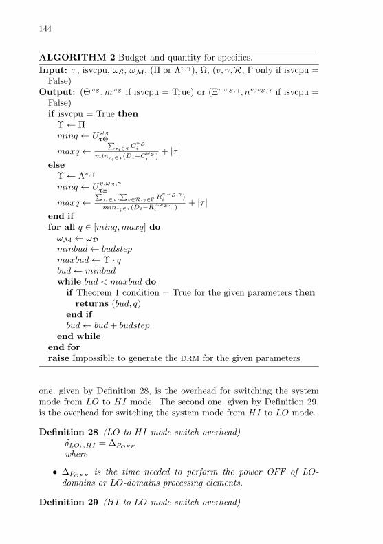
144
ALGORITHM 2 Budget and quantity for specifics.
Input: τ , isvcpu, ωS , ωM, (Π or Λv,γ), Ω, (v, γ,R, Γ only if isvcpu =False)
Output: (ΘωS ,mωS if isvcpu = True) or (Ξv,ωS ,γ , nv,ωS ,γ if isvcpu =False)if isvcpu = True then
Υ← Πminq ← UωS
τΘ
maxq ←∑τi∈τ C
ωSi
minτi∈τ(Di−CωSi )
+ |τ |else
Υ← Λv,γ
minq ← Uv,ωS ,γτΞ
maxq ←∑τi∈τ(
∑v∈R,γ∈Γ R
v,ωS ,γi )
minτi∈τ(Di−Rv,ωS ,γi )
+ |τ |end iffor all q ∈ [minq,maxq] doωM ← ωDminbud← budstepmaxbud← Υ · qbud← minbudwhile bud < maxbud do
if Theorem 1 condition = True for the given parameters thenreturns (bud, q)
end ifbud← bud+ budstep
end whileend forraise Impossible to generate the DRM for the given parameters
one, given by Definition 28, is the overhead for switching the systemmode from LO to HI mode. The second one, given by Definition 29,is the overhead for switching the system mode from HI to LO mode.
Definition 28 (LO to HI mode switch overhead)δLOtoHI = ∆POFF
where
• ∆POFF is the time needed to perform the power OFF of LO-domains or LO-domains processing elements.
Definition 29 (HI to LO mode switch overhead)

145
δHItoLO = ∆PON
where
• ∆PON is the time needed to perform the power ON of LO-domainsor LO-domains processing elements.
The LO to HI mode switch occurs every time the hypervisordetects that HI-tasks will become unschedulable at LO mode (thescheduling test is presented in Section 5.8) taking into account LLC
miss and interconnect contention overhead. The LO to HI mode switchoverhead quantifies the cost of such mode switch. Conversely, the HIto LO mode switch overhead occurs whenever the system switches backfrom HI to LO mode.
Definition 30 summarizes the mode switch overhead dependingon the current system mode and whether the decision of performingthe mode switch has been taken.
Definition 30 (Mode Switch Overhead)
δms =
1st case : ωS = LO ∧ testfails
δLOtoHI
2nd case : ωS = HI ∧ noHIjob∧ ELAPSED ∧ testpass
δHItoLO
Otherwise :
0
(5.15)
The first case of Definition 30 indicates the HI to LO modeswitch case, the system is in LO mode, and the overhead-aware schedul-ing test has failed. The second case indicates the LO toHI mode switchcase, the system is in HI mode for a given ELAPSED time, there is nojob of HI-task pending (noHIjob), and the overhead-aware schedulingtest has passed. The idea of ELAPSED is to spend some time in HImode before switching back to LO mode even if the scheduling testpass. That can be used to give the system some “inertia”, preventingneedless back-and-forth HI to LO mode switching. The other casesrepresent the decision of not performing the mode switch (either be-cause the system is in LO mode and the scheduling test pass or becausethe system is in HI mode and the conditions for switching back to LOmode have not being fulfilled yet).
The Mode Switch Overhead only includes the time for poweringOFF or ON processing elements, but not the time taken to decide

146
whether to do so. That is part of the “Host Scheduling Overhead”,introduced by Definition 31.
Definition 31 (Host Scheduling Overhead)δhyper = ∆test + δms + ∆rel + ∆sch + ∆cxtst + ∆cxtld
where
• ∆test is the scheduling test delay, defined as the time taken todecide whether a system mode switch shall happen.
• δms is the mode switch delay, as given by Definition 30.
• ∆rel is the release delay, defined as the time between the schedul-ing interrupt in the hypervisor (i.e. host-level), which indicatesthat a virtual processing element is ready for executing and thetime it is selected to be scheduled.
• ∆sch is the scheduling delay, defined as the time for choosing avirtual processing element to execute.
• ∆cxtst is the context store delay, defined as the time taken tostore the context of the virtual processing element that will leavethe physical processing element.
• ∆cxtld is the context load delay, defined as the time taken to loadthe context of the virtual processing element that was chosen toexecute into it correspondent physical processing element.
The host scheduling overhead includes three main components.The first one is the time the hypervisor takes to decide whether a modeswitch shall me performed (∆test) based on the sampled interferencevalues and on the overhead-aware scheduling test introduced in Section5.8. The second one is the time to perform the mode switch itself (δms).The third one is the time associated with the scheduling of virtualprocessing elements (VCPUs and virtual I/O devices on the physicalprocessing elements). This overhead occurs on each Π (VCPU period)or Λv,γ (virtual I/O device period).
5.8 OVERHEAD-AWARE COMPOSITIONAL SCHEDULABILITY ANAL-YSIS
This section formalizes the sources of memory and I/O over-head presented in Sections 4.4 and 4.2, respectively, and it presentsthe schedulability conditions taking into account such overheads.

147
5.8.1 LLC miss overhead
Definition 32 (LLC miss overhead)
δωSΘ =
1st case : ωS = HI
WCmiss∆miss
2nd case : ωS = LO
AV Gmiss∆miss
(5.16)
where
• ∆miss is the delay caused by one cache miss event (choice of whichcache line will be evicted and its replacement by the contents re-trieved from the main memory).
• WCmiss is the maximum number of cache misses events duringa period.
• AV Gmiss is the average number of cache misses events during aperiod.
How tasks are affected, inflation of CωSi
Definition 33 (Inflated required VCPU budget)
CωS′′
i = CωSi + dT i−(
∑x∈R,γ∈Γ R
x,ωS ,γi )
Π eδωSΘ
5.8.2 Interconnect Contention overhead
The interconnect overhead that each virtual I/O device will suffercomes from the interconnect time that its physical counterpart willexperience on the interconnect element it is directly connected to. Theinterconnect element of the physical I/O device in question is obtainedfrom the interconnect topology that follows the structure described inSection 5.4. Definition 34 shows how to compute the contention timeCT v,ω,γ on the interconnect used by the I/O device of class v while ωs =ω and I/O device is executing γ operation. The equation assumes theinterconnect element (queue) with deterministic arrival and servicingtimes that follow a Poisson distribution (M/D/1 queue). M/D/1 queuesassume one server and that is always valid in the considered topologiessince each I/O device is connected to a single interconnect element.

148
Definition 34 (Interconnect contention time)
CT v,ωS ,γ =λγ,cl2lv(ωS)inter
2µγ,cl2lv(ωS)inter (µ
γ,cl2lv(ωS)inter − λγ,cl2lv(ωS)
inter )(5.17)
where
1. λγ,cl2lv(LO)inter and µ
γ,cl2lv(LO)inter ∈ V of Top(LO)
2. λγ,cl2lv(HI)inter and µ
γ,cl2lv(HI)inter ∈ V of Top(HI)
Observations 1 and 2 remember that not only the bandwidthlevel (see Definition 16) changes but also the topology is different whenchanging ωS . That is because in Top(HI) the processing elementsassociated with LO-domains are powered OFF.
The interconnect contention overhead, as show by Definition 35is exactly the interconnect contention time.
Definition 35 (Interconnect contention overhead)δv,ωS ,γΞ = CT v,ω,γ
Queuing theory usually works with distributions that are repre-sented by their average time, thus becoming unsuitable for modeling theworst-case required while modeling HRT systems. This work proposesto overcome such limitation by using the worst-case time as the aver-age time for computing the system requirements in the HI criticalitylevel. Therefore, values above the average will not occur in practice.For the LO criticality level, this approach will use the average timevalues for computing system requirements. Therefore, this approach ispessimistic in the HI criticality level and takes into account the averagecase in the LO criticality level.
How tasks are affected, inflation of Rv,ω,γi
Definition 36 (Inflated required virtual I/O device budget )
Rv,ωS ,γ′′
i = Rv,ωS ,γi + dT i−(C
ωSi +
∑x∈R\v,γ∈Γ R
x,ωS ,γi )
Λv,γ eδv,ωS ,γΞ
5.8.3 Schedulability Analysis
A domain D composed of a task set τ is scheduled under gEDF
by a DRM in the presence of memory and interconnect overhead if the
149
inflated task set τ ′′ is scheduled under gEDF by the same DRM whileusing the SBF in the absence of overhead.
The same goes for the whole system schedulability after trans-forming all DRM into tasks as explained by Definition 27.
5.9 OVERALL DYNAMICS
The scheduling strategy can be divided in two parts, one duringdesign time and the other during runtime. The goal of the designtime part is to compute DRMs for HI-domains in a way to ensure theirschedulability in HI and LO modes while taking into account LLC missand I/O interconnect contention overheads.
Two variants of the design time part are envisioned. The firstone (summarized in Section 5.9.1) handles the cases where both HIand LO domains requirement are known beforehand. The second one(summarized in Section 5.9.2) handles the cases where only HI require-ments are known beforehand.
The runtime part of both variants is similar, and the LO toHI mode switch can be triggered either reactively or predictively. Inthe reactive mode switch, the system switches from LO to HI modewhenever a HI-task job is not able to complete using its LO-budget(either CLO or Rv,LO,γ). In the predictive mode the system will beoperating on a Monitoring-decide-act cycle where decisions are taken.In such Monitoring-decide-act cycle, overhead-related information isgathered and used to predict the inflation of CLO and Rv,LO,γ of HI-tasks. Such inflated budgets are compared with the DRM of the domainsobtained from the design phase and an overhead-aware schedulabilitytest is performed. If the overhead-aware schedulability test fails thesystem switches to HI mode.
In the event of a LO to HI mode switch, processing elementsassigned to LO-domains and the LO-domains themselves are poweredOFF as described in Section 4.2. As the computed overhead startsto decrease, the inflation on the execution budgets will decrease andthe overhead-aware schedulability will pass. Then, processing elementsassigned to non-critical domains can be powered ON again, gradually.Additionally, a HI to LO mode switch will only occur when there areno pending HI-jobs (i.e. all HI-tasks have concluding their jobs in HImode for that period).
Regarding the overhead-related information, ∆miss, WCmiss,and AV Gmiss can be obtained by consulting HPC registers. All vari-
150
ables are measured in the design time while executing HI-domainsin conjunction with known LO-domains (or with the Slack Domain).Those LLC-related variables are sampled on each VCPU period. Duringruntime, all variables are continued to being measured in the Monitoring-decide-act cycle while executing all loaded domains.
5.9.1 Variant 1: Knowing the requirements of LO-domains
Design Time
1. Requirements of HI-domains and LO-domains are given
2. Physical Topology and physical allocation are given
(a) δv,ωS ,γΞ is computed (using Top(FULL) and the known Top(LO))
3. HI-domains and known LO-domains run, one by one, cumula-tively
(a) WCmiss and AV Gmiss are measured
(b) δHIΘ and δLOΘ are computed
(c) The mappings CHI to δHIΘ and CHI to δLOΘ are recorded
4. A function fCδΘ that approximates the mapping CωS to δωSΘ is
computed. Are also computed the total VCPU requirement (sumof all domains), denoted as CωallS .
5. Task’s CHI and Rv,HI,γ are inflated using δHIΘ = fCδΘ(KCHIall )
and δv,FULL,γΞ , while task’s CLO and Rv,LO,γ are inflated using
δLOΘ = fCδΘ(KCLOall ) and δv,LO,γΞ . K is a constant.
6. DRMs are computed using the inflated tasks. The constant Kopens the possibility (if K > 1) of accepting new domains thatarrive at runtime.
7. Domains schedulability and system schedulability is checked/en-sured (for all ωS modes).
Runtime
1. HI-domains and known LO-domains start to run

151
2. Eventually, new LO-domains can be added if their requirementis known and there is enough budget for them
3. Monitoring-decide-act cycle
In Step 2 of runtime, the hypervisor uses the new LO-domainrequirements as inputs to check HI-domains (in HI mode) and system(all modes) schedulability. If it detects that one of the HI-domains (inHI mode) or the system will become unschedulable (overhead-awaretest) the new LO-domain is not admitted in the system. RegardingLLC miss overhead, the overhead the new LO-domain can cause in thesystem is estimated using fCδΘ. Regarding interconnect contentionoverhead, the overhead is computed using an updated (the new domainscan use devices that the domains in the design phase did not use)version of Top(LO).
5.9.2 Variant 2: Using the Slack Domain
Design Time
1. Requirements of HI-domains are given
(a) DRMs are computed (optional intermediate step)
2. Physical Topology is given
(a) δv,ωS ,γΞ is computed
3. HI-domains run alone
(a) WCmiss is measured
(b) Task’s CHI and Rv,HI,γ are inflated using WCmiss and
δv,HI,γΞ
(c) 3b 7→ Slack Domain is computed
(d) (2a, 3a) 7→ DRMs are recomputed to attend the inflated tasks(optional intermediate step)
4. HI-domains and Slack Domain run
(a) AV Gmiss is measured
(b) Task’s CLO and Rv,LO,γ are inflated using AV Gmiss and
δv,LO,γΞ (HI-domains only)
152
(c) 4b 7→ Slack Domain is recomputed
(d) (2a, 4a) 7→ DRMs are recomputed to attend the inflated tasks(optional intermediate step)
5. (2a, 3a, 4a) 7→ HI-domain DRMs are computed
6. (4c) 7→ DRM for Slack Domain is computed
7. HI-domains schedulability and system schedulability is checked/en-sured.
Runtime Time
1. HI-domains run alone
2. LO-domains start to run (one by one or simultaneously), eachusing a fraction of Slack Domain budgets
3. Monitoring-decide-act cycle
The AV Gmiss measured when LO-domains start to run (in con-junction with HI-domains) should have a similar value to the AV Gmissmeasured while running HI-domains and the Slack Domain together(in the design phase). In practice, due to hypervisor overhead (e.g.VCPU scheduling), it is possible that the former is higher than the lat-ter since LO-domains will be composed of several tasks while SlackDomain has a single task.
5.10 DISCUSSION
The proposed model extends the VCPU-related definitions foundin (EASWARAN; SHIN; LEE, 2009) to a MC scenario and presents virtualI/O device definitions that encompass MC, two operations (“read” and“write”), and multiple virtual I/O device classes.
Additionally, the proposed model extends the cache-related over-head definitions found in (XU et al., 2013) to a MC scenario and presentsnew virtual I/O device-related overhead definitions based on queuingtheory.
The proposed hypervisor overhead definition, presented in Sec-tion 5.7 is based on the one presented by (NELSON et al., 2014), ex-tending it for virtual I/O devices. The goals, however, are different.While (NELSON et al., 2014) uses similar definition for defining cycle-accurate virtual processor context switch, this works focuses on defininga scheduling overhead to be used into account on scheduling tests.

153
6 EVALUATION OF THE PROPOSED MODEL
This chapter evaluates the proposed design time and runtimestrategy introduced in Section 5.9. Such strategy, in turn, employs themodeling approach proposed in Chapter 5, and the techniques describedin Chapter 4.
All evaluations were performed analytically by simulating prac-tical executions, instead of performing experiments in a real platform.The main reason for employing an analytical approach is that, as farwas possible to identify, no single hypervisor implements all the tech-niques required by this work proposal such as, composite MC real-timescheduling, powering ON and OFF physical and virtual devices, page-coloring, and time-deterministic multilevel interrupt handling.
Section 6.1 evaluates the proposed scheduling test for distinctdomains and guest OS tasks, while comparing it to a gEDF schedulingtest.
Section 6.2 evaluates the impact that guest OS tasks of LO-domains have on guest OS tasks of a HI-domain. First, it evaluatesthe LLC miss overhead over execution time while the HI-domain exe-cutes together with a LO-domain expected at design time and with twoadditional LO-domains that come at runtime. Then, it compares theproposed approach with the MPR approach introduced by (EASWARAN;
SHIN; LEE, 2009) regarding PCPU requirement, and schedulability deci-sions over time (DRM vs MPR).
Section 6.3 closes the chapter presenting a discussion of the ob-tained results and their implication while compared to related works.
6.1 SCHEDULABILITY EVALUATION
This section evaluates the overhead-free domain schedulabilitytest introduced by Definition 1 in Section 5.5 for distinct task setsand distinct whole-domain utilizations. From the point-of-view of theDRM-based approach, each task set is a domain, composed of guestOS tasks. To give an idea of how the proposed domain schedulabilitytest performs, it is compared to the gEDF schedulability test proposedby (GOOSSENS; FUNK; BARUAH, 2003) that is shown is Section 2.2. Itshould be noted, however, that the two tests are not direct comparablesince the domain schedulability test takes into account a virtualizedplatform where the VCPUs are not available to the domain one hundred
154
percent of the time, which is the case of gEDF that is agnostic fromwhether the underling platform is virtual or physical. The evaluationtakes into account a single HI-domain and, for comparing it to gEDF, ittakes into account only the HI budget of tasks (the LO budget of everytask is zero). The number of processors, used as input for the gEDF
test (m) is taken from the DRM used for the domain schedulability test(i.e. m = mHI).
The method for generating the task sets is based on the methodpresented by (BASTONI; BRANDENBURG; ANDERSON, 2010) for multi-processor platforms. The proposed method extends (BASTONI; BRAN-
DENBURG; ANDERSON, 2010) to take into account not only CPU butalso I/O device budgets. The proposed method generates synthetictask sets, each task having distinct VCPU and virtual I/O device bud-gets. First, the proposed method generates task sets while ranging thewhole-domain utilization from 2 to 8 using a step of 1, thus generating6 whole-domain utilization “steps”. The proposed method generates aDRM capable of scheduling all domains (all task sets) generated fromthe [2, 8] whole-domain utilization range. A whole-domain utilization iscomputed not only from VCPU budget but also from virtual I/O devicebudget. Therefore, the proposed method keeps generating task setsuntil the VCPU utilization of a task set (UωS
τΘ ) reaches the maximumestablished whole-domain utilization (i.e.: until UωS
τΘ = 8). Each task isgenerated by using random values of a given distribution. The periodof each guest OS task is randomly obtained from an uniform distribu-tion in the interval [25 ms, 200 ms]. The whole-task utilization of eachguest OS task is randomly obtained from an uniform distribution in theinterval [0.1, 0.9]. The whole-task utilization if further divided in orderto compute the VCPU and virtual I/O device budgets. The gEDF testonly takes into account the VCPU budget, ignoring the virtual I/O de-vice ones. The domain schedulability test takes into account all thosebudgets.
The Listing shown in Figure 15 illustrates how the whole-taskutilization is divided in order to compute the VCPU and virtual I/O
device budgets of each task. As show in the Listing, in the evaluationof this section two classes of virtual I/O device are taken into account,named CM and FS. The multiplication of the αi values of Listing15 with the whole-task utilization gives the utilization for each typeof budget. The subsequent multiplication by the task period gives thebudget. The Dirichlet distribution (BALAKRISHNAN; NEVZOROV, 2003)is employed in such a way the sum of all randomly generated αis is 1(one). Additionally, each αi individually fits in the interval [0.01, 1].

155
• CHIi = α0 · WTUHIi · T i
• RCM,HI,rdi = α1 · WTUHIi · T i
• RCM,HI,wri = α2 · WTUHIi · T i
• RFS,HI,rdi = α3 · WTUHIi · T i
• RFS,HI,wri = α4 · WTUHIi · T i
Figure 15: Division of WTUHIi .
Table 7: Generated DRM.
DRM
ωM HIΠ 1.0E-03ΘHI 3.5E-03mHI 4ΛCM,rd=wr 1.0E-03ΞCM,HI,rd=wr 3.5E-03nCM,HI,rd=wr 4ΛFS,rd=wr 1.0E-03ΞFS,HI,rd=wr 3.5E-03nFS,HI,rd=wr 4
The first obtained αi is the one that will define the VCPU budget, whilethe others will define the virtual I/O device budgets. The order of eachvirtual I/O device class and operation is also randomly obtained. TheListing 15 shows just one example of order in which the CM, rd appearfirst but it could be for example, first FS,wr, followed by CM,wr orany other possible combination.
Table 7 shows the generated DRM employed in the domain schedu-lability test analysis. For the gEDF test it was used m = 4.
Figure 16 shows the obtained results of the DRM-based and(GOOSSENS; FUNK; BARUAH, 2003) gEDF schedulability tests, while us-ing the proposed method for task set generation. DRM can scheduleall task sets up to whole-domain utilization equals 8. gEDF also goes upto 8 (in which the total VCPU utilization UωS
τΘ = 1.9). DRM and gEDF
fail to schedule with whole-domain utilization equals to 9 (in which
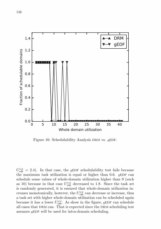
156
0 5 10 15 20 25 30 35 40
Whole domain utilization
0.0
0.2
0.4
0.6
0.8
1.0
1.2
1.4
Fract
ion o
f sc
hedula
ble
dom
ain
s
DRM
gEDF
Figure 16: Schedulability Analysis DRM vs. gEDF.
UωSτΘ = 2.4). In that case, the gEDF schedulability test fails because
the maximum task utilization is equal or higher than 0.6. gEDF canschedule some values of whole-domain utilization higher than 9 (suchas 10) because in that case UωS
τΘ decreased to 1.8. Since the task setis randomly generated, it is ensured that whole-domain utilization in-creases monotonically, however, the UωS
τΘ can decrease or increase, thusa task set with higher whole-domain utilization can be scheduled againbecause it has a lower UωS
τΘ . As show in the figure, gEDF can scheduleall cases that DRM can. That is expected since the DRM scheduling testassumes gEDF will be used for intra-domain scheduling.
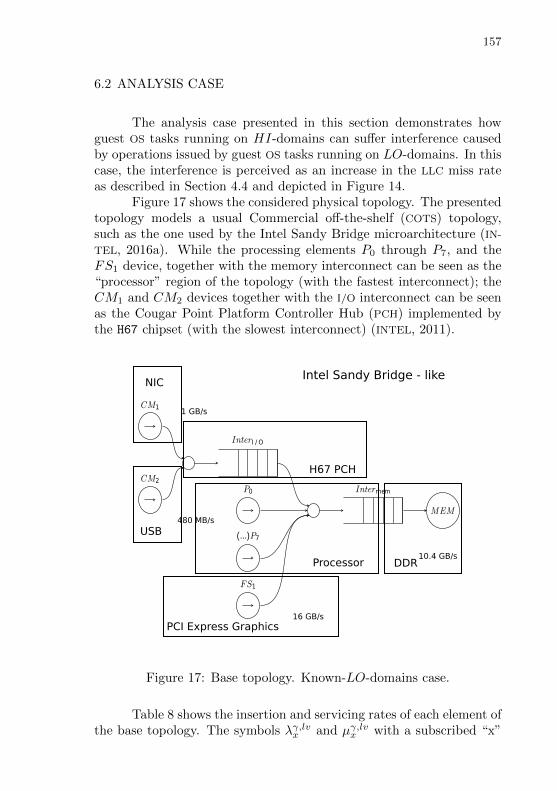
157
6.2 ANALYSIS CASE
The analysis case presented in this section demonstrates howguest OS tasks running on HI-domains can suffer interference causedby operations issued by guest OS tasks running on LO-domains. In thiscase, the interference is perceived as an increase in the LLC miss rateas described in Section 4.4 and depicted in Figure 14.
Figure 17 shows the considered physical topology. The presentedtopology models a usual Commercial off-the-shelf (COTS) topology,such as the one used by the Intel Sandy Bridge microarchitecture (IN-
TEL, 2016a). While the processing elements P0 through P7, and theFS1 device, together with the memory interconnect can be seen as the“processor” region of the topology (with the fastest interconnect); theCM1 and CM2 devices together with the I/O interconnect can be seenas the Cougar Point Platform Controller Hub (PCH) implemented bythe H67 chipset (with the slowest interconnect) (INTEL, 2011).
P0
(...)P7
FS1
InterI / O
CM1
CM2Intermem
MEM
PCI Express Graphics
Processor DDR
H67 PCH
USB
NIC
1 GB/s
480 MB/s
10.4 GB/s
16 GB/s
Intel Sandy Bridge - like
Figure 17: Base topology. Known-LO-domains case.
Table 8 shows the insertion and servicing rates of each element ofthe base topology. The symbols λγ,lvx and µγ,lvx with a subscribed “x”

158
Table 8: Base topology insertion and servicing rates. Known-LO-domains case. Units in bytes per seconds (B/s).
PE λrd=wr,MAXx λrd=wr,AV G
x µrd=wr,MAXx µrd=wr,AV G
x
CM 2 x 1.98E-08 2 x 6.6E-07FS 1 x 7.26E-08 1 x 3.3E-08P 8 x 6.6E-08 8 x 3.3E-08InterI/O 3.96E-08 13.2E-07 6.6E-09 5.94E-09Intermem 6.402E-09 3.102E-09 6.6E-09 5.94E-09MEM 6.6E-09 5.94E-09
are used instead of the usual λγ,lvpe , λγ,lvinter, µγ,lvinter, and µγ,lvme for gener-
ality. Cells are left in blank in the non-applicable cases (e.g. servicingrate for processing elements). While Figure 17 presents the nominalvalues of insertion and servicing rates of the elements, Table 8 presentsthe maximum values (MAX) and the average (AV G) used in this anal-ysis case. The insertion and servicing rates of Table 8 are arbitrary,being bellow the nominal values of the Intel Sand Bridge microarchi-tecture, and respecting the assumptions of Definition 21 that definesthe physical topology: (i) µγ,lvinter > λγ,lvinter, (ii) λγ,MAX
x > λγ,AV Gx , (iii)µγ,MAXx > µγ,AV Gx . Assumption (i) comes from queuing theory and
prevents the contention time to be infinite. Assumptions (ii) and (iii)respect the MC definitions of the model (where the budgets in HI modeshall be greater than the budgets in LO mode). Respecting the guestOS task and DRM definitions, processing elements of the same class(e.g. CM1 and CM2 of CM class) have the same insertion and servic-ing rates. Additionally, it is assumed in this topology that the insertionand servicing rates of read and write operations are the same.
The interconnect servicing and insertion rates follows λγ,lvinter =∑x ∈ income(inter) λ
γ,lvx from Definition 21. For instance, λrd=wr,MAX
Intermem=
λrd=wr,MAXP +λrd=wr,MAX
FS +λrd=wr,MAXInterI/O
(6.402E-09 = 8 x 6.6E-08 +
1 x 7.26E-08 + 3.96E-08). Table 8 present insertion and servicing ratesfor all processing elements ON (i.e. “full topology”). It is importantto notice that as processing elements are powered OFF, the insertionrate of their classes’ decreases.
In this analysis case, oneHI-domain (Dom1) and one LO-domain(Dom2) are given at design time. Table 9 summarizes their original re-quirements taking into account an overhead-free scenario, while Table

159
10 shows the employed physical allocation. One HI-domain and oneLO-domain is the minimal domain quantity needed to exercise the de-sign part of the strategy proposed in Section 5.9.1 in which the require-ments of LO-domains are known. The task set within each domain canbe seen as one instance of the task sets generated using synthetic taskset generation methods such as the ones employed in (BASTONI; BRAN-
DENBURG; ANDERSON, 2010), and used again by (XI et al., 2014) in avirtualized platform. The physical allocation is arbitrary, respectingthe Definition 22, which states that HI-domains have exclusive accessto their processing elements.
In Table 9, values equal to zero are left as blank space. In thecase of virtual I/O devices, Table 9 shows the sum of “read” and “write”budgets. In all computations, such budget is divided in such a way that70% of the operations are “read” and 30% are “write”. Such 70%/30%division is arbitrary serving to exercise the model but does not changethe final results since, as Table 8 shows, the insertion rates for “read”and “write” are the same.
Table 11 shows the variations of the physical topology used inthis case, along with the interconnect contention overhead experiencedby each I/O device. FullMAX is the topology where all processing ele-ments are ON using their maximum insertion rate (MAX). Conversely,FullAVG is the topology where all processing elements are ON but us-ing their average insertion rate (AV G) instead. The third topology inthe table, Dom1.2, is the topology in place while running Dom1 andDom2 in LO mode (using the average insertion rates of processing el-ements). In that case, the device FS1 is OFF as it is not used. In thisanalysis case, it is considered that all PCPUs are ON in all topologies(only virtual power OFF of CPUs is employed). The interconnect con-tention overhead is computed using Definition 35, presented in Section5.8.2, applied on the physical topology.
During the design-phase, as described in Section 5.9.1, domainsstart to run one by one, first Dom1 and then Dom1and Dom2. Oneach execution scenario (Dom1 alone and Dom1+Dom2) CωallS is com-puted, WCmiss and AV Gmiss are measured, δωS
Θ is computed, andthe mapping CωallS to δωS
Θ is recorded. Table 12 shows the values forWCmiss, AV Gmiss, and δωS
Θ for each execution scenario. In a practicalexperiment scenario, the values for WCmiss, AV Gmiss are measuredusing HPCs and the techniques described in Section 4.1. In this ana-lytical analysis case, the values for values for WCmiss, AV Gmiss arearbitrary inputs, simulating values measured in practice. The WCmiss,AV Gmiss values increase as more domains execute, which is expected
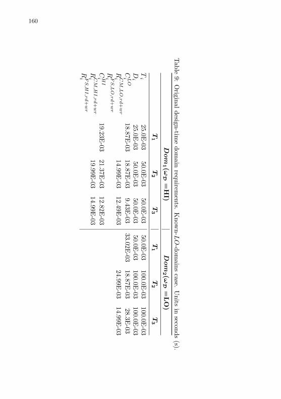
160
Tab
le9:
Origin
ald
esign-tim
ed
omain
requ
iremen
ts.K
now
n-LO
-dom
ain
sca
se.U
nits
inseco
nd
s(s).
Dom
1(ω
D=
HI)
Dom
2(ω
D=
LO
)
T1
T2
T3
T1
T2
T3
Ti
25.0E-03
50.0E-03
50.0E-03
50.0E-0
3100.0
E-0
3100.0
E-0
3Di
25.0E-03
50.0E-03
50.0E-03
50.0E-0
3100.0
E-0
3100.0
E-0
3CLO
i18.87E
-0318.87E
-039.43E
-0333.02E
-03
18.8
7E
-03
28.3
E-0
3
RCM,LO,rd+wr
i14.99E
-0312.49E
-0324.9
9E
-03
14.9
9E
-03
RFS,LO,rd+wr
i
CHI
i19.23E
-0321.37E
-0312.82E
-03
RCM,HI,rd+wr
i19.99E
-0314.99E
-03
RFS,HI,rd+wr
i

161
Table 10: Physical allocation. Domains known at design time. Known-LO-domains case.
PE Domains
P0, P1 Dom1
P2, ..., P7 Dom2 (can be shared with others LO-domains)CM1 Dom1
CM2 Dom2 (can be shared with others LO-domains)FS1 “free” (can be shared with others LO-domains)
Table 11: Interconnect contention overhead (in seconds). Known-LO-domains case.
Top ωS m nFS nCM δFS,ωS ,γΞ δCM,ωS ,γ
Ξ
FullMAX HI 8 1 2 2.45E-09 4.84E-12FullAVG LO 8 1 2 9.20E-11 1.91E-12Dom1.2 LO 8 0 2 7.37E-11 1.91E-12
in a practical scenario as well. The δωSΘ is computed using the Defini-
tion 32, presented in Section 5.8.1. The execution scenario Dom1.2 is adesign-phase scenario and indicates that Dom1 and Dom2 are running.The other scenarios occur at runtime phase and are explained later.
CωS of Dom1 tasks are inflated using δωSΘ = fCδΘ(KCωS
all ), ac-cording to Definition 33 presented in Section 5.8.1, and the strategypresented in Section 5.9.1. CωS
all takes into account the computationtime of all domains that run in the design phase (Dom1 and Dom2).
Table 12: LLC miss values and overhead (in seconds). Known-LO-domains case.
∆miss = 4.00E-08
Scenario WCmiss δHIΘ AV Gmiss δLOΘ
Dom1 2.38E+03 9.50E-05 8.75E+02 3.50E-05Dom1.2 3.13E+03 1.25E-04 1.13E+03 4.50E-05Dom1.2.3 4.25E+03 1.70E-04 1.50E+03 6.00E-05Dom1.2.3.4 5.38E+03 2.15E-04 1.88E+03 7.50E-05
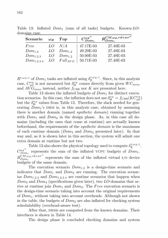
162
Table 13: Inflated Dom1 (sum of all tasks) budgets. Known-LO-domains case.
Scenario ωS Top CωS′′
Dom1RCM,ωS ,rd+wr′′
Dom1
Free LO N/A 47.17E-03 27.48E-03Dom1.2 LO Dom1.2 49.29E-03 27.48E-03Dom1.2.3 LO Dom1.2 50.00E-03 27.48E-03Dom1.2.3.4 LO FullAVG 50.71E-03 27.48E-03
Rv,ωS ,γ of Dom1 tasks are inflated using δv,ωS ,γΞ . Since, in this analysis
case, CωSall is not measured but δωS
Θ comes directly from given WCmissand AV Gmiss instead, neither fCδΘ nor K are presented here.
Table 13 shows the inflated budgets of Dom1 for distinct execu-tion scenarios. In this case, the inflation does not use δωS
Θ = fCδΘ(KCωSall )
but the δωSΘ values from Table 12. Therefore, the slack needed for gen-
erating Dom1’s DRM is, in this analysis case, obtained by assumingthere is another domain (named synthetic domain) running togetherwith Dom1 and Dom2 in the design phase. As, in this case all do-mains (including the ones that come at runtime) are actually knownbeforehand, the requirements of the synthetic domain is the maximumof each runtime domain (Dom3 and Dom4 presented later). In thatway and, as it is shown later in this section, the system will admit oneextra domain at runtime but not two.
Table 13 also shows the physical topology used to compute δv,ωS ,γΞ .
CωS′′
Dom1represents the sum of the inflated VCPU budgets of Dom1.
RCM,ωS ,rd+wr′′
Dom1represents the sum of the inflated virtual I/O device
budgets of the same domain.The execution scenario Dom1.2 is a design-time scenario and
indicates that Dom1 and Dom2 are running. The execution scenar-ios Dom1.2.3 and Dom1.2.3.4 are runtime scenarios that happen whenDom3 and Dom4 (specifications given later), two LO-domains that ar-rive at runtime join Dom1 and Dom2. The Free execution scenario isthe design-time scenario taking into account the original requirementsof Dom1, without taking into account overheads. Although not shownin the table, the budgets of Dom2 are also inflated for checking systemschedulability (overhead-aware test).
After that, DRMs are computed from the known domains. Theirinterfaces is shown in Table 14.
The design phase is concluded checking domains and system

163
Table 14: DRMs. Known-LO-domains case.
DRM1 DRM2
ωM HI LOΠ 1.0E-03 1.0E-03ΘHI 3.7E-03 0.0E-03mHI 4 0ΘLO 2.7E-03 1.9E-03mLO 3 2ΛCM,rd=wr 1.0E-03 1.0E-03ΞCM,HI,rd+wr 8.0E-04 0.0E-03nCM,HI,rd+wr 2 0ΞCM,LO,rd+wr 6.0E-04 5.0E-04nCM,LO,rd+wr 2 2ΛFS,rd=wr 0.0E-03 0.0E-03ΞFS,HI,rd+wr 0.0E-03 0.0E-03nFS,HI,rd+wr 0 0ΞFS,LO,rd+wr 0.0E-03 0.0E-03nFS,LO,rd+wr 0 0
schedulability.In this case, two new LO-domains are loaded at runtime, Dom3
and Dom4. Table 15 shows their non-inflated requirements. Require-ments for HI mode are all zero (and omitted) in the table since bothDom3 and Dom4 are LO-domains.
Table 16 shows the updated physical allocation taking into ac-count the resources used by the new domains. Both Dom3 and Dom4
share PCPUs with Dom2. Dom3 also uses CM2, while Dom4 uses FS1.
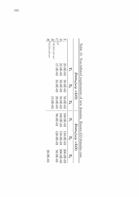
164
Tab
le15:
Non
-infl
atedreq
uirem
ents
ofn
ewd
omain
s.K
now
n-LO
-dom
ain
sca
se.
Dom
3(ω
D=
LO
)Dom
4(ω
D=
LO
)
T1
T2
T3
T1
T2
T3
Ti
25.0E-03
50.0E-03
50.0E-03
100.0E-0
3150.0
E-0
3200.0
E-0
3Di
25.0E-03
50.0E-03
50.0E-03
100.0E-0
3150.0
E-0
3200.0
E-0
3CLO
i17.5E
-0335.0E
-0320.0E
-0390.0E
-03120.0
E-0
350.0
E-0
3
RCM,LO,rd+wr
i15.0E
-03
RFS,LO,rd+wr
i20.0
E-0
3

165
Table 16: Updated physical allocation. All domains (known LO-domains case).
PE Domains
P0, P1 Dom1
P2, ..., P7 Dom2, Dom3, Dom4
CM1 Dom1
CM2 Dom2, Dom3
FS1 Dom4
166
The runtime time scenario considered for this analysis case isshown in Figure 18.
The first evaluation of this case was according to LLC miss over-head over execution time. Figure 19 shows the variation of AV Gmissalong time, showing also scheduling decisions on each state of the run-time scenario. Marks POFF indicate that the hypervisor has decided toperform a LO to HI mode switch and to power OFF physical or virtualprocessing elements. Conversely, PON marks indicate that the hyper-visor has decided to perform a HI to LO mode switch and to powerON physical or virtual processing elements. On State 1 AV Gmiss hasthe same value as the one it was measured in the design phase. OnState 2 LO-domains Dom3 and Dom4 start to execute. The AV Gmissis sampled and used for inflating the VCPU LO budget of Dom1. Theline Dom1.2.3.4 of Table 13 show the inflated budget of Dom1. Testingdomain schedulability using the inflated tasks and the respective do-mains’ DRMs, the hypervisor verifies on State 3 that HI-domains (oneor more) will become unschedulable. Then, the hypervisor performs aLO to HI mode switch, choosing to virtual power OFF (VCPUs andvirtual I/O devices) Dom3 and Dom4 (State 5). The hypervisor detectsthat HI-domains will become schedulable again in LO mode and de-cides to perform a HI to LO mode switch (State 6 and State 7). Thehypervisor, in this case, decides to turn one the domains one by one.Powering ON Dom3 the hypervisor detects that HI-domains are stillschedulable in LO mode (State 8 and State 9). After that, the hyper-visor powers ON Dom4 but it notices that HI-domains will becomeunschedulable (State 10 and State 11). Then, the hypervisor decidesto power OFF Dom4 again (State 12 and State 13). The monitoringcycle goes on and, depending on the strategy employed, the hypervisorcan learn that Dom3 and Dom4 can be used in isolation but not atthe same time. Therefore, the hypervisor can choose to switch fromone domain to another from time to time so neither becomes unserved.As shown in Table 11, the maximum contention time experienced byCM is at the order of pico seconds (E-12), reason why in Table 13,the task budget of CM shows no observable change. In the case of themaximum contention time observed, which is at the memory intercon-nect while using Fullmax topology, the overhead is still in the order ofnanoseconds (δv,ωS ,γ
Ξ = 2.45E − 9). In that case, the overhead from
the virtual I/O device point-of-view (δv,ωS ,γΞ
Λv,γ ) will be in the order ofmicro seconds (2.45E − 6), and The overhead experienced by the task
(Rv,ωS ,γi
Λv,γ δv,ωS ,γΞ ) will be in the order of nano-seconds (E − 3 * E − 6).
In despite of the contention time experienced on each period of a task
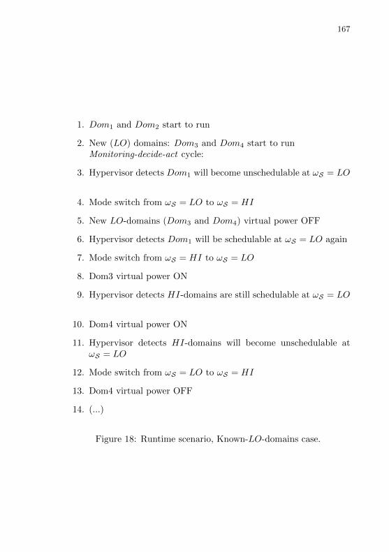
167
1. Dom1 and Dom2 start to run
2. New (LO) domains: Dom3 and Dom4 start to runMonitoring-decide-act cycle:
3. Hypervisor detects Dom1 will become unschedulable at ωS = LO
4. Mode switch from ωS = LO to ωS = HI
5. New LO-domains (Dom3 and Dom4) virtual power OFF
6. Hypervisor detects Dom1 will be schedulable at ωS = LO again
7. Mode switch from ωS = HI to ωS = LO
8. Dom3 virtual power ON
9. Hypervisor detects HI-domains are still schedulable at ωS = LO
10. Dom4 virtual power ON
11. Hypervisor detects HI-domains will become unschedulable atωS = LO
12. Mode switch from ωS = LO to ωS = HI
13. Dom4 virtual power OFF
14. (...)
Figure 18: Runtime scenario, Known-LO-domains case.
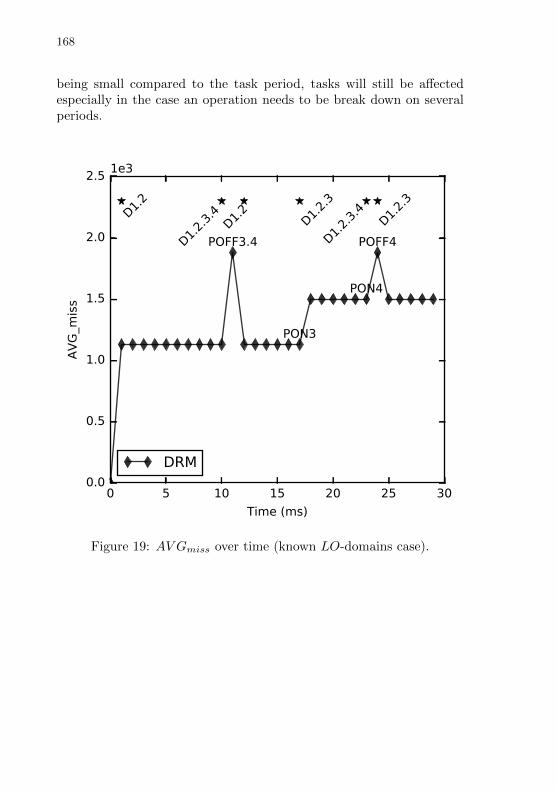
168
being small compared to the task period, tasks will still be affectedespecially in the case an operation needs to be break down on severalperiods.
0 5 10 15 20 25 30
Time (ms)
0.0
0.5
1.0
1.5
2.0
2.5
AV
G_m
iss
1e3
POFF3.4
PON3
PON4
POFF4
D1.2
D1.2.
3
D1.2.
3.4
D1.2.
3.4
D1.2
D1.2.
3
DRM
Figure 19: AV Gmiss over time (known LO-domains case).
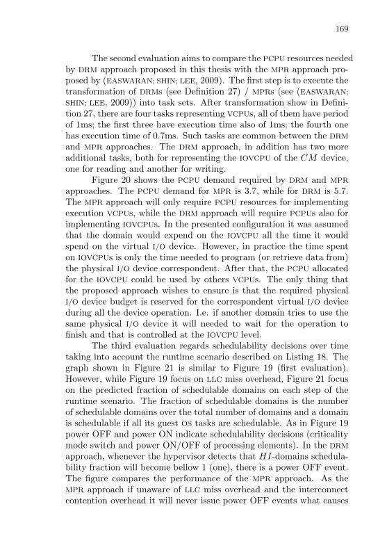
169
The second evaluation aims to compare the PCPU resources neededby DRM approach proposed in this thesis with the MPR approach pro-posed by (EASWARAN; SHIN; LEE, 2009). The first step is to execute thetransformation of DRMs (see Definition 27) / MPRs (see (EASWARAN;
SHIN; LEE, 2009)) into task sets. After transformation show in Defini-tion 27, there are four tasks representing VCPUs, all of them have periodof 1ms; the first three have execution time also of 1ms; the fourth onehas execution time of 0.7ms. Such tasks are common between the DRM
and MPR approaches. The DRM approach, in addition has two moreadditional tasks, both for representing the IOVCPU of the CM device,one for reading and another for writing.
Figure 20 shows the PCPU demand required by DRM and MPR
approaches. The PCPU demand for MPR is 3.7, while for DRM is 5.7.The MPR approach will only require PCPU resources for implementingexecution VCPUs, while the DRM approach will require PCPUs also forimplementing IOVCPUs. In the presented configuration it was assumedthat the domain would expend on the IOVCPU all the time it wouldspend on the virtual I/O device. However, in practice the time spenton IOVCPUs is only the time needed to program (or retrieve data from)the physical I/O device correspondent. After that, the PCPU allocatedfor the IOVCPU could be used by others VCPUs. The only thing thatthe proposed approach wishes to ensure is that the required physicalI/O device budget is reserved for the correspondent virtual I/O deviceduring all the device operation. I.e. if another domain tries to use thesame physical I/O device it will needed to wait for the operation tofinish and that is controlled at the IOVCPU level.
The third evaluation regards schedulability decisions over timetaking into account the runtime scenario described on Listing 18. Thegraph shown in Figure 21 is similar to Figure 19 (first evaluation).However, while Figure 19 focus on LLC miss overhead, Figure 21 focuson the predicted fraction of schedulable domains on each step of theruntime scenario. The fraction of schedulable domains is the numberof schedulable domains over the total number of domains and a domainis schedulable if all its guest OS tasks are schedulable. As in Figure 19power OFF and power ON indicate schedulability decisions (criticalitymode switch and power ON/OFF of processing elements). In the DRM
approach, whenever the hypervisor detects that HI-domains schedula-bility fraction will become bellow 1 (one), there is a power OFF event.The figure compares the performance of the MPR approach. As theMPR approach if unaware of LLC miss overhead and the interconnectcontention overhead it will never issue power OFF events what causes
170
DRM MPR0
1
2
3
4
5
6
PCPU
dem
and
Figure 20: PCPU demand. Known-LO-domains case.
HI-domains to lose deadlines.

171
05
1015
2025
30Tim
e (s)
0.0
0.2
0.4
0.6
0.8
1.0
1.2
1.4
Fraction of schedulable HI domains at LO mode
Potential HI miss
Potential HI miss
POFF3.4
PON3PON4
POFF4
D1.2
D1.2.3.4
D1.2
D1.2.3D1.2.3.4
D1.2.3
DRMM
PR
Figure 21: Fraction of schedulable domains. (known LO-domains case).

172
6.3 DISCUSSION
While comparing to MPR proposed by (EASWARAN; SHIN; LEE,2009), the proposed DRM approach requires more PCPU resources sinceit employs PCPUs for implementing not only VCPUs but also for imple-menting IOVCPUs. On the other hand, the DRM approach presents abetter schedulability decision while comparing to MPR since DRM takesinto account LLC and interconnect overheads. As consequence, the pro-posed DRM approach will prevent LO-tasks from executing when theperceived interference is high. The MPR approach, on the other hand,can be over optimistic admitting the LO-tasks jobs that will later,due to the unperceived high interference, cause HI-tasks to miss theirdeadlines.
Similar conclusions can be inferred if comparing the proposedDRM approach to the DMPR approach proposed by (XU et al., 2013).Again, DRM requires more PCPU resources than DMPR since the formeruses PCPUs for implementing IOVCPUs, while the latter does not han-dle interconnect overhead and does not require IOVCPUs for handlingvirtual I/O devices. While the proposed approach takes into accountthe LLC, (XU et al., 2013)’s approach only take into account privatecaches. In cases where the Work Set Size (WSS) of every task fits insidethe private caches of PCPUs and the interconnect contention overheadis negligible, the schedulability decisions obtained with DRM and theDMPR approaches can reach equivalent results. However, in scenarioswhere the WSS of tasks are bigger than the private caches of PCPUs andthus it is required access to the LLC and thus can be LLC misses, orin scenarios where the interconnect contention overhead is significant,the proposed approach will present better schedulability decisions than(XU et al., 2013)’s approach since the former takes into account suchoverheads.
In addition, the proposed approach is distinct from (EASWARAN;
SHIN; LEE, 2009) and from (XU et al., 2013) in its goal. The main focusof (EASWARAN; SHIN; LEE, 2009) and (XU et al., 2013) is at design time,and their goal is to decide whether domains can be scheduled by theirmodels and whether the underlining physical platform is able to attendthe models requirements. The guest OS tasks requirement are fixedand, in the case of (XU et al., 2013), the upper bound limits for privatecache overheads are also fixed. The proposed approach, on the otherhand, presents a more dynamic nature, presenting a design time andruntime phases as introduced in Section 5.9. While the guest OS tasksbase requirements are also fixed, the overhead values are dynamically
173
sampled during the monitoring-decide-act at runtime, differently from(EASWARAN; SHIN; LEE, 2009) and from (XU et al., 2013). Such sampledvalues, feed the model back and are used for overhead-aware schedulingdecisions as presented in Chapter 5.

174

175
7 CONCLUSION
The shift from dedicated hardware to software running on mul-tiprocessor systems for implementing real-time embedded system fea-tures has been motivated by the growing in complexity of the fea-tures and the advances of processor technology. Such shift brings newchallenges, mainly the separation between system components, onceperformed in hardware, which now needs to be ensured by software.In such scenario, the use of hypervisors has presented itself as a suit-able solution especially regarding spatial isolation. Temporal, isolation,however, still lefts room for improvements. The main challenges are toquantify the interference caused on real-time tasks in a physical plat-form in which physical resources are shared among domains.
This work targets this problem by presenting a modeling ap-proach which takes into account shared resources (CPUs, I/O devices,and interconnects) and that quantifies the impact of temporal inter-ference on the guest OS tasks. The approach takes into account acompositing scenario, where guest OS tasks use VCPUs, and virtual I/O
devices, while their domains are mapped on PCPUs and physical I/O
devices. Furthermore, the modeling approach takes into account twodistinct criticality levels, LO and HI. When the system is operatingin LO mode, both HI-tasks and LO-tasks execute. However, when thesystem is operating in HI mode, all LO-tasks are suspended, and onlyHI-tasks can run. Moreover, this work proposes to power OFF theprocessing elements used by LO-tasks, preventing them from keepinginterfering on HI-tasks.
In the proposed modeling approach task sets of the same crit-icality define a domain. Each task is defined by its period, deadline,computation (time on VCPUs), and I/O (time or rate of virtual I/O de-vices) requirements. The interconnect topology is expressed as a graph,and describes the connections among processing elements, interconnect,and memory elements. Additionally, it describes the insertion rate ofeach processing element, the servicing rate of memory elements, andthe insertion and servicing rate of interconnect elements. The overheadassociated with replacement of evicted cache lines, and the contentiontime on each interconnect elements is also an input for the model. Thecache-related overhead can be obtained by measurements performed onthe physical platform, while the contention time on interconnect ele-ments is computed based on queuing theory using their insertion ratesand servicing rates. Such rates, in turn, are obtained form nominal

176
values of the physical platform components or by measurement.For each domain, is computed a DRM that abstracts the process-
ing and I/O requirements of the domain tasks. A DRM is defined bya criticality, which is the same of the domain it is designed for, VCPU
period, VCPU budgets (a budget for criticality level), VCPU quantities(for each criticality level), virtual I/O device periods (for each deviceclass and operation), virtual I/O device budgets (for each device class,criticality level, and operation), and virtual I/O device quantities (forthe same parameters as virtual I/O device budgets). The budgets of aDRM represent the capacity that all its virtual processing elements willcollectively provide, its periods represent the replenishment interval ofthose budgets. Domain schedulability is then defined by whether thesupply a DRM provides is able to fulfill the domain task set demand.To perform overhead-aware schedulability, memory and I/O overheadsare used to inflate the budget of the domain tasks and it is checkedwhether the original DRM can still schedule them.
The overall approach is composed of a design and a runtimephase. In the design phase the known domains (HI and LO) run,overhead is measured, and the budgets of the tasks are inflated. Duringruntime, a LO to HI mode switch will occur whenever (i) a HI-task isunable to complete its job while using its LO budget or (ii) wheneverthe hypervisor predicts that the measured overhead will cause the LObudgets of HI tasks to inflate in such a way its DRM will not be ableto scheduled it. As the algorithm that computes the DRMs interfaces isdesigned to compute the minimal required budgets that will attend thedomain, in the design phase of the system development the task set ofdomains is inflated with the overhead measured on that scenario plussome slack. Otherwise during runtime, the system would not toleratea minimal interference caused new domains. A HI to LO mode switchwill occur whenever there are no pendent jobs of HI-tasks in HI modeand the hypervisor predicts the DRMs of all HI-domains are able toschedule their tasks taking into account the current interference.
The proposed modeling approach was evaluated while using syn-thetic domain requirements and while using a physical topology com-mon in several platforms. For evaluation, it was taking into account aspecific runtime scenario, so the approach could be evaluated while per-forming its design and runtime phases. The approach, which is basedon DRM was compared to the MPR model introduced by (EASWARAN;
SHIN; LEE, 2009). The DRM-based approach presents a higher PCPU
demand than MPR since it uses PCPUs for implementing not only execu-tion VCPUs but also for implementing IOVCPUs that are used by virtual
177
I/O devices. On the other hand, the proposed approach presents betterdomain schedulability than MPR since it takes into account LLC missand interconnect contention overhead. As consequence, the proposedapproach chooses to power OFF LO-domains avoiding HI-domains oflosing their deadlines. Additionally, the proposed domain schedulabil-ity test was evaluated for distinct domains and whole-domain utilizationvalues, and it achieves similar performance to the (GOOSSENS; FUNK;
BARUAH, 2003) gEDF schedulability test.From the obtained results, it is possible to conclude that the
main goal of this work is reached, since while using the proposed ap-proach, HI-tasks are ensured to always meet their deadlines as thescheduling tests demonstrate. It is also possible to affirm that the re-search questions brought up in the Introduction chapter are answered.Revisiting those questions and pointing out where and how they areanswered:
• (i) How the sharing of resources interferes with the temporal be-havior of tasks in a multicore hypervisor?.
This question is answered in Chapter 4, Sections 4.2, and 4.4, re-garding interconnect and LLC respectively. The types of interfer-ence are illustrated by Figure 6 (interference due to interconnectcontention), Figure 13 (interference due to cache line evictioncaused by another PCPU.), and Figure 14 (Interference due tocache line eviction caused by an I/O device).
• (ii) How to quantify the extent of such interference?
Definition 32, which defines LLC miss overhead, and Definition33, which defines how the VCPU budget of guest OS tasks areaffected by such overhead answer this question regarding the LLC.Similarly, Definition 35, and Definition 36 present the equivalentfor interconnect contention overhead. All these definitions arepresented in Chapter 5, Section 5.8, which presents the overhead-aware compositional schedulability analysis.
• (iii) What are the techniques that can be used to reduce such in-terference and keep it bounded?
Regarding LLC miss overhead, Section 4.4 answers this ques-tion presenting the domain-oriented, VCPU-oriented, and guestOS task-oriented approaches for implementing page-coloring ina virtualized platform. Regarding interconnect contention over-head, Section 4.2 answer this question discussing power OFF tech-niques, while Section 4.3, which presents the Semaphore Observer
178
design pattern, discuss how to keep the time for interrupt han-dling bounded.
• (iv) How such interference can feed a model of the system in orderto check tasks schedulability and domain feasibility?
The schedulability tests presented in Section 5.5 (Theorem 1regarding domain schedulability and Theorem 2 regarding sys-tem schedulability) and the discussion of how they are used foroverhead-aware tests in Section 5.8.3 answers this question.
• (v) How such interference-aware schedulability tests can be usedin a (design and runtime) strategy that ensures that temporallycritical guest OS tasks never miss a deadline?
The strategies presented in Section 5.9 answer this question forthe case when LO-domains requirements are known (Section 5.9.1)and for the case when they are not known (Section 5.9.2).
As far was possible to identify, this work is the first work thatproposes an approach for guest OS task schedulability evaluation andcomputation of domain requirements that takes into account memoryand I/O resource sharing. It is expected that the proposed approachcan help system designers to evaluate whether a given platform is ableto support real-time requirements and how guest OS tasks can be dis-tributed among distinct domains.
The proposed modeling approach assumes cache-related over-head and contention time will affect all tasks in a domain equally, thusit can be overly pessimistic. Such pessimism is mitigated by using aver-age cache-related overhead values and contention time while computingthe LO criticality mode budget of each task but does not eliminate thefact that every task is affected equally. To overcome this limitation andregarding memory-related overhead specifically, (XU et al., 2013) pro-poses ways estimate an upper bound for VCPUs context switches andother events that would cause cache misses. Their approach, however,besides adding complexity to the model assumes only private cachesand not a shared LLC. Regarding interconnect contention overhead themodel presented in this work assumes a single memory element, andthus employs a single server queue. While that fits most real physicalplatforms, which have a single main memory that could be a limitationwhile employing other topologies. In this work processing elements areseem as source elements that make request to interconnect elements.An alternative approach would see each processing element as a com-plete queue system, composed of source, interconnect, and server. In

179
that way would be possible to explore contention time inside each pro-cessing element, which in turn could be used to investigate contentiontime focused on distinct servers and not only centered in the mainmemory. Such investigations and models extensions are left as poten-tial future works.
The proposed approach was evaluated only analytically, usingscenarios that mimic practical executions. On one hand the efficacy andefficiency of the proposed techniques was already demonstrated in nonvirtualized scenarios, e.g. page-coloring (GRACIOLI; FRoHLICH, 2013),(GRACIOLI, 2014), and powering ON and OFF devices (HOELLER, 2007)and (REIS, 2016), and is expected to be preserved on virtualized scenar-ios. On the other hand, as far was possible to identify, no single hyper-visor implements all the required techniques proposed by this thesis,composite MC real-time scheduling, powering ON and OFF physicaland virtual devices, time-deterministic multilevel interrupt handling.The EPOS OS is the one that has most of these required features, how-ever, in its current state does not support virtualization fully. Anextension of EPOS, named HyperEPOS has envisioned in the context ofthis work. A preliminary version of its design is presented in AppendixA, and an adaptation of Linux to run atop HyperEPOS is described by(MEURER; LUDWICH; FRoHLICH, 2016). The mechanisms for support-ing time-deterministic interrupt handling are presented and evaluatedin a single-level interrupt handling by (LUDWICH; FRoHLICH, 2015) andby (LUDWICH et al., 2014). Early stages of this research and still inthe context of this PhD, have evaluated the scheduler of EPOS accord-ing functional correctness (LUDWICH; FRoHLICH, 2013) and (LUDWICH;
FRoHLICH, 2012). The same scheduler, then used for scheduling OS
threads would be employed for scheduling VCPUs in HyperEPOS.

180
181
REFERENCES
AL-ZOUBI, H.; MILENKOVIC, A.; MILENKOVIC, M. Performanceevaluation of cache replacement policies for the spec cpu2000benchmark suite. In: Proceedings of the 42Nd Annual SoutheastRegional Conference. New York, NY, USA: ACM, 2004. (ACM-SE42), p. 267–272. ISBN 1-58113-870-9. Available from Internet:<http://doi.acm.org/10.1145/986537.986601>.
ANDREWS, G. R. Foundations of Parallel and DistributedProgramming. 1st. ed. Boston, MA, USA: Addison-Wesley LongmanPublishing Co., Inc., 1999. ISBN 0201357526.
AXER, P. et al. Building timing predictable embedded systems. ACMTrans. Embed. Comput. Syst., ACM, New York, NY, USA, v. 13, n. 4,p. 82:1–82:37, mar. 2014. ISSN 1539-9087. Available from Internet:<http://doi.acm.org/10.1145/2560033>.
BALAKRISHNAN, N.; NEVZOROV, V. B. A Primer onStatistical Distributions. [S.l.]: John Wiley & Sons, 2003. ISBN978-0-471-42798-8.
BARUAH, S.; BERTOGNA, M.; BUTTAZZO, G. MultiprocessorScheduling for Real-Time Systems. 1st. ed. [S.l.]: SpringerInternational Publishing, 2015. 228 p. (Embedded Systems). ISBN978-3-319-08696-5.
BASTONI, A.; BRANDENBURG, B. B.; ANDERSON,J. H. An empirical comparison of global, partitioned, andclustered multiprocessor edf schedulers. In: Proceedings of the2010 31st IEEE Real-Time Systems Symposium. Washington,DC, USA: IEEE Computer Society, 2010. (RTSS ’10), p.14–24. ISBN 978-0-7695-4298-0. Available from Internet:<http://dx.doi.org/10.1109/RTSS.2010.23>.
BECKERT, M. et al. Sufficient temporal independence and improvedinterrupt latencies in a real-time hypervisor. In: Proceedings of the 51stAnnual Design Automation Conference. New York, NY, USA: ACM,2014. (DAC ’14), p. 86:1–86:6. ISBN 978-1-4503-2730-5. Availablefrom Internet: <http://doi.acm.org/10.1145/2593069.2593222>.
BERTOGNA, M.; CIRINEI, M.; LIPARI, G. Improved schedulabilityanalysis of edf on multiprocessor platforms. In: 17th Euromicro
182
Conference on Real-Time Systems (ECRTS’05). [S.l.: s.n.], 2005. p.209–218. ISSN 1068-3070.
CHENG, Y. et al. Precise contention-aware performance predictionon virtualized multicore system. Journal of Systems Architecture- Embedded Systems Design, v. 72, p. 42–50, 2016. Available fromInternet: <http://dx.doi.org/10.1016/j.sysarc.2016.06.006>.
CHISNALL, D. The Definitive Guide to the Xen Hypervisor. First.Upper Saddle River, NJ, USA: Prentice Hall Press, 2007. ISBN9780132349710.
CHO, H.; RAVINDRAN, B.; JENSEN, E. An optimal real-timescheduling algorithm for multiprocessors. In: Real-Time SystemsSymposium, 2006. RTSS ’06. 27th IEEE International. [S.l.: s.n.],2006. p. 101–110. ISSN 1052-8725.
DAVIS, R. I.; BURNS, A. A survey of hard real-time scheduling formultiprocessor systems. ACM Comput. Surv., ACM, New York, NY,USA, v. 43, n. 4, p. 35:1–35:44, out. 2011. ISSN 0360-0300. Availablefrom Internet: <http://doi.acm.org/10.1145/1978802.1978814>.
EASWARAN, A.; SHIN, I.; LEE, I. Optimal virtual cluster-based multiprocessor scheduling. Real-Time Systems, v. 43,n. 1, p. 25–59, 2009. ISSN 1573-1383. Available from Internet:<http://dx.doi.org/10.1007/s11241-009-9073-x>.
FOYO, L. Leyva-del; MEJIA-ALVAREZ, P.; NIZ, D. de. Predictableinterrupt scheduling with low overhead for real-time kernels. In:Embedded and Real-Time Computing Systems and Applications, 2006.Proceedings. 12th IEEE International Conference on. [S.l.: s.n.], 2006.p. 385–394. ISSN 1533-2306.
FRoHLICH; LISHA. Open EPOS 1.0. 2010. Available from Internet:<http://epos.lisha.ufsc.br/EPOS+Software>.
FRoHLICH, A. A. Application-Oriented Operating Systems. SanktAugustin: GMD - Forschungszentrum Informationstechnik, 2001.200 p. ISBN 3-88457-400-0.
GAMMA, E. et al. Design Patterns: Elements of Reusable Object-oriented Software. Boston, MA, USA: Addison-Wesley LongmanPublishing Co., Inc., 1995. ISBN 0-201-63361-2.

183
GOOSSENS, J.; FUNK, S.; BARUAH, S. Priority-driven schedulingof periodic task systems on multiprocessors. Real-Time Syst.,Kluwer Academic Publishers, Norwell, MA, USA, v. 25, n. 2-3,p. 187–205, set. 2003. ISSN 0922-6443. Available from Internet:<https://doi.org/10.1023/A:1025120124771>.
GOPALAKRISHNAN, S. et al. Hard real-time communication inbus-based networks. In: Real-Time Systems Symposium, 2004.Proceedings. 25th IEEE International. [S.l.: s.n.], 2004. p. 405–414.ISSN 1052-8725.
GRACIOLI, G. Real-Time Operating System Support for MulticoreApplications. 359 p. Tese (Doutorado) — Federal University of SantaCatarina, Florianopolis, 2014. Ph.D. Thesis. Available from Internet:<http://www.lisha.ufsc.br/pub/Gracioli PHD 2014.pdf>.
GRACIOLI, G.; FRoHLICH, A. A. An embedded operatingsystem api for monitoring hardware events in multicoreprocessors. In: Workshop on Hardware-support for parallelprogram correctness - IEEE Micro 2011. Porto Alegre, Brazil:[s.n.], 2011. ISBN 978-1-4503-1053-6. Available from Internet:<http://www.lisha.ufsc.br/pub/Gracioli HPPC 2011.pdf>.
GRACIOLI, G.; FRoHLICH, A. A. An experimental evalua-tion of the cache partitioning impact on multicore real-timeschedulers. In: 19th IEEE International Conference onEmbedded and Real-Time Computing Systems and Applica-tions. Taipei, Taiwan: [s.n.], 2013. Available from Internet:<http://www.lisha.ufsc.br/pub/Gracioli RTCSA 2013.pdf>.
HEISER, G.; LESLIE, B. The okl4 microvisor: Convergence pointof microkernels and hypervisors. In: Proceedings of the First ACMAsia-pacific Workshop on Workshop on Systems. New York, NY, USA:ACM, 2010. (APSys ’10), p. 19–24. ISBN 978-1-4503-0195-4. Availablefrom Internet: <http://doi.acm.org/10.1145/1851276.1851282>.
HENNESSY, J. L.; PATTERSON, D. A. Computer Architecture:A quantitative approach. 5th. ed. 225 Wyman Street, Waltham,MA 02451, USA: Elsevier / Morgan Kaufmann, 2012. ISBN978-0-12-383872-8.
HOELLER, A. S. Gerenciamento do Consumo de Energia Dirigidopela Aplicacao em Sistemas Embarcados. Dissertacao (Mestrado)

184
— Federal University of Santa Catarina, Florianopolis, 2007. M.Sc.Thesis.
HOELLER, A. S. J.; WANNER, L. F.; FRoHLICH, A. A. Ahierarchical approach for power management on mobile embeddedsystems. In: 5th IFIP Working Conference on Distributed and ParallelEmbedded Systems. Braga, Portugal: [s.n.], 2006. p. 265–274. ISBN978-0-387-39361-7.
HOFER, W.; LOHMANN, D.; SCHRODER-PREIKSCHAT, W.Sleepy sloth: Threads as interrupts as threads. In: Real-Time SystemsSymposium (RTSS), 2011 IEEE 32nd. [S.l.: s.n.], 2011. p. 67–77. ISSN1052-8725.
INTEL. Intel 6 Series Chipset and Intel C200 Series Chipset :Datasheet. [S.l.]: Intel Corporation, 2011. 934 p. Document Number:324645-006.
INTEL. Intel 64 and IA-32 Architectures Software Developer’sManual : System programming guide, part 1. [S.l.]: Intel Corporation,2014. 454 p. ISBN 3-88457-400-0.
INTEL. Intel 64 and IA-32 Architectures Optimization ReferenceManual. [S.l.]: Intel Corporation, 2016. 644 p. Order Number:248966-032.
INTEL. Intel 64 and IA-32 Architectures Software Developer’sManual : System programming guide, part 2. [S.l.]: Intel Corporation,2016. 576 p. Order Number 253669-058US.
KIM, H.; RAJKUMAR, R. R. Real-time cache management formulti-core virtualization. In: Proceedings of the 13th InternationalConference on Embedded Software. New York, NY, USA: ACM, 2016.(EMSOFT ’16), p. 15:1–15:10. ISBN 978-1-4503-4485-2. Availablefrom Internet: <http://doi.acm.org/10.1145/2968478.2968480>.
KIM, S.; IM, C.; HA, S. Schedule-aware performance estimation ofcommunication architecture for efficient design space exploration.IEEE Transactions on Very Large Scale Integration (VLSI) Systems,v. 13, n. 5, p. 539–552, May 2005. ISSN 1063-8210.
KLEIMAN, S.; EYKHOLT, J. Interrupts as threads. SIGOPSOper. Syst. Rev., ACM, New York, NY, USA, v. 29, n. 2, p.21–26, abr. 1995. ISSN 0163-5980. Available from Internet:<http://doi.acm.org/10.1145/202213.202217>.

185
LEE, J. et al. Towards compositional mixed-criticality real-timescheduling in open systems: Invited paper. SIGBED Rev., ACM, NewYork, NY, USA, v. 13, n. 3, p. 49–51, ago. 2016. ISSN 1551-3688. Avail-able from Internet: <http://doi.acm.org/10.1145/2983185.2983193>.
LIEDTKE, J.; HAERTIG, H.; HOHMUTH, M. Os-controlledcache predictability for real-time systems. In: Proceedings of the3rd IEEE Real-Time Technology and Applications Symposium(RTAS ’97). Washington, DC, USA: IEEE Computer Society, 1997.(RTAS ’97), p. 213–. ISBN 0-8186-8016-4. Available from Internet:<http://dl.acm.org/citation.cfm?id=523983.828369>.
LIU, X.; TONG, W.; SHEN, C. Qos-aware i/o schedule for virtualmachines in cloud computing environment. In: 2013 SeventhInternational Conference on Innovative Mobile and Internet Servicesin Ubiquitous Computing. [S.l.: s.n.], 2013. p. 276–282.
LUDWICH, M. K.; FRoHLICH, A. A. System-level verification ofembedded operating systems components. In: Brazilian Symposiumon Computing System Engineering. Natal, Brazil: IEEE, 2012. ISBN978-1-4673-5747-0.
LUDWICH, M. K.; FRoHLICH, A. A. On the formal verification ofcomponent-based embedded operating systems. Operating SystemsReview, v. 47, n. 1, p. 28–34, 2013. ISSN 0163-5980.
LUDWICH, M. K.; FRoHLICH, A. A. Proper handling ofinterrupts in cyber-physical systems. In: 26th IEEE InternationalSymposium on Rapid System Prototyping. Amsterdam, TheNetherlands: [s.n.], 2015. p. 83–89. Available from Internet:<http://www.lisha.ufsc.br/pub/Ludwich RSP 2015.pdf>.
LUDWICH, M. K. et al. Run-time support system for models ofcomputation in cyber-physical systems. In: First Workshop onCyber-Physical System Architectures and Design Methodologies.New Delhi, India: [s.n.], 2014. p. 6. Available from Internet:<http://www.lisha.ufsc.br/pub/Ludwich CPSARCH 2014.pdf>.
MA, R. et al. Cache isolation for virtualization ofmixed general-purpose and real-time systems. Jour-nal of Systems Architecture, v. 59, n. 10, Part D, p.1405 – 1413, 2013. ISSN 1383-7621. Available from Internet:<http://www.sciencedirect.com/science/article/pii/S1383762113001288>.
186
MALKA, M. et al. riommu: Efficient iommu for i/o devices thatemploy ring buffers. In: Proceedings of the Twentieth InternationalConference on Architectural Support for Programming Languages andOperating Systems. New York, NY, USA: ACM, 2015. (ASPLOS’15), p. 355–368. ISBN 978-1-4503-2835-7. Available from Internet:<http://doi.acm.org/10.1145/2694344.2694355>.
MEURER, R.; LUDWICH, M. K.; FRoHLICH, A. A. Vir-tualizing mixed-criticallity operating systems. In: Brazil-ian Symposium on Computing Systems Engineering.Joao Pessoa, Brazil: [s.n.], 2016. Available from Internet:<http://www.lisha.ufsc.br/pub/Meurer SBESC 2016.pdf>.
MISSIMER, E. et al. Mixed-criticality scheduling with i/o. In: 201628th Euromicro Conference on Real-Time Systems (ECRTS). [S.l.:s.n.], 2016. p. 120–130.
MOHAN, S. et al. Using multicore architectures in cyber-physicalsystems. In: Workshop on Developing Dependable and SecureAutomotive Cyber-Physical Systems from Components. Michigan,USA: [s.n.], 2011.
MOSBERGER, D.; JIN, T. Httperf—a tool for measuring webserver performance. SIGMETRICS Perform. Eval. Rev., ACM, NewYork, NY, USA, v. 26, n. 3, p. 31–37, dez. 1998. ISSN 0163-5999. Avail-able from Internet: <http://doi.acm.org/10.1145/306225.306235>.
MOSBERGER, D. et al. The httperf HTTP load generator. 2017.Available from Internet: <https://github.com/httperf/httperf>.Cited 31 Mar. 2017.
MuNCH, D. et al. Mpiov: Scaling hardware-based i/o virtualization formixed-criticality embedded real-time systems using non transparentbridges to (multi-core) multi-processor systems. In: Proceedingsof the 2015 Design, Automation & Test in Europe Conference &Exhibition. San Jose, CA, USA: EDA Consortium, 2015. (DATE’15), p. 579–584. ISBN 978-3-9815370-4-8. Available from Internet:<http://dl.acm.org/citation.cfm?id=2755753.2755883>.
NELSON, A. et al. Comik: A predictable and cycle-accuratelycomposable real-time microkernel. In: Proceedings of the Conferenceon Design, Automation & Test in Europe. 3001 Leuven, Belgium,Belgium: European Design and Automation Association, 2014.
187
(DATE ’14), p. 222:1–222:4. ISBN 978-3-9815370-2-4. Available fromInternet: <http://dl.acm.org/citation.cfm?id=2616606.2616878>.
NOORSHAMS, Q. et al. Modeling of i/o performance interference invirtualized environments with queueing petri nets. In: Proceedingsof the 2014 IEEE 22Nd International Symposium on Modelling,Analysis & Simulation of Computer and Telecommunication Systems.Washington, DC, USA: IEEE Computer Society, 2014. (MASCOTS’14), p. 331–336. ISBN 978-1-4799-5610-4. Available from Internet:<http://dx.doi.org/10.1109/MASCOTS.2014.48>.
PATTERSON, D. A.; HENNESSY, J. L. Computer Organization andDesign: The Hardware/Software Interface. 3rd. ed. San Francisco, CA,USA: Morgan Kaufmann Publishers Inc., 2005. ISBN 1-55860-604-1.
PELLIZZONI, R. et al. Coscheduling of cpu and i/o transactions incots-based embedded systems. In: Real-Time Systems Symposium,2008. [S.l.: s.n.], 2008. p. 221–231. ISSN 1052-8725.
PHAN, L. T. X.; XU, M.; LEE, I. Cache-aware interfaces for compo-sitional real-time systems: Invited paper. SIGBED Rev., ACM, NewYork, NY, USA, v. 13, n. 3, p. 52–55, ago. 2016. ISSN 1551-3688. Avail-able from Internet: <http://doi.acm.org/10.1145/2983185.2983194>.
POPEK, G. J.; GOLDBERG, R. P. Formal requirementsfor virtualizable third generation architectures. Commun.ACM, ACM, New York, NY, USA, v. 17, n. 7, p. 412–421, jul. 1974. ISSN 0001-0782. Available from Internet:<http://doi.acm.org/10.1145/361011.361073>.
PORTAL, O. V. OSEK VDX Portal. 2008. Available from Internet:<http://www.osek-vdx.org/>. Cited 20 jun. 2015.
REINEKE, J.; GRUND, D. Sensitivity of cache replacement policies.ACM Trans. Embed. Comput. Syst., ACM, New York, NY, USA,v. 12, n. 1s, p. 42:1–42:18, mar. 2013. ISSN 1539-9087. Available fromInternet: <http://doi.acm.org/10.1145/2435227.2435238>.
REIS, J. G. A Framework For Predictable Hardware/SoftwareComponent Reconfiguration. 119 p. Dissertacao (Mestrado) — FederalUniversity of Santa Catarina, Florianopolis, 2016. M.Sc. Thesis.
REIS, J. G.; FRoHLICH, A. A.; JR., A. H. On the fpga dynamicpartial reconfiguration interference on real-time systems. In:Brazilian Symposium on Computing Systems Engineering. Foz do
188
Iguacu, Brazil: [s.n.], 2015. p. 110–115. Available from Internet:<http://www.lisha.ufsc.br/pub/JGReis SBESC 2015.pdf>.
SCHEFFEL, R. M.; FRoHLICH, A. A. Analise do comportamentode processos atraves de um sistema especialista probabilıstico.In: Brazilian Symposium on Computing Systems Engineering.Joao Pessoa, Brazil: [s.n.], 2016. Available from Internet:<http://www.lisha.ufsc.br/pub/Scheffel SBESC 2016.pdf>.
SHIN, K. G.; RAMANATHAN, P. Real-time computing: a newdiscipline of computer science and engineering. Proceedings of theIEEE, v. 82, n. 1, p. 6–24, Jan 1994. ISSN 0018-9219.
TU, C.-C. et al. A comprehensive implementation and evaluationof direct interrupt delivery. In: Proceedings of the 11th ACMSIGPLAN/SIGOPS International Conference on Virtual ExecutionEnvironments. New York, NY, USA: ACM, 2015. (VEE ’15),p. 1–15. ISBN 978-1-4503-3450-1. Available from Internet:<http://doi.acm.org/10.1145/2731186.2731189>.
VESTAL, S. Preemptive scheduling of multi-criticality systemswith varying degrees of execution time assurance. In: 28th IEEEInternational Real-Time Systems Symposium (RTSS 2007). [S.l.: s.n.],2007. p. 239–243. ISSN 1052-8725.
WAIKATO, M. L. G. at the University of. Weka - Data Mining withOpen Source Machine Learning Software in Java. 2017. Available fromInternet: <http://www.cs.waikato.ac.nz/ml/weka/>. Cited 31 Mar.2017.
WILHELM, R. et al. The worst-case execution-time problem;overviewof methods and survey of tools. ACM Trans. Embed. Comput.Syst., ACM, New York, NY, USA, v. 7, n. 3, p. 36:1–36:53, maio 2008. ISSN 1539-9087. Available from Internet:<http://doi.acm.org/10.1145/1347375.1347389>.
XI, S. et al. Real-time multi-core virtual machine scheduling in xen.In: Proceedings of the 14th International Conference on EmbeddedSoftware. New York, NY, USA: ACM, 2014. (EMSOFT ’14),p. 27:1–27:10. ISBN 978-1-4503-3052-7. Available from Internet:<http://doi.acm.org/10.1145/2656045.2656066>.
XU, M. et al. Cache-aware compositional analysis of real-timemulticore virtualization platforms. In: 2013 IEEE 34th Real-TimeSystems Symposium. [S.l.: s.n.], 2013. p. 1–10. ISSN 1052-8725.

189
YUN, H. et al. Palloc: Dram bank-aware memory allocator forperformance isolation on multicore platforms. In: 2014 IEEE 19thReal-Time and Embedded Technology and Applications Symposium(RTAS). [S.l.: s.n.], 2014. p. 155–166. ISSN 1545-3421.

190
APPENDIX A -- Embedded Multicore Hypervisor

193
Most of hypervisors do not deal with the challenges imposed bymodern multicore processors (such as cache hierarchy and interrupthandling) that need to be faced in order to provide for temporal iso-lation in such architectures. Instead, they either employ a dedicatedhardware approach (e.g. CoMik) (NELSON et al., 2014) or do not ad-dress hard real-time (e.g. OKL4 and uC/OS-MMU) (HEISER; LESLIE,2010; BECKERT et al., 2014). RT Xen (XI et al., 2014) is the most similarwork related to this as it aims the same hardware architecture. How-ever, it focuses mostly on multicore scheduling issues not performing afurther investigation on memory neither I/O.
This Section describes how this work intends on dealing withprocess and memory management, time virtualization, access control,interrupt handling, and I/O devices in multicore platforms. For suchits presents the design and current implementation of the HyperEPOSreal-time multicore hypervisor, which was named after the EPOS RTOS.
The current (ongoing) HyperEPOS implementation runs on theIA32 architecture. Thus, this Section uses IA32 as an example. How-ever, as EPOS confine architecture-dependent part in hardware medi-ators HyperEPOS shall be easily ported to others architectures. It isassumed that an architecture able to support for HyperEPOS will haveat least two modes of processor execution (user and supervisor).
A.1 PROCESS MANAGEMENT
This section describes this thesis proposal for virtualized versionsof CPUs, named VCPUs, as well how such CPUs are group together indomains, how such VCPUs are scheduled by the hypervisor and howthey are assigned to PCPU (e.g. the cores in a multicore processor).This section also describes the proposed strategy for IDC and explainshow new VMs start running.
A.1.1 Virtual CPU
According to the virtualization requirements of Popek and Gold-berg (POPEK; GOLDBERG, 1974), all non-privileged instructions shallnot suffer interference by the VMM, executing on the hardware directly.In the proposed approach, a VCPU is implemented as a periodic taskthat serves the guest OS tasks. A VCPU is assigned to a specific PCPU
(e.g. CPU core). All non-privileged instructions in a VM task will exe-
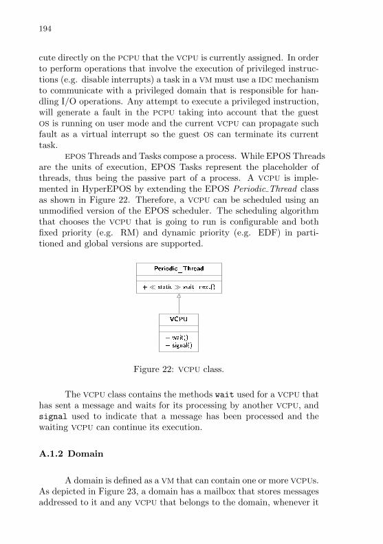
194
cute directly on the PCPU that the VCPU is currently assigned. In orderto perform operations that involve the execution of privileged instruc-tions (e.g. disable interrupts) a task in a VM must use a IDC mechanismto communicate with a privileged domain that is responsible for han-dling I/O operations. Any attempt to execute a privileged instruction,will generate a fault in the PCPU taking into account that the guestOS is running on user mode and the current VCPU can propagate suchfault as a virtual interrupt so the guest OS can terminate its currenttask.
EPOS Threads and Tasks compose a process. While EPOS Threadsare the units of execution, EPOS Tasks represent the placeholder ofthreads, thus being the passive part of a process. A VCPU is imple-mented in HyperEPOS by extending the EPOS Periodic Thread classas shown in Figure 22. Therefore, a VCPU can be scheduled using anunmodified version of the EPOS scheduler. The scheduling algorithmthat chooses the VCPU that is going to run is configurable and bothfixed priority (e.g. RM) and dynamic priority (e.g. EDF) in parti-tioned and global versions are supported.
Periodic_Thread
+ static wait_next()
VCPU
+ wait()+ signal()
Figure 22: VCPU class.
The VCPU class contains the methods wait used for a VCPU thathas sent a message and waits for its processing by another VCPU, andsignal used to indicate that a message has been processed and thewaiting VCPU can continue its execution.
A.1.2 Domain
A domain is defined as a VM that can contain one or more VCPUs.As depicted in Figure 23, a domain has a mailbox that stores messagesaddressed to it and any VCPU that belongs to the domain, whenever it

195
is scheduled to run, can get one of these messages and process it.A domain is implemented as EPOS task and has a collection of
VCPUs. Therefore, all VCPU in the same domain share the same addressspace. The guest OS sees a domain as a single machine that can havemore than one CPUs.
Task
Domain
Mailbox
+ post(msg : Message)+ get(msg : out Message) : bool
Figure 23: Domain class.
A.1.3 VCPU Scheduling and Migration
In the proposed approach, the VMM can schedule VCPU either byusing global or partitioned real-time multicore algorithms such as par-titioned EDF (pEDF), gEDF, partitioned RM (pRM), global RM (gRM),partitioned DM (pDM), and global DM (gDM). Besides that, a VCPU
can migrate from one PCPU to another depending on the schedulingpolicy. The VMM scheduler is agnostic of the tasks running at theguest OS level. Therefore, the VMM will preserve the schedulability ofguest OS tasks as long their schedule was feasible before the use of theVMM.
Given any particular PCPU at a specific time where the numberof VCPUs that can run on it is denoted by Nvcpu, given the period ofsuch PCPU, denoted by Ppcpu and determined by the PCPU frequencyof operation, the period each VCPU will provide for the guest OS tasksto run (denoted by Pvcpu) is given by Equation A.1.
Pvcpu =Ppcpu
Nvcpu
− Overheadh (A.1)
where Overheadh denotes the hypervisor overhead to schedulethe VCPUs without taking into account VCPUs migration.
In the case global real-time multicore algorithms (e.g. gEDF) are

196
used, there is only one scheduling queue in the system andNpcpu queueheads, where Npcpu denotes the number of PCPUs the system has. Inthe case of partitioned algorithms, the system has Npcpu schedulingqueues and Npcpu queue heads.
A.1.4 Inter Domain Communication
Domains communicate to each other by sending messages us-ing an Remote Method Invocation (RMI)-like mechanism as detailed inFigure 24. Therefore, up to the invocation of a method a message isgenerated and sent to the hypervisor. If the message is to the kernelitself, it executes the method related to the message and returns theresult if any. If the message is to a domain, the kernel posts the mes-sage in the mailbox of the target domain and puts the sender VCPU
(source VCPU) to wait for the message handling.As shown in Figure 25, every time a VCPU is scheduled to run,
it checks for messages in its domain’s mailbox. After getting a messagefrom the domain’s mailbox, the VCPU executes the method related tothat message, writes the message result if any, and executes the signalhypercall so the source VCPU can continue its execution.
Messages have a fixed maximum size that determines the WCRT
of a message passing.
A.1.5 Start of Day
The virtualization strategy, para-virtualization or full-virtualization,will define how a guest OS will start in a given VM. In the case of para-virtualization, the guest OS will start to run on a full operational VCPU
(e.g. that is operating in protected mode in the case of the IA32 archi-tecture). However, if full-virtualization is employed, the guest OS willexecute a boot phase (e.g. in the case of IA32 architecture that meansthat guest OS will start to run at real-mode and will need to configurethe protected mode, etc.).
In the current implementation of HyperEPOS, tasks running ina VCPU start at protected mode.

197
A.2 MEMORY MANAGEMENT
As for processors, where the guest OS must not execute privilegedPCPU instructions, the guest OS must not have direct access to theregisters and data structures related to page table management. Inthis section, we describe how such page table-related structures can bevirtualized. In order to achieve real-time memory accesses must havea bounded maximum latency and should be preferably deterministic.This section also describes the adopted approach for reducing inter-domain last-level cache temporal interference, thus making memoryaccess more deterministic and reducing access latencies.
Memory management in HyperEPOS is built using the MMU
hardware mediator family of EPOS, responsible for allocating physi-cal memory to the system and by heap abstractions, responsible forallocating logical memory to the domain tasks.
A.2.1 Page Table Management
The guest OS running on a VCPU muss not have direct accessto data structures and registers related to page table management ofthe PCPU they are running on. In the case of para-virtualization theguest OS kernel is adapted to use virtual structures provided by thehypervisor. In the case of full-virtualization, some hardware virtual-ization support is usually employed, implementing techniques such asSPT: whenever the guest attempts to update a data structure or regis-ter related to page table management (e.g. CR3 register at IA32), ormodify the page tables, the PCPU traps into the hypervisor and allowsit to emulate the update.
The current implementation of HyperEPOS still does not vir-tualize data structures related to page table management. Therefore,HyperEPOS only admits at the VM level tasks that do not access suchstructures.
A.2.2 Page Coloring
Page coloring was chosen to be used in HyperEPOS since thecache partitioning it provides enables time predictability (LIEDTKE;
HAERTIG; HOHMUTH, 1997; AXER et al., 2014). Partitioning suits wellwith domains since domains usually do not share memory and com-
198
municate through IDC. Additionally, page coloring does not dependon dedicated hardware and can be implemented in current multicoreprocessors (AXER et al., 2014; GRACIOLI, 2014).
The strategy planned to be used in Hyper EPOS is to assignthe same color to every VCPU running in the same domain. As conse-quence, tasks executing at the guest OS level will not cause temporalinterference on tasks that belong to another domain (another color)and the domain will be able to keep the real-time requirements of itstasks.
The implementation of page coloring used in HyperEPOS is de-scribed in (GRACIOLI; FRoHLICH, 2013) and relies on the EPOS MMU
hardware mediator family. While employing colors, the MMU providesfor multiple lists for free-frames management, one list for each color.Similarly, there are multiple heaps, one for each color, to provide dy-namic memory allocation for the domain tasks.
A.3 TIME
The hypervisor Application Programming Interface (API) shallprovide to the guest OS tasks a way of dealing with real-time. Two keyconcepts here are Wall-clock Time (WCT) and DVT.
•Wall-clock Time, represents the real-time in the Unix time for-mat: seconds and microseconds since 1st January 1970.
•Domain Virtual Time, represents the time as seen by the guestOS running in a domain. It is only incremented when a VCPU ofsuch domain is scheduled to run.
Taking into account that a VCPU has only one part of the PCPU
execution period, by following Equation A.1, a real-time periodic taskrunning on the guest OS that has a period of M times units shall runin terms of VCPU execution with a period of M× 1
Ncpu−Overheadh.
In other words, for a DVT of M time units there will be M × 1Ncpu
−Overheadh time units of WCT.
In the API of HyperEPOS, a task running at the guest OS willbe specified in terms of DVT and the hypervisor itself will handle theconversion to WCT, been transparent for whom has specified the taskperiod of the guest OS.
In a Personal Computer (PC) platform, Wall-clock Time is mea-sured by using a local real-time clock. For measuring DVT, a chronome-ter abstraction is used on each VCPU. Such chronometers are feed by
199
the Time Stamp Counter (TSC) of the PCPU where the VCPU is assignedto. If migration of VCPUs across distinct PCPUs is employed, the un-derlining micro architecture must keep TSCs of all PCPUs synchronizedor else the time measured before the migration will not be valid afterthe migration.
A.4 ACCESS CONTROL
Every component in HyperEPOS is associated with a capability,and each domain manages the capabilities of the components it handles.Whenever a task running on a VCPU (source VCPU) wishes to invokea method that belongs to a component that relies in a domain (targetdomain) it does so using the RMI mechanism. Inside the message usedin the RMI, the source VCPU adds its capability and the access rights tothe component it wishes to use. The VCPU that process such a messagein the target domain then checks whether the capability provided by thesource VCPU is valid and, only then, executes the method correspondingto the component in question.
By having fixed size messages and fixed size representations forcapabilities values and access rights, the verification of the validity ofa capability can be performed deterministically and with a boundedworst-case time.
A.5 INTERRUPTS AND EVENTS
One of the key ideas to achieve bounded interrupt handling,needed to fulfill real-time requirements, is to decoupling interrupt re-ception and acknowledgment from interrupt servicing. HyperEPOSachieves that by employing ISTs that are modeled and implementedusing a design pattern, developed in the context of this work, namedConcurrent Observer. The Concurrent Observer is a concurrent vari-ant of the Publisher/Subscriber design pattern (a.k.a. Observed/Ob-server) (GAMMA et al., 1995). It is depicted in Figure 26. The maindifference between Concurrent Observer and the original Publisher/-Subscriber is that the notify() method of the Publisher does not in-voke the update() method of its subscribers. Instead, it only notifiessubscribers that a state change has occurred through a synchronizationmechanism. Subscribers are modeled as threads (or VCPUs in the con-text of HyperEPOS) that wait for such state change notification on the

200
shared synchronization mechanism and then perform the updates.The synchronization mechanism in the pattern is abstracted as
a Semaphore Handler. The Handler is shared between the Concur-rent Observer and the publisher (i.e. the Concurrent Observed), whichholds a list of handlers as its subscribers. The notify() method ofConcurrent Observed, described in the sequence diagram of Figure 27,invokes the call operator for each handler. A Semaphore Handler isessential for interrupt handling. Since a semaphore has memory, in-terrupts notifications are never lost even if the frequency with whichinterrupts are generated is higher than the frequency with which inter-rupts are serviced. In such a case, however, in order to prevent dataloss (in the case there is data generation associated with the interruptoccurrence) a larger buffer and/or a ring buffer strategy should be em-ployed.
The update() method of Concurrent Observer depicted in Fig-ure 28, invokes the “dual call operator” of its handler. For the Semaphore Handler,the operator is v() and its dual call operator is p(). From the point ofview of the Concurrent Observer pattern, the call operator is the oneused by the publisher to notify a change and the dual call operator isthe one used by the subscriber to wait for a change.
It should be noted that the use of semaphores in Concurrent Ob-server does not introduce priority inversion problems since they are notbeing used to guard a critical section. They are used only to synchro-nize the ISR with the corresponding IST, much in a Producer/Consumerway.
A.6 I/O DEVICES
Following a ukernel approach, I/O operations are not handledby the kernel but for a privileged domain named “Domain 0” as in Xen(CHISNALL, 2007) terminology. Therefore, the other domains performI/O operations sending messages addressed to “Domain 0”.
The interrupts generated by devices are received by the hard-ware mediator that abstract that device and follow the approach ofconcurrent interrupt handling describe in Section A.5.
Every device is abstracted by a hardware mediator, and the Do-main 0 handles I/O hardware mediators. A task running in a VM usesthe IDC mechanism to use the hardware mediator of a device (e.g. writ-ing on a UART).
Inside the Domain 0, the Concurrent Observer design pattern is
201
employed for receiving and processing interrupts associated with eachdevice.
An alternative to IDC to be used in the case of intensive I/O op-erations is to “give” the control of the hardware device to the domainthat will interact with it. In such a case, the domain shall have theproper capability, and the memory-mapped I/O registers can be ex-ported by attaching the segment that contains it into the address spaceof the domain. An example of the use of this approach is in the case ofthe video device. Since the video frame buffer is mapped on memoryno supervisor mode instructions are required to control the device.
A.7 DISCUSSION
Table 17 compare the proposed hypervisor HyperEPOS withother hypervisors found in literature.
HyperEPOS focus on supporting HRT tasks while also support-ing for Best-effort (BE) tasks running in other domains. It employs asynchronous IDC strategy. HyperEPOS uses real-time scheduling andpage coloring to provide temporal isolation between distinct domains(each domain is assigned to a set of distinct colors). It also employsconcurrent interrupt handling that bounds the handling time of aninterrupt in a domain. Inter domain interrupt handling is also keptbounded while using IDC with messages of a fixed maximum size.

202
Tab
le17:
Com
parison
ofhyp
ervisors,
inclu
din
gth
ep
roposed
on
e(H
yp
erEP
OS
).
Hyp
erv
isor
RT
IDC
Mem
.In
terru
pt
Tim
eIso
latio
n
RT
Xen
2.0H
RT
Syn
c.N
one
Dom
0+S
yn
cID
CR
Tsch
ed.
CoM
ikH
RT
NM
Mem
oryT
ilesN
MC
ycle-a
ccura
teco
ntex
tsw
itchO
KL
4S
RT
Asy
nc.
Non
evIR
Q+
Asy
nc
IDC
RR
+p
riorities
uC
/O
S-M
MU
FR
TN
MN
one
Interp
osing
TD
Msch
ed.
+In
t.In
terposin
gH
yp
erEP
OS
HR
TS
yn
c.C
ache-colorin
gC
oncu
rrent
Int.
+S
yn
cID
CR
Tsch
ed.,
Page
col.C
on
c.In
t.
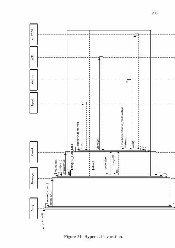
203
Figure 24: Hypercall invocation.

204
Figure 25: VCPU processing messages.
_observers*
Concurrent_Observer
+ update()# do_update()
Concurrent_Observed
+ notify()+ attach(observer : Handler)+ detach(observer : Handler)
Handler
+ call_operator()
Dual_Handler
+ dual_call_operator()
Figure 26: Concurrent Observer.
Figure 27: Concurrent Observed::notify.
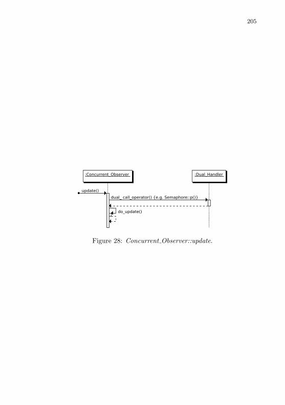
205
Figure 28: Concurrent Observer::update.