marine & offshore - staer misure
TRANSCRIPT

APPLICATION GUIDE
MARINE & OFFSHORE
32
POWEREFFICIENCY
SUPPORTINGYOUR BUSINESS
GOALSAND EMISSION TARGETSWITH INNOVATIVE TECHNOLOGY,
OPTIMISEDPOWER MANAGEMENT
SYSTEMS,AND A PORTFOLIO OFPROVEN PRODUCTSAND SERVICES

4 5
DEIF HAS A LONG AND RICH HISTORY OF PROVIDING CLASS APPROVED, RELIABLE BRIDGE INSTRUMENTATION, SWITCHBOARD EQUIPMENT AND POWER CONTROL.
Conceived and designed to anticipate user needs today and in years to come, DEIF products respond to market demands for easier integration, improved user-friendliness, fuel economy and high ROI.
MARINE & OFFSHOREMost customers are able to install and commission our standard products working from data sheets only. In cases of doubt, DEIF’s extended network of sales and application centres, distributors, customer care teams, and technical support teams is available to assist you and ensure you invest in and implement the best solution for your application.
Vessels Platforms Bridge
INDUSTRIES
THE WORLD’SPREFERRED SUPPLIER*
Our market share in marine bridge instrumentation is estimated at 40 %.See www.deif.com/marine

76
DEIF SHIPSSTANDARD PRODUCTS
IN LESS THAN 3 DAYS.GLOBALLY, 99 % OF ALL DEIF
DELIVERIES ARE ON TIME.
5 YEAR GUARANTEE SUPPLYOF SPARE PARTS FOR
STANDARD CONTROLLERS.
10 YEAR SUPPLYFOR STANDARD
SWITCHBOARD EQUIPMENT.
SCALABLESERVICE CONTRACTS FOR SYSTEM SOLUTIONS
AND ADVANCED PLANT MANAGEMENT SYSTEMS.
ONE-STOP-SHOPFULL SERVICE & SOLUTIONS PROVIDERStrenghten your product & system compatibility working with one supplier. DEIF markets a complete scope of supply ranging from simple instruments to complex and customised power engineering solutions.
► Pre-engineering and design support ► Commissioning, support, and service contracts► 24/7/365 global after-sales service & support
GUARANTEE

98
DEIF Norway
DEIF Spain
DEIF United Kingdom
DEIF USA
DEIF India
DEIF France
DEIF Korea
DEIF Mexico
DEIF Middle East
DEIF Asia Pacific
DEIF Brazil
DEIF China
DEIF Denmark
DEIF Germany
The DEIF group
DEIF OfficeDEIF DistributorDEIF Service Partner
OUR 24/7 GLOBAL REACHOffering you unrivalled response times, the DEIF Group’s extended reach means we are on call for maintenance, repairs, replacements or upgrades 24/7/365 with regional and local anchors guaranteeing a “glocal” view.
► Sales offices, competence centres and training facilities in 17 key markets► Global distributor, system integrator and trusted service partner network► Day-to-day spare part delivery, 3 year supply of spare parts for standard controllers.
We want to maximise your uptime
11.00 12.00 13.00 14.00 15.00 16.00 17.00 18.00 19.00 20.00 21.00 22.00 23.00 24.00 00.00 00.00 02.00 03.00 04.00 05.00 06.00 07.00 08.00 09.00 10.0001.00
1110
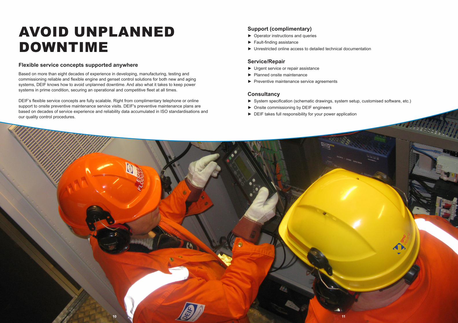
AVOID UNPLANNED DOWNTIMEFlexible service concepts supported anywhereBased on more than eight decades of experience in developing, manufacturing, testing and commissioning reliable and flexible engine and genset control solutions for both new and aging systems, DEIF knows how to avoid unplanned downtime. And also what it takes to keep power systems in prime condition, securing an operational and competitive fleet at all times.
DEIF’s flexible service concepts are fully scalable. Right from complimentary telephone or online support to onsite preventive maintenance service visits. DEIF's preventive maintenance plans are based on decades of service experience and reliability data accumulated in ISO standardisations and our quality control procedures.
Support (complimentary)► Operator instructions and queries► Fault-finding assistance► Unrestricted online access to detailed technical documentation
Service/Repair► Urgent service or repair assistance► Planned onsite maintenance► Preventive maintenance service agreements
Consultancy► System specification (schematic drawings, system setup, customised software, etc.)► Onsite commissioning by DEIF engineers► DEIF takes full responsibility for your power application

1312
CUSTOMER PROFILES
Powering business efficiencyAlready acclaimed for our ability to customise products and solutions to match the exact needs of individual systems and conditions, we are focused on answering the specific needs of multiple industries and customer groups with benefits that generate competitive advantages.
To DEIF, Power Efficiency also means maximising your business potential, powering your competitive efficiency with innovative technology, market-leading logistics, and flexible solutions.
Shipowner Technical Management
Switchboard Manufacturers
Engineering, Procurement &
Construction (EPC)
System Integrators

SHIPOWNERSPeace of mind for your technical managementDEIF provides products, services, consultancy and project solutions that give shipowners and their technical management peace of mind to plan and execute competitive, safe and reliable operation of their fleets.
We design our advanced Power Management System (PMS) controllers and HMIs to be intelligent and intuitive with one-touch auto sequences and user display information messages. Reducing fuel and maintenance costs by up to 40 %, our Dynamic Propulsion (DP) mode balances both the main engine and shaft generator speed and the thruster pitch for minimised power requirements while maintaining full DP functionality. Contrary to traditional PMS thinking on shaft and AUX long-term parallel operation, this system is likely to deliver above expectations on both consumption and new build or refit investment cost.
Offering training and education sessions at our local and regional offices, we can also provide your crew with the competences and proficiency that support this aim.
Innovative power management solutions► Dedicated for DP diesel-hybrid-mechanic offshore supply vessels► Dedicated for shaft-gen & CPP-equipped merchant vessels► Full range of flexible genset controllers, bridge instrumentation & switchboard equipment
Reduced fuel & maintenance costs► Up to 40 % reduction of fuel and maintenance costs► Optimised genset operation reduces running hours► Preventive maintenance service agreements
Global services & support► Retrofit & upgrades► Hands-on training for service & operation► Fast service & support from 17 key offices & 35 distributors
1514

16 17
ENGINEERING, PROCUREMENT & CONSTRUCTIONTaking your power control & monitoring solutions to a new level Experienced in working with Engineering, Procurement and Construction (EPC) contractors globally, DEIF is dedicated to delivering a full range of reliable and documented quality solutions, products and services.
Combining our knowhow within standard and engineered solutions developed for quick and seamless installation and commissioning, we will help you simplify and speed up your system design process and time to market.
Engineering: One-stop-shop► Standard and customised power management & genset control solutions► Full range of bridge instrumentation & switchboard equipment► Customisation of products & solutions possible
Procurement: Quality delivered in record-time► In-house type test centre & laboratory► ISO 9001 & ISO 14001 certified► 99 % of all DEIF deliveries on time
Construction: Reduced installation time & costs► Simplified system wiring► Pre-configured products► DEIF Emulation to test your design before installation► Free online access to technical documentation

SYSTEM INTEGRATORSGetting it right from the startWorking with integrators, our primary aim is to support your business success rates and customer satisfaction.
We achieve this aim by supplying market-leading solutions, products and services that help you cut your inventory, give you faster time to market, and reduce installation time.
Our market-leading delivery performance on standard products enables integrators to react with flexibility on demand and boost production at peaks. With shorter time to market, you also avoid locking cash in stock and costly inventory.
Find & test the right solution► Optimum solution specified
by DEIF engineers► DEIF Emulation to test your
design before installation► Free online access to
technical documentation
Easy & fast installation► Universal communication
standards► Designed to meet compact
space requirements► Fully configurable
controllers for fast retrofit installations
► Free software upgrade from deif.com for optimal operation
Global service & support 24/7/365► Fast service & support
from 17 key offices & 35 distributors
► Best-in-class delivery time► Day-to-day spare part
delivery
1918

20 21
SWITCHBOARD MANUFACTURERSA comprehensive product line for all marine & offshore applicationsDEIF guarantees immediate and reliable delivery performance for projects of all sizes making us an ideal partner for switchboard manufacturers both locally and internationally.
On top, DEIF’s advanced and basic controller systems have been designed with flexibility and versatility in view, giving EPC consultants, integrators and shipowners a range of options that enable them to meet all types of application requests.
One-stop-shop► Standard and customised power management & genset control solutions► Full range of bridge instrumentation► Unmatched portfolio of switchboard equipment► Customisation of products & solutions possible
Quality delivered in record-time► In-house type test centre & laboratory► Certified according to ISO 9001 and ISO 14001► 99 % of all DEIF deliveries on time
Reduced installation time & costs► Simplified system wiring► Pre-configured products► DEIF Emulation to test your design before installation► Free online access to technical documentation
2322 2322
Application examples & casesUncompromising qualityIntroIn-house testing & classification approvals
The following application examples and case studies document the scope of DEIF deliveries, from reliable systems for basic projects to ground-breaking technology for complex, frontrunner challenges in the power industry.
Please note that the examples are generic principles and not exhaustive.
From planning to commissioning, the DEIF Group is ready to support you with power efficient, market-leading solutions in critical power, standby power systems, plant management, rental, and more.
DEIF offers the full range of genset controllers, synchronisation & load sharing units, protection, switchboard equipment, along with:► Project engineering, application and system solution design► Wiring diagram design► Complete pre-delivery testing► On-site commissioning► Training for you and your customers
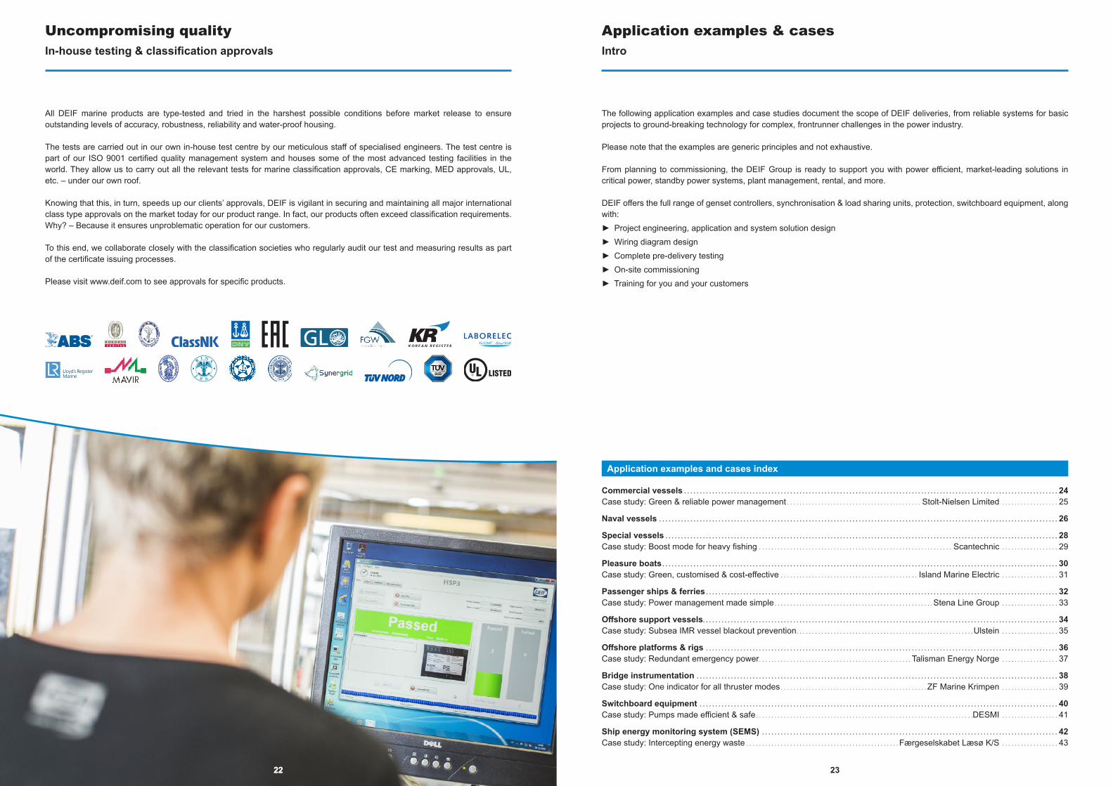
All DEIF marine products are type-tested and tried in the harshest possible conditions before market release to ensure outstanding levels of accuracy, robustness, reliability and water-proof housing.
The tests are carried out in our own in-house test centre by our meticulous staff of specialised engineers. The test centre is part of our ISO 9001 certified quality management system and houses some of the most advanced testing facilities in the world. They allow us to carry out all the relevant tests for marine classification approvals, CE marking, MED approvals, UL, etc. – under our own roof.
Knowing that this, in turn, speeds up our clients’ approvals, DEIF is vigilant in securing and maintaining all major international class type approvals on the market today for our product range. In fact, our products often exceed classification requirements. Why? – Because it ensures unproblematic operation for our customers.
To this end, we collaborate closely with the classification societies who regularly audit our test and measuring results as part of the certificate issuing processes.
Please visit www.deif.com to see approvals for specific products.
Application examples and cases index
Commercial vessels . . . . . . . . . . . . . . . . . . . . . . . . . . . . . . . . . . . . . . . . . . . . . . . . . . . . . . . . . . . . . . . . . . . . . . . . . . . . . . . . . . . . . . . . . . . . . . . . . . . . . . . . . . . . . . . . . . . . . . . . 24Case study: Green & reliable power management . . . . . . . . . . . . . . . . . . . . . . . . . . . . . . . . . . . . . . . . . . . Stolt-Nielsen Limited . . . . . . . . . . . . . . . . . . 25
Naval vessels . . . . . . . . . . . . . . . . . . . . . . . . . . . . . . . . . . . . . . . . . . . . . . . . . . . . . . . . . . . . . . . . . . . . . . . . . . . . . . . . . . . . . . . . . . . . . . . . . . . . . . . . . . . . . . . . . . . . . . . . . . . . . . . . 26
Special vessels . . . . . . . . . . . . . . . . . . . . . . . . . . . . . . . . . . . . . . . . . . . . . . . . . . . . . . . . . . . . . . . . . . . . . . . . . . . . . . . . . . . . . . . . . . . . . . . . . . . . . . . . . . . . . . . . . . . . . . . . . . . . . . 28Case study: Boost mode for heavy fishing . . . . . . . . . . . . . . . . . . . . . . . . . . . . . . . . . . . . . . . . . . . . . . . . . . . . . . . . . . . . . . Scantechnic . . . . . . . . . . . . . . . . . . 29
Pleasure boats . . . . . . . . . . . . . . . . . . . . . . . . . . . . . . . . . . . . . . . . . . . . . . . . . . . . . . . . . . . . . . . . . . . . . . . . . . . . . . . . . . . . . . . . . . . . . . . . . . . . . . . . . . . . . . . . . . . . . . . . . . . . . . . 30Case study: Green, customised & cost-effective . . . . . . . . . . . . . . . . . . . . . . . . . . . . . . . . . . . . . . . . . . . . Island Marine Electric . . . . . . . . . . . . . . . . . . 31
Passenger ships & ferries . . . . . . . . . . . . . . . . . . . . . . . . . . . . . . . . . . . . . . . . . . . . . . . . . . . . . . . . . . . . . . . . . . . . . . . . . . . . . . . . . . . . . . . . . . . . . . . . . . . . . . . . . . . . . . . . . 32Case study: Power management made simple . . . . . . . . . . . . . . . . . . . . . . . . . . . . . . . . . . . . . . . . . . . . . . . . . . . Stena Line Group . . . . . . . . . . . . . . . . . . 33
Offshore support vessels. . . . . . . . . . . . . . . . . . . . . . . . . . . . . . . . . . . . . . . . . . . . . . . . . . . . . . . . . . . . . . . . . . . . . . . . . . . . . . . . . . . . . . . . . . . . . . . . . . . . . . . . . . . . . . . . . . 34Case study: Subsea IMR vessel blackout prevention. . . . . . . . . . . . . . . . . . . . . . . . . . . . . . . . . . . . . . . . . . . . . . . . . . . . . . . . .Ulstein . . . . . . . . . . . . . . . . . . 35
Offshore platforms & rigs . . . . . . . . . . . . . . . . . . . . . . . . . . . . . . . . . . . . . . . . . . . . . . . . . . . . . . . . . . . . . . . . . . . . . . . . . . . . . . . . . . . . . . . . . . . . . . . . . . . . . . . . . . . . . . . . . 36Case study: Redundant emergency power. . . . . . . . . . . . . . . . . . . . . . . . . . . . . . . . . . . . . . . . . . . . . . . . . Talisman Energy Norge . . . . . . . . . . . . . . . . . . 37
Bridge instrumentation . . . . . . . . . . . . . . . . . . . . . . . . . . . . . . . . . . . . . . . . . . . . . . . . . . . . . . . . . . . . . . . . . . . . . . . . . . . . . . . . . . . . . . . . . . . . . . . . . . . . . . . . . . . . . . . . . . . . 38Case study: One indicator for all thruster modes . . . . . . . . . . . . . . . . . . . . . . . . . . . . . . . . . . . . . . . . . . . . . . . ZF Marine Krimpen . . . . . . . . . . . . . . . . . . 39
Switchboard equipment . . . . . . . . . . . . . . . . . . . . . . . . . . . . . . . . . . . . . . . . . . . . . . . . . . . . . . . . . . . . . . . . . . . . . . . . . . . . . . . . . . . . . . . . . . . . . . . . . . . . . . . . . . . . . . . . . . . 40Case study: Pumps made efficient & safe . . . . . . . . . . . . . . . . . . . . . . . . . . . . . . . . . . . . . . . . . . . . . . . . . . . . . . . . . . . . . . . . . . . . . .DESMI . . . . . . . . . . . . . . . . . . 41
Ship energy monitoring system (SEMS) . . . . . . . . . . . . . . . . . . . . . . . . . . . . . . . . . . . . . . . . . . . . . . . . . . . . . . . . . . . . . . . . . . . . . . . . . . . . . . . . . . . . . . . . . . . . . . . 42Case study: Intercepting energy waste . . . . . . . . . . . . . . . . . . . . . . . . . . . . . . . . . . . . . . . . . . . . . . . . .Færgeselskabet Læsø K/S . . . . . . . . . . . . . . . . . . 43
2524
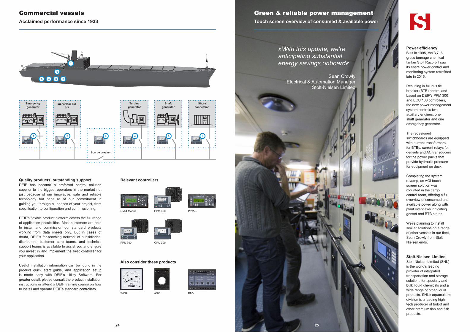
Green & reliable power managementTouch screen overview of consumed & available power
Power efficiencyBuilt in 1995, the 3,716 gross tonnage chemical tanker Stolt Razorbill saw its entire power control and monitoring system retrofitted late in 2015.
Resulting in full bus tie breaker (BTB) control and based on DEIF's PPM 300 and ECU 100 controllers, the new power management system controls two auxiliary engines, one shaft generator and one emergency generator.
The redesigned switchboards are equipped with current transformers for BTBs, current relays for gensets and AC transducers for the power packs that provide hydraulic pressure for equipment on deck.
Completing the system revamp, an AGI touch screen solution was mounted in the cargo control room, offering a full overview of consumed and available power along with plant overviews indicating genset and BTB states.
We're planning to install similar solutions on a range of other vessels in our fleet, Sean Crowly from Stolt-Nielsen ends.
Stolt-Nielsen LimitedStolt-Nielsen Limited (SNL) is the world’s leading provider of integrated transportation and storage solutions for specialty and bulk liquid chemicals and a wide range of other liquid products. SNL’s aquaculture division is a leading high-tech producer of turbot and other premium fish and fish products.
»With this update, we're anticipating substantial energy savings onboard«
Sean Crowly Electrical & Automation Manager
Stolt-Nielsen Limited
Quality products, outstanding supportDEIF has become a preferred control solution supplier to the biggest operators in the market not just because of our innovative, safe and reliable technology but because of our commitment in guiding you through all phases of your project, from specification to configuration and commissioning.
DEIF’s flexible product platform covers the full range of application possibilities. Most customers are able to install and commission our standard products working from data sheets only. But in cases of doubt, DEIF’s far-reaching network of subsidiaries, distributors, customer care teams, and technical support teams is available to assist you and ensure you invest in and implement the best controller for your application.
Useful installation information can be found in the product quick start guide, and application setup is made easy with DEIF’s Utility Software. For greater detail, please consult the product installation instructions or attend a DEIF training course on how to install and operate DEIF’s standard controllers.
Relevant controllers
DM-4 Marine PPM 300 PPM-3
GPU 300PPU 300
Also consider these products
RMVWQR ASK
Commercial vesselsAcclaimed performance since 1933
25
Generator set 1-3
Bus tie breaker
Turbine generator
Emergency generator
Shore connection
1 2 3 4 6
Shaft generator
5
1
6
5 4 3 2
2726
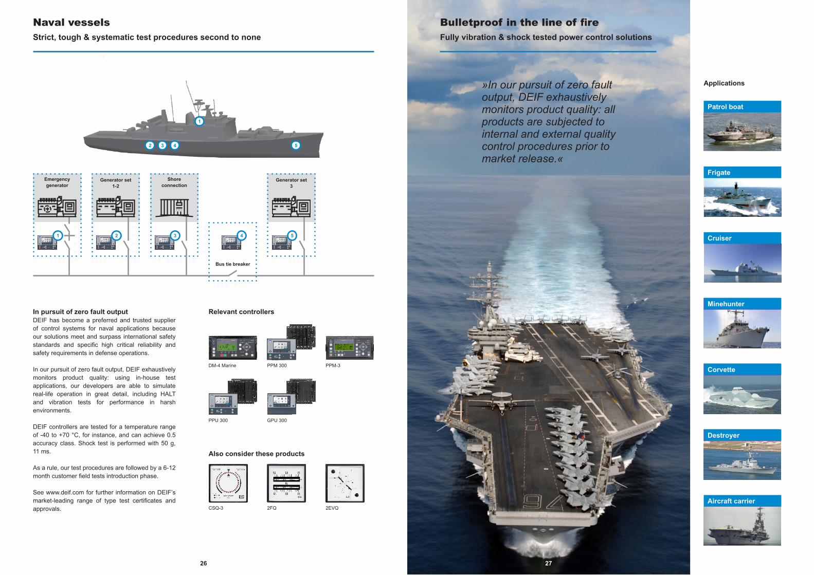
Bulletproof in the line of fireFully vibration & shock tested power control solutions
»In our pursuit of zero fault output, DEIF exhaustively monitors product quality: all products are subjected to internal and external quality control procedures prior to market release.«
In pursuit of zero fault outputDEIF has become a preferred and trusted supplier of control systems for naval applications because our solutions meet and surpass international safety standards and specific high critical reliability and safety requirements in defense operations.
In our pursuit of zero fault output, DEIF exhaustively monitors product quality: using in-house test applications, our developers are able to simulate real-life operation in great detail, including HALT and vibration tests for performance in harsh environments.
DEIF controllers are tested for a temperature range of -40 to +70 °C, for instance, and can achieve 0.5 accuracy class. Shock test is performed with 50 g, 11 ms.
As a rule, our test procedures are followed by a 6-12 month customer field tests introduction phase.
See www.deif.com for further information on DEIF’s market-leading range of type test certificates and approvals.
Relevant controllers
Also consider these products
2EVQCSQ-3 2FQ
Naval vesselsStrict, tough & systematic test procedures second to none
Applications
Minehunter
Corvette
Destroyer
Frigate
Cruiser
Aircraft carrier
Patrol boat
DM-4 Marine PPM 300 PPM-3
GPU 300PPU 300
27
Bus tie breaker
4
Shore connection
3
Emergency generator
1 2
Generator set 1-2
5
Generator set 3
1
2 3 4 5
2928
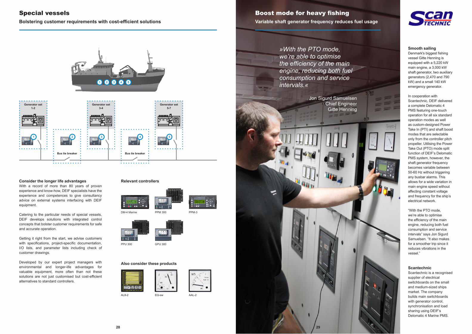
Boost mode for heavy fishingVariable shaft generator frequency reduces fuel usage
ScantechnicScantechnic is a recognised supplier of electrical switchboards on the small and medium-sized ships market. The company builds main switchboards with generator control, synchronisation and load sharing using DEIF’s Delomatic 4 Marine PMS.
»With the PTO mode, we’re able to optimise the efficiency of the main engine, reducing both fuel consumption and service intervals.«
Jon Sigurd Samuelsen Chief Engineer Gitte Henning
Consider the longer life advantagesWith a record of more than 80 years of proven experience and know-how, DEIF specialists have the experience and competences to give consultancy advice on external systems interfacing with DEIF equipment.
Catering to the particular needs of special vessels, DEIF develops solutions with integrated control concepts that bolster customer requirements for safe and accurate operation.
Getting it right from the start, we advise customers with specifications, project-specific documentation, I/O lists, and parameter lists including check of customer drawings.
Developed by our expert project managers with environmental and longer-life advantages for valuable equipment, more often than not these solutions are not just customised but cost-efficient alternatives to standard controllers.
Relevant controllers
Also consider these products
AAL-2AL8-2 EQ-sw
Special vesselsBolstering customer requirements with cost-efficient solutions
Smooth sailingDenmark's biggest fishing vessel Gitte Henning is equipped with a 5,220 kW main engine, a 3,000 kW shaft generator, two auxiliary generators (2,470 and 790 kW) and a small 140 kW emergency generator.
In cooperation with Scantechnic, DEIF delivered a complete Delomatic 4 PMS featuring one-touch operation for all six standard operation modes as well as custom-designed Power Take In (PTI) and shaft boost modes that are selectable only from the controller pitch propeller. Utilising the Power Take Out (PTO) mode split function of DEIF’s Delomatic PMS system, however, the shaft generator frequency becomes variable between 50-60 Hz without triggering any busbar alarms. This allows for a wide variation in main engine speed without affecting constant voltage and frequency for the ship’s electrical network.
“With the PTO mode, we’re able to optimise the efficiency of the main engine, reducing both fuel consumption and service intervals” says Jon Sigurd Samuelsen. “It also makes for a smoother trip since it reduces vibrations in the vessel.”
DM-4 Marine PPM 300 PPM-3
GPU 300PPU 300
29
Bus tie breaker
2
Bus tie breaker
41
Generator set 1-2
3
Generator set 3-4
5
Generator set 5-7
1 2 3 4 5
3130
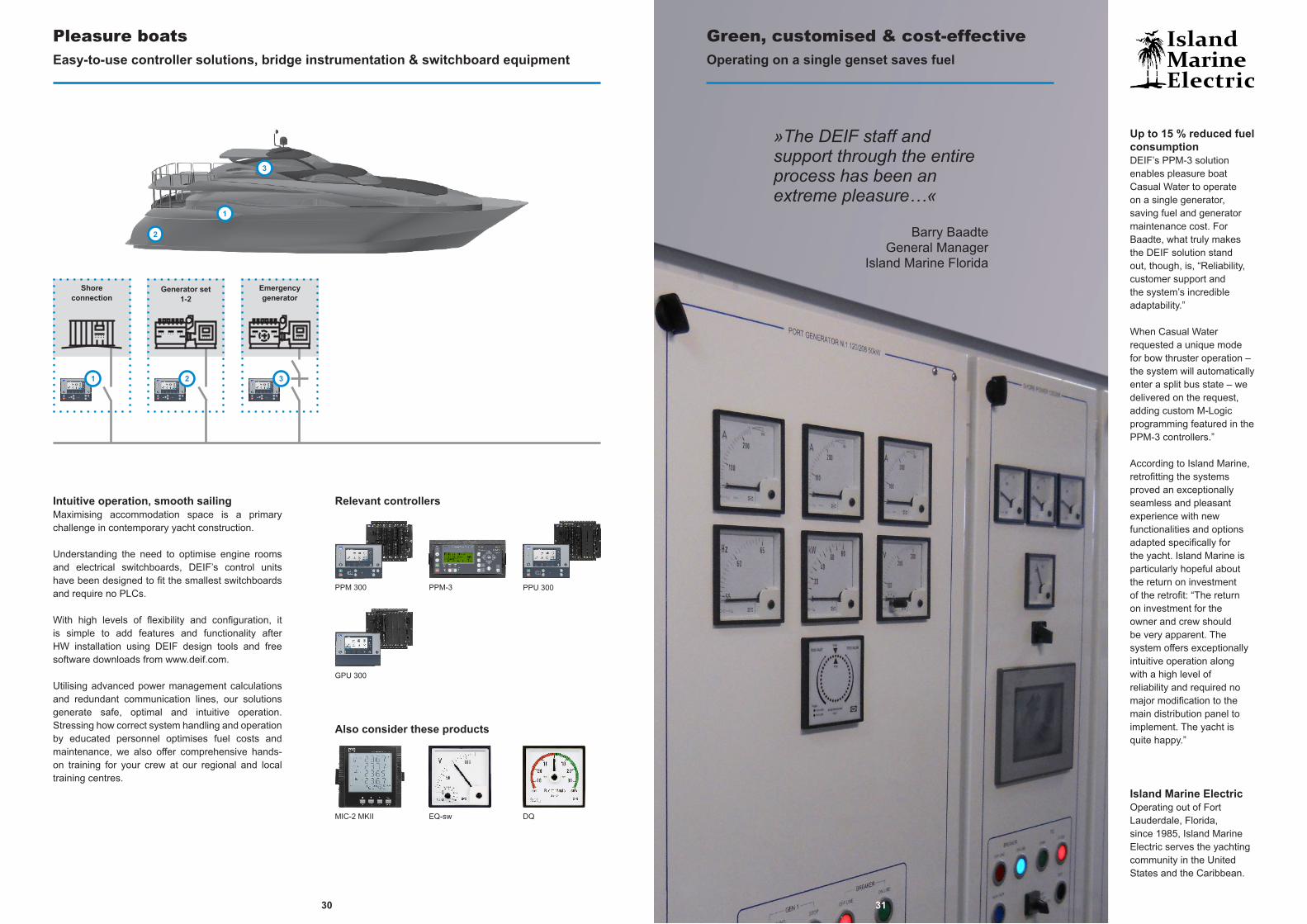
Green, customised & cost-effectiveOperating on a single genset saves fuel
Up to 15 % reduced fuel consumptionDEIF’s PPM-3 solution enables pleasure boat Casual Water to operate on a single generator, saving fuel and generator maintenance cost. For Baadte, what truly makes the DEIF solution stand out, though, is, “Reliability, customer support and the system’s incredible adaptability.”
When Casual Water requested a unique mode for bow thruster operation – the system will automatically enter a split bus state – we delivered on the request, adding custom M-Logic programming featured in the PPM-3 controllers.”
According to Island Marine, retrofitting the systems proved an exceptionally seamless and pleasant experience with new functionalities and options adapted specifically for the yacht. Island Marine is particularly hopeful about the return on investment of the retrofit: “The return on investment for the owner and crew should be very apparent. The system offers exceptionally intuitive operation along with a high level of reliability and required no major modification to the main distribution panel to implement. The yacht is quite happy.”
Island Marine ElectricOperating out of Fort Lauderdale, Florida, since 1985, Island Marine Electric serves the yachting community in the United States and the Caribbean.
»The DEIF staff and support through the entire process has been an extreme pleasure…«
Barry BaadteGeneral Manager
Island Marine Florida
Intuitive operation, smooth sailingMaximising accommodation space is a primary challenge in contemporary yacht construction.
Understanding the need to optimise engine rooms and electrical switchboards, DEIF’s control units have been designed to fit the smallest switchboards and require no PLCs.
With high levels of flexibility and configuration, it is simple to add features and functionality after HW installation using DEIF design tools and free software downloads from www.deif.com.
Utilising advanced power management calculations and redundant communication lines, our solutions generate safe, optimal and intuitive operation. Stressing how correct system handling and operation by educated personnel optimises fuel costs and maintenance, we also offer comprehensive hands-on training for your crew at our regional and local training centres.
Relevant controllers
Also consider these products
DQMIC-2 MKII EQ-sw
Pleasure boatsEasy-to-use controller solutions, bridge instrumentation & switchboard equipment
PPM 300 PPM-3
GPU 300
PPU 300
31
Shore connection
1
Emergency generator
32
Generator set 1-2
1
2
3

3332
Power management made simpleFour predefined modes cover the entire route
Stena Line GroupStena Line Group is an international transport and travel service company with Europe's most comprehensive route network.
»Easy to install. Easy to operate. Full touch screen overview. In simple terms: Perfect.«
Anders EfraimssonChief Engineer
Stena Line
Reliable power control made simpleFully commissionable without interrupting commercial operations, a DEIF power control solution is the innovative, safe and reliable choice for ferry route operators and their crews. We are committed to guiding you through all phases of your project, from specification to configuration and commissioning.
DEIF’s flexible power control solutions contain leading technology genset controllers, the world's most sold range of bridge instrumentation and an exhaustive portfolio of switchboard equipment.
Advanced load-dependent start/stop, long-time parallel operation on diesel/shaft generators and combined emergency/harbour generator functionality reduce fuel consumption, and one-touch auto sequences, PTI, PTO, PTH and BOOST shaft generator modes along with preventive maintenance alarms make day-to-day operations easy and intuitive for the crew. Everything can be fully monitored and controlled on graphical touch screens.
Relevant controllers
Also consider these products
EQTAS WQR
Passenger ships & ferriesComplete packages with outstanding safety & reliability
Modular & intuitiveOperating the ferry route between Frederikshavn, Denmark, and Göteborg, Sweden, M/F Stena Gothica's power management system was fully upgraded in just three weeks with DEIF's new and modular PPM 300 power management solution.
For ease of operation, the installed solution offers four standard modes that cover the entire route. Auto for standard sailing, secure for near-coast sailing, harbour for harbour operation and shore for seamless shore-to-ship supply.
Fitted with DEIF's AGI touch screen, the delivered solution also improves overview and control for the crew.
"Our crew can easily control the four gensets onboard using the intuitive PPM 300 menues and the four standard operation modes. It doesn't get much simpler than that". DM-4 Marine PPM 300 PPM-3
GPU 300PPU 300
33
Bus tie breaker
4
Shore connection
2
Shore connection
6
Emergency generator
1 3
Generator set 1-2
5
Generator set 3-4
1
4
5 2 3
3534
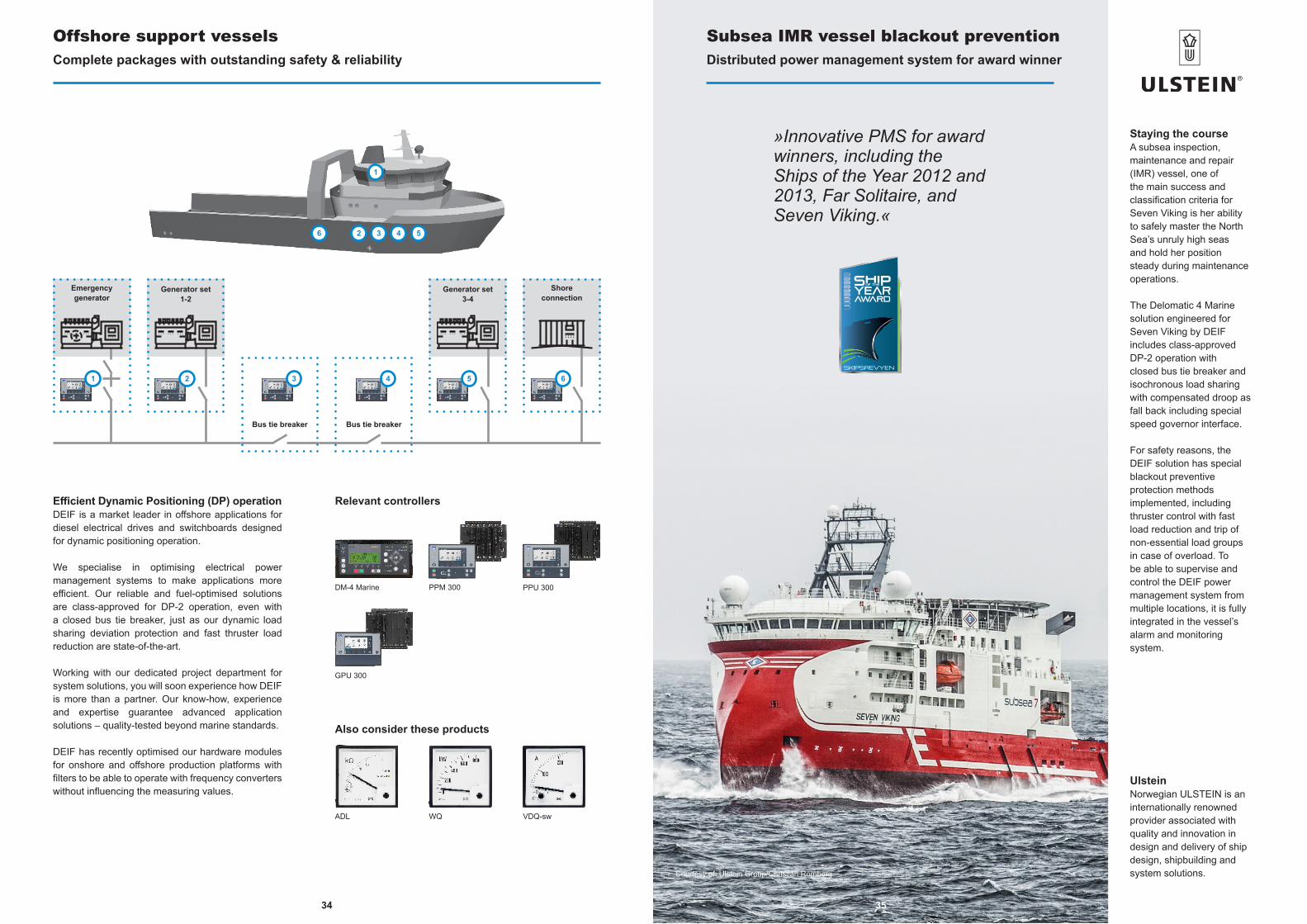
Subsea IMR vessel blackout preventionDistributed power management system for award winner
UlsteinNorwegian ULSTEIN is aninternationally renowned provider associated with quality and innovation in design and delivery of ship design, shipbuilding and system solutions.
»Innovative PMS for award winners, including the Ships of the Year 2012 and 2013, Far Solitaire, and Seven Viking.«
Efficient Dynamic Positioning (DP) operationDEIF is a market leader in offshore applications for diesel electrical drives and switchboards designed for dynamic positioning operation.
We specialise in optimising electrical power management systems to make applications more efficient. Our reliable and fuel-optimised solutions are class-approved for DP-2 operation, even with a closed bus tie breaker, just as our dynamic load sharing deviation protection and fast thruster load reduction are state-of-the-art.
Working with our dedicated project department for system solutions, you will soon experience how DEIF is more than a partner. Our know-how, experience and expertise guarantee advanced application solutions – quality-tested beyond marine standards.
DEIF has recently optimised our hardware modules for onshore and offshore production platforms with filters to be able to operate with frequency converters without influencing the measuring values.
Relevant controllers
Also consider these products
VDQ-swADL WQ
Offshore support vesselsComplete packages with outstanding safety & reliability
Staying the courseA subsea inspection, maintenance and repair (IMR) vessel, one of the main success and classification criteria for Seven Viking is her ability to safely master the North Sea’s unruly high seas and hold her position steady during maintenance operations.
The Delomatic 4 Marine solution engineered for Seven Viking by DEIF includes class-approved DP-2 operation with closed bus tie breaker and isochronous load sharing with compensated droop as fall back including special speed governor interface.
For safety reasons, the DEIF solution has special blackout preventive protection methods implemented, including thruster control with fast load reduction and trip of non-essential load groups in case of overload. To be able to supervise and control the DEIF power management system from multiple locations, it is fully integrated in the vessel’s alarm and monitoring system.
Courtesy of: Ulstein Group/Christian Romberg
DM-4 Marine PPM 300
GPU 300
PPU 300
35
Bus tie breaker
4
Bus tie breaker
3
Shore connection
6
Emergency generator
1 2
Generator set 1-2
5
Generator set 3-4
2
1
6 3 4 5
3736
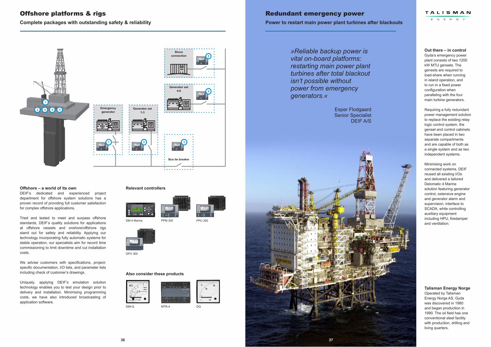
Redundant emergency powerPower to restart main power plant turbines after blackouts
Out there – in controlGyda’s emergency power plant consists of two 1200 kW MTU gensets. The gensets are required to load-share when running in island operation, and to run in a fixed power configuration when paralleling with the four main turbine generators.
Requiring a fully redundant power management solution to replace the existing relay logic control system, the genset and control cabinets have been placed in two separate compartments and are capable of both as a single system and as two independent systems.
Minimising work on connected systems, DEIF reused all existing I/Os and delivered a tailored Delomatic 4 Marine solution featuring generator control, extensive engine and generator alarm and supervision, interface to SCADA, while controlling auxiliary equipment including HPU, firedamper and ventilation.
Talisman Energy NorgeOperated by Talisman Energy Norge AS, Gyda was discovered in 1980 and began production in 1990. The oil field has one conventional steel facility with production, drilling and living quarters.
»Reliable backup power is vital on-board platforms: restarting main power plant turbines after total blackout isn’t possible without power from emergency generators.«
Esper FlodgaardSenior Specialist
DEIF A/S
Offshore – a world of its ownDEIF’s dedicated and experienced project department for offshore system solutions has a proven record of providing full customer satisfaction for complex offshore applications.
Tried and tested to meet and surpass offshore standards, DEIF’s quality solutions for applications at offshore vessels and onshore/offshore rigs stand out for safety and reliability. Applying our technology incorporating fully automatic systems for stable operation, our specialists aim for record time commissioning to limit downtime and cut installation costs.
We advise customers with specifications, project-specific documentation, I/O lists, and parameter lists including check of customer’s drawings.
Uniquely, applying DEIF’s emulation solution technology enables you to test your design prior to delivery and installation. Minimising programming costs, we have also introduced broadcasting of application software.
Relevant controllers
Also consider these products
DQSIM-Q MTR-4
Offshore platforms & rigsComplete packages with outstanding safety & reliability
DM-4 Marine PPM 300
GPU 300
PPU 300
37
Bus tie breaker
3
Shore connection
Generator set 4-6
5
4
Emergency generator
1 2
Generator set 1-3
1
2 3 4 5
3938
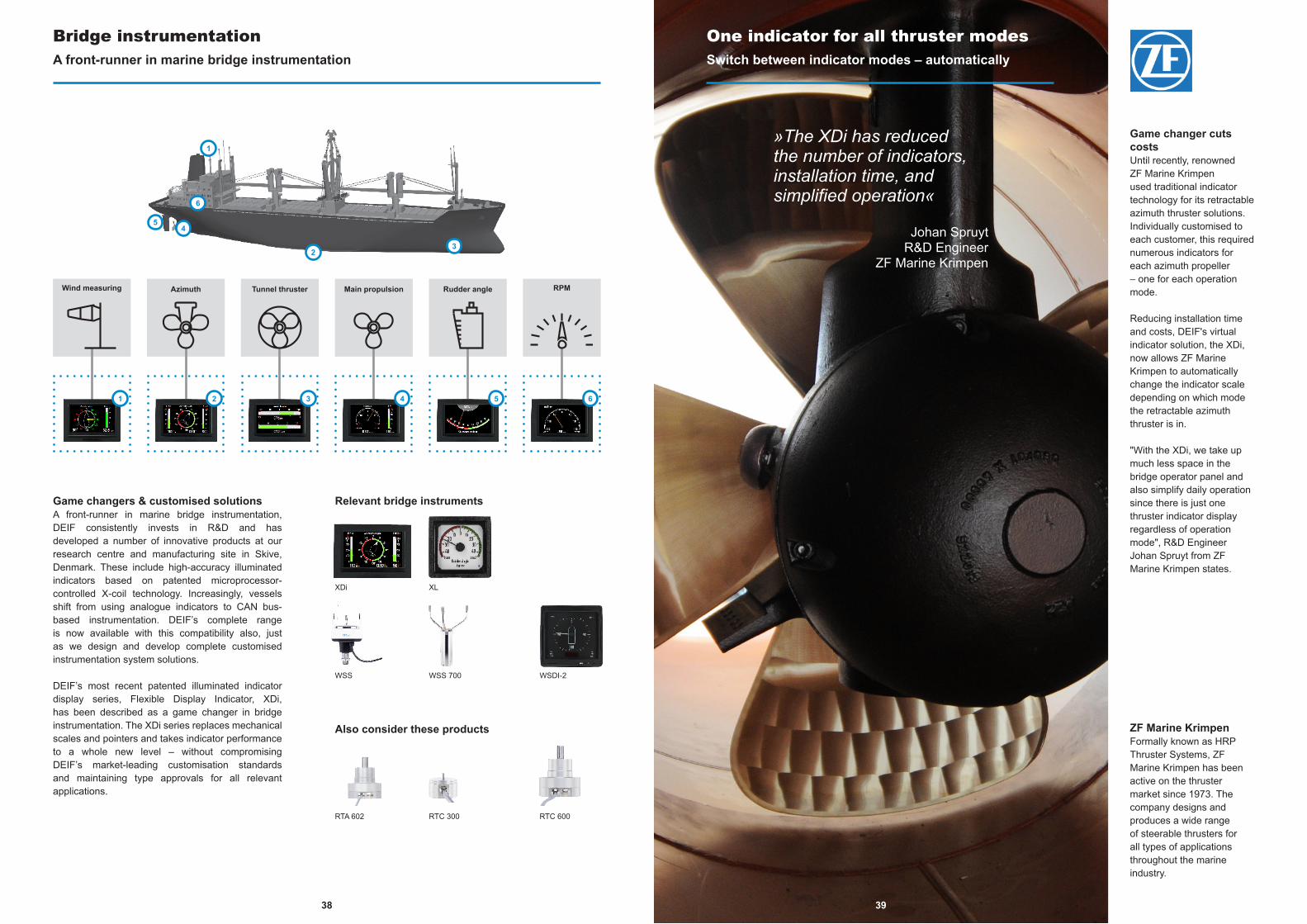
One indicator for all thruster modes Switch between indicator modes – automatically
Game changer cuts costsUntil recently, renowned ZF Marine Krimpen used traditional indicator technology for its retractable azimuth thruster solutions. Individually customised to each customer, this required numerous indicators for each azimuth propeller – one for each operation mode.
Reducing installation time and costs, DEIF's virtual indicator solution, the XDi, now allows ZF Marine Krimpen to automatically change the indicator scale depending on which mode the retractable azimuth thruster is in.
"With the XDi, we take up much less space in the bridge operator panel and also simplify daily operation since there is just one thruster indicator display regardless of operation mode", R&D Engineer Johan Spruyt from ZF Marine Krimpen states.
ZF Marine KrimpenFormally known as HRP Thruster Systems, ZF Marine Krimpen has been active on the thruster market since 1973. The company designs and produces a wide range of steerable thrusters for all types of applications throughout the marine industry.
»The XDi has reduced the number of indicators, installation time, and simplified operation«
Johan SpruytR&D Engineer
ZF Marine Krimpen
Game changers & customised solutionsA front-runner in marine bridge instrumentation, DEIF consistently invests in R&D and has developed a number of innovative products at our research centre and manufacturing site in Skive, Denmark. These include high-accuracy illuminated indicators based on patented microprocessor-controlled X-coil technology. Increasingly, vessels shift from using analogue indicators to CAN bus-based instrumentation. DEIF’s complete range is now available with this compatibility also, just as we design and develop complete customised instrumentation system solutions.
DEIF’s most recent patented illuminated indicator display series, Flexible Display Indicator, XDi, has been described as a game changer in bridge instrumentation. The XDi series replaces mechanical scales and pointers and takes indicator performance to a whole new level – without compromising DEIF’s market-leading customisation standards and maintaining type approvals for all relevant applications.
Relevant bridge instruments
Also consider these products
RTA 602 RTC 300 RTC 600
Bridge instrumentationA front-runner in marine bridge instrumentation
XDi XL
WSS WSS 700
39
RPMWind measuring
21 3 4 5 6
Azimuth Tunnel thruster Main propulsion Rudder angle
1
23
6
45
WSDI-2
4140
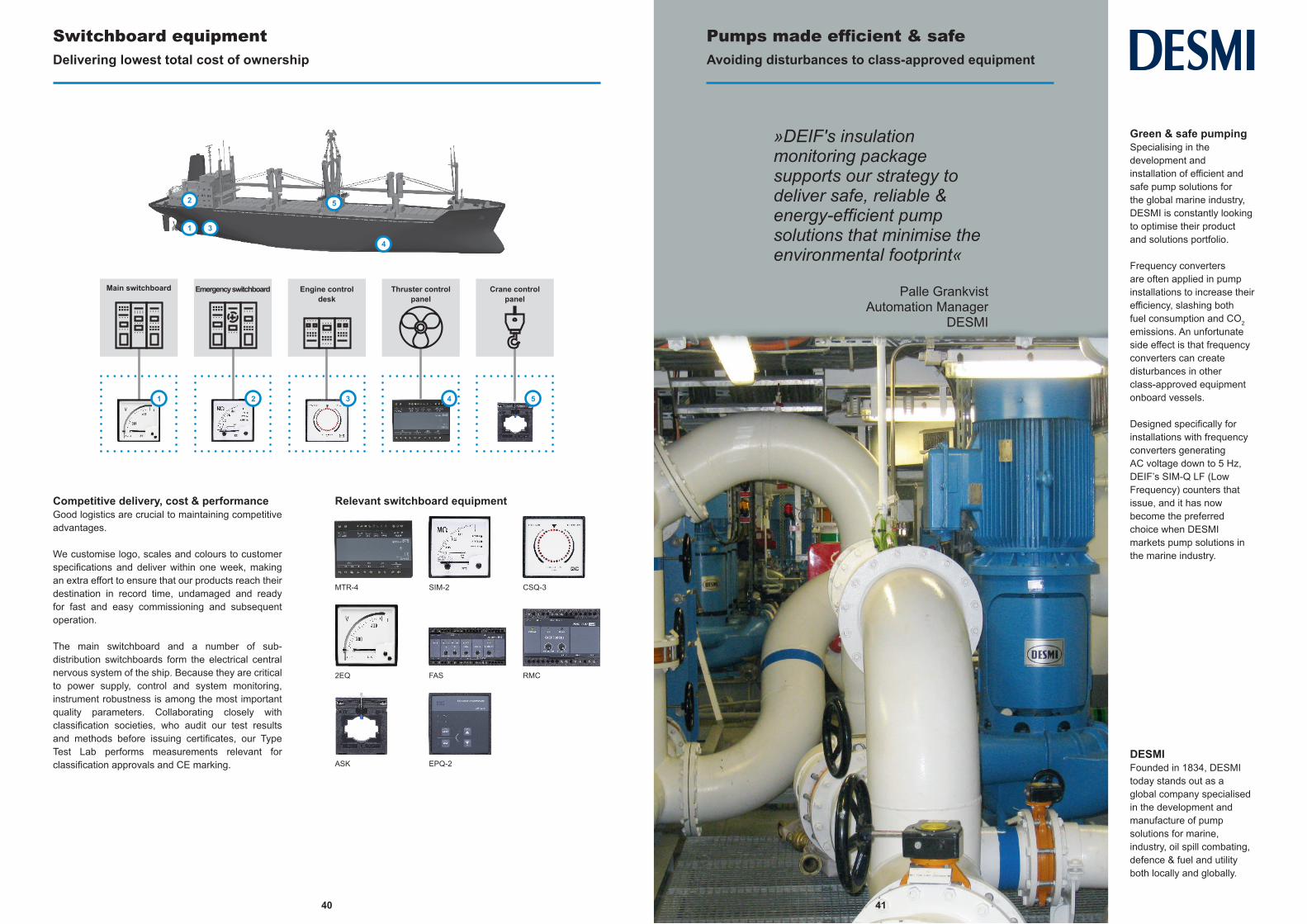
Switchboard equipmentDelivering lowest total cost of ownership
Competitive delivery, cost & performanceGood logistics are crucial to maintaining competitive advantages.
We customise logo, scales and colours to customer specifications and deliver within one week, making an extra effort to ensure that our products reach their destination in record time, undamaged and ready for fast and easy commissioning and subsequent operation.
The main switchboard and a number of sub-distribution switchboards form the electrical central nervous system of the ship. Because they are critical to power supply, control and system monitoring, instrument robustness is among the most important quality parameters. Collaborating closely with classification societies, who audit our test results and methods before issuing certificates, our Type Test Lab performs measurements relevant for classification approvals and CE marking.
Relevant switchboard equipment
MTR-4 SIM-2 CSQ-3
2EQ FAS RMC
Pumps made efficient & safeAvoiding disturbances to class-approved equipment
Green & safe pumpingSpecialising in the development and installation of efficient and safe pump solutions for the global marine industry, DESMI is constantly looking to optimise their product and solutions portfolio.
Frequency converters are often applied in pump installations to increase their efficiency, slashing both fuel consumption and CO2 emissions. An unfortunate side effect is that frequency converters can create disturbances in other class-approved equipment onboard vessels.
Designed specifically for installations with frequency converters generating AC voltage down to 5 Hz, DEIF’s SIM-Q LF (Low Frequency) counters that issue, and it has now become the preferred choice when DESMI markets pump solutions in the marine industry.
»DEIF's insulation monitoring package supports our strategy to deliver safe, reliable & energy-efficient pump solutions that minimise the environmental footprint«
Palle GrankvistAutomation Manager
DESMI
DESMIFounded in 1834, DESMI today stands out as a global company specialised in the development and manufacture of pump solutions for marine, industry, oil spill combating, defence & fuel and utility both locally and globally.
41
ASK EPQ-2
1
2
3
4
5
Main switchboard
21 3 4 5
Emergency switchboard Engine control desk
Thruster control panel
Crane control panel
4342
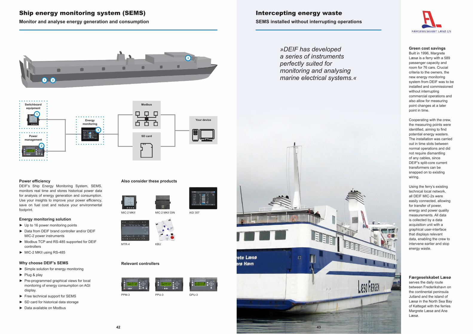
Ship energy monitoring system (SEMS)Monitor and analyse energy generation and consumption
Power efficiencyDEIF’s Ship Energy Monitoring System, SEMS, monitors real time and stores historical power data for analysis of energy generation and consumption. Use your insights to improve your power efficiency, save on fuel cost and reduce your environmental footprint.
Energy monitoring solution► Up to 16 power monitoring points► Data from DEIF brand controller and/or DEIF
MIC-2 power instruments► Modbus TCP and RS-485 supported for DEIF
controllers► MIC-2 MKII using RS-485
Why choose DEIF’s SEMS► Simple solution for energy monitoring► Plug & play► Pre-programmed graphical views for local
monitoring of energy consumption on AGI display.
► Free technical support for SEMS► SD card for historical data storage► Data available on Modbus
Relevant controllers
Also consider these products
GPU-3PPM-3
MIC-2 MKII
PPU-3
MIC-2 MKII DIN AGI 307
Intercepting energy wasteSEMS installed without interrupting operations
Green cost savingsBuilt in 1996, Margrete Læsø is a ferry with a 589 passenger capacity and room for 76 cars. Crucial criteria to the owners, the new energy monitoring system from DEIF was to be installed and commissioned without interrupting commercial operations and also allow for measuring point changes at a later point in time.
Cooperating with the crew, the measuring points were identified, aiming to find potential energy wasters. The installation was carried out in time slots between normal operations and did not require dismantling of any cables, since DEIF's split-core current transformers can be snapped on to existing wiring.
Using the ferry’s existing technical local network, all DEIF MIC-2s were easily connected, allowing for transfer of power, energy and power quality measurements. All data is collected by a data acquisition unit with a graphical user-interface that displays relevant data, enabling the crew to intervene earlier and stop energy waste.
»DEIF has developed a series of instruments perfectly suited for monitoring and analysing marine electrical systems.«
Færgeselskabet Læsøserves the daily route between Frederikshavn on the continental peninsula Jutland and the island of Læsø in the North Sea Bay of Kattegat with the ferries Margrete Læsø and Ane Læsø.
43
2
3
1
Switchboard equipment
Modbus
Your device
Power management
SD card
Energy monitoring
1 2
3
MTR-4 KBU

4544
Leading the way in marine & offshore power control technologyDEIF Marine & Offshore’s extensive product portfolio is one of the most comprehensive on the global markets for marine & offshore power control and monitoring, ranging from quality analogue relays and cost-effective single and multi-function controller platforms to engineered solutions for all types of vessels, offshore platforms and rigs. DEIF’s control concepts eliminate the need for external controllers and are user-friendly alternatives to standard controllers.
Innovation has been of the heart of the remarkable success DEIF product lines have seen over the past decades, starting with the introduction of the Uni-line, single-function controller platform series in 1998. Acclaimed for its quality and reliability, DEIF’s Uni-Line research led to the development of the Multi-line 2 multi-function controller, protection and power management platform, which again fostered the recent launch of the versatile and modular-based Multi-line 300 platform.
A DEIF solution is a greener choice because it means optimised operation: life extensions and other advanced technologies make our customers’ assets more valuable and operationally more efficient.
Platform & product type overviewsIntro
Platform & product type overviews index
Multi-line 300 . . . . . . . . . . . . . . . . . . . . . . . . . . . . . . . . . . . . . . . . . . . . . . . . . . . . . . . . . . . . . . . . . . . . . . . . . . . . . . . . . . . . . . . . . . . . . . . . . . . . . Platform . . . . . . . . . . . . . . . . . . 45Multi-line 2 . . . . . . . . . . . . . . . . . . . . . . . . . . . . . . . . . . . . . . . . . . . . . . . . . . . . . . . . . . . . . . . . . . . . . . . . . . . . . . . . . . . . . . . . . . . . . . . . . . . . . . . . Platform . . . . . . . . . . . . . . . . . . 46Illuminated bridge indicators . . . . . . . . . . . . . . . . . . . . . . . . . . . . . . . . . . . . . . . . . . . . . . . . . . . . . . . . . . . . . . . . . . . . . . . . . . . . . . . . . . . Platform . . . . . . . . . . . . . . . . . . 47Power management and paralleling & operation . . . . . . . . . . . . . . . . . . . . . . . . . . . . . . . . . . . . . . . . . . . . . . . . . . . . . . . . . . . . . . . . . . . . . . . . . . . . . . . . . . . . . . . . . 48Synchronisation & load sharing . . . . . . . . . . . . . . . . . . . . . . . . . . . . . . . . . . . . . . . . . . . . . . . . . . . . . . . . . . . . . . . . . . . . . . . . . . . . . . . . . . . . . . . . . . . . . . . . . . . . . . . . . . . . . 49Protection . . . . . . . . . . . . . . . . . . . . . . . . . . . . . . . . . . . . . . . . . . . . . . . . . . . . . . . . . . . . . . . . . . . . . . . . . . . . . . . . . . . . . . . . . . . . . . . . . . . . . . . . . . . . . . . . . . . . . . . . . . . . . . . . . . . . . . 50Measuring . . . . . . . . . . . . . . . . . . . . . . . . . . . . . . . . . . . . . . . . . . . . . . . . . . . . . . . . . . . . . . . . . . . . . . . . . . . . . . . . . . . . . . . . . . . .Measuring centres . . . . . . . . . . . . . . . . . . 51Measuring . . . . . . . . . . . . . . . . . . . . . . . . . . . . . . . . . . . . . . . . . . . . . . . . . . . . . . . . . . . . . . . . . . . . . . . . . . . . . . . . . . . . . . . . Analogue instruments . . . . . . . . . . . . . . . . . . 52Measuring . . . . . . . . . . . . . . . . . . . . . . . . . . . . . . . . . . . . . . . . . . . . . . . . . . . . . . . . . . . . . . . . . . . . . . . . . . . . . . . AC/DC current measurement . . . . . . . . . . . . . . . . . . 53Measuring . . . . . . . . . . . . . . . . . . . . . . . . . . . . . . . . . . . . . . . . . . . . . . . . . . . . . . . . . . . . . . . . . . . . . . . . . . . . . . . . . . . . . . . . . . Monitoring & alarms . . . . . . . . . . . . . . . . . . 54Bridge instrumentation . . . . . . . . . . . . . . . . . . . . . . . . . . . . . . . . . . . . . . . . . . . . . . . . . . . . . . . . . . . . . . . . . . . . . . . . . . . . . . . . . . . . . . . . . . . . . . . . . . . . . . . . . . . . . . . . . . . . . . . 55
Multi-line 300Platform overview
Marine power technology has changedAnticipating user needs and responding to market demands in a changing world, DEIF is in the process of developing a ground-breaking range of advanced controller solutions that adapt to your application automatically. Named Multi-line 300, ML 300, the quality controller range equals user-friendly operation and DEIF’s hallmarks of green, safe and reliable performance.
Complete with built-in troubleshooting and fuel-efficient technology, Multi-line 300 is based on a versatile and modular base-mounted hardware platform developed for all levels of control solutions: from simple stand-alone engine control to complex and engineered power management systems. Using advanced processor technology, ML 300 units feature redundant high speed internal communication lines capable of handling protection functions at record speeds.
The flexible units can be expanded with input and output modules, and an LED graphical colour display with intuitive one-touch sequences gives you immediate access to easy-read parameters, read-outs and service menus. Moreover, the unique and integrated emulation solution’s exact reproduction of behaviour improves your planning, approvals and training.
Reducing risks of personal and equipment damage and letting you change parameters and sequences to simulate alternative setups to optimise your application, ML 300’s emulation feature is about giving you critical market advantages and cutting-edge, top-performing results.
Features GPU 300 PPU 300 PPM 300Power management ×
Load sharing × ×
Safety system for engine protection ×
Synchronisation × ×
Generator & busbar protection × × ×
Engine control & protection × ×
GPU 300Generator protection unit for PLC-based systems.
PPU 300Paralleling & protection unit for PLC-based systems.
PPM 300Protection & power management controller.
4746
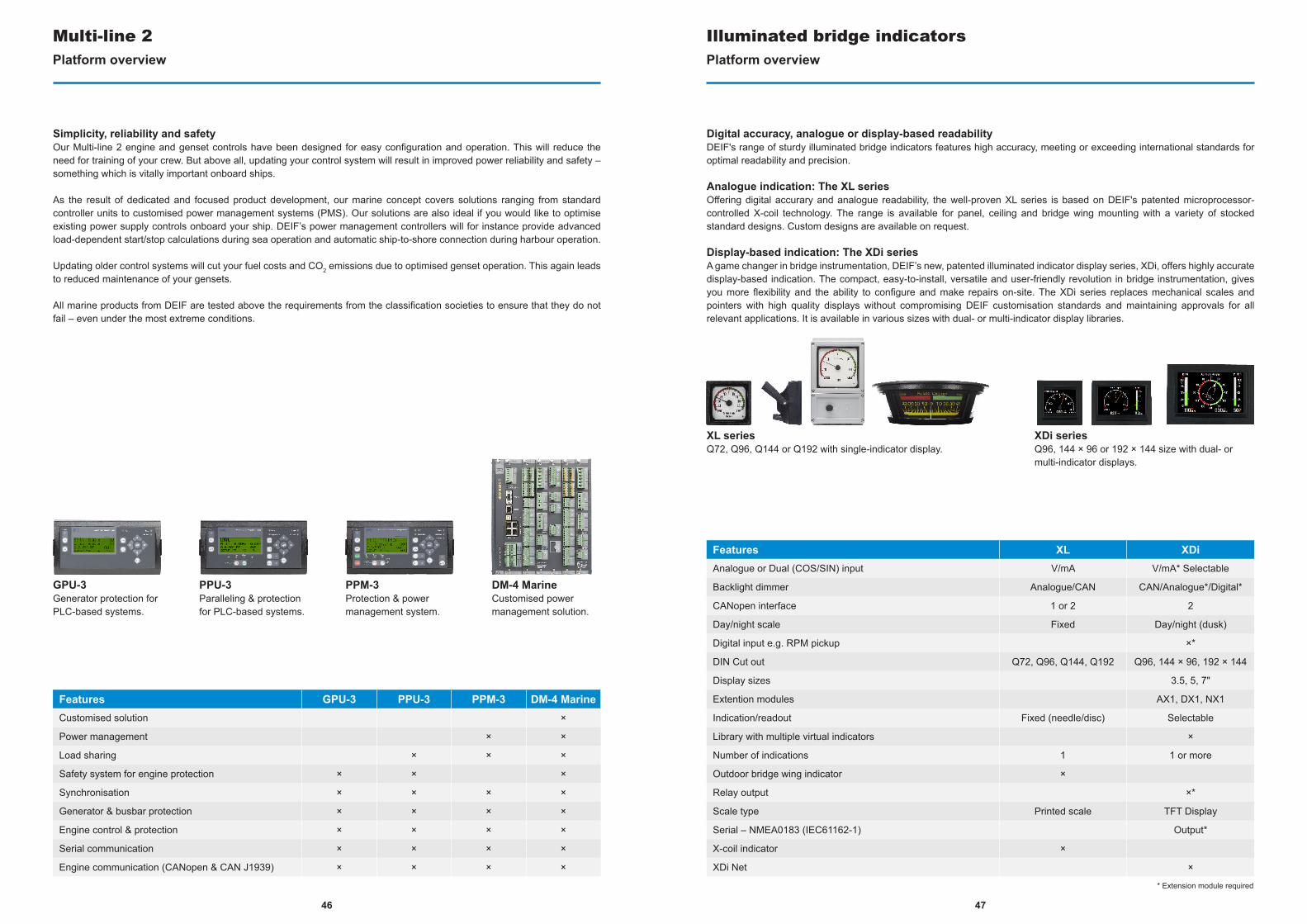
Multi-line 2Platform overview
Features GPU-3 PPU-3 PPM-3 DM-4 MarineCustomised solution ×
Power management × ×
Load sharing × × ×
Safety system for engine protection × × ×
Synchronisation × × × ×
Generator & busbar protection × × × ×
Engine control & protection × × × ×
Serial communication × × × ×
Engine communication (CANopen & CAN J1939) × × × ×
PPM-3Protection & power management system.
Simplicity, reliability and safetyOur Multi-line 2 engine and genset controls have been designed for easy configuration and operation. This will reduce the need for training of your crew. But above all, updating your control system will result in improved power reliability and safety – something which is vitally important onboard ships.
As the result of dedicated and focused product development, our marine concept covers solutions ranging from standard controller units to customised power management systems (PMS). Our solutions are also ideal if you would like to optimise existing power supply controls onboard your ship. DEIF’s power management controllers will for instance provide advanced load-dependent start/stop calculations during sea operation and automatic ship-to-shore connection during harbour operation.
Updating older control systems will cut your fuel costs and CO2 emissions due to optimised genset operation. This again leads to reduced maintenance of your gensets.
All marine products from DEIF are tested above the requirements from the classification societies to ensure that they do not fail – even under the most extreme conditions.
DM-4 MarineCustomised power management solution.
PPU-3Paralleling & protection for PLC-based systems.
GPU-3Generator protection for PLC-based systems.
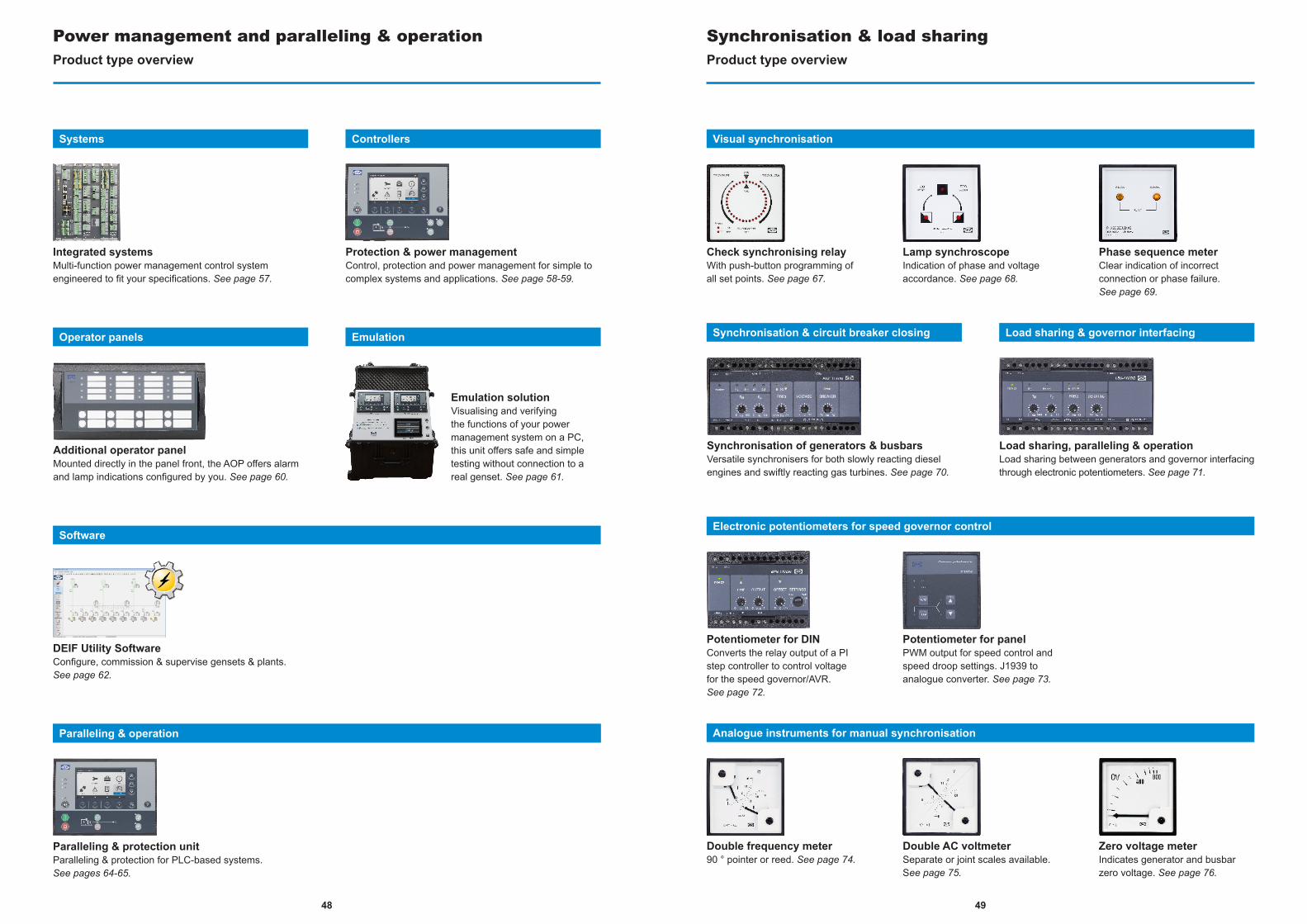
Illuminated bridge indicatorsPlatform overview
Digital accuracy, analogue or display-based readabilityDEIF's range of sturdy illuminated bridge indicators features high accuracy, meeting or exceeding international standards for optimal readability and precision.
Analogue indication: The XL seriesOffering digital accurary and analogue readability, the well-proven XL series is based on DEIF's patented microprocessor-controlled X-coil technology. The range is available for panel, ceiling and bridge wing mounting with a variety of stocked standard designs. Custom designs are available on request.
Display-based indication: The XDi seriesA game changer in bridge instrumentation, DEIF’s new, patented illuminated indicator display series, XDi, offers highly accurate display-based indication. The compact, easy-to-install, versatile and user-friendly revolution in bridge instrumentation, gives you more flexibility and the ability to configure and make repairs on-site. The XDi series replaces mechanical scales and pointers with high quality displays without compromising DEIF customisation standards and maintaining approvals for all relevant applications. It is available in various sizes with dual- or multi-indicator display libraries.
Features XL XDiAnalogue or Dual (COS/SIN) input V/mA V/mA* Selectable
Backlight dimmer Analogue/CAN CAN/Analogue*/Digital*
CANopen interface 1 or 2 2
Day/night scale Fixed Day/night (dusk)
Digital input e.g. RPM pickup ×*
DIN Cut out Q72, Q96, Q144, Q192 Q96, 144 × 96, 192 × 144
Display sizes 3.5, 5, 7"
Extention modules AX1, DX1, NX1
Indication/readout Fixed (needle/disc) Selectable
Library with multiple virtual indicators ×
Number of indications 1 1 or more
Outdoor bridge wing indicator ×
Relay output ×*
Scale type Printed scale TFT Display
Serial – NMEA0183 (IEC61162-1) Output*
X-coil indicator ×
XDi Net ×
XDi seriesQ96, 144 × 96 or 192 × 144 size with dual- or multi-indicator displays.
XL seriesQ72, Q96, Q144 or Q192 with single-indicator display.
* Extension module required
4948
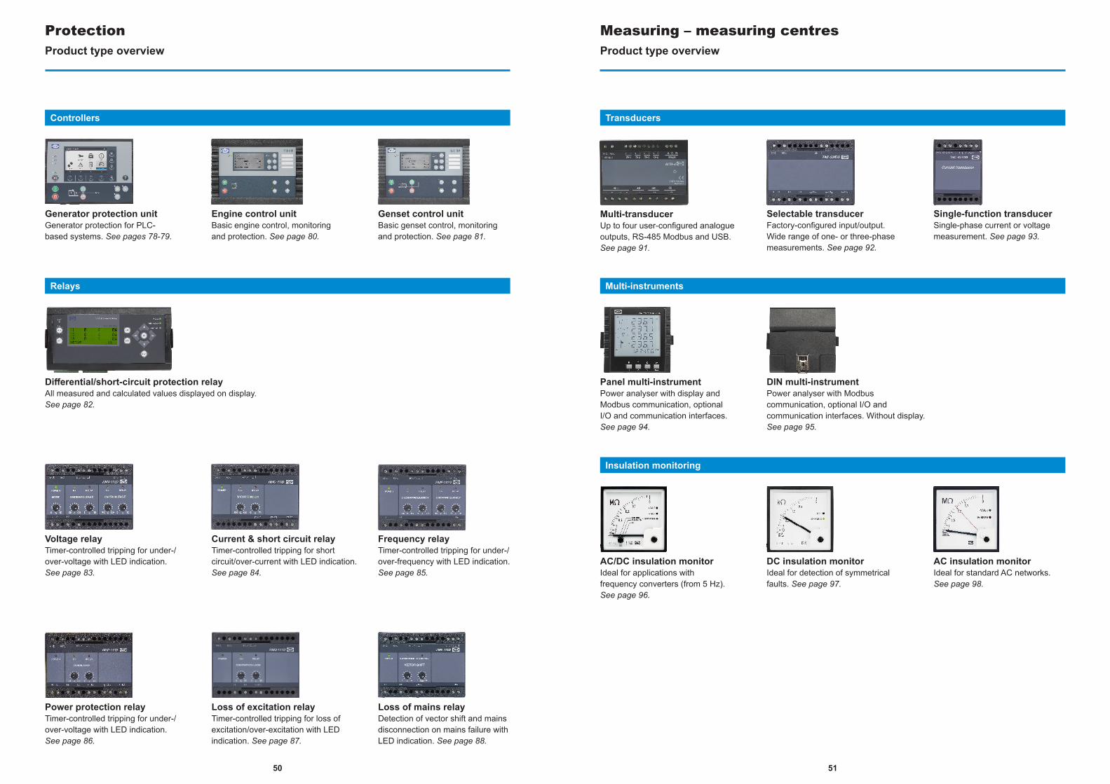
Integrated systemsMulti-function power management control system engineered to fit your specifications. See page 57.
Protection & power managementControl, protection and power management for simple to complex systems and applications. See page 58-59.
Controllers
Additional operator panelMounted directly in the panel front, the AOP offers alarm and lamp indications configured by you. See page 60.
Emulation solutionVisualising and verifying the functions of your power management system on a PC, this unit offers safe and simple testing without connection to a real genset. See page 61.
Operator panels
Systems
Emulation
Controllers
Power management and paralleling & operationProduct type overview
Paralleling & protection unitParalleling & protection for PLC-based systems. See pages 64-65.
Paralleling & operation
DEIF Utility SoftwareConfigure, commission & supervise gensets & plants. See page 62.
Software
Synchronisation & load sharingProduct type overview
Check synchronising relayWith push-button programming of all set points. See page 67.
Lamp synchroscopeIndication of phase and voltage accordance. See page 68.
Phase sequence meterClear indication of incorrect connection or phase failure. See page 69.
Visual synchronisation
Double frequency meter90 ° pointer or reed. See page 74.
Double AC voltmeterSeparate or joint scales available. See page 75.
Zero voltage meterIndicates generator and busbar zero voltage. See page 76.
Analogue instruments for manual synchronisation
Synchronisation of generators & busbarsVersatile synchronisers for both slowly reacting diesel engines and swiftly reacting gas turbines. See page 70.
Load sharing, paralleling & operationLoad sharing between generators and governor interfacing through electronic potentiometers. See page 71.
Synchronisation & circuit breaker closing Load sharing & governor interfacing
Potentiometer for DINConverts the relay output of a PI step controller to control voltage for the speed governor/AVR. See page 72.
Potentiometer for panelPWM output for speed control and speed droop settings. J1939 to analogue converter. See page 73.
Electronic potentiometers for speed governor control
5150
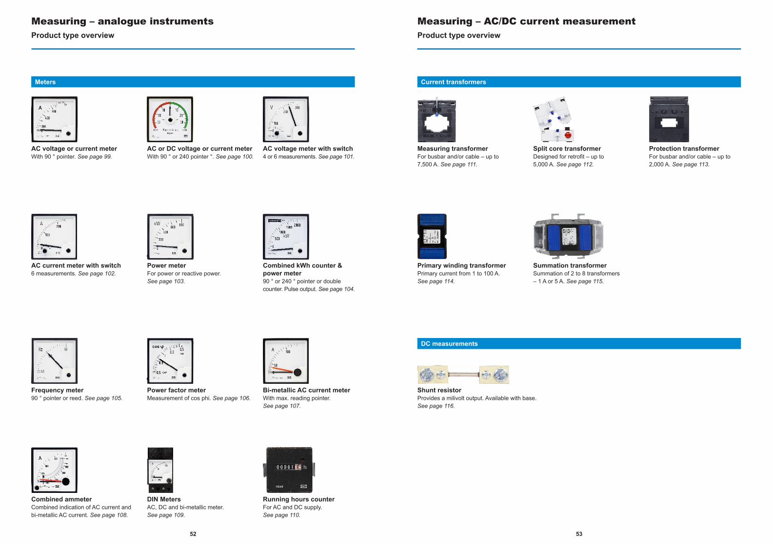
ProtectionProduct type overview
Differential/short-circuit protection relayAll measured and calculated values displayed on display. See page 82.
Genset control unitBasic genset control, monitoring and protection. See page 81.
Engine control unitBasic engine control, monitoring and protection. See page 80.
Generator protection unitGenerator protection for PLC-based systems. See pages 78-79.
Voltage relayTimer-controlled tripping for under-/over-voltage with LED indication. See page 83.
Current & short circuit relayTimer-controlled tripping for short circuit/over-current with LED indication. See page 84.
Frequency relayTimer-controlled tripping for under-/over-frequency with LED indication. See page 85.
Loss of mains relayDetection of vector shift and mains disconnection on mains failure with LED indication. See page 88.
Power protection relayTimer-controlled tripping for under-/over-voltage with LED indication. See page 86.
Loss of excitation relayTimer-controlled tripping for loss of excitation/over-excitation with LED indication. See page 87.
Controllers
Relays
Measuring – measuring centresProduct type overview
Multi-transducerUp to four user-configured analogue outputs, RS-485 Modbus and USB. See page 91.
Selectable transducerFactory-configured input/output. Wide range of one- or three-phase measurements. See page 92.
Single-function transducerSingle-phase current or voltage measurement. See page 93.
AC/DC insulation monitorIdeal for applications with frequency converters (from 5 Hz). See page 96.
DC insulation monitorIdeal for detection of symmetrical faults. See page 97.
AC insulation monitorIdeal for standard AC networks. See page 98.
Insulation monitoring
Transducers
DIN multi-instrument Power analyser with Modbus communication, optional I/O and communication interfaces. Without display. See page 95.
Panel multi-instrumentPower analyser with display and Modbus communication, optional I/O and communication interfaces. See page 94.
Multi-instruments
5352
Measuring – analogue instrumentsProduct type overview
Power meterFor power or reactive power. See page 103.
Combined kWh counter & power meter90 ° or 240 ° pointer or double counter. Pulse output. See page 104.
AC current meter with switch6 measurements. See page 102.
AC voltage or current meterWith 90 ° pointer. See page 99.
AC or DC voltage or current meterWith 90 ° or 240 pointer °. See page 100.
AC voltage meter with switch4 or 6 measurements. See page 101.
Frequency meter90 ° pointer or reed. See page 105.
Power factor meterMeasurement of cos phi. See page 106.
Bi-metallic AC current meterWith max. reading pointer. See page 107.
Meters
Combined ammeterCombined indication of AC current and bi-metallic AC current. See page 108.
DIN MetersAC, DC and bi-metallic meter. See page 109.
Running hours counterFor AC and DC supply.See page 110.
Current transformers
DC measurements
Measuring – AC/DC current measurementProduct type overview
Shunt resistorProvides a milivolt output. Available with base.See page 116.
Summation transformerSummation of 2 to 8 transformers – 1 A or 5 A. See page 115.
Primary winding transformerPrimary current from 1 to 100 A.See page 114.
Measuring transformerFor busbar and/or cable – up to 7,500 A. See page 111.
Split core transformerDesigned for retrofit – up to 5,000 A. See page 112.
Protection transformerFor busbar and/or cable – up to 2,000 A. See page 113.
5554
Measuring – monitoring & alarmsProduct type overview
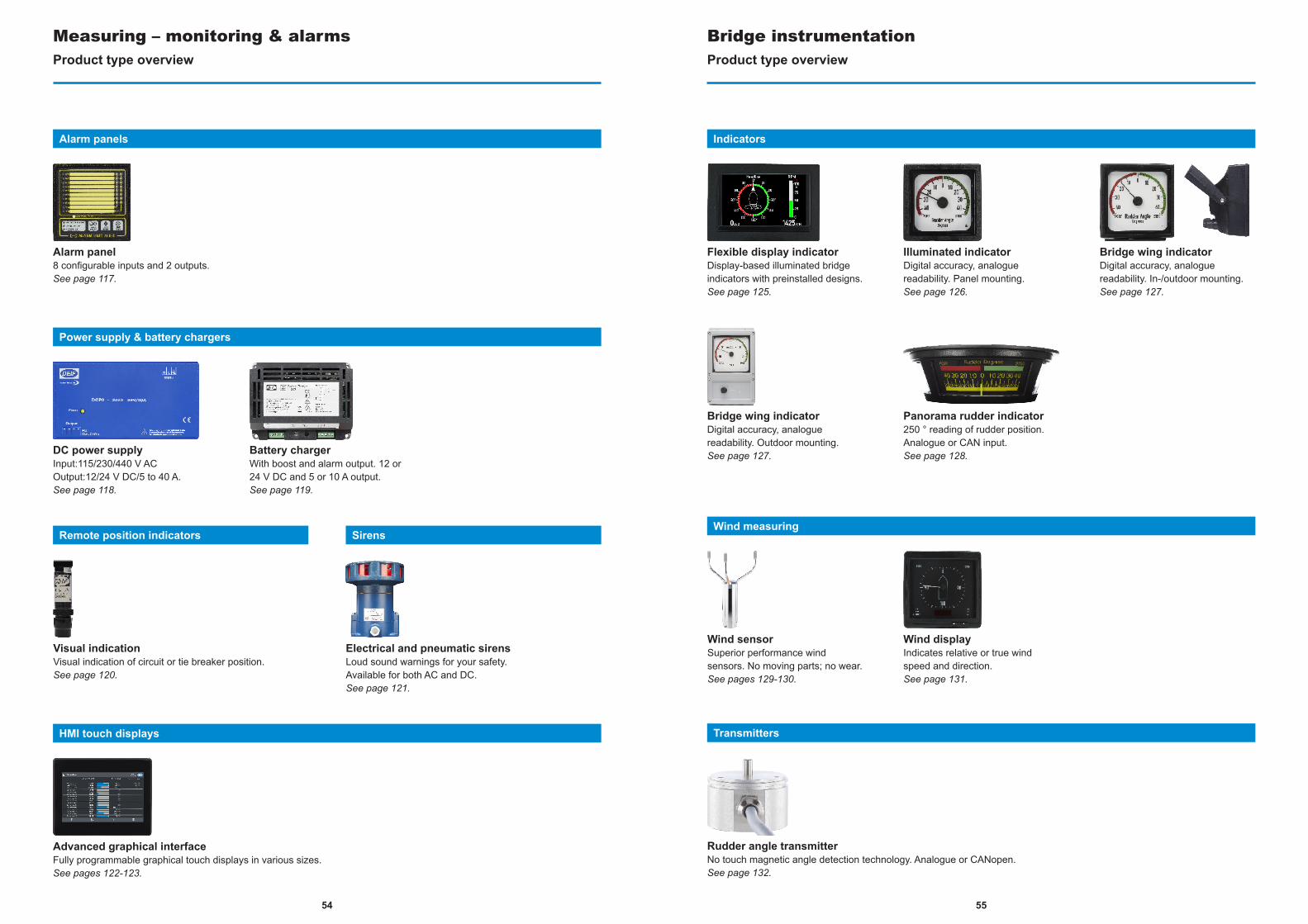
Alarm panel8 configurable inputs and 2 outputs.See page 117.
Alarm panels
Battery chargerWith boost and alarm output. 12 or 24 V DC and 5 or 10 A output.See page 119.
DC power supplyInput:115/230/440 V AC Output:12/24 V DC/5 to 40 A.See page 118.
Power supply & battery chargers
Advanced graphical interfaceFully programmable graphical touch displays in various sizes.See pages 122-123.
HMI touch displays
Visual indicationVisual indication of circuit or tie breaker position.See page 120.
Electrical and pneumatic sirensLoud sound warnings for your safety. Available for both AC and DC.See page 121.
Remote position indicators Sirens
Bridge instrumentationProduct type overview
Flexible display indicatorDisplay-based illuminated bridge indicators with preinstalled designs.See page 125.
Illuminated indicatorDigital accuracy, analogue readability. Panel mounting.See page 126.
Indicators
Bridge wing indicatorDigital accuracy, analogue readability. In-/outdoor mounting.See page 127.
Bridge wing indicatorDigital accuracy, analogue readability. Outdoor mounting.See page 127.
Panorama rudder indicator250 ° reading of rudder position. Analogue or CAN input.See page 128.
Wind sensorSuperior performance wind sensors. No moving parts; no wear.See pages 129-130.
Wind displayIndicates relative or true wind speed and direction.See page 131.
Rudder angle transmitterNo touch magnetic angle detection technology. Analogue or CANopen.See page 132.
Transmitters
Wind measuring
56
Power managementIntro
Power management index
SystemIntegrated Systems. . . . . . . . . . . . . . . . . . . . . . . . . . . . . . . . . . . . . . . . . . . . . . . . . . . . . . . . . . . . . . . . . . . . . . . . . . . . . . . . . . . . . . . . DM-4 Marine . . . . . . . . . . . . . . . . . . 57
ControllersProtection & Power Management . . . . . . . . . . . . . . . . . . . . . . . . . . . . . . . . . . . . . . . . . . . . . . . . . . . . . . . . . . . . . . . . . . . . . . . . . . . .PPM 300 . . . . . . . . . . . . . . . . . . 58Protection & Power Management . . . . . . . . . . . . . . . . . . . . . . . . . . . . . . . . . . . . . . . . . . . . . . . . . . . . . . . . . . . . . . . . . . . . . . . . . . . . . . .PPM-3 . . . . . . . . . . . . . . . . . . 59
Operator panelsAdditional Operator Panel . . . . . . . . . . . . . . . . . . . . . . . . . . . . . . . . . . . . . . . . . . . . . . . . . . . . . . . . . . . . . . . . . . . . . . . . . . . . . . . . . . . . . . . . . . AOP . . . . . . . . . . . . . . . . . . 60
EmulationEmulation Solution. . . . . . . . . . . . . . . . . . . . . . . . . . . . . . . . . . . . . . . . . . . . . . . . . . . . . . . . . . . . . . . . . . . . . . . . . . . . . . . . . . . . . . . . . . . . . . . . . . . . . . . . . . . . . . . . . . . . . . . . . . . . 61
SoftwareDEIF Utility Software . . . . . . . . . . . . . . . . . . . . . . . . . . . . . . . . . . . . . . . . . . . . . . . . . . . . . . . . . . . . . . . . . . . . . . . . . . . . . . . . . . . . . . . . . . . . . USW-3 . . . . . . . . . . . . . . . . . . 62
DEIF Marine & Offshore’s award-winning and innovative power management units are some of the most comprehensive on the market today, ranging from cost-effective single and advanced multi-function controller platforms to units suitable for innovative and fully engineered Power Management System solutions. As a rule, our control concepts eliminate the need for external controllers and are user-friendly alternatives to standard controllers.
Working with DEIF, you benefit from the advantages of collaborating with one qualified supplier.
We also offer outstanding product quality, expert support engineers for standard support, consultant application engineers to check specifications, and project managers ready to assume responsibility for turnkey power management solutions.
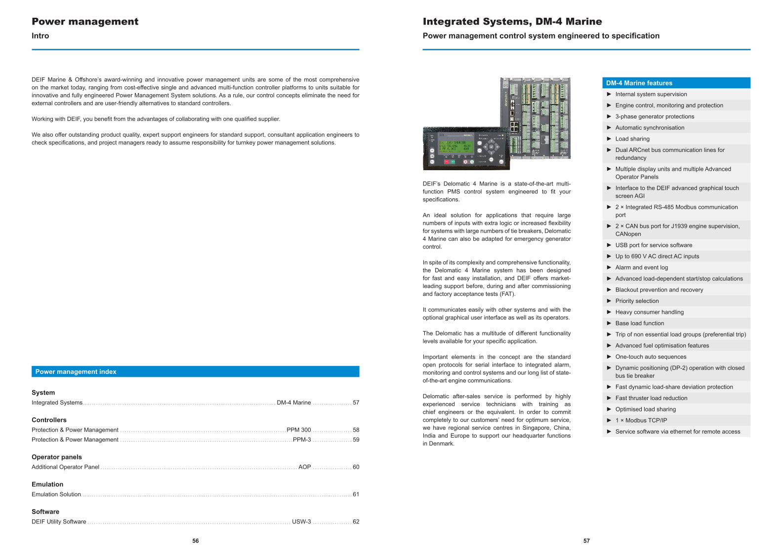
DEIF’s Delomatic 4 Marine is a state-of-the-art multi-function PMS control system engineered to fit your specifications.
An ideal solution for applications that require large numbers of inputs with extra logic or increased flexibility for systems with large numbers of tie breakers, Delomatic 4 Marine can also be adapted for emergency generator control.
In spite of its complexity and comprehensive functionality, the Delomatic 4 Marine system has been designed for fast and easy installation, and DEIF offers market-leading support before, during and after commissioning and factory acceptance tests (FAT).
It communicates easily with other systems and with the optional graphical user interface as well as its operators.
The Delomatic has a multitude of different functionality levels available for your specific application.
Important elements in the concept are the standard open protocols for serial interface to integrated alarm, monitoring and control systems and our long list of state-of-the-art engine communications.
Delomatic after-sales service is performed by highly experienced service technicians with training as chief engineers or the equivalent. In order to commit completely to our customers’ need for optimum service, we have regional service centres in Singapore, China, India and Europe to support our headquarter functions in Denmark.
Integrated Systems, DM-4 MarinePower management control system engineered to specification
DM-4 Marine features► Internal system supervision
► Engine control, monitoring and protection
► 3-phase generator protections
► Automatic synchronisation
► Load sharing
► Dual ARCnet bus communication lines for redundancy
► Multiple display units and multiple Advanced Operator Panels
► Interface to the DEIF advanced graphical touch screen AGI
► 2 × Integrated RS-485 Modbus communication port
► 2 × CAN bus port for J1939 engine supervision, CANopen
► USB port for service software
► Up to 690 V AC direct AC inputs
► Alarm and event log
► Advanced load-dependent start/stop calculations
► Blackout prevention and recovery
► Priority selection
► Heavy consumer handling
► Base load function
► Trip of non essential load groups (preferential trip)
► Advanced fuel optimisation features
► One-touch auto sequences
► Dynamic positioning (DP-2) operation with closed bus tie breaker
► Fast dynamic load-share deviation protection
► Fast thruster load reduction
► Optimised load sharing
► 1 × Modbus TCP/IP
► Service software via ethernet for remote access
57

Designed for applications in the marine and offshore industry, DEIF’s innovative PPM 300 solution is a versatile, intelligent controller platform.
Incorporating an extensive range of control, protection and supervision functions, PPM 300 applications range from genset control and protection to engineered power management solutions developed for diesel generators (including emergency diesel generators), shaft generators, shore connections, and bus tie breakers.
PPM 300 power management systems control and monitor applications meet and maintain set power requirements and guarantee stable operation. PPM 300 power management systems also incorporate market-leading fuel optimisation technology.
In multi-master solutions, the integrated PPM 300 controllers connect and communicate as a closed circuit to eradicate single point failures: in cases of unit fall-out, the master functionality automatically moves to another host keeping the system not just operational but safe and reliable at all times.
Built as a sturdy piece of market-leading quality hardware, the PPM 300 features the latest processor technology and long-life adaptability.
Uniquely, the PPM 300’s modular build supports on-site replacement of processor, communication, measurement and input-output modules with comprehensive class approvals. Changes to the unit at sea or in the field are assisted with automatic recognition functionality facilitating fast, easy and cost-saving service, repairs, and upgrades.
The controller display unit includes a 5” colour graphic screen with intuitive sequences and icons for fast readout of live data, and easy access to alarms handling and controller setup. Functionality is defined and targeted according to user permission levels.
Protection & Power Management, PPM 300Advanced processor technology & high-speed internal communication
PPM 300 features► PMS with ring communicaiton
► One touch sequences for genset start & stop, and breaker close & open
► Automatic synchronise and deload breaker
► Fast load reduction of less than 100 ms
► Advanced heavy consumer control
► Advanced fuel optimisation feature
► Advanced blackout prevention and recovery
► Broadcast of software
► Emulation and supervision
► High resolution 5" colour graphic display with push-buttons
► Flexible and modular input/output with metal rack
► Plug & play, auto-configure I/O modules and network
► Integrated 5x RJ45 ports with auto dectected multi-function
► Access to all connected units in one point
► Context-sensitive help in the controller display unit
► Event and alarm log, with real-time clock
► Pre-defined control settings
► User-friendly logic configuration tool, based on ladder logic and function blocks with monitor operation
► Password-protected, with cutomisable permission levels
► 3 phase AC measurement up to 690 V AC directly, class 0.5
► Easy using PC tool: PICUS, compatible with major OS.
► Advanced alarm handling with latch and shelve possible
DEIF’s PPM-3 is a market-leading Power Management System (PMS) standard suitable for a broad range of marine applications with up to 16 diesel generators, two shaft generators, two shore connections, eight bus tie breakers and two emergency/harbour generators including bus tie breaker control and the possibility of wrapped busbar applications.
The versatile and fully redundant multi-master system has been developed with fuel-efficient engine operation in view, and is an efficient and cost-effective solution with up to three powerful microprocessors.
Encompassing all necessary three-phase measuring circuits, values and alarms are displayed on a quality LCD screen.
Using a separate engine interface card as a backup shutdown unit, the PPM-3 also provides extra safety for your engine with a separate microprocessor and separate power supply.
Multiple display units and operator panels can be connected to each controller, making access to the system possible from any location on the ship. Dedicated to versatile application uses and intuitive configuration and operation installing, the redundant multi-master system is fast, easy, requiring limited space.
DEIF’s programmable utility software allows for comprehensive customisation, including dedicating specific functions or logic conditions to different inputs and outputs. Applications with shaft generators, shore connections and bus tie breakers can be easily configured to the switchboard design itself. Operator-friendly one-touch sequences handle all automatic functions. Using the application tool, even complicated systems can be configured within a few minutes.
In addition, DEIF’s innovative Emulation software solution allows for safe PMS testing at your desk, revolutionising the design and test of power management systems for multiple diesel gensets for instance.
Protection & Power Management, PPM-3Market-leading standard power management system
PPM-3 features► Internal system supervision
► Engine control, monitoring and protection
► 3-phase generator protections
► Automatic synchronisation and load sharing
► Internal redundant CAN bus and backup analogue load-share line
► Multiple display units and multiple Additional Operator Panels (AOPs)
► RS-485 and TCP/IP Modbus communication ports
► Interface to the DEIF advanced graphical touch screen AGI
► CAN bus port for J1939 engine supervision
► Alarm and event log, USB port for service software
► Up to 690 V AC direct AC inputs
► Advanced load-dependent start/stop calculations
► Blackout prevention and recovery
► Priority selection and base load function
► Heavy consumer handling and preferential trip
► Advanced fuel optimisation features
► One-touch auto sequences and M-Logic event builder
► Integrated emulation software solution
5958
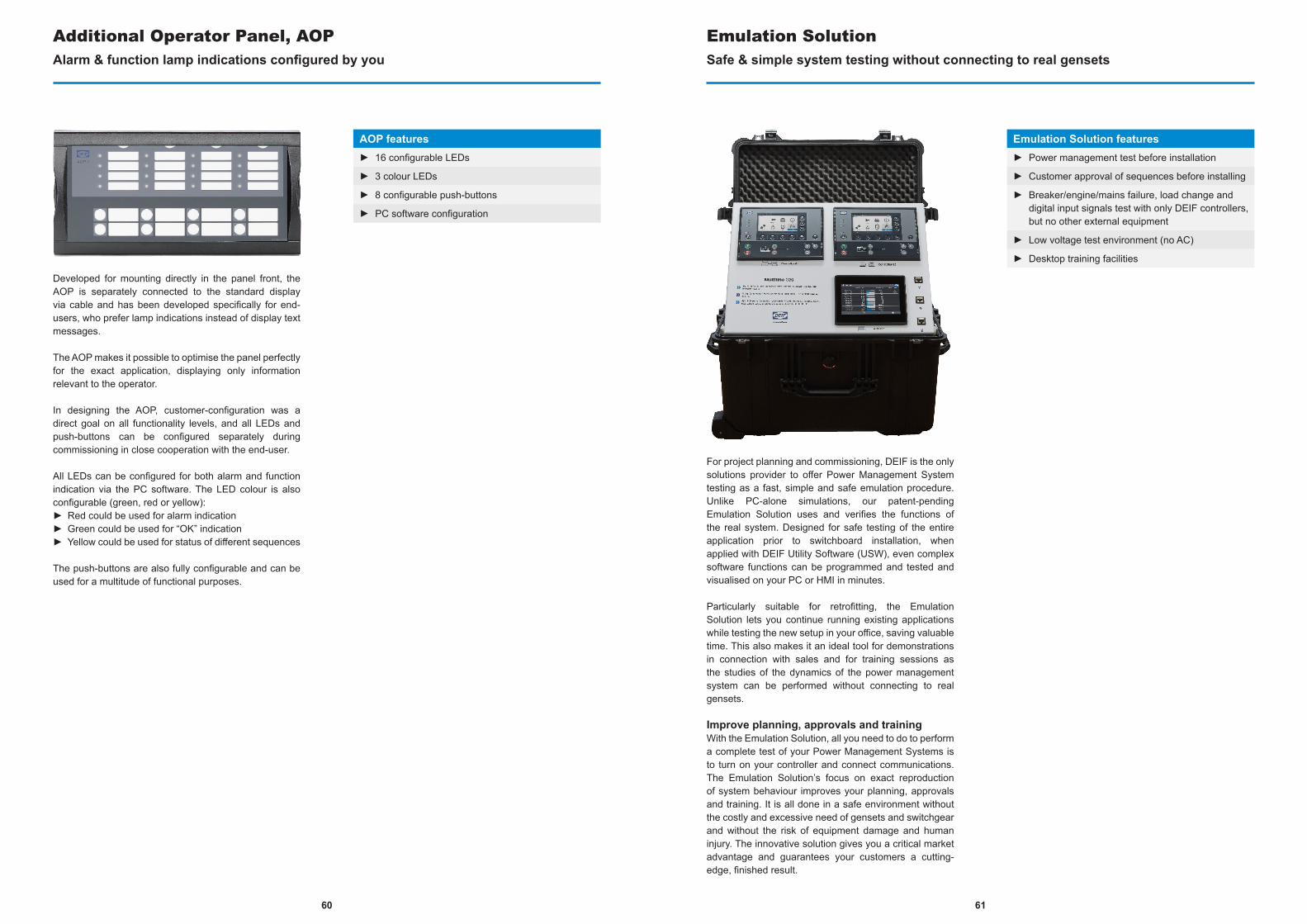
Developed for mounting directly in the panel front, the AOP is separately connected to the standard display via cable and has been developed specifically for end-users, who prefer lamp indications instead of display text messages.
The AOP makes it possible to optimise the panel perfectly for the exact application, displaying only information relevant to the operator.
In designing the AOP, customer-configuration was a direct goal on all functionality levels, and all LEDs and push-buttons can be configured separately during commissioning in close cooperation with the end-user.
All LEDs can be configured for both alarm and function indication via the PC software. The LED colour is also configurable (green, red or yellow):► Red could be used for alarm indication► Green could be used for “OK” indication► Yellow could be used for status of different sequences
The push-buttons are also fully configurable and can be used for a multitude of functional purposes.
Additional Operator Panel, AOPAlarm & function lamp indications configured by you
AOP features► 16 configurable LEDs
► 3 colour LEDs
► 8 configurable push-buttons
► PC software configuration
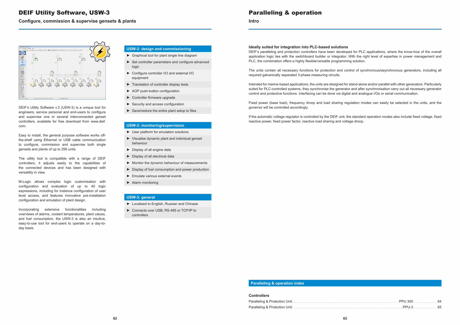
For project planning and commissioning, DEIF is the only solutions provider to offer Power Management System testing as a fast, simple and safe emulation procedure. Unlike PC-alone simulations, our patent-pending Emulation Solution uses and verifies the functions of the real system. Designed for safe testing of the entire application prior to switchboard installation, when applied with DEIF Utility Software (USW), even complex software functions can be programmed and tested and visualised on your PC or HMI in minutes.
Particularly suitable for retrofitting, the Emulation Solution lets you continue running existing applications while testing the new setup in your office, saving valuable time. This also makes it an ideal tool for demonstrations in connection with sales and for training sessions as the studies of the dynamics of the power management system can be performed without connecting to real gensets.
Improve planning, approvals and trainingWith the Emulation Solution, all you need to do to perform a complete test of your Power Management Systems is to turn on your controller and connect communications. The Emulation Solution’s focus on exact reproduction of system behaviour improves your planning, approvals and training. It is all done in a safe environment without the costly and excessive need of gensets and switchgear and without the risk of equipment damage and human injury. The innovative solution gives you a critical market advantage and guarantees your customers a cutting-edge, finished result.
Emulation SolutionSafe & simple system testing without connecting to real gensets
Emulation Solution features► Power management test before installation
► Customer approval of sequences before installing
► Breaker/engine/mains failure, load change and digital input signals test with only DEIF controllers, but no other external equipment
► Low voltage test environment (no AC)
► Desktop training facilities
6160
63
DEIF’s Utility Software v.3 (USW-3) is a unique tool for engineers, service personel and end-users to configure and supervise one or several interconnected genset controllers, available for free download from www.deif.com.
Easy to install, the general purpose software works off-the-shelf using Ethernet or USB cable communication to configure, commission and supervise both single gensets and plants of up to 256 units.
The utility tool is compatible with a range of DEIF controllers; it adjusts easily to the capabilities of the connected devices and has been designed with versatility in view.
M-Logic allows complex logic customisation with configuration and evaluation of up to 40 logic expressions, including for instance configuration of user level access, and features innovative pre-installation configuration and emulation of plant design.
Incorporating extensive functionalities including overviews of alarms, coolant temperatures, plant values, and fuel consumption, the USW-3 is also an intuitive, easy-to-use tool for end-users to operate on a day-to-day basis.
DEIF Utility Software, USW-3Configure, commission & supervise gensets & plants
USW-3: design and commissioning► Graphical tool for plant single line diagram
► Set controller parameters and configure advanced logic
► Configure controller I/O and external I/O equipment
► Translation of controller display texts
► AOP push-button configuration
► Controller firmware upgrade
► Security and access configuration
► Save/restore the entire plant setup to files
USW-3: monitoring/supervision► User platform for emulation solutions
► Visualise dynamic plant and individual genset behaviour
► Display of all engine data
► Display of all electrical data
► Monitor the dynamic behaviour of measurements
► Display of fuel consumption and power production
► Emulate various external events
► Alarm monitoring
USW-3: general► Localised to English, Russian and Chinese
► Connects over USB, RS-485 or TCP/IP to controllers
Paralleling & operationIntro
Paralleling & operation index
ControllersParalleling & Protection Unit . . . . . . . . . . . . . . . . . . . . . . . . . . . . . . . . . . . . . . . . . . . . . . . . . . . . . . . . . . . . . . . . . . . . . . . . . . . . . . . . . . PPU 300 . . . . . . . . . . . . . . . . . . 64Paralleling & Protection Unit . . . . . . . . . . . . . . . . . . . . . . . . . . . . . . . . . . . . . . . . . . . . . . . . . . . . . . . . . . . . . . . . . . . . . . . . . . . . . . . . . . . . . PPU-3 . . . . . . . . . . . . . . . . . . 65
Ideally suited for integration into PLC-based solutionsDEIF’s paralleling and protection controllers have been developed for PLC applications, where the know-how of the overall application logic lies with the switchboard builder or integrator. With the right level of expertise in power management and PLC, the combination offers a highly flexible/versatile programming solution.
The units contain all necessary functions for protection and control of synchronous/asynchronous generators, including all required galvanically separated 3-phase measuring circuits.
Intended for marine-based applications, the units are designed for stand-alone and/or parallel with other generators. Particularly suited for PLC-controlled systems, they synchronise the generator and after synchronisation carry out all necessary generator control and protective functions. Interfacing can be done via digital and analogue I/Os or serial communication.
Fixed power (base load), frequency droop and load sharing regulation modes can easily be selected in the units, and the governor will be controlled accordingly.
If the automatic voltage regulator is controlled by the DEIF unit, the standard operation modes also include fixed voltage, fixed reactive power, fixed power factor, reactive load sharing and voltage droop.
62
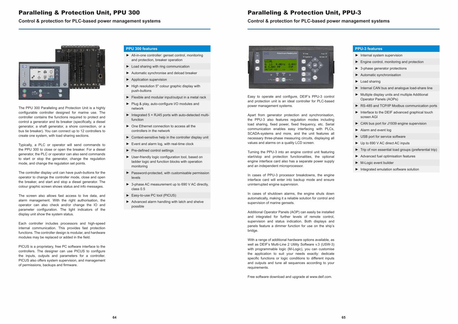
The PPU 300 Paralleling and Protection Unit is a highly configurable controller designed for marine use. The controller contains the functions required to protect and control a generator and its breaker (specifically, a diesel generator, a shaft generator, a shore connection, or a bus tie breaker). You can connect up to 12 controllers to create one system, with load sharing sections.
Typically, a PLC or operator will send commands to the PPU 300 to close or open the breaker. For a diesel generator, the PLC or operator can also send commands to start or stop the generator, change the regulation mode, and change the regulation set points.
The controller display unit can have push-buttons for the operator to change the controller mode, close and open the breaker, and start and stop a diesel generator. The colour graphic screen shows status and info messages.
The screen also allows fast access to live data, and alarm management. With the right authorisation, the operator can also check and/or change the IO and parameter configuration. The light indicators of the display unit show the system status.
Each controller includes processors and high-speed internal communication. This provides fast protection functions. The controller design is modular, and hardware modules may be replaced or added in the field.
PICUS is a proprietary, free PC software interface to the controllers. The designer can use PICUS to configure the inputs, outputs and parameters for a controller. PICUS also offers system supervision, and management of permissions, backups and firmware.
Paralleling & Protection Unit, PPU 300Control & protection for PLC-based power management systems
PPU 300 features► All-in-one controller: genset control, monitoring
and protection, breaker operation
► Load sharing with ring communication
► Automatic synchronise and deload breaker
► Application supervision
► High resolution 5" colour graphic display with push-buttons
► Flexible and modular input/output in a metal rack
► Plug & play, auto-configure I/O modules and network
► Integrated 5 × RJ45 ports with auto-detected multi-function
► One Ethernet connection to access all the controllers in the network
► Context-sensitive help in the controller display unit
► Event and alarm log, with real-time clock
► Pre-defined control settings
► User-friendly logic configuration tool, based on ladder logic and function blocks with operation monitoring
► Password-protected, with customisable permission levels
► 3-phase AC measurement up to 690 V AC directly, class 0.5
► Easy-to-use PC tool (PICUS)
► Advanced alarm handling with latch and shelve possible
Easy to operate and configure, DEIF’s PPU-3 control and protection unit is an ideal controller for PLC-based power management systems.
Apart from generator protection and synchronisation, the PPU-3 also features regulation modes including load sharing, fixed power, fixed frequency, etc. Serial communication enables easy interfacing with PLCs, SCADA-systems and more, and the unit features all necessary three-phase measuring circuits, displaying all values and alarms on a quality LCD screen.
Turning the PPU-3 into an engine control unit featuring start/stop and protection functionalities, the optional engine interface card also has a separate power supply and an independent microprocessor.
In cases of PPU-3 processor breakdowns, the engine interface card will enter into backup mode and ensure uninterrupted engine supervision.
In cases of shutdown alarms, the engine shuts down automatically, making it a reliable solution for control and supervision of marine gensets.
Additional Operator Panels (AOP) can easily be installed and integrated for further levels of remote control, supervision and status indication. Both displays and panels feature a dimmer function for use on the ship’s bridge.
With a range of additional hardware options available, as well as DEIF’s Multi-Line 2 Utility Software v.3 (USW-3) with programmable logic (M-Logic), you can customise the application to suit your needs exactly: dedicate specific functions or logic conditions to different inputs and outputs and tune all sequences according to your requirements.
Free software download and upgrade at www.deif.com.
Paralleling & Protection Unit, PPU-3Control & protection for PLC-based power management systems
PPU-3 features► Internal system supervision
► Engine control, monitoring and protection
► 3-phase generator protections
► Automatic synchronisation
► Load sharing
► Internal CAN bus and analogue load-share line
► Multiple display units and multiple Additional Operator Panels (AOPs)
► RS-485 and TCP/IP Modbus communication ports
► Interface to the DEIF advanced graphical touch screen AGI
► CAN bus port for J1939 engine supervision
► Alarm and event log
► USB port for service software
► Up to 690 V AC direct AC inputs
► Trip of non essential load groups (preferential trip)
► Advanced fuel optimisation features
► M-Logic event builder
► Integrated emulation software solution
6564
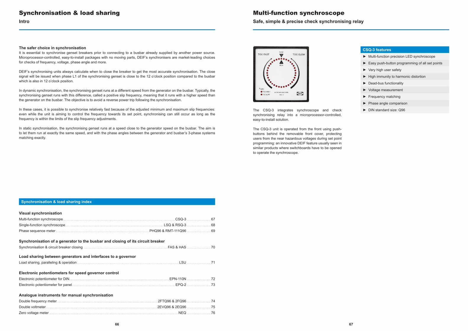
66
Synchronisation & load sharingIntro
Synchronisation & load sharing index
Visual synchronisationMulti-function synchroscope. . . . . . . . . . . . . . . . . . . . . . . . . . . . . . . . . . . . . . . . . . . . . . . . . . . . . . . . . . . . . . . . . . . . . . . . . . . . . . . . . . . . . .CSQ-3 . . . . . . . . . . . . . . . . . . 67Single-function synchroscope. . . . . . . . . . . . . . . . . . . . . . . . . . . . . . . . . . . . . . . . . . . . . . . . . . . . . . . . . . . . . . . . . . . . . . . . . . . LSQ & RSQ-3 . . . . . . . . . . . . . . . . . . 68Phase sequence meter . . . . . . . . . . . . . . . . . . . . . . . . . . . . . . . . . . . . . . . . . . . . . . . . . . . . . . . . . . . . . . . . . . . . . . . PHQ96 & RMT-111Q96 . . . . . . . . . . . . . . . . . . 69
Synchronisation of a generator to the busbar and closing of its circuit breakerSynchronisation & circuit breaker closing . . . . . . . . . . . . . . . . . . . . . . . . . . . . . . . . . . . . . . . . . . . . . . . . . . . . . . . . . . . . . . . . FAS & HAS . . . . . . . . . . . . . . . . . . 70
Load sharing between generators and interfaces to a governorLoad sharing, paralleling & operation . . . . . . . . . . . . . . . . . . . . . . . . . . . . . . . . . . . . . . . . . . . . . . . . . . . . . . . . . . . . . . . . . . . . . . . . . . . . . .LSU . . . . . . . . . . . . . . . . . . 71
Electronic potentiometers for speed governor controlElectronic potentiometer for DIN. . . . . . . . . . . . . . . . . . . . . . . . . . . . . . . . . . . . . . . . . . . . . . . . . . . . . . . . . . . . . . . . . . . . . . . . . . . . EPN-110N . . . . . . . . . . . . . . . . . . 72Electronic potentiometer for panel. . . . . . . . . . . . . . . . . . . . . . . . . . . . . . . . . . . . . . . . . . . . . . . . . . . . . . . . . . . . . . . . . . . . . . . . . . . . . . .EPQ-2 . . . . . . . . . . . . . . . . . . 73
Analogue instruments for manual synchronisationDouble frequency meter . . . . . . . . . . . . . . . . . . . . . . . . . . . . . . . . . . . . . . . . . . . . . . . . . . . . . . . . . . . . . . . . . . . . . . . . . . . . .2FTQ96 & 2FQ96 . . . . . . . . . . . . . . . . . . 74Double voltmeter. . . . . . . . . . . . . . . . . . . . . . . . . . . . . . . . . . . . . . . . . . . . . . . . . . . . . . . . . . . . . . . . . . . . . . . . . . . . . . . . . . . . . 2EVQ96 & 2EQ96 . . . . . . . . . . . . . . . . . . 75Zero voltage meter . . . . . . . . . . . . . . . . . . . . . . . . . . . . . . . . . . . . . . . . . . . . . . . . . . . . . . . . . . . . . . . . . . . . . . . . . . . . . . . . . . . . . . . . . . . . . . . . . . NEQ . . . . . . . . . . . . . . . . . . 76
The safer choice in synchronisationIt is essential to synchronise genset breakers prior to connecting to a busbar already supplied by another power source. Microprocessor-controlled, easy-to-install packages with no moving parts, DEIF’s synchronisers are market-leading choices for checks of frequency, voltage, phase angle and more.
DEIF’s synchronising units always calculate when to close the breaker to get the most accurate synchronisation. The close signal will be issued when phase L1 of the synchronising genset is close to the 12 o’clock position compared to the busbar which is also in 12 o’clock position.
In dynamic synchronisation, the synchronising genset runs at a different speed from the generator on the busbar. Typically, the synchronising genset runs with this difference, called a positive slip frequency, meaning that it runs with a higher speed than the generator on the busbar. The objective is to avoid a reverse power trip following the synchronisation.
In these cases, it is possible to synchronise relatively fast because of the adjusted minimum and maximum slip frequencies: even while the unit is aiming to control the frequency towards its set point, synchronising can still occur as long as the frequency is within the limits of the slip frequency adjustments.
In static synchronisation, the synchronising genset runs at a speed close to the generator speed on the busbar. The aim is to let them run at exactly the same speed, and with the phase angles between the generator and busbar’s 3-phase systems matching exactly.
The CSQ-3 integrates synchroscope and check synchronising relay into a microprocessor-controlled, easy-to-install solution.
The CSQ-3 unit is operated from the front using push-buttons behind the removable front cover, protecting users from the near hazardous voltages during set point programming: an innovative DEIF feature usually seen in similar products where switchboards have to be opened to operate the synchroscope.
Multi-function synchroscopeSafe, simple & precise check synchronising relay
CSQ-3 features► Multi-function precision LED synchroscope
► Easy push-button programming of all set points
► Very high user safety
► High immunity to harmonic distortion
► Dead-bus functionality
► Voltage measurement
► Frequency matching
► Phase angle comparison
► DIN standard size: Q96
67
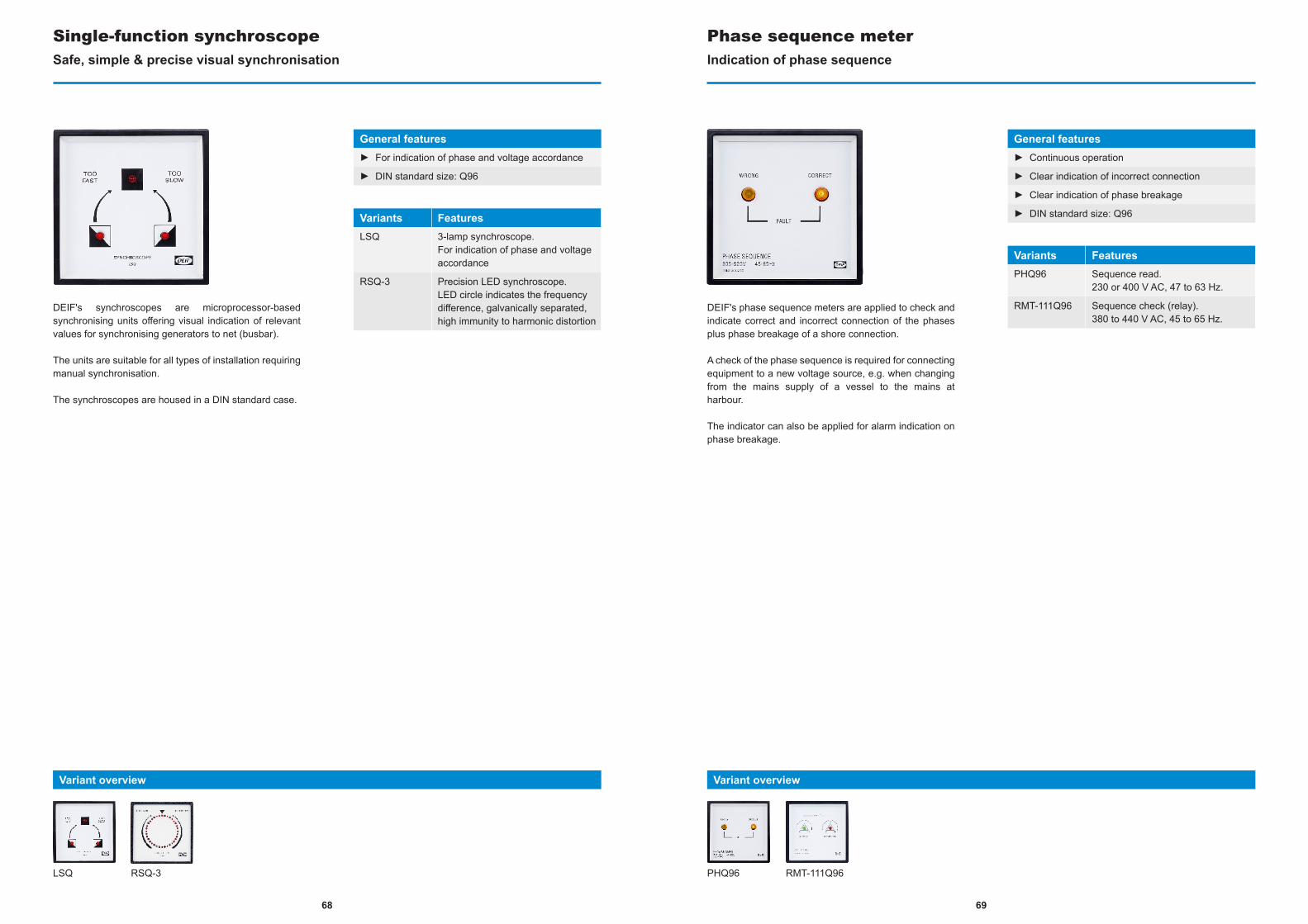
DEIF's synchroscopes are microprocessor-based synchronising units offering visual indication of relevant values for synchronising generators to net (busbar).
The units are suitable for all types of installation requiring manual synchronisation.
The synchroscopes are housed in a DIN standard case.
Single-function synchroscopeSafe, simple & precise visual synchronisation
General features► For indication of phase and voltage accordance
► DIN standard size: Q96
Variants FeaturesLSQ 3-lamp synchroscope.
For indication of phase and voltage accordance
RSQ-3 Precision LED synchroscope.LED circle indicates the frequency difference, galvanically separated, high immunity to harmonic distortion
LSQ RSQ-3
Variant overview
DEIF's phase sequence meters are applied to check and indicate correct and incorrect connection of the phases plus phase breakage of a shore connection.
A check of the phase sequence is required for connecting equipment to a new voltage source, e.g. when changing from the mains supply of a vessel to the mains at harbour.
The indicator can also be applied for alarm indication on phase breakage.
Indication of phase sequence
General features► Continuous operation
► Clear indication of incorrect connection
► Clear indication of phase breakage
► DIN standard size: Q96
Variants FeaturesPHQ96 Sequence read.
230 or 400 V AC, 47 to 63 Hz.
RMT-111Q96 Sequence check (relay).380 to 440 V AC, 45 to 65 Hz.
PHQ96 RMT-111Q96
Variant overview
Phase sequence meter
6968
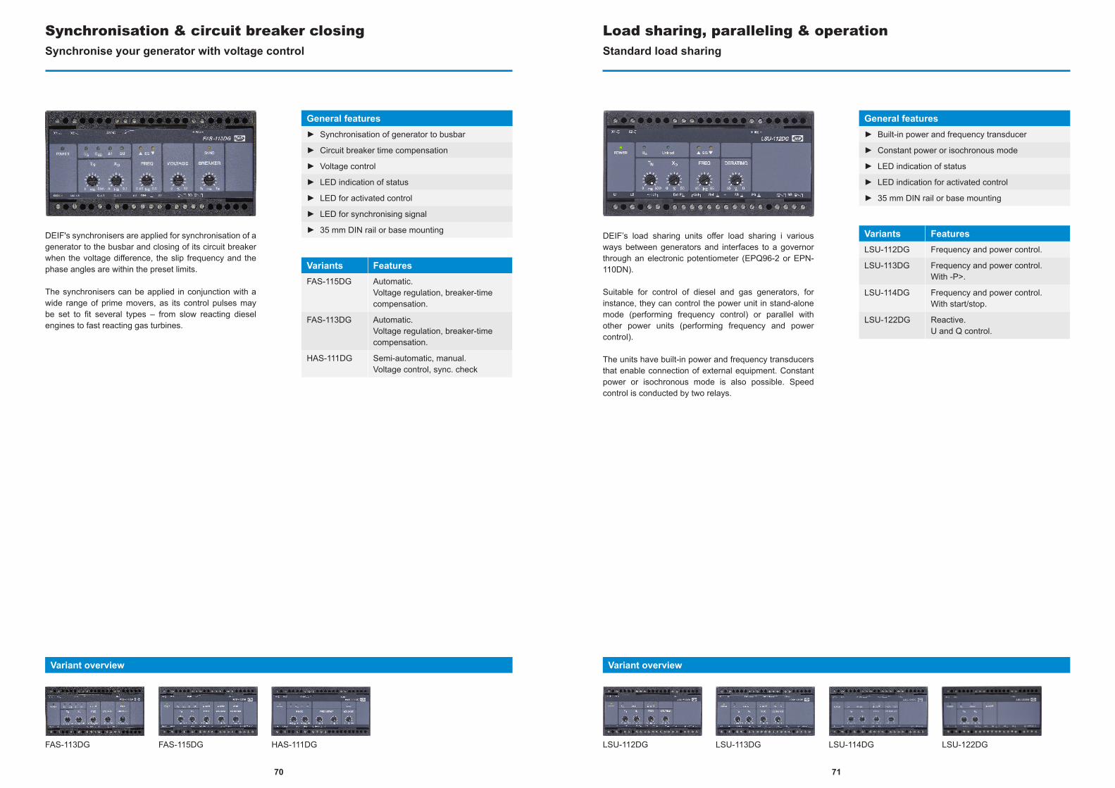
DEIF's synchronisers are applied for synchronisation of a generator to the busbar and closing of its circuit breaker when the voltage difference, the slip frequency and the phase angles are within the preset limits.
The synchronisers can be applied in conjunction with a wide range of prime movers, as its control pulses may be set to fit several types – from slow reacting diesel engines to fast reacting gas turbines.
Synchronisation & circuit breaker closingSynchronise your generator with voltage control
General features► Synchronisation of generator to busbar
► Circuit breaker time compensation
► Voltage control
► LED indication of status
► LED for activated control
► LED for synchronising signal
► 35 mm DIN rail or base mounting
Variants FeaturesFAS-115DG Automatic.
Voltage regulation, breaker-time compensation.
FAS-113DG Automatic.Voltage regulation, breaker-time compensation.
HAS-111DG Semi-automatic, manual.Voltage control, sync. check
FAS-113DG FAS-115DG HAS-111DG
Variant overview
DEIF’s load sharing units offer load sharing i various ways between generators and interfaces to a governor through an electronic potentiometer (EPQ96-2 or EPN-110DN).
Suitable for control of diesel and gas generators, for instance, they can control the power unit in stand-alone mode (performing frequency control) or parallel with other power units (performing frequency and power control).
The units have built-in power and frequency transducers that enable connection of external equipment. Constant power or isochronous mode is also possible. Speed control is conducted by two relays.
LSU-112DG
Load sharing, paralleling & operationStandard load sharing
General features► Built-in power and frequency transducer
► Constant power or isochronous mode
► LED indication of status
► LED indication for activated control
► 35 mm DIN rail or base mounting
Variants FeaturesLSU-112DG Frequency and power control.
LSU-113DG Frequency and power control.With -P>.
LSU-114DG Frequency and power control.With start/stop.
LSU-122DG Reactive.U and Q control.
LSU-113DG LSU-114DG LSU-122DG
Variant overview
7170
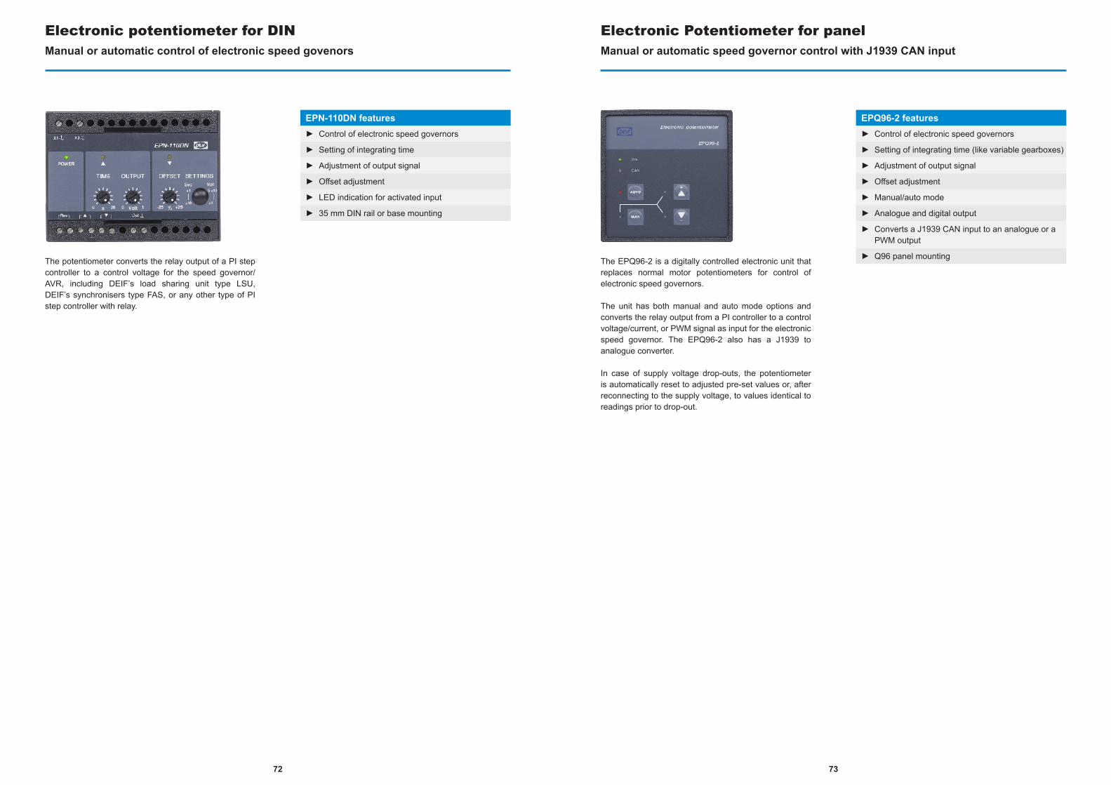
The potentiometer converts the relay output of a PI step controller to a control voltage for the speed governor/AVR, including DEIF’s load sharing unit type LSU, DEIF’s synchronisers type FAS, or any other type of PI step controller with relay.
Electronic potentiometer for DINManual or automatic control of electronic speed govenors
EPN-110DN features► Control of electronic speed governors
► Setting of integrating time
► Adjustment of output signal
► Offset adjustment
► LED indication for activated input
► 35 mm DIN rail or base mounting
The EPQ96-2 is a digitally controlled electronic unit that replaces normal motor potentiometers for control of electronic speed governors.
The unit has both manual and auto mode options and converts the relay output from a PI controller to a control voltage/current, or PWM signal as input for the electronic speed governor. The EPQ96-2 also has a J1939 to analogue converter.
In case of supply voltage drop-outs, the potentiometer is automatically reset to adjusted pre-set values or, after reconnecting to the supply voltage, to values identical to readings prior to drop-out.
Electronic Potentiometer for panelManual or automatic speed governor control with J1939 CAN input
EPQ96-2 features► Control of electronic speed governors
► Setting of integrating time (like variable gearboxes)
► Adjustment of output signal
► Offset adjustment
► Manual/auto mode
► Analogue and digital output
► Converts a J1939 CAN input to an analogue or a PWM output
► Q96 panel mounting
7372

DEIF's robust double frequency meters are highly accurate and compact. Offering linear read-outs, they provide visual indication of frequency for manual synchronisation of generators to net (busbar).
Double frequency meterHighly accurate & linear read-out
General features► Robust and thoroughly tested construction
► Available in Q96 DIN size design
► High accuracy and linear read-out
► High immunity to 3rd harmonics
Variants Features2FTQ96 Reed vibrating pointers.
45 to 65 Hz, 100 to 440 V AC.
2FQ96 Standard pointers, diagonal.45 to 65 Hz, 150 to 600 V AC.
2FQ96 2FTQ96
Variant overview
DEIF's double voltmeters with two moving iron systems mounted in one housing. Offering linear read-outs, they provides visual indication of frequency for manual synchronisation of generators to net (busbar).
Double voltmeterHighly accurate & linear read-out
General features► Robust and thoroughly tested construction
► Available in Q96 DIN size design
► High accuracy
► High immunity to 3rd harmonics
► 150 to 600 V AC, 50/60 Hz
Variants Features2EVQ96 Dual diagonal pointers and scales
2EQ96 Dual pointers on common scale
Variant overview
2EQ96 2EVQ96
7574
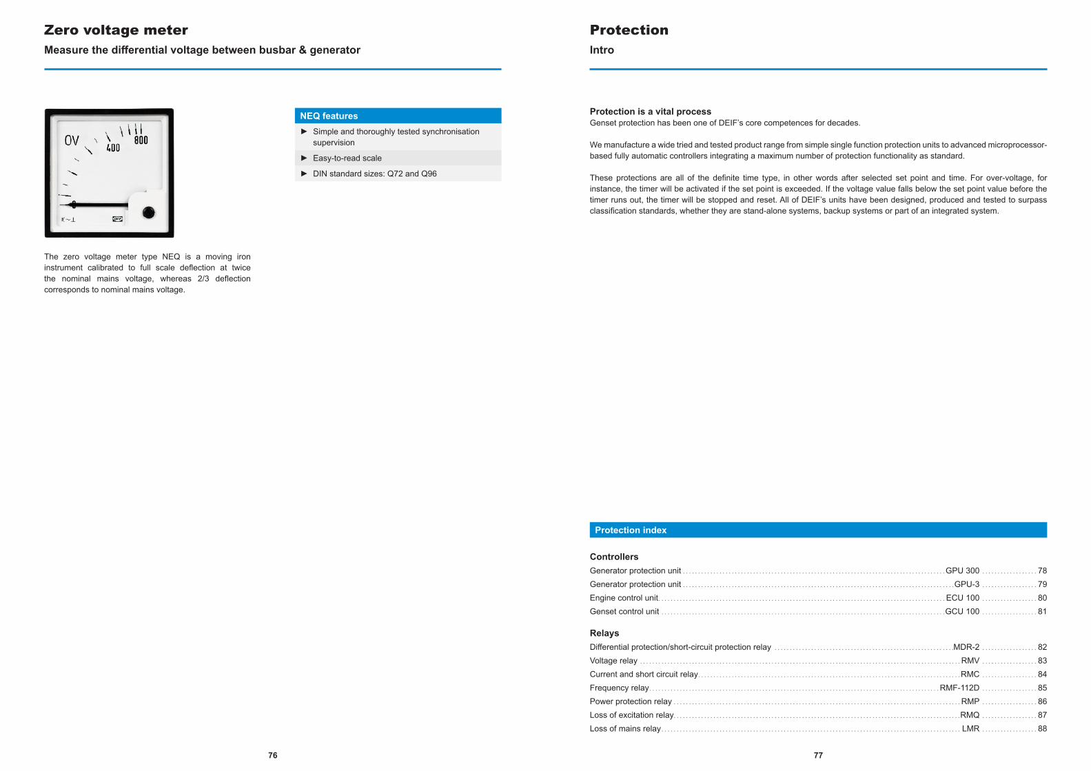
77
The zero voltage meter type NEQ is a moving iron instrument calibrated to full scale deflection at twice the nominal mains voltage, whereas 2/3 deflection corresponds to nominal mains voltage.
Zero voltage meterMeasure the differential voltage between busbar & generator
NEQ features► Simple and thoroughly tested synchronisation
supervision
► Easy-to-read scale
► DIN standard sizes: Q72 and Q96
ProtectionIntro
Protection index
ControllersGenerator protection unit . . . . . . . . . . . . . . . . . . . . . . . . . . . . . . . . . . . . . . . . . . . . . . . . . . . . . . . . . . . . . . . . . . . . . . . . . . . . . . . . . . . . . .GPU 300 . . . . . . . . . . . . . . . . . . 78Generator protection unit . . . . . . . . . . . . . . . . . . . . . . . . . . . . . . . . . . . . . . . . . . . . . . . . . . . . . . . . . . . . . . . . . . . . . . . . . . . . . . . . . . . . . . . . .GPU-3 . . . . . . . . . . . . . . . . . . 79Engine control unit. . . . . . . . . . . . . . . . . . . . . . . . . . . . . . . . . . . . . . . . . . . . . . . . . . . . . . . . . . . . . . . . . . . . . . . . . . . . . . . . . . . . . . . . . . . . . . ECU 100 . . . . . . . . . . . . . . . . . . 80Genset control unit . . . . . . . . . . . . . . . . . . . . . . . . . . . . . . . . . . . . . . . . . . . . . . . . . . . . . . . . . . . . . . . . . . . . . . . . . . . . . . . . . . . . . . . . . . . . .GCU 100 . . . . . . . . . . . . . . . . . . 81
RelaysDifferential protection/short-circuit protection relay . . . . . . . . . . . . . . . . . . . . . . . . . . . . . . . . . . . . . . . . . . . . . . . . . . . . . . . . . . .MDR-2 . . . . . . . . . . . . . . . . . . 82Voltage relay . . . . . . . . . . . . . . . . . . . . . . . . . . . . . . . . . . . . . . . . . . . . . . . . . . . . . . . . . . . . . . . . . . . . . . . . . . . . . . . . . . . . . . . . . . . . . . . . . . . . . . . . . RMV . . . . . . . . . . . . . . . . . . 83Current and short circuit relay. . . . . . . . . . . . . . . . . . . . . . . . . . . . . . . . . . . . . . . . . . . . . . . . . . . . . . . . . . . . . . . . . . . . . . . . . . . . . . . . . . . . . . RMC . . . . . . . . . . . . . . . . . . 84Frequency relay. . . . . . . . . . . . . . . . . . . . . . . . . . . . . . . . . . . . . . . . . . . . . . . . . . . . . . . . . . . . . . . . . . . . . . . . . . . . . . . . . . . . . . . . . . . . . . .RMF-112D . . . . . . . . . . . . . . . . . . 85Power protection relay . . . . . . . . . . . . . . . . . . . . . . . . . . . . . . . . . . . . . . . . . . . . . . . . . . . . . . . . . . . . . . . . . . . . . . . . . . . . . . . . . . . . . . . . . . . . . . RMP . . . . . . . . . . . . . . . . . . 86Loss of excitation relay. . . . . . . . . . . . . . . . . . . . . . . . . . . . . . . . . . . . . . . . . . . . . . . . . . . . . . . . . . . . . . . . . . . . . . . . . . . . . . . . . . . . . . . . . . . . . .RMQ . . . . . . . . . . . . . . . . . . 87Loss of mains relay. . . . . . . . . . . . . . . . . . . . . . . . . . . . . . . . . . . . . . . . . . . . . . . . . . . . . . . . . . . . . . . . . . . . . . . . . . . . . . . . . . . . . . . . . . . . . . . . . . LMR . . . . . . . . . . . . . . . . . . 88
Protection is a vital processGenset protection has been one of DEIF’s core competences for decades.
We manufacture a wide tried and tested product range from simple single function protection units to advanced microprocessor-based fully automatic controllers integrating a maximum number of protection functionality as standard.
These protections are all of the definite time type, in other words after selected set point and time. For over-voltage, for instance, the timer will be activated if the set point is exceeded. If the voltage value falls below the set point value before the timer runs out, the timer will be stopped and reset. All of DEIF’s units have been designed, produced and tested to surpass classification standards, whether they are stand-alone systems, backup systems or part of an integrated system.
76
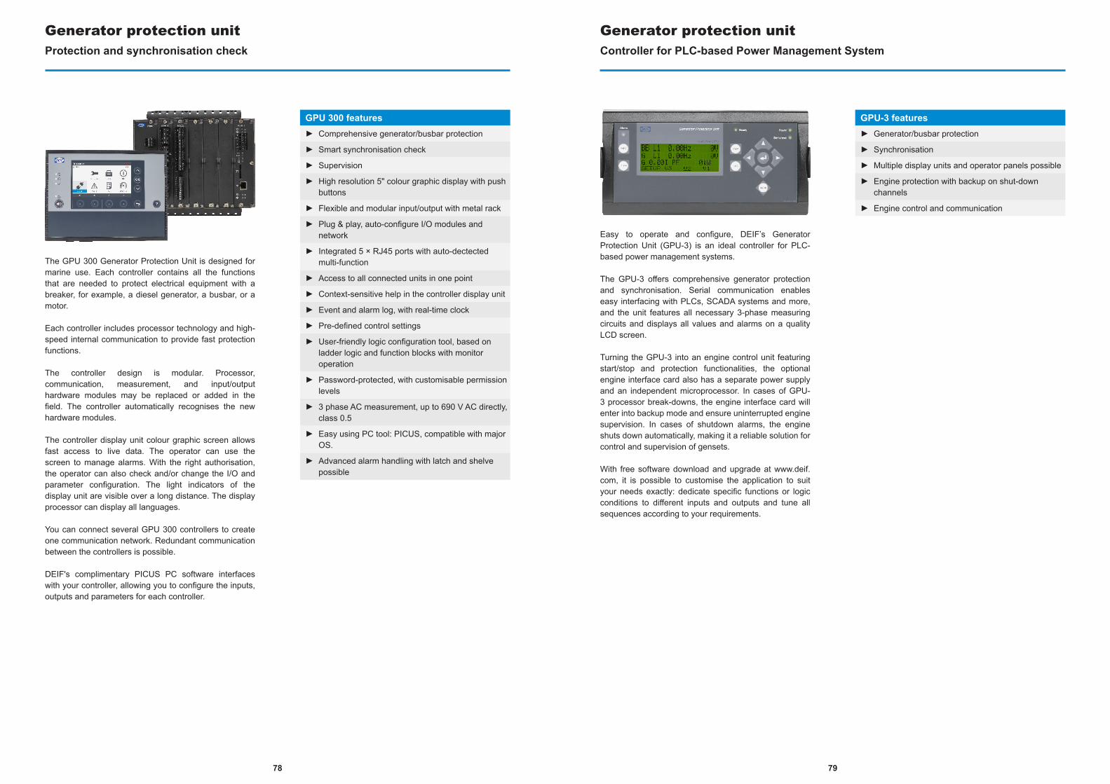
The GPU 300 Generator Protection Unit is designed for marine use. Each controller contains all the functions that are needed to protect electrical equipment with a breaker, for example, a diesel generator, a busbar, or a motor.
Each controller includes processor technology and high-speed internal communication to provide fast protection functions.
The controller design is modular. Processor, communication, measurement, and input/output hardware modules may be replaced or added in the field. The controller automatically recognises the new hardware modules.
The controller display unit colour graphic screen allows fast access to live data. The operator can use the screen to manage alarms. With the right authorisation, the operator can also check and/or change the I/O and parameter configuration. The light indicators of the display unit are visible over a long distance. The display processor can display all languages.
You can connect several GPU 300 controllers to create one communication network. Redundant communication between the controllers is possible.
DEIF's complimentary PICUS PC software interfaces with your controller, allowing you to configure the inputs, outputs and parameters for each controller.
Generator protection unitProtection and synchronisation check
GPU 300 features► Comprehensive generator/busbar protection
► Smart synchronisation check
► Supervision
► High resolution 5" colour graphic display with push buttons
► Flexible and modular input/output with metal rack
► Plug & play, auto-configure I/O modules and network
► Integrated 5 × RJ45 ports with auto-dectected multi-function
► Access to all connected units in one point
► Context-sensitive help in the controller display unit
► Event and alarm log, with real-time clock
► Pre-defined control settings
► User-friendly logic configuration tool, based on ladder logic and function blocks with monitor operation
► Password-protected, with customisable permission levels
► 3 phase AC measurement, up to 690 V AC directly, class 0.5
► Easy using PC tool: PICUS, compatible with major OS.
► Advanced alarm handling with latch and shelve possible
Easy to operate and configure, DEIF’s Generator Protection Unit (GPU-3) is an ideal controller for PLC-based power management systems.
The GPU-3 offers comprehensive generator protection and synchronisation. Serial communication enables easy interfacing with PLCs, SCADA systems and more, and the unit features all necessary 3-phase measuring circuits and displays all values and alarms on a quality LCD screen.
Turning the GPU-3 into an engine control unit featuring start/stop and protection functionalities, the optional engine interface card also has a separate power supply and an independent microprocessor. In cases of GPU-3 processor break-downs, the engine interface card will enter into backup mode and ensure uninterrupted engine supervision. In cases of shutdown alarms, the engine shuts down automatically, making it a reliable solution for control and supervision of gensets.
With free software download and upgrade at www.deif.com, it is possible to customise the application to suit your needs exactly: dedicate specific functions or logic conditions to different inputs and outputs and tune all sequences according to your requirements.
Generator protection unitController for PLC-based Power Management System
GPU-3 features► Generator/busbar protection
► Synchronisation
► Multiple display units and operator panels possible
► Engine protection with backup on shut-down channels
► Engine control and communication
7978
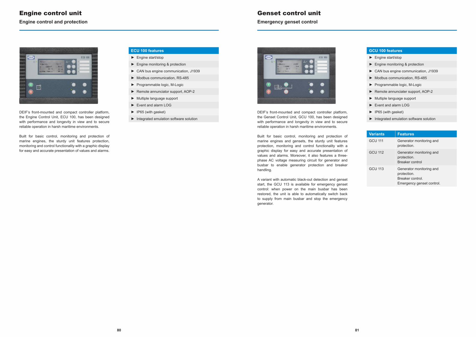
DEIF’s front-mounted and compact controller platform, the Engine Control Unit, ECU 100, has been designed with performance and longevity in view and to secure reliable operation in harsh maritime environments.
Built for basic control, monitoring and protection of marine engines, the sturdy unit features protection, monitoring and control functionality with a graphic display for easy and accurate presentation of values and alarms.
Engine control unitEngine control and protection
ECU 100 features► Engine start/stop
► Engine monitoring & protection
► CAN bus engine communication, J1939
► Modbus communication, RS-485
► Programmable logic, M-Logic
► Remote annunciator support, AOP-2
► Multiple language support
► Event and alarm LOG
► IP65 (with gasket)
► Integrated emulation software solution
DEIF’s front-mounted and compact controller platform, the Genset Control Unit, GCU 100, has been designed with performance and longevity in view and to secure reliable operation in harsh maritime environments.
Built for basic control, monitoring and protection of marine engines and gensets, the sturdy unit features protection, monitoring and control functionality with a graphic display for easy and accurate presentation of values and alarms. Moreover, it also features a three-phase AC voltage measuring circuit for generator and busbar to enable generator protection and breaker handling.
A variant with automatic black-out detection and genset start, the GCU 113 is available for emergency genset control: when power on the main busbar has been restored, the unit is able to automatically switch back to supply from main busbar and stop the emergency generator.
Genset control unitEmergency genset control
GCU 100 features► Engine start/stop
► Engine monitoring & protection
► CAN bus engine communication, J1939
► Modbus communication, RS-485
► Programmable logic, M-Logic
► Remote annunciater support, AOP-2
► Multiple language support
► Event and alarm LOG
► IP65 (with gasket)
► Integrated emulation software solution
Variants FeaturesGCU 111 Generator monitoring and
protection.
GCU 112 Generator monitoring and protection.Breaker control
GCU 113 Generator monitoring and protection.Breaker control.Emergency genset control.
8180
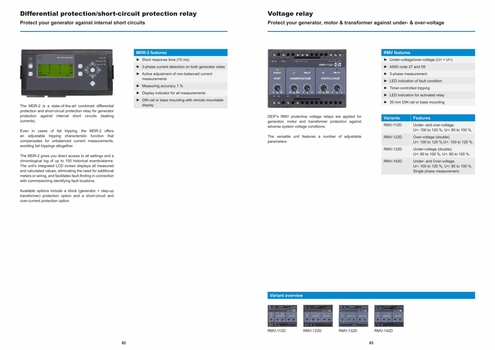
The MDR-2 is a state-of-the-art combined differential protection and short-circuit protection relay for generator protection against internal short circuits (leaking currents).
Even in cases of fail tripping, the MDR-2 offers an adjustable tripping characteristic function that compensates for unbalanced current measurements, avoiding fail trippings altogether.
The MDR-2 gives you direct access to all settings and a chronological log of up to 150 historical events/alarms. The unit’s integrated LCD screen displays all measured and calculated values, eliminating the need for additional meters or wiring, and facilitates fault-finding in connection with commissioning identifying fault locations.
Available options include a block (generator + step-up transformer) protection option and a short-circuit and over-current protection option.
Differential protection/short-circuit protection relayProtect your generator against internal short circuits
MDR-2 features► Short response time (70 ms)
► 3-phase current detection on both generator sides
► Active adjustment of non-balanced current measurements
► Measuring accuracy 1 %
► Display indicator for all measurements
► DIN rail or base mounting with remote mountable display
DEIF's RMV protective voltage relays are applied for generator, motor and transformer protection against adverse system voltage conditions.
The versatile unit features a number of adjustable parameters.
Voltage relayProtect your generator, motor & transformer against under- & over-voltage
RMV features► Under-voltage/over-voltage (U< + U>)
► ANSI code 27 and 59
► 3-phase measurement
► LED indication of fault condition
► Timer-controlled tripping
► LED indication for activated relay
► 35 mm DIN rail or base mounting
Variants FeaturesRMV-112D Under- and over-voltage.
U>: 100 to 120 %, U<: 80 to 100 %.
RMV-122D Over-voltage (double).U>: 100 to 120 %,U>: 100 to 120 %.
RMV-132D Under-voltage (double).U<: 80 to 100 %, U<: 80 to 100 %.
RMV-142D Under- and Over-voltage.U>: 100 to 120 %, U<: 80 to 100 %.Single phase measurement.
RMV-112D RMV-122D RMV-132D RMV-142D
Variant overview
8382
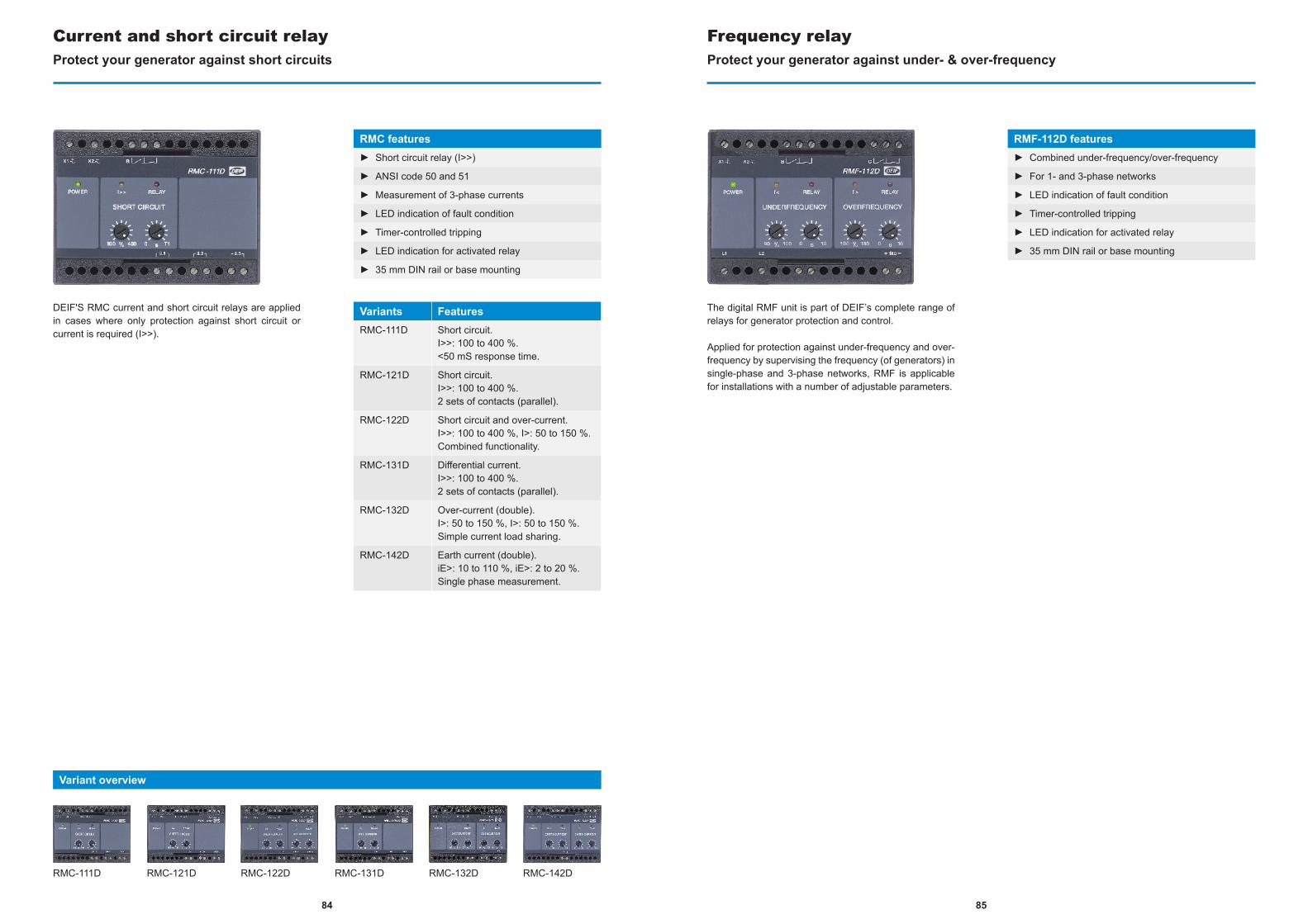
DEIF'S RMC current and short circuit relays are applied in cases where only protection against short circuit or current is required (I>>).
Current and short circuit relayProtect your generator against short circuits
RMC features► Short circuit relay (I>>)
► ANSI code 50 and 51
► Measurement of 3-phase currents
► LED indication of fault condition
► Timer-controlled tripping
► LED indication for activated relay
► 35 mm DIN rail or base mounting
Variants FeaturesRMC-111D Short circuit.
I>>: 100 to 400 %.<50 mS response time.
RMC-121D Short circuit.I>>: 100 to 400 %.2 sets of contacts (parallel).
RMC-122D Short circuit and over-current.I>>: 100 to 400 %, I>: 50 to 150 %.Combined functionality.
RMC-131D Differential current.I>>: 100 to 400 %.2 sets of contacts (parallel).
RMC-132D Over-current (double).I>: 50 to 150 %, I>: 50 to 150 %.Simple current load sharing.
RMC-142D Earth current (double).iE>: 10 to 110 %, iE>: 2 to 20 %.Single phase measurement.
RMC-111D RMC-132D RMC-142DRMC-121D RMC-122D RMC-131D
Variant overview
The digital RMF unit is part of DEIF’s complete range of relays for generator protection and control.
Applied for protection against under-frequency and over-frequency by supervising the frequency (of generators) in single-phase and 3-phase networks, RMF is applicable for installations with a number of adjustable parameters.
Frequency relayProtect your generator against under- & over-frequency
RMF-112D features► Combined under-frequency/over-frequency
► For 1- and 3-phase networks
► LED indication of fault condition
► Timer-controlled tripping
► LED indication for activated relay
► 35 mm DIN rail or base mounting
8584
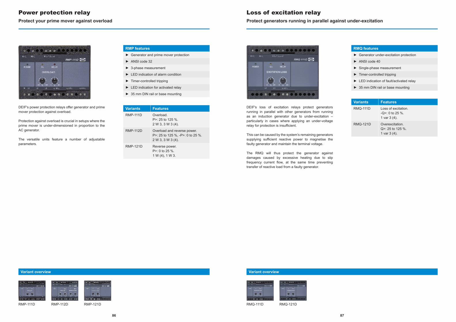
RMP-111D RMP-112D RMP-121D
DEIF's power protection relays offer generator and prime mover protection against overload.
Protection against overload is crucial in setups where the prime mover is under-dimensioned in proportion to the AC generator.
The versatile units feature a number of adjustable parameters.
Power protection relayProtect your prime mover against overload
RMP features► Generator and prime mover protection
► ANSI code 32
► 3-phase measurement
► LED indication of alarm condition
► Timer-controlled tripping
► LED indication for activated relay
► 35 mm DIN rail or base mounting
Variants FeaturesRMP-111D Overload.
P>: 25 to 125 %.2 W 3, 3 W 3 (4).
RMP-112D Overload and reverse power.P>: 25 to 125 %, -P>: 0 to 25 %.2 W 3, 3 W 3 (4).
RMP-121D Reverse power.P>: 0 to 25 %.1 W (4), 1 W 3.
Variant overview
DEIF's loss of excitation relays protect generators running in parallel with other generators from running as an induction generator due to under-excitation – particularly in cases where applying an under-voltage relay for protection is insufficient.
This can be caused by the system’s remaining generators supplying sufficient reactive power to magnetise the faulty generator and maintain the terminal voltage.
The RMQ will thus protect the generator against damages caused by excessive heating due to slip frequency current flow, at the same time preventing transfer of reactive load from a faulty generator.
Loss of excitation relayProtect generators running in parallel against under-excitation
RMQ features► Generator under-excitation protection
► ANSI code 40
► Single-phase measurement
► Timer-controlled tripping
► LED indication of fault/activated relay
► 35 mm DIN rail or base mounting
Variants FeaturesRMQ-111D Loss of excitation.
-Q>: 0 to 25 %.1 var 3 (4).
RMQ-121D Overexcitation.Q>: 25 to 125 %.1 var 3 (4).
RMQ-111D RMQ-121D
Variant overview
8786

89
DEIF's loss of mains relays protect generators against damage resulting from a non-synchronised reconnection to the grid after a temporary mains failure.
A mains failure will be detected, provided a disconnection at an arbitrary point of the network results in a swift change of the generator frequency (vector shift). An opening signal is then transmitted to the mains circuit breaker, and the generator will thus be protected against damages caused by an automatic reconnection to the high-voltage network.
Loss of mains relayProtect your generator against damages due to loss of mains failure
LMR features► Detection of vector shift
► ANSI code 78
► Mains disconnection on mains failure
► Ensures no asynchronous reconnection
► LED indication of fault condition
► LED indication for activated relay
► 35 mm DIN rail or base mounting
Variants FeaturesLMR-111D Vector shift
LMR-122D Vector shift and df/dt (ROCOF)
LMR-111D LMR-122D
Variant overview
Measuring centers
TransducersMulti-transducer. . . . . . . . . . . . . . . . . . . . . . . . . . . . . . . . . . . . . . . . . . . . . . . . . . . . . . . . . . . . . . . . . . . . . . . . . . . . . . . . . . . . . . . . . . . . . . . . . . . .MTR-4 . . . . . . . . . . . . . . . . . . 91Selectable transducer . . . . . . . . . . . . . . . . . . . . . . . . . . . . . . . . . . . . . . . . . . . . . . . . . . . . . . . . . . . . . . . . . . . . . . . . . . . . . . . . . . . . . . . . . . . . . . . . TAS . . . . . . . . . . . . . . . . . . 92Single-function transducer. . . . . . . . . . . . . . . . . . . . . . . . . . . . . . . . . . . . . . . . . . . . . . . . . . . . . . . . . . . . . . . . . . . . . . . . . . . . . . . . . . .TAC & TAV . . . . . . . . . . . . . . . . . . 93
Multi-instrumentsMulti-instrument for panel. . . . . . . . . . . . . . . . . . . . . . . . . . . . . . . . . . . . . . . . . . . . . . . . . . . . . . . . . . . . . . . . . . . . . . . . . . . . . . . . . . . MIC-2 MKII . . . . . . . . . . . . . . . . . . 94Multi-instrument for DIN. . . . . . . . . . . . . . . . . . . . . . . . . . . . . . . . . . . . . . . . . . . . . . . . . . . . . . . . . . . . . . . . . . . . . . . . . . . . . . . .MIC-2 MKII DIN . . . . . . . . . . . . . . . . . . 95
Insulation monitoringInsulation monitor, AC/DC-networks . . . . . . . . . . . . . . . . . . . . . . . . . . . . . . . . . . . . . . . . . . . . . . . . . . . . . . . . . . . . . . . . . . . . . . . . . . . . . . . SIM . . . . . . . . . . . . . . . . . . 96Insulation monitor, DC-networks. . . . . . . . . . . . . . . . . . . . . . . . . . . . . . . . . . . . . . . . . . . . . . . . . . . . . . . . . . . . . . . . . . . . . . . . . .ADL-111Q96 . . . . . . . . . . . . . . . . . . 97Insulation monitor, AC-networks . . . . . . . . . . . . . . . . . . . . . . . . . . . . . . . . . . . . . . . . . . . . . . . . . . . . . . . . . . . . . . . . . . . . . . . . . . . . . . . . . .AAL-2 . . . . . . . . . . . . . . . . . . 98
Analogue instruments
MetersAC voltage and current with 90 ° pointer . . . . . . . . . . . . . . . . . . . . . . . . . . . . . . . . . . . . . . . . . . . . . . . . . . . . . . . . . . . . . . . . . . . . . . . . . . . EQ . . . . . . . . . . . . . . . . . . 99AC/DC current and voltage with 90 ° or 240 ° pointer . . . . . . . . . . . . . . . . . . . . . . . . . . . . . . . . . . . . . . . . . . . . . . . . . . .DQ & VDQ . . . . . . . . . . . . . . . . .100AC voltage meter with switch . . . . . . . . . . . . . . . . . . . . . . . . . . . . . . . . . . . . . . . . . . . . . . . . . . . . . . . . . . . . . . . . . . . . . . . . . . . . . . . . . . . . EQ-sw . . . . . . . . . . . . . . . . .101AC current meter with switch. . . . . . . . . . . . . . . . . . . . . . . . . . . . . . . . . . . . . . . . . . . . . . . . . . . . . . . . . . . . . . . . . . . . . . . . . . . . . . . . . . . VDQ-sw . . . . . . . . . . . . . . . . .102Power meter. . . . . . . . . . . . . . . . . . . . . . . . . . . . . . . . . . . . . . . . . . . . . . . . . . . . . . . . . . . . . . . . . . . . . . . . . . . . . . . . . . . . . . . . . . . . . . . . . . . . . . . . . . . WQ . . . . . . . . . . . . . . . . .103Combined kWh counter and power meter . . . . . . . . . . . . . . . . . . . . . . . . . . . . . . . . . . . . . . . . . . . . . . . . . . . . . . . . . . . . . . . . . WQR MKII . . . . . . . . . . . . . . . . .104Frequency meter. . . . . . . . . . . . . . . . . . . . . . . . . . . . . . . . . . . . . . . . . . . . . . . . . . . . . . . . . . . . . . . . . . . . . . . . . . . . . . . . . . . . . . . . . . . . . . .FTQ & FQ . . . . . . . . . . . . . . . . .105Power factor meter . . . . . . . . . . . . . . . . . . . . . . . . . . . . . . . . . . . . . . . . . . . . . . . . . . . . . . . . . . . . . . . . . . . . . . . . . . . . . . . . . . . . . . . . . . . . . . . . . . .PFQ . . . . . . . . . . . . . . . . .106Bi-metallic meter . . . . . . . . . . . . . . . . . . . . . . . . . . . . . . . . . . . . . . . . . . . . . . . . . . . . . . . . . . . . . . . . . . . . . . . . . . . . . . . . . . . . . . . . . . . . . . . . . . . . . . . BQ . . . . . . . . . . . . . . . . .107Combined ammeter . . . . . . . . . . . . . . . . . . . . . . . . . . . . . . . . . . . . . . . . . . . . . . . . . . . . . . . . . . . . . . . . . . . . . . . . . . . . . . . . . . . . . . . . . . . . . . . . . BEQ . . . . . . . . . . . . . . . . .108Meters for DIN . . . . . . . . . . . . . . . . . . . . . . . . . . . . . . . . . . . . . . . . . . . . . . . . . . . . . . . . . . . . . . . . . . . . . . . . . . . . . . . . . . . . . . . . . .D45, E45 & B45 . . . . . . . . . . . . . . . . .109Running hours counter. . . . . . . . . . . . . . . . . . . . . . . . . . . . . . . . . . . . . . . . . . . . . . . . . . . . . . . . . . . . . . . . . . . . . . . . . . . . . .HC 48 & HC 24/36 . . . . . . . . . . . . . . . . .110
AC/DC current measurement
Current transformersMeasuring transformer . . . . . . . . . . . . . . . . . . . . . . . . . . . . . . . . . . . . . . . . . . . . . . . . . . . . . . . . . . . . . . . . . . . . . . . . . . . . . . . . . . . . . . ASK & ASR . . . . . . . . . . . . . . . . . 111Split core transformer . . . . . . . . . . . . . . . . . . . . . . . . . . . . . . . . . . . . . . . . . . . . . . . . . . . . . . . . . . . . . . . . . . . . . . . . . . . . . . . . . . . . . . . . . . . . . . . .KBU . . . . . . . . . . . . . . . . .112Protection transformer . . . . . . . . . . . . . . . . . . . . . . . . . . . . . . . . . . . . . . . . . . . . . . . . . . . . . . . . . . . . . . . . . . . . . . . . . . . . . . . . . . SASK & SASR . . . . . . . . . . . . . . . . .113Primary winding transformer . . . . . . . . . . . . . . . . . . . . . . . . . . . . . . . . . . . . . . . . . . . . . . . . . . . . . . . . . . . . . . . . . . . . . . . . . . . . . . . . . . . . . . . WSK . . . . . . . . . . . . . . . . .114Summation transformer . . . . . . . . . . . . . . . . . . . . . . . . . . . . . . . . . . . . . . . . . . . . . . . . . . . . . . . . . . . . . . . . . . . . . . . . . . . . . . . . . . .KSU & SUSK . . . . . . . . . . . . . . . . .115
DC measurementsShunt resistor . . . . . . . . . . . . . . . . . . . . . . . . . . . . . . . . . . . . . . . . . . . . . . . . . . . . . . . . . . . . . . . . . . . . . . . . . . . . . . . . . . . . . . . . . . . . . . . . . . . . . . . . . . . . . . . . . . . . . . . . . . . . . . . .116
MeasuringIndex
88
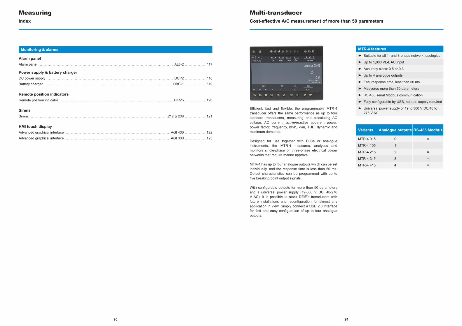
90
Monitoring & alarms
Alarm panelAlarm panel. . . . . . . . . . . . . . . . . . . . . . . . . . . . . . . . . . . . . . . . . . . . . . . . . . . . . . . . . . . . . . . . . . . . . . . . . . . . . . . . . . . . . . . . . . . . . . . . . . . . . . . . . .AL8-2 . . . . . . . . . . . . . . . . .117
Power supply & battery chargerDC power supply . . . . . . . . . . . . . . . . . . . . . . . . . . . . . . . . . . . . . . . . . . . . . . . . . . . . . . . . . . . . . . . . . . . . . . . . . . . . . . . . . . . . . . . . . . . . . . . . . . .DCP2 . . . . . . . . . . . . . . . . .118Battery charger. . . . . . . . . . . . . . . . . . . . . . . . . . . . . . . . . . . . . . . . . . . . . . . . . . . . . . . . . . . . . . . . . . . . . . . . . . . . . . . . . . . . . . . . . . . . . . . . . . . . .DBC-1 . . . . . . . . . . . . . . . . .119
Remote position indicatorsRemote position indicator. . . . . . . . . . . . . . . . . . . . . . . . . . . . . . . . . . . . . . . . . . . . . . . . . . . . . . . . . . . . . . . . . . . . . . . . . . . . . . . . . . . . . . . . . .PIR25 . . . . . . . . . . . . . . . . .120
SirensSirens . . . . . . . . . . . . . . . . . . . . . . . . . . . . . . . . . . . . . . . . . . . . . . . . . . . . . . . . . . . . . . . . . . . . . . . . . . . . . . . . . . . . . . . . . . . . . . . . . . . . . . . . . . .212 & 208 . . . . . . . . . . . . . . . . .121
HMI touch displayAdvanced graphical interface . . . . . . . . . . . . . . . . . . . . . . . . . . . . . . . . . . . . . . . . . . . . . . . . . . . . . . . . . . . . . . . . . . . . . . . . . . . . . . . . . AGI 400 . . . . . . . . . . . . . . . . .122Advanced graphical interface . . . . . . . . . . . . . . . . . . . . . . . . . . . . . . . . . . . . . . . . . . . . . . . . . . . . . . . . . . . . . . . . . . . . . . . . . . . . . . . . . AGI 300 . . . . . . . . . . . . . . . . .123
MeasuringIndex
Efficient, fast and flexible, the programmable MTR-4 transducer offers the same performance as up to four standard transducers, measuring and calculating AC voltage, AC current, active/reactive apparent power, power factor, frequency, kWh, kvar, THD, dynamic and maximum demands.
Designed for use together with PLCs or analogue instruments, the MTR-4 measures, analyses and monitors single-phase or three-phase electrical power networks that require marine approval.
MTR-4 has up to four analogue outputs which can be set individually, and the response time is less than 50 ms. Output characteristics can be programmed with up to five breaking point output signals.
With configurable outputs for more than 50 parameters and a universal power supply (19-300 V DC, 40-276 V AC), it is possible to stock DEIF’s transducers with future installations and reconfiguration for almost any application in view. Simply connect a USB 2.0 interface for fast and easy configuration of up to four analogue outputs.
Multi-transducerCost-effective A/C measurement of more than 50 parameters
MTR-4 features► Suitable for all 1- and 3-phase network topologies
► Up to 1,000 VL-L AC input
► Accuracy class: 0.5 or 0.3
► Up to 4 analogue outputs
► Fast response time, less than 50 ms
► Measures more than 50 parameters
► RS-485 serial Modbus communication
► Fully configurable by USB, no aux. supply required
► Universal power supply of 19 to 300 V DC/40 to 276 V AC
Variants Analogue outputs RS-485 Modbus
MTR-4 015 0 ×
MTR-4 105 1
MTR-4 215 2 ×
MTR-4 315 3 ×
MTR-4 415 4 ×
91

Powerful, fast and compact, the TAS units in DEIF’s transducer range measure sinusoidal alternating voltage and/or current signal and provide output signal as direct current or voltage signal proportional to measurements for PLCs, PCs, microprocessor control, indicators, alarm units etc.
TAS transducers are micro-controller-based with one analogue output for measurement of power, voltage, current etc. on an AC network. Because these transducers have no mechanical parts like potentiometers, the calibration stability is excellent.
TAS transducers can be delivered pre-configured to set measuring values and ranges or un-configured for customer configuration using DEIF’s free PC tool.
Selectable transducerFactory-configured inputs/outputs
TAS features► Class 0.5 measurement
► Supply and measuring voltage up to 690 V
► Pre-configuration or easy PC tool configuration
► Configurable up to three output slopes
Variants FeaturesTAS-311DG Factory-configured transducer for
voltage, current, frequency or phase angle measurement.Aux supply: from 57 to 690 V AC.Aux supply: 24 to 220 V DC.
TAS-321DG Factory-configured transducer for bi-directional current measurement.Aux supply: from 57 to 690 V AC.Aux supply: 24 to 220 V DC.
TAS-331DG Factory-configured transducer for power or reactive power measurement.Aux supply: from 57 to 690 V AC.Aux supply: 24 to 220 V DC.
TAS-311DG TAS-321DG TAS-331DG
Variant overview
Powerful, fast and compact, the TAC and TAV units in DEIF’s transducer range measure sinusoidal alternating voltage and/or current signal and provide output signal as direct current or voltage signal proportional to measurements for PLCs, PCs, microprocessor control, indicators, alarm units etc.
The transducers are compact, single function transducers for measurement of a sinusoidal AC current converted into a DC current or voltage signal proportional to the measured value on a single-phase network.
Single-function transducerMeasuring transducers for voltage or current
General features► Compact design, 55 × 75 mm
► Easily accessible terminals
► Easy identification of unit/function
► Accuracy class: 0.5
► 35 mm DIN rail or base mounting
Variants FeaturesTAC-311DG For current measurement.
Aux supply: 24 or 48 to 110 or 88 to 220 V DC, 110/230 or 440 V AC.
TAC-321DG For current measurement.No aux. supply required.
TAV-311DG For voltage measurement.Aux supply: 24 to 220 V DC, 110/230 V AC.
TAV-321DG For voltage measurement.No aux. supply required.
TAC-311DG TAC-321DG TAV-311DG TAV-321DG
Variant overview
9392
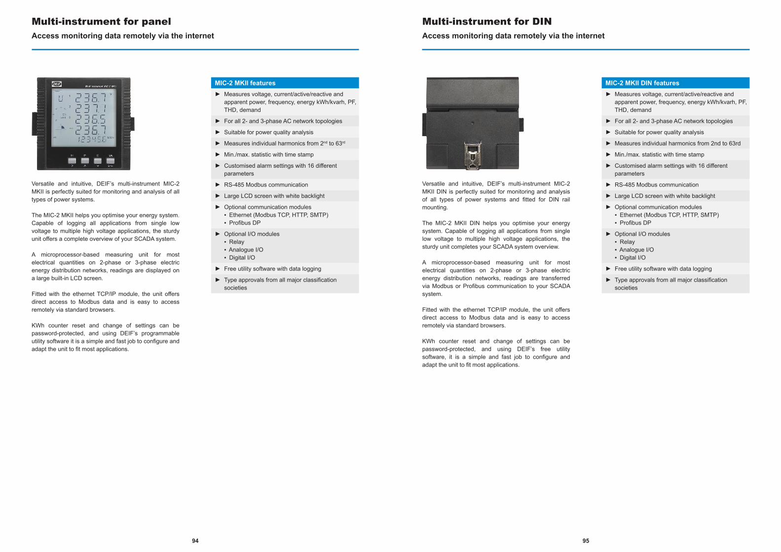
Versatile and intuitive, DEIF’s multi-instrument MIC-2 MKII is perfectly suited for monitoring and analysis of all types of power systems.
The MIC-2 MKII helps you optimise your energy system. Capable of logging all applications from single low voltage to multiple high voltage applications, the sturdy unit offers a complete overview of your SCADA system.
A microprocessor-based measuring unit for most electrical quantities on 2-phase or 3-phase electric energy distribution networks, readings are displayed on a large built-in LCD screen.
Fitted with the ethernet TCP/IP module, the unit offers direct access to Modbus data and is easy to access remotely via standard browsers.
KWh counter reset and change of settings can be password-protected, and using DEIF’s programmable utility software it is a simple and fast job to configure and adapt the unit to fit most applications.
Multi-instrument for panelAccess monitoring data remotely via the internet
MIC-2 MKII features► Measures voltage, current/active/reactive and
apparent power, frequency, energy kWh/kvarh, PF, THD, demand
► For all 2- and 3-phase AC network topologies
► Suitable for power quality analysis
► Measures individual harmonics from 2nd to 63rd
► Min./max. statistic with time stamp
► Customised alarm settings with 16 different parameters
► RS-485 Modbus communication
► Large LCD screen with white backlight
► Optional communication modules ▪ Ethernet (Modbus TCP, HTTP, SMTP) ▪ Profibus DP
► Optional I/O modules ▪ Relay ▪ Analogue I/O ▪ Digital I/O
► Free utility software with data logging
► Type approvals from all major classification societies
Versatile and intuitive, DEIF’s multi-instrument MIC-2 MKII DIN is perfectly suited for monitoring and analysis of all types of power systems and fitted for DIN rail mounting.
The MIC-2 MKII DIN helps you optimise your energy system. Capable of logging all applications from single low voltage to multiple high voltage applications, the sturdy unit completes your SCADA system overview.
A microprocessor-based measuring unit for most electrical quantities on 2-phase or 3-phase electric energy distribution networks, readings are transferred via Modbus or Profibus communication to your SCADA system.
Fitted with the ethernet TCP/IP module, the unit offers direct access to Modbus data and is easy to access remotely via standard browsers.
KWh counter reset and change of settings can be password-protected, and using DEIF’s free utility software, it is a simple and fast job to configure and adapt the unit to fit most applications.
Multi-instrument for DINAccess monitoring data remotely via the internet
MIC-2 MKII DIN features► Measures voltage, current/active/reactive and
apparent power, frequency, energy kWh/kvarh, PF, THD, demand
► For all 2- and 3-phase AC network topologies
► Suitable for power quality analysis
► Measures individual harmonics from 2nd to 63rd
► Min./max. statistic with time stamp
► Customised alarm settings with 16 different parameters
► RS-485 Modbus communication
► Large LCD screen with white backlight
► Optional communication modules ▪ Ethernet (Modbus TCP, HTTP, SMTP) ▪ Profibus DP
► Optional I/O modules ▪ Relay ▪ Analogue I/O ▪ Digital I/O
► Free utility software with data logging
► Type approvals from all major classification societies
9594
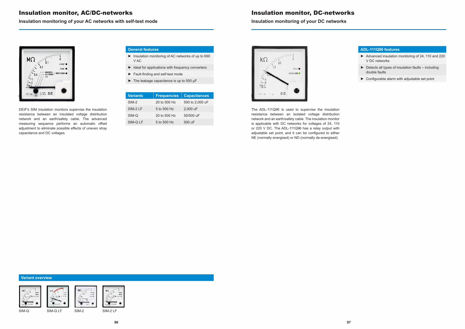
DEIF's SIM insulation monitors supervise the insulation resistance between an insulated voltage distribution network and an earth/safety cable. The advanced measuring sequence performs an automatic offset adjustment to eliminate possible effects of uneven stray capacitance and DC voltages.
Insulation monitor, AC/DC-networksInsulation monitoring of your AC networks with self-test mode
General features► Insulation monitoring of AC networks of up to 690
V AC
► Ideal for applications with frequency converters
► Fault-finding and self-test mode
► The leakage capacitance is up to 500 μF
Variants Frequencies CapacitancesSIM-2 20 to 500 Hz 500 to 2,000 uF
SIM-2 LF 5 to 500 Hz 2,000 uF
SIM-Q 20 to 500 Hz 50/500 uF
SIM-Q LF 5 to 500 Hz 500 uF
SIM-Q SIM-Q LF SIM-2
Variant overview
SIM-2 LF
The ADL-111Q96 is used to supervise the insulation resistance between an isolated voltage distribution network and an earth/safety cable. The insulation monitor is applicable with DC networks for voltages of 24, 110 or 220 V DC. The ADL-111Q96 has a relay output with adjustable set point, and it can be configured to either NE (normally energised) or ND (normally de-energised).
Insulation monitor, DC-networksInsulation monitoring of your DC networks
ADL-111Q96 features► Advanced insulation monitoring of 24, 110 and 220
V DC networks
► Detects all types of insulation faults – including double faults
► Configurable alarm with adjustable set point
9796
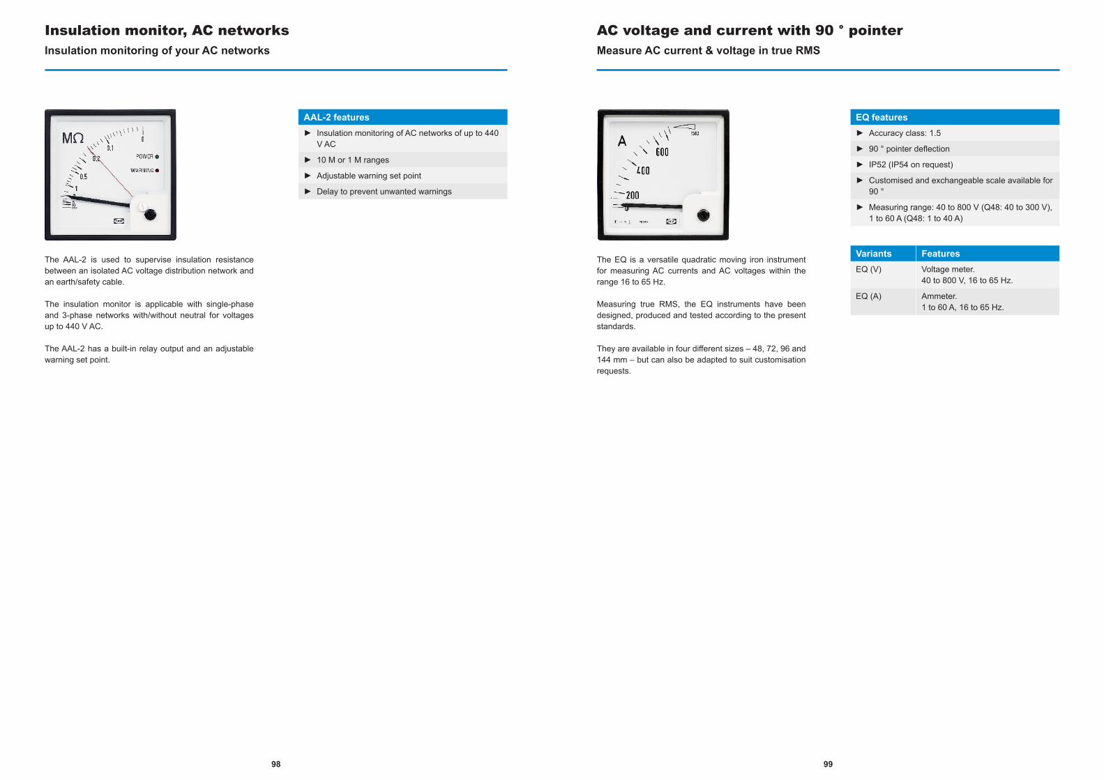
The AAL-2 is used to supervise insulation resistance between an isolated AC voltage distribution network and an earth/safety cable.
The insulation monitor is applicable with single-phase and 3-phase networks with/without neutral for voltages up to 440 V AC.
The AAL-2 has a built-in relay output and an adjustable warning set point.
Insulation monitor, AC networksInsulation monitoring of your AC networks
AAL-2 features► Insulation monitoring of AC networks of up to 440
V AC
► 10 M or 1 M ranges
► Adjustable warning set point
► Delay to prevent unwanted warnings
The EQ is a versatile quadratic moving iron instrument for measuring AC currents and AC voltages within the range 16 to 65 Hz.
Measuring true RMS, the EQ instruments have been designed, produced and tested according to the present standards.
They are available in four different sizes – 48, 72, 96 and 144 mm – but can also be adapted to suit customisation requests.
AC voltage and current with 90 ° pointerMeasure AC current & voltage in true RMS
EQ features► Accuracy class: 1.5
► 90 ° pointer deflection
► IP52 (IP54 on request)
► Customised and exchangeable scale available for 90 °
► Measuring range: 40 to 800 V (Q48: 40 to 300 V), 1 to 60 A (Q48: 1 to 40 A)
Variants FeaturesEQ (V) Voltage meter.
40 to 800 V, 16 to 65 Hz.
EQ (A) Ammeter.1 to 60 A, 16 to 65 Hz.
9998
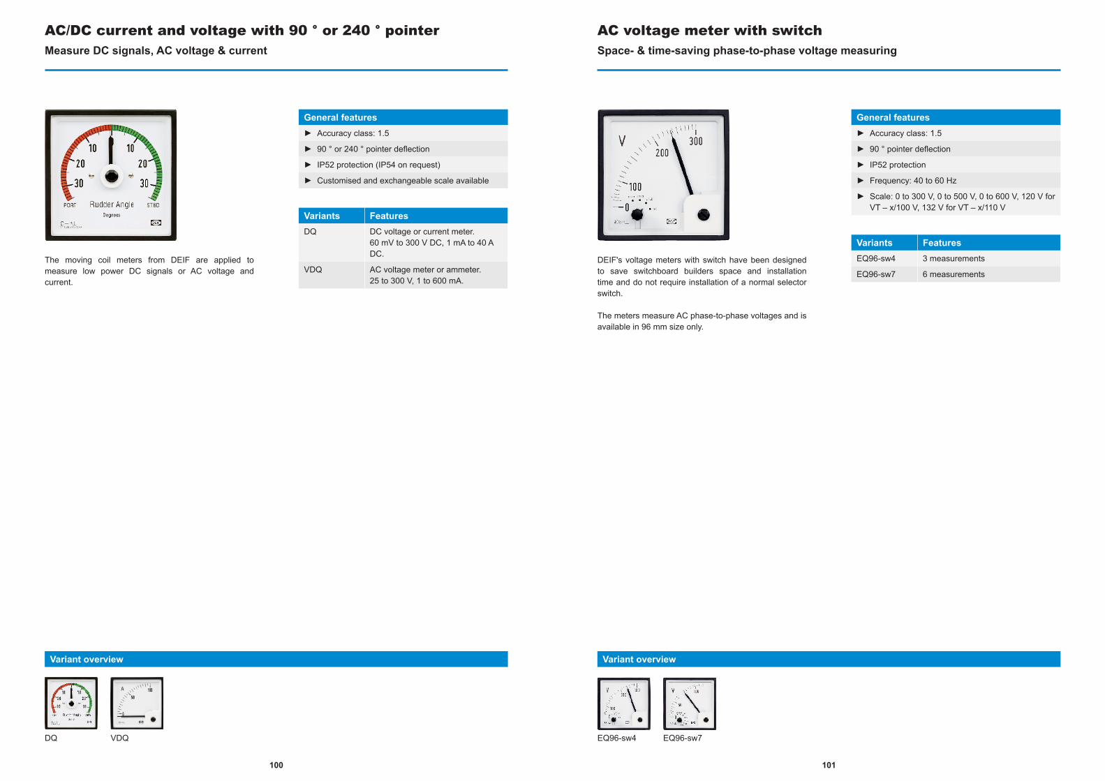
The moving coil meters from DEIF are applied to measure low power DC signals or AC voltage and current.
AC/DC current and voltage with 90 ° or 240 ° pointerMeasure DC signals, AC voltage & current
General features► Accuracy class: 1.5
► 90 ° or 240 ° pointer deflection
► IP52 protection (IP54 on request)
► Customised and exchangeable scale available
Variants FeaturesDQ DC voltage or current meter.
60 mV to 300 V DC, 1 mA to 40 A DC.
VDQ AC voltage meter or ammeter.25 to 300 V, 1 to 600 mA.
DQ VDQ
Variant overview
DEIF's voltage meters with switch have been designed to save switchboard builders space and installation time and do not require installation of a normal selector switch.
The meters measure AC phase-to-phase voltages and is available in 96 mm size only.
AC voltage meter with switchSpace- & time-saving phase-to-phase voltage measuring
General features► Accuracy class: 1.5
► 90 ° pointer deflection
► IP52 protection
► Frequency: 40 to 60 Hz
► Scale: 0 to 300 V, 0 to 500 V, 0 to 600 V, 120 V for VT – x/100 V, 132 V for VT – x/110 V
Variants FeaturesEQ96-sw4 3 measurements
EQ96-sw7 6 measurements
EQ96-sw4 EQ96-sw7
Variant overview
101100

The VDQ96-sw has been designed to save switchboard builders space and installation time and does not require installation of normal selector switch.
The instruments measure phase-to-phase currents and is available in 96 mm size only.
AC current meter with switchSpace- & time-saving phase-to-phase current measuring
VDQ96-sw features► Accuracy class: 1.5
► 90 ° pointer deflection
► IP52
► Customised and exchangeable scale available for 90 °
► Measuring range: 0 to 1 A, 0 to 5 A or from current transformer(s)
The WQ measures power or reactive power using a moving coil movement and a built-in electronic watt or var transducer.
Measuring power in a single-phase or three-phase network, the transducer PCB converts the signal into a DC current which is then fed to the moving coil instrument.
The DEIF WQ comes with a high degree of transient protection and is available in Q96 mm and Q144 mm sizes.
Power meterMeasure power or reactive power
WQ features► 1.5 accuracy class
► 90 ° and 240 ° pointer deflection
► IP52 protection (IP54 on request)
► Measuring voltage: 100 to 110 to 127 to 220 to 230 to 240 to 380 to 400 to 415 to 440 V AC
► Measuring range: Frequency: 45 to 65 Hz
► Measuring current: direct or from C.T.-/1 A or -/5 A
► Scale: customised and exchangeable scale available for 90 °
103102

kWh counters are for registration of consumed or generated electrical energy. They are microprocessor-controlled and equipped with a 7-digit electromechanical counter which retains the reading in case of supply voltage failure.
Combined kWh counter and power meterRegister & retain consumed or generated electrical energy
General features► Accuracy class 1.0 (EN 62053-21)
► For single-phase and 3-phase net-works
► Microprocessor-controlled meters with pulse output (SO)
► Simultaneous measurement of two quantities (except type WQR96 MKII)
► Scale: customised and exchangeable scale
► 60 to 400 V AC aux. power supply
Variants FeaturesWQR96 MKII 1 seven-digit register (kWh or
kvarh).One pulse output.
WQ2R96 MKII 2 seven-digit registers (kWh and kvarh).Two pulse outputs.
WQR96-x MKII 1 seven-digit register (kWh or kvarh) & 90 ° indication.One pulse output.
WQR96-c MKII 1 seven-digit register (kWh or kvarh) & 240 ° indication.One pulse output.
WQR96 MKII WQR96-x MKIIWQ2R96 MKII WQR96-C MKII
Variant overview
With high immunity to 3rd harmonics, DEIF's frequency meters are suitable for all applications. The moving coil meters feature integrated electronics that convert frequency into analogue readings with accurate and linear readouts.
Frequency meterConvert frequency to analogue readings
General features► Robust and thoroughly tested construction
► Accuracy class: 0.5 and linear read-out
► High immunity to 3rd harmonics
Variants FeaturesFTQ Q96.
Reed.
FQ Q72 and Q96.90 ° movement pointer.Exchangeable scale.
FQ FTQ
Variant overview
105104
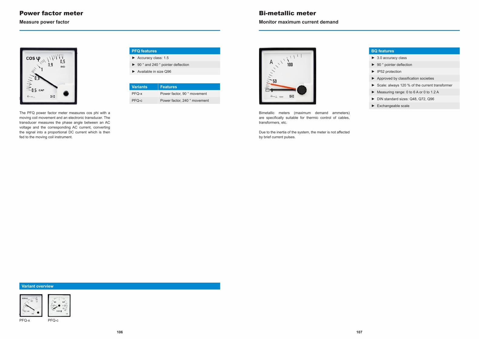
The PFQ power factor meter measures cos phi with a moving coil movement and an electronic transducer. The transducer measures the phase angle between an AC voltage and the corresponding AC current, converting the signal into a proportional DC current which is then fed to the moving coil instrument.
Power factor meterMeasure power factor
PFQ features► Accuracy class: 1.5
► 90 ° and 240 ° pointer deflection
► Available in size Q96
Variants FeaturesPFQ-x Power factor, 90 ° movement
PFQ-c Power factor, 240 ° movement
Bimetallic meters (maximum demand ammeters) are specifically suitable for thermic control of cables, transformers, etc.
Due to the inertia of the system, the meter is not affected by brief current pulses.
Bi-metallic meterMonitor maximum current demand
BQ features► 3.0 accuracy class
► 90 ° pointer deflection
► IP52 protection
► Approved by classification societies
► Scale: always 120 % of the current transformer
► Measuring range: 0 to 6 A or 0 to 1.2 A
► DIN standard sizes: Q48, Q72, Q96
► Exchangeable scale
PFQ-x PFQ-c
Variant overview
107106
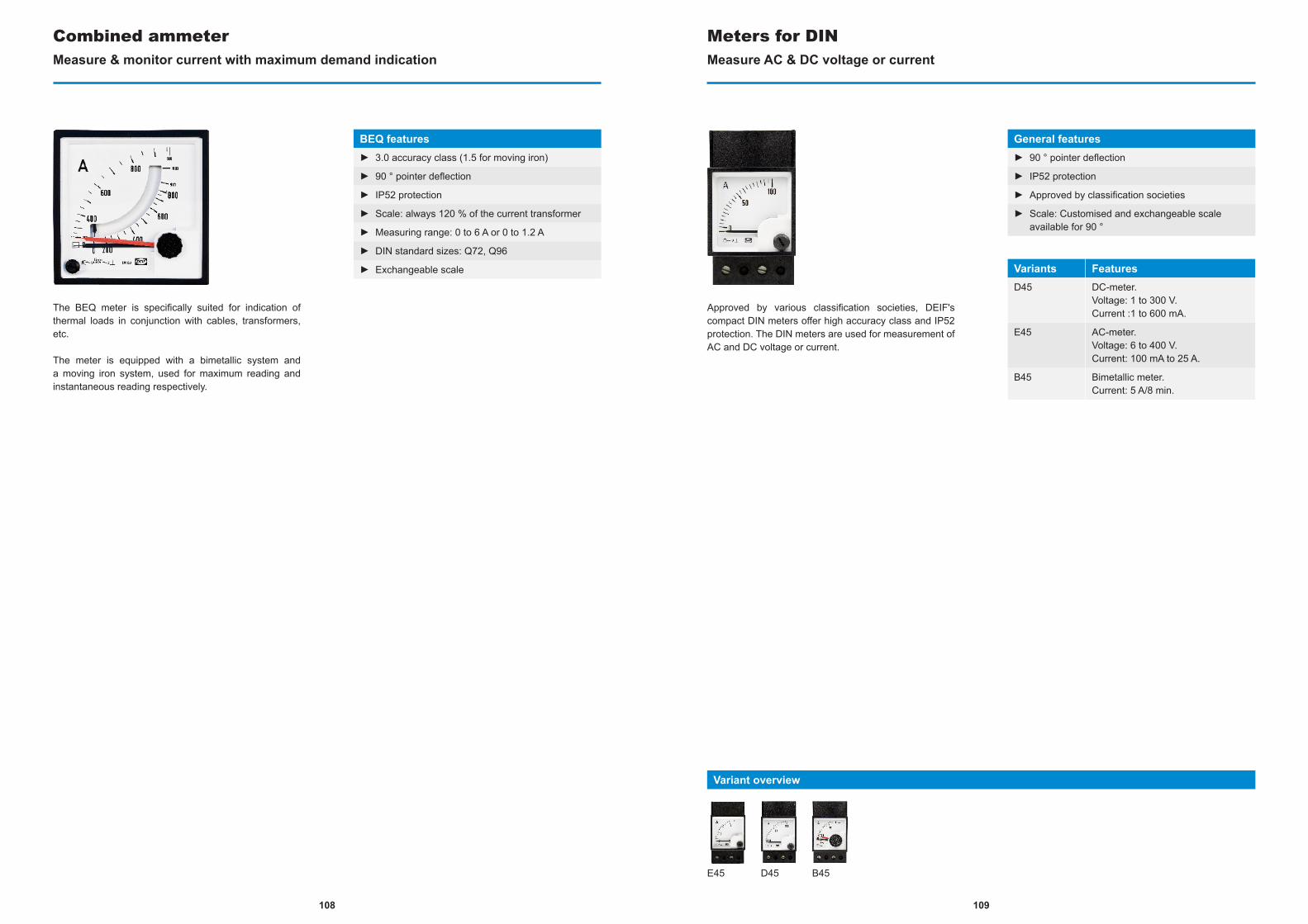
The BEQ meter is specifically suited for indication of thermal loads in conjunction with cables, transformers, etc.
The meter is equipped with a bimetallic system and a moving iron system, used for maximum reading and instantaneous reading respectively.
Combined ammeterMeasure & monitor current with maximum demand indication
BEQ features► 3.0 accuracy class (1.5 for moving iron)
► 90 ° pointer deflection
► IP52 protection
► Scale: always 120 % of the current transformer
► Measuring range: 0 to 6 A or 0 to 1.2 A
► DIN standard sizes: Q72, Q96
► Exchangeable scale
Approved by various classification societies, DEIF's compact DIN meters offer high accuracy class and IP52 protection. The DIN meters are used for measurement of AC and DC voltage or current.
Meters for DINMeasure AC & DC voltage or current
General features► 90 ° pointer deflection
► IP52 protection
► Approved by classification societies
► Scale: Customised and exchangeable scale available for 90 °
Variants FeaturesD45 DC-meter.
Voltage: 1 to 300 V.Current :1 to 600 mA.
E45 AC-meter.Voltage: 6 to 400 V.Current: 100 mA to 25 A.
B45 Bimetallic meter.Current: 5 A/8 min.
E45 D45 B45
Variant overview
109108
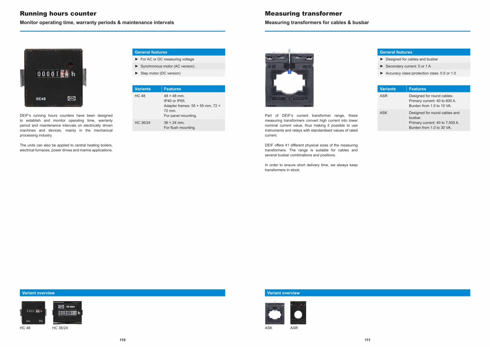
DEIF’s running hours counters have been designed to establish and monitor operating time, warranty period and maintenance intervals on electrically driven machines and devices, mainly in the mechanical processing industry.
The units can also be applied to central heating boilers, electrical furnaces, power drives and marine applications.
Running hours counterMonitor operating time, warranty periods & maintenance intervals
General features► For AC or DC measuring voltage
► Synchronous motor (AC version)
► Step motor (DC version)
Variants FeaturesHC 48 48 × 48 mm.
IP40 or IP65.Adapter frames: 55 × 55 mm, 72 × 72 mm.For panel mounting.
HC 36/24 36 × 24 mm.For flush mounting.
HC 48 HC 36/24
Variant overview
Part of DEIF’s current transformer range, these measuring transformers convert high current into lower nominal current value, thus making it possible to use instruments and relays with standardised values of rated current.
DEIF offers 41 different physical sizes of the measuring transformers. The range is suitable for cables and several busbar combinations and positions.
In order to ensure short delivery time, we always keep transformers in stock.
Measuring transformerMeasuring transformers for cables & busbar
General features► Designed for cables and busbar
► Secondary current: 5 or 1 A
► Accuracy class:/protection class: 0.5 or 1.0
Variants FeaturesASR Designed for round cables.
Primary current: 40 to 600 A.Burden from 1.0 to 10 VA.
ASK Designed for round cables and busbar.Primary current: 40 to 7,500 A.Burden from 1.0 to 30 VA.
ASK ASR
Variant overview
111110
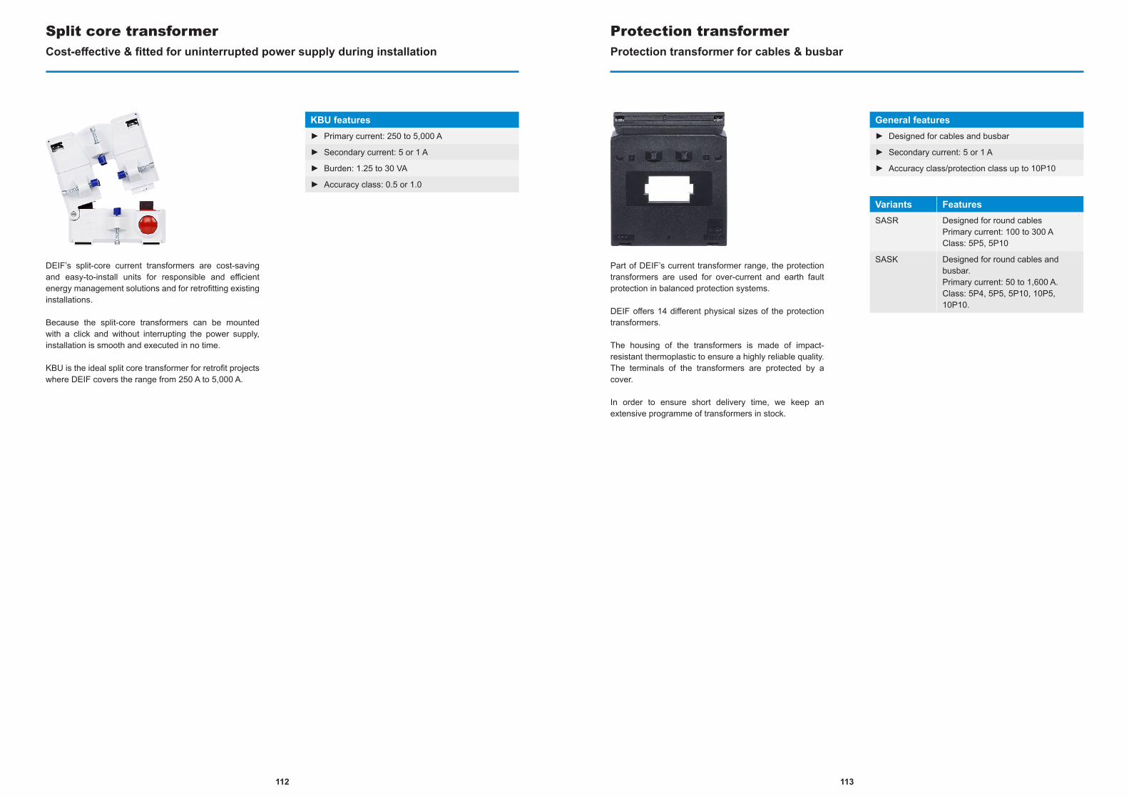
DEIF’s split-core current transformers are cost-saving and easy-to-install units for responsible and efficient energy management solutions and for retrofitting existing installations.
Because the split-core transformers can be mounted with a click and without interrupting the power supply, installation is smooth and executed in no time.
KBU is the ideal split core transformer for retrofit projects where DEIF covers the range from 250 A to 5,000 A.
Split core transformerCost-effective & fitted for uninterrupted power supply during installation
KBU features► Primary current: 250 to 5,000 A
► Secondary current: 5 or 1 A
► Burden: 1.25 to 30 VA
► Accuracy class: 0.5 or 1.0
Part of DEIF’s current transformer range, the protection transformers are used for over-current and earth fault protection in balanced protection systems.
DEIF offers 14 different physical sizes of the protection transformers.
The housing of the transformers is made of impact-resistant thermoplastic to ensure a highly reliable quality. The terminals of the transformers are protected by a cover.
In order to ensure short delivery time, we keep an extensive programme of transformers in stock.
Protection transformerProtection transformer for cables & busbar
General features► Designed for cables and busbar
► Secondary current: 5 or 1 A
► Accuracy class/protection class up to 10P10
Variants FeaturesSASR Designed for round cables
Primary current: 100 to 300 AClass: 5P5, 5P10
SASK Designed for round cables and busbar.Primary current: 50 to 1,600 A.Class: 5P4, 5P5, 5P10, 10P5, 10P10.
113112
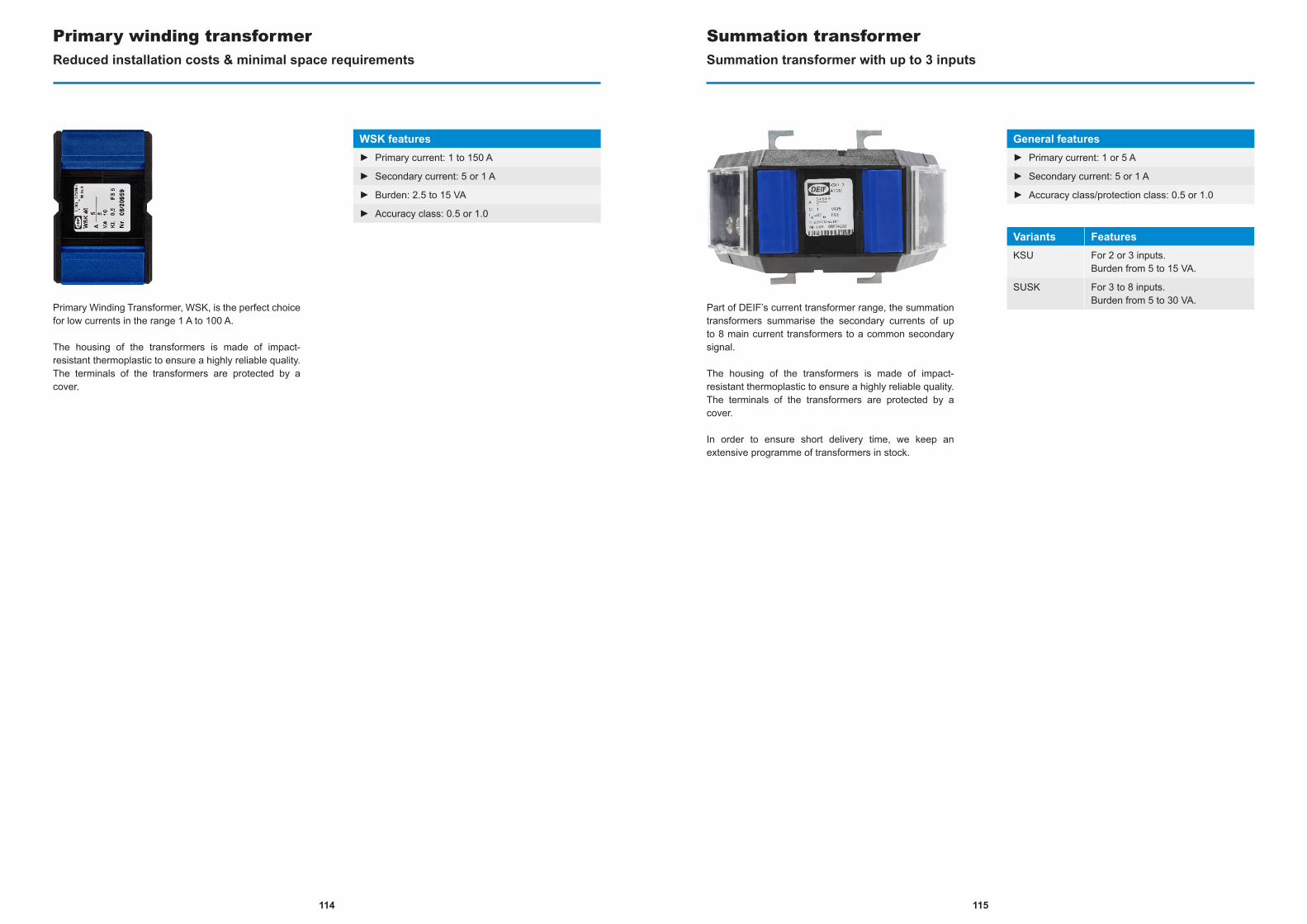
Primary Winding Transformer, WSK, is the perfect choice for low currents in the range 1 A to 100 A.
The housing of the transformers is made of impact-resistant thermoplastic to ensure a highly reliable quality. The terminals of the transformers are protected by a cover.
Primary winding transformerReduced installation costs & minimal space requirements
WSK features► Primary current: 1 to 150 A
► Secondary current: 5 or 1 A
► Burden: 2.5 to 15 VA
► Accuracy class: 0.5 or 1.0
Part of DEIF’s current transformer range, the summation transformers summarise the secondary currents of up to 8 main current transformers to a common secondary signal.
The housing of the transformers is made of impact-resistant thermoplastic to ensure a highly reliable quality. The terminals of the transformers are protected by a cover.
In order to ensure short delivery time, we keep an extensive programme of transformers in stock.
Summation transformerSummation transformer with up to 3 inputs
General features► Primary current: 1 or 5 A
► Secondary current: 5 or 1 A
► Accuracy class/protection class: 0.5 or 1.0
Variants FeaturesKSU For 2 or 3 inputs.
Burden from 5 to 15 VA.
SUSK For 3 to 8 inputs.Burden from 5 to 30 VA.
115114
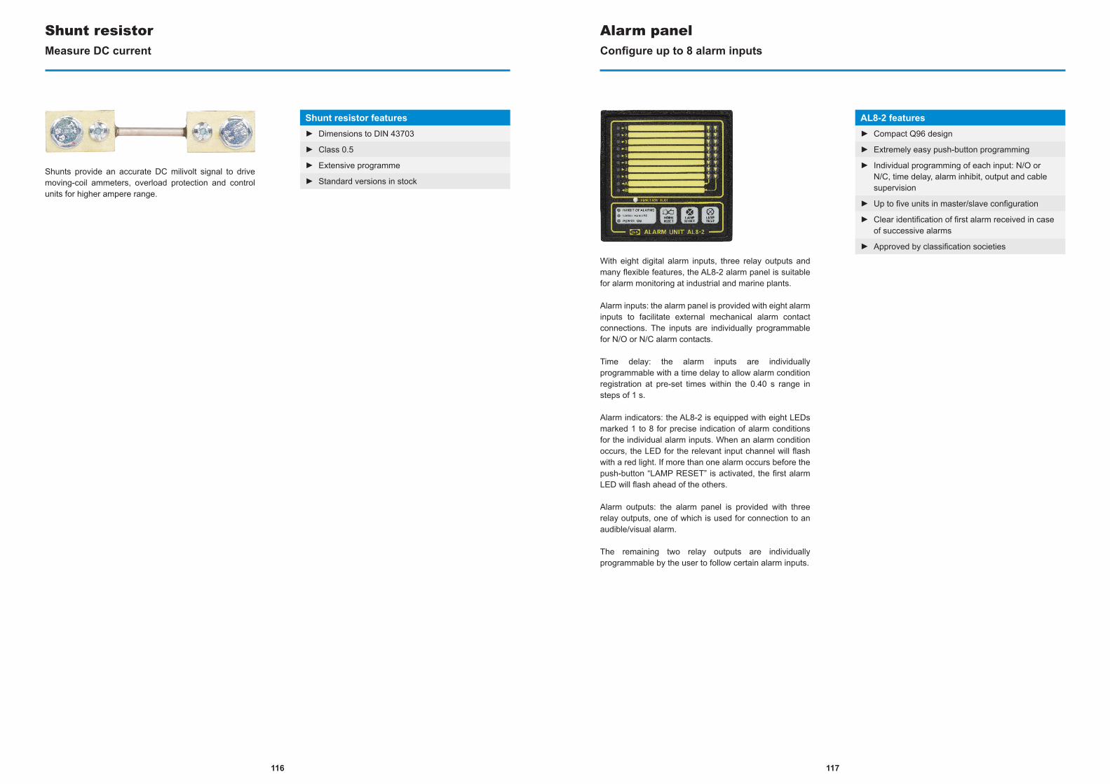
Shunts provide an accurate DC milivolt signal to drive moving-coil ammeters, overload protection and control units for higher ampere range.
Shunt resistorMeasure DC current
Shunt resistor features► Dimensions to DIN 43703
► Class 0.5
► Extensive programme
► Standard versions in stock
With eight digital alarm inputs, three relay outputs and many flexible features, the AL8-2 alarm panel is suitable for alarm monitoring at industrial and marine plants.
Alarm inputs: the alarm panel is provided with eight alarm inputs to facilitate external mechanical alarm contact connections. The inputs are individually programmable for N/O or N/C alarm contacts.
Time delay: the alarm inputs are individually programmable with a time delay to allow alarm condition registration at pre-set times within the 0.40 s range in steps of 1 s.
Alarm indicators: the AL8-2 is equipped with eight LEDs marked 1 to 8 for precise indication of alarm conditions for the individual alarm inputs. When an alarm condition occurs, the LED for the relevant input channel will flash with a red light. If more than one alarm occurs before the push-button “LAMP RESET” is activated, the first alarm LED will flash ahead of the others.
Alarm outputs: the alarm panel is provided with three relay outputs, one of which is used for connection to an audible/visual alarm.
The remaining two relay outputs are individually programmable by the user to follow certain alarm inputs.
Alarm panelConfigure up to 8 alarm inputs
AL8-2 features► Compact Q96 design
► Extremely easy push-button programming
► Individual programming of each input: N/O or N/C, time delay, alarm inhibit, output and cable supervision
► Up to five units in master/slave configuration
► Clear identification of first alarm received in case of successive alarms
► Approved by classification societies
117116
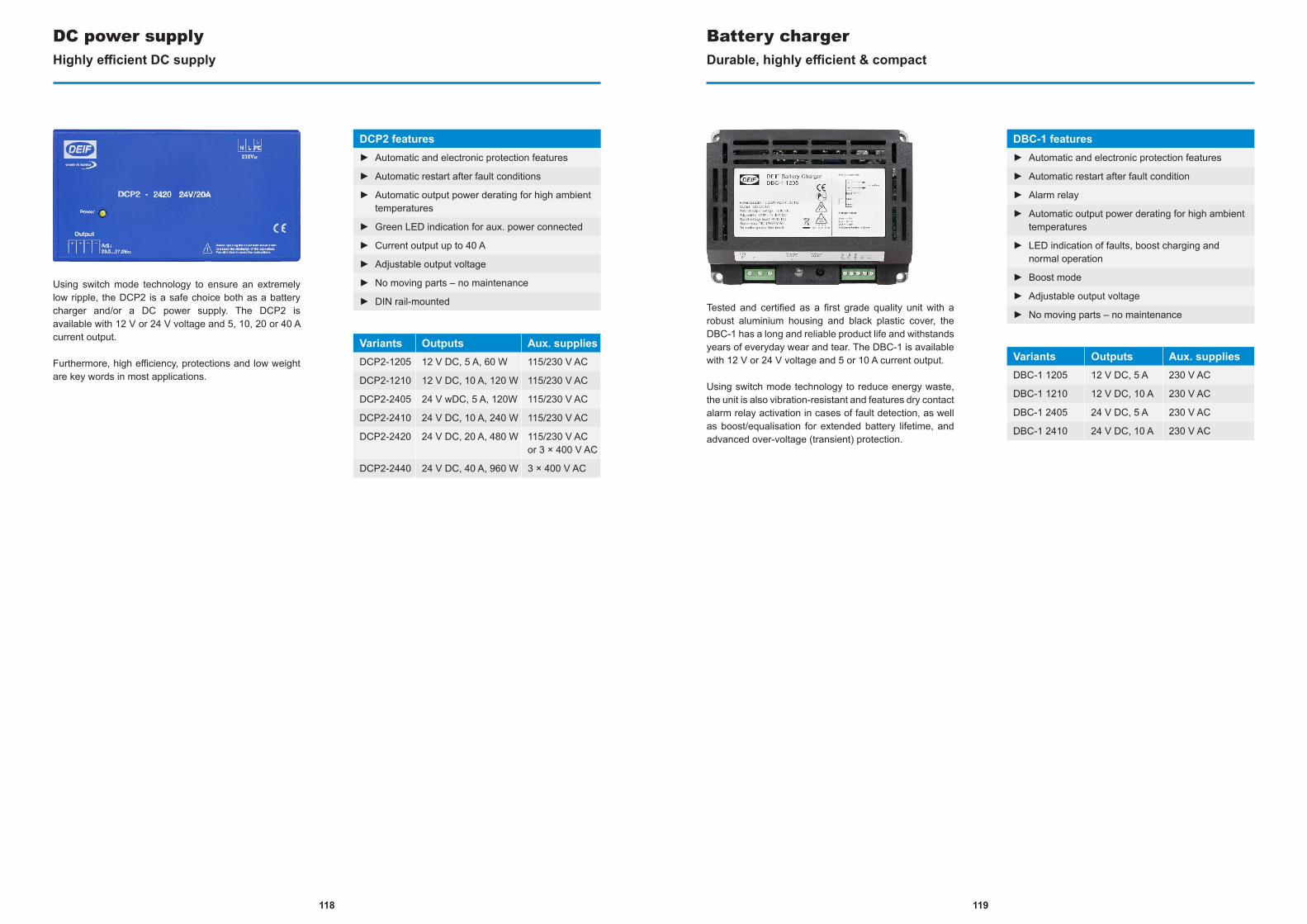
Using switch mode technology to ensure an extremely low ripple, the DCP2 is a safe choice both as a battery charger and/or a DC power supply. The DCP2 is available with 12 V or 24 V voltage and 5, 10, 20 or 40 A current output.
Furthermore, high efficiency, protections and low weight are key words in most applications.
DC power supplyHighly efficient DC supply
DCP2 features► Automatic and electronic protection features
► Automatic restart after fault conditions
► Automatic output power derating for high ambient temperatures
► Green LED indication for aux. power connected
► Current output up to 40 A
► Adjustable output voltage
► No moving parts – no maintenance
► DIN rail-mounted
Variants Outputs Aux. suppliesDCP2-1205 12 V DC, 5 A, 60 W 115/230 V AC
DCP2-1210 12 V DC, 10 A, 120 W 115/230 V AC
DCP2-2405 24 V wDC, 5 A, 120W 115/230 V AC
DCP2-2410 24 V DC, 10 A, 240 W 115/230 V AC
DCP2-2420 24 V DC, 20 A, 480 W 115/230 V AC or 3 × 400 V AC
DCP2-2440 24 V DC, 40 A, 960 W 3 × 400 V AC
Tested and certified as a first grade quality unit with a robust aluminium housing and black plastic cover, the DBC-1 has a long and reliable product life and withstands years of everyday wear and tear. The DBC-1 is available with 12 V or 24 V voltage and 5 or 10 A current output.
Using switch mode technology to reduce energy waste, the unit is also vibration-resistant and features dry contact alarm relay activation in cases of fault detection, as well as boost/equalisation for extended battery lifetime, and advanced over-voltage (transient) protection.
Battery chargerDurable, highly efficient & compact
DBC-1 features► Automatic and electronic protection features
► Automatic restart after fault condition
► Alarm relay
► Automatic output power derating for high ambient temperatures
► LED indication of faults, boost charging and normal operation
► Boost mode
► Adjustable output voltage
► No moving parts – no maintenance
Variants Outputs Aux. suppliesDBC-1 1205 12 V DC, 5 A 230 V AC
DBC-1 1210 12 V DC, 10 A 230 V AC
DBC-1 2405 24 V DC, 5 A 230 V AC
DBC-1 2410 24 V DC, 10 A 230 V AC
119118
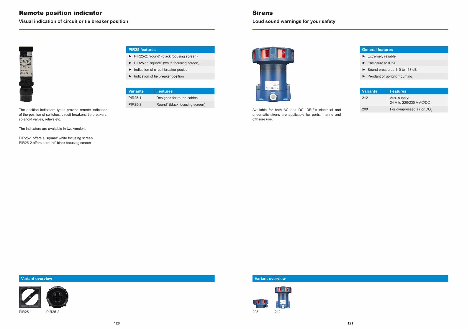
The position indicators types provide remote indication of the position of switches, circuit breakers, tie breakers, solenoid valves, relays etc.
The indicators are available in two versions:
PIR25-1 offers a ‘square' white focusing screenPIR25-2 offers a ‘round' black focusing screen
Remote position indicatorVisual indication of circuit or tie breaker position
PIR25 features► PIR25-2: ”round” (black focusing screen)
► PIR25-1: ”square” (white focusing screen)
► Indication of circuit breaker position
► Indication of tie breaker position
Variants FeaturesPIR25-1 Designed for round cables
PIR25-2 Round” (black focusing screen)
Variant overview
PIR25-1 PIR25-2
Available for both AC and DC, DEIF’s electrical and pneumatic sirens are applicable for ports, marine and offhsore use.
SirensLoud sound warnings for your safety
General features► Extremely reliable
► Enclosure to IP54
► Sound pressures 110 to 118 dB
► Pendant or upright mounting
Variants Features212 Aux. supply:
24 V to 220/230 V AC/DC
208 For compressed air or CO2
Variant overview
208 212
121120
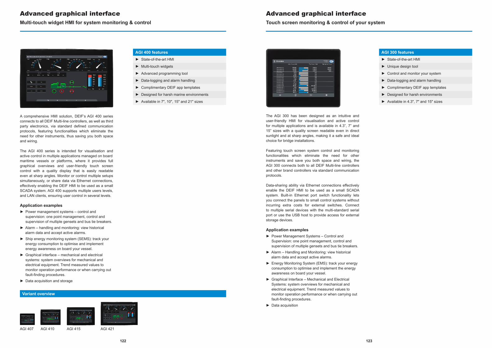
122
AGI 400 features► State-of-the-art HMI
► Multi-touch widgets
► Advanced programming tool
► Data-logging and alarm handling
► Complimentary DEIF app templates
► Designed for harsh marine environments
► Available in 7", 10", 15" and 21" sizes
A comprehensive HMI solution, DEIF’s AGI 400 series connects to all DEIF Multi-line controllers, as well as third party electronics, via standard defined communication protocols, featuring functionalities which eliminate the need for other instruments, thus saving you both space and wiring.
The AGI 400 series is intended for visualisation and active control in multiple applications managed on boardmaritime vessels or platforms, where it provides full graphical overviews and user-friendly touch screen control with a quality display that is easily readable even at sharp angles. Monitor or control multiple setups simultaneously, or share data via Ethernet connections, effectively enabling the DEIF HMI to be used as a small SCADA system. AGI 400 supports multiple users levels, and LAN clients, ensuring user control in several levels.
Application examples► Power management systems – control and
supervision: one point management, control and supervision of multiple gensets and bus tie breakers.
► Alarm – handling and monitoring: view historical alarm data and accept active alarms.
► Ship energy monitoring system (SEMS): track your energy consumption to optimise and implement energy awareness on board your vessel.
► Graphical interface – mechanical and electrical systems: system overviews for mechanical and electrical equipment. Trend measured values to monitor operation performance or when carrying out fault-finding procedures.
► Data acquisition and storage
Advanced graphical interfaceMulti-touch widget HMI for system monitoring & control
AGI 300 features► State-of-the-art HMI
► Unique design tool
► Control and monitor your system
► Data-logging and alarm handling
► Complimentary DEIF app templates
► Designed for harsh environments
► Available in 4.3", 7" and 15" sizes
The AGI 300 has been designed as an intuitive and user-friendly HMI for visualisation and active control for multiple applications and is available in 4.3”, 7” and 15” sizes with a quality screen readable even in direct sunlight and at sharp angles, making it a safe and ideal choice for bridge installations.
Featuring touch screen system control and monitoring functionalities which eliminate the need for other instruments and save you both space and wiring, the AGI 300 connects both to all DEIF Multi-line controllers and other brand controllers via standard communication protocols.
Data-sharing ability via Ethernet connections effectively enable the DEIF HMI to be used as a small SCADA system. Built-in Ethernet port switch functionality lets you connect the panels to small control systems without incurring extra costs for external switches. Connect to multiple serial devices with the multi-standard serial port or use the USB host to provide access for external storage devices.
Application examples► Power Management Systems – Control and
Supervision: one point management, control and supervision of multiple gensets and bus tie breakers.
► Alarm – Handling and Monitoring: view historical alarm data and accept active alarms.
► Energy Monitoring System (EMS): track your energy consumption to optimise and implement the energy awareness on board your vessel.
► Graphical Interface – Mechanical and Electrical Systems: system overviews for mechanical and electrical equipment. Trend measured values to monitor operation performance or when carrying out fault-finding procedures.
► Data acquisition
Advanced graphical interfaceTouch screen monitoring & control of your system
AGI 407 AGI 410 AGI 415 AGI 421
Variant overview
123
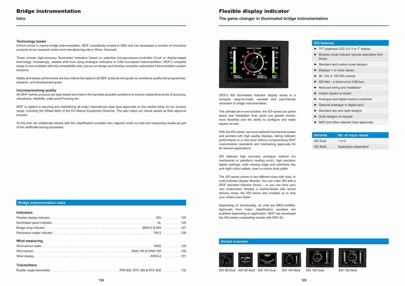
124
Technology leaderA front-runner in marine bridge instrumentation, DEIF consistently invests in R&D and has developed a number of innovative products at our research centre and manufacturing site in Skive, Denmark.
These include high-accuracy illuminated indicators based on patented microprocessor-controlled X-coil or display-based technology. Increasingly, vessels shift from using analogue indicators to CAN bus-based instrumentation. DEIF’s complete range is now available with this compatibility also, just as we design and develop complete customised instrumentation system solutions.
Safety and steady performance are key criteria that apply to all DEIF products and guide our ambitious quality test programmes, research, and development goals.
Uncompromising qualityAll DEIF marine products are type-tested and tried in the harshest possible conditions to ensure outstanding levels of accuracy, robustness, reliability, water-proof housing etc.
DEIF is vigilant in securing and maintaining all major international class type approvals on the market today for our product range, including the Wheel Mark of the EU Marine Equipment Directive. This also helps our clients speed up their approval process.
To this end, we collaborate closely with the classification societies who regularly audit our test and measuring results as part of the certificate-issuing processes.
Bridge instrumentation index
IndicatorsFlexible display indicator. . . . . . . . . . . . . . . . . . . . . . . . . . . . . . . . . . . . . . . . . . . . . . . . . . . . . . . . . . . . . . . . . . . . . . . . . . . . . . . . . . . . . . . . . . . . . .XDi . . . . . . . . . . . . . . . . .125Illuminated panel indicator. . . . . . . . . . . . . . . . . . . . . . . . . . . . . . . . . . . . . . . . . . . . . . . . . . . . . . . . . . . . . . . . . . . . . . . . . . . . . . . . . . . . . . . . . . . . .XL . . . . . . . . . . . . . . . . .126Bridge wing indicator . . . . . . . . . . . . . . . . . . . . . . . . . . . . . . . . . . . . . . . . . . . . . . . . . . . . . . . . . . . . . . . . . . . . . . . . . . . . . . . . . . . . . .BRW-2 & BW . . . . . . . . . . . . . . . . .127Panorama rudder indicator . . . . . . . . . . . . . . . . . . . . . . . . . . . . . . . . . . . . . . . . . . . . . . . . . . . . . . . . . . . . . . . . . . . . . . . . . . . . . . . . . . . . . . . . TRI-2 . . . . . . . . . . . . . . . . .128
Wind measuringWind sensor static . . . . . . . . . . . . . . . . . . . . . . . . . . . . . . . . . . . . . . . . . . . . . . . . . . . . . . . . . . . . . . . . . . . . . . . . . . . . . . . . . . . . . . . . . . . . . . . . . . . WSS . . . . . . . . . . . . . . . . .129Wind sensor . . . . . . . . . . . . . . . . . . . . . . . . . . . . . . . . . . . . . . . . . . . . . . . . . . . . . . . . . . . . . . . . . . . . . . . . . . . . . . . . . . . . . .WSS 700 & WSS 750 . . . . . . . . . . . . . . . . .130Wind display. . . . . . . . . . . . . . . . . . . . . . . . . . . . . . . . . . . . . . . . . . . . . . . . . . . . . . . . . . . . . . . . . . . . . . . . . . . . . . . . . . . . . . . . . . . . . . . . . . . . . . .WSDI-2 . . . . . . . . . . . . . . . . .131
TransmittersRudder angle transmitter . . . . . . . . . . . . . . . . . . . . . . . . . . . . . . . . . . . . . . . . . . . . . . . . . . . . . . . . . . . . .RTA 602, RTC 300 & RTC 600 . . . . . . . . . . . . . . . . .132
Bridge instrumentationIntro
Variant overview
XDI 96 Dual XDI 96 Multi XDI 144 Dual XDI 144 Multi XDI 192 Dual XDI 192 Multi
DEIF’s XDi illuminated indicator display series is a compact, easy-to-install, versatile and user-friendly revolution in bridge instrumentation.
The ultimate all-in-one solution, the XDi saves you panel space and installation time, gives you greater choice, more flexibility and the ability to configure and make repairs on-site.
With the XDi series, we have replaced mechanical scales and pointers with high quality displays, taking indicator performance to a new level without compromising DEIF customisation standards and maintaining approvals for all relevant applications.
XDi features high accuracy analogue readout (no mechanical or parallax’s reading error), high precision digital readings, wide viewing angle and optimised day and night colour pallets, even a custom dusk pallet.
The XDi series comes in two different sizes with dual- or multi-indicator display libraries. You can order XDi with a DEIF standard indicator library – or you can have your own customised. Already a market-leader with record delivery times, the XDi series also enables us to ship your orders even faster.
Depending on functionality, all units are MED-certified. Approvals from major classification societies are available depending on application. DEIF has developed the XDi series cooperating closely with DNV GL.
Flexible display indicatorThe game changer in illuminated bridge instrumentation
XDi features► TFT graphical LED 3.5, 5 or 7" display
► Multiple virtual indicator layouts selectable from library
► Standard and custom scale designs
► Displays 1 or more values
► 96, 144 or 192 DIN cutouts
► XDi-Net – a short-cut to CAN bus
► Reduced wiring and installation
► Instant repairs on board
► Analogue and digital readout combined
► Optional analogue or digital input
► Standard day and night designs
► Dusk designs on request
► MED and other relevant class approvals
Variants No. of input valuesXDi Dual 1 or 2
XDi Multi Application-dependent
125

Patented range of illuminated panel indicators designed to indicate e.g. rpm, pitch and rudder angle. These indicators are based on microprocessor-controlled X-coil technology.
XL scale designsDEIF stocks a wide range of recommended standard scale designs, including scale designs for rpm, pitch, rudder, rate-of-turn and azimuth.
The range has been designed to meet international standards for optimal readability and precision – seewww.deif.com for the current list.
DEIF can also handle customised scale designs, adding logos/text or create a new visual layout to identifyyour brand.
Illuminated panel indicatorDigital accuracy, analogue readability
XL features► High shock/vibration resistance (robust)
► Class 0.5 accuracy
► 360 ° deflection
► Analogue or dual CANopen interface
► Optional IP66 protection
► LED illumination
► Q72, Q96, Q144 and Q192 scale sizes
Variant overview
XL
Patented range of illuminated bridge wing indicators designed to indicate e.g. rpm, pitch and rudder angle. These indicators are based on microprocessor-controlled X-coil technology.
BRW-2 and BW scale designsDEIF stocks a wide range of recommended standard scale designs, including scale designs for rpm, pitch, rudder, rate-of-turn and azimuth.
The range has been designed to meet international standards for optimal readability and precision – seewww.deif.com for the current list.
DEIF can also handle customised scale designs, adding logos/text or create a new visual layout to identifyyour brand.
Bridge wing indicatorDigital accuracy, analogue readability
General features► High shock/vibration resistance (robust)
► Class 0.5 accuracy
► 360 ° deflection
► Analogue or dual CANopen interface
► IP66 protection
► LED illumination
Variants FeaturesBRW-2 Outdoor bridge wing mounting.
Front-mounted dimmer.
BW Indoor and outdoor bridge wing mounting, hanging or standing on pivot foot.Rear-mounted dimmer.
Variant overview
BRW-2 BW
127126
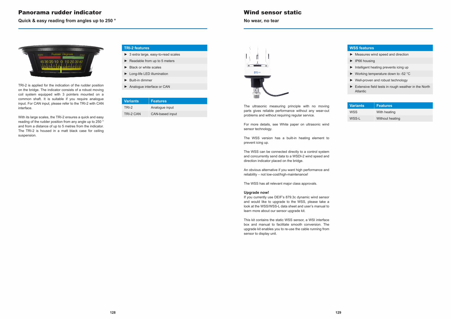
TRI-2 is applied for the indication of the rudder position on the bridge. The indicator consists of a robust moving coil system equipped with 3 pointers mounted on a common shaft. It is suitable if you require analogue input. For CAN input, please refer to the TRI-2 with CAN interface.
With its large scales, the TRI-2 ensures a quick and easy reading of the rudder position from any angle up to 250 ° and from a distance of up to 5 metres from the indicator. The TRI-2 is housed in a matt black case for ceiling suspension.
Panorama rudder indicatorQuick & easy reading from angles up to 250 °
TRI-2 features► 3 extra large, easy-to-read scales
► Readable from up to 5 meters
► Black or white scales
► Long-life LED illumination
► Built-in dimmer
► Analogue interface or CAN
Variants FeaturesTRI-2 Analogue input
TRI-2 CAN CAN-based input
The ultrasonic measuring principle with no moving parts gives reliable performance without any wear-out problems and without requiring regular service.
For more details, see White paper on ultrasonic wind sensor technology.
The WSS version has a built-in heating element to prevent icing up.
The WSS can be connected directly to a control system and concurrently send data to a WSDI-2 wind speed and direction indicator placed on the bridge.
An obvious alternative if you want high performance and reliability – not low-cost/high-maintenance!
The WSS has all relevant major class approvals.
Upgrade now!If you currently use DEIF’s 879.3c dynamic wind sensor and would like to upgrade to the WSS, please take a look at the WSS/WSS-L data sheet and user’s manual to learn more about our sensor upgrade kit.
This kit contains the static WSS sensor, a WSI interface box and manual to facilitate smooth conversion. The upgrade kit enables you to re-use the cable running from sensor to display unit.
Wind sensor staticNo wear, no tear
WSS features► Measures wind speed and direction
► IP66 housing
► Intelligent heating prevents icing up
► Working temperature down to -52 °C
► Well-proven and robust technology
► Extensive field tests in rough weather in the North Atlantic
Variants FeaturesWSS With heating
WSS-L Without heating
129128
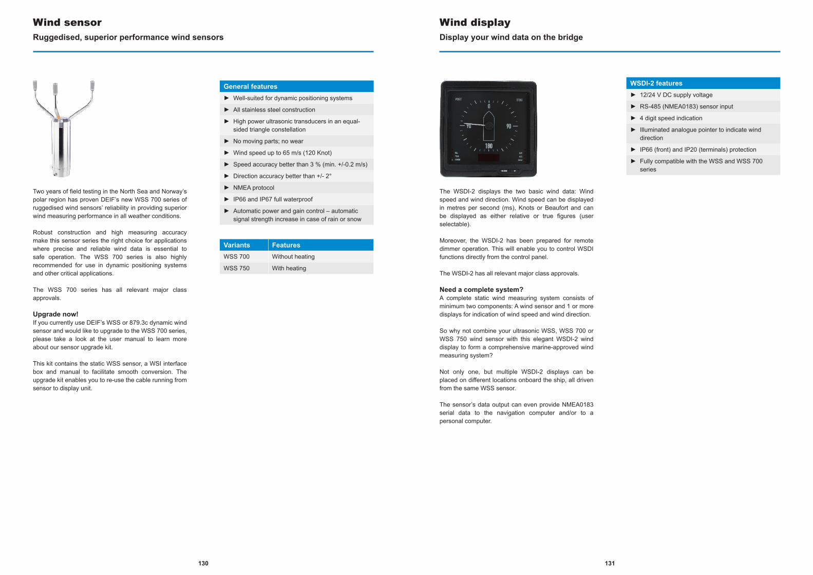
Two years of field testing in the North Sea and Norway’s polar region has proven DEIF’s new WSS 700 series of ruggedised wind sensors’ reliability in providing superior wind measuring performance in all weather conditions.
Robust construction and high measuring accuracy make this sensor series the right choice for applications where precise and reliable wind data is essential to safe operation. The WSS 700 series is also highly recommended for use in dynamic positioning systems and other critical applications.
The WSS 700 series has all relevant major class approvals.
Upgrade now!If you currently use DEIF’s WSS or 879.3c dynamic wind sensor and would like to upgrade to the WSS 700 series, please take a look at the user manual to learn more about our sensor upgrade kit.
This kit contains the static WSS sensor, a WSI interface box and manual to facilitate smooth conversion. The upgrade kit enables you to re-use the cable running from sensor to display unit.
Wind sensorRuggedised, superior performance wind sensors
General features► Well-suited for dynamic positioning systems
► All stainless steel construction
► High power ultrasonic transducers in an equal-sided triangle constellation
► No moving parts; no wear
► Wind speed up to 65 m/s (120 Knot)
► Speed accuracy better than 3 % (min. +/-0.2 m/s)
► Direction accuracy better than +/- 2°
► NMEA protocol
► IP66 and IP67 full waterproof
► Automatic power and gain control – automatic signal strength increase in case of rain or snow
Variants FeaturesWSS 700 Without heating
WSS 750 With heating
The WSDI-2 displays the two basic wind data: Wind speed and wind direction. Wind speed can be displayed in metres per second (ms), Knots or Beaufort and can be displayed as either relative or true figures (user selectable).
Moreover, the WSDI-2 has been prepared for remote dimmer operation. This will enable you to control WSDI functions directly from the control panel.
The WSDI-2 has all relevant major class approvals.
Need a complete system?A complete static wind measuring system consists of minimum two components: A wind sensor and 1 or more displays for indication of wind speed and wind direction.
So why not combine your ultrasonic WSS, WSS 700 or WSS 750 wind sensor with this elegant WSDI-2 wind display to form a comprehensive marine-approved wind measuring system?
Not only one, but multiple WSDI-2 displays can be placed on different locations onboard the ship, all driven from the same WSS sensor.
The sensor’s data output can even provide NMEA0183 serial data to the navigation computer and/or to a personal computer.
Wind displayDisplay your wind data on the bridge
WSDI-2 features► 12/24 V DC supply voltage
► RS-485 (NMEA0183) sensor input
► 4 digit speed indication
► Illuminated analogue pointer to indicate wind direction
► IP66 (front) and IP20 (terminals) protection
► Fully compatible with the WSS and WSS 700 series
131130
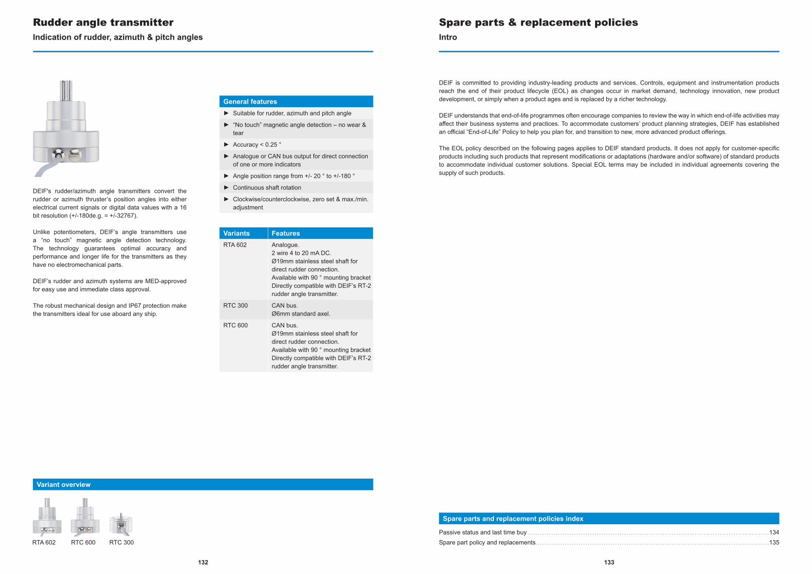
133
DEIF's rudder/azimuth angle transmitters convert the rudder or azimuth thruster’s position angles into either electrical current signals or digital data values with a 16 bit resolution (+/-180de.g. = +/-32767).
Unlike potentiometers, DEIF’s angle transmitters use a “no touch” magnetic angle detection technology. The technology guarantees optimal accuracy and performance and longer life for the transmitters as they have no electromechanical parts.
DEIF’s rudder and azimuth systems are MED-approved for easy use and immediate class approval.
The robust mechanical design and IP67 protection make the transmitters ideal for use aboard any ship.
Rudder angle transmitterIndication of rudder, azimuth & pitch angles
General features► Suitable for rudder, azimuth and pitch angle
► “No touch” magnetic angle detection – no wear & tear
► Accuracy < 0.25 °
► Analogue or CAN bus output for direct connection of one or more indicators
► Angle position range from +/- 20 ° to +/-180 °
► Continuous shaft rotation
► Clockwise/counterclockwise, zero set & max./min. adjustment
Variants FeaturesRTA 602 Analogue.
2 wire 4 to 20 mA DC.Ø19mm stainless steel shaft for direct rudder connection.Available with 90 ° mounting bracketDirectly compatible with DEIF’s RT-2 rudder angle transmitter.
RTC 300 CAN bus.Ø6mm standard axel.
RTC 600 CAN bus.Ø19mm stainless steel shaft for direct rudder connection.Available with 90 ° mounting bracketDirectly compatible with DEIF’s RT-2 rudder angle transmitter.
Variant overview
RTC 600 RTC 300RTA 602
DEIF is committed to providing industry-leading products and services. Controls, equipment and instrumentation products reach the end of their product lifecycle (EOL) as changes occur in market demand, technology innovation, new product development, or simply when a product ages and is replaced by a richer technology.
DEIF understands that end-of-life programmes often encourage companies to review the way in which end-of-life activities may affect their business systems and practices. To accommodate customers’ product planning strategies, DEIF has established an official “End-of-Life” Policy to help you plan for, and transition to new, more advanced product offerings.
The EOL policy described on the following pages applies to DEIF standard products. It does not apply for customer-specific products including such products that represent modifications or adaptations (hardware and/or software) of standard products to accommodate individual customer solutions. Special EOL terms may be included in individual agreements covering the supply of such products.
Spare parts and replacement policies index
Passive status and last time buy . . . . . . . . . . . . . . . . . . . . . . . . . . . . . . . . . . . . . . . . . . . . . . . . . . . . . . . . . . . . . . . . . . . . . . . . . . . . . . . . . . . . . . . . . . . . . . . . . . . . . . . . . .134Spare part policy and replacements. . . . . . . . . . . . . . . . . . . . . . . . . . . . . . . . . . . . . . . . . . . . . . . . . . . . . . . . . . . . . . . . . . . . . . . . . . . . . . . . . . . . . . . . . . . . . . . . . . . . . . .135
Spare parts & replacement policiesIntro
132
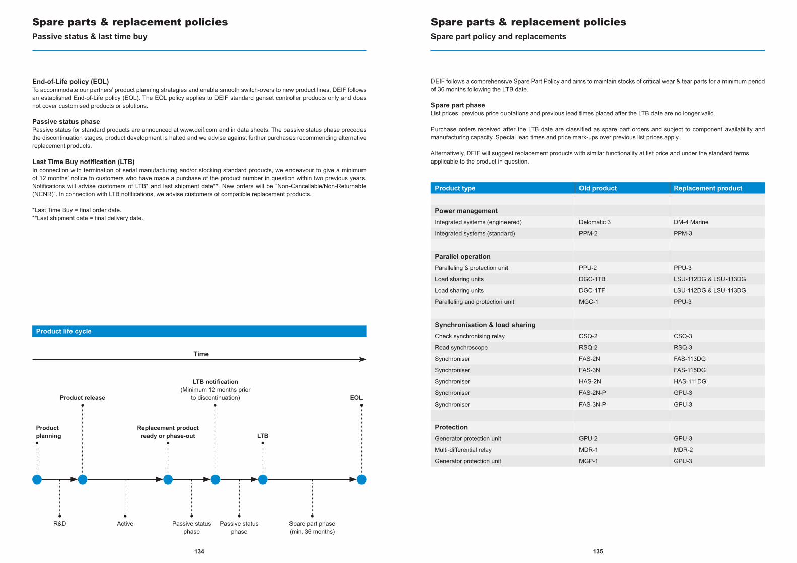
135134
End-of-Life policy (EOL)To accommodate our partners’ product planning strategies and enable smooth switch-overs to new product lines, DEIF follows an established End-of-Life policy (EOL). The EOL policy applies to DEIF standard genset controller products only and does not cover customised products or solutions.
Passive status phasePassive status for standard products are announced at www.deif.com and in data sheets. The passive status phase precedes the discontinuation stages, product development is halted and we advise against further purchases recommending alternative replacement products.
Last Time Buy notification (LTB)In connection with termination of serial manufacturing and/or stocking standard products, we endeavour to give a minimum of 12 months’ notice to customers who have made a purchase of the product number in question within two previous years. Notifications will advise customers of LTB* and last shipment date**. New orders will be “Non-Cancellable/Non-Returnable (NCNR)”. In connection with LTB notifications, we advise customers of compatible replacement products.
*Last Time Buy = final order date.**Last shipment date = final delivery date.
Passive status & last time buy
Product life cycle
Spare parts & replacement policies
Time
Product planning
Product release
Replacement product ready or phase-out LTB
LTB notification(Minimum 12 months prior
to discontinuation) EOL
R&D Active Passive status phase
Passive status phase
Spare part phase(min. 36 months)
Spare part policy and replacements
DEIF follows a comprehensive Spare Part Policy and aims to maintain stocks of critical wear & tear parts for a minimum period of 36 months following the LTB date.
Spare part phaseList prices, previous price quotations and previous lead times placed after the LTB date are no longer valid.
Purchase orders received after the LTB date are classified as spare part orders and subject to component availability and manufacturing capacity. Special lead times and price mark-ups over previous list prices apply.
Alternatively, DEIF will suggest replacement products with similar functionality at list price and under the standard terms applicable to the product in question.
Product type Old product Replacement product
Power management Integrated systems (engineered) Delomatic 3 DM-4 Marine
Integrated systems (standard) PPM-2 PPM-3
Parallel operationParalleling & protection unit PPU-2 PPU-3
Load sharing units DGC-1TB LSU-112DG & LSU-113DG
Load sharing units DGC-1TF LSU-112DG & LSU-113DG
Paralleling and protection unit MGC-1 PPU-3
Synchronisation & load sharingCheck synchronising relay CSQ-2 CSQ-3
Read synchroscope RSQ-2 RSQ-3
Synchroniser FAS-2N FAS-113DG
Synchroniser FAS-3N FAS-115DG
Synchroniser HAS-2N HAS-111DG
Synchroniser FAS-2N-P GPU-3
Synchroniser FAS-3N-P GPU-3
ProtectionGenerator protection unit GPU-2 GPU-3
Multi-differential relay MDR-1 MDR-2
Generator protection unit MGP-1 GPU-3
Spare parts & replacement policies
137136
ReplacementsSpare parts & replacement policies
Product Type Old Product Replacement Product
Bridge instrumentationWind measuring system 879.3C WSS
Bridge wing indicator BRW-1 BRW-2
Illuminated marine bridge instrument DLQ XL series
Illuminated 360 ° azimuth Indicators DLQA XL series
Watertight marine instruments with illumination DLQW XL series
Rudder transmitter RT-1 RTA 602 & RTC 600
Rudder angle transmitter RT-2 RTA 602 & RTC 600
Rudder angle indicator TRI-1 TRI-2
Bridge wing indicator VTR-5 BW
Bridge wing indicator VTR-3 BW
Indicator WSDI (879.50) WSDI-2
Indicator WSDI (879.521) WSDI-2
Switchboard equipmentElectronic potentiometers EPQ96 EPQ96-2
Insulation monitoring DIM-Q SIM-Q
Running hours counter HCQ48 HC 48
Multi transducer MTR-1 MTR-3
Multi transducer MTR-2 MTR-3
Watt transducer TAP-210DG TAS-331DG
Watt transducer TAQ-210DG TAS-331DG
Dual output power transducer TAX-312DG-1 TAS-331DG
Mains frequency transducers TMF-210DG TAS-311DG
Multi-instrument MIQ96 MIC-2 MKII
Multi-instrument MIQ96-2 MIC-2 MKII
Multi-instrument MIQ96-3 MIC-2 MKII
Advanced graphical interface AGI 100 AGI 300
The corporate values & services that make DEIF the best choiceWhy DEIF
Why DEIF index
Find – Win – Secure. . . . . . . . . . . . . . . . . . . . . . . . . . . . . . . . . . . . . . . . . . . . . . . . . . . . . . . . . . . . . . . . . . . . . . . . . . . . . . . . . . . . . . . . . . . . . . . . . . . . . . . . . . . . . . . . . . . . . . . . .138Corporate social responsibility . . . . . . . . . . . . . . . . . . . . . . . . . . . . . . . . . . . . . . . . . . . . . . . . . . . . . . . . . . . . . . . . . . . . . . . . . . . . . . . . . . . . . . . . . . . . . . . . . . . . . . . . . . . . .142Code of conduct . . . . . . . . . . . . . . . . . . . . . . . . . . . . . . . . . . . . . . . . . . . . . . . . . . . . . . . . . . . . . . . . . . . . . . . . . . . . . . . . . . . . . . . . . . . . . . . . . . . . . . . . . . . . . . . . . . . . . . . . . . . . .144Land Power. . . . . . . . . . . . . . . . . . . . . . . . . . . . . . . . . . . . . . . . . . . . . . . . . . . . . . . . . . . . . . . . . . . . . . . . . . . . . . . . . . . . . . . . . . . . . . . . . . . . . . . . . . . . . . . . . . . . . . . . . . . . . . . . . . .146Wind Power . . . . . . . . . . . . . . . . . . . . . . . . . . . . . . . . . . . . . . . . . . . . . . . . . . . . . . . . . . . . . . . . . . . . . . . . . . . . . . . . . . . . . . . . . . . . . . . . . . . . . . . . . . . . . . . . . . . . . . . . . . . . . . . . . .148Eight decades of achievement . . . . . . . . . . . . . . . . . . . . . . . . . . . . . . . . . . . . . . . . . . . . . . . . . . . . . . . . . . . . . . . . . . . . . . . . . . . . . . . . . . . . . . . . . . . . . . . . . . . . . . . . . . . . .150Contact information. . . . . . . . . . . . . . . . . . . . . . . . . . . . . . . . . . . . . . . . . . . . . . . . . . . . . . . . . . . . . . . . . . . . . . . . . . . . . . . . . . . . . . . . . . . . . . . . . . . . . . . . . . . . . . . . . . . . . . . . . .152
VISION
Our vision is to be the preferred global supplier of green, safe and reliable energy control solutions
MISSION
Our mission is to enhance he competitive advantage of our customers.
To achieve this, we:► Identify their needs and wants in detail► Develop high-quality products► Stay logistically efficient► Offer unsurpassed technical service
and support
VALUES
The company culture at DEIF is based on a set of common values. Every employee is encouraged to make the right decisions based on these values – supported by rules and policies when relevant: Ambition, Perspective & Respect
139138
FIND NEW OPPORTUNITIES
DEIF’s business ethic is based on knowledge sharing and informed by environmental awareness. Working with global experience of customer needs across the full range of power management applications, collaborating with DEIF you will find new opportunities.
WIN SUPERIOR CONTROL
20 % of DEIF’s employees work in R&D. Their focus is innovation and progress for the industry as a whole, and in creating customised solutions with end-to-end system integrity. With DEIF, you win superior control thanks to our experience and expertise across multiple industries.
SECURE MAXIMUM UPTIME
Our tried-and-tested equipment, advanced automation technology, training programmes, and 24/7 support will boost your business goals by providing steady, maximum uptime.
LAND POWER MARINE & OFFSHORE WIND POWER
POWERED BY

141140
GREEN AMBITIONEnvironmentally improvedDEIF’s intelligent power management solutions and cleantech products meet growing needs for reliable power while supporting the world’s environmental transition.
► Cut fuel consumption and harmful emissions► Extend maintenance intervals► Increase performance
SALES, TRAINING & COMPETENCE CENTRES IN 17
KEY MARKETS.DISTRIBUTORS IN 35
COUNTRIES AND TERRITORIES
20 % OF DEIF’S 600+ EMPLOYEES
WORK EXCLUSIVELY IN RESEARCH & DEVELOPMENT
DEIF ISISO 9001 AND
ISO 14001 CERTIFIED

142 143 143142
CORPORATESOCIAL RESPONSIBILITY
Powering aid to the third worldJust 2.3 doctors per 1,000 people (33.3 in Europe). And up to 69 % of all citizens living on $ 2 or less a day. Those are the conditions in Sub-Saharan Africa. So, for most, healthcare is not an option, simply because it is physically or financially out of reach. As a result, a large proportion of the 85 % of African children expected to need surgical treatment before the age of 15 remain untreated, leading to complications, lifelong disability or death.
DEIF and Mercy Ships agree that a ship is the most efficient hospital platform in this region where clean water, electricity, medical facilities and personnel is limited or nonexistent. Since more than 50 % of the world’s population live within 100 miles of the coast, we can reach more people who need care too. More impact for less money.
Cooperating with Mercy Ships is one of the ways DEIF offers charity help to the global community by doing what we do best. Delivering our brand promise: Power Efficiency.
When power is the difference between life & death The largest NGO hospital ship in the world with 78 patient beds and an onboard surgical capacity exceeding 7,000 interventions per year, the Africa Mercy depends on 100 % reliable power supply at all times to avoid loss of life.
Having experienced numerous blackouts in recent years, a power management retrofit was required. A charity donation, DEIF installed and commissioned a solution consisting of four genset controllers (PPM 300), one synchroniser (FAS) and one touch screen (AGI 300).
"With the revamped power control solution from DEIF, our surgeons no longer fear blackouts during surgery", Jens-Erik Engelbrecht, CEO & MSDK board member at Mercy Ships happily concludes.
Mercy ShipsMercy Ships is a global charity founded in 1978. Having completed more than 581 port visits in 57 nations, Mercy Ships has performed services valued at more than $1 billion, impacting more than 2.48 million of the world’s most desperate people.
»With the revamped power control solution from DEIF, our surgeons no longer fear blackouts during surgery«
Jens-Erik Engelbrecht CEO & MSDK board member
Mercy Ships

144 145
CODE OF CONDUCTCommitted to working according to the ten principles expressed in the UN Global Compact since 2014, the
overall goal of DEIF is to develop the company’s long-term value, observing high ethical standards in relation
to DEIF employees, business partners, and the global community.
Human rights:1. we support and respect internationally proclaimed human rights2. we ensure that we are not complicit in human rights abuses
Labour rights:3. we uphold the freedom of association and recognise effectively the right to collective bargaining4. we support the elimination of all forms of forced and compulsory labour5. we support the efforts to abolish child labour6. we eliminate discrimination in respect of employment and occupation
Safety & environment:7. we support a precautionary approach to safety and environmental challenges8. we undertake initiatives to promote greater environmental responsibility9. we encourage the development and diffusion of environmentally friendly technologies
Anti-corruption:10. we work against corruption in all its forms, including extortion and bribery

146 147
LAND POWER
Working with EPC, switchboard manufacturers, system integrators/OEMs and asset owners, DEIF LAND POWER identifies new ways to increase performance and efficiency for the IPP, rental, critical power and standby power markets.
Whether we retrofit older installations or design projected setups, DEIF’s innovative solutions can cut fuel costs compared to competitive products.
CHOOSE DEIF LAND POWER TO INCREASE PERFORMANCE & EFFICIENCY
16 grids and 992 generator breakers in one application.See www.deif.com/IPP for more about our award-winning IPP solutions.
Diesel Gas Hybrid Hydro Steam
INDUSTRIES
NO MATCH IN POWER CAPACITY & SCOPE*

148 149
EUROPE’S LARGEST ONSHORE WIND PARK*
See www.deifwindpower.com
WIND POWER
As a renowned supplier of robust components for turbine pitch and control, DEIF Wind Power designs and manufactures complete control systems for both new and existing wind turbines of any size.
Building on years of experience, DEIF’s performance-optimising solutions include wind turbine operation, modeling, control strategies, grid compliance, and pitch and park control systems. Controlling wind park power production accurately and quickly, they will help you produce more green power at the lowest possible cost.
ROBUST SOLUTIONS AND KNOWLEDGE SHARING ARE HALLMARKS OF DEIF WIND POWER.
Onshore Offshore
INDUSTRIES
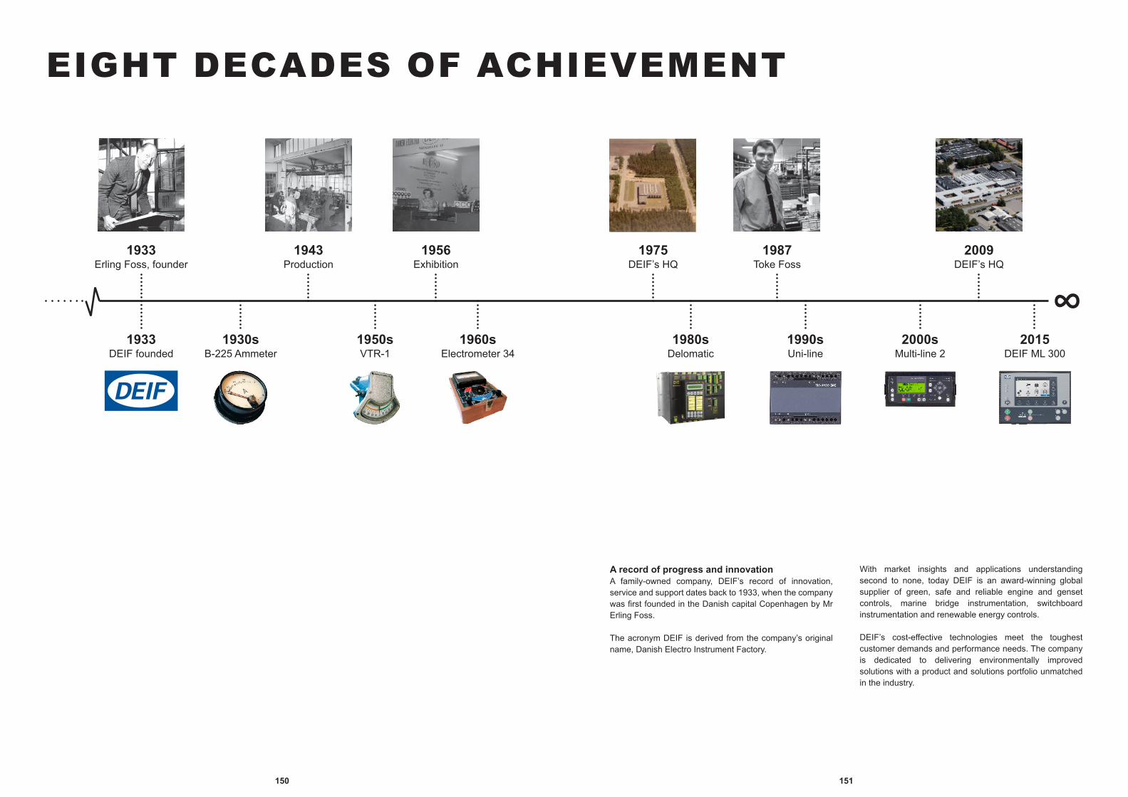
151150
EIGHT DECADES OF ACHIEVEMENT
1933DEIF founded
1933Erling Foss, founder
1943Production
1956Exhibition
1930sB-225 Ammeter
1950sVTR-1
1960sElectrometer 34
2009DEIF’s HQ
1975DEIF’s HQ
1987Toke Foss
2015DEIF ML 300
2000sMulti-line 2
1990sUni-line
1980sDelomatic
A record of progress and innovationA family-owned company, DEIF’s record of innovation, service and support dates back to 1933, when the company was first founded in the Danish capital Copenhagen by Mr Erling Foss.
The acronym DEIF is derived from the company’s original name, Danish Electro Instrument Factory.
With market insights and applications understanding second to none, today DEIF is an award-winning global supplier of green, safe and reliable engine and genset controls, marine bridge instrumentation, switchboard instrumentation and renewable energy controls.
DEIF’s cost-effective technologies meet the toughest customer demands and performance needs. The company is dedicated to delivering environmentally improved solutions with a product and solutions portfolio unmatched in the industry.
153152
Danish Power & Marine, S.A. de C.V.Circonvalación Pte. No. 219, Cd. Satélite, Naucalpan 53100, Mexico City, Edo. de México; México
Contact informationTel.: +52 1 55 6126 3716E-mail: [email protected]
Mexico
DEIF MEDiterraneaWTC 4 – Entrée N, 1300 Route des CrêtesCS 50007 Valbonne, 06901 Sophia Antipolis Cedex. France
Contact informationTel.: +33 (0)4 92 38 05 06E-mail: [email protected]
France
DEIF officesContact information
DEIF do Brasil Comercio de Controles e Equipamentos Ltda.Av. Brasil, 2287, Jardim Chapadão,CEP: 13070-178 Campinas, SP, Brazil
Contact informationTel.: +55 19 3579 4681E-mail: [email protected]
Brazil
DEIF GmbHLilienthalstr. 47,D-64625 Bensheim, Germany
Contact informationTel.: +49 (0) 6251/1756-0E-mail: [email protected]
Germany
DEIF Electrical (Shanghai) Co., Ltd.Room 206, No.8 Building, Shanghai Zhangjiang Semiconductor Industry Park, No.3000 Long Dong Road, Pudong Area, 201203 Shanghai, China
Contact informationTel.: +86 21 68796200E-mail: [email protected]
China
DEIF India Pvt. Ltd.602, Town Centre II, Andheri – Kurla Road, Sakinaka, Andheri (East), Mumbai 400 059 MH, India
Contact informationTel.: (+91) 22 4245 2000E-mail: [email protected]
India
DEIF A/S (Headquarters)Frisenborgvej 33, 7800 SkiveDenmark
Contact informationTel.: +45 9614 9614E-mail: [email protected]
Denmark
DEIF Korea co., LtdPostal code : 46721Address : 7-103, 203, 303. 76, Yutongdanji 1-ro, Gangseo-gu, Busan, Korea
Contact informationTel.: (+82) 51-558-1380E-mail: [email protected]
Korea, Republic of
DEIF Norge ASDøvleveien 41, N-3170 SemNorway
Contact informationTel.: +47 3338 1600E-mail: [email protected]
Norway
DEIF Middle East FZEOffice No. LB02013, JAFZA 2, Near Gate No. 3P.O. Box No. 263194, Jebel Ali Free Zone, Dubai
Contact informationTel.: + +971 4 8808908E-mail: [email protected]
United Arab Emirates
DEIF Asia Pacific Pte Ltd31, Bukit Batok Crescent #01-16, The Splendour658070 Singapore, Singapore
Contact informationTel.: +65-69335300E-mail: [email protected]
Singapore
DEIF (UK) Limited8 Acorn Business Park, Heaton Lane, StockportSK4 1AS Cheshire, United Kingdom
Contact informationTel.: +44 (0) 161 429 4940E-mail: [email protected]
United Kingdom
DEIF Iberia S.L. (Liaison Office)Av. Pintor Xavier Soler 24 Local 303015 Alicante, Spain
Contact informationTel.: +34 965 24 23 95E-mail: [email protected]
Spain
DEIF, Inc.185 Hansen Ct., Suite 125Wood Dale, IL 60191, United States
Contact informationTel.: +1 708-391-5454E-mail: [email protected]
USA
For a complete and updated list ofDEIF offices and global distributors,please visit www.deif.com
DEIF officesContact information
155154
ETS, d.o.o (Electronics, Trade, Service)Put Brodarice 2, HR-21000 Split, Croatia, P.O Box 305
Contact informationMr. Ivica Dzapo & Mr. Veljko VukovicTel.: +385 21 332 477/332 478
Croatia
Protección, Automatización y Control, Ltda (PAC)Calle 145 #16 A-32, Bogotá D.C, Colombia
Contact informationMr. Julian Rueda MolinaTel.: +57 (1) 475 3358E-mail: [email protected]
Colombia
Rave Group International Pty. Ltd.Trading as Rave Industrial, 14/31 Acanthus Street, Darra, Queensland, 4076, Australia
Contact informationMr. Adrian ClarkTel.: +61 01 3139 8080E-mail: [email protected]
Australia
HAINZL INDUSTRIESYSTEME GmbHIndustriezeile 56, 4021 Linz, Austria
Contact informationMr. Heribert ZellerTel.: +43 (0)732 7892-359E-mail: [email protected]
Austria
STAER S.r.l. Techniche di Misura e AutomazioneVia Sibilla Aleramo 4, 20090 Segrate (MI), Italy
Contact informationMr. Mario FantiniTel.: +39 02 26 95 20 67E-mail: [email protected]
Italy
Exell Power Services LTD.#206-19049-54th Avenue, Surrey, British Columbia, Canada V3S 4R1, Canada
Contact informationMr. Ron KlimmerTel.: 604-514-9472www.exellpower.com
Canada
PEBSA S.AMartin Rodriguez 545, Capital Federal, Argentina
Contact informationMr. Jorge CirelliTel.: +54 11 3968 3639E-mail: [email protected]
Argentina
SDM-Engineering BVBATerhulpense Steenweg 362, B-3090 Overijse, Belgium
Contact informationMr. Bavo De ManTel.: +32 2 688 33 89E-mail: [email protected]
Belgium
DEIF distributorsContact information
Caldic Techniek BVSchuttevaerweg 60, 3044 BB Rotterdam, Netherlands
Contact informationMr. Akash RaktoeTel.: +31 (0) 10 4156622E-mail: [email protected] www.caldic-techniek.nl
Netherlands
TriSystems Engineering Sdn BhdNo. 6, Jalan Tiang U8/91, Taman Perindustrian Bukit Jelutong, Selangor Darul Ehsan, 40150 Shah Alam, Malaysia
Contact informationMr. Syed R. B. S. HamidTel.: +60 3 7848 3278E-mail: [email protected]
Malaysia
RIX Corporation1-15-15 Sanno Hakata-ku, Fukuoka 822-8672, Japan
Contact informationMr. Koij OkitaTel.: +81 45 534 1211E-mail: [email protected]
Japan
Carrel-Electrade Ltd.661 Great South Road, Penrose, Auckland 1061, New Zealand
Contact informationMr. Kevin BeebyTel.: +64 9 525 1753E-mail: [email protected] www.carrel-electrade.co.nz
New Zealand
GRETEK S.R.L. (Grupo Técnico Kilowatt S.R.L.)Jr. Iquique 058, Breña, Lima 5, Peru
Contact informationMr. David GalbaniTel.: +51 1 332 3271E-mail: [email protected]
Peru
DVK-electroul. Shvetcova 12/2, St-Petersburg, 198095 St. Petersburg, Russian Federation
Contact informationMr. Vladimir ChentsovTel.: +7 (812) 318 30 69E-mail: [email protected]
Russian Federation
Al Mashariq Trading & Contracting Co.Energy Projects and Services Div., 1 Street, Al Ulaya, Khobar 31952, Kingdom of Saudi Arabia
Contact informationMr. Nader E. MasoudTel.: +966 13 8878017E-mail: [email protected]
Saudi Arabia, Kingdom of
DEIF distributorsContact information
See more DEIF distributors at next page ►
157156
DEIF distributorsContact information
Thai Engineering & Services Co., Ltd555/232 On Nut Road, Pravate, Pravate District, 10250 Bangkok, Thailand
Contact informationMrs. Kitja WunpantTel.: +66 2 328 8734-5E-mail: [email protected] www.tes-company.com
Thailand
Ward's Marine Electric617 SW 3rd Avenue, 33315 Ft. Lauderdale, United States
Contact informationMr. John ChampagneTel.: +1 954 523 2815E-mail: [email protected]
USA
ORMAR Co. Ltd.Rauf Orbay CAD. No. 37, 34944 Tuzla, Istanbul, Turkey
Contact informationMr. A. Fuat OralTel.: +90 216 446 23 28E-mail: [email protected]
Turkey
KDU World Wide Technical Services (FZC)Warehouse Q3-016, SAIF Zone, Sharjah, United Arab Emirates
Contact informationMr. Hardy GeorgeTel.: +971 6 5575480E-mail: [email protected]
United Arab Emirates
Leitor Inc.1150 NW 52nd Street, 98107 Seattle, Washington, United States
Contact informationMr. Øyvind HenningsenTel.: +1 (206) 781 8110E-mail: [email protected]
USA
For a complete and updated list ofDEIF offices and global distributors,please visit www.deif.com
U I Technical Services (Pvt.) Ltd187, Ward Place, Colombo 07, Sri Lanka
Contact informationMr. Lishan PathiranaTel.: +94 11 2688537E-mail: [email protected]
Sri Lanka
Index
Symbols2EQ96: 752EVQ96: 752FQ96: 742FTQ96: 74208: 121212: 121879.3C: 136
AAAL-2: 98AC current meter with switch: 102AC/DC current and voltage with 90 ° or 240 ° pointer: 100AC voltage and current with 90 ° pointer: 99AC voltage meter with switch: 101Additional Operator Panel: 60ADL-111Q96: 97Advanced graphical interface: 122, 123AGI 100: 136AGI 300: 123AGI 400: 122AGI 407: 122AGI 410: 122AGI 415: 122AGI 421: 122AL8-2: 117Alarm panel: 117AOP: 60ASK: 111ASR: 111
BB45: 109Battery charger: 119BEQ: 108Bi-metallic meter: 107BQ: 107Bridge wing indicator: 127BRW-1: 136BRW-2: 127BW: 127
CCombined ammeter: 108Combined kWh counter and power meter: 104CSQ-2: 135
CSQ-3: 67Current and short circuit relay: 84
DD45: 109DBC-1: 119DBC-1 1205: 119DBC-1 1210: 119DBC-1 2405: 119DBC-1 2410: 119DCP2: 118DCP2-1205: 118DCP2-1210: 118DCP2-2405: 118DCP2-2410: 118DCP2-2420: 118DCP2-2440: 118DC power supply: 118DEIF Utility Software: 62Delomatic 3: 135DGC-1TB: 135DGC-1TF: 135Differential protection/short-circuit protection relay: 82DIM-Q: 136DLQ: 136DLQA: 136DLQW: 136DM-4 Marine: 57Double frequency meter: 74Double voltmeter: 75DQ: 100
EE45: 109ECU 100: 80Electronic potentiometer for DIN: 72Electronic Potentiometer for panel: 73Emulation Solution: 61Engine control unit: 80EPN-110DN: 72EPQ96: 136EPQ96-2: 73EQ: 99EQ96-sw4: 101EQ96-sw7: 101EQ (A): 99EQ (V): 99
159158
Index
FFAS-2N: 135FAS-2N-P: 135FAS-3N: 135FAS-3N-P: 135FAS-113DG: 70FAS-115DG: 70Flexible display indicator: 125FQ: 105Frequency meter: 105Frequency relay: 85FTQ: 105
GGCU 100: 81GCU 111: 81GCU 112: 81GCU 113: 81Generator protection unit: 78, 79Genset control unit: 81GPU-2: 135GPU-3: 79GPU 300: 78
HHAS-2N: 135HAS-111DG: 70HC 36/24: 110HC 48: 110HCQ48: 136
IIlluminated bridge indicators: 47Illuminated panel indicator: 126Insulation monitor, AC/DC-networks: 96Insulation monitor, AC networks: 98Insulation monitor, DC-networks: 97Integrated Systems: 57
KKBU: 112KSU: 115
LLMR-111D: 88LMR-122D: 88Load sharing, paralleling & operation: 71Loss of excitation relay: 87
Loss of mains relay: 88LSQ: 68LSU-112DG: 71LSU-113DG: 71LSU-114DG: 71LSU-122DG: 71
MMDR-1: 135MDR-2: 82Measuring transformer: 111Meters for DIN: 109MGC-1: 135MGP-1: 135MIC-2 MKII: 94MIC-2 MKII DIN: 95MIQ96: 136MIQ96-2: 136MIQ96-3: 136MTR-1: 136MTR-2: 136MTR-4: 91MTR-4 015: 91MTR-4 105: 91MTR-4 215: 91MTR-4 315: 91MTR-4 415: 91Multi-function synchroscope: 67Multi-instrument for DIN: 95Multi-instrument for panel: 94Multi-line 2: 46Multi-line 300: 45Multi-transducer: 91
NNEQ: 76
PPanorama rudder indicator: 128Paralleling & Protection Unit: 64, 65PFQ: 106PFQ-c: 106PFQ-x: 106Phase sequence meter: 69PHQ96: 69PIR25: 120PIR25-1: 120
PIR25-2: 120Power factor meter: 106Power meter: 103Power protection relay: 86PPM-2: 135PPM-3: 59PPM 300: 58PPU-2: 135PPU-3: 65PPU 300: 64Primary winding transformer: 114Protection & Power Management: 58, 59Protection transformer: 113
RRemote position indicator: 120RMC: 84RMC-111D: 84RMC-121D: 84RMC-122D: 84RMC-131D: 84RMC-132D: 84RMC-142D: 84RMF-112D: 85RMP: 86RMP-111D: 86RMP-112D: 86RMP-121D: 86RMQ: 87RMQ-111D: 87RMQ-121D: 87RMT-111Q96: 69RMV: 83RMV-112D: 83RMV-122D: 83RMV-132D: 83RMV-142D: 83RSQ-2: 135RSQ-3: 68RT-1: 136RT-2: 136RTA 602: 132RTC 300: 132RTC 600: 132Rudder angle transmitter: 132Running hours counter: 110
SSASK: 113SASR: 113Selectable transducer: 92Shunt resistor: 116SIM-2: 96SIM-2 LF: 96SIM-Q: 96SIM-Q LF: 96Single-function synchroscope: 68Single-function transducer: 93Sirens: 121Split core transformer: 112Summation transformer: 115SUSK: 115Synchronisation & circuit breaker closing: 70
TTAC-311DG: 93TAC-321DG: 93TAP-210DG: 136TAQ-210DG: 136TAS: 92TAS-311DG: 92TAS-321DG: 92TAS-331DG: 92TAV-311DG: 93TAV-321DG: 93TAX-312DG-1: 136TMF-210DG: 136TRI-1: 136TRI-2: 128TRI-2 CAN: 128
UUSW-3: 62
VVDQ: 100VDQ96-sw: 102Voltage relay: 83VTR-3: 136VTR-5: 136
WWind display: 131Wind sensor: 130
Index

161160
Index Notes
Wind sensor static: 129WQ: 103WQ2R96 MKII: 104WQR96-c MKII: 104WQR96 MKII: 104WQR96-x MKII: 104WSDI-2: 131WSDI (879.50): 136WSDI (879.521): 136WSK: 114WSS: 129WSS 700: 130WSS 750: 130WSS-L: 129
XXDi: 125XDI 96 Dual: 125XDI 96 Multi: 125XDI 144 Dual: 125XDI 144 Multi: 125XDI 192 Dual: 125XDI 192 Multi: 125XDi Dual: 125XDi Multi: 125XL: 126
ZZero voltage meter: 76

163162
NotesNotes

DEIF A/SFrisenborgvej 33, 7800 Skive, DenmarkTel. +45 9614 9614
LEARN MORE AT WWW.DEIF.COM/MARINE-OFFSHORE
E&OE. The D
EIF Group has m
ade every attempt to ensure accuracy in this catalogue at the tim
e of printing.How
ever, the products and specifications are subject to change without notice.