manual 31 guidelines for calibrating a binder distributor and
TRANSCRIPT
1
Manual 31Guidelines for calibrating a binder
distributor and ensuring satisfactoryperformance
Published by Sabita
Postnet Suite 56
Private Bag X21
Howard Place 7450
SOUTH AFRICA
ISBN 978-1-874968-53-5
Published June 2011
Disclaimer
Considerable effort has been made to ensure the accuracy and reliability of
the information contained in this publication. However, neither Sabita nor any
of its members can accept any liability whatsoever for any loss, damage or
injury resulting from the use of this information. The contents of this
publication do not necessarily represent the views of all members of Sabita.
This document is provided to the reader as a service by Sabita and is
intended for the sole use of the reader. It remains the property of Sabita. It
may not be given to any third party, or copied and given to a third party, in
part or in whole, without the express written permission of Sabita.
ii
Manuals published by SabitaManual 1
Manual 2
Manual 3*
Manual 4*
Manual 5
Manual 6*
Manual 7
Manual 8
Manual 9
Manual 10
Manual 11
Manual 12
Manual 13
Manual 14***
Manual 15*
Manual 16**
Manual 17
Manual 18
Manual 19
Manual 20
Manual 21***
Manual 22
Manual 23
Manual 24
Manual 25
Manual 26
Manual 27
Manual 28
Manual 29
Manual 30
Manual 31
Construction of bitumen rubber seals
Bituminous binders for road construction and maintenance
Test methods for bitumen rubber
Specifications for rubber in binders
Manufacture and construction of hot mix asphalt
Interim specifications for bitumen rubber
SuperSurf: Economic warrants for surfacing unpaved roads
Safe and responsible handling of bituminous products (CD only)
Bituminous surfacings for temporary deviations
Appropriate standards for bituminous surfacings
Labour enhanced construction for bituminous surfacings
Methods for labour intensive construction of bituminous surfacings (CD only)
LAMBS – The design and use of large aggregate mixes for bases
GEMS – The design and use of granular emulsion mixes
Technical guidelines for seals using homogeneous modified binders
REACT – Economic analysis of short-term rehabilitation actions
The design and use of porous asphalt mixes (CD only)
Appropriate standards for the use of sand asphalt
Guidelines for the design, manufacture and construction of bitumen rubber asphalt wearing courses
Sealing of active cracks in road pavements
ETBs – The design and use of emulsion treated bases
Hot mix paving in adverse weather
Code of Practice: Loading bitumen at refineries (CD only)
User guide for the design of hot mix asphalt
Quality management in the handling and transport of bituminous binders
Interim guidelines for primes and stone precoating fluids
Guideline for thin layer hot mix asphalt wearing courses on residential streets
Best practice for the design and construction of slurry seals (CD only)
Guide to the safe use of solvents in a bituminous products laboratory (CD only)
A guide to the selection of bituminous binders for road construction (CD only)
Guidelines for calibrating a binder distributor and ensuring satisfactory performance
* Withdrawn and their contents have been incorporated in Technical Guideline 1 (see below) ** Withdrawn and its software incorporated in TRH12: Flexible pavement rehabilitation investigation and design***These manuals have been withdrawn and contents incorporated in Technical Guideline 2 (see below).
Technical GuidelinesTG1
TG2
TG3
The use of modified binders in road construction
Bitumen stabilised materials
Asphalt reinforcement for road construction
DVDsDVD100
DVD200
DVD300
DVD410
DVD420
DVD430
DVD440
Testing of bituminous products
Repair of blacktop roads
Hot mix asphalt
The safe handling of bitumen
Treatment of bitumen burns
Working safely with bitumen
Firefighting in the bituminous product industry iii
iv
CONTENTS
ACKNOWLEDGEMENTS . . . . . . . . . . . . . . . . . . . . . . . . . vi
INTRODUCTION . . . . . . . . . . . . . . . . . . . . . . . . . . . . . . 7
PART A: GENERAL INFORMATION . . . . . . . . . . . . . . . . . . . . 9
A.1 Distributor identification number . . . . . . . . . . . . . . . . . . 9A.2 Vehicle . . . . . . . . . . . . . . . . . . . . . . . . . . . . . . . 9A.3 Binder tank . . . . . . . . . . . . . . . . . . . . . . . . . . . . . 9
A.3.1 Manhole. . . . . . . . . . . . . . . . . . . . . . . . . . . 10
A.3.2 Heater elements . . . . . . . . . . . . . . . . . . . . . . 10
A.3.3 Temperature gauges (thermometers) . . . . . . . . . . . . 12
A.3.4 Pressure Gauge . . . . . . . . . . . . . . . . . . . . . . 13
A.3.5 Dipstick and guide . . . . . . . . . . . . . . . . . . . . . 14
A.4 Pump . . . . . . . . . . . . . . . . . . . . . . . . . . . . . . . 15A.5 Pipework . . . . . . . . . . . . . . . . . . . . . . . . . . . . . 16A.6 Strainers. . . . . . . . . . . . . . . . . . . . . . . . . . . . . . 16A.7 Spray bar . . . . . . . . . . . . . . . . . . . . . . . . . . . . . 17A.8 Nozzles . . . . . . . . . . . . . . . . . . . . . . . . . . . . . . 17
PART B: DETAILS OF THE INSPECTION AND TEST PROCEDURES TOBE CARRIED OUT TO OBTAIN A CALIBRATION CERTIFICATE FOR ABINDER DISTRIBUTOR IN ACCORDANCE WITH SANS 3001-BT20 . . 20
B.1 Required annual tests . . . . . . . . . . . . . . . . . . . . . . . 20B.2 Ad hoc tests during a project . . . . . . . . . . . . . . . . . . . 21B.3 Testing facilities . . . . . . . . . . . . . . . . . . . . . . . . . . 21B.4 General . . . . . . . . . . . . . . . . . . . . . . . . . . . . . . 22
B.4.1 Check list . . . . . . . . . . . . . . . . . . . . . . . . . . 22B.5 Comments regarding the calibration tests . . . . . . . . . . . . . 25
B.5.1 Dipstick calibration test – (SANS 3001-BT21) . . . . . . . 26
B.5.2 Power test – (SANS 3001-BT22) . . . . . . . . . . . . . . 26
B.5.3 Pump output test – (SANS 3001-BT23). . . . . . . . . . . 26
B.5.4 Transverse distribution ‘bucket test’ – (SANS 3001-BT24) . 26
B.5.6 Fluid for testing and calibration of binder distributors . . . . 29
B.5.7 Volume measurements . . . . . . . . . . . . . . . . . . . 30
B.5.8 Cost of testing . . . . . . . . . . . . . . . . . . . . . . . 30
B.5.9 Documentation . . . . . . . . . . . . . . . . . . . . . . . 30
PART C: CHECKS, PROCEDURES AND TESTS TO BE FOLLOWEDWHEN A DISTRIBUTOR ARRIVES ON SITE . . . . . . . . . . . . . . . 32
C.1 Log book inspection . . . . . . . . . . . . . . . . . . . . . . . . . . 32
C.1.1 Calibration certificate . . . . . . . . . . . . . . . . . . . . . . 32
C.1.2 Current modifications . . . . . . . . . . . . . . . . . . . . . . 32
C.1.3 Routine maintenance . . . . . . . . . . . . . . . . . . . . . . 32
C.1.4 ‘Bucket test’ . . . . . . . . . . . . . . . . . . . . . . . . . . . 32
C.1.5 Recent work . . . . . . . . . . . . . . . . . . . . . . . . . . . 33C.2 Physical checks on vehicle . . . . . . . . . . . . . . . . . . . . . . 33
C.2.1 Nozzles . . . . . . . . . . . . . . . . . . . . . . . . . . . . . 33
C.2.2 Spray bar height. . . . . . . . . . . . . . . . . . . . . . . . . 33C.3 On site transverse distribution test (‘Bucket test’) . . . . . . . . . . . 34C.4 Road speed indicator calibration. . . . . . . . . . . . . . . . . . . . 34C.5 Spray joints . . . . . . . . . . . . . . . . . . . . . . . . . . . . . . 34C.6 Trial section . . . . . . . . . . . . . . . . . . . . . . . . . . . . . . 35C.7 Repeat visits . . . . . . . . . . . . . . . . . . . . . . . . . . . . . . 35
APPENDIX A . . . . . . . . . . . . . . . . . . . . . . . . . . . . . . . 36
Binder Distributor inspection check lists
APPENDIX B . . . . . . . . . . . . . . . . . . . . . . . . . . . . . . . 40
Modification and maintenance log
APPENDIX C . . . . . . . . . . . . . . . . . . . . . . . . . . . . . . . 41
“Bucket Test” record
APPENDIX D . . . . . . . . . . . . . . . . . . . . . . . . . . . . . . . 42
Spray performance log
APPENDIX E . . . . . . . . . . . . . . . . . . . . . . . . . . . . . . . 43
Check list before spraying commences on site
APPENDIX F. . . . . . . . . . . . . . . . . . . . . . . . . . . . . . . . 46
Checks required after each day's spraying
v
ACKNOWLEDGEMENTS
This manual was originally prepared by a team from VelaVKEConsulting Engineers, led by Simon Kotze and assisted by a number of persons in the industry. Their contribution is gratefullyacknowledged.
The manual has subsequently been edited by Dave Wright to takeinto account the changes in requirements for certification of binderdistributors as set out in SANS 3001-BT20 to BT24.
This manual is published under the auspices of the Road PavementForum task team on binder distributors.
vi
INTRODUCTION
This document sets out procedures to ensure that a binder distributor is functioning properly and capable of delivering the requiredapplication of binder uniformly during construction of bituminousseals and other spray applications. The procedures essentiallyinclude two parts:
i) Distributor calibration at a testing facility on an annual basis,and
ii) On-site check procedures prior to allowing the distributor tospray binder on the road surface to ensure that the distibutoris still likely to operate within calibration limits and that auniform application can be achieved.
Procedures are to be in place to ensure that binder applicationdiscrepancies are quickly detected and recorded and that theappropriate action is taken to remedy the fault in the distributionprocess.
7
NOTE
The reader should note that there are also a number of safetyand risk assessment procedures to be followed during loading,heating and application and disposal of bituminous binders toensure that binder distributor operators, site staff, equipmentand the environment are not unduly exposed to incidents of loss of life, injury or damage. While these measures are cruciallyimportant this document will focus only on best practicepertaining to the performance of binder distributors and process control with respect to the application thereof. The reader is
referred to Sabita Manual 8: Guidelines for the safe and
responsible handling of bituminous products for best practice in
the safe handling of binders.
The document is divided into three parts as follows:
• Part A: General information
• Part B: Calibration at a testing facility
• Part C: On site checks, procedures and testing
8
It is also encumbent on the owner of the binder distributor toensure that the driver and sprayer operator are not only
competent to carry out the operational procedures as requiredbut that they are trained to apply the prescribed safetyprocedures and are equipped with the necessary safetyequipment.
It is recommended that all the personnel associated with thehandling of binders during the spraying operating should have
completed the BitSafe training course.
PART A: GENERAL INFORMATION
Binder distributors consist of a number of components each of whichneeds to be in good working order to ensure that the requiredapplication rate of binder is achieved. The following paragraphsprovide some general information regarding the condition of thevarious distributor mechanisms and procedures applicable to ensuregood performance.
A.1 Distributor identification number
Each binder distributor is marked with a unique identification number. This identification number is to be permanently attached or engraved on all of the following distributor components:
• The distributor vehicle
• The tank
• The dipstick
• The spray bar
• The pump
• The thermometers
• The pressure gauges
• The speed tachometer and fifth wheel.
A.2 Vehicle
It is the supplier’s responsibility to ensure that the distributor is in aroadworthy condition at all times. The distributor should be able toaccelerate fast enough from a standing start with the tank filled tocapacity to reach and maintain the speed required to apply therequired rates of application. The vehicle shall also comply with allthe legal requirements covering the vehicle and its equipment.
A.3 Binder tank
The tank is constructed or mounted in such a way that it can becompletely emptied when the distributor is standing on level ground.
9
Except for distributors that are used solely for spraying coldbituminous materials, the distributor tank is covered with suitablenon-combustible insulation of adequate thickness. The insulation issuch that without circulating and heating the product the temperature drop of a full load of binder at a temperature of 150°C should notexceed 10°C in any one hour.
An overflow pipe, capable of discharging overflow from the tank andreadily accessible for cleaning, is mounted inside the tank at or nearthe mid-length of the tank. The internal diameter of the overflow pipeis normally not less than 75 mm.
A.3.1 ManholeA manhole with readily removable cover is mounted on top of thetank, preferably at or near the mid-length of the tank.
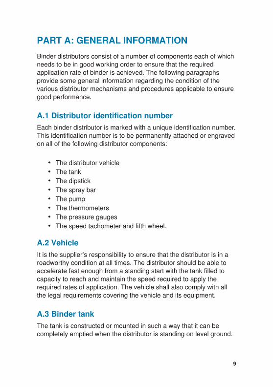
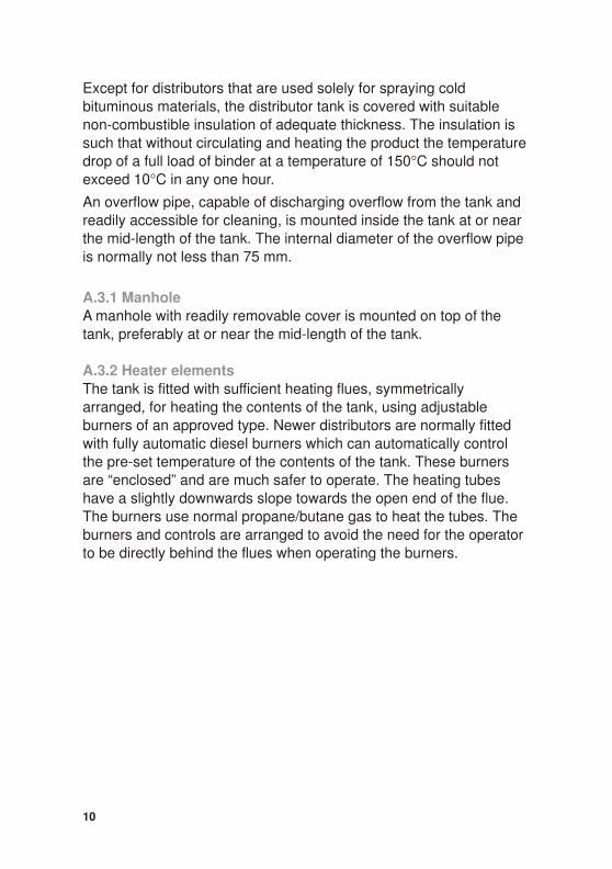
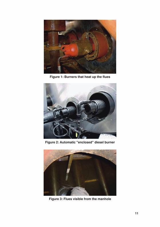
A.3.2 Heater elementsThe tank is fitted with sufficient heating flues, symmetricallyarranged, for heating the contents of the tank, using adjustableburners of an approved type. Newer distributors are normally fittedwith fully automatic diesel burners which can automatically controlthe pre-set temperature of the contents of the tank. These burnersare “enclosed” and are much safer to operate. The heating tubeshave a slightly downwards slope towards the open end of the flue.The burners use normal propane/butane gas to heat the tubes. Theburners and controls are arranged to avoid the need for the operatorto be directly behind the flues when operating the burners.
10
11
Figure 1: Burners that heat up the flues
Figure 2: Automatic "enclosed" diesel burner
Figure 3: Flues visible from the manhole
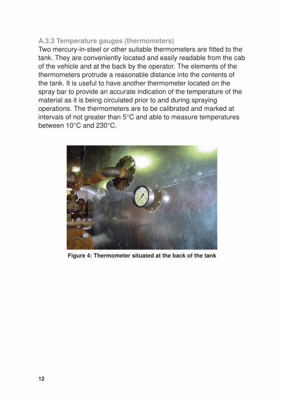
A.3.3 Temperature gauges (thermometers)Two mercury-in-steel or other suitable thermometers are fitted to thetank. They are conveniently located and easily readable from the cab of the vehicle and at the back by the operator. The elements of thethermometers protrude a reasonable distance into the contents ofthe tank. It is useful to have another thermometer located on thespray bar to provide an accurate indication of the temperature of thematerial as it is being circulated prior to and during sprayingoperations. The thermometers are to be calibrated and marked atintervals of not greater than 5°C and able to measure temperaturesbetween 10°C and 230°C.
12
Figure 4: Thermometer situated at the back of the tank
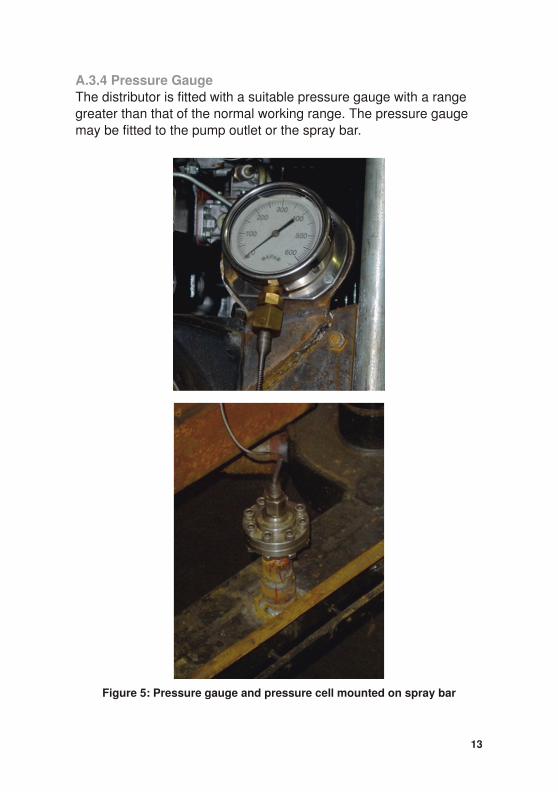
A.3.4 Pressure GaugeThe distributor is fitted with a suitable pressure gauge with a rangegreater than that of the normal working range. The pressure gaugemay be fitted to the pump outlet or the spray bar.
13
Figure 5: Pressure gauge and pressure cell mounted on spray bar
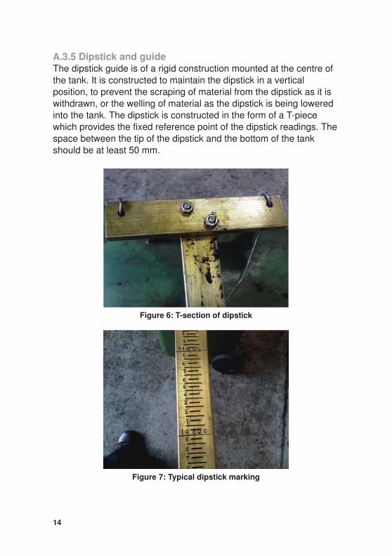
A.3.5 Dipstick and guideThe dipstick guide is of a rigid construction mounted at the centre ofthe tank. It is constructed to maintain the dipstick in a verticalposition, to prevent the scraping of material from the dipstick as it iswithdrawn, or the welling of material as the dipstick is being loweredinto the tank. The dipstick is constructed in the form of a T-piecewhich provides the fixed reference point of the dipstick readings. The space between the tip of the dipstick and the bottom of the tankshould be at least 50 mm.
14
Figure 6: T-section of dipstick
Figure 7: Typical dipstick marking
A.4 Pump
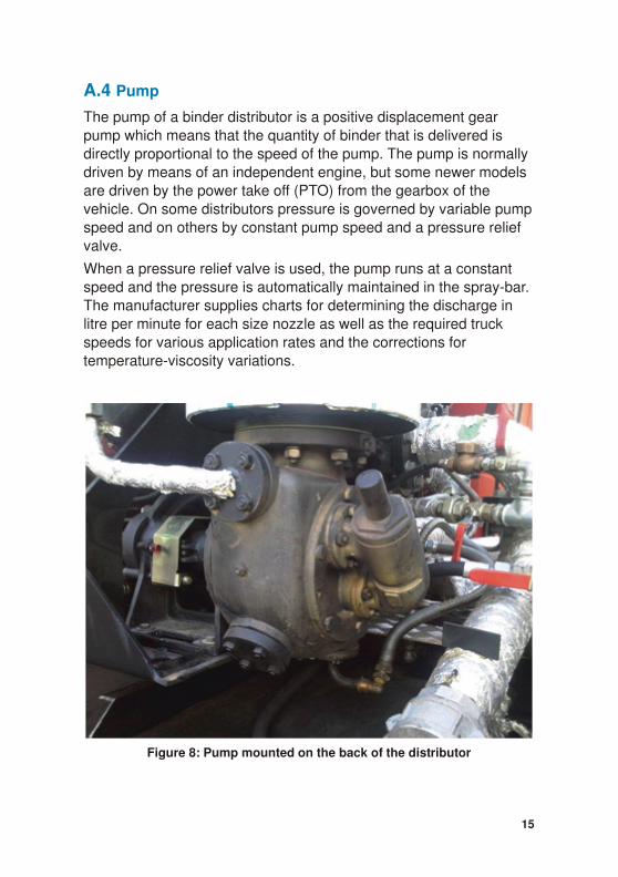
The pump of a binder distributor is a positive displacement gearpump which means that the quantity of binder that is delivered isdirectly proportional to the speed of the pump. The pump is normallydriven by means of an independent engine, but some newer modelsare driven by the power take off (PTO) from the gearbox of thevehicle. On some distributors pressure is governed by variable pump speed and on others by constant pump speed and a pressure reliefvalve.
When a pressure relief valve is used, the pump runs at a constantspeed and the pressure is automatically maintained in the spray-bar.The manufacturer supplies charts for determining the discharge inlitre per minute for each size nozzle as well as the required truckspeeds for various application rates and the corrections fortemperature-viscosity variations.
15
Figure 8: Pump mounted on the back of the distributor
A.5 Pipework
All pipes and couplings which are part of the distributor circuit shallbe able to handle the maximum pressure and temperature required.
A.6 Strainers
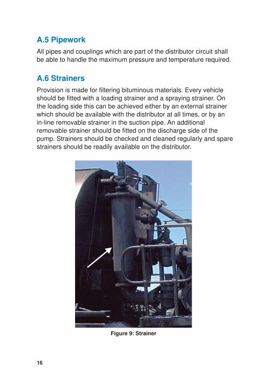
Provision is made for filtering bituminous materials. Every vehicleshould be fitted with a loading strainer and a spraying strainer. Onthe loading side this can be achieved either by an external strainerwhich should be available with the distributor at all times, or by anin-line removable strainer in the suction pipe. An additionalremovable strainer should be fitted on the discharge side of thepump. Strainers should be checked and cleaned regularly and sparestrainers should be readily available on the distributor.
16
Figure 9: Strainer
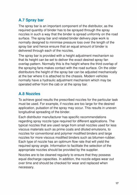
A.7 Spray bar
The spray bar is an important component of the distributor, as therequired quantity of binder has to be sprayed through the spraynozzles in such a way that the binder is spread uniformly on the road surface. The spray bar and related binder delivery pipe work isnormally designed to minimise pressure loss over the length of thespray bar and hence ensure that an equal amount of binder isdelivered through each of the nozzles.
The spray bar is provided with a height adjustment mechanism sothat its height can be set to deliver the exact desired spray fanoverlap pattern. Normally this is the height where the third overlap ofthe spraying fans makes contact with the road surface. On the olderdistributors the height of the spray bar can be adjusted mechanicallyat the bar where it is attached to the chassis. Modern vehiclesnormally have a hydraulic adjustment mechanism which may beoperated either from the cab or at the spray bar.
A.8 Nozzles
To achieve good results the prescribed nozzles for the particular task must be used. For example, if nozzles are too large for the desiredapplication, pulsation of the spray may occur. This results in unevenlongitudinal spreading of the binder.
Each distributor manufacturer has specific recommendationsregarding spray nozzle type required for different applications. Thetypical nozzles that are used range from small nozzles used for lessviscous materials such as prime coats and diluted emulsions, tonozzles for conventional and polymer modified binders and largenozzles for more viscous modified binders such as bitumen-rubber.Each type of nozzle has an optimum flow rate that will yield therequired spray angle. Information to facilitate the selection of theappropriate nozzles should be provided by the supplier.
Nozzles are to be cleaned regularly to ensure that they possessequal discharge capacities. In addition, the nozzle edges wear outover time and should be checked for wear and replaced whennecessary.
17
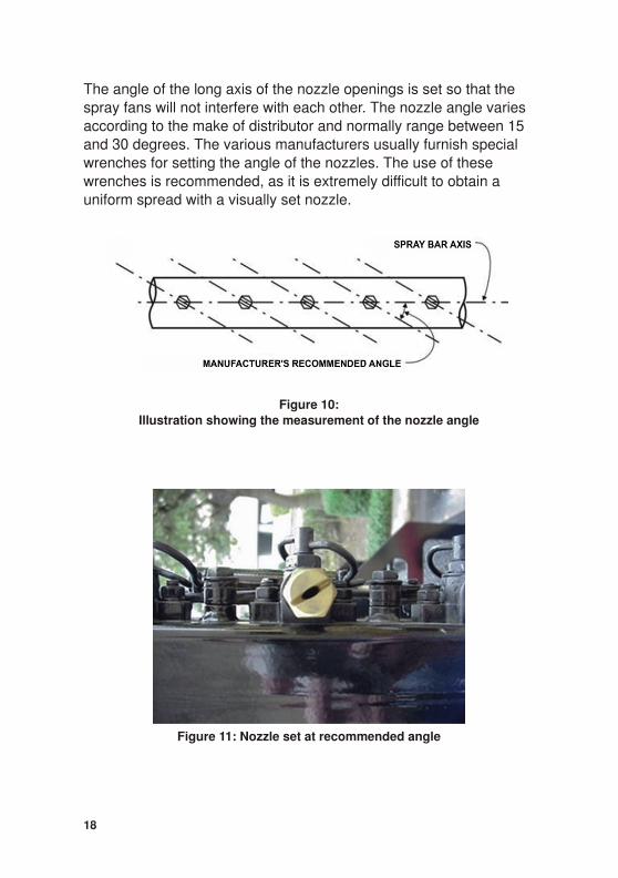
The angle of the long axis of the nozzle openings is set so that thespray fans will not interfere with each other. The nozzle angle variesaccording to the make of distributor and normally range between 15and 30 degrees. The various manufacturers usually furnish specialwrenches for setting the angle of the nozzles. The use of thesewrenches is recommended, as it is extremely difficult to obtain auniform spread with a visually set nozzle.
18
Figure 10:Illustration showing the measurement of the nozzle angle
Figure 11: Nozzle set at recommended angle
19
Figure 12: Effect of improper nozzle angles
PART B: DETAILS OF THE INSPECTION ANDTEST PROCEDURES TO BE CARRIED OUTTO OBTAIN A CALIBRATION CERTIFICATEFOR A BINDER DISTRIBUTOR INACCORDANCE WITH SANS 3001-BT20
The purpose of the calibration procedure and certificate is to providean annual check of bitumen distributors to ensure that they are in areasonable condition, that the tank is clean and that there is a highprobability of achieving the desired result on site.
A credible and valid Calibration Certificate will give the assurancethat the binder distributor is operating correctly and that it is capableof delivering the required application rate within the prescribedtolerances. It is, however, not a guarantee of accurate and uniformspraying capability. In addition to the annual Calibration Certificateand depending on the nature and size of the project a number oftests and inspections may be carried out on site prior to and duringspraying operations to ensure the required quality of spray work.
It is recommended that the calibration tests are carried out in theorder that they are listed below. This will ensure best time andresource efficiency and will prevent repetition of some steps.
The Calibration Certificate as well as the calibration parameters,such as road speed and pump output, are to be made available forinspection on site to assess the extent to which site tests need to becarried out and on-site performance monitored to ensure compliance with the specification. The data should be kept on board thedistributor.
B.1 Required annual tests
The following tests specified in SANS 3001-BT20 are required forannual certification of a binder distributor:
• SANS 3001 BT-21Validation of a binder distributor dipstick;
20
• SANS 3001 BT-22 Power and road speed indicator tests for a
binder distributor;
• SANS 3001 BT-23 Pump system performance of a binder
distributor; and
• SANS 3001 BT-24 Measurement of transverse distribution
(‘Bucket Test’) for a binder distributor.
B.2 Ad hoc tests during a project
While the annual certification ensures that the distributor is regularlychecked, this does not ensure that during the certification period it isfunctioning satisfactorily. Particularly on major projects it isrecommended that at the start of spraying operations SANS3001-BT24 (‘Bucket Test’) should be carried out on site. This testand others may be repeated during the project as a precautionarycheck or if it is suspected that the distributor is not performingsatisfactorily.
B.3 Testing facilities
Historically there were a number of testing facilities throughout South Africa (usually government run). Over time most of these facilitieshave closed down with the result that binder distributors often had tobe sent long distances for the annual calibration. In consultation withall the major role players it was decided that to remedy this situationa degree of self-regulation had to be introduced while stillmaintaining independent annual certification.
The new standard for calibration, SANS 3001 BT-20 makes
allowance for annual certification testing at the following locations:
21
NOTE
Where repairs or alterations are made to critical elements of acertificated distributor which could affect the spray rates anddistribution of binder, the distributor is to be recalibrated.
• a government run testing and calibration facility;
• a suitably equipped facility belonging to the distributor owneror operator; or
• a suitably equipped facility belonging to a third party.
The testing is to be carried out by the distributor owner’s staff whoare responsible for all logistics, and health and safety issues. Thetests are to be observed and recorded by an experienced technicianfrom an independent accredited testing laboratory which will issue acalibration certificate following the successful outcome of all thetests.
The new standard also makes allowance for ad hoc testing whichmay be carried out on site or at a testing facility.
B.4 General
The requirements for each of the SANS 3001-BT tests are clearly set out in the methods. However, the following general information isprovided regarding the condition the distributor should be in when
presented for testing and also on arrival on site for a specific
project.
The distributor should be clean and operational. Failure to meetthese requirements may cause a delay in testing and result inadditional costs for the applicant. The owner should arrange for anexperienced driver and operator to be present with the distributorduring testing to assist with the tests.
For annual calibration the default fluid to be used is a bitumenemulsion heated to the recommended spray temperature. The use of other fluids including a project specific binder or oil is permitted.
B.4.1 Check listBefore calibrating a binder distributor and before starting spraying on site the following checks should be undertaken:
22
Visual inspection
Inspect the distributor for any damage or dirty components (tankincluded). Check that:
• the general condition of the distributor is satisfactory;
• the levers and linkages are functioning properly;
• all the components are properly marked with identification as required.
Dipstick
The dipstick is:
• properly marked with an identification number;
• straight with no signs of wear;
• marked as prescribed with no fading of scale incrementmarkings;
• firmly attached to the T-piece.
Any new or reconditioned dipstick shall have been manufactured and marked by an accredited dipstick manufacturer who is to issue acalibration certificate with the dipstick.
Vehicle performance
The vehicle is to be road worthy in terms of current traffic legislationand/or regulations).
The main engine of the vehicle is to be sufficiently powerful so that itis capable of driving at a pre-set constant speed without any difficulty or noticeable jerking for a given road speed within the range of 80 to300 metres per minute with a full load on any road gradient.
23
NOTE
If these conditions are not met the dipstick is to be replaced orreconditioned.
Road speed
The vehicle is to be fitted with a speed controller (and fifth wheel oncertain distributor models) to control the spraying road speedbetween 80 and 300 metres per minute with an accuracy of + 1metre per minute.
The road speed controller is to have a valid calibration certificate.
In the case of a fifth wheel system the wheel and mechanical partsare to be free of any signs of wear.
The speedometer cable is to be in a good condition.
The locking device holding the fifth wheel at bay from the road during normal travelling is to function satisfactory.
In the case of a mechanical road speed indicator the gauge is to befitted with an indicator needle.
The speed indicator needle is to be steady and should not vibrate oroscillate when the speed of the vehicle, while spraying, is within therequired speed range.
When the vehicle is fitted with an electronic, digital indicator thedigits are to be clearly visible and when the vehicle is stationary thedisplay is to be free of any drift. The display unit is to be equippedwith a warning signal when the road speed is outside the tolerancelimits of the prescribed speed.
Output pump
The binder output pump is to be capable of delivering a constantvolume of binder i.e. 150 litres/metre/minute for any required lengthof spray bar with an accuracy of + 1 litre/metre/minute. It is important that the pump output rate remains constant throughout the discharge of the binder from the tank. The rate of delivery of the output pump is controlled by either the pressure in the output pipe circuit or therevolutions of the output pump engine. A calibration certificate is tobe available for the output pump discharge indicator.
Transverse distribution
Previous ‘Bucket Test’ reports are to be available.
24

Spray nozzles
All the spray nozzles are to be of the same type (except those at theend of the spray bar) and are set at the correct angle to the spray bar
as per the manufacturers specifications.
Mechanical (hydraulic) linkages and couplings
All the linkages and couplings are to be in working order withoutvisible signs of wear and tear.
Thermometers
All thermometers are to be calibrated by an accredited metrologicalinstitute. Thermometers are to be capable of indicating temperaturesbetween 10oC and 230oC with an accuracy of + 5oC.
B.5 Comments regarding the calibration tests
The SANS 3001 BT-20 to BT-24 set out the required standards forcertification and the calibration tests. The following comments areintended to be informative and in no way supersede or replace thestandards.
Upon arrival at the testing facility the testing officer will check detailsof previous distributor visual inspection reports (if appropriate) andcarry out an inspection.
The distributor log book will be checked to see if any maintenance or replacement of any parts of the distributor has taken place since theprevious calibration.
It is the owner’s responsibility to ensure that the distributor isthoroughly clean when it is presented for calibration.
25
NOTE
No calibration testing or spraying is to be carried out unless theabove mentioned conditions are met.
B.5.1 Dipstick calibration test – (SANS 3001-BT21)This test is carried out to check that the volume of fluid in the tank asmeasured on the readings on the dipstick, match the actual volumespumped into the tank. The standards make provision for binderdistributor flow measure indicators to be used instead of a dipstickprovided that it can be demonstrated, using the principles of SANS3001-BT21, that a similar or improved accuracy can be achieved.
The dipstick, in the shape of a “T with a long leg”, is manufacturedfrom brass metal. It should resist mechanical wear and distortionunder normal use. The brass strip selected for the dipstick is at least25 mm wide (30 mm is recommended) and 7 mm thick. The metalshould be easy to calibrate with a sharp chisel. The length of dipstick is such that the clearance between the bottom of the tank and thedipstick, when fully dipped in, is 50 mm.
B.5.2 Power test – (SANS 3001-BT22)This test is carried out to assess whether the fully laden distributor isable to accelerate fast enough to reach required spraying speeds ina short distance under normal working conditions. The distributorshould be able to reach a speed of 300 m/min i.e. 18 km/h within 2seconds.
This test can be conducted after the dipstick calibration test with thetank filled to capacity with testing fluid.
B.5.3 Pump output test – (SANS 3001-BT23)This test is carried out to confirm that the indicated volume of binderdelivered by the pump matches the actual volume delivered. The test consists of a series of three minute sprays taking measurements at30 second intervals, starting with a full load of binder and continuinguntil the tank is almost empty but without exposing the flues.
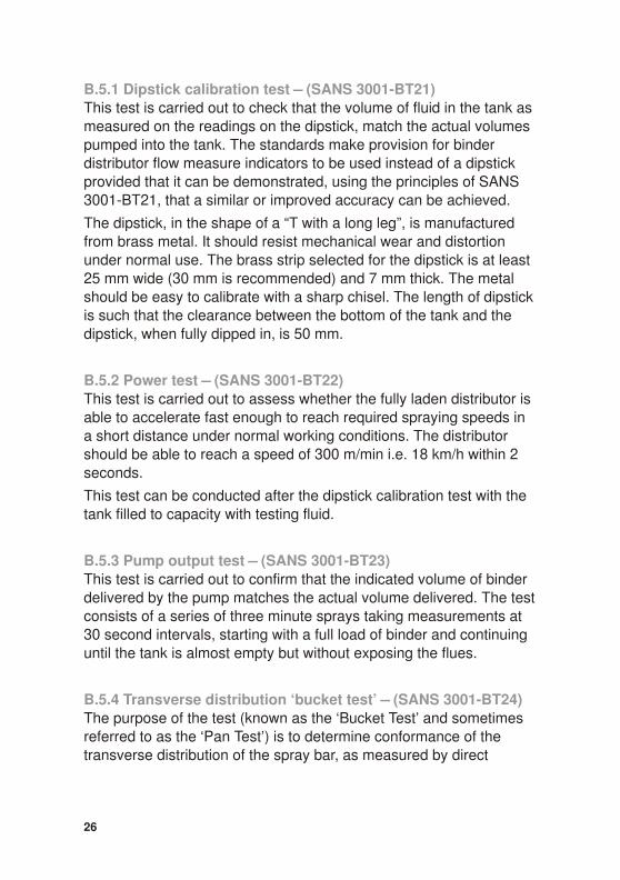
B.5.4 Transverse distribution ‘bucket test’ – (SANS 3001-BT24)The purpose of the test (known as the ‘Bucket Test’ and sometimesreferred to as the ‘Pan Test’) is to determine conformance of thetransverse distribution of the spray bar, as measured by direct
26
discharge from sets of three nozzles. This test may also be carriedout on site to check that the distributor is still able to deliver an evenuniform application of binder.
The test is normally carried out using a spray bar width of 4,2 m splitinto three sections, but may be adjusted for other widths. The
apparatus used includes 14 numbered steel troughs fitted withhandles, manufactured from 3 mm mild steel plate and 265 mm(wide) by 405 mm (long) by 300 mm (high). The troughs are placedbeneath the spray bar so that all the binder is collected for each setof three nozzles.
27
Figure 13: 'Bucket Test'
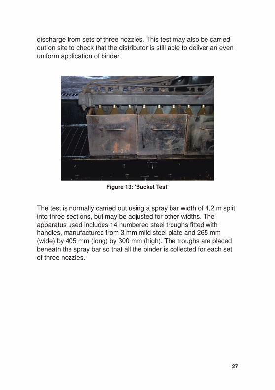
The troughs are weighed before and after each spray and the results are then calculated and compared with the limits set in the testmethod. Three comparisons are made:
• individual trough values versus the mean for all troughs;
• right and left sides of the spray bar versus the central portion;and,
• right versus left side of the spray bar.
28
Figure 14: Apparatus to be used for the 'Bucket Test'
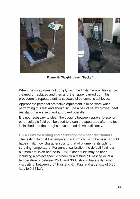
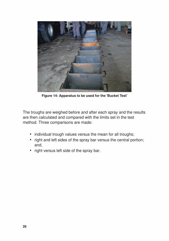
When the spray does not comply with the limits the nozzles can becleaned or replaced and then a further spray carried out. Thisprocedure is repeated until a successful outcome is achieved.
Appropriate personal protective equipment is to be worn whenperforming this test and should include a pair of safety gloves (heatresistant), face shield and approved overalls.
It is not necessary to clean the troughs between sprays. Diesel orother suitable fluid can be used to clean the apparatus after the testis finished and the troughs have cooled down sufficiently.
B.5.6 Fluid for testing and calibration of binder distributorsThe testing fluid, at the temperature at which it is to be used, shouldhave similar flow characteristics to that of bitumen at its optimumspraying temperature. For annual calibration the default fluid is abitumen emulsion heated to 60oC. Other fluids may be usedincluding a project specific binder or a testing oil. Testing oil at atemperature of between 25°C and 30°C should have a dynamicviscosity of between 0,07 Pa.s and 0,1 Pa.s and a density of 0,85kg/L to 0,94 kg/L.
29
Figure 15: Weighing each 'Bucket'
B.5.7 Volume measurementsAll volume measurements for annual calibration are made by takingmass measurements and converting to volumes. Methods SANS3001-BT21 and BT23 require the use of a weighbridge and adequate size tanks or sumps.
B.5.8 Cost of testingThe cost of calibration testing will depend on the owner of the facilityand the rate charged by the independent laboratory for theirtechnician to observe, record, calculate and issue a calibrationcertificate in accordance with SANS 3001-BT20.
B.5.9 DocumentationSANS 3001-BT20 requires that certain documentation, including thecalibration certificate, be kept with the distributor. It is recommendedthat this and other relevant data should be kept as part of a vehiclelogbook. The logbook should contain the Calibration Certificate,performance charts, modification and maintenance log, a record of‘Bucket’ tests done and a log showing the performance of thedistributor in the field.
• Calibration Certificate: A certificate showing that thedistributor conforms to all the requirements as specified inSANS 3001-BT20, with the results of the last annual testsattached. The logbook should also contain certificates statingthat other equipment not tested at the testing facility, such astemperature and pressure gauges, have also been calibratedto SANAS standards.
• Copies of the vehicle supplier’s performance charts togetherwith any amendments resulting from the annual calibration tests.
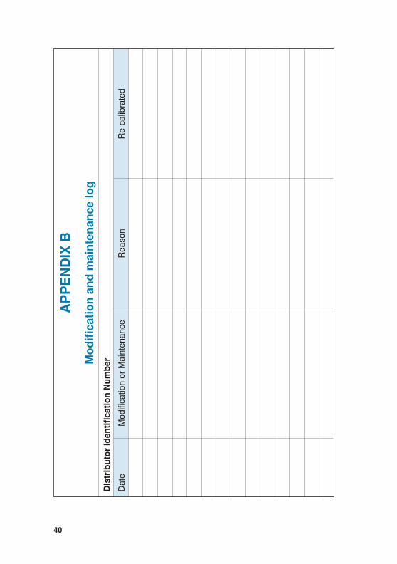
• Modification and maintenance log (Appendix B): A log kepton all modifications done on the distributor that could affectthe spraying performance of the distributor. All maintenancedone on the distributor should also be recorded together withproof of calibration provided by an accredited testing facilitythat the equipment under question has also beenre-calibrated.
30
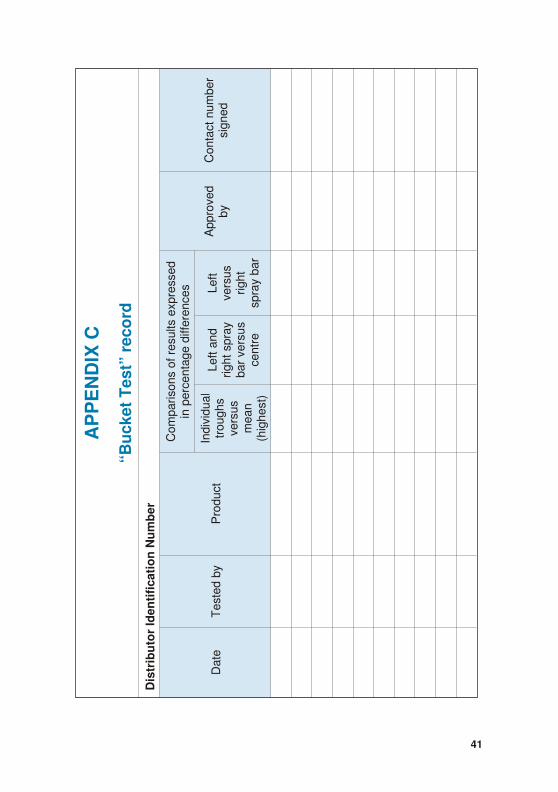
• ‘Bucket Test’ record (Appendix C): This record will record all‘Bucket’ tests done on the distributor within the last year,
whether on site or at a testing facility. The object of this record is to show continuous good performance on transversedistribution tests so that in future the parties concerned may,based on the evidence of the ‘Bucket Test’ record, decide notto repeat the ‘Bucket Test’, especially in cases where products with low viscosities or low volumes of binder are sprayed.
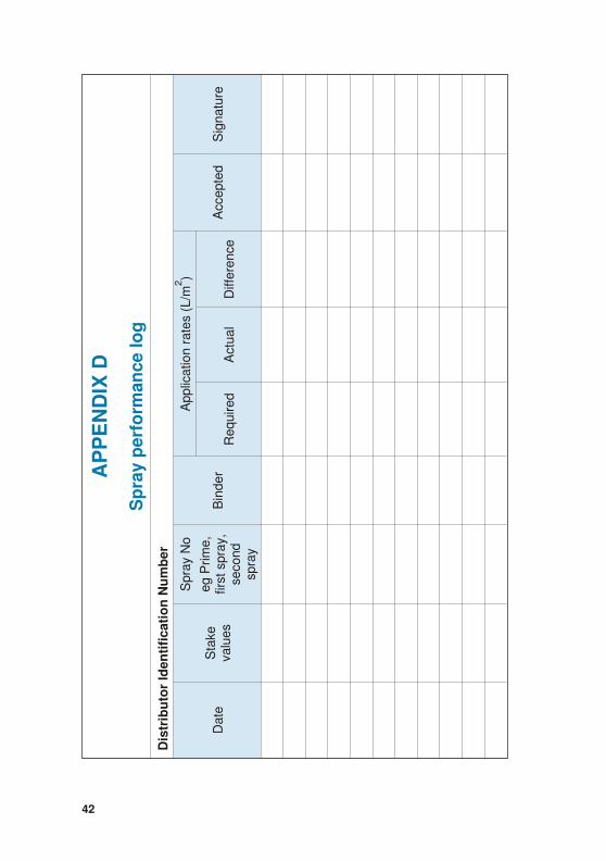
• Performance log (Appendix D): This is a log showing thedistributor’s performance in terms of rate of application andthe variance thereof on recent projects. The log will notcontain sensitive information such as volumes sprayed andthe client names, but only date of spray, an indication ofsatisfaction of the client, the person who approved the sprayand a contact number for this person.
• It is recommended that site staff should keep separate records indicating the checks made before and after spraying(Appendices E and F).
31
PART C: CHECKS, PROCEDURES ANDTESTS TO BE FOLLOWED WHEN ADISTRIBUTOR ARRIVES ON SITE
When a distributor arrives on a construction site the site staff willneed to confirm that the driver/operator and its equipment arecapable of delivering the required rate of application to the roadsurface in a uniformly distributed manner in accordance with thespecifications. Various inspections, checks and tests that culminatein spraying a trial section are carried out to confirm the above.
C.1 Log book inspection
The vehicle log book will be checked in respect of the following:
C.1.1 Calibration certificateThe vehicle will have a valid Calibration Certificate and the site staffwill check for any recent non-conformances and related actionstaken to clear these.
C.1.2 Current modificationsThe site staff will check the modifications section of the log book(See Appendix B, Modification and maintenance log) to determinewhether any modifications have been carried out since calibrationand to assess their likely impact on performance.
C.1.3 Routine maintenanceThe site staff will assess the section that records any routinemaintenance carried out on the distributor including filter cleaning(See Appendix B, Modification and maintenance log).
C.1.4 ‘Bucket test’The site staff will check to see the results of any recent ‘Bucket Tests’ to assess whether a site ‘Bucket Test’ will be required taking intoconsideration the volume of binder to be applied and the type ofbinder (See Appendix C, ‘Bucket Test record’). If only a small amount
32
is to be applied or the binder is an emulsion or prime (i.e. lowviscosity) which will in any event flow over the road surface, it maynot be necessary to carry out a ‘Bucket Test’ on-site. However, in this case a short test spray into a drip tray will be required to check thatno nozzles are blocked, the angle of the flares are satisfactory andthe overlapping is as required.
C.1.5 Recent workThe site staff will check the vehicle log (See Appendix E, Sprayperformance log) for recent works carried out where the client or itsagent has recorded their satisfaction or dissatisfaction.
C.2 Physical checks on vehicle
Having examined the log books the physical characteristics of thedistributor should be checked, using the check lists supplied in
Appendix A. Before starting any spray work the following checksshould routinely be made.
C.2.1 NozzlesAll the nozzles need to be inspected to ensure that they are:
• all the same size and type;
• not blocked and free of wear and tear; and
• are uniformly aligned at the correct angle.
C.2.2 Spray bar heightThe site staff may carry out a simple test procedure to ensure theproper height setting of a spray-bar with 100 mm nozzle spacing.This involves closing off the second and third, fifth and sixth, eighthand ninth etc. nozzles and using the centre section of the bar only.The distributor is then operated at the correct pump speed orpressure with the spray-bar height changed not more than 20 mm ata time in order to produce a single film of binder on the surface withno overlaps and no gaps between the strips produced by every thirdnozzle. At that point an exact triple overlap will be produced when allnozzles are opened.
33
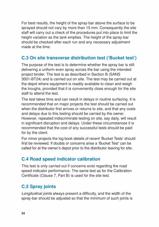
For best results, the height of the spray-bar above the surface to besprayed should not vary by more than 15 mm. Consequently the sitestaff will carry out a check of the procedures put into place to limit the height variation as the tank empties. The height of the spray-barshould be checked after each run and any necessary adjustmentmade at the time.
C.3 On site transverse distribution test (‘Bucket test’)
The purpose of the test is to determine whether the spray bar is stilldelivering a uniform even spray across the bar using the intendedproject binder. The test is as described in Section B (SANS3001-BT24) and is carried out on site. The test may be carried out atthe depot where equipment is readily available to clean and weighthe troughs, provided that it is conveniently close enough for the sitestaff to attend the test.
The test takes time and can result in delays in routine surfacing. It isrecommended that on major projects the test should be carried outwhen the distributor first arrives or returns to site, and that any costsand delays due to this testing should be carried by the owner.However, repeated indiscriminate testing on site, say daily, will resultin significant disruption and delays. Under these circumstances it isrecommended that the cost of any successful tests should be paidfor by the client.
For minor projects the log book details of recent ‘Bucket Tests’ shouldfirst be reviewed. If doubts or concerns arise a ‘Bucket Test’ can becalled for at the owner’s depot prior to the distributor leaving for site.
C.4 Road speed indicator calibration
This test is only carried out if concerns exist regarding the roadspeed indicator performance. The same test as for the CalibrationCertificate (Clause 7, Part B) is used for the site test.
C.5 Spray joints
Longitudinal joints always present a difficulty, and the width of thespray-bar should be adjusted so that the minimum of such joints is
34
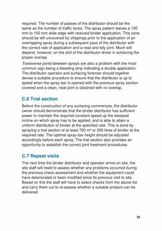
required. The number of passes of the distributor should be thesame as the number of traffic lanes. The spray pattern leaves a 100mm to 150 mm wide edge with reduced binder application. This zone should be left uncovered by chippings prior to the application of anoverlapping spray during a subsequent pass of the distributor withthe correct rate of application and a neat and tidy joint. Much willdepend, however, on the skill of the distributor driver in achieving the proper overlap.
Transverse joints between sprays are also a problem with the mostcommon sign being a bleeding strip indicating a double application.The distributor operator and surfacing foreman should togetherdevise a suitable procedure to ensure that the distributor is up tospeed when the spray bar is opened with the previous spray sectioncovered and a clean, neat joint is obtained with no overlap.
C.6 Trial section
Before the construction of any surfacing commences, the distributorowner should demonstrate that the binder distributor has sufficientpower to maintain the required constant speed up the steepestincline on which spray has to be applied, and is able to attain auniform distribution of binder at the specified rate. This is done byspraying a trial section of at least 700 m² or 500 litres of binder at the required rate. The optimal spray-bar height should be adjustedaccordingly before each spray. The trial section also provides anopportunity to establish the correct joint treatment procedures.
C.7 Repeat visits
The next time the binder distributor and operator arrive on site, thesite staff will need to assess whether any problems occurred duringthe previous check assessment and whether the equipment couldhave deteriorated or been modified since its previous visit to site.Based on this the staff will have to select checks from the above listand carry them out to re-assess whether a suitable product can bedelivered.
35
36
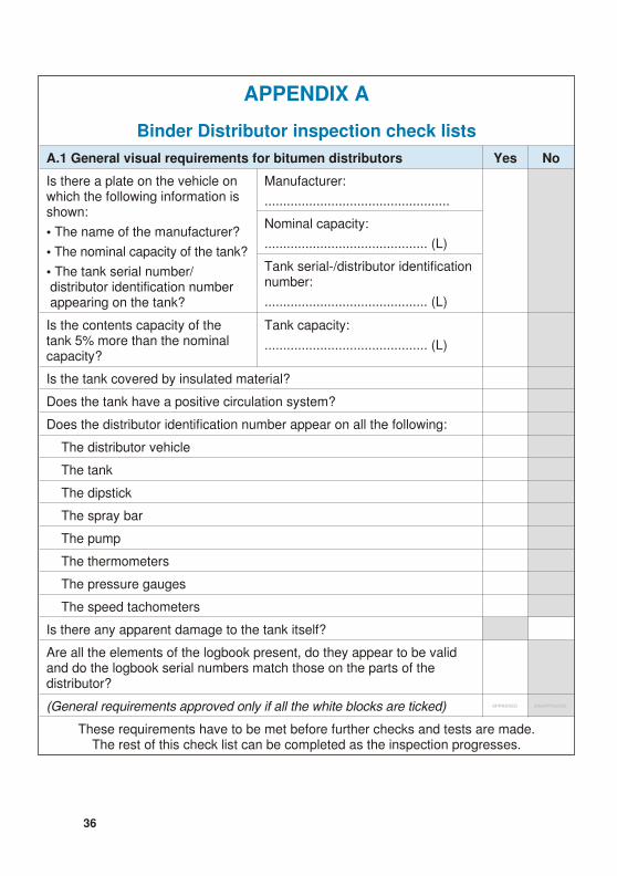
APPENDIX A
Binder Distributor inspection check lists
A.1 General visual requirements for bitumen distributors Yes No
Is there a plate on the vehicle onwhich the following information isshown:
• The name of the manufacturer?
• The nominal capacity of the tank?
• The tank serial number/ distributor identification number appearing on the tank?
Manufacturer:
..................................................
Nominal capacity:
............................................ (L)
Tank serial-/distributor identification number:
............................................ (L)
Is the contents capacity of thetank 5% more than the nominalcapacity?
Tank capacity:
............................................ (L)
Is the tank covered by insulated material?
Does the tank have a positive circulation system?
Does the distributor identification number appear on all the following:
The distributor vehicle
The tank
The dipstick
The spray bar
The pump
The thermometers
The pressure gauges
The speed tachometers
Is there any apparent damage to the tank itself?
Are all the elements of the logbook present, do they appear to be validand do the logbook serial numbers match those on the parts of thedistributor?
(General requirements approved only if all the white blocks are ticked)
These requirements have to be met before further checks and tests are made.The rest of this check list can be completed as the inspection progresses.
37
A.2 Requirements for the dipstick Yes No
Is the dipstick made of brass?
Are the markings clear and easy to read?
Is the dipstick worn out or welded?
Are the markings accurate to the limits prescribed inSANS 3001-BT21?Refer to calibration certificate and outcome of test.
Are the markings spaced in such a way that increments of 50 L can be read off the dipstick?
Does the dipstick hang from a suitable T-piece or anyother suitable method to ensure that readings are alwaystaken from the same reference point?
Is the dipstick touching the bottom of the tank?
Is the dipstick situated near the middle of the tank?
(Dipstick approved only if the white blocks are ticked)
A.3 Requirements for the speed tachometer Yes No
Is the tachometer of the vehicle separate from thespeedometer?
Can the driver read the speed easily?
Is the tachometer calibrated in metres/minute?
Is the reading on the outside scale of such a nature thatincrements of 5 metres/minute are equal or greater than2 mm apart?
Is the difference in the actual speed and the speedshowing on the tachometer within 5%?
(See outcome of SANS 3001-BT22 test with calibrationcertificate)
(Speed tachometer approved only if the white blocks areticked)
38
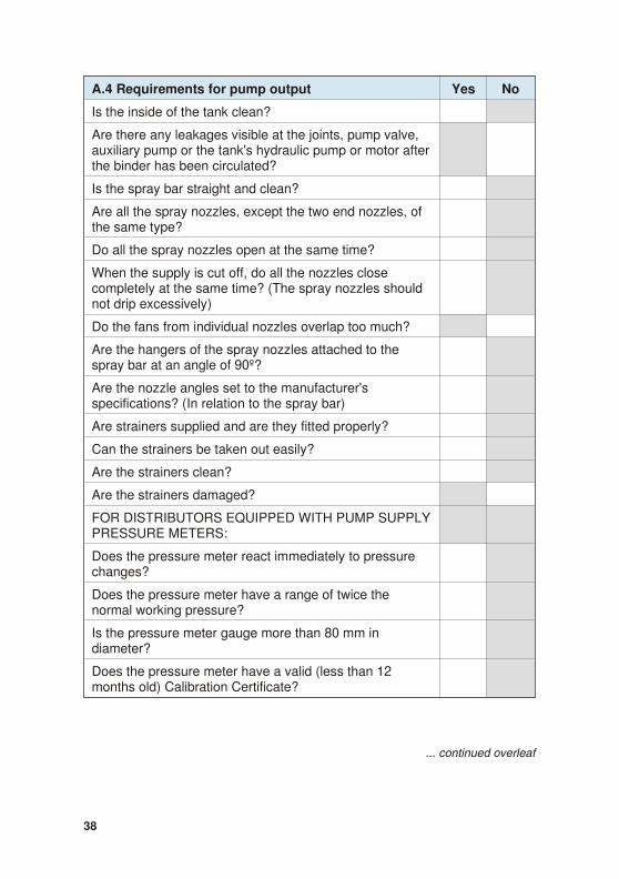
A.4 Requirements for pump output Yes No
Is the inside of the tank clean?
Are there any leakages visible at the joints, pump valve,auxiliary pump or the tank's hydraulic pump or motor after the binder has been circulated?
Is the spray bar straight and clean?
Are all the spray nozzles, except the two end nozzles, ofthe same type?
Do all the spray nozzles open at the same time?
When the supply is cut off, do all the nozzles closecompletely at the same time? (The spray nozzles shouldnot drip excessively)
Do the fans from individual nozzles overlap too much?
Are the hangers of the spray nozzles attached to thespray bar at an angle of 90º?
Are the nozzle angles set to the manufacturer'sspecifications? (In relation to the spray bar)
Are strainers supplied and are they fitted properly?
Can the strainers be taken out easily?
Are the strainers clean?
Are the strainers damaged?
FOR DISTRIBUTORS EQUIPPED WITH PUMP SUPPLY PRESSURE METERS:
Does the pressure meter react immediately to pressurechanges?
Does the pressure meter have a range of twice thenormal working pressure?
Is the pressure meter gauge more than 80 mm indiameter?
Does the pressure meter have a valid (less than 12months old) Calibration Certificate?
... continued overleaf
39
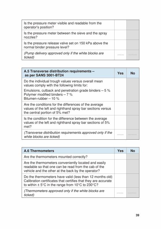
Is the pressure meter visible and readable from theoperator's position?
Is the pressure meter between the sieve and the spraynozzles?
Is the pressure release valve set on 150 kPa above thenormal binder pressure level?
(Pump delivery approved only if the white blocks areticked)
A.5 Transverse distribution requirements – as per SANS 3001-BT24
Yes No
Do the individual trough values versus overall meanvalues comply with the following limits for:
Emulsions, cutback and penetration grade binders – 5 %Polymer modified binders – 7 %Bitumen-rubber – 10 %
Are the conditions for the differences of the averagevalues of the left and righthand spray bar sections versusthe central portion of 5% met?
Is the condition for the difference between the averagevalues of the left and righthand spray bar sections of 5%met?
(Transverse distribution requirements approved only if the white blocks are ticked)
A.6 Thermometers Yes No
Are the thermometers mounted correctly?
Are the thermometers conveniently located and easilyreadable so that one can be read from the cab of thevehicle and the other at the back by the operator?
Do the thermometers have valid (less than 12 months old) Calibration certificates that certifies that they are accurate to within ± 5°C in the range from 10°C to 230°C?
(Thermometers approved only if the white blocks areticked)
40
B XI
DN
EP
PA
gol
ec
na
net
nia
m d
na
noit
acifi
do
M re
bm
uN
noit
acifit
ne
dI rot
ubirt
siD
eta
Dec
na
net
nia
M ro
noit
acifid
oM
nos
ae
Rd
etar
bilac-
eR
41
C XI
DN
EP
PA
dro
cer ”t
se
T te
kc
uB“
re
bm
uN
noit
acifit
ne
dI rot
ubirt
siD
eta
Dy
b d
etse
Ttc
ud
orP
dess
erpx
e stlus
er fo s
nosir
ap
mo
Cs
ecn
ereffi
d e
gat
necr
ep
ni
dev
orp
pA
yb
re
bm
un tc
atn
oC
de
ngis
la
udivi
dnI
sh
gu
orts
usrev
na
em
)tse
hgi
h(
dn
a tfe
L y
arps t
hgir
susr
ev ra
bert
nec
tfe
Ls
usrev
th
girr
ab y
arps
42
D XI
DN
EP
PA
gol
ec
na
mrofr
ep
yar
pS
re
bm
uN
noit
acifit
ne
dI rot
ubirt
siD
eta
Dek
atS
se
ulav
oN y
arp
S
,e
mirP
ge
,yar
ps tsrifd
noc
esy
arps
re
dni
B
/L( s
etar
noit
acilp
pA
m2)
det
pecc
Aer
uta
ngi
Sd
eriu
qe
Rl
autc
Aec
ner
effiD
43
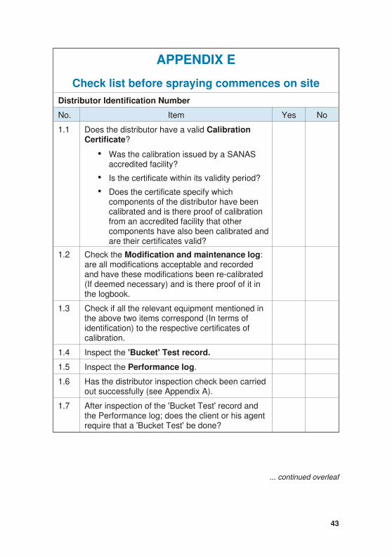
APPENDIX E
Check list before spraying commences on site
Distributor Identification Number
No. Item Yes No
1.1 Does the distributor have a valid CalibrationCertificate?
• Was the calibration issued by a SANASaccredited facility?
• Is the certificate within its validity period?
• Does the certificate specify whichcomponents of the distributor have beencalibrated and is there proof of calibrationfrom an accredited facility that othercomponents have also been calibrated and are their certificates valid?
1.2 Check the Modification and maintenance log:are all modifications acceptable and recordedand have these modifications been re-calibrated(If deemed necessary) and is there proof of it inthe logbook.
1.3 Check if all the relevant equipment mentioned inthe above two items correspond (In terms ofidentification) to the respective certificates ofcalibration.
1.4 Inspect the 'Bucket' Test record.
1.5 Inspect the Performance log.
1.6 Has the distributor inspection check been carried out successfully (see Appendix A).
1.7 After inspection of the 'Bucket Test' record andthe Performance log; does the client or his agentrequire that a 'Bucket Test' be done?
... continued overleaf
44
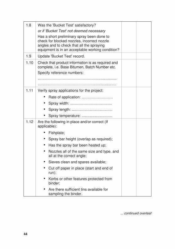
1.8 Was the 'Bucket Test' satisfactory?
or if 'Bucket Test' not deemed necessary
Has a short preliminary spray been done tocheck for blocked nozzles, incorrect nozzleangles and to check that all the sprayingequipment is in an acceptable working condition?
1.9 Update 'Bucket Test' record.
1.10 Check that product information is as required andcomplete, i.e. Base Bitumen, Batch Number etc.
Specify reference numbers:
………………………………………………………
…………………………………………….......……
1.11 Verify spray applications for the project:
• Rate of application: …………………….
• Spray width: ...………………………….
• Spray length: ...…………………………
• Spray temperature: ...………………….
1.12 Are the following in place and/or correct (Ifapplicable):
• Fishplate;
• Spray bar height (overlap as required);
• Has the spray bar been heated up;
• Nozzles all of the same size and type, andall at the correct angle;
• Sieves clean and spares available;
• Cut off paper in place (start and end ofrun);
• Kerbs or other features protected frombinder;
• Are there sufficient tins available forsampling the binder.
... continued overleaf

45
1.13 Is the trial section satisfactory?
• Required rate of application ………………..
• Actual rate of application …………………...
If all of the above items are found satisfactory to the client or hisagent, spraying may commence.
46
APPENDIX F
Checks required after each day's spraying
Distributor Identification Number
No. Item Yes No
2.1 Has the Client/Engineer approved the applicationrate and has he signed the supplier's delivery note /spray register?
2.2 Has all spilled binder been removed from site?
2.3 Has the Spray performance log been updated?
2.4 Has routine cleaning of the distributor, spray bar,strainers and nozzles been carried out?