electronic components distributor - elcodis.com
TRANSCRIPT
(888) 597-WALL www.wallindustries.com Page 1 of 13
TECHNICAL DATASHEETRev C
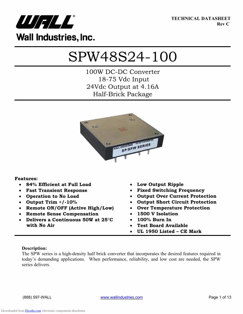
SPW48S24-100100W DC-DC Converter
18-75 Vdc Input24Vdc Output at 4.16A
Half-Brick Package
Features:84% Efficient at Full LoadFast Transient ResponseOperation to No Load Output Trim +/-10% Remote ON/OFF (Active High/Low) Remote Sense Compensation Delivers a Continuous 50W at 25 Cwith No Air
Low Output RippleFixed Switching Frequency Output Over Current Protection Output Short Circuit Protection Over Temperature Protection 1500 V Isolation 100% Burn In Test Board Available UL 1950 Listed – CE Mark
Description: The SPW series is a high-density half brick converter that incorporates the desired features required in today’s demanding applications. When performance, reliability, and low cost are needed, the SPW series delivers.
Downloaded from Elcodis.com electronic components distributor
TECHNICAL DATASHEETWALL INDUSTRIES, INC. Rev C SPW48S24-100
(888) 597-WALL www.wallindustries.com Page 2 of 13
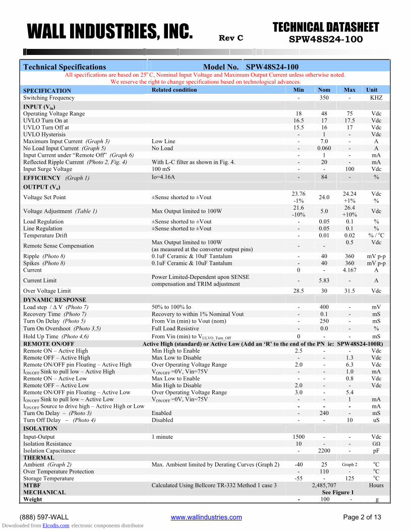
Technical Specifications MMooddeell NNoo.. SPW48S24-100All specifications are based on 25o C, Nominal Input Voltage and Maximum Output Current unless otherwise noted.
We reserve the right to change specifications based on technological advances.SPECIFICATION Related condition Min Nom Max UnitSwitching Frequency - 350 - KHZ INPUT (Vin)Operating Voltage Range 18 48 75 Vdc UVLO Turn On at 16.5 17 17.5 VdcUVLO Turn Off at 15.5 16 17 Vdc UVLO Hysterisis - 1 - VdcMaximum Input Current (Graph 3) Low Line - 7.0 - A No Load Input Current (Graph 5) No Load - 0.060 - AInput Current under “Remote Off” (Graph 6) - 1 - mA Reflected Ripple Current (Photo 2, Fig. 4) With L-C filter as shown in Fig. 4. - 20 - mAInput Surge Voltage 100 mS - - 100 Vdc EFFICIENCY (Graph 1) Io=4.16A - 84 - %
OUTPUT (Vo)
Voltage Set Point ±Sense shorted to ±Vout 23.76-1% 24.0 24.24
+1%Vdc%
Voltage Adjustment (Table 1) Max Output limited to 100W 21.6-10% 5.0 26.4
+10% Vdc
Load Regulation ±Sense shorted to ±Vout - 0.05 0.1 % Line Regulation ±Sense shorted to ±Vout - 0.05 0.1 %Temperature Drift - 0.01 0.02 % / oC
Remote Sense Compensation Max Output limited to 100W (as measured at the converter output pins) - - 0.5 Vdc
Ripple (Photo 8) 0.1uF Ceramic & 10uF Tantalum - 40 360 mV p-p Spikes (Photo 8) 0.1uF Ceramic & 10uF Tantalum - 40 360 mV p-p Current 0 - 4.167 A
Current Limit Power Limited-Dependent upon SENSE compensation and TRIM adjustment - 5.83 - A
Over Voltage Limit 28.5 30 31.5 Vdc DYNAMIC RESPONSE Load step / V (Photo 7) 50% to 100% Io - 400 - mV Recovery Time (Photo 7) Recovery to within 1% Nominal Vout - 0.1 - mSTurn On Delay (Photo 5) From Vin (min) to Vout (nom) - 250 - mS Turn On Overshoot (Photo 3,5) Full Load Resistive - 0.0 - %Hold Up Time (Photo 4,6) From Vin (min) to VULVO_Turn_Off 0 - - mS REMOTE ON/OFFRemote ON – Active High Min High to Enable 2.5 - - VdcRemote OFF – Active High Max Low to Disable - - 1.3 VdcRemote ON/OFF pin Floating – Active High Over Operating Voltage Range 2.0 - 6.3 Vdc ION/OFF Sink to pull low – Active High VON/OFF =0V, Vin=75V - - 1.0 mARemote ON – Active Low Max Low to Enable - - 0.8 Vdc Remote OFF – Active Low Min High to Disable 2.0 - - VdcRemote ON/OFF pin Floating – Active Low Over Operating Voltage Range 3.0 - 5.4 ION/OFF Sink to pull low – Active Low VON/OFF =0V, Vin=75V - - 1 mAION/OFF Source to drive high – Active High or Low - - - mATurn On Delay – (Photo 3) Enabled - 240 - mSTurn Off Delay – (Photo 4) Disabled - - 10 uS ISOLATIONInput-Output 1 minute 1500 - - VdcIsolation Resistance 10 - - GIsolation Capacitance - 2200 - pF THERMALAmbient (Graph 2) Max. Ambient limited by Derating Curves (Graph 2) -40 25 Graph 2 oCOver Temperature Protection - 110 - oCStorage Temperature -55 - 125 oCMTBF Calculated Using Bellcore TR-332 Method 1 case 3 2,485,707 HoursMECHANICAL See Figure 1 Weight - 100 - g
Active High (standard) or Active Low (Add an ‘R’ to the end of the PN ie: SPW48S24-100R)
Downloaded from Elcodis.com electronic components distributor
TECHNICAL DATASHEETWALL INDUSTRIES, INC. Rev C SPW48S24-100
(888) 597-WALL www.wallindustries.com Page 3 of 13
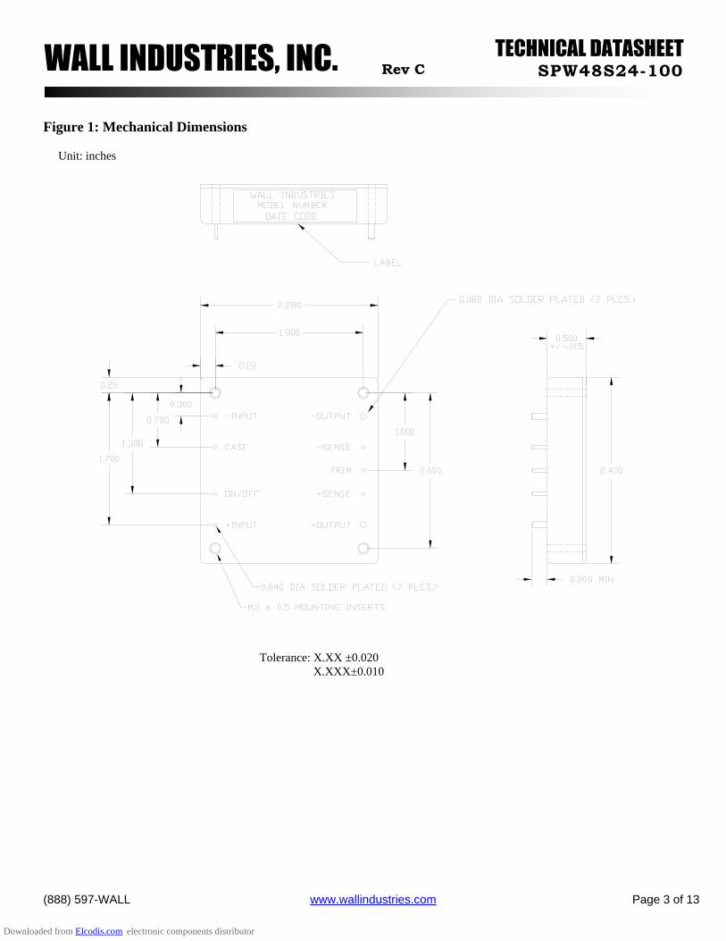
Figure 1: Mechanical Dimensions
Unit: inches
Tolerance: X.XX ±0.020 X.XXX±0.010
Downloaded from Elcodis.com electronic components distributor
TECHNICAL DATASHEETWALL INDUSTRIES, INC. Rev C SPW48S24-100
(888) 597-WALL www.wallindustries.com Page 4 of 13
DESIGN CONSIDERATIONSUnder Voltage Lock Out (UVLO) The converter output is disabled until the input voltage exceeds the UVLO turn-on limit. The converter will remain ON until the input voltage falls below the UVLO turn-off limit.
Over Current Protection The converter is internally protected from short circuit and over current conditions. During these fault conditions, the converter output will ‘hiccup’. The converter output will recover once the short or over current fault is removed.
Over Temperature ProtectionThe converter is protected from over temperature conditions. Upon exceeding this temperature, the converter will shut down. The converter will automatically recover once the over temperature condition is removed.
Input Filter No additional input capacitor is needed for the power supply to operate. However, to reduce the input ripple voltage and current beyond what is seen in Photo 1, additional capacitance may be added across the input (see Photo 2). No inductor should be placed between the capacitor and the input to the converter without a termination capacitor (“Cin” Fig. 4).
Output Filter No additional output capacitor is needed for the power supply to operate. However, to reduce the ripple and noise on the output,additional capacitance may be added. Usually, a 0.1uF X7R capacitor works best for reducing H.F.spike noise. Also, capacitance in the form of a tantalum or aluminum electrolytic capacitor may also be placed across the output in order reduce base ripple, and improve the transient peak-to-peak voltage deviation.
Remote Sense To improve the regulation at the load, route the connections from the -Sense and the +Sense pins to the –Vout and +Vout connections AT the load. This will force the converter to regulate the voltage at the load and not at the pins of the converter (refer to Graph 9). If it is not desired to use the Remotes Sense feature, the –Sense and +Sense pins should be shorted to the -Vout and +Vout pins respectively.Shorting the Sense pins to the Vout pins will reduce the voltage drops through the converter pins.
FusingIt is required that the input to the converter be supplied with a maximum 10 A, 250 V rated fuse.
SafetyThe SPW series is CE marked and certified by the following: UL1950 ,CUL950, TUV60950 FILE 155800. The isolation provided by theSPW series is a Basic insulation in accordance with EN60950. SELV output reliability is maintained only if the input to the SPWconverter is a SELV source.
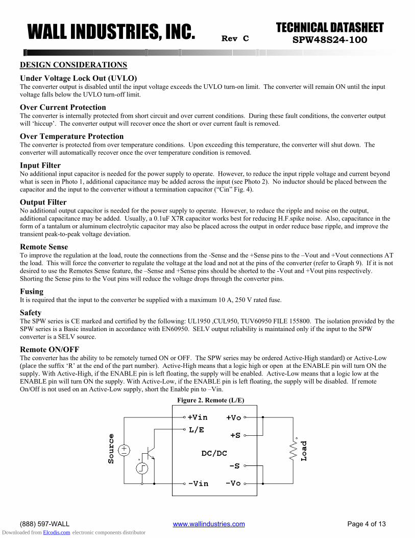
Remote ON/OFF The converter has the ability to be remotely turned ON or OFF. The SPW series may be ordered Active-High standard) or Active-Low(place the suffix ‘R’ at the end of the part number). Active-High means that a logic high or open at the ENABLE pin will turn ON thesupply. With Active-High, if the ENABLE pin is left floating, the supply will be enabled. Active-Low means that a logic low at theENABLE pin will turn ON the supply. With Active-Low, if the ENABLE pin is left floating, the supply will be disabled. If remoteOn/Off is not used on an Active-Low supply, short the Enable pin to –Vin.
Figure 2. Remote (L/E)
Downloaded from Elcodis.com electronic components distributor
TECHNICAL DATASHEETWALL INDUSTRIES, INC. Rev C SPW48S24-100
(888) 597-WALL www.wallindustries.com Page 5 of 13
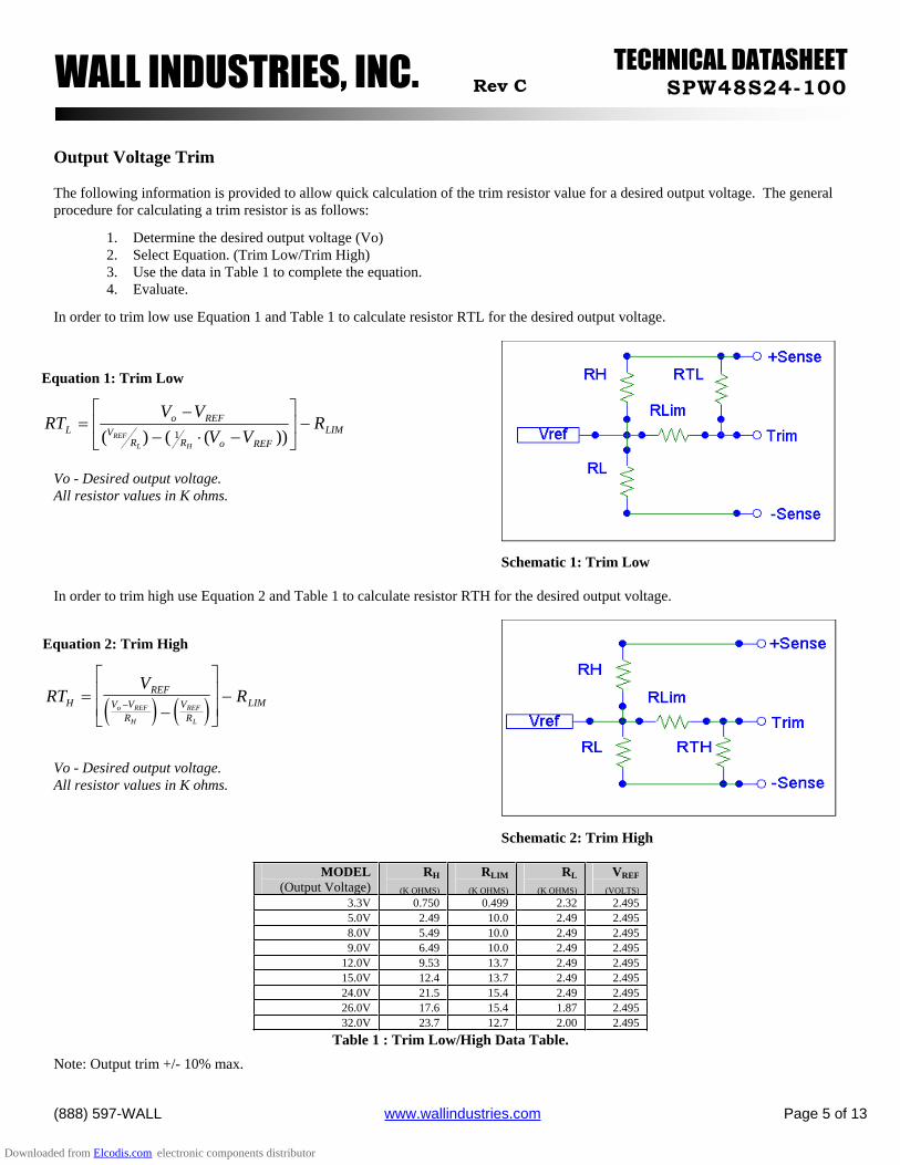
Output Voltage Trim
The following information is provided to allow quick calculation of the trim resistor value for a desired output voltage. The generalprocedure for calculating a trim resistor is as follows:
1. Determine the desired output voltage (Vo) 2. Select Equation. (Trim Low/Trim High) 3. Use the data in Table 1 to complete the equation. 4. Evaluate.
In order to trim low use Equation 1 and Table 1 to calculate resistor RTL for the desired output voltage.
Vo - Desired output voltage. All resistor values in K ohms.
In order to trim high use Equation 2 and Table 1 to calculate resistor RTH for the desired output voltage.
Vo - Desired output voltage. All resistor values in K ohms.
MODEL(Output Voltage)
RH
(K OHMS)
RLIM
(K OHMS)
RL
(K OHMS)
VREF
(VOLTS)
3.3V 0.750 0.499 2.32 2.495 5.0V 2.49 10.0 2.49 2.495 8.0V 5.49 10.0 2.49 2.495 9.0V 6.49 10.0 2.49 2.495
12.0V 9.53 13.7 2.49 2.495 15.0V 12.4 13.7 2.49 2.495 24.0V 21.5 15.4 2.49 2.495 26.0V 17.6 15.4 1.87 2.495 32.0V 23.7 12.7 2.00 2.495
Table 1 : Trim Low/High Data Table.
Note: Output trim +/- 10% max.
Schematic 1: Trim Low
Equation 1: Trim Low
LIMREFoRR
VREFo
L RVV
VVRT
HL
REF ))(()( 1
Schematic 2: Trim High
Equation 2: Trim High
RTV
RHREF
V VR
VR
LIMo REF
H
REF
L
Downloaded from Elcodis.com electronic components distributor
TECHNICAL DATASHEETWALL INDUSTRIES, INC. Rev C SPW48S24-100
(888) 597-WALL www.wallindustries.com Page 6 of 13
Note: Output trim +/- 10% max.
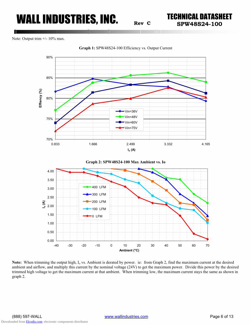
Graph 1: SPW48S24-100 Efficiency vs. Output Current
70%
75%
80%
85%
90%
0.833 1.666 2.499 3.332 4.165
Io (A)
Effie
ncy
(%)
Vin=36V
Vin=48V
Vin=60V
Vin=75V
Graph 2: SPW48S24-100 Max Ambient vs. Io
0.00
0.50
1.00
1.50
2.00
2.50
3.00
3.50
4.00
-40 -30 -20 -10 0 10 20 30 40 50 60 70Ambient (°C)
I o (A
)
400 LFM
300 LFM
200 LFM
100 LFM
0 LFM
Note: When trimming the output high, Io vs. Ambient is derated by power. ie: from Graph 2, find the maximum current at the desired ambient and airflow, and multiply this current by the nominal voltage (24V) to get the maximum power. Divide this power by the desired trimmed high voltage to get the maximum current at that ambient. When trimming low, the maximum current stays the same as shown in graph 2.
Downloaded from Elcodis.com electronic components distributor
TECHNICAL DATASHEETWALL INDUSTRIES, INC. Rev C SPW48S24-100
(888) 597-WALL www.wallindustries.com Page 7 of 13
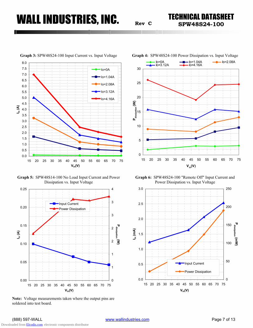
Graph 3: SPW48S24-100 Input Current vs. Input Voltage Graph 4: SPW48S24-100 Power Dissipation vs. Input Voltage
0.0
0.5
1.0
1.5
2.0
2.5
3.0
3.5
4.0
4.5
5.0
5.5
6.0
6.5
7.0
7.5
8.0
15 20 25 30 35 40 45 50 55 60 65 70 75Vin(V)
I in (A
)
Io=0A
Io=1.04A
Io=2.08A
Io=3.12A
Io=4.16A
0
5
10
15
20
25
30
15 20 25 30 35 40 45 50 55 60 65 70 75
Vin(V)
P diss
ipat
ion (
W)
Io=0A Io=1.04A Io=2.08AIo=3.12A Io=4.16A
Graph 5: SPW48S14-100 No Load Input Current and Power Dissipation vs. Input Voltage
Graph 6: SPW48S24-100 "Remote Off" Input Current and Power Dissipation vs. Input Voltage
0.00
0.05
0.10
0.15
0.20
0.25
15 20 25 30 35 40 45 50 55 60 65 70 75Vin(V)
I in (A
)
0
1
1
2
2
3
3
4
Pdissipation (W
)
Input CurrentPower Dissipation
0.0
0.5
1.0
1.5
2.0
2.5
3.0
15 20 25 30 35 40 45 50 55 60 65 70 75
Vin(V)
I in (m
A)
0
50
100
150
200
250
Pdissipation (m
W)
Input Current
Power Dissipation
Note: Voltage measurements taken where the output pins are soldered into test board.
Downloaded from Elcodis.com electronic components distributor
TECHNICAL DATASHEETWALL INDUSTRIES, INC. Rev C SPW48S24-100
(888) 597-WALL www.wallindustries.com Page 8 of 13
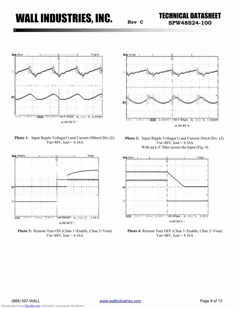
Photo 1: Input Ripple Voltage(1) and Current-500mA/Div.(2). Vin=48V, Iout = 4.16A
Photo 2: Input Ripple Voltage(1) and Current-20mA/Div. (2). Vin=48V, Iout = 4.16A
With an L-C filter across the Input (Fig. 4)
Photo 3: Remote Turn ON (Chan 1=Enable, Chan 2=Vout) Vin=48V, Iout = 4.16A
Photo 4: Remote Turn OFF (Chan 1=Enable, Chan 2=Vout) Vin=48V, Iout = 4.16A
Downloaded from Elcodis.com electronic components distributor
TECHNICAL DATASHEETWALL INDUSTRIES, INC. Rev C SPW48S24-100
(888) 597-WALL www.wallindustries.com Page 9 of 13
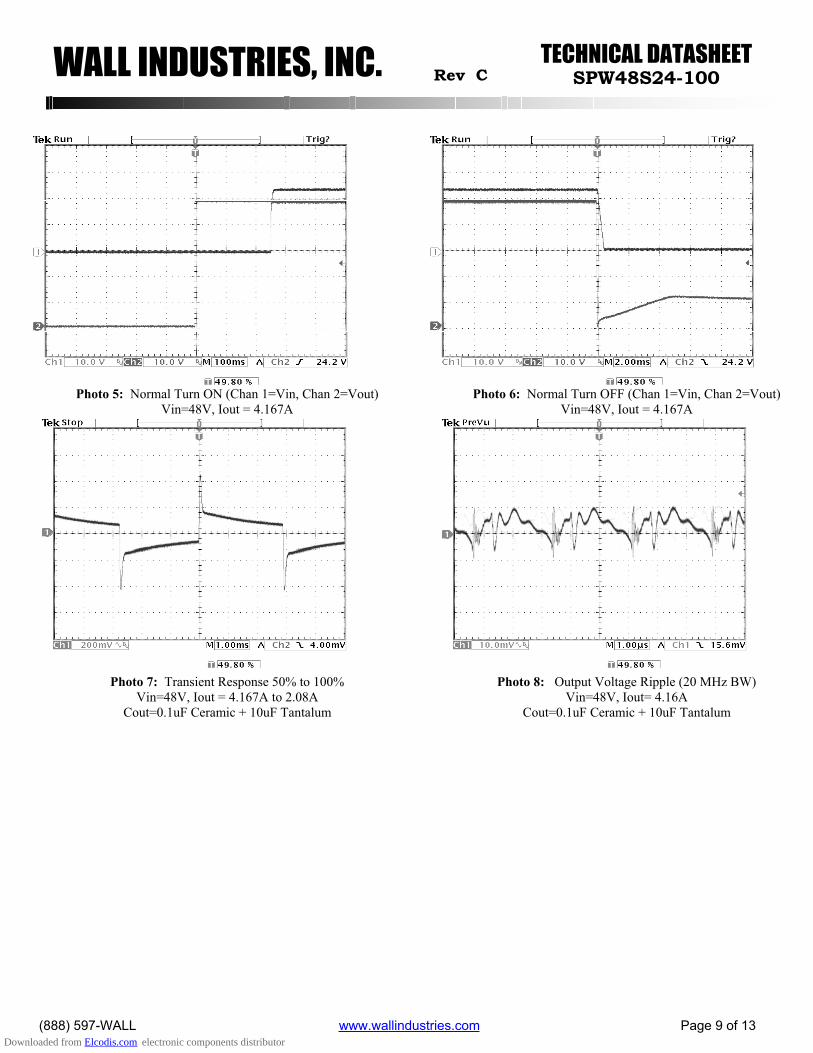
Photo 5: Normal Turn ON (Chan 1=Vin, Chan 2=Vout) Vin=48V, Iout = 4.167A
Photo 6: Normal Turn OFF (Chan 1=Vin, Chan 2=Vout) Vin=48V, Iout = 4.167A
Photo 7: Transient Response 50% to 100% Vin=48V, Iout = 4.167A to 2.08A
Cout=0.1uF Ceramic + 10uF Tantalum
Photo 8: Output Voltage Ripple (20 MHz BW) Vin=48V, Iout= 4.16A
Cout=0.1uF Ceramic + 10uF Tantalum
Downloaded from Elcodis.com electronic components distributor
TECHNICAL DATASHEETWALL INDUSTRIES, INC. Rev C SPW48S24-100
(888) 597-WALL www.wallindustries.com Page 10 of 13
TEST SETUP: The SPW48S24-100 specifications are tested with the following configurations:
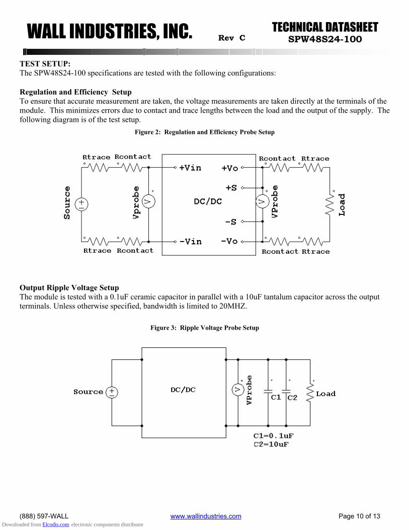
Regulation and Efficiency Setup To ensure that accurate measurement are taken, the voltage measurements are taken directly at the terminals of the module. This minimizes errors due to contact and trace lengths between the load and the output of the supply. The following diagram is of the test setup.
Figure 2: Regulation and Efficiency Probe Setup
Output Ripple Voltage Setup The module is tested with a 0.1uF ceramic capacitor in parallel with a 10uF tantalum capacitor across the output terminals. Unless otherwise specified, bandwidth is limited to 20MHZ.
Figure 3: Ripple Voltage Probe Setup
Downloaded from Elcodis.com electronic components distributor
TECHNICAL DATASHEETWALL INDUSTRIES, INC. Rev C SPW48S24-100
(888) 597-WALL www.wallindustries.com Page 11 of 13
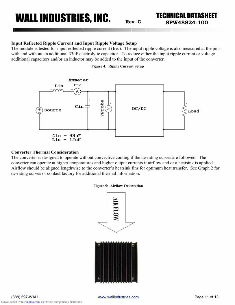
Input Reflected Ripple Current and Input Ripple Voltage Setup The module is tested for input reflected ripple current (Irrc). The input ripple voltage is also measured at the pins with and without an additional 33uF electrolytic capacitor. To reduce either the input ripple current or voltage additional capacitors and/or an inductor may be added to the input of the converter.
Figure 4: Ripple Current Setup
Converter Thermal ConsiderationThe converter is designed to operate without convective cooling if the de-rating curves are followed. The converter can operate at higher temperatures and higher output currents if airflow and or a heatsink is applied.Airflow should be aligned lengthwise to the converter’s heatsink fins for optimum heat transfer. See Graph 2 for de-rating curves or contact factory for additional thermal information.
Figure 5: Airflow Orientation
Downloaded from Elcodis.com electronic components distributor
TECHNICAL DATASHEETWALL INDUSTRIES, INC. Rev C SPW48S24-100
(888) 597-WALL www.wallindustries.com Page 12 of 13
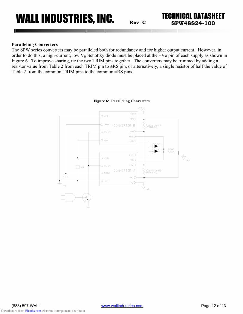
Paralleling Converters The SPW series converters may be paralleled both for redundancy and for higher output current. However, in order to do this, a high-current, low Vf, Schottky diode must be placed at the +Vo pin of each supply as shown in Figure 6. To improve sharing, tie the two TRIM pins together. The converters may be trimmed by adding a resistor value from Table 2 from each TRIM pin to ±RS pin, or alternatively, a single resistor of half the value of Table 2 from the common TRIM pins to the common ±RS pins.
Figure 6: Paralleling Converters
Downloaded from Elcodis.com electronic components distributor
TECHNICAL DATASHEETWALL INDUSTRIES, INC. Rev C SPW48S24-100
(888) 597-WALL www.wallindustries.com Page 13 of 13
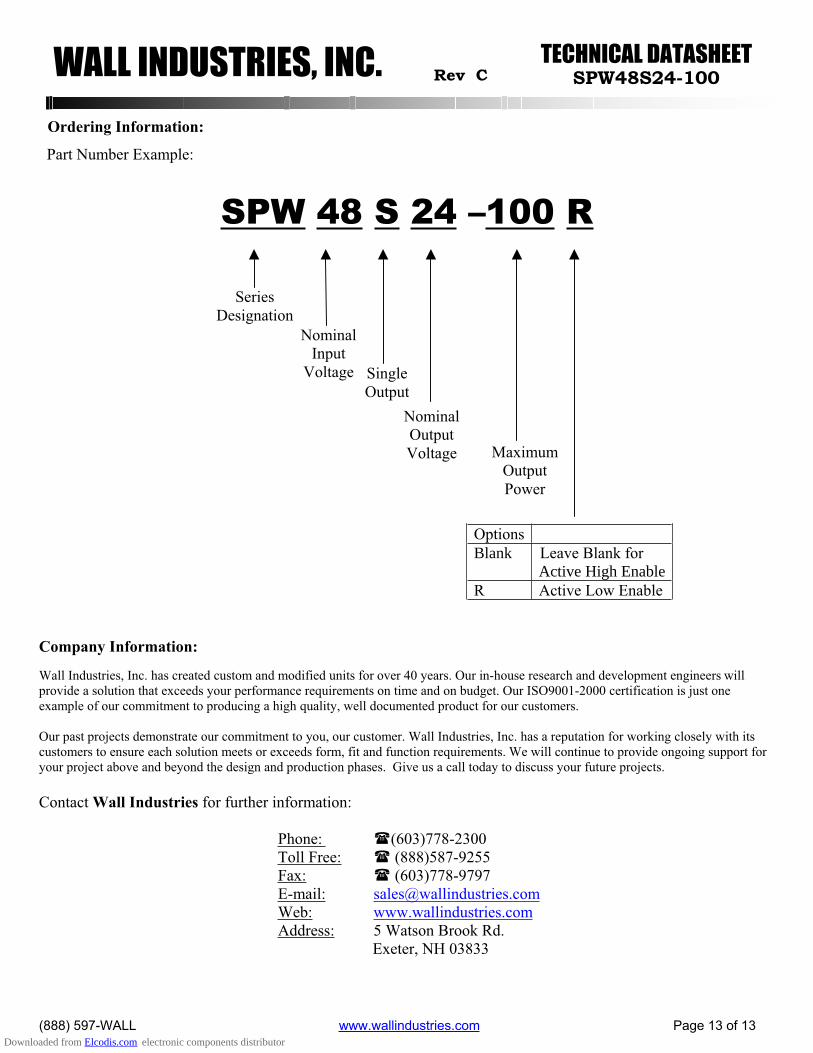
Ordering Information:
Company Information:
Wall Industries, Inc. has created custom and modified units for over 40 years. Our in-house research and development engineers willprovide a solution that exceeds your performance requirements on time and on budget. Our ISO9001-2000 certification is just oneexample of our commitment to producing a high quality, well documented product for our customers.
Our past projects demonstrate our commitment to you, our customer. Wall Industries, Inc. has a reputation for working closely with its customers to ensure each solution meets or exceeds form, fit and function requirements. We will continue to provide ongoing support for your project above and beyond the design and production phases. Give us a call today to discuss your future projects.
Contact Wall Industries for further information:
Phone: (603)778-2300Toll Free: (888)587-9255 Fax: (603)778-9797 E-mail: [email protected]: www.wallindustries.comAddress: 5 Watson Brook Rd.
Exeter, NH 03833
Part Number Example:
SPW 48 S 24 –100 R
Options Blank Leave Blank for
Active High EnableR Active Low Enable
SeriesDesignation
Nominal Input
Voltage SingleOutput
Nominal OutputVoltage Maximum
OutputPower
Downloaded from Elcodis.com electronic components distributor