maintenance manual dg-500 issued
TRANSCRIPT
Maintenance Manual DG-500
Issued: December 2009 0.0 Copyright DG Flugzeugbau GmbH - any copy or publishing prohibited Manual valid with the up-to-date cover page only
Recommendations to order spare parts
Please try to determine the exact designations of the spare parts for your order using the maintenance manual. This is to guarantee a fast and correct delivery of the parts. The designations are to find in the sections system description, instructions for assembly and servicing work and especially in the diagrams of the maintenance manual. Yours sincerely DG FLUGZEUGBAU GMBH
Dipl.- Ing. W. Dirks
Maintenance Manual DG-500
Issued: September 2011 TN500/05 0.1 Copyright DG Flugzeugbau GmbH - any copy or publishing prohibited Manual valid with the up-to-date cover page only
0 General
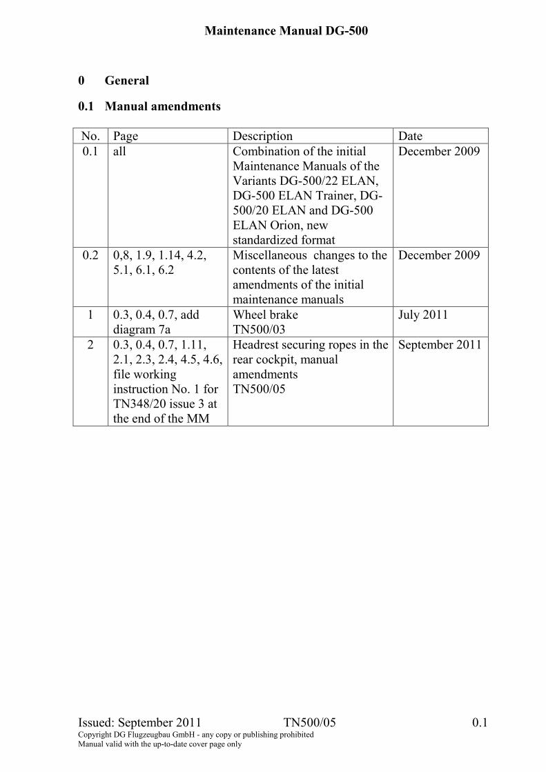
0.1 Manual amendments No. Page Description Date 0.1
all Combination of the initial
Maintenance Manuals of the Variants DG-500/22 ELAN, DG-500 ELAN Trainer, DG-500/20 ELAN and DG-500 ELAN Orion, new standardized format
December 2009
0.2 0,8, 1.9, 1.14, 4.2, 5.1, 6.1, 6.2
Miscellaneous changes to the contents of the latest amendments of the initial maintenance manuals
December 2009
1 0.3, 0.4, 0.7, add diagram 7a
Wheel brake TN500/03
July 2011
2 0.3, 0.4, 0.7, 1.11, 2.1, 2.3, 2.4, 4.5, 4.6, file working instruction No. 1 for TN348/20 issue 3 at the end of the MM
Headrest securing ropes in the rear cockpit, manual amendments TN500/05
September 2011
Maintenance Manual DG-500
Issued: December 2009 0.2 Copyright DG Flugzeugbau GmbH - any copy or publishing prohibited Manual valid with the up-to-date cover page only
Page intentionally left blank
Maintenance Manual DG-500
Issued: September 2011 TN500/05 0.3 Copyright DG Flugzeugbau GmbH - any copy or publishing prohibited Manual valid with the up-to-date cover page only
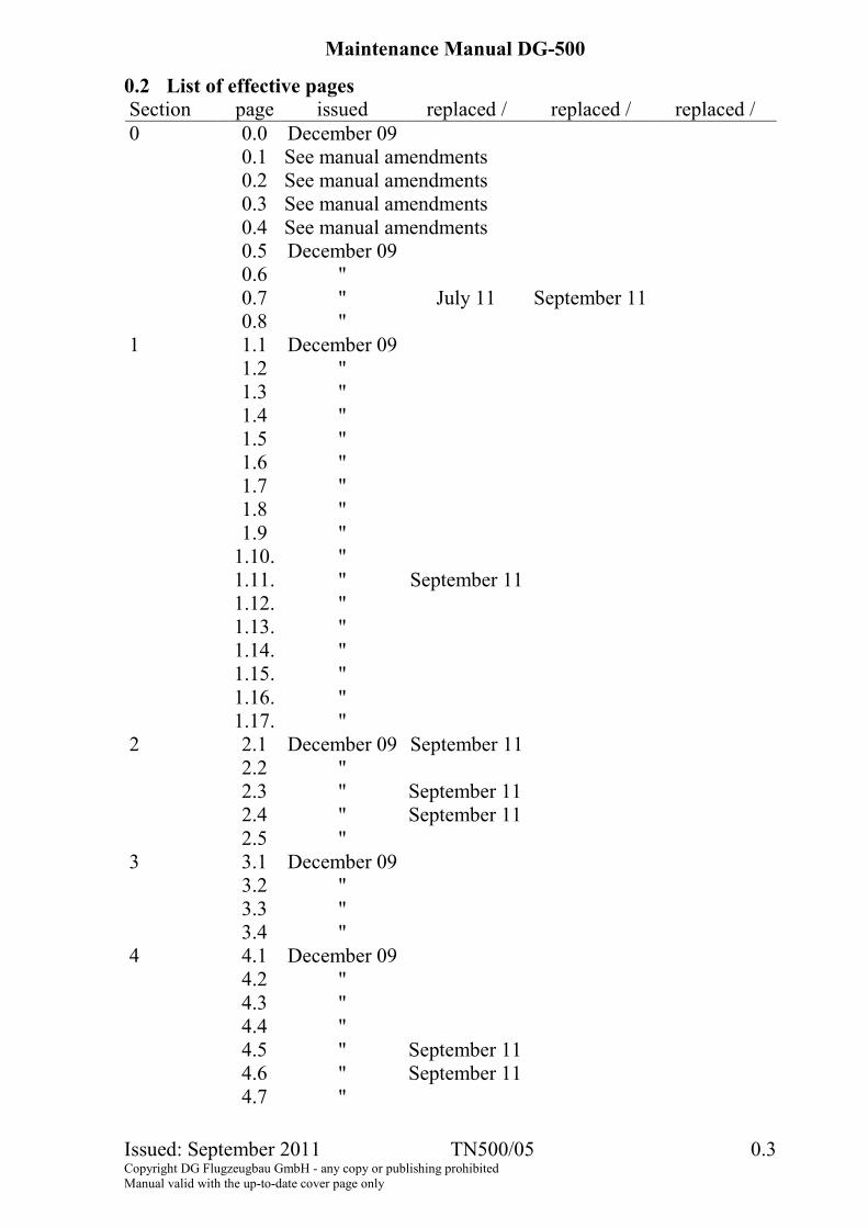
0.2 List of effective pages Section page issued replaced / replaced / replaced / 0 0.0 December 09 0.1 See manual amendments 0.2 See manual amendments 0.3 See manual amendments 0.4 See manual amendments 0.5 December 09 0.6 " 0.7 " July 11 September 11 0.8 " 1 1.1 December 09 1.2 " 1.3 " 1.4 " 1.5 " 1.6 " 1.7 " 1.8 " 1.9 " 1.10. " 1.11. " September 11 1.12. " 1.13. " 1.14. " 1.15. " 1.16. " 1.17. " 2 2.1 December 09 September 11 2.2 " 2.3 " September 11 2.4 " September 11 2.5 " 3 3.1 December 09 3.2 " 3.3 " 3.4 " 4 4.1 December 09 4.2 " 4.3 " 4.4 " 4.5 " September 11 4.6 " September 11 4.7 "
Maintenance Manual DG-500
Issued: September 2011 TN500/05 0.4 Copyright DG Flugzeugbau GmbH - any copy or publishing prohibited Manual valid with the up-to-date cover page only
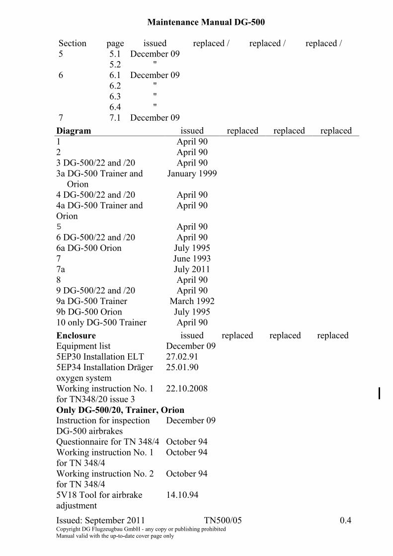
Section page issued replaced / replaced / replaced / 5 5.1 December 09 5.2 " 6 6.1 December 09 6.2 " 6.3 " 6.4 " 7 7.1 December 09
Diagram issued replaced replaced replaced 1 April 90 2 April 90 3 DG-500/22 and /20 April 90 3a DG-500 Trainer and
Orion January 1999
4 DG-500/22 and /20 April 90 4a DG-500 Trainer and Orion
April 90
5 April 90 6 DG-500/22 and /20 April 90 6a DG-500 Orion July 1995 7 June 1993 7a July 2011 8 April 90 9 DG-500/22 and /20 April 90 9a DG-500 Trainer March 1992 9b DG-500 Orion July 1995 10 only DG-500 Trainer April 90
Enclosure issued replaced replaced replaced Equipment list December 09 5EP30 Installation ELT 27.02.91 5EP34 Installation Dräger oxygen system
25.01.90
Working instruction No. 1 for TN348/20 issue 3
22.10.2008
Only DG-500/20, Trainer, Orion Instruction for inspection DG-500 airbrakes
December 09
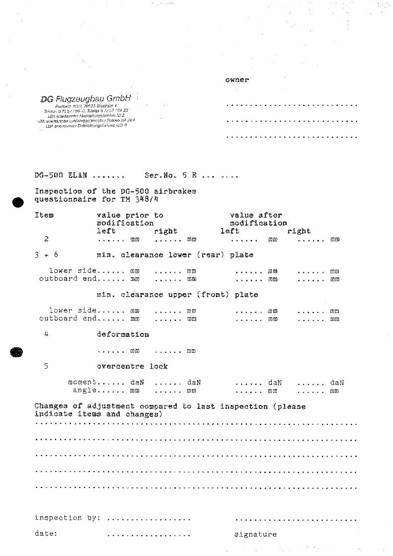
Questionnaire for TN 348/4 October 94 Working instruction No. 1 for TN 348/4
October 94
Working instruction No. 2 for TN 348/4
October 94
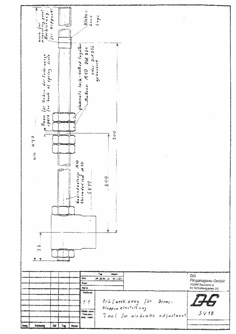
5V18 Tool for airbrake adjustment
14.10.94
Maintenance Manual DG-500
Issued: December 2009 0.5 Copyright DG Flugzeugbau GmbH - any copy or publishing prohibited Manual valid with the up-to-date cover page only
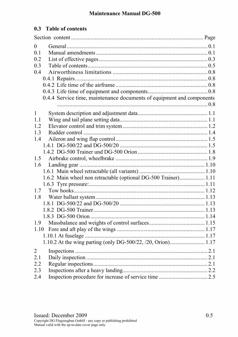
0.3 Table of contents Section content ............................................................................................... Page 0 General ..................................................................................................... 0.1 0.1 Manual amendments ................................................................................ 0.1 0.2 List of effective pages.............................................................................. 0.3 0.3 Table of contents...................................................................................... 0.5 0.4 Airworthiness limitations .................................................................... 0.8
0.4.1 Repairs ............................................................................................... 0.8 0.4.2 Life time of the airframe .................................................................. 0.8 0.4.3 Life time of equipment and components........................................... 0.8 0.4.4 Service time, maintenance documents of equipment and components
............................................................................................................ 0.8
1 System description and adjustment data.................................................. 1.1 1.1 Wing and tail plane setting data............................................................... 1.1 1.2 Elevator control and trim system............................................................. 1.2 1.3 Rudder control ......................................................................................... 1.4 1.4 Aileron and wing flap control.................................................................. 1.5
1.4.1 DG-500/22 and DG-500/20 ............................................................... 1.5 1.4.2 DG-500 Trainer und DG-500 Orion .................................................. 1.8
1.5 Airbrake control, wheelbrake .................................................................. 1.9 1.6 Landing gear .......................................................................................... 1.10
1.6.1 Main wheel retractable (all variants) ............................................... 1.10 1.6.2 Main wheel non retractable (optional DG-500 Trainer).................. 1.11 1.6.3 Tyre pressure:................................................................................... 1.11
1.7 Tow hooks.............................................................................................. 1.12 1.8 Water ballast system .............................................................................. 1.13
1.8.1 DG-500/22 and DG-500/20 ............................................................. 1.13 1.8.2 DG-500 Trainer................................................................................ 1.13 1.8.3 DG-500 Orion .................................................................................. 1.14
1.9 Massbalance and weights of control surfaces........................................ 1.15 1.10 Fore and aft play of the wings ............................................................... 1.17
1.10.1 At fuselage ...................................................................................... 1.17 1.10.2 At the wing parting (only DG-500/22, /20, Orion)......................... 1.17
2 Inspections ............................................................................................... 2.1 2.1 Daily inspection ....................................................................................... 2.1 2.2 Regular inspections.................................................................................. 2.1 2.3 Inspections after a heavy landing............................................................. 2.2 2.4 Inspection procedure for increase of service time ................................... 2.5
Maintenance Manual DG-500
Issued: December 2009 0.6 Copyright DG Flugzeugbau GmbH - any copy or publishing prohibited Manual valid with the up-to-date cover page only
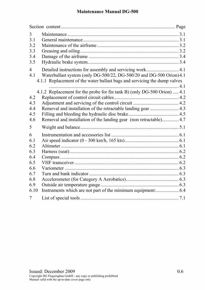
Section content ............................................................................................... Page 3 Maintenance............................................................................................. 3.1 3.1 General maintenance................................................................................ 3.1 3.2 Maintenance of the airframe .................................................................... 3.2 3.3 Greasing and oiling .................................................................................. 3.2 3.4 Damage of the airframe ........................................................................... 3.4 3.5 Hydraulic brake system............................................................................ 3.4
4 Detailed instructions for assembly and servicing work........................... 4.1 4.1 Waterballast system (only DG-500/22, DG-500/20 and DG-500 Orion)4.1
4.1.1 Replacement of the water ballast bags and servicing the dump valves............................................................................................................ 4.1
4.1.2 Replacement for the probe for fin tank B) (only DG-500 Orion) ..... 4.1 4.2 Replacement of control circuit cables...................................................... 4.2 4.3 Adjustment and servicing of the control circuit ...................................... 4.2 4.4 Removal and installation of the retractable landing gear ........................ 4.3 4.5 Filling and bleeding the hydraulic disc brake.......................................... 4.5 4.6 Removal and installation of the landing gear (non retractable).............. 4.7
5 Weight and balance.................................................................................. 5.1
6 Instrumentation and accessories list ........................................................ 6.1 6.1 Air speed indicator (0 - 300 km/h, 165 kts)............................................. 6.1 6.2 Altimeter .................................................................................................. 6.1 6.3 Harness (seat)........................................................................................... 6.2 6.4 Compass ................................................................................................... 6.2 6.5 VHF transceiver ....................................................................................... 6.2 6.6 Variometer ............................................................................................... 6.3 6.7 Turn and bank indicator ........................................................................... 6.3 6.8 Accelerometer (for Category A Aerobatics)............................................ 6.3 6.9 Outside air temperature gauge ................................................................. 6.3 6.10 Instruments which are not part of the minimum equipment:................... 6.4
7 List of special tools .................................................................................. 7.1
Maintenance Manual DG-500
Issued: September 2011 TN500/05 0.7 Copyright DG Flugzeugbau GmbH - any copy or publishing prohibited Manual valid with the up-to-date cover page only
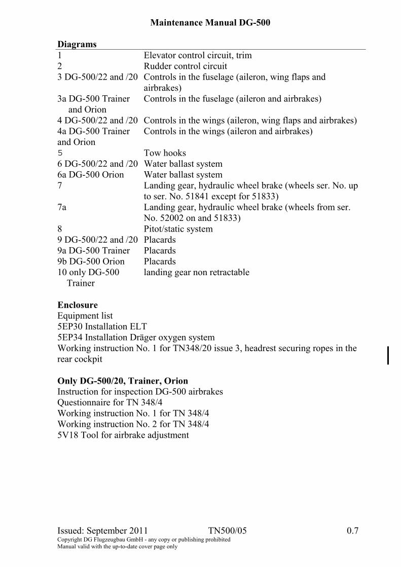
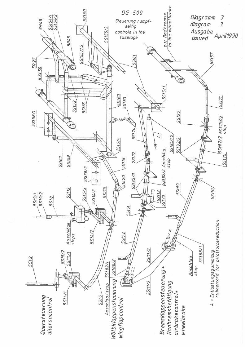
Diagrams 1 Elevator control circuit, trim 2 Rudder control circuit 3 DG-500/22 and /20 Controls in the fuselage (aileron, wing flaps and
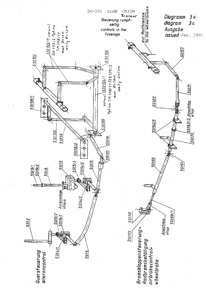
airbrakes) 3a DG-500 Trainer
and Orion Controls in the fuselage (aileron and airbrakes)
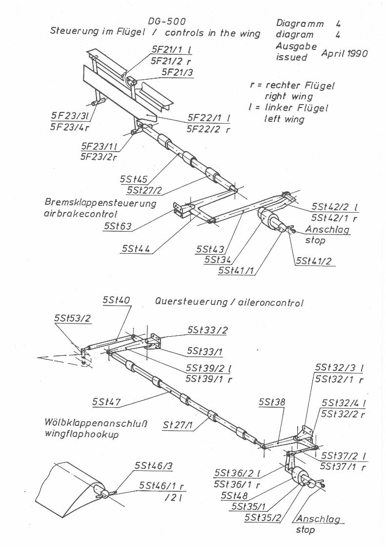
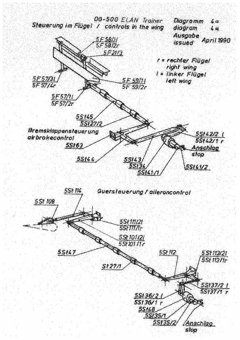
4 DG-500/22 and /20 Controls in the wings (aileron, wing flaps and airbrakes) 4a DG-500 Trainer and Orion
Controls in the wings (aileron and airbrakes)
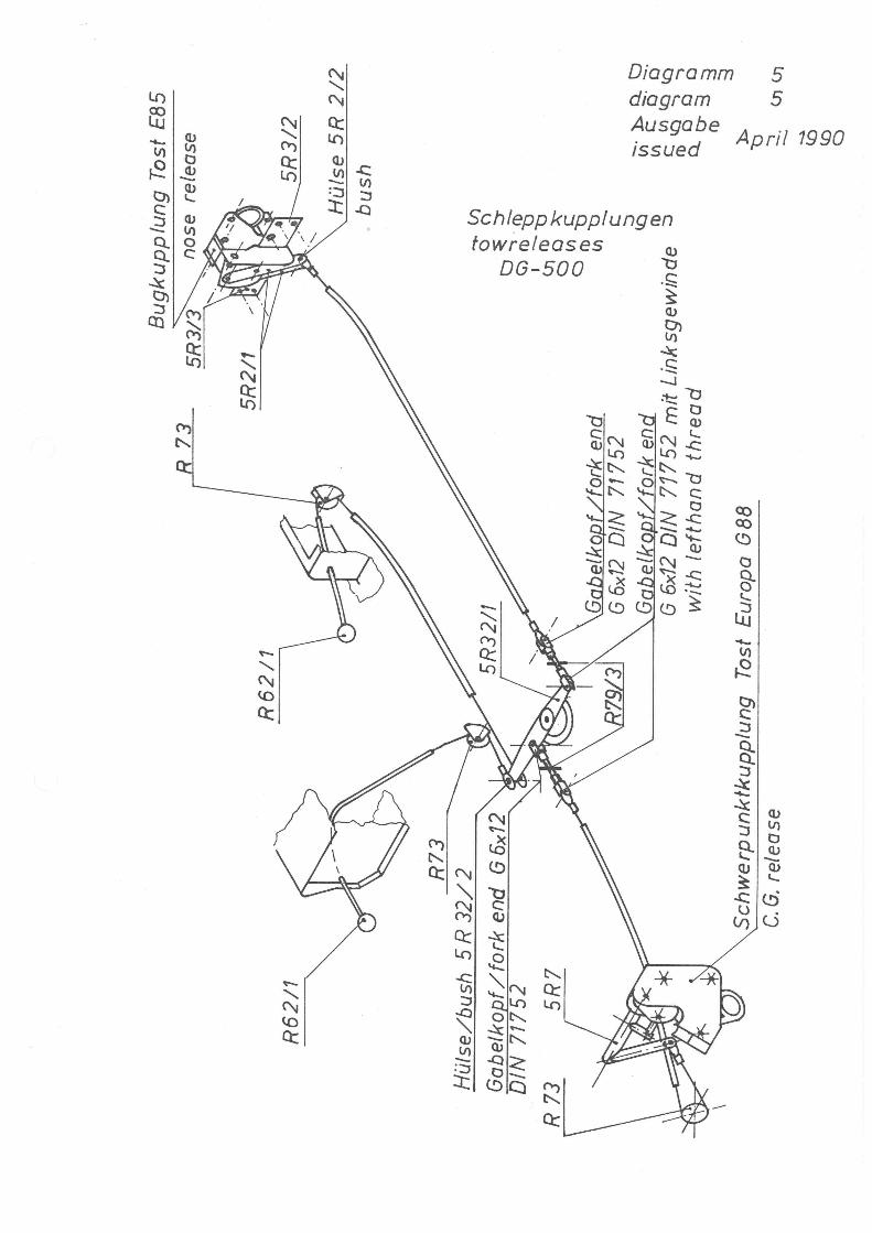
5 Tow hooks 6 DG-500/22 and /20 Water ballast system 6a DG-500 Orion Water ballast system 7 Landing gear, hydraulic wheel brake (wheels ser. No. up
to ser. No. 51841 except for 51833) 7a Landing gear, hydraulic wheel brake (wheels from ser.
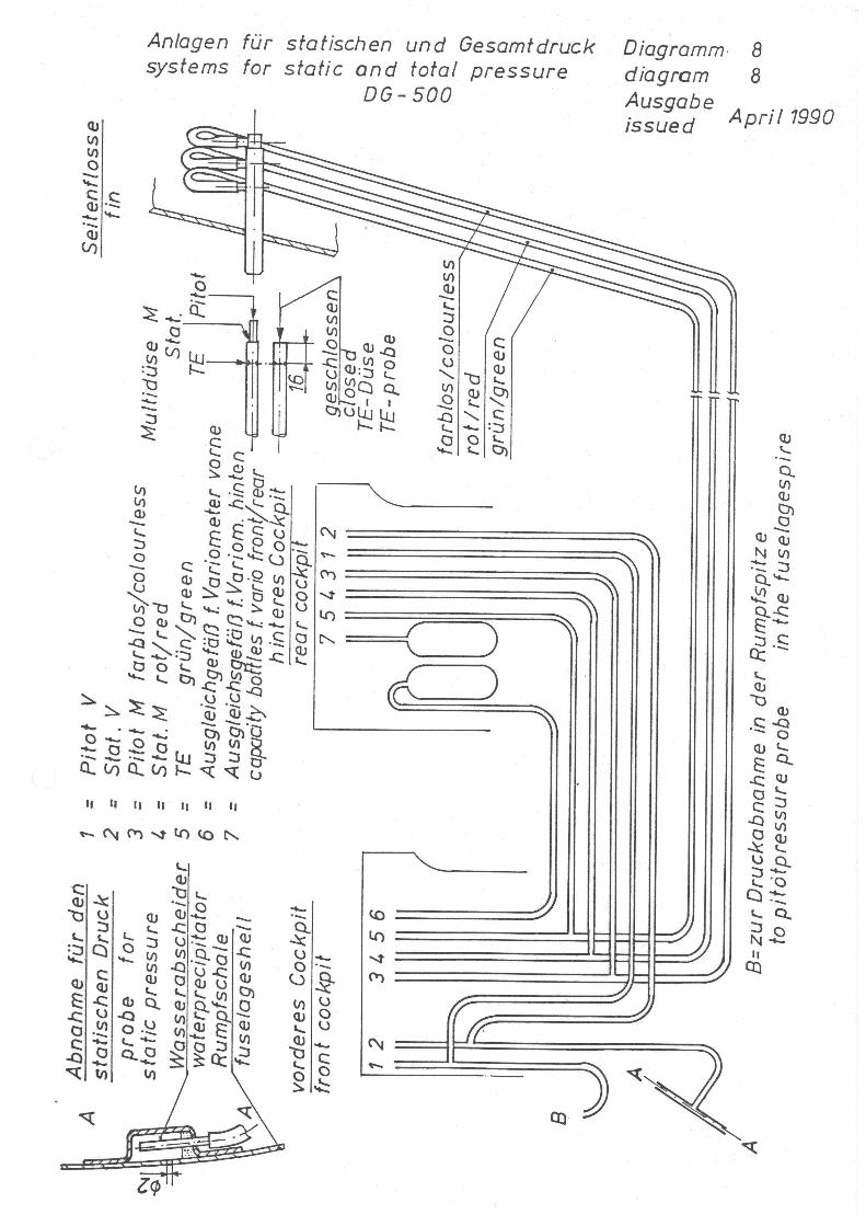
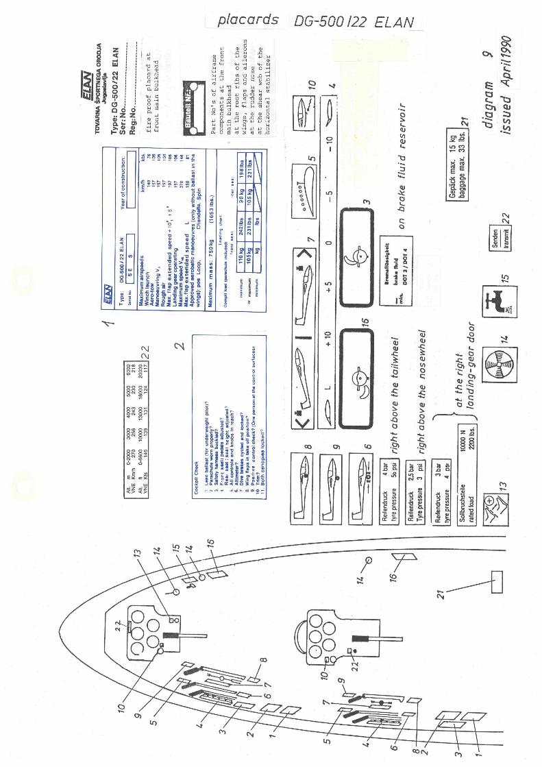
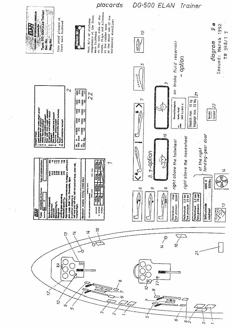
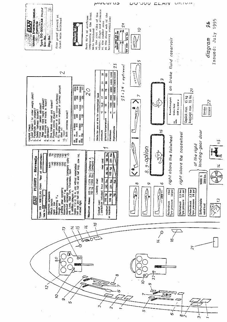
No. 52002 on and 51833) 8 Pitot/static system 9 DG-500/22 and /20 Placards 9a DG-500 Trainer Placards 9b DG-500 Orion Placards 10 only DG-500 Trainer
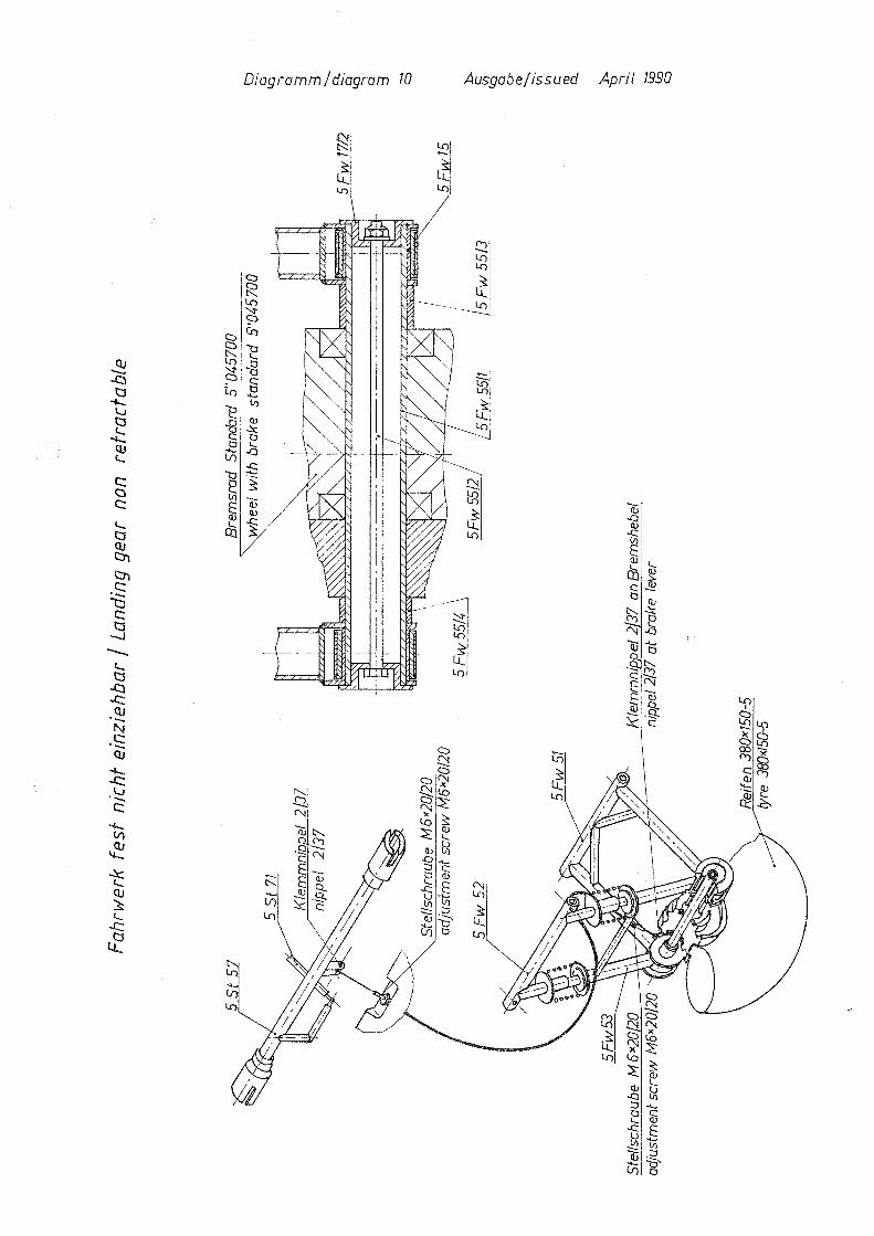
landing gear non retractable
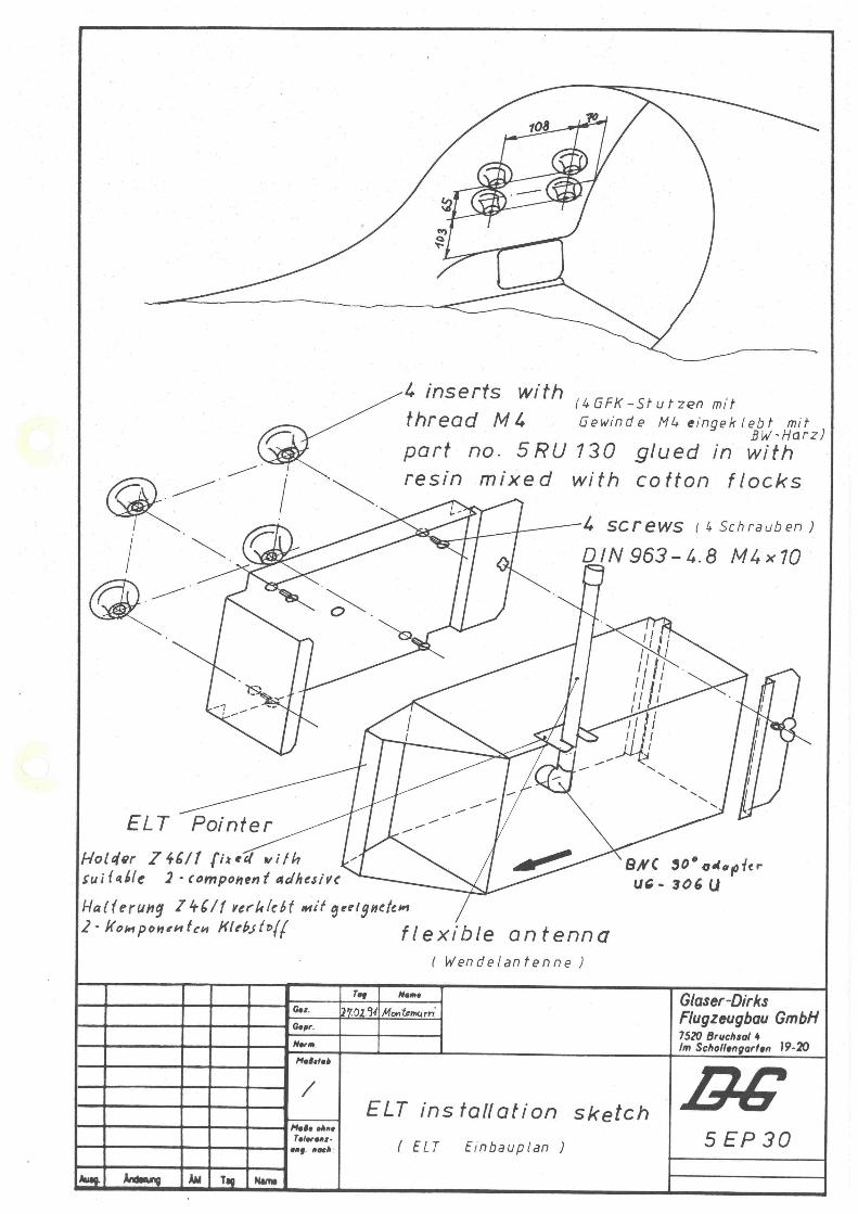
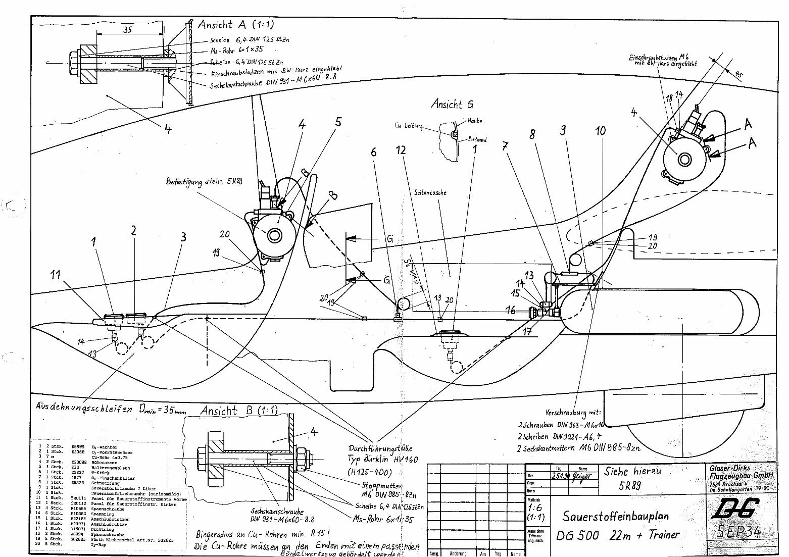
Enclosure Equipment list 5EP30 Installation ELT 5EP34 Installation Dräger oxygen system Working instruction No. 1 for TN348/20 issue 3, headrest securing ropes in the rear cockpit Only DG-500/20, Trainer, Orion Instruction for inspection DG-500 airbrakes Questionnaire for TN 348/4 Working instruction No. 1 for TN 348/4 Working instruction No. 2 for TN 348/4 5V18 Tool for airbrake adjustment
Maintenance Manual DG-500
Issued: December 2009 0.8 Copyright DG Flugzeugbau GmbH - any copy or publishing prohibited Manual valid with the up-to-date cover page only
Instructions for continued airworthiness 0.4 Airworthiness limitations 0.4.1 Repairs
Repair damaged wings, fuselage and tail surfaces prior to next flight. Repairs outside the scope of DG Flugzeugbau DG-500 repair manual and major repairs must be accomplished at an approved repair station or an approved mechanic rated for composite aircraft structure work in accordance with DG Flugzeugbau repair methods. Use only genuine spare parts. For all aircraft under EASA regulations the following applies: According to part 21, subpart M to accomplish major repairs an approved repair instruction is required, see also TN DG-G-01 “Approved repair methods according to EU Commission Regulation 1702/2003 part 21, subpart M”
0.4.2 Life time of the airframe The maximum allowable operating time for the Variants DG-500/22 ELAN, DG-500 ELAN Trainer, DG-500/20 ELAN and DG-500 ELAN Orion is 12000 flight hours. Therefore inspection according to sect. 2.4 of this manual has to be executed at 3000 h, 6000 h, 9000 h and every 1000 hours following thereafter.
0.4.3 Life time of equipment and components a) The fabric straps of the safety harness have to be exchanged
according to the instructions of the respective manufacturer. If no limitations are given, exchange after 12 years.
b) The rubber cords in the elevator control system see sect. 1.2.6 and in the wing flap control system (DG-500/22 and /20) see sect. 1.4.6 have to be replaced at least every 6 years.
c) Other components: All other components like tow hook, wheels, gas struts, control system parts, bolts, pins etc. have no life time limitation, but should be replaced when worn, damaged or disqualified by excessive corrosion.
0.4.4 Service time, maintenance documents of equipment and components
Follow the instructions of the respective manufacturer. a) Operating Manual for Safety Tow Releases Series: Europa G 88 Safety
Tow Release latest approved version Operating Manual for Tow Releases Series: E 85 Nose Tow Release latest approved version
b) safety harness: instructions of the manufacturer c) minimum instrumentation: instructions of the manufacture
Maintenance Manual DG-500
Issued: December 2009 1.1 Copyright DG Flugzeugbau GmbH - any copy or publishing prohibited Manual valid with the up-to-date cover page only
1 System description and adjustment data
1.1 Wing and tail plane setting data
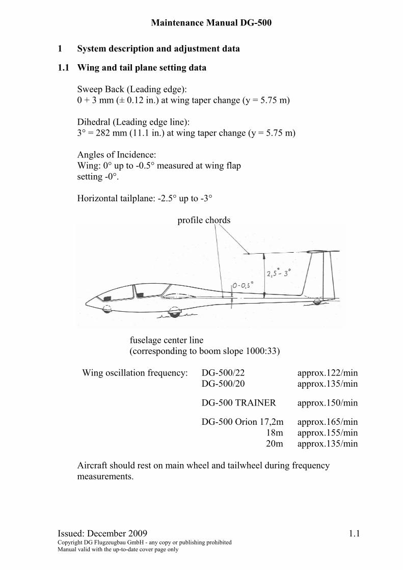
Sweep Back (Leading edge): 0 + 3 mm (± 0.12 in.) at wing taper change (y = 5.75 m) Dihedral (Leading edge line): 3° = 282 mm (11.1 in.) at wing taper change (y = 5.75 m) Angles of Incidence: Wing: 0° up to -0.5° measured at wing flap setting -0°. Horizontal tailplane: -2.5° up to -3°
profile chords
fuselage center line (corresponding to boom slope 1000:33)
Wing oscillation frequency: DG-500/22 approx.122/min DG-500/20 approx.135/min
DG-500 TRAINER approx.150/min
DG-500 Orion 17,2m approx.165/min 18m approx.155/min
20m approx.135/min
Aircraft should rest on main wheel and tailwheel during frequency measurements.
Maintenance Manual DG-500
Issued: December 2009 1.2 Copyright DG Flugzeugbau GmbH - any copy or publishing prohibited Manual valid with the up-to-date cover page only
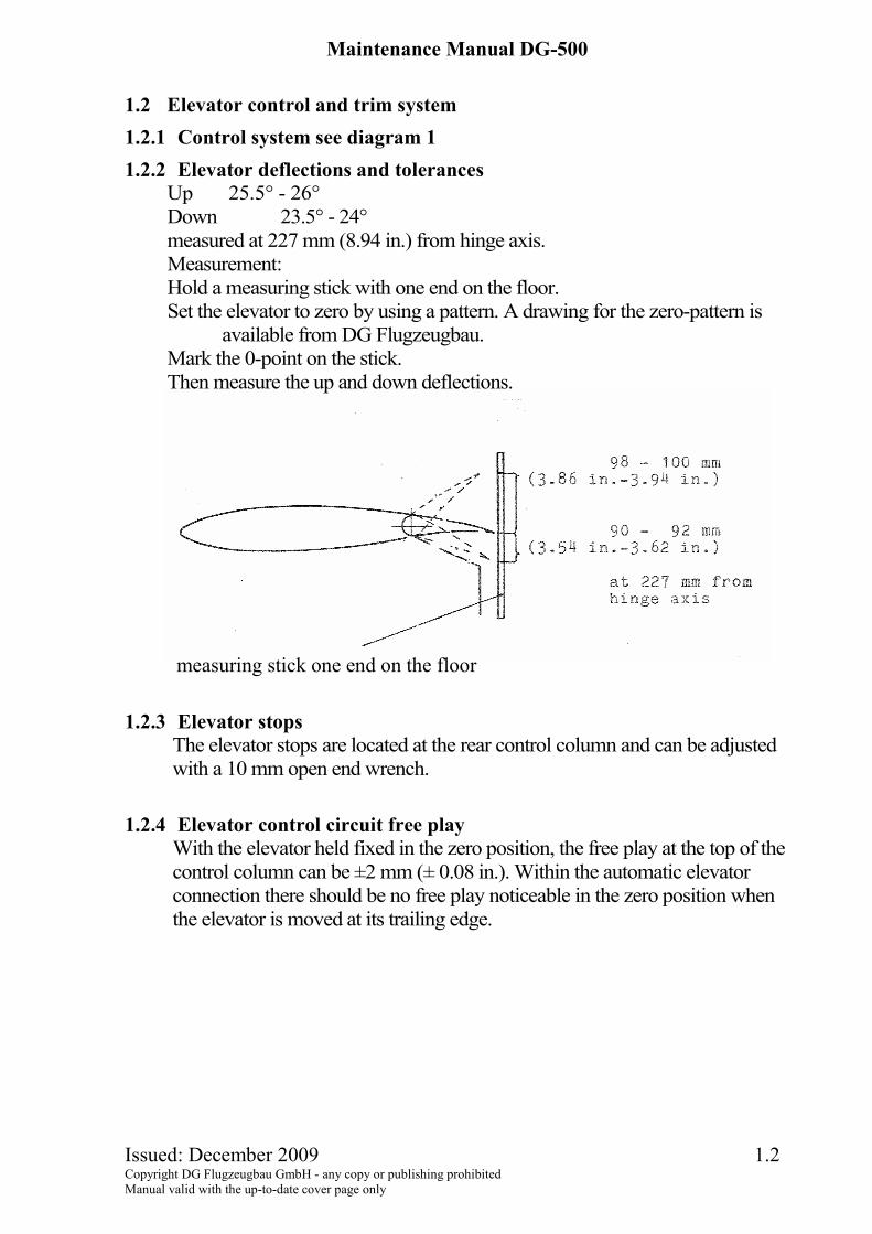
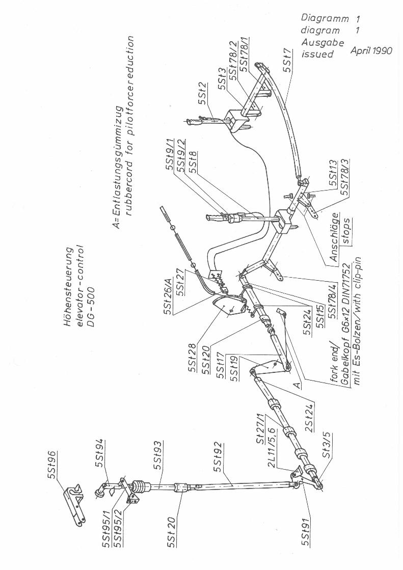
1.2 Elevator control and trim system 1.2.1 Control system see diagram 1 1.2.2 Elevator deflections and tolerances
Up 25.5° - 26° Down 23.5° - 24° measured at 227 mm (8.94 in.) from hinge axis. Measurement: Hold a measuring stick with one end on the floor. Set the elevator to zero by using a pattern. A drawing for the zero-pattern is
available from DG Flugzeugbau. Mark the 0-point on the stick. Then measure the up and down deflections. measuring stick one end on the floor
1.2.3 Elevator stops
The elevator stops are located at the rear control column and can be adjusted with a 10 mm open end wrench.
1.2.4 Elevator control circuit free play With the elevator held fixed in the zero position, the free play at the top of the control column can be ±2 mm (± 0.08 in.). Within the automatic elevator connection there should be no free play noticeable in the zero position when the elevator is moved at its trailing edge.
Maintenance Manual DG-500
Issued: December 2009 1.3 Copyright DG Flugzeugbau GmbH - any copy or publishing prohibited Manual valid with the up-to-date cover page only
locking nut adjustment screw
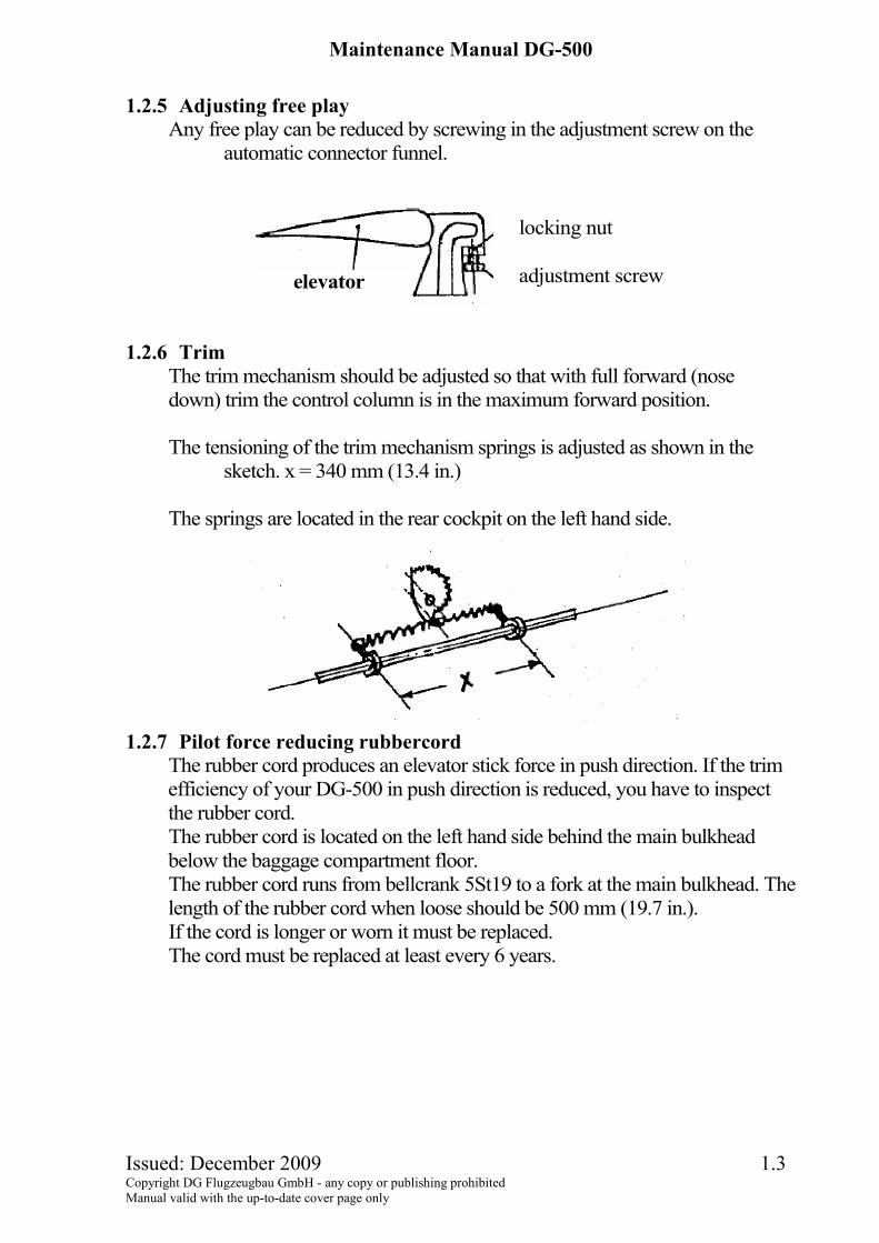
1.2.5 Adjusting free play
Any free play can be reduced by screwing in the adjustment screw on the automatic connector funnel.
1.2.6 Trim The trim mechanism should be adjusted so that with full forward (nose down) trim the control column is in the maximum forward position. The tensioning of the trim mechanism springs is adjusted as shown in the
sketch. x = 340 mm (13.4 in.) The springs are located in the rear cockpit on the left hand side.
1.2.7 Pilot force reducing rubbercord
The rubber cord produces an elevator stick force in push direction. If the trim efficiency of your DG-500 in push direction is reduced, you have to inspect the rubber cord. The rubber cord is located on the left hand side behind the main bulkhead below the baggage compartment floor. The rubber cord runs from bellcrank 5St19 to a fork at the main bulkhead. The length of the rubber cord when loose should be 500 mm (19.7 in.). If the cord is longer or worn it must be replaced. The cord must be replaced at least every 6 years.
elevator

Maintenance Manual DG-500
Issued: December 2009 1.4 Copyright DG Flugzeugbau GmbH - any copy or publishing prohibited Manual valid with the up-to-date cover page only
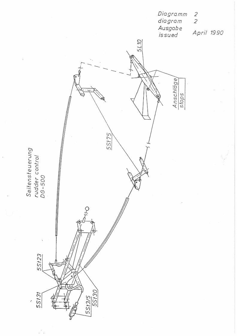
1.3 Rudder control 1.3.1 Rudder control circuit - see diagram 2 1.3.2 Rudder deflections and tolerances
217-5 mm (+ 30°) (8.54 - .2 inch) measured at 420 mm (16.5 inch) from the hinge axis.
1.3.3 Rudder stops The rudder stops are located at the lower hinge of the rudder.
1.3.4 Axial free play The maximum allowable free play at the upper hinge point is 1 mm
(0.04 inch) 1.3.5 Sealing the rudder
The rudder is sealed on both sides. Inside the fin with a V sealing tape (3 M Scotch Flexodicht Band 2743 white) which is attached at the fin trailing edge. If damaged it should be replaced and sprayed with Teflon spray. On the outside a combo sealing (flexible sealing with turbulator zig-zag dents at its leading edge) is installed. Prior to installation of this sealing clean the glue area of the fin with Acetone.
Caution: Acetone may damage competition no's. or the colour scheme. Warning: These sealings are not to be removed. If damaged or if the flexible sealings does not touch the rudder any more, the sealing have to be exchanged. Use only original material.
These materials should be purchased from DG. item part.-no. amount 1 70000295 2 x 1.5 m(59 in.) V sealing tape 2 30003130 2 x 1.48 m (58 in.) combi sealing 30/15
Maintenance Manual DG-500
Issued: December 2009 1.5 Copyright DG Flugzeugbau GmbH - any copy or publishing prohibited Manual valid with the up-to-date cover page only
1.4 Aileron and wing flap control 1.4.1 DG-500/22 and DG-500/20 1.4.1.1 Control circuit (see diagrams 3 and 4)
A spring at the mixer shaft 5St60 provides additional aileron return force at positive wing flap settings.
1.4.1.2 Deflections and tolerances Aileron deflections: up 20° ± 1° 64 ± 3 mm down 10° ± 1° 32 ± 3 mm measured at 182 mm (7.17 in.) from hinge axis (at the aileron root), wing flap setting 0°. Wing flap deflections: - 10° -40±3mm (1.57 ± 0.12 in.) L = + 15° +59±3mm (2.32 ± 0.12in.) measured at 228 mm (9.0 in.) from hinge axis against the fixed part at the wing root. At flap setting 0° the wingflaps have to be adjusted against the fixed part at the wing root with 0 ± 1 mm (0 ± 0.04 in.).
1.4.1.3 Stops The aileron stops are located at the rear control column and can be adjusted with two 10 mm open-end wrenches. The stop for positive wingflap setting is located under the removable left-hand side panel of the rear seat on the pushrod of the wingflap handle 5St73. The sleeve which is riveted to the rod must stop at the main bulkhead in landing setting. Adjustment is by adjusting the rear pushrod 5St74 against 5St73. The stop for negative setting (front) is located in the front cockpit on the inner guiding tube 5ST68/2 of the front wingflap handle 5St72. Adjustment by placing shims with inside diameter 12 mm (0.47 in.) between 5St72 and the sleeve which is riveted to 5St68/2.
Maintenance Manual DG-500
Issued: December 2009 1.6 Copyright DG Flugzeugbau GmbH - any copy or publishing prohibited Manual valid with the up-to-date cover page only
1.4.1.4 Free play
Ailerons The max. free play measured at the trailing edge of the ailerons measured at 166 mm (6.54 in.) from hinge axis should not exceed ± 1.5 mm (0.06 in.) The control stick and the wingflap should be in neutral position. If the free play is excessive replace the hinge axis (part 2F7/1) at the aileron control surface horn. With both ailerons fixed, a maximum free play of ± 2 mm (0.08 in.) at the top of the control stick is allowed. Wingflaps The max. free play measured at the trailing edge of the wingflap measured at 228 mm (9.0 in.) from hinge axis should not exceed ± 2 mm (0.08 in.). The control stick and the wingflap should be in neutral position. With excessive free play replace the pin of the wingflap hook up 5St46 against an oversize pin (part no. 5St46/3 oversize 1).
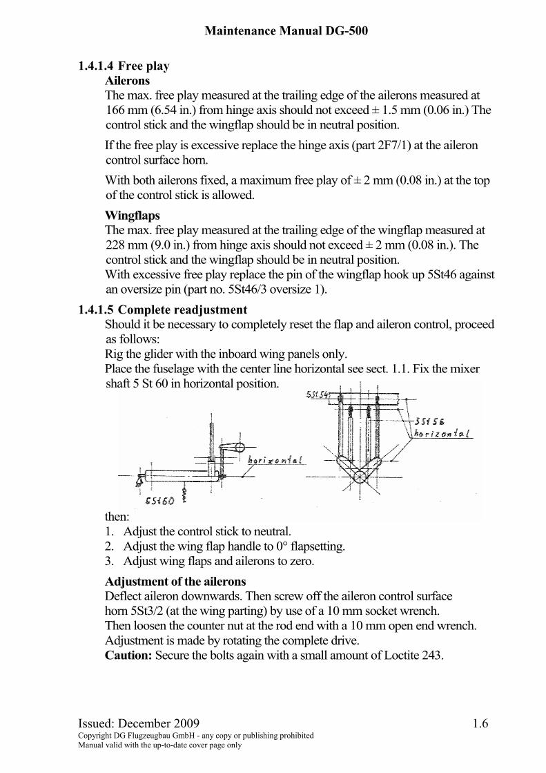
1.4.1.5 Complete readjustment Should it be necessary to completely reset the flap and aileron control, proceed as follows: Rig the glider with the inboard wing panels only. Place the fuselage with the center line horizontal see sect. 1.1. Fix the mixer shaft 5 St 60 in horizontal position.
then: 1. Adjust the control stick to neutral. 2. Adjust the wing flap handle to 0° flapsetting. 3. Adjust wing flaps and ailerons to zero. Adjustment of the ailerons Deflect aileron downwards. Then screw off the aileron control surface horn 5St3/2 (at the wing parting) by use of a 10 mm socket wrench. Then loosen the counter nut at the rod end with a 10 mm open end wrench. Adjustment is made by rotating the complete drive. Caution: Secure the bolts again with a small amount of Loctite 243.
Maintenance Manual DG-500
Issued: December 2009 1.7 Copyright DG Flugzeugbau GmbH - any copy or publishing prohibited Manual valid with the up-to-date cover page only
Adjustment of the wing flaps Adjust at the rod ends of the pushrods 5ST56 which run from the mixer shaft 5 St 60 to the wing flaps operating shaft 5St54. 4. Adjust the aileron stops. 5. Check the flap deflections and adjust the stops if necessary.
1.4.1.6 Pilot force reducing rubber cord The rubber cord in the wing flap control system reduces the pilot forces when moving the flap into the positive positions. The cord is located on the left hand side behind the main bulkhead below the baggage compartment floor. The cord runs from a fork at the main bulkhead around a pulley at the rear main bulkhead to the spring at pushrod 5St74. The length of the rubber cord when loose should be 700 mm (27.5 in.) If the cord is longer or worn it must be replaced. It must be replaced at least every 6 years.
Maintenance Manual DG-500
Issued: December 2009 1.8 Copyright DG Flugzeugbau GmbH - any copy or publishing prohibited Manual valid with the up-to-date cover page only
1.4.2 DG-500 Trainer und DG-500 Orion 1.4.2.1 Control circuit
See diagram 3a and diagram 4a 1.4.2.2 Deflections and tolerances
Aileron deflections: Normal: up 30° ± 1° 75 ± 3 mm down 15° ± 1° 38 ± 3 mm Option TM 348/11 only Orion: up 24° ± 1° 60 ± 3 mm down 12° ± 1° 30 ± 3 mm measured at 144 mm (5.67 in.) from hinge axis (inboard of the aileron)
1.4.2.3 Stops The aileron stops are located at the rear control column and can be adjusted
with two 10 mm open-end wrenches. 1.4.2.4 Free play
The max. free play measured at the trailing edge of the ailerons measured at 144 mm (5.67 in.) from hinge axis should not exceed ± 1.5 mm (0.06 in.) The control stick should be in neutral position. If the free play is excessive replace the hinge axis (part 2F7/3) at the aileron control surface horn. With both ailerons fixed, a maximum free play of ± 2 mm (0.08 in.) at the top of the control stick is allowed.
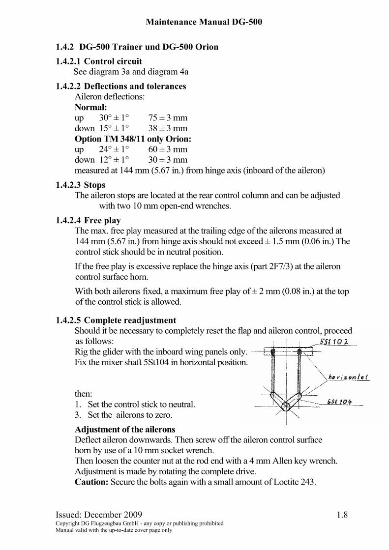
1.4.2.5 Complete readjustment Should it be necessary to completely reset the flap and aileron control, proceed as follows: Rig the glider with the inboard wing panels only. Fix the mixer shaft 5St104 in horizontal position.
then: 1. Set the control stick to neutral. 3. Set the ailerons to zero. Adjustment of the ailerons Deflect aileron downwards. Then screw off the aileron control surface horn by use of a 10 mm socket wrench. Then loosen the counter nut at the rod end with a 4 mm Allen key wrench. Adjustment is made by rotating the complete drive. Caution: Secure the bolts again with a small amount of Loctite 243.
Maintenance Manual DG-500
Issued: December 2009 1.9 Copyright DG Flugzeugbau GmbH - any copy or publishing prohibited Manual valid with the up-to-date cover page only
1.5 Airbrake control, wheelbrake 1.5.1 Control circuit
See diagrams 3 and 4 DG-500/22 and /20, or Diagrams 3a and 4a DG-500 Trainer and Orion. The wheelbrake is connected to the airbrake torsion shaft (part 5 St 57).
1.5.2 Adjustment a) Airbrake overcentre locking force.
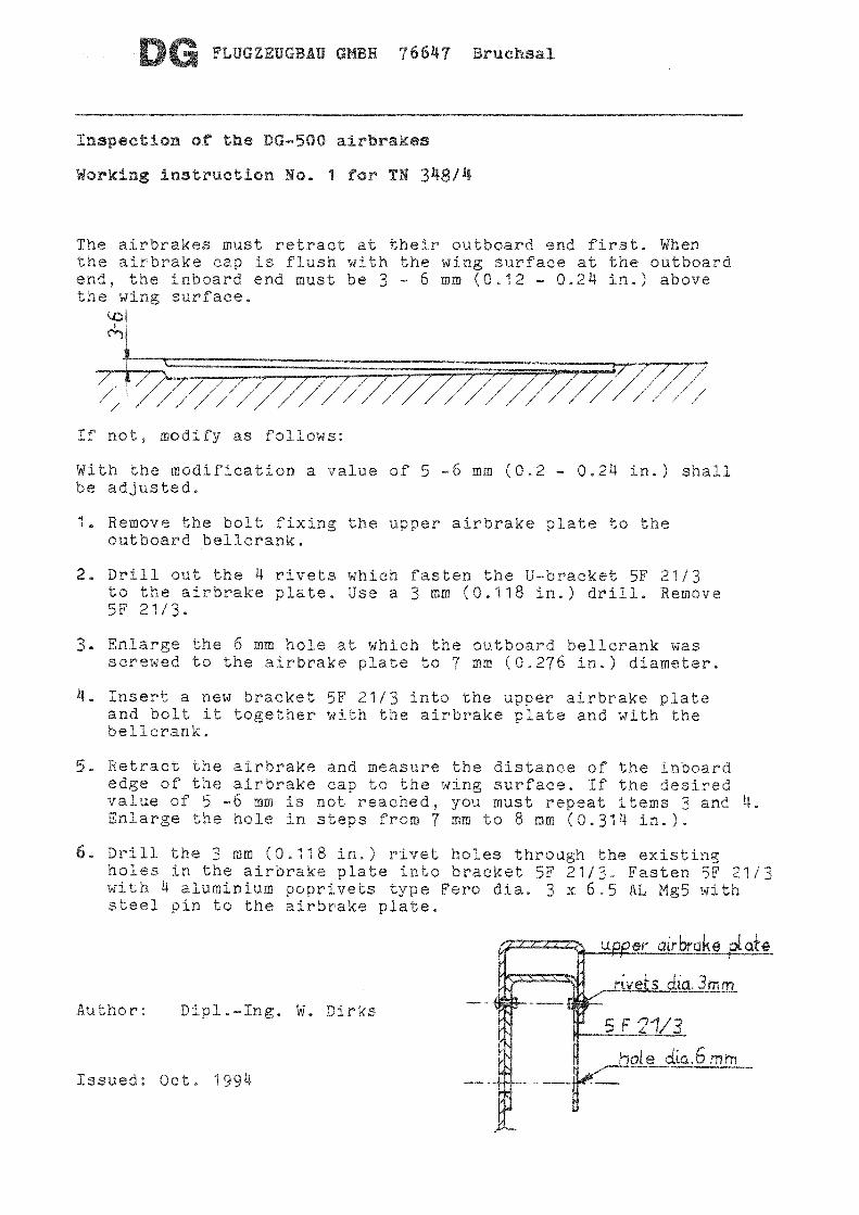
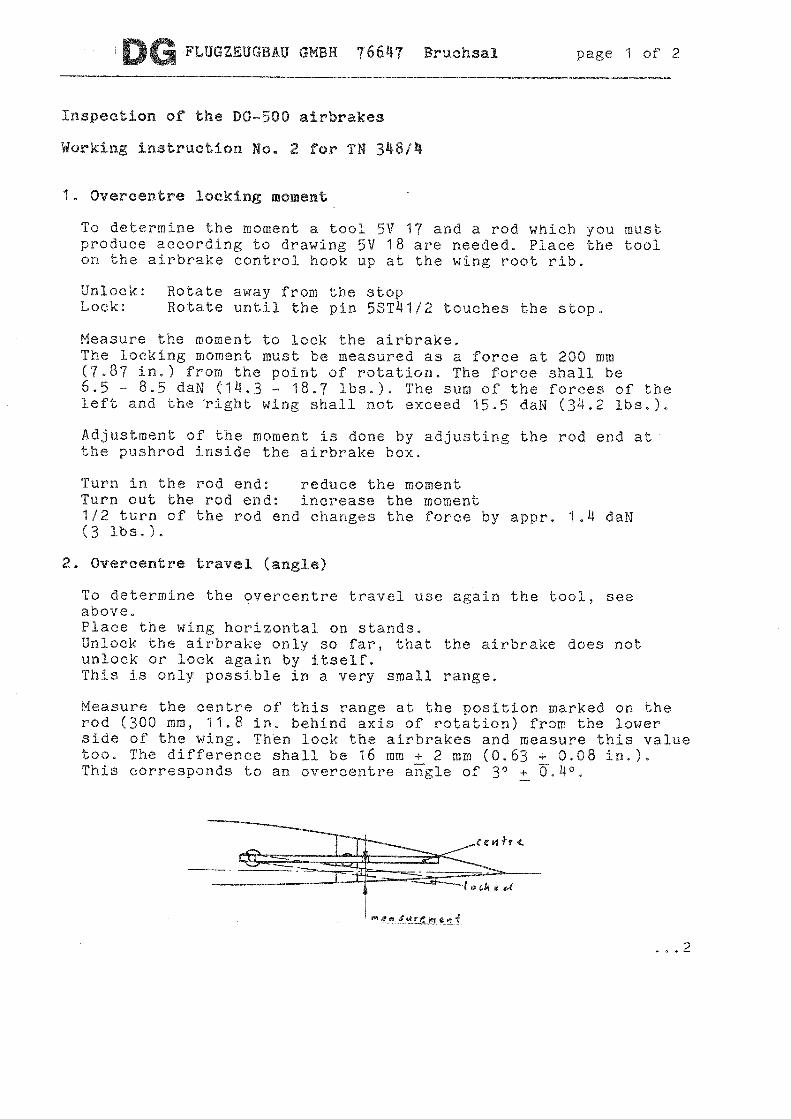
Adjust the airbrake rod in the airbrake box so that both airbrakes retract evenly and that the overcentre locking force on the airbrake operating handle is between 15 - 20 daN (33-44 lbs). Adjustment can be done with a 13mm open end wrench.. Further details see “Instruction for inspection DG-500 airbrakes” (attached to this manual)
b) Airbrake extension height. The height the airbrakes extend depends on the wheelbrake adjustment.
c) Wheel braking force. With insufficient braking effect, the wheel-brake can be adjusted at the adjustment screws between torsion shaft 5 St 57 and the master cylinder (at the landing gear box). If this does not increase the braking effect refer to sect. 1.6.4 b).
d) Only DG-500/20, Trainer, Orion: During the annual inspection check the airbrakes according to “Instruction for inspection DG-500 airbrakes” (attached to this manual).
1.5.3 Airbrake Stops The airbrake control extension stop is located at the main bulkhead. The stop, in locked direction, is situated at the wing rootribs. The corresponding stop at the guide rod 5 St 68/1 in the cockpit should be placed to allow a free play of 0-3 mm (0-.12 in.) between the airbrake handle and the stop at the guide rod with the airbrakes locked over centre. Adjustment can be made by adjusting the rod end between pushrod 5 St 71 and the airbrake torsion shaft 5 St 57.
1.5.4 Free play Free play in the airbrake control system has no effect. The airbrakes themselves at their hinges should not have so much free play that the bolt heads hit the wing surfce instead of entering into the airbrakeboxes during retraction under airloads.
Maintenance Manual DG-500
Issued: December 2009 1.10 Copyright DG Flugzeugbau GmbH - any copy or publishing prohibited Manual valid with the up-to-date cover page only
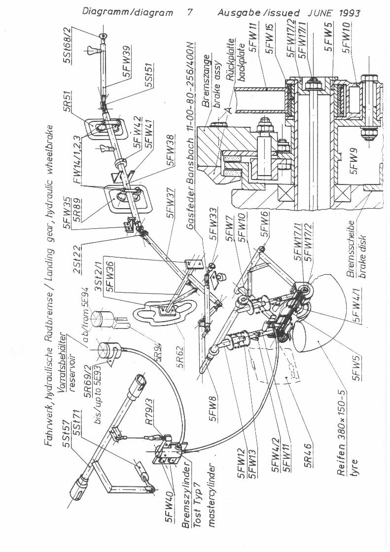
1.6 Landing gear 1.6.1 Main wheel retractable (all variants) 1.6.1.1 Landing gear control circuit see diagram 7
In the retracted position the landing gear is locked by an overcenter device. In the extended position the lock is by a locking plate in the rear cockpit. A gas strut reduces the retraction force and keeps the landing gear in the overcenter locking position (retracted and extended).
1.6.1.2 Adjustment a) Overcenter lock in retracted position
Adjustment at the adjustment screw between landing gear operating lever 5FW8 and the bellcrank 5FW36. The stop is located at the pushrod 5 FW 38 and stops against the pedestal 5FW41. Adjust this stop after adjusting the lock in the extended position see b) by gluing slotted shims onto the stopsleeve on 5FW38.
b) In extended position (landing gear struts over center) a max. free play of approx. 0.5 mm (0.02 in.) between the lock at pushrod 5FW38 and the locking plate 5FW35 is allowed. Adjustment at the rod end in pushrod 5FW37 between 5FW38 and 5FW36.
1.6.1.3 Free play Free play between lever 5 FW 8 and the upper strut 5FW12 is not allowed. If there is any free play, the two securing bolts M6 x 40 should be tightened with a 10 mm open-end wrench. If there is still some free play, the bolts should be removed and the holes drilled out and reamed to diameter 8 H7. M8 x 40 LN9037 bolts should then be installed.
Maintenance Manual DG-500
Issued: September 2011 TN500/05 1.11 Copyright DG Flugzeugbau GmbH - any copy or publishing prohibited Manual valid with the up-to-date cover page only
1.6.1.4 Hydraulic brake system
a) Brake fluid approved specification DOT 3, DOT 4, SAEJ 1703. The brake fluid must be exchanged at least every 4 years.
Warning: brake fluid is poisonous
b) Adjustment: see section 1.5.2 c) If adjustment does not increase the braking effect as desired, the brake system is leaking or there is air in the brake system. Bleeding of the brake system see section 4.5.
c) The brake linings must be replaced if they are used up to a thickness of 2.5 mm (0.098 in.). Removal of brake calliper see sect. 4.4 B.
Replacement set (2 linings, 6 rivets) Tost No. 075860
d) The brake disc must be replaced if it is used up to a thickness of 4.2 mm (0.167 in.). Removal of the wheel see sect. 4.4 A.
1.6.2 Main wheel non retractable (optional DG-500 Trainer) 1.6.2.1 System
See diagram 10 Instead of the hydraulic disc brake a wheel with drum brake is used.
1.6.3 Tyre pressure: DG-500/22, /20, Orion DG-500 Trainer
Main wheel 3 bar (44.5 psi) 2.5 bar (36 psi) Nose wheel 2.5 bar (36 psi) 2.5 bar (36 psi) Tail wheel 4 bar (58 psi) 4 bar (58 psi)
Maintenance Manual DG-500
Issued: December 2009 1.12 Copyright DG Flugzeugbau GmbH - any copy or publishing prohibited Manual valid with the up-to-date cover page only
1.7 Tow hooks 1.7.1 Tow release circuit see diagram 5 1.7.2 Adjustment
Check if both tow releases open fully. Adjustment at the bellcrank 5R32 in the rear cockpit.
Caution: The ring muzzle of the C.G. hook should not be bent or ground down and move easily. If the muzzle is damaged, the tow release has to be exchanged and repaired by the manufacturer (Tost).
1.7.3 Removing the tow hooks
C.G. tow hook Remove the mounting bolts and the actuating lever. Don't remove the bolt which carries the actuating lever. Move the tow hook some mm in an upward direction (use a piece of hard wood and a hammer). Then pull it out towards the front. Nose tow hook Remove the tow hook with the fittings 5 R 3/2 and 3.
1.7.4 Rubber cords To keep the actuating cables tight there is a rubber cord at both of the cables in front of the bellcrank 5 R 32. Replace the rubber cords if worn. For further information refer to the operating and maintenance instructions for the release mechanism. (See sect. 0.4 of this maintenance manual)
Maintenance Manual DG-500
Issued: December 2009 1.13 Copyright DG Flugzeugbau GmbH - any copy or publishing prohibited Manual valid with the up-to-date cover page only
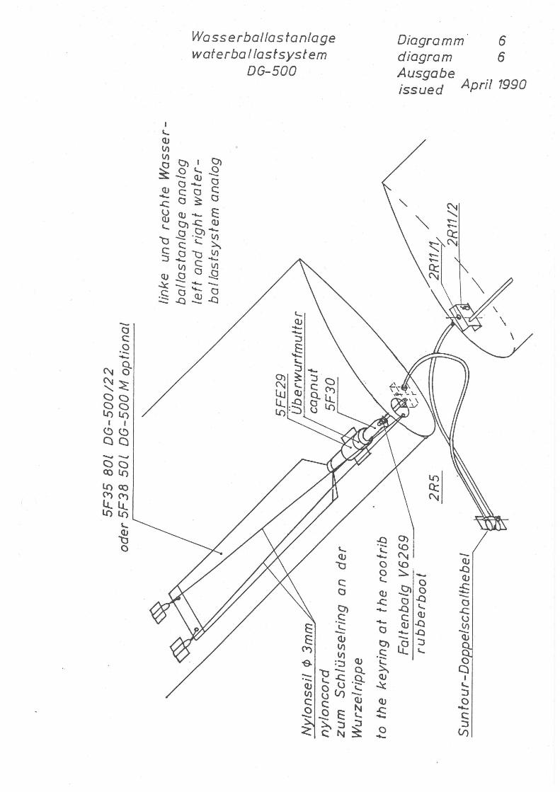
1.8 Water ballast system 1.8.1 DG-500/22 and DG-500/20 1.8.1.1 Water ballast system see diagram 6 1.8.1.2 Wing tanks 1.8.1.2.1 Adjustment
For the dump valve in the closed position, there should be 1 mm (.04 in.) space between the 8 mm (.315 in.) diameter PVC rod from the dump valve, and the plate lever on the fuselage. Adjust at the adjustment screw located at the fuselage wall. If this is insufficient, the 8 mm PVC rod can be shortened. If a valve still leaks, then the rubber gasket and the associated spring at the end of the 8 mm PVC rod should be loosened, pressed further in and secured again. If this is not successful, the valve ball seat should be greased. (see sect. 4.1)
1.8.1.2.2 Servicing (see sect. 4.1) 1.8.2 DG-500 Trainer No waterballast system existent.
Maintenance Manual DG-500
Issued: December 2009 1.14 Copyright DG Flugzeugbau GmbH - any copy or publishing prohibited Manual valid with the up-to-date cover page only
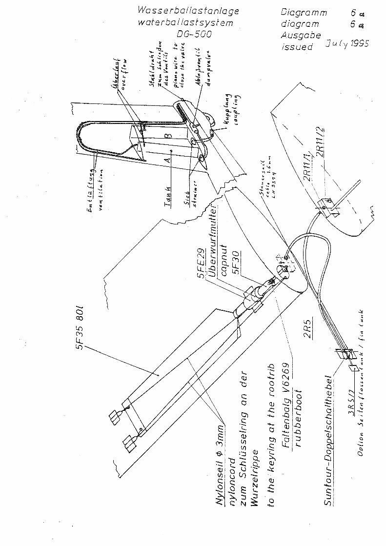
1.8.3 DG-500 Orion 1.8.3.1 Warerballast system see diagram 6a 1.8.3.2 Wing tanks see section 1.8.1.2 1.8.3.3 Fin tank A (to compensate the wing ballast) 1.8.3.3.1 Adjustment
The release cable must be adjusted so, that the wing tank handles only can be opened, when the fin tank has been opened fully.
1.8.3.3.2 Inspection According to sect. 2.2.1 the fin ballast tank system must be checked at the annual inspection. Therefore the tailwheel is to be removed and the cover plate in the tailwheel box to be unscrewed. Check the control cable and the lever of the valve carefully for wear. The control cable has to be checked at the operating handle in the cockpit too. If the cable or the lever is worn, it is prohibited to use the fin tank any more. Please contact DG Flugzeugbau for a detailed repair instruction. The dump time of the full fin tank is to measure. 120 sec. should not be exceeded. Outside air temperature gauge: Check for correct indication.
1.8.3.4 Fintank B (to compensate the mass of the rear pilot) 1.8.3.4.1 Inspection
Check the function of the control light in the front instrument panel. With empty tank the light must be on at "tank empty". Fill in 1/2 l (.1 US gal) of water. Now the light at "tank filled" must be on.
Maintenance Manual DG-500
Issued: December 2009 1.15 Copyright DG Flugzeugbau GmbH - any copy or publishing prohibited Manual valid with the up-to-date cover page only
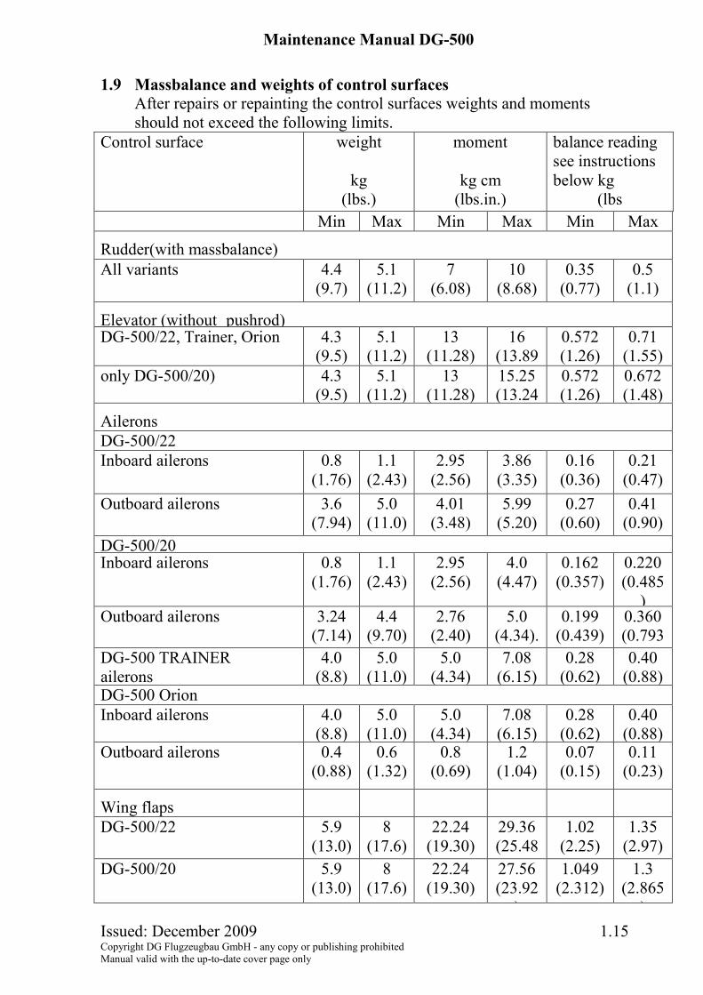
1.9 Massbalance and weights of control surfaces
After repairs or repainting the control surfaces weights and moments should not exceed the following limits.
Control surface weight
kg (lbs.)
moment
kg cm (lbs.in.)
balance reading see instructions below kg
(lbs Min Max Min Max Min Max
Rudder(with massbalance) All variants 4.4
(9.7) 5.1
(11.2)7
(6.08) 10
(8.68) 0.35
(0.77) 0.5
(1.1)
Elevator (without pushrod) DG-500/22, Trainer, Orion 4.3
(9.5) 5.1
(11.2)13
(11.28) 16
(13.890.572 (1.26)
0.71 (1.55)
only DG-500/20) 4.3 (9.5)
5.1 (11.2)
13 (11.28)
15.25 (13.24
0.572 (1.26)
0.672 (1.48)
Ailerons DG-500/22 Inboard ailerons 0.8
(1.76)1.1
(2.43)2.95
(2.56) 3.86
(3.35) 0.16
(0.36) 0.21
(0.47) Outboard ailerons 3.6
(7.94)5.0
(11.0)4.01
(3.48) 5.99
(5.20) 0.27
(0.60) 0.41
(0.90) DG-500/20 Inboard ailerons 0.8
(1.76)1.1
(2.43)2.95
(2.56) 4.0
(4.47) 0.162
(0.357) 0.220 (0.485
)Outboard ailerons 3.24
(7.14)4.4
(9.70)2.76
(2.40) 5.0
(4.34). 0.199
(0.439) 0.360 (0.793
DG-500 TRAINER ailerons
4.0 (8.8)
5.0 (11.0)
5.0 (4.34)
7.08 (6.15)
0.28 (0.62)
0.40 (0.88)
DG-500 Orion Inboard ailerons 4.0
(8.8)5.0
(11.0)5.0
(4.34)7.08
(6.15) 0.28
(0.62)0.40
(0.88)Outboard ailerons 0.4
(0.88)0.6
(1.32)0.8
(0.69) 1.2
(1.04) 0.07
(0.15) 0.11
(0.23)
Wing flaps
DG-500/22 5.9 (13.0)
8 (17.6)
22.24 (19.30)
29.36 (25.48
1.02 (2.25)
1.35 (2.97)
DG-500/20 5.9 (13.0)
8 (17.6)
22.24 (19.30)
27.56 (23.92
)
1.049 (2.312)
1.3 (2.865
)
Maintenance Manual DG-500
Issued: December 2009 1.16 Copyright DG Flugzeugbau GmbH - any copy or publishing prohibited Manual valid with the up-to-date cover page only
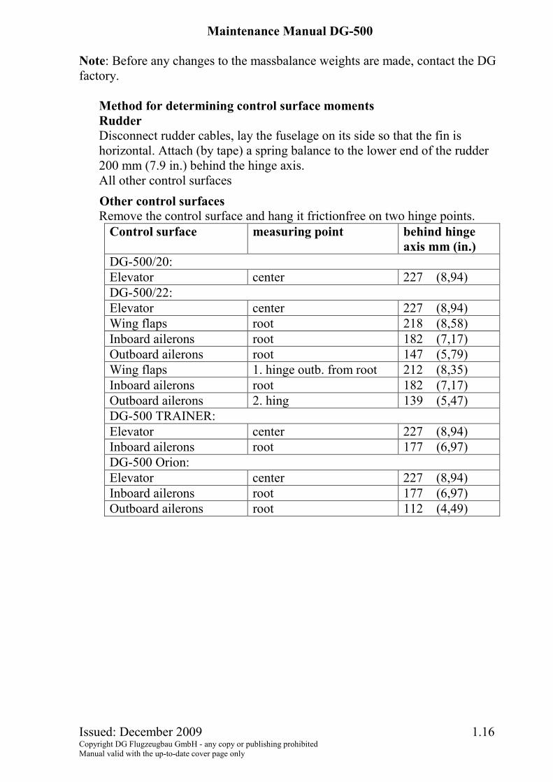
Note: Before any changes to the massbalance weights are made, contact the DG factory.
Method for determining control surface moments Rudder Disconnect rudder cables, lay the fuselage on its side so that the fin is horizontal. Attach (by tape) a spring balance to the lower end of the rudder 200 mm (7.9 in.) behind the hinge axis. All other control surfaces Other control surfaces Remove the control surface and hang it frictionfree on two hinge points.
Control surface measuring point behind hinge axis mm (in.)
DG-500/20: Elevator center 227 (8,94) DG-500/22: Elevator center 227 (8,94) Wing flaps root 218 (8,58) Inboard ailerons root 182 (7,17) Outboard ailerons root 147 (5,79) Wing flaps 1. hinge outb. from root 212 (8,35) Inboard ailerons root 182 (7,17) Outboard ailerons 2. hing 139 (5,47) DG-500 TRAINER: Elevator center 227 (8,94) Inboard ailerons root 177 (6,97) DG-500 Orion: Elevator center 227 (8,94) Inboard ailerons root 177 (6,97) Outboard ailerons root 112 (4,49)
Maintenance Manual DG-500
Issued: December 2009 1.17 Copyright DG Flugzeugbau GmbH - any copy or publishing prohibited Manual valid with the up-to-date cover page only
1.10 Fore and aft play of the wings 1.10.1 At fuselage
a) Fore and aft play at the front wing suspension is acceptable and a design feature
b) The fore and aft play at the rear wing suspension shall not exceed 0.5 mm (0.02 in.) at each wing. Move the wings fore and aft to determine the free play. If the free play is excessive the rear locking pins must be replaced by oversize pins (5 F 28 oversize 1). Therefore you must ream the hole for the locking pin with the glider rigged. Allow no free play when reaming.
1.10.2 At the wing parting (only DG-500/22, /20, Orion) a) Check see above.
The free play at both pins together shall not exceed 0.5 mm (0.02 in.) b) Roughen the area around the lift pin and attach a distance washer inside
diameter 10.5 mm (0.41 in.) with a suitable metal adhesive (e.g. Stabilit Express). Note the total thickness of the washers at the root rib with a waterproof marker pen.
c) Rig the outboard wing panels again and check the free play.
Maintenance Manual DG-500
Issued: September 2011 TN500/05 2.1 Copyright DG Flugzeugbau GmbH - any copy or publishing prohibited Manual valid with the up-to-date cover page only
2 Inspections
2.1 Daily inspection see flight manual section 4.3
2.2 Regular inspections A After 200 flight hours and during the annual inspection
Check the rudder cables for wear especially around the “S” tubes on the rudder pedals. Worn rudder cables should be replaced (see section 4.2). Check the sealing of the rudder (see section 1.3.5).
B Annual inspection (and 100hr inspection only for USA) • Execute all items of the daily inspection (see flight manual section 4.3).
Check especially the headrest securing ropes in the rear cockpit according to “Working instruction No. 1 for TN348/20 issue 3” (attached to this manual) for correct assembly and for wear.
• Inspect all bolted connections and locking devices ie. locknuts, split pins etc.
• Check all metal parts for adequate greasing and rust prevention. (see section 3.3).
• Check the control surface deflections (see sections 1.2 up to 1.4). • Check the free play in all control circuits (see section 1.2 up to 1.6) • Check the fore and aft play of the wings (see section 1.10). • Check the canopy emergency releases according to section 7.15 of the
flight manual. • Check the rubber cords in the control system (see sections 1.2.6, 1.4.6
(only DG-500/22 and /20) and 1.7.5. • Check the thickness of the wheel brake linings and the thickness of the
wheel brake disc (see section 1.6.1.4). • Check if the brake fluid has to be exchanged (see section 1.6.1.4). • Check the airbrakes according to “Instruction for inspection DG-500
airbrakes” (attached to this manual) ( not necessary for DG-500/22). • Tow hooks: The operating and maintenance instructions for the release
mechanisms, see sect. 0.4 of this maintenance manual have to be followed.
• All-up weight and centre of gravity: These should be checked at least every 4 years.
C Every 3 months Check the tension of the lines of the waterbag attachment (see section 4.1).
D Special inspections Tow hook: After a wheel-up landing, the C.G. tow hook is to be cleaned. Check tow hook and tow hook bulkheads carefully for any damage. C.G. weighing: After all work which may influence the C.G..
Maintenance Manual DG-500
Issued: December 2009 2.2 Copyright DG Flugzeugbau GmbH - any copy or publishing prohibited Manual valid with the up-to-date cover page only
2.3 Inspections after a heavy landing
The whole aircraft Check that the tailplane is still properly aligned in the vertical and horizontal axis. Check the wing oscillating frequency with respect to previous checks.
Wings
Spar ends: Check the wing pins and bushes for any deformation - are there any white areas around the bushes?
Root ribs: Are there any cracks at the rib/wing skin joint or rib/spar joint? If so, remove any paint or filler to see if the crack continues into the structure. Any white areas around the bushes?
Outer skins: Crushing, cracks, delaminations? Note: hairline cracks from the edges of the airbrake housing and on the wing leading edge running along the span are harmless, if these don't enlarge when you press on the wing shells.
Wingflaps and ailerons: Crushing, cracks, delaminations? Hinge mounts checked? - Control circuit drives checked?
Fuselage
Fuselage wing connection: White areas, increased free play, bent lift pin tubes, difficult assembly?
Torsion check: Hold the fuselage fixed and from the top of the fin try to turn the fin around the fuselage. While applying this torsion are any cracks made visible? Does the fuselage shell show any uncommon deformations?
Fuselage - fin intersection: Check for cracks. Remove gelcoat and any filler along the cracks. Apply pressure to the fin (push the fin towards the nose as well as applying torsion). Do the cracks penetrate the glass fibre structure? Disassemble the rudder and check the glued connection of the fuselage end bulkhead and the fin trailing edge web.
Maintenance Manual DG-500
Issued: September 2011 TN500/05 2.3 Copyright DG Flugzeugbau GmbH - any copy or publishing prohibited Manual valid with the up-to-date cover page only
Fuselage cont.
To check the elevator control circuit and the bulkhead attachments in the fin area, the tail-wheel and the cover plate in the wheel box should be removed. Tailplane attachment: Increased free play? Cracks in the fin top rib? Check if the aluminium parts of the tailplane attachment are bent or loose, check the tailplane locking device
Rudder mounts: Increased free play? White areas in the glass fibre, bent rudder hinge pin supports?
Fuselage skin: outside: cracks, nicks, folds? Any separation of the skin from the
core? inside: white spots, zig zag white lines, cracks? Has any bulkhead become loose?
C.G. tow release: Especially after a wheel up landing, check for dirt etc., check for proper functioning. Has the tow release housing become detached from the fuselage?
Seat back bulkhead: Cracks? Shoulder strap attachment point?
Belly harness attachment points: Check for cracking around the mountings in the seat. Check the safety harness assembly.
Controls: Check for proper functioning and condition of all controls and adjustment mechanisms (i.e. rudder pedal adjustment, tow release, air brake, control column and trim etc.).
Instruments: Proper functioning? Dirt in the static ports or in the pitot probe?
Maintenance Manual DG-500
Issued: September 2011 TN500/05 2.4 Copyright DG Flugzeugbau GmbH - any copy or publishing prohibited Manual valid with the up-to-date cover page only
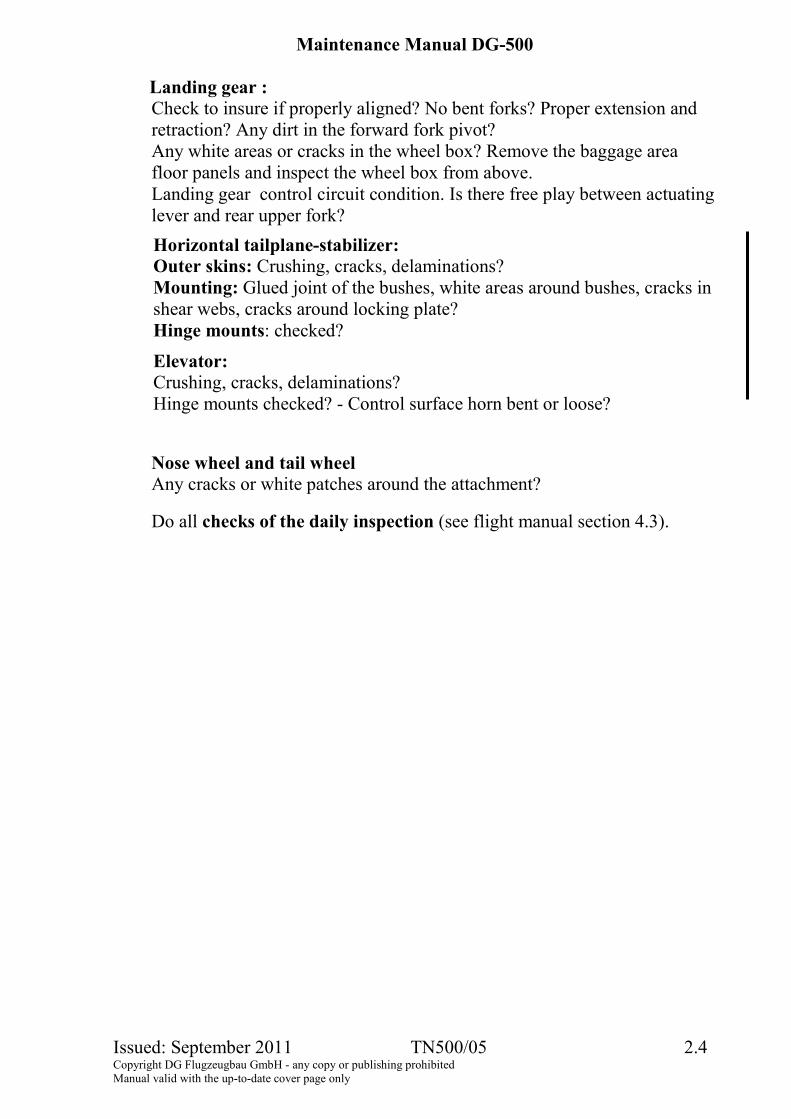
Landing gear : Check to insure if properly aligned? No bent forks? Proper extension and retraction? Any dirt in the forward fork pivot? Any white areas or cracks in the wheel box? Remove the baggage area floor panels and inspect the wheel box from above. Landing gear control circuit condition. Is there free play between actuating lever and rear upper fork? Horizontal tailplane-stabilizer: Outer skins: Crushing, cracks, delaminations? Mounting: Glued joint of the bushes, white areas around bushes, cracks in shear webs, cracks around locking plate? Hinge mounts: checked?
Elevator: Crushing, cracks, delaminations? Hinge mounts checked? - Control surface horn bent or loose?
Nose wheel and tail wheel Any cracks or white patches around the attachment?
Do all checks of the daily inspection (see flight manual section 4.3).
Maintenance Manual DG-500
Issued: December 2009 2.5 Copyright DG Flugzeugbau GmbH - any copy or publishing prohibited Manual valid with the up-to-date cover page only
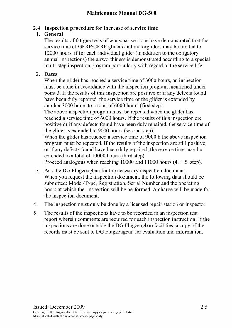
2.4 Inspection procedure for increase of service time
1. General The results of fatigue tests of wingspar sections have demonstrated that the service time of GFRP/CFRP gliders and motorgliders may be limited to 12000 hours, if for each individual glider (in addition to the obligatory annual inspections) the airworthiness is demonstrated according to a special multi-step inspection program particularly with regard to the service life.
2. Dates When the glider has reached a service time of 3000 hours, an inspection must be done in accordance with the inspection program mentioned under point 3. If the results of this inspection are positive or if any defects found have been duly repaired, the service time of the glider is extended by another 3000 hours to a total of 6000 hours (first step). The above inspection program must be repeated when the glider has reached a service time of 6000 hours. If the results of this inspection are positive or if any defects found have been duly repaired, the service time of the glider is extended to 9000 hours (second step). When the glider has reached a service time of 9000 h the above inspection program must be repeated. If the results of the inspection are still positive, or if any defects found have been duly repaired, the service time may be extended to a total of 10000 hours (third step). Proceed analogous when reaching 10000 and 11000 hours (4. + 5. step).
3. Ask the DG Flugzeugbau for the necessary inspection document. When you request the inspection document, the following data should be submitted: Model/Type, Registration, Serial Number and the operating hours at which the inspection will be performed. A charge will be made for the inspection document.
4. The inspection must only be done by a licensed repair station or inspector. 5. The results of the inspections have to be recorded in an inspection test
report wherein comments are required for each inspection instruction. If the inspections are done outside the DG Flugzeugbau facilities, a copy of the records must be sent to DG Flugzeugbau for evaluation and information.
Maintenance Manual DG-500
Issued: December 2009 3.1 Copyright DG Flugzeugbau GmbH - any copy or publishing prohibited Manual valid with the up-to-date cover page only
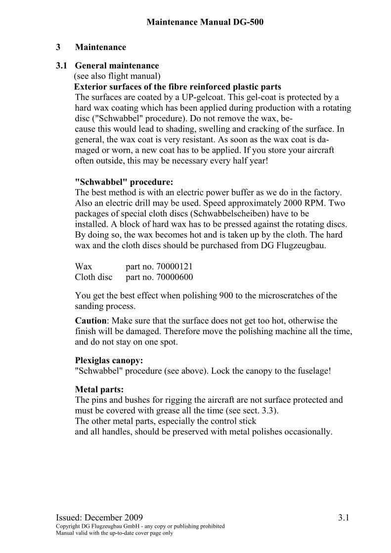
3 Maintenance
3.1 General maintenance (see also flight manual) Exterior surfaces of the fibre reinforced plastic parts The surfaces are coated by a UP-gelcoat. This gel-coat is protected by a hard wax coating which has been applied during production with a rotating disc ("Schwabbel" procedure). Do not remove the wax, be- cause this would lead to shading, swelling and cracking of the surface. In general, the wax coat is very resistant. As soon as the wax coat is da- maged or worn, a new coat has to be applied. If you store your aircraft often outside, this may be necessary every half year! "Schwabbel" procedure: The best method is with an electric power buffer as we do in the factory. Also an electric drill may be used. Speed approximately 2000 RPM. Two packages of special cloth discs (Schwabbelscheiben) have to be installed. A block of hard wax has to be pressed against the rotating discs. By doing so, the wax becomes hot and is taken up by the cloth. The hard wax and the cloth discs should be purchased from DG Flugzeugbau. Wax part no. 70000121 Cloth disc part no. 70000600
You get the best effect when polishing 900 to the microscratches of the sanding process. Caution: Make sure that the surface does not get too hot, otherwise the finish will be damaged. Therefore move the polishing machine all the time, and do not stay on one spot.
Plexiglas canopy: "Schwabbel" procedure (see above). Lock the canopy to the fuselage!
Metal parts: The pins and bushes for rigging the aircraft are not surface protected and must be covered with grease all the time (see sect. 3.3). The other metal parts, especially the control stick and all handles, should be preserved with metal polishes occasionally.
Maintenance Manual DG-500
Issued: December 2009 3.2 Copyright DG Flugzeugbau GmbH - any copy or publishing prohibited Manual valid with the up-to-date cover page only
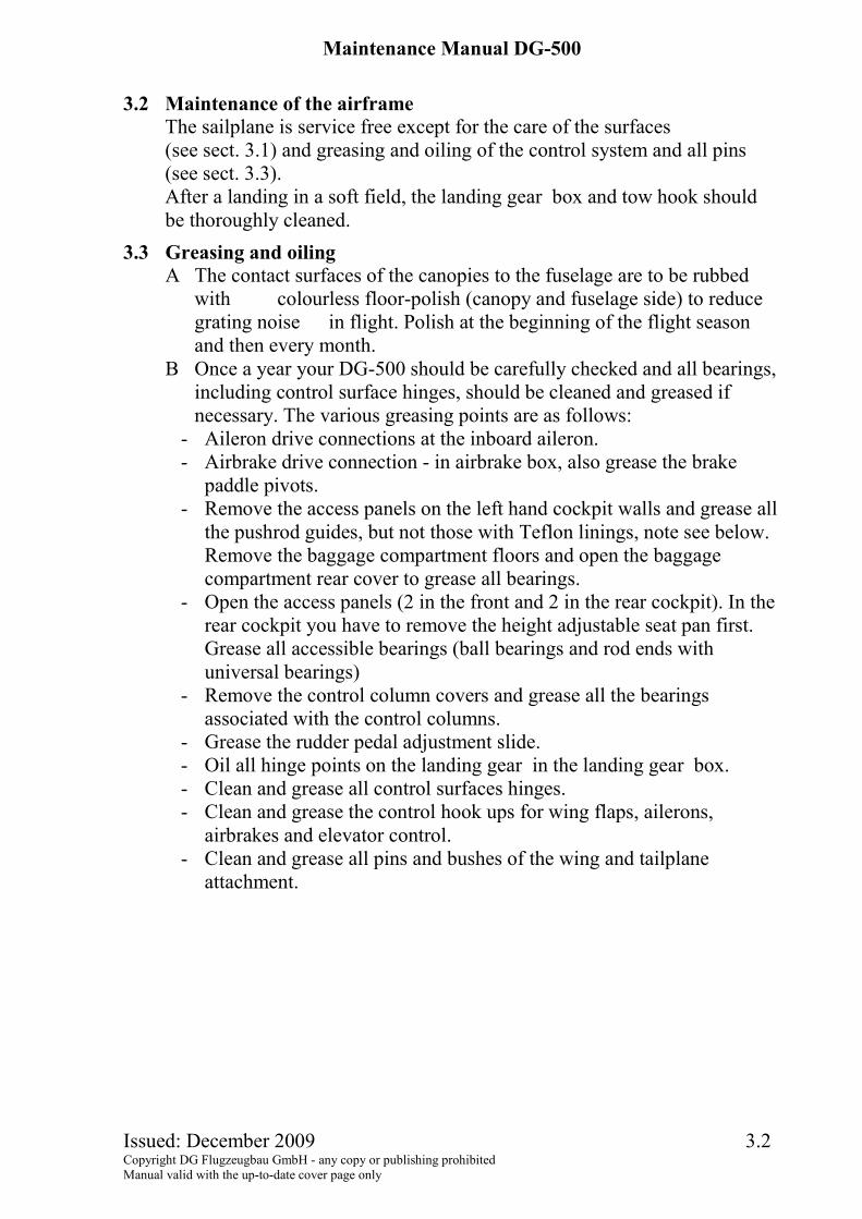
3.2 Maintenance of the airframe
The sailplane is service free except for the care of the surfaces (see sect. 3.1) and greasing and oiling of the control system and all pins (see sect. 3.3). After a landing in a soft field, the landing gear box and tow hook should be thoroughly cleaned.
3.3 Greasing and oiling A The contact surfaces of the canopies to the fuselage are to be rubbed
with colourless floor-polish (canopy and fuselage side) to reduce grating noise in flight. Polish at the beginning of the flight season and then every month.
B Once a year your DG-500 should be carefully checked and all bearings, including control surface hinges, should be cleaned and greased if necessary. The various greasing points are as follows:
- Aileron drive connections at the inboard aileron. - Airbrake drive connection - in airbrake box, also grease the brake
paddle pivots. - Remove the access panels on the left hand cockpit walls and grease all
the pushrod guides, but not those with Teflon linings, note see below. Remove the baggage compartment floors and open the baggage compartment rear cover to grease all bearings.
- Open the access panels (2 in the front and 2 in the rear cockpit). In the rear cockpit you have to remove the height adjustable seat pan first. Grease all accessible bearings (ball bearings and rod ends with universal bearings)
- Remove the control column covers and grease all the bearings associated with the control columns.
- Grease the rudder pedal adjustment slide. - Oil all hinge points on the landing gear in the landing gear box. - Clean and grease all control surfaces hinges. - Clean and grease the control hook ups for wing flaps, ailerons,
airbrakes and elevator control. - Clean and grease all pins and bushes of the wing and tailplane
attachment.
Maintenance Manual DG-500
Issued: December 2009 3.3 Copyright DG Flugzeugbau GmbH - any copy or publishing prohibited Manual valid with the up-to-date cover page only
Note: The greases we recommend are lithium based pressure-resistant anticorrosion greases or lithium-soap greases (multi-purpose greases for rolling element bearings).
Caution: The sliding guides of the following parts are made from Teflon and should not be greased: Landing gear controlhandle 5FW39 on 5St68/2, Airbrake control handle 5St69 on 5St68/1 and wingflaps handle 5St72 on 5 St68/2 (only DG-500/22 und /20).
If these parts have been greased inadvertently you have to disassemble the parts and to clean them completely with Acetone.
Maintenance Manual DG-500
Issued: December 2009 3.4 Copyright DG Flugzeugbau GmbH - any copy or publishing prohibited Manual valid with the up-to-date cover page only
3.4 Damage of the airframe
Before every flight, especially after a longer period of non--use, an inspection should be carried out. Check for any small changes such as small holes, bubbles and uneven areas on any skin surfaces, as these signal that may be wrong. With major damage, contact DG Flugzeugbau immediately and send photographs and a damage report from a licensed inspector or from an appropriately rated mechanic. With this information, the correct repair procedures can then be determined. Minor damage such as small cracks and holes in the skin surfaces can be repaired by an approved repair station. Additional information, such as a listing of all materials used in your aircraft can be found in the repair manual. Home repairs should not be attempted when: the main spars are damaged. major fittings on the wings, fuselage or tailplane are broken out or
white patches are noted around them in the laminate. When areas are so badly damaged that component parts cannot be
repaired without special jigs for proper positioning and alignment. Whenever it is necessary to cut into undamaged areas to execute
repairs.
3.5 Hydraulic brake system The brake fluid must be exchanged at least every 4 years (see section 1.6.1.4).
Maintenance Manual DG-500
Issued: December 2009 4.1 Copyright DG Flugzeugbau GmbH - any copy or publishing prohibited Manual valid with the up-to-date cover page only
4 Detailed instructions for assembly and servicing work
4.1 Waterballast system (only DG-500/22, DG-500/20 and DG-500 Orion) 4.1.1 Replacement of the water ballast bags and servicing the dump valves
Unscrew the bolt attaching the perlon line to the root rib and attach an additional 5 m (17 ft) long perlon line dia. 3 mm (.12 in.) to it. Unscrew the water ballast dump valve cap nut. Remove the dump valve with attached water ballast bag out of its wing stand by pushing the valve towards the wingtip. Remove the valve and ballast tank through the hole in the wing root. Remove the perlon line and loosen the hose clamp. Assemble the new tank to the valve body. Therefore apply some silicone sealing agent onto the neck of the valve body. Before reassembling the hose clamp wrap fabric tape (Tesaband 651) 3 times around the bag at this place.
The lines holding the tank are to be fixed, so that the key ring will remain 5 cm (2 in.) inside of the wing when the lines are just tensioned. By this the tension of the lines will be satisfactory even if the lines will strain.
Every 3 months, you should check, that the lines are still tensioned. If not, undo the knot and tie it again to the key ring (see above) . The front line should not be tensioned.
Each time you unscrew the valve, grease its thread, otherwise you won't be able to open it again. The seat of the valve ball (see diagr. 6) should be greased. Fill the new water ballast tank(s) and check for water tightness and test the dump time.
4.1.2 Replacement for the probe for fin tank B) (only DG-500 Orion)
Remove the cover of the coupling (located in front of the tailwheel) by pressing the spring clamp. Unplug the electrical probe connector which is fixed to the bulkhead at the rear end of the opening. Use a long 19 mm wrench to screw out the probe.
Maintenance Manual DG-500
Issued: December 2009 4.2 Copyright DG Flugzeugbau GmbH - any copy or publishing prohibited Manual valid with the up-to-date cover page only
4.2 Replacement of control circuit cables
The following cable connections are approved: 3.2 mm dia. control cable construction 7x19 with Nicopress-sleeves 28-3-M Copper and tool No. 51-M850 or 63-V-XPM or 64-CGMP where the M groove is to be used. The above applies to the rudder cables and the tow release cable. The cable for the rudder pedal adjustment are 1.6 mm dia. control cable construction 7x7 with Nicopress-sleeves 28-1C Copper and the C groove for tool 64-CGMP should be used. Only DG-500 Orion: The same type of cable is used for the control cables of fin tank. Attachment of the Nicopress sleeves should only be done using the respective tool. All the procedures and checks noted by the tool manufacturers should be followed. Please refer to aircraft inspection and repair FAA AC 43.13-1 B or later issues.
Caution: Control cables according to MIL-W-83420 I/A (was MIL-W-1511A) or ISO2020 (was LN9374) should be used. 4.3 Adjustment and servicing of the control circuit
a) In all cases, new self locking nuts DIN 985.8 should be used. b) Bolts which are not secured with locking nuts have to be secured with
Loctite 243. Before installing the bolt clean the thread and the inside thread with Acetone. Apply only 1 drop of Loctite on the bolt thread. Too much Loctite may cause damage when you try to loosen the bolt again.
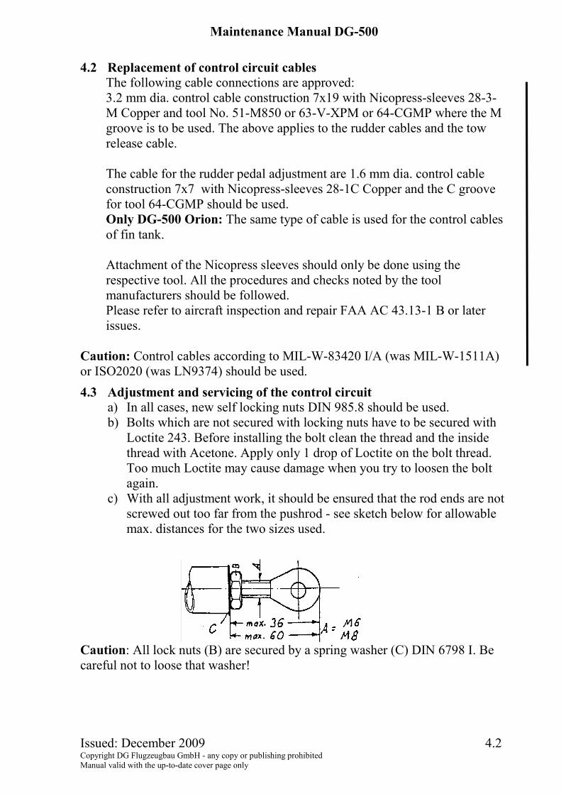
c) With all adjustment work, it should be ensured that the rod ends are not screwed out too far from the pushrod - see sketch below for allowable max. distances for the two sizes used.
Caution: All lock nuts (B) are secured by a spring washer (C) DIN 6798 I. Be careful not to loose that washer!
Maintenance Manual DG-500
Issued: December 2009 4.3 Copyright DG Flugzeugbau GmbH - any copy or publishing prohibited Manual valid with the up-to-date cover page only
4.4 Removal and installation of the retractable landing gear
See diagram 7 A Removal of the main wheel
1. Remove the bolt M8 x 45 DIN931-8.8 zn which secures the holder 5FW9 for the brake assembly to the front landing gear strut 5FW 0.
2. Remove the axis 5F17/1 and the parts 5FW17/2. 3. Remove the wheel axis 5FW5 and the bush 5FW4/1. 4. Move the wheel with the brake assembly to the right, so that the pin of
part 5FW9 slides out of 5FW10. Now remove the wheel with the brake assembly.
B Removal of the brake assembly from the mainwheel This is only necessary if the tyre is to be disassembled or if the brake linings are to be exchanged. 1. Remove the 2 upper bolts A from the brake assembly. 2. Take off brake assembly with holder 5 FW 9 and take away the loose
part (back plate assy) with the brake lining. Caution: Don't operate the airbrake and thus the wheel brake, as the piston and the brakefluid will be pressed out of the brake assembly. 3. During reassembly secure the 2 bolts A with Loctite 243 or safety wire.
C Removal of the rear landing gear strut 1. Remove the baggage compartment floor and the rear cover of the
baggage compartment. 2. Disassemble the wheel see A. 3. Retract the landing gear. Warning, the landing gear will retract by itself
when unlocked by the force of the gas spring. 4. Remove the short adjustable pushrod from the actuating lever 5FW8. 5. Disassemble the gas spring from the left side of the landing gear box. 6. Extend the landing gear again. 7. Disassemble the 3 bolts M6 x 40 LN9037 which fix the parts 5FW7 and
5FW8 to the strut 5FW12. Work inside the landing gear box. 8. Pull out 5FW7 and 5FW8 (with the gas spring). 9. Take out the rear landing gear strut.
Maintenance Manual DG-500
Issued: December 2009 4.4 Copyright DG Flugzeugbau GmbH - any copy or publishing prohibited Manual valid with the up-to-date cover page only
D Removal of the front landing gear strut
1. Remove the baggage compartment floor 2. Remove the main wheel see A 3. Screw out the front landing gear axis 5FW6 (Spanner 13 mm) and pull it
out towards the fuselage wall. Mark the head of the axis at the fuselage wall and drill a 15 mm hole through the fuselage wall. Pull out the axis through this hole.
4. Take out the front landing gear strut. Note: It is sufficient to tape the hole. GFRP repair is not necessary.
E Installation
Reverse the above procedures
Maintenance Manual DG-500
Issued: September 2011 TN500/05 4.5 Copyright DG Flugzeugbau GmbH - any copy or publishing prohibited Manual valid with the up-to-date cover page only
4.5 Filling and bleeding the hydraulic disc brake Note: The master cylinder is mounted in an upright position. This means that filling and bleeding the system is only possible from the lowest point, which is the brake cylinder assembly at the wheel.
Necessary tools: 1 open-end wrench 1/4" = 6.35 mm for the bleeder valve at the brake calliper. 1 open-end wrench 11/16" = 18 mm. 2 Plastic syringes acid resistant, volume approx. 100 ml (6 cu.in.). Use this
syringe for brake fluid only! 1 bleeder assy Tost No. 075890. 1 m (3 ft.) transparent PVC hose inside diameter 8 mm (0.31 in.), fixed to
syringe and bleeder assy with hose clamps. Brake-fluid DOT 3, DOT 4 or SAEJ 1703.
1. Preparations - Raise the fuselage, extend the landing gear. - Fix left wheel door in the fully open position. - Set the airbrake control in the retracted position. - Remove the baggage compartment floor and rear cover, check that the
actuating cable for the master cylinder is loose and if the piston rod of the master cylinder is at its upper stop.
- Remove the main wheel according to section 4.4 A. Place the wheel so that the brake hose makes no bow above or below the horizontal. If necessary lift the fuselage even more.
2. Filling (empty system) Warning: Brake fluid is poisonous! Protect your hands and clothes. Remove all spilled brake fluid. Clean all parts which had contact with brake fluid with alcohol, don't use fuel or solvents.
- Remove the cap and the membrane from the reservoir. - Fill the first syringe (with hose and bleeder assy.) with brake fluid,
eliminate all air bubbles. - Remove the protection cap from the bleeder valve at the brake calliper,
attach the bleeder assy. and fix it with the 11/16" wrench. - Open the bleeder valve at the cylinder assy, use the 1/4" wrench, fill in
slowly the complete volume avoiding air bubbles. - Fill the complete system up to 15 mm (0.6 in.) below the upper edge of
the reservoir, avoid over filling. - Close the bleeder valve at the brake calliper. - Use the second syringe to remove all brake fluid from the reservoir.
Maintenance Manual DG-500
Issued: September 2011 TN500/05 4.6 Copyright DG Flugzeugbau GmbH - any copy or publishing prohibited Manual valid with the up-to-date cover page only
- Fill the first syringe again, open the bleeder valve and fill in further
brake-fluid. Look at the reservoir while filling to see if air bubbles are coming out of the line. Fill up to 15 mm (0.6 in.) below the upper edge of the reservoir.
- Close the bleeder valve, reinstall the membrane and the cap to the reservoir and remove the bleeder assy.
- Check brake pressure according to step 3.. - Reinstall the main wheel.
3. Check brake pressure:
- Extend the airbrakes, there must be a strong pressure when the wheel brake engages.
- Check several times, the wheel brake must engage at the same point every time
- If this is not the case, you have to bleed the system again, see step 5..
4. Check the hydraulic brake system for leaks: Extend the airbrakes with high force and hold it in this position for 2 minutes. Then check the whole hydraulic system visually for leaks. If necessary tighten the screwed joints or replace the sealings and bleed the system again.
Note: The adjustment of the length of the cable between the master cylinder and the airbrake control shaft restricts the max. airbrake extension height. The adjustment of this cable should be done with the glider rigged.
5. Bleeding the hydraulic brake system Remove the brake fluid from the reservoir using the syringe. Then execute again steps 2 and 3 of this instruction.
6. Exchanging brake fluid (every 4 years)
- Perform preparations (see step 1.) of this instruction. It is not necessary to remove the main wheel.
- Fill the system with new brake fluid (see step 2.). To accomplish this remove all brake fluid from the reservoir first with the second syringe. Used brake fluid is darker than new brake fluid and can easily be identified. Watch the reservoir while filling to see when the new fluid streams into the reservoir. Repeat the filling process until only new fluid is in the system and no air bubbles can be detected.
- Perform steps 3. and 4. of this instruction.
Maintenance Manual DG-500
Issued: December 2009 4.7 Copyright DG Flugzeugbau GmbH - any copy or publishing prohibited Manual valid with the up-to-date cover page only
4.6 Removal and installation of the landing gear (non retractable)
see diagram 10 A Removal of the main wheel
1. Remove the wheel axle. 2. Remove the brake cable at the brake lever by loosening the attachment
screw. 3. Remove the wheel ensuring that the hub locking pin comes free from the
left hand front fork.
B Removal of the rear landing gear strut 1. Remove the baggage compartment floor and the rear cover of the baggage
compartment. 2. Disassemble the wheel see A. 3. From inside the wheel box remove the two bolts M6 x 40 LN9037 which
secure the parts 5FW7 to the rear strut. 4. Pull out both parts 5FW7. 5. Take out the rear landing gear strut.
C Removal of the front landing gear strut 1. Remove the baggage compartment floor 2. Remove the main wheel see A 3. Screw out the front landing gear axis 5 FW 6 (Spanner 13 mm) and pull it
out towards the fuselage wall.Mark the head of the axis at the fuselage wall and drill a 15 mm hole through the fuselage wall. Pull out the axis through this hole.
4. Take out the front landing gear strut.
Note: It is sufficient to tape the hole. GFRP repair is not necessary.
D Installation Reverse the above procedures.
Maintenance Manual DG-500
Issued: December 2009 5.1 Copyright DG Flugzeugbau GmbH - any copy or publishing prohibited Manual valid with the up-to-date cover page only
5 Weight and balance
1. Assemble the glider completely with gear down. 2. Place a scale under the tailwheel. 3. The fuselage must be levelled so that the top of the aft fuselage
boom has a tail-down slope of 1000 : 33. 4. Empty water ballast tank. 5. Read weight of tail wheel: W 2
Read W1 if suitable scales are available, otherwise see note below. Be certain the wings are level so, that no load is applied.
6. Measure the distance between perpendiculars through points a and b.(See figure, next page).
Caution: The distances a and b may change with different masses due to deflection of the landing gear.
Note: The total mass M may be determined by weighing and adding W1 and W2 or by weighing and adding the masses of all components.
C.G. empty XSE: XSE = W2E • b / ME + a
ME = empty mass W2E load on tailwheel (empty) The empty weight includes all accessories but excludes pilot and parachute. Remove loose objects from the cockpit. The weighing is to be executed with the battery (Z 07, mass 4.3 kg - 9.5 lbs) in the fin. C.G. in flight XSF: XSF = W2F • b / MF + a MF = flight mass W2F - load on tailwheel (flight mass) The flight mass includes empty weight items plus pilot, parachute, and all items needed in flight (barograph, camera, cushions, etc.). In addition, the rudder pedals and seating position should be adjusted as in flight.
When weighing with 2 pilots the load W 2 will be negative. This means that you need a spring balance to determine W 2. Therefore push a pin through the hollow tail wheel axis.
Maintenance Manual DG-500
Issued: December 2009 5.2 Copyright DG Flugzeugbau GmbH - any copy or publishing prohibited Manual valid with the up-to-date cover page only
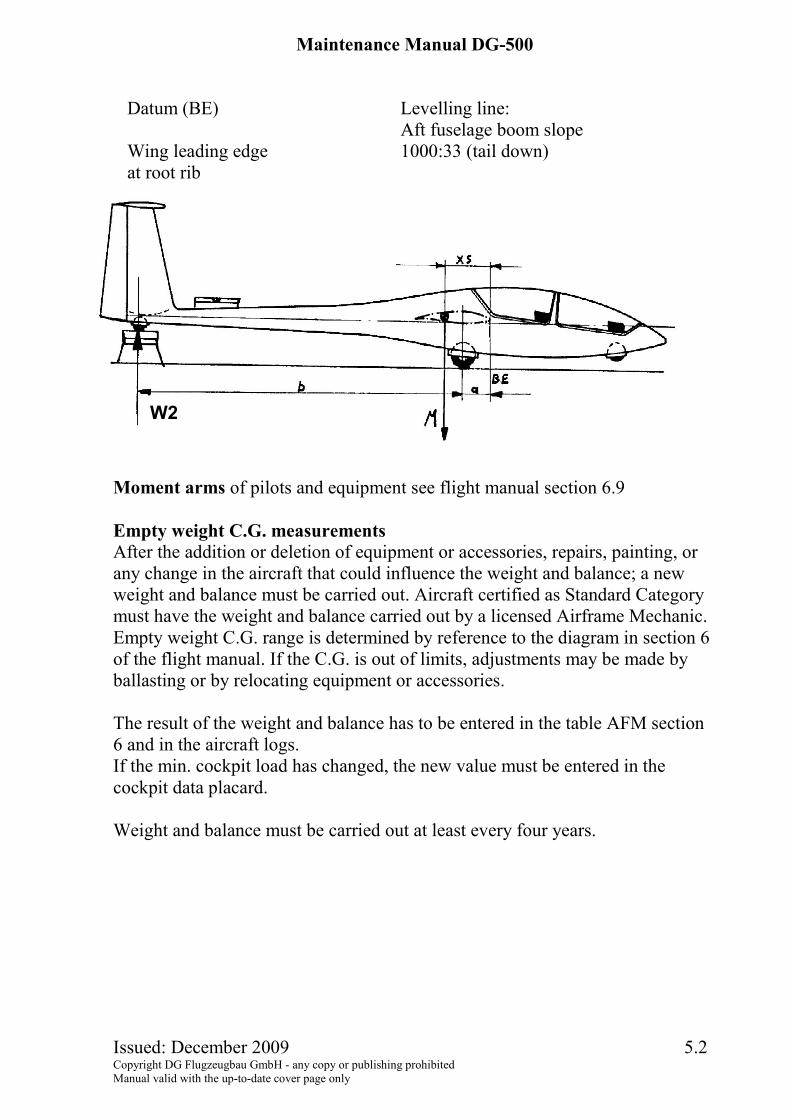
Datum (BE) Levelling line: Aft fuselage boom slope Wing leading edge 1000:33 (tail down) at root rib
Moment arms of pilots and equipment see flight manual section 6.9 Empty weight C.G. measurements After the addition or deletion of equipment or accessories, repairs, painting, or any change in the aircraft that could influence the weight and balance; a new weight and balance must be carried out. Aircraft certified as Standard Category must have the weight and balance carried out by a licensed Airframe Mechanic. Empty weight C.G. range is determined by reference to the diagram in section 6 of the flight manual. If the C.G. is out of limits, adjustments may be made by ballasting or by relocating equipment or accessories. The result of the weight and balance has to be entered in the table AFM section 6 and in the aircraft logs. If the min. cockpit load has changed, the new value must be entered in the cockpit data placard. Weight and balance must be carried out at least every four years.
W2
Maintenance Manual DG-500
Issued: December 2009 6.1 Copyright DG Flugzeugbau GmbH - any copy or publishing prohibited Manual valid with the up-to-date cover page only
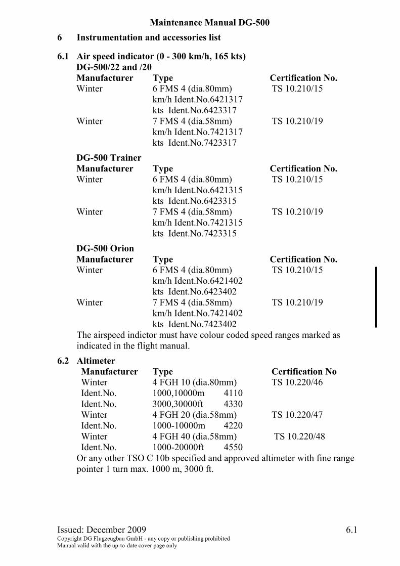
6 Instrumentation and accessories list
6.1 Air speed indicator (0 - 300 km/h, 165 kts) DG-500/22 and /20 Manufacturer Type Certification No. Winter 6 FMS 4 (dia.80mm) TS 10.210/15
km/h Ident.No.6421317 kts Ident.No.6423317
Winter 7 FMS 4 (dia.58mm) TS 10.210/19 km/h Ident.No.7421317 kts Ident.No.7423317
DG-500 Trainer Manufacturer Type Certification No. Winter 6 FMS 4 (dia.80mm) TS 10.210/15
km/h Ident.No.6421315 kts Ident.No.6423315
Winter 7 FMS 4 (dia.58mm) TS 10.210/19 km/h Ident.No.7421315 kts Ident.No.7423315
DG-500 Orion Manufacturer Type Certification No. Winter 6 FMS 4 (dia.80mm) TS 10.210/15
km/h Ident.No.6421402 kts Ident.No.6423402
Winter 7 FMS 4 (dia.58mm) TS 10.210/19 km/h Ident.No.7421402 kts Ident.No.7423402
The airspeed indictor must have colour coded speed ranges marked as indicated in the flight manual.
6.2 Altimeter Manufacturer Type Certification No Winter 4 FGH 10 (dia.80mm) TS 10.220/46 Ident.No. 1000,10000m 4110 Ident.No. 3000,30000ft 4330 Winter 4 FGH 20 (dia.58mm) TS 10.220/47 Ident.No. 1000-10000m 4220 Winter 4 FGH 40 (dia.58mm) TS 10.220/48 Ident.No. 1000-20000ft 4550
Or any other TSO C 10b specified and approved altimeter with fine range pointer 1 turn max. 1000 m, 3000 ft.
Maintenance Manual DG-500
Issued: December 2009 6.2 Copyright DG Flugzeugbau GmbH - any copy or publishing prohibited Manual valid with the up-to-date cover page only
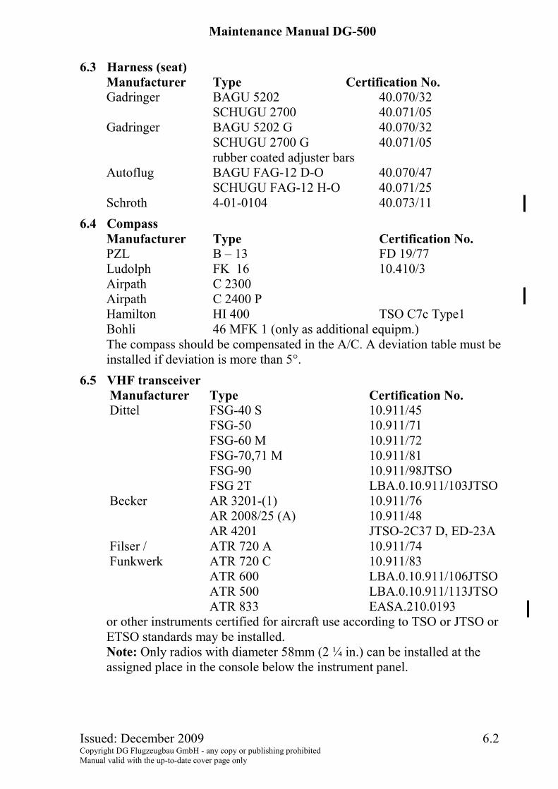
6.3 Harness (seat)
Manufacturer Type Certification No. Gadringer BAGU 5202 40.070/32
SCHUGU 2700 40.071/05 Gadringer BAGU 5202 G 40.070/32
SCHUGU 2700 G 40.071/05 rubber coated adjuster bars
Autoflug BAGU FAG-12 D-O 40.070/47 SCHUGU FAG-12 H-O 40.071/25
Schroth 4-01-0104 40.073/11 6.4 Compass
Manufacturer Type Certification No. PZL B – 13 FD 19/77 Ludolph FK 16 10.410/3 Airpath C 2300 Airpath C 2400 P Hamilton HI 400 TSO C7c Type1 Bohli 46 MFK 1 (only as additional equipm.) The compass should be compensated in the A/C. A deviation table must be installed if deviation is more than 5°.
6.5 VHF transceiver Manufacturer Type Certification No. Dittel FSG-40 S 10.911/45 FSG-50 10.911/71 FSG-60 M 10.911/72 FSG-70,71 M 10.911/81 FSG-90 10.911/98JTSO FSG 2T LBA.0.10.911/103JTSO Becker AR 3201-(1) 10.911/76 AR 2008/25 (A) 10.911/48 AR 4201 JTSO-2C37 D, ED-23A Filser / ATR 720 A 10.911/74 Funkwerk ATR 720 C 10.911/83 ATR 600 LBA.0.10.911/106JTSO ATR 500 LBA.0.10.911/113JTSO ATR 833 EASA.210.0193 or other instruments certified for aircraft use according to TSO or JTSO or ETSO standards may be installed. Note: Only radios with diameter 58mm (2 ¼ in.) can be installed at the assigned place in the console below the instrument panel.

Maintenance Manual DG-500
Issued: December 2009 6.3 Copyright DG Flugzeugbau GmbH - any copy or publishing prohibited Manual valid with the up-to-date cover page only
6.6 Variometer
Manufacturer Type Certification No. Winter 5 St VM5 (dia.58 mm) TS 10.230/14 +5 m/sec Ident.No.5451 +1000 ft/min ident.No.5452 +10 knts Ident.No.5453 Winter 5 StV5 (dia.80 mm) TS 10.230/13 +5 m/sec Ident.No.5251 +1000 ft/min Ident.No.5252 +10 knts Ident.No.5253
6.7 Turn and bank indicator Manufacturer Type Certification No. Apparatebau Gauting WZ-402/31 12 V 10.241/8
6.8 Accelerometer (for Category A Aerobatics) Only for DG-500 Orion and. TRAINER Accelerometer capable of retaining max. And min. g-values with markings red redial lines at +7g and -5g. Manufacturer Typ Certification No. AOA Apparatebau Gauting BM 470-RL/L MIL-A-5885 A Bendix 2" 5V LITE MS 28025-1 Bendix 3419-5A-A1 MS 28025-1 Burton Manufacturing Co. B-6 MS 280025-1 INSCO 6610 MS 33638 Kelvin & Hughes Ltd. KAE 0504K MS 23009-1 Milhard Engineering Co ABU-4/A MS 23009-1 QED/Inc. (ASG) ABU-4/A MIL-A-25949 Smiths KAE 0504/K MS 23009-1 Falcon Gauge GMS 10-2 MIL-A-5885 C
6.9 Outside air temperature gauge Only for DG-500 Orion Manufacturer Typ Störk TF 00-059K (-20 - + 40° C)
Maintenance Manual DG-500
Issued: December 2009 6.4 Copyright DG Flugzeugbau GmbH - any copy or publishing prohibited Manual valid with the up-to-date cover page only
6.10 Instruments which are not part of the minimum equipment:
Transponders: Transponders certified for aircraft use according to TSO or JTSO or ETSO standards may be installed. Other instruments and equipment (eg. variometers, gliding computers or flight data recorders): Instruments and other equipment may be installed if they do not in themselves, or by their effect upon the sailplane, constitute a hazard to safe operation. After installation raise a new weight and balance report.
Caution: If additional instruments or equipment are to be installed after production of the glider, it must be assured that they will be installed in the places provided by the design. If installed in other places it must be assured that they are secured safely. Electrical instruments and equipment must be connected via appropriately rated fuses, the power consumption of each single part should not exceed 3A.

Maintenance Manual DG-500
Issued: December 2009 7.1 Copyright DG Flugzeugbau GmbH - any copy or publishing prohibited Manual valid with the up-to-date cover page only
7 List of special tools
A Special tool with 6 mm thread (W38/2) for the se- curing of the tailplane and for the locking pins of the rear wing suspension
B cial tool W 38/1 for mounting of the outboard wings.
C Open end spanners
mm 7 8 9 10 13 14 1/4" = 6.35 mm
D Allen key wrench 5 mm, 6 mm
E spring balance: max. reading 50 N, 11 lbs.
F Nicopress tool 64 - CGMP Girclip pliers A (outside) for the range 8-14 mm for the tail wheel axis. Hose with outside dia 25 mm (1 in.) approx. 2 m (6.5 ft.) long for filling the wingtanks.

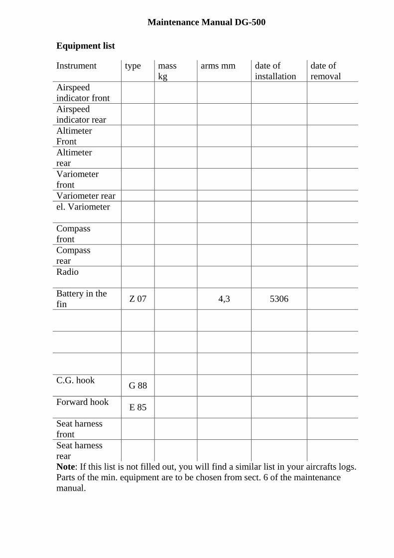
Maintenance Manual DG-500 Equipment list
Note: If this list is not filled out, you will find a similar list in your aircrafts logs. Parts of the min. equipment are to be chosen from sect. 6 of the maintenance manual.
Instrument type mass kg
arms mm date of installation
date of removal
Airspeed indicator front
Airspeed indicator rear
Altimeter Front
Altimeter rear
Variometer front
Variometer rear el. Variometer
Compass front
Compass rear
Radio
Battery in the fin Z07 4,3 5306
C.G. hook G 88
Forward hook E 85
Seat harness front
Seat harness rear

Maintenance Manual DG-500 Equipment list
Note: If this list is not filled out, you will find a similar list in your aircrafts logs. Parts of the min. equipment are to be chosen from sect. 6 of the maintenance manual.
Instrument type mass kg
arms mm date of installation
date of removal
Airspeed indicator front
Airspeed indicator rear
Altimeter Front
Altimeter rear
Variometer front
Variometer rear el. Variometer
Compass front
Compass rear
Radio
Battery in the fin Z 07 4,3 5306
C.G. hook G 88
Forward hook E 85
Seat harness front
Seat harness rear
DG Flugzeugbau GmbH page 1 from 5 Working instruction No. 1 for TN348/20
Issue 3: 13.09.2011 Author: Dipl. Ing. Wilhelm Dirks
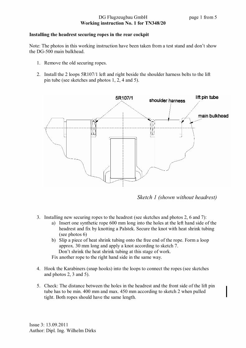
Installing the headrest securing ropes in the rear cockpit Note: The photos in this working instruction have been taken from a test stand and don’t show the DG-500 main bulkhead.
1. Remove the old securing ropes. 2. Install the 2 loops 5R107/1 left and right beside the shoulder harness belts to the lift
pin tube (see sketches and photos 1, 2, 4 and 5).
Sketch 1 (shown without headrest)
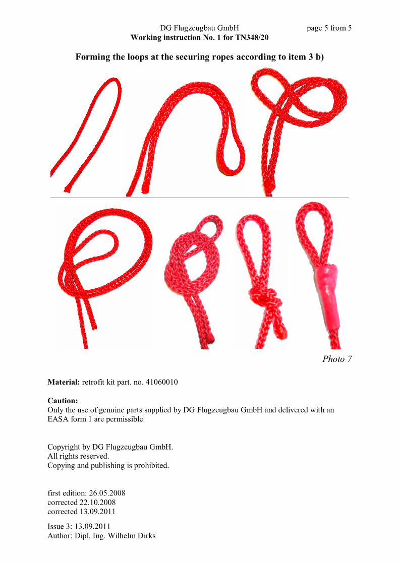
3. Installing new securing ropes to the headrest (see sketches and photos 2, 6 and 7): a) Insert one synthetic rope 600 mm long into the holes at the left hand side of the
headrest and fix by knotting a Palstek. Secure the knot with heat shrink tubing (see photos 6)
b) Slip a piece of heat shrink tubing onto the free end of the rope. Form a loop approx. 30 mm long and apply a knot according to sketch 7. Don’t shrink the heat shrink tubing at this stage of work.
Fix another rope to the right hand side in the same way.
4. Hook the Karabiners (snap hooks) into the loops to connect the ropes (see sketches and photos 2, 3 and 5).
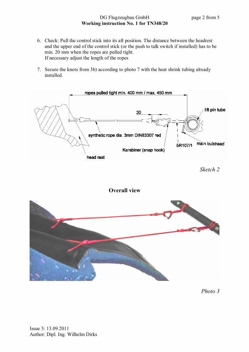
5. Check: The distance between the holes in the headrest and the front side of the lift pin
tube has to be min. 400 mm and max. 450 mm according to sketch 2 when pulled tight. Both ropes should have the same length.
DG Flugzeugbau GmbH page 2 from 5 Working instruction No. 1 for TN348/20
Issue 3: 13.09.2011 Author: Dipl. Ing. Wilhelm Dirks
6. Check: Pull the control stick into its aft position. The distance between the headrest
and the upper end of the control stick (or the push to talk switch if installed) has to be min. 20 mm when the ropes are pulled tight. If necessary adjust the length of the ropes
7. Secure the knots from 3b) according to photo 7 with the heat shrink tubing already
installed.
Sketch 2
Overall view
Photo 3
DG Flugzeugbau GmbH page 3 from 5 Working instruction No. 1 for TN348/20
Issue 3: 13.09.2011 Author: Dipl. Ing. Wilhelm Dirks
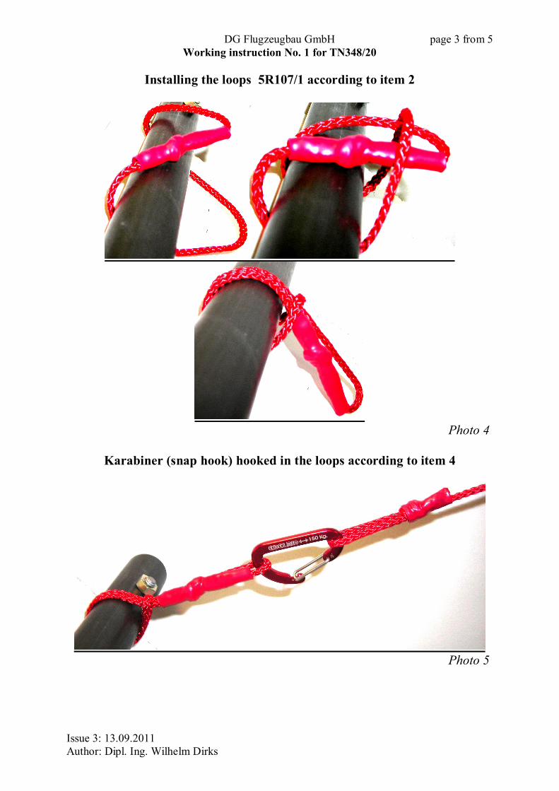
Installing the loops 5R107/1 according to item 2
Photo 4
Karabiner (snap hook) hooked in the loops according to item 4
Photo 5

DG Flugzeugbau GmbH page 4 from 5 Working instruction No. 1 for TN348/20
Issue 3: 13.09.2011 Author: Dipl. Ing. Wilhelm Dirks
Installation of the securing ropes at the head rest according to item 3 a)
Photo 6
DG Flugzeugbau GmbH page 5 from 5 Working instruction No. 1 for TN348/20
Issue 3: 13.09.2011 Author: Dipl. Ing. Wilhelm Dirks
Forming the loops at the securing ropes according to item 3 b)
Photo 7
Material: retrofit kit part. no. 41060010 Caution: Only the use of genuine parts supplied by DG Flugzeugbau GmbH and delivered with an EASA form 1 are permissible. Copyright by DG Flugzeugbau GmbH. All rights reserved. Copying and publishing is prohibited. first edition: 26.05.2008 corrected 22.10.2008 corrected 13.09.2011
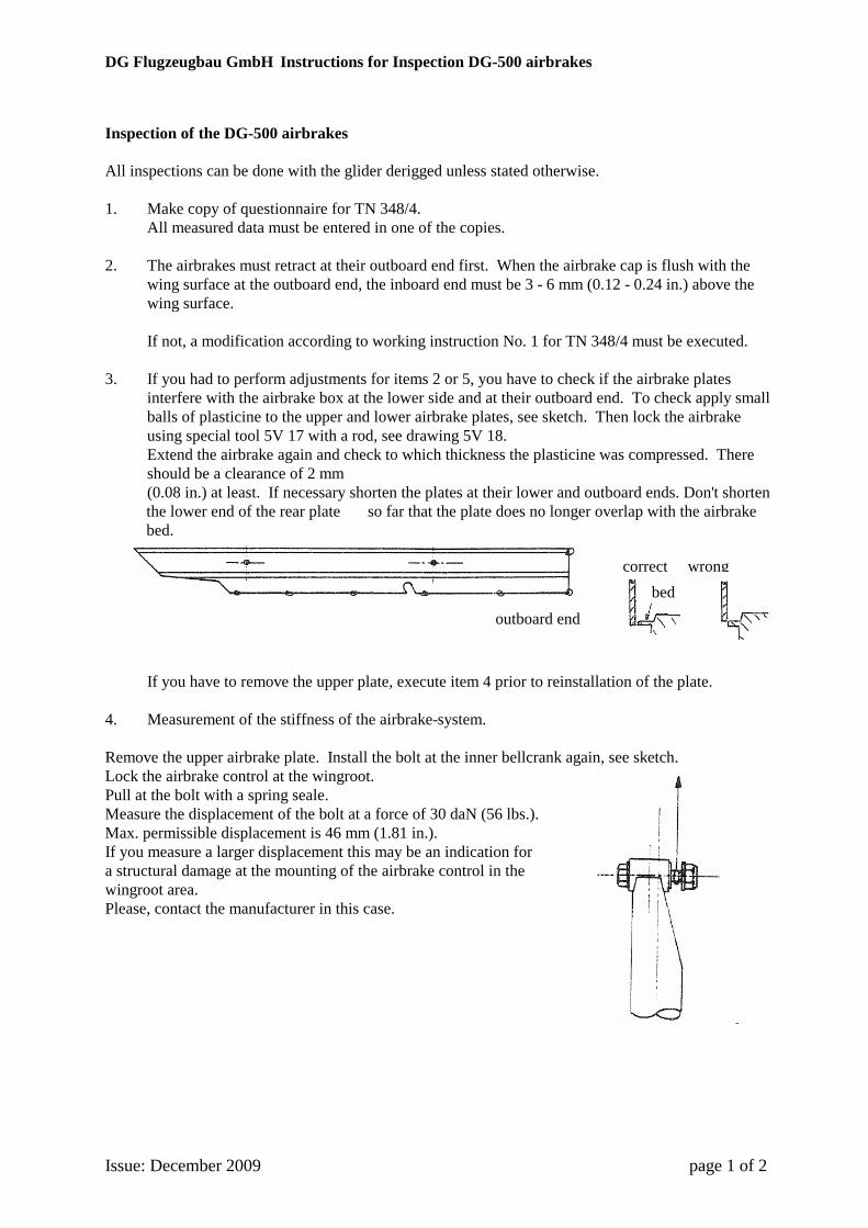
DG Flugzeugbau GmbH Instructions for Inspection DG-500 airbrakes
Issue: December 2009 page 1 of 2
Inspection of the DG-500 airbrakes All inspections can be done with the glider derigged unless stated otherwise. 1. Make copy of questionnaire for TN 348/4. All measured data must be entered in one of the copies. 2. The airbrakes must retract at their outboard end first. When the airbrake cap is flush with the
wing surface at the outboard end, the inboard end must be 3 - 6 mm (0.12 - 0.24 in.) above the wing surface.
If not, a modification according to working instruction No. 1 for TN 348/4 must be executed. 3. If you had to perform adjustments for items 2 or 5, you have to check if the airbrake plates
interfere with the airbrake box at the lower side and at their outboard end. To check apply small balls of plasticine to the upper and lower airbrake plates, see sketch. Then lock the airbrake using special tool 5V 17 with a rod, see drawing 5V 18. Extend the airbrake again and check to which thickness the plasticine was compressed. There should be a clearance of 2 mm (0.08 in.) at least. If necessary shorten the plates at their lower and outboard ends. Don't shorten the lower end of the rear plate so far that the plate does no longer overlap with the airbrake bed.
If you have to remove the upper plate, execute item 4 prior to reinstallation of the plate. 4. Measurement of the stiffness of the airbrake-system. Remove the upper airbrake plate. Install the bolt at the inner bellcrank again, see sketch. Lock the airbrake control at the wingroot. Pull at the bolt with a spring seale. Measure the displacement of the bolt at a force of 30 daN (56 lbs.). Max. permissible displacement is 46 mm (1.81 in.). If you measure a larger displacement this may be an indication for a structural damage at the mounting of the airbrake control in the wingroot area. Please, contact the manufacturer in this case.
outboard end
correct wrongbed
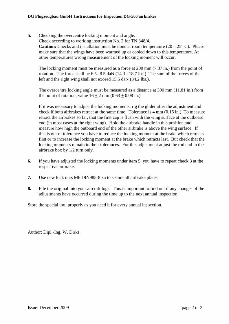
DG Flugzeugbau GmbH Instructions for Inspection DG-500 airbrakes
Issue: December 2009 page 2 of 2
5. Checking the overcentre locking moment and angle. Check according to working instruction No. 2 for TN 348/4.
Caution: Checks and installation must be done at room temperature (20 – 25° C). Please make sure that the wings have been warmed up or cooled down to this temperature. At other temperatures wrong measurement of the locking moment will occur.
The locking moment must be measured as a force at 200 mm (7.87 in.) from the point of rotation. The force shall be 6.5 - 8.5 daN (14.3 - 18.7 lbs.). The sum of the forces of the left and the right wing shall not exceed 15.5 daN (34.2 lbs.).
The overcentre locking angle must be measured as a distance at 300 mm (11.81 in.) from the point of rotation, value 16 + 2 mm (0.63 + 0.08 in.).
If it was necessary to adjust the locking moments, rig the glider after the adjustment and check if both airbrakes retract at the same time. Tolerance is 4 mm (0.16 in.). To measure retract the airbrakes so far, that the first cap is flush with the wing surface at the outboard end (in most cases at the right wing). Hold the airbrake handle in this position and measure how high the outboard end of the other airbrake is above the wing surface. If this is out of tolerance you have to reduce the locking moment at the brake which retracts first or to increase the locking moment at the brake which retracts last. But check that the locking moments remain in their tolerances. For this adjustment adjust the rod end in the airbrake box by 1/2 turn only.
6. If you have adjusted the locking moments under item 5, you have to repeat check 3 at the
respective airbrake. 7. Use new lock nuts M6 DIN985-8 zn to secure all airbrake plates. 8. File the original into your aircraft logs. This is important to find out if any changes of the
adjustments have occurred during the time up to the next annual inspection. Store the special tool properly as you need it for every annual inspection. Author: Dipl.-Ing. W. Dirks