digital communication server dg-x1
TRANSCRIPT

Shanghai Digigrid Information Technology Co., Ltd. 1
Digital Communication Server
DG-X1
F5, Building NO.2, NO.1295
Xinjinqiao Road Pudong District,
Shanghai, China, 201206
(86)21-6162 9203
www.digigrid.com.cn
Shanghai Digigrid Information Technology Co., Ltd. 2
Copyright Information and Ownership Statement
Shanghai Digigrid Information Technology Co., Ltd. holds the copyright
and reserves all rights in this manual. No one shall extract, copy, cut or use
any other means to replicate part or all of the text, graphics, and data of the
guide without permission. Otherwise, the company will call to corresponding
account in due course.
Version Revision
Version Date Revision
Note: User could refer this manual for DG-Mini installation.
☆Note:Recommend that carefully read this manual after obtaining the
device.
Shanghai Digigrid Information Technology Co., Ltd. 3
TABLE OF CONTENTS
1. Introduction and Specification .................................................................................................. 5
1.1 Overview ............................................................................................................................. 5
1.2 Feature ................................................................................................................................. 5
1.3 Specification........................................................................................................................ 7
2. Installation ................................................................................................................................... 9
2.1 Overview ............................................................................................................................. 9
2.2 Installation ........................................................................................................................... 9
2.3 Wiring ............................................................................................................................... 10
3. Application ................................................................................................................................. 18
3.1 Protocol Conversion .......................................................................................................... 18
3.2 Substation Automation ...................................................................................................... 18
3.3 Virtual Port Connection ..................................................................................................... 18
3.4 IEC61850 Communication................................................................................................ 18
3.5 Advanced Calculation ....................................................................................................... 18
4. Communication ........................................................................................................................ 19
4.1 Overview ........................................................................................................................... 19
4.2 Communication Interfaces ................................................................................................ 19
4.3 IEC61850 Communication Protocol ................................................................................. 20
4.4 Modbus Communication Protocol .................................................................................... 21
4.5 IEC101 Communication Protocol ..................................................................................... 22
4.6 IEC104 Communication Protocol ..................................................................................... 23
4.7 SEL Communication Protocol .......................................................................................... 24
4.8 DNP Communication Protocol .......................................................................................... 25
4.9 Courier Communication Protocol ..................................................................................... 37
4.10 Customized Protocols ..................................................................................................... 38
5 Configuration Software ............................................................................................................. 39
5.1 Overview ........................................................................................................................... 39
5.2 Setup ................................................................................................................................. 39
5.3 Interface Layout ................................................................................................................ 43
5.4 Firmware Upgrade ............................................................................................................ 44
6. Testing and Troubleshooting .................................................................................................. 48
6.1 Overview ........................................................................................................................... 48
6.2 Testing Tools ..................................................................................................................... 48
6.3 Self-Test ............................................................................................................................ 48
6.4 Troubleshooting ................................................................................................................ 49
Appendix A ............................................................................................................................. 58
A.1 Firmware and Manual Versions ....................................................................................... 58
Appendix B .................................................................................................................................... 58
B.1 IEC61850 Configuration .................................................................................................. 58
Appendix C .................................................................................................................................... 66
Shanghai Digigrid Information Technology Co., Ltd. 4
C.1 Modbus Configuration ..................................................................................................... 66
Appendix D .................................................................................................................................... 76
D.1 IEC101 Configuration ...................................................................................................... 76
Appendix E .................................................................................................................................... 84
E.1 IEC104 Configuration ...................................................................................................... 84
Appendix F .................................................................................................................................... 92
F.1 SEL Configuration ............................................................................................................ 92
Appendix G .................................................................................................................................... 99
G.1 DNP Configuration ........................................................................................................... 99
Appendix H .................................................................................................................................. 106
H.1 Script Calculation Advanced Application ...................................................................... 106
H.1.1 Application Information .............................................................................................. 106
H.1.2 Parameter Information................................................................................................. 108
H.1.3 Configuration Information .......................................................................................... 109
Appendix I 110
I.1 Courier Configuration ...................................................................................................... 110
Shanghai Digigrid Information Technology Co., Ltd. 5
1. Introduction and Specification
1.1 Overview
DG-X1 is a specially designed communication facility based on the Freescale
PPC architecture. It can be easily deployed to collect various types of data,
supervise, control and manage various IEDs in substation through its
independent 3×10/100M Ethernet ports, 2×Modem ports and
8×RS-232/422/485 ports.
This manual contains the information needed to install, test, operate, and
maintain any DG-X1. You need not review the entire manual to perform
specific tasks.
1.2 Feature
Hardened design
DG-X1 is based on harden CPU module. The CPU module is based on
Freescale MPC8270 Power QUICC II, a powerful PowerPC 603e CPU core
provides 850 MIPS horse power, and a separate CPM (Communication
Processing Machine) handles all the communications. This dual-core design
enables the CPU module to support multiple Ethernet while have CPU power
similar as PC, only with much higher reliability.
PowerQUICC is specially designed for communication and industrial control.
For example, a common fan-less 600MHz X86 based CPU module will
consume about 20W of power. While
an ePM82xx CPU module with 850MIPS horsepower needs only about 5W.
The very low power consumption largely increased system reliability.
DG-X1 supports as high as 64MB/128MB NOR Flash. Besides boot loader,
operating system, root file system and applications can be stored in the Flash.
Shanghai Digigrid Information Technology Co., Ltd. 6
CF cards can be used purely for user data. This design not only simplified the
firmware/software distribution, but also increased system reliability.
Ethernet
DG-X1 supports maximum 3 independent Ethernet ports, each with separate
MAC address, can be configured as 10/100BASE-FX optical-fiber based ports.
CAN
2 independent CAN controllers are implemented in the DG-X1 system.
Redundant Dual-CAN bus system can be implemented.
Serial I/O
As many as 10 serial ports are implemented in the DG-X1 system. 2 of the
ports are designed as complete EIA-232C ports, normal use or standard
telephone MODEM can be supported. For other 8 ports, EIA-232C,
EIA-422/485 can be selected by software. And loop back test mode can be
supported by software.
Frequency measurement
DG-X1 supports frequency estimation. A separate frequency estimation input
can be accepted from the rear panel. Standard 50Hz or 60Hz line frequencies
are supported. Frequency estimation accuracy is +/-0.005Hz.
PC like functionalities
PC features, such as VGA display, USB ports, Keyboard and mouse based
GUI, disk (CF card) storage, are very tempting functions even in industrial
control. That is one of the reasons why even X86 based CPU modules are not
harden enough for industrial, but still widely used.
DG-X1 CPU system support as high as 128MB/256MB RAM, 0~1MB NVRAM,
and supports many PC like features like VGA display, USB, keyboard and

Shanghai Digigrid Information Technology Co., Ltd. 7
mouse based GUI. This design achieved both system reliability and
functionality.
Real time capability
DG-X1 supports latest Linux 2.6 with Xenomai real time extension. System
response time can reach micro-seconds with the Xenomai support. For
example, DG-X1 supports Digital Inputs with SOE function on milliseconds
resolution. Other real time functions can be implemented.
IT applications
With standard Linux 2.6 operating system, DG-X1 can be used as industrial
server system using IT application. For this purpose, MySQL DB server,
HTTP WEB server, and other applications are pre-installed.
Point of Load Power Supply
The power supply of the DG-X1 system provides 12V to each module. Then
within the module, distributed converters are used to convert the 12V into 3.3V
and 5V for actual load. This 2 level power supply technology can reduce the
power supply impact to the system operation.
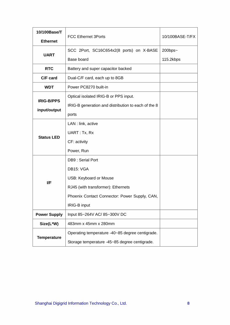
1.3 Specification
Item Spec. Etc.
CPU Freescale MPC8270 450/300/100 MHz
DRAM 256M Bytes 64bit
128M Bytes 64bit
NVRAM 0MB~1MB, Battery and super capacitor backed 16 bit
FLASH 64MB/128MB 32 bit
Shanghai Digigrid Information Technology Co., Ltd. 8
10/100Base/T
Ethernet FCC Ethernet 3Ports 10/100BASE-T/FX
UART SCC 2Port, SC16C654x2(8 ports) on X-BASE
Base board
200bps~
115.2kbps
RTC Battery and super capacitor backed
C/F card Dual-C/F card, each up to 8GB
WDT Power PC8270 built-in
IRIG-B/PPS
input/output
Optical isolated IRIG-B or PPS input.
IRIG-B generation and distribution to each of the 8
ports
Status LED
LAN : link, active
UART : Tx, Rx
CF: activity
Power, Run
I/F
DB9 : Serial Port
DB15: VGA
USB: Keyboard or Mouse
RJ45 (with transformer): Ethernets
Phoenix Contact Connector: Power Supply, CAN,
IRIG-B input
Power Supply Input 85~264V AC/ 85~300V DC
Size(L*W) 483mm x 45mm x 280mm
Temperature Operating temperature -40~85 degree centigrade.
Storage temperature -45~85 degree centigrade.
Shanghai Digigrid Information Technology Co., Ltd. 9
2. Installation
2.1 Overview
This section describes common installation features and requirements. Dual-computer
redundancy installation is also mentioned.
2.2 Installation
Desktop
Installation
This installation requires a clean and dry desk with fresh air around.
User need to stick four single-side rubber pads to the bottom of DG-X1,
just four corners will be OK. Keep certain distance from DG-X1 for heat
dissipation purpose.
To avoid any physical damage, do not place any goods on the top of
DG-X1.
Keep away from hot objects with high temperature. Avoid tiny metal
object getting into DG-X1, and avoid liquid splashing such danger
events. If happens, please turn off power supply or plug out power
supply wire immediately, then call our technical department for help.
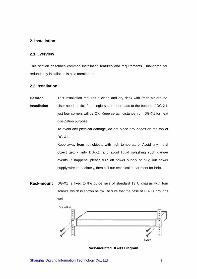
Rack-mount DG-X1 is fixed to the guide rails of standard 19 U chassis with four
screws, which is shown below. Be sure that the case of DG-X1 grounds
well.
Rack-mounted DG-X1 Diagram

Shanghai Digigrid Information Technology Co., Ltd. 10
DG-X1 Dimensions Diagram
2.3 Wiring
Power Supply Connection
Input voltage: 85~264V AC/ 85~300V DC.
☆Note:It is advised that power supply connection and
debugging should be implemented before connecting to
network and serial port devices.
Please heed the following steps for DG-X1 power supply
connection:
Connection Ensure that power supply switch is off status (switch placed
Shanghai Digigrid Information Technology Co., Ltd. 11
of AC power
supply
in “O” mark). If not, turn off the switch;
Connect the grounding wire to the outside of DC power
supply wiring terminal;
Connect power supply wire to the power supply outlet of
rear panel of DG-X1;
Turn on power supply switch of DG-X1 front panel(placed
in “|” mark);
Be sure LED indicators of 12V, 5V, 3.3V operate normally;
In case of any exceptions, please turn off power supply or
plug out power supply wire immediately, then call our
technical department for help.
Connection
of DC power
supply
Ensure that power supply switch is off status (switch
placed in “O” mark). If not, turn off the switch;
Connect the grounding wire to the outside of DC power
supply wiring terminal;
Connect power supply wire(PWR+, PWR-, GND) to the
rear panel wiring terminals with corresponding label;
Turn on power supply switch of DG-X1 front panel(placed
in “|” mark);
Be sure LED indicators of 12V, 5V, 3.3V operate normally;
In case of any exceptions, please turn off power supply or
plug out power supply wire immediately, then call our
technical department for help.
Network Connection
Network
Connection
3×10/100BaseT Ethernet ports are provided on DG-X1 marked
by “Ethernet 1”, “Ethernet 2”, and “Ethernet 3”.
Shanghai Digigrid Information Technology Co., Ltd. 12
Ethernet 1 is the factory default console port (IP:
192.168.0.111).
Other two ports are used for network distribution for real time
data. Generally, user could insert one side of net cable into the
network interface, and insert the other to network (such as:
network switch, hub, router, etc.). Two network ports set on
different LAN or network segment could be connected to
network together.
“Ethernet1” is also used to configure system communication.
During DG-X1 system setting, communication
analysis/debugging, user might find it convenient if DG-X1 is
connected to PC. At this time, twisted pair is recommended.
Insert one side to the “Ethernet 1” network interface, the other
side to network interface of PC.
☆Note: The onsite operating environment is subject to
interference, it is advised that turn off power supply
switch before connecting to network devices.
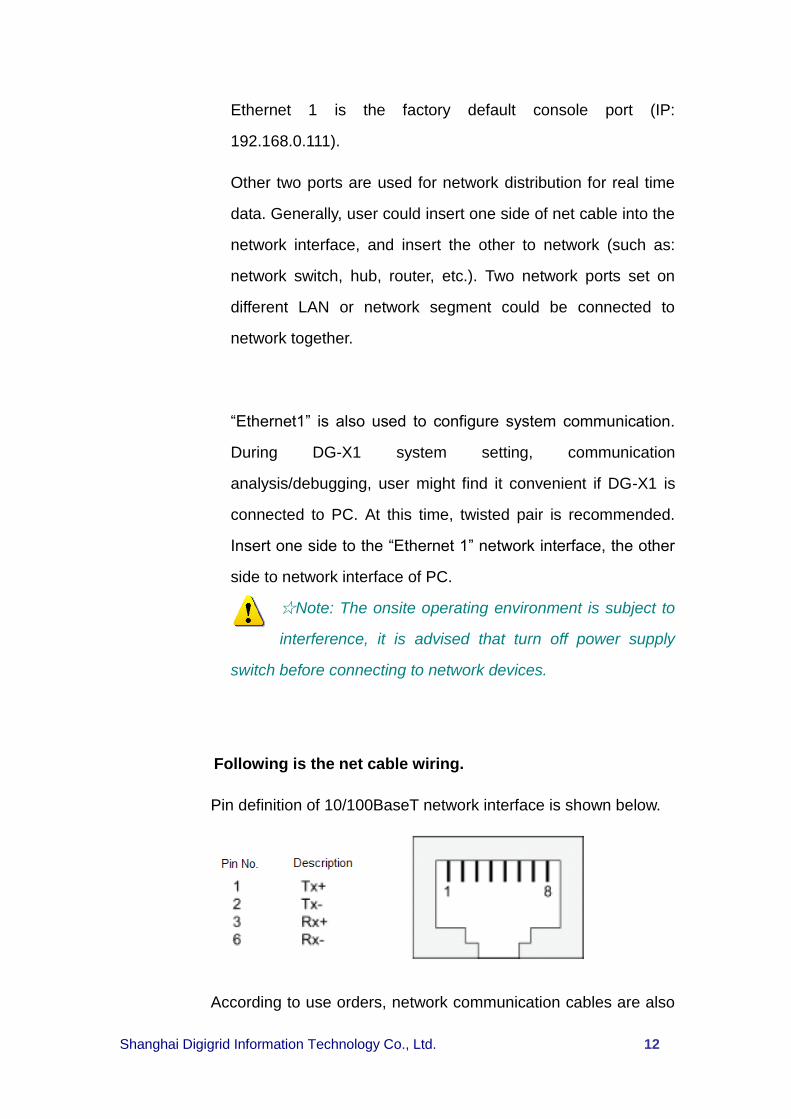
Following is the net cable wiring.
Pin definition of 10/100BaseT network interface is shown below.
According to use orders, network communication cables are also
Shanghai Digigrid Information Technology Co., Ltd. 13
provided, including coaxial cable and twisted pair (UTP-5 types) in
accordance with TIA/EIA-568B standard.
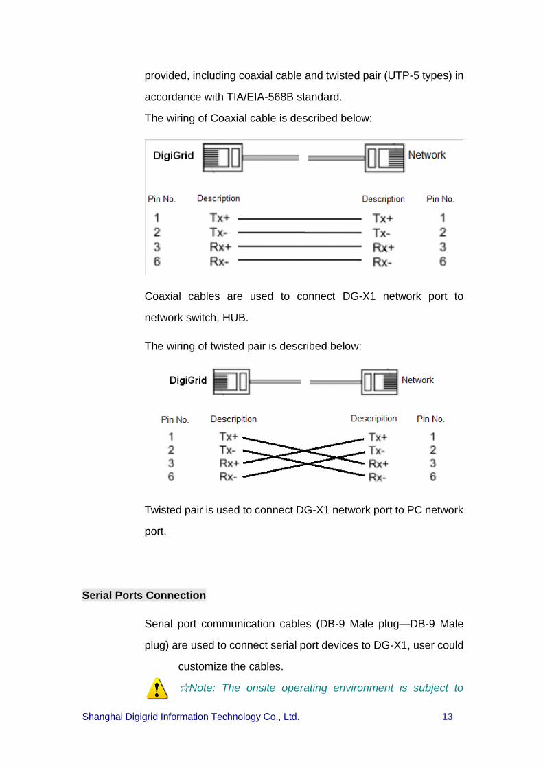
The wiring of Coaxial cable is described below:
Coaxial cables are used to connect DG-X1 network port to
network switch, HUB.
The wiring of twisted pair is described below:
Twisted pair is used to connect DG-X1 network port to PC network
port.
Serial Ports Connection
Serial port communication cables (DB-9 Male plug—DB-9 Male
plug) are used to connect serial port devices to DG-X1, user could
customize the cables.
☆Note: The onsite operating environment is subject to
Shanghai Digigrid Information Technology Co., Ltd. 14
interference, it is advised that turn off power supply switch before
connecting to network devices.
If user wants to make serial port communication cables, refer
to the following information:
DB9- Male Plug Connection
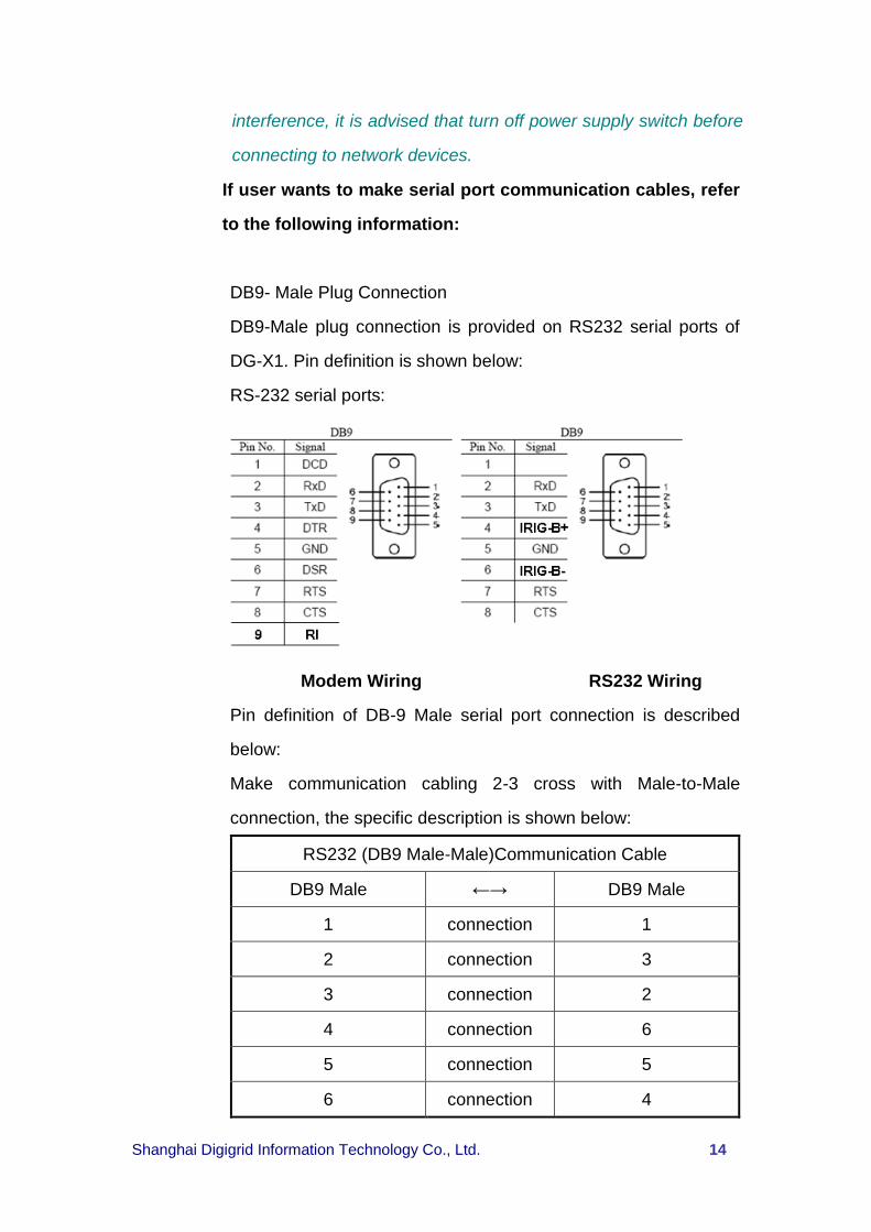
DB9-Male plug connection is provided on RS232 serial ports of
DG-X1. Pin definition is shown below:
RS-232 serial ports:
Modem Wiring RS232 Wiring
Pin definition of DB-9 Male serial port connection is described
below:
Make communication cabling 2-3 cross with Male-to-Male
connection, the specific description is shown below:
RS232 (DB9 Male-Male)Communication Cable
DB9 Male ←→ DB9 Male
1 connection 1
2 connection 3
3 connection 2
4 connection 6
5 connection 5
6 connection 4
Shanghai Digigrid Information Technology Co., Ltd. 15
7 connection 8
8 connection 7
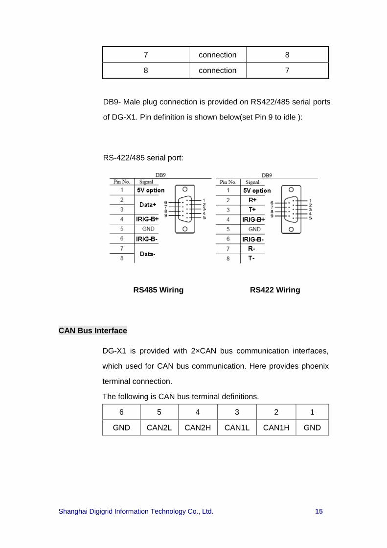
DB9- Male plug connection is provided on RS422/485 serial ports
of DG-X1. Pin definition is shown below(set Pin 9 to idle ):
RS-422/485 serial port:
RS485 Wiring RS422 Wiring
CAN Bus Interface
DG-X1 is provided with 2×CAN bus communication interfaces,
which used for CAN bus communication. Here provides phoenix
terminal connection.
The following is CAN bus terminal definitions.
6 5 4 3 2 1
GND CAN2L CAN2H CAN1L CAN1H GND
Shanghai Digigrid Information Technology Co., Ltd. 16
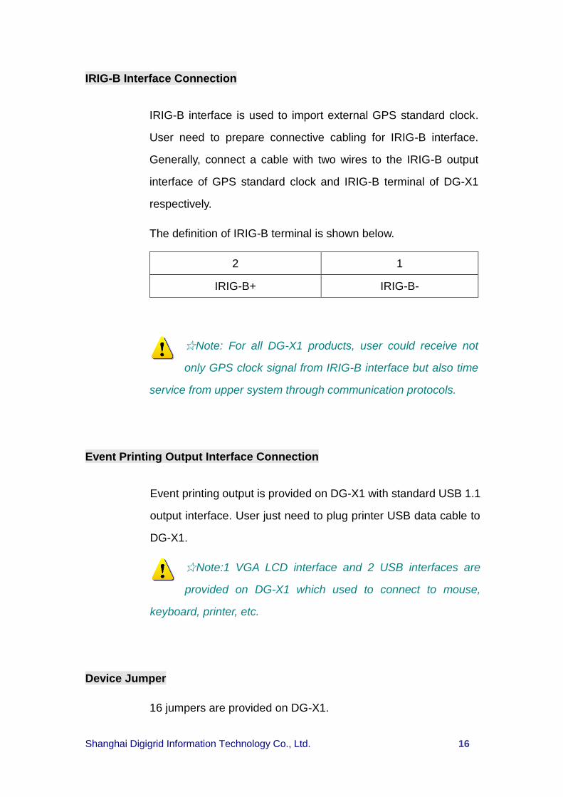
IRIG-B Interface Connection
IRIG-B interface is used to import external GPS standard clock.
User need to prepare connective cabling for IRIG-B interface.
Generally, connect a cable with two wires to the IRIG-B output
interface of GPS standard clock and IRIG-B terminal of DG-X1
respectively.
The definition of IRIG-B terminal is shown below.
2 1
IRIG-B+ IRIG-B-
☆Note: For all DG-X1 products, user could receive not
only GPS clock signal from IRIG-B interface but also time
service from upper system through communication protocols.
Event Printing Output Interface Connection
Event printing output is provided on DG-X1 with standard USB 1.1
output interface. User just need to plug printer USB data cable to
DG-X1.
☆Note:1 VGA LCD interface and 2 USB interfaces are
provided on DG-X1 which used to connect to mouse,
keyboard, printer, etc.
Device Jumper
16 jumpers are provided on DG-X1.
Shanghai Digigrid Information Technology Co., Ltd. 17
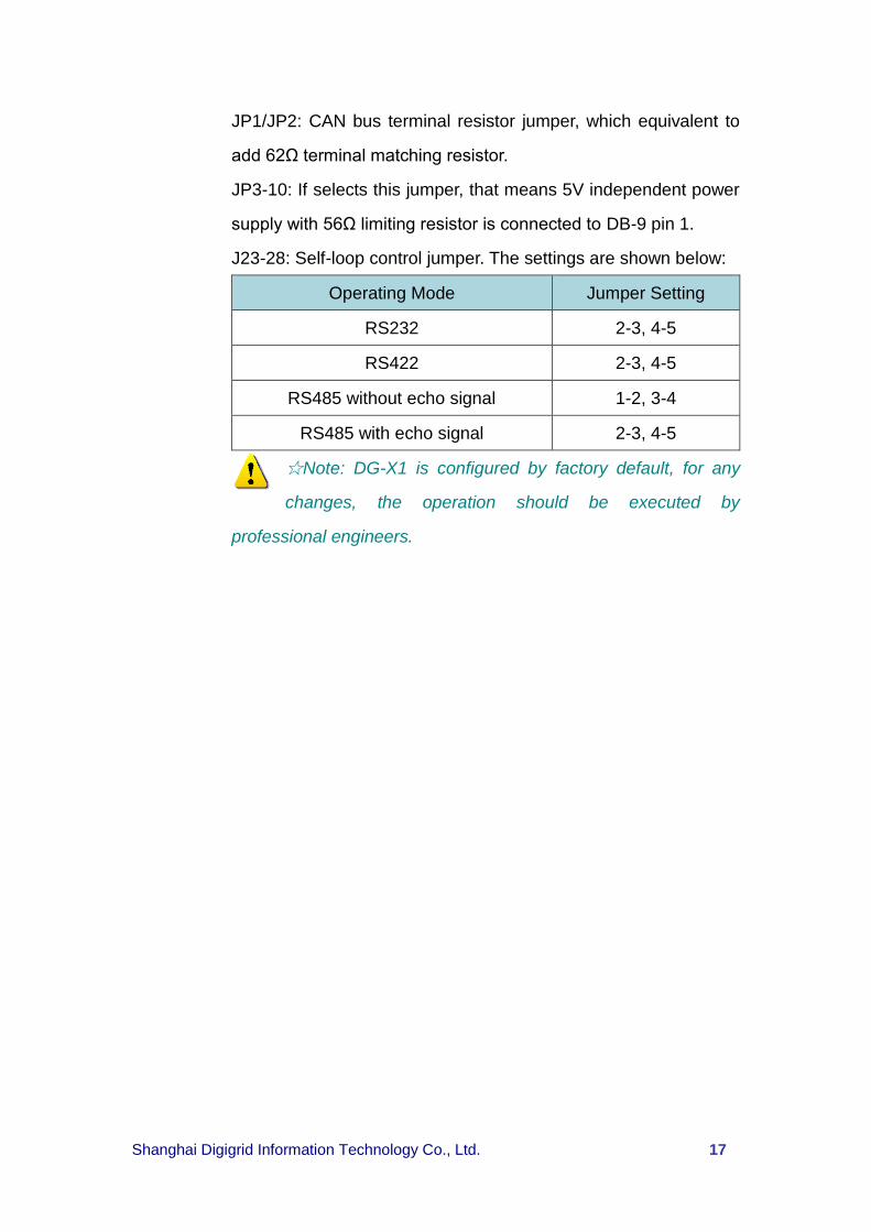
JP1/JP2: CAN bus terminal resistor jumper, which equivalent to
add 62Ω terminal matching resistor.
JP3-10: If selects this jumper, that means 5V independent power
supply with 56Ω limiting resistor is connected to DB-9 pin 1.
J23-28: Self-loop control jumper. The settings are shown below:
Operating Mode Jumper Setting
RS232 2-3, 4-5
RS422 2-3, 4-5
RS485 without echo signal 1-2, 3-4
RS485 with echo signal 2-3, 4-5
☆Note: DG-X1 is configured by factory default, for any
changes, the operation should be executed by
professional engineers.

Shanghai Digigrid Information Technology Co., Ltd. 18
3. Application
3.1 Protocol Conversion
3.2 Substation Automation
3.3 Virtual Port Connection
3.4 IEC61850 Communication
3.5 Advanced Calculation
Shanghai Digigrid Information Technology Co., Ltd. 19
4. Communication
4.1 Overview
A communications interface and protocol are required for communicating with
the DG-X1 Server. A communications interface is the physical connection on a
device. Once you have established a physical connection, you must use a
communication protocol to interact with the server.
The first part of this section describes communication interfaces and protocols
available with the server, including communication interface connections. The
remainder of the section describes the ASCII commands you can use to
communicate with the server to obtain information, reports, data, or perform
control functions.
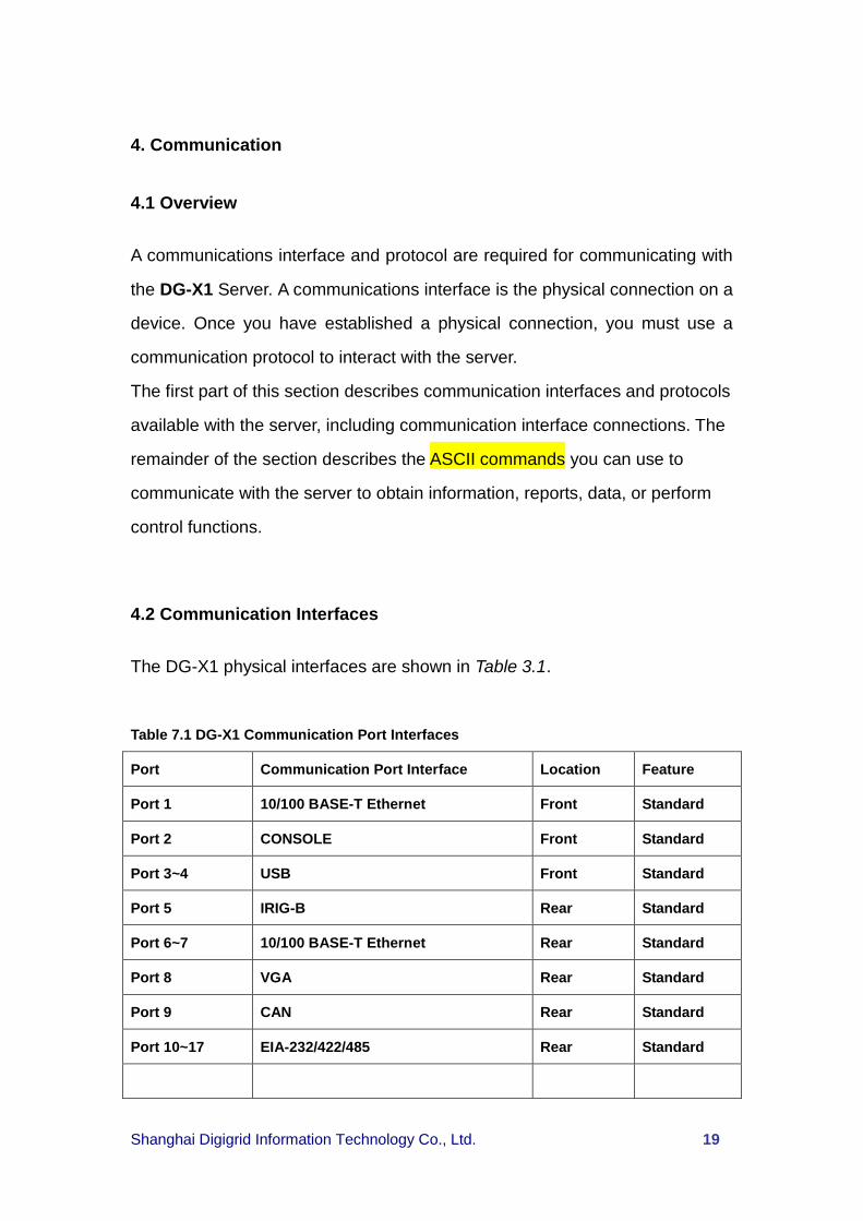
4.2 Communication Interfaces
The DG-X1 physical interfaces are shown in Table 3.1.
Table 7.1 DG-X1 Communication Port Interfaces
Port Communication Port Interface Location Feature
Port 1 10/100 BASE-T Ethernet Front Standard
Port 2 CONSOLE Front Standard
Port 3~4 USB Front Standard
Port 5 IRIG-B Rear Standard
Port 6~7 10/100 BASE-T Ethernet Rear Standard
Port 8 VGA Rear Standard
Port 9 CAN Rear Standard
Port 10~17 EIA-232/422/485 Rear Standard
Shanghai Digigrid Information Technology Co., Ltd. 20
4.3 IEC61850 Communication Protocol
4.3.1 Overview
IEC 61850 is a standard for the design of electrical substation automation. IEC 61850 is a
part of the International Electrotechnical Commission's (IEC) Technical Committee 57
(TC57) reference architecture for electric power systems. The abstract data models
defined in IEC 61850 can be mapped to a number of protocols. Current mappings in the
standard are to MMS (Manufacturing Message Specification), GOOSE, SMV (Sampled
Measured Values), and soon to Web Services. These protocols can run over TCP/IP
networks or substation LANs using high speed switched Ethernet to obtain the necessary
response times below four milliseconds for protective relaying.
IEC 61850 features include:
1. Data Modeling— Primary process objects as well as protection and control
functionality in the substation is modelled into different standard logical nodes
which can be grouped under different logical devices. There are logical nodes for
data/functions related to the logical device (LLN0) and physical device (LPHD).
2. Reporting Schemes— There are various reporting schemes (BRCB & URCB) for
reporting data from server through a server-client relationship which can be
triggered based on pre-defined trigger conditions.
3. Fast Transfer of events— Generic Substation Events (GSE) are defined for fast
transfer of event data for a peer-to-peer communication mode. This is again
subdivided into GOOSE &GSSE.
4. Setting Groups — The setting group control Blocks (SGCB) are defined to handle
the setting groups so that user can switch to any active group according to the
requirement.

Shanghai Digigrid Information Technology Co., Ltd. 21
5. Sampled Data Transfer— Schemes are also defined to handle transfer of sampled
values using Sampled Value Control blocks (SVCB)
6. Commands— Various command types are also supported by IEC 61850 which
include direct & select before operate (SBO) commands with normal and
enhanced securities.
7. Data Storage— Substation Configuration Language (SCL) is defined for complete
storage of configured data of the substation in a specific format.
4.3.2 Protocol Profile
4.4 Modbus Communication Protocol
4.4.1 Overview
Modbus is a serial communications protocol originally published by Modicon (now
Schneider Electric) in 1979 for use with its programmable logic controllers (PLCs). Simple
and robust, it has since become concerning fact standard communication protocol, and it
is now a commonly available means of connecting industrial electronic devices. The main
reasons for the use of Modbus in the industrial environment are:
developed with industrial applications in mind
openly published and royalty-free
easy to deploy and maintain
moves raw bits or words without placing many restrictions on vendors
Modbus enables communication between many (approximately 240) devices connected
to the same network, for example a system that measures temperature and humidity and
communicates the results to a computer. Modbus is often used to connect a supervisory
computer with a remote terminal unit (RTU) in supervisory control and data acquisition
(SCADA) systems. Many of the data types are named from its use in driving relays: a

Shanghai Digigrid Information Technology Co., Ltd. 22
single-bit physical output is called a coil, and a single-bit physical input is called a discrete
input or a contact.
The development and update of Modbus protocols has been managed by the Modbus
Organization since April 2004, when Schneider Electric transferred rights to that
organization, signaling a clear commitment to openness.
The Modbus Organization is an association formed of independent users and suppliers of
Modbus compliant devices that seeks to drive the adoption of the Modbus communication
protocol suite, and its evolution to address architectures for distributed automation
systems across multiple market segments.
4.4.2 Protocol Profile
4.5 IEC101 Communication Protocol
4.5.1 Overview
IEC 60870-5-101 [IEC101] is a standard for power system monitoring, control &
associated communications for telecontrol, teleprotection, and associated
telecommunications for electric power systems. This is completely compatible with IEC
60870-5-1 to IEC 60870-5-5 standards and uses standard asynchronous serial
tele-control channel interface between DTE and DCE. The standard is suitable for multiple
configurations like point-to-point, star, mutidropped etc.
Supports unbalanced (only master initiated message) & balanced (can be
master/slave initiated) modes of data transfer.
Link address and ASDU (Application Service Data Unit) addresses are provided for
classifying the end station and different segments under the same.
Data is classified into different information objects and each information object is
provided with a specific address.
Facility to classify the data into high priority (class-1) and low priority (class-2) and
transfer the same using separate mechanisms.
Shanghai Digigrid Information Technology Co., Ltd. 23
Possibility of classifying the data into different groups (1-16) to get the data
according to the group by issuing specific group interrogation commands from the
master & obtaining data under all the groups by issuing a general interrogation.
Cyclic & Spontaneous data updating schemes are provided.
Facility for time synchronization
Schemes for transfer of files-Example:IED's will store disturbance recorder file in
the memory, When electrical disturbance is occurred in the field. This file can be
retrieved through IEC104 protocol for fault analysis
4.5.2 Protocol Profile
4.6 IEC104 Communication Protocol
4.6.1 Overview
IEC 60870-5-104 (IEC 104) protocol is an extension of IEC 101 protocol with the changes
in transport, network, link & physical layer services to suit the complete network access.
The standard uses an open TCP/IP interface to network to have connectivity to the LAN
(Local Area Network) and routers with different facility (ISDN, X.25, Frame relay etc.) can
be used to connect to the WAN (Wide Area Network). Application layer of IEC 104 is
preserved same as that of IEC 101 with some of the data types and facilities not used.
There are two separate link layers defined in the standard, which is suitable for data
transfer over Ethernet & serial line (PPP - Point-to-Point Protocol). The control field data of
IEC104 contains various types of mechanisms for effective handling of network data
synchronization.
Shanghai Digigrid Information Technology Co., Ltd. 24
4.6.2 Protocol Profile
4.7 SEL Communication Protocol
4.7.1 Overview
SEL Fast Meter is a binary message that you solicit with binary commands. Fast Operate
is a binary message for control. The relay can also send unsolicited Fast SER messages
automatically. If the relay is connected to an SEL communications processor, these
messages provide the mechanism that the communications processor uses for SCADA or
DCS functions that occur simultaneously with ASCII interaction.
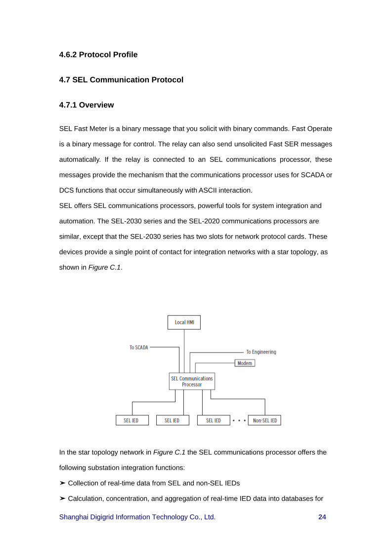
SEL offers SEL communications processors, powerful tools for system integration and
automation. The SEL-2030 series and the SEL-2020 communications processors are
similar, except that the SEL-2030 series has two slots for network protocol cards. These
devices provide a single point of contact for integration networks with a star topology, as
shown in Figure C.1.
In the star topology network in Figure C.1 the SEL communications processor offers the
following substation integration functions:
➤ Collection of real-time data from SEL and non-SEL IEDs
➤ Calculation, concentration, and aggregation of real-time IED data into databases for

Shanghai Digigrid Information Technology Co., Ltd. 25
SCADA, HMI, and other data consumers
➤ Access to the IEDs for engineering functions including configuration, report data
retrieval, and control through local serial, remote dial-in, and Ethernet network
connections
➤ Distribution of IRIG-B time synchronization signal to IEDs based on external IRIG-B
input, internal clock, or protocol interface
➤ Simultaneous collection of SCADA data and engineering connection to SEL IEDs over
a single cable
➤ Automated dial-out on alarms
4.7.2 Protocol Profile
4.8 DNP Communication Protocol
4.8.1 Overview
DNP (Distributed Network Protocol) is a set of communications protocols used between
components in process automation systems. Its main use is in utilities such as electric and
water companies. Usage in other industries is not common. It was developed for
communications between various types of data acquisition and control equipment. It plays
a crucial role in SCADA systems, where it is used by SCADA Master Stations (aka Control
Centers), Remote Terminal Units (RTUs), and Intelligent Electronic Devices (IEDs). It is
primarily used for communications between a master station and RTUs or IEDs. ICCP, the
Inter-Control Center Communications Protocol (a part of IEC 60870-6), is used for
inter-master station communications.
Shanghai Digigrid Information Technology Co., Ltd. 26
4.8.2 Protocol Profile
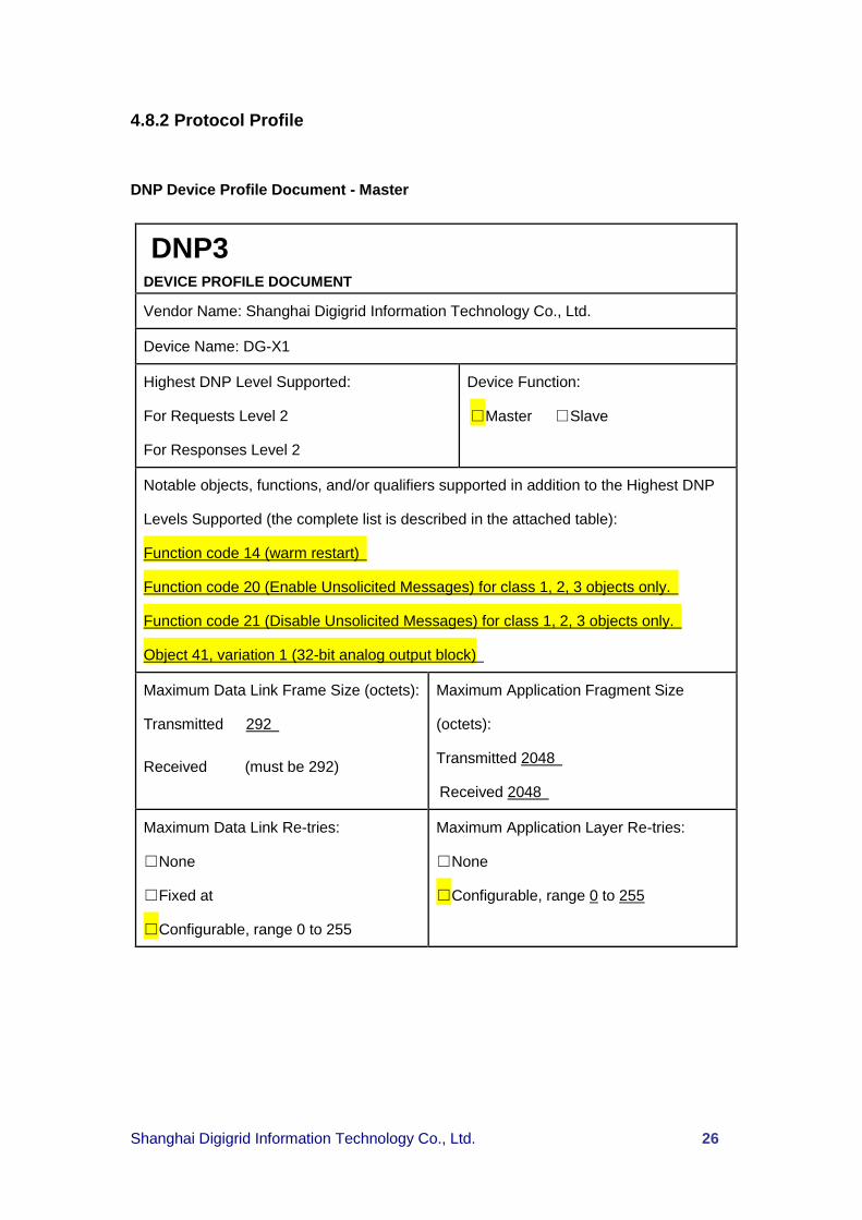
DNP Device Profile Document - Master
DNP3 DEVICE PROFILE DOCUMENT
Vendor Name: Shanghai Digigrid Information Technology Co., Ltd.
Device Name: DG-X1
Highest DNP Level Supported:
For Requests Level 2
For Responses Level 2
Device Function:
M □Master □Slave
Notable objects, functions, and/or qualifiers supported in addition to the Highest DNP
Levels Supported (the complete list is described in the attached table):
Function code 14 (warm restart)
Function code 20 (Enable Unsolicited Messages) for class 1, 2, 3 objects only.
Function code 21 (Disable Unsolicited Messages) for class 1, 2, 3 objects only.
Object 41, variation 1 (32-bit analog output block)
Maximum Data Link Frame Size (octets):
Transmitted 292
Received (must be 292)
Maximum Application Fragment Size
(octets):
Transmitted 2048
Recei Received 2048
Maximum Data Link Re-tries:
□None
□Fixed at
□Configurable, range 0 to 255
Maximum Application Layer Re-tries:
□None
□Configurable, range 0 to 255
Shanghai Digigrid Information Technology Co., Ltd. 27
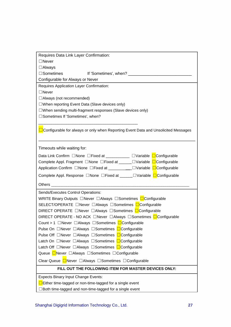
Requires Data Link Layer Confirmation:
□Never
□Always
□Sometimes If 'Sometimes', when? ____________________________
Configurable for Always or Never
Requires Application Layer Confirmation:
□Never
□Always (not recommended)
□When reporting Event Data (Slave devices only)
□When sending multi-fragment responses (Slave devices only)
□Sometimes If 'Sometimes', when?
______________________________________________
□Configurable for always or only when Reporting Event Data and Unsolicited Messages
Timeouts while waiting for:
Data Link Confirm □None □Fixed at ___________ □Variable □Configurable
Complete Appl. Fragment □None □Fixed at _____ □Variable □Configurable
Application Confirm □None □Fixed at __________ □Variable □Configurable
Complete Appl. Response □None □Fixed at _____ □Variable □Configurable
Others ________________________________________________________________
Sends/Executes Control Operations:
WRITE Binary Outputs □Never □Always □Sometimes □Configurable
SELECT/OPERATE □Never □Always □Sometimes □Configurable
DIRECT OPERATE □Never □Always □Sometimes □Configurable
DIRECT OPERATE - NO ACK □Never □Always □Sometimes □Configurable
Count > 1 □Never □Always □Sometimes □Configurable
Pulse On □Never □Always □Sometimes □Configurable
Pulse Off □Never □Always □Sometimes □Configurable
Latch On □Never □Always □Sometimes □Configurable
Latch Off □Never □Always □Sometimes □Configurable
Queue □Never □Always □Sometimes □Configurable
Clear Queue □Never □Always □Sometimes □Configurable
FILL OUT THE FOLLOWING ITEM FOR MASTER DEVICES ONLY:
Expects Binary Input Change Events:
□Either time-tagged or non-time-tagged for a single event
□Both time-tagged and non-time-tagged for a single event
Shanghai Digigrid Information Technology Co., Ltd. 28
□Configurable (attach explanation)
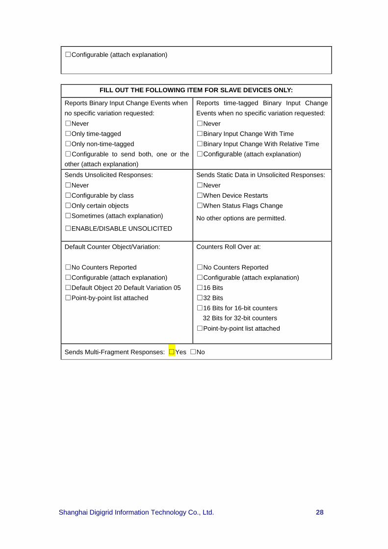
FILL OUT THE FOLLOWING ITEM FOR SLAVE DEVICES ONLY:
Reports Binary Input Change Events when
no specific variation requested:
□Never
□Only time-tagged
□Only non-time-tagged
□Configurable to send both, one or the
other (attach explanation)
Reports time-tagged Binary Input Change
Events when no specific variation requested:
□Never
□Binary Input Change With Time
□Binary Input Change With Relative Time
□Configurable (attach explanation)
Sends Unsolicited Responses:
□Never
□Configurable by class
□Only certain objects
□Sometimes (attach explanation)
□ENABLE/DISABLE UNSOLICITED
Sends Static Data in Unsolicited Responses:
□Never
□When Device Restarts
□When Status Flags Change
No other options are permitted.
Default Counter Object/Variation:
□No Counters Reported
□Configurable (attach explanation)
□Default Object 20 Default Variation 05
□Point-by-point list attached
Counters Roll Over at:
□No Counters Reported
□Configurable (attach explanation)
□16 Bits
□32 Bits
□16 Bits for 16-bit counters
32 Bits for 32-bit counters
□Point-by-point list attached
Sends Multi-Fragment Responses: □Yes □No
Shanghai Digigrid Information Technology Co., Ltd. 29
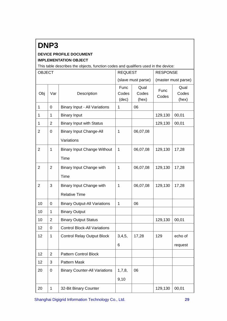
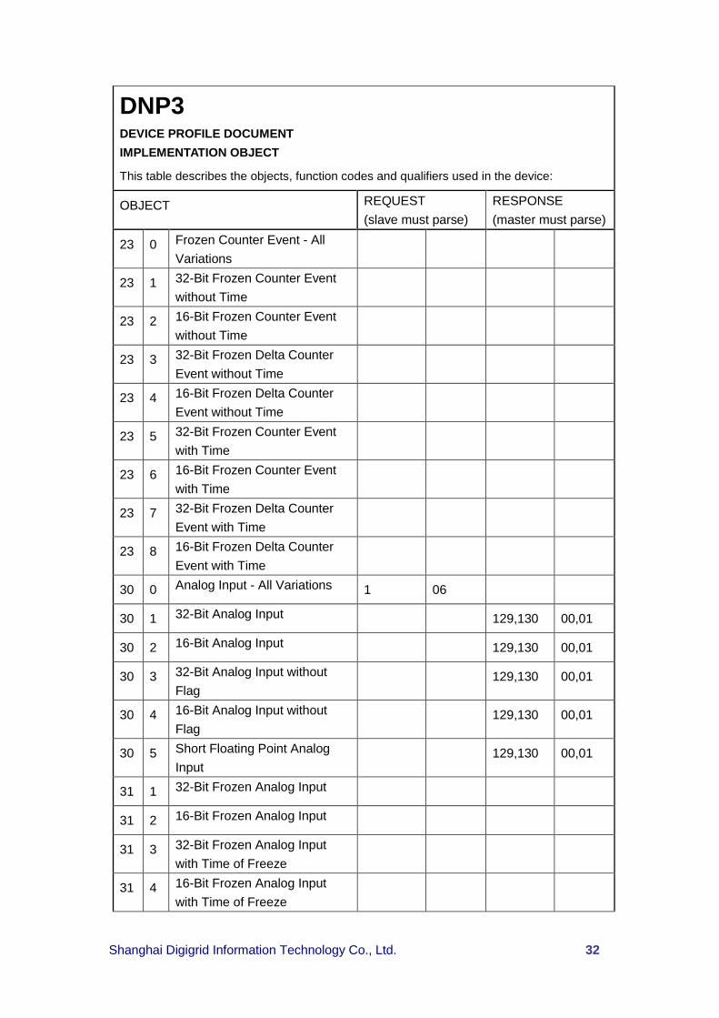
DNP3 DEVICE PROFILE DOCUMENT
IMPLEMENTATION OBJECT
This table describes the objects, function codes and qualifiers used in the device:
OBJECT REQUEST
(slave must parse)
RESPONSE
(master must parse)
Obj Var Description
Func
Codes
(dec)
Qual
Codes
(hex)
Func
Codes
Qual
Codes
(hex)
1 0 Binary Input - All Variations 1 06
1 1 Binary Input 129,130 00,01
1 2 Binary Input with Status 129,130 00,01
2 0 Binary Input Change-All
Variations
1 06,07,08
2 1 Binary Input Change Without
Time
1 06,07,08 129,130 17,28
2 2 Binary Input Change with
Time
1 06,07,08 129,130 17,28
2 3 Binary Input Change with
Relative Time
1 06,07,08 129,130 17,28
10 0 Binary Output-All Variations 1 06
10 1 Binary Output
10 2 Binary Output Status 129,130 00,01
12 0 Control Block-All Variations
12 1 Control Relay Output Block 3,4,5,
6
17,28 129 echo of
request
12 2 Pattern Control Block
12 3 Pattern Mask
20 0 Binary Counter-All Variations 1,7,8,
9,10
06
20 1 32-Bit Binary Counter 129,130 00,01
Shanghai Digigrid Information Technology Co., Ltd. 30
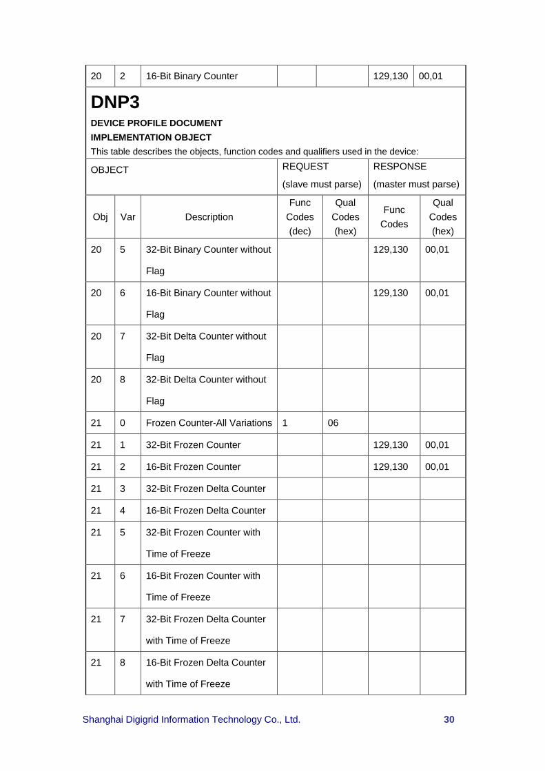
20 2 16-Bit Binary Counter 129,130 00,01
DNP3 DEVICE PROFILE DOCUMENT
IMPLEMENTATION OBJECT
This table describes the objects, function codes and qualifiers used in the device:
OBJECT REQUEST
(slave must parse)
RESPONSE
(master must parse)
Obj Var Description
Func
Codes
(dec)
Qual
Codes
(hex)
Func
Codes
Qual
Codes
(hex)
20 5 32-Bit Binary Counter without
Flag
129,130 00,01
20 6 16-Bit Binary Counter without
Flag
129,130 00,01
20 7 32-Bit Delta Counter without
Flag
20 8 32-Bit Delta Counter without
Flag
21 0 Frozen Counter-All Variations 1 06
21 1 32-Bit Frozen Counter 129,130 00,01
21 2 16-Bit Frozen Counter 129,130 00,01
21 3 32-Bit Frozen Delta Counter
21 4 16-Bit Frozen Delta Counter
21 5 32-Bit Frozen Counter with
Time of Freeze
21 6 16-Bit Frozen Counter with
Time of Freeze
21 7 32-Bit Frozen Delta Counter
with Time of Freeze
21 8 16-Bit Frozen Delta Counter
with Time of Freeze
Shanghai Digigrid Information Technology Co., Ltd. 31
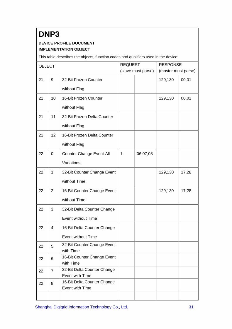
DNP3 DEVICE PROFILE DOCUMENT
IMPLEMENTATION OBJECT
This table describes the objects, function codes and qualifiers used in the device:
OBJECT REQUEST
(slave must parse) RESPONSE
(master must parse) 21 9 32-Bit Frozen Counter
without Flag
129,130 00,01
21 10 16-Bit Frozen Counter
without Flag
129,130 00,01
21 11 32-Bit Frozen Delta Counter
without Flag
21 12 16-Bit Frozen Delta Counter
without Flag
22 0 Counter Change Event-All
Variations
1 06,07,08
22 1 32-Bit Counter Change Event
without Time
129,130 17,28
22 2 16-Bit Counter Change Event
without Time
129,130 17,28
22 3 32-Bit Delta Counter Change
Event without Time
22 4 16-Bit Delta Counter Change
Event without Time
22 5 32-Bit Counter Change Event
with Time
22 6 16-Bit Counter Change Event
with Time
22 7 32-Bit Delta Counter Change
Event with Time
22 8 16-Bit Delta Counter Change
Event with Time
Shanghai Digigrid Information Technology Co., Ltd. 32
DNP3 DEVICE PROFILE DOCUMENT
IMPLEMENTATION OBJECT
This table describes the objects, function codes and qualifiers used in the device:
OBJECT REQUEST
(slave must parse) RESPONSE
(master must parse) 23 0 Frozen Counter Event - All
Variations
23 1 32-Bit Frozen Counter Event
without Time
23 2 16-Bit Frozen Counter Event
without Time
23 3 32-Bit Frozen Delta Counter
Event without Time
23 4 16-Bit Frozen Delta Counter
Event without Time
23 5 32-Bit Frozen Counter Event
with Time
23 6 16-Bit Frozen Counter Event
with Time
23 7 32-Bit Frozen Delta Counter
Event with Time
23 8 16-Bit Frozen Delta Counter
Event with Time
30 0 Analog Input - All Variations 1 06
30 1 32-Bit Analog Input 129,130 00,01
30 2 16-Bit Analog Input 129,130 00,01
30 3 32-Bit Analog Input without
Flag 129,130 00,01
30 4 16-Bit Analog Input without
Flag 129,130 00,01
30 5 Short Floating Point Analog
Input 129,130 00,01
31 1 32-Bit Frozen Analog Input
31 2 16-Bit Frozen Analog Input
31 3 32-Bit Frozen Analog Input
with Time of Freeze
31 4 16-Bit Frozen Analog Input
with Time of Freeze
Shanghai Digigrid Information Technology Co., Ltd. 33
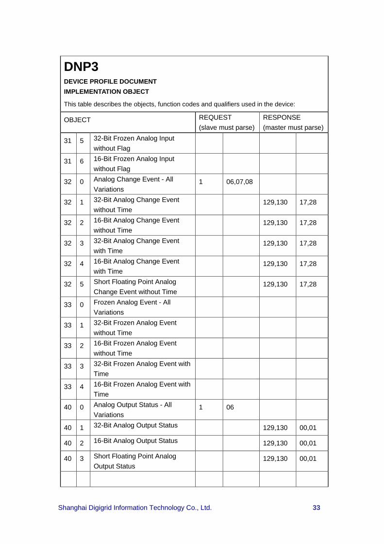
DNP3 DEVICE PROFILE DOCUMENT
IMPLEMENTATION OBJECT
This table describes the objects, function codes and qualifiers used in the device:
OBJECT REQUEST
(slave must parse) RESPONSE
(master must parse) 31 5 32-Bit Frozen Analog Input
without Flag
31 6 16-Bit Frozen Analog Input
without Flag
32 0 Analog Change Event - All
Variations 1 06,07,08
32 1 32-Bit Analog Change Event
without Time 129,130 17,28
32 2 16-Bit Analog Change Event
without Time 129,130 17,28
32 3 32-Bit Analog Change Event
with Time 129,130 17,28
32 4 16-Bit Analog Change Event
with Time 129,130 17,28
32 5 Short Floating Point Analog
Change Event without Time 129,130 17,28
33 0 Frozen Analog Event - All
Variations
33 1 32-Bit Frozen Analog Event
without Time
33 2 16-Bit Frozen Analog Event
without Time
33 3 32-Bit Frozen Analog Event with
Time
33 4 16-Bit Frozen Analog Event with
Time
40 0 Analog Output Status - All
Variations 1 06
40 1 32-Bit Analog Output Status 129,130 00,01
40 2 16-Bit Analog Output Status 129,130 00,01
40 3 Short Floating Point Analog
Output Status 129,130 00,01
Shanghai Digigrid Information Technology Co., Ltd. 34
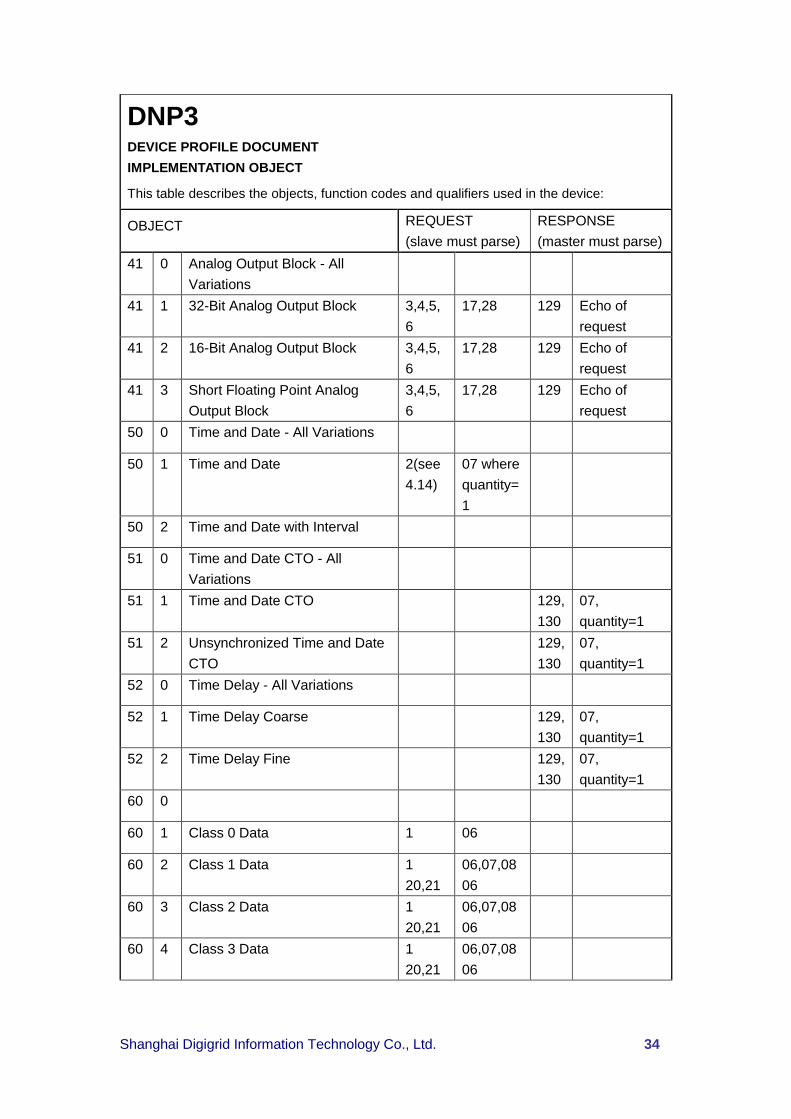
DNP3 DEVICE PROFILE DOCUMENT
IMPLEMENTATION OBJECT
This table describes the objects, function codes and qualifiers used in the device:
OBJECT REQUEST
(slave must parse) RESPONSE
(master must parse) 41 0 Analog Output Block - All
Variations
41 1 32-Bit Analog Output Block 3,4,5,
6
17,28 129 Echo of
request
41 2 16-Bit Analog Output Block 3,4,5,
6
17,28 129 Echo of
request
41 3 Short Floating Point Analog
Output Block
3,4,5,
6
17,28 129 Echo of
request
50 0 Time and Date - All Variations
50 1 Time and Date 2(see
4.14)
07 where
quantity=
1
50 2 Time and Date with Interval
51 0 Time and Date CTO - All
Variations
51 1 Time and Date CTO 129,
130
07,
quantity=1
51 2 Unsynchronized Time and Date
CTO
129,
130
07,
quantity=1
52 0 Time Delay - All Variations
52 1 Time Delay Coarse 129,
130
07,
quantity=1
52 2 Time Delay Fine 129,
130
07,
quantity=1
60 0
60 1 Class 0 Data 1 06
60 2 Class 1 Data 1
20,21
06,07,08
06
60 3 Class 2 Data 1
20,21
06,07,08
06
60 4 Class 3 Data 1
20,21
06,07,08
06
Shanghai Digigrid Information Technology Co., Ltd. 35
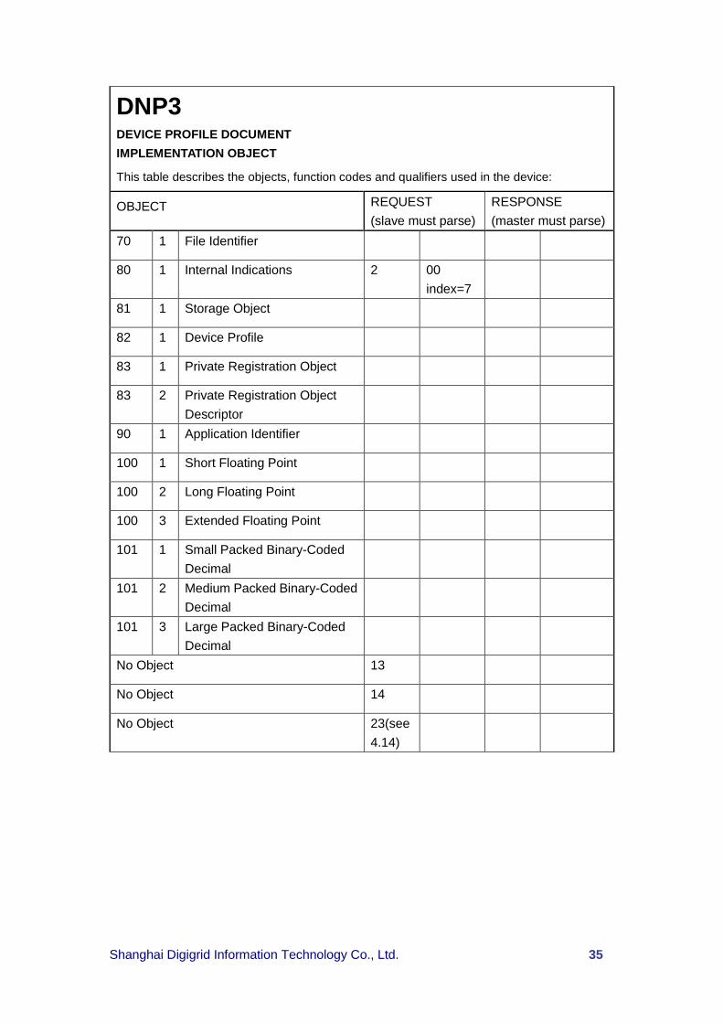
DNP3 DEVICE PROFILE DOCUMENT
IMPLEMENTATION OBJECT
This table describes the objects, function codes and qualifiers used in the device:
OBJECT REQUEST
(slave must parse) RESPONSE
(master must parse) 70 1 File Identifier
80 1 Internal Indications 2 00
index=7
81 1 Storage Object
82 1 Device Profile
83 1 Private Registration Object
83 2 Private Registration Object
Descriptor
90 1 Application Identifier
100 1 Short Floating Point
100 2 Long Floating Point
100 3 Extended Floating Point
101 1 Small Packed Binary-Coded
Decimal
101 2 Medium Packed Binary-Coded
Decimal
101 3 Large Packed Binary-Coded
Decimal
No Object 13
No Object 14
No Object 23(see
4.14)
Shanghai Digigrid Information Technology Co., Ltd. 36
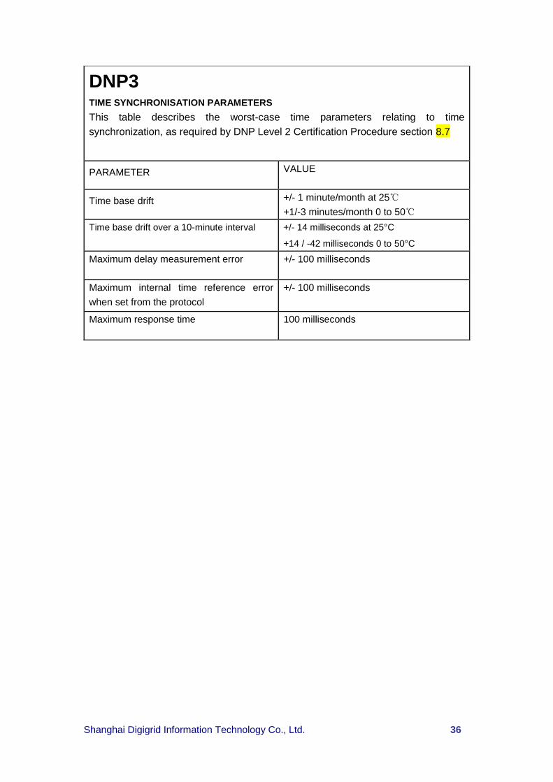
DNP3 TIME SYNCHRONISATION PARAMETERS
This table describes the worst-case time parameters relating to time
synchronization, as required by DNP Level 2 Certification Procedure section 8.7
PARAMETER VALUE
Time base drift +/- 1 minute/month at 25℃
+1/-3 minutes/month 0 to 50℃
Time base drift over a 10-minute interval +/- 14 milliseconds at 25°C
+14 / -42 milliseconds 0 to 50°C
Maximum delay measurement error +/- 100 milliseconds
Maximum internal time reference error
when set from the protocol
+/- 100 milliseconds
Maximum response time 100 milliseconds
Shanghai Digigrid Information Technology Co., Ltd. 37
4.9 Courier Communication Protocol
4.9.1 Overview
The Courier communication language was created by Alstom for communicating with their
K-series range of protection relays. It provides a means of retrieving and setting data cells
in the relay’s menu system. In the context of Veesta-Automation, the Courier protocol is
mainly used to exchange real-time values between menu cells of the protection relays and
RTD elements. It is based on the ISO-OSI enhanced performance architecture (EPA). The
Courier protocol layers correspond to the application layer of this model. For
Veesta-Automation, the IEC 60870-5 standard is used for the link layer and physical
connection. The Courier protocol implementation runs on Communication boards.
Communication with the relays is performed via a KITZ conversion unit for each
communications line which translates the IEC 60870-5 frame format into the K-BUS
format that the relays use. Up to 32 relays per serial line can be supported with this
configuration. The implementation of the COURIER protocol makes it possible to map
relay menu cells on RTD elements. The COURIER menu cells to be mapped may be of
the following value types:
• Binary flags
• Unsigned integer
• Signed integer
• Numeric Number
• IEEE floating point number
Read-only menu cells can be mapped on input RTD elements. Settings cells and
password protected setting cells can be mapped on input and/or output RTD elements.
For cells that can be reset, the reset cell function can be mapped on an output RTD
element. Changing this element from 0 to 1 will trigger the reset cell.
The RTD elements that are updated by the protocol can be used in the same way as other
I/O elements (e.g. digital inputs, analog inputs, read from conventional i/o boards). They

Shanghai Digigrid Information Technology Co., Ltd. 38
can be used for:
• Alarming
• Display on graphical user interface
• Input or output for (composed) objects
• Transfer to the RCC through the RCC protocol
4.9.2 Protocol Profile
4.10 Customized Protocols
Shanghai Digigrid Information Technology Co., Ltd. 39
5 Configuration Software
5.1 Overview
EDPS is an embedded product with independent intellectual property rights
which is designed by Shanghai Digigrid Information Technology Co., Ltd. The
ability of powerful data processing and applications can meet digital
requirements for more and more power customers.
ICE, the integrated configuration environment, based on the EDPS. The
function configuration and management of EDPS products are implemented
via ICE.
A set of standard edit mode provided by ICE helps user deploy easily.
5.2 Setup
A CD-ROM is equipped with EDPS ICE which can help user implement
“single-click installation”. Currently support the OS, including
WIN2000/WINXP/WINNT. EDPS include the executive files, configuration files,
language package and firmware package. Firmware package is the operating
file which provided for the target equipment by system. By the firmware
management tools of EDPS ICE, firmware can be transmitted to any target
device as long as the one meets the conditions.
Program Installation:
Step 1: Open the CD-ROM directory, find installation file edpsices.msi and
execute the file.
Shanghai Digigrid Information Technology Co., Ltd. 40
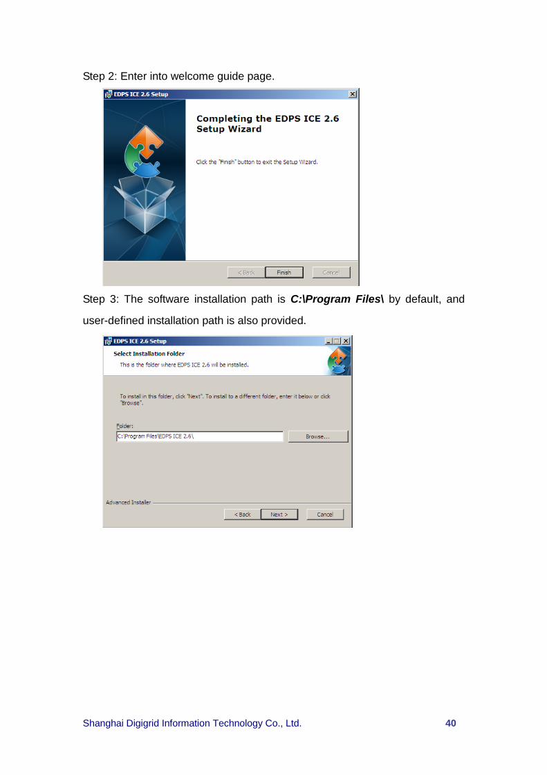
Step 2: Enter into welcome guide page.
Step 3: The software installation path is C:\Program Files\ by default, and
user-defined installation path is also provided.
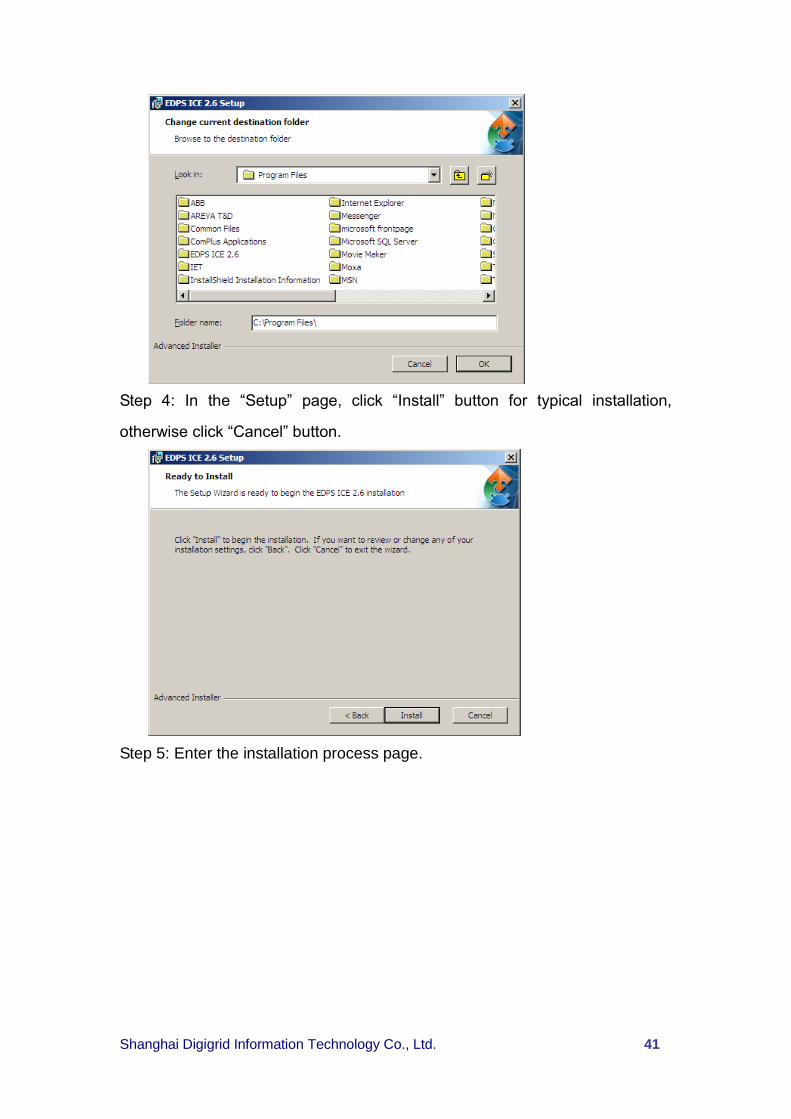
Shanghai Digigrid Information Technology Co., Ltd. 41
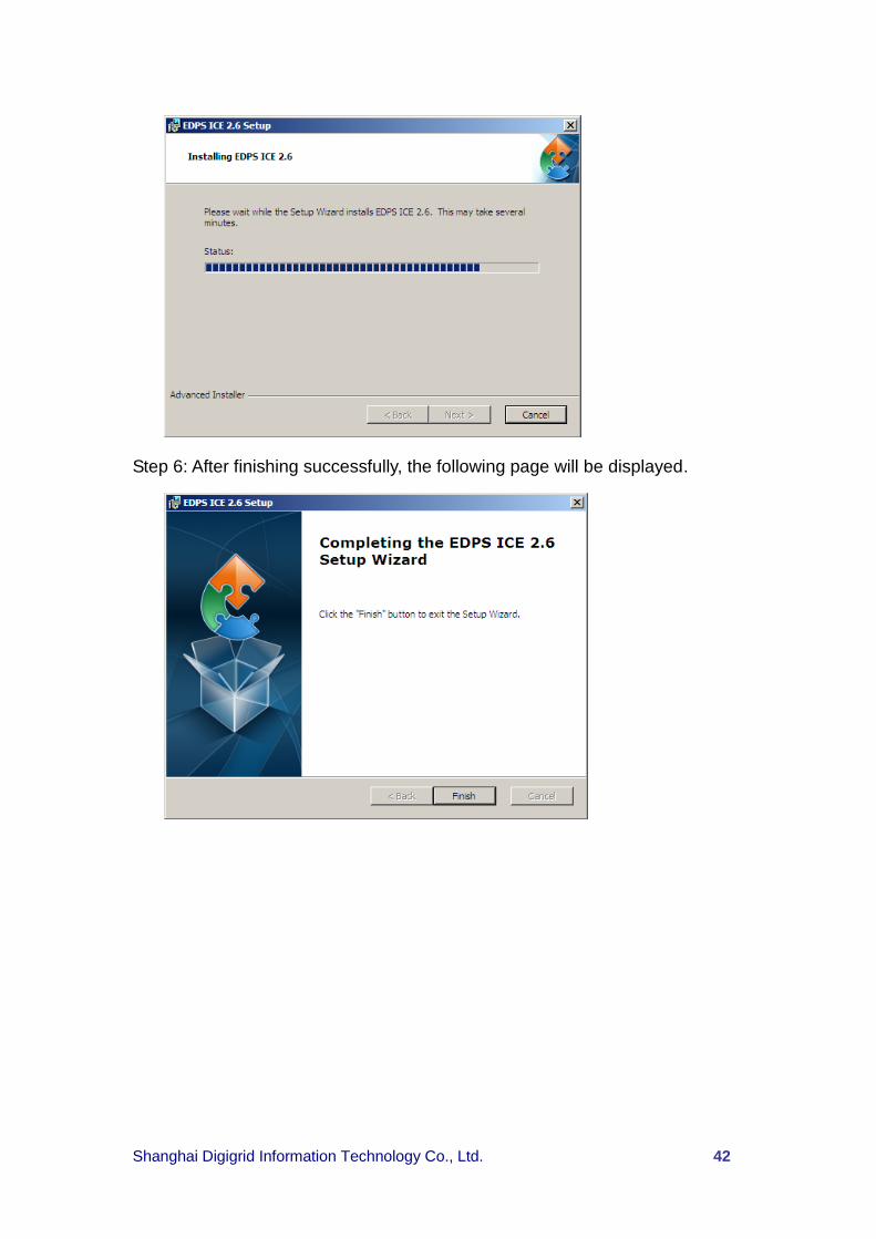
Step 4: In the “Setup” page, click “Install” button for typical installation,
otherwise click “Cancel” button.
Step 5: Enter the installation process page.
Shanghai Digigrid Information Technology Co., Ltd. 42
Step 6: After finishing successfully, the following page will be displayed.
Shanghai Digigrid Information Technology Co., Ltd. 43
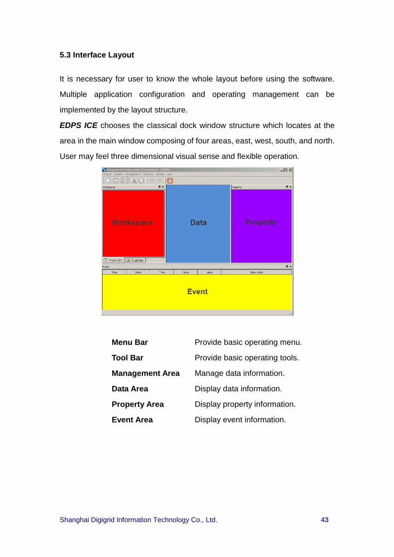
5.3 Interface Layout
It is necessary for user to know the whole layout before using the software.
Multiple application configuration and operating management can be
implemented by the layout structure.
EDPS ICE chooses the classical dock window structure which locates at the
area in the main window composing of four areas, east, west, south, and north.
User may feel three dimensional visual sense and flexible operation.
Menu Bar Provide basic operating menu.
Tool Bar Provide basic operating tools.
Management Area Manage data information.
Data Area Display data information.
Property Area Display property information.
Event Area Display event information.
Shanghai Digigrid Information Technology Co., Ltd. 44
5.4 Firmware Upgrade
5.4.1 Required Equipment
Gather the following equipment before starting this firmware upgrade:
Personal computer(PC)
DG-X1
WinSCP software
Disk containing the firmware upgrade file
5.4.2 Approach of Viewing Device Firmware
EDPS ICE
Make sure there is a communication between PC and the device.
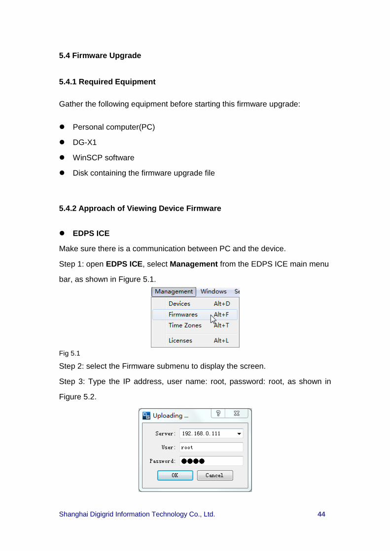
Step 1: open EDPS ICE, select Management from the EDPS ICE main menu
bar, as shown in Figure 5.1.
Fig 5.1
Step 2: select the Firmware submenu to display the screen.
Step 3: Type the IP address, user name: root, password: root, as shown in
Figure 5.2.
Shanghai Digigrid Information Technology Co., Ltd. 45
Fig 5.2
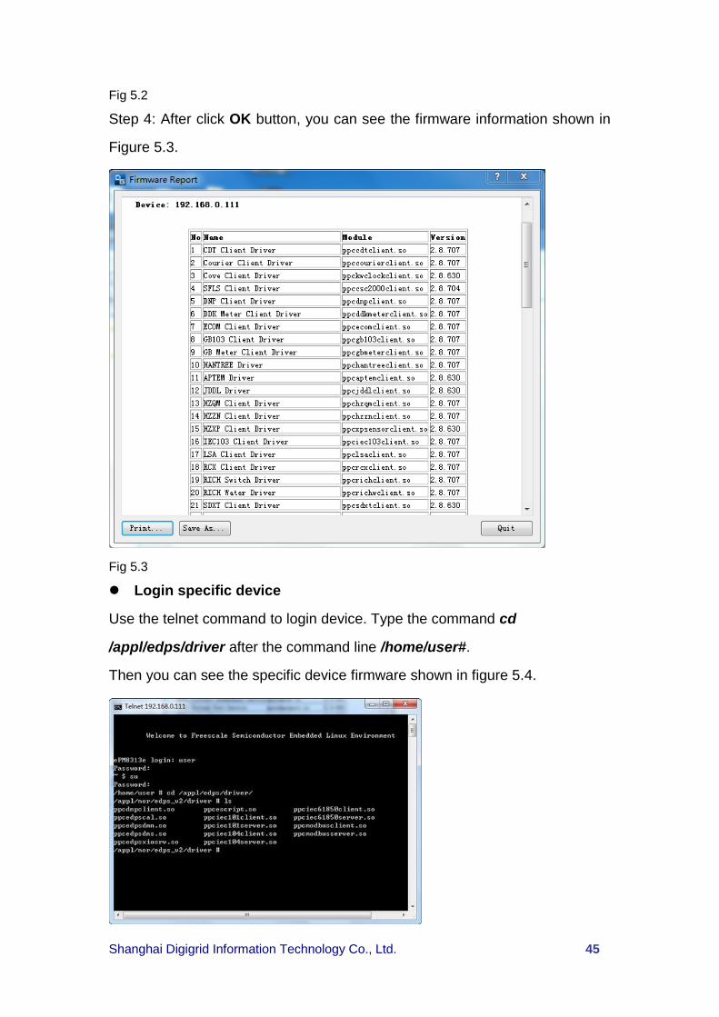
Step 4: After click OK button, you can see the firmware information shown in
Figure 5.3.
Fig 5.3
Login specific device
Use the telnet command to login device. Type the command cd
/appl/edps/driver after the command line /home/user#.
Then you can see the specific device firmware shown in figure 5.4.
Shanghai Digigrid Information Technology Co., Ltd. 46
Fig 5.4
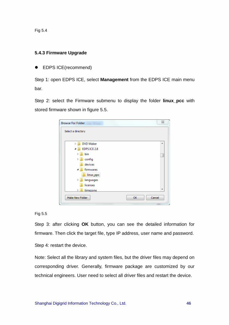
5.4.3 Firmware Upgrade
EDPS ICE(recommend)
Step 1: open EDPS ICE, select Management from the EDPS ICE main menu
bar.
Step 2: select the Firmware submenu to display the folder linux_pcc with
stored firmware shown in figure 5.5.
Fig 5.5
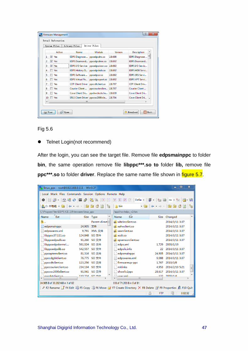
Step 3: after clicking OK button, you can see the detailed information for
firmware. Then click the target file, type IP address, user name and password.
Step 4: restart the device.
Note: Select all the library and system files, but the driver files may depend on
corresponding driver. Generally, firmware package are customized by our
technical engineers. User need to select all driver files and restart the device.
Shanghai Digigrid Information Technology Co., Ltd. 47
Fig 5.6
Telnet Login(not recommend)
After the login, you can see the target file. Remove file edpsmainppc to folder
bin, the same operation remove file libppc***.so to folder lib, remove file
ppc***.so to folder driver. Replace the same name file shown in figure 5.7.
Shanghai Digigrid Information Technology Co., Ltd. 48
6. Testing and Troubleshooting
6.1 Overview
DG-X1 testing is typically divided into two categories:
Tests performed at the time the communication server is installed or
commissioned;
Tests performed periodically once the communication server is in service
This section provides the testing and troubleshooting for DG-X1.
6.2 Testing Tools
6.3 Self-Test
Step 1:Import the configuration file into DG-X1 by Ethernet port(make sure
there is a connection between the PC and Ethernet port)
Step 2:After the import, restart DG-X1. You’ll see the RUN indicator light
twinkling. This means DG-X1 is operating normally, main program
edpsmainppc is running.
Otherwise, possible cause are the followings: 1)RUN indicator light is broken;
2)Main program is not running. Use Telnet command to verify this cause.
Command ps is used to check whether main program is running or not.
Step 3: After that, you can see the two lights of TX and RX are flashing
alternately.
Step 4: For some special situations, users could check the DG-X1 by ICE.
Click the button, type correct server IP address, user(admin) and leave
the password blank. Then you’ll see whether drivers have been loaded
successfully on the event area. For successfully loading, data value are not
correct, you need to check the wiring.
Shanghai Digigrid Information Technology Co., Ltd. 49
Step 5: If the data are not correct, check the configuration parameters.
6.4 Troubleshooting
6.4.1 Hardware
Start power supply, front-panel light is off.
Check order:
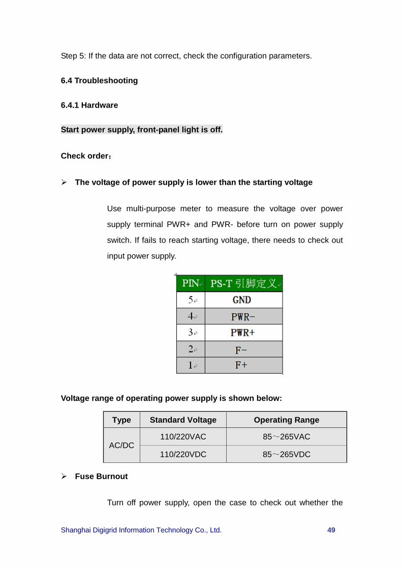
The voltage of power supply is lower than the starting voltage
Use multi-purpose meter to measure the voltage over power
supply terminal PWR+ and PWR- before turn on power supply
switch. If fails to reach starting voltage, there needs to check out
input power supply.
Voltage range of operating power supply is shown below:
Type Standard Voltage Operating Range
AC/DC 110/220VAC 85~265VAC
110/220VDC 85~265VDC
Fuse Burnout
Turn off power supply, open the case to check out whether the
Shanghai Digigrid Information Technology Co., Ltd. 50
fuse has been burned out. If so, change a new fuse, then check
out whether there is a short circuit over PWR+ and PWR-.
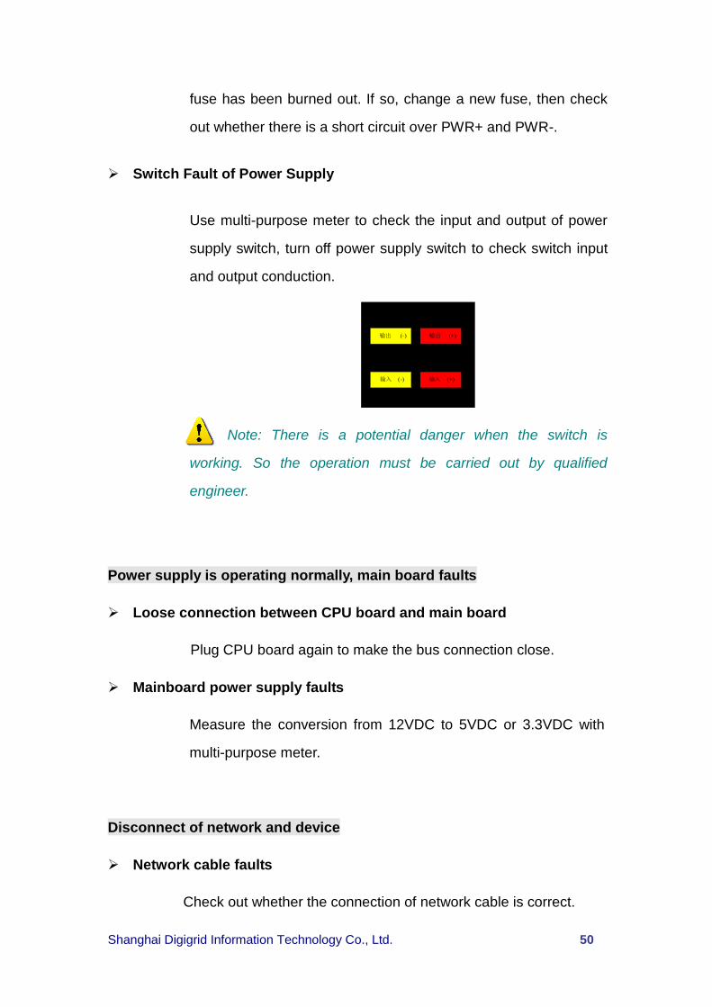
Switch Fault of Power Supply
Use multi-purpose meter to check the input and output of power
supply switch, turn off power supply switch to check switch input
and output conduction.
输出 (+)
输入 (+)
输出 (-)
输入 (-)
Note: There is a potential danger when the switch is
working. So the operation must be carried out by qualified
engineer.
Power supply is operating normally, main board faults
Loose connection between CPU board and main board
Plug CPU board again to make the bus connection close.
Mainboard power supply faults
Measure the conversion from 12VDC to 5VDC or 3.3VDC with
multi-purpose meter.
Disconnect of network and device
Network cable faults
Check out whether the connection of network cable is correct.

Shanghai Digigrid Information Technology Co., Ltd. 51
Network connection error
If laptop network port is not adaptive, twisted pair is selected to
connect the device. Use 2 coaxial wires to connect device via
Switch or Hub.
Network setting
Check out whether local network is located in 192.168.0.XXX.
Wireless network interference
Check out whether wireless network is located in the same
address with local network address. If so, disconnect wireless
network connection or change into other address.
Serial ports communication faults
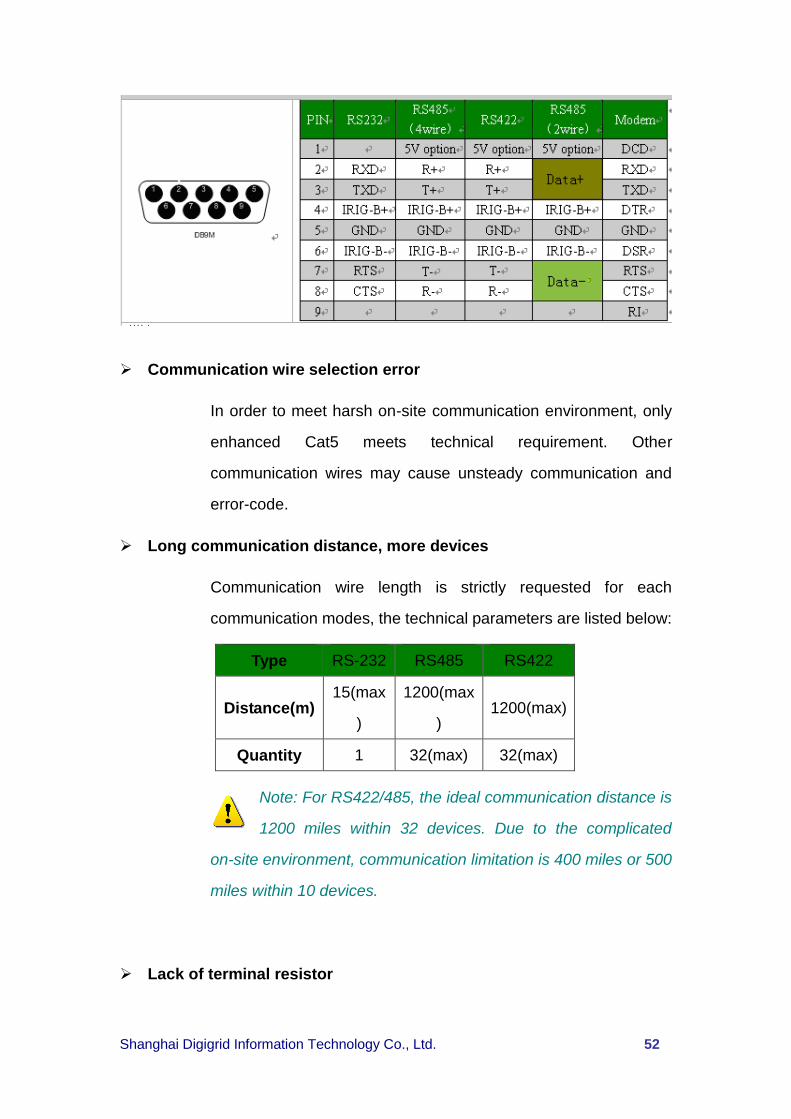
Incorrect serial port definitions
The correct definitions are listed below:
Shanghai Digigrid Information Technology Co., Ltd. 52
Communication wire selection error
In order to meet harsh on-site communication environment, only
enhanced Cat5 meets technical requirement. Other
communication wires may cause unsteady communication and
error-code.
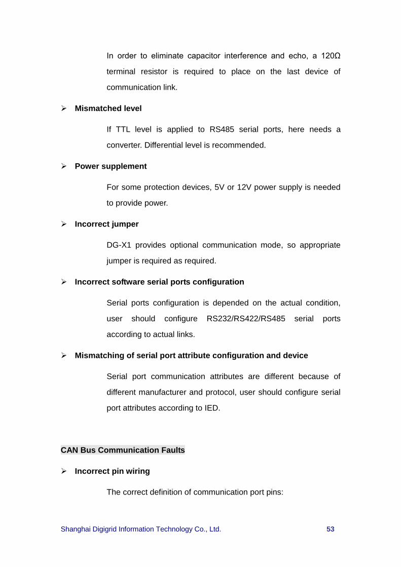
Long communication distance, more devices
Communication wire length is strictly requested for each
communication modes, the technical parameters are listed below:
Type RS-232 RS485 RS422
Distance(m) 15(max
)
1200(max
) 1200(max)
Quantity 1 32(max) 32(max)
Note: For RS422/485, the ideal communication distance is
1200 miles within 32 devices. Due to the complicated
on-site environment, communication limitation is 400 miles or 500
miles within 10 devices.
Lack of terminal resistor
Shanghai Digigrid Information Technology Co., Ltd. 53
In order to eliminate capacitor interference and echo, a 120Ω
terminal resistor is required to place on the last device of
communication link.
Mismatched level
If TTL level is applied to RS485 serial ports, here needs a
converter. Differential level is recommended.
Power supplement
For some protection devices, 5V or 12V power supply is needed
to provide power.
Incorrect jumper
DG-X1 provides optional communication mode, so appropriate
jumper is required as required.
Incorrect software serial ports configuration
Serial ports configuration is depended on the actual condition,
user should configure RS232/RS422/RS485 serial ports
according to actual links.
Mismatching of serial port attribute configuration and device
Serial port communication attributes are different because of
different manufacturer and protocol, user should configure serial
port attributes according to IED.
CAN Bus Communication Faults
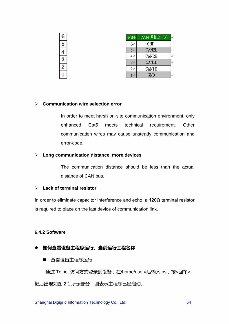
Incorrect pin wiring
The correct definition of communication port pins:
Shanghai Digigrid Information Technology Co., Ltd. 54
Communication wire selection error
In order to meet harsh on-site communication environment, only
enhanced Cat5 meets technical requirement. Other
communication wires may cause unsteady communication and
error-code.
Long communication distance, more devices
The communication distance should be less than the actual
distance of CAN bus.
Lack of terminal resistor
In order to eliminate capacitor interference and echo, a 120Ω terminal resistor
is required to place on the last device of communication link.
6.4.2 Software
如何查看设备主程序运行、当前运行工程名称
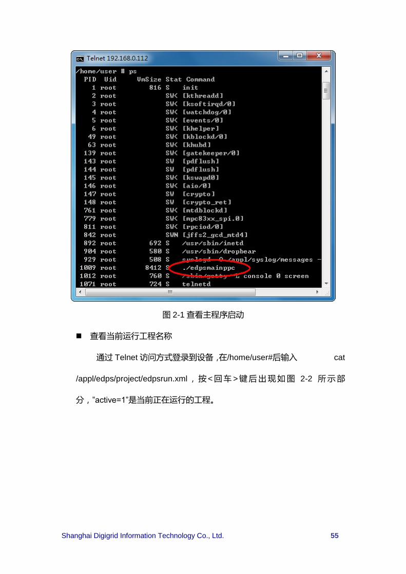
查看设备主程序运行
通过 Telnet 访问方式登录到设备,在/home/user#后输入 ps,按<回车>
键后出现如图 2-1 所示部分,则表示主程序已经启动。
Shanghai Digigrid Information Technology Co., Ltd. 55
图 2-1 查看主程序启动
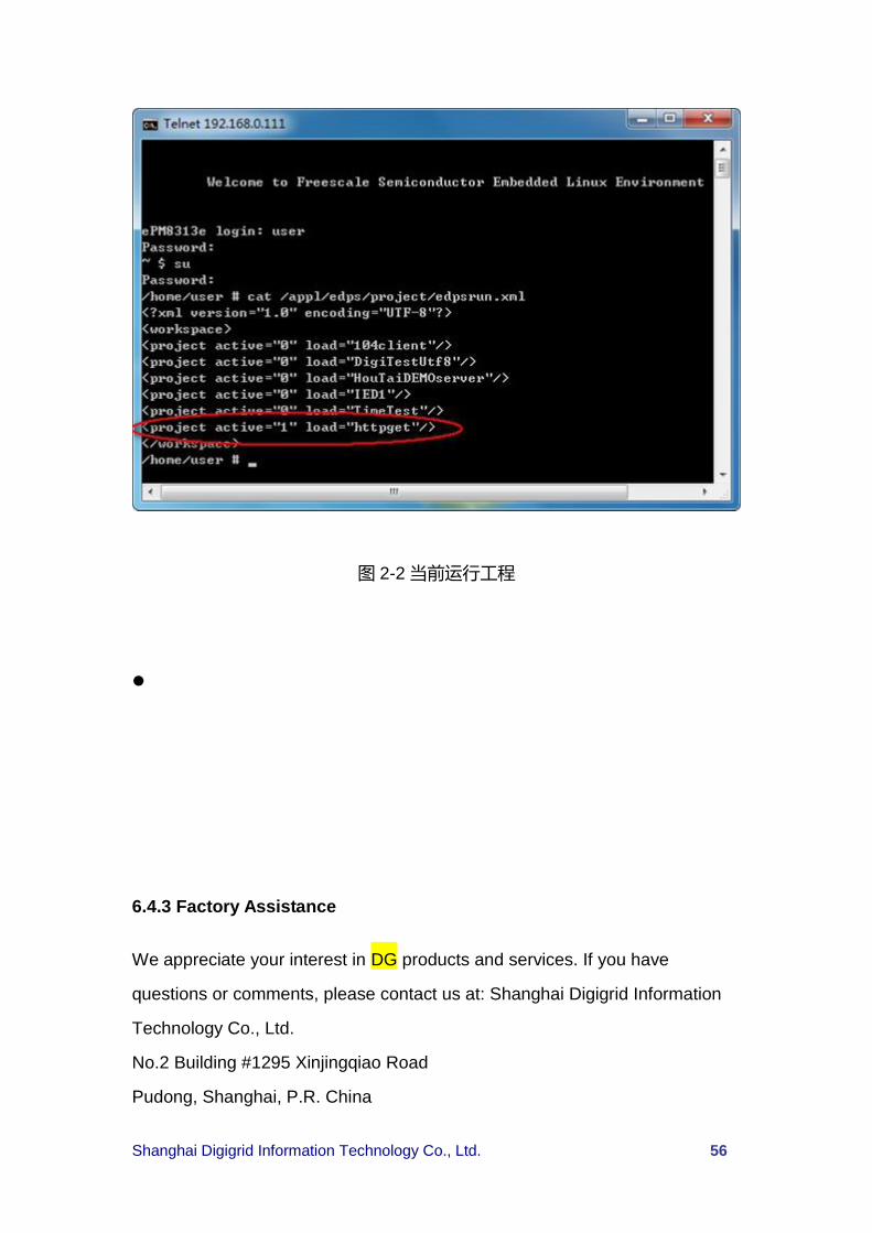
查看当前运行工程名称
通过 Telnet 访问方式登录到设备,在/home/user#后输入 cat
/appl/edps/project/edpsrun.xml,按<回车>键后出现如图 2-2 所示部
分,”active=1”是当前正在运行的工程。
Shanghai Digigrid Information Technology Co., Ltd. 56
图 2-2 当前运行工程
6.4.3 Factory Assistance
We appreciate your interest in DG products and services. If you have
questions or comments, please contact us at: Shanghai Digigrid Information
Technology Co., Ltd.
No.2 Building #1295 Xinjingqiao Road
Pudong, Shanghai, P.R. China

Shanghai Digigrid Information Technology Co., Ltd. 57
Tel: +86-21-6162-9***
Fax:+86-21-6162-9213
Website: www.digigrid.com cn
Shanghai Digigrid Information Technology Co., Ltd. 58
Appendix A
A.1 Firmware and Manual Versions
我们公司的固件是否有版本号。
Table A.1 lists the instruction manual release dates and a description of
modifications. The most recent instruction manual revisions are listed at the
top.
Revision Date Summary of Revisions
20140303 Initial Release
Appendix B
B.1 IEC61850 Configuration
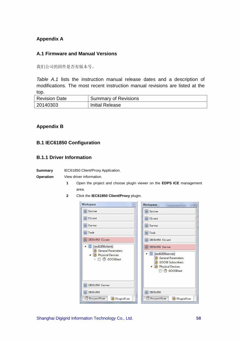
B.1.1 Driver Information
Summary IEC61850 Client/Proxy Application.
Operation View driver information.
1 Open the project and choose plugin viewer on the EDPS ICE management
area.
2 Click the IEC61850 Client/Proxy plugin.
Shanghai Digigrid Information Technology Co., Ltd. 59
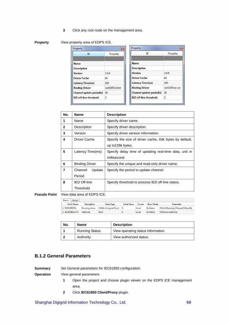
3 Click any root node on the management area.
Property View property area of EDPS ICE.
No. Name Description
1 Name Specify driver name.
2 Description Specify driver description.
3 Version Specify driver version information.
4 Driver Cache Specify the size of driver cache, 64k bytes by default,
up to128k bytes.
5 Latency Time(ms) Specify delay time of updating real-time data, unit in
millisecond.
6 Binding Driver Specify the unique and read-only driver name.
7 Channel Update
Period
Specify the period to update channel.
8 IED Off-line
Threshold
Specify threshold to process IED off-line status.
Pseudo Point View data area of EDPS ICE.
No. Name Description
1 Running Status View operating status information.
2 Authority View authorized status.
B.1.2 General Parameters
Summary Set General parameters for IEC61850 configuration.
Operation View general parameters.
1 Open the project and choose plugin viewer on the EDPS ICE management
area.
2 Click IEC61850 Client/Proxy plugin.
Shanghai Digigrid Information Technology Co., Ltd. 60
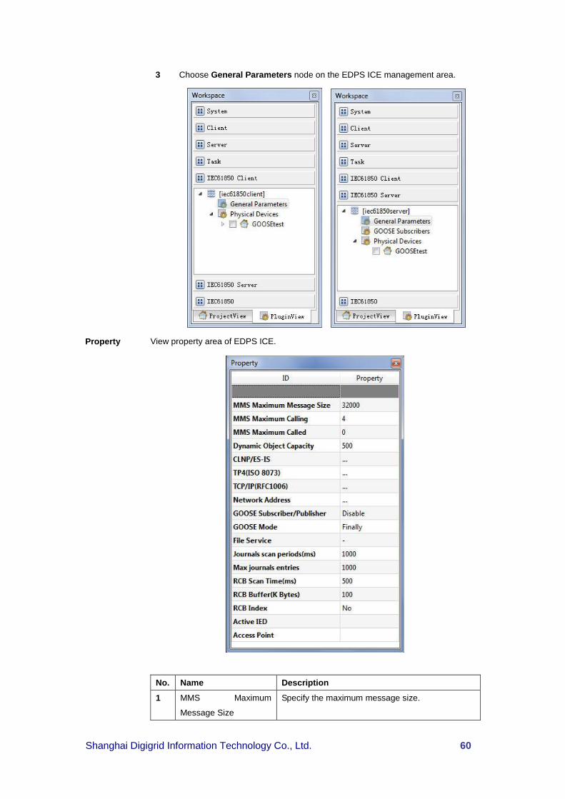
3 Choose General Parameters node on the EDPS ICE management area.
Property View property area of EDPS ICE.
No. Name Description
1 MMS Maximum
Message Size
Specify the maximum message size.
Shanghai Digigrid Information Technology Co., Ltd. 61
2 MMS Maximum Calling Specify the maximum calling connections of the
client.
3 MMS maximum
Called
Specify the maximum called connections of the
server.
4 Dynamic Object
Capacity
5 CLNP/ES-IS Specify the configuration of OSI network layer.
6 TP4(ISO 8073) Specify the configuration of OSI transport layer.
7 TCP/IP(RFC1006) Specify the configuration of TCP/IP stack.
8 Network Address Specify the configuration of local network address.
9 GOOSE
Subscriber/Publisher
10 GOOSE Mode
11 File Service
12 Journals scan
periods(ms)
Max journals entries
RCB Scan Time(ms) Specify the scan time of the report.
RCB Buffer(K Bytes) Specify the default buffer size of the buffer report.
RCB Index Specify whether or not to add the suffix of RCB
reference.
Active IED Specify the activated device name which
generally is the iedName property of ConnectedAP
of the CID instance file.
Access Point Specify the access point name which is generally
the apName property of ConnectedAP of the CID
instance file.
B.1.3 Device Parameters
Summary Set physical device parameters for IEC61850 driver.
Operation View device parameters.
1 Open the project and choose plugin viewer on the EDPS ICE management
area.
2 Click the IEC61850 Client/Proxy plugin.
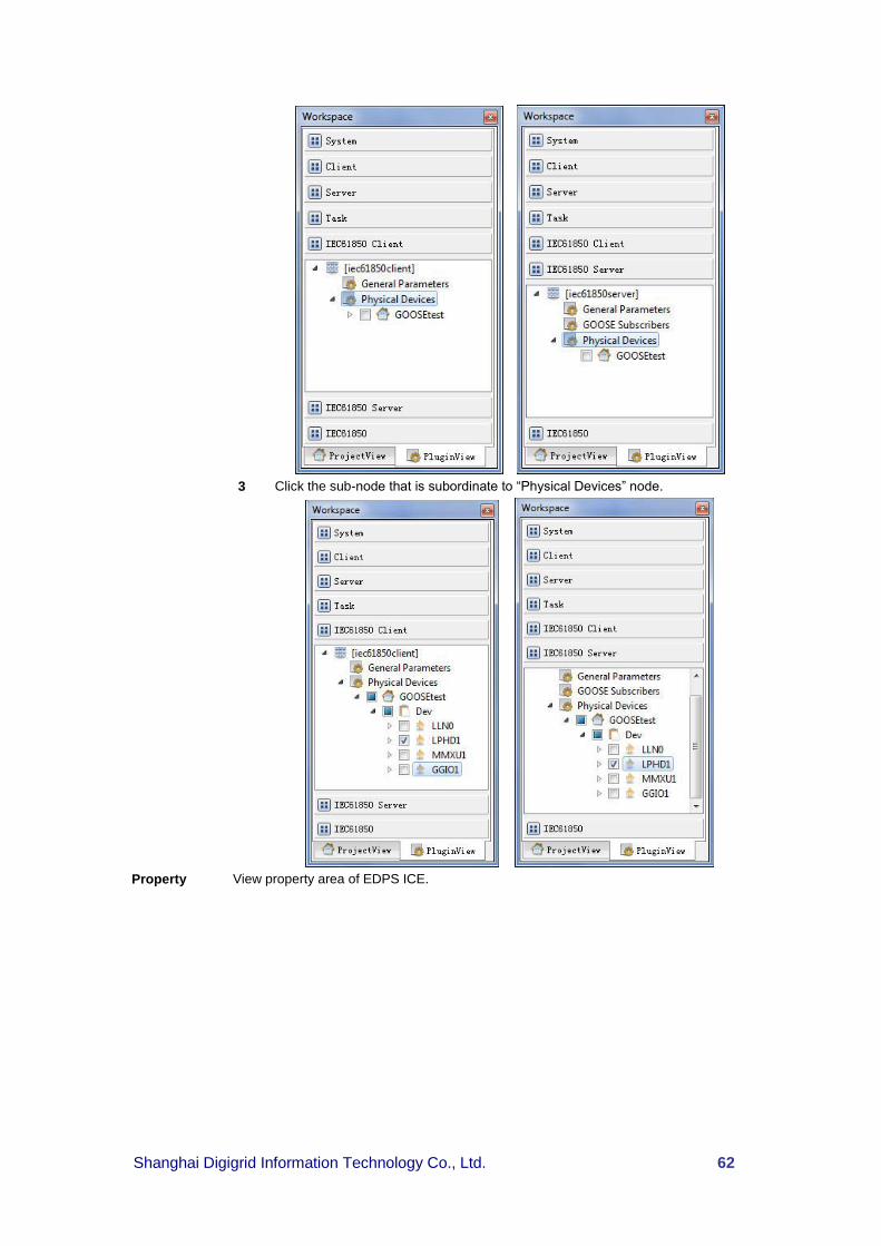
Shanghai Digigrid Information Technology Co., Ltd. 62
3 Click the sub-node that is subordinate to “Physical Devices” node.
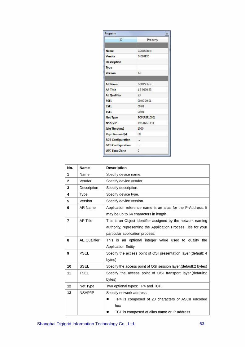
Property View property area of EDPS ICE.
Shanghai Digigrid Information Technology Co., Ltd. 63
No. Name Description
1 Name Specify device name.
2 Vendor Specify device vendor.
3 Description Specify description.
4 Type Specify device type.
5 Version Specify device version.
6 AR Name Application reference name is an alias for the P-Address. It
may be up to 64 characters in length.
7 AP Title This is an Object Identifier assigned by the network naming
authority, representing the Application Process Title for your
particular application process.
8 AE Qualifier This is an optional integer value used to qualify the
Application Entity.
9 PSEL Specify the access point of OSI presentation layer.(default: 4
bytes)
10 SSEL Specify the access point of OSI session layer.(default:2 bytes)
11 TSEL Specify the access point of OSI transport layer.(default:2
bytes)
12 Net Type Two optional types: TP4 and TCP.
13 NSAP/IP Specify network address.
TP4 is composed of 20 characters of ASCII encoded
hex
TCP is composed of alias name or IP address
Shanghai Digigrid Information Technology Co., Ltd. 64
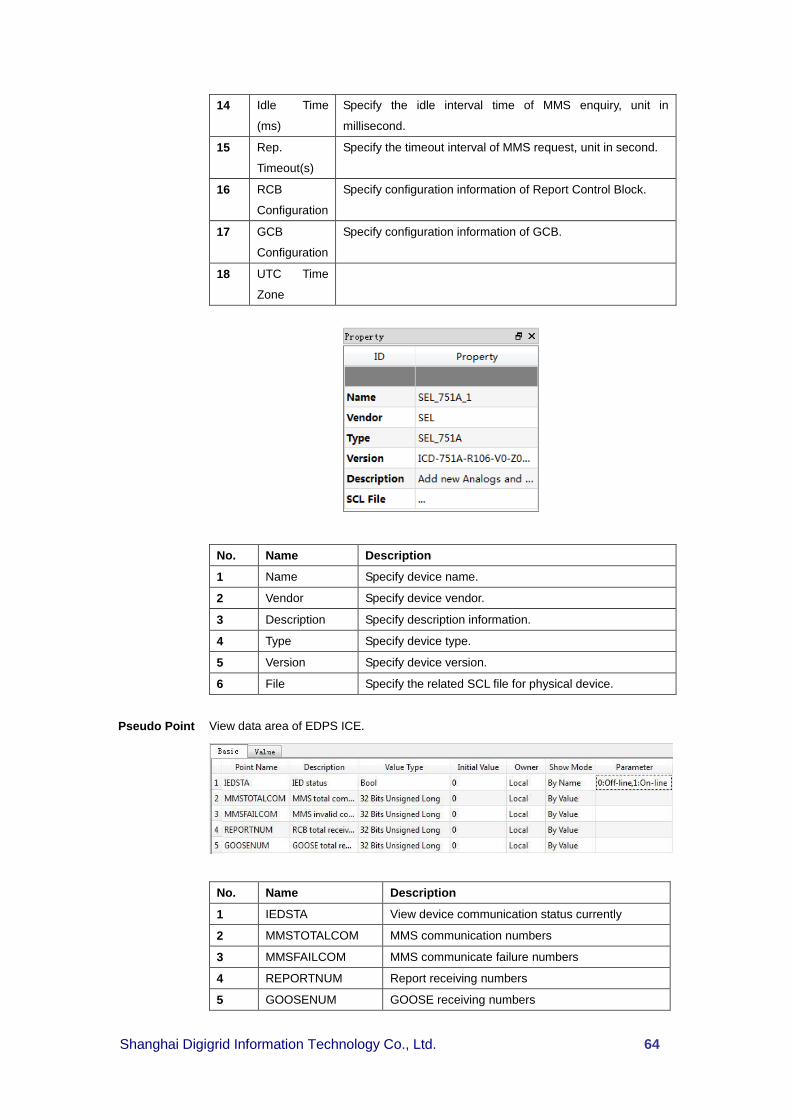
14 Idle Time
(ms)
Specify the idle interval time of MMS enquiry, unit in
millisecond.
15 Rep.
Timeout(s)
Specify the timeout interval of MMS request, unit in second.
16 RCB
Configuration
Specify configuration information of Report Control Block.
17 GCB
Configuration
Specify configuration information of GCB.
18 UTC Time
Zone
No. Name Description
1 Name Specify device name.
2 Vendor Specify device vendor.
3 Description Specify description information.
4 Type Specify device type.
5 Version Specify device version.
6 File Specify the related SCL file for physical device.
Pseudo Point View data area of EDPS ICE.
No. Name Description
1 IEDSTA View device communication status currently
2 MMSTOTALCOM MMS communication numbers
3 MMSFAILCOM MMS communicate failure numbers
4 REPORTNUM Report receiving numbers
5 GOOSENUM GOOSE receiving numbers
Shanghai Digigrid Information Technology Co., Ltd. 65
B.1.4 Basic Parameters
Summary View basic parameters for information point through the IO page of different types of data.
The device name and point name are not allowed to edit depending on IEC61850 device.
Note: For more information, refer to “EDPS ICE V2.x User Guide” for more details.
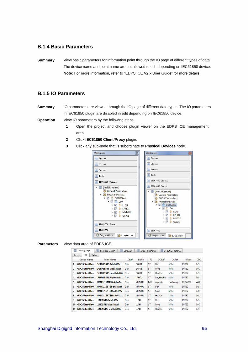
B.1.5 IO Parameters
Summary IO parameters are viewed through the IO page of different data types. The IO parameters
in IEC61850 plugin are disabled in edit depending on IEC61850 device.
Operation View IO parameters by the following steps.
1 Open the project and choose plugin viewer on the EDPS ICE management
area.
2 Click IEC61850 Client/Proxy plugin.
3 Click any sub-node that is subordinate to Physical Devices node.
Parameters View data area of EDPS ICE.
Shanghai Digigrid Information Technology Co., Ltd. 66
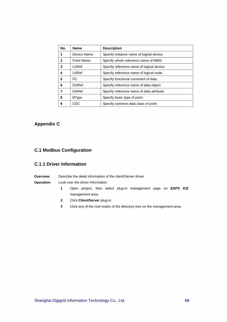
No. Name Description
1 Device Name Specify instance name of logical device.
2 Point Name Specify whole reference name of MMS.
3 LDRef Specify reference name of logical device.
4 LNRef Specify reference name of logical node.
5 FC Specify functional constraint of data.
6 DORef Specify reference name of data object.
7 DARef Specify reference name of data attribute.
8 BType Specify basic type of point.
9 CDC Specify common data class of point.
Appendix C
C.1 Modbus Configuration
C.1.1 Driver Information
Overview Describe the detail information of the client/Server driver.
Operation Look over the driver information.
1 Open project, then select plug-in management page on EDPS ICE
management area.
2 Click Client/Server plug-in.
3 Click any of the root nodes of the directory tree on the management area.
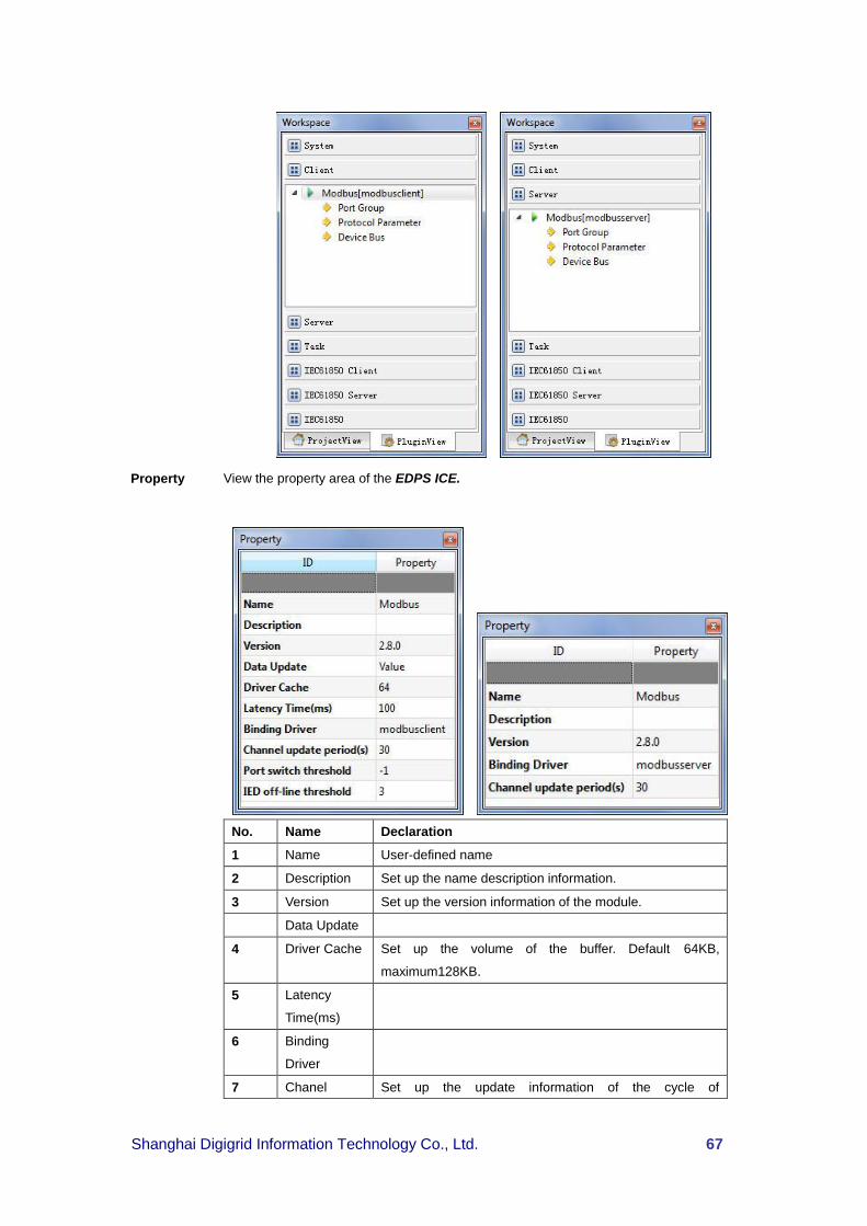
Shanghai Digigrid Information Technology Co., Ltd. 67
Property View the property area of the EDPS ICE.
No. Name Declaration
1 Name User-defined name
2 Description Set up the name description information.
3 Version Set up the version information of the module.
Data Update
4 Driver Cache Set up the volume of the buffer. Default 64KB,
maximum128KB.
5 Latency
Time(ms)
6 Binding
Driver
7 Chanel Set up the update information of the cycle of
Shanghai Digigrid Information Technology Co., Ltd. 68
Update
Period
communication channels. The unit is second.
8 Port
Switching
Threshold
Set up the statistical threshold carried on in the port. The
port will be switched when the continuous fault times
exceed the threshold values. -1 means no port switch.
9 IED Off-line
Threshold
Set up the statistical threshold of the device state. The
device will in off-line state when the continuous fault times
exceed the threshold values.
Pseudo
Point
View the data area of EDPS ICE.
No. Name Declaration
1 Running Status View the diver running status information
2 Authority View the authorization status of the diver.
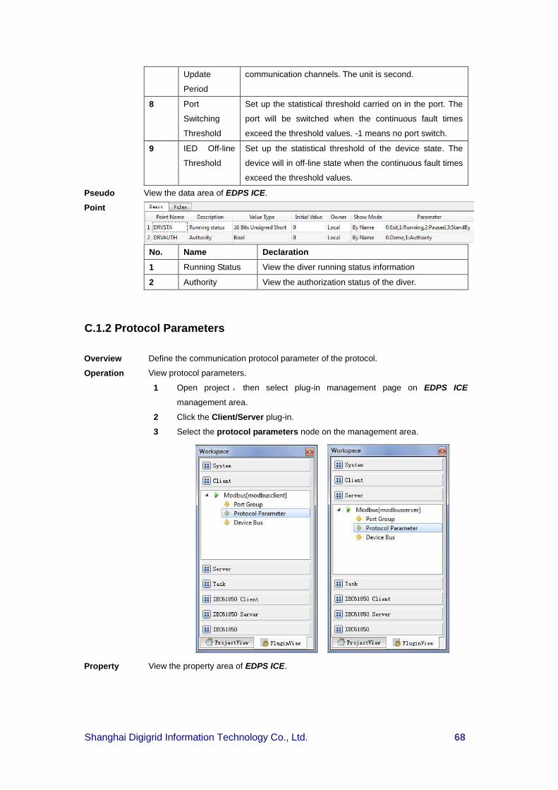
C.1.2 Protocol Parameters
Overview Define the communication protocol parameter of the protocol.
Operation View protocol parameters.
1 Open project , then select plug-in management page on EDPS ICE
management area.
2 Click the Client/Server plug-in.
3 Select the protocol parameters node on the management area.
Property View the property area of EDPS ICE.
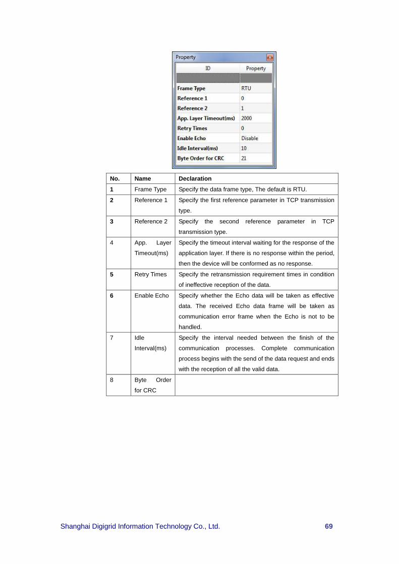
Shanghai Digigrid Information Technology Co., Ltd. 69
No. Name Declaration
1 Frame Type Specify the data frame type, The default is RTU.
2 Reference 1 Specify the first reference parameter in TCP transmission
type.
3 Reference 2 Specify the second reference parameter in TCP
transmission type.
4 App. Layer
Timeout(ms)
Specify the timeout interval waiting for the response of the
application layer. If there is no response within the period,
then the device will be conformed as no response.
5 Retry Times Specify the retransmission requirement times in condition
of ineffective reception of the data.
6 Enable Echo Specify whether the Echo data will be taken as effective
data. The received Echo data frame will be taken as
communication error frame when the Echo is not to be
handled.
7 Idle
Interval(ms)
Specify the interval needed between the finish of the
communication processes. Complete communication
process begins with the send of the data request and ends
with the reception of all the valid data.
8 Byte Order
for CRC
Shanghai Digigrid Information Technology Co., Ltd. 70
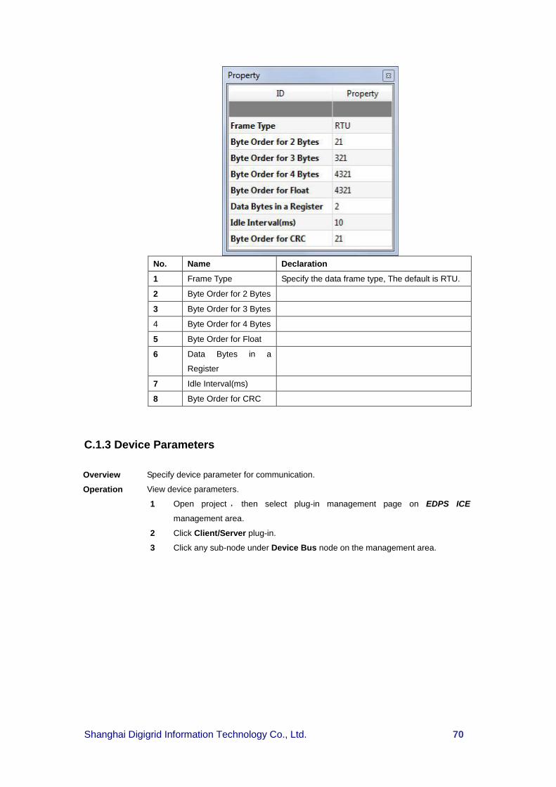
No. Name Declaration
1 Frame Type Specify the data frame type, The default is RTU.
2 Byte Order for 2 Bytes
3 Byte Order for 3 Bytes
4 Byte Order for 4 Bytes
5 Byte Order for Float
6 Data Bytes in a
Register
7 Idle Interval(ms)
8 Byte Order for CRC
C.1.3 Device Parameters
Overview Specify device parameter for communication.
Operation View device parameters.
1 Open project , then select plug-in management page on EDPS ICE
management area.
2 Click Client/Server plug-in.
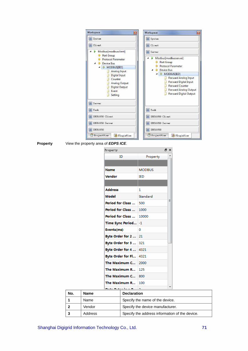
3 Click any sub-node under Device Bus node on the management area.
Shanghai Digigrid Information Technology Co., Ltd. 71
Property View the property area of EDPS ICE.
No. Name Declaration
1 Name Specify the name of the device.
2 Vendor Specify the device manufacturer.
3 Address Specify the address information of the device.
Shanghai Digigrid Information Technology Co., Ltd. 72
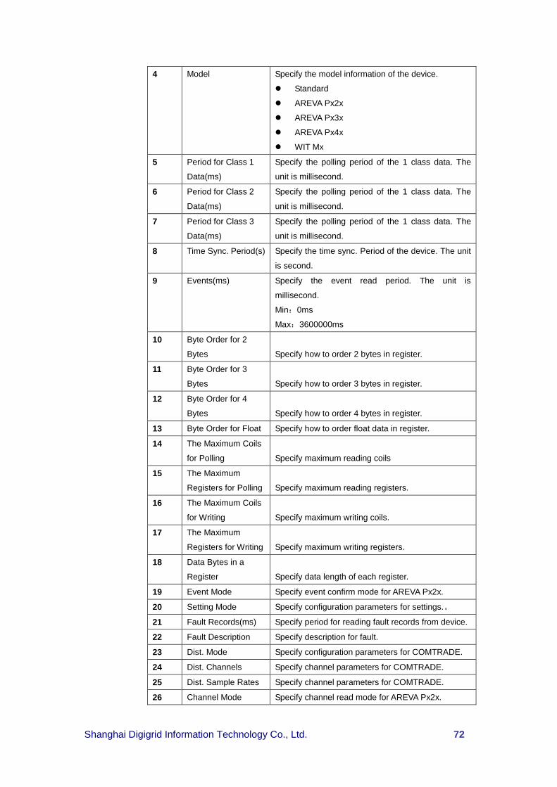
4 Model Specify the model information of the device.
Standard
AREVA Px2x
AREVA Px3x
AREVA Px4x
WIT Mx
5 Period for Class 1
Data(ms)
Specify the polling period of the 1 class data. The
unit is millisecond.
6 Period for Class 2
Data(ms)
Specify the polling period of the 1 class data. The
unit is millisecond.
7 Period for Class 3
Data(ms)
Specify the polling period of the 1 class data. The
unit is millisecond.
8 Time Sync. Period(s) Specify the time sync. Period of the device. The unit
is second.
9 Events(ms) Specify the event read period. The unit is
millisecond.
Min:0ms
Max:3600000ms
10 Byte Order for 2
Bytes Specify how to order 2 bytes in register.
11 Byte Order for 3
Bytes Specify how to order 3 bytes in register.
12 Byte Order for 4
Bytes Specify how to order 4 bytes in register.
13 Byte Order for Float Specify how to order float data in register.
14 The Maximum Coils
for Polling Specify maximum reading coils
15 The Maximum
Registers for Polling Specify maximum reading registers.
16 The Maximum Coils
for Writing Specify maximum writing coils.
17 The Maximum
Registers for Writing Specify maximum writing registers.
18 Data Bytes in a
Register Specify data length of each register.
19 Event Mode Specify event confirm mode for AREVA Px2x.
20 Setting Mode Specify configuration parameters for settings.。
21 Fault Records(ms) Specify period for reading fault records from device.
22 Fault Description Specify description for fault.
23 Dist. Mode Specify configuration parameters for COMTRADE.
24 Dist. Channels Specify channel parameters for COMTRADE.
25 Dist. Sample Rates Specify channel parameters for COMTRADE.
26 Channel Mode Specify channel read mode for AREVA Px2x.
Shanghai Digigrid Information Technology Co., Ltd. 73
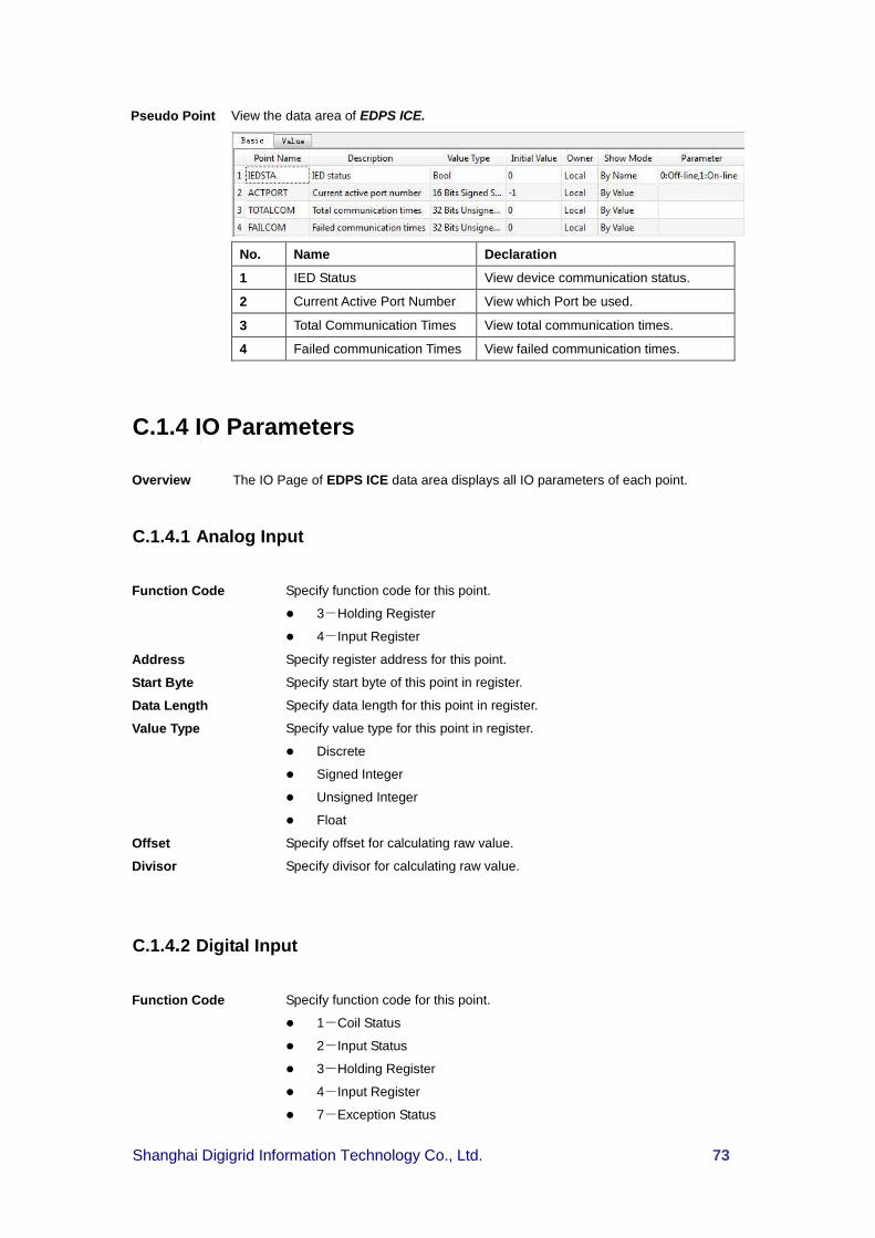
Pseudo Point View the data area of EDPS ICE.
No. Name Declaration
1 IED Status View device communication status.
2 Current Active Port Number View which Port be used.
3 Total Communication Times View total communication times.
4 Failed communication Times View failed communication times.
C.1.4 IO Parameters
Overview The IO Page of EDPS ICE data area displays all IO parameters of each point.
C.1.4.1 Analog Input
Function Code Specify function code for this point.
3-Holding Register
4-Input Register
Address Specify register address for this point.
Start Byte Specify start byte of this point in register.
Data Length Specify data length for this point in register.
Value Type Specify value type for this point in register.
Discrete
Signed Integer
Unsigned Integer
Float
Offset Specify offset for calculating raw value.
Divisor Specify divisor for calculating raw value.
C.1.4.2 Digital Input
Function Code Specify function code for this point.
1-Coil Status
2-Input Status
3-Holding Register
4-Input Register
7-Exception Status

Shanghai Digigrid Information Technology Co., Ltd. 74
Address Specify register address for this point.
Position Specify bit position for this point in register.
C.1.4.3 Counter
Function Code Specify function code for this point.
3-Holding Register
4-Input Register
Address Specify register address for this point.
Start Byte Specify start byte of this point in register.
Data Length Specify data length for this point in register.
Value Type Specify value type for this point in register.
Discrete
Signed Integer
Unsigned Integer
Float
Offset Specify offset for calculating raw value.
Divisor Specify divisor for calculating raw value.
C.1.4.4 Analog Output
Function Code Specify function code for this point.
3-Holding Register
4-Input Register
Address Specify register address for this point.
Start Byte Specify start byte for this point in register.
Data Length Specify data length for this point.
Value Type Specify value type for this point in register.
Discrete
Signed Integer
Unsigned Integer
Float
Offset Specify offset for calculating raw value.
Divisor Specify divisor for calculating raw value.
C.1.4.5 Digital Output
Function Code Specify function code for this point.
5-Force Coil
15-Force Multiple Coils
Address Specify register address for this point.

Shanghai Digigrid Information Technology Co., Ltd. 75
C.1.4.6 Status Output
Function Code Specify function code for this point.
5-Force Coil
15-Force Multiple Coils
6-Force Register
10-Force Multiple Register
Register Address Specify register address for this point.
Start Byte Specify start byte of this point in register.
Control Mode Specify the control output mode of the point.
Tripping/Closing
Pulse
Pulse Frequency Specify the pulse frequency, maximum 1000. Effective in the pulse control
mode.
High Time Specify the hold time of the high level in the pulse output mode.
Low Time Specify the hold time of the low level in the pulse output mode.
C.1.4.7 Event
Event Code Specify the number of the event code. Used in the search of the event
information.
C.1.4.8 Setting Value
Function Code Specify function code for this point.
3-Holding Register
4-Input Register
Register Address Specify register address for this point.
Start Byte Specify start byte of this point in register.
Priority Specify the priority of data handling.
1 class data
2 class data
3 class data
Data Length Specify data length for this point.
Value Type Specify value type for this point in register.
Discrete
Signed Integer
Unsigned Integer
Float
Write Function Specify the write function of the information point.
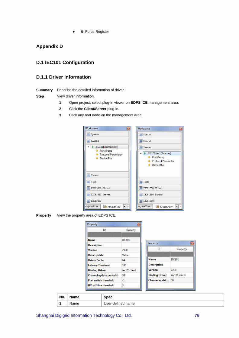
Shanghai Digigrid Information Technology Co., Ltd. 76
6- Force Register
Appendix D
D.1 IEC101 Configuration
D.1.1 Driver Information
Summary Describe the detailed information of driver.
Step View driver information.
1 Open project, select plug-in viewer on EDPS ICE management area.
2 Click the Client/Server plug-in.
3 Click any root node on the management area.
Property View the property area of EDPS ICE.
No. Name Spec.
1 Name User-defined name.
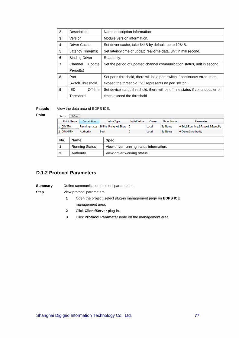
Shanghai Digigrid Information Technology Co., Ltd. 77
2 Description Name description information.
3 Version Module version information.
4 Driver Cache Set driver cache, take 64kB by default, up to 128kB.
5 Latency Time(ms) Set latency time of updatd real-time data, unit in millisecond.
6 Binding Driver Read only.
7 Channel Update
Period(s)
Set the period of updated channel communication status, unit in second.
8 Port
Switch Threshold
Set ports threshold, there will be a port switch if continuous error times
exceed the threshold, “-1” represents no port switch.
9 IED Off-line
Threshold
Set device status threshold, there will be off-line status if continuous error
times exceed the threshold.
Pseudo
Point
View the data area of EDPS ICE.
No. Name Spec.
1 Running Status View driver running status information.
2 Authority View driver working status.
D.1.2 Protocol Parameters
Summary Define communication protocol parameters.
Step View protocol parameters.
1 Open the project, select plug-in management page on EDPS ICE
management area.
2 Click Client/Server plug-in.
3 Click Protocol Parameter node on the management area.
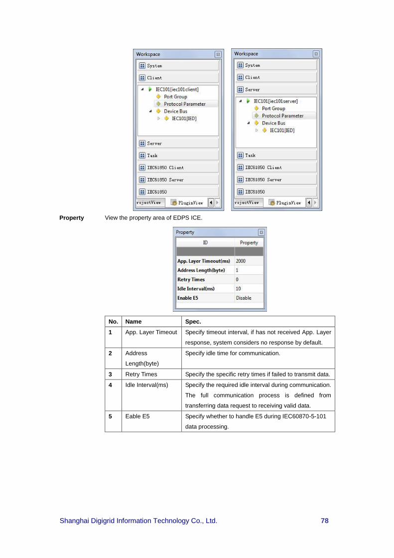
Shanghai Digigrid Information Technology Co., Ltd. 78
Property View the property area of EDPS ICE.
No. Name Spec.
1 App. Layer Timeout Specify timeout interval, if has not received App. Layer
response, system considers no response by default.
2 Address
Length(byte)
Specify idle time for communication.
3 Retry Times Specify the specific retry times if failed to transmit data.
4 Idle Interval(ms) Specify the required idle interval during communication.
The full communication process is defined from
transferring data request to receiving valid data.
5 Eable E5 Specify whether to handle E5 during IEC60870-5-101
data processing.
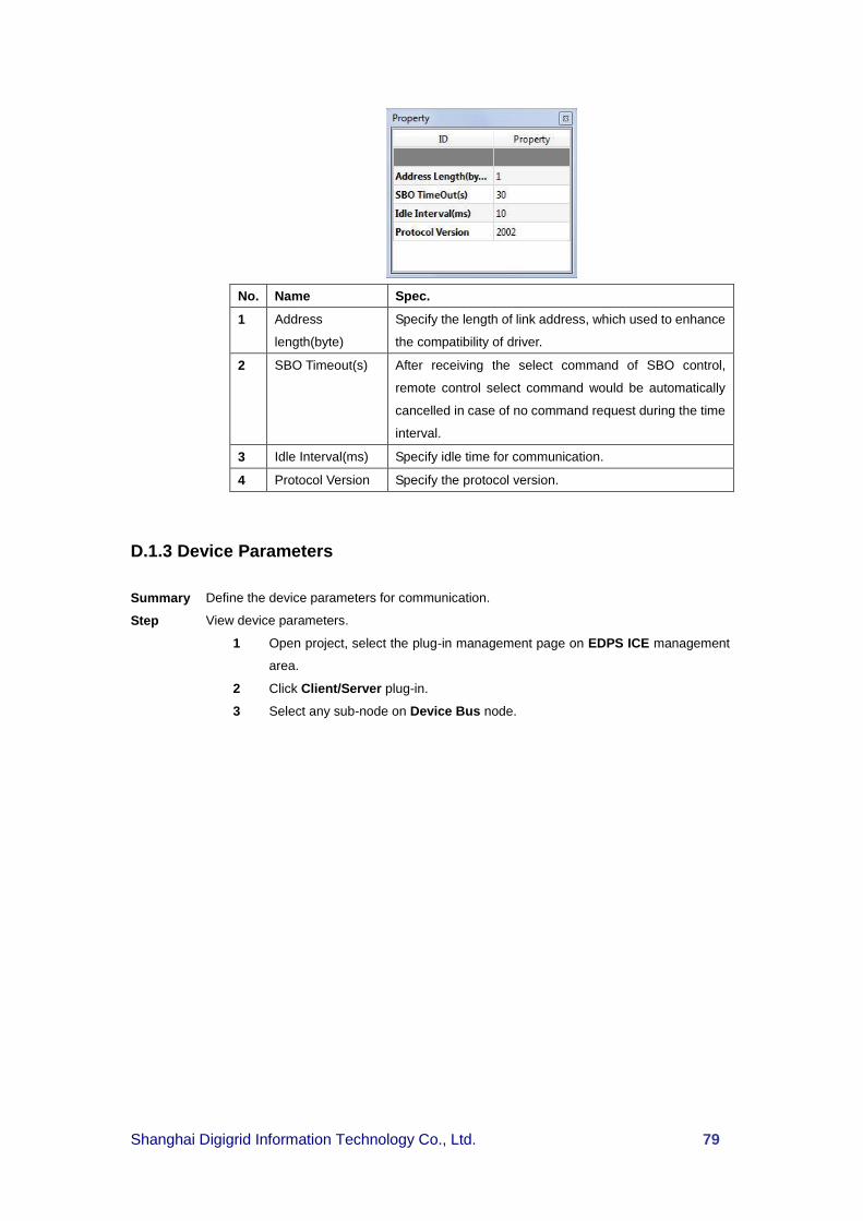
Shanghai Digigrid Information Technology Co., Ltd. 79
No. Name Spec.
1 Address
length(byte)
Specify the length of link address, which used to enhance
the compatibility of driver.
2 SBO Timeout(s) After receiving the select command of SBO control,
remote control select command would be automatically
cancelled in case of no command request during the time
interval.
3 Idle Interval(ms) Specify idle time for communication.
4 Protocol Version Specify the protocol version.
D.1.3 Device Parameters
Summary Define the device parameters for communication.
Step View device parameters.
1 Open project, select the plug-in management page on EDPS ICE management
area.
2 Click Client/Server plug-in.
3 Select any sub-node on Device Bus node.
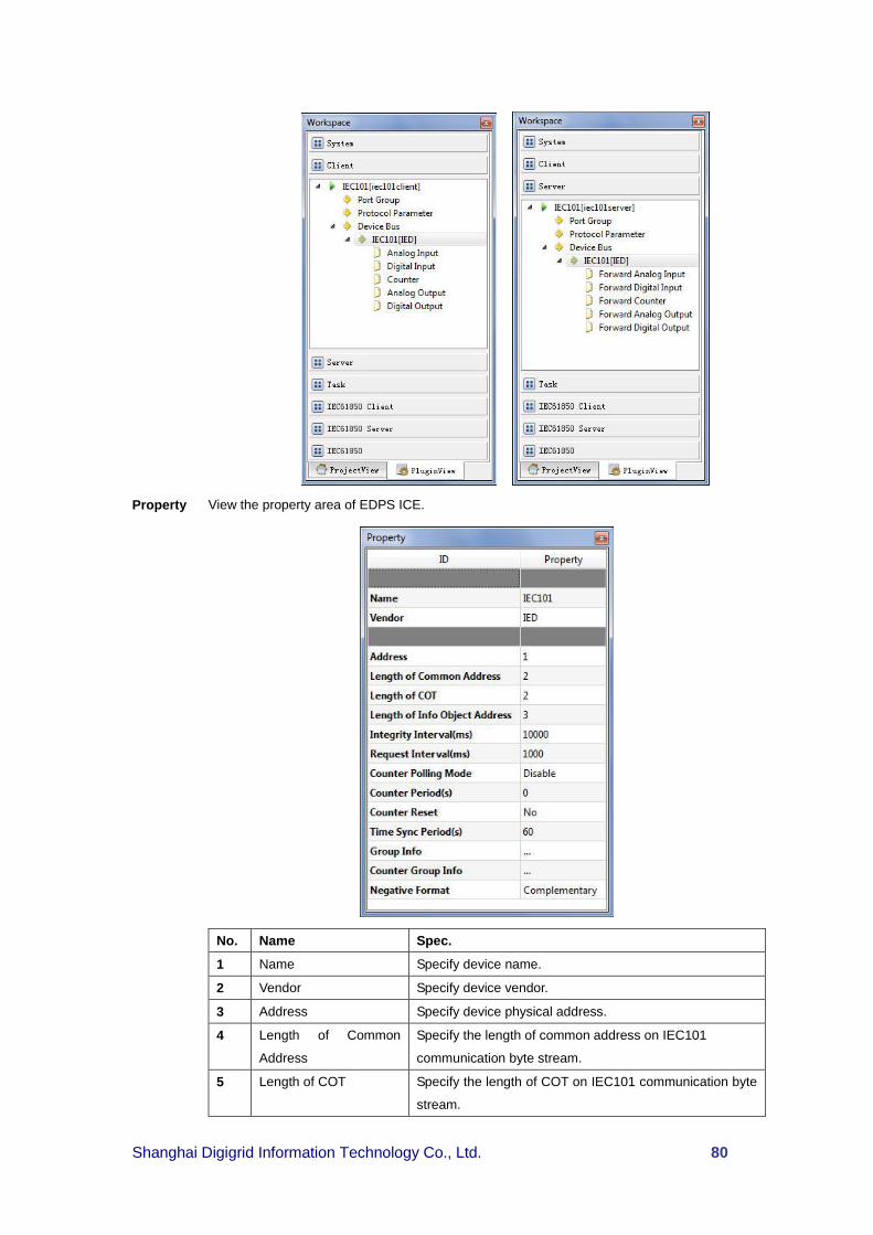
Shanghai Digigrid Information Technology Co., Ltd. 80
Property View the property area of EDPS ICE.
No. Name Spec.
1 Name Specify device name.
2 Vendor Specify device vendor.
3 Address Specify device physical address.
4 Length of Common
Address
Specify the length of common address on IEC101
communication byte stream.
5 Length of COT Specify the length of COT on IEC101 communication byte
stream.
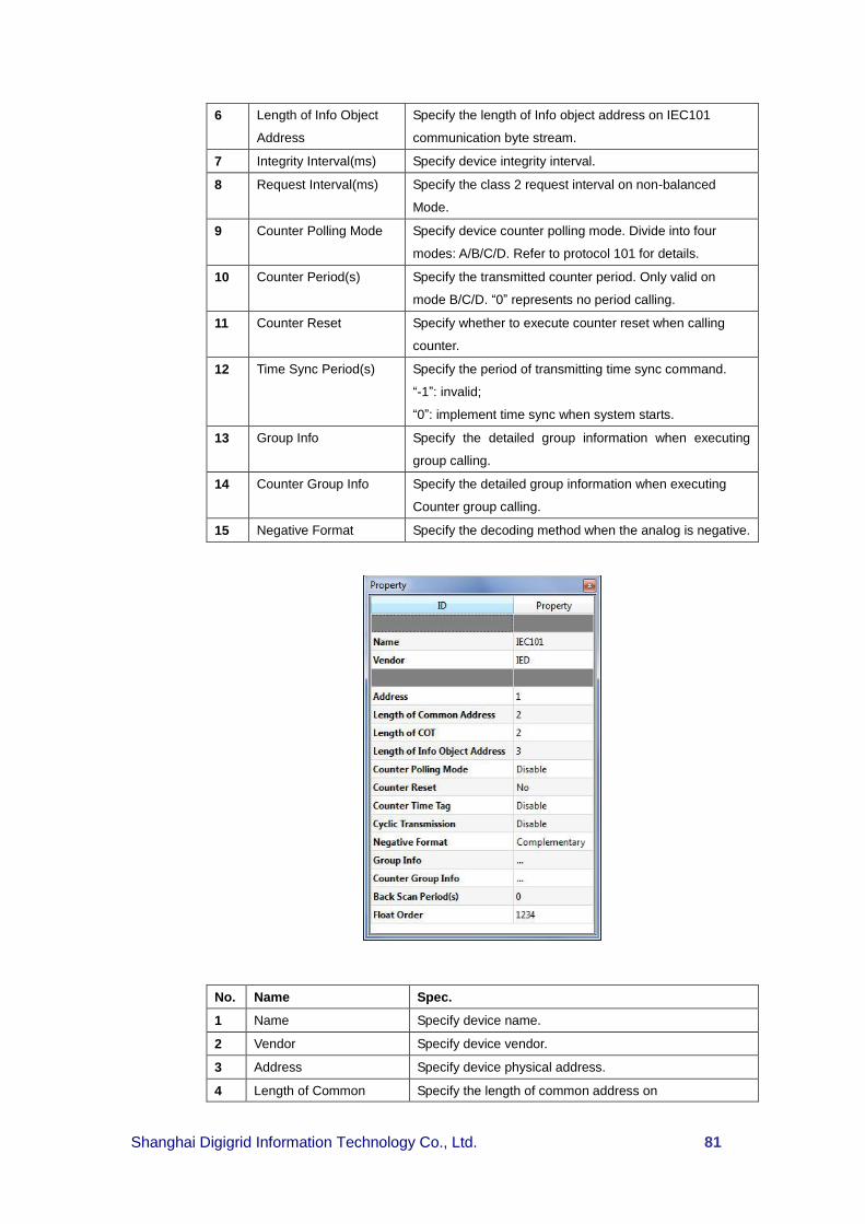
Shanghai Digigrid Information Technology Co., Ltd. 81
6 Length of Info Object
Address
Specify the length of Info object address on IEC101
communication byte stream.
7 Integrity Interval(ms) Specify device integrity interval.
8 Request Interval(ms) Specify the class 2 request interval on non-balanced
Mode.
9 Counter Polling Mode Specify device counter polling mode. Divide into four
modes: A/B/C/D. Refer to protocol 101 for details.
10 Counter Period(s) Specify the transmitted counter period. Only valid on
mode B/C/D. “0” represents no period calling.
11 Counter Reset Specify whether to execute counter reset when calling
counter.
12 Time Sync Period(s) Specify the period of transmitting time sync command.
“-1”: invalid;
“0”: implement time sync when system starts.
13 Group Info Specify the detailed group information when executing
group calling.
14 Counter Group Info Specify the detailed group information when executing
Counter group calling.
15 Negative Format Specify the decoding method when the analog is negative.
No. Name Spec.
1 Name Specify device name.
2 Vendor Specify device vendor.
3 Address Specify device physical address.
4 Length of Common Specify the length of common address on
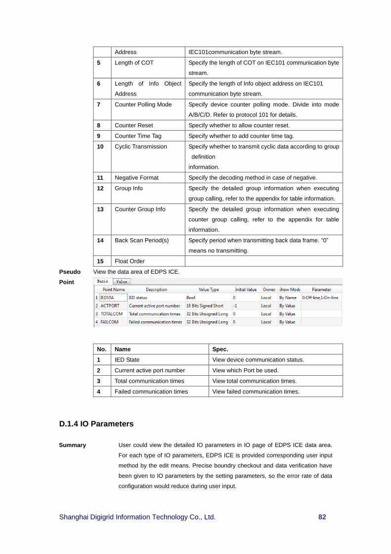
Shanghai Digigrid Information Technology Co., Ltd. 82
Address IEC101communication byte stream.
5 Length of COT Specify the length of COT on IEC101 communication byte
stream.
6 Length of Info Object
Address
Specify the length of Info object address on IEC101
communication byte stream.
7 Counter Polling Mode Specify device counter polling mode. Divide into mode
A/B/C/D. Refer to protocol 101 for details.
8 Counter Reset Specify whether to allow counter reset.
9 Counter Time Tag Specify whether to add counter time tag.
10 Cyclic Transmission Specify whether to transmit cyclic data according to group
definition
information.
11 Negative Format Specify the decoding method in case of negative.
12 Group Info Specify the detailed group information when executing
group calling, refer to the appendix for table information.
13 Counter Group Info Specify the detailed group information when executing
counter group calling, refer to the appendix for table
information.
14 Back Scan Period(s) Specify period when transmitting back data frame. “0”
means no transmitting.
15 Float Order
Pseudo
Point
View the data area of EDPS ICE.
No. Name Spec.
1 IED State View device communication status.
2 Current active port number View which Port be used.
3 Total communication times View total communication times.
4 Failed communication times View failed communication times.
D.1.4 IO Parameters
Summary User could view the detailed IO parameters in IO page of EDPS ICE data area.
For each type of IO parameters, EDPS ICE is provided corresponding user input
method by the edit means. Precise boundry checkout and data verification have
been given to IO parameters by the setting parameters, so the error rate of data
configuration would reduce during user input.
Shanghai Digigrid Information Technology Co., Ltd. 83
D.1.4.1 Analog Input
Common Address Specify the common address in the process of communication.
Point Index Specify the point number of information point.
ASDU Type Specify the application types for information point.
M_ME_NA_1(normalized value)
M_ME_NB_1(scale value)
M_ME_NC_1(short float)
M_ME_ND_1(normalized value with character)
M_ST_NA_1(Step information)
Operating Mode Specify the operating mode for information point.
Cyclic
Burst
Time Tag Specify whether there is a time tag in the transmitted frame.
Offset Specify the original data offset for information point.
Divisor Specify the divisor factor when information point calculates original data.
Dead Zone Value Specify the dead zone value when generating event data. The absolute value, that
is the difference between current transmitting value and current value should be
greater than dead zone value.
D.1.4.2 Digital Input
Common Address Specify the common address in the process of communication.
Point Index Specify the point number of information point.
ASDU Type Specify the ASDU transmission types for information point.
M_SP_NA_1(single point)
M_DP_NA_1(double points)
Operating Mode Specify the operating mode for information point.
Cyclic
Burst
Auto SOE Specify whether or not automatic generate SOE according to changed value.
Diable
Enable when open
Enable when close
Enable when changed
SOE Specify whether or not transmit SOE to client.
D.1.4.3 Counter
Common Address Specify the common address in the process of communication.
Point Index Specify the point number of information point.
Shanghai Digigrid Information Technology Co., Ltd. 84
Min. Value Specify minimum value to calculate current value.
Max.Value Specify maximum value to calculate current value.
Offset Specify offset for calculating the raw value.
Divisor Specify divisor for calculating the raw value.
D.1.4.4 Analog Output
Common Address Specify the common address in the process of communication.
Point Index Specify the point number of information point.
ASDU Type Specify the application types for information point.
normalized value
scale value
short float
Offset Specify offset for calculating the raw value.
Divisor Specify divisor for calculating the raw value.
D.1.4.5 Digital Output
Common Address Specify the common address in the process of communication.
Point Index Specify the point number of information point.
Control Mode Specify the control mode for information point.
Direct execution
Select remote control
Appendix E
E.1 IEC104 Configuration
E.1.1 Driver Information
Summary Describe the detailed information of driver.
Operation View driver information.
1 Open project, select plug-in viewer on EDPS ICE management area.
2 Click Client/Server plug-in.
3 Click any root node on the management area.
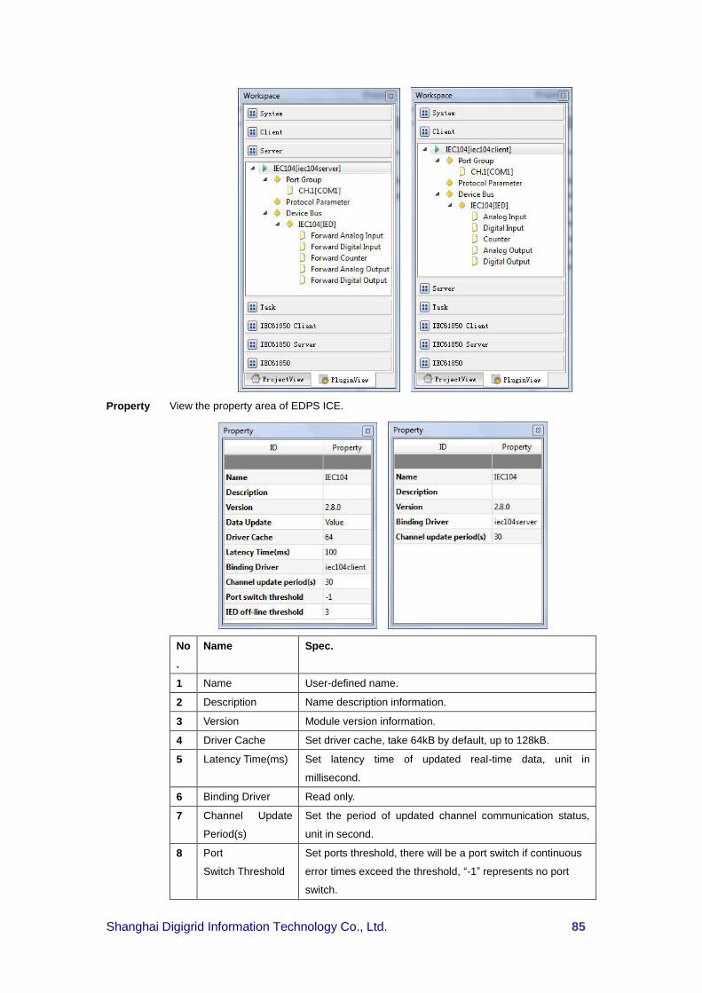
Shanghai Digigrid Information Technology Co., Ltd. 85
Property View the property area of EDPS ICE.
No
.
Name Spec.
1 Name User-defined name.
2 Description Name description information.
3 Version Module version information.
4 Driver Cache Set driver cache, take 64kB by default, up to 128kB.
5 Latency Time(ms) Set latency time of updated real-time data, unit in
millisecond.
6 Binding Driver Read only.
7 Channel Update
Period(s)
Set the period of updated channel communication status,
unit in second.
8 Port
Switch Threshold
Set ports threshold, there will be a port switch if continuous
error times exceed the threshold, “-1” represents no port
switch.
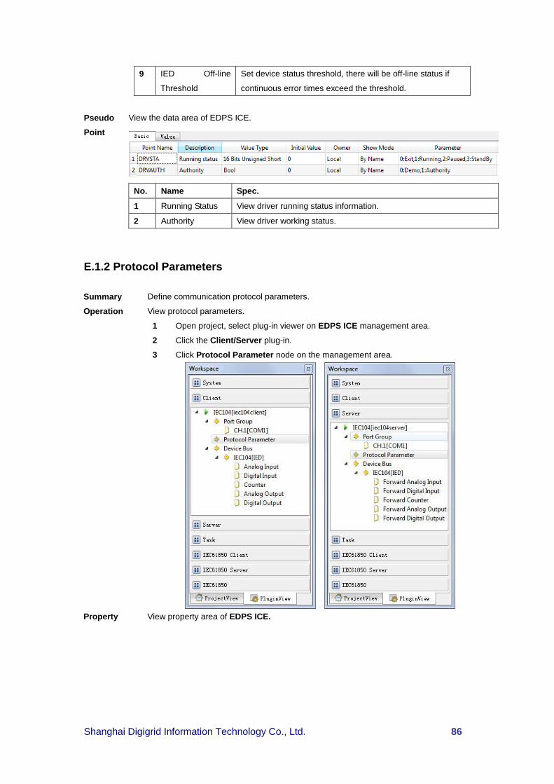
Shanghai Digigrid Information Technology Co., Ltd. 86
9 IED Off-line
Threshold
Set device status threshold, there will be off-line status if
continuous error times exceed the threshold.
Pseudo
Point
View the data area of EDPS ICE.
No. Name Spec.
1 Running Status View driver running status information.
2 Authority View driver working status.
E.1.2 Protocol Parameters
Summary Define communication protocol parameters.
Operation View protocol parameters.
1 Open project, select plug-in viewer on EDPS ICE management area.
2 Click the Client/Server plug-in.
3 Click Protocol Parameter node on the management area.
Property View property area of EDPS ICE.
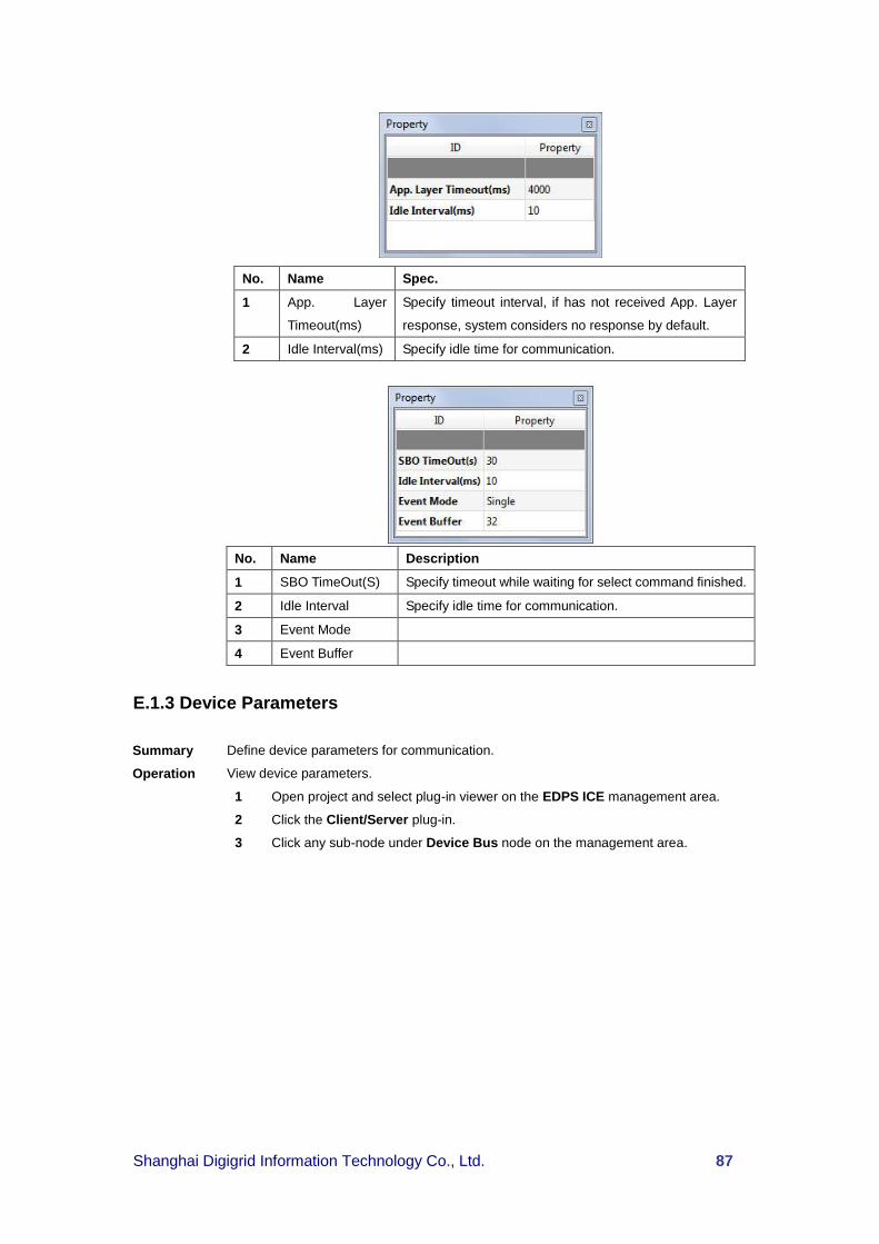
Shanghai Digigrid Information Technology Co., Ltd. 87
No. Name Spec.
1 App. Layer
Timeout(ms)
Specify timeout interval, if has not received App. Layer
response, system considers no response by default.
2 Idle Interval(ms) Specify idle time for communication.
No. Name Description
1 SBO TimeOut(S) Specify timeout while waiting for select command finished.
2 Idle Interval Specify idle time for communication.
3 Event Mode
4 Event Buffer
E.1.3 Device Parameters
Summary Define device parameters for communication.
Operation View device parameters.
1 Open project and select plug-in viewer on the EDPS ICE management area.
2 Click the Client/Server plug-in.
3 Click any sub-node under Device Bus node on the management area.
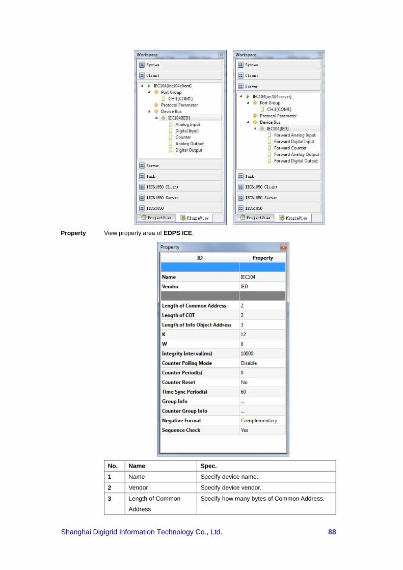
Shanghai Digigrid Information Technology Co., Ltd. 88
Property View property area of EDPS ICE.
No. Name Spec.
1 Name Specify device name.
2 Vendor Specify device vendor.
3 Length of Common
Address
Specify how many bytes of Common Address.
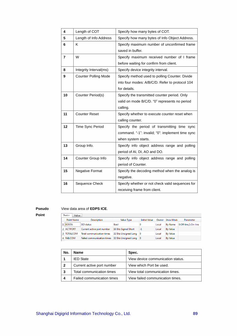
Shanghai Digigrid Information Technology Co., Ltd. 89
4 Length of COT Specify how many bytes of COT.
5 Length of Info Address Specify how many bytes of Info Object Address.
6 K Specify maximum number of unconfirmed frame
saved in buffer.
7 W Specify maximum received number of I frame
before waiting for confirm from client.
8 Integrity Interval(ms) Specify device integrity interval.
9 Counter Polling Mode Specify method used to polling Counter. Divide
into four modes: A/B/C/D. Refer to protocol 104
for details.
10 Counter Period(s) Specify the transmitted counter period. Only
valid on mode B/C/D. “0” represents no period
calling.
11 Counter Reset Specify whether to execute counter reset when
calling counter.
12 Time Sync Period Specify the period of transmitting time sync
command. “-1”: invalid; “0”: implement time sync
when system starts.
13 Group Info. Specify info object address range and polling
period of AI, DI, AO and DO.
14 Counter Group Info Specify info object address range and polling
period of Counter.
15 Negative Format Specify the decoding method when the analog is
negative.
16 Sequence Check Specify whether or not check valid sequences for
receiving frame from client.
Pseudo
Point
View data area of EDPS ICE.
No. Name Spec.
1 IED State View device communication status.
2 Current active port number View which Port be used.
3 Total communication times View total communication times.
4 Failed communication times View failed communication times.
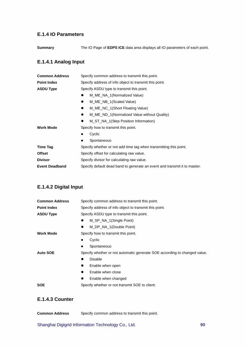
Shanghai Digigrid Information Technology Co., Ltd. 90
E.1.4 IO Parameters
Summary The IO Page of EDPS ICE data area displays all IO parameters of each point.
E.1.4.1 Analog Input
Common Address Specify common address to transmit this point.
Point Index Specify address of info object to transmit this point.
ASDU Type Specify ASDU type to transmit this point.
M_ME_NA_1(Normalized Value)
M_ME_NB_1(Scaled Value)
M_ME_NC_1(Short Floating Value)
M_ME_ND_1(Normalized Value without Quality)
M_ST_NA_1(Step Position Information)
Work Mode Specify how to transmit this point.
Cyclic
Spontaneous
Time Tag Specify whether or not add time tag when transmitting this point.
Offset Specify offset for calculating raw value.
Divisor Specify divisor for calculating raw value.
Event Deadband Specify default dead band to generate an event and transmit it to master.
E.1.4.2 Digital Input
Common Address Specify common address to transmit this point.
Point Index Specify address of info object to transmit this point.
ASDU Type Specify ASDU type to transmit this point.
M_SP_NA_1(Single Point)
M_DP_NA_1(Double Point)
Work Mode Specify how to transmit this point.
Cyclic
Spontaneous
Auto SOE Specify whether or not automatic generate SOE according to changed value.
Disable
Enable when open
Enable when close
Enable when changed
SOE Specify whether or not transmit SOE to client.
E.1.4.3 Counter
Common Address Specify common address to transmit this point.

Shanghai Digigrid Information Technology Co., Ltd. 91
Point Index Specify address of info object to transmit this point.
Min. Value Specify minimum value to calculate current value.
Max. Value Specify maximum value to calculate current value.
Offset Specify offset for calculating the raw value.
Divisor Specify divisor for calculating the raw value.
E.1.4.4 Analog Output
Common Address Specify common address to transmit this point.
Point Index Specify address of info object to transmit this point.
ASDU Type Specify ASDU type to transmit this point.
Normalized Value
Scaled Value
Short Floating Value
Offset Specify offset for calculating the raw value.
Divisor Specify divisor for calculating the raw value.
E.1.4.5 Digital Output
Common Address Specify common address to transmit this point.
Point Index Specify address of info object to transmit this point.
Control Flag Specify control mode for this point.
Direct
SBO
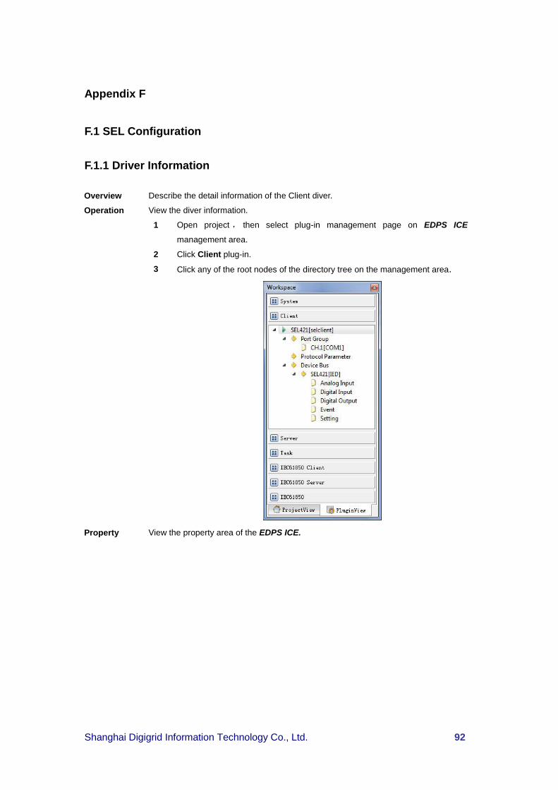
Shanghai Digigrid Information Technology Co., Ltd. 92
Appendix F
F.1 SEL Configuration
F.1.1 Driver Information
Overview Describe the detail information of the Client diver.
Operation View the diver information.
1 Open project , then select plug-in management page on EDPS ICE
management area.
2 Click Client plug-in.
3 Click any of the root nodes of the directory tree on the management area.
Property View the property area of the EDPS ICE.
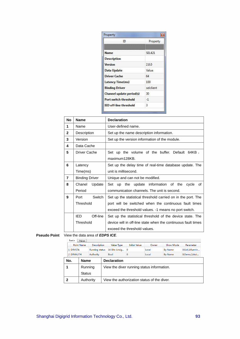
Shanghai Digigrid Information Technology Co., Ltd. 93
No Name Declaration
1 Name User-defined name.
2 Description Set up the name description information.
3 Version Set up the version information of the module.
4 Data Cache
5 Driver Cache Set up the volume of the buffer. Default 64KB ,
maximum128KB.
6 Latency
Time(ms)
Set up the delay time of real-time database update. The
unit is millisecond.
7 Binding Driver Unique and can not be modified.
8 Chanel Update
Period
Set up the update information of the cycle of
communication channels. The unit is second.
9 Port Switch
Threshold
Set up the statistical threshold carried on in the port. The
port will be switched when the continuous fault times
exceed the threshold values. -1 means no port switch.
IED Off-line
Threshold
Set up the statistical threshold of the device state. The
device will in off-line state when the continuous fault times
exceed the threshold values.
Pseudo Point View the data area of EDPS ICE.
No. Name Declaration
1 Running
Status
View the diver running status information.
2 Authority View the authorization status of the diver.
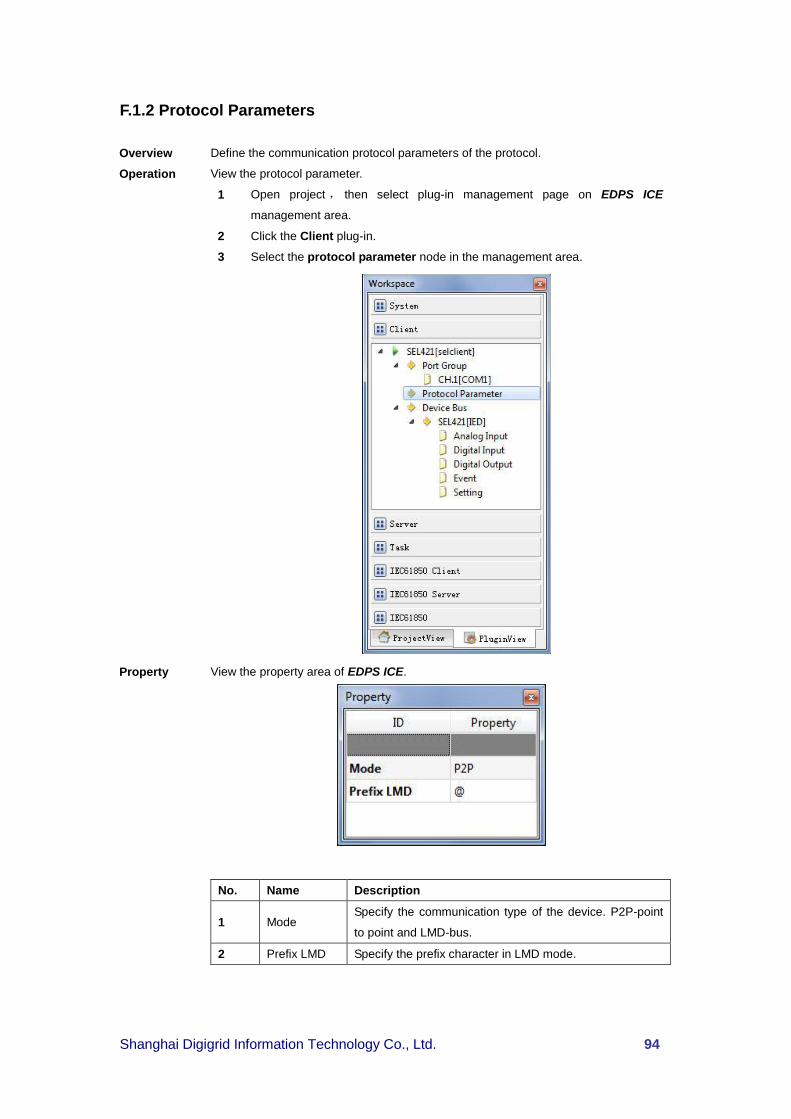
Shanghai Digigrid Information Technology Co., Ltd. 94
F.1.2 Protocol Parameters
Overview Define the communication protocol parameters of the protocol.
Operation View the protocol parameter.
1 Open project , then select plug-in management page on EDPS ICE
management area.
2 Click the Client plug-in.
3 Select the protocol parameter node in the management area.
Property View the property area of EDPS ICE.
No. Name Description
1 Mode Specify the communication type of the device. P2P-point
to point and LMD-bus.
2 Prefix LMD Specify the prefix character in LMD mode.
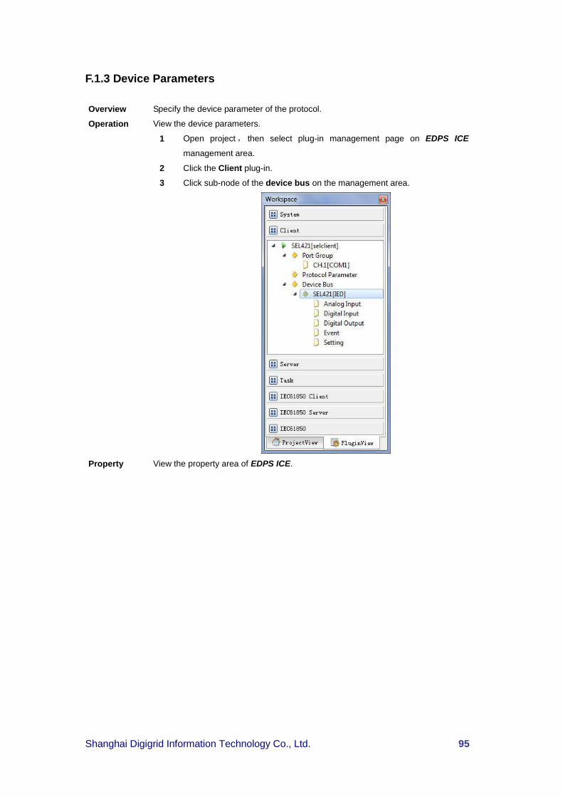
Shanghai Digigrid Information Technology Co., Ltd. 95
F.1.3 Device Parameters
Overview Specify the device parameter of the protocol.
Operation View the device parameters.
1 Open project , then select plug-in management page on EDPS ICE
management area.
2 Click the Client plug-in.
3 Click sub-node of the device bus on the management area.
Property View the property area of EDPS ICE.
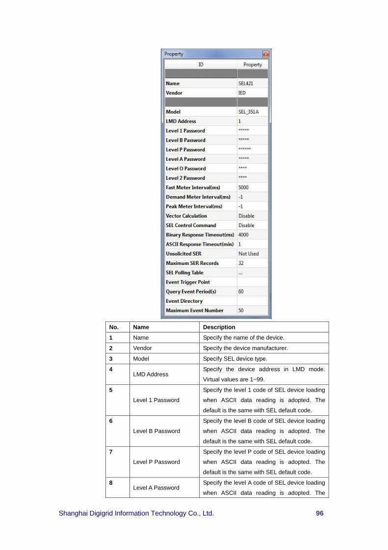
Shanghai Digigrid Information Technology Co., Ltd. 96
No. Name Description
1 Name Specify the name of the device.
2 Vendor Specify the device manufacturer.
3 Model Specify SEL device type.
4 LMD Address
Specify the device address in LMD mode.
Virtual values are 1~99.
5
Level 1 Password
Specify the level 1 code of SEL device loading
when ASCII data reading is adopted. The
default is the same with SEL default code.
6
Level B Password
Specify the level B code of SEL device loading
when ASCII data reading is adopted. The
default is the same with SEL default code.
7
Level P Password
Specify the level P code of SEL device loading
when ASCII data reading is adopted. The
default is the same with SEL default code.
8 Level A Password
Specify the level A code of SEL device loading
when ASCII data reading is adopted. The
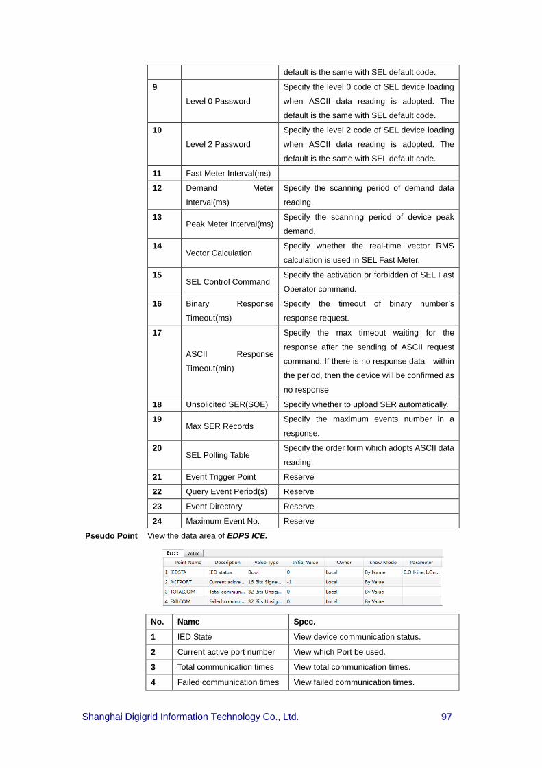
Shanghai Digigrid Information Technology Co., Ltd. 97
default is the same with SEL default code.
9
Level 0 Password
Specify the level 0 code of SEL device loading
when ASCII data reading is adopted. The
default is the same with SEL default code.
10
Level 2 Password
Specify the level 2 code of SEL device loading
when ASCII data reading is adopted. The
default is the same with SEL default code.
11 Fast Meter Interval(ms)
12 Demand Meter
Interval(ms)
Specify the scanning period of demand data
reading.
13 Peak Meter Interval(ms)
Specify the scanning period of device peak
demand.
14 Vector Calculation
Specify whether the real-time vector RMS
calculation is used in SEL Fast Meter.
15 SEL Control Command
Specify the activation or forbidden of SEL Fast
Operator command.
16 Binary Response
Timeout(ms)
Specify the timeout of binary number’s
response request.
17
ASCII Response
Timeout(min)
Specify the max timeout waiting for the
response after the sending of ASCII request
command. If there is no response data within
the period, then the device will be confirmed as
no response
18 Unsolicited SER(SOE) Specify whether to upload SER automatically.
19 Max SER Records
Specify the maximum events number in a
response.
20 SEL Polling Table
Specify the order form which adopts ASCII data
reading.
21 Event Trigger Point Reserve
22 Query Event Period(s) Reserve
23 Event Directory Reserve
24 Maximum Event No. Reserve
Pseudo Point View the data area of EDPS ICE.
No. Name Spec.
1 IED State View device communication status.
2 Current active port number View which Port be used.
3 Total communication times View total communication times.
4 Failed communication times View failed communication times.
Shanghai Digigrid Information Technology Co., Ltd. 98
F.1.4 IO Parameters
Summary The IO Page of EDPS ICE data area displays all IO parameters of each point.
F.1.4.1 Analog Input
Point No. Specify the point number of the information point.
Row No. Specify the row number of the data which resulted from the ASCII command.
Line No. Specify the line number of the data which resulted from the ASCII command.
ASCII Command Specify the command ID associated with the index point.
F.1.4.2 Status Input
Point No. Specify the point number of the information point.
Associated SER
Point
Specify the associated SER point number of the information point.
Row No. Specify the row number of the data which resulted from the ASCII command.
Line No. Specify the line number of the data which resulted from the ASCII command.
ASCII Command Specify the command ID associated with the index point.
F.1.4.3 Status Output
Point No. Specify the point number of the information point.
Control Times Specify the control time of the information point.
Close Time Specify the lasting output time of the Close.
Trip Time Specify the lasting output time of the Trip.
F.1.4.4 Events
SEL Flag Specify flag bit of status.
F.1.4.5 Setting Values
Row No. Specify the row number of the data which resulted from the ASCII command.
Line No. Specify the line number of the data which resulted from the ASCII command.
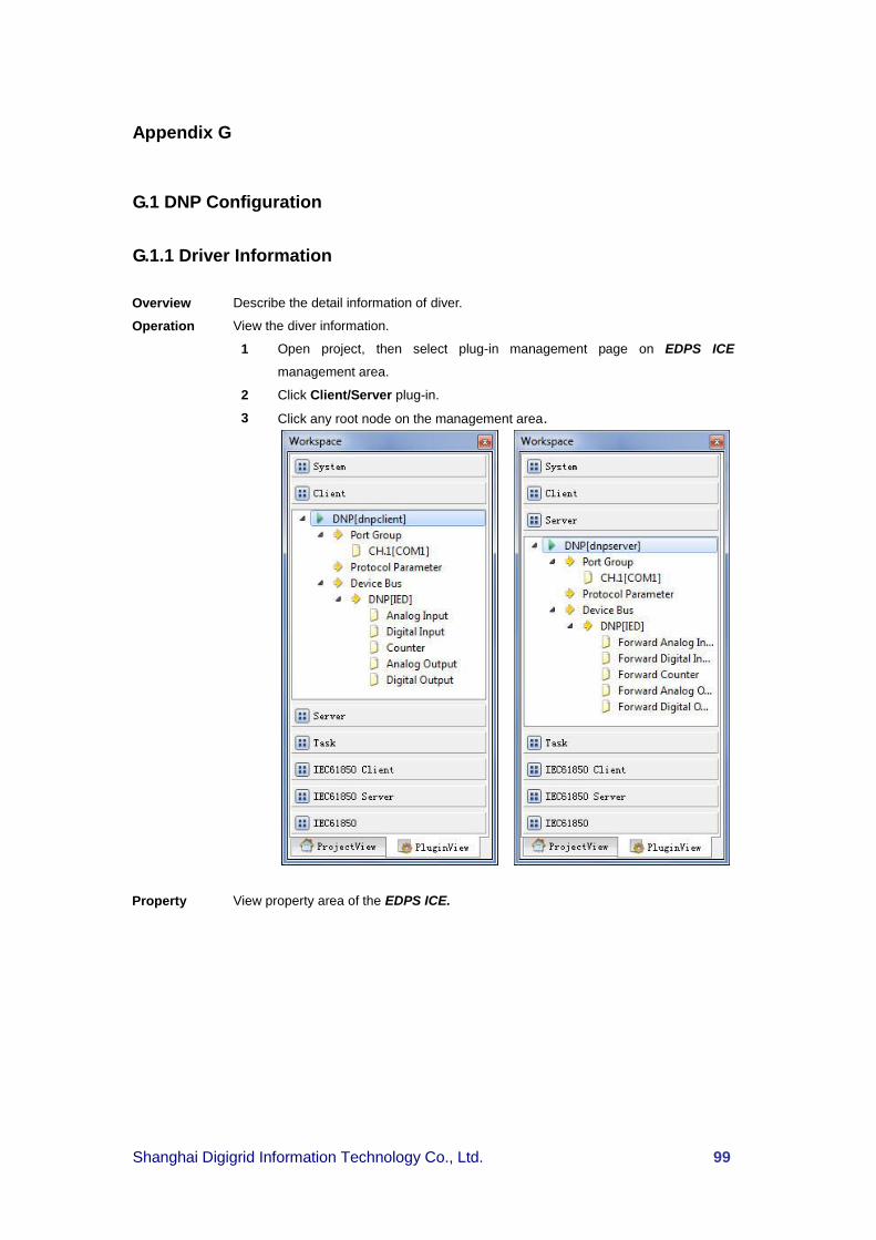
Shanghai Digigrid Information Technology Co., Ltd. 99
Appendix G
G.1 DNP Configuration
G.1.1 Driver Information
Overview Describe the detail information of diver.
Operation View the diver information.
1 Open project, then select plug-in management page on EDPS ICE
management area.
2 Click Client/Server plug-in.
3 Click any root node on the management area.
Property View property area of the EDPS ICE.
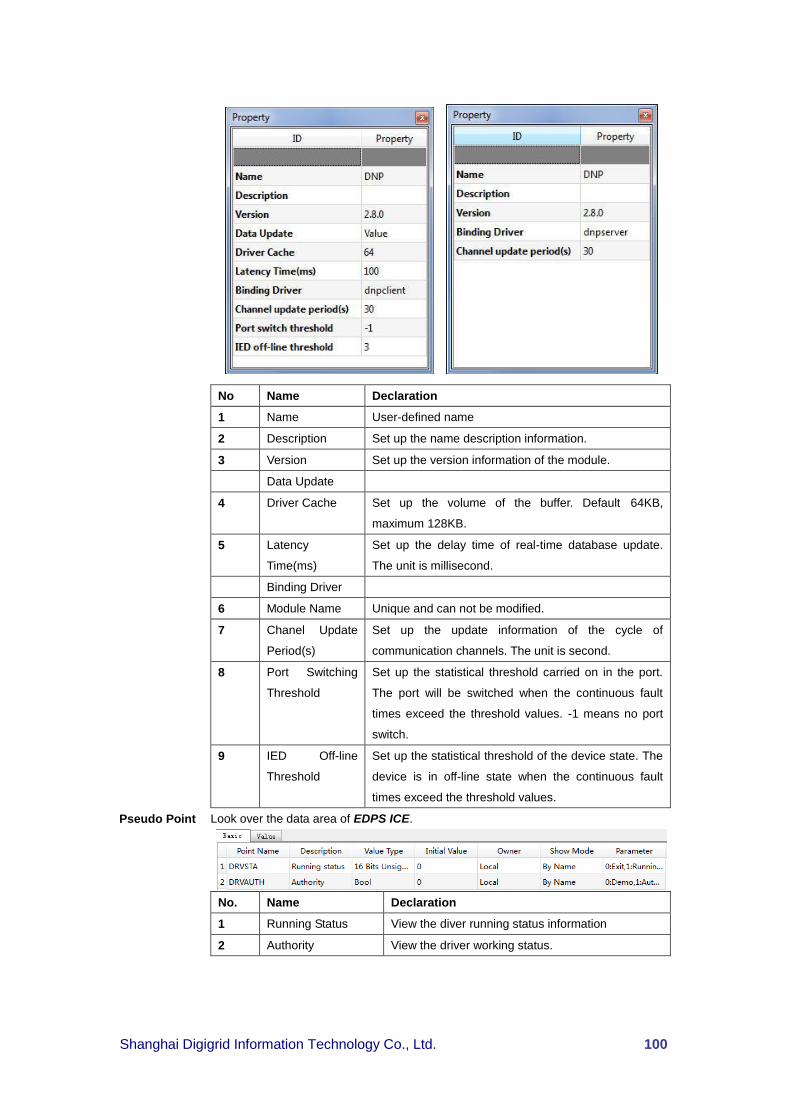
Shanghai Digigrid Information Technology Co., Ltd. 100
No Name Declaration
1 Name User-defined name
2 Description Set up the name description information.
3 Version Set up the version information of the module.
Data Update
4 Driver Cache Set up the volume of the buffer. Default 64KB,
maximum 128KB.
5 Latency
Time(ms)
Set up the delay time of real-time database update.
The unit is millisecond.
Binding Driver
6 Module Name Unique and can not be modified.
7 Chanel Update
Period(s)
Set up the update information of the cycle of
communication channels. The unit is second.
8 Port Switching
Threshold
Set up the statistical threshold carried on in the port.
The port will be switched when the continuous fault
times exceed the threshold values. -1 means no port
switch.
9 IED Off-line
Threshold
Set up the statistical threshold of the device state. The
device is in off-line state when the continuous fault
times exceed the threshold values.
Pseudo Point Look over the data area of EDPS ICE.
No. Name Declaration
1 Running Status View the diver running status information
2 Authority View the driver working status.
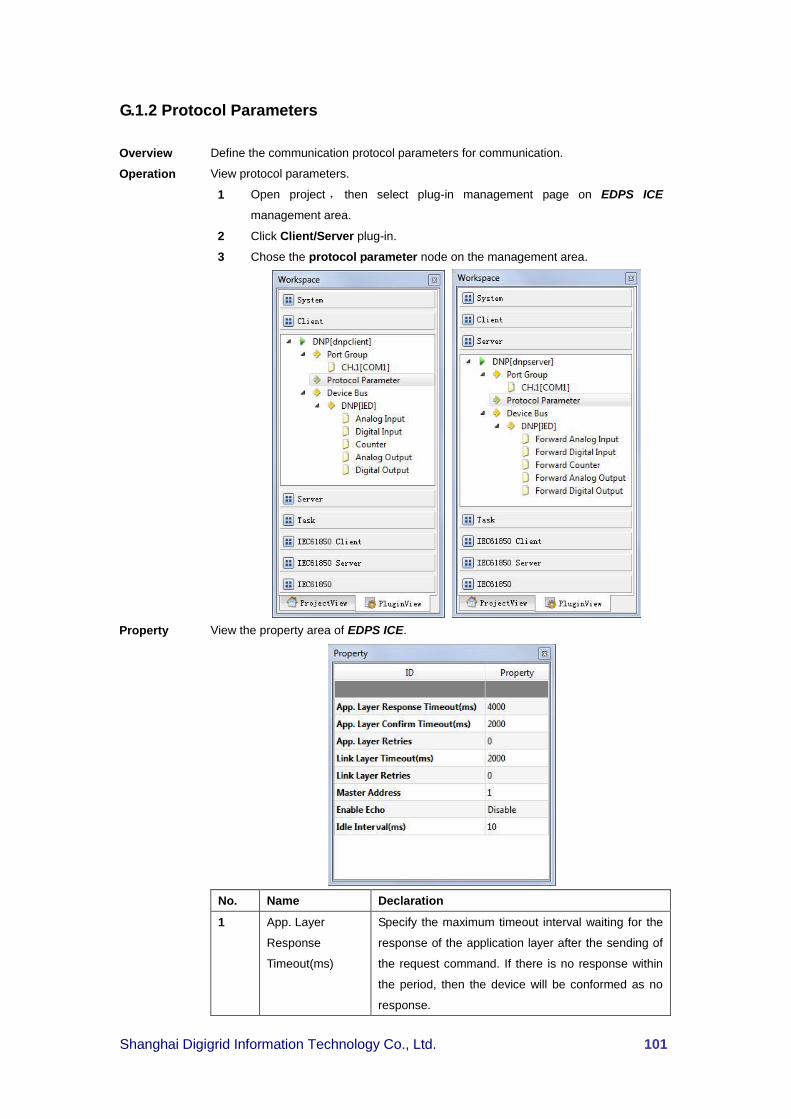
Shanghai Digigrid Information Technology Co., Ltd. 101
G.1.2 Protocol Parameters
Overview Define the communication protocol parameters for communication.
Operation View protocol parameters.
1 Open project , then select plug-in management page on EDPS ICE
management area.
2 Click Client/Server plug-in.
3 Chose the protocol parameter node on the management area.
Property View the property area of EDPS ICE.
No. Name Declaration
1 App. Layer
Response
Timeout(ms)
Specify the maximum timeout interval waiting for the
response of the application layer after the sending of
the request command. If there is no response within
the period, then the device will be conformed as no
response.
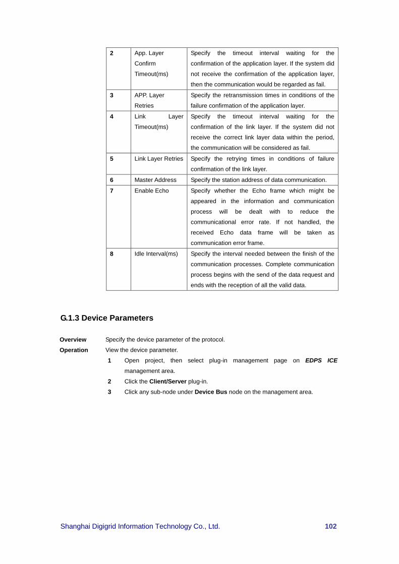
Shanghai Digigrid Information Technology Co., Ltd. 102
2 App. Layer
Confirm
Timeout(ms)
Specify the timeout interval waiting for the
confirmation of the application layer. If the system did
not receive the confirmation of the application layer,
then the communication would be regarded as fail.
3 APP. Layer
Retries
Specify the retransmission times in conditions of the
failure confirmation of the application layer.
4 Link Layer
Timeout(ms)
Specify the timeout interval waiting for the
confirmation of the link layer. If the system did not
receive the correct link layer data within the period,
the communication will be considered as fail.
5 Link Layer Retries Specify the retrying times in conditions of failure
confirmation of the link layer.
6 Master Address Specify the station address of data communication.
7 Enable Echo Specify whether the Echo frame which might be
appeared in the information and communication
process will be dealt with to reduce the
communicational error rate. If not handled, the
received Echo data frame will be taken as
communication error frame.
8 Idle Interval(ms) Specify the interval needed between the finish of the
communication processes. Complete communication
process begins with the send of the data request and
ends with the reception of all the valid data.
G.1.3 Device Parameters
Overview Specify the device parameter of the protocol.
Operation View the device parameter.
1 Open project, then select plug-in management page on EDPS ICE
management area.
2 Click the Client/Server plug-in.
3 Click any sub-node under Device Bus node on the management area.
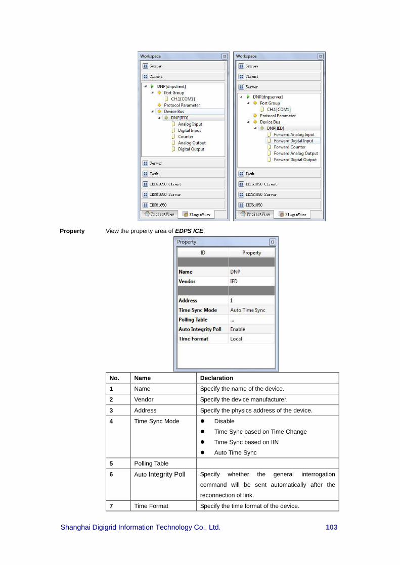
Shanghai Digigrid Information Technology Co., Ltd. 103
Property View the property area of EDPS ICE.
No. Name Declaration
1 Name Specify the name of the device.
2 Vendor Specify the device manufacturer.
3 Address Specify the physics address of the device.
4 Time Sync Mode Disable
Time Sync based on Time Change
Time Sync based on IIN
Auto Time Sync
5 Polling Table
6 Auto Integrity Poll Specify whether the general interrogation
command will be sent automatically after the
reconnection of link.
7 Time Format Specify the time format of the device.
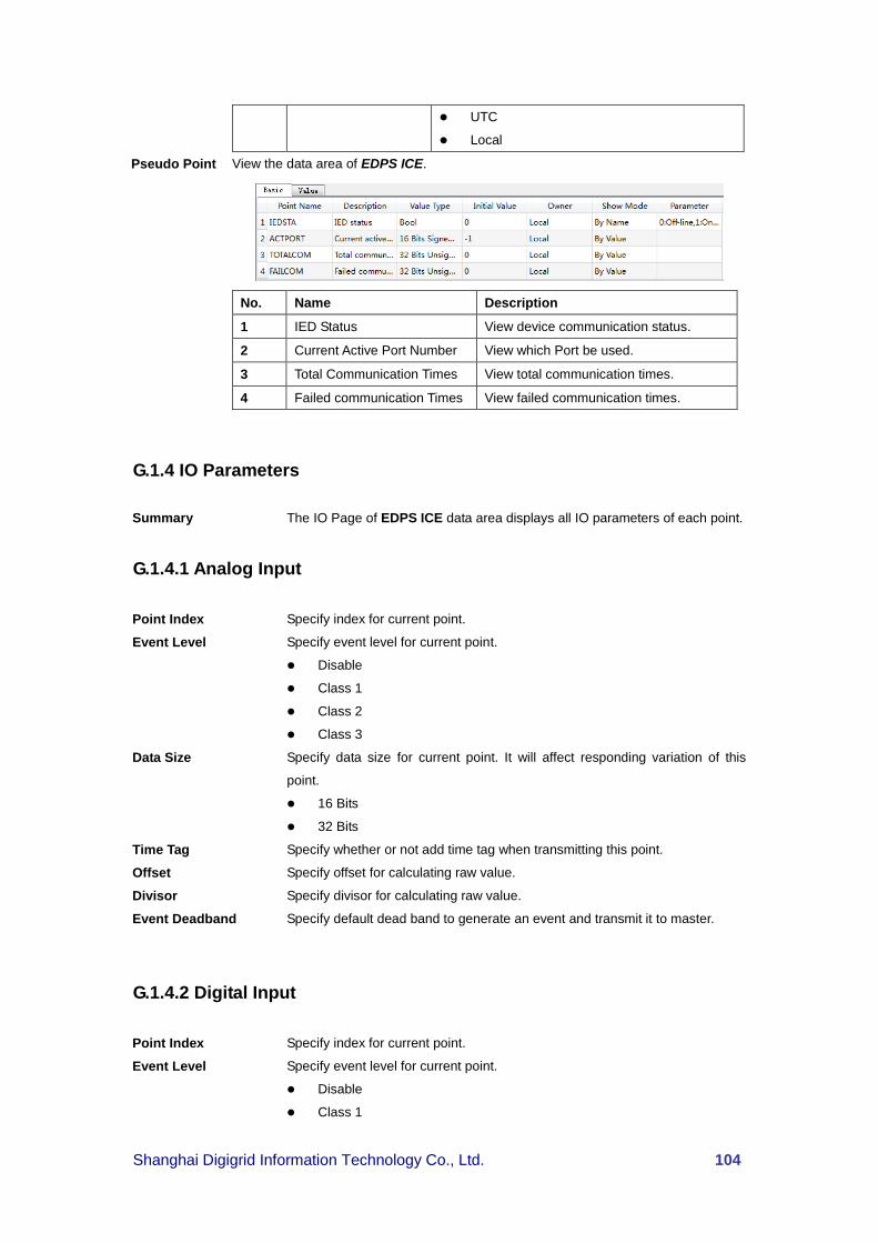
Shanghai Digigrid Information Technology Co., Ltd. 104
UTC
Local
Pseudo Point View the data area of EDPS ICE.
No. Name Description
1 IED Status View device communication status.
2 Current Active Port Number View which Port be used.
3 Total Communication Times View total communication times.
4 Failed communication Times View failed communication times.
G.1.4 IO Parameters
Summary The IO Page of EDPS ICE data area displays all IO parameters of each point.
G.1.4.1 Analog Input
Point Index Specify index for current point.
Event Level Specify event level for current point.
Disable
Class 1
Class 2
Class 3
Data Size Specify data size for current point. It will affect responding variation of this
point.
16 Bits
32 Bits
Time Tag Specify whether or not add time tag when transmitting this point.
Offset Specify offset for calculating raw value.
Divisor Specify divisor for calculating raw value.
Event Deadband Specify default dead band to generate an event and transmit it to master.
G.1.4.2 Digital Input
Point Index Specify index for current point.
Event Level Specify event level for current point.
Disable
Class 1

Shanghai Digigrid Information Technology Co., Ltd. 105
Class 2
Class 3
Auto SOE Specify whether or not automatic generate SOE according to changed value.
Disable
Enable when open
Enable when close
Enable when changed
SOE Specify whether or not transmit SOE to client.
G.1.4.3 Counter
Point Index Specify index for current point.
Event Level Specify event level for current point.
Disable
Class 1
Class 2
Class 3
Data Type Specify data type for current point.
Binary Counter
Frozen Counter
Data Size Specify data size for current point. It will affect responding variation of this
point.
16 Bits
32 Bits
Min. Value Specify minimum value to calculate current value.
Max. Value Specify maximum value to calculate current value.
Offset Specify offset for calculating the raw value.
Divisor Specify divisor for calculating the raw value.
Event Deadband Specify default dead band to generate an event and transmit it to master.
G.1.4.4 Analog Output
Point Index Specify index for current point.
Data Size Specify data size for current point. It will affect responding variation of this
point.
16 Bits
32 Bits
Offset Specify offset for calculating the raw value.
Divisor Specify divisor for calculating the raw value.
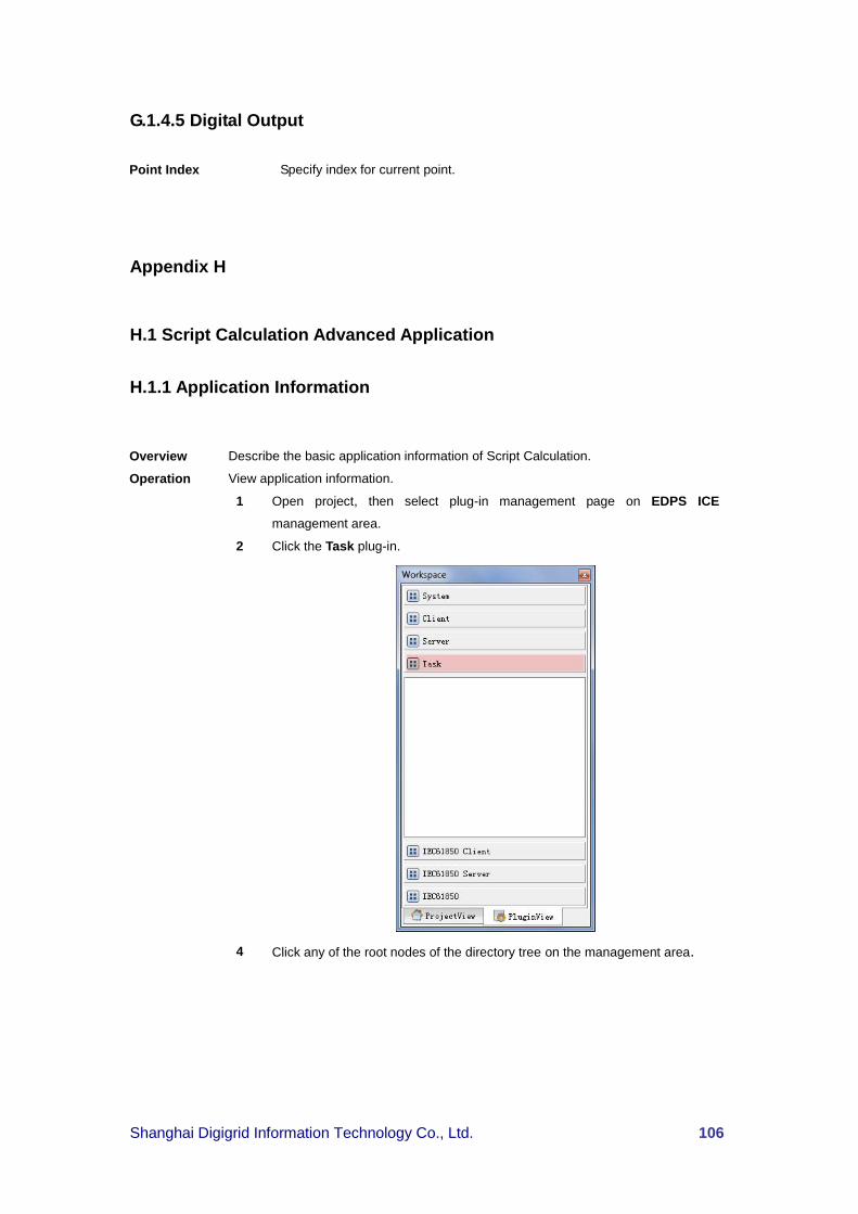
Shanghai Digigrid Information Technology Co., Ltd. 106
G.1.4.5 Digital Output
Point Index Specify index for current point.
I
Appendix H
H.1 Script Calculation Advanced Application
H.1.1 Application Information
Overview Describe the basic application information of Script Calculation.
Operation View application information.
1 Open project, then select plug-in management page on EDPS ICE
management area.
2 Click the Task plug-in.
4 Click any of the root nodes of the directory tree on the management area.
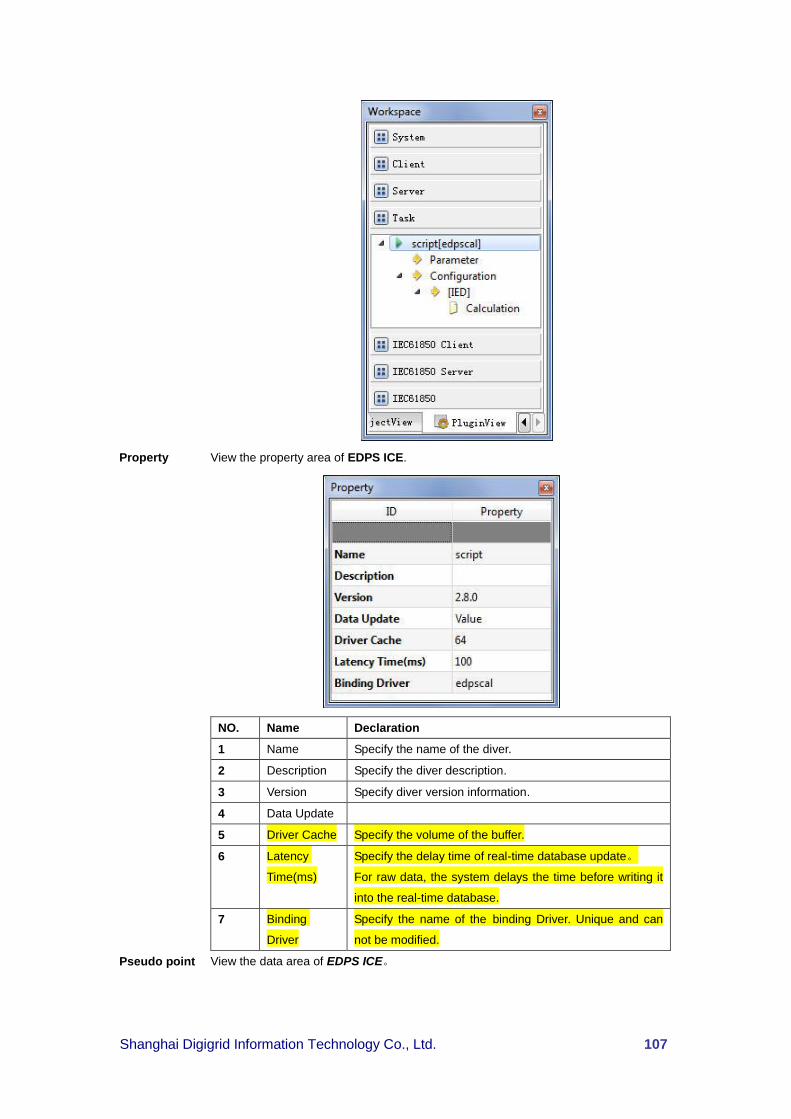
Shanghai Digigrid Information Technology Co., Ltd. 107
Property View the property area of EDPS ICE.
NO. Name Declaration
1 Name Specify the name of the diver.
2 Description Specify the diver description.
3 Version Specify diver version information.
4 Data Update
5 Driver Cache Specify the volume of the buffer.
6 Latency
Time(ms)
Specify the delay time of real-time database update。
For raw data, the system delays the time before writing it
into the real-time database.
7 Binding
Driver
Specify the name of the binding Driver. Unique and can
not be modified.
Pseudo point View the data area of EDPS ICE。
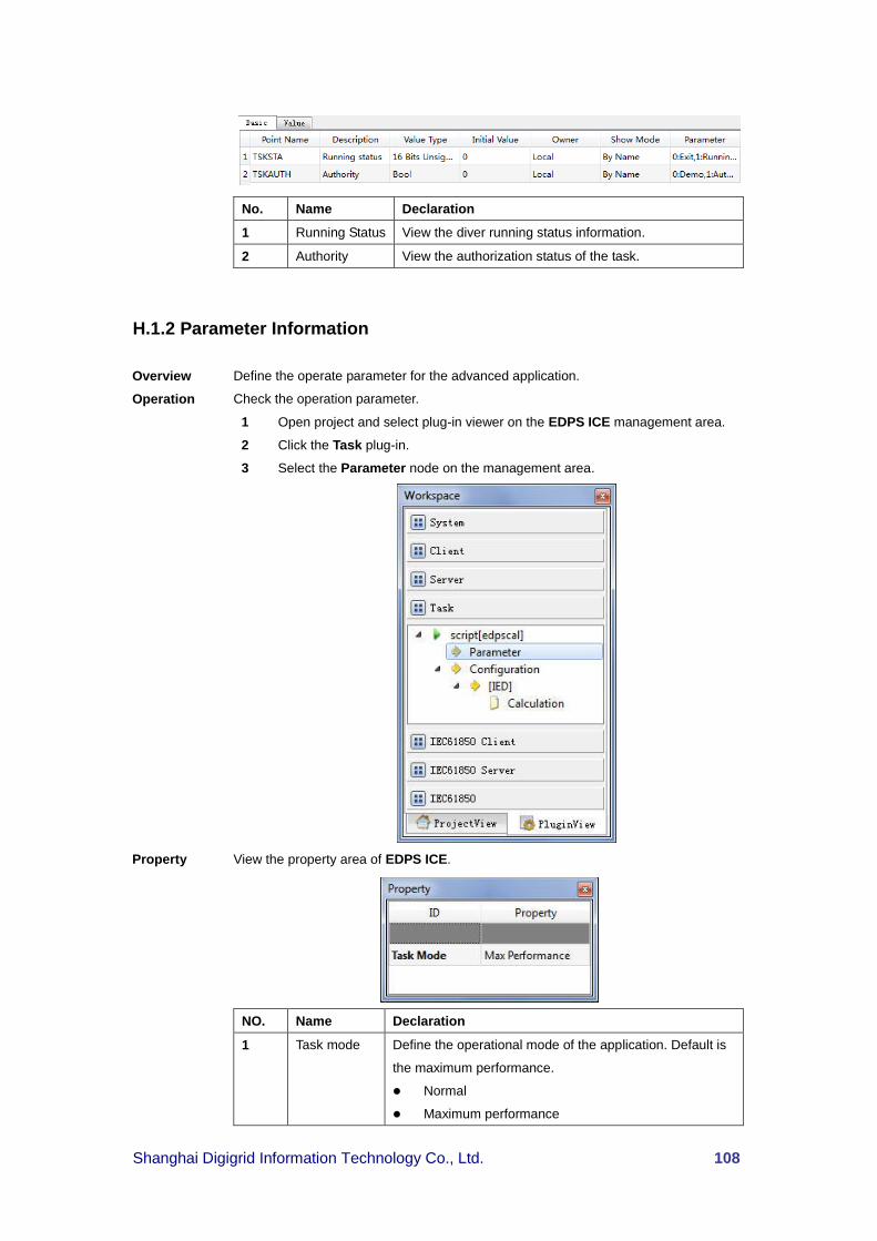
Shanghai Digigrid Information Technology Co., Ltd. 108
No. Name Declaration
1 Running Status View the diver running status information.
2 Authority View the authorization status of the task.
H.1.2 Parameter Information
Overview Define the operate parameter for the advanced application.
Operation Check the operation parameter.
1 Open project and select plug-in viewer on the EDPS ICE management area.
2 Click the Task plug-in.
3 Select the Parameter node on the management area.
Property View the property area of EDPS ICE.
NO. Name Declaration
1 Task mode Define the operational mode of the application. Default is
the maximum performance.
Normal
Maximum performance
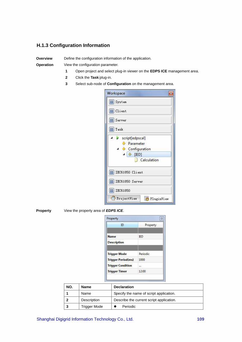
Shanghai Digigrid Information Technology Co., Ltd. 109
H.1.3 Configuration Information
Overview Define the configuration information of the application.
Operation View the configuration parameter.
1 Open project and select plug-in viewer on the EDPS ICE management area.
2 Click the Task plug-in.
3 Select sub-node of Configuration on the management area.
Property View the property area of EDPS ICE.
NO. Name Declaration
1 Name Specify the name of script application.
2 Description Describe the current script application.
3 Trigger Mode Periodic
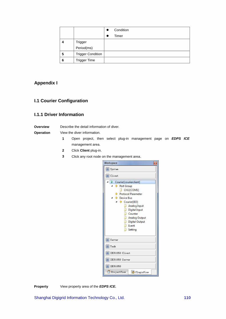
Shanghai Digigrid Information Technology Co., Ltd. 110
Condition
Timer
4 Trigger
Period(ms)
5 Trigger Condition
6 Trigger Time
Appendix I
I.1 Courier Configuration
I.1.1 Driver Information
Overview Describe the detail information of diver.
Operation View the diver information.
1 Open project, then select plug-in management page on EDPS ICE
management area.
2 Click Client plug-in.
3 Click any root node on the management area.
Property View property area of the EDPS ICE.
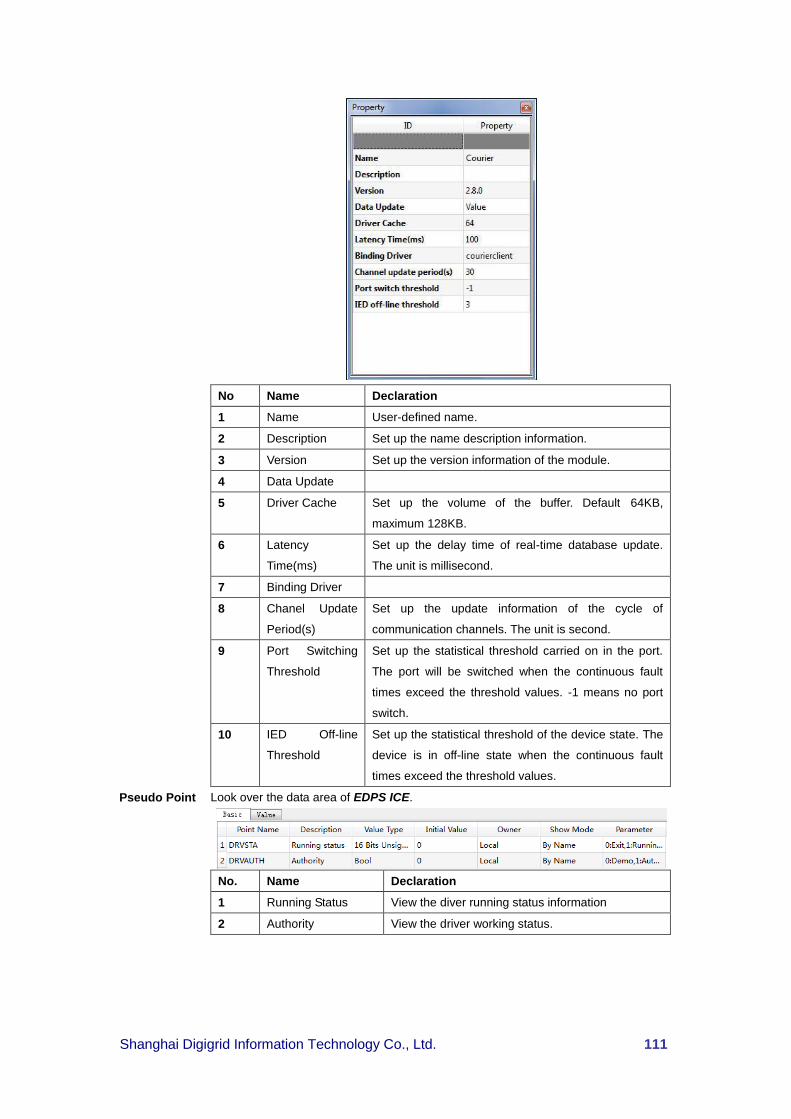
Shanghai Digigrid Information Technology Co., Ltd. 111
No Name Declaration
1 Name User-defined name.
2 Description Set up the name description information.
3 Version Set up the version information of the module.
4 Data Update
5 Driver Cache Set up the volume of the buffer. Default 64KB,
maximum 128KB.
6 Latency
Time(ms)
Set up the delay time of real-time database update.
The unit is millisecond.
7 Binding Driver
8 Chanel Update
Period(s)
Set up the update information of the cycle of
communication channels. The unit is second.
9 Port Switching
Threshold
Set up the statistical threshold carried on in the port.
The port will be switched when the continuous fault
times exceed the threshold values. -1 means no port
switch.
10 IED Off-line
Threshold
Set up the statistical threshold of the device state. The
device is in off-line state when the continuous fault
times exceed the threshold values.
Pseudo Point Look over the data area of EDPS ICE.
No. Name Declaration
1 Running Status View the diver running status information
2 Authority View the driver working status.
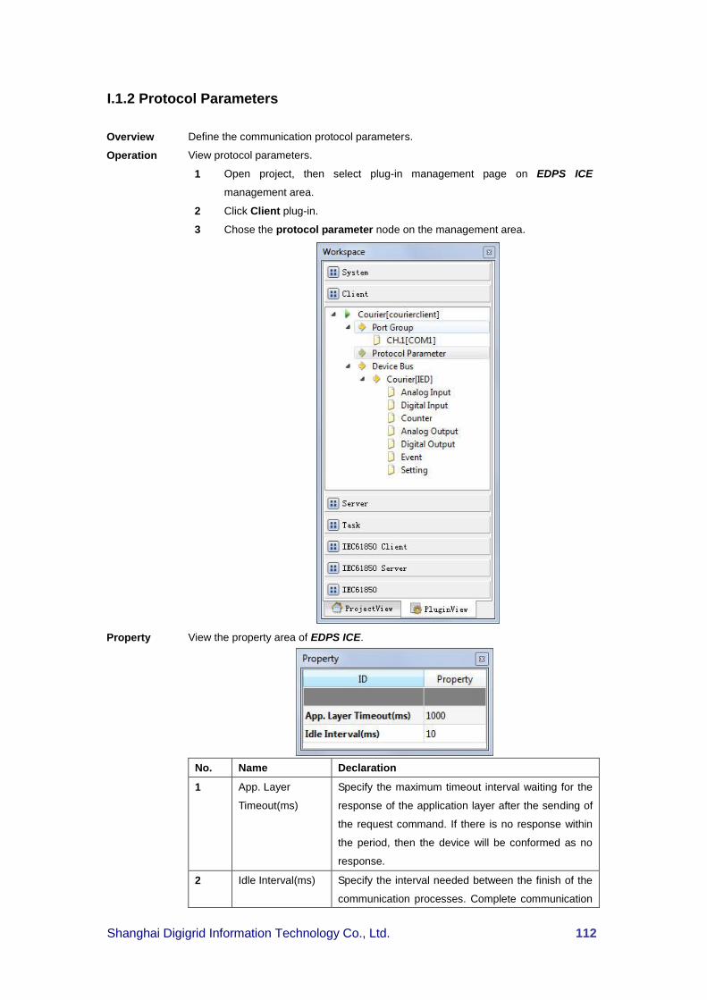
Shanghai Digigrid Information Technology Co., Ltd. 112
I.1.2 Protocol Parameters
Overview Define the communication protocol parameters.
Operation View protocol parameters.
1 Open project, then select plug-in management page on EDPS ICE
management area.
2 Click Client plug-in.
3 Chose the protocol parameter node on the management area.
Property View the property area of EDPS ICE.
No. Name Declaration
1 App. Layer
Timeout(ms)
Specify the maximum timeout interval waiting for the
response of the application layer after the sending of
the request command. If there is no response within
the period, then the device will be conformed as no
response.
2 Idle Interval(ms) Specify the interval needed between the finish of the
communication processes. Complete communication
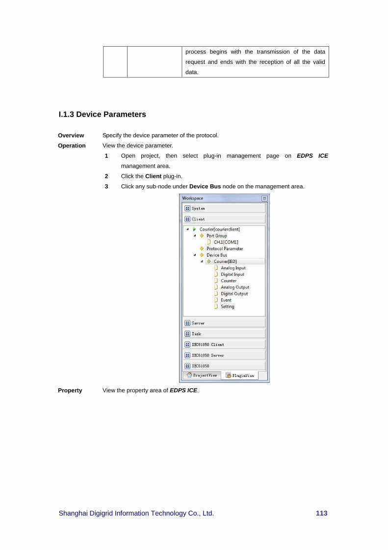
Shanghai Digigrid Information Technology Co., Ltd. 113
process begins with the transmission of the data
request and ends with the reception of all the valid
data.
I.1.3 Device Parameters
Overview Specify the device parameter of the protocol.
Operation View the device parameter.
1 Open project, then select plug-in management page on EDPS ICE
management area.
2 Click the Client plug-in.
3 Click any sub-node under Device Bus node on the management area.
Property View the property area of EDPS ICE.
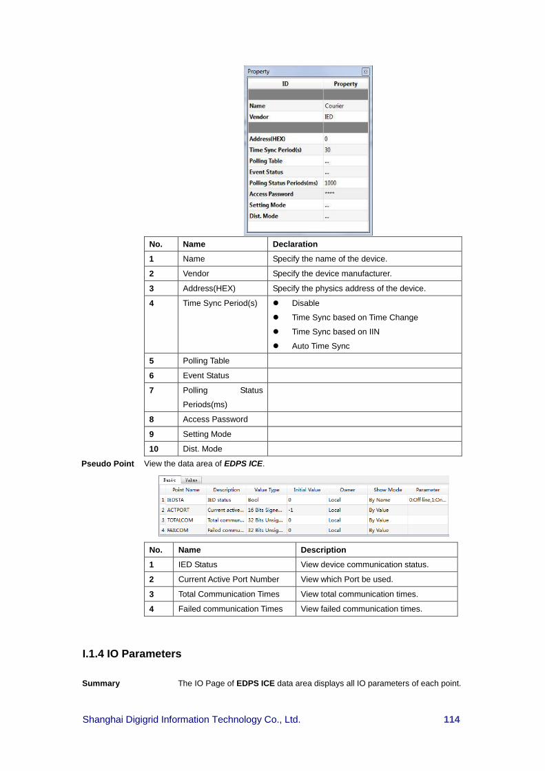
Shanghai Digigrid Information Technology Co., Ltd. 114
No. Name Declaration
1 Name Specify the name of the device.
2 Vendor Specify the device manufacturer.
3 Address(HEX) Specify the physics address of the device.
4 Time Sync Period(s) Disable
Time Sync based on Time Change
Time Sync based on IIN
Auto Time Sync
5 Polling Table
6 Event Status
7 Polling Status
Periods(ms)
8 Access Password
9 Setting Mode
10 Dist. Mode
Pseudo Point View the data area of EDPS ICE.
No. Name Description
1 IED Status View device communication status.
2 Current Active Port Number View which Port be used.
3 Total Communication Times View total communication times.
4 Failed communication Times View failed communication times.
I.1.4 IO Parameters
Summary The IO Page of EDPS ICE data area displays all IO parameters of each point.

Shanghai Digigrid Information Technology Co., Ltd. 115
I.1.4.1 Analog Input
Row No Specify the specific row number.
Col No Specify the specific column number.
I.1.4.2 Digital Input
Row No Specify the specific row number.
Col No Specify the specific column number.
Position Specify the specific offset in the byte.
I.1.4.3 Counter
Row No Specify the specific row number.
Col No Specify the specific column number.
I.1.4.4 Analog Output
Row No Specify the specific row number.
Col No Specify the specific column number.
Position Specify the specific offset in the byte.
I.1.4.5 Digital Output
Row No Specify the specific row number.
Col No Specify the specific column number.
I.1.4.6 Event
Row No Specify the specific row number.
Col No Specify the specific column number.
I.1.4.7 Setting
Row No Specify the specific row number.
Col No Specify the specific column number.

Shanghai Digigrid Information Technology Co., Ltd. 116