m. preventive maintenance for vehicle
TRANSCRIPT

GAMME TAPREVENTIVE MAINTENANCE FOR VEHICLE TRANSPORT EQUIPMENT DOCT00043C
M.
PREVENTIVE MAINTENANCE FOR VEHICLE TRANSPORT EQUIPMENT
Applicability : EHR-MHR-MXR-SHR-CHR-SRTC-IHR-TA
Adresse postalePost-AdressePostal Adress
29 rue du 14 Juillet - Bp1 - HANGENBIETEN67838 TANNERIES CEDEX - FranceTel. +33 (0)3 88 38 98 00Fax +33 (0)3 88 96 06 36E-mail : [email protected]
M - -1Applicability : EHR-MHR-MXR-SHR-CHR-SRTC-IHR-TA© LOHR 2008 - 01/2013

GAMME TAPREVENTIVE MAINTENANCE FOR VEHICLE TRANSPORT EQUIPMENT DOCT00043C
WARNING
This document summarizes preventive maintenance operations for all LOHR vehicle transport equipment.
V0 basic maintenance operations described in this document can be performed by the driver and do not require any special skills.
V1 and V2 preventive maintenance operations described in this document must be performed by qualified personnel using appropriatetools.
More important, V3 to V6 maintenance operations or repairs must be performed by a workshop or personnel approved by LOHR INDUSTRIE.
The operations described in this brochure are to be performed as needed, depending on the components of your equipment. It is importantto follow this maintenance schedule to guarantee safety and reliability.
SYMBOLS USED
this symbol indicates the operation to be performed by the operator.
THIS SYMBOL INDICATES A SPECIFIC DANGER. This symbol indicates a comment.
This symbol operation to be performed operat. This symbol indicates a or a torque. This symbol indicates a value.
M - 0Applicability : EHR-MHR-MXR-SHR-CHR-SRTC-IHR-TA© LOHR 2008 - 01/2013

GAMME TADOCT00043C
SUMMARY
M. PREVENTIVE MAINTENANCE FOR VEHICLE TRANSPORTEQUIPMENT
1. MAINTENANCE SCHEDULE . . . . . . . . . . . . . . . . . . . . . . . . . . . . . . . . . . . . M - 3
1.1. Levels of intervention . . . . . . . . . . . . . . . . . . . . . . . . . . . . . . . . . . . . . . . . . . . . . . . M - 3
M. PREVENTIVE MAINTENANCE FOR VEHICLE TRANSPORTEQUIPMENT
1.2. .Periodicity . . . . . . . . . . . . . . . . . . . . . . . . . . . . . . . . . . . . . . . . . . . . . . . . . . . . . . . . M - 4
1.3. Summary of maintenance operations . . . . . . . . . . . . . . . . . . . . . . . . . . . . . . . . . . M - 5
2. WASHING . . . . . . . . . . . . . . . . . . . . . . . . . . . . . . . . . . . . . . . . . . . . . . . . . . M - 10
2.1. Washing the bodywork . . . . . . . . . . . . . . . . . . . . . . . . . . . . . . . . . . . . . . . . . . . . . M - 10
3. GREASING . . . . . . . . . . . . . . . . . . . . . . . . . . . . . . . . . . . . . . . . . . . . . . . . . M - 11
3.1. Lubricating the equipment . . . . . . . . . . . . . . . . . . . . . . . . . . . . . . . . . . . . . . . . . . M - 11
3.2. Greasing symbols . . . . . . . . . . . . . . . . . . . . . . . . . . . . . . . . . . . . . . . . . . . . . . . . . M - 11
3.3. Running gear . . . . . . . . . . . . . . . . . . . . . . . . . . . . . . . . . . . . . . . . . . . . . . . . . . . . . M - 12
3.4. Screw lifting system . . . . . . . . . . . . . . . . . . . . . . . . . . . . . . . . . . . . . . . . . . . . . . . M - 13
3.4.1. Lubricating the screws . . . . . . . . . . . . . . . . . . . . . . . . . . . . . . . . . . . . . . . . . . . . M - 13
3.4.2. Check the level of lifting screw mechanisms . . . . . . . . . . . . . . . . . . . . . . . . . . M - 13
3.5. Cable lifting system. . . . . . . . . . . . . . . . . . . . . . . . . . . . . . . . . . . . . . . . . . . . . . . . M - 14
3.5.1. Checking cable wear on cable lifting . . . . . . . . . . . . . . . . . . . . . . . . . . . . . . . . . M - 14
3.5.2. Lubrication . . . . . . . . . . . . . . . . . . . . . . . . . . . . . . . . . . . . . . . . . . . . . . . . . . . . . . M - 14
3.6. Servicing the hydraulic jack rods . . . . . . . . . . . . . . . . . . . . . . . . . . . . . . . . . . . . M - 15
3.7. Rig with friction discs. . . . . . . . . . . . . . . . . . . . . . . . . . . . . . . . . . . . . . . . . . . . . . M - 16
3.8. Centralized lubrication (option). . . . . . . . . . . . . . . . . . . . . . . . . . . . . . . . . . . . . . M - 17
3.8.1. Filling . . . . . . . . . . . . . . . . . . . . . . . . . . . . . . . . . . . . . . . . . . . . . . . . . . . . . . . . . . M - 17
3.9. Check connection anti-corrosion . . . . . . . . . . . . . . . . . . . . . . . . . . . . . . . . . . . . M - 18
3.10. Table of recommended lubricants . . . . . . . . . . . . . . . . . . . . . . . . . . . . . . . . . . . M - 20
4. TIGHTNESS OF SAFETY ELEMENTS . . . . . . . . . . . . . . . . . . . . . . . . . . . M - 21
4.1. Couplings . . . . . . . . . . . . . . . . . . . . . . . . . . . . . . . . . . . . . . . . . . . . . . . . . . . . . . . M - 22
4.1.1. Ball coupling (depending on assembly) . . . . . . . . . . . . . . . . . . . . . . . . . . . . . . M - 22
4.1.2. Automatic hook (depending on assembly) . . . . . . . . . . . . . . . . . . . . . . . . . . . . M - 22
4.1.3. Rig with friction discs (depending on assembly) . . . . . . . . . . . . . . . . . . . . . . . M - 22
4.1.4. Kingpin (depending on assembly) . . . . . . . . . . . . . . . . . . . . . . . . . . . . . . . . . . . M - 23
4.1.5. Fifth wheel EUROLOHR. . . . . . . . . . . . . . . . . . . . . . . . . . . . . . . . . . . . . . . . . . . . M - 23
4.1.6. Coupling stabiliser (depending on assembly) . . . . . . . . . . . . . . . . . . . . . . . . . M - 244.1.6.1. Stabilizer mount with track on truck side. . . . . . . . . . . . . . . . . . . . . . . . . . . . . M - 244.1.6.2. Stabilizer mount with track on trailer side . . . . . . . . . . . . . . . . . . . . . . . . . . . . M - 24
4.2. Suspension (depending on assembly) . . . . . . . . . . . . . . . . . . . . . . . . . . . . . . . . M - 25
4.3. Brakes (depending on assembly) . . . . . . . . . . . . . . . . . . . . . . . . . . . . . . . . . . . . M - 26
4.4. Wheels . . . . . . . . . . . . . . . . . . . . . . . . . . . . . . . . . . . . . . . . . . . . . . . . . . . . . . . . . . M - 27
4.5. Screw posts. . . . . . . . . . . . . . . . . . . . . . . . . . . . . . . . . . . . . . . . . . . . . . . . . . . . . . M - 28
4.6. General torque settings . . . . . . . . . . . . . . . . . . . . . . . . . . . . . . . . . . . . . . . . . . . . M - 29
5. CHECKING AND REPLACING WEAR PARTS . . . . . . . . . . . . . . . . . . . . . M - 30
5.1. Screw lifting system . . . . . . . . . . . . . . . . . . . . . . . . . . . . . . . . . . . . . . . . . . . . . . . M - 30
5.1.1. Checking wear on lifting nuts. . . . . . . . . . . . . . . . . . . . . . . . . . . . . . . . . . . . . . . M - 30
M - 1© LOHR 2008 - 01/2013

GAMME TADOCT00043C
5.2. Spindles and pins . . . . . . . . . . . . . . . . . . . . . . . . . . . . . . . . . . . . . . . . . . . . . . . . . M - 31
5.3. BALL COUPLING TA2050 (depending on assembly). . . . . . . . . . . . . . . . . . . . . M - 31
5.3.1. Uncoupling . . . . . . . . . . . . . . . . . . . . . . . . . . . . . . . . . . . . . . . . . . . . . . . . . . . . . . M - 32
5.3.2. Coupling . . . . . . . . . . . . . . . . . . . . . . . . . . . . . . . . . . . . . . . . . . . . . . . . . . . . . . . . M - 33
5.3.3. Tightening the kingpin . . . . . . . . . . . . . . . . . . . . . . . . . . . . . . . . . . . . . . . . . . . . . M - 34
5.4. Pneumatic coupling stabilizer (depending on assembly) . . . . . . . . . . . . . . . . . M - 35
5.4.1. Check pad wear . . . . . . . . . . . . . . . . . . . . . . . . . . . . . . . . . . . . . . . . . . . . . . . . . . M - 36
5.4.2. Replacing wear pads . . . . . . . . . . . . . . . . . . . . . . . . . . . . . . . . . . . . . . . . . . . . . . M - 37
5.4.3. Check alarm function . . . . . . . . . . . . . . . . . . . . . . . . . . . . . . . . . . . . . . . . . . . . . . M - 38
5.4.4. Check MXL telescopic drawbar shoes . . . . . . . . . . . . . . . . . . . . . . . . . . . . . . . . M - 39
5.5. Hydraulic circuit . . . . . . . . . . . . . . . . . . . . . . . . . . . . . . . . . . . . . . . . . . . . . . . . . . M - 40
5.5.1. Manual pump . . . . . . . . . . . . . . . . . . . . . . . . . . . . . . . . . . . . . . . . . . . . . . . . . . . . M - 40
5.5.2. Hydraulic tank. . . . . . . . . . . . . . . . . . . . . . . . . . . . . . . . . . . . . . . . . . . . . . . . . . . . M - 40
5.5.3. Cartridge filter. . . . . . . . . . . . . . . . . . . . . . . . . . . . . . . . . . . . . . . . . . . . . . . . . . . . M - 425.5.3.1. Verification. . . . . . . . . . . . . . . . . . . . . . . . . . . . . . . . . . . . . . . . . . . . . . . . . . . . . . M - 425.5.3.2. Replacing the filter cartridge . . . . . . . . . . . . . . . . . . . . . . . . . . . . . . . . . . . . . . . M - 43
5.6. Pneumatic equipment . . . . . . . . . . . . . . . . . . . . . . . . . . . . . . . . . . . . . . . . . . . . . . M - 44
5.6.1. General inspection . . . . . . . . . . . . . . . . . . . . . . . . . . . . . . . . . . . . . . . . . . . . . . . . M - 44
5.6.2. Venting tanks (depending on assembly) . . . . . . . . . . . . . . . . . . . . . . . . . . . . . . M - 44
5.6.3. Inspecting the emergency line rupture brake . . . . . . . . . . . . . . . . . . . . . . . . . . M - 45
5.7. Tyres . . . . . . . . . . . . . . . . . . . . . . . . . . . . . . . . . . . . . . . . . . . . . . . . . . . . . . . . . . . . M - 46
5.7.1. Verifying tyre wear . . . . . . . . . . . . . . . . . . . . . . . . . . . . . . . . . . . . . . . . . . . . . . . . M - 46
5.7.2. Checking pressures . . . . . . . . . . . . . . . . . . . . . . . . . . . . . . . . . . . . . . . . . . . . . . . M - 47
5.8. Check wear on brake mechanisms . . . . . . . . . . . . . . . . . . . . . . . . . . . . . . . . . . . M - 48
5.8.1. Drum brake wear . . . . . . . . . . . . . . . . . . . . . . . . . . . . . . . . . . . . . . . . . . . . . . . . . M - 48
5.8.2. Disk brake wear . . . . . . . . . . . . . . . . . . . . . . . . . . . . . . . . . . . . . . . . . . . . . . . . . . M - 49
6. REPAIR . . . . . . . . . . . . . . . . . . . . . . . . . . . . . . . . . . . . . . . . . . . . . . . . . . . . M - 51
6.1. Releasing the screw lifting system . . . . . . . . . . . . . . . . . . . . . . . . . . . . . . . . . . . M - 51
6.2. Changing a wheel . . . . . . . . . . . . . . . . . . . . . . . . . . . . . . . . . . . . . . . . . . . . . . . . . M - 52
M - 2© LOHR 2008 - 01/2013

GAMME TAPREVENTIVE MAINTENANCE FOR VEHICLE
TRANSPORT EQUIPMENT DOCT00043C
1. MAINTENANCE SCHEDULE
1.1. Levels of interventionThe level of intervention determines the skills and resources needed to perform thesepreventive maintenance operations.
M.
Three levels of intervention are recommended :
PREVENTIVE MAINTENANCE FOR VEHICLE TRANSPORT EQUIPMENTApplicability : EHR-MHR-MXR-SHR-CHR-SRTC-IHR-TA
• Level (A) : Services performed by the equipment user (or customer's maintenance workshop).
Operations performed with no particular technical training.
(service V0 - not on the timetable).
• Level (B) : Services, replacements and adjustments made at the garage.
Operations requiring technical mechanical engineering skills which can be performed in a heavy goods garage, following the constructor's recommendations (inspections V1 and V2).
• Level (C) : Replacements and adjustments made in the workshop using specific resources and training.
Operations needing technical skills in mechanical engineering, hydraulics, pneumatics and electrici (depending on the operation). They can be performed by the LOHR SERVICE network under the terms of a maintenance contract.
(inspections V3, V4, V5, V6).
M - 3Applicability : EHR-MHR-MXR-SHR-CHR-SRTC-IHR-TA© LOHR 2008 - 01/2013

GAMME TAPREVENTIVE MAINTENANCE FOR VEHICLE
TRANSPORT EQUIPMENT DOCT00043C
1.2. .PeriodicityThe general maintenance schedule is drawn up for 9 years and 1 350 000 kilometres, corresponding to an average annual mileage of 150000 km.
Services are performed cumulatively as shown in the following table :
1 2 3 4 5 6 7 8 9
V1
V2
V3
V4
V5
V6
Kmx 1000
Périodicitéen Km
Années
150 300 450 600 750 900 1050 1200 1350
25 000
100 000
150 000
300 000
450 000
750 000
(2 mois)
(8 mois)
(12 mois)
(24 mois)
(36 mois)
(60 mois)
B
C
M - 4Applicability : EHR-MHR-MXR-SHR-CHR-SRTC-IHR-TA© LOHR 2008 - 01/2013

GAMME TAPREVENTIVE MAINTENANCE FOR VEHICLE
TRANSPORT EQUIPMENT DOCT00043C
E.G. , after 48 months of use (600 000 km), you must perform: - a V1 service + a V2 service + a V3 service + a V4 service.
i.e :
1.3. Summary of maintenance operationsThe following table defines the frequency of inspections, lubrication and replacement operations to be performed.
For inspection and lubrication, follow the frequency times very carefully. In some cases of intensive or very severe use, it is recommendedto reduce these periods by half, for example.
For replacement operations, frequencies are given as an indication only, in the knowledge that every wear part must be replaced as soonas the limit of wear is reached. It is not essential to replace the wear parts or mechanisms indicated if they are still in good condition andcan go on working until the next service.
• 1 Service "V0" very week, performed by the user (not illustrated on the table),• 53 Service "V1" (every 2 months or 25 000 km),• 13 Service "V2" (every 8 months or 100 000 km),• 8 Service "V3" (every 12 months or 150 000 km),• 4 Service "V4" (every 24 months or 300 000 km),• 2 Service "V5" (every 36 months or 450 000 km),• 1 Service "V6" (after 60 months or 750 000 km).
Legend :(1) Every day (5) Only on EUROLOHR equipment(2) Depending on the type of equipment, version and option (6) Only when V4 coincides with V5 1x: see timetable(3) Only when V2 coincides with V3, see timetable (X) Operation repeated for this service(4) Except bracing joints
M - 5Applicability : EHR-MHR-MXR-SHR-CHR-SRTC-IHR-TA© LOHR 2008 - 01/2013

GAMME TAPREVENTIVE MAINTENANCE FOR VEHICLE
TRANSPORT EQUIPMENT DOCT00043C
PREVENTIVE MAINTENANCE OPERATIONSFREQUENCY SEE (M - 4)
V0 V1 V2 V3 V4 V5 V6
LEVEL
A
PAGE V0 OPERATOR SERVICE
M - 27 CHECK WHEEL TIGHTNESS X
M - 21 VISUAL CHECK OF SAFETY COMPONENT TIGHTNESS X
M - 30 CHECK WEAR ON LIFTING SCREWS (2) X
M - 35 VISUAL CHECK OF COUPLING STABILISER (2) X
M - 36 CHECK WEAR ON COUPLING STABILISER (2) X
M - 17 CHECK CENTRAL LUBRICATION LEVEL (2) X
M - 46 CHECK TYRE WEAR X
M - 47 CHECK TYRE PRESSURES X
M - 45 CHECK EMERGENCY BRAKE FUNCTION X
M - 42 CHECK HYDRAULIC CLOGGING INDICATOR X
M - 44 PNEUMATIC TANK VENT (1) (2) X
- AIR LEAK DETECTION IN PNEUMATIC CIRCUIT X
- OIL LEAK DETECTION IN HYDRAULIC CIRCUIT X
- CHECK INDICATOR CONDITION AND FUNCTION X
- CHECK LOADING LIGHT FUNCTION X
- POWER TAKE OFF LEAK DETECTION (VISUAL EXAMINATION) X
M - 14 CHECKING CABLE WEAR ON CABLE LIFTING (2) X
M - 15 SERVICING THE HYDRAULIC JACK RODS (2) X
The driver's check to make sure safety components are tight, is a visual check.Wheels must be systematically tightened.
M - 6Applicability : EHR-MHR-MXR-SHR-CHR-SRTC-IHR-TA© LOHR 2008 - 01/2013

GAMME TAPREVENTIVE MAINTENANCE FOR VEHICLE
TRANSPORT EQUIPMENT DOCT00043C
PREVENTIVE MAINTENANCE OPERATIONS FREQUENCY SEE (M - 4)V0 V1 V2 V3 V4 V5 V6
LEVEL
B
PAGE GARAGE SERVICE V1- GENERAL VISUAL CHECK OF EQUIPMENT X X X X X X- GENERAL FUNCTIONAL CHECK OF EQUIPMENT X X X X X X
M - 21 CHECK SAFETY COMPONENT TIGHTNESS X X X X X XM - 40 CHECK HYDRAULIC TANK LEVEL X X X X X XM - 40 CHECK MANUAL PUMP HYDRAULIC TANK LEVEL (2) X X X X X XM - 17 CHECK CENTRAL LUBRICATION LEVEL (2) X X X X X XM - 13 CHECK SCREW LIFT MECHANISM LEVEL (2) X X X X X XM - 36 CHECK WEAR ON COUPLING STABILISER (2) X X X X X XM - 38 CHECK COUPLING STABILISER ALARM (2) X X X X X XM - 31 CHECK WEAR ON TA2050 COUPLING SHOES (2) X X X X X XM - 48 CHECK WEAR ON BRAKE MECHANISMS (2) X X X X X XM - 46 CHECK TYRE WEAR X X X X X XM - 47 CHECK TYRE PRESSURES X X X X X XM - 11 LUBRICATION (EXCEPT CENTRALISED LUBRICATION) X X X X X X
- POWER TAKE OFF LEAK DETECTION (VISUAL EXAMINATION) X X X X X XM - 18 CHECK CONNECTION ANTI-CORROSION X X X X X X
GARAGE SERVICE V2V1 service operations X
M - 32 REPLACE TA2050 COUPLING WEAR PARTS (2) X (2) X XM - 37 REPLACE COUPLING SHOCK ABSORBER WEAR PARTS (2) X (2) X XM - 43 REPLACE HYDRAULIC FILTER CARTRIDGE X X X X
- CHECK POWER TAKE OFF MOUNT TIGHTNESS X X X XM - 39 CHECK WEAR ON TELESCOPIC DRAWBAR SHOES (2) X X X X
Legend :(1) Every day (5) Only on EUROLOHR equipment(2) Depending on the type of equipment, version and option (6) Only when V4 coincides with V5 1x: see timetable(3) Only when V2 coincides with V3, see timetable (X) Operation repeated for this service(4) Except bracing joints
M - 7Applicability : EHR-MHR-MXR-SHR-CHR-SRTC-IHR-TA© LOHR 2008 - 01/2013

GAMME TAPREVENTIVE MAINTENANCE FOR VEHICLE
TRANSPORT EQUIPMENT DOCT00043C
PREVENTIVE MAINTENANCE OPERATIONSFREQUENCY SEE (M - 4)
V0 V1 V2 V3 V4 V5 V6
LEVEL
C
V3 OPERATOR SERVICE
V1, V2 service operations (3) X
REPLACE AXLE BRAKING WEAR PARTS X X X X
REPLACE HUB BEARING GREASE X X X X
ADJUST SELF-ADJUSTING LEVERS X X X X
ADJUST AUTOMATIC CORRECTOR (2) X X X X
REPLACE SUSPENSION SHOCK-ABSORBERS X X X X
ADJUST LEVEL VALVE X X X X
V4 OPERATOR SERVICE
V1, V2, V3 service operations X
REPLACE HYDRAULIC TRAC. AND TRAIL. COUPLERS (5) X (6)
REPLACE LIFTING SYSTEM WEAR PARTS (2) X (6)
REPLACE ALL NUT WEAR PARTS ROTOBLOC (2) X (6)
REPLACE HYDRAULIC LIFTING SYSTEM WEAR PARTS (2) (4) X (6)
CHECK DISTRIBUTOR PRESSURES X (6)
EMPTY HYDRAULIC TANK X (6)M - 14 LUBRICATING CABLES AND PNEUMATIC FORKS ON CABLE LIFT (2) X (6)
V5 OPERATOR SERVICE
V1, V2, V3, V4 service operations (6) X
REPLACE HYDRAULIC LIFTING CYLINDERS (2) X
CHECK TRAILER WEAR PLATES (REPLACE IF NECESSARY) (2) X
M - 8Applicability : EHR-MHR-MXR-SHR-CHR-SRTC-IHR-TA© LOHR 2008 - 01/2013

GAMME TAPREVENTIVE MAINTENANCE FOR VEHICLE
TRANSPORT EQUIPMENT DOCT00043C
PREVENTIVE MAINTENANCE OPERATIONSFREQUENCY SEE (M - 4)
V0 V1 V2 V3 V4 V5 V6
LEVEL
C
V6 OPERATOR SERVICE
V1, V3 service operations X
REPLACE PLATFORM WEAR PARTS (SHOES, ROLLERS, ETC.) X
REPLACE HYDRAULIC CYLINDERS (6) X
REPLACE ARTICULATION BRACING WEAR PARTS (2) X
REPLACE LIFTING SCREW ROLLER BEARINGS (2) X
REPLACE HYDRAULIC MOTORS (2) X
REPLACE AXLE WEAR PARTS X
REPLACE PNEUMATIC SUSPENSION BELLOWS X
REPLACE PNEUMATIC SUSPENSION SILENTBLOCS X
REPLACE PNEUMATIC SUSPENSION SPRING SHAFTS X
REPLACE TA2050 BALL COUPLING PIN (2) X
REPLACE AUTOMATIC COUPLING WEAR PARTS (2) X
REPLACE PNEUMATIC SUSPENSION LEVEL VALVE X
REPLACE AUTOMATIC BRAKE CORRECTOR (2) X
REPLACE CABLE LIFTING SYSTEM CABLE (2) X
Legend :(1) Every day (5) Only on EUROLOHR equipment(2) Depending on the type of equipment, version and option (6) Only when V4 coincides with V5 1x: see timetable(3) Only when V2 coincides with V3, see timetable (X) Operation repeated for this service(4) Except bracing joints
M - 9Applicability : EHR-MHR-MXR-SHR-CHR-SRTC-IHR-TA© LOHR 2008 - 01/2013

GAMME TAPREVENTIVE MAINTENANCE FOR VEHICLE
TRANSPORT EQUIPMENT DOCT00043C
2. WASHING
2.1. Washing the bodywork
During the first two months of use, to give the paint time to harden, you arerecommended to wash the rig only with low pressure cold water and avoid usingdetergent
After this period, washing can be more intense (hot water at high pressure with added detergent). Nevertheless, don't rub too hard on plates carrying stickers or the electrical control boxes. The combined effect of heat and pressure could damage them.
To avoid corrosion, do not limit washing to visible parts only; the chassis and under parts must also be kept clean.
It is important to keep the bodywork as clean as possible. Inspections and servicingwill then be easier.
Each time the rig is washed, to prevent mobile parts from corroding and binding, it is essential to lubricate the body completely. This operation must be done at least every two months (Service V2).
M - 10Applicability : EHR-MHR-MXR-SHR-CHR-SRTC-IHR-TA© LOHR 2008 - 01/2013

GAMME TAPREVENTIVE MAINTENANCE FOR VEHICLE
TRANSPORT EQUIPMENT DOCT00043C
3. GREASING
3.1. Lubricating the equipmentIf your vehicle does not have central lubrication (optional), lubrication must be doneregularly to maintain your equipment's performance level (see chapter 1.2..).
The sheet detailing lubrication points for each item of equipment is given in the appendixwith the "USER MANUAL".
3.2. Greasing symbols
Operating symbols Location symbols
Pump lubrication (grease gun) Pin (hinge pin, etc.) Lifting cable
Brush lubrication Bearing (ring or roller) Lock
Oil can lubrication Mechanism Fifth wheel
Change (oil) replace (grease) Hydraulic tank Ball coupling hook LOHR
Check level (oil) Slides
Spray lubrication Lfiting screw
M - 11Applicability : EHR-MHR-MXR-SHR-CHR-SRTC-IHR-TA© LOHR 2008 - 01/2013

GAMME TAPREVENTIVE MAINTENANCE FOR VEHICLE
TRANSPORT EQUIPMENT DOCT00043C
3.3. Running gear
1 .......... : Wheel hubs .............................................................................................. (replace the grease)
2 .......... : Brake cam joints ........................................................................... (moderate pump lubrication)
3 .......... : Cam swivel joints ..................................................................................... (pump lubrication)
4 .......... : Brake lever mechanism............................................................................ (pump lubrication)
"Brake cam joints" (2) must be lubricated only slightly to avoid spreading excess grease into the brake.
2 3 41
M - 12Applicability : EHR-MHR-MXR-SHR-CHR-SRTC-IHR-TA© LOHR 2008 - 01/2013

GAMME TAPREVENTIVE MAINTENANCE FOR VEHICLE
TRANSPORT EQUIPMENT DOCT00043C
3.4. Screw lifting system
3.4.1. Lubricating the screws
3.4.2. Check the level of lifting screw mechanisms
These operations must be performed in addition to lubrication. See lubrication diagram provided in the "USER MANUAL" appendix.
To maintain lifting performance and extend the life of the nuts, all lifting or translation systems must be regularly oiled at each service V1 (i.e. every 2 months or 25 000 km).
This operation must be performed on clean, dry screws. If necessary, clean the screws using a high pressure washer and dry with compressed air.Use only "DROSERA MS32 TOTAL-FINA-ELF" ( reference LOHR A07130303 or equivalent).
Do not use grease or lubricant in aerosol form as this becomes sticky after a fewdays and traps sand and dust.
Unscrew the stoppers to check the level of lifting screw mechanisms.
Check the level (X) and top up if necessary (TRANSMISSION TM80W90 TOTAL-FINA-ELF) (reference LOHR A07130202 or equivalent).X
M - 13Applicability : EHR-MHR-MXR-SHR-CHR-SRTC-IHR-TA© LOHR 2008 - 01/2013

GAMME TAPREVENTIVE MAINTENANCE FOR VEHICLE
TRANSPORT EQUIPMENT DOCT00043C
3.5. Cable lifting system
3.5.1. Checking cable wear on cable lifting
3.5.2. Lubrication
These operations must be performed in addition to lubrication. See lubrication diagram provided in the "USER MANUAL" appendix.
Lock successively the upper platform in the max low position, then in the max high position. Inspect the lifting cable thoroughly in both positions.
It must be void of distortion, marks, dents, incipient wire tears.
In case of doubt, go immediately to a certified garage or Service Point for a thorough check.
To maintain lifting performance and extend the lifetime of the cable and fork, all cable lifting systems must be lubricated at each V4 visit (i.e. every 24 months or 300,000 km).
This operation must be performed on clean and dry cables and forks. If required, clean with a "high pressure washer" and dry with compressed air.Use only "DROSERA MS32 TOTAL-FINA-ELF" ( reference LOHR A07130303 or equivalent).
After removing the deux plug screws (2) on the pneumatic fork (1), sligntly oil the inside of the fork. Refit the two plug screws (2) using weak locking compound.
1
2
3
M - 14Applicability : EHR-MHR-MXR-SHR-CHR-SRTC-IHR-TA© LOHR 2008 - 01/2013

GAMME TAPREVENTIVE MAINTENANCE FOR VEHICLE
TRANSPORT EQUIPMENT DOCT00043C
3.6. Servicing the hydraulic jack rodsTo protect effectively the hydraulic jack rods against corrosion, actuate them over theirentire stroke regularly.
Oil the lifting cable slightly (3).
Do not use grease or lubricant in aerosol form as this becomes sticky after a fewdays and traps sand and dust.
M - 15Applicability : EHR-MHR-MXR-SHR-CHR-SRTC-IHR-TA© LOHR 2008 - 01/2013

GAMME TAPREVENTIVE MAINTENANCE FOR VEHICLE
TRANSPORT EQUIPMENT DOCT00043C
3.7. Rig with friction discs
Remove the two screws and washers (2) maintaining the protection cover (1).
Grease the two upper greasers (3) as well as the four greasers (4) around the base.
Use only "MULTI 2 TOTAL-FINA-ELF" grease (reference LOHR C07070109 or equivalent).
2
1
3
4
M - 16Applicability : EHR-MHR-MXR-SHR-CHR-SRTC-IHR-TA© LOHR 2008 - 01/2013

GAMME TAPREVENTIVE MAINTENANCE FOR VEHICLE
TRANSPORT EQUIPMENT DOCT00043C
3.8. Centralized lubrication (option)Your equipment can optionally be delivered with centralized lubrication, which takes overall the lubrication operations needed to ensure that all moving parts work optimally.
The frequency with which the lubrication pump is activated is factory set, as is the dose oflubricant distributed to each part.
3.8.1. FillingThe level of lubricant in the rubber diaphragm (1) can be seen through the transparenttank.
When the minimum level is reached, the tank must be refilled as soon as possible. Thisrequires a special pump (3) which is connected to the coupler (2).
Be careful not to get dirt into the lubrication circuit. Never change the lubricationfrequency and dose settings. Excessive lubrication may cause damage, especiallyto brake mechanisms. Use only the special lubricant designed for use in centrallubrication systems CLASS NLGI 000,00 or 0.
Used lubricant must be collected for disposal in accordance with currentlegislation.
Only put lubricant where it is needed, when it is needed and in reasonable =economy + cleanliness + environmental protection.
1
2
3
M - 17Applicability : EHR-MHR-MXR-SHR-CHR-SRTC-IHR-TA© LOHR 2008 - 01/2013

GAMME TAPREVENTIVE MAINTENANCE FOR VEHICLE
TRANSPORT EQUIPMENT DOCT00043C
3.9. Check connection anti-corrosion
To guarantee anticorrosion protection (anti-humidity) for the electric contacts on ourproducts, we apply a fine layer of grease (ref. LOHR : C07070125) to all electricalconnections.
Check the presence of the grease and add some more if necessary.
Connections at the back of the tractor chassis for the EHR range and between the lorryand the trailer for the rest of the range must be disconnected and then reconnected to avoidcorrosion forming on the couplers.
(1, 1a) : Quick-release coupler for hydraulic tank pressurization, Only on EUROLOHRequipment.
(2) : 24S electric signalling plug (pale).
(3) : EBS electrical plug.
(4) : Hydraulic coupler (P).
(5) : Hydraulic coupler (T).
(6) : 24N electric signalling plug (dark).
Hydraulic coupler (LS), Depending on the type of equipment, version and option.
1
1a
3
45
6
2
Boîtier électrique
Fiche 17 pôles Femelle ASPOCK ASS3
Fiche 17 pôles Mâles ASPOCK ASS3
Fiche 15 pôles femmellePrise socle 15 pôles
Fiche 2 pôles ASS2 F ASPOCK
Fiche 2 pôles ASS2 M ASPOCK
M - 18Applicability : EHR-MHR-MXR-SHR-CHR-SRTC-IHR-TA© LOHR 2008 - 01/2013
GAMME TAPREVENTIVE MAINTENANCE FOR VEHICLE
TRANSPORT EQUIPMENT DOCT00043C
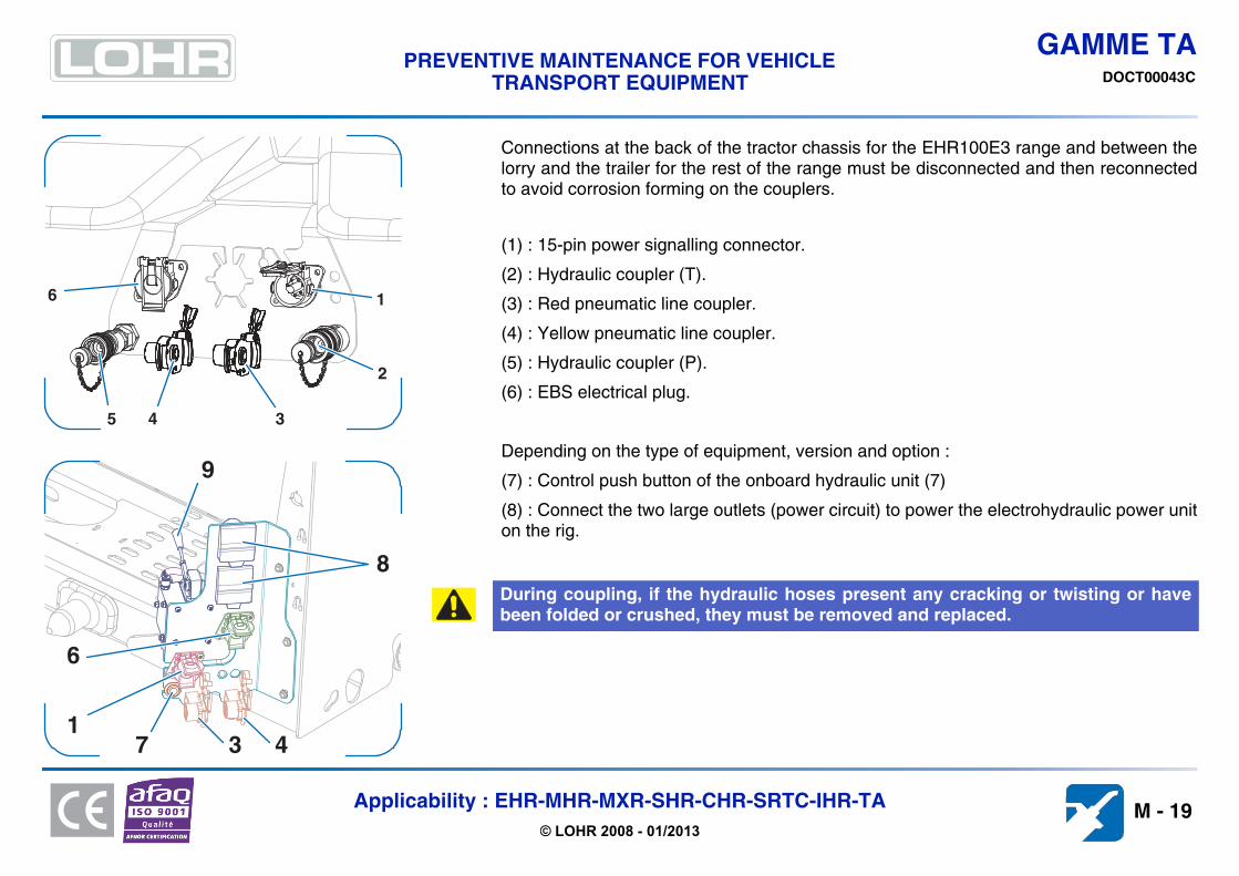
Connections at the back of the tractor chassis for the EHR100E3 range and between thelorry and the trailer for the rest of the range must be disconnected and then reconnectedto avoid corrosion forming on the couplers.
(1) : 15-pin power signalling connector.
(2) : Hydraulic coupler (T).
(3) : Red pneumatic line coupler.
(4) : Yellow pneumatic line coupler.
(5) : Hydraulic coupler (P).
(6) : EBS electrical plug.
Depending on the type of equipment, version and option :
(7) : Control push button of the onboard hydraulic unit (7)
(8) : Connect the two large outlets (power circuit) to power the electrohydraulic power uniton the rig.
During coupling, if the hydraulic hoses present any cracking or twisting or havebeen folded or crushed, they must be removed and replaced.
1
2
345
6
471
6
9
8
3
M - 19Applicability : EHR-MHR-MXR-SHR-CHR-SRTC-IHR-TA© LOHR 2008 - 01/2013

GAMME TAPREVENTIVE MAINTENANCE FOR VEHICLE
TRANSPORT EQUIPMENT DOCT00043C
3.10. Table of recommended lubricants
Origin Equivalence Operation
Oils hydraulic
TOTAL FINA ELF "EQUIVIS XTL 22" A07130316 • Cap circuit• Hydraulic circuit cold climate• AFNOR NF E 48-603 HV AGIP "HYDRAULIC VHI 15" SHELL "TELLUS OIL ARCTIC 32"
TOTAL "BIOHYDRAN TMP 32" A07130312• Cap circuit• Hydraulic circuit cold climate• VDMA 24568: HEES
• ISO 15380 : HEES
SHELL "NATURELLE HSE 32"
Oils
TOTAL FINA ELF "TRANSMISSION TM 80W90" A07130202• Angle drive• Rig with friction discs• API GL5 - SAE 80W90 - OTAN 0226
• MIL-L-2105 C D MOBIL "MOBILUB HD 80W90"
TOTAL FINA ELF "DROSERA MS 32" A07130303 • Lfiting screw• Lifting cable• Pneumatic lifting fork• ISO 6743/13 MOBIL "VACTRA N°1" SHELL "TONNA T32"
TOTAL FINA ELF "DROSERA MS 68" A07130110• Different Oilings
• AFNOR E 60-200 - GL5 MOBIL "VACTRA N°2" SHELL "TONNA T68"
Greases
TOTAL FINA ELF "MULTIS 2" C07070109 • bearings• ball bearings• Slides• slides• Rig with friction discs
• NLGI 2 - ISO L XBCEA 2• DIN 51502 K2K-25• OTAN G414
RENAULT "SUPEROL EP2" SHELL "RETINAX C" ARAL "MULTI-PURPOSE"
MOBIL "MOBILGREASE" ESSO "CASAR K2"
ELECTROLUBE "CG53A" C07070125• Electric connections
• NLGI 1-2
VOGEL "FL 000 BIO" BIODEGRADABLE• central lubrication
• NLGI 000,00ARAL "ARALUB BAB 000" AVIA "AVIALITH 000 BIO" TEXACO "STARFAK EP 00"
SHELL "RETINAX CSB 00" BP "BIOGREASE EP 00/000"
SHELL "RETINAX CS 00" C07070110• central lubrication• ISO 6743-9 - ISO-L-XCBEB 00
• DIN 51502-GP000-30
TOTAL FINA ELF "MULTIS EP 00" AVIA "AVIALITH 000 EP" TEXACO "MULTIFAK 6833 EP 00"
BP "ENERGREASE ZS 00" ARAL "FLIESSFETT N"
M - 20Applicability : EHR-MHR-MXR-SHR-CHR-SRTC-IHR-TA© LOHR 2008 - 01/2013

GAMME TAPREVENTIVE MAINTENANCE FOR VEHICLE
TRANSPORT EQUIPMENT DOCT00043C
4. TIGHTNESS OF SAFETY ELEMENTS
The tightness of safety elements must be verified after the first trip (or after repair)then periodically (see maintenance schedule).
A stick on the truck windscreen reminds the driver to perform these checks regularly.
LOHR INDUSTRIE F00059959B
IT IS ABOLUTELY NECESSARYTO TIGHTEN THE FIXINGS OF
THE SAFETY PARTS
WHEEL MOUTINGTROWING HOOK
& DRAWBAR EYE
WITH WHEEL
WRENCH
AFTER THE
FIRST 35 MILESVISUAL CONTROL
AFTER 800 MILESTIGHTENING CONTROL WITH
DYNAMOMETRIC KEY
VISUAL CONTROL
( SEE MAINTENANCE BOOK )EVEY WEEK
THE CONSTRUCTOR CANNOT BE HELD RESPONSIBLE OF THESE RULES
AFTER EACH REPAIR , RENEW THE CYCLE
M - 21Applicability : EHR-MHR-MXR-SHR-CHR-SRTC-IHR-TA© LOHR 2008 - 01/2013

GAMME TAPREVENTIVE MAINTENANCE FOR VEHICLE
TRANSPORT EQUIPMENT DOCT00043C
4.1. Couplings
4.1.1. Ball coupling (depending on assembly)
4.1.2. Automatic hook (depending on assembly)
4.1.3. Rig with friction discs (depending on assembly)
Check the torque settings of coupling mounts.
Torque setting :(1) & (2) . . . . . . . . . . . . . . . . . . . . . . . . . . . . . . . . . . . . . . . . . . . .(3) . . . . . . . . . . . . . . . . . . . . . . . . . . . . . . . . . . . . . . . . . . . . . . . .
600 N.m
300 N.m
Torque setting :(4) . . . . . . . . . . . . . . . . . . . . . . . . . . . . . . . . . . . . . . . . . . . . . . . .(5) . . . . . . . . . . . . . . . . . . . . . . . . . . . . . . . . . . . . . . . . . . . . . . . .(6) . . . . . . . . . . . . . . . . . . . . . . . . . . . . . . . . . . . . . . . . . . . . . . . .
425 N.m200 N.m600 N.m
Torque setting :(7) & (8). . . . . . . . . . 600 N.m
2 3 1
4
56
+50-0
7 8
M - 22Applicability : EHR-MHR-MXR-SHR-CHR-SRTC-IHR-TA© LOHR 2008 - 01/2013

GAMME TAPREVENTIVE MAINTENANCE FOR VEHICLE
TRANSPORT EQUIPMENT DOCT00043C
4.1.4. Kingpin (depending on assembly)
4.1.5. Fifth wheel EUROLOHR
Check the torque setting of the kingpin mounting nuts, respecting the order (1).
TORQUE SETTING : . . . . . . . . . . . . . . . . . . . . . . . . . . . . . . . . . 190 N.m
TORQUE SETTING : (2) . . . . . . . . . . . . . . . . . . . . . . . . . . . . . . 170 N.m
1
2
3
4
58
7
61
2 2
2
M - 23Applicability : EHR-MHR-MXR-SHR-CHR-SRTC-IHR-TA© LOHR 2008 - 01/2013

GAMME TAPREVENTIVE MAINTENANCE FOR VEHICLE
TRANSPORT EQUIPMENT DOCT00043C
4.1.6. Coupling stabiliser (depending on assembly)
4.1.6.1. Stabilizer mount with track on truck side
4.1.6.2. Stabilizer mount with track on trailer side
Check the torque setting of track mounts (1).
TORQUE SETTING : (1) . . . . . . . . . . . . . . . . . . . . . . . . . . . . . . 500 N.m
TORQUE SETTING : (2) . . . . . . . . . . . . . . . . . . . . . . . . . . . . . . 600 N.m
1
2
M - 24Applicability : EHR-MHR-MXR-SHR-CHR-SRTC-IHR-TA© LOHR 2008 - 01/2013

GAMME TAPREVENTIVE MAINTENANCE FOR VEHICLE
TRANSPORT EQUIPMENT DOCT00043C
4.2. Suspension (depending on assembly)
Check the torque setting for the suspension mounts. This must be done with the suspension in "road" position (pneumatic circuit under pressure).
Torque setting :
Euro100E/MXR/SRTC3 =Assembly 1
(2)EHR/MXR/SRTC =Assembly 2
Multi(1)/SHR =Assembly 3
Multi(2) =Assembly 4
CHR/EHR300 =Assembly 5
123456
625 N.m325 N.m450 N.m325 N.m25 N.m
210 N.m
123456
625 N.m325 N.m625 N.m325 N.m25 N.m
210 N.m
123456
625 N.m325 N.m625 N.m325 N.m25 N.m
160 N.m
123456
625 N.m325 N.m450 N.m325 N.m25 N.m
160 N.m
123456
625 N.m325 N.m450 N.m325 N.m25 N.m
210 N.m
Assembly 1 Assembly 2 Assembly 3 Assembly 4 Assembly 5
12 5
4 3 6
12 5
4 3 6
12 5
4 3 6
12 5
4 3 6
1 2 5
4 3 6
M - 25Applicability : EHR-MHR-MXR-SHR-CHR-SRTC-IHR-TA© LOHR 2008 - 01/2013

GAMME TAPREVENTIVE MAINTENANCE FOR VEHICLE
TRANSPORT EQUIPMENT DOCT00043C
4.3. Brakes (depending on assembly)
Check the torque setting on the air brake chamber mounts.
torque setting : drum brake actuators(1) . . . . . . . . . . . . . . . . . . . . . . . . . . . . . . . . . . . . . . . . . . . . . . . .(2) . . . . . . . . . . . . . . . . . . . . . . . . . . . . . . . . . . . . . . . . . . . . . . . .
180 - 210 N.m180 - 210 N.m
torque setting : disk brake calliper(3) . . . . . . . . . . . . . . . . . . . . . . . . . . . . . . . . . . . . . . . . . . . . . . . . 290 N.m
1
2
3
M - 26Applicability : EHR-MHR-MXR-SHR-CHR-SRTC-IHR-TA© LOHR 2008 - 01/2013

GAMME TAPREVENTIVE MAINTENANCE FOR VEHICLE
TRANSPORT EQUIPMENT DOCT00043C
4.4. Wheels
Check the torque setting of the wheel mounting nuts, respecting the order.
TORQUE SETTING : . . . . . . . . . . . . . . . . . . . . . . . . . . . . . . . . . 600 - 650 N.m
M - 27Applicability : EHR-MHR-MXR-SHR-CHR-SRTC-IHR-TA© LOHR 2008 - 01/2013

GAMME TAPREVENTIVE MAINTENANCE FOR VEHICLE
TRANSPORT EQUIPMENT DOCT00043C
4.5. Screw postsThe lifting posts are attached to the framework by bolting.
Check the tightness of the mounts.
The resistance class is marked visibly on the screw head.
The torque setting varies with the class of resistance of the bolts used to assemble the lifting posts.
torque setting : disk brake calliperclass 10.9 bolts . . . . . . . . . . . . . . . . . . . . . . . . . . . . . . . . . . . . . .class 12.9 (MULTILOHR) bolts . . . . . . . . . . . . . . . . . . . . . . . . . .
105 N.m105 N.m
M - 28Applicability : EHR-MHR-MXR-SHR-CHR-SRTC-IHR-TA© LOHR 2008 - 01/2013

GAMME TAPREVENTIVE MAINTENANCE FOR VEHICLE
TRANSPORT EQUIPMENT DOCT00043C
4.6. General torque settings
The following torque settings are to be used in the absence of specific instructions.
TORQUE SETTING
In Newtons x metre
Diametre en mm Pas en mmTORQUE SETTING
Class 8.8 Class 10.9
6 1 10 7,5 N.m 11 N.m
8 1,25 13 18,2 N.m 26 N.m
10 1,50 16 36 N.m 52 N.m
12 1,75 18 62 N.m 91 N.m
14 2 21 99 N.m 145 N.m
16 2 24 153 N.m 225 N.m
18 2,5 27 220 N.m 313 N.m
20 2,5 30 311 N.m 440 N.m
22 2,5 34 424 N.m 602 N.m
24 3 36 534 N.m 758 N.m
27 3 41 784 N.m 1114 N.m
30 3,5 46 1067 N.m 1515 N.m
33 3,5 50 1442 N.m 2048 N.m
36 4 55 1855 N.m 2636 N.m
M - 29Applicability : EHR-MHR-MXR-SHR-CHR-SRTC-IHR-TA© LOHR 2008 - 01/2013

GAMME TAPREVENTIVE MAINTENANCE FOR VEHICLE
TRANSPORT EQUIPMENT DOCT00043C
5. CHECKING AND REPLACING WEAR PARTS
5.1. Screw lifting system
The lifting screws are made of two components :
• The weight-bearing nut which bears the load.• The lower nut which does not bear any load.
This assembly allows wear on the weight-bearing nut to be checked and prevents theplatform from falling in the event of severe wear.
5.1.1. Checking wear on lifting nuts
Verification involves inserting the special gauge (1,5 mm thick), supplied with the equipment, between the two parts of the nut. When the gauge no longer fits in between, both parts of the nut should be replaced.
M - 30Applicability : EHR-MHR-MXR-SHR-CHR-SRTC-IHR-TA© LOHR 2008 - 01/2013

GAMME TAPREVENTIVE MAINTENANCE FOR VEHICLE
TRANSPORT EQUIPMENT DOCT00043C
5.2. Spindles and pinsOn some components, hinge pins and spindles are locked by pins, which must be in position and in good condition.
5.3. BALL COUPLING TA2050 (depending on assembly)The TA2050 coupling (1) is fitted with an upper pad with a wear indicator (2a).
This visual indicator located on the upper pad (2a) allows viewing its wear level.
After washing the coupling, inspect both pads (2a and 2b).
If the wear indicator is no longer visible (even partly), replace both pads (F00210232 (2a),F00215423 (2b)).
A missing pin may cause a component to rupture or be lost during loading or on theroad and cause an accident.
Check and replace any damaged or broken pins.
The lower pad (2b) must remain visible and prevent any steel/steel contact between the ball and the bracket. In case of doubt, change the pads.
1
2a
2b
Patin neuf Patin usé
2aTémoin d'usure
M - 31Applicability : EHR-MHR-MXR-SHR-CHR-SRTC-IHR-TA© LOHR 2008 - 01/2013

GAMME TAPREVENTIVE MAINTENANCE FOR VEHICLE
TRANSPORT EQUIPMENT DOCT00043C
5.3.1. Uncoupling
This operation is performed to replace wear parts (6) on the coupling.
Inflate the truck's rear suspension to a maximum.
Chock the trailer deflection jack.
Remove the protective caps (1).
Remove the split pin (4).
Use a 46 mm spanner to hold the kingpin (2) equipped with its nut.
Unscrew the nut (3) using a second 46 mm spanner.
Use a mallet to knock the kingpin, nut and pin assembly apart (2).
Remove the washers (5a, 5b, 5c).
Twist the flap (7) and remove the upper pad (6).
Deflate the truck's rear suspension to release the ball from its support (9).
Disconnect the hydraulic, pneumatic and electrical connections and move the tractor forwards.
8
6b1
4
5a
3
1
2
5a
5b
5c
76a
M - 32Applicability : EHR-MHR-MXR-SHR-CHR-SRTC-IHR-TA© LOHR 2008 - 01/2013

GAMME TAPREVENTIVE MAINTENANCE FOR VEHICLE
TRANSPORT EQUIPMENT DOCT00043C
5.3.2. Coupling
Before proceeding with the coupling, make sure the ball, holder and hook contact surfaces are clean.
Oil the contact surfaces of the ball, flap and holder very slightly to attenuate operating noise somewhat.
Raise the flap (7).
If necessary, set the height of the truck rear suspension so that the bottom of the ball (8) is about 10 mm above the support (9).
Reverse the truck slowly until the support (9) is under the ball (8). Raise the truck's rear suspension so that the ball rests in the support.
release the truck brakes in order to center the ball.
Refit the kingpin with its nut (2), and washers (5a, 5b, 5c).
Tighten the kingpin and refit the protective caps as described in chapter. (see chapter 5.3.3.).
Connect the hydraulic, pneumatic and electrical connections.
1
2
5a
5b
5c
7
1
5a43
10 mm
9
7
6a
6b
8
M - 33Applicability : EHR-MHR-MXR-SHR-CHR-SRTC-IHR-TA© LOHR 2008 - 01/2013

GAMME TAPREVENTIVE MAINTENANCE FOR VEHICLE
TRANSPORT EQUIPMENT DOCT00043C
5.3.3. Tightening the kingpin
It must be tightened using a torque wrench set to the value noted below and a 46 mmsocket, while holding the second nut with a 46 mm spanner. When the torque setting isreached, check whether the new split pin (4) can be inserted and continue tightening, ifnecessary (very slowly), until this is possible.
Before refitting the protective caps (2), they should be cleaned of grease and have newgrease applied.
To tighten the kingpin you must remove the upper and lower protective caps (2).
Using a clean cloth, remove any grease deposited on the nuts (3).
The two nuts (3) on the kingpin are held by pins (1and 4). La pin (1) must stay in place on the kingpin to immobilize the nut during tightening or loosening operatio. The kingpin can be mounted with the fixed nut at top or bottom depending on the available space.
TORQUE SETTING : (3) . . . . . . . . . . . . . . . . . . . . . . . . . . . . . . 300 N.m
1 2
3
324
+50-0
M - 34Applicability : EHR-MHR-MXR-SHR-CHR-SRTC-IHR-TA© LOHR 2008 - 01/2013

GAMME TAPREVENTIVE MAINTENANCE FOR VEHICLE
TRANSPORT EQUIPMENT DOCT00043C
5.4. Pneumatic coupling stabilizer (depending on assembly)Pneumatic stabilizer components are mounted differently according to the type of equipment :
reference Equipment Diaphragm mount Type of inspection Pad ref
1 EUROLOHR 100E trailer drawbar On-board kit gauge
F002516592 EHR 300 trailer drawbar On-board kit gauge
3 MULTILOHR trailer drawbar On-board kit gauge
4 MAXILOHR rear truck hook Fixed indicator
1 2
3 4
M - 35Applicability : EHR-MHR-MXR-SHR-CHR-SRTC-IHR-TA© LOHR 2008 - 01/2013

GAMME TAPREVENTIVE MAINTENANCE FOR VEHICLE
TRANSPORT EQUIPMENT DOCT00043C
5.4.1. Check pad wearDepending on the mount, friction pad (1) wear can be checked in different ways. In allcases, this operation must be performed with the stabilizer under pressure (truck enginerunning).
Check with a gauge :
Wear is checked using the gauge (2) provided with the on-board kit.
Check by wear indicator :
The level of wear is indicated by a notch at the end of the indicator (4).
The limit of wear is reached when the gauge (5) cannot be slipped between the track (3) and one of the plates (upper or lower) or this is difficult.
The limit of wear is reached when the notch is above the level of the plate (5).
When the limit of wear is reached (3mm), the pads (1) must be replaced as quicklyas possible.
1
3
2
1
51341
M - 36Applicability : EHR-MHR-MXR-SHR-CHR-SRTC-IHR-TA© LOHR 2008 - 01/2013

GAMME TAPREVENTIVE MAINTENANCE FOR VEHICLE
TRANSPORT EQUIPMENT DOCT00043C
5.4.2. Replacing wear padsThe procedure describes the principle for replacing the pads, mounting on the vehicle maydiffer according to the type of equipment (see page M - 35).
Uncouple the pneumatic power circuit (11).
Remove the two pins (1) and the spindles (2), plate (3) and unbolted pad (4).
Remove the screws (8), washers (9), and nuts (10) and remove the second pad (6).
Clean the parts of the stabilizer to eliminate any traces of sand, soil, grease, oil, etc....
Install the new pad (6) and fix it using new screws (8), washers (9), and nuts (10).
Refit the new pad (4), plate (3), spindles (2) and pins (1).
Connect the pneumatic power supply (11).
Put the pneumatic circuit under pressure and visually check the assembly, particularly making sure that the pads are in good contact with the track.
Never grease or oil the coupling stabilizer components.
Tête du stabilisateur Arrivée pneumatique
2765431
M - 37Applicability : EHR-MHR-MXR-SHR-CHR-SRTC-IHR-TA© LOHR 2008 - 01/2013

GAMME TAPREVENTIVE MAINTENANCE FOR VEHICLE
TRANSPORT EQUIPMENT DOCT00043C
5.4.3. Check alarm functionThis device alerts the driver if there is a fall of pressure in the pneumatic diaphragm (6).
Depending on the assembly, the low pressure light indicator may be located :
• on the left front post behind the cab (12),• in the cab, coupled to a buzzer.
The check is made when the circuit is under pressure, by disconnecting the power connection (11) which should set off the alarms.
Reconnecting the circuit should stop the alarms as soon as pressure is re-established.
In the event of any functional defect contact a garage in the lohr service network.
6
8
10
9
12
M - 38Applicability : EHR-MHR-MXR-SHR-CHR-SRTC-IHR-TA© LOHR 2008 - 01/2013

GAMME TAPREVENTIVE MAINTENANCE FOR VEHICLE
TRANSPORT EQUIPMENT DOCT00043C
5.4.4. Check MXL telescopic drawbar shoes
Install the leg and relieve the trailer drawbar.
Remove the flat holding bars (1) and their anchorage (2 and 4).
Remove the friction pads (3 and 5).
Install new friction pads (3 and 5).
If necessary, position bracing (2 and 4) (about 2.5 mm).
Refit the flat holding bars (1) and tighten to torque setting.
1
1
3
2
4
5
M - 39Applicability : EHR-MHR-MXR-SHR-CHR-SRTC-IHR-TA© LOHR 2008 - 01/2013

GAMME TAPREVENTIVE MAINTENANCE FOR VEHICLE
TRANSPORT EQUIPMENT DOCT00043C
5.5. Hydraulic circuit
5.5.1. Manual pumpIf the »cap» lifting circuit is not working properly, check the level of the manual pump tank.This must be done with the cap in low position.
5.5.2. Hydraulic tank
Place all the jacks in »RETRACTED» position.
Before any work on the hydraulic circuit and mechanisms, it is essential to make sure there is no remaining pressure in thesystem :• the power take-off must not be engaged,• activate the distributor levers.
Unscrew the filler stopper (1) and top up the tank if necessary. (see table of lubricants page M - 20).
To prevent oil from the jack emptying into the tank while on the road, which may cause overflow, you are recommended to always reset the tap to "up".
After any operation on the hydraulic circuit, make sure that all the functionsrespond normally to the controls.
To facilitate priming the hydraulic pump on certain devices, the tank is maintained pressurized by a pneumatic source. Place all the jacks in »RETRACTED» position. For that, make sure the power take off is not engaged. For that, make sure the power take off is not engaged.
IMPORTANT !
IMPORTANT !
AUSSITOT APRES UTILISATION
AUSSITOT APRES UTILISATION
REMETTRE LA MANETTE
EN POSITION LEVAGE
EN POSITION LEVAGE
F00104915 C
F00104915 C
1
M - 40Applicability : EHR-MHR-MXR-SHR-CHR-SRTC-IHR-TA© LOHR 2008 - 01/2013

GAMME TAPREVENTIVE MAINTENANCE FOR VEHICLE
TRANSPORT EQUIPMENT DOCT00043C
Depending on assembly.
Reduce the pressure before inspection by gently unscrewing the stopper (1), or disconnecting the pneumatic pressurizationcoupler. Hydraulic oil is corrosive, so it is important to always wear protective goggles and gloves.
It is important to avoid getting dirt and pollution into the circuit during checking or filling operations. See the lubrication tablefor the reference of the oil to use.
Unscrew the gauge (1) completely, the level should be between the 2 marks.
Unscrew the stopper (3) completely, the level must reach the filler hole.
Top up if necessary via the holes (2 or 3) (see table of lubricants page M - 20).
1
2 3
M - 41Applicability : EHR-MHR-MXR-SHR-CHR-SRTC-IHR-TA© LOHR 2008 - 01/2013

GAMME TAPREVENTIVE MAINTENANCE FOR VEHICLE
TRANSPORT EQUIPMENT DOCT00043C
5.5.3. Cartridge filterThe hydraulic circuit is fitted with a cartridge filter (1) with clogging indicator. The deviceincludes a bypass (2) to allow oil to pass through without being filtered when the filter isclogged.
5.5.3.1. VerificationThe filter must be checked while the hydraulic circuit is in operation :
Make sure the clogging indicator (1) is in the green zone A. If it moves into the red zone B, filtration is no longer operational and the oil is flowing through the bypass (2).
Replace the filter cartridge without delay to avoid the accumulation of impurities in the circuit.
Before rying out this operation, make sure that the circuit is not under pressure(power take-off not engaged, tank not under pressure).
1
huile
huile
polluée
filtrée
2
A
B
C
M - 42Applicability : EHR-MHR-MXR-SHR-CHR-SRTC-IHR-TA© LOHR 2008 - 01/2013

GAMME TAPREVENTIVE MAINTENANCE FOR VEHICLE
TRANSPORT EQUIPMENT DOCT00043C
5.5.3.2. Replacing the filter cartridge
To unscrew the cartridge holder (3), use an oil filter key (4).
Throw the used filter cartridge (5) into an appropriate container.
Clean the cartridge holder (3) with a clean cloth.
Verify the state of the seal (6) and replace it if necessary.
On refitting it, oil the seal lightly (6) and screw up the cartridge holder (3) by hand.
Check the oil level in the hydraulic tank (see chapter 5.5.2.).
Never try to clean the filter cartridge. It must be replaced by a new lohr part. The hydraulic filter must be replaced in a clean dust-free atmosphere to avoid polluting the circuit. After any operation on the hydraulic circuit, the operator must make sure that thefunctions respond normally to the controls.
5
33
6
3
34
5
3
M - 43Applicability : EHR-MHR-MXR-SHR-CHR-SRTC-IHR-TA© LOHR 2008 - 01/2013

GAMME TAPREVENTIVE MAINTENANCE FOR VEHICLE
TRANSPORT EQUIPMENT DOCT00043C
5.6. Pneumatic equipment
5.6.1. General inspectionThis operation involves verifying the following :
• The condition of the body / trailer connection hoses which must be neither cut nor cracked nor show signs of wear revealing the bare structure.
• The general condition of the circuit (mounts of devices, connecting pipes, etc...).• Detection of leaks under pressure (tractor engine off), by listening.
5.6.2. Venting tanks (depending on assembly)Tank venting is a preventive maintenance operation. It can be automatic or manual, inwhich case it must be purged every day to prevent condensation water from accumulatingin the tank and escaping into the circuit.
For automatic venting, tanks are equipped with purge valves which automaticallydischarge impurities (water, oil, etc.).
Purge activation is indicated by a brief sound of air escaping which can occur at any time.
Venting is performed remotely by a ring linked to the tank by a cable. Pull the ring for a few seconds to vent the tank.
There is one vent (1) for each air tank (1, 2 or 3 tanks depending on the model)..
1
M - 44Applicability : EHR-MHR-MXR-SHR-CHR-SRTC-IHR-TA© LOHR 2008 - 01/2013

GAMME TAPREVENTIVE MAINTENANCE FOR VEHICLE
TRANSPORT EQUIPMENT DOCT00043C
5.6.3. Inspecting the emergency line rupture brake
The trailer is fitted with a safety device which activates the brakes when the »red» (1) brakeline is disconnected (if the coupling breaks, for instance).
This operation must be performed with the trailer coupled and the braking circuit underpressure (tractor engine on).
If the safety device is working, the trailer brakes should tighten. If they don't, the brakevalve is faulty and must be replaced.
Twist and disconnect the red coupler (1).
It is prohibited to take to the road if the safety device is faulty.
1
M - 45Applicability : EHR-MHR-MXR-SHR-CHR-SRTC-IHR-TA© LOHR 2008 - 01/2013

GAMME TAPREVENTIVE MAINTENANCE FOR VEHICLE
TRANSPORT EQUIPMENT DOCT00043C
5.7. Tyres
5.7.1. Verifying tyre wearVerify the state of wear of the tyres regularly.
Replace the tyres as soon as the wear indicators are reached.
Wear should be even across the whole tread (1).
Uneven wear often indicates a mechanical fault or incorrect tyre pressures, for example :
• (2) : ...... Tyre pressure too low. • (4) : ...... Wheel alignment faulty.• (3) : ...... Tyre pressure too high. • (5) : ...... Faulty braking system (wheels blocked).
Tyres can have retreads or be regrooved, respecting the specific regulations. This operation must be performed by a specialist.
Replace a damaged (tear or cut reaching the internal structure) or worn tyre immediately.
1 2 3 4 5
M - 46Applicability : EHR-MHR-MXR-SHR-CHR-SRTC-IHR-TA© LOHR 2008 - 01/2013

GAMME TAPREVENTIVE MAINTENANCE FOR VEHICLE
TRANSPORT EQUIPMENT DOCT00043C
5.7.2. Checking pressures
Tyre pressures must be systematically modified to the load carried and the use to which the vehicle is put. Weighing per loaded axle is theonly way of defining the correct pressure.
Check and adjust tyre pressures on receiving the vehicle, then every week, depending on the load per axle applied (see table below).
Most damage to tyres is a direct result of incorrect inflation pressure, or is made worse by this.
The inflation pressure is determined according to load per axle. Over or under-inflation affects comfort, adhesion and durability of the tyres. Tyre pressure increases with distance travelled. This is a self-regulation phenomenon which opposes too high an increase in temperature due to successive flexing of the tyres.
Tyres mounted in pairs Tyres mounted in simple
Load per axle (Kg)
Pressure (bar) 215/75 R. 17,5
Pressure (bar) 245/70 R. 17,5
Pressure (bar) 255/60 R. 19,5
Load per axle (Kg)
Pressure (bar) 285/70 R. 19,5
Load per axle (Kg)
Pressure (bar) 275/70 R. 22,5
Pressure (bar) 295/60 R. 22,5
5570 5.5 - - 4940 6.5 5330 6.5 7.06010 6.0 - - 5280 7.0 5660 7.0 7.56900 7.0 - - 5620 7.5 6020 7.5 8.07790 8.0 - 7 5960 8.0 6360 8.0 8.58240 8.5 - 7.5 6300 8.5 6700 8.5 9.08630 - 7.0 8 6700 9.0 7000 9.0 -9190 - 7.5 8.5 - - - - -
Default pressure 8,5 7,5 8,5 Default pressure 9,0 Default pressure 9,0 9,0
Pressures must be checked when the tyres are cold, not forgetting the spare tyre, using an accurate pressure gauge (manometer). See the truck manual for checking the truck tyre pressures.
Never reduce the pressure in a hot tyre.
0 5,± 0 5,± 0 5,± 0 5,± 0 5,± 0 5,±
M - 47Applicability : EHR-MHR-MXR-SHR-CHR-SRTC-IHR-TA© LOHR 2008 - 01/2013

GAMME TAPREVENTIVE MAINTENANCE FOR VEHICLE
TRANSPORT EQUIPMENT DOCT00043C
5.8. Check wear on brake mechanismsThe thickness of the brake linings or pads must be checked regularly depending on how intensely the vehicle is used, according to law, butat least every three months.
5.8.1. Drum brake wear
When the minimum residual thickness of the lining (2) is 5 mm or the wear point of thebrake lining is reached, it must be replaced.
Replace the linings if necessary.
Open the inspection port by lifting the rubber flap (1).
Close the rubber flap.
When replacing brake linings or pads, it is essential to use only original parts. Usingany other parts may reduce the braking performance and seriously compromise thevehicle's safety..
2
1
M - 48Applicability : EHR-MHR-MXR-SHR-CHR-SRTC-IHR-TA© LOHR 2008 - 01/2013

GAMME TAPREVENTIVE MAINTENANCE FOR VEHICLE
TRANSPORT EQUIPMENT DOCT00043C
5.8.2. Disk brake wear
Brake pad wear (1) must not exceed a residual thickness (A) of 2 mm.
Mean wear on the pads can be measured with a metre rule, either on the adjustment bolt(long bolt at the entrance to the disk) or on the play bolt (short bolt at the disk exit).
For this purpose, measure the distance between the axle flange and the edge of the bolthousing in question (see figure). The wear limit is reached or exceeded for the followingvalues :
• Short bolt : Wear limit > 70 mm - replace the pads.• Long bolt : Wear limit > 97 mm - replace the pads
When replacing brake linings or pads, it is essential to use only original parts. Usingany other parts may reduce the braking performance and seriously compromise thevehicle's safety..
1
A
M - 49Applicability : EHR-MHR-MXR-SHR-CHR-SRTC-IHR-TA© LOHR 2008 - 01/2013

GAMME TAPREVENTIVE MAINTENANCE FOR VEHICLE
TRANSPORT EQUIPMENT DOCT00043C
M - 50Applicability : EHR-MHR-MXR-SHR-CHR-SRTC-IHR-TA© LOHR 2008 - 01/2013

GAMME TAPREVENTIVE MAINTENANCE FOR VEHICLE
TRANSPORT EQUIPMENT DOCT00043C
6. REPAIR
6.1. Releasing the screw lifting systemOccasionally, during operations, the lifting nuts may bind against the upper stop and causethe gantry to stick. If this happens, the lifting system can be released manually, byloosening the mounting nut at the top of each screw (2). This operation requires a 36 mmspanner (not provided).
This operation may be dangerous if it is not carried out according to instructions.You must wear protective gloves and goggles.
Before any work on the hydraulic circuit and mechanisms, it is essential to makesure there is no remaining pressure in the system :• the power take-off must not be engaged,• activate the distributor levers.
Remove the protective cap (1).
Use the spanner to loosen the mounting nut slightly (2).
Set the distributor to down.
Stop the distributor as soon as the system is released.
Retighten the mounting nut to torque 250 N.m 250 N.m.
1
2
M - 51Applicability : EHR-MHR-MXR-SHR-CHR-SRTC-IHR-TA© LOHR 2008 - 01/2013

GAMME TAPREVENTIVE MAINTENANCE FOR VEHICLE
TRANSPORT EQUIPMENT DOCT00043C
6.2. Changing a wheel
This operation requires the truck jack to be used on ground which is as hard and flat as possible. If necessary, set a metal plate under the jack to prevent it from sinking into the ground.
Engage the truck and trailers parking brakes.
Fit the jack in position :• Under a cross-piece (A, B, C, D, E, F, J, K, L).• Under the body of the axle (G, H, I).
Release the wheel mounting nuts.
Raise the trailer by operating the jack until the wheel lifts off the ground.
Remove the mounting nuts and lift the wheel off.
On refitting, oil the wheel studs lightly.
Using the wheel spanner provided in the toolkit, tighten the wheel (see chapter 4.4..).
It is essential to check the wheel's tightness again after 50 and 250 kilometres.
M - 52Applicability : EHR-MHR-MXR-SHR-CHR-SRTC-IHR-TA© LOHR 2008 - 01/2013

GAMME TAPREVENTIVE MAINTENANCE FOR VEHICLE
TRANSPORT EQUIPMENT DOCT00043C
MULTILOHR
MAXILOHR
EUROLOHR 100E
EUROLOHR 3.00
A
E
GB
F
H
J
SHR
CHR
I
C D
K L
M - 53Applicability : EHR-MHR-MXR-SHR-CHR-SRTC-IHR-TA© LOHR 2008 - 01/2013

GAMME TAPREVENTIVE MAINTENANCE FOR VEHICLE
TRANSPORT EQUIPMENT DOCT00043C
M - 54Applicability : EHR-MHR-MXR-SHR-CHR-SRTC-IHR-TA© LOHR 2008 - 01/2013