commercial vehicle classification using vehicle signature data
TRANSCRIPT
Commercial Vehicle Classification using Vehicle Signature Data Hang Liu Institute of Transportation Studies University of California Irvine, CA 92697-3600, U.S.A. Voice) 949-824-5859 Fax) 949-824-8385 [email protected] Shin-Ting (Cindy) Jeng Institute of Transportation Studies University of California Irvine, CA 92697-3600, U.S.A. Voice) 949-824-5859 Fax) 949-824-8385 [email protected] Yeow Chern Andre Tok Institute of Transportation Studies University of California Irvine, CA 92697-3600, U.S.A. Voice) 949-824-5859 Fax) 949-824-8385 [email protected] Stephen G. Ritchie Department of Civil and Environmental Engineering and Institute of Transportation Studies University of California Irvine, CA 92697-3600, U.S.A. Voice) 949-824-4214 Fax) 949-824-8385 [email protected] Word Count: 4,991 words + 3 table + 7 figures = 7,491
Paper submitted to the 88th Annual meeting of the Transportation Research Board, January 11-15, 2009, Washington D.C.
Liu, Jeng, Tok, and Ritchie 2
ABSTRACT: Knowledge of vehicle classes is especially useful for monitoring commercial vehicles (CVs). Accurate CV class information will enhance truck traffic surveillance and fleet management, such as in port areas by providing information for environmental impact investigations. From an implementation perspective, it is recognized that there are often significant advantages to use the existing inductive loop infrastructure. However, inductive loops are not always the most practical surveillance technology considering the required implementation effort and cost. In this regard, this study explored the potential of adopting a new vehicle signature detection technology - wireless magnetic sensors - for CV classification. The vehicle signature data used for the development of the wireless sensor based models was collected from the University of California, Irvine (UCI) Commercial Vehicle Study Test-bed in San Onofre, California. Vehicle signatures from round inductive loop sensors were also collected for refining an existing round loop based model and for comparison purposes. Significant dropped data was observed in the wireless sensor signatures, which required the implementation of a dual sensor data recovery procedure to reconstruct the signatures, which would otherwise have been unusable. The results indicate that the single wireless sensor vehicle classification model, which is based on multi-layer perceptron neural network, successfully distinguished single-unit and multi-unit trucks with 93.5% accuracy. The double wireless sensor vehicle classification model, which adopted a K-means clustering and discriminant function, achieved 73.6% accuracy, while the round loop based model produced even better performance (85%) in testing, both according to the FHWA scheme F with 13 classes.
Liu, Jeng, Tok, and Ritchie 3
BACKGROUND STATEMENT Vehicle classification algorithms allocate vehicles to predefined categories by processing selected vehicle features obtained from traffic sensors to reveal intrinsic vehicle characteristics. Such algorithms have many important applications in transportation systems analysis and policy development. These include travel forecasting, goods movement, road design and maintenance, setting user fees, safety, traffic flow modeling, environmental impact analysis, traffic management, and automated toll collection. Knowledge of vehicle classes is especially useful for monitoring commercial vehicles (CVs), since most CVs are heavy and oversized, and consequently possess performance characteristics that differ from passenger cars.
Monitoring heavy vehicles can assist with pavement design, providing more accurate estimates of pavement service life, and scheduling road rehabilitation and maintenance. Furthermore, accurate CV class information can enhance truck traffic surveillance and fleet management in port areas by providing information for environmental impact investigations. This may be of particular interest, as trucks with diesel engines are reported (1) to account for 71% of traffic-emitted PM2.5 (fine particulate matter).
Various detection technologies have been investigated and applied to perform vehicle classification. Examples include imaging-based sensors which consist of infrared imaging, video imaging and laser range imaging systems, acoustic signature analysis, magnetic sensors, and inductive signature systems. Inductive signature-based classification systems currently demonstrate advantages over other systems because of the widespread infrastructure deployment of inductive loop sensors and the cost effectiveness of implementation – requiring minimal out-of-pavement hardware updates, and good performance (80-90% accuracy in general [2]).
Study of vehicle classification using inductive signatures can be dated back to 1979, when Reijmers (3) examined 5 classes of vehicles, primarily based on vehicle length information acquired from double loops. There also exist commercially available vehicle classification products that claim capability of performing axle based vehicle classification from loop detectors as well as other technologies (4 and 5).
However, limited studies have sought to achieve reliable CV classification performance, due in part to the difficulty of obtaining a large CV dataset. This exposes the need to further improve truck classification performance using a more comprehensive CV dataset (2). Consequently, researchers at the University of California, Irvine (UCI) set up a test-bed for advanced CV surveillance research. This study yields two objectives: collecting more truck data for current inductive loop signature-based vehicle classification model re-calibration (2), and a new investigation of alternative technologies to obtain comprehensive high quality travel data for CVs.
In recent years, extensive research has been conducted at UCI on inductive vehicle signatures obtained from conventional inductive loops through the use of advanced high-speed scanning detector cards. Since inductive vehicle signatures such as those obtained from inductive loops vary across vehicle types, vehicle classification models can be developed to categorize vehicles based on their physical features. Previously, vehicle classification studies from UCI have been focused on utilizing vehicle
Liu, Jeng, Tok, and Ritchie 4
signatures from inductive loop detectors (2 and 6) and more recently, the studies have been carried out using Blade inductive sensors, which can provide both the undercarriage profile and axle configuration of each vehicle. This fusion provides the potential for distinguishing between CVs at a more detailed level (7 and 8).
Another new traffic surveillance technology called the wireless magnetometer, or wireless magnetic sensor, recently has shown potential as an alternative to inductive loop detector systems to provide conventional traffic performance measures. Its main advantage lies in the wireless communication between the in-pavement magnetometers and the out-of-pavement access points, which removes the need for installing lead-in cables from each sensor. In addition the footprint of each magnetometer is significantly smaller than a conventional inductive loop sensor, which reduces the installation time and overall road closure window. The potential for obtaining detailed vehicle signature-based information from this sensor is still currently under evaluation. At this point, only one signature-based investigation has been performed at a test site with limited control vehicles. Hence, there is a need to further investigate this technology for developing a practical signature-based vehicle classification system.
A unique dataset of CV signatures using conventional inductive loops and the new wireless sensors was collected for this study. The data was collected at UCI’s Commercial Vehicle Study Test-bed (CVS Test-bed).
UCI TEST-BED FOR COMMERCIAL VEHICLE STUDY
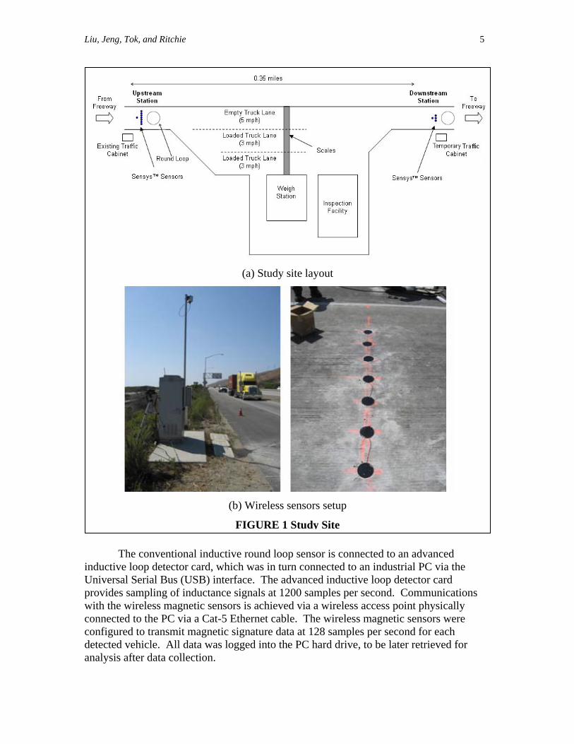
Test-bed Layout The UCI CVS Test-bed is located at the California Highway Patrol (CHP) I-5S Truck Weigh and Inspection Station in San Onofre, between Los Angeles and San Diego, California. I-5 is a major truck route in Southern California and truck volumes at the San Onofre site are high. The CVS Test-bed was chosen as the data collection site for investigating commercial vehicles due to the high volume and variety of commercial vehicles that enter the site daily. It has a single lane entrance ramp from the I-5S, which expands into three lanes approaching the weighing scales followed by a single lane exit ramp back to the mainline freeway. Two temporary detector stations were set up at the entrance and exit ramps as shown in FIGURE 1(a). The upstream and downstream detector stations span a distance of 0.35 miles.
Each detector station is instrumented with single 1.8 m (6-foot) conventional inductive round loop sensors together with an array of wireless magnetic sensors. The array of magnetic sensors at the upstream detector station consists of a leading sensor followed by a set of seven sensors spaced equally at 0.30 m (1 foot) laterally across the lane and 1.8 m (6 feet) downstream from the leading sensor. At the downstream detector station, a single leading sensor was installed with three sensors spaced equally at 0.30 m (1 foot) laterally across the lane and 1.8 m (6 feet) downstream from the leading sensor. FIGURE 1(b) shows the actual setup of the cabinet with a pole-mounted wireless access point and the array of seven sensors at upstream.
Liu, Jeng, Tok, and Ritchie 5
(a) Study site layout
(b) Wireless sensors setup
FIGURE 1 Study Site
The conventional inductive round loop sensor is connected to an advanced inductive loop detector card, which was in turn connected to an industrial PC via the Universal Serial Bus (USB) interface. The advanced inductive loop detector card provides sampling of inductance signals at 1200 samples per second. Communications with the wireless magnetic sensors is achieved via a wireless access point physically connected to the PC via a Cat-5 Ethernet cable. The wireless magnetic sensors were configured to transmit magnetic signature data at 128 samples per second for each detected vehicle. All data was logged into the PC hard drive, to be later retrieved for analysis after data collection.
Liu, Jeng, Tok, and Ritchie 6
Data Description Data were collected from both the round inductive loop and wireless magnetic sensors on May 29th, 2008 between 9:30am and 1:30am. About 1200 vehicle signatures were collected for each sensor type at each location, yielding a total of 2400 vehicle signatures for both detector stations. The speeds of the vehicles ranged from about 15 to 50 mph, with a mean of 27.6 mph and a standard deviation of 5.9 mph. Side-fire video data was concurrently recorded for visual ground truthing of vehicle classes at both locations.
The round loop data was found to generally be of high quality, and thus was applied directly to re-calibrate an existing round loop based classification model. However, a significant proportion of signatures was observed with dropped information in the wireless sensor data, which required the development of a data recovery procedure (these data would otherwise have been unusable). The following section describes this procedure in detail.
WIRELESS SENSOR DATA PREPROCESSING AND RECOVERY The wireless sensors measure the x-, y-, and z-axis components of the Earth’s magnetic field in the direction of travel, perpendicular to the direction of travel, and the field out of the ground, respectively. Since the y-axis measurement is usually corrupted by the magnetic signals from vehicles traveling in adjacent lanes (11), the y-axis data was not considered for further analysis.
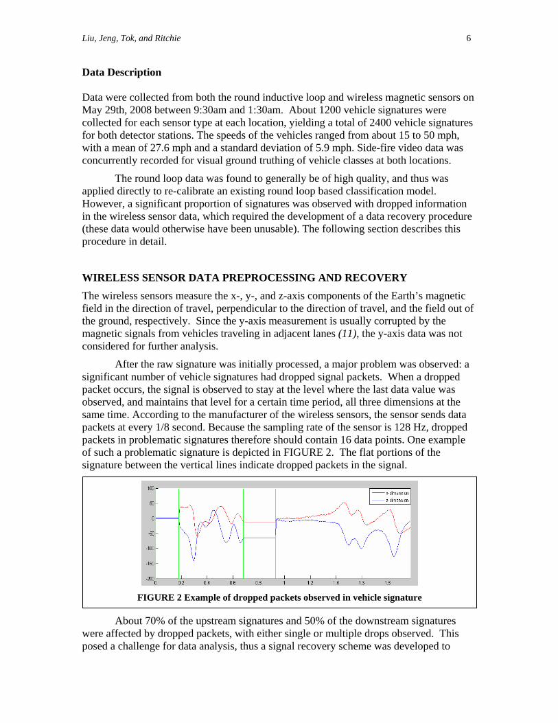
After the raw signature was initially processed, a major problem was observed: a significant number of vehicle signatures had dropped signal packets. When a dropped packet occurs, the signal is observed to stay at the level where the last data value was observed, and maintains that level for a certain time period, all three dimensions at the same time. According to the manufacturer of the wireless sensors, the sensor sends data packets at every 1/8 second. Because the sampling rate of the sensor is 128 Hz, dropped packets in problematic signatures therefore should contain 16 data points. One example of such a problematic signature is depicted in FIGURE 2. The flat portions of the signature between the vertical lines indicate dropped packets in the signal.
FIGURE 2 Example of dropped packets observed in vehicle signature
About 70% of the upstream signatures and 50% of the downstream signatures were affected by dropped packets, with either single or multiple drops observed. This posed a challenge for data analysis, thus a signal recovery scheme was developed to
Liu, Jeng, Tok, and Ritchie 7
account for this issue and is described in the section below. Moreover, after further investigating the signatures, it is found that signatures from sensors other than the two placed in the middle of the lane (the single leading sensor and the mid-array sensor) were very different from each other. This variation, together with the problematic signatures (i.e., signatures with dropped sections) made it impossible to decide directly which of the signatures were representative of vehicle characteristics. However, we found that signatures from the two mid-lane sensors showed repeatability. The reason might be that there is only one lane at both detection stations, so most of the vehicles will drive closer to the center of the lane. The repeatability of the signatures is very useful for recovering some of the signatures with dropped sections. Therefore, the data from the single leading sensor and the mid-array sensor were selected for further analysis.
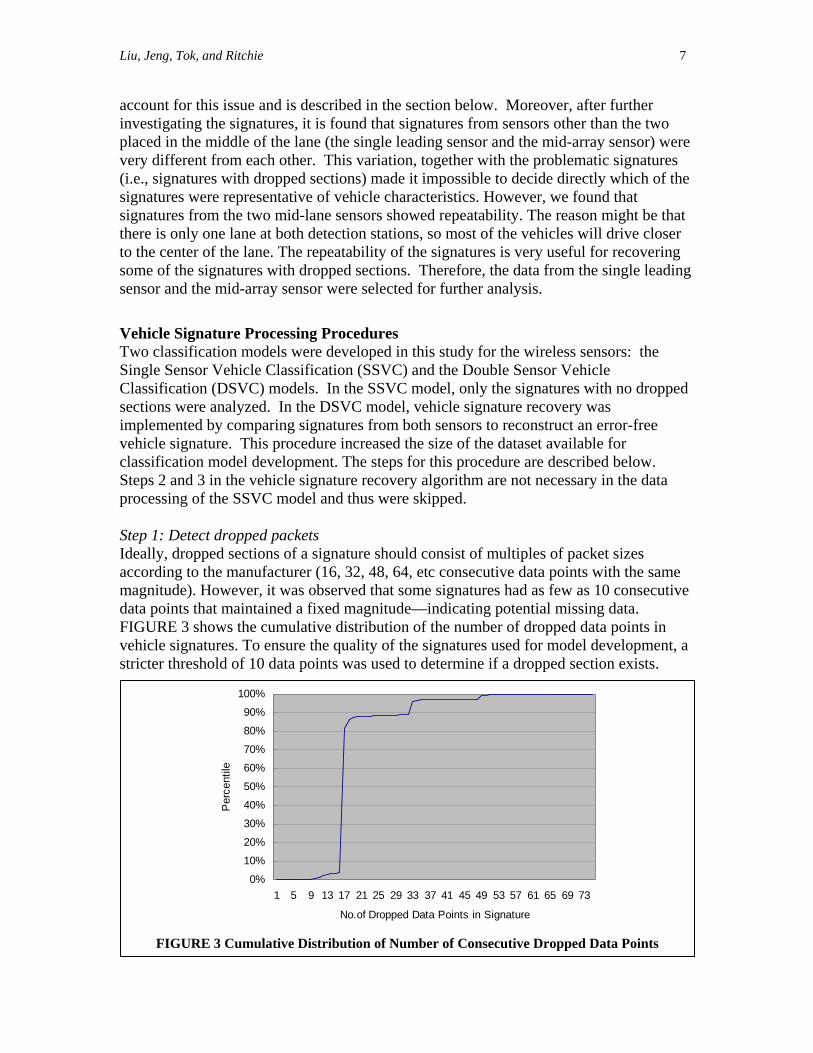
Vehicle Signature Processing Procedures Two classification models were developed in this study for the wireless sensors: the Single Sensor Vehicle Classification (SSVC) and the Double Sensor Vehicle Classification (DSVC) models. In the SSVC model, only the signatures with no dropped sections were analyzed. In the DSVC model, vehicle signature recovery was implemented by comparing signatures from both sensors to reconstruct an error-free vehicle signature. This procedure increased the size of the dataset available for classification model development. The steps for this procedure are described below. Steps 2 and 3 in the vehicle signature recovery algorithm are not necessary in the data processing of the SSVC model and thus were skipped. Step 1: Detect dropped packets Ideally, dropped sections of a signature should consist of multiples of packet sizes according to the manufacturer (16, 32, 48, 64, etc consecutive data points with the same magnitude). However, it was observed that some signatures had as few as 10 consecutive data points that maintained a fixed magnitude—indicating potential missing data. FIGURE 3 shows the cumulative distribution of the number of dropped data points in vehicle signatures. To ensure the quality of the signatures used for model development, a stricter threshold of 10 data points was used to determine if a dropped section exists.
0%
10%
20%
30%
40%
50%
60%
70%
80%
90%
100%
1 5 9 13 17 21 25 29 33 37 41 45 49 53 57 61 65 69 73
No.of Dropped Data Points in Signature
Per
cent
ile
FIGURE 3 Cumulative Distribution of Number of Consecutive Dropped Data Points
Liu, Jeng, Tok, and Ritchie 8
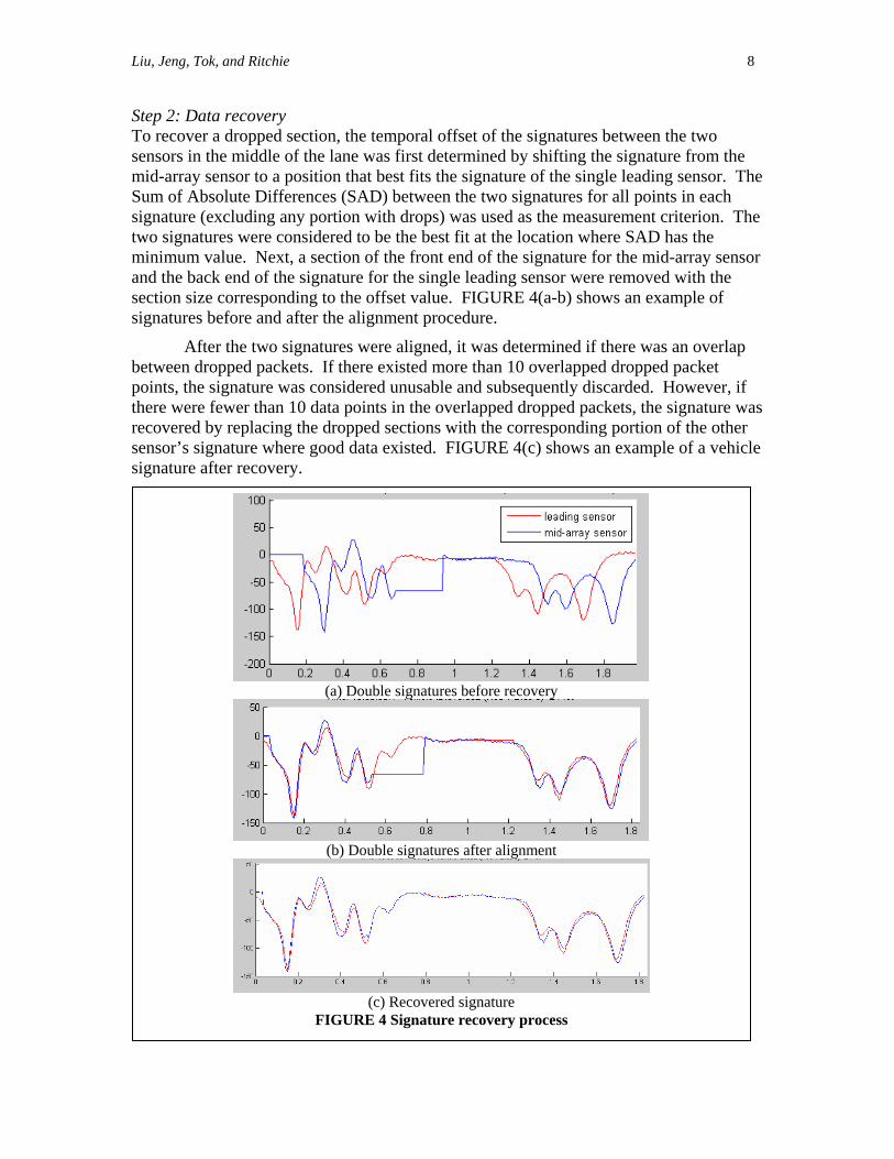
Step 2: Data recovery To recover a dropped section, the temporal offset of the signatures between the two sensors in the middle of the lane was first determined by shifting the signature from the mid-array sensor to a position that best fits the signature of the single leading sensor. The Sum of Absolute Differences (SAD) between the two signatures for all points in each signature (excluding any portion with drops) was used as the measurement criterion. The two signatures were considered to be the best fit at the location where SAD has the minimum value. Next, a section of the front end of the signature for the mid-array sensor and the back end of the signature for the single leading sensor were removed with the section size corresponding to the offset value. FIGURE 4(a-b) shows an example of signatures before and after the alignment procedure.
After the two signatures were aligned, it was determined if there was an overlap between dropped packets. If there existed more than 10 overlapped dropped packet points, the signature was considered unusable and subsequently discarded. However, if there was
the dropped sections with the corresponding portion of the other hicle
were fewer than 10 data points in the overlapped dropped packets, the signature recovered by replacing sensor’s signature where good data existed. FIGURE 4(c) shows an example of a vesignature after recovery.
(a) Double signatures before recovery
(b) Double signatures after alignment
(c) Recovered signature
FIGURE 4 Signature recovery process
Liu, Jeng, Tok, and Ritchie 9
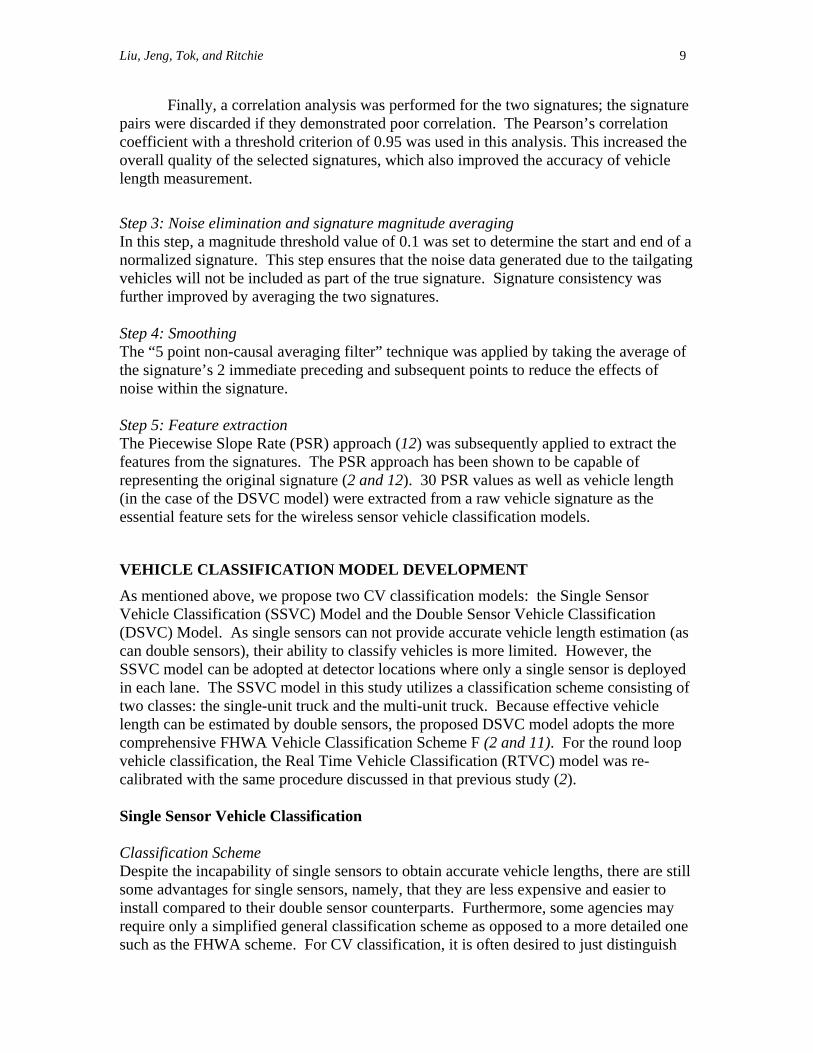
Finally, a correlation analysis was performed for the two signatures; the signature pairs were discarded if they demonstrated poor correlation. The Pearson’s correlation coefficient with a threshold criterion of 0.95 was used in this analysis. This increased the overall quality of the selected signatures, which also improved the accuracy of vehicle length measurement.
Step 3: Noise elimination and signature magnitude averaging In this step, a magnitude threshold value of 0.1 was set to determine the start and end of a normalized signature. This step ensures that the noise data generated due to the tailgating vehicles will not be include nature cons tency was further improved by averaging the two signatures. Step 4: Smoothing The “5 point non-causal averaging filter” technique was applied by taking the average of the signature’s 2 immediate preceding and subsequent points to reduce the effects of noise within the signature. Step 5: Feature extraction The Piecewise Slope Rate (PSR) approach (12) was subsequently applied to extract the features from the signatures. The PSR approach has been shown to be capable of representing the original signature (2 and 12). 30 PSR values as well as vehicle length (in the case of the DSVC model) were extracted from a raw vehicle signature as the essential feature sets for the wireless sensor vehicle classification models.
VEHICLE CLASSIFICA As mentioned above, we propose two CV classification models: the Single Sensor Vehicle
as
C model in this study utilizes a classification scheme consisting of s: the single-unit truck and the multi-unit truck. Because effective vehicle
odel adopts the more
uble sensor counterparts. Furthermore, some agencies may
classification scheme as opposed to a more detailed one ification, it is often desired to just distinguish
d as part of the true signature. Sig is
TION MENT MODEL DEVELOP
Classification (SSVC) Model and the Double Sensor Vehicle Classification (DSVC) Model. As single sensors can not provide accurate vehicle length estimation (can double sensors), their ability to classify vehicles is more limited. However, the SSVC model can be adopted at detector locations where only a single sensor is deployed in each lane. The SSVtwo classelength can be estimated by double sensors, the proposed DSVC mcomprehensive FHWA Vehicle Classification Scheme F (2 and 11). For the round loop vehicle classification, the Real Time Vehicle Classification (RTVC) model was re-calibrated with the same procedure discussed in that previous study (2). Single Sensor Vehicle Classification Classification Scheme Despite the incapability of single sensors to obtain accurate vehicle lengths, there are still some advantages for single sensors, namely, that they are less expensive and easier toinstall compared to their dorequire only a simplified general such as the FHWA scheme. For CV class
Liu, Jeng, Tok, and Ritchie 10
between single and multi-unit trucks. Therefore, a vehicle classification scheme with twclasses, the single-unit truck and the multi-unit truck, was used for the SSVC mode Methodology: Multi-Layer Perceptron Neural Network (MLPNN) Neural networks have been applied extensively in signal processing and ma
o l.
ny other elds that fall under the category of pattern recognition (7 and 14). The Multi-Layer erceptron Neural Network (MLPNN) was applied in this research to predict the CV
e-
d
, t with the
the model can still achieve an overall correct
Predicted Class
fiPclasses with a single sensor.
The overall dataset used in this model development consisted of 1075 clean vehicle signatures (without any dropped packets) including signatures from 557 singlunit vehicles (51.8%) and 518 multi-unit vehicles (48.2%). A stratified random sampling technique was used to partition the dataset. For each class, the dataset was partitioneinto three parts: 60 percent of the sample was assigned to train the MLPNN, 20 percent was applied for validation during the training process to prevent over-training, and the remaining 20 percent was used for testing of the final model.
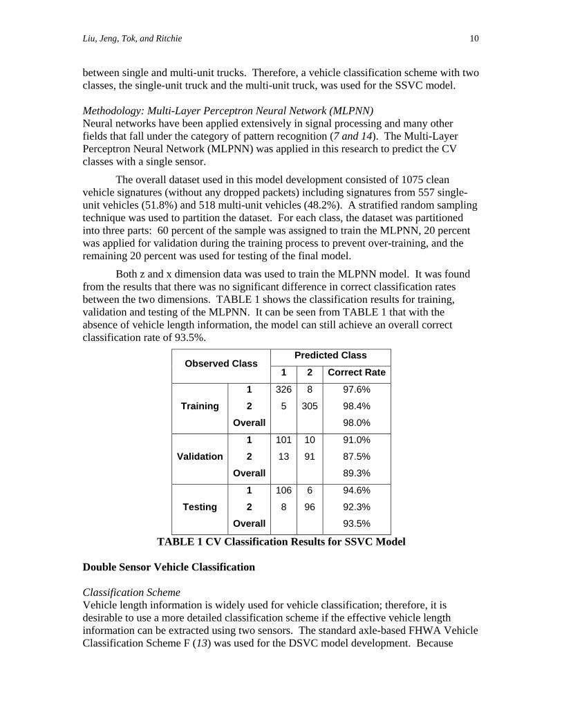
Both z and x dimension data was used to train the MLPNN model. It was found from the results that there was no significant difference in correct classification rates between the two dimensions. TABLE 1 shows the classification results for training
alidation and testing of the MLPNN. It can be seen from TABLE 1 thavabsence of vehicle length information, lassification rate of 93.5%. c
Observed Class 1 2 Correct Rate
Training 1 2
Overall
326
5
8
305
97.6%
98.4%
98.0%
Validation 2 13 91 87.5%
1 101 10 91.0%
Overall 89.3%
Testing 1 2
106
8
6
96
94.6%
92.3%
Overall 93.5%
TABLE 1 CV Classification Results for SSVC Model Double Sensor Vehicle Classification Classification Scheme Vehicle length information is widely used for vehicle classification; therefore, it is desirable to use a more detailed classification scheme if the effective vehicle length inform ation can be extracted using two sensors. The standard axle-based FHWA VehicleClassification Scheme F (13) was used for the DSVC model development. Because
Liu, Jeng, Tok, and Ritchie 11
vehicle classes 1, 4, and 13 were absent from our dataset, a total number of 10 vehicleclasses were selected for model development.
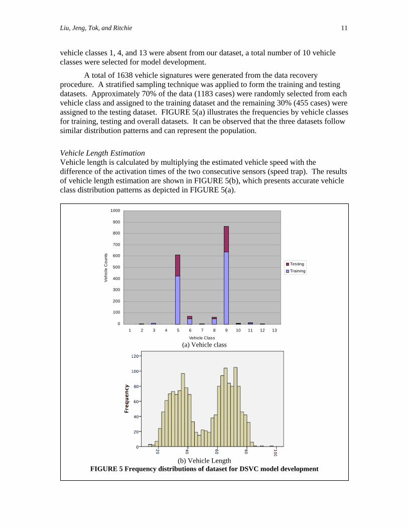
A total of 1638 vehicle signatures were generated from the data recovery procedure. A stratified samp
ling technique was applied to form the training and testing datasets. Approximately 70% of the data (1183 cases) were randomly selected from each vehicle class and assig dat t an th % (455 cases) were assigned to the testing dataset. FIGURE 5(a) t tes th ies by vehicle classes for training, testing and overall datas . It e serve e three datasets follow similar distribution pa can resen e ulatio
Vehicle Length Estimation Vehicle length is calcu ultiplying th ated vehicle speed with the difference of the acti of t two se ive se peed trap). The results of vehicle length estimation are sh FIGURE 5(b), which presents accurate vehicle class distribution patterns as depicted in FIGURE 5(a).
ned to the training aseillus
d ra
e remaining 30e frequenc
ets can b ob d that thtterns and rep t th pop n.
lated by mvation times
e estim conhe cut nsors (s
own in
0
100
200
300
400Vehi
cl
500e C
oun 600
1000
ts
800
900
700
Testing
Training
1 2 3 4 5 6 7 8 9 10 11 12 13
Vehicle Class (a) Vehicle class
(b) Vehicle Length
FIGURE 5 Frequency distributions of dataset for DSVC model development
Liu, Jeng, Tok, and Ritchie 12
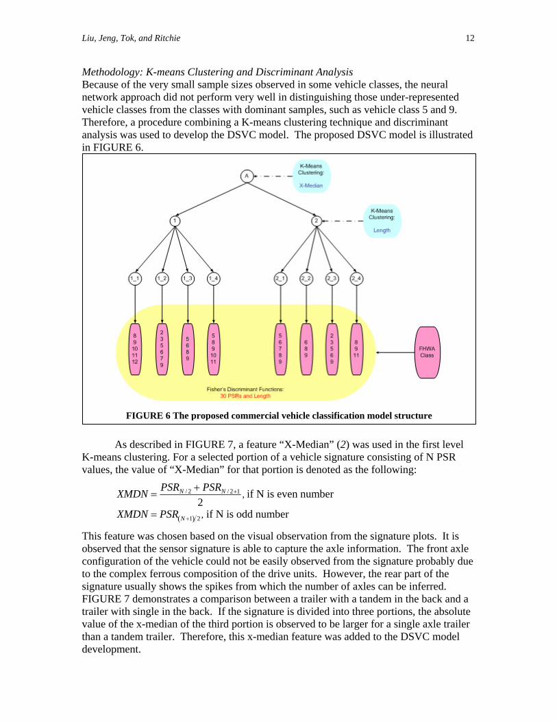
Methodology: K-means Clustering and Discriminant Analysis Because of the very small sample sizes observed in some vehicle classes, the neural network approach did not perform very well in distinguishing those under-represented vehicle classes from the classes with dominant samples, such as vehicle class 5 and 9. Therefore, a procedure combining a K-means clustering technique and discriminant analysis was used to develop the DSVC model. The proposed DSVC model is illustrated in FIGURE 6.
as used in the first level
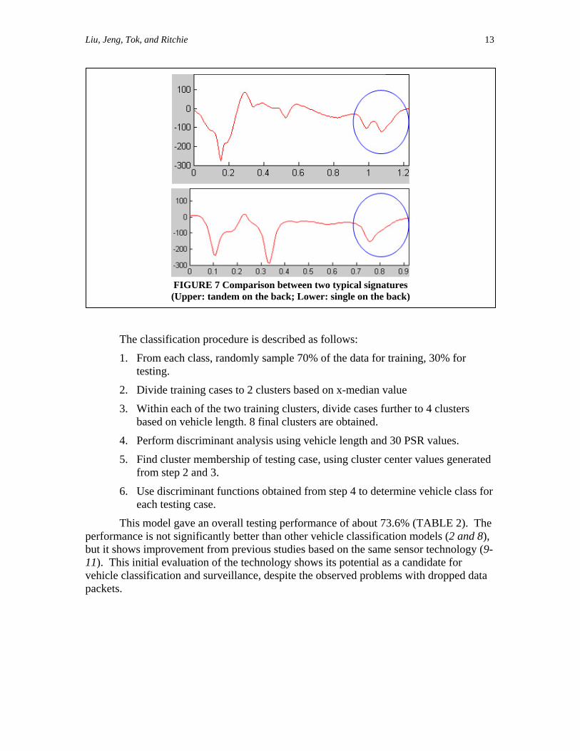
As described in FIGURE 7, a feature “X-Median” (2) w
K-means clustering. For a selected portion of a vehicle signature consisting of N PSRvalues, the value of “X-Median” for that portion is denoted as the following:
XMDN =PSRN / 2 + PSRN / 2+1
2, if N is even number
XMDN = PSR N +1( ) 2 , if N is odd number
This feature was chosen based on the visual observation from the signature plots. It is observed that the sensor signature is able to capture the axle information. The front axle configuration of the vehicle could not be easily observed from the signature probably due to the complex ferrous composition of the drive units. However, the rear part of the signature usually shows the spikes from which the number of axles can be inferred. FIGURE 7 demonstrates a comparison between a trailer with a tandem in the back and a trailer with single in the back. If the signature is divided into three portions, the absolute value of the x-median of the third portion is observed to be larger for a single axle trailer than a tandem trailer. Therefore, this x-median feature was added to the DSVC model development.
FIGURE 6 The proposed co ssification modelmmercial vehicle cla structure
Liu, Jeng, Tok, and Ritchie 13
Th
1. From each class, randomly sample 70% of the data for training, 30% for
3. Within each of the two training clusters, divide cases further to 4 clusters based on vehicle length. ined.
4. Perform discrim ehicle length and 30 PSR values.
The
FIGURE 7 Comparison between two typical signatures (Upper: tandem on the back; Lower: single on the back)
e classification procedure is described as follows:
testing.
2. Divide training cases to 2 clusters based on x-median value
8 final clusters are obta
inant analysis using v
5. Find cluster membership of testing case, using cluster center values generated from step 2 and 3.
6. Use discriminant functions obtained from step 4 to determine vehicle class for each testing case.
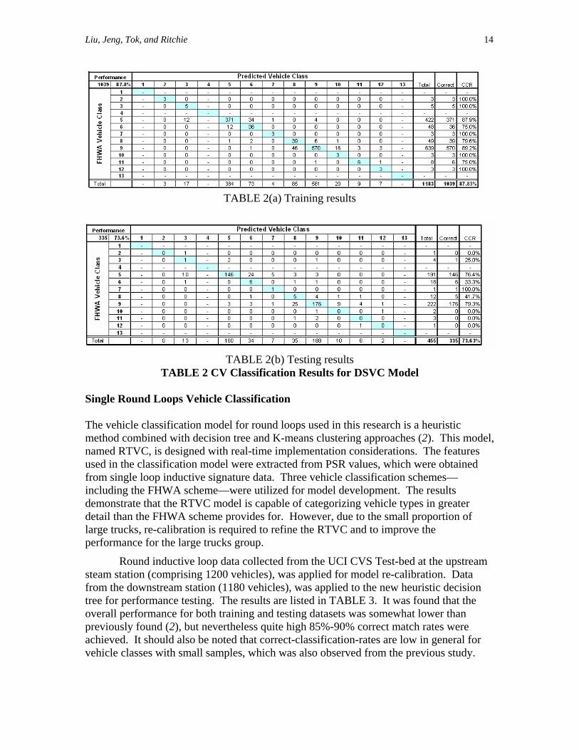
This model gave an overall testing performance of about 73.6% (TABLE 2). performance is not significantly better than other vehicle classification models (2 and 8), but it shows improvement from previous studies based on the same sensor technology (9-11). This initial evaluation of the technology shows its potential as a candidate for vehicle classification and surveillance, despite the observed problems with dropped datapackets.
Liu, Jeng, Tok, and Ritchie 14
TABLE 2(a) Training results
TABLE 2(b) Testing results TABLE 2 CV Classification Results for DSVC Model
Single Round Loops Vehicle Classification The vehicl rch is a heuristic method model, named RTVC, is designed withused infrom single loop inductive signature data. Three vehicle classification schemes—includidemonstrat odel is capable of categorizing vehicle types in greater detail t
eam
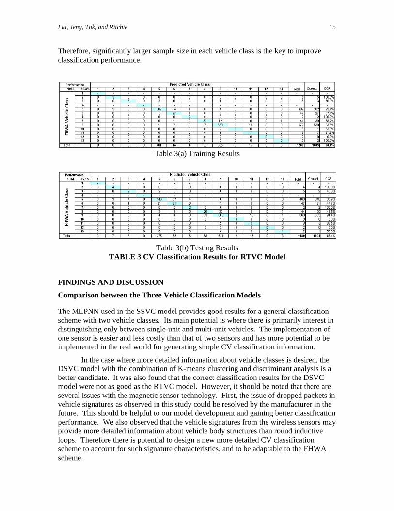
downstream station (1180 vehicles), was applied to the new heuristic decision ee for performance testing. The results are listed in TABLE 3. It was found that the verall performance for both training and testing datasets was somewhat lower than
previously found (2), but nevertheless quite high 85%-90% correct match rates were achieved. It should also be noted that correct-classification-rates are low in general for vehicle classes with small samples, which was also observed from the previous study.
e classification model for round loops used in this resea combined with decision tree and K-means clustering approaches (2). This
real-time implementation considerations. The features the classification model were extracted from PSR values, which were obtained
ng the FHWA scheme—were utilized for model development. The results e that the RTVC m
han the FHWA scheme provides for. However, due to the small proportion of large trucks, re-calibration is required to refine the RTVC and to improve the performance for the large trucks group.
Round inductive loop data collected from the UCI CVS Test-bed at the upstrsteam station (comprising 1200 vehicles), was applied for model re-calibration. Data from the tro
Liu, Jeng, Tok, and Ritchie 15
Therefore, significantly larger sample size in each vehicle class is the key to improve classification performance.
Table 3(a) Training Results
Table 3(b) Testing Results
TABLE 3 CV Classification Results for RTVC Model
FINDINGS AND DISCUSSION
n on of
be
sired, the -means clustering and discriminant analysis is a
better c
n
on may
scheme.
Comparison between the Three Vehicle Classification Models The MLPNN used in the SSVC model provides good results for a general classification scheme with two vehicle classes. Its main potential is where there is primarily interest idistinguishing only between single-unit and multi-unit vehicles. The implementatione sensor is easier and less costly than that of two sensors and has more potential to implemented in the real world for generating simple CV classification information.
In the case where more detailed information about vehicle classes is deDSVC model with the combination of K
andidate. It was also found that the correct classification results for the DSVC model were not as good as the RTVC model. However, it should be noted that there are several issues with the magnetic sensor technology. First, the issue of dropped packets ivehicle signatures as observed in this study could be resolved by the manufacturer in thefuture. This should be helpful to our model development and gaining better classificatiperformance. We also observed that the vehicle signatures from the wireless sensors provide more detailed information about vehicle body structures than round inductive loops. Therefore there is potential to design a new more detailed CV classification scheme to account for such signature characteristics, and to be adaptable to the FHWA
Liu, Jeng, Tok, and Ritchie 16
Low Correct Classification Rates for Certain Vehicle Classes For both the DSVC and RTVC models, significant classification errors were observed for class 6 and class 8. Many vehicles of class 6 were misclassified as class 5, and many of class 8 were classified as class 9. This is not unexpected because of the similarity of the vehicle signatures observed in these classes. Vehicles could be very similar in length between class 5 and class 6 as well as class 8 and class 9. The only possible way to distinguish them from each other is from exact axle information extracted from the signatures. A very small variation in the signature could cause misclassification quite easily.
It was also noticed that the performance for vehicle classes with only a few samples was generally low, an small to be representative. The results for these classes, such as class 2, 3, 10, 11 and 12, are not necessarily indicative of model limitations. A significant larger number of samples in each vehicle class would be helpful for classification model development, and thus potentially increase the model performance.
CONCLUSIONS This research explored the potential of adopting new vehicle signature detection technology, wireless magnetic sensors, for commercial vehicle classification. Two new vehicle classification models, S osed for the wireless sensor based models w g vehicle classification model, RTVC, wh
odified for model improvement and comparison purposes. A major problem observed was the frequency of dropped data in many vehicle
ecovery procedure to ble.
perform
d their sample sizes were too
SVC and DSVC, were propith different classification schemes. In addition, an existin
ich utilizes single round inductive loop detector data, was mwith the wireless magnetic sensors signatures. This required the implementation of a dual sensor data rreconstruct the signatures, which would otherwise have been unusa The results show that the single wireless sensor vehicle classification model, which is based on a multi-layer perceptron neural network, successfully distinguished single-unit and multi-unit trucks with 93.5% accuracy. The double wireless sensor vehicle classification model, which adopted a K-means clustering and discriminant function, achieved 73.6% accuracy, while the round loop based model produced even better
ance (85%) in testing, both according to the FHWA scheme F with 13 classes. In addition to resolution of the dropped data problem with the wireless sensor, classification performance of all the models developed could be improved through collection of more CV data so that no vehicle class suffers from a sample size that is too small.
Liu, Jeng, Tok, and Ritchie 17
ACKNOWLEDGEMENT This work was performed as part of the University of California Transportation Center program, also was in part supported by the California Partners for Advanced Transit and Highways program of the University of California. The contents of this paper reflect the views of the authors, who are responsible for the facts and the accuracy of the data presented. The contents do not necessarily reflect the official views or policies of theof California. This paper does not constitute a standard, specification, or regulation. authors gratefully acknowledge the collaboration and assistance of Sensys Networks Inin cond
state The
c. ucting this research, especially in providing the wireless magnetic sensors and
access
points used in this study. The authors also appreciate the cooperation and assistance of Nadine Martin and Fred Yazdan of the California Department of Transportation, John Slonaker of Caltrans Division of Research and Innovation, and theCalifornia Highway Patrol officers and inspectors at the southbound San Onofre Truck Weigh and Inspection Facility.
Liu, Jeng, Tok, and Ritchie 18
REFERENCES 1. CARB. Diesel Particulate Matter Health Risk Assessment Study for the West
Oakland Community: Preliminary Summary of Results. http://www.arb.ca.gov/ch/communities/ra/westoakland/documents/factsheet0308.pdf. Accessed Nov 06, 2008.
2. Jeng, S.-T., and S. G. Ritchie. Real-time Vehicle Classification using Inductive Loop Signature Data. Accepted for publication in Transportation Research Record, Oct. 2008.
3. Reijmers, J.J., "On-line vehicle classification," Vehicular Technology, IEEE Transactions on , vol.29, no.2, pp. 156-161, May 1980
4. Diamond Consulting Service Ltd., Using Idris Technology for Vehicle Clashttp://www.idris-technology.com/TechSheets/Tech02.pdf
sification, . Accessed Nov. 06, 2008
5. United Toll Systems LLC, Intelligent Vehicle Identification System (IVIS), http://www.unitedtoll.com/ivis.html. Accessed Nov. 06, 2008
6. Ritchie, S. G., C. Oh, S.-T. Jeng, A. Tok, and S. Park. Corridor Deployment and Investigation of Anonymous Vehicle Tracking for Real-time Traffic Performance Measurement. California PATH Research Report, submitted to California PATH. 2007.
7. Oh, C., and S. G. Ritchie. Recognizing vehicle classification information from blade sensor signature. Source Pattern Recognition Letters, Vol. 28, Issue 9, July 2007, pp. 1041-1049.
8. Tok, A., S. G. Ritchie and S.-T. Jeng. Understanding Commercial Vehicle Travel through New High Fidelity Inductive Sensors. In Proceedings of the 86th Annual Meeting of the Transportation Research Board, Washington, D.C., 2007.
9. Cheung , S. Y., S. Coleri, B. Dundar, S. Ganesh, C.-W. Tan, and P. Varaiya. Traffic Measurement and Vehicle Classification with Single Magnetic Sensor. Transportation Research Record, No. 1917, 2005, pp. 173- 181.
10. Haoui A., R. Kavaler, amd P. Varaiya. Wireless magnetic sensors for traffic surveillance. Accepted for publication in Transportation Research Part C, 2007.
11. Cheung, S.-Y. and P. Varaiya. Traffic Surveillance by Wireless Sensor Networks: Final Report. UCB-ITS-PRR-2007-4, California PATH Research Report, 2007.
12. Jeng, S.-T., and S. G. Ritchie. A New Inductive Signature Data Compression and Transformation Method for On-Line Vehicle Reidentification. In Proceedings of the 85th Annual Meeting of the Transportation Research Board, Washington, D.C., 2006.
13. USDOT. FHWA Vehicle Classification Scheme F Report. http://www.dot.state.oh.us/Divisions/Planning/TechServ/Prod_Services/SchemeF/Documents/SchemeF.pdf. Accessed Nov. 06, 2008.
14. Mazarakis, G. P. and J. N. Avaritsiotis. Vehicle Classification in Sensor Networks using Time-domain Signal Processing and Neural Networks. Microprocessors and Microsystems, Vol. 31, Issue 6, Special Issue on Sensor Systems, September 2007, pp. 381-392.

Liu, Jeng, Tok, and Ritchie 19
List of Tables TABLE 1 CV Classification Results for SSCV Model
BLE 2 CV Classification Results for DSVC Model BLE 3 CV Classification Results for RTVC Model
TATA

Liu, Jeng, Tok, and Ritchie 20
List of Figures
icle signature. ed data points in problematic
signatures FIGURE 4 Signature recovery process FIGURE 5 Frequency distributions of dataset for DSVC model development FIGURE 6 The proposed commercial vehicle classification model structure. FIGURE 7 Comparison between two typical signatures
FIGURE 1 Study site. FIGURE 2 Example of dropped packets observed in vehFIGURE 3 Cumulative distribution of number of dropp