luk double clutch - schaeffler
TRANSCRIPT

LuK Double Clutch Technology/special tools

2
Copyright ©Schaeffler Automotive Aftermarket GmbH & Co. KG September 2021
The content of this brochure shall not be legally binding and is for information purposes only. To the extent legally permissible, Schaeffler Automotive Aftermarket GmbH & Co. KG assumes no liability out of or in connection with this brochure.
All rights reserved. Any copying, distribution, repro-duction, making publicly available or other publication of this brochure in whole or in extracts without the prior written consent of Schaeffler Automotive Aftermarket GmbH & Co. KG is prohibited.

3
Schaeffler in the Automotive Aftermarket – more innovation, more quality and more service.
Schaeffler in the Automotive Aftermarket – always the first choice for vehicle repair.Whenever a vehicle needs to go to the garage, our products and repair solutions are first choice to fix them. With our system competence in transmission, engine, and chassis, we are a reliable partner around the world. Whether passenger cars, light and heavy commercial vehicles, or tractors – our optimally tuned components allow fast and professional parts re- placement.
Our products are based on a comprehensive systems approach. Innovation, technical expertise, and the highest material and manufacturing quality make us not only one of the leading development partners for vehicle manufacturers, but also a pioneering provider of value-retaining spare parts and complete repair solutions for clutches and clutch release systems, engine and transmission applications, and chassis applications in original-equipment quality – right up to the appropriate special tools.
For over 50 years, we have offered everything needed for transmission repair under the LuK brand. Besides the LuK RepSet family and products for the entire hydraulic release system for professional clutch repair, the portfolio also includes the dual mass flywheel and components for expert repair of transmissions and differentials. It also includes professional solutions for transmission repair of commercial vehicles and tractors.
Schaeffler REPXPERT –the service brand for garage professionals.With REPXPERT, we offer a comprehensive service package for our products and repair solutions. Looking for specific information about damage diagnosis? Are you in need of particular tools to help make your every- day garage routine easier? Whether online portal, service hotline, installation instructions and videos, training seminars, or events – you get all technical services from a single source.Register now for free, in just a few clicks, at: www.repxpert.com.

4

5
Page
1 The double clutch transmission (DCT) 6
2 Design and function of the wet double clutch system – Audi, SEAT, ŠKODA, Volkswagen 8 7-speed transmission 0BH, 0DE, 0BT, 0DW (DQ 380/81 and DQ 500)
2.1 Double clutch 9
3 Design and function of the dry double clutch system – Audi, SEAT, ŠKODA, Volkswagen 14 7-speed transmission 0AM and 0CW
3.1 Double clutch 15
3.2 Engagement system 18
4 Design and function of the dry double clutch system – Ford 1.0 liter (6-speed transmission DPS6); 20 Hyundai, Kia (6-speed transmission D6GF1); Renault, Dacia (6-speed transmission DC0/DC4); Smart (6-speed transmission H-DCT), Mercedes Benz (6-speed transmission 6G-DCT), Geely (6-speed transmission 6DCT)
4.1 Double clutch 21
4.2 Engagement system 24
5 Design and function of the dry double clutch system – Ford 1.6- and 2.0-liter gasoline engines, 28 6-speed transmission DPS6
5.1 Double clutch 29
6 Structure and function of the dry double clutch system – Alfa Romeo, Fiat (1.4-liter petrol engines and 38 2.0-liter diesel engines, 6-speed transmission C635 DDCT), Jeep (1.4-liter petrol enginges and 1.6 liter diesel engines), Suzuki (1.6 liter diesel engines)
6.1 Double clutch 39
6.2 Release and engagement system 45
7 Dual mass flywheel (DMF) for the double clutch transmission (DCT) 48
8 Description and contents of the LuK special tools 49
8.1 Tool kits for dry double clutches 50
8.2 Tool kits for wet double clutches 51
9 Overview of how to use the tool kits 59
9.1 Tool kits for dry double clutches 59
9.2 Tool kits for wet double clutches 59
Contents
Content

6
1 The double clutch transmission (DCT)
1 The double clutch transmission (DCT)
Since automatic torque converter transmissions have been in existence, their greatest advantage, gear shifts under load, has been highly valued. However, due to converter losses, automatic transmissions have considerably reduced efficiency in comparison with manual transmissions. For this reason, great efforts were made to develop a DCT right from an early stage.The objective being to combine the efficiency of a manual transmission with the comfort of an automatic, in a completely new design.
The French inventor Adolphe Kégresse and Darmstadt-based Professor Rudolf Franke registered the first patents for a type of DCT in 1939/40. However, it took a good quarter of a century to get from the idea to initial use.
Most importantly, Porsche worked intensively from 1968 on developing the DCT for motor racing, as it promised considerable advantages in pushing the limits of maxi-mum acceleration. It was thus possible to perform gear shifts significantly more quickly and with fewer losses at full tractive power. The acceleration of cars from that time remains impressive to this day.
For many years, the DCT was merely used as a special solution for use in sport, but in the mid-90s the transmis-sion system increasingly became the focus of auto-motive deve-lopment. During the search for an alternative to auto-matic transmission, the advantages of the DCT became apparent. Both the sports and consumer-oriented requirements of European customers as well as stricter laws to promote a reduction in CO2 emissions ultimately gave the decisive impetus for development for series production. In Autumn 2002, the Volkswagen Group presented the first production vehicle with the new technology. It initially contained a wet double clutch (running in an oil bath), followed five years later by a dry version. This type of transmission is now supplied by other renowned automotive manufacturers.

7
What is a double clutch transmission?The DCT consists of two independent sub-transmissions positioned in a single transmission housing. Each sub-transmission is constructed like a manual transmission in terms of function. Consequently, each sub-transmission is assigned its own clutch. Dry and wet versions of the clutches are possible, depending on the engine torque and mounting space.
While driving, all the processes of a gear shift are regu-lated automatically. A control unit relays commands to either an electrohydraulic or electromechanical actuating mechanism. This enables the clutches and gear shift forks to perform their work within a precisely defined time window. One sub-transmission is therefore always connected to the engine in a non-positive connection. In the other sub-transmission, the next gear is pre-selected and is ready to be requested. In driving mode, the clutches are then actuated alternately within a matter of milliseconds. For the driver, this means, among other things, greater driving comfort due to barely noticeable interruptions of tractive power when accelerating.
The DCT is available with a wet or dry double clutch. Vehicle manufacturers decide between these systems based mainly on mounting space, torque capacity and cost-effectiveness.
Wet double clutches require little mounting space and can transfer higher torques because of their good heat dissipation. However, drag losses in the oil experienced by the clutch and the pump performance lead to a re-duction in efficiency.
The dry double clutch requires slightly more mounting space, but it works more efficiently as no oil is being moved in the clutch area. Frictional heat needs to be dis-sipated through air, which is a poorer heat conductor. As a result, the thermal load capacity and transferrable torque are lower than in the wet version.
This brochure describes the design and function of the various wet and dry double clutch systems from LuK.
An overview of all the advantages of a double clutch transmission
• Combines the comfort of an automatic trans- mission with the responsiveness of a manual transmission
• Similar properties to an automatic transmission, but with excellent efficiency
• Barely noticeable interruption of tractive power when performing crossover gear shifts
• Reduction in fuel consumption
• Reduction in CO2 emissions

8
2 Design and function of the wet double clutch system – Audi, SEAT, ŠKODA, Volkswagen
The main components of the double clutch system are the dual mass flywheel (DMF) and double clutch (DC). The system is controlled by the mechatronics. This con-sists of the electronic control unit, sensors and the elec-tro-hydraulic control unit (actuating mechanism). These functional groups are combined in a single housing. The compact design allows space-neutral integration into the gearbox housing.
Sub-transmission 2
1 Wet double clutch
2 Dual mass flywheel
1 Crankshaft
2 Double clutch
3 Transmission input shaft 1
4 Transmission input shaft 2
5 Output shaft 1
6 Output shaft 2
7 Output shaft 3 (reverse gear)
2 Design and function of the wet double clutch system – Audi, SEAT, ŠKODA, Volkswagen 7-speed transmission 0BH, 0DE, 0BT, 0DW (DQ 380/81 and DQ 500)
During driving operations, the mechatronics evaluate various pieces of information, including:
• Speed of both transmission input shafts
• Wheel speed and vehicle speed
• Selector lever position
• Gas pedal position (acceleration or deceleration)
Depending on this data, the mechatronic system cal-culates which gear to select, and engages the relevant gear using the gear actuator and shift fork. Oil pressure closes the clutches. The system is designed so that both sub-clutches are open when the engine is stopped or id-ling (normally open), and are only closed by oil pressu-re. One clutch is always closed during driving operations and therefore one sub-transmission is always connected
in a non-positive connection. The gear in the other sub-transmission is already pre-selected as the clutch for this sub-transmission is still open. When changing gear, one clutch opens while at the same time the other closes. Force is then transmitted via the previously en-gaged gear. This means that it is possible to accelerate with virtually no interruption to the tractive power.
Transmission diagram
Sub-transmission 1
7
46
2 1
5
3
6 42
13
57
R

9
Clutch 1 (K1)K1 is responsible for gears 1, 3, 5 and 7.
Clutch 2 (K2)K2 is responsible for gears 2, 4, 6 and reverse.
engaged by clutch 1 (K1) and the torque is transmitted to the transmission via the solid shaft. Gears 2, 4, 6 and reverse are engaged by clutch 2 (K2) and the torque is transmitted to the transmission via the hollow shaft.
In the case of 7-speed double clutch transmissions, each sub-transmission is constructed like a manual transmission in terms of function. A sub-clutch is responsible for each sub-transmission. Both clutches are located on two interlocking transmission input shafts, the outer hollow shaft and the inner solid shaft. Gears 1, 3, 5 and 7 are
Basic principle
2.1 Double clutch
462
R
1357
462
R
1357

10
1 Outer plate carrier
2 Disk packet K2
3 Support ring
4 Snap ring 2
5 Inner plate carrier K2
6 Disk packet K1
7 Inner plate carrier K1
8 Driving disk with input hub
9 Snap ring for driving disk
321 4 5 6 7 8 9
1. By the same principle, transmission input shaft 2 is driven by the inner plate carrier of clutch K2. On the backs of the multi-disc clutches there are actuating pis-tons; these close the relevant multi-disc clutch by means of oil pressure and open the clutch via a pressure spring as soon as no oil pressure is present.
Engine torque is transmitted from the dual mass flywheel to the input hub of the driving disk by means of a spline. The driving disk is positively connected to the outer plate carrier of clutch K1. It is locked by a snap ring. The outer plate carriers form a unit from which engine torque is transferred to the disk packets of K1 and K2. The inner plate carrier of clutch K1 drives transmission input shaft
Design
2 Design and function of the wet double clutch system – Audi, SEAT, ŠKODA, Volkswagen
1 Dual mass flywheel
2 Input hub
3 Transmission input shaft 1 (solid shaft)
4 Clutch K1
5 Clutch K2
6 Transmission input shaft 2 (hollow shaft)
7 Actuating piston K1
8 Actuating piston K2
9 Pressure spring for actuating piston K1
10 Pressure spring for actuating piston K2
321 4 5 6
7
8
9
10

11
The steel plates have been ground on both sides and form the friction surfaces for the respective facing pla-tes. These are fitted with bonded friction linings which have grooves at regular intervals. Oil flows through these grooves during operation to provide cooling.
ween the gearbox and the rotary connections. Oil flows through holes on the front side of the main hub onto the facing plates for cooling purposes. The double clutch transmission is driven on the transmission side by two needle roller bearings on drive shaft 2, on the engine side by the spline of the DMF and a needle bearing (pilot bearing) in the crankshaft.
Inside the double clutch there are two disk packets, in which several steel plates and facing plates are arranged alternately. The number and diameter of the plates can vary depending on the torque capacity of the particular double clutch. The steel plates and facing plates are positively connected with the outer or inner plate carrier.
Both clutches can be opened and closed independently of each other by changing the oil pressure. The clut-ches are supplied with oil pressure via the main hub using two rotary connections. One supplies clutch K1, the other clutch K2. Four radial seals (rectangular rings which are similar to the piston rings) create a seal bet-
Double Clutch: Engine Side
1 Outer plate carrier K1
2 Inner plate carrier K1
3 Facing plate
4 Inner plate carrier K2
5 Driving disk
6 Outer plate carrier K2
7 Steel plate
Double clutch gearbox side (main hub)
1 Toothed gear for oil pump drive (only
DQ 380/500)
2 Radial seal for rotary connection K1
3 Rotary connection K1
4 Radial seal for rotary connection K1
5 Radial seal for rotary connection K2
6 Needle roller bearing for transmission
input shafts
7 Rotary connection K2
8 Radial seal for rotary connection K2
9 Hole for oil cooling
321 4 5 6 7
321 4 5 6
789

12
open the clutch, the oil pressure is lowered. The force of the pre-tensioned pressure springs is now greater than that of the oil pressure, causing the actuating piston to return to its initial position.
To drive in gears 1, 3, 5 or 7, clutch K1 must be closed. To do so, the electro-hydraulic control unit directs oil pres-sure to rotary connection K1. The oil travels through a channel between the plate carrier and the actuating pis-ton of K1. As a result, both the pressure springs and the disc packet are compressed and the clutch is closed. To
Function
2 Design and function of the wet double clutch system – Audi, SEAT, ŠKODA, Volkswagen
Clutch 1 closed, clutch 2 open

13
lowered. The force of the pre-tensioned pressure springs is now greater than that of the oil pressure, causing the actuating piston to return to its initial position.
To drive in gears 2, 4, 6 or in reverse, clutch K2 must be closed. To do so, the electro-hydraulic control unit directs oil pressure to rotary connection K2. The oil travels through a channel between the plate carrier and the actuating piston of K2. As a result, both the pressure springs and the disc packet are compressed and the clutch is closed. To open the clutch, the oil pressure is
Clutch 2 closed, clutch 1 open

14
1 2 3
3 Design and function of the dry double clutch system — Audi, SEAT, ŠKODA, Volkswagen
The double clutch system consists of three main com ponents: the dual mass flywheel (DMF), the double clutch (DC) and the engagement system. The system is controlled by mechatronics, consisting of an electronic control unit, sensors and an electrohydraulic control unit (actuating mechanism). These functional groups are combined in a single housing. The compact design enables integration into the transmission housing without requiring any extra space.
Sub-transmission 2
1 Dual mass flywheel
2 Double clutch
3 Engagement system
1 Crankshaft
2 Double clutch
3 Transmission input shaft 1
4 Transmission input shaft 2
5 Output shaft 1
6 Output shaft 2
7 Output shaft 3
(reverse gear)
3 Design and function of the dry double clutch system – Audi, SEAT, ŠKODA, Volkswagen 7-speed transmission 0AM and 0CW
In driving mode, the mechatronics evaluate, among other things, the following information:
• Speed of both transmission input shafts
• Wheel speed and driving speed
• Gear selection
• Accelerator pedal position (acceleration or deceleration)
Depending on this data, the mechatronics calculate which gear is to be selected and engage the gear by me-ans of the gear actuator and the gear shift forks. The clutches are opened and closed by means of two pi-stons, which each activate an engagement lever.
The system is constructed so that both sub-clutches are open when the engine is idling and in neutral and are not closed until the engagement lever is activated (normally open). One clutch is always closed in driving mode and therefore one sub-transmission is always connected in a non-positive connection. The gear in the other sub-transmission is already pre-selected since the clutch for this sub-transmission is still open. During a gear shift, one clutch opens while the other clutch closes simultaneously. The torque is then trans-mitted via the previously engaged gear. This means that acceleration is possible with almost no interruption of tractive power.
Transmission diagram
Sub-transmission 1
7
46
2 1
5
3
6 42
13
57
R

15
Clutch 1 (K1)K1 is responsible for gears 1, 3, 5 and 7.
Clutch 2 (K2)K2 is responsible for gears 2, 4, 6 and reverse.
engaged by clutch 1 (K1) and the torque is transmitted to the transmission via the solid shaft. Gears 2, 4, 6 and reverse are engaged by clutch 2 (K2) and the torque is transmitted to the transmission via the hollow shaft.
In the case of 7-speed double clutch transmissions, each sub-transmission is constructed like a manual transmission in terms of function. A sub-clutch is responsible for each sub-transmission. Both clutches are located on two interlocking transmission input shafts, the outer hollow shaft and the inner solid shaft. Gears 1, 3, 5 and 7 are
Basic principle
3.1 Double clutch
462
R
1357
462
R
1357

16
1 K1 driving ring with pressure plate
2 K1 clutch disc
3 Central plate
4 K2 clutch disc
5 K2 pressure plate
6 Lever spring with adjustment device for K2
7 Clutch cover with adjustment device for K1
8 K1 lever spring
9 Retaining ring
10 Stop ring
321 4 5 6 7 8 9 10
A clutch disc and the corresponding pressure plate are positioned on each side.
The central plate with its two friction surfaces forms the core of the clutch. It is secured to the hollow shaft via a support bearing.
1 Crankshaft
2 Dual mass flywheel (DMF)
3 Central plate
4 Support bearing
5 K1 pressure plate
6 K1 clutch disc
7 K2 pressure plate
8 K2 clutch disc
9 K2 engagement bearing
10 K1 engagement bearing
11 Transmission input shaft 1 (solid shaft)
12 Transmission input shaft 2 (hollow shaft)
13 Retaining ring
14 K2 lever spring
15 K1 lever spring
13
14
109
15
7
8
3
5
2
46
1112
1
Design
3 Design and function of the dry double clutch system – Audi, SEAT, ŠKODA, Volkswagen

17
If a shift to gear 2, 4, 6 or reverse is then necessary, the large engagement lever is driven back, thus opening K1. At the same time, the mechatronics actuate the small en-gagement lever. K2 is closed and the torque is transmit-ted to the hollow shaft.
If one of gears 1, 3, 5 or 7 is to be used when driving, the mechatronics actuate the large engagement lever. This closes K1 and the power is transmitted to the solid shaft. While driving in an “uneven” gear, the mechatronics engage the next highest or next lowest gear. This gear “waits” until K2 is closed.
Function
• The power of the large engagement lever of the K1 is transmitted to the lever spring via the engagement bearing, and the direction of action of this power is reversed by the deflection points of the pressure plate housing
• The K1 pressure plate moves in the direction of the central plate, thus closing the clutch
• The small engagement lever presses the K2 pressure plate against the K2 clutch disc, thus closing the clutch

18
3.2 Engagement system
1 Guiding sleeve
2 Large engagement lever for engagement bearing K1
3 K1 engagement bearing
4 Adjusting shim for K1
1 2 3 4 5 6 7
5 Small engagement lever with guiding pistons for C2
6 Adjusting shim with 4 or 8 recesses for K2
7 Engagement bearing for K2
fore, if a repair is needed, the entire engagement system must be replaced. To correctly identify which system is used, the date of manufacture is shown on a plate on the transmission. It is located near the parking lock cover and mechatronics system.
Audi, SEAT, SKODA and Volkswagen vehicles utilise two different engagement systems. The first generation was used for vehicles produced until May 2011, and the second generation from June 2011. Each system is both visibly and technically different from the other. There-
First generation engagement system*
* Up to May 2011 transmission production date, with forged engagement levers
1 Guiding sleeve
2 Large engagement lever for engagement bearing K1
3 K1 engagement bearing
4 Spherical adjustment cap for K1
1 2 3 4 5 6 7
5 Small engagement lever with guiding pistons for C2
6 Adjusting shim with 8 recesses for K2
7 Engagement bearing for K2
Second generation engagement system*
* From June 2011 transmission production date, with sheet steel engagement levers
Design
Both levers are supported in the clutch housing by a replaceable counter-bearing. Adjusting shims are used on (K1) or under (K2) the respective engagement bearing in order to compensate for axial tolerances.
In the first generation, the engagement levers are forged and can be recognised by their rough surface.
The K1 lever is supported in the clutch housing by a non-replaceable hinge bearing. In contrast, the counter-bearing (ball head) for the C2 lever is always replaced in the event of a repair. Another change is the K1 engagement bearing, which is now designed as a spherical bearing. The corresponding adjusting shim is omitted. Instead, the axial clearance is adjusted by means of spherical caps of differing thicknesses.
The two second generation engagement levers are made of pressed steel and have a smooth surface.
3 Design and function of the dry double clutch system – Audi, SEAT, ŠKODA, Volkswagen

19
Function
In previous manual transmissions with a single disc clutch, the clutch is closed when idling. It is opened by pressing on the clutch pedal, which disconnects the transmission of power. This takes place via the “release system”.
In contrast, the clutches in this double clutch system are open when idling. They are closed when the engagement lever is actuated. This is therefore referred to an engage-ment system.
The mechatronics alternately activate the two engagement levers along with the engagement bearings by means of two tappets. The engagement levers are supported by the counter-bearings and transfer the force to the lever springs via the engagement bearings. This closes the corresponding clutch. The wear of the clutch discs is compensated for by an integrated self-adjustment device. In this way, the position of both actuators in the mechatronics are always kept constant over the whole service life.

20
1 2 3
4 Design and function – Ford 1.0 liter, Hyundai, Kia, Renault, Dacia, Smart, Mercedes Benz and Geely
The Ford 1.0-liter, Hyundai, Kia, Renault, Dacia, Smart, Mercedes Benz and Geely double clutch system con-sists of three main components: the dual mass flywheel (DMF), the double clutch (DC) and the engaging system with lever actuators. The trans mission control unit, which is located on the outside of the transmission housing, controls two servo motors. These set the lever actuators into motion and cause the clutches to close and open alternately.
Sub-transmission 2
1 Dual mass flywheel
2 Double clutch
3 Guiding sleeve with engagement bearing
4 Lever actuators with servo motors
1 Crankshaft
2 Double clutch
3 Transmission input shaft 1
4 Transmission input shaft 2
5 Output shaft 1
6 Output shaft 2
7 Output shaft 3
(reverse gear)
4 Design and function of the dry double clutch system – Ford 1.0 liter (6-speed transmission DPS6); Hyundai, Kia (6-speed transmission D6GF1); Renault, Dacia (6-speed transmission DC0/DC4); Smart (6-speed transmission H-DCT); Mercedes Benz (6-speed transmission 6G-DCT); Geely (6-speed transmission 6DCT)
In driving mode, the transmission electronics evaluate, among other things, the following information:
• Transmission input speed
• Vehicle speed
• Gear selection
• Accelerator pedal position
• Brake pedal information
Depending on this data, the control unit calculates which gear is to be selected and engages the gear by means of gear change motors. These are located in the transmission control unit and act directly upon the gear shift forks inside the transmission.
The double clutch system contains two clutches that are open when the engine is idling and in neutral (normally open). One clutch is always closed in driving mode and therefore one sub-transmission is always connected. The gear in the other sub-transmission is already pre-selected since the clutch for this sub-transmission is still open. During a gear shift, one clutch opens while at the same time the other closes. The torque is then transmitted via the previously engaged gear. This means that it is possible to drive with almost no interruption of tractive power.
Transmission diagram
Sub-transmission 1
7
46
2 1
5
3
6 42
13
5
R
44

21
Clutch 1 (K1)K1 is responsible for gears 1, 3 and 5.
Clutch 2 (K2)K2 is responsible for gears 2, 4, 6 and reverse.
transmitted to the transmission via the solid shaft. Gears 2, 4, 6 and reverse are engaged by K2 and the torque is transmitted to the transmission via the hollow shaft.
Each sub-transmission in the double clutch transmission is constructed like a manual transmission. One clutch is responsible for each sub-transmission. Both clutches are located on two interlocking transmission input shafts, the outer hollow shaft and the inner solid shaft. Gears 1, 3 and 5 are engaged by K1 and the torque is
Basic principle
4.1 Double clutch
462
R
135
462
R
135

22
1 K1 driving ring with pressure plate
2 K1 clutch disc
3 Central plate
4 K2 clutch disc
5 K2 pressure plate
6 Lever spring with adjustment device for K2 and
the K2 transport fastener
7 Clutch cover with adjustment device for K1 and
the K1 transport fastener
8 K1 lever spring
9 Retaining ring
321 4 5 6 7 8 9
A clutch disc and the corresponding pressure plate are positioned on each side.
The central plate with its two friction surfaces forms the core of the clutch. It is secured to the hollow shaft via a support bearing.
1 Crankshaft
2 Dual mass flywheel (DMF)
3 Central plate
4 Support bearing
5 K1 pressure plate
6 K1 clutch disc
7 K2 pressure plate
8 K2 clutch disc
10
9
7
8
3
5
2
4
6
Design
4 Design and function – Ford 1.0 liter, Hyundai, Kia, Renault, Dacia, Smart, Mercedes Benz and Geely
9 K1 engagement bearing
10 K2 engagement bearing
11 Retaining ring
12 Transmission input shaft 1 (solid shaft)
13 Transmission input shaft 2 (hollow shaft)
14 K1 lever spring
15 K2 lever spring
1
11
1514
1312

23
If one of gears 2, 4, 6 or R is to be used when driving, the servo motor for K2 actuates the engagement lever with the narrow fork opening. The inner lever spring is activated via the engagement bearing. This moves the K2 pressure plate towards the central plate. This creates a connection to the clutch disc. The engine torque is transmitted to the hollow shaft. At the same time, K1 opens.
When driving in gears 1, 3 or 5, the servo motor for K1 is activated electrically. This causes the engagement lever with the wide fork opening and the large engagement bearing to move towards the double clutch. The outer lever spring transmits this movement to the retaining ring and reverses the effective direction of the engage-ment force. As a result, the pressure plate for K1 is pulled towards the central plate, closing the clutch. The clutch disc then transfers the engine torque to the solid shaft.
Function

24
1 Engagement bearing for K1
2 Engagement bearing for K2
3 Guiding sleeve
4 Lever actuator with return springs for K1
5 Lever actuator with return springs for K2
6 Servo motor for K1
7 Servo motor for K2
The engaging system is operated electrically and consists of the two engagement bearings for K1 and K2 [1 and 2], the guiding sleeve [3] and two lever actuators [4 and 5]. These components are arranged in the transmission bell housing. The two servo motors [6 and 7] are mounted on the outside. They are connected to the respective lever actuator via a spindle. Both work identically, only the fork openings on the engagement levers are different.
With previous manual transmissions with single disc clutch, the clutch is closed when idling. It is opened by pressing on the clutch pedal, thus disconnecting the transmission of power. This takes place via the “release system”.
By contrast, the clutches in this double clutch system are open when idling (normally open). They are closed when the engagement lever is actuated. This is therefore referred to as an engaging system.
4.2 Engagement system
Structure of the overall system
4 Design and function – Ford 1.0 liter, Hyundai, Kia, Renault, Dacia, Smart, Mercedes Benz and Geely
6
4
1
2 3
7
5

25
In order to achieve the optimum performance of the engaging system, return springs and lever actuators are adapted to one another and paired ex works. These units are identified by an identical four-digit number that is located on the sleeve and the engagement lever.
1 Bolt
2 Sleeve
3 Pressure spring
4 Nut
5 Retaining ring
5
4
3
2
1
The base plate is used to secure the lever actuator in the transmission bell housing and to guide the rollers pre-cisely. The engagement lever contains two return springs, which serve as deflection points and energy stores.
The lever actuator consists of a base plate, spindle, sled (nut ball screw with multi-part rollers), engagement lever and return springs. Together they form the actuating mechanism.
Structure of the lever actuator
The return spring acts as an energy store during the engagement process. The sleeve [2] and the pressure spring [3] form a single unit. There is a stop at the lower end of the screw [1] that limits the path of the sleeve. There is a nut [4] at the upper end. This supports the pressure spring and is used to adjust the return spring ex works.
The engagement lever and sleeve are designed with a wave profile. On the one hand, this ensures that the en-gagement lever is guided correctly. It also forms a rocker joint connection that enables virtually frictionless work during operation.
At the start of the engagement process, the pressure spring is compressed by the sleeve. The energy stored in this way is used to close the clutch at the end of the engagement process.
1 Base plate
2 Spindle
3 Sled
4 Nut ball screw
5 Rollers
6 Engagement lever
7 Return spring
8 Servo motor
Design and function of the return spring
8
1
6
5
4
7
2
3

26
4 Design and function – Ford 1.0 liter, Hyundai, Kia, Renault, Dacia, Smart, Mercedes Benz and Geely
By moving the sled further, even more energy is stored in the return spring, to the point where the changed lever ratio together with the force of the return spring is suf-ficient to close the clutch.
Intelligent use of the lever principle results in an almost constant force level for the servo motor. This allows a considerable reduction in motor size. Due to the low energy requirement and the universally applicable actuating mechanism, this system also fulfils the future requirements for hybrid systems.
The servo motor changes the central bearing point of the engagement lever, the sled, via a ball screw drive. This influences the effective lever ratio, which changes continually over the course of the engagement process.
The sled moves towards the transmission input shaft during the engagement process. The return spring is compressed due to the inclined plane (working angle) of the engagement lever and thus acts as an energy store. The force on the engagement bearing increases but, due to the unfavourable lever ratio, is not yet sufficient to close the clutch.
The pre-tension force of the pressure spring [FSpring] in the return spring and the leverage ratio [x/(L – x)] resulting from the position [x] of the sled determine the engagement force of the clutch [FClutch].
In order to engage the clutch, the sled must be moved along its max. roller path [ROPmax].
The actuator force [FActuator] consists of the equilibrium between the spring and clutch force, offset against the working angle [α].
Schematic representation
FClutch = FSpring ∙x
L – x
FActuator = (FClutch+ FSpring) ∙
ROPmin
FSpring
FClutch
ROPmax
Engagement pathClutch
FActuator
FSpring
FClutch
Function

27
Automatic emergency clutch openingSince, in contrast to manual transmissions, the clutches are actively closed, in the event of a malfunction the engaging system could come to a stop in an inseparable clamped state. The vehicle would then no longer be able to move with a gear engaged.
Motor active Motor passive
MMotor
FSpindle
In order to prevent this, the lever actuators are designed so that, with a currentless servo motor, the counter force of the lever spring is sufficient to push back the sled automatically, thus opening the clutch. In this way, the vehicle can still be moved in an emergency, even when a gear is engaged.
FSpring
FClutch FClutch
FSpring

28
1 2 3
5 Design and function of the dry double clutch system — Ford 1.6- and 2.0-liter gasoline engines
The main components of the Ford 1.6- and 2.0-liter double clutch system are the flywheel, the double clutch (DC) and the engaging system with lever actuators. A control unit, which is located on the outside of the transmission housing, controls two servo motors. These set the lever actuators into motion and cause the clut-ches to close and open alternately.
Sub-transmission 2
1 Flywheel
2 Double clutch
3 Guiding sleeve with engagement bearing
4 Lever actuators with servo motors
1 Crankshaft
2 Double clutch
3 Transmission input shaft 1
4 Transmission input shaft 2
5 Output shaft 1
6 Output shaft 2
7 Output shaft 3
(reverse gear)
5 Design and function of the dry double clutch system — Ford 1.6- and 2.0-liter gasoline engines 6-speed transmission DPS6
In driving mode, the transmission electronics evaluate, among other things, the following information:
• Transmission input speed
• Vehicle speed
• Gear selection
• Throttle position
• Accelerator pedal position
• Brake pedal information
• Engine speed and engine torque
• Engine temperature and external temperature
• Steering angle
Depending on this data, the control unit calculates which gear is to be selected and engages the gear by means of servo motors. These are located in the transmission control unit and act directly upon the gear shift forks inside the transmission.
The double clutch system contains two clutches that are open when the engine is idling and in neutral (normally open). One clutch is always closed in driving mode and therefore one sub-transmission is always connected in a non-positive connection. The gear in the other sub-transmission is already pre-selected since the clutch for this sub-transmission is still open. During a gear shift, one clutch opens while at the same time the other clo-ses. The power is then transmitted via the previously engaged gear. This means that it is possible to drive with almost no interruption of tractive power.
Transmission diagram
Sub-transmission 1
7
46
2 1
5
3
6 42
13
5
R
44

29
Clutch 1 (K1)K1 is responsible for gears 1, 3 and 5.
Clutch 2 (K2)K2 is responsible for gears 2, 4, 6 and reverse.
Gears 1, 3 and 5 are engaged by K1 and the torque is transmitted to the transmission via the solid shaft. Gears 2, 4, 6 and reverse are engaged by K2 and the torque is transmitted to the transmission via the hollow shaft.
Each sub-transmission in the Ford double clutch trans-mission is constructed like a manual transmission. One clutch is responsible for each sub-transmission. Both clutches are located on two interlocking transmission input shafts, the outer hollow shaft and the inner solid shaft.
Basic principle
5.1 Double clutch
462
R
135
462
R
135
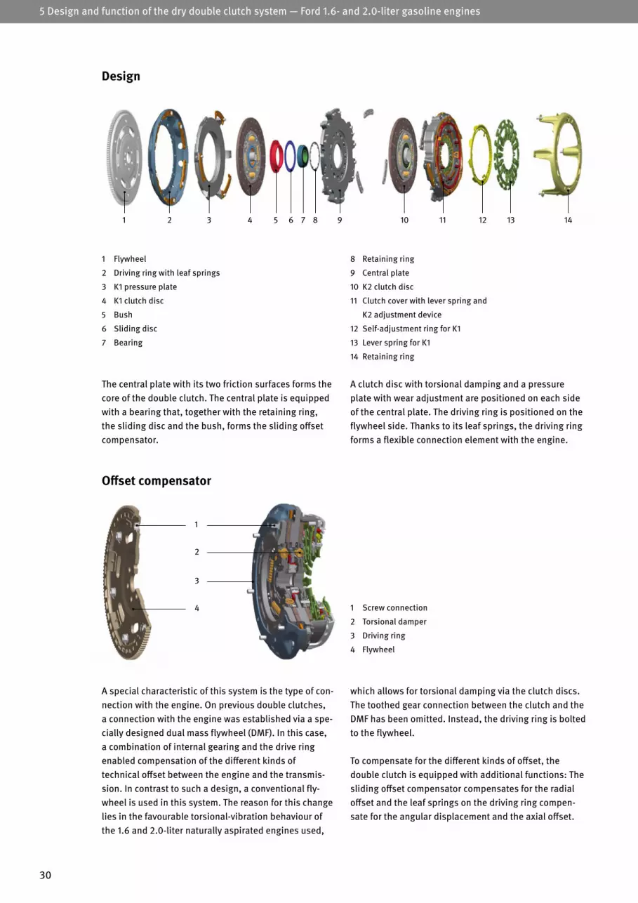
30
1 Flywheel
2 Driving ring with leaf springs
3 K1 pressure plate
4 K1 clutch disc
5 Bush
6 Sliding disc
7 Bearing
8 Retaining ring
9 Central plate
10 K2 clutch disc
11 Clutch cover with lever spring and
K2 adjustment device
12 Self-adjustment ring for K1
13 Lever spring for K1
14 Retaining ring
A clutch disc with torsional damping and a pressure plate with wear adjustment are positioned on each side of the central plate. The driving ring is positioned on the flywheel side. Thanks to its leaf springs, the driving ring forms a flexible connection element with the engine.
The central plate with its two friction surfaces forms the core of the double clutch. The central plate is equipped with a bearing that, together with the retaining ring, the sliding disc and the bush, forms the sliding offset compensator.
1 Screw connection
2 Torsional damper
3 Driving ring
4 Flywheel
1
Design
5 Design and function of the dry double clutch system — Ford 1.6- and 2.0-liter gasoline engines
321 4 9 10 11 13 145 6 7 8 12
Offset compensator
which allows for torsional damping via the clutch discs. The toothed gear connection between the clutch and the DMF has been omitted. Instead, the driving ring is bolted to the flywheel.
To compensate for the different kinds of offset, the double clutch is equipped with additional functions: The sliding offset compensator compensates for the radial offset and the leaf springs on the driving ring compen-sate for the angular displacement and the axial offset.
A special characteristic of this system is the type of con-nection with the engine. On previous double clutches, a connection with the engine was established via a spe-cially designed dual mass flywheel (DMF). In this case, a combination of internal gearing and the drive ring enabled compensation of the different kinds of technical offset between the engine and the transmis-sion. In contrast to such a design, a conventional fly-wheel is used in this system. The reason for this change lies in the favourable torsional-vibration behaviour of the 1.6 and 2.0-liter naturally aspirated engines used,
2
3
4

31
Radial offsetAutomotive components are generally produced within a defined range of tolerance, which allows for deviations from the standard state without preventing a system from functioning correctly. When fitting the engine and transmission together, the combination of component tolerances may be unfavourable, thereby causing a radial offset. In such instances, the axes of rotation of the crankshaft and the transmission input shaft are not at the same level. This offset can lead to idling noises and increased wear, particularly if the transmission input shaft does not have a pilot bearing.
The sliding offset compensator is employed here as a countermeasure. It uses a dry-running plain bearing to provide the double clutch with radial flexibility on the transmission input shaft. As such, the relative move-ments are directed via a durable sliding disc and radial forces are effectively prevented.
Axial offsetThe crankshaft is subject to bending due to the combus-tion in the cylinders. When these combustion occur, the crankshaft extends to the axis of rotation, resulting in pulsing changes in length at the flange of the crankshaft that occur in line with the combustion frequency. These changes in length create an axial offset, which causes the flywheel to wobble. This movement must not be transferred directly to the double clutch, as this would have a negative impact on comfort characteristics.
Angular displacementAngular displacement can also result from the combina-tions of component tolerances. In such instances, the axes of rotation of the crankshaft and the transmission input shaft are positioned at differing angles to each other. Consequently, the clutch discs are constantly subject to bending during operation, causing premature damage to the clutch discs.
To compensate for the axial offset and angular displace-ment without producing any wear, the double clutch is flexibly mounted in the driving ring. As part of this design, specially shaped leaf springs effectively compensate for the axial offset and angular displacement.
Note: If the double clutch is removed, the ball bearing of the sliding offset compensator becomes unattached in the central plate. This occurs as a result of the design and should not be regarded as a defect.

32
1 Crankshaft
2 Flywheel
3 Central plate
4 Support bearing
5 K1 pressure plate
6 K1 clutch disc
7 K2 pressure plate
8 K2 clutch disc
Design
9 K1 engagement bearing
10 K2 engagement bearing
11 Retaining ring
12 Transmission input shaft 1 (solid shaft)
13 Transmission input shaft 2 (hollow shaft)
14 K1 lever spring
15 K2 lever spring
10
9
7
8
3
5
2
4
6
1
11
15
14
1312
5 Design and function of the dry double clutch system — Ford 1.6- and 2.0-liter gasoline engines

33
the servo motor for K2 actuates the engagement lever with the narrow fork opening. The inner lever spring is activated via the engagement bearing. This moves the K2 pressure plate towards the central plate. This creates a connection to the clutch disc. The engine torque is transmitted to the hollow shaft. At the same time, K1 opens.
When driving in gears 1, 3 or 5, the servo motor for K1 is activated electrically. This causes the engagement lever with the wide fork opening and the large engagement bearing to move towards the double clutch. The outer lever spring transmits this movement to the retaining ring and reverses the effective direction of the engage-ment force. As a result, the pressure plate for K1 is pulled towards the central plate, closing the clutch. The clutch disc then transfers the engine torque to the solid shaft. If one of gears 2, 4, 6 or R is to be used when driving,
Function

34
1 Engagement bearing for K1 with washer
2 Engagement bearing for K2 with washer
3 Guiding sleeve
4 Lever actuator with return springs for K1
5 Lever actuator with return springs for K2
6 Servo motor for K1
7 Servo motor for K2
The engaging system is operated electrically and con-sists of the two engagement bearings with washers for K1 and K2 [1 and 2], the guiding sleeve [3] and two lever actuators [4 and 5]. These components are arranged in the transmission bell housing. The two servo motors [6 and 7] are mounted on the outside. They are connec-ted to the respective lever actuator via a spindle. Both work identically, only the fork openings on the engage-ment levers are different.
With previous manual transmissions with single disc clutch, the clutch is closed when idling. It is opened by pressing on the clutch pedal, thus disconnecting the transmission of power. This takes place via the “release system”.
By contrast, the clutches in this double clutch system are open when idling (normally open). They are closed when the engagement lever is actuated. This is therefore referred to as an engaging system.
5.2 Engagement system
Structure of the overall system
6
4
1
23
7
5
5 Design and function of the dry double clutch system — Ford 1.6- and 2.0-liter gasoline engines

35
In order to achieve the optimum performance of the engaging system, return springs and lever actuators are adapted to one another and paired ex works. These units are identified by an identical four-digit number that is located on the sleeve and the engagement lever.
1 Bolt
2 Sleeve
3 Pressure spring
4 Nut
5 Retaining ring
5
4
3
2
1
The base plate is used to secure the lever actuator in the transmission bell housing and to guide the rollers pre-cisely. The engagement lever contains two return springs, which serve as deflection points and energy stores.
The lever actuator consists of a base plate, spindle, sled (nut ball screw with multi-part rollers), engagement lever and return springs. Together they form the actuating mechanism.
Structure of the lever actuator
The return spring acts as an energy store during the engagement process. The sleeve [2] and the pressure spring [3] form a single unit. There is a stop at the lower end of the screw [1] that limits the path of the sleeve. There is a nut [4] at the upper end. This supports the pressure spring and is used to adjust the return spring ex works.
The engagement lever and sleeve are designed with a wave profile. On the one hand, this ensures that the en-gagement lever is guided correctly. It also forms a rocker joint connection that enables virtually frictionless work during operation.
At the start of the engagement process, the pressure spring is compressed by the sleeve. The energy stored in this way is used to close the clutch at the end of the engagement process.
1 Base plate
2 Spindle
3 Sled
4 Nut ball screw
5 Rollers
6 Engagement lever
7 Return spring
8 Servo motor
Design and function of the return spring
8
1
6
5
4
7
2
3

36
5 Design and function of the dry double clutch system — Ford 1.6- and 2.0-liter gasoline engines
By moving the sled further, even more energy is stored in the return spring, to the point where the changed lever ratio together with the force of the return spring is suf-ficient to close the clutch.
Intelligent use of the lever principle results in an almost constant force level for the servo motor. This allows a considerable reduction in motor size. Due to the low energy requirement and the universally applicable actuating mechanism, this system also fulfils the future requirements for hybrid systems.
The servo motor changes the central bearing point of the engagement lever, the sled, via a ball screw drive. This influences the effective lever ratio, which changes continually over the course of the engagement process.
The sled moves towards the transmission input shaft during the engagement process. The return spring is compressed due to the inclined plane (working angle) of the engagement lever and thus acts as an energy store. The force on the engagement bearing increases but, due to the unfavourable lever ratio, is not yet sufficient to close the clutch.
The pre-tension force of the pressure spring [FSpring] in the return spring and the leverage ratio [x/(L – x)] resulting from the position [x] of the sled determine the engagement force of the clutch [FClutch].
In order to engage the clutch, the sled must be moved along its max. roller path [ROPmax].
The actuator force [FActuator] consists of the equilibrium between the spring and clutch force, offset against the working angle [α].
Schematic representation
FClutch = FSpring ∙x
L – x
FActuator = (FClutch + FSpring) ∙
ROPmin
FSpring
FClutch
ROPmax
Engagement pathClutch
FActuator
FSpring
FClutch
Function

37
Automatic emergency clutch openingSince, in contrast to manual transmissions, the clutches are actively closed, in the event of a malfunction the engaging system could come to a stop in an inseparable clamped state. The vehicle would then no longer be able to move with a gear engaged.
Motor active Motor passive
MMotor
FSpindle
In order to prevent this, the lever actuators are designed so that, with a currentless servo motor, the counter force of the lever spring is sufficient to push back the sled automatically, thus opening the clutch. In this way, the vehicle can still be moved in an emergency, even when a gear is engaged.
FSpring
FClutch FClutch
FSpring

38
6 Structure and function of the dry double clutch system – Alfa Romeo, Fiat, Jeep and Suzuki
The system consists of the following main components: double clutch, engagement system and release system, dual mass flywheel (DMF) and electro-hydraulic control unit.All gear change actions are executed by the electro-hydraulic control unit. This control unit is mounted on the outside of the transmission and consists of a pump, a pressure accumulator and various electromagnetic valves. The “control center” is an external control unit, which uses the information received to calculate the exact shift point and activates the actuators at the right moment.
Special features of this system
• Two different operating systems are used for clutch control
• One clutch is operated externally via a central control rod
• A high (for a dry double clutch) transferable torque of 350 Nm
During driving operations, the transmission electronics evaluate various pieces of information, including:
• Transmission input speed• Vehicle speed• Selector lever position• Throttle valve position• Engine temperature and external temperature• Steering angle• Brake pedal information• Engine speed and engine torque
6 Structure and function of the dry double clutch system Alfa Romeo, Fiat (1.4 petrol engines and 2.0 diesel engines, 6-speed transmission C635 DDCT); Jeep (1.4-liter petrol engines and 1.6 liter diesel engines); Suzuki (1.6 liter diesel engines)
Using this information, the transmission control unit generates the shift commands and converts them into electric signals. These signals operate the actuators in the electro-hydraulic control unit, which operate the gear shift forks inside the transmission as well as the clutches. When idling, one clutch is closed and one is open. Unlike the other double clutch transmissions detailed in this brochure, both a hydraulically actuated concentric slave cylinder and a central engagement system are used to operate the clutches alternately while driving.
However, the basic functions are the same as all other double clutch systems. During the journey, one sub-transmission is always non-positively connected to the engine. The gear in the other sub-transmission can be already pre-selected as the clutch for this sub-trans-mission is still open. In response to a gear shift, clutch 1 is opened using the concentric slave cylinder and clutch 2 is closed via the central engagement system at the sametime. The power now flows via the previously engaged gear. This means that it is possible to drive with virtually no interruption to the tractive power.
1 Dual mass flywheel (DMF)
2 Double clutch
3 Central engagement system
4 Concentric slave cylinder
1 2 3 4
1 Crankshaft
2 Double clutch
3 Transmission input shaft 1
4 Transmission input shaft 2
5 Output shaft 1
6 Output shaft 2
7 Output shaft 3
(reverse gear)
135
R
6 4 2
6
4
3
7
5
2 1

39
1 Dual mass flywheel (DMF)
2 Double clutch
3 Central engagement system
4 Concentric slave cylinder
6.1 Double clutch
Fundamental principle
In the case of a 6-speed double clutch transmission, each sub-transmission is constructed like a manual transmission in terms of its function. One clutch is responsible for each sub-transmission. These clutches are located on two coaxial input shafts arranged as inner and outer input shafts.
Gears 1, 3, 5 and reverse are shifted via clutch 1, while the torque is transmitted to the transmission via the inner shaft. Gears 2, 4 and 6 are shifted via clutch 2, with the torque being transmitted to the transmission via the outer shaft.
6 2 4
5 31
R
Clutch 1 is responsible for gears 1, 3, 5 and R
Clutch 2 is responsible for gears 2, 4 and 6
6 2 4
5 31
R

40
6 Structure and function of the dry double clutch system – Alfa Romeo, Fiat, Jeep and Suzuki
Clutch 1 works on the basis of the “normally closed” principle, meaning that the clutch is closed in the normal (non-actuated) state. To open the clutch, it must be “released”. Clutch 2 is located on the opposite side. It works according to the “normally open” principle. This means that the clutch is open when idling.
To close the clutch, it must be “engaged”, which is why this is referred to as an engaging system. It uses the lever spring to generate the required clamp load on the pressure plate. On the transmission side, the clutch cover is fitted with a rotating flange bearing. The flange bearing is bolted to the bell housing and bears part of the weight of the double clutch. As a result, the bearings on the input shafts are subjected to lower loads.
The central plate with its two friction surfaces forms the core of the double clutch. Both clutches are arranged such that the friction surfaces of the pressure plates point in the direction of the central plate.
Clutch 1 is located on the flywheel side. Its housing is equipped with a toothed gear that engages into the flange of the DMF. The engine torque is transferred to the clutch via this connection. The clutch type in use is a self-adjusting clutch (SAC). The technology behind the SAC has already proven its value in conventional manual transmissions for many years. This clutch type allows facing wear to be compen-sated for by means of sensor springs and an adjuster ring.
Design
1 Toothed gear
2 Clutch cover (clutch 1)
3 Adjuster ring
4 Sensor spring
5 Diaphragm spring
6 Tangential leaf spring (clutch 1)
7 Pressure plate (clutch 1)
8 Clutch disc (clutch 1)
9 Central plate
10 Clutch disc (clutch 2)
11 Tangential leaf spring (clutch 2)
12 Pressure plate (clutch 2)
13 Lever spring
14 Clutch cover (clutch 2)
15 Flange bearing
1 2 3 4 5 6 7 8 9 10 12 13 14 1511

41
1 Crankshaft
2 Dual mass flywheel (DMF)
3 Release bearing (clutch 1)
4 Disc spring
5 Tangential leaf spring (clutch 1)
6 Pressure plate (clutch 1)
7 Clutch disc (clutch 1)
8 Central plate
9 Clutch disc (clutch 2)
10 Pressure plate (clutch 2)
11 Lever spring
12 Flange bearing
13 Tangential leaf spring (clutch 2)
14 Central engagement system (clutch 2)
15 Inner transmission input shaft
16 Outer transmission input shaft
17 Control rod
18 Concentric slave cylinder
1 2 3 4 5 6 7 8 9 10 11 12 13 14 15 16 17 18

42
6 Structure and function of the dry double clutch system – Alfa Romeo, Fiat, Jeep and Suzuki
Engaging the odd gearsWhen shifting into gears 1, 3, 5 or R, clutch 1 closes while clutch 2 opens. The control pressure in the engagement system and release system is thus reduced in separate lines independently of each other.
During this process, the piston in the concentric slave cylinder is pushed into its initial position via the release bearing and control rod. The force of the diaphragm spring of clutch 1 causes the clutch disc to be pressed against the central plate by the pressure plate.
Clutch 1 closes/clutch 2 opens
Function
This creates a non-positive connection that transmits the engine torque to the inner transmission input shaft.
The pressure drop in the central engagement system of clutch 2 reduces the lever actuation force on the lever spring, allowing the tangential leaf springs to lift the pressure plate off the clutch disc and open the clutch. No engine torque is transmitted to the outer transmission input shaft.

43
Engaging the even gearsAt the beginning of a change into gears 2, 4 and 6, the control pressure in both the engagement system and the release system is increased. This opens clutch 1 and closes clutch 2.
The higher hydraulic pressure generates a greater force on the piston of the concentric slave cylinder of clutch 1. The force actuates the diaphragm spring. The pressure plate is lifted by the tangential leaf springs and separated from the clutch disc.
Clutch 1 opens/clutch 2 closes
Clutch 1 opens and interrupts the power transmission to the inner transmission input shaft.
At the same time, the concentric slave cylinder exerts pressure on the lever spring of clutch 2. This rests against the housing and actuates the pressure plate against the force of the tangential leaf springs. This action creates a non-positive connection that transmits the engine torque to the outer transmission input shaft.

44
6 Structure and function of the dry double clutch system – Alfa Romeo, Fiat, Jeep and Suzuki
Engaging idle speed Due to the alternating closing action of the clutches (cross-shifting), one sub-transmission is always non-positively connected to the engine. However, there are some situations—such as starting, driving off or stopping—in which the power flow must be completely stopped. To do this, the engagement system and release system are actuated such that both clutches open.
The functions in this operating state are as follows: Clutch 1 is held in the open position by the pressure in the concentric slave cylinder being increased and held at a consistently high level. In parallel, the pressure in the central engagement system is lowered, causing clutch 2 to open independently and disconnect the power flow.
To ensure that sufficient operating pressure is available after a long period of downtime, the system is equipped with a pressure accumulator. The pressure accumulator is monitored by a sensor and supplied by a pump. As soon as the driver’s door is opened, the transmission control unit detects whether the pressure is sufficient to open clutch 1, or whether it needs to be increased.
Clutch 1 and 2 open

45
The piston is hollow and has an internal thread for mounting the control rod. The outer side of the piston features a preload spring that is supported in the central position.
The concentric slave cylinder closes to the outside with a cover attached to the plastic sleeve. This cover prevents contamination and is equipped with ventilation to enable volume compensation.
The concentric slave cylinder was designed specifically for the double clutch of the C635 DDCT transmission. The concentric slave cylinder is fitted opposite the clutch bell housing on the outside of the transmission or on the back of the gearbox.
The metal casing features a plastic bushing that serves as the outer cylinder barrel for the piston. The piston is shaped like an anchor, with a head that is similar to a ring. The head of the piston features a sealing ring fixed in place via a groove.
6.2 Release and engagement system
Concentric slave cylinder, clutch 1
Design
1 Hydraulic connection
2 Metal housing
3 Pressure chamber
4 Piston with magnetic ring and
internal thread for the control rod
5 Preload spring
6 Sealing ring
7 Plastic sleeve
8 Ventilation
9 Extensometer
1
2
3
4
6
7
8
9
5

46
6 Structure and function of the dry double clutch system – Alfa Romeo, Fiat, Jeep and Suzuki
Function
The concentric slave cylinder actuates clutch 1 for the odd gears.
To open the clutch, hydraulic fluid is pumped into the pressure chamber, causing the piston to be retracted with the control rod. As a result, the diaphragm spring is actuated by the release bearing and the clutch is discon-nected. If the pressure of the hydraulic fluid is reduced, the piston moves into its initial position under the force of the disc spring. In this operating state, the preload spring enables a slight preloading of the thrust ring and therefore reduces the wear of the contact surfaces.
Signal detectionIn order to implement rapid gear changes, the position of the release bearing must be transmitted to the control unit in the form of an electrical signal. This signal is generated directly on the concentric slave cylinder by the magnetic ring in the piston together with the exten-someter.
1 Release bearing with thrust ring
2 Direction of motion to release clutch 1
3 Direction of motion to engage clutch 1
4 Control rod
5 Concentric slave cylinder
1 2 3 4 5

47
Function
The electro-hydrauliccontrol unit conveys hydraulic fluid into the pressure chamber of the concentric slave cylinder (CSC), thus actuating the clutch. This causes the piston to move out and close the clutch.
To open the clutch, the pressure in the system is re-duced. As a result of the force from the tangential leaf springs, the piston of the CSC is pushed into its initial position via the lever spring. The hydraulic fluid previ-ously pumped in flows back to the control unit.
Self-centering actionThe thrust ring of the central engagement system can be moved radially and, due to the force of the preload spring, remains in constant contact with the clutch. Due to these properties, the thrust ring can center itself on the tips of the lever spring independently during operation.
The central engagement system consists of a ring-shaped hydraulic piston that moves within in a double-walled cylinder. One side of the piston closes the pressure chamber.
The other side is equipped with a bearing that has a self-centering thrust ring. The preload spring visible from the outside is arranged between the housing and the bearing.
Central engagement system, clutch 2
Design
2
1
3
4
5
In the event of a possible misalignment of the engine and transmission, this property reduces the wear on the contact surfaces to a minimum.
Signal detectionThe position of the release bearing is detected via the pres-sure level. As part of this process, a sensor in the electro-hydraulic control unit assigns a specific signal to the respective pressure in the engagement system. Using this information, the control unit can determine the position of the release bearing.
1 Preload spring
2 Pressure chamber
3 Thrust ring
4 Piston
5 Bearing

48
7 Dual mass flywheel (DMF) for the double clutch transmission (DCT)
7 Dual mass flywheel (DMF) for the double clutch transmission (DCT)
The flywheel used with the DCT is a special form of the LuK DMF. Just like conventional DMFs in manual trans-missions, there is a primary side and a secondary side. However, in contrast to conventional DMFs, the second-ary side is not a fixed part of the DMF and is therefore not designed as a flywheel mass, rather in the form of a flange, and only serves as a connection between the primary mass and the double clutch.
One further difference from conventional DMFs is that the friction surface on the secondary side is omitted. This is also located in the double clutch, where it forms the central plate on which the friction surfaces for both clutches are located. Instead of the friction surface on the DMF, a flange with internal teeth is used. The toothed gear of the double clutch meshes with this flange.
In this case, the secondary flywheel mass is incorporated into the weight of the double clutch, which is located on an input shaft (hollow shaft) belonging to the transmission. This means that the direct bearing arrangement of the adjacent masses using a ball bearing or plain bearing that is implemented in conventional DMFs is also omitted.
Since the two interlocking sprockets would produce noise as a result of tooth backlash, an anti-backlash ring is attached as a countermeasure. This tensions the two sprockets so that the tooth flanks have no clearance between them. On some versions, the anti-backlash ring must be reset using a special tool before being installed in the transmission.
Note: Further information on the DMF is described in the LuK brochure “Dual mass flywheel”.
3
1 Primary mass with arc springs
2 Flange with internal teeth to accommodate the
rim of the toothed gear of the double clutch
21 4
3 Anti backlash ring
4 Cover for the primary mass with ring gear
12
1 Anti backlash ring
2 Toothed gear of the double clutch

49
The following tool kits are currently available:(for wet double clutches)• Volkswagen tool kit (Audi, SEAT, ŠKODA and VW)(for dry double clutches)• Basic tool kit• Volkswagen tool kit (Audi, SEAT, ŠKODA and VW)• Ford 1.0 liter, Hyundai, Kia, Renault, Dacia, Smart, Mercedes Benz and Geely tool kit • Ford 1.6-/2.0-liter tool kit• Reset tool kit (Ford, Hyundai, Kia, Renault, Dacia, Smart)• Alfa Romeo, Fiat, Jeep and Suzuki tool kit• Supplementary tool kit (for previous LuK double clutch special tool, part no.: 400 0240 10)• Supplementary tool kit (for previous LuK double clutch
special tool, part no. 400 0423 10)
8 Description and contents of the LuK special tools
8 Description and contents of the LuK special tools
Work on the double clutch systems must always be car-ried out using appropriate special tools. This ensures professional repairs and prevents damage to the clutch and transmission.
Schaeffler Automotive Aftermarket offers a future-proof tool system for correct installation/removal. It has a modular design and consists of a basic tool kit and several vehicle-specific tool kits. The range of tools can be easily adapted to new and future double clutch systems. This enables tools to be put together as required.
Note: If you have any questions about the special tool case or diagnostics and repairs, please call our Schaeffler REPXPERT Service Center on +49 0800 1753-333*
*Toll-free number, Mon. to Fri. from 8 a.m. to 5 p.m.

50
8 Description and contents of the LuK special tools
6 Retaining pin for DQ 2507 Retaining pin for DQ 380/81 and DQ 5008 Mounting sleeve for DQ 250 9 Collet10 Mounting sleeve for DQ 380/81 and DQ 500
1 Slide hammer2 Dial gage with stand3 Holder4 2 plugs5 2 mounting hooks
installation of the new double clutch. Unlike comparable tools, this is designed in such a way that additional mechanics are not required for the installation process. After installation, the axial clearance of the double clutch has to be adjusted using washers (included in the RepSet). The necessary measuring tools as well as their mounts on the transmission housing are also included in the tool kit.
The LuK special tool is an essential piece of equipment for correct removal/installation of the wet double clut-ches in 6-speed and 7-speed transmissions. Part num-ber: 400 0540 10. Due to the restricted mounting space, the double clutch cannot be removed from the bell housing and re-inserted again by hand. Therefore, the set contains two special installation tools for this purpo-se. A retaining pin is required to enable the professional
8.1 Tool kits for wet double clutches
Volkswagen tool kit
6
7
8
2
35
1
49
10
Part no. 400 0540 10

51
Art.-Nr. 400 0240 10
complete kit for professional repairs. This refers to almost all dry double clutch systems currently available from LuK except for Alfa/Fiat, Jeep and Suzuki.
The basic tool kit (part no. 400 0418 10) forms the basis of the modular tool system. It contains those tools that are generally required for all repairs to double clutches. Together with a vehicle-specific tool kit, they form a
8.2 Tool kits for dry double clutches Basic tool kit
Part no. 400 0418 10
7 Transmission support with height adjustment8 2 plugs for driveshaft holes9 DMF reset tool10 Unlocking key11 Special open-end wrench
1 Puller with spindle and pressure piece 2 3 thumb screws3 3 M10 threaded bolts, 100 mm long 4 3 M10 threaded bolts, 160 mm long5 Circlip pliers, angled6 Magnet
6
7 8
2
3
5
1
4
9
11
10

52
generation dry double clutches (from June 2011) in vehicles manufactured by Audi, SEAT, ŠKODA and Volkswagen with a 0AM and 0CW transmission.
Part no. 400 0419 10
This vehicle-specific tool kit (part no. 400 0419 10) must be combined with the basic tool kit. It can be used to re-move, install and adjust both first generation dry double clutches (up to May 2011) and second
Volkswagen tool kit
8 Description and contents of the LuK special tools
8 Pressure sleeve for removal9 Plugs10 3 hooks11 Setting gauge for reference gauge12 Coupling hooks13 Weight, 3.5 kg
1 Dial gauge with stand 2 Reference gauge 32.92 mm (1st generation, K2)3 Reference gauge 48.63 mm (1st generation, K1)4 Reference gauge 32.12 mm (2nd generation, K2)5 Reference gauge 48.42 mm (2nd generation, K1) 6 3 plungers7 Support sleeve for installation
6
78
23
5
1
4
9
12
11
10
13

53
This tool kit (Art.-Nr. 400 0470 10) contains all tools that are required to carry out professional repairs on a dry double clutch on a Renault, Dacia vehicle (DC0/DC4 6-speed transmission), Hyundai/Kia (D6GF1 6-speed-trans mission), Ford 1.0 liter (6-speed transmission
1 Pressure sleeve for Ford, Renault, Dacia ,Smart, Mercedes Benz and Geely2 Support sleeve for Ford, Renault, Dacia and Smart, Mercedes Benz and Geely3 Detent pin
Art.-Nr. 400 0240 10
DPS6), Smart (H-DCT 6-speed-trans mission), Mercedes Benz (6-speed transmission 6G-DCT) and Geely (6-speed transmission 6DCT) . It must be used together with the basic tool kit.
Ford 1.0-liter, Hyundai, Kia, Renault, Dacia, Smart, Mercedes Benz and Geely tool kit
Part no. 400 0470 10
4 Pressure sleeve for Hyundai and Kia5 Support sleeve for Hyundai and Kia 6 Threaded pin with fine thread for Hyundai and Kia 7 Spacer8 Hooks
67
2
3
5
1
4
8

54
This tool kit (part no. 400 0427 10) contains all tools that are required to carry out professional repairs on a dry double clutch on a Ford with a 1.6 or 2.0-liter gasoli-ne engine. It must be used together with the basic tool kit.
Ford 1.6-/2.0-liter tool kit
8 Description and contents of the LuK special tools
Part no. 400 0427 10
5 2 handles6 Template KL-0500-8341 for 1.6-liter engines7 Template KL-0500-8342 for 2.0-liter engines
1 3 hooks2 3 plungers3 Support sleeve4 Pressure sleeve
6
7
2
51
4
3

55
tional work is necessary prior to installation. The trans-port fastener must be put back in place if the double clutch is used again after removal, e.g. because work has been carried out on the transmission seals. The re-set tool kit (part no. 400 0425 10) must be used for this type of work.
New dry double clutches vehicles from Renault, Dacia (6-speed transmission DC0/DC4), Hyundai/Kia (6-speed trans mission D6GF1), Ford 1.0 liter (6-speed trans-mission DPS6), Smart (6-speed transmission H-DCT), Mercedes Benz (6-speed transmission 6G-DCT) and Geely (6-speed transmission 6DCT) are always equipped with a transport safety device. This means that no addi-
Reset tool kit
Part no. 400 0425 10
7 Thrust piece K2 - Ø 131 mm8 Thrust ring K1 - Ø 85 mm9 Thrust ring K1 - Ø 105 mml10 Locating ring K1 11 Locating ring K212 3 locating lugs K1
1 Base plate with spindle2 Locking nut 3 Adapter4 2 locating pins 5 2 knurled nuts 6 Thrust piece K2 - Ø 115 mm
6
7
8
2
3
5
1
49
12
11
10

56
8 Description and contents of the LuK special tools
ring must be reset and locked before installation of the transmission. This step is performed using the reset tool supplied. The tool can be adjusted to the respective DMF versions of the dry double clutch systems by Alfa Romeo, Fiat, Jeep and Suzuki with just a few manual ad-justments and can be used directly on the vehicle.
The tool kit (part no. 400 0471 10) contains all the tools required for the professional repair of dry double clutches in Alfa Romeos/Fiats, Jeep and Suzuki (6-speed trans-mission C635 DDCT). The tool kit can be used without the basic tool kit. If the DMF is not replaced, the associated anti-backlash
Alfa Romeo/Fiat, Jeep and Suzuki tool kit
Part no. 400 0471 10
7 Installation device for the radial lip seal8 Mounting sleeve for the radial lip seal9 DMF reset tool10 2 locking screws
1 2 plugs for differential openings2 4 plugs for hydraulic openings3 Installation device for the control rod4 Hexagon socket set for the control rod5 3 centering sleeves6 3 threaded rods for centering sleeves
6
7 82
3 5
1
4
9
10

57
Together, the contents of the two tool kits correspond to the basic tool kit and the Volkswagen tool kit.
The previous LuK double clutch special tool (part no. 400 0240 10) can be adapted to the new, modular tool system range with the supplementary tool kit (part no. 400 0420 10).
Supplementary tool kit (for the previous LuK double clutch special tool, part no. 400 0240 10)
5 Reference gauge 48.42 mm (2nd generation, K1)6 DMF reset tool 7 Unlocking key
1 Transmission support with height adjustment2 Plugs for driveshaft holes3 Special open-end wrench 4 Reference gauge 32.12 mm (2nd generation, K2)
Part no. 400 0420 10
6
7
2
3
5
1
4

1 Pressure sleeve for Ford, Renault, Dacia, Smart, Mercedes Benz, Geely2 Support sleeve for Ford, Renault, Dacia Smart, Mercedes Benz, Geely3 Detent pin
58
8 Description and contents of the LuK special tools
Dacia, Hyundai/Kia, Ford 1.0-liter, Smart, Mercedes Benz, Geely tool kit. It must be used together with the basic tool kit.
The previous Renault tool kit (part no. 400 0423 10) can be modified with the supplementary tool kit (part no. 400 0520 10) to the scope of the new Renault,
Supplementary tool kit (for the previous LuK double clutch special tool, part no. 400 0423 10)
Part no. 400 0520 10
4 Pressure sleeve for Hyundai and Kia5 Support sleeve for Hyundai and Kia 6 Threaded pin with fine thread for Hyundai and Kia 7 Spacer
67
2
3
51
4

Supplementary tool kitPart no. 400 0420 10
Ford 1.0 liter, Hyundai, Kia, Renault, Dacia, Smart, Mercedes Benz, Geely tool kit – Part no. 400 0470 10
Ford 1.6-/2.0-liter tool kitPart no. 400 0427 10
Alfa Romeo/Fiat, Jeep, Suzuki tool kit Part no. 400 0471 10
59
9.1 Tool kits for dry double clutches
9 Overview of how to use the tool kits
9.2 Tool kits for wet double clutches
The table below shows which tool kits need to be combined if no LuK special tool is available yet.
This table illustrates how the tool systems are combined if the LuK double clutch special tool part no. 400 0240 10 is already available.
Tool
kit
If a double clutch that has been used previously is reinstalled, the transport safety devices must be reset. The vehi-cles affected and the required reset tool are listed in the following table.
For the wet double clutches in VW Group 6 and 7-speed transmissions, only the Volkswagen tool kit (wet) part no.: 400 0540 10 should be used.
Tool
kit
Reset tool kit Part no. 400 0425 10
Application Audi, SEAT, ŠKODA, VW, 1st generation
Audi, SEAT, ŠKODA, VW, 2nd generation
Ford 1.0 liter, Hyundai, Kia,
Renault, Dacia, Smart, Mercedes Benz, Geely
Ford1.6-/2.0-liter
Alfa Romeo,Fiat, Jeep, Suzuki
Tool
kit
ApplicationAudi, SEAT, ŠKODA, VW, 1st generation
Audi, SEAT, ŠKODA, VW, 1st generation
Audi, SEAT, ŠKODA, VW, 2nd generation
Application Audi, SEAT, ŠKODA, VW, 2nd generation
Ford 1.0 liter, Hyundai, Kia,
Renault, Dacia, Smart, Mercedes Benz, Geely
Ford 1.0 liter, Hyundai, Kia,
Renault, Dacia, Smart, Mercedes Benz, Geely
Ford 1.6- /2.0 liter
Ford 1.6- /2.0 liter
Alfa Romeo,Fiat, Jeep, Suzuki
Alfa Romeo,Fiat, Jeep, Suzuki
9 Overview of how to use the tool kits
Basic tool kitPart no. 400 0418 10
Volkswagen tool kitPart no. 400 0419 10
Ford 1.0 liter, Hyundai, Kia, Renault, Dacia, Smart, Mercedes Benz, Geely tool kit – Part no. 400 0470 10
Ford 1.6-/2.0-liter tool kitPart no. 400 0427 10
Alfa Romeo/Fiat, Jeep, Suzuki tool kit Part no. 400 0471 10

9996006550/09.2021 ©
2021 Schaeffler Automotive Afterm
arket Gm
bH &
Co. KGwww.repxpert.com