lessons learnt during the refurbishment of digester mixing and heating at goudkoppies wwtp
TRANSCRIPT
LESSONS LEARNT DURING THE REFURBISHMENT OF
DIGESTER MIXING AND HEATING AT GOUDKOPPIES WWTP
Andre Le Roux*, Thoko Nesamari**, Dave Keegan**
*Golder Associates Africa, P O Box 6001, Halfway House, 1685,
Tel: 011-254-4916, Fax: 011-315-0317 **Johannesburg Water, P O Box 3006, Halfway House, 1685
Tel: +27 (0)11 541 3840 Fax: +27 (0)11 541 3858 ABSTRACT Goudkoppies Wastewater Treatment Plant is one of the largest Biological Nutrient Removal plants (BNR) activated sludge plants in Southern Africa, routinely treating 120-150 Ml/day. The plant is operated by Johannesburg Water and discharges to the sensitive Vaal Barrage catchment. The plant has a large anaerobic digestion facility, originally equipped with steam heating and gas mixing facilities. The Anaerobic Digesters at Goudkoppies Wastewater Treatment Plant (WWTP) were operating without adequate mixing and heating for a period of time. Without proper mixing, digester heating via steam lances could not be carried out as direct steam injection would kill the anaerobic bacteria. Without mixing and heating, the Digesters were unable to perform as originally designed, as current operating conditions do not meet the required retention time for ambient temperature digestion. The digester complex consists of six digesters, eight compressors for gas mixing, five steam boilers for heating, gas holder with waste gas flare, gas/steam piping and associated safety equipment. A digester refurbishment project was implemented with the following components: a) Installation of eight (8) liquid ring compressors, including gas/liquid separators and
ancilliaries. b) Refurbishment of the gas mixing system including the gas collection, storage and
flare of waste gas. c) Upgrade of the gas cleaning equipment, including the storage, make-up and transfer
of dilute caustic. d) Digester heating system, including the biogas boosting station, boilers and steam
injection controls. The paper will present the design concepts and approach to substantially upgrade and retrofit the original digester installation. During the contract execution and subsequent commissioning a number of challenges arose. These resulted in modifications to the original facility design, but had additional advantages not considered during the project scope definition. These included: a) Overflow of the seal water cooling towers. b) Accumulation of moisture in gas pipelines.
c) Sludge foaming in the digesters resulting in sludge carry over into the gas pipelines. d) Digester pressure relief valves blowing off during digester operation. e) Digester overflowing during sludge feed. f) Boiler capacity during first heating of digesters. The paper will present the practical lessons learnt in the design and operation of steam injection and biogas mixing as applied to large anaerobic digesters. INTRODUCTION Goudkoppies Wastewater Treatment Plant (WWTP) is one of the largest BNR activated sludge plants in Southern Africa, routinely treating 120-150 Ml/day. The plant is operated by Johannesburg Water and discharges to the sensitive Vaal Barrage catchment. The plant has a large anaerobic digestion facility, originally equipped with steam heating and gas mixing facilities. Goudkoppies WWTP has three sludge streams that are fed to the anaerobic digesters: • Goudkoppies WWTP thickened primary sludge. • Goudkoppies WWTP thickened waste activated sludge (WAS). • Bushkoppies WWTP thickened primary sludge. On occasions, when Bushkoppies WWTP has problems with transferring WAS to Olifantsvlei WWTP, the WAS is also transferred to Goudkoppies WWTP. The digesters at Goudkoppies WWTP were operating without mixing and heating. Without proper mixing, digester heating via steam lances cannot be carried out as direct steam heating would kill the anaerobic bacteria. Without mixing and heating, the digesters are unable to perform as designed, as the required retention time for ambient temperature digestion is not met by current operating conditions. The digester refurbishment project was formulated to reinstate the gas mixing and steam heating facilities. ANAEROBIC DIGESTER PROCESS DESCRIPTION Goudkoppies Anaerobic Digester facility consists of the following components (See Figure 1 for equipment details): a) Primary sludge thickeners installed with the original Anaerobic Digesters. These
receive sludge from the primary clarifiers, thicken the sludge for feed to the Digesters and return an overflow to the equalisation basin. Due to strict nutrient discharge standards, these thickeners are operated as elutriation tanks to assist in the generation of volatile fatty acids (VFA) for enhanced phosphorous removal in the BNR activated sludge process. This results in the sludge thickener overflow having a high solids content due to the elutriation of the thickeners sludge blanket by recycling of underflow sludge. The particulate solids concentration in the overflow also assists with the denitrification process
b) The thickened (elutriated) sludge discharges into a wet well, from where two
Digester feed pumps (one operational and one stand-by) transfer the sludge to the main distribution box. The sludge from Bushkoppies WWTP and the waste activated sludge (mixed at the WAS pump station) also discharge into this main distribution box. From the main distribution box, the sludge is distributed to each Digester.
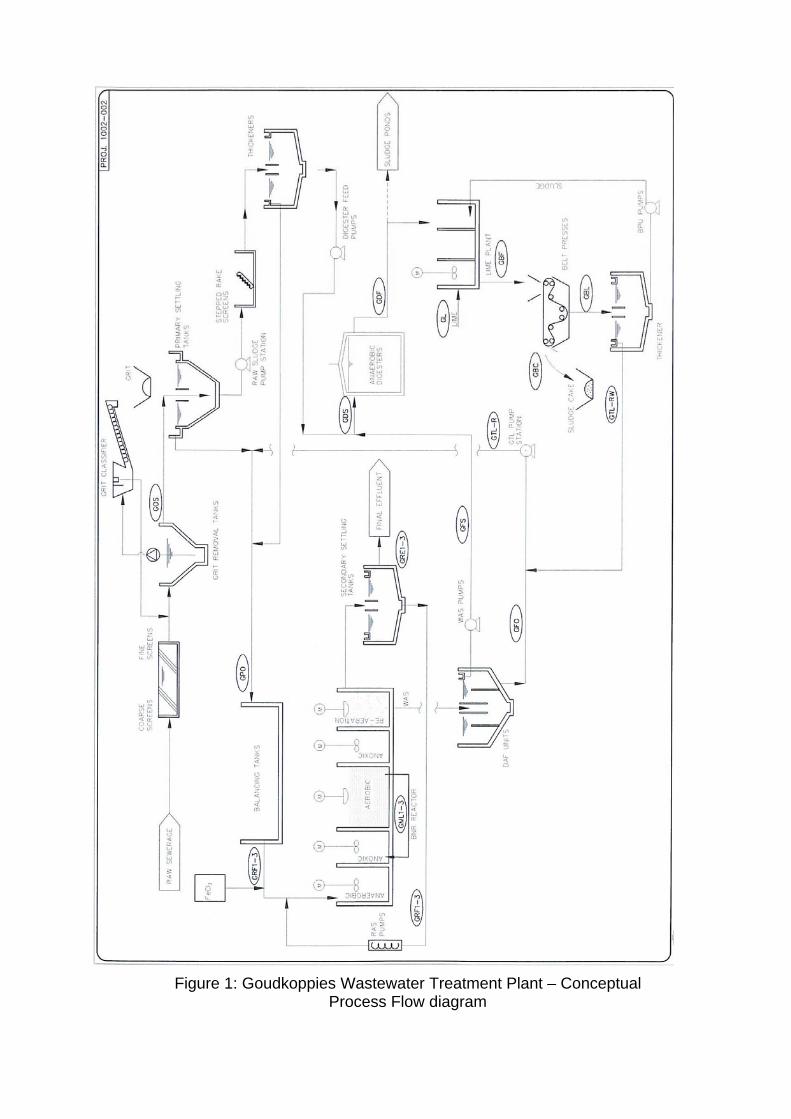
Figure 1: Goudkoppies Wastewater Treatment Plant – Conceptual Process Flow diagram
c) From the main distribution box, the feed sludge is distributed to Digesters 3 to 6 and Digesters 1 and 2. Digesters 1 and 2 feed discharges into a smaller distribution box located between Digesters 1 and 2. From this distribution box, the feed sludge is distributed to Digester 1 and 2.
d) Sludge draw-off is done through separate collection boxes for Digesters 1 and 2,
and Digesters 3 to 6. The digested sludge from the Digesters is collected and transferred to the adjacent sludge collection ponds.
e) During digestion of the sludge a biogas is produced. The gas produced has an
estimated composition of 65 to 70% (by volume) methane, 25 to 30% (by volume) carbon dioxide and small amounts of N2, H2, H2S, water vapour and other gases. The Digester gas was used to mix the Digester contents via seven gas mixing draft tubes. The draft tubes are hollow tubes open at each end and submerged into the Digesters. At the bottom end gas is released, rising into and through the tube to the sludge liquid level. While rising in the tube, the gas movement draws in surrounding sludge into the draft tube, moving it to the top of the tube via a siphon action. This creates a mixing action in the Digester. The gas arising from the sludge digestion is collected in the top cone of the Digester. Using gas compressors, the gas is re-circulated back to the Digester mixing system.
f) The biogas generated has a high energy content, which is used to fire steam
boilers. The excess gas can be diverted to a gas holder. The gas holder takes up surges in biogas production to allow supply of gas to the Digesters and the steam boilers. To obtain the correct feed pressure and supply to the steam boilers, the gas pressure is boosted through fans. The boilers produce steam which is used for Digester heating. Steam lances installed into the top of the Digesters are used to inject steam directly into the sludge. As mentioned, the heating with the steam lances cannot take place unless the Digester contents is properly mixed. If the tank contents are not mixed, then the injected steam may destroy the bacteria in the immediate area of the steam injection.
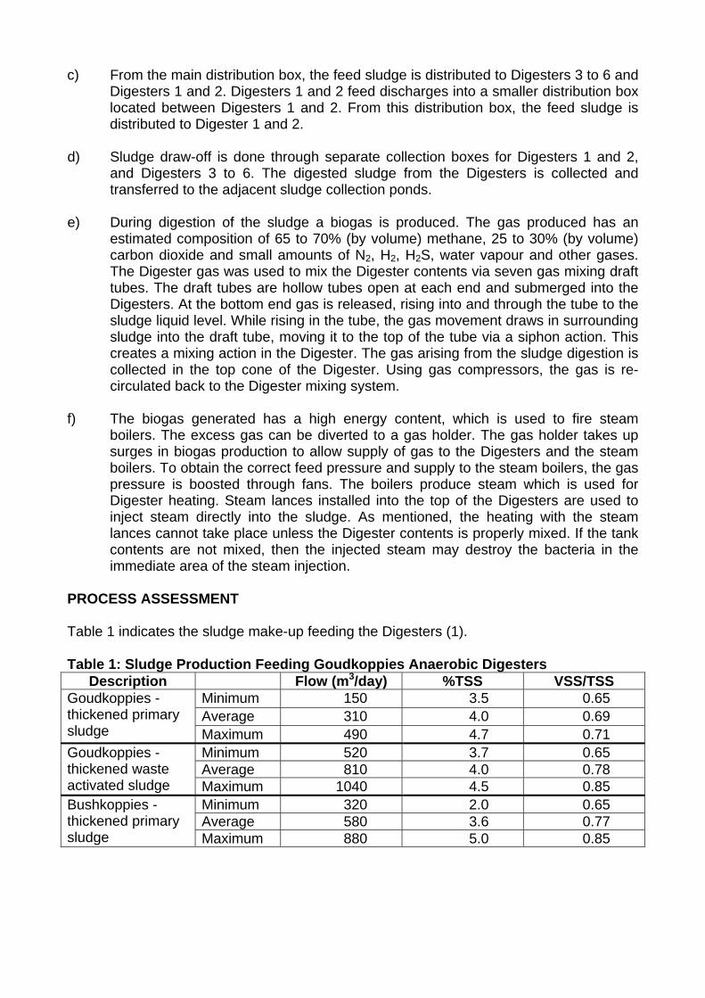
PROCESS ASSESSMENT Table 1 indicates the sludge make-up feeding the Digesters (1). Table 1: Sludge Production Feeding Goudkoppies Anaerobic Digesters
Description Flow (m3/day) %TSS VSS/TSS Minimum 150 3.5 0.65 Average 310 4.0 0.69
Goudkoppies -thickened primary sludge Maximum 490 4.7 0.71
Minimum 520 3.7 0.65 Average 810 4.0 0.78
Goudkoppies -thickened waste activated sludge Maximum 1040 4.5 0.85
Minimum 320 2.0 0.65 Average 580 3.6 0.77
Bushkoppies -thickened primary sludge Maximum 880 5.0 0.85
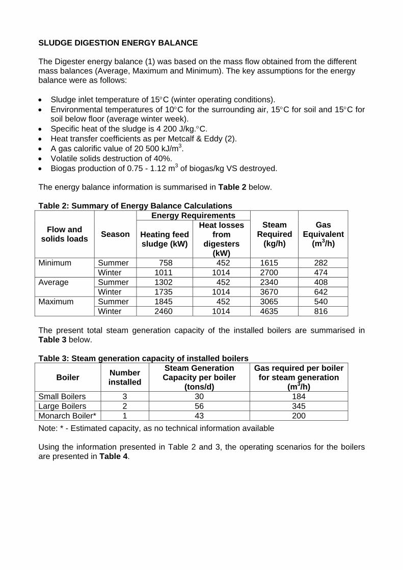
SLUDGE DIGESTION ENERGY BALANCE The Digester energy balance (1) was based on the mass flow obtained from the different mass balances (Average, Maximum and Minimum). The key assumptions for the energy balance were as follows: • Sludge inlet temperature of 15°C (winter operating conditions). • Environmental temperatures of 10°C for the surrounding air, 15°C for soil and 15°C for
soil below floor (average winter week). • Specific heat of the sludge is 4 200 J/kg.°C. • Heat transfer coefficients as per Metcalf & Eddy (2). • A gas calorific value of 20 500 kJ/m3. • Volatile solids destruction of 40%. • Biogas production of 0.75 - 1.12 m3 of biogas/kg VS destroyed. The energy balance information is summarised in Table 2 below. Table 2: Summary of Energy Balance Calculations
Energy Requirements Flow and
solids loads Season Heating feed sludge (kW)
Heat losses from
digesters (kW)
Steam Required
(kg/h)
Gas Equivalent
(m3/h)
Summer 758 452 1615 282 Minimum Winter 1011 1014 2700 474 Summer 1302 452 2340 408 Average Winter 1735 1014 3670 642 Summer 1845 452 3065 540 Maximum Winter 2460 1014 4635 816
The present total steam generation capacity of the installed boilers are summarised in Table 3 below. Table 3: Steam generation capacity of installed boilers
Boiler Number installed
Steam Generation Capacity per boiler
(tons/d)
Gas required per boiler for steam generation
(m3/h) Small Boilers 3 30 184 Large Boilers 2 56 345 Monarch Boiler* 1 43 200 Note: * - Estimated capacity, as no technical information available Using the information presented in Table 2 and 3, the operating scenarios for the boilers are presented in Table 4.
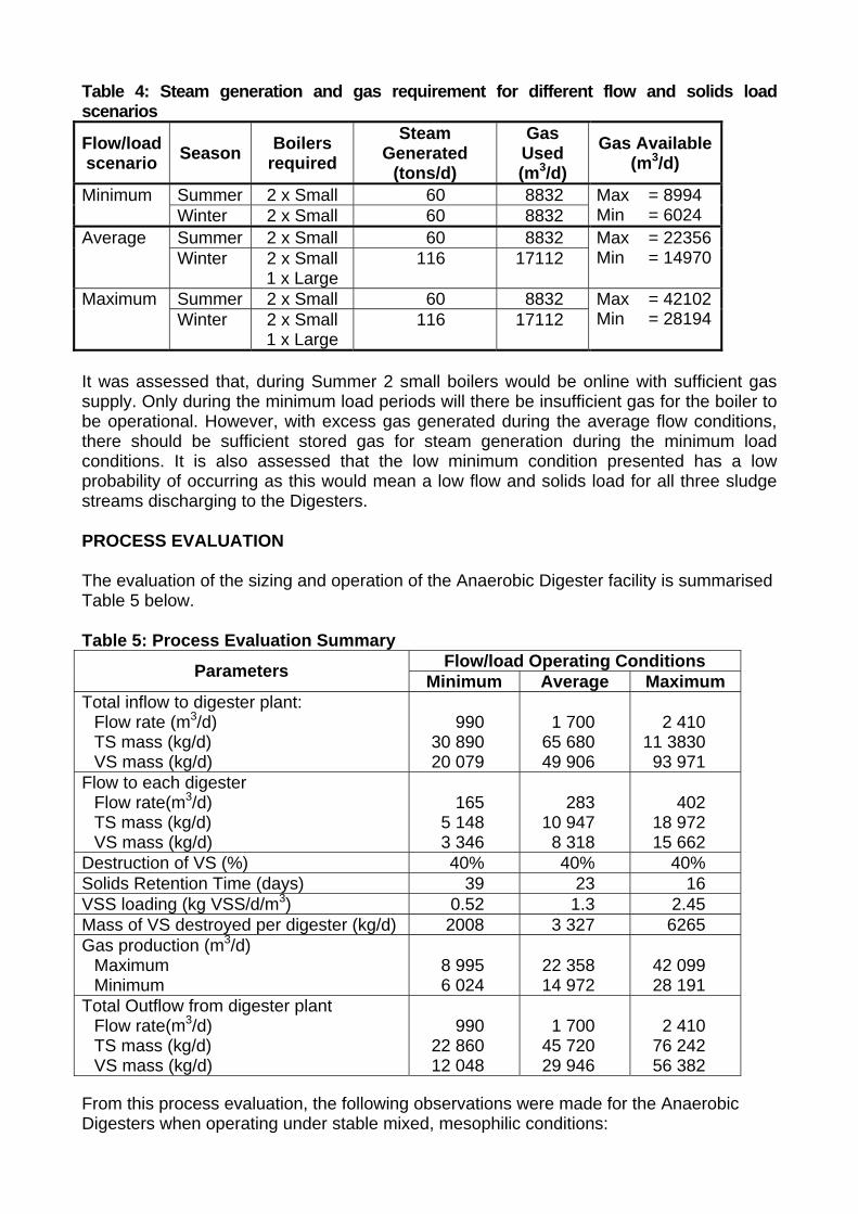
Table 4: Steam generation and gas requirement for different flow and solids load scenarios
Flow/load scenario Season Boilers
required Steam
Generated (tons/d)
Gas Used (m3/d)
Gas Available (m3/d)
Summer 2 x Small 60 8832 Minimum Winter 2 x Small 60 8832
Max = 8994 Min = 6024
Summer 2 x Small 60 8832 Average Winter 2 x Small
1 x Large 116 17112
Max = 22356Min = 14970
Summer 2 x Small 60 8832 Maximum Winter 2 x Small
1 x Large 116 17112
Max = 42102Min = 28194
It was assessed that, during Summer 2 small boilers would be online with sufficient gas supply. Only during the minimum load periods will there be insufficient gas for the boiler to be operational. However, with excess gas generated during the average flow conditions, there should be sufficient stored gas for steam generation during the minimum load conditions. It is also assessed that the low minimum condition presented has a low probability of occurring as this would mean a low flow and solids load for all three sludge streams discharging to the Digesters. PROCESS EVALUATION The evaluation of the sizing and operation of the Anaerobic Digester facility is summarised Table 5 below. Table 5: Process Evaluation Summary
Flow/load Operating Conditions Parameters Minimum Average Maximum Total inflow to digester plant:
Flow rate (m3/d) TS mass (kg/d) VS mass (kg/d)
990
30 890 20 079
1 700
65 680 49 906
2 410
11 3830 93 971
Flow to each digester Flow rate(m3/d) TS mass (kg/d) VS mass (kg/d)
165
5 148 3 346
283
10 947 8 318
402
18 972 15 662
Destruction of VS (%) 40% 40% 40% Solids Retention Time (days) 39 23 16 VSS loading (kg VSS/d/m3) 0.52 1.3 2.45 Mass of VS destroyed per digester (kg/d) 2008 3 327 6265 Gas production (m3/d)
Maximum Minimum
8 995 6 024
22 358 14 972
42 099 28 191
Total Outflow from digester plant Flow rate(m3/d) TS mass (kg/d) VS mass (kg/d)
990
22 860 12 048
1 700
45 720 29 946
2 410
76 242 56 382
From this process evaluation, the following observations were made for the Anaerobic Digesters when operating under stable mixed, mesophilic conditions:
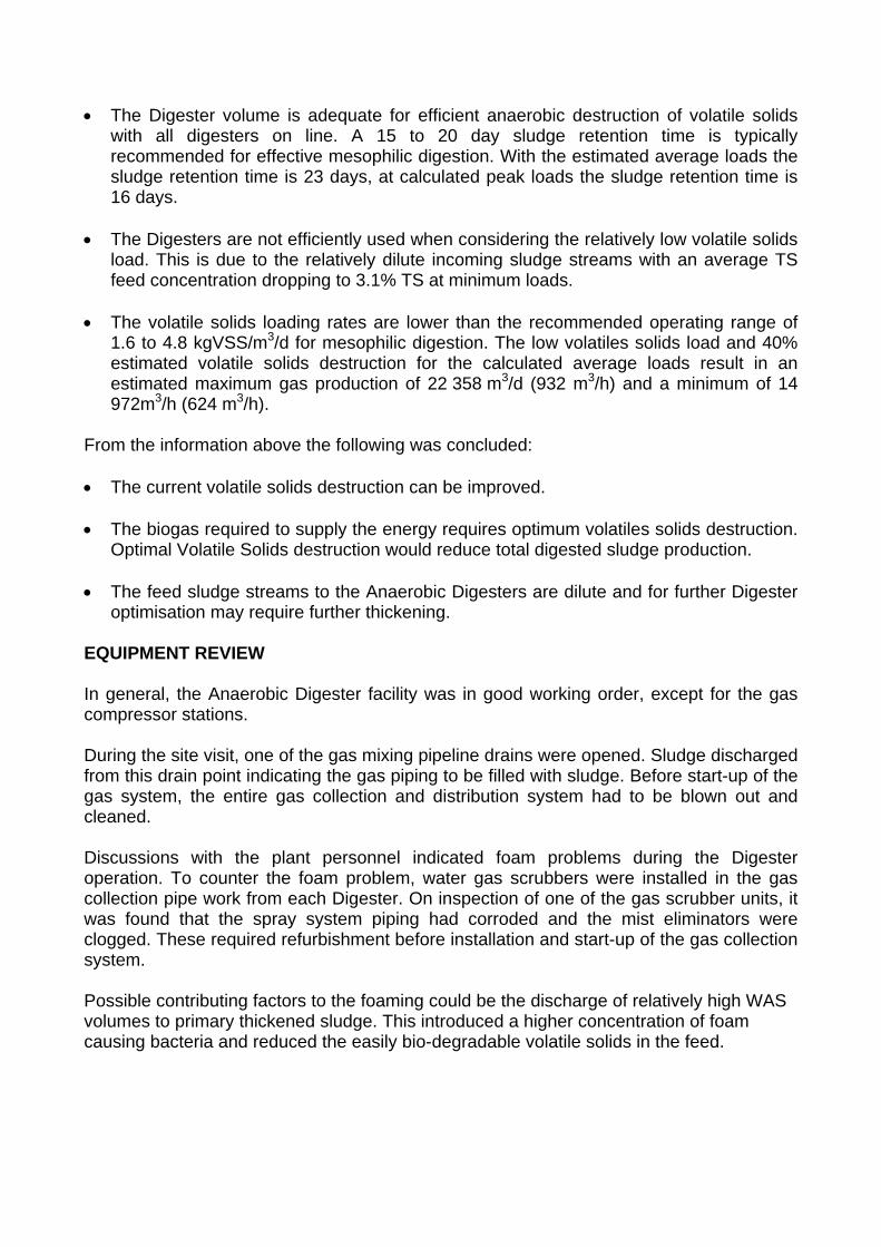
• The Digester volume is adequate for efficient anaerobic destruction of volatile solids
with all digesters on line. A 15 to 20 day sludge retention time is typically recommended for effective mesophilic digestion. With the estimated average loads the sludge retention time is 23 days, at calculated peak loads the sludge retention time is 16 days.
• The Digesters are not efficiently used when considering the relatively low volatile solids
load. This is due to the relatively dilute incoming sludge streams with an average TS feed concentration dropping to 3.1% TS at minimum loads.
• The volatile solids loading rates are lower than the recommended operating range of
1.6 to 4.8 kgVSS/m3/d for mesophilic digestion. The low volatiles solids load and 40% estimated volatile solids destruction for the calculated average loads result in an estimated maximum gas production of 22 358 m3/d (932 m3/h) and a minimum of 14 972m3/h (624 m3/h).
From the information above the following was concluded: • The current volatile solids destruction can be improved. • The biogas required to supply the energy requires optimum volatiles solids destruction.
Optimal Volatile Solids destruction would reduce total digested sludge production. • The feed sludge streams to the Anaerobic Digesters are dilute and for further Digester
optimisation may require further thickening. EQUIPMENT REVIEW In general, the Anaerobic Digester facility was in good working order, except for the gas compressor stations. During the site visit, one of the gas mixing pipeline drains were opened. Sludge discharged from this drain point indicating the gas piping to be filled with sludge. Before start-up of the gas system, the entire gas collection and distribution system had to be blown out and cleaned. Discussions with the plant personnel indicated foam problems during the Digester operation. To counter the foam problem, water gas scrubbers were installed in the gas collection pipe work from each Digester. On inspection of one of the gas scrubber units, it was found that the spray system piping had corroded and the mist eliminators were clogged. These required refurbishment before installation and start-up of the gas collection system. Possible contributing factors to the foaming could be the discharge of relatively high WAS volumes to primary thickened sludge. This introduced a higher concentration of foam causing bacteria and reduced the easily bio-degradable volatile solids in the feed.
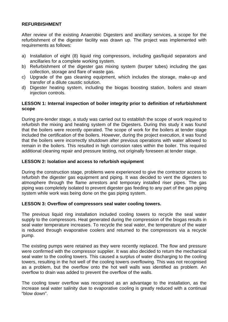
REFURBISHMENT After review of the existing Anaerobic Digesters and ancillary services, a scope for the refurbishment of the digester facility was drawn up. The project was implemented with requirements as follows: a) Installation of eight (8) liquid ring compressors, including gas/liquid separators and
ancillaries for a complete working system. b) Refurbishment of the digester gas mixing system (burper tubes) including the gas
collection, storage and flare of waste gas. c) Upgrade of the gas cleaning equipment, which includes the storage, make-up and
transfer of a dilute caustic solution. d) Digester heating system, including the biogas boosting station, boilers and steam
injection controls. LESSON 1: Internal inspection of boiler integrity prior to definition of refurbishment scope During pre-tender stage, a study was carried out to establish the scope of work required to refurbish the mixing and heating system of the Digesters. During this study it was found that the boilers were recently operated. The scope of work for the boilers at tender stage included the certification of the boilers. However, during the project execution, it was found that the boilers were incorrectly shutdown after previous operations with water allowed to remain in the boilers. This resulted in high corrosion rates within the boiler. This required additional cleaning repair and pressure testing, not originally foreseen at tender stage. LESSON 2: Isolation and access to refurbish equipment During the construction stage, problems were experienced to give the contractor access to refurbish the digester gas equipment and piping. It was decided to vent the digesters to atmosphere through the flame arrestors and temporary installed riser pipes. The gas piping was completely isolated to prevent digester gas feeding to any part of the gas piping system while work was being done on the gas piping system. LESSON 3: Overflow of compressors seal water cooling towers. The previous liquid ring installation included cooling towers to recycle the seal water supply to the compressors. Heat generated during the compression of the biogas results in seal water temperature increases. To recycle the seal water, the temperature of the water is reduced through evaporative coolers and returned to the compressors via a recycle pump. The existing pumps were retained as they were recently replaced. The flow and pressure were confirmed with the compressor supplier. It was also decided to return the mechanical seal water to the cooling towers. This caused a surplus of water discharging to the cooling towers, resulting in the hot well of the cooling towers overflowing. This was not recognised as a problem, but the overflow onto the hot well walls was identified as problem. An overflow to drain was added to prevent the overflow of the walls. The cooling tower overflow was recognised as an advantage to the installation, as the increase seal water salinity due to evaporative cooling is greatly reduced with a continual “blow down”.
LESSON 4: Biological growth in cooling tower packing High biological growth was experienced in the cooling tower packing. This resulted in cooling tower media collapsing. The high biological growth can be attributed to the carry over of foam and sludge with the digester gas. As this is likely to be a continual problem, Johannesburg Water was requested to add a biocide shock treatment as a routine maintenance requirement. The supplier of the softening plant and softening chemicals was requested to implement the biocide shock treatment. LESSON 5: Accumulation of water in gas piping After commissioning of the gas liquid ring compressors, problems with water accumulation in the compressed gas pipelines were again experienced. First the sizing of the liquid/gas separator was identified as the problem. However, this was checked and found not to be the problem. The compressor supplier then indicated that the level of the water in the separator was too high. The flow of seal water to the compressors was checked by installing a flow meter to one of the compressors. This indicated that the flow water to the compressors was correct. The compressor supplier then checked the mechanical dump valves installed on the outlet of the gas/ liquid separator and indicated that it was correctly sized. The final conclusion was that the discharge pipeline from the liquid/gas separator is too small for the flow from the separators. This is still under investigation, as the contractor was requested to supply and complete the operating system. LESSON 6: Sludge foaming in digesters During start-up of the mixing and heating systems the digesters started foaming. This resulted in solids carry over into the gas system (gas scrubbing was not initially set up correctly). The carry over of solids into the gas system resulted in blockage of water traps which created water locks in the gas piping. The carry over solids also contaminated the liquid ring seal water. Poor access to the existing water traps and gas piping prevented easy cleaning of the gas piping. The water in the cooling towers needed to be replaced, but poor drain access required an extended shutdown of the mixing and heating system. This in turn resulted in renewed foaming, once the system was restarted. Gas mixing and seal water recycle systems must include adequate cleaning points in the gas piping, easy drainage of the liquid/ gas separators and the cooling tower hot and cold wells. LESSON 7: Digester pressure relief valves blowing off during routine Digester operation During commissioning and start-up of the mixing and heating systems, the refurbished gas pressure relief valves continually release gas. After extended evaluation and assessment, it was observed that the blow off occurred due to water accumulation in the gas piping, preventing gas flow to the gas holder and/or supply to the compressors. Addressing the water accumulation in the gas piping, will address the continual blow off of the pressure relief valves.
LESSON 8: Boiler capacity during heating of digesters During the scoping stage of the refurbishment project, the boiler capacity was assessed to be sufficient to heat the digester from cold and maintain the digesters at the 35 degree Celsius. However, due to incorrectly selected steam traps, incorrectly set steam control valves and poor steam distribution the heating up of the digesters took longer than expected (two weeks instead of the four (4) days originally foreseen). It was decided to heat one digester at a time, which improved the heating time of the digesters. The poor steam distribution to the digesters was a result of blocked steam lance pipelines. This was addressed by closing all of the steam supply lines to the digesters to build up pressure in the blocked steam lines. This pressure was used to unblock individual steam lance pipelines (hot pipelines indicating flow, cold pipelines indicating blocked pipelines). LESSON 9: Re-us of gas flow meter orifice plates The previous installed orifice plates used for flow measurement were re-used, but with replacement of differential pressure transmitters. However, due to the initial low gas pressure resulting in low gas pressure drop manifested in poor flow meter accuracy. The orifice flow meters were accurately calibrated to the best estimate of gas flow in the individual pipelines. This would result in lower accuracy error for the individual pipelines. Alternative gas flow measurement should be considered for future similar installations. LESSON 10: Accumulation / loss of caustic solution used for gas scrubbing The gas scrubbing system was designed to operate on a recycle system, from the make-up tank through recycle pumps to the respective gas scrubbers. After a period of 25 days, the caustic supply would be exhausted requiring draining of the system into the digested sludge outlet box. During commissioning, the caustic tank contents emptied during the recycle of the solution. It was identified that the scrubber drain could not cope with the caustic flow. The supply flow was reduced and equally distributed to the different gas scrubbers. This reduced the loss of caustic solution. During normal operation of the gas mixing and heating system, there were observations of liquid accumulation in the caustic system. This is still under investigation and could be attributed to the carry-over of water into the gas piping, condensation of water in the gas scrubbers, or possibly the carry over of foam/sludge. Additional overflows should be installed in similar installations. This could be in the form of a solenoid valve on the drain valves linked to the caustic dilution tank level, indicating overflow from the caustic make-up tank. REFERENCES 1. A Le Roux and A M van Niekerk, Golder Report 5596/5889/1/w (September 2003) 2. Metcalf and Eddy Inc, Wastewater Treatment Engineering Treatment and Reuse, Fourth
Edition (2003)