lensing and waveguiding of ultraslow pulses in an atomic bose–einstein condensate
TRANSCRIPT

arX
iv:1
103.
4771
v1 [
phys
ics.
optic
s] 2
4 M
ar 2
011
Lensing and Waveguiding of Ultraslow Pulses in an
Atomic Bose-Einstein Condensate
Devrim Tarhan∗,a, Alphan Sennaroglub, Ozgur E. Mustecaplıoglub,c
aDepartment of Physics, Harran University, Osmanbey Yerleskesi, Sanlıurfa, 63300,
TurkeybDepartment of Physics, Koc University, Rumelifeneri yolu, Sarıyer, Istanbul, 34450,
TurkeycInstitute of Quantum Electronics, ETH Zurich Wolfgang-Pauli-Strasse 16, CH-8093
Zurich, Switzerland
Abstract
We investigate lensing and waveguiding properties of an atomic Bose-Einstein condensate for ultraslow pulse generated by electromagnetically in-duced transparency method. We show that a significant time delay can becontrollably introduced between the lensed and guided components of theultraslow pulse. In addition, we present how the number of guided modessupported by the condensate and the focal length can be controlled by thetrap parameters or temperature.
Key words:
Bose-Einstein condensate, Electromagnetically induced transparency,ultraslow pulse propagation, Waveguides, LensesPACS: 03.75.Nt, 42.50.Gy, 41.20.Jb, 42.82.Et, 42.79.Bh
∗Corresponding author. Address:Department of Physics, Harran University, OsmanbeyYerleskesi, Sanlıurfa, 63300, Turkey. Tel.: +90 414 3183578; fax: +90 414 3440051.
Email address: [email protected] (Devrim Tarhan)
Preprint submitted to Optics Communications March 25, 2011
1. Introduction
Quantum interference effects, such as electromagnetically induced trans-parency (EIT) [1, 2], can produce considerable changes in the optical prop-erties of matter and have been utilized to demonstrate ultraslow light prop-agation through an atomic Bose-Einstein condensate (BEC) [3]. This haspromised a variety of new and appealing applications in coherent opticalinformation storage as well as in quantum information processing . How-ever, the potential of information storage in such systems is shadowed bytheir inherently low data rates. To overcome this challenge, exploitation oftransverse directions for a multimode optical memory via three dimensionalwaveguiding of slow EIT pulse [4] has been recently suggested for BECs [5].Transverse confinement of slow light is also quintessential for various pro-posals of high performance intracavity and nanofiber slow light schemes (Seee.g. Ref. [6] and references therein). Furthermore, temperature dependenceof group velocity of ultraslow light in a cold gas has been investigated for aninteracting Bose gases [7].
A recent experiment, on the other hand, has drawn attention that ul-tracold atomic systems with graded index profiles may not necessarily haveperfect transverse confinement due to simultaneously competing effects oflensing and waveguiding [8]. The experiment is based upon a recoil-inducedresonance (RIR) in the high gain regime, employed for an ultracold atomicsystem as a graded index waveguiding medium. As a result of large coreradius with high refractive index contrast, and strong dispersion due to RIR,radially confined multimode slow light propagation has been realized [8]. Asalso noted in the experiment, a promising and intriguing regime would havefew modes where guided nonlinear optical phenomena could happen [8].
It has already been shown that the few mode regime of ultraslow waveg-uiding can be accessed by taking advantage of the sharp density profile ofBEC and the strong dispersion provided by the usual EIT [5]. Present workaims to reconsider this result by taking into account the simultaneous lensingcomponent. On one hand, the lensing could be imagined as a disadvantageagainst reliable high capacity quantum memory applications. Our investi-gations do aid to comprehend the conditions of efficient transverse confine-ment. On the other hand, we argue that because the lensing component isalso strongly delayed with a time scale that can be observably large rela-tive to the waveguiding modes, such spatially resolved slow pulse splittingcan offer intriguing possibilities for creating and manipulating flying bits of
2
information, especially in the nonlinear regime. Indeed, earlier proposals tosplit ultraslow pulses in some degrees of freedom (typically polarization), facemany challenges of complicated multi-level schemes, multi-EIT windows, andhigh external fields [9]. Quite recently birefringent lensing in atomic gaseousmedia in EIT setting has been discussed [10]. The proposed splitting of lens-ing and guiding modes is both intuitively and technically clear, and easy toimplement in EIT setting, analogous to the RIR experiment.
The paper is organized as follows: After describing our model systembriefly in Sec. 2, EIT scheme for an interacting BEC is presented in Sec.3. Subsequently we focus on the lensing effect of the ultraslow pulse whilereviewing already known waveguiding results shortly in Sec. 4. Main resultsand their discussion are in Sec. 5. Finally, we conclude in Section 6.
2. Model System
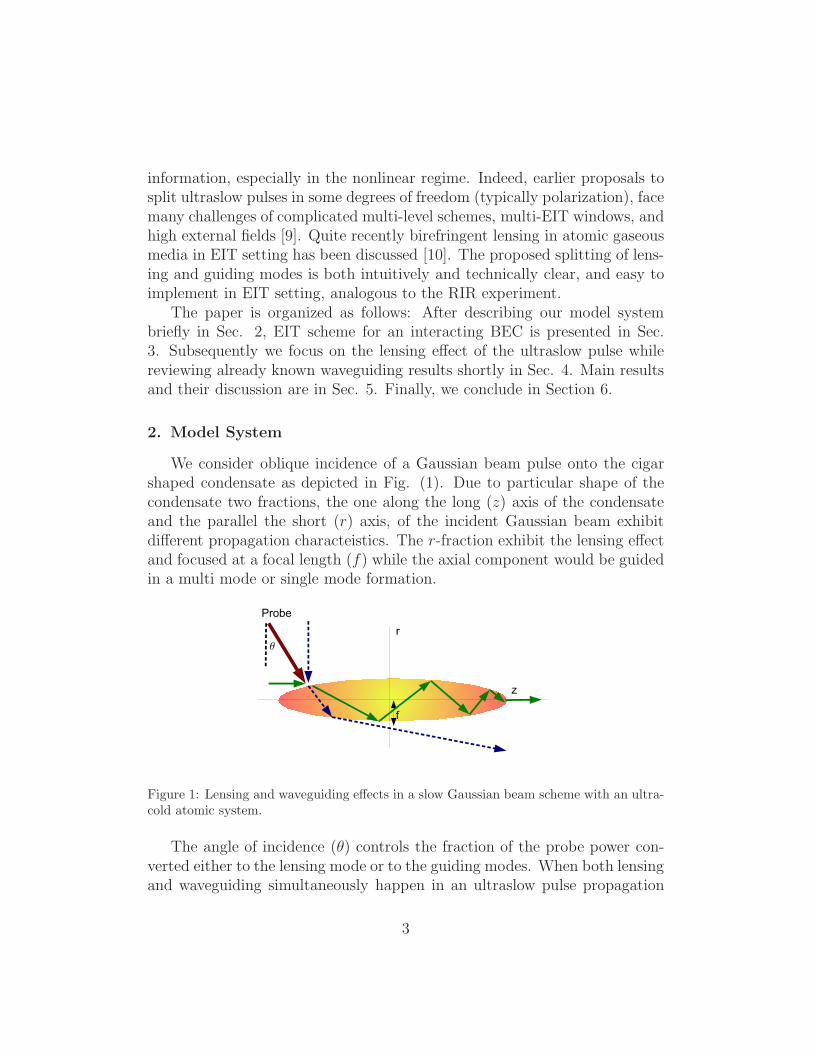
We consider oblique incidence of a Gaussian beam pulse onto the cigarshaped condensate as depicted in Fig. (1). Due to particular shape of thecondensate two fractions, the one along the long (z) axis of the condensateand the parallel the short (r) axis, of the incident Gaussian beam exhibitdifferent propagation characteistics. The r-fraction exhibit the lensing effectand focused at a focal length (f) while the axial component would be guidedin a multi mode or single mode formation.
Figure 1: Lensing and waveguiding effects in a slow Gaussian beam scheme with an ultra-cold atomic system.
The angle of incidence (θ) controls the fraction of the probe power con-verted either to the lensing mode or to the guiding modes. When both lensingand waveguiding simultaneously happen in an ultraslow pulse propagation
3
set up, an intriguing possibility arises. Different density profiles along ra-dial and axial directions translates to different time delays of the focusedand guided modes. Due to significant difference in the optical path lengthsof guided and focused components, an adjustable relative time delay can begenerated between these two components. As a result, these two componentsbecome spatially separated. The fraction of the beam parallel to the shortaxis of the condensate undergoes propagation in a lens-like quadratic indexmedium resulting in a change in the spot size or the beam waist of the outputbeam. We call this as the lensing effect and the corresponding fraction as thelensed-fraction. The fraction of the beam propagating along the long axis ispropagating in weakly-guided regime of graded index medium that can bedescribed in terms of LP modes. This is called as guiding effect and the cor-responding fraction is called as guided fraction. We use the usual Gaussianbeam transformation methods under paraxial approximation to estimate thefocal length. In addition our aim is to estimate time delay between these twofractions. The output lensed and guided fractions of the incident beam aredelayed in time relative to each other. In general temporal splitting dependson modal, material and waveguide dispersions. For a simple estimation ofrelative time delay of these components, we consider only the lowest ordermodes in the lensed and the guided fractions, and take the optical paths asthe effective lengths of the corresponding short and long axes of the conden-sate. In this case we ignore the small contributions of modal and waveguidedispersions and determine the group velocity, same for both fractions, by as-suming a constant peak density of the condensate in the material dispersionrelation.
3. EIT scheme for an interacting BEC
A Bose gas can be taken as condensate part and thermal part at lowtemperature. Following Ref. [11], density profile of BEC can be written byρ(~r) = ρc(~r) + ρth(~r), where ρc(~r) = [(µ(T ) − V (~r))/U0]Θ(µ − V (~r)) is thedensity of the condensed atoms and ρth is the density of the thermal idealBose gas. Here U0 = 4π~2as/m; m is atomic mass; as is the atomic s-wavescattering length. Θ(.) is the Heaviside step function and TC is the criticaltemperature. The external trapping potential is V (~r) = (m/2)(ω2
rr2 + ω2
zz2)
with trap frequencies ωr, ωz for the radial and axial directions, respectively.At temperatures below Tc, the chemical potential µ is evaluated by µ(T ) =µTF (N0/N)2/5, where µTF is the chemical potential obtained under Thomas-
4
Fermi approximation, µTF = ((~ωt)/2)(15Nas/ah)2/5, with ωt = (ωzω
2r)
1/3
and ah =√
~/(ωzω2r)
1/3, the average harmonic oscillator length scale. Thecondensate fraction is given by N0/N = 1 − x3 − sζ(2)/ζ(3)x2(1 − x3)2/5,with x = T/Tc, and ζ is the Riemann-Zeta function. The scaling parameters is given by s = µTF/kBTC = (1/2)ζ(3)1/3(15N1/6as/ah)
2/5.Treating condensate in equilibrium and under Thomas-Fermi approxima-
tion (TFA) is common in ultraslow light literature and generally a good ap-proximation because density of an ultracold atomic medium is slowly chang-ing during the weak probe propagation. The propagation is in the order ofmicroseconds while atomic dynamics is in millisecond time scales. Due toweak probe propagation under EIT conditions, most of the atoms remainin the lowest state[12]. The validity of TFA further depends on the lengthscale of the harmonic potential. If the length scale is much larger than thehealing length, TFA with the harmonic potential works fine. The healinglength of the BEC is defined as ξ = [1/(8πnas)]
1/2 [13] where n is the densityof an atomic Bose-Einstein condensate and it can be taken as n = ρ(0, 0).We consider range of parameters in this work within the range of validityof TFA. The interaction of atomic BEC with strong probe and the couplingpump field may drive atomic BEC out of equilibrium. This non- equilibriumdiscussion is beyond the scope of the present paper.
We consider, beside the probe pulse, there is a relatively strong couplingfield interacting with the condensate atoms in a Λ-type three level schemewith Rabi frequency Ωc. The upper level is coupled to the each level of thelower doublet either by probe or coupling field transitions. Under the weakprobe condition, susceptibility χ for the probe transition can be calculated asa linear response as most of the atoms remain in the lowest state. Assuminglocal density approximation, neglecting local field, multiple scattering andquantum corrections and employing steady state analysis we find the well-known EIT susceptibility [1, 14], χi, i = r, z, for either radial (r) or axial (z)fraction of the probe pulse. Total EIT susceptibility for BEC in terms of thedensity ρ can be expressed as χi = ρi χ1 in the framework of local densityapproximation. Here χ1 is the single atom response given by
χ1 =|µ|2ε0~
i(−i∆+ Γ2/2)
(Γ2/2− i∆)(Γ3/2− i∆) + Ω2C/4
, (1)
where ∆ is the detuning from the resonant probe transition . For the ultra-cold atoms and assuming co-propagating laser beams, Doppler shift in the
5
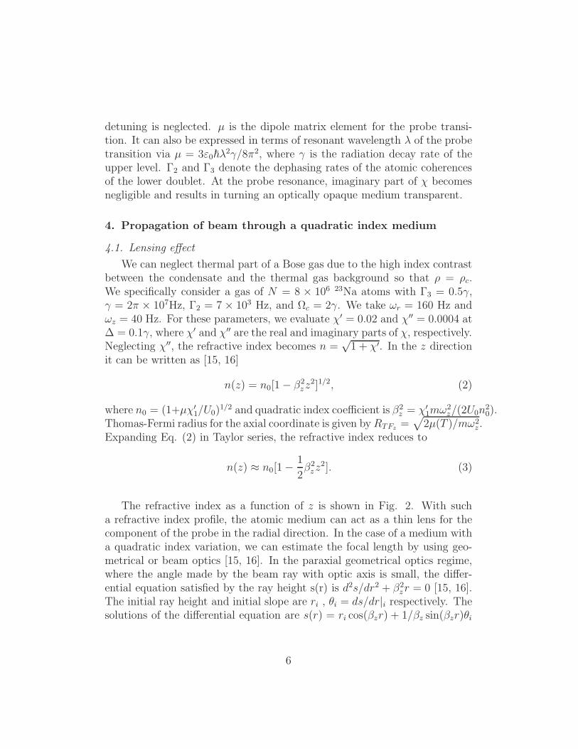
detuning is neglected. µ is the dipole matrix element for the probe transi-tion. It can also be expressed in terms of resonant wavelength λ of the probetransition via µ = 3ε0~λ
2γ/8π2, where γ is the radiation decay rate of theupper level. Γ2 and Γ3 denote the dephasing rates of the atomic coherencesof the lower doublet. At the probe resonance, imaginary part of χ becomesnegligible and results in turning an optically opaque medium transparent.
4. Propagation of beam through a quadratic index medium
4.1. Lensing effect
We can neglect thermal part of a Bose gas due to the high index contrastbetween the condensate and the thermal gas background so that ρ = ρc.We specifically consider a gas of N = 8 × 10⁶ 23Na atoms with Γ3 = 0.5γ,γ = 2π × 107Hz, Γ2 = 7 × 10³ Hz, and Ωc = 2γ. We take ωr = 160 Hz andωz = 40 Hz. For these parameters, we evaluate χ′ = 0.02 and χ′′ = 0.0004 at∆ = 0.1γ, where χ′ and χ′′ are the real and imaginary parts of χ, respectively.Neglecting χ′′, the refractive index becomes n =
√1 + χ′. In the z direction
it can be written as [15, 16]
n(z) = n0[1− β2zz
2]1/2, (2)
where n0 = (1+µχ′
1/U0)1/2 and quadratic index coefficient is β2
z = χ′
1mω2z/(2U0n
20).
Thomas-Fermi radius for the axial coordinate is given byRTFz=
√
2µ(T )/mω2z .
Expanding Eq. (2) in Taylor series, the refractive index reduces to
n(z) ≈ n0[1−1
2β2zz
2]. (3)
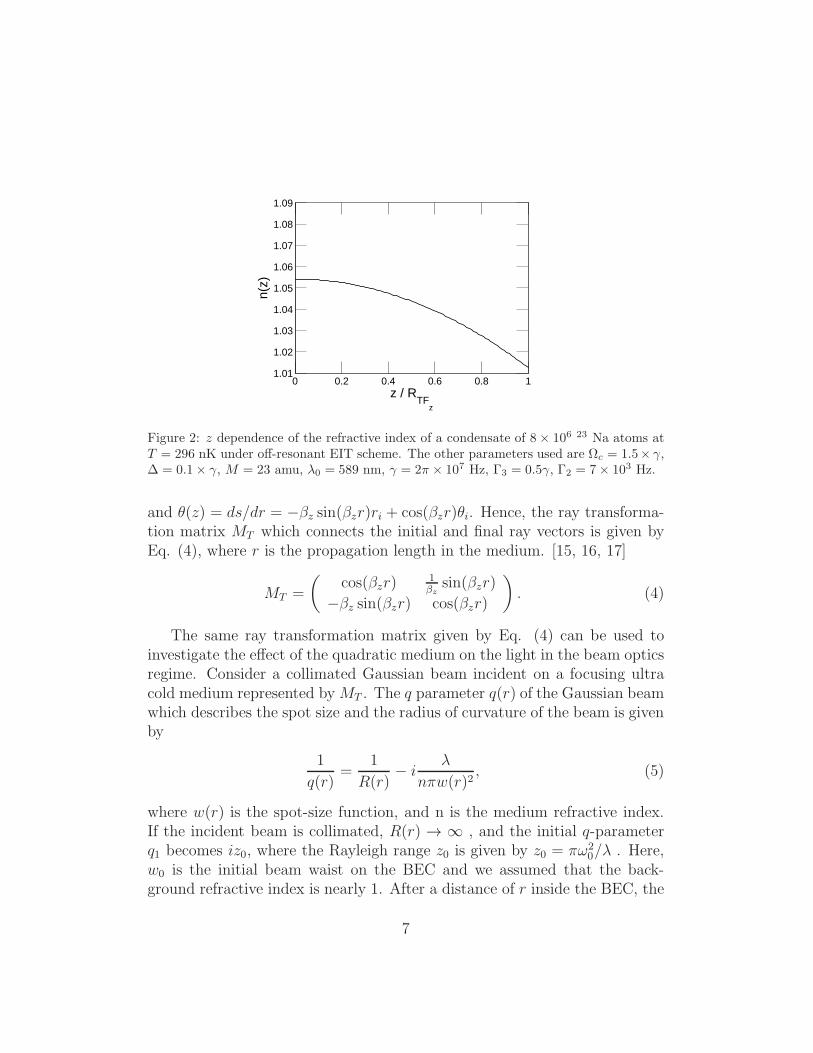
The refractive index as a function of z is shown in Fig. 2. With sucha refractive index profile, the atomic medium can act as a thin lens for thecomponent of the probe in the radial direction. In the case of a medium witha quadratic index variation, we can estimate the focal length by using geo-metrical or beam optics [15, 16]. In the paraxial geometrical optics regime,where the angle made by the beam ray with optic axis is small, the differ-ential equation satisfied by the ray height s(r) is d2s/dr2 + β2
zr = 0 [15, 16].The initial ray height and initial slope are ri , θi = ds/dr|i respectively. Thesolutions of the differential equation are s(r) = ri cos(βzr) + 1/βz sin(βzr)θi
6
0 0.2 0.4 0.6 0.8 11.01
1.02
1.03
1.04
1.05
1.06
1.07
1.08
1.09
z / RTF
z
n(z)
Figure 2: z dependence of the refractive index of a condensate of 8× 10⁶ 23 Na atoms atT = 296 nK under off-resonant EIT scheme. The other parameters used are Ωc = 1.5× γ,∆ = 0.1× γ, M = 23 amu, λ0 = 589 nm, γ = 2π × 107 Hz, Γ3 = 0.5γ, Γ2 = 7× 10³ Hz.
and θ(z) = ds/dr = −βz sin(βzr)ri + cos(βzr)θi. Hence, the ray transforma-tion matrix MT which connects the initial and final ray vectors is given byEq. (4), where r is the propagation length in the medium. [15, 16, 17]
MT =
(
cos(βzr)1βz
sin(βzr)
−βz sin(βzr) cos(βzr)
)
. (4)
The same ray transformation matrix given by Eq. (4) can be used toinvestigate the effect of the quadratic medium on the light in the beam opticsregime. Consider a collimated Gaussian beam incident on a focusing ultracold medium represented byMT . The q parameter q(r) of the Gaussian beamwhich describes the spot size and the radius of curvature of the beam is givenby
1
q(r)=
1
R(r)− i
λ
nπw(r)2, (5)
where w(r) is the spot-size function, and n is the medium refractive index.If the incident beam is collimated, R(r) → ∞ , and the initial q-parameterq1 becomes iz0, where the Rayleigh range z0 is given by z0 = πω2
0/λ . Here,w0 is the initial beam waist on the BEC and we assumed that the back-ground refractive index is nearly 1. After a distance of r inside the BEC, the
7
transformed q-parameter q2 will given by
q2 =iz0 cos(βrr) +
1
βz
sin(βzr)
−iz0βz sin(βzr) + cos(βzr). (6)
We have two cases to consider for focusing. If the BEC is very thin, thefocal length will be approximately given by 1/β2
zLr where Lr is the transversewidth of the BEC. If the BEC length is not negligible, the next collimatedbeam will be formed inside the BEC at the location Lf , given by βzLf = π/2.
4.2. Waveguiding effect
Along the radial direction, similar to previous treatment, refractive indexprofile in the radial direction can be written as
n(r) =
n0[1− 1
2β2r r
2]1/2 r ≤ RTFr.
1 r ≥ RTFr
, (7)
where n0 = (1+µχ′
i/U0)1/2 and β2
r = χ′
1mω2z/(2U0n
20). Thomas-Fermi radius
is given by RTFr=
√
2µ(T )/mω2r .
0 0.2 0.4 0.6 0.8 11
1.005
1.01
1.015
1.02
1.025
1.03
1.035
r / RTF
r
n(r)
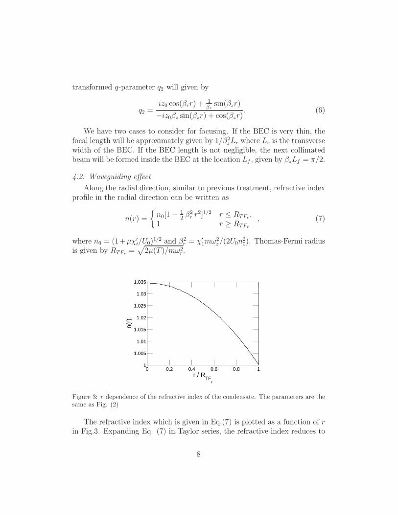
Figure 3: r dependence of the refractive index of the condensate. The parameters are thesame as Fig. (2)
The refractive index which is given in Eq.(7) is plotted as a function of rin Fig.3. Expanding Eq. (7) in Taylor series, the refractive index reduces to
8
n(r) ≈ n0(1 − 0.5β2r r
2). Such an index behavior is analogous to the one ofa graded index fiber [5]. Slow light propagation through the condensate canbe described similar to that of the weakly guided regime of the graded indexfiber, where the optical modes can be given in terms of linearly polarizedmodes (LP modes). The mode profiles are determined by solving the waveequation which reduces to the Helmholtz equation [5].
We use the cylindrical coordinates as the refractive index n(r) is axiallysymmetric. The wave equation for the axial fraction of the probe field is[∇2 + k2]E = 0, where k2 = k2z + k2r and ∇2 is the Laplacian operatorin cylindrical coordinate. Here kr is the radial wave number and kz is thepropagation constant in the z direction. The solution for the wave equation isE = ψ(r) cos(lφ) exp[i(ωt− kzz)]. Here l = 0, 1, 2, 3, ... and φ is the absolutephase. If we put this solution in the wave equation, we get the Helmholtzradial equation
[d2/dr2 + (1/r)d/dr + p2(r)]ψ(r) = 0, (8)
in which p2(r) = (k20n2(r) − k2z − l2/r2) [15]. Here k0 can be expressed in
terms of resonant wavelength λ of the probe transition k0 = 2π/λ = 1.07×10⁷
(1/m).We use transfer matrix method developed in Ref. [5] in order to solve the
Helmholtz equation. Eq.(8).We assume that the atomic cloud can be described by layers of constant
refractive index, such that, their indices monotonically increase towards thecenter of the cloud. By taking sufficiently large number of thin layers sucha discrete model can represent the true behavior of the refractive index.For constant index, analytical solutions of the Helmholtz equation can befound in terms of Bessel functions. Such solutions are then matched at theshell boundaries of the layers. Doing this for all the layers, electromagneticboundary conditions provide a recurrence relation for the Bessel functioncoefficients, whose solution yields the wave number k. The mode profilesdetermined by this method are shown in Fig. (6), and Fig. (7).
5. Results and Discussions
5.1. Lensing Properties
The condensate can act as a lens or a guiding medium depending on theRayleigh range of the probe relative to the effective length of the condensate
9
[8]. For the cigar shaped BEC geometry we consider, the radial fraction ofthe probe is subject to lensing while the axial fraction is guided. Let usfirst examine the focal length of the condensate for the radial fraction of theincident probe. For that aim we need to determine the effective radial length
Lr =
[∫
V
d3rr2ρ(r, z)
]1/2
, (9)
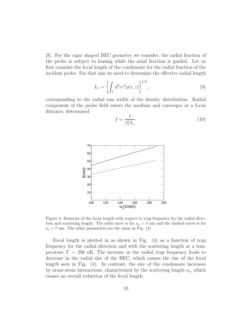
corresponding to the radial rms width of the density distribution. Radialcomponent of the probe field enters the medium and converges at a focusdistance, determined
f =1
β2zLr
. (10)
100 120 140 160 180 200
10
20
30
40
50
60
70
ωr(1/sec)
f(m
m)
Figure 4: Behavior of the focus length with respect to trap frequency for the radial direc-tion and scattering length. The solid curve is for as = 5 nm and the dashed curve is foras = 7 nm. The other parameters are the same as Fig. (2)
Focal length is plotted in as shown in Fig. (4) as a function of trapfrequency for the radial direction and with the scattering length at a tem-perature T = 296 nK. The increase in the radial trap frequency leads todecrease in the radial size of the BEC, which causes the rise of the focallength seen in Fig. (4). In contrast, the size of the condensate increasesby atom-atom interactions, characterized by the scattering length as, whichcauses an overall reduction of the focal length.
10
5.2. Waveguiding Properties
For the cigar shaped BEC geometry we consider again the axial fractionof the probe is subject to guided. The effective axial length is determined by
Lz =
[
4π
N
∫
∞
0
rdr
∫
∞
0
dzz2ρ(r, z)
]1/2
. (11)
The axial length Lz is an effective length corresponding to the axial widthof the density distribution. Group velocities (vgi, i = r, z) of the differentdensity profiles for both radial and axial directions can be calculated fromthe susceptibility using the relations
1
vgi=
1
c+π
λ
∂χi
∂∆. (12)
Here, c is the speed of light and imaginary part of the susceptibility is neg-ligibly small relative to the real part of it. EIT can be used to achieveultraslow light velocities, owing to the steep dispersion of the EIT suscepti-bility χ [3]. In general temporal splitting depends on modal, material andwaveguide dispersions. For a simple estimation of relative time delay of thesecomponents, we consider only the lowest order modes in the lensed and theguided fractions, and take the optical paths as the effective lengths of thecorresponding short and long axes of the condensate. In this case we ignorethe small contributions of modal and waveguide dispersions and determinethe group velocity, same for both fractions, by assuming a constant peak den-sity of the condensate in the material dispersion relation. Density profilesalong radial and axial directions lead to different time delays of the focusedand guided modes. Due to significant difference in the optical path lengthsof guided and focused components, a certain time delay can be generatedbetween these two components.
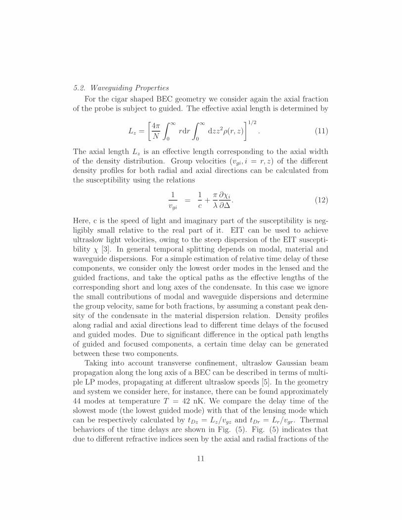
Taking into account transverse confinement, ultraslow Gaussian beampropagation along the long axis of a BEC can be described in terms of multi-ple LP modes, propagating at different ultraslow speeds [5]. In the geometryand system we consider here, for instance, there can be found approximately44 modes at temperature T = 42 nK. We compare the delay time of theslowest mode (the lowest guided mode) with that of the lensing mode whichcan be respectively calculated by tDz = Lz/vgz and tDr = Lr/vgr. Thermalbehaviors of the time delays are shown in Fig. (5). Fig. (5) indicates thatdue to different refractive indices seen by the axial and radial fractions of the
11
0 0.2 0.4 0.6 0.8
10
20
30
40
50
60
70
80
T/TC
t D(µ
sec
)
Figure 5: Thermal behavior of the time delays of the guided and focused fractions. Thesolid and dashed lines are for tDz and tDr , respectively. The parameters are the same asFig. (2) except Ωc = 0.5γ
probe, significant temporal delay, ∼ 50µs, can occur between them at lowtemperatures T ∼ 42 nK. Time delays for each fraction decreases with thetemperature. Besides, the relative difference of their time delays diminisheswith the temperature. The condensed cloud shrinks due to the increase intemperature, so that effective lengths of the BEC diminish. Therefore, justbelow TC , time delays drop to zero.
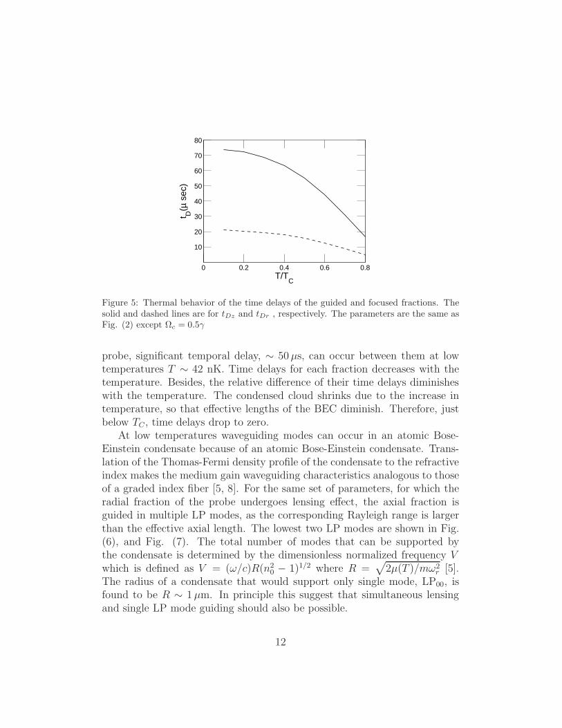
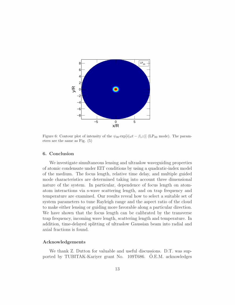
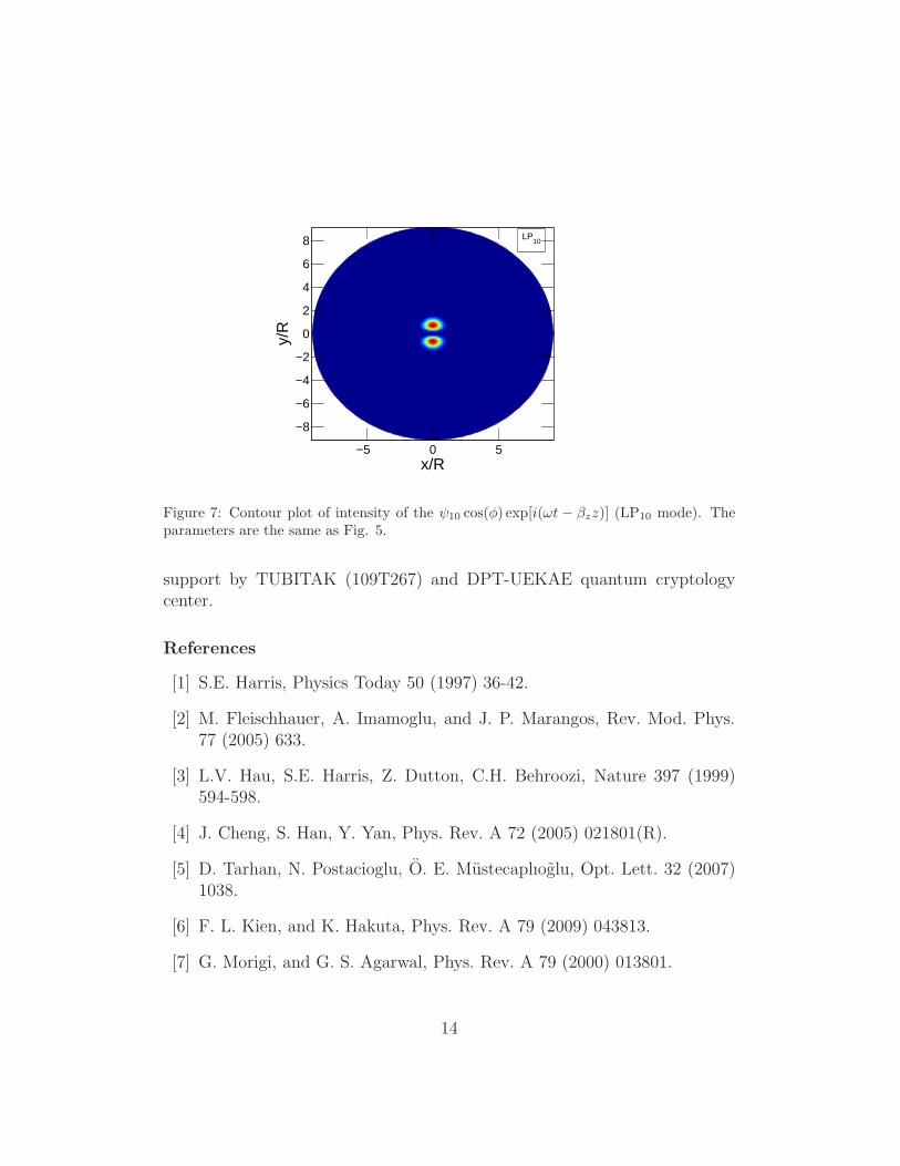
At low temperatures waveguiding modes can occur in an atomic Bose-Einstein condensate because of an atomic Bose-Einstein condensate. Trans-lation of the Thomas-Fermi density profile of the condensate to the refractiveindex makes the medium gain waveguiding characteristics analogous to thoseof a graded index fiber [5, 8]. For the same set of parameters, for which theradial fraction of the probe undergoes lensing effect, the axial fraction isguided in multiple LP modes, as the corresponding Rayleigh range is largerthan the effective axial length. The lowest two LP modes are shown in Fig.(6), and Fig. (7). The total number of modes that can be supported bythe condensate is determined by the dimensionless normalized frequency Vwhich is defined as V = (ω/c)R(n2
0 − 1)1/2 where R =√
2µ(T )/mω2r [5].
The radius of a condensate that would support only single mode, LP00, isfound to be R ∼ 1µm. In principle this suggest that simultaneous lensingand single LP mode guiding should also be possible.
12
x/R
y/R
−5 0 5
−8
−6
−4
−2
0
2
4
6
8 LP00
Figure 6: Contour plot of intensity of the ψ00 exp[i(ωt− βzz)] (LP00 mode). The param-eters are the same as Fig. (5)
6. Conclusion
We investigate simultaneous lensing and ultraslow waveguiding propertiesof atomic condensate under EIT conditions by using a quadratic-index modelof the medium. The focus length, relative time delay, and multiple guidedmode characteristics are determined taking into account three dimensionalnature of the system. In particular, dependence of focus length on atom-atom interactions via s-wave scattering length, and on trap frequency andtemperature are examined. Our results reveal how to select a suitable set ofsystem parameters to tune Rayleigh range and the aspect ratio of the cloudto make either lensing or guiding more favorable along a particular direction.We have shown that the focus length can be calibrated by the transversetrap frequency, incoming wave length, scattering length and temperature. Inaddition, time-delayed splitting of ultraslow Gaussian beam into radial andaxial fractions is found.
Acknowledgements
We thank Z. Dutton for valuable and useful discussions. D.T. was sup-ported by TUBITAK-Kariyer grant No. 109T686. O.E.M. acknowledges
13
x/R
y/R
−5 0 5
−8
−6
−4
−2
0
2
4
6
8 LP10
Figure 7: Contour plot of intensity of the ψ10 cos(φ) exp[i(ωt − βzz)] (LP10 mode). Theparameters are the same as Fig. 5.
support by TUBITAK (109T267) and DPT-UEKAE quantum cryptologycenter.
References
[1] S.E. Harris, Physics Today 50 (1997) 36-42.
[2] M. Fleischhauer, A. Imamoglu, and J. P. Marangos, Rev. Mod. Phys.77 (2005) 633.
[3] L.V. Hau, S.E. Harris, Z. Dutton, C.H. Behroozi, Nature 397 (1999)594-598.
[4] J. Cheng, S. Han, Y. Yan, Phys. Rev. A 72 (2005) 021801(R).
[5] D. Tarhan, N. Postacioglu, O. E. Mustecaplıoglu, Opt. Lett. 32 (2007)1038.
[6] F. L. Kien, and K. Hakuta, Phys. Rev. A 79 (2009) 043813.
[7] G. Morigi, and G. S. Agarwal, Phys. Rev. A 79 (2000) 013801.
14
[8] M. Vengalattore, and M. Prentiss, Phys. Rev. Lett. 95 (2005) 243601.
[9] G. S. Agarwal, and S. Dasgupta, Phys. Rev. A 65 (2002) 053811.
[10] H. R. Zhang, L. Zhou and C. P. Sun, Phys. Rev. A 80 (2009) 013812.
[11] M. Naraschewski, D.M. Stamper-Kurn, Phys. Rev. A 58 (1998) 2423.
[12] Z. Dutton, and L. V. Hau, Phys. Rev. A 70 (2004) 053831.
[13] C. J. Pethick and H. Smith, Bose-Einstein Condensation in Dilute Gases,Cambridge, Cambridge, 2002.
[14] M.O. Scully, M.S. Zubairy, Quantum Optics, Cambridge, Cambridge,1997.
[15] A. Yariv, Optical Electronics, Saunders College,Holt,Rinehart and Wis-ton, 1991.
[16] A. Sennaroglu, Photonics and Laser Engineering: Principles, Devicesand Applications, New Yowk, McGraw-Hill, 2010.
[17] L. Casperson, A. Yariv, Appl. Phys. Lett. 12 (1968) 355.
15