lecture slide 4 (mec 391 day/eve)
TRANSCRIPT
mec 391-mechanical design
BYBY
ENGR. FAZLAR RAHMANAssistant ProfessorME Faculty, IUBAT
LECTURE NOTE-4
mec -391 (mechanical design)LOAD AND STRESS ANALYSIS
Plane Stress: Plane stress is defined to be a state of stress in which the
normal and shear stresses are zero in the direction ofperpendicular to a plane.
Stresses in the Z-direction will be zero for a XY-plane. Butstrain in Z-direction is not zero.
Fazlar Rahman; ME Faculty; MEC 391; LEC_4;
strain in Z-direction is not zero.Plane Strain: It is defined to be a state of strain in which the strain in
the direction normal to a plane is assumed to be zero. It is normally happened if dimension of the structure in
one direction say Z-direction is large in comparison withdimensions in the other two directions or XY-directions.
Strain in the Z-direction will be zero for a XY plane.
mec -391 (mechanical design)STRESS AT A POINT IN A BODY
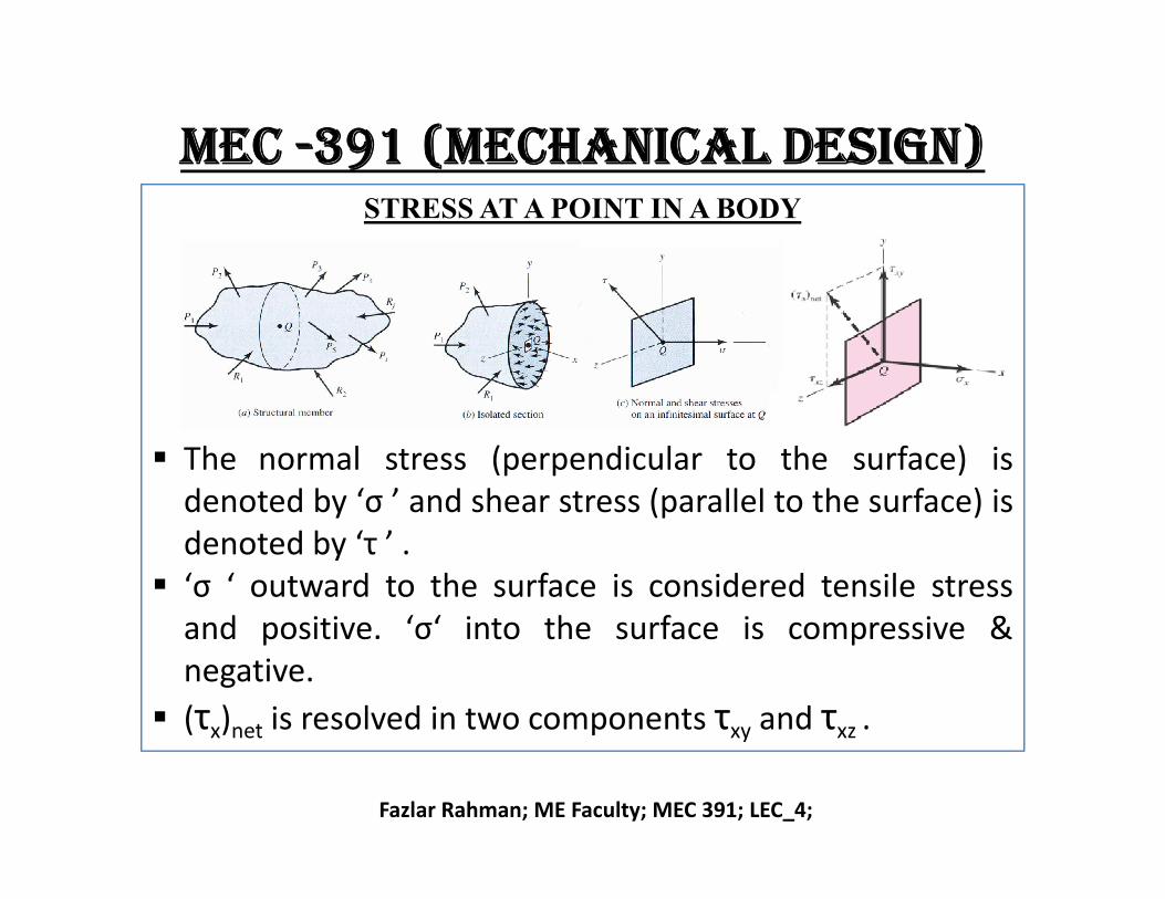
The normal stress (perpendicular to the surface) is
Fazlar Rahman; ME Faculty; MEC 391; LEC_4;
The normal stress (perpendicular to the surface) isdenoted by ‘σ ’ and shear stress (parallel to the surface) isdenoted by ‘τ ’ .
‘σ ‘ outward to the surface is considered tensile stressand positive. ‘σ‘ into the surface is compressive &negative.
(τx)net is resolved in two components τxy and τxz .
mec -391 (mechanical design)STRESS AT A POINT IN A BODY (Continue)
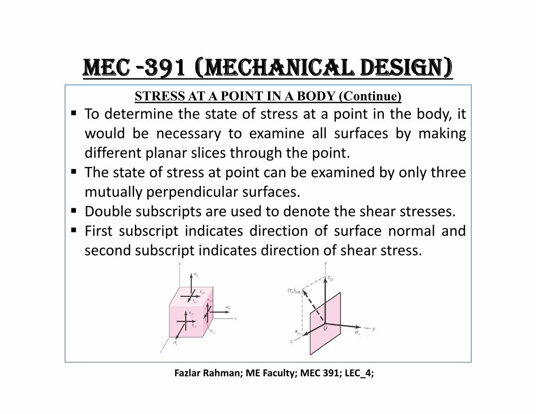
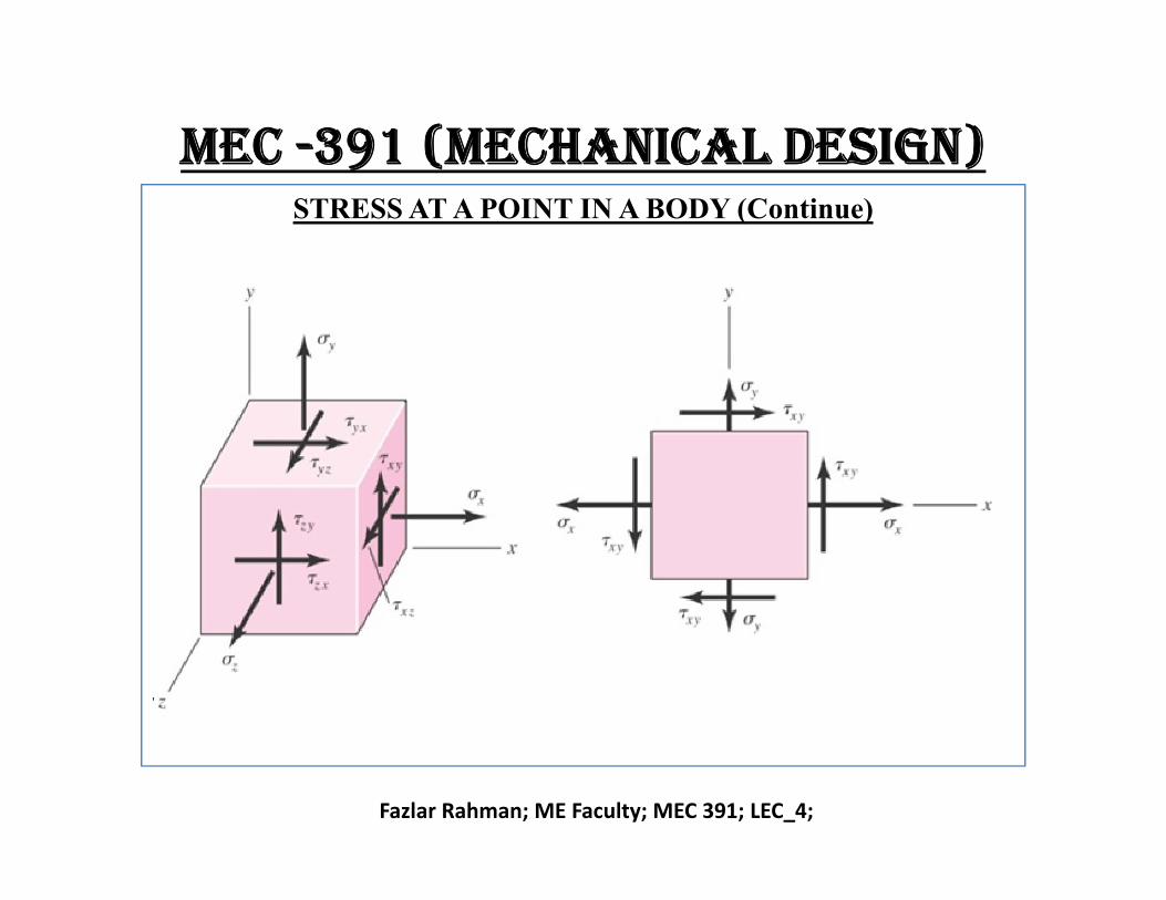
To determine the state of stress at a point in the body, itwould be necessary to examine all surfaces by makingdifferent planar slices through the point.
The state of stress at point can be examined by only threemutually perpendicular surfaces.
Double subscripts are used to denote the shear stresses.
Fazlar Rahman; ME Faculty; MEC 391; LEC_4;
Double subscripts are used to denote the shear stresses. First subscript indicates direction of surface normal and
second subscript indicates direction of shear stress.
mec -391 (mechanical design)STRESS AT A POINT IN A BODY (Continue)
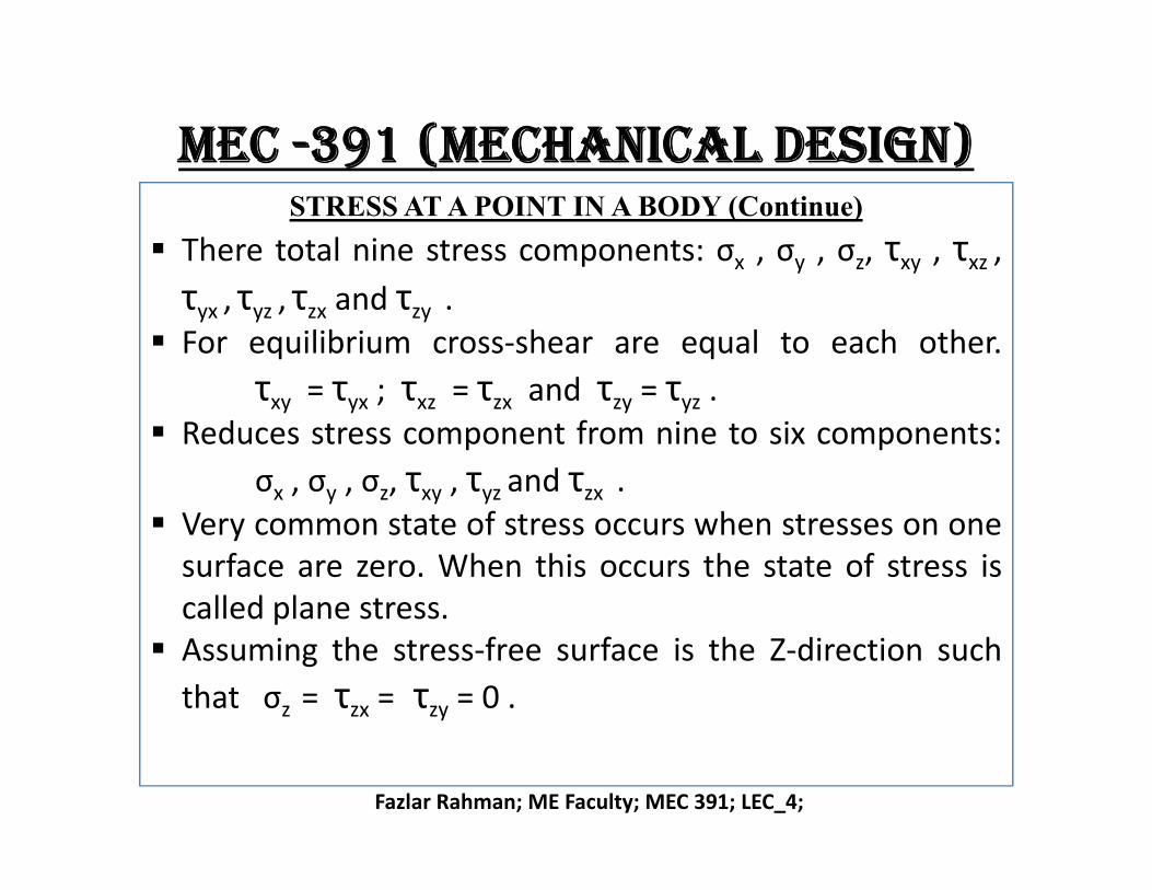
There total nine stress components: σx , σy , σz, τxy , τxz ,
τyx , τyz , τzx and τzy . For equilibrium cross-shear are equal to each other.
τxy = τyx ; τxz = τzx and τzy = τyz . Reduces stress component from nine to six components:
Fazlar Rahman; ME Faculty; MEC 391; LEC_4;
Reduces stress component from nine to six components:
σx , σy , σz, τxy , τyz and τzx . Very common state of stress occurs when stresses on one
surface are zero. When this occurs the state of stress iscalled plane stress.
Assuming the stress-free surface is the Z-direction such
that σz = τzx = τzy = 0 .
mec -391 (mechanical design)STRESS AT A POINT IN A BODY (Continue)
Fazlar Rahman; ME Faculty; MEC 391; LEC_4;
mec -391 (mechanical design)PLANE STRESS TRANSFORMATION EQUATIONS
Fazlar Rahman; ME Faculty; MEC 391; LEC_4;
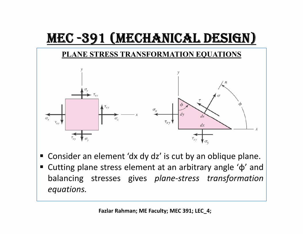
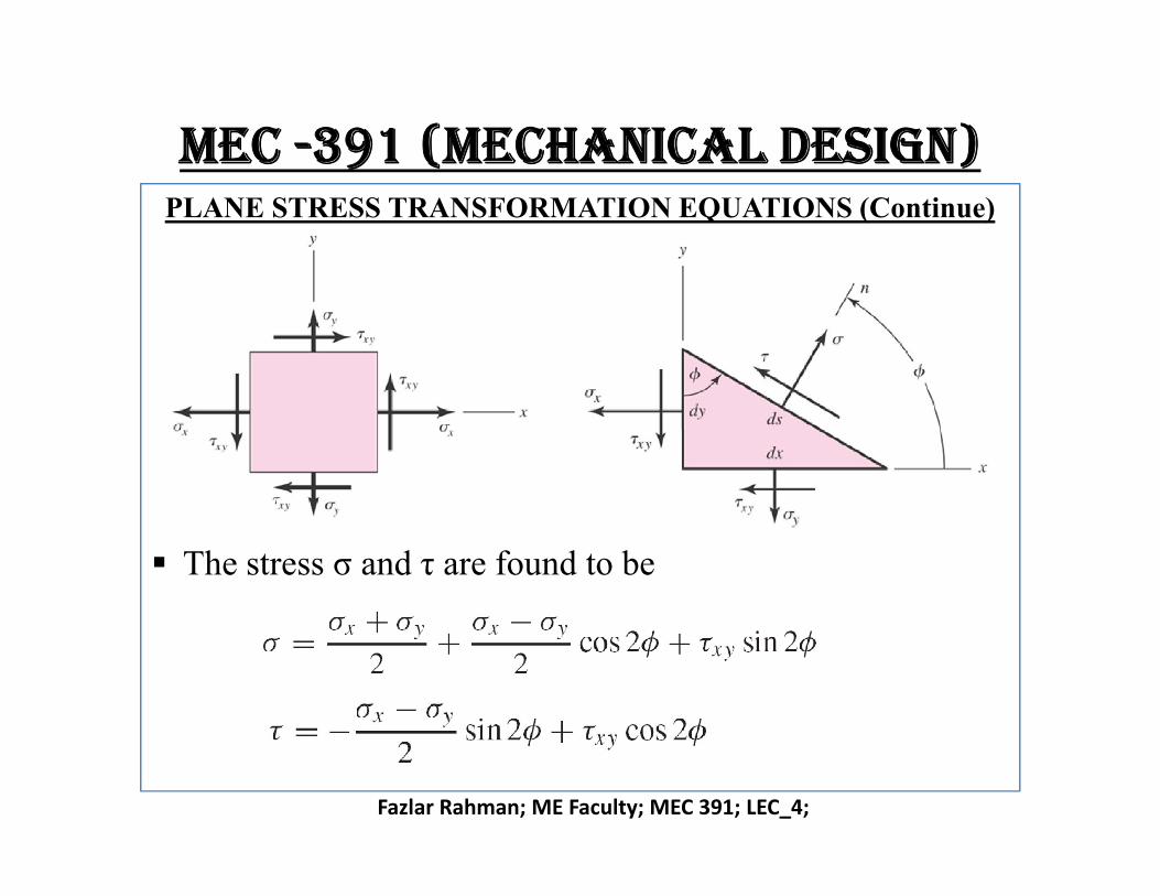
Consider an element ‘dx dy dz’ is cut by an oblique plane. Cutting plane stress element at an arbitrary angle ‘φ’ and
balancing stresses gives plane-stress transformationequations.
mec -391 (mechanical design)PLANE STRESS TRANSFORMATION EQUATIONS (Continue)
Fazlar Rahman; ME Faculty; MEC 391; LEC_4;
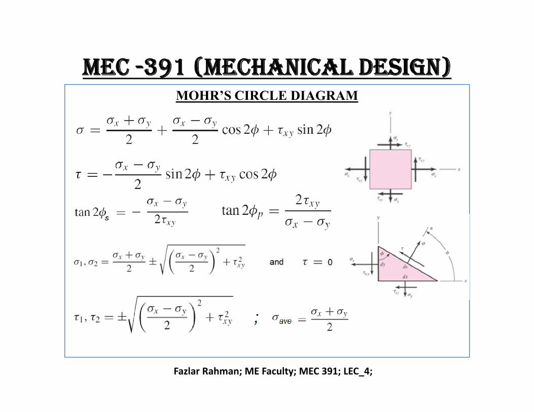
The stress σ and τ are found to be
mec -391 (mechanical design)PLANE STRESS TRANSFORMATION EQUATIONS (Continue)
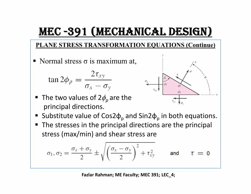
Normal stress σ is maximum at,
The two values of 2f are the
Fazlar Rahman; ME Faculty; MEC 391; LEC_4;
The two values of 2fp are theprincipal directions.
Substitute value of Cos2φp and Sin2φp in both equations. The stresses in the principal directions are the principal
stress (max/min) and shear stress are
mec -391 (mechanical design)PLANE STRESS TRANSFORMATION EQUATIONS (Continue)
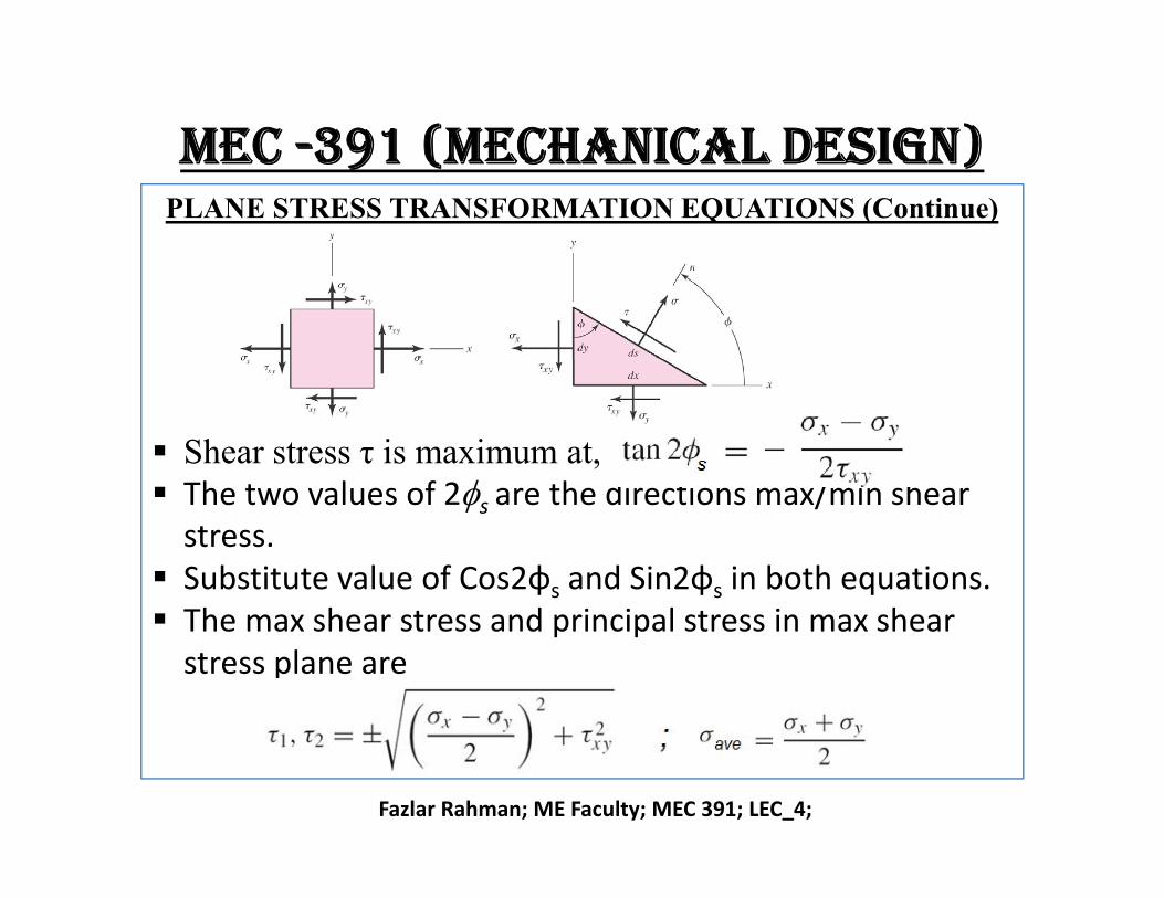
Shear stress τ is maximum at,
Fazlar Rahman; ME Faculty; MEC 391; LEC_4;
Shear stress τ is maximum at, The two values of 2fs are the directions max/min shear
stress. Substitute value of Cos2φs and Sin2φs in both equations. The max shear stress and principal stress in max shear
stress plane are
mec -391 (mechanical design)PLANE STRESS TRANSFORMATION EQUATIONS (Continue)
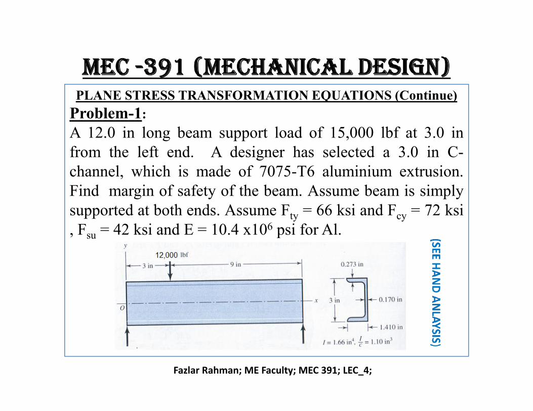
Problem-1:
A 12.0 in long beam support load of 15,000 lbf at 3.0 infrom the left end. A designer has selected a 3.0 in C-channel, which is made of 7075-T6 aluminium extrusion.Find margin of safety of the beam. Assume beam is simplysupported at both ends. Assume F = 66 ksi and F = 72 ksi
Fazlar Rahman; ME Faculty; MEC 391; LEC_4;
supported at both ends. Assume Fty = 66 ksi and Fcy = 72 ksi, Fsu = 42 ksi and E = 10.4 x10⁶ psi for Al.
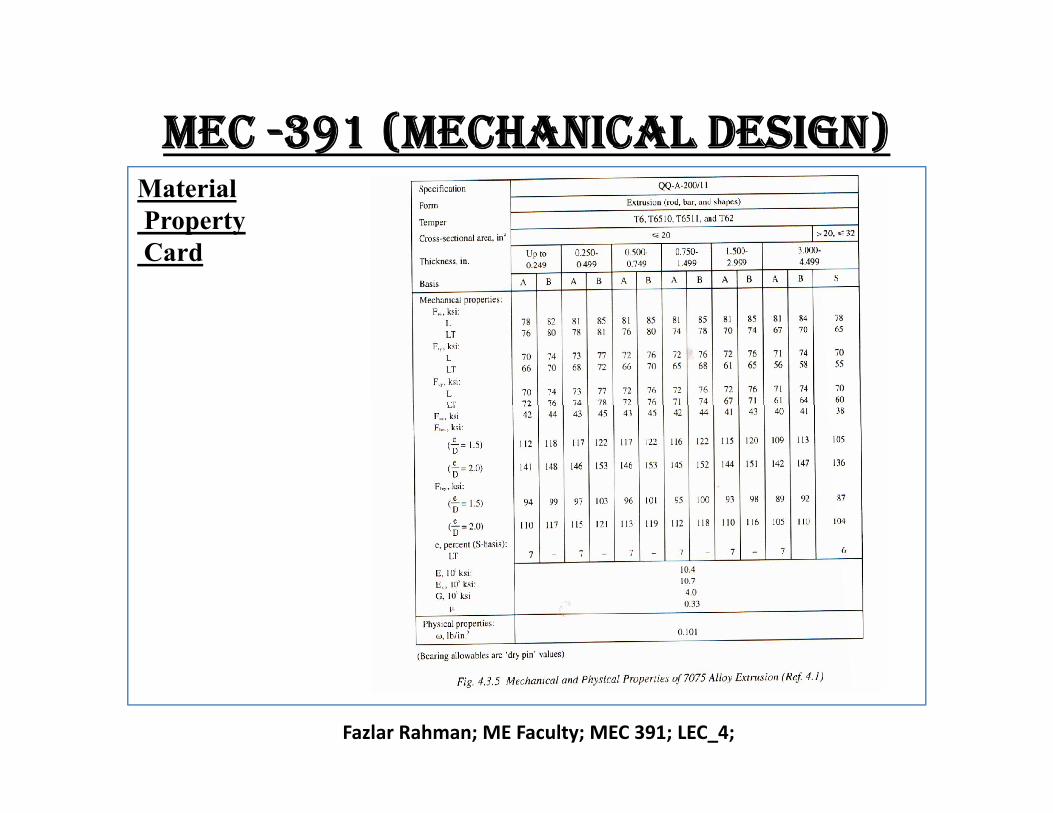
mec -391 (mechanical design)MaterialPropertyCard
Fazlar Rahman; ME Faculty; MEC 391; LEC_4;
mec -391 (mechanical design)PLANE STRESS TRANSFORMATION EQUATIONS (Continue)
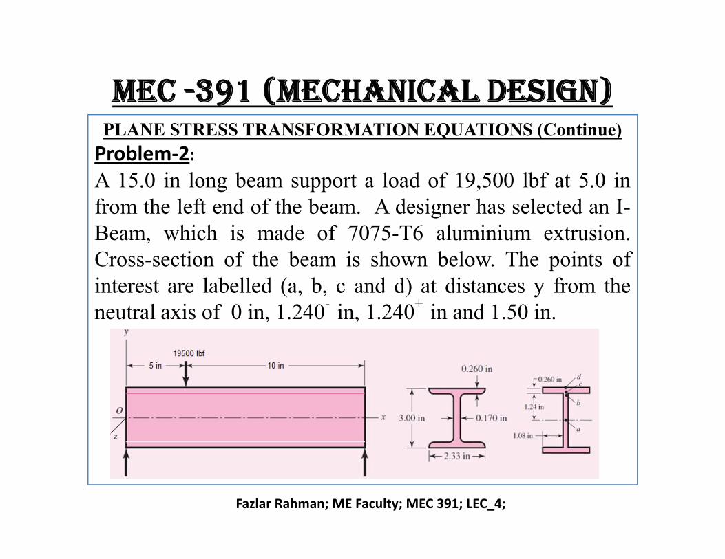
Problem-2:
A 15.0 in long beam support a load of 19,500 lbf at 5.0 infrom the left end of the beam. A designer has selected an I-Beam, which is made of 7075-T6 aluminium extrusion.Cross-section of the beam is shown below. The points ofinterest are labelled (a, b, c and d) at distances y from the
Fazlar Rahman; ME Faculty; MEC 391; LEC_4;
interest are labelled (a, b, c and d) at distances y from theneutral axis of 0 in, 1.240- in, 1.240+ in and 1.50 in.
mec -391 (mechanical design)PLANE STRESS TRANSFORMATION EQUATIONS (Continue)
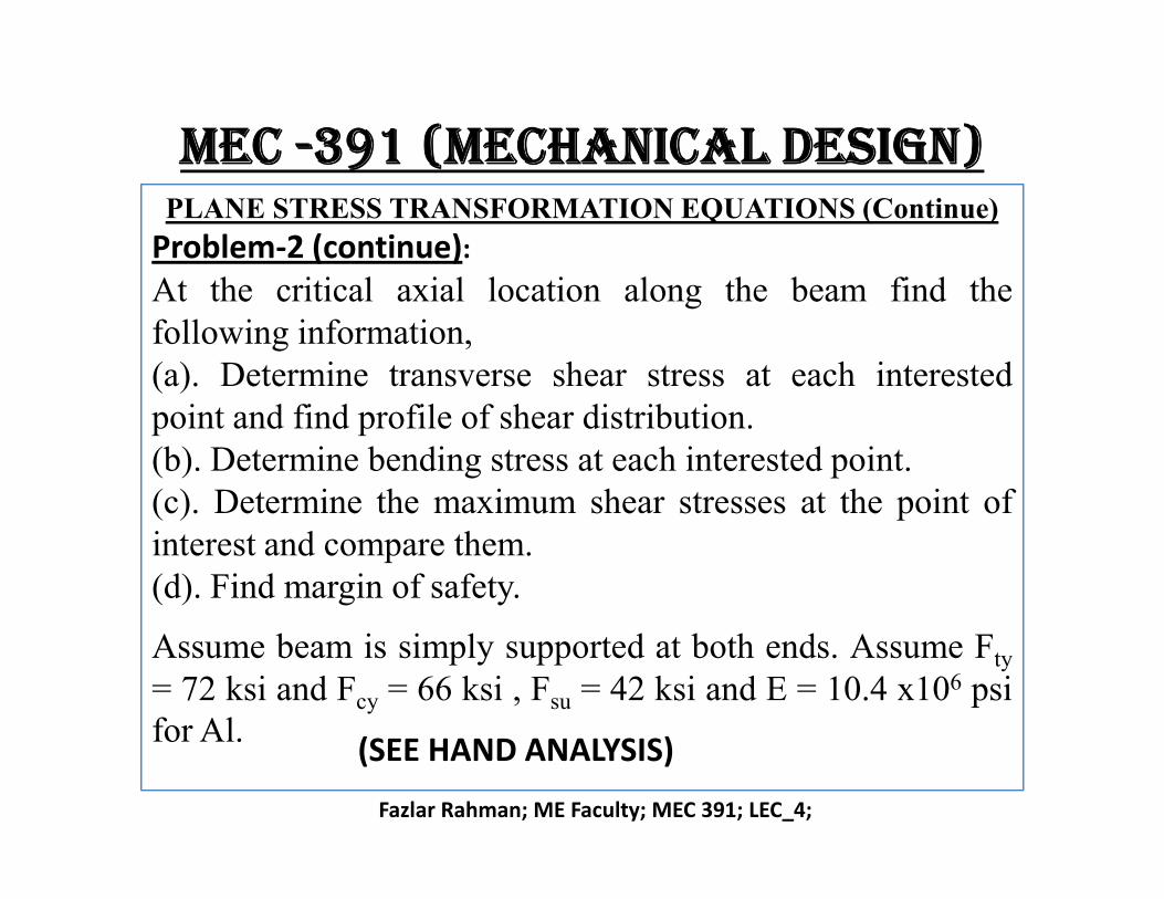
Problem-2 (continue):
At the critical axial location along the beam find thefollowing information,(a). Determine transverse shear stress at each interestedpoint and find profile of shear distribution.(b). Determine bending stress at each interested point.
Fazlar Rahman; ME Faculty; MEC 391; LEC_4;
(b). Determine bending stress at each interested point.(c). Determine the maximum shear stresses at the point ofinterest and compare them.(d). Find margin of safety.
Assume beam is simply supported at both ends. Assume Fty
= 72 ksi and Fcy = 66 ksi , Fsu = 42 ksi and E = 10.4 x10⁶ psifor Al.
(SEE HAND ANALYSIS)
mec -391 (mechanical design)MOHR’S CIRCLE DIAGRAM
Fazlar Rahman; ME Faculty; MEC 391; LEC_4;
mec -391 (mechanical design)MOHR’S CIRCLE DIAGRAM (Continue)
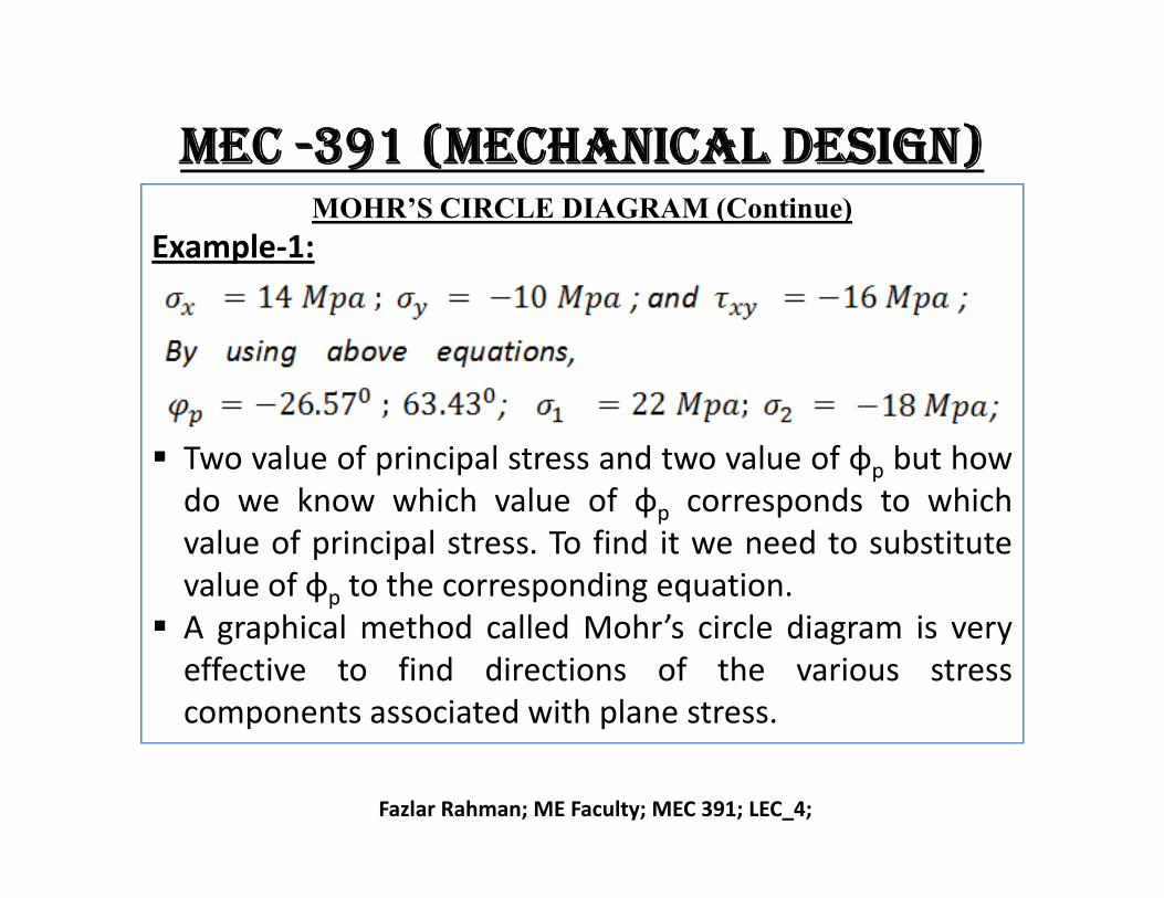
Example-1:
Two value of principal stress and two value of φ but how
Fazlar Rahman; ME Faculty; MEC 391; LEC_4;
Two value of principal stress and two value of φp but howdo we know which value of φp corresponds to whichvalue of principal stress. To find it we need to substitutevalue of φp to the corresponding equation.
A graphical method called Mohr’s circle diagram is veryeffective to find directions of the various stresscomponents associated with plane stress.
mec -391 (mechanical design)MOHR’S CIRCLE DIAGRAM (Continue)
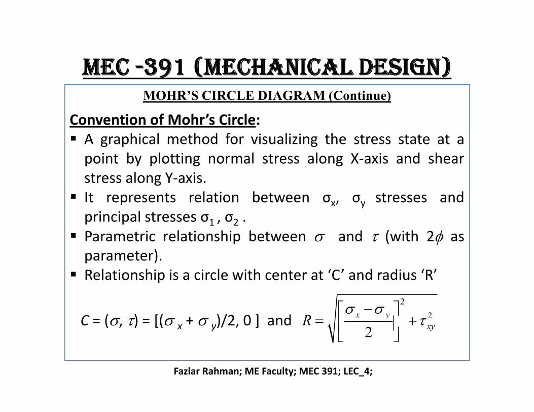
Convention of Mohr’s Circle: A graphical method for visualizing the stress state at a
point by plotting normal stress along X-axis and shearstress along Y-axis.
It represents relation between σx, σy stresses and
Fazlar Rahman; ME Faculty; MEC 391; LEC_4;
It represents relation between σx, σy stresses andprincipal stresses σ1 , σ2 .
Parametric relationship between and (with 2f asparameter).
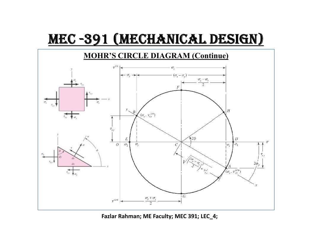
Relationship is a circle with center at ‘C’ and radius ‘R’
C = (, ) = [( x + y)/2, 0 ] and
2
2
2
x y
xyR
mec -391 (mechanical design)MOHR’S CIRCLE DIAGRAM (Continue)
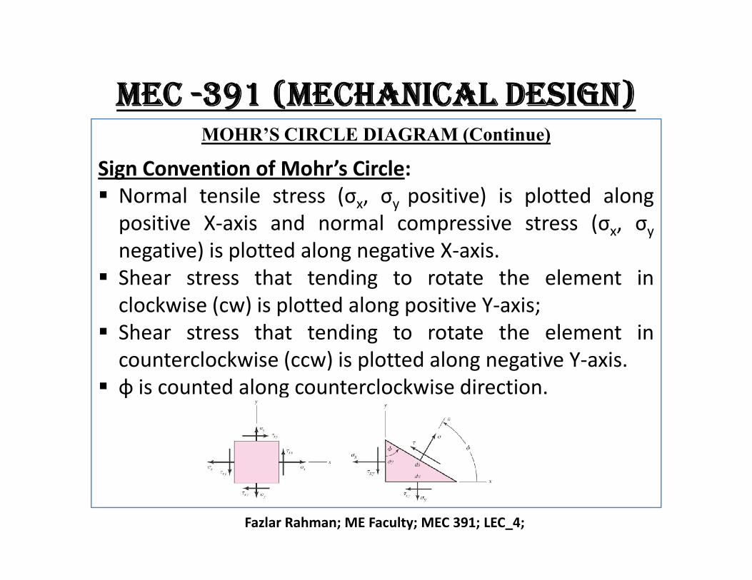
Sign Convention of Mohr’s Circle: Normal tensile stress (σx, σy positive) is plotted along
positive X-axis and normal compressive stress (σx, σy
negative) is plotted along negative X-axis. Shear stress that tending to rotate the element in
Fazlar Rahman; ME Faculty; MEC 391; LEC_4;
Shear stress that tending to rotate the element inclockwise (cw) is plotted along positive Y-axis;
Shear stress that tending to rotate the element incounterclockwise (ccw) is plotted along negative Y-axis.
φ is counted along counterclockwise direction.
mec -391 (mechanical design)MOHR’S CIRCLE DIAGRAM (Continue)
Fazlar Rahman; ME Faculty; MEC 391; LEC_4;
mec -391 (mechanical design)MOHR’S CIRCLE DIAGRAM (Continue)
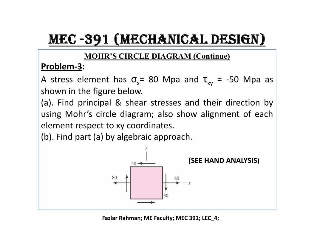
Problem-3:
A stress element has σx= 80 Mpa and τxy = -50 Mpa asshown in the figure below.(a). Find principal & shear stresses and their direction byusing Mohr’s circle diagram; also show alignment of eachelement respect to xy coordinates.
Fazlar Rahman; ME Faculty; MEC 391; LEC_4;
element respect to xy coordinates.(b). Find part (a) by algebraic approach.
(SEE HAND ANALYSIS)
mec -391 (mechanical design)MOHR’S CIRCLE DIAGRAM (Continue)
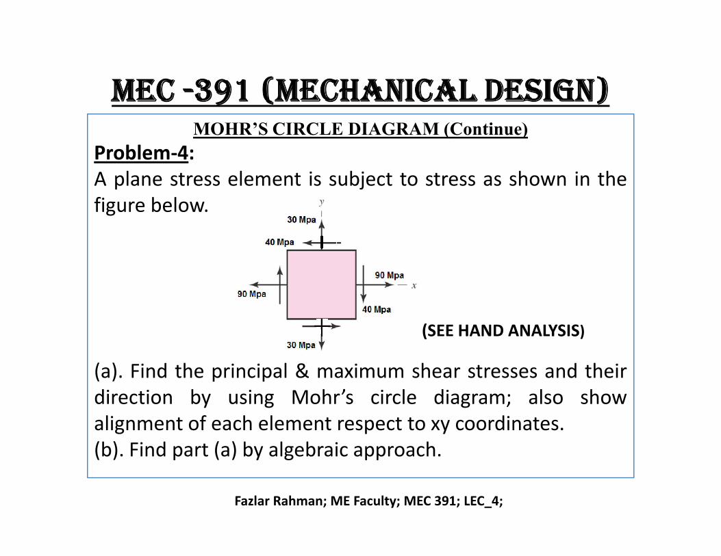
Problem-4:A plane stress element is subject to stress as shown in thefigure below.
Fazlar Rahman; ME Faculty; MEC 391; LEC_4;
(a). Find the principal & maximum shear stresses and theirdirection by using Mohr’s circle diagram; also showalignment of each element respect to xy coordinates.(b). Find part (a) by algebraic approach.
(SEE HAND ANALYSIS)
mec -391 (mechanical design)MOHR’S CIRCLE DIAGRAM (Continue)
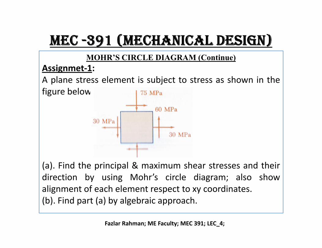
Assignmet-1:A plane stress element is subject to stress as shown in thefigure below.
Fazlar Rahman; ME Faculty; MEC 391; LEC_4;
(a). Find the principal & maximum shear stresses and theirdirection by using Mohr’s circle diagram; also showalignment of each element respect to xy coordinates.(b). Find part (a) by algebraic approach.
mec -391 (mechanical design)THREE DIMENSIONAL STRESSES
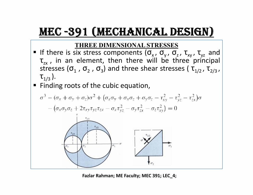
If there is six stress components (σx , σy , σz , τxy , τyz andτzx , in an element, then there will be three principalstresses (σ1 , σ2 , σ3) and three shear stresses ( τ1/2 , τ2/3 ,τ1/3 ).
Finding roots of the cubic equation,
Fazlar Rahman; ME Faculty; MEC 391; LEC_4;
mec -391 (mechanical design)THREE DIMENSIONAL STRESSES
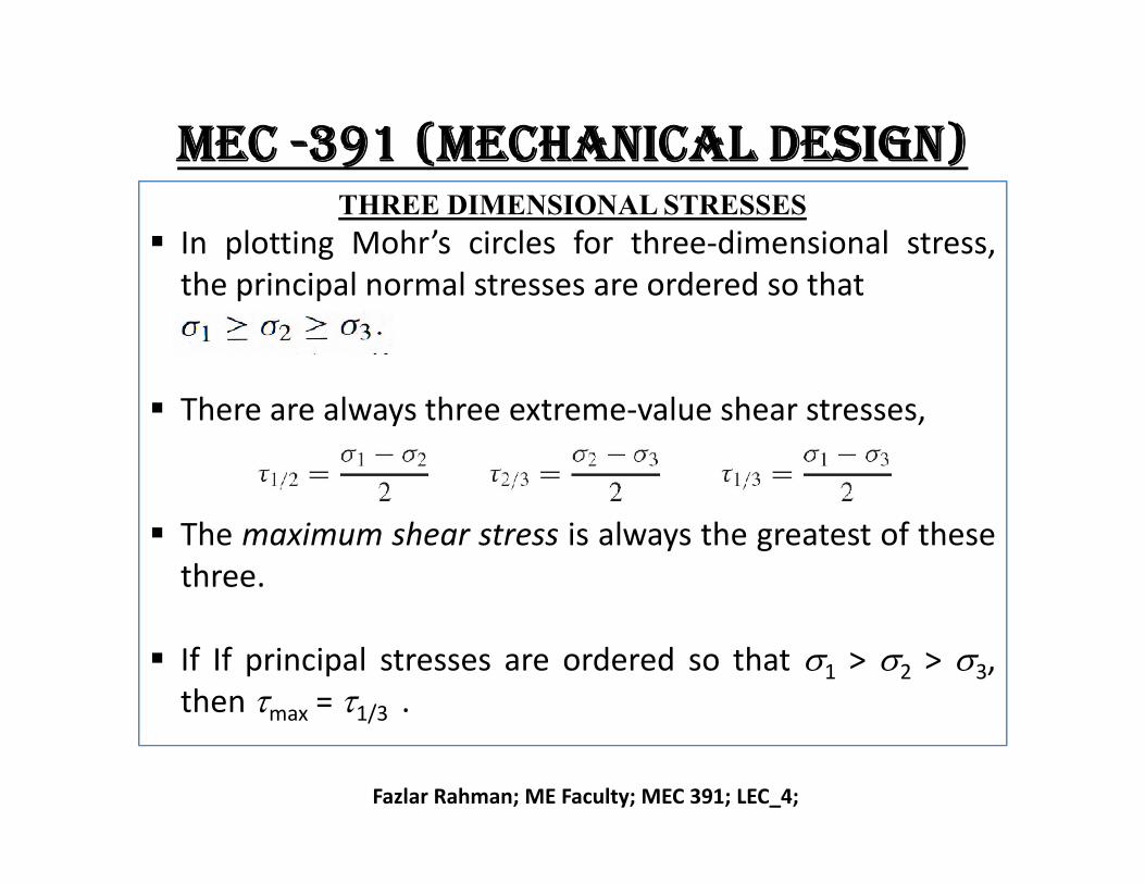
In plotting Mohr’s circles for three-dimensional stress,the principal normal stresses are ordered so that
There are always three extreme-value shear stresses,
Fazlar Rahman; ME Faculty; MEC 391; LEC_4;
The maximum shear stress is always the greatest of thesethree.
If If principal stresses are ordered so that 1 > 2 > 3,then max = 1/3 .
mec -391 (mechanical design)BENDING IN CURVED BEAM
Crane hooks, U-shaped Frame and Frame of clamp etc are example of curved beam (beam initially curved) .
Neutral axis and centroidal axis are not coincident. Bending stress does not vary linearly with distance from
the neutral axis. Assume, r = radius of outer fiber; r = radius of inner
Fazlar Rahman; ME Faculty; MEC 391; LEC_4;
Assume, ro = radius of outer fiber; ri = radius of inner fiber ; rn = radius of neutral axis ; rc = radius of centroidal axis ; h = depth of section; always rn < rc and e = rc – rn.
And co= distance from neutral axis to outer fiber; ci = distance from neutral axis to inner fiber ; e = distance from centroidal axis to neutral axis ; M = bending moment (positive M decreases curvature).
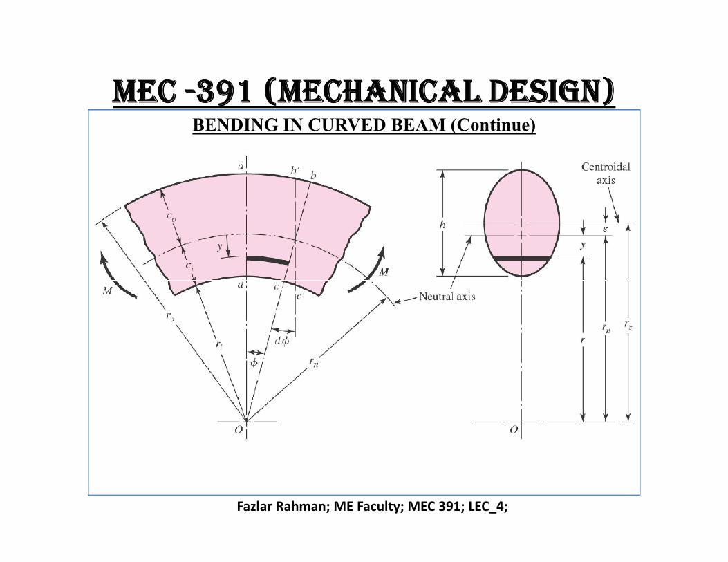
mec -391 (mechanical design)BENDING IN CURVED BEAM (Continue)
Fazlar Rahman; ME Faculty; MEC 391; LEC_4;
mec -391 (mechanical design)BENDING IN CURVED BEAM (Continue)
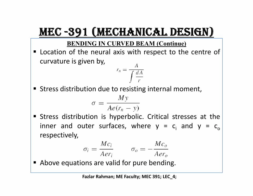
Location of the neural axis with respect to the centre ofcurvature is given by,
Stress distribution due to resisting internal moment,
Fazlar Rahman; ME Faculty; MEC 391; LEC_4;
Stress distribution is hyperbolic. Critical stresses at theinner and outer surfaces, where y = ci and y = co
respectively,
Above equations are valid for pure bending.
mec -391 (mechanical design)BENDING IN CURVED BEAM (Continue)
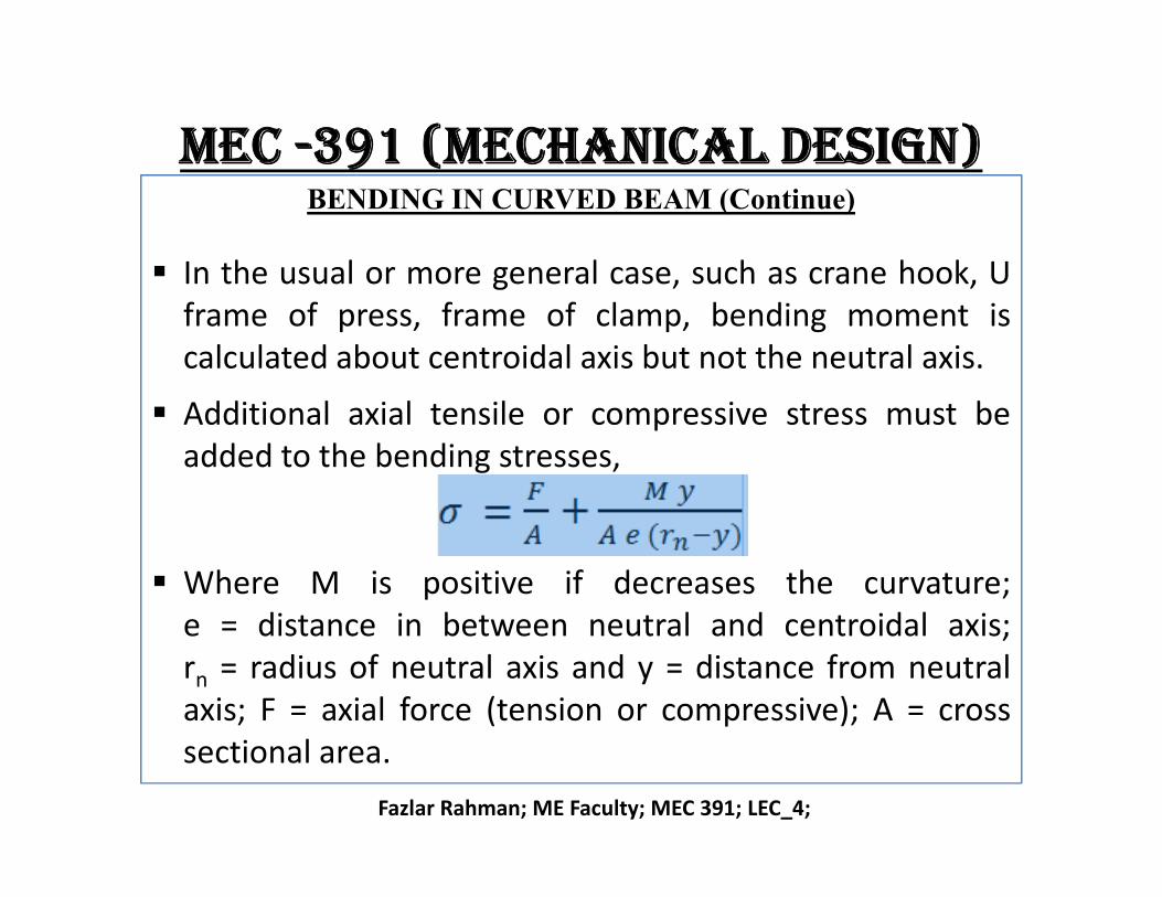
In the usual or more general case, such as crane hook, Uframe of press, frame of clamp, bending moment iscalculated about centroidal axis but not the neutral axis.
Additional axial tensile or compressive stress must beadded to the bending stresses,
Fazlar Rahman; ME Faculty; MEC 391; LEC_4;
added to the bending stresses,
Where M is positive if decreases the curvature;e = distance in between neutral and centroidal axis;rn = radius of neutral axis and y = distance from neutralaxis; F = axial force (tension or compressive); A = crosssectional area.

mec -391 (mechanical design)BENDING IN CURVED BEAM (Continue)
Problem-5: (SEE HAND ANLAYSIS)Plot stress distribution across section A-A of the crane hookshown in the figure below. The cross section is rectangularwith b = 0.75 in and h = 4.0 in. Load on the hook is 5000 lbf.
Fazlar Rahman; ME Faculty; MEC 391; LEC_4;
mec -391 (mechanical design)BENDING IN CURVED BEAM (Continue)
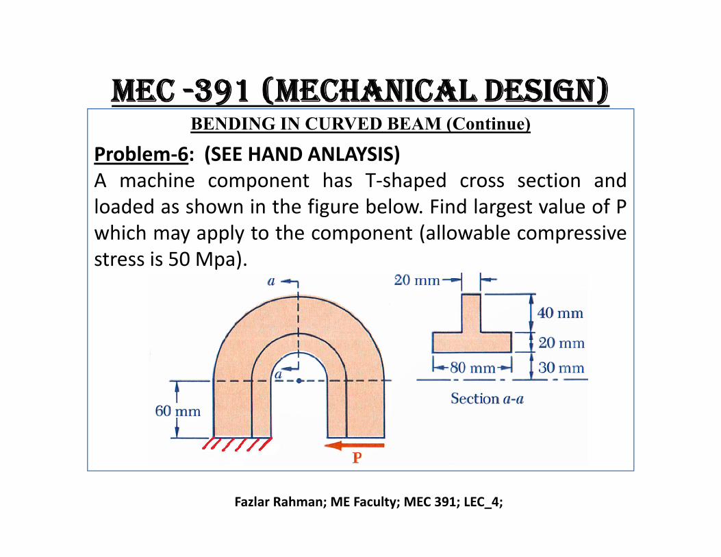
Problem-6: (SEE HAND ANLAYSIS)A machine component has T-shaped cross section andloaded as shown in the figure below. Find largest value of Pwhich may apply to the component (allowable compressivestress is 50 Mpa).
Fazlar Rahman; ME Faculty; MEC 391; LEC_4;
mec -391 (mechanical design)PRESSURE VESSELS
There are two kind of pressure vessels:o Thin-walled pressure vessel :o Thick-walled pressure vessel.
Example of pressure vessel: Cylindrical Pressure vessels,Spherical pressure vessel, hydraulic cylinders, gun barrelsand pipe carrying fluids at high pressure etc.
Fazlar Rahman; ME Faculty; MEC 391; LEC_4;
and pipe carrying fluids at high pressure etc. There are three types of stresses developed in the
pressure vessels depending on wall thickness, shape(cylindrical or spherical).
o Tangential or hoop stress, σt
o Radial stress, σr
o Longitudinal stress, σl
mec -391 (mechanical design)PRESSURE VESSELS
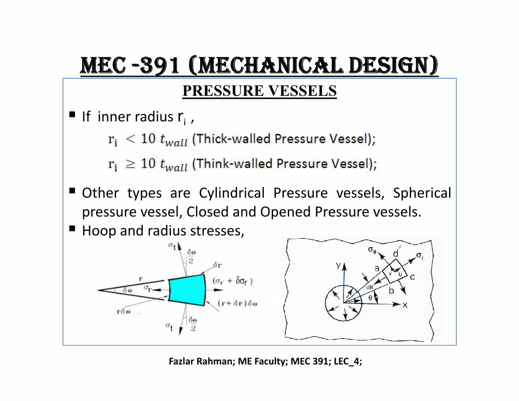
If inner radius ri ,
Other types are Cylindrical Pressure vessels, Spherical
Fazlar Rahman; ME Faculty; MEC 391; LEC_4;
Other types are Cylindrical Pressure vessels, Sphericalpressure vessel, Closed and Opened Pressure vessels.
Hoop and radius stresses,
mec -391 (mechanical design)THICK-WALLED PRESSURE VESSELS
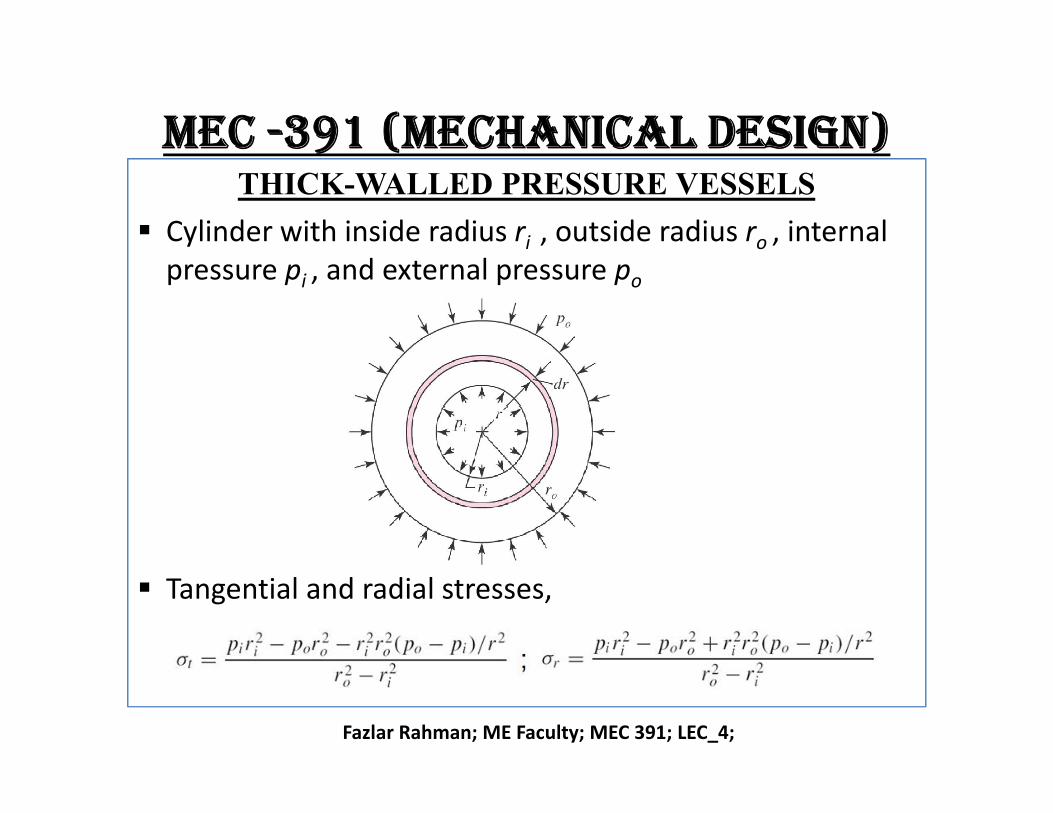
Cylinder with inside radius ri , outside radius ro , internal pressure pi , and external pressure po
Fazlar Rahman; ME Faculty; MEC 391; LEC_4;
Tangential and radial stresses,
mec -391 (mechanical design)THICK-WALLED PRESSURE VESSELS
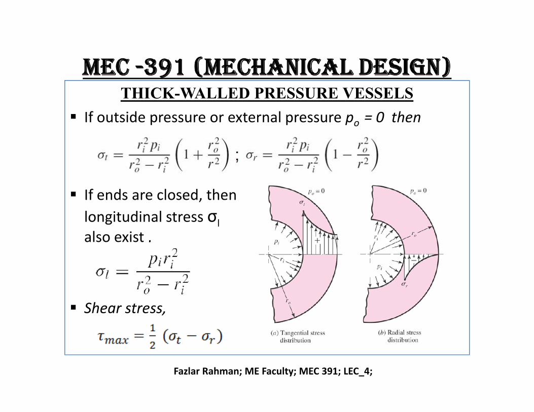
If outside pressure or external pressure po = 0 then
If ends are closed, then
σ
Fazlar Rahman; ME Faculty; MEC 391; LEC_4;
longitudinal stress σl
also exist ,
Shear stress,
mec -391 (mechanical design)THIN-WALLED PRESSURE VESSELS
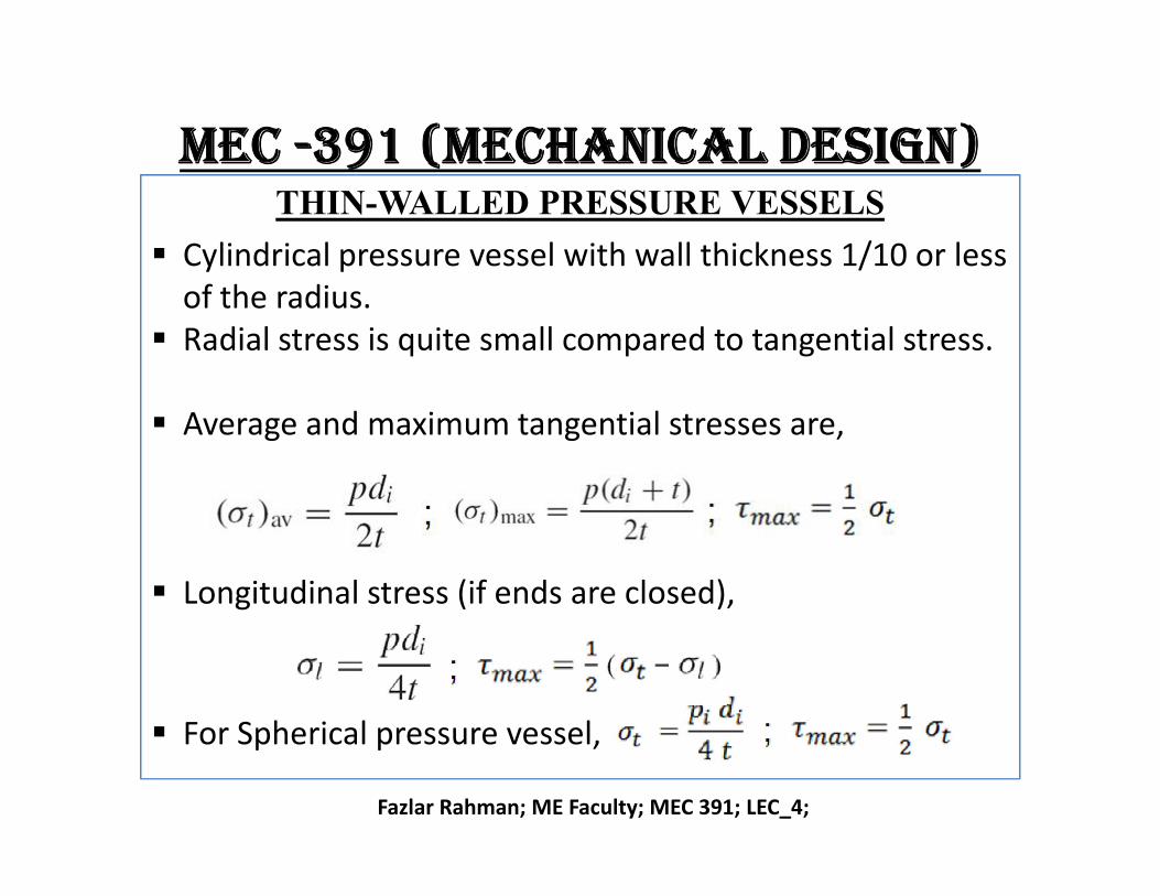
Cylindrical pressure vessel with wall thickness 1/10 or less of the radius.
Radial stress is quite small compared to tangential stress.
Average and maximum tangential stresses are,
Fazlar Rahman; ME Faculty; MEC 391; LEC_4;
Longitudinal stress (if ends are closed),
For Spherical pressure vessel,
mec -391 (mechanical design)PRESSURE VESSELS PROBLEM
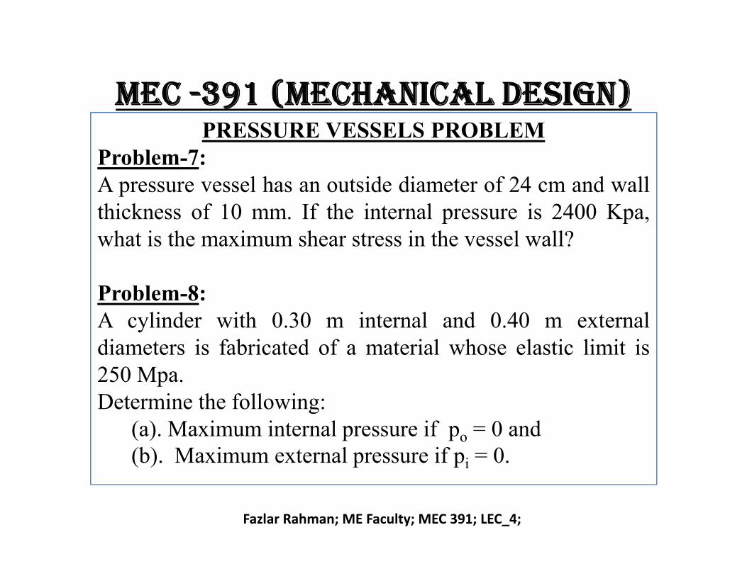
Problem-7:A pressure vessel has an outside diameter of 24 cm and wallthickness of 10 mm. If the internal pressure is 2400 Kpa,what is the maximum shear stress in the vessel wall?
Problem-8:
Fazlar Rahman; ME Faculty; MEC 391; LEC_4;
Problem-8:A cylinder with 0.30 m internal and 0.40 m externaldiameters is fabricated of a material whose elastic limit is250 Mpa.Determine the following:
(a). Maximum internal pressure if po = 0 and(b). Maximum external pressure if pi = 0.
mec -391 (mechanical design)PRESS AND SHRINK FITS
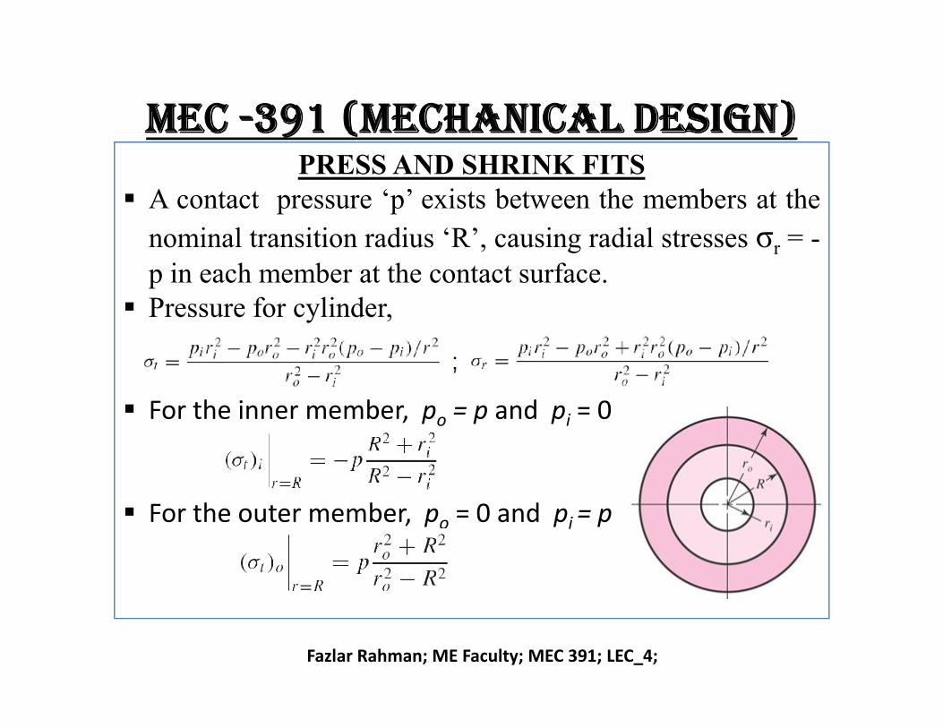
A contact pressure ‘p’ exists between the members at the
nominal transition radius ‘R’, causing radial stresses σr = -p in each member at the contact surface.
Pressure for cylinder,
Fazlar Rahman; ME Faculty; MEC 391; LEC_4;
For the inner member, po = p and pi = 0
For the outer member, po = 0 and pi = p
mec -391 (mechanical design)PRESS AND SHRINK FITS (Continue)
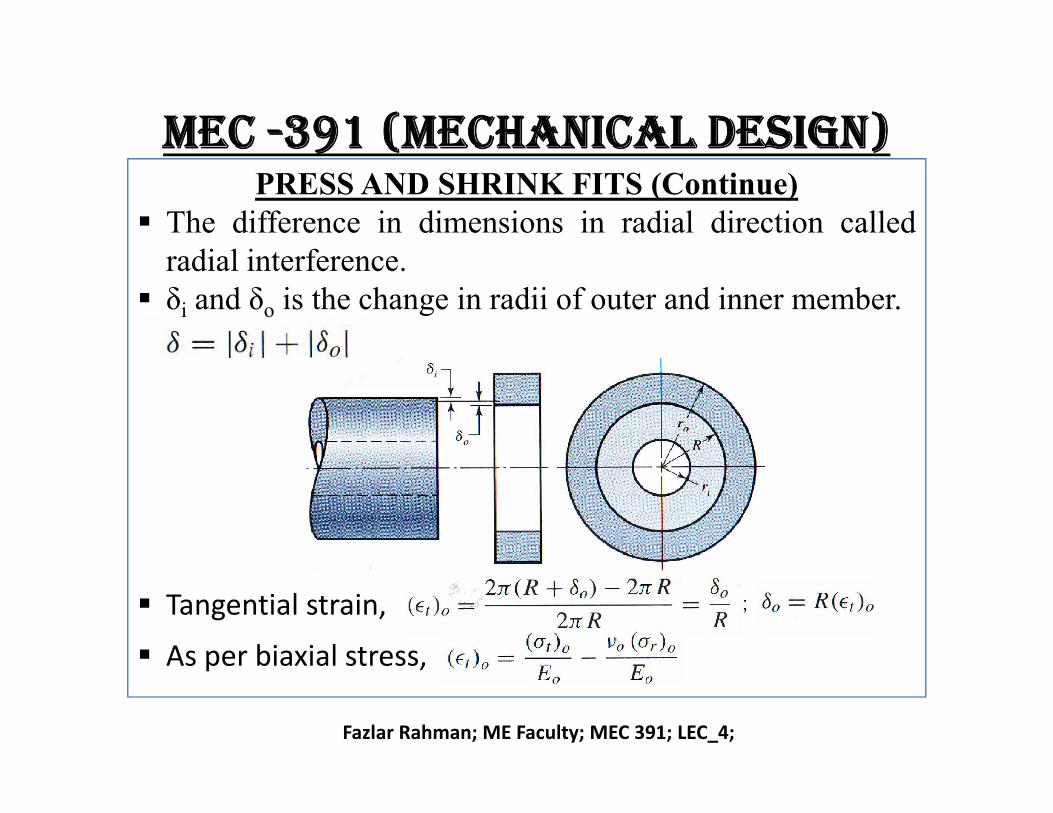
The difference in dimensions in radial direction calledradial interference.
δi and δo is the change in radii of outer and inner member.
Fazlar Rahman; ME Faculty; MEC 391; LEC_4;
Tangential strain,
As per biaxial stress,
mec -391 (mechanical design)PRESS AND SHRINK FITS (Continue)
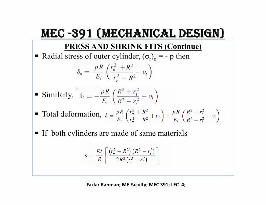
Radial stress of outer cylinder, (σr)o = - p then
Similarly,
Fazlar Rahman; ME Faculty; MEC 391; LEC_4;
Total deformation,
If both cylinders are made of same materials
mec -391 (mechanical design)PRESS AND SHRINK FITS (Continue)
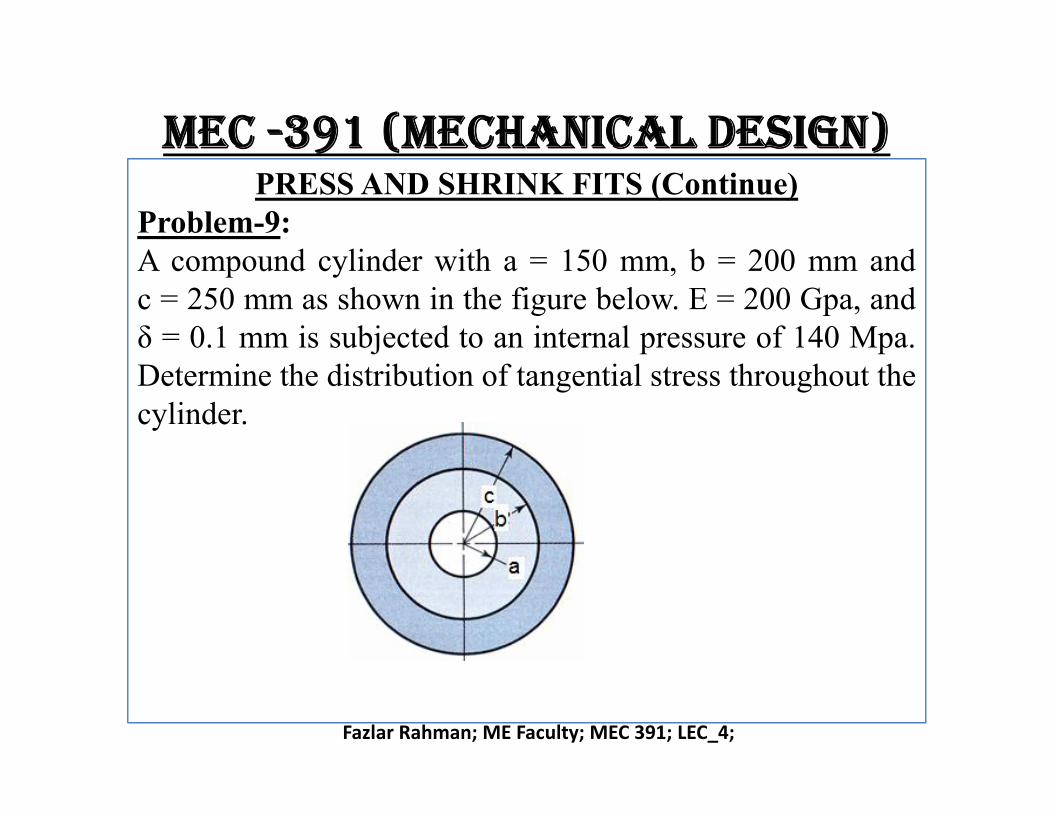
Problem-9:A compound cylinder with a = 150 mm, b = 200 mm andc = 250 mm as shown in the figure below. E = 200 Gpa, andδ = 0.1 mm is subjected to an internal pressure of 140 Mpa.Determine the distribution of tangential stress throughout thecylinder.
Fazlar Rahman; ME Faculty; MEC 391; LEC_4;
cylinder.