laying & construction of cs 3 lpe coated underground pipelines
TRANSCRIPT
LAYING & CONSTRUCTION OF CS 3 LPECOATED UNDERGROUND PIPELINESFOR DEVELOPMENT OF CGD NETWORKIN THE GA OF ROHTAK Project No. P.013460Document No. P.013460 D11031 034E - Tender No. 1000329391
Bharat Petroleum Corporation LimitedNew Delhi | INDIA
PUBLIC
2 May 2019
TECHNICAL DOCUMENTATIONTechnical, Vol IIB of II, Rev. 0
S.No. Document / Drawing No. Rev. No. Pages Page No.
I COMMERCIAL
1
2
3
4
5
6
II TECHNICAL
1 P.013460 D11077 006 0 62 1
2 P.013460 D11077 007 0 13 63
3 P.013460 D11077 008 0 11 76
4 P.013460 D11077 009 0 5 87
5 P.013460 D11077 010 0 80 92
6 P.013460 D11077 011 0 15 172
7 P.013460 D11077 012 0 9 187
8 P.013460 D11077 013 0 6 196
9 P.013460 D11077 014 0 4 202
10 P.013460 D11077 015 0 24 206
11 P.013460 D11077 016 0 9 230
12 P.013460 D11077 017 0 23 239
13 P.013460 D11077 018 0 7 262
14 P.013460 D11077 019 0 15 269
15 P.013460 D11077 020 0 18 284
16 P.013460 D11077 021 0 3 302
17 P.013460 D11077 022 0 4 305
17 P.013460 D 11087 001 0 1 309
18 P.013460 D 11087 004 0 2 310
19 P.013460 D 11087 005 0 2 312
SECTION - VISCHEDULE OF RATES (SOR) FOR LAYING OF 3 LPE COATED
CARBON STEEL PIPELINE IN ROHTAK DISTRICT, HARYANA
P.013460 D 11031 034 0 Page No. 1 t o 163163
MAIN TABLE OF CONTENTS
LAYING OF 3 LPE COATED CARBON STEEL PIPELINES IN ROHTAK DISTRICTS
(HARYANA)
P.013460
D 11031
034
Description
VOLUME IA OF II
SECTION - I INVITATION FOR BID (IFB)
SECTION - II INSTRUCTION TO BIDDERS (ITB)
SECTION - III GENERAL CONDITIONS OF CONTRACT (GCC)
SECTION - IV SPECIAL CONDITIONS OF CONTRACT (SCC)
SECTION - V FORMS AND FORMATS
PTS QUALITY ASSURANCE / QUALITY CONTROL
PTS THIRD PARTY INSPECTION AGENCY
PTS HEALTH, SAFETY & ENVIRONMENT
VOLUME IIA OF II
PTS CONSTRUCTION OF NATURAL GAS CS PIPELINE
PTS HDD
PTS LAYING OF PLB - HDPE DUCT
PTS OPTICAL FIBER CABLE
PTS HDPE DUCT
PTS TEMPORARY CATHODIC PROTECTION SYSTEM
PTS ELECTROFUSION FOR PE PIPES & FITTINGS
PTS LAYING OF OPTICAL FIBER CABLE
PTS INSULATING JOINTS
PTS PAINTING SYSTEM & COLOUR CODE FOR FINAL LAYER
PTS PIPING CLASS
PTS FITTING & FLANGES
PTS MDPE FITTINGS & VALVES
PTS PIPELINE VALVE
DATA SHEET PRESSURE GAUGE
DATA SHEET BALL VALVE (VBA-3C1)
DATA SHEET GLOBE VALVE (VGA-3C1)
Laying of 3 LPE Coated Carbon Steel Pipeline Page 1 of 4
S.No. Document / Drawing No. Rev. No. Pages Page No.
MAIN TABLE OF CONTENTS
LAYING OF 3 LPE COATED CARBON STEEL PIPELINES IN ROHTAK DISTRICTS
(HARYANA)
P.013460
D 11031
034
Description
20 P.013460 D 11087 006 0 1 314
21 P.013460 D11013 003 0 3 315
22 P.013460 D11013 004 0 3 318
23 P.013460 D11013 005 0 5 321
24 P.013460 D11013 006 0 4 326
25 P.013460 D11013 007 0 4 330
26 P.013460 D11013 008 0 6 334
27 P.013460 D11013 009 0 3 340
28 P.013460 D11013 010 0 2 343
29 P.013460 D11013 011 0 2 345
28 P.013460 D 11076 001 0 6 347
29 P.013460 D 11076 002 0 6 353
30 P.013460 D 11040 002 0 3 359
31
31.1 P.013460-D-20749-001 0 1 362
31.2 P.013460-D-20749-002 0 1 363
31.3 P.013460-D-20749-003 1 364
31.4 GGNG-D-20707-002 0 1 365
31.5 GGNG-D-20707-003 0 1 366
31.6 GGNG-D-20707-004A 1 1 367
31.7 GGNG-D-20707-004B 1 1 368
31.8 GGNG-D-20707-012A 1 1 369
31.9 GGNG-D-20707-012B 1 1 370
31.10 GGNG-D-20707-013 0 1 371
31.11 GGNG-D-20707-008 0 1 372
31.12 GGNG-D-20707-009 0 1 373
31.13 GGNG-D-20707-010 0 1 374
31.14 GGNG-D-20707-007 0 1 375
31.15 GGNG-D-20707-014 0 1 376
31.16 GGNG-D-20707-026 0 1 377
31.17 GGNG-D-20707-053 0 1 378
31.18P.013460-C-21028-003
(Sheet 1 of 2)0 1 379
31.19P.013460-C-21028-003
(Sheet 2 of 2)0 1 380
DATA SHEET INSULATING JOINTS (IJ-3C1)
QCT FITTINGS
QCT FLANGES
QCT UNARMOURED OFC
QCT HDPE DUCT
QCT MDPE FITTINGS
QCT BALL VALVE
QCT GLOBE VALVE
QCT INSULATING JOINTS
GENERAL ARRANGEMENT DRAWING FOR FUTURE TAP - OFF POINTS
PIPING GENERAL ARRANGEMENT DRAWING FOR CONNECTIVITY TO RO / CNG
STATIONS
TYPICAL SKETCH FOR RENCH CROSS SECTION WITH STEEL AND MDPE
PIPELINE
TYPICAL TRENCH DETAILS
TYPICAL ROAD CROSSING (OPEN CUT / JACKING METHOD)
TYPICAL ROAD CASED CROSSING ( B + C) - TYPE I
QCT MDPE VALVES
PIPING SPECIFICATION - 3C1
PIPING SPECIFICATION - 3C1U
LIST OF RECOMMENDED VENDORS
STANDARD / PROJECT DRAWING
TYPICAL CONCRETE COATING
TYPICAL MECHANICAL PROTECTION CONCRETE SLAB DETAILS
TYPICAL EXISTING PIPE LINE CROSSING
TYPICAL RAIN CAP FOR VENT PIPES
POLE MARKER WITH FOUNDATION
BRICK VALVE CHAMBER (2.0M X 1.5M) TYPE - A
TYPICAL ROAD CASED CROSSING ( B + C) - TYPE II
TYPICAL RAILWAY CASED CROSSING ( B + C) - TYPE I
TYPICAL RAILWAY CASED CROSSING ( B + C) - TYPE II
TYPICAL HDD RIVER CROSSING SHOWING MAX. SCOUR LEVEL & MIN. COVER
FOR PIPE
TYPICAL UNDERGROUND CABLE CROSSING DETAILS
TYPICAL OVERHEAD POWER LINE CROSSING DETAILS
BRICK VALVE CHAMBER (1.5M X 1.5M) TYPE - B
Laying of 3 LPE Coated Carbon Steel Pipeline Page 2 of 4
S.No. Document / Drawing No. Rev. No. Pages Page No.
MAIN TABLE OF CONTENTS
LAYING OF 3 LPE COATED CARBON STEEL PIPELINES IN ROHTAK DISTRICTS
(HARYANA)
P.013460
D 11031
034
Description
31.20 P.013460-C-20728-001 0 1 381
31.21 P.013460-C-21028-004 0 1 382
31.22 P.013460-C-21028-005 0 1 383
31.23 P.013460-C-21028-006 0 1 384
31.24 P.013460-C-21028-007 0 1 385
31.25 P.013460-C-21028-009 0 1 386
31.26 P.013460-C-21028-008 0 1 387
31.27 GGNG-E-20712-321 0 1 388
31.28 GGNG-E-20712-322 0 1 389
31.29 GGNG-E-20712-323 0 1 390
31.30 GGNG-E-20712-324 0 1 391
31.31 GGNG-E-20712-325 0 1 392
31.32 GGNG-E-20712-326 0 5 393
31.33 GGNG-E-20712-327 0 1 398
31.34 GGNG-E-20712-328 0 1 399
31.35 GGNG-E-20712-329 0 1 400
31.36 GGNG-E-20712-330 0 1 401
31.37 GGNG-E-20712-331 0 1 402
31.38 GGNG-E-20712-332 0 1 403
31.39 GGNG-E-20712-333 0 1 404
31.40 GGNG-E-20712-334 0 1 405
31.41 GGNG-E-20712-335 0 1 406
31.42 GGNG-E-20712-336 0 1 407
BARRICADING
CAUTION BOARD
IMPRESSED CURRENT CATHODIC PROTECTION SCHEMATIC
FABRICATION & INSTALLATION DETAILS OF CuCuSO4 REFERENCE
ELECTRODES
FABRICATION & INSTALLATION DETAILS OF CABLE LAYING (TYPICAL) FOR
CATHODIC PROTECTION
FABRICATION & INSTALLATION DETAILS OF DEEP ANODE GROUND BED
TYPICAL DETAILS OF RCC VALVE CHAMBER
TYPICAL DETAIL OF FENCING
TYPICAL DETAILS OF GATE
TYPICAL PIPE SUPPORT DETAIL
SKETCH FOR RCC ROUTE MARKER
CABLE TO PIPE CONNECTION BY PIN BRAZING
SPARK GAP ARRESTOR INSTALLATION
TYPICAL INSTALLATION DETAILS OF SHALLOW HORIZONTAL ANODE BED
THERMIT WELDINF DETAILS
CONSTRUCTION DETAILS OF ZINC GROUNDING CELL (20KG)
TYPICAL INSTALLATION AND CONNECTION DETAILS OF EXTERNAL ER
PROBE WITH TEST STATION
TEST LEAD POINTS & JUNCTION BOX WITH FOUNDATION DETAILS
TEST STATION CONNECTION SCHEME (TYPICAL) DETAILS
FABRICATION & INSTALLATION DETAILS OF CABLE ROUTE MARKER
TEMPORARY CATHODIC PROTECTION SCHEMATIC
TYPICAL CATODIC PROTECTION SCHEME FOR CASED CROSSINGS
INSTALLATION DETAILS OF VERTICAL SHALLOW ANODE BED
Laying of 3 LPE Coated Carbon Steel Pipeline Page 3 of 4
S.No. Document / Drawing No. Rev. No. Pages Page No.
MAIN TABLE OF CONTENTS
LAYING OF 3 LPE COATED CARBON STEEL PIPELINES IN ROHTAK DISTRICTS
(HARYANA)
P.013460
D 11031
034
Description
II TECHNICAL
1 GTS PART-1 1 4 1
2 GTS PART-4 1 10 5
3 GTS PART-6 1 14 15
4 GTS PART-7 1 9 29
5 GTS PART-9 1 11 38
6 GTS PART-10 1 18 49
7 GTS PART-11 1 5 67
8 GTS PART-14 1 14 72
9 GTS PART-15 1 10 86
10 GTS PART-16 1 27 96
11 GTS PART-18 1 58 123
12 GTS GTS 740 501 4 17 181
13 GTS 70000 740 GTS/0402 7 34 198
14 GTS 70000/740/GTS/0011 C 25 232
15 GTS 70000/740/GTS/0012 C 11 257
16 GTS 70000/740/GTS/0015 A 19 268
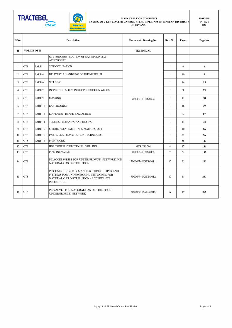
VOL IIB OF II
GTS FOR CONSTRUCTION OF GAS PIPELINES &
ACCESSORIES
70000 740 GTS/0502
SITE OCCUPATION
DELIVERY & HANDLING OF THE MATERIAL
WELDING
INSPECTION & TESTING OF PRODUCTION WELDS
COATING
HORIZONTAL DIRECTIONAL DRILLING
PIPELINE VALVE
PE ACCESSORIES FOR UNDERGROUND NETWORK FOR
NATURAL GAS DISTRIBUTION
PE COMPOUNDS FOR MANUFACTURE OF PIPES AND
FITTINGS FOR UNDERGROUND NETWORKS FOR
NATURAL GAS DISTRIBUTION - ACCEPTANCE
PROCEDURE
PE VALVES FOR NATURAL GAS DISTRIBUTION
UNDERGROUND NETWORK
EARTHWORKS
LOWERING - IN AND BALLASTING
TESTING , CLEANING AND DRYING
SITE REINSTATEMENT AND MARKING OUT
PARTICULAR CONSTRUTION TECHNIQUES
PAINTWORK
Laying of 3 LPE Coated Carbon Steel Pipeline Page 4 of 4
GENERAL TECHNICAL
SPECIFICATION
GTS 740 502
�������
������ ������
1 14/09/09 Logo Changed SS DNS NC
0 24/03/08 Logo Changed SS DNS NC
C 16/04/04 Logo Changed MRT DKB MRY
B 06/09/00 Updated MRT AES LEP
A 27/07/00 First issue MRT DKB LEP
Rev. Date Subject of revision Author Checked Approved
GENERAL TECHNICAL
SPECIFICATION
70000 740
GTS/0502
Rev. 1 – 14/09/09 Part 1 - Page 1 of 1
���������������
�
� � ������������� ���
����� �������������������������������������������������������������������������������������������������������������������������������
����� �������������������������� �����������������������������������������������������������������������������������������
��!�� �"���������������������� ������������������������������������������������������������������������������������������������
��!���� �����#�$$�����������������������������������������������������������������������������������������������������������������������
��!���� ��%�&��'�(�%��$�������������������������������������������������������������������������������������������������������������
��)�� � ������������������������ ���������������������������������������������������������������������������������������������
S S S
GENERAL TECHNICAL
SPECIFICATION
70000 740
GTS/0502
Rev. 1 – 14/09/09 Part 1 - Page 1 of 2
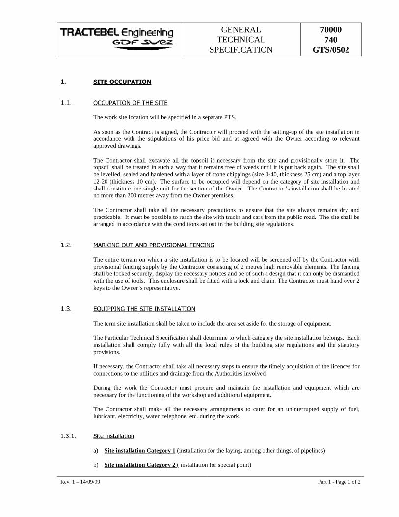
1. �������������
1.1. �����������������������
The work site location will be specified in a separate PTS.
As soon as the Contract is signed, the Contractor will proceed with the setting-up of the site installation in accordance with the stipulations of his price bid and as agreed with the Owner according to relevant approved drawings.
The Contractor shall excavate all the topsoil if necessary from the site and provisionally store it. The topsoil shall be treated in such a way that it remains free of weeds until it is put back again. The site shall be levelled, sealed and hardened with a layer of stone chippings (size 0-40, thickness 25 cm) and a top layer 12-20 (thickness 10 cm). The surface to be occupied will depend on the category of site installation and shall constitute one single unit for the section of the Owner. The Contractor’s installation shall be located no more than 200 metres away from the Owner premises.
The Contractor shall take all the necessary precautions to ensure that the site always remains dry and practicable. It must be possible to reach the site with trucks and cars from the public road. The site shall be arranged in accordance with the conditions set out in the building site regulations.
1.2. �������������������������� ���������
The entire terrain on which a site installation is to be located will be screened off by the Contractor with provisional fencing supply by the Contractor consisting of 2 metres high removable elements. The fencing shall be locked securely, display the necessary notices and be of such a design that it can only be dismantled with the use of tools. This enclosure shall be fitted with a lock and chain. The Contractor must hand over 2 keys to the Owner’s representative.
1.3. �"���������������������� ������
The term site installation shall be taken to include the area set aside for the storage of equipment.
The Particular Technical Specification shall determine to which category the site installation belongs. Each installation shall comply fully with all the local rules of the building site regulations and the statutory provisions.
If necessary, the Contractor shall take all necessary steps to ensure the timely acquisition of the licences for connections to the utilities and drainage from the Authorities involved.
During the work the Contractor must procure and maintain the installation and equipment which are necessary for the functioning of the workshop and additional equipment.
The Contractor shall make all the necessary arrangements to cater for an uninterrupted supply of fuel, lubricant, electricity, water, telephone, etc. during the work.
��!��� �����#�$$�����
a) Site installation Category 1 (installation for the laying, among other things, of pipelines)
b) Site installation Category 2 ( installation for special point)
GENERAL TECHNICAL
SPECIFICATION
70000 740
GTS/0502
Rev. 1 – 14/09/09 Part 1 - Page 2 of 2
c) Site installation Category 3 (installation for, among other things, the construction of a new main station - e.g. mixing or compression station)
d) Site installation Category 4 (installation, for example, for such things as the construction of a new regulating station or adaptations to an existing one, diversion works and reconstruction works)
Due to the diversity of the work site location and the local conditions the site installation required for the Owner's representatives as well as for the recognised inspection agency will be stated in a separate PTS.
��!��� ��%�&��'�(�%��$�
When the Contractor takes over the materials, he shall immediately store the materials supplied by the Owner in accordance with the code of good practice and the conditions set out in the building site regulations and GTS part 4. The Contractor shall provide a covered and locked storage area to store the protected materials. Each covered and locked storage area is provided with lighting. The material shall be stored in the immediate vicinity of the site offices.
1.4. � ������������������������ ������
The installation shall remain at the disposal of the Owner until restoration of the site is completed. After the site installation has been dismantled and removed, the Contractor shall restore the terrain to its original condition to the satisfaction of all Parties Concerned.
GENERAL TECHNICAL
SPECIFICATION
70000 740
GTS/ 0502
�������
����� ��������������������������
1 14/09/09 Logo Changed SS DNS NC
0 24/03/08 Logo Changed SS DNS NC
C 16/04/04 Logo Changed MRT DKB MRY
B 06/09/00 Updated MRT AES LEP
A 27/07/00 First issue MRT DKB LEP
Rev. Date Subject of revision Author Checked Approved
w97
_98_
gts.
dot
GENERAL TECHNICAL
SPECIFICATION
70000 740
GTS/ 0502
Rev. 1 – 14/09/09 Part 4 - Page I of II
���������������
�
� � ����������������������������������� ���
����� ������������������������������������������������������������������������������������������������������������������������������������������
����� ���� �� !����"#��$���������������������������������������������������������������������������������������������������������������
������� �%�&���������������������������������������������������������������������������������������������������������������������������������
������� �����������&�'&���%����&�&(�������������)*�����&���������������������������������������������������������
��+�� �,,�����,���� ,��-��.���������������������������������������������������������������������������������������������������������
��+���� /������%������&�����&������������������������������������������������������������������������������������������������������
��+���� ���0��������&��������&����������������������������������������������������������������������������������������������������
��+�+�� ��1���������%�������������������������������������������������������������������������������������������������������������������
����� �����"���� �2��.-���"���2$�����, ����,� �����������������������������������������������������������������������+�
������� .*%%�&��������������������������������������������������������������������������������������������������������������������������+�
������� �3����&*%%�&������������������������������������������������������������������������������������������������������������������+�
��4�� ��!�,�.�� ����"���"���"��������������5 ���6-"�������������"������ �� !�����"�������������������������������������������������������������������������������������������������������������������������������������+�
��4���� ����0����������%%����������������������������������������������������������������������������������������������������
��4���� ����0�&�����)*%����������00�&&���&����������������������������������������������������������������������������������
��7�� .� ��������������"��� !������"��.������������������������������������������������������������������������������������
��7���� .����������������������)*%������������������������������������������������������������������������������������������
��7���� .���������������������%%�&��������������������������������������������������������������������������������������������4�
��7�+�� .�����������&������������������������������������������������������������������������������������������������������������������4�
��7���� .��������������%%�&�'%%����0��&��*0���(�����������������������������������������������������������������������7�
��8�� �"��� !!�,-���������������������������������������������������������������������������������������������������������������������������7�
��8���� ���������������������������������������������������������������������������������������������������������������������������������7�
��8���� �%����0��&��*0������������������������������������������������������������������������������������������������������������7�
��9�� ���-��"���.-���-.������"��.���������������������������������������������������������������������������������������������8�
GENERAL TECHNICAL
SPECIFICATION
70000 740
GTS/ 0502
Rev. 1 – 14/09/09 Part 4 - Page II of II
��9���� �%����0��&��*0������������������������������������������������������������������������������������������������������������8�
��9���� .������0��&��*0�������������������������������������������������������������������������������������������������������������8�
��:�� -.�!-��"�! ����" ��������������������������������������������������������������������������������������������������������������8�
��:���� /���;&�&�������&��<�/�����*&������/��1&��%&������&&�&���������������������������������������������������8�
S S S
GENERAL TECHNICAL
SPECIFICATION
70000 740
GTS/ 0502
Rev. 1 – 14/09/09 Part 4 - Page 1 of 7
4. DELIVERY AND HANDLING OF THE MATERIAL
4.1. GENERAL
The description and quantities of the materials supplied by the Owner and/or to be supplied by the Contractor are described in the PTS and in the part lists.
The Contractor takes delivery of the items after a joint inspection with the Owner, after which the acceptance note drawn up by both parties is signed jointly.
When the materials are being handed over, the Contractor must take the required measures to:
� comply with the conditions of edited by the Owner in the purchase specification;
� avoid any form of damage and pollution;
� have sufficiently qualified personnel and equipment in relation to the quantity and type of deliveries available to handle and/or string them quickly;
� facilitate the acceptance inspections.
All equipment used for taking delivery of, handling and/or stringing the materials must be approved by the Owner and or the Engineer and accompanied by a certificate drawn up by a recognised inspection organisation.
The application period for the supply of material (Owner's supply) will be at least 10 working days. The delivery shall be requested to the representative of the Owner on the site.
All contacts between the Contractor and the Owner’s suppliers must always be made through the presentative of the Owner on the site.
All documents delivered together with the materials must immediately be handed over to the Owner.
For pipeline elements (pipes, fittings, bends, etc.), the thickness specified in the parts lists are minimum thickness.
4.2. METHOD OF DELIVERY
4.2.1. Pipes
The Owner will specify in the purchase order the location of his store site and depot.
The Contractor himself must take responsibility for the collection of the Owner’s material.
a) Except otherwise stated by the Owner if the pipes are stored in the Owner depot, transportation to the site and unloading shall be borne by the Contractor.
GENERAL TECHNICAL
SPECIFICATION
70000 740
GTS/ 0502
Rev. 1 – 14/09/09 Part 4 - Page 2 of 7
b) If certain materials are delivered directly to the site, this will be mentioned in the Particular Technical Specifications. In this case, the Contractor will only be responsible for unloading on the construction site. The Contractor chooses the unloading site and ensures that the access roads are sufficiently stable and accessible for the trucks of the supplier (min. length of trailer = 14.5 m). At least 5 working days prior to delivery, the Contractor sends an order form and a detailed plan indicating the unloading place and access roads to the representatives of the Owner/and or the Engineer on the worksite.
N.B.
The attention of the Contractor is drawn to the fact that uncoated pipes may be supplied with a plastic coating that has to be removed and evacuated to an approved waste disposal site.
4.2.2. Other materials (see part lists) and additional quantities
These can be collected by the Contractor from the Owner store or depot after prior written request sent to the Owner’s representative on the worksite.
If the PTS states that the Owner is responsible for delivery to the site, the Contractor will order the materials to deliver per full load in places accessible to trucks. Unloading is borne by the Contractor. Transport costs for incomplete loads will be charged to the Contractor.
4.3. ACCEPTANCE PROCEDURES
4.3.1. Owner depot or store site
Delivery shall be taken over by the Contractor during loading of the trucks. Every material element must be inspected by the Contractor for visible defects. For pipe elements, this is when uplifted. Defects are noted and reported jointly in the take over report (delivery note). In the absence of the Contractor, they are noted by the Owner and are not refutable.
4.3.2. Direct deliveries on the site
The take over by the Contractor of the pipe elements or other material directly deliver on the worksite will be carried out during the uplifting of the elements.
4.3.3. Take over report
The take over report is drawn up jointly (Contractor and supplier or Owner) and must, among other things, include the following information :
� the length of each pipe and the individual number;
� the identification number of the equipment and pipeline element;
GENERAL TECHNICAL
SPECIFICATION
70000 740
GTS/ 0502
Rev. 1 – 14/09/09 Part 4 - Page 3 of 7
� any visible damage (scratches, dents, etc.);
� an estimation in dm² of the defects in the pipe external coating, visible or detected by means of a holiday detector (for test voltage see GTS part 9);
� any remarks regarding the deliveries.
4.4. MATERIAL TO BE SUPPLIED BY THE CONTRACTOR
4.4.1. Supplies
The materials indicated as “Contractor supply” on the part lists are supplied by the Contractor. For direct supplies to the worksite, the Contractor shall present the material supplied at least 2 working days prior to assembly to the Owner in order to control jointly the quantities supplied.
All costs resulting from late deliveries or from supply of damaged or defective material shall be borne by the Contractor. When some materials cannot be supplied, the contractor shall submit another option in writing to the Owner and/or the Engineer, taking into consideration the initially fixed term of delivery. The option is not accepted without the Owner’s prior written consent. For the electrical equipment instruments and installation located in hazardous area classified as class 1 zone 0, 1 and 2 the Contractor will hand over to the Owner and/or the Engineer the required certificate of conformity.
4.4.2. Extra supplies
Materials not listed on the part lists and that are required for normal operation shall be listed by the Contractor and communicated in writing to the Owner prior to the start of the works. This material shall be purchased by the Contractor with the written consent of the Owner and or the Engineer.
4.5. DEFECTS NOTED IN PIPELINE ELEMENT AND/OR EQUIPMENT AND THEIR METHOD OF REPAIR
Damage and defects that are noticed at the time of delivery and expressly described in the take over report will be borne by the Owner. The repair and removal of damaged parts shall be carried out by the Contractor at the expense of the Owner for a price corresponding with the price list.
Damage and defects noticed after delivery must be repaired at the expense of the Contractor, as well as any extra costs due to the inspection work of the recognised inspection organisation. In the event of any non-conformity of the material at the time of delivery, the Contractor must immediately inform the Owner and or before accepting the delivery. If this condition is not observed, the Contractor will be the sole responsible for all the consequences resulting therefrom.
GENERAL TECHNICAL
SPECIFICATION
70000 740
GTS/ 0502
Rev. 1 – 14/09/09 Part 4 - Page 4 of 7
4.5.1. Defect noted in pipeline element
Any defects noted in the pipeline element may under certain conditions be repaired. Nonetheless, the final decision whether or not to use repaired pipeline element rests with the Owner and/or Engineer.
4.5.1.1. Surface defects in the metal
Surface defects noted in the pipe metal may be removed by grinding/polishing as long as the thickness of the wall, obtained after grinding, remains within the tolerances of the relevant standard and codes.
All repaired superficial defects shall be examined by the inspection organisation by means of ultrasonic, electromagnetic or penetrant testing. If these wall thickness tolerances cannot be respected, the damaged part must be cut away. The undamaged parts will be bevelled again and bear an identification number, etc.
4.5.1.2. Dents in the metal
The pipes must show no evidence of dents. The damaged part shall be cut out and the undamaged parts will be bevelled again and bear an identification number, etc.
4.5.1.3. Defects to the external coating
Defects to the external coating must be repaired by the Contractor as specified in GTS part 9.
4.5.2. Defects to equipment and accessories
All defects must be reported to the Owner and/or the Engineer. Defects noted in the equipment (shut-off valves, safety valves, relief valves, regulator, etc.) must be repaired by the equipment supplier in order to maintain the guarantee. Defects to accessories (fittings etc.) must be inspected by the recognised inspection organisation and repaired according to their instructions by the Contractor.
4.6. STORAGE AND HANDLING OF MATERIALS
The Contractor shall provide separate storage areas for all materials delivered by the Owner. Pipes, pipe parts and equipment must be handled with sufficient care so that all damage is avoided.
4.6.1. Storage and handling of equipment
The Contractor shall pay special attention to the handling and storage of control devices (regulator, filters, shut-off valves, operators, meter, etc.) so that this equipment is supported adequately and in a correct manner and completely protected against infiltration of dirt and humidity.
GENERAL TECHNICAL
SPECIFICATION
70000 740
GTS/ 0502
Rev. 1 – 14/09/09 Part 4 - Page 5 of 7
The Contractor should enquire with the Owner and/or the Engineer which method should be used for lifting special devices. The Contractor shall ensure that all openings in the equipment are sealed. The Contractor should provide all the means required to ensure that the external coating, paint and metallic paint are not damaged.
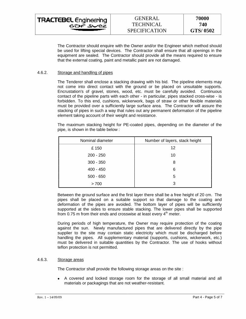
4.6.2. Storage and handling of pipes
The Tenderer shall enclose a stacking drawing with his bid. The pipeline elements may not come into direct contact with the ground or be placed on unsuitable supports. Encrustation's of gravel, stones, wood, etc. must be carefully avoided. Continuous contact of the pipeline parts with each other - in particular, pipes stacked cross-wise - is forbidden. To this end, cushions, wickerwork, bags of straw or other flexible materials must be provided over a sufficiently large surface area. The Contractor will assure the stacking of pipes in such a way that rules out any permanent deformation of the pipeline element taking account of their weight and resistance.
The maximum stacking height for PE-coated pipes, depending on the diameter of the pipe, is shown in the table below :
Nominal diameter Number of layers, stack height
£ 150 12
200 - 250 10
300 - 350 8
400 - 450 6
500 - 650 5
> 700 3
Between the ground surface and the first layer there shall be a free height of 20 cm. The pipes shall be placed on a suitable support so that damage to the coating and deformation of the pipes are avoided. The bottom layer of pipes will be sufficiently supported at the sides to ensure stable stacking. The lower pipes shall be supported from 0.75 m from their ends and crosswise at least every 4th meter.
During periods of high temperature, the Owner may require protection of the coating against the sun. Newly manufactured pipes that are delivered directly by the pipe supplier to the site may contain static electricity which must be discharged before handling the pipes. All supplementary material (supports, cushions, wickerwork, etc.) must be delivered in suitable quantities by the Contractor. The use of hooks without teflon protection is not permitted.
4.6.3. Storage areas
The Contractor shall provide the following storage areas on the site :
� A covered and locked storage room for the storage of all small material and all materials or packagings that are not weather-resistant.
GENERAL TECHNICAL
SPECIFICATION
70000 740
GTS/ 0502
Rev. 1 – 14/09/09 Part 4 - Page 6 of 7
� A marked-off stacking area for all large material that is weather-resistant.
4.6.4. Stringing of the pipes (pipeline construction)
The Contractor specifies the method of handling in the execution method file. The pipes shall be distributed by the Contractor along the pipeline alignment in the working area. He shall ensure that they do not hinder the traffic and shall prevent their lying too long in a situation that would be harmful to them (intactness, quality of coating). Transportation will be effected with suitable equipment to prevent damage to pipes and terrain. In rainy weather or on unstable subsoil, transportation will only take place with vehicles fitted with caterpillar tracks. The pipes must be laid on wooden blocks at least 0.15m x 0.15m x 1m or sand bags. The blocks or sand bags shall be provided by the Contractor.
4.7. PIPE OFF CUT
4.7.1. General
The Contractor shall keep a detailed inventory of the pipes received, per type of pipe, and a note of their location. On every 15th and 30th day of the month, the Contractor shall provide the Owner and or the Engineer with a detailed summary of:
� the pipes off-cut that can still be used in the lifetime of the Contract (minimum length, without defects and numbered, see Article 6);
� the rejected pipes, stating the reason for their rejection.
Before the end of the leak tests, the Contractor must provide the Owner with an inventory of the surplus pipes.
The term “surplus pipe” is defined as:
any pipe that can immediately be reused (undeformed, numbered, coating and chamfers in good condition), bearing the individual pipe number, stamp of the recognised inspection organisation, origin, type and length.
4.7.2. Pipeline construction
Only complete lengths of pipe element will be taken back by the Owner; all other pipe surpluses are the responsibility of the Contractor. Before termination of the strength and leak tests the Contractor will draw up a final account of the pipes and transmit it to the Owner and or the Engineer.
Settlement formula :
X = Tr - (Tp + Tc + Cr + Lr)
where :
Tr = length of the pipes delivered and accepted on the working sites.
GENERAL TECHNICAL
SPECIFICATION
70000 740
GTS/ 0502
Rev. 1 – 14/09/09 Part 4 - Page 7 of 7
Tp = length of the pipes effectively laid
Tc = 1.5 ‰ permitted loss
Cr = length of the remaining whole pipe elements
Lr = length of defective pipes element rejected for reasons which are not imputable to the Contractor
X = length invoiced to the Contractor (non re-usable pipe element or missing pipes).
4.8. RETURNING SURPLUS MATERIALS
The Contractor shall be responsible for collecting, transporting and unloading surplus material. This material must be sufficiently clean so that it cannot be distinguished from new. Returned material shall always be accompanied a document that shall be drawn up by the Contractor and countersigned by the Owner and or the Engineer. Material that is defective and/or unaccepted by the Owner will be charged to the Contractor.
4.8.1. Pipeline construction
Only whole and unbent pipes element in perfect condition shall be accepted. They must be transported to the Owner's storage site.
4.8.2. Station construction
� Only surplus pipes longer than 1m and bearing an individual number will be returned to the Owner’s storage site. They shall bear the stamp of a recognised inspection organisation and shall again have chamfers along both sides;
� All unused equipment and small material must be returned to the Owner's warehouse.
4.9. USEFUL INFORMATION
4.9.1. Owner's storage site, warehouse and workshops addresses
To be specified in the PTS.
GENERAL TECHNICAL
SPECIFICATION
70000 740
GTS/ 502
�������
���� �
1 14/09/09 Logo Changed SS SG NC
0 12.02.08 Logo Changed SS SG NC
D 16/04/04 Logo Changed MRT DKB MRY
C 25/08/03 General updated MRT MRY DKB
B 06/09/00 Updated MRT AES LEP
A 27/07/00 First issue MRT DKB LEP
Rev. Date Subject of revision Author Checked Approved
� 16 / c:\users\daniel_indes\7000_740_gts_502_part6_rev25_08_03.doc no
rmal
.dot
GENERAL TECHNICAL
SPECIFICATION
70000 740
GTS/ 502
Rev. 1 – 14.0.09 Part 6 - Page 1 of 1 � 20 /
������������������
�
��� ��������������������������������������������������������������������������������������������������������������������������������������������
����� �����������������������������������������������������������������������������������������������������������������������������
����� ���������������������������������������������������������������������������������������������������������������������
������� �����������������������������������������������������������������������������������������������������������������������������������
������� ���� ����!�"��� �#�$%�&���'#�%�(�%�)�$�'�������������������������������������������������������������������������
����*�� ��)�$����''��)���+����,�'�����������������������������������������������������������������������������������������������
����-�� �&��(�%�)�$��)�')'�������������������������������������������������������������������������������������������������������������*�
����.�� �&��(�%�)�$��$(�)/��"��� �#�$%�&���($����#���'�������������������������������������������������������������������
��*�� �����������������������0���������������������������������������������������������������������������������������������������
��*���� ���� �%$��)�$�'�������������������������������������������������������������������������������������������������������������
��*���� ���#���)�$��$(�)/��"��� �"$�1�����������������������������������������������������������������������������������������2�
��*�*�� ����� � ��)�$(�)/��#�#���� ��)'��������������������������������������������������������������������������������������3�
��-�� �������0������������������������������������������������������������������������������������������������������3�
��-���� �& ,���� ����������������������������������������������������������������������������������������������������������������������3�
��-���� ���� ��)����%$�'��������������������������������������������������������������������������������������������������������4�
��.�� ����0�����������0�5����0����������������������������������������������������������������������������������������4�
�
�
S��������S��������S�
GENERAL TECHNICAL
SPECIFICATION
70000 740
GTS/ 502
Rev. 1 – 14.0.09 Part 6 - Page 1 of 12 � 20 /
6. ������
Applicable documents :
� API 1104 Nineteenth Edition , Sept. 1999 � The present GTS.
General :
� API 1104 is applicable and all paragraphs of the present GTS as specified below.
� The line welds will be, to the extend possible, welded by an automatic or semi-automatic process. The requirements for automatic welding will be according to Section 12 of API 1104 as amended in this GTS under Section 6.5. "Automatic Welding".
� Manual welding will be used for all other welds where, in principal, automatic or semi-automatic welding is not possible or not justified for technical or economical reasons. This can apply, e.g., in the case of steep hills in the line, crossings, tie-ins, stations, special points, in city environment and other situations where access with the automatic or semi-automatic welding machines is limited.
� The Contractor must clearly state in his bid where automatic, semi-automatic or manual welding will be applied, and what type of welding process he intends to use.
���� � ����������������������
Only qualified welders, according to the requirements of Section 6 of API 1104, will be used for the manual welding processes.
� The Contractor will take all the necessary measures to implement the welder qualification tests.
� The qualification tests will be made using a coupon of a line-pipe. Every welders will execute a test weld using a qualified procedure.
� A welder who has successfully completed the qualification test shall be qualified.
� Every welder shall execute for his qualification test a weld at least on half the circumference of the pipe starting from the top of the pipe until the bottom.
� If the W.P.S. specifies a procedure for a single welder.
� The welder will execute the weld test on the entire circumference of the pipe.
� A welder can only participate once to the qualification test. If he didn't completed successfully the qualification test session, he will be disqualified for the present contract.
� Before production welding is started, the Contractor will submit to the Owner and or the Engineer and/or appointed Third Party Inspection Agency :
� the list of the qualified welders; � the procedures for which they are qualified; � the records of the welding performance test; � the validity dates of the qualifications.
GENERAL TECHNICAL
SPECIFICATION
70000 740
GTS/ 502
Rev. 1 – 14.0.09 Part 6 - Page 2 of 12 � 20 /
� If during welding, question arise about his competence (e.g. too many repairs), the Owner, Engineer and/or Third Party Inspection Agency may require a re-qualification, eventually after an additional welder training.
���� ������������ ���� ������������������
6.2.1. General
The welding procedures qualifications must be performed according to the requirements of Section 5 of API 1104, the additional requirements specified on this GTS.
The characteristics of the pipeline elements are described in the PTS.
A welding procedure qualification must be performed for :
� each welding procedure used; � each diameter and thickness (see PTS); � for each type of steel, from a different origin (steel mill and/or pipe mill).
The use of the same welding procedure qualification for different thickness and/or different origin of steel is only acceptable after written approval of the Owner and/or Engineer.
6.2.2. Preliminary Welding Procedure Specifications (WPS)
� The Tenderer shall attach to his bid every preliminary Welding Procedure Specifications (WPS) he intends to use during the execution of the work. He will indicate where and under what circumstances these WPS are applicable i.e. line welding, repair welding, tie-ins, stations, etc...
� Once the Owner has approved and ordered the work, the Contractor shall submit a list of required final WPS he plans to qualify and use. The required material for the qualification tests should be added.
� After approval by the Owner and/or Engineer of these documents, the Contractor can start with the qualification welding.
� The Tenderer will quote a price per WPQ, since the total number of procedures depends on different factors, which are not known at the moment of the bidding.
6.2.3. Additional essential variables
Referring to API 1104 (Sections 5.3. and 5.4.), following additional essential variables are also applicable :
� 5.3.2.3. and 5.4.2.5. Diameters and wall thicknesses
� Line pipes
Each diameter and wall thicknesses shall be subject to a different WPQ.
� 5.3.2.5. and 5..4.2.6. Filler metal and number of beads
� The type and size of electrodes, and the brand name used for the welding in an uphill or downhill direction must be submitted for approval by Owner and/or Engineer.
� In addition, the change in filler metal from a different Supplier will require new qualification of the applicable WPS.
GENERAL TECHNICAL
SPECIFICATION
70000 740
GTS/ 502
Rev. 1 – 14.0.09 Part 6 - Page 3 of 12 � 20 /
� A charge in the number of beads will also require a new WPQ.
� 5.3.2.13., 5.4.2.8. Pre- and post-heat treatment, tune between paces, cooling rate (i.e. heat management)
� The preheat temperature must be specified in the WPS and checked during welding. The prescribed preheat temperature may not be exceeded by more than 100° C. If the ambient temperature is lower than 5° C and/or the weld joint is damp, the pipe must be preheated to a temperature of minimum 50° C.
� The line between paces must be specified.
� Post-weld heat treatment and/or controlled cooling of the welded joint must also be specified in the WPS and respected during welding.
� 5.4.2.2. Base material
Any base material, even from the same type but from a different steel mill and/or pipe mill will result in a separate WPQ, except when written approval is given by the Owner and/or Engineer for a waiver.
� 5.4.2.3. Joint design
Minor changes to a joint design, as specified in WPS, cannot be made without re-qualification, except when written approval is given by the Owner and/or Engineer.
� 5.4.2.9. Direction of welding and number of welders
� For each WPS, the number of welders will be specified.
� The welding position and direction of welding for each welder will be specified.
6.2.4. Qualification tests
6.2.4.1. Introduction
The qualification test will be executed as described in Section 5.6. of API 1104, as amended by the requirements of this GTS.
Qualification tests must be carried out with the material from same origin (steel mill and pipe mill) as the material that will be welded by the Contractor in the field.
The pipes for the qualification tests must be provided by the Owner.
The number of qualification welds to be executed depend on the scope of work and eventually the origin of the pipe material.
The number of qualification tests can therefore only be determined after procurement of the pipes, and will be notified in writing by the Owner and/or Engineer.
The Owner, Engineer and/or the Third Party Inspection Agency will attend the welding, mechanical testing, and non destructive testing of WPQ.
6.2.4.2. Additional general requirements
In addition to the test specified in Section 5.6. of API, the following testing will be done during the Welding Procedure Qualifications :
GENERAL TECHNICAL
SPECIFICATION
70000 740
GTS/ 502
Rev. 1 – 14.0.09 Part 6 - Page 4 of 12 � 20 /
� Non-destructive testing
� Visual examination � X-ray testing � Manual ultrasonic testing � Electromagnetic examination
� Additional destructive testing
� Charpy impact testing in the weld metal and Heat Affected Zone (HAZ) � Macrographic examination � Hardness testing
Further details are provided below.
6.2.4.3. Non-destructive testing
1. Visual examination
The qualification test welds must be usually examined, on the inside and outside.
The acceptance criteria for the visual examination are stipulated in Part 7, Article 7.2.1.1 of the GTS.
2. Radiographic Examination
Each qualification test weld will be 100 % examined by radiography, according to the requirement of Section 11.1. of API 1104.
The Radiographic Examination will be performed by filmy x-ray method (not gamma ray) and will be done according to a written procedure drafted and/or approved by a Level III according to American Society of None Destructive Testing (ASNT) (or equivalent).
The x-ray operate must be Level II according ASNT (or equivalent).
The acceptance criteria are specified in the Section 9.3. of API 1104.
3. Ultrasonic testing
Each qualification test weld will also be 100 % examined by the ultrasonic method, according to the requirement of Section 11.4. of API 1104.
The acceptance criteria are specified in Section 9.6. of API 1104.
The ultrasonic testing will be executed, after the x-ray examination and interpretation of the films.
The results of both examination methods will determine the acceptability of the qualification test welds.
4. Magnetic particle examination (MT)
This examination will only be performed after acceptance by visual - radiographic and ultrasonic testing.
The weld will be 100 % electromagnetically tested, after grinding out the reinforcement on the internal surface.
The testing method must be in agreement with Section 11.2. of API 1104.
GENERAL TECHNICAL
SPECIFICATION
70000 740
GTS/ 502
Rev. 1 – 14.0.09 Part 6 - Page 5 of 12 � 20 /
The classification of the indications and the acceptance standards are defined in Section 9.4. of API 1104.
The additional macrographic examination will be preferentially located in the areas where imperfections are observed with the MT method.
6.2.4.4. Destructive tests
� Before the tests are carried out, test welds using a cellulose electrode may be rendered hydrogen-free. This is carried out by heating the test weld to a temperature of 200 - 250° C for a minimum of six hours.
� The destructive tests must be in accordance with Section 5.6. of API 1104.
� The following destructive tests must be performed on the welding qualification test pieces :
1. Impact testing
� 3 sets of 3 full size Charpy V - notch specimens must be taken in each process qualification weld in transverse direction to the weld :
� 1 set of specimens will be located in the middle of the weld thickness, with the notch located in the HAZ;
� the other 2 sets of Charpy V notch specimens will also be taken in the middle of the weld thickness with the notch located in the deposited weld material. These two sets must be taken at 180° C from each other, i.e. 1 set at the top of the weld and the other set at the bottom of the weld.
� The test temperature of all Charpy V tests is -20° C.
� The acceptance criteria are :
The average value of a set of 3 specimens shall not be less than 35 J/cm².
In addition, the lowest individual value of only one of the three specimens shall not be less than 28 J/cm².
2. Macrographic examination
4 macrographic examination of the full cross-section of each qualification weld will be performed. The location of these macrographic examination will, by preference, be estimated in the area where imperfections were observed during the electromagnetic examination of the weld. These locations will be indicated by the Owner, Engineer and/or appointed Third Party Inspection Agency.
3. Hardness testing
A serie of 10 hardness measurements will be taken at the level of the penetration bead in each cross section taken for macrography :
� 2 measurements will be in the base metal � 2 in the HAZ � 6 in the weld metal (from HAZ to the middle of the weld).
The average value of these measurements in the base metal, HAZ and weld will be max. 370 HV 10. An individual value may be max. 400 HV 10.
GENERAL TECHNICAL
SPECIFICATION
70000 740
GTS/ 502
Rev. 1 – 14.0.09 Part 6 - Page 6 of 12 � 20 /
6.2.5. Qualification of the welding procedures for repairs
Welding procedures for repairs will be submitted by the Contractor for approval by the Owner, Engineer and/or Third Party Inspection Agency.
Each repair welding procedure must be qualified according to API 1104.
���� �������������������������
6.3.1. Welding conditions
The welding conditions as specified in Section 7 of API 1104 are applicable.
In addition, the following conditions are applicable :
� All welds and weld repairs shall be carried out in accordance with qualified welding procedures, by qualified welders.
� In the event of wind, rain or low temperatures which may affect the stability of the arc, welding tents or other suitable protection shall be used.
One end of the pipe shall be sealed off during welding to avoid drafts which may influence the stability of the arc.
The protective measures are subject to approval of the Owner, Engineer and/or Third Party Inspection Agency's representative on site.
� The welding procedures must specify the requirements concerning the interpass temperatures and the acceptable rest times between the different runs.
In any case, the rest times between the different runs shall be kept to a maximum. The first three layers must always be performed without rest times. Only the necessary time for eventual brushing or grinding is allowed.
� Interruption in the welding for more than 30 minutes can only be allowed if the weld grove is filled up more than 40 % of the wall thickness.
� All welds must be completely filled at the end of a working day.
� The required pre-heat temperature (as stated on the qualified welding procedure) must be checked on each weld at the moment that the welding will be started. No welding should be performed if the minimum pre-heat temperature is not reached or exceeded by 100° C.
� If the welding is interrupted at the end of the welding pieces, isolating blankets should be put on the weld to avoid a quick cooling of the weld.
� The pipe elements to be welded shall be supported in a suitable manner without damaging the coating of the pipe. The height of the supports (wooden blocks or sands bags) must be such that each weld is at least 40 cm above the ground.
� After welding all weld spatter will be removed by grinding and/or brushing.
� Successive beads should not stop and/or end at the same place. The stops and starts of successive beads should be at least 10 cm shifted.
GENERAL TECHNICAL
SPECIFICATION
70000 740
GTS/ 502
Rev. 1 – 14.0.09 Part 6 - Page 7 of 12 � 20 /
6.3.2. Preparation of the welding work
6.3.2.1. Verification of good condition of pipes and fittings
The Contractor shall check the condition of the pipes and fittings. Any defects (scratches, indentations, chips in the bevels, etc.,) shall be reported to the Owner and or the Engineer and the Third Party Inspection Agency.
6.3.2.2. Preparation of the pipe ends
The Contractor shall take account of the fact that the pipe ends may be protected with an anti-rust primer.
The ends of the pipes (bevel and root face) shall be cleaned with a metal brush, file or grinder. The bevels shall have an even surface free from laminations tears, scale, slag, grease, paint, etc...
If the pipes are delivered on site without prefabricated weld levels (i.e. plain ends), the bevelling will be performed on site by the Contractor, according to the requirements of the qualified welding procedures.
The levelling should be done as close as possible before the start of the welding pieces.
6.3.2.3. Joint preparation
The pipe ends are bevelled according to the pipeline technical delivery conditions.
If pipes of unequal thickness must be joined, the Contractor shall carry out the necessary additional joint preparation himself to bring the joint preparation into line with fig. 15 of standard ASME B 31.8.
Should a cut be made, the cutting material and the working method shall be subject to the approval of the Owner and or the Engineer and the Third Party Inspection Agency.
The unprocessed pipe ends shall be ground so that the bevels and root faces meet the requirements of the WPS.
The markings shall be transferred to the pipe element which does not contain this information. In the absence of these data, the pipe element in question shall be rejected and considered unfit for reuse.
6.3.2.4. Alignment
a) General
For both longitudinally seam and helical seam welded pipes, the pipes shall be positioned so that the ends of the longitudinal or helical welds of two successive pipes are offset from each other by at least 100 mm, measured on the circumference.
b) Pipeline fabrication
All longitudinal seam welds must be in a circular sector of 45° along either side of the lowest traced line of the pipe.
c) Station construction
For pipeline branches, a distance of 100 mm shall be maintained between the longitudinal seam or helical seam weld and the butt weld of the branch.
GENERAL TECHNICAL
SPECIFICATION
70000 740
GTS/ 502
Rev. 1 – 14.0.09 Part 6 - Page 8 of 12 � 20 /
The zone cut out of the pipe shall be examined by ultrasound beforehand (zone of 100 mm along and around the complete weld).
If a distance of 100 mm cannot be maintained between the longitudinal or helical seam weld and the butt weld of the branch, the longitudinal seam or helical seam weld of the pipe shall be examined ultrasonically beforehand over a distance of at least one diameter along either side of the zone to be cut.
If these checks reveal any unacceptable imperfections, another zone shall be sought.
6.3.2.5. Handling of pipes during welding and support of the pipeline
The pipes shall not be manipulated during the welding of the first run (root bead). Thereafter they shall be supported on wooden blocks or sand bags without creating any additional stresses.
6.3.3. Arrangement of the pipe elements
6.3.3.1. Pipeline fabrication
working in line:
The length of the pipes to be welded shall be at least twice the pipe diameter, with a minimum of 1 m.
On either side of each circular joint, only one round joint shall be permitted within a distance of 8 m.
6.3.3.2. Gas Stations (and valve stations)
The number of welds shall be limited to a strict minimum. Should a bridging sleeve be used, it shall be at least 1 x ˘ in length.
The welds shall be carried out as pipe-to-pipe connections. Thus for a butt weld where moulded pieces are used, the pipe sections shall be welded to them first.
Tie-ins-butt welds which cannot be hydrostatically tested for strength shall be performed on pipes having the same wall thickness.
���� ����� ���������������������������
6.4.1. Numbering
6.4.1.1. Pipeline fabrication
In accordance with the provisions of Part 2, the Contractor shall indicate the kilometre points along the working strip.
The welds between KP 0 and KP 1 are numbered 000/0001, 000/002, 000/003 etc. The welds between KP 1 and KP 2 are numbered 001/001, 001/002, 001/003 etc. All tie-in welds between KP 0 and KP 1 are numbered 000/101, 000/102, 000/103 etc.
These numbers are shown on the radiographic images preceded by the digit code number of the pipeline.
GENERAL TECHNICAL
SPECIFICATION
70000 740
GTS/ 502
Rev. 1 – 14.0.09 Part 6 - Page 9 of 12 � 20 /
6.4.1.2. Gas station construction and valve stations
In the gas stations, the welds shall be numbered according to the Owner particular numbering system or numbering system approved by him and/or Engineer.
Example of a gas station numbering system (for information only) :
9.99.999 / STXX / 9999 where;
9.99.999 = the code number of the installation of the Client ST = standard 'ST' to indicate 'STATION' XX = the first two letters of the name of the gas station 9999 = maximum of four figures for the individual weld number.
6.4.1.3. Applying the weld numbers
The Contractor will submit for approval to the Owner and or the Engineer the way he will indicate the weld number on the pipes.
The Contractor shall apply the weld number next to each weld in a correct and legible manner using an indelible product.
6.4.2. Welding data records
The Contractor shall provide the Owner and/or the Engineer on a daily basis with all the information for inspection and technical files, i.e. for every weld, root head, filler beads and finish beads :
� the ID of the welders who have carried out the welds; � the weld number � the date of the execution of the weld � the individual numbers of the joined pipes and/or accessories, their grade, nominal thickness, origin and
length � the WPS used � the number of repairs or cut out welds, the reason for repair and the date of repair.
All these data must be signed by both the Owner and or the Engineer and the recognised inspection organisation.
���� � ����������������� ��������������
General
Line welds will be welded by an automatic or semi-automatic method : exceptions to this general requirement must be approved by the Owner, Engineer and/or Third Party Inspection Agency..
The requirements are those stipulated in Section 12 of API 1104 "Automatic welding", as amended below by this GTS.
The amendments are given in accordance with the respective articles of API 1104 - Section 12.
Art. 12.1. : Acceptable procedures
Add :
GENERAL TECHNICAL
SPECIFICATION
70000 740
GTS/ 502
Rev. 1 – 14.0.09 Part 6 - Page 10 of 12 � 20 /
The welding process and the type of welding machine must be detailed in the bid documents, including the eventual name(s) of the subcontractor(s) and/or supplier of the welding machine(s).
Art. 1.2.2. : Procedure qualification
� The qualification procedure shall be done on the same pipes that must be welded on site for this project. The pipes will be provided by the Owner.
� One procedure qualification must be done per :
� diameter � thickness � origin of the pipe (steel mill and/or pipe mill).
� The conditions for the procedure qualification must be as close as possible to the conditions that will be met on site.
� The mechanical testing will be the same as for the qualification testing of manual weld (see Section 6.2.4. of this GTS).
� The non-destructive testing will also be the same as specified in Section 6.24. of this GTS, except that the UItrasonic Testing (UT) will be performed by the automated UT method that will be used on the field welds and by the same non-destructive testing company.
The requirements for the field testing are specified below.
Art. 12.4. : Procedure specification
12.4.1. General
� A preliminary WPS shall be added to the bid documents with all information as stated below.
� The origin and/or brand name of the major parts of the machine will be stated, i.e. welding machine, levelling machine, clamps, ...
12.4.2. Specification information
12.4.2.1. Process
A detailed description must be given.
12.4.2.2. Pipe and fitting material
Pipes will be provided by the Owner.
12.4.2.3. Diameters
As specified in the PTS.
12.4.2.4. Wall thickness
As specified in the PTS.
One qualification must be done per diameter and thickness, and combination (e.g. if different thicknesses must be welded together).
GENERAL TECHNICAL
SPECIFICATION
70000 740
GTS/ 502
Rev. 1 – 14.0.09 Part 6 - Page 11 of 12 � 20 /
12.4.2.5. Joint design
� One sketch per diameter and thickness, or any combination of thicknesses.
� A detailed description must be given of the bevelling machine, including brand name and/or name of manufacturer.
12.4.2.6. Filler metal
In addition, the type, size and brand name of the filler metal shall be given.
12.4.2.10. Time between paces
� The qualification parameters must be the same as those that will be utilised on site. Under these conditions, a weld that has been started must be completed.
12.4.2.11. Type of lining clamp
A detailed description of the clamp and how it operates must be given. In addition, the brand name or a name of manufacturer must be given.
12.4.2.12. Cleaning
In addition, the cleaning after welding must be specified.
12.4.2.13. Preheat treatment
The method of measuring the preheat temperature shall also be specified.
12.4.2.14. Post-heat treatment
The use of isolation blankets during the cooling-off of the weld should be specified, and also applied during the qualification testing.
12.4.2.16. Shelding flux
The American Welding Society (AWS) classification number and brand name number shall be given.
12.4.2.18. Other factors
Some of these factors are :
� the use of a tent or any other means of weather protection � the composition of the welding team, and their qualifications � The time required for :
� preparation of welding � welding cycle � cleaning
� number of welds that is foreseen on site per hour (for different diameters and thicknesses)
Art. 12.5. : Essential variables
In addition to API requirements, the following amendments are applicable :
12.5.2.2. Pipe material
GENERAL TECHNICAL
SPECIFICATION
70000 740
GTS/ 502
Rev. 1 – 14.0.09 Part 6 - Page 12 of 12 � 20 /
Pipes from different steel mills and/or pipe mills will be qualified for each origin.
12.5.2.4. Wall thickness
� Each thickness/diameter combination will be qualified separately. � The welding of different thicknesses shall also be qualified separately.
12.5.2.5. Pipe diameter
See 12.5.2.4.
12.5.2.6. Filler metal
A change in type, diameter and/or brand name of filler metal will require re-qualification.
12.5.2.11 Shielding flux
A change in AWS classification and/or brand name will require re-qualification.
12.5.2.12 Speed of travel
In addition, the total welding time, as stated in the welding procedure, should not change beyond ± 10 %.
Art. 12.6. : Qualification of welding equipment and operators
The destructive and non-destructive testing, as defined above, must be performed.
Art. 12.7. : Records of qualified operators
The company must keep detailed records of the welding operators on site, in a manner that an operator performing repeated bad welds may be identified. The Owner, Engineer and/or third party agency may request his renewal from the site. He may only be re-qualified after complementary training and approval by the Owner/engineer.
Art. 12.8. : Inspection and testing of production welds
� In addition, the amendments of this GTS will apply.
� All automatic welded joints will be inspected by automatic UT, as described in Section 7.9. of this GTS.
Art. 12.9. : Acceptance standards for NDT
See GTS Part 7 "Inspection and testing of production welds".
Art. 12.10. : Repair and removal of defects
The same criteria apply as for the manual welds (see 7.7. of this GTS).
Art. 12.11. : Radiographic testing
The testing of the automatic and semi-automatic welded joints shall be done by automatic UT (AVT) (See Section 7.9.).
GENERAL TECHNICAL
SPECIFICATION
70000 740
GTS/502
PART 7
Inspection and testing of production welds
1 14/09/09 Logo Changed SS DNS NC
0 24/03/08 Logo Changed SS DNS NC
D 16/04/04 Logo Changed MRT DKB MRY
C 27/08/03 Updated MRT MRY DKB
B 06/09/03 Updated MRT AES LEP
A 27/07/00 First issue MRT DKB LEP
Rev. Date Subject of revision Author Checked Approved
GENERAL TECHNICAL
SPECIFICATION
70000 740
GTS/502
Rev. 1 – 14/09/09 Part 7 - Page 1 of 8
TABLE OF CONTENTS
7. INSPECTION AND TESTING OF PRODUCTION WELDS ................................................................................ 2
7.1. GENERALITIES ................................................................................................................................................. 2
7.2. TESTING OF WELDED JOINTS AND ACCEPTANCE CRITERIA ............................................................... 2
7.2.1. Non-destructive testing .............................................................................................................................. 2
7.2.2. Other test methods ..................................................................................................................................... 3
7.2.3. Destructive tests ......................................................................................................................................... 3
7.3. IDENTIFICATION OF INCOMPETENT WELDER(S) .................................................................................... 4
7.4. IMPLEMENTATION OF THE NON-DESTRUCTIVE TESTS ......................................................................... 4
7.5. ANNOUNCEMENT OF TEST RESULTS ......................................................................................................... 4
7.5.1. General ....................................................................................................................................................... 4
7.5.2. Welding of tie-ins, special points, and repairs ........................................................................................... 4
7.6. INSPECTION OF FILMS BY CONTRACTOR ................................................................................................. 5
7.7. LOCAL REPAIRS AND CUT-OUT OF DEFECTIVE WELDS ........................................................................ 5
7.7.1. General ....................................................................................................................................................... 5
7.7.2. Pipeline construction .................................................................................................................................. 5
7.8. SHARING OUT THE TEST COSTS .................................................................................................................. 6
7.9. INSPECTION AND TESTING OF AUTOMATIC WELDED JOINTS............................................................. 6
7.9.1. General ....................................................................................................................................................... 6
7.9.2. Details of the AUT procedure .................................................................................................................... 6
7.9.3. Implementation of AUT ............................................................................................................................. 7
7.9.4. Acceptance standards for AUT .................................................................................................................. 7
7.9.5. Calibration blocks ...................................................................................................................................... 8
S S S
GENERAL TECHNICAL
SPECIFICATION
70000 740
GTS/502
Rev. 1 – 14/09/09 Part 7 – Page 2 of 8
7. INSPECTION AND TESTING OF PRODUCTION WELDS
7.1. GENERALITIES
� The Inspection and testing of the field butt welds will be done according to the requirements of API 1104, and these of this GTS.
� The line welds will be to the extend possible welded by an automatic or semi-automatic paces. The inspection of these welds will be done by an Automated Ultrasonic System (AUT). The requirements for these inspections will be treated under Section 7.9. "Inspection and testing of automatic welded joints".
� The inspection and testing of the production welds will be supervised on site by the Owner, Engineer and/or third party inspection agency.
7.2. TESTING OF WELDED JOINTS AND ACCEPTANCE CRITERIA
The welded joints shall be tested prior to painting or coating.
7.2.1. Non-destructive testing
7.2.1.1. Visual inspection
The visual inspection shall be interpreted in accordance with API 1104 with the following additional requirements :
� Arc ignition points :
� £ 0.5 mm : acceptable if ground out � > 0.5 mm : unacceptable and cut out
� Mass clamp craters :
� £ 0.5 mm : acceptable if ground out
� 0.5 mm - 1.5 mm : acceptable if ground out and welded according to repair procedure
� > 1.5 mm : unacceptable and cut out
7.2.1.2. Radiographic testing
� Radiographic testing with x-rays shall be carried out in accordance with the provisions of API 1104.
� Gamma-rays shall only be used in case that the use of x-rays equipment is not possible and is agreed y the Owner, Engineer or third party inspection agency.
7.2.1.3. Ultrasonic testing
7.2.1.3.1. Test method and acceptance criteria
� Manual UT shall be carried out in accordance with ASMEV - Art. 5 and API 1104.
GENERAL TECHNICAL
SPECIFICATION
70000 740
GTS/502
Rev. 1 – 14/09/09 Part 7 – Page 3 of 8
� The automatic or semi-automatic welded line pipe joints shall be tested by an automatic UT system (See 7.9.).
7.2.1.3.2. Scope of the test
a) Minimum test planned
� Manual welded joints will be 100 % tested by x-ray, and eventually also by manual UT, if deemed necessary by the Owner, Engineer and/or third party inspection agency, e.g. if there is doubt concerning the quality of the weld on basis of the interpretation of the x-ray films.
� For the stations and valve stations all welds will be inspected by x-ray, eventually complemented by UT if deemed necessary by the Owner, Engineer or third party inspection agency.
� Welded joints which are welded with the use of external clamps (e.g. tie-ins) shall be tested by 100 % x-ray and 100 % UT.
b) Supplementary tests
Further to a decision by the Owners and a Engineer and the third party inspection agency (for example in the event of cracks), all the welds carried out in the course of that day may be tested with ultrasound and if necessary this inspection may be extended to all welds. If these tests bring to light any defective welds, the Contractor shall carry out the repairs at his own expense.
7.2.2. Other test methods
As well as the non-destructive tests described above, the Owner and/or the Engineer and the third party inspection agency may decide to carry out additional destructive or non-destructive tests, such as :
� magnetic particle test � liquid penetrant test � weld sampling � any other destructive or non-destructive test methods.
The acceptance criteria for the magnetic partial test and liquid penetrant test are defined on the basis of the following standards:
� Magnetic particle test :
� Method : ASME V - Art 7 � Acceptance criteria ASME VIII- Div 1 - App 6 and API 1104.
� Liquid penetrant test :
� Method ASME V - Art 6 � Acceptance criteria ASME VIII- Div 1 - App 8 and API 1104.
The acceptance criteria for the weld samples shall be the same as for the welding procedure qualification.
7.2.3. Destructive tests
In case of doubt of welding quality (i.e. too many repairs), the Contractor may be ask to cut out one production weld with a minimum of 50 cm of material on either side of the weld.
GENERAL TECHNICAL
SPECIFICATION
70000 740
GTS/502
Rev. 1 – 14/09/09 Part 7 – Page 4 of 8
The production welds to be cut out shall be selected by the Owner’s representative on site or the Engineer. The Contractor shall present this production weld for destructive testing to a recognised laboratory.
7.3. IDENTIFICATION OF INCOMPETENT WELDER(S)
The Contractor shall, within the limits of the welding procedure, form welding teams and keep track of there works in the field in such a way that incompetent welders can be identified at any time.
If the tests show that the majority of imperfections can be traced to the same welder(s), the third party inspection agency and the Owner and/or the Engineer can require the exclusion of this/these welder/s.
At the consent of the Owner, Engineer and/or third party inspection agency, excluded welders may eventually be proposed for additional training and re-qualification.
7.4. IMPLEMENTATION OF THE NON-DESTRUCTIVE TESTS
Radiographic examinations will be carried out daily after completion of the welding on the stretch of line and/or special point, station, ...
The necessary safety precautions, as specified in the Site Safety Procedure, to be drafted by the Contractor, will be taken before start of the inspection.
7.5. ANNOUNCEMENT OF TEST RESULTS
Only binding for work carried out during normal working hours.
7.5.1. General
The results of the non-destructive tests carried out during the course of the day shall be sent to the Contractor in writing by the Owner or the Engineer or by the third party inspection agency, subject to the agreement of the Owner, on the morning of the following working day before noon.
7.5.2. Welding of tie-ins, special points, and repairs
7.5.2.1. Radiographic testing
Subject to the approval of the Owner and/or the Engineer and the third party inspection agency, in urgent cases, the third party inspection agency shall inform the Contractor verbally of the provisional test results within the hour following the photograph by interpreting the wet film.
The results shall not be definitive until the dry film has been examined.
The deadline for verbal communication of the definitive results shall be twelve hours following the announcement of the results when they have been interpreted from the wet film. The definitive results shall be communicated as described in Article 7.5.1.
7.5.2.2. Visual and ultrasonic testing
The results of these tests shall be given verbally at the time of the test.
Written communication of the results shall be carried out in the same way as described in Article 7.5.1.
GENERAL TECHNICAL
SPECIFICATION
70000 740
GTS/502
Rev. 1 – 14/09/09 Part 7 – Page 5 of 8
7.6. INSPECTION OF FILMS BY CONTRACTOR
Before carrying out any repairs, the Contractor may inspect the relevant film himself. The film remains the property of the Owner.
7.7. LOCAL REPAIRS AND CUT-OUT OF DEFECTIVE WELDS
7.7.1. General
The Contractor shall be obliged to repair welds or re-weld or cut out welds which are deemed defective by the third party inspection agency. This shall be carried out within normal working hours.
Each repair of a defective weld, whether local or total, shall be carried out within the two working days following the announcement of the results by the third party inspection agency. The performance of the repairs implies that the Contractor agrees with the interpretation of the non-destructive testing.
Section 10 of API 1104 is applicable, with the following requirements :
� all cracks other than shallow crater cracks or star cracks (see 9.3.10. of API 1104) shall not be repaired by welding. The cracks must be removed by cutting out the weld;
� all other defects (except superficial defects) detected by non-destructive testing can only be repaired by welding after approval by the third party representative on site;
� only superficial defects that can be removed by grinding do not need to be approved, provided the minimum thickness of the pipe is respected. After grinding, the ground area will be inspected by liquid penetrant (PT) or magnetic particle examination (MT);
� all areas to be repaired by welding must also be inspected by PT or MT after grinding, to make sure that all defects are removed;
� the weld repairs must be re-inspected by x-ray, UT and or MT as required by the third party representative on site;
� a second weld repair is not admitted, and the weld must be cut out in case defects are detected in the repairs;
� in case a weld must be cut out, a zone of a least 5 cm of the pipe material must be removed on both side of the weld. The new bevel should be checked by PT on the absence of defects;
� the cut out welds should be identified with the weld number and kept in stock for eventual further investigations.
7.7.2. Pipeline construction
Cut-out welds shall be repaired by welding in a connection sleeve. The repair shall be prepared and undertaken in accordance with the requirements of this specification.
If local circumstances permit, and subject to the agreement of the Owner and third party inspection agency, a cut-out weld may be remade without using a connection sleeve by displacing the adjacent pipe elements. The cut, as well as the new bevels, the positioning of the pipes and the performance of the new weld shall be carried out in accordance with the current specifications.
GENERAL TECHNICAL
SPECIFICATION
70000 740
GTS/502
Rev. 1 – 14/09/09 Part 7 – Page 6 of 8
If there are separate procedures for tie-in welding and line welding, a cut-out weld shall be replaced according to the same welding procedure as for a tie-in weld.
7.8. SHARING OUT THE TEST COSTS
Costs relating to testing and supervision shall be charged to the Contractor insofar as they are incurred at his request outside normal working hours.
Testing during normal working hours.
Visual inspection
Radiographic testing
Ultrasonic testing
Other test methods
Destructive testing
Minimum inspection prescribed in Articles 7.2.1., 7.2.2., 7.2.3.
Owner Owner Owner Owner Owner
Inspection above the minimum of Articles 7.2.1., 7.2.2
Contractor Contractor Contractor Contractor --
Inspection of repairs Contractor Contractor Contractor Contractor --
The costs shall be divided between the Owner and the Contractor in proportion to the total test costs for the work in question, in other words :
costs charged to Contractor = total test costs x (% defective welds / 100 + % defective welds).
7.9. INSPECTION AND TESTING OF AUTOMATIC WELDED JOINTS
7.9.1. General
All requirements for inspection and testing, as described above, remain valid except that all automatic and semi-automatic welded joints will be inspected by Automatic Ultrasonic Testing (AUT) in stead of RX.
The AUT must be performed according to a detailed inspection procedure (see 7.9.2.) by an experienced Inspection Organisation accepted by the Owner, Engineer and/or third party inspection agency.
7.9.2. Details of the AUT procedure
A detailed AUT procedure must be drawn up by the Inspection Organisation. This inspection procedure must be approved by the welding Contractor and submitted to the Owner, Engineer and/or third party inspection agency for review and approval.
One AUT procedure must be made for each diameter, thickness and weld configuration.
The AUT procedures shall contain at least following information :
� number of UT probes (type, angle, frequency and focus) on both sides of the weld, including the TOFD probes;
� a sketch with the cross section of the weld, the different zones of the weld covered by the respective probes and placement of the probes;
� description of the scanner;
GENERAL TECHNICAL
SPECIFICATION
70000 740
GTS/502
Rev. 1 – 14/09/09 Part 7 – Page 7 of 8
� description of cables coupling system and electronic equipment; � detailed description of the UT instrument, computer and printing equipment; � different type of mapping and data presentation used during inspection; � calibration set-up; � maximum temperature of the weld that can be inspected; � inspection time for different diameters; � number of welds than can be performed per hour (under normal field conditions); � amount of water required.
In addition, the operational requirements and restrictions of AUT system should be given, e.g. accessibility to welds, steep kills in the field, conditions of welds and surrounding zones, ...
The required material for the fabrication of the calibration blocks should also be specified.
The procedure should also give a description (with sketch) of the calibration blocks for each diameter and thickness and the delay necessary for the fabrication of these blocks.
7.9.3. Implementation of AUT
The UAT should be performed as close as possible behind the welding team, in agreement with the welding contractor, and all completed joints should be tested the same day of welding.
Welding imperfections (especially systematic defects) should be reported directly to the welding contractor, to reduce the eventual repair rates.
The written reporting shall comply to Section 7.5.1. of the GTS.
7.9.4. Acceptance standards for AUT
The classification of indications and acceptance standards as defined in Section 9.6. of API 1104 are applicable.
The threshold settings of the AUT equipment should be agreed on before the start of the AUT inspections on site.
The Inspection Organisation, welding Contractor, Owner, Engineer and/or third party inspection agency, should during the AUT inspections of the qualification welds, define these threshold settings.
The different mappings that are required, should be defined during the qualification tests, and clear interpretation of these mappings for the different types of defects (cracks, linear defects, volumetric defects) should be given.
Special attention should be paid to geometric indications that are similar to those caused by weld imperfections but are not relevant to acceptability according to API 1104.
Once all parties are agreed with the threshold settings and form presentation (colour codes, amplitudes, range of transit distance, ...) no changes should be made in these settings and way of reporting them.
Different settings can only be used by the third party inspection agency during their interpretation of the results (E;G. other amplitude settings), but the mapping resulting from these settings will not be respected in order to avoid confusion by the different parties.
GENERAL TECHNICAL
SPECIFICATION
70000 740
GTS/502
Rev. 1 – 14/09/09 Part 7 – Page 8 of 8
7.9.5. Calibration blocks
The Inspection Organisation will manufacture the calibration blocks with material provided by the Owner. The dimensions of the pipe sections to be provided by the Owner, should be specified by the third party inspection agency.
The Owner should provide the specified pipe sections, for each diameter, thickness and origin of the steel (steel mill and/or pipe mill).
Measurements of the ultrasonic wave propagation will be performed by the Inspection Organisation inspection agency, in order to determine if material from a different origin behave in a similar manner, and if 1 calibration block (for a given diameter and thickness) can be used for different type of steel or not.
The number of calibration blocks will therefore depend on the outcome of results the measurements.
The Inspection Organisation should draft a report of these measurements, and explain why the selected number of calibration blocks have been manufactured and the conditions where these calibration blocks can be used. The identification of the blocks should be clearly marked on the blocks, so that no confusion is possible during the inspection on site.
The applicable calibration block for the inspections on site should be given on the daily reports on site.
The Inspection Organisation must also include a sketch of each calibration block (per diameter and thickness) showing the different holes, notches, ... that have been put on the blocks.
These sketches must be added to the AUT procedures (see 7.9.2.)
�
�
�
GENERAL TECHNICAL
SPECIFICATION
70000 740
GTS/ 0502
�������
���� �
1 14/09/09 Logo Changed SS DNS NC
0 24/03/08 Logo Changed SS DNS NC
C 16/04/04 Logo Changed MRT DKB MRY
B 06/09/00 Updated MRT AES LEP
A 27/07/00 First issue MRT DKB LEP
Rev. Date Subject of revision Author Checked Approved
w97
_98_
gts.
dot
GENERAL TECHNICAL
SPECIFICATION
70000 740
GTS/ 0502
Rev. 1 – 14/09/09 Part 9 - Page I of II
�
������������������
�
��� ���������������������������������������������������������������������������������������������������������������������������������������������
����� ������������������������������������������������������������������������������������������������������������������������������������������
������� ������������������ ��������������������������������������������������������������������������������������������������������
���� �� !���"���#�����$����������������������������������������������������������������������������������������������������������
����%�� �#"� ����������#�$$���������������������������������������������������������������������������������������������������������
����&�� �#"� ������������������������������������������������������������������������������������������������������������������
����'�� �(��(��)����������� ��*��+����#�������$�#*�����)���,�� ������������������������������������� �
����-�� .���������������*���������� �����$�� �����"����������������������������������������������������������� �
����/�� !���"����$�#*���������������������������������������������������������������������������������������������������� �
����0�� ��������"������������������������������������������������������������������������������������������������������������������������ �
������� ���*�+��������������""�����������(�����������������������������������������������������������������������������%�
�� �� ��������1�������2���3������������������.�����������������������������������������������������������������������%�
��%�� 1.���1�1���1�����������3�1�.�4�1��������������������������������������������������������������������������������������%�
��&�� 5���2������.1�1����52�������61����3���2��5��7����������������������������������������������������������%�
��'�� ����1���1�������2������1��������������������������������������������������������������������������������������������������&�
��'���� ���� �)����"����)����� ����������������������������������������������������������������������������������������&�
��'� �� ���� �)���#��+����������������������������������������������������������������������������������������������������'�
��'�%�� ���� �)�����������8#"���"��(�������������������������������������������������������������������������������������'�
��-�� ����1�1�������2������1������������������������������������������������������������������������������������������������������-�
��-���� ������� �������� ��������������������������������������������������������������������������������������������������������-�
��-� �� ������� �#��+���������� ���������������������������������������������������������������������������������������������/�
��-�%�� ������� ����� �"������������������������������������������������������������������������������������������������������/�
��/�� ��!�9����������1���������������������������������������������������������������������������������������������������������������/�
��0�� :3��1�6�������������2��������1����������1������������������������������������������������������������������/�
GENERAL TECHNICAL
SPECIFICATION
70000 740
GTS/ 0502
Rev. 1 – 14/09/09 Part 9 - Page II of II
��0���� �*��+��������������������������������������������������������������������������������������������������������������������0�
��0� �� 1���������#*��+�"�� �����������������������������������������������������������������������������������������������������0�
�
�
S��������S��������S�
�
�
�
GENERAL TECHNICAL
SPECIFICATION
70000 740
GTS/ 0502
Rev. 1 – 14/09/09 Part 9 - Page 1 of 8
9. ������
9.1. ��������
������ ������������������ �
The purpose of the external coating is to insulate the steel pipe as much as possible from the ground and from every incidental structure located in the ground.
���� � !���"���#�����$�
Except otherwise stated in the PTS the Owner supplies :
� line pipes with a polyethylene external coating that meets the requirements of standard DIN 30 670 unless otherwise specified in the Special Specifications.
� uncoated fittings, uncoated moulded pieces, uncoated valves and uncoated hot bends.
� valves with protegol coating.
� at the following places, the Owner provides, for station construction, uncoated pipes that the Contractor shall coat:
� For buried sections
� all vertical pipes provided with a protection of reinforced polyester (ground passages).
� all underground pipes ˘ £ 600 and a length < 1.5 m.
� all underground pipes ˘ > 600 and a length < 2.5 m.
����%� �#"� ����������#�$$���
The Tenderer shall specify in his bid the type of external coating that he will use and attach a certificate of conformity of the supplier specifying that the material to be used meets DIN 30 672 and/or DIN 30 673 and/or NEN 6909.
����&� �#"� ������������������
The Contractor shall thus :
� submit a quality control certificate from the supplier stating that all products supplied comply with the requirements
� Apply the coating on the buried bare pipeline parts
� Apply the coating on the buried welded joints
� Make all the required repairs to defects in the external pipe coating that are either
GENERAL TECHNICAL
SPECIFICATION
70000 740
GTS/ 0502
Rev. 1 – 14/09/09 Part 9 - Page 2 of 8
� at the expense of the Owner (if there are defects that existed before the Contractor took delivery of the line pipes), or
� at the expense of the Contractor for defects that are discovered later; the acceptance note has conclusive force here (see Part 4).
� provide special protection at places indicated in the special execution conditions of the PTS or Particular drawings.
����'� �(��(��)����������� ��*��+����#�������$�#*�����)���,�� ������
The pipeline sections can be coated by means of :
� bitumen (asphalt)
� bituminous tapes reinforced with fiber glass
� PE wrapping tape
� Heat shrinkable sleeves
� plastic instant repair, tape
� polypropylene
� 2 components: coal tar epoxy
����-� .���������������*���������� �����$�� �����"������
� Bare pipes and hot bends are coated with plastic wrapping tape.
� Welds joints can be coated with plastic wrapping tapes or heat shrinkable sleeves.
� Moulded pieces can be coated with plastic wrapping tape, or bituminous tape.
� Bare valves will be coated with bitumen or bituminous tape.
� Valves with protegol coating will be repaired with 2 components: coal tar epoxy.
� For horizontal directional drilling, the Tenderer will submit a specific proposal.
� Reinforced heat shrinkable sleeves or equivalent will be used for pneumatic impact mole or thrust boring system.
����/� !���"����$�#*������������
The properties of the devices and machines used for the coating process (melting equipment) must be approved by the Owner and or the Engineer. This material must be properly maintained and checked.
����0� ��������"�
The personnel employed by the Contractor for on site coating of the welded joints must be in possession of a certificate of qualification issued by the supplier of the coating products certified by a Recognised Inspection Organisation.
GENERAL TECHNICAL
SPECIFICATION
70000 740
GTS/ 0502
Rev. 1 – 14/09/09 Part 9 - Page 3 of 8
������ ���*�+��������������""�����������(����
� The Contractor must take the required safety measures when removing and applying the coating to live installations in accordance with a procedure agreed with the Owner and or the Engineer. In each case, work may only be carried out on a live installation with a work procedure and fire licence and under the constant supervision of the Owner and or the Engineer.
� The formation of condensation in live installations can be removed by heating the section of pipe to a maximum of 50° C on small surfaces with an electric hot air blower.
N.B. :
Before buried valves are coated, the Contractor will check that the position of the body relief valves and the lubricant valves are in the “open” position. The valves may only be operated in the presence of the Owner and or the Engineer.
9.2. ��������1�������2���3������������������.�
The products must be applied to a surface that is completely dry and free of all impurities such as rust, scales, lamination tears, slags, grease, oil, paint, etc. Tar, grease, oil and all other greasy substances must first be removed by means of an approved solution (e.g. 1,1,1-trichloro-ethane) or an emulsifier. White spirit or turpentine may not be used. The pipe surfaces and the welded area should then be mechanically cleaned to a degree of cleanliness ST 2 in accordance with ISO 8501-1.
This mechanical cleaning must be carried out by means of mechanically driven rotating steel brushes. After this surface preparation has been carried out, the surfaces should be completely free of weld spatters slags, rust, lamination tears scales, paint or varnish stains and other foreign substances and impurities.
The mechanical cleaning must be continued to at least 10 cm beyond the existing intact coating, in such a way that all dirt is removed and the coating is roughened to ensure good adhesion. The intact coating will be chamfered at the extremities to an angle of 15 to 30° in order to form a perfect joint.
9.3. 1.���1�1���1�����������3�1�.�4�1����
The Contractor will identify each buried joint by means of small aluminium plates that must always be positioned on the upper side of the welded joint. A first self-adhesive aluminium plate with the information in accordance with Part 6 will be stuck to the welded joint after applying the primer coat. A second self-adhesive aluminium plate will be placed above the joint after applying the coating. The uppermost plate must be kept visible and secured at the sides with PE tape.
9.4. 5���2������.1�1����52�������61����3���2��5��7�
In order to achieve optimum results during the coating work, it is essential that no condensation occurs on the blasted or cleaned surface or between the different layers. For this reason, the temperature of the surface to be coated should be at least 3°C higher than the dew point or condensation temperature of the surrounding air. The dew point of the air is given in the table below for a number of conditions of air temperature and relative atmospheric humidity.
Air temp. Dew point in °C with a relative humidity of
°C 50 % 55 % 60 % 65 % 70 % 75 % 80 % 85 % 90 %
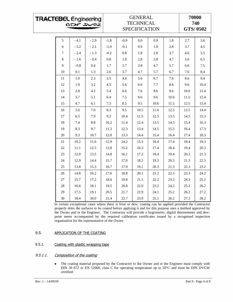
GENERAL TECHNICAL
SPECIFICATION
70000 740
GTS/ 0502
Rev. 1 – 14/09/09 Part 9 - Page 4 of 8
5
6
7
8
9
10
- 4.1
- 3.2
- 2.4
- 1.6
- 0.8
0.1
- 2.9
- 2.1
- 1.3
- 0.4
0.4
1.3
-1.8
-1.0
-0.2
0.8
1.7
2.6
-0.9
-0.1
0.8
1.8
2.7
3.7
0.0
0.9
1.8
2.8
3.8
4.7
0.9
1.8
2.8
3.8
4.7
5.7
1.8
2.8
3.7
4.7
5.7
6.7
2.7
3.7
4.6
5.6
6.6
7.6
3.6
4.5
5.5
6.5
7.5
8.4
11
12
13
14
15
1.0
1.9
2.8
3.7
4.7
2.3
3.2
4.2
5.1
6.1
3.5
4.5
5.4
6.4
7.3
4.6
5.6
6.6
7.5
8.5
5.6
6.6
7.6
8.6
9.5
6.7
7.7
8.6
9.6
10.6
7.6
8.6
9.6
10.6
11.5
8.6
9.6
10.6
11.5
12.5
9.4
10.4
11.4
12.4
13.4
16
17
18
19
20
5.6
6.5
7.4
8.3
9.3
7.0
7.9
8.8
9.7
10.7
8.3
9.2
10.2
11.2
12.0
9.5
10.4
11.4
12.3
13.3
10.5
11.5
12.4
13.4
14.4
11.6
12.5
13.5
14.5
15.4
12.5
13.5
14.5
15.5
16.4
13.5
14.5
15.4
16.4
17.4
14.4
15.3
16.3
17.3
18.3
21
22
23
24
25
10.2
11.1
12.0
12.9
13.8
11.6
12.5
13.5
14.4
15.3
12.9
13.8
14.8
15.7
16.7
14.2
15.2
16.1
17.0
17.9
15.3
16.3
17.2
18.2
19.1
16.4
17.4
18.4
19.3
20.3
17.4
18.4
19.4
20.3
21.3
18.4
19.4
20.3
21.3
22.3
19.3
20.3
21.3
22.3
23.2
26
27
28
29
30
14.8
15.7
16.6
17.5
18.4
16.2
17.2
18.1
19.1
20.0
17.6
18.6
19.5
20.5
21.4
18.8
19.8
20.8
21.7
22.7
20.1
21.1
22.0
22.9
23.9
21.2
22.2
23.2
24.1
25.1
22.3
23.2
24.2
25.2
26.2
23.3
24.3
25.2
26.2
27.2
24.2
25.2
26.2
27.2
28.2
In certain exceptional cases where there is frost or dew, coating can be applied provided the Contractor properly dries the surfaces to be coated before applying it and for this purpose uses a method approved by the Owner and or the Engineer. The Contractor will provide a hygrometer, digital thermometer and dew-point meter accompanied by the required calibration certificates issued by a recognised inspection organisation for the representative of the Owner.
9.5. ����1���1�������2������1���
��'��� ���� �)����"����)����� ����
��'����� ��+������������������ ��
� The coating material proposed by the Contractor to the Owner and or the Engineer must comply with DIN 30 672 or EN 12068, class C for operating temperature up to 50°C and must be DIN DVGW certified.
GENERAL TECHNICAL
SPECIFICATION
70000 740
GTS/ 0502
Rev. 1 – 14/09/09 Part 9 - Page 5 of 8
The heat shrinkable sleeves must comply with DIN 30672 or EN 12068 class C for operating temperature up to 50°C.
� For moulded pieces, branching pieces and flanges, the plastic wrapping tape must meet :
EN 12068 class C for operating temperature up 30°C or 50°C or DIN 30 672, class C for operating temperature up to 30°C or 50°C as stated in the PTS.
Nota :
For the compression station and within a area of 1 000 meters after the station the wrapping will comply with DIN 30672 or EN 12068 class C for operating temperature up to 50°C.
� The plastic wrapping tape and primer must be supplied by the same manufacturer.
��'��� � ���"*�� �������� ��
The Contractor shall draw up a working procedure accordingly to the supplier instructions and recommendations for the welded joints, bare pipes etc. as well as for the fittings, valves, relief pipes etc.
��'� � ���� �)���#��+����������
��'� ��� ��+��������������#��+������� �
The coating material proposed by the Contractor to the Owner and or the Engineer must comply with the standard EN 12068 Class B for operating temperature up to 50°C.
The coating consists of:
� An oxidised bitumen-based priming or adhesive layer, solutions containing hydrocarbon and an adhesive to be applied to all blank metal parts. The product must comply with the provisions of the General Regulations for the Protection at Work.
� One or more petroleum bitumen-based plastic layers when the primer coat is sufficiently dry.
� A double reinforcement made of fibre glass (45 gr. per m2) set in the above-mentioned plastic layers.
The minimum thickness of the bitumen coating will be 4 mm and must at least be equal to the thickness of the existing pipe coating.
��'� � � ���"������������#��+���������� �
The Contractor shall draw up a working procedure accordingly to the supplier instructions and recommendations for the welded joints, bare pipes etc. as well as for the fittings, valves, relief pipes etc.
��'�%� ���� �)�����������8#"���"��(����
��'�%��� ��+������������������ �
The contraction sleeves must meet DIN 30 672 class C operating temperature up to 50°C.
GENERAL TECHNICAL
SPECIFICATION
70000 740
GTS/ 0502
Rev. 1 – 14/09/09 Part 9 - Page 6 of 8
��'�%� � ���"��������������������8#"���"��(���
The Contractor shall draw up a working procedure accordingly to the supplier instructions and recommendations for the welded joints, bare pipes etc. as well as for the fittings, valves, relief pipes etc.
9.6. ����1�1�������2������1����
Any defects detected will be repaired by the Contractor under the supervision of the Owner and or the Engineer. In places where the coating has been removed, reworked or repaired, the inspection will be conducted by the Contractor by means of a holiday detector under supervision of the Owner and or the Engineer.
The Contractor will only be paid for repairs that were accepted under the responsibility of the Owner at the time of the hand-over of the materials. In the case of adhesion defects, insufficient thickness of the coating, inaccurate positioning and/or bad impregnation of the reinforcement, the presence of traces of humidity, of air-pocket and solid particles, the coating will be removed and completely repaired.
��-��� ������� �������� �
��-����� ������� �������� �)����"����)����� ����
a) Repairing small defects in the PE coating that do not reach down to the metal by means of plastic wrapping tape.
� Preparation :
Roughen the PE surface around the point faults with a brush disk. Dry the PE surface over the entire pipe circumference with the propane burner to a pre-heating temperature of 30°C. Apply adhesive plastic wrapping tape over the entire pipe circumference in accordance with the supplier instructions and recommendations.
b) Repairs to other defects in the PE coating with plastic wrapping tape.
� Preparation :
Cut out the damaged PE surface around the defect to the point where the coating is adhering properly. Chamfer and roughen the edges of the existing coating. Clean the whole surface to be coated with a brush disk to a degree of cleanliness S.T.2.
Dry the entire part to be coated with a propane burner to 30°C. Apply primer to the cleaned steel surface and the PE coating over the entire pipe circumference.
Fill in the hole that has appeared with a mastic filler.
Apply adhesive plastic wrapping tapes over the entire pipe circumference in accordance with the supplier instructions and recommendation.
��-��� � ������� �������� �)����"��������������
This method can be applied to all PE damage up to a maximum size of 350 mm x 350 mm. except for directional drillings The plastic repair patch must comply with DIN 30672 class C.
� Preparation :
GENERAL TECHNICAL
SPECIFICATION
70000 740
GTS/ 0502
Rev. 1 – 14/09/09 Part 9 - Page 7 of 8
Cut out the damaged PE surface around the defect to the point where the coating is adhering properly. Chamfer and roughen the edges of the existing coating. Clean the entire surface to be coated with a brush disk to a degree of cleanliness S.T.2.
Dry the entire part to be coated with a propane burner to 60°C. Fill in uneven spots and holes with mastic filler. Apply the correct size adhesive plastic repair patch and heat it until the pigment has disappeared. The repair patch must be smaller than the roughened PE surface area.
��-���%� ������� �������� �����$�������"�$��""�� �
The repair is carried out by means of a heat shrinkable sleeve reinforced with fibre glass or epoxy reinforced with fibre glass or of a specific proposal submitted by the Tenderer.
��-� � ������� �#��+���������� �
��-� ��� ������� ��+""�$+ �$�����£���+;�
Small damaged areas in bituminous coating must be repaired by heating the bitumen and sealing the defect using a spatula.
��-� � � ������� �"� ��$+ �$�����<���+;�
� Preparation :
The damage must be cut out in a rectangle. Clean the whole surface to be coated with a brush disk to a degree of cleanliness S.T.2. Dry the surface to be coated with a propane burner to 30°C and then apply a primer. Apply the bituminous coating in accordance with supplier instructions and recommendations.
��-�%� ������� ����� �"����������
Some valves are provided with a protective layer consisting of Protegol UT 32-10 R applied according to the supplier instructions and recommendations. The repairs must be carried out with Protegol UT 32-10 L applied with a brush and according to the instructions of the supplier.
9.7. ��!�9����������1���
The Contractor shall draw up the method for "removal of the pipe coating" and submit at to the Owner and or the Engineer for approval.
9.8. :3��1�6�������������2��������1����������1���
Independently of the inspection of the method of execution, the conditions of use of the products and the material for the realisation of the coating, the Owner and/or Engineer reserves the right to examine systematically the continuity of the insulation and to inspect the adhesion, the thickness, the position of the fibre glass fabric and his correct and complete impregnation, the presence of any trace of humidity, of any air pocket or of any solid particle by taking samples.
When pipelines are being constructed and laid, the Owner and or the Engineer will check, after backfilling, the electrical resistance of the coating by means of detection devices suitable for detecting any drops in potential through the coating (see Part 13). The Contractor will bear all costs resulting from the repair of the defects detected.
GENERAL TECHNICAL
SPECIFICATION
70000 740
GTS/ 0502
Rev. 1 – 14/09/09 Part 9 - Page 8 of 8
��0��� �*��+��������������
The Contractor will check the quality of the pipes insulation protections over their entire length at the appropriate time by means of a detector or a holiday detector.
This inspection will be carried out in the presence of the Owner and or the Engineer who reserves the right at any time to check the proper functioning of the device. The holiday detector will be clearly identifiable by means of an individual number engraved in an identification tag attached to the apparatus. A certificate, drawn up by the Supervisory Body, will attest that the apparatus complies with a recognised code. Verification is effected with a high-voltage voltmeter HV-40, calibrated by a calibrated testing bench (ball diameter 20 mm) according to the 50 % method.
For a preset scale value of 0.65, the maximum permitted deviation of the output voltage for 5 V can be 15 %. For a preset scale value of 8.3 the maximum permitted deviation of the output voltage for 25 V can be 10 %.
Besides the calibration, the HV-cable and handle, the sealing ring, the earthing cable and earthing as well as the carrying case must be accepted by the Supervisory Body. The maximum validity of the certificate is one year.
The test current of the device must be in accordance with the type of coating and must meet the standard according to which this coating was executed. During holiday detection, the pipeline and the holiday detector will be interconnected continuously by means of a copper wire, regardless of the length of the pipeline.
Specification of the test current for the inspection with the holiday detector :
� 5 kV/mm of coating thickness + 5 kV; maximum equal to 25 kV unless otherwise instructed by the supplier (protegol = max. 5 KV).
� The holiday detector may only be used when the coating is completely dry and after thorough removal of dirt from the surface.
� Inspection with the holiday detector is carried out before laying and after the repair of the defects.
All welded joints will be checked with an holiday detector after application of the welded joint coating in the trench.
��0� � 1���������#*��+�"�� �
A test sample with a surface area of 15 cm² will be cut out as soon as the coating has reached ambient temperature. There is a defect in the adhesion when this operation makes the plastic layer come loose without tearing.
Moreover, the Owner and or the Engineer will check the thickness of the coating, the position of the reinforcement and his complete impregnation as well as the presence of any trace of humidity, air pocket or solid particles.
GENERAL TECHNICAL
SPECIFICATION
70000 740
GTS/502
��������
��� ����
1 14/09/09 Logo Changed SS DNS NC
0 24/03/08 Logo Changed SS DNS NC
E 16/04/04 Logo Changed MRT DKB MRY
D 03/10/02 Updated MRT DKB LEP
C 10/12/01 Updated MRT AES LEP
B 06/09/00 Updated MRT AES LEP
A 20/07/00 First Issue MRT DKB LEP
Rev. Date Subject of revision Author Checked Approved
w97
_98_
gts.
dot
GENERAL TECHNICAL
SPECIFICATION
70000 740
GTS/502
Rev. 1 – 14/09/09 Part 10 - Page I of I
������������������
�
������������ ���������������������������������������������������������������������������������������������������������������������������� ��
������ ���������������������������������������������������������������������������������������������������������������������������������������
�������� ����������������������������������������������������������������������������������������������������������������������������������
����� �� !�"�#�$�"��%��&��������������������������������������������������������������������������������������������������������'�
�����'�� ���&��(��)�)������������������������������������������������������������������������������������������������������������������*�
�����*�� ���&����"�(������������������������������������������������������������������������������������������������������������������*�
�����+�� ���&�� )"����������������������������������������������������������������������������������������������������������������������,�
�����,�� -).���)�����/����� ��)�#�()��������������������������������������������������������������������������������������������,�
�����0�� ���)�#��������&���"1�� ���()��������������������������������������������������������������������������������������0�
�����2�� �((��&���/��������&��%����.��"����&�� ������������������������������������������������������������������0�
�����3�� 4���$�5�//�")�#���/��������&���"� ���()����������������������������������������������������������������0�
��������� ��&�6���)�������������������������������������������������������������������������������������������������������������������������2�
��� �� ���7���������8�������8�������������������������������������������������������������������������������������������������������3�
��� ���� ��������������������������������������������������������������������������������������������������������������������������������3�
��� � �� �$9�6����%��&)�"��$��()�����%&�/)��)�#�������������������������������������������������������������������������3�
��� �'�� 4��)�#�.����"�/��%&�/)��)�#��������������������������������������������������������������������������������������������
��� �*�� 4����"$)�#�%&�/)��)�#��������������������������������������������������������������������������������������������������� �
��� �+�� �&�/)��)�#����%��� 5#�$�"��%��&�����������������������������������������������������������������������������������'�
��� �,�� ���()�#���)�����������������������������������������������������������������������������������������������������������������+�
��� �0�� ���(�&�)����/�����&��)�#�/���%&�/)��)�#���������������������������������������������������������������������������+�
S S S
GENERAL TECHNICAL
SPECIFICATION
70000 740
GTS/502
Rev. 1 – 14/09/09 Part 10 - Page 1 of 16
10. ��������
10.1. ������������
������� �������
��������� ��:$��&���/��(��)�����
As a general rule, the trench is excavated on the basis of the lengthwise profile. With specific soil types (rocks, solid blocks, etc.), it may nevertheless occur that the Owner and/or the Engineer require the excavation of the trench wholly or partially before the length profile has been drawn up and therefore before the changes of direction of the pipe have been carried out.
If this method is not prescribed, it may nevertheless be implemented at the suggestion of the Contractor who will then present to the Owner and/or the Engineer the necessary argumentation based on his surveys and soundings. In any case the permission of the Owner and/or the Engineer is required.
If the Owner and/or the Engineer requires or accepts this method, the Contractor shall draw up the lengthwise profile on the basis of the trench actually excavated. After the Owner and/or the Engineer has approved the lengthwise profile thus drawn up, the Contractor shall once more carry out the changes of direction of the pipe on the basis of this profile.
������� � ;����"��/��<�&$�)����
Before commencing excavations, the Contractor must in every case submit the work procedure and the material for the approval of the Owner and the Administrations concerned. For the work undertaken near existing buildings, the rules as described in part 16 art. 16.7.1 shall be applied.
If the Contractor wishes to use explosives, he automatically undertakes to keep and use them in accordance with the regulations currently in force and with the approval of the Authorities concerned and of the Owner or the Engineer. The supply of the explosives is the responsibility the Contractor as is the procurement of the required permits from the authorised official bodies.
If due to local circumstances the Owner and/or the Engineer deems it necessary, the Contractor shall carry out the excavation work manually without entitlement to any further payment.
In particular, the Contractor must detect all the cables, pipelines, services, etc. of the concessionary companies by means of a sufficient number of inspection holes before any pipes and cables etc. are exposed. Uncovering them will be carried out manually and according to the rules set out in the Building Site Regulations. The capacity of the excavator is specified on the basis of the following tables:
• Using an excavator bucket is not allowed
Values can be obtained in these tables to limit the maximum force capacity of excavating machines working in the vicinity of the utility services to a certain maximum value in accordance with the practical possibilities. Two values are given in the tables, i.e. a force capacity (Fcap.) and a weight (W) derived from it based on average experimental values, and a force capacity (Fsafe) and a weight (Wsafe) derived from this based on a statistical lower limit for these experimental values. In the first instance, it is recommended to choose the values based on the lower limit and, if practically possible, lower still in order to incorporate a certain safety margin.
• Installations operated at a maximum working pressure of 66 bar
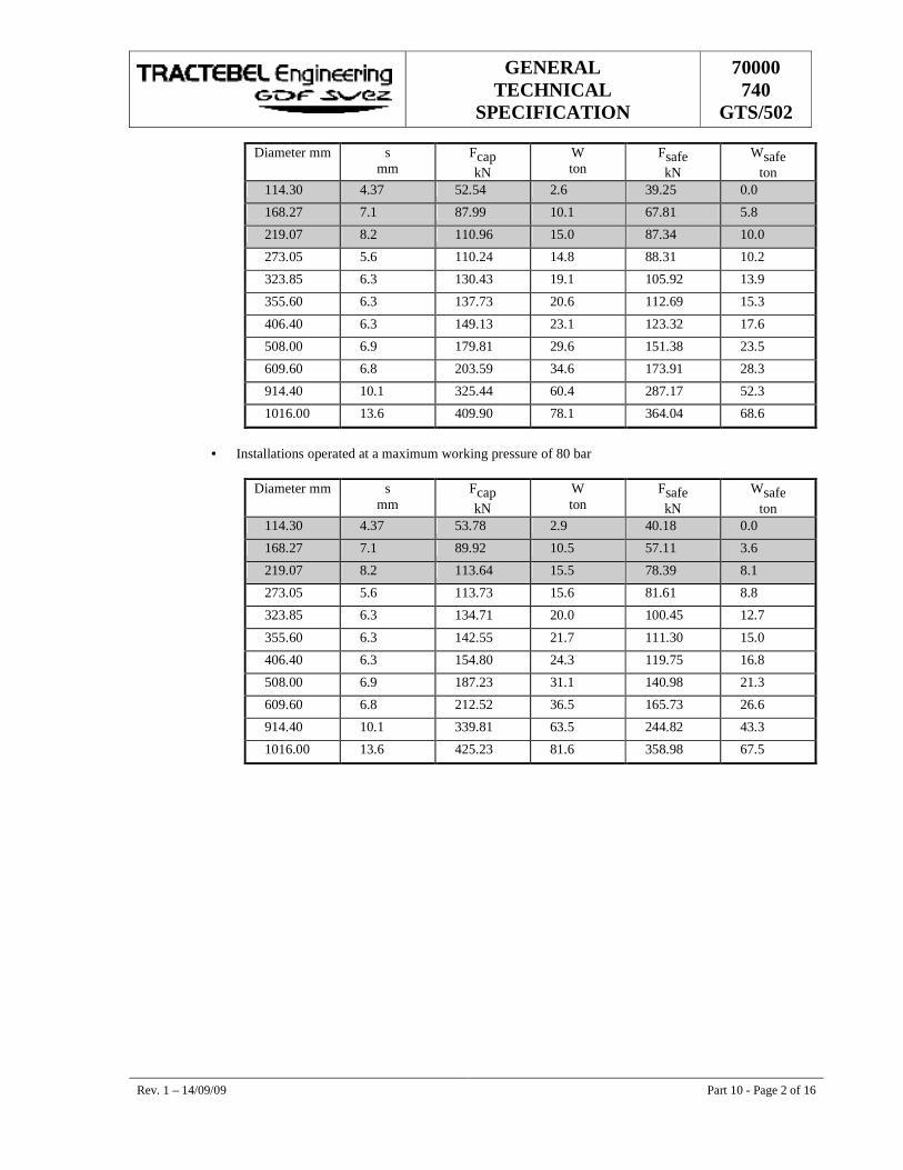
GENERAL TECHNICAL
SPECIFICATION
70000 740
GTS/502
Rev. 1 – 14/09/09 Part 10 - Page 2 of 16
Diameter mm s mm
Fcap kN
W ton
Fsafe kN
Wsafe ton
114.30 4.37 52.54 2.6 39.25 0.0
168.27 7.1 87.99 10.1 67.81 5.8
219.07 8.2 110.96 15.0 87.34 10.0
273.05 5.6 110.24 14.8 88.31 10.2
323.85 6.3 130.43 19.1 105.92 13.9
355.60 6.3 137.73 20.6 112.69 15.3
406.40 6.3 149.13 23.1 123.32 17.6
508.00 6.9 179.81 29.6 151.38 23.5
609.60 6.8 203.59 34.6 173.91 28.3
914.40 10.1 325.44 60.4 287.17 52.3
1016.00 13.6 409.90 78.1 364.04 68.6
• Installations operated at a maximum working pressure of 80 bar
Diameter mm s mm
Fcap kN
W ton
Fsafe kN
Wsafe ton
114.30 4.37 53.78 2.9 40.18 0.0
168.27 7.1 89.92 10.5 57.11 3.6
219.07 8.2 113.64 15.5 78.39 8.1
273.05 5.6 113.73 15.6 81.61 8.8
323.85 6.3 134.71 20.0 100.45 12.7
355.60 6.3 142.55 21.7 111.30 15.0
406.40 6.3 154.80 24.3 119.75 16.8
508.00 6.9 187.23 31.1 140.98 21.3
609.60 6.8 212.52 36.5 165.73 26.6
914.40 10.1 339.81 63.5 244.82 43.3
1016.00 13.6 425.23 81.6 358.98 67.5
GENERAL TECHNICAL
SPECIFICATION
70000 740
GTS/502
Rev. 1 – 14/09/09 Part 10 - Page 3 of 16
If it is deemed necessary for the laying of the pipe that cables, pipelines, poles or pylons have to be shifted or divert temporarily, this should take place in accordance with the directives of the Parties Concerned. If these activities cannot be carried out by the managers or owners concerned, they should be carried out by the Contractor or by a subcontractor in possession of the required professional qualifications or recognition.
If in spite of all safety measures a pipe or cable is nonetheless damaged, the works must immediately be halted and the Owner and/or Eengineer and the concessionary company concerned must be informed without delay. In addition, the Contractor shall provide all the assistance required for the repair work at his own expense.
If unforeseen obstacles appear during excavation work (old foundations, posts, bunkers, etc.), these must be removed in accordance with the indications of and in consultation with the Owner and/or the Engineer and possibly the Authorities concerned to at least 0.50 m below the underside of the pipe to be laid and evacuated from the site. "Good filling soil" should subsequently be used for backfilling.
If the subsoil appears to have several layers, each layer shall be stored separately from the other and later replaced in accordance with the original layering if these layers differ in density, elasticity or hydraulic permeability. If the excavated material is composed of layers of peat, the following rules shall be applied:
• peaty soil in layers with a thickness < 30 cm is not stored separately but mixed into the backfill soil;
• peaty soil in layers with a thickness > 30 cm is stored separately and mixed into the arable soil. The excavated volume, less the volume of the pipeline, shall be replaced by stone-free soil.
In the case of clay or rocky soil, the Contractor shall choose his working method in such a way that the excavated material is sufficiently crushed to ensure correct backfill of the trench. If the Contractor wishes to use a mechanical trencher in areas with different subsoil's, he must submit a study that indicates that the new structure of the subsoil is at least equivalent. In the following areas, the use of a mechanical trencher is forbidden because this causes irreparable structural damage:
• Areas with the presence of thin layers of silt clay (from 20 to 100 µm) and sand or clay layers.
• Areas with sedimentary chalk and peat.
• Areas with peat and clay layers.
• Areas with large presence of basic and carbon-containing material, and layers with a very high iron content.
����� � !�"�#�$�"��%��&����
When the Contractor comes across buried cables, pipelines and drainage networks during excavation work, he must take the following measures:
• protect and support the cables, pipelines, drainage networks, etc. as the works progress;
• complete the inventory of fixture of the services encountered during excavation with the parties involved and the Owner and/or the Engineer;
• immediately after digging the trench, the Contractor shall survey the existing drainage systems in the presence of the Owner and/or the Engineer.
The drains must be made visible by placing blue-painted posts at the edges of the trench. The drains must be closed off on both sides of the trench if they are not directly included in a drainage system laid out by the Contractor.
GENERAL TECHNICAL
SPECIFICATION
70000 740
GTS/502
Rev. 1 – 14/09/09 Part 10 - Page 4 of 16
However, this does not diminish the Contractor’s obligation to keep the existing drainage systems in operation and not to affect their functioning. After surveying the drains, the posts shall be positioned on the outside of the working area. These measurements shall immediately be set out by the Contractor in a 1/1000 layout drawing. This drawing shall mention for each Owner plot number:
� the position of each drain measured in relation to a fixed reference point;
� direction of slope;
� type and inner diameter of the drainpipe;
� condition of the drain;
� depth of the drain in relation to the surface.
and one copy of it shall be given to the Owner and/or the Engineer at the latest two working days after the excavation. The Owner and/or the Engineer will carry out the required inspection and if necessary the required corrections will be communicated to the Contractor. Three copies of the accepted drawing will be given to the Owner.
• The “Report of the Presence of Drainage Networks” (see Appendix 1) shall then be filled in together with the tenant/owner and the representative of the Owner;
• In the event of any damage, a proposal for repairs must be submitted for the approval of the Owner and/or the Engineer and the Parties Concerned;
• Observe a clearance of a least 0.20 m between the nearest parts of the cables, pipes and drains at points at which they cross and 0.40 m where they are parallel. These distances should be increased wherever possible especially where they approach large installation. So as to reduce, as far as possible, any risk to neighbouring installation inherent in the Contractor works.
• Adapt the profile design, if necessary.
�����'� ���&��(��)�)���
The trench shall be dug in such a way that is is symmetrical in relation to the axis of the channel actually market out.
Directrional changes on the trench floor should tally with the draft longitudinal profile perfectly – both horizontally and vertically – and with changes in pipe direction, so that welded pipe sections lie in a continuous and uniform manner along the trench floor.
To ensure that the above changes correspond, the Contractor shall conduct a topographical survey, in the presence of the Owner and/or the Engineer, after the trench has been dug and before laying the pipe in the trench.
�����*� ���&����"�(����
�����*��� ;)�).$.�"�(����
Except other stated in the Particular Technical Specifications the minimum depth should be as follows:
The trench depth should allow a minimum covering of 1.10 m between the upper generatrix of the pipe and the general ground level even if the drawings require a smaller minimum covering. The covering is defined
GENERAL TECHNICAL
SPECIFICATION
70000 740
GTS/502
Rev. 1 – 14/09/09 Part 10 - Page 5 of 16
as the vertical distance between the reference levels. The provisions of this article take precedence over the measurements shown on the drawings.
The Contractor is not entitled to increase his price if in local circumstances the pipe has a covering varying between 1.10 m and 1.40 m and/or if the increased depth (greater than 1.40 m) has already been stipulated in the Particular Technical Specifications or detail drawings.
An increase may only be granted if the additional depth is greater than 30 cm over a length exceeding 50 m. If the local additional depth could not be known beforehand and no supplementary storage space for piling up soil was provided on that basis (cf. Part 2), the Contractor should store the supplementary excavated soil on the access road. Such storage should be carried out in conformity with Part 2 of the GTS.
The Contractor shall ensure that when storing another type of soil on the access way it shall be kept separate from any other soil thus stored and that during the works no mixing shall occur due to works traffic. The Contractor shall himself be responsible for the inspection of the covering of the pipe after it has been laid in the trench, independently of the measurements that the Owner and/or the Engineer carries out for drawing up the technical archives.
�����*� � -�(����#������������.)�).$.��
Except otherwise stated in the Particular Technical Specifications or the detail drawings and the Authorities concerned, the Contractor shall provide a greater trench depth :
• when the pipeline lies underneath a road or crosses a road;
• In such cases, a covering of 1.2 m is required between the upper generatrix of the pipe and the road surface;
• when the pipeline crosses a watercourse in an open cut. In this case, a covering of minimum 1.3 m is required between the upper generatrix of the pipe and the theoretical profile if this profile is lower than the existing natural profile. If the theoretical profile is higher than the natural profile, a covering of minimum 1.3 m is required between the upper generatrix of the pipe and the natural profile;
• when the pipeline crosses a waterway by means of a borehole. In this case, a covering of minimum 1.3 m is required between the upper generatrix of the casing and the theoretical profile if this profile is lower than the existing natural profile. If the theoretical profile is higher than the natural profile, a covering of minimum 1.3 m is required between the upper generatrix of the casing and the natural profile;
• when the pipeline crosses a ditch. In this case, a covering of 1.1 m is required between the upper generatrix of the pipe and the natural profile of the dredged and deepened ditch, with gauging down to compact ground;
• when the pipe crosses a railway, a minimum covering of 1.6 m is required between the upper generatrix coating of the casing and the bottom of the rail. Except otherwise requested by the railway Authority, the crossing should be perpendicular to the rails.
• when the pipe is located in a casing.
• In this case, a covering of minimum 1.2 m is required between the upper generatrix of the casing and the surface;
• when the pipe has additional equipment (half shells, ballast, anchoring, etc.).
• In such cases, there shall be a minimum covering of 1.1 m measured between the top side of the protection and the surface;
GENERAL TECHNICAL
SPECIFICATION
70000 740
GTS/502
Rev. 1 – 14/09/09 Part 10 - Page 6 of 16
N.B.
Concrete slabs are considered as a mechanical protection and not as an additional equipment and are placed 30 cm above the upper generatrix of the pipe;
where under-ground obstacles are encountered, well-defined distances must be maintained.
�����*�'� ��.)���"��"$&�)����/�����.)�).$.����&��"�(����
If, exceptionally, the minimum depth of the trench cannot be achieve due to local reasons, the Contractor will, provided he has received permission from the Owner and/or the Engineer, provide special protection (binders, half shells, concrete slabs, concrete tiles, etc.). The method of execution must be submitted beforehand for the approval of the Owner and/or the Engineer and the Parties Concerned.
�����+� ���&�� )"���
The foot of the trench must always have a minimum width equal to the outer diameter of the pipe with its coating and any mechanical protection plus at least 20 cm (10 cm on either side). If local circumstances dictate (ballast, anchoring, half shells, etc.), a wider trench shall be provided depending on the space required to ensure proper execution and complete filling up around the pipe.
When using a mechanical trencher, the foot of the trench shall have a width equal to the outer diameter of the pipe with its coating and any mechanical protection plus at least 40 cm (20 cm on either side). The Contractor must take the required precautionary measures to prevent the trench from caving in. In dry, non-cohesive ground, for example, the angle of the bank may at most be equal to the angle of the natural embankment.
In any case, the Contractor must take account of unfavourable factors such as water flowing into the trench, vibrations and excessive loads near the trench, heterogeneity of the ground, the trench remaining open for a long time, etc. Trench side shall under no circumstances be vertical.
�����,� -).���)�����/����� ��)�#�()���
In places where welding must be carried out in the trench, the Contractor shall execute the working pits and/or connecting pits (“Under gas”) so as to facilitate welding as well as the inspection and coating thereof. The working pits must be kept dry. The minimum dimensions of these working pits are :
• length: distance between the welded joints + 2 x 1 m
• width: diameter of the pipe + 2 x 1 m
• the distance between a part fixed (e.g. valve) and the wall of the recess should be 0.60 m min;
• depth: 0.6 m under the pipe.
The minimum dimensions of connecting pits “Under gas” are :
• length: length of the pipe element to be put in place + 2 x 1.5 m.
• width : ˘ of the pipe + 2 x 1 m for a ø smaller than or equal to 300 mm
˘ of the pipe + 2 x 1.5 m for a ø of 300 to 600 mm
˘ of the pipe + 2 x 2 m for a ø larger than 600 mm
GENERAL TECHNICAL
SPECIFICATION
70000 740
GTS/502
Rev. 1 – 14/09/09 Part 10 - Page 7 of 16
• depth : free space of at least 0.8 m under the pipe.
�����0� ���)�#��������&���"1�� ���()��
If the type of terrain makes it difficult to obtain a stable trench and in the vicinity of buildings, existing structures, cables and pipelines, the Contractor must, among other things, with a view to safety, use the required means for shoring up the trench walls. As a matter of principle, all temporary timbering sheathing and sharing shall not be left behind in the trenches and/or work pits.
Nevertheless, the Owner and/or the Engineer may, if he judges that the stability of the construction work requires it, oblige the Contractor to leave these struts in place. The Contractor will in this case be reimbursed in accordance with the unit prices of the pricelists. The Contractor shall keep the trench dry and stable until after the topographical measurements and until after the activities of the recognised Inspection Organisation have been completed.
Moreover, the Contractor is obliged to provide the assistance required and to ensure the safety of all personnel working in the trench and/or work pit, even if certain activities take place after normal working hours in the interest of the progress of the site.
�����2� �((��&���/��������&��%����.��"����&�� ����
�����2��� ���&��%����.��
The trench bottom should be evened out depending on the changes of pipeline direction. The bottom of the trench must be completely flat and free of all stones, debris, tree trunks, tree roots, remains of welding electrodes, sharp objects, etc. which would impede the proper execution of the work and damage the pipeline coating.
If the bottom of the trench is rocky or gravely or contains hard objects, the Contractor must apply a layer of sand or light soil to protect the pipeline coating so that any protruding points are covered by at least 20 cm.
The application of top soil instead of sand or light soil is forbidden as is the separation of the subsoil into light soil and stones when this would change the properties of the subsoil in the trench in relation to the surrounding situation. The Contractor may apply a special protection with the approval of the Owner (lathes, neoprene, geo-textile fabric, etc.).
�����2� � ���&�� �����
The trench walls must be free of hard and protruding points to avoid damaging the pipeline coating when it is being lowered in.
�����3� 4���$�5�//�")�#���/��������&���"� ���()���
Before starting the drainage operation, the Contractor should apply for the required licences from the administrations concerned. If there is no suitable discharge point to hand in the vicinity (waterway, brook, drain, etc.), closed discharge pipes must be installed to a suitable discharge point. Laying these pipelines, procuring the required licences for this purpose and the right of way and any compensation to be paid are the responsibility of the Agreement. Water from the drainage operation shall only be discharged into a canal, ditch, waterway or drain. The dewatering pipes shall extend to these drainage points laid just outside the working area and buried and protected if they cross the access way. Under no circumstances shall the dewatering pipes discharge onto the adjoining terrain outside the working area.
GENERAL TECHNICAL
SPECIFICATION
70000 740
GTS/502
Rev. 1 – 14/09/09 Part 10 - Page 8 of 16
The pumps may be placed on the outside of the working strip. Only pumps muffled for sound may be used. Only electrically driven pumps connected to the mains electricity network may be used in the vicinity of houses.
The discharge water may not under any circumstances run freely over the terrain. The removal of discharge water may cause neither damage nor nuisance to third parties. Any pollution, silts, etc. accumulated during the work must be evacuated by the Contractor after completion of the work at his own expense. The Tenderer shall attach to his bid a note in which the different types of dewatering methods are described in detail.
Prior to the start of the works, the Contractor should ascertain the correct height of the water table. He should also carry out some test bore-hole or soundings. The Contractor shall at regular intervals analyse the discharge water at his own expense. The quality thereof should always conform to the standards laid down (inter alia, the content of salt, iron, heavy metals, foreign matter, pH, etc.).
The dewatering operation or horizontal drainage should be carried out in good time so that when excavations start the trench will be sufficiently dry and the Owner and/or the Engineer can check the condition of the trench bottom before lowering in the pipeline.
The dewatering operation should, moreover, be kept in operation if this is necessary for the execution of the works, the topographical measurements, the activities of the Recognised Inspection Organisation, connecting up to the telemetry cable and backfilling.
The dewatering operation should be stopped in such a way that the water table rises slowly and regularly. When the dewatering wells are removed, the bore-holes must be filled in with sand.
In any case, care should be taken to prevent the pipeline from floating the dewatering operation fails or is stopped. The installation of the dewatering operation shall be carried out by an expert subcontractor or by the Contractor himself if he can prove that he is sufficiently competent and experienced in this field.
Any damage to third parties installations, buildings, plantations, crops, etc. as a consequence of drawing off ground water by the dewatering operation should be reported without delay to the Owner and/or Engineer and to the Authorities or private persons concerned. The Contractor, and only the Contractor, will be held responsible for this.
More particularly, the Contractor shall take the required measures if in consequence of the dewatering operation certain water wells run dry or if the course and/or the flow of natural springs are affected by the laying operations.
The Contractor shall bear the consequences of any disruptions to the water discharge system that he causes as a result of works of any kind whatsoever, both within the construction sites and in the vicinity thereof. He must ensure the protection of the construction site continuously against water to prevent any detrimental effect on the execution of the works.
�������� ��&�6���)��
���������� ������
In rocky soil, the trench must be excavated with a mechanical trencher fitted with suitable teeth which assures maximum fragmentation of the excavated material.
The rocky soil is excavated with a mechanical trencher and backfilled with fine crushed stone. If the use of a mechanical trencher is unfeasible for technical reasons, such as:
• terrain's with a slope greater than 20%
GENERAL TECHNICAL
SPECIFICATION
70000 740
GTS/502
Rev. 1 – 14/09/09 Part 10 - Page 9 of 16
• in bends with a bending radius smaller than 40D
• at special points
excavation is carried out with a excavator equipped with a toothed back-hoe which is permitted provided all stones with a diameter greater than 30 mm are crushed prior to backfilling or gathered, transported to a recognised waste disposal site and replaced by stone-free ground.
In such cases, the Contractor is only paid according to pricelist for the cotting, excavation, disposal and replacement by stone-free ground of class 3 rocks in the case of “works in line”.
�������� � ����)/)&�)����/��&���
The classification of rocks on the basis of their natural cohesion comprises three classes:
� Class 1 Weathered rocks
� Class 2 Uneathered rocks
� Class 3 Compacted rocks
• Class 1 :
All kinds of rocks can appear in this class provided the cohesion of their components are reduced by weathering or crumbling. In this way, small broken pieces occur which are referred to as weathering material. This material can be excavated with an ordinary excavator.
• Class 2 :
These rocks show little or no sign of weathering or crumbling and can be excavated with a normal excavator equipped with a toothed back-hoe.
• Class 3 :
The rocks show no sign of weathering or crumbling and can be considered as the mother rock. This rock can only be excavated with the use of a pneumatic rock breaking hammer mounted on an excavator. When encountering areas with a rocky soil structure, the Owner and/or the Engineer will determine to which class the rocks belong with the help of a geologist.
10.2. ���7���������8�������8��
��� ��� ������
Before backfilling the trench, the Contractor must make sure that all the required work has been completed before backfilling (cathodic protection, anchoring, ballast, etc.). In addition, he must take account of the work that has to be carried out during backfilling (teletransmission cable, mechanical protections such as half shells, concrete slabs, warning tape, warning net, etc.).
��� � � �$9�6����%��&)�"��$��()�����%&�/)��)�#�
Before backfilling the trench, the Contractor will take measurements for drawing up the technical archives.
The measurements relate to :
GENERAL TECHNICAL
SPECIFICATION
70000 740
GTS/502
Rev. 1 – 14/09/09 Part 10 - Page 10 of 16
• position of the pipe;
• covering of the pipeline;
• location of the welded joints, concrete slabs, anchorings, ballast, connections of the telemetry cable, cable and connection boxes of the potential measuring points, etc.;
• determination of the angles and the position of each change of direction.
Backfilling may in principle be started after the abovementioned measurements have been completed and the results communicated to the Owner and/or the Engineer.
��� �'� 4��)�#�.����"�/��%&�/)��)�#�
��� �'��� �� ��(��
The trench shall be backfilled to 10 cm above the pipe with light soil or sand. The light soil or sand must be free of all hard objects (stones, gravels, material that has been broken up, etc.) that might damage the coating. Filling in around the pipe must be carried out in such a way that all voids are filled so that later no subsidence of any kind will occur. As a matter of principle, all the different layers of earth shall be replaced as they were excavated.
If the excavated material contains no light soil or sand that could serve for this first backfill without changing the characteristics of the excavated material in relation to the surrounding subsoil, the Contractor shall provide for the importation of light soil or sand. The use of salty sand, gravel, coal slag, iron slag, etc. is forbidden.
In certain special cases, the Owner and/or the Engineer may stipulate methods of protection during the course of the works that are better suited to the local circumstances (see table). The supply and positioning of such protective items and/or backfilling systems will be paid in accordance with the unit prices of the pricelist as an addition to the price per linear metre of the existing unit price per linear metre for filling in the trench in the relevant pricelist. This price increase will also take account of the removal by transportation of surplus soil depending on the chosen backfilling system. Lump sum prices of the S.P. will always take account of these supplements. Consequently, no additional charge will be made for this.
In hot weather, backfilling may only be carried out if resistance to depressions on the pipeline coating permits it. If this resistance is insufficient, the Contractor shall carry out the backfilling only if the coating and the backfilling material have cooled off sufficiently. Filling in with frozen soil is also forbidden.
• Backfilling systems
TYPE OF FILLING SOIL BACKFILLING SYSTEM
good filling earth backfill with excavated soil
crushed rocky soil
from the trencher
apply geo-textile fabric, min. thickness 8 mm.
Fill in with excavated soil
medium rocky soil
(1) particles < 30 mm
sand bed of 20 cm in trench bottom (2)
apply geo-textile (3) or rock shield (5) fill in with excavated soil max. 0/30
GENERAL TECHNICAL
SPECIFICATION
70000 740
GTS/502
Rev. 1 – 14/09/09 Part 10 - Page 11 of 16
rocky soil with (1)
particles > 30 mm
sand bed to 30 cm above and 20 cm under the pipe (2) or non-rotting interlocking wooden lathes, thickness min. 15 mm (4) or geo-textile fabric or rock shield (5) with infill with particles smaller than 30 mm(3) to 30 cm above and 20 cm under the pipe
(1) Filling method to be approved by Owner and/or the Engineer.
Drop height of the filling soil must be limited to the absolute minimum.
(2) Filling with sand-bed only applicable on flat terrain. On sloping terrain, an alternative protection method shall be used.
(3) Geo-textile fabric must be approved by the Owner - and/or the Engineer min. thickness 8 mm.
(4) Non-rotting interlocking wooden lathes, min. thickness 15 mm, must be approved by the Owner and/or the Engineer.
(5) Rock shield protection must be approved by the Owner and/or Engineer.
The Contractor is free to propose to the Owner and/or the Engineer another backfilling method which is taking into account the abovementioned remarks as far as the pipeline coating is well protected from any kind of damages.
Only an approved (by the Owner and/or the Engineer) alternative backfilling method is applicable.
��� �'� � !((��(��
The thickness of the layers and the frequency of compacting depend on the type of backfilling material. If this backfilling material contains large stones or blocks of rock, these fragments shall be laid in the trench provided the stones are not heavier than 50 kg and the layer of light soil over the pipe must be at least 30 cm.
The upper part of the backfill shall be carried out in consecutive layers. Each layer must be tamped down to avoid hollow spaces which might later lead to subsidence. Each layer shall be put back in such a way that the original layering of the terrain is respected.
Backfilling is carried out with layers max. 30 cm thick. The Contractor must draw up a work procedure for compacting with a description of the compacting equipment that he wishes to use and their functioning. Compacting the filling soil must be carried out continuously by repeated processing of each layer with compacting equipment. The humidity shall be checked before compacting.
After compacting, the soil that has been put back must have the same penetration-resistance characteristics as the soil for the works, and this to a depth of 1m. This may be checked by the Owner and/or the Engineer using a penetrograph.
��� �'�'� ��(���)���6��=%�����)�>��
In places where the arable soil has been taken away for storage, it shall be replaced and levelled in its original position. The top soil layer, which must be put back at its original height, shall be completely free of foreign objects.
If for one reason or another arable soil must be brought in from outside the working area, it must have the same physical and chemical characteristics as the original soil. The soil brought in should be free of debris or remains and of weed seeds.
GENERAL TECHNICAL
SPECIFICATION
70000 740
GTS/502
Rev. 1 – 14/09/09 Part 10 - Page 12 of 16
Before placing the soil back on the working way, the subsoil should be raked up to restore the natural hydraulic permeability of the ground. The Contractor shall carry out an inspection in the presence of the Owner and/or the Engineer to determine the extent and depth of the compaction. The rake depth shall be determined by mutual consultation, depending on the results and taking account of the drainage presence.
��� �*� 4����"$)�#�%&�/)��)�#�
��� �*��� ��)�/�&�"�&��&������%����.�&��)&��(���&�)���/������()(���
The Contractor is responsible for the supply and placing of the reinforced concrete slabs in the places defined in the PTS or in the relevant drawings. The concrete slabs shall meet the specifications of the typical drawing.
The concrete slabs shall be laid in such a way that there is a 30 cm layer of soil or sand between the pipe and the concrete slabs. The slabs must be placed in a dry trench.
Partial backfilling of the trench to 30 cm above the pipe shall be carried out as described before. Prior to lay the concrete slabs, this partial backfilling shall be compacted in a adequate manner.
Before backfilling - necessary for the laying of the concrete slabs the Contractor shall take same measurements as described in para. 10.2.2.
The concrete slabs must be laid in such a way that they are centred on the centre-line of the pipe. The Contractor should take all the measures required to mark out the pipe’s centre-line after partial backfilling to ensure that the concrete slabs are laid correctly. A warning tape (width 6”) shall also be laid on the concrete slabs.
��� �*� � 4�)�#��)#���
��� �*� ��� ����)�#�
The Contractor is responsible for the supply and laying of the warning net over the entire length of the pipe.
• Characteristics: Plastified Minimum width: ˘ of the pipe + 2 x 0.2 m.
• The warning net shall be applied horizontally 30 cm above the upper generatrix of the pipeline.
No warning net is laid on the concrete protection slabs.
��� �*� � � 4�)�#��(���
The Contractor is responsible for the laying of the warning tape over the entire length of the pipe. Except otherwise specified in the PTS, the Contractor will supply the warning tape.
• Characteristics: Width: 6”
• The warning tape shall be attached horizontally 30 cm above the upper generatrix of the pipeline.
GENERAL TECHNICAL
SPECIFICATION
70000 740
GTS/502
Rev. 1 – 14/09/09 Part 10 - Page 13 of 16
��� �+� �&�/)��)�#����%��� 5#�$�"��%��&����
��� �+��� �����&���/�$�"�#�$�"�&%������()(��)�����
In places where the trench meets underground cables or pipelines, the Contractor shall place protective devices in accordance with the requirement of the Public Services and Authorities, owners, tenants and/or operators concerned. Protective items already existing shall be reinstalled by the Contractor and if damaged replaced at his own expense.
��� �+� � �����&���/�")�#���6���.��
��� �+� ��� ��())�#�")�#���6���.��
1. General :
For the repair work to the existing drainage system, it shall be assumed that the Contractor or his subcontractor is in possession of the necessary practical knowledge required for drainage work. He is therefore responsible for the repairs and should take all measures required and employ the working methods to supply a repaired drainage system that is free of deposits left behind after the repairs.
It must be emphasised that the repaired drains must be of the same type and have the same characteristics as the original drains (among other things, with regard to material, thickness, diameter, specific gravity, perforation pattern, resistance to compression, resistance to impact, tension, etc.).
It is in all cases forbidden to replace cut or damaged drainage pipes with drainage pipes of another type or with drainage pipes of a larger diameter slipped over the original pipe. The drainage pipes must be joined axially by means of fitted or threaded earth resist sleeves, so as to resist to axial forces. The sleeve must under no circumstances cover or hinder the perforations over a distance exceeding 300 mm.
2. Investigation before drain repair
Before commencing the drain repair, the Contractor shall investigate with suitable devices whether the drains have been moved, damaged or blocked by earth, mud, etc. If the Contractor proves that the drains on the working strip are not damaged, he may be discharged from responsibility for repair subject to the agreement of the Owner and/or the Engineer.
3. Draft for drain repairing
The materials used and the working procedure must be submitted for approval to the owners and/or the Engineer and the land owner/tenants. The Contractor shall submit a draft plan to the Owner and/or the Engineer at least five working days before repairing the drain. The draft plan shall be drawn up to a scale of 1/1 000 and shall mention the following:
� the position of the existing and new drains
� type and slope of the existing and new drains
� connections and closure points
� outlet point
� depth in relation to ditch bottom and gradient
GENERAL TECHNICAL
SPECIFICATION
70000 740
GTS/502
Rev. 1 – 14/09/09 Part 10 - Page 14 of 16
The Owner and/or the Engineer will submit this draft via the Negotiator to the Parties Concerned for the purpose of obtaining prior agreement for the working procedure and for the restoration of the site. If the Party concerned refuses a proposal for repairs with diverted drains, the drainage network must be repaired in the conventional manner.
4. Conventional drain repair
The repair of conventional drains must as a matter of obligation be carried out before the restoration of the site. The drainage systems must be repaired over the complete width of the trench and if necessary over the width of the working strip. Prior to the repairs, the extremities of the drains shall be dug free so that a repair drain can be put in place in accordance with engineering design and the approved procedure.
5. Repair by means of longitudinal drains
If the Contractor decides to repair the drains by means of an open trench technique, this shall be carried out before the restoration of the site. Techniques without trenches can be applied after restoration of the site provided they do not constitute a danger to underground installations. In particular, any mixing of arable soil with subsoil must be avoided and if necessary rectified.
Drainage collectors or drainage pipes laid in parallel with the pipe must discharge into ditches or drains in such a way that their function cannot be reduced due to the block-off of the outlet caused by a build-up of deposits. In particular, the outlet must be located at least 20 cm above the ditch bottom. The Contractor shall hand over to the Owner and/or the Engineer an “as built” drawing (scale 1/1000) with the layout of the longitudinal drains, the connections and closure points, the outlet point with the depth in relation to the ditch bottom and slope, as the case may be.
6. Visiting the site after drain repair
After repairing the drainage, the Contractor will invite the party concerned to come and confirm whether the repair has in his opinion been carried out correctly. The Contractor will complete the “Report of Presence of Drainage Networks” and will submit it to the party concerned for signing. The rest of the backfilling of the trench may only be carried out after acceptance without reservation of the repaired drainage system by the Party concerned.
��� �+� � � �&�/)��)�#���")���
The first 30 cm shall be backfilled manually. An endeavour should be made to ensure that the different back-filled layers will have hydraulic permeability equivalent to the original surrounding layers of soil. Outside the first layer of 30 cm, each layer shall then be compacted to prevent any subsidence and to prevent the water finding a course other than through the drainage network after the repair of the drainage system.
New drains and drains to be repaired must be laid according to the rules of the trade and in water-permeable soil (water flow at least 1 cm/hour); this should be sufficiently raked through according to the circumstances.
��� �+�'� �����&���/���&�)���?$�&�)�����
At pipeline tie-in joints, backfilling may not be carried out over a distance that is a function of the diameter of the pipeline, on either side of the places in question, to facilitate the tie-in of the elements to be welded.
GENERAL TECHNICAL
SPECIFICATION
70000 740
GTS/502
Rev. 1 – 14/09/09 Part 10 - Page 15 of 16
��� �+�*� �����&���/������� ����"� ��)�#�/)������9��%����)������"�
Their lower part shall be carefully filled with sand. The upper part should be filled with arable soil (top soil).
��� �,� ���()�#���)���
When the slope requires, the Contractor shall take the necessary measures under his own responsibility to prevent washout of the backfill, such as :
• the immediate re-sowing of sloping terrain (such as road embankments)
• non-removal of tree stumps in the working strip in wooded terrain (except in the trench) subject to the permission of the Owner and/or the Engineer and the Land Owner.
• the placement of a drain at the bottom, next to the pipe. Depending on the slope and the hydraulic permeability, setting of water pit trap, filled with gravel, into which the drain flows (buffer). Each water pit trap shall have minimum dimensions of 1 m x 1 m and a depth to 1 m under the level of the drain. 50 cm of the uppermost soil layers shall be replaced over these drainage pit trap.
• the placing of clay block-off wall.
• the placing of block-off wall composed of sand bags.
• other proposals (in particular situations) made by the Contractor and approved by the Owner/Engineer.
��� �0� ���(�&�)����/�����&��)�#�/���%&�/)��)�#�
• After backfilling and before restoration of the site, the Contractor will carry out a supplementary inspection of the coating.
• In order for this inspection to be carried out in the best possible manner, the Contractor shall free the extremities of the sections to be checked and ensure the accessibility and the stability of the trenches (shoring) and ensure that the connection pits are kept dry.
• There must be absolutely no contact of bare metal with the surrounding ground. Bare metal shall be insulated from the ground by means of wooden blocks or equivalent. The sections of pipe to be inspected shall be a maximum of 5000 metres long.
• If the ground is too dry, the Contractor shall dampen the backfill by means of ± 1 000 litres of water per 250 metres of length.
• The Contractor shall immediately unearth all indicated defects and repair them in accordance with an approved procedure (see part 9).
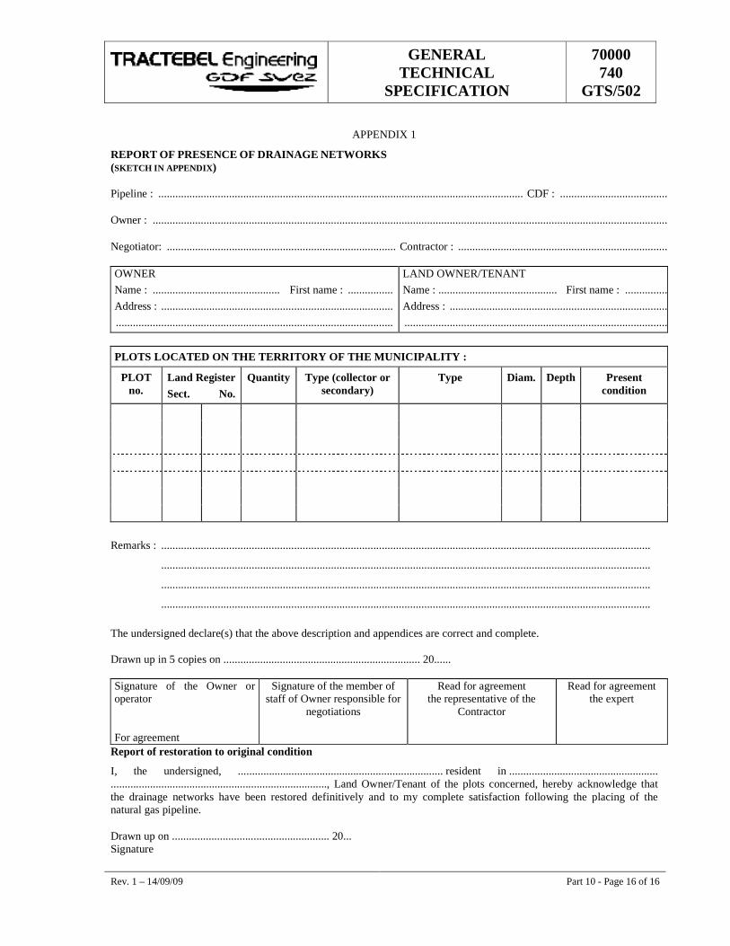
GENERAL TECHNICAL
SPECIFICATION
70000 740
GTS/502
Rev. 1 – 14/09/09 Part 10 - Page 16 of 16
APPENDIX 1
REPORT OF PRESENCE OF DRAINAGE NETWORKS (SKETCH IN APPENDIX)
Pipeline : ................................................................................................................................. CDF : ......................................
Owner : ......................................................................................................................................................................................
Negotiator: ................................................................................. Contractor : ..........................................................................
OWNER Name : ............................................. First name : ................ Address : .................................................................................. ..................................................................................................
LAND OWNER/TENANT Name : .......................................... First name : ..........................Address : ........................................................................................ ................................................................................................
PLOTS LOCATED ON THE TERRITORY OF THE MUNICIPALITY :
PLOT no.
Land Register Sect. No.
Quantity Type (collector or secondary)
Type Diam. Depth Present condition
Remarks : .............................................................................................................................................................................
.............................................................................................................................................................................
.............................................................................................................................................................................
............................................................................................................................................................................. The undersigned declare(s) that the above description and appendices are correct and complete. Drawn up in 5 copies on ...................................................................... 20...... Signature of the Owner or operator For agreement
Signature of the member of staff of Owner responsible for
negotiations
Read for agreement the representative of the
Contractor
Read for agreement the expert
Report of restoration to original condition
I, the undersigned, ......................................................................... resident in ..................................................... ............................................................................., Land Owner/Tenant of the plots concerned, hereby acknowledge that the drainage networks have been restored definitively and to my complete satisfaction following the placing of the natural gas pipeline.
Drawn up on ........................................................ 20... Signature

GENERAL TECHNICAL
SPECIFICATION
70000 740
GTS/ 502
��������
���� ��� �� ���������� ��
1 14/09/09 Logo Changed SS DNS NC
0 24/03/08 Logo Changed SS DNS NC
D 16/04/04 Logo Changed MRT DKB MRY
C 06/09/00 Updated MRT AES LEP
B 08/08/00 First issue MRT DKB LEP
A 27/07/00 Preliminary draft MRT DKB LEP
Rev. Date Subject of revision Author Checked Approved
w97
_98_
gts.
dot
GENERAL TECHNICAL
SPECIFICATION
70000 740
GTS/ 502
Rev. 1 – 14/09/09 Part 11 - Page I of I
�
������������������
�
������������� ��� �� �����������������������������������������������������������������������������������������������������
������ ������� �������������������������������������������������������������������������������������������������������������������������������
�������� ��������������������������������������������������������������������������������������������������������������������������������
�����!�� �� ����� ���"�����#� �������������������������������������������������������������������������������������������������������
�����$�� ��%�&��� ���������' ��&�� ������ ��� ����������������������������������������������������������������������������
�����(�� � �)%��� ��"��*�)�)�� ��"������� ��� ��������������������������������������������������������������������������!�
�����+�� ���� �)�)����� ���������������������������������������������������������������������������������������������������������������!�
�����,�� ���� �%� ���%����& ���#���������������������������������������������������������������������������������������������������$�
���!�� ��������� �����-���������������������������������������������������������������������������������������������������������������$�
���!���� ������������������������������������������������������������������������������������������������������������������������������$�
���!�!�� ���&���"��*�����������������������������������������������������������������������������������������������������������������$�
���!�$�� ����%��� ��"��*�)�)�� �%���� ����������������������������������������������������������������������������������������$�
S S S
GENERAL TECHNICAL
SPECIFICATION
70000 740
GTS/ 502
Rev. 1 – 14/09/09 Part 11 - Page 1 of 3
11. ��������� ��� �� ����
11.1. ������� �����
������� �����
The working method that the Contractor will apply and the material that he will use for laying must :
• be adapted to the local circumstances (site configuration, geological and hydro-geological properties of the ground, diameter of the pipe, etc.);
• be approved by the Owner and/or the Engineer.
�����!� �� ����� ���"�����#� ��
A pipe string section may only be laid if :
• the changes of direction were effected in accordance with the specifications of G.T.S. Part 5.,
• the requirements provided in G.T.S. Part 10 have been met,
• inspections of the welding seams have been carried out and accepted by the recognised inspection organisation,
• the external coating has been checked to see that it is in good condition with holiday detector immediately before laying (see G.T.S. Part 9). The inspection is carried out in the presence of the Owner and/or the Engineer,
• Prior to lowering-in work the recognised inspection organisation may (at the Owner and/or the Engineer request) check the pipeline coating by means of a holiday detector. This random inspection will be carried-out at the same time as the Contractor's inspection work and will not release the Contractor from his responsibility of his own inspection work.
• the temperature is such that the coating will not be damaged.
�����$� ��%�&��� ���������' ��&�� ������ ��� ��
�����$��� ��� %��"��*�� ���
Lowering-in must be carried-out in the presence of the Owner representative and/or the Engineer. The Contractor must notify him in time.
�����$�!� ����%��� ��"��*�)�)�� ������%���� ��
During lowering-in, the Contractor must ensure that :
• the pipe is not subjected to inadmissible stresses;
• The Contractor will submit the required calculation notes in the work procedure;
GENERAL TECHNICAL
SPECIFICATION
70000 740
GTS/ 502
Rev. 1 – 14/09/09 Part 11 - Page 2 of 3
• the pipeline is supported over a sufficient surface area to prevent the supports from penetrating the coating;
• a sufficient number of machines with the required capacity will be used for lowering-in the pipeline strings (as per calculation note).
�����(� � �)%��� ��"��*�)�)�� ��"������� ��� �
�����(��� � �)%��� ��"��*�������� ��*�.�����
After lowering-in, the pipeline shall be completely stress free in the trench. Joining the different sections may not cause any inadmissible stresses in the pipeline. Tie-ins joints are only executed on consecutive sections at their definitive level.
�����(�!� � �)%��� ��"��*�)��"����"��*�)�)�
In the absence of concordance between the changes of direction of the pipeline and the trench, both in the horizontal and in the vertical plane, the Owner and/or the Engineer may require the Contractor to make the necessary adjustments, it being understood that this does not entitle the Contractor to any price supplement.
These adjustments comprise :
• widening or deepening the trench,
• backfilling and compaction of the trench bottom,
• cutting out and replacing bends that are not adapted to the profile of the trench,
• if necessary, the complete adaptation of the section concerned.
All material supplied by the Owner and damaged as a result of such activities will be replaced by the Contractor at his own expense.
�����+� ���� �)�)����� ���
�����+��� ����
The Contractor will carry out all the work required to tie-in the different welded and lowered-in sections together so that a continuous string is produced.
After digging out the working trenches, the Contractor will take all measures necessary to ensure their stability to guarantee the safety of his personnel, the personnel of the Owner and/or the Engineer and that of the recognised Inspection Organisation.
�����+�!� /�0� ���%��� ���"������� ��� �
It is forbidden to shift or move the sections on the trench bottom with lifting gear or other means to bring the pipe ends to be joined closer together. The only method that shall be accepted in this case consists of welding in an additional piece.
GENERAL TECHNICAL
SPECIFICATION
70000 740
GTS/ 502
Rev. 1 – 14/09/09 Part 11 - Page 3 of 3
�����,� ���� �%� ���%����& ���#�
The Contractor should take account of the fact that he may be asked to provide the necessary assistance in this tie-in work after his normal in-line activities have been completed.
These works comprise :
• signposting the construction site
• dewatering of the working pit
• excavations, manual and mechanical
• shoring up
• coating of the pipeline and welded joint
• filling up + compaction
• reinstatement
This work will be charged in the price list.
11.2. ��������� �����-�������
���!��� ����
In places where the type of ground is such that the pipe might rise as a result of the hydrostatic pressure, ballast should be placed on the pipeline.
The ballast will be applied in places that will be indicated in the P.T.S. and or the relevant drawings.
The Contractor is responsible for the supply and the placement unless otherwise stipulated in the P.T.S..
���!�!� ���&���"��*���������
The ballast consists of ballast blocks or blocks of prefabricated reinforced concrete, bags of cement, or a continuous coating of reinforced concrete on the most important section.
The reinforcement of the concrete may not come into contact with the pipe. The concrete in contact with the coated pipe should be sufficiently smooth. The cement must be resistant to the earth or the water with which it comes into contact.
���!�$� ����%��� ��"��*�)�)�� �%���� ��
Protection material must be placed between the pipeline coating and the ballast except for those applications where the ballast is applied by guniting. The costs for this should be included in the price for ballast.
The Contractor should indicate in his bid the method(s) of ballasting he intends to use as well as the sizes, the intermediate distances and the ballast materials. The depth of covering mentioned in the P.T.S. Part 10 is calculated between the upper generatrix of the anchoring or ballast fittings and the natural ground level.

GENERAL TECHNICAL
SPECIFICATION
70000 740
GTS/ 0502
��������
���� ��������� ���������� �
1 14/09/09 Logo Changed SS DNS NC
0 24/03/08 Logo Changed SS DNS NC
D 16/04/04 Logo Changed MRT DKB MRY
C 06/09/00 Updated MRT AES LEP
B 08/08/00 First issue MRT DKB LEP
A 27/07/00 Preliminary draft MRT DKB LEP
Rev. Date Subject of revision Author Checked Approved
w97
_98_
gts.
dot
GENERAL TECHNICAL
SPECIFICATION
70000 740
GTS/ 0502
Rev. 1 – 14/09/09 Part 14 - Page I of I
������������������
�
������������ ����������������������������������������������������������������������������������������������������������
������ ������������������������������������������������������������������������������������������������������������������������������������������
������ ������������� ��������������������������������������������������������������������������������������������������������������������
�������� ��!"������#�"$�������������������������������������������������������������������������������������������������������������
�������� �%���#��%��#��#�&����'#����#���#��"��#���������������������������������������������������������������
���(�� )��*�� ������� �����������������������������������������������������������������������������������������������������������(�
���(���� ����������������������������������������������������������������������������������������������������������������������������������(�
���(���� *����"�����������������������������������������������������������������������������������������������������������������+�
���(�(�� ,�������#�����# ��������������������������������������������������������������������������������������������������-�
���(���� )��"��$���.�$��"��� ���/����'#��&��$��&����������������������������������������������������0�
������ � �*������1���23���������������������������������������������������������������������������������������������������������������0�
�������� ��%����������$����#�#%����������&���-�4�5���1�66����� �3���������������������������������������������0�
�������� ��%������7�-�4�5���1$�8�$"$�#%����� �%��"��3��������������������������������������������������������������9�
���+�� ����� �����,�,�: ��������������������������������������������������������������������������������������������������������������9�
���+���� ��%���#��"��#���������������������������������������������������������������������������������������������������������������9�
���+���� ���#���#��"��#�����������������������������������������������������������������������������������������������������������4�
���-�� ������ ������;������,�� �. ��������� ���<��,��1���,�<��,�3������������������������������������6�
���0�� �� �� ��� �������= ������������������������������������������������������������������������������������������������������������
���9�� ��������������������������������������������������������������������������������������������������������������������������������������
���4�� ����;)����� �����,����;��� ���� ��; ���>��?�����������������������������������������������������������������
S S S
GENERAL TECHNICAL
SPECIFICATION
70000 740
GTS/ 0502
Rev. 1 – 14/09/09 Part 14 - Page 1 of 12
14. �������� ������������
14.1. ��������
Except otherwise stated in the P.T.S., the following statutory acceptance tests shall be carried-out after construction of the pipeline in accordance with the provisions of the ASME code B31.8 latest edition and where applicable, with provisions that may be imposed by the authorities of the concerned country.
At latest 30 days prior to the start of the tests, the Contractor shall submit to the Owner and/or the Engineer a detailed work schedule and a work procedure file for the execution of the testing, cleaning and drying operations. The Contractor shall provide the labour, test medium, temporary supports, ladders and scaffolding, all material including test heads, the measuring apparatus and any spare parts that may be required for the tests and trials.
Such equipment shall be approved in its entirety by the Recognised Inspection Organisation and by the Owner and/or the Engineer. Measuring instruments, such as manometers, manometrographs, manometric scales, barometers, thermometers etc., shall be sufficiently sensitive to give the required degree of precision. Such instruments shall be accompanied by the required valid calibration certificates. The pumps, compressors, etc. should have sufficient capacity and output to permit rapid filling.
The tightness test shall be carried out following the resistance test.
Exception
The following equipment shall not undergo any mechanical test on the worksite:
� gas meters, gas regulator, shut-off valves, safety valves, instruments, thermowells, boilers, pressure vessels, etc., provided such parts have an acceptable pressure certificate;
� discharge lines to the atmosphere such as open vent pipes without noise mufflers and drains;
� (for the testing of instrumentation pipes, see Article 14.9. and Part 17 of the G.T.S.).
14.2. ������������� ����
������� ��!"������#�"$���
� Plan of the section to be tested:
a) For pipeline construction:
For the purposes of the resistance test, the Contractor shall submit to the Owner and/or the Engineer and to the recognised inspection organisation a pipeline split up plan ten working days before the test. Due account should be taken in the split up plan of the minimum pressure at the highest point and the maximum pressure at the lowest point. This maximum pressure may under no circumstances exceed the test pressure of the pipes in the factory (i.e. 95 % of the Specified Minimum Yield Strength).
b) For station construction:
For each test section, an overall sketch or isometric drawing shall be submitted to the Owner and/or the Engineer and the recognised inspection organisation. Such documents shall include the following information:
GENERAL TECHNICAL
SPECIFICATION
70000 740
GTS/ 0502
Rev. 1 – 14/09/09 Part 14 - Page 2 of 12
� the location of the test inlet pipe, measuring instruments and bleeders;
� the adjustments that will be carried out for the test.
e.g. :
� removal of internal parts of check valves or bridging of the same by means of a bypass or instrumentation bosses;
� bridging carried out for non-tested "in-line" parts (see exceptions above);
� physical limits of the pipe by means of blind plates, blanks, hollow bases, etc.;
� as a general rule, it is not permissible to subject the shut-off valves in the closed position to one side test pressure;
� Copy of the valid calibration certificates of the devices and equipments used for the tests.
� Pressure data of the test apparatus used (manifold) such as valves, test heads, etc.
� Copy of all Non-Destructive Testing documents drawn up by the recognised inspection organisation.
� Copy of the weld log book.
� Form giving :
� date of the test;
� identification of the test equipment;
� test medium and origin;
� the maximum operating pressure;
� test pressure and duration.
� Description of the working method and the material for filling up with water and purging of water from each section.
������� �%���#��%��#��#�&����'#����#���#��"��#��
� All welds, screw and flange joints must be clean (free of rust, paint, etc.);
� All welds must be accessible for visual inspection:
� no temporary supports on the welds or flange connections;
� provide all necessary ladders or scaffolding for the safe inspection of the welds.
� All heat treatments shall be carried out prior to the tests;
� All reinforcement plates shall already be tested;
� All welds for the preparation of the testing work shall be subjected to the same non-destructive tests as those which are required for the piping to be tested;
GENERAL TECHNICAL
SPECIFICATION
70000 740
GTS/ 0502
Rev. 1 – 14/09/09 Part 14 - Page 3 of 12
� Inspection of conformity with the isometric drawing;
� Inspection of the half-open position of the valves;
� All spring supports and expansion joints shall be anchored in good time according to the manufacturer’s instructions;
� All precision instruments or regulators which may be damaged shall be temporarily removed by the Contractor;
� Orifice plates which may hinder correct filling up and drying shall only be mounted once the testing, cleaning and drying operations have been completed;
� Inspection of the connection of the filler pipe, manometer and pressure recording device;
� Cut-off valves which are used to close the testing system (e.g. test equipment) shall have a nominal pressure higher than or equal to the test pressure;
� The valves of drainage and bleeding points shall remain open during the tests and the ends must be fitted either with a flange with a blind flange or a screwed cover;
� For gas filters, check that the filter elements are removed;
� Inspection of marking-off of the test zone;
� When testing with nitrogen in a closed space, the Contractor shall assure constant ventilation. Furthermore, oxygen measurements shall be taken regularly;
� During the tests, the recording and testing devices shall be at least 10 m away from the tested pipe.
Exceptions
� If the trenches hinder the further construction of the station, at the request of the Owner and/or the Engineer and subject to the agreement of the recognised inspection organisation, the pipe shall be clad and the trench shall be backfilled before the mechanical resistance test and tightness test are carried out. The tightness test (with dry air or nitrogen only) must then be carried out with a manometric scale (see Article 14.4).
� If the scraper trap station is connected to a pipe, everything must be backfilled before the start of the resistance test (in conformity with the stress calculations).
� If exceptionally some parts of the pipeline sections under testing are not backfilled, those parts, will be covered by means of thermal insulation sheet.
14.3. )��*�� ������� ������������
���(��� ��������
� The test medium and the necessary accessory apparatus shall be supplied by the Contractor;
� For the pipeline, the pressure test shall be submitted to the recognised inspection organisation for approval on the basis of the split up plan. The maximum length per section is 30 km;
GENERAL TECHNICAL
SPECIFICATION
70000 740
GTS/ 0502
Rev. 1 – 14/09/09 Part 14 - Page 4 of 12
� The backfilling of the trench must be completed before starting the mechanical resistance test. During the resistance test, all traffic over the pipeline is forbidden;
� All reinforcement plates should preferably be tested in advance in the prefabrication workshop with nitrogen at 3.4 bar. The air bleed opening shall remain open until after the mechanical resistance test unless the trench is backfilled before the execution of the mechanical resistance test and tightness test (with dry air or nitrogen only) with a manometric scale;
� The choice of the test medium shall be made according to the following overview table.
Overview table - Resistance test for pipelines and mains to operate at less than 30% of the specified minimum yield strength of the pipe, but in excess of 100 PSI.
Situation Test medium
Test pressure
Test time Safety measures *
Backfill Dry air, nitrogen or water
As specified in ASME CODE B31.8
6 hours
Around intersections and non-buried parts
Above-ground or under ground (but not backfilled) on supports
Everywhere
Overview table - Resistance test for pipelines and mains to operate at hoop stresses of 30 % or more of the specified minimum yield strength of the pipe.
Situation Test medium
Test pressure
Test time Conditions Safety measures *
Backfill Water Min : 1.4 x MOP
Max : testing pressure of factory
6 hours
Around intersections and non-buried parts
Above-ground or underground (but not backfilled) on supports and stations
everywhere
Gas supplied actuators and stations
Dry air or nitrogen
1.25 x MOP 6 hours only for ND £ 3” pipe sections with max. volume £ 2m³ and if pipes have no low points where water can be drawn off (drains)
Overview table - Resistance test for stainless steel control and instrumentation piping or tubing.
Situation Test medium
Test pressure
Test time Conditions Safety measures *
Control and instrumentation piping
Dry air or nitrogen
1.1 x MOP soaping time
see Article 14.9. everywhere
* safety measures :
GENERAL TECHNICAL
SPECIFICATION
70000 740
GTS/ 0502
Rev. 1 – 14/09/09 Part 14 - Page 5 of 12
During the pressurisation of the installation and up to one hour after the test pressure has been reached, there is a general safety zone of 10 metres which all personnel and persons are forbidden to enter. Subsequently, until the installation is free of pressure, a safety zone of 5 metres must be observed. All valves and flange connections shall be marked with a sticker bearing the warning “Danger: under pressure”. The zone in which the test is carried out must be marked out and indicated with pictograms and a rotating light.
���(��� *����"��������������
� General
When the outside temperature is below + 4 °C, no hydraulic tests shall be carried out with water unless the water is mixed with glycol.
a) Pipeline construction
A caliper plate or-pig shall be used to check that there are no unacceptable deformations in the pipeline before starting the resistance test. Sections with unacceptable deformations shall be cut out and replaced before any resistance test shall start.
For pipelines construction, a bi-di pig or scraper is used to fill the pipe. A quantity of clean water should be pumped in front of the scraper (i.e. approx. 150 m of pipeline volume depending with the pipeline routing).
The scraper and the test heads shall be supplied by the Contractor. The type of scraper must be approved by the Owner and/or the Engineer. The test heads must have the necessary approval certificates (non destructive testing and hydraulic tests. After filling up the pipeline, the valves must be in the half-open position.
Any pressure fluctuations noted during the passage of the scraper should not indicate the presence of obstacles which hinder the free passage of the section.
The pressure increase shall be effected under the supervision of the Owner and/or the Engineer and shall be monitored by the recognised inspection organisation.
Once these operations have started, it is strictly forbidden to cross the pipeline with heavy equipment.
b) Station construction
For station construction, all high points of the pipe section to be tested must be vented. The system must then be pressurised.
� Test water
The test water shall be supplied by the Contractor. It must be clean (eventually after filtering), not silty, with a pH between 6 and 8 and non-corrosive. For stainless steel pipes, the test water shall contain max. 5 ppm of chlorides.
The water shall be sand-free. A compulsory analysis shall be carried out by a recognised inspection organisation at the expense of the Contractor (with the exception of potable tape water). If, after analysis of the water, any doubt persists, a corrosion inhibitor - supplied by the Contractor and submitted to the Owner and/or the Engineer for approval - may be added to it, or another water supply source shall be sought.
GENERAL TECHNICAL
SPECIFICATION
70000 740
GTS/ 0502
Rev. 1 – 14/09/09 Part 14 - Page 6 of 12
If for any reason the test water has to remain in the pipeline for an unusually long period of time, it should have corrosion inhibitors added to it (supplied by the Contractor and submitted to the Owner and/or the Engineer for approval). In the case of longer storage periods, the Owner and/or the Engineer reserves the right to have a titration test carried out at the expense of the Contractor.
� De-watering
a) Pipeline construction
The Contractor shall under the supervision of the Owner and/or the Engineer inspect the complete open position of the valves before starting de-watering de pipeline.
The type of pigs and foam pigs shall be approved by the Owner and/or the Engineer.
The discharge of the test water shall be carried out in such a way that there is no damage to installations or adjacent plots of land. The Contractor shall request the necessary discharge permit from the competent authorities.
Conventional pigs and foam pigs shall be run through the pipeline as many times as necessary to de-water and clean satisfactorily the pipeline sections. This is subject to the judgement of the Owner and/or the Engineer who must be present at the installation when removing the pigs from the pipeline.
b) Station construction
If water is the test medium, the water may be drained through the bleeders and drains provided. During assembly, the Contractor shall check whether any additional drains and bleeders must be provided.
The valves shall be drained as much as possible in the half-open position under air pressure through the bleeder pipes under the supervision of and in consultation with the Owner and/or the Engineer. The discharge of the test water shall be carried out in such a way that there is no damage to installations or adjacent installations. The Contractor shall request the necessary discharge permit from the competent authorities.
���(�(� ,�������#�����# �������������
a) Pipe construction
(Only applicable if approved by the Owner and/or the Engineer.)
For pipe construction, the pipe shall be completely buried. Only applicable for pipelines and mains to operate at less than 30 % of the specified minimum yield strength of the pipe, but in excess of 6.9 bar (100 P.S.I.) and within the limits set in the ASME CODE B31.8.
b) Station construction
General safety regulations
� For the pneumatic test (air excluded) in enclosed spaces, the premises must be constantly ventilated if any personnel are present. Furthermore, oxygen measurements shall be taken regularly;
� Care must be taken to ensure that the pressure in the test system does not exceed the permissible limit (e.g. under the influence of heat from the sun);
� It is forbidden to hammer the piping;
GENERAL TECHNICAL
SPECIFICATION
70000 740
GTS/ 0502
Rev. 1 – 14/09/09 Part 14 - Page 7 of 12
� Weld, screw and flange connections found to be leak-free shall be marked with an indelible colour code on the piping;
� The paint or coloured markers used must not damage the material of the installation.
���(��� )��"��$���.�$��"��� ���/����'#��&��$��&�����������������
� Pressure measurement
The pressure measurement shall be carried out by at least three devices:
� at least one manometer, which must be mounted on one of the piping of the test system;
� a pressure recording device and at least one manometer, mounted near to the pressure recording device.
Such measuring devices shall have an identification number and be accompanied by a calibration certificate. The two types of devices shall have a suitable scale position and range (preferably 1.5 x the pressure to be measured).
When the difference between the readings of two of these devices is greater than 4 % of the arithmetic average of the readings on these 2 devices, the two measuring devices must be recalibrated. The recorded test pressure diagram shall be marked with the test system number and the identification number of the recording device and shall be appended to the test file.
� Pressure loss
In the event of pressure loss, the cause must be investigated. If it is due to any defect in materials supplied by the Owner, any costs arising from any reworking and test re-runs shall be borne by the Owner. In all other cases, the Contractor undertakes to bear the consequences and the costs.
14.4. � �*������1���23������
������� ��%����������$����#�#%����������&���-�4�5���1�66����� �3�
Overview table of tightness test for pipeline sections with maximum operating pressure (M.O.P) £ 6.9 bar.
Situation Test medium Test pressure Test time Safety measures*
Buried
Dry air or nitrogen Min. 6 bar
6 hours around intersections and non-buried parts
Above-ground or underground (not backfilled) on definitive supports
soaping time everywhere
* Safety measures :
During the pressurisation of the installation and up to one hour after the test pressure has been reached, there is a general safety zone of 10 metres which all personnel and persons are forbidden to enter. Subsequently, until the installation is free of pressure, a safety zone of 5 metres must be observed. All valves and flange connections shall be marked with a sticker bearing the warning “Danger: under pressure”. The zone in which the test is carried out must be marked out and indicated with pictograms and a rotating light.
GENERAL TECHNICAL
SPECIFICATION
70000 740
GTS/ 0502
Rev. 1 – 14/09/09 Part 14 - Page 8 of 12
������� ��%������7�-�4�5���1$�8�$"$�#%����� �%��"��3�
� Buried pipes
Except if otherwise specified in the P.T.S., tightness test shall be performed with water.
The tightness test may be combined with the strength test.
The tightness test pressure shall not be higher than the Resistance test pressure. The test pressure shall not be less than D.P. (Design Pressure).
The test duration shall be determined on the basis of the characteristics of the structure and the accuracy of the measuring instruments. It shall not be less than 24 hours. For volumes of less than 20 m³ or for uncovered sections which can be fully inspected visually, this duration may be reduced for so far duly approved by the Owner and/or the Engineer.
Before carrying out the tightness test, it shall be ascertained that the quantity of air in the pipe is sufficiently small not to affect the test results.
The pipe is considered leak-tight if the temperature and pressure measurements show that the volume of test medium is maintained throughout the test.
If the test reveals that the pipe is not perfectly leak-tight, the Contractor may only be indemnified for the cost of finding the fault if he can prove that the leak was the result of a defect in the Owner’s supplies and that in any case this fault could not have been detected at the time when the pipe sections were received.
� For the installations which have been (resistance) tested with dry air or nitrogen as test medium
The installation shall be brought to 6 bar air pressure and all welds and joints shall be soaped (bubble test) after 24 hours in the presence of the recognised inspection organisation.
14.5. ����� �����,�,�: ���
���+��� ��%���#��"��#��
For pipeline construction once the tests (resistance and leak test) results have been declared satisfactory, the cleaning and drying operations shall be carried out. The pipeline section to be cleaned and dried is sealed at the ends by means of welded testing pig traps. These end stations are equipped with instruments for permanent measurement of the temperature, pressure and dew point. After de-watering, conventional pigs and foam pigs shall be run through the pipelines as many times as necessary until internal surface is free of dirt, such as welding slags, rust, oil and dust particles.
The compressors used to draw the pigs shall have an absorption drying units with adequate dew point outlet. After having measured a constant dew point of - 8°C during the last run, the pipeline is closed for at least 24 h.
Except otherwise specified in the P.T.S. the dew point is fixed at -8°C. During this time, the dew point is measured every 4 h. If the dew point has not increased after 24 h, the pipeline is considered dry. It is left at 0.2 bar overpressure dry air or under nitrogen. Dew point measurements are carried out under the supervision of and in consultation with the Owner and/or the Engineer or the recognised inspection organisation at the other end from the drying installation. The Contractor shall only use oil-free and soundproofed compressors for supply to the drying units. When venting the pipeline sections, there shall
GENERAL TECHNICAL
SPECIFICATION
70000 740
GTS/ 0502
Rev. 1 – 14/09/09 Part 14 - Page 9 of 12
always be a Contractor's staff present and the public authorities concerned shall be informed by the Contractor.
���+��� ���#���#��"��#��
���+����� ������� �.���������
During the works, the Contractor shall take the utmost care to keep the inside of the piping clean. He shall carry out the necessary inspections and fit protective covers where necessary.
During de-watering through the purges and drains, the necessary samples shall be taken in glass bottles to check the cleanliness of the pipelines. If it is discovered that these samples have an excess of dirt, the piping shall be cleaned again.
���+����� )�&#��#'�������� �
� Compressed air
After drying, the piping system shall be pressurised with pure, dry and oil-free air or nitrogen which shall subsequently be blown out with sufficient force through the specially designed valves. For the noise pollution caused by the venting, the Contractor shall as a general rule comply with the legislation on work and the environment of the Country concerned.
If the cleanliness is insufficient, the blowing operation shall be continued. For low-pressure pipes, the pressure of blowing used shall under no circumstances be higher than ¾ of the max. operating pressure. For cryogenic pipelines, following cleaning and drying only the upper flanges of the valves shall be dismantled to check the cleanliness of the pipes.
� Flushing (only applicable for small diameters)
The water speed (m/s), depending on the impurities in the case of construction in horizontal pipes (welding slags, rust and loose particles) can be calculated on the basis of the following experimental formula:
U = [0.225(R)0.12 X (H)0.48] x 1.251
where :
� U = flushing water velocity (m/s)
� R = inner radius of pipe (mm)
� H = dimension of the impurity (mm)
The flushing shall be continued until the desired cleanliness is achieved.
� High-pressure cleaning
1 Bron : The institution of mechanical engineers proceedings, 1973, volume 18763/73. Pipework purging by water
flushing, RR Cranfield, J. Lawrence
GENERAL TECHNICAL
SPECIFICATION
70000 740
GTS/ 0502
Rev. 1 – 14/09/09 Part 14 - Page 10 of 12
Can be applied when :
� the injected water can be removed;
� the pipe diameter ‡ 3”;
� the pipe has no inner coating;
� there are no obstacles such as purges or valves with soft joints.
� Chemical cleaning (Pickling)
Only applicable for certain piping processes (e.g. oil cooling circuit of compressors). If pickling is desired, it must be carried out by a specialised firm. When selecting, care must be taken to ensure that the proposed method will not damage the basic material and the welds.
Immediately after this treatment, the pipes shall be thoroughly rinsed and dried. If possible, they should be passivated. As a protection, the pipe should be brought to a slight overpressure with dry air or nitrogen (0.2 bar).
���+���(� ,���� �
Unless otherwise stipulated in the Particular Technical Specifications (P.T.S.), the piping shall be dried with compressed air. The compressors used for drying shall have an absorption drying units with adequate dew point outlet.
Valves shall be drained as much as possible in the half-open position under air pressure through the vent pipes under the supervision of and in consultation with the Owner and /or the Engineer. Manipulations of the valves without the supervision of the Owner and/or the Engineer is strictly forbidden. The blowing shall be continued until a constant dew point of -8°C (or other dew point as per PTS) is measured. Subsequently, the pipe shall be closed for 24 hours. If the dew point has not increased after 24 h, the installation is considered dry.
If lower dew points are required, they shall be stipulated in the Particular Technical Specifications (e.g. cryogenic pipes, pipes for piston compressors, etc.).
� The piping to be dried must have the necessary measuring devices to measure constantly the temperature, pressure and dew point;
� The piping is considered dry if following several measurements in 24 h and at several branches of the pipe the dew point measurements are constant and the desired value is not exceeded.
For faster drying, the Contractor may propose drying with heated nitrogen. The temperature shall be limited to +50 °C.
14.6. ������ ������;������,�� �. ��������� ���<��,��1���,�<��,�3�
The connection spool piece to be welded must already have successfully undergone a resistance test. The recognised inspection organisation must be informed at least 4 working days before the execution of the tie-in connection welds. Tie-in connection welds which do not undergo the resistance and tightness tests must :
� undergo all the necessary NDT inspections,
GENERAL TECHNICAL
SPECIFICATION
70000 740
GTS/ 0502
Rev. 1 – 14/09/09 Part 14 - Page 11 of 12
� be soaped (bubble test) when the pipe is brought into service at a pressure of 6 bar and at operating pressure.
These inspections shall be carried out in the presence of the recognised inspection organisation and the Owner and/or the Engineer. Certain gold welds determined by the Owner and/or the Engineer may only be soaped (bubble test) at a later stage. Consequently, these must be temporarily coated. The terrains shall be temporarily restored to their original condition.
Subsequently, the welds shall be uncovered once again in order to carry out the necessary inspections and to carry out definitive coating and backfill. If this work must be carried out outside the contractual period, they shall be paid for on the basis of pricelists.
14.7. �� �� ��� �������= ���
� All above-ground flange and screw connections shall be soaped (bubble test) at operating pressure (including instrumentation);
� The Contractor shall provide the necessary material and labour for this purpose.
14.8. �����������
The Contractor shall hand over the final dossier to the Owner and/or the Engineer. The final dossier includes :
� a split-up plan or isometric drawing of each tested section;
� a copy of the calibration certificates for the tested devices;
� a duly completed test form mentioning :
� the date of the test;
� the identification of the test system;
� the test medium;
� the test pressure;
� the test temperature (the ambient and pipe temperature);
� the differences of any Nonconformity Reports and derogations with regard to the test, signed by the recognised inspection organisation and the Owner and/or the Engineer.
� the recording disks or pressure level diagrams of the resistance tests that have been interpreted and completed by the recognised inspection organisation;
� the QRN of the recognised inspection organisation;
� the NDT inspection reports.
GENERAL TECHNICAL
SPECIFICATION
70000 740
GTS/ 0502
Rev. 1 – 14/09/09 Part 14 - Page 12 of 12
14.9. ����;)����� �����,����;��� ���� ��; ���>��?�
� Instrumentation and regulation circuits smaller than 2” (instruments, coupling, control line and accessories), insofar as these parts (e.g. thermowell) have not been included in a resistance test of a section of piping, shall be tested for their respective operating pressure during the precommissioning (carried out by the Owner and/or the Engineer). The instrumentation contractor shall include in his assembly price the necessary material and personnel, test medium and accessories (i.e. regulators flexible tubes, etc.);
� These tests need not be submitted to the recognised inspection organisation for approval;
� The instrumentation contractor shall submit the necessary proof that the materials supplied by him withstand the required operating pressure;
� The instrumentation connection pipes between the mini-cabins, the regulator, etc. and the gas pipe shall be tested with nitrogen at 1.1 x MOP.
GENERAL TECHNICAL
SPECIFICATION
70000 740
GTS/ 0502
��������
����� ����� �� ������ �����
1 14/09/09 Logo Changed SS DNS NC
0 24/03/08 Logo Changed SS DNS NC
D 16/04/04 Logo Changed MRT DKB MRY
C 06/09/00 Updated MRT AES LEP
B 05/09/00 First issue MRT DKB LEP
A 27/07/00 Preliminary draft MRT DKB LEP
Rev. Date Subject of revision Author Checked Approved
w97
_98_
gts.
dot
GENERAL TECHNICAL
SPECIFICATION
70000 740
GTS/ 0502
Rev. 1 – 14/09/09 Part 15 - Page I of I
������������������
�
��������������������� ��������������������������������������������������������������������������������������������
������ ������������������� �!�����������������������������������������������������������������������������������������������������
���"�� ��������������#��$��������������������������������������������������������������������������������������������������������������
���%�� ��������&���������&����������������������������������������������������������������������������������������"�
���'�� �����������������������������������������������������������������������������������������������������������������������������������%�
������ ���$��!��(������)���������������������������������������������������������������������������������������������������������%�
�������� �� *�����������+���������������������������������������������������������������������������������������������������������%�
�����"�� ������ ��������,����������������������������������������������������������������������������������������������������������%�
S S S
GENERAL TECHNICAL
SPECIFICATION
70000 740
GTS/ 0502
Rev. 1 – 14/09/09 Part 15 - Page 1 of 8
15. ����������������� �����������
15.1. ������������������� �!��������
The Contractor will restore the Construction Site and any other places that have been damaged as a result of the Works to their original condition and this to the entire satisfaction of the Parties concerned.
These works must be carried out within the shortest possible time and at least within 8 weeks following the opening of the working area. In unfavourable weather conditions, the Owner may halt the schedule of the reinstatement work if no effective work can be carried out under these circumstances.
15.2. ��������������#��$��
The reinstatement of the terrain consists, among other things, of the works summarised in the following non-exhaustive list:
� The works arising out of the conditions, requirements and wishes of the public authorities and administrations;
� Removal of all remaining and surplus material and equipment;
� Reinstatement of drainage and outflow systems, canals, streams, waterways, dikes, road metal, roads, paths, etc;
� Removal of all debris of whatever type as well as stones or broken pieces that might hinder the farming of the land;
� Before replacing the topsoil, the Contractor will even out, level, and break down the subsoil in the working strip to the agreed depth (cf. Part 10, Article 10.2.3.3);
� The machines used for this purpose must be adapted to the different types of ground strata and the depth of the drains; these layers must each be break down without mixing them. The processing of the soil must finally result in a ground structure that shows properties in the areas of texture, permeability, fertility, etc. comparable with those that existed prior to the work operations;
� Replacing the topsoil in its original condition;
� After replacing the top soil, it will be evened out and levelled and thereafter made ready for sowing by raking and hoeing over the entire width of the working area;
� Placement of banks consolidation devices, concrete slabs or posts, wooden posts and sleepers, water fascines, blocks and/or sections of lawn. Wooden materials will be treated against rotting to guarantee a lifetime of 15 years;
� Repair of closures, access ways, walls, slopes, embankments, retainings walls and installations;
� Replacement of removed and/or damaged hedges, closures etc. to the entire satisfaction of the Parties concerned;
� Positioning and/or re-positioning of displaced or removed markers, beacons, property markers etc. with the aid of a surveyor;
� Dismantling and removal of provisional installations. See also part 2 art. 2.2.3.2a.;
GENERAL TECHNICAL
SPECIFICATION
70000 740
GTS/ 0502
Rev. 1 – 14/09/09 Part 15 - Page 2 of 8
� Clearing of the constructions sites;
� Any other special point mentioned in the inventory of fixtures.
15.3. ��������&���������&���������������������������
The reinstatement of site report will be drawn up by the Owner’s representative. All remarks in connection with the reinstatement will be reported therein. The representatives of the Contractor and the Owner will together:
� measure and estimation of the off-working Strip area;
� state whether the terrain has been restored to its original condition (cf. Article 15.2). The Contractor will draw up a “List of plots of land for release” on the basis of this assessment. The Contractor undertakes to finish off the reinstatement of the terrain completely, including the markings and accessories, before the evaluation can be made.
On the basis of the “List of plots of land”, a site visit will be organised within 15 days between the representative of the Owner (the Negotiator), the representative of the Contractor and the Parties concerned. They will together complete the “Declaration of release of plot”, see Appendix 1.
If there are no reservations about the reinstatement of the site:
� the Contractor may no longer have access to the plot;
� the “Declaration of release of plot” will be signed by all parties;
� the Party concerned may have the use of his land;
� the Owner’s Negotiator will make an arrangement with the Party concerned for the subsequent administrative settlement and payment joint assessment of the damage/satisfaction, see Appendix 2.
However, if there are any reservations:
� the reservations will be noted in the “Declaration of release of plot” together with a deadline for these to be made good. The Contractor undertakes to adhere to the agreed deadline;
� it will be mentioned whether the Party concerned may or may not have the use of his land;
� the “Declaration of release of plot” will be signed by all parties;
� a date will be specified for a new site visit.
If during the second visit to the site it is noticed that the works cannot be carried out or if the works yet to be carried out on the terrain are so inextensive, compensation can be awarded and the “Settlement” document will be completed (see appendix 3). These cases must be kept to a strict minimum by the Contractor and clearly justified before he requests permission from the Owner.
The Owner reserves the right to pay the Parties concerned directly for any damage caused by the Contractor during the course of the works and not repaired in the appropriate time by the latter, at the expense of the Contractor.
This will include the damage that might result from poorly executed reinstatement, in particular with regard to composition of the topsoil and the soil backfilled above the drainage pipes. This also includes abnormal damage, all damage arising or exacerbated by the non-observance of the contractual obligations including those relating to deadlines and working strip.
GENERAL TECHNICAL
SPECIFICATION
70000 740
GTS/ 0502
Rev. 1 – 14/09/09 Part 15 - Page 3 of 8
15.4. ���������������
The purpose of the definitive markings is :
� to indicate the correct location of the pipeline;
� to indicate the position of the pipeline for the purpose of survey with a helicopter.
The pipeline must be marked out during site reinstatement and before the terrain release. Positioning and placing the markers is carried out by the Contractor in accordance with the relevant drawings. Except otherwise specified the aerial beacons will be supplied by the Contractor. They will be in accordance with the relevant drawing and approved by the Owner and/or Engineer.
The Contractor will place the markers and attach the marker plates thereto in accordance with the instructions of the Owner and/or the Engineer. The Contractor will be paid in accordance with the quantities actually supplied and the work actually carried out and on the basis of the price given in the bid in pricelist.
15.5. ���$��!��(������)������������
������� �� *�����������+�����
The positioning of the marker posts is carried out by the Contractor in consultation with the Owner’s Negotiator if the marker posts are located on private land and with the authorities concerned for the public domain in accordance with the relevant drawings and before the terrain release.
The concrete marker posts will be supplied by the Contractor. The Contractor will submit to the Owner and/or the Engineer (for approval) the type of marker he intends to use. The Contractor will place the marker posts, attach the Owner identification signs and fix the information on them. Immediately after the placing of the marker posts by the Contractor these will be checked by the Owner’s surveyor for their correct positioning.
�����"� ������ ��������,����
The positioning of the marker tiles is carried out by the Contractor in consultation with the Owner’s Negotiator if the marker tiles are to be located on private land and with the authorities concerned for the public domain according to the relevant drawing and before the terrain release.
The marker tiles will be supplied by the Contractor. The Contractor will submit to the Owner and/or the Engineer (for approval) the type of marker he intends to use. The Contractor will be responsible for the positioning and placing of the marker tiles in places indicated on the relevant drawing. Immediately after the placement of the marker tiles by the Contractor these will be checked by the Owner’s surveyor for their correct positioning.
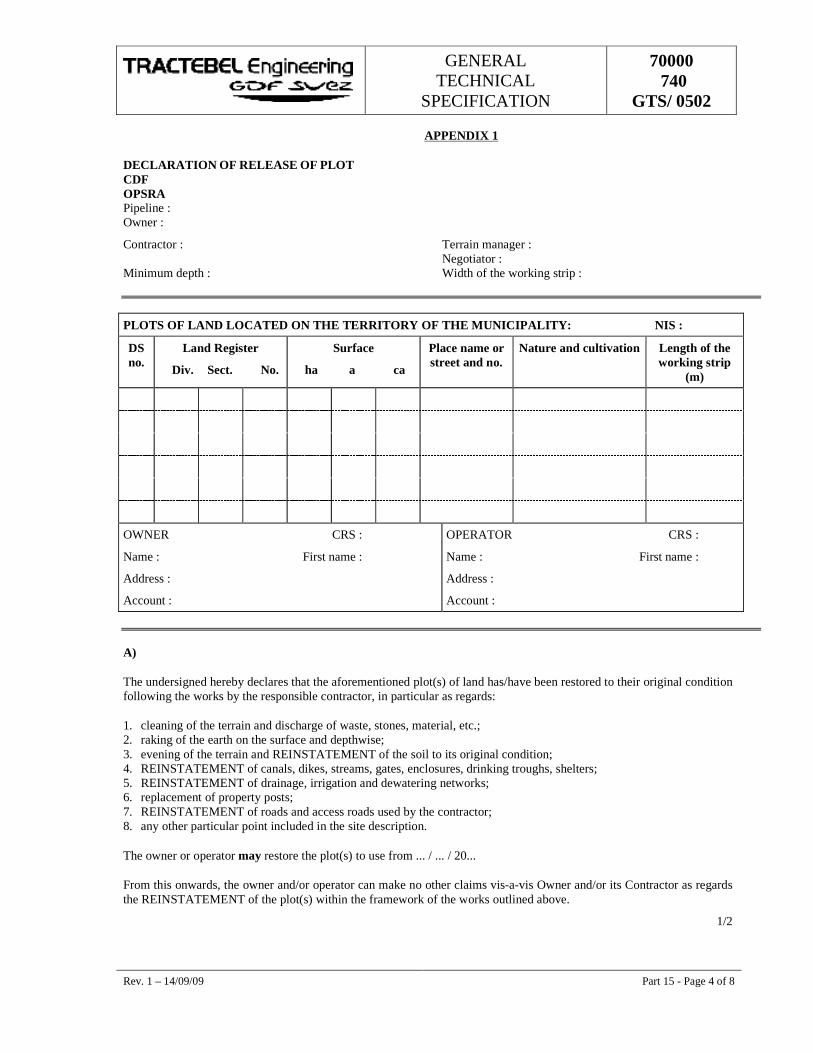
GENERAL TECHNICAL
SPECIFICATION
70000 740
GTS/ 0502
Rev. 1 – 14/09/09 Part 15 - Page 4 of 8
APPENDIX 1
DECLARATION OF RELEASE OF PLOT CDF OPSRA Pipeline : Owner :
Contractor : Terrain manager : Negotiator : Minimum depth : Width of the working strip :
PLOTS OF LAND LOCATED ON THE TERRITORY OF THE MUNICIPALITY: NIS :
DS no.
Land Register
Div. Sect. No.
Surface
ha a ca
Place name or street and no.
Nature and cultivation Length of the working strip
(m)
OWNER CRS :
Name : First name :
Address :
Account :
OPERATOR CRS :
Name : First name :
Address :
Account :
A)
The undersigned hereby declares that the aforementioned plot(s) of land has/have been restored to their original condition following the works by the responsible contractor, in particular as regards:
1. cleaning of the terrain and discharge of waste, stones, material, etc.; 2. raking of the earth on the surface and depthwise; 3. evening of the terrain and REINSTATEMENT of the soil to its original condition; 4. REINSTATEMENT of canals, dikes, streams, gates, enclosures, drinking troughs, shelters; 5. REINSTATEMENT of drainage, irrigation and dewatering networks; 6. replacement of property posts; 7. REINSTATEMENT of roads and access roads used by the contractor; 8. any other particular point included in the site description.
The owner or operator may restore the plot(s) to use from ... / ... / 20...
From this onwards, the owner and/or operator can make no other claims vis-a-vis Owner and/or its Contractor as regards the REINSTATEMENT of the plot(s) within the framework of the works outlined above.
1/2
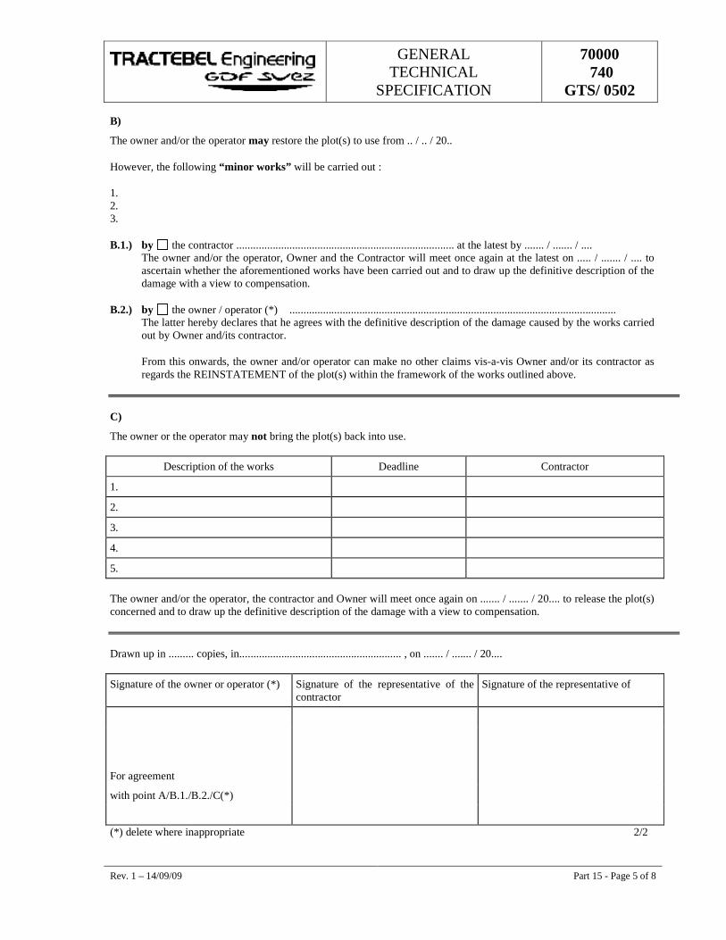
GENERAL TECHNICAL
SPECIFICATION
70000 740
GTS/ 0502
Rev. 1 – 14/09/09 Part 15 - Page 5 of 8
B)
The owner and/or the operator may restore the plot(s) to use from .. / .. / 20..
However, the following “minor works” will be carried out :
1. 2. 3.
B.1.) by the contractor .............................................................................. at the latest by ....... / ....... / .... The owner and/or the operator, Owner and the Contractor will meet once again at the latest on ..... / ....... / .... to ascertain whether the aforementioned works have been carried out and to draw up the definitive description of the damage with a view to compensation.
B.2.) by the owner / operator (*) ..................................................................................................................... The latter hereby declares that he agrees with the definitive description of the damage caused by the works carried out by Owner and/its contractor.
From this onwards, the owner and/or operator can make no other claims vis-a-vis Owner and/or its contractor as regards the REINSTATEMENT of the plot(s) within the framework of the works outlined above.
C)
The owner or the operator may not bring the plot(s) back into use.
Description of the works Deadline Contractor
1.
2.
3.
4.
5.
The owner and/or the operator, the contractor and Owner will meet once again on ....... / ....... / 20.... to release the plot(s) concerned and to draw up the definitive description of the damage with a view to compensation. Drawn up in ......... copies, in.......................................................... , on ....... / ....... / 20....
Signature of the owner or operator (*) Signature of the representative of the contractor
Signature of the representative of
For agreement
with point A/B.1./B.2./C(*)
(*) delete where inappropriate 2/2
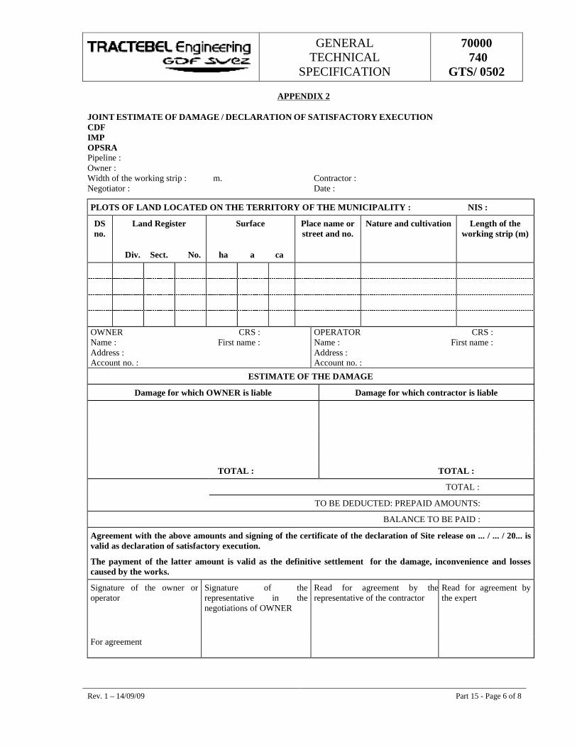
GENERAL TECHNICAL
SPECIFICATION
70000 740
GTS/ 0502
Rev. 1 – 14/09/09 Part 15 - Page 6 of 8
APPENDIX 2
JOINT ESTIMATE OF DAMAGE / DECLARATION OF SATISFACTORY EXECUTION CDF IMP OPSRA Pipeline : Owner : Width of the working strip : m. Contractor : Negotiator : Date :
PLOTS OF LAND LOCATED ON THE TERRITORY OF THE MUNICIPALITY : NIS :
DS no.
Land Register
Div. Sect. No.
Surface
ha a ca
Place name or street and no.
Nature and cultivation Length of the working strip (m)
OWNER CRS : Name : First name : Address : Account no. :
OPERATOR CRS : Name : First name : Address : Account no. :
ESTIMATE OF THE DAMAGE
Damage for which OWNER is liable Damage for which contractor is liable
TOTAL : TOTAL :
TOTAL :
TO BE DEDUCTED: PREPAID AMOUNTS:
BALANCE TO BE PAID :
Agreement with the above amounts and signing of the certificate of the declaration of Site release on ... / ... / 20... is valid as declaration of satisfactory execution.
The payment of the latter amount is valid as the definitive settlement for the damage, inconvenience and losses caused by the works.
Signature of the owner or operator
Signature of the representative in the negotiations of OWNER
Read for agreement by the representative of the contractor
Read for agreement by the expert
For agreement
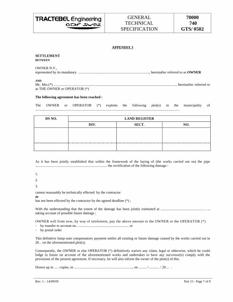
GENERAL TECHNICAL
SPECIFICATION
70000 740
GTS/ 0502
Rev. 1 – 14/09/09 Part 15 - Page 7 of 8
APPENDIX 3
SETTLEMENT BETWEEN OWNER N.V., represented by its mandatary ..............................................................................., hereinafter referred to as OWNER AND Mr, Mrs.(*) ........................................................................................................................................, hereinafter referred to as THE OWNER or OPERATOR (*) The following agreement has been reached : The OWNER or OPERATOR (*) exploits the following plot(s) in the municipality of .................................................................................................................................................................
DS NO. LAND REGISTER
DIV. SECT. NO.
As it has been jointly established that within the framework of the laying of (the works carried out on) the pipe ................................................................................ the rectification of the following damage : 1.
2.
3.
cannot reasonably be technically effected by the contractor or has not been effected by the contractor by the agreed deadline (*) ; With the understanding that the extent of the damage has been jointly estimated at ..............................................……, taking account of possible future damage ; OWNER will from now, by way of settlement, pay the above amount to the OWNER or the OPERATOR (*) - by transfer to account no.. ........................................................ or - by postal order This definitive lump-sum compensatory payment settles all existing or future damage caused by the works carried out in 20... on the aforementioned plot(s). Consequently, the OWNER or else OPERATOR (*) definitively waives any claim, legal or otherwise, which he could lodge in future on account of the aforementioned works and undertakes to have any successor(s) comply with the provisions of the present agreement. If necessary, he will also inform the owner of the plot(s) of this. Drawn up in ..... copies, in ................................................................., on ......... / ........... / 20.... .
GENERAL TECHNICAL
SPECIFICATION
70000 740
GTS/ 0502
Rev. 1 – 14/09/09 Part 15 - Page 8 of 8
Signature of the owner or operator (*)
Signature of the representative of the contractor
Signature of the representative of Owner
(*) delete where inappropriate
GENERAL TECHNICAL
SPECIFICATION
70000 740
GTS/ 0502
��������
���������� ������ ���� �����
1 14/09/09 Logo Changed SS DNS NC
0 24/03/08 Logo Changed SS DNS NC
D 16/04/04 Logo Changed MRT DKB MRY
C 06/09/00 Updated MRT AES LEP
B 05/09/00 First issue MRT DKB LEP
A 27/07/00 Preliminary draft MRT DKB LEP
Rev. Date Subject of revision Author Checked Approved
w
97_9
8_gt
s.do
t
GENERAL TECHNICAL
SPECIFICATION
70000 740
GTS/ 0502
Rev. 1 – 14/09/09 Part 16 - Page I of I
���������� �� ���
������������� ������ ������������������������������������������������������������������������������������������
������ �� ���������������������������������������������������������������������������������������������������������������������������������������
������ ��� ����������� �������������������������������������������������������������������������������������������������������������
�������� �������������������������������������������������������������������������������������������������������������������������������������
�������� �������������� !"#$"����%�����%����������������������������������������������������������������������������������������&�
�����'�� (�"��$#!��%))������������������������������������������������������������������������������������������������������������������*�
�����+�� ����,��#�)� ��%"#����)� ��))���-���������������������������������������������������������������������������������������������
���'�� ��� ���� ������� �����������������������������������������������������������������������������������������������������������
���'���� �-���������%��#�%�".��������������������������������������������������������������������������������������������������������
���+�� �� /���0�1��� ���������������������������������������������������������������������������������������������������������������������
���+���� �%������2��--%�3)2��� �"��-#�!"#����-�#%-��������������������������������������������������������������������������
���+���� -.%%#���)%-��� �"���%�� ��-������������������������������������������������������������������������������������������������
���+�'�� ��".�����4�3�))�-#���4��%".���"�)����#%"#�������#.%�-��5%�����������������������������������������������������'�
���+�+�� 6%-"���#�������#.%�7��5-���������������������������������������������������������������������������������������������������8�
���8�� ���9���� 6������� ��:��/������������������������������������������������������������������������������������������������
���8���� �%�%��)����������������������������������������������������������������������������������������������������������������������������
���8���� ���!� �)%;%)�#���-�#�������#%"#�������������������������������������������������������������������������������������������
���8�'�� �)�"����-#���)%--�-#%%)�")�����������-�#.�#�-%�;%��-�-)� ����-)%%;%-�������-%�;�"%����%)��%-��������<�
���8�+�� �)�"��������9�.�)�$-.%))-��-����#%"#���������-#� �-".���%�7�#%���#�%=���-����>���#-����
3�� �%-��� �-#�!"#!�%-�����������������������������������������������������������������������������������������������������?�
���8�8�� �%�)�"����%=�-#����-!����#-�32��%7�-!����#-����������������������������������������������������������������������?�
���8���� �%��;�)4��%������� ��%�)�"�������#.%����%$�%-�-#��#�-"�%%�-�����������������������������������������������������
���8�&�� :%) �������-#���)%--�-#%%)�-.%))-�#�����%)��%-�������������������������������������������������������������������������
������ 6��� ��� ���@���� �������� ���������������������������������������������������������������������������������������+�
�������� �%�%��)��������������������������������������������������������������������������������������������������������������������������+�
�������� �#�#!-����#.%����%�#��3%� �-"���%"#% ��� �-�%"��)����)�"�#���-����������������������������������������������8�
S S S
GENERAL TECHNICAL
SPECIFICATION
70000 740
GTS/ 0502
Rev. 1 – 14/09/09 Part 16 - Page 1 of 25
16. PARTICULAR CONSTRUCTION TECHNIQUES
16.1. GENERAL
The Particular Technical Specifications define the specific construction method to be used.
In his bid, the Contractor may suggest a different construction method. The Owner and/or the Engineer and the Recognised Inspection Organisation must approve of this method.
16.2. TRENCHLESS CROSSINGS
16.2.1. Boring
16.2.1.1. Geo technical survey report
If the Owner possesses a Geo technical report, he shall inform the Contractor of the results and mention them in the Particular Special Specifications for his interpretation. The Contractor must carry out the required supplementary tests himself if he deems that the information given to him is not sufficient.
The results will be brought to the attention of the Owner and/or the Engineer. The soil depths described in the drawings are estimated depths. Before starting the works, soundings must be carried out in order to ascertain the correct profile of the watercourse, or other obstacles to be crossed.
16.2.1.2. Working pits and shoring works
The supporting sheet piles of the working pits must always be higher than the highest possible level of the water course to be crossed so that if water breaks through there will be no danger of flooding the surrounding areas.
The calculation notes, including the design and construction method for supporting of the working pits, must be submitted by the Contractor to the Owner and/or the Engineer. However, the Contractor remains responsible for any damage or accident.
The Owner and/or the Engineer must be informed of any changes to the shorings during the works. No material may be left behind on the site. The works comprise, among other things, delivery, placing, maintenance, dismantling and removal of the provisional shorings, including driving unit parts, scaffoldings and all attendant obligations.
16.2.1.3. Casings
The casing elements to be used must be delivered by the Contractor. These pipes may be of the following types:
� approved reinforced concrete pipes;
� approved reinforced concrete pipes with steel plate core;
� approved concrete pipes reinforced with steel fibres.
Any other types are not approved by the Owner and/or Engineer.
GENERAL TECHNICAL
SPECIFICATION
70000 740
GTS/ 0502
Rev. 1 – 14/09/09 Part 16 - Page 2 of 25
If the Owner and/or Engineer prescribes a special type of casing, this shall be mentioned in the Particular Special Specifications. The section of the casing to be drive must be specified in the Particular Special Specifications or the relevant drawings. The casing elements used must comply with the following requirements :
a) They must comply with all the external loads during construction and after completion of the work. To this end, the Contractor will submit with his bid a detailed calculation note and detailed drawing for the casing mentioning all technical characteristics;
b) The casing elements (reinforced concrete or asbestos concrete pipes) must be fitted with a watertight joint able to resist at least the maximum prevailing water pressure;
c) Required tolerances of the casing elements :
� on the length of the segment : + 30 mm;
� on the inner side ˘ : + 1 cm;
� on the total thickness of the casing wall : +4 % and -2 % of the theoretical wall thickness;
� on the straightness of the casing : the straightness of the casing may deviate from the theoretical center-line at most 2.5 mm per metre.
d) Where necessary, the casing is provided with injection openings to enable lubrication of the casing during driving between the soil and the outside wall with thixotropic or equivalent fluids in order to reduce the friction between the outside wall and the soil as well as the driving force to be used. Following the driving, the lubricant must be pushed aside, stabilised or bound through injection of a mortar based on trass, lime or cement, after which the remaining cavities must be filled (blocking injection). Finally, the injection openings must be sealed with a durable air and watertight seal (e.g. a screw-cap);
e) Unless otherwise mentioned in the Particular Special Specifications, the following external pressures apply :
� soil pressure : volume weight = 2 t/m3
� dry weight = 1.6 t/m3;
� water pressure : water table level = ground level;
� traffic load : heavy convoy in accordance with relevant standard.
As far as soil covering and water levels are concerned, refer to the applicable drawings. Account must also be taken of the local soil characteristics in the soil analysis. The easing must be resistant to the various influences that may occur during transportation, handling and the driving operation itself.
16.2.1.4. The driving
If the Contractor deems that carrying out the driving is difficult or even impossible because of special circumstances (geographical situation, geology, special conditions imposed by the Particular Special Specifications, etc.), the Contractor must accordingly inform the Owner in his price bid. Otherwise, he is obliged to use all means to carry out the driving works to full completion.
The choice of the driving unit to be used for the driving of the casing as well as the method for excavation at the leading edge come under the responsibilities of the Contractor. However, he must take into account the construction requirements set by the Owner and/or the Engineer. The methodology suggested by the Contractor must guarantee reliable construction within the set timescale. The operating principle must be
GENERAL TECHNICAL
SPECIFICATION
70000 740
GTS/ 0502
Rev. 1 – 14/09/09 Part 16 - Page 3 of 25
specified by the Tenderer in his bid. In his work procedure file, the Contractor must submit to the Owner and/or Engineer a complete and detailed description of his operating method supported by calculations.
The proposed method must comply with the following conditions :
� The driving may start only after the working pits has been constructed and finished completely and the assembly between the wall and the driving unit has been carried out to the satisfaction of the Owner and/or the Engineer;
� An adapted device must guarantee sufficient pressure distribution over the walls of the working pit and the circumference of the casing;
� During construction of the bore holes for the entry and exit working pits, the Contractor must take into account all legal safety measures. He must submit for approval to the Owner a detailed description of the method of construction of these access ways;
� Approval of this method does not discharge the Contractor of any responsibility;
� During the driving process, a cutting head must be pushed gradually into the virgin soil. As the driving progresses, the soil excavated by the cutting head must be removed using a soil transportation device. The excavation face must under no circumstances go beyond the cutting head. Consequently, the excavation must always be fully lined along the sides;
� Where necessary, the works must be carried out by exercising a counter-pressure at the excavation face to prevent any water from bursting through;
� Depending on the nature of the soil, the groundwater level and the drilling shield used, this face support may consist of:
� air pressure;
� mechanical support;
� drilling fluid or equivalent;
� a combination of the above techniques.
� The front face must at all times be sealed tight against water and soil and separated from the area in which the labourers are operating the drilling shield. The cutting head must be manageable by itself and provided with the necessary guiding jacks which must be able to be driven independently;
� In case of driving with pressurised air as front support, the air pressure must be constantly maintained where there is a danger of water seepage and/or collapse. The Contractor must submit a calculation note illustrating that, under all circumstances, the front face support air pressure will preserve the equilibrium of the soil;
� The Contractor must provide all deliveries and works for the filling of any cavities that may arise at the front face;
� The casing must have a sufficient number of injection openings to enable lubrication of the casing, during driving, between the soil and the outside wall with thixotropic or equivalent fluids in order to reduce soil friction;
� After the driving operations, the injection openings must be sealed to air- and water-tightness;
� The maximum capacity of the entire driving unit must be specified by the Contractor. If this capacity is insufficient to drive the entire casing from the entry pit to the exit pit or if the driving pressure on the casing is too high, the Contractor must, where necessary, provide for intermediate driving stations;
GENERAL TECHNICAL
SPECIFICATION
70000 740
GTS/ 0502
Rev. 1 – 14/09/09 Part 16 - Page 4 of 25
� During the driving operation, the Contractor must take the following measurements:
a) measurement of the number of metres drived in, including the cutting head in each work shift of 8 hours;
b) measurement of the peak pressure of the main jacks and that of any intermediate driving stations required to start moving the casing at the commencement of the work of each work shift;
c) measurement of the centre of the cutting head in x, y and z co-ordinates after driving each pipe with an accuracy of 5 mm and comparison with a fixed center-line system independent of the driving wall and casing train;
d) the automatic recording of the front face support pressures (drilling fluid, air, soil, water).
� If the measurement reveals that the center-line of the cutting head deviates by more than 10 cm from the theoretical center-line, the Contractor must stop the work and determine with the Owner and/or the Engineer what measures must be taken to improve the manageability of the driving;
� The maximum permitted deviation throughout the entire duration of the driving process is 10 cm both vertically and horizontally measured in relation to the connection line of the centres of the boreholes in the entry and exit working pit walls. If, following the termination of the driving the deviations are greater at any point than permitted, the works will not be accepted by the Owner and/or the Engineer;
� The Contractor must submit the layout of his safety installation;
� A permanent guard must be present (on ground level) when work is carried out by workers in the casing;
� If work is being carried out with the front face supported by air pressure, the air pressure installation must be able to provide sufficient flow and pressure to turn back the groundwater; stand-by compressor unit must be provided;
� A backup electric generator must also be present to take over automatically the supply the power in case of electric power failure;
� The Contractor must take into account that the pipes used (for the casing) must be able to withstand all loads during driving without showing damages or cracks;
� Special attention must be given to the contact materials between two pipes element during the driving operation;
� The Contractor must provide for the finishing of the joints on the inside of the casing in such a way that they do not damage the pipeline and/or its accessories while being driving through.
16.2.1.5. Spacer collars
The spacer collars must be placed at 2.50 m from each other. At the extremities of the casing, two spacer collars must be placed whereby the outer spacer collars must be located at least 30 cm inside the casing.
The support points of the successive spacer collars may not be located in one line, but must be regularly staggered. The spacer collars must be supplied by the Contractor. They will be made completely of PEHD material with a minimum height of 10 cm and must be submitted to the Owner and/or the Engineer for approval.
GENERAL TECHNICAL
SPECIFICATION
70000 740
GTS/ 0502
Rev. 1 – 14/09/09 Part 16 - Page 5 of 25
16.2.1.6. Driving the pipeline through the casing
When the pipe is insert into the casing, the presence of the Owner and/or the Engineer is required. The insertion must be carried out with a sufficient number of suitable machines.
The pipeline must be kept completely in line with the casing. Damage to the coating must be excluded altogether. The progress of the pipeline in the casing must be gradual and under control. The front end of the pipe must be equipped with a slider-shoe and drawn by a cable through the casing.
16.2.1.7. Description of the works
The execution of an intersection by means of boring includes, in addition to the abovementioned works :
� The drafting of a length profile as described in Part 2, Article 2.2.4.3.;
� The preparation of the site, entry as well as exit working pit;
� The installation of appropriate road signs;
� The placement of work site warning signs in Part 2, Article 2.2.3.;
� The excavation and piling-up of the arable soil;
� The provision of thoroughfare for worksite traffic;
� The exact location and the accessibility of the complete drilling facilities;
� The excavation of the working pits up to a sufficient depth for the driving of the casing including the temporary piling-up of the soil, the necessary excavation supports, keeping the working pits and the installation dry, manipulation and removal of all necessary materials;
� The execution of all the works stipulated in the foregoing articles;
� The clearing of all excess excavation soil to a recognised waste disposal site;
� The temporary sealing of the casing ends after execution of the driving operation;
� The maintenance of the entry and exit working pits until after the tie-in with the line;
� The insertion of a PE encasement for the passage of a teletransmission cable and, where appropriate, the insertion of a HDPE encasement for the optic fibre cable if the pipe is equipped accordingly;
� The backfilling and compacting in layers of 30 cm of all excavations according to part 10.2;
� The restoration of the site according to part 15.
16.2.1.8. Filling the casing with sand and sealing the extremities of the casing
The working methods of filling and sealing the ends of the casing as proposed by the Contractor must guarantee sufficiently against subsequent subsidence at the extremities of the conduit. In any case, the method must guarantee that at least 95% of the casing will be filled with sand after filling.
GENERAL TECHNICAL
SPECIFICATION
70000 740
GTS/ 0502
Rev. 1 – 14/09/09 Part 16 - Page 6 of 25
16.2.1.9. Information to be provided by the tenderer
The Tenderer must include in his bid an outline and description of the excavation and working methods that he wishes to use as well as of the materials used both for the excavation and transportation of the excavated soil.
� Driving method: He will construct the required entry and exit working pits in accordance with his own working method. He must respect the minimum length measurements of the casing as indicated in the attached basic drawings;
� Level at the upper generatrix of the casing;
� Evaluation of the maximum driving force considered that must be taken into account;
� Number of possible intermediate driving unit;
� Planning and progress in metres per day of the casing. The Tenderer will also take the following into account while drafting his bid:
a) The drafting of:
� a driving report in which progress and any deviations must be noted daily;
� a diagram of the works showing:
� the driving forces; � progress, delays, break down, etc.; � the measured deviations.
b) The supply of:
� a (continuous) calibrated recording manometer on the main driving unit and any intermediate driving unit(s).
c) The supply of :
� the required testing and manufacturing certificates of the casing as well as the date of manufacture;
� The concrete casing must have at least six weeks of drying before they can be used; if they must be used earlier, they must at least have the strength guaranteed by the manufacturer.
d) The tolerances relating to the results.
If the Tenderer cannot adhere to the required tolerances he must mention this in his bid and must indicate and guarantee the tolerances of his driving method - all of which taking into account his experience as well as the examination of any soil tests attached to the Particular Special Specifications.
e) Before starting the works, the Contractor must have his calculations and working methods approved by the Parties concerned and by the Owner and/or the Engineeer. Furthermore, all these documents must be accompanied by the required certificates that confirm the basic data used by the Contractor;
These documents must include :
� Technical notes that define the characteristics of the Contractor’s supplies, for example: casing pipes, sheet piles, etc.;
GENERAL TECHNICAL
SPECIFICATION
70000 740
GTS/ 0502
Rev. 1 – 14/09/09 Part 16 - Page 7 of 25
� Calculations notes accompanied by sufficient justification, mainly referring to the following elements of the project:
1) The distance between the upper generatrix of the casing and the bottom of the water course, the foundations of railways and roads;
2) The sheet piles, coffer dams, supports, anchorings that form the entry and exit working pits;
3) The calculations of the settings as a result of the driving;
4) The provisions relating to injection, the use of lubricants, the construction details of the joints;
5) The casing elements during the following stages:
� during driving and over the largest possible driving length, i.e. before reaching the exit pit;
� termination of the driving, empty casing;
� during the insertion of the gas pipeline;
� the completed installation, i.e. the remaining space filled with sand.
f) For the driving of casing underneath roads and railways, the working pits are located completely outside the area bordered by a line at an angle of 45° with the horizontal starting from the outermost edge of the road or rail construction (unless otherwise indicated in the drawings);
g) The driving of the sheet piles may not start until such time as the Contractor has obtained the approval referred to above;
h) The Contractor must consider the construction of the working pits in such a way that, following driving, all provisional sheet piles can be removed. If some sheet piles cannot be pulled out and as a consequence must remain in the ground, there must be explicit agreement on this between the Parties concerned. The working floor (gravel, concrete, steel plates, etc.) must also be removed completely.
This list is not exhaustive.
16.2.2. Ramming of product-carrier pipe
The intersection to be constructed must be limited to 2 complete pipe lengths (approx. 26 m) and the pipe must be clad with adequate PE.
16.2.2.1. Description
The construction of a crossing by means of ramming with the product-carrier pipe comprises :
� The setting-up of a length profile as described in part 2, Article 2.2.4.3;
� The preparation of the construction site, both entry and exit working pits;
� The placement of appropriate road signs;
� The placement of work site warning signs as described in Part 2, Article 2.2.3;
� Excavating and storage of the arable soil;
� Provision of an access way for worksite traffic;
GENERAL TECHNICAL
SPECIFICATION
70000 740
GTS/ 0502
Rev. 1 – 14/09/09 Part 16 - Page 8 of 25
� The exact location and the accessibility of the entire ramming installation;
� The excavation of the working pits to a sufficient depth for driving by ramming the pipeline, including provisional storage of the soil, the required support, keeping the working pits and the installation dry, manipulation and removal of all required equipment (compressors, driving unit installation, cleaning installation, etc.);
� The execution of the welding joint in accordance with approved welding procedure. The crossing may contain at most 1 welding joint. The welding joint must be milled flat prior to carrying out the welding checks;
� The preparation and coating of the welding joint with previously approved coating products for ramming. The approved products in Article 9.1. are not valid for ramming method;
� The ramming of the product-carrier pipe. The removal of the soil in the product-carrier pipe may under no circumstances be carried out by compressed air. The pipe must be absolutely clean inside;
� The transportation of the surplus excavated soil;
� The temporary sealing of the pipe ends after carrying out the ramming;
� The maintenance of the entry and exit working pits until after tie-in with the line;
� The insertion of a PE encasement for the passage of a teletransmission cable and the insertion - if any - of a HDPE-encasement for the optical fibre cable if the pipe is equipped accordingly;
� The backfilling and compacting in layers of 30 cm of all excavations according to part 10.2;
� The restoration of the site according to part 15.
16.2.2.2. Working method
The working method must be described in the bid. Before starting the works, the Contractor will submit a complete and detailed description of his working method to the Owner and/or the Engineer and the recognised Inspection Organisation.
The detailed description includes :
� The working method description and illustrations of the power transfer system on the product-carrier pipe;
� The description of the Working method for the insertion of the PE/HDPE encasements;
� The static calculation of entry and exit working pits;
� A sketch on which the entry and the exit working pits are indicated, among other things;
� The welding procedures to be used;
� The coating products for the welded joints;
� The dynamic force of the driving unit, percussion frequency and duration of the operation.
GENERAL TECHNICAL
SPECIFICATION
70000 740
GTS/ 0502
Rev. 1 – 14/09/09 Part 16 - Page 9 of 25
16.2.2.3. Inspections
The ramming of product-carrier pipes must be subjected to a number of technical tests:
� The preceding technical tests for the materials;
� Radiographic and US examination of the welded joints;
� Inspection of the coating of the welded joints and the pipe with a holiday detector prior to position the driving unit;
� Systematic checks, as the progress of the pipes demands, to verify whether the work is conform to the instructions in the drawings and to the specifications;
In this regard, the following must be checked in particular:
� The prescribed profile, direction lines and level markers;
� The condition of the pipes;
� The cutting of 30 cm of pipe at the pneumatic hammer side and US (ultrasonic test) or liquid penetrant test inspection of about 30 cm of the product-carrier pipe after removal of the 30 cm pipe section;
� Inspection of the coating by the cathodic protection company after the driving of the product-carrier pipes prior to tie-in with the line. For this purpose, the uncoated extremities of the pipe must be clean and lie completely free and dry. The cathodic protection current in the not yet coupled pipeline section must not exceed 1 µA per m².
16.2.3. Micro-tunnelling
16.2.3.1. General
This construction method is limited to a maximum of 2 entire pipe lengths (approx. 26 m) and the pipe must be coated with adequate PE.
16.2.3.2. Description
The construction of a crossing by means of dry-excavating and directly driving of the product-carrier pipe includes :
� The drafting of a length profile as described in Part 2, Article 2.2.4.3.;
� The preparation of the construction site, both entry and exit working pits;
� The placement of worksite signs as described in Part 2, Article 2.2.3;
� The placement of appropriate road signs;
� Excavation and storage of the arable soil;
� Provision of an access way for worksite traffic;
� Exact location and the accessibility of the entire micro-tunnelling installation;
GENERAL TECHNICAL
SPECIFICATION
70000 740
GTS/ 0502
Rev. 1 – 14/09/09 Part 16 - Page 10 of 25
� The excavation of the working pits, to a sufficient depth, necessary for driving the pipe through, including temporary storage of the excavated soil, the required support, keeping working pits and installation dry, manipulation and removal of all required equipment (including guiding and driving unit, jacks, drilling head, electrical generator, hydraulic sets, vacuum installation, soil transport system, drilling fluid, installation, etc.);
� Execution of the welding joint in accordance with an approved welding procedure with a maximum of one welded joint in the crossing;
� The preparation and coating of the welding joint with coating products that have been approved for micro-tunnelling. The approved products in Part 9 are not valid for micro-tunnelling;
� The driving of the pipes in loose or compact soil and the removal of the excavation soil to be carried away through the pipe which has been drived in;
� This may under no circumstances be carried out by means of compressed air;
� The transportation of surplus excavated soil;
� The works arising from and accompanying the foregoing works:
� the injection of thixotropic or equivalent fluids to reduce friction;
� the temporary sealing of the pipe ends after the driving;
� the maintenance of the entry and exit working pits until after tie-in to the line;
� the insertion of a PE encasement for the passage of the teletransmission cable and the insertion of an HDPE encasement to the optical fibre cable if the pipe is equipped accordingly.
16.2.3.3. Construction method
The construction method must be described in the bid. Before starting the works, the Contractor must submit a complete and detailed description of his working method to the Owner and/or the Engineer and Parties concerned. The detailed description comprises the following, among other things :
� A description and illustrations of the power transfer system on the product-carrier pipe;
� The description of the working method for the insertion of the PE/HDPE encasements;
� The static calculation of entry and exit working pits;
� The provisions relating to the injection and use of lubricant;
� A sketch in which the entry and exit working pits are indicated;
� The welding procedure to be used;
� The coating products for the welded joints.
16.2.3.4. Inspections
The drived pipes must be subjected to a number of technical tests:
� The previous technical tests of the materials;
� Radiographic and US examination of the welded joints;
� Inspection of the coating of the welded joints and the pipe with a holiday detector prior to driving;
� Systematic checks, according to the progress the pipes, in order to verify whether the works are conform to the instructions in the drawings and/or the specifications.
GENERAL TECHNICAL
SPECIFICATION
70000 740
GTS/ 0502
Rev. 1 – 14/09/09 Part 16 - Page 11 of 25
In this regard, the following will be checked in particular:
� The described profile, direction lines and level markers;
� The condition of the pipes;
� The coating by the cathodic protection company after driving of the pipe. For this purpose, the extremities of the pipe must lie completely free and dry. The cathodic protection current in the pipe not yet coupled pipeline section must not exceed 1 µA per m².
16.2.4. Horizontal directional drillings
Refer to GTS 740/001.
16.3. OPEN TRENCH CROSSING
16.3.1. Casing in open trench
16.3.1.1. Materials
The casing elements to be used for the works must be supplied by the Contractor. They may be of the following types :
� approved reinforced concrete pipes, open trench type
� approved fibre-cement conduits, sewage type
� any other types of conduits approved by the Owner
The inner diameter of the pipe must be at least 300 mm larger than the pipe diameter.
16.3.1.2. Description
The construction of a crossing by means of a casing includes :
� The drafting of a length profile as described in Part 2, Article 2.2.4.3.;
� The preparation of the construction site;
� The placement of worksite warning signs as described in Part 2, Article 2.2.3;
� The placement of appropriate road signs;
� Location of underground obstacles by means of sounding pits;
� Excavation of the trench including temporary storage (temporary transportation where necessary) of the soil, the required support, keeping the trench dry;
� The placing of casing element on a bed of 15 cm of stabilised sand;
� The backfilling and compaction of the trench;
� The transportation of the surplus soil to an approved waste disposal site;
GENERAL TECHNICAL
SPECIFICATION
70000 740
GTS/ 0502
Rev. 1 – 14/09/09 Part 16 - Page 12 of 25
� The temporary or final repair works of the roads;
� The insertion of the pipe into the casing;
� The placement of a HDPE encasement for the optical fibre cable if the pipe is equipped accordingly for the teletransmission cable if any;
� The placement of a 2” ø PE encasement with pulling cable;
� The placement of Mg anodes, supplied by the Owner, for casing longer than 40 m.;
� The filling of the casing with sand.
16.3.1.3. Spacer collars
See Article 16.2.2.5.
16.3.1.4. Insertion of the pipe in the casing
See Article 16.2.2.6.
16.3.1.5. Filling the casing with sand
See Article 16.2.2.8.
16.4. SINKERS/SYPHONS
16.4.1. Temporary assembly and construction sites
Moving already existing structures must be the subject of a special permit issued by the Parties concerned. The Contractor must carry out or have these works carried out in accordance with the instructions and requirements of the Owner and/or the Engineer and the Parties concerned. Permanent access must always be ensured along both banks of waterway.
The constructions of dikes and support dikes, provisional access roads, coffer dams, encasement sheet piles, excavation works, protections as well as reinstatement of existing installations, more particularly banks and dikes, construction of a slipway (where necessary), may only take place after having obtained the necessary permissions of the Parties concerned.
16.4.2. sheet piles and coffer dams
The Contractor must carry out the required supplementary tests or measurements if he deems that the information (relating to currents, tides, sediment movement, soil characteristics, etc.) provided for in the Particular Special Specifications is inadequate to guarantee professional work.
The Contractor must mention this in his bid. The results of any supplementary tests must be communicated to the Owner. The top level of the temporary sheet pile screens must always be higher than the highest possible water level of the waterway to be crossed to ensure that there is no danger of flooding of the surrounding areas if water should break through. For carrying out the excavation works, the Contractor must provide for coffer dams and/or sheet piles in accordance with the soil stability.
GENERAL TECHNICAL
SPECIFICATION
70000 740
GTS/ 0502
Rev. 1 – 14/09/09 Part 16 - Page 13 of 25
The sheet piles must be constructed over both dikes in such a way as to provide for maximum safety against water break-through. For instance, at no time when the works are being carried may free passage exist between the waterway and the surrounding land, even while the sinker is being put in place. The Contractor will be held fully responsible for any damage caused by the infiltration of water through the sheet piles or coffer dams.
Important note:
The coffer dams must be designed and constructed in the area specially provided for this purpose and indicated on the basic drawing in order not to obstruct any shipping activities. In his bid, the Contractor will provide a description of:
� measurements and installation of these coffer dams and/or sheet piles;
� type and characteristics of the sheet piles provided.
The installation as well as the measurements of coffer dams and sheet piles will be subject to an implementation drawing and a calculation to be submitted to the Owner and/or the Engineer as well as to the Parties concerned for approval. This approval does not in any way diminish the responsibility of the Contractor. The ramming of the sheet piles may not commence until the Contractor has obtained the approval mentioned above.
The specifications of Article 10.1. are also applicable to the realisation of the sinker trench. For this purpose tolerances of –10 cm apply. The proposed working method must be selected in such a way that this method is in accordance with the planning, safety and stability of the entire works.
16.4.3. Anchoring, ballasting, mechanical protection of the sinker
Weight of the sinker per linear metre prior to application of a protection :
� GL = 14
p (˘ coated steel pipe)2 x weight of displaced water.
Weight of the coated pipe :
� GB = Weight 1 (steel pipe + P.E. coating) + Weight 2 protection.
� G1 = see manufacturer
� G2 = p4
(˘2 B - ˘2
L) x specific gravity of concrete.
˘B= average outer diameter of the pipe after application of the protection (based on at least 5 measurements)
˘L= ˘ coated steel pipe.
� GB/GL > 1.3 unless otherwise specified in the Particular Special Specifications
The form work used for the application of the concrete protection must be removed. The concrete protection must be at least 10 cm tick everywhere. The application there of may not damage the coating anywhere. The concrete must be reinforced. In the case of injected concrete, the Contractor must guarantee the specific gravity of the concrete.
GENERAL TECHNICAL
SPECIFICATION
70000 740
GTS/ 0502
Rev. 1 – 14/09/09 Part 16 - Page 14 of 25
16.4.3.1. Specifications relating to shipping
All floating material to be used (dredging vessels, floating derricks, pontoons, containers, tugs, etc.) must be provided with the required lighting, signalling devices, transmitter and transceiver equipment, in conformity with the requirements of the Parties concerned. In particular, during the sinking manoeuvre proper communications with the shore must be assured. The relevant instructions and requirements of the Parties concerned must be followed promptly and strictly.
The Contractor must submit the characteristics of his floating equipment for approval to the Owner and/or the Engineer and the Parties concerned in good time. In particular, all floating equipment or the accompanying support vessel must have sufficient motor capacity in order to ensure adequate manoeuvrability. Shipping may not be hindered during the dredging works; the shipping route must therefore always be freed in good time and provided with beacons according to the instructions of the Parties concerned. Non-operational floating equipment must always be moored alongside the shores according to regulations.
All work activities (profile narrowing, presence of floating equipment, etc.) must be announced through “Messages for Shipping” to the Parties concerned within the stipulated timescale. The date of the sinking works must also be announced in good time; this date may not be changed afterwards except in the case of unforeseen weather circumstances (ice-drift, fog, etc.).
16.4.3.2. Dredging
The characteristics of the soil to be dredged may be mentioned for information in the soil analysis attached to the Particular Special Specifications. If this information is not available, the Contractor himself must carry out the necessary investigations and present the results to the Owner and/or the Engineer and the Parties concerned before starting the works.
The minimum covering described on the drawings must be adhered to everywhere. The transversal banks of the temporary trench must be made in such a way as to avoid any danger of shearing and/or earth depletions that may affect the stability of constructions in the vicinity. Furthermore, the Contractor must adapt his working method to the speed of silting of the trench to be dredged.
If the Particular Special Specifications do not mention a waste disposal site, the Contractor himself must take the necessary steps. The waste disposal site must comply with the applicable legislation.
If during the dredging works it becomes clear that there are unforeseen and bulky obstacles at the bottom of the sinker trench, such obstacles must be removed to a minimum of 1 metre below the lowest generatrix line of the protected pipe. The resulting cavities must be filled with soil of which the characteristics are roughly equivalent to those of the soil from the dredging trench.
Before starting the works the Contractor must carry out a detailed sounding of the waterway to be crossed. This sounding must be repeated before the sinker is placed and after the backfilling has been carried out. In his bid, the Contractor must mention which method will be used for this sounding (determination of depth - positioning).
16.4.3.3. Sinking
The Contractor is free to suggest an alternative method of launching and sinking. He must submit this method, supported by the required calculations, for approval to the Owner and/or the Engineer and the Parties concerned. To his bid, the Contractor must attach a theoretical drawing and a detailed description that must provide clear insight into the various stages from prefabrication of the sinker on the land up to and including the process of laying it in the trench.
GENERAL TECHNICAL
SPECIFICATION
70000 740
GTS/ 0502
Rev. 1 – 14/09/09 Part 16 - Page 15 of 25
This work schedule must clearly show, among other things, which temporary measures are considered by the Contractor (including the application of temporary sheet pile constructions, coffer dams, dikes, bridge constructions, etc.) that will reduce the free profile of the waterway. If the Parties concerned do not agree with a certain working method, the Contractor must work out an acceptable working method at his own expense. The approval of a working method by the Owner and/or the Engineer and the Parties concerned, however, in no way discharges the Contractor of his responsibility in this matter.
In particular, special attention must be paid to the hoisting plan drawn up by the Contractor. It must be designed in such a way that during the entire operation no inadmissible stresses may occur in the pipeline and that there will be no danger of lateral kinking or folding. The hoisting belts may not damage either the pipe or the cladding around it.
During the sinking works, the Contractor must have sufficiently trained staff and equipment at his disposal. If necessary, the sinker must be ballasted evenly during launching, proportionate to the water displacement of the pipe during sinking. The filling of the trench may only start after measuring the correct position of the sinker and after explicit agreement by the Owner and/or the Engineer. This must be carried out with filling material that complies with the instructions of the Parties concerned and guarantees sufficient safety against floating. This must be submitted for approval to the Owner and/or the Engineer.
The filling must be carried out carefully to 1 metre above the pipe. In each case the filling soil must be free of stones, fragments or sharp objects that could damage the pipeline and its protection. The soil remaining after filling the trench and the rising banks becomes the property of the Contractor and must be transported away from the site or from the temporary waste disposal site to a recognised waste disposal site.
16.4.3.4. Crossing of bank reinforcements, sheet pile supports coffer dams, embankments, etc.
The demolition works at the crossing must be limited to a minimum area, compatible with the implementation of the work in accordance with the code of good practices. In order to render the sinker compatible in terms of stability and form with existing constructions, the Contractor must request the relevant drawings, calculations and working methods of the constructions to be crossed from the Parties concerned in good time.
If these are not available and/or provide insufficient information, the Contractor must carry out the necessary supplementary surveys (excavating test trenches, taking soundings, measuring, soil analysis, etc.). Based on the information thus obtained, the Contractor must draw up his design and construction drawings and submit them to the Owner and/or the Engineer and the Parties concerned for approval. The instructions of the latter must be strictly followed, and during reconstruction special attention must be given to the connection between old and new parts in order to avoid water seepage around and under the construction.
If certain demolition material are, in the opinion of the Parties concerned, fit to be reused after cleaning, they must be stored temporarily. Removed piles, asphalt concrete, rush mats, filter cloth, fascine mattresses, concrete, masonry, etc., however, become the property of the Contractor and must be carried away to a recognised waste disposal site.
16.4.4. Description of the works
The placement of a sinker also includes, in addition to the abovementioned works:
� The drafting of a length profile as described in Part 2, Article 2.2.4.3;
� The preparation of the worksite, for any working pits;
� The placement of appropriate road and waterway signs;
� The placement of worksite signs as described in Part 2, Article 2.2.3;
GENERAL TECHNICAL
SPECIFICATION
70000 740
GTS/ 0502
Rev. 1 – 14/09/09 Part 16 - Page 16 of 25
� The excavation and piling-up of arable soil;
� The provision of a access for worksite traffic;
� The excavation up to a sufficient depth for the placement of the sinker, including the temporary piling-up of the soil, the necessary support, keeping the work pit and the installation dry, manipulation and removal of all necessary materials;
� The execution of all works stipulated in the foregoing articles;
� The removal of all excess excavation soil to a recognised waste disposal site;
� The temporary sealing of the pipe ends after the placement of the sinker;
� The maintenance of the tie-in work pits until after the connection with the line;
� The insertion of a PE encasement for the passage of a teletransmission cable and, where appropriate, the insertion of an HDPE encasement for the optic fibre cable if the pipe is equipped accordingly;
� Backfilling according to Part 10, Article 10.2.;
� The restoration of the site according to the aforementioned articles and Part 15 of the General Technical Specifications.
16.5. ABOVEGROUND PIPELINE WORK
FOR INFORMATION ONLY.
16.5.1. General
To guarantee maximum security during Works near existing structures with underground access ways for persons, the following measures shall be taken:
• the demolition materials shall be removed immediately;
• the excavation shall be backfilled or removed the same day;
• the trenches may not remain open after 5 p.m.
16.5.2. Ground level transition protection
16.5.2.1. General note
The brand names of products used in this article are the result of a procedure approved by the Owner for treating the pipeline at above/underground transition point. It is not the intention to promote these products in one way or another. Consequently, the Contractor is free to suggest to the Owner equivalent products from other suppliers or with other brand names. The working method described here below are approved recommended method only. The Contractor must submit for approval his working method to the Owner and/or the Engineer.
16.5.2.2. Method 1 - In accordance relevant drawing
Application of Fibaroll; see part 18 article 18.5
GENERAL TECHNICAL
SPECIFICATION
70000 740
GTS/ 0502
Rev. 1 – 14/09/09 Part 16 - Page 17 of 25
16.5.2.3. Method 2 - In accordance with relevant drawing
Placing and filling of protection casing.
16.5.2.3.1. Required materials:
� Casings: these consist of concrete or fibre cement with an internal diameter that is 100 mm larger than the outer diameter of the pipe to be protected and a length of 1 metre + the nominal outer diameter. For the protection of existing pipelines two half-shells must be used. For new pipelines casings made out of one piece must be used;
� Centring collars must be placed in the middle of the part of the pipe to be protected;
� Closing device : to be placed on each end of the conduit. On new pipelines these rubber closing devices must be of the closed type;
� Other materials:
1) PU paint Voss Chemie type K6 S.
2) Liquid polyurethane, 2 components.
3) Special glue for gluing the 2 half-shells: Mono-component polyurethane-based glue, PU type Glue 10.
16.5.2.3.2. Working procedure
1) Treating the pipe
a) Existing pipe (one part painted, the other part coated):
� Remove the pipe coating in accordance with a working method recognised by the Owner and/or the Engineer;
� Cleaning the unclad part by means of a solvent;
� The coating must not be removed further than point A of the below-ground section. Point A is located at 600 mm + nominal diameter of the casing below the surface;
� Sand-blasting SA 3 or mechanical brushing ST3;
� Application of a first layer of Voss Chemie PU paint type K6 S diluted with 20% trichloroethylene;
� Application of a sufficient number of undiluted layers of K6 S to obtain a dry layer 250 microns in depth. The surface to be treated with K6 S extends from point A, below-ground section, to 50 mm past the location where the closing device is to be fixed to the above ground section, to ensure a good connection with the paint.
b) New coated pipelines:
� Pipes coated with extruded polyurethane : the placement and filling of the casing may be carried out without removing the coating;
� Pipes coated with tapes or with a damaged coating: identical treatment as for existing pipelines.
GENERAL TECHNICAL
SPECIFICATION
70000 740
GTS/ 0502
Rev. 1 – 14/09/09 Part 16 - Page 18 of 25
2) Filling the casing
a) Existing pipe:
� The casing consists of 2 half-shells that are glued on site with PU glue 10;
� The closing device must be of the open type and glued on site (Special glue for vulcanising the rubber).
� 1. In vertical position:
� placing the centring collars in the middle of the part to be protected;
� placing and gluing the 2 half-shells, centring the casing;
� placing the bottom closing device;
� filling the conduit with polyurethane in order to ensure the adhesion of the coating at point A;
� repairing the painted part of the pipe above ground level;
� securing the upper closing device after polymerisation of the polyurethane;
� repairing the layers of paint according to code 01 of the Owner.
� 2 In horizontal position:
� placing the centring collars in the middle of the casing to be protected;
� fixing and securing the 2 half-shells, centring the glued casing to connect the coating point A with polyurethane;
� placing the rubber closing devices at the extremities of the casing (to be glued by means of vulcanistion);
� filling the casing with polyurethane;
� removing the closing devices after polymerisation and examining the surfaces injected;
� retouching the layers of paint on the side where the pipe is unclad.
b) New pipe:
The filling of the casing is performed in the workshop. The conduit is filled with polyurethane in accordance with the procedure under 1.b) or 1.a) according to whether they are pipes with PE coating or not. A casing made out of one piece will be used. Further steps are according to 2. (vertical position).
The products must be applied according to the specifications of the manufacturer.
16.5.3. Placing stainless steel clamping rings that serve as sliding sleeves on in service pipelines
In accordance with relevant drawing.
GENERAL TECHNICAL
SPECIFICATION
70000 740
GTS/ 0502
Rev. 1 – 14/09/09 Part 16 - Page 19 of 25
16.5.3.1. General
Clamping rings may only be applied to pipelines that are protected with paint against corrosion in accordance with code 01.
16.5.3.2. Materials
� 2 clamping ring halves made of stainless steel 304 or 304 L, 3 mm thick;
� neoprene mat 5 mm thick;
� silicone-based sealing product;
� stainless screws.
16.5.3.3. Inspection and examination before applying the clamping rings
a) Make sure that the pipe has already been treated with anti-corrosion paint (complete 01 system) at the location of the clamping rings. The paint must be dry and hard;
b) The indicated locations must be cleaned with cloths soaked well in trichloro-ethane, solvetane or chlorothene. There may be no grease or oil, humidity, scale, etc. on the contact surfaces between the neoprene sheet and the pipe. Where a new layer of paint must be applied at the locations of the clamping rings, this layer must be dry and hard before the clamping rings can be placed (24 to 48 hours);
c) Where necessary, dry the surface prior to application;
d) Check the length and width of the neoprene sheet; its width must be 5 to 10 mm less than the width of the clamping rings, and the circumference of the neoprene sheet must be ± 1 mm less than the circumference of the pipe;
16.5.3.4. Placing the clamping rings
a) Indicate with chalk the final position of the clamping ring on the pipe taking into account that the axis of the clamping ring must lie in the axis of the support;
b) Place the neoprene sheet close to the pipe, taking into account that the seam is located on the bottom line of the pipe at the same level as the seam of the stainless steel clamping rings. For fixing the seam, adhesive tape or glue paper may be used, to be applied crosswise to the pipeline;
c) Moisten the outside of the neoprene sheet slightly with soapy water in order to facilitate the sliding of the clamping ring halves when securing;
d) Place the uppermost half of the clamping ring;
e) Place the lower half of the clamping ring;
f) Connect the two clamping ring halves with stainless steel bolts without applying excessive force to prevent the neoprene creeping between the clamping rings. The bolts must be fixed with one of the following products:
� PERMA BOND no. 118;
GENERAL TECHNICAL
SPECIFICATION
70000 740
GTS/ 0502
Rev. 1 – 14/09/09 Part 16 - Page 20 of 25
� LOCTITE Stud Loc. no. 270.
g) Filling of the space between the clamping rings and the pipe by means of silicone jointing compound that must be properly smoothed in such a way that no rainwater or condensation can infiltrate between the clamping rings and the pipe.
16.5.4. Placing of PVC half-shells as protection against discharge water at expansion joints of bridges and structures
In accordance with relevant drawing.
16.5.4.1. Materials
� Casing halves made of PVC with an inner diameter equal to the outer diameter of the pipe + 20 mm and a minimum length of 1.5 m;
� Rubber tape 20 mm thick;
� Special glue for rubber tapes;
� PVC fixing tape, “Colson” type or equivalent.
16.5.4.2. Inspection and examination prior to placing the half-shells
� The half-shells may only be placed around the pipe after being covered with a complete anti-corrosion paint treatment and after cleaning the surface to be treated;
� The rubber bands may not be glued to the pipeline.
16.5.4.3. Placing the half-shells
� Gluing the rubber bands on the PVC casing halves;
� Placing the casing halves on the pipe at the fixed locations;
� Placing the ring connection around the pipe.
N.B. : To secure the PVC casing halves only fixing clasps made of PVC may be used.
16.5.5. Replacing existing supports by new supports
16.5.5.1. Preparatory precautions
Prior to starting the works, the Contractor must:
a) Measure the position of the pipe - both vertically and horizontally - at the level of the existing support and the ground exits. The measurements must by carried out by the Contractor in the presence of the Owner’s representative. The markers must be indicated on the installation and set out in the drawing by the Contractor. One or more copies of this drawing must be permanently present on the Construction site;
b) Take all required measures to prevent stresses in the pipe;
GENERAL TECHNICAL
SPECIFICATION
70000 740
GTS/ 0502
Rev. 1 – 14/09/09 Part 16 - Page 21 of 25
c) Start by dismantling the fire protection taking into account the approved procedure. The elements of the fire protection may only be reassembled at their definitive location when the new supports have been set in place;
d) The different parts of the supports must be delivered, finished and painted. Consequently, the Contractor must take all necessary precautions to avoid damage to the paintwork during unloading at the construction site and during assembly operations.
16.5.5.2. Working method for dismantling a support
a) Check that all preparatory measures have been taken;
b) Remove sliding supports or rollers below the pipe;
c) Grind away all metal parts that will no longer be used for the mounting of the new support;
d) Sand-blast all places where welding will be carried out.
16.5.5.3. Procedure for mounting the new supports
Except otherwise stated in the Particular Technical Specification the mounting and welding of the gliders or stainless steel shells shall be made by the Contractor under the express supervision of the Owner's representative.
16.5.5.3.1. Preparatory works and precautionary measures
a) Before placing the supports the Contractor must have the Teflon plates (gliders) already mounted on the supports;
b) All new supporting parts to be welded to the structure or the already existing support must be welded over the entire circumference in order to ensure complete tightness;
c) After welding new parts to the existing support, the support must be painted completely.
16.5.5.3.2. Mounting
a) Presenting, placing, adjusting and welding of the basic parts of the support to the existing structure;
b) Presenting, placing, adjusting and welding of the lateral guides;
c) Presenting, placing, adjusting and welding of the base plate or cross beam of the support. Painting of the entire assembly after welding;
d) Assembly and adjustment of the lowest sliding plate taking account of the time necessary for the paint previously applied to dry;
e) Assembly and adjustment of the base plate or uppermost transverse plate. A clearance of 0.2 mm must be provided between the pipe and the Teflon plate;
f) After the final adjustment, paint the entire support.
GENERAL TECHNICAL
SPECIFICATION
70000 740
GTS/ 0502
Rev. 1 – 14/09/09 Part 16 - Page 22 of 25
16.5.6. Removal, repair and replacing of the fire-resistant screens
16.5.6.1. Description of the fire-resistant screen
The fire-resistant screen consists of a [-shaped plate of galvanised metal painted prior to mounting and protected on the side of the pipe with a plate of asbestos cement with natural mineral fibres.
All fire-resistant elements must be mounted on the pipe support between the pipe and the structure of the bridge over the entire length of the construction. The elements of the fire-resistant screens will nearly always be used as support for the teletransmission cables.
16.5.6.2. Procedure
Before starting the works, the Contractor, in cooperation with the Owner, must make a site description to evaluate the scope of the works to be carried out and of the materials to be replaced. To this end, each fire-resistant part will be checked for distortion as well as the asbestos-cement plates, the connections, the paintwork, etc.
16.5.6.3. Scope of the works
a) Before dismantling the fire-resistant elements, the Contractor must determine the correct location of these elements because the distances between the supports may vary. The reinforcement steel plates (150 x 6 mm) will be prepared;
b) Dismantling the fire-resistant elements;
c) Remove the existing reinforcement steel plates from the supports by grinding;
d) Repair the damaged elements, where necessary replacing the plates of asbestos-cement, retouch the paintwork;
e) Mount the reinforcement steel plates on the elements of the fire-resistant equipment (steel bars 150 x 6 mm). The holes for fixing may be drilled in the steel plates beforehand (see detailed drawing). The last two elements on the upstream side of the bridge will be shortened to allow expansion (see detailed plan);
f) The new reinforcement steel plates on the support must be mounted and welded by means of continuous welding beads;
g) After the welding of the new reinforcement plates, retouch the paintwork;
h) Assembly and adjustment of the fire-resistant elements. The corner irons must be welded free of stress so that the axes can slide easily. Furthermore, they must be lubricated when they are mounted;
i) The new parts will be painted before delivery. Consequently, the Contractor must take all the necessary precautions to avoid any damage to the paintwork.
16.5.7. Welding of stainless steel shells to pipelines
The work must be carried out according to relevant drawing.
GENERAL TECHNICAL
SPECIFICATION
70000 740
GTS/ 0502
Rev. 1 – 14/09/09 Part 16 - Page 23 of 25
16.5.7.1. Preparation
a) The marking of locations of the shells, in accordance with the instructions in the drawing and specifications, taking into account the expansion of the pipe, in such a way that the welding of the shells remains at a distance of at least 300 mm from the welded joints of the pipes. If this distance is unfeasible, it may be reduced provided that supplementary checks are made of the round seam weld of the pipe;
b) Cleaning by sandblasting (Sa 3) or mechanical brushing (St 2.5) of the area(s) before placing and welding the stainless steel shells;
c) U.S. and E.M. inspection of the area concerned of the pipe before welding the shells;
d) Inspection of the outer diameter of the pipe at places where the stainless steel shells will be welded;
e) Apply the shells to the pipe and tighten them using a special tool intended for this purpose (clamping ring or chain) after, where necessary, grinding away the surplus thickness of the existing lengthwise weld on the pipe leaving a surplus thickness of 0.5 mm on the welding joint.
16.5.7.2. Welding procedure for stainless steel shells, stainless steel 304L, on above ground pipes to be laid or on existing pipes which are not in service or under pressure
The procedure is valid for welding on pipes made of steel API. Gr.B up to X60 with wall thicknesses of at least 4.5 mm and with a cooling rate limited to 75ºC/minute with min. temp. of 80ºC at the welding end.
16.5.7.2.1. Electrodes to be used
� Soudochrom L309 L.N.D. 2.5 mm;
� Soudochrom A.D. D.N. 2.5 mm exclusively for downward welding.
16.5.7.2.2. Inspection of the pipe before welding
U.S. inspection according to ASME V, art. 5 and API 1104 assessed according to ASME VIII, Div. 1, App. 12 and E.M. inspection according to ASME V, Art. 7 and acceptance criteria according to ASME VIII, Div. 1, App. 6 and API 1104.
If during inspection an error is discovered, another location must be chosen or if necessary a section of the pipe will be replace. Where necessary, however, the welding joint must be ground with a surplus thickness of approximately 0.5 mm, among other things for helical seam welded pipes or longitudinal seam welded pipes. The pipe must be perfectly cleaned, free of grease, scale, residue of metallisation and humidity.
16.5.7.2.3. Welding sequence
� Press the stainless steel shell solidly against the pipe by means of the appropriate tools;
� Pre-heat.
a) For the lengthwise welding of stainless steel shells:
The entire surface of the shells must be pre-heated with a burner to ± 100º C in order to remove all traces of humidity between the pipe and the shell. Weld in accordance with the indicated sequence 1-2-3-4 on fig. 1 and/or 2.
GENERAL TECHNICAL
SPECIFICATION
70000 740
GTS/ 0502
Rev. 1 – 14/09/09 Part 16 - Page 24 of 25
b) For round seam welding:
Pre-heat the pipe with a burner to 150 - 200 º C. Try to avoid heating the shell to such an extent that it might come loose from the pipe by expansion. Carry out the entire welding joint A following the sequence of the arrows of fig. 1 and/or 2, after which the same working method must be repeated for welding joint B. After welding, the shell must be neutralised, cleaned and polished with a product approved by the Owner (passivation - Betspastor type, AVESTA-JOHNSON & Co. N.V.).
16.5.7.2.4. Inspection after the welding
The welding seams must be thoroughly checked 100%.
16.5.7.2.5. Welding procedures approved by a recognised inspection organisation
The Contractor shall submit for approval the welding procedure he intends to use.
16.5.7.2.6. Special conditions for painting the round seam welds of the stainless steel shells welded on pipelines
The round seam welds between the stainless steel shells and the steel pipe must be protected against atmospheric influences by painting. To this end, a collar of approx. 20 mm at both ends of the stainless steel shell must be sand-blasted (Sa 3) or mechanically brushed (St 2.5) and painted in accordance with system code 01 approved by the Owner.
During these operations, the central parts of the stainless steel shells must be protected against sand-blasting or stripping. These parts must remain polished in order to facilitate the sliding of the shells on the Teflon sliding supports.
16.6. DISCONNECTING EXISTING PIPELINES
FOR INFORMATION ONLY.
16.6.1. General
The Particular Special Specifications determine which parts of the pipes must be disconnected. The interventions under gas will be carried out by the Contractor well trained team with a recognised experience and the Contractor will also carry out the following work :
� The required excavation works in accordance with the specifications of the G.T.S. Part 10;
� The removal of the existing coating as described in part 9 over the entire length of the working pit except for 0.5 metres along each extremity;
� The supply of all materials and the execution of all work as described in Art. 19.8.2. according to the specific status and service pressure of the pipe;
� The removal of the pipe parts indicated in the P.T.S. (valve station, sample pieces, etc.);
� The restoration of the site in accordance with G.T.S. Part 15;
� The transportation and unloading of the pipeline parts indicated in the P.T.S. to the worksites of the Owner.
GENERAL TECHNICAL
SPECIFICATION
70000 740
GTS/ 0502
Rev. 1 – 14/09/09 Part 16 - Page 25 of 25
The Contractor will supply all the materials that are not included in the parts lists.
16.6.2. Status of the pipe to be disconnected and special applications
16.6.2.1. Disconnection of pipelines to remain in service
a) Low-pressure pipes (£ 14,7 bar):
The pipe must be disconnected with a conical terminal plug with a 1” vent. The Owner will supply the end cap and the materials for the 1” pressure release point. The Contractor will carry out all the necessary works in accordance with the relevant drawing.
The 1” pipe Sch.80 of the pressure release point must be bent cold by the Contractor. All welding seams must be tested non-destructively (Rg for butt welding and liquid penetrant testing for the corner welded seams). The Contractor will deliver and place an approved 16 mm² cable in accordance with G.T.S. Part 13. The welding of the terminal part to the pipeline is carried out by the Contractor well trained team. The Contractor must carry out the required coating works in accordance with G.T.S. Part 9. The tie-in joint must be soaped at 6 bar and at operating pressure.
b) High-pressure pipelines > 14.71 bar:
The pipe must be disconnected with an end-piece in accordance with the relevant drawing. The Contractor will deliver all materials in accordance with the parts list. The Contractor must construct the end-piece in accordance with the drawing mentioned above. All welded joints must be radiographied. The Contractor will carry out a resistance test (1.4 x M.O.P.) and a leak test (soaping at 6 bar). The tie-in joint will be carried out by the Contractor well trained team, radiographied and soaped at 6 bar and operating pressure. The Contractor will supply and place an approved 16 mm² cable in accordance with G.T.S. Part 13 and carry out the coating work in accordance with G.T.S Part 9.
16.6.2.2. Disconnecting pipelines to be left behind permanently
The pipe must be disconnected with a terminal cap in accordance with the relevant drawing. The Contractor will supply all materials in accordance with the parts list. The Contractor will construct the end cap in accordance with the relevant drawing and weld it to the existing pipe after rinsing it with nitrogen and after the Owner and/or the Engineer's approval.
The Contractor will deliver the nitrogen required for rinsing the pipe. The Contractor will deliver and place an approved 50 mm² cable in accordance with G.T.S. Part 13 and will carry out all the coating works in accordance with G.T.S. Part 9. The Contractor will fill the pipe to be left with nitrogen with an over-pressure of 100 gr.
S S S
GENERAL TECHNICAL
SPECIFICATION
70000 740
GTS/502
��������
���� ���
1 14/09/09 Logo Changed SS DNS NC
0 24/03/08 Logo Changed SS DNS NC
C 16/04/04 Logo Changed MRT DKB MRY
B 06/09/00 First issue MRT DKB LEP
A 27/07/00 Preliminary draft MRT DKB LEP
Rev. Date Subject of revision Author Checked Approved
w97
_98_
gts.
dot
GENERAL TECHNICAL
SPECIFICATION
70000 740
GTS/502
Rev. 1 – 14/09/09 Part 18 - Page I of II
���������������
�
� ��������������������������������������������������������������������������������������������������������������������������������������������
������ ������������������������������������������������������������������������������������������������������������������������������������������
�������� �� ��� �������� �����������������������������������������������������������������������������������������������������������
�������� � �� �� � ������������ ������������������������������������������������������������������������������������������
����� �� � �� �� ����!"��#����������������������������������������������������������������������������������������������������������
�����$�� ���"%���������������� ����������������������������������������������������������������������������������������������������
������ ��������&'��'(��)��*+�(���*���������������������������������������������������������������������������������������������� �
�������� �����!��������� �������������������������������������������������������������������������������������������������������� �
�������� *��,!���%�������������������������������������������������������������������������������������������������������������������� �
����� �� -������!��!��%����������������������������������������������������������������������������������������������������������$�
�����$�� -���!�������%��������������������������������������������������������������������������������������������������������������.�
�����.�� �������� � �������������� "�����������!�#��� ������������ ���� �����������������������������������.�
�����/�� �������� � ������������ "������������!�������!�#����������� ������������%����� ���������%����������������������������������������������������������������������������������������������������������������������/�
�����0�� �������� � ��� ������ ���������!����������������������������������������������������������������������������/�
�������� +��� ��� !"��������������������������������������������������������������������������������������������������������������������/�
�����1�� � �� � ����������!������������%����������������������������������������������������������������������������������/�
������2�� ��� "%�� ��%��� �������������!�������������������������������������������������������������������������������0�
��� �� -�����&*��&'������������������������������������������������������������������������������������������������������������������������0�
��� ���� ���!#%���������!!��� ��������������������������������������������������������������������������������������������������0�
���$�� ����3&���'+���)����&��4'�5����������������������������������������������������������������������������������������������0�
���$���� � �� ��� ������#%� ������� �����������������������������������������������������������������������������������0�
���$���� *����!�� �� ����������������������������������������������������������������������������������������������������������������
���$� �� ������� ��� �,�������������������������������������������������������������������������������������������������������������
���$�$�� -��� �� �����!��� ��������������������������������������������������������������������������������������������������������1�
GENERAL TECHNICAL
SPECIFICATION
70000 740
GTS/502
Rev. 1 – 14/09/09 Part 18 - Page II of II
���$�.�� ���!��� � ������� ��%��������������������������������������������������������������������������������������������������1�
���$�/�� ����� ��%������������������������������������������������������������������������������������������������������������2�
���$�0�� (��%������!�%��6����� �����������6��������������������, !�����������������������������������������2�
���.�� ��'+�78��9�������*&�&'���'&���������������������������������������������������������������������������������������������
���.���� � !#�������� ���� ��#����������������������������������������������������������������������������������������������������
���.���� ����� ��� ���� ��#���������������������������������������������������������������������������������������������������
���/�� +*��'(�*��(('�7&�����������������������������������������������������������������������������������������������������������������
���0�� :+��&�3��'���'�*���7��+�����������������������������������������������������������������������������������������������
���0���� &����� � ������� ���������������������������������������������������������������������������������������������������������
���0���� �����������������������������������������������������������������������������������������������������������������������������
���0� �� -��������� �,�������������"��� ����������������������������������������������������������������������������� �
���0�$�� ������������������������������������������������������������������������������������������������������������������������������ �
������ ��'7+��*��)'*���;3��)��'4����<('��&�('�-��&'��'��3=������������������������������������������������.�
���1�� *+�(�������������+���&'�*����������������������������������������������������������������������������������������������� .�
���1���� �����������%������������������������������������������������������������������������������������������������������������� .�
���1���� � ������ ��!���������������������������������������������������������������������������������������������������������� .�
���1� �� *�����������6�����>�, !������������������������������������������������������������������������������������������������ .�
S S S
GENERAL TECHNICAL
SPECIFICATION
70000 740
GTS/502
Rev. 1 – 14/09/09 Part 18 - Page 1 of 45
� � ���������
����� �����!�
������� �� ��� �������� �����
The term system will be taken to mean the whole of two or more layers that will be applied consecutively to the base to be protected and which must finally constitute the homogeneous, continuous and sealed protective layer.
The Contractor will consult the paint manufacturer for the technical description of the paint systems stipulated in Article 18.8 of these specifications. The chosen paint systems will be included in the price quotation. The Contractor will indicate the methods of application for the different systems and the environmental conditions.
The Contractor will refer to the paint supplier of his choice to obtain all the guidelines for the addition of additives and solvents to obtain the required finish regardless of the environmental conditions of temperature and wind speed and the method of applying the coats (brush, roller or spray gun).
��������� �� �������� ���,#�����'����
FOR INFORMATION ONLY
The Owner has selected complete paint systems with a number of paint manufacturers for different applications. The selected systems along with the conditions for use and application are specified by the paint manufacturer in Article 18.8 of these Specifications.
Article 18.8 defines the systems to be used.
��������� �"� ����8��%%����"�����
When a particular part of work is being carried out, the painting system should be chosen in accordance with the environment in which the material to be painted will be located. Indeed, the degree of aggressiveness of the atmosphere that will be encountered in the environment of the work can range from an environment which is not very aggressive to an extremely aggressive environment, depending on whether the location is in a rural area, a non-industrial built-up area, ventilated workshops, in the vicinity of the sea, at chemical plants, in humid rooms or in the vicinity of sources of cold or heat.
Taking account of these uncertainties, different painting systems can be recommended, and it is consequently important to mention at the time of the invitation to tender the degree of aggressiveness in which the material to be painted will be located so that the Contractor can mention this to the supplier of the paint products to determine the system to be applied.
������� � �� �� � ������������ �����������
��������� :��!�#�
The composition and quality of the products may not differ from batch to batch. A batch is all of the products of a specified manufacture. If the analyses of products bring to light that the composition does not conform to the specifications of the paint manufacturer, the Owner may refuse to use this batch of products. The paint products must comply with the following conditions:
GENERAL TECHNICAL
SPECIFICATION
70000 740
GTS/502
Rev. 1 – 14/09/09 Part 18 - Page 2 of 45
� they must have the viscosity necessary for the described use and the established condition: use of the brush - paint roller (spray gun only for special cases and in the workshop).
Thinning on the building site of paint products with two components will be carried out in accordance with the specifications of the supplier.
��������� :��!�#�� �� !�8�*���!%�
While the works are in progress on the construction site, the Owner and/or the Engineer may carry out sampling on the paint being used for the purpose of checking conformity. The paint products must be made available free of charge to the laboratory or the approved supervisory body in sufficient quantities so that all the tests can be carried out on the same batch.
If the analyses reveal a non-conformity in the composition of the products used (tolerance of + 3 % of the dosage of every component), the Owner and/or the Engineer may refuse application of the product under consideration, halt the work and have the nonconforming product already applied removed.
Before proceeding with the work, a product that does conform will be required. The only purpose of the analyses is to reveal any nonconformity of the composition of the products. Their purpose is therefore not to assess the quality of the different components. The analyses concerned are not acceptance tests of the products supplied and in no way affect the obligations of the Contractor specified in the contract towards the Owner.
����� � � �� �� ����!"��#��
����� ��� �����%%�
Every recipient will be fitted with a hermetically-sealed lid with an opening that is sufficiently large to allow the contents to be stirred; the outside and inside are protected against oxidation, and, like the lid, are marked with a strip of colour identical to the contents.
����� ��� &������� �
Every recipient will bear the following information:
� name of the manufacturer;
� date and number of manufacture;
� name of the product type;
� net weight of the product or the contents of the recipient.
At the time of delivery, this packaging must be bear labels in conformity with the legal stipulations in force.
�����$� ���"%���������������� ���
After completion of a job, a general clean-up shall be carried out by the Contractor to remove all debris, materials or irregularities that his work has brought to the site so that it is left tidy.
The restoration work includes, among other things:
GENERAL TECHNICAL
SPECIFICATION
70000 740
GTS/502
Rev. 1 – 14/09/09 Part 18 - Page 3 of 45
� the removal of abrasives;
� the removal of the different protective coverings;
� the Contractor will make the required repairs to any damage after refitting the supports;
� the removal of paint and cleaning of the stains on the floor.
����� �������� � ������*��������
������� �����!��������� ��
The cases that occur in practice on building sites, with regard to painted surfaces, can be broken down as follows :
� material of which the oxide content disappears by natural oxidation;
� material that has already been covered with a layer of paint in the workshop;
� material that is covered with old paint layers that show different degrees of weathering.
Good preparation of the surface is the best guarantee for good anti-corrosion protection.
Paintwork may never begin until the surface to be treated is dry and is independent of the base coat and cleared of dirt, dust, rust, scale, grease, salt attack, cement powder, cement mud-scale, sand, oil, etc.
The method of preparation of the surface will be implemented in accordance with the preparation methods described below:
� cleaning (bright blast-cleaning);
� mechanical cleaning;
� manual derusting.
The Contractor should have the required material at his disposal to clean the surfaces to be coated thoroughly in accordance with the preparation methods specified in Article 18.2, regardless of the form or the condition of such surfaces. Devices that might be damaged during the preparation will either be taken away by the Owner or screened off by the Contractor. The latter will inquire about this during his exploration of the site for the works.
������� *��,!���%�
Before beginning cleaning by blasting, the person carrying out the work will take the following measures:
� clear the steel surface of oil and/or grease;
� ensure that each flange collar (section where the sealing is applied) is properly screened off against the blasting and the subsequent works;
� check that no blasting grains can get into the pipes during this process. Any openings not sealed off must be screened off;
GENERAL TECHNICAL
SPECIFICATION
70000 740
GTS/502
Rev. 1 – 14/09/09 Part 18 - Page 4 of 45
� where there are valves, regulators and other devices, the manufacturer’s identification plate will be dismantled so that all surfaces can be treated. The plate will then be put back again;
� screen off all non-metal structures such as rubber where there is a filter;
� with valves, operators and other devices, care should be taken to ensure that no metal filings or paint get into the apparatus;
� the Owner reserves the right to carry out or all of these works himself.
To prevent rust forming quickly as the result of humidity on the blasted surface, cleaning by blasting may only be carried out when the temperature of the steel surface is at least 3°C higher than the dew-point of the ambient air.
Blasting may not be carried out if the relative degree of humidity exceeds 80 %. The choice of the type of blasting medium used depends on local circumstances such as the possible presence of gas and the material to be blasted - e.g. INOX (stainless steel).
The abrasive to be used must conform to the local low i.e. it may contain no carbon and less than 1 % free silicone dioxide. The Sa 3 will always be requested and must at least reach Sa 2 1/2 during the initial stage of the paintwork. For blasting followed by metallisation, the surface preparation degree to be achieved is always Sa 3. The degree of cleanliness to be obtained will be inspected in accordance with the Swedish standard SVENSK STANDARD ISO 8501-1-1988 SS 05.5900.
� Sa 3 : surface blasted down to the bare metal; when the surface is inspected with a magnifying glass, scale, rust and foreign bodies must be completely removed and it should be possible to raise a metallic shine on the treated surface;
� Sa 2 1/2: blasted very carefully. Scale, rust and foreign bodies must be removed in such a way that anything left behind will only be visible as nuances (shading) or strips.
The blast-cleaning will be carried out by means of compressed air free of water and oil.
After the blasting and before painting, the surface should be completely cleaned of blasting material and so forth with a soft brush, a dry cloth or dry compressed air.
����� � -������!��!��%�
If sandblasting is not permitted or if the metal structures are not easily accessible for blasting or blasting for one reason or another is technically unfeasible, mechanical derusting can be used instead. With mechanical cleaning by means of chipping, rotating steel brushes and sanding discs, a degree of cleanliness St 3 should be reached.
� St 3 : removal of the old paint layers of which the adhesion leaves something to be desired and/or of which the paint layer no longer fulfils the requirements.
If parts are present that are so corroded that St 3 is difficult to achieve, this should be notified to the Owner’s representative prior to the start of the works.
N.B. :
� St 3 : means removal of every old paint layer. Retouching means local polishing with St 3 or Sa 3 followed by application of the desired painting system.
GENERAL TECHNICAL
SPECIFICATION
70000 740
GTS/502
Rev. 1 – 14/09/09 Part 18 - Page 5 of 45
After mechanical cleaning, the surface should be made dust-free with a cloth or a soft brush, washed with an organic solvent and thoroughly dried off with a dry cloth (e.g. with 1.1.1. Trichloroethane such as Solvethane, Chlorothene NU).
�����$� -���!�������%�
Manual derusting with the aid of scrapers, steel brushes, sandpaper etc. shall only be permitted in exceptional cases for local repairs. Any deviation therefrom must be requested from the Owner and/or the Engineer.
With manual derusting, a surface preparation degree St 3 must be obtained. The length of the handles of the equipment used may not exceed 50 cm.
�����.� �������� � �������������� "�����������!�#��� ������������ ���� ��
This layer is in general applied by the manufacturer, for example, on valves, regulators, etc. Layers of this kind will be checked for their proper adhesion in accordance with ASTM D3359, method A. The adhesion should be at least 4A (see APPENDIX 1).
If the paint layer shows less adhesion or is incompatible with the rest of the system, it should be completely removed (see also Article 18.2.6.). If the paint layer is not removed, the Contractor accepts it in the state in which the coating is found and the guarantee remains in force. The adhesion does not have to be examined if system 63 has already been applied in the workshop on behalf of the Owner.
The Contractor, who must provide for the protection on the construction site, must therefore obtain the information regarding the treatment of the surface and the quality of the paint that was used and must, moreover, examine the adhesion of the layer on the construction site, the percentage of damage and weathering as well as the value of the preparation of the surface in the workshop together with the thickness thereof that must be supplemented if necessary.
�����.��� ��!"��������������
Galvanised surfaces, both old and new, will be carefully roughened up. Every foreign body (concrete splatters, chalk marks, grease and oil stains, etc.) will be removed. Thereafter, rub the surfaces with abundant water and, if necessary, with cleaning products.
To this end, nylon brushes will be used for every kind of dirt as well as for removing zinc salt residue. Thereafter, the surfaces will be treated in accordance with system 21. Where the zinc layer is lacking, it will be derusted manually to a degree of cleanliness St 3, after which a primer coat will be applied in accordance with system 22.
�����.��� -���!!�������������������������������%�� �!�#���
� degrease with the desired degreasing product;
� clean under high pressure or with a product prescribed by the paint supplier.
If the paint layer adheres well and is applied on a clean base, the painting system described may be continued (see Article 18.8). If the percentage of damage and weathering does not exceed 5 %/m, retouching may be considered. These partial repairs will be carried out in accordance with the stipulation in Article 18.8.
GENERAL TECHNICAL
SPECIFICATION
70000 740
GTS/502
Rev. 1 – 14/09/09 Part 18 - Page 6 of 45
If, on the other hand, the percentage of damage does exceed 5 %/m or if the layer applied in the workshop comes loose, the Contractor must draw the attention of the Owner to this and carry out the complete application system in accordance with Article 18.8.
�����/� �������� � �� ��������� � "����� ���� ���!��� ���� !�#���� ����� �� �� �������� ��%����� ���������%�
If the surfaces do not show deep weathering limited to the spread of rust by small pitted areas or non-penetrative rust in spots, it will very often be sufficient to clean the surfaces with abrasives or with an abrasive disc, then to rub them down with steel wool, remove the dust and wash off. If thick rust appears, in spots, scale rust and active rust canker, this should be removed with needle hammers or stripped away directly by blasting, removing the dust and washing off.
�����0� �������� � ��� ������ ���������!����������������
Remove unsound paint layers and loose components with scrapers, blades or rotating steel brushes. Thoroughly clean the entire surface with water containing ammonia. Thoroughly remove moss, algae and fungal growths. Where these growths have been removed, treat the area with a fungicide in accordance with the instructions for use.
Once the entire area is completely dry, brush off the dead residue of moss, algae and fungus with a hard brush. In the case of reinforcement steel that has been laid bare, remove as much rust, dust and grease as possible and treat it with a primer coat. When painting concrete surfaces, they must first be checked for cracks. Cracks larger than 0.3 mm must be repaired with an appropriate system in accordance with the type and extent of the repairs (e.g. injection with epoxy mortar). Repair damage such as cracks and bursts to concrete parts with a two-component mortar or preferably with micro-mortars. Finally, check the alkalinity of the surface with the aid of litmus paper and neutralise it if necessary.
������� +��� ��� !"����
It is sometimes necessary to use solvents when the surfaces to be painted are streaked with grease or oil. In this case a suitable organic solvent should be applied. The operation should be carried out with the aid of clean brushes or rags and clean solvent.
All the legal specifications in connection with solvents etc. must be adhered to. The Owner and/or the Engineer will be informed in advance of any toxicity or flammability. All measures must be taken to prevent any risk of fire and to rule out any possibility of poisoning (ventilation). The Contractor will provide drip collectors to keep the environment free of pollution.
�����1� � �� � ����������!������������%�
The Contractor must call in a representative of the Owner and/or the Engineer or of the Approved Supervisory Body responsible for checking the condition of the metal during stripping and informing the Owner and/or the Engineer immediately of any damage that he might have noticed:
� deep corrosion of the plates - rivets – bolts;
� faulty welding;
� fittings that appear to be dangerous because of their age
GENERAL TECHNICAL
SPECIFICATION
70000 740
GTS/502
Rev. 1 – 14/09/09 Part 18 - Page 7 of 45
������2� ��� "%�� ��%��� �������������!����
The Contractor must have the equipment necessary for the removal of asphalt from the pipe without damaging the latter (scratching, impact, etc.). The Contractor undertakes to carry out the work in accordance with an approved procedure.
��� � -�����&*��&'��
��� ��� ���!#%���������!!��� �
� Metallisation must be carried out in accordance with ISO 2063;
� Metallisation is carried out as rapidly as possible after blasting in order to limit corrosion of the pipes (max. 3 hours later). With metallisation, a surface preparation degree Sa 3 is compulsory. The roughness of the blasted surfaces should be from 25 to 50 m Rmax ;
� The metallising is always carried out on dry parts in good weather conditions (maximum relative humidity 80 %);
� For metallisation, a wire composed of 85 % zinc and 15 % aluminium with a minimum guaranteed degree of purity of 99.5 % is used (subject to other specifications). The application thereof is always carried out in accordance with the conditions of the manufacturer and may at all times be submitted to the Owner’s representative;
� The sealant should be applied maximum 3 hours after metallisation;
� The sealant must be thinned and applied in accordance with the tables in Article 18.8 of the present specifications. A visual inspection whereby the sealant completely covers the metallisation will suffice here;
� When evaluating the metallisation, a negative deviation from the minimum coating thickness, as prescribed in the tables in Article 18.8, to 80 m for 20% of the measurements will be permitted.
N.B.:
For the metallisation of the surfaces that are exposed to high temperatures such as chimneys, ZINACOR 850 (85/ZN/15 AL) will be used of which the systems are defined in Article 18.8 of the present "Specifications for Paintwork" (syst. 51 - 51a).
���$� ����3&���'+���)����&��4'�5�
���$��� � �� ��� ������#%� ������� ����
Painting may not be carried out in unsuitable conditions.
All preparatory work and painting may only be carried out in dry weather and at a minimum temperature of 10°C, except for special cases requested by the Owner and/or the Engineer.
Unless otherwise stipulated in the specifications of the paint supplier, application of the paint is forbidden if it is forecast that the temperature will fall to below 0°C before the paint is dry. The temperature of the surface to be painted must be at least 3°C higher than the dew point of the ambient air. Application of the paint is also not permitted if there is a danger that the coat of paint will not be dry before dew or condensation sets in.
GENERAL TECHNICAL
SPECIFICATION
70000 740
GTS/502
Rev. 1 – 14/09/09 Part 18 - Page 8 of 45
The work must be stopped:
� if the temperature of the surface to be painted is higher than that described by the supplier;
� in rain, snow, mist or fog or when the relative humidity is higher than 80 %.
Coats that have not yet dried and have been exposed to frost, mist, snow or rain and might thereby be damaged must be removed after drying and the surfaces must be repainted at the expense of the Contractor.
Working in direct sunlight or in hot weather must be avoided.
The first coat of paint must be applied maximum 3 hours after the preparation of the surface if the relative humidity of the air is between 50 % and 80 %. This time span may be increased to 6 hours if the relative humidity is less than 50 %. In all cases, the preparation of the surface must exhibit degree Sa 3 and at the very least the appearance of degree Sa 2 ½ at the time of painting.
The coats of paint may only be applied on carefully cleaned surfaces that must be dry and free of grease and dust.
���$��� *����!�� �� ��
Painting may be carried out when the Contractor can be sure that the instructions of the paint supplier have been scrupulously followed with regard to the parameters in the following (non-exhaustive) list:
� ambient temperature;
� surface temperature;
� relative humidity;
� dew point;
� drying times.
The Contractor must in this respect be able to produce the instructions for the paint on the site. The Owner will guarantee 100% supervision in this regard during the execution of the work.
In addition, the paintwork may only be carried out to a minimum ambient temperature of 5°C and/or to a maximum relative degree of humidity of 85 %. Application of the paint is also not permitted if there is a danger that the coat of paint will not be dry before dew or condensation sets in.
���$� � ������� ��� �,�������
Neither the environment of the site nor the marking labels of devices may be covered with paint, and they must be kept free of paint splashes. To this end, it is advisable to use removable masking tape.
Paint splashes, leaks, etc. on any adjacent installations such as measuring apparatus, valves, pipes, sources of light, insulation, heat insulators, walls, concrete, etc. must immediately be wiped up and the damage repaired before the paint is dry.
Otherwise, the Owner will be obliged to have the cleaning carried out at the expense of the Contractor. The paint recipient will only be opened at the time of use (unless otherwise specified by the manufacturer).
The product will be mixed in the recipient with the aid of suitable tools and thus homogenised.
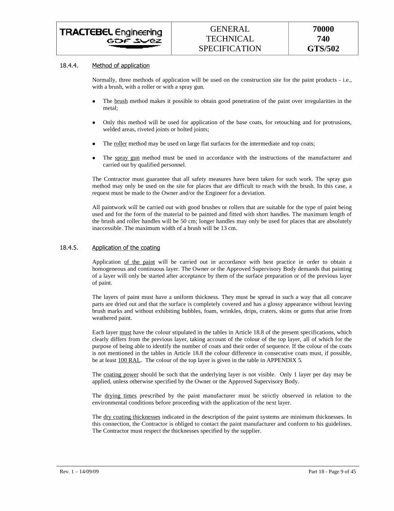
GENERAL TECHNICAL
SPECIFICATION
70000 740
GTS/502
Rev. 1 – 14/09/09 Part 18 - Page 9 of 45
���$�$� -��� �� �����!��� �
Normally, three methods of application will be used on the construction site for the paint products - i.e., with a brush, with a roller or with a spray gun.
� The brush method makes it possible to obtain good penetration of the paint over irregularities in the metal;
� Only this method will be used for application of the base coats, for retouching and for protrusions, welded areas, riveted joints or bolted joints;
� The roller method may be used on large flat surfaces for the intermediate and top coats;
� The spray gun method must be used in accordance with the instructions of the manufacturer and carried out by qualified personnel.
The Contractor must guarantee that all safety measures have been taken for such work. The spray gun method may only be used on the site for places that are difficult to reach with the brush. In this case, a request must be made to the Owner and/or the Engineer for a deviation.
All paintwork will be carried out with good brushes or rollers that are suitable for the type of paint being used and for the form of the material to be painted and fitted with short handles. The maximum length of the brush and roller handles will be 50 cm; longer handles may only be used for places that are absolutely inaccessible. The maximum width of a brush will be 13 cm.
���$�.� ���!��� � ������� ��%��
Application of the paint will be carried out in accordance with best practice in order to obtain a homogeneous and continuous layer. The Owner or the Approved Supervisory Body demands that painting of a layer will only be started after acceptance by them of the surface preparation or of the previous layer of paint.
The layers of paint must have a uniform thickness. They must be spread in such a way that all concave parts are dried out and that the surface is completely covered and has a glossy appearance without leaving brush marks and without exhibiting bubbles, foam, wrinkles, drips, craters, skins or gums that arise from weathered paint.
Each layer must have the colour stipulated in the tables in Article 18.8 of the present specifications, which clearly differs from the previous layer, taking account of the colour of the top layer, all of which for the purpose of being able to identify the number of coats and their order of sequence. If the colour of the coats is not mentioned in the tables in Article 18.8 the colour difference in consecutive coats must, if possible, be at least 100 RAL. The colour of the top layer is given in the table in APPENDIX 5.
The coating power should be such that the underlying layer is not visible. Only 1 layer per day may be applied, unless otherwise specified by the Owner or the Approved Supervisory Body.
The drying times prescribed by the paint manufacturer must be strictly observed in relation to the environmental conditions before proceeding with the application of the next layer.
The dry coating thicknesses indicated in the description of the paint systems are minimum thicknesses. In this connection, the Contractor is obliged to contact the paint manufacturer and conform to his guidelines. The Contractor must respect the thicknesses specified by the supplier.
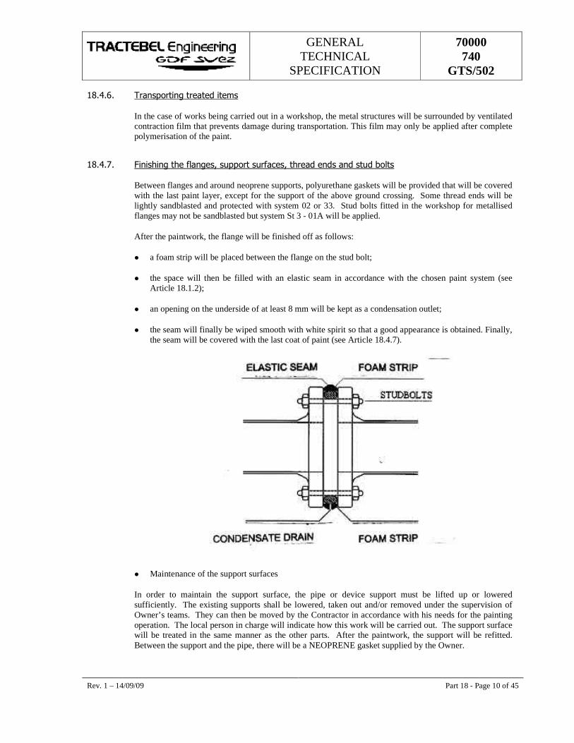
GENERAL TECHNICAL
SPECIFICATION
70000 740
GTS/502
Rev. 1 – 14/09/09 Part 18 - Page 10 of 45
���$�/� ����� ��%��������������
In the case of works being carried out in a workshop, the metal structures will be surrounded by ventilated contraction film that prevents damage during transportation. This film may only be applied after complete polymerisation of the paint.
���$�0� (��%������!�%��6����� �����������6��������������������, !���
Between flanges and around neoprene supports, polyurethane gaskets will be provided that will be covered with the last paint layer, except for the support of the above ground crossing. Some thread ends will be lightly sandblasted and protected with system 02 or 33. Stud bolts fitted in the workshop for metallised flanges may not be sandblasted but system St 3 - 01A will be applied.
After the paintwork, the flange will be finished off as follows:
� a foam strip will be placed between the flange on the stud bolt;
� the space will then be filled with an elastic seam in accordance with the chosen paint system (see Article 18.1.2);
� an opening on the underside of at least 8 mm will be kept as a condensation outlet;
� the seam will finally be wiped smooth with white spirit so that a good appearance is obtained. Finally, the seam will be covered with the last coat of paint (see Article 18.4.7).
� Maintenance of the support surfaces
In order to maintain the support surface, the pipe or device support must be lifted up or lowered sufficiently. The existing supports shall be lowered, taken out and/or removed under the supervision of Owner’s teams. They can then be moved by the Contractor in accordance with his needs for the painting operation. The local person in charge will indicate how this work will be carried out. The support surface will be treated in the same manner as the other parts. After the paintwork, the support will be refitted. Between the support and the pipe, there will be a NEOPRENE gasket supplied by the Owner.
GENERAL TECHNICAL
SPECIFICATION
70000 740
GTS/502
Rev. 1 – 14/09/09 Part 18 - Page 11 of 45
Finally, the whole unit will be sealed with an elastic seam that will finally be covered with the last layer of paint between the support and the pipe. In the case of above-ground crossing , this grouting may not be covered with the last layer of paint (see Article 18.4.7).
���.� ��'+�78��9�������*&�&'���'&���
���.��� � !#�������� ���� ��#�����
The Contractor will provide system 02 over the entire length of the pipes above ground and below ground and up to a height of 20 cm and a depth of 40 cm, perpendicular to the ground level mark. In each case, he must ensure that the jointing below the asphalt is in good condition and assures faultless adhesion. He will apply the following products over the entire surface area, prepared in accordance with Sa 3:
1) The primer of system 01a
2) Reinforced polyester – 20 cm above the ground level marker and – 5 cm on the asphalt cleaned beforehand. (application of reinforced polyester is carried out in accordance with the work method prescribed by the manufacturer - see appendix 2). Moreover, in the case of PE, in contrast to asphalt, he will apply a polyken primer to the PE immediately before applying the reinforced polyester.
3) He will then apply the other coats of system 01a to the surface section and thus cover the reinforced polyester with about 5 cm (see article 18.8 paint systems)
4) For new constructions, the polyken primer will be applied to PE and then subsequently processed as described under point 2.
���.��� ����� ��� ���� ��#�����
The transition point will be treated in accordance with the products and methods described in the G.T.S. Part 16.
GENERAL TECHNICAL
SPECIFICATION
70000 740
GTS/502
Rev. 1 – 14/09/09 Part 18 - Page 12 of 45
���/� +*��'(�*��(('�7&���
� Mounting, maintenance and dismantling of scaffolding for carrying out adaptation and/or paintwork to surface gas pipes or gas transport installations in use;
� The Contractor will specify the cost of scaffolding in the pricelist;
� The supplementary rental price for delays attributable to the Contractor will be charged to him;
� In his price quotation, the Contractor should present the Owner with diagrams of the scaffolding that he intends to install for carrying out the works of the Owner;
� For certain works, the Owner will provide scaffolding himself to carry out his own works. This scaffolding will be made available to the Contractor;
� A report will be drawn up when the scaffolding is handed over. The duration of the period when this scaffolding is made available free of charge is the number of working days necessary for the paintwork given in the pricelist, plus any delay resulting from bad weather conditions.
���0� :+��&�3��'���'�*���7��+��������
���0��� &����� � ������� ����
The Contractor is responsible for checking the weather conditions to ascertain whether the paintwork can be carried out within the technical specifications mentioned in the present specifications (see Article 18.4.1 & 18.4.2.).
The Contractor should have the required calibrated monitoring apparatus for this purpose on site (with calibration certificates). The personnel who will have to use this apparatus should have the training required for this purpose.
The Owner or his representative and possibly the Approved Supervisory Body indicated by the Owner will maintain supervision during the works and inspect the works with random checks. A daily report (C45-N) (APPENDIX 3) will be drawn up in relation to the department that maintains supervision of these works.
The supplementary inspection and the supervision by the Owner or the Approved Supervisory Body does not diminish in any way the liability of the Contractor. The proper execution of the work and the materials used may be checked at any time.
���0��� ������������������
At the start of the works, the Owner or the Approved Supervisory Body will indicate a few surfaces that the Contractor will prepare and cover in accordance with the recognised method of operation under the inspection and to the satisfaction of all parties: the Owner or his representative, the Approved Supervisory Body, the Contractor and possibly the paint manufacturer. These reference surfaces will serve as a point of comparison for the good adhesion of the paint on the installations as a whole. The parties will together work out a system for the identification of these surfaces in order to be able to monitor the condition of the coatings over time. If the paintwork on a section of the installations is in a worse condition than the reference surfaces, the Contractor may be obliged to treat these parts again.
GENERAL TECHNICAL
SPECIFICATION
70000 740
GTS/502
Rev. 1 – 14/09/09 Part 18 - Page 13 of 45
���0� � -��������� �,�������������"��� �����������
If on delivery of the works no agreement can be reached between the Contractor and the Owner regarding the conformity of the works to the requirements of these specifications, an Approved Supervisory Body will be called in. The Approved Supervisory Body will then carry out inspections on site whereby the following assessment criteria will be used:
� The Swedish standards ISO 8501-1 1988 SS 05.5900 concerning the degree of cleanliness of the areas derusted by blasting, by machine or by hand;
� The wet film thickness of the paint will be measured in accordance with ISO 2808 or ASTM D1212;
� The dry layer thickness of the film will be measured electronically, with complete statistical information, in accordance with ISO 2808 or ASTM D 1186;
� The thickness of each layer will be measured in accordance with ISO 2808, ASTM 4138 or DIN 50986;
� Adhesion tests will be carried out in accordance with ISO 2409, ASTM 3359 or DIN 53151;
� Traction tests will be carried out in conformity with ISO 4624 or ASTM D 4541;
� The rugosity will be measured electronically in accordance with DIN 4768;
� The non-porosity will be measured with a test tension depending on the type of coating, the layer thickness and after consultation with the paint manufacturer;
� Any defects in the paint film may be inspected visually by means of a magnifying glass or microscope. If necessary, a photographic report may be drawn up in accordance with ASTM Standard D 4121-82.
The final judgement of the Approved Supervisory Body is irrevocable and binding for the Contractor and the Owner. In the event of non-conformity of the works with the criteria of these specifications, all costs arising from the inspection by the Approved Supervisory Body shall be borne by the Contractor.
���0�$� ����������
���0�$��� �����!�����!���
The Contractor declares that he is aware of:
� the maximum operating temperature of the surfaces to be covered;
� the maximum permitted degree of humidity of the bearing surface;
� the properties of the environment to which the surfaces to be covered are subject.
���0�$��� *�����#� ������%��������
The Contractor fully guarantees the following without reservation:
� the observance of all stipulations of the specifications for paintwork regarding, among other things :
� the preparation of the surfaces;
GENERAL TECHNICAL
SPECIFICATION
70000 740
GTS/502
Rev. 1 – 14/09/09 Part 18 - Page 14 of 45
� the thickness of each layer;
� the total thickness of the covering.
� the uniformity of the materials used;
� the repair of all defects before delivery of the works;
The Contractor will carry out the requested repair work as promptly as possible.
���0�$� � �������������� �
Every protection system is considered to give satisfaction during the period of guarantee. The Owner requires the conditions as described in the General Terms and Conditions of Purchase.
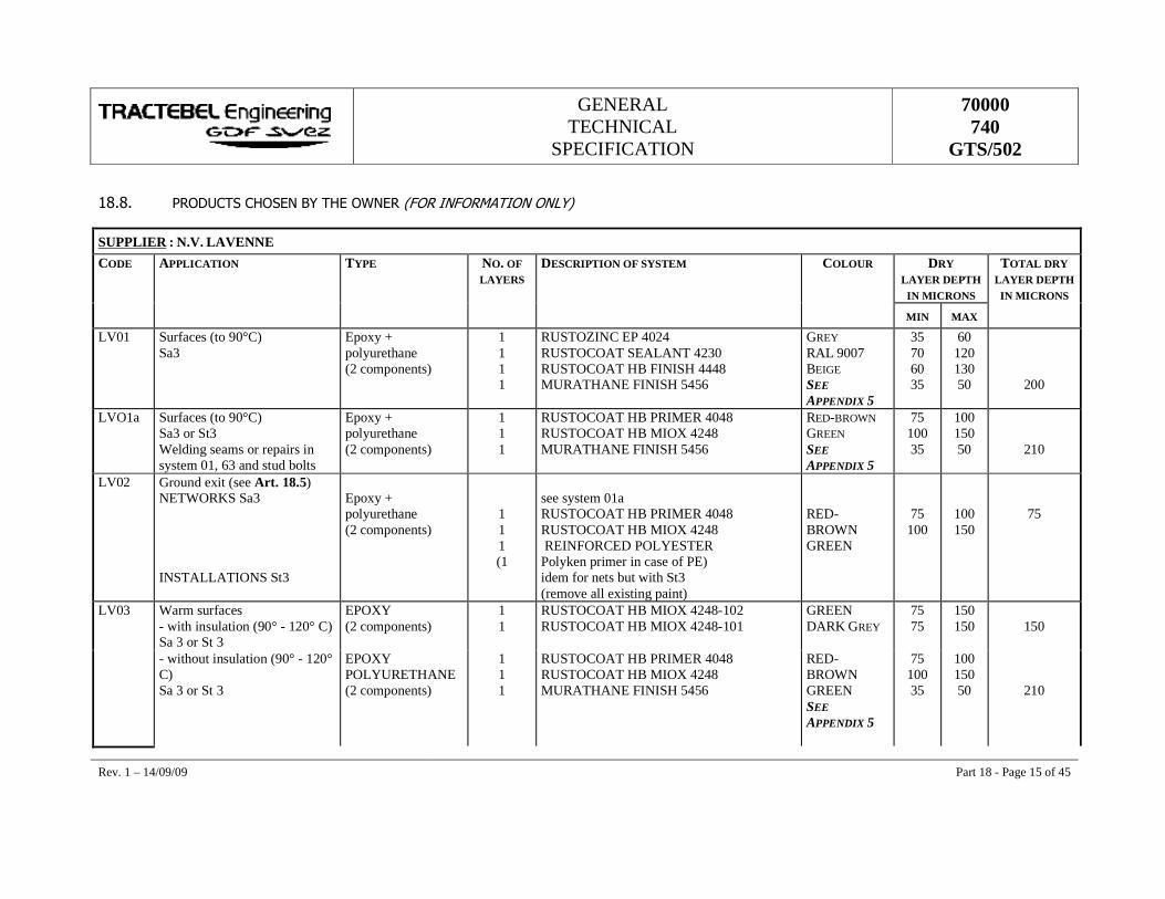
GENERAL TECHNICAL
SPECIFICATION
70000 740
GTS/502
Rev. 1 – 14/09/09 Part 18 - Page 15 of 45
����� ��'7+��*��)'*���;3��)��'4����<('��&�('�-��&'��'��3=�
SUPPLIER : N.V. LAVENNE CODE APPLICATION TYPE NO. OF
LAYERS DESCRIPTION OF SYSTEM COLOUR DRY
LAYER DEPTH IN MICRONS
TOTAL DRY LAYER DEPTH
IN MICRONS MIN MAX
LV01 Surfaces (to 90°C) Sa3
Epoxy + polyurethane (2 components)
1 1 1 1
RUSTOZINC EP 4024 RUSTOCOAT SEALANT 4230 RUSTOCOAT HB FINISH 4448 MURATHANE FINISH 5456
GREY RAL 9007 BEIGE SEE APPENDIX 5
35 70 60 35
60 120 130 50
200
LVO1a Surfaces (to 90°C) Sa3 or St3 Welding seams or repairs in system 01, 63 and stud bolts
Epoxy + polyurethane (2 components)
1 1 1
RUSTOCOAT HB PRIMER 4048 RUSTOCOAT HB MIOX 4248 MURATHANE FINISH 5456
RED-BROWN GREEN SEE APPENDIX 5
75 100 35
100 150 50
210
LV02 Ground exit (see Art. 18.5) NETWORKS Sa3 INSTALLATIONS St3
Epoxy + polyurethane (2 components)
1 1 1 (1
see system 01a RUSTOCOAT HB PRIMER 4048 RUSTOCOAT HB MIOX 4248 REINFORCED POLYESTER Polyken primer in case of PE) idem for nets but with St3 (remove all existing paint)
RED-BROWN GREEN
75 100
100 150
75
LV03 Warm surfaces - with insulation (90° - 120° C) Sa 3 or St 3
EPOXY (2 components)
1 1
RUSTOCOAT HB MIOX 4248-102 RUSTOCOAT HB MIOX 4248-101
GREEN DARK GREY
75 75
150 150
150
- without insulation (90° - 120° C) Sa 3 or St 3
EPOXY POLYURETHANE (2 components)
1 1 1
RUSTOCOAT HB PRIMER 4048 RUSTOCOAT HB MIOX 4248 MURATHANE FINISH 5456
RED-BROWN GREEN SEE APPENDIX 5
75 100 35
100 150 50
210
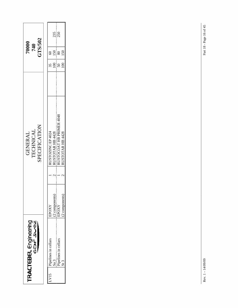
GE
NE
RA
L
TEC
HN
ICA
L
SPE
CIF
ICA
TIO
N
7000
0 74
0 G
TS/
502
R
ev. 1
– 1
4/09
/09
Part
18 -
Page
16
of 4
5 L
V15
Pi
pelin
es in
cel
lars
Sa
3
EPO
XY
(2
com
pone
nts)
1 2
RU
STO
ZIN
C E
P 40
24
RU
STO
TA
R H
B 4
428
35
10
0 60
15
0
235
Pi
pelin
es in
cel
lars
St
3
EPO
XY
(2
com
pone
nts)
1 2
RU
STO
CO
AT
HB
PR
IME
R 4
048
RU
STO
TA
R H
B 4
428
50
10
0 80
15
0 25
0
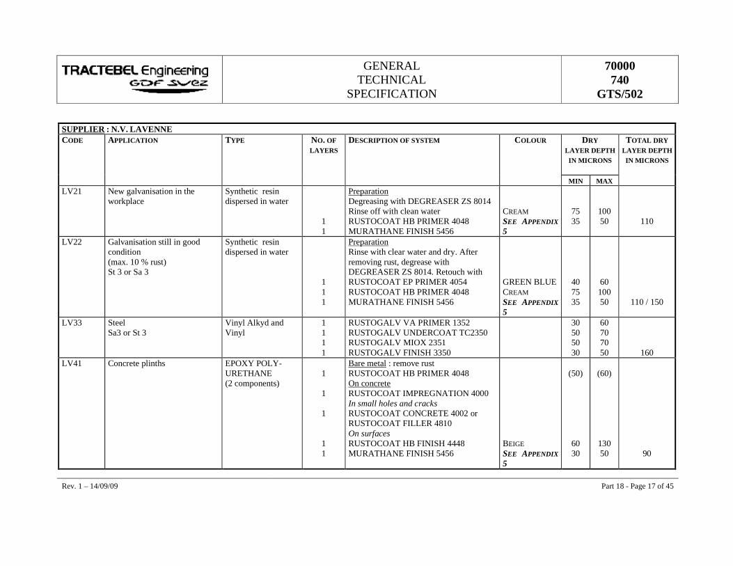
GENERAL TECHNICAL
SPECIFICATION
70000 740
GTS/502
Rev. 1 – 14/09/09 Part 18 - Page 17 of 45
SUPPLIER : N.V. LAVENNE CODE APPLICATION TYPE NO. OF
LAYERS DESCRIPTION OF SYSTEM COLOUR DRY
LAYER DEPTH IN MICRONS
TOTAL DRY LAYER DEPTH IN MICRONS
MIN MAX LV21 New galvanisation in the
workplace Synthetic resin dispersed in water
1 1
Preparation Degreasing with DEGREASER ZS 8014 Rinse off with clean water RUSTOCOAT HB PRIMER 4048 MURATHANE FINISH 5456
CREAM SEE APPENDIX 5
75 35
100 50
110
LV22 Galvanisation still in good condition (max. 10 % rust) St 3 or Sa 3
Synthetic resin dispersed in water
1 1 1
Preparation Rinse with clear water and dry. After removing rust, degrease with DEGREASER ZS 8014. Retouch with RUSTOCOAT EP PRIMER 4054 RUSTOCOAT HB PRIMER 4048 MURATHANE FINISH 5456
GREEN BLUE CREAM SEE APPENDIX 5
40 75 35
60 100 50
110 / 150
LV33 Steel Sa3 or St 3
Vinyl Alkyd and Vinyl
1 1 1 1
RUSTOGALV VA PRIMER 1352 RUSTOGALV UNDERCOAT TC2350 RUSTOGALV MIOX 2351 RUSTOGALV FINISH 3350
30 50 50 30
60 70 70 50
160 LV41 Concrete plinths EPOXY POLY-
URETHANE (2 components)
1
1
1
1 1
Bare metal : remove rust RUSTOCOAT HB PRIMER 4048 On concrete RUSTOCOAT IMPREGNATION 4000 In small holes and cracks RUSTOCOAT CONCRETE 4002 or RUSTOCOAT FILLER 4810 On surfaces RUSTOCOAT HB FINISH 4448 MURATHANE FINISH 5456
BEIGE SEE APPENDIX 5
(50)
60 30
(60)
130 50
90
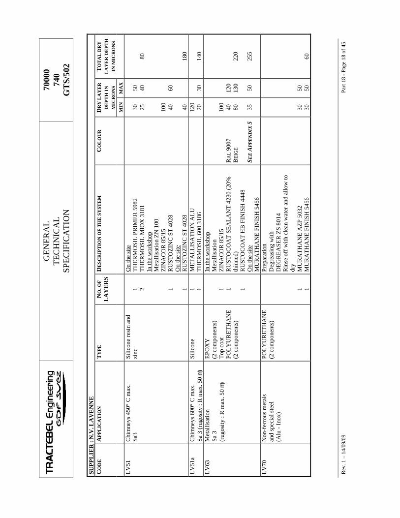
GE
NE
RA
L
TEC
HN
ICA
L
SPE
CIF
ICA
TIO
N
7000
0 74
0 G
TS/
502
R
ev. 1
– 1
4/09
/09
Part
18 -
Page
18
of 4
5 SU
PPL
IER
: N
.V. L
AV
EN
NE
C
OD
E
APP
LIC
AT
ION
T
YPE
N
O. O
F
LA
YE
RS
DE
SCR
IPT
ION
OF
TH
E S
YST
EM
C
OL
OU
R
DR
Y L
AY
ER
D
EPT
H I
N
MIC
RO
NS
TO
TA
L D
RY
L
AY
ER
DE
PTH
IN
MIC
RO
NS
MIN
M
AX
LV
51
Chi
mne
ys 4
50°
C m
ax.
Sa3
Silic
one
resi
n an
d zi
nc
1 2 1 1
On
the
site
T
HE
RM
OSI
L P
RIM
ER
598
2 T
HE
RM
OSI
L M
IOX
318
1 In
the
wor
ksho
p
Met
allis
atio
n Z
N 1
00
ZIN
AC
OR
85/
15
RU
STO
ZIN
C S
T 4
028
On
the
site
R
UST
OZI
NC
ST
402
8
30
25
10
0 40
40
50
40 60
80
180
LV
51a
Chi
mne
ys 6
00°
C m
ax.
Sa 3
(rug
osity
: R
max
. 50
m)
Silic
one
1 1 M
ET
AL
LIS
AT
ION
AL
U
TH
ER
MO
SIL
600
318
6
120
20
30
14
0 L
V63
M
etal
lisat
ion
Sa 3
(r
ugos
ity :
R m
ax. 5
0 m)
EPO
XY
(2
com
pone
nts)
T
op c
oat
POL
YU
RE
TH
AN
E
(2 c
ompo
nent
s)
1 1 1
In th
e w
orks
hop
Met
allis
atio
n Z
INA
CO
R 8
5/15
R
UST
OC
OA
T S
EA
LA
NT
423
0 (2
0%
thin
ned)
R
UST
OC
OA
T H
B F
INIS
H 4
448
On
the
site
M
UR
AT
HA
NE
FIN
ISH
545
6
RA
L 9
007
BE
IGE
S EE
APP
EN
DIX
5
10
0 40
80
35
12
0 13
0 50
22
0 25
5
LV
70
Non
-fer
rous
met
als
and
spec
ial s
teel
(A
lu -
Inox
)
POL
YU
RE
TH
AN
E
(2 c
ompo
nent
s)
1 1
Prep
arat
ion
Deg
reas
ing
with
D
EG
RE
ASE
R Z
S 80
14
Rin
se o
ff w
ith c
lean
wat
er a
nd a
llow
to
dry
M
UR
AT
HA
NE
AZ
P 50
32
MU
RA
TH
AN
E F
INIS
H 5
456
30
30
50
50
60
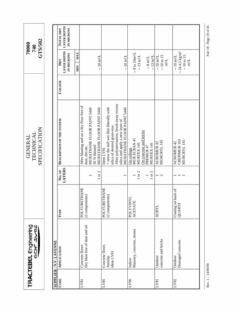
GE
NE
RA
L
TEC
HN
ICA
L
SPE
CIF
ICA
TIO
N
7000
0 74
0 G
TS/
502
R
ev. 1
– 1
4/09
/09
Part
18 -
Page
19
of 4
5 SU
PPL
IER
: N
.V. L
AV
EN
NE
C
OD
E
APP
LIC
AT
ION
T
YPE
N
O. O
F
LA
YE
RS
DE
SCR
IPT
ION
OF
TH
E S
YST
EM
C
OL
OU
R
DR
Y
LA
YE
R D
EPT
H
IN M
ICR
ON
S
TO
TA
L D
RY
L
AY
ER
DE
PTH
IN
MIC
RO
NS
MIN
M
AX
LV
81
Con
cret
e fl
oors
D
ry b
last
free
of d
ust a
nd o
il PO
LY
UR
ET
HA
NE
(2
com
pone
nts)
1
1 or
2
Aft
er b
last
ing
and
on a
dry
floo
r fre
e of
du
st, d
irt e
tc.
MU
RA
TH
AN
E F
LO
OR
PA
INT
544
0 50
% th
inne
d M
UR
AT
HA
NE
FL
OO
R P
AIN
T 5
440
– 10
m²/L
LV
85
Con
cret
e fl
oors
A
ntis
lip
idem
LV
81
POL
YU
RE
TH
AN
E
(2 c
ompo
nent
s)
1
Idem
LV
81
+ st
rew
the
still
wet
film
libe
rally
with
si
lica
of d
esir
ed g
rain
-siz
e.
Aft
er p
olym
eris
atio
n, b
rush
aw
ay e
xces
s si
lica
and
appl
y a
new
laye
r of
MU
RA
TH
AN
E F
LO
OR
PA
INT
544
0
– 10
m²/L
LV
90
Indo
or
Mas
onry
, con
cret
e, s
tone
s
POL
YV
INY
L
AC
ET
AT
E
1 1
or 2
1
1 or
2
On
ceili
ngs
MU
R E
CR
AN
41
MU
RT
EX
141
O
n co
ncre
te a
nd b
rick
s PR
EM
UR
47
MU
RT
EX
141
– 8
to 1
0m²/L
–
13 m
²/L
–
8 m
²/L
– 13
m²/L
LV
91
Out
door
co
ncre
te a
nd b
rick
s
AC
RY
L
1 2 A
CR
OM
UR
42
MU
RC
RY
L 1
45
–
10 m
²/L
– 10
to 1
5 m
²/L
LV
92
Out
door
D
amag
ed c
oncr
ete
C
oatin
g on
bas
is o
f Q
UA
RTZ
1 1 1
AC
RO
MU
R 4
2 C
RE
PIM
UR
163
M
UR
CR
YL
145
–
10 m
²/L
– 2à
4,5
kg/
m²
– 10
to 1
5 m
²/L
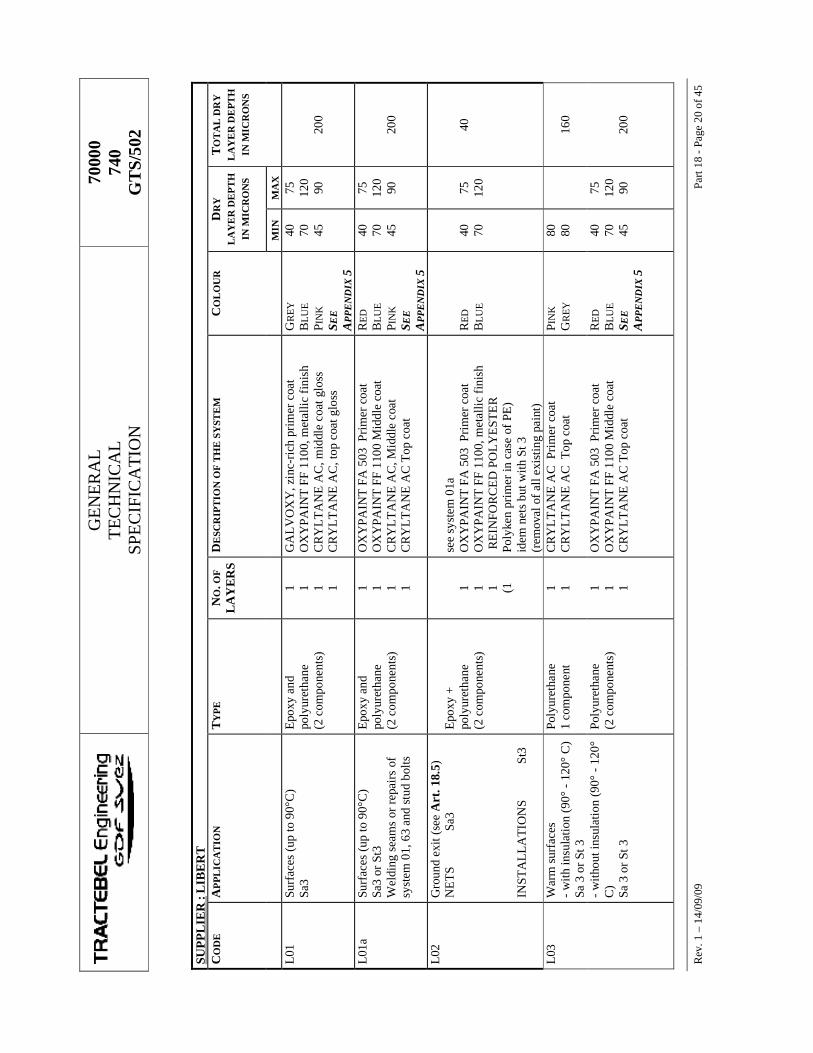
GE
NE
RA
L
TEC
HN
ICA
L
SPE
CIF
ICA
TIO
N
7000
0 74
0 G
TS/
502
R
ev. 1
– 1
4/09
/09
Part
18 -
Page
20
of 4
5 SU
PPL
IER
: L
IBE
RT
C
OD
E
APP
LIC
AT
ION
T
YPE
N
O. O
F
LA
YE
RS
DE
SCR
IPT
ION
OF
TH
E S
YST
EM
C
OL
OU
R
DR
Y
LA
YE
R D
EPT
H
IN M
ICR
ON
S
TO
TA
L D
RY
L
AY
ER
DE
PTH
IN
MIC
RO
NS
MIN
M
AX
L01
Su
rfac
es (u
p to
90°
C)
Sa3
Epo
xy a
nd
poly
uret
hane
(2
com
pone
nts)
1 1 1 1
GA
LV
OX
Y, z
inc-
rich
pri
mer
coa
t O
XY
PAIN
T F
F 11
00, m
etal
lic fi
nish
C
RY
LT
AN
E A
C, m
iddl
e co
at g
loss
C
RY
LT
AN
E A
C, t
op c
oat g
loss
GR
EY
BL
UE
P IN
K
SEE
A
PPE
ND
IX 5
40
70
45
75
120
90
20
0
L01
a Su
rfac
es (u
p to
90°
C)
Sa3
or S
t3
Wel
ding
sea
ms
or re
pair
s of
sy
stem
01,
63
and
stud
bol
ts
Epo
xy a
nd
poly
uret
hane
(2
com
pone
nts)
1 1 1 1
OX
YPA
INT
FA
503
Pri
mer
coa
t O
XY
PAIN
T F
F 11
00 M
iddl
e co
at
CR
YL
TA
NE
AC
, Mid
dle
coat
C
RY
LT
AN
E A
C T
op c
oat
RE
D
BL
UE
PIN
K
SEE
A
PPE
ND
IX 5
40
70
45
75
120
90
20
0
L02
G
roun
d ex
it (s
ee A
rt. 1
8.5 )
N
ET
S
Sa3
INST
AL
LA
TIO
NS
St
3
Epo
xy +
po
lyur
etha
ne
(2 c
ompo
nent
s)
1 1 1 (1
see
syst
em 0
1a
OX
YPA
INT
FA
503
Pri
mer
coa
t O
XY
PAIN
T F
F 11
00, m
etal
lic fi
nish
R
EIN
FOR
CE
D P
OL
YE
STE
R
Poly
ken
prim
er in
cas
e of
PE
) id
em n
ets
but w
ith S
t 3
(rem
oval
of a
ll ex
istin
g pa
int)
RE
D
BL
UE
40
70
75
120
40
L03
W
arm
sur
face
s - w
ith in
sula
tion
(90°
- 12
0° C
) Sa
3 o
r St 3
Poly
uret
hane
1
com
pone
nt
1 1 C
RY
LT
AN
E A
C P
rim
er c
oat
CR
YL
TA
NE
AC
Top
coa
t PI
NK
G
REY
80
80
16
0
- w
ithou
t ins
ulat
ion
(90°
- 12
0°
C)
Sa 3
or S
t 3
Poly
uret
hane
(2
com
pone
nts)
1 1 1
OX
YPA
INT
FA
503
Pri
mer
coa
t O
XY
PAIN
T F
F 11
00 M
iddl
e co
at
CR
YL
TA
NE
AC
Top
coa
t
RE
D
BL
UE
S EE
A
PPE
ND
IX 5
40
70
45
75
120
90
20
0
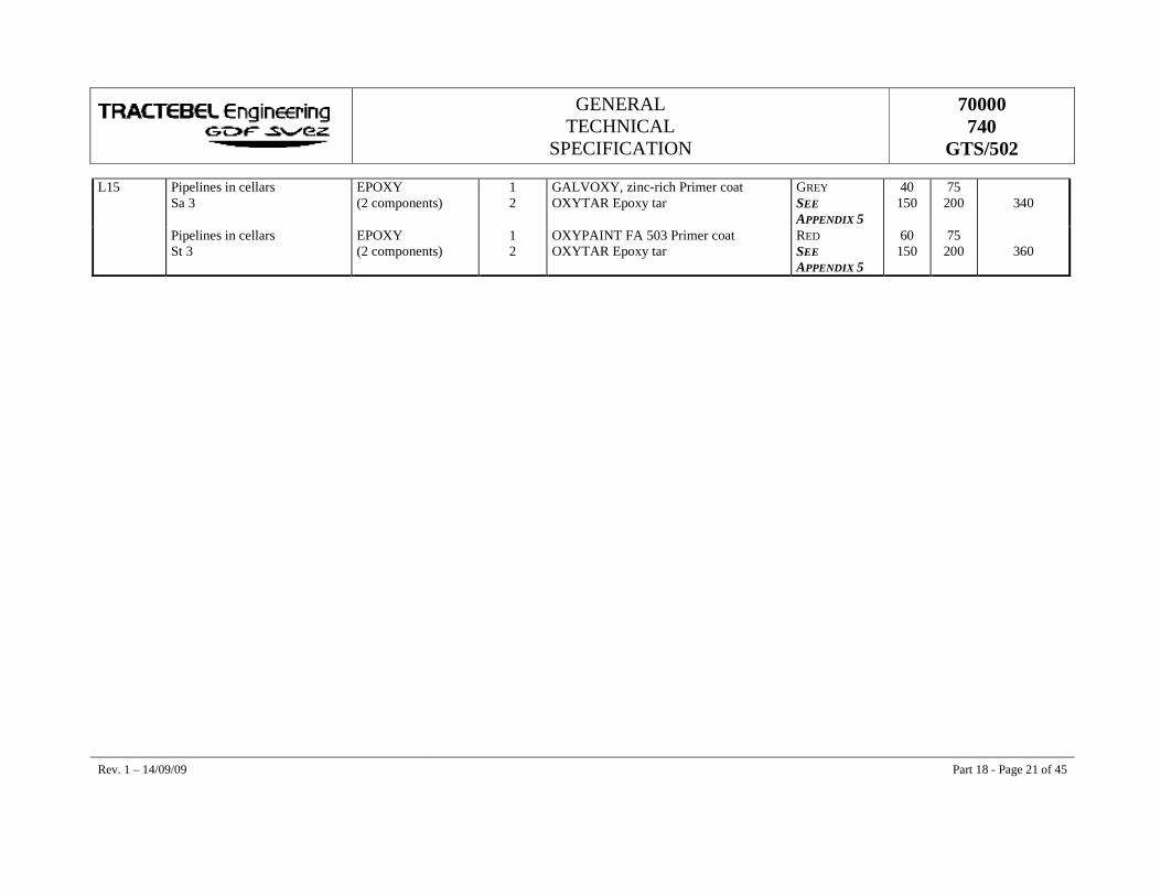
GENERAL TECHNICAL
SPECIFICATION
70000 740
GTS/502
Rev. 1 – 14/09/09 Part 18 - Page 21 of 45
L15 Pipelines in cellars Sa 3
EPOXY (2 components)
1 2
GALVOXY, zinc-rich Primer coat OXYTAR Epoxy tar
GREY SEE APPENDIX 5
40 150
75 200
340
Pipelines in cellars St 3
EPOXY (2 components)
1 2
OXYPAINT FA 503 Primer coat OXYTAR Epoxy tar
RED SEE APPENDIX 5
60 150
75 200
360
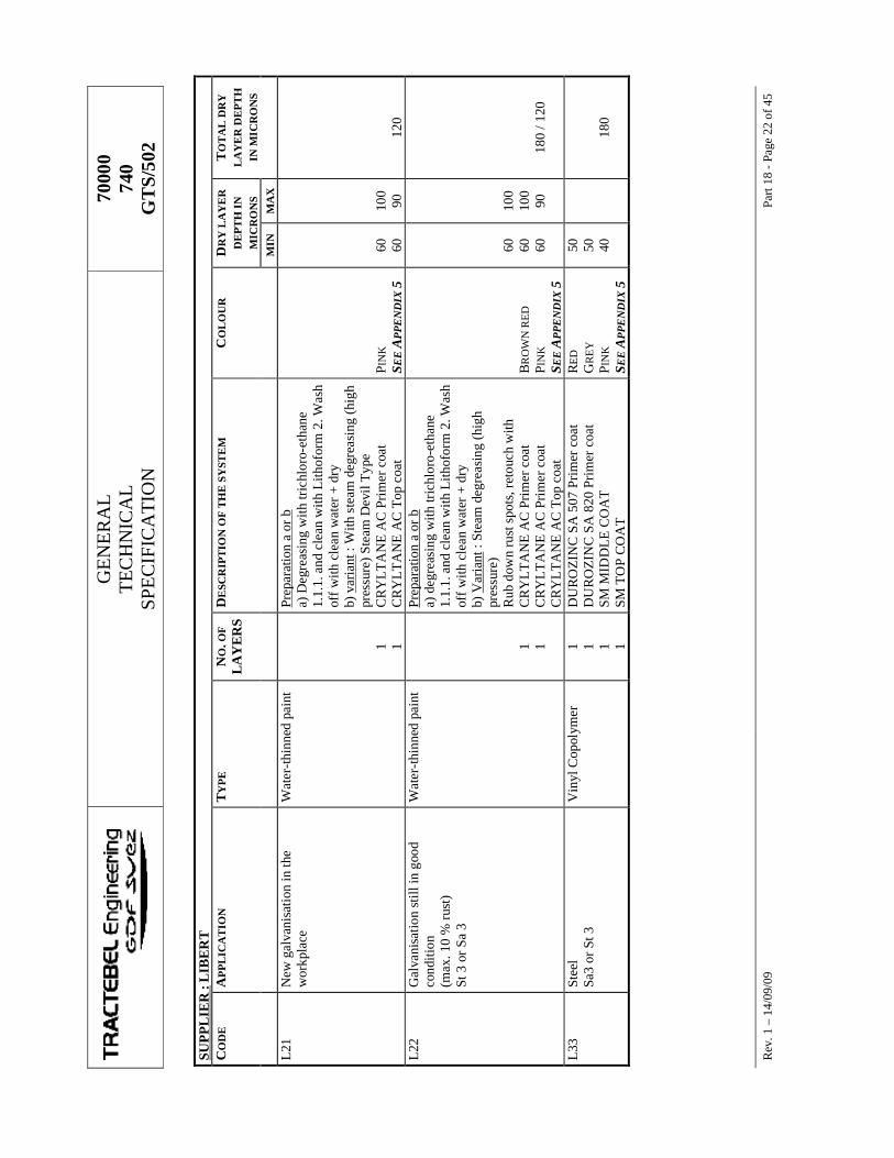
GE
NE
RA
L
TEC
HN
ICA
L
SPE
CIF
ICA
TIO
N
7000
0 74
0 G
TS/
502
R
ev. 1
– 1
4/09
/09
Part
18 -
Page
22
of 4
5 SU
PPL
IER
: L
IBE
RT
C
OD
E
APP
LIC
AT
ION
T
YPE
N
O. O
F
LA
YE
RS
DE
SCR
IPT
ION
OF
TH
E S
YST
EM
C
OL
OU
R
DR
Y L
AY
ER
D
EPT
H IN
M
ICR
ON
S
TO
TA
L D
RY
L
AY
ER
DE
PTH
IN
MIC
RO
NS
MIN
M
AX
L21
N
ew g
alva
nisa
tion
in th
e w
orkp
lace
W
ater
-thi
nned
pai
nt
1 1
Prep
arat
ion
a or
b
a) D
egre
asin
g w
ith tr
ichl
oro-
etha
ne
1.1.
1. a
nd c
lean
with
Lith
ofor
m 2
. Was
h of
f with
cle
an w
ater
+ d
ry
b) v
aria
nt :
With
ste
am d
egre
asin
g (h
igh
pres
sure
) Ste
am D
evil
Typ
e C
RY
LT
AN
E A
C P
rim
er c
oat
CR
YL
TA
NE
AC
Top
coa
t
P IN
K
SEE
APP
EN
DIX
5
60
60
10
0 90
12
0 L
22
Gal
vani
satio
n st
ill in
goo
d co
nditi
on
(max
. 10
% ru
st)
St 3
or S
a 3
Wat
er-t
hinn
ed p
aint
1 1
Prep
arat
ion
a or
b
a) d
egre
asin
g w
ith tr
ichl
oro-
etha
ne
1.1.
1. a
nd c
lean
with
Lith
ofor
m 2
. Was
h of
f with
cle
an w
ater
+ d
ry
b) V
aria
nt :
Stea
m d
egre
asin
g (h
igh
pres
sure
) R
ub d
own
rust
spo
ts, r
etou
ch w
ith
CR
YL
TA
NE
AC
Pri
mer
coa
t C
RY
LT
AN
E A
C P
rim
er c
oat
CR
YL
TA
NE
AC
Top
coa
t
BR
OW
N R
ED
P I
NK
SE
E A
PPE
ND
IX 5
60
60
60
10
0 10
0 90
18
0 / 1
20
L33
St
eel
Sa3
or S
t 3
Vin
yl C
opol
ymer
1 1 1 1
DU
RO
ZIN
C S
A 5
07 P
rim
er c
oat
DU
RO
ZIN
C S
A 8
20 P
rim
er c
oat
SM M
IDD
LE
CO
AT
SM
TO
P C
OA
T
RE
D
GR
EY
P I
NK
SE
E A
PPE
ND
IX 5
50
50
40
180
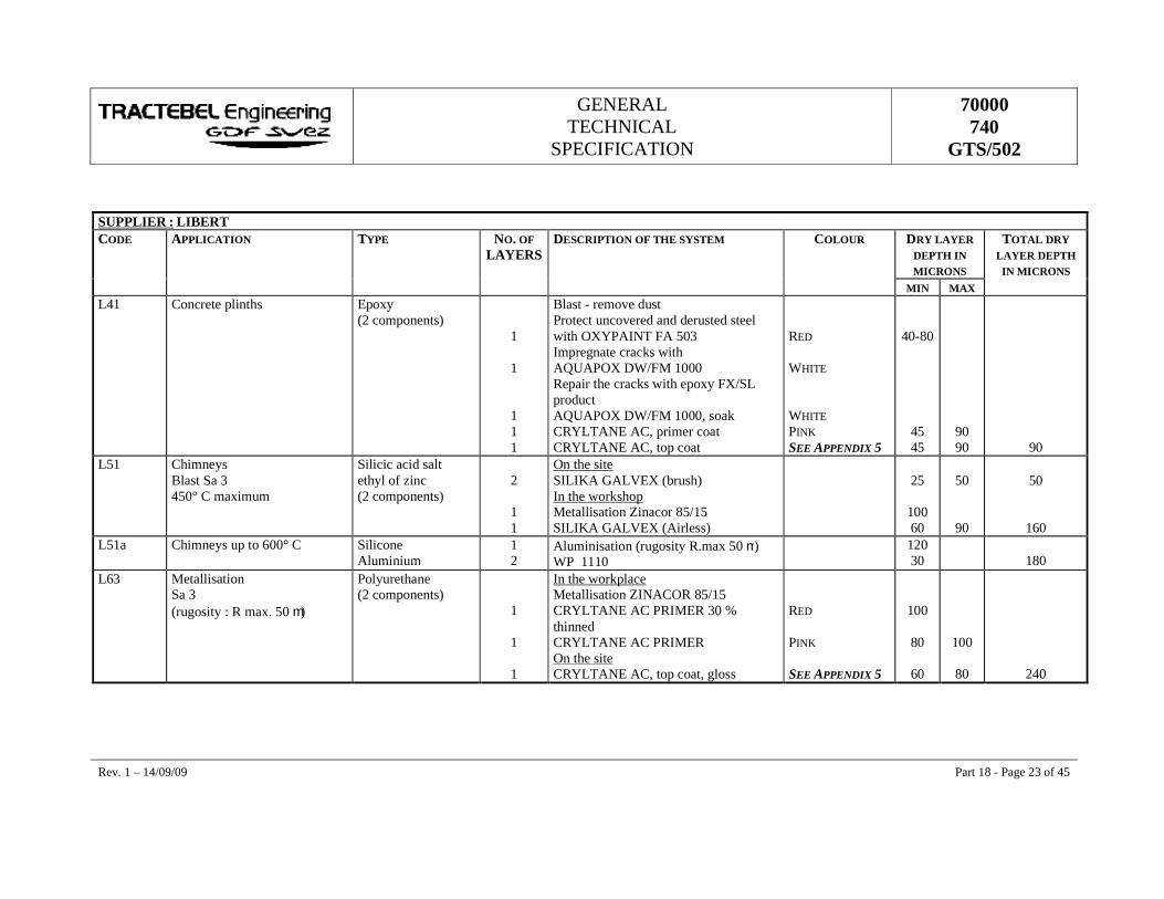
GENERAL TECHNICAL
SPECIFICATION
70000 740
GTS/502
Rev. 1 – 14/09/09 Part 18 - Page 23 of 45
SUPPLIER : LIBERT CODE APPLICATION TYPE NO. OF
LAYERS DESCRIPTION OF THE SYSTEM COLOUR DRY LAYER
DEPTH IN MICRONS
TOTAL DRY LAYER DEPTH
IN MICRONS MIN MAX L41 Concrete plinths Epoxy
(2 components)
1
1
1 1 1
Blast - remove dust Protect uncovered and derusted steel with OXYPAINT FA 503 Impregnate cracks with AQUAPOX DW/FM 1000 Repair the cracks with epoxy FX/SL product AQUAPOX DW/FM 1000, soak CRYLTANE AC, primer coat CRYLTANE AC, top coat
RED WHITE WHITE PINK SEE APPENDIX 5
40-80
45 45
90 90
90 L51 Chimneys
Blast Sa 3 450° C maximum
Silicic acid salt ethyl of zinc (2 components)
2
1 1
On the site SILIKA GALVEX (brush) In the workshop Metallisation Zinacor 85/15 SILIKA GALVEX (Airless)
25
100 60
50
90
50
160 L51a Chimneys up to 600° C Silicone
Aluminium 1 2
Aluminisation (rugosity R.max 50 m) WP 1110
120 30
180
L63 Metallisation Sa 3 (rugosity : R max. 50 m)
Polyurethane (2 components)
1
1
1
In the workplace Metallisation ZINACOR 85/15 CRYLTANE AC PRIMER 30 % thinned CRYLTANE AC PRIMER On the site CRYLTANE AC, top coat, gloss
RED PINK SEE APPENDIX 5
100
80
60
100
80
240
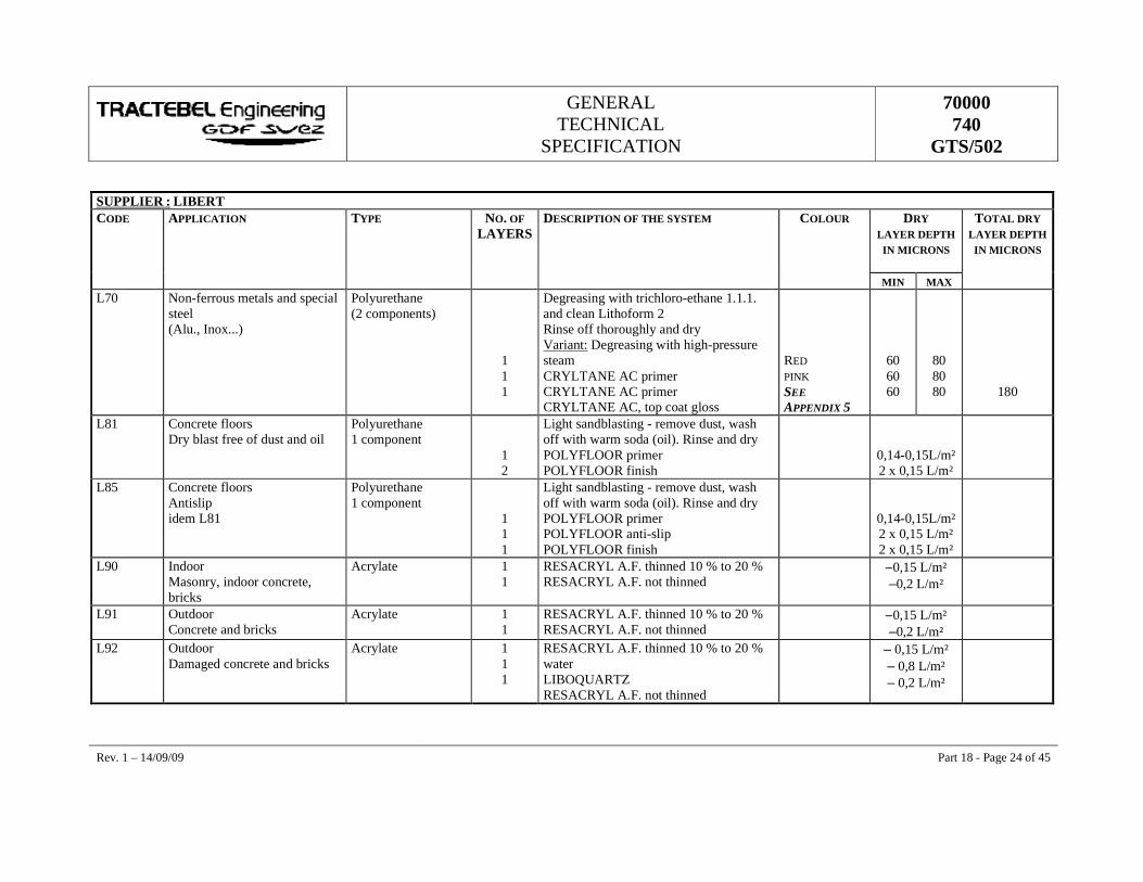
GENERAL TECHNICAL
SPECIFICATION
70000 740
GTS/502
Rev. 1 – 14/09/09 Part 18 - Page 24 of 45
SUPPLIER : LIBERT CODE APPLICATION TYPE NO. OF
LAYERS DESCRIPTION OF THE SYSTEM COLOUR DRY
LAYER DEPTH IN MICRONS
TOTAL DRY LAYER DEPTH
IN MICRONS
MIN MAX L70 Non-ferrous metals and special
steel (Alu., Inox...)
Polyurethane (2 components)
1 1 1
Degreasing with trichloro-ethane 1.1.1. and clean Lithoform 2 Rinse off thoroughly and dry Variant: Degreasing with high-pressure steam CRYLTANE AC primer CRYLTANE AC primer CRYLTANE AC, top coat gloss
RED PINK SEE APPENDIX 5
60 60 60
80 80 80
180
L81 Concrete floors Dry blast free of dust and oil
Polyurethane 1 component
1 2
Light sandblasting - remove dust, wash off with warm soda (oil). Rinse and dry POLYFLOOR primer POLYFLOOR finish
0,14-0,15L/m² 2 x 0,15 L/m²
L85 Concrete floors Antislip idem L81
Polyurethane 1 component
1 1 1
Light sandblasting - remove dust, wash off with warm soda (oil). Rinse and dry POLYFLOOR primer POLYFLOOR anti-slip POLYFLOOR finish
0,14-0,15L/m² 2 x 0,15 L/m² 2 x 0,15 L/m²
L90 Indoor Masonry, indoor concrete, bricks
Acrylate 1 1
RESACRYL A.F. thinned 10 % to 20 % RESACRYL A.F. not thinned
–0,15 L/m² –0,2 L/m²
L91 Outdoor Concrete and bricks
Acrylate 1 1
RESACRYL A.F. thinned 10 % to 20 % RESACRYL A.F. not thinned
–0,15 L/m² –0,2 L/m²
L92 Outdoor Damaged concrete and bricks
Acrylate 1 1 1
RESACRYL A.F. thinned 10 % to 20 % water LIBOQUARTZ RESACRYL A.F. not thinned
– 0,15 L/m² – 0,8 L/m² – 0,2 L/m²
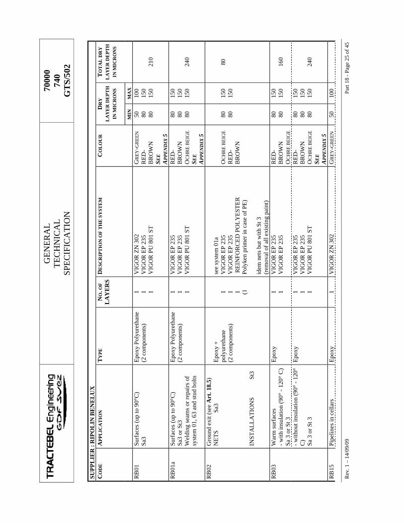
GE
NE
RA
L
TEC
HN
ICA
L
SPE
CIF
ICA
TIO
N
7000
0 74
0 G
TS/
502
R
ev. 1
– 1
4/09
/09
Part
18 -
Page
25
of 4
5 SU
PPL
IER
: R
IPO
LIN
BE
NE
LU
X
CO
DE
A
PPL
ICA
TIO
N
TY
PE
NO
. OF
L
AY
ER
S D
ESC
RIP
TIO
N O
F T
HE
SY
STE
M
CO
LO
UR
D
RY
L
AY
ER
DE
PTH
IN
MIC
RO
NS
TO
TA
L D
RY
L
AY
ER
DE
PTH
IN
MIC
RO
NS
MIN
M
AX
RB
01
Surf
aces
(up
to 9
0°C
) Sa
3 E
poxy
Pol
yure
than
e
(2 c
ompo
nent
s)
1 1 1
VIG
OR
ZN
302
V
IGO
R E
P 23
5 V
IGO
R P
U 8
01 S
T
GR
EY-G
RE
EN
R
ED
-B
RO
WN
SE
E
APP
EN
DIX
5
50
80
80
100
150
150
21
0
RB
01a
Surf
aces
(up
to 9
0°C
) Sa
3 or
St3
W
eldi
ng s
eam
s or
repa
irs
of
syst
em 0
1, 6
3 an
d st
ud b
olts
Epo
xy P
olyu
reth
ane
(2
com
pone
nts)
1 1 1
VIG
OR
EP
235
VIG
OR
EP
235
VIG
OR
PU
801
ST
RE
D-
BR
OW
N
OC
HR
E B
EIG
E
SEE
A
PPE
ND
IX 5
80
80
80
150
150
150
24
0
RB
02
Gro
und
exit
(see
Art
. 18.
5 )
NE
TS
Sa
3 IN
STA
LL
ATI
ON
S
St3
Epo
xy +
po
lyur
etha
ne
(2 c
ompo
nent
s)
1 1 1 (1
see
syst
em 0
1a
VIG
OR
EP
235
VIG
OR
EP
235
RE
INFO
RC
ED
PO
LY
EST
ER
Po
lyke
n pr
imer
in c
ase
of P
E)
idem
net
s bu
t with
St 3
(r
emov
al o
f all
exis
ting
pain
t)
OC
HR
E B
EIG
E
RE
D-
BR
OW
N
80
80
15
0 15
0
80
RB
03
War
m s
urfa
ces
- with
insu
latio
n (9
0° -
120°
C)
Sa 3
or S
t 3
Epo
xy
1 1 V
IGO
R E
P 23
5 V
IGO
R E
P 23
5 R
ED
-B
RO
WN
O
CH
RE
BE
IGE
80
80
150
150
16
0
- w
ithou
t ins
ulat
ion
(90°
- 12
0°
C)
Sa 3
or S
t 3
Epo
xy
1 1 1
VIG
OR
EP
235
VIG
OR
EP
235
VIG
OR
PU
801
ST
RE
D-
BR
OW
N
OC
HR
E B
EIG
E
SEE
A
PPE
ND
IX 5
80
80
80
150
150
150
24
0
RB
15
Pipe
lines
in c
ella
rs
Epo
xy
1 V
IGO
R Z
N 3
02
GR
EY-G
RE
EN
50
10
0
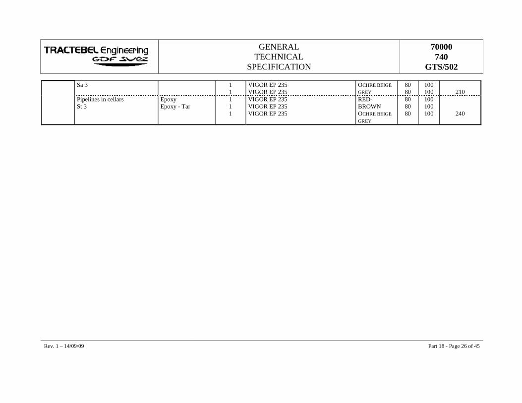
GENERAL TECHNICAL
SPECIFICATION
70000 740
GTS/502
Rev. 1 – 14/09/09 Part 18 - Page 26 of 45
Sa 3 1 1
VIGOR EP 235 VIGOR EP 235
OCHRE BEIGE GREY
80 80
100 100
210
Pipelines in cellars St 3
Epoxy Epoxy - Tar
1 1 1
VIGOR EP 235 VIGOR EP 235 VIGOR EP 235
RED-BROWN OCHRE BEIGE GREY
80 80 80
100 100 100
240
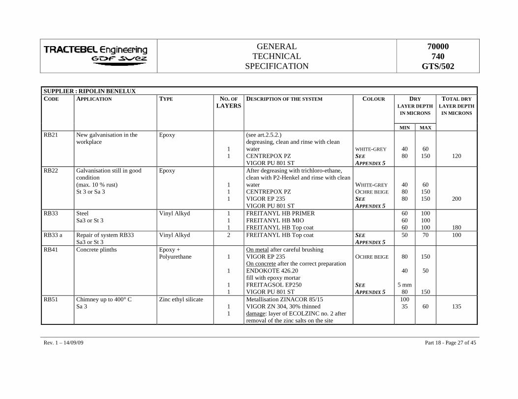
GENERAL TECHNICAL
SPECIFICATION
70000 740
GTS/502
Rev. 1 – 14/09/09 Part 18 - Page 27 of 45
SUPPLIER : RIPOLIN BENELUX CODE APPLICATION TYPE NO. OF
LAYERS DESCRIPTION OF THE SYSTEM COLOUR DRY
LAYER DEPTH IN MICRONS
TOTAL DRY LAYER DEPTH
IN MICRONS
MIN MAX RB21 New galvanisation in the
workplace Epoxy
1 1
(see art.2.5.2.) degreasing, clean and rinse with clean water CENTREPOX PZ VIGOR PU 801 ST
WHITE-GREY SEE APPENDIX 5
40 80
60 150
120
RB22 Galvanisation still in good condition (max. 10 % rust) St 3 or Sa 3
Epoxy
1 1 1
After degreasing with trichloro-ethane, clean with P2-Henkel and rinse with clean water CENTREPOX PZ VIGOR EP 235 VIGOR PU 801 ST
WHITE-GREY OCHRE BEIGE SEE APPENDIX 5
40 80 80
60 150 150
200
RB33 Steel Sa3 or St 3
Vinyl Alkyd 1 1 1
FREITANYL HB PRIMER FREITANYL HB MIO FREITANYL HB Top coat
60 60 60
100 100 100
180 RB33 a Repair of system RB33
Sa3 or St 3 Vinyl Alkyd 2 FREITANYL HB Top coat SEE
APPENDIX 5 50 70 100
RB41 Concrete plinths Epoxy + Polyurethane
1
1
1 1
On metal after careful brushing VIGOR EP 235 On concrete after the correct preparation ENDOKOTE 426.20 fill with epoxy mortar FREITAGSOL EP250 VIGOR PU 801 ST
OCHRE BEIGE SEE APPENDIX 5
80
40
5 mm 80
150
50
150
RB51 Chimney up to 400° C Sa 3
Zinc ethyl silicate 1 1
Metallisation ZINACOR 85/15 VIGOR ZN 304, 30% thinned damage: layer of ECOLZINC no. 2 after removal of the zinc salts on the site
100 35
60
135
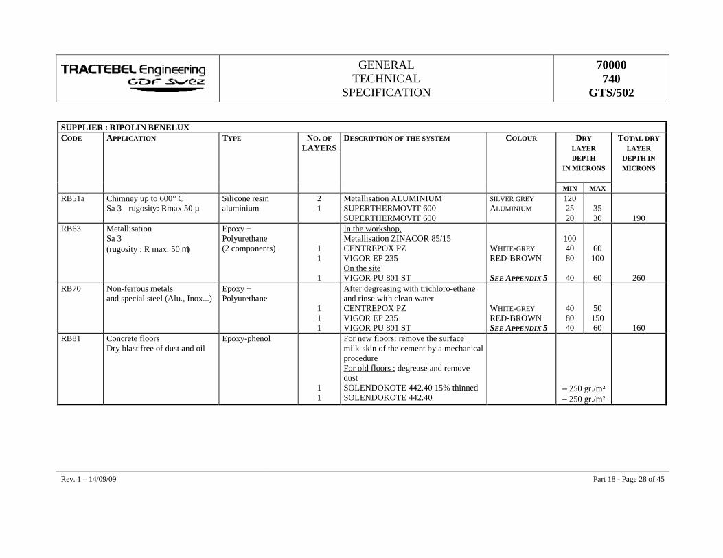
GENERAL TECHNICAL
SPECIFICATION
70000 740
GTS/502
Rev. 1 – 14/09/09 Part 18 - Page 28 of 45
SUPPLIER : RIPOLIN BENELUX CODE APPLICATION TYPE NO. OF
LAYERS DESCRIPTION OF THE SYSTEM COLOUR DRY
LAYER DEPTH
IN MICRONS
TOTAL DRY LAYER
DEPTH IN MICRONS
MIN MAX RB51a Chimney up to 600° C
Sa 3 - rugosity: Rmax 50 µ Silicone resin aluminium
2 1
Metallisation ALUMINIUM SUPERTHERMOVIT 600 SUPERTHERMOVIT 600
SILVER GREY ALUMINIUM
120 25 20
35 30
190 RB63 Metallisation
Sa 3 (rugosity : R max. 50 m)
Epoxy + Polyurethane (2 components)
1 1
1
In the workshop, Metallisation ZINACOR 85/15 CENTREPOX PZ VIGOR EP 235 On the site VIGOR PU 801 ST
WHITE-GREY RED-BROWN SEE APPENDIX 5
100 40 80
40
60 100
60
260 RB70 Non-ferrous metals
and special steel (Alu., Inox...) Epoxy + Polyurethane
1 1 1
After degreasing with trichloro-ethane and rinse with clean water CENTREPOX PZ VIGOR EP 235 VIGOR PU 801 ST
WHITE-GREY RED-BROWN SEE APPENDIX 5
40 80 40
50 150 60
160 RB81 Concrete floors
Dry blast free of dust and oil Epoxy-phenol
1 1
For new floors: remove the surface milk-skin of the cement by a mechanical procedure For old floors : degrease and remove dust SOLENDOKOTE 442.40 15% thinned SOLENDOKOTE 442.40
– 250 gr./m² – 250 gr./m²
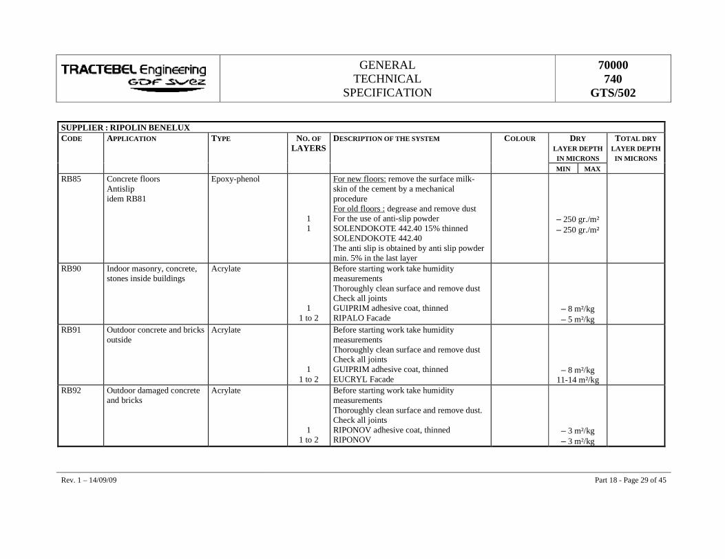
GENERAL TECHNICAL
SPECIFICATION
70000 740
GTS/502
Rev. 1 – 14/09/09 Part 18 - Page 29 of 45
SUPPLIER : RIPOLIN BENELUX CODE APPLICATION TYPE NO. OF
LAYERS DESCRIPTION OF THE SYSTEM COLOUR DRY
LAYER DEPTH IN MICRONS
TOTAL DRY LAYER DEPTH
IN MICRONS MIN MAX RB85 Concrete floors
Antislip idem RB81
Epoxy-phenol
1 1
For new floors: remove the surface milk-skin of the cement by a mechanical procedure For old floors : degrease and remove dust For the use of anti-slip powder SOLENDOKOTE 442.40 15% thinned SOLENDOKOTE 442.40 The anti slip is obtained by anti slip powder min. 5% in the last layer
– 250 gr./m² – 250 gr./m²
RB90 Indoor masonry, concrete, stones inside buildings
Acrylate
1 1 to 2
Before starting work take humidity measurements Thoroughly clean surface and remove dust Check all joints GUIPRIM adhesive coat, thinned RIPALO Facade
– 8 m²/kg – 5 m²/kg
RB91 Outdoor concrete and bricks outside
Acrylate
1 1 to 2
Before starting work take humidity measurements Thoroughly clean surface and remove dust Check all joints GUIPRIM adhesive coat, thinned EUCRYL Facade
– 8 m²/kg 11-14 m²/kg
RB92 Outdoor damaged concrete and bricks
Acrylate
1 1 to 2
Before starting work take humidity measurements Thoroughly clean surface and remove dust. Check all joints RIPONOV adhesive coat, thinned RIPONOV
– 3 m²/kg – 3 m²/kg
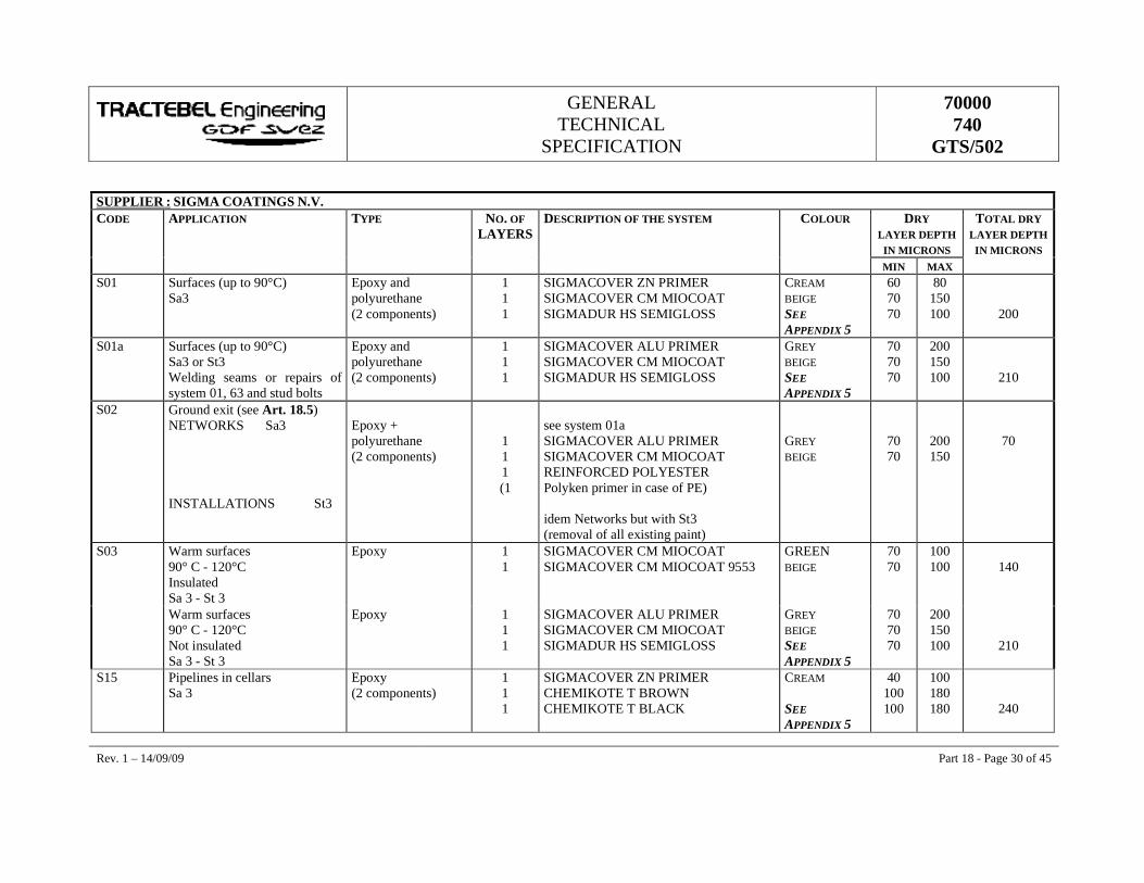
GENERAL TECHNICAL
SPECIFICATION
70000 740
GTS/502
Rev. 1 – 14/09/09 Part 18 - Page 30 of 45
SUPPLIER : SIGMA COATINGS N.V. CODE APPLICATION TYPE NO. OF
LAYERS DESCRIPTION OF THE SYSTEM COLOUR DRY
LAYER DEPTH IN MICRONS
TOTAL DRY LAYER DEPTH
IN MICRONS MIN MAX S01 Surfaces (up to 90°C)
Sa3 Epoxy and polyurethane (2 components)
1 1 1
SIGMACOVER ZN PRIMER SIGMACOVER CM MIOCOAT SIGMADUR HS SEMIGLOSS
CREAM BEIGE SEE APPENDIX 5
60 70 70
80 150 100
200
S01a Surfaces (up to 90°C) Sa3 or St3 Welding seams or repairs of system 01, 63 and stud bolts
Epoxy and polyurethane (2 components)
1 1 1
SIGMACOVER ALU PRIMER SIGMACOVER CM MIOCOAT SIGMADUR HS SEMIGLOSS
GREY BEIGE SEE APPENDIX 5
70 70 70
200 150 100
210
S02 Ground exit (see Art. 18.5) NETWORKS Sa3 INSTALLATIONS St3
Epoxy + polyurethane (2 components)
1 1 1 (1
see system 01a SIGMACOVER ALU PRIMER SIGMACOVER CM MIOCOAT REINFORCED POLYESTER Polyken primer in case of PE) idem Networks but with St3 (removal of all existing paint)
GREY BEIGE
70 70
200 150
70
S03 Warm surfaces 90° C - 120°C Insulated Sa 3 - St 3
Epoxy 1 1
SIGMACOVER CM MIOCOAT SIGMACOVER CM MIOCOAT 9553
GREEN BEIGE
70 70
100 100
140
Warm surfaces 90° C - 120°C Not insulated Sa 3 - St 3
Epoxy 1 1 1
SIGMACOVER ALU PRIMER SIGMACOVER CM MIOCOAT SIGMADUR HS SEMIGLOSS
GREY BEIGE SEE APPENDIX 5
70 70 70
200 150 100
210
S15 Pipelines in cellars Sa 3
Epoxy (2 components)
1 1 1
SIGMACOVER ZN PRIMER CHEMIKOTE T BROWN CHEMIKOTE T BLACK
CREAM SEE APPENDIX 5
40 100 100
100 180 180
240
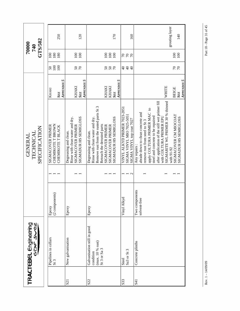
GE
NE
RA
L
TEC
HN
ICA
L
SPE
CIF
ICA
TIO
N
7000
0 74
0 G
TS/
502
R
ev. 1
– 1
4/09
/09
Part
18 -
Page
31
of 4
5
Pipe
lines
in c
ella
rs
St 3
E
poxy
(2
com
pone
nts)
1 1 1
SIG
MA
CO
VE
R P
RIM
ER
C
HE
MIK
OT
E T
BR
OW
N
CH
EM
IKO
TE
T B
LA
CK
KH
AK
I SE
E
APP
EN
DIX
5
50
100
100
100
180
180
25
0
S21
New
gal
vani
satio
n E
poxy
1 1
Deg
reas
ing
and
clea
n.
Rin
se w
ith c
lean
wat
er a
nd d
ry.
SIG
MA
CO
VE
R P
RIM
ER
SI
GM
AD
UR
HS
SEM
IGL
OSS
KH
AK
I S E
E
APP
EN
DIX
5
50
70
10
0 10
0
12
0
S22
Gal
vani
satio
n st
ill in
goo
d co
nditi
on
(max
. 10
% ru
st)
St 3
or S
a 3
Epo
xy
1 1 1
Deg
reas
ing
and
clea
n.
Rin
se w
ith c
lean
wat
er a
nd d
ry.
Rem
ove
rust
from
the
rust
ed p
arts
St 3
R
etou
ch th
e de
rust
ed p
arts
SI
GM
AC
OV
ER
PR
IME
R
SIG
MA
CO
VE
R P
RIM
ER
SI
GM
AD
UR
HS
SEM
IGL
OSS
KH
AK
I K
HA
KI
S EE
A
PPE
ND
IX 5
50
50
70
10
0 10
0 10
0
17
0
S33
Stee
l Sa
3 or
St 3
V
inyl
Alk
yd
1 1 2
VIN
YL
AL
KY
D P
RIM
ER
702
3-20
51
SIG
MA
VIN
YL
MIO
702
5-50
51
SIG
MA
VIN
YL
top
coat
702
7
40
40
40
70
70
70
16
0 S4
1 C
oncr
ete
plin
ths
Tw
o co
mpo
nent
s so
lven
t-fr
ee
1 1 1 1
Any
repa
irs
:
abra
de d
own
to c
lean
con
cret
e an
d re
mov
e ru
st fr
om s
teel
to S
t 3
ap
ply
CO
LTU
RA
PR
IME
R M
AC
to
stee
l and
con
cret
e to
be
repa
ired
afte
r app
licat
ion
of th
e st
ill w
et p
rim
er fi
ll w
ith C
OL
TU
RA
PR
IME
R E
PU
SIG
MA
RIT
E W
L P
RIM
ER
30
% th
inne
d w
ith 9
1-92
SI
GM
AC
OV
ER
CM
MIO
CO
AT
SI
GM
AD
UR
HS
SEM
IGL
OSS
WH
ITE
BE
IGE
S EE
A
PPE
ND
IX 5
70
70
10
0 10
0
gr
outin
g la
yer
14
0

GENERAL TECHNICAL
SPECIFICATION
70000 740
GTS/502
Rev. 1 – 14/09/09 Part 18 - Page 32 of 45
S51 Chimneys 450° C
Sa3
1
1
In the workshop Metallisation ZN 100 ZINACOR 85/15 SIGMASILGUARD MC, thinned 50% with 90-53 On the site Remove chloride by washing off with water to which a detergent has been added, with a hard brush SIGMASILGUARD MC, 50 % thinned with 90-53
100 35
35
55
55
– 170
S51a Chimneys up to 600° C Sa 3 - rugosity: Rmax 50 µ
Alu silicate 1 1
Metallisation Alu. SIGMATERM SILICAAT ALUMINIUM
120 30
150
S63 Metallisation Sa 3 (rugosity : R max. 50 m)
Epoxy (2 components) Polyurethane
1 1
1
In the workshop Metallisation ZN 100 ZINACOR 85/15 SIGMARITE SEALANT 20% thinned SIGMACOVER CM MIOCOAT On the site SIGMADUR HS SEMIGLOSS
GREEN BEIGE SEE APPENDIX 5
100 40 70
70
60 150
100
280
S70 Non-ferrous metals (Alu, Inox ...)
Epoxy (2 components) Polyurethane
1 1 1
Preparation Remove the oxidation layer with Deoxidiser 670 solution and. hard nylon brush. Rinse off to remove every trace of Deoxidiser. On the still wet surface, apply Alodine 1200* (ready for use) * Instructions Henkel SIGMACOVER PRIMER SIGMACOVER CM MIOCOAT SIGMADUR HS SEMIGLOSS
KHAKI BEIGE SEE APPENDIX 5
50 70 70
100 150 100
190
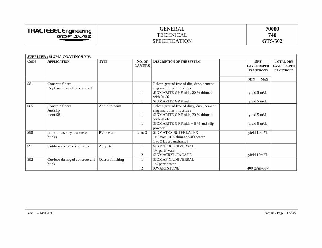
GENERAL TECHNICAL
SPECIFICATION
70000 740
GTS/502
Rev. 1 – 14/09/09 Part 18 - Page 33 of 45
SUPPLIER : SIGMA COATINGS N.V. CODE APPLICATION TYPE NO. OF
LAYERS DESCRIPTION OF THE SYSTEM DRY
LAYER DEPTH IN MICRONS
TOTAL DRY LAYER DEPTH IN MICRONS
MIN MAX S81 Concrete floors
Dry blast, free of dust and oil
1
1
Below-ground free of dirt, dust, cement slag and other impurities SIGMARITE GP Finish, 20 % thinned with 91-92 SIGMARITE GP Finish
yield 5 m²/L
yield 5 m²/L
S85 Concrete floors Antislip idem S81
Anti-slip paint
1
1
Below-ground free of dirty, dust, cement slag and other impurities SIGMARITE GP Finish, 20 % thinned with 91-92 SIGMARITE GP Finish + 5 % anti-slip powder
yield 5 m²/L
yield 5 m²/L
S90 Indoor masonry, concrete, bricks
PV acetate 2 to 3 SIGMATEX SUPERLATEX 1st layer 10 % thinned with water 1 or 2 layers unthinned
yield 10m²/L
S91 Outdoor concrete and brick Acrylate 1
2
SIGMAFIX UNIVERSAL 1/4 parts water SIGMACRYL FACADE
yield 10m²/L
S92 Outdoor damaged concrete and brick
Quartz finishing 1
2
SIGMAFIX UNIVERSAL 1/4 parts water KWARTSTONE
400 gr/m²/low

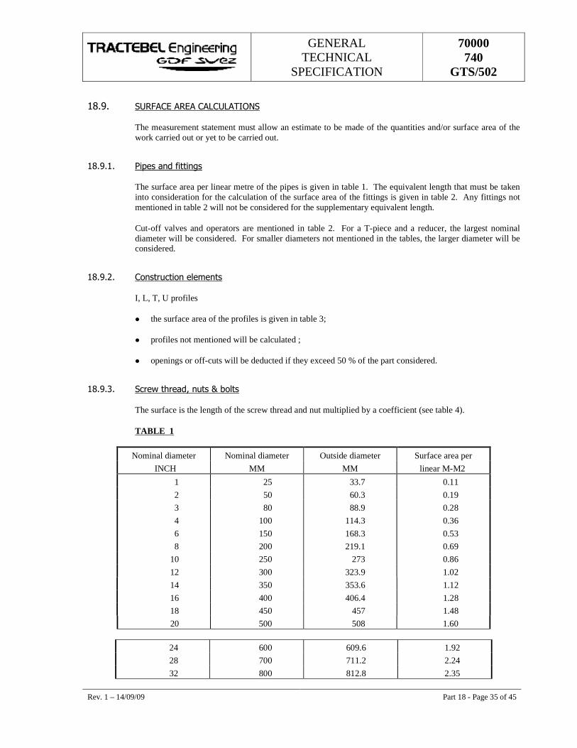
GENERAL TECHNICAL
SPECIFICATION
70000 740
GTS/502
Rev. 1 – 14/09/09 Part 18 - Page 35 of 45
���1� *+�(�������������+���&'�*�
The measurement statement must allow an estimate to be made of the quantities and/or surface area of the work carried out or yet to be carried out.
���1��� �����������%��
The surface area per linear metre of the pipes is given in table 1. The equivalent length that must be taken into consideration for the calculation of the surface area of the fittings is given in table 2. Any fittings not mentioned in table 2 will not be considered for the supplementary equivalent length.
Cut-off valves and operators are mentioned in table 2. For a T-piece and a reducer, the largest nominal diameter will be considered. For smaller diameters not mentioned in the tables, the larger diameter will be considered.
���1��� � ������ ��!������
I, L, T, U profiles
� the surface area of the profiles is given in table 3;
� profiles not mentioned will be calculated ;
� openings or off-cuts will be deducted if they exceed 50 % of the part considered.
���1� � *�����������6�����>�, !���
The surface is the length of the screw thread and nut multiplied by a coefficient (see table 4).
TABLE 1
Nominal diameter Nominal diameter Outside diameter Surface area per INCH MM MM linear M-M2
1 25 33.7 0.11 2 50 60.3 0.19 3 80 88.9 0.28 4 100 114.3 0.36 6 150 168.3 0.53 8 200 219.1 0.69
10 250 273 0.86 12 300 323.9 1.02 14 350 353.6 1.12 16 400 406.4 1.28 18 450 457 1.48 20 500 508 1.60
24 600 609.6 1.92 28 700 711.2 2.24 32 800 812.8 2.35
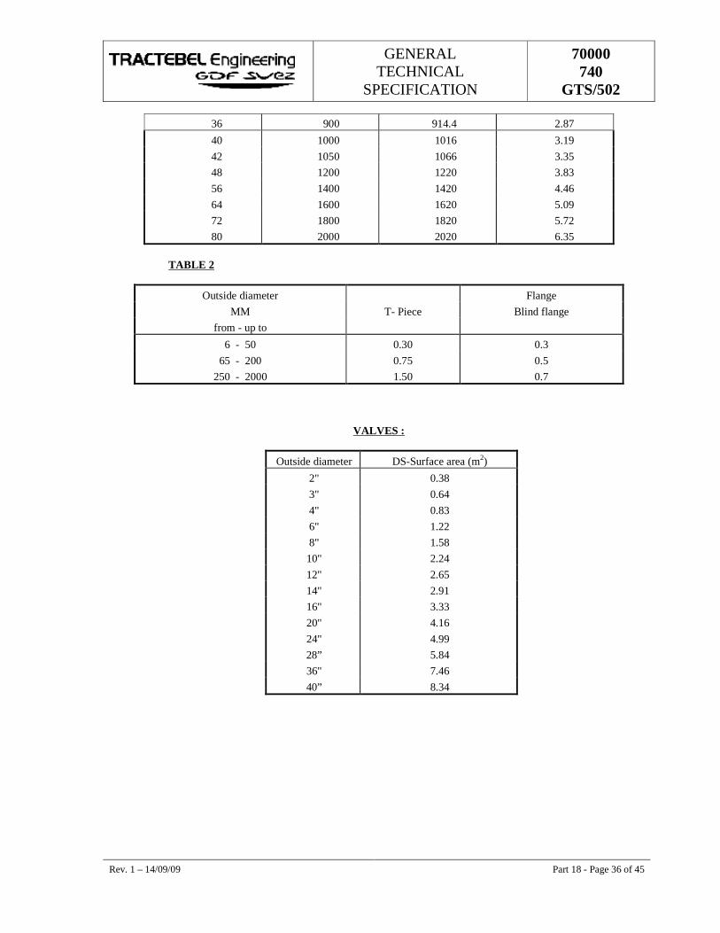
GENERAL TECHNICAL
SPECIFICATION
70000 740
GTS/502
Rev. 1 – 14/09/09 Part 18 - Page 36 of 45
36 900 914.4 2.87
40 1000 1016 3.19 42 1050 1066 3.35 48 1200 1220 3.83 56 1400 1420 4.46 64 1600 1620 5.09 72 1800 1820 5.72 80 2000 2020 6.35
TABLE 2
Outside diameter Flange MM T- Piece Blind flange
from - up to
6 - 50 0.30 0.3 65 - 200 0.75 0.5
250 - 2000 1.50 0.7
VALVES :
Outside diameter DS-Surface area (m2)
2" 0.38 3" 0.64 4" 0.83 6" 1.22 8" 1.58 10" 2.24 12" 2.65 14" 2.91 16" 3.33 20" 4.16 24" 4.99 28” 5.84 36" 7.46 40” 8.34
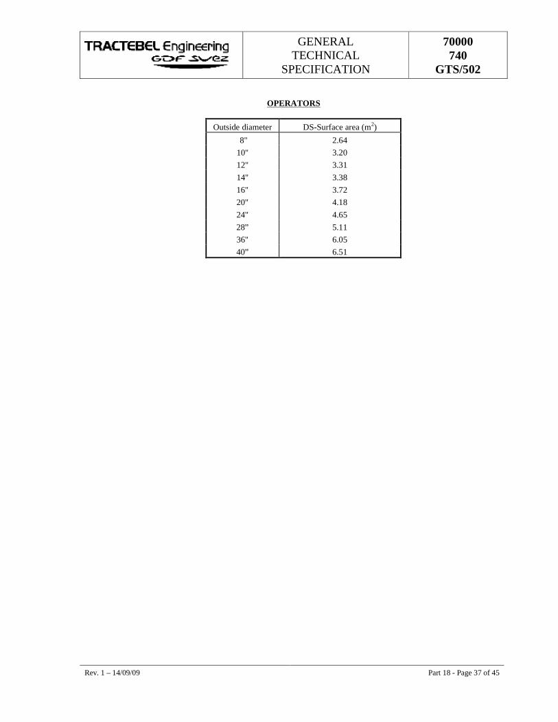
GENERAL TECHNICAL
SPECIFICATION
70000 740
GTS/502
Rev. 1 – 14/09/09 Part 18 - Page 37 of 45
OPERATORS
Outside diameter DS-Surface area (m2)
8" 2.64 10" 3.20 12" 3.31 14" 3.38 16" 3.72 20" 4.18 24" 4.65 28” 5.11 36" 6.05 40” 6.51
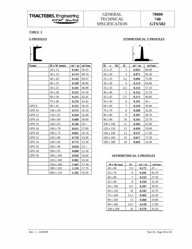
GENERAL TECHNICAL
SPECIFICATION
70000 740
GTS/502
Rev. 1 – 14/09/09 Part 18 - Page 38 of 45
TABLE 3
U-PROFILES SYMMETRICAL T-PROFILES
Name H x W (mm) m² / m m²/ton H x W D m² / m m²/ton 30 x 15 0.103 59.19 15 x 15 3 0.055 84.60
30 x 33 0.174 40.74 20 x 20 3 0.075 85.20
40 x 20 0.142 49.47 25 x 25 3.2 0.094 72.90
40 x 35 0.199 40.86 30 x 30 4 0.114 64.40
50 x 25 0.181 46.89 35 x 35 4.5 0.133 57.10
50 x 38 0.232 41.50 40 x 40 5 0.153 51.70
60 x 30 0.215 42.41 45 x 45 5.5 0.171 46.60
70 x 40 0.276 41.02 50 x 50 6 0.191 43.--
UPN 8 80 x 45 0.312 36.10 60 x 60 7 0.229 36.80
UPN 10 100 x 50 0.372 35.10 70 x 70 8 0.268 32.20
UPN 12 120 x 55 0.434 32.40 80 x 80 9 0.307 28.70
UPN 14 140 x 60 0.489 30.60 90 x 90 10 0.345 25.70
UPN 16 160 x 65 0.546 29.-- 100 x 100 11 0.383 23.40
UPN 18 180 x 70 0.611 27.80 120 x 120 13 0.459 19.80
UPN 20 200 x 75 0.661 26.10 140 x 140 15 0.537 17.20
UPN 22 220 x 80 0.718 24.40 160 x 160 15 0.617 17.20
UPN 24 240 x 85 0.775 23.30 180 x 180 18 0.693 14.30
UPN 26 260 x 90 0.834 22.--
UPN 28 280 x 95 0.890 21.30
UPN 30 300 x 100 0.950 20.60 ASYMMETRICAL T-PROFILES 320 x 100 0.982 16.50
350 x 100 1.047 17.30 H x W mm D m² / m m²/ton 380 x 102 1.110 17.70 30 x 60 5.5 0.171 47.--
400 x 110 1.182 16.50 35 x 70 6 0.201 43.10
40 x 80 7 0.233 37.50
45 x 90 8 0.258 32.20
50 x 100 8.5 0.287 30.50
60 x 120 10 0.345 25.70
70 x 140 11.5 0.402 22.50
80 x 160 13 0.460 19.80
90 x 180 14.5 0.518 17.80
100 x 200 16 0.576 16.20
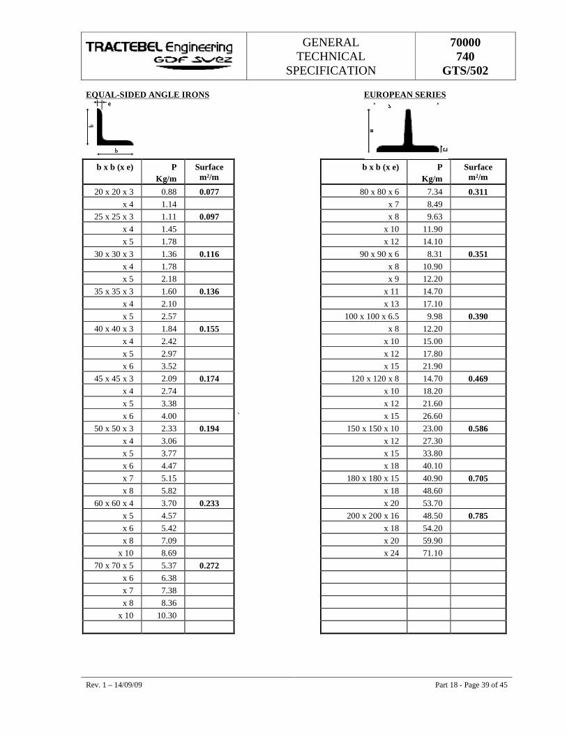
GENERAL TECHNICAL
SPECIFICATION
70000 740
GTS/502
Rev. 1 – 14/09/09 Part 18 - Page 39 of 45
EQUAL-SIDED ANGLE IRONS EUROPEAN SERIES
b x b (x e) P Kg/m
Surface m²/m
b x b (x e) P Kg/m
Surface m²/m
20 x 20 x 3 0.88 0.077 80 x 80 x 6 7.34 0.311 x 4 1.14 x 7 8.49
25 x 25 x 3 1.11 0.097 x 8 9.63 x 4 1.45 x 10 11.90 x 5 1.78 x 12 14.10
30 x 30 x 3 1.36 0.116 90 x 90 x 6 8.31 0.351 x 4 1.78 x 8 10.90 x 5 2.18 x 9 12.20
35 x 35 x 3 1.60 0.136 x 11 14.70 x 4 2.10 x 13 17.10 x 5 2.57 100 x 100 x 6.5 9.98 0.390
40 x 40 x 3 1.84 0.155 x 8 12.20 x 4 2.42 x 10 15.00 x 5 2.97 x 12 17.80 x 6 3.52 x 15 21.90
45 x 45 x 3 2.09 0.174 120 x 120 x 8 14.70 0.469 x 4 2.74 x 10 18.20 x 5 3.38 x 12 21.60 x 6 4.00 ` x 15 26.60
50 x 50 x 3 2.33 0.194 150 x 150 x 10 23.00 0.586 x 4 3.06 x 12 27.30 x 5 3.77 x 15 33.80 x 6 4.47 x 18 40.10 x 7 5.15 180 x 180 x 15 40.90 0.705 x 8 5.82 x 18 48.60
60 x 60 x 4 3.70 0.233 x 20 53.70 x 5 4.57 200 x 200 x 16 48.50 0.785 x 6 5.42 x 18 54.20 x 8 7.09 x 20 59.90
x 10 8.69 x 24 71.10 70 x 70 x 5 5.37 0.272
x 6 6.38 x 7 7.38 x 8 8.36
x 10 10.30
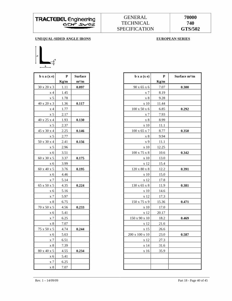
GENERAL TECHNICAL
SPECIFICATION
70000 740
GTS/502
Rev. 1 – 14/09/09 Part 18 - Page 40 of 45
UNEQUAL-SIDED ANGLE IRONS EUROPEAN SERIES
b x a (x e) P Kg/m
Surface m²/m
b x a (x e) P Kg/m
Surface m²/m
30 x 20 x 3 1.11 0.097 90 x 65 x 6 7.07 0.300 x 4 1.45 x 7 8.19 x 5 1.78 x 8 9.28
40 x 20 x 3 1.36 0.117 x 10 11.44 x 4 1.77 100 x 50 x 6 6.85 0.292 x 5 2.17 x 7 7.93
40 x 25 x 4 1.93 0.130 x 8 8.99 x 5 2.37 x 10 11.1
45 x 30 x 4 2.25 0.146 100 x 65 x 7 8.77 0.350 x 5 2.77 x 8 9.94
50 x 30 x 4 2.41 0.156 x 9 11.1 x 5 2.96 x 10 12.25 x 6 3.51 100 x 75 x 8 10.6 0.342
60 x 30 x 5 3.37 0.175 x 10 13.0 x 6 3.99 x 12 15.4
60 x 40 x 5 3.76 0.195 120 x 80 x 8 12.2 0.391 x 6 4.46 x 10 15.0 x 7 5.14 x 12 17.8
65 x 50 x 5 4.35 0.224 130 x 65 x 8 11.9 0.381 x 6 5.16 x 10 14.6 x 7 5.97 x 12 17.3
x 8 6.75 150 x 75 x 9 15.36 0.471 70 x 50 x 5 4.56 0.233 x 10 17.0
x 6 5.41 x 12 20.17
x 7 6.25 150 x 90 x 10 18.2 0.469 x 8 7.07 x 12 21.6
75 x 50 x 5 4.74 0.244 x 15 26.6 x 6 5.63 200 x 100 x 10 23.0 0.587 x 7 6.51 x 12 27.3 x 8 7.39 x 14 31.6
80 x 40 x 5 4.55 0.234 x 16 35.9 x 6 5.41 x 7 6.25
x 8 7.07
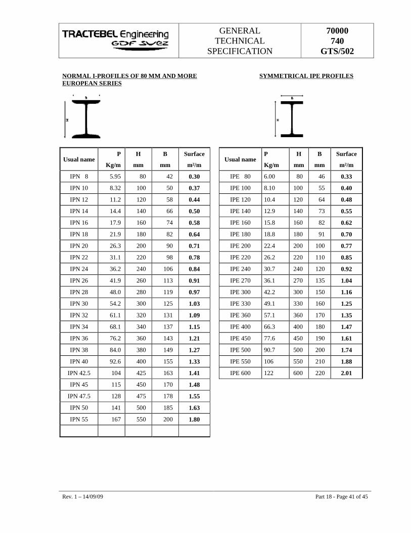
GENERAL TECHNICAL
SPECIFICATION
70000 740
GTS/502
Rev. 1 – 14/09/09 Part 18 - Page 41 of 45
NORMAL I-PROFILES OF 80 MM AND MORE SYMMETRICAL IPE PROFILES EUROPEAN SERIES
Usual name P
Kg/m
H
mm
B
mm
Surface
m²/m Usual name
P
Kg/m
H
mm
B
mm
Surface
m²/m
IPN 8 5.95 80 42 0.30 IPE 80 6.00 80 46 0.33
IPN 10 8.32 100 50 0.37 IPE 100 8.10 100 55 0.40
IPN 12 11.2 120 58 0.44 IPE 120 10.4 120 64 0.48
IPN 14 14.4 140 66 0.50 IPE 140 12.9 140 73 0.55
IPN 16 17.9 160 74 0.58 IPE 160 15.8 160 82 0.62
IPN 18 21.9 180 82 0.64 IPE 180 18.8 180 91 0.70
IPN 20 26.3 200 90 0.71 IPE 200 22.4 200 100 0.77
IPN 22 31.1 220 98 0.78 IPE 220 26.2 220 110 0.85
IPN 24 36.2 240 106 0.84 IPE 240 30.7 240 120 0.92
IPN 26 41.9 260 113 0.91 IPE 270 36.1 270 135 1.04
IPN 28 48.0 280 119 0.97 IPE 300 42.2 300 150 1.16
IPN 30 54.2 300 125 1.03 IPE 330 49.1 330 160 1.25
IPN 32 61.1 320 131 1.09 IPE 360 57.1 360 170 1.35
IPN 34 68.1 340 137 1.15 IPE 400 66.3 400 180 1.47
IPN 36 76.2 360 143 1.21 IPE 450 77.6 450 190 1.61
IPN 38 84.0 380 149 1.27 IPE 500 90.7 500 200 1.74
IPN 40 92.6 400 155 1.33 IPE 550 106 550 210 1.88
IPN 42.5 104 425 163 1.41 IPE 600 122 600 220 2.01
IPN 45 115 450 170 1.48
IPN 47.5 128 475 178 1.55
IPN 50 141 500 185 1.63
IPN 55 167 550 200 1.80
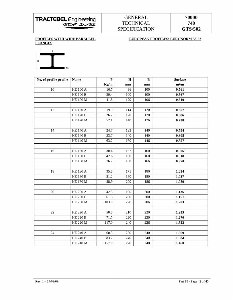
GENERAL TECHNICAL
SPECIFICATION
70000 740
GTS/502
Rev. 1 – 14/09/09 Part 18 - Page 42 of 45
PROFILES WITH WIDE PARALLEL EUROPEAN PROFILES: EURONORM 53-62 FLANGES
No. of profile profile Name P Kg/m
H mm
B mm
Surface m²/m
10 HE 100 A 16.7 96 100 0.561 HE 100 B 20.4 100 100 0.567 HE 100 M 41.8 120 106 0.619
12 HE 120 A 19.9 114 120 0.677 HE 120 B 26.7 120 120 0.686 HE 120 M 52.1 140 126 0.738
14 HE 140 A 24.7 133 140 0.794 HE 140 B 33.7 140 140 0.805 HE 140 M 63.2 160 146 0.857
16 HE 160 A 30.4 152 160 0.906 HE 160 B 42.6 160 160 0.918 HE 160 M 76.2 180 166 0.970
18 HE 180 A 35.5 171 180 1.024 HE 180 B 51.2 180 180 1.037 HE 180 M 88.9 200 186 1.089
20 HE 200 A 42.3 190 200 1.136 HE 200 B 61.3 200 200 1.151 HE 200 M 103.0 220 206 1.203
22 HE 220 A 50.5 210 220 1.255 HE 220 B 71.5 220 220 1.270 HE 220 M 117.0 240 226 1.322
24 HE 240 A 60.3 230 240 1.369 HE 240 B 83.2 240 240 1.384 HE 240 M 157.0 270 248 1.460
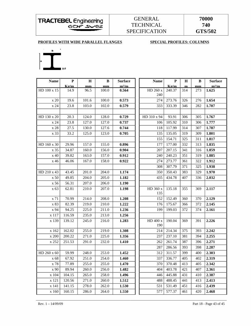
GENERAL TECHNICAL
SPECIFICATION
70000 740
GTS/502
Rev. 1 – 14/09/09 Part 18 - Page 43 of 45
PROFILES WITH WIDE PARALLEL FLANGES SPECIAL PROFILES: COLUMNS
Name P Kg/m
H mm
B mm
Surface m²/m
Name P Kg/m
H m
B mm
Surface m²/m
HD 100 x 15 14.9 96.5 100.0 0.564 HD 260 x 240
240.37 314 273 1.625
x 20 19.6 101.6 100.0 0.573 274 273.76 326 276 1.654 x 24 23.8 103.0 102.0 0.579 333 333.39 346 282 1.707
HD 130 x 20 20.3 124.0 128.0 0.729 HD 310 x 94 93.91 306 305 1.767
x 24 23.8 127.0 127.0 0.737 106 105.92 310 306 1.777 x 28 27.5 130.0 127.6 0.744 118 117.99 314 307 1.787 x 33 33.2 125.0 123.0 0.705 135 135.05 319 309 1.801
155 154.71 325 311 1.817 HD 160 x 30 29.96 157.0 155.0 0.896 177 177.00 332 313 1.835
x 35 34.87 160.0 156.0 0.904 207 207.15 341 316 1.859 x 40 39.82 163.0 157.0 0.912 240 240.23 351 319 1.885 x 46 46.06 167.0 158.0 0.922 274 273.77 361 322 1.912
308 307.79 371 325 1.938 HD 210 x 43 43.45 201.0 204.0 1.174 350 350.43 383 329 1.970
x 50 49.85 204.0 205.0 1.182 435 434.78 407 336 2.032 x 56 56.31 207.0 206.0 1.190 x 63 62.81 210.0 207.0 1.198 HD 360 x
135 135.18 355 369 2.117
x 71 70.99 214.0 208.0 1.208 152 152.49 360 370 2.129 x 83 82.39 219.0 210.0 1.222 176 175.67 366 372 2.145 x 94 94.25 225.0 211.0 1.236 199 199.03 372 374 2.161
x 117 116.59 235.0 213.0 1.256 x 139 139.12 245.0 216.0 1.283 HD 400 x
190 190.04 369 391 2.226
x 162 162.02 255.0 219.0 1.308 214 214.34 375 393 2.242 x 200 200.22 271.0 225.0 1.356 237 237.10 381 394 2.255 x 252 251.53 291.0 232.0 1.410 262 261.74 387 396 2.271
287 286.56 393 398 2.287 HD 260 x 60 59.99 248.0 253.0 1.452 312 311.57 399 400 2.303
x 68 67.92 251.0 254.0 1.460 337 336.77 405 402 2.319 x 78 77.89 255.0 255.0 1.470 370 370.48 413 405 2.342 x 90 89.94 260.0 256.0 1.482 404 403.78 421 407 2.361
x 104 104.15 265.0 258.0 1.496 446 445.88 431 410 2.387 x 121 120.56 271.0 260.0 1.512 488 488.45 441 413 2.413 x 141 141.15 278.0 262.0 1.530 531 531.49 451 416 2.439 x 160 160.15 286.0 264.0 1.550 577 577.37 461 420 2.468
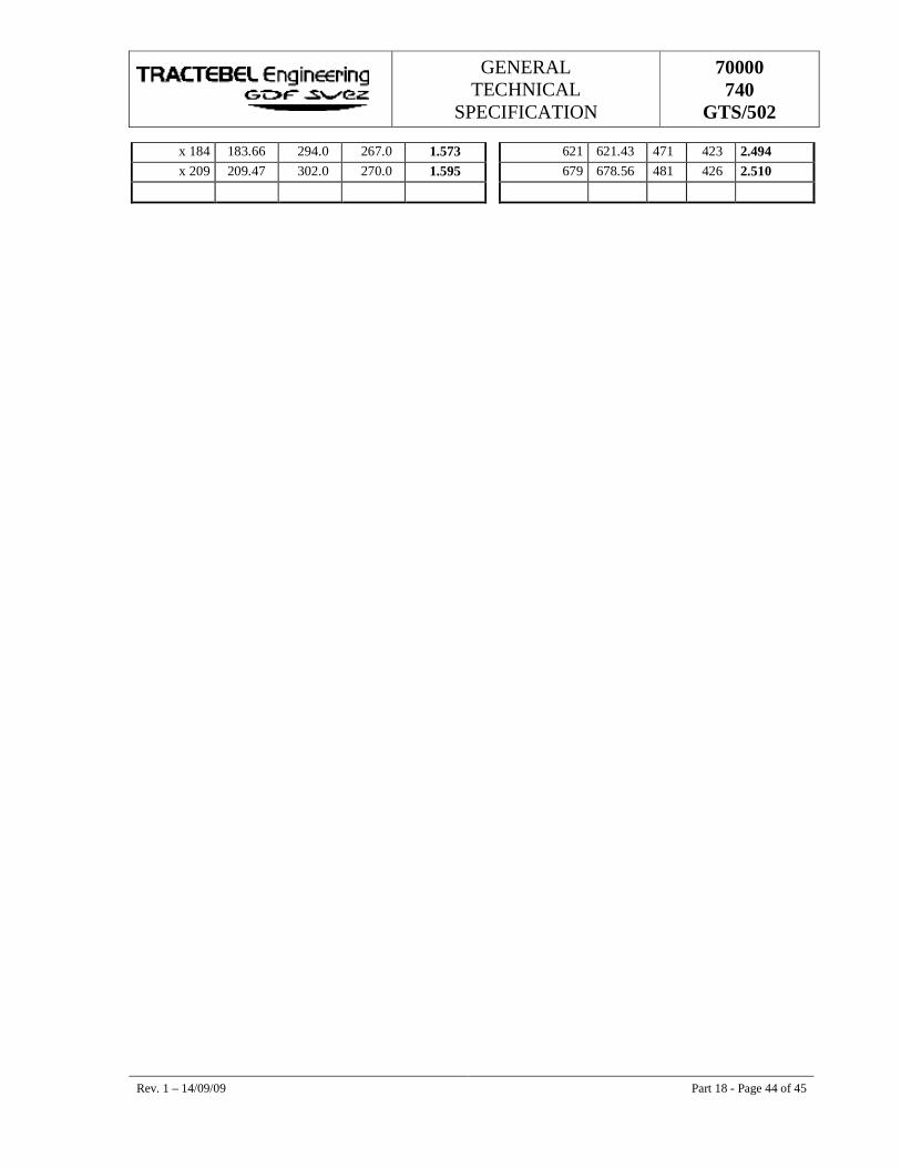
GENERAL TECHNICAL
SPECIFICATION
70000 740
GTS/502
Rev. 1 – 14/09/09 Part 18 - Page 44 of 45
x 184 183.66 294.0 267.0 1.573 621 621.43 471 423 2.494 x 209 209.47 302.0 270.0 1.595 679 678.56 481 426 2.510
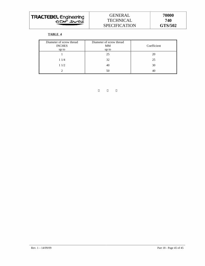
GENERAL TECHNICAL
SPECIFICATION
70000 740
GTS/502
Rev. 1 – 14/09/09 Part 18 - Page 45 of 45
TABLE 4
Diameter of screw thread Diameter of screw thread INCHES MM Coefficient
up to up to
1 25 20
1 1/4 32 25
1 1/2 40 30
2 50 40
S S S
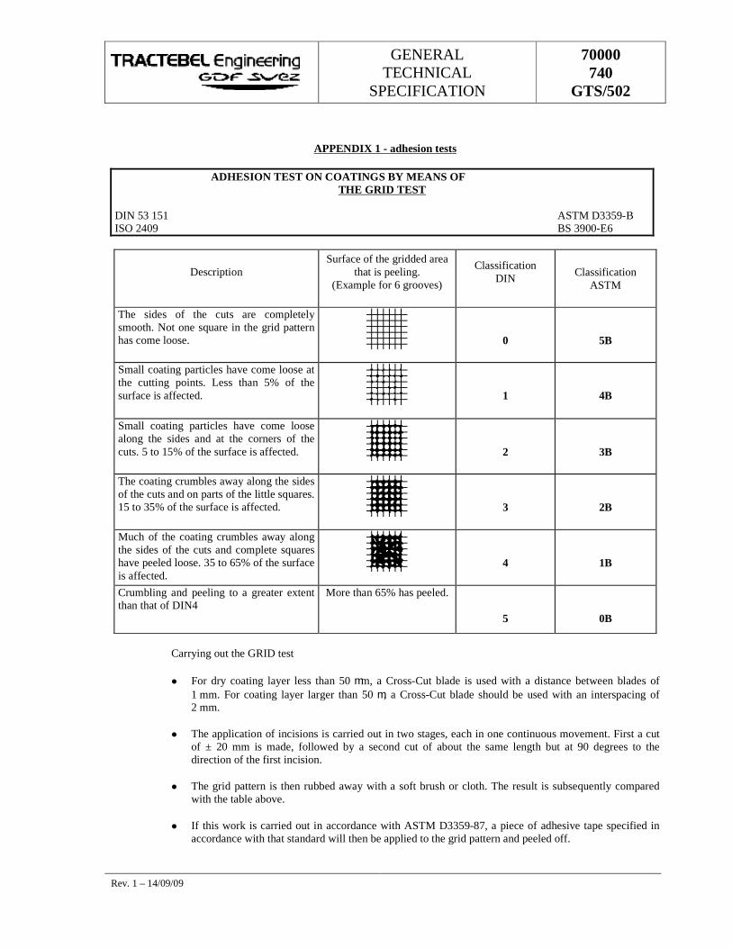
GENERAL TECHNICAL
SPECIFICATION
70000 740
GTS/502
Rev. 1 – 14/09/09
APPENDIX 1 - adhesion tests
ADHESION TEST ON COATINGS BY MEANS OF THE GRID TEST
DIN 53 151 ASTM D3359-B ISO 2409 BS 3900-E6
Description Surface of the gridded area
that is peeling. (Example for 6 grooves)
Classification DIN Classification
ASTM
The sides of the cuts are completely smooth. Not one square in the grid pattern has come loose.
0
5B
Small coating particles have come loose at the cutting points. Less than 5% of the surface is affected.
1
4B
Small coating particles have come loose along the sides and at the corners of the cuts. 5 to 15% of the surface is affected.
2
3B
The coating crumbles away along the sides of the cuts and on parts of the little squares. 15 to 35% of the surface is affected.
3
2B
Much of the coating crumbles away along the sides of the cuts and complete squares have peeled loose. 35 to 65% of the surface is affected.
4
1B
Crumbling and peeling to a greater extent than that of DIN4
More than 65% has peeled.
5
0B
Carrying out the GRID test
� For dry coating layer less than 50 mm, a Cross-Cut blade is used with a distance between blades of 1 mm. For coating layer larger than 50 m, a Cross-Cut blade should be used with an interspacing of 2 mm.
� The application of incisions is carried out in two stages, each in one continuous movement. First a cut of ± 20 mm is made, followed by a second cut of about the same length but at 90 degrees to the direction of the first incision.
� The grid pattern is then rubbed away with a soft brush or cloth. The result is subsequently compared with the table above.
� If this work is carried out in accordance with ASTM D3359-87, a piece of adhesive tape specified in accordance with that standard will then be applied to the grid pattern and peeled off.
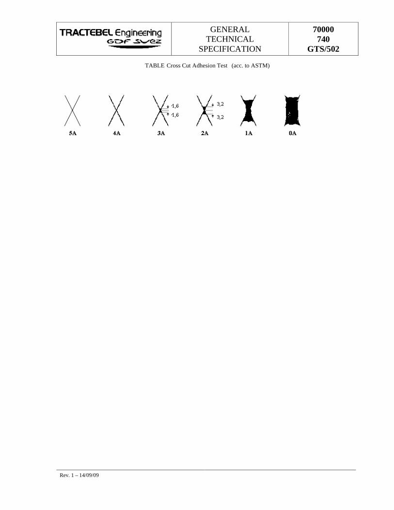
GENERAL TECHNICAL
SPECIFICATION
70000 740
GTS/502
Rev. 1 – 14/09/09
TABLE Cross Cut Adhesion Test (acc. to ASTM)
GENERAL TECHNICAL
SPECIFICATION
70000 740
GTS/502
Rev. 1 – 14/09/09
APPENDIX 2 WORK METHOD FOR REINFORCED POLYESTER
� Information about the product
� is a polyester coating in rolls;
� is a plastic easy to work with, reinforced with glass fibre (G.R.P.);
� is made in sheets and delivered as standard in 10 m x 2 mm rolls;
� in its untreated form is extremely flexible; it can be cut to any shape or in accordance with the required format; it can then be fashioned, adapted, rolled up, rolled out and/or fitted to practically any object or surface;
� when exposed to UV light, it begins to harden after a few minutes and will become hard over a period of a few hours;
� once hardened is:
� an extremely strong and inalterable material with an exceptional lifetime and good resistance to heat;
� waterproof;
� resistant to a large number of acids, chemical products and solvents;
� offers numerous possibilities:
� clean, safe and extremely easy to use;
� quality always guaranteed;
� maintains its strength, weight and lifetime;
� has a resistance stronger than UV;
� minimum waste.
� Painting firms
Paint appliers :
� must be officially recognised and registered;
� must be known and given a permit by DuPol Benelux;
� once registered and given a permit, they will undergo training by the instructors of DuPol;
� after the training and practical experience, they will be taken on as “recognised appliers of reinforced polyester”;
� every year an assessment will take place regarding the working method used and the knowledge developed with reinforced polyester.
Application
� requires the use of suitable tools and accessories of good quality, such as:
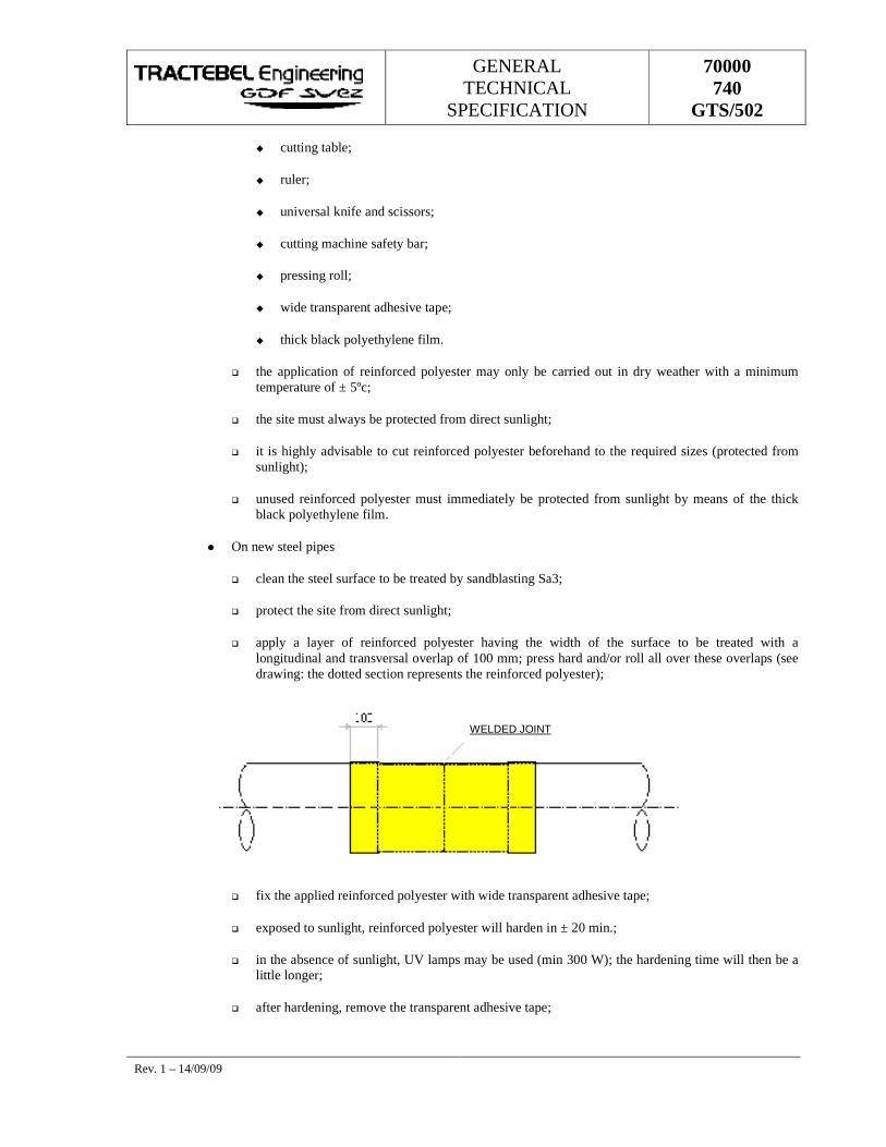
GENERAL TECHNICAL
SPECIFICATION
70000 740
GTS/502
Rev. 1 – 14/09/09
� cutting table;
� ruler;
� universal knife and scissors;
� cutting machine safety bar;
� pressing roll;
� wide transparent adhesive tape;
� thick black polyethylene film.
� the application of reinforced polyester may only be carried out in dry weather with a minimum temperature of ± 5ºc;
� the site must always be protected from direct sunlight;
� it is highly advisable to cut reinforced polyester beforehand to the required sizes (protected from sunlight);
� unused reinforced polyester must immediately be protected from sunlight by means of the thick black polyethylene film.
� On new steel pipes
� clean the steel surface to be treated by sandblasting Sa3;
� protect the site from direct sunlight;
� apply a layer of reinforced polyester having the width of the surface to be treated with a longitudinal and transversal overlap of 100 mm; press hard and/or roll all over these overlaps (see drawing: the dotted section represents the reinforced polyester);
� fix the applied reinforced polyester with wide transparent adhesive tape;
� exposed to sunlight, reinforced polyester will harden in ± 20 min.;
� in the absence of sunlight, UV lamps may be used (min 300 W); the hardening time will then be a little longer;
� after hardening, remove the transparent adhesive tape;
WELDED JOINT
GENERAL TECHNICAL
SPECIFICATION
70000 740
GTS/502
Rev. 1 – 14/09/09
� for increased protection, it is recommended to use UV resin (UVH-100) on the transversal and longitudinal overlaps;
� use UV resin (UVH-100) beforehand for jointing with already hardened reinforced polyester.
� On existing steel pipes (after sandblasting)
� remove the old coating;
� sandblast Sa3 to check the condition of the surface;
� repair or replace the metal, if necessary;
� derust manually to St3;
� apply a layer of ALUTEC and/or PRIMER (D400);
� protect the site against sunlight;
� after drying, apply reinforced polyester over the width of the surface to be treated with an overlap of 100 mm; press hard and/or roll all over these overlaps;
� spread the extremities with UV resin (UVH-100);
� fix the applied reinforced polyester with wide transparent adhesive tape;
� exposed to sunlight, reinforced polyester will harden in ± 20 min.;
� in the absence of sunlight, UV lamps may be used (min 300 W); the hardening time will then be a little longer;
� use UV resin (UVH-100) beforehand for jointing with already hardened reinforced polyester.
� Existing steel pipes (without sandblasting)
� do not remove the old coating, but do remove dust;
� apply 1 layer of PRIMER (D400);
� protect the site from direct sunlight;
� after drying (± 1 to 1 ½ hours), apply reinforced polyester over the width of the surface to be treated with an overlap of 100 mm; press hard and/or roll all over these overlaps;
� spread the extremities with UV resin (UVH-100);
� fix the applied reinforced polyester with wide transparent adhesive tape;
� exposed to sunlight, reinforced polyester will harden in ± 20 min.;
� in the absence of sunlight, UV lamps may be used (min 300 W); the hardening time will then be a little longer;
� use UV resin (UVH-100) beforehand for jointing with already hardened reinforced polyester.
� Concrete
GENERAL TECHNICAL
SPECIFICATION
70000 740
GTS/502
Rev. 1 – 14/09/09
� clean the surface to be treated and, if necessary, smooth it;
� apply 1 layer of PRIMER (D400);
� protect the site from direct sunlight;
� after drying (± 1 to 1 ½ hours), apply reinforced polyester over the width of the surface to be treated with an overlap of 50 mm;
� press hard and/or roll over the reinforced polyester;
� it is recommended to use UV resin (UVH-100) and vulcanising on the overlaps for a better seal before applying the next layer of reinforced polyester;
� exposed to sunlight, reinforced polyester will harden in ± 20 min.;
� in the absence of sunlight, UV lamps may be used (min 300 W); the hardening time will then be a little longer;
� use UV resin (UVH-100) beforehand for jointing with already hardened reinforced polyester.
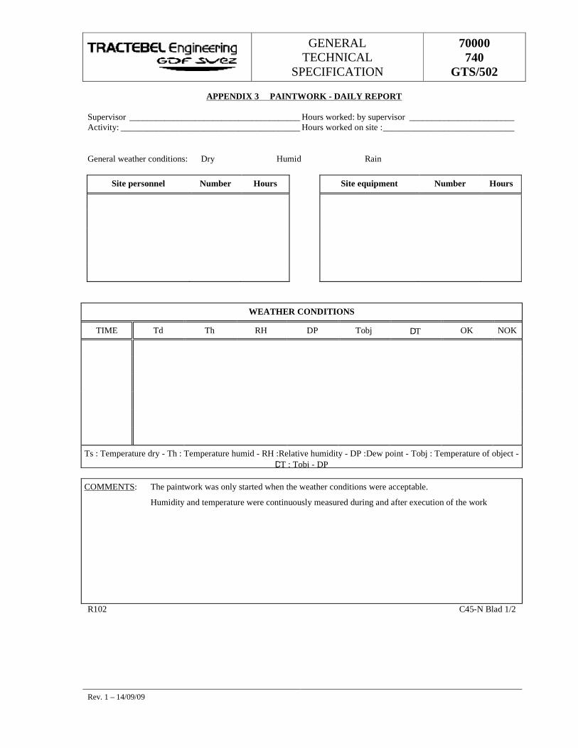
GENERAL TECHNICAL
SPECIFICATION
70000 740
GTS/502
Rev. 1 – 14/09/09
APPENDIX 3 PAINTWORK - DAILY REPORT
Supervisor _______________________________________ Hours worked: by supervisor ________________________ Activity: _________________________________________ Hours worked on site : ______________________________
General weather conditions: Dry � Humid � Rain �
Site personnel Number Hours Site equipment Number Hours
WEATHER CONDITIONS
TIME Td Th RH DP Tobj DT OK NOK
Ts : Temperature dry - Th : Temperature humid - RH :Relative humidity - DP :Dew point - Tobj : Temperature of object - DT : Tobj - DP
COMMENTS: The paintwork was only started when the weather conditions were acceptable.
Humidity and temperature were continuously measured during and after execution of the work
R102 C45-N Blad 1/2
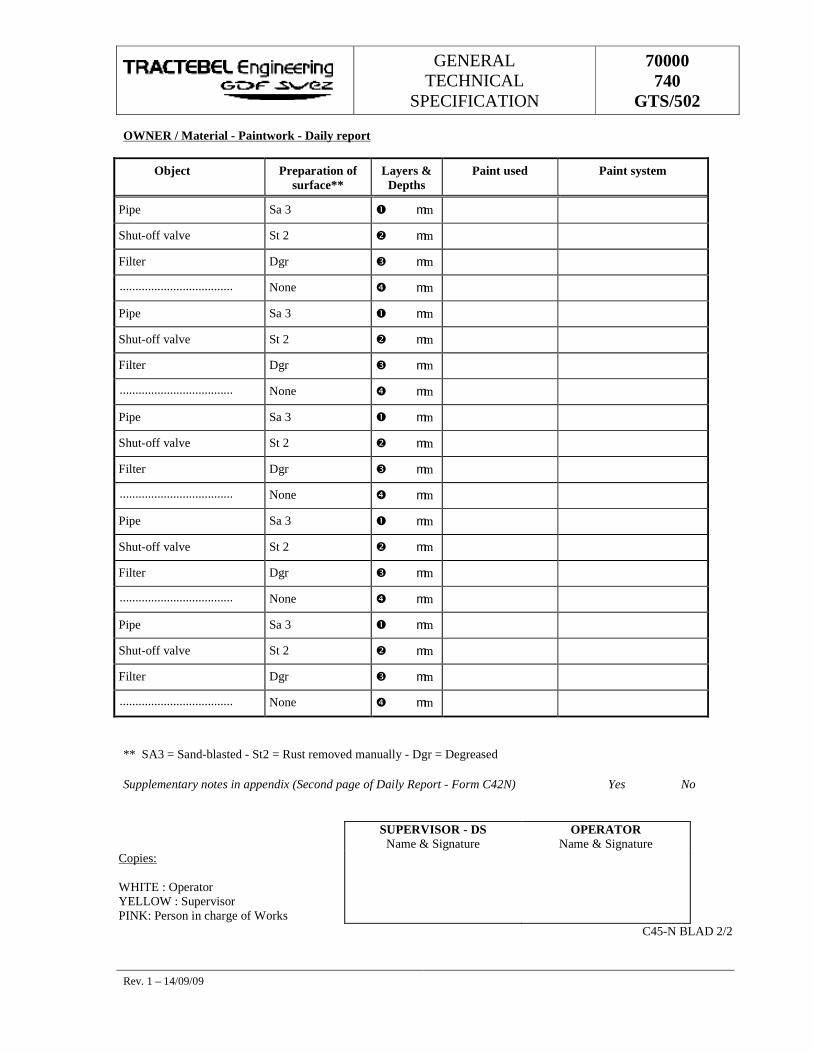
GENERAL TECHNICAL
SPECIFICATION
70000 740
GTS/502
Rev. 1 – 14/09/09
OWNER / Material - Paintwork - Daily report
Object Preparation of surface**
Layers & Depths
Paint used Paint system
Pipe � Sa 3 � � mm
Shut-off valve � St 2 � � mm
Filter � Dgr � � mm
.................................... � None � � mm
Pipe � Sa 3 � � mm
Shut-off valve � St 2 � � mm
Filter � Dgr � � mm
.................................... � None � � mm
Pipe � Sa 3 � � mm
Shut-off valve � St 2 � � mm
Filter � Dgr � � mm
.................................... � None � � mm
Pipe � Sa 3 � � mm
Shut-off valve � St 2 � � mm
Filter � Dgr � � mm
.................................... � None � � mm
Pipe � Sa 3 � � mm
Shut-off valve � St 2 � � mm
Filter � Dgr � � mm
.................................... � None � � mm
** SA3 = Sand-blasted - St2 = Rust removed manually - Dgr = Degreased
Supplementary notes in appendix (Second page of Daily Report - Form C42N) Yes � No �
SUPERVISOR - DS
Name & Signature OPERATOR
Name & Signature Copies: WHITE : Operator YELLOW : Supervisor PINK: Person in charge of Works
C45-N BLAD 2/2
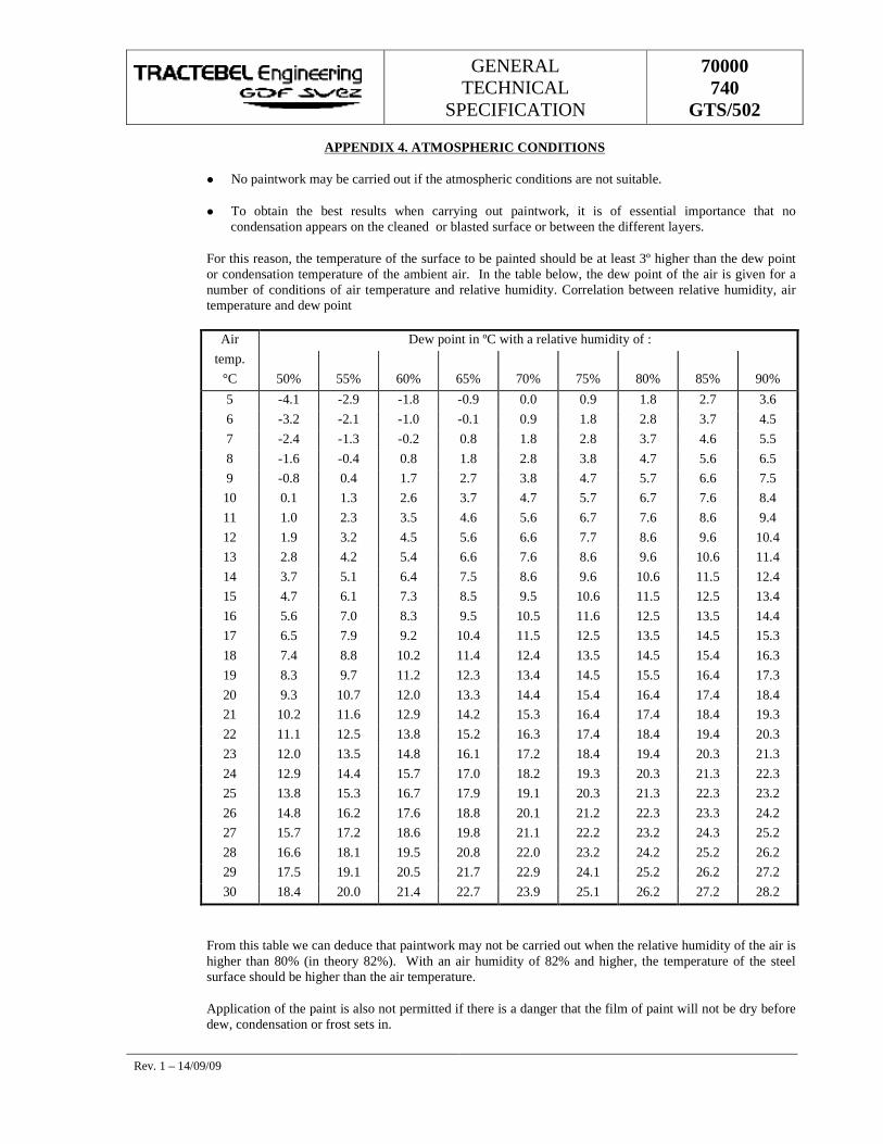
GENERAL TECHNICAL
SPECIFICATION
70000 740
GTS/502
Rev. 1 – 14/09/09
APPENDIX 4. ATMOSPHERIC CONDITIONS
� No paintwork may be carried out if the atmospheric conditions are not suitable.
� To obtain the best results when carrying out paintwork, it is of essential importance that no condensation appears on the cleaned or blasted surface or between the different layers.
For this reason, the temperature of the surface to be painted should be at least 3º higher than the dew point or condensation temperature of the ambient air. In the table below, the dew point of the air is given for a number of conditions of air temperature and relative humidity. Correlation between relative humidity, air temperature and dew point
Air Dew point in ºC with a relative humidity of : temp.
°C 50% 55% 60% 65% 70% 75% 80% 85% 90%
5 -4.1 -2.9 -1.8 -0.9 0.0 0.9 1.8 2.7 3.6 6 -3.2 -2.1 -1.0 -0.1 0.9 1.8 2.8 3.7 4.5 7 -2.4 -1.3 -0.2 0.8 1.8 2.8 3.7 4.6 5.5 8 -1.6 -0.4 0.8 1.8 2.8 3.8 4.7 5.6 6.5 9 -0.8 0.4 1.7 2.7 3.8 4.7 5.7 6.6 7.5 10 0.1 1.3 2.6 3.7 4.7 5.7 6.7 7.6 8.4 11 1.0 2.3 3.5 4.6 5.6 6.7 7.6 8.6 9.4 12 1.9 3.2 4.5 5.6 6.6 7.7 8.6 9.6 10.4 13 2.8 4.2 5.4 6.6 7.6 8.6 9.6 10.6 11.4 14 3.7 5.1 6.4 7.5 8.6 9.6 10.6 11.5 12.4 15 4.7 6.1 7.3 8.5 9.5 10.6 11.5 12.5 13.4 16 5.6 7.0 8.3 9.5 10.5 11.6 12.5 13.5 14.4 17 6.5 7.9 9.2 10.4 11.5 12.5 13.5 14.5 15.3 18 7.4 8.8 10.2 11.4 12.4 13.5 14.5 15.4 16.3 19 8.3 9.7 11.2 12.3 13.4 14.5 15.5 16.4 17.3 20 9.3 10.7 12.0 13.3 14.4 15.4 16.4 17.4 18.4 21 10.2 11.6 12.9 14.2 15.3 16.4 17.4 18.4 19.3 22 11.1 12.5 13.8 15.2 16.3 17.4 18.4 19.4 20.3 23 12.0 13.5 14.8 16.1 17.2 18.4 19.4 20.3 21.3 24 12.9 14.4 15.7 17.0 18.2 19.3 20.3 21.3 22.3 25 13.8 15.3 16.7 17.9 19.1 20.3 21.3 22.3 23.2 26 14.8 16.2 17.6 18.8 20.1 21.2 22.3 23.3 24.2 27 15.7 17.2 18.6 19.8 21.1 22.2 23.2 24.3 25.2 28 16.6 18.1 19.5 20.8 22.0 23.2 24.2 25.2 26.2 29 17.5 19.1 20.5 21.7 22.9 24.1 25.2 26.2 27.2 30 18.4 20.0 21.4 22.7 23.9 25.1 26.2 27.2 28.2
From this table we can deduce that paintwork may not be carried out when the relative humidity of the air is higher than 80% (in theory 82%). With an air humidity of 82% and higher, the temperature of the steel surface should be higher than the air temperature.
Application of the paint is also not permitted if there is a danger that the film of paint will not be dry before dew, condensation or frost sets in.

GENERAL TECHNICAL
SPECIFICATION
70000 740
GTS/502
Rev. 1 – 14/09/09
APPENDIX 5 colour code
COLOUR CODE
COMPRESSION STATIONS
DESCRIPTION COLOUR RAL CODE
High-pressure gas White RAL 9010
Low-pressure gas Orange RAL 2003
Surplus gas burners Yellow RAL 1004
Fire extinguishers Red RAL 3000
Air Blue RAL 5009
Water Green RAL 6010
Oil Brown RAL 8003
Valves - devices Grey RAL 7038
Supports Black RAL 9005
Doors Dark blue RAL 5010
PRESSURE REGULATING
Pipes - valves Supports etc. Grey RAL 7038
Fences, doors Green RAL 6020
High-pressure arrow Red RAL 3000
Low- or medium-pressure arrow Orange RAL 2003
GENERAL TECHNICAL
SPECIFICATION
GTS 740 501
HORIZONTAL DIRECTIONAL DRILLING
GENERAL TECHNICAL SPECIFICATION
4 14/09/09 Logo Changed SS DNS NC
3 24/03/08 Logo Changed SS DNS NC
2 16/04/04 Logo Changed MRT DKB MRY
1 15/06/00 First Issue MRT DKB LEP
Rev. Date Subject of revision Author Checked Approved
� LEP / 6 / \\tr2\data\managmt\gts\740\gaz\740s0501.doc w
97_9
8_gt
s.do
t
GENERAL TECHNICAL
SPECIFICATION
GTS 740 501
Rev. 4 – 14/09/09 Page I of II � LEP / 10 / e:\pradeep data\00_general technical specifications\gts revised 2009_gdf suez\mech 2008\70000_740_gts_501__61053_859315997.doc
TABLE OF CONTENTS
1. GLOSSARY ................................................................................................................................ 1
2. GENERALITIES .......................................................................................................................... 1
2.1. SCOPE OF THE GTS .......................................................................................................... 1
2.2. SCOPE OF THE CONTRACTOR ........................................................................................ 1
2.3. SUPPLIES ........................................................................................................................... 2
2.4. SITE LOCATION ................................................................................................................. 3
2.5. GEOGRAPHICAL CO-ORDINATES .................................................................................... 3
3. LAWS - CODES - RULES & STANDARDS ................................................................................ 3
3.1. GENERAL ........................................................................................................................... 3
3.2. PECULIAR CODES & STANDARDS ................................................................................... 3
4. GEOLOGICAL DATA .................................................................................................................. 4
5. RIGHTS OF WAY AND WORK SPACE ...................................................................................... 4
5.1. WORK SPACE .................................................................................................................... 4
5.2. RIGHTS OF WAY ................................................................................................................ 4
6. DRILLING PROFILE ................................................................................................................... 5
7. DOCUMENTS TO BE SUPPLIED BY THE CONTRACTOR ....................................................... 5
8. PIPELINE CALCULATION.......................................................................................................... 7
9. DOCUMENTS TO BE SUPPLIED BY THE CONTACTOR BEFORE AND DURING THE EXECUTION OF THE HDD AND AFTER HIS COMPLETION .................................................... 8
9.1. BEFORE AND DURING THE HDD EXECUTION ................................................................ 8
9.2. AFTER THE HDD EXECUTION .......................................................................................... 8
10. CONTROLS ................................................................................................................................ 9
10.1. GENERAL ........................................................................................................................... 9
10.2. WELD EXAMINATION ......................................................................................................... 9
GENERAL TECHNICAL
SPECIFICATION
GTS 740 501
Rev. 4 – 14/09/09 Page II of II � LEP / 10 / e:\pradeep data\00_general technical specifications\gts revised 2009_gdf suez\mech 2008\70000_740_gts_501__61053_859315997.doc
10.3. COATING .......................................................................................................................... 10
10.4. CLEANING ........................................................................................................................ 10
10.5. TESTING ........................................................................................................................... 10
10.5.1. General...................................................................................................................... 10
10.5.2. Pre-testing ................................................................................................................. 10
10.5.3. Final Test preparation ................................................................................................ 10
10.5.4. Resistance test .......................................................................................................... 11
10.5.5. Tightness test ............................................................................................................ 11
10.5.6. De-watering - Cleaning - Drying ................................................................................. 11
11. REINSTATEMENT .................................................................................................................... 12
11.1. REINSTATEMENT OF THE WORKING SITE AND ACCESS ROAD ................................ 12
11.2. MARKINGS ....................................................................................................................... 12
11.3. FINAL SITE INSPECTION WITH OWNERS AND USERS................................................. 13
12. ACCEPTANCE .......................................................................................................................... 13
12.1. AS-BUILT RECORDS ........................................................................................................ 13
12.2. PRE-COMMISSIONING & COMMISSIONING ................................................................... 13
12.3. READY FOR "START-UP" ................................................................................................. 13
12.4. PROVISIONAL ACCEPTANCE ......................................................................................... 14
12.5. FINAL ACCEPTANCE ....................................................................................................... 14
S S S
GENERAL TECHNICAL
SPECIFICATION
GTS 740 501
Rev. 4 – 14/09/09 Page 1 of 14 � LEP / 10 / e:\pradeep data\00_general technical specifications\gts revised 2009_gdf suez\mech 2008\70000_740_gts_501__61053_859315997.doc
1. GLOSSARY
Consultant the Engineering Company appointed by the Owner for the design of the Project.
Contractor The specialised construction company that will be granted the contract by the Owner to implement the HDD.
DP The Design Pressure as specified in the PTS.
GTS General Technical Specification.
HDD Horizontal Directional Drilling.
MOP The Maximum Operating Pressure as specified in the PTS.
ND The Nominal Diameter of the pipeline as specified in the PTS.
Owner Shall have the meaning as defined in the PTS.
Project Is specified in the PTS
PTS Particular Technical Specifications.
SITE Means the location where the Contractor has to perform the work.
Third Party Inspection Agency specially appointed by the Owner to perform Quality Controls and Certification.
2. GENERALITIES
2.1. SCOPE OF THE GTS
The present GTS intends to define the nature of the works to be performed by a Contractor for the design and the construction of a gas pipeline at particular major obstacle crossing point using the HDD method (Horizontal Directional Drilling).
2.2. SCOPE OF THE CONTRACTOR
Otherwise specified under the PTS the mission of the Contractor shall include all the required tasks necessary to built a gas pipeline string across a major obstacle using the HDD method.
These tasks can be summarised as follow (non-limited)
GENERAL TECHNICAL
SPECIFICATION
GTS 740 501
Rev. 4 – 14/09/09 Page 2 of 14 � LEP / 10 / e:\pradeep data\00_general technical specifications\gts revised 2009_gdf suez\mech 2008\70000_740_gts_501__61053_859315997.doc
� The Contractor shall provide and pay for all labour, materials, tools, equipment machinery, water, electricity, utilities, transportation, installation of other facilities and services necessary for the proper execution and completion of the works. The Contractor shall be fully in charge with the dismantling and eventually the repatriation of the equipment etc…
� The Contractor shall pay any duty tax, load and unload port duties, temporary import taxes etc… for all the equipment mentioned above.
� The Contractor shall be fully responsible for all means, methods, techniques, sequences and procedures and for the co-ordination of all operations of the work under contract.
� Contractor shall verify accurately the data provided and proceed to all additional tests or surveys (Topographic - Hydrological - Geological - etc.) he feels necessary to implement its works.
� The Contractor shall perform all engineering activities that are needed to complete the basic documentation provided by the Owner; in particular, it shall not neglect to proceed to all engineering - detailed engineering - stress calculations - etc. as necessary.
� The Contractor is deemed to have considered and accepted all the risks involved in his task.
� The Contractor shall make all necessary arrangements for the hiring of the labour (local or not) and care for their payment. He will take care of all the expenses relating to accommodation, transportation and subsistence for the staff.
� The work will be supervised by competent staff who speaks at least the official language (specify in the PTS) of the concerned country.
� The Contractor will execute all the required tasks including the welding of the pipeline by qualified welders specified in the contract and the PTS in conformity with the relevant code and standard.
� Traceability Due attention of the Contractor is drawn to the absolute necessity to keep detailed trace of all equipment subjected to pressurised gas.
2.3. SUPPLIES
� Except otherwise stated in the PTS the line pipe elements and fittings will be directly supplied at the work-site by other.
� The Contractor will provide all the necessary consumable to built the pipeline.
� During the works, the Contractor must procure and maintain the installation and equipment which are necessary for the functioning of the workshop and additional equipment.
GENERAL TECHNICAL
SPECIFICATION
GTS 740 501
Rev. 4 – 14/09/09 Page 3 of 14 � LEP / 10 / e:\pradeep data\00_general technical specifications\gts revised 2009_gdf suez\mech 2008\70000_740_gts_501__61053_859315997.doc
� The Contractor shall make all the necessary arrangements to cater for an uninterrupted supply of fuel, lubricant, electricity, water, telephone, etc… during the work.
2.4. SITE LOCATION
The exact location of the work site as well as the access road will be specified in the PTS
2.5. Geographical Co-ordinates
The local official system of co-ordinates that is in force in the concerned country will be used for all activities related to survey, drawings, alignment sheet, geographical information, measurements, etc…
3. LAWS - CODES - RULES & STANDARDS
3.1. GENERAL
Basically, the following is applicable :
� Basic Laws - Codes - Rules & Standards, mandatory by law in the country concerned.
� The present GTS as amended from time to time by attached PTS;
� Peculiar Codes & Standards as per Section 3.2.
� The "Rules of good Practice" commonly used by the world-wide gas industry;
� The "Rules of Art" and "Sound Practices" of the Engineer.
� in general the HDD has to be built in accordance with the best states of Engineering practice.
In case of contradiction, the above shall prevail in descending order of precedence.
3.2. PECULIAR CODES & STANDARDS
The Codes - Rules and Standards applicable in specific cases are listed under a separate PTS.
Except if otherwise specified in the PTS, the following shall serve as basis :
� ASME B.31.8 "Gas Transmission and Distribution Piping Systems" - Last edition and all Codes it refers to.
� Codes - Rules and Standards that are already mandatory at European level.
GENERAL TECHNICAL
SPECIFICATION
GTS 740 501
Rev. 4 – 14/09/09 Page 4 of 14 � LEP / 10 / e:\pradeep data\00_general technical specifications\gts revised 2009_gdf suez\mech 2008\70000_740_gts_501__61053_859315997.doc
� European standards that are still in project but under final clean-up before final approved (referenced "pr EN number") shall be assimilated.
Except if otherwise specified in the PTS, in case of contradiction, the most stringent of the present GTS and the above shall be applied.
4. GEOLOGICAL DATA
The owner has performed hydrological and geological surveys. The final report is appended to the PTS.
These data are given for indicative purpose.
It is the responsibility of Contractor to proceed, at its costs, to any additional surveys that it deems necessary.
5. RIGHTS OF WAY AND WORK SPACE
5.1. WORK SPACE
The minimum temporary working space allocated to Contractor by the Owner is :
� 75 m x 75 m at the drilling site
� 50 m x 50 m at the opposite site.
A working space of 15 m wide will be granted to built and test the pipeline string.
Prior to any HDD activity or pipeline construction work the top soil will be removed and keep in stock apart from the subsoil for reinstatement purpose.
If the drilling points (entry/exit) are located below the highest river water level, the Contractor shall protect the drilling points by creating a dyke 50 cm minimum above the highest recorded water level.
The temporary access road to the work sites will be determine jointly by the Owner and the Contractor and granted by the Owner.
The cost of improvement or execution of temporary accesses will be born by the Contractor.
5.2. RIGHTS OF WAY
The working space and the site location is specified in the PTS.
The right to use the specified working space will be granted by the Owner.
GENERAL TECHNICAL
SPECIFICATION
GTS 740 501
Rev. 4 – 14/09/09 Page 5 of 14 � LEP / 10 / e:\pradeep data\00_general technical specifications\gts revised 2009_gdf suez\mech 2008\70000_740_gts_501__61053_859315997.doc
Should Contractor require more space, it will be Contractor's responsibility to negotiate such additional space in close co-ordination with the Owner. Contractor shall support all relevant costs.
6. DRILLING PROFILE
The Owner will provide (annexed to the PTS) a basic profile drawing and the constraints and particularities of the obstacle to be crossed.
The Contractor shall specify and submit to the Owner for approval his final profile and the different parameters or their limited value which define the location and configuration of the drilled path.
These parameters are:
� entry point
� exit point
� entry angle
� exit angle
� PI elevation
� radius of curvature.
It is acceptable that the entry and exit will vary from the design proposed location. They have to be located inside an area (5 x 10 m) centred around the proposed location, 10 m shall be measured parallel to the HDD alignment.
Except if otherwise specified in the PTS, the minimum radius shall be not less than 1 000 times the Nominal Diameter(ND).
The predetermined theoretical profile shall be closely adhered to when drilling the pilot hole. The permitted deviation shall not exceed 2 m laterally and 1 m vertically from the approved theoretical profile.
7. DOCUMENTS TO BE SUPPLIED BY THE CONTRACTOR
the Contractor will supply with his tender the different documents listed here below.
� Key staff organisation chart.
� curriculum vitae of his key staff
� Project reference list regarding similar HDD works he carried out in the past 5 years.
� A complete description of the anti-corrosion pipe wraps he intends to use for pipeline field joints and repairs.
GENERAL TECHNICAL
SPECIFICATION
GTS 740 501
Rev. 4 – 14/09/09 Page 6 of 14 � LEP / 10 / e:\pradeep data\00_general technical specifications\gts revised 2009_gdf suez\mech 2008\70000_740_gts_501__61053_859315997.doc
� A description of the major drilling equipment as
� Drill rig specification
� Maximum dynamic torque
� Pull back capacity
� Drilling fluid trailer tank specification
� Control cab
� Pipe racks
� Workshop
� Generators
� Positioning system
� Drilling head
� Ancillary equipment.
� A complete description of the directional drilling working method as:
� The positioning record system and procedure
� Drilling of the pilot hole and wash over pipe.
� Hearing operation (type and size of the reamer)
� Mix compound of the bentonite mud.
� Soil cuttings/Bentonite mud separation and treatment process and reuse of the Bentonite.
� Pipeline pull back operation.
� Alignment and positioning of the pipe string.
� Rollers support used. The support will be designed so as not to damage the pipe coating.
� Detail drawing showing the theoretical profile, the final design profile, the position of the pipe string (with support arrangement) before pull back operation and the location of the bends if any.
� Detailed Time-schedule.
� On site working-time.
GENERAL TECHNICAL
SPECIFICATION
GTS 740 501
Rev. 4 – 14/09/09 Page 7 of 14 � LEP / 10 / e:\pradeep data\00_general technical specifications\gts revised 2009_gdf suez\mech 2008\70000_740_gts_501__61053_859315997.doc
� The method he intends to use for controlling the integrity of the pipeline coating as well as "anti-corrosion" pipe-wraps.
� The method he intends to use for verification of the pipeline final profile after the pull-back operations.
8. PIPELINE CALCULATION
The Contractor will submit for approval to the Owner and Third Party Inspection agency the stress calculation as described in the Deutsche standard NEN 3650 and NEN 3651 or equivalent.
The following phases should be analysed in the pipeline design process :
� predisposition of the launching catenary : Before the pulling operation, the pipeline is outside the bore-hole and has a configuration which allows it to enter the hole. During this phase, the only bending moment is due to the curvature of the catenary and the weight. The pipeline should be designed so that it behaves elastically.
� pull-back operation :
In this phase the pipeline will be pulled back through the bore-hole. The following forces should be considered :
� bending moment due to curvature of the hole;
� friction force between the pipe and drilling mud including the friction due to extra cables/sleeves attached to the string;
� friction force inside the hole, at the location where the soil reaction occurs;
� stress due to soil reaction;
� the Contractor will specify the means he intends to use in order to reduce the friction during the pull-back operation.
The resultant stress should be calculated and the pipeline designed to behave elastically.
� operating conditions :
In this phase the loads acting on the pipeline are :
� bending moment due to curvature of the hole;
� internal pressure of the gas;
� temperature difference of the line between the pipe-laying and operating conditions;
GENERAL TECHNICAL
SPECIFICATION
GTS 740 501
Rev. 4 – 14/09/09 Page 8 of 14 � LEP / 10 / e:\pradeep data\00_general technical specifications\gts revised 2009_gdf suez\mech 2008\70000_740_gts_501__61053_859315997.doc
� dead loads
Vertical soil load at the top of the pipe can be calculated for different pipe laying conditions.
� for pipeline with ND > 500 mm the Contractor shall specify the ballasting method he intends to use to limit the friction during pull-back.
The following effects should be combined for the purposes of calculating the resultant stress :
� calculated longitudinal effects on the entire pipeline system;
� calculated effects on the cross-section of the pipeline.
The stress/strain shall not exceed the relevant allowable stress.
The effects of soil load on the cross-section of the pipe may be analysed. This analysis should be carried out at the deepest point reached in drilling.
9. DOCUMENTS TO BE SUPPLIED BY THE CONTACTOR BEFORE AND DURING THE EXECUTION OF THE HDD AND AFTER HIS COMPLETION
9.1. BEFORE AND DURING THE HDD EXECUTION
� Before the pull-back operation the Contractor will submit for approval to the Owner the final profile of the HDD including any deflexion of the drilling head. The Contractor can start the pull-back operation only after the Owner approval.
This document needs to demonstrate that after completion (operating condition) and under internal pressure (MOP and test pressure), soil load and hydrostatic load the section of the pipeline will not have a radius of curvature smaller than those permitted by the design.
The document shall also indicate the pulling force on the pipe at the beginning, during and at the end of the process and the rate of progress of the pipe.
� During the different execution phases of the HDD the Contractor will record all the information regarding the different operations which includes, among others :
� the measurements of mud pressure, mud flow rate, pulling force, X-Y-Z of the drill head recorded during drilling and any other relevant statistics.
� stand-off during operations and the reasons thereof
9.2. AFTER THE HDD EXECUTION
After completions of the HDD the Contractor will transmit to the Owner the horizontal drilling operation record of the relevant activities which includes.
GENERAL TECHNICAL
SPECIFICATION
GTS 740 501
Rev. 4 – 14/09/09 Page 9 of 14 � LEP / 10 / e:\pradeep data\00_general technical specifications\gts revised 2009_gdf suez\mech 2008\70000_740_gts_501__61053_859315997.doc
� Concerning the drilling mud
� quantity of mud used;
� mud pressure (at the drilling)
� the density of the drilling fluid and soil cuttings;
� the localisation of storage site for the waste from the drilling operation and the measures taken to comply with environmental constraints.
� During drilling operation (per drill pipe element)
� the maximum force applied (push/pull/torque);
� time duration for assembling 2 elements;
� the drilling head position in X-Y-Z- co-ordinates;
� deviation compared to the required position;
� the proposed corrective measures.
� During drill pipe pull-back (per drill pipe element)
� pull-back duration per element;
� maximum pulling force per element.
� An alignment sheet with length profile of the pipeline (scale 1/500) showing the location of each weld joint and their X-Y-Z co-ordinates.
� An official certificate concerning the discharge of the drilling operations tailings approved by the relevant Authorities.
10. CONTROLS
10.1. GENERAL
Prior to any control on site, the overall procedure for weld examination, cleaning, pre-testing, testing, de-watering, etc… shall be submitted to the Owner and the Third Party Agency for approval.
The approved control procedure shall be carried out under the supervision of the Third Party Agency.
10.2. WELD EXAMINATION
All welds shall be inspected non-destructively (Radiographic and ultrasonic testing) in accordance with the requirements of the selected and approved standard for welding.
GENERAL TECHNICAL
SPECIFICATION
GTS 740 501
Rev. 4 – 14/09/09 Page 10 of 14 � LEP / 10 / e:\pradeep data\00_general technical specifications\gts revised 2009_gdf suez\mech 2008\70000_740_gts_501__61053_859315997.doc
10.3. COATING
Immediately after the pull-back operation an expert in cathodic protection from the Contractor or his sub-contractor (accepted by the Owner) will control the pipeline external coating. The impressed current needs for the unconnected pipeline string will not exceed 1mA/m².
10.4. CLEANING
Before testing and commissioning, the pipeline section shall be checked for cleanliness and ovalization.
The pipeline section shall be cleaned with a pig or foam sphere.
To clean the pipe and check for ovalization , a pig or a sphere shall be run several times through each underground section.
The pig travel speed shall be controlled and monitored.
To prevent ingress of foreign matter, the sections shall be capped before and after the test.
10.5. TESTING
10.5.1. General
The pressure tests shall prove the resistance and tightness of the pipeline. Testing shall be performed in accordance with applicable standard.
The Contractor will transmit all the records of the tests to the Owner and the third party agency.
10.5.2. Pre-testing
Pipe and fittings shall be pre-tested prior to the pull back operation and weld joint coating a compulsory strength and leak test shall be performed. The minimum duration for strength testing shall be 6 hours (see Resistance test for the test pressure).
The leak test will be carried out using dry air or inert gas of a minimum pressure of 6 bar (see weld points shall be distempered with soapy water and visually examined (soap bubble test).
10.5.3. Final Test preparation
Except if otherwise specified in the PTS, resistance test shall be performed with water.
The water shall be clean, with a corrosion inhibitor added if necessary.
The pipe shall be filled using pigs to prevent the formation of air pockets.
GENERAL TECHNICAL
SPECIFICATION
GTS 740 501
Rev. 4 – 14/09/09 Page 11 of 14 � LEP / 10 / e:\pradeep data\00_general technical specifications\gts revised 2009_gdf suez\mech 2008\70000_740_gts_501__61053_859315997.doc
The tests should normally be carried out with trenches adequately back-filled, if any, to avoid the influence of temperature changes. If the ground temperature in the immediate vicinity of the pipes is less than 2°C, antifreeze shall be added.
On completion of filling operations, time should be allowed for the water in the sections to stabilise. The water pressures to be maintained and the location and characteristics of the measuring apparatus (thermometers, dead-weight pressure gauges etc.) shall be defined before testing commences.
The measuring instruments shall have undergone certified periodic calibration. Pressure-recording instruments shall be installed in a sheltered place.
10.5.4. Resistance test
The minimum duration for Resistance testing shall be 6 hours.
Except if otherwise specified in the PTS, Resistance testing shall be carried out at a pressure of at least 1.4 times the DP at the highest point but, at the lowest point, below the pressure at which the line pipes have been tested in factory
The pressure shall be continuously monitored and recorded and shall not show any significant drop during the test.
The test may be performed during the stabilisation period prior to the tightness test.
10.5.5. Tightness test
Except if otherwise specified in the PTS, Tightness test shall be performed with water.
The tightness test may be combined with the strength test.
The tightness test pressure shall not be higher than the Resistance test pressure. The test pressure shall not be less than DP.
The test duration shall be determined on the basis of the characteristics of the structure and the accuracy of the measuring instruments. It shall not be less than 24 hours. For volumes of less than 20 m³ or for uncovered sections which can be fully inspected visually, this duration may be reduced for so far duly approved by the Owner.
Before carrying out the tightness test, it shall be ascertained that the quantity of air in the pipe is sufficiently small not to affect the test results.
The pipe is considered leak-tight if the temperature and pressure measurements show that the volume of test medium is maintained throughout the test.
10.5.6. De-watering - Cleaning - Drying
Once the test results have been declared satisfactory, the pipeline shall be de-watered and properly cleaned and dried.
GENERAL TECHNICAL
SPECIFICATION
GTS 740 501
Rev. 4 – 14/09/09 Page 12 of 14 � LEP / 10 / e:\pradeep data\00_general technical specifications\gts revised 2009_gdf suez\mech 2008\70000_740_gts_501__61053_859315997.doc
Conventional pigs and foam pigs shall be run through the pipeline as many times as necessary to de-water and clean it satisfactorily.
Cleaning and drying shall be performed after all tests are finished and certified.
The pigging system shall be equipped with necessary devices to measure temperature - pressure and Dew Point on a continuous way.
After completion of the test, the pipeline is scraped as much as needed by using bi-directional pigs followed by additional runs of foam- en polypigs as needed up to when the pigs do not show any more humidity and all dirt is removed like calamine or other residues from welding, rust, oil, dust, etc..
The compressors used for running the pigs shall be of "oil-free" type and equipped with absorption drying units with adequate Dew Point outlet.
When, during the last run, a constant Dew Point of -8°C is measured, the pipeline is then closed and left quiet for minimum 24 hours.
If, after 24 hours, the Dew Point does not increase any more, the pipeline is then considered dry.
11. REINSTATEMENT
11.1. REINSTATEMENT OF THE WORKING SITE AND ACCESS ROAD
The ground occupied during the work shall be reinstated to its original condition as quickly as possible after completion of the works.
Accesses to property, fences, ditches, retaining walls, irrigation systems and other structures shall be reinstated in compliance with the agreements drawn up at the time of initial survey.
Land register marks moved for the work shall be replaced by a surveyor. Where necessary, devices to prevent erosion of the backfill materials shall be installed when reinstating embankments and slopes.
Reinstatement of footpaths, road surfaces, banks, shoulders etc. shall be performed with the agreement of authorities concerned.
11.2. MARKINGS
The location of the pipe shall be clearly marked by suitable means : conventional yellow markers, overhead markers, sign, etc..
The Marker systems shall be firmly anchored to ensure permanency throughout the time.
GENERAL TECHNICAL
SPECIFICATION
GTS 740 501
Rev. 4 – 14/09/09 Page 13 of 14 � LEP / 10 / e:\pradeep data\00_general technical specifications\gts revised 2009_gdf suez\mech 2008\70000_740_gts_501__61053_859315997.doc
11.3. FINAL SITE INSPECTION WITH OWNERS AND USERS
When reinstatement and marking is completed, the site affected by the work shall be subjected to a final inspection by the parties concerned.
12. ACCEPTANCE
12.1. AS-BUILT RECORDS
As work advances, the position of the pipe shall be surveyed and plotted on the drawings.
"As-Built" Documentation containing all documents (drawings, design calculations, welding log etc) which enable location and description of the pipe shall be compiled on completion of the work.
"As-Built" documents shall maximise the use of CAD, computer database (Access 97) and digital records in such a way to allow later integration in a "Geographical Information System" (GIS).
All equipment shall be duly traced with reference to initial supplier Identification Reference (ID) - weld log-book - Certificates - etc..
The exact position "As-build" of these elements shall be accurately located with reference to ID and geographical co-ordinates.
12.2. PRE-COMMISSIONING & COMMISSIONING
Except if otherwise stated in the PTS, Pre-commissioning and Commissioning shall be performed by the Owner after being declared "Ready for Start-up".
Pre-commissioning shall take place prior to the introduction of the gas.
The system may only be commissioned when it is completely installed, tested and cleaned and where applicable, connected to a main network.
If necessary, drying may be completed by vacuum drying, blasting with dry air or any other suitable method in addition to drying by pigging.
If pre-commissioning of the pipeline is not to commence soon after "Ready for Star-up", it shall be filled with a fluid to protect against internal corrosion.
12.3. READY FOR "START-UP"
After "Final Testing" - de-watering - cleaning and drying duly certified by the Third Party Inspection - adequate back-filling of sections adjacent to the HDD itself and completion of all works except those mentioned in a "Punch List" as accepted for later completion, the system may be handed over to Owner as "Ready to Start-up".
GENERAL TECHNICAL
SPECIFICATION
GTS 740 501
Rev. 4 – 14/09/09 Page 14 of 14 � LEP / 10 / e:\pradeep data\00_general technical specifications\gts revised 2009_gdf suez\mech 2008\70000_740_gts_501__61053_859315997.doc
12.4. PROVISIONAL ACCEPTANCE
The pipeline system may be proposed for "Provisional Acceptance" after pre-commissioning on final and countersigned inspection of the site and on submission of the construction completion report, including archives, construction drawings, specifications and all documents related to the design and construction.
12.5. FINAL ACCEPTANCE
General criteria for "Final Acceptance" are described in the "Administrative & Commercial Conditions".
In addition to these, "Final Acceptance" shall not be declared before all works are satisfactorily achieved including all points in the "Punch-list" agreed at "Provisional Acceptance" and for so far all certificates are obtained from Authorities - Owners of obstacles - Owner & Tenants of lands - etc. that the reinstatement is achieved properly and to their satisfaction.
S S S
GENERAL TECHNICAL
SPECIFICATION
70000 740
GTS/402
PIPELINE VALVES
7 14/09/09 Logo Changed AA PK NC
6 22/09/08 Logo Changed AA PK NC
5 27/01/04 Updated + Logo Changed MRY MRT DKB
4 30/10/02 Updated MRY LEP LEP
3 01/07/02 Updated MRY LEP LEP
2 07/11/01 Updated AES LEP LEP
1 22/06/00 First issue AES LEP LEP
Rev. Date Subject of revision Author Checked Approved
GENERAL TECHNICAL
SPECIFICATION
70000 740
GTS/402
Rev. 7 – 14/09/09 Page I of II
TABLE OF CONTENTS
1. SCOPE ........................................................................................................................................ 1
2. DEFINITIONS .............................................................................................................................. 1
3. PRELIMINARY STATEMENT ..................................................................................................... 1
4. GENERAL ................................................................................................................................... 3
5. CODES, NORMS AND STANDARDS ......................................................................................... 3
6. DESIGN AND CONSTRUCTION ................................................................................................. 5
6.1. RATINGS ............................................................................................................................. 5
6.2. DESIGN ............................................................................................................................... 6
6.3. OPERATION ..................................................................................................................... 10
7. MATERIALS ............................................................................................................................. 11
7.1. STEEL USED .................................................................................................................... 11
7.2. PRESSURE RETAINING PARTS ...................................................................................... 11
7.3. BONNET, COVER AND BODY BOLTING ......................................................................... 13
7.4. NON-METALLIC PARTS ................................................................................................... 13
7.5. OTHER PARTS ................................................................................................................. 13
7.6. SOUR GAS SERVICE ....................................................................................................... 13
8. FABRICATION AND TEST ....................................................................................................... 13
8.1. WELDING FABRICATION ................................................................................................. 13
8.2. WELDING PROCEDURES ................................................................................................ 14
8.3. HEAT TREATMENT .......................................................................................................... 15
8.4. MECHANICAL TESTS ON THE PARTS USED FOR WELDING CONNECTION WITH THE LINE PIPES ..................................................................................................... 15
8.5. NON DESTRUCTIVE EXAMINATION (NDE) .................................................................... 16
8.6. PRESSURE TESTING ....................................................................................................... 18
GENERAL TECHNICAL
SPECIFICATION
70000 740
GTS/402
Rev. 7 – 14/09/09 Page II of II
8.7. OPERATIONAL TORQUE TEST ....................................................................................... 21
8.8. FIRE TEST ........................................................................................................................ 21
8.9. ANTI-STATIC DEVICE TESTING ...................................................................................... 21
8.10. VISUAL AND DIMENSIONAL EXAMINATION ................................................................... 21
9. MARKING ................................................................................................................................. 21
10. INSPECTION............................................................................................................................. 22
10.1. INFORMATION .................................................................................................................. 22
10.2. DOCUMENTS.................................................................................................................... 22
10.3. CERTIFIED MATERIAL TEST REPORT ........................................................................... 23
10.4. QRN 23
10.5. REPAIR ............................................................................................................................. 23
10.6. REJECTION ...................................................................................................................... 23
11. PAINTING AND COATING ....................................................................................................... 23
TABLE I : CHEMICAL COMPOSITION FOR WELDING END OF VALVES
TABLE II : TENSILE REQUIREMENTS OF THE WELDING END OF VALVES
ANNEX I : LOFC (LIST OF OPERATIONS OF FABRICATIONS AND CONTROLS)
S S S

GENERAL TECHNICAL
SPECIFICATION
70000 740
GTS/402
Rev. 7 – 14/09/09 Page 1 of 31
1. SCOPE
This General Technical Specification covers the supply of pipeline valves used in high pressure natural gas transport and distribution systems. It describes the general requirements, controls, tests, QA/QC, examination and final acceptance criteria which needs to be fulfilled.
This specification is general and is updated / amended by the Particular Technical Specification dedicated to the project.
2. DEFINITIONS
Engineer : The Entity of the Purchaser or the Company nominated by the Purchaser to design the natural gas transport or distribution system and to specify the equipment.
Purchaser : The Company which makes the purchase order.
Control Authority or CA : The Organisation put in place/requested by the Purchaser/Engineer to proceed to Quality Controls and Certification.
Manufacturer : Manufacturer who receive the purchase order
3. PRELIMINARY STATEMENT
The name of Control Organisation shall be mentioned in the purchase order.
Eventual interpretations and deviations to this specification by the Manufacturer shall be requested by writing in his offer with detailed justification and approved by the Purchaser/Engineer and the Control Authority before the eventual order to the Manufacturer. The latter is responsible and shall indemnify the Purchaser/Engineer for any damage resulting from the non-respect of this obligation.
The specifications of the steel used, the material Manufacturer and all potential subcontractors (such as forging plant, heat treatment, weld fabrication, …) will be described in the offer. After order, no change will be accepted except for justified "force majeure". In that case, the asked changes shall be supported by a technical file submitted to the Purchaser/Engineer for approval.
The Manufacturer shall provide a technical description of the manufacturing method that might influence the quality of the material.
When the order is placed, the Manufacturer shall promptly inform the Purchaser/Engineer about his subcontractor's names, addresses, phone numbers as well as sub-order numbers, extent and delivery terms. On this basis, the Manufacturer shall send a general planning including at least the raw material supply, the manufacturing stages (machining, welding, part assembly, …), testing , painting and packing/dispatching. This planning shall be updated by the Manufacturer at least every month unless otherwise provided in the purchase order. A Dispatcher/Inspector
GENERAL TECHNICAL
SPECIFICATION
70000 740
GTS/402
Rev. 7 – 14/09/09 Page 2 of 31
delegated by the Purchaser is entitled to follow, examine and verify the planning's' relevance and effectiveness.
The Purchaser keeps the right to audit the Manufacturers and subcontractor's manufacturing process and control methods. All costs form such an audit shall be borne by the Manufacturer except the wages and travel expenditures of the auditor(s) supported by the Purchaser.
The manufacturing processes and the laboratories, in which welding tests, destructive and non destructive tests are carried out, shall be approved by the Control Authority.
The Purchaser/Engineer and the Control Authority shall have, at any time, free access to all parts of the Manufacturer's facilities and to those of all his subcontractors involved in the order manufacturing. All reasonable means shall be placed at the inspector(s)'s disposal to enable him to check that the product is being manufactured in accordance with this specification. All tests and inspections required in this specification shall be carried out, prior to shipment, in the Manufacturer's plant (or subcontractor's plant) and at the Manufacturer's expenses, unless otherwise provided in the order. The Purchaser/Engineer and the Control Authority shall try not to interfere unnecessarily with other Manufacturer's works when running these tests and inspection.
A valid copy of the ISO 9001 certificate shall be included in the offer.
For any control, test or examination required under the supervision of the Control Authority (LOFC intervention points included), the latter shall be informed in writing FIFTEEN (15) working days in advance by the Manufacturer about place and time with a copy to the Purchaser/Engineer.
If manufacturing is to be carried out under LOFC concept, the Manufacturer shall send for approval a List of Operation in Manufacturing and Control to the Control Authority and Purchaser/Engineer, TEN (10) working days before manufacturing. This list shall be in conformity with the annex 1 to this document. Before starting any manufacturing, the Manufacturer shall be in possession of this approved document, filled in with all intervention points.
Material, even released by the Control Authority and in which injurious defects are found after delivery, shall be rejected. The Manufacturer shall be notified and the material replaced : all costs involved, including wages and travel expenditure of the Control Authority's representative, Purchaser and Engineer shall be borne by the Manufacturer.
An approval of documents can never be considered as an acceptance of deviations on relaxations to requirements. A deviation is only possible after specific request to the purchaser.
GENERAL TECHNICAL
SPECIFICATION
70000 740
GTS/402
Rev. 7 – 14/09/09 Page 3 of 31
4. GENERAL
� Valves are intended to be used in aboveground or underground, with cathodic protection services.
All particular conditions for each valve are described in attached data sheet and valve list.
All valves shall conform to API 6D spec. Whenever this specification and API 6D spec. conflict, this specification shall prevail.
Unless otherwise specified, pipeline valves covered by this specification are suitable for use in gas transmission and distribution systems, and in accordance with ASME B31.8.
5. CODES, NORMS AND STANDARDS
Latest edition of following standards are applicable.
� ASME STANDARDS
ASME B16.5 Pipe flanges and flanged fittings
ASME B16.34 Valves- flanged and butt welding end
ASME B31.8 Gas transmission and distribution piping systems
� ASTM STANDARDS
ASTM A 53 Pipe, steel, black and hot-dipped zinc coated welded and seamless
ASTM A 105/A 105 M Forgings, carbon steel, for piping components
ASTM A 106 Seamless carbon steel pipe for high temperature service
ASTM A 193/A 193 M Alloy steel and stainless steel bolting materials for high temperature service
ASTM A 194/A 194 M Carbon and alloy steel nuts for bolts for high temperature service
ASTM A 234/A 234 M Piping, fittings of wrought carbon steel and alloy steel for moderate and elevated temperatures
ASTM A 320/A 320 M Alloy steel bolting materials for low temperature service
GENERAL TECHNICAL
SPECIFICATION
70000 740
GTS/402
Rev. 7 – 14/09/09 Page 4 of 31
ASTM A 333 Seamless & Steel Pipes for low temperature service
ASTM A 350/A 350 M Forgings, carbon and low alloy steel, requiring notch toughness testing for piping components
ASTM A 370 Mechanical testing of steel products
ASTM A 381 Metal-arc-welded steel pipe for use with high-pressure transmission systems
ASTM A 420/A 420 M Piping fittings of wrought carbon steel and alloy steel for low temperature service
ASTM A 694/A 694 M Forgings, carbon and alloy steel, for pipe flanges, fittings, valves, and parts for high-pressure transmission service
ASTM A 707/A 707 M Flanges, forged, carbon and alloy steel for low temperature service
� API STANDARDS
API 5L Specification for line pipe
API 6D Specification for pipeline valves, end closures, connectors and swivels
API 6FA Fire test for valves
API 605 Large diameter carbon steel flanges
� MSS STANDARDS
MSS SP 6 Standard Finishes for Contact Faces of Pipe Flanges & Connecting – End Flanges of Valves and Fittings
MSS SP 25 Standard marking system for valves, fittings, flanges and unions
MSS SP 44 Steel pipeline flanges
MSS SP 54 Quality Standard for Steel Castings for Valves, Flanges and Fittings and Other Piping Components Radiographic Examination Method
MSS SP 55 Quality standard for steel castings for valves, flanges and fittings and other piping components (visual method)
GENERAL TECHNICAL
SPECIFICATION
70000 740
GTS/402
Rev. 7 – 14/09/09 Page 5 of 31
MSS SP 72 Ball valves with flanged or butt welding ends for general service
MSS SP 75 Specification for high test wrought butt welding fittings
� ASME STANDARDS
ASME Boiler and Pressure Vessel code
� EN STANDARDS
EN 10204 Metallic products : types of inspection documents
EN 10045/1 Metallic products : Charpy impact test – test methods (V and U notches)
� ISO STANDARDS
ISO 148 Acier – Essai de résilience Charpy (entaille V)
ISO 9001 : Quality management standard
� BRITISH STANDARDS
BS 5146 Inspection and test of valves
BS 5351 Steel ball valves for the petroleum, petrochemical and allied industries
� NACE STANDARDS
MR0175 Sulphide Stress Cracking Resistant Metallic Materials for Oilfield Equipment.
6. DESIGN AND CONSTRUCTION
6.1. RATINGS
1) The pressure temperature ratings of flanged and butt welding end valves shall be in accordance with ASME B16.34.
2) The temperature and pressure ranges of valves shall be in accordance with the indicated values on the appropriated piping specification and valve data sheet.
3) Wall thickness for parts used for the welding connection with the line pipes shall meet the following requirements :
GENERAL TECHNICAL
SPECIFICATION
70000 740
GTS/402
Rev. 7 – 14/09/09 Page 6 of 31
� The maximum allowable stress in the material of the butt weld connection for butt welding end valves shall be equal to fifty per cent of the minimum yield strength guaranteed by the specification of the steel used.
� The minimum wall thickness for butt welding connection must be greater than or equal to the largest value of either the calculated minimum thickness of butt welding connection or the nominal thickness of the pipe as indicated on data sheet.
� If the butt welding connection has a yield strength lower than the yield strength of the pipe to which it is intended to be welded, the wall thickness in each zone of the butt welding connection is at least equal to the specified pipe wall thickness times the ratio of the minimum yield strength guaranteed by the specification of the steel of the pipe and the minimum yield strength guaranteed by the specification of the steel of the butt welding connection.
� The specified pipe wall thickness and grade (with reference to the equivalent grade in API 5L spec. or ASTM spec.) with which the valve is intended to be used is specified in the data sheet/piping class.
4) The Manufacturer shall submit for approval to the Control Authority and to the Purchaser/Engineer the dimensional drawings, the calculation of the parts used for the welding connection to the pipeline and the material part list for all the types of valves. All these documents must be identified with the individual valve number according to attached valve list and shall be attached to the CMTR.
5) The design shall take into consideration performance requirements prescribed in the next paragraph.
All valves under this specification shall be designed to withstand a field hydrostatic test pressure with non corrosive water, after installation, during 24 hours when the gate, plug, ball or piston is partially or fully open at a pressure of 1.5 times the 38OC pressure rating gauged by ASME B16.34
During this test the closure element shall not be moved.
6.2. DESIGN
6.2.1. Face-to-face and end-to-end dimensions
Face-to-face and end-to-end dimensions for ball valves shall be in accordance with API spec. 6D.
Valves may be made to special dimension by agreement between the Manufacturer and the Purchaser.
GENERAL TECHNICAL
SPECIFICATION
70000 740
GTS/402
Rev. 7 – 14/09/09 Page 7 of 31
6.2.2. Welding ends
The connecting pipe outside diameter, wall thickness, specified minimum yield strength and material grade are mentioned in the relevant piping specification and valve data sheet.
Butt-welding ends shall be in accordance with figure 1 for wall thickness up to 20.0 mm; for thicker walls, refer to figure 2. The inside diameter at the welding end shall be equal to that of the pipe on which the valve shall be welded. If a welding end of a valve has a thickness not equal to the pipe with which it is intended to be used, the welding end preparation at the joint has to be in conformity with fig. 3.
The tolerance of the inside diameter at the bevel end shall be following :
NPS Tolerance of inside diameter at bevel end (1) (mm)
2" - 10"
12" - 48"
+ 1.6
+ 2.4
-0.4
-0.8
(1) Tolerance refers to variation from specified ID calculation by (OD spec. - 2t spec). OD = outside diameter t = wall thickness
The out-of roundness at a welding end, defined as the difference between the maximum and the minimum inside diameter at the welding pipe end shall not exceed 1% of the specified inside diameter.
The length of the butt end shall be sufficient to allow welding and heat treatment without damage of the internal parts of the valve. If Purchaser/Engineer accepts design which do not meet this requirement, than Manufacturer shall inform the Purchaser/Engineer about the precautions which needs to be fulfilled in order to guarantee that during welding of the butt welding ends no damage shall occur to the seat. These precautions shall be highlighted by the Manufacturer in the erection and installation instruction book.
6.2.3. End flanges
End flanges shall be furnished in the same class as the valve body with raised face or ring-joint face, as specified by the valve data sheet. Dimensions and tolerances (including drilling templates, flange facing, spot facing and back facing) shall conform to :
� ASME B16.5 standard for NPS 24" and smaller
� MSS SP-44 for NPS 26" to 60"
� MSS SP-6 for flange facing.
GENERAL TECHNICAL
SPECIFICATION
70000 740
GTS/402
Rev. 7 – 14/09/09 Page 8 of 31
6.2.4. Design features
All ball valves shall be full bore - to allow pigging - unless stipulated otherwise on the valve data sheet.
All trunnion mounted ball valves shall be fitted with following devices :
� Double block and bleed : design of a valve with two seating surfaces between which the cavity can be vented through a bleed connection and thus confirm the tightness of the valve, at least in closed position, when pressure is applied to any side or both sides of the valve.
� Double piston effect : when the pressure is applied to one side, let us say "upstream" side, and when upstream ball seat is leaking, transfer pressure shall have a positive shut-off effect on the downstream seat (acting, for instance, on the back face of this seat) and thus reinforcing the global tightness of the valve.
� Anti-static design : all ball valves shall be fitted with anti-static device conforming to BS 5351.
� Stem retention (anti blow-out) : In conformity with BS 5351 valve shall be designed with an anti blow-out stem so that the stem cannot be fully ejected by pressure inside the valve with the stem packing, gland retainer bolting removed.
� Secondary seat and stem sealing : all ball valves NPS 6" shall be fitted with a secondary stem sealing and all ball valves greater or equal to NPS 8" shall be fitted with a secondary seat and stem sealing. This system permits an injection of sealant and shall be fitted with an integral check valve. The number and the location of sealing points shall be on the Manufacturer's responsibility.
Purchaser is allowed to request the check of this system design and its operation, specially for modified or new valve model.
� A drain connection shall be located at the lowest part of the body cavity.
6.2.5. Auxiliary connections
The Manufacturer shall complete the valve data sheet with the size and allowable pressure for the following auxiliary piping connections.
a) Aboveground valves
� The drain shall be plugged.
� The vent/bleed connection for valves NPS 6" and above shall be equipped with one block valve plus one needle valve, each with anti blow-out stem. The block valve shall be of ball type. The needle valve shall have screwed connections, shall be preferably of angular pattern and shall be fitted with a special plug at the outlet : this plug shall be designed to relieve slowly the pressure without being ejected.
GENERAL TECHNICAL
SPECIFICATION
70000 740
GTS/402
Rev. 7 – 14/09/09 Page 9 of 31
� For valve size < NPS 6", the vent/bleed connection shall be equipped with this anti blow-out, depressurising plug only.
� Each secondary stem - and each secondary seat sealing device, when required (see § 6.2.4.), shall be fitted with a check valve integrated in the body plus a sealant fitting with built-in, spring loaded ball check valve, as mentioned in the valve data sheet.
b) Underground valves
� Vent/bleed connection shall be plugged and this functionality is by passed through the drain.
� Drain shall be fitted with a normally open block valve (ball type with anti blow-out stem) at the drain tap, piped to the upper part of the extension and ended by one ball valve plus one needle valve, each with anti blow-out stem.
� The needle valve shall have screwed connections, shall be preferably of angular pattern and shall be fixed with an anti blow-out, depressurising plug, at the outlet.
� Each stem and seat sealing connection, when required (see § 6.2.4) shall have a check valve integrated in the main valve body, a block valve (ball type with anti blow-out stem) closed to the body tap, shall be piped up to the upper part of the extension and equipped with a block valve (same type) plus a sealant fitting with built-in, spring loaded check valve, as mentioned in the valve data sheet.
� Valves and tubing shall be carefully fastened to the valve body and/or extension.
Valve bodies shall have tapped holes with a minimum effective threaded engagement at least equal to the nominal thread diameter. If body wall thickness is too thin, then unthreaded side of OEP/OET (One End Plain/One End Threaded) piece of pipe of a material compatible with the body, shall be welded to the valve body with full penetration or via a boss. Anyway, weld on threads is prohibited.
Material of auxiliary connections (pipe, tube, fittings, valve, …) shall be, at the least of the same material quality as the main valve and can be in stainless steel series AISI 300.
6.2.6. Stem extension for underground valve
When a stem extension is required (see valve data sheet), the configuration and the length H shall be in accordance with this valve data sheet.
In this case and except otherwise specified in the purchase order, valves shall be fitted with drain and sealant extensions well fixed to the stem extension and clearly indicated in the as built design. The stem extension shall be fully watertight, but shall be provided with a means to prevent overpressure built up in the mechanism resulting from stem or bonnet seal leakage.
Valves, equipped with stem extension and/or actuator, shall be delivered completely equipped and mounted (in one piece).
GENERAL TECHNICAL
SPECIFICATION
70000 740
GTS/402
Rev. 7 – 14/09/09 Page 10 of 31
Underground actuated valves shall be provided with one identification plate on the valve body and one on the upper part of the extension.
6.2.7. Miscellaneous
Lifting lugs are required on all valves NPS 6" and larger. The lifting lugs shall be stamped with the safe working load. Number of lugs shall be sufficient for safe handling on site. Valve support : All valves greater than NPS 24" shall be equipped with supports to permit the installation of the valve in horizontal position directly on the floor. These supports shall be directly welded or fitted on the body of the valve.
6.2.8. Design review
The Manufacturer shall submit for approval to the Engineer/Purchaser and Control Authority the calculation for all bonnet, cover and body bolting for pressure retaining parts conforming to ASME B16.34.
6.3. OPERATION
6.3.1. Valve shall be operated by a hand-wheel, wrench, manual key or actuator.
Manual override devices shall be provided on all valves. Hand-wheels of electric actuators, shall be normally disengaged and shall automatically disengage when the actuator is operated.
6.3.2. The length of the wrench or diameter of the hand-wheel for direct or gear operated valves shall (after opening and closing a new valve at last three times) be such that a force not exceeding 350 N shall be required to operate the ball from either the open or closed position under the maximum differential pressure recommended by the Manufacturer.
For valves without stem extension equipped with a hand-wheel in vertical position, the maximum radius of the hand-wheel is equal to the distance between the centre line of the pipe and the centre of the hand-wheel minus 120 mm. In this case no extruding lugs on hand-wheel are permitted, and provision for by-pass valve shall be kept.
6.3.3. Hand-wheel shall be marked to indicate the direction of closing.
6.3.4. Hand-wheels and wrenches shall be fitted in such a way that whilst held securely they can be removed and replaced where necessary.
6.3.5. All ball valves shall be provided with a mark on the stem to show the position of the ball in order to enable a good regulation of the actuator without seeing the ball. Exception can be made for valves with gear boxes for underground service.
GENERAL TECHNICAL
SPECIFICATION
70000 740
GTS/402
Rev. 7 – 14/09/09 Page 11 of 31
6.3.6. Ball manual direct operated valves shall be fitted out with fully open and fully closed stops. These stops shall be well fixed to the body of the valve in order to withstand many extreme opening and closing actions. These stops shall be easily removable. Ball gear operated valves shall be fitted out with fully open and fully closed stops shall be adjusted and fixed on the gear box.
6.3.7. The Manufacturer shall advise the maximum operating torque or force which can be sustained without causing permanent damage anywhere in the drive train from the actuator to the obturator. The Manufacturer shall also provide the torque graph : torque value in function of opening angle of the ball and pressure.
Deflection in the extended drive train must be limited so that the closing position contact reflects exactly the real position of the obturator.
6.3.8. Maximum rated differential pressure (MRDP)
The MRDP is the maximum difference between the valve upstream and downstream pressure at which the obturator (closure member) may be operated (opening). The Manufacturer shall specify this value and shall mark it on the valve name plate.
For the specification of different types of actuator refer to the concerned GTS/740/403.
7. MATERIALS
7.1. STEEL USED
The steel used in the valve Manufacturing shall be selected by the Manufacturer and filled in data sheet form
This list shall be submitted for approval to the purchaser/Engineer at the time of the offer. This list shall be added to the CMTR.
7.2. PRESSURE RETAINING PARTS
For pressure retaining parts the following requirements must be fulfilled
7.2.1. Bodies, including end flanges and welding ends (other than for field welding), bonnet and covers of valves shall be made in material conforming to API 6D spec. (or another material specification accepted by the Purchaser/Engineer) and be furnished with certificates EN 10204-3.1. B stating the quality, the mechanical properties (yield strength, tensile strength, percent elongation, impact test value at the temperature specified under per Section 8.4.2), the chemical analysis, the manufacturing process and the marking (e.g. the heat number) of the steel. These certificates shall be added to the CMTR.
For the valves with butt welding end, for the part on which the line pipe shall be welded, see paragraph 7.2.4. and 8.4.
GENERAL TECHNICAL
SPECIFICATION
70000 740
GTS/402
Rev. 7 – 14/09/09 Page 12 of 31
7.2.2. Notch toughness properties
The impact test temperature conditions and temperature are defined under Section 8.4.2.
7.2.3. The carbon content of parts involved in welding operation (except for those parts which shall be used for the welding connection with the line pipes) shall be restricted as follows :
� maximum percentage of carbon : 0.230
� C + Mn6
£ 0.41
7.2.4. For parts used for the welding connection with the line pipes the following supplementary requirements must be fulfilled :
� The chemical composition of the steel meets the requirements of table 1. The choice and use of alloying elements made from high strength low alloy steels to give the tensile properties prescribed in table 2 shall be made by the Manufacturer and included and reported to identify the type of steel.
� For each heat, the Manufacturer shall analyse the following elements : C, Mn, Si, P, S, Nb, V, Cr, Mo, Ni and Cu.
� The carbon equivalent shall be computed by the following equation :
C.E. = C + Mn6
+ Cr Mo V+ +
5 +
Ni Cu+15
and shall not exceed 0.45.
� The steel used shall be fully killed, fine grain practice.
� The steel used shall be suitable for field welding to pipes, flanges or fittings manufactured under ASTM A53, A105, A106, A234, A333, A350, A381, A420, A694, A707 or API 5L, 605 or MSS SP-44, SP-72, SP-75, EN10208-2.
� The steel used has tensile properties conforming to requirements prescribed in table 2 and capable of meeting the valve design.
� The ratio of yield strength to tensile strength shall not exceed 0.85.
� Mechanical tests as prescribed in section 8.4. shall be performed after final heat treatment.
GENERAL TECHNICAL
SPECIFICATION
70000 740
GTS/402
Rev. 7 – 14/09/09 Page 13 of 31
7.3. BONNET, COVER AND BODY BOLTING
Bonnet flange cover, and body bolting shall be conform to ASTM A320 Gr L7 or L7M or ASTM A193 grade B7 or B7M. Nuts shall be conform to ASTM A194 Gr 7 or 7M or 2H. For NPS greater than 4", they must be supplied with certificates EN 10204-3.1.C. and for NPS 4" and smaller with certificates EN 10204.3.1.B. These certificates shall be added to CMTR.
Bolt design shall be done to withstand safety all stresses occurring under operating conditions, calculations shall be submitted for approval.
Materials shall be compatible in order to avoid galvanic corrosion and shall not be susceptible to hydrogen embrittlement or stress corrosion cracking. Manufacturer must take into account that the materials shall be eventually cathodic protected.
7.4. NON-METALLIC PARTS
Non-metallic parts and elements, which usually include such items as packing, injectable material and lubricants, shall be suitable for the service and must be defined in the offer.
7.5. OTHER PARTS
Metal parts, which usually include such items as yokes, yoke nuts, stems, glands, gland bushing, gates, balls, plugs, discs, pistons, hand-wheel, gearing and motor drive attachments, shall be of material suitable for the service and must be defined in the offer.
7.6. SOUR GAS SERVICE
When sour gas service or NACE is specified, all process wetted, pressure containing parts and bolting shall meet the requirements of NACE MR0175.
8. FABRICATION AND TEST
Prior to manufacturing a meeting shall be organised between Manufacturer, Purchasing agent, Engineer and Control Authority.
8.1. WELDING FABRICATION
1) Welds and repair welds shall be performed according to written procedures. The welding procedure must be submitted for approval to the Control Authority before any fabrication and/or repair.
2) Only welders and welder operators who are qualified shall be used in production.
3) The joints shall be furnished in accordance with the requirements of Section VIII of ASME Boiler and Pressure Vessel Code - Division 1.
GENERAL TECHNICAL
SPECIFICATION
70000 740
GTS/402
Rev. 7 – 14/09/09 Page 14 of 31
4) The machine welding shall be done by an electric process, preferably by submerged arc.
5) Repair by welding is prohibited on forged material.
8.2. WELDING PROCEDURES
8.2.1. All welds, repair welds and repair by welding shall be performed according to written procedures. These welding procedures shall be qualified according to the requirements of the ASME Boiler and Pressure Vessel Code, Section IX.
The welding procedure tests are required on material which is on the high side of the chemistry specification.
The Manufacturer shall maintain a weld record of the procedure and performance test results.
For the tensile test, the rupture of the specimen must take place in the unaffected parent material.
The welding procedure qualification must include an impact test set in the weld and in the HAZ with requirements of paragraph 8.4.2. and a macrographic examination described in paragraph 8.2.2. These tests shall be performed after eventual final heat treatment. If weld thickness is higher than 25 mm, even covered by the PQR, additional impact test shall be performed on the test specimens taken in weld thickness layers.
8.2.2. Macrographic examination : the etched surface of the macro test specimen viewed macroscopically must display the image of a well performed welded joint with sufficient penetration, free from linear defects and important inclusions. In case of doubt, the etched surface must be examined microscopically and additional macroscopic examinations of other areas may be required.
The macrographic examination will include hardness measurements in the weld and the HAZ. The hardness will not exceed the values measured on the parent metal by more than 80 points for the welds and 100 point for HAZ, with an absolute maximum of 350HV10.
The acceptance of inclusions can be decided upon with the NDE of the welded plates (see paragraph 8.5.).
8.2.3. Additional requirements for "Sour Gas". Qualified welding procedure shall guarantee a good geometry without stress concentration and shall be realised according to NACE MR 0175 (max. 1% Ni in welding consumables).
On the macro, series of hardness tests shall be performed in the base metal, weld and Heat affected zone; results shall be maximum 248HV10.
GENERAL TECHNICAL
SPECIFICATION
70000 740
GTS/402
Rev. 7 – 14/09/09 Page 15 of 31
8.3. HEAT TREATMENT
8.3.1. After hot working and before re-heating for normalising heat treatment, forging or casting shall be allowed to cool substantially below the transformation range. All forging or casting shall be heat treated by normalising. Normalising shall be carried out in such a way that the base material acquires a fine grained perlitic structure.
8.3.2. Heat treatment of welds : the rules of ASME VIII Div. 1 are applicable. If a required treatment is not feasible (seat damage, etc, …), special agreement must be obtained from Purchaser/Engineer and Control Authority ACA, after the Manufacturer has proved good quality of welds.
8.3.3. The Manufacturer shall include in the CMTR data of this heat treatment.
8.4. MECHANICAL TESTS ON THE PARTS USED FOR WELDING CONNECTION WITH THE LINE PIPES
The following mechanical tests shall be performed on these parts after final heat treatment under the supervision of the Control Authority's delegate and the certificates shall be added to the CMTR.
Test specimens may only be cut after a marking transfer by the Control Authority.
8.4.1. Tensile testing
Requirements :
The material shall be in conformity with table 2. The ratio of yield strength to tensile strength shall not exceed 0.85.
Test specimen :
The test specimen represents any part of the same shape, the same heat of steel and the same heat treatment lot.
Number of test : one
Test location and orientation :
The test specimen shall be orientated transversally to direction of lamination and if this orientation is not feasible, it shall be orientated longitudinally. For castings only one orientation is applicable.
Test method :
Testing shall be performed in accordance with ASTM A370 standard rectangular plate type 1 1/2" wide (fig. 4 - A370) or standard round (fig. 5 or fig. 6 - A370).
GENERAL TECHNICAL
SPECIFICATION
70000 740
GTS/402
Rev. 7 – 14/09/09 Page 16 of 31
Yield strength shall be determined either by the 0.2 % offset or the 0.5 % extension under load (EUL) method. If another material are accepted by the Purchaser, the test method will be as specified in the material specification.
8.4.2. Impact test
Requirements :
The standard impact test temperature is -20°C, except if otherwise stated in the "Material Requisition" or particular Technical Specification. The average value of a set of 3 test specimens shall be equal to 35 J/cm². The minimum value per test specimen shall be equal to 35 J/cm² but this value may drop to 28 J/cm² for only one test specimen per series.
� Test specimen :
The test specimen represents any part of the same shape, the same heat of steel and the same heat treatment lot.
� Number of tests :
2 test sets (3 test specimens constitute one test set). For castings only 1 test set.
� Test location and orientation :
1 set shall be orientated longitudinally and another one transversally. For castings only one orientation is applicable.
� Test method :
The notched bar impact test shall be performed in accordance with ISO 148 or A370- Charpy V - Notch.
If the wall thickness of these parts or the coupon does not enable machining of full size specimens, the largest possible size must be used but not less than (10 x 5) mm. The axis of the notch shall be orientated through the wall thickness of these parts. If the weld thickness is > 25 mm, several specimen sets shall be taken in the weld thickness with min one (1) set per 12.5 mm of thickness, the specimen sets shall be selected in agreement with the Purchaser/Engineer and Authorised Control Authority.
8.5. NON DESTRUCTIVE EXAMINATION (NDE)
The following NDE will be performed after the final heat treatment and before coating.
8.5.1. List of NDE
� All butt welds shall be examined by a radiographic examination. If the thickness exceeds 15 mm or if the radiographic examination is not feasible than welds are only examined by ultrasonic examination to the largest extent possible.
GENERAL TECHNICAL
SPECIFICATION
70000 740
GTS/402
Rev. 7 – 14/09/09 Page 17 of 31
The radiographic examination shall be executed in accordance with ASME Boiler and Pressure Vessel Code, section V, art. 2 - using fine grain film and lead screens.
� Butt welding ends on cast bodies shall be examined before fabrication welding end, by radiography in accordance to MSS-SP-54 and over a width of 70 mm.
� 25 mm of base material at each side of each weld and each weld shall be 100 % ultrasonically examined.
The ultrasonic examination shall be executed in accordance with ASME Boiler and Pressure Vessel Code, section 5, art. 5.
� Body for all valves NPS 6" and greater shall be tested by magnetic particle examination in conformity with ASME Boiler and Pressure Vessel Code, section V, art. 7.
� All valves shall be visually examined.
� All valves shall be dimensionally examined.
� For butt welding end valves after machining, the finished bevel end pipe used for field welding shall be submitted to the following tests :
� Magnetic (ASME V Art. 7) or liquid penetrant (ASME V Art. 6).
� Ultrasonic inspection (ASME V Art. 5) or radiographic examination (ASME V Art. 2)on 25 mm of base material.
� Visual and dimensional examination.
� If any repair by welding is performed, the concerned parts shall be completely re-examined.
8.5.2. Additional NDE requirement for "SOUR Gas"
A series of hardness test on surfaces in contact with the fluid shall be performed to NACE MR 0175. Results shall be 22 HRC or 248 HV 10 max.
8.5.3. Acceptance criteria of the different NDE
� Radiographic examination :
ASME Boiler and Pressure Vessel Code, section VIII, division 1, UW 51 for forged steel
ASME Boiler and Pressure Vessel Code, section VIII, division 1, appendix 7 for casted steel. The control will done on width of 70mm with.
On the first 40mm A1,B1,C1 acceptable, D, E, F and G are rejected.
GENERAL TECHNICAL
SPECIFICATION
70000 740
GTS/402
Rev. 7 – 14/09/09 Page 18 of 31
Between 40mm and 70mm, A2, B3, C3 acceptables; D, E, F, G are rejected.
� Ultrasonic inspection of weldings and HAZ:
ASME Boiler and Pressure Vessel Code, section VIII, division 1, Appendix 12.
� Magnetic particle inspection of the body:
ASME Boiler and Pressure Vessel Code, section VIII, division 1, Appendix 6.
For casted pieces refer to Appendix 7.
� Visual examination
MSS-SP-55.
� Magnetic particle or liquid penetrant of the finished bevel:
The following defects are unacceptable :
� Defects extending into the bevel provided the lamination is parallel to the surface and has a transverse dimension exceeding 6.35 mm.
� All defects not parallel to the surface extending into the bevel.
All the NDE (except radiographic examination) shall be performed under the supervision of the control authority's delegate and the certificates shall be added to the CMTR.
8.6. PRESSURE TESTING
8.6.1. General requirements
� Each valve shall be tested by the Manufacturer under the supervision of the Control Authority after final completion of all welding and all heat treatment operations.
� Hydrostatic and air seat test shall be performed after an acceptable shell test.
� Fluid for shell and hydrostatic seat tests shall be liquid as water (which may contain a corrosion inhibitor), kerosene, or other fluid with a viscosity not greater than that of water. Temperature of the test fluid shall not exceed 50°C.
� Valves shall be substantially relieved of air when tested with liquid.
� Valves shall be shell tested prior to painting.
� Valve test fixture loads applied to valve ends shall be limited to those required to effectively seal the valve ends.
� Pressure testing certificates shall be included in the CMTR.
GENERAL TECHNICAL
SPECIFICATION
70000 740
GTS/402
Rev. 7 – 14/09/09 Page 19 of 31
� Drain, the sealant and the bleed valve shall be included in all pressure tests.
� If any supplementary welding, repair by welding or treatment are performed, valve shall be completely re-tested.
8.6.2. Shell test
� Each valve shall be given a shell test at the gauge pressure not less than 1.5 times the 38°C rating gauged by ASME B16.34, rounded off to the next higher 1 bar increment.
� Shell test shall be conducted with the valve in a partially open position and with the valve ends closed.
� Drain lines and valves
Shall be either included in the hydrostatic shell test, or tested separately.
� Duration of the shell test
NPS up to 18" shall not be less than 15 minutes.
NPS 20" and larger shall not be less than 30 minutes.
� Visual leakage or harmful inelastic deformation are not accepted.
8.6.3. Hydrostatic seat test
� Each valve shall be given a hydrostatic seat test at the gauge pressure not less than 1.1 times the 38°C rating gauged by ASME B16.34, rounded off to the next higher 1 bar increment.
� Seat closure testing shall be performed with seat surfaces free of sealant, grease or other foreign material that aids in sealing except as provided hereafter :
� When necessary to prevent damage during valve actuation, a light oil of viscosity not greater than that of kerosene may be applied to sealing surface.
� When valve primary design is based on the presence of a sealant material (lubricated plug valve), the sealant material may be in place.
� For valve of the double seating type such as gate, plug and ball valve, the test pressure shall be applied successively to each end of the closed valve and leakage to opposite end checked. Provision shall be taken before, for de energising the self relieving pressure system.
� For soft seated valves there shall be no visible leakage - for metal seated valves the leakage rate shall not exceed 0.006 ml per minute and per mm of nominal pipe size (ND).
GENERAL TECHNICAL
SPECIFICATION
70000 740
GTS/402
Rev. 7 – 14/09/09 Page 20 of 31
� For double block and bleed valve the following tests shall be performed :
Close valve, open body vent, apply seat test pressure to both ends of the valve.
Close valve, open body vent, apply seat test pressure to one end of the valve, release pressure and repeat test for the other end of the valve.
� For double piston effect valve the following test shall be performed :
Release pressure, close valve, open body vent, apply seat test pressure through the body vent.
� For other valve type, the test pressure shall be applied across the closure member in the direction producing the most adverse seating conditions. For example, a globe valve shall be tested with pressure under the disc. A check valve, globe valve or other valve type designed, sold and marked as a one-way valve, requires a closure test only in the appropriate direction.
� The duration of the hydrostatic seat test shall not be less than 5 minutes for each end.
� Visual leakage or harmful inelastic deformation are not accepted.
8.6.4. External leak testing
Under the supervision of the Control Authority's delegate, the Manufacturer shall check the external leak tightness of body, stem and all external taps. This shall be done with soap suds at an inner pressure of 6 bar. For underground valves, this test shall include piping, fittings and valves of the auxiliary lines for drain, vent/bleed and sealant connections.
8.6.5. Air seat test
� Each valve shall be given an air seat test at 6 bar.
� This test shall be performed in the same manner as hydrostatic seat test.
� The duration of this test shall not be less than 5 minutes for each end.
� No signs of leakage are accepted.
8.6.6. Procedure
Procedure of all pressure tests shall be included in the offer.
8.6.7. After tests
After test, any auxiliary connections shall not be removed, and auxiliary piping shall be cleaned and dried, especially the sealant piping.
GENERAL TECHNICAL
SPECIFICATION
70000 740
GTS/402
Rev. 7 – 14/09/09 Page 21 of 31
8.7. OPERATIONAL TORQUE TEST
For valves operated with an actuator the Manufacturer shall perform an operational torque test at full rated differential pressure and at ambient temperature. The procedure must be included in the offer. The certificates shall be included in the CMTR.
8.8. FIRE TEST
The Manufacturer shall supply valves qualified by fire testing as specified in API 6FA and this certificate shall be added to the CMTR.
8.9. ANTI-STATIC DEVICE TESTING
If requested in the purchase order, all ball valves shall be submitted of to an anti-static electricity testing in accordance with BS 5146 and this certificate shall be added to the CMTR.
8.10. VISUAL AND DIMENSIONAL EXAMINATION
All valves shall be visually and dimensionally examined, according to API 1104 and MSS-SP-55.
9. MARKING
9.1.1. All valves supplied under this specification shall be clearly identified on the body, on the identification plate and on the valve flange edge.
9.1.2. Body markings
The following markings shall be cast, stamped, forged or engraved on the body of the valve :
c) Manufacturer's name or trademark.
Individual tag number according to attached valves list.
The monogram of the Control Authority. This marking shall only be applied after complete approval of the CMTR.
Flow direction on unidirectional valve.
9.1.3. Permanently attached identification plate markings
On minimum the following markings shall be shown on permanently attached identification plates :
GENERAL TECHNICAL
SPECIFICATION
70000 740
GTS/402
Rev. 7 – 14/09/09 Page 22 of 31
a) Manufacturer's name or trademark.
b) Individual valve fabrication number (serial number).
c) Individual tag number.
d) The maximum operating pressure;
e) The min and maximum operating temperatures
f) Body material designation (conforming MSS SP-25).
g) Rating designation (conforming ASME B16.34).
h) Valve trim identification (conforming MSS SP-25).
i) Nominal valve size.
j) Monogram of the Control Authority.
10. INSPECTION
10.1. INFORMATION
The Manufacturer shall inform the Control Authority min. five (5) working days in advance of any intervention required by this specification and shall send a copy of it to the Purchaser/Engineer (by fax).
10.2. DOCUMENTS
Before starting any fabrication, the Manufacturer shall submit for approval to the Control Authority and the Purchaser/Engineer the following documents :
� Detailed fabrication drawing and calculations.
� Fabrication and control procedure.
� Qualified welding procedures;
� Welders performances qualifications;
� NDT procedures;
� List of Operations in Fabrication and Control (LOFC) in accordance with annex 1.
Each company dealing in the order by fabrication and/or control shall implement a LOFC for all operations and interventions performed in its organisation. They shall also be responsible for the implementation of the same by their subcontractors.
GENERAL TECHNICAL
SPECIFICATION
70000 740
GTS/402
Rev. 7 – 14/09/09 Page 23 of 31
10.3. CERTIFIED MATERIAL TEST REPORT
A Certified Material Test Report (CMTR) shall be furnished listing as built drawings and calculations, the LOFC (see paragraph 10.2.), the base material certificate, the chemical check analysis of the welding ends. The certificate of the heat treatment, the mechanical test, the non-destructive examination, the pressure testing, the operational torque test, the quality release note (see paragraph 10.4.) and any special test required by the purchase order. The valve individual number (see paragraph 9.1.2.) must be indicated in the CMTR to permit the correct traceability of each valve. The Manufacturer shall furnish one copy of the CMTR to the Control Authority's delegate and one original and one copy to the Purchaser/Engineer.
10.4. QRN
After final approval of valves and the acceptance of the CMTR, the control authority's delegate shall furnish to the Purchaser/Engineer and to the Manufacturer a Quality Release Note (QRN). The Manufacturer shall deliver one copy of the QRN with the valves and one copy shall be included in the CMTR (see paragraph 10.3.).
10.5. REPAIR
Defects in material may only be repaired provided written acceptance by the contracting parties and the Control Authority has first been obtained.
This written acceptance must be given case per case. Defective material, that cannot be satisfactory repaired or repaired without written approval shall be definitively rejected.
10.6. REJECTION
Each valve in which injurious defects are found after delivery shall be rejected. The Manufacturer shall be notified. In this case, the valve shall be replaced immediately. All the costs involved, including wages and travel expenses of the Control Authority's delegate shall be borne by the Manufacturer.
11. PAINTING AND COATING
The surface of the valve will be shot-blasted SA 2 1/2 (Swedish standard SIS 055900). Before painting, the valve shall be cleaned from grease and dirt. The painting shall consist of a primer coating (30 - 40 µm) and a finish coating (30 - 40 µm).
The nature of the products shall be specified in the offer and shall guarantee a corrosion protection for a storage period in a shop for at least one year.
Painting in accordance with Purchaser/Engineer's specifications.
Painting and coating procedures shall be submitted for approval before manufacturing to the authorized Control authority and to the purchaser / engineer.
GENERAL TECHNICAL
SPECIFICATION
70000 740
GTS/402
Rev. 7 – 14/09/09 Page 24 of 31
For underground valves the Manufacturer shall propose an adequate protection at the time of offer. This adequate protection shall be in accordance with the Purchaser/Engineer's specification.
GENERAL TECHNICAL
SPECIFICATION
70000 740
GTS/402
Rev. 7 – 14/09/09 Page 25 of 31
TABLE 1
CHEMICAL COMPOSITION FOR WELDING END OF VALVES
Maximum limit of chemical elements which may be used in material under this standard.
% Maximum
C 0.230
Mn 1.60
Si 0.50
P 0.030
S 0.025
Nb 0.080
V 0.120
Mo 0.250
Nt 0.0150
Alternate alloy elements may be used but they shall be discussed with the user prior to delivery of the material. This table is not intended to represent the composition of any heat of steel, but merely to record the maximum permissible amounts of one element. The combination of elements of any heat must conform to the carbon equivalent, subsection 3.2.4.3.
For each heat the Manufacturer shall analyse the following elements :
C, Mn, Si, P, S, Nb, V, Cr, Mo, Ni and Cu.
The intentional addition of elements other than those specified is not permitted unless agreed upon by the Purchaser.
In any case, for unintentional additions, the following limitations shall be respected :
Cr £ 0.15 % Mo £ 0.05 % Cu £ 0.20 %
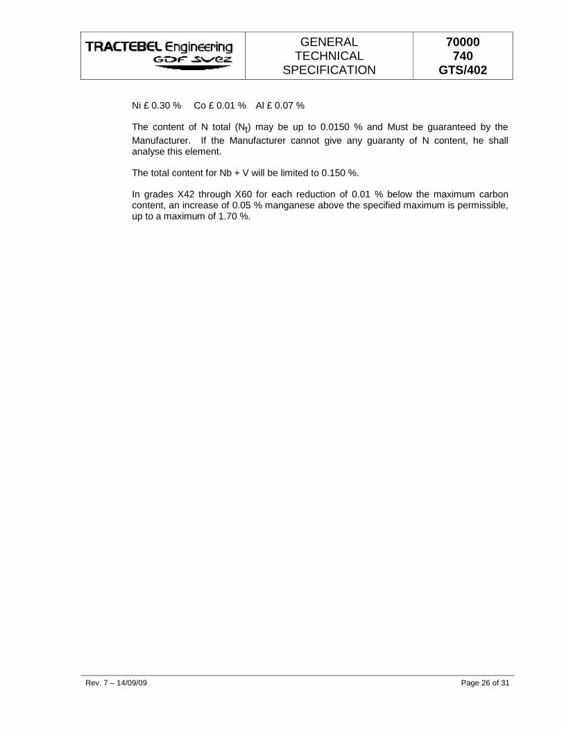
GENERAL TECHNICAL
SPECIFICATION
70000 740
GTS/402
Rev. 7 – 14/09/09 Page 26 of 31
Ni £ 0.30 % Co £ 0.01 % Al £ 0.07 %
The content of N total (Nt) may be up to 0.0150 % and Must be guaranteed by the Manufacturer. If the Manufacturer cannot give any guaranty of N content, he shall analyse this element.
The total content for Nb + V will be limited to 0.150 %.
In grades X42 through X60 for each reduction of 0.01 % below the maximum carbon content, an increase of 0.05 % manganese above the specified maximum is permissible, up to a maximum of 1.70 %.
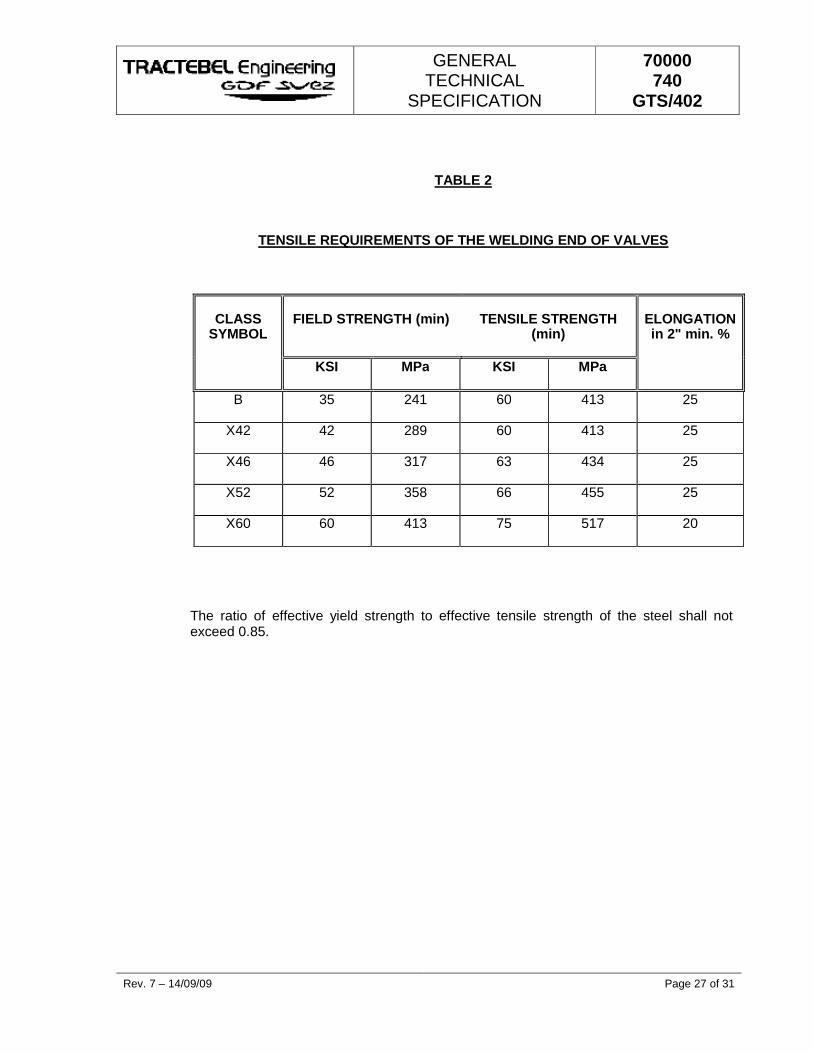
GENERAL TECHNICAL
SPECIFICATION
70000 740
GTS/402
Rev. 7 – 14/09/09 Page 27 of 31
TABLE 2
TENSILE REQUIREMENTS OF THE WELDING END OF VALVES
CLASS
SYMBOL
FIELD STRENGTH (min)
TENSILE STRENGTH
(min)
ELONGATION in 2" min. %
KSI MPa KSI MPa
B 35 241 60 413 25
X42 42 289 60 413 25
X46 46 317 63 434 25
X52 52 358 66 455 25
X60 60 413 75 517 20
The ratio of effective yield strength to effective tensile strength of the steel shall not exceed 0.85.
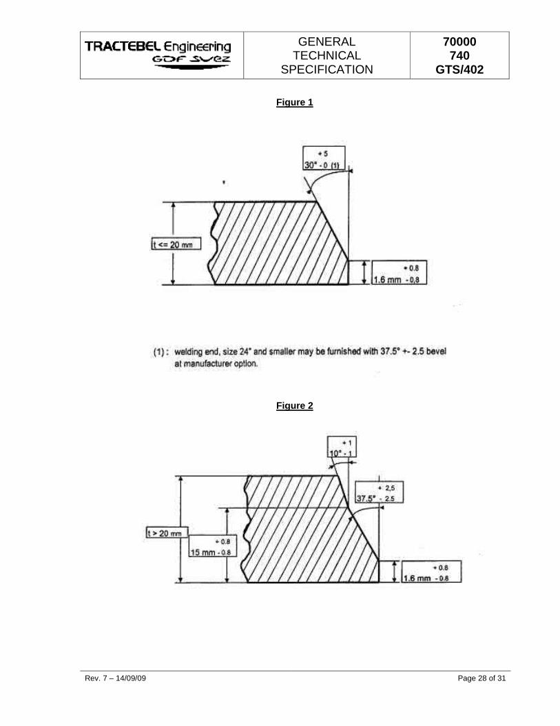
GENERAL TECHNICAL
SPECIFICATION
70000 740
GTS/402
Rev. 7 – 14/09/09 Page 28 of 31
Figure 1
Figure 2
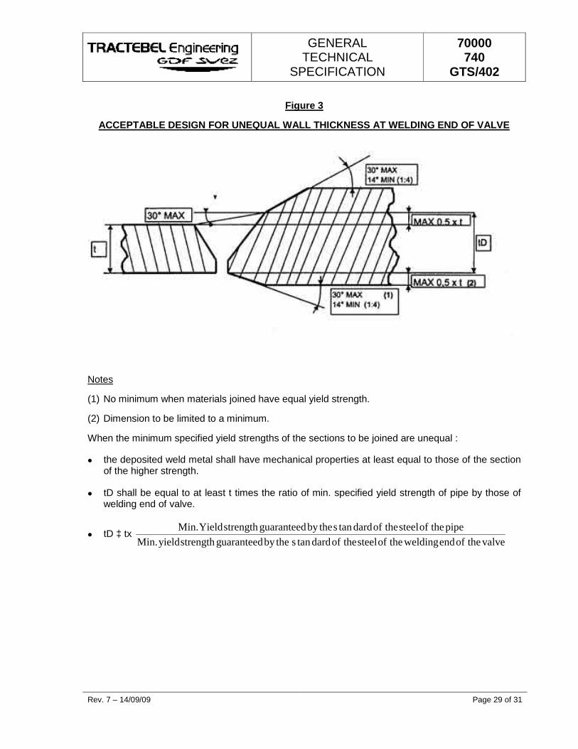
GENERAL TECHNICAL
SPECIFICATION
70000 740
GTS/402
Rev. 7 – 14/09/09 Page 29 of 31
Figure 3
ACCEPTABLE DESIGN FOR UNEQUAL WALL THICKNESS AT WELDING END OF VALVE
Notes
(1) No minimum when materials joined have equal yield strength.
(2) Dimension to be limited to a minimum.
When the minimum specified yield strengths of the sections to be joined are unequal :
� the deposited weld metal shall have mechanical properties at least equal to those of the section of the higher strength.
� tD shall be equal to at least t times the ratio of min. specified yield strength of pipe by those of welding end of valve.
� tD ‡ tx valvetheofendweldingtheofsteeltheofdardtansthebyguaranteedstrengthyield.Min
pipetheofsteeltheofdardtansthebyguaranteedstrengthYield.Min
GENERAL TECHNICAL
SPECIFICATION
70000 740
GTS/402
Rev. 7 – 14/09/09 Page 30 of 31
ANNEX 1
LOFC (LIST OF OPERATIONS OF FABRICATIONS AND CONTROLS)
Each LOFC must contain the following information as a minimum (all clearly marked and separated) :
k) Company name and references relating to the order.
l) All technical and other information required in order to define the items covered.
The area of application will be limited to that item or those considered as in fabrication and control.
m) A numerical sequence of operations with description will be built-up in a logical way of work progress.
� The first operation will be the control of the incoming material(s) and documents.
� The last operation will be the control of the CMTR.
The following operations have to be included (not limited to) :
� Each fabrication step.
� Each step which calls for own quality control (eventually QA).
� Each applicable examination as part of this specification.
� Document controls - stamping and final documentation.
n) Each operation will be followed by the applicable specification or procedure number (with the latest revision).
o) Columns to be provided for possible interventions of :
� the Manufacturer's fabrication control,
� the Manufacturer's quality control (eventually QA),
� Control Authority,
� the Purchaser/Engineer,
and place of intervention if not by the Manufacturer.
The interventions will be indicated per operation with H or W and/or R.
H = hold point No further steps may be undertaken before the intervention of the appointed responsible takes place.
GENERAL TECHNICAL
SPECIFICATION
70000 740
GTS/402
Rev. 7 – 14/09/09 Page 31 of 31
W = witness point The appointed responsible has to be notified of the operation in advance, but production will continue whether the intervention took place or not.
R = point for which a control report or a recording has to be made.
The Manufacturer will fill in his own H, W and R points. The Control Authority and the Purchaser/Engineer will do the same in their designated columns, but this will not implicate a relaxation or wearing of the requirements of the Manufacturer's controls.
Each intervention has to be signed and dated by the person acting as controller. Only the original documents will be presented for this purpose.
p) One column to be provided for report or record numbers (points marked R) and one for the review of these documents by the Control Authority.
q) Two extra columns may give reference to a non-conformity report if any and to the resolution given to it.
Completion of the LOFC does not automatically give rise to a release of the material or it must be stipulated otherwise in the contract.
S S S
GENERAL TECHNICAL
SPECIFICATION
70000 740
GTS/0011
PE ACCESSORIES for underground networks for natural gas distribution
C 06/09/02 Updated (see revision marks) MRT MRY MRT
B 21/08/02 Updated MRT MRY MRT
A 13/08/02 First Issue MRT MRY MRT
Rev. Date Subject of revision Author Checked Approved
SWA/26/ *70000/740/GTS/0011*
GENERAL TECHNICAL
SPECIFICATION
70000 740
GTS/0011
Rev. C - 06/09/02 Page I of II SWA/27
TABLE OF CONTENTS
1. SUBJECT AND AREA OF APPLICATION...................................................................................1
2. REFERENCE STANDARDS AND SPECIFICATIONS.................................................................1
3. DEFINITIONS................................................................................................................................2
3.1. ELECTROFUSION ACCESSORY.........................................................................................2
3.2. ELECTROFUSION SADDLE.................................................................................................2
3.3. END TO END WELDING ACCESSORIES............................................................................3
4. GENERAL SPECIFICATIONS......................................................................................................4
5. MATERIALS..................................................................................................................................5
5.1. GENERAL INFORMATION ...................................................................................................5
5.2. RAW MATERIAL SPECIFICATIONS ....................................................................................5
5.3. SPECIFICATIONS FOR COMPONENTS MADE OF MATERIALS OTHER THAN POLYETHYLENE ..................................................................................................................5
6. GENERAL ACCESSORY CHARACTERISTICS..........................................................................7
6.1. TECHNICAL INFORMATION ................................................................................................7
6.2. APPEARANCE AND FINISH.................................................................................................8
6.3. COLOUR ...............................................................................................................................8
6.4. JOIN APPEARANCE.............................................................................................................8
6.5. ELECTROFUSION ACCESSORY ELECTRICAL CHARACTERISTICS ..............................8
6.6. SUPPORT DRILLING EQUIPMENT ...................................................................................10
6.7. BRANCHING SUPPORT AND SADDLE LOAD LOSS UNDER LOW PRESSURE............10
6.8. ELECTROFUSION SLEEVE B LOCK.................................................................................10
7. GEOMETRICAL CHARACTERISTICS.......................................................................................11
7.1. SIZE OF ELECTROFUSION SLEEVES..............................................................................11
7.2. ELECTROFUSION SADDLE MEASUREMENTS ...............................................................12
GENERAL TECHNICAL
SPECIFICATION
70000 740
GTS/0011
Rev. C - 06/09/02 Page II of II SWA/27
7.3. MEASUREMENTS OF ACCESSORY ENDS TO BE WELDED..........................................13
8. ACCESSORY MECHANICAL CHARACTERISTICS .................................................................14
9. PHYSICAL CHARACTERISTICS ...............................................................................................14
10. PRODUCT APPROVAL..............................................................................................................14
11. MARKING ...................................................................................................................................15
11.1. ACCESSORY MARKING ....................................................................................................15
11.2. COMPLEMENTARY INFORMATION..................................................................................15
12. PACKAGING AND DELIVERY...................................................................................................16
13. QUALITY CONTROL ..................................................................................................................17
13.1. GENERAL RULINGS ..........................................................................................................17
13.2. CONTROLS.........................................................................................................................17
13.3. ACCEPTANCE OR REFUSAL ............................................................................................19
ANNEX 1...........................................................................................................................................20
Σ Σ Σ
GENERAL TECHNICAL
SPECIFICATION
70000 740
GTS/0011
Rev. C - 06/09/02 Page 1 of 22 SWA/27
The information contained in this document should be treated as confidential and is to be considered as the exclusive property of Tractebel. Direct or indirect use of this document or any part of it is only allowed for Tractebel productions.
1. SUBJECT AND AREA OF APPLICATION
This specification has been established to define the requirements that must be met by injected moulded polyethylene accessories (PE) destined for the construction or the maintenance of underground networks for natural gas distribution where the maximum operating pressure (MOP) is equal to 5 bars.
It also defines some of the more general characteristics of materials used for accessory manufacturing and includes the appropriate classification model.
The specification also includes testing method parameters for the material in question.
All accessories included in these specifications are listed as follows :
• Electrofusion welded accessories
• Electrofusion welded saddles
• Accessories equipped with insertion connection for end to end welding and assembly using electrofusion-welded sleeve coupling.
This specification is limited to accessories with a nominal diameter of 225 mm and a working temperature between -20°C and +40°C.
PE and steel accessories with a tapered section and front section connections are not included in these specifications.
2. REFERENCE STANDARDS AND SPECIFICATIONS
EN 682 Air-tight rubber seals - specification for air-tight seal materials for gas and hydrocarbon fluid transfer piping
EN 1555-1 Plastic piping systems for combustible gas distribution. Polyethylene (PE). Part 1. General information
EN 1555-3 Plastic piping systems for combustible gas distribution.Polyethylene (PE). Part 3 . Accessories
EN 1555-7 Plastic piping systems for combustible gas distribution.Polyethylene (PE). Part 7. Conformity evaluation.
ISO DIS 11413 Preparation of test assemblies between a polyethylene (PE) pipe and an electrofusion fitting.
GENERAL TECHNICAL
SPECIFICATION
70000 740
GTS/0011
Rev. C - 06/09/02 Page 2 of 22 SWA/27
ISO DIS 11414 Preparation of test assemblies between a pipe/pipe or
pipe/fitting polyethylene (PE) by butt fusion
ISO DIS 12093 Format for a technical brochure for electrofusion joint characteristics
ISO TR 13950 Electrofusion identification methods
CEI 60335-1 Safety standards for household appliances and similar equipment.
CEI 364 Electrical installations on buildings (including building sites and other temporary installations)
CEI 449 Voltage domains for building electrical installations.
70000/740/GTS/0008 to 70000/740/GTS/0010
Tractebel technical specification: polyethylene piping for underground networks for natural gas distribution
70000/740/GTS/0012 Tractebel technical specification: raw materials for manufacturing piping and accessories for underground networks for natural gas distribution.
70000/740/GTS/0013 Tractebel specification sheets: program execution. Polyethylene pipe laying.
3. DEFINITIONS
3.1. ELECTROFUSION ACCESSORY
This term covers all injected moulded polyethylene accessories equipped with a heated element designed to transform electrical energy into heat to create self-welding.
In certain exceptional cases, an accessory can present one or more smooth ends. In this case the accessory will provide for the requirements of each connection end as regards shape, measurement, and technical characteristics.
3.2. ELECTROFUSION SADDLE
This term covers a saddle shaped injection moulded PE accessory that is equipped with one or several heating elements that convert electrical energy into heat. The released heat provides a fusion surface sufficiently large to ensure correct saddle-pipe assembly.
Electrofusion saddles can be subdivided into two categories:
Wrap around Electrofusion saddle whose upper shell is brought against the pipe during welding using a fastening stirrup located on the lower part of the accessory to guarantee that the welding pressure is sufficient. Generally the stirrup is left in place after welding.
GENERAL TECHNICAL
SPECIFICATION
70000 740
GTS/0011
Rev. C - 06/09/02 Page 3 of 22 SWA/27
Top load Electrofusion saddle where the welding pressure is obtained by pressing down on the saddle head using a fixing system (clamp) that is removed after welding is completed.
There are four different saddle types: Support This is an accessory designed for joining branch pipes and is
equipped with a drill bit made to pierce the wall of the pipe; this bit remains in the saddle body after installation.
Branch piping saddle
This accessory is designed for joining branch piping where an additional bit is necessary to pierce the wall of the main pipe next to the branch.
Ballooning saddle
This accessory provides the positioning of a sealing (or blocking) balloon and that can be filled again after work completion.
Repair saddle This accessory will seal/block any leaks on the pipe or will reinforce piping in the case of localised deterioration.
According to their leakage flow, the supports are divided into two model categories:
Model 1 Supports whose maximum immediate external leak flow is practically equal to zero at 5 bar pressure in the piping.
Model 2 Supports whose maximum immediate external leak flow never exceed 200 litres an hour at 5 bar pressure in the piping.
3.3. END TO END WELDING ACCESSORIES
This term describes injection moulded polyethylene accessories with smooth ends but not equipped with integrated heating elements. These are connected to the network by end-to-end welding using electrofusion sleeves.
In certain exceptional cases, an accessory can also present one or more electrofusion ends. In this case the accessory will provide for the requirements of each connection end in shape, measurement, and technical characteristics.
GENERAL TECHNICAL
SPECIFICATION
70000 740
GTS/0011
Rev. C - 06/09/02 Page 4 of 22 SWA/27
4. GENERAL SPECIFICATIONS
This specification is based on the series of EN 1555 standards, which standardise all the gas distribution network plastic piping systems.
The accessories described in this document comply with all prescriptions included in EN standard 1555-3, as well as all complementary requirements and/or options described in these Tractebel specifications.
The accessories are destined for use in gas distribution networks in piping in compliance with Tractebel specification 70000/740/GTS/0008 to 70000/740/GTS/0010
The pipes are laid and welded as described in our specification sheet for pipe laying 70000/740/GTS/0013.
GENERAL TECHNICAL
SPECIFICATION
70000 740
GTS/0011
Rev. C - 06/09/02 Page 5 of 22 SWA/27
5. MATERIALS
5.1. GENERAL INFORMATION
The materials used for the manufacturing of the accessories must conform to the requirements demanded for components used in gas fuel distribution networks.
The accessory material that is in contact with the PE piping must not be composed of any material that will provoke a reduction in pipe performance, nor must it provoke cracking under stress.
All equipment will marked with inscription/description and specification in English language.
5.2. RAW MATERIAL SPECIFICATIONS
The raw material PE, used for accessory production, is in compliance with all prescriptions in EN 1555-1 standards. It must be approved according to the prescriptions in Tractebel specification 70000/740/GTS/0012.
The raw material belongs to class PE100.
The following are strictly forbidden:
• use of recycled raw materials
• mixing of different raw materials
• The addition of supplementary additives to the raw material.
5.3. SPECIFICATIONS FOR COMPONENTS MADE OF MATERIALS OTHER THAN POLYETHYLENE
5.3.1. Metal parts
All metal parts subject to corrosion must be protected in an adequate manner
Metal parts must conform to prescribed standards of that particular material for gas distribution, for quality levels, size/gauge and measurements.
Cast iron, aluminium and its alloys are not authorised for use.
5.3.2. Elastomers
Elastomer air and watertight seals, like all other elements manufactured in this material, must comply with the prescriptions of EN 682 standards.
GENERAL TECHNICAL
SPECIFICATION
70000 740
GTS/0011
Rev. C - 06/09/02 Page 6 of 22 SWA/27
5.3.3. Other materials
All other materials used are in compliance with the prescriptions described in paragraph 5.1. The accessories included in the paragraph comply with the requirements of this specification and are adapted for all general use for natural gas distribution.
GENERAL TECHNICAL
SPECIFICATION
70000 740
GTS/0011
Rev. C - 06/09/02 Page 7 of 22 SWA/27
6. GENERAL ACCESSORY CHARACTERISTICS
6.1. TECHNICAL INFORMATION
The manufacturer must supply a technical information dossier composed and including the same material and presented in the same manner, in compliance with the prescriptions of the ISO DIS standard12093.
This dossier must mention all of the following information for each accessory:
• PE raw material used
• Measurements and tolerances
• Domain of application (temperature and pressure limits, SDR and ovalisation)
• Assembly instructions
• Welding instructions (welding parameters and limits)
• Test results attesting to the accessory conformity standard: c.f. EN standard 1555-3 for test descriptions.
For electrofusion accessories, the manufacturer must also supply the SDR series for the pipes, which will be used together with their accessory, according to their thickness.
In addition, for the saddles:
• The attaching method (tools necessary and/or lower shell)
• saddle category (refer to 3.2)
• Maximum saddle height (H in figure 2)
• the height of the branch pipe for supports ( h in figure 2)
For all smooth ended accessories, the manufacturer must also supply the SDR series of connections; the accessory must be guaranteed for use on piping of the same class.
In the case of welding parameter modification, size or raw material changes, the manufacturer must include a new technical dossier providing proof that the accessory in question is still compliant with the specification prescriptions.
Testing assemblies will take into consideration manufacturing tolerance, assembly tolerance and the variations in environmental temperature corresponding with the conditions where the accessories will be in use. The manufacturer must observe all methods recommended for polyethylene accessory installation as shown in the Tractebel specifications.
GENERAL TECHNICAL
SPECIFICATION
70000 740
GTS/0011
Rev. C - 06/09/02 Page 8 of 22 SWA/27
The accessories will be tested exclusively using piping in compliance with Tractebel specifications concerning PE piping (70000/740/GTS/0008 to 70000/740/GTS/0010).
The assembly of piping and accessories manufactured and used in the tests must be in compliance with the manufacturer’s technical instructions and the limits of use conditions. When the test assemblies are carried out, the manufacturing and assembly tolerances must be taken into consideration. Samples destined for assembly testing with electrofusion accessories must be prepared according to standard ISO DIS 11413. End-to-end welded samples must be prepared according to standard ISO DIS 11414.
6.2. APPEARANCE AND FINISH
The internal and external surfaces of the accessories must be smooth, clean and free of all scratching, pitting and other surface faults that can possibly reduce accessory and assembly performance.
No element of any accessory must show any signs of damage: scratching, scraping, piercing, blisters, bloating, denting, holes, cracks or other faults that can reduce required performance.
It must be possible to place the accessory on the pipe or on another accessory without moving the electric winding or the air/water tight seals etc. and this must respect the tolerance permitted for piping and accessories.
6.3. COLOUR
All accessories will be black. If agreed previously, they can also be coloured yellow or orange.
6.4. JOIN APPEARANCE
After welding, when examined visually without a magnifying glass, the internal and external surfaces of the pipes and accessories must appear free of welding exudation outside the accessory limits (unless identified by the accessory manufacturer as normal, or carried out deliberately as a welding test, but on condition that there is no wiring position change inside the electrofusion accessories that could provoke a short-circuit). Internal surfaces of all adjacent piping must remain identical to the previous condition before welding.
6.5. ELECTROFUSION ACCESSORY ELECTRICAL CHARACTERISTICS
6.5.1. General information
The accessories include an electrical system as described in the standards CENELEC 60335-1, CEI 364 and CEI 449.
GENERAL TECHNICAL
SPECIFICATION
70000 740
GTS/0011
Rev. C - 06/09/02 Page 9 of 22 SWA/27
This system is equipped with an appropriate electrical protection for the voltage and intensity of the current in use, and adapted to the characteristics of the electrical supply line.
For voltage over 24 V protection is essential against direct contact with the active parts (conductors on line). The type of protection in question depends on the local site conditions.
6.5.2. Classification
Electrofusion accessories are divided into three classes according to the voltage and/or current characteristics.
Class A Electrical supply based on voltage set between 8V and 42 V
Class B Electrical supply based on voltage set between 42 V and 220 V
Class C Electrical supply based on power supply settings.
All supplies, unless otherwise stipulated in the order, concern Class A accessories.
The power required for electrofusion accessory welding must not exceed 3kW during welding operations.
Unless stipulated otherwise in the order, only “wrap-around” saddles can be supplied (refer to par. 3.2.)
Unless otherwise agreed between Tractebel and the supplier, all electrofusion accessories must be “single wire“ type.
6.5.3. Connectors
Electrical connectors installed on electrofusion accessories must comply with the diagram included in Annex 1 with these specifications, also including constant current supply where this is the case. The state of the connector terminal surface must offer the minimum possible contact resistance during voltage cable joining.
6.5.4. Protection against overheating
Electrofusion accessories that can only be welded once are equipped with a lock system which prevents re-welding.
Electrofusion accessories that cannot be re-welded immediately after initial welding are equipped with an incorporated security system in their welding program: that is they cannot weld while the wire is still hot.
If the welding program does not possess this lock system, the electrofusion accessory must absolutely be protected against a second or several welding cycles whatever the temperature of the winding wire.
GENERAL TECHNICAL
SPECIFICATION
70000 740
GTS/0011
Rev. C - 06/09/02 Page 10 of 22 SWA/27
6.6. SUPPORT DRILLING EQUIPMENT
The support drilling equipment has been designed so that during drilling the maximum immediate leak flow will never exceed 200 litres per hour at 5 bar pressure, in the main pipe. According to this flow rate, the supports are divided into two categories:- models 1 and 2 (refer to par. 3.2.) The required model will be specified when ordered.
The bell drill is equipped with a manoeuvring opening for the insertion of a 17 mm hexagonal spanner.
The bell drill path is limited at the top and bottom by a limit block.
The drill mechanism is designed so that no additional tools (except the hexagonal spanner described above) are necessary for carrying out drilling operations.
6.7. BRANCHING SUPPORT AND SADDLE LOAD LOSS UNDER LOW PRESSURE
The maximum load loss measured with natural gas at an inlet pressure of 20 mbar must not exceed the values listed below.
Flow m3 /hr
Saddle Type
Maximum load loss Mbar
10 63 x 32 1.0 10 110 x 32 1.0 10 160 x 32 1.0 10 200 x 32 1.0 40 63 x 63 2.0 40 110 x 63 1.0 40 160 x 63 1.0 40 200 x 63 1.0
6.8. ELECTROFUSION SLEEVE B LOCK
All electrofusion sleeves are equipped with an immovable block in the centre of the sleeve.
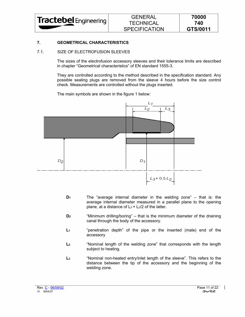
GENERAL TECHNICAL
SPECIFICATION
70000 740
GTS/0011
Rev. C - 06/09/02 Page 11 of 22 SWA/27
7. GEOMETRICAL CHARACTERISTICS
7.1. SIZE OF ELECTROFUSION SLEEVES
The sizes of the electrofusion accessory sleeves and their tolerance limits are described in chapter “Geometrical characteristics” of EN standard 1555-3.
They are controlled according to the method described in the specification standard. Any possible sealing plugs are removed from the sleeve 4 hours before the size control check. Measurements are controlled without the plugs inserted.
The main symbols are shown in the figure 1 below:
D1 The “average internal diameter in the welding zone” – that is: the average internal diameter measured in a parallel plane to the opening plane, at a distance of L3 + L2/2 of the latter.
D2 “Minimum drilling/boring” – that is the minimum diameter of the draining canal through the body of the accessory.
L1 “penetration depth” of the pipe or the inserted (male) end of the accessory
L2 “Nominal length of the welding zone” that corresponds with the length subject to heating.
L3 “Nominal non-heated entry/inlet length of the sleeve”. This refers to the distance between the tip of the accessory and the beginning of the welding zone.
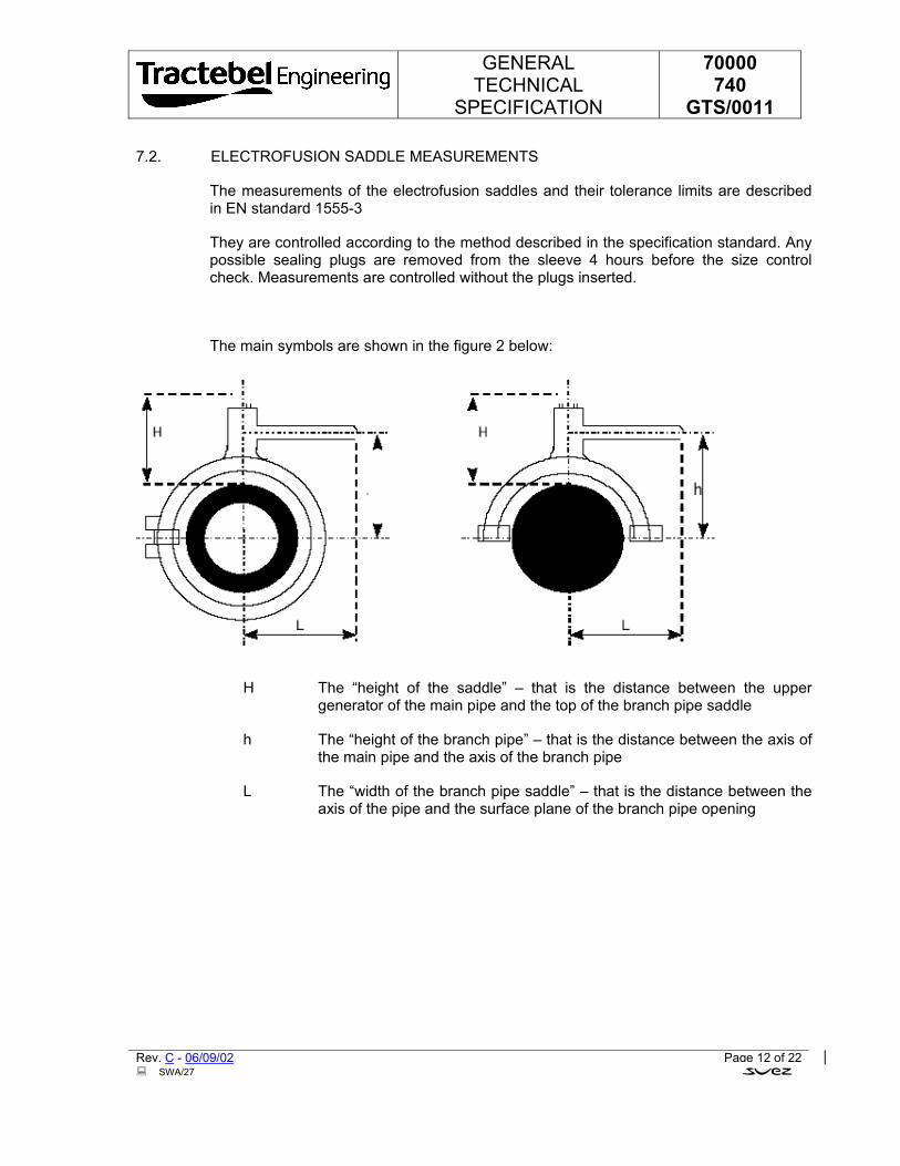
GENERAL TECHNICAL
SPECIFICATION
70000 740
GTS/0011
Rev. C - 06/09/02 Page 12 of 22 SWA/27
7.2. ELECTROFUSION SADDLE MEASUREMENTS
The measurements of the electrofusion saddles and their tolerance limits are described in EN standard 1555-3
They are controlled according to the method described in the specification standard. Any possible sealing plugs are removed from the sleeve 4 hours before the size control check. Measurements are controlled without the plugs inserted.
The main symbols are shown in the figure 2 below:
H The “height of the saddle” – that is the distance between the upper generator of the main pipe and the top of the branch pipe saddle
h The “height of the branch pipe” – that is the distance between the axis of the main pipe and the axis of the branch pipe
L The “width of the branch pipe saddle” – that is the distance between the axis of the pipe and the surface plane of the branch pipe opening
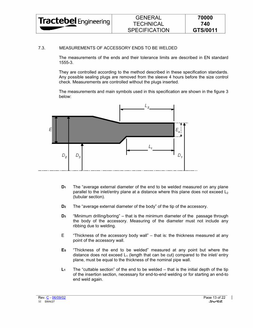
GENERAL TECHNICAL
SPECIFICATION
70000 740
GTS/0011
Rev. C - 06/09/02 Page 13 of 22 SWA/27
7.3. MEASUREMENTS OF ACCESSORY ENDS TO BE WELDED
The measurements of the ends and their tolerance limits are described in EN standard 1555-3.
They are controlled according to the method described in these specification standards. Any possible sealing plugs are removed from the sleeve 4 hours before the size control check. Measurements are controlled without the plugs inserted.
The measurements and main symbols used in this specification are shown in the figure 3 below:
D1 The “average external diameter of the end to be welded measured on any plane parallel to the inlet/entry plane at a distance where this plane does not exceed L2 (tubular section).
D2 The “average external diameter of the body” of the tip of the accessory.
D3 “Minimum drilling/boring” – that is the minimum diameter of the passage through the body of the accessory. Measuring of the diameter must not include any ribbing due to welding.
E “Thickness of the accessory body wall” – that is: the thickness measured at any point of the accessory wall.
ES “Thickness of the end to be welded” measured at any point but where the distance does not exceed L1 (length that can be cut) compared to the inlet/ entry plane, must be equal to the thickness of the nominal pipe wall.
L1 The “cuttable section” of the end to be welded – that is the initial depth of the tip of the insertion section, necessary for end-to-end welding or for starting an end-to end weld again.
GENERAL TECHNICAL
SPECIFICATION
70000 740
GTS/0011
Rev. C - 06/09/02 Page 14 of 22 SWA/27
L2 The “tubular section” of the end to be welded – that is the initial length of this section. This tubular section permits the following in all types of combination :
• Use of the clamp stirrups, as is essential for end-to-end welding, or for electrofusion.
• Assembly using electrofusion sleeves.
8. ACCESSORY MECHANICAL CHARACTERISTICS
All accessories must obey the requirements and tests described in the chapter concerning the mechanical characteristics of EN standard 1555-3. They must also comply with the hydrostatic test conditions described in the same standard.
They must be controlled as described in the same standard.
9. PHYSICAL CHARACTERISTICS
All accessories must obey the requirements and tests described in the chapter concerning the mechanical characteristics of EN standard 1555-3
They must be controlled as described in the same standard
10. PRODUCT APPROVAL
The product will be approved by the Owner if all results of the tests, controls and checking prescribed by this specification are satisfying.
The manufacturer will provide a complete approval dossier including all the product characteristics specified in 6.1. (technical dossier) and the results of tests prescribed in these specifications. The number of tests run on the product must comply with EN standard 1555-7. The results of these tests described in the approval dossier must be confirmed by the Owner authorised laboratory. Hydraulic testing must be continued until the rupture of at least two test samples for each set of tests. (max. 2000 hours).
All changes made to the approved product must be communicated to the Owner, and this entails further control checks for approval.
Any requirement not observed or test missing from this specification will result in the withdrawal of the product approval and can even result on annulment of contract.
GENERAL TECHNICAL
SPECIFICATION
70000 740
GTS/0011
Rev. C - 06/09/02 Page 15 of 22 SWA/27
11. MARKING
11.1. ACCESSORY MARKING
11.1.1. Identification marking will be made directly on the accessory. The system used to make the product must not provoke cracking or other faults. All marking must be permanently legible for the product life under standard stocking conditions, exposure to external weather conditions, treatment, installation, and use.
11.1.2. Where the products are printed, the colour of the printed identification mark must be different from that of the basic product colour.
11.1.3. Marking quality and size must be of a standard that can be read with the naked eye without magnification.
No marking must be printed on the minimum length of the insertion section of accessories.
11.1.4. 11.1.4. Each accessory must be marked with at least the obligatory details required by EN standard 1555-3. The marking must be printed on the accessory itself or on a label as shown in the standard described above
The SDR pipe range that are to be fitted with these accessories must be clearly marked on the fitting. Details must include: each SDR value, or the upper and lower value of the permitted SDR range.
11.2. COMPLEMENTARY INFORMATION
All complementary information on welding conditions (welding time and cooling time) can also be described on a label affixed to the accessory or delivered with the accessory.
GENERAL TECHNICAL
SPECIFICATION
70000 740
GTS/0011
Rev. C - 06/09/02 Page 16 of 22 SWA/27
12. PACKAGING AND DELIVERY
Normally all accessories are packed separately in plastic sheeting and/or cardboard boxes.
Sometimes they can be loosely packed together where there is no danger of damage or deterioration or loss of loose parts.
All boxes and plastic sheeting must be marked with at least one label showing the manufacturer’s name, the product type, part measurements, and number of single parts contained in the box or bag, plus all details necessary for stocking and stock expiry dates.
All electrofusion accessories must be printed with a bar code and an individual magnetic card. The magnetic card contains the welding parameters that have been encoded in the magnetic track, as well as the bar code printed on the card. Coding must be carried out according to prescriptions included in ISO TR 13950 standards.
With regard to stocking guarantee, accessories must correspond with the prescriptions of the local laws & regulations if any. If the guarantee period decided by the manufacturer is shorter that that in these document, the Owner must be informed in writing at the time of the offer.
GENERAL TECHNICAL
SPECIFICATION
70000 740
GTS/0011
Rev. C - 06/09/02 Page 17 of 22 SWA/27
13. QUALITY CONTROL
13.1. GENERAL RULINGS
13.1.1. Manufacturer’s responsibility
The manufacturer is entirely responsible for the quality of the PE accessories manufactured by his firm.
All control checks prescribed above do not relieve him of this responsibility.
To ensure that all PE accessories are in compliance with the specification in all aspects, they must be controlled by the plant control service, which must be independent from the manufacturing department.
All PE accessories supplied are guaranteed for a one-year period after application for use, that is a maximum of three years after the date of production.
13.1.2. Quality assurance
The manufacturer must have some form of quality control to ensure that products comply with EN standards 29001 or 29002. The quality assurance manual must be madeavailable to the Owner Control Service or an external Control laboratory appointed byhim.
The system of quality assurance must be certified by an authorised body.
13.2. CONTROLS
13.2.1. Control testing b y the manufacturer
13.2.1.1. By material batch.
The manufacturer demands a certificate from the raw material manufacturer including the following :
• Fluid index
• Water content
• Volume mass
• Carbon black or yellow stabilising agent content
• Carbon black or yellow stabilising agent quality
• OIT value (thermal stability)
13.2.1.2. By accessory batch
The manufacturer must run control checks as follows :
GENERAL TECHNICAL
SPECIFICATION
70000 740
GTS/0011
Rev. C - 06/09/02 Page 18 of 22 SWA/27
• Appearance / colour • Measurements • Hydraulic testing • Electrical resistance • Printing/marking.
Control checks and the number of tests must be carried out according to the prescriptions of the EN standard 1555-3
Also refer to table N° 8, paragraph 4.2.3. “Lot release tests” of EN standard 1555-7.
The results must be written out in documents that contain the complete identification of the accessory batch.
These documents must be made immediately available for the Owner representative.
13.2.2. Plant Reception by the Owner Control Service representative
13.2.2.1. General information
All quality controls must be run in the presence of the Owner Control Service representative.
All tests and control checks must comply with appropriate standard prescriptions and with the specific specifications established with the order.
At each visit by the Owner representative, the manufacturer must provide, free of charge, all means and personnel necessary for running the established control checks.
While the order is under production, the Owner representative must have access to stocking installations of all raw materials before manufacturing, manufacturing and control installations, as well as the accessory stocking areas for any control checks he is responsible for.
During his visits, the Owner representative will receive a certificate as soon as he reaches the plant for each batch of accessories presented for reception.
Each time this is requested by the Owner representative, the manufacturer must provide recent reports of all control checks and measuring instrument results and testing results.
13.2.2.2. Convocation for reception
Convocation instructions for reception are to be defined with the order.
13.2.2.3. Reception control checks
For each accessory batch or any fractions of the batch, minimal batch sampling is established in annexed enclosure 3. These control checks and tests are to be run according to the prescriptions of EN standard 1555-3
GENERAL TECHNICAL
SPECIFICATION
70000 740
GTS/0011
Rev. C - 06/09/02 Page 19 of 22 SWA/27
13.3. ACCEPTANCE OR REFUSAL
13.3.1. Appearance, measurements and marking
Any requirements not supplied will lead to the refusal of the complete batch. However in the case where a batch is refused, it can be presented for approval again after a control check, on agreement with the Owner Control Service.
13.3.2. Control check on characteristics
All results that do not comply with the specification prescriptions and the particular specifications requested with the order, demand counter-testing on at least double the number of the samples previously tested. If the undesirable result is confirmed, then the batch is refused permanently. If the result is positive, then the batch will be accepted.
As a complementary control check, other analyses and/or tests can be run after common agreement, and at the manufacturer’s cost.
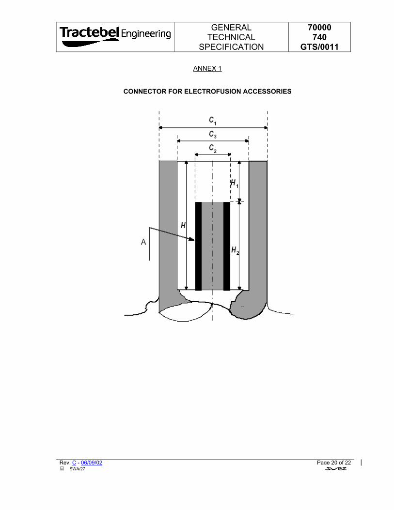
GENERAL TECHNICAL
SPECIFICATION
70000 740
GTS/0011
Rev. C - 06/09/02 Page 20 of 22 SWA/27
ANNEX 1
CONNECTOR FOR ELECTROFUSION ACCESSORIES
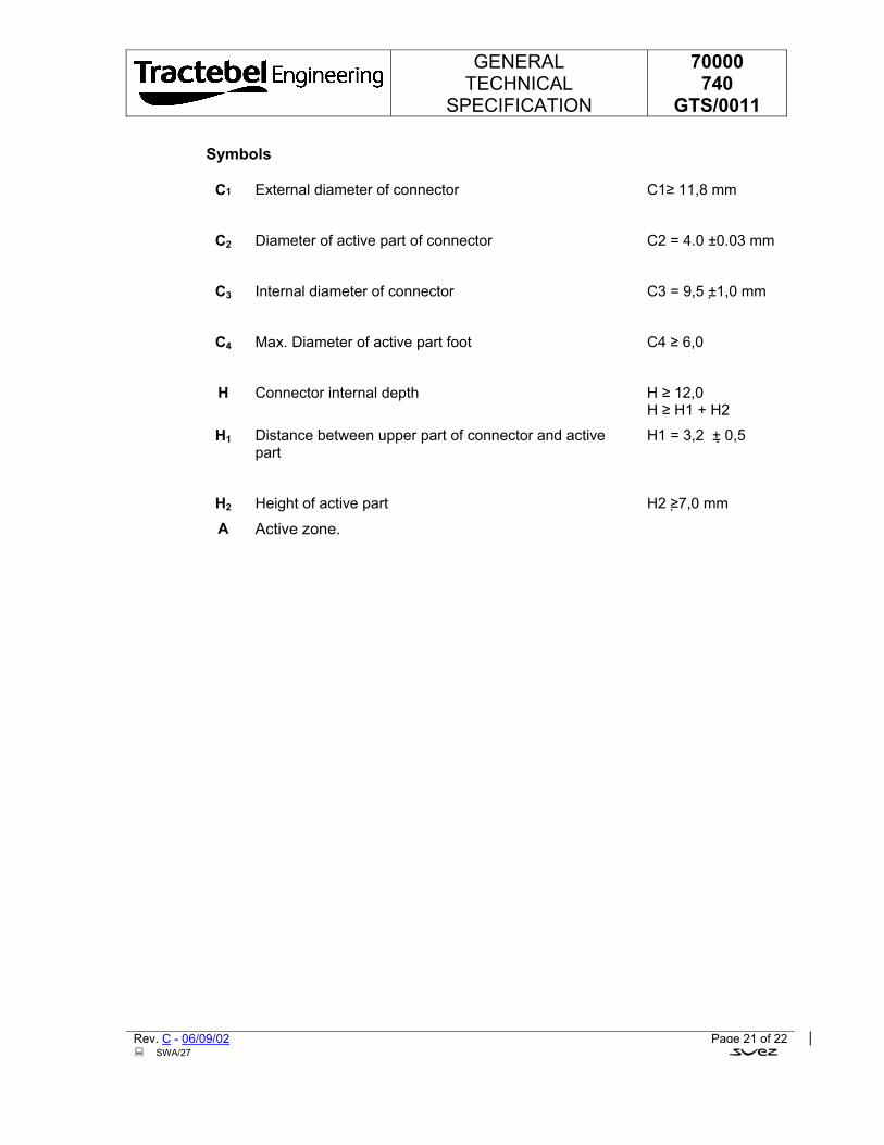
GENERAL TECHNICAL
SPECIFICATION
70000 740
GTS/0011
Rev. C - 06/09/02 Page 21 of 22 SWA/27
Symbols
C1 External diameter of connector
C1≥ 11,8 mm
C2 Diameter of active part of connector
C2 = 4.0 ±0.03 mm
C3 Internal diameter of connector
C3 = 9,5 ±1,0 mm
C4 Max. Diameter of active part foot
C4 ≥ 6,0
H Connector internal depth H ≥ 12,0 H ≥ H1 + H2
H1 Distance between upper part of connector and active part
H1 = 3,2 ± 0,5
H2 Height of active part H2 ≥7,0 mm
A Active zone.
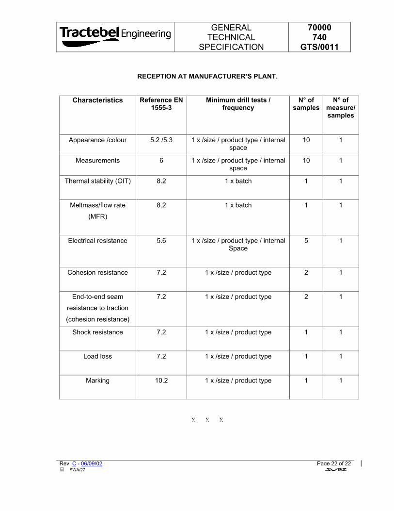
GENERAL TECHNICAL
SPECIFICATION
70000 740
GTS/0011
Rev. C - 06/09/02 Page 22 of 22 SWA/27
RECEPTION AT MANUFACTURER’S PLANT.
Characteristics Reference EN 1555-3
Minimum drill tests / frequency
N° of samples
N° of measure/samples
Appearance /colour 5.2 /5.3 1 x /size / product type / internal space
10 1
Measurements 6 1 x /size / product type / internal space
10 1
Thermal stability (OIT) 8.2 1 x batch
1 1
Meltmass/flow rate
(MFR)
8.2 1 x batch 1 1
Electrical resistance 5.6 1 x /size / product type / internal Space
5 1
Cohesion resistance 7.2 1 x /size / product type
2 1
End-to-end seam
resistance to traction
(cohesion resistance)
7.2 1 x /size / product type 2 1
Shock resistance 7.2 1 x /size / product type
1 1
Load loss 7.2 1 x /size / product type
1 1
Marking 10.2 1 x /size / product type
1 1
Σ Σ Σ
GENERAL TECHNICAL
SPECIFICATION
70000 740
GTS/0012
Polyethylene compounds for manufacture of pipes and fittings for underground networks for natural gas distribution
Acceptance procedure
C 06/09/02 Updated (see revision marks) MRT MRY MRT
B 21/08/02 Updated MRT MRY MRT
A 13/08/02 First Issue MRT MRY MRT
Rev. Date Subject of revision Author Checked Approved
�SWA/15/ *70000/740/GTS/0012*
GENERAL TECHNICAL
SPECIFICATION
70000 740
GTS/0012
Rev. C - 06/09/02 SWA/13
TABLE OF CONTENTS
1. SUBJECT......................................................................................................................................3
2. REFERENCES: STANDARDS AND SPECIFICATIONS .............................................................3
3. DEFINITIONS AND SYMBOLS ....................................................................................................4
3.1. LOWER CONFIDENCE LIMIT (LCL).....................................................................................4
3.2. MINIMUM REQUIRED STRENGTH (MRS 10) .....................................................................4
3.3. PE 100...................................................................................................................................5
3.4. BATCH OF COMPOUND ......................................................................................................5
3.5. BATCH OF PIPES.................................................................................................................5
4. GENERAL SPECIFICATIONS......................................................................................................5
5. SUMMARY OF THE PROCEDURE..............................................................................................5
5.1. GENERAL .............................................................................................................................5
5.2. APPLICATION FOR APPROVAL..........................................................................................6
6. TECHNICAL FILE .........................................................................................................................6
6.1. EVALUATION........................................................................................................................6
6.2. ADDITIONAL TESTS ............................................................................................................7
7. CONFIRMATION TESTS ..............................................................................................................8
8. FOLLOW-UP.................................................................................................................................9
8.1. TECHNICAL DATA SHEET...................................................................................................9
8.2. CONTINUITY OF THE COMPOUND ....................................................................................9
APPENDIX 1 .....................................................................................................................................10
Σ Σ Σ
GENERAL TECHNICAL
SPECIFICATION
70000 740
GTS/0012
Rev. C - 06/09/02 Page 1 of 9 SWA/16
The information contained in this document should be treated as confidential and is to be considered as the exclusive property of Tractebel. Direct or indirect use of this document or any part of it is only allowed for Tractebel productions.
1. SUBJECT
This specification describes the procedure to be followed for acceptance of a polyethylene (PE) compound for manufacture of natural gas underground distribution systems.
This specification also gives the minimum requirements which have to be met by PE compounds for manufacture of pipes, fittings and valves and for the construction of underground distribution systems for natural gas.
The compounds that meet this specification must at the minimum be PE 100.
The colour shall be black or orange in accordance with the local requirements.
2. REFERENCES: STANDARDS AND SPECIFICATIONS
This section contains the list of standards and specifications referred to in this specification.
EN 728: 1997 Plastics piping and ducting systems – Polyolefin pipes and fittings - Determination of oxidation induction time.
prEN 1555-1 Plastics piping systems for the supply of gaseous fuels - Polyethylene (PE) - Part 1: General
EN 1555-3 prEN 1555-7 Plastics piping systems for the supply of gaseous fuels - Polyethylene (PE) - Part 7: Assessment of conformity.
prEN 12099 Plastics piping systems - Polyethylene piping materials and components - Determination of volatile content.
prEN 12118 Plastics piping systems - Determination of moisture content in plastics by coulometry.
EN ISO 12162: 1995 Thermoplastics materials for pipes and fittings for pressure applications - Classification and designation - Overall service (design) coefficient.
EN ISO 13478: 1997 Thermoplastics pipes for the conveyance of fluids - Determination of resistance to rapid crack aaaaa
GENERAL TECHNICAL
SPECIFICATION
70000 740
GTS/0012
Rev. C - 06/09/02 Page 2 of 9 SWA/16
propagation (RCP) - Full-scale test (FST).
EN ISO 13479: 1997 Thermoplastics pipes for the conveyance of fluids - Determination of resistance to crack propagation (RCP) - Test method for slow crack growth on notched pipes (notch test).
EN 45001: 1990 General criteria for the operation of testing laboratories.
ISO 1133: 1997 Determination of the melt mass-flow rate (MFR) and the melt volume-flow rate (MVR) of thermoplastics.
ISO 6964: 1996 Polyolefin pipes and fittings - Determination of carbon black content by calcination and pyrolysis - Test method and basic specification.
ISO/DIS 9080 Plastics piping and ducting systems - Determination of the long-term hydrostatic strength of thermoplastics materials in pipe from by extrapolation.
ISO 11420: 1996 Method for the assessment of the degree of carbon black dispersion in polyolefin pipes, fittings and compounds.
ISO 13477: 1997 Thermoplastics pipes for the conveyance of fluids - Determination of resistance to rapid crack propagation (RCP) - Small-scale-steady-state test (S4 test).
TBL 70000/740/GTS/0008 to 70000/740/GTS/0010
Polyethylene pipes for underground networks for natural gas distribution
TBL 70000/740/GTS/0011
PE Accessories for underground networks for natural gas distribution
3. DEFINITIONS AND SYMBOLS
3.1. LOWER CONFIDENCE LIMIT (LCL)
A quantity with the dimensions of stress, in megapascal, which can be considered as a property of the material under consideration and represents the 97.5% lower confidence limit of the predicted long-term hydrostatic strength at a temperature of 20°C for 50 years with internal water pressure.
GENERAL TECHNICAL
SPECIFICATION
70000 740
GTS/0012
Rev. C - 06/09/02 Page 3 of 9 SWA/16
3.2. MINIMUM REQUIRED STRENGTH (MRS 10)
Standardised class of compounds for which the LCL is equal to 10.
3.3. PE 100
Standard designation for PE compounds in class MRS 10.
For such PE compounds, the long-term hydrostatic strength – calculated and classified according to the standardised method (ISO 9080 and ISO 12162) for a temperature of 20°C, a period of 50 years and a reliability of 97.5 % – must be at least 10 MPa.
3.4. BATCH OF COMPOUND
By batch of compound is meant a homogeneous quantity of PE compound of the same origin and of a particular brand.
The batch must be registered under a single identification number (batch number) which leaves no doubt as to the origin, identity and date of manufacture of the compound.
3.5. BATCH OF PIPES
By batch of pipes is meant a homogenous lot of pipes with identical dimensions, made in a continuous process by the same extrusion machine and from the same batch of compound.
4. GENERAL SPECIFICATIONS
The PE compounds that are acceptable according to the requirements of this specification must conform to the requirements for PE 100 described in prEN1555-1.
If the proposed compound is destined for manufacture of pipes, then the acceptance procedure is carried out as described in this specification.
If the proposed compound is destined for manufacture of fittings, then the first stage (section 6) of this acceptance procedure is carried out, after which type tests are carried out on the fittings manufactured from the material concerned. An independent laboratory appointed by Owner will then evaluate whether conformity with the characteristics mentioned in the technical file has been proved, on the basis of the provisions of prEN 1555-7 and Tractebel specification TBL 70000/740/GTS/0011.
GENERAL TECHNICAL
SPECIFICATION
70000 740
GTS/0012
Rev. C - 06/09/02 Page 4 of 9 SWA/16
5. SUMMARY OF THE PROCEDURE
5.1. GENERAL
The acceptance procedure for PE compounds comprises two stages, namely the evaluation of the technical file and the confirmation tests. The different steps are carried out in the order described below.
The tests which form part of the technical file are carried out on pipes or samples supplied by the compounds manufacturer. In principle, all tests mentioned in the technical file are carried out on pipes from the same batch.
The tests mentioned in chapter 7 are carried out on pipes manufactured by a pipe manufacturer chosen by Owner.
The tests mentioned in chapter 6.1 (table 1), 6.2 and 7 are carried out in a laboratory appointed by Owner.
5.2. APPLICATION FOR APPROVAL
A manufacturer that wishes to have a certain PE compound classified for the manufacture of PE gas components must submit a written application to Owner.
This application must be accompanied by a clear description of the compound concerned, including the technical characteristics.
All correspondence must be in English.
6. TECHNICAL FILE
6.1. EVALUATION
If the application is taken into consideration by Owner, the compound manufacturer must submit a technical file to a laboratory appointed by Owner.
This technical file must include the following information:
• name and class of the PE compound;
• technical characteristics of the compound, with reference to the standard;
• a dossier with test results, from an independent laboratory, showing that the proposed compound meets the requirements of prEN 1555-1 for a PE 100 compound. The dossier must also state which tests have been carried out on the same batch of pipes or test samples, including the identification of their origin.
The laboratory chosen by Owner will also evaluate the conformity of this dossier, taking the following rules into account:
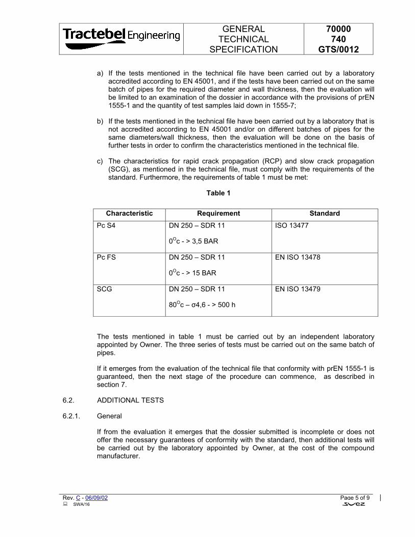
GENERAL TECHNICAL
SPECIFICATION
70000 740
GTS/0012
Rev. C - 06/09/02 Page 5 of 9 SWA/16
a) If the tests mentioned in the technical file have been carried out by a laboratory accredited according to EN 45001, and if the tests have been carried out on the same batch of pipes for the required diameter and wall thickness, then the evaluation will be limited to an examination of the dossier in accordance with the provisions of prEN 1555-1 and the quantity of test samples laid down in 1555-7;
b) If the tests mentioned in the technical file have been carried out by a laboratory that is not accredited according to EN 45001 and/or on different batches of pipes for the same diameters/wall thickness, then the evaluation will be done on the basis of further tests in order to confirm the characteristics mentioned in the technical file.
c) The characteristics for rapid crack propagation (RCP) and slow crack propagation (SCG), as mentioned in the technical file, must comply with the requirements of the standard. Furthermore, the requirements of table 1 must be met:
Table 1
Characteristic Requirement Standard
Pc S4 DN 250 – SDR 11
0Oc - > 3,5 BAR
ISO 13477
Pc FS DN 250 – SDR 11
0Oc - > 15 BAR
EN ISO 13478
SCG DN 250 – SDR 11
80Oc – σ4,6 - > 500 h
EN ISO 13479
The tests mentioned in table 1 must be carried out by an independent laboratory appointed by Owner. The three series of tests must be carried out on the same batch of pipes.
If it emerges from the evaluation of the technical file that conformity with prEN 1555-1 is guaranteed, then the next stage of the procedure can commence, as described in section 7.
6.2. ADDITIONAL TESTS
6.2.1. General
If from the evaluation it emerges that the dossier submitted is incomplete or does not offer the necessary guarantees of conformity with the standard, then additional tests will be carried out by the laboratory appointed by Owner, at the cost of the compound manufacturer.
GENERAL TECHNICAL
SPECIFICATION
70000 740
GTS/0012
Rev. C - 06/09/02 Page 6 of 9 SWA/16
The same procedure will be followed if the technical file has been drawn up by a laboratory that is not accredited and/or if several batches of pipes have been used for each diameter/wall thickness in carrying out the tests.
6.2.2. Delivery of the pipes
The required batch of pipes must be delivered by the compound manufacturer, the pipes having been produced by a pipe manufacturer who at that moment is a Owner supplier.
The number of pipes must be based on the numbers and frequencies mentioned in prEN 1555-7.
If the technical file is based on tests carried out by a non-accredited laboratory and/or carried out on several batches of pipes per diameter/wall thickness, then the tests will repeated on at least half of the required test samples; if the number thus calculated is not a whole number, the number of test samples taken will be equal to the next whole number.
6.2.3. Test results
If from the additional tests it appears that conformity with prEN 1555-1 is guaranteed, then the next phase of the procedure can commence, as described in section 7.
If despite the additional tests no unambiguous decision can be taken regarding the conformity of the compound, then further additional tests will be carried out, until the number of test samples is at maximum equal to the number specified in the standard concerned. For this purpose, the manufacturer must keep sufficient pipes of the same batch in reserve.
If the evaluation is still not positive after the maximum number of samples has been tested, then the compound will be considered as not accepted.
7. CONFIRMATION TESTS
The second stage of the acceptance covers the industrial production of pipes, the verification of the characteristics, the laying of the pipes and the fusion to existing PE systems.
This second stage of the acceptance is carried out by Owner.
Before this stage can commence, the manufacturer must provide Owner with a technical data sheet (see appendix 1) showing the limit values for the characteristics of the compound concerned.
For the purpose of carrying out this part of the procedure, Owner will order a batch of pipes from one of its pipe manufacturers. After verification of the characteristics in the factory and confirmation by an independent laboratory, the pipes will be installed in the Owner gas distribution network, taking into account the following aspects:
GENERAL TECHNICAL
SPECIFICATION
70000 740
GTS/0012
Rev. C - 06/09/02 Page 7 of 9 SWA/16
• Any problems with delivery and with extrusion of the compound will be noted.
• The limits of the characteristics mentioned in the technical data sheet.
• For characteristics not included in the technical data sheet, the measured value may
• deviate by max. 30% from the average values mentioned in the technical file, to the extent that these are relevant and not in conflict with the requirements of the standard.
• Any problems with laying or welding or connecting the pipes; these will be noted.
If from the test results it appears that the characteristics of the compound and/or pipes do not comply with the requirements, or if anomalies are found in laying and/or welding of the pipes, then the acceptance procedure will be provisionally suspended. The problems found will be analysed in consultation with the compound manufacturer, and an attempt will be made to find solutions which are acceptable to both parties. If this turns out to be impossible, then the compound will be considered as not accepted.
In such a case, the costs of the second stage could be charged to the compound manufacturer.
If the second stage of the procedure is successfully completed, then the compound is accepted and will be included in the list of “Approved PE Compounds”. This list is published in the Tractebel specifications for PE pipes (TBL 70000/740/GTS/0008 to 0010) and PE fittings (TBL 70000/740/GTS/0011). The materials will be included when the list is next published (around once every two year).
8. FOLLOW-UP
8.1. TECHNICAL DATA SHEET
The manufacturer must supply Owner with a technical data sheet, as described in Appendix 1, with permission for Owner to publish this technical data sheet in the specifications for PE pipes and fittings, for as long as the compound is included in the list of approved compounds.
The data entered on this data sheet apply as limit values for the compound concerned. Whenever one or more characteristics of a batch of compounds falls outside these limits, then the batch will be automatically refused for production of components destined for our gas network.
8.2. CONTINUITY OF THE COMPOUND
No alterations may be made to the compound without prior permission from Owner.
As mentioned in 8.1, the limits mentioned in the technical data sheet must be respected. Furthermore, in the case of characteristics not included in the technical data sheet, the measured values may not deviate by more than 30% from the average value mentioned
GENERAL TECHNICAL
SPECIFICATION
70000 740
GTS/0012
Rev. C - 06/09/02 Page 8 of 9 SWA/16
in the technical file, to the extent that these are relevant and not in conflict with the requirements of the standard.
Each change that affects the final characteristics of the compound can result in additional tests being carried out by the compound manufacturer in accordance with the provisions of prEN 1555-7 appendix A. The procedures for the test shall correspond to those described in section 6.1 of this specification.
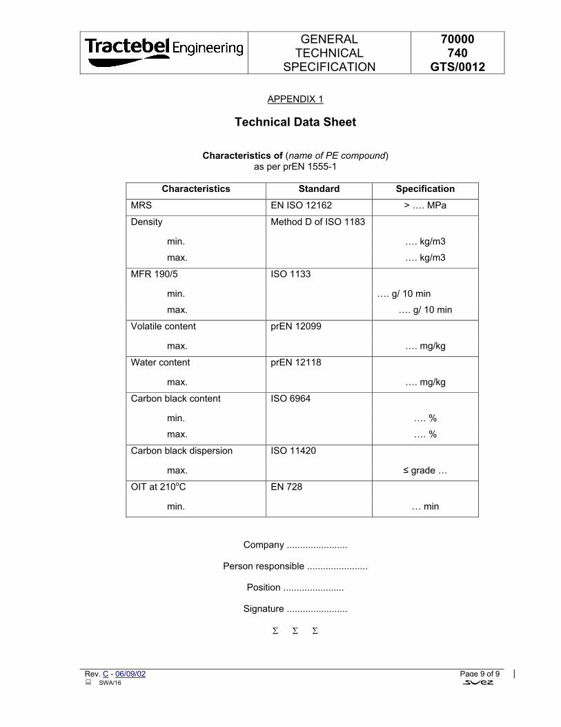
GENERAL TECHNICAL
SPECIFICATION
70000 740
GTS/0012
Rev. C - 06/09/02 Page 9 of 9 SWA/16
APPENDIX 1
Technical Data Sheet
Characteristics of (name of PE compound)
as per prEN 1555-1
Characteristics Standard Specification
MRS EN ISO 12162 > …. MPa
Density Method D of ISO 1183
min. …. kg/m3
max. …. kg/m3
MFR 190/5 ISO 1133
min. …. g/ 10 min
max. …. g/ 10 min
Volatile content prEN 12099
max. …. mg/kg
Water content prEN 12118
max. …. mg/kg
Carbon black content ISO 6964
min. …. %
max. …. %
Carbon black dispersion ISO 11420
max. ≤ grade …
OIT at 210oC EN 728
min. … min
Company .......................
Person responsible .......................
Position .......................
Signature .......................
Σ Σ Σ
GENERAL TECHNICAL
SPECIFICATION
70000 740
GTS/0015
POLYETHYLENE VALVES FOR NATURAL GAS DISTRIBUTIONUNDERGROUND NETWORK
A 22/08/02 First Issue MRT MRY MRT
Rev. Date Subject of revision Author Checked Approved
SN1/21/ *70000/740/GTS/0015*
GENERAL TECHNICAL
SPECIFICATION
70000 740
GTS/0015
Rev. A - 22/08/02 Page I of III SN1/22
TABLE OF CONTENTS
1. SCOPE AND FIELD OF APPLICATION.......................................................................................1
2. NORMATIVE REFERENCES .......................................................................................................1
3. DEFINITIONS................................................................................................................................2
3.1. NOMINAL SIZE DN/OD.........................................................................................................2
3.2. NOMINAL OUTSIDE DIAMETER (DN) ..................................................................................2
3.3. NOMINAL WALL THICKNESS (EN) ......................................................................................2
3.4. COMPOUND .........................................................................................................................2
3.5. MAXIMUM OPERATING PRESSURE (MOP).......................................................................2
3.6. VALVES.................................................................................................................................2
3.7. BASE PLATE.........................................................................................................................2
3.8. SPINDLE PROTECTION SLEEVE........................................................................................3
3.9. EXTERNAL LEAK-TIGHTNESS............................................................................................3
3.10. INTERNAL LEAK-TIGHTNESS.............................................................................................3
3.11. LEAK-TIGHTNESS TEST .....................................................................................................3
3.12. INITIATING TORQUE............................................................................................................3
3.13. RUNNING TORQUE..............................................................................................................3
3.14. LEAKAGE..............................................................................................................................3
4. GENERAL SPECIFICATION ........................................................................................................4
5. MATERIAL PARTICULARITIES...................................................................................................4
5.1. GENERAL .............................................................................................................................4
5.2. PE COMPOUND FOR POLYETHYLENE VALVES BODIES................................................4
5.3. SEALS ...................................................................................................................................5
5.4. LUBRICANTS........................................................................................................................5
GENERAL TECHNICAL
SPECIFICATION
70000 740
GTS/0015
Rev. A - 22/08/02 Page II of III SN1/22
5.5. OPERATING CAP .................................................................................................................5
6. VALVES GENERAL PARTICULARITIES ....................................................................................5
6.1. TECHNICAL FILE..................................................................................................................5
6.2. DESIGN.................................................................................................................................6
6.3. APPEARANCE AND COLOUR .............................................................................................6
6.4. DIMENSIONS........................................................................................................................7
7. MECHANICAL CHARACTERISTICS FOR ASSEMBLED VALVES............................................7
7.1. GENERAL .............................................................................................................................7
7.2. RUNNING TORQUE..............................................................................................................7
7.3. INDIVIDUAL TEST (BATCH RELEASE TEST) .....................................................................7
7.4. PRESSURE DROP AT LOW PRESSURE............................................................................8
8. MARKING .....................................................................................................................................8
9. PACKAGING AND DELIVERY.....................................................................................................9
10. GUARANTEE................................................................................................................................9
11. QUALITY CONTROL ....................................................................................................................9
11.1. GENERAL RULINGS ............................................................................................................9
11.1.1. Manufacturer’s responsibility .................................................................................................9
11.1.2. Quality assurance..................................................................................................................9
11.2. CONTROLS.........................................................................................................................10
11.2.1. Control testing by the manufacturer.....................................................................................10
11.3. ACCEPTANCE OR REFUSAL ............................................................................................11
11.3.1. Appearance, measurements and marking...........................................................................11
11.3.2. Control check on characteristics..........................................................................................11
ANNEXE A........................................................................................................................................12
DIMENSIONS OF THE EXTENSION SPINDLE ...............................................................................12
GENERAL TECHNICAL
SPECIFICATION
70000 740
GTS/0015
Rev. A - 22/08/02 Page III of III SN1/22
ANNEX B ..........................................................................................................................................13
DIMENSIONS OF THE OPERATING CAP TYPE A.........................................................................13
ANNEX C ..........................................................................................................................................14
DIMENSIONS OF THE OPERATING CAP TYPE B.........................................................................14
ANNEX D ..........................................................................................................................................15
DIMENSIONS OF THE OPERATING CAP TYPE C.........................................................................15
Σ Σ Σ
GENERAL TECHNICAL
SPECIFICATION
70000 740
GTS/0015
Rev. A - 22/08/02 Page 1 of 15 SN1/22
1. SCOPE AND FIELD OF APPLICATION
This General Technical Specification specifies the requirements for valves and its component made from extruded or injected moulded polyethylene (PE) and which are intended to be used for the Natural gas distribution systems where the maximum operating pressure (MOP) is equal to 5 bar.
In addition, it specifies some general properties of the materials from which these valves are made.
It applies to bi-directional valves with spigot ends or electrofusion sockets intended to be fused with polyethylene pipes in accordance with the TBL 70000/740/GTS/0008-0009- 0010 and 0012 PE pipe specification and with spigot fittings in accordance with the TBL 70000/740/GTS/0011.
This specification is limited to valves with a nominal diameter (dn) up to and including 225 mm.
2. NORMATIVE REFERENCES
prEN 1555-1 Plastics piping systems for the supply of gaseous fuels-Polyethylene (PE) - part 1 : General
prEN 1555-4 Plastics piping systems for the supply of gaseous fuels-Polyethylene (PE) - part 4 : Valves
prEN 1555-7 Plastics piping systems for the supply of gaseous fuels-Polyethylene (PE) - part 7 : Guidance for assessment of conformity
ISO CD 12176-4 Plastics pipes and fittings - Equipment for fusion jointingpolyethylene system - part 4 : raceability coding
ISO TR 13950 Plastics pipes and fittings - Automatic recognition systems for electrofusions
TBL 7000/740/GTS/0008 Polyethylene pipes for underground networks for Natural gas distribution - General requirements
TBL 70000/740/GTS/0009 Polyethylene pipes for underground networks for Natural gas distribution - Technical data sheet
TBL 70000/740/GTS/0010 Polyethylene pipes for underground networks for Natural gas distribution - Quality control of pipes
TBL 70000/740/GTS/0011 PE accessories for underground network for natural gas distribution
TBL 70000/740/GTS/0012 Polyethylene components for manufacture of pipes and fittings for underground networks for natural gas distribution - Acceptance procedure
TBL 70000/740/GTS/0013 Execution of works. Installation of polyethylene pipes
GENERAL TECHNICAL
SPECIFICATION
70000 740
GTS/0015
Rev. A - 22/08/02 Page 2 of 15 SN1/22
3. DEFINITIONS
3.1. NOMINAL SIZE DN/OD
Nominal size, related to the outside diameter.
3.2. NOMINAL OUTSIDE DIAMETER (dn)
Specified outside diameter, in millimetre, assigned to a nominal size DN/OD.
3.3. NOMINAL WALL THICKNESS (en)
Numerical designation of the wall thickness of a component, which is a convenient round number, approximately equal to the manufacturing dimension in millimetre (mm).
Note : For thermoplastics components conforming to prEN 1555, the value of the nominal wall thickness en is identical to the specified minimum wall thickness at any point, emin.
3.4. COMPOUND
Homogenous mixture of base polymer (PE) and additives, i.e. anti-oxidants, pigments, UV-stabilisers and others, at a dosage level necessary for the processing and use of components conforming to the requirements of this standard.
3.5. MAXIMUM OPERATING PRESSURE (MOP)
Maximum effective pressure of the fluid in the piping system, expressed in bar, which is allowed in continuous use. It takes into account the physical and the mechanical characteristics of the components of a piping system.
Note : It is calculated using the following equation : MOP = )1(
)20(−SDRCx
xMRS
3.6. VALVES
An obturating device designed to stop or restore the gas flow by operating the opening and closing mechanisms.
3.7. BASE PLATE
The valves are split into two models.
MODEL 1 Valve supply without base plate MODEL 2 Valve supply with a base plate fixed or integrated
GENERAL TECHNICAL
SPECIFICATION
70000 740
GTS/0015
Rev. A - 22/08/02 Page 3 of 15 SN1/22
3.8. SPINDLE PROTECTION SLEEVE
A sleeve tube that protect the valve spindle. The protection sleeve exists in two models
VENTILATED The sleeve is provided with opening and wrapped with textile fabric in order to let the gas escape and prevent the soil to go in.
NON VENTILATED A normal sleeve tube without textile fabric.
3.9. EXTERNAL LEAK-TIGHTNESS
The tightness of the body enveloping the space containing the gas, with respect to the atmosphere.
3.10. INTERNAL LEAK-TIGHTNESS
The tightness between the inlet and the outlet of the valve, obtained by closing the operating mechanism.
3.11. LEAK-TIGHTNESS TEST
Test to determine
• the internal leak-tightness of the valve's closing seat when closed and pressurised from either side;
• the external leak-tightness of the valve when half open.
3.12. INITIATING TORQUE
Torque required to initiate movement of the obturator.
3.13. RUNNING TORQUE
Torque required to achieve full opening or closing of the valve at maximum allowable operating pressure.
3.14. LEAKAGE
Emission of gas through the body, sealing membrane or any other component of the valve.
GENERAL TECHNICAL
SPECIFICATION
70000 740
GTS/0015
Rev. A - 22/08/02 Page 4 of 15 SN1/22
4. GENERAL SPECIFICATION
The present specification is based on the European Standards EN 1555 series prepared by technical committee CEN/TC 155 plastic technical and ducting system.
The requirements of this General technical specification are chosen in order to guarantee a high quality gas system which will respond to the European Standards for gas supply systems.
• the valves described in this General technical specification comply with the standard prEN1555-4 and the complementary particular requirements or options of the present GTS.
• the valves are intended to be use in gas distribution networks made of PE pipes and accessories complying with TBL 70000/740/GTS/0008-0009-0010-0011-0012.
• the valves are laid and welded as specified in the TBL 70000/740/GTS/0013
5. MATERIAL PARTICULARITIES
5.1. GENERAL
All parts of the valve in contact with the gas stream shall be resistant to the gas, its condensates and other occurring substances such as dust.
All metallic parts of the PE valve shall resist to both internal and external corrosion.
5.2. PE COMPOUND FOR POLYETHYLENE VALVES BODIES
• The PE compound from which the valve body, with spigot end or electrofusion socket is made out, shall conform to prEN1555-1 and comply with the TBL 70000/740/GTS/0012 "acceptance procedure".
• The PE valves bodies are PE 100 class made from approved material as specified in the TBL 70000/740/GTS/0008 General requirements - appendix 1.
Are forbidden :
• use of recycled materials,
• mixture of different materials,
• addition of complementary materials.
GENERAL TECHNICAL
SPECIFICATION
70000 740
GTS/0015
Rev. A - 22/08/02 Page 5 of 15 SN1/22
5.3. SEALS
• The seals shall be homogeneous, without any inner crack, inclusion or impurities and cannot contain any component that can alter the properties of the materials they are in contact with, and prevent the non-conformity of those materials with the present specification.
• additives shall be distributed evenly.
• The rubber seal rings shall comply with standard EN 682.
• Other seals shall comply with the relevant standard and be suitable for gas service.
5.4. LUBRICANTS
Lubricants cannot have any adverse effects on the long-term performance of the valve parts.
5.5. OPERATING CAP
Operating cap are in plastic material or in metal, protected against corrosion.
6. VALVES GENERAL PARTICULARITIES
6.1. TECHNICAL FILE
The manufactures of the valves shall deliver for each type of valve a technical file which includes:
• Raw materiel used,
• drawings, dimensions and tolerances, including for the accessories,
• application range (temperature and pressure limits),
• running torque and initiating torque,
• pressure drop and flow diagram,
• test results and data proving the conformity of the valve in accordance with prEN1555-4 and prEN1555-7,
• the pipe elements used during valves testing have to be conform to the TBL 70000/740/GTS/0008,
• the assembly pipes/valves realised during testing shall be in conformity with the manufactures instructions and the extreme installation conditions.
GENERAL TECHNICAL
SPECIFICATION
70000 740
GTS/0015
Rev. A - 22/08/02 Page 6 of 15 SN1/22
• For the test assembly due consideration should be taken regarding the fabrication tolerances and the variation of the outside ambient temperature.
• The welding of the assembly will comply with TBL 70000/740/GTS/0013.
6.2. DESIGN
• The valves will be designed for a maximum operating pressure (MOP) equal to 10 bar.
• The wall thickness of the PE valve body shall be equal or greater than the minimum wall thickness of the corresponding SDR 11 series pipes.
• Valves body and valves ends form an indivisible whole.
• Except otherwise stated in the Owner purchase order, all valves will be "ball valve" type.
• The operating cap shall be designed in a way that it cannot be ejected "non blow out" type.
• The design of the extension spindle and the spindle protection sleeve will be such that they will never, in any case, even due to soil settlement, lay on the non reinforced part of the valve body or the valve ends. The spindle protection sleeve cannot turn during valve turning operation.
• The owner will specify if the spindle protection sleeve is a ventilated or non-ventilated type.
• The spindle protection sleeve ventilated type will have holes (min. diameter 10 mm) or slot type holes (min. width 1 mm) all around the sleeve in sufficient number in order to assure a maximum permeability for the gas.
• The sleeve will be covered by a non-waved geo-textile fabric (90 µm). The geo-textile fabric with a 50 mm overlap will be well secured on the sleeve;
• The valves should be equipped with a base plate. In order to achieve this, the valve body will be design with a flat base (model 1) or with an attached base plate or an integrated one (model 2). The Owner or his representative will specify the model.
• The operating mechanism and the stop wedges will be protected against water intrusion.
• The valve body is completely sealed except a passage for the spindle mechanism.
6.3. APPEARANCE AND COLOUR
• The internal and external surfaces of valves shall be smooth clean and shall have no scoring, cavities or other defects to an extend that would prevent non-conformity to the present GTS or to the standard prEN 1555-4.
GENERAL TECHNICAL
SPECIFICATION
70000 740
GTS/0015
Rev. A - 22/08/02 Page 7 of 15 SN1/22
• The colour of the PE valves shall be either yellow, black or orange.
• The colour of the valve shall be specify by the Owner or his representative in the purchase order;
6.4. DIMENSIONS
• The dimensions will be in conformity with the standard prEN1555-3 and prEN1555-4.
• The dimensions of the extensions spindle are detailed in appendix A.
• The operating cap will be design as per appendix B, C or D.
• The type of the operating cap will be specified by the Owner or his representative in the purchase order.
• The design of the extension spindle is such that the extension can be turn easily at
• any time to suit the site conditions.
7. MECHANICAL CHARACTERISTICS FOR ASSEMBLED VALVES
7.1. GENERAL
The valve shall have mechanical characteristics and be tested as specified in the standard prEN 1555-4.
7.2. RUNNING TORQUE
The running torque and the concept of the valve shall prevent the valve from being easily
operated (by hand) without an operating key. To operate the valve designed with running
torque as specified I the standard prEN 1555-4, the use of an operating key is requested.
Neither the operating cap nor the spindle shall be damaged when operating at maximum
operating torque as specified in the standard prEN 1555-4;
7.3. INDIVIDUAL TEST (BATCH RELEASE TEST)
Before delivery each valves will be individually tested for mechanical strength and leaktightness as per standard prEN1555-4.
A combined mechanic resistance and leak-tightness test shall be performed in conformity with the prEN1555-4.
By batch of valves a supplementary leak-tightness test (25 mbar) shall be performed in conformity with the prEN 1555-4 on 3 valves taken at random.
GENERAL TECHNICAL
SPECIFICATION
70000 740
GTS/0015
Rev. A - 22/08/02 Page 8 of 15 SN1/22
7.4. PRESSURE DROP AT LOW PRESSURE
The drop of pressure is measured with natural gas as a medium and according to the diagram specified in the standard EN 12117 (fig.1).
The maximum drop of pressure measured with natural gas (inlet pressure 25 mbar) will be limited to 0,2 mbar for a nominal gas flow as per table below.
dn Flow m3/h
32 10 40 15 63 60 90 180
110 250 160 600 200 1000
8. MARKING
At least the information given below shall be printed or formed directly on the valve :
a) Manufacturer's name and/or trademark;
b) Material and designation (e.g. PE 100);
c) Design application series (e.g. SDR 11);
d) Nominal diameter;
e) Internal fluid "gas";
f) Traceability code (valve and component) as per standard ISO/FDIS 12176-4;
g) Number of the system standard (e.g. prEN 1555-4) this information can be printed/formed directly on the valve or on a label associated with the valve or on an individual bag.
h) Production period, year and month;
The marking shall stay legible during normal manipulation, storage and installation.
The marking shall not adversely influence the performance of the valve and prevent the non-conformity of the valve.
GENERAL TECHNICAL
SPECIFICATION
70000 740
GTS/0015
Rev. A - 22/08/02 Page 9 of 15 SN1/22
No marking will be accepted at the valve spigot ends.
9. PACKAGING AND DELIVERY
The valve and its accessories shall be packaged individually in plastic bags in order to prevent them from deterioration. The valves ends shall be protected with external caps.
The cartons and/or individual bags shall bear at least one label with the manufacturer's name, type and dimensions of the part number, number of units in the box and, any special storage conditions and storage time limits.
10. GUARANTEE
The manufacturer will extend his guarantee for each part for 10 years after production. This guarantee period is valid if the parts are kept in proper conditions and in the original packaging.
The valves equipped with electrofusion sockets will be supply with a magnetic card and a code bar tag containing the welding parameters. The coding of the parameters shall be in conformity with the standard ISO TR 13950.
The operating manual (in English) will be inserted in the individual part package.
11. QUALITY CONTROL
11.1. GENERAL RULINGS
11.1.1. Manufacturer’s responsibility
The manufacturer is entirely responsible for the quality of the PE valves manufactured by his firm.
All control checks prescribed above do not relieve him of this responsibility.
To ensure that all PE valves are in compliance with the specification in all aspects, they must be controlled by the plant control service, which must be independent from the manufacturing department.
All PE valves supplied are guaranteed for 10 years after the date of production.
11.1.2. Quality assurance
The manufacturer must have some form of quality control to ensure that products comply with EN standards 29001 or 29002. The quality assurance manual must be made available to the Owner Control Service or an external Control laboratory appointed by him.
GENERAL TECHNICAL
SPECIFICATION
70000 740
GTS/0015
Rev. A - 22/08/02 Page 10 of 15 SN1/22
The system of quality assurance must be certified by an authorised body.
11.2. CONTROLS
11.2.1. Control testing by the manufacturer
11.2.1.1. By material batch.
The manufacturer demands a certificate from the raw material manufacturer including the following :
• Fluid index • Water content • Volume mass • Carbon black or yellow stabilising agent content • Carbon black or yellow stabilising agent quality • OIT value (thermal stability)
11.2.1.2. By accessory batch
The manufacturer must run control checks as specified in the standard prEN 1555-4 and prEN 1555-7:
Control checks and the number of tests must be carried out according to the prescriptions of the EN standard 1555-4.
Also refer to table N° 8, paragraph 4.2.3. “Lot release tests” of standard prEN 1555-7.
The results must be written out in documents that contain the complete identification of the accessory batch.
These documents must be made immediately available for the Owner representative.
11.2.2. Plant Reception by the Owner Control Service representative
11.2.2.1. General information
All quality controls must be run in the presence of the Owner Control Service representative.
All tests and control checks must comply with appropriate standard prescriptions and with the specific specifications established with the order.
At each visit by the Owner representative, the manufacturer must provide, free of charge, all means and personnel necessary for running the established control checks.
While the order is under production, the Owner representative must have access to stocking installations of all raw materials before manufacturing, manufacturing and
GENERAL TECHNICAL
SPECIFICATION
70000 740
GTS/0015
Rev. A - 22/08/02 Page 11 of 15 SN1/22
control installations, as well as the accessory stocking areas for any control checks he is responsible for.
During his visits, the Owner representative will receive a certificate as soon as he reaches the plant for each batch of accessories presented for reception.
Each time this is requested by the Owner representative, the manufacturer must provide recent reports of all control checks and measuring instrument results and testing results.
11.2.2.2. Convocation for reception
Convocation instructions for reception are to be defined with the order.
11.2.2.3. Reception control checks
For each accessory batch or any fractions of the batch, minimal batch sampling is established in annexed enclosure 3. These control checks and tests are to be run according to the prescriptions of standard prEN 1555-4.
11.3. ACCEPTANCE OR REFUSAL
11.3.1. Appearance, measurements and marking
Any requirements not supplied will lead to the refusal of the complete batch. However in the case where a batch is refused, it can be presented for approval again after a control check, on agreement with the Owner Control Service.
11.3.2. Control check on characteristics
All results that do not comply with the specification prescriptions and the particular specifications requested with the order, demand counter-testing on at least double the number of the samples previously tested. If the undesirable result is confirmed, then the batch is refused permanently. If the result is positive, then the batch will be accepted.
As a complementary control check, other analyses and/or tests can be run after common agreement, and at the manufacturer’s cost.
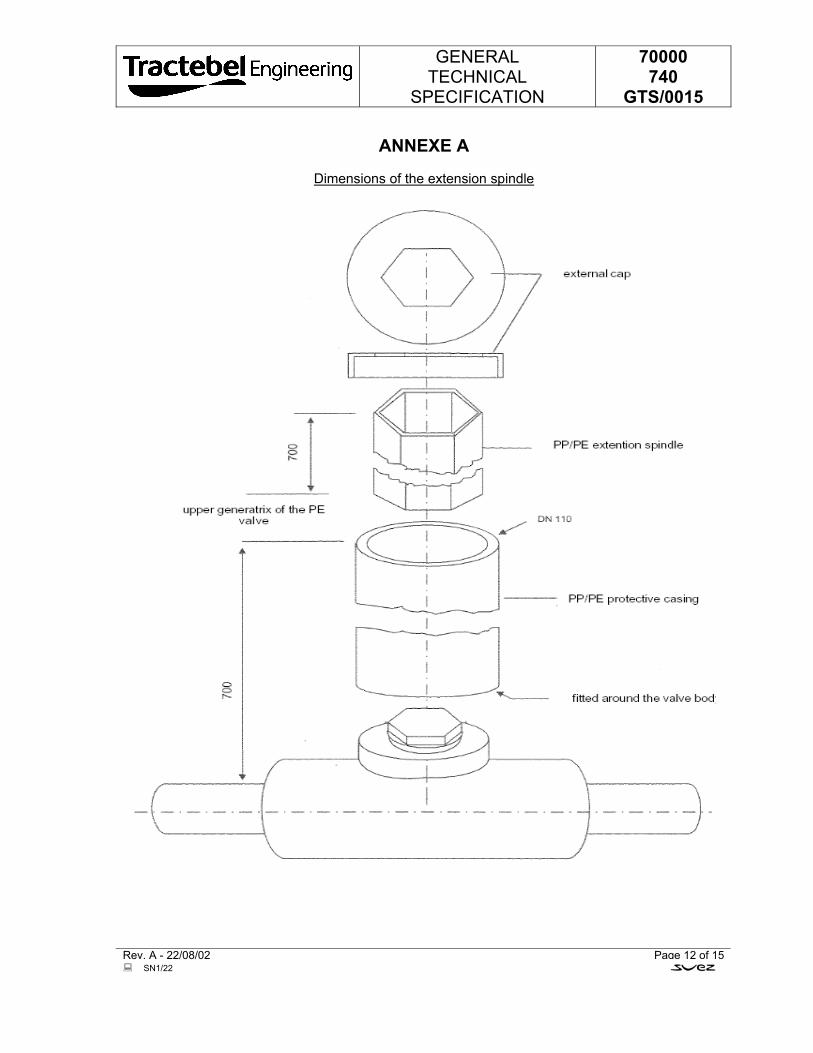
GENERAL TECHNICAL
SPECIFICATION
70000 740
GTS/0015
Rev. A - 22/08/02 Page 12 of 15 SN1/22
ANNEXE A
Dimensions of the extension spindle
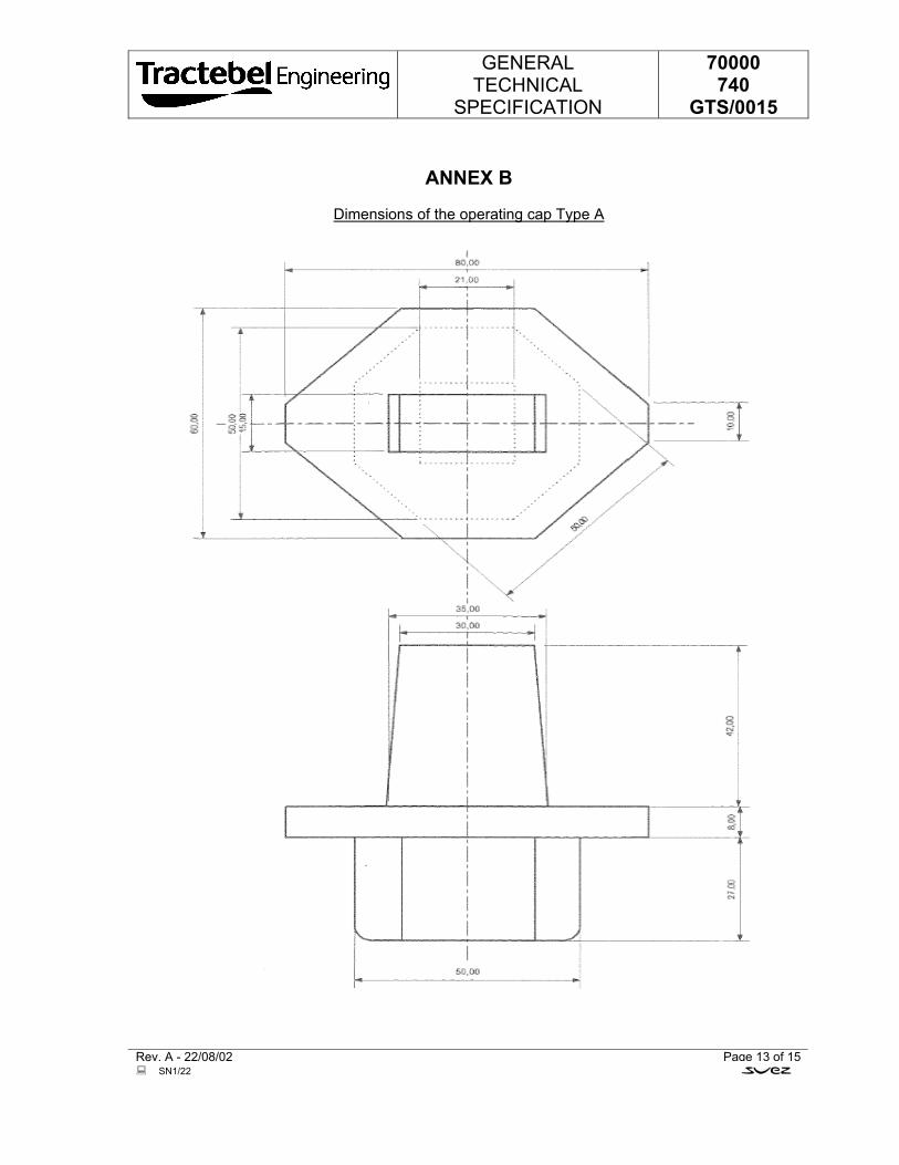
GENERAL TECHNICAL
SPECIFICATION
70000 740
GTS/0015
Rev. A - 22/08/02 Page 13 of 15 SN1/22
ANNEX B
Dimensions of the operating cap Type A
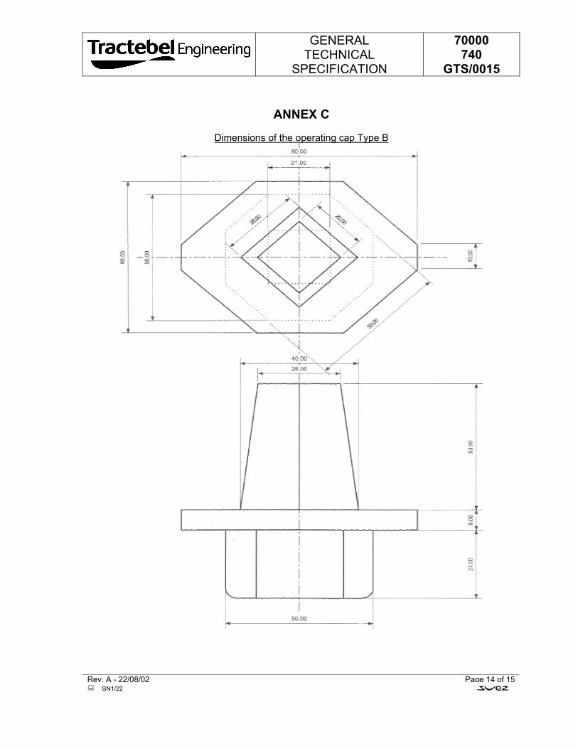
GENERAL TECHNICAL
SPECIFICATION
70000 740
GTS/0015
Rev. A - 22/08/02 Page 14 of 15 SN1/22
ANNEX C
Dimensions of the operating cap Type B
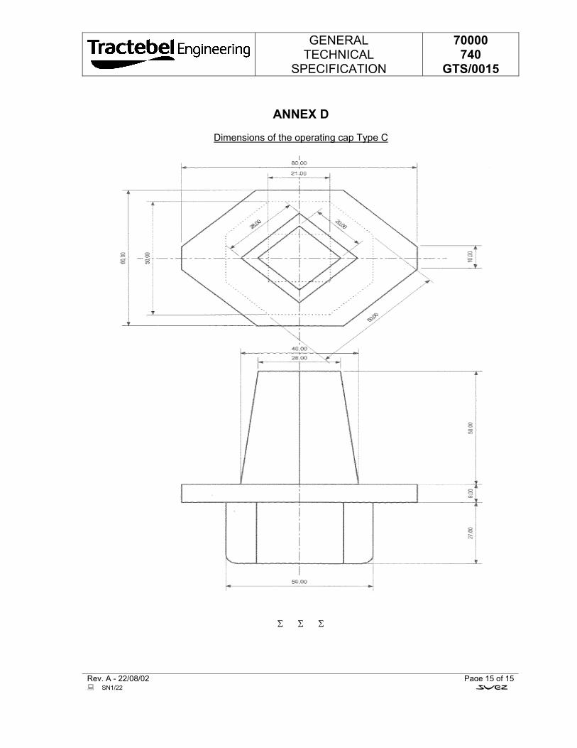
GENERAL TECHNICAL
SPECIFICATION
70000 740
GTS/0015
Rev. A - 22/08/02 Page 15 of 15 SN1/22
ANNEX D
Dimensions of the operating cap Type C
Σ Σ Σ
At the helm of the Energy Transition, Tractebel provides a full range of engineering and advisory servicesthroughout the life cycle of its clients’ projects, including design and project management. As one of the world’sleading engineering and advisory companies and with more than 150 years of experience, it's our mission toactively shape the world of tomorrow. With about 5,000 experts and presence in more than 70 countries, we areable to offer our customers multidisciplinary solutions in energy, water and urban.
TRACTEBEL ENGINEERING PVT. LTD.Intec House 37Institutional Area, Sector 44122 002 - Gurgaon - INDIAtractebel-engie.com
Chandan Kumar SINGHtel. +91 124 471 2260fax + 91 124 469 [email protected]