kv changes the meaning of “selection”
TRANSCRIPT
KV changes the meaning of “selection”
Programmable ControllerKV Series
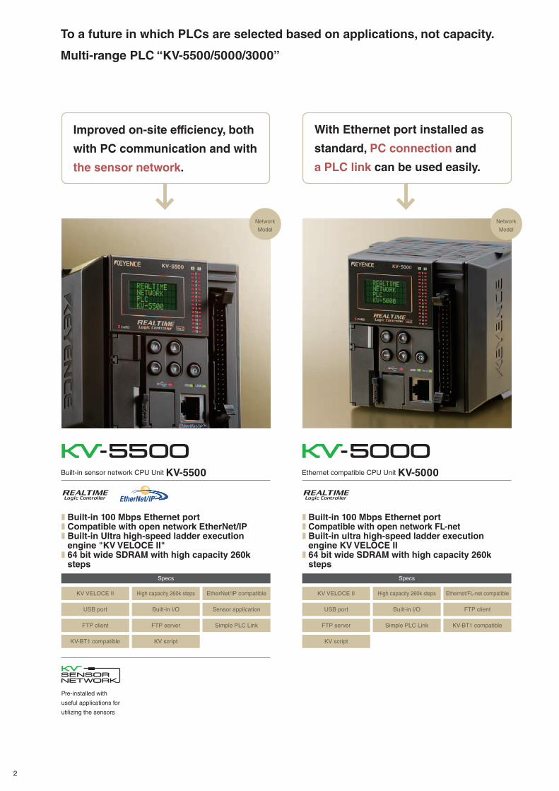
To a future in which PLCs are selected based on applications, not capacity.
Multi-range PLC “KV-5500/5000/3000”
Network
Model
Network
Model
Built-in sensor network CPU Unit KV-5500 Ethernet compatible CPU Unit KV-5000
Improved on-site efficiency, both
with PC communication and with
the sensor network.
With Ethernet port installed as
standard, PC connection and
a PLC link can be used easily.
Pre-installed with
useful applications for
utilizing the sensors
❚ Built-in 100 Mbps Ethernet port❚ Compatible with open network EtherNet/IP❚ Built-in Ultra high-speed ladder execution engine "KV VELOCE II"
❚ 64 bit wide SDRAM with high capacity 260k steps
❚ Built-in 100 Mbps Ethernet port❚ Compatible with open network FL-net❚ Built-in ultra high-speed ladder execution engine KV VELOCE II
❚ 64 bit wide SDRAM with high capacity 260k steps
KV VELOCE II KV VELOCE II
Specs Specs
High capacity 260k steps High capacity 260k stepsEtherNet/IP compatible Ethernet/FL-net compatible
USB port USB portBuilt-in I/O Built-in I/OSensor application FTP client
FTP client FTP serverFTP server Simple PLC LinkSimple PLC Link KV-BT1 compatible
KV-BT1 compatible KV script KV script
2
Standard
Model
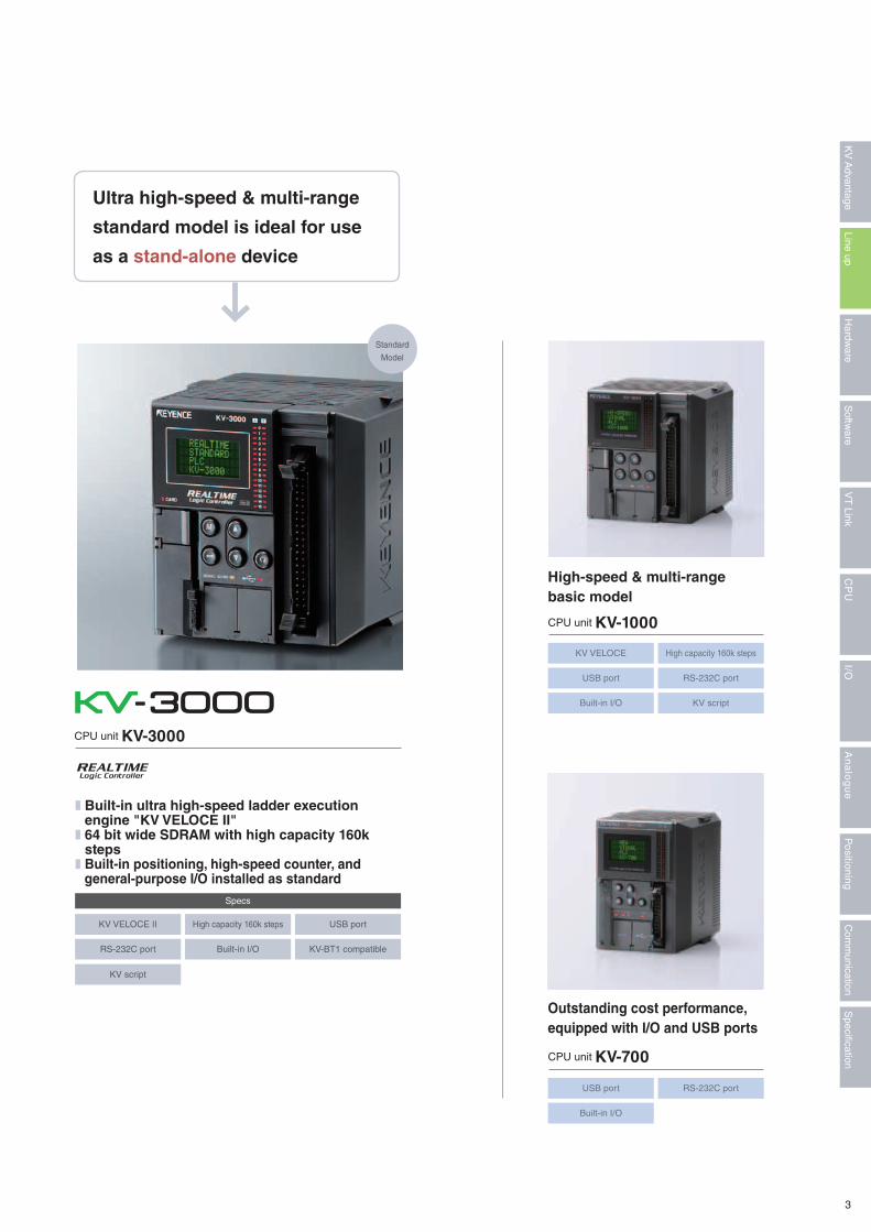
CPU unit KV-3000
CPU unit KV-1000
CPU unit KV-700
Ultra high-speed & multi-range
standard model is ideal for use
as a stand-alone device
High-speed & multi-rangebasic model
Outstanding cost performance, equipped with I/O and USB ports
❚ Built-in ultra high-speed ladder execution engine "KV VELOCE II"
❚ 64 bit wide SDRAM with high capacity 160k steps
❚ Built-in positioning, high-speed counter, and general-purpose I/O installed as standard
KV VELOCE II
KV script
KV VELOCE
Specs
High capacity 160k steps
High capacity 160k steps
USB port
RS-232C port
USB port
Built-in I/O
RS-232C port
Built-in I/O
KV-BT1 compatible
KV script
USB port RS-232C port
Built-in I/O
3
Specification
Com
munication
Positioning
An
alo
gu
eI/O
CP
UV
T Link
Softw
areLine up
Hardw
areK
V A
dvantage
CPU Unit
P.14
Powersupply/peripheral
P.14
I/O Unit
P.16
Analogue/ThermostatUnit
P.18
CPU Unit(24-Point I/O) KV-5000
CPU Unit(24-Point I/O) KV-5500
Power UnitKV-U7
Input UnitKV-B16XC
8 Point Relay Output(Independent Common Point) UnitKV-B8RC
8 Point Input + 8 PointTransistor NPN Output UnitKV-B8XTD
4 ch A/D Conversion UnitKV-AD40V
4 ch D/A Conversion UnitKV-DA40V
Input UnitKV-C32XC
PNP TransistorOutput UnitKV-B16TCP
16 Point Input + 16 PointTransistor NPN Output UnitKV-C16XTD
4 ch A/D Conversion UnitKV-AD40G
4 ch D/A Conversion UnitKV-DA40
PNP TransistorOutput UnitKV-C32TCP
32 Point Input + 32 PointTransistor NPN Output UnitKV-C32XTD
4 ch A/D Conversion UnitKV-AD40
4 ch Thermostat UnitKV-TF40
2 ch A/D Conversion +2 ch D/A Conversion UnitKV-AM40V
4 ch Temperature and Analogue Multi-Input UnitKV-TP40
PNP TransistorOutput UnitKV-C64TCP
Input UnitKV-C64XC
InputUnit
OutputUnit
Input/outputhybrid unit
16-point Screw Terminal Block
16-point Screw Terminal Block
16-point Screw Terminal Block
Relay Output UnitKV-B16RC
Transistor NPN Output Unitwith Overcurrent ProtectionKV-B16TD
Transistor NPN Output Unitwith Overcurrent ProtectionKV-C32TD
Transistor NPN Output Unitwith Overcurrent ProtectionKV-C64TD
32-point Connector
16-point Screw Terminal Block
32-point Connector
64-point Connector
32-point Connector
64-point Connector
64-point Connector
Error Output Unit KV-DR1
Bluetooth UnitKV-BT1
Extended UnitKV-EB1
CPU Unit(24-Point I/O) KV-3000
CPU Unit(24-Point I/O) KV-1000
CPU Unit(14-Point I/O) KV-700
*KV-xxxxA, KV-xxxTC, and KV-C64XB can also be used
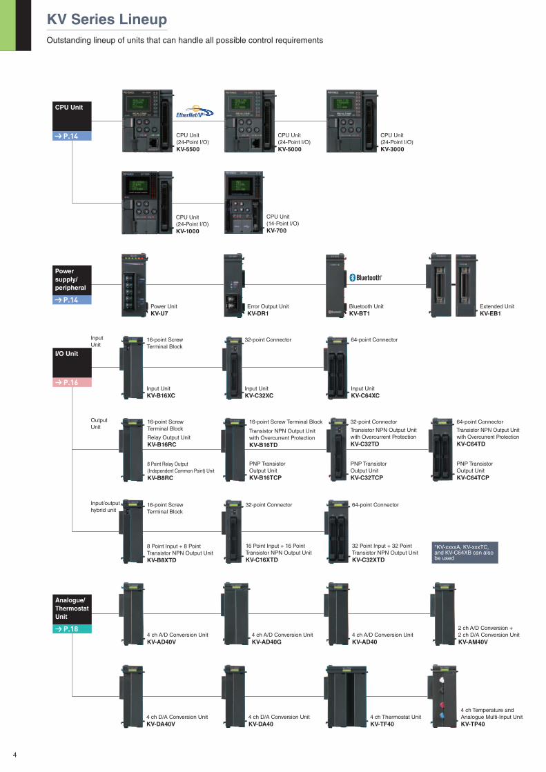
KV Series LineupOutstanding lineup of units that can handle all possible control requirements
4
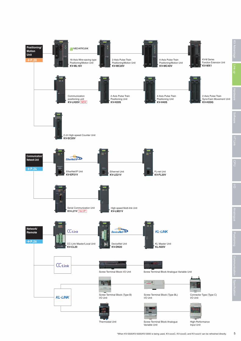
Positioning/MotionUnit
P.20
Communication/Network Unit
P.24
Network/Remote
P.26
16-Axis Wire-saving typePositioning/Motion Unit KV-ML16V
2-Axis Pulse TrainPositioning UnitKV-H20S
Ethernet UnitKV-LE21V
EtherNet/IP UnitKV-EP21V
CC-Link Master/Local UnitKV-CL20
2-Axis Pulse TrainPositioning/Motion Unit KV-MC20V
4-Axis Pulse TrainPositioning UnitKV-H40S
2 ch High-speed Counter UnitKV-SC20V
Screw Terminal Block I/O Unit
Screw Terminal Block (Type B) I/O Unit
Thermostat Unit
Screw Terminal Block Analogue Variable Unit
Screw Terminal Block (Type BL) I/O Unit
Screw Terminal Block AnalogueVariable Unit
Connector Type (Type C) I/O Unit
High-PerformanceInput Unit
*When KV-5500/KV-5000/KV-3000 is being used, KV-xxxxC, KV-xxxxD, and KV-xxxxV can be refreshed directly.
DeviceNet UnitKV-DN20
Serial Communication UnitKV-L21V Ver.UP
FL-net UnitKV-FL20V
KL Master UnitKL-N20V
High-speed Multi-link UnitKV-LM21V
4-Axis Pulse TrainPositioning/Motion UnitKV-MC40V
2-Axis Pulse TrainSync/Cam Movement Unit KV-H20G
KV-M Series Function Extension UnitKV-MX1
Communication positioning unitKV-LH20V
5
Specification
Com
munication
Positioning
An
alo
gu
eI/O
CP
UV
T Link
Softw
areLine up
Hardw
areK
V A
dvantage
NEW
Master CPU32 bit RISC CPU
Ladder execution engineKV-VELOCE II
Instruction interpretation
Built-in CPUEthernet function
Used forcommunication
with a PC or monitor
Peripheralprocessing
Built-in CPUEthernet function
*KV-5500/5000
32 bit
32 bit
32 bit
32 bit
32 bit 32 bit 32 bit
64 bit
program reading
Instruction execution (FPU)(operation circuit)
Memory (SRAM) Device
Built-in CPUEthernet enabled CPU*
Memory (SDRAM) Ladder
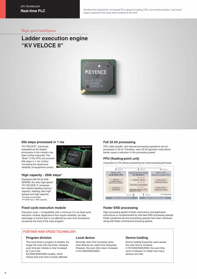
High speed intelligence
Ladder execution engine"KV VELOCE II"
"KV VELOCE", previously evaluated as the fastest processors in the industry has been further improved. The "Brain" of the CPU can process 60k steps in 1 ms, further increasing the speed and reliability of equipment control.
Equipped with 64 bit wide SDRAM, the ultra high-speed "KV VELOCE II" accesses the industry-leading memory capacity, realising ultra high speeds and high capacity.* KV-5500 and KV5000. KV-3000 has a 160k capacity.
Execution cycle = Compatibility with a minimum 0.2 ms fixed cycle execution module. Applications that require reliability can take advantage of control that is not affected by scan time fluctuations caused by the load of the main program.
The more times a program is divided, the longer the scan time becomes. However, scan time per module is only increased by 2 μs in the KV-5500/5000/3000 models, which means that scan time is barely affected.
Normally, scan time increases when local devices are used more frequently. However, the scan time never increases in KV-5500/5000/3000.
Device holding frequently used causes the scan time to increase. In KV-5500/5000/3000, the scan time never increases no matter how many devices are held.
CPU, data transfer, and internal processing operations are all processed in 32 bit. Therefore, even 32 bit operation instructions barely cause a reduction in the processing speed.
Incorporation of a FPU delivers overwhelming real number-calculating performance.
High processing speed of basic instructions and application instructions is complemented by ultra-fast END processing speeds. Faster peripheral service processing speeds have been achieved along with faster command processing speeds.
60k steps processed in 1 ms
High capacity - 260k steps*
Fixed cycle execution module
Program division Local device Device holding
FURTHER HIGH SPEED TECHNOLOGY
Full 32 bit processing
FPU (floating-point unit)
Faster END processing
Real-time PLC All elements required for increased PLC speed including CPU, bus communication, and input/output response time have been pushed to the limit
CPU TECHNOLOGY
64 bit wide SDRAM
KV VELOCE II
6
� Conventional System
� DDR System
Communicationclock
Data
Communicationclock
DataCPU unit(Main program)
R500 ON
R500 : Output
R500 ON
: Direct refresh command : Automatic refresh
1 scan
Difference
Direct refresh
Automatic refresh
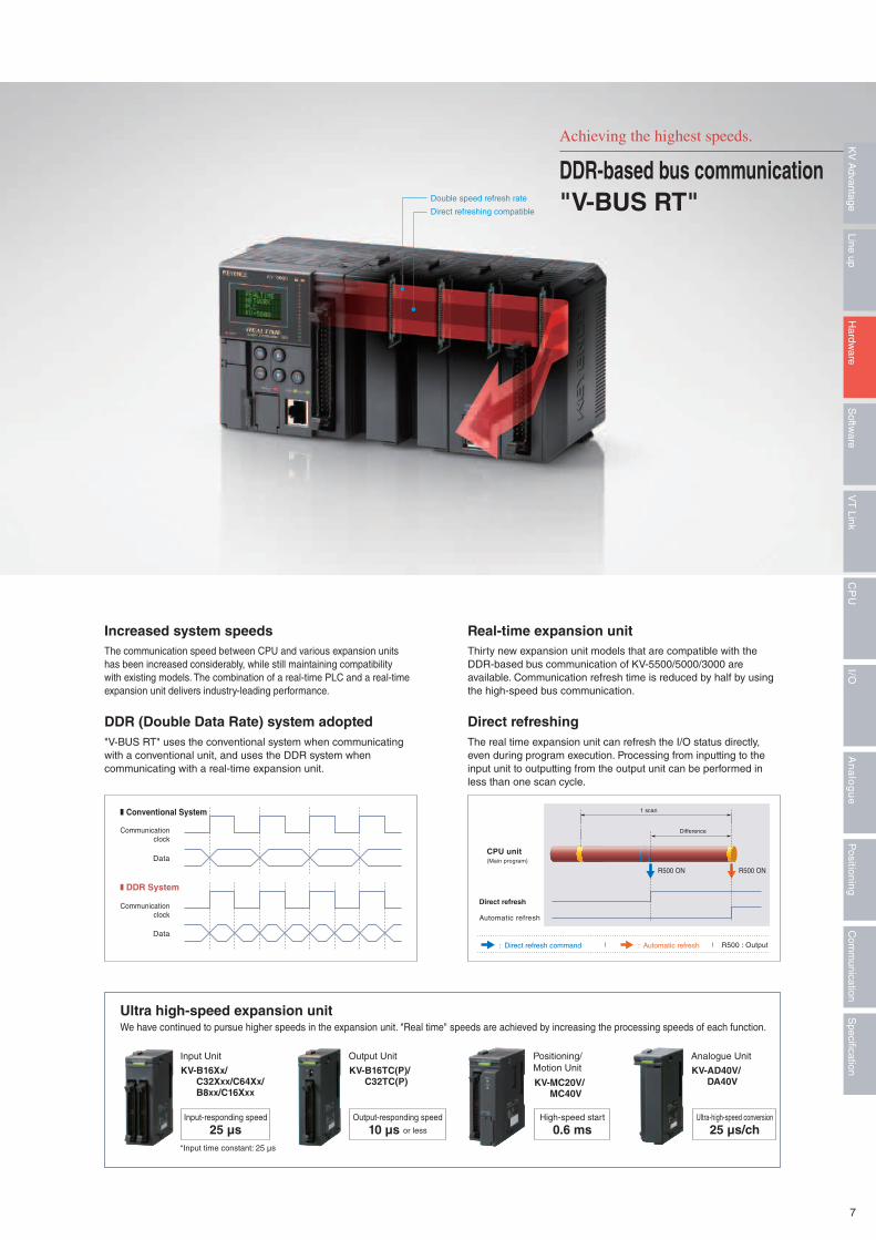
Thirty new expansion unit models that are compatible with the DDR-based bus communication of KV-5500/5000/3000 are available. Communication refresh time is reduced by half by using the high-speed bus communication.
The real time expansion unit can refresh the I/O status directly, even during program execution. Processing from inputting to the input unit to outputting from the output unit can be performed in less than one scan cycle.
The communication speed between CPU and various expansion units has been increased considerably, while still maintaining compatibility with existing models. The combination of a real-time PLC and a real-time expansion unit delivers industry-leading performance.
"V-BUS RT" uses the conventional system when communicating with a conventional unit, and uses the DDR system when communicating with a real-time expansion unit.
We have continued to pursue higher speeds in the expansion unit. "Real time" speeds are achieved by increasing the processing speeds of each function.
Input Unit Positioning/Motion Unit
Output Unit Analogue Unit
KV-B16Xx/ C32Xxx/C64Xx/ B8xx/C16Xxx
KV-MC20V/ MC40V
KV-B16TC(P)/ C32TC(P)
KV-AD40V/ DA40V
Input-responding speed Output-responding speed High-speed start Ultra-high-speed conversion
*Input time constant: 25 μs
25 μs 10 μs or less 0.6 ms 25 μs/ch
Real-time expansion unit
Direct refreshing
Increased system speeds
DDR (Double Data Rate) system adopted
Ultra high-speed expansion unit
Achieving the highest speeds.
Double speed refresh rate
Direct refreshing compatible
DDR-based bus communication"V-BUS RT"
7
Specification
Com
munication
Positioning
An
alo
gu
eI/O
CP
UV
T Link
Softw
areLine up
Hardw
areK
V A
dvantage
012345678910
to output
* Only I/O unit
andThrough select thedevice to be ON
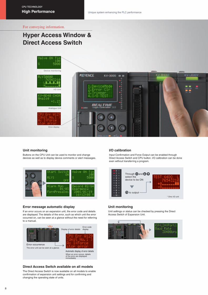
Device monitoring
I/O Unit
Analogue Unit
Error display
Buttons on the CPU Unit can be used to monitor and change devices as well as to display device comments or alert messages.
If an error occurs on an expansion unit, the error code and details are displayed. The details of the error, such as which unit the error occurred on, can be seen at a glance without the need for referring to a manual.
The Direct Access Switch is now available on all models to enable confirmation of expansion unit settings and for confirming and changing the operating state of units.
Input Confirmation and Force Output can be enabled through Direct Access Switch and CPU button. I/O calibration can be done even without transferring a program.
Unit settings or status can be checked by pressing the Direct Access Switch of Expansion Unit.
Unit monitoring
Error message automatic display
Direct Access Switch available on all models
I/O calibration
Unit monitoring
The error unit can be seen at a glance.
Error occurrence
When an error occurs, details of the error are displayed immediately
Automatic display of error details
Error codedisplayDisplay of error details
For conveying information.
Hyper Access Window &Direct Access Switch
High Performance Unique system enhancing the PLC performance
CPU TECHNOLOGY
8
CPU Unit isequipped withpower terminals.
DC 24 VInput
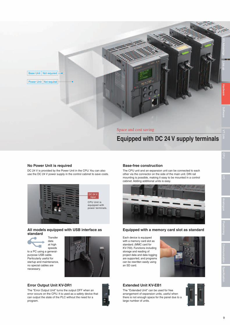
The "Extended Unit" can be used for free arrangement of expansion units, useful when there is not enough space for the panel due to a large number of units.
Each device is equipped with a memory card slot as standard. (MMC card for KV-700). Functions including storage and reading of project data and data logging are supported, and programs can be rewritten easily using an SD card.
The CPU unit and an expansion unit can be connected to each other via the connector on the side of the main unit. DIN rail mounting is possible, making it easy to be mounted in a control cabinet. Adding additional units is easy.
The "Error Output Unit" turns the output OFF when an error occurs on the CPU. It is used as a safety device that can output the state of the PLC without the need for a program.
Transfer data at high speeds
to a PC using a general-purpose USB cable. Particularly useful for startup and maintenance, no special cables are necessary.
DC 24 V is provided by the Power Unit in the CPU. You can also use the DC 24 V power supply in the control cabinet to save costs.
Extended Unit KV-EB1
Equipped with a memory card slot as standard
Base-free construction
Error Output Unit KV-DR1
All models equipped with USB interface as standard
No Power Unit is required
Space and cost saving
Equipped with DC 24 V supply terminals
Base Unit Not required
Not requiredPower Unit
9
Specification
Com
munication
Positioning
An
alo
gu
eI/O
CP
UV
T Link
Softw
areLine up
Hardw
areK
V A
dvantage
Dedicated commands for motor control
Positioning instructionValue/DMPLSX
Value/DMCHGSPX
JOGXHOMEX
ORGX TCHX
CWCCWHIGH
Jogging instruction Home positioning instruction
Origin return instruction Teaching instruction Speed change instruction
With functions included
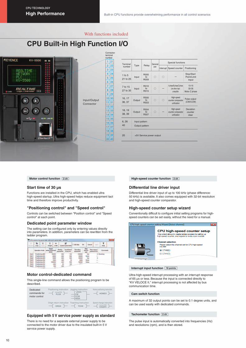
CPU Built-in High Function I/O
Functions are installed in the CPU, which has enabled ultra high-speed startup. Ultra high-speed helps reduce equipment tact time and therefore improve productivity.
Controls can be switched between "Position control" and "Speed control" at each point.
Differential line driver input of up to 100 kHz (phase difference: 50 kHz) is available. It also comes equipped with 32-bit resolution and high-speed counter comparator.
Conventionally difficult to configure initial setting programs for high-speed counters can be set easily, without the need for a manual.
The setting can be configured only by entering values directly into parameters. In addition, parameters can be rewritten from the ladder program.
There is no need for a separate external power supply to be connected to the motor driver due to the insulated built-in 5 V service power supply.
This single-line command allows the positioning program to be described.
The pulse input is automatically converted into frequencies (Hz) and revolutions (rpm), and is then stored.
Ultra-high-speed interrupt processing with an interrupt response of 65 μs or less. Because the input is connected directly to "KV VELOCE II," interrupt processing is not affected by bus communication time.
A maximum of 32 output points can be set to 0.1 degree units, and can be used easily with dedicated commands.
Start time of 30 μs
"Positioning control" and "Speed control"
Differential line driver input
High-speed counter setup wizard
Dedicated point parameter window
Equipped with 5 V service power supply as standard
Motor control-dedicated command
Motor control function High-speed counter function
Tachometer function
Interrupt input function
Cam switch function
2 ch 2 ch
2 ch
10 points
High Performance Built-in CPU functions provide overwhelming performance in all control scenarios
CPU TECHNOLOGY
1
2
3
4
5
6
7
8
9
10
11
12
13
14
15
16
17
18
19
20
21
22
23
24
25
26
27
28
29
30
31
32
33
34
35
36
37
38
39
40
Input/Output Connector
Connector terminal number
1 to 5
21 to 25
7 to 15
27 to 35
16, 17
36, 37
18, 19
38, 39
6, 26
40
20
Input
Input
Output
Output
+5V Service power output
Input pattern
Output pattern
Terminal number Type Relay General
use Interrupt Speed counter
Special functions
Positioning
A phase/B phase/Z phaseLine driver input
compatible
High-speed counter comparator
unification
High-speed counter comparator
unification
Stop/Start Point/Limit
Input
Pulse output (CW/CCW)
13-1533-35
Motor Z phase
Deviation counter
clear
R000
R009
R010
R015
R500
R503
R504
R507
to
to
to
to
10
PC
KV-5500/5000/3000
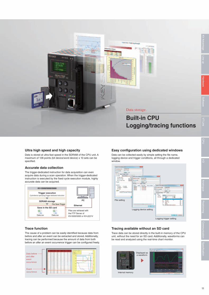
Trigger execution
SDRAM storageFile Save Trigger
Save in the SD cardEthernet
Files are retrieved withthe FTP Server of KV-5500/5000 or KV-LE21V
Cycle/device specifying/Trigger-dedicated instruction
Data.csv Data.csv
The cause of a problem can be easily identified because data from before and after an event can be extracted and stored. Additionally, tracing can be performed because the amount of data from both before an after an event occurrence trigger can be configured freely.
Trace data can be stored directly in the built-in memory of the CPU unit, without the need for an SD card. Additionally, waveforms can be read and analyzed using the real-time chart monitor.
Data is stored at ultra-fast speed in the SDRAM of the CPU unit. A maximum of 128 points (bit device/word device) x 10 sets can be specified.
Data can be collected easily by simple setting the file name, logging device and trigger conditions, all through a dedicated window.
The trigger-dedicated instruction for data acquisition can even acquire data during a scan operation. When the trigger-dedicated instruction is executed by the fixed cycle execution module, highly accurate data can be acquired.
Trace function Tracing available without an SD card
Ultra high speed and high capacity Easy configuration using dedicated windows
Accurate data collection
Data storage.
Built-in CPULogging/tracing functions
Eventoccurrence
Data before and afterevent occurrence
Displayed as a waveform
Internal memory
File setting
Logging device setting
Logging trigger setting
11
Specification
Com
munication
Positioning
An
alo
gu
eI/O
CP
UV
T Link
Softw
areLine up
Hardw
areK
V A
dvantage
PLC B(Otherstation)
PLC A(Otherstation)
Writesinternal devices(DM, MR, etc.)
Readsinternal devices
(D, M etc.)
Reads internaldevices (DM, MR, etc.)
Writes internaldevices (DM, MR, etc.)
For each setting, bit device 4096 bits + word device 256 word communication is possible.Total number of link points 2048 words, maximum 32 settings.
Up to 32 unitscan beconnected
Localstation
KV-5000 KV-5000
FL-net
USBKV-5000 Other vendors' PLC Other vendors' PLC
Run mode orProduction mode
Process information or production indication
KV-5500/5000
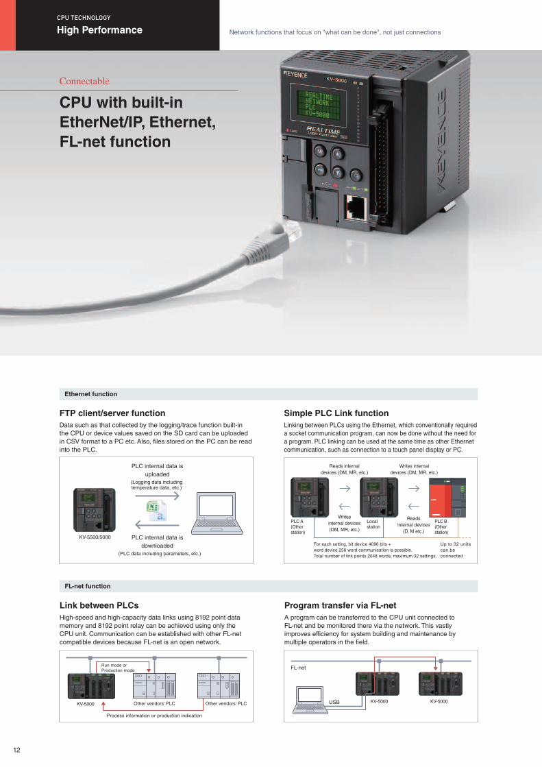
High-speed and high-capacity data links using 8192 point data memory and 8192 point relay can be achieved using only the CPU unit. Communication can be established with other FL-net compatible devices because FL-net is an open network.
Linking between PLCs using the Ethernet, which conventionally required a socket communication program, can now be done without the need for a program. PLC linking can be used at the same time as other Ethernet communication, such as connection to a touch panel display or PC.
Data such as that collected by the logging/trace function built-in the CPU or device values saved on the SD card can be uploaded in CSV format to a PC etc. Also, files stored on the PC can be read into the PLC.
A program can be transferred to the CPU unit connected to FL-net and be monitored there via the network. This vastly improves efficiency for system building and maintenance by multiple operators in the field.
Link between PLCs
Simple PLC Link functionFTP client/server function
Program transfer via FL-net
FL-net function
Ethernet function
High Performance Network functions that focus on "what can be done", not just connections
CPU TECHNOLOGY
Connectable
CPU with built-in EtherNet/IP, Ethernet, FL-net function
PLC internal data isdownloaded
(PLC data including parameters, etc.)
(Logging data including temperature data, etc.)
PLC internal data isuploaded
12
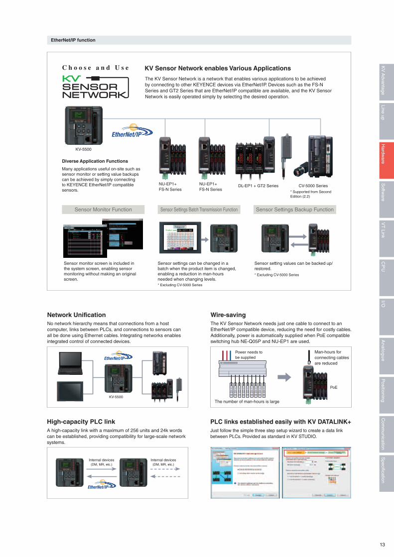
A high-capacity link with a maximum of 256 units and 24k words can be established, providing compatibility for large-scale network systems.
No network hierarchy means that connections from a host computer, links between PLCs, and connections to sensors can all be done using Ethernet cables. Integrating networks enables integrated control of connected devices.
The KV Sensor Network is a network that enables various applications to be achieved by connecting to other KEYENCE devices via EtherNet/IP. Devices such as the FS-N Series and GT2 Series that are EtherNet/IP compatible are available, and the KV Sensor Network is easily operated simply by selecting the desired operation.
Many applications useful on-site such as sensor monitor or setting value backups can be achieved by simply connecting to KEYENCE EtherNet/IP compatible sensors.
Just follow the simple three step setup wizard to create a data link between PLCs. Provided as standard in KV STUDIO.
The KV Sensor Network needs just one cable to connect to an EtherNet/IP compatible device, reducing the need for costly cables. Additionally, power is automatically supplied when PoE compatible switching hub NE-Q05P and NU-EP1 are used.
High-capacity PLC link
Network Unification
KV Sensor Network enables Various Applications
Diverse Application Functions
Sensor Settings Backup FunctionSensor Settings Batch Transmission FunctionSensor Monitor Function
Sensor setting values can be backed up/restored.
Sensor settings can be changed in a batch when the product item is changed, enabling a reduction in man-hours needed when changing levels.
Sensor monitor screen is included in the system screen, enabling sensor monitoring without making an original screen.
PLC links established easily with KV DATALINK+
Wire-saving
EtherNet/IP function
Power needs to be supplied
Man-hours for connecting cablesare reduced
The number of man-hours is largeKV-5500
PoE
NU-EP1+FS-N Series
KV-5500
NU-EP1+FS-N Series
DL-EP1 + GT2 Series CV-5000 Series
* Excluding CV-5000 Series
* Excluding CV-5000 Series
* Supported from Second Edition (2.2)
Internal devices(DM, MR, etc.)
Internal devices(DM, MR, etc.)
C h o o s e a n d U s e
13
Specification
Com
munication
Positioning
An
alo
gu
eI/O
CP
UV
T Link
Softw
areLine up
Hardw
areK
V A
dvantage
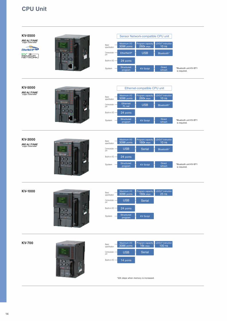
Basicspecification
Communicationport
Built-in I/O
System
Maximum I/O3096 points
Program capacity260k steps
LD/OUT instruction10 ns
EtherNet/IP USB Bluetooth*
24 points
Structured program KV Script
Directrefresh
*Bluetooth unit KV-BT1 is required.
Basicspecification
Communicationport
Built-in I/O
System
Maximum I/O3096 points
Program capacity260k steps
LD/OUT instruction10 ns
Ethernet/FL-net USB Bluetooth*
24 points
Structured program KV Script
Directrefresh
*Bluetooth unit KV-BT1 is required.
Basicspecification
Communicationport
Built-in I/O
System
Maximum I/O3096 points
Program capacity160k steps
LD/OUT instruction10 ns
USB Serial Bluetooth*
24 points
Structured program KV Script
Directrefresh
*Bluetooth unit KV-BT1 is required.
Basicspecification
Communicationport
Built-in I/O
System
Maximum I/O3096 points
Program capacity160k steps
LD/OUT instruction25 ns
USB Serial
24 points
Structured program KV Script
Basicspecification
Communicationport
Built-in I/O 14 points
Maximum I/O3086 points
Program capacity16k steps
LD/OUT instruction100 ns
SerialUSB
*32k steps when memory is increased.
CPU Unit
KV-5500
KV-5000
KV-3000
KV-1000
KV-700
Sensor Network-compatible CPU unit
Ethernet-compatible CPU unit
14
CPU
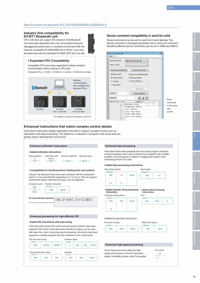
New functions of real-time PLC KV-5500/5000Ver.2/3000Ver.2
CPU units that can support the industry's first Bluetooth unit have been expanded. Not only can programming and debugging be performed in a wireless environment with the network compatible KV-5500/5000 Ver.2 CPUs, it can even be performed with the standard KV-3000 CPU Ver.2 as well.
Industry Top execution times have been achieved, with the comparison point in 1.4 μs and arithmetic operations in 2.1 to 3.4 μs. This can support controls that require arithmetic accuracy, such as alignment.
Instructions that posses PID control and auto-tuning functions have been prepared. PID control, which takes time and effort to adjust, can be used with ease. Also, even concerning output processing, instructions have been prepared to simplify programs that had a tendency to be cumbersome.
Instructions have been prepared that can easily program character string processing, which was cumbersome to program with a ladder program, and processing in relation to logging that used an ever increasing amount SD cards.
Timer instructions that utilise the high-speed performance of the KV have been added. Incredibly precise control is possible.
Instructions have been greatly expanded to be able to support complex control such as calculation and data processing. This allows for a reduction in program work hours and can greatly reduce development work hours.
Device comments can be set for each bit of word devices. The device comment is managed separately from a word unit comment, therefore different device comments can be set in DM0 and DM0.0.
Industry first compatibility for KV-BT1 Bluetooth unit
Enhanced instructions that match complex control details
Device comment compatibility in word bit units
❚ Expanded CPU Compatibility
Compatible CPUs have been expanded to achieve wireless communication without relying on CPU type.[Compatible CPUs] ∙ KV-5500 ∙ KV-5000 Ver.1.1 and later ∙ KV-3000 Ver.2 and later
KV-5500 KV-5000Ver.1.1 and later
KV-3000Ver.2 and later
Comparison point
Enhanced high-speed processing
❚ Added character string processing instructions
Enter
comments
in the same
way
as bits
KV script arithmetic operation
Enhanced arithmetic instructions
Enhanced processing for high-difficulty PID
❚ Added arithmetic instructions
❚ Compatibility for double-precision floating point real numbers
❚ Added file operation instructions
❚ Added byte-processing instructions
❚ Added PID instructions with auto-tuning
Transfer instruction
Enhanced data processing
❚ Added data processing instructions
DM0
DM10
>.DF DM0
MOV.DF
DM1000
#5
U T 0
DM0 #10
#10 #4
DM100
BYBMOV
DM0
BSWAP
#2
DM0 DM6
#0
DM100
SFIND
DM0 DM10 #5
SORT
#2POW
MR000ASRA LOG10 ABS.S
DM0 DM10 DM100
MREN
DM0
MFREE
DM10
DM0 DM1000 DM2000
PIDAT
DM100
RAMP
DM4+0 DM0
DM0 DM2 DM4
TPOUT
DM0 DM4 DM100
LLFLT
10 μs timer
Byte string transfer
Character string search
Exponentiation
File name change
PID with auto-tuning
Time-sharing ratio output
Gradient signal
Lag filter
Obtain free space
Arithmetic shift Common logarithm Absolute value
Sort
Block swap
Wireless communication also available with standard CPUs
*For details on radio law compliance, see P.43.
15
Specification
Com
munication
Positioning
An
alo
gu
eI/O
CP
UV
T Link
Softw
areLine up
Hardw
areK
V A
dvantage
Direcr I/O*1
24 V/5 V*2
input
Input timeConstant switching
Direcr I/O*1
24V/5V*2
input
Input timeConstant switching
Removableterminal block
Direcr I/O*1
Direcr I/O*1
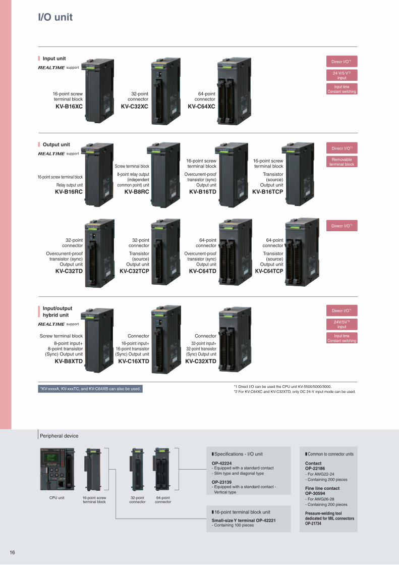
I/O unit
Input unit
Input/outputhybrid unit
Output unit
support
support
support
KV-B16XC
KV-B8XTD
KV-B16RC
KV-C32TD
KV-C32XC
KV-C16XTD
KV-B8RC
KV-C32TCP
KV-C64XC
KV-C32XTD
KV-B16TD
KV-C64TD
KV-B16TCP
KV-C64TCP
16-point screwterminal block
Screw terminal block
8-point input+8-point transistor
(Sync) Output unit
16-point screw terminal block
Relay output unit
32-point connector
Overcurrent-prooftransistor (sync)
Output unit
32-pointconnector
Connector
16-point input+16-point transistor(Sync) Output unit
Screw terminal block
8-point relay output (independent
common point) unit
32-pointconnector
Transistor(source)
Output unit
64-pointconnector
Connector
32-point input+32-point transistor(Sync) Output unit
16-point screwterminal block
Overcurrent-prooftransistor (sync)
Output unit
64-pointconnector
Overcurrent-prooftransistor (sync)
Output unit
16-point screwterminal block
Transistor(source)
Output unit
64-pointconnector
Transistor(source)
Output unit
*1 Direct I/O can be used the CPU unit KV-5500/5000/3000.*2 For KV-C64XC and KV-C32XTD, only DC 24-V input mode can be used.
*KV-xxxxA, KV-xxxTC, and KV-C64XB can also be used.
Peripheral device
CPU unit 16-point screw terminal block
32-point connector
64-point connector
❚ Specifications - I/O unit ❚ Common to connector units
❚ 16-point terminal block unit
OP-42224 ContactOP-22186
Fine line contactOP-30594
Pressure-welding tool dedicated for MIL connectorsOP-21734
Small-size Y terminal OP-42221
OP-23139
- Equipped with a standard contact- Slim type and diagonal type - For AWG22-24
- Containing 200 pieces
- For AWG26-28- Containing 200 pieces
- Containing 100 pieces
- Equipped with a standard contact - Vertical type
16
I/O
PLCresponsiveness
Buscommunication
speedV-BUS RT
Unitresponse
speed
CPU commandexecution speedKV VELOCE II
General processing Direct I/O
Input state loaded by input processing of A
Output processing output by B
A
B
END
R30000 R31000
1
Input state isloaded beforeexecution ofthe command.
Immediate output before scanning is finished.
END
DR30000 DR31000
* When direct I/O is used, “D” is added before the device No. for marking purposes.
scan1
scan I/O LED indicator Always displays theON/OFF state.
Setup can be checkedor changed withoutdismounting the unit.
ON/OFF state can be checked graphically
012345678910 to output
* Only I/O unit
andThroughselect the device to be ON
❚ Features common to I/O units
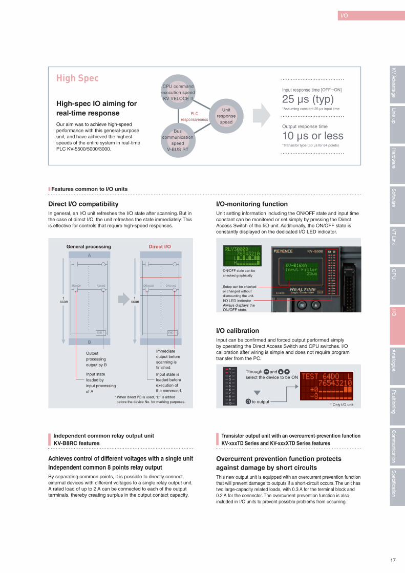
High Spec
High-spec IO aiming for real-time response Our aim was to achieve high-speed performance with this general-purpose unit, and have achieved the highest speeds of the entire system in real-time PLC KV-5500/5000/3000.
Input response time [OFF"ON]
Output response time
*Assuming constant 25 μs input time
*Transistor type (50 μs for 64 points)
25 μs (typ)
10 μs or less
Direct I/O compatibility I/O-monitoring function
I/O calibration
In general, an I/O unit refreshes the I/O state after scanning. But in the case of direct I/O, the unit refreshes the state immediately. This is effective for controls that require high-speed responses.
Unit setting information including the ON/OFF state and input time constant can be monitored or set simply by pressing the Direct Access Switch of the I/O unit. Additionally, the ON/OFF state is constantly displayed on the dedicated I/O LED indicator.
Input can be confirmed and forced output performed simply by operating the Direct Access Switch and CPU switches. I/O calibration after wiring is simple and does not require program transfer from the PC.
Independent common relay output unitKV-B8RC features
Achieves control of different voltages with a single unitIndependent common 8 points relay outputBy separating common points, it is possible to directly connect external devices with different voltages to a single relay output unit. A rated load of up to 2 A can be connected to each of the output terminals, thereby creating surplus in the output contact capacity.
Transistor output unit with an overcurrent-prevention function KV-xxxTD Series and KV-xxxXTD Series features
Overcurrent prevention function protects against damage by short circuits This new output unit is equipped with an overcurrent prevention function that will prevent damage to outputs if a short-circuit occurs. The unit has two large-capacity related loads, with 0.3 A for the terminal block and 0.2 A for the connector. The overcurrent prevention function is also included in I/O units to prevent possible problems from occurring.
17
Specification
Com
munication
Positioning
An
alo
gu
eI/O
CP
UV
T Link
Softw
areLine up
Hardw
areK
V A
dvantage
Basic specification
Hardware
Function
Software
Super-highspeedconversion 25 μs
4 ch
Direct refresh
High resolution1/20000
Conversion*1
precision ±0.1%
Movingaverage*2 Zero drift
Unit monitorUnit specificinstruction
Voltage/Current Differentialinput*2
Scaling
Basic specification
Hardware
Function
Software
High-speedconversion 80 μs
Moving average Zero drift
Unit specificinstruction
Unit monitor
Direct refresh
Input 2 chOutput 2 ch
Reso lu t ion1/8000
Conversion*1
precision ±0.2%
Voltage/current Differential input
Scaling
Basic specification
Hardware
Function
Software
High speedconversion 80 μs
Moving averageprimary delay filter Zero drift
System macro Unit monitor
Data buffer
High resolution1/30000
Conversion*1
precision ±0.05%
4 ch Voltage/current Differentialinput
Insulation is providedbetween CH_A/Bs
Scaling
Basic specification
Hardware
Function
Software
Conversion*1
precision ±0.2%
Timeaveraging*2
Unit monitor
High-speedconversion 80 μs
Resolution1/4000
4 ch Voltage/current
Scaling Averagingtimes*2
Differentialinput*2
Basic specification
Hardware
Function
Software
Conversion*1
precision ±0.2%
Zero drift
Unit monitor
High-speed conversion50 ms/4 ch
High resolution1/20000
4 chThermocouples/
Platinum temperaturemeasurement resistance/
Voltage/Current
ScalingMoving average
primary delay filter
Differential inputInsulated
between channels
Alarm function
Basic specification
Hardware
Function
Software Unit monitor
Auto tune
4 ch
3 mode voltagestabiliser
Thermocouples
High-speed conversion125 ms
Indication accuracy±0.3%
Heating·coolingcontrol
Heater breakdetection
Platinumtemperature
measurementresistance
Insulatedbetween channels
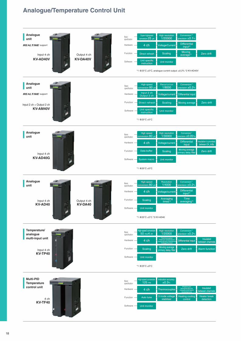
Analogue/Temperature Control Unit
Analogueunit
Analogueunit
Analogueunit
Analogueunit
Temperature/analogue multi-input unit
Multi-PID Temperature control unit
support
support
KV-AD40V
KV-AM40V
KV-AD40G
KV-AD40 KV-DA40
KV-TP40
KV-TF40
KV-DA40VInput 4 ch
Input 2 ch + Output 2 ch
Input 4 ch
Input 4 ch Output 4 ch
Input 4 ch
4 ch
Output 4 ch
*1 @25°C ±5°C, analogue current output: ±0.2% *2 KV-AD40V
*1 @25°C ±5°C
*1 @25°C ±5°C
*1 @25°C ±5°C *2 KV-AD40
*1 @25°C ±5°C
18
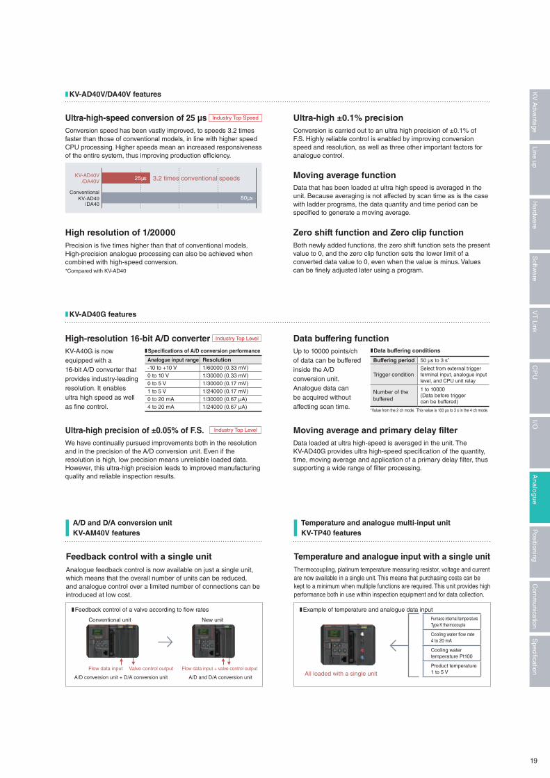
❚ KV-AD40V/DA40V features
Ultra-high-speed conversion of 25 μs Ultra-high ±0.1% precision
Moving average function
Zero shift function and Zero clip functionHigh resolution of 1/20000
Conversion speed has been vastly improved, to speeds 3.2 times faster than those of conventional models, in line with higher speed CPU processing. Higher speeds mean an increased responsiveness of the entire system, thus improving production efficiency.
Conversion is carried out to an ultra high precision of ±0.1% of F.S. Highly reliable control is enabled by improving conversion speed and resolution, as well as three other important factors for analogue control.
Data that has been loaded at ultra high speed is averaged in the unit. Because averaging is not affected by scan time as is the case with ladder programs, the data quantity and time period can be specified to generate a moving average.
Both newly added functions, the zero shift function sets the present value to 0, and the zero clip function sets the lower limit of a converted data value to 0, even when the value is minus. Values can be finely adjusted later using a program.
Precision is five times higher than that of conventional models. High-precision analogue processing can also be achieved when combined with high-speed conversion. *Compared with KV-AD40
KV-AD40V/DA40V
ConventionalKV-AD40
/DA40
25 μs
80 μs
3.2 times conventional speeds
Industry Top Speed
*Value from the 2 ch mode. This value is 100 μs to 3 s in the 4 ch mode.
❚ KV-AD40G features
High-resolution 16-bit A/D converter Data buffering function
Ultra-high precision of ±0.05% of F.S. Moving average and primary delay filter
KV-A40G is now equipped with a 16-bit A/D converter that provides industry-leading resolution. It enables ultra high speed as well as fine control.
Up to 10000 points/ch of data can be buffered inside the A/D conversion unit. Analogue data can be acquired without affecting scan time.
We have continually pursued improvements both in the resolution and in the precision of the A/D conversion unit. Even if the resolution is high, low precision means unreliable loaded data. However, this ultra-high precision leads to improved manufacturing quality and reliable inspection results.
Data loaded at ultra high-speed is averaged in the unit. The KV-AD40G provides ultra high-speed specification of the quantity, time, moving average and application of a primary delay filter, thus supporting a wide range of filter processing.
❚ Specifications of A/D conversion performance ❚ Data buffering conditions
Analogue input range Resolution-10 to +10 V 1/60000 (0.33 mV)0 to 10 V 1/30000 (0.33 mV)0 to 5 V 1/30000 (0.17 mV)1 to 5 V 1/24000 (0.17 mV)0 to 20 mA 1/30000 (0.67 μA)4 to 20 mA 1/24000 (0.67 μA)
Buffering period 50 μs to 3 s*
Trigger conditionSelect from external trigger terminal input, analogue input level, and CPU unit relay
Number of the buffered
1 to 10000(Data before triggercan be buffered)
Industry Top Level
Industry Top Level
A/D and D/A conversion unitKV-AM40V features
Temperature and analogue multi-input unitKV-TP40 features
Feedback control with a single unit Temperature and analogue input with a single unitAnalogue feedback control is now available on just a single unit, which means that the overall number of units can be reduced, and analogue control over a limited number of connections can be introduced at low cost.
Thermocoupling, platinum temperature measuring resistor, voltage and current are now available in a single unit. This means that purchasing costs can be kept to a minimum when multiple functions are required. This unit provides high performance both in use within inspection equipment and for data collection.
❚ Feedback control of a valve according to flow rates ❚ Example of temperature and analogue data input
Conventional unit
A/D conversion unit + D/A conversion unit
Flow data inputAll loaded with a single unit
Valve control output Flow data input + valve control output
New unit
A/D and D/A conversion unit
Furnace internal temperatureType K thermocouple
Cooling water flow rate4 to 20 mA
Cooling water temperature Pt100
Product temperature1 to 5 V
19
Specification
Com
munication
Positioning
An
alo
gu
eI/O
CP
UV
T Link
Softw
areLine up
Hardw
areK
V A
dvantage
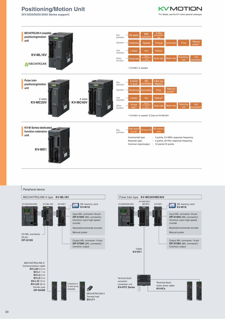
Peripheral device
Pulse train type KV-MC20V/MC40VMECHATROLINK-II type KV-ML16V
MECHATROLINK-II Communication cable
SV-LA5 0.5 mSV-L1 1 mSV-L3 3 mSV-L5 5 m
SV-L10 10 mSV-L20 20 m
Ferrite coreOP-84409
MECHATROLINK-IITerminal loadSV-LT1
A maximum of16 units can beconnected
I/O MIL connector20-pinOP-22185
KV-5500/5000/3000 KV-MX1KV-ML16V SD memory cardKV-M1G
Input MIL connector 40-pinOP-51404 (MIL connector)Common input high-speedcounter
Absolute/incremental encoder
Manual pulser
Output MIL connector 14-pinOP-27284 (MIL connector)Common output
SD memory cardKV-M1G
Input MIL connector 40-pinOP-51404 (MIL connector)Common input high-speedcounter
Absolute/incremental encoder
Manual pulser
Output MIL connector 14-pinOP-27284 (MIL connector)Common output
KV-5500/5000/3000 KV-MC20V/ MC40V KV-MX1
CableKV-HC1
Terminal blockconnector conversion unitKV-HTC Series
Terminal block-motor driver cableKV-HCx
Basicspecification
Operation
modeInterpolation
Otherfunction
Positioning
Linear Arc Helical
Virtual axisUnit
conversion
Bezieracceleration
anddeceleration
Cache start Motion flow Teaching unit
Speed Torque Synchronisation Fine
16-axis 800points/axis
10 Mbpstransmission
rate
Manualpulser*1
Basicspecification
Operation
modeInterpolation
Otherfunction
Positioning
Linear Arc Helical*2
Virtual axis*3
Unitconversion
Bezieracceleration
anddeceleration
Cache start Motion flowTeaching
unit
Synchronisation Fine
2-axis/4-axis
800points/axis
4 MHz max.frequency
Manualpulser*1
Basicspecification
Direct I/O SD memorycard
High-speedcounter
MECHATROLINK-II compatiblepositioning/motionunit
Pulse trainpositioning/motionunit
KV-M Series-dedicatedfunction extensionunit
KV-ML16V
KV-MX1
2 axesKV-MC20V
4 axesKV-MC40V
*1 KV-MX1 is needed
*1 KV-MX1 is needed *2 Only for KV-MC40V
Incremental type : 4 points, 6.4 MHz response frequency
Absolute type : 2 points, 20 KHz response frequency
Common input/output : 12 points/12 points
Positioning/Motion Unit[KV-5500/5000/3000 Series support] *For details, see the KV motion general catalogue.
20
Peripheral device
Pulse train type KV-MC20V/MC40VMECHATROLINK-II type KV-ML16V
MECHATROLINK-II Communication cable
SV-LA5 0.5 mSV-L1 1 mSV-L3 3 mSV-L5 5 m
SV-L10 10 mSV-L20 20 m
Ferrite coreOP-84409
MECHATROLINK-IITerminal loadSV-LT1
A maximum of16 units can beconnected
I/O MIL connector20-pinOP-22185
KV-5500/5000/3000 KV-MX1KV-ML16V SD memory cardKV-M1G
Input MIL connector 40-pinOP-51404 (MIL connector)Common input high-speedcounter
Absolute/incremental encoder
Manual pulser
Output MIL connector 14-pinOP-27284 (MIL connector)Common output
SD memory cardKV-M1G
Input MIL connector 40-pinOP-51404 (MIL connector)Common input high-speedcounter
Absolute/incremental encoder
Manual pulser
Output MIL connector 14-pinOP-27284 (MIL connector)Common output
KV-5500/5000/3000 KV-MC20V/ MC40V KV-MX1
CableKV-HC1
Terminal blockconnector conversion unitKV-HTC Series
Terminal block-motor driver cableKV-HCx
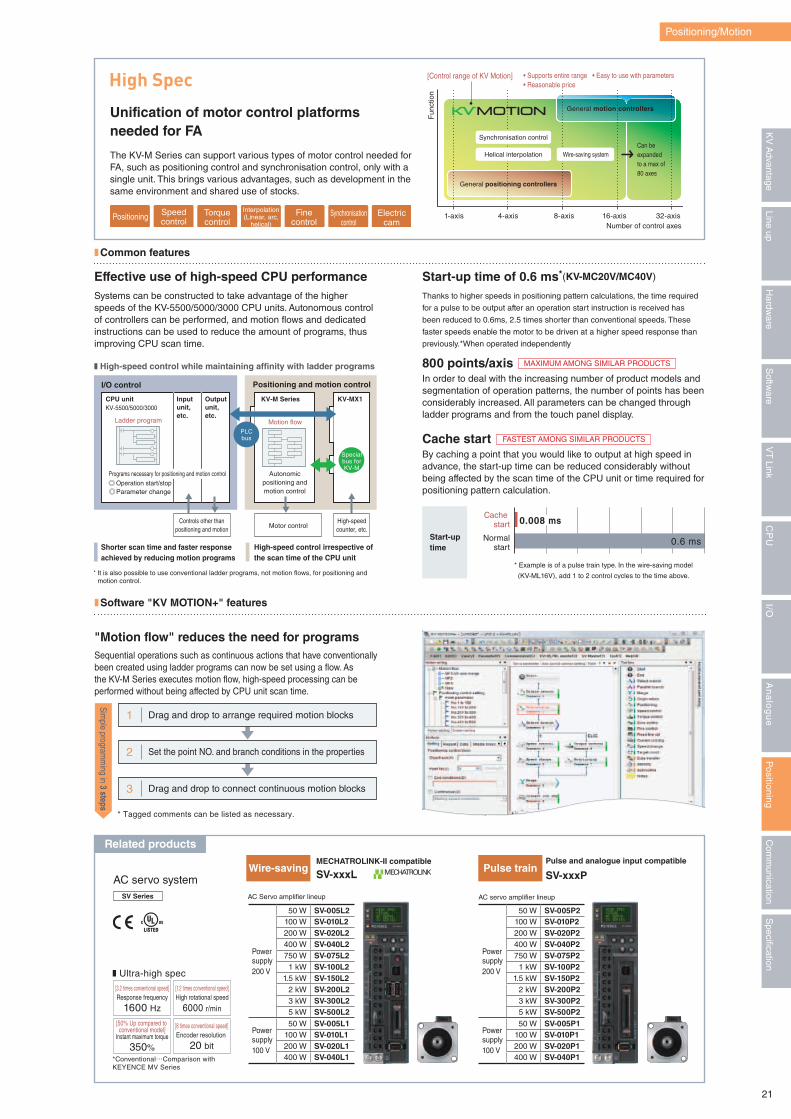
Positioning/Motion
Thanks to higher speeds in positioning pattern calculations, the time required
for a pulse to be output after an operation start instruction is received has
been reduced to 0.6ms, 2.5 times shorter than conventional speeds. These
faster speeds enable the motor to be driven at a higher speed response than
previously.*When operated independently
In order to deal with the increasing number of product models and segmentation of operation patterns, the number of points has been considerably increased. All parameters can be changed through ladder programs and from the touch panel display.
Systems can be constructed to take advantage of the higher speeds of the KV-5500/5000/3000 CPU units. Autonomous control of controllers can be performed, and motion flows and dedicated instructions can be used to reduce the amount of programs, thus improving CPU scan time.
By caching a point that you would like to output at high speed in advance, the start-up time can be reduced considerably without being affected by the scan time of the CPU unit or time required for positioning pattern calculation.
Start-up time of 0.6 ms*(KV-MC20V/MC40V)
800 points/axis
Effective use of high-speed CPU performance
Cache start
Cache start
Normalstart
Start-uptime
* Example is of a pulse train type. In the wire-saving model
(KV-ML16V), add 1 to 2 control cycles to the time above.
0.6 ms
0.008 ms
CPU unitKV-5500/5000/3000
Inputunit,etc.
Outputunit,etc.
KV-M Series KV-MX1
I/O control Positioning and motion control
Motor controlControls other than
positioning and motionHigh-speedcounter, etc.
PLCbus
Specialbus forKV-M
Ladder program Motion flow
Autonomicpositioning andmotion control
Programs necessary for positioning and motion control Operation start/stop Parameter change
Shorter scan time and faster responseachieved by reducing motion programs
* It is also possible to use conventional ladder programs, not motion flows, for positioning and motion control.
High-speed control irrespective ofthe scan time of the CPU unit
� High-speed control while maintaining affinity with ladder programs
Positioning Speedcontrol
Torquecontrol
Finecontrol
Synchronisationcontrol
Electriccam
Interpolation(Linear, arc,
helical)
High Spec
Unification of motor control platforms needed for FA
The KV-M Series can support various types of motor control needed for FA, such as positioning control and synchronisation control, only with a single unit. This brings various advantages, such as development in the same environment and shared use of stocks.
Fun
ctio
n
Number of control axes1-axis 4-axis 8-axis 16-axis 32-axis
• Supports entire range • Easy to use with parameters• Reasonable price
[Control range of KV Motion]
General motion controllers
Can beexpandedto a max of80 axes
General positioning controllers
Synchronisation control
Helical interpolation Wire-saving system
❚ Common features
MAXIMUM AMONG SIMILAR PRODUCTS
FASTEST AMONG SIMILAR PRODUCTS
Related products
[3.2 times conventional speed]Response frequency
1600 Hz
[1.2 times conventional speed]High rotational speed
6000 r/min
[8 times conventional speed]Encoder resolution
20 bit
[50% Up compared to conventional model]
Instant maximum torque
350%*Conventional…Comparison with KEYENCE MV Series
� Ultra-high spec
Wire-saving Pulse train
3 Drag and drop to connect continuous motion blocks
2 Set the point NO. and branch conditions in the properties
1 Drag and drop to arrange required motion blocks
* Tagged comments can be listed as necessary.
Simple program
ming in 3 steps
❚ Software "KV MOTION+" features
"Motion flow" reduces the need for programsSequential operations such as continuous actions that have conventionally been created using ladder programs can now be set using a flow. As the KV-M Series executes motion flow, high-speed processing can be performed without being affected by CPU unit scan time.
AC servo systemSV Series
Complies withEU RoHSDirective
Power supply200 V
50 W SV-005P2100 W SV-010P2200 W SV-020P2400 W SV-040P2750 W SV-075P2
1 kW SV-100P21.5 kW SV-150P2
2 kW SV-200P23 kW SV-300P25 kW SV-500P2
Power supply100 V
50 W SV-005P1100 W SV-010P1200 W SV-020P1400 W SV-040P1
Power supply 200 V
50 W SV-005L2100 W SV-010L2200 W SV-020L2400 W SV-040L2750 W SV-075L2
1 kW SV-100L21.5 kW SV-150L2
2 kW SV-200L23 kW SV-300L25 kW SV-500L2
Power supply 100 V
50 W SV-005L1100 W SV-010L1200 W SV-020L1400 W SV-040L1
MECHATROLINK-II compatible
SV-xxxLPulse and analogue input compatible
SV-xxxP
AC Servo amplifier lineup AC servo amplifier lineup
21
Specification
Com
munication
Positioning
An
alo
gu
eI/O
CP
UV
T Link
Softw
areLine up
Hardw
areK
V A
dvantage
CPU unit
Connecting cableKV-HC1
KV-5500/5000/3000 KV-LH20V
Connector adaptor unitwith terminal blockKV-HTCx
Servo motor amplifier*Stepping motor driven
2-axis origin sensor,CW/CCW limit sensor,stop sensor, emergencystop input etc
Connecting cable KV-HC2KV-HC3KV-HC4
* KV-SC20(V) adopts MIL34-pin connector
OP-51404• Standard contact/slender type, inclined type is attached
OP-22184• Standard contact /longitudinal type is attached
One for KV-H20S, two for KV-H40S/KV-H20G
� Connector adaptor unit with terminal block
* Please inquire for details of corresponding motor drive.
� MIL connector (40-pin) kitKV-H20S
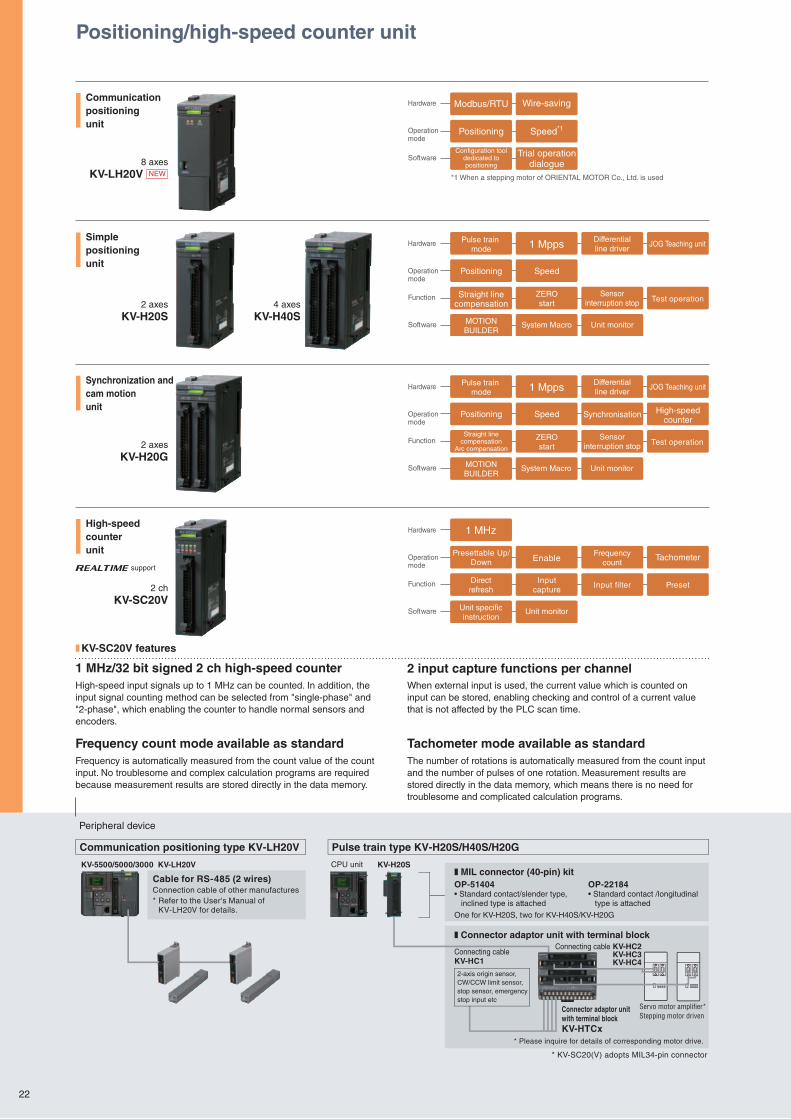
Pulse train type KV-H20S/H40S/H20GCommunication positioning type KV-LH20V
Cable for RS-485 (2 wires)Connection cable of other manufactures* Refer to the User's Manual of KV-LH20V for details.
Hardware
Operation mode
Software
Modbus/RTU
Positioning
Configuration tooldedicated topositioning
Wire-saving
Speed*1
Trial operationdialogue
*1 When a stepping motor of ORIENTAL MOTOR Co., Ltd. is used
Hardware
Operation mode
Function
Software
Sensorinterruption stop
MOTIONBUILDER
Straight linecompensation
Arc compensation
Synchronisation High-speedcounter
ZEROstart Test operation
Pulse train mode
Positioning
1 Mpps Differentialline driver
JOG Teaching unit
Speed
System Macro Unit monitor
Hardware
Operation mode
Function
Software Unit specificinstruction
Inputcapture
Directrefresh
Presettable Up/Down
Input filter
Enable
1 MHz
Preset
Frequencycount
Tachometer
Unit monitor
Hardware
Operation mode
Function
Software
Pulse train mode
Positioning
Straight linecompensation
1 Mpps Differentialline driver
JOG Teaching unit
Sensorinterruption stop Test operation
MOTIONBUILDER
System Macro Unit monitor
Speed
ZEROstart
Communication positioningunit
Synchronization andcam motionunit
High-speedcounterunit
8 axesKV-LH20V NEW
2 axesKV-H20G
2 chKV-SC20V
Positioning/high-speed counter unit
Peripheral device
support
❚ KV-SC20V features
1 MHz/32 bit signed 2 ch high-speed counter
Frequency count mode available as standard
2 input capture functions per channel
Tachometer mode available as standard
High-speed input signals up to 1 MHz can be counted. In addition, the input signal counting method can be selected from "single-phase" and "2-phase", which enabling the counter to handle normal sensors and encoders.
Frequency is automatically measured from the count value of the count input. No troublesome and complex calculation programs are required because measurement results are stored directly in the data memory.
When external input is used, the current value which is counted on input can be stored, enabling checking and control of a current value that is not affected by the PLC scan time.
The number of rotations is automatically measured from the count input and the number of pulses of one rotation. Measurement results are stored directly in the data memory, which means there is no need for troublesome and complicated calculation programs.
Simplepositioningunit
2 axesKV-H20S
4 axesKV-H40S
22
Positioning/high-speed counter
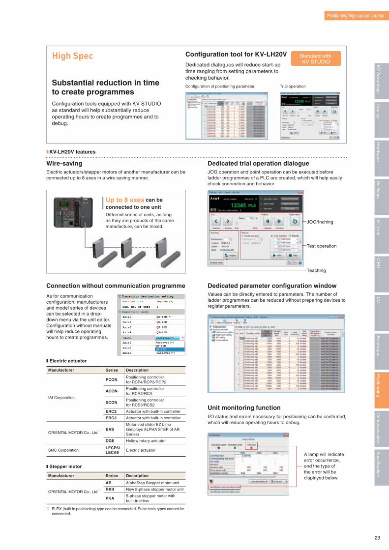
Standard with KV STUDIO
High Spec
Substantial reduction in time to create programmesConfiguration tools equipped with KV STUDIO as standard will help substantially reduce operating hours to create programmes and to debug.
❚ KV-LH20V features
Wire-savingElectric actuators/stepper motors of another manufacturer can be connected up to 8 axes in a wire saving manner.
Configuration tool for KV-LH20V
Dedicated dialogues will reduce start-up time ranging from setting parameters to checking behavior.
Configuration of positioning parameter Trial operation
Up to 8 axes can be connected to one unitDifferent series of units, as long as they are products of the same manufacture, can be mixed.
Dedicated trial operation dialogueJOG operation and point operation can be executed before ladder programmes of a PLC are created, which will help easily check connection and behavior.
JOG/Inching
Test operation
Teaching
*1 FLEX (built-in positioning) type can be connected. Pulse train types cannot be connected.
Manufacturer Series Description
IAI Corporation
PCONPositioning controller for RCP4/RCP3/RCP2
ACONPositioning controller for RCA2/RCA
SCONPositioning controller for RCS3/RCS2
ERC2 Actuator with built-in controller
ERC3 Actuator with built-in controller
ORIENTAL MOTOR Co., Ltd.*1EAS
Motorised slider EZ Limo(Employs ALPHA STEP of AR Series)
DGII Hollow rotary actuator
SMC CorporationLECP6/LECA6 Electric actuator
Manufacturer Series Description
ORIENTAL MOTOR Co., Ltd.*1
AR AlphaStep Stepper motor unit
RKII New 5-phase stepper motor unit
PKA5-phase stepper motor with built-in driver
Connection without communication programme
As for communication configuration, manufacturers and model series of devices can be selected in a drop-down menu via the unit editor. Configuration without manuals will help reduce operating hours to create programmes.
❚ Electric actuator
❚ Stepper motor
Dedicated parameter configuration windowValues can be directly entered to parameters. The number of ladder programmes can be reduced without preparing devices to register parameters.
Unit monitoring functionI/O status and errors necessary for positioning can be confirmed, which will reduce operating hours to debug.
A lamp will indicate error occurrence, and the type of the error will be displayed below.
23
Specification
Com
munication
Positioning
An
alo
gu
eI/O
CP
UV
T Link
Softw
areLine up
Hardw
areK
V A
dvantage
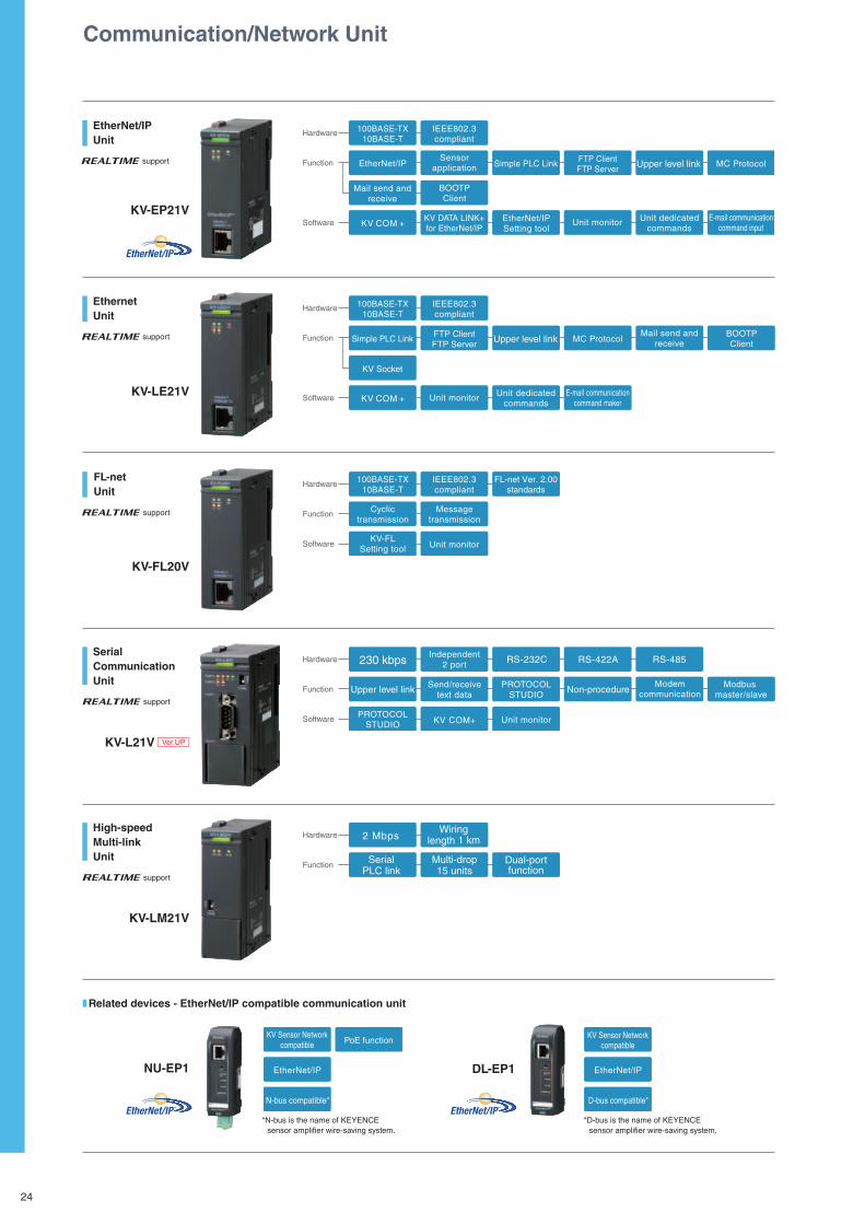
Hardware
Function
Software
100BASE-TX10BASE-T
IEEE802.3compliant
Unit monitor
FTP ClientFTP Server
Simple PLC Link
KV Socket
Upper level link
E-mail communicationcommand maker
MC ProtocolMail send and
receive
KV COM +Unit dedicated
commands
BOOTPClient
Hardware
Function
Software
100BASE-TX10BASE-T
KV-FLSetting tool Unit monitor
IEEE802.3compliant
FL-net Ver. 2.00standards
Cyclictransmission
Messagetransmission
Hardware
Function
Software PROTOCOLSTUDIO
Independent2 port RS-232C
Upper level link Send/receivetext data
RS-422A RS-485
ModemcommunicationNon-procedure Modbus
master/slave
230 kbps
PROTOCOLSTUDIO
Unit monitorKV COM+
Multi-drop15 units
Hardware
Function Serial PLC link
Dual-portfunction
2 MbpsWiring
length 1 km
Hardware
Function
Software
100BASE-TX10BASE-T
EtherNet/IP
IEEE802.3compliant
KV DATA LINK+for EtherNet/IP
FTP ClientFTP Server
EtherNet/IPSetting tool
Simple PLC Link
BOOTPClient
Mail send andreceive
Sensorapplication Upper level link
E-mail communicationcommand input
MC Protocol
Unit monitorKV COM +Unit dedicated
commands
KV Sensor Networkcompatible
EtherNet/IP
N-bus compatible*
PoE functionKV Sensor Network
compatible
EtherNet/IP
D-bus compatible*
Communication/Network Unit
EthernetUnit
FL-netUnit
SerialCommunicationUnit
High-speedMulti-linkUnit
KV-LE21V
KV-FL20V
KV-L21V Ver.UP
KV-LM21V
NU-EP1 DL-EP1
support
support
support
support
EtherNet/IPUnit
KV-EP21V
support
❚ Related devices - EtherNet/IP compatible communication unit
* N-bus is the name of KEYENCE sensor amplifier wire-saving system.
* D-bus is the name of KEYENCE sensor amplifier wire-saving system.
24
Communication/Network
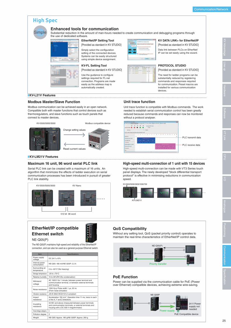
The need for ladder programs can be substantially reduced by registering commands and responses required for communication. Preset macros are installed for various communication devices.
Data link between PLCs on EtherNet/IP can be set easily using the wizard.
Use the guidance to configure settings required for FL-net connection. Programs are made easily as the address map is automatically created.
Simply select the configuration setting of the connected devices. Systems can be easily structured using simple device assignment.
KV-FL Setting Tool[Provided as standard in KV STUDIO]
High SpecEnhanced tools for communication Substantial reduction in the amount of man-hours needed to create communication and debugging programs through the use of dedicated software.
EtherNet/IP Setting Tool[Provided as standard in KV STUDIO]
KV DATA LINK+ for EtherNet/IP[Provided as standard in KV STUDIO]
PROTOCOL STUDIO[Provided as standard in KV STUDIO]
Simple
High-speed multi-connection can be made with VT3 Series touch panel displays. The newly developed "block differential transport protocol" is effective in minimising reductions in communication speed.
High-speed multi-connection of 1 unit with 15 devices
KV-5500/5000/3000/1000/700
KV-LM21V
Item Specifications
Power supply voltage DC 24 V ±10%
Internal powerconsumption NE-Q05: 180 mA/NE-Q05P: 2.2 A
Surrounding air temperature
0 to +50°C*(No freezing)
Storage temperature -20 to +70°C
Relative humidity 10 to 95%RH (No condensation)
Withstand
voltage
AC 1500 V for 1 minute, between power terminal and communication terminal, or between external terminals and housing
Noise resistance1500 Vp-p Pulse width 1 μs, 50 ns(From noise simulator)
Vibration resistance JIS B 3502 IEC61131-2 compliant
Impact resistance
Acceleration 150 m/s2, Operation time 11 ms, twice in each of the X, Y and Z directions
Insulating resistance
50 MΩ and above (measured between power terminals and communication terminals, or external terminals and housing with a DC 500 V megohmmeter)
Overvoltage category I
Pollution degree 2
Weight NE-Q05: Approx. 180 g/NE-Q05P: Approx. 260 g
NE-Q05(P)
EtherNet/IP compatibleEthernet switch
The NE-Q05(P) maintains high-speed and reliability of the EtherNet/IP connection, and can also be used as a general purpose Ethernet switch.
PoE Function
QoS Compatibility
Power can be supplied via the communication cable for PoE (Power over Ethernet) compatible devices, achieving extreme wire-saving.
Without any setting tool, QoS (packet priority control) operates to maintain the real-time characteristics of EtherNet/IP control data.
PoE Compatible device
Power supply
24 V Power supply not needed
Priority transfer
NE-Q05(P)
NE-Q05P
Maximum 16 unit, 96 word serial PLC link
Modbus communication can be achieved easily in an open network. Compatible both with master functions that control devices such as thermoregulators, and slave functions such as touch panels that connect to master devices.
Unit trace function is compatible with Modbus commands. The work needed to establish serial communication control has been greatly reduced because commands and responses can now be monitored without a protocol analyser.
Modbus Master/Slave Function Unit trace function
■ KV-LM21V Features
■ KV-L21V Features
Serial PLC link can be created with a maximum of 16 units. An algorithm that minimizes the effects of ladder execution on serial communication processes has been introduced in pursuit of greater PLC link stability.
PLC transmit data
PLC receive data
Change setting values
Read current values
KV-5500/5000/3000 KV Nano
KV-5500/5000/3000 Modbus compatible device
512 bit 96 word
25
Specification
Com
munication
Positioning
An
alo
gu
eI/O
CP
UV
T Link
Softw
areLine up
Hardw
areK
V A
dvantage
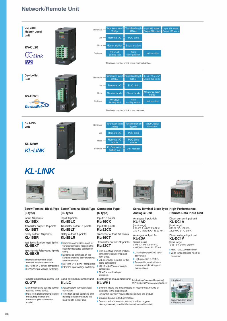
Network/Remote Unit
CC-LinkMaster Localunit
DeviceNetunit
KL-LINKunit
KV-CL20
KV-DN20
KL-N20V
*Maximum number of link points per local station
*Maximum number of link points per slave
Hardware
Use
Mode
Software
Transmission speed10 Mbps
Remote I/O
Master station
Trunk line length1200 m
Input 896 points*Output 896 points
Input 128 wordsOutput 128 words
KV-CL20Setting tool
Autoconfiguration Unit monitor
PLC Link
Local station
Hardware
Use
Mode
Software
Transmission speed500 kbps
Master & slavemode
KV-DN20Setting tool
Autoconfiguration Unit monitor
Master mode
Trunk line length500 m
Input 128 words*Output 128 words
Remote I/O PLC Link
Slave mode
Hardware
Use
Mode
Software
Input/Output128 words
KL ConnectionSetting tool Unit monitor
Transmission speed5 Mbps
Trunk line length1200 m
Remote I/O PLC Link
Remote I/Omode
PLC Linkmode
Screw Terminal Block Type(B type)
Input: 16 points KL-16BXTransistor output: 16 pointsKL-16BTRelay output: 16 points KL-16BRInput: 8 points Transistor output: 8 points KL-8BXTInput: 8 points Relay output: 8 points KL-8BXR
Screw Terminal Block Type(BL type)
Input: 8 points KL-8BLXTransistor output: 8 points KL-8BLTRelay output: 8 points KL-8BLR
Connector Type(C type)
Input: 16 points KL-16CXInput: 32 points KL-32CXTransistor output: 16 points KL-16CT Transistor output: 32 pointsKL-32CT
Screw Terminal Block Type Analogue Unit
Analogue input: 4ch KL-4AD[Input range] 0 to 5 V, 1 to 5 V, 0 to 10 V,±10 V, 0 to 20 mA, 4 to 20 mA
Analogue output: 2ch KL-2DA[Output range] 0 to 5 V, 1 to 5 V, 0 to 10 V,±10 V, 0 to 20 mA, 4 to 20 mA
High-Performance Remote Data Input Unit
Direct current input unit KL-DC1A[Input range] 0 to 20 mA, ±10 mA,±100 mA, ±1 A, ±10 A
Direct voltage input unit KL-DC1V[Input range] 0 to 10 V, ±10 V, ±100 V
Remote temperature control unit
KL-2TFLoad cell measurement unit
KL-LC1Electricity measurement unit
KL-WH1[Input voltage/measured frequency]ACZ 100 to 250 V (sine wave)/50/60 Hz
❚ Ultra-high speed 200 μs/ch conversion.
❚ High precision 0.2%F.S.❚ Removable terminal block
enables simple wiring and maintenance.
❚ 2 ch heating and cooling control realised in one device.
❚ Input from platinum temperature measuring resistor and thermocoupler covered by 1 model.
❚ Actual weight correction/local correction.
❚ 1 ms high speed sampling and holding function measure the load weight in real time.
❚ 2 control inputs are most suitable for measuring amounts of electricity in the original unit. *Amount of electricity required to manufacture one product
❚ Integrated pulse output compatible.
❚ Demand value*measured without a ladder program. *Average electricity used in 30 minutes (demand time-limit)
❚ Application
Measuring electricity amount in filling equipment
❚ Max. 1/200.000 resolution ❚ Wide range reduces need for
converter.
❚ Removable terminal block enables easy maintenance .
❚ DC 12 to 24 V power compatible.❚ 24 V/5 V input voltage switching.
❚ Common connections used for various terminals, reducing the need for dedicated connection wiring.
❚ Switches all arranged on top surface enabling easy switching after installation.
❚ DC 12 to 24 V power compatible.❚ 24 V/5 V input voltage switching.
❚ Slim mounting bracket enables connector output on top and front sides.
❚ MIL connector included for flat cable connection.
❚ DC 12 to 24 V power supply compatible.
❚ 24 V/5 V input voltage switching.
26
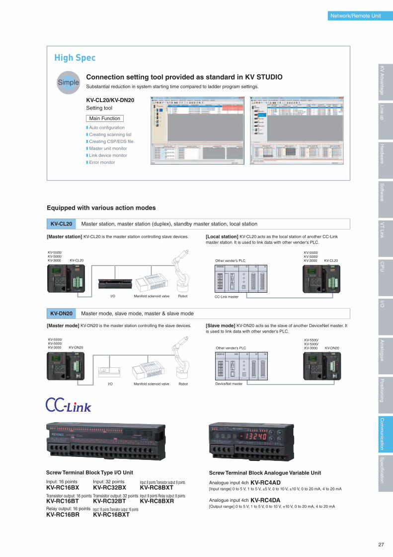
High Spec
Connection setting tool provided as standard in KV STUDIOSubstantial reduction in system starting time compared to ladder program settings.
KV-CL20/KV-DN20Setting tool
❚ Auto configuration
❚ Creating scanning list
❚ Creating CSP/EDS file
❚ Master unit monitor
❚ Link device monitor
❚ Error monitor
Main Function
Simple
KV-CL20
KV-DN20
Master station, master station (duplex), standby master station, local station
Master mode, slave mode, master & slave mode
Equipped with various action modes
[Master station] KV-CL20 is the master station controlling slave devices.
[Master mode] KV-DN20 is the master station controlling the slave devices.
[Local station] KV-CL20 acts as the local station of another CC-Link master station. It is used to link data with other vender's PLC.
[Slave mode] KV-DN20 acts as the slave of another DeviceNet master. It is used to link data with other vender's PLC.
Network/Remote Unit
KV-5500/KV-5000/KV-3000 KV-CL20
RobotManifold solenoid valveI/O
KV-CL20
CC-Link master
Other vender's PLC
KV-5500/KV-5000/KV-3000
KV-5500/KV-5000/KV-3000 KV-DN20
RobotManifold solenoid valveI/O
KV-DN20
DeviceNet master
Other vender's PLC
KV-5500/KV-5000/KV-3000
Screw Terminal Block Type I/O Unit
Input: 16 pointsKV-RC16BX
Input: 32 pointsKV-RC32BX
Input: 8 points Transistor output: 8 pointsKV-RC8BXT
Transistor output: 16 pointsKV-RC16BT
Transistor output: 32 pointsKV-RC32BT
Input: 8 points Relay output: 8 pointsKV-RC8BXR
Relay output: 16 pointsKV-RC16BR
Input: 16 points Transistor output: 16 pointsKV-RC16BXT
Screw Terminal Block Analogue Variable Unit
Analogue input 4ch KV-RC4AD[Input range] 0 to 5 V, 1 to 5 V, ±5 V, 0 to 10 V, ±10 V, 0 to 20 mA, 4 to 20 mA
Analogue input 4ch KV-RC4DA[Output range] 0 to 5 V, 1 to 5 V, 0 to 10 V, ±10 V, 0 to 20 mA, 4 to 20 mA
27
Specification
Com
munication
Positioning
An
alo
gu
eI/O
CP
UV
T Link
Softw
areLine up
Hardw
areK
V A
dvantage
L A D D E R S U P P O R T S O F T W A R E
Positioning Unit Paramater Configuration Software
KV MOTION+MOTION BUILDERMV LINK STUDIOCommunication Macro Support SoftwarePROTOCOL STUDIOPROTOCOL BUILDER
Datalink Configuration SoftwareKV DATALINK+for EtherNet/IP
Integrated Support Software Package KV-H5WE
KV STUDIO Ver.7
KV STUDIO Ver.7LA
DD
ER
SU
PP
OR
T S
OF
TW
AR
EIntegrated Support Softw
are Package KV-H5WE
Windows 2000(SP3 or later)/ XP(only the 32-bit version)
Pentium at 800 MHz or higher(1 GHz or more is recommended)
256 MB or more(512MB or more is recommended)Windows Vista(only the 32-bit version)/ 7
Processor recommended by MicrosoftMemory recommended by Microsoft
×2 or faster950MB or moreXGA(1024 × 768), 16-bit high color or more
OSCPU *2
Memory *2
CD-ROM driveHard drive spaceDisplay
Internet support serviceThe latest version of CAD Data Software is available for download online.
Please receive our Emails for the latest news.
www.keyence.com
Operating environment *1
*1 Microsoft Internet Explorer Ver.6.0 or later must be installed on your PC.
*2 Using the Remote XG display requires pentium4 1.4GHz or higher (2.4GHz or higher recommended) with 512MB or higher (2GB or higher recommended)
www.keyence.com/kvs/
QUICK ONLINE USER REGISTRATIONUser Registration Password : 01524
Registered User AdvantagesFREE Software UpgradeThe latest software version can be downloaded anytime from the special site free of charge.
Multiple users can use the software within the same business address (factory, division, office).
*You will require user registration to use the software.
Without registration, only one license is available for one computer.
Site License[About the license of KV STUDIO (KV-H5WE)]
KV STUDIO User Registration Site
Please read this software license agreement (this “agreement”) carefully. By using all or any portion of KV STUDIO (this “software”),
you are agreeing to be bound by all the terms and conditons of this agreement. If you do not agree to any terms of this agreement,
do not use this software.
Software License Agreement
Conditioned upon compliance with all of the terms and conditions of this Agreement, KEYENCE grants you a nonexclusive
and nontransferable license to install this Software on all computers used in a single business addres (factory, division, office)
in order to use the KEYENCE product. You will require user registration to use the software. Without registration, only one license is
available for one computer.You may make one copy of this Software for backup or archive purposes only.
Grant of License.
Except as expressly stated herein, KEYENCE reserves all right, title and interest in this Software, and all associated copyrights,
trademarks, and other intellectual property rights therein.
Intellectual Property Rights.
1 Except for installation of updates or new functions provided by KEYENCE, you may not modify or add any function to this Software.
2 You may not reverse engineer, decompile or disassemble this Software.
3 You may not create derivative works based on this Software.
4 Other than expressly stated by KEYENCE, you may not resell, retransfer, rent or otherwise redistribute this Software to any third parties.
Restrictions.
Keyence is licensing this Software to you “AS IS” and without any warranty of any kind. In no event will KEYENCE or its suppliers be liable
to you for any damages, claims, costs or any lost profits caused by using this Software.
Disclaimer.
This disc is a CD-ROM. Do not play this disc in a standard audio player.
Otherwise, the speakers and your hearing may be damaged by sudden high volume sound.
Warning
* Microsoft and Windows are registered trademarks of the Microsoft Corporation in the United States and other countries.
* Pentium is a trademark of the Intel Corporation in the United States.
* The names of other companies and products used herein are the registered trademarks of their respective owners.
1013-1 96M*******
1-3-14, Higashi-Nakajima, Higashi-Yodogawa-ku, Osaka, 533-8555, Japan
Phone: +81-6-6379-2211 Fax: +81-6-6379-2131
KEYENCE CORPORATIONwww.keyence.comKV STUDIO Ver.7
Ladder support software with intuitive operation
Real-time Programming Cutting-edge technology provides drastic reduction in programming time
PROGRAMMING FUNCTIONS
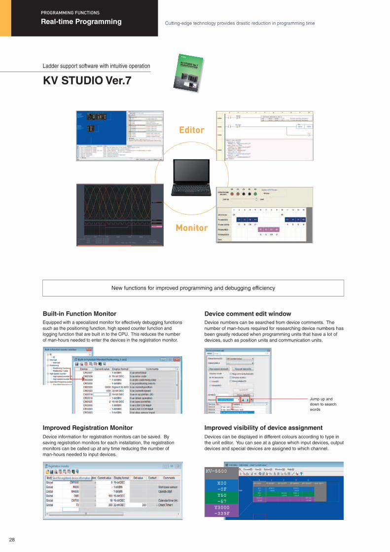
New functions for improved programming and debugging efficiency
Editor
Monitor
Equipped with a specialized monitor for effectively debugging functions such as the positioning function, high speed counter function and logging function that are built in to the CPU. This reduces the number of man-hours needed to enter the devices in the registration monitor.
Device information for registration monitors can be saved. By saving registration monitors for each installation, the registration monitors can be called up at any time reducing the number of man-hours needed to input devices.
Device numbers can be searched from device comments. The number of man-hours required for researching device numbers has been greatly reduced when programming units that have a lot of devices, such as position units and communication units.
Devices can be displayed in different colours according to type in the unit editor. You can see at a glance which input devices, output devices and special devices are assigned to which channel.
Built-in Function Monitor
Improved Registration Monitor
Device comment edit window
Improved visibility of device assignment
Jump up and down to search words
28
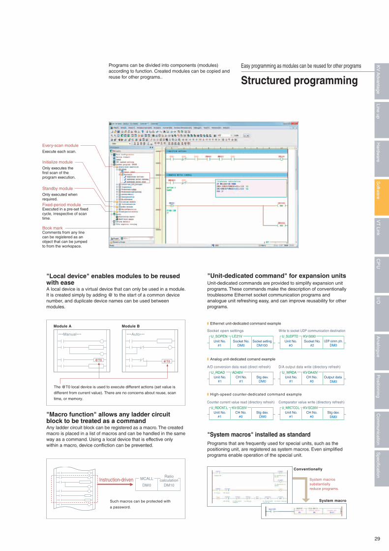
Every-scan moduleExecute each scan.
Standby moduleOnly executed when required.
Initialize moduleOnly executes the first scan of the program execution.
Fixed-period moduleExecuted in a pre-set fixed cycle, irrespective of scan time.
Book markComments from any line can be registered as an object that can be jumped to from the workspace.
A local device is a virtual device that can only be used in a module. It is created simply by adding @ to the start of a common device number, and duplicate device names can be used between modules.
Programs can be divided into components (modules) according to function. Created modules can be copied and reuse for other programs..
Any ladder circuit block can be registered as a macro. The created macro is placed in a list of macros and can be handled in the same way as a command. Using a local device that is effective only within a macro, device confliction can be prevented.
Unit-dedicated commands are provided to simplify expansion unit programs. These commands make the description of conventionally troublesome Ethernet socket communication programs and analogue unit refreshing easy, and can improve reusability for other programs.
Programs that are frequently used for special units, such as the positioning unit, are registered as system macros. Even simplified programs enable operation of the special unit.
"Local device" enables modules to be reused with ease
"Macro function" allows any ladder circuit block to be treated as a command
"Unit-dedicated command" for expansion units
"System macros" installed as standard
Socket open settings
A/D conversion data read (direct refresh)
Counter current value read (directory refresh)
Write to socket UDP communication destination
D/A output data write (directory refresh)
Comparator value write (directory refresh)
Unit No.#1
Socket No.DM0
Socket settingDM100
U_SOPEN LE21V
Unit No.#1
CH No.#1
Stg dev.DM0
U_RDAD AD40V
Unit No.#1
CH No.#0
Stg dev. DM0
U_RDCNT.L KV-SC20V
Unit No.#0
Socket No.#2
UDP comm. ptn.DM0
U_SUDPTO KV-5000
Unit No.#1
CH No.#0
Output data DM0
U_WRDA KV-DA40V
Unit No.#1
CH No.#0
Stg dev.DM0
U_WRCTCO.L KV-SC20V
❚ Ethernet unit-dedicated command example
❚ Analog unit-dedicated comand example
❚ High-speed counter-dedicated command example
The @T0 local device is used to execute different actions (set value is
different from current value). There are no concerns about reuse, scan
time, or memory.
***Manual***
Module A
@T0
***Auto***
Module B
@T0
Conventionally
System macro
System macros substantially reduce programs.
Such macros can be protected with
a password.
Instruction-driven MCALLRatio
calculationDM0 DM10
Easy programming as modules can be reused for other programs
Structured programming
29
Specification
Com
munication
Positioning
An
alo
gu
eI/O
CP
UV
T Link
Softw
areLine up
Hardw
areK
V A
dvantage
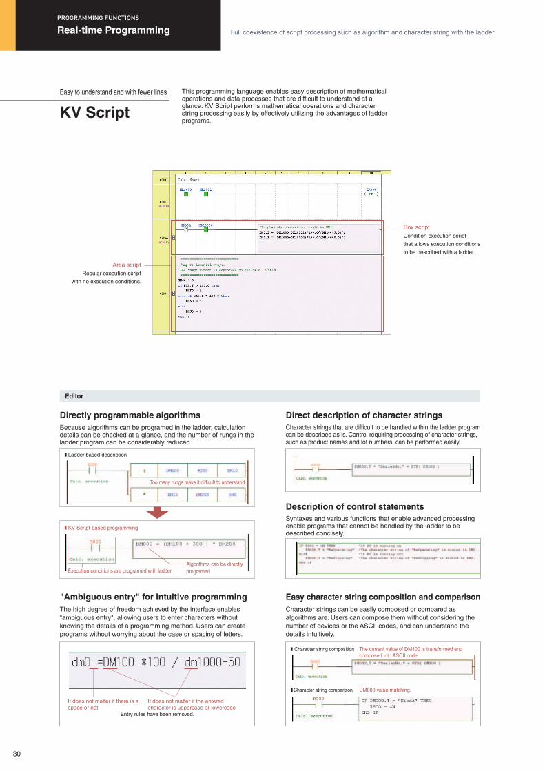
Too many rungs make it difficult to understand
Algorithms can be directly programedExecution conditions are programed with ladder
❚ KV Script-based programming
❚ Ladder-based description
The current value of DM100 is transformed andcomposed into ASCII code.
DM000 value matching.
� Character string composition
� Character string comparison
This programming language enables easy description of mathematical operations and data processes that are difficult to understand at a glance. KV Script performs mathematical operations and character string processing easily by effectively utilizing the advantages of ladder programs.
Easy to understand and with fewer lines
KV Script
Editor
Because algorithms can be programed in the ladder, calculation details can be checked at a glance, and the number of rungs in the ladder program can be considerably reduced.
The high degree of freedom achieved by the interface enables "ambiguous entry", allowing users to enter characters without knowing the details of a programming method. Users can create programs without worrying about the case or spacing of letters.
Character strings that are difficult to be handled within the ladder program can be described as is. Control requiring processing of character strings, such as product names and lot numbers, can be performed easily.
Character strings can be easily composed or compared as algorithms are. Users can compose them without considering the number of devices or the ASCII codes, and can understand the details intuitively.
Syntaxes and various functions that enable advanced processing enable programs that cannot be handled by the ladder to be described concisely.
Directly programmable algorithms
"Ambiguous entry" for intuitive programming
Direct description of character strings
Easy character string composition and comparison
Description of control statements
It does not matter if there is a space or not
Entry rules have been removed.
It does not matter if the entered character is uppercase or lowercase
Box scriptCondition execution script
that allows execution conditions
to be described with a ladder.
Area scriptRegular execution script
with no execution conditions.
Real-time Programming Full coexistence of script processing such as algorithm and character string with the ladder
PROGRAMMING FUNCTIONS
30
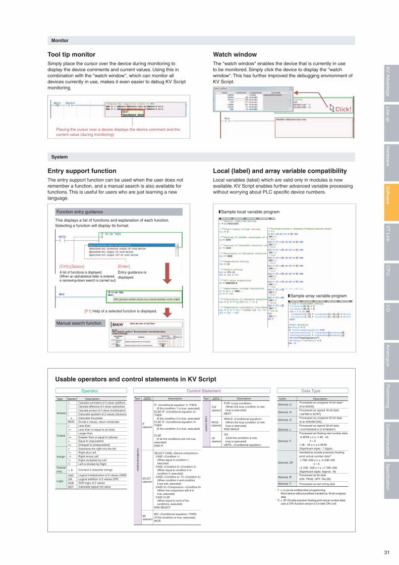
Operator Control Statement Data Type
Calculate summation of 2 values (addition)Calculate difference of 2 values (subtraction)Calculate product of 2 values (multiplication)Calculate quotient of 2 values (division)Calculate the powerDivide 2 values, return remainderLess thanLess than or equal to (or less)Larger thanGreater than or equal to (above)Equal to (equivalent)Unequal to (unequivalent)Substitute the right into the leftRight plus LeftRight minus LeftRight multiplied by LeftLeft is divided by Right
Connect 2 character strings
Logical multiplication of 2 values (AND)Logical addition of 2 values (OR)EOR logic of 2 valuesCalculate logical not value
+−*/
MOD<<=>>==<>=+=–=*=/=
+, &
ANDORXORNOT
Arithmetic
Compare
Assign
Characterstring
Logic
^
Type Operator DescriptionProcessed as unsigned 16-bit data*1
(0 to 65535)Processed as signed 16-bit data(-32768 to 32767)Processed as unsigned 32-bit data(0 to 4294967295)Processed as signed 32-bit data(-2147483648 to 2147483647)Processed as floating real number data-3.4E38 ≤ n ≤ -1.4E - 45 n = 01.4E - 45 ≤ n ≤ 3.4E38(Significant digits : 7 digits)Handled as double precision floating point actual number data*2
-1.79E+308 ≤ n ≤ -2.23E-308 n = 0+2.23E -308 ≤ n ≤ +1.79E+308(Significant digits: Approx. 16) Processed as bit data(ON: TRUE, OFF: FALSE)
Processed as text string data
(Device) .U
(Device) .S
(Device) .D
(Device) .L
(Device) .F
(Device) .DF
(Device) .B
(Device) .T
*1 x. U can be omitted when programming. Word device without postfixes handled as 16-bit unsigned data.*2 x. DF (Double precision floating point actual number data) uses a CPU function version 2.0 or later CPU unit.
Suffix Description
IF <Conditional equation 1> THEN (If the condition 1 is true, executed)ELSE IF <Conditional equation 2> THEN (If the condition 2 is true, executed)ELSE IF <Conditional equation 3> THEN (If the condition 3 is true, executed)
ELSE (If all the conditions are not true, executed)END IF
SELECT CASE <Device comparison> CASE <Condition 1> (When equal to condition 1, executed) CASE <Condition 2><Condition 3> (When equal to condition 2 or condition 3, executed) CASE <Condition 4> T0 <Condition 5> (When condition 4 and condition 5 are met, executed) CASE IS <Comparison> <Condition 6> (When the comparison with 6 is true, executed) CASE ELSE (When equal to none of the conditions, executed)END SELECT
MC <Conditional equation> THEN(If the condition is true, executed)MCR
Type Controlstatement Description Type Control
statement Description
FOR <Loop condition> (When the loop condition is met, loop is executed)NEXT
WHILE <Conditional equation> (When the loop condition is met, loop is executed)END WHILE
DO (Until the condition is met, loop is executed)UNTIL <Conditional equation>
DOstatement
IF statement
SELECTstatement
MCstatement
FORstatement
WHILEstatement
Conditional branch
Loop control
❚ Sample local variable program
Monitor
System
Function entry guidance
Manual search function
Simply place the cursor over the device during monitoring to display the device comments and current values. Using this in combination with the "watch window", which can monitor all devices currently in use, makes it even easier to debug KV Script monitoring.
The entry support function can be used when the user does not remember a function, and a manual search is also available for functions. This is useful for users who are just learning a new language.
The "watch window" enables the device that is currently in use to be monitored. Simply click the device to display the "watch window". This has further improved the debugging environment of KV Script.
Local variables (label) which are valid only in modules is now available. KV Script enables further advanced variable processing without worrying about PLC specific device numbers.
Tool tip monitor
Entry support function
Usable operators and control statements in KV Script
Watch window
Local (label) and array variable compatibility
❚ Sample array variable program
This displays a list of functions and explanation of each function. Selecting a function will display its format.
[Ctrl]+[Space] A list of functions is displayed.(When an alphabetical letter is entered,a narrowing-down search is carried out)
Placing the cursor over a device displays the device comment and the current value (during monitoring)
[Enter]Entry guidance is displayed.
[F1] Help of a selected function is displayed.
Click!
31
Specification
Com
munication
Positioning
An
alo
gu
eI/O
CP
UV
T Link
Softw
areLine up
Hardw
areK
V A
dvantage
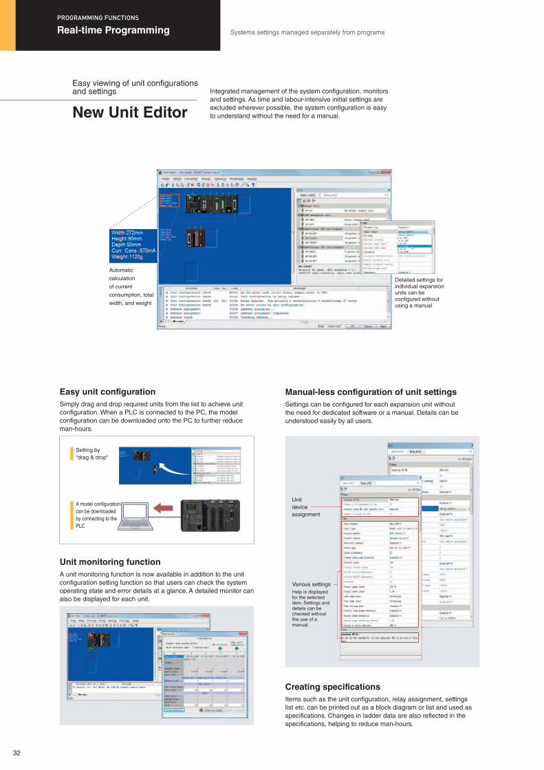
Easy viewing of unit configurations and settings
New Unit Editor
Simply drag and drop required units from the list to achieve unit configuration. When a PLC is connected to the PC, the model configuration can be downloaded onto the PC to further reduce man-hours.
A unit monitoring function is now available in addition to the unit configuration setting function so that users can check the system operating state and error details at a glance. A detailed monitor can also be displayed for each unit.
Settings can be configured for each expansion unit without the need for dedicated software or a manual. Details can be understood easily by all users.
Items such as the unit configuration, relay assignment, settings list etc. can be printed out as a block diagram or list and used as specifications. Changes in ladder data are also reflected in the specifications, helping to reduce man-hours.
Easy unit configuration
Automatic
calculation
of current
consumption, total
width, and weight
Detailed settings for individual expansion units can be configured without using a manual
Unit monitoring function
Manual-less configuration of unit settings
Creating specifications
Unitdeviceassignment
Various settingsHelp is displayed for the selected item. Settings and details can be checked without the use of a manual.
Real-time Programming Systems settings managed separately from programs
PROGRAMMING FUNCTIONS
Integrated management of the system configuration, monitors and settings. As time and labour-intensive initial settings are excluded wherever possible, the system configuration is easy to understand without the need for a manual.
Setting by"drag & drop"
A model configuration can be downloaded by connecting to the PLC
32
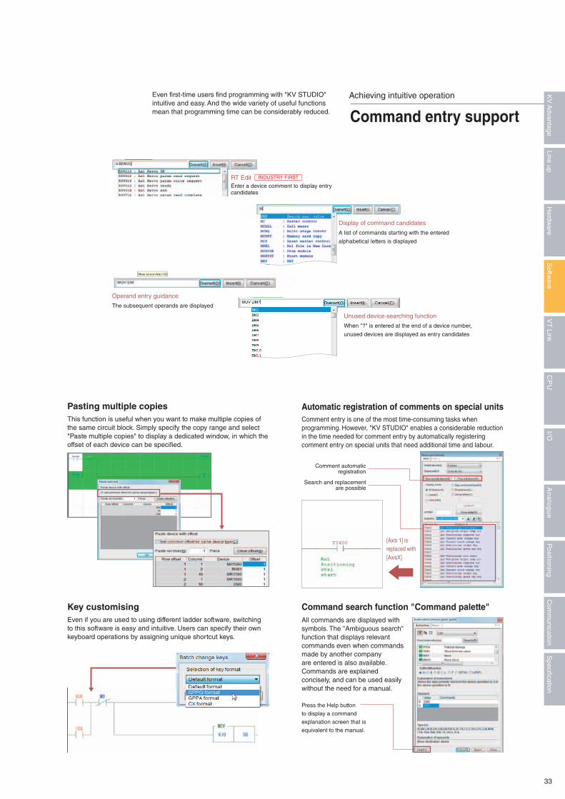
This function is useful when you want to make multiple copies of the same circuit block. Simply specify the copy range and select "Paste multiple copies" to display a dedicated window, in which the offset of each device can be specified.
Even if you are used to using different ladder software, switching to this software is easy and intuitive. Users can specify their own keyboard operations by assigning unique shortcut keys.
Comment entry is one of the most time-consuming tasks when programming. However, "KV STUDIO" enables a considerable reduction in the time needed for comment entry by automatically registering comment entry on special units that need additional time and labour.
All commands are displayed with symbols. The "Ambiguous search" function that displays relevant commands even when commands made by another company are entered is also available. Commands are explained concisely, and can be used easily without the need for a manual.
Pasting multiple copies
Operand entry guidance
The subsequent operands are displayed
Key customising
Automatic registration of comments on special units
Unused device-searching function
When "?" is entered at the end of a device number,
unused devices are displayed as entry candidates
Display of command candidates
A list of commands starting with the entered
alphabetical letters is displayed
Command search function "Command palette"
Press the Help button
to display a command
explanation screen that is
equivalent to the manual.
Comment automatic registration
Search and replacement are possible
Achieving intuitive operation
Command entry support
Even first-time users find programming with "KV STUDIO" intuitive and easy. And the wide variety of useful functions mean that programming time can be considerably reduced.
[Axis 1] isreplaced with[AxisX]
RT EditEnter a device comment to display entry candidates
INDUSTRY FIRST
33
Specification
Com
munication
Positioning
An
alo
gu
eI/O
CP
UV
T Link
Softw
areLine up
Hardw
areK
V A
dvantage
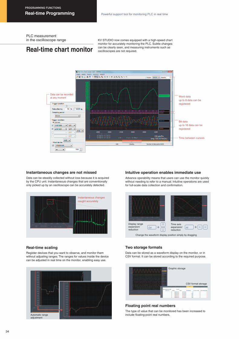
PLC measurement in the oscilloscope range
Real-time chart monitor
Data can be steadily collected without loss because it is acquired by the CPU unit. Instantaneous changes that are conventionally only picked up by an oscilloscope can be accurately detected.
Advance operability means that users can use the monitor quickly without needing to refer to a manual. Intuitive operations are used for full-scale data collection and confirmation.
Data can be stored as a waveform display on the monitor, or in CSV format. It can be stored according to the required purpose.
The type of value that can be monitored has been increased to include floating-point real numbers.
Instantaneous changes are not missed Intuitive operation enables immediate use
Two storage formats
Floating point real numbers
Change the waveform display position simply by dragging
Display rangeexpansion/ reduction
Graphic storage
CSV format storage
Instantaneous changes caught accurately
Time axisexpansion/ reduction
Real-time Programming Powerful support tool for monitoring PLC in real time
PROGRAMMING FUNCTIONS
KV STUDIO now comes equipped with a high-speed chart monitor for accurately monitoring the PLC. Subtle changes can be clearly seen, and measuring instruments such as oscilloscopes are not required.
Word dataup to 8 data can be registered
Bit dataup to 16 data can be registered
Time between cursors
Data can be recorded at any moment
Register devices that you want to observe, and monitor them without adjusting ranges. The ranges for values inside the device can be adjusted in real time on the monitor, enabling easy use.
Real-time scaling
Automatic range adjustment
34
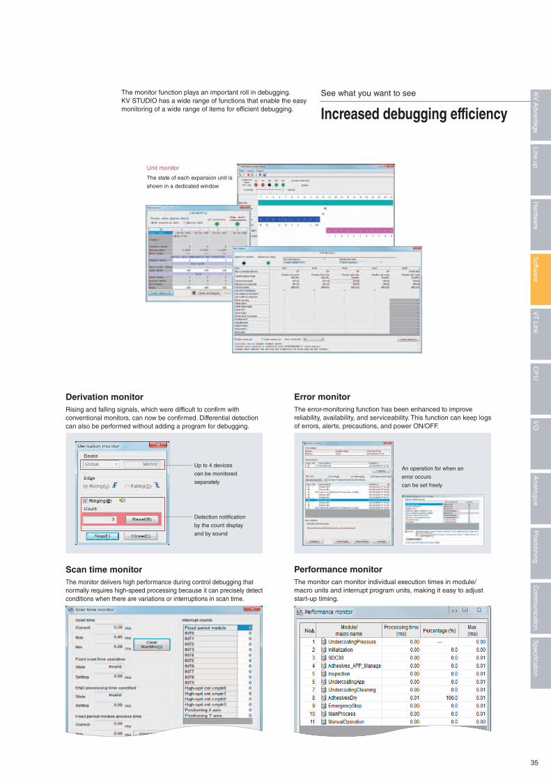
An operation for when an
error occurs
can be set freely
Up to 4 devices
can be monitored
separately
Detection notification
by the count display
and by sound
The state of each expansion unit is
shown in a dedicated window
Unit monitor
Rising and falling signals, which were difficult to confirm with conventional monitors, can now be confirmed. Differential detection can also be performed without adding a program for debugging.
The monitor delivers high performance during control debugging that normally requires high-speed processing because it can precisely detect conditions when there are variations or interruptions in scan time.
The error-monitoring function has been enhanced to improve reliability, availability, and serviceability. This function can keep logs of errors, alerts, precautions, and power ON/OFF.
The monitor can monitor individual execution times in module/macro units and interrupt program units, making it easy to adjust start-up timing.
Derivation monitor
Scan time monitor
Error monitor
Performance monitor
See what you want to see
Increased debugging efficiency
The monitor function plays an important roll in debugging. KV STUDIO has a wide range of functions that enable the easy monitoring of a wide range of items for efficient debugging.
35
Specification
Com
munication
Positioning
An
alo
gu
eI/O
CP
UV
T Link
Softw
areLine up
Hardw
areK
V A
dvantage
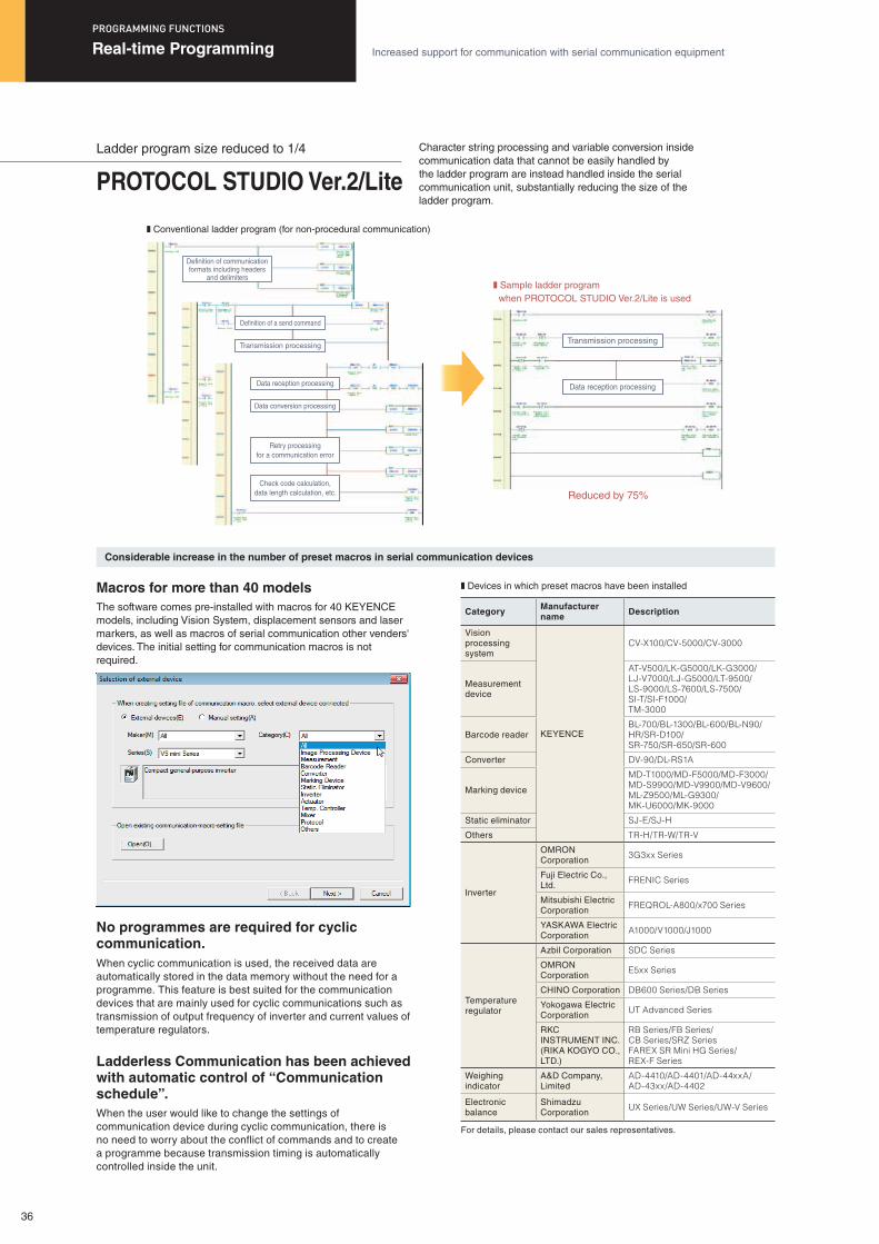
Definition of communication formats including headers
and delimiters
Definition of a send command
Transmission processing
Data reception processing
Transmission processing
Data reception processing
Data conversion processing
Retry processingfor a communication error
Check code calculation,data length calculation, etc.
Category Manufacturer name Description
Vision processing system
KEYENCE
CV-X100/CV-5000/CV-3000
Measurement device
AT-V500/LK-G5000/LK-G3000/ LJ-V7000/LJ-G5000/LT-9500/LS-9000/LS-7600/LS-7500/ SI-T/SI-F1000/TM-3000
Barcode readerBL-700/BL-1300/BL-600/BL-N90/HR/SR-D100/SR-750/SR-650/SR-600
Converter DV-90/DL-RS1A
Marking device
MD-T1000/MD-F5000/MD-F3000/MD-S9900/MD-V9900/MD-V9600/ML-Z9500/ML-G9300/MK-U6000/MK-9000
Static eliminator SJ-E/SJ-H
Others TR-H/TR-W/TR-V
Inverter
OMRON Corporation
3G3xx Series
Fuji Electric Co., Ltd.
FRENIC Series
Mitsubishi Electric Corporation
FREQROL-A800/x700 Series
YASKAWA Electric Corporation
A1000/V1000/J1000
Temperature regulator
Azbil Corporation SDC Series
OMRON Corporation
E5xx Series
CHINO Corporation DB600 Series/DB Series
Yokogawa Electric Corporation
UT Advanced Series
RKC INSTRUMENT INC. (RIKA KOGYO CO., LTD.)
RB Series/FB Series/ CB Series/SRZ SeriesFAREX SR Mini HG Series/ REX-F Series
Weighing indicator
A&D Company, Limited
AD-4410/AD-4401/AD-44xxA/ AD-43xx/AD-4402
Electronic balance
Shimadzu Corporation
UX Series/UW Series/UW-V Series
For details, please contact our sales representatives.
Ladder program size reduced to 1/4
PROTOCOL STUDIO Ver.2/Lite
Real-time Programming Increased support for communication with serial communication equipment
PROGRAMMING FUNCTIONS
Character string processing and variable conversion inside communication data that cannot be easily handled by the ladder program are instead handled inside the serial communication unit, substantially reducing the size of the ladder program.
The software comes pre-installed with macros for 40 KEYENCE models, including Vision System, displacement sensors and laser markers, as well as macros of serial communication other venders' devices. The initial setting for communication macros is not required.
When cyclic communication is used, the received data are automatically stored in the data memory without the need for a programme. This feature is best suited for the communication devices that are mainly used for cyclic communications such as transmission of output frequency of inverter and current values of temperature regulators.
No programmes are required for cyclic communication.
Macros for more than 40 models
When the user would like to change the settings of communication device during cyclic communication, there is no need to worry about the conflict of commands and to create a programme because transmission timing is automatically controlled inside the unit.
Ladderless Communication has been achieved with automatic control of “Communication schedule”.
Considerable increase in the number of preset macros in serial communication devices
❚ Conventional ladder program (for non-procedural communication)
❚ Sample ladder program when PROTOCOL STUDIO Ver.2/Lite is used
❚ Devices in which preset macros have been installed
Reduced by 75%
36
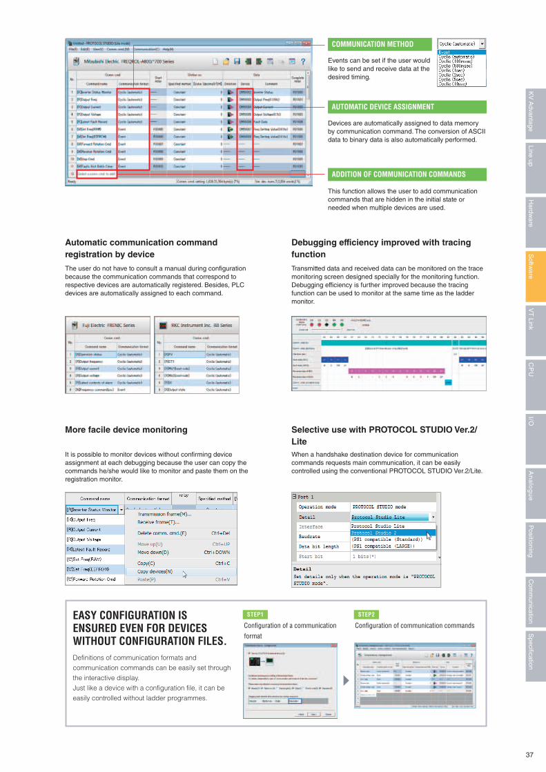
Transmitted data and received data can be monitored on the trace monitoring screen designed specially for the monitoring function. Debugging efficiency is further improved because the tracing function can be used to monitor at the same time as the ladder monitor.
EASY CONFIGURATION IS ENSURED EVEN FOR DEVICES WITHOUT CONFIGURATION FILES. Definitions of communication formats and communication commands can be easily set through the interactive display. Just like a device with a configuration file, it can be easily controlled without ladder programmes.
Configuration of a communication format
STEP1 STEP2
Configuration of communication commands
When a handshake destination device for communication commands requests main communication, it can be easily controlled using the conventional PROTOCOL STUDIO Ver.2/Lite.
Selective use with PROTOCOL STUDIO Ver.2/Lite
Debugging efficiency improved with tracing function
Devices are automatically assigned to data memory by communication command. The conversion of ASCII data to binary data is also automatically performed.
AUTOMATIC DEVICE ASSIGNMENT
This function allows the user to add communication commands that are hidden in the initial state or needed when multiple devices are used.
ADDITION OF COMMUNICATION COMMANDS
Events can be set if the user would like to send and receive data at the desired timing.
COMMUNICATION METHOD
It is possible to monitor devices without confirming device assignment at each debugging because the user can copy the commands he/she would like to monitor and paste them on the registration monitor.
More facile device monitoring
Automatic communication command registration by device
The user do not have to consult a manual during configuration because the communication commands that correspond to respective devices are automatically registered. Besides, PLC devices are automatically assigned to each command.
37
Specification
Com
munication
Positioning
An
alo
gu
eI/O
CP
UV
T Link
Softw
areLine up
Hardw
areK
V A
dvantage
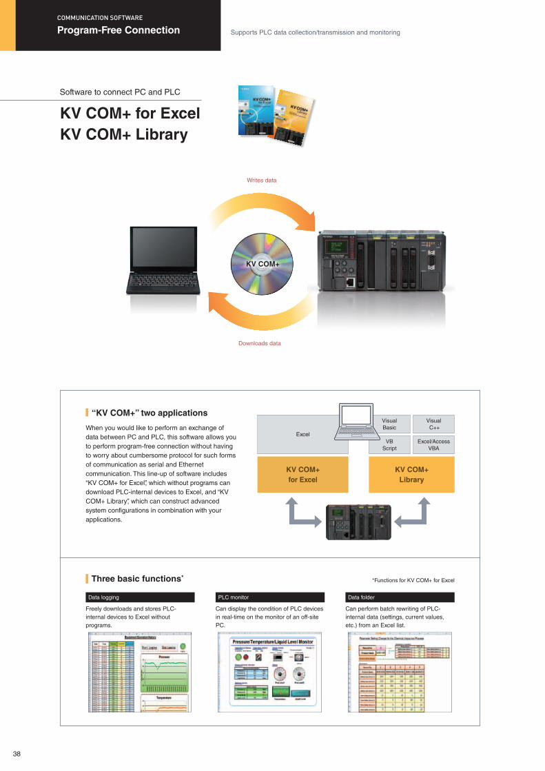
Software to connect PC and PLC
KV COM+ for ExcelKV COM+ Library
When you would like to perform an exchange of data between PC and PLC, this software allows you to perform program-free connection without having to worry about cumbersome protocol for such forms of communication as serial and Ethernet communication. This line-up of software includes “KV COM+ for Excel”, which without programs can download PLC-internal devices to Excel, and “KV COM+ Library”, which can construct advanced system configurations in combination with your applications.
“KV COM+” two applications
Writes data
KV COM+
Downloads data
KV COM+for Excel
KV COM+Library
VisualBasic
Excel
Visual C++
VBScript
Excel/Access VBA
Three basic functions*
Data logging
Freely downloads and stores PLC-internal devices to Excel without programs.
*Functions for KV COM+ for Excel
PLC monitor
Can display the condition of PLC devices in real-time on the monitor of an off-site PC.
Data folder
Can perform batch rewriting of PLC-internal data (settings, current values, etc.) from an Excel list.
Program-Free Connection Supports PLC data collection/transmission and monitoring
COMMUNICATION SOFTWARE
38
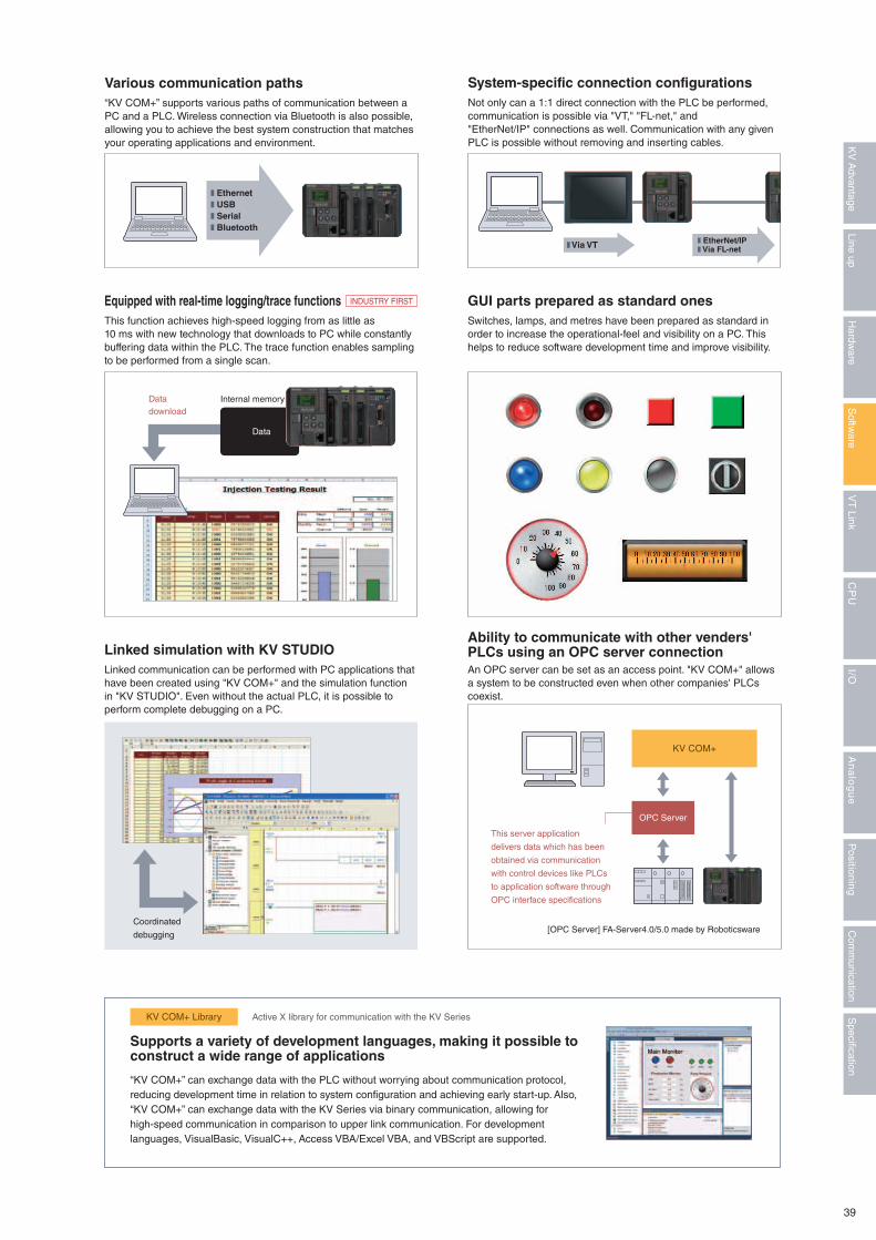
Data
“KV COM+” supports various paths of communication between a PC and a PLC. Wireless connection via Bluetooth is also possible, allowing you to achieve the best system construction that matches your operating applications and environment.
Not only can a 1:1 direct connection with the PLC be performed, communication is possible via "VT," "FL-net," and "EtherNet/IP" connections as well. Communication with any given PLC is possible without removing and inserting cables.
Various communication paths System-specific connection configurations
This function achieves high-speed logging from as little as 10 ms with new technology that downloads to PC while constantly buffering data within the PLC. The trace function enables sampling to be performed from a single scan.
Linked communication can be performed with PC applications that have been created using "KV COM+" and the simulation function in "KV STUDIO". Even without the actual PLC, it is possible to perform complete debugging on a PC.
Switches, lamps, and metres have been prepared as standard in order to increase the operational-feel and visibility on a PC. This helps to reduce software development time and improve visibility.
An OPC server can be set as an access point. "KV COM+" allows a system to be constructed even when other companies' PLCs coexist.
Equipped with real-time logging/trace functions
Linked simulation with KV STUDIO
Supports a variety of development languages, making it possible to construct a wide range of applications
GUI parts prepared as standard ones
Ability to communicate with other venders' PLCs using an OPC server connection
Coordinated
debugging
Datadownload
KV COM+
OPC Server
[OPC Server] FA-Server4.0/5.0 made by Roboticsware
This server application
delivers data which has been
obtained via communication
with control devices like PLCs
to application software through
OPC interface specifications
❚ Ethernet❚ USB❚ Serial❚ Bluetooth
“KV COM+” can exchange data with the PLC without worrying about communication protocol, reducing development time in relation to system configuration and achieving early start-up. Also, “KV COM+” can exchange data with the KV Series via binary communication, allowing for high-speed communication in comparison to upper link communication. For development languages, VisualBasic, VisualC++, Access VBA/Excel VBA, and VBScript are supported.
KV COM+ Library Active X library for communication with the KV Series
❚ Via VT ❚ EtherNet/IP❚ Via FL-net
INDUSTRY FIRST
Internal memory
39
Specification
Com
munication
Positioning
An
alo
gu
eI/O
CP
UV
T Link
Softw
areLine up
Hardw
areK
V A
dvantage
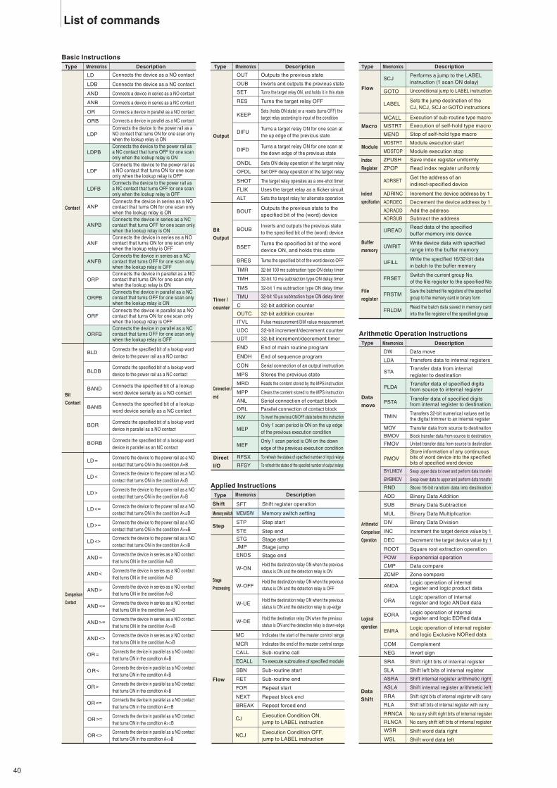
Data
Shift
SLA
RRA
SRA
RLA
Shift right bits of internal register
Shift left bits of internal register
ASLA
ASRA Shift internal register arithmetic right
Shift internal register arithmetic left
Shift right bits of internal register with carry
Shift left bits of internal register with carry
RRNCA No carry shift right bits of internal register
RLNCA No carry shift left bits of internal register
WSR
WSL
Shift word data right
Shift word data left
CALL Sub-routine call
SBN Sub-routine start
RET Sub-routine end
FOR Repeat start
NEXT Repeat block end
BREAK Repeat forced end
ECALL To execute subroutine of specified module
LD
LDB
AND
ANB
OR
ORB
LDP
LDPB
LDF
LDFB
ANP
ANPB
BLD
BLDB
BAND
BANB
BOR
BORB
LD =
LD<
LD>
LD<=
LD>=
LD<>
AND =
AND<
AND>
AND<=
AND>=
AND<>
OR =
O R<
OR >
OR<=
Contact
Bit
Contact
Comparison
Contact
Connects the device as a NO contact
Connects the device as a NC contact
Connects a device in series as a NO contact
Connects a device in series as a NC contact
Connects a device in parallel as a NO contact
Connects a device in parallel as a NC contactConnects the device to the power rail as a NO contact that turns ON for one scan only when the lookup relay is ONConnects the device to the power rail as a NC contact that turns OFF for one scan only when the lookup relay is ONConnects the device to the power rail as a NO contact that turns ON for one scan only when the lookup relay is OFFConnects the device to the power rail as a NC contact that turns OFF for one scan only when the lookup relay is OFFConnects the device in series as a NO contact that turns ON for one scan only when the lookup relay is ONConnects the device in series as a NC contact that turns OFF for one scan only when the lookup relay is ON
ANFConnects the device in series as a NO contact that turns ON for one scan only when the lookup relay is OFF
ANFBConnects the device in series as a NC contact that turns OFF for one scan only when the lookup relay is OFF
ORPConnects the device in parallel as a NO contact that turns ON for one scan only when the lookup relay is ON
ORPBConnects the device in parallel as a NC contact that turns OFF for one scan only when the lookup relay is ON
ORFConnects the device in parallel as a NO contact that turns ON for one scan only when the lookup relay is OFF
ORFBConnects the device in parallel as a NC contact that turns OFF for one scan only when the lookup relay is OFF
Connects the specified bit of a lookup word device to the power rail as a NO contact
Connects the specified bit of a lookup word device to the power rail as a NC contact
Connects the specified bit of a lookup word device serially as a NO contact
Connects the specified bit of a lookup word device serially as a NC contact
Connects the specified bit of a lookup word device in parallel as a NO contact
Connects the specified bit of a lookup word device in parallel as an NC contact
Connects the device to the power rail as a NOcontact that turns ON in the condition A=B
Connects the device to the power rail as a NOcontact that turns ON in the condition A<B
Connects the device to the power rail as a NOcontact that turns ON in the condition A>B
Connects the device to the power rail as a NOcontact that turns ON in the condition A<=B
Connects the device to the power rail as a NOcontact that turns ON in the condition A>=B
Connects the device to the power rail as a NOcontact that turns ON in the condition A<>B
Connects the device in series as a NO contactthat turns ON in the condition A=B
Connects the device in series as a NO contact that turns ON in the condition A<B
Connects the device in series as a NO contact that turns ON in the condition A>B
Connects the device in series as a NO contact that turns ON in the condition A<=B
Connects the device in series as a NO contact that turns ON in the condition A>=B
Connects the device in series as a NO contact that turns ON in the condition A<>B
Connects the device in parallel as a NO contact that turns ON in the condition A=B
Connects the device in parallel as a NO contact that turns ON in the condition A<B
Connects the device in parallel as a NO contact that turns ON in the condition A>B
Connects the device in parallel as a NO contact that turns ON in the condition A<=B
Type
Applied Instructions
Basic Instructions
Arithmetic Operation Instructions
Mnemonics Description
OR >=
OR<>
END
CON
MRD
ANL
ENDH
MPS
MPP
ORL
OUB
RES
OUT
SET
KEEP
DIFU
DIFD
OFDL
SHOT
ONDL
FLIK
ALT
BOUT
BOUB
BSET
BRES
Output
Bit
Output
Timer /
counter
Connection /
end
Direct
I/O
Outputs the previous state
Inverts and outputs the previous state
Turns the target relay ON, and holds it in this state
Turns the target relay OFF
Sets ON delay operation of the target relay
Set OFF delay operation of the target relay
The target relay operates as a one-shot timer
Uses the target relay as a flicker circuit
TMH
TMS
TMR
C
32-bit 100 ms subtraction type ON delay timer
32-bit 10 ms subtraction type ON delay timer
32-bit 1 ms subtraction type ON delay timer
TMU 32-bit 10 μs subtraction type ON delay timer
32-bit addition counter
OUTC 32-bit addition counter
ITVL
UDC
Pulse measurement/DM value measurement
32-bit increment/decrement counter
UDT 32-bit increment/decrement timer
End of main routine program
End of sequence program
Serial connection of an output instruction
Stores the previous state
Reads the content stored by the MPS instruction
Clears the content stored to the MPS instruction
Serial connection of contact block
Parallel connection of contact block
INV To invert the previous ON/OFF state before this instruction
MEPOnly 1 scan period is ON on the up edge of the previous execution condition
MEFOnly 1 scan period is ON on the down edge of the previous execution condition
RFSX To refresh the states of specified number of input relays
RFSY To refresh the states of the specifed number of output relays
Sets the target relay for alternate operation
Sets (holds ON state) or a resets (turns OFF) thetarget relay according to input of the condition
Turns a target relay ON for one scan at the up edge of the previous state
Turns a target relay ON for one scan at the down edge of the previous state
Outputs the previous state to the specified bit of the (word) device
Inverts and outputs the previous state to the specified bit of the (word) device
Turns the specified bit of the word device ON, and holds this state
Hold the destination relay ON when the previousstatus is ON and the detection relay is ON
Hold the destination relay ON when the previousstatus is ON and the detection relay is OFF
Hold the destination relay ON when the previousstatus is ON and the detection relay is up-edge
Hold the destination relay ON when the previousstatus is ON and the detection relay is down-edge
Turns the specified bit of the word device OFF
Connects the device in parallel as a NO contact that turns ON in the condition A>=B
Connects the device in parallel as a NO contact that turns ON in the condition A<>B
Mnemonics
DW
LDA
STA
PLDA
DEC
ROOT
INC
CMP
ZCMP
ANDA
ORA
EORA
COM
Arithmetic/
Comparison
Operation
Data
move
Logical
operation
Data move
ADD
SUB
Binary Data Addition
Binary Data Subtraction
MUL
DIV
Binary Data Multiplication
Binary Data Division
Increment the target device value by 1
Decrement the target device value by 1
Square root extraction operation
POW Exponential operation
Data compare
Zone compare
Complement
NEG Invert sign
Logic operation of internal register and logic product data
Logic operation of internal register and logic ANDed data
Logic operation of internal register and logic EORed data
ENRALogic operation of internal register and logic Exclusive NORed data
BSR Shift the content of the device to the right towards the larger device No.
BSL Shift the content of the device to the left towards the smaller device No.
Transfers data to internal registers
Transfer data from internal register to destination
MOV Transfer data from source to destination
BMOV Block transfer data from source to destination
FMOV United transfer data from source to destination
PMOVStore information of any continuous bits of word device into the specified bits of specified word device
Transfer data of specified digits from source to internal register
PSTATransfer data of specified digits from internal register to destination
TMINTransfers 32-bit numerical values set by the digital trimmer to an internal register
Mnemonics
Flow
Macro
Indirect
specification
Module
Index
Register
Mnemonics
Mnemonics
STP
STE
W-ON
W-OFF
W-UE
W-DE
Shift SFT Shift register operation
Memory switch
Step
Stage
Processing
Flow
MEMSW Memory switch setting
Step start
Step end
JMP
ENDS
Stage jump
STG Stage start
Stage end
MC Indicates the start of the master control range
MCR Indicates the end of the master control range
CJExecution Condition ON, jump to LABEL instruction
NCJ
GOTO
LABEL
MCALL
MSTRT
MEND
MDSTRT
MDSTOP
ZPUSH
ZPOP
ADRSET
ADRINC
ADRDEC
ADRADD
ADRSUB
Execution Condition OFF, jump to LABEL instruction
SCJPerforms a jump to the LABEL instruction (1 scan ON delay)
Unconditional jump to LABEL instruction
Sets the jump destination of the CJ, NCJ, SCJ or GOTO instructions
Execution of sub-routine type macro
Execution of self-hold type macro
Stop of self-hold type macro
Module execution start
Module execution stop
Save index register uniformly
Read index register uniformly
Get the address of an indirect-specified device
Increment the device address by 1
Decrement the device address by 1
Add the address
Subtract the address
UREADRead data of the specified buffer memory into device
UWRITWrite device data with specified range into the buffer memory
UFILLWrite the specified 16/32-bit data in batch to the buffer memory
FRSETSwitch the current group No. of the file register to the specified No
FRSTMSave the batched file registers of the specified group to the memory card in binary form
FRLDMRead the batch data saved in memory card into the file register of the specified group
Description Description
Description
Description
Type Type
Type
Type
Extended InstructionsHKEY
DCNT
BCNT
SER
MAX
MIN
AVG
WSUM
BSUM
CRC
WTIME
SEC
RSEC
AJST
LDWK
Hex key data input
SEG Decode for 7-segment display
Count number of ON bits in internal register
Count number of data of same value as internal register in data block
Detect device No. of data of same value as internal registers in a data block
Search minimum value in data block
Search maximum value in data block
Calculate average value in data block
Total binary data in specified range
Total of binary data (8 bits) in specified range => internal register
Calculate CRC value
Reset zone
Write the time data to the calendar timer
Convert date/time format data to second format data
Convert second format data to date/time format data
Adjust the calendar timer by ±30 seconds
Connect ON/OFF of specified week/hour/minute/ second ranges with power rail as NO contacts
LDWKB
ANDWK
ANDWKB
Connect ON/OFF of specified week/hour/minute/ second ranges with power rail as NC contacts
Connect ON/OFF of specified week/hour/minute/ second ranges as NO contacts in series
Connect ON/OFF of specified week/hour/minute/ second ranges as NC contacts in series
ORWKConnect ON/OFF of specified week/hour/minute/ second ranges as NO contacts in parallel
Mnemonics
ZRES
Compare binary data in two specified rangesBCMP
Compare binary data in specified range with specified binary dataBCMPI
Search the position of the device for storing data consistent with the specified data
DSER
FIFOW
FIFOR
EXT
Write FIFO data
Read FIFO data
LIFOW
LIFOR
FWRIT
FINS
FDEL
Write LIFO data
SORT Arrange binary data
SORTN Split and arrange binary data
Overwrite data block of data table
Insert data in data block
Delete data in data block
Read LIFO data
Extend 16-bit internal register => 32-bit internal register
Data
Processing
Table
Processing
Clock
Processing
Week
contact
Calendar
Contact
ORWKB
LDCAL
LDCALB
Connect ON/OFF of specified week/hour/minute/ second ranges as NC contacts in parallel
Connect ON/OFF of specified year/month/day ranges with power rail as NO contacts
Connect ON/OFF of specified year/month/day ranges with power rail as NC contacts
ANDCAL
ANDCALB
ORCALB
Connect ON/OFF of specified year/month/day ranges as NO contacts in series
Connect ON/OFF of specified year/month/day ranges as NC contacts in series
ORCALConnect ON/OFF of specified year/month/day ranges as NO contacts in parallel
Connect ON/OFF of specified year/month/day ranges as NC contacts in parallel
TAN
ASIN
ACOS
ATAN
ASC
RASC
DASC
RDASC
HASC
RHASC
FASC
RFASC
SMOV
SADD
SCMP
DISS
Calculates the tangent (tan) value from the angle (rad)
Calculates the angle (rad) from the sine (sin) value
Calculates the angle (rad) from the cosine (cos) value
Calculates the angle (rad) from the tangent (tan) value
Convert binary to HEX ASCII code
Convert HEX ASCII code to binary
Convert binary to decimal ASCII code
Convert decimal ASCII code to binary
Convert 16/32-bit unsigned binary to Hex ASCII
Convert Hex ASCII to 16/32-bit unsigned binary
Convert floating real number to text string
Convert text string to floating real number
Move text string
Add text string
SRGHTCut a specified number of characters from the right end of a text string
SLEFT Cut a specified number of characters from the left end of a text string
SMID Cut part of a text string
SRPLCReplace part of a text string with a specified text string
SINS Insert a text string to be specified
SDEL Delete a text string to be specified
SFIND Searche a specified text string from a text string
Compare text string
Disperse text string (byte units) into text strings (word units)
UNIS
LEN
RCOM
Unite text string (word units) into text strings (byte units)
Detect text string length
Read text string
STRIM
SFINDN
Delete end of character string
Search character strings
RCPSASC
CPSASC Convert CIP character string data
Perform reverse conversion of CIP character string data
CAL+ Operand3 Binary data addition operation
CAL- Operand3 Binary data subtraction operation
CAL* Operand3 Binary data multiplication operation
CAL/ Operand3 Binary data division operation
CAL& Operand3 Logical AND operation
CAL| Operand3 Logical OR operation
CAL^ Operand3 Exclusive OR operation
CAL~ Operand2 Bit Inversion
CAL>> Operand2 Shift right
CAL<< Operand2 Shift left
Text
Processing
Description
HSP
DI
EI
Set input time constant to 10 μs
Disable interrupt
Enable interrupt
DIC Set interrupt disabled range
INT Execute interrupt
Mnemonics
High-speed
processing
Positioning
Cam
Switch
Frequency
counter
PID
Log
Memory
card
Access
Window
RETI
CTH
CTC
End interrupt
32-bit high-speed counter
32-bit high-speed counter comparator
PLSX
PLSY
JOGX
ORGX
ORGY
TCHX
TCHY
JOGY
X-axis positioning start
Y-axis positioning start
X-axis inching operation
Y-axis inching operation
Zero return on X-axis
Zero return on Y-axis
Teaching X-axis
MPRINT
MREADL
MCOPY
MMOV
MREN
Write character strings to a file on a memory card
Read a single line from a file on a memory card
Copy a file on a memory card
Move a file on a memory card
Change the name of a file on a memory card
Obtain amount of free space on a memory card in kilobytes
Obtain status of a file on a memory card
Teaching Y-axis
ARES Clean alarm relay / alarm historyAlarm
RFSCTHUpdate the current value of high-speed counter CTH as the latest value
HOMEX
HOMEY
MCMP
RFSPSX
X-axis home movement start
Y-axis home movement start
CHGSPY Change the speed on the Y-axis
CHGSPX Change the speed on the X-axis
SPRD Sensor parameter read
SPWR
SSVC
Sensor parameter write
Sensor service execute
RFSCO Cyclic communication output refresh
RFSCI Cyclic communication input refresh
Update current value and current speed of X-axis to the newest value
RFSPSYUpdate current value and current speed of Y-axis to the newest value
Multi-stage comparator operation
Measurement of pulse input frequency using CTH0
Measurement of the speed of rotation of pulse input using CTH0
The pulse of the frequency specified by CTH1 is output
PID Control
Enable the log with the specified log ID
Disable the log with the specified log ID
ABSENCCam switch operation by an absolute encoder
INCENC
FCNT
RCNT
PID
Control PID instructions with auto-tuningPIDAT
LOGE
LOGD
Capture the data log with the specified log IDTRGD
Write device data to memory cardMWRIT
Read device data from memory cardMREAD
Get the free space on the memory cardMFREE
Make a directory on the memory cardMMKDIR
Delete the specified folder in the memory card
MRMDIR
Delete specified files in memory cardMDEL
Display user message 1 on the access window (value)
AWNUM
Display user message 2 on the access window (text string)
AWMSG
Update the current value of free operation counter as the latest value
RFSFRC
PLSOUT
Cam switch operation by an incremental encoder
Description
TBCD
MPX
GRY
DISN
TBIN
DMX
RGRY
INTG
DISF
EXP
LOG
LOG10
DEG
SIN
COS
UNIF
Data
conversion
Convert binary to BCD
APR Linear approximation
ZONE Zone control
BANDC Dead band control
LIMIT Upper and lower limit control
LLFLT Output input through the lag filter
TPOUT Perform pulse output at a specific ON cycle and time
RAMP Output input value variation in a specified gradient
Convert BCD to binary
Encode 4-bit number to 16-bit
Encode 16-bit number to 4-bit
Convert binary to gray code
Convert gray code to binary
Floating
Point
Disperse word (16-bit) into nibble units (4-bit)
UNIN
UNIB
Unite the nibble (4-bit) to word (16-bit)
DISB Disperse word (16-bit) into byte (4-bit)
SWAP
Unite the byte (8-bit) to word (16-bit)
Mnemonics
XCH
DECO
ENCO
Swap the upper and lower data
BSWAP Switch block units for upper and lower data
Exchange
Decode the numbers of the lower n bits of the internal register to 2n bit binary data
Encode the “1” (ON) positions of specified continuous n number of bit devices to an 8-bit numerical value
FLOAT Convert binary to floating real number
Convert floating real number to binary
Disperse mantissa/exponent of floating real number
Unite mantissa and exponent to floating real number
ABS
CPMSET
CPMGET
Absolute value
Create CIP message
Obtain CIP message
DINTG
DFTOF
FTODF
Convert double-precision floating point real numbers to binary
DFLOAT Convert binary to double-precision floating point real numbers
Convert double-precision floating point real numbers to single-precision floating point real numbers
Convert single-precision floating point real numbersto double-precision floating point real numbers
Exponent operation
Natural logarithm operation
Common logarithm operation
RAD Converts degree (°) to radians (rad)
Converts radians (rad) to degree (°)
Calculates the sine (sin) value from the angle (rad)
Calculates the cosine (cos) value from the angle (rad)
DescriptionType Type Type
Buffer
memory
File
register
RND Store 16-bit random data into destination
BYBMOV Swap lower data to upper and perform data transfer
BYLMOV Swap upper data to lower and perform data transfer
Data
Shift
Data
Control
Text
Processing
Simple
operation
Calendar
Contact
Free operation Counter
Sensor setting command
Cyclic communicationRefresh command
Only instructions available for KV-5500/5000/3000/1000.
Only instructions available for KV-1000/700.
Only instructions available for KV-5500/5000/3000.
Instructions available for KV-5500/5000/3000 functions Ver.2.0 or later.
MSTAT
MFREEK
List of commands
40
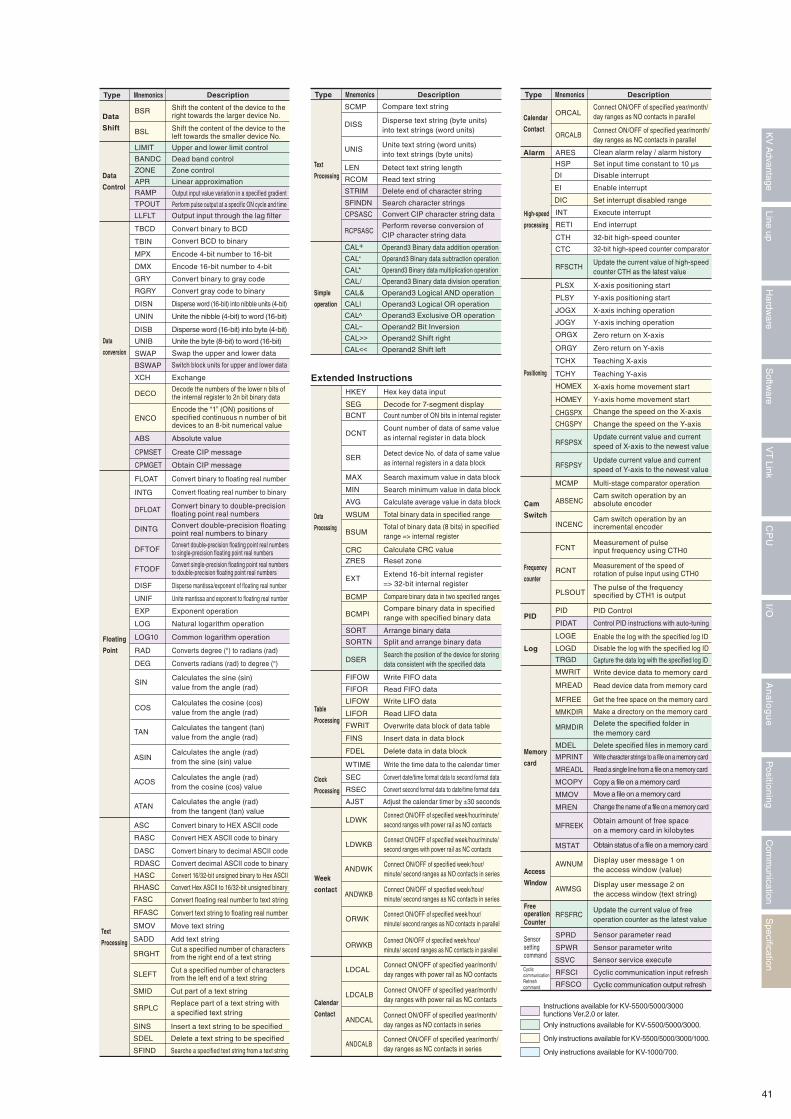
Data
Shift
SLA
RRA
SRA
RLA
Shift right bits of internal register
Shift left bits of internal register
ASLA
ASRA Shift internal register arithmetic right
Shift internal register arithmetic left
Shift right bits of internal register with carry
Shift left bits of internal register with carry
RRNCA No carry shift right bits of internal register
RLNCA No carry shift left bits of internal register
WSR
WSL
Shift word data right
Shift word data left
CALL Sub-routine call
SBN Sub-routine start
RET Sub-routine end
FOR Repeat start
NEXT Repeat block end
BREAK Repeat forced end
ECALL To execute subroutine of specified module
LD
LDB
AND
ANB
OR
ORB
LDP
LDPB
LDF
LDFB
ANP
ANPB
BLD
BLDB
BAND
BANB
BOR
BORB
LD =
LD<
LD>
LD<=
LD>=
LD<>
AND =
AND<
AND>
AND<=
AND>=
AND<>
OR =
O R<
OR >
OR<=
Contact
Bit
Contact
Comparison
Contact
Connects the device as a NO contact
Connects the device as a NC contact
Connects a device in series as a NO contact
Connects a device in series as a NC contact
Connects a device in parallel as a NO contact
Connects a device in parallel as a NC contactConnects the device to the power rail as a NO contact that turns ON for one scan only when the lookup relay is ONConnects the device to the power rail as a NC contact that turns OFF for one scan only when the lookup relay is ONConnects the device to the power rail as a NO contact that turns ON for one scan only when the lookup relay is OFFConnects the device to the power rail as a NC contact that turns OFF for one scan only when the lookup relay is OFFConnects the device in series as a NO contact that turns ON for one scan only when the lookup relay is ONConnects the device in series as a NC contact that turns OFF for one scan only when the lookup relay is ON
ANFConnects the device in series as a NO contact that turns ON for one scan only when the lookup relay is OFF
ANFBConnects the device in series as a NC contact that turns OFF for one scan only when the lookup relay is OFF
ORPConnects the device in parallel as a NO contact that turns ON for one scan only when the lookup relay is ON
ORPBConnects the device in parallel as a NC contact that turns OFF for one scan only when the lookup relay is ON
ORFConnects the device in parallel as a NO contact that turns ON for one scan only when the lookup relay is OFF
ORFBConnects the device in parallel as a NC contact that turns OFF for one scan only when the lookup relay is OFF
Connects the specified bit of a lookup word device to the power rail as a NO contact
Connects the specified bit of a lookup word device to the power rail as a NC contact
Connects the specified bit of a lookup word device serially as a NO contact
Connects the specified bit of a lookup word device serially as a NC contact
Connects the specified bit of a lookup word device in parallel as a NO contact
Connects the specified bit of a lookup word device in parallel as an NC contact
Connects the device to the power rail as a NOcontact that turns ON in the condition A=B
Connects the device to the power rail as a NOcontact that turns ON in the condition A<B
Connects the device to the power rail as a NOcontact that turns ON in the condition A>B
Connects the device to the power rail as a NOcontact that turns ON in the condition A<=B
Connects the device to the power rail as a NOcontact that turns ON in the condition A>=B
Connects the device to the power rail as a NOcontact that turns ON in the condition A<>B
Connects the device in series as a NO contactthat turns ON in the condition A=B
Connects the device in series as a NO contact that turns ON in the condition A<B
Connects the device in series as a NO contact that turns ON in the condition A>B
Connects the device in series as a NO contact that turns ON in the condition A<=B
Connects the device in series as a NO contact that turns ON in the condition A>=B
Connects the device in series as a NO contact that turns ON in the condition A<>B
Connects the device in parallel as a NO contact that turns ON in the condition A=B
Connects the device in parallel as a NO contact that turns ON in the condition A<B
Connects the device in parallel as a NO contact that turns ON in the condition A>B
Connects the device in parallel as a NO contact that turns ON in the condition A<=B
Type
Applied Instructions
Basic Instructions
Arithmetic Operation Instructions
Mnemonics Description
OR >=
OR<>
END
CON
MRD
ANL
ENDH
MPS
MPP
ORL
OUB
RES
OUT
SET
KEEP
DIFU
DIFD
OFDL
SHOT
ONDL
FLIK
ALT
BOUT
BOUB
BSET
BRES
Output
Bit
Output
Timer /
counter
Connection /
end
Direct
I/O
Outputs the previous state
Inverts and outputs the previous state
Turns the target relay ON, and holds it in this state
Turns the target relay OFF
Sets ON delay operation of the target relay
Set OFF delay operation of the target relay
The target relay operates as a one-shot timer
Uses the target relay as a flicker circuit
TMH
TMS
TMR
C
32-bit 100 ms subtraction type ON delay timer
32-bit 10 ms subtraction type ON delay timer
32-bit 1 ms subtraction type ON delay timer
TMU 32-bit 10 μs subtraction type ON delay timer
32-bit addition counter
OUTC 32-bit addition counter
ITVL
UDC
Pulse measurement/DM value measurement
32-bit increment/decrement counter
UDT 32-bit increment/decrement timer
End of main routine program
End of sequence program
Serial connection of an output instruction
Stores the previous state
Reads the content stored by the MPS instruction
Clears the content stored to the MPS instruction
Serial connection of contact block
Parallel connection of contact block
INV To invert the previous ON/OFF state before this instruction
MEPOnly 1 scan period is ON on the up edge of the previous execution condition
MEFOnly 1 scan period is ON on the down edge of the previous execution condition
RFSX To refresh the states of specified number of input relays
RFSY To refresh the states of the specifed number of output relays
Sets the target relay for alternate operation
Sets (holds ON state) or a resets (turns OFF) thetarget relay according to input of the condition
Turns a target relay ON for one scan at the up edge of the previous state
Turns a target relay ON for one scan at the down edge of the previous state
Outputs the previous state to the specified bit of the (word) device
Inverts and outputs the previous state to the specified bit of the (word) device
Turns the specified bit of the word device ON, and holds this state
Hold the destination relay ON when the previousstatus is ON and the detection relay is ON
Hold the destination relay ON when the previousstatus is ON and the detection relay is OFF
Hold the destination relay ON when the previousstatus is ON and the detection relay is up-edge
Hold the destination relay ON when the previousstatus is ON and the detection relay is down-edge
Turns the specified bit of the word device OFF
Connects the device in parallel as a NO contact that turns ON in the condition A>=B
Connects the device in parallel as a NO contact that turns ON in the condition A<>B
Mnemonics
DW
LDA
STA
PLDA
DEC
ROOT
INC
CMP
ZCMP
ANDA
ORA
EORA
COM
Arithmetic/
Comparison
Operation
Data
move
Logical
operation
Data move
ADD
SUB
Binary Data Addition
Binary Data Subtraction
MUL
DIV
Binary Data Multiplication
Binary Data Division
Increment the target device value by 1
Decrement the target device value by 1
Square root extraction operation
POW Exponential operation
Data compare
Zone compare
Complement
NEG Invert sign
Logic operation of internal register and logic product data
Logic operation of internal register and logic ANDed data
Logic operation of internal register and logic EORed data
ENRALogic operation of internal register and logic Exclusive NORed data
BSR Shift the content of the device to the right towards the larger device No.
BSL Shift the content of the device to the left towards the smaller device No.
Transfers data to internal registers
Transfer data from internal register to destination
MOV Transfer data from source to destination
BMOV Block transfer data from source to destination
FMOV United transfer data from source to destination
PMOVStore information of any continuous bits of word device into the specified bits of specified word device
Transfer data of specified digits from source to internal register
PSTATransfer data of specified digits from internal register to destination
TMINTransfers 32-bit numerical values set by the digital trimmer to an internal register
Mnemonics
Flow
Macro
Indirect
specification
Module
Index
Register
Mnemonics
Mnemonics
STP
STE
W-ON
W-OFF
W-UE
W-DE
Shift SFT Shift register operation
Memory switch
Step
Stage
Processing
Flow
MEMSW Memory switch setting
Step start
Step end
JMP
ENDS
Stage jump
STG Stage start
Stage end
MC Indicates the start of the master control range
MCR Indicates the end of the master control range
CJExecution Condition ON, jump to LABEL instruction
NCJ
GOTO
LABEL
MCALL
MSTRT
MEND
MDSTRT
MDSTOP
ZPUSH
ZPOP
ADRSET
ADRINC
ADRDEC
ADRADD
ADRSUB
Execution Condition OFF, jump to LABEL instruction
SCJPerforms a jump to the LABEL instruction (1 scan ON delay)
Unconditional jump to LABEL instruction
Sets the jump destination of the CJ, NCJ, SCJ or GOTO instructions
Execution of sub-routine type macro
Execution of self-hold type macro
Stop of self-hold type macro
Module execution start
Module execution stop
Save index register uniformly
Read index register uniformly
Get the address of an indirect-specified device
Increment the device address by 1
Decrement the device address by 1
Add the address
Subtract the address
UREADRead data of the specified buffer memory into device
UWRITWrite device data with specified range into the buffer memory
UFILLWrite the specified 16/32-bit data in batch to the buffer memory
FRSETSwitch the current group No. of the file register to the specified No
FRSTMSave the batched file registers of the specified group to the memory card in binary form
FRLDMRead the batch data saved in memory card into the file register of the specified group
Description Description
Description
Description
Type Type
Type
Type
Extended InstructionsHKEY
DCNT
BCNT
SER
MAX
MIN
AVG
WSUM
BSUM
CRC
WTIME
SEC
RSEC
AJST
LDWK
Hex key data input
SEG Decode for 7-segment display
Count number of ON bits in internal register
Count number of data of same value as internal register in data block
Detect device No. of data of same value as internal registers in a data block
Search minimum value in data block
Search maximum value in data block
Calculate average value in data block
Total binary data in specified range
Total of binary data (8 bits) in specified range => internal register
Calculate CRC value
Reset zone
Write the time data to the calendar timer
Convert date/time format data to second format data
Convert second format data to date/time format data
Adjust the calendar timer by ±30 seconds
Connect ON/OFF of specified week/hour/minute/ second ranges with power rail as NO contacts
LDWKB
ANDWK
ANDWKB
Connect ON/OFF of specified week/hour/minute/ second ranges with power rail as NC contacts
Connect ON/OFF of specified week/hour/minute/ second ranges as NO contacts in series
Connect ON/OFF of specified week/hour/minute/ second ranges as NC contacts in series
ORWKConnect ON/OFF of specified week/hour/minute/ second ranges as NO contacts in parallel
Mnemonics
ZRES
Compare binary data in two specified rangesBCMP
Compare binary data in specified range with specified binary dataBCMPI
Search the position of the device for storing data consistent with the specified data
DSER
FIFOW
FIFOR
EXT
Write FIFO data
Read FIFO data
LIFOW
LIFOR
FWRIT
FINS
FDEL
Write LIFO data
SORT Arrange binary data
SORTN Split and arrange binary data
Overwrite data block of data table
Insert data in data block
Delete data in data block
Read LIFO data
Extend 16-bit internal register => 32-bit internal register
Data
Processing
Table
Processing
Clock
Processing
Week
contact
Calendar
Contact
ORWKB
LDCAL
LDCALB
Connect ON/OFF of specified week/hour/minute/ second ranges as NC contacts in parallel
Connect ON/OFF of specified year/month/day ranges with power rail as NO contacts
Connect ON/OFF of specified year/month/day ranges with power rail as NC contacts
ANDCAL
ANDCALB
ORCALB
Connect ON/OFF of specified year/month/day ranges as NO contacts in series
Connect ON/OFF of specified year/month/day ranges as NC contacts in series
ORCALConnect ON/OFF of specified year/month/day ranges as NO contacts in parallel
Connect ON/OFF of specified year/month/day ranges as NC contacts in parallel
TAN
ASIN
ACOS
ATAN
ASC
RASC
DASC
RDASC
HASC
RHASC
FASC
RFASC
SMOV
SADD
SCMP
DISS
Calculates the tangent (tan) value from the angle (rad)
Calculates the angle (rad) from the sine (sin) value
Calculates the angle (rad) from the cosine (cos) value
Calculates the angle (rad) from the tangent (tan) value
Convert binary to HEX ASCII code
Convert HEX ASCII code to binary
Convert binary to decimal ASCII code
Convert decimal ASCII code to binary
Convert 16/32-bit unsigned binary to Hex ASCII
Convert Hex ASCII to 16/32-bit unsigned binary
Convert floating real number to text string
Convert text string to floating real number
Move text string
Add text string
SRGHTCut a specified number of characters from the right end of a text string
SLEFT Cut a specified number of characters from the left end of a text string
SMID Cut part of a text string
SRPLCReplace part of a text string with a specified text string
SINS Insert a text string to be specified
SDEL Delete a text string to be specified
SFIND Searche a specified text string from a text string
Compare text string
Disperse text string (byte units) into text strings (word units)
UNIS
LEN
RCOM
Unite text string (word units) into text strings (byte units)
Detect text string length
Read text string
STRIM
SFINDN
Delete end of character string
Search character strings
RCPSASC
CPSASC Convert CIP character string data
Perform reverse conversion of CIP character string data
CAL+ Operand3 Binary data addition operation
CAL- Operand3 Binary data subtraction operation
CAL* Operand3 Binary data multiplication operation
CAL/ Operand3 Binary data division operation
CAL& Operand3 Logical AND operation
CAL| Operand3 Logical OR operation
CAL^ Operand3 Exclusive OR operation
CAL~ Operand2 Bit Inversion
CAL>> Operand2 Shift right
CAL<< Operand2 Shift left
Text
Processing
Description
HSP
DI
EI
Set input time constant to 10 μs
Disable interrupt
Enable interrupt
DIC Set interrupt disabled range
INT Execute interrupt
Mnemonics
High-speed
processing
Positioning
Cam
Switch
Frequency
counter
PID
Log
Memory
card
Access
Window
RETI
CTH
CTC
End interrupt
32-bit high-speed counter
32-bit high-speed counter comparator
PLSX
PLSY
JOGX
ORGX
ORGY
TCHX
TCHY
JOGY
X-axis positioning start
Y-axis positioning start
X-axis inching operation
Y-axis inching operation
Zero return on X-axis
Zero return on Y-axis
Teaching X-axis
MPRINT
MREADL
MCOPY
MMOV
MREN
Write character strings to a file on a memory card
Read a single line from a file on a memory card
Copy a file on a memory card
Move a file on a memory card
Change the name of a file on a memory card
Obtain amount of free space on a memory card in kilobytes
Obtain status of a file on a memory card
Teaching Y-axis
ARES Clean alarm relay / alarm historyAlarm
RFSCTHUpdate the current value of high-speed counter CTH as the latest value
HOMEX
HOMEY
MCMP
RFSPSX
X-axis home movement start
Y-axis home movement start
CHGSPY Change the speed on the Y-axis
CHGSPX Change the speed on the X-axis
SPRD Sensor parameter read
SPWR
SSVC
Sensor parameter write
Sensor service execute
RFSCO Cyclic communication output refresh
RFSCI Cyclic communication input refresh
Update current value and current speed of X-axis to the newest value
RFSPSYUpdate current value and current speed of Y-axis to the newest value
Multi-stage comparator operation
Measurement of pulse input frequency using CTH0
Measurement of the speed of rotation of pulse input using CTH0
The pulse of the frequency specified by CTH1 is output
PID Control
Enable the log with the specified log ID
Disable the log with the specified log ID
ABSENCCam switch operation by an absolute encoder
INCENC
FCNT
RCNT
PID
Control PID instructions with auto-tuningPIDAT
LOGE
LOGD
Capture the data log with the specified log IDTRGD
Write device data to memory cardMWRIT
Read device data from memory cardMREAD
Get the free space on the memory cardMFREE
Make a directory on the memory cardMMKDIR
Delete the specified folder in the memory card
MRMDIR
Delete specified files in memory cardMDEL
Display user message 1 on the access window (value)
AWNUM
Display user message 2 on the access window (text string)
AWMSG
Update the current value of free operation counter as the latest value
RFSFRC
PLSOUT
Cam switch operation by an incremental encoder
Description
TBCD
MPX
GRY
DISN
TBIN
DMX
RGRY
INTG
DISF
EXP
LOG
LOG10
DEG
SIN
COS
UNIF
Data
conversion
Convert binary to BCD
APR Linear approximation
ZONE Zone control
BANDC Dead band control
LIMIT Upper and lower limit control
LLFLT Output input through the lag filter
TPOUT Perform pulse output at a specific ON cycle and time
RAMP Output input value variation in a specified gradient
Convert BCD to binary
Encode 4-bit number to 16-bit
Encode 16-bit number to 4-bit
Convert binary to gray code
Convert gray code to binary
Floating
Point
Disperse word (16-bit) into nibble units (4-bit)
UNIN
UNIB
Unite the nibble (4-bit) to word (16-bit)
DISB Disperse word (16-bit) into byte (4-bit)
SWAP
Unite the byte (8-bit) to word (16-bit)
Mnemonics
XCH
DECO
ENCO
Swap the upper and lower data
BSWAP Switch block units for upper and lower data
Exchange
Decode the numbers of the lower n bits of the internal register to 2n bit binary data
Encode the “1” (ON) positions of specified continuous n number of bit devices to an 8-bit numerical value
FLOAT Convert binary to floating real number
Convert floating real number to binary
Disperse mantissa/exponent of floating real number
Unite mantissa and exponent to floating real number
ABS
CPMSET
CPMGET
Absolute value
Create CIP message
Obtain CIP message
DINTG
DFTOF
FTODF
Convert double-precision floating point real numbers to binary
DFLOAT Convert binary to double-precision floating point real numbers
Convert double-precision floating point real numbers to single-precision floating point real numbers
Convert single-precision floating point real numbersto double-precision floating point real numbers
Exponent operation
Natural logarithm operation
Common logarithm operation
RAD Converts degree (°) to radians (rad)
Converts radians (rad) to degree (°)
Calculates the sine (sin) value from the angle (rad)
Calculates the cosine (cos) value from the angle (rad)
DescriptionType Type Type
Buffer
memory
File
register
RND Store 16-bit random data into destination
BYBMOV Swap lower data to upper and perform data transfer
BYLMOV Swap upper data to lower and perform data transfer
Data
Shift
Data
Control
Text
Processing
Simple
operation
Calendar
Contact
Free operation Counter
Sensor setting command
Cyclic communicationRefresh command
Only instructions available for KV-5500/5000/3000/1000.
Only instructions available for KV-1000/700.
Only instructions available for KV-5500/5000/3000.
Instructions available for KV-5500/5000/3000 functions Ver.2.0 or later.
MSTAT
MFREEK
41
Specification
Com
munication
Positioning
An
alo
gu
eI/O
CP
UV
T Link
Softw
areLine up
Hardw
areK
V A
dvantage
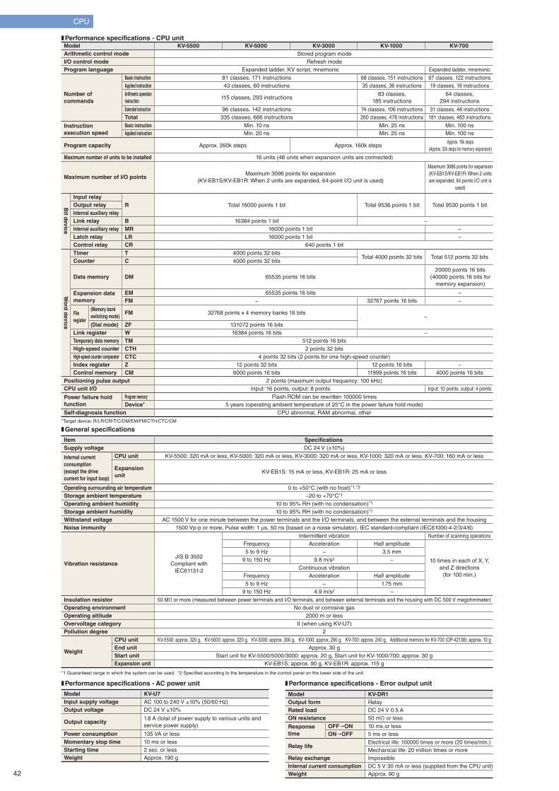
CPU
*Target device: R/LR/CR/T/C/DM/EM/FM/CTH/CTC/CM
*1 Guaranteed range in which the system can be used. *2 Specified according to the temperature in the control panel on the lower side of the unit.
❚ General specifications
❚ Performance specifications - CPU unit
❚ Performance specifications - AC power unit ❚ Performance specifications - Error output unit
Model KV-5500 KV-5000 KV-3000 KV-1000 KV-700Arithmetic control mode Stored program modeI/O control mode Refresh modeProgram language Expanded ladder, KV script, mnemonic Expanded ladder, mnemonic
Number of commands
Basic instruction 81 classes, 171 instructions 68 classes, 151 instructions 67 classes, 122 instructionsApplied instruction 43 classes, 60 instructions 35 classes, 36 instructions 19 classes, 19 instructions
Arithmetic operation instruction
115 classes, 293 instructions83 classes,
185 instructions64 classes,
294 instructions
Extended instruction 96 classes, 142 instructions 74 classes, 106 instructions 31 classes, 48 instructionsTotal 335 classes, 666 instructions 260 classes, 478 instructions 181 classes, 483 instructions
Instruction execution speed
Basic instruction Min. 10 ns Min. 25 ns Min. 100 nsApplied instruction Min. 20 ns Min. 25 ns Min. 100 ns
Program capacity Approx. 260k steps Approx. 160k stepsApprox. 16k steps
(Approx. 32k steps for memory expansion)
Maximum number of units to be installed 16 units (48 units when expansion units are connected)
Maximum number of I/O pointsMaximum 3096 points for expansion
(KV-EB1S/KV-EB1R: When 2 units are expanded, 64-point I/O unit is used)
Maximum 3086 points for expansion (KV-EB1S/KV-EB1R: When 2 units are expanded, 64 points I/O unit is
used)
Bit d
evice
Input relayR Total 16000 points 1 bit Total 9536 points 1 bit Total 9530 points 1 bitOutput relay
Internal auxiliary relayLink relay B 16384 points 1 bit −Internal auxiliary relay MR 16000 points 1 bit −Latch relay LR 16000 points 1 bit −Control relay CR 640 points 1 bit
Wo
rd d
evice
Timer T 4000 points 32 bitsTotal 4000 points 32 bits Total 512 points 32 bits
Counter C 4000 points 32 bits
Data memory DM 65535 points 16 bits20000 points 16 bits
(40000 points 16 bits for memory expansion)
Expansion data memory
EM 65535 points 16 bits −FM − 32767 points 16 bits −
Fileregister
(Memory bank switching mode)
FM 32768 points x 4 memory banks 16 bits−
(Dial mode) ZF 131072 points 16 bitsLink register W 16384 points 16 bits −Temporary data memory TM 512 points 16 bitsHigh-speed counter CTH 2 points 32 bitsHigh-speed counter comparator CTC 4 points 32 bits (2 points for one high-speed counter)Index register Z 12 points 32 bits 12 points 16 bits −Control memory CM 6000 points 16 bits 11999 points 16 bits 4000 points 16 bits
Positioning pulse output 2 points (maximum output frequency: 100 kHz)CPU unit I/O Input: 16 points, output: 8 points Input: 10 points, output: 4 points
Power failure hold function
Program memory Flash ROM can be rewritten 100000 timesDevice* 5 years (operating ambient temperature of 25°C in the power failure hold mode)
Self-diagnosis function CPU abnormal, RAM abnormal, other
Item SpecificationsSupply voltage DC 24 V (±10%)
Internal current consumption(except the drive current for input loop)
CPU unit KV-5500: 320 mA or less, KV-5000: 320 mA or less, KV-3000: 320 mA or less, KV-1000: 320 mA or less, KV-700: 160 mA or less
Expansion unit
KV-EB1S: 15 mA or less, KV-EB1R: 25 mA or less
Operating surrounding air temperature 0 to +50°C (with no frost)*1,*2
Storage ambient temperature −20 to +70°C*1
Operating ambient humidity 10 to 95% RH (with no condensation)*1
Storage ambient humidity 10 to 95% RH (with no condensation)*1
Withstand voltage AC 1500 V for one minute between the power terminals and the I/O terminals, and between the external terminals and the housingNoise immunity 1500 Vp-p or more, Pulse width: 1 μs, 50 ns (based on a noise simulator), IEC standard-compliant (IEC61000-4-2/3/4/6)
Vibration resistanceJIS B 3502
Compliant with IEC61131-2
Intermittent vibration Number of scanning operationsFrequency Acceleration Half amplitude
10 times in each of X, Y, and Z directions
(for 100 min.)
5 to 9 Hz − 3.5 mm9 to 150 Hz 9.8 m/s2 −
Continuous vibrationFrequency Acceleration Half amplitude5 to 9 Hz − 1.75 mm
9 to 150 Hz 4.9 m/s2 −Insulation resistor 50 MΩ or more (measured between power terminals and I/O terminals, and between external terminals and the housing with DC 500 V megohmmeter)Operating environment No dust or corrosive gasOperating altitude 2000 m or lessOvervoltage category II (when using KV-U7)Pollution degree 2
Weight
CPU unit KV-5500: approx. 320 g, KV-5000: approx. 320 g, KV-3000: approx. 300 g, KV-1000: approx. 290 g, KV-700: approx. 240 g, Additional memory for KV-700 (OP-42138): approx. 10 gEnd unit Approx. 30 gStart unit Start unit for KV-5500/5000/3000: approx. 20 g, Start unit for KV-1000/700: approx. 30 gExpansion unit KV-EB1S: approx. 90 g, KV-EB1R: approx. 115 g
Model KV-U7Input supply voltage AC 100 to 240 V ±10% (50/60 Hz)Output voltage DC 24 V ±10%
Output capacity1.8 A (total of power supply to various units and service power supply)
Power consumption 135 VA or lessMomentary stop time 10 ms or lessStarting time 2 sec. or lessWeight Approx. 190 g
Model KV-DR1Output form RelayRated load DC 24 V 0.5 AON resistance 50 mΩ or less
Response time
OFF"ON 10 ms or lessON"OFF 5 ms or less
Relay lifeElectrical life: 100000 times or more (20 times/min.)Mechanical life: 20 million times or more
Relay exchange ImpossibleInternal current consumption DC 5 V 30 mA or less (supplied from the CPU unit)Weight Approx. 90 g42
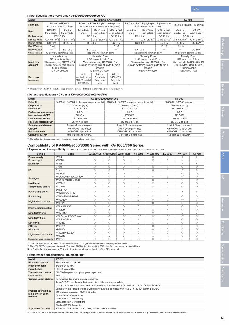
CPU
*1 This is switched with the input voltage-switching switch. *2 This is a reference value of input current.
*1 The delay time is response time + internal processing time (scan time).
*1 Use KV-BT1 only in countries that observe the radio law. Using KV-BT1 in countries that do not observe this law may result in punishment under the laws of that country.
*1 Direct refresh cannot be used. *2 KV-1000 and KV-700 programs can be used in the compatibility mode.*3 The KV-LE20V mode cannot be used. (The easy PLC link function and the FTP client function cannot be used either.) Note: For the function version of a CPU unit, check the serial seal on the side of the CPU main unit.
❚ Input specifications - CPU unit KV-5500/5000/3000/1000/700
❚ Output specifications - CPU unit KV-5500/5000/3000/1000/700
❚ Performance specifications - Bluetooth unit
❚ Expansion unit compatibility
Model KV-5500/5000/3000/1000 KV-700
Relay No.R00000 to R00009
(common input 10 points)R00010 to R00013 (high-speed A-phase/B-phase input 2 ch counted as 4 points)
R00014 to R00015 (high-speed Z-phase input 2 ch counted as 2 points)
R00000 to R00009 (10 points)
ItemDC 24 V
Input mode*1DC 5 V
Input mode*1Line driver
inputDC 5-V input
(open collector)DC 24-V input
(open collector)Line driver
inputDC 5-V input
(open collector)DC 24-V input
(open collector)DC 24 V
Input mode*1DC 5 V
Input mode*1
Max. input voltage DC 26.4 V DC 5.5 V DC 26.4 V DC 5.5 V DC 26.4 V DC 26.4 V Rated input voltage DC 24 V (5.3 mA*2) DC 5 V (1 mA*2) — DC 5 V (20 mA*2) DC 24 V (6.5 mA*2) — DC 5 V (8.3 mA*2) DC 24 V (3.5 mA*2) DC 24 V (5.3 mA*2) DC 5 V (1 mA*2)Min. ON voltage DC 19 V DC 4.5 V DC 2.0 V DC 19 V DC 2.0 V DC 19 V DC 19 V DC 4.5 V Max. OFF current 1.5 mA — — 1.5 mA — 1.5 mA 1.5 mA —Max. OFF voltage — DC 1.5 V DC 1.0 V — DC 1.0 V — — DC 1.5 V Common point mode 10 points/2 common points Independent common point Independent common point 10 points/1 common point
Input time constant
Normally 10 msHSP instruction of 10 μs
When control relay CR2305 is ON8-stage switching from 10 μs to
10 ms is possible(Set with CM1620)
Normally 10 msHSP instruction of 10 μs
When control relay CR2305 is ON8-stage switching from 10 μs to 10 ms is
possible(Set with CM1620)
Normally 10 msHSP instruction of 10 μs
When control relay CR2305 is ON8-stage switching from 10 μs to 10 ms is
possible(Set with CM1620)
Normally 10 msHSP instruction of 10 μs
When control relay CR2305 is ON7-stage switching from 10 μs to
10 ms is possible(Set with CM1620)
Response frequency
—
100 kHzInput signal: line driverAM26LS31-equivalent
Duty ratio: 50%
60 kHz5 V ±10%Duty ratio:
50%
60 kHz24 V ±10%Duty ratio:
50%
— —
Model KV-5500/5000/3000/1000 KV-700Relay No. R00500 to R00503 (high-speed output 4 points) R00504 to R00507 (universal output 4 points) R00500 to R00503 (4 points)Output form Transistor (sync) Transistor (sync) Transistor (sync)Rated load DC 30 V 0.1 A DC 30 V 0.1 A DC 30 V 0.1 APeak value load current 0.2 A 0.2 A 0.2 AMax. voltage at OFF DC 30 V DC 30 V DC 30 VLeak current at OFF 100 μA or less 100 μA or less 100 μA or lessResidual voltage at ON DC 0.6 V or less DC 0.6 V or less DC 0.3 V or lessCommon point mode 8 points/1 common point 8 points/1 common point 4 points/1 common point
ON/OFFResponse time*1
OFF"ON: 1 μs or lessON"OFF: 5 μs or less
OFF"ON: 5 μs or lessON"OFF: 30 μs or less
OFF"ON: 10 μs or lessON"OFF: 10 μs or less
Output frequency 100 kHz (at 5 to 100 mA) 10 kHz (at 5 to 100 mA) 100 kHz (at 5 to 50mA)
Sorting Model KV-5500 Ver.2 KV-5000 Ver.2 KV-5000 Ver.1.1 KV-5000 KV-3000 Ver.2 KV-3000 KV-1000 KV-700Power supply KV-U7 � � � � � � � �
Error output KV-DR1 � � � � � � × ×Bluetooth KV-BT1 � � � × � × × ×
I/OD type � � � � � � �*1 �*1
C type � � � � � � �*1 �*1
A/B type � � � � � � � �
AnalogueKV-AD40V/DA40V/AM40V � � � � � � �*1 �*1
KV-AD40/AD40G/DA40 � � � � � � � �
Multi-input KV-TP40 � � � � � � � �
Temperature control KV-TF40 � � � � � � � �
Positioning/MotionKV-ML16VKV-MC20V/MC40V
� � � � � � × ×
Positioning KV-H20S/H40S/H20G � � � � � � � �
High-speed counterKV-SC20V � � � � � � �*1 �*1
KV-SC20 � � � � � � � �
Serial communicationKV-L21V/L20V � � � � � � � �
KV-L20R × × × × × × � �
EtherNet/IP unit KV-EP21V � � × × � × × ×
EtherNet/FL-netKV-LE21V/LE20V/FL20V �*2 �*2 �*2 �*2 �*2 �*2 �*3 �*3
KV-LE20A/FL20 × × × × × × � �
DeviceNet KV-DN20 � � � � � � � �
CC-Link KV-CL20 � � � � � � � �
KL master KL-N20V � � � � � � � �
High-speed multi-linkKV-LM21V/LM20V � � � � � � � �
KV-LM20 × × × × × × � �
Decentralised system configuration KV-EB1 � � � � � � � �
Model KV-BT1Bluetooth version Bluetooth Ver.2.0 +EDRFrequency band 2402 to 2480 MHzOutput class Class-2 compatibleTransmission method FH-SS (Frequency hopping spread spectrum)Used profile SPPCommunication distance 10 m*Differs depending on environments.
Product definition by radio laws in each country*1
Japan*KV-BT1 contains a design-certified built-in wireless module.USA*KV-BT1 incorporates a wireless module that complies with FCC Part 15C. FCC ID: RYYEYXFDCCanada*KV-BT1 incorporates a wireless module that complies with RSS-210. IC ID: 4389A-EYXFDCEU member countries (R&TTE Directive)China (SRRC Certification)Taiwan (NCC Certification)Singapore (iDA Certification)Thailand (NTC Regulation)
Supported CPU unit KV-5500, KV-5000 Ver.1.1 and later, KV-3000 Ver.2 and later
Compatibility of KV-5500/5000/3000 Series with KV-1000/700 SeriesI/O units can be used for all CPU units. With a few exceptions, special units can be used for all CPU units.
43
Specification
Com
munication
Positioning
An
alo
gu
eI/O
CP
UV
T Link
Softw
areLine up
Hardw
areK
V A
dvantage
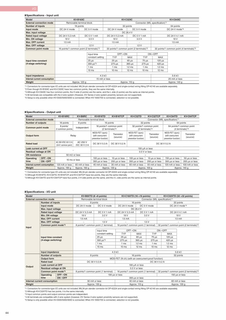
I/O
Model KV-B16XC KV-C32XC KV-C64XCExternal connection mode Removable terminal block Connector (MIL specification)*1 Number of inputs 16 points 32 points 64 pointsInput mode DC 24-V mode DC 5-V mode DC 24-V mode DC 5-V mode DC 24-V mode*4
Max. input voltage DC 26.4 VRated input voltage DC 24 V 5.3 mA DC 5 V 1 mA DC 24 V 5.3 mA DC 5 V 1 mA DC 24 V 4.1 mAMin. ON voltage 19 V 3.5 V 19 V 3.5 V 19 VMax. OFF current 1.5 mA - 1.5 mA - 1.5 mAMax. OFF voltage - 1.5 V - 1.5 V -Common point mode 16 points/1 common point (2 terminals)*2 32 points/1 common point (2 terminals)*2 32 points/1 common point (4 terminals)*3
Input time constant (4-stage switching)
Input time constant setting
OFF"ON ON"OFFTYP MAX TYP MAX
25 μs 25 μs 65 μs 75 μs 120 μs300 μs*5 275 μs 365 μs 275 μs 420 μs1 ms 1 ms 1.2 ms 1 ms 1.2 ms10 ms 10 ms 12 ms 10 ms 12 ms
Input impedance 4.3 kΩ 5.6 kΩInternal current consumption 15 mA or less 25 mA or lessWeight Approx. 120 g Approx. 110 g Approx. 140 g
*1 Connectors for connector-type I/O units are not included. MIL34-pin slender connector kit OP-42224 and single-contact wiring fitting OP-42140 are available separately.*2 Even though KV-B16XC and KV-C32XC have two common points, they are the same internally.*3 Although KV-C64XC has four common points, the H side (2 points) are the same, and the L side (2 points) are the same as internal points.*4 All terminals are compatible with the 2-wire system (However, EV Series 2-wire system proximity sensors are not supported).*5 Setup is only possible when KV-5500/5000/3000 is connected. When KV-1000/700 is connected, selection is not possible.
❚ Specifications - Input unit
*1 Connectors for connector-type I/O units are not included. MIL34-pin slender connector kit OP-42224 and single-contact wiring fitting OP-42140 are available separately. *2 Although KV-B16TD, KV-C32TD, KV-B16TCP, and KV-C32TCP have two points, they are the same internally. *3 Although KV-C64TD and KV-C64TCP have four points, 2 H side points are the same, and the 2 L side points are the same as internal points.
❚ Specifications - Output unit
Model KV-B16RC KV-B8RC KV-B16TD KV-B16TCP KV-C32TD KV-C32TCP KV-C64TD KV-C64TCPExternal connection mode Removable terminal block Connector (MIL specification)*1
Number of outputs 16 points 8 points 16 points 32 points 64 points
Common point mode8 points/
2 common pointsIndependent
16 points/1 common point (2 terminals)*2
32 points/1 common point (2 terminals)*2
64 points/1 common point (4 terminals)*3
Output form RelayMOS-FET (sync)(with overcurrent-
prevention function)
Transistor(source)
MOS-FET (sync)(with overcurrent-
prevention function)
Transistor(source)
MOS-FET (sync)(with overcurrent-
prevention function)
Transistor(source)
Rated loadAC 250 V/DC 30 V 2 A(8 A/1 common point)
AC 250 V /DC 30 V 2 A
DC 30 V 0.3 A DC 30 V 0.2 A DC 30 V 0.2 A
Leak current at OFF−
100 μA or lessResidual voltage at ON 0.5 V or lessON resistance 50 mΩ or less −
Operating time
OFF"ON10 ms or less
100 μs or less 10 μs or less 100 μs or less 10 μs or less 150 μs or less 50 μs or lessON"OFF 300 μs or less 200 μs or less 300 μs or less 200 μs or less 300 μs or less 200 μs or less
Internal current consumption 120 mA or less 65 mA or less 45 mA or less 35 mA or less 65 mA or less 55 mA or less 120 mA or less 100 mA or lessWeight Approx. 190 g Approx. 160 g Approx. 130 g Approx. 100 g Approx. 140 g
*1 Connectors for connector-type I/O units are not included. MIL34-pin slender connector kit OP-42224 and single-contact wiring fitting OP-42140 are available separately.*2 Although KV-C32XTD has two points, it is the same internally.*3 Input common points and output common points are independent.*4 All terminals are compatible with 2-wire system (however, EV Series 2-wire system proximity sensors are not supported). *5 Setup is only possible when KV-5500/5000/3000 is connected. When KV-1000/700 is connected, selection is not possible.
❚ Specifications - I/O unit
Model KV-B8XTD (8 +8 points) KV-C16XTD (16 +16 points) KV-C32XTD (32 +32 points)External connection mode Removable terminal block Connector (MIL specification)*1
Input
Number of inputs 8 points 16 points 32 pointsInput mode DC 24-V mode DC 5-V mode DC 24-V mode DC 5-V mode DC 24-V mode*4
Max. input voltage DC 26.4 VRated input voltage DC 24 V 5.3 mA DC 5 V 1 mA DC 24 V 5.3 mA DC 5 V 1 mA DC 24 V 4.1 mAMin. ON voltage 19 V 3.5 V 19 V 3.5 V 19 VMax. OFF current 1.5 mA - 1.5 mA - 1.5 mAMax. OFF voltage - 1.5 V - 1.5 V -Common point mode*3 8 points/1 common point (1 terminal) 16 points/1 common point (1 terminal) 32 points/1 common point (2 terminals)*2
Input time constant (4-stage switching)
Input time constant setting
OFF"ON ON"OFFTYP MAX TYP MAX
25 μs 25 μs 65 μs 75 μs 120 μs300 μs*5 275 μs 365 μs 275 μs 420 μs1 ms 1 ms 1.2 ms 1 ms 1.2 ms10 ms 10 ms 12 ms 10 ms 12 ms
Input impedance 4.3 kΩ 5.6 kΩ
Output
Number of outputs 8 points 16 points 32 pointsOutput form MOS-FET (N ch) (with an overcurrent-proof function)Rated load DC 30 V 0.3 A DC 30 V 0.2 ALeak current at OFF 100 μA or lessResidual voltage at ON 0.5 V or lessCommon point mode*3 8 points/1 common point (1 terminal) 16 points/1 common point (1 terminal) 32 points/1 common point (2 terminals)*2
Operating time
OFF"ON 100 μs or less 150 μs or lessON"OFF 300 μs or less
Internal current consumption 30 mA or less 40 mA or less 65 mA or lessWeight Approx. 130 g Approx. 110 g Approx. 130 g
44
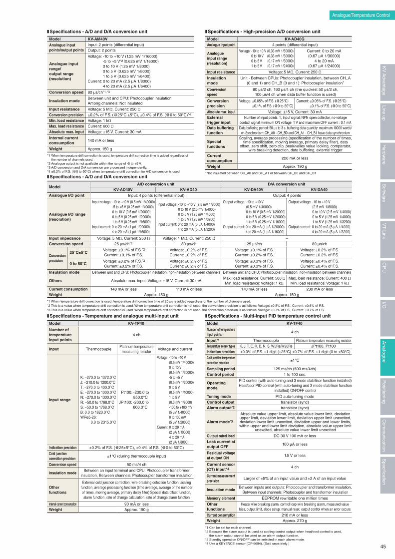
Analogue/Temperature Control
❚ Specifications - A/D and D/A conversion unit
❚ Specifications - Temperature and analogue multi-input unit
❚ Specifications - A/D and D/A conversion unit
❚ Specifications - High-precision A/D conversion unit
❚ Specifications - Multi-input PID temperature control unit
Model KV-AM40V
Analogue input points/output points
Input: 2 points (differential input)Output: 2 points
Analogue input range/output range (resolution)
Voltage: -10 to +10 V (1.25 mV 1/16000) -5 to +5 V*2 (0.625 mV 1/16000) 0 to 10 V (1.25 mV 1/8000) 0 to 5 V (0.625 mV 1/8000) 1 to 5 V (0.625 mV 1/6400)
Current: 0 to 20 mA (2.5 μA 1/8000) 4 to 20 mA (2.5 μA 1/6400)
Conversion speed 80 μs/ch*1,*3
Insulation modeBetween unit and CPU: Photocoupler insulationAmong channels: Not insulated
Input resistance Voltage: 5 MΩ, Current: 250 ΩConversion precision ±0.2% of F.S. (@25°C ±5°C), ±0.4% of F.S. (@0 to 50°C)*4
Min. load resistance Voltage: 1 kΩMax. load resistance Current: 600 ΩAbsolute max. input Voltage: ±15 V, Current: 30 mA
Internal current consumption
140 mA or less
Weight Approx. 150 g
*1 When temperature drift correction is used, temperature drift correction time is added regardless of the number of channels used.
*2 Analogue output is not available within the range of -5 to +5 V.*3 A/D conversion and D/A conversion are processed independently.*4 ±0.2% of F.S. (@0 to 50°C) when temperature drift correction for A/D conversion is used
*1 When temperature drift correction is used, temperature drift correction time of 25 μs is added regardless of the number of channels used.*2 This is a value when temperature drift correction is used. When temperature drift correction is not used, the conversion precision is as follows: Voltage: ±0.5% of F.S., Current: ±0.6% of F.S.*3 This is a value when temperature drift correction is used. When temperature drift correction is not used, the conversion precision is as follows: Voltage: ±0.7% of F.S., Current: ±0.7% of F.S.
*Not insulated between CH_A0 and CH_A1 or between CH_B0 and CH_B1
*1 Can be set for each channel.*2 Because the alarm output is used as cooling control output when heat/cool control is used,
the alarm output cannot be used as an alarm output function.*3 Standby operation ON/OFF can be selected in each alarm mode.*4 Use a KEYENCE sensor (OP-6694). (Sold separately.)
Model KV-AD40GAnalogue input point 4 points (differential input)
Analogue input range (resolution)
Voltage: -10 to 10 V (0.33 mV 1/60000) 0 to 10 V (0.33 mV 1/30000) 0 to 5 V (0.17 mV 1/30000) 1 to 5 V (0.17 mV 1/24000)
Current: 0 to 20 mA (0.67 μA 1/30000)
4 to 20 mA (0.67 μA 1/24000)
Input resistance Voltage: 5 MΩ, Current: 250 Ω
Insulation mode
Unit - Between CPUs: Photocoupler insulation, between CH_A (0 and 1) and CH_B (0 and 1): Photocoupler insulation*
Conversion speed
80 μs/2 ch, 160 μs/4 ch (the quickest 50 μs/2 ch, 100 μs/4 ch when data buffer function is used)
Conversion precision
Voltage: ±0.05% of F.S. (@25°C) ±0.1% of F.S. (@0 to 50°C)
Current: ±0.05% of F.S. (@25°C) ±0.1% of F.S. (@0 to 50°C)
Absolute max. input Voltage: ±15 V, Current: 30 mAExternal trigger input
Number of input points: 1, Input signal: NPN open collector, no-voltage contact signal minimum ON voltage: 1 V and maximum OFF current : 0.1 mA
Data buffering function
Data buffering period: 50 μs to 3 s, buffering data quantity: maximum 10000 words/ch Synchronism: CH_A0 - CH_B0 and CH_A1 - CH_B1 have data synchronism
Special functions
Scaling, average processing (specification of the number of times, time specification, moving average, primary delay filter), data
offset, zero shift, zero clip, peak/valley value locking, comparator, wire breaking detection, data buffering, external trigger
Current consumption
220 mA or less
Weight Approx. 190 g
ModelA/D conversion unit D/A conversion unit
KV-AD40V KV-AD40 KV-DA40V KV-DA40Analogue I/O point Input: 4 points (differential input) Output: 4 points
Analogue I/O range(resolution)
Input voltage: -10 to +10 V (0.5 mV 1/40000) -5 to +5 V (0.25 mV 1/40000) 0 to 10 V (0.5 mV 1/20000) 0 to 5 V (0.25 mV 1/20000) 1 to 5 V (0.25 mV 1/16000)
Input current: 0 to 20 mA (1 μA 1/20000) 4 to 20 mA (1 μA 1/16000)
Input voltage: -10 to +10 V (2.5 mV 1/8000) 0 to 10 V (2.5 mV 1/4000) 0 to 5 V (1.25 mV 1/4000) 1 to 5 V (1.25 mV 1/3200)
Input current: 0 to 20 mA (5 μA 1/4000) 4 to 20 mA (5 μA 1/3200)
Output voltage: -10 to +10 V (0.5 mV 1/40000) 0 to 10 V (0.5 mV 1/20000) 0 to 5 V (0.25 mV 1/20000) 1 to 5 V (0.25 mV 1/16000)
Output current: 0 to 20 mA (1 μA 1/20000) 4 to 20 mA (1 μA 1/16000)
Output voltage: -10 to +10 V (2.5 mV 1/8000) 0 to 10 V (2.5 mV 1/4000) 0 to 5 V (1.25 mV 1/4000) 1 to 5 V (1.25 mV 1/3200)
Output current: 0 to 20 mA (5 μA 1/4000) 4 to 20 mA (5 μA 1/3200)
Input impedance Voltage: 5 MΩ, Current: 250 Ω Voltage: 1 MΩ, Current: 250 Ω −Conversion speed 25 μs/ch*1 80 μs/ch 25 μs/ch 80 μs/ch
Conversion precision
25°C±5°C Voltage: ±0.1% of F.S.*2Current: ±0.1% of F.S.
Voltage: ±0.2% of F.S.Current: ±0.2% of F.S.
Voltage: ±0.1% of F.S.Current: ±0.2% of F.S.
Voltage: ±0.2% of F.S.Current: ±0.2% of F.S.
0 to 50°C Voltage: ±0.2% of F.S.*3Current: ±0.2% of F.S.
Voltage: ±0.2% of F.S.Current: ±0.2% of F.S.
Voltage: ±0.3% of F.S.Current: ±0.3% of F.S.
Voltage: ±0.4% of F.S.Current: ±0.4% of F.S.
Insulation mode Between unit and CPU: Photocoupler insulation, non-insulation between channels Between unit and CPU: Photocoupler insulation, non-insulation between channels
Others Absolute max. input: Voltage: ±15 V, Current: 30 mAMax. load resistance: Current: 500 ΩMin. load resistance: Voltage: 1 kΩ
Max. load resistance: Current: 400 ΩMin. load resistance: Voltage: 1 kΩ
Current consumption 140 mA or less 110 mA or less 170 mA or less 230 mA or lessWeight Approx. 150 g Approx. 150 g
Model KV-TP40
Number of temperature input points
4 ch
Input ThermocouplePlatinum temperature
measuring resistorVoltage and current
Input range
K: −270.0 to 1372.0°CJ: −210.0 to 1200.0°CT: −270.0 to 400.0°CE: −270.0 to 1000.0°CN: −270.0 to 1300.0°CR: −50.0 to 1768.0°CS: −50.0 to 1768.0°CB: 0.0 to 1820.0°CWRe5-26:
0.0 to 2315.0°C
Pt100: -200.0 to 850.0°C
JPt100: -200.0 to 600.0°C
Voltage: -10 to +10 V (0.5 mV 1/40000) 0 to 10 V (0.5 mV 1/20000) -5 to +5 V (0.5 mV 1/20000) 0 to 5 V (0.5 mV 1/10000) 1 to 5 V (0.5 mV 1/8000) -100 to +100 mV (5 μV 1/40000) 0 to 100 mV (5 μV 1/20000)
Current: 0 to 20 mA (2 μA 1/10000) 4 to 20 mA (2 μA 1/8000)
Indication precision ±0.2% of F.S. (@25±5°C), ±0.4% of F.S. (@0 to 50°C)
Cold junction correction precision
±1°C (during thermocouple input)
Conversion speed 50 ms/4 ch
Insulation modeBetween an input terminal and CPU: Photocoupler transformer
insulation, Between channels: Photocoupler transformer insulation
Other functions
External cold junction correction, wire-breaking detection function, scaling function, average processing function (time average, average of the number of times, moving average, primary delay filter) Special data offset function, alarm function, rate of change calculation, rate of change alarm function
Internal current consumption 90 mA or lessWeight Approx. 190 g
Model KV-TF40
Number of temperature input points
4 ch
Input*1 Thermocouple Platinum temperature measuring resistorTemperature sensor types K, J, T, E, R, B, N, S, W5Re/W26Re JPt100, Pt100Indication precision ±0.3% of F.S. ±1 digit (+25°C) ±0.7% of F.S. ±1 digit (0 to +50°C)
Cold junction temperature correction precision
±1°C
Sampling period 125 ms/ch (500 ms/4ch)Control period 1 to 100 sec.
Operating mode
PID control (with auto-tuning and 3 mode stabiliser function installed)Heat/cool PID control (with auto-tuning and 3 mode stabiliser function
installed) ON/OFF control
Tuning mode PID auto-tuning modeControl output transistor (sync)Alarm output*2 transistor (sync)
Alarm mode*3
Absolute value upper limit, absolute value lower limit, deviation upper limit, deviation lower limit, deviation upper limit unexcited, deviation lower limit unexcited, deviation upper and lower limits, within upper and lower limit deviation, absolute value upper limit
unexcited, absolute value lower limit unexcited
Output rated load DC 30 V 100 mA or less
Leak current at output OFF
100 μA or less
Residual voltage at output ON
1.5 V or less
Current sensor (CT) input*4
4 ch
Current measurement precision
Larger of ±5% of an input value and ±2 A of an input value
Insulation modeBetween inputs and outputs: Photocoupler and transformer insulation,
Between input channels: Photocoupler and transformer insulation
Memory element EEPROM rewritable one million times
Other functions
Heater wire breaking alarm, control loop wire breaking alarm, measured value bias, output limit, slope setup, manual reset, output control when an error occurs
Current consumption 210 mA or lessWeight Approx. 270 g
45
Specification
Com
munication
Positioning
An
alo
gu
eI/O
CP
UV
T Link
Softw
areLine up
Hardw
areK
V A
dvantage
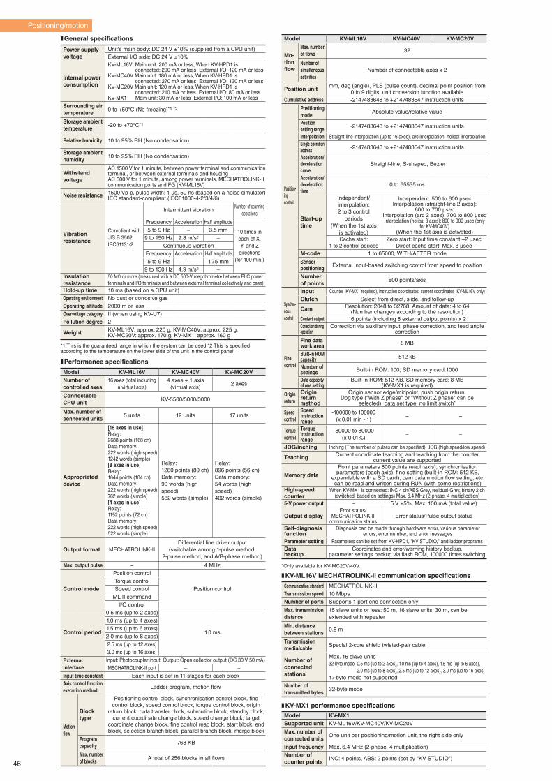
Power supply voltage
Unit's main body: DC 24 V ±10% (supplied from a CPU unit)External I/O side: DC 24 V ±10%
Internal power consumption
KV-ML16V Main unit: 200 mA or less, When KV-HPD1 is connected: 290 mA or less External I/O: 120 mA or lessKV-MC40V Main unit: 180 mA or less, When KV-HPD1 is connected: 270 mA or less External I/O: 130 mA or lessKV-MC20V Main unit: 120 mA or less, When KV-HPD1 is connected: 210 mA or less External I/O: 80 mA or lessKV-MX1 Main unit: 30 mA or less External I/O: 100 mA or less
Surrounding air temperature
0 to +50°C (No freezing)*1 *2
Storage ambient temperature
-20 to +70°C*1
Relative humidity 10 to 95% RH (No condensation)
Storage ambient humidity
10 to 95% RH (No condensation)
Withstand voltage
AC 1500 V for 1 minute, between power terminal and communication terminal, or between external terminals and housingAC 500 V for 1 minute, among power terminals, MECHATROLINK-II communication ports and FG (KV-ML16V)
Noise resistance 1500 Vp-p, pulse width: 1 μs, 50 ns (based on a noise simulator)IEC standard-compliant (IEC61000-4-2/3/4/6)
Vibration resistance
Compliant withJIS B 3502IEC61131-2
Intermittent vibrationNumber of scanning
operations
Frequency Acceleration Half amplitude
10 times in each of X, Y, and Z
directions(for 100 min.)
5 to 9 Hz − 3.5 mm9 to 150 Hz 9.8 m/s2 −
Continuous vibrationFrequency Acceleration Half amplitude5 to 9 Hz − 1.75 mm
9 to 150 Hz 4.9 m/s2 −Insulation resistance
50 MΩ or more (measured with a DC 500-V megohmmetre between PLC power terminals and I/O terminals and between external terminal collectively and case)
Hold-up time 10 ms (based on a CPU unit)Operating environment No dust or corrosive gasOperating altitude 2000 m or lessOvervoltage category II (when using KV-U7)Pollution degree 2
Weight KV-ML16V: approx. 220 g, KV-MC40V: approx. 225 g, KV-MC20V: approx. 170 g, KV-MX1: approx. 160 g
Model KV-ML16V KV-MC40V KV-MC20VNumber of controlled axes
16 axes (total including a virtual axis)
4 axes + 1 axis (virtual axis)
2 axes
ConnectableCPU unit
KV-5500/5000/3000
Max. number of connected units
5 units 12 units 17 units
Appropriated device
[16 axes in use]Relay:2688 points (168 ch)Data memory:222 words (high speed)1242 words (simple)[8 axes in use]Relay:1644 points (104 ch)Data memory:222 words (high speed)762 words (simple)[4 axes in use]Relay:1152 points (72 ch)Data memory:222 words (high speed)522 words (simple)
Relay:1280 points (80 ch)Data memory:90 words (high speed)582 words (simple)
Relay:896 points (56 ch)Data memory:54 words (high speed)402 words (simple)
Output format MECHATROLINK-IIDifferential line driver output
(switchable among 1-pulse method, 2-pulse method, and A/B-phase method)
Max. output pulse − 4 MHz
Control mode
Position control
Position controlTorque controlSpeed control
ML-II commandI/O control
Control period
0.5 ms (up to 2 axes)
1.0 ms
1.0 ms (up to 4 axes)1.5 ms (up to 6 axes)2.0 ms (up to 8 axes)2.5 ms (up to 12 axes)3.0 ms (up to 16 axes)
External interface
Input: Photocoupler input, Output: Open collector output (DC 30 V 50 mA)MECHATROLINK-II port − −
Input time constant Each input is set in 11 stages for each blockAxis control function execution method
Ladder program, motion flow
Motionflow
Blocktype
Positioning control block, synchronisation control block, fine control block, speed control block, torque control block, origin
return block, data transfer block, subroutine block, standby block, current coordinate change block, speed change block, target
coordinate change block, fine control read block, start block, end block, selection branch block, parallel branch block, merge block
Program capacity
768 KB
Max. number of blocks
A total of 256 blocks in all flows
*1 This is the guaranteed range in which the system can be used.*2 This is specified according to the temperature on the lower side of the unit in the control panel.
*Only available for KV-MC20V/40V.
Model KV-ML16V KV-MC40V KV-MC20V
Mo-tionflow
Max. number of flows
32
Number of simultaneous activities
Number of connectable axes x 2
Position unit mm, deg (angle), PLS (pulse count), decimal point position from 0 to 9 digits, unit conversion function available
Cumulative address -2147483648 to +2147483647 instruction units
Position-ingcontrol
Positioning mode
Absolute value/relative value
Position setting range -2147483648 to +2147483647 instruction units
Interpolation Straight-line interpolation (up to 16 axes), arc interpolation, helical interpolationSingle operation address -2147483648 to +2147483647 instruction units
Acceleration/deceleration curve
Straight-line, S-shaped, Bezier
Acceleration/deceleration time
0 to 65535 ms
Start-up time
Independent/interpolation:2 to 3 control
periods(When the 1st axis
is activated)
Independent: 500 to 600 μsecInterpolation (straight-line 2 axes):
600 to 700 μsecInterpolation (arc 2 axes): 700 to 800 μsecInterpolation (helical 3 axes): 800 to 900 μsec (only
for KV-MC40V)(When the 1st axis is activated)
Cache start:1 to 2 control periods
Zero start: Input time constant +2 μsecDirect cache start: Max. 8 μsec
M-code 1 to 65000, WITH/AFTER mode
Sensor positioning External input-based switching control from speed to position
Number of points
800 points/axis
Synchro-nouscontrol
Input Counter (KV-MX1 required), instruction coordinates, current coordinates (KV-ML16V only)Clutch Select from direct, slide, and follow-up
Cam Resolution: 2048 to 32768, Amount of data: 4 to 64 (Number changes according to the resolution)
Contact output 16 points (including 8 external output points) x 2Correction during operation
Correction via auxiliary input, phase correction, and lead angle correction
Finecontrol
Fine datawork area 8 MB
Built-in ROM capacity 512 kB
Number of settings Built-in ROM: 100, SD memory card:1000
Data capacity of one setting
Built-in ROM: 512 KB, SD memory card: 8 MB (KV-MX1 is required)
Originreturn
Origin returnmethod
Origin sensor edge/midpoint, push origin return,Dog type ("With Z phase" or "Without Z phase" can be
selected), data set type, no limit switch*
Speedcontrol
Speed instructionrange
-100000 to 100000(x 0.01 min - 1)
− −
Torquecontrol
Torque instructionrange
-80000 to 80000(x 0.01%)
− −
JOG/inching Inching (The number of pulses can be specified), JOG (high speed/low speed)
Teaching Current coordinate teaching and teaching from the counter current value are supported
Memory data
Point parameters 800 points (each axis), synchronisation parameters (each axis), fine setting (built-in ROM: 512 KB,
expandable with a SD card), cam data motion flow setting, etc. can be read and written during RUN (with some restrictions)
High-speed counter
When KV-MX1 is connected: INC 4 ch/ABS Grey, residual Grey, binary 2 ch (switched, based on settings) Max. 6.4 MHz (2-phase, 4 multiplication)
5-V power output − 5 V ±5%, Max. 100 mA (total value)
Output displayError status/
MECHATROLINK-II communication status
Error status/Pulse output status
Self-diagnosis function
Diagnosis can be made through hardware error, various parameter errors, error number, and error messages
Parameter setting Parameters can be set from KV-HPD1, "KV STUDIO," and ladder programsDatabackup
Coordinates and error/warning history backup,parameter settings backup via flash ROM, 100000 times switching
Communication standard MECHATROLINK-IITransmission speed 10 MbpsNumber of ports Supports 1 port end connection only
Max. transmission distance
15 slave units or less: 50 m, 16 slave units: 30 m, can be extended with repeater
Min. distance between stations
0.5 m
Transmission media/cable
Special 2-core shield twisted-pair cable
Number of connected stations
Max. 16 slave units 32-byte mode 0.5 ms (up to 2 axes), 1.0 ms (up to 4 axes), 1.5 ms (up to 6 axes),
2.0 ms (up to 8 axes), 2.5 ms (up to 12 axes), 3.0 ms (up to 16 axes) 17-byte mode not supported
Number of transmitted bytes
32-byte mode
❚ General specifications
❚ Performance specifications
❚ KV-ML16V MECHATROLINK-II communication specifications
Model KV-MX1Supported unit KV-ML16V/KV-MC40V/KV-MC20V
Max. number of connected units
One unit per positioning/motion unit, the right side only
Input frequency Max. 6.4 MHz (2-phase, 4 multiplication)Number of counter points
INC: 4 points, ABS: 2 points (set by "KV STUDIO")
❚ KV-MX1 performance specifications
Positioning/motion
46
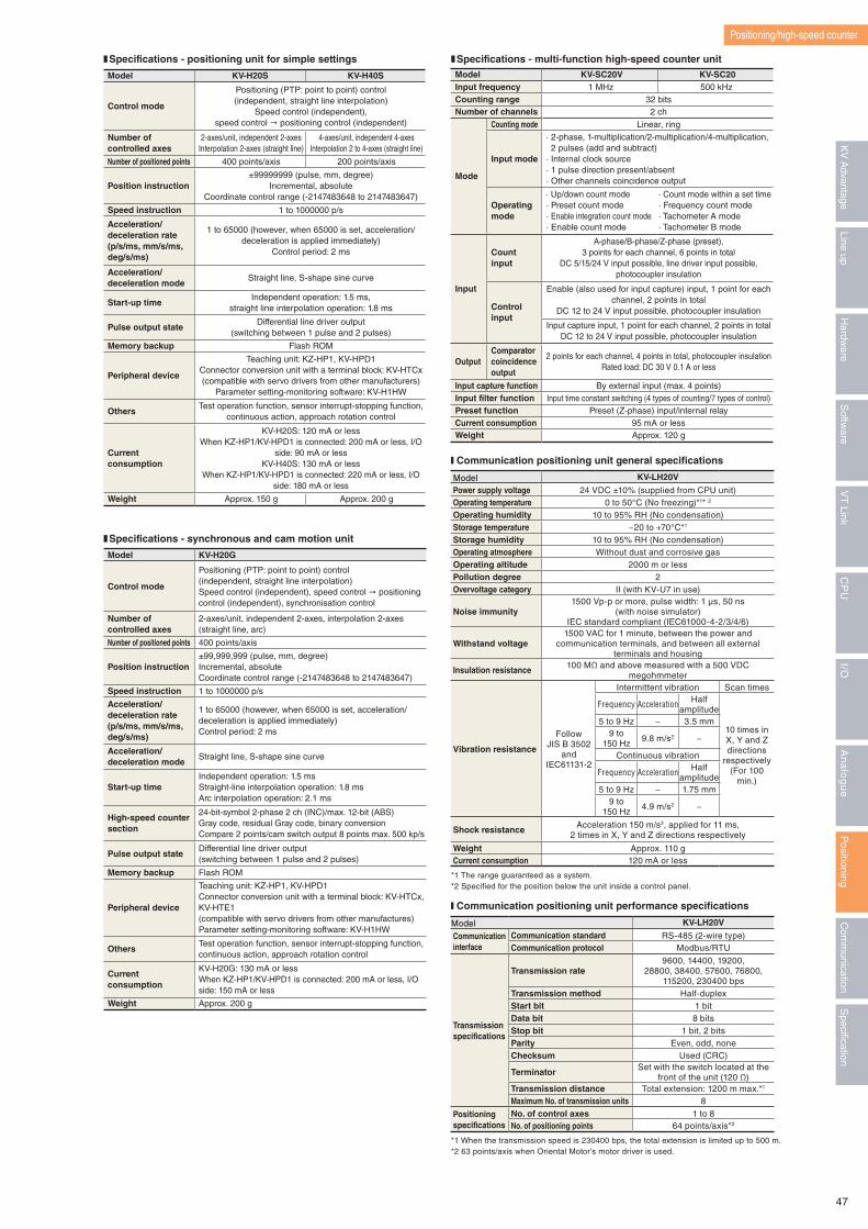
Model KV-H20S KV-H40S
Control mode
Positioning (PTP: point to point) control (independent, straight line interpolation)
Speed control (independent), speed control " positioning control (independent)
Number of controlled axes
2-axes/unit, independent 2-axes Interpolation 2-axes (straight line)
4-axes/unit, independent 4-axesInterpolation 2 to 4-axes (straight line)
Number of positioned points 400 points/axis 200 points/axis
Position instruction±99999999 (pulse, mm, degree)
Incremental, absoluteCoordinate control range (-2147483648 to 2147483647)
Speed instruction 1 to 1000000 p/s
Acceleration/ deceleration rate(p/s/ms, mm/s/ms, deg/s/ms)
1 to 65000 (however, when 65000 is set, acceleration/deceleration is applied immediately)
Control period: 2 ms
Acceleration/deceleration mode
Straight line, S-shape sine curve
Start-up timeIndependent operation: 1.5 ms,
straight line interpolation operation: 1.8 ms
Pulse output stateDifferential line driver output
(switching between 1 pulse and 2 pulses)
Memory backup Flash ROM
Peripheral device
Teaching unit: KZ-HP1, KV-HPD1Connector conversion unit with a terminal block: KV-HTCx(compatible with servo drivers from other manufacturers)
Parameter setting-monitoring software: KV-H1HW
OthersTest operation function, sensor interrupt-stopping function,
continuous action, approach rotation control
Current consumption
KV-H20S: 120 mA or lessWhen KZ-HP1/KV-HPD1 is connected: 200 mA or less, I/O
side: 90 mA or lessKV-H40S: 130 mA or less
When KZ-HP1/KV-HPD1 is connected: 220 mA or less, I/O side: 180 mA or less
Weight Approx. 150 g Approx. 200 g
Model KV-H20G
Control mode
Positioning (PTP: point to point) control (independent, straight line interpolation)Speed control (independent), speed control " positioning control (independent), synchronisation control
Number of controlled axes
2-axes/unit, independent 2-axes, interpolation 2-axes (straight line, arc)
Number of positioned points 400 points/axis
Position instruction±99,999,999 (pulse, mm, degree)Incremental, absoluteCoordinate control range (-2147483648 to 2147483647)
Speed instruction 1 to 1000000 p/s
Acceleration/deceleration rate(p/s/ms, mm/s/ms, deg/s/ms)
1 to 65000 (however, when 65000 is set, acceleration/deceleration is applied immediately)Control period: 2 ms
Acceleration/deceleration mode
Straight line, S-shape sine curve
Start-up timeIndependent operation: 1.5 msStraight-line interpolation operation: 1.8 msArc interpolation operation: 2.1 ms
High-speed counter section
24-bit-symbol 2-phase 2 ch (INC)/max. 12-bit (ABS)Gray code, residual Gray code, binary conversionCompare 2 points/cam switch output 8 points max. 500 kp/s
Pulse output stateDifferential line driver output (switching between 1 pulse and 2 pulses)
Memory backup Flash ROM
Peripheral device
Teaching unit: KZ-HP1, KV-HPD1Connector conversion unit with a terminal block: KV-HTCx, KV-HTE1(compatible with servo drivers from other manufactures)Parameter setting-monitoring software: KV-H1HW
OthersTest operation function, sensor interrupt-stopping function,continuous action, approach rotation control
Current consumption
KV-H20G: 130 mA or less When KZ-HP1/KV-HPD1 is connected: 200 mA or less, I/O side: 150 mA or less
Weight Approx. 200 g
❚ Specifications - positioning unit for simple settings
❚ Specifications - synchronous and cam motion unit
❚ Specifications - multi-function high-speed counter unitModel KV-SC20V KV-SC20Input frequency 1 MHz 500 kHzCounting range 32 bitsNumber of channels 2 ch
Mode
Counting mode Linear, ring
Input mode
· 2-phase, 1-multiplication/2-multiplication/4-multiplication, 2 pulses (add and subtract)· Internal clock source· 1 pulse direction present/absent· Other channels coincidence output
Operating mode
· Up/down count mode · Count mode within a set time· Preset count mode · Frequency count mode· Enable integration count mode · Tachometer A mode· Enable count mode · Tachometer B mode
Input
Count input
A-phase/B-phase/Z-phase (preset), 3 points for each channel, 6 points in total
DC 5/15/24 V input possible, line driver input possible, photocoupler insulation
Control input
Enable (also used for input capture) input, 1 point for each channel, 2 points in total
DC 12 to 24 V input possible, photocoupler insulation
Input capture input, 1 point for each channel, 2 points in totalDC 12 to 24 V input possible, photocoupler insulation
OutputComparatorcoincidence output
2 points for each channel, 4 points in total, photocoupler insulationRated load: DC 30 V 0.1 A or less
Input capture function By external input (max. 4 points)Input filter function Input time constant switching (4 types of counting/7 types of control)Preset function Preset (Z-phase) input/internal relayCurrent consumption 95 mA or lessWeight Approx. 120 g
Positioning/high-speed counter
■ Communication positioning unit general specifications
Model KV-LH20V
Power supply voltage 24 VDC ±10% (supplied from CPU unit)Operating temperature 0 to 50°C (No freezing)*1* 2
Operating humidity 10 to 95% RH (No condensation)Storage temperature −20 to +70°C*1
Storage humidity 10 to 95% RH (No condensation)Operating atmosphere Without dust and corrosive gasOperating altitude 2000 m or lessPollution degree 2Overvoltage category II (with KV-U7 in use)
Noise immunity1500 Vp-p or more, pulse width: 1 μs, 50 ns
(with noise simulator)IEC standard compliant (IEC61000-4-2/3/4/6)
Withstand voltage1500 VAC for 1 minute, between the power and
communication terminals, and between all external terminals and housing
Insulation resistance 100 MΩ and above measured with a 500 VDC megohmmeter
Vibration resistance
Follow JIS B 3502
and IEC61131-2
Intermittent vibration Scan times
Frequency Acceleration Half amplitude
10 times in X, Y and Z directions
respectively(For 100
min.)
5 to 9 Hz − 3.5 mm9 to
150 Hz9.8 m/s2 −
Continuous vibration
Frequency Acceleration Half amplitude
5 to 9 Hz − 1.75 mm9 to
150 Hz4.9 m/s2 −
Shock resistance Acceleration 150 m/s2, applied for 11 ms, 2 times in X, Y and Z directions respectively
Weight Approx. 110 gCurrent consumption 120 mA or less
*1 The range guaranteed as a system. *2 Specified for the position below the unit inside a control panel.
■ Communication positioning unit performance specifications
Model KV-LH20V
Communication interface
Communication standard RS-485 (2-wire type)Communication protocol Modbus/RTU
Transmission specifications
Transmission rate9600, 14400, 19200,
28800, 38400, 57600, 76800, 115200, 230400 bps
Transmission method Half-duplexStart bit 1 bitData bit 8 bitsStop bit 1 bit, 2 bitsParity Even, odd, noneChecksum Used (CRC)
Terminator Set with the switch located at the front of the unit (120 Ω)
Transmission distance Total extension: 1200 m max.*1
Maximum No. of transmission units 8
Positioning specifications
No. of control axes 1 to 8No. of positioning points 64 points/axis*2
*1 When the transmission speed is 230400 bps, the total extension is limited up to 500 m.*2 63 points/axis when Oriental Motor’s motor driver is used.
47
Specification
Com
munication
Positioning
An
alo
gu
eI/O
CP
UV
T Link
Softw
areLine up
Hardw
areK
V A
dvantage
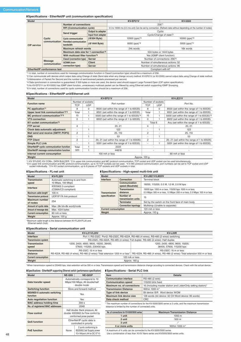
Communication/Network
*1 KV STUDIO, KV COM+, DATA BUILDER *2 In upper link communication and MC protocol communication, TCP socket and UDP socket can be used simultaneously.*3 In upper link communication and MC protocol communication, up to 15 TCP sockets can be used. *4 In MC protocol communication, port numbers can be set to TCP socket and UDP
socket individually. *5 In KV socket communication, up to 8 pieces of TCP sockets and UDP sockets in total.
❚ Specifications - EtherNet/IP unit/Ethernet unit
Model KV-EP21V KV-LE21V
Function nameNumber of sockets
Port numberNumber of sockets
Port No.TCP UDP TCP UDP
PC application*1 8 0 8500 (set within the range of 1 to 65535) 8 0 8500 (set within the range of 1 to 65535)Upper level link communication*2*3 Total
151 8501 (set within the range of 1 to 65535) Total
151 8501 (set within the range of 1 to 65535)
MC protocol communication*2*3 1 5000 (set within the range of 1 to 65535)*4 1 5000 (set within the range of 1 to 65535)*4
VT3 connection 0 1 8502 (set within the range of 1 to 65535) 0 1 8502 (set within the range of 1 to 65535)KV socket communication*5 - - Total 8 Any (set within the range of 1 to 65535)FTP server 4 - 20, 21 4 - 20, 21Clock data automatic adjustment - 1 123 - 1 123Mail send and receive (SMTP, POP3) 2 - 25, 110 2 - 25, 110DNS - 1 53 - 1 53FTP Client 2 - 20, 21 (set within the range of 1 to 65535) 2 - 20, 21 (set within the range of 1 to 65535)Simple PLC Link - 1 5001 (set within the range of 1 to 65535) - 1 5001 (set within the range of 1 to 65535)EtherNet/IP cyclic communication function Total
3201 2222 - -
EtherNet/IP message communication function 1 44818 - -Internal current consumption 100 mA or less 80 mA or lessWeight Approx. 120 g
❚ Specifications - EtherNet/IP supporting Ethernet switch (performance specification)
Model NE-Q05 NE-Q05P
Data transfer speedAutomatically correspond to 10 Mbps/100 Mbps, All double/half
double mode
Switching function Store and forward method
MDI/MDI-X automatic switching function
Yes
Auto negotiation function YesMAC address holding time 300 sNo. of registered MAC addresses 2048
Flow controlHalf double: Back pressure, All
double: IEEE802.3x Flow control by conformed pose packet
QoS functionEtherNet/IP cyclic data is
controlled in priority
PoE function None2 ports conforming to
IEEE802.3af Supply power 15.4 W/port (44 to DC 57 V)
*When transmission speed is 230400 bps, total extention will be 500 m or less. Transmission speed and transmission distance change accoding to connected devices. Check with the actual device.
❚ Specifications - Serial communication unit
Model KV-L21V/L20V KV-L20RInterface Port 1: RS-232C Port2: RS-232C, RS-422A, RS-485 (4 wires), RS-485 (2 wires) switchingTransmission system RS-232C, RS-422A, RS-485 (4 wires): Full duplex RS-485 (2 wires): Half duplex
Transmission speed
1200, 2400, 4800, 9600, 19200, 38400, 57600, 115200, 230400 bps
1200, 2400, 4800, 9600, 19200, 38400, 57600, 115200 bps
Transmission distance
RS-232C: 15 m or lessRS-422A, RS-485 (4 wires), RS-485 (2 wires): Total extension 1200 m or less*
RS-232C: 15 m or lessRS-422A, RS-485 (4 wires), RS-485 (2 wires): Total extension 500 m or less
Current consumption 120 mA or lessWeight Approx. 160 g
* Maximum cable length is the distance between KV-FL20V/FL20 and Ethernet switch (hub)
❚ Specifications - FL-net unit ❚ Specifications - High-speed multi-link unit
Model KV-FL20VTransmission speed
Automatic switching to and from 10 Mbps, 100 Mbps
InterfaceIEEE802.3 compliant (CSMA/CD compliant)
Maximum cable length* 100 mTransmission protocol UDP/IP FA link protocolMaximum number of nodes
254
Amount of cyclic data Max. (8k bit+8k word)/nodeAmount of message data Max. 1024 bytesCurrent consumption 80 mA or lessWeight Approx. 120 g
Model KV-LM21V/LM20VInterface Connection Terminal block
Transmission specification
Communication speed (Baudrate)
19200, 115200, 0.5 M, 1.0 M, 2.0 M bps
Transmission distance
19200 bps: 1000 m or less, 115200 bps: 1000 m or less, 0.5 Mbps: 500 m or less, 1.0 Mbps: 200 m or less, 2.0 Mbps: 100 m or less
Number of transmission units
15
Terminator Set by the switch on the front face of main bodyConnection topology Multidrop (Unable to separate)
Current consumption 120 mA or lessWeight Approx. 110 g
*1 In total, number of connections used for message communication function in Class3 (connection type) should be a maximum of 256. *2 Can communicate with devices which output data using Change of state (Send data when any change occurs) method. KV-EP21V (or KV-5500) cannot output data using Change of state method.*3 Abbreviation of Packet Per Second and the number of sent/received packets processed per second. *4 Data synchronism in connection is guaranteed. If 505 bytes or more are used, the device used should support Large Forward Open (CIP option specification).*5 As KV-EP21V (or KV-5500) has IGMP client function, unnecessary multicast packet can be filtered by using Ethernet switch supporting IGMP Snooping.*6 In total, number of connections used for cyclic communication function should be a maximum of 256.
❚ Specifications - EtherNet/IP unit (communication specification)
Model KV-EP21V KV-5500
CIP service
Cyclic communication
Number of connections 256*1
RPI (Communication cycle) 0.5 to 10000 ms (0.5 ms unit) Can be set by connection. (Refresh data without depending on the number of nodes)
Send triggerOutput to adapter CyclicInput from adapter Cyclic/Change of state*2
Cyclic communicationPermitted communication bandwidth
(@504 Byte) 12000 (pps)*3 10000 (pps)*3
(@1444 Byte) 6000 (pps)*3 5000 (pps)*3
Maximum refresh words 24k words 16k wordsMaximum data size for 1 connection*4 504 bytes or 1444 bytesWith multicast filter function*5 Yes (IGMP client function)
Message communication
Class3 (connection type) Server Number of connections: 256*6
UCMM (non-connection type)
Client Number of simultaneous actions: 32Server Number of simultaneous actions: 96
EtherNet/IP conformance test Compliant with A7
❚ Specifications - Serial PLC link
Item DetailsCommunication interface RS-485 (2 wire)Communication speed 115200 bit/s fixed Maximum no. of connections 16 (Including master station and ListenOnly setting station)* Transmission Distance Within 1000 m*Type of link device Bit device: B/R Word device: W/DMMaximum link device size 128 words (bit device: 32 CH Word device: 96 words)Data check method CRC
* The maximum number of connections for the KV-5000/3000 series is 3 units, and the maximum transmission distance is limited by the number of connected units.
No. of connections for KV-5000/3000 series Maximum Transmission Distance1 unit 1000 m2 unit 500 m3 unit -*
4 or more units Within 1000 m*
* A maximum of 4 units can be connected to the KV-5000/3000 series. Use a combination of less than 16 KV Nano series and KV5000/3000 series units. 48
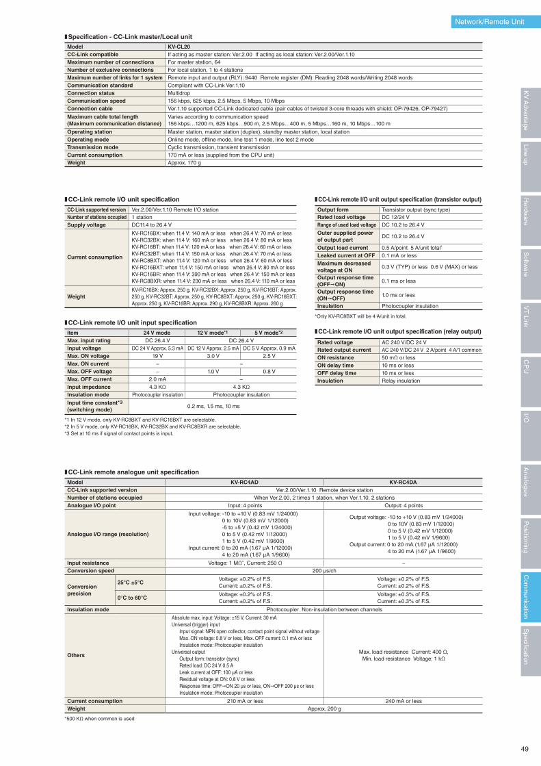
❚ Specification - CC-Link master/Local unit
Model KV-CL20CC-Link compatible If acting as master station: Ver.2.00 If acting as local station: Ver.2.00/Ver.1.10Maximum number of connections For master station, 64Number of exclusive connections For local station, 1 to 4 stationsMaximum number of links for 1 system Remote input and output (RLY): 9440 Remote register (DM): Reading 2048 words/Writing 2048 wordsCommunication standard Compliant with CC-Link Ver.1.10Connection status MultidropCommunication speed 156 kbps, 625 kbps, 2.5 Mbps, 5 Mbps, 10 MbpsConnection cable Ver.1.10 supported CC-Link dedicated cable (pair cables of twisted 3-core threads with shield: OP-79426, OP-79427)
Maximum cable total length (Maximum communication distance)
Varies according to communication speed156 kbps…1200 m, 625 kbps…900 m, 2.5 Mbps…400 m, 5 Mbps…160 m, 10 Mbps…100 m
Operating station Master station, master station (duplex), standby master station, local stationOperating mode Online mode, offline mode, line test 1 mode, line test 2 modeTransmission mode Cyclic transmission, transient transmissionCurrent consumption 170 mA or less (supplied from the CPU unit)Weight Approx. 170 g
*Only KV-RC8BXT will be 4 A/unit in total.
*1 In 12 V mode, only KV-RC8BXT and KV-RC16BXT are selectable.*2 In 5 V mode, only KV-RC16BX, KV-RC32BX and KV-RC8BXR are selectable.*3 Set at 10 ms if signal of contact points is input.
❚ CC-Link remote I/O unit specification ❚ CC-Link remote I/O unit output specification (transistor output)
❚ CC-Link remote I/O unit input specification❚ CC-Link remote I/O unit output specification (relay output)
CC-Link supported version Ver.2.00/Ver.1.10 Remote I/O stationNumber of stations occupied 1 stationSupply voltage DC11.4 to 26.4 V
Current consumption
KV-RC16BX: when 11.4 V: 140 mA or less when 26.4 V: 70 mA or lessKV-RC32BX: when 11.4 V: 160 mA or less when 26.4 V: 80 mA or lessKV-RC16BT: when 11.4 V: 120 mA or less when 26.4 V: 60 mA or lessKV-RC32BT: when 11.4 V: 150 mA or less when 26.4 V: 70 mA or lessKV-RC8BXT: when 11.4 V: 120 mA or less when 26.4 V: 60 mA or lessKV-RC16BXT: when 11.4 V: 150 mA or less when 26.4 V: 80 mA or lessKV-RC16BR: when 11.4 V: 390 mA or less when 26.4 V: 150 mA or lessKV-RC8BXR: when 11.4 V: 230 mA or less when 26.4 V: 110 mA or less
WeightKV-RC16BX: Approx. 250 g, KV-RC32BX: Approx. 250 g, KV-RC16BT: Approx. 250 g, KV-RC32BT: Approx. 250 g, KV-RC8BXT: Approx. 250 g, KV-RC16BXT: Approx. 250 g, KV-RC16BR: Approx. 290 g, KV-RC8BXR: Approx. 260 g
Item 24 V mode 12 V mode*1 5 V mode*2
Max. input rating DC 26.4 V DC 26.4 VInput voltage DC 24 V Approx. 5.3 mA DC 12 V Approx. 2.5 mA DC 5 V Approx. 0.9 mAMax. ON voltage 19 V 3.0 V 2.5 VMax. ON current − −Max. OFF voltage − 1.0 V 0.8 VMax. OFF current 2.0 mA −Input impedance 4.3 KΩ 4.3 KΩInsulation mode Photocoupler insulation Photocoupler insulation
Input time constant*3(switching mode)
0.2 ms, 1.5 ms, 10 ms
Output form Transistor output (sync type)Rated load voltage DC 12/24 VRange of used load voltage DC 10.2 to 26.4 V
Outer supplied power of output part
DC 10.2 to 26.4 V
Output load current 0.5 A/point 5 A/unit total*
Leaked current at OFF 0.1 mA or lessMaximum decreased voltage at ON
0.3 V (TYP) or less 0.6 V (MAX) or less
Output response time (OFF¨ON)
0.1 ms or less
Output response time (ON¨OFF)
1.0 ms or less
Insulation Photocoupler insulation
Rated voltage AC 240 V/DC 24 VRated output current AC 240 V/DC 24 V 2 A/point 4 A/1 commonON resistance 50 mΩ or lessON delay time 10 ms or lessOFF delay time 10 ms or lessInsulation Relay insulation
*500 KΩ when common is used
❚ CC-Link remote analogue unit specification
Model KV-RC4AD KV-RC4DACC-Link supported version Ver.2.00/Ver.1.10 Remote device stationNumber of stations occupied When Ver.2.00, 2 times 1 station, when Ver.1.10, 2 stationsAnalogue I/O point Input: 4 points Output: 4 points
Analogue I/O range (resolution)
Input voltage: -10 to +10 V (0.83 mV 1/24000) 0 to 10V (0.83 mV 1/12000) -5 to +5 V (0.42 mV 1/24000) 0 to 5 V (0.42 mV 1/12000) 1 to 5 V (0.42 mV 1/9600)Input current: 0 to 20 mA (1.67 μA 1/12000) 4 to 20 mA (1.67 μA 1/9600)
Output voltage: -10 to +10 V (0.83 mV 1/24000) 0 to 10V (0.83 mV 1/12000) 0 to 5 V (0.42 mV 1/12000) 1 to 5 V (0.42 mV 1/9600)Output current: 0 to 20 mA (1.67 μA 1/12000) 4 to 20 mA (1.67 μA 1/9600)
Input resistance Voltage: 1 MΩ*, Current: 250 Ω −Conversion speed 200 μs/ch
Conversion precision
25°C ±5°CVoltage: ±0.2% of F.S.Current: ±0.2% of F.S.
Voltage: ±0.2% of F.S.Current: ±0.2% of F.S.
0°C to 60°CVoltage: ±0.2% of F.S.Current: ±0.2% of F.S.
Voltage: ±0.3% of F.S.Current: ±0.3% of F.S.
Insulation mode Photocoupler Non-insulation between channels
Others
Absolute max. input: Voltage: ±15 V, Current: 30 mAUniversal (trigger) input Input signal: NPN open collector, contact point signal without voltage Max. ON voltage: 0.8 V or less, Max. OFF current: 0.1 mA or less Insulation mode: Photocoupler insulationUniversal output Output form: transistor (sync) Rated load: DC 24 V 0.5 A Leak current at OFF: 100 μA or less Residual voltage at ON: 0.8 V or less Response time: OFF"ON 20 μs or less, ON"OFF 200 μs or less Insulation mode: Photocoupler insulation
Max. load resistance Current: 400 Ω, Min. load resistance Voltage: 1 kΩ
Current consumption 210 mA or less 240 mA or lessWeight Approx. 200 g
Network/Remote Unit
49
Specification
Com
munication
Positioning
An
alo
gu
eI/O
CP
UV
T Link
Softw
areLine up
Hardw
areK
V A
dvantage
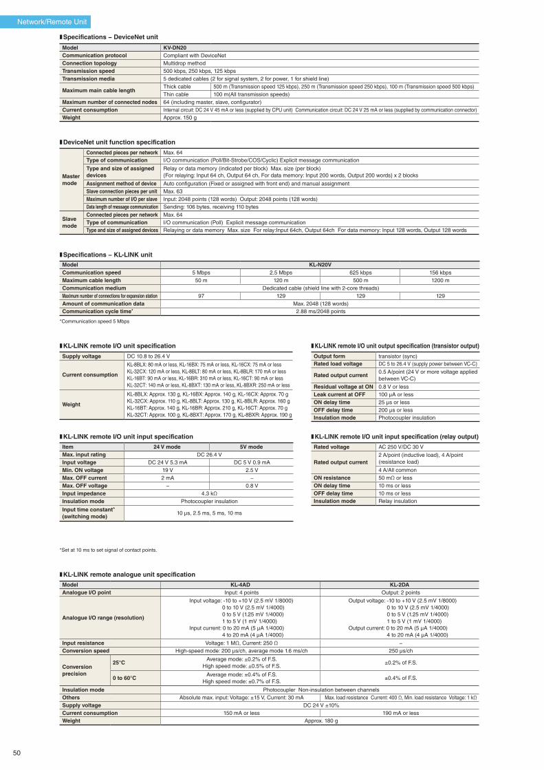
❚ Specifications − DeviceNet unit
Model KV-DN20Communication protocol Compliant with DeviceNetConnection topology Multidrop methodTransmission speed 500 kbps, 250 kbps, 125 kbpsTransmission media 5 dedicated cables (2 for signal system, 2 for power, 1 for shield line)
Maximum main cable lengthThick cable 500 m (Transmission speed 125 kbps), 250 m (Transmission speed 250 kbps), 100 m (Transmission speed 500 kbps)Thin cable 100 m(All transmission speeds)
Maximum number of connected nodes 64 (including master, slave, configurator)Current consumption Internal circuit: DC 24 V 45 mA or less (supplied by CPU unit) Communication circuit: DC 24 V 25 mA or less (supplied by communication connector)Weight Approx. 150 g
❚ DeviceNet unit function specification
Mastermode
Connected pieces per network Max. 64Type of communication I/O communication (Poll/Bit-Strobe/COS/Cyclic) Explicit message communication
Type and size of assigned devices
Relay or data memory (indicated per block) Max. size (per block){For relaying: Input 64 ch, Output 64 ch, For data memory: Input 200 words, Output 200 words} x 2 blocks
Assignment method of device Auto configuration (Fixed or assigned with front end) and manual assignmentSlave connection pieces per unit Max. 63Maximum number of I/O per slave Input: 2048 points (128 words) Output: 2048 points (128 words)Data length of message communication Sending: 106 bytes, receiving 110 bytes
Slavemode
Connected pieces per network Max. 64Type of communication I/O communication (Poll) Explicit message communicationType and size of assigned devices Relaying or data memory Max. size For relay:Input 64ch, Output 64ch For data memory: Input 128 words, Output 128 words
*Set at 10 ms to set signal of contact points.
❚ Specifications − KL-LINK unit
Model KL-N20VCommunication speed 5 Mbps 2.5 Mbps 625 kbps 156 kbpsMaximum cable length 50 m 120 m 500 m 1200 mCommunication medium Dedicated cable (shield line with 2-core threads) Maximum number of connections for expansion station 97 129 129 129Amount of communication data Max. 2048 (128 words)Communication cycle time* 2.88 ms/2048 points
*Communication speed 5 Mbps
❚ KL-LINK remote I/O unit specification
❚ KL-LINK remote I/O unit input specification ❚ KL-LINK remote I/O unit input specification (relay output)
Supply voltage DC 10.8 to 26.4 V
Current consumption
KL-8BLX: 80 mA or less, KL-16BX: 75 mA or less, KL-16CX: 75 mA or lessKL-32CX: 120 mA or less, KL-8BLT: 80 mA or less, KL-8BLR: 170 mA or lessKL-16BT: 90 mA or less, KL-16BR: 310 mA or less, KL-16CT: 90 mA or lessKL-32CT: 140 mA or less, KL-8BXT: 130 mA or less, KL-8BXR: 250 mA or less
Weight
KL-8BLX: Approx. 130 g, KL-16BX: Approx. 140 g, KL-16CX: Approx. 70 gKL-32CX: Approx. 110 g, KL-8BLT: Approx. 130 g, KL-8BLR: Approx. 160 gKL-16BT: Approx. 140 g, KL-16BR: Approx. 210 g, KL-16CT: Approx. 70 gKL-32CT: Approx. 100 g, KL-8BXT: Approx. 170 g, KL-8BXR: Approx. 190 g
Item 24 V mode 5V modeMax. input rating DC 26.4 VInput voltage DC 24 V 5.3 mA DC 5 V 0.9 mAMin. ON voltage 19 V 2.5 VMax. OFF current 2 mA −Max. OFF voltage − 0.8 VInput impedance 4.3 kΩInsulation mode Photocoupler insulation
Input time constant*(switching mode)
10 μs, 2.5 ms, 5 ms, 10 ms
❚ KL-LINK remote I/O unit output specification (transistor output)
Output form transistor (sync)Rated load voltage DC 5 to 26.4 V (supply power between VC-C)
Rated output current0.5 A/point (24 V or more voltage applied between VC-C)
Residual voltage at ON 0.8 V or lessLeak current at OFF 100 μA or lessON delay time 25 μs or lessOFF delay time 200 μs or lessInsulation mode Photocoupler insulation
Rated voltage AC 250 V/DC 30 V
Rated output current2 A/point (inductive load), 4 A/point (resistance load)
4 A/All commonON resistance 50 mΩ or lessON delay time 10 ms or lessOFF delay time 10 ms or lessInsulation mode Relay insulation
❚ KL-LINK remote analogue unit specification
Model KL-4AD KL-2DAAnalogue I/O point Input: 4 points Output: 2 points
Analogue I/O range (resolution)
Input voltage: -10 to +10 V (2.5 mV 1/8000) 0 to 10 V (2.5 mV 1/4000) 0 to 5 V (1.25 mV 1/4000) 1 to 5 V (1 mV 1/4000)Input current: 0 to 20 mA (5 μA 1/4000) 4 to 20 mA (4 μA 1/4000)
Output voltage: -10 to +10 V (2.5 mV 1/8000) 0 to 10 V (2.5 mV 1/4000) 0 to 5 V (1.25 mV 1/4000) 1 to 5 V (1 mV 1/4000)Output current: 0 to 20 mA (5 μA 1/4000) 4 to 20 mA (4 μA 1/4000)
Input resistance Voltage: 1 MΩ, Current: 250 Ω −Conversion speed High-speed mode: 200 μs/ch, average mode 1.6 ms/ch 250 μs/ch
Conversion precision
25°CAverage mode: ±0.2% of F.S.
High speed mode: ±0.5% of F.S. ±0.2% of F.S.
0 to 60°CAverage mode: ±0.4% of F.S.
High speed mode: ±0.7% of F.S. ±0.4% of F.S.
Insulation mode Photocoupler Non-insulation between channelsOthers Absolute max. input: Voltage: ±15 V, Current: 30 mA Max. load resistance Current: 400 Ω, Min. load resistance Voltage: 1 kΩSupply voltage DC 24 V ±10%Current consumption 150 mA or less 190 mA or lessWeight Approx. 180 g
Network/Remote Unit
50
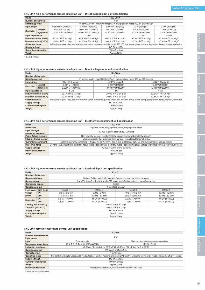
❚ KL-LINK high-performance remote data input unit - Direct current input unit specification
*-5 A to 5 A input
Model KL-DC1ANumber of channels 1 chSampling period In normal mode 1 ms (1000 times/s)/ in high precision mode 100 ms (10 times/s)Input range 0 to 20 mA (Range 1) ±10 mA (Range 2) ±100 mA (Range 3) ±1 A (Range 4) ±10 A (Range 5)
ResolutionNormal 0.01 mA (1/2000) 0.001 mA (1/20000) 0.01 mA (1/20000) 0.1 mA (1/20000) 1 mA (1/20000)High precision 0.0001 mA (1/200000) 0.0001 mA (1/200000) 0.001 mA (1/200000) 0.01 mA (1/200000) 0.1 mA (1/200000)
Input impedance 10 Ω 10 Ω 1 Ω 0.1 Ω 10 mΩMeasurement precision (25 ±5°C) ±0.2% of F.S. ±1 digit ±0.2% of F.S. ±1 digit ±0.2% of F.S. ±1 digit ±0.3% of F.S. ±1 digit ±0.5% of F.S. ±1 digit*
Measurement precision (0 to 50°C) ±0.6% of F.S. ±1 digit ±0.6% of F.S. ±1 digit ±0.6% of F.S. ±1 digit ±0.7% of F.S. ±1 digit ±0.9% of F.S. ±1 digit*
Other functions Holding function (peak, valley), zero point adjustment function, comparator output, filter function (LPF, HPF), time average (simple, moving), scaling function, display unit change, lock functionSupply voltage DC 24 V ±10%Current consumption 170 mA or lessWeight Approx. 350 g
❚ KL-LINK high-performance remote data input unit - Direct voltage input unit specification
Model KL-DC1VNumber of channels 1 chSampling period In normal mode 1 ms (1000 times/s)/ in high precision mode 100 ms (10 times/s)Input range 0 to 10 V (Range 1) ±10 V (Range 2) ±100 V (Range 3)
ResolutionNormal 0.001 V (1/10000) 0.001 V (1/20000) 0.01 V (1/20000)High precision 0.0001 V (1/100000) 0.0001 V (1/200000) 0.001 V (1/200000)
Input impedance 1 MΩ 1 MΩ 4 MΩMeasurement precision (25 ±5°C) ±0.1% of F.S. ±1 digit ±0.1% of F.S. ±1 digit ±0.2% of F.S. ±1 digitMeasurement precision (0 to 50°C) ±0.5% of F.S. ±1 digit ±0.5% of F.S. ±1 digit ±0.6% of F.S. ±1 digit
Other functions Holding function (peak, valley), zero point adjustment function, comparator output, filter function (LPF, HPF), time average (simple, moving), scaling function, display unit change, lock function
Supply voltage DC 24 V ±10%Current consumption 170 mA or lessWeight Approx. 350 g
❚ KL-LINK high-performance remote data input unit - Electricity measurement unit specification
Model KL-WH1Phase wire 3-phase 3-wire, single-phase 2-wire, single-phase 3-wireInput voltage/measured frequency
AC 100 to 250 V(sine wave) / 50/60 Hz
Power failure memory Non-volatility memory (valid electricity amount and invalid electricity amount)Integrated value cleared Clearing order by key switch on front surface, control input terminal, or KLCurrent measurement External currency sensors (CT: 3 types for 50 A, 100 A, 250 A) are available as options, and currency is set using a switchMeasured items Demand value, instant valid electricity, instant invalid electricity, valid electricity, invalid electricity, interphase voltage, interphase current, power rate, frequencySupply voltage AC 100 to 220 V ±10% 50/60 HzPower consumption 10 VA or lessWeight Approx. 400 g
❚ KL-LINK high-performance remote data input unit - Load cell input unit specification
Model KL-LC1Number of channels 1 ch Range switching Setting: Setting switch, Connection: Connecting terminal differs by range Sensor power 5 V ±5% (30 mA or less)/10 V±5% (30 mA or less): Setting selection by setting switchConformed sensor 350 ΩSampling period 1 ms (1000 times/s)
Input rangeSensor power
Input range Range 1 Range 2 Range 3 Range 45 V -2.5 to +2.5 mV -5.0 to +5.0 mV -10.0 to +10.0 mV -15.0 to +15.0 mV10 V -5.0 to +5.0 mV -10.0 to +10.0 mV -20.0 to +20.0 mV -30.0 to +30.0 mV
Resolution5 V 0.5 μV (1/10000) 1.0 μV (1/10000) 2.0 μV (1/10000) 3.0 μV (1/10000)10 V 0.5 μV (1/20000) 1.0 μV (1/20000) 2.0 μV (1/20000) 3.0 μV (1/20000)
Linearity drift (0 to 50°C) ±0.2% of F.S. ±1 digitZero drift (0 to 50°C) ±0.4% of F.S. ±1 digitSupply voltage DC 24 V ±10%Current consumption 170 mA or lessWeight Approx. 350 g
❚ KL-LINK remote temperature control unit specification
*Can be set for each channel.
Model KL-2TFNumber of temperature input points
2 ch
Input* Thermocoupler Platinum temperature measuring resistorTemperature sensor types K, J, T, E, R, B, N, S, W5Re/W26Re JPt100, Pt100Indication precision ±0.3% of F.S. ±1 digit (at 25°C ±5°C) ±0.7% of F.S. ±1 digit (at 0 to 60°C)Sampling period 125 ms/ch (250 ms/2 ch)Control period 1 to 100 sec.Operating mode PID control (with auto-tuning and 3 mode stabiliser function)/heating and cooling PID control (with auto-tuning and 3 mode stabiliser) / ON/OFF controlSupply voltage DC 24 V ±10%Current consumption 160 mA or lessWeight Approx. 210 gProtection structure IP66f (panel installation, front surface operation part only)
Network/Remote Unit
51
Specification
Com
munication
Positioning
An
alo
gu
eI/O
CP
UV
T Link
Softw
areLine up
Hardw
areK
V A
dvantage
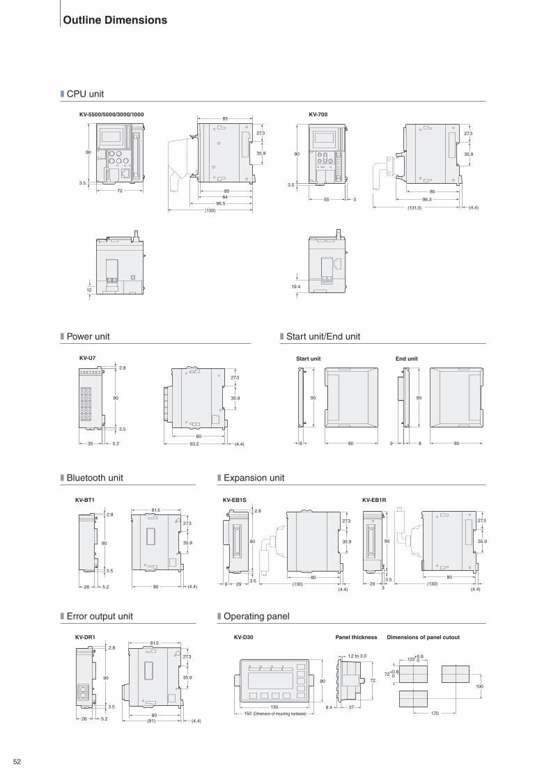
27.3
96.5
35.9
(130)
8480
85
72
90
3.5
12
(4.4)
27.3
96.3
80
35.9
(131.3)
355
90
3.5
19.4
3.5
5.235
35.9
27.3
2.8
90
80
93.2 (4.4) 809
90
880
90
8
90
3.5
2.8
26 5.2 80
81.5
(4.4)
27.3
35.9
(130)2980
90
3.5
2.8
27.3
35.9
9(4.4)
(130)3.5
90 35.9
27.3
80
329
(4.4)
(Dimension of mounting hardware)130
1508.4 37
1.2 to 3.0
7280
170
100
72+0.8 0
122+0.8 0
90
3.5
2.8
26 5.280
81.5
(91) (4.4)
27.3
35.9
Outline Dimensions
❚ CPU unit
❚ Power unit
❚ Bluetooth unit
❚ Error output unit
❚ Expansion unit
❚ Operating panel
❚ Start unit/End unit
KV-5500/5000/3000/1000
KV-U7
KV-BT1
KV-DR1
KV-EB1S
KV-D30 Panel thickness Dimensions of panel cutout
KV-EB1R
KV-700
Start unit End unit
52
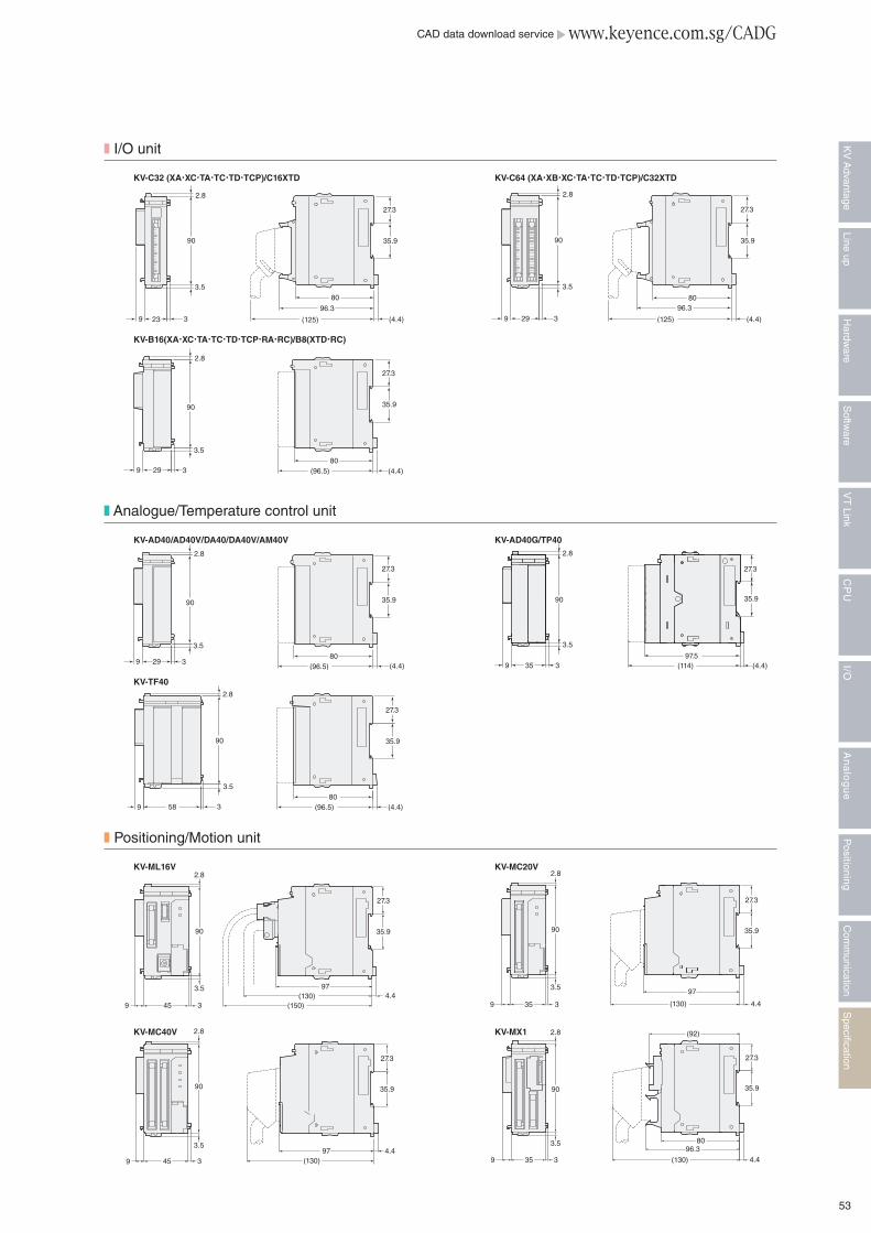
2.8
3.5
90
39 29
35.9
27.3
(96.5)80
(4.4)
9 23
90
3.5
2.8
80
27.3
35.9
96.3
(125)3 (4.4)
2.8
3.5
90
39 29
80
27.3
35.9
96.3
(125) (4.4)
2.8
3.5
90
39 29
35.9
27.3
(96.5)80
(4.4) 9 35
3.5
2.8
90
3 (114)97.5
(4.4)
27.3
35.9
58 39
90
3.5
2.8
80(96.5)
27.3
35.9
(4.4)
9 335
3.5
90
27.3
35.9
97
2.8
(130) 4.4
9 45 (130)97 4.4
3
3.5
2.8
90
27.3
35.9
345 (150)(130) 4.4
97
90
2.8
3.5
9
27.3
35.9
4.496.3
80
35 (130)9 3
3.5
90
2.8 (92)
27.3
35.9
CAD data download service www.keyence.com.sg/CADG
❚ I/O unit
❚ Analogue/Temperature control unit
❚ Positioning/Motion unit
KV-C32 (XA�XC�TA�TC�TD�TCP)/C16XTD
KV-AD40/AD40V/DA40/DA40V/AM40V
KV-ML16V
KV-MC40V
KV-TF40
KV-B16(XA�XC�TA�TC�TD�TCP�RA�RC)/B8(XTD�RC)
KV-C64 (XA�XB�XC�TA�TC�TD�TCP)/C32XTD
KV-AD40G/TP40
KV-MC20V
KV-MX1
53
Specification
Com
munication
Positioning
An
alo
gu
eI/O
CP
UV
T Link
Softw
areLine up
Hardw
areK
V A
dvantage
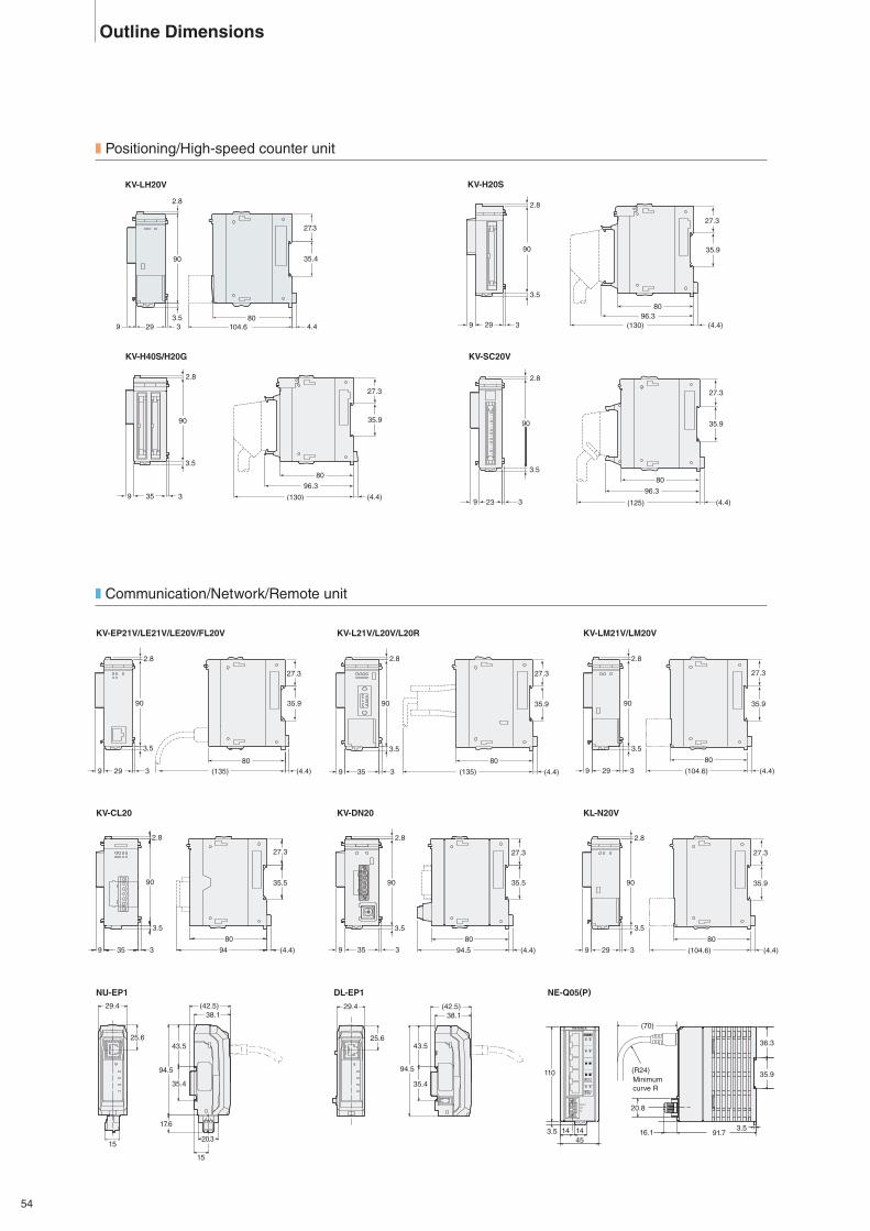
29
3.5
90
2.8
39
27.3
35.9
8096.3
(130) (4.4)
(130)
96.3
80
(4.4)
27.3
35.9
359
3.5
3
90
2.8
9 23
90
3.5
2.8
3
80
27.3
35.9
96.3
(125) (4.4)
35.9
27.3
80
2.8
90
3299
3.5
(104.6) (4.4)9 335
2.8
3.5
90
27.3
35.5
80
94 (4.4) 9 335
2.8
3.5
90
27.3
35.5
80
94.5 (4.4)
(135)
80
9 335
2.8
3.5
90 35.9
27.3
(4.4)
35.9
27.3
80
2.8
90
3299
3.5
(104.6) (4.4)29 39
90
2.8
3.5
(135)80
27.3
35.9
(4.4)
(42.5)38.1
94.5
17.6
15
15
20.3
43.5
35.4
29.4
25.6
29.4 (42.5)38.1
94.5
43.5
35.4
25.6
3.516.1 91.714 14
45
36.3
110
3.5
(70)
(R24)Minimum curve R
35.9
20.8
LINK 100M
POWER
PoE
POWERPOWER
NE-Q05PPoE
PoE
LINK
LINK
LINK
LINK
100M
100M
100M
100M
POWER
0VDC 24 V
Outline Dimensions
❚ Positioning/High-speed counter unit
❚ Communication/Network/Remote unit
KV-H20S
KV-SC20V
KV-EP21V/LE21V/LE20V/FL20V
NU-EP1 DL-EP1 NE-Q05(P)
KV-LM21V/LM20V
KV-DN20
KV-H40S/H20G
KV-L21V/L20V/L20R
KV-CL20 KL-N20V
104.680
90
2993.5
3
2.8
35.4
4.4
27.3
KV-LH20V
54
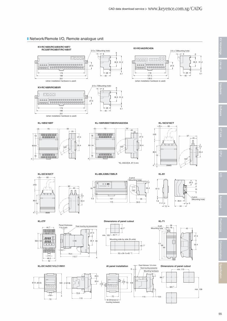
(when installation hardware is used)
179189
201
8 6
35.5 51.2
5.128
40
27.5
2-5 x 7(Mounting hole)
(when installation hardware is used)
118127.5
139.5
27.5
9 6
35.5 51.2
5.128
40
2-5 x 7(Mounting hole)
(when installation hardware is used)
179189
201
8 6
35.5 51.2
5.128
40
27.5
2-5 x 7(Mounting hole)
5925
27.3
35.4120°
70
9054
18
18
5
4
79*45
25
27.3
35.4120°
70
90 54
18
18
5
4
*KL-4AD/2DA, 87.5 mm
6725
7.3
35.4
120°
60
(43)
88.5
70
4
5
8240
7.3
35.4
60
(43)
88.5
70
4
5
115
5.2
50 42
107
2-ø4.6(Mounting hole)
59.5
35.4
35
7.2
120°
44
536.5
2-ø3.4(Mounting hole)
15
2720.3
4
67.5
1.6
15
11199
90
35.4
27.3
199.538
432-ø5
Mounting hole
min. 113
min. 158
68 +0.7-0
68 +0.7-0
Mounting hardware
Panel mounting accessories
13.5
Panel thickness 1.6 to 4mm
6
115
109
92 (Dimension of mounting hardware)
72
72(13)
(13)
13
72
(63.5)67.8 109
472.8
115
(£67.8)
28.5
35.4
Panel thickness 1 to 4 mm
£45
112.779.4
12
35.4
27.3
4
90
44.7
59.6 52
5246.211
Panel mounting ring (accessories)
0+0.645
0+0.645
min. 120
0+0.652 x (N-1)+45
0+0.645
Mounting side by side (N units)
❚ Network/Remote I/O, Remote analogue unit
KV-RC16BX/RC32BX/RC16BT/ RC32BT/RC8BXT/RC16BXT KV-RC4AD/RC4DA
KV-RC16BR/RC8BXR
KL-16BX/16BT
KL-32CX/32CT
KL-2TF Dimensions of panel cutout
KL-DC1A/DC1V/LC1/WH1 At panel installation Dimensions of panel cutout
KL-16BR/8BXT/8BXR/4AD/2DA
KL-8BLX/8BLT/8BLR
KL-16CX/16CT
KL-B1
KL-T1
CAD data download service www.keyence.com.sg/CADG
55
Specification
Com
munication
Positioning
An
alo
gu
eI/O
CP
UV
T Link
Softw
areLine up
Hardw
areK
V A
dvantage
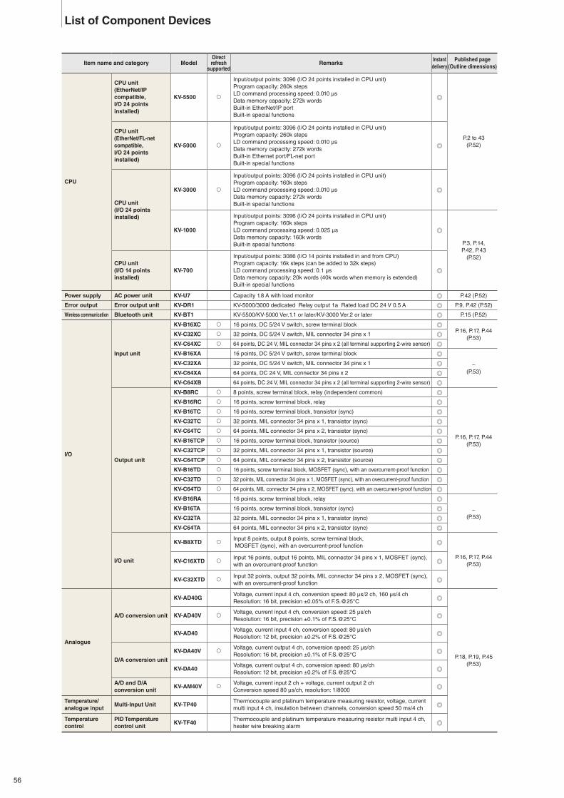
Item name and category ModelDirectrefresh
supportedRemarks
Instant delivery
Published page(Outline dimensions)
CPU
CPU unit(EtherNet/IP compatible,I/O 24 points installed)
KV-5500 �
Input/output points: 3096 (I/O 24 points installed in CPU unit)Program capacity: 260k stepsLD command processing speed: 0.010 μsData memory capacity: 272k wordsBuilt-in EtherNet/IP portBuilt-in special functions
P.2 to 43(P.52)
CPU unit(EtherNet/FL-net compatible,I/O 24 points installed)
KV-5000 �
Input/output points: 3096 (I/O 24 points installed in CPU unit)Program capacity: 260k stepsLD command processing speed: 0.010 μsData memory capacity: 272k wordsBuilt-in Ethernet port/FL-net portBuilt-in special functions
CPU unit(I/O 24 points installed)
KV-3000 �
Input/output points: 3096 (I/O 24 points installed in CPU unit)Program capacity: 160k stepsLD command processing speed: 0.010 μsData memory capacity: 272k wordsBuilt-in special functions
KV-1000
Input/output points: 3096 (I/O 24 points installed in CPU unit)Program capacity: 160k stepsLD command processing speed: 0.025 μsData memory capacity: 160k wordsBuilt-in special functions P.3, P.14,
P.42, P.43(P.52)
CPU unit(I/O 14 points installed)
KV-700
Input/output points: 3086 (I/O 14 points installed in and from CPU)Program capacity: 16k steps (can be added to 32k steps)LD command processing speed: 0.1 μsData memory capacity: 20k words (40k words when memory is extended)Built-in special functions
Power supply AC power unit KV-U7 Capacity 1.8 A with load monitor P.42 (P.52)
Error output Error output unit KV-DR1 KV-5000/3000 dedicated Relay output 1a Rated load DC 24 V 0.5 A P.9, P.42 (P.52)
Wireless communication Bluetooth unit KV-BT1 KV-5500/KV-5000 Ver.1.1 or later/KV-3000 Ver.2 or later P.15 (P.52)
I/O
Input unit
KV-B16XC � 16 points, DC 5/24 V switch, screw terminal blockP.16, P.17, P.44
(P.53)KV-C32XC � 32 points, DC 5/24 V switch, MIL connector 34 pins x 1
KV-C64XC � 64 points, DC 24 V, MIL connector 34 pins x 2 (all terminal supporting 2-wire sensor)
KV-B16XA 16 points, DC 5/24 V switch, screw terminal block
−(P.53)
KV-C32XA 32 points, DC 5/24 V switch, MIL connector 34 pins x 1
KV-C64XA 64 points, DC 24 V, MIL connector 34 pins x 2
KV-C64XB 64 points, DC 24 V, MIL connector 34 pins x 2 (all terminal supporting 2-wire sensor)
Output unit
KV-B8RC � 8 points, screw terminal block, relay (independent common)
P.16, P.17, P.44(P.53)
KV-B16RC � 16 points, screw terminal block, relay
KV-B16TC � 16 points, screw terminal block, transistor (sync)
KV-C32TC � 32 points, MIL connector 34 pins x 1, transistor (sync)
KV-C64TC � 64 points, MIL connector 34 pins x 2, transistor (sync)
KV-B16TCP � 16 points, screw terminal block, transistor (source)
KV-C32TCP � 32 points, MIL connector 34 pins x 1, transistor (source)
KV-C64TCP � 64 points, MIL connector 34 pins x 2, transistor (source)
KV-B16TD � 16 points, screw terminal block, MOSFET (sync), with an overcurrent-proof function
KV-C32TD � 32 points, MIL connector 34 pins x 1, MOSFET (sync), with an overcurrent-proof function
KV-C64TD � 64 points, MIL connector 34 pins x 2, MOSFET (sync), with an overcurrent-proof function
KV-B16RA 16 points, screw terminal block, relay
−(P.53)
KV-B16TA 16 points, screw terminal block, transistor (sync)
KV-C32TA 32 points, MIL connector 34 pins x 1, transistor (sync)
KV-C64TA 64 points, MIL connector 34 pins x 2, transistor (sync)
I/O unit
KV-B8XTD �Input 8 points, output 8 points, screw terminal block, MOSFET (sync), with an overcurrent-proof function
P.16, P.17, P.44(P.53)KV-C16XTD �
Input 16 points, output 16 points, MIL connector 34 pins x 1, MOSFET (sync), with an overcurrent-proof function
KV-C32XTD �Input 32 points, output 32 points, MIL connector 34 pins x 2, MOSFET (sync), with an overcurrent-proof function
Analogue
A/D conversion unit
KV-AD40GVoltage, current input 4 ch, conversion speed: 80 μs/2 ch, 160 μs/4 chResolution: 16 bit, precision ±0.05% of F.S.@25°C
P.18, P.19, P.45(P.53)
KV-AD40V �Voltage, current input 4 ch, conversion speed: 25 μs/chResolution: 16 bit, precision ±0.1% of F.S.@25°C
KV-AD40Voltage, current input 4 ch, conversion speed: 80 μs/chResolution: 12 bit, precision ±0.2% of F.S.@25°C
D/A conversion unit
KV-DA40V �Voltage, current output 4 ch, conversion speed: 25 μs/chResolution: 16 bit, precision ±0.1% of F.S.@25°C
KV-DA40Voltage, current output 4 ch, conversion speed: 80 μs/chResolution: 12 bit, precision ±0.2% of F.S.@25°C
A/D and D/A conversion unit
KV-AM40V �Voltage, current input 2 ch + voltage, current output 2 chConversion speed 80 μs/ch, resolution: 1/8000
Temperature/analogue input
Multi-Input Unit KV-TP40Thermocouple and platinum temperature measuring resistor, voltage, current multi input 4 ch, insulation between channels, conversion speed 50 ms/4 ch
Temperature control
PID Temperature control unit
KV-TF40Thermocouple and platinum temperature measuring resistor multi input 4 ch, heater wire breaking alarm
List of Component Devices
56
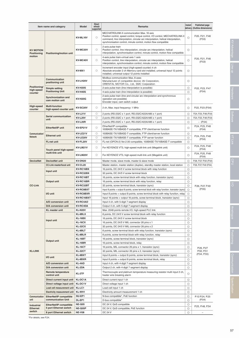
Item name and category ModelDirectrefresh
supportedRemarks
Instant delivery
Published page(Outline dimensions)
KV MOTIONPositioningmotion
Positioning/motion unit
KV-ML16V �
MECHATROLINK-II communication Max. 16 axis Position control, speed control, torque control, I/O control, MECHATROLINK-II command, line interpolation, circular arc interpolation, helical interpolation, synchronisation control, minute control, motion flow compatible
P.20, P.21, P.46(P.53)
KV-MC20V �2-axis pulse train Position control, line interpolation, circular arc interpolation, helical interpolation, synchronisation control, minute control, motion flow compatible
P.20, P.21, P.46(P.53)
KV-MC40V �4-axis pulse train+virtual axis 1 axis Position control, line interpolation, circular arc interpolation, helical interpolation, synchronisation control, minute control, motion flow compatible
KV-MX1 �Increment encoder input (high-speed counter) 4 ch Absolute encoder 2 ch Memory card slot installed, universal input 12 points installed, universal output 12 points installed
Positioning/high-speed counter
Communication positioning unit
KV-LH20VModbus communication Max. 8 axesManufacturer of compatible device: IAI Corporation, ORIENTAL MOTOR Co., Ltd., SMC Corporation
P.22, P.23, P.47(P.54)
Simple settingPositioning Unit
KV-H20S 2-axis pulse train (line interpolation is possible)
KV-H40S 4-axis pulse train (line interpolation is possible)
Synchronization and cam motion unit
KV-H20G2-axis pulse train (line and circular arc interpolation and synchronous operation are possible) Encoder input, cam switch output
High-speed counter
Multi-function high-speed counter unit
KV-SC20V � 2 ch, Max. input frequency: 1 MHz P.22, P.23 (P.54)
Communication/Network
Serial communication unit
KV-L21V � 2 ports (RS-232C x 1 port, RS-232C/422A/485 x 1 port) P.24, P.25, P.48 (P.54)
KV-L20V � 2 ports (RS-232C x 1 port, RS-232C/422A/485 x 1 port) P.24, P.25, P.48 (P.54)
KV-L20R 2 ports (RS-232C x 1 port, RS-232C/422A/485 x 1 port) − (P.54)
EtherNet/IP unit KV-EP21V �EtherNet/IP compatible100BASE-TX/10BASE-T compatible, FTP client/server function
P.24, P.25, P.48(P.54)
Ethernet unitKV-LE21V � 100BASE-TX/10BASE-T compatible, FTP client/server function
P.24, P.25, P.48(P.54)
KV-LE20V � 100BASE-TX/10BASE-T compatible, FTP server function
FL-net unit KV-FL20V � FL-net (OPCN-2) Ver.2.00 compatible, 100BASE-TX/10BASE-T compatible
Touch panel high-speed multi-link unit
KV-LM21V � For KEYENCE VT3, high-speed multi-link unit (Megalink unit)P.24, P.25, P.48
(P.54)
KV-LM20V � For KEYENCE VT3, high-speed multi-link unit (Megalink unit)P.24, P.25, P.48
(P.54)
DeviceNet DeviceNet unit KV-DN20 Master mode, slave mode, master & slave mode P.26, P.27, P.50 (P.54)
CC-Link
CC-Link master/local unit KV-CL20 Master station, master station (duplex), standby master station, local station P.26, P.27, P.49 (P.54)
Input unitKV-RC16BX 16 points, DC 24/5 V screw terminal block with relay function
P.26, P.27, P.49(P.55)
KV-RC32BX 32 points, DC 24/5 V screw terminal block
Output unit
KV-RC16BT 16 points, screw terminal block with relay function, transistor (sync)
KV-RC16BR 16 points, screw terminal block with relay function, relay
KV-RC32BT 32 points, screw terminal block, transistor (sync)
I/O unit
KV-RC8BXT Input 8 points + output 8 points, screw terminal block with relay function, transistor (sync)
KV-RC8BXR Input 8 points + output 8 points, screw terminal block with relay function, relay
KV-RC16BXT Input 16 points + output 16 points, screw terminal block, transistor (sync)
A/D conversion unit KV-RC4AD Input 4 ch, with 5-digit 7 segment display
D/A conversion unit KV-RC4DA Output 4 ch, with 5-digit 7 segment display
KL-LINK
KL master unit KL-N20V Max. 2048 points remote I/O, high-speed PLC link
P.26, P.27P.50, P.51
(P.54, P.55)
Input unit
KL-8BLX 8 points, DC 24/5 V screw terminal block with relay function
KL-16BX 16 points, DC 24/5 V screw terminal block
KL-16CX 16 points, DC 24/5 V MIL connector 26 pins x 1
KL-32CX 32 points, DC 24/5 V MIL connector 26 pins x 2
Output unit
KL-8BLT 8 points, screw terminal block with relay function, transistor (sync)
KL-8BLR 8 points, screw terminal block with relay function, relay
KL-16BT 16 points, screw terminal block, transistor (sync)
KL-16BR 16 points, screw terminal block, relay
KL-16CT 16 points, MIL connector 26 pins x 1, transistor (sync)
KL-32CT 32 points, MIL connector 26 pins x 2, transistor (sync)
I/O unitKL-8BXT Input 8 points + output 8 points, screw terminal block, transistor (sync)
KL-8BXR Input 8 points + output 8 points, screw terminal block, relay
A/D conversion unit KL-4AD Input 4 ch, with 4-digit 7 segment display
D/A conversion unit KL-2DA Output 2 ch, with 4-digit 7 segment display
Remote temperature control unit
KL-2TFThermocouple and platinum temperature measuring resistor multi input 2 ch, heater wire breaking alarm
Direct current input unit KL-DC1A Direct current input 1 ch
Direct voltage input unit KL-DC1V Direct voltage input 1 ch
Load cell measurement unit KL-LC1 Load cell input 1 ch
Electricity measurement unit KL-WH1 Electricity amount measurement 1 ch
Communication unit
EtherNet/IP compatiblecommunication Unit
NU-EP1 N-bus compatible*, PoE function P.13 P.24, P.25 (P.54)DL-EP1 D-bus compatible*
IndustrialEthernetswitch
EtherNet/IP compatible5 port Ethernet switch
NE-Q05 DC 24 V, QoS compatibleP.25, P.48, P.54
NE-Q05P DC 24 V, QoS compatible, PoE function
8 port Ethernet switch NE-V08 DC 24 V −
*For details, see P.24.
57
Specification
Com
munication
Positioning
An
alo
gu
eI/O
CP
UV
T Link
Softw
areLine up
Hardw
areK
V A
dvantage
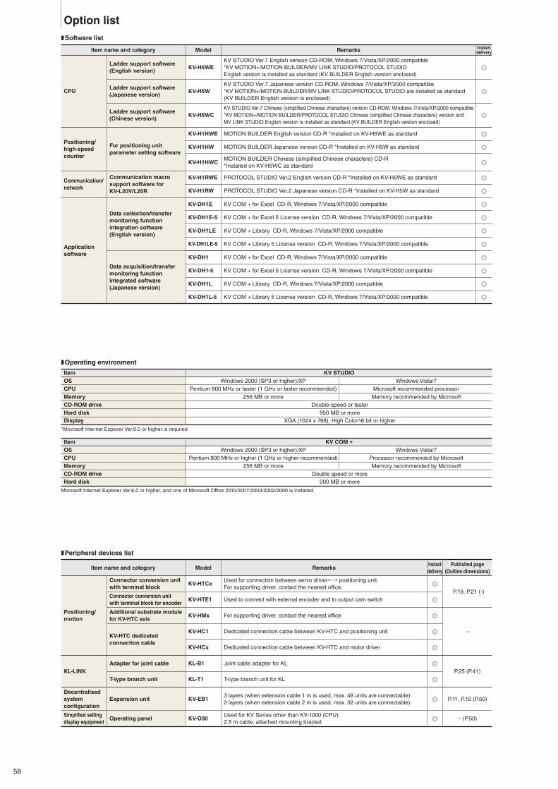
❚ Software list
Item name and category Model Remarks Instant delivery
CPU
Ladder support software (English version)
KV-H5WEKV STUDIO Ver.7 English version CD-ROM, Windows 7/Vista/XP/2000 compatible*KV MOTION+/MOTION BUILDER/MV LINK STUDIO/PROTOCOL STUDIOEnglish version is installed as standard (KV BUILDER English version enclosed)
Ladder support software(Japanese version)
KV-H5WKV STUDIO Ver.7 Japanese version CD-ROM, Windows 7/Vista/XP/2000 compatible*KV MOTION+/MOTION BUILDER/MV LINK STUDIO/PROTOCOL STUDIO are installed as standard (KV BUILDER English version is enclosed)
Ladder support software (Chinese version)
KV-H5WCKV STUDIO Ver.7 Chinese (simplified Chinese characters) version CD-ROM, Windows 7/Vista/XP/2000 compatible *KV MOTION+/MOTION BUILDER/PROTOCOL STUDIO Chinese (simplified Chinese characters) version and MV LINK STUDIO English version is installed as standard (KV BUILDER English version enclosed)
Positioning/high-speed counter
For positioning unitparameter setting software
KV-H1HWE MOTION BUILDER English version CD-R *Installed on KV-H5WE as standard
KV-H1HW MOTION BUILDER Japanese version CD-R *Installed on KV-H5W as standard
KV-H1HWCMOTION BUILDER Chinese (simplified Chinese characters) CD-R *Installed on KV-H5WC as standard
Communication/network
Communication macro support software for KV-L20V/L20R
KV-H1RWE PROTOCOL STUDIO Ver.2 English version CD-R *Installed on KV-H5WE as standard
KV-H1RW PROTOCOL STUDIO Ver.2 Japanese version CD-R *Installed on KV-H5W as standard
Application software
Data collection/transfermonitoring function integration software(English version)
KV-DH1E KV COM + for Excel CD-R, Windows 7/Vista/XP/2000 compatible
KV-DH1E-5 KV COM + for Excel 5 License version CD-R, Windows 7/Vista/XP/2000 compatible
KV-DH1LE KV COM + Library CD-R, Windows 7/Vista/XP/2000 compatible
KV-DH1LE-5 KV COM + Library 5 License version CD-R, Windows 7/Vista/XP/2000 compatible
Data acquisition/transfer monitoring function integrated software(Japanese version)
KV-DH1 KV COM + for Excel CD-R, Windows 7/Vista/XP/2000 compatible
KV-DH1-5 KV COM + for Excel 5 License version CD-R, Windows 7/Vista/XP/2000 compatible
KV-DH1L KV COM + Library CD-R, Windows 7/Vista/XP/2000 compatible
KV-DH1L-5 KV COM + Library 5 License version CD-R, Windows 7/Vista/XP/2000 compatible
❚ Peripheral devices list
Item name and category Model RemarksInstant delivery
Published page(Outline dimensions)
Positioning/motion
Connector conversion unitwith terminal block
KV-HTCxUsed for connection between servo driver!" positioning unit.For supporting driver, contact the nearest office.
P.19, P.21 (-)Connector conversion unitwith terminal block for encoder
KV-HTE1 Used to connect with external encoder and to output cam switch
Additional substrate modulefor KV-HTC axis
KV-HMx For supporting driver, contact the nearest office
−KV-HTC dedicated connection cable
KV-HC1 Dedicated connection cable between KV-HTC and positioning unit
KV-HCx Dedicated connection cable between KV-HTC and motor driver
KL-LINKAdapter for joint cable KL-B1 Joint cable adapter for KL
P.25 (P.41)T-type branch unit KL-T1 T-type branch unit for KL
Decentralised system configuration
Expansion unit KV-EB13 layers (when extension cable 1 m is used, max. 48 units are connectable) 2 layers (when extension cable 2 m is used, max. 32 units are connectable)
P.11, P.12 (P.50)
Simplified setting display equipment
Operating panel KV-D30Used for KV Series other than KV-1000 (CPU).2.5 m cable, attached mounting bracket
− (P.50)
Option list
❚ Operating environment
*Microsoft Internet Explorer Ver.6.0 or higher is required
Microsoft Internet Explorer Ver.6.0 or higher, and one of Microsoft Office 2010/2007/2003/2002/2000 is installed
Item KV STUDIOOS Windows 2000 (SP3 or higher)/XP Windows Vista/7CPU Pentium 800 MHz or faster (1 GHz or faster recommended) Microsoft recommended processorMemory 256 MB or more Memory recommended by MicrosoftCD-ROM drive Double-speed or fasterHard disk 950 MB or moreDisplay XGA (1024 x 768), High Color16 bit or higher
Item KV COM +
OS Windows 2000 (SP3 or higher)/XP Windows Vista/7CPU Pentium 800 MHz or higher (1 GHz or higher recommended) Processor recommended by MicrosoftMemory 256 MB or more Memory recommended by MicrosoftCD-ROM drive Double speed or moreHard disk 200 MB or more
58
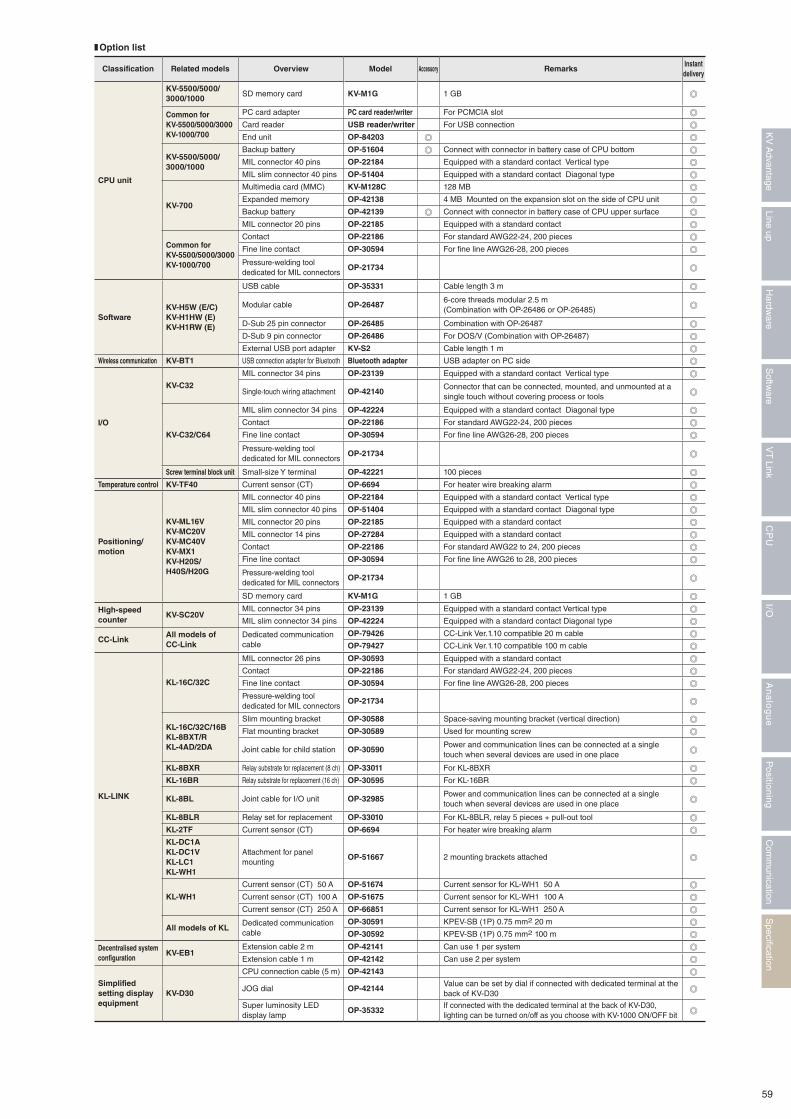
❚ Option list
Classification Related models Overview Model Accessory RemarksInstant delivery
CPU unit
KV-5500/5000/3000/1000
SD memory card KV-M1G 1 GB
Common for KV-5500/5000/3000 KV-1000/700
PC card adapter PC card reader/writer For PCMCIA slot
Card reader USB reader/writer For USB connection
End unit OP-84203
KV-5500/5000/3000/1000
Backup battery OP-51604 Connect with connector in battery case of CPU bottom
MIL connector 40 pins OP-22184 Equipped with a standard contact Vertical type
MIL slim connector 40 pins OP-51404 Equipped with a standard contact Diagonal type
KV-700
Multimedia card (MMC) KV-M128C 128 MB
Expanded memory OP-42138 4 MB Mounted on the expansion slot on the side of CPU unit
Backup battery OP-42139 Connect with connector in battery case of CPU upper surface
MIL connector 20 pins OP-22185 Equipped with a standard contact
Common for KV-5500/5000/3000KV-1000/700
Contact OP-22186 For standard AWG22-24, 200 pieces
Fine line contact OP-30594 For fine line AWG26-28, 200 pieces
Pressure-welding tool dedicated for MIL connectors
OP-21734
SoftwareKV-H5W (E/C)KV-H1HW (E)KV-H1RW (E)
USB cable OP-35331 Cable length 3 m
Modular cable OP-264876-core threads modular 2.5 m (Combination with OP-26486 or OP-26485)
D-Sub 25 pin connector OP-26485 Combination with OP-26487
D-Sub 9 pin connector OP-26486 For DOS/V (Combination with OP-26487)
External USB port adapter KV-S2 Cable length 1 m
Wireless communication KV-BT1 USB connection adapter for Bluetooth Bluetooth adapter USB adapter on PC side
I/O
KV-C32
MIL connector 34 pins OP-23139 Equipped with a standard contact Vertical type
Single-touch wiring attachment OP-42140Connector that can be connected, mounted, and unmounted at a single touch without covering process or tools
KV-C32/C64
MIL slim connector 34 pins OP-42224 Equipped with a standard contact Diagonal type
Contact OP-22186 For standard AWG22-24, 200 pieces
Fine line contact OP-30594 For fine line AWG26-28, 200 pieces
Pressure-welding tool dedicated for MIL connectors
OP-21734
Screw terminal block unit Small-size Y terminal OP-42221 100 pieces
Temperature control KV-TF40 Current sensor (CT) OP-6694 For heater wire breaking alarm
Positioning/motion
KV-ML16VKV-MC20VKV-MC40VKV-MX1KV-H20S/H40S/H20G
MIL connector 40 pins OP-22184 Equipped with a standard contact Vertical type
MIL slim connector 40 pins OP-51404 Equipped with a standard contact Diagonal type
MIL connector 20 pins OP-22185 Equipped with a standard contact
MIL connector 14 pins OP-27284 Equipped with a standard contact
Contact OP-22186 For standard AWG22 to 24, 200 pieces
Fine line contact OP-30594 For fine line AWG26 to 28, 200 pieces
Pressure-welding tool dedicated for MIL connectors
OP-21734
SD memory card KV-M1G 1 GB
High-speed counter
KV-SC20VMIL connector 34 pins OP-23139 Equipped with a standard contact Vertical type
MIL slim connector 34 pins OP-42224 Equipped with a standard contact Diagonal type
CC-LinkAll models of CC-Link
Dedicated communication cable
OP-79426 CC-Link Ver.1.10 compatible 20 m cable
OP-79427 CC-Link Ver.1.10 compatible 100 m cable
KL-LINK
KL-16C/32C
MIL connector 26 pins OP-30593 Equipped with a standard contact
Contact OP-22186 For standard AWG22-24, 200 pieces
Fine line contact OP-30594 For fine line AWG26-28, 200 pieces
Pressure-welding tool dedicated for MIL connectors
OP-21734
KL-16C/32C/16BKL-8BXT/RKL-4AD/2DA
Slim mounting bracket OP-30588 Space-saving mounting bracket (vertical direction)
Flat mounting bracket OP-30589 Used for mounting screw
Joint cable for child station OP-30590Power and communication lines can be connected at a single touch when several devices are used in one place
KL-8BXR Relay substrate for replacement (8 ch) OP-33011 For KL-8BXR
KL-16BR Relay substrate for replacement (16 ch) OP-30595 For KL-16BR
KL-8BL Joint cable for I/O unit OP-32985Power and communication lines can be connected at a single touch when several devices are used in one place
KL-8BLR Relay set for replacement OP-33010 For KL-8BLR, relay 5 pieces + pull-out tool
KL-2TF Current sensor (CT) OP-6694 For heater wire breaking alarm
KL-DC1A KL-DC1VKL-LC1KL-WH1
Attachment for panel mounting
OP-51667 2 mounting brackets attached
KL-WH1
Current sensor (CT) 50 A OP-51674 Current sensor for KL-WH1 50 A
Current sensor (CT) 100 A OP-51675 Current sensor for KL-WH1 100 A
Current sensor (CT) 250 A OP-66851 Current sensor for KL-WH1 250 A
All models of KLDedicated communication cable
OP-30591 KPEV-SB (1P) 0.75 mm2 20 m
OP-30592 KPEV-SB (1P) 0.75 mm2 100 m
Decentralised system configuration
KV-EB1Extension cable 2 m OP-42141 Can use 1 per system
Extension cable 1 m OP-42142 Can use 2 per system
Simplified setting display equipment
KV-D30
CPU connection cable (5 m) OP-42143
JOG dial OP-42144Value can be set by dial if connected with dedicated terminal at the back of KV-D30
Super luminosity LED display lamp
OP-35332If connected with the dedicated terminal at the back of KV-D30, lighting can be turned on/off as you choose with KV-1000 ON/OFF bit
59
Specification
Com
munication
Positioning
An
alo
gu
eI/O
CP
UV
T Link
Softw
areLine up
Hardw
areK
V A
dvantage
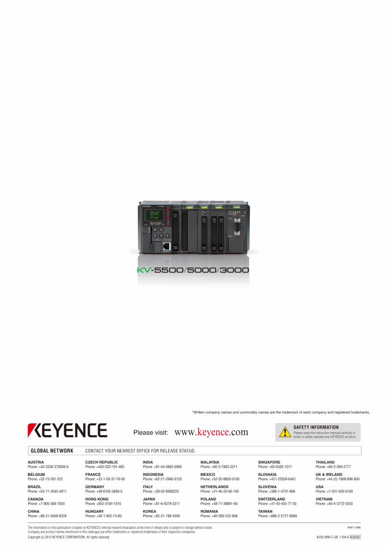
*Written company names and commodity names are the trademark of each company and registered trademarks.
KV55-WW-C-GB 1104-6 600A82Copyright (c) 2012 KEYENCE CORPORATION. All rights reserved.
www.keyence.com