kbox a-150-apl - recab uk
TRANSCRIPT

USER GUIDE
www.kontron.com // 1
KBox A-150-APL Doc. User Guide, Rev. 1.3
Doc. ID: 1062-3589

KBox A-150-APL - User Guide, Rev. 1.3
www.kontron.com // 2
This page has been intentionally left blank

KBox A-150-APL - User Guide, Rev. 1.3
www.kontron.com // 3
KBOX A-150-APL - USER GUIDE
Disclaimer Kontron would like to point out that the information contained in this user guide may be subject to alteration, particularly as a result of the constant upgrading of Kontron products. This document does not entail any guarantee on the part of Kontron with respect to technical processes described in the user guide or any product characteristics set out in the user guide. Kontron assumes no responsibility or liability for the use of the described product(s), conveys no license or title under any patent, copyright or mask work rights to these products and makes no representations or warranties that these products are free from patent, copyright or mask work right infringement unless otherwise specified. Applications that are described in this user guide are for illustration purposes only. Kontron makes no representation or warranty that such application will be suitable for the specified use without further testing or modification. Kontron expressly informs the user that this user guide only contains a general description of processes and instructions which may not be applicable in every individual case. In cases of doubt, please contact Kontron.
This user guide is protected by copyright. All rights are reserved by Kontron. No part of this document may be reproduced, transmitted, transcribed, stored in a retrieval system, or translated into any language or computer language, in any form or by any means (electronic, mechanical, photocopying, recording, or otherwise), without the express written permission of Kontron. Kontron points out that the information contained in this user guide is constantly being updated in line with the technical alterations and improvements made by Kontron to the products and thus this user guide only reflects the technical status of the products by Kontron at the time of publishing.
Brand and product names are trademarks or registered trademarks of their respective owners.
©2018 by Kontron S&T AG
Kontron S&T AG
Lise-Meitner-Str. 3-5 86156 Augsburg Germany www.kontron.com

KBox A-150-APL - User Guide, Rev. 1.3
www.kontron.com // 4
Intended Use This DIN rail industrial embedded computer platform, sold by Kontron, is part of Kontron’s A-Series intended for control cabinet applications, offering high performance at low power dissipation. The KBox A-150 product family can operate in a temperature range from 0°C to plus 40°C, and a humidity of 10 to 90 percent does not affect the function of the product. The products fanless design ensures a significantly prolonged lifespan and high system availability. This product offers flexible DIN Rail mounting positions within a control cabinet even when space is limited. Users must comply with all product specifications stated in the product documentation and this user guide. If it is intended, to incorporated the product into any total systems or applications, carry out sufficient, compatibility and functions tests prior to any use or resale.
THIS PRODUCT IS NOT DESIGNED, MANUFACTURED OR INTENDED FOR USE OR RESALE FOR THE OPERATION OF APPLICATION IN A HAZARDOUS ENVIRONMENT, OR REQUIRING FAIL-SAFE PERFORMANCE, OR IN WHICH THE FAILURE OF PRODUCTS COULD LEAD DIRECTLY TO DEATH, PERSONAL INJURY, OR SEVERE PHYSICAL OR ENVIRONMENTAL DAMAGE (COLLECTIVELY "HIGH RISK APPLICATIONS").
You understand and agree that your use of Kontron product as a component in High Risk Applications is entirely at your own risk. To minimize the risks associated with your systems and applications, you must provide adequate design and operating safeguards. You are responsible to ensure that your systems (and any Kontron hardware or software products incorporated in your systems) meet all applicable requirements. Unless otherwise stated in the product documentation, the Kontron product is not provided with error-tolerance capabilities and therefore cannot be deemed as being engineered, manufactured or setup to be compliant for implementation or for resale as a component in High Risk Applications. All application and safety related information in this document (including application descriptions, suggested safety measures, suggested Kontron products, and other materials) is provided for reference only.

KBox A-150-APL - User Guide, Rev. 1.3
www.kontron.com // 5
Revision History
Revision Brief Description of Changes Date of Issue Author/Editor
1.0 Initial version 2018-Oct-02 CW
1.1 Update standards, BIOS, block diagram, scope of delivery, accessories, type label, battery info, OS type, internal component pin assignments, and standards certification and directives information. Added heatsink dimensions, keep out area data and internal component diagram.
2020-Jan-07 CW
1.2 Added UEFI BIOS only information in Chapter 12. 2020-Feb-05 CW
1.3 Updated general safety instructions and added caution in Special Handling and Unpacking Instruction. Added PSU spec. data and LPS caution. Added mating power connector/terminal wiring spec.
2020-Sept-09 CW
Terms and Conditions Kontron warrants products in accordance with defined regional warranty periods. For more information about warranty compliance and conformity, and the warranty period in your region, visit http://www.kontron.com/terms-and-conditions.
Kontron sells products worldwide and declares regional General Terms & Conditions of Sale, and Purchase Order Terms & Conditions. Visit http://www.kontron.com/terms-and-conditions.
For contact information, refer to the corporate offices contact information on the last page of this user guide or visit our website CONTACT US.
Customer Support Find Kontron contacts by visiting: http://www.kontron.com/support.
Customer Service As a trusted technology innovator and global solutions provider, Kontron extends its embedded market strengths into a services portfolio allowing companies to break the barriers of traditional product lifecycles. Proven product expertise coupled with collaborative and highly-experienced support enables Kontron to provide exceptional peace of mind to build and maintain successful products.
For more details on Kontron’s service offerings such as: enhanced repair services, extended warranty, Kontron training academy, and more visit http://www.kontron.com/support-and-services/services.
Customer Comments If you have any difficulties using this user guide, discover an error, or just want to provide some feedback, contact Kontron support. Detail any errors you find. We will correct the errors or problems as soon as possible and post the revised user guide on our website.

KBox A-150-APL - User Guide, Rev. 1.3
www.kontron.com // 6
Symbols The following symbols may be used in this user guide
DANGER indicates a hazardous situation which, if not avoided,
will result in death or serious injury.
WARNING indicates a hazardous situation which, if not avoided,
could result in death or serious injury.
NOTICE indicates a property damage message.
CAUTION indicates a hazardous situation which, if not avoided,
may result in minor or moderate injury.
Electric Shock!
This symbol and title warn of hazards due to electrical shocks (> 60 V) when touching products or parts of products. Failure to observe the precautions indicated and/or prescribed by the law may endanger your life/health and/or result in damage to your material.
ESD Sensitive Device!
This symbol and title inform that the electronic boards and their components are sensitive to static electricity. Care must therefore be taken during all handling operations and inspections of this product in order to ensure product integrity at all times.
HOT Surface!
Do NOT touch! Allow to cool before servicing.
Laser!
This symbol inform of the risk of exposure to laser beam and light emitting devices (LEDs) from an electrical device. Eye protection per manufacturer notice shall review before servicing.
This symbol indicates general information about the product and the user guide.
This symbol also indicates detail information about the specific product configuration.
This symbol precedes helpful hints and tips for daily use.

KBox A-150-APL – User Guide, Rev. 1.3
www.kontron.com // 7
For Your Safety Your new Kontron product was developed and tested carefully to provide all features necessary to ensure its compliance with electrical safety requirements. It was also designed for a long fault-free life. However, the life expectancy of your product can be drastically reduced by improper treatment during unpacking and installation. Therefore, in the interest of your own safety and of the correct operation of your new Kontron product, you are requested to conform with the following guidelines.
High Voltage Safety Instructions
As a precaution and in case of danger, the power connector must be easily accessible. The power connector is the product’s main disconnect device.
Warning
All operations on this product must be carried out by sufficiently skilled personnel only.
Electric Shock!
Before installing a non hot-swappable Kontron product into a system always ensure that your main power is switched off. This also applies to the installation of piggybacks. Serious electrical shock hazards can exist during all installation, repair, and maintenance operations on this product. Therefore, always unplug the power cable and any other cables which provide external voltages before performing any work on this product.
Earth ground connection to vehicle’s chassis or a central grounding point shall remain connected. The earth ground cable shall be the last cable to be disconnected or the first cable to be connected when performing installation or removal procedures on this product.
Special Handling and Unpacking Instruction
ESD Sensitive Device!
Electronic boards and their components are sensitive to static electricity. Therefore, care must be taken during all handling operations and inspections of this product, in order to ensure product integrity at all times.
Handling and operation of the product is permitted only for trained personnel within a work
place that is access controlled. Follow the “General Safety Instructions for IT Equipment” supplied with the system.
Do not handle this product out of its protective enclosure while it is not used for operational purposes unless it is otherwise protected.
Whenever possible, unpack or pack this product only at EOS/ESD safe work stations. Where a safe work station is not guaranteed, it is important for the user to be electrically discharged before touching the product with his/her hands or tools. This is most easily done by touching a metal part of your system housing.
It is particularly important to observe standard anti-static precautions when changing piggybacks, ROM devices, jumper settings etc. If the product contains batteries for RTC or memory backup, ensure that the product is not placed on conductive surfaces, including anti-static plastics or sponges. They can cause short circuits and damage the batteries or conductive circuits on the product.

KBox A-150-APL - User Guide, Rev. 1.3
www.kontron.com // 8
Lithium Battery Precautions
If your product is equipped with a lithium battery, take the following precautions when replacing the battery.
Danger of explosion if the battery is replaced incorrectly.
Replace only with same or equivalent battery type recommended by the manufacturer.
Dispose of used batteries according to the manufacturer’s instructions.
General Instructions on Usage In order to maintain Kontron’s product warranty, this product must not be altered or modified in any way. Changes or modifications to the product, that are not explicitly approved by Kontron and described in this user guide or received from Kontron Support as a special handling instruction, will void your warranty. This product should only be installed in or connected to systems that fulfill all necessary technical and specific environmental requirements. This also applies to the operational temperature range of the specific board version that must not be exceeded. If batteries are present, their temperature restrictions must be taken into account. In performing all necessary installation and application operations, only follow the instructions supplied by the present user guide. Keep all the original packaging material for future storage or warranty shipments. If it is necessary to store or ship the product then re-pack it in the same manner as it was delivered. Special care is necessary when handling or unpacking the product. See Special Handling and Unpacking Instruction.
Quality and Environmental Management Kontron aims to deliver reliable high-end products designed and built for quality, and aims to complying with environmental laws, regulations, and other environmentally oriented requirements. For more information regarding Kontron’s quality and environmental responsibilities, visit http://www.kontron.com/about-kontron/corporate-responsibility/quality-management.
Disposal and Recycling
Kontron’s products are manufactured to satisfy environmental protection requirements where possible. Many of the components used are capable of being recycled. Final disposal of this product after its service life must be accomplished in accordance with applicable country, state, or local laws or regulations.
WEEE Compliance
The Waste Electrical and Electronic Equipment (WEEE) Directive aims to:
Reduce waste arising from electrical and electronic equipment (EEE)
Make producers of EEE responsible for the environmental impact of their products, especially when the product become waste
Encourage separate collection and subsequent treatment, reuse, recovery, recycling and sound environmental disposal of EEE
Improve the environmental performance of all those involved during the lifecycle of EEE
Environmental protection is a high priority with Kontron.
Kontron follows the WEEE directive

KBox A-150-APL - User Guide, Rev. 1.3
www.kontron.com // 9
Table of Contents Symbols ................................................................................................................................................................................................................. 6 For Your Safety ................................................................................................................................................................................................... 7 High Voltage Safety Instructions .................................................................................................................................................................. 7 Special Handling and Unpacking Instruction ............................................................................................................................................ 7 Lithium Battery Precautions .......................................................................................................................................................................... 8 General Instructions on Usage ..................................................................................................................................................................... 8 Quality and Environmental Management ................................................................................................................................................ 8 Disposal and Recycling .................................................................................................................................................................................... 8 WEEE Compliance.............................................................................................................................................................................................. 8 Table of Contents............................................................................................................................................................................................... 9 List of Tables ...................................................................................................................................................................................................... 11 List of Figures ..................................................................................................................................................................................................... 11 1/ General Safety Instructions ........................................................................................................................................................... 13
Electrostatic Discharge (ESD) ................................................................................................................................................................ 14 1.1.
1.1.1. Grounding Methods ................................................................................................................................................................................ 14 Instructions for Lithium Battery ........................................................................................................................................................... 15 1.2.
2/ Electromagnetic Compatibility (Class B Device) .................................................................................................................... 16 Electromagnetic Compatibility (EU) .................................................................................................................................................... 16 2.1.
FCC Statement (USA) ............................................................................................................................................................................... 16 2.2.
EMC-Compliance (Canada) ................................................................................................................................................................... 16 2.3.
3/ Shipment and Unpacking ................................................................................................................................................................ 17 Packaging ..................................................................................................................................................................................................... 17 3.1.
Unpacking.................................................................................................................................................................................................... 17 3.2.
Scope of Delivery ...................................................................................................................................................................................... 17 3.3.
Accessories ................................................................................................................................................................................................ 17 3.4.
Type Label and Product Identification ............................................................................................................................................... 18 3.5.
Kontron Parts (option) ............................................................................................................................................................................ 18 3.6.
4/ System Overview ............................................................................................................................................................................... 19 Front Panel Views .................................................................................................................................................................................... 20 4.1.
4.1.1. DC Input Power Connector .................................................................................................................................................................. 21 4.1.2. Protective Earth Stud Bolt .................................................................................................................................................................. 21 4.1.3. HDMI ........................................................................................................................................................................................................... 21 4.1.4. Display Port (DP) ................................................................................................................................................................................... 21 4.1.5. Ethernet (LAN1, LAN2) .......................................................................................................................................................................... 21 4.1.6. USB 3.0 Ports .......................................................................................................................................................................................... 21 4.1.7. Power-On Switch ................................................................................................................................................................................... 21 4.1.8. Serial Ports (X1, X2)............................................................................................................................................................................... 21 4.1.9. Breakouts (X3, X4) ................................................................................................................................................................................ 21
Rear View ................................................................................................................................................................................................... 22 4.2.
Top View and Bottom View .................................................................................................................................................................. 22 4.3.
Side Views .................................................................................................................................................................................................. 23 4.4.
Internal Components ............................................................................................................................................................................. 24 4.5.
SBC On-board Components ................................................................................................................................................................. 25 4.6.
5/ System Expansion ............................................................................................................................................................................ 26 External Storage Expansion ................................................................................................................................................................. 26 5.1.
Internal Expansion .................................................................................................................................................................................. 27 5.2.

KBox A-150-APL - User Guide, Rev. 1.3
www.kontron.com // 10
5.2.1. M.2 Module ............................................................................................................................................................................................. 27 5.2.2. mPCIe Expansion Card ........................................................................................................................................................................ 27 6/ Accessing Components ................................................................................................................................................................... 28
Accessing the 2.5” HDD/SSD Drive Bay ............................................................................................................................................. 28 6.1.
Opening the System ............................................................................................................................................................................... 29 6.2.
6.2.1. Installing and Removing M.2 SSD Cards ....................................................................................................................................... 32 6.2.2. Installing and Removing mPCIe Expansion Cards ..................................................................................................................... 33 7/ Thermal Considerations ................................................................................................................................................................. 34
Heatsink Plate ............................................................................................................................................................................................ 34 7.1.
Heatsink (Option) ..................................................................................................................................................................................... 34 7.2.
8/ Installation Instructions ................................................................................................................................................................. 35 DIN Rail Mounting .................................................................................................................................................................................... 35 8.1.
Control Cabinet Mounting .................................................................................................................................................................... 36 8.2.
Wiring the Mating Power Connector/Terminal ............................................................................................................................ 37 8.3.
9/ Switching On ....................................................................................................................................................................................... 39 Connecting to a DC Power Supply ...................................................................................................................................................... 39 9.1.
Switch On ................................................................................................................................................................................................... 40 9.2.
Switch Off ................................................................................................................................................................................................... 40 9.3.
Operating System (OS) and Drivers .................................................................................................................................................. 40 9.4.
10/ Technical Data .................................................................................................................................................................................... 41 Block Diagram........................................................................................................................................................................................... 41 10.1.
Technical Specification ........................................................................................................................................................................ 42 10.2.
Mechanical Specification .................................................................................................................................................................... 43 10.3.
10.3.1. Mechanical Diagrams ........................................................................................................................................................................ 43 Environmental Specification ............................................................................................................................................................. 47 10.4.
Certifications ........................................................................................................................................................................................... 47 10.5.
Power Supply Specification ............................................................................................................................................................... 50 10.6.
10.6.1. Power Supply Protection Requirements ..................................................................................................................................... 50 10.6.2. Power Consumption ........................................................................................................................................................................... 51 10.6.3. Protective Earth Stud Bolt ................................................................................................................................................................ 51 11/ Connector Pin Assignments .......................................................................................................................................................... 52
Front Panel Connector Pin Assignments ......................................................................................................................................... 52 11.1.
11.1.1. Input Power Connector (- +) ............................................................................................................................................................ 52 11.1.2. HDMI Connector (HDMI) .................................................................................................................................................................... 52 11.1.3. Display Port Connector (DP) ............................................................................................................................................................ 52 11.1.4. GbE RJ45 Connectors (LAN1, LAN2) ............................................................................................................................................... 53 11.1.5. USB 3.0 Port Connectors ................................................................................................................................................................... 53 11.1.6. Serial Port Connectors (X1, X2)........................................................................................................................................................ 53
SBC On-board Connector and Jumper Pin Assignments ........................................................................................................... 54 11.2.
11.2.1. Battery Power Input Connector ...................................................................................................................................................... 54 11.2.2. 12 VDC Out Power Connector .......................................................................................................................................................... 54 11.2.3. HDD Power Output Connector ........................................................................................................................................................ 54 11.2.4. Serial-ATA Port 0 (SATA1) Connector........................................................................................................................................... 54 11.2.5. Serial Port 1 and Serial Port 2 Connector .................................................................................................................................... 55 11.2.6. USB 2.0 Port Pin Header .................................................................................................................................................................... 55 11.2.7. Audio Input/Output Pin Header ...................................................................................................................................................... 55 11.2.8. Left Channel 3W Audio AMP Output Connector ....................................................................................................................... 56 11.2.9. Right Channel 3W Audio Amplification Output Connector .................................................................................................... 56 11.2.10. Power-on Switch Pin Header ........................................................................................................................................................ 56

KBox A-150-APL - User Guide, Rev. 1.3
www.kontron.com // 11
11.2.11. USB Power Selection Jumper (JP9) .............................................................................................................................................. 56 11.2.12. Micro-SD Card Cage .......................................................................................................................................................................... 56 12/ BIOS .........................................................................................................................................................................................................57
Starting the uEFI BIOS ............................................................................................................................................................................ 57 12.1.
Setup Menus ............................................................................................................................................................................................ 58 12.2.
12.2.1. Main Setup Menu ................................................................................................................................................................................ 58 12.2.2. Advanced Setup Menu ...................................................................................................................................................................... 59 12.2.3. Power Setup Menu ............................................................................................................................................................................. 63 12.2.4. Boot Setup Menu ................................................................................................................................................................................ 64 12.2.5. Security Setup Menu ......................................................................................................................................................................... 65 12.2.6. Save and Exit Set up Menu .............................................................................................................................................................. 67 13/ Technical Support ............................................................................................................................................................................. 68
Returning Defective Merchandise .................................................................................................................................................... 68 13.1.
14/ Storage, Transportation and Maintenance ............................................................................................................................. 69 Storage ....................................................................................................................................................................................................... 69 14.1.
Transportation ....................................................................................................................................................................................... 69 14.2.
Maintenance ............................................................................................................................................................................................ 69 14.3.
14.3.1. Cleaning .................................................................................................................................................................................................. 69 14.3.2. Replacing the Lithium Battery ....................................................................................................................................................... 69 15/ Warranty ............................................................................................................................................................................................... 71
Limitation/Exemption from Warranty Obligation ........................................................................................................................ 71 15.1.
Appendix A: List of Acronyms ..................................................................................................................................................................... 72 About Kontron .................................................................................................................................................................................................. 73
List of Tables Table 1: Scope of Delivery .............................................................................................................................................................................. 17 Table 2: Accessories ........................................................................................................................................................................................ 17 Table 3: Product Identification ..................................................................................................................................................................... 18 Table 4: External Storage Devices ............................................................................................................................................................. 26 Table 5: M.2 Module memory Expansion ................................................................................................................................................ 27 Table 6: Expansion Card Option .................................................................................................................................................................. 27 Table 7: Technical Specification ................................................................................................................................................................. 42 Table 8: Mechanical Specification ............................................................................................................................................................. 43 Table 9: Environmental Specification ....................................................................................................................................................... 47 Table 10: Certifications of KBox A-150-APL without Wi-Fi ................................................................................................................ 47 Table 11: Certifications of KBox A-150-APL with Wi-Fi........................................................................................................................ 48 Table 12: KBox A-150-APL Electrical Specification ............................................................................................................................... 50 Table 13: Power Consumption ...................................................................................................................................................................... 51 Table 14: Navigation Hot Keys Available in the Legend Bar ............................................................................................................... 57 Table 15: Advanced Menu ............................................................................................................................................................................. 59 Table 16: Power Configuration Setup Menu ........................................................................................................................................... 63 Table 17: Boot Setup Menu Sub-screens and Functions .................................................................................................................... 64 Table 18: Security Setup Menu Sub-screens and Functions ............................................................................................................. 65 Table 19: Save and Exit Setup Menu Sub-screens and Functions ................................................................................................... 67 Table 20: List of Acronyms (Example) ..................................................................................................................................................... 72
List of Figures Figure 1: Type Label Example ....................................................................................................................................................................... 18 Figure 2: KBox A-150-APL Drive Bay Variant ........................................................................................................................................... 19 Figure 3: Front Panel (with external 2.5”HDD/SSD drive bay) ......................................................................................................... 20 Figure 4: Front Panel (no external drive bay) ........................................................................................................................................ 20

KBox A-150-APL - User Guide, Rev. 1.3
www.kontron.com // 12
Figure 5: Rear View ......................................................................................................................................................................................... 22 Figure 6: Top and Bottom Views ................................................................................................................................................................ 22 Figure 7: Left Side View and Right Side View (with external 2.5” HDD/SSD drive bay) ............................................................ 23 Figure 8: Left Side View and Right Side View (with no external drive bay) ................................................................................. 23 Figure 9: Internal Components ................................................................................................................................................................... 24 Figure 10: SBC On-board Connectors ........................................................................................................................................................ 25 Figure 11: 2.5” HDD/SSD Drive Bay ............................................................................................................................................................. 28 Figure 12: SBC Fastening Screws ................................................................................................................................................................ 30 Figure 13: Front Panel Fastening Screws................................................................................................................................................. 30 Figure 14: Removing the Front panel- SBC Assembly .......................................................................................................................... 31 Figure 15: M.2 Module on the SBC .............................................................................................................................................................. 32 Figure 16: mPCIe Expansion Card on the SBC ......................................................................................................................................... 33 Figure 17: Heatsink and Heatsink with DIN Rail Clamp ........................................................................................................................ 34 Figure 18: DIN Rail Mounting Clamp Upper Position ............................................................................................................................ 35 Figure 19: DIN Rail Mounting Clamp Screw Dimensions (mm) ......................................................................................................... 35 Figure 20: Keep Out Area for Mounting for KBox A-150-APL (with external 2.5” HDD/SSD drive bay) .............................. 36 Figure 21: Keep Out Area for Mounting for KBox A-150-APL (with no drive bay) ...................................................................... 36 Figure 22: Keep Out Area for Mounting for KBox A-150-APL (with heatsink & external 2.5” HDD/SSD drive bay) ........ 36 Figure 23: Keep Out Area for Mounting for KBox A-150-APL (with heatsink & no drive bay) ................................................ 36 Figure 24: Keep Out Area for installed dual Wi-Fi Antenna (with external 2.5” HDD/SSD drive bay) ................................ 37 Figure 25: Phoenix Input Power Connector and Mating Power Connector/Terminal .............................................................. 37 Figure 26: Block Diagram ............................................................................................................................................................................... 41 Figure 27: Front Panel Dimensions with External 2.5” Drive Bay (mm) ........................................................................................ 43 Figure 28: Rear Side Dimensions with External 2.5” Drive Bay (mm) ............................................................................................ 43 Figure 29: Top Side Dimensions with External Drive Bay (mm) ...................................................................................................... 44 Figure 30: Side View Dimensions with External 2.5” Drive Bay (mm) ............................................................................................ 44 Figure 31: Front Panel Dimensions without Drive Bay (mm) ............................................................................................................ 44 Figure 32: Rear Side Dimensions without Drive Bay (mm) ................................................................................................................ 45 Figure 33: Top Side Dimensions with External Drive Bay (mm) ...................................................................................................... 45 Figure 34: Side View Dimensions without Drive Bay (mm) ............................................................................................................... 45 Figure 35: Mechanical Diagram Heatsink (mm) .................................................................................................................................... 46 Figure 36: Main Setup Menu Example ...................................................................................................................................................... 58 Figure 37: Advanced Setup Menu Example ............................................................................................................................................. 59 Figure 38: Power Configuration Setup Menu Example ....................................................................................................................... 63 Figure 39: Boot Setup Menu Example ....................................................................................................................................................... 64 Figure 40: Security Setup Menu Example ............................................................................................................................................... 65 Figure 41: Save and Exit Set up Menu Example ..................................................................................................................................... 67 Figure 42: Lithium Battery Location .......................................................................................................................................................... 70 Figure 43: Lithium Battery Power Input Connector ............................................................................................................................. 70

KBox A-150-APL - User Guide, Rev. 1.3
www.kontron.com // 13
1/ General Safety Instructions
Read this chapter carefully and take careful note of the instructions, that have been compiled for your safety and to ensure compliance with intended regulations. If the following general safety instructions are not observed, it could lead to injuries to the operator and/or damage of the product; in cases of nonobservance of the instructions Kontron is exempt from accident liability, this also applies during the warranty period.
The product has been built and tested according to the basic safety requirements for low voltage (LVD) applications and has left the manufacturer in safety-related, flawless condition. To maintain this condition and also to ensure safe operation, the operator must not only observe the correct operating conditions for the product but also the following general safety instructions:
The product must be used as specified in the product documentation, in which the instructions for safety for the product and for the operator are described. These contain guidelines for setting up, installation and assembly, maintenance, transport or storage.
The on-site electrical installation must meet the requirements of the country's specific local regulations.
The product must be connected only to a certified mains power supply complying with the requirements of IEC 60950-1 or IEC 62368-1 standard or better.
If a power supply comes with the product, only this power supply should be used to supply the product.
If a power cable for your region comes with the product, only this cable should be used to supply the product.
Do not use an extension cable to connect the product.
To guarantee that sufficient air circulation is available to cool the product, ensure that if the product has ventilation openings the openings are not covered or blocked. If an air filter is provided, this should be cleaned regularly. Additionally, make sure the system is well ventilated by observing that heat-dissipating elements are not covered/obstructed by objects as this can cause a build-up of heat and stop heat from being dispersed into the ambient environment.
Do not place the system close to heat sources or damp places.
Only devices or parts that fulfill the safety requirements as stipulated by the applied safety standards may be connected to the available interfaces.
Before opening the product, make sure that the product is disconnected from the mains. Switching off the product by its power-on switch does not disconnect it from the mains. Complete disconnection is only possible if the power cable is disconnected and removed. Ensure that there is free and easy access to enable disconnection.
Handling and operation of the product is permitted only by trained personnel within a work place that is access controlled.
Only qualified persons may open the system for the insertion or removal of expansion devices.
If expansions are made to the product, the following must be observed:
All effective legal regulations and all technical data for the expansion devices are adhered to. The power consumption of any expansion devices does not exceed the specified limitations. The current consumption of the system does not exceed the value stated on the product label.
Only original accessories that have been approved by Kontron can be used.
Note: safe operation is no longer possible when any of the following applies:
Damage is visible. The product no longer functions. In these cases, the product must be switched off and it must be ensured that the product can no longer be operated.

KBox A-150-APL - User Guide, Rev. 1.3
www.kontron.com // 14
Additional safety instructions for DC power supply circuits
To guarantee safe operation of products with DC power supply voltages larger than 60 volts DC or a power consumption larger than 240 VA, observe that:
The product is set up, installed and operated in a room or enclosure marked with “RESTRICTED ACCESS”, if there are no safety messages on product as safety signs and labels on the product itself.
No cables or parts without insulation in electrical circuits with dangerous voltage or power should be touched directly or indirectly.
A reliable protective earth connection is provided. A suitable, easily accessible disconnecting product is used in the application (e.g. overcurrent protective
product), if the product cannot be disconnected. A disconnect product, if provided in or as part of the equipment, shall disconnect both poles simultaneously Interconnecting power circuits of different products cause no electrical hazards
A sufficient dimensioning of the power cable wires must be selected – according to the maximum electrical specifications on the product label – as stipulated by the applied safety standards.
The product does not generally fulfill the requirements for "centralized DC power systems” as stipulated by the applied safety standards and therefore may not be connected to such devices!
Electrostatic Discharge (ESD) 1.1.
A sudden discharge of electrostatic electricity can destroy static-sensitive devices or micro-circuitry.
Therefore, proper packaging and grounding techniques are necessary precautions to prevent damage. Always take the following precautions:
1. Transport boards in ESD-safe containers such as boxes or bags.
2. Keep electrostatic sensitive parts in their containers until they arrive at the ESD-safe workplace.
3. Always be properly grounded when touching a sensitive board, component, or assembly.
4. Store electrostatic-sensitive boards in protective packaging or on antistatic mats.
1.1.1. Grounding Methods
By adhering to the guidelines below, electrostatic damage to the product can be avoided:
1. Cover workstations with approved antistatic material. Always wear a wrist strap connected to workplace. Always use properly grounded tools and equipment.
2. Use antistatic mats, heel straps, or air ionizers for more protection.
3. Always handle electrostatically sensitive components by their edge or by their casing.
4. Avoid contact with pins, leads, or circuitry.
5. Switch off power and input signals before inserting and removing connectors or connecting test equipment.
6. Keep work area free of non-conductive materials such as ordinary plastic assembly aids and Styrofoam.
7. Use only field service tools that are conductive, such as cutters, screwdrivers, and vacuum cleaners.
8. Always place drives and boards PCB-assembly-side down on the foam.

KBox A-150-APL - User Guide, Rev. 1.3
www.kontron.com // 15
Instructions for Lithium Battery 1.2.
The KBox A-150-APL is equipped with a Kontron specific battery assembly and is not designed to operate without a battery. If the battery is empty or disconnected, the BIOS settings will be set to the factory defaults. To replace the battery, observe the instructions described in Chapter 14.3.1: Replacing the Lithium Battery.
Danger of explosion when replacing with wrong type of battery. Replace only with the same or equivalent type recommended by the manufacturer. The lithium battery type must be UL recognized.
After removing the lithium battery, dispose of the lithium battery according to the regulations within your region.
Do not dispose of lithium batteries in general trash collection. Dispose of the battery according to the local regulations dealing with the disposal of these special materials, (e.g. to collecting points for battery disposal).

KBox A-150-APL - User Guide, Rev. 1.3
www.kontron.com // 16
2/ Electromagnetic Compatibility (Class B Device)
Electromagnetic Compatibility (EU) 2.1.
This product complies with the European Council Directive on the approximation of the laws of the member states relating to Electromagnetic Compatibility (EMC) directive 2014/30/EU ensuring that electrical and electronic equipment does not generate, or is not affected by, electrical disturbance.
The EMC directive 2014/30/EU limits electromagnetic emissions from products to ensure that, when used as intended, the product does not disturb radio and telecommunication, or other equipment. The directive also governs the immunity of the product to interference and seeks to ensure that the product is not disturbed by radio emissions, when used as intended.
FCC Statement (USA) 2.2.
This product has been tested and found to comply with Part 15 of the Federal Communications Commission (FCC) Rules for Class B products. These limits are designed to provide reasonable protection against harmful interference in a residential installation. This product generates, uses and can radiate radio frequency energy and, if not installed and used in accordance with the instructions, may cause harmful interference to radio communications. However, there is no guarantee that interference will not occur in a particular installation.
If this product does cause harmful interference to radio or television reception, that can be determined by turning the equipment off and on, the user is encouraged to try to correct the interference by one or more of the following measures:
Reorient or relocate the receiving antenna.
Increase the separation between the product and receiver.
Connect the product into an outlet on a circuit different from that to which the receiver is connected.
Consult the dealer or an experienced radio/TV technician for help.
Kontron is not responsible for any radio television interference caused by unauthorized modifications of this product or the substitution or attachment of connecting cables and devices other than those specified by Kontron. The correction of interference caused by such unauthorized modification, substitution or attachment will be the responsibility of the user.
The use of shielded I/O cables is required when connecting this product to an optional peripheral or host devices. Failure to do so may violate FCC and ICES rules.
EMC-Compliance (Canada) 2.3.
The method of compliance is self-declaration:
(English): This Class B product complies with the Canadian ICES-003.
(French) : Cet appareil numérique de la class B est conforme à la norme NMB-003 du Canada.

KBox A-150-APL - User Guide, Rev. 1.3
www.kontron.com // 17
3/ Shipment and Unpacking
Packaging 3.1.
All parts are delivered together in a product specific cardboard package designed to provide adequate protection to absorb shock. Kontron recommends keeping the packaging to store or transport the product.
Unpacking 3.2.
To unpack the product, perform the following:
1. Remove packaging.
2. Do not discard the original packaging. Keep the original packaging for future transportation or storage.
3. Check the delivery for completeness by comparing the delivery with the original order.
4. Keep the associated paperwork. It contains important information for handling the product.
5. Check the contents for visible shipping damage.
6. If you notice any shipping damage or inconsistencies between the contents and the original order, contact Kontron for help and information.
Scope of Delivery 3.3.
Check that your delivery is complete, and contains the items listed below. If you discover damaged or missing items, contact your dealer.
Table 1: Scope of Delivery
Delivered Item Part Description
KBox A-150-APL Corresponding to the ordered product configuration
Phoenix Power Connector 3-pin mating power connector/terminal (PSC 1,5/ 3-F) inserted on DC Input Power connector
DIN Rail Clamp DIN rail clamp installed on the rear side using 2x M4x6 screws
HDD Protective Film Adhesive protective film attaches to the 2.5”HDD/SDD to protect the HDD/SSD against antistatic electrification when touched. ( External drive bay variant only)
General Safety Instructions
General safety instruction when operating or handling IT equipment
Accessories 3.4.
Table 2: Accessories
Part Number Part Part Description
EE04-100001-01 Power connector (3-pin) Phoenix mating power connector/terminal (PSC 1,5/ 3-F) in DSUB 9 housing
ER40-100001-01 Power Supply 24 V External AC/DC PSU with 50 W, 24 VDC at 40°C
840-0059 Power cable EU Power cable AC mains to external adapter, Europe, UK and USA 840-0115 Power cable UK
840-0405 / 0-0064-4317 Power cable US
PM00-100057-01 HDD/SSD extension frame Adjusts drives installation height from 7 mm to 9 mm
EN05-100003-01 Heatsink kit Heatsink with four screws (M4x8 )

KBox A-150-APL - User Guide, Rev. 1.3
www.kontron.com // 18
Type Label and Product Identification 3.5.
The KBox A-150-APL is part of Kontron’s DIN rail embedded Box PC. Kontron’s A-Series is intended for control cabinet applications.
Table 3: Product Identification
System Type
Product Designation
Model Description
KBox A KBox A-150 KBox A-150-APL Corresponds to system configurations with the ECX-APL0, 3.5” ECX Single Board Computer with Intel® Pentium® Quad Core™ N4200 processor
The type label contains specific product identification information and KBox A-150-APL technical information.
Figure 1: Type Label Example
1 Model
2 Material Part Number(MPN) with
3 Serial Number (S/N) with barcode
4 For internal use
5 Certification information
6 Technical information
Kontron Parts (option) 3.6.
The APPROTECT security solution is based on WIBU-Systems CodeMeter® in tandem with a specifically developed software framework. APPROTECT provides full IP and copy/reverse engineering protection through an optional WIBU-Systems security chip. For more information, contact Kontron Support.
1 2 3
4 5
6

KBox A-150-APL - User Guide, Rev. 1.3
www.kontron.com // 19
4/ System Overview This user guide specifies the main technical features of the KBox A-150-APL, DIN rail industrial computer platform and includes detailed information and guidelines for set up, assembly, installation, maintenance, transport and storage. Before working with the KBox A-150-APL, Kontron recommends that users take a few minutes to learn about the KBox A-150-APL’s various parts. New users are recommended to study the instructions and any warning notices within this user guide before handling or switching on the product.
The KBox A-150-APL is a flexible fanless industrial grade DIN rail embedded box PC designed for use in performance demanding applications requiring flexible DIN rail mounting positions in limited space, 24/7 continuous operation and longtime industrial employment.
Based on a 3.5” Single Board Computer (SBC) using the Intel® Pentium® Quad Core™ N4200 platform, the KBox A-150-APL features a variety of on-board interfaces to enable connectivity to nearly all applications. An internal M.2 Key B socket supports up to 512 GBytes of memory expansion and an internal mPCIe slot enables Wi-Fi/Bluetooth (BT) expansion. All components are selected to ensure a long lifetime and the fanless design ensures a significantly prolonged lifespan and high system availability.
The KBox A-150-APL’s robust steel chassis is designed for horizontal or vertical operation in a DIN rail control cabinet. The chassis height increases when the KBox A-150 APL includes an externally accessible 2.5” HDD/SSD drive bay.
Key features are:
Intel® Pentium® Quad Core™ N4200
Up to 8 GB RAM with 2x DDR3L SODIMM
Up to 512 GB memory storage via Internal M.2 SSD (option)
External 2.5” HDD/SSD drive bay (option)
External Interfaces: 1x HDMI, 1x DP, 2x GbE, 4x USB 3.0, 2x COM (RS232, RS422, RS485 configurable)
Expansion: 1x mPCIe expansion card (full-size)
Wi-Fi (2.4GHz/5GHz) /Bluetooth (4.1) combo solution (option)
Fanless passive cooling
Supports Kontron’s APPROTECT (option)
Figure 2: KBox A-150-APL Drive Bay Variant
Protection label
The KBox A-150-APL is factory configured to meet customer requirements and then sealed with a protection label. Opening the KBox A-150-APL invalidates the warranty and may cause damage internal components.
The KBox A-150-APL is designed for horizontal or vertical operation in a DIN rail control cabinet.

KBox A-150-APL - User Guide, Rev. 1.3
www.kontron.com // 20
Front Panel Views 4.1.
The front panel includes all I/O connectors.
The protective earth stud bolt’s position varies depending on whether the product variant includes an external 2.5” HDD/SSD drive bay.
Figure 3: Front Panel (with external 2.5”HDD/SSD drive bay)
Figure 4: Front Panel (no external drive bay)
1 DC Input Power connector (shown with mating power connector/terminal)
2 Protective Earth stud bolt
3 HDMI connector
4 Display port
5 2x LAN connector
6 4x USB 3.0
7 Power-on switch
8 2x Serial ports
9 2x Breakouts (use for Wi-Fi antenna)
1 3 5 2 4 7
9 8
6
1 3 5 2 4 7
9 8
6

KBox A-150-APL - User Guide, Rev. 1.3
www.kontron.com // 21
4.1.1. DC Input Power Connector
The 3-pin DC input power connector (PSC 1,5/ 3-M) connects to the appropriate DC power supply using the supplied mating power connector/terminal (PSC 1,5/ 3-F).( Figure 3 and Figure 4 pos. 1). For information on how to wire the mating power connector/terminal, refer to Chapter 8.3: Wiring the Mating Power Connector/Terminal. For the pin assignment of the input power connector, refer to Chapter 11.1.1: Input Power Connector.
4.1.2. Protective Earth Stud Bolt
There is a protective earth stud bolt on the front panel connected to the chassis GND. The position of the protective earth stud bolt varies, refer to Figure 3 and Figure 4 (pos. 2).
The protective earth stud bolt’s position varies depending on whether the product variant includes an external 2.5” HDD/SSD drive bay.
4.1.3. HDMI
There is one HDMI 1.4 interface (3840 x 2160 @ 30Hz), for video/audio solutions, see Figure 3 and Figure 4, pos.3. For the pin assignment of the HDMI connector, refer to Chapter 11.1.2: HDMI Connector (HDMI).
4.1.4. Display Port (DP)
There is one DP 1.2 interface (4096 x 2160 @ 60Hz) for video only, see Figure 3 and Figure 4, pos.4. For the pin assignment of the DP connector, refer to Chapter 11.1.3: Display Port Connector (DP).
4.1.5. Ethernet (LAN1, LAN2)
There are two GbE LAN ports both supporting 10/100/100 Mbit Ethernet, see Figure 3 and Figure 4,pos.5. For the pin assignment of the RJ45 Ethernet connectors, refer to Chapter 11.1.4: GbE RJ45 Connectors (LAN1, LAN2).
4.1.6. USB 3.0 Ports
There are four USB 3.0 ports (Type A) allowing for the connection of a USB 3.0/USB 2.0 compatible device, see Figure 3 and Figure 4, pos.6. For the pin assignment of the USB 3.0 connector, refer to Chapter 11.1.5: USB 3.0 Port.
4.1.7. Power-On Switch
There is a power-on switch on the front panel to apply power or perform an orderly shutdown, see Figure 3 and Figure 4, pos.7. The power-on switch is controlled by the on-board power-on switch pin header, refer to Chapter 11.2.10: Power-on Switch Pin Header.
4.1.8. Serial Ports (X1, X2)
The two serial ports (X1) and (X2) support RS232/422/485, see Figure 3 and Figure 4, pos.8. The supported serial port type is configured in the BIOS setup menu: Advanced>Super IO Configuration>Serial Port # Configuration>Serial Port # Type>. For the pin assignment of the serial port connectors, refer to Chapter 11.1.6: Serial Port Connectors (X1, X2).
4.1.9. Breakouts (X3, X4)
The two breakouts can be used to install Wi-Fi antennas, if the WI-FI + Bluetooth combo mPCIe expansion card is implemented, or further custom IO expansion e.g. additional serial ports see Figure 3 and Figure 4, pos. 9.

KBox A-150-APL - User Guide, Rev. 1.3
www.kontron.com // 22
Rear View 4.2.
Figure 5: Rear View
1 Din rail clamp
Top View and Bottom View 4.3.
Figure 6: Top and Bottom Views
1 Din rail clamp
2 2x DIN rail mounting holes pairs (M4 x 6 mm) for horizontal or vertical)
3 Heatsink plate 4 4x Mounting holes for heatsink fins
1 2
3
1
4
1

KBox A-150-APL - User Guide, Rev. 1.3
www.kontron.com // 23
Side Views 4.4.
The 2.5” HDD/SSD drive bay is on the left side. The height of the KBox A-150-APL’s chassis increases with the external 2.5” HDD/SSD drive bay option:
58 mm high with drive bay
50 mm high without drive bay
Figure 7: Left Side View and Right Side View (with external 2.5” HDD/SSD drive bay)
Figure 8: Left Side View and Right Side View (with no external drive bay)
1 2.5” HDD/SSD drive bay
2 Drive bay eject button
1 2

KBox A-150-APL - User Guide, Rev. 1.3
www.kontron.com // 24
Internal Components 4.5.
Figure 9: Internal Components
1 Main chassis
2 2.5” HDD/SSD drive bay
3 SATA connector
4 2x Screw holes for2x bottom head (M3x5) screws
5 3x Main chassis screws holes for 3x flathead (M2 5x6) screws. (Corresponding to front panel screw holes, pos.10)
6 3.5” SBC ECX-APL0
7 1x mPCIe slot with card
8 1x M.2 module
9 Lithium battery
10 3x Front panel screw holes for 3x flathead (M2 5x6) screws (Corresponding to main chassis screw holes, pos. 5)
11 Front panel
12 2x Wi-Fi antenna cables
13 System memory (DIMM1, DIMM2)
4
1 2
3
5
6
13 11
9
10
12
8 7
KBox A-150-APL - User Guide, Rev. 1.3
www.kontron.com // 25
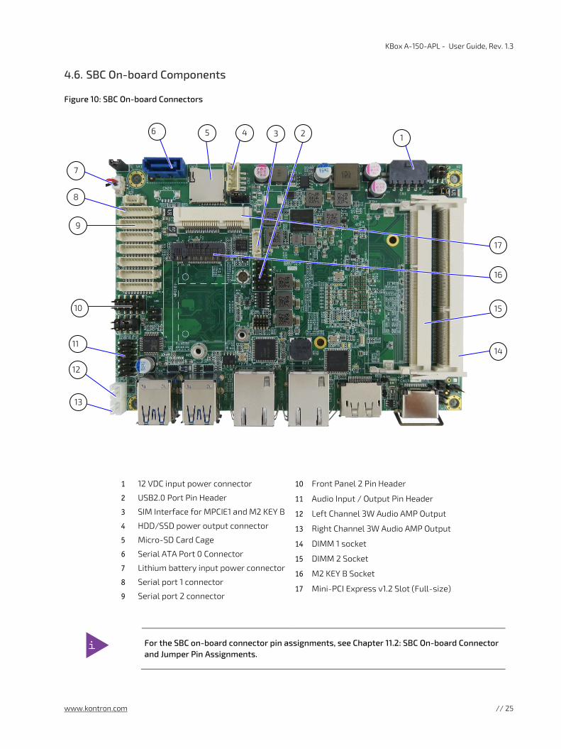
SBC On-board Components 4.6.
Figure 10: SBC On-board Connectors
1 12 VDC input power connector
2 USB2.0 Port Pin Header
3 SIM Interface for MPCIE1 and M2 KEY B
4 HDD/SSD power output connector
5 Micro-SD Card Cage
6 Serial ATA Port 0 Connector
7 Lithium battery input power connector
8 Serial port 1 connector
9 Serial port 2 connector
10 Front Panel 2 Pin Header
11 Audio Input / Output Pin Header
12 Left Channel 3W Audio AMP Output
13 Right Channel 3W Audio AMP Output
14 DIMM 1 socket
15 DIMM 2 Socket
16 M2 KEY B Socket
17 Mini-PCI Express v1.2 Slot (Full-size)
For the SBC on-board connector pin assignments, see Chapter 11.2: SBC On-board Connector and Jumper Pin Assignments.
10
11
17
16
5 4 6
7
8
9
14
15
12
13
1 3 2

KBox A-150-APL - User Guide, Rev. 1.3
www.kontron.com // 26
5/ System Expansion Observe the procedures and instructions within this chapter properly when installing, removing or handling internal component. It is recommended to expand the system with internal components, before installing in an industrial control cabinet.
Protection label
The KBox A-150-APL is factory configured to meet customer requirements and then sealed with a protection label. Opening the KBox A-150-APL invalidates the warranty and may cause damage to internal components.
Before opening the KBox A-150-APL, the product must be switched off using the power-on
switch, and disconnect all peripheral devices. Disconnect the product by removing the power cable from the DC power supply or the mains power socket. Observe the General Safety Instructions within this user guide.
ESD Sensitive
Follow the safety instructions for components that are sensitive to electrostatic discharge (ESD). Failure to observe this warning notice may result in damage to the product or/and internal components.
Pay attention to manufacturer’s instructions before installing/removing expansion cards.
Due to the limited predetermined lifespan of expansion devices, Kontron recommends that users check on the condition of installed expansion devices regularly and pay attention to the manufacturer’s lifespan specifications.
Depending on the ordered system configuration, the KBox A-150-APL can be extended externally and internally with:
2.5” HDD/SSD drive bay (external)
1x mPCIe (full-size) slot (Internal)
1x M.2 2242 Key B socket (Internal)
When adding expansion devices, observe that the maximum power consumption does not exceed the maximum PSU specification, see Table 13: Power Consumption.
External Storage Expansion 5.1.
For externally accessible memory expansion, the KBox A-150-APL drive bay variant supports one 2.5” HDD/SSD slim drive.
Table 4: External Storage Devices
Storage Device Description
2.5” HDD/SSD slim drive[1] Both 9.5 mm and 7 mm high HDD/SSDs can be used. Note: For 7 mm HDD/SSDs use the HDD/SSD extension frame, see Table 2: Accessories.
[1] For the KBox A-150-APL drive bay variant only.
Due to the manufacturer’s limited specified lifespan for HDD/SSD drives. Kontron recommends checking installed HDD/SSD drives via S.M.A.R.T. regularly.
KBox A-150-APL - User Guide, Rev. 1.3
www.kontron.com // 27
Internal Expansion 5.2.
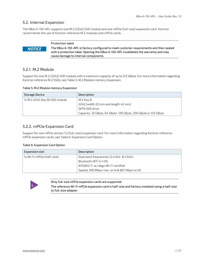
The KBox A-150-APL supports one M.2 (2242) SSD module and one mPCIe (full-size) expansion card. Kontron recommends the use of Kontron reference M.2 modules and mPCIe cards.
Protection label
The KBox A-150-APL is factory configured to meet customer requirements and then sealed with a protection label. Opening the KBox A-150-APL invalidates the warranty and may cause damage to internal components.
5.2.1. M.2 Module
Support for one M.2 (2242) SSD module with a maximum capacity of up to 512 GByte. For more information regarding Kontron reference M.2 SSDs, see Table 5: M.2 Module memory Expansion.
Table 5: M.2 Module memory Expansion
Storage Device Description
1x M.2 2242 (key B) SSD module M.2 Key B, 2242 (width 22 mm and length 42 mm) SATA SSD drive Capacity: 32 GByte, 64 GByte, 128 GByte, 256 GByte or 512 GByte
5.2.2. mPCIe Expansion Card
Support for one mPCIe version 1.2 (full-size) expansion card. For more information regarding Kontron reference mPCIe expansion cards, see Table 6: Expansion Card Option.
Table 6: Expansion Card Option
Expansion slot Description
1x Wi-Fi mPCIe (half-size) Dual band frequencies (2.4 GHz & 5 GHz) Bluetooth (BT) 4.1+HS IEEE802.11 ac/abgn Wi-Fi certified Speeds 300 Mbps max. on N & 867 Mbps on AC
Only full-size mPCIe expansion cards are supported.
The reference Wi-Fi mPCIe expansion card is half-size and factory installed using a half-size to full-size adapter.

KBox A-150-APL - User Guide, Rev. 1.3
www.kontron.com // 28
6/ Accessing Components This chapter contains important information that users must read before accessing components. Follow these procedures properly when accessing or installing component.
Protection label
The KBox A-150-APL is factory configured to meet customer requirements and sealed with a protection label. Opening the KBox A-150-APL invalidates the warranty and may damage internal components.
Before opening the KBox A-150-APL, the product must be switched off using the power-on
switch, and disconnect all peripheral devices. Disconnect the product by removing the power cable from the DC power supply or the mains power socket. Observe the General Safety Instructions within this user guide.
ESD Sensitive
Follow the safety instructions for components that are sensitive to electrostatic discharge (ESD). Failure to observe this warning notice may result in damage to the product or/and internal components.
Pay attention to manufacturer’s instructions before installing/removing expansion cards. Due to the limited predetermined lifespan of expansion devices, Kontron recommends that users check on the condition of installed expansion devices regularly and pay attention to the manufacturer’s lifespan specifications.
Accessing the 2.5” HDD/SSD Drive Bay 6.1.
To install or remove a 2.5” HDD/SSD drive (7 mm or 9.5 mm) in the 2.5 “HDD/SSD drive bay, perform the following:
1. Close all applications. Shut down properly using the power-on switch and disconnect the power cable from the DC power supply.
2. Slide the drive bay eject button to the left (Figure 11, pos. 2), to release the drive bay cover and gain access to the drive bay. When released the drive bay cover flips open automatically. (Figure 11, pos. 3)
Figure 11: 2.5” HDD/SSD Drive Bay
1 Drive bay cover (closed)
2 Drive bay eject button
3 Drive bay cover (open)
4 Drive bay
3. Remove an existing drive by holding the sides of the drive and carefully pulling the drive out of the drive bay.
2
1
4
3

KBox A-150-APL - User Guide, Rev. 1.3
www.kontron.com // 29
4. Insert a 9.5 mm high drive into the drive bay by carefully pushing the drive into the drive bay, with the drive’s contacts facing inward, until the connectors attach. Alternatively, attach an extension frame to a 7 mm high drive and insert the drive with extension frame into the drive bay with the drive’s contacts facing inward, until the connectors attach.
Attaching an extension frame for 7 mm to 9.5 mm to 7 mm high drives adjusts the height and ensure that the HDD/SSD is inserted correctly into the drive bays internal SATA data and SATA power connectors.
5. Push the drive bay cover into the closed position (Figure 11, pos. 1) until the drive bay eject button clicks.
Opening the System 6.2.
To access the internal component, open the system as described in this chapter and following the installing and removing instructions and procedures.
Protection label
The KBox A-150-APL is factory configured to meet customer requirements and then sealed with a protection label. Opening the KBox A-150-APL invalidates the warranty and may cause damage to internal components.
Before opening the KBox A-150-APL, the product must be switched off using the power-on
switch, and disconnect all peripheral devices. Disconnect the product by removing the power cable from the DC power supply or the mains power socket. Observe the General Safety Instructions within this user guide.
Only qualified personnel aware of the associated dangers must perform activities inside the chassis!
KBox A-150 APL is to be operated in closed condition only
It is only ensured that users do not have access to internal components during operation if closed and the front panel SBC assembly screws (Figure 12, pos. 1) & (Figure 13, pos. 1 & 2) are secured.
To access the internal component, perform the following:
1. Close all applications. Shut down properly using the power-on switch and disconnect the power cable from the DC power supply. Disconnect all peripherals.
2. Place on a flat, clean and ESD-safe surface with the top side facing upwards.
3. The front panel is attached to the SBC. Removing the two screws shown in Figure 12, pos. 1. to release the front panel-SBC assembly. Retain the screws for later use.

KBox A-150-APL - User Guide, Rev. 1.3
www.kontron.com // 30
Figure 12: SBC Fastening Screws
1 2x Bottom head torx (M3x5) screws
2 2x Screws fasten the front panel to SBC to form a Front panel-SBC assembly that slides in/out of the chassis. Do not remove or loosen the screws!
Do not remove or loosen the two screws (Figure 12, pos. 2) that fasten the front panel and
SBC together to form a SBC-front panel assembly that can slide in/ out of the chassis.
4. Turn the system around with the bottom side facing upwards. Remove the screw located in the middle of the front panel (Figure 13, Pos. 1). Then remove the two screws located on the front panel’s right and left sides (Figure 13, Pos. 2). Retain the screws for later use.
Figure 13: Front Panel Fastening Screws
1 1x Flathead (M2 5x6) screw
2 2x Flathead (M2 5x6) screw (right side & left side)
1
1
2
2

KBox A-150-APL - User Guide, Rev. 1.3
www.kontron.com // 31
5. Carefully slide the front panel-SBC assembly out of the main chassis while taking care not to damage the SBC and internal components. When removing the front panel-SBC assembly ensure that internal cables do not catch on internal components.
Figure 14: Removing the Front panel- SBC Assembly
1 Front panel with side screw removed
2 Front panel- SBC assembly slides out of the main chassis
3 Main chassis with side screw removed
6. Place the front panel- SBC assembly on an ESD-safe surface.
7. Close the system, by proceeding in the reverse order. Align the front panel- SBC assembly with the open chassis. Carefully slide the front panel- SBC assembly towards the rear side of the chassis, while taking care that the internal cables have space and do not catch on or damage internal components. Secure using the screws retained in step 3 and 4.
1
2 3

KBox A-150-APL - User Guide, Rev. 1.3
www.kontron.com // 32
6.2.1. Installing and Removing M.2 SSD Cards
Protection label
The KBox A-150-APL is factory configured to meet customer requirements and then sealed with a protection label. Opening the KBox A-150-APL invalidates the warranty and may cause damage to internal components.
Figure 15: M.2 Module on the SBC
1 M.2 Key B socket
2 M.2 2242 module
3 M.2 card screw hole for a button head (M3x5) screw
To install an M.2 SSD, perform the following:
1. Open the system as described in Chapter 6.2: Opening the System (steps 1-6).
2. Place the system on a flat, clean and ESD-safe surface.
3. Locate the M.2 socket and the corresponding fastening screw hole.
4. Insert the M.2. SSD card into the M.2 socket, at an angle (approx.. 30°). If required move the M.2 SSD module slightly from side to side to help ease the module carefully into the socket.
5. Push down on the M.2 SSD module’s free end until the module’s screw hole aligns with the screw hole on the SBC.
6. Secure the M.2 SSD module by carefully tighten the fastening screw with a torx (m3x5) screwdriver until the M.2 SSD module is flat with the SBC.
7. Close the system as described in Chapter 6.2: Opening the System (step 7).
To remove an M.2 SSD, perform the following:
1. Open the system as described in the Chapter 6.2: Opening the System (steps 1-6).
2. Place the system on a flat, clean and ESD-safe surface.
3. Locate the installed M.2 SSD card.
4. Use a torx (M3x5) screwdriver to remove the module’s fastening screw. The module springs up at the free end.
5. Gently pull the M.2 SSD module out of the M.2 socket. If required move the module slightly from side to side to ease the module carefully out of the socket. Retain the fastening screw for later use.
6. Close the system as described in Chapter 6.2: Opening the System (step 7).
After changing the M.2 SSD the partitioning of the memory may differ and require
repartitioned.
2
3
1

KBox A-150-APL - User Guide, Rev. 1.3
www.kontron.com // 33
6.2.2. Installing and Removing mPCIe Expansion Cards
Protection label
The KBox A-150-APL is factory configured to meet customer requirements and sealed with a protection label. Opening the KBox A-150-APL invalidates the warranty and may damage internal components.
Figure 16: mPCIe Expansion Card on the SBC
1 mPCI e V1.2 slot
2 mPCIe Wi-Fi card
3 Wi-Fi antenna cable connections
4 Stand-off with screw hole, for mPCIe cards fastening screw
To install a mPCIe card, perform the following:
1. Open the chassis as described in the Chapter 6.2: Opening the System (step 1-6).
2. Place the KBox A-150 APL on a flat, clean and ESD-safe surface.
3. Locate the mPCIe card slot and the corresponding fastening screw hole.
4. Insert the mPCIe card into the slot at an angle of approx. 30°. If required move the card slightly from side to side to help ease the card carefully into the slot.
5. Push down on the mPCIe cards free end until the card’s screw hole aligns with the screw hole on the SBC.
6. Secure the mPCIe by carefully tightening the fastening screw until the card is flat with the SBC.
7. Close the system as described in Chapter 6.2: Opening the System (step 7).
To remove a mPCIe card, perform the following:
1. Open the system as described in the Chapter 6.2: Opening the System (step 1-6).
2. Place the system on a flat, clean and ESD-safe surface.
3. Locate the installed mPCIe card.
4. Use a Torx (M3x5) screwdriver to remove the mPCIe card’s fastening screw. The card springs up at the free end.
5. Gently pull the mPCIe card out of the slot. If required move the card slightly from side to side to ease the card carefully out of the slot. Retain the fastening screw for later use.
6. Close the system as described in Chapter 6.2: Opening the System (step 7).
1
2
4
3

KBox A-150-APL - User Guide, Rev. 1.3
www.kontron.com // 34
7/ Thermal Considerations The KBox A-150-APL is fanless and passively cooled using a heatsink plate or optional heatsink. The heatsink plate and optional heatsink absorb the heat produced by the internal components and transfers the heat away from the internal components by dissipating the heat into the ambient environment.
Hot Surface
Heatsinks can get hot. To avoid burns and personal injury:
• Do not touch a product’s heatsink when in operation
• Allow the product to cool before handling
• Wear protective gloves
• Always turn the product off when not in use
Heatsink Plate 7.1.
When mounting in a DIN rail control cabinet take care not to obstruct the airflow over the heatsink plate, as this can stop sufficient heat dispersing into the ambient environment and cause a build-up of heat.
The heatsink plate dimensions are:
171 mm ( 6.7” ) x 105 mm (4.1” )
Heatsink (Option) 7.2.
The heatsink is installed on top of the heatsink plate. It is possible to rotate the heatsink by 90° to enable the heatsink to remain in the vertical position to support vertical airflow within a DIN rail control cabinet. The DIN rail clamp can be installed directly on the top of the heatsink.
Figure 17: Heatsink and Heatsink with DIN Rail Clamp
Heatsink
Heatsink with DIN rail clamp
When mounting in a DIN rail control cabinet, take care not to obstruct the airflow over the heatsink. Obstructing the airflow can stop sufficient heat dispersing into the ambient environment and causes a build-up of heat.
The heatsink dimensions are:
130 mm (5.12”), 130 mm (5.12”), 19.2 mm (0.76”)
For additional heatsink mechanical information, see Chapter 10.3.1.1: Mechanical Diagrams Heatsink.
The Heatsink Kit’s part number is EN05-100003-01.

KBox A-150-APL - User Guide, Rev. 1.3
www.kontron.com // 35
8/ Installation Instructions
Due to possible access restrictions, before installing in a control cabinet ensure that the product is configured as required. If access to the front panel is restricted, connect peripherals to the corresponding ports before installation.
DIN Rail Mounting 8.1.
The KBox A-150-APL is mounted on a DIN Rail in a control cabinet using a DIN rail clamp assembled on either the :
Top side of the chassis
Heat sink on the top side of the chassis
Rear side of the chassis
The position and direction of the DIN rail clamp decides the orientation of the KBox A-150-APL within the control cabinet. Therefore, when installing the DIN rail clamp take the following into consideration:
Do not obstruct the airflow over the heatsink, this can stop sufficient heat dispersing and causes a build-up of heat.
Access to the front panel I/O connectors, power connector and external drive bay
To attach the DIN rail mounting clamp, perform the following:
1. Make sure that the DIN rail mounting clamp is in the upper position, for the required mounting option.
Figure 18: DIN Rail Mounting Clamp Upper Position
2. Fasten the DIN rail clamp firmly using the supplied two flathead (M4x6) screws only.
Figure 19: DIN Rail Mounting Clamp Screw Dimensions (mm)
3. Clip the top of the DIN rail clamp in to the DIN rail and push the bottom of the DIN rail firmly until it clamps on to the bottom of the DIN rail.
22
35.2
50

KBox A-150-APL - User Guide, Rev. 1.3
www.kontron.com // 36
Control Cabinet Mounting 8.2.
For sufficient air circulation around the KBox A-150-APL, Kontron recommends users not to place, mount or operate any other devices within the specified keep out areas around the KBox A-150-APL. Users must observe the marked keep out areas shown in Figure 20, Figure 21, Figure 22, Figure 23 and Figure 24.
Figure 20: Keep Out Area for Mounting for KBox A-150-APL (with external 2.5” HDD/SSD drive bay)
Figure 21: Keep Out Area for Mounting for KBox A-150-APL (with no drive bay)
Figure 22: Keep Out Area for Mounting for KBox A-150-APL (with heatsink & external 2.5” HDD/SSD drive bay)
Figure 23: Keep Out Area for Mounting for KBox A-150-APL (with heatsink & no drive bay)
The cable clearance depends on the installed connectors types.
Up to 50 mm cable clearance
Up to 50 mm cable clearance
Up to 50 mm cable clearance
Up to 50 mm cable clearance
26.7 mm
26.7 mm
8.5 mm
8.5 mm
100 mm
100 mm

KBox A-150-APL - User Guide, Rev. 1.3
www.kontron.com // 37
For the KBox A-150-APL with Wi-Fi, the front panel keep out area depends on the implemented dual Wi-Fi antennas and the orientation of the Wi-Fi antennas.
Figure 24: Keep Out Area for installed dual Wi-Fi Antenna (with external 2.5” HDD/SSD drive bay)
Wi-Fi antennas require an additional keep out area. Kontron’s reference Wi-Fi antennas require a minimum of 40 mm horizontally and 135 mm in required antenna direction when measured from the Wi-Fi connector.
Wiring the Mating Power Connector/Terminal 8.3.
The DC input power connector connects to a DC power supply using the supplied mating power connector/terminal (PSC 1.5/ 3-F) and the corresponding wiring. The wiring is inserted in to the mating power connector/terminal’s clamps, see Figure 25, pos. 4, 5 & 6 and must be clearly marked (+/-/functional earth) to ensure proper connection to the DC power supply.
The wiring is not part of the delivery und must be provided by the user.
Use copper conductors only if the field wiring terminal is only for connection to copper wire.
Minimum temperature rating of the cables connected to the field wiring terminals is 75° C.
Figure 25: Phoenix Input Power Connector and Mating Power Connector/Terminal
1 3-pin input power connector (PSC 1,5/ 3-M)
2 3-pin mating power connector/terminal (PSC 1,5/ 3-F)
3 Cover over the slotted pan head screws
4 Clamp for functional earth wire
5 Clamp for 0 VDC wire
6 Clamp for +24 VDC wire
40 mm
135 mm
2
6
5
4
1 3

KBox A-150-APL - User Guide, Rev. 1.3
www.kontron.com // 38
To wire the supplied mating power connector/terminal (PSC 1,5/ 3-F), perform the following:
1. Cut three (1 mm2) AWG18 isolated wires to the required length and strip each end 5 mm – 7 mm.
2. Twist the striped wire-ends and provide them with ferrules.
3. Access the slotted pan head screws by opening the mating power connector/terminal’s cover (Figure 25, pos. 3).
4. Loosen the slotted pan head screws far enough so that you can insert the end of the prepared wires.
5. Insert the wires into the corresponding clamp of the mating power connector/terminal. Make sure that you have the right polarity of the connection. For the pin assignment of the input power connector, see Chapter 11.1.1: Input Power Connector.
6. Fasten the screws to secure the wires into the mating power connector/terminal’s clamps.
7. Close the mating power connector/terminal’s cover (Figure 25, pos. 3).
Mark the wires clearly as (+/-/functional earth) to ensure a safe connection from the input
power connector to the DC power supply.
Support the power and I/O cables to minimize the strain on the product’s connectors.

KBox A-150-APL - User Guide, Rev. 1.3
www.kontron.com // 39
9/ Switching On Before switching on, observe the instructions in Chapter 1/: General Safety Instructions and the instructions within this chapter.
Connecting to a DC Power Supply 9.1.
Observed that wiring and short-circuit/overcurrent protection is performed according to the
applicable standards, regulations and in respect to the product’s electrical specification. The disconnecting device (fuse/circuit breaker) rating must be in accordance with the product’s wire cross-section.
Even when switched off via the power-on switch, parts of the system are still energized. The
product is only completely switched off when the power has been switched off using the power-on switch and the power cable is disconnected from either the power supply or the DC Input power connector.
Following a proper cabling procedure prevents a false power-on condition, that could result in operational failure. When installing/disconnecting the system ensure that:
• The functional earth connection is made first and disconnected last.
• The last connection made to the product is the power cable.
The wires used for power connections must be clearly marked (+/-/functional earth) to ensure that the wires are connected to the DC input power connector and power supply properly.
Support the power and I/O cables to minimize the strain on the product’s connectors.
Do not disconnect the power while the product is switched on! This performs a forced
shutdown and can lead to loss of data. To shutdown without data loss, switch off using the Power-on switch.
To connecting to the DC power supply, perform the following:
1. Wire the supplied mating power connector/terminal (PSC 1.5/3-F) as described in Chapter 8.3: Wiring the Mating Power Connector/Terminal.
2. Switch off the external DC power supply via a disconnecting device (fuse/circuit breaker), to ensure that no power flows during the connection procedure.
3. Connect the protective earth stud bolt to an appropriate common earth connection.
4. Connect the wired mating power connector/terminal (PSC 1.5/3-F) to the DC Input power connector. Pay attention to the polarity of the connection, see Chapter 11.1.1: Input Power Connector.
5. Connect the other end of the wired mating power connector/terminal to the external DC power supply.
Once connected to an external DC power supply the KBox A-150-APL can be switch on and switch off using the front panel power-on switch.

KBox A-150-APL - User Guide, Rev. 1.3
www.kontron.com // 40
Switch On 9.2.
To switch on while connected to the power supply, perform the following:
1. Press the Power-on switch, see Figure 3 and Figure 4, pos. 7.
2. The system switches on.
Do not disconnect the power while the product is switched on! This performs a forced
shutdown and can lead to loss of data. To shutdown without data loss, switch off using the Power-on switch.
Switch Off 9.3.
To switch off without performing a force shutdown, perform the following:
1. Press the Power-on switch, see Figure 3 and Figure 4, pos.7.
2. The system performs an orderly shutdown.
3. If required, completely switch off by disconnecting the power connection at the DC Input power connector or the power supply.
Even when switched off using the power-on switch, parts of the system are still energized.
The product is only completely switched off when the power has been switched off using the power-on switch and the power wiring is disconnected from either the power supply or the DC Input power connector.
Operating System (OS) and Drivers 9.4.
The KBox A-150-APL comes factory configured, with a pre-installed Operating System (OS) and all the necessary drivers (in accordance with the ordered hardware configuration). The KBox-A-150-APL is full operation when switched on for the first time
To download relevant drivers for the factory installed hardware components visit Kontron’s EMD customer section: https://emdcustomersection.kontron.com.
Pay attention to the manufacturer OS specifications relating to the integrated hardware components.

KBox A-150-APL - User Guide, Rev. 1.3
www.kontron.com // 41
10/ Technical Data
Block Diagram 10.1.
Figure 26: Block Diagram
KBox A-150-APL
SOC
mPCIe Slot (full-size)
M.2 Key B 2242
Socket
SATA
Po
wer
SATA
D
ata
Legend SBC SOCOn-board
connectorsExternal
interfaces Processor On-board controller
On-board memory
4x USB 3.0
2x LAN (GbE)
1x HDMI
1x DisplayPort
2x Serial Port (configurable)
External Power Source
External Part
Audio Chip
Realtek ALC662
Power-on switch
SIOChip
2x DDR3L 1866SODIMM Sockets
Up to 8 GB max.
2x Speaker out Connectors
(option)
Intel ® Pentium® Quad Core ™ N4200
AudioHeader
Dual Antenna(option)
2x WI-Fi Breakouts (option)
mPCIe Wi-Fi
(optional)
2.5" HDD/SSD
(optional)
DC-Input Power

KBox A-150-APL - User Guide, Rev. 1.3
www.kontron.com // 42
Technical Specification 10.2.
Table 7: Technical Specification
Type ECX-APL0 3.5” ECX Single Board Computer(SBC)
Processor Intel® Pentium® Quad Core™ N4200 1.1 GHz /2.5 GHz (Burst)
System Memory 2x DDR3L 1866 1.35 V SODIMM Up to 8 GB Max.
Storage M.2 2242 (key B) SSD Up to 512 GB Max. (128 GB, 256 GB and 512 GB)
2.5” slim SSD drive bay[1]
Interfaces 4x USB 3.0 2x LAN (GbE) 1x HDMI 1x DP 2x COM ( RS 232, RS422, RS485, BIOS configurable) 2x COM (RS232 option)
Audio Line-In/Line-Out/Mic via Audio connector (option)
Expansion Sockets 1x mPCIe V1.2 (full-size)
Lithium Battery CR 2032, 3 V
Power 9 VDC to 30 VDC input range 3.8 A Input current max. 24 VDC nominal input voltage
IP Protection Class IP 40
Operating System (OS) Windows 10 IoT Enterprise (64 bit) Linux Ubuntu 16.xx (64 bit)
BIOS AMI uEFI BIOS, Aptio V5
[1]Only for KBox A-150-APL variants with externally accessible 2.5” SSD/HDD drive bay

KBox A-150-APL - User Guide, Rev. 1.3
www.kontron.com // 43
Mechanical Specification 10.3.
Table 8: Mechanical Specification
Dimensions KBox A-150-APL (with 2.5” HDD/SSD Drive Bay)
KBox A-150-APL (without Drive Bay)
Width 180 mm (7.09”)
Depth 134 mm (5.28”)
Height 58 mm (2.28”) 50 mm (1.97”)
76 mm (2.99”) with heatsink fin 68 mm (2.68”) with heatsink fin
Weight (chassis only) Approx. ~1 kg (~2.2 lbs.)
Construction Steel chassis
Mounting DIN Rail
Color RAL7035 (Front panel) RAL7043 (Top cover and main chassis) Heatsink fins: black
10.3.1. Mechanical Diagrams
For detailed mechanical information, refer to the outline dimensions diagrams in this chapter showing the main external mechanical dimensions.
The following outline dimension drawings show the features for the KBox A-150-APL with an external 2.5” HDD/SSD drive bay.
Figure 27: Front Panel Dimensions with External 2.5” Drive Bay (mm)
Figure 28: Rear Side Dimensions with External 2.5” Drive Bay (mm)
90.5 mm
180 mm
58 mm
12 m
m
46
mm
180 mm
58 mm

KBox A-150-APL - User Guide, Rev. 1.3
www.kontron.com // 44
Figure 29: Top Side Dimensions with External Drive Bay (mm)
Figure 30: Side View Dimensions with External 2.5” Drive Bay (mm)
The following outline dimension drawings show the features for the KBox A-150-APL without a drive bay.
Figure 31: Front Panel Dimensions without Drive Bay (mm)
180 mm
130.2 mm
90.5 mm
135.25 mm
58 mm
29 m
m
15.9
mm
10 mm 94.8 mm
180 mm
50 mm
4.5 mm

KBox A-150-APL - User Guide, Rev. 1.3
www.kontron.com // 45
Figure 32: Rear Side Dimensions without Drive Bay (mm)
Figure 33: Top Side Dimensions with External Drive Bay (mm)
Figure 34: Side View Dimensions without Drive Bay (mm)
43.
5 m
m
180 mm
50
6 m
m
90.5 mm
50 mm
130.25 mm
25 m
m
180 mm
130.25 mm
90.5 mm

KBox A-150-APL - User Guide, Rev. 1.3
www.kontron.com // 46
10.3.1.1. Mechanical Diagrams Heatsink
The following outline dimension drawings show the features of the optional heatsink with DIN rail mounting holes.
Figure 35: Mechanical Diagram Heatsink (mm)
7.6 mm 32.5 mm
130 mm
19.2 mm
32.5 mm 32.5 mm 47.4 mm 47.4 mm
130 mm
11 8 mm
1.5 mm ±0.1
65 mm
32.5 mm 30°
4 mm
4 mm 19.2 mm
130 mm
130 mm
1.5 mm ±0.1

KBox A-150-APL - User Guide, Rev. 1.3
www.kontron.com // 47
Environmental Specification 10.4.
Table 9: Environmental Specification
Temperature Description
Temperature Operating 0°C to 40°C ambient (up to 50°C with heatsink fink)
Storage & Transit -20°C to 60°C ambient
Relative Humidity Operating 10%-90% RH @ 39°C, non-condensing
Environmental Description
Shock EN 60068-2-27
Operating Half sine, 15 g, 11 ms
Storage & Transit Half sine, 30 g, 11 ms
Vibration EN 60068-2-6
Operating 5 to 500 Hz, 1.0 g, 3 axis
Storage &Transit 10 to 500 Hz, 2.0 g, 3 axis
Altitude Up to 2,000 m (operating)
Cooling Fanless passive cooling
Certifications 10.5.
The KBox A-150-APL without Wi-Fi, complies with the European Council Directive (93/68/EEC) and the approximation of the laws of the member states, see Table 10.
The KBox A-150-APL with Wi-Fi, complies with the Radio Equipment Directive (RED) (2014/53/EU) and the approximation of the laws of the member states, see Table 11.
If the product is modified, the prerequisites for specific approvals may no longer apply.
Kontron is not responsible for any radio television interference caused by unauthorized modifications of the product or the substitution or attachment of connecting cables and equipment other than those specified by Kontron. The correction of interference caused by such unauthorized modification, substitution or attachment will be the responsibility of the user.
The use of shielded I/O cables is required when connecting to peripheral or host devices. Failure to do so may violate FCC/ICES rules.
Table 10: Certifications of KBox A-150-APL without Wi-Fi
CE
Electromagnetic Compatibility (EMC) Directive 2014/30/EU
General Product Safety Directive 2001/95/EC
Low Voltage Directive 2014/35/EU
EMC
Emission (Class B)
EN55032 CISPR 32: Edition 2
Complies with the electromagnetic compatibility of multimedia equipment - emissions requirements
Immunity
EN55024 CISPR 24
Complies with the information technology equipment - Immunity characteristics, limits and methods of measurement

KBox A-150-APL - User Guide, Rev. 1.3
www.kontron.com // 48
Safety
Europe EN 61010-1 Safety requirements for electrical equipment for measurement, control and laboratory use - Part 1: General requirements
CB Scheme CB certificate IEC/EN/UL 61010-1
Safety requirements for electrical equipment for measurement, control and laboratory use - Part 1: General requirements
CB Scheme CB certificate IEC/EN/UL 61010-2-201
Safety requirements for electrical equipment for measurement, control and laboratory use - Part 2-201: Particular requirements for control equipment
FCC
FCC 47 CFR Part 15 (Class B)
Complies with part 15 FCC rules and regulations of title 47 of the CFR rules for class B products; under which an unintentional radiator may be operated, administrated and other conditions relating to the marketing of part 15 devices.
ICES-003 Information technology equipment – Radio disturbance characteristics, limits and methods of measurement ICES-003:2016 rules to limit the potential of harmful interference.
Environment
WEEE Compliant with the Waste Electrical and Electronic Equipment (WEEE) 2012/19/EU directive; to reduce waste of electrical and electronic equipment, encourage recycling and environmental disposal and increase the environmental awareness of producers
RoHS II Compliant with the Restriction of Hazardous Substances (RoHS) 2011/65/EU directive or the late status thereof, to reduce hazardous substances in electrical and electronic equipment
Table 11: Certifications of KBox A-150-APL with Wi-Fi
RED Directive 2014/53/EU
Draft ETSI EN 301 489-01 V2.2.0 (2017-03)
EMC standard for radio equipment and services; Part 1:Common technical requirements; Harmonized standard for Electromagnetic compatibility
Final Draft ETSI EN 301 489-17 V3.2.0 (2017-03)
EMC standard for radio equipment and services – part 17: Specific conditions for Broadband Data Transmission Systems; Harmonized Standard covering the essential requirements of article 3.1(b) of Directive 2014/53/EU
ETSI EN 300 328 V2.2.1 (2016-11)
Wideband transmission systems; Data transmission equipment operating in the 2,4 GHz ISM band and using wide band modulation techniques; Harmonized Standard for access to radio spectrum
ETSI EN 301 893 V2.1.1 (2017-11)
5 GHz RLAN; Harmonized Standard covering the essential requirements of article 3.2 of Directive 2014/53/EU
EMC
Emission (Class B)
EN55032 CISPR 32: Edition 2
Complies with the electromagnetic compatibility of multimedia equipment - emissions requirements
Immunity EN61000-6-2 Electromagnetic compatibility (EMC) - Part 6-2: Generic standards- Immunity for industrial environment
Safety
Europe EN 61010-1 Safety requirements for electrical equipment for measurement, control and laboratory use - Part 1: General requirements
CB Scheme CB certificate IEC/EN/UL 61010-1
Safety requirements for electrical equipment for measurement, control and laboratory use - Part 1: General requirements
CB certificate IEC/EN/UL 61010-2-201
Safety requirements for electrical equipment for measurement, control and laboratory use - Part 2-201: Particular requirements for control equipment

KBox A-150-APL - User Guide, Rev. 1.3
www.kontron.com // 49
FCC
FCC 47 CFR Part 15 (Class B)
Complies with part 15 FCC rules and regulations of title 47 of the CFR rules for class B products under which an unintentional radiator may be operated, administrated and other conditions relating to the marketing of part 15 devices.
ICES-003 Information technology equipment – Radio disturbance characteristics, limits and methods of measurement ICES-003 rules to limit the potential of harmful interference.
Environment
WEEE Compliant with the Waste Electrical and Electronic Equipment (WEEE) 2012/19/EU directive; to reduce waste of electrical and electronic equipment, encourage recycling and environmental disposal and increase the environmental awareness of producers
RoHS II Compliant with the Restriction of Hazardous Substances (RoHS) 2011/65/EU directive or the late status thereof, to reduce hazardous substances in electrical and electronic equipment

KBox A-150-APL - User Guide, Rev. 1.3
www.kontron.com // 50
Power Supply Specification 10.6.
Before connecting the product to a DC power supply ensure that the power supply meets the required electrical specification for the product and that protection and supply limitation have been taken into consideration. Additionally, the power supply used must automatically recover from AC power loss and start up under peak loading.
Connect the product only to a power supply designed to achieve NEC Class-2 and Limited Power Source (LPS).
Table 12: KBox A-150-APL Electrical Specification
Nominal Input Voltage 24 VDC
Input Voltage Range 9 VDC to 30 VDC
Input Current 3.8 A (Max.)
Inrush Current 6 A
Input Power Connector 3- pin Phoenix PSC 1.5/3-M
Observed that wiring and short-circuit/overcurrent protection is performed according to the
applicable standards, regulations and in respect to the product’s electrical specification. The disconnecting device (fuse/circuit breaker) rating must be in accordance with the product’s wire cross-section.
Only connect to an external power supply delivering the specified input rating and
complying with the requirements of Safety Extra Low Voltage (SELV) and Limited Power Source (LPS) of UL/IEC 60950-1 or (PS2) of UL/IEC 62368-1.
Ensure that the power supply is used according to the manufacturer’s instructions.
Ensure the power supply has been fully tested to at least meet the minimum immunity of AC inputs requirements, as stipulated in IEC 55024. Including power supplies marketed with a separate AC/DC power converter.
Do not disconnect the power from the system while the system is switched on!
Performing a forced shut down can lead to loss of data or other undesirable effects!
10.6.1. Power Supply Protection Requirements
The used external power supply is required to incorporated protection and supply features such as over current protection, inrush current protection, over voltage protection and under voltage (brownout) protection, to protect the product against fluctuations and interruptions in the delivered DC power supply.
If an under voltage (brownout) condition occurs the used power supply must remain in the “off state” long enough to allow internal voltages to discharge sufficiently. Failure to observe this “off state” may mean that parts of the product or peripherals work incorrectly or suffer a reduction of MTBF. The minimum “off state”, to allow internal voltages to discharge sufficiently, is dependent on the power supply and additional electrical factors. To determine the required “off state”, each case must be considered individually. For more information, contact Kontron Support.

KBox A-150-APL - User Guide, Rev. 1.3
www.kontron.com // 51
10.6.2. Power Consumption
The used external power supply must be capable of delivering the product with the required power when configured with all components. The total power consumption depends on factors such as the SBC, interfaces, and system/memory expansion.
Table 13: Power Consumption
Power Consumption Type Label Rating
SBC (Burn-In) External Interfaces Total
100% RAM 100% CPU 100% Disk
4x USB 3.0 1x HDMI 1x DP
SBC + External Interfaces
Voltage
9 V to 30 V (Max. range)
Current 3.8 A (Max.)
9.7 W 22.6 W 32.3 W Power 33.9 W (32.3 W + 5%)
The external power supply must supply power to all configured components.
10.6.3. Protective Earth Stud Bolt
The protective earth stud bolt connects to the internal chassis GND. The protective earth stud bolt is located next to the DC Input Power connector at the bottom of the front panel when the external 2.5” HDD/SSD drive bay is included (Figure 3, pos. 2) and at the top of the front panel without an external drive bay (Figure 4, pos. 2).
When installing cables to the product the first cable connection must be to the the protective earth stud bolt and when disconnecting the last cable to be disconnected must be from the protective earth stud bolt.

KBox A-150-APL - User Guide, Rev. 1.3
www.kontron.com // 52
11/ Connector Pin Assignments
Front Panel Connector Pin Assignments 11.1.
11.1.1. Input Power Connector (- +)
3-Pin Phoenix PSC 1.5/3-M (male) Pin Signal Name
1 GND (-)
2 Functional earth
3 VCC (+)
11.1.2. HDMI Connector (HDMI)
19-pin HDMI Pin Signal Name Pin Signal Name
3 18
1 19
1 TMDS Data2+ 11 GND
2 GND 12 TMDS Clock-
3 TMDS Data2- 13 Reserved
4 TMDS Data1+ 14 Reserved
5 GND 15 DDC_CLK
6 TMDS Data1- 16 DDC_DATA
7 TMDS Data0+ 17 GND
8 GND 18 +5V Power
9 TMDS Data0- 19 Hot Plug Detect
10 TMDS Clock+
11.1.3. Display Port Connector (DP)
20-pin DP Pin Signal Name Pin Signal Name
1 TX0+ 11 GND
2 GND 12 TX3-
3 TX0- 13 GND
4 TX1+ 14 GND
5 GND 15 AUX+
6 TX1- 16 GND
7 TX2+ 17 AUX-
8 GND 18 HPD
9 TX2- 19 GND
10 TX3+ 20 PWR
2 20
1 19

KBox A-150-APL - User Guide, Rev. 1.3
www.kontron.com // 53
11.1.4. GbE RJ45 Connectors (LAN1, LAN2)
RJ45 (female) Pin Signal Name Pin Signal Name
1 MDI0+ 5 MDI2-
2 MDI0- 6 MDI1-
3 MDI1+ 7 MDI3+
4 MDI1 8 MDI3-
Left LED: Speed Right LED: Activity/Link
Off 10 Mbit Off NO LAN connectivity
Green 100 Mbit Yellow Link
Orange 1 GbE Blinking Activity
11.1.5. USB 3.0 Port Connectors
USB Type A Pin Signal Name Pin Signal Name 4 1
5 9 13 10
14 18
1 +USBA_VCC[1] 10 +USBB_VCC[1]
2 USBA_D- 11 USBB_D-
3 USBA_D+ 12 USBB_D+
4 GND 13 GND
5 USBA_RX- 14 USBB_RX-
6 USBA_RX+ 15 USBB_RX+
7 GND 16 GND
8 USBA_TX- 17 USBB_TX-
9 USBA_TX+ 18 USBB_TX+
[1] The power source of +USB_VCC can be selected by JP9.
For USB power selection information, see Chapter 11.2.11: USB Power Selection Jumper (JP9).
11.1.6. Serial Port Connectors (X1, X2)
9-pin D-SUB (male) Pin RS232 RS422 RS 485 Half Duplex
RS 485 Full Duplex
1 5
6 9
1 DCD Tx- Data- Tx-
2 RxD Tx+ Data+ Tx+
3 TxD Rx+ Rx+
4 DTR Rx- Rx-
5 GND GND GND GND
6 DSR
7 RTS
8 CTS
9 RI

KBox A-150-APL - User Guide, Rev. 1.3
www.kontron.com // 54
SBC On-board Connector and Jumper Pin Assignments 11.2.
11.2.1. Battery Power Input Connector
Connector for Kontron’s RTC battery assembly (CR2032)
Pin Signal Name
1 +VBAT
2 GND
11.2.2. 12 VDC Out Power Connector
Connector supplies the internal components with a nominal input voltage of 12 VDC.
Pin Signal Name
1 +12 V
2 GND
3 GND
4 +12V
11.2.3. HDD Power Output Connector
Power connector for the drive bay.
Pin Signal Name
1 +12 V
2 GND
3 GND
4 +5V
11.2.4. Serial-ATA Port 0 (SATA1) Connector
Data connector for the drive bay.
Pin Signal Name
1 GND
2 TX+
3 TX-
4 GND
5 RX-
6 RX+
7 GND
4 1
1
4
1
7
1
2

KBox A-150-APL - User Guide, Rev. 1.3
www.kontron.com // 55
11.2.5. Serial Port 1 and Serial Port 2 Connector
Both serial ports are RS232, RS422 and RS485 configurable in the BIOS setup menu Advanced>Super IO configuration>Serial port # configuration>Serial port # Type> RS232, RS422, RS485.
Pin RS232 RS422 RS485 Half Duplex
RS485 Full Duplex
1 DCD Tx- Data- Tx-
2 DSR
3 RXD Tx+ Data+ Tx+
4 RTS
5 TXD RX+ RX+
6 CTS
7 DTR RX- RX-
8 RI
9 GND GND GND GND
10 +5V +5V +5V +5V
11.2.6. USB 2.0 Port Pin Header
Pin Signal Name Pin Signal Name
1 +USBVCC[1] 2 +USBVCC[1]
3 USB_A- 4 USB_B-
5 USB_A+ 6 USB_B+
7 GND 8 GND
9 KEY 10 GND [1]The power source of +USB_ VCC can be selected by JP9
For USB power selection information, see Chapter11.2.11: USB Power Selection Jumper (JP9).
11.2.7. Audio Input/Output Pin Header
Pin Signal Name Pin Signal Name
1 Mic-In_L 2 MIC-In_R
3 Mic-In_JD# 4 GND
5 Line-In_L 6 Line-In_R
7 Line-in_JD# 8 GND
9 Line-Out_L 10 Line-Out_R
11 Line-Out_JD# 12 GND
Audio is an option and not connected as standard.
1
1
10
1
11
2
12

KBox A-150-APL - User Guide, Rev. 1.3
www.kontron.com // 56
11.2.8. Left Channel 3W Audio AMP Output Connector
Speaker output left.
Pin Signal Name
1 Speaker+
2 Speaker-
11.2.9. Right Channel 3W Audio Amplification Output Connector
Speaker output right.
Pin Signal Name
1 Speaker+
2 Speaker-
11.2.10. Power-on Switch Pin Header
Connects to the front panel’s Power-on switch.
Pin Signal Name Pin Signal Name
1 Power LED + 2 Power Button +
3 NC 4 Power Button -
5 Power LED - 6 SMB_ALERT#
7 Batlow# 8 SMBus DATA
9 GND 10 SMBus Clock
11.2.11. USB Power Selection Jumper (JP9)
Jumper selects the power source for +USBVCC, for the USB 2.0 port.
Setting Status
1-2 open USB power will be cut off in S4 and S5 state
1-2 short USB power is always supply
11.2.12. Micro-SD Card Cage
On-board internal micro-SD card.
Pin Signal Name Pin Signal Name
1 DAT2 5 CLK
2 CD/DAT3 6 GND
3 CMD 7 DAT0
4 VDD 8 DAT1
1
2
1
2
1
3
5
7
9
2
4
6
8
10
1
2
1
8

KBox A-150-APL - User Guide, Rev. 1.3
www.kontron.com // 57
12/ BIOS The KBox-A-150-APL uses the AMI uEFI BIOS supported by the SBC and based on the Unified Extensible Firmware Interface (uEFI) specification and the Intel® Platform Innovation Framework for EFI. The AMI uEFI BIOS preferences are preset and do not require further adjustment for operation. Enhanced uEFI BIOS features that are configurable for the KBox A-150-APL are COMs (RS232, RS422, RS485) and power settings.
The AMI BIOS setup menus and available selection may vary. For specific Information on the BIOS for your product, contact Kontron Support.
UEFI only! No legacy support and no Master Boot Record (MBR) installation.
The BIOS features listed in this user guide are open to change and may not be available in the latest version of the BIOS. For the latest BIOS Information, visit Kontron’s EMD Customer Section: https://emdcustomersection.kontron.com.
Starting the uEFI BIOS 12.1.
The uEFI BIOS’s Setup program provides quick and easy access to the individual function settings for control or modification of the uEFI BIOS configuration. The Setup program allows for access to various menus that provide functions or access to sub-menus with further specific functions of their own.
To start the uEFI BIOS Setup program, follow the steps below:
1. Switch on the KBox A-150-APL.
2. Wait until the first characters appear on the screen (POST messages or splash screen).
3. Press the <DEL> key.
4. If the uEFI BIOS is password-protected, a request for password will appear. Enter either the User Password or the Supervisor Password, press <RETURN>, and proceed with step 5.
5. The BIOS setup utility appears in the Main menu
Using the hot key navigation system users can navigate through the BIOS. The hot key legend bar is located at the bottom of the Setup screens. The following table provides a list of navigation hot keys available in the legend bar.
Table 14: Navigation Hot Keys Available in the Legend Bar
Sub-screen Description
<F1> <F1> key invokes the General Help window
<-> <Minus> key selects the next lower value within a field
<+> <Plus> key selects the next higher value within a field
<F2> <F2> key loads previous values
<F3> <F3> key loads optimized defaults
<F4> <F4> key Saves and Exits
<→> or <←> <Left/Right> arrows selects major Setup menus on menu bar, for example, Main or Advanced
<↑> or <↓> <Up/Down> arrows select fields in the current menu, for example, Setup function or sub-screen
<ESC> <ESC> key exits a major Setup menu and enters the Exit Setup menu Pressing the <ESC> key in a sub-menu displays the next higher menu level
<RETURN> <RETURN> key executes a command or selects a submenu

KBox A-150-APL - User Guide, Rev. 1.3
www.kontron.com // 58
Setup Menus 12.2.
The Setup utility features menus listed in the selection bar at the top of the screen are:
Main
Advanced
Power
Boot
Security
Save & Exit
The currently active menu and active BIOS Setup item are highlighted in white. Use the left and right arrow keys to select the Setup menus.
Each Setup menu provides two main frames. The left frame displays all available functions. Configurable functions are displayed in blue. Functions displayed in grey provide information about the status or the operational configuration. The right frame displays an explanation of the respective function in a help window.
12.2.1. Main Setup Menu
Figure 36: Main Setup Menu Example
Aptio Setup Utility – Copyright (C) 2018 American Megatrends, Inc.
Main Advanced Power Boot Security Save & Exit
Product Information
Product Name ECX-APL0
BIOS Version W1.2 (x64)
BIOS Build Date 03/06/2019
TXE Version 3.1.50.2222
CPU Information
Intel ® Pentium ® Processor N4200 @ 1.10GHz
Microcode Revision 2E
Processor Cores 4 Core(s)
→ ←: Select Screen
Memory Information ↑ ↓: Select Item
Total Size 8192 MB (DDR3L) Enter: Select
Frequency 1600 MHz +/-: Change Opt.
F1: General Help
System Date [Thur 09/12/2019] F2: Previous Values
System Time [00:16:42] F3: Optimized Defaults
F4: Save & Reset
Access Level Administrator ESC: Exit
Version 2.18.1263. Copyright (C) 2018, American Megatrends, Inc.
The Main Menu provides an overview of the system information and enables users to set the System date and time.

KBox A-150-APL - User Guide, Rev. 1.3
www.kontron.com // 59
12.2.2. Advanced Setup Menu
Figure 37: Advanced Setup Menu Example
Aptio Setup Utility – Copyright (C) 2018 American Megatrends, Inc.
Main Advanced Power Boot Security Save & Exit
Onboard LAN1 Controller [Enabled]
Onboard LAN2 Controller [Enabled]
Audio Controller [Enabled]
> Display Configuration
> Super IO Configuration
> CPU Chipset Configuration
> SATA Configuration
> USB Configuration → ←: Select Screen
↑ ↓: Select Item > Trusted Computing
> DIO Configuration Enter: Select
> Network Stack +/-: Change Opt.
> H/W Monitor F1: General Help
F2: Previous Values
F3: Optimized Defaults
> Intel (R) I210 Gigabit Network Connection- 00:50:08:0B:2C:24 > Intel (R) Ethernet Connection I219-LM – 00:50:08:0B:2C:23
F4: Save & Reset ESC: Exit
Version 2.18.1263. Copyright (C) 2018, American Megatrends, Inc.
The following table gives more information for important setup options within the Advanced Menu. Default setting are displayed in bold.
Table 15: Advanced Menu
Sub-screen Additional Sub-screens with Description
On-board LAN 1 Controller
[Enabled, Disabled]
On-board LAN 2 Controller
[Enabled, Disabled]
Audio Controller [Enabled, Disabled]
Display Configuration
Primary Display [IGD, PCIe]
UMA Frame Buffer Size [128MB, 256MB, 512MB]
DVMT Pre-Allocated [64M, 96M, 128M, 160M, 192M, 224M, 256M, 288M, 320M, 352M, 384M, 416M, 448M, 480M, 512M]
DVMT Total Gfx Mem [128M, 256M, MAX]
Active LVDS [Enabled, Disabled]
PWM Backlight Control [By External, By Internal]
LVDS Backlight Control –PWM
[0 .. 255] PWM duty

KBox A-150-APL - User Guide, Rev. 1.3
www.kontron.com // 60
Sub-screen Additional Sub-screens with Description
Display Configuration (continued)
LVDS Backlight Control – Voltage
[0.0V, 0.5V, 1.0V, 1.5V, 2.0V, 2.5V, 3.0V, 3.5V, 4.0V, 4.5V, 5.0V]
Additional information: Display Resolution: 10.4“ > 800 x 600 12.1“ > 800 x 600 / 1280x800 15“ > 1024 x 768 15.6“ > 1366 x 768 15.6“ > 1920 x 1080 18.5“ > 1366 x 768 21.5“ > 1920 x 1080
Super IO Configuration
Serial Port 1 Configuration
Serial Port [Enabled, Disabled]
Device Settings Read only field IO=3F8h; IRQ=4
Change Settings [Auto; IO=3F8h; IRQ=4; IO=3F8h; IRQ=3, 4, 5, 6, 7, 9, 10, 11, 12; IO=2F8h; IRQ=3, 4, 5, 6, 7, 9, 10, 11, 12; IO=3E8h; IRQ=3, 4, 5, 6, 7, 9, 10, 11, 12; IO=2E8h; IRQ=3, 4, 5, 6, 7, 9, 10, 11, 12;]
Serial Port 1 Type [RS232, RS422, RS485]
Serial Port 2 Configuration Serial Port [Enabled, Disabled]
Device Settings Read only field IO=2F8h; IRQ=3;
Change Settings [Auto; IO=2F8h; IRQ=3; IO=3F8h; IRQ=3, 4, 5, 6, 7, 9, 10, 11, 12; IO=2F8h; IRQ=3, 4, 5, 6, 7, 9, 10, 11, 12; IO=3E8h; IRQ=3, 4, 5, 6, 7, 9, 10, 11, 12; IO=2E8h; IRQ=3, 4, 5, 6, 7, 9, 10, 11, 12]
Serial Port 2 Type [RS232, RS422, RS485]
Serial Port 3 Configuration Serial Port [Enabled, Disabled]
Device Settings Read only Field IO=3E8h; IRQ=7;
Change Settings [Auto; IO=3E8h; IRQ=7; IO=3E8h; IRQ=3, 4, 5, 6, 7, 9, 10, 11, 12; IO=2E8h; IRQ=3, 4, 5, 6, 7, 9, 10, 11, 12; IO=2F0h; IRQ=3, 4, 5, 6, 7, 9, 10, 11, 12; IO=2E0h; IRQ=3, 4, 5, 6, 7, 9, 10, 11, 12]
Serial Port 4 Configuration
Serial Port [Enabled, Disabled]
Device Settings Read only field IO=2E8h; IRQ=7;
Change Settings
[Auto; IO=2E8h; IRQ=7; IO=3F8h; IRQ=3, 4, 5, 6, 7, 9, 10, 11, 12;

KBox A-150-APL - User Guide, Rev. 1.3
www.kontron.com // 61
Sub-screen Additional Sub-screens with Description
Super IO Configuration (continued)
Serial Port 4 Configuration (continued)
Change Settings (continued)
IO=2F8h; IRQ=3, 4, 5, 6, 7, 9, 10, 11, 12; IO=3E8h; IRQ=3, 4, 5, 6, 7, 9, 10, 11, 12; IO=2E8h; IRQ=3, 4, 5, 6, 7, 9, 10, 11, 12; IO=2F0h; IRQ=3, 4, 5, 6, 7, 9, 10, 11, 12; IO=2E0h; IRQ=3, 4, 5, 6, 7, 9, 10, 11, 12;]
Serial Port 5 Configuration
Serial Port [Enabled, Disabled]
Device Settings Read only field IO=2F0h; IRQ=7;
Change Settings [Auto; IO=2F0h; IRQ=7; IO=3E8h; IRQ=3, 4, 5, 6, 7, 9, 10, 11, 12; IO=2E8h; IRQ=3, 4, 5, 6, 7, 9, 10, 11, 12; IO=2F0h; IRQ=3, 4, 5, 6, 7, 9, 10, 11, 12; IO=2E0h; IRQ=3, 4, 5, 6, 7, 9, 10, 11, 12]
Serial Port 6 Configuration Serial Port [Enabled, Disabled] This serial port is not connected on the standard product but is optional due to a breakout on the front panel
Device Settings Read Only Field IO=2E0h; IRQ=7
Change Settings [Auto; IO=2E0h; IRQ=7; IO=3E8h; IRQ=3, 4, 5, 6, 7, 9, 10, 11, 12; IO=2E8h; IRQ=3, 4, 5, 6, 7, 9, 10, 11, 12; IO=2F0h; IRQ=3, 4, 5, 6, 7, 9, 10, 11, 12; IO=2E0h; IRQ=3, 4, 5, 6, 7, 9, 10, 11, 12]
CPU Chipset Configuration
EIST [Enabled, Disabled]
Active Processor Cores [Enabled, Disabled]
Intel ® Virtualization Tech [Enabled, Disabled]
VT-d [Enabled, Disabled]
C-States [Enabled, Disabled]
SATA Configuration
SATA Controller [Enabled, Disabled]
SATA Mode Selection [AHCI Mode]
Serial ATA Port 1
Port 1 [Enabled, Disabled]
mSATA Port 1
Port 1 [Enabled, Disabled]
USB Configuration
Read only field Displays the attached USB devices
Legacy USB Support [Enabled, Disabled]

KBox A-150-APL - User Guide, Rev. 1.3
www.kontron.com // 62
Sub-screen Additional Sub-screens with Description
USB Configuration (continued)
XHCI hand-off [Enabled, Disabled]
USB Mass Storage Driver Support
[Enabled, Disabled]
Trusted Computing
Security Device Support [Enabled, Disabled] Note: Enabled is customer setting, Disabled is BIOS default
SHA-1 PCR Bank [Enabled, Disabled]
SHA256 PCR Bank [Enabled, Disabled]
Pending Operation [None, TPM Clear]
Platform Hierarchy [Enabled, Disabled]
Storage Hierarchy [Enabled, Disabled]
Endorsement Hierarchy [Enabled, Disabled]
TPM2.0 UEFI Spec Version [TCG_1_2; TCG_2]
Physical Presence Spec Version
[1.2, 1.3]
DIO Configuration
User Configured [Enabled, Disabled]
DIO-0 Value [1]
DIO-1 Value [1]
DIO-2 Value [1]
DIO-3 Value [1]
DIO-4 Value [1]
DIO-5 Value [1]
DIO-6 Value [1]
DIO-7 Value [1]
Network Stack Network Stack [Enabled, Disabled]
Ipv4 PXE Support Read only field [Enabled, Disabled]
Ipv6 PXE Support Read only field [Enabled, Disabled]
H/W Monitor Read only field CPU temp., System temp., CPU fan speed, +VCore, +Vin, +5 V, +VMEN

KBox A-150-APL - User Guide, Rev. 1.3
www.kontron.com // 63
12.2.3. Power Setup Menu
Figure 38: Power Configuration Setup Menu Example
Aptio Setup Utility – Copyright (C) 2018 American Megatrends, Inc.
Main Advanced Power Boot Security Save & Exit
Power Configuration
ACPI Sleep State [S3 (Suspend to RAM)]
Restore AC Power Loss [Power On]
Power Saving Mode [Disabled]
Resume Event Control → ←: Select Screen
↑ ↓: Select Item
Enter: Select +/-: Change Opt. F1: General Help F2: Previous Values F3: Optimized Defaults F4: Save & Reset ESC: Exit
Resume by LAN1 Device [Disabled]
Resume by LAN2 Device [Disabled]
Resume By MPCI-E Device [Disabled]
Resume By M.2 Device [Disabled]
Resume By Ring Device [Disabled]
Resume By RTC Device [Disabled]
> Watchdog Timer Configuration
Version 2.18.1263. Copyright (C) 2018, American Megatrends, Inc.
The following table gives more information for important setup options within the Power Configuration Menu. Default setting are displayed in bold.
Table 16: Power Configuration Setup Menu
Sub-screen Additional Sub-screens with Description
Power Configuration
ACPI Sleep State Read only field [S3 (Suspend to RAM)]
Restore AC Power Loss [Power Off, Power On, Last State]
Power Saving Mode [EUP Enabled, Disabled]
Resume Event Control
Resume By LAN1 Device [Enabled, Disabled]
Resume BY LAN 2 Device [Enabled, Disabled]
Resume By MPCIE1 Device [Enabled, Disabled]
Resume By M2 Device [Enabled, Disabled]
Resume By Ring Device [Enabled, Disabled]
Resume By RTC Alarm [Enabled, Disabled]
Watchdog Timer Configuration
WDT Function [Enabled, Disabled]

KBox A-150-APL - User Guide, Rev. 1.3
www.kontron.com // 64
12.2.4. Boot Setup Menu
Figure 39: Boot Setup Menu Example
Aptio Setup Utility – Copyright (C) 2018 American Megatrends, Inc.
Main Advanced Power Boot Security Save & Exit
Boot Configuration
Full Screen LOGO Display [Disabled]
Setup Prompt Timeout 1
Bootup Num Lock State [On]
→ ←: Select Screen
↑ ↓: Select Item
Enter: Select +/-: Change Opt. F1: General Help F2: Previous Values F3: Optimized Defaults F4: Save & Reset ESC: Exit
CSM Support [Disabled]
BOOT Option Filter [UEFI only]
Boot Option Properties
Boot Option #1 [Windows Boot Manger]
Version 2.18.1263. Copyright (C) 2018, American Megatrends, Inc.
The following table gives more information for important setup options within the Boot Menu. Default setting are displayed in bold.
Table 17: Boot Setup Menu Sub-screens and Functions
Function Description
Full Screen LOGO Display Full Screen LOGO Display Options: [Disabled, Enabled]
Setup Prompt Timeout Displays number of seconds that the firmware waits for setup activation key The value 65535(0xFFFF) means an indefinite wait. [1]
Bootup NumLock State Selects keyboard NumLock state [ON, OFF]
CSM Support Read only field [Enabled, Disabled]
Boot Option Filter Read only field [UEFI only]
Boot Option #1 Windows Boot manager
UEFI only! No legacy support and no Master Boot Record (MBR) installation.

KBox A-150-APL - User Guide, Rev. 1.3
www.kontron.com // 65
12.2.5. Security Setup Menu
Figure 40: Security Setup Menu Example
Aptio Setup Utility – Copyright (C) 2018 American Megatrends, Inc.
Main Advanced Power Boot Security Save & Exit
Password Description
If ONLY the Administrator’s password is set, then this only limits access to Setup and is only asked for when entering Setup If ONLY the User’s password is set, then this is a power on password and must be entered to boot or enter Setup. In Setup the User will have Administrator rights. The password length must be in the following range:
Minimum Length 3
Maximum length 20 → ←: Select Screen
↑ ↓: Select Item
Set Up Administrator Password Enter: Select
User Password +/-: Change Opt.
F1: General Help
HDD Security Configuration: F2: Previous Values
> Secure Boot Menu F3: Optimized Defaults
F4: Save & Reset
ESC: Exit
Version 2.18.1263. Copyright (C) 2018, American Megatrends, Inc.
The following table gives more information for important setup options within the Security Menu. Default setting are displayed in bold.
Table 18: Security Setup Menu Sub-screens and Functions
Function Description
Administrator Password
Sets administrator password
User Password Sets user password
HDD Security Configuration
Read Only Information Allows access to set, modify and clear Hard Disk user and master passwords.
User Passwords need to be installed for Enabling Security. Master Password can be modified only when successfully unlocked with the Master Password in Post.
Secure Boot Menu
System Mode Read only field Set up
Secure Boot Read only field Not active
Vendors Key Read only field Not active
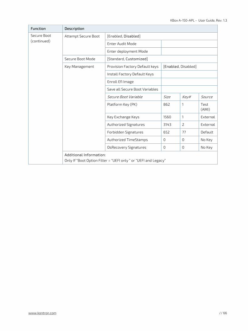
KBox A-150-APL - User Guide, Rev. 1.3
www.kontron.com // 66
Function Description
Secure Boot (continued)
Attempt Secure Boot [Enabled, Disabled]
Enter Audit Mode
Enter deployment Mode
Secure Boot Mode [Standard, Customized]
Key Management
Provision Factory Default keys [Enabled, Disabled]
Install Factory Default Keys
Enroll Efi Image
Save all Secure Boot Variables
Secure Boot Variable Size Key# Source
Platform Key (PK) 862 1 Test (AMI)
Key Exchange Keys 1560 1 External
Authorized Signatures 3143 2 External
Forbidden Signatures 652 77 Default
Authorized TimeStamps 0 0 No Key
OsRecovery Signatures 0 0 No Key
Additional Information: Only If “Boot Option Filter = “UEFI only ” or “UEFI and Legacy”

KBox A-150-APL - User Guide, Rev. 1.3
www.kontron.com // 67
12.2.6. Save and Exit Set up Menu
Figure 41: Save and Exit Set up Menu Example
Aptio Setup Utility – Copyright (C) 2018 American Megatrends, Inc.
Main Advanced Power Boot Security Save & Exit
Save Changes and Reset
Discard Changes and Reset
→ ←: Select Screen
Save Options ↑ ↓: Select Item
Save Changes Enter: Select
Discard Changes +/-: Change Opt.
F1: General Help
Restore Defaults F2: Previous Values
F3: Optimized Defaults
F4: Save & Reset
ESC: Exit
Version 2.18.1263. Copyright (C) 2018, American Megatrends, Inc.
The following table gives more information for important setup options within the Save and Exit Menu.
Table 19: Save and Exit Setup Menu Sub-screens and Functions
Function Description
Save Changes and Reset
Exits system after saving changes Once you are finished making your selections, choose this option to ensure the values you selected are saved to the CMOS RAM. The CMOS RAM is sustained by an on-board backup battery and stays on even when the PC is turned off. When you select this option, a confirmation window appears. Select [Yes] to save changes and exit.
Discard Changes and Reset
Exits system setup without saving changes Select this option only if you do not want to save the changes that you made to the Setup program. If you made changes to fields other than system date, system time, and password, the BIOS will asks for a confirmation before exiting.
Save Options Read only field
Save Changes Saves changes made so far for any setup options
Discard Changes Discards changes made so far to any of the setup values This option allows you to discard the selections you made and restore the previously saved values. After selecting this option, a confirmation appears. Select [Yes] to discard any changes and load the previously saved values.
Restore Defaults Restores/loads standard default values for all setup options Load Optimal Default values for all the setup values This option allows you to load optimal default values for each of the parameters on the Setup menus, that provides the best performance settings The F9 key can be used for this operation. Load Failsafe Default values for all the setup values This option allows you to load failsafe default values for each of the parameters on the Setup menus, that provides the most stable performance settings. The F8 key can be used for this operation.

KBox A-150-APL - User Guide, Rev. 1.3
www.kontron.com // 68
13/ Technical Support For technical support contact our Support department:
E-mail: [email protected]
Phone: +49-821-4086-888
Make sure you have the following information available when you call:
Product ID Number (PN)
Serial Number (SN)
The serial number can be found on the product’s type label.
Returning Defective Merchandise 13.1.
All equipment returned to Kontron must have a Return of Material Authorization (RMA) number assigned exclusively by Kontron. Kontron cannot be held responsible for any loss or damage caused to the equipment received without an RMA number. The buyer accepts responsibility for all freight charges for the return of goods to Kontron's designated facility. Kontron will pay the return freight charges back to the buyer's location in the event that the equipment is repaired or replaced within the stipulated warranty period. Follow these steps before returning any product to Kontron.
1. Visit the RMA Information website:
http://www.kontron.com/support-and-services/support/rma-information
2. Download the RMA Request sheet for Kontron Europe GmbH –Ismaning and fill out the form. Take care to include a short detailed description of the observed problem or failure and to include the product identification Information (Name of product, Product number and Serial number). If a delivery includes more than one product, fill out the above information in the RMA Request form for each product.
3. Send the completed RMA-Request form to the fax or email address given on the RMA Request sheet and Kontron will provide an RMA-Number.
4. The goods for repair must be packed properly for shipping, considering shock and ESD protection.
Goods returned to Kontron in non-proper packaging will be considered as customer caused faults and cannot be accepted as warranty repairs.
5. Include the RMA-Number with the shipping paperwork and send the product to the delivery address provided in the RMA form or received from Kontron RMA Support.

KBox A-150-APL - User Guide, Rev. 1.3
www.kontron.com // 69
14/ Storage, Transportation and Maintenance
Storage 14.1.
If the product is not in use for an extended period time, disconnect the power plug from the AC outlet .If it is necessary to store the product then re-pack the product as originally delivered to avoid damage. The storage facility must meet the products environmental requirements as stated within this user guide. Kontron recommends keeping the original packaging material for future storage or warranty shipments.
Transportation 14.2.
To ship the product use the original packaging, designed to withstand impact and adequately protect the product. When packing or unpacking products always take shock and ESD protection into consideration and use an EOS/ESD safe working area.
Maintenance 14.3.
Maintenance or repair on the open product may only be carried out by qualified personnel authorized by Kontron.
14.3.1. Cleaning
For light soiling, clean the product with a dry cloth.
Carefully remove dust from the surface of the chassis and cooling fins using a clean, soft brush.
Stubborn dirt should be removed using a mild detergent and a soft cloth
Do not use steel wool, metallic threads or solvents like abrasives, alcohol, acetone or
benzene for cleaning the KBox A-150-APL.
14.3.2. Replacing the Lithium Battery
The KBox A-150-APL is equipped with a Kontron specific battery assembly that may need to be replaced during the lifetime of the product. The KBox A-150-APL is not designed to operate without a battery. If the battery is empty or disconnected, the BIOS settings will be set to the factory defaults.
Replaced the lithium battery only when the KBox A-150-APL has been shut down properly by using the power-on switch and removing the power cable to disconnect the DC power supply. Replace the Kontron specific battery assembly only with the same type of battery (CR 2032) or with a Kontron recommended battery type.
To replace the Lithium battery, perform the following:
1. Open the KBox A-150-APL as described in Chapter 6.2: Opening the System(steps 1 to 6)
2. The lithium battery (Figure 42, pos. 1) is attached to the top of one of the internal USB 3.0 connectors (Figure 42, pos. 2) using a double –sided adhesive pad. Carefully, remove the lithium battery from the USB 3.0 connector and disconnect the battery’s cable from the on-board battery power input connector (Figure 43, pos. 3).

KBox A-150-APL - User Guide, Rev. 1.3
www.kontron.com // 70
Figure 42: Lithium Battery Location
1 Lithium battery (CR 2032, 3 V ) attached to connector with an adhesive pad
2 Internal USB 3.0 connector housing
3. Replace with a new lithium battery by inserting the battery’s connector into the on-board battery power input connector (Figure 43, pos. 3), while paying attention to the polarity of lithium battery connector cables.
Figure 43: Lithium Battery Power Input Connector
1 Lithium battery (CR 2032, 3 V )
2 Lithium battery cable
3 Battery power input connector
4. Position the battery cable to ensure that the cables do not interfere with other components and attach the lithium battery to the top of the internal USB 3.0 connector (Figure 42, pos. 2), using a double-sided adhesive pad.
5. Close the system as described in Chapter 6.2: Opening the System(step 7)
Danger of explosion when replacing with wrong type of battery. Replace only with the same
or equivalent type recommended by the manufacturer. The lithium battery type must be UL recognised.
The KBox A-150-APL is not designed to operate without a battery. If the battery is empty or disconnected, the BIOS settings will be set to the factory defaults.
Do not dispose of lithium batteries in general trash collection. Dispose of the battery according to the local regulations dealing with the disposal of these special materials, (e.g. to the collecting points for dispose of batteries).
1
2
3
2
1

KBox A-150-APL - User Guide, Rev. 1.3
www.kontron.com // 71
15/ Warranty Kontron defines product warranty in accordance with regional warranty definitions. Claims are at Kontron’s discretion and limited to the defect being of a material nature. To find out more about the warranty conditions and the defined warranty period for your region, following the steps below:
1. Visit Kontron’s Term and Conditions webpage.
http://www.kontron.com/terms-and-conditions
2. Click on your region’s General Terms and Conditions of Sale.
Protection label
The KBox A-150-APL is factory configured to meet customer requirements and sealed with a protection label. Opening the KBox A-150-APL, invalidates the warranty and may damage internal components.
Limitation/Exemption from Warranty Obligation 15.1.
In general, Kontron shall not be required to honor the warranty, even during the warranty period, and shall be exempted from the statutory accident liability obligations in the event of damage caused to the product due to failure to observe the following:
General safety instructions for IT equipment within this user guide
Warning labels on the product and warning symbols within this user guide
Information and hints within this user guide
Additionally, alterations or modifications to the product that are not explicitly approved by Kontron, described in this user guide, or received from Kontron Support as a special handling instruction will void your warranty.
Within the warranty period, the product should only be opened by Kontron. Removing the protection label and opening the product within the warranty period exempts the product from the statutory warranty obligation.
Due to their limited service life, parts which by their nature are subject to a particularly high degree of wear (wearing parts) are excluded from the warranty beyond that provided by law.

KBox A-150-APL - User Guide, Rev. 1.3
www.kontron.com // 72
Appendix A: List of Acronyms
Table 20: List of Acronyms (Example)
AC Alternating Current
ACPI Advanced Configuration Control Interface
ANSI American National Standards Institute
CPU Central Processing Unit
DC Direct Current
DIO Digital Input/Output
DP Display Port
ECC Error Checking and Correction
EHCI Enhanced Host Controller Interface
ES Energy Source
ESD Electrostatic Discharge
GbE Gigi bit Ethernet
GPU Graphics Processing Unit
HD/HDD Hard Disk /Drive
HDMI High Definition Multimedia Interface
HPM PICMG Hardware Platform Management specification family
H/W Hardware
IOL IPMI-Over-LAN
IOT Internet of Things
KVM Keyboard Video Mouse
LAN Local Area Network
LPS Limited Power Source
LVD Low Voltage Device
M.2 Next smaller generation of mSATA
MEI Management Engine Interface
mPCIe Mini PCI-Express
mSATA Mini SATA
OS Operating System
PCIe PCI-Express
RAM Read Access Memory
RoHS Restriction of the use of certain hazardous substances
RTC Real Time Clock
SATA Serial-ATA
SEL System Event Log
SELV Safety Extra Low Voltage
SIO Super Input/output
SMBus System Management Bus
SMWI System Monitor Web Interface
SOL Serial Over LAN
SSD Solid State Drive
TPM Trusted Platform Module
UEFI Unified Extensible Firmware Interface
USB Universal Serial Bus
VGA Video Graphics Array
VLP Very Low Profile
WEEE Waste Electrical and Electronic Equipment
Wi-Fi Wireless- Fidelity
XHCI eXtensible Host Controller Interface

KBox A-150-APL – User Guide, Rev. 1.3
www.kontron.com // 73
About Kontron Kontron is a global leader in embedded computing technology (ECT). As a part of technology group S&T, Kontron offers a combined portfolio of secure hardware, middleware and services for Internet of Things (IoT) and Industry 4.0 applications. With its standard products and tailor-made solutions based on highly reliable state-of-the-art embedded technologies, Kontron provides secure and innovative applications for a variety of industries. As a result, customers benefit from accelerated time-to-market, reduced total cost of ownership, product longevity and the best fully integrated applications overall. For more information, please visit: www.kontron.com
Global Headquarters
Kontron S&T AG
Lise-Meitner-Str. 3-5 86156 Augsburg Germany Tel.: + 49 821 4086-0 Fax: + 49 821 4086-111 [email protected]