bel 150 / 151 bel 150x / 151x
TRANSCRIPT

2/6/2007
Operation & Service Manual 65-02-7
BEL 150 / 151 Semi-Automatic Uniform Case Tape Sealers BEL 150X / 151X Extended Range Semi-Automatic Uniform Case Tape Sealers
Wexxar Packaging Inc. Phone (604) 270-0811 • Fax (604) 270-7897
E-mail: [email protected]
B E L 1 5 0 - 1 5 1 / 1 5 0 X - 1 5 1 X S e m i - A u t o m a t i c U n i f o r m C a s e T a p e S e a l e r s 2
65-02-7 02/06/07
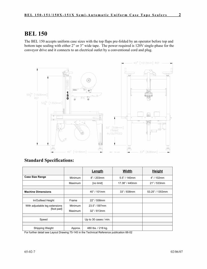
BEL 150 The BEL 150 accepts uniform case sizes with the top flaps pre-folded by an operator before top and bottom tape sealing with either 2” or 3” wide tape. The power required is 120V single-phase for the conveyor drive and it connects to an electrical outlet by a conventional cord and plug.
51
0
DEKKA
Standard Specifications:
Length Width Height Case Size Range Minimum 8” / 203mm 5.5” / 140mm 4” / 102mm Maximum [no limit] 17.38” / 440mm 21” / 533mm Machine Dimensions 40” / 101mm 33” / 838mm 53.25” / 1353mm
In/Outfeed Height Frame 22” / 558mm
With adjustable leg extensions [foot pad]
Minimum
Maximum
23.5” / 597mm
32” / 813mm
Speed Up to 30 cases / min.
Shipping Weight Approx. 480 lbs. / 218 kg.
For further detail see Layout Drawing 75-145 in the Technical Reference publication 66-02

B E L 1 5 0 - 1 5 1 / 1 5 0 X - 1 5 1 X S e m i - A u t o m a t i c U n i f o r m C a s e T a p e S e a l e r s 3
65-02-7 02/06/07
BEL 151 The BEL 151 accepts uniform cases for bottom tape sealing with 2” or 3” wide tape. The power required is 120V single-phase for the side-belt conveyor drive and it connects to an electrical outlet by a conventional cord and plug.
151
DEKKA
Standard Specifications Length Width Height Case Size Range Minimum 8” / 203mm 5.5” / 140mm 4” / 102mm Maximum - 17.38” / 440mm - Machine Dimensions 40” / 1016mm 33” / 838mm 37” / 937mm
In/Outfeed Height Frame 22” / 558mm
With adjustable leg extensions [foot pad]
Minimum
Maximum
23.5” / 597mm
32” / 813mm
Speed Up to 30 cases / min.
Shipping Weight Approx. 400 lbs. / 182 kg.
For further detail, see Layout Drawing 75-089 in the Technical Reference publication 66-02

B E L 1 5 0 - 1 5 1 / 1 5 0 X - 1 5 1 X S e m i - A u t o m a t i c U n i f o r m C a s e T a p e S e a l e r s 4
65-02-7 02/06/07
BEL 150X The BEL 150X can handle uniform case sizes of a larger maximum size than a standard BEL 150. The top flaps are pre-folded by an operator before top and bottom tape sealing with either 2” or 3” wide tape. The power required is 120VAC single-phase for the conveyor drive and the machine connects to an electrical outlet by a conventional cord and plug.
1
05
X
DEKKA
Standard Specifications Length Width Height Case Size Range Minimum 8” / 203mm 6.5” / 165mm 5” / 127mm Maximum [no limit] 24.75” / 629mm 30” / 762mm Machine Dimensions 40” / 101mm 41” / 1041mm 54.25” / 1378mm
In/Outfeed Height Frame 18” / 457mm
With adjustable leg extensions* [foot pad]
Minimum
Maximum
20.38” / 518mm
25.75” / 654mm
Speed Up to 30 cases / min.
Shipping Weight Approx. 500 lbs. / 227 kg.
*For further detail, see Layout Drawing 75-146 in the Technical Reference publication 66-02

B E L 1 5 0 - 1 5 1 / 1 5 0 X - 1 5 1 X S e m i - A u t o m a t i c U n i f o r m C a s e T a p e S e a l e r s 5
65-02-7 02/06/07
BEL 151X The BEL 151X can handle uniform case sizes of a wider maximum size than a standard BEL 151 for bottom tape sealing with either 2” or 3” wide tape. The power required is 120VAC single-phase for the conveyor drive and the machine connects to an electrical outlet by a conventional cord and plug.
151X
DEKKA
STANDARD SPECIFICATIONS Length Width Height Case Size Range Minimum 8” / 203mm 6.5” / 165mm 5.0” Maximum Unlimited 24.75” / 629mm Unlimited Machine Dimensions 40” / 101mm 41” / 1041mm 37” / 940mm
In/Outfeed Height Frame 18” / 457mm
With adjustable leg extensions [foot pad]
Minimum
Maximum
20.38” / 518mm
25.75” / 654mm
Speed Up to 30 cases / min.
Shipping Weight Approx. 425 lbs / 193 kg.
For further detail, see Layout Drawing 75-535 in the Technical Reference publication 66-02

B E L 1 5 0 - 1 5 1 / 1 5 0 X - 1 5 1 X S e m i - A u t o m a t i c U n i f o r m C a s e T a p e S e a l e r s 6
65-02-7 02/06/07
TABLE OF CONTENTS
INSTALLING YOUR BEL 150 7
Leveling the Machine 7
Installing the Tape Heads 7
Power Connection 7
CASE SIZE ADJUSTMENTS 9
Height Adjustment 9
Width Adjustment 10
STARTING THE MACHINE 10
FEEDING CASES 10
PREVENTATIVE MAINTENANCE GUIDE BEL 150-151 / 150X-151X 11
SERVICE AND MAINTENANCE PROCEDURES 12
UNI-DRIVE Side Belt Drive System 12 Chain Drive Tension 13 Side Belt Replacement 13 Belt Tensioning and Tracking Adjustment 13
ARCH CROSS MEMBER VERTICAL SLIDE ADJUSTMENT 14
TROUBLE SHOOTING GUIDE 17
Section 1 - Corrugated Case Quality & Specifications 17
Section 2 - Case Drive Belt System 18
Section 3 - General Taping Conditions 20
BEL 150 OPTIONAL EQUIPMENT 22
TECHNICAL REFERENCE INFORMATION – SEE PUBLICATION 66-02 22
B E L 1 5 0 - 1 5 1 / 1 5 0 X - 1 5 1 X S e m i - A u t o m a t i c U n i f o r m C a s e T a p e S e a l e r s 7
65-02-7 02/06/07
Installing Your BEL 150
Remove the through bolts that secure the machine to the shipping base. Use wooden dunnage blocks to lift the machine off its base with a forklift and position it in line.
Leveling the Machine
The machine should be in a level position to avoid frame stress and ensure optimum performance. The machine is equipped with adjustable leg height and leveling pads as standard equipment and adjustable casters are available as an option. Once the infeed / outfeed height has been set, use a spirit level both along and across the frame side rail members to level the machine.
Installing the Tape Heads
Tape heads are mounted with pins on the sides of the heads that fit into corresponding slots in the tape head mounting brackets. Lower the tape head into the bracket aligning the pins with the slots. The upper tape head, when pushed firmly toward the rear of the machine in its mounting slots, is held in position by spring retainers. Please consult the tape head manual for instructions on the mounting of tape rolls and the proper threading of tape through the applicator head.
Power Connection
The BEL 150 is equipped with single-phase 110 VAC electrics to NEMA 12 specifications as standard. The drive system is powered by a 1/2 horsepower TEFC motor that draws eight amps. A 14 gauge (AWG) power extension cord with standard three pin connection should be used to connect the machine to the power source.
A dedicated electrical circuit is recommended for this machine. If any electrical connections are needed to install the machine these must be handled by an electrician qualified in your jurisdiction.

B E L 1 5 0 - 1 5 1 / 1 5 0 X - 1 5 1 X S e m i - A u t o m a t i c U n i f o r m C a s e T a p e S e a l e r s 8
65-02-7 02/06/07
Fig.1 BEL 150 Semi-Automatic Case Taper
START / STOP SWITCH [MAGNETIC MOTOR STARTER AND THERMAL OVERLOAD PROTECTION]
CASE HEIGHT [VERTICAL] ADJUSTMENT
TOP TAPE HEAD AND MOUNTING BRACKET
OPTIONAL TOP CASE SIDE [SHOULDER] COMPRESSION ROLLERS
UNI-DRIVE SIDE DRIVE BELT CONVEYOR [WITH ENDLESS ROUGH-TOP BELTS]
SINGLE ½ HP CONVEYOR DRIVE MOTOR
CASE [CONVEYOR] WIDTH ADJUSTMENT
BOTTOM TAPE HEAD
OPTIONAL INFEED TABLE
OPTIONAL CASTERS [FOOT PADS STANDARD]

B E L 1 5 0 - 1 5 1 / 1 5 0 X - 1 5 1 X S e m i - A u t o m a t i c U n i f o r m C a s e T a p e S e a l e r s 9
65-02-7 02/06/07
SAFETY CAUTION
Make sure machine is disconnected from electrical power source before undertaking any adjustment or service procedures.
Only qualified personnel must operate machine.
Case Size Adjustments
Setting up the BEL 150 to run a particular box size requires only two settings: • Case height • Case width
Each is by adjusted screws, height by a hand wheel and width by a crank, both of which can be positioned on either side of the machine for operator convenience.
Height Adjustment
Turn the hand wheel located at the top of the machine frame arch, raising the tape head until it clears the top of box to be sealed. Position the box under the tape head and wind the tape head down until the folded top flaps fit snugly under the upper tape holder front compression rollers.
Note: Depending on case fill some minor adjustment may be further required in order to firmly tape down the top flaps.
Height adjustment handwheel can be located on either side of the machine arch
Top tapehead holder rollers should contact the fully closed top flaps of the case.

B E L 1 5 0 - 1 5 1 / 1 5 0 X - 1 5 1 X S e m i - A u t o m a t i c U n i f o r m C a s e T a p e S e a l e r s 10
65-02-7 02/06/07
Width Adjustment
Position the case between the infeed guides and by turning the crank at the machine side frame bring the guides inward until they lightly touch the case sides, without squeezing. Another method is to place the case between the belts and adjust them until they just touch the case but allow it to be removed, then remove the case and adjust-in another ½ turn. After adjustment, the crank can be reverse mounted on the shaft so the handle tucks behind the leg and no longer projects outward.
Starting the Machine BEL machines are fitted with magnetic starter switches for added safety protection from accidental start up in the event of a power outage or disconnection. The switch is positioned at the center of the frame arch for easy access from either side of the machine.
To start the machine, press the green start button on the switch. Use the red button to stop the machine.
FEEDING CASES
First fold down the top flaps of the case must by hand. Holding the top flaps closed, the operator directs the case between the infeed guides until it contacts the side drive belts which grip it and transport it through the tape heads that apply tape to the top and/or bottom flaps. Because of the BEL Uni-drive feature cases presented squarely to the machine will retain this squareness throughout the sealing cycle providing a stronger seal and better appearance.
Note: If the case sides are bulged by the product inside, the use of an optional side compression roller (Kit # 70-007 for the BEL 150, 70-185 for the BEL 150X) is recommended to draw the top major flaps together to effect a tighter seal. This option is also recommended when the case being sealed has a sealed length that is less than half of the box height.
Infeed guides lightly contacting case sides

B E L 1 5 0 - 1 5 1 / 1 5 0 X - 1 5 1 X S e m i - A u t o m a t i c U n i f o r m C a s e T a p e S e a l e r s 11
65-02-7 02/06/07
Preventative Maintenance Guide BEL 150-151 / 150X-151X
D A I L Y
8 Hrs.
• Keep framework and conveyor belts clean of dirt build-up, grease and oil residues.
• Check drive belts for wear.
• Check for worn or broken electrical connections.
• If supplied, check that all casters are in the locked position.
3
W E E K S
120 Hrs.
• Check drive belts for proper Belt Tension and Belt Tracking, refer to pages 6 & 7 of Operation
and Service manual. Note: Correct tension and tracking will prolong belt and drive bearing life.
• Lubricate Uni-Drive Side Belt drive chain and width adjustment roller chain with a Moly type spray chain lube.
• Cycle Height and Width adjustments and check for binding.
• Inspect electric motor and gearbox for evidence of oil leakage, noise or vibration and keep unit free of dirt, excess accumulation of dirt or grease will affect the proper cooing of the units.
3
M O N T H L Y
480 Hrs
• Lubricate width and height adjustment lead screws with a Synthetic Teflon Grease (Loctite –
Super Lube )
• Remove drive belts, Drive and Idle Pulleys should be inspected for bearing wear and pulley damage. Remove any dirt build-up before drive belts are re-installed. Refer to pages 6 & 7 of Operation and Service manual.
• Check Tension of the Uni-Drive Side Belt chain drive. Note: Proper Tension is achieved when the horizontal sag in the chain measures between 1/8” and ¼” with drive belts in a fully opened position. Refer to Operation and Service manual
• Check Cross Member Vertical Slide Adjustment for wear. Excessive wear may affect taping performance. Refer to Operation and Service manual
• Check and lubricate Swivel Casters if equipped.
• Check for any loose or missing fasteners.
For more detail, see BEL 150-151 / 150X-151X Technical Reference publication 66-02
B E L 1 5 0 - 1 5 1 / 1 5 0 X - 1 5 1 X S e m i - A u t o m a t i c U n i f o r m C a s e T a p e S e a l e r s 12
65-02-7 02/06/07
Service and Maintenance Procedures
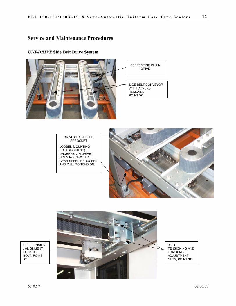
UNI-DRIVE Side Belt Drive System
SIDE BELT CONVEYOR WITH COVERS REMOVED, POINT ‘A’
SERPENTINE CHAIN DRIVE
DRIVE CHAIN IDLER SPROCKET
LOOSEN MOUNTING BOLT (POINT ‘D’) UNDERNEATH DRIVE HOUSING (NEXT TO GEAR SPEED REDUCER) AND PULL TO TENSION.
BELT TENSIONING AND TRACKING ADJUSTMENT NUTS, POINT ‘B’
BELT TENSION / ALIGNMENT LOCKING BOLT, POINT ‘C’

B E L 1 5 0 - 1 5 1 / 1 5 0 X - 1 5 1 X S e m i - A u t o m a t i c U n i f o r m C a s e T a p e S e a l e r s 13
65-02-7 02/06/07
The Uni-Drive side belt drive is a simple system designed to keep the case square during sealing which results in a technically stronger seal and a better-finished appearance. It is achieved by linking the drives of both side belts to a single motor and gear reducer by single continuous loop of #40 prestretched machine chain around four sprockets.
Uniform chain tension is maintained during case width adjustments through a self-compensating serpentine configuration as shown in the “Chain and Belt Tensioning Points” photo illustrations on the following page.
Chain Drive Tension
Refer to “Chain and Belt Tensioning Points” photo illustrations of the previous page
Chain tension is preset at the factory but if adjustment is needed then tighten at point D. Proper tension is achieved when the horizontal sag in the chain measures between 1/8 inch and 1/4 inch with drive belts in a fully opened position.
The chain should be lubricated once every one hundred hours of operation using a spray type chain lubricant. (Recommended: Moly type spray chain lube.)
If it becomes necessary to access the drive serpentine the stainless steel safety covers can be removed by unfastening the screws and attaching them to the machine frame cross member.
IMPORTANT: Replace the safety covers before operating the machine.
The optional BEL 150 Spare Parts Maintenance Kit contains all of the parts necessary for maintaining the Uni-Drive system. See the Technical Reference manual 66-02 for details and contact the factory or your local Belcor Distributor for price and availability.
Side Belt Replacement
Refer to “Chain and Belt Tensioning Points” photo illustrations on the previous page.
The side belts can be quickly and easily replaced with the following procedure: 1. Remove the stainless steel safety covers, (point A) 2. Loosen the Locking Bolt (point C) at the bracket under the front of each conveyor beam 3. Loosen the Tensioning and Tracking Adjustment Nuts (point B) until the belts can be lifted up and
off. 4. Fit new belts (We recommend that both belts be replaced at the same time)
Belt Tensioning and Tracking Adjustment Tension the belt using the two Tensioning and Tracking Adjustment Nuts (point B). The tension of the belt should be just enough to prevent belt slippage or so that approximately one inch of play is available when the belt is pulled sideways by hand in the center of the machine.
Alternately tighten the upper and lower nut to position the belt so that it is running true and not trying to ride up or down on the idle pulley. When done, tighten the Locking Bolts that retain the set position (point C).
Replace the stainless steel safety covers before operating the machine.

B E L 1 5 0 - 1 5 1 / 1 5 0 X - 1 5 1 X S e m i - A u t o m a t i c U n i f o r m C a s e T a p e S e a l e r s 14
65-02-7 02/06/07
ARCH CROSS MEMBER VERTICAL SLIDE ADJUSTMENT
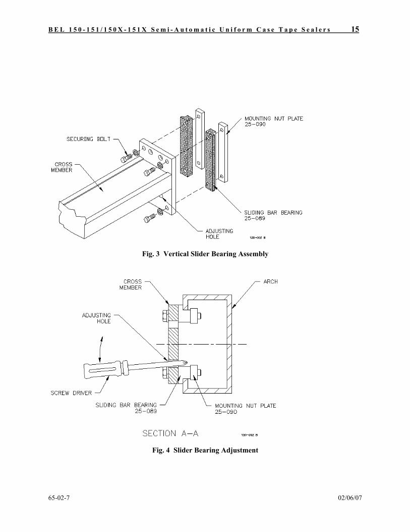
The machine arch cross member supports the upper tape head holder on the BEL 150. It mounts to the arch assembly with vertical slide bar bearings that ride inside the arch columns, allowing the cross member to move smoothly up and down for case height adjustment.
The bearings are made of a special hardwearing plastic material but may need periodic adjustment to compensate for wear or for loosening due to shipping or operating vibration. If worn or loose, the bearings allow excessive movement of the upper tape head holder and may affect taping performance.
Fig. 2 Arch Cross Member Mounting
B E L 1 5 0 - 1 5 1 / 1 5 0 X - 1 5 1 X S e m i - A u t o m a t i c U n i f o r m C a s e T a p e S e a l e r s 15
65-02-7 02/06/07
Fig. 3 Vertical Slider Bearing Assembly
Fig. 4 Slider Bearing Adjustment

B E L 1 5 0 - 1 5 1 / 1 5 0 X - 1 5 1 X S e m i - A u t o m a t i c U n i f o r m C a s e T a p e S e a l e r s 16
65-02-7 02/06/07
Adjusting Vertical Slider Bearing Clearance
SAFETY - Disconnect the machine from its electrical supply before making any adjustments or changes.
1. Remove the upper tape head from its holder.
2. Place two bars or pieces of wood of uniform thickness across the tops of side belt conveyor covers to provide a level resting place for the upper tape head assembly and lower the cross member with the tape head holder and/or Snap Folders until they rest on the bars.
3. Loosen the four corner bolts in each end plate that secure the cross member to the arch column just enough so the slider bar bearings are free to be adjusted.
4. Place a screwdriver through an adjusting hole and use it to lever a slider bar bearing tighter against the column channel flange. While holding the pressure with the screwdriver, tighten the two securing bolts through each bearing. Repeat this procedure for the other three bearings and try to equalize the amount of adjustment between all four.
5. Test the fit of the bearings by lifting the cross member with the adjusting hand wheel. If too much force is required and the fit seems very tight, loosen the bolts on one of the bearings on each side just enough to free the movement. If the fit still seems too loose and there is still excessive movement of the tape head holder, repeat the adjusting procedure using more leverage force. If the fit cannot be improved with greater force, the bearings are excessively worn and need to be replaced.
B E L 1 5 0 - 1 5 1 / 1 5 0 X - 1 5 1 X S e m i - A u t o m a t i c U n i f o r m C a s e T a p e S e a l e r s 17
65-02-7 02/06/07
Trouble Shooting Guide
Section 1 - Corrugated Case Quality & Specifications
Corrugated case quality is a major factor in smooth running and quality sealing.
1. Check your case dimensions to see that the products fill the case efficiently and do not bulge, over-fill or under-fill the case. Re-sizing of cases can often result in cost savings by using the correct box size and material weight. Consult your corrugated supplier, for help to achieve this. A correctly filled box will help the automatic process by supporting the case body during flap folding and the top flap sealing.
2. Make sure that all scores (fold lines) on your cases are well defined to help with the automatic folding process. Your corrugated case supplier can help with this by making sure that correct scoring pressure is used for your case specification. This is one of the most common causes of poor case closing performance
3. Corrugated case weakness is often an area that needs quality control. The fluted construction of corrugated board can be impaired by various factors in the corrugated box manufacturing process. Points to watch for:
a. that the flutes have not been crushed overall, causing the box to have a ‘soft’ and limp feeling. This causes poor case rigidity during machining and also does not give your product the protection it deserves.
b. selective bands of crushing, usually parallel to the box flutes that can cause failure lines down the box and result in poor machine handling performance.
c. case storage, flat cases should be stored in dry conditions and on a flat surface. Be careful not to stack excessive weight on to the cases as crushing can result.
4. Check the ‘squareness’ of cases. The glue joint where the manufacturer glues the flat case together often can present a quality problem by being misaligned. It causes the case to be wider at one end than the other or to be twisted from end to end. Both conditions can cause case jams and poor sealing quality.
5. Corner slots in the case should be wide as possible so cases can be automatically folded with a minimum of interference between major and minor flaps.
6. Overlap or gapped case flaps can be a result of incorrect flap lengths. Fold the box by hand to see that flaps meet neatly in the case center.
Use your corrugated case supplier’s expertise to help you achieve the correct specifications for your automatic sealing line.
B E L 1 5 0 - 1 5 1 / 1 5 0 X - 1 5 1 X S e m i - A u t o m a t i c U n i f o r m C a s e T a p e S e a l e r s 18
65-02-7 02/06/07
Section 2 - Case Drive Belt System The Uni-Drive side belt system is designed to keep the case square during sealing which results in a technically stronger seal and a better looking appearance.
Problem: Case Is Not Sealing Squarely.
Despite the parallel drive nature of the Uni-Drive system, the cases exit the machine not square after sealing. Check that:
• The case is square prior to engagement in the side drive conveyor belts.
• The side belts are adjusted to case width correctly by the following method: 1. Adjust the belts in until they lightly contact case sides, but so the case can still slide through
belts if pushed firmly. 2. Remove the case and adjust the belts in one half turn more.
• Neither of the conveyor belts are slipping on its drive pulley. See the section on belt tensioning procedure under Service and Maintenance Procedures.
• In the case of round can or bottle products, check that belts are set to grip lightly but firmly on case sides. Excessive side pressure can cause round objects to roll “over-center” and push the case out of square.
Problem: Depressed or Crushed Band on Lower Case. If the cases exit the machine with a band of crushed corrugation at the level of the conveyor belts, it is likely that the case is gripped too tightly in the belts.
Problem: Rubber ‘Dust’ Being Shed by Belt.
A dark gray or almost black dust appears beneath the conveyor belts, particularly at the case exit end of the machine
• Check that carton is clearing the belts as it exits the machine and that outfeed conditions do not cause cases to back up into the machine.
• Check that belt tensioning and tracking adjustments are correct as described under Service and Maintenance Procedures. Incorrect settings can cause premature belt wear and possible belt breakage.
Problem: Rattling Noise from the Conveyor Drive.
Although pre-stretched chain is used in the machine drive, the chain over time may loosen and rattle on the drive cover. Tighten the idler sprocket as described in the Service and Maintenance Procedures section.
B E L 1 5 0 - 1 5 1 / 1 5 0 X - 1 5 1 X S e m i - A u t o m a t i c U n i f o r m C a s e T a p e S e a l e r s 19
65-02-7 02/06/07
Problem: Frequent Belt Breakage.
Belt life will depend on the conditions of machine use but frequent breakage may be due to one or more of the following conditions:
• Belt tracking. Check that the belt does not try to ride up or down on the pulleys. See belt tensioning and tracking adjustment under Service and Maintenance Procedures
• Belt Tension. Belts may be over-tensioned - correct setting allows approximately one inch of slack at center point of conveyor.
• Idler and drive pulley rotation. Check that pulleys rotate freely and that bearings are not excessively worn or seized.
• Rotation direction of belt. Look on the back of the belt for the type of join. Stepped-lap splice belts must move in the direction of the arrow marked on the inside of the belt. Newer style “finger”-spliced belts can move in either direction..
Problem: Machine Jams Frequently.
Turn off the machine as soon as jam occurs and before clearing jam. Open Belts and raise the top tape head, remove jammed case and debris. Check for jam causes:
• Top tape head is adjusted too low.
• Product is overfilled or inconsistent causing intermittent jams.
• Top flaps are not folding correctly, flaps then hit top ski or tape head mechanism.

B E L 1 5 0 - 1 5 1 / 1 5 0 X - 1 5 1 X S e m i - A u t o m a t i c U n i f o r m C a s e T a p e S e a l e r s 20
65-02-7 02/06/07
Section 3 - General Taping Conditions
Problem: Tape Does Not Stick To Case Surface. The tape is not bonding to the corrugated board of the flaps or ends of the case to provide a secure seal. Look for the following conditions:
• Under-filled Case. Check that product provides support under the top flaps so that they are not simply pushed down or away from the tape head rather than having the tape rolled onto the surface.
• Overlapping flaps. If the outside (major) flaps are allowed to overlap the “step” created results in an uneven taping surface causing poor tape adhesion that can release during shipping and handling. See comments on flaps under Troubleshooting section 1, Corrugated Case Quality & Specifications
• Tape head roller contact. Check that the tape head contact or wipe-down rollers are making good contact with the box and that the roller spring tension is correct.
• Dust or dirt. Large amounts of dust or dirt gathering on boxes or in the air will impair adhesive effectiveness.
• Temperature. Hot or cold temperature may require tapes with appropriate adhesive formulations for good initial bond and permanent sealing performance.
• Tape adhesive. Check presence and quality of tape adhesive.
Problem: Tape is not cut uniformly. The tape is not cut properly every time, in the worst situations several boxes may be taped together. Check the following conditions:
• Tape head position. If the top tape head is set too high the cut off knife will not be fully activated resulting in poor cut off. The tape head side plates should be within 1/16 to 1/8” of the case. Check also that cases ride fully down between the conveyor belts to provide proper contact with the bottom head cut off knife.
• Knife extension. Be sure that knife extends enough to fully contact the tape during the cutting stroke.
• Tape tension. Unroll tension should be smooth and not too tight as a ‘snap back’ caused by stretched tape can cause a jagged cut off and tape pieces to stick to the blade.
• Clean knife. Clean the blade and apply a little silicon or oil to avoid adhesive build up on the sharp points.
• Knife blade wear or damage. Blades must be very sharp to work well. The points are easily damaged if contacted by any hard material. Replace the blade if it seems dull.
• Cut-off spring tension. Check to ensure the spring that provides power to cut off arm has enough tension to cut through the tape. Replace the spring if it is too weak.
Problem: Tape tail does not stick down properly.
SAFETY CAUTION – Tape Head knife is very sharp
!
B E L 1 5 0 - 1 5 1 / 1 5 0 X - 1 5 1 X S e m i - A u t o m a t i c U n i f o r m C a s e T a p e S e a l e r s 21
65-02-7 02/06/07
The end of the tape on the back side of the case as it leaves the machine has not adhered well to the box. Check these conditions:
• Tape tension. Tension should be is smooth and not too tight. “Snap back” will cause tape tail to recoil and not stick well on the back of the case.
• Tape head roller contact. Tape head contact or wipe-down rollers should make good contact with the box. Adjust roller spring tension, if necessary.
Problem: Tape is off-center. The line of tape is not centered over the gap between flaps on the top or bottom of the box. Look for the following conditions:
• Tape roll position. Check that the tape roll is fully pushed on to spool. • Tape head straight. Check that the tape head sits straight in its bracket and is not tilted to either
side. • Obstructions. Look for obstructions that could be pushing the tape off center. Problem: Tape Falls Forward on Bottom Head. The beginning end of the tape must stand vertically in front of the tape head front roller in order to contact the leading end of the next case. A bow made across the tape by the tape head guides help to stiffen it and a static electric charge on the tape head rollers attract the tape and help to keep it in place. If the bottom tape will not stand vertically, examine the following factors:
• Contamination. Tape may be wound around the roller or other dirt on the roller. • No static charge. Dust roller surfaces with talcum powder to the increase static charge on the roller. • Tape head guides. Check that the tape holder or finger is set correctly, see tape head manual. • Ambient conditions. A strong breeze in the vicinity of the tape sealer can cause the tape to blow
down. High temperature or humidity may affect tape characteristics. • Type of tape. Some brands and types of tape have more ‘body’ than others and a change of tape may
be needed, particularly in difficult ambient conditions.
B E L 1 5 0 - 1 5 1 / 1 5 0 X - 1 5 1 X S e m i - A u t o m a t i c U n i f o r m C a s e T a p e S e a l e r s 22
65-02-7 02/06/07
BEL 150 OPTIONAL EQUIPMENT • Adjustable stainless steel leg extenders with U.H.M.W. pads. (70-003) • Adjustable stainless steel leg extenders with zinc plated casters. (70-004) • Alternate voltages available on request. • Machine spare parts kits (BEL 150/151 #70-010, BEL 150X/151X#70-189 as above) • DEKKA tape head spare parts kits (Dekka 22 #70-056, Dekka 23 #70-057) • Spare tape heads. • Shoulder compression rollers for bulged cases. (70-007)
All parts available individually.
TECHNICAL REFERENCE INFORMATION – See Publication 66-02