itu-r sg5 wp5a 第2回会合への日本寄与文書(案)一覧
TRANSCRIPT
資料地-3-4
ITU-R SG5 WP5A 第2回会合への日本寄与文書(案)一覧
資料番号 題 名 提出先 提出元
資料地
3-4-1
(英文) Preliminary Draft New Recommendation
Integrated millimeter wave ITS radiocommunication systems
5A
NICT
(和文) 「ミリ波を用いたITS無線通信」の暫定新勧告案の修正提案
資料地-
3-4-2
(英文) Proposed Revision of Recommendation M.1310
(ITS– Objectives and requirements)
5A ITS情報通
信システム
推進会議(和文) ITU-R勧告M.1310「ITSの目的と要件」の改訂提案
資料地-
3-4-3
(英文) Proposed revision for A Preliminary Draft New Report
“Cognitive radio systems in the land mobile services”
5A NICT,
KDDI研究所
ATR (和文) PDNレポート”陸上移動業務におけるコグニティブ無線”の改
訂提案
資料地
3-4-4
(英文) Proposal for a preliminary draft new Question; Mobile
wireless access systems providing communications to a large
number of ubiquitous sensors and/or actuators scattered
over wide areas
5A
NTT
(和文) 新研究課題「広いエリアに点在する人やモノに取り付けられ
た非常に多くのセンサやアクチュエータとの双方向通信を提
供する移動通信システム」の提案
資料地
3-4-5
(英文) Mobile wireless access systems providing communications
to a large number of ubiquitous sensors and/or actuators
scattered over wide areas
5A
NTT
(和文) PDNQ [SAC/5]に対する勧告/レポートの作業文書案の提案
資料地
3-4-6
(英文) Proposed modification to a revision of
recommendation ITU-R M.1801
5A
ウィルコム
(和文) 勧告ITU-R M.1801リバイズ版に向けた修正提案
資料地
3-4-7
(英文) Proposals for early completion of the work for draft revisi
on of recommendation ITU-R F.758-4
5A/5CNTTドコモ,
NTT (和文) 勧告ITU-R F.758の改訂作業の早期完了提案
資料地
3-4-8
(英文) Review of certain recommendations developed by former
working party 9D
5A/5C
NTTドコモ
(和文) 旧Working Party 9Dが作成した勧告の見直し。
資料地
3-4-9
(英文) Draft Updating of recommendation ITU-R F.1335 5A/5C NTTドコモ,
東京工科大学(和文) 勧告ITU-R F.1335のUpdate案
資料地
3-4-10
(英文) Draft revision of recommendation ITU-R F.1336-2 5A/5CNTT ,
NTTドコモ(和文) 勧告F.1336(P-MP方式用アンテナ基準放射パターン)の改
定案

資料番号 題 名 提出先 提出元
資料地
3-4-11
(英文) Proposal for preliminary draft revision of Report ITU-R
F.2107 Characteristics and applications of fixed wireless
systemsoperating in the 57GHz to 95 GHz
5C
NTT
(和文) Report ITU-R F.2107の暫定改定提案
資料地-
3-4-12
(英文) Preliminary Draft Revision of Report ITU-R F.2106
FIXED SERVICE APPLICATIONS USING FREE-SPACE
OPTICAL-LINK
5C
大阪大学
(和文) Report ITU-R F.2106の暫定改定提案
資料地-
3-4-13
(英文) A PROPOSAL OF AMENDMENTS IN CHAPTERS 7 AND 8
OF PRELIMINARY DRAFT NEW REPORT M.[IMT.EVAL] 5D
ARIB (和文) 新レポート草案ITU-R M.[IMT.EVAL]の7章および8章の修正
提案
資料地
3-4-14
(英文) PROPOSED MODIFICATION TO THE TECHNOLGY
DESCRIPTION TEMPLATE 5D
ARIB
(和文) 技術記述テンプレートの修正提案
資料地
3-4-15
(英文) VIEWS ON ADOPTION OF ACLR PROVISION FOR THE
UPDATE OF RECOMMENDATIONS ITU-R M.1580 and
M.1581
5D
ARIB (和文) 勧告ITU-R M.1580とM.1581の更新にあたってのACLRの取り
扱いについて
(和文) 勧告ITU-R M.1801リバイズ版に向けた修正提案
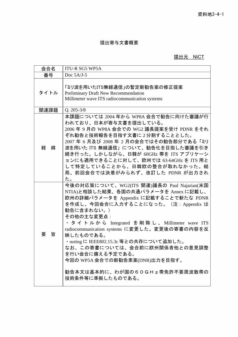
資料地3-4-1
提出寄与文書概要
提出元 NICT
会合名 ITU-R SG5 WP5A 番号 Doc 5A/J-5
タイトル
「ミリ波を用いたITS無線通信」の暫定新勧告案の修正提案 Preliminary Draft New Recommendation Millimeter wave ITS radiocommunication systems
関連課題 Q. 205-3/8
経 緯
本課題については 2004 年から WP8A 会合で勧告に向けた審議が行
われており、日本が寄与文書を提出している。 2006 年 9 月の WP8A 会合での WG2 議長提案を受け PDNR をそれ
ぞれ勧告と技術報告を目指す文書に 2 分割することとした。 2007 年 6 月及び 2008 年 2 月の会合ではその勧告部分である「ミリ
波を用いた ITS 無線通信」について、勧告化を目指した審議を引き
続き行った。しかしながら、日韓が 60GHz 帯を ITS アプリケーシ
ョンにも適用できることに対して、欧州では 63-64GHz を ITS 用と
して特定していることから、日韓欧の整合が取れなかった。結
局、前回会合では決着がみられず、改訂した PDNR が出力され
た。
要 旨
今後の対応策について、WG2(ITS 関連)議長の Paul Najarian(米国 NTIA)と相談した結果、各国の共通パラメータを Annex に記載し、
欧州の詳細パラメータを Appendix に記載することで新たな PDNRを作成し、今回会合に入力することになった。(注:Appendix は
勧告に含まれない。) その他の主な変更点: ・ タ イ ト ル か ら Integrated を 削 除 し 、 Millimeter wave ITS radiocommunication systems に変更した。変更後の寄書の内容を反
映したものである。 ・noting に IEEE802.15.3c 等との共存について追加した。 なお、この寄書については、会合前に欧州関係者他との意見調整
を行い会合に備える予定である。 今回の WP5A 会合での新勧告素案(DNR)出力を目指す。 勧告本文は基本的に、わが国の60GHz帯免許不要周波数帯の
技術条件等に準拠したものである。
資料地3-4-2
提出寄与文書概要
提出元 ITS情報通信システム推進会議
会合名 ITU-R SG5 WP5A 番号 Doc 5A/J-6
タイトル
ITU-R勧告M.1310「ITSの目的と要件」の改訂提案 Proposed Revision of Recommendation M.1310 ITS– Objectives and requirements
関連課題 Q. 205-4/8
経 緯
この勧告 M.1310 は制定されてから既に 10 年以上を経過し、見直
しが必要となっている。前回会合(2008 年 2 月)ではカナダから勧告
の見なおし提案がなされ、審議を開始した。今回会合では各国か
らの改訂提案が求められている。
要 旨
日本からは前回会合でのカナダからの寄書に対して次の各項に関
する検討を提案し、次回会合での決着を目指す。 ・日米欧の最新版の ITS アーキテクチャを参照すべきである。 ・最新のディジタル放送や携帯電話技術など、現状に見合った ITS 技術を反映した検討事項を提案する。 今回会合では、勧告 M.1310 改訂は次回会合への継続審議になるも
のと予想される。

資料地3-4-3
提出寄与文書概要
提出元 NICT、KDDI研、ATR
会合名 ITU-R WP5A
番号 Doc 5A/J-7
タイトル
(英文)
Proposed revision for A Preliminary Draft New Report “Cognitive
radio systems in the land mobile services”
(和文)
PDNレポート”陸上移動業務におけるコグニティブ無線”の改訂提案
関連課題 Question ITU-R 241/8
経 緯
- 研究課題 (Question ITU-R 241-1/8)が承認されたことを受け、2007
年 6 月の WP8A(現 WP5A)にてレポートを目指した作業文書作成に着
手し、フレームワーク(目次)に合わせて各国寄書から相当するテキス
トを切り出し作業文書に配置した。
- 日本からは、最新の R&D 動向を 2008 年 2 月の WP5A において入力し
た。その内容については、議論されていない。
- レポートの内容について、さらに情報の追加や議論が必要である。
要 旨
- 本寄与文書では、議長報告(Annex 10 to Document 5A/45-E)の
Working document を基に改訂提案を行っている。
- 寄与文書本文は、以下の 4章から構成している。
1. Introduction
2. Definition of CRS
3 Summary of other new text proposal or modification
4. Conclusion
- 上記の第 2 章は、CRS の定義の提案であり、最も重要と考えられるの
で、1つの独立した節とし、また提案の内容についても述べている。
- 上記の第 3 章は、その他の提案のサマリーを提案理由も含めて述べて
いる。内容の概要は、以下の通りである。(以下の節は、Attachment
に相当)
- 第 5 節で、subsection とそのテキストの追加、並びに第 5 節の一
部にテキストを追加
- 第 6節で、テキストの追加
- 第 7節で、7.2 節~7.5 節の追加
- ANNEX 3 に、“R&D Activities concerning the cognitive radio
related common control channel concept in Japanese
project”と題したテキストを追加
以上
資料地3-4-4
日本寄与文書概要(案)
作成元 NTT
会合名 ITU-R WP5A 番号 Doc 5A/J-8
タイトル
(和文)新研究課題「広いエリアに点在する人やモノに取り付け
られた非常に多くのセンサやアクチュエータとの双方向
通信を提供する移動通信システム」の提案 (英文)Proposal for a preliminary draft new Question; Mobile
wireless access systems providing communications to a large number of ubiquitous sensors and/or actuators scattered over wide areas
関連課題等
経 緯
近年、人やモノにセンサ/アクチュエータを取り付け、ネットワ
ークへ接続することで、人やモノがもつ情報を収集、あるいは遠
隔から無線を介してモノを制御するセンサネットワークが注目さ
れている。センサネットワークでは、近距離無線システムによる
プライベートエリアやローカルエリアでのネットワーク化が普及
しているが、新たな移動通信システムを用いて、適用エリアをパ
ブリックエリアまで拡大することにより、サービスエリアの拡大
や新たなサービス領域の開拓が可能である。
要 旨
本提案書では、上記のような広いエリアを対象としたセンサネッ
トワークに適用する移動通信システムという新たな研究課題(技
術面・運用面の要求条件および技術的特性など)を提案する。 本システムは、以下の特徴を有する。 ・低能力、低価格のセンサ/アクチュエータに対する双方向通信
を提供 ・広いエリアに点在する莫大な数のセンサ/アクチュエータをセ
ルベースの無線ネットワークにて面的に収容 ・モビリティをサポート
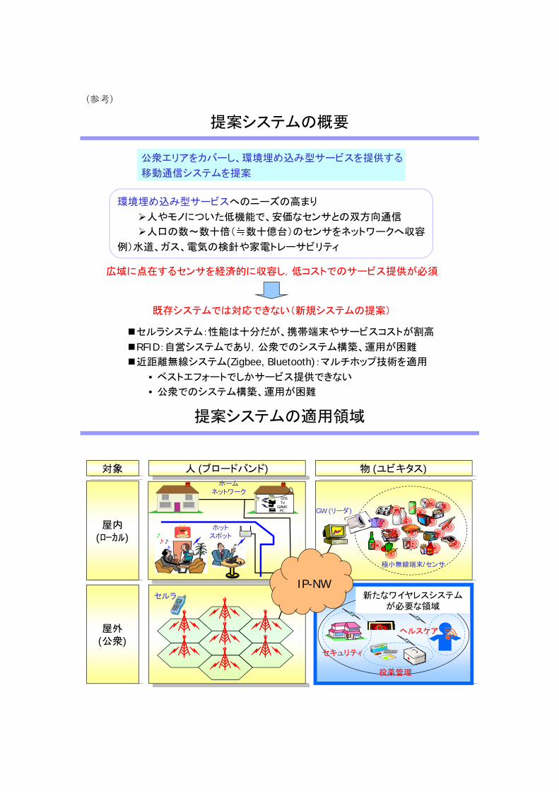
(参考)
提案システムの概要
環境埋め込み型サービスへのニーズの高まり
人やモノについた低機能で、安価なセンサとの双方向通信
人口の数~数十倍(≒数十億台)のセンサをネットワークへ収容
例)水道、ガス、電気の検針や家電トレーサビリティ
既存システムでは対応できない(新規システムの提案)
公衆エリアをカバーし、環境埋め込み型サービスを提供する
移動通信システムを提案
セルラシステム:性能は十分だが、携帯端末やサービスコストが割高
RFID:自営システムであり,公衆でのシステム構築、運用が困難
近距離無線システム(Zigbee, Bluetooth):マルチホップ技術を適用
• ベストエフォートでしかサービス提供できない
• 公衆でのシステム構築、運用が困難
広域に点在するセンサを経済的に収容し,低コストでのサービス提供が必須
提案システムの適用領域
対象 人 (ブロードバンド) 物 (ユビキタス)
屋内(ローカル)
屋外(公衆)
極小無線端末/センサ
GW (リーダ)
♪♪♪
♪
ホットスポット
STBTV
GAMEPC
ホームネットワーク
セルラ
IP-NW
セキュリティ
ヘルスケア
投薬管理
新たなワイヤレスシステムが必要な領域
資料地3-4-5
日本寄与文書概要(案)
作成元 NTT
会合名 ITU-R WP5A
番号 5A/J-9
タイトル
PDNQ [SAC/5]に対する勧告/レポートの作業文書案の提案
Mobile wireless access systems providing communications to a large number of ubiquitous sensors and/or actuators scattered over wide areas
関連課題等
経 緯
本会合において、広いエリアを対象としたセンサネットワークに
関するPDNQ [SAC/5]を同時にWP5Aに入力予定である。
要 旨
前記PDNQに対する勧告/レポートの作業文書案を提案する。
Attachment では、本勧告/レポートの作業文書案を提示する。
Annexでは、NTTの実験システム、フィールド実験ならびにその
結果について併せて紹介する。これは、本勧告/レポートの文書
作成作業にあたって本システムのフィージビリティを訴求するも
のである。

資料地3-4-6
提出寄与文書概要
提出元 株式会社ウィルコム
会合名 ITU-R WP5A
番号 Doc 5A/J-10
タイトル
(英文)
PROPOSED MODIFICATION TO A REVISION OF RECOMMENDATION ITU-R M.1801
(和文)
勧告ITU-R M.1801リバイズ版に向けた修正提案
関連課題 RECOMMENDATION ITU-R M.1801
経 緯
2007年3月に成立した勧告ITU-R M.1801に記載されているBWA技
術の一つである次世代PHSは、勧告成立以降、2007年9月PHS MoU Group規格のリバイズ版が承認され、更に昨年12月にARIBでの標準
規格化が完了した。
要 旨
2007年3月の勧告ITU-R M.1801初版リリース以降の情報アップデー
トとして、次世代PHSの記載内容の拡充、技術名称の変更(eXtended Global Platform:XGP)、ARIB規格としての紹介を今回の寄与文書に
て実施。
資料地3-4-7
日本入力寄与文書(案)
作成元 NTT DoCoMo, NTT
会合名 ITU-R WP5A/WP5C
番号 1 Doc 5A/J-1, Doc 5C/J-
タイトル 勧告ITU-R F.758の改訂作業の早期完了提案
(
the work for DRAFT REVISION
(和文)
英文)
Proposals for early completion ofof RECOMMENDATION ITU-R F.758-4
関連課題 Q.225/9
経 緯
勧告ITU-R F.758は、各周波数帯ごとに固定業務の代表的方式パ
ラ
短時間規格
「一部方式のパラメータ」については、前回会合で以下の指摘
noise bandwidth に Channel spacing と同じ値(もし
にかなり
現状の改訂案作業文書は、Document 5C/26 Annex 3に収録され
て
メータを提示するとともに、他業務との周波数共用における干
渉評価方法、干渉基準に関する考え方を取り纏めたものであり、
F-series勧告の中でも最も重要な勧告の一つである。
本勧告の改訂作業は、「方式パラメータの更新」「
に関する考察追加」「一次業務間共用以外の環境下における両立
性の考察追加」などを中心に、旧Study Group 9 (Working Party 9D)において2005年当初から行われて来ており、Annex 2のTableに記載の「一部方式のパラメータ」以外についてはほぼ合意が得
られている。
があった。 ● Receiver
くは大きい値)を採用していることは現実的でない。 ● Minimum value を示すはずの Feeder/multiplexer loss
大きい値が見られる。
いる。
要 旨
上記の代表的「方式パラメータ」には、2005年に日本から提案し
また、勧告のテキスト全般についてEditorial updateを施し、本勧
たものが含まれている。これらにつき、前回会合での指摘事項を
考慮しつつ、最新の諸元に更新するよう新たな方式パラメータを
提案する。
告の重要性に鑑み3年以上経過している改訂作業を早期に完了す
ることを提案する。
資料地3-4-8
日本入力寄与文書(案)
作成元 NTT DoCoMo
会合名 ITU-R WP5A/WP5C
番号 2 Doc 5A/J-2, Doc 5C/J-
タイトル 旧Working Party 9Dが作成した勧告の見直し。
(
(和文)
英文)
Review of certain Recommendations developed by former working party 9D
関連課題
経 緯
最終改訂から10年以上経過したものを対象にITU-R勧告の
Up い
この考え方に沿って前会期には、旧WP9A, 9Bにおいて旧い勧告
の
date作業促進が、決議1-5のsection 11において規定されて
る。
見直し作業が行われた。
要 旨
今回は旧WP9Dの所掌であった勧告を対象として、1999年以降改
結果は以下のとおりである。
SUP F.759, F.760
② 7件、(F.1246, F.1248, F.1333, F.1334, F.1338, F.1402,
l Updating または公式改訂 1件、(F.1335)
④ 1件(F.14
の勧告F.1335 のupdatingについては、修正箇所が多くなるこ
訂が行われていないもの(11勧告)について、内容を評価し
「削除(SUP)」、「無修正維持(NOC)」及び「Editorial updating」など今後の扱いについての提案を作成した。
次回RA-11前には、「2001年以降改訂されていないもの」につい
てUpdate検証が必要となるが、とりあえず「最終改訂から10
年」の期限が迫っているもののみを取り上げた。
① 2件、( )
NOC F.1403)
③Editoria
SUP または Editorial updating 05)
③
と、P-series勧告の最新内容の反映を含むこと、から別文書でテキ
ストを提示し、各国の意見を取り入れて扱いを決定する。
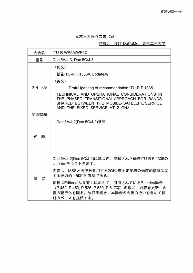
資料地3-4-9
日本入力寄与文書(案)
作成元 NTT DoCoMo、東京工科大学
会合名 ITU-R WP5A/WP5C
番号 3 Doc 5A/J-3, Doc 5C/J-
タイトル
勧告ITU-R F.1335のUpdate案
(
raft Updating of recommendation ITU-R F.1335 TECHNICAL AND OPERATIONAL CONSIDERATIONS IN
(和文)
英文)
D
THE PHASED TRANSITIONAL APPROACH FOR BANDS SHARED BETWEEN THE MOBILE- SATELLITE SERVICE AND THE FIXED SERVICE AT 2 GHz
関連課題
経 緯
Doc 5A/J-2(Doc 5C/J-2)参照
要 旨
Doc 5A/J-2(Doc 5C/J-2)に基づき、提起された勧告ITU-R F.1335の
MSSと周波数共用する2GHz帯固定業務の過渡的措置に関
P-series勧告
Update テキストを示す。
内容は、
する技術的・運用的考察である。
純粋にEditorialな見直しに加えて、引用されている
(P.452, P.453, P.526, P.530, P.617等)の数式、図表を更新し内
容の現行化を図る。改訂手続き、本勧告の今後の扱いを含めて検
討のベースを提供する。
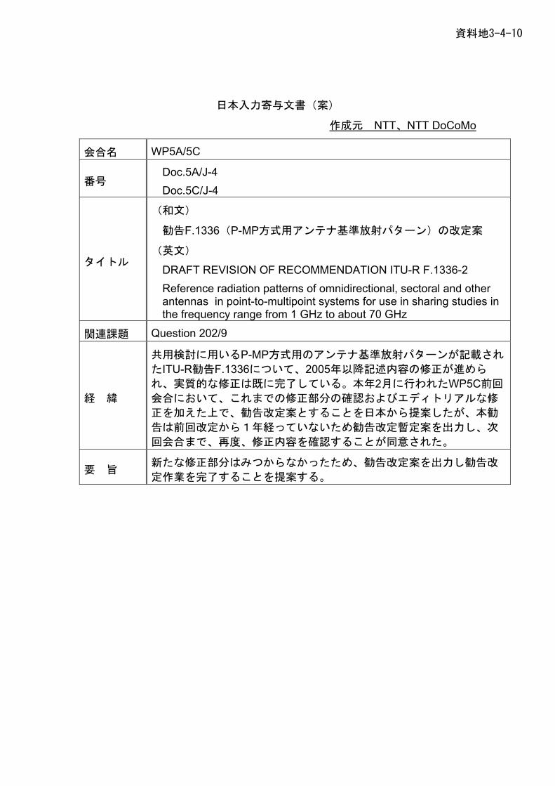
資料地3-4-10
日本入力寄与文書(案)
作成元 NTT、NTT DoCoMo
会合名 WP5A/5C
番号 Doc.5A/J-4 Doc.5C/J-4
タイトル
(
勧告F.1336(P-MP方式用アンテナ基準放射パターン)の改定案
MMENDATION ITU-R F.1336-2 her
和文)
(英文)
DRAFT REVISION OF RECOReference radiation patterns of omnidirectional, sectoral and otantennas in point-to-multipoint systems for use in sharing studies inthe frequency range from 1 GHz to about 70 GHz
関連課題 Question 202/9
経 緯
P-MP方式用のアンテナ基準放射パターンが記載され
回
共用検討に用いる
たITU-R勧告F.1336について、2005年以降記述内容の修正が進めら
れ、実質的な修正は既に完了している。本年2月に行われたWP5C前
会合において、これまでの修正部分の確認およびエディトリアルな修
正を加えた上で、勧告改定案とすることを日本から提案したが、本勧
告は前回改定から1年経っていないため勧告改定暫定案を出力し、次
回会合まで、再度、修正内容を確認することが同意された。
要 旨 新たな修正部分はみつからなかったため、勧告改定案を出力し勧告改
定作業を完了することを提案する。
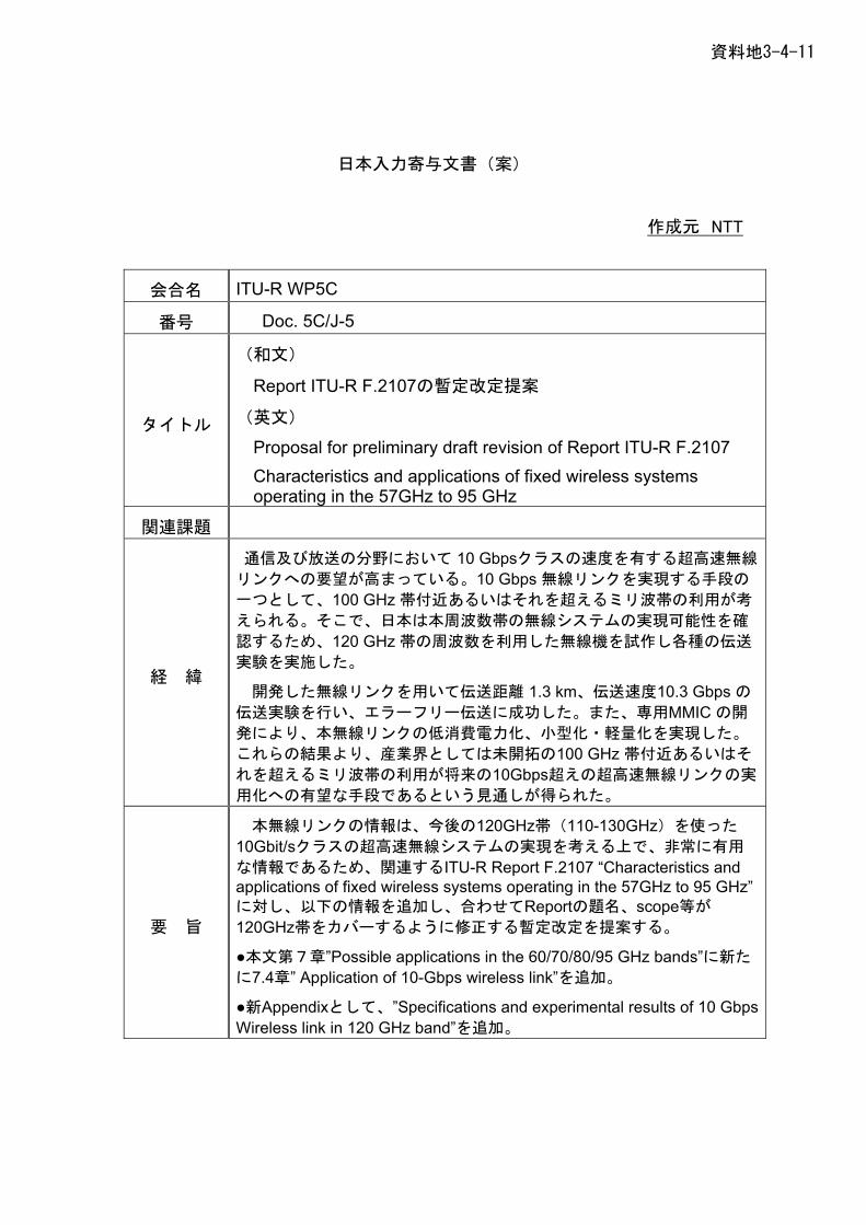
資料地3-4-11
日本入力寄与文書(案)
作成元 NTT
会合名 ITU-R WP5C
番号 Doc. 5C/J-5
タイトル
(和文)
Report ITU-R F.2107の暫定改定提案
(英文)
Proposal for preliminary draft revision of Report ITU-R F.2107 Characteristics and applications of fixed wireless systems operating in the 57GHz to 95 GHz
関連課題
経 緯
通信及び放送の分野において 10 Gbpsクラスの速度を有する超高速無線
リンクへの要望が高まっている。10 Gbps 無線リンクを実現する手段の
一つとして、100 GHz 帯付近あるいはそれを超えるミリ波帯の利用が考
えられる。そこで、日本は本周波数帯の無線システムの実現可能性を確
認するため、120 GHz 帯の周波数を利用した無線機を試作し各種の伝送
実験を実施した。
開発した無線リンクを用いて伝送距離 1.3 km、伝送速度10.3 Gbps の伝送実験を行い、エラーフリー伝送に成功した。また、専用MMIC の開
発により、本無線リンクの低消費電力化、小型化・軽量化を実現した。
これらの結果より、産業界としては未開拓の100 GHz 帯付近あるいはそ
れを超えるミリ波帯の利用が将来の10Gbps超えの超高速無線リンクの実
用化への有望な手段であるという見通しが得られた。
要 旨
本無線リンクの情報は、今後の120GHz帯(110-130GHz)を使った
10Gbit/sクラスの超高速無線システムの実現を考える上で、非常に有用
な情報であるため、関連するITU-R Report F.2107 “Characteristics and applications of fixed wireless systems operating in the 57GHz to 95 GHz”に対し、以下の情報を追加し、合わせてReportの題名、scope等が
120GHz帯をカバーするように修正する暫定改定を提案する。
●本文第7章”Possible applications in the 60/70/80/95 GHz bands”に新た
に7.4章” Application of 10-Gbps wireless link”を追加。
●新Appendixとして、”Specifications and experimental results of 10 Gbps Wireless link in 120 GHz band”を追加。
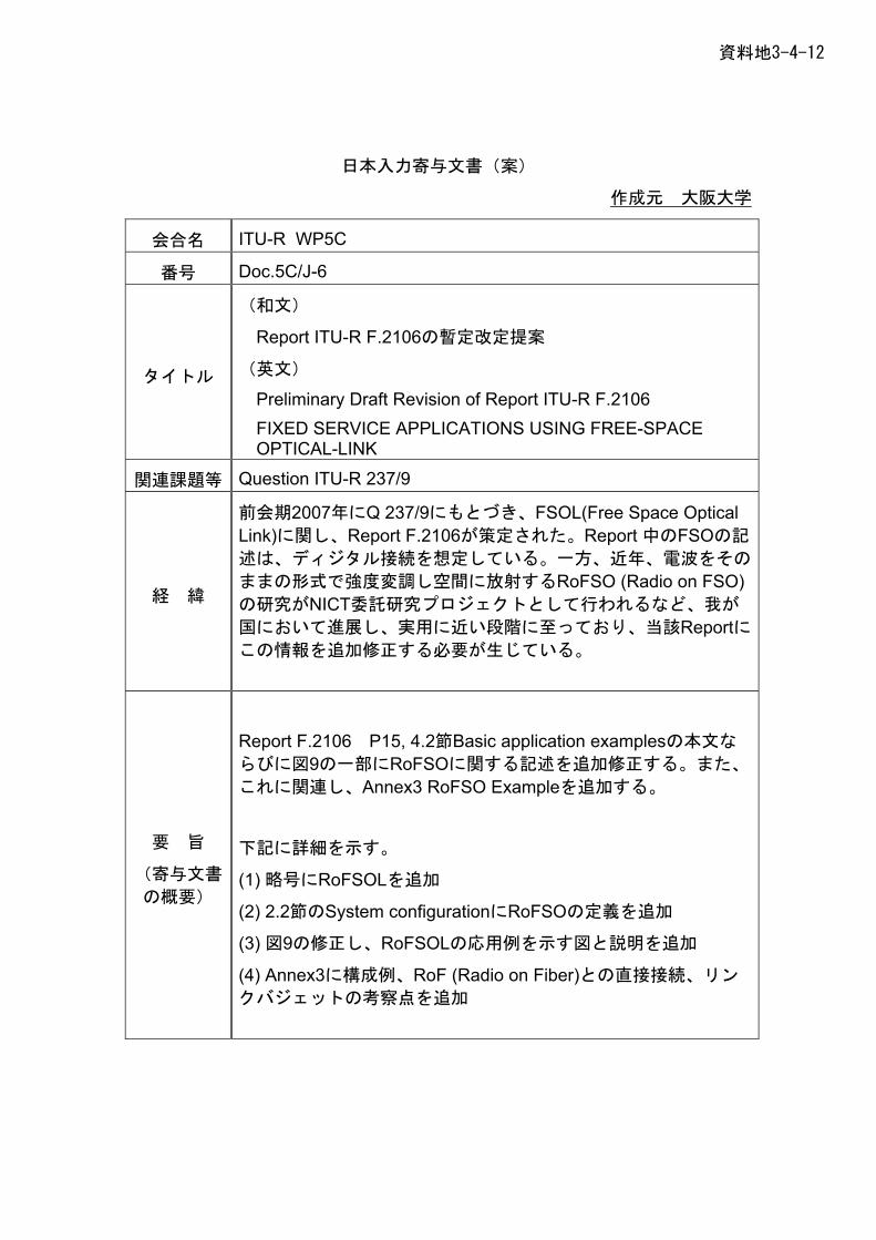
資料地3-4-12
日本入力寄与文書(案)
作成元 大阪大学
会合名 ITU-R WP5C
番号 Doc.5C/J-6
タイトル
Report ITU-R F.2106の暫定改定提案
(
on of Report ITU-R F.2106 ACE
(和文)
英文)
Preliminary Draft RevisiFIXED SERVICE APPLICATIONS USING FREE-SPOPTICAL-LINK
関連課題等 Question ITU-R 237/9
経 緯
にもとづき、FSOL(Free Space Optical 前会期2007年にQ 237/9Link)に関し、Report F.2106が策定された。Report 中のFSOの記
述は、ディジタル接続を想定している。一方、近年、電波をその
ままの形式で強度変調し空間に放射するRoFSO (Radio on FSO)の研究がNICT委託研究プロジェクトとして行われるなど、我が
国において進展し、実用に近い段階に至っており、当該Reportにこの情報を追加修正する必要が生じている。
要 旨
(寄与文書
eport F.2106 P15, 4.2節Basic application examplesの本文な
記に詳細を示す。
(1) 略号にRoFSOLを追加
にRoFSOの定義を追加
の修 図と説明を追
の概要)
Rらびに図9の一部にRoFSOに関する記述を追加修正する。また、
これに関連し、Annex3 RoFSO Exampleを追加する。
下
(2) 2.2節のSystem configuration
(3) 図9 正し、RoFSOLの応用例を示す 加
(4) Annex3に構成例、RoF (Radio on Fiber)との直接接続、リン
クバジェットの考察点を追加
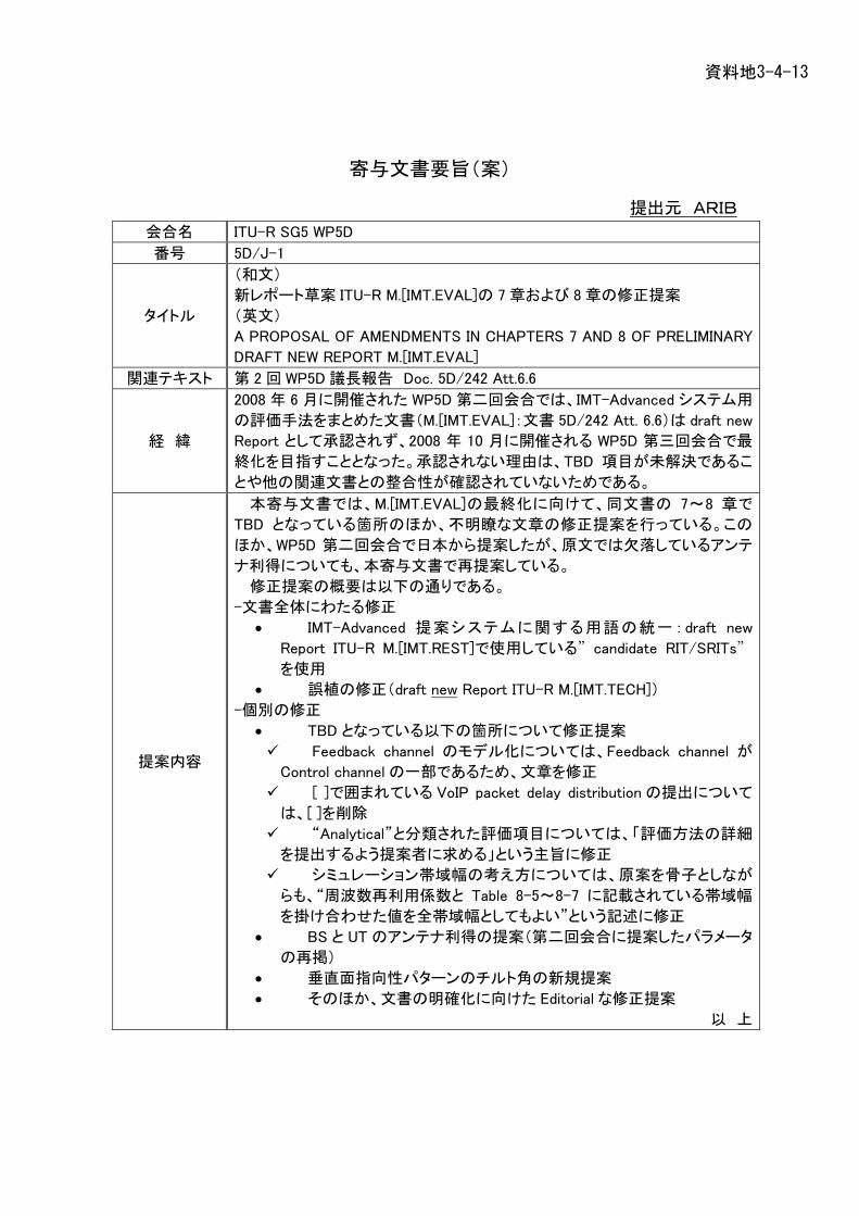
資料地3-4-13
寄与文書要旨(案)
提出元 ARIB
会合名 ITU-R SG5 WP5D
番号 5D/J-1
タイトル
(和文)
新レポート草案 ITU-R M.[IMT.EVAL]の 7 章および 8 章の修正提案
(英文)
A PROPOSAL OF AMENDMENTS IN CHAPTERS 7 AND 8 OF PRELIMINARY
DRAFT NEW REPORT M.[IMT.EVAL]
関連テキスト 第 2 回 WP5D 議長報告 Doc. 5D/242 Att.6.6
経 緯
2008 年 6 月に開催された WP5D 第二回会合では、IMT-Advanced システム用
の評価手法をまとめた文書(M.[IMT.EVAL]:文書 5D/242 Att. 6.6)は draft new
Report として承認されず、2008 年 10 月に開催される WP5D 第三回会合で最
終化を目指すこととなった。承認されない理由は、TBD 項目が未解決であるこ
とや他の関連文書との整合性が確認されていないためである。
提案内容
本寄与文書では、M.[IMT.EVAL]の最終化に向けて、同文書の 7~8 章で
TBD となっている箇所のほか、不明瞭な文章の修正提案を行っている。この
ほか、WP5D 第二回会合で日本から提案したが、原文では欠落しているアンテ
ナ利得についても、本寄与文書で再提案している。
修正提案の概要は以下の通りである。
-文書全体にわたる修正
• IMT-Advanced 提案システムに関する用語の統一:draft new
Report ITU-R M.[IMT.REST]で使用している”candidate RIT/SRITs”
を使用
• 誤植の修正(draft new Report ITU-R M.[IMT.TECH])
-個別の修正
• TBD となっている以下の箇所について修正提案
Feedback channel のモデル化については、Feedback channel が
Control channel の一部であるため、文章を修正
[ ]で囲まれている VoIP packet delay distribution の提出について
は、[ ]を削除
“Analytical”と分類された評価項目については、「評価方法の詳細
を提出するよう提案者に求める」という主旨に修正
シミュレーション帯域幅の考え方については、原案を骨子としなが
らも、“周波数再利用係数と Table 8-5~8-7 に記載されている帯域幅
を掛け合わせた値を全帯域幅としてもよい”という記述に修正
• BS と UT のアンテナ利得の提案(第二回会合に提案したパラメータ
の再掲)
• 垂直面指向性パターンのチルト角の新規提案
• そのほか、文書の明確化に向けた Editorial な修正提案
以 上

資料地3-4-14
寄与文書要旨(案)
提出元 ARIB
会合名 ITU-R SG5 WP5D
番号 5D/J-2
タイトル
(和文)
技術記述テンプレートの修正提案
(英文)
PROPOSED MODIFICATION TO THE TECHNOLGY DESCRIPTION TEMPLATE
関連テキスト 第2回 WP5D 議長報告 Doc. 5D/242 Att.6.7
経 緯
第 2 回 WP5D 会合にて、IMT-Advanced の無線インタフェースの要求条件、評
価基準と手順などを記述した ITU-R レポート M.[IMT.REST]が作成された。本レポ
ートには、提案される候補技術を記述するテンプレートが含まれている。レポート
自体は完成承認されたが、このレポートの 4.2.3 章に記述される技術記述テンプレ
ートは、次回会合で継続審議となった。
この技術記述テンプレートは、第 3 回会合において、無線インタフェース技術の
要求条件に関する ITU-R レポート M.[IMT.TECH]および評価に関する ITU-R レポ
ート M.[IMT.EVAL]との整合性がとられた後に、完成承認の見込みである。
提案内容
日 本 は 、 無 線 イ ン タ フ ェ ー ス 技 術 の 要 求 条 件 に 関 す る ITU-R レ ポ ー ト
M.[IMT.TECH]および評価に関する ITU-R レポート M.[IMT.EVAL]との整合性を精
査し、技術記述テンプレートの修正提案を行う。
提案の主要点は下記のとおりである。
(1) テンプレートの導入テキストの修正
テンプレートの導入テキストは、全ての項目が必須ではないと書いた上で、関係の
ない項目については N/A と回答してよいとの記述がある。しかし、どの項目が必
須であるか必須でないかは、候補技術の提案者が安易に決めるべきではなく、必
須でないことを提案者が正当化できる場合にのみ、N/A と回答することを許可す
べきである。この考え方に基づいて、修正を提案する。
(2) 技術記述テンプレートのフォーマット
現在の作業文書のフォーマットは、第1回ジュネーブ会合における PDNR ITU-R
M.[IMT.TECH]の章構成を前提としたものである。すなわち、当時の作業文書の第
5 章が存在することが前提である。しかし、第2回ドバイ会合で第5章は削除するこ
とで合意した。そこで、第 5 章への参照目的で付け加えられた Source の欄を削除
することを提案する。また、テンプレートは、もっとも階層が上のレベルで、A1「RIT
を記述するための項目」と、A2「評価に関する項目」との 2 分類を設けるべきとし
て、新たに A2「評価に関する項目」を追加することを提案している。
(3) RIT を記述するための項目を精査整理し、重複項目の削除と類似関連項目
のグループ化を提案している。
(4) 新たに A2「評価に関する項目」として、下記の4つを提案している。
(i)パケットの遅延分布、(ii)周波数繰り返し数が 1 でないときの詳細なシミュレーシ
ョン方法、(iii)回線設計に関するテンプレートに関する事項、(iv)アンテナのチルト角
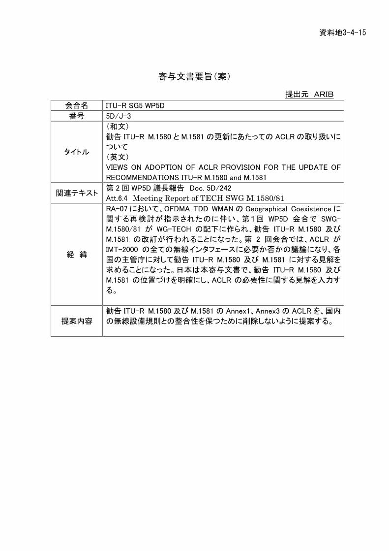
資料地3-4-15
寄与文書要旨(案)
提出元 ARIB
会合名 ITU-R SG5 WP5D
番号 5D/J-3
タイトル
(和文)
勧告 ITU-R M.1580 と M.1581 の更新にあたっての ACLR の取り扱いに
ついて
(英文)
VIEWS ON ADOPTION OF ACLR PROVISION FOR THE UPDATE OF
RECOMMENDATIONS ITU-R M.1580 and M.1581
関連テキスト 第 2 回 WP5D 議長報告 Doc. 5D/242
Att.6.4 Meeting Report of TECH SWG M.1580/81
経 緯
RA-07 において、OFDMA TDD WMAN の Geographical Coexistence に
関する再検討が指示されたのに伴い、第1回 WP5D 会合で SWG-
M.1580/81 が WG-TECH の配下に作られ、勧告 ITU-R M.1580 及び
M.1581 の改訂が行われることになった。第 2 回会合では、ACLR が
IMT-2000 の全ての無線インタフェースに必要か否かの議論になり、各
国の主管庁に対して勧告 ITU-R M.1580 及び M.1581 に対する見解を
求めることになった。日本は本寄与文書で、勧告 ITU-R M.1580 及び
M.1581 の位置づけを明確にし、ACLR の必要性に関する見解を入力す
る。
提案内容
勧告 ITU-R M.1580 及び M.1581 の Annex1、Annex3 の ACLR を、国内
の無線設備規則との整合性を保つために削除しないように提案する。

- 1 - 5A/XX -E
(Question ITU-R 205-4/8)
This preliminary draft new Recommendation (PDNR) provides a framework for the development of a draft new Recommendation that covers the radiocommunication requirements and applications anticipated for mobile intelligent transport systems (ITS) operating in the millimetre wave.
The following studies were conducted under Question ITU-R 205-4/8. These studies included: – an investigation of millimetre wave applications for ITS; – functional requirements for millimetre wave ITS radiocommunication systems; – technical characteristics of the physical and data link layers of millimetre wave ITS
radiocommunication systems.
This document modifies and amends Annex 4 to Document 85A/5545 with Document 5A/33, with a view toward the completion of this new draft new Recommendation.
A separate working document toward preliminary draft new Report describes some examples of millimetre wave ITS radiocommunications systems.
Items or data in square brackets need to be provided or verified before the completion of this draft new Recommendation.
Attachment: 1
Radiocommunication Study Groups
Source: Document 5A/45 (Annex 4) Document 5A/XX-E
XX September 2008 English only
Japan
PRELIMINARY DRAFT NEW RECOMMENDATION
Integrated mMillimetre wave ITS radiocommunication systems
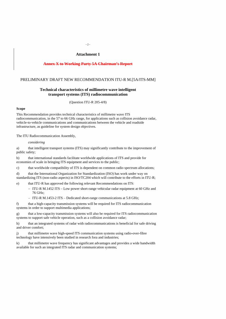
- 2 -
Attachment 1
Annex X to Working Party 5A Chairman’s Report
PRELIMINARY DRAFT NEW RECOMMENDATION ITU-R M.[5A/ITS-MM]
Technical characteristics of millimetre wave intelligent transport systems (ITS) radiocommunication
(Question ITU-R 205-4/8)
Scope This Recommendation provides technical characteristics of millimetre wave ITS radiocommunication, in the 57 to 66 GHz range, for applications such as collision avoidance radar, vehicle-to-vehicle communications and communications between the vehicle and roadside infrastructure, as guideline for system design objectives.
The ITU Radiocommunication Assembly,
considering
a) that intelligent transport systems (ITS) may significantly contribute to the improvement of public safety;
b) that international standards facilitate worldwide applications of ITS and provide for economies of scale in bringing ITS equipment and services to the public;
c) that worldwide compatibility of ITS is dependent on common radio spectrum allocations;
d) that the International Organization for Standardization (ISO) has work under way on standardizing ITS (non-radio aspects) in ISO/TC204 which will contribute to the efforts in ITU-R;
e) that ITU-R has approved the following relevant Recommendations on ITS: – ITU-R M.1452 ITS – Low power short-range vehicular radar equipment at 60 GHz and
76 GHz; – ITU-R M.1453-2 ITS – Dedicated short-range communications at 5.8 GHz;
f) that a high-capacity transmission systems will be required for ITS radiocommunication systems in order to support multimedia applications;
g) that a low-capacity transmission systems will also be required for ITS radiocommunication systems to support safe vehicle operation, such as a collision avoidance radar;
h) that an integrated systems of radar with radiocommunications is beneficial for safe driving and driver comfort;
j) that millimetre wave high-speed ITS communication systems using radio-over-fibre technology have intensively been studied in research fora and industries;
k) that millimetre wave frequency has significant advantages and provides a wide bandwidth available for such an integrated ITS radar and communication systems;
- 3 -
l) that the millimetre wave frequency range, 57-66 GHz, is also used by other radio systems and services operating in accordance with the Radio Regulations;
m) that the millimetre wave frequency range, 57-66 GHz, is also standardizing millimetre wave communications by the Institute of Electrical and Electronics Engineers (IEEE), for example IEEE802.15.3c is wireless personal network standardization.
mn) that strong absorption in millimetre wave frequency ranges due to atmospheric oxygen has a potential to reduce the interference among different radio services operating in the ranges;
no) that technical and operational characteristics of the integrated millimetre wave ITS radiocommunication system needs to be identified to facilitate the global deployment of such a system,
noting
that the Land Mobile Handbook (Volume 4 on ITS) contains additional information on millimetre wave communications, including propagation characteristics for vehicle-to-vehicle communications and inter-vehicle communications and radar,
recommends
the operational and technical characteristics of millimetre wave ITS systems, described shown in Annex 1below and shown in Table 1, should be used as a guideline for system design objectives.
System description:
System A: [TBD]
System B: [TBD]
System C: [TBD]
[Editor’s Note – Detailed system description(s) and applicability need to be provided for each.]
Annex 1
Technical characteristics of millimetre wave ITS system
1 Technical conditions of millimetre-wave ITS communications system
1.1 General conditions
1) Communications method: One-way, Simplex, Half duplex, Full duplex, Multicast 2) Modulation method: The modulation method is not provided for to correspond to the
upgrade of the future use 3) Frequency band: 57.0 - 66.0 GHz (The channels to be use for ITS applications will
be specified by regions or countries separately.) 4) Transmitter power (power transferred to antenna): 10 mW or less / 40dBm or less (e.i.r.p)
1.2 Technical conditions of transmitter
1) Permissible occupied bandwidth: 2.5 GHz or less
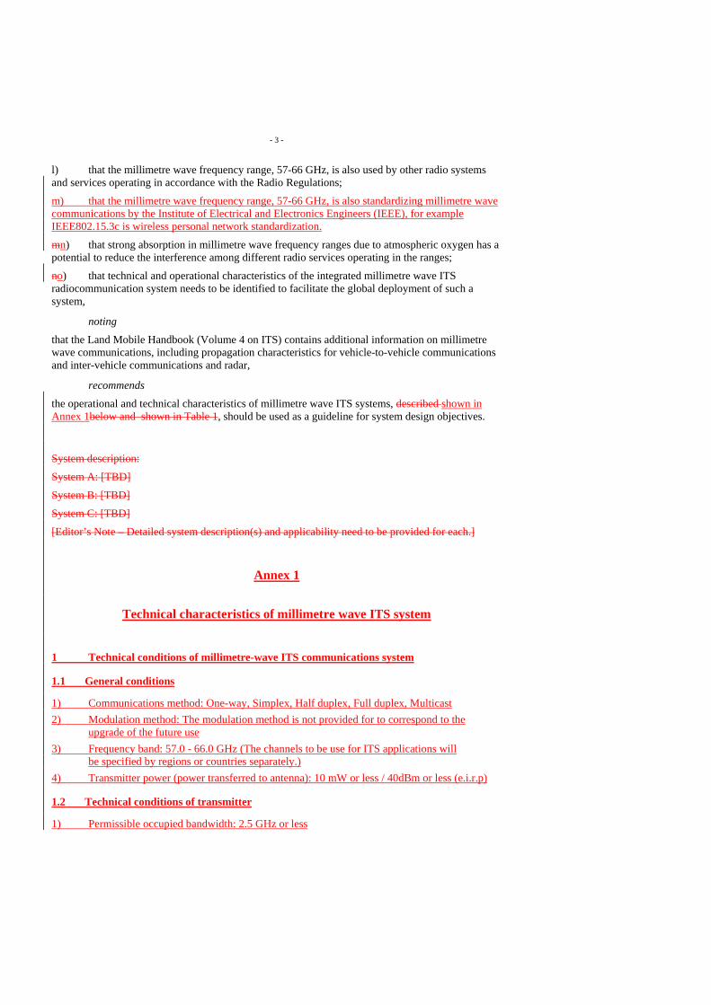
- 4 -
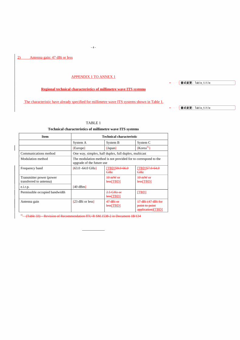
2) Antenna gain: 47 dBi or less
APPENDIX 1 TO ANNEX 1
Regional technical characteristics of millimetre wave ITS systems
The characteristic have already specified for millimetre wave ITS systems shown in Table 1.
TABLE 1
Technical characteristics of millimetre wave ITS systems
Item Technical characteristic
System A System B System C [Europe] [Japan] [Korea1) ] Communications method One way, simplex, half duplex, full duplex, multicast Modulation method The modulation method is not provided for to correspond to the
upgrade of the future use Frequency band [63.0 -64.0 GHz] [TBD]59.0-66.0
GHz [TBD]57.0-64.0 GHz
Transmitter power (power transferred to antenna)
10 mW or less[TBD]
10 mW or less[TBD]
e.i.r.p. [40 dBm] Permissible occupied bandwidth 2.5 GHz or
less[TBD] [TBD]
Antenna gain [23 dBi or less] 47 dBi or less[TBD]
17 dBi (47 dBi for point to point application)[TBD]
1) (Table 33) – Revision of Recommendation ITU-R SM.1538-2 in Document 1B/134
____________
書式変更: Table_title
書式変更: Table_title

(Question ITU-R 205-4/8) (1997)
Summary of the revision <TBD>
Scope
This Recommendation provides the radio requirements aspects of Intelligent Transport Systems (ITS). ITS are systems utilizing the combination of computers, communications, positioning, and automation technologies to improve the safety, management, and efficiency of terrestrial transportation systems.
____________________ * This Recommendation should be brought to the attention of the International Organization for
Standardization (ISO) and the International Electrotechnical Commission (IEC).
Radiocommunication Study Groups
Source: Doc.5A/45 (Annex 6) Document 5A/XX-E
XX September 2008 English only
Japan
PRELIMINARY DRAFT REVISION TO RECOMMENDATION ITU-R M.1310*
Intelligent transport systems(ITS) – Objectives and requirements
- 2 - 5A/45 (Annex 6)-E
The ITU Radiocommunication Assembly,
considering
a) that there is a need to integrate various technologies including radiocommunications into land transportation systems;
b) that many new land transport systems use intelligence in land vehicles coupled with advanced vehicle, advanced traffic management, advanced traveller information, advanced public transportation, and advanced fleet management systems, to improve traffic management;
c) that Intelligent Transport Systems (ITS) are being planned and implemented in various regions by administrations;
d) that a wide variety of applications and services are defined;
e) that international standards would facilitate worldwide applications of ITS and provide for economies of scale in bringing ITS equipment and services to the public;
g) that worldwide compatibility of ITS may be dependent on common radio spectrum allocations;
h) that the ISO is standardizing ITS (non-radio aspects) in ISO/TC204;
j) that Recommendation ITU-R M.1453-2 “Intelligent Transport Systems-Dedicated short range communications at 5.8 GHz” details the technologies and characteristics for DSRC in the 5.8 GHz band;
k) that Recommendation ITU-R M.1797 “Vocabulary of terms for the land mobile service” provides some terminology on ITS,
recommends
that ITS intended for regional and/or worldwide use should meet the following characteristics and objectives:
1 Elements of ITS Based on major services identified to date, the elements of ITS for which RF links are the major communication method are identified in the following sections. For rural area applications, it might be necessary to adapt these technologies to meet their requirements.
[Editor’s note: Update the contents in reference to the latest version of US ITS architecture (http://iteris.com/itsarch/), European ITS architecture (http://www.frame-online.net/eithsfa2.htm) and Japanese ITS architecture (http://www.its-jp.org/english/arch_e/index.htm).]
書式変更: フォント : 斜体
書式変更: フォント : 斜体
書式変更: フォント : 斜体
書式変更: フォントの色 : 赤
- 3 - 5A/45 (Annex 6)-E
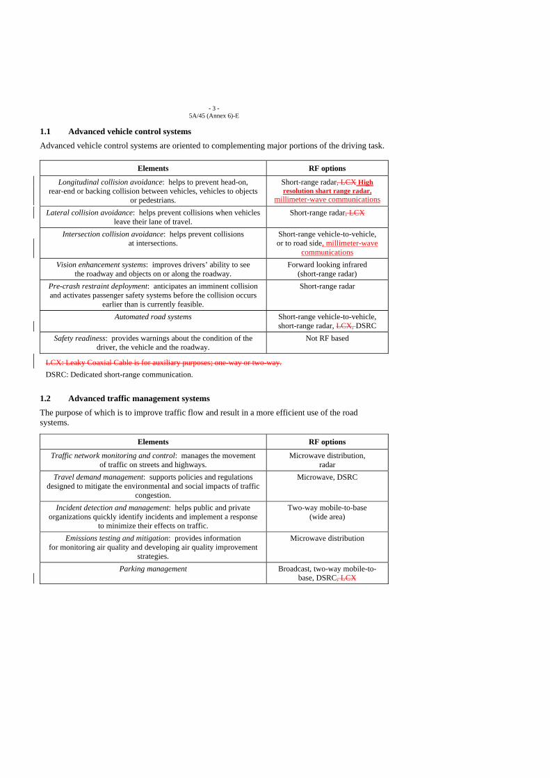
1.1 Advanced vehicle control systems
Advanced vehicle control systems are oriented to complementing major portions of the driving task.
Elements RF options
Longitudinal collision avoidance: helps to prevent head-on, rear-end or backing collision between vehicles, vehicles to objects
or pedestrians.
Short-range radar, LCX High resolution shart range radar,
millimeter-wave communications
Lateral collision avoidance: helps prevent collisions when vehicles leave their lane of travel.
Short-range radar, LCX
Intersection collision avoidance: helps prevent collisions at intersections.
Short-range vehicle-to-vehicle, or to road side, millimeter-wave
communications Vision enhancement systems: improves drivers’ ability to see
the roadway and objects on or along the roadway. Forward looking infrared
(short-range radar) Pre-crash restraint deployment: anticipates an imminent collision and activates passenger safety systems before the collision occurs
earlier than is currently feasible.
Short-range radar
Automated road systems Short-range vehicle-to-vehicle, short-range radar, LCX, DSRC
Safety readiness: provides warnings about the condition of the driver, the vehicle and the roadway.
Not RF based
LCX: Leaky Coaxial Cable is for auxiliary purposes; one-way or two-way. DSRC: Dedicated short-range communication.
1.2 Advanced traffic management systems
The purpose of which is to improve traffic flow and result in a more efficient use of the road systems.
Elements RF options
Traffic network monitoring and control: manages the movement of traffic on streets and highways.
Microwave distribution, radar
Travel demand management: supports policies and regulations designed to mitigate the environmental and social impacts of traffic
congestion.
Microwave, DSRC
Incident detection and management: helps public and private organizations quickly identify incidents and implement a response
to minimize their effects on traffic.
Two-way mobile-to-base (wide area)
Emissions testing and mitigation: provides information for monitoring air quality and developing air quality improvement
strategies.
Microwave distribution
Parking management Broadcast, two-way mobile-to-base, DSRC, LCX
- 4 - 5A/45 (Annex 6)-E
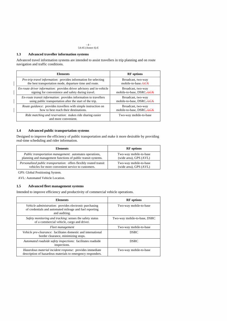
1.3 Advanced traveller information systems
Advanced travel information systems are intended to assist travellers in trip planning and on route navigation and traffic conditions.
Elements RF options
Pre-trip travel information: provides information for selecting the best transportation mode, departure time and route.
Broadcast, two-way mobile-to-base, LCX
En-route driver information: provides driver advisory and in-vehicle signing for convenience and safety during travel.
Broadcast, two-way mobile-to-base, DSRC, LCX
En-route transit information: provides information to travellers using public transportation after the start of the trip.
Broadcast, two-way mobile-to-base, DSRC, LCX
Route guidance: provides travellers with simple instruction on how to best reach their destinations.
Broadcast, two-way mobile-to-base, DSRC, LCX
Ride matching and reservation: makes ride sharing easier and more convenient.
Two-way mobile-to-base
1.4 Advanced public transportation systems
Designed to improve the efficiency of public transportation and make it more desirable by providing real-time scheduling and rider information.
Elements RF options
Public transportation management: automates operations, planning and management functions of public transit systems.
Two-way mobile-to-base (wide area), GPS (AVL)
Personalized public transportation: offers flexibly routed transit vehicles for more convenient service to customers.
Two-way mobile-to-base (wide area), GPS (AVL)
GPS: Global Positioning System.
AVL: Automated Vehicle Location.
1.5 Advanced fleet management systems
Intended to improve efficiency and productivity of commercial vehicle operations.
Elements RF options
Vehicle administration: provides electronic purchasing of credentials and automated mileage and fuel reporting
and auditing.
Two-way mobile-to-base
Safety monitoring and tracking: senses the safety status of a commercial vehicle, cargo and driver.
Two-way mobile-to-base, DSRC
Fleet management Two-way mobile-to-base Vehicle pre-clearance: facilitates domestic and international
border clearance, minimizing stops. DSRC
Automated roadside safety inspections: facilitates roadside inspections.
DSRC
Hazardous material incident response: provides immediate description of hazardous materials to emergency responders.
Two-way mobile-to-base
- 5 - 5A/45 (Annex 6)-E
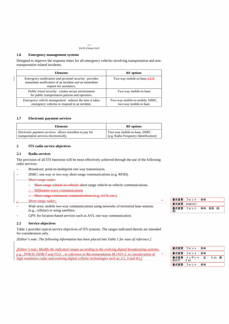
1.6 Emergency management systems
Designed to improve the response times for all emergency vehicles involving transportation and non-transportation related incidents.
Elements RF options
Emergency notification and personal security: provides immediate notification of an incident and an immediate
request for assistance.
Two-way mobile-to-base, LCX
Public travel security: creates secure environment for public transportation patrons and operators.
Two-way mobile-to-base
Emergency vehicle management: reduces the time it takes emergency vehicles to respond to an incident.
Two-way mobile-to-mobile, DSRC, two-way mobile-to base
1.7 Electronic payment services
Elements RF options
Electronic payment services: allows travellers to pay for transportation services electronically.
Two-way mobile-to-base, DSRC (e.g. Radio Frequency Identification)
2 ITS radio service objectives
2.1 Radio services
The provision of all ITS functions will be most effectively achieved through the use of the following radio services: – Broadcast: point-to-multipoint one way transmission. – DSRC: one way or two-way short-range communications (e.g. RFID). – Short-range radar:
– Short-range vehicle-to-vehicle: short-range vehicle-to-vehicle communications. – Millimeter-wave communications – Short-range continuous communications (e.g., LCX, etc.).
– Short-range radar: – Wide area: mobile two-way communications using networks of terrestrial base stations
(e.g., cellular) or using satellites. – GPS: for location-based services such as AVL one way communication.
2.2 Service objectives Table 1 provides typical service objectives of ITS systems. The ranges indicated therein are intended for consideration only.
[Editor’s note: The following information has been placed into Table 1 for ease of reference.] [Editor’s note: Modify the indicated ranges according to the evolving digital broadcasting systems, e.g., DVB-H, ISDB-T and FLO. , in reference to Recommendation M.1453-2, in consideration of high resolution radar and evolving digital cellular technologies such as 2.5, 3 and 4G.]
書式変更: フォント : 斜体
書式変更: enumlev1
書式変更: フォント : 斜体, 英語 (英国)
書式変更: フォント : 斜体
書式変更: フォント : 斜体
書式変更: インデント : 左 : 0 pt, 最初の行 : 0 pt
書式変更: フォント : 斜体
- 6 - 5A/45 (Annex 6)-E
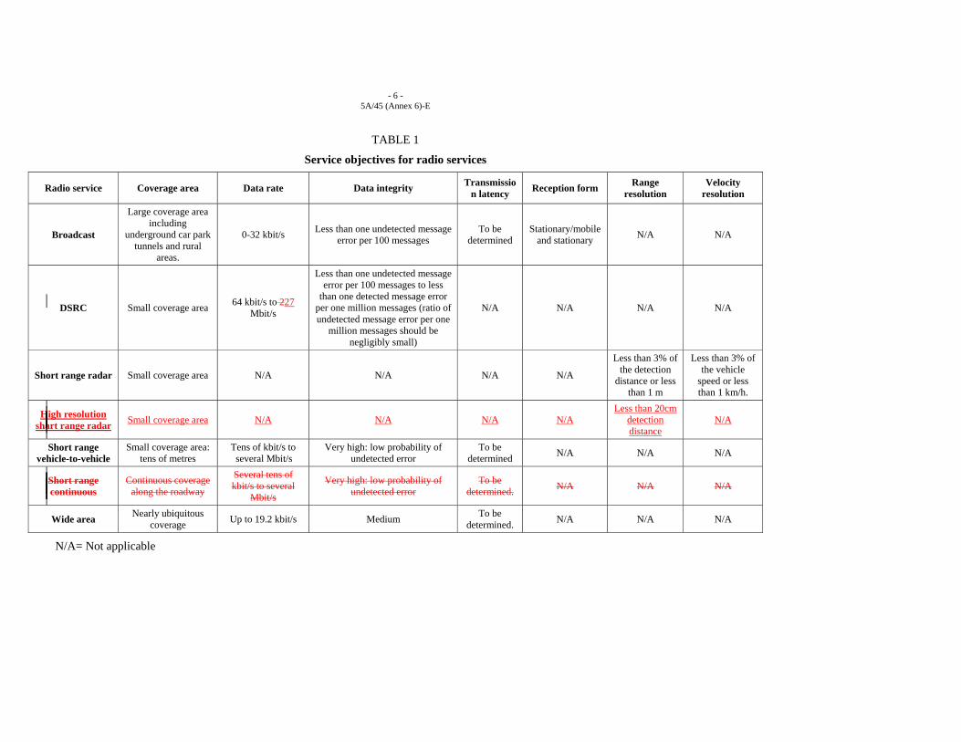
TABLE 1
Service objectives for radio services
Radio service Coverage area Data rate Data integrity Transmission latency Reception form Range
resolution Velocity
resolution
Broadcast
Large coverage area including
underground car park tunnels and rural
areas.
0-32 kbit/s Less than one undetected message error per 100 messages
To be determined
Stationary/mobile and stationary N/A N/A
DSRC Small coverage area 64 kbit/s to 227 Mbit/s
Less than one undetected message error per 100 messages to less
than one detected message error per one million messages (ratio of undetected message error per one
million messages should be negligibly small)
N/A N/A N/A N/A
Short range radar Small coverage area N/A N/A N/A N/A
Less than 3% of the detection
distance or less than 1 m
Less than 3% of the vehicle
speed or less than 1 km/h.
High resolution shart range radar Small coverage area N/A N/A N/A N/A
Less than 20cm detection distance
N/A
Short range vehicle-to-vehicle
Small coverage area: tens of metres
Tens of kbit/s to several Mbit/s
Very high: low probability of undetected error
To be determined N/A N/A N/A
Short range continuous
Continuous coverage along the roadway
Several tens of kbit/s to several
Mbit/s
Very high: low probability of undetected error
To be determined. N/A N/A N/A
Wide area Nearly ubiquitous coverage Up to 19.2 kbit/s Medium To be
determined. N/A N/A N/A
N/A= Not applicable

- 7 - 5A/45 (Annex 6)-E
3 International standardization For safety reasons international standardization is desirable in respect to the short-range vehicle-to-vehicle or to road side communications and any short-range radar employing cooperative techniques. From a user’s perspective, international standardization is highly desirable, at least on a region-wide basis, for the convenience of users moving across the region and for broadcast and short-range vehicle-to-vehicle or to vehicle-to-roadside communications.
4 Interconnection requirements
The largest capacity will probably be required for the purpose of data collection from roadside sensors. Other services include control of signals and variable message signs, distribution of data between traffic authorities, service providers and fleet managers and for distribution of data to/from broadcast and roadside communications facilities. A mix of dedicated and switched connections are anticipated. Multipoint distribution will benefit from the use of packet mode communications.
5 Use of evolving mobile telecommunication services
It is expected that the evolving mobile telecommunication would be able to provide for many of the ITS services, particularly those requiring terrestrial, two-way, wide-area communications.
______________
Received: yy xxxx 2008
Source: Annex 10 to Document 5A/45-E
Japan
PROPOSED REVISION FOR A PRELIMINARY DRAFT NEW REPORT “COGNITIVE RADIO SYSTEMS IN THE LAND MOBILE SERVICES” (DRAFT)
1 Introduction Concerning the Cognitive Radio System (CRS), a new Question (Question ITU-R 241-1/8) has been established. Furthermore, in WRC-07 held in Geneva, the agenda item 1.19 for WRC-11 is set up, whose text is “to consider regulatory measures and their relevance, in order to enable the introduction of software-defined radio and cognitive radio systems, based on the results of ITU-R studies, in accordance with Resolution 956 (WRC-07)”. In response to the above Question and the agenda item, Working Party 5A and its WG 5 have been in progress for the development of the working document towards the draft new Report “Cognitive Radio Systems in the land mobile services”. Working Party 1B has also been studying a regulatory aspect of the cognitive radio system. The results of technical studies on cognitive radio system being performed at WP5A will be a useful base for further studies in other ITU-R Working Parties. The ongoing technical studies at WP5A on the CRS, including its definition, are needed to be accelerated for the completion of the Report in time for the next WRC.
2 Definition of CRS The working document toward a Preliminary Draft New Report (PDN Report) is under discussion, which is shown in Annex 10 to document 5A/45-E, the Chairman’s report of the last Working Party 5A meeting. It seems at this stage that more information and text are needed.
It is thought that the most important issue is a definition of CRS, which is the first item in the Question 241-1/8. In this contribution, the following definition is proposed, which is also described in Sec.4 of the Attachment. In the proposed definition, CRS is divided into some functional elements to easily understand it.
Cognitive Radio System: A combination of cognitive radio network, cognitive terminals, and management system responsible for operational environment awareness, reconfiguration decision making, and reconfiguration control.
INTERNATIONAL TELECOMMUNICATION UNION
RADIOCOMMUNICATION STUDY GROUPS
Document 5A/J-xxyy October 2008English only

- 2 - 5A/J-xx-E
Cognitive radio network: A combination of cognitive base stations and networking capabilities connecting these cognitive base stations with each other and with external world.
Cognitive terminal: A cognitive radio node on user side.
Cognitive base station: A cognitive radio node on network side.
Cognitive radio node: A radio node that has capabilities to be aware of its operational environment, to make decisions to change its operational parameters using this awareness, and to reconfigure its hardware and/or software accordingly.
3 Summary of other new text proposal or modification In addition to the definition, other new text proposal or modification are summarized as follows.
- Addition of new subsection Sec. 5.1 and its text, and addition of text in a part of Sec.5 “General description of Cognitive Radio Systems”,
- Addition of text in Sec.6 “Related radio technologies and functionalities”,
- Addition of new subsection Sec. 7.2 – 7.5 and their text in Sec.7 “Potential applications”,
- Addition of new ANNEX 3 and its text “R&D Activities concerning the cognitive radio related common control channel concept in Japanese project”.
The proposed texts in Sec. 5-7 show an understanding of cognitive radio systems based on a lot of studies and implementations in Japan as described in ANNEX 1. The ideas are already inputted to IEEE SCC 41 and IEEE P1900.4 working group, working to define industrial standards of dynamic spectrum access network and its architecture. The ideas have been widely accepted and treated as a primal concept in the draft standard.
The new sentences in ANNEX 3 describe several ways of implementation of common signaling channel studied in Japan. The descriptions suggest several ways how to design the control methods between network-side and terminal-side, and also give a hint of technical requirements for the common signaling channel.
The details proposed are described in the following Attachment, which is revised one of the latest development of the PDN Report (Annex 10 to Document 5A/45-E).
Herein, the ANNEX 3 is separately proposed as a matter of convenience, which is also R & D activity in Japan. Furthermore, description of the relationship between Software-Defined Radio and Cognitive Radio Systems are included, because the Doc. 5A/TEMP/6-E “Liaison statement to ITU-R Working Party 1B on software-defined radio and cognitive radio systems” has the text “WP 5A is prepared to contribute on technical matters to WP 1B as required within the scope of the work in WP 5A for the successful resolution of this agenda item at WRC-11. This may include a description of the relationship between software-defined radio and cognitive radio systems”.
The proposed items may be necessary to draw attentions of relevant Working Parties.
3 Conclusions As for the Preliminary Draft New Report of the Cognitive Radio, some revisions of text are proposed, which include the definition of Cognitive Radio System (CRS), general description of

- 3 - 5A/J-xx-E
CRS, related radio technologies and functionalities and potential applications and so on. It is expected that proposed revision will be reflected in the PDN Report.
- 4 - 5A/J-xx-E
Attachment
Proposed revision of preliminary draft new report of Cognitive Radio
WORKING DOCUMENT TOWARDS A PRELIMINARY DRAFT NEW REPORT COGNITIVE RADIO SYSTEMS IN THE LAND MOBILE SERVICE
(Annex 10 to Document 5A/45-E)
1 Introduction With the rapid growth of mobile radio systems, there is an increased demand for more efficient use of spectrum. Advancements in technology are enabling the development of radio systems that have the potential to use the spectrum much more dynamically and efficiently. Among such advancements, cognitive radio systems characterized by enhanced adaptive capabilities not only have the potential to make more efficient use of spectrum, but also offer more versatility and flexibility, with the increased ability to adapt their operations based on internal and external factors.
Cognitive radio systems may have a profound effect on interoperability, as well as on spectrum utilization and allocation.
2 Scope [Editor’s note: the scope below will be revisited after the completion of the review of the whole document.]
[
This report addresses the definition, description and application of cognitive radio systems in the land mobile service. It discusses the key technical characteristics and requirements of cognitive radio systems and their potential applications [and benefits], while addressing their impact on the management and use of spectrum. Also [briefly] addressed are closely related radio technologies such as software defined radio, smart radio, reconfigurable radio, policy-defined adaptive radio, and their functionalities that may form part of cognitive radio systems. [Operational implications of the cognitive radio systems, facilitating coexistence, [potential regulatory implications (Editor’s note: other wording is needed)] and potential applications are also discussed.]
]
3 Related documents
ITU-R Recommendations: M.1652 Dynamic frequency selection (DFS) in wireless access systems including radio local
area networks for the purpose of protecting the radiodetermination service in the 5 GHz band.
ITU-R Reports: M.2117 (Ex. Doc.8/213) Software defined radio in the land mobile, amateur and amateur
satellite services.
- 5 - 5A/J-xx-E
M.2034 Impact of radar detection requirements of dynamic frequency selection on 5 GHz wireless access system receivers.
4 Definitions [Editor’s Note: AH-VOC group is waiting for the provision of the definition of Cognitive Radio from WG5. The vocabulary definition should consequently be aligned with this definition within AH-VOC.]
Cognitive radio system: A radio system that has the capability to sense and be aware of its operational environment, to be trained to dynamically and autonomously adjust its radio operating parameters accordingly and to learn from the results of its actions and environmental usage patterns.
[Editor’s note: there is a potential difficulty to conclude the definition of CR at this early stage. Other alternative definitions have been proposed with issues as follows.]
[Japan’ Note: Proposed definition is as follows, where the Cognitive Radio System is divided into some functional elements.]
Cognitive Radio System: A combination of cognitive radio network, cognitive terminals, and management system responsible for operational environment awareness, reconfiguration decision making, and reconfiguration control.
Cognitive radio network: A combination of cognitive base stations and networking capabilities connecting these cognitive base stations with each other and with external world.
Cognitive terminal: A cognitive radio node on user side.
Cognitive base station: A cognitive radio node on network side.
Cognitive radio node: A radio node that has capabilities to be aware of its operational environment, to make decisions to change its operational parameters using this awareness, and to reconfigure its hardware and/or software accordingly.
[Editor’s note: the following issues should be considered in refining the definition of Cognitive Radio System. - the definition should encompass the additional capability of the cognitive radio systems to be
assisted in the determination of the local spectrum usage through means such as wireless or wired access to a database or to other networks, to assist in the determination of the local spectrum usage (e.g. Cognition supporting Pilot Channel). (See Section 9.1.1 and Doc. 5A/25 for the details) “A radio system that has the capability to gain knowledge sense and be aware of its operational environment, to be trained to dynamically and autonomously adjust its radio operating parameters accordingly and to learn from the results of its actions and environmental usage patterns.”
- the “sense” is just one of the way to be aware of CRS operational environment. Data base and CPC could be used in implementing the CRS. (See Doc. 5A/18)
“Cognitive radio system: A radio system that has the capability to sense and be aware of its operational electromagnetic environment, to be trained to dynamically and which can dynamically and autonomously adjust its radio operating parameters accordingly and to learn from the results of its actions and environmental usage patterns.”
- the following proposed definition should also be considered. (See Doc. 5A/29 for the details):
書式変更: フォント : 斜体, 蛍光ペン(なし)
書式変更: フォント : 斜体
書式変更: 蛍光ペン (なし)
書式変更: フォント : 斜体
書式変更: 蛍光ペン (なし)
書式変更: 蛍光ペン (なし)
書式変更: 蛍光ペン (なし)
書式変更: 蛍光ペン (なし)
- 6 - 5A/J-xx-E
“a) Radio in which communication systems are aware of their environment and internal state and can make decisions about their radio operating behaviour based on that information and predefined objectives. The environmental information may or may not include location information related to communication systems.
b) Cognitive Radio (as defined in a)) that utilizes Software Defined Radio, Adaptive Radio, and other technologies to automatically adjust its behaviour or operations to achieve desired objectives.”
]
5 General description of Cognitive Radio Systems
[Note: In the following sections and sub-sections, some suggested topics are included for consideration.]
5.1 Components of cognitive radio system
5.1.1 Cognitive base station
5.1.2 Cognitive terminal
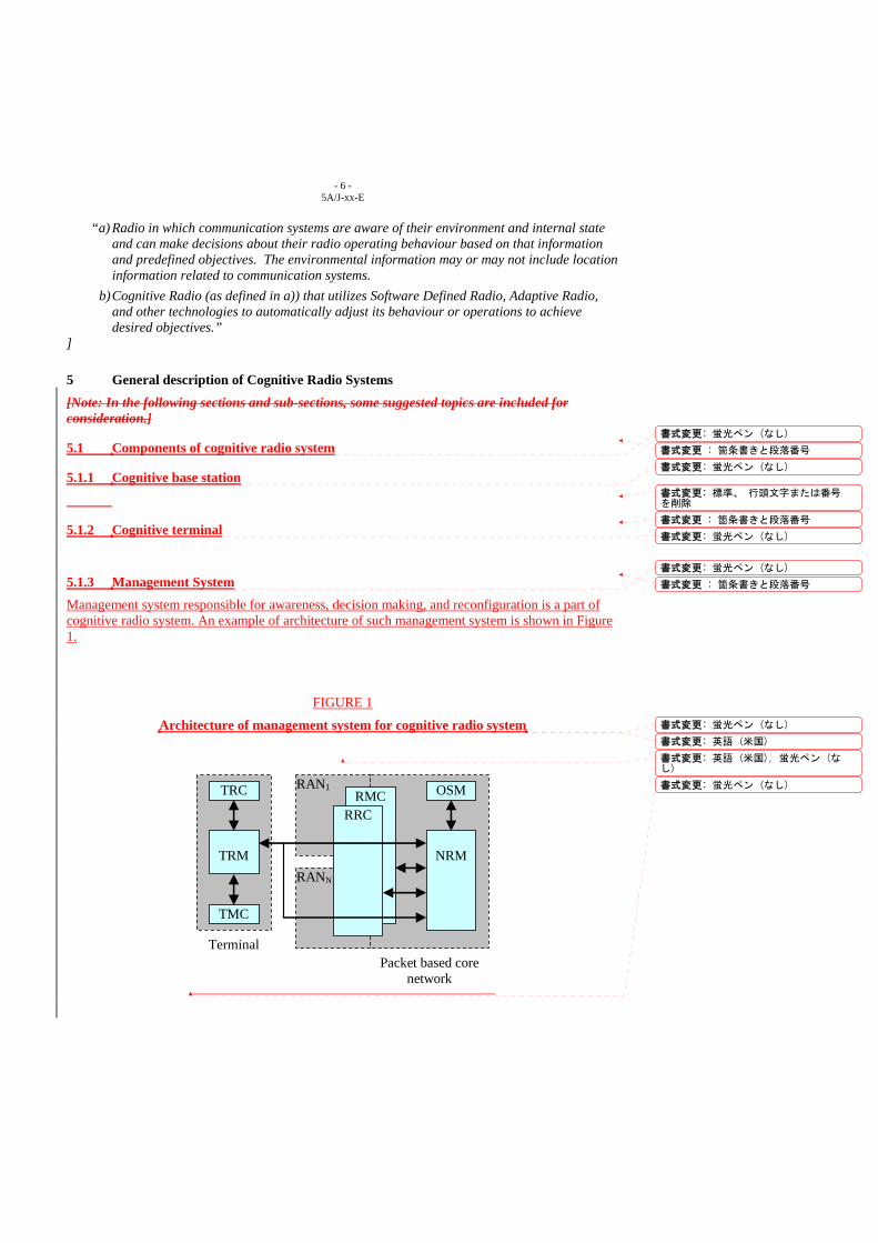
5.1.3 Management System Management system responsible for awareness, decision making, and reconfiguration is a part of cognitive radio system. An example of architecture of such management system is shown in Figure 1.
FIGURE 1
Architecture of management system for cognitive radio system
TRC
TRM
TMC
RAN1
RANN
RMC RRC
OSM
NRM
Terminal Packet based core
network
書式変更 : 箇条書きと段落番号
書式変更: 蛍光ペン (なし)
書式変更: 蛍光ペン (なし)
書式変更: 標準、 行頭文字または番号を削除
書式変更 : 箇条書きと段落番号
書式変更: 蛍光ペン (なし)
書式変更 : 箇条書きと段落番号
書式変更: 蛍光ペン (なし)
書式変更: 蛍光ペン (なし)
書式変更: 英語 (米国)
書式変更: 英語 (米国), 蛍光ペン (なし)
書式変更: 蛍光ペン (なし)
- 7 - 5A/J-xx-E
Two entities are responsible for awareness of operational environment, that is, Radio Access Network (RAN) Measurement Collector (RMC) and Terminal Measurement Collector (TMC). Two entities are responsible for decision making, that is, Network Reconfiguration Manager (NRM) and Terminal Reconfiguration Manager (TRM). Two entities are responsible for reconfiguration, that is, RAN Reconfiguration Controller (RRC) and Terminal Reconfiguration Controller (TRC).
RMC collects information related to cognitive radio network (for example, from cognitive base stations) and provides it to NRM. TRC collects information related to cognitive terminal and provides it to TRM.
NRM makes decisions on reconfiguration of cognitive radio network. TRM makes decision on reconfiguration of cognitive terminal. NRM and TRM may exchange available information to enrich awareness of each other. Also, they may exchange some control information to support distributed decision making (for example, NRM may send policies to TRM, if policy-based approach is applied).
Based on decisions made by NRM, RRC controls corresponding reconfiguration of cognitive radio network. Based on decisions made by TRM, TRC controls corresponding reconfiguration of its cognitive terminal. One more entity is defined in Figure 1, that is, Operator Spectrum Manager. This entity has two main roles. The first one is to inform NRM about regulatory rules. The second one is to allow operators to control reconfiguration decisions of NRM.
5.1.4 Common Signalling Channel The common signalling channel is a two-way communication channel used for exchanging operational environment information and control information between cognitive radio network and cognitive terminals. Referring to management system described in previous section, common signalling channel corresponds to interface between NRM and TRMs.
Downlink of this channel is used for providing initial operational environment information to cognitive terminals. This will enable fast and power efficient selection of RAN by the cognitive terminal.
Accurate and timely information about operational environment, such as, measurements, spectrum sensing results, etc, is of great importance for making reasonable reconfiguration decisions within cognitive radio system. Sources of this information are cognitive terminals and cognitive radio network. Exchange of information between cognitive terminals and cognitive radio network is also of great importance, because reconfiguration decisions can be made on both sides.
When cognitive terminal has active connection with cognitive radio network, it can use this connection to forward information about its operational environment to cognitive radio network. If cognitive terminal does not have active connection with cognitive radio network, it still can sense its environment. The uplink of the common signalling channel can be used by such cognitive terminals to forward sensing results to cognitive radio network.
5.21 Technical characteristics The key features of cognitive radio system are operational environment awareness, decision making and reconfiguration.
5.2.1 Awareness Cognitive radio system is aware of its operational environment. This includes possibility to know different types of information, related to different layers of OSI model and to different network nodes. In general, such information includes capabilities, configuration, and measurements.
書式変更 : 箇条書きと段落番号
書式変更: 蛍光ペン (なし)
書式変更: 蛍光ペン (なし)
書式変更: 蛍光ペン (なし)
書式変更 : 箇条書きと段落番号
書式変更: 蛍光ペン (なし)
- 8 - 5A/J-xx-E
5.2.2 Decision Making Based on the available information and according to some objectives, cognitive radio system is capable of making decisions on changing its operational parameters. Taking into account the large size of a cognitive radio system, decision making in cognitive radio system is done in a distributed manner.
5.2.3 Reconfiguration Based on decisions to change operational parameters, cognitive radio system is capable of reconfiguration. Typically, this will include reconfiguration of cognitive radio nodes (cognitive base stations and cognitive terminals).
5.3 Requirements
5.4 Potential Benefits Economic benefits:
Apart from the technical benefits, cognitive radio technology brings tremendous economic benefit by generating a new market opportunity to both telecommunication operators and customers through reusing the unused or underutilized spectrum.
Spectrum Utilization Efficiency:
Services with licensed spectrum (primary service) do not necessarily occupy their allocated spectrum all the time. Thus the actual spectral load of licensed spectrum band varies depending on the time and geographic location. However, the traditional fixed spectrum allocation scheme doesn’t allow exploiting idle spectral bands and hence resulted in spectrum scarcity. Through cognitive radio technology, the existing spectrum congestion can be relieved through dynamic spectrum allocation of idle spectral bands to unlicensed services. This potentially improves the spectrum utilization efficiency.
New Communication Services:
The conventional fixed spectrum allocation has barely left any spectrum space for upcoming technologies. Lack of available space in the lower band causes the new services to consider the high frequency which is not favourable for radio communication. Moreover, as new services emerge, the demand for spectrum also grows causing artificial soar in price. This phenomenon deters the advancement of new technology. However, by using cognitive radio technology to exploit any available spectral opportunity in the already licensed spectral bands, new communication services can be encouraged.
Spectrum Monitoring and Regulation:
Key concepts of spectrum monitoring include validation of information on legitimate users (users of primary service), evaluation of real levels of usage of the spectrum, identification of areas for further use, sharing or reallocation. Based on the active monitoring, regulatory issues such as monitoring the compliance with the conditions in the license can be investigated. Spectrum monitoring can also be used to resolve harmful interference cases.
Disaster Recovery and Relief activity
A cognitive radio technology being a self-autonomous system in communications environment that senses its environment, tracks changes, and reacts upon its findings, brings a unique opportunity to deploy a new communication system in disaster stricken areas. In such scenario, where the existing
書式変更 : 箇条書きと段落番号
書式変更: 蛍光ペン (なし)
書式変更 : 箇条書きと段落番号
書式変更: 蛍光ペン (なし)
書式変更: 蛍光ペン (なし)
書式変更: 蛍光ペン (なし)
書式変更: 左揃え
書式変更: 左揃え
書式変更: 左揃え
書式変更: 左揃え
- 9 - 5A/J-xx-E
infrastructure is destroyed or malfunctioned, the cognitive radio system can assists the re-establishment of the communication network that creates a potential benefit of facilitating the relief and emergency activity.
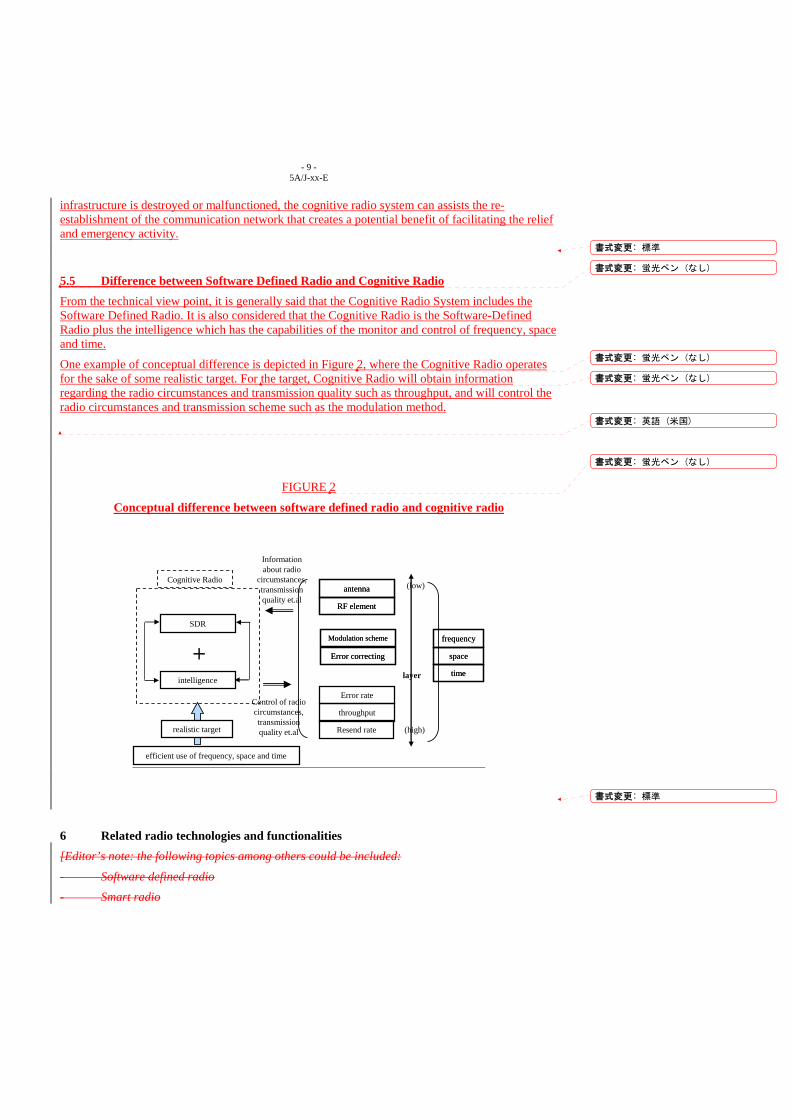
5.5 Difference between Software Defined Radio and Cognitive Radio From the technical view point, it is generally said that the Cognitive Radio System includes the Software Defined Radio. It is also considered that the Cognitive Radio is the Software-Defined Radio plus the intelligence which has the capabilities of the monitor and control of frequency, space and time.
One example of conceptual difference is depicted in Figure 2, where the Cognitive Radio operates for the sake of some realistic target. For the target, Cognitive Radio will obtain information regarding the radio circumstances and transmission quality such as throughput, and will control the radio circumstances and transmission scheme such as the modulation method.
FIGURE 2
Conceptual difference between software defined radio and cognitive radio
SDR
intelligence
+
Cognitive Radioantenna
RF element
antenna
RF element
Error rate
throughput
Resend rate
Modulation scheme
Error correcting
Modulation scheme
Error correcting
layer
(low)
(high)
Information about radio
circumstances, transmission quality et.al
Control of radio circumstances, transmission quality et.al
efficient use of frequency, space and time
realistic target
frequency
space
time
frequency
space
time
6 Related radio technologies and functionalities [Editor’s note: the following topics among others could be included:
- Software defined radio
- Smart radio
書式変更: 標準
書式変更: 蛍光ペン (なし)
書式変更: 蛍光ペン (なし)
書式変更: 蛍光ペン (なし)
書式変更: 英語 (米国)
書式変更: 蛍光ペン (なし)
書式変更: 標準
- 10 - 5A/J-xx-E
- Reconfigurable radio
- Policy-defined adaptive radio]
[Editor’s note: – Contributions are invited on the description of these and other related radio technologies so that they may be included in this section. ]
6.1 Spectrum Sensing Radio frequency spectrum information of radio environment is among the vital context information for a cognitive radio system to realize its functionality. Currently different spectrum sensing methods are considered for cognitive radio systems. These methods include energy detection, matched filtering, cyclostationary detection and wavelet based detection etc. These existing sensing methods differ in their sensing capabilities and also their computational complexities. The choice of a particular sensing method can be made depending on sensing requirements, available resource such as power, computational resource and sensing application.
Matched filter detection:
The optimal detector in stationary Gaussian noise is the matched filter since it maximizes the received signal-to-noise ratio (SNR). However, the problem with this approach is that the prior information of the signal to be detected (modulation type, order, pulse shape and packet format, etc.) is needed. Radio networks with pilot, preambles and synchronization words and spreading codes can use this matched filer detection.
Energy detection:
If there is no information of the primary user signals to be detected, the optimal detection is an energy detector. The energy detector simply measures the energy of the receive signals and compare it to a threshold. However, the problem with the energy detection is that 1) the noise power might be unknown to the detector, though training can be done with pilot signals; 2) and, false detection might be triggered by unintended signals.
Cyclostationary property detection:
This type of detectors operates based on the cyclostationary property of the signals. It performs better than the energy detection. However, the computation complexity is relatively high. For more efficient detection, the cyclostationary property can be combined with pattern recognition based on neural networks.
Noise floor based method:
The receiver measures the cumulative RF energy from multiple transmissions over a particular frequency spectrum and set a maximum cap on their aggregate level. As long as a cognitive radio node does not exceed this limit by their transmissions, it can use that frequency spectrum.
Detection of local oscillator leakage:
Detection of local oscillator (LO) leakage is an indirect way of detecting the signals in licensed spectrum. In particular this detection method is used in sensing TV white space. The idea exploits the fact that modern day TV/radio receivers are based to a large extent on the superheterodyne receiver architecture. In these receivers, some of the LO power couples back to the antenna causing reverse leakage. This phenomenon has been used to propose a method of identifying the presence of TV signals through the detection and identification of the LO leakage. The approach has the limit in terms of rage of detection. It might require additional relaying sensors fixed near by the TV receivers.
Self-correlation detection:
書式変更: 蛍光ペン (なし)
書式変更: 左揃え
- 11 - 5A/J-xx-E
In self-correlation detection, the decision statistic for the binary hypothesis is derived from signal autocorrelation sequence instead of the received signal itself. The correlation lag/delay is chosen in accordance with the maximum bandwidth of the signal involved. The decision statistic is obtained after converting the correlation sequence to frequency domain through FFT. The scheme improves the detection performance with less complexity compared to standard energy detection. However, if multiple primary users are present, unwanted signal due to the non-linearity of the correlation operation arises. This would affect the performance especially if the primary users are many and have weak signals.
Distributed sensing:
Distributed sensing system has been employed in the past for both commercial and military services. Here, the focus is in the context of radio spectrum sensing. Due to multiple factors like noise and interference, shadowing, fading and limitation of the sensing method, it is difficult to use a single standalone sensor to obtain high quality of sensing. In this case, distributed sensing can be used where each individual sensor can either be located inside or outside the cognitive node. As the name implies, the spectrum sensing is executed using multiple sensors distributed spatially. These distributed sensors have the ability to exchange sensing information, making decisions and relay the sensing information to the cognitive terminals or base stations. The sensing information is supplied to the cognitive node in a cooperative manner where the data from all sensors is aggregated to obtain the final sensing information. Such implementation method can dramatically improve the sensing quality of the cognitive radio system. This would relax the sensing requirements and choice of the sensing method at each sensor.
6.2 Cooperative Communication Cooperative communication is an efficient way to achieve diversity in multipath fading to improve the performance of wireless transmission. It can be implemented at both physical layer and MAC layer. It allows multiple mobile stations or terminals to exploit their spatial uniqueness to achieve cooperative diversity thus increasing spectrum efficiency. Recently cooperative communication received much attention and is now under the standardization process. For instance, there are lot standardization activities such as IEEE802.16j (WiMax) trying to exploit the potential benefits of cooperative communications.
For cognitive radio network, applying cooperative transmission saves transmission time and spectrum resources for both primary users and secondary users. For example, instead of competing each other for the unoccupied resources or spectrum opportunities secondary users might cooperate to maximize the usage of available resources. Therefore, applied in the cognitive radio network, cooperation among secondary users can help them to use the detected spectrum opportunity efficiently. Furthermore, secondary users can cooperate with the primary user to speed up data transmission of the primary. Thus, by cooperating with primary users, secondary users will help the primary users to complete transmission and then to free more spectrum resource for secondary users.
Through cooperation, different portions of a data frame from one user are transmitted to the destination by different users. Thus, a data frame is split into multiple subframes and are transmitted through different channels to achieve a diversity advantage. This frame splitting scheme can be implemented by coded cooperation with channel coding (e.g., RCPC, turbo code). The optimal frame-splitting ratios are to be used for the design of practical channel codes.
The nature of wireless communication determines that many unwanted signals can be overheard. In a coordinated wireless network these unwanted signals are avoided by employing protocols. In uncoordinated wireless networks, such as cognitive radio network, these overheard unwanted
書式変更: 蛍光ペン (なし)
書式変更: 左揃え
- 12 - 5A/J-xx-E
signals cannot be avoided. Instead of treating these overheard unwanted signals as interference, this feature can be taken advantage to increase the throughput of the network.
The concept of network coding was originally proposed for wired networks to improve the information flow. Recently, the idea of network coding has been extended to wireless networks. Instead of sending individual packets, wireless terminals can send a combination of different packets. Different destination with some prior information that is overheard during the transmission in previous time slot can extract wanted information. Employing network coding brings two major advantages. One is the improved stability of wireless transmission. The other is the saving of transmission time slot thus the increased throughput of wireless networks. To improve the spectrum usage of cognitive radio network, network coding techniques can be implemented in addition to cooperative communication.
6.3 Context Information Processing and Storage for Radio Awareness Apart from the need for immediate use, context information may also be needed for other purposes. However, in general wireless sensor network nodes have limited resource with regard to power supply, processing capabilities, and storage of measurements. Thus, instantaneous context data may only short lived in the sensor node for limited processing before supplied to the cognitive terminal. In this case, measurements from terminals and radio access networks are accumulated as long-term spectrum usage information onto database server in network side after adequate processing. The database can be utilized for cognitive terminals to find the best base station quickly, estimate its location, and reduce scanning time. It is also utilized for operators to assign spectrum dynamically to radio access networks or base stations, plan future deployment of base stations, and control or suggest terminals to select specific base stations for radio resource optimization.
6.4 Context Information Management and Delivery in Cognitive Radio System In general, context information can be obtained on demand or based on some schedules. Also, the cognitive terminal node can obtain the context information directly from the sensors or from other entities that process and store information. The context information obtained from storage facility can be used in many ways. For example a cognitive terminal node can directly use the stored information if it is recently updated or valid for that instant time. The stored information can also be used to generate the trend of the spectrum change and forward it to the cognitive terminal node to enhance the cognitive terminal radio awareness.
6.5 User-centric Radio Resource Utilization in Cognitive Radio System In the current wireless systems, user terminal subscribes to one operator (or service provider) and receives the service by accessing to the spectrum allocated to the subscribing operator (service provider). These systems are called operator-centric systems. In cognitive radio system, a novel approach called user-centric, which allows cognitive radio terminal to utilize radio resource that maximize user experience by satisfying user’s preferences, has been proposed. To support this approach the following technologies need to be considered: user-preference based radio resource selection, data structures and description for user-preference, etc.
6.6 Link Aggregation Cognitive terminals can utilize multiple radio links simultaneously, which is called link aggregation. By the link aggregation, it is possible to communicate using as many vacant radio links as possible, by which the spectrum utilization efficiency can be increased. Senders, receivers, or
書式変更: 蛍光ペン (なし)
書式変更: 蛍光ペン (なし)
書式変更: 蛍光ペン (なし)
書式変更: 蛍光ペン (なし)
- 13 - 5A/J-xx-E
both of them can use this technology to increase their communication speed. In addition, possibility to lose communication opportunities is reduced because connections on some of radio links are still established even if one of them is disconnected suddenly. Nodes on network may be required to receive the distributed traffic from cognitive terminals via same or different base stations.
Especially in heterogeneous wireless network operations, mechanisms and algorithms for packet order sorting, estimation of link quality, adaptation of transmission speed to each radio links, selection of adequate radio links, optimization of packet distribution ratio into each radio link, and network coding are needed to increase performance.
7 Potential applications [Editor’s note: – it should be noted that Potential applications could be discussed in the last section after considering all other contents about cognitive radio systems.]
[Editor’s note: the following topics among others could be included: – Radio Resource Management (RRM) – Cognitive networks – Industry Verticals (e.g. market structure) – Services – Service Specific Quality Measures – Billing Models]
7.1 Cognitive networks The last few years have seen the deployment of different RATs (Radio Access Technologies) covering the same geographical area at the same time. A typical example is the network operator that already owns a network and deploys a new one related to a new generation system (e.g. a network operator deploying an UMTS network and already having a GSM one).
It is well-known that in a certain geographical area (e.g. a city), the offered traffic may be non-uniform in time and in space. This usually leads to a congestion situation (i.e. high blocking percentage) in some portions of the considered area in which the traffic is more heavy (typically these portions are called hot-spots), while the other portions of that area may be characterized by lower blocking percentages since they are less loaded. In addition, in case of deployment of two or more RATs in the area, the traffic offered to each deployed RAT could also be differently distributed in time and space with respect to the traffic offered to the other deployed RAT.
In this scenario, network operators owning two or more RATs could be very interested in the new opportunity to dynamically and jointly manage the resources of the deployed RATs, in order to adapt the network to the behavior of the traffic and to globally maximize the capacity.
7.1.1 Concept of Cognitive Networks Cognitive Networks are the application of Cognitive Radio Systems to the network domain. In particular, a Cognitive Network is a network that could dynamically adapt its behaviour on the basis of the knowledge of its environment.
In principle, a Cognitive Network is characterized by the following functionalities and entities:
• Cognitive Network Management
- 14 - 5A/J-xx-E
• Reconfigurable Base Stations.
The Cognitive Network Management functionality over-spans different RATs, managing and controlling the nodes inside the network, with the goal to self-adapt towards an optimal mix of supported RATs and frequency bands. This functionality could act on the basis of some input parameters, for example the available resources, the traffic demand, the capabilities of the mobiles within the cell (supported RATs, frequency bands, etc.), the requested bearer services (bandwidth, QoS, etc.), etc. In addition, this functionality could exploit a collaborative cognitive radio resource management scheme, where the decision making functions are shared among different network nodes.
The Reconfigurable Base Stations are the nodes building the Cognitive Network. The hardware resources of a reconfigurable base station could be dynamically reconfigured in order to be used with different RATs, frequencies, channels, etc., and could support multi-RAT operation with dynamic load-management.
In addition, Cognitive Networks enable the introduction of the cognition radio enablers in a multi RAT environment, such as the CPC (Cognition supporting Pilot Channel).
The availability of reconfigurable base stations in the networks in conjunction with cognitive network management functionalities could give the network operators the means for managing in a globally efficient way the radio and hardware resource pool, with the aim to adapt the network itself to the dynamic variations of the traffic offered to the deployed RATs and to the different portions of the area.
7.1.2 Main features of the Cognitive Networks The Cognitive Networks [are shown to be /could be] [an essential /a useful/a relevant] application of the Cognitive Radio Systems in the network domain, implementing the following main features:
• self-adapting towards an optimal mix of supported RATs and frequency bands (e.g. exploiting a collaborative cognitive radio resource management scheme)
• dynamically reconfiguring network nodes in order to be used with different RATs, frequencies, channels, etc., and to support multi-RAT operation with dynamic load-management
• enabling the introduction of a cognition radio enabler, such as the CPC.
[Editor’s Note: Ongoing R&D studies are underway to further investigate specific aspects of the Cognitive Networks, and it is expected that more material will be presented in future ITU-R WP 5A meetings for further completion of the associated working document.]
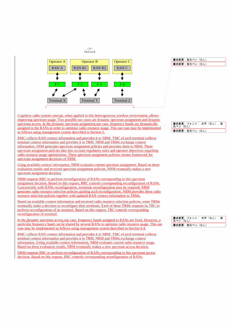
7.2 Heterogeneous wireless environment Current wireless environment is heterogeneous. It may include multiple operators, multiple RANs, multiple radio interfaces, and multiple terminals. Example of such heterogeneous wireless environment is shown in Figure 3.
FIGURE 3
Heterogeneous wireless environment
書式変更: 蛍光ペン (なし)
書式変更: 蛍光ペン (なし)
書式変更: フランス語(フランス), 蛍光ペン (なし)
- 15 - 5A/J-xx-E
Operator C Operator B
RAN B1
Operator A
RAN A RAN C
Terminal X
F 1
RAN B2
F 2 F 3 F 4
Terminal ZTerminal Y
Cognitive radio system concept, when applied to this heterogeneous wireless environment, allows improving spectrum usage. Two possible use cases are dynamic spectrum assignment and dynamic spectrum access. In the dynamic spectrum assignment use case, frequency bands are dynamically assigned to the RANs in order to optimize radio resource usage. This use case may be implemented as follows using management system described in Section 5.
RMC collects RAN context information and provides it to NRM. TMC of each terminal collects terminal context information and provides it to TRM. NRM and TRMs exchange context information. OSM generates spectrum assignment policies and provides them to NRM. These spectrum assignment policies take into account regulatory rules and operator objectives regarding radio resource usage optimization. These spectrum assignment policies creates framework for spectrum assignment decisions of NRM.
Using available context information, NRM evaluates current spectrum assignment. Based on these evaluation results and received spectrum assignment policies, NRM eventually makes a new spectrum assignment decision.
NRM requests RRC to perform reconfiguration of RANs corresponding to this spectrum assignment decision. Based on this request, RRC controls corresponding reconfiguration of RANs. Concurrently with RANs reconfiguration, terminals reconfiguration may be required. NRM generates radio resource selection policies guiding such reconfiguration. NRM provides these radio resource selection policies together with updated RAN context information to TRMs.
Based on available context information and received radio resource selection policies, some TRMs eventually make a decision to reconfigure their terminals. Each of these TRMs requests its TRC to perform reconfiguration of its terminal. Based on this request, TRC controls corresponding reconfiguration of terminal.
In the dynamic spectrum access use case, frequency bands assigned to RANs are fixed. However, a particular frequency band can be shared by several RANs to optimize radio resource usage. This use case may be implemented as follows using management system described in Section 6.4.
RMC collects RAN context information and provides it to NRM. TMC of each terminal collects terminal context information and provides it to TRM. NRM and TRMs exchange context information. Using available context information, NRM evaluates current radio resource usage. Based on these evaluation results, NRM eventually makes a new spectrum access decision.
NRM requests RRC to perform reconfiguration of RANs corresponding to this spectrum access decision. Based on this request, RRC controls corresponding reconfiguration of RANs.
書式変更: 蛍光ペン (なし)
書式変更: 蛍光ペン (なし)
書式変更: フォント : 太字 (なし) , 蛍光ペン (なし)
書式変更: 蛍光ペン (なし)
書式変更: フォント : 太字 (なし) , 蛍光ペン (なし)
書式変更: 蛍光ペン (なし)
- 16 - 5A/J-xx-E
Also, NRM generates radio resource selection policies which will guide TRMs in their spectrum access decisions. NRM provides these radio resource selection policies to TRMs. Based on available context information and received radio resource selection policies, some TRMs eventually make new spectrum access decisions.
Each of these TRMs requests its TRC to perform reconfiguration of its terminal corresponding to its spectrum access decision. Based on this request, TRC controls corresponding reconfiguration of terminal.
7.3 Radio Resource Management (RRM) In cognitive radio system, radio resource can be shared by different operators and can be used by many cognitive terminals. The resource can be managed by one entity, or can be managed by multiple entities. For each scenario, the Radio Resource Management applications should provide flexible and fair usage of radio resource for all cognitive terminals. Also, the RRM applications should improve the efficiency of radio resource utilization of the cognitive radio system.
7.4 Industry verticals The mobile communication market has been grown rapidly over the past 10 years and has reached high penetration rate. Without major changes in service models this market may approach saturation point in the near future. There is need of an open market model that enables new players to enter the market and lets them provide innovative services for more competition environment. With cognitive radio technologies, it could be easier to split the radio system into spectrum layer, network layer, and service layer. In this structure, different management frameworks for each layer can be introduced.
7.5 Services New players, some of them may not have spectrum licenses or network infrastructure can enter the mobile communication market. Also, current operators can lend their spectrum and network resource to other operators. Moreover, public networks by operators can cooperate with private networks for more efficient and reliable communication. In this environment, heterogeneity and diversity will be increased. The end users have more chances to access innovative services suitable for their preferences.
8 Operational implications [Editor’s note: the following topics among others could be included: – Performance – Potential implementation challenges – Security consideration – Authentication – Certification and Conformity – Operational Flexibility – Transmission Protocols and Development – Operation in conjunction with Licensed vs. Unlicensed bands – Autonomic Performance Monitoring
書式変更: 蛍光ペン (なし)
書式変更: 蛍光ペン (なし)
書式変更: 蛍光ペン (なし)
書式変更: 英語 (米国)
- 17 - 5A/J-xx-E
– Impact to Mobile Devices and Technologies – Impact of coexistence on system performance – Cost Economics – [Regulatory requirements for cognitive radio systems] – Deployment Strategies – [Compliance testing for cognitive radio systems] – [Impact on spectrum management] ]
9 Facilitating coexistence
9.1 Cognitive capabilities [Editor’s note: the following topics among others could be included:
– Parameters Definition for cognitive sensing – Internal Database Creation and Management – Common (internal/external) Database Creation and Management – Dedicated control channel – Techniques for Analysis of coexistence among cognitive and non-cognitive radio systems ] 9.1.1 [Dedicated control channel/Concept of the Cognition supporting Pilot Channel (CPC)] [Editor’s Note: this section could be entitled “Dedicated control channel” or “Concept of the CPC” depending on further contribution to the next meeting.]
[Editor’s Note: it should be determined what other elements should be included in this section and what elements should be kept in Annex 2 of the document.]
The Cognition supporting Pilot Channel (CPC) is a cognition enabling radio channel in a multi radio access technology (RAT) environment as illustrated in Fig. 1.
FIGURE 14
The multi RAT environment context
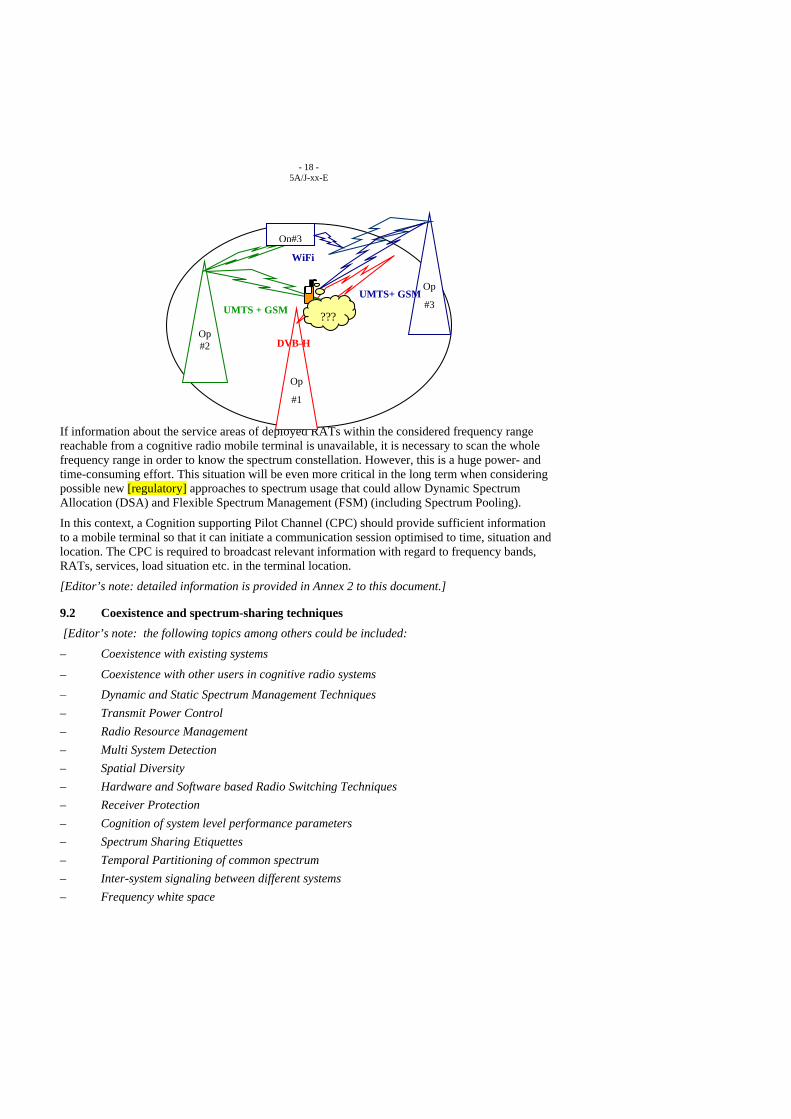
- 18 - 5A/J-xx-E
If information about the service areas of deployed RATs within the considered frequency range reachable from a cognitive radio mobile terminal is unavailable, it is necessary to scan the whole frequency range in order to know the spectrum constellation. However, this is a huge power- and time-consuming effort. This situation will be even more critical in the long term when considering possible new [regulatory] approaches to spectrum usage that could allow Dynamic Spectrum Allocation (DSA) and Flexible Spectrum Management (FSM) (including Spectrum Pooling).
In this context, a Cognition supporting Pilot Channel (CPC) should provide sufficient information to a mobile terminal so that it can initiate a communication session optimised to time, situation and location. The CPC is required to broadcast relevant information with regard to frequency bands, RATs, services, load situation etc. in the terminal location.
[Editor’s note: detailed information is provided in Annex 2 to this document.]
9.2 Coexistence and spectrum-sharing techniques [Editor’s note: the following topics among others could be included:
– Coexistence with existing systems
– Coexistence with other users in cognitive radio systems
– Dynamic and Static Spectrum Management Techniques – Transmit Power Control – Radio Resource Management – Multi System Detection – Spatial Diversity – Hardware and Software based Radio Switching Techniques – Receiver Protection – Cognition of system level performance parameters – Spectrum Sharing Etiquettes – Temporal Partitioning of common spectrum – Inter-system signaling between different systems – Frequency white space
Op#2
Op
#3UMTS + GSM UMTS+ GSM
Op#3
WiFi
Op
#1
DVB-H
???
- 19 - 5A/J-xx-E
] [Editor’s Note: AH-VOC group is waiting for the provision of the technical definition of “frequency white space” from WG5.The vocabulary definition should consequently be aligned with this definition within AH-VOC.]
In some frequency bands, there may exist so-called frequency white space. This is frequency space which is unused in a certain geographic area by existing services.
[Editor’s note: the definition of the “frequency white space” should be further considered at the future WP 5A meetings.]
[Editor’s note: there is a potential difficulty to conclude the definition of “frequency white space” at this early stage. Other alternative definition has been proposed as follows. The term “unused” should be “underutilized”:
“In some frequency bands, there may exist so-called frequency “white space”. This is a frequency band underutilized on either a temporal or geographic basis. space which is unused in a certain geographic area by existing services. “
]
With the use of cognitive radio with a database, the actual frequency white space in a certain area could be derived, taking into account the potential interference produced by an additional radio system. At the moment a cognitive radio is notified, it takes this information into account. Thus, the use of frequency white space could ease the sharing with existing services in frequency bands.
Cognitive radio cannot sense/detect stations that operate in a receive mode. [Editor’s Note: some solutions were presented for the sense/detection of the receiving only station. Text is encouraged to be provided at future WP 5A meetings.] However, in the case of terrestrial based receive-only stations, if their locations and the radio parameters as well as the maximum power or e.i.r.p. level for cognitive radio transmissions are known, they could be used to define a protection area around the terrestrial based receive-only stations within which Cognitive Radio transmissions are not allowed. Beyond this protection area and for the maximum power or e.i.r.p. level considered, this frequency band could be considered as a frequency white space available for cognitive radio operations.
On the basis of this information, white spaces for mobile applications could be identified and used in specific geographical areas. In this way it could be possible to dynamically allocate frequency resources to be used by several mobile communication systems.
[For dissimilar systems sharing the same frequency band, it may be necessary to access the relevant information on the frequency availability via other means than direct sensing. The relevant information of the stations in use could be made available in an up-to-date database. The link to the database could be for example via a "Cognition supporting Pilot Channel" or an IP-link.]
[Editor’s note: the above paragraph should be clarified in terms of the services the sharing is related to.]
10 Conclusion [Editor’s note: possible Annexes: – System design example – Research and Development activities ]
- 20 - 5A/J-xx-E
ANNEX 1 Research and Development Activities in Japan
ANNEX 2 R&D Activities concerning the cognitive radio related CPC concept in the E²R and E3 Project
ANNEX 3 R&D Activities concerning the cognitive radio related common control channel concept in Japanese project
Annex 1
Research and Development Activities in Japan
No Change
Annex 2
R&D Activities concerning the cognitive radio related CPC concept in the E²R and E3 Project
No Change
Annex 3
R&D Activities concerning the cognitive radio related common control channel concept in Japanese project
1 Introduction of the common control channel concept To seamlessly use different wireless access networks in heterogeneous wireless network environment, we need a multimode terminal or software defined radio terminal. Each terminal has several ways to connect radio access networks. To always receive control signals from the network side related to reconfiguration and handover, it is efficient to keep connected using only one RAN interface to receive information, such as reconfiguration request to the terminal, handover control messages, connection establishment request for an in-coming call from other networks and so on.
The common control channel concept has been proposed to exchange such messages regarding radio resource usage optimization in heterogeneous wireless network environment. The original concept was proposed in 1997 by CRL (which was reorganized as NICT in 2004), and is the first proposal of such common signalling networks. Various experimental systems of the cognitive control channel have been developed and tested with various applications in NICT.
書式変更: 蛍光ペン (なし)
書式変更: 標準
書式変更: 蛍光ペン (なし)
書式変更 : 箇条書きと段落番号
書式変更: 蛍光ペン (なし)
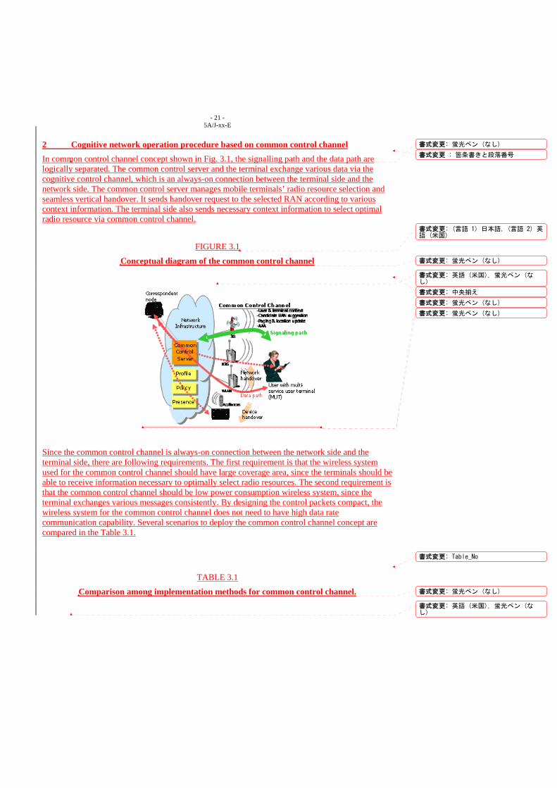
- 21 - 5A/J-xx-E
2 Cognitive network operation procedure based on common control channel In common control channel concept shown in Fig. 3.1, the signalling path and the data path are logically separated. The common control server and the terminal exchange various data via the cognitive control channel, which is an always-on connection between the terminal side and the network side. The common control server manages mobile terminals’ radio resource selection and seamless vertical handover. It sends handover request to the selected RAN according to various context information. The terminal side also sends necessary context information to select optimal radio resource via common control channel.
FIGURE 3.1
Conceptual diagram of the common control channel
Since the common control channel is always-on connection between the network side and the terminal side, there are following requirements. The first requirement is that the wireless system used for the common control channel should have large coverage area, since the terminals should be able to receive information necessary to optimally select radio resources. The second requirement is that the common control channel should be low power consumption wireless system, since the terminal exchanges various messages consistently. By designing the control packets compact, the wireless system for the common control channel does not need to have high data rate communication capability. Several scenarios to deploy the common control channel concept are compared in the Table 3.1.
TABLE 3.1
Comparison among implementation methods for common control channel.
書式変更 : 箇条書きと段落番号
書式変更: 蛍光ペン (なし)
書式変更: (言語 1) 日本語, (言語 2) 英語 (米国)
書式変更: 蛍光ペン (なし)
書式変更: 英語 (米国), 蛍光ペン (なし)
書式変更: 中央揃え
書式変更: 蛍光ペン (なし)
書式変更: 蛍光ペン (なし)
書式変更: Table_No
書式変更: 蛍光ペン (なし)
書式変更: 英語 (米国), 蛍光ペン (なし)
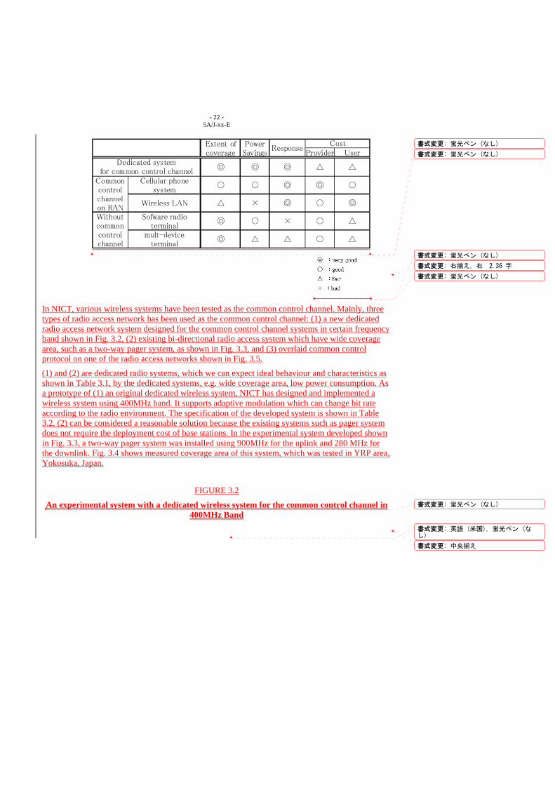
- 22 - 5A/J-xx-E
Extent of Powercoverage Savings Provider User
◎ ◎ ◎ △ △
Cellular phonesystem
Sofware radioterminal
mult-deviceterminal
Withoutcommoncontrolchannel
◎
◎
◎
△
△
◎
×
△
○
◎
×
○
△ ○
○
ResponseCost
△Wireless LAN
Dedicated systemfor common control channel
○ ◎ ○○Commoncontrolchannelon RAN
In NICT, various wireless systems have been tested as the common control channel. Mainly, three types of radio access network has been used as the common control channel: (1) a new dedicated radio access network system designed for the common control channel systems in certain frequency band shown in Fig. 3.2, (2) existing bi-directional radio access system which have wide coverage area, such as a two-way pager system, as shown in Fig. 3.3, and (3) overlaid common control protocol on one of the radio access networks shown in Fig. 3.5.
(1) and (2) are dedicated radio systems, which we can expect ideal behaviour and characteristics as shown in Table 3.1, by the dedicated systems, e.g. wide coverage area, low power consumption. As a prototype of (1) an original dedicated wireless system, NICT has designed and implemented a wireless system using 400MHz band. It supports adaptive modulation which can change bit rate according to the radio environment. The specification of the developed system is shown in Table 3.2. (2) can be considered a reasonable solution because the existing systems such as pager system does not require the deployment cost of base stations. In the experimental system developed shown in Fig. 3.3, a two-way pager system was installed using 900MHz for the uplink and 280 MHz for the downlink. Fig. 3.4 shows measured coverage area of this system, which was tested in YRP area, Yokosuka, Japan.
FIGURE 3.2
An experimental system with a dedicated wireless system for the common control channel in 400MHz Band
書式変更: 蛍光ペン (なし)
書式変更: 蛍光ペン (なし)
書式変更: 蛍光ペン (なし)
書式変更: 右揃え, 右 2.36 字
書式変更: 蛍光ペン (なし)
書式変更: 蛍光ペン (なし)
書式変更: 英語 (米国), 蛍光ペン (なし)
書式変更: 中央揃え
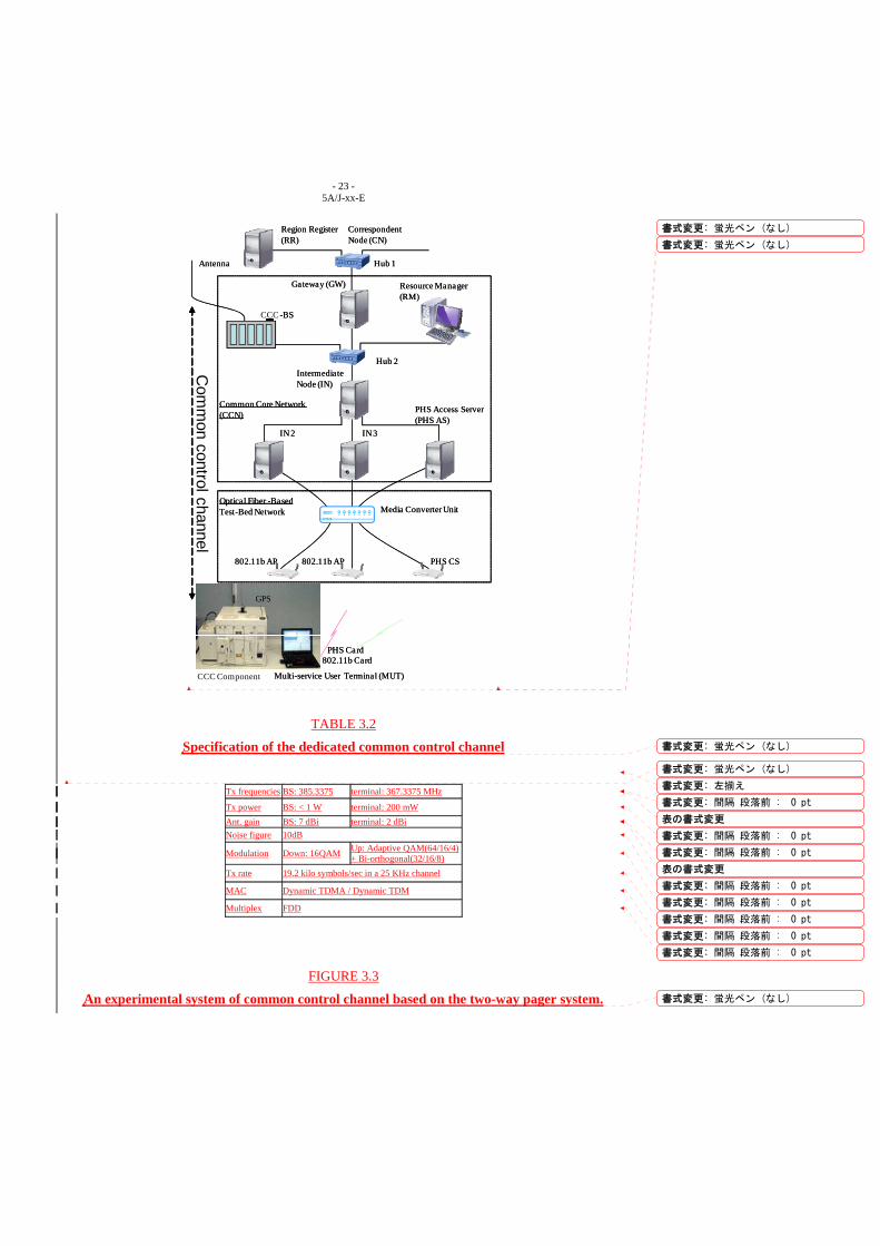
- 23 - 5A/J-xx-E
Region Register (RR)
Hub 1
CCC -BS
Hub 2
IN 2 IN 3
Media Converter Unit
802.11b AP 802.11b AP PHS CS
CCC Component Multi-service User Terminal (MUT)
PHS Card802.11b Card
Correspondent Node (CN)
Gateway (GW) Resource Manager (RM)
Intermediate Node (IN)
PHS Access Server (PHS AS)
GPS
Common Core Network (CCN)
Optical Fiber -Based Test-Bed Network
Antenna
Com
mon control channel
Region Register (RR)
Hub 1
-BS
Hub 2
IN 2 IN 3
Media Converter Unit
802.11b AP 802.11b AP PHS CS
Multi-service User Terminal (MUT)
PHS Card802.11b Card
Correspondent Node (CN)
Gateway (GW) Resource Manager (RM)
Intermediate Node (IN)
PHS Access Server (PHS AS)
GPS
Common Core Network (CCN)
Optical Fiber -Based Test-Bed Network
Antenna
TABLE 3.2
Specification of the dedicated common control channel
Tx frequencies BS: 385.3375 terminal: 367.3375 MHz
Tx power BS: < 1 W terminal: 200 mW Ant. gain BS: 7 dBi terminal: 2 dBi Noise figure 10dB
Modulation Down: 16QAM Up: Adaptive QAM(64/16/4) + Bi-orthogonal(32/16/8)
Tx rate 19.2 kilo symbols/sec in a 25 KHz channel
MAC Dynamic TDMA / Dynamic TDM
Multiplex FDD
FIGURE 3.3
An experimental system of common control channel based on the two-way pager system.
書式変更: 蛍光ペン (なし)
書式変更: 蛍光ペン (なし)
書式変更: 蛍光ペン (なし)
書式変更: 蛍光ペン (なし)
書式変更: 左揃え
書式変更: 間隔 段落前 : 0 pt
表の書式変更
書式変更: 間隔 段落前 : 0 pt
書式変更: 間隔 段落前 : 0 pt
表の書式変更
書式変更: 間隔 段落前 : 0 pt
書式変更: 間隔 段落前 : 0 pt
書式変更: 間隔 段落前 : 0 pt
書式変更: 間隔 段落前 : 0 pt
書式変更: 間隔 段落前 : 0 pt
書式変更: 蛍光ペン (なし)
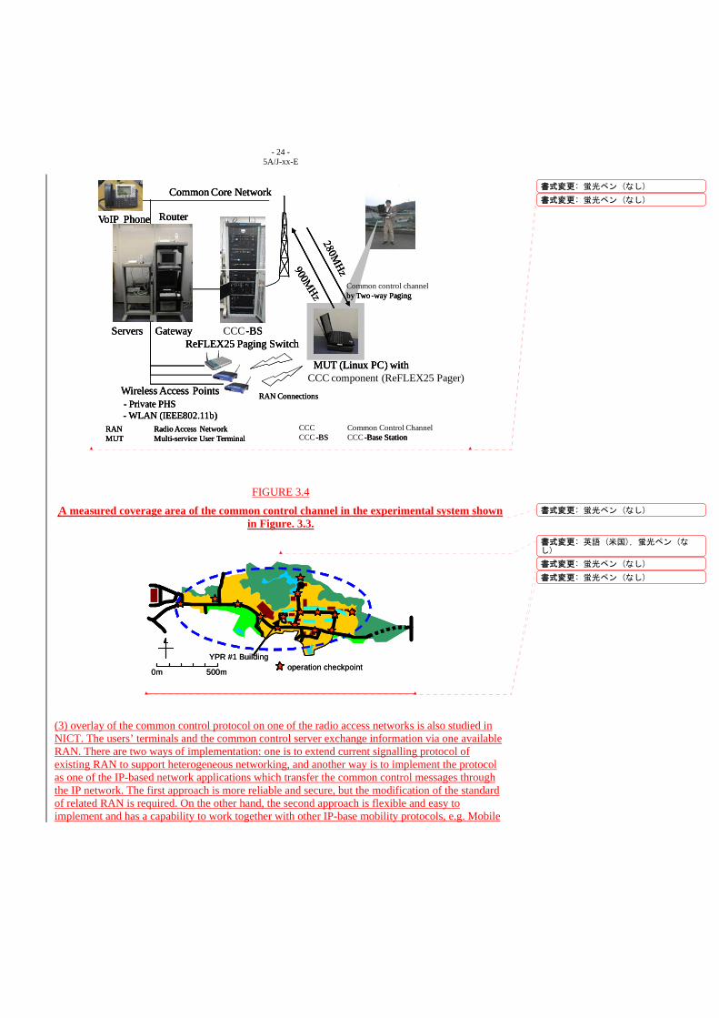
- 24 - 5A/J-xx-E
Common Core Network
Gateway CCC-BSReFLEX25 Paging Switch
MUT (Linux PC) with CCC component (ReFLEX25 Pager)
Router
Wireless Access Points- Private PHS- WLAN (IEEE802.11b)
Servers
by Two -way Paging
RAN Connections
CCC Common Control ChannelRAN Radio Access NetworkCCC-BS CCC-Base StationMUT Multi-service User Terminal
VoIP Phone
Common Core Network
Gateway -BSReFLEX25 Paging Switch
MUT (Linux PC) with
Router
Wireless Access Points- Private PHS- WLAN (IEEE802.11b)
Servers
by Two -way Paging
RAN Connections
RAN Radio Access Network-BS -Base StationMUT Multi-service User Terminal
VoIP Phone
Common Core Network
Gateway -BSReFLEX25 Paging Switch
MUT (Linux PC) with
Common control channel
Router
Wireless Access Points- Private PHS- WLAN (IEEE802.11b)
Servers
by Two -way Paging
RAN Connections
RAN Radio Access Network- -Base StationMUT Multi-service User Terminal
VoIP Phone
FIGURE 3.4
A measured coverage area of the common control channel in the experimental system shown in Figure. 3.3.
operation checkpoint0m 500m
YPR #1 Buildingoperation checkpoint0m 500m
YPR #1 Building
(3) overlay of the common control protocol on one of the radio access networks is also studied in NICT. The users’ terminals and the common control server exchange information via one available RAN. There are two ways of implementation: one is to extend current signalling protocol of existing RAN to support heterogeneous networking, and another way is to implement the protocol as one of the IP-based network applications which transfer the common control messages through the IP network. The first approach is more reliable and secure, but the modification of the standard of related RAN is required. On the other hand, the second approach is flexible and easy to implement and has a capability to work together with other IP-base mobility protocols, e.g. Mobile
書式変更: 蛍光ペン (なし)
書式変更: 蛍光ペン (なし)
書式変更: 蛍光ペン (なし)
書式変更: 英語 (米国), 蛍光ペン (なし)
書式変更: 蛍光ペン (なし)
書式変更: 蛍光ペン (なし)
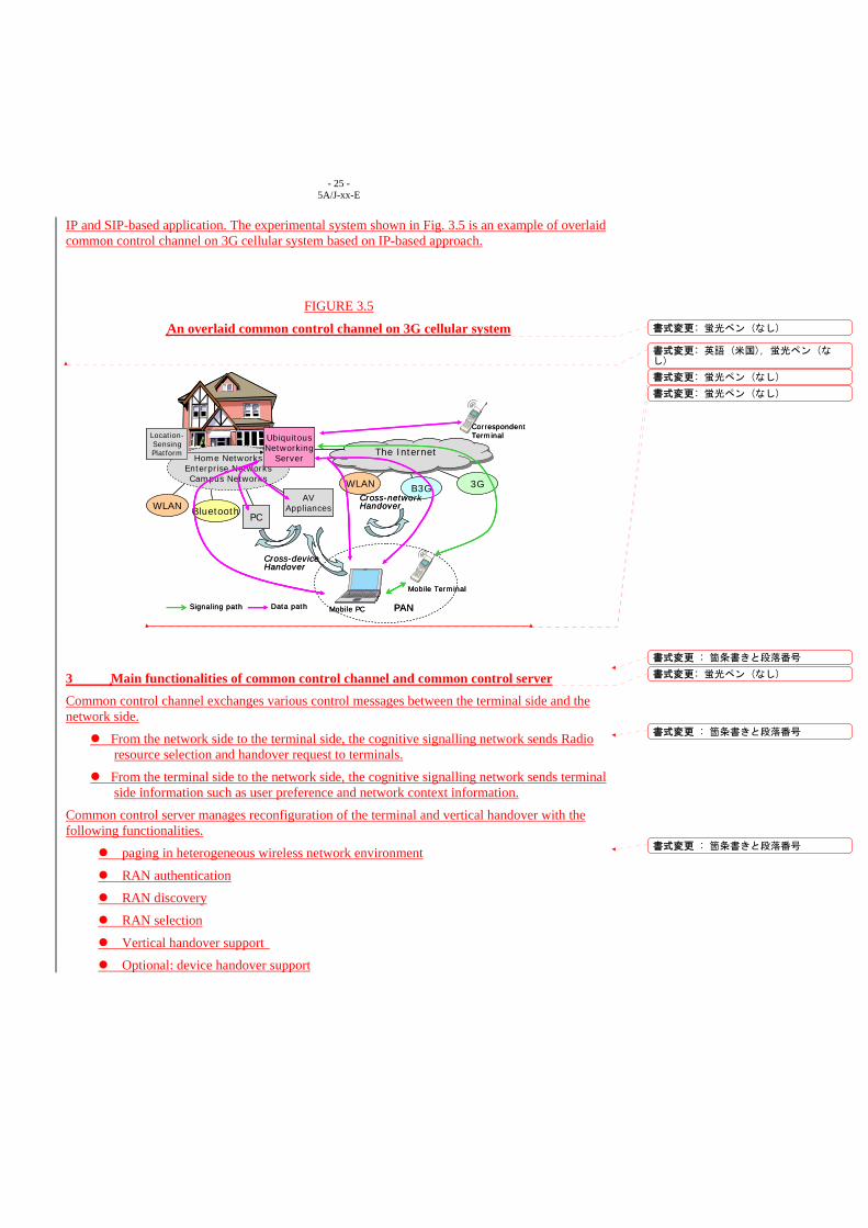
- 25 - 5A/J-xx-E
IP and SIP-based application. The experimental system shown in Fig. 3.5 is an example of overlaid common control channel on 3G cellular system based on IP-based approach.
FIGURE 3.5
An overlaid common control channel on 3G cellular system
Data pathSignaling path
Home NetworksEnterprise NetworksCampus Networks
UbiquitousNetworking
Server
WLAN Bluetooth
The InternetThe Internet
WLAN 3GB3G
Location-SensingPlatform
Cross-networkHandover
Cross-deviceHandover
Mobile Terminal
Mobile PC
PC
AVAppliances
CorrespondentTerminal
PANData pathSignaling path
Home NetworksEnterprise NetworksCampus Networks
UbiquitousNetworking
Server
WLAN Bluetooth
The InternetThe Internet
WLAN 3GB3G
Location-SensingPlatform
Cross-networkHandover
Cross-deviceHandover
Mobile Terminal
Mobile PC
PC
AVAppliances
CorrespondentTerminal
PAN
3 Main functionalities of common control channel and common control server Common control channel exchanges various control messages between the terminal side and the network side.
From the network side to the terminal side, the cognitive signalling network sends Radio resource selection and handover request to terminals.
From the terminal side to the network side, the cognitive signalling network sends terminal side information such as user preference and network context information.
Common control server manages reconfiguration of the terminal and vertical handover with the following functionalities.
paging in heterogeneous wireless network environment
RAN authentication
RAN discovery
RAN selection
Vertical handover support
Optional: device handover support
書式変更: 蛍光ペン (なし)
書式変更: 英語 (米国), 蛍光ペン (なし)
書式変更: 蛍光ペン (なし)
書式変更: 蛍光ペン (なし)
書式変更 : 箇条書きと段落番号
書式変更: 蛍光ペン (なし)
書式変更 : 箇条書きと段落番号
書式変更 : 箇条書きと段落番号
- 26 - 5A/J-xx-E
4 Main features of the common control channel concept In common control channel concept, signalling path and data path is separated logically or physically. Advantages of the common control channel concept are the followings.
Low power consumption
RAN discovery time can be reduced
Possible to collect various RANs’ information via one dedicated network
Optimal radio resource selection in heterogeneous wireless network
______________
書式変更: 蛍光ペン (なし)
書式変更 : 箇条書きと段落番号
書式変更: インデント : 左 : 28.65 pt,タブ位置: 6.62 字(なし) + 7 字
書式変更: 英語 (米国)
書式変更: 標準
INTERNATIONAL TELECOMMUNICATION UNION
RADIOCOMMUNICATIONSTUDY GROUPS
Document 5A/J-X XX October 2008 English only
Source: Question:
Japan
PROPOSAL FOR A PRELIMINARY DRAFT NEW QUESTION [SAC/5]
Mobile wireless access systems providing communications to a large number of ubiquitous sensors and/or actuators scattered over wide areas
1. Introduction
There is a growing need to provide wireless access media that can link sensors and actuators
associated with humans or widely-dispersed objects to backbone networks in order to support an
increasing number of popular service categories. These categories include environment monitoring,
stolen goods tracing, monitoring of gas, water, and electricity use, social security and health care, etc.
Currently, wireless access with sensors is established only for short-range communications in private
and local areas, e.g., by using RFID tags. Such wireless access links should be provided to objects
with mobility in wide areas as well. Therefore, it is proposed that a new mobile wireless access
system be studied and developed to achieve communications with a large number of ubiquitous
sensors and/or actuators scattered over wide public areas.
2. Concept of the system
This system provides communications to sensors and/or actuators associated with humans and
objects. This system is different from the conventional cellular systems in the following points;
(1) Communication style: Cellular systems offer communications to and from humans. This system,
on the other hand, also offers communications to non-human objects or machines. (2) Terminal style:
Cellular terminals are high-capacity, high-capability, and high-cost. To realize the ubiquitous
network society, on the other hand, the sensors and actuators in this system are simple, low-capacity,
1
low-capability, very small, and low-cost. (3) Scalability: This system accommodates much more
sensors and/or actuators in number than the cellular phone users.
Due to the sensor network, one communication service of this system transmits small amounts of
data (such as measurement data, location information and object control signals) at comparatively
long intervals. Therefore, this mobile system should support a large number of sensors and/or
actuators scattered over wide areas on a cell basis since the communication traffic is not significant.
Moreover, it is noted that this mobile system requires only narrowband links.
To enhance system performance, this system has the following functions:
(1) This wireless network is applied to public areas on a cell-by-cell basis, which leads to the ready
expansion of service areas and categories.
(2) Mobility is offered to the objects carrying sensors and/or actuators.
3. Proposal
A preliminary draft new Question on this subject is given in Attachment 1.
A working document on detailed technical description of an example system is given in another
contribution from Japan (Document 5A/J-).
Attachment: 1
2
Attachment 1
PRELIMINARY DRAFT NEW QUESTION ITU-R [SAC]/5
Mobile wireless access systems providing communications to a large number of ubiquitous sensors and/or actuators scattered over wide
areas
The ITU Radiocommunication Assembly,
considering a) that rapid advances are being made in wireless communications to link sensors
and/or actuators associated with humans and objects in various environments; b) that sensors and/or actuators for such communications should be simple, small
and cheap to realize the ubiquitous network society. c) that one communication service will transmit small amounts of data such as
measurement data, location information and object control signals at comparatively long intervals.
d) that the application of such communications to public areas may provide the expansion of service areas and categories on a cell-by-cell basis due to the traffic characteristics stated in item (c) above;
e) that mobility should be offered for such communications; f) that for such communications non line-of-sight operation may be required
while it may not be necessary to use wide bandwidth or to support real-time transmission due to item (d);
g) that it is desirable to identify the preferred characteristics for the mobile wireless access systems used for such communications;
h) that such wireless access systems may also be used in nomadic and/or fixed applications;
decides that the following Question should be studied 1 What are the technical and operational requirements and characteristics of
mobile wireless access systems that will be used to provide communications to large numbers of sensors and/or actuators scattered over wide areas?
3
4
further decides 1 that the results of the above studies should be included in one or more
Recommendation(s) or Report(s); 2 that the above studies should be completed by 2011. Category: S1
INTERNATIONAL TELECOMMUNICATION UNION
RADIOCOMMUNICATION STUDY GROUPS
Document 5A/J-Y XX October 2008 English only
Source:
Question:
Japan
WORKING DOCUMENT TOWARDS A PRELIMINARY DRAFT NEW RECOMMENDATION/REPORT
Mobile wireless access systems providing communications to a large number of ubiquitous sensors and/or actuators scattered over wide
areas
1. Introduction
Nowadays, social demands and technological innovations are emerging in wireless communications
to link sensors and actuators associated with humans and objects. Considering this situation, we are
formulating suitable concepts of the mobile wireless access system needed and feasibility studies
examined by an example system are given.
2. Proposal
This document provides a working document for a preliminary draft new Question [SAC/5] for
consideration by the Working Party 5A meeting in October/November 2008.
A working document towards a preliminary draft new Recommendation/Report is presented in
Attachment 1. As a basis of further consideration towards a preliminary draft
Recommendation/Report, concepts of an experimental system and the results of a field experiments
in Japan are presented in its Annex 1.
Attachment: 1
1
Attachment 1
Working document towards a preliminary draft new Recommendation/Report
Mobile wireless access systems providing communications to a large number of ubiquitous sensors and/or actuators scattered over wide
areas
1. Scope This working document proposes the concept of mobile wireless access systems providing
communications to a large number of ubiquitous sensors and/or actuators scattered over wide public
areas. It is noted that this working document is intended for a Preliminary Draft
Recommendation/Report.
2. System Characteristics The recent trends of wireless access systems from the viewpoints of transmission rate and cell size
(usage environments) are shown in Figure 1. One trend is toward high transmission rates and
broadband. Systems with large cells are used in cellular networks and those with small cells are used
in local networks. Another trend shown in Figure 1 is the development of low-speed and narrowband
wireless access systems such as ZigBee and RFID. They are clearly necessary in the “ubiquitous
network society” because low speed and narrowband mean low power consumption, i.e., long
battery lifetime, which are key requirements along with wide coverage.
This document considers the situations in which low-capability and low-performance terminals are
deployed in much greater numbers than the number of existing personal computers and cellular
phones and need to be networked. One of the interests is to investigate what kind of wireless
network should be offered by network/communication operators to support such a large number of
low-end terminals over wide public areas. There should be wireless network concepts other than
those of conventional sensor networks equipped with conventional personal area network (PAN)
technologies.
2
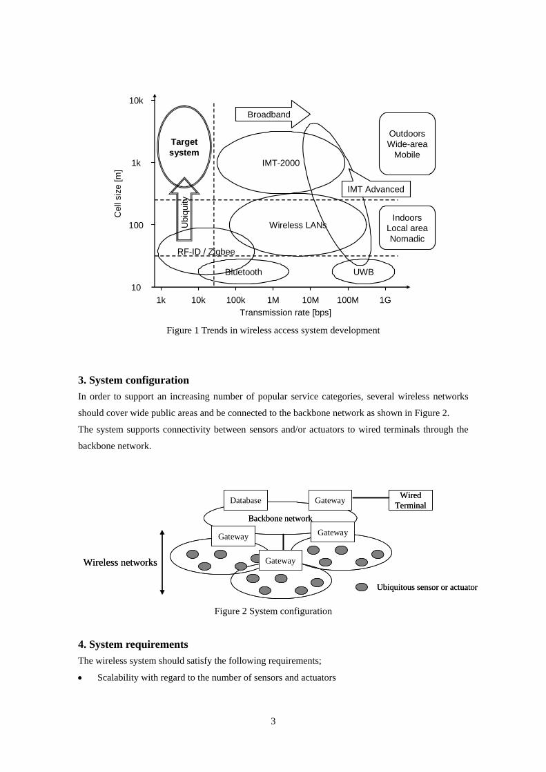
10k
1k
100
101k 10k 100k
Transmission rate [bps]
Cel
l siz
e [m
]
1M 10M 100M 1G
Targetsystem
IMT-2000
Wireless LANs
RF-ID / Zigbee
Bluetooth UWB
Broadband
OutdoorsWide-area
Mobile
IndoorsLocal areaNomadic
IMT AdvancedU
biqu
ity
Figure 1 Trends in wireless access system development
3. System configuration In order to support an increasing number of popular service categories, several wireless networks
should cover wide public areas and be connected to the backbone network as shown in Figure 2.
The system supports connectivity between sensors and/or actuators to wired terminals through the
backbone network.
Backbone network
GatewayDatabase WiredTerminal
Wireless networks
Ubiquitous sensor or actuator
Gateway Gateway
Gateway
Backbone network
GatewayDatabase WiredTerminal
Wireless networks
Ubiquitous sensor or actuator
Gateway Gateway
Gateway
Figure 2 System configuration
4. System requirements The wireless system should satisfy the following requirements;
• Scalability with regard to the number of sensors and actuators
3
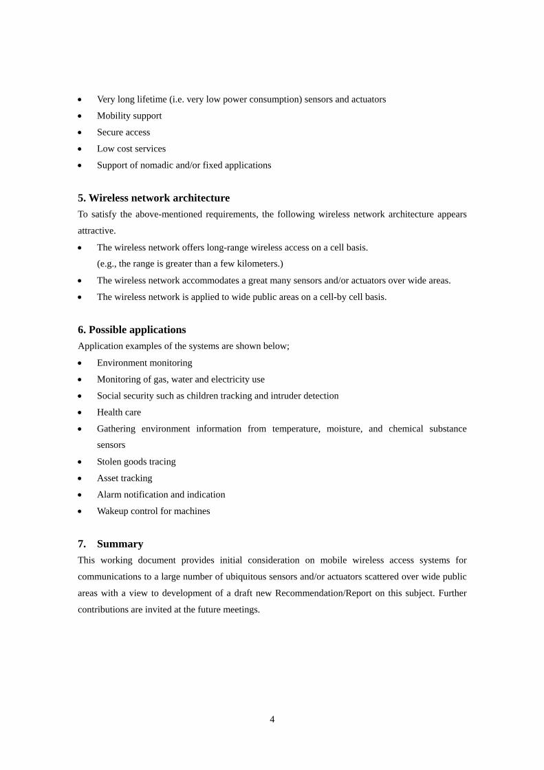
• Very long lifetime (i.e. very low power consumption) sensors and actuators
• Mobility support
• Secure access
• Low cost services
• Support of nomadic and/or fixed applications
5. Wireless network architecture To satisfy the above-mentioned requirements, the following wireless network architecture appears
attractive.
• The wireless network offers long-range wireless access on a cell basis.
(e.g., the range is greater than a few kilometers.)
• The wireless network accommodates a great many sensors and/or actuators over wide areas.
• The wireless network is applied to wide public areas on a cell-by cell basis.
6. Possible applications Application examples of the systems are shown below;
• Environment monitoring
• Monitoring of gas, water and electricity use
• Social security such as children tracking and intruder detection
• Health care
• Gathering environment information from temperature, moisture, and chemical substance
sensors
• Stolen goods tracing
• Asset tracking
• Alarm notification and indication
• Wakeup control for machines
7. Summary This working document provides initial consideration on mobile wireless access systems for
communications to a large number of ubiquitous sensors and/or actuators scattered over wide public
areas with a view to development of a draft new Recommendation/Report on this subject. Further
contributions are invited at the future meetings.
4

Annex 1 to Attachment 1
Feasibility study on an example system through field experiments
1. Scope This Annex provides results of field experiments on a mobile sensor network, accompanied with
restricted power emission from wireless terminals over several km wireless transmissions [1]. These
results suggest the feasibility of a cell-based wireless system that satisfies the requirements and the
concept of connecting a large number of sensors and/or actuators over wide areas for public
communication services.
2. Outline of field experiments In Japan, an experimental system has been developed to conduct feasibility studies of wide-area
mobile sensor networks with wireless communications. The major system parameters are shown in
Table 1. Considering the tradeoff between spectral efficiency and power efficiency, QPSK
(Quadrature Phase Shift Keying) and coherent detection are currently employed. The antenna gain of
the wireless terminal (WT) was assumed to be -16 dBi in the case of internal antennas, whereas the
antenna gain of the Base station (BS) is assumed to be 10 dBi. A block diagram of the experimental
system is shown in Figure 1. We have conducted field experiments in Kanazawa-city, a typical local
city in Japan, to confirm the technical feasibility of the wireless network. The area of the field
experiments is shown in Figure 2.
3. Results of field experiments The received level was measured at the BS with diversity reception along with the location data of
the WT. These data were collated offline. By associating the measurement time to WT location, we
could obtain the received level at the BS according to WT location. First, cumulative probability of
received level measured at the BS is shown in Figure 3. Here, the required received average level to
achieve acceptable radio link performance was taken to be about -123 dBm with the parameters
shown in Table.1. As shown in Figure 3, reception level of -123 dBm is achieved within 92% of the
measured area. Second, the measured packet error rate performance on the sample test course is
shown in Figure 4. The test course is also shown in Figure 2. As shown in Figure 4, the packet error
rate was insignificant for transmission distances of up to 3.5 kilometers. Although the packet error
rate deteriorates with distances over 3.5 kilometers, the low packet error rate of 10-1 is achieved
within 6 kilometers. While this is just one example, the field experiment results demonstrate the
possibility of wireless connections of several kilometers with just 10 mW emission power, and so
5
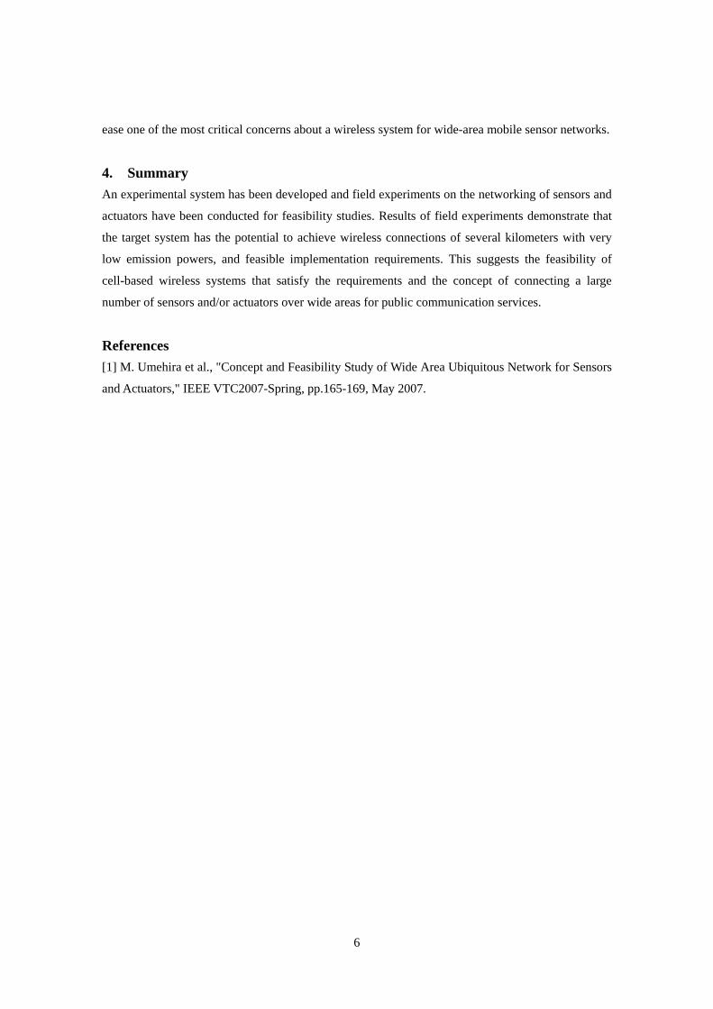
ease one of the most critical concerns about a wireless system for wide-area mobile sensor networks.
4. Summary An experimental system has been developed and field experiments on the networking of sensors and
actuators have been conducted for feasibility studies. Results of field experiments demonstrate that
the target system has the potential to achieve wireless connections of several kilometers with very
low emission powers, and feasible implementation requirements. This suggests the feasibility of
cell-based wireless systems that satisfy the requirements and the concept of connecting a large
number of sensors and/or actuators over wide areas for public communication services.
References [1] M. Umehira et al., "Concept and Feasibility Study of Wide Area Ubiquitous Network for Sensors
and Actuators," IEEE VTC2007-Spring, pp.165-169, May 2007.
6
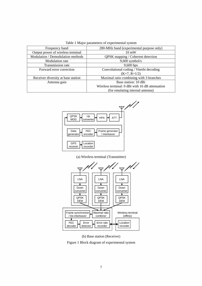
Table 1 Major parameters of experimental system Frequency band 280-MHz band (experimental purpose only)
Output power of wireless terminal 10 mW Modulation / Demodulation methods QPSK mapping / Coherent detection
Modulation rate 9,600 symbol/s Transmission rate 9,600 bps
Forward error correction Convolutional coding / Viterbi decoding (K=7, R=1/2)
Receiver diversity at base station Maximal ratio combining with 3 branches Antenna gain Base station: 10 dBi
Wireless terminal: 0 dBi with 16 dB attenuation (for emulating internal antenna)
QPSKMOD
Upconverter HPA ATT
Datagenerator
FECencoder
Frame generator/ Interleaver
GPSreceiver
Locationrecorder
(a) Wireless terminal (Transmitter)
Downconverter
LNA
Errordetector
FECdecoder
Frame synchronizer/ De-interleaver
Error raterecorder
QPSKDEM
Downconverter
LNA
QPSKDEM
Downconverter
LNA
QPSKDEM
Maximal ratiocombiner
Locationrecorder
Wireless terminal(offline)
(b) Base station (Receiver)
Figure 1 Block diagram of experimental system
7
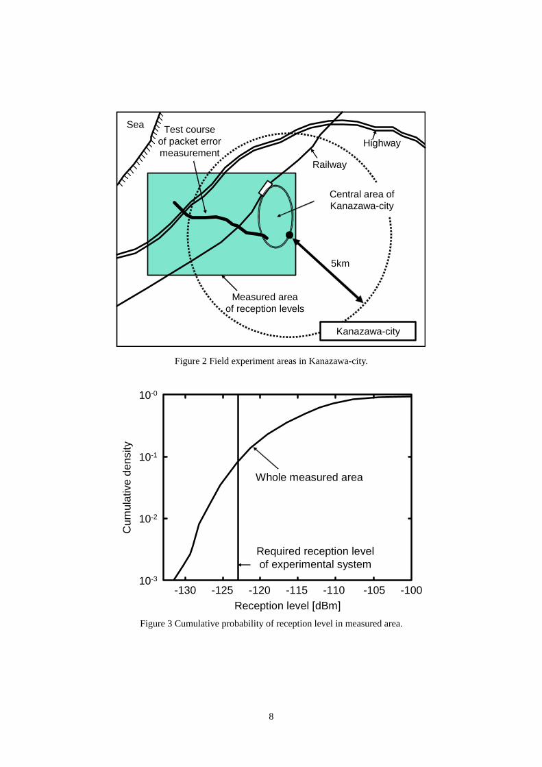
5km
Measured areaof reception levels
Railway
Highway
Sea
Kanazawa-city
Test courseof packet errormeasurement
Central area ofKanazawa-city
Figure 2 Field experiment areas in Kanazawa-city.
Whole measured area
10-0
10-1
10-2
10-3
-130 -125 -120 -115 -110 -105 -100Reception level [dBm]
Cum
ulat
ive
dens
ity
Required reception levelof experimental system
Figure 3 Cumulative probability of reception level in measured area.
8
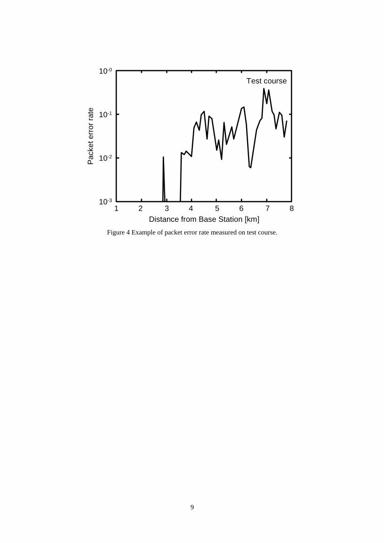
9
10-0
10-1
10-2
10-3
Pack
et e
rror
rate
1 2Distance from Base Station [km]
3 4 5 6 7
Test course
8
Figure 4 Example of packet error rate measured on test course.
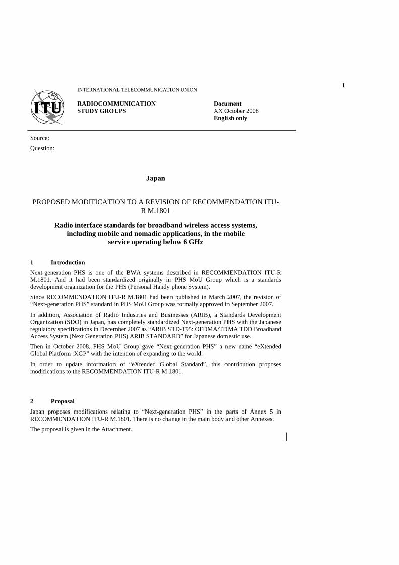
1
Source:
Question:
Japan
PROPOSED MODIFICATION TO A REVISION OF RECOMMENDATION ITU-
R M.1801
Radio interface standards for broadband wireless access systems, including mobile and nomadic applications, in the mobile
service operating below 6 GHz
1 Introduction Next-generation PHS is one of the BWA systems described in RECOMMENDATION ITU-R M.1801. And it had been standardized originally in PHS MoU Group which is a standards development organization for the PHS (Personal Handy phone System).
Since RECOMMENDATION ITU-R M.1801 had been published in March 2007, the revision of “Next-generation PHS” standard in PHS MoU Group was formally approved in September 2007.
In addition, Association of Radio Industries and Businesses (ARIB), a Standards Development Organization (SDO) in Japan, has completely standardized Next-generation PHS with the Japanese regulatory specifications in December 2007 as “ARIB STD-T95: OFDMA/TDMA TDD Broadband Access System (Next Generation PHS) ARIB STANDARD” for Japanese domestic use.
Then in October 2008, PHS MoU Group gave “Next-generation PHS” a new name “eXtended Global Platform :XGP” with the intention of expanding to the world.
In order to update information of “eXtended Global Standard”, this contribution proposes modifications to the RECOMMENDATION ITU-R M.1801.
2 Proposal Japan proposes modifications relating to “Next-generation PHS” in the parts of Annex 5 in RECOMMENDATION ITU-R M.1801. There is no change in the main body and other Annexes.
The proposal is given in the Attachment.
INTERNATIONAL TELECOMMUNICATION UNION
RADIOCOMMUNICATION STUDY GROUPS
Document XX October 2008 English only
Attachment
Annex 5
“eXtended Global Platform : XGPNext-generation PHS” for broadband wireless access (BWA) systems in the mobile service
1 Overview of the radio interface PHS MoU Group, which is a standards development organization for personal handy phone systems (PHS), has developed “eXtended Global Platform : XGPNext-generation PHS1” as one of the BWA (broadband wireless access) systems. “Next-generation PHSeXtended Global Platform” also known as “Next-generation PHS”, achieves high efficiency of spectral utilization mainly because of using micro-cells whose radii are much shorter than the typical mobile phone cells, as well as original PHS system.
“eXtended Global PlatformNext-generation PHS” is the new mobile BWA system which utilizes OFDMA/TDMA-TDD, and some more advanced features described below: – Enabling continuous connectivity at IP level Considering the convenience of continuous connection provided on the cable modem
circumstance, etc., the continuous connectivity at IP level that enables users to start high-speed transmission in a moment is essential.
– High transmission data rate It is also important to keep throughput of some extent for practical use even in case that
serious concentration of traffic occurs. – High transmission data rate for uplink Considering future demand of bidirectional broadband communication such as a
videoconference, an uplink transmission data rate over 10 Mbit/s is considered to become still more important in the near future.
– High efficiency in spectral utilization When serious traffic congestion occurs concentrically at a business district or downtown
area, some problems by shortage of frequency would hamper many services. In order to avoid such situations, highly efficient spectral utilization is necessary.
In addition, it has the ability of highly efficient spectral utilization by adopting the technologies described below: – Adaptive array antenna technology and space division multiple access technology enable a
frequency re-use factor of more than 4. – Autonomous decentralized control technology contributes to make cell designing plans
unnecessary, and as a result, the cell radius down to less than 100 m is realized.
Because many cells can basically overlap each other in “eXtended Global PlatformNext-generation PHS” system, a handset can access multiple cell stations around it at the same time. Therefore, this
1 “Next-generation PHS”, in the broad sense, can include enhanced a PHS system, that is a TDMA-TDD
system.
3
system is able to provide all users with continuous stable throughput by way of spreading traffic volume that might occur intensively and temporarily.
The autonomous decentralized control method are effective in order to construct micro-cell networks. The advantage of this method is its unexacting features of the installation position.
Mobile wireless systems generally require a relatively high level of accuracy in its installation position in order to avoid interference with other cells. In the case of macro-cell networks, a shift of the base station from the intended building to an adjoining substitute building due to unsuccessful negotiations with the building owner, only causes inter-cell interferences which still lies within the range of marginal error.
However, in the case of micro-cell networks, as such shifts cannot be dismissed as marginal error; readjustments of the surrounding cell designs are needed in some cases.
This concern is already solved with “eXtended Global Platform” system, as it has an interference resistant structure and does not require strict accuracy for the positioning of the base stations, promising less trouble for the construction of micro-cell networks.
Since “eXtended Global PlatformNext-generation PHS” adopts the autonomous decentralized control method, which enables several operators to share the same frequency band, more efficient spectral utilization would be realized. “eXtended Global PlatformNext-generation PHS” is a system among BWA systems, which possesses a differentiating feature by flexibly utilizing micro-cell networks as well as macro-cells in order to resolve heavy traffic congestions in densely populated areaswhose service coverage areas consist of many micro-cells.
The autonomous decentralized control method of “eXtended Global Platform” demonstrates advantage in the construction of micro-cell networks. It is also possible to form a network without distressing about the interference problems when the pico-cell and the femto-cell are similarly introduced with the same method. Moreover, as strict cell design is unnecessary for the macro-cell network construction, a simple network operation is possible, and regardless of the micro-cell or the macro-cell, it allows simple method operations for the installation of additional base-stations to the network.
The radio interface of “eXtended Global PlatformNext-generation PHS” supports bandwidths from 1.25 MHz up to 20 MHz and up to 256QAM modulation to realize high transmission data rate for up/downlinks.
2 Detailed specification of the radio interface The “eXtended Global PlatformNext-generation PHS” radio interface has two dimensions for multiple access methods such as OFDMA (controlled along frequency axis) and TDMA (controlled along time axis). At the time axis, the time-frame format is the same as that of the original PHS which is a 5 ms symmetric frame. And at the frequency axis, using the method of OFDMA, a number of subcarriers would be allocated within the allowed whole bandwidth, depending on the user’s demand and the frequency circumstance at each time.
This radio interface can use some sorts of bandwidth, 1.25 MHz, 2.5 MHz, 5 MHz, 10 MHz, 20 MHz, and the subcarrier frequency spacing is 37.5 kHz. The time-frame has eight slots of 5 ms each, the consecutive 4 slots are for downlink, and other consecutive 4 slots are for uplink. Each slot of 4 slots can be used separately, of course, and also can be used continuously for one user, and moreover continuous using of over 4 slots is possible in asymmetry frame structure.
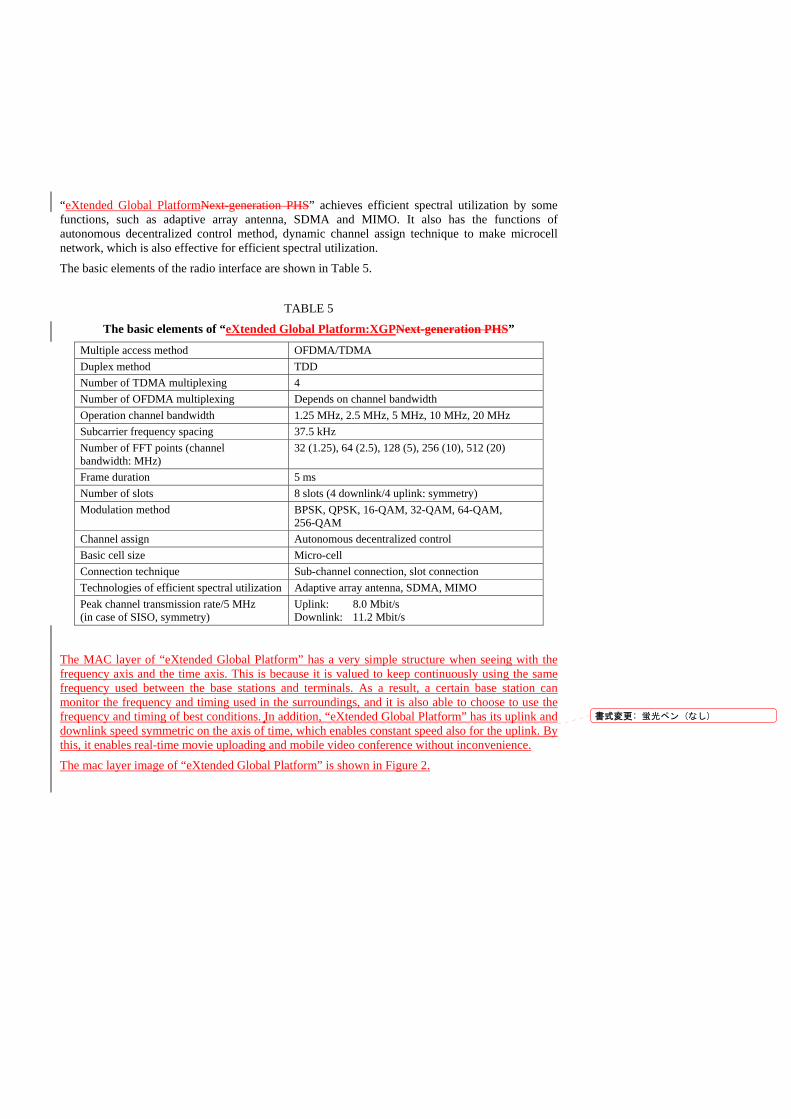
“eXtended Global PlatformNext-generation PHS” achieves efficient spectral utilization by some functions, such as adaptive array antenna, SDMA and MIMO. It also has the functions of autonomous decentralized control method, dynamic channel assign technique to make microcell network, which is also effective for efficient spectral utilization.
The basic elements of the radio interface are shown in Table 5.
TABLE 5
The basic elements of “eXtended Global Platform:XGPNext-generation PHS”
Multiple access method OFDMA/TDMA Duplex method TDD Number of TDMA multiplexing 4 Number of OFDMA multiplexing Depends on channel bandwidth Operation channel bandwidth 1.25 MHz, 2.5 MHz, 5 MHz, 10 MHz, 20 MHz Subcarrier frequency spacing 37.5 kHz Number of FFT points (channel bandwidth: MHz)
32 (1.25), 64 (2.5), 128 (5), 256 (10), 512 (20)
Frame duration 5 ms Number of slots 8 slots (4 downlink/4 uplink: symmetry) Modulation method BPSK, QPSK, 16-QAM, 32-QAM, 64-QAM,
256-QAM Channel assign Autonomous decentralized control Basic cell size Micro-cell Connection technique Sub-channel connection, slot connection Technologies of efficient spectral utilization Adaptive array antenna, SDMA, MIMO Peak channel transmission rate/5 MHz (in case of SISO, symmetry)
Uplink: 8.0 Mbit/s Downlink: 11.2 Mbit/s
The MAC layer of “eXtended Global Platform” has a very simple structure when seeing with the frequency axis and the time axis. This is because it is valued to keep continuously using the same frequency used between the base stations and terminals. As a result, a certain base station can monitor the frequency and timing used in the surroundings, and it is also able to choose to use the frequency and timing of best conditions. In addition, “eXtended Global Platform” has its uplink and downlink speed symmetric on the axis of time, which enables constant speed also for the uplink. By this, it enables real-time movie uploading and mobile video conference without inconvenience.
The mac layer image of “eXtended Global Platform” is shown in Figure 2.
書式変更: 蛍光ペン (なし)
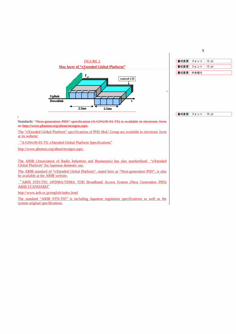
5
FIGURE 2 Mac layer of “eXtended Global Platform”
Standards: “Next-generation PHS” specification (A-GN4.00-01-TS) is available in electronic form at: http://www.phsmou.org/about/nextgen.aspx.
The “eXtended Global Platform” specifications of PHS MoU Group are available in electronic form at its website:
“A-GN4.00-01-TS: eXtended Global Platform Specifications”
http://www.phsmou.org/about/nextgen.aspx.
The ARIB (Association of Radio Industries and Businesses) has also standardized “eXtended Global Platform” for Japanese domestic use.
The ARIB standard of “eXtended Global Platform”, stated here as “Next-generation PHS”, is also be available at the ARIB website.
“ARIB STD-T95: OFDMA/TDMA TDD Broadband Access System (Next Generation PHS) ARIB STANDARD”
http://www.arib.or.jp/english/index.html
The standard “ARIB STD-T95” is including Japanese regulation specifications as well as the system original specifications.
2.5ms2.5ms
UplinkDownlink t
control-CHf
2.5ms2.5ms
UplinkDownlink t
control-CHf
書式変更: フォント : 12 pt
書式変更: フォント : 12 pt
書式変更: 中央揃え
書式変更: フォント : 10 pt
M:\文書管理フォルダ\200 国際係\02 情報通信審議会 技術分科会\02 地上業務委員会(SG5)\第03回(2008.9.24)\ロジ\HP\007 5A_J-1, 5C_J-1REVA.DOC 10/11/2008 10/11/2008
1 Introduction
Working Party 5C is tackling the work on revision of Recommendation ITU-R F.758. This work started in early 2005 immediately after the current version of this Recommendation was approved. Since then a number of administrations submitted their contributions, which have resulted in a working document towards a preliminary draft revision of F.758 (Annex 3 to Document 5C/26).
Recommendation ITU-R F.758 is one of the most important Recommendations (in the F-series), which provides a basis for the criteria for fixed wireless systems in the sharing/compatibility with other radio services as well as system parameters to be used in the sharing studies. Now, we are in the new study period, during which many sharing studies involving the fixed service have been assigned to ITU-R Study Groups by the CPM07-1. Recommendation ITU-R F.758 would therefore need to be referred to in these sharing studies.
Taking into account the above, Japan is of the view that the work on the revision of F.758 should be completed as early as possible by obtaining agreement on the remaining issues.
2 Discussion
2.1 Updating of the proposed system parameters It is more than three years ago that some of the parameters in the Tables in Annex 3 to Doc. 5C/26, including those proposed from Japan, were initially submitted. There is a need to further update them into the latest information.
In this contribution, the following system parameters for P-P systems are proposed for updating.
- 5.925-6.425 GHz band 64QAM system, 6.570-6.870 GHz band 16QAM system and 7.425-7.75 GHz band 16QAM system (the 1st, the 3rd and the 4th systems in Table 5).
Radiocommunication Study Groups
Source: Recommendation ITU-R F.758, Annex 3 to Document
5C/26 Document 5A/J-1 -E Document 5C/J-1 -E September 2008 English only
Japan
PROPOSALS FOR EARLY COMPLETION OF THE WORK FOR DRAFT REVISION OF RECOMMENDATION ITU-R F.758-4
Considerations in the development of criteria for sharing or compatibility between digital fixed wireless systems in the fixed service and systems
in other services and other sources of interference
- 2 - 5C/26 (Annex 3)-E
M:\文書管理フォルダ\200 国際係\02 情報通信審議会 技術分科会\02 地上業務委員会(SG5)\第03回(2008.9.24)\ロジ\HP\007 5A_J-1, 5C_J-1REVA.DOC 10/11/2008 10/11/2008
- 10.7-11.7 GHz band 16QAM system and 14.4-15.23 GHz band 16QAM system (the 1st and the current 2nd systems in Table 6).
- 22.4-22.6/23.0-23.2 GHz band 4-PSK system (the current 2nd system in Table 7)
Also, the following additions are proposed:
- 10.715-10.955/11.245-11.485 GHz band 64QAM system and 14.500-14.660/14.970-15.130 GHz band 64QAM system (to Table 6);
- 17.850-17.970/18.600-18.720 GHz band 64QAM system (to Table 7).
We believe that the new parameters are meaningful not only because they are the latest information but because they would provide typical examples for the worst case evaluation as either the interfering side or the interfered-with side.
These proposals are shown in the relevant Tables in the Attachment 1 to this contribution.
2.2 Some ambiguous points associated with the system parameters in the Tables 5 to 10 At the previous Working Party 5C meeting in February 2008, the following points were raised during the discussion on the revision of Recommendation ITU-R F.758:
(1) The values of “feeder/multiplexer loss (minimum) (dB)” for some systems seem to be too large as a “minimum” value.
(2) In some cases, the same (or an even greater) value is given to “Receiver noise bandwidth” as “Channel spacing”. Such values are difficult to understand.
We understand these concerns and provide the updated information at least for those originally proposed from Japan.
For item (1), it should be noted that feeder structures are quite different between a simple roof top station and a traditional in-building station using a high tower.
For item (2), if confirmation is not obtained for all the relevant parameters, the following text may be added in an appropriate place of the Recommendation.
- In general, a value of “Receiver noise bandwidth” should be smaller than the value of the corresponding “Channel spacing”. If this condition is not met, the adjacent channels for such a system may not be used in the same route.
However, we do not positively propose this solution.
2.3 Other editorial refinement of the text We have attempted to editorially refine the current main text of Annex 3 to Doc. 5C/26 making references to Report ITU-R F.2108 as required.
Also, the deletion of the existing Annexes 3 and 4 to Recommendation ITU-R F.758-4 should be identified at the end of the text as they have been already transferred to Annexes 1 and 2 to Report F.2108, respectively.
3 Proposal The proposed new texts discussed in 2.1 to 2.3 are given in Attachment 1 to this contribution (the portions highlighted in blue).
It is also proposed that Working party 5C should, as far as possible, get confirmation and agreement with respect to the system parameters in all the Tables during the October/November 2008 meeting, and, with cooperation of the participants, early finalize the revision work on this Recommendation.
- 3 - 5C/26 (Annex 3)-E
M:\文書管理フォルダ\200 国際係\02 情報通信審議会 技術分科会\02 地上業務委員会(SG5)\第03回(2008.9.24)\ロジ\HP\007 5A_J-1, 5C_J-1REVA.DOC 10/11/2008 10/11/2008
Attachment 1
WORKING DOCUMENT TOWARDS A [PRELIMINARY] DRAFT REVISION TO RECOMMENDATION ITU-R F.758-4*
Considerations in the development of criteria for sharing or compatibility between digital fixed wireless systems in the fixed service and systems in
and other services and other sources of interference
(Questions ITU-R 225/9 and ITU-R 127/9)
(1992-1997-2000-2003-2005)
Scope This Recommendation contains principles for the development of sharing criteria of digital systems in the fixed service. Considerations are mainly given on how to properly design performance and availability degradations due to interference within the allowable objectives, as specified in Recommendation ITU-R F.1094, under the various interference environments. It also contains information on the technical characteristics and typical system sharing parameters of digital fixed wireless systems in the fixed service for use for sharing studies. Information relating to analogue systems is contained in previousior versions of this Recommendation or can be found in a Report ITU-R F.2108.
Summary for draft revision In this revision, the Recommendation is clarified to address considerations on sharing or compatibility criteria between fixed wireless systems and systems in other services or other interference sources. The Annex 1 has been amplified to include basic principles for the development of sharing criteria. In the Annex 2, the typical system parameters are selected for use for sharing studies by transferring most of the former data to Report ITU-R F.2108.
The ITU Radiocommunication Assembly,
considering
a) that it is necessary to establish sharing criteria between the fixed service (FS) and other services in frequency bands where both services have a primary allocation;
b) that sharing may be managed by determining allowable values of performance and availability degradations of fixedanalogue and digital radio-relay wireless systems caused by interference from other radio services allocated in the same frequency bands as the FS on a primary basis;
c) that interference from other services sharing the same band on a non-primary basis, emissions from other services outside the shared band, and emissions from sources other than radio services must also be taken into accountconsidered;
____________________ * This Recommendation should be brought to the attention of Radiocommunication Study Groups 4, 6, and
7 and 8.
書式変更: 蛍光ペン
書式変更: 蛍光ペン
書式変更: 蛍光ペン
書式変更: 蛍光ペン
書式変更: 蛍光ペン
書式変更
書式変更
書式変更
書式変更
書式変更
書式変更
書式変更
書式変更: フォント : (日) MS 明朝,(言語 1) 日本語
書式変更: 蛍光ペン
書式変更: 蛍光ペン
- 4 - 5C/26 (Annex 3)-E
M:\文書管理フォルダ\200 国際係\02 情報通信審議会 技術分科会\02 地上業務委員会(SG5)\第03回(2008.9.24)\ロジ\HP\007 5A_J-1, 5C_J-1REVA.DOC 10/11/2008 10/11/2008
d) that principles for apportioning the performance and availability degradation among the different elements of the fixed wireless over the length of the radio-relay systems, and between each interference source, need to be established;
e) that the technical characteristics of each service need to be understood in order to derive interference criteria corresponding to the allowable degradation in performance and availability of the fixed wireless radio-relay system;
f) that performance and availability degradation may result from both long-term and short-term interference and hence both long-term and short-term interference criteria need to be established;
g) that availability of a basic methodology for the development of sharing criteria for the FS may be useful to for other ITU-R Study Groups when formulating criteria for sharing with the FS,
noting
a) that a more detailed set of characteristics of digital and analogue fixed systems is contained in Report ITU-R F.[FS Characteristics]2108;
b) that Recommendation ITU-R F.1094 provides also the overall apportionment principle of the performance and availability degradations to the FS due to interference from other services or sources,
recommends
1 that the development of sharing criteria and assessment of interference conditions between the FS and other services and other sources of interference should be carried out in accordance with the principles described in Annex 1;
2 that the information provided in Annex 2 should be used as guidance to the technical characteristics and typical system sensitive sharing parameters of digital fixed wireless FS systems that need to be taken into account when developing criteria for sharing with other services.;
3 that studies are required to further develop appropriate short-term interference criteria;
4 that further studies are required to derive interference criteria that are appropriate for specific types of new services.
NOTE 1 – Annex 3 describes additional technical characteristics of some FS systems specifically useful for sharing analysis in the 1-3 GHz band.
書式変更: 蛍光ペン
書式変更: 蛍光ペン
書式変更: 蛍光ペン
- 5 - 5C/26 (Annex 3)-E
M:\文書管理フォルダ\200 国際係\02 情報通信審議会 技術分科会\02 地上業務委員会(SG5)\第03回(2008.9.24)\ロジ\HP\007 5A_J-1, 5C_J-1REVA.DOC 10/11/2008 10/11/2008
Annex 1
Basic considerations in the development of sharing criteria
1 Overall performance objective One of the functions of a radiocommunications planner is to design and implement a transmission network which meets the performance objectives laid down by the ITU-T and ITU-R. It is important, therefore, that real systems can meet the appropriate design objectives, recognizing the increasing use of the radio spectrum. There are various ITU-R F-Series Recommendations which that relate to the overall performance objective for various types of circuit.
1.1 Error performance and availability objectives Error performance objectives for real digital fixed wireless links used in 27 500 km hypothetical reference paths and connections are given in Recommendation ITU-R F.1668, Error performance objectives for real digital fixed wireless links used in 27 500 km hypothetical reference paths and connections, based on ITU-T Recommendations G.826, G.828 and G.829. It is the only Recommendation defining error performance objectives for all real digital fixed wireless links. The applicability of Recommendations ITU-R F.594, ITU-R F.634, ITU-R F.696 and , ITU-R F.697, ITU-R F.1092, ITU-R F.1189, ITU-R F.1397 and ITU-R F.1491 is limited to systems designed prior to the approval of ITU-T Recommendation G.826 (December 2002)ITU-R F.1668.
Availability objectives for real digital fixed wireless links used in 27 500 km hypothetical reference paths and connections are given in Recommendation ITU-R F.1703, based on ITU-T Recommendation G.827. It is the only Recommendation defining availability objectives for all real digital fixed wireless links. Recommendations ITU-R F.1492 and ITU-R F.1493 are superseded by this Recommendation. The applicability of Recommendations ITU-R F.557, ITU-R F.695, ITU-R F.696 and ITU-R F.697 is limited to systems designed prior to the approval of this Recommendation (January 2005)ITU-R F.1703.
2 Sub-division of the performance and availability objectives The previous section dealt with the overall performance objectives for digital reference connections. However, there are, in practice, a large number of potential sources of interference contributing to the degradation of performance of a fixed radio-relay wireless system. In order to move towards a practical method for planning, the overall performance objectives need to be sub-divided between individual sections of the overall hypothetical reference connections (HRX)C and hypothetical reference path (HRP). Within a section, the performance objective is then apportioned between the various sources.
2.1 Apportionment of section error performance and availability objective This is covered in Recommendation ITU-R F.1094, Maximum allowable error performance and availability degradations to digital fixed wireless systems arising from interference from emissions and radiations from other sources. The allowable degradation is divided into an element of X% for the FS portion, Y% for frequency sharing on a primary basis, and Z% for all other sources of interference (it should be noted that X% + Y% + Z% = 100%). In the case of sharing with the fixed-satellite service (FSS), typically, Y = 10% (e.g. Recommendation ITU-R SF.615).
書式変更: 蛍光ペン
- 6 - 5C/26 (Annex 3)-E
M:\文書管理フォルダ\200 国際係\02 情報通信審議会 技術分科会\02 地上業務委員会(SG5)\第03回(2008.9.24)\ロジ\HP\007 5A_J-1, 5C_J-1REVA.DOC 10/11/2008 10/11/2008
There may be a further sub-division of the X% allowance to suit local requirements and this could be apportioned in such a way as to suit the grade of service (see section 4.1.3).
A particular point to note is that an interference source (say a transmitter (Tx)) may affect more than one hop of a system.
2.2 Apportionment of performance and availability degradation to different services When establishing the sharing criteria with other co-primary services it may be necessary to consider the apportionment of the EPO (error performance objective) and APO (availability performance objectives) to short-term and long-term interferences1 (see § 4.0). Then, the following points should be taken into consideration: a) For the band shared by the FS and one radio service on a primary basis,
performance/availability degradation Y1% of the FS caused by the interference from the other service should not exceed 10% of the objective in accordance with Recommendation ITU-R F.1094.
b) After the establishment of the sharing criteria with the first co-primary service, performance/availability degradation Y2% of the FS caused by the interference from another co-primary service sharing the same band may be developed as follows: – multi-interference environment due to both services should carefully be examined,
in particular the case leading to the allowance limit of Y1% and simultaneously receiving additional interference from the second co-primary service;
– then the limit of Y2 could be derived from a typical interference model for the FS and the second co-primary service taking also into account potential effect of the first co-primary service in that model.
3 Characteristics of interference It is necessary to have information available on interference levels arising from other services, which would degrade system performance by specific amounts. This would be facilitated if, with the assistance from other Study Groups, a table were compiled giving information on the characteristics of emissions.
Two categories of interference are worth considering: – the interference arising from services sharing on a primary basis that is likely to be within
the receiver (Rx) bandwidth from digital modulations, in either carrier wave or burst emissions. Reference can be made to existing text where available in ITU-R F-Series and SF-Series Recommendations (e.g. Rec. ITU-R SF.766);
– emissions from systems other than those sharing on a primary basis that could be numerous and diverse, and may be considered in a similar way to the spurious emissions.
Ultimately, another table could be prepared, again with the assistance of other Radiocommunication Study Groups, which compares levels of interference or Gaussian noise required to produce a specified degradation in the channel performance.
____________________ 1 Short-term and long-term interference in the context of this Recommendation is to be defined.
書式変更: 蛍光ペン
書式変更: enumlev2
書式変更: 蛍光ペン
書式変更: 英語 (米国)
- 7 - 5C/26 (Annex 3)-E
M:\文書管理フォルダ\200 国際係\02 情報通信審議会 技術分科会\02 地上業務委員会(SG5)\第03回(2008.9.24)\ロジ\HP\007 5A_J-1, 5C_J-1REVA.DOC 10/11/2008 10/11/2008
4 Considerations on allowable performance/availability degradations due to Limit values of interference and related interference criteria
Following the considerations in the previous sections, one may now determine the limit values of interference allowable to a particular source. This has been done for the case of frequency sharing between the FSS and the FS in the joint workings of Radiocommunication Study Groups 4 and 9, where certain models have been established. These models may be appropriate for frequency sharing between fixed radio-relay wireless systems and other services in general.
Methods for characterizing interference levels into terrestrial radio-relayfixed wireless systems include power flux-density (pfd), power level at the input to the antenna or the power level at the receiver input. It is worth noting that both methods are in used in ITU-R F and SF-Series Recommendations.
In general, the received power due to an interferer is not constant, but it varies because of varying propagation conditions of the interfering path or because of motion of the interfering transmitter. To simplify the analysis of interference, separate analyses are given to short-term and long-term interference.
Short-term interference is interference that has a high enough power level to produce error performance degradations when the desired signal is unfaded. Such interference events must be of short duration if the interference is to be acceptable. Long-term interference is a characteristic of interference that is present for most of the time. The value associated with a long-term interference is a value close to the median value of the distribution of the values of interference power. To be acceptable, its value must be much less than the short-term level. Long-term interference degrades the error performance and availability of a system by reducing the fade margin that is available to protect the fixed service system against fading.
The number and values of the interference criteria necessary to protect a fixed wireless systemFWS will depend on the characteristics of the fixed wireless systemFWS and the interferer and the methods used in the sharing study to analyse the interference. A single interference limit value is not adequate because of the time varying nature of the interference. Two limit or three values, corresponding to a long term (20% of time) and a short terms (<1% of time) have been identified specified in some Recommendations ITU-R SF.1006.
In the past, simple interference scenarios with fixed interferers, two limiting values, or interference criteria, have been sufficient. One is a long-term interference limit based on the level to be exceeded no more than 20% of the time; the other is a short-term limit to be exceeded for a percentage less than 1% of the time. The exact percentage of time associated with a value of the short-term interference criterion time percentage is related to athe performance objectives for the system under consideration; more information on short-term interference can be found in Recommendations ITU-R F.1494, ITU-R F.1495 and ITU-R F.1606, all of which deal with protection criteria applicable to time varying interference. Radiocommunication Study Groups 4 and 9 have developed this method for the specific purpose of sharing between the FS and the FSS. Further study is needed to determine the extent to which the techniques developed in Radiocommunication Study Groups 4 and 9 are applicable to the other cases. Table 1 lists the references relating to sharing between the FS and the FSSother primary services, concerning interference into the FS.
書式変更: 蛍光ペン
書式変更: 蛍光ペン
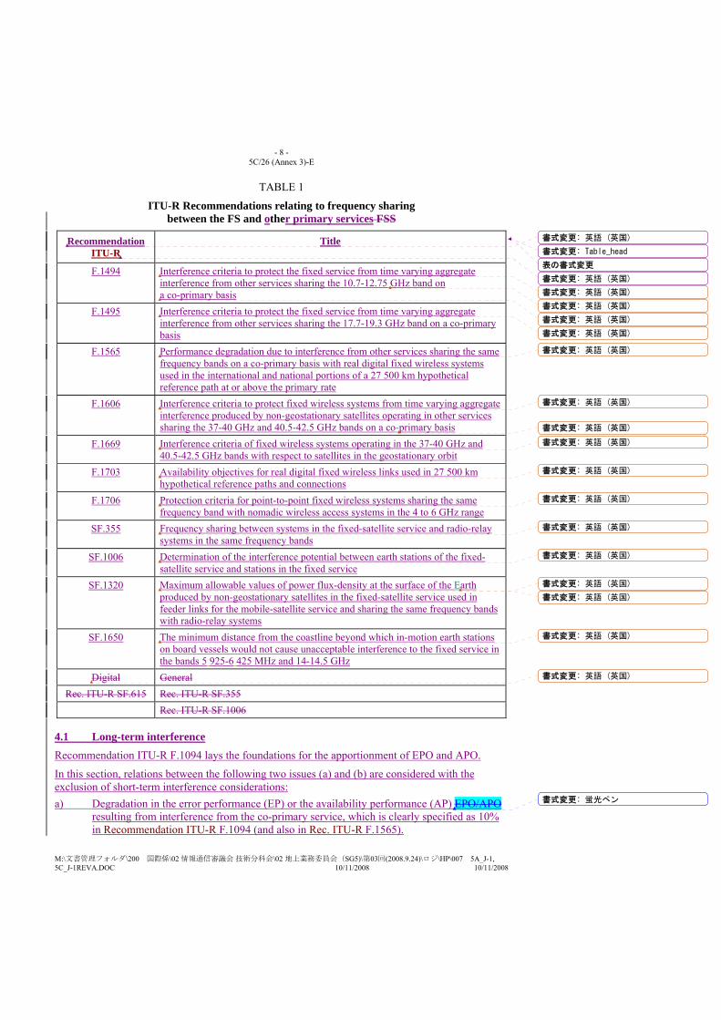
- 8 - 5C/26 (Annex 3)-E
M:\文書管理フォルダ\200 国際係\02 情報通信審議会 技術分科会\02 地上業務委員会(SG5)\第03回(2008.9.24)\ロジ\HP\007 5A_J-1, 5C_J-1REVA.DOC 10/11/2008 10/11/2008
TABLE 1
ITU-R Recommendations relating to frequency sharing between the FS and other primary services FSS
Recommendation ITU-R
Title
F.1494 Interference criteria to protect the fixed service from time varying aggregate interference from other services sharing the 10.7-12.75 GHz band on a co-primary basis
F.1495 Interference criteria to protect the fixed service from time varying aggregate interference from other services sharing the 17.7-19.3 GHz band on a co-primary basis
F.1565 Performance degradation due to interference from other services sharing the same frequency bands on a co-primary basis with real digital fixed wireless systems used in the international and national portions of a 27 500 km hypothetical reference path at or above the primary rate
F.1606 Interference criteria to protect fixed wireless systems from time varying aggregate interference produced by non-geostationary satellites operating in other services sharing the 37-40 GHz and 40.5-42.5 GHz bands on a co-primary basis
F.1669 Interference criteria of fixed wireless systems operating in the 37-40 GHz and 40.5-42.5 GHz bands with respect to satellites in the geostationary orbit
F.1703 Availability objectives for real digital fixed wireless links used in 27 500 km hypothetical reference paths and connections
F.1706 Protection criteria for point-to-point fixed wireless systems sharing the same frequency band with nomadic wireless access systems in the 4 to 6 GHz range
SF.355 Frequency sharing between systems in the fixed-satellite service and radio-relay systems in the same frequency bands
SF.1006 Determination of the interference potential between earth stations of the fixed-satellite service and stations in the fixed service
SF.1320 Maximum allowable values of power flux-density at the surface of the Earth produced by non-geostationary satellites in the fixed-satellite service used in feeder links for the mobile-satellite service and sharing the same frequency bands with radio-relay systems
SF.1650 The minimum distance from the coastline beyond which in-motion earth stations on board vessels would not cause unacceptable interference to the fixed service in the bands 5 925-6 425 MHz and 14-14.5 GHz
Digital General Rec. ITU-R SF.615 Rec. ITU-R SF.355
Rec. ITU-R SF.1006
4.1 Long-term interference Recommendation ITU-R F.1094 lays the foundations for the apportionment of EPO and APO.
In this section, relations between the following two issues (a) and (b) are considered with the exclusion of short-term interference considerations: a) Degradation in the error performance (EP) or the availability performance (AP) EPO/APO
resulting from interference from the co-primary service, which is clearly specified as 10% in Recommendation ITU-R F.1094 (and also in Rec. ITU-R F.1565).
書式変更: 英語 (英国)
書式変更: Table_head
表の書式変更
書式変更: 英語 (英国)
書式変更: 英語 (英国)
書式変更: 英語 (英国)
書式変更: 英語 (英国)
書式変更: 英語 (英国)
書式変更: 英語 (英国)
書式変更: 英語 (英国)
書式変更: 英語 (英国)
書式変更: 英語 (英国)
書式変更: 英語 (英国)
書式変更: 英語 (英国)
書式変更: 英語 (英国)
書式変更: 英語 (英国)
書式変更: 英語 (英国)
書式変更: 英語 (英国)
書式変更: 英語 (英国)
書式変更: 英語 (英国)
書式変更: 蛍光ペン
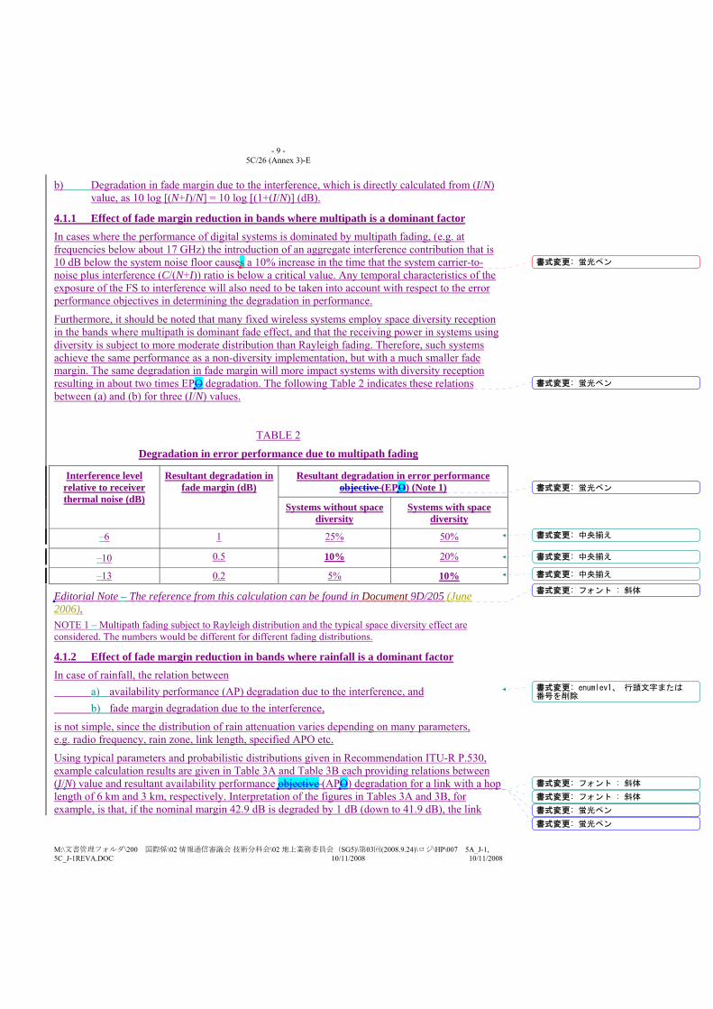
- 9 - 5C/26 (Annex 3)-E
M:\文書管理フォルダ\200 国際係\02 情報通信審議会 技術分科会\02 地上業務委員会(SG5)\第03回(2008.9.24)\ロジ\HP\007 5A_J-1, 5C_J-1REVA.DOC 10/11/2008 10/11/2008
b) Degradation in fade margin due to the interference, which is directly calculated from (I/N) value, as 10 log [(N+I)/N] = 10 log [(1+(I/N)] (dB).
4.1.1 Effect of fade margin reduction in bands where multipath is a dominant factor In cases where the performance of digital systems is dominated by multipath fading, (e.g. at frequencies below about 17 GHz) the introduction of an aggregate interference contribution that is 10 dB below the system noise floor causes a 10% increase in the time that the system carrier-to-noise plus interference (C/(N+I)) ratio is below a critical value. Any temporal characteristics of the exposure of the FS to interference will also need to be taken into account with respect to the error performance objectives in determining the degradation in performance.
Furthermore, it should be noted that many fixed wireless systems employ space diversity reception in the bands where multipath is dominant fade effect, and that the receiving power in systems using diversity is subject to more moderate distribution than Rayleigh fading. Therefore, such systems achieve the same performance as a non-diversity implementation, but with a much smaller fade margin. The same degradation in fade margin will more impact systems with diversity reception resulting in about two times EPO degradation. The following Table 2 indicates these relations between (a) and (b) for three (I/N) values.
TABLE 2
Degradation in error performance due to multipath fading
Interference level relative to receiver thermal noise (dB)
Resultant degradation in fade margin (dB)
Resultant degradation in error performance objective (EPO) (Note 1)
Systems without space diversity
Systems with space diversity
–6 1 25% 50%
–10 0.5 10% 20%
–13 0.2 5% 10%
Editorial Note – The reference from this calculation can be found in Document 9D/205 (June 2006). NOTE 1 – Multipath fading subject to Rayleigh distribution and the typical space diversity effect are considered. The numbers would be different for different fading distributions.
4.1.2 Effect of fade margin reduction in bands where rainfall is a dominant factor In case of rainfall, the relation between a) availability performance (AP) degradation due to the interference, and b) fade margin degradation due to the interference,
is not simple, since the distribution of rain attenuation varies depending on many parameters, e.g. radio frequency, rain zone, link length, specified APO etc.
Using typical parameters and probabilistic distributions given in Recommendation ITU-R P.530, example calculation results are given in Table 3A and Table 3B each providing relations between (I/N) value and resultant availability performance objective (APO) degradation for a link with a hop length of 6 km and 3 km, respectively. Interpretation of the figures in Tables 3A and 3B, for example, is that, if the nominal margin 42.9 dB is degraded by 1 dB (down to 41.9 dB), the link
書式変更: 蛍光ペン
書式変更: 蛍光ペン
書式変更: 蛍光ペン
書式変更: 中央揃え
書式変更: 中央揃え
書式変更: 中央揃え
書式変更: フォント : 斜体
書式変更: enumlev1、 行頭文字または番号を削除
書式変更: フォント : 斜体
書式変更: フォント : 斜体
書式変更: 蛍光ペン
書式変更: 蛍光ペン
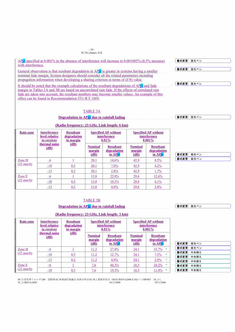
- 10 - 5C/26 (Annex 3)-E
M:\文書管理フォルダ\200 国際係\02 情報通信審議会 技術分科会\02 地上業務委員会(SG5)\第03回(2008.9.24)\ロジ\HP\007 5A_J-1, 5C_J-1REVA.DOC 10/11/2008 10/11/2008
APO specified at 0.001% in the absence of interference will increase to 0.001085% (8.5% increase) with interference.
General observation is that resultant degradation in APO is greater in systems having a smaller nominal fade margin. System designers should consider all the related parameters including propagation information when developing a sharing criterion in terms of (I/N) value.
It should be noted that the example calculations of the resultant degradations of APO and fade margin in Tables 3A and 3B are based on uncorrelated rain fade. If the effects of correlated rain fade are taken into account, the resultant numbers may become smaller values. An example of this effect can be found in Recommendation ITU-R F.1669.
TABLE 3A
Degradation in APO due to rainfall fading
(Radio frequency: 23 GHz, Link length: 6 km)
Rain zone Interference level relative to receiver
thermal noise (dB)
Resultant degradation in margin
(dB)
Specified AP without interference
0.01%
Specified AP without interference
0.001%
Nominal margin
(dB)
Resultant degradation
in APO
Nominal margin
(dB)
Resultant degradation
in APO
Zone H (32 mm/h)
–6 1 20.1 14.6% 42.9 8.5%
–10 0.5 20.1 7.0% 42.9 4.2% –13 0.2 20.1 2.8% 42.9 1.7%
Zone E (22 mm/h)
–6 1 13.8 22.0% 29.6 12.6% –10 0.5 13.8 10.3% 29.6 6.1% –13 0.2 13.8 4.0% 29.6 2.4%
TABLE 3B
Degradation in APO due to rainfall fading
(Radio frequency: 23 GHz, Link length: 3 km)
Rain zone Interference level relative to receiver
thermal noise (dB)
Resultant degradation in margin
(dB)
Specified AP without interference
0.01%
Specified AP without interference
0.001%
Nominal margin
(dB)
Resultant degradation
in APO
Nominal margin
(dB)
Resultant degradation
in APO
Zone H (32 mm/h)
–6 1 11.2 27.8% 24.1 15.7% –10 0.5 11.2 12.7% 24.1 7.5% –13 0.2 11.2 4.8% 24.1 2.9%
Zone E (22 mm/h)
–6 1 7.6 44.3% 16.3 24.2% –10 0.5 7.6 19.5% 16.3 11.4%
書式変更: 蛍光ペン
書式変更: 蛍光ペン
書式変更: 蛍光ペン
書式変更: 蛍光ペン
書式変更: 蛍光ペン
書式変更: 蛍光ペン
書式変更: 蛍光ペン
書式変更: 蛍光ペン
書式変更: 蛍光ペン
書式変更: 中央揃え
書式変更: 中央揃え
書式変更: 中央揃え
書式変更: 中央揃え
書式変更: 中央揃え
- 11 - 5C/26 (Annex 3)-E
M:\文書管理フォルダ\200 国際係\02 情報通信審議会 技術分科会\02 地上業務委員会(SG5)\第03回(2008.9.24)\ロジ\HP\007 5A_J-1, 5C_J-1REVA.DOC 10/11/2008 10/11/2008
–13 0.2 7.6 7.2% 16.3 4.5%
4.1.3 Contribution of combined receiver thermal and interference noise The calculations in Tables 2 and 3 of the preceding sections were referenced to a power level identified as the “receiver thermal noise.” In practice the reference level should be an effective noise level that includes all the noise in the receiving system as well as the assumed interference within the fixed service as in the portion X defined in Recommendation ITU-R F.1094. Note that the other-service interference would also be referenced to this effective level. Thus, increasing the assumed value for same-service interference will reduce the performance degradation caused by a given level of other-service interference power.
4.1.4 EP/AP degradation in multi-hop links In Recommendation ITU-R F.1565, EPO degradation of real FWS fixed wireless system due to interference from other co-primary service is specified for each section of the HRX. More specifically, EPO degradation of real FWS could be evaluated for the entire portion of short haul inter-exchange section and access network section. In case of the long haul inter-exchange section, the minimum link length for which the EPO is specified is 50 km.
It should be noted that, if a multi-hop fixed wireless systemFWS is deployed forming all of the access network section or short haul inter-exchange section, or long haul inter-exchange section shorter than 50 km, the EPO for interference specified in Recommendation ITU-R F.1565 does not need to apply to individual hops but to the multi-hop link in total.
Similar consideration could apply to the allocation of the APO specified in Recommendation ITU-R F.1703.
This point should be taken into account in the sharing environment where the interference does not occur significantly in every hop but affect only specific hops. For example, if only one hop is exposed to the interference within the N-hop fixed wireless systemFWS link forming all of the section, resultant EP/AP degradation will become N times one Nth smaller accordingly than the figures given in Tables 2, 3A and 3B.
4.2 Short-term interference The derivation of permitted short-term interference levels, and associated time percentages, is a complex process which includes careful examination of performance/availability objectives, and assumptions about the fading characteristics and correlation of periods of wanted signal fading and interference enhancement. The degradations allocated to short-term interference need to be balanced against the allocation for long-term interference so that their sum does not exceed the permitted degradation. The procedures described in the Recommendations ITU-R F.1494, ITU-R F.1495 and ITU-R F.1606 provide examples of the development of short-term interference criteria. An example of the development of short-term interference criteria is provided in the following section.
4.2.1 An example of the development of short-term interference criteria This example describes the approach taken to develop interference criteria to protect the fixed service from aeronautical mobile telemetry (AMT) systems in the mobile service proposed to operate in the mobile sService in the band 5 925-6 425 MHz. Although no FS interference criteria had been developed for AMT use of the 5 925-6 700 MHz frequency band, criteria have been developed for portions of this band or for nearby bands in sharing studies with other services employing moving emitters of potential interference. The relevant Recommendations are
書式変更: 中央揃え
書式変更: 蛍光ペン
- 12 - 5C/26 (Annex 3)-E
M:\文書管理フォルダ\200 国際係\02 情報通信審議会 技術分科会\02 地上業務委員会(SG5)\第03回(2008.9.24)\ロジ\HP\007 5A_J-1, 5C_J-1REVA.DOC 10/11/2008 10/11/2008
Recommendation ITU-R SF.1320, ITU-R F.1494 and ITU-R SF.1650. See also Annex 5 to Report ITU-R M.[4/6 GHz].
Because it was proposed to use simulation methods for this sharing study, it was appropriate to consider for long-term interference considerations the use of FDP, the fractional degradation in performance as defined in Recommendation ITU-R F.1108. FDP can be used where multipath fading is the primary limit on the performance of a fixed service link. Although Recommendation ITU-R F.1108 suggests a value of 10 percent, Recommendation ITU-R SF.1320 used a lower value (FDP of 4%) because it addressed the addition of space-to-Earth interference in a frequency band where the FS was already exposed to interference from Earth-to-space operations by the FSS and because of the wide-spread use of diversity operation by the FS in this band. The fractional degradation in performance of a diversity (FDPD) FS system will be more than twice as great as the non-diversity FDP, as shown in Annex 4 of Recommendation ITU-R F.1108 and § 2 of the Annex to Recommendation ITU-R SF.1320. It is notable that the band 6 425-7 025 MHz is administered for FS use as the upper 6 GHz band by many administrations in accordance with Recommendation ITU-R F.384. Since the center reference frequency for the band is 6 770 MHz and the fixed satellite service (FSS) operates in the Earth-to-space direction throughout the entire band, the same interference considerations should apply to both halves of the band. The same long-term criterion should be used for the entire band from 5 925 to 6 700 MHz because the FSS operates in the Earth-to-space direction throughout this entire band.
While precipitation fading may affect the performance on many paths near 10 GHz in certain countries, the interference criteria of Recommendation ITU-R F.1494 were developed under the assumption that system performance in the absence of interference was limited only by multipath fading. The approach taken in Recommendation ITU-R F.1494 was to develop short-term interference criteria for severely errored seconds (SES) and for errored seconds (ES). By imposing a hard limit on I/N, the recommended short-term interference criterion prevents any performance degradation relative to the error performance objectives (EPO) for either SES or ES because of short-term interference events. Since diversity is not used much by the FS in the frequency bands above 10 GHz, the entire performance degradation of 10%, as specified by Recommendation ITU-R F.1108, is allocated to the long term interference in this band.
Typical FS systems in the 6 GHz bands have the same fade margins as typical systems in the 10.7-12.75 GHz bands and are even more likely to implement automatic transmit power control (ATPC). Hence, the interference criteria applied in Recommendation ITU-R SF.1650 were developed using an approach similar to that used in Recommendation ITU-R F.1494. The difference is that the interference considerations in Recommendation ITU-R SF.1650 are limited to short-term interference events so that only short-term interference criteria were needed. The two short-term interference criteria are those required to meet SES and ES error performance objectives: – For SES: I/N < 23 dB for all but 1.2×10⁻⁵% of a month. – For ES: I/N < 19 dB for all but 4.5×10⁻⁴% of a month.
Although the use of the short-term interference criteria of Recommendation ITU-R SF.1006 was considered, this Recommendation was developed in 1993, before the criteria of Recommendation ITU-R F.1108 were developed to address moving sources of interference and before error performance criteria of Recommendation ITU-R F.1668 were in place. In particular, Recommendation ITU-R SF.1649 notes that the short-term criteria of Recommendation ITU-R SF.1006 are only compliant with ITU-T Recommendation G.821. On the other hand, Recommendation ITU-R SF.1650 provides FS short-term protection criteria for up-to-date links designed to meet the requirements of ITU-T Recommendations G.826 and G.828.
書式変更: 上付き
書式変更: 上付き

- 13 - 5C/26 (Annex 3)-E
M:\文書管理フォルダ\200 国際係\02 情報通信審議会 技術分科会\02 地上業務委員会(SG5)\第03回(2008.9.24)\ロジ\HP\007 5A_J-1, 5C_J-1REVA.DOC 10/11/2008 10/11/2008
In conclusion, from the various FS frequency sharing situations addressed in existing Recommendations, the short-term interference criteria applied in Recommendation ITU-R SF.1650 and the long-term interference criteria applied in Recommendation ITU-R SF.1320 appear to be the most applicable for the AMT sharing situation in the 5 925-6 700 MHz band. However, it is noted that these criteria apply to the cases where interference is allocated entirely to either short-term or long-term interference, and further work would be needed to apportion the EPO degradations to these two types of interference.
5 Use of automatic transmit power control (ATPC) in digital systems FS systems in some frequency bands may make use of ATPC. Where applicable, ATPC may be taken into account when performing sharing studies involving the FS. Such studies should consider the maximum transmit power level, the range of ATPC and the distribution of FS power levels with respect to time. This distribution may be difficult to determine since it would need to take into account the level of interference that would cause ATPC to activate. More information on ATPC can be found in Recommendations ITU-R F.1494, ITU-R F.1495, ITU-R F.1606 and ITU-R F.1669.
Recommendation ITU-R F.1094 lays the foundations for the apportionment of the performance and availability objectives, from which the long-term interference limit can be calculated. In the case of Rayleigh fading, it can be shown that if the aggregate level of interference is no higher than 10 dB below the receiver noise floor, the performance degradation will not exceed 10%.
Any temporal characteristics of exposure of the FS to interference will also need to be taken into account.
The derivation of permitted short-term interference levels, and associated time percentages, is a complex process which includes careful examination of performance/availability objectives, and assumptions about the fading characteristics and correlation of periods of wanted signal fading and interference enhancement. The procedures described in the ITU-R SF-Series Recommendations texts and the principles described in this Annex should be developed for this purpose and the tables expanded to include this important information.
65 Calculation of actual interference levels To complete the analysis of sharing, the probability of interference arriving at the input to the antenna must be evaluated. This will take into account up-to-date propagation models and path factors, which are described in the ITU-R P-Series Recommendations and Reports. It is unlikely that a single model will suffice for all possible applications. The transmission loss calculation will also include factors such as absorption losses, diffraction losses, scattering loss, polarization coupling loss, aperture-to-medium coupling loss and the effect of multipath. Also, both aggregate and single-entry interference levels may need to be considered.
- 14 - 5C/26 (Annex 3)-E
M:\文書管理フォルダ\200 国際係\02 情報通信審議会 技術分科会\02 地上業務委員会(SG5)\第03回(2008.9.24)\ロジ\HP\007 5A_J-1, 5C_J-1REVA.DOC 10/11/2008 10/11/2008
Annex 2
Digital FS system parameters for frequency sharing studies
1 Introduction In order to calculate degradations in performance and availability, it is necessary to know the characteristics of the radio-relayfixed wireless system being degraded. There is a large variety of radio-relayfixed wireless systems in operation or being developed to meet future requirements. It would be unwise, therefore, to use a single “typical” radio-relayfixed wireless system as a general purpose model. This Annex provides details of the key radio system parameters required for interference evaluation and calculations for frequency sharing studies with other services. The system parameters are presented in tabular form for the minimal number of frequency ranges required to undertake sharing studies between the FS and other services.
2 Transmitter characterization The basic transmitter parameters needed to assess interference potential to other services are: – carrier frequency, – spectral characteristics, – equivalent isotropically radiated power (e.i.r.p.), – antenna radiation pattern.
Operating frequencies normally correspond to radio-frequency channel arrangements specified instandard ITU-R Recommendationschannel plans. The modulation type and system capacity will give a guide to the spectral characteristics of the emissions. However, detailed sharing calculations would require a template of the spectral characteristics to be specified so that any frequency offset rejection at a given wanted/interfering signal carrier frequency separation may be calculated.
The e.i.r.p. of the transmitter is calculated from the transmitter power, feeder/multiplexer losses and antenna gain. A maximum e.i.r.p. value would correspond to maximum antenna gain, minimum feeder/multiplexer losses and maximum transmitter output power, which represents the worst interference potential to other services.
Knowledge of antenna radiation patterns is essential to perform detailed sharing studies. In cases where measured patterns are not available, the reference radiation patterns addressed in the following Recommendations should be used:
Recommendation ITU-R F.699 Reference radiation patterns for fixed wireless system antennas for use in coordination studies and interference assessment in the frequency range from 100 MHz to about 70 GHz,
Recommendation ITU-R F.1245 Mathematical model of average radiation patterns for line-of-sight point-to-point radio-relay system antennas for use in certain coordination studies and interference assessment in the frequency range from 1 GHz to about 70 GHz, and
Recommendation ITU-R F.1336 Reference radiation patterns of omnidirectional, sectoral and other antennas in point-to-multipoint systems for use in sharing studies in the frequency range from 1 GHz to about 70 GHz.
should be used to obtain information on FS antenna radiation pattern envelopes in cases where measured patterns are not available.
書式変更: 蛍光ペン
書式変更: 英語 (英国)
書式変更: 蛍光ペン
- 15 - 5C/26 (Annex 3)-E
M:\文書管理フォルダ\200 国際係\02 情報通信審議会 技術分科会\02 地上業務委員会(SG5)\第03回(2008.9.24)\ロジ\HP\007 5A_J-1, 5C_J-1REVA.DOC 10/11/2008 10/11/2008
3 Receiver characterization
3.1 Equipment parameters Assessment of the effects of interference into the FS from other services requires knowledge of the performance characteristics of the radio receiver. The following receiver parameters are important for frequency sharing studies: – noise figure, – IF noise bandwidth, – receiver thermal noise, – received signal power for 1 × 10⁻³, 1 × 10⁻⁶, 1 × 10⁻¹⁰ BER (post-error-correction) (Refer to
Note 1)(digital systems), – nominal receiver input level. NOTE 1 – Typically, the carrier level corresponding to 1 × 10⁻⁶ BER is around 4 dB higher than that for 1 × 10⁻³ BER; the carrier level difference between the 1 × 10⁻⁶ and 1 × 10⁻¹⁰ BER points is also about 4 dB. For radio equipment using forward error correction (FEC), the carrier level corresponding to 1 × 10⁻⁶ BER is 1 to 2 dB higher than that for 1 × 10⁻³ BER; the carrier difference between 1 × 10⁻⁶ and 1 × 10⁻¹⁰ is also 1 to 2 dB. In the later Tables, the received signal power for 1 × 10⁻⁶ is only addressed, since the corresponding parameters for other BERs could be theoretically derived from the modulation scheme or the error correction effect.
The received signal levels and interference levels could be referenced to the low noise amplifier (LNA)/mixer input of the receiver, so that they would be independent of receive antenna gain and feeder/multiplexer losses (assuming this to be the same for both transmitter/receiver).
It should also be noted that accurate sharing calculations require information on the frequency selectivity of the radio equipment.
The required signal levels for given BERs could be combined with the calculated receiver thermal noise level to obtain the required carrier-to-thermal noise ratio, C/N, for a given BER.
3.2 Permitted interference It is necessary to specify maximum interference levels for both long- and short-term time percentages. For long-term interference, a time percentage of 20% is commonly used. Where aggregate long-term interference is specified, if interference from multiple sources can simultaneously occur, it should be noted that single-entry interference criteria will be correspondingly lower. In the case of short-term interference, the time percentages of interest will be related to the system performance objectives.
The long- and short-term interference levels, and associated time percentages, must be individually derived for each system type in accordance with the principles described in Annex 1.
3.2.1 Digital systems For digital receivers, it is the total interference power falling within the receiver bandwidth that is generally of most relevance. For convenience, the equivalent power spectral density (PSD) (dB(W/MHz)) can also be specified.
4 Tables of system parameters TA tables can be constructed showing system parameters to be used when considering sharing between the FS and other services, and this these should include the information discussed above. 書式変更: 蛍光ペン

- 16 - 5C/26 (Annex 3)-E
M:\文書管理フォルダ\200 国際係\02 情報通信審議会 技術分科会\02 地上業務委員会(SG5)\第03回(2008.9.24)\ロジ\HP\007 5A_J-1, 5C_J-1REVA.DOC 10/11/2008 10/11/2008
Tables 42 to 213 show representative parameters values to be used in studies of sharing with for digital fixed wirelessselected examples of some FS systems that are currently in used in some of thevarious frequency bands in which FSS operate. The various radio system types are identified in the Tables by modulation type and system capacity.
The nominal long-term interference criteria specified in the Tables provide some guidance to the results that would be obtained from detailed calculations. and can be used for information for the time being. However, fFor detailed sharing studies accurate criteria must be derived in accordance with the information principle in Annex 1, and these may differ slightly in some cases from those in the Tables.
It is most important that the following Notes be taken into account when considering the example Tables.
NOTE 1 – To simplify the Tables, only the carrier level corresponding to the 1 × 10⁻³ BER is included. Equally important are the 1 × 10⁻⁶ and 1 × 10⁻¹⁰ BER objectives, used in the evaluation of permissible performance degradation. Typically, the carrier level corresponding to 1 × 10⁻⁶ BER is around 4 dB lower than that for 1 × 10⁻³ BER; the carrier level difference between the 1 × 10⁻⁶ and 1 × 10⁻¹⁰ BER points is also about 4 dB. For radio equipment using forward error correction (FEC), the carrier level corresponding to 1 × 10⁻⁶ BER is 1 to 2 dB higher than that for 1 × 10⁻³ BER; the carrier difference between 1 × 10⁻⁶ and 1 × 10⁻¹⁰ is also 1 to 2 dB.
NOTE 2 – In the example Tables a straightforward, but conservative, approach to specifying maximum permitted long-term external interference is used. This was done because the characteristics and spatial distribution of the interference sources are undefined, and it is also impractical to attempt detailed performance and availability predictions for such a large number of unspecified systems at this stage.
By referencing interference to the receiver thermal noise level the problem is greatly simplified, since the permitted interference PSD power spectrum density so derived will be dependent solely on receiver noise figure and independent of the modulation scheme of the victim system. It may be shown that, independent of the normal received carrier level, the degradation in fade margin with interference set to a given level relative to receiver thermal noise level is as follows:
Interference level relative to receiver thermal noise (dB)
Resultant degradation in fade margin (dB)
–6 1
–10 0.5
Within the Tables, the choice of an interference to thermal noise I/N value of –6 dB or –10 dB is selected to match the typical requirements of individual systems. For detailed sharing analyses, the interference criteria must be derived in accordance with Annex 1, to match the individual, specific, sharing scenario under consideration, and will need to be agreed between the parties concerned.
Another approach stated in Note(3) of Tables 8 and 17 can be applied, conforming to the method given in Recommendation ITU-R F.1565, such that the specified interference have a relative contribution of no more than 10% of total noise.
NOTE 3 – Short-term interference criteria have not been included in the example Tables. This information must be derived in accordance with the principles derived in Annex 1. More information on short-term interference criteria can be found in the Recommendations listed in Table 1.
書式変更: 蛍光ペン
書式変更: 蛍光ペン
書式変更: 蛍光ペン
書式変更: 蛍光ペン
書式変更: 蛍光ペン
書式変更: 標準
書式変更: 蛍光ペン
書式変更: 標準、左揃え
書式変更: 標準、タブ位置: 7.67 字(なし)
書式変更: 標準、タブ位置: 7.17 字(なし)
書式変更: 標準、タブ位置: 7.67 字(なし)
書式変更: 標準、タブ位置: 7.17 字(なし)
書式変更: 標準
- 17 - 5C/26 (Annex 3)-E
M:\文書管理フォルダ\200 国際係\02 情報通信審議会 技術分科会\02 地上業務委員会(SG5)\第03回(2008.9.24)\ロジ\HP\007 5A_J-1, 5C_J-1REVA.DOC 10/11/2008 10/11/2008
The Tables may be updated when this information becomes available, as a result of future detailed studies of sharing with specific services.
NOTE 4 – In Tables 42 to 138, the antenna gain is expressed only in terms of maximum gain. However, in certain frequency sharing scenarios, the minimum gain or other parameters (such as side-lobe and back-lobe gain) of the antenna may be more relevant. Annex 324 to Report ITU-R F.2108 gives information about typical minimum antenna gains.
The following tTables take into account: a) parameters provided are considered to be representative for the purpose of carrying out
technical sharing studies. In some cases certain parameters may vary due to practical operating requirements;
b) sharing studies are generally independent of modulation because they are based upon I/N objectives;
c) the noise figure data include the duplexer filter losses, while the feeder/multiplexer loss row are related to feeder losses only;
d) representative antenna types are Omni, Yagi, Dish, Horn, Sectoral, etc.; e) where regulatory limits apply, EIRP may not be equal to the maximum power plus the
maximum gain (in decibels).
書式変更: 蛍光ペン
書式変更: 蛍光ペン
書式変更: 蛍光ペン
書式変更: 英語 (英国), 上付き/下付き(なし)

- 18 - 5C/26 (Annex 3)-E
M:\文書管理フォルダ\200 国際係\02 情報通信審議会 技術分科会\02 地上業務委員会(SG5)\第03回(2008.9.24)\ロジ\HP\007 5A_J-1, 5C_J-1REVA.DOC 10/11/2008 10/11/2008
TABLE 2
FS system parameters for FS frequency sharing below 1 GHz
Frequency band (MHz) 340-470 406.1-450 610-960
Modulation GMSK GMSK GMSK DQPSK DQPSK 16-QAM 16-QAM 32-QAM 32-QAM 2-FSK and others
Capacity (Mbit/s) 5 × 32 kbit/s 5 × 32 kbit/s 5 × 32 kbit/s 0.32 4 2 8 0.768 8 1.024; 30 channels (it can use lower data rates)
Channel spacing (MHz) 0.6 0.6 0.6 0.25 3.5 1.75 3.5 0.20 1.75 0.75
Base station Base station Out station
Antenna gain (maximum) (dBi) 7 12 6 25 25 25 25 25 25 16
Feeder/multiplexer loss (minimum) (dB) 4.4 4.4 2.2 2 2 2 2 2 2 1
Antenna type Omni Sectoral Panel Yagi Yagi Yagi Yagi Yagi Yagi Square reflector
Maximum Tx output power (dBW) 6 6 6 7 7 10 10 0 0 7 dBW (typical: 0 dBW)
e.i.r.p. (maximum) (dBW) 8.6 13.6 9.8 30 30 33 33 23 23 22 dBW (typical: 15 dBW)
Receiver IF bandwidth (MHz) 0.6 0.6 0.6 0.3 3.14 3.5 3.5 0.15 1.67 0.75
Receiver noise figure (dB) 4 4 4 5 5 3 3 3.5 3.5 7
Receiver thermal noise (dBW) –146.5 −146.5 −146.5 −144 −134 −143 −137 −148.7 −138.3 −138
Nominal Rx input level (dBW) −100 −100 −100 −100
Rx input level for 1 × 10⁻³ BER (dBW) −117 −117 −117 −131 −121 −122 −116 −127 −117 −124
Nominal long-term interference (dBW) −152.5 −152.5 −152.5 −154 −144 −153 −147 −157 −147
Spectral density (dB(W/MHz)) −150.3 −150.3 −150.3 −149 −149 −151 −151 −149 −149
DQPSK: differentially coherent quaternary phase shift keying
GMSK: gaussian minimum shift keying
- 19 - 5C/26 (Annex 3)-E
M:\文書管理フォルダ\200 国際係\02 情報通信審議会 技術分科会\02 地上業務委員会(SG5)\第03回(2008.9.24)\ロジ\HP\007 5A_J-1, 5C_J-1REVA.DOC 10/11/2008 10/11/2008
TABLE 3
FS system parameters for FS frequency sharing below 1 GHz
Frequency band (GHz) 0.81-0.96
Modulation 7-FSK 4-QAM 16-QAM 7-FSK 4-QAM 16-QAM
Capacity (Mbit/s) 64 kbit/s 64 kbit/s 128 kbit/s 256 kbit/s 256 kbit/s 512 kbit/s
Channel spacing (kHz) 50 50 50 200 200 200
Antenna gain (maximum) (dBi) 24 24 24 24 24 24
Feeder/multiplexer loss (minimum) (dB) 3 3 3 3 3 3
Antenna type Grid Grid Grid Grid Grid Grid
Maximum Tx output power (dBW) 7 7 7 7 7 7
e.i.r.p. (maximum) (dBW) 31 31 31 31 31 31
Receiver IF bandwidth (kHz) 50 50 50 200 200 200
Receiver noise figure (dB) 5 5 5 5 5 5
Receiver thermal noise (dBW) −152 −152 −152 −146 –146 −146
Nominal Rx input level (dBW) −90 −90 −90 −90 −90 −90
Rx input level for 1 × 10⁻³ BER (dBW) −123 −135 −130 −117 −129 −124
Nominal long-term interference (dBW) −153 −165 −160 −147 −159 −154
Spectral density (dB(W/MHz)) −140 −152 −147 −140 −152 −147
- 20 - 5C/26 (Annex 3)-E
M:\文書管理フォルダ\200 国際係\02 情報通信審議会 技術分科会\02 地上業務委員会(SG5)\第03回(2008.9.24)\ロジ\HP\007 5A_J-1, 5C_J-1REVA.DOC 10/11/2008 10/11/2008
TABLE 4
Representative system parameters for point-to-point FS systems in allocated bands below 3 GHz
Frequency band (GHz)
Modulation Channel spacing (MHz) Tx output power (maximum) (dBW)
Feeder/multiplexer loss (minimum) (dB)
Antenna type and gain (maximum) (dBi)
EIRP (dBW) Receiver noise bandwidth (MHz)
Receiver noise figure (dB)
Nominal Rx input level (dBW)
Rx input level for 1 × 10⁻⁶ BER (dBW)
Nominal long-term interference (dBW in Rx noise bandwidth)
Nominal long-term interference (dBW/MHz)
Date last updated
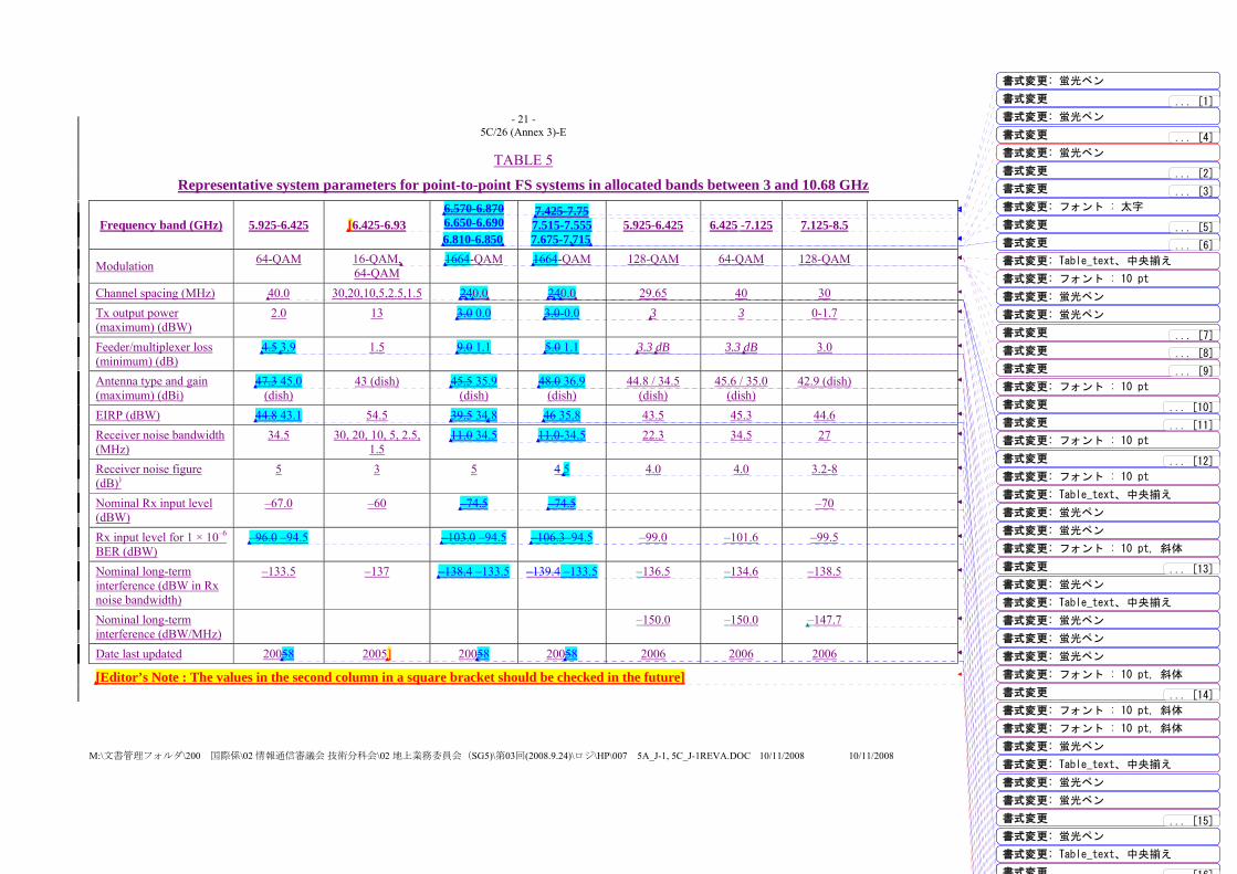
- 21 - 5C/26 (Annex 3)-E
M:\文書管理フォルダ\200 国際係\02 情報通信審議会 技術分科会\02 地上業務委員会(SG5)\第03回(2008.9.24)\ロジ\HP\007 5A_J-1, 5C_J-1REVA.DOC 10/11/2008 10/11/2008
TABLE 5
Representative system parameters for point-to-point FS systems in allocated bands between 3 and 10.68 GHz
Frequency band (GHz) 5.925-6.425 [6.425-6.93 6.570-6.870 6.650-6.690 6.810-6.850
7.425-7.75 7.515-7.555 7.675-7.715
5.925-6.425 6.425 -7.125 7.125-8.5
Modulation 64-QAM 16-QAM, 64-QAM
1664-QAM 1664-QAM 128-QAM 64-QAM 128-QAM
Channel spacing (MHz) 40.0 30,20,10,5,2.5,1.5 240.0 240.0 29.65 40 30 Tx output power (maximum) (dBW)
2.0 13 3.0 0.0 3.0-0.0 3 3 0-1.7
Feeder/multiplexer loss (minimum) (dB)
4.5 3.9 1.5 9.0 1.1 5.0 1.1 3.3 dB 3.3 dB 3.0
Antenna type and gain (maximum) (dBi)
47.3 45.0 (dish)
43 (dish) 45.5 35.9 (dish)
48.0 36.9 (dish)
44.8 / 34.5 (dish)
45.6 / 35.0 (dish)
42.9 (dish)
EIRP (dBW) 44.8 43.1 54.5 39.5 34.8 46 35.8 43.5 45.3 44.6 Receiver noise bandwidth (MHz)
34.5 30, 20, 10, 5, 2.5, 1.5
11.0 34.5 11.0-34.5 22.3 34.5 27
Receiver noise figure (dB))
5 3 5 4 5 4.0 4.0 3.2-8
Nominal Rx input level (dBW)
–67.0 –60 –74.5 –74.5 –70
Rx input level for 1 × 10⁻⁶ BER (dBW)
–96.0 –94.5 –103.0 –94.5 –106.3–94.5 –99.0 –101.6 –99.5
Nominal long-term interference (dBW in Rx noise bandwidth)
–133.5 –137 –138.4 –133.5 –139.4 –133.5 –136.5 –134.6 –138.5
Nominal long-term interference (dBW/MHz)
–150.0 –150.0 –147.7
Date last updated 20058 2005] 20058 20058 2006 2006 2006
[Editor’s Note : The values in the second column in a square bracket should be checked in the future]
書式変更: 蛍光ペン
書式変更: 蛍光ペン
書式変更 ... [1]
書式変更 ... [2]
書式変更 ... [3]
書式変更: フォント : 太字
書式変更: 蛍光ペン
書式変更 ... [4]
書式変更 ... [5]
書式変更 ... [6]
書式変更: Table_text、中央揃え
書式変更: フォント : 10 pt
書式変更: 蛍光ペン
書式変更: 蛍光ペン
書式変更 ... [7]
書式変更 ... [8]
書式変更 ... [9]
書式変更: フォント : 10 pt
書式変更 ... [10]
書式変更 ... [11]
書式変更: フォント : 10 pt
書式変更 ... [12]
書式変更: フォント : 10 pt
書式変更: Table_text、中央揃え
書式変更: 蛍光ペン
書式変更: 蛍光ペン
書式変更: フォント : 10 pt, 斜体
書式変更 ... [13]
書式変更: 蛍光ペン
書式変更: Table_text、中央揃え
書式変更: 蛍光ペン
書式変更: 蛍光ペン
書式変更: 蛍光ペン
書式変更: フォント : 10 pt, 斜体
書式変更 ... [14]
書式変更: フォント : 10 pt, 斜体
書式変更: フォント : 10 pt, 斜体
書式変更: 蛍光ペン
書式変更: Table_text、中央揃え
書式変更: 蛍光ペン
書式変更: 蛍光ペン
書式変更 ... [15]
書式変更: 蛍光ペン
書式変更: Table_text、中央揃え
書式変更 [16]
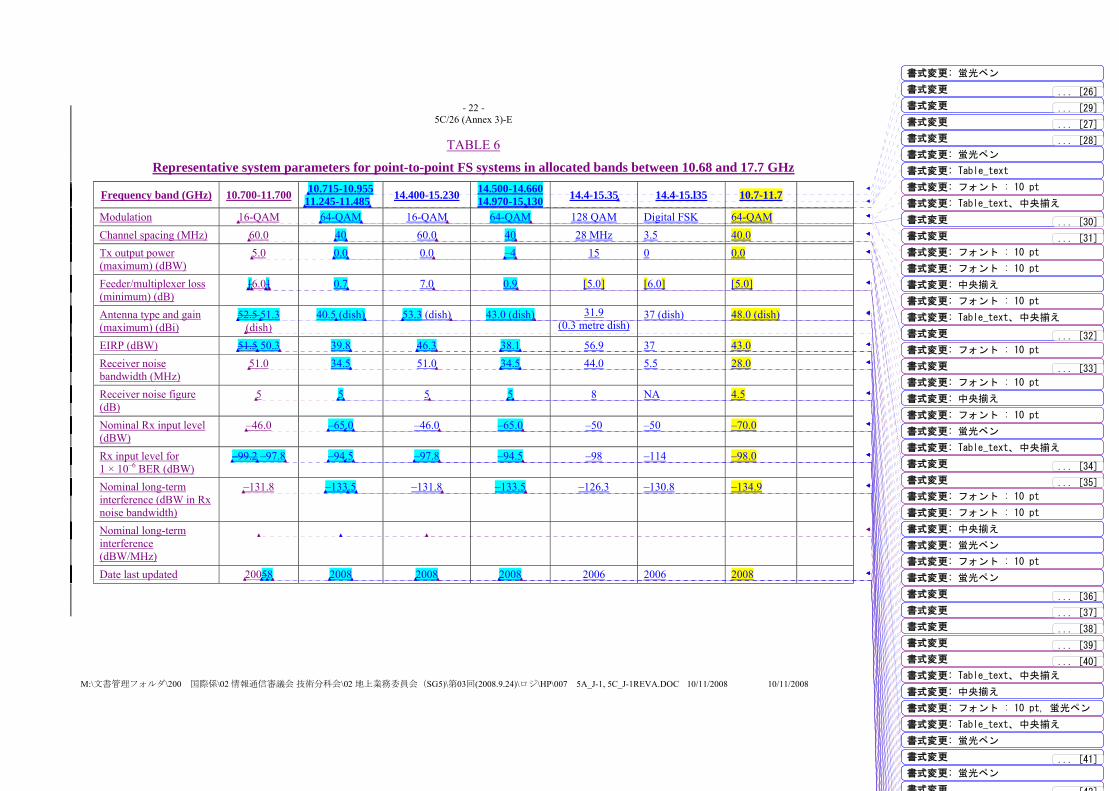
- 22 - 5C/26 (Annex 3)-E
M:\文書管理フォルダ\200 国際係\02 情報通信審議会 技術分科会\02 地上業務委員会(SG5)\第03回(2008.9.24)\ロジ\HP\007 5A_J-1, 5C_J-1REVA.DOC 10/11/2008 10/11/2008
TABLE 6
Representative system parameters for point-to-point FS systems in allocated bands between 10.68 and 17.7 GHz
Frequency band (GHz) 10.700-11.700 10.715-10.95511.245-11.485 14.400-15.230 14.500-14.660
14.970-15.130 14.4-15.35 14.4-15.l35 10.7-11.7
Modulation 16-QAM 64-QAM 16-QAM 64-QAM 128 QAM Digital FSK 64-QAM Channel spacing (MHz) 60.0 40 60.0 40 28 MHz 3.5 40.0 Tx output power (maximum) (dBW)
5.0 0.0 0.0 –4 15 0 0.0
Feeder/multiplexer loss (minimum) (dB)
[6.0] 0.7 7.0 0.9 [5.0] [6.0] [5.0]
Antenna type and gain (maximum) (dBi)
52.5 51.3 (dish)
40.5 (dish) 53.3 (dish) 43.0 (dish) 31.9 (0.3 metre dish)
37 (dish) 48.0 (dish)
EIRP (dBW) 51.5 50.3 39.8 46.3 38.1 56.9 37 43.0 Receiver noise bandwidth (MHz)
51.0 34.5 51.0 34.5 44.0 5.5 28.0
Receiver noise figure (dB)
5 5 5 5 8 NA 4.5
Nominal Rx input level (dBW)
–46.0 –65.0 –46.0 –65.0 –50 –50 –70.0
Rx input level for 1 × 10⁻⁶ BER (dBW)
–99.2 –97.8 –94.5 –97.8 –94.5 –98 –114 –98.0
Nominal long-term interference (dBW in Rx noise bandwidth)
–131.8 –133.5 –131.8 –133.5 –126.3 –130.8 –134.9
Nominal long-term interference (dBW/MHz)
Date last updated 20058 2008 2008 2008 2006 2006 2008
書式変更: 蛍光ペン
書式変更 ... [26]
書式変更 ... [27]
書式変更: Table_text
書式変更 ... [28]
書式変更: 蛍光ペン
書式変更 ... [29]
書式変更: フォント : 10 pt
書式変更: Table_text、中央揃え
書式変更 ... [30]
書式変更 ... [31]
書式変更: フォント : 10 pt
書式変更: フォント : 10 pt
書式変更: 中央揃え
書式変更: フォント : 10 pt
書式変更: Table_text、中央揃え
書式変更 ... [32]
書式変更 ... [33]
書式変更: フォント : 10 pt
書式変更: フォント : 10 pt
書式変更: 中央揃え
書式変更: フォント : 10 pt
書式変更: Table_text、中央揃え
書式変更 ... [34]
書式変更 ... [35]
書式変更: フォント : 10 pt
書式変更: 蛍光ペン
書式変更: フォント : 10 pt
書式変更: 中央揃え
書式変更: 蛍光ペン
書式変更: Table_text、中央揃え
書式変更: フォント : 10 pt
書式変更: 蛍光ペン
書式変更 ... [36]
書式変更 ... [37]
書式変更 ... [38]
書式変更 ... [39]
書式変更 ... [40]
書式変更: 中央揃え
書式変更: フォント : 10 pt, 蛍光ペン
書式変更: Table_text、中央揃え
書式変更: 蛍光ペン
書式変更 ... [41]
書式変更: 蛍光ペン
書式変更 [42]
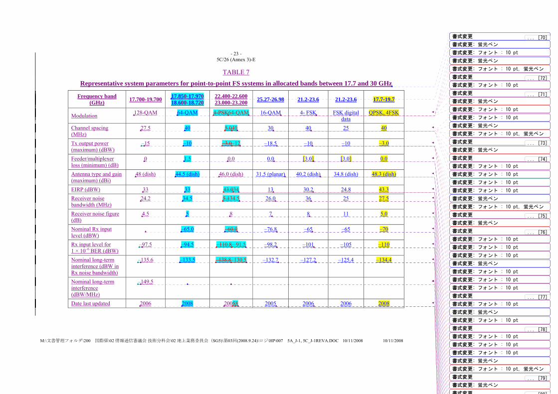
- 23 - 5C/26 (Annex 3)-E
M:\文書管理フォルダ\200 国際係\02 情報通信審議会 技術分科会\02 地上業務委員会(SG5)\第03回(2008.9.24)\ロジ\HP\007 5A_J-1, 5C_J-1REVA.DOC 10/11/2008 10/11/2008
TABLE 7
Representative system parameters for point-to-point FS systems in allocated bands between 17.7 and 30 GHz
Frequency band (GHz) 17.700-19.700 17.850-17.970
18.600-18.720 22.400-22.60023.000-23.200 25.27-26.98 21.2-23.6 21.2-23.6 17.7-19.7
Modulation 128-QAM 64-QAM 4-PSK64-QAM 16-QAM 4- FSK FSK digital data
QPSK, 4FSK
Channel spacing (MHz)
27.5 40 5.040 30 40 25 40
Tx output power (maximum) (dBW)
–15 –10 –3.0–12 –18.5 –10 –10 –3.0
Feeder/multiplexer loss (minimum) (dB)
0 1.5 0.0 0.0 [3.0] [3.0] 0.0
Antenna type and gain (maximum) (dBi)
48 (dish) 44.5 (dish) 46.0 (dish) 31.5 (planar) 40.2 (dish) 34.8 (dish) 48.3 (dish)
EIRP (dBW) 33 33 43.034 13 30.2 24.8 43.3 Receiver noise bandwidth (MHz)
24.2 34.5 5.134.5 26.0 36 25 27.5
Receiver noise figure (dB)
4.5 5 8 7 8 11 5.0
Nominal Rx input level (dBW)
–65.0 –60.0 –76.8 –65 –65 –70
Rx input level for 1 × 10⁻⁶ BER (dBW)
–97.5 –94.5 –110.8 –91.5 –98.2 –101 –105 –110
Nominal long-term interference (dBW in Rx noise bandwidth)
–135.6 –133.5 –138.8–130.5 –132.7 –127.2 –125.4 –134.4
Nominal long-term interference (dBW/MHz)
–149.5
Date last updated 2006 2008 20058 2005 2006 2006 2008
書式変更 ... [70]
書式変更: 蛍光ペン
書式変更: フォント : 10 pt
書式変更: 蛍光ペン
書式変更: フォント : 10 pt, 蛍光ペン
書式変更 ... [71]
書式変更: 蛍光ペン
書式変更 ... [72]
書式変更: フォント : 10 pt
書式変更: フォント : 10 pt
書式変更: フォント : 10 pt
書式変更: 蛍光ペン
書式変更: フォント : 10 pt, 蛍光ペン
書式変更 ... [73]
書式変更: 蛍光ペン
書式変更 ... [74]
書式変更: フォント : 10 pt
書式変更: フォント : 10 pt
書式変更: フォント : 10 pt
書式変更: フォント : 10 pt
書式変更: 蛍光ペン
書式変更: フォント : 10 pt, 蛍光ペン
書式変更 ... [75]
書式変更: 蛍光ペン
書式変更 ... [76]
書式変更: フォント : 10 pt
書式変更: フォント : 10 pt
書式変更: フォント : 10 pt
書式変更: 蛍光ペン
書式変更: フォント : 10 pt
書式変更 ... [77]
書式変更: フォント : 10 pt
書式変更: フォント : 10 pt
書式変更: フォント : 10 pt
書式変更: 蛍光ペン
書式変更: フォント : 10 pt
書式変更 ... [78]
書式変更: フォント : 10 pt
書式変更: フォント : 10 pt
書式変更: フォント : 10 pt
書式変更: 蛍光ペン
書式変更: フォント : 10 pt, 蛍光ペン
書式変更 ... [79]
書式変更: 蛍光ペン
書式変更 [80]

- 24 - 5C/26 (Annex 3)-E
M:\文書管理フォルダ\200 国際係\02 情報通信審議会 技術分科会\02 地上業務委員会(SG5)\第03回(2008.9.24)\ロジ\HP\007 5A_J-1, 5C_J-1REVA.DOC 10/11/2008 10/11/2008
TABLE 8
Representative system parameters for point-to-point FS systems in allocated bands above 30 GHz
Frequency band (GHz) 38.6-40.0 37-39.5 GHz
Modulation QPSK,
16-QAM, 64-QAM
128-QAM
Channel spacing (MHz) 28, 50 28 Tx output power (maximum) (dBW)
10 –15
Feeder/multiplexer loss (minimum) (dB)
0
Antenna type and gain (maximum) (dBi)
38 (dish) 44.6
EIRP (dBW) 55 29.6 Receiver noise bandwidth (MHz)
28, 50 24.2
Receiver noise figure (dB) 7 6.3 Nominal Rx input level (dBW)
Rx input level for 1 × 10⁻⁶ BER (dBW)
–95.5
Nominal long-term interference (dBW in Rx noise bandwidth)
–133.8
Nominal long-term interference (dBW/MHz)
Date last updated 2005 2006
書式変更: フォント : 10 pt
書式変更: Table_text、中央揃え
書式変更 ... [94]
書式変更: フォント : 10 pt
書式変更: フォント : 10 pt
書式変更: Table_text、中央揃え
書式変更 ... [95]
書式変更: フォント : 10 pt
書式変更: Table_text、中央揃え
書式変更 ... [96]
書式変更: フォント : 10 pt, 太字
書式変更: フォント : 10 pt
書式変更: Table_text、中央揃え
書式変更: フォント : 10 pt, 太字
書式変更 ... [97]
書式変更: フォント : 10 pt
書式変更: Table_text、中央揃え
書式変更 ... [98]
書式変更: フォント : 10 pt
書式変更: Table_text、中央揃え
書式変更 ... [99]
書式変更: フォント : 10 pt
書式変更: Table_text、中央揃え
書式変更: フォント : 10 pt
書式変更: Table_text、中央揃え
書式変更 ... [100]
書式変更: フォント : 10 pt
書式変更: Table_text、中央揃え
書式変更: フォント : 10 pt
書式変更: Table_text、中央揃え
書式変更: フォント : 10 pt
書式変更: フォント : 10 pt
書式変更: Table_text、中央揃え
書式変更 ... [101]
書式変更: フォント : 10 pt
書式変更: フォント : 10 pt
書式変更: Table_text、中央揃え
書式変更 ... [102]
書式変更: フォント : 10 pt
書式変更: Table_text、中央揃え
書式変更 ... [103]
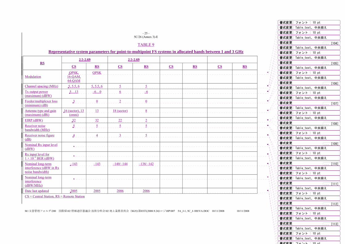
- 25 - 5C/26 (Annex 3)-E
M:\文書管理フォルダ\200 国際係\02 情報通信審議会 技術分科会\02 地上業務委員会(SG5)\第03回(2008.9.24)\ロジ\HP\007 5A_J-1, 5C_J-1REVA.DOC 10/11/2008 10/11/2008
TABLE 9
Representative system parameters for point-to-multipoint FS systems in allocated bands between 1 and 3 GHz
RS 2.5-2.69 2.5-2.69
CS RS CS RS CS RS CS RS
Modulation QPSK,
16-QAM, 64-QAM
QPSK
Channel spacing (MHz) 5, 5.5, 6 5, 5.5, 6 5 5 Tx output power (maximum) (dBW)
5…13 –6…0 6 –6
Feeder/multiplexer loss (minimum) (dB)
3 0 2 0
Antenna type and gain (maximum) (dBi)
16 (sector), 13 (omni)
13 18 (sector) 8
EIRP (dBW) 32 32 22 2 Receiver noise bandwidth (MHz)
5 5 5 5
Receiver noise figure (dB)
4 4 3 5
Nominal Rx input level (dBW)
Rx input level for 1 × 10⁻⁶ BER (dBW)
Nominal long-term interference (dBW in Rx noise bandwidth)
–143 –143 –140/–144 –138/–142
Nominal long-term interference (dBW/MHz)
Date last updated 2005 2005 2006 2006 CS = Central Station, RS = Remote Station
書式変更: フォント : 10 pt
書式変更: Table_text、中央揃え
書式変更: フォント : 10 pt
書式変更: Table_text、中央揃え
書式変更 ... [104]
書式変更: Table_text、中央揃え
書式変更: フォント : 10 pt
書式変更: Table_text、中央揃え
書式変更 ... [105]
書式変更: Table_text、中央揃え
書式変更: フォント : 10 pt
書式変更: Table_text、中央揃え
書式変更 ... [106]
書式変更: Table_text、中央揃え
書式変更: フォント : 10 pt
書式変更: Table_text、中央揃え
書式変更 ... [107]
書式変更: Table_text、中央揃え
書式変更: フォント : 10 pt
書式変更: Table_text、中央揃え
書式変更 ... [108]
書式変更: Table_text、中央揃え
書式変更: フォント : 10 pt
書式変更: Table_text、中央揃え
書式変更 ... [109]
書式変更: Table_text、中央揃え
書式変更: フォント : 10 pt
書式変更: Table_text、中央揃え
書式変更 ... [110]
書式変更: Table_text、中央揃え
書式変更: フォント : 10 pt
書式変更: Table_text、中央揃え
書式変更 ... [111]
書式変更: Table_text、中央揃え
書式変更: フォント : 10 pt
書式変更: Table_text、中央揃え
書式変更 ... [112]
書式変更: Table_text、中央揃え
書式変更: フォント : 10 pt
書式変更: Table_text、中央揃え
書式変更 ... [113]
書式変更: Table_text、中央揃え
書式変更: フォント : 10 pt
書式変更: Table_text、中央揃え
書式変更: フォント : 10 pt

- 26 - 5C/26 (Annex 3)-E
M:\文書管理フォルダ\200 国際係\02 情報通信審議会 技術分科会\02 地上業務委員会(SG5)\第03回(2008.9.24)\ロジ\HP\007 5A_J-1, 5C_J-1REVA.DOC 10/11/2008 10/11/2008
TABLE 10 Representative system parameters for point-to-multipoint FS systems in allocated bands between 3 and 10.68 GHz
Frequency band (GHz)
3.4-3.8 3.4-3.6 10.55-10.68 10.15-10.30 GHz and 10.50-10.65 GHz
CS RS CS RS CS RS CS RS
Modulation QPSK,
16-QAM, 64-QAM
QPSK 64-QAM 64-QAM QPSK QPSK 64-QAM 64-QAM
Channel spacing (MHz) 1.75, 3.5, … 14
1.75, 3.5, … 14
1.75 1.75 3.5 3.5 1.75 1.75
Tx output power (maximum) (dBW)
5…13 –6…0 –12 –12 –10 –10 –3 –12
Feeder/multiplexer loss (minimum) (dB)
2 0 1 1 dB 0 0 0.5 0
Antenna type and gain (maximum) (dBi)
18 (sectoral), 10 (omni)
18 (outdoor), 8 (indoor)
14 (90o Microstrip sectoral)
18 (18o Microstrip directional)
13 (sectoral) 19…26 (dish) 15 (90º Microstrip sectoral)
18 (Panel)
EIRP (dBW) 32 32 +1 +5 +11.5 +6 Receiver noise bandwidth (MHz)
1.75, 3.5, … 14
1.75, 3.5, … 14
1.1 1.1 3.5 3.5 1.1 1.1
Receiver noise figure (dB)
3 5 4 4 5 5
Nominal Rx input level (dBW)
–110 –110 –110 –110 –110 –110
Rx input level for 1 × 10⁻⁶ BER (dBW)
–96…–74 –94…–72 –119 –119 –119 –119
Nominal long-term interference (dBW in Rx noise bandwidth)
–145 –143 –145.5 –145.5 –144.5 –144.5
Nominal long-term interference (dBW/MHz)
Date last updated 2005 2005 2005 2005 2005 2005 2005 2005 CS = Central Station, RS = Remote Station
書式変更: フォント : 10 pt
書式変更: Table_text、中央揃え, 間隔段落前 : 0 pt
書式変更: フォント : 10 pt
書式変更: フォント : 10 pt
書式変更: Table_text、中央揃え, 間隔段落前 : 0 pt
書式変更: フォント : 10 pt
書式変更: Table_text、中央揃え, 間隔段落前 : 0 pt
書式変更: フォント : 10 pt
書式変更: Table_text、中央揃え, 間隔段落前 : 0 pt
書式変更: フォント : 10 pt
書式変更: Table_text、中央揃え, 間隔段落前 : 0 pt
書式変更: フォント : 10 pt
書式変更: Table_text、中央揃え, 間隔段落前 : 0 pt
書式変更: フォント : 10 pt
書式変更: Table_text、中央揃え, 間隔段落前 : 0 pt
書式変更: フォント : 10 pt
書式変更: Table_text、中央揃え, 間隔段落前 : 0 pt
書式変更: フォント : 10 pt
書式変更: Table_text、中央揃え, 間隔段落前 : 0 pt
書式変更: フォント : 10 pt
書式変更 ... [115]
書式変更: フォント : 10 pt
書式変更 ... [116]
書式変更: フォント : 10 pt
書式変更 ... [117]
書式変更: フォント : 10 pt
書式変更 ... [118]

- 27 - 5C/26 (Annex 3)-E
M:\文書管理フォルダ\200 国際係\02 情報通信審議会 技術分科会\02 地上業務委員会(SG5)\第03回(2008.9.24)\ロジ\HP\007 5A_J-1, 5C_J-1REVA.DOC 10/11/2008 10/11/2008
TABLE 11
Representative system parameters for point-to-multipoint FS systems between 10.68 and 17.7 GHz
Frequency band (GHz)
CS RS CS RS CS RS CS RS
Modulation Channel spacing (MHz) Tx output power (maximum) (dBW)
Feeder/multiplexer loss (minimum) (dB)
Antenna type and gain (maximum) (dBi)
EIRP (dBW) Receiver noise bandwidth (MHz)
Receiver noise figure (dB)
Nominal Rx input level (dBW)
Rx input level for 1 × 10⁻⁶ BER (dBW)
Nominal long-term interference (dBW in Rx noise bandwidth)
Nominal long-term interference (dBW/MHz)
Date last updated CS = Central Station, RS = Remote Station
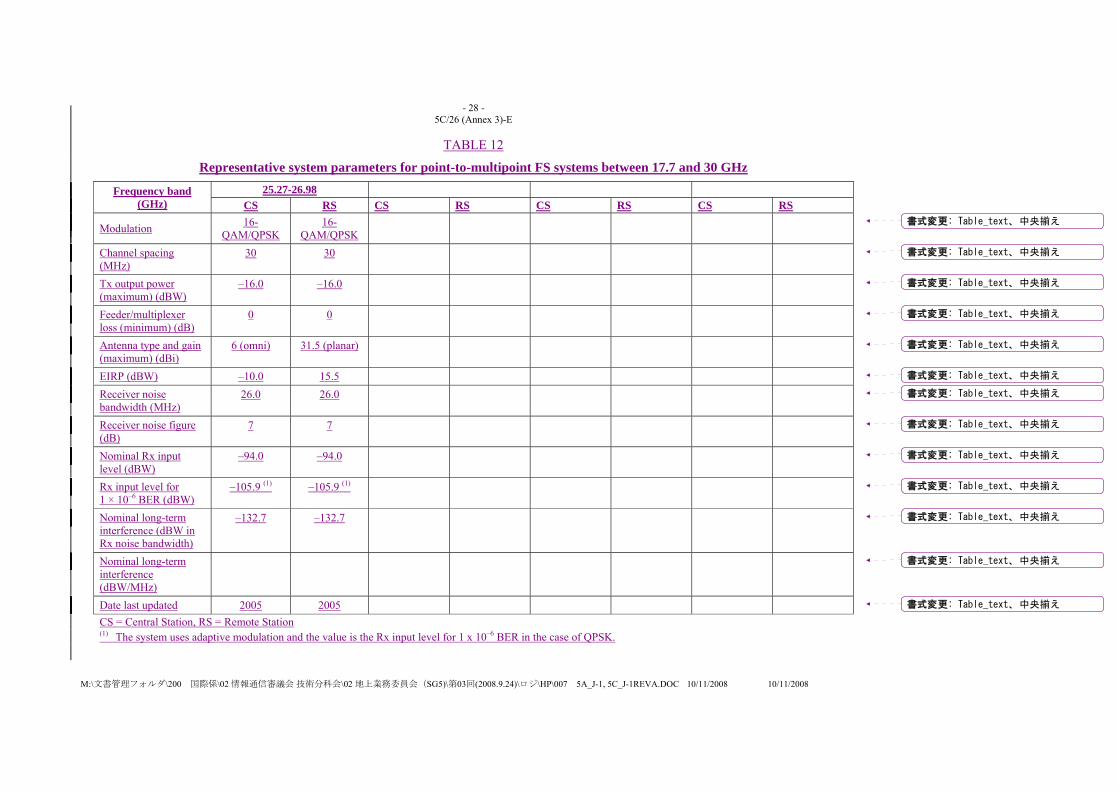
- 28 - 5C/26 (Annex 3)-E
M:\文書管理フォルダ\200 国際係\02 情報通信審議会 技術分科会\02 地上業務委員会(SG5)\第03回(2008.9.24)\ロジ\HP\007 5A_J-1, 5C_J-1REVA.DOC 10/11/2008 10/11/2008
TABLE 12
Representative system parameters for point-to-multipoint FS systems between 17.7 and 30 GHz
Frequency band (GHz)
25.27-26.98 CS RS CS RS CS RS CS RS
Modulation 16-QAM/QPSK
16-QAM/QPSK
Channel spacing (MHz)
30 30
Tx output power (maximum) (dBW)
–16.0 –16.0
Feeder/multiplexer loss (minimum) (dB)
0 0
Antenna type and gain (maximum) (dBi)
6 (omni) 31.5 (planar)
EIRP (dBW) –10.0 15.5 Receiver noise bandwidth (MHz)
26.0 26.0
Receiver noise figure (dB)
7 7
Nominal Rx input level (dBW)
–94.0 –94.0
Rx input level for 1 × 10⁻⁶ BER (dBW)
–105.9 (1) –105.9 (1)
Nominal long-term interference (dBW in Rx noise bandwidth)
–132.7 –132.7
Nominal long-term interference (dBW/MHz)
Date last updated 2005 2005 CS = Central Station, RS = Remote Station (1) The system uses adaptive modulation and the value is the Rx input level for 1 x 10⁻⁶ BER in the case of QPSK.
書式変更: Table_text、中央揃え
書式変更: Table_text、中央揃え
書式変更: Table_text、中央揃え
書式変更: Table_text、中央揃え
書式変更: Table_text、中央揃え
書式変更: Table_text、中央揃え
書式変更: Table_text、中央揃え
書式変更: Table_text、中央揃え
書式変更: Table_text、中央揃え
書式変更: Table_text、中央揃え
書式変更: Table_text、中央揃え
書式変更: Table_text、中央揃え
書式変更: Table_text、中央揃え
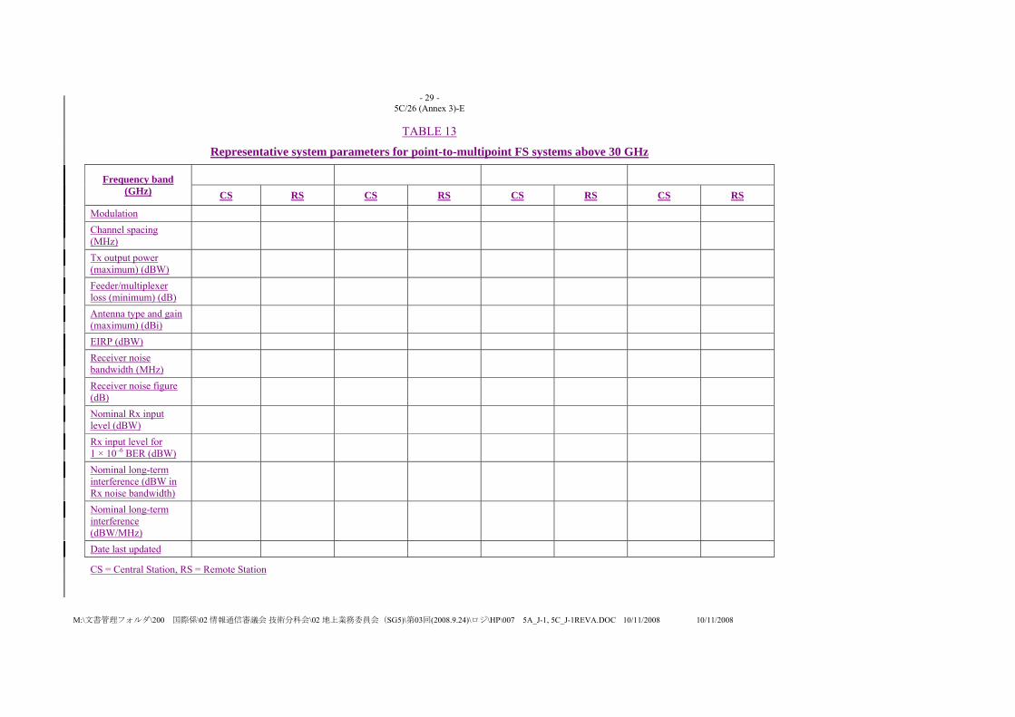
- 29 - 5C/26 (Annex 3)-E
M:\文書管理フォルダ\200 国際係\02 情報通信審議会 技術分科会\02 地上業務委員会(SG5)\第03回(2008.9.24)\ロジ\HP\007 5A_J-1, 5C_J-1REVA.DOC 10/11/2008 10/11/2008
TABLE 13
Representative system parameters for point-to-multipoint FS systems above 30 GHz
Frequency band (GHz)
CS RS CS RS CS RS CS RS
Modulation Channel spacing (MHz)
Tx output power (maximum) (dBW)
Feeder/multiplexer loss (minimum) (dB)
Antenna type and gain (maximum) (dBi)
EIRP (dBW) Receiver noise bandwidth (MHz)
Receiver noise figure (dB)
Nominal Rx input level (dBW)
Rx input level for 1 × 10⁻⁶ BER (dBW)
Nominal long-term interference (dBW in Rx noise bandwidth)
Nominal long-term interference (dBW/MHz)
Date last updated
CS = Central Station, RS = Remote Station
- 30 - 5C/26 (Annex 3)-E
M:\文書管理フォルダ\200 国際係\02 情報通信審議会 技術分科会\02 地上業務委員会(SG5)\第03回(2008.9.24)\ロジ\HP\007 5A_J-1, 5C_J-1REVA.DOC 10/11/2008 10/11/2008
Annex 3
Additional technical characteristics of some FS systems useful for sharing analysis in the 1-3 GHz band
Delete the entire text in the existing Annex 3, which has been already transferred to Report ITU-R F.2108 as its Annex 1.
Annex 4
FS antenna size in sharing studies Delete the entire text in the existing Annex 4, which has been already transferred to Report ITU-R F.2108 as its Annex 2.
M:\文書管理フォルダ\200 国際係\02 情報通信審議会 技術分科会\02 地上業務委員会(SG5)\第03回(2008.9.24)\ロジ\HP\008 5A_J-2, 5C_J-2REVA.DOC 22.09.08 10.11.08
Received:
Japan
REVIEW OF CERTAIN RECOMMENDATIONS DEVELOPED BY FORMER WORKING PARTY 9D
1 Introduction As stipulated in section 11 in Resolution ITU-R 1-5, Study Groups/Working Parties are requested to continuously examine maintained Recommendations, particularly older Recommendations for which any substantial revision was not made within 10-15 years, whether they should be deleted in the light of their content. In the previous study period, this updating work was done within the former Working Parties 9A and 9B for the F-series Recommendations developed by the both Working Parties.
This contribution proposes similar work for the Recommendations developed by the former Working Party 9D, which was responsible for frequency sharing issues between the fixed service and other radio services (except for the fixed-satellite service).
2 Proposed work for review of old Recommendations
2.1 Category of actions In the reviewing work in this contribution, the following principle is proposed: (1) The Recommendations, the latest versions of which were approved before 2000, are examined.
Within this study period until the year 2011, all the old Recommendations for which any substantial revision was not made after 2001 need to be examined. However, since it is about 3 years before the next RA, we will have another opportunity to review the remaining Recommendations. (2) Results of the consideration should be categorized in 4 cases below;
SUP: suppression without any action NOC: no change MOD: revision of the substance through the formal approval procedure Editorial Updating: no change in substance but editorial updating based on Resolution ITU-R 1-5
(section 11)
“Editorial updating” should basically be avoided for those Recommendations, the latest version of which was approved before 1998 (except for Recommendation ITU-R F.1335, see item (7) in section 2.2).
INTERNATIONAL TELECOMMUNICATION UNION
RADIOCOMMUNICATION STUDY GROUPS
Document 5A/J-2 -E Document 5C/J-2 -E September 2008English only
書式変更
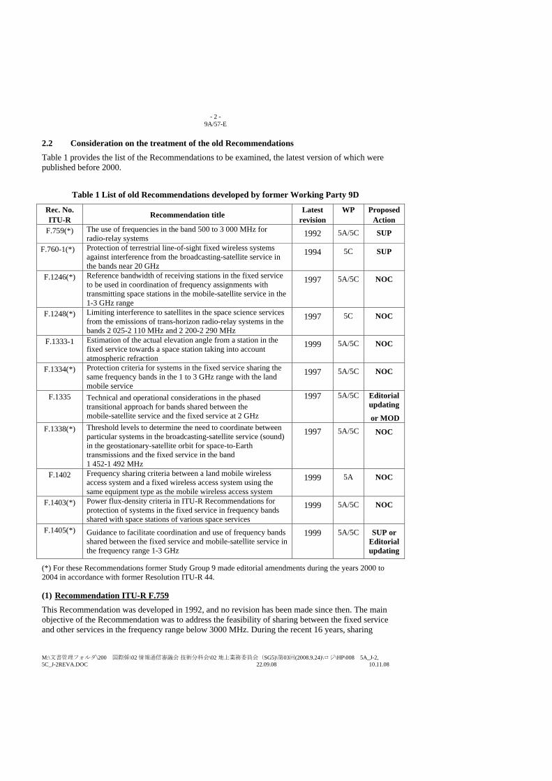
- 2 - 9A/57-E
M:\文書管理フォルダ\200 国際係\02 情報通信審議会 技術分科会\02 地上業務委員会(SG5)\第03回(2008.9.24)\ロジ\HP\008 5A_J-2, 5C_J-2REVA.DOC 22.09.08 10.11.08
2.2 Consideration on the treatment of the old Recommendations Table 1 provides the list of the Recommendations to be examined, the latest version of which were published before 2000.
Table 1 List of old Recommendations developed by former Working Party 9D
Rec. No. ITU-R Recommendation title Latest
revision WP Proposed
Action F.759(*) The use of frequencies in the band 500 to 3 000 MHz for
radio-relay systems 1992 5A/5C SUP
F.760-1(*) Protection of terrestrial line-of-sight fixed wireless systems against interference from the broadcasting-satellite service in the bands near 20 GHz
1994 5C SUP
F.1246(*) Reference bandwidth of receiving stations in the fixed service to be used in coordination of frequency assignments with transmitting space stations in the mobile-satellite service in the 1-3 GHz range
1997 5A/5C NOC
F.1248(*) Limiting interference to satellites in the space science services from the emissions of trans-horizon radio-relay systems in the bands 2 025-2 110 MHz and 2 200-2 290 MHz
1997 5C NOC
F.1333-1 Estimation of the actual elevation angle from a station in the fixed service towards a space station taking into account atmospheric refraction
1999 5A/5C NOC
F.1334(*) Protection criteria for systems in the fixed service sharing the same frequency bands in the 1 to 3 GHz range with the land mobile service
1997 5A/5C NOC
F.1335 Technical and operational considerations in the phased transitional approach for bands shared between the mobile-satellite service and the fixed service at 2 GHz
1997 5A/5C Editorial updating
or MOD F.1338(*) Threshold levels to determine the need to coordinate between
particular systems in the broadcasting-satellite service (sound) in the geostationary-satellite orbit for space-to-Earth transmissions and the fixed service in the band 1 452-1 492 MHz
1997 5A/5C NOC
F.1402 Frequency sharing criteria between a land mobile wireless access system and a fixed wireless access system using the same equipment type as the mobile wireless access system
1999 5A NOC
F.1403(*) Power flux-density criteria in ITU-R Recommendations for protection of systems in the fixed service in frequency bands shared with space stations of various space services
1999 5A/5C NOC
F.1405(*) Guidance to facilitate coordination and use of frequency bands shared between the fixed service and mobile-satellite service in the frequency range 1-3 GHz
1999 5A/5C SUP or Editorial updating
(*) For these Recommendations former Study Group 9 made editorial amendments during the years 2000 to 2004 in accordance with former Resolution ITU-R 44.
(1) Recommendation ITU-R F.759 This Recommendation was developed in 1992, and no revision has been made since then. The main objective of the Recommendation was to address the feasibility of sharing between the fixed service and other services in the frequency range below 3000 MHz. During the recent 16 years, sharing
- 3 - 9A/57-E
M:\文書管理フォルダ\200 国際係\02 情報通信審議会 技術分科会\02 地上業務委員会(SG5)\第03回(2008.9.24)\ロジ\HP\008 5A_J-2, 5C_J-2REVA.DOC 22.09.08 10.11.08
studies involving the fixed service in this frequency range have been well conducted and, as the results, ITU-R has established a number of Recommendations, which have contributed to the spectrum access for the fixed service as well as efficient use of the frequency bands in the above range.
Therefore, this Recommendation could be suppressed by completing its role.
(2) Recommendation ITU-R F.760-1
This Recommendation was initially approved in 1992 immediately before the WARC-92, and was revised once in 1994 taking into account the result of the WARC-92 (new allocation to the BSS in the bands near 20 GHz). The main substance of this Recommendation (power flux-density values for the BSS space stations to protect the fixed service) was reflected in WRC Resolution 525 approved at the WARC-92 and revised later at the WRC-03. However, the relevant text was deleted at the WRC-07 and Resolution 525 (Rev.WRC-07) no more includes these PFD values. The new requirements for the BSS space stations are under consideration in accordance with WRC-11 agenda item 1.13. This Recommendation could be suppressed since it is no more valid.
(3) Recommendation ITU-R F.1246 This Recommendation was developed in 1997 as one of the outcomes of former Joint Rapporteur Group 8D-9D. The text was editorially updated in 2004 by former Study Group 9. The content is still valid and useful to evaluate the interference between MSS space stations and the fixed service. Therefore “NOC” is proposed.
(4) Recommendation ITU-R F.1248 This Recommendation was developed in 1997 jointly by Study Group 7 and former Study Group 9. The text was editorially updated in 2004 by former Study Group 9. The content is basically still valid and useful to protect the space stations in the space science services from the emissions of trans-horizon radio-relay systems in the 2GHz frequency range. Therefore “NOC” is proposed.
(5) Recommendation ITU-R F.1333-1 This Recommendation was developed in 1997 and the text was once revised in 1999. The content is still valid and useful to estimate the elevation angle from an FS station towards a space station taking into account atmospheric refraction. Therefore “NOC” is proposed (the deletion of the referenced Question which was already suppressed is to be done by the Secretariat).
(6) Recommendation ITU-R F.1334 This Recommendation was developed in 1997 and the text was once editorially updated in 2004. The content is still valid and useful to evaluate the interference between certain land mobile stations and the fixed service. Therefore “NOC” is proposed.
(7) Recommendation ITU-R F.1335
This Recommendation was developed in 1997 as one of the outcomes of former Joint Rapporteur Group 8D-9D. Since then, the Recommendation has provided technical and operational considerations in the transitional approach in the bands near 2 GHz which are shared between the MSS and the FS. The technical analyses in this Recommendation are largely based on analogue FS systems, which the former Study Group 9 often attempted to remove from a new version of the F-
- 4 - 9A/57-E
M:\文書管理フォルダ\200 国際係\02 情報通信審議会 技術分科会\02 地上業務委員会(SG5)\第03回(2008.9.24)\ロジ\HP\008 5A_J-2, 5C_J-2REVA.DOC 22.09.08 10.11.08
series Recommendations. However, at this time, we would exceptionally propose to retain the material in this Recommendation and suggest its possible updating with the following reasons:
- It does not recommend any analogue technology but provides the interference evaluation between the FS networks using certain propagation models.
- Resolution 716 (Rev. WRC-2000) is still valid and it requests for ITU-R to develop tools to assist Administrations in possible re-planning of 2 GHz FS systems.
- A number of the equations or figures based on the P-series Recommendations require updating in the light of the latest version of these Recommendations.
The proposed text for the updating of Recommendation ITU-R F.1335 is given in a separate contribution from Japan for consideration by the meetings including which approach (editorial updating or normal revision) is preferred.
However, if most of the members are of the view that the above idea is no more necessary after consideration by Working Party 5A/5C, we are prepared to simply retain this Recommendation as “NOC”.
(8) Recommendation ITU-R F.1338 This Recommendation was developed in 1997 and the text was once editorially updated in 2004. The content is still valid and useful to evaluate the interference between certain land mobile stations and the fixed service. Therefore “NOC” is proposed.
(9) Recommendation ITU-R F.1402 This Recommendation was developed in 1999 as one of the outcomes of former Joint Rapporteur Group 8A-9B. The content is still valid and useful to analyze frequency sharing criteria between a land mobile wireless access system and a fixed wireless access system using the same equipment type. Therefore “NOC” is proposed (the deletion of the referenced Question which was already suppressed is to be done by the Secretariat).
(10) Recommendation ITU-R F.1403 This Recommendation was developed in 1999 and the text was once editorially updated in 2003. The Recommendation provides the Recommendations (not only in the F-series but also in other series) specifying power flux-density values for space stations in the various space services as well as their historical background. The content could be still useful for understanding of the pfd values derived from a number of different interference models (in particular the text in its Annex 1). There may be some updating needed in the case that a new Recommendation is adopted or an old Recommendation is deleted (e.g. if Rec. F.760-1 is suppressed as proposed in this document). For the moment, NOC is proposed for this Recommendation (the deletion of the referenced Question which was already suppressed is to be done by the Secretariat).
(11) Recommendation ITU-R F.1405 This Recommendation approved in 1999 is recommending no new substance but providing a list of the other Recommendations relevant to the information on facilitating coordination and interference assessment between FS and MSS in the frequency range 1-3 GHz. All the Recommendations listed here are still valid and important. However, it is questionable to retain the list itself in this Recommendation.
Therefore, SUP is basically suggested. However, if there is a support to maintain this Recommendation, editorial updating for several points may be required (see Attachment 1).
- 5 - 9A/57-E
M:\文書管理フォルダ\200 国際係\02 情報通信審議会 技術分科会\02 地上業務委員会(SG5)\第03回(2008.9.24)\ロジ\HP\008 5A_J-2, 5C_J-2REVA.DOC 22.09.08 10.11.08
3 Proposal
The proposed actions discussed in the previous section are indicated in the right last column of the Table 1.
Attachment 1 to this contribution (Draft updating of Recommendation ITU-R F.1405) and a separate contribution addressing draft updating of Recommendation ITU-R F.1335 also need to be referred to.
- 6 - 9A/57-E
M:\文書管理フォルダ\200 国際係\02 情報通信審議会 技術分科会\02 地上業務委員会(SG5)\第03回(2008.9.24)\ロジ\HP\008 5A_J-2, 5C_J-2REVA.DOC 22.09.08 10.11.08
Attachment 1
DRAFT UPDATING OF RECOMMENDATION ITU-R F.1405*,**
Guidance to facilitate coordination and use of frequency bands shared between the fixed service and mobile-satellite
service in the frequency range 1-3 GHz (Questions ITU-R 201/8 and ITU-R 118/9)
(1999)
Scope
(To be provided by the work of the Correspondence Group 5C-Anlist.)
The ITU Radiocommunication Assembly,
considering
a) that the fixed service (FS) is allocated in various portions of the 1-3 GHz frequency range and continues to be extensively used by many administrations in these bands;
b) that recent world radiocommunication conferences have made new allocations to the mobile-satellite service (MSS), including provisions for satellites in non-geostationary-satellite orbit (non-GSO);
c) that most of the new allocations for the MSS in the 1-3 GHz range have been established in frequency bands that were already allocated to the FS;
d) that numerous ITU-R Recommendations have been developed and adopted by Radiocommunication Study Groups 8 and 9 regarding various aspects of frequency sharing between the FS and MSS, and that an analytical index which identifies and categorizes these Recommen-dations will facilitate their application;
e) that in accordance with Article 9/Resolution 46 (Rev.WRC-97) and Appendix 7 of the Radio Regulations (RR), a coordination area is determined to identify FS stations which could affect or be affected by the operation of mobile earth stations, and analyses, if required, may be needed in the course of coordination to further define the potential for interference and identify design and operating constraints that may be needed to resolve any difficulties;
f) that in order to prevent interference between MSS (space-to-Earth) transmissions and receiving FS stations, the RR specify thresholds of power flux-density (pfd) and fractional degradation in performance (FDP) as well as a system-specific methodology (RR Appendix 5/ Resolution 46 (Rev.WRC-97)) to determine whether coordination is required, and analyses may be needed in the course of coordination to define the potential for interference and design and operating constraints that may be needed to resolve any difficulties;
g) that RR Article 21 specifies limits on the e.i.r.p. of FS stations in bands shared between the FS and MSS (Earth-to-space), but these limits were developed for protection of systems in the
____________________ * This Recommendation should be brought to the attention of Radiocommunication Study Group 8
4(Working Party 8D). ** Radiocommunication Study Group 9 5 made editorial amendments to this Recommendation in 2001 2008
in accordance with Resolution ITU-R 441.
書式変更: フォント : 斜体

- 7 - 9A/57-E
M:\文書管理フォルダ\200 国際係\02 情報通信審議会 技術分科会\02 地上業務委員会(SG5)\第03回(2008.9.24)\ロジ\HP\008 5A_J-2, 5C_J-2REVA.DOC 22.09.08 10.11.08
fixed-satellite service (FSS) (Earth-to-space) using fixed earth stations that generally operate at e.i.r.p. levels that are substantially higher than those used by mobile earth stations,
noting
a) that in light of anticipated FS-MSS frequency sharing difficulties, Resolution 716 (Rev.WRC-2000) invited the ITU-R to develop planning tools to assist those administrations considering a replanning of their terrestrial fixed networks specially in MSS (Earth-to-space) in the frequency bands 1 980-2 010 MHz and 2 170-2 200 MHz in all three Regions, and 2 010-2 025 MHz and 2 160-2 170 MHz in Region 2, in order to facilitate the introduction of MSS systems in these bands,
recognizing
a) that the specific factors and methodologies applied in the course of coordination are subject to agreement of the parties concerned, and that the relevant ITU-R Recommendations are intended to provide impartial technical advice that may facilitate the coordination process;
b) that the technical aspects of coordination of frequency assignments for FS and MSS systems are complex and may require application of analyses using complicated computer software;
c) that the availability of ITU-R Recommendations relevant to coordination of FS and MSS frequency assignments may be particularly beneficial to developing countries in relation to protection of their FS systems, their introduction of MSS systems within their territories, and the introduction of MSS systems in neighbouring territories;
d) that administrations are submitting to the ITU Radiocommunication Bureau computer software that has been developed to facilitate bilateral coordination,
recommends
1 that the following Recommendations should be considered in the coordination of FS stations with MES mobile earth stations (see Note 1): – Recommendation ITU-R M.1469: Methodology for evaluating potential for interference
from time division multiple access/frequency division multiple access (TDMA/FDMA) mobile-satellite service (MSS) (Earth-to-space) transmissions into line-of-sight fixed service receivers in the 2 GHz range.
– Recommendation ITU-R F.1245: Mathematical model of average and related radiation patterns for line-of-sight point-to-point radio-relay system antennas for use in certain coordination studies and interference assessment in the frequency range from 1 GHz to about 70 GHz.
– Recommendation ITU-R F.1336: Reference radiation patterns of omnidirectional, sectoral and other antennas in point-to-multipoint systems for use in sharing studies in the frequency range from 1 GHz to about 70 GHz;
2 that the following Recommendations should be considered in the coordination of FS systems with MSS (space-to-Earth) systems (see Note 1):
– Recommendation ITU-R M.1141: Sharing in the 1-3 GHz frequency range between non-geostationary space stations operating in the mobile-satellite service and stations in the fixed service.
- 8 - 9A/57-E
M:\文書管理フォルダ\200 国際係\02 情報通信審議会 技術分科会\02 地上業務委員会(SG5)\第03回(2008.9.24)\ロジ\HP\008 5A_J-2, 5C_J-2REVA.DOC 22.09.08 10.11.08
– Recommendation ITU-R M.1142: Sharing in the 1-3 GHz frequency range between geosta-tionary space stations operating in the mobile-satellite service and stations in the fixed service.
– Recommendation ITU-R M.1143: System specific methodology for coordination of non-geostationary space stations (space-to-Earth) operating in the mobile-satellite service with the fixed service.
– Recommendation ITU-R M.1319: The basis of a methodology to assess the impact of interference from a time division multiple access/ frequency division multiple access (TDMA/FDMA) mobile-satellite service (MSS) satellite system operating in the 2 GHz range on the performance of line-of-sight fixed service receivers.
– Recommendation ITU-R F.1108: Determination of the criteria to protect fixed service receivers from the emissions of space stations operating in non-geostationary orbits in shared frequency bands.
– Recommendation ITU-R F.699: Reference radiation patterns for line-of-sight radio-relayfixed wireless system antennas for use in coordination studies and interference assessment in the frequency range from 1 GHz100 MHz to about 70 GHz.
– Recommendation ITU-R F.1245: Mathematical model of average radiation patterns for line-of-sight point-to-point radio-relay system antennas for use in certain coordination studies and interference assessment in the frequency range from 1 GHz to about 70 GHz.
– Recommendation ITU-R F.1336: Reference radiation patterns of omnidirectional, sectoral and other antennas in point-to-multipoint systems for use in sharing studies in the frequency range from 1 GHz to about 70 GHz.
– Recommendation ITU-R M.1472: Methodology to evaluate the impact of interference from time division multiple access/frequency division multiple access (TDMA/FDMA) mobile-satellite service (MSS) systems operating in the 2 GHz range on baseband performance in frequency division multiplexing-frequency modulation (FDM-FM) analogue line-of-sight (LOS) fixed service receivers.
– Recommendation ITU-R M.1473: Methodology to evaluate the impact of interference from time division multiple access/frequency division multiple access (TDMA/FDMA) mobile-satellite service (MSS) systems operating in the 2 GHz range on video baseband performance in TV-FM analogue line-of-sight fixed service receivers.
– Recommendation ITU-R M.1474: Methodology to evaluate the impact of interference from time division multiple access/frequency division multiple access (TDMA/FDMA) mobile-satellite service (MSS) systems operating in the 2 GHz range on baseband performance in digital line-of-sight fixed service receivers based on statistics of radio-frequency inter-ference;
- 9 - 9A/57-E
M:\文書管理フォルダ\200 国際係\02 情報通信審議会 技術分科会\02 地上業務委員会(SG5)\第03回(2008.9.24)\ロジ\HP\008 5A_J-2, 5C_J-2REVA.DOC 22.09.08 10.11.08
3 that the following Recommendations should be considered in assessments of the potential for interference from FS transmitters to MSS space station receivers (see Note 1): – Recommendation ITU-R M.1141: Sharing in the 1-3 GHz frequency range between non-
geostationary space stations operating in the mobile-satellite service and stations in the fixed service.
– Recommendation ITU-R M.1142: Sharing in the 1-3 GHz frequency range between geo-stationary space stations operating in the mobile-satellite service and stations in the fixed service;
4 that the technical guidance and planning tool provided in Recommendation ITU-R F.1335 should be considered when planning the transition of FS systems from the bands 1 980-2 010 MHz and 2 170-2 200 MHz in all three Regions, and 2 010-2 025 MHz and 2 160-2 170 MHz in Region 2.
NOTE 1 – Radiocommunication Study Groups 8 and 95 should expand this list, as appropriate, and should consider establishing a finer categorization of the Recommendations included in the list.
Rec. ITU-R F.1335 1
Received
Japan
DRAFT UPDATING OF RECOMMENDATION ITU-R F.1335
TECHNICAL AND OPERATIONAL CONSIDERATIONS IN THE PHASED TRANSITIONAL APPROACH FOR BANDS SHARED BETWEEN THE MOBILE-
SATELLITE SERVICE AND THE FIXED SERVICE AT 2 GHz
As proposed in another contribution from Japan (Document 5A/J-2, 5C/J-2), this document provides the updated text for Recommendation ITU-R F.1335 for consideration by the Working Party meetings 5A/5C including which approach (editorial updating or normal revision) is preferred as given in the Attachment 1.
INTERNATIONAL TELECOMMUNICATION UNION
RADIOCOMMUNICATION STUDY GROUPS
Document 5A/J-3 -E Document 5C/J-3-E September 2008English only
2 Rec. ITU-R F.1335
Attachment 1
DRAFT UPDATING OF RECOMMENDATION ITU-R F.1335*
TECHNICAL AND OPERATIONAL CONSIDERATIONS IN THE PHASED TRANSITIONAL APPROACH FOR BANDS SHARED BETWEEN THE MOBILE-SATELLITE
SERVICE AND THE FIXED SERVICE AT 2 GHz**
(Question ITU-R 208/9)
(1997) Rec. ITU-R F.1335
Scope
(TBD)
The ITU Radiocommunication Assembly,
considering
...
e) that Resolution 716 (WRC-95Rev.WRC-2000) concerning the use of the 2 GHz band by the FS and MSS and associated transition arrangements, encouraged administrations where practicable to draw up plans for the gradual transfer of the frequency assignments to their FS stations in the shared 2 GHz MSS bands to non- overlapping bands, giving priority to the transfer of their frequency assignments in the Earth-to-space band 1 980-2 010 MHz in all Regions and 2 010-2 025 MHz in Region 2, considering the technical, operational and economic aspects;
...
g) that Resolution 716 (Rev.WRC-2000WRC-95) requests ITU-R to develop planning tools necessary to assist those administrations considering re-planning of their terrestrial networks to accommodate the MSS in the 2 GHz bands,
recommends
1 that administrations may take into account the material in the Annexes 1 to 4 when considering transitional arrangements for the MSS and FS at 2 GHz.
_______________ * This Recommendation was developed jointly by former Radiocommunication Study Groups 8 and 9, and any further revision
should also be undertaken jointly by Radiocommunication Study Groups 4 and 5. This Recommendation should be brought to the attention of Radiocommunication Bureau.
** In accordance with Resolution 716 (Rev.WRC-2000WRC-95) of the World Radiocommunication Conference (GenevaIstanbul, 19952000), the frequency bands dealt with in this Recommendation are mainly in the bands 1 980-2 010 MHz (worldwide) and 2 010-2 025 MHz (Region 2) allocated to the MSS (Earth-to-space) and the bands 2 160-2 170 MHz (Region 2) and 2 170-2 200 MHz (worldwide) allocated to the MSS (space-to-Earth).
書式変更: フランス語(フランス)
書式変更: フランス語(フランス)

Rec. ITU-R F.1335 3
ANNEX 1
Technical and operational considerations in the phased transitional approach for bands shared between the MSS and the FS at 2 GHz
1 Introduction ...
Two aspects are dealt with in this Annex: – the continued operation of fixed systems within the spectrum identified for MSS implementation for a reasonable
period of time; and – the continued operation of the FS systems in the 2 GHz range beyond this transition period, including the necessary
planning and coordination tools to move the system, or a portion of the system, to spectrum outside that which is required for MSS implementation. (See Resolution 716 (WRC-95Rev.WRC-2000) Requests Invites ITU-R 1.2.)
2 Co-primary MSS allocations at 2 GHz (No change)
3 Background There are two principal radio-frequency channel arrangements used by the existing fixed systems, Ex-Recommen-dations ITU-R F.283 (which was suppressed in 2007 and the relevant information is available on the ITU Website) and Recommendation ITU-R F.382. Ex-Recommendation ITU-R F.283 provides the channel arrangements for the two sub-bands 1 900-2 100 MHz and 2 100-2 300 MHz with six paired channels in each sub-band, each with a bandwidth of 14 MHz. Recommendation ITU-R F.382 provides channel arrangements for the band 1 900-2 300 MHz with six paired channels, each with a bandwidth of 29 MHz, using two 29 MHz channel arrangements overlayed at a 14.5 MHz offset. These arrangements and their relationship with the current MSS allocations are illustrated in Fig. 1.
Recommendation ITU-R F.1098, developed in response to Resolution 113 (WRC-92) as a result of the World Administrative Radio Conference for Dealing with Frequency Allocations in Certain Parts of the Spectrum, Malaga-Torremolinos, 1992 (WARC-92) allocations, provides for three channel arrangements for new fixed systems in the band 1 900-2 300 MHz. It focuses on the “core” bands 2 025-2 110 MHz and 2 200-2 290 MHz wherein the FS, mobile and space operations, space research, earth exploration-satellite services (MS, SOS, SRS, EESS) share co-primary allocation space. These channel arrangement descriptions are illustrated in Fig. 2.
Figure 1 (No change)
Figure 2 (No change)
...
Allowance is made in Annexes 2 and 3 to Recommendation ITU-R F.1098 for extended channel arrangements where adequate geographical and/or frequency separation would make sharing possible with MSS or future public landinternational mobile telecommunications -2000systems (FPLMTSIMT-2000).
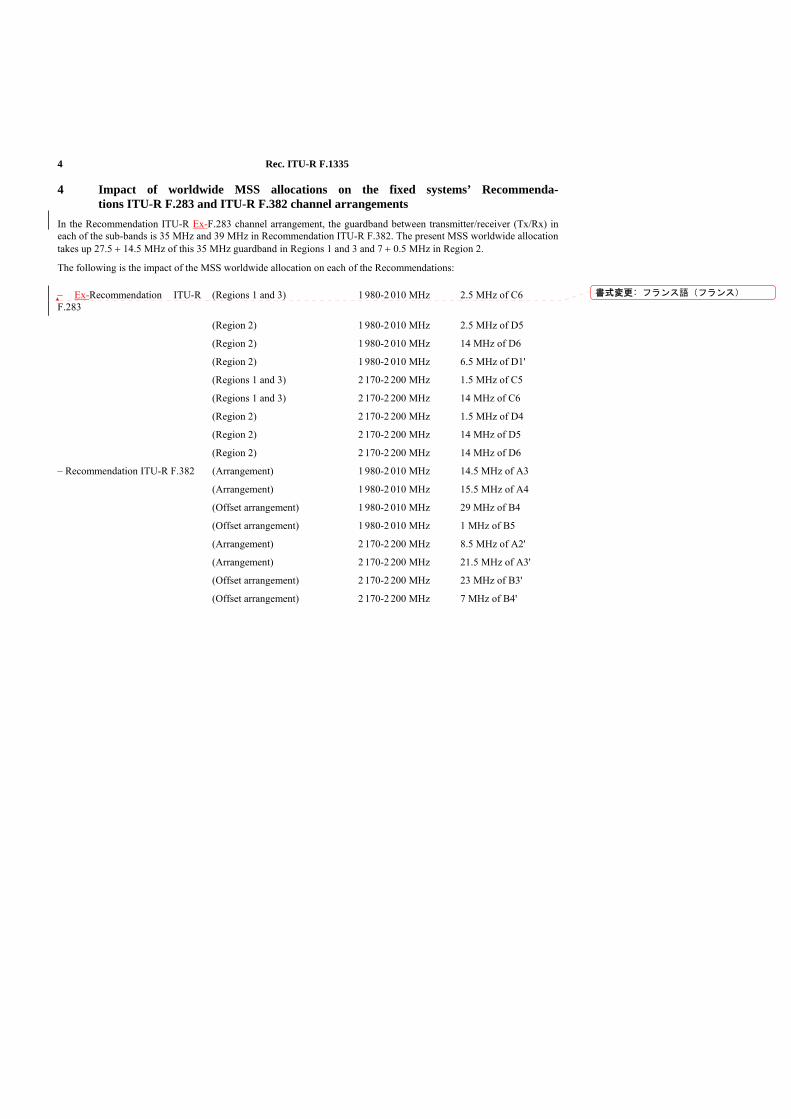
4 Rec. ITU-R F.1335
4 Impact of worldwide MSS allocations on the fixed systems’ Recommenda-tions ITU-R F.283 and ITU-R F.382 channel arrangements
In the Recommendation ITU-R Ex-F.283 channel arrangement, the guardband between transmitter/receiver (Tx/Rx) in each of the sub-bands is 35 MHz and 39 MHz in Recommendation ITU-R F.382. The present MSS worldwide allocation takes up 27.5 + 14.5 MHz of this 35 MHz guardband in Regions 1 and 3 and 7 + 0.5 MHz in Region 2.
The following is the impact of the MSS worldwide allocation on each of the Recommendations: – Ex-Recommendation ITU-R F.283
(Regions 1 and 3) 1 980-2 010 MHz 2.5 MHz of C6
(Region 2) 1 980-2 010 MHz 2.5 MHz of D5
(Region 2) 1 980-2 010 MHz 14 MHz of D6
(Region 2) 1 980-2 010 MHz 6.5 MHz of D1'
(Regions 1 and 3) 2 170-2 200 MHz 1.5 MHz of C5
(Regions 1 and 3) 2 170-2 200 MHz 14 MHz of C6
(Region 2) 2 170-2 200 MHz 1.5 MHz of D4
(Region 2) 2 170-2 200 MHz 14 MHz of D5
(Region 2) 2 170-2 200 MHz 14 MHz of D6
– Recommendation ITU-R F.382 (Arrangement) 1 980-2 010 MHz 14.5 MHz of A3
(Arrangement) 1 980-2 010 MHz 15.5 MHz of A4
(Offset arrangement) 1 980-2 010 MHz 29 MHz of B4
(Offset arrangement) 1 980-2 010 MHz 1 MHz of B5
(Arrangement) 2 170-2 200 MHz 8.5 MHz of A2'
(Arrangement) 2 170-2 200 MHz 21.5 MHz of A3'
(Offset arrangement) 2 170-2 200 MHz 23 MHz of B3'
(Offset arrangement) 2 170-2 200 MHz 7 MHz of B4'
書式変更: フランス語(フランス)
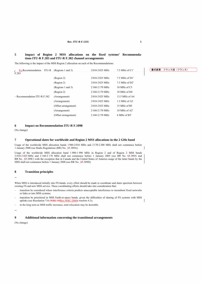
Rec. ITU-R F.1335 5
5 Impact of Region 2 MSS allocations on the fixed systems’ Recommenda-tions ITU-R F.283 and ITU-R F.382 channel arrangements
The following is the impact of the MSS Region 2 allocation on each of the Recommendations: – Ex-Recommendation ITU-R F.283
(Regions 1 and 3) 2 010-2 025 MHz 7.5 MHz of C1'
(Region 2) 2 010-2 025 MHz 7.5 MHz of D1'
(Region 2) 2 010-2 025 MHz 7.5 MHz of D2'
(Regions 1 and 3) 2 160-2 170 MHz 10 MHz of C5
(Region 2) 2 160-2 170 MHz 10 MHz of D4
– Recommendation ITU-R F.382 (Arrangement) 2 010-2 025 MHz 13.5 MHz of A4
(Arrangement) 2 010-2 025 MHz 1.5 MHz of A5
(Offset arrangement) 2 010-2 025 MHz 15 MHz of B5
(Arrangement) 2 160-2 170 MHz 10 MHz of A2'
(Offset arrangement) 2 160-2 170 MHz 6 MHz of B3'
6 Impact on Recommendation ITU-R F.1098 (No change)
7 Operational dates for worldwide and Region 2 MSS allocations in the 2 GHz band Usage of the worldwide MSS allocation bands 1 980-2 010 MHz and 2 170-2 200 MHz shall not commence before 1 January 2000 (see Radio Regulations (RR) No. S5.389A).
Usage of the worldwide MSS allocation band 1 980-1 990 MHz in Region 2 and of Region 2 MSS bands 2 010-2 025 MHz and 2 160-2 170 MHz shall not commence before 1 January 2005 (see RR No. S5.389A and RR No. S5.389C) with the exception that in Canada and the United States of America usage of the latter bands by the MSS shall not commence before 1 January 2000 (see RR No. S5.389D).
8 Transition principles ...
When MSS is introduced initially into FS bands, every effort should be made to coordinate and share spectrum between existing FS and new MSS service. These coordinating efforts should take into consideration that: – transition be considered where interference criteria predicts unacceptable interference to incumbent fixed networks
or links or into MSS systems; – transition be prioritized in MSS Earth-to-space bands, given the difficulties of sharing of FS systems with MSS
uplinks (see Resolution 716 (WRC-95Rev.WRC-2000) resolves 4.3); – in the long term as MSS traffic increases, total relocation may be desirable.
...
9 Additional information concerning the transitional arrangements (No change)
書式変更: フランス語(フランス)
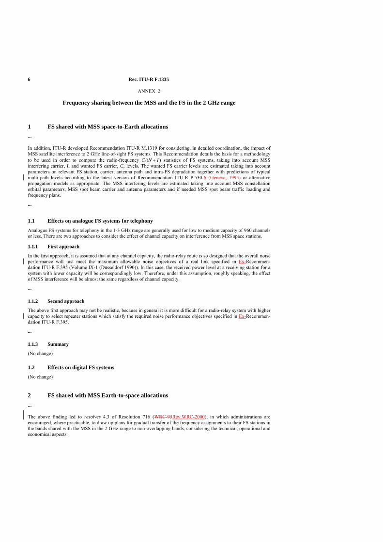
6 Rec. ITU-R F.1335
ANNEX 2
Frequency sharing between the MSS and the FS in the 2 GHz range
1 FS shared with MSS space-to-Earth allocations ...
In addition, ITU-R developed Recommendation ITU-R M.1319 for considering, in detailed coordination, the impact of MSS satellite interference to 2 GHz line-of-sight FS systems. This Recommendation details the basis for a methodology to be used in order to compute the radio-frequency C / (N + I ) statistics of FS systems, taking into account MSS interfering carrier, I, and wanted FS carrier, C, levels. The wanted FS carrier levels are estimated taking into account parameters on relevant FS station, carrier, antenna path and intra-FS degradation together with predictions of typical multi-path levels according to the latest version of Recommendation ITU-R P.530-6 (Geneva, 1995) or alternative propagation models as appropriate. The MSS interfering levels are estimated taking into account MSS constellation orbital parameters, MSS spot beam carrier and antenna parameters and if needed MSS spot beam traffic loading and frequency plans.
...
1.1 Effects on analogue FS systems for telephony
Analogue FS systems for telephony in the 1-3 GHz range are generally used for low to medium capacity of 960 channels or less. There are two approaches to consider the effect of channel capacity on interference from MSS space stations.
1.1.1 First approach
In the first approach, it is assumed that at any channel capacity, the radio-relay route is so designed that the overall noise performance will just meet the maximum allowable noise objectives of a real link specified in Ex-Recommen-dation ITU-R F.395 (Volume IX-1 (Düsseldorf 1990)). In this case, the received power level at a receiving station for a system with lower capacity will be correspondingly low. Therefore, under this assumption, roughly speaking, the effect of MSS interference will be almost the same regardless of channel capacity.
...
1.1.2 Second approach
The above first approach may not be realistic, because in general it is more difficult for a radio-relay system with higher capacity to select repeater stations which satisfy the required noise performance objectives specified in Ex-Recommen-dation ITU-R F.395.
...
1.1.3 Summary
(No change)
1.2 Effects on digital FS systems
(No change)
2 FS shared with MSS Earth-to-space allocations ...
The above finding led to resolves 4.3 of Resolution 716 (WRC-95Rev.WRC-2000), in which administrations are encouraged, where practicable, to draw up plans for gradual transfer of the frequency assignments to their FS stations in the bands shared with the MSS in the 2 GHz range to non-overlapping bands, considering the technical, operational and economical aspects.
Rec. ITU-R F.1335 7
ANNEX 3
Some transitional arrangements for analogue radio-relay systems for telephony in the 2 GHz range
1 Review of optimum frequency deviation Preferred frequency deviation for analogue radio-relay systems for telephony using FDM-FM is given in Ex-Recommendation ITU-R F.404-2 (Volume IX-1 ((Düsseldorf, 1990)). The values applicable to capacities of 960 channels or less are reproduced in Table 1.
...
The performance of FDM-FM analogue radio-relay system is usually measured using a continuous uniform spectrum signal (see Ex-Recommendation ITU-R F.399-3 (Volume IX-1 ((Düsseldorf, 1990)). Generally the baseband signal-to-noise (S / N ) ratio shows the characteristic of Fig. 3 as a function of r.m.s. frequency deviation per channel (loading level).
...
Figure 3 (No change)
...
2.1 New pre-emphasis circuit
Pre-emphasis characteristic for FDM-FM radio-relay systems for telephony is given in Ex-Recommendation ITU-R F.275-3 (Volume IX-1 (Düsseldorf, 1990)).
If practicable, a new pre-emphasis circuit and a new de-emphasis circuit applicable to the lower capacity should be adopted. In case of a change from 960 to 600 channels, the interference from the MSS will be reduced by at least 20 log (4 028/2 540) = 4 dB due to the change of the highest baseband frequency.
...
ANNEX 4
Algorithms and methodologies for simulation of interference between FS networks
1 Introduction This Annex describes algorithms and methods required to simulate interference between networks operating in the terrestrial FS.
The motivation for this type of simulation is two fold: – to respond to Resolution 716 (WRC-95Rev.WRC-2000) § 1.2, where the ITU-R is requested to develop tools to
assist Administrations in possible re-planning of 2 GHz FS systems to avoid overlap with the 2 GHz MSS allocations;
8 Rec. ITU-R F.1335
– to allow Administrations to investigate the feasibility of replanning existing 2 GHz FS systems using for example Recommendation ITU-R F.382 or Ex-Recommendation ITU-R F.283 to replace FS channels presently overlapping with the 2 GHz MSS allocations, in particular in the MSS Earth-to-space direction, with other available FS channels. Such a simulation tool would be able to assist in determining whether or not in the replanned FS system the network performance objectives would continue to be respected.
1.1 Features of an intra-FS analysis model
The top level requirements can be summarized as follows: – one FS system must be defined as the wanted system; – define all stations of all other FS systems as potentially interfering; – aggregate interference from all interfering links into each wanted link is calculated; – wanted propagation model based on Recommendation ITU-R P.530-6 (Geneva, 1995); – interfering propagation model based on Recommendation ITU-R P.452-7 (Geneva, 1995), including terrain based
diffraction model and digital terrain data;
– computation of C / I, C / N and C / (N + I ) PDF (probability distribution function) and CDF (cumulative distribution function) for each station of the wanted system;
– end-to-end statistics calculated, making a distinction between digital and analogue systems; – inclusion of polarization discrimination for orthogonal linearly polarized carriers.
1.2 Antennas and polarization discrimination
(No change)
2 FS system representation (No change)
Figure 4 (No change) FIGURE 1335-04
3 The interference calculation (No change)
3.1 Power calculation
(No change)
Figure 5 (No change)
3.2 Propagation modelling
This subsection gives an overview of the applicable propagation models. Detailed descriptions of these models are given in § 5.
A distinction is made between interfering signals and wanted signals in performing the interference analysis. For LOS losses, Recommendation ITU-R P.530-6 (Geneva, 1995) is applicable to wanted signals and Recommen-dation ITU-R P.452 to interfering signals.
These Recommendations (i.e. Recommendations ITU-R P.530-6 and ITU-R P.452) are being revised and the intent of this section is to specify the algorithm. Relevant algorithms are included in this Recommendation for completeness based on existing equations in Recommendations ITU-R P.530-6 and ITU-R P.452. These algorithms would be however generally applicable within the context of new revisions to Recommendations ITU-R P.530-6 and ITU-R P.452, although the specific form of the equations contained herein may change.
LOS fixed links can be modelled using the Recommendation ITU-R P.530-6 initial planning method, combined with free space path loss. This method gives a distribution of fade and multipath enhancement as a function of link length, frequency antenna heights and meteorological parameters.

Rec. ITU-R F.1335 9
...
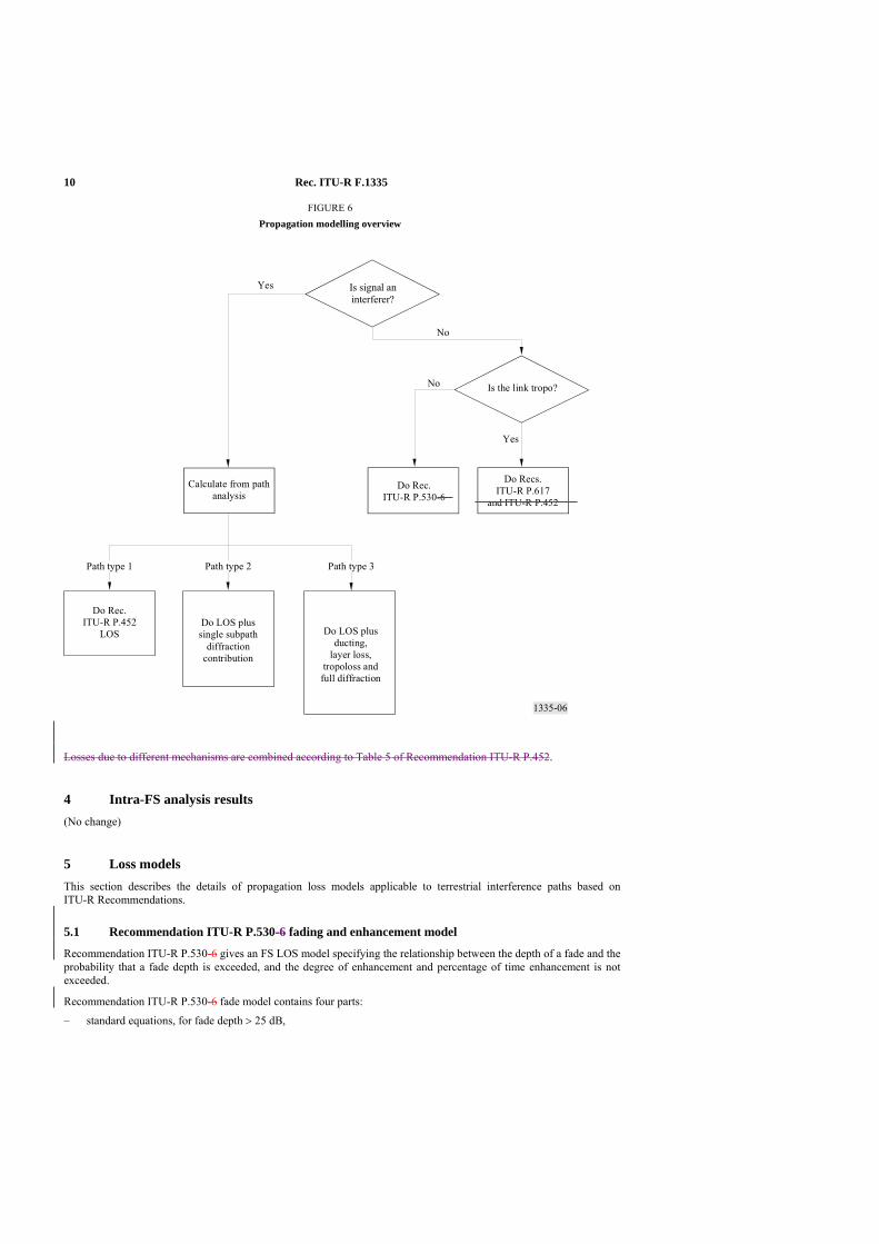
10 Rec. ITU-R F.1335
1335-06
Is signal aninterferer?
Is the link tropo?
Calculate from pathanalysis
Do Rec.ITU-R P.530-6
Do Recs.ITU-R P.617
and ITU-R P.452
Do Rec.ITU-R P.452
LOSDo LOS plussingle subpath
diffractioncontribution
Do LOS plusducting,
layer loss,tropoloss andfull diffraction
FIGURE 6Propagation modelling overview
Path type 3
No
Yes
No
Yes
Path type 2Path type 1
FIGURE 1335-06
Losses due to different mechanisms are combined according to Table 5 of Recommendation ITU-R P.452.
4 Intra-FS analysis results (No change)
5 Loss models This section describes the details of propagation loss models applicable to terrestrial interference paths based on ITU-R Recommendations.
5.1 Recommendation ITU-R P.530-6 fading and enhancement model
Recommendation ITU-R P.530-6 gives an FS LOS model specifying the relationship between the depth of a fade and the probability that a fade depth is exceeded, and the degree of enhancement and percentage of time enhancement is not exceeded.
Recommendation ITU-R P.530-6 fade model contains four parts:
– standard equations, for fade depth > 25 dB,

Rec. ITU-R F.1335 11
– extrapolation, for fade depth < 25 dB,
– equations for propagation enhancement for enhancements > 10 dB, – equations for propagation enhancement for enhancements between 0 and 10 dB.
Two methods are proposed in Recommendation 530-6 to assess the fading model. Method 1 is intended for link planning and design and is described below.
Wherever the multipath fade model is used, the enhancement model must also be taken into account. The long and short term fades together with the enhancement define a cumulative distribution function which can be used in a Monte-Carlo simulation of the fade depth. A random number is generated and used to define a % time for which the CDF must be inverted. This inversion of the CDF is a standard method for sampling non-standard distributions, and can always be performed to the required accuracy using a binary chop algorithm.
The equations for calculating the probability of a given fade and a given enhancement are detailed below.
The percentage of time, pw, that the fade depth, A (dB) is exceeded in the average worst month is given by (valid for small percentages of time):
p K Q f dwB C A= −10 10/
10/10 ACw BdQKp −=
where: K, Q, B, C are defined as follows:
B = 100.032f-0.0085hL 0.89
C = 3.62
Q = (1 + |εp |)−14 ( ) 97.01
−+ pε
where:
εp : path inclination (mrad) given by εp h h d= −1 2 /
h1, h2 : antenna heights (m) above sea level
d : path length (km) f : frequency (GHz)
hL: the altitude of the lower antenna (i.e. the smaller of h1 and h2) K : geoclimatic factor for the average worst month from fading.
42.0003.09.3 110 −−−= adN sK
where dN1 is the point refractivity gradient in the lowest 65 m of the atmosphere not exceeded for 1% of an average year, and sa is the area terrain roughness.
dN1 is provided on a 1.5° grid in latitude and longitude in Recommendation ITU-R P.453. The correct value for the latitude and longitude at path centre should be obtained from the values for the four closest grid points by bilinear interpolation. The data are available in a tabular format and are available from the Radiocommunication Bureau (BR).
sa is defined as the standard deviation of terrain heights (m) within a 110 km × 110 km area with a 30 s resolution (e.g. the Globe “gtopo30” data). The area should be aligned with the longitude, such that the two equal halves of the area are on each side of the longitude that goes through the path centre. Terrain data are available from the World Wide Web (the web address is provided by the BR).
If the parameters to estimate K, the geoclimatic factor are not available, then K can be found using an alternative means such as the contour maps of Figs. 7 to 10 of Recommendation ITU-R P.453 for the percentage of time pL that the
書式変更: フォント : 10 pt, 文字位置下げる 6 pt
書式変更: 上付き
書式変更: 文字位置下げる 8 pt
書式変更: 標準、タブ位置: 5.39 字(なし)
書式変更: 下付き
書式変更: 下付き
書式変更: 下付き
書式変更: 標準、タブ位置: 5.39 字(なし)
書式変更: 英語 (米国)
書式変更: 標準、タブ位置: 5.39 字(なし)
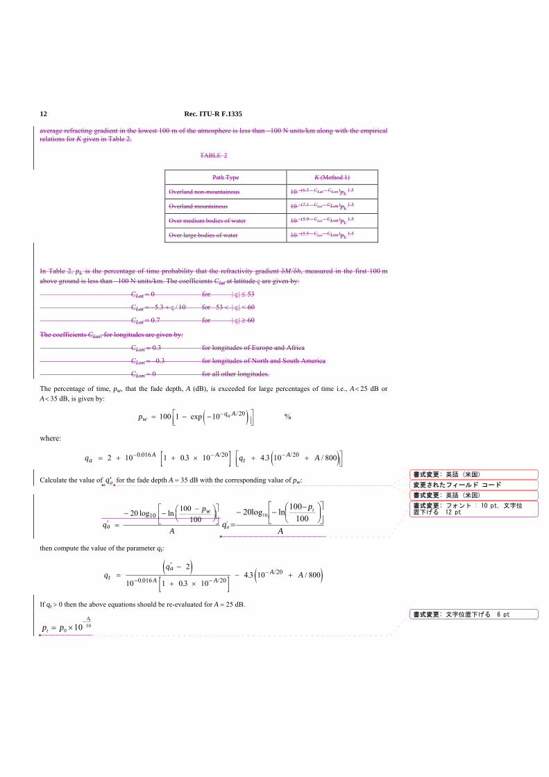
12 Rec. ITU-R F.1335
average refracting gradient in the lowest 100 m of the atmosphere is less than –100 N units/km along with the empirical relations for K given in Table 2.
TABLE 2
In Table 2, pL is the percentage of time probability that the refractivity gradient δM / δh, measured in the first 100 m above ground is less than –100 N units/km. The coefficients Clat at latitude ς are given by:
CLat = 0 for | ς | ≤ 53
CLat = –5.3 + ς / 10 for 53 < | ς | < 60
CLat = 0.7 for | ς | ≥ 60
The coefficients Clon, for longitudes are given by:
CLon = 0.3 for longitudes of Europe and Africa
CLon = –0.3 for longitudes of North and South America
CLon = 0 for all other longitudes.
The percentage of time, pw, that the fade depth, A (dB), is exceeded for large percentages of time i.e., A < 25 dB or A < 35 dB, is given by:
( )pwq Aa= − −⎡
⎣⎢⎤⎦⎥
−100 1 10 20exp / %
where:
[ ] ( )q q AaA A
tA= + + × + +⎡
⎣⎢⎤⎦⎥
− − −2 10 1 0 3 10 4 3 10 8000 016 20 20. / /. . /
Calculate the value of ′qa for the fade depth A = 35 dB with the corresponding value of pw:
q
p
Aa
w
′ =− − −⎛
⎝⎜⎞⎠⎟
⎡
⎣⎢
⎤
⎦⎥20 100
10010log ln
A
p
q
t
a
⎥⎦
⎤⎢⎣
⎡⎟⎠⎞
⎜⎝⎛ −
−−=′
100100lnlog20 10
then compute the value of the parameter qt:
( )[ ] ( )q
qAt
a
A AA=
−
+ ×− +
′
− −−
2
10 1 0 3 104 3 10 800
0 016 2020
. //
.. /
If qt > 0 then the above equations should be re-evaluated for A = 25 dB.
100 10
tA
t pp−
×=
Path Type K (Method 1)
Overland non-mountainous 10 –(6.5 – CLat – CLon )pL 1.5
Overland mountainous 10 –(7.1 – CLat – CLon )pL 1.5
Over medium bodies of water 10 –(5.9 – CLat – CLon )pL 1.5
Over large bodies of water 10 –(5.5 – CLat – CLon )pL 1.5
書式変更: 英語 (米国)
変更されたフィールド コード
書式変更: 英語 (米国)
書式変更: フォント : 10 pt, 文字位置下げる 12 pt
書式変更: 文字位置下げる 6 pt
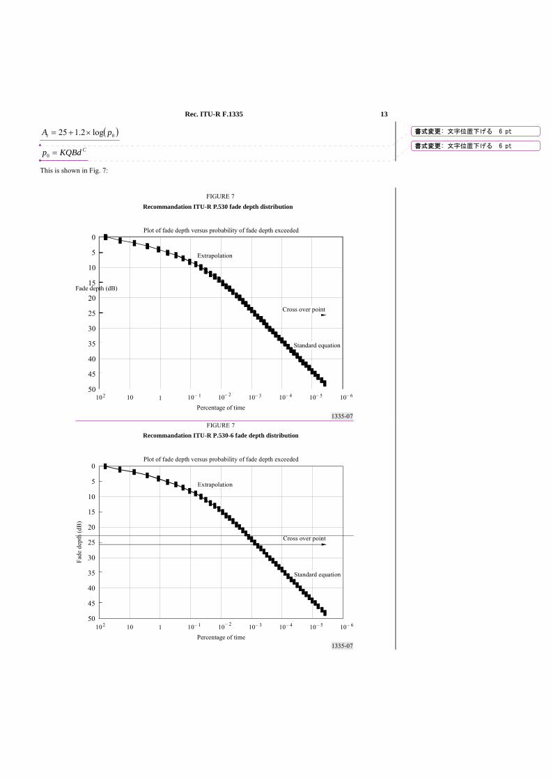
Rec. ITU-R F.1335 13
( )0log2.125 pAt ×+=
CKQBdp =0
This is shown in Fig. 7:
1335-07
0
10
15
5
20
25
30
35
40
45
50 10 2 10 10 – 1 1 10– 3 10– 4 10– 5 10– 610 – 2
Fade depth (dB)
Percentage of time
FIGURE 7Recommandation ITU-R P.530 fade depth distribution
Plot of fade depth versus probability of fade depth exceeded
Extrapolation
Cross over point
Standard equation
1335-07
0
10
15
5
20
25
30
35
40
45
50102 10 10– 11 10– 3 10– 4 10– 5 10– 610– 2
Fade
dep
th (d
B)
Percentage of time
FIGURE 7Recommandation ITU-R P.530-6 fade depth distribution
Plot of fade depth versus probability of fade depth exceeded
Extrapolation
Cross over point
Standard equation
書式変更: 文字位置下げる 6 pt
書式変更: 文字位置下げる 6 pt
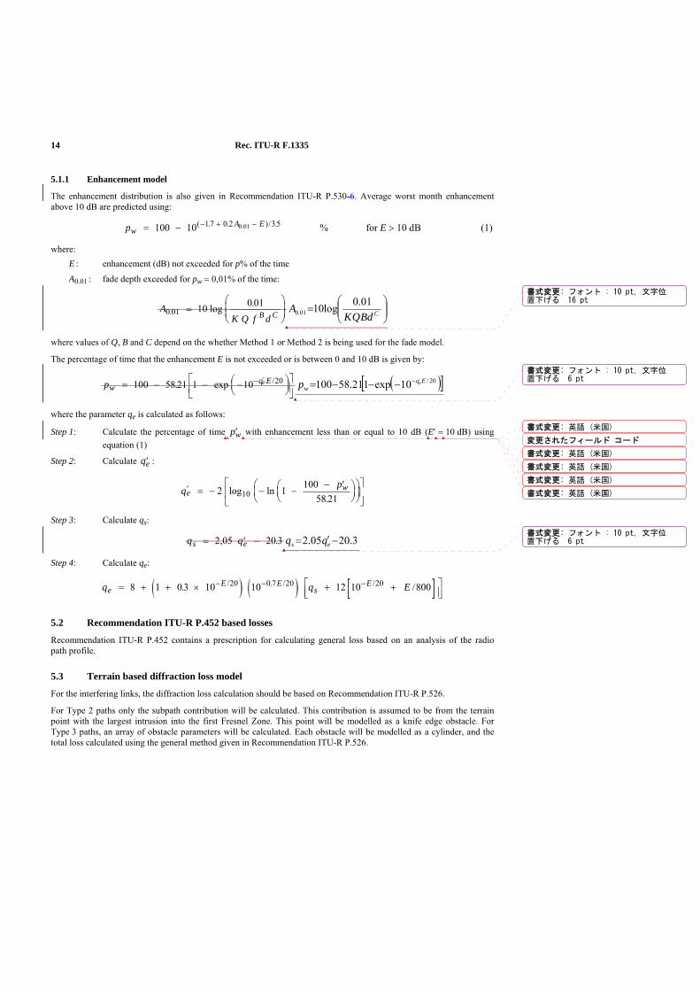
14 Rec. ITU-R F.1335
FIGURE 1335-07
5.1.1 Enhancement model
The enhancement distribution is also given in Recommendation ITU-R P.530-6. Average worst month enhancement above 10 dB are predicted using:
pwA E= − − + −100 10 1 7 0 2 3 50.01( . . )/ . % for E > 10 dB (1)
where: E : enhancement (dB) not exceeded for p% of the time
A0.01 : fade depth exceeded for pw = 0,01% of the time:
AK Q f dB C0 01 10 0 01
. log .=⎛
⎝⎜⎜
⎞
⎠⎟⎟ ⎟⎟
⎠
⎞⎜⎜⎝
⎛= CBdQK
A 01.0log1001.0
where values of Q, B and C depend on the whether Method 1 or Method 2 is being used for the fade model.
The percentage of time that the enhancement E is not exceeded or is between 0 and 10 dB is given by:
pwq Ee= − − −⎛
⎝⎜⎞⎠⎟
⎡⎣⎢
⎤⎦⎥
− ′100 58 21 1 10 20. exp / ( )[ ]20/10exp121.58100 Eqw
ep −−−−=
where the parameter qe is calculated as follows:
Step 1: Calculate the percentage of time ′pw with enhancement less than or equal to 10 dB (E′ = 10 dB) using equation (1)
Step 2: Calculate ′qe :
q pe
w′ = − − −− ′⎛
⎝⎜⎞⎠⎟
⎛⎝⎜
⎞⎠⎟
⎡
⎣⎢
⎤
⎦⎥2 1 100
58 2110log ln.
Step 3: Calculate qs:
q qs e= ′ −2 05 20 3, . 3.2005.2 −′= es qq
Step 4: Calculate qe:
( ) ( ) [ ]q q EeE E
sE= + + × + +⎡
⎣⎢⎤⎦⎥
− − −8 1 0 3 10 10 12 10 80020 0 7 20 20. // . / /
5.2 Recommendation ITU-R P.452 based losses
Recommendation ITU-R P.452 contains a prescription for calculating general loss based on an analysis of the radio path profile.
5.3 Terrain based diffraction loss model
For the interfering links, the diffraction loss calculation should be based on Recommendation ITU-R P.526.
For Type 2 paths only the subpath contribution will be calculated. This contribution is assumed to be from the terrain point with the largest intrusion into the first Fresnel Zone. This point will be modelled as a knife edge obstacle. For Type 3 paths, an array of obstacle parameters will be calculated. Each obstacle will be modelled as a cylinder, and the total loss calculated using the general method given in Recommendation ITU-R P.526.
書式変更: フォント : 10 pt, 文字位置下げる 16 pt
書式変更: フォント : 10 pt, 文字位置下げる 6 pt
書式変更: 英語 (米国)
変更されたフィールド コード
書式変更: 英語 (米国)
書式変更: 英語 (米国)
書式変更: 英語 (米国)
書式変更: 英語 (米国)
書式変更: フォント : 10 pt, 文字位置下げる 6 pt
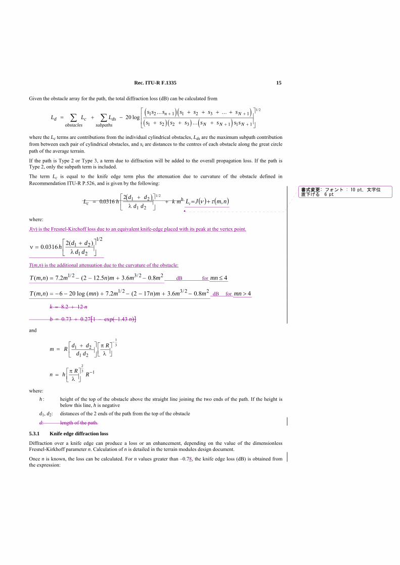
Rec. ITU-R F.1335 15
Given the obstacle array for the path, the total diffraction loss (dB) can be calculated from
( ) ( )( ) ( ) ( )
L L Ls s s s s s s
s s s s s s s sd c ds
subpathsobstacles
n N
N N N= + −
+ + + +
+ + +
⎡
⎣
⎢⎢
⎤
⎦
⎥⎥∑∑ + +
+ +20
1 2 1 1 2 3 1
1 2 2 3 1 1 1
1 2
log... ...
...
/
where the Lc terms are contributions from the individual cylindrical obstacles, Lds are the maximum subpath contribution from between each pair of cylindrical obstacles, and si are distances to the centres of each obstacle along the great circle path of the average terrain.
If the path is Type 2 or Type 3, a term due to diffraction will be added to the overall propagation loss. If the path is Type 2, only the subpath term is included.
The term Lc is equal to the knife edge term plus the attenuation due to curvature of the obstacle defined in Recommendation ITU-R P.526, and is given by the following:
( )L h
d dd d
k mcb=
+⎡
⎣⎢
⎤
⎦⎥ +0 0316
2 1 2
1 2
1 2
./
λ( ) ( )nmJLc ,τν +=
where:
J(ν) is the Fresnel-Kirchoff loss due to an equivalent knife-edge placed with its peak at the vertex point.
2/1
21
21 )(20316.0 ⎥⎦
⎤⎢⎣
⎡λ
+=ν
ddddh
T(m,n) is the additional attenuation due to the curvature of the obstacle:
22/32/1 8.06.3)5.122(2.7),( mmmnmnmT −+−−= dB for mn ≤ 4
22/32/1 8.06.3)172(2.7)(log206),( mmmnmmnnmT −+−−+−−= dB for mn > 4
k = 8.2 + 12 n
b = 0.73 + 0.27[1 – exp(–1.43 n)] and
m = R d dd d
R1 2
1 2
13+⎡
⎣⎢
⎤
⎦⎥
⎡⎣⎢
⎤⎦⎥
−πλ
n = h R Rπλ
⎡⎣⎢
⎤⎦⎥
−23 1
where: h : height of the top of the obstacle above the straight line joining the two ends of the path. If the height is
below this line, h is negative d1, d2: distances of the 2 ends of the path from the top of the obstacle
d: length of the path.
5.3.1 Knife edge diffraction loss
Diffraction over a knife edge can produce a loss or an enhancement, depending on the value of the dimensionless Fresnel-Kirkhoff parameter n. Calculation of n is detailed in the terrain modules design document.
Once n is known, the loss can be calculated. For n values greater than –0.78, the knife edge loss (dB) is obtained from the expression:
書式変更: フォント : 10 pt, 文字位置下げる 6 pt
16 Rec. ITU-R F.1335
( ) ( )J v v v= + − + + −⎛⎝⎜
⎞⎠⎟
6 9 20 01 1 012. log . .
For values less than –0.78, the loss can be extracted from Fig. 8 taken from Recommendation ITU-R P.526.
Figure 8 (No change)
5.4 Stretched string analysis and obstacle modelling
5.4.1 Path characterization
This paragraph describes how the path parameters required to classify the path according to Recommen-dation ITU-R P.452 are extracted from the path profile. The parameters calculated are given in Table 3. Additional parameters required for the calculation of the diffraction loss are described in § 5.3. Before characterizing the path a term for the curvature of the Earth will be added to each point in the path profile. This is a function of length along the path and the earth radius factor. Note that if path characterization is performed using a median value for the earth curvature according to § 3.2.2 1 of Recommendation ITU-R P.452 and then the obstacle analysis is performed using a different earth curvature factor the classification of the path may change.
...
5.4.2 Path classification
(No change)
Figure 9 (No change)
Figure 10 (No change) FIGURE 1335-10
5.4.3 Diffraction obstacle characterization
...
5.4.3.1 Identification and classification of diffraction obstacles
Obstacles locations will be identified using the stretched string analysis suggested in the Appendix 2 to Annex 1 of Recommendation ITU-R P.452.
...
Figure 11 (No change)
Figure 12 (No change)
Figure 13 (No change)
5.4.3.2 Determination of dominant sub-path diffraction contribution
(No change)
Figure 14 (No change)
5.5 Transhorizon pathloss model
Transhorizon propagation for frequencies above 30 MHz can occur by diffraction, or by scatter from atmospheric irregularities. Due to the rapid attenuation of the diffracted wave with range and frequency, the principal mechanism for establishing transhorizon links is tropospheric scatter (troposcatter).
These models are applicable to the interfering paths which are transhorizon and do not have first Fresnel Zone clearance.
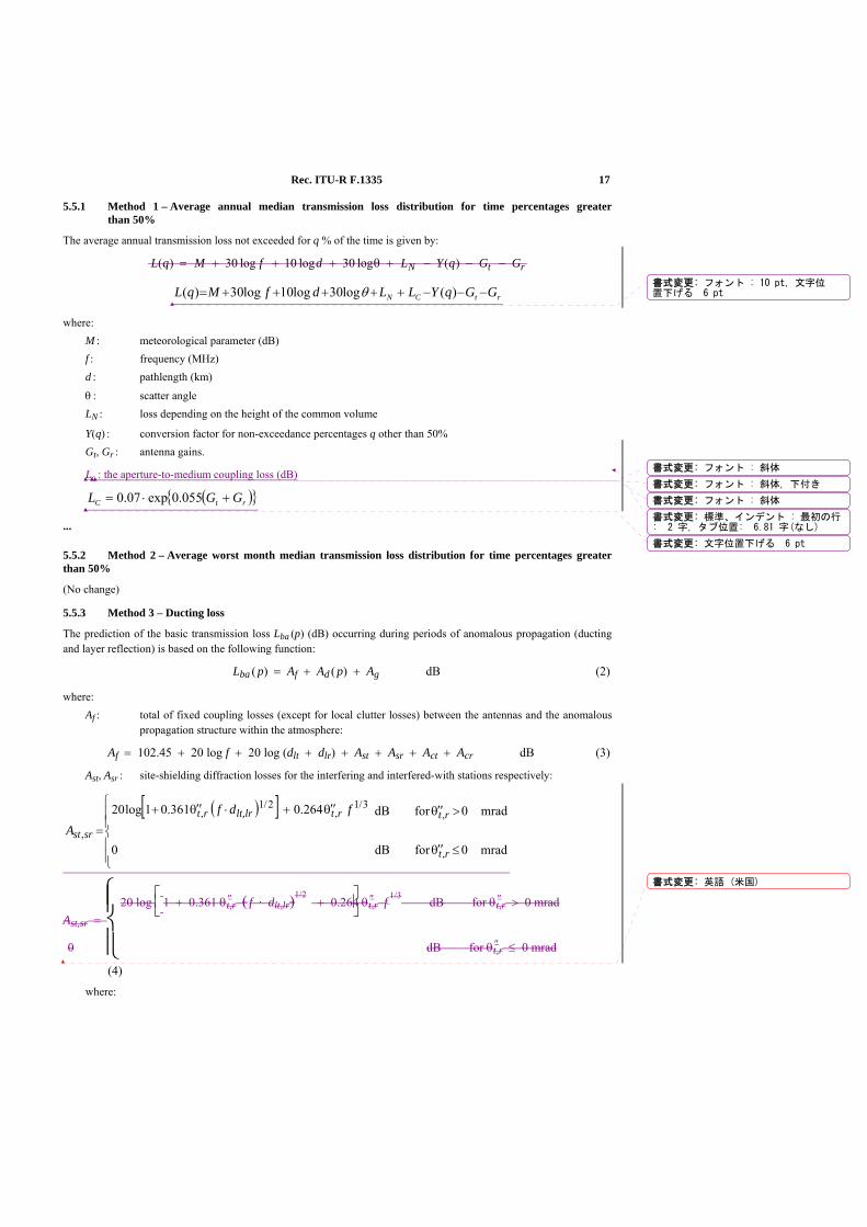
Rec. ITU-R F.1335 17
5.5.1 Method 1 – Average annual median transmission loss distribution for time percentages greater than 50%
The average annual transmission loss not exceeded for q % of the time is given by:
L q M f d L Y q G GN t r( ) log log log ( )= + + + + − − −30 10 30 θ
rtCN GGqYLLdfMqL −−−+++++= )(log30log10log30)( θ
where: M : meteorological parameter (dB) f : frequency (MHz) d : pathlength (km)
θ : scatter angle LN : loss depending on the height of the common volume
Y(q) : conversion factor for non-exceedance percentages q other than 50% Gt, Gr : antenna gains.
Lc : the aperture-to-medium coupling loss (dB)
( ){ }rtC GGL +⋅= 055.0exp07.0
...
5.5.2 Method 2 – Average worst month median transmission loss distribution for time percentages greater than 50%
(No change)
5.5.3 Method 3 – Ducting loss
The prediction of the basic transmission loss Lba (p) (dB) occurring during periods of anomalous propagation (ducting and layer reflection) is based on the following function:
Lba ( p) = Af + Ad ( p) + Ag dB (2)
where: Af : total of fixed coupling losses (except for local clutter losses) between the antennas and the anomalous
propagation structure within the atmosphere:
Af = 102.45 + 20 log f + 20 log (dlt + dlr) + Ast + Asr + Act + Acr dB (3)
Ast, Asr : site-shielding diffraction losses for the interfering and interfered-with stations respectively:
( )[ ]
⎪⎪⎩
⎪⎪⎨
⎧
≤θ ′′
>θ ′′θ ′′+⋅θ ′′+
=mrad0fordB
mrad0fordB
0
264.0361.01log20
,
,3/1
,2/1
,
,
rt
rtrtlt,lrrt
srst
fdfA
Ast,sr =
⎩⎪⎨⎪⎧20 log
⎣⎢⎡
⎦⎥⎤
1 + 0.361 θ
″t,r ( f · dlt,lr)
1/2 + 0.264 θ
″t,r f
1/3 dB for θ ″t,r > 0 mrad
0 dB for θ ″t,r ≤ 0 mrad
(4)
where:
書式変更: フォント : 10 pt, 文字位置下げる 6 pt
書式変更: フォント : 斜体
書式変更: 標準、インデント : 最初の行: 2 字, タブ位置: 6.81 字(なし)
書式変更: フォント : 斜体, 下付き
書式変更: フォント : 斜体
書式変更: 文字位置下げる 6 pt
書式変更: 英語 (米国)
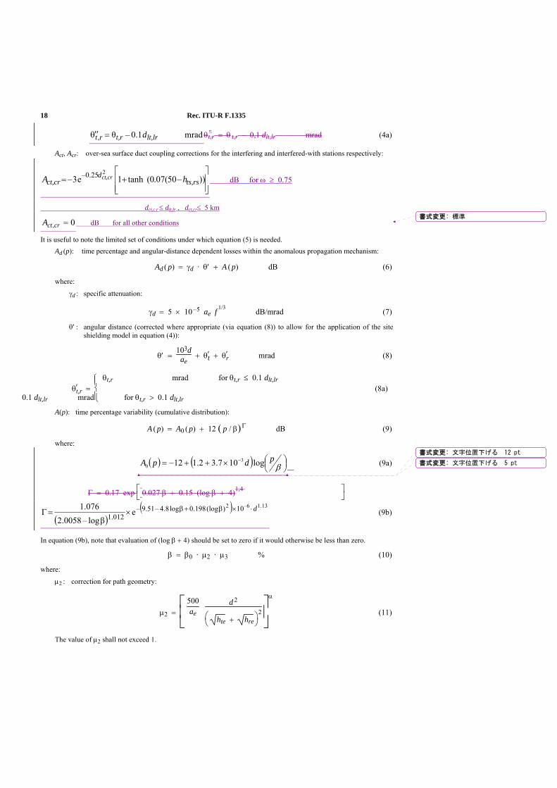
18 Rec. ITU-R F.1335
mrad1.0–θ, lt,lrt,rrt d=θ ′′ θ ″t,r = θ t,r – 0,1 dlt,lr mrad (4a)
Act, Acr: over-sea surface duct coupling corrections for the interfering and interfered-with stations respectively:
⎥⎥⎦
⎤
⎢⎢⎣
⎡+= ))–50(07.0(tanh1e3–
20.25–ts,rs
dct,cr hA ct,cr dB for ω ≥ 0.75
dct,c r ≤ dlt,lr , dct,cr≤ 5 km
0, =crctA dB for all other conditions
It is useful to note the limited set of conditions under which equation (5) is needed. Ad (p): time percentage and angular-distance dependent losses within the anomalous propagation mechanism:
Ad ( p) = γd · θ′ + A ( p) dB (6)
where:
γd : specific attenuation:
γd = 5 × 10 –5 ae f
1/3 dB/mrad (7)
θ′ : angular distance (corrected where appropriate (via equation (8)) to allow for the application of the site shielding model in equation (4)):
θ′ = 103d
ae + θ′t + θ′r mrad (8)
θ′t,r = ⎩⎪⎨⎪⎧ θt,r mrad for θt,r ≤ 0.1 dlt,lr
0.1 dlt,lr mrad for θt,r > 0.1 dlt,lr
(8a)
A(p): time percentage variability (cumulative distribution):
A ( p) = A0 ( p) + 12 ( p / β) Γ dB (9)
where:
( ) ( ) ⎟⎠⎞⎜
⎝⎛×++−= −
βpdpA log107.32.112 3
0 (9a)
Γ = 0.17 exp ⎣⎡
⎦⎤
0.027 β + 0.15 (log β + 4)1,4
( )( ) 13.16–2 10)(log198.0log8.4–51.9–
012.1 eβlog–0058.2
076.1 d⋅×β+β×=Γ (9b)
In equation (9b), note that evaluation of (log β + 4) should be set to zero if it would otherwise be less than zero.
β = β0 · μ2 · μ3 % (10)
where:
μ2 : correction for path geometry:
μ2 = ⎣⎢⎡
⎦⎥⎤
500ae
d
2
⎝⎛
⎠⎞
hte + hre
2
α
(11)
The value of μ2 shall not exceed 1.
書式変更: 標準
書式変更: 文字位置下げる 12 pt
書式変更: 文字位置下げる 5 pt
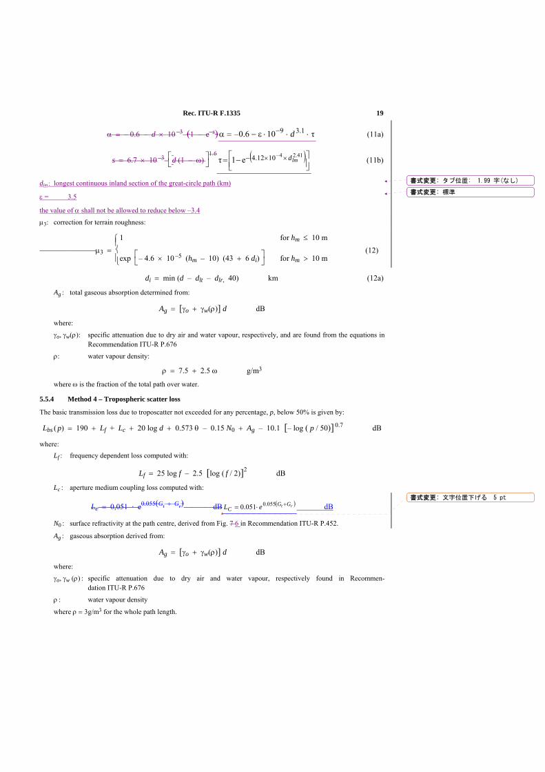
Rec. ITU-R F.1335 19
α = – 0.6 – d × 10 –3 (1 – e–s) τ106.0– 1.39 ⋅⋅⋅ε−=α − d (11a)
s = 6.7 × 10 –3 ⎣
⎡⎦⎤
d (1 – ω) 1.6 ( )
⎥⎦⎤
⎢⎣⎡ −= ××− 41.24–1012.4e1τ lmd (11b)
dlm : longest continuous inland section of the great-circle path (km)
ε = 3.5
the value of α shall not be allowed to reduce below –3.4
μ3: correction for terrain roughness:
μ3 = ⎩⎪⎨⎪⎧
1 for hm ≤ 10 m
exp ⎣⎡
⎦⎤
– 4.6 × 10 –5 (hm – 10) (43 + 6 di) for hm > 10 m
(12)
di = min (d – dlt – dlr, 40) km (12a)
Ag : total gaseous absorption determined from:
Ag = [γo + γw(ρ)] d dB
where:
γo, γw(ρ): specific attenuation due to dry air and water vapour, respectively, and are found from the equations in Recommendation ITU-R P.676
ρ: water vapour density:
ρ = 7.5 + 2.5 ω g/m3
where ω is the fraction of the total path over water.
5.5.4 Method 4 – Tropospheric scatter loss
The basic transmission loss due to troposcatter not exceeded for any percentage, p, below 50% is given by:
Lbs ( p) = 190 + Lf + Lc + 20 log d + 0.573 θ – 0.15 N0 + Ag – 10.1 [– log ( p / 50)] 0.7 dB
where: Lf : frequency dependent loss computed with:
Lf = 25 log f – 2.5 [log ( f / 2)]2 dB
Lc : aperture medium coupling loss computed with:
Lc = 0,051 · e0.055(Gt + Gr) dB ( )rt GGC eL +⋅= 055.0051.0 dB
N0 : surface refractivity at the path centre, derived from Fig. 7 6 in Recommendation ITU-R P.452.
Ag : gaseous absorption derived from:
Ag = [γo + γw(ρ)] d dB
where:
γo, γw (ρ) : specific attenuation due to dry air and water vapour, respectively found in Recommen-dation ITU-R P.676
ρ : water vapour density
where ρ = 3g/m3 for the whole path length.
書式変更: タブ位置: 1.99 字(なし)
書式変更: 標準
書式変更: 文字位置下げる 5 pt

20 Rec. ITU-R F.1335
1 Introduction At the previous meeting in February 2008, Working Party 5C produced a preliminary draft revision of Recommendation ITU-R F.1336-2 in line with the Doc. 5C/15 from Japan which proposed one editorial modification and completion of the revision of the Recommendation. Though the editorial modification was agreed and the whole content was confirmed, the status of the document was decided to keep preliminary draft revision of Recommendation for further consideration until the next meeting as it has not been less than one year since the last revision of this Recommendation.
2 Proposal Japan would like to propose to complete the revision of this Recommendation with no additional modification in this meeting. The proposed draft revision of Recommendation F.1336 is provided in Attachment to this document.
Radiocommunication Study Groups
Subject : Question ITU-R 202/9
Source : Annex 2 to Document 5C/26
Document 5A/J-4-E Document 5C/J-4-E September 2008 English only
Japan
DRAFT REVISION OF RECOMMENDATION ITU-R F.1336-2
Reference radiation patterns of omnidirectional, sectoral and other antennas in point-to-multipoint systems for use in sharing studies in the
frequency range from 1 GHz to about 70 GHz
- 2 -
ATTACHMENT
[WORKING DOCUMENT TOWARDS A] PRELIMINARY DRAFT REVISION OF RECOMMENDATION ITU-R F.1336-2
Reference radiation patterns of omnidirectional, sectoral and other antennas in point-to-multipoint systems for use in sharing studies in the
frequency range from 1 GHz to about 70 GHz
(Question ITU-R 202/9)
(1997-2000-2007)
Scope This Recommendation gives reference models of the peak and average antenna patterns of omnidirectional, sectoral and directional antennas in point-to-multipoint systems to be used in sharing studies in the frequency range 1 GHz to about 70 GHz.
Summary This revision proposes modifications to some parameters used in the basic formula used for the side-lobe patterns of sectoral antennas.
The ITU Radiocommunication Assembly,
considering
a) that, for coordination studies and for the assessment of mutual interference between point-to-multipoint (P-MP) fixed wireless systems (FWSs) and between stations of such systems and stations of space radiocommunication services sharing the same frequency band, it may be necessary to use reference radiation patterns for FWS antennas;
b) that, depending on the sharing scenario, it may be appropriate to consider the peak envelope or average sidelobe patterns in the sharing studies;
書式変更: 英語 (米国)
書式変更: Heading_b
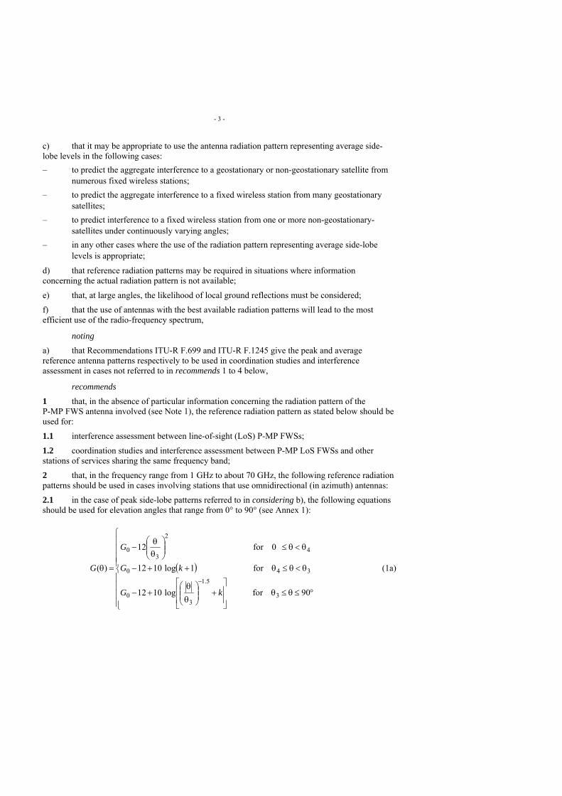
- 3 -
c) that it may be appropriate to use the antenna radiation pattern representing average side-lobe levels in the following cases: – to predict the aggregate interference to a geostationary or non-geostationary satellite from
numerous fixed wireless stations; – to predict the aggregate interference to a fixed wireless station from many geostationary
satellites; – to predict interference to a fixed wireless station from one or more non-geostationary-
satellites under continuously varying angles; – in any other cases where the use of the radiation pattern representing average side-lobe
levels is appropriate;
d) that reference radiation patterns may be required in situations where information concerning the actual radiation pattern is not available;
e) that, at large angles, the likelihood of local ground reflections must be considered;
f) that the use of antennas with the best available radiation patterns will lead to the most efficient use of the radio-frequency spectrum,
noting
a) that Recommendations ITU-R F.699 and ITU-R F.1245 give the peak and average reference antenna patterns respectively to be used in coordination studies and interference assessment in cases not referred to in recommends 1 to 4 below,
recommends
1 that, in the absence of particular information concerning the radiation pattern of the P-MP FWS antenna involved (see Note 1), the reference radiation pattern as stated below should be used for:
1.1 interference assessment between line-of-sight (LoS) P-MP FWSs;
1.2 coordination studies and interference assessment between P-MP LoS FWSs and other stations of services sharing the same frequency band;
2 that, in the frequency range from 1 GHz to about 70 GHz, the following reference radiation patterns should be used in cases involving stations that use omnidirectional (in azimuth) antennas:
2.1 in the case of peak side-lobe patterns referred to in considering b), the following equations should be used for elevation angles that range from 0° to 90° (see Annex 1):
( )
⎪⎪⎪⎪
⎩
⎪⎪⎪⎪
⎨
⎧
°≤θ≤θ⎥⎥
⎦
⎤
⎢⎢
⎣
⎡+⎟⎟
⎠
⎞⎜⎜⎝
⎛θθ
+−
θ<θ≤θ++−
θ<θ≤⎟⎟⎠
⎞⎜⎜⎝
⎛θθ
−
=θ−
90forlog1012
for1log1012
0for12
)(
3
5.1
30
340
4
2
30
kG
kG
G
G (1a)
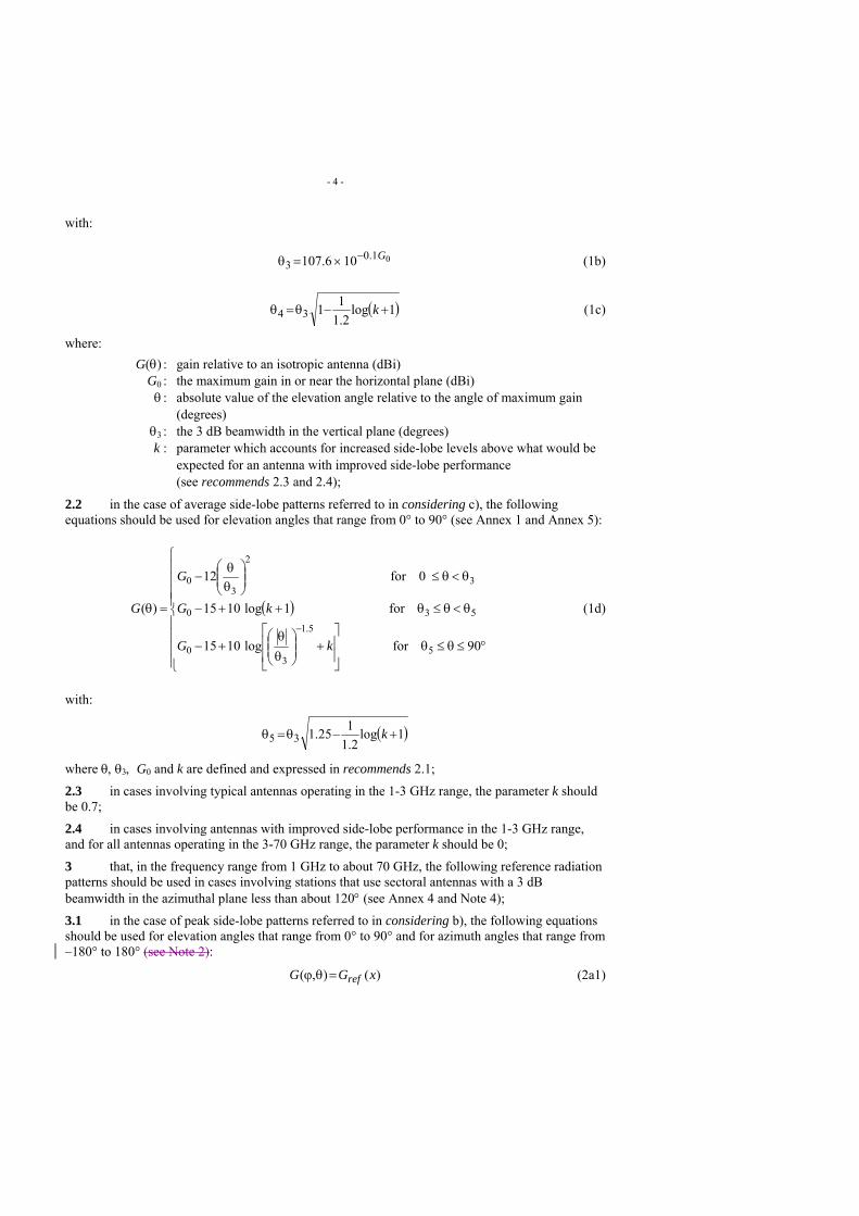
- 4 -
with:
01.03 106.107 G−×=θ (1b)
( )1log2.1
1134 +−θ=θ k (1c)
where: G(θ) : gain relative to an isotropic antenna (dBi) G0 : the maximum gain in or near the horizontal plane (dBi) θ : absolute value of the elevation angle relative to the angle of maximum gain
(degrees) θ3 : the 3 dB beamwidth in the vertical plane (degrees)
k : parameter which accounts for increased side-lobe levels above what would be expected for an antenna with improved side-lobe performance (see recommends 2.3 and 2.4);
2.2 in the case of average side-lobe patterns referred to in considering c), the following equations should be used for elevation angles that range from 0° to 90° (see Annex 1 and Annex 5):
( )
⎪⎪⎪⎪
⎩
⎪⎪⎪⎪
⎨
⎧
°≤θ≤θ⎥⎥
⎦
⎤
⎢⎢
⎣
⎡+⎟⎟
⎠
⎞⎜⎜⎝
⎛θθ
+−
θ<θ≤θ++−
θ<θ≤⎟⎟⎠
⎞⎜⎜⎝
⎛θθ
−
=θ−
90forlog1015
for1log1015
0for12
)(
5
5.1
30
530
3
2
30
kG
kG
G
G (1d)
with:
( )1log2.1
125.135 +−θ=θ k
where θ, θ3, G0 and k are defined and expressed in recommends 2.1;
2.3 in cases involving typical antennas operating in the 1-3 GHz range, the parameter k should be 0.7;
2.4 in cases involving antennas with improved side-lobe performance in the 1-3 GHz range, and for all antennas operating in the 3-70 GHz range, the parameter k should be 0;
3 that, in the frequency range from 1 GHz to about 70 GHz, the following reference radiation patterns should be used in cases involving stations that use sectoral antennas with a 3 dB beamwidth in the azimuthal plane less than about 120° (see Annex 4 and Note 4);
3.1 in the case of peak side-lobe patterns referred to in considering b), the following equations should be used for elevation angles that range from 0° to 90° and for azimuth angles that range from –180° to 180° (see Note 2):
)(),( xGG ref=θϕ (2a1)
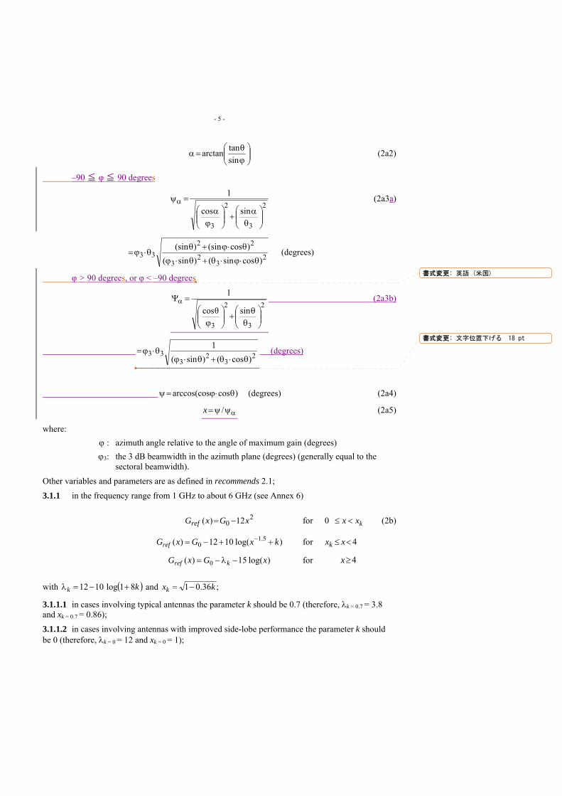
- 5 -
⎟⎟⎠
⎞⎜⎜⎝
⎛ϕθ
=αsintanarctan (2a2)
–90 ≦ φ ≦ 90 degrees
2
3
2
3
sincos
1
⎟⎟⎠
⎞⎜⎜⎝
⎛θ
α+⎟⎟⎠
⎞⎜⎜⎝
⎛ϕ
α=ψα (2a3a)
23
23
2233
)cossin()sin()cos(sin)(sin
θ⋅ϕ⋅θ+θ⋅ϕ
θ⋅ϕ+θθ⋅ϕ= (degrees)
φ > 90 degrees, or φ < –90 degrees
2
3
2
3
sinθcos
1
⎟⎟⎠
⎞⎜⎜⎝
⎛θ
θ+⎟⎟⎠
⎞⎜⎜⎝
⎛ϕ
=Ψα (2a3b)
23
23
33)cos()sin(
1θ⋅θ+θ⋅ϕ
θ⋅ϕ= (degrees)
)cosarccos(cos θ⋅ϕ=ψ (degrees) (2a4)
αψψ= /x (2a5)
where: ϕ : azimuth angle relative to the angle of maximum gain (degrees) ϕ3: the 3 dB beamwidth in the azimuth plane (degrees) (generally equal to the
sectoral beamwidth).
Other variables and parameters are as defined in recommends 2.1;
3.1.1 in the frequency range from 1 GHz to about 6 GHz (see Annex 6)
20 12)( xGxGref −= for kxx <≤0 (2b)
)log(1012)( 5.10 kxGxGref ++−= − for 4<≤ xxk
)log(15)( 0 xGxG kref −λ−= for 4≥x
with ( )kk 81log1012 +−=λ and ;36.01 kxk −=
3.1.1.1 in cases involving typical antennas the parameter k should be 0.7 (therefore, λk = 0.7 = 3.8 and xk = 0.7 = 0.86);
3.1.1.2 in cases involving antennas with improved side-lobe performance the parameter k should be 0 (therefore, λk = 0 = 12 and xk = 0 = 1);
書式変更: 英語 (米国)
書式変更: 文字位置下げる 18 pt
- 6 -
3.1.2 in the frequency range from 6 GHz to about 70 GHz:
20 12)( xGxGref −= for 10 <≤ x (2c)
)log(1512)( 0 xGxGref −−= for x≤1
3.2 in the case of average side-lobe patterns referred to in considering c), for use in a statistical interference assessment, the following equations should be used for elevation angles that range from 0° to 90° and for azimuth angles that range from –180° to 180° (see Annex 5 and Note 2):
G(φ, θ) = Gref(x)
3.2.1 in the frequency range from 1 GHz to about 6 GHz (see Annex 6):
20 12)( xGxGref −= for kxx <≤0 (2d)
)log(1015)( 5.10 kxGxGref ++−= − for 4<≤ xxk
)log(153)( 0 xGxG kref −−λ−= for 4≥x
with ( )kk 81log1012 +−=λ and ;36.025.1 kxk −=
3.2.1.1 in cases involving typical antennas the parameter k should be 0.2 (therefore, λk = 0.2 = 7.85 and xk = 0.2 = 1.08);
3.2.1.2 in cases involving antennas with improved side-lobe performance the parameter k should be 0 (therefore, λk = 0 = 12 and xk = 0 = 1.118);
3.2.2 in the frequency range from 6 GHz to about 70 GHz:
20 12)( xGxGref −= for 152.10 <≤ x (2e)
)log(1515)( 0 xGxGref −−= for x≤152.1
3.3 in cases involving sectoral antennas with a 3 dB beamwidth in the azimuthal plane less than about 120°, the relationship between the maximum gain and the 3 dB beamwidth in both the azimuthal plane and the elevation plane, on a provisional basis, is (see Annex 3 and Note 4):
3
1.0
301000031
ϕ×
=θ− G
(3)
where all parameters are as defined under recommends 3.1;
4 that, in the frequency range from 1 GHz to about 3 GHz, the following reference radiation patterns should be used in cases involving stations that use low-gain antennas with circular symmetry about the 3 dB beamwidth and with a main lobe antenna gain less than about 20 dBi:
4.1 the following equations should be used in the case of peak side-lobe patterns referred to in considering b) (see Annex 2 and Note 3):

- 7 -
⎪⎪⎪
⎩
⎪⎪⎪
⎨
⎧
°≤θ≤ϕ−
ϕ<θ≤ϕ⎟⎟⎠
⎞⎜⎜⎝
⎛ϕθ
−−
ϕ<θ≤ϕ−
ϕ<θ≤⎟⎟⎠
⎞⎜⎜⎝
⎛ϕθ
−
=θ
180for8
forlog3214
1.08for14
08.10for12
)(
2
211
0
130
3
2
30
G
G
G
G (4)
where: G(θ) : gain relative to an isotropic antenna (dBi) G0 : the main lobe antenna gain (dBi) θ : off-axis angle (degrees) ϕ3 : the 3 dB beamwidth of the low-gain antenna (degrees)
= 01.01000027 G−× (degrees)
ϕ1 = 1.9 ϕ3 (degrees) ϕ2 = ϕ1 × 10(G0 – 6)/32 (degrees);
4.2 in the case of average side-lobe patterns referred to in considering c), the antenna pattern given in Recommendation ITU-R F.1245 should be used;
5 that the following Notes should be regarded as part of this Recommendation: NOTE 1 – It is essential that every effort be made to utilize the actual antenna pattern in coordination studies and interference assessment. NOTE 2 – To evaluate the gain for all elevation angles, θ′ from 0 to 180°, in a vertical plane, the value of x for elevation angles beyond 90° must be determined by using the complementary value of the elevation angle (180° – θ′) at the supplementary value of the azimuth, i.e. 180 ± ϕ. NOTE 23 – The different values of parameter k in recommends 3.1.1.1 and 3.2.1.1 are derived taking into account peak envelopes and average side-lobe levels of a number of typical measured antenna patterns in the 1 to 6 GHz frequency range. NOTE 34 – In a case involving an antenna whose main beam width is different that this calculated with equation (3), it is recommended to use 3θ as an input parameter.
Note 45 – As discussed in Annex 3, an exponential factor has been replaced by unity. As a result, the theoretical error introduced by this approximation will be less than 6% for 3 dB beamwidths in the elevation plane less than 45�. Note 56 – The reference radiation pattern given in recommends 4.1 primarily applies in situations where the main lobe antenna gain is less than or equal to 20 dBi and the use of Recommendation ITU-R F.699 produces inadequate results. Further study is required to establish the full range of frequencies and gain over which the equations are valid. NOTE 67 – Measured results of a specially designed sectoral antenna for use around 20 GHz indicate the possibility of compliance with a more restrictive reference side-lobe radiation pattern. Further studies are required to develop such an optimized pattern.
[Editor’s note: Annexes 1 to 3 are unchanged]
- 8 -
Annex 4
Procedure for determining the gain of a sectoral antenna at an arbitrary off-axis angle specified by an azimuth angle and an elevation angle
referenced to the boresight of the antenna
1 Analysis The basic geometry for determining the gain of a sectoral antenna at an arbitrary off-axis angle is shown in Fig. 17. It is assumed that the antenna is located at the centre of the spherical coordinate system; the direction of maximum radiation is along the x-axis; the x-y plane is the local horizontal plane; the elevation plane contains the z-axis; and, u0 is a unit vector whose direction is used to determine the gain of the sectoral antenna.
FIGURE 17
Determining the off-boresight angle given the azimuth and elevation angle of interest
The two fundamental assumptions regarding this procedure are that: – the –3 dB gain contour of the far-field pattern when plotted in two-dimensions as a function
of the azimuth and elevation angles will be an ellipse as shown in Fig. 182; and – the gain of the sectoral antenna at an arbitrary off-axis angle is a function of the 3 dB
beamwidth and the beamwidth of the antenna when measured in the plane containing the x-axis and the unit vector u0 (see Fig. 17).
Given the 3 dB beamwidth (degrees) of the sectoral antenna in the azimuth and elevation planes, ϕ3 and θ3, the numerical value of the boresight gain is given, on a provisional basis, by (see recommends 3.3 and equation (32a)).
33
000031θϕ
=G (40)
ψα
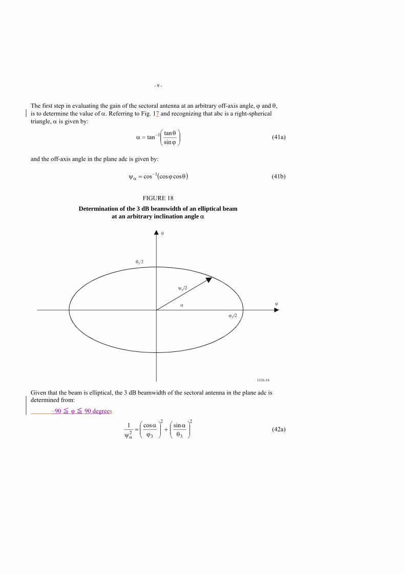
- 9 -
The first step in evaluating the gain of the sectoral antenna at an arbitrary off-axis angle, ϕ and θ, is to determine the value of α. Referring to Fig. 17 and recognizing that abc is a right-spherical triangle, α is given by:
⎟⎟⎠
⎞⎜⎜⎝
⎛ϕθ
=α −
sintantan 1 (41a)
and the off-axis angle in the plane adc is given by:
( )θϕ=ψ −α coscoscos 1 (41b)
FIGURE 18
Determination of the 3 dB beamwidth of an elliptical beam at an arbitrary inclination angle α
Given that the beam is elliptical, the 3 dB beamwidth of the sectoral antenna in the plane adc is determined from:
–90 ≦ φ ≦ 90 degrees
2
3
2
32
sincos1⎟⎟⎠
⎞⎜⎜⎝
⎛θ
α+⎟⎟
⎠
⎞⎜⎜⎝
⎛ϕ
α=
ψα (42a)
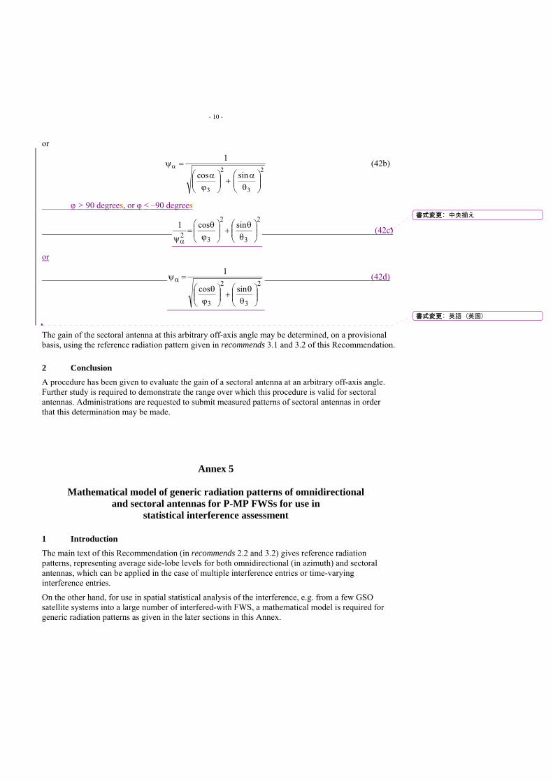
- 10 -
or
2
3
2
3
sincos
1
⎟⎟⎠
⎞⎜⎜⎝
⎛θ
α+⎟⎟
⎠
⎞⎜⎜⎝
⎛ϕ
α=ψα (42b)
φ > 90 degrees, or φ < –90 degrees
2
3
2
32sincos1
⎟⎟⎠
⎞⎜⎜⎝
⎛θ
θ+⎟⎟
⎠
⎞⎜⎜⎝
⎛ϕ
θ=
ψα (42c)
or
2
3
2
3
sincos
1
⎟⎟⎠
⎞⎜⎜⎝
⎛θ
θ+⎟⎟
⎠
⎞⎜⎜⎝
⎛ϕ
θ=ψα (42d)
The gain of the sectoral antenna at this arbitrary off-axis angle may be determined, on a provisional basis, using the reference radiation pattern given in recommends 3.1 and 3.2 of this Recommendation.
2 Conclusion A procedure has been given to evaluate the gain of a sectoral antenna at an arbitrary off-axis angle. Further study is required to demonstrate the range over which this procedure is valid for sectoral antennas. Administrations are requested to submit measured patterns of sectoral antennas in order that this determination may be made.
Annex 5
Mathematical model of generic radiation patterns of omnidirectional and sectoral antennas for P-MP FWSs for use in
statistical interference assessment
1 Introduction The main text of this Recommendation (in recommends 2.2 and 3.2) gives reference radiation patterns, representing average side-lobe levels for both omnidirectional (in azimuth) and sectoral antennas, which can be applied in the case of multiple interference entries or time-varying interference entries.
On the other hand, for use in spatial statistical analysis of the interference, e.g. from a few GSO satellite systems into a large number of interfered-with FWS, a mathematical model is required for generic radiation patterns as given in the later sections in this Annex.
書式変更: 中央揃え
書式変更: 英語 (英国)
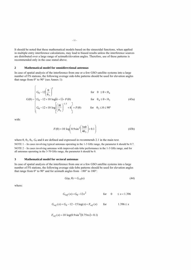
- 11 -
It should be noted that these mathematical models based on the sinusoidal functions, when applied in multiple entry interference calculations, may lead to biased results unless the interference sources are distributed over a large range of azimuth/elevation angles. Therefore, use of these patterns is recommended only in the case stated above.
2 Mathematical model for omnidirectional antennas In case of spatial analysis of the interference from one or a few GSO satellite systems into a large number of FS stations, the following average side-lobe patterns should be used for elevation angles that range from 0° to 90° (see Annex 1):
( )
⎪⎪⎪⎪
⎩
⎪⎪⎪⎪
⎨
⎧
°≤θ≤θθ+⎥⎥
⎦
⎤
⎢⎢
⎣
⎡+⎟⎟
⎠
⎞⎜⎜⎝
⎛θθ
+−
θ<θ≤θθ+++−
θ<θ≤⎟⎟⎠
⎞⎜⎜⎝
⎛θθ
−
=θ−
90for)(log1012
for)(1log1012
0for12
)(
3
5.1
30
340
4
2
30
FkG
FkG
G
G (43a)
with:
⎟⎟⎠
⎞⎜⎜⎝
⎛+⎟⎟
⎠
⎞⎜⎜⎝
⎛θπθ
=θ 1.043sin9.0log10)(
3
2F (43b)
where θ, θ3, θ4, G0 and k are defined and expressed in recommends 2.1 in the main text. NOTE 1 – In cases involving typical antennas operating in the 1-3 GHz range, the parameter k should be 0.7. NOTE 2 – In cases involving antennas with improved side-lobe performance in the 1-3 GHz range, and for all antennas operating in the 3-70 GHz range, the parameter k should be 0.
3 Mathematical model for sectoral antennas In case of spatial analysis of the interference from one or a few GSO satellite systems into a large number of FS stations, the following average side-lobe patterns should be used for elevation angles that range from 0° to 90° and for azimuth angles from –180° to 180°:
G(φ, θ) = Gref(x) (44)
where:
20 12)( xGxGref −= for 396.10 <≤ x
)()log(1512)( 0 xFxGxG refref +−−= for x≤396.1
( ) )1.075.0sin9.0log(10)( 2 +π= xxFref
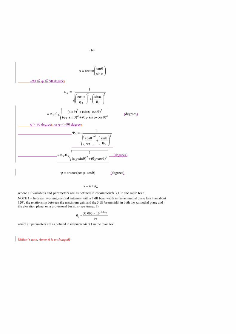
- 12 -
⎟⎟⎠
⎞⎜⎜⎝
⎛ϕθ
=αsintanarctan
–90 ≦ φ ≦ 90 degrees
2
3
2
3
sincos
1
⎟⎟⎠
⎞⎜⎜⎝
⎛θ
α+⎟⎟
⎠
⎞⎜⎜⎝
⎛ϕ
α=ψα
23
23
22
33 )cossin()sin()cos(sin)(sin
θ⋅ϕ⋅θ+θ⋅ϕθ⋅ϕ+θ
θ⋅ϕ= (degrees)
φ > 90 degrees, or φ < –90 degrees
2
3
2
3
sinθcos
1
⎟⎟⎠
⎞⎜⎜⎝
⎛θ
θ+⎟⎟⎠
⎞⎜⎜⎝
⎛ϕ
=Ψα
23
23
33)cos()sin(
1θ⋅θ+θ⋅ϕ
θ⋅ϕ= (degrees)
)cosarccos(cos θ⋅ϕ=ψ (degrees)
αψψ= /x
where all variables and parameters are as defined in recommends 3.1 in the main text. NOTE 1 – In cases involving sectoral antennas with a 3 dB beamwidth in the azimuthal plane less than about 120°, the relationship between the maximum gain and the 3 dB beamwidth in both the azimuthal plane and the elevation plane, on a provisional basis, is (see Annex 3):
3
1.0
301000031
ϕ×
=θ− G
where all parameters are as defined in recommends 3.1 in the main text. [Editor’s note: Annex 6 is unchanged]

M:\文書管理フォルダ\200 国際係\02 情報通信審議会 技術分科会\02 地上業務委員会(SG5)\第03回(2008.9.24)\ロジ\HP\011 5C_J-5REV.DOC 22.09.08 10.11.08
Japan
PROPOSAL FOR PRELIMINARY DRAFT REVISION OF REPORT ITU-R F.2107 Characteristics and applications of fixed wireless systems
operating in the 57GHz to 95 GHz band
1. Introduction Demand for 10-gigabit-class wireless communications is increasing year by year. One of the promising ways to meet the demand for 10-gigabit-class wireless link is to use millimetre-wave at a frequency of over 100 GHz.
In order to verify that over-100-GHz wireless system can be used for practical applications, Japan has developed a wireless link, and conducted various trial experiments. Transmission experiments were conducted at a rate of 10.3 Gbit/s over a distance of 1.3 km, and error-free transmission was obtained. The use of monolithic microwave integrated circuits (MMICs) makes the wireless equipments compact, light, and low power consumption. These results indicate that the use of over-100-GHz frequency band that are unexplored frequency region in the field of industry is a promising way to build ultra-high-speed wireless systems with a rate of over 10 Gbit/s in the near future.
2. Proposal Japan would like to propose to add the foregoing information to the relevant Report ITU-R F.2107 on characteristics and applications of fixed wireless systems operating in the 57 GHz to 95 GHz as the information of this wireless link is very important to achieve very-high-speed fixed wireless system with a carrier frequency of over 100 GHz in the future.
Attachment provides the preliminary draft revision of report ITU-R F.2107.
The proposed additional information may be used as elements for considering WRC-11 Agenda item 1.8; Consideration of technical and regulatory issues relative to the fixed service in the bands between 71 GHz and 238 GHz.
INTERNATIONAL TELECOMMUNICATION UNION
RADIOCOMMUNICATION STUDY GROUPS
Document 5C/J-5September 2008 English only

- 2 - 9B/186-E
M:\文書管理フォルダ\200 国際係\02 情報通信審議会 技術分科会\02 地上業務委員会(SG5)\第03回(2008.9.24)\ロジ\HP\011 5C_J-5REV.DOC 22.09.08 10.11.08
Attachment
PRELIMINARY DRAFT REVISION OF REPORT ITU-R F.2107
Characteristics and applications of fixed wireless systems
operating in the 57GHz to 95 130 GHz band
(2007)
Scope
This Report contains propagation aspects, system design parameters, possible applications and other technical/operational characteristics, which are required for the implementation of fixed wireless systems in the frequency ranges 57 to 95130 GHz. The applications include specific examples of outdoor/indoor wireless connections taking advantage of these frequency bands. It is intended that future versions of this Report would be needed.
Vocabulary
(no change)
Abbreviations
(Add the following words)
FEC Forward error correction
FPU Filed pick-up unit
FWA Fixed wireless access
HD-SDI High-definition serial digital interface
IP Internet protocol
LAN Local area network
OC-192 Optical carrier-192
PRBS Pseudorandom bit sequence
RF Radio frequency
10GbE 10 Gigabit Ethernet
書式変更: 標準、間隔 段落前 : 0 pt

- 3 - 9B/186-E
M:\文書管理フォルダ\200 国際係\02 情報通信審議会 技術分科会\02 地上業務委員会(SG5)\第03回(2008.9.24)\ロジ\HP\011 5C_J-5REV.DOC 22.09.08 10.11.08
References
ITU-R Recommendations
(Add the following recommendation)
Recommendation ITU-R P. 838-3: Specific attenuation model for rain for use in prediction methods
1 Introduction In recent years, the interest in the 57-95 130 GHz range for wireless communication applications has increased significantly. The main reason for this interest is the potential for wide bandwidth implementations which meet the growing requirement [Correia and Prasad, 1997] for high data rates in the range of hundreds of Mbit/s.
In Canada, the band 57-64 GHz is available for licence-exempt applications. In the United States of America, the 60 GHz (57-64 GHz), 70 GHz (71-76 GHz), 80 GHz (81-86 GHz) and 95 GHz (92-95 GHz) bands are available for broadband wireless applications. In Japan, wireless personal area network (WPAN) systems are being implemented in the 60 GHz range for short-range, high-speed multimedia data services to terminals located in rooms or office space, and the feasibility experiments of 10-Gbit/s wireless link was conducted in the 120 GHz band (110-130 GHz).,. In Europe, several bands above 57 GHz are currently being considered for fixed wireless systems. In the United Kingdom, the 57-59 GHz band is available for licence-exempt FS point-to-point applications and the 64-66 GHz, 71-76 GHz and 81-86 GHz bands are also available for point-to-point FS applications under a simple regulatory process.
2 Propagation characteristics and considerations in the 60/70/80/95/120 GHz bands Free-space loss is proportional to the square of the operating frequency; therefore, the free-space loss in the 60/70/80/95/120 GHz bands is much higher than the losses in the 2.4 GHz or 5 GHz bands available in many administrations for WLAN operations.
The free-space loss PLFS (dB) at a reference distance d0 (m) is given by:
⎟⎠⎞
⎜⎝⎛
λπ
= 010
4log20 dPLFS (1)
where λ is the wavelength (m). The average path loss over a distance d (m) can be determined using the following path loss exponent model based on Recommendation P.675 (ex-CCIR):
⎟⎟⎠
⎞⎜⎜⎝
⎛+=
0100 log10)()(
ddndPLdPL FS (2)
where )(dPL is the average path loss (dB) at a particular distance d and n is the path loss exponent that characterizes how fast the path loss increases with transmit and receive antenna separation. Figure 1 shows the simulated results of the received signal level (dBm) as a function of the distance from the transmit antenna. The simulated results are provided for the 2.4/5.5/60/70/80/95/120 GHz
書式変更: フォントの色 : 自動
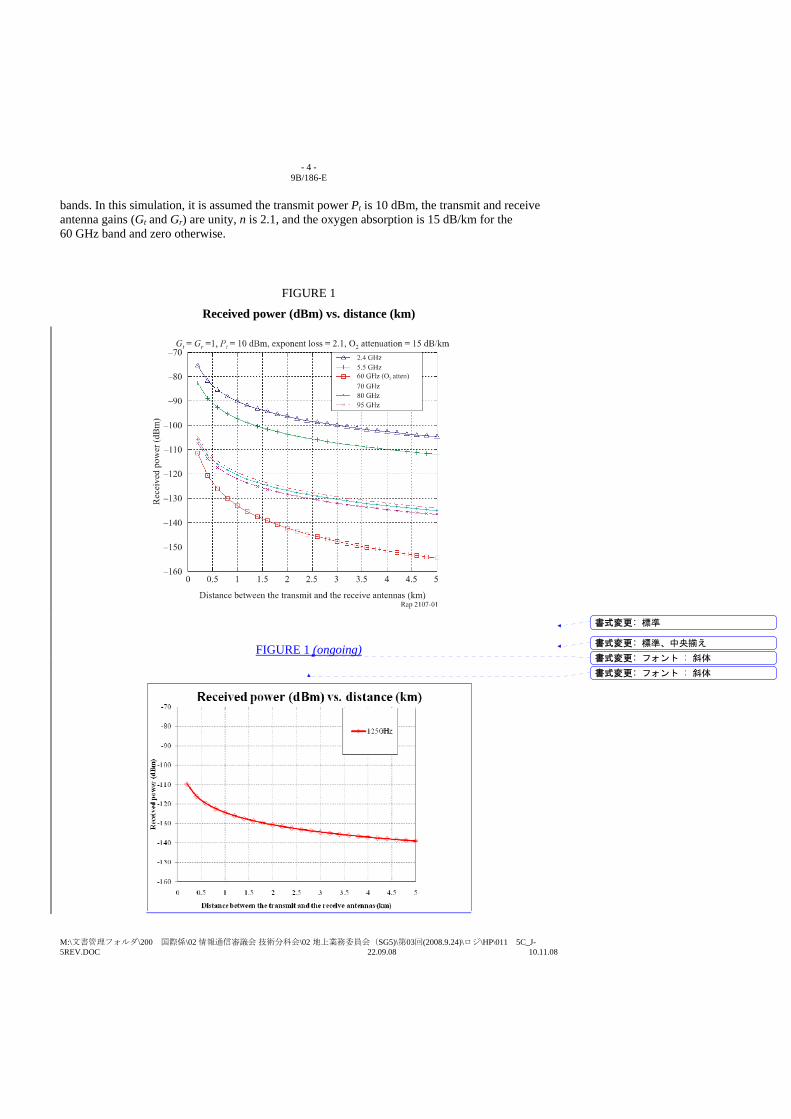
- 4 - 9B/186-E
M:\文書管理フォルダ\200 国際係\02 情報通信審議会 技術分科会\02 地上業務委員会(SG5)\第03回(2008.9.24)\ロジ\HP\011 5C_J-5REV.DOC 22.09.08 10.11.08
bands. In this simulation, it is assumed the transmit power Pt is 10 dBm, the transmit and receive antenna gains (Gt and Gr) are unity, n is 2.1, and the oxygen absorption is 15 dB/km for the 60 GHz band and zero otherwise.
FIGURE 1
Received power (dBm) vs. distance (km)
FIGURE 1 (ongoing)
書式変更: 標準
書式変更: 標準、中央揃え
書式変更: フォント : 斜体
書式変更: フォント : 斜体

- 5 - 9B/186-E
M:\文書管理フォルダ\200 国際係\02 情報通信審議会 技術分科会\02 地上業務委員会(SG5)\第03回(2008.9.24)\ロジ\HP\011 5C_J-5REV.DOC 22.09.08 10.11.08
From Fig. 1, the path loss at 60 GHz is much higher than the losses at other frequency bands because of the oxygen absorption, which is detrimental to signal propagation. In an outdoor environment, the gaseous absorption attenuates the transmitted signal (~10 to 15 dB/km) in addition to free-space loss. Notwithstanding the above, the oxygen absorption loss can be compensated for by the use of high-gain directive antennas. As well, it can also prove attractive for short-range communications as it further attenuates harmful interference such as co-channel interference in wireless cell-based systems, which combined with low transmit powers in the 60 GHz band (~10 mW) can increase frequency reuse from cell to cell.
For the 70/80/95/120 GHz bands, the gaseous absorption is negligible. Figure 2 shows the attenuation (dB/km) vs. the frequency (GHz) due to the gasses and hydrometeors for radio transmission through the atmosphere. The figure indicates that rain has the greatest impact on transmitted signals in the 60/70/80/95/120 GHz bands.
FIGURE 2
Attenuation due to gasses and hydrometeors for transmission through the atmosphere
For indoor applications, transmitted signals in the 60/70/80/95/120 GHz bands are significantly attenuated by surrounding objects and inner walls and can result in a substantial drop in the received signal level.
Additionally, measured values of RF signal material attenuation have been published in [Rappaport, 2002]. The following results of minimum and maximum attenuation (57-95 GHz) through various materials have been interpolated from these findings: – Fibreglass insulation: ~3-3.5 dB – Dry paper-towel: ~3-3.5 dB – Asphalt shingle: ~3.5-4 dB – Drywall: ~3.5-6.5 dB – Glass: ~4.5-7 dB – Wet paper-towel: ~5-7 dB – 19 mm pine board: ~8-11 dB
- 6 - 9B/186-E
M:\文書管理フォルダ\200 国際係\02 情報通信審議会 技術分科会\02 地上業務委員会(SG5)\第03回(2008.9.24)\ロジ\HP\011 5C_J-5REV.DOC 22.09.08 10.11.08
– 19 mm plywood: ~7-11 dB – Clay brick: 10-23 dB – Painted 2 × 8 (5 cm × 20 cm) board: ~20-35 dB.
There are also various ITU-R Recommendations that are useful in dealing with propagation issues at these frequencies (see References).
Other factors such as delay spread and Doppler may also need to be taken into consideration. The delay spread is caused by reflections and scattering and will depend on the size of the room and the nature of the walls and objects in it. In a typical office (nomadic) environment, the reflected signals may cause delay spread of the order of few tens of nanoseconds at 58 GHz [Smulders and Wagemans, 1992] and subsequence intersymbol interference, depending on the symbol duration. This effect can be minimized by using directive antennas, which in turn complicate other aspects such as broader coverage.
Experimental results of vertical propagation characteristics in the 60 GHz band are given later Appendix 1.
3 System design considerations for the 60/70/80/95/120 GHz bands In addition to the propagation medium, the performance of a wireless communication system also strongly depends on the hardware specifications of the transmitter, the receiver, and the antenna subsystems. Design parameters such as amplifier linearity, output power, noise figure, mixer conversion loss, oscillator phase noise, antenna gain, and antenna beamwidth influence the entire system performance. In the millimetre-wave (mm-wave) bands, choosing the parameters mentioned above is a challenging task because of their inter-dependencies. Trade-offs and compromises must be made to ensure a realistic design. Furthermore, the cost of the RF subsystems depends on the volumes of production. As the volume increases, the cost per subsystem decreases. Therefore, for the 60/70/80/95/120 GHz systems to be competitive with systems operating at lower frequencies, the volume of the deployed systems needs to be very high.
3.1 Multiplexing and modulation schemes One of the efficient schemes for transmission in the 60/70/80/950/120 GHz bands is the orthogonal frequency division multiplex (OFDM) scheme [Heiskala and Terry, 2002], which enhances the system’s spectrum efficiency and makes the propagation channel robust against large delay spread. In the case of OFDM systems, the phase noise of the local oscillators in the link’s transceivers is very critical and could impair the orthogonality of OFDM transmission.
For 60/70/80/95/120 GHz systems, the carrier frequency is obtained by multiplying the frequency of the reference local oscillator whereby the phase noise at these frequencies would be higher than in 2.4 GHz and 5.5 GHz systems. The increase in the system’s phase noise leads to BER performance degradation, particularly when OFDM is used with higher order modulation techniques such as 16-QAM and 64-QAM [Heiskala and Terry, 2002]. Therefore, the phase noise of the local oscillators for these mm-wave systems is a design challenge and requires design attention.
The use of adaptive modulation makes the adaptation of a user’s data rate as a function of the channel conditions (average SINR, BER, etc.) possible [Nanda et al., 2000 and Lin et al., 1984]. Efficient adaptive modulation schemes must incorporate both robust transmission modes with low modulation efficiency such as BPSK or QPSK and high data rate modes with high modulation efficiency such as 64-QAM or 256-QAM. Typically, the use of adaptive modulation yields
- 7 - 9B/186-E
M:\文書管理フォルダ\200 国際係\02 情報通信審議会 技術分科会\02 地上業務委員会(SG5)\第03回(2008.9.24)\ロジ\HP\011 5C_J-5REV.DOC 22.09.08 10.11.08
substantial improvement in data rate in comparison with non-adaptive systems, which uses a conservative modulation mode to guarantee a given BER performance at worst conditions at the expense of data rate.
3.2 Countermeasures to improve propagation environments In point-to-multipoint wireless links, broader antenna beams (even omnidirectional antennas) can be used at both the transmitter and the receiver, which incurs frequency-selective fading due to delay spread and broadband transmission. Frequency-selective fading is typically mitigated through the use of an equalizer, but the complexity of the equalizer quickly grows as a function of data rate.
In a typical indoor environment, obstructions of human movement, walls, floors and ceilings resulting in radio path blockage will cause the received signal level to fluctuate significantly. This challenge should be met to realize wireless local area networks (WLAN) or wireless personal area networks (WPAN) using the 60/70/80/95/120 GHz bands. An acknowledgment and retransmission algorithm is implemented between the transmitter and the receiver using the automatic repeat request (ARQ) protocol [Nanda et al., 2000 and Proakis, 1989]. ARQ removes packet errors at the cost of only moderate additional transmission latency. Assuming that adequate antenna spacing is achievable, spatial diversity (SD) is also an efficient scheme to mitigate an unexpected obstacle to a LOS path by making multiple wireless links between the transmitter with multiples antennas and the receiver (transmit diversity) or between the transmitter and the receiver with multiples antennas (receive diversity). The basic idea of SD is that multiple links are much less likely to be obstructed simultaneously than a single links. In case of receive diversity, the received signals are combined by maximal ratio combining (MRC) rule or the best quality signal is selected among the received signals [Proakis, 1989]. Space-time block coding is a particularly attractive approach to realize transmits diversity without requiring channel knowledge at the transmitter [Gesbert et al., 2002 and Alamouti, 1998].
(Section 3.3 to 3.4: no change)
4 Advantages and disadvantage of the 60/70/80/95/120 GHz bands The advantages of using the 60/70/80/95/120 GHz bands include:
– frequency reuse in dense areas with reduced potential for undesired interference; – use of smaller size antennas (antenna gains are proportional to the antenna dimension
and the wavelength); – small size radio equipment as to provide nomadic applications; – narrow antenna beamwidths (antenna beamwidth is inversely proportional to the operating
frequency) which reduce interference and increase frequency reuse; – potential frequency sharing feasibility with other radio services; – support for high capacity transmission due to their wider usable bandwidth (Shannon’s Law).
The following example demonstrates the increase in system capacity [Haroun et al., 2004] due to the wide bandwidth for 60 GHz and 2.4 GHz systems (C = bandwidth × log2(1 + SNRlinear)): – for 60 GHz system with bandwidth of 4 GHz and SNR = 18 dB, the capacity, C is:
C = 4 × 10⁹ × log2 (1 + 63.1) = 24 Gbit/s – for 2.4 GHz system with bandwidth of 5 MHz, SNR = 18 dB, the capacity, C is:

- 8 - 9B/186-E
M:\文書管理フォルダ\200 国際係\02 情報通信審議会 技術分科会\02 地上業務委員会(SG5)\第03回(2008.9.24)\ロジ\HP\011 5C_J-5REV.DOC 22.09.08 10.11.08
C = 5 × 10⁶ × log2 (1 + 63.1) = 30 Mbit/s
From the above example, the 60/70/80/95/120 GHz bands are ideal choices for high-data-rate short-haul links, but further studies are needed to investigate all the system design challenges.
The disadvantages of these bands include: – signal obstruction by an object or persons; – oxygen absorption in the 60 GHz range; – susceptibility to outage in heavy rain and snow-fall regions; – unsuitable for long-haul transmission.
5 Technology developments The very high operating frequencies in the 60/70/80/95/120 GHz bands permit the design of small size high gain antennas with directive beams. Therefore, for communication devices in close proximity, practical antennas could be designed to form small mesh radio networks with minimum interference.
For example, one company1 developed broadband antennas for applications up to 100 GHz. The large bandwidths that are expected in these systems require state-of-the-art microwave monolithic integrated circuit (MMIC) technology. High performance medium-power amplifiers and low-noise amplifiers using metamorphic high electron mobility transistors (MHEMT) and GaAs based high electron mobility transistors (HEMT) for the 95 GHz band were reported2. Other amplifiers operating in the 60/70/80/95/120 GHz bands [Samoska, 2004, Morf et al., 1999 and Li et al., 2003, Kosugi et al.,2006] were also reported. Multipurpose voltage control oscillators (VCOs) with wide tuning ranges and oscillation frequencies up to 74 GHz were reported by researchers [Li et al., 2003]. Systems in the 70/80/95 GHz bands are now also reported and available3. Off-the-shelf circuit-blocks which support 60 GHz applications are now available. These blocks include low noise amplifiers, power amplifiers, multipliers and switches.
In addition to the above-mentioned circuit and block level development, above 57 GHz systems are now available where one manufacturer4 introduced a new high-capacity wireless system which combines free space optical (FSO) equipment with 60 GHz millimetre-wave technology. The new solution is expected to provide near error-free communications (up to 1.5 Gbit/s) and 99.999% availability over 1 km. Another company5 introduced an ultra-high capacity system which operates in the 60 GHz band and it is a full rate Gigabit Ethernet (1.25 Gbit/s). Yet another6 introduced a high capacity point-to-point radio link that operates in the 60 GHz band. This particular solution is designed for use in metropolitan areas and other situations where a fibre optic link is not practical to implement. As well as 60 GHz systems for communications in the range of 1 km, another company7 introduced a 70 GHz point-to-point system providing near error-free communications up to 1.25 Gbit/s over the effective range of 2~5 km. In addition to the above, systems are being
____________________ 1 ThinKom Solutions Inc., 3825 Del Amo Blvd., Torrance, CA, 90503, United States of America. 2 Millimeterwellen-ICs und Module, Franunhofer IAF 2001, p. 26. 3 ElvaLink LCC, 5900 Harper Rd# 102 Solon, OH 44139-1866, United States of America. 4 http://www.airfiber.com 5 http://www.connectronics.com/ceragon 6 http://www.ydi.com 7 http://www.comotech.com
- 9 - 9B/186-E
M:\文書管理フォルダ\200 国際係\02 情報通信審議会 技術分科会\02 地上業務委員会(SG5)\第03回(2008.9.24)\ロジ\HP\011 5C_J-5REV.DOC 22.09.08 10.11.08
developed that could enable access for customers in remote locations, urban areas and metropolitan areas, and facilitate high-speed services such as movies on demand8 with successful experiments reported in transmitting video and teleconferencing information over separate channels at 71-72.75 GHz and 73-74.75 GHz9. It is important to note that devices for the 70/80/95/120 GHz bands are only produced in small quantities at present and are therefore costly.
(Section 6: no change)
7 Possible applications in the 60/70/80/95/120 GHz bands Examples of outdoor/indoor applications that could benefit from the 60/70/80/95/120 GHz bands: – wireless local area networks (WLANs) and wireless personal area networks (WPANs); – microcellular and frequency reuse architecture, e.g. fixed links for mobile infrastructure; – high resolution nomadic multimedia services; – wireless video distribution systems; – wireless communications serving underground tunnels and large convention halls; – 10-Gbit/s wireless link.
(Section 7.1 to 7.3: no change)
(New) 7.4 Application of 10-Gbit/s wireless link
Figure 7 shows possible applications of 10-Gbit/s wireless links. One application is fixed wireless access (FWA) for 10-Gigabit Ethernet (10GbE). It is difficult to install fiber networks across rivers and main roads because of the construction works involved and the need for authorization. FWA is cheaper and quicker to install than a fiber network, so it can be used to extend a fiber network to the next building across main roads, and for backhaul with a low cost and a short installation time.
A 10-Gbit/s wireless link can be used for temporary gigabit access because it can be set up quickly and inexpensively. For example, it is a key component in a disaster-recovery plans for emergencies when fiber networks fail in a disaster. Furthermore, it can transmit the huge volume of data needed for moving pictures, such as digital cinema or high-definition movies for remote medical treatment. The data rate of 4K digital cinema is 6 Gbit/s, and the wireless data transmission of 4K digital cinema enables the public viewing of the digital cinema at various events.
The most promising application for 10-Gbit/s wireless links is multiplexed wireless transmission of uncompressed high-definition television (HDTV) signals (high-definition serial digital interface signals: HD-SDI signals) whose data rate is 1.5 Gbit/s. For wireless transmission of broadcast materials, a microwave field pick-up unit (FPU) is commonly used. The data rate of the state-of-the-art FPU is insufficient for transmitting HD-SDI signals. Therefore, current microwave wireless communications systems must compress the HD-SDI signal. This compression causes a time delay. The 10-Gbit/s wireless link enables transmission of 6-channel multiplexed HD-SDI signals without compression and delay. Relay broadcasting using the 10-Gbit/s wireless link is schematically shown
____________________ 8 http://www.gigabeam.com 9 FCC 02-180, WT Docket No. 02-146, June 28, 2002.
書式変更: フォント : 斜体, 英語 (米国)
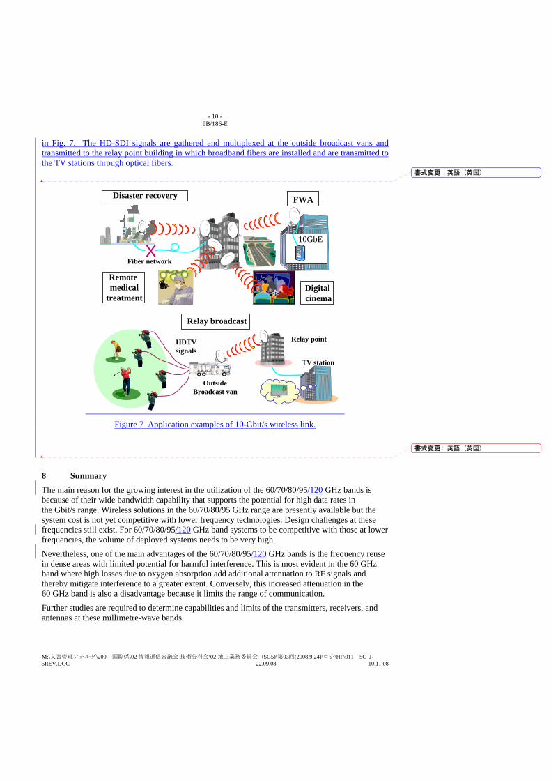
- 10 - 9B/186-E
M:\文書管理フォルダ\200 国際係\02 情報通信審議会 技術分科会\02 地上業務委員会(SG5)\第03回(2008.9.24)\ロジ\HP\011 5C_J-5REV.DOC 22.09.08 10.11.08
in Fig. 7. The HD-SDI signals are gathered and multiplexed at the outside broadcast vans and transmitted to the relay point building in which broadband fibers are installed and are transmitted to the TV stations through optical fibers.
Disaster recovery
Digitalcinema
Remotemedical
treatment
Fiber network
FWA
10GbE
HDTVsignals
Relay point
OutsideBroadcast van
TV station
Relay broadcast
Figure 7 Application examples of 10-Gbit/s wireless link.
8 Summary The main reason for the growing interest in the utilization of the 60/70/80/95/120 GHz bands is because of their wide bandwidth capability that supports the potential for high data rates in the Gbit/s range. Wireless solutions in the 60/70/80/95 GHz range are presently available but the system cost is not yet competitive with lower frequency technologies. Design challenges at these frequencies still exist. For 60/70/80/95/120 GHz band systems to be competitive with those at lower frequencies, the volume of deployed systems needs to be very high.
Nevertheless, one of the main advantages of the 60/70/80/95/120 GHz bands is the frequency reuse in dense areas with limited potential for harmful interference. This is most evident in the 60 GHz band where high losses due to oxygen absorption add additional attenuation to RF signals and thereby mitigate interference to a greater extent. Conversely, this increased attenuation in the 60 GHz band is also a disadvantage because it limits the range of communication.
Further studies are required to determine capabilities and limits of the transmitters, receivers, and antennas at these millimetre-wave bands.
書式変更: 英語 (英国)
書式変更: 英語 (英国)
- 11 - 9B/186-E
M:\文書管理フォルダ\200 国際係\02 情報通信審議会 技術分科会\02 地上業務委員会(SG5)\第03回(2008.9.24)\ロジ\HP\011 5C_J-5REV.DOC 22.09.08 10.11.08
References (Add the following reference)
KOSUGI, T. et al. [November2006] 120-GHz Tx/Rx waveguide Modules for 10-Gbit/s Wireless Link
System. IEEE CSIC Symp. Dig., pp.25-28
Bibliography (no change)
Appendix 1 (no change)
(Add) Appendix 2
Specifications and experimental results of 10-Gbit/s wireless link in 120 GHz band
1 Introduction Demand for 10-gigabit-class wireless communications is increasing year by year. In the field of telecommunications, the leading edge in the local area network (LAN) market is moving from Fast Ethernet to Gigabit Ethernet. Commercial 10-Gigabit Ethernet (10GbE) service has already started, and the 10-Gigabit Ethernet market is now growing as well. In the field of broadcasting, TV program production with the high-definition television (HDTV) standard is spreading. The data rate of uncompressed HDTV signal (high-definition serial digital interface signals: HD-SDI signal) is 1.5 Gbit/s. Moreover, research and development of a next generation television system called ultra high definition television (UHDTV) have been underway. The data rate of the UHDTV amounts to tens of Gbit/s. To catch up with the speed-up of telecommunications and broadcasts, wireless systems with a data rate of over 10 Gbit/s are required. However, no commercial wireless system meets these requirements. One of the promising ways to meet the demand for 10-gigabit-class wireless links is to use millimetre-wave signal at a frequency of over 100 GHz.
One organization has developed 120-GHz-band wireless link that has a maximum data rate of over 10 Gbit/s. The organization had obtained experimental radio station licences from Japanese Ministry of Internal Affairs and Communications and conducted various trial experiments. The wireless link yielded the error-free transmission of 10GbE signal, optical carrier-192 (OC-192) signal, and 6-channel multiplexed uncompressed HDTV signal. The wireless link was used for the transmission of broadcast materials for TV program productions. The success using over-100-GHz-band millimetre-waves that are unexplored frequency region in the field of industry has open a
書式変更: 中央揃え
書式変更: 左揃え
書式変更: フォント : 斜体
書式変更: フォント : 10 pt
書式変更: フォント : (英) Times NewRoman, 12 pt
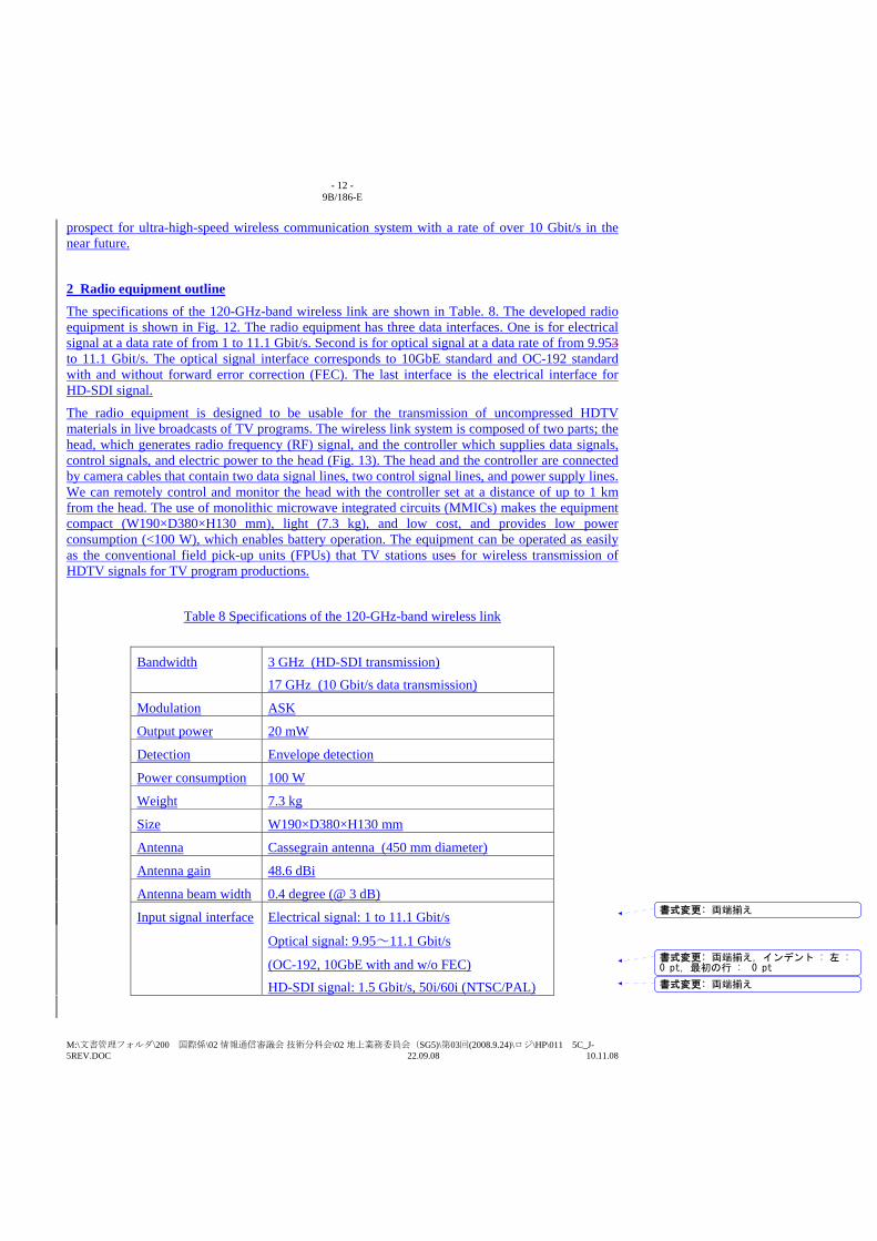
- 12 - 9B/186-E
M:\文書管理フォルダ\200 国際係\02 情報通信審議会 技術分科会\02 地上業務委員会(SG5)\第03回(2008.9.24)\ロジ\HP\011 5C_J-5REV.DOC 22.09.08 10.11.08
prospect for ultra-high-speed wireless communication system with a rate of over 10 Gbit/s in the near future.
2 Radio equipment outline The specifications of the 120-GHz-band wireless link are shown in Table. 8. The developed radio equipment is shown in Fig. 12. The radio equipment has three data interfaces. One is for electrical signal at a data rate of from 1 to 11.1 Gbit/s. Second is for optical signal at a data rate of from 9.953 to 11.1 Gbit/s. The optical signal interface corresponds to 10GbE standard and OC-192 standard with and without forward error correction (FEC). The last interface is the electrical interface for HD-SDI signal.
The radio equipment is designed to be usable for the transmission of uncompressed HDTV materials in live broadcasts of TV programs. The wireless link system is composed of two parts; the head, which generates radio frequency (RF) signal, and the controller which supplies data signals, control signals, and electric power to the head (Fig. 13). The head and the controller are connected by camera cables that contain two data signal lines, two control signal lines, and power supply lines. We can remotely control and monitor the head with the controller set at a distance of up to 1 km from the head. The use of monolithic microwave integrated circuits (MMICs) makes the equipment compact (W190×D380×H130 mm), light (7.3 kg), and low cost, and provides low power consumption (<100 W), which enables battery operation. The equipment can be operated as easily as the conventional field pick-up units (FPUs) that TV stations uses for wireless transmission of HDTV signals for TV program productions.
Table 8 Specifications of the 120-GHz-band wireless link
Bandwidth 3 GHz (HD-SDI transmission)
17 GHz (10 Gbit/s data transmission)
Modulation ASK
Output power 20 mW
Detection Envelope detection
Power consumption 100 W
Weight 7.3 kg
Size W190×D380×H130 mm
Antenna Cassegrain antenna (450 mm diameter)
Antenna gain 48.6 dBi
Antenna beam width 0.4 degree (@ 3 dB)
Input signal interface Electrical signal: 1 to 11.1 Gbit/s
Optical signal: 9.95~11.1 Gbit/s
(OC-192, 10GbE with and w/o FEC)
HD-SDI signal: 1.5 Gbit/s, 50i/60i (NTSC/PAL)
書式変更: 両端揃え
書式変更: 両端揃え, インデント : 左 : 0 pt, 最初の行 : 0 pt
書式変更: 両端揃え
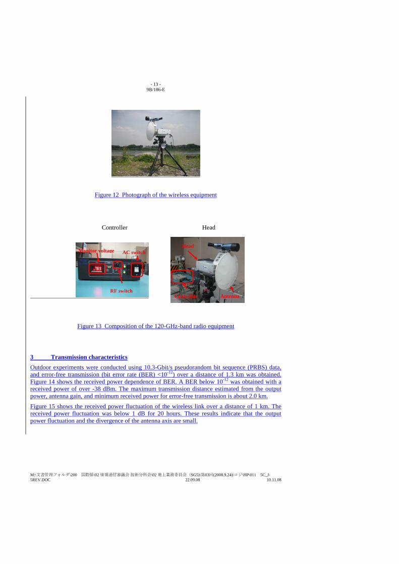
- 13 - 9B/186-E
M:\文書管理フォルダ\200 国際係\02 情報通信審議会 技術分科会\02 地上業務委員会(SG5)\第03回(2008.9.24)\ロジ\HP\011 5C_J-5REV.DOC 22.09.08 10.11.08
Figure 12 Photograph of the wireless equipment
Figure 13 Composition of the 120-GHz-band radio equipment
3 Transmission characteristics Outdoor experiments were conducted using 10.3-Gbit/s pseudorandom bit sequence (PRBS) data, and error-free transmission (bit error rate (BER) <10-12) over a distance of 1.3 km was obtained. Figure 14 shows the received power dependence of BER. A BER below 10-12 was obtained with a received power of over -38 dBm. The maximum transmission distance estimated from the output power, antenna gain, and minimum received power for error-free transmission is about 2.0 km.
Figure 15 shows the received power fluctuation of the wireless link over a distance of 1 km. The received power fluctuation was below 1 dB for 20 hours. These results indicate that the output power fluctuation and the divergence of the antenna axis are small.
Controller Head
AC switch Monitor voltage
RF switch Controller
Head
Antenna
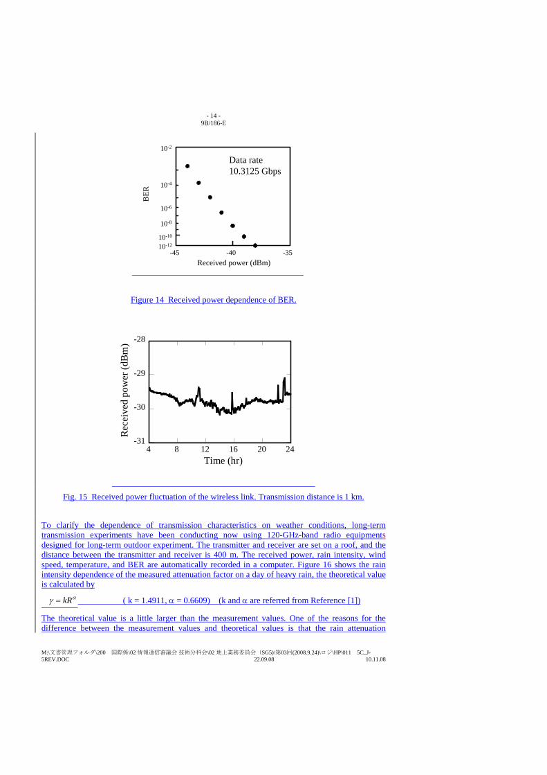
- 14 - 9B/186-E
M:\文書管理フォルダ\200 国際係\02 情報通信審議会 技術分科会\02 地上業務委員会(SG5)\第03回(2008.9.24)\ロジ\HP\011 5C_J-5REV.DOC 22.09.08 10.11.08
-45 -40 -35
10-2B
ER
Received power (dBm)
10-4
10-6
10-8
10-10
10-12
Data rate10.3125 Gbps
Figure 14 Received power dependence of BER.
Fig. 15 Received power fluctuation of the wireless link. Transmission distance is 1 km.
To clarify the dependence of transmission characteristics on weather conditions, long-term transmission experiments have been conducting now using 120-GHz-band radio equipments designed for long-term outdoor experiment. The transmitter and receiver are set on a roof, and the distance between the transmitter and receiver is 400 m. The received power, rain intensity, wind speed, temperature, and BER are automatically recorded in a computer. Figure 16 shows the rain intensity dependence of the measured attenuation factor on a day of heavy rain, the theoretical value is calculated by
αγ kR= ( k = 1.4911, α = 0.6609) (k and α are referred from Reference [1])
The theoretical value is a little larger than the measurement values. One of the reasons for the difference between the measurement values and theoretical values is that the rain attenuation
-31
-30
-29
-28
4 8 12 16 20 24
Rec
eive
d po
wer
(dBm
)
Time (hr)

- 15 - 9B/186-E
M:\文書管理フォルダ\200 国際係\02 情報通信審議会 技術分科会\02 地上業務委員会(SG5)\第03回(2008.9.24)\ロジ\HP\011 5C_J-5REV.DOC 22.09.08 10.11.08
depends on the rain drop diameters. The long-term accumulation of received power data will contribute to clarifying the transmission characteristics of 120-GHz-band millimetre-wave signal.
Figure 16 Rain intensity dependence of the attenuation factor.
4 Multiplexed uncompressed HDTV signal transmission One of the most promising applications of the 120-GHz-band wireless link is multiplexed wireless transmission of uncompressed HD-SDI signals. Multiplexed wireless transmission of uncompressed HD-SDI signals was achieved by multiplexing them over Internet protocol (IP) networks. A schematic of the multiplexed wireless transmission system is shown in Fig. 17. The multiplexing HD-SDI signals were conducted by an IP multiplexer. The IP multiplexer converts six HD-SDI video streams to IP packets, then multiplex these packets via a 10GbE network interface. The 10GbE signals were transmitted over the 120-GHz-band wireless link. In the receiver, an IP demultiplexer outputs six reconfigured video streams. Six-channel multiplexed uncompressed HD-SDI signals were transmitted over a distance of 300 m by using the 120-GHz-band wireless link.
O/E
HD-SDI
Transmitter
IP multiplexer10 GbE
E/O
HD-SDI
Receiver
10 GbE
IP demultiplexer
Figure 17: Schematic of 6-channel multiplexed wireless transmission of uncompressed HD-SDI signal over the 120-GHz-band wireless link.
INTERNATIONAL TELECOMMUNICATION UNION
RADIOCOMMUNICATION STUDY GROUPS
Document 5C/J-6 -EOctober 2008 English only
Subject: Question ITU-R 237/9
Japan
PRELIMINARY DRAFT REVISION OF REPORT ITU-R F.2106
FIXED SERVICE APPLICATIONS USING FREE-SPACE OPTICAL LINKS
1 Introduction At the meeting of the former Study Group 9 in May 2007, a new Report ITU-R F.2106 “Fixed Service applications using free-space optical links” was approved. The report provides characteristics, applications and other technical aspects of free-space optical links in the fixed service above 3000GHz.
Recently, Radio on FSO Link (RoFSOL) has been researched and is now in the stage of practical development. RoFSOL technology directly converts various types of radio signals into an optical signal using WDM (wavelength division multiplex) and transmits it to the free space. It will facilitate flexible connection between FSOL and other networks, because of the utilization of various optical wave lengths. The main point of the proposed modifications is to add the RoFSOL technological characteristics to the relevant parts of Report ITU-R F.2106.
2 Proposal The proposed modifications to the Report are followings as shown in the Attachment 1.
(1) Add the term RoFSOL in abbreviations.
(2) Add the definition of RoFSOL and the relating terminology in Sec.2.2 “System configuration”.
(3) Add the RoFSOL application example as Fig.9B and the associated text for explanation, in Sec.4.2 “Basic application example”.
(4) Add Annex 3, which explains the configuration of RoFSOL in detail, and items for further consideration in relation to RoFSO link budget.

- 2 -
Attachment 1
Preliminary Draft modifications to Report ITU-R F.2106
Fixed service applications using free-space optical links (Question ITU-R 237/9)
(2007)
Scope
This Report provides a ... (No Change)
Abbreviations AAC: Automatic attenuation control
APD: Avalanche photo diode
FSO: Free-space optics
FSOL: Free-space optical link
LD: Laser diode.
RoFSOL: Radio on Free-space optical link
References ……(No Change)…..
2.2 System configuration Basic configuration of a FSOL for the FS applications is illustrated in Fig 2.
FIGURE 2
Basic configuration of FSOL
In many FSOLs, the function of electrical/optical (E/O) or optical/electrical (O/E) conversion is implemented in the LD in the Tx or in the PD in the Rx, respectively. Recently, some systems
- 3 -
adopted the WDM technique in which more than one optical carrier can be accommodated in a couple of transmitters and receivers to increase the link capacity [1] [2]. WDM systems, however, may need further development in particular in the branching filter technology at the receiving side from a viewpoint of economical use.
The equipment uses the modulation of a laser beam to exchange binary data in both directions through a transmitter/receiver couple (Laser diode/APD or PIN diode) at each end. The equipment is used for point-to-point, bilateral links and in line of sight (LoS).
Another configuration of RoFSOL is illustrated in Annex 3. In the RoFSOL, various types of radio signals, e.g. from mobile and/or broadcast applications, are directly converted to optical wave through modulation of intensity, phase or other parameters. In such a system, WDM technology is used to discriminate service and forward/reverse link.
Each equipment consists of several modules: – For the transmission:
a) the tributary interface: electric or optics to send and receive digital data or radio signal; b) the E/O conversion module (in the event of optical interface), or the R/O (Radio to
Optical-signal) conversion module for RoFSOL; c) the filtering and the amplification of the electric digital or radio signal; d) the optical transmission module containing the laser.
– For the reception: a) the optical receiver module containing the diode; b) the filtering and the amplification of the electric digital or radio signal; c) the O/E conversion module (in the event of optical interface), or the O/R (Optical-signal
to Radio-signal) conversion module for RoFSOL; d) the tributary interface: electric or optics to send and receive the digital data or radio
signal.
A management software is sometimes provided with the equipment and allows to configure the link and to obtain qualitative and quantitative information from the different modules.
Additional functionalities are implemented depending on to the manufacturers, such as: – a tracking system, ATPC, AAC; – a radio assistance link, with a limited rate, in the event of a laser link interruption.
An example of FSO equipment structure is presented in Fig. 3.
FIGURE 3
FSO terminal example (according to optical access, San Diego, USA)

- 4 -
2.3 Basic system parameters ……(No Change)……
4.2 Basic application examples Making use of the advantages, typical FSOL applications are realized in limited distance. This paragraph presents examples of local area network (LAN) connection link between the buildings and a connection for the mobile infrastructure extension as shown in Figs. 8, 9A and 9B. In Fig.9B, RoFSOL utilizes R/O and O/R instead of E/O and O/E for FSOL of digital data transmission. And this application can distribute radio signals, not only to out door shadow area but also indoor shadow areas through optical fiber. In such applications, WDM grids of RoFSOL are shared by the WDM grids used by the fixed optical services, such as data and video.
FIGURE 8
FSOL connecting LANs deployed in the separate buildings
FIGURE 9A
FSOL extending mobile infrastructure
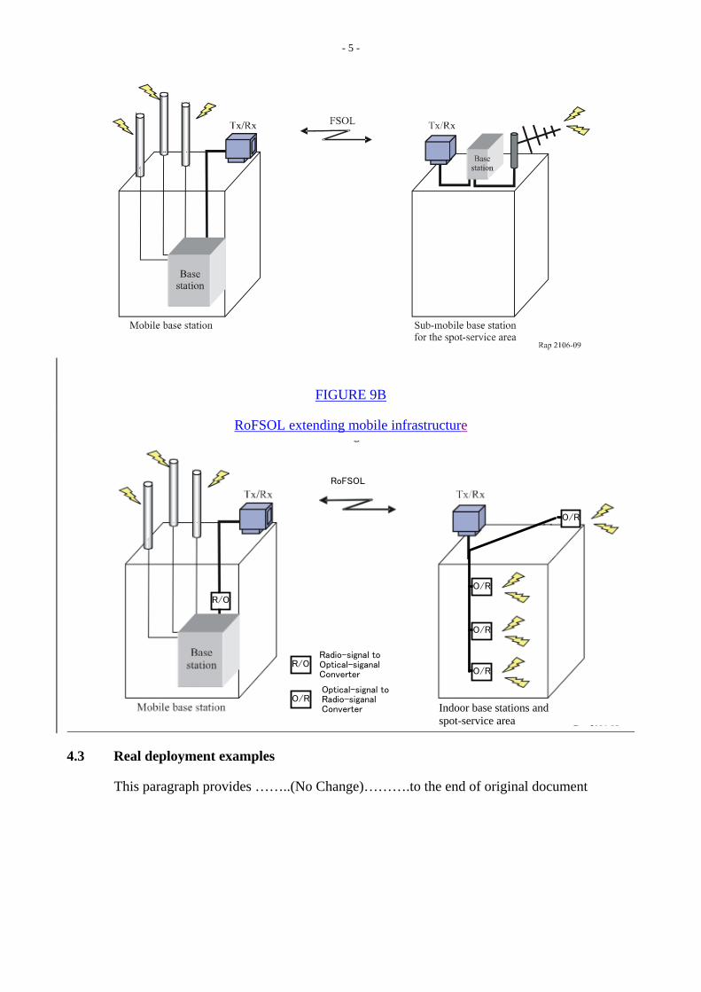
- 5 -
FIGURE 9B
RoFSOL extending mobile infrastructure
R/O
O/R
O/R
O/R
RoFSOL
Indoor base stations and spot-service area
O/R
O/R
Radio-signal to Optical-siganal Converter
R/O
Optical-signal to Radio-siganal Converter
4.3 Real deployment examples
This paragraph provides ……..(No Change)……….to the end of original document
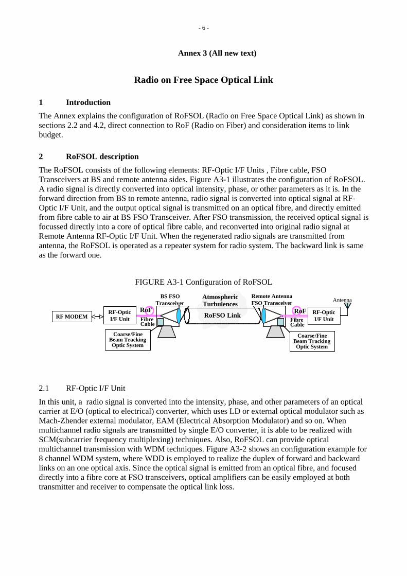
- 6 -
Annex 3 (All new text)
Radio on Free Space Optical Link
1 Introduction The Annex explains the configuration of RoFSOL (Radio on Free Space Optical Link) as shown in sections 2.2 and 4.2, direct connection to RoF (Radio on Fiber) and consideration items to link budget.
2 RoFSOL description The RoFSOL consists of the following elements: RF-Optic I/F Units , Fibre cable, FSO Transceivers at BS and remote antenna sides. Figure A3-1 illustrates the configuration of RoFSOL. A radio signal is directly converted into optical intensity, phase, or other parameters as it is. In the forward direction from BS to remote antenna, radio signal is converted into optical signal at RF-Optic I/F Unit, and the output optical signal is transmitted on an optical fibre, and directly emitted from fibre cable to air at BS FSO Transceiver. After FSO transmission, the received optical signal is focussed directly into a core of optical fibre cable, and reconverted into original radio signal at Remote Antenna RF-Optic I/F Unit. When the regenerated radio signals are transmitted from antenna, the RoFSOL is operated as a repeater system for radio system. The backward link is same as the forward one.
FIGURE A3-1 Configuration of RoFSOL
AtmosphericTurbulences
RoFSO Link RF-OpticI/F Unit
RoF RoFFibreCable
Coarse/FineBeam TrackingOptic System
Coarse/FineBeam TrackingOptic System
FibreCable
RF-OpticI/F Unit
BS FSOTransceiver
RF MODEM
AntennaRemote AntennaFSO Transceiver
2.1 RF-Optic I/F Unit
In this unit, a radio signal is converted into the intensity, phase, and other parameters of an optical carrier at E/O (optical to electrical) converter, which uses LD or external optical modulator such as Mach-Zhender external modulator, EAM (Electrical Absorption Modulator) and so on. When multichannel radio signals are transmitted by single E/O converter, it is able to be realized with SCM(subcarrier frequency multiplexing) techniques. Also, RoFSOL can provide optical multichannel transmission with WDM techniques. Figure A3-2 shows an configuration example for 8 channel WDM system, where WDD is employed to realize the duplex of forward and backward links on an one optical axis. Since the optical signal is emitted from an optical fibre, and focused directly into a fibre core at FSO transceivers, optical amplifiers can be easily employed at both transmitter and receiver to compensate the optical link loss.
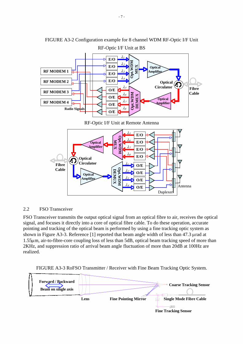
- 7 -
FIGURE A3-2 Configuration example for 8 channel WDM RF-Optic I/F Unit
RF-Optic I/F Unit at BS
O/E
O/E
O/E
O/E
OpticalAmplifier
OpticalAmplifier
E/O
Opt
.WD
MM
UX
Opt
.WD
MD
EM
UX
OpticalCirculator
E/O
E/O
E/O
λ1
λ2
λ3
λ4
λ5
λ6
λ7
λ8
RF MODEM 1
Radio Signals
RF MODEM 2
RF MODEM 3
RF MODEM 4
FibreCable
RF-Optic I/F Unit at Remote Antenna
DuplexerAntenna
O/E
O/E
O/E
O/E
Opt.W
DM
MU
XO
pt.WD
MD
EM
UX
OpticalCirculator
E/O
E/O
E/O
E/O
λ1
λ2
λ3
λ4
λ5
λ6
λ7
λ8
OpticalAmplifier
OpticalAmplifier
FibreCable
2.2 FSO Transceiver
FSO Transceiver transmits the output optical signal from an optical fibre to air, receives the optical signal, and focuses it directly into a core of optical fibre cable. To do these operation, accurate pointing and tracking of the optical beam is performed by using a fine tracking optic system as shown in Figure A3-3. Reference [1] reported that beam angle width of less than 47.3 μrad at 1.55μm, air-to-fibre-core coupling loss of less than 5dB, optical beam tracking speed of more than 2KHz, and suppression ratio of arrival beam angle fluctuation of more than 20dB at 100Hz are realized.
FIGURE A3-3 RoFSO Transmitter / Receiver with Fine Beam Tracking Optic System.
Coarse Tracking Sensor
Fine Tracking Sensor
Single Mode Fibre Cable
Forward / Backward
Beam on single axis
Fine Pointing MirrorLens

- 8 -
3 Considerable items for RoFSO link budget
Editor’s Note: The texts for the following sections are to be provided at the future meetings.
3.1 Transmitting Capacity
Transmitting Capacity of RoFSO link is defined in terms of following parameters:
- Number of RF carriers per an optical carrier
- Frequency and Bandwidth (Data Rate) of radio signals
- Number of wavelength
3.2 FSOL parameter
- Maximum power per optical carrier considering safety
- Beam divergence
- Wavelength
3.3 System and device parameters
- Link length and loss (Geometrical attenuation)
- Insertion loss of optical equipments
- Optical amplifier gain at transmitter and receiver
- O/E and E/O conversion factors
- Link gain in RF region forward and backward
- Required receiver sensitivity and Spurious characteristics of transmitted radio signals
3.4 Degradation parameters
- Additive noises ( Relative Intensity noise for LD, ASE at optical amplifier, Ambient light, Shot Noise, Receiver thermal noise, etc.)
- Intermodulation distortion due to nonlinearity at E/O
- Rain and Fog attenuation at FSOL
- Atmospheric turbulence (beam broadening and angle-of-arrival fluctuations, scintillation, etc. )
4 References [1] K. Tsukamoto, S. Komaki, M. Matsumoto, "Development Project of Radio on Free Space Optics", Proc. of SPIE, Vol. 6776, No. 6, pp. 1-8, Septe mber 2007.
M:\文書管理フォルダ\200 国際係\02 情報通信審議会 技術分科会\02 地上業務委員会(SG5)\第03回(2008.9.24)\ロジ\HP\013 5D_J-1.DOC (255358) 22.09.08 10.11.08
1 Introduction It was concluded at the 2nd WP5D meeting held in Dubai, UAE, in June 2008 that preliminary
draft new Report ITU-R M.[IMT.EVAL] (described as [IMT.EVAL] hereafter), which is included in Attachment 6.6 to Document 5D/242, was carried forward to the 3rd WP5D meeting for its finalization. The reasons of the carry-forward are not only incompletion of documentation but also necessity of carefully examining consistency [IMT.EVAL] with related documents such as draft new Reports ITU-R M. [IMT.TECH] and M. [IMT.REST].
Japan has reviewed [IMT.EVAL] while referring to the related documents. Japan found not only TBD parts, which are marked in square brackets with pained in yellow colour, but also editorial errors and inconsistent words/terminologies throughout [IMT.EVAL].
This contribution proposes amendments and modifications on the parts as mentioned above for the purpose of the finalization of [IMT.EVAL]. In addition, a few parameters, some of which were actually proposed in the 2nd WP5D meeting, are re-proposed in this contribution for the purpose of less ambiguity in evaluations. It is noted that this contribution focuses only on Chapters 7 and 8 in [IMT.EVAL]. In other words, Japan has no comments on the other parts in [IMT.EVAL] at this moment.
2 Summary of modification/proposals This contribution shows proposals on modifications of several sentences for their further
clarifications and global corrections of the followings.
To correct typos: ”draft Report ITU-R M.[IMT.TECH]” “draft new Report ITU-R M.[IMT.TECH]”
To use single term “candidate RIT/SRITs,” which is used in Section 2 of [IMT.EVAL] and [IMT.REST] , instead of similar words (Note: the current [IMT.EVAL] includes a variety of words/terminology such as ”candidate
Radiocommunication Study Groups
Received: XX October 2008
Subject: Question ITU-R 229-1/8
Document 5D/J-1-E XX October 2008 English only TECHNOLOGY
Japan
A PROPOSAL OF AMENDMENTS IN CHAPTERS 7 AND 8 OF PRELIMINARY DRAFT NEW REPORT M.[IMT.EVAL]
- 2 - 5D/J-1-E
22.09.08 10.11.08
technologies,” ”IMT-Advanced candidate technologies,” “candidate IMT-Advanced RIT/SRITs,” “candidate RIT/SRITs for IMT-Advanced,” “RIT/SRIT,” “candidate RIT or SRIT,”, and so on.)
In addition to the above, major modifications proposed in this contribution are summarized below.
(1) Chapter 7 (before Section 7.1)
The sentences in the second paragraph are modified to have more clarifications.
In the last paragraph, the words “layer 1 and layer 2” are deleted because we need to take account of not only the overhead at layers 1 and 2 but also layers 3 and 4 when we evaluate the VoIP capacity as described in Annex 2 of [IMT.EVAL]. Note that Section 4.1 of [IMT.TECH] clearly describes “number of bits contained in the SDUs delivered to Layer 3” for evaluations of both cell spectral efficiency and cell edge user spectral efficiency. Considering both the VoIP capacity and the spectral efficiency calculations, the term “overhead” is considered sufficient.
(2) Section 7.1: TBD on feedback channel modeling
It is generally considered that feedback channels are part of control channels (more specifically, feedback messages are conveyed over control channels). The text in this paragraph is modified on the basis of this idea, but the text proposal still uses the words “feedback channel” to give more information to proponents.
(3) Section 7.1.2: Editorial changes for consistency with [IMT.TECH]
This section briefly describes how to calculate the cell edge user spectral efficiency. However, the sentence “the number of correctly received bits per user for the time the user is in the simulation” is unclear. In order to clarify this part, this contribution proposes to use “during the active session time,” which is used in [IMT.TECH], to replace the underlined part above.
(4) Section 7.1.3: TBD on submission of packet delay distribution
The packet delay distribution is important to confirm the VoIP capacity of candidate RIT/SRITs. Hence, this contribution proposes to remove the square brackets enclosing the words “packet delay distribution,” in order to require submitting the packet delay distribution for VoIP.
(5) Section 7.3: TBD regarding submission of details on “analytical” methods
It is indispensable for evaluators to understand details on how to estimate evaluation items marked as “analytical” in Table 6-1. Otherwise, evaluators cannot confirm and/or re-evaluate whether the results provided from proponents are correct or not. This contribution proposes to modify the text in line with the idea.
(6) Section 8.1.1: Editorial changes on explanation of the base coverage urban test environment
The baseline text in [IMT.EVAL] explains the outline of the base coverage urban test environment using “Manhattan type of grid.” However, the Manhattan grid model is not used for evaluating candidate RIT/SRITs. Thus, unnecessary sentences are deleted in this contribution.

- 3 - 5D/J-1-E
22.09.08 10.11.08
(7) Section 8.3: TBD on the simulation bandwidth, especially for the cases of frequency reuse factor, which is larger than 1
The point of this TBD is that we need to take account of a proposal of candidate RIT/SRITs, which does not assume or specify the unit of frequency channels that is not equal to the frequency bandwidth in [IMT.EVAL] (e.g., 10 MHz) divided by a frequency reuse factor (e.g. 3 and 7).
The baseline text in Section 8.3 describes that “the total spectrum used in the simulation should be calculated as the product of the spectrum bandwidth and the frequency reuse factor” in order to solve this issue
Japan, however, has two concerns on the baseline text: (a) One is the unfairness in terms of frequency bandwidth to be used for evaluation depending on candidate RIT/SRITs. In general, we can obtain larger frequency diversity gain as the frequency bandwidth increases. (b) The other one is that there are a variety of frequency reuse schemes such as “fractional frequency reuse (FFR)” these days. Even in the FFR, we can find several types of FFR such as static FFR, semi-static FFR, and dynamic FFR. Those FFR schemes partially utilize the concept of the conventional frequency reuse scheme but the frequency reuse factor is not an integer number. In addition, the semi-static and dynamic FFR schemes dynamically vary frequency reuse factors as time goes by. In this sense, the current text “The total spectrum used in the simulation should be calculated as the product of the spectrum bandwidth and the frequency reuse factor” is not appropriate.
Regarding (a), Japan has not yet come up with a good idea to solve the issue while taking into consideration of a proposal of candidate RIT/SRITs as mentioned above. We then need to admit special cases to use wider bandwidth for simulations of those candidate RIT/SRITs. As for (b), the current text should be revised to allow proponents to use the simulation bandwidth specified in Tables 8-5, 8-6, and 8-7.
As a consequence, this contribution proposes modification of the current text while maintaining the concept of the spectrum bandwidth (= “simulation bandwidth” x “frequency reuse factor”).
(8) New proposal of specifying antenna gain values for both BS and UT
In fact, Japan submitted a contribution “Document 5D/170,” where antenna gain values for both BS and UT are included as parameters. However, those parameters were not discussed during the 2nd WP5D meeting. Since those parameters are important as well as other parameters that have already been in the latest [IMT.EVAL], Japan proposes them again to the 3rd WP5D meeting.
Note that those values are added to Table 8-4.
(9) Section 8.5: Replacement from test environment to deployment scenario
The baseline text in [IMT.EVAL] uses terminologies for test environments rather than deployment scenarios. The conversions between the test environments and the deployment scenarios are already presented in Section 8.2. Therefore, this contribution proposes to use deployment scenarios instead of test environments as for this section.
(10) Section 8.5.1.1: Proposal of introducing tilt angle for vertical antenna pattern
The baseline text on the vertical antenna pattern in Section 8.5.1.1 does not include the tilt angle, even though realistic BSs employ tilt angles. Thus, this contribution proposes to modify the
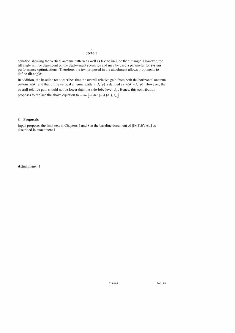
- 4 - 5D/J-1-E
22.09.08 10.11.08
equation showing the vertical antenna pattern as well as text to include the tilt angle. However, the tilt angle will be dependent on the deployment scenarios and may be used a parameter for system performance optimizations. Therefore, the text proposed in the attachment allows proponents to define tilt angles.
In addition, the baseline text describes that the overall relative gain from both the horizontal antenna pattern ( )A θ and that of the vertical antennal pattern ( )eA φ is defined as ( ) ( )eA Aθ φ+ . However, the overall relative gain should not be lower than the side-lobe level mA . Hence, this contribution proposes to replace the above equation to ( ) ( )( )min ,e mA A Aθ φ⎡ ⎤− − +⎣ ⎦ .
3 Proposals Japan proposes the final text in Chapters 7 and 8 in the baseline document of [IMT.EVAL] as described in attachment 1.
Attachment: 1
- 5 - 5D/J-1-E
22.09.08 10.11.08
ATTACHMENT 1
Source : 5D/242 Attachment 6.6
PRELIMINARY DRAFT NEW REPORT ITU-R M.[IMT.EVAL]
“Guidelines for evaluation of radio interface technologies for IMT-Advanced”
Note from the Chairman of Working Party 5D:
At the second meeting of Working Party 5D, the work on draft new Report ITU-R M.[IMT.EVAL] was progressed to the point where the meeting was able to conclude and agree on the majority of the document, which is considered stable, however the meeting decided that it was appropriate to carry this work forward to the 3rd meeting of WP 5D where it was agreed to be finalized. The meeting took this approach to ensure that draft new Report M.[IMT.EVAL] could be thoroughly reviewed by the relevant experts in its total context due to the detailed nature and critical importance of the document in the evaluation stages of the IMT-Advanced process. Work on the channel model (Section 9 and Annex 1), which had been conducted under a separate drafting group exercise, was fully agreed and this portion of the work has closed. Several sections, including section 7.4.4 of the document were also edited in the Plenary and agreed as they form the basis for information in other key documents.
CONTENTS
1 Introduction
2 Scope
3 Structure of the Report
4 Related documents
5 Evaluation guidelines
6 Characteristics for evaluation
7 Evaluation methodology
8 Test environments and evaluation configurations
9 Channel model approach
10 References
Annex 1 – Test environments and channel models
Annex 2 – Traffic models
Annex 3 – Link budget template

- 6 - 5D/J-1-E
22.09.08 10.11.08
[omitted]
7 Evaluation methodology
The submission and evaluation processes on candidate RIT/SRITs is are defined in ITU-R IMT-ADV/2(Rev.1).
Evaluation should be performed in strict compliance with the technical parameters provided by the proponents and the evaluation configurations specified for the deployment scenarios in Section 8.4. Each requirement evaluation item listed in Table 6-1 should be evaluated independently according to the criteria defined in draft new Report ITU-R M.[IMT.TECH], except for the cell spectral efficiency and cell edge user spectral efficiency criteria that shall be assessed jointly using the same computer simulation, and that consequently the candidate RIT/SRITscandidate technology proposal also shall fulfil the corresponding minimum requirements jointly. Furthermore, as the procedure stated in Section 7.2, the system simulation used in the mobility evaluation should be the same as the system simulation for cell spectral efficiency and cell edge user spectral efficiency.
The evaluation methodology should include the following elements:
1) Candidate RIT/SRITsCandidate technologies should be evaluated using reproducible methods including computer simulation, analytical approaches and inspection of the proposal.
2) Technical evaluation of the candidate RIT/SRITs candidate technology made against each evaluation criterion for the required test environments.
3) Candidate RIT/SRITsCandidate technologies should be evaluated based on technical descriptions that are submitted using a technologies description template.
In order to have a good comparability of the evaluation results, the following solutions and enablers are to be taken into account:
• Use of unified methodology, software, and data sets by the evaluation groups wherever possible, e.g. in the area of channel modelling, link-level data, and link-to-system-level interface.
• Direct comparison of multiple proposals using one simulation tool as proposed in the case of horizontal evaluation above.
• Question-oriented working method that adapts the level of detail in modelling of specific functionalities according to the particular requirements of the actual investigation
Evaluation of cell spectral efficiency, peak spectral efficiency, cell edge user spectral efficiency and VoIP capacity of candidate RIT/SRITsproposed IMT-Advanced candidate technologies should consider the layer 1 and layer 2 overhead information provided by the proponents, which may vary when evaluating different performance metrics and deployment scenarios.
7.1 System simulation procedures System simulations shall be based on the network layout defined in Section 8.3. The following principles shall be followed in system simulations:
Users are dropped independently with uniform distribution over predefined area of the network layout throughout the system. Each mobile corresponds to an active user session that runs for the duration of the drop.
Mobiles are randomly assigned channel models. Depending on the simulation, these may be in support of a desired channel model mix, or separate statistical realizations of a single type of channel model.

- 7 - 5D/J-1-E
22.09.08 10.11.08
Cell assignment selection tofor a user is based on the proponent’s cell selection scheme, which must be described by the proponent.
The minimum distance between a user and an active base station is defined in Table 8-2 in Section 8.4.
Fading signal and fading interference are computed from each mobile station into each cell and from each cell into each mobile station (in both directions on an aggregated basis).
In simulations based on the full-buffer traffic mode, packets are not blocked when they arrive into the system (i.e. queue depthslength is are assumed infinite).
Users with a required traffic class shall be modelled according to the traffic models defined in Annex 2.
Packets are scheduled with an appropriate packet scheduler(s) proposed by the proponents for full buffer case and VoIP separately. Channel quality feedback delay, feedback error, PDU (Protocol Data Unit) errors, real channel estimation effect are modelled and packets are retransmitted as necessary.
Simulation time is chosen to ensure convergence in user performance metrics. For a given drop the simulation is run for this duration, and then the process is repeated with the users dropped at new random locations. A sufficient number of drops are simulated to ensure convergence in the system performance metrics.
Performance statistics are collected for users in all cells. All cells in the system shall be simulated with dynamic channel properties.
In order to perform less complex system simulations, often the simulations are divided into separate ‘link’ and ‘system’ simulations with a specific link-to-system interface. Another possible way to reduce system simulation complexity is to employ simplified interference modelling. Such methods should be sound in principle, and are technology dependent and thus it is not within the scope of this document to describe them. Evaluation groups are allowed to use such approaches provided that the used methodologies are • well described and made available to the BR (Bureau Radiocommunications) and other
evaluation groups; • included in the evaluation report.
[The channel estimation should be executed during simulations. Errors in all the control channels that, feedback channel errors and the errors of control channel that is are required indispensable to decode decoding the traffic channel should all be modelled. The overheads (e.g. the overheads of the feedback channel and the control channel) should be modelled realistically.]
7.1.1 Cell spectral efficiency The results from the system simulation are used to calculate the cell spectral efficiency as defined in draft Reportdraft new Report ITU-R M.[IMT.TECH]. The necessary information includes the number of correctly received bits during the simulation period.
7.1.2 Cell edge user spectral efficiency The results from the system simulation are used to calculate the cell edge user spectral efficiency as defined in draft Reportdraft new Report ITU-R M.[IMT.TECH]. The necessaryeded information is the number of correctly received bits per user duringfor the active session time the user is in the simulation. It isshould be noted that the cell edge user spectral efficiency shall be evaluated using theidentical simulation assumptions configurations used for as the cell spectral efficiency for that test environment.
- 8 - 5D/J-1-E
22.09.08 10.11.08
7.1.3 VoIP capacity The VoIP capacity should be measured according to the definition in draft Reportdraft new Report ITU-R M.[IMT.TECH]. Information about [packet delay distribution] for each user should be provided from the simulation. The VoIP traffic model is defined in Annex 2.
7.2 Evaluation methodology for mobility requirements The evaluator shall perform the following steps in order to evaluate the mobility requirement.
1. Run system simulations (identical to those for cell spectral efficiencies, see Section 7.1.1) for a the set of selected test environment(s) associated with the candidate RIT/SRITs proposal and collect overall statistics for uplink C/I values, and construct cumulative distribution function (CDF) over these values for each test environment.
2. Use the CDF for the test environment(s) to save the respective 50%-percentile C/I value.
3. Run uplink link-level simulations for the selected test environment(s) for both NLOS and LOS channel models using the associated C/I value obtained from Step 2 and the associated speeds in the Table 3 of draft new Report ITU-R M.[IMT.TECH] Section 4.6 as input parameters, to obtain associated spectral efficiency value(s).
4. Compare the spectral efficiency values for each channel model case obtained from Step 2 with the corresponding threshold values in the Table 3 of draft new Report ITU-R M.[IMT.TECH] Section 4.6.
5. The proposal fulfils the mobility requirement if the spectral efficiency value is larger than or equal to the corresponding threshold value and if also the decoded target packet error rate is less than 1 percent, for all selected test environments. For each test environment it is sufficient if one of the spectral efficiency values (of either NLOS or LOS channel models) fulfil the threshold.
The link level simulation shall use air interface configuration(s) supported by the proposal and may take into account retransmission.
Although the system simulations (Step 1) might may not contain users with the high speeds associated with the mobility requirements, such simulations are nevertheless used to obtain a typical C/I value (Step 2) for the technology in question and the selected test environment(s).
These values are then to be used in the respective link simulations for the relevant test environment(s) (Step 3), after which compliance test can be made (steps 4 and 5).
Note also that the system simulations are the same and can be performed simultaneously with those associated with evaluation of the spectral efficiency and cell edge spectral efficiency.
7.3 Analytical approach For the characteristics described in the following subsections,below a straight forward calculation based on information in the proposal will be enough to evaluate them. ProponentsThe evaluation shall show [how to estimate the following evaluation itemsthe calculation has been done].
7.3.1 Peak spectral efficiency calculation The peak spectral efficiency is calculated as specified in draft new Report ITU-R M.[IMT.TECH]. The antenna configuration to be used for peak spectral efficiency is defined in Table 8-3.
7.3.2 Control plane latency calculation The control plane latency is calculated as specified in draft new Report ITU-R M.[IMT.TECH].
7.3.3 User plane latency calculation
- 9 - 5D/J-1-E
22.09.08 10.11.08
The user plane latency is calculated as specified in draft new Report ITU-R M.[IMT.TECH].
7.3.4 Intra- and inter-frequency handover interruption time derivation The intra- and inter-frequency handover interruption time is calculated as specified in draft new Report ITU-R M.[IMT.TECH]. The handover procedure shall be described based on the proposed technology including the functions and the timing involved.
7.4 Inspection
7.4.1 Bandwidth and channel bandwidth scalability The support of maximum bandwidth required in draft new Report ITU-R M.[IMT.TECH] Section 4.4 is verified by inspection of the proposal.
The scalability requirement is verified by demonstrating that the candidate RIT/ or SRITs can support at least three bandwidth values. These values shall include the minimum and maximum supported bandwidth values of the candidate RIT or /SRITs.
7.4.2 Deployment in IMT bands
The set of IMT bands supported is demonstrated by inspection of the proposal.
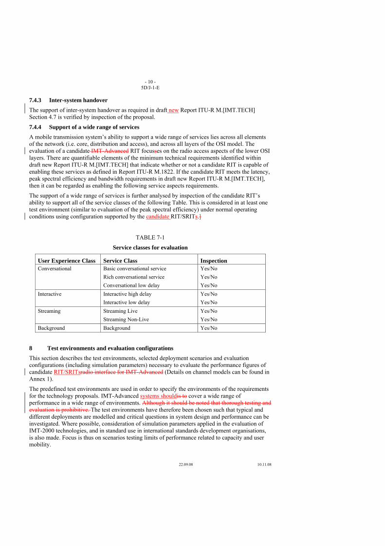
- 10 - 5D/J-1-E
22.09.08 10.11.08
7.4.3 Inter-system handover The support of inter-system handover as required in draft new Report ITU-R M.[IMT.TECH] Section 4.7 is verified by inspection of the proposal.
7.4.4 Support of a wide range of services A mobile transmission system’s ability to support a wide range of services lies across all elements of the network (i.e. core, distribution and access), and across all layers of the OSI model. The evaluation of a candidate IMT-Advanced RIT focusses on the radio access aspects of the lower OSI layers. There are quantifiable elements of the minimum technical requirements identified within draft new Report ITU-R M.[IMT.TECH] that indicate whether or not a candidate RIT is capable of enabling these services as defined in Report ITU-R M.1822. If the candidate RIT meets the latency, peak spectral efficiency and bandwidth requirements in draft new Report ITU-R M.[IMT.TECH], then it can be regarded as enabling the following service aspects requirements.
The support of a wide range of services is further analysed by inspection of the candidate RIT’s ability to support all of the service classes of the following Table. This is considered in at least one test environment (similar to evaluation of the peak spectral efficiency) under normal operating conditions using configuration supported by the candidate RIT/SRITs.]
TABLE 7-1
Service classes for evaluation
User Experience Class Service Class Inspection Conversational Basic conversational service
Rich conversational service Conversational low delay
Yes/No Yes/No Yes/No
Interactive Interactive high delay Interactive low delay
Yes/No Yes/No
Streaming Streaming Live Streaming Non-Live
Yes/No Yes/No
Background Background Yes/No
8 Test environments and evaluation configurations This section describes the test environments, selected deployment scenarios and evaluation configurations (including simulation parameters) necessary to evaluate the performance figures of candidate RIT/SRITsradio interface for IMT-Advanced (Details on channel models can be found in Annex 1).
The predefined test environments are used in order to specify the environments of the requirements for the technology proposals. IMT-Advanced systems shouldis to cover a wide range of performance in a wide range of environments. Although it should be noted that thorough testing and evaluation is prohibitive. The test environments have therefore been chosen such that typical and different deployments are modelled and critical questions in system design and performance can be investigated. Where possible, consideration of simulation parameters applied in the evaluation of IMT-2000 technologies, and in standard use in international standards development organisations, is also made. Focus is thus on scenarios testing limits of performance related to capacity and user mobility.
- 11 - 5D/J-1-E
22.09.08 10.11.08
8.1 Test environments Evaluation of candidate IMT-Advanced RIT/SRITs will be performed in selected scenarios of the following test environments: • Base coverage urban: an urban macro-cellular environment targeting continuous coverage
for pedestrian up to fast vehicular users. • Microcellular: an urban micro-cellular environment with higher user density focusing on
pedestrian and slow vehicular users • Indoor: an indoor environment targeting isolated cells at offices and/or in hotspot based on
stationary and pedestrian users. • High speed: macro cells environment with high speed vehicular and trains.
8.1.1 Base coverage urban test environment The base coverage urban test environment focuses on large cells and continuous coverage. The key characteristics of this test environment are continuous and ubiquitous coverage in urban areas. This scenario will therefore be interference-limited, using macro cells (i.e. radio access points above rooftop level).
In urban macro-cell scenario mobile station is located outdoors at street level and fixed base station antenna clearly above surrounding building heights. As for propagation conditions, non- or obstructed line-of-sight is a common case, since street level is often reached by a single diffraction over the rooftop. The building blocks can form either a regular Manhattan type of grid, or have more irregular locations. Typical building heights in urban environments are over four floors. Buildings height and density in typical urban macro-cell are mostly homogenous.
8.1.2 Microcellular test environment The microcellular test environment focuses on small cells and high user densities and traffic loads in city centres and dense urban areas. The key characteristics of this test environment are high traffic loads, outdoor and outdoor-to-indoor coverage. This scenario will therefore be interference-limited, using micro cells. A continuous cellular layout and the associated interference shall be assumed. Radio access points shall be below rooftop level.
A similar scenario is used to the base coverage urban test environment but with reduced site-to-site distance and the antennas below rooftops.
8.1.3 Indoor test environment The indoor test environment focuses on smallest cells and high user throughput in buildings. The key characteristics of this test environment are high user throughput in indoor coverage.
8.1.4 High-speed test environment The high-speed test environment focuses on larger cells and continuous coverage. The key characteristics of this test environment are continuous wide area coverage supporting high speed vehicles. This scenario will therefore be noise-limited and/or interference-limited, using macro cells.
8.2 Deployment scenarios for the evaluation process The deployment scenarios that shall be used for each test environment are shown in the following table:
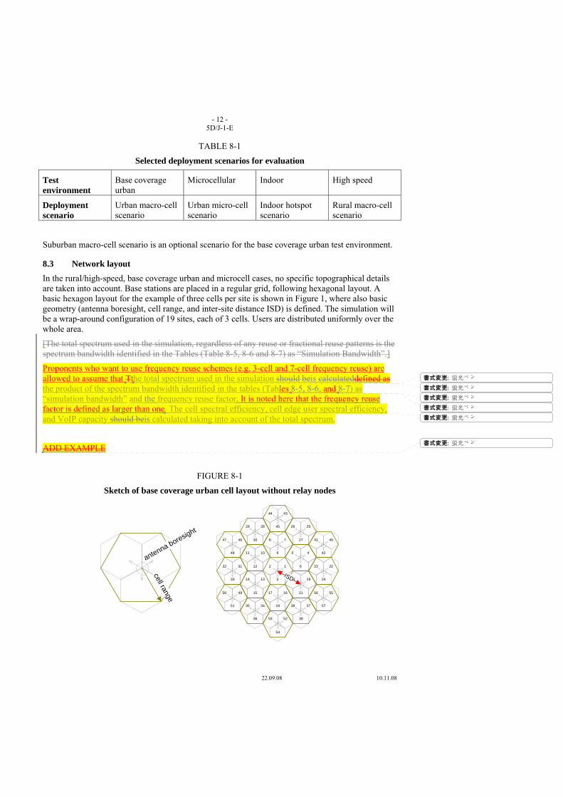
- 12 - 5D/J-1-E
22.09.08 10.11.08
TABLE 8-1
Selected deployment scenarios for evaluation
Test environment
Base coverage urban
Microcellular Indoor High speed
Deployment scenario
Urban macro-cell scenario
Urban micro-cell scenario
Indoor hotspot scenario
Rural macro-cell scenario
Suburban macro-cell scenario is an optional scenario for the base coverage urban test environment.
8.3 Network layout In the rural/high-speed, base coverage urban and microcell cases, no specific topographical details are taken into account. Base stations are placed in a regular grid, following hexagonal layout. A basic hexagon layout for the example of three cells per site is shown in Figure 1, where also basic geometry (antenna boresight, cell range, and inter-site distance ISD) is defined. The simulation will be a wrap-around configuration of 19 sites, each of 3 cells. Users are distributed uniformly over the whole area.
[The total spectrum used in the simulation, regardless of any reuse or fractional reuse patterns is the spectrum bandwidth identified in the Tables (Table 8-5, 8-6 and 8-7) as “Simulation Bandwidth”.]
Proponents who want to use frequency reuse schemes (e.g. 3-cell and 7-cell frequency reuse) are allowed to assume that Tthe total spectrum used in the simulation should beis calculateddefined as the product of the spectrum bandwidth identified in the tables (Tables 8-5, 8-6, and 8-7) as “simulation bandwidth” and the frequency reuse factor. It is noted here that the frequency reuse factor is defined as larger than one. The cell spectral efficiency, cell edge user spectral efficiency, and VoIP capacity should beis calculated taking into account of the total spectrum.
ADD EXAMPLE
FIGURE 8-1
Sketch of base coverage urban cell layout without relay nodes
12
3
45
6
78
91011
12
1314
15 1617
18
1920
21
2223
24
2526
27
2829
30
3132
33
3435
36
3738
39
4041
42
4344
45
4647
48
4950
51
5253
54
5556
57
cell range
antenna boresight
ISD
書式変更: 蛍光ペン
書式変更: 蛍光ペン
書式変更: 蛍光ペン
書式変更: 蛍光ペン
書式変更: 蛍光ペン
書式変更: 蛍光ペン

- 13 - 5D/J-1-E
22.09.08 10.11.08
The indoor hotspot scenario consists of one floor of a building. The height of the floor is 6 m. The floor contains 16 rooms of 15 m x 15 m and a long hall of 120 m x 20m. Two sites are placed in the middle of the hall at 30m and 90m with respect to the left side of the building (see following Figure).
FIGURE 8-2
Sketch of indoor hotspot environment (one floor)
8.4 Evaluation configurations This section contains baseline configuration parameters that shall be applied in analytical and simulation assessments of candidate RIT/SRITs.
The parameters (and also the propagation and channel models in Annex 1) are solely for the purpose of consistent evaluation of the candidate RIT/SRITs for IMT-Advanced and relate only to specific test environments used in these simulations. They should not be considered as the values that must be used in actualny deployments of any IMT-Advanced systems andnor should they taken as the default values for any other or subsequent studiesy in ITU or elsewhere. They do not necessarily themselves constitute any requirements on the implementation of the system.
Configuration parameters in Table 8-2 shall be applied when evaluation groups assess the characteristics of cell spectral efficiency, cell edge user spectral efficiency, control plane latency, user plane latency, mobility, handover interruption time and VoIP capacity in evaluation of candidate RIT/SRITs.
TABLE 8-2
Baseline evaluation configuration parameters
Deployment scenario for the
evaluation process
Urban macro-cell
Urban micro-cell
Indoor hotspot Rural macro-cell
Suburban macro-cell
Base Station (BS) antenna height
25 m, above rooftop
10 m, below rooftop
6 m, mounted on ceiling
35 m, above rooftop
35 m, above rooftop
Number of BS antenna elements1
Up to 8 rx Up to 8 tx
Up to 8 rx Up to 8 tx
Up to 8 rx Up to 8 tx
Up to 8 rx Up to 8 tx
Up to 8 rx Up to 8 tx
____________________ 1 Evaluation group should use the number of antennas specified by proponent in the technology description
template if it is not more than the number specified in this table.
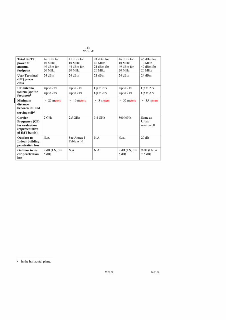
- 14 - 5D/J-1-E
22.09.08 10.11.08
Total BS TX power at antenna feedpoint
46 dBm for 10 MHz, 49 dBm for 20 MHz
41 dBm for 10 MHz, 44 dBm for 20 MHz
24 dBm for 40 MHz, 21 dBm for 20 MHz
46 dBm for 10 MHz, 49 dBm for 20 MHz
46 dBm for 10 MHz, 49 dBm for 20 MHz
User Terminal (UT) power class
24 dBm 24 dBm 21 dBm 24 dBm 24 dBm
UT antenna system (see the footnote)1
Up to 2 tx Up to 2 rx
Up to 2 tx Up to 2 rx
Up to 2 tx Up to 2 rx
Up to 2 tx Up to 2 rx
Up to 2 tx Up to 2 rx
Minimum distance between UT and serving cell2
>= 25 meters >= 10 meters >= 3 meters >= 35 meters >= 35 meters
Carrier Frequency (CF) for evaluation (representative of IMT bands)
2 GHz 2.5 GHz 3.4 GHz 800 MHz Same as Urban macro-cell
Outdoor to Indoor building penetration loss
N.A. See Annex 1 Table A1-1
N.A. N.A. 20 dB
Outdoor to in-car penetration loss
9 dB (LN, σ = 5 dB)
N.A. N.A. 9 dB (LN, σ = 5 dB)
9 dB (LN, σ = 5 dB)
____________________ 2 In the horizontal plane.
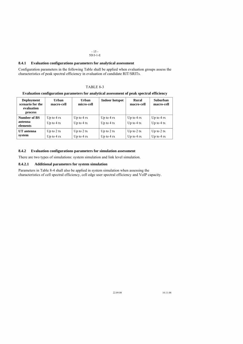
- 15 - 5D/J-1-E
22.09.08 10.11.08
8.4.1 Evaluation configurations parameters for analytical assessment Configuration parameters in the following Table shall be applied when evaluation groups assess the characteristics of peak spectral efficiency in evaluation of candidate RIT/SRITs.
TABLE 8-3
Evaluation configuration parameters for analytical assessment of peak spectral efficiency
Deployment scenario for the
evaluation process
Urban macro-cell
Urban micro-cell
Indoor hotspot Rural macro-cell
Suburban macro-cell
Number of BS antenna elements
Up to 4 rx Up to 4 tx
Up to 4 rx Up to 4 tx
Up to 4 rx Up to 4 tx
Up to 4 rx Up to 4 tx
Up to 4 rx Up to 4 tx
UT antenna system
Up to 2 tx Up to 4 rx
Up to 2 tx Up to 4 rx
Up to 2 tx Up to 4 rx
Up to 2 tx Up to 4 rx
Up to 2 tx Up to 4 rx
8.4.2 Evaluation configurations parameters for simulation assessment There are two types of simulations: system simulation and link level simulation.
8.4.2.1 Additional parameters for system simulation Parameters in Table 8-4 shall also be applied in system simulation when assessing the characteristics of cell spectral efficiency, cell edge user spectral efficiency and VoIP capacity.
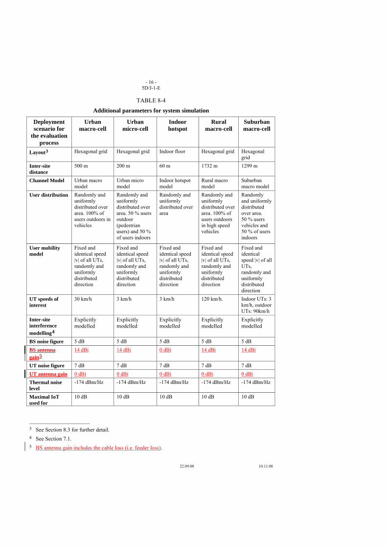
- 16 - 5D/J-1-E
22.09.08 10.11.08
TABLE 8-4
Additional parameters for system simulation
Deployment scenario for
the evaluation process
Urban macro-cell
Urban micro-cell
Indoor hotspot
Rural macro-cell
Suburban macro-cell
Layout3 Hexagonal grid Hexagonal grid Indoor floor Hexagonal grid Hexagonal grid
Inter-site distance
500 m 200 m 60 m 1732 m 1299 m
Channel Model Urban macro model
Urban micro model
Indoor hotspot model
Rural macro model
Suburban macro model
User distribution Randomly and uniformly distributed over area. 100% of users outdoors in vehicles
Randomly and uniformly distributed over area. 50 % users outdoor (pedestrian users) and 50 % of users indoors
Randomly and uniformly distributed over area
Randomly and uniformly distributed over area. 100% of users outdoors in high speed vehicles
Randomly and uniformly distributed over area. 50 % users vehicles and 50 % of users indoors
User mobility model
Fixed and identical speed |v| of all UTs, randomly and uniformly distributed direction
Fixed and identical speed |v| of all UTs, randomly and uniformly distributed direction
Fixed and identical speed |v| of all UTs, randomly and uniformly distributed direction
Fixed and identical speed |v| of all UTs, randomly and uniformly distributed direction
Fixed and identical speed |v| of all UTs, randomly and uniformly distributed direction
UT speeds of interest
30 km/h 3 km/h 3 km/h 120 km/h. Indoor UTs: 3 km/h, outdoor UTs: 90km/h
Inter-site interference modelling4
Explicitly modelled
Explicitly modelled
Explicitly modelled
Explicitly modelled
Explicitly modelled
BS noise figure 5 dB 5 dB 5 dB 5 dB 5 dB BS antenna gain5
14 dBi 14 dBi 0 dBi 14 dBi 14 dBi
UT noise figure 7 dB 7 dB 7 dB 7 dB 7 dB UT antenna gain 0 dBi 0 dBi 0 dBi 0 dBi 0 dBi Thermal noise level
-174 dBm/Hz -174 dBm/Hz -174 dBm/Hz -174 dBm/Hz -174 dBm/Hz
Maximal IoT used for
10 dB 10 dB 10 dB 10 dB 10 dB
____________________ 3 See Section 8.3 for further detail. 4 See Section 7.1. 5 BS antenna gain includes the cable loss (i.e. feeder loss).
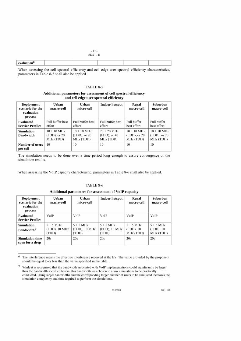
- 17 - 5D/J-1-E
22.09.08 10.11.08
evaluation6
When assessing the cell spectral efficiency and cell edge user spectral efficiency characteristics, parameters in Table 8-5 shall also be applied.
TABLE 8-5
Additional parameters for assessment of cell spectral efficiency and cell edge user spectral efficiency
Deployment scenario for the
evaluation process
Urban macro-cell
Urban micro-cell
Indoor hotspot Rural macro-cell
Suburban macro-cell
Evaluated Service Profiles
Full buffer best effort
Full buffer best effort
Full buffer best effort
Full buffer best effort
Full buffer best effort
Simulation Bandwidth
10 + 10 MHz (FDD), or 20 MHz (TDD)
10 + 10 MHz (FDD), or 20 MHz (TDD)
20 + 20 MHz (FDD), or 40 MHz (TDD)
10 + 10 MHz (FDD), or 20 MHz (TDD)
10 + 10 MHz (FDD), or 20 MHz (TDD)
Number of users per cell
10 10 10 10 10
The simulation needs to be done over a time period long enough to assure convergence of the simulation results.
When assessing the VoIP capacity characteristic, parameters in Table 8-6 shall also be applied.
TABLE 8-6
Additional parameters for assessment of VoIP capacity
Deployment scenario for the
evaluation process
Urban macro-cell
Urban micro-cell
Indoor hotspot Rural macro-cell
Suburban macro-cell
Evaluated Service Profiles
VoIP VoIP VoIP VoIP VoIP
Simulation Bandwidth7
5 + 5 MHz (FDD), 10 MHz (TDD)
5 + 5 MHz (FDD), 10 MHz (TDD)
5 + 5 MHz (FDD), 10 MHz (TDD)
5 + 5 MHz (FDD), 10 MHz (TDD)
5 + 5 MHz (FDD), 10 MHz (TDD)
Simulation time span for a drop
20s 20s 20s 20s 20s
____________________ 6 The interference means the effective interference received at the BS. The value provided by the proponent
should be equal to or less than the value specified in the table. 7 While it is recognized that the bandwidth associated with VoIP implementations could significantly be larger
than the bandwidth specified herein; this bandwidth was chosen to allow simulations to be practically conducted. Using larger bandwidths and the corresponding larger number of users to be simulated increases the simulation complexity and time required to perform the simulations.
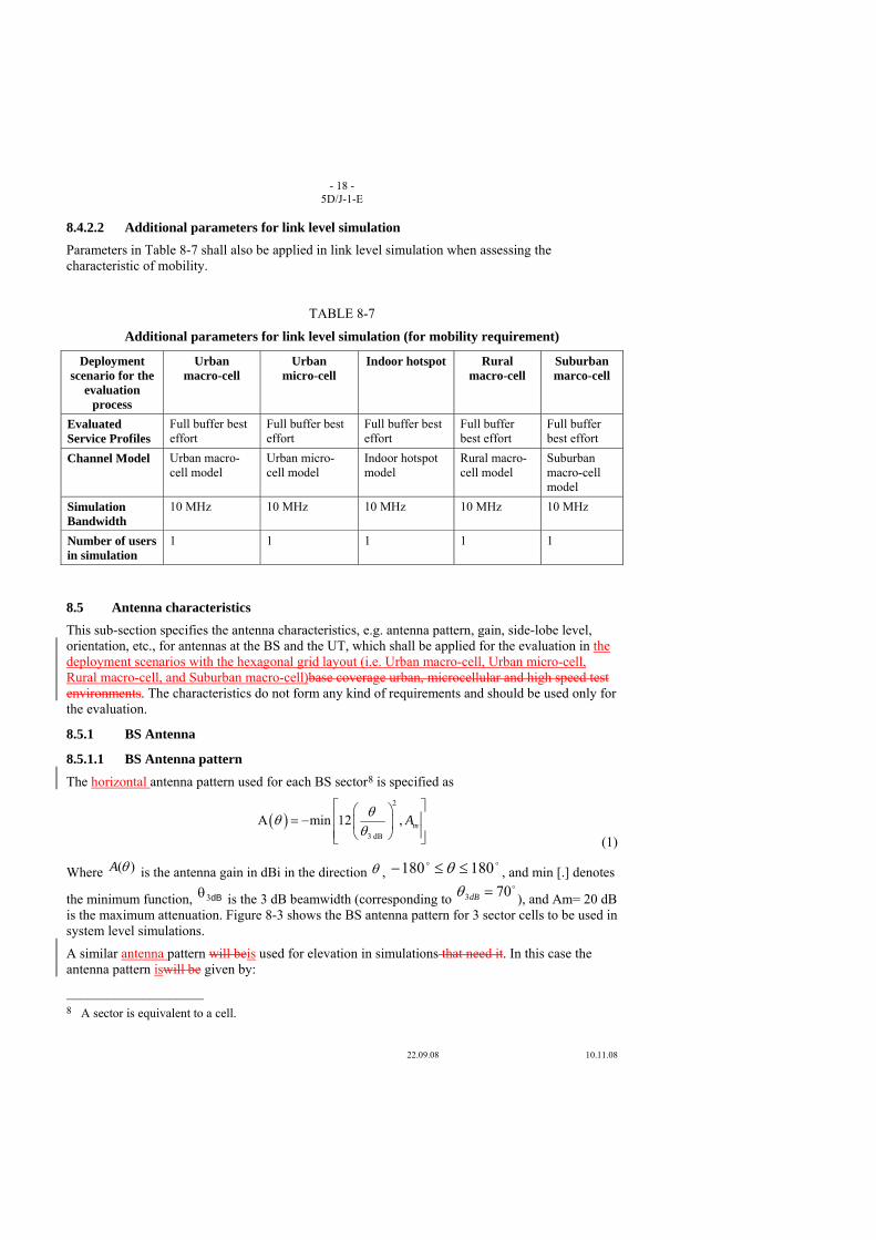
- 18 - 5D/J-1-E
22.09.08 10.11.08
8.4.2.2 Additional parameters for link level simulation Parameters in Table 8-7 shall also be applied in link level simulation when assessing the characteristic of mobility.
TABLE 8-7
Additional parameters for link level simulation (for mobility requirement)
Deployment scenario for the
evaluation process
Urban macro-cell
Urban micro-cell
Indoor hotspot Rural macro-cell
Suburban marco-cell
Evaluated Service Profiles
Full buffer best effort
Full buffer best effort
Full buffer best effort
Full buffer best effort
Full buffer best effort
Channel Model Urban macro-cell model
Urban micro-cell model
Indoor hotspot model
Rural macro-cell model
Suburban macro-cell model
Simulation Bandwidth
10 MHz 10 MHz 10 MHz 10 MHz 10 MHz
Number of users in simulation
1 1 1 1 1
8.5 Antenna characteristics This sub-section specifies the antenna characteristics, e.g. antenna pattern, gain, side-lobe level, orientation, etc., for antennas at the BS and the UT, which shall be applied for the evaluation in the deployment scenarios with the hexagonal grid layout (i.e. Urban macro-cell, Urban micro-cell, Rural macro-cell, and Suburban macro-cell)base coverage urban, microcellular and high speed test environments. The characteristics do not form any kind of requirements and should be used only for the evaluation.
8.5.1 BS Antenna
8.5.1.1 BS Antenna pattern
The horizontal antenna pattern used for each BS sector8 is specified as
( )
2
3 dB
A min 12 , mAθθθ
⎡ ⎤⎛ ⎞⎢ ⎥= − ⎜ ⎟⎢ ⎥⎝ ⎠⎣ ⎦ (1)
Where )(θA is the antenna gain in dBi in the direction θ , oo 180180 ≤≤− θ , and min [.] denotes
the minimum function, dB3θ is the 3 dB beamwidth (corresponding to o703 =dBθ ), and Am= 20 dB
is the maximum attenuation. Figure 8-3 shows the BS antenna pattern for 3 sector cells to be used in system level simulations.
A similar antenna pattern will beis used for elevation in simulations that need it. In this case the antenna pattern iswill be given by:
____________________ 8 A sector is equivalent to a cell.
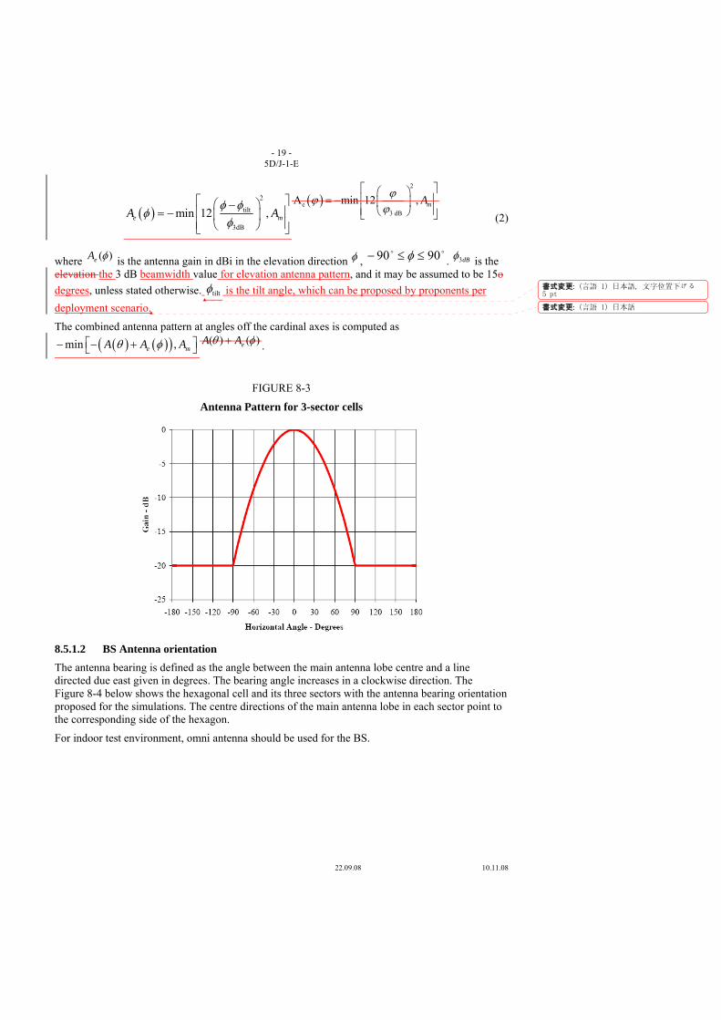
- 19 - 5D/J-1-E
22.09.08 10.11.08
( )2
tilt
3dB
min 12 ,e mA Aφ φ
φφ
⎡ ⎤⎛ ⎞−⎢ ⎥= − ⎜ ⎟⎢ ⎥⎝ ⎠⎣ ⎦
( )2
e3 dB
A min 12 , mAϕϕϕ
⎡ ⎤⎛ ⎞⎢ ⎥= − ⎜ ⎟⎢ ⎥⎝ ⎠⎣ ⎦ (2)
where )(φeA is the antenna gain in dBi in the elevation direction φ , oo 9090 ≤≤− φ . dB3φ is the
elevation the 3 dB beamwidth value for elevation antenna pattern, and it may be assumed to be 15o degrees, unless stated otherwise. tiltφ is the tilt angle, which can be proposed by proponents per deployment scenario.
The combined antenna pattern at angles off the cardinal axes is computed as
( ) ( )( )min ,e mA A Aθ φ⎡ ⎤− − +⎣ ⎦)()( φθ eAA + .
FIGURE 8-3
Antenna Pattern for 3-sector cells
8.5.1.2 BS Antenna orientation The antenna bearing is defined as the angle between the main antenna lobe centre and a line directed due east given in degrees. The bearing angle increases in a clockwise direction. The Figure 8-4 below shows the hexagonal cell and its three sectors with the antenna bearing orientation proposed for the simulations. The centre directions of the main antenna lobe in each sector point to the corresponding side of the hexagon.
For indoor test environment, omni antenna should be used for the BS.
書式変更: (言語 1) 日本語, 文字位置下げる 5 pt
書式変更: (言語 1) 日本語
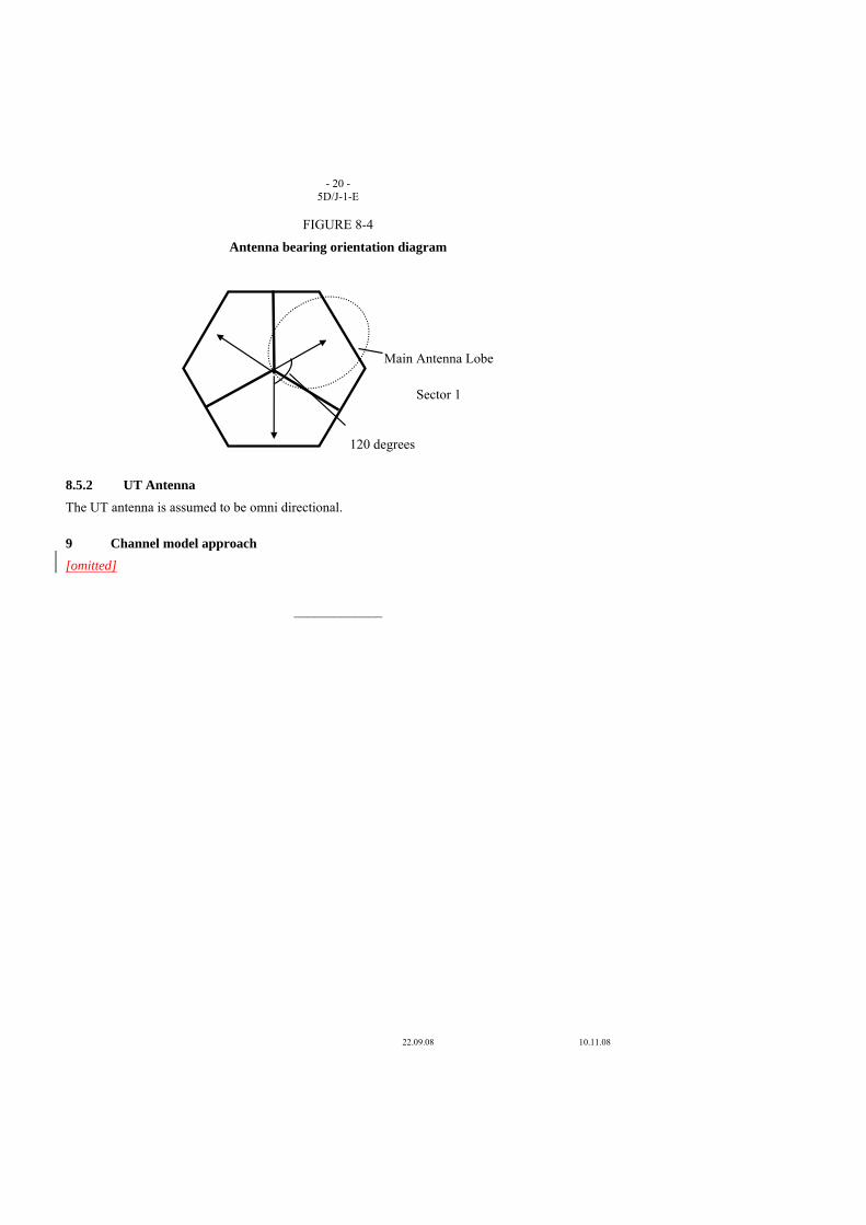
- 20 - 5D/J-1-E
22.09.08 10.11.08
FIGURE 8-4
Antenna bearing orientation diagram
8.5.2 UT Antenna The UT antenna is assumed to be omni directional.
9 Channel model approach [omitted]
_____________
120 degrees
Main Antenna Lobe
Sector 1

22.09.08 10.11.08
1 Introduction The 2nd meeting of ITU-R Working Party 5D (WP 5D) created the technology description template to be included in Section 4.2.3 of the Draft New Report ITU-R M.[IMT.REST]. WP 5D has carried forward the technology description template to its 3rd meeting in order to further refine and to check consistency with the Draft New Reports ITU-R M.[IMT.TECH] and M.[IMT.EVAL].
Japan reviewed the technology description template in the Document 5D/242 Attachment 6.7 and proposes modifications to it in order to facilitate WP 5D’s work to complete the template.
2 Discussion
2.1 Introductory text of the technology description template The technology description template will be used for independent evaluation groups to evaluate candidate technologies. The technology description template should provide relevant and necessary information for evaluation groups to evaluate candidate radio interface technologies well. Japan therefore believes that the proponents can answer N/A only if the proponents can provide justification that the items are not relevant to the proposed candidate technologies. According to this view, Japan proposes modification to the introductory text as shown in Attachment 1 to this contribution.
2.2 Format of the technology description template The format of the current technology description template was developed at the WP 5D 1st meeting in Geneva on the assumption that the Draft New Report M.[IMT.TECH] would have the section on the technological items required to describe candidate air interface (Section 5 of Document 5D/97 Attachment 6.11). During the discussion at the WP 5D 2nd meeting in Dubai, the original section 5 was agreed to be deleted. Japan thinks that the column describing “Source” has therefore no longer been required and can be deleted.
During the WP5D 2nd meeting, there was a discussion on the format of the technology description template, which was that the template should preferably have hierarchical structure so that the proponents can fulfill necessary/relevant items and skip irrelevant items, which are depending on the proposed technologies, e.g. CDMA, OFDMA, etc. but for the items at a higher description level,
Radiocommunication Study Groups
Received: XX October 2008
Subject: Question ITU-R 229-1/8
Document 5D/J-2-E XX October 2008 English only
Technology
Japan
PROPOSED MODIFICATION TO TECHNOLOGY DESCRIPTION TEMPLATE
- 2 - 5D/J-2-E
22.09.08 10.11.08
e.g. access scheme, the proponents must provide some information. Japan believes that a hierarchical format should be used in order to avoid potential missing items to be described in the technology description template. The modified format can be seen in Attachment 1 to this document. It should be noted that the change of the format itself will not cause substantial change on each item.
In addition, the template should have a highest hierarchy which has A1 Items required to describe candidate RIT and A2 Evaluation related items.
2.3 New items to be added The following new items need to be added so that independent evaluation groups can evaluate proposed candidate technologies. Japan believes that the evaluation could not properly be performed without these items.
(1) Delay distribution used for VoIP evaluation Packet delay distribution is a key variable for VoIP evaluation. This should be also provided by the proponents. (See section 7.1.3 of Report ITU-R M.[IMT.EVAL])
(2) Simulation method with regard to frequency reuse factor At the 2nd WP5D meeting in Dubai, there was a discussion on how to perform a simulation when frequency reuse factor is not a unity. Different approach would come up in terms of simulation bandwidth, i.e. it can be (10 MHz) x (the reuse factor of 3) or (10MHz/3) x (the reuse factor of 3). This may reach a different evaluation result. The detailed simulation method needs to be clarified if the candidate technology employs the frequency reuse factor other than a unity. (See section 8.3 of Report ITU-R M.[IMT.EVAL])
(3) Link budget Link budget is one of the key items. Proponents of candidate RIT or SRITs should provide information of link budget according to the template shown in Annex 3 of Report ITU-R M.[IMT.EVAL]. The reminder to provide link budget information is required.
(4) Antenna tilting angle The proponents of candidate RIT or SRITs should provide information on the angle of antenna tilting. The values would depend on the cell size therefore they are different. Taking this into account, Japan believes that the value should be calculated so that peak power level can be obtained at a cell edge and the resultant values should be provided in the technology description template.
2.4 Proposed detailed modifications
(1) Item A1.1.2 on features that the RIT uses to support the stationary mobility Item A1.1.2 focuses on the stationary mobility and asks to provide information on features that the RIT uses to support the stationary mobility. This item should be more general so that the proponents can be provide any features that the proposed RIT uses to support the test environment(s) other than the defined four test environment in order to facilitate possible consensus building among similar RITs which have similar features in terms of their support of particular environment(s). Japan therefore proposes modification on the text.
(2) Item A1.2.1 “Multiple access methods”
The original A1.6 and its sub-items are similar to the item A1.2.1. Japan therefore proposes that the item A1.6 and its sub-items should be moved up under Item A1.2.1.
(3) Item A1.2.5 “Mobility management”
- 3 - 5D/J-2-E
22.09.08 10.11.08
The items under A1.2.5;
- Centralized/Distributed RRM, and
- Inter-RAT spectrum sharing
should be discussed in the original item A1.2.6 Resource Management. Japan proposes the modification to the original item A1.2.6.
(4) Item A1.2.7 “Frame structure” This item seems appropriate to be addressed just after the item A1.2.4 Physical channel structure and multiplexing. This item should be moved up and put just after the item A1.2.4.
(5) Item A1.3.11 Flexibility of spectrum usage This item seems a duplication item of the item A1.3.1. This can be deleted since the item has already been covered by the item A1.3.1.
(6) Item A1.4.2 to A1.4.7 on MIMO related sub items These items are relevant to MIMO scheme. These should be described as a single item.
3 Proposal Japan proposes that the updated template in Attachment 1 to this contribution be considered for the further modification of the technology description template of Draft New Report M.[IMT.REST].
Attachment: 1
- 4 - 5D/J-2-E
22.09.08 10.11.08
ATTACHMENT 1
Source: Document 5D/242 Attachment 6.7
Technology description template (Step 2, Step 4 and Step 6)
The purpose of this technology description template is that the proponents can describe their proposal for a radio interface for IMT-Advanced to a level of detail that will enable independent third-party assessment of compliance with the minimum technical requirements as specified in Draft new Report ITU-R M.[IMT.TECH]. This template defines the set of requested information. The inclusion of an item in this template shall not imply that it is a minimum requirement of IMT-Advanced (e.g. positioning or broadcasting). Furthermore, where an item is not relevant to or for a proposal, it should can be answered N/A, if it is justified. It is not mandatory to provide information for each item, recognising that evaluation groups may need to make independent assumptions during their evaluation, or may request additional information from the proponent.
Item to be described
A1 Items required to describe candidate RIT
A1.1 Test Environment(s)
A.1.1.1 What test environments (described in IMT.EVAL) does this technology description template address?
A.1.1.2 Describe any features, if any, which that the RIT uses to support the stationary mobilityparticular classtest environment(s) other than the four test environments described in Report ITU-R M.[IMT.EVAL].
A1.2
Technological items required to describerelated to candidate RIT
A1.2.1 Multiple access methodsscheme
Which access technology does the proposal use: TDMA, FDMA, CDMA, OFDMA, IDMA, SDMA, hybrid, or a new technology?
Characterise its summarised specifications with key parameters which feature the multiple access scheme.
-In the case of CDMA, which type of CDMA is used: frequency hopping (FH) or direct sequence (DS) or hybrid? Characterize. What is the chip rate (Mchips/s)? Rate at input to modulator. What is the processing gain? 10 log (chip rate/information rate). Explain the uplink and downlink code structures and provide the details about the types (e.g. pseudo-noise (PN) code, Walsh code) and purposes (e.g. spreading, identification, etc.) of the codes.
In the case of OFDMA, what are the sub-carrier spacing, FFT size and CP length? Provide details.
書式変更
書式変更: フォント : Times New Roman
書式変更: フォント : 太字 (なし)
書式変更: フォント : (英) Times NewRoman, (日) MS 明朝, 太字 (なし)
書式変更: 蛍光ペン (なし)
書式変更
書式変更: 蛍光ペン (なし)
書式変更
書式変更
書式変更 : 箇条書きと段落番号
書式変更: フォント : (日) MS 明朝
書式変更
書式変更
書式変更: フォント : (日) MS 明朝
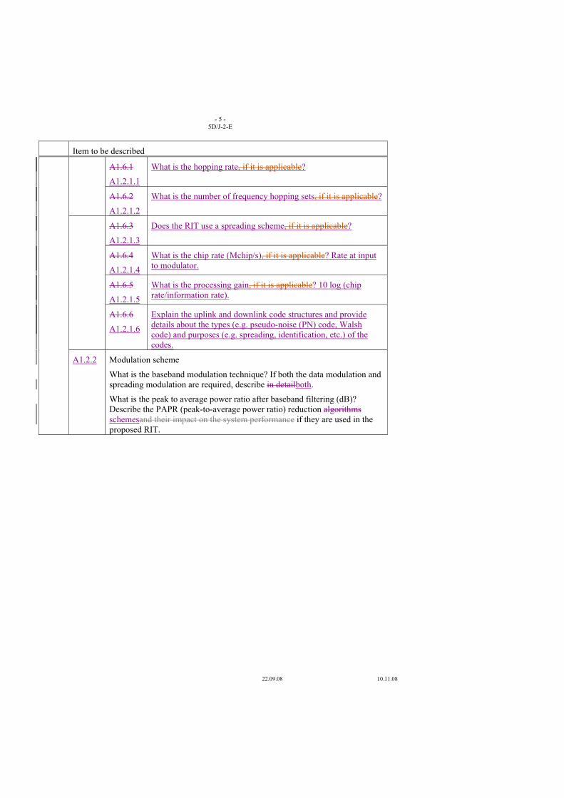
- 5 - 5D/J-2-E
22.09.08 10.11.08
Item to be described
A1.6.1
A1.2.1.1
What is the hopping rate, if it is applicable?
A1.6.2
A1.2.1.2
What is the number of frequency hopping sets, if it is applicable?
A1.6.3
A1.2.1.3
Does the RIT use a spreading scheme, if it is applicable?
A1.6.4
A1.2.1.4
What is the chip rate (Mchip/s), if it is applicable? Rate at input to modulator.
A1.6.5
A1.2.1.5
What is the processing gain, if it is applicable? 10 log (chip rate/information rate).
A1.6.6
A1.2.1.6
Explain the uplink and downlink code structures and provide details about the types (e.g. pseudo-noise (PN) code, Walsh code) and purposes (e.g. spreading, identification, etc.) of the codes.
A1.2.2 Modulation scheme
What is the baseband modulation technique? If both the data modulation and spreading modulation are required, describe in detailboth.
What is the peak to average power ratio after baseband filtering (dB)? Describe the PAPR (peak-to-average power ratio) reduction algorithms schemesand their impact on the system performance if they are used in the proposed RIT.
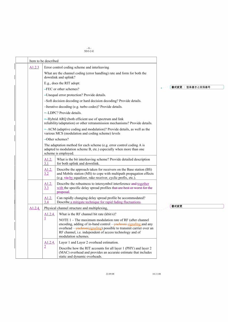
- 6 - 5D/J-2-E
22.09.08 10.11.08
Item to be described
A1.2.3 Error control coding scheme and interleaving
What are the channel coding (error handling) rate and form for both the downlink and uplink?
E.g., does the RIT adopt:
–FEC or other schemes?
–Unequal error protection? Provide details.
–Soft decision decoding or hard decision decoding? Provide details.
–Iterative decoding (e.g. turbo codes)? Provide details.
– LDPC? Provide details.
– Hybrid ARQ (both efficient use of spectrum and link reliability/adaptation) or other retransmission mechanisms? Provide details.
– ACM (adaptive coding and modulation)? Provide details, as well as the various MCS (modulation and coding scheme) levels
–Other schemes?
The adaptation method for each scheme (e.g. error control coding A is adapted to modulation scheme B, etc.) especially when more than one scheme is employed.
A1.2.3.1
What is the bit interleaving scheme? Provide detailed description for both uplink and downlink.
A1.2.3.2
Describe the approach taken for receivers on the Base station (BS) and Mobile station (MS) to cope with multipath propagation effects (e.g. via by equalizer, rake receiver, cyclic prefix, etc.).
A1.2.3.3
Describe the robustness to intersymbol interference and together with the specific delay spread profiles that are best or worst for the proposal.
A1.2.3.4
Can rapidly changing delay spread profile be accommodated? Describe a mitigate technique for rapid fading fluctuations.
A1.2.4 Physical channel structure and multiplexing,
A1.2.4.1
What is the RF channel bit rate (kbit/s)?
NOTE 1 – The maximum modulation rate of RF (after channel encoding, adding of in-band control ynchroni signaling and any overhead ynchronisignaling) possible to transmit carrier over an RF channel, i.e. independent of access technology and of modulation schemes.
A1.2.4.2
Layer 1 and Layer 2 overhead estimation.
Describe how the RIT accounts for all layer 1 (PHY) and layer 2 (MAC) overhead and provides an accurate estimate that includes static and dynamic overheads.
書式変更 : 箇条書きと段落番号
書式変更
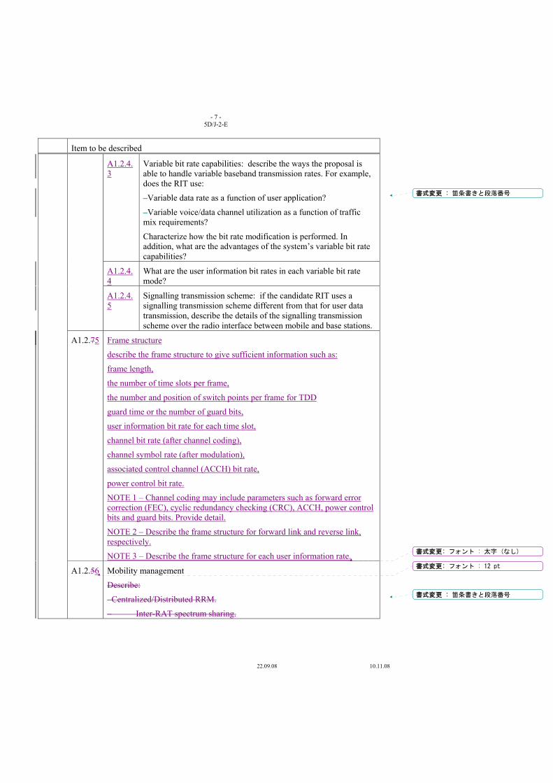
- 7 - 5D/J-2-E
22.09.08 10.11.08
Item to be described
A1.2.4.3
Variable bit rate capabilities: describe the ways the proposal is able to handle variable baseband transmission rates. For example, does the RIT use:
–Variable data rate as a function of user application?
–Variable voice/data channel utilization as a function of traffic mix requirements?
Characterize how the bit rate modification is performed. In addition, what are the advantages of the system’s variable bit rate capabilities?
A1.2.4.4
What are the user information bit rates in each variable bit rate mode?
A1.2.4.5
Signalling transmission scheme: if the candidate RIT uses a signalling transmission scheme different from that for user data transmission, describe the details of the signalling transmission scheme over the radio interface between mobile and base stations.
A1.2.75 Frame structure
describe the frame structure to give sufficient information such as:
frame length,
the number of time slots per frame,
the number and position of switch points per frame for TDD
guard time or the number of guard bits,
user information bit rate for each time slot,
channel bit rate (after channel coding),
channel symbol rate (after modulation),
associated control channel (ACCH) bit rate,
power control bit rate.
NOTE 1 – Channel coding may include parameters such as forward error correction (FEC), cyclic redundancy checking (CRC), ACCH, power control bits and guard bits. Provide detail.
NOTE 2 – Describe the frame structure for forward link and reverse link, respectively.
NOTE 3 – Describe the frame structure for each user information rate.
A1.2.56
Mobility management
Describe:
–Centralized/Distributed RRM.
– Inter-RAT spectrum sharing.
書式変更 : 箇条書きと段落番号
書式変更: フォント : 太字 (なし)
書式変更: フォント : 12 pt
書式変更 : 箇条書きと段落番号
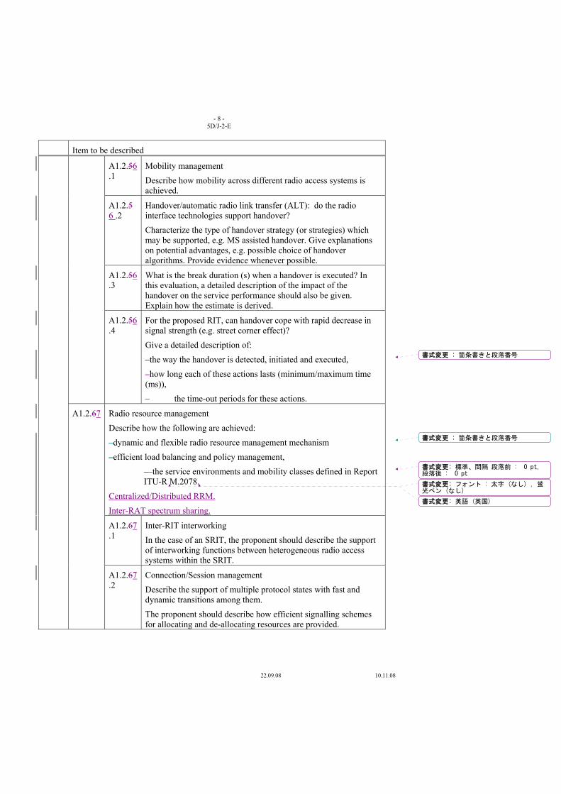
- 8 - 5D/J-2-E
22.09.08 10.11.08
Item to be described
A1.2.56.1
Mobility management
Describe how mobility across different radio access systems is achieved.
A1.2.5 6 .2
Handover/automatic radio link transfer (ALT): do the radio interface technologies support handover?
Characterize the type of handover strategy (or strategies) which may be supported, e.g. MS assisted handover. Give explanations on potential advantages, e.g. possible choice of handover algorithms. Provide evidence whenever possible.
A1.2.56.3
What is the break duration (s) when a handover is executed? In this evaluation, a detailed description of the impact of the handover on the service performance should also be given. Explain how the estimate is derived.
A1.2.56.4
For the proposed RIT, can handover cope with rapid decrease in signal strength (e.g. street corner effect)?
Give a detailed description of:
–the way the handover is detected, initiated and executed,
–how long each of these actions lasts (minimum/maximum time (ms)),
– the time-out periods for these actions.
A1.2.67
Radio resource management
Describe how the following are achieved:
–dynamic and flexible radio resource management mechanism
–efficient load balancing and policy management,
– the service environments and mobility classes defined in Report ITU-R M.2078.
Centralized/Distributed RRM.
Inter-RAT spectrum sharing.
A1.2.67.1
Inter-RIT interworking
In the case of an SRIT, the proponent should describe the support of interworking functions between heterogeneous radio access systems within the SRIT.
A1.2.67.2
Connection/Session management
Describe the support of multiple protocol states with fast and dynamic transitions among them.
The proponent should describe how efficient signalling schemes for allocating and de-allocating resources are provided.
書式変更 : 箇条書きと段落番号
書式変更 : 箇条書きと段落番号
書式変更: 標準、間隔 段落前 : 0 pt,段落後 : 0 pt
書式変更: フォント : 太字 (なし) , 蛍光ペン (なし)
書式変更: 英語 (英国)
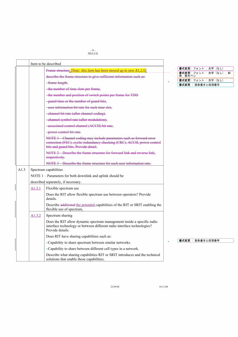
- 9 - 5D/J-2-E
22.09.08 10.11.08
Item to be described
Frame structure [Note: this item has been moved up to new A1.2.5]
describe the frame structure to give sufficient information such as:
–frame length,
–the number of time slots per frame,
–the number and position of switch points per frame for TDD
–guard time or the number of guard bits,
–user information bit rate for each time slot,
–channel bit rate (after channel coding),
–channel symbol rate (after modulation),
–associated control channel (ACCH) bit rate,
–power control bit rate.
NOTE 1 – Channel coding may include parameters such as forward error correction (FEC), cyclic redundancy checking (CRC), ACCH, power control bits and guard bits. Provide detail.
NOTE 2 – Describe the frame structure for forward link and reverse link, respectively.
NOTE 3 – Describe the frame structure for each user information rate.
A1.3
Spectrum capabilities
NOTE 1 – Parameters for both downlink and uplink should be
described separately, if necessary.
A1.3.1 Flexible spectrum use
Does the RIT allow flexible spectrum use between operators? Provide details.
Describe additional the potential capabilities of the RIT or SRIT enabling the flexible use of spectrum.
A1.3.2 Spectrum sharing
Does the RIT allow dynamic spectrum management inside a specific radio interface technology or between different radio interface technologies? Provide details.
Does RIT have sharing capabilities such as:
–Capability to share spectrum between similar networks.
–Capability to share between different cell types in a network.
Describe what sharing capabilities RIT or SRIT introduces and the technical solutions that enable those capabilities.
書式変更: フォント : 太字 (なし)
書式変更: フォント : 太字 (なし) , 斜体, 蛍光ペン
書式変更: フォント : 太字 (なし)
書式変更 : 箇条書きと段落番号
書式変更 : 箇条書きと段落番号
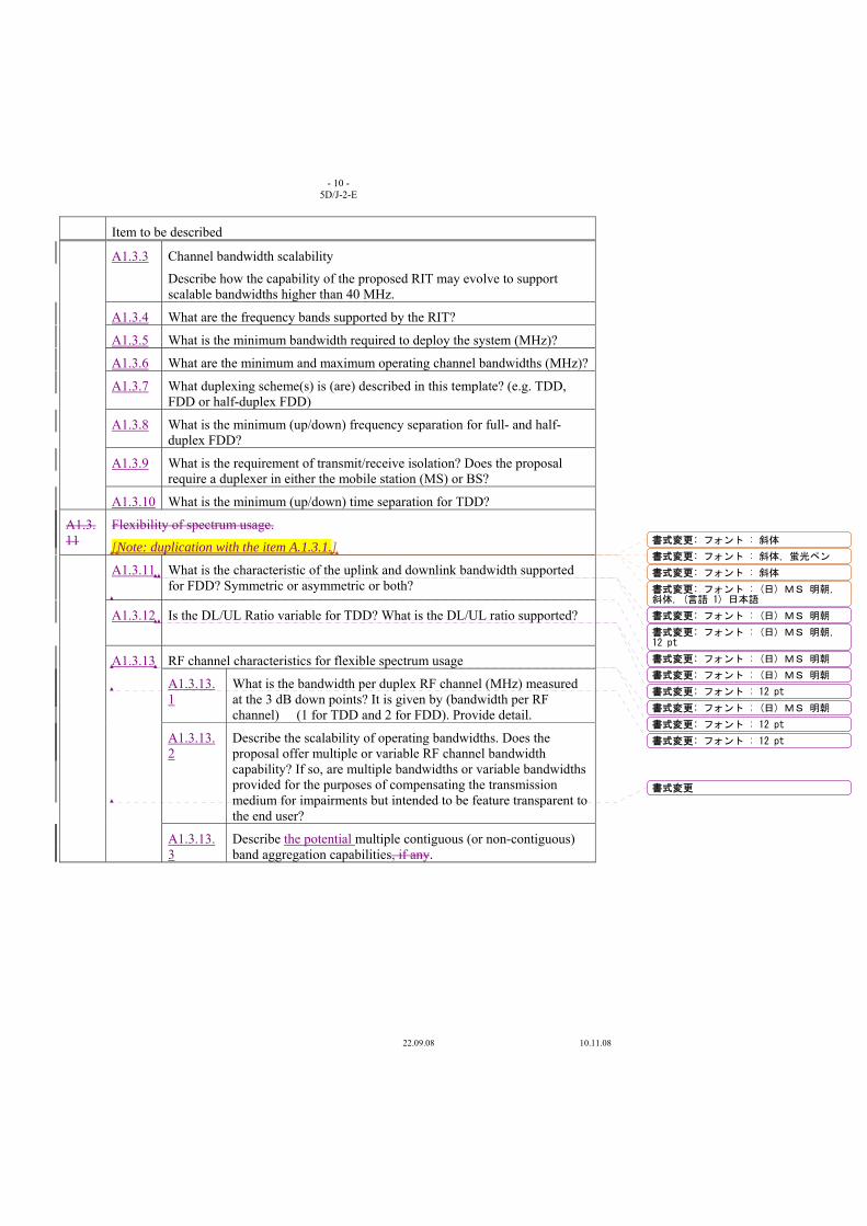
- 10 - 5D/J-2-E
22.09.08 10.11.08
Item to be described
A1.3.3 Channel bandwidth scalability
Describe how the capability of the proposed RIT may evolve to support scalable bandwidths higher than 40 MHz.
A1.3.4 What are the frequency bands supported by the RIT?
A1.3.5 What is the minimum bandwidth required to deploy the system (MHz)?
A1.3.6 What are the minimum and maximum operating channel bandwidths (MHz)?
A1.3.7 What duplexing scheme(s) is (are) described in this template? (e.g. TDD, FDD or half-duplex FDD)
A1.3.8 What is the minimum (up/down) frequency separation for full- and half-duplex FDD?
A1.3.9 What is the requirement of transmit/receive isolation? Does the proposal require a duplexer in either the mobile station (MS) or BS?
A1.3.10 What is the minimum (up/down) time separation for TDD?
A1.3.11
Flexibility of spectrum usage.
[Note: duplication with the item A.1.3.1.]
A1.3.11
What is the characteristic of the uplink and downlink bandwidth supported for FDD? Symmetric or asymmetric or both?
A1.3.12
Is the DL/UL Ratio variable for TDD? What is the DL/UL ratio supported?
A1.3.13
RF channel characteristics for flexible spectrum usage
A1.3.13.1
What is the bandwidth per duplex RF channel (MHz) measured at the 3 dB down points? It is given by (bandwidth per RF channel) � (1 for TDD and 2 for FDD). Provide detail.
A1.3.13.2
Describe the scalability of operating bandwidths. Does the proposal offer multiple or variable RF channel bandwidth capability? If so, are multiple bandwidths or variable bandwidths provided for the purposes of compensating the transmission medium for impairments but intended to be feature transparent to the end user?
A1.3.13.3
Describe the potential multiple contiguous (or non-contiguous) band aggregation capabilities, if any.
書式変更: フォント : 斜体
書式変更: フォント : 斜体, 蛍光ペン
書式変更: フォント : 斜体
書式変更: フォント : (日) MS 明朝,斜体, (言語 1) 日本語
書式変更: フォント : (日) MS 明朝
書式変更: フォント : (日) MS 明朝,12 pt
書式変更: フォント : (日) MS 明朝
書式変更: フォント : (日) MS 明朝
書式変更: フォント : 12 pt
書式変更: フォント : (日) MS 明朝
書式変更: フォント : 12 pt
書式変更: フォント : 12 pt
書式変更
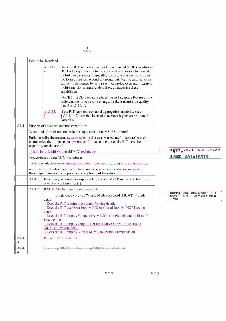
- 11 - 5D/J-2-E
22.09.08 10.11.08
Item to be described
A1.3.13.4
Does the RIT support a bandwidth on demand (BOD) capability? BOD refers specifically to the ability of an end-user to request multi-bearer services. Typically, this is given as the capacity in the form of bits per second of throughput. Multi-bearer services can be implemented by using such technologies as multi-carrier, multi-time slot or multi-codes. If so, characterize these capabilities.
NOTE 1 – BOD does not refer to the self-adaptive feature of the radio channel to cope with changes in the transmission quality (see § A1.3.14.1).
A1.3.13.5
If the RIT supports a channel aggregation capability (see § A1.3.14.2), can this be used to achieve higher user bit rates? Describe.
A1.4 Support of advanced antenna capabilities
What kind of multi-antenna scheme supported in the MS, BS or both?
Fully describe the antenna systems scheme that can be used and/or have to be used; characterize their impacts on systems performance; e.g., does the RIT have the capability for the use of:
–Multi-Input Multi-Output (MIMO) techniques,
–space-time coding (STC) techniques,
–real-time adaptive array antennas with real-time beam-forming with antenna array,
with specific attention being paid to increased spectrum efficiencies, increased throughput, power consumption and complexity of the setup.
A1.4.1 How many antennas are supported by BS and MS? Provide both basic and advanced configuration(s).
A1.4.2 If MIMO techniques are employed, S
Single codeword (SCW) and Multi codeword (MCW)? Provide detail. - Does the RIT require precoding? Provide detail. - Does the RIT use Open-loop MIMO or Closed-loop MIMO? Provide detail. - Does the RIT employ Cooperative MIMO in single-cell and multi-cell? Provide detail. - Does the RIT employ Single-User (SU) MIMO or Multi-User MU (MIMO)? Provide detail. - Does the RIT employ Virtual MIMO in uplink? Provide detail.
A1.4.3
Precoding? Provide detail.
A1.4.4
Open-loop MIMO or Closed-loop MIMO? Provide detail.
書式変更: フォント : 12 pt, フランス語(フランス)
書式変更 : 箇条書きと段落番号
書式変更: 標準、間隔 段落前 : 0 pt,段落後 : 0 pt, 行頭文字または番号を削除
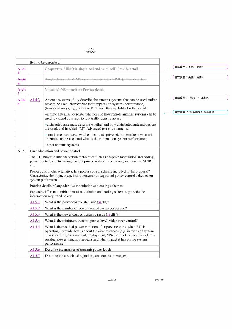
- 12 - 5D/J-2-E
22.09.08 10.11.08
Item to be described
A1.4.5
Cooperative MIMO in single-cell and multi-cell? Provide detail.
A1.4.6
Single-User (SU) MIMO or Multi-User MU (MIMO)? Provide detail.
A1.4.7
Virtual MIMO in uplink? Provide detail.
A1.4.8
A1.4.3 Antenna systems : fully describe the antenna systems that can be used and/or have to be used; characterize their impacts on systems performance, (terrestrial only); e.g., does the RTT have the capability for the use of:
–remote antennas: describe whether and how remote antenna systems can be used to extend coverage to low traffic density areas;
–distributed antennas: describe whether and how distributed antenna designs are used, and in which IMT-Advanced test environments;
–smart antennas (e.g., switched beam, adaptive, etc.): describe how smart antennas can be used and what is their impact on system performance;
–other antenna systems.
A1.5
Link adaptation and power control
The RIT may use link adaptation techniques such as adaptive modulation and coding, power control, etc. to manage output power, reduce interference, increase the SINR, etc.
Power control characteristics: Is a power control scheme included in the proposal? Characterize the impact (e.g. improvements) of supported power control schemes on system performance.
Provide details of any adaptive modulation and coding schemes.
For each different combination of modulation and coding schemes, provide the information requested below
A1.5.1 What is the power control step size (in dB)?
A1.5.2 What is the number of power control cycles per second?
A1.5.3 What is the power control dynamic range (in dB)?
A1.5.4 What is the minimum transmit power level with power control?
A1.5.5 What is the residual power variation after power control when RIT is operating? Provide details about the circumstances (e.g. in terms of system characteristics, environment, deployment, MS-speed, etc.) under which this residual power variation appears and what impact it has on the system performance.
A1.5.6 Describe the number of transmit power levels
A1.5.7 Describe the associated signalling and control messages.
書式変更: 英語 (英国)
書式変更: 英語 (英国)
書式変更: (言語 1) 日本語
書式変更 : 箇条書きと段落番号
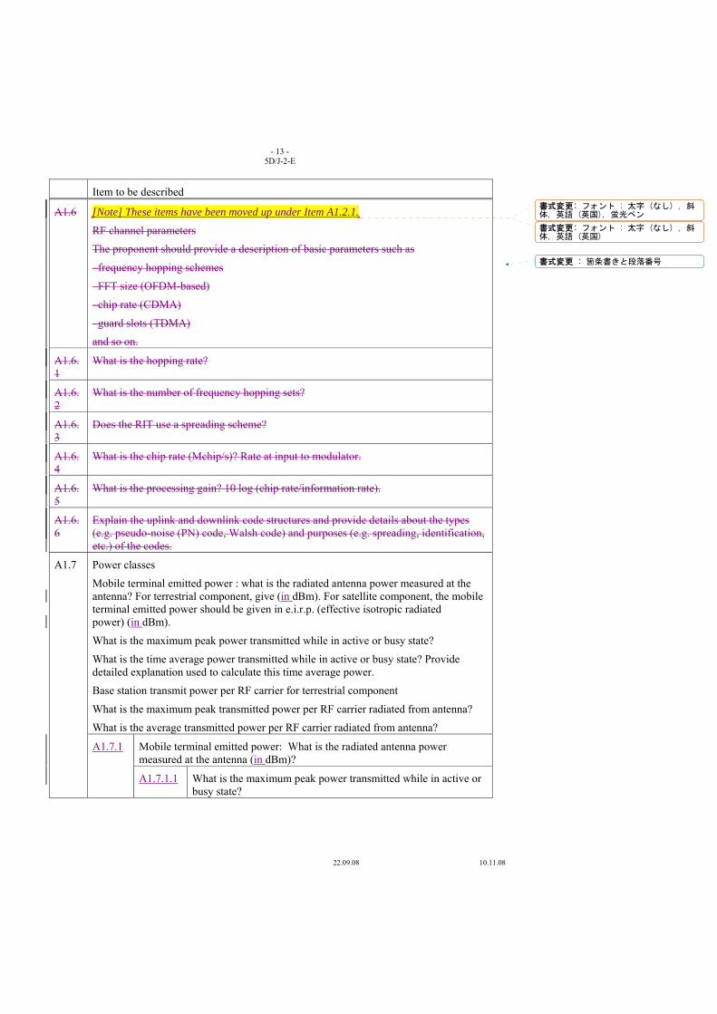
- 13 - 5D/J-2-E
22.09.08 10.11.08
Item to be described
A1.6 [Note] These items have been moved up under Item A1.2.1.
RF channel parameters
The proponent should provide a description of basic parameters such as
–frequency hopping schemes
–FFT size (OFDM-based)
–chip rate (CDMA)
–guard slots (TDMA)
and so on.
A1.6.1
What is the hopping rate?
A1.6.2
What is the number of frequency hopping sets?
A1.6.3
Does the RIT use a spreading scheme?
A1.6.4
What is the chip rate (Mchip/s)? Rate at input to modulator.
A1.6.5
What is the processing gain? 10 log (chip rate/information rate).
A1.6.6
Explain the uplink and downlink code structures and provide details about the types (e.g. pseudo-noise (PN) code, Walsh code) and purposes (e.g. spreading, identification, etc.) of the codes.
A1.7
Power classes
Mobile terminal emitted power : what is the radiated antenna power measured at the antenna? For terrestrial component, give (in dBm). For satellite component, the mobile terminal emitted power should be given in e.i.r.p. (effective isotropic radiated power) (in dBm).
What is the maximum peak power transmitted while in active or busy state?
What is the time average power transmitted while in active or busy state? Provide detailed explanation used to calculate this time average power.
Base station transmit power per RF carrier for terrestrial component
What is the maximum peak transmitted power per RF carrier radiated from antenna?
What is the average transmitted power per RF carrier radiated from antenna?
A1.7.1 Mobile terminal emitted power: What is the radiated antenna power measured at the antenna (in dBm)?
A1.7.1.1 What is the maximum peak power transmitted while in active or busy state?
書式変更: フォント : 太字 (なし) , 斜体, 英語 (英国), 蛍光ペン
書式変更: フォント : 太字 (なし) , 斜体, 英語 (英国)
書式変更 : 箇条書きと段落番号
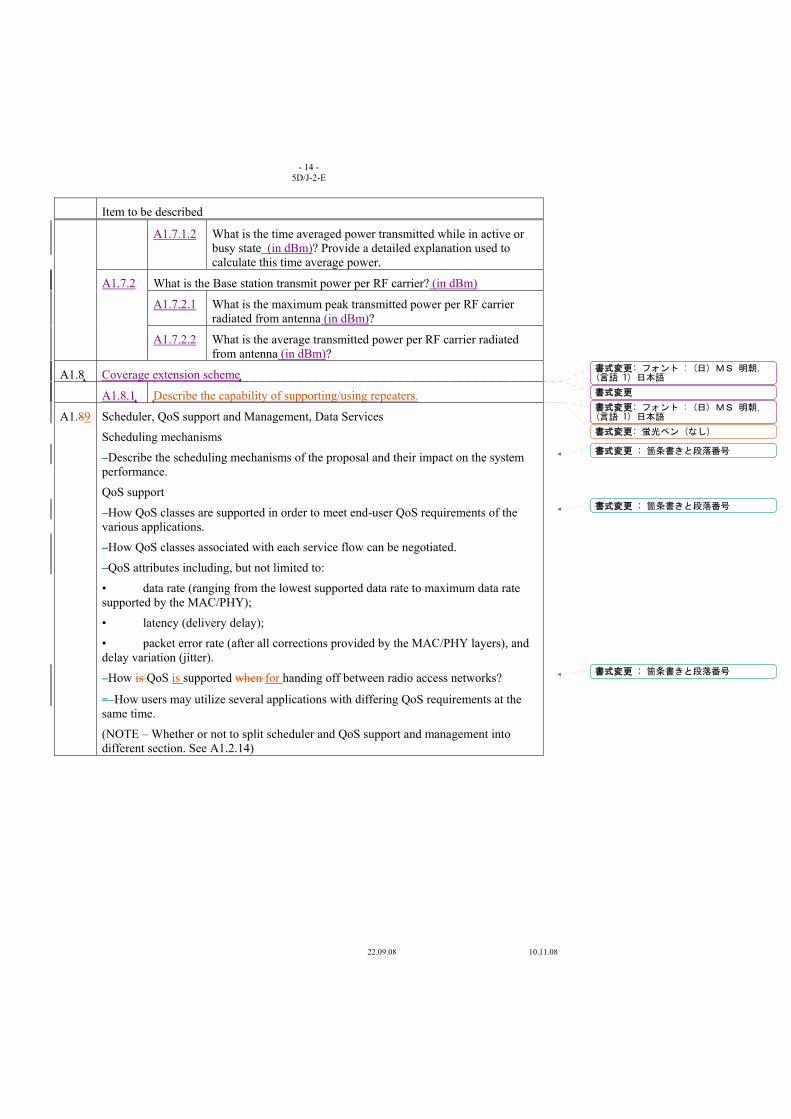
- 14 - 5D/J-2-E
22.09.08 10.11.08
Item to be described
A1.7.1.2 What is the time averaged power transmitted while in active or busy state (in dBm)? Provide a detailed explanation used to calculate this time average power.
A1.7.2 What is the Base station transmit power per RF carrier? (in dBm)
A1.7.2.1 What is the maximum peak transmitted power per RF carrier radiated from antenna (in dBm)?
A1.7.2.2 What is the average transmitted power per RF carrier radiated from antenna (in dBm)?
A1.8 Coverage extension scheme
A1.8.1 Describe the capability of supporting/using repeaters.
A1.89
Scheduler, QoS support and Management, Data Services
Scheduling mechanisms
–Describe the scheduling mechanisms of the proposal and their impact on the system performance.
QoS support
–How QoS classes are supported in order to meet end-user QoS requirements of the various applications.
–How QoS classes associated with each service flow can be negotiated.
–QoS attributes including, but not limited to:
• data rate (ranging from the lowest supported data rate to maximum data rate supported by the MAC/PHY);
• latency (delivery delay);
• packet error rate (after all corrections provided by the MAC/PHY layers), and delay variation (jitter).
–How is QoS is supported when for handing off between radio access networks?
– How users may utilize several applications with differing QoS requirements at the same time.
(NOTE – Whether or not to split scheduler and QoS support and management into different section. See A1.2.14)
書式変更: フォント : (日) MS 明朝,(言語 1) 日本語
書式変更
書式変更: フォント : (日) MS 明朝,(言語 1) 日本語
書式変更: 蛍光ペン (なし)
書式変更 : 箇条書きと段落番号
書式変更 : 箇条書きと段落番号
書式変更 : 箇条書きと段落番号

- 15 - 5D/J-2-E
22.09.08 10.11.08
Item to be described
A1.89.1 Data services: are there particular aspects of the proposed technologies which are applicable for the provision of packet-switched or other data services like asymmetric data services? For each service class (A, B, C and D) a description of RIT services should be provided, at least in terms of bit rate, delay and BER/frame error rate (FER).
NOTE 1 – See Recommendation ITU-R M.1224 for the definition of:
–“packet transfer mode”,
–“connectionless service”,
and for the aid of understanding “packet switched” data services.
NOTE 2 – See Recommendation ITU-T I.362 for details about the service classes A, B, C and D.
For delay constrained, connection oriented, variable bit rate (Class B).
For delay unconstrained, connection oriented (Class C).
For delay unconstrained, connectionless (Class D).
A1.910
Radio interface architecture and protocol stack
Describe Radio interface architecture and protocol stack such as,
–Control channel
–Logical channel
– Transport channel
A1.1011
Location Based Services
Are Does the RIT have the capability to offer location based services offered?
Describe the location determination mechanisms.
A1.1112
Priority Access
Does the proposal provide priority access? Describe how prioritization of access to network resources for certain specific services is achieved.
A1.1213
Voice, multicast and broadcast
Describe how the RIT supports:
–broadcast services,
–multicast services,
–unicast services,
using both dedicated carriers and/or mixed carriers. It is possible that all three services exist simultaneously – please describe any multimedia support.
A1.123.1
Provide information on the number of voice users per MHz that can be supported at one BS with 1 RF channel (TDD systems) or 1 duplex RF channel pair (FDD systems), assuming VoIP.
Does the RIT support several codecs?
書式変更 : 箇条書きと段落番号
書式変更 : 箇条書きと段落番号
書式変更 : 箇条書きと段落番号
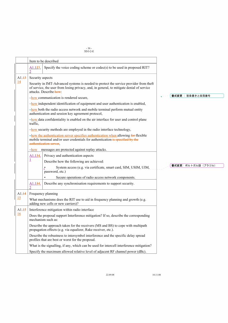
- 16 - 5D/J-2-E
22.09.08 10.11.08
Item to be described
A1.123.2
Specify the voice coding scheme or codec(s) to be used in proposed RIT?
A1.1314
Security aspects
Security in IMT-Advanced systems is needed to protect the service provider from theft of service, the user from losing privacy, and, in general, to mitigate denial of service attacks. Describe how:
–how communication is rendered secure,
–how independent identification of equipment and user authentication is enabled,
–how both the radio access network and mobile terminal perform mutual entity authentication and session key agreement protocol,
–how data confidentiality is enabled on the air interface for user and control plane traffic,
–how security methods are employed in the radio interface technology,
–how the authentication server specifies authentication when allowing for flexible mobile terminal and/or user credentials for authentication is specified by the authentication server,
–how messages are protected against replay attacks.
A1.134.1
Privacy and authentication aspects
Describe how the following are achieved:
• System access (e.g. via certificate, smart card, SIM, USIM, UIM, password, etc.)
• Secure operations of radio access network components.
A1.134.2
Describe any synchronisation requirements to support security.
A1.1415
Frequency planning
What mechanisms does the RIT use to aid in frequency planning and growth (e.g. adding new cells or new carriers)?
A1.1516
Interference mitigation within radio interface
Does the proposal support Interference mitigation? If so, describe the corresponding mechanism such as:
Describe the approach taken for the receivers (MS and BS) to cope with multipath propagation effects (e.g. via equalizer, Rake receiver, etc.).
Describe the robustness to intersymbol interference and the specific delay spread profiles that are best or worst for the proposal.
What is the signalling, if any, which can be used for intercell interference mitigation?
Specify the maximum allowed relative level of adjacent RF channel power (dBc).
書式変更 : 箇条書きと段落番号
書式変更: ポルトガル語 (ブラジル)
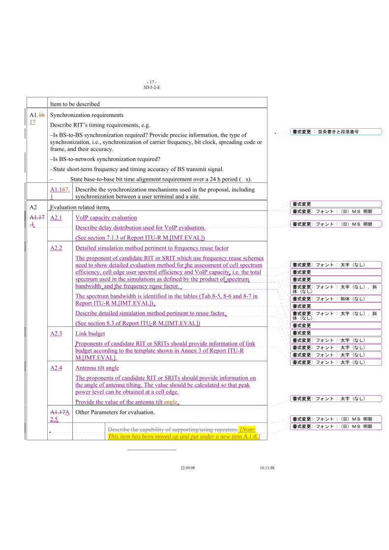
- 17 - 5D/J-2-E
22.09.08 10.11.08
Item to be described
A1.1617
Synchronization requirements
Describe RIT’s timing requirements, e.g.
–Is BS-to-BS synchronization required? Provide precise information, the type of synchronization, i.e., synchronization of carrier frequency, bit clock, spreading code or frame, and their accuracy.
–Is BS-to-network synchronization required?
–State short-term frequency and timing accuracy of BS transmit signal.
– State base-to-base bit time alignment requirement over a 24 h period (�s).
A1.167.1
Describe the synchronization mechanisms used in the proposal, including synchronization between a user terminal and a site.
A2
A1.17.1
Evaluation related items
A2.1 VoIP capacity evaluation
Describe delay distribution used for VoIP evaluation.
(See section 7.1.3 of Report ITU-R M.[IMT.EVAL])
A2.2 Detailed simulation method pertinent to frequency reuse factor
The proponent of candidate RIT or SRIT which use frequency reuse schemes need to show detailed evaluation method for the assessment of cell spectrum efficiency, cell edge user spectral efficiency and VoIP capacity, i.e. the total spectrum used in the simulations as defined by the product of spectrum bandwidth and the frequency reuse factor.
The spectrum bandwidth is identified in the tables (Tab.8-5, 8-6 and 8-7 in Report ITU-R M.[IMT.EVAL]).
Describe detailed simulation method pertinent to reuse factor.
(See section 8.3 of Report ITU-R M.[IMT.EVAL])
A2.3 Link budget
Proponents of candidate RIT or SRITs should provide information of link budget according to the template shown in Annex 3 of Report ITU-R M.[IMT.EVAL].
A2.4 Antenna tilt angle
The proponents of candidate RIT or SRITs should provide information on the angle of antenna tilting. The value should be calculated so that peak power level can be obtained at a cell edge.
Provide the value of the antenna tilt angle.
A1.17A2.5
Other Parameters for evaluation.
Describe the capability of supporting/using repeaters. [Note: This item has been moved up and put under a new item A.1.8.]
________________
書式変更 : 箇条書きと段落番号
書式変更: フォント : (日) MS 明朝
書式変更
書式変更: フォント : (日) MS 明朝
書式変更: フォント : 太字 (なし)
書式変更
書式変更
書式変更: フォント : 太字 (なし) , 斜体 (なし)
書式変更: フォント : 斜体 (なし)
書式変更
書式変更: フォント : 太字 (なし) , 斜体 (なし)
書式変更
書式変更
書式変更: フォント : 太字 (なし)
書式変更: フォント : 太字 (なし)
書式変更: フォント : 太字 (なし)
書式変更: フォント : 太字 (なし)
書式変更: フォント : 太字 (なし)
書式変更: フォント : (日) MS 明朝
書式変更: フォント : (日) MS 明朝

Radiocommunication Study Groups
Received: xx October 2008
Subject: Question ITU-R 229-1/8
Document 5D/J-3-E xx October 2008 English only TECHNOLOGY
Japan
VIEWS ON ADOPTION OF ACLR PROVISION FOR THE UPDATE OF RECOMMENDATIONS ITU-R M.1580 AND M.1581
1 Introduction At the 22nd meeting of ITU-R WP 8F in Kyoto and the special meeting of WP 8F in Seoul, WP
8F discussed the inclusion of the 6th radio interface technology of IMT-2000, OFDMA TDD WMAN, and drafted the revisions of Recommendations ITU-R M.1457-6, M.1580-1 and M.1581-1. After the meeting of SG8, RA-07 approved those revised Recommendations, expressing the necessity of urgent work with regard to Annex 6 of Recommendations ITU-R M.1580-1 and M.1581-1 on IMT-2000 OFDMA TDD WMAN [1] .
At the first meeting of ITU-R WP 5D in Geneva, WG-Technology established the SWG M.1580/M.1581 in order to respond to the urgent work identified by RA-07. In the work plan developed by SWG M.1580/M.1581 [2], the updates of Recommendations ITU-R M.1580 and M.1581 were planned to be finalized in the third meeting of WP 5D, which would be approximately one year after previous approval of Recommendations ITU-R M.1580-2 and ITU-R M.1581-2 in RA-07.
At the second meeting of ITU-R WP 5D in Dubai, the SWG M.1580/M.1581 discussed the applicability of adjacent channel leakage power ratio (ACLR) to each Annex of Recommendations ITU-R M.1580 and ITU-R M.1581. Hence SWG M.1580/M.1581 requested Administrations to provide their views on ACLR.
In this contribution Japan explains the background of Recommendations ITU-R M.1580 and M.1581 and indicates views on adoption of ACLR to finalize the urgent work instructed by RA-07.
2 Discussion about background of Recommendations ITU-R M.1580 and M.1581, and ACLR provisions in Japanese regulation
There was following description about Recommendation ITU-R M.1580 in the chairman’s report of fourth meeting of ITU-R WP 8F [3].
22.09.08 10.11.08
- 2 - 5D/J-3-E
22.09.08 10.11.08
“For base stations, the objective of IMT.UNWANT is to provide a set of values for manufacturers to produce equipment. Therefore base station values may contain different options to take into account regional needs.”
This means that Recommendation ITU-R M.1580 for base station includes provisions of unwanted emission provided in each country and/or region.
On the other hand, there is following description about Recommendation ITU-R M.1581 in the chairman’s report of fourth meeting of ITU-R WP 8F [3].
”The spurious emission limit values for mobile terminals shall be compliant with all national/regional regulations. This implies the use of Category B limits for spurious emissions (Rec. ITU-R SM.329 “Unwanted emissions in the spurious domain”) together with additional requirements such as for the PHS band.”
This means that Recommendation ITU-R M.1581 for mobile terminal includes the most stringent limits of unwanted emission among all countries and regions concerned, to ensure the global circulation of mobile terminals. It is worth noting that global circulation is mentioned in Recommendation ITU-R M.1579 “Global circulation of IMT-2000 terminals” as follows [4].
considering a)
“that global circulation of terminals is the right of users to carry their personal terminals into a visited country, and the ability to use them wherever possible;”
recognizing c)
“that the global circulation and use of terminals must be in conformity with the laws and regulations in the visited country, thereby generating the need for international cooperation between regulatory authorities;”
In addition, there is following description in Recommends of Recommendations ITU-R M.1580-2 and M.l581-2.
“the unwanted emission characteristics of IMT-2000 MSs/BSs should be based on the limits contained in the technology specific Annexes 1 to 6 which correspond to the radio interface specifications described in Sec.5.1 to 5.6 of Rec. ITU-R M.1457”
Hence the requirements of unwanted emissions in Recommendations ITU-R M.1580 and M.1581 need to be based on Recommendation ITU-R M.1457. The stake holder SDOs of radio transmission technologies (RTTs) should be responsible for the contents in each Annex of Recommendations ITU-R M.1457, M.1580 and M.1581 taking into account the purpose of the recommendations, and the contents is also desirable to be compliant with specifications developed by the stake holder SDOs.
Japan believes that provisions in all Annexes are not necessarily required to be consistent, hence it is not required to add or delete provisions to current Annexes in Recommendations ITU-R M.1580 and M.1581. The minimal restrictions shall be described in those Recommendations to achieve their scope.
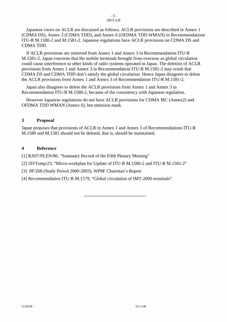
- 3 - 5D/J-3-E
22.09.08 10.11.08
Japanese views on ACLR are discussed as follows. ACLR provisions are described in Annex 1 (CDMA DS), Annex 3 (CDMA TDD), and Annex 6 (OFDMA TDD WMAN) in Recommendations ITU-R M.1580-2 and M.1581-2. Japanese regulations have ACLR provisions on CDMA DS and CDMA TDD.
If ACLR provisions are removed from Annex 1 and Annex 3 in Recommendation ITU-R M.1581-2, Japan concerns that the mobile terminals brought from overseas as global circulation could cause interference to other kinds of radio systems operated in Japan. The deletion of ACLR provisions from Annex 1 and Annex 3 in Recommendation ITU-R M.1581-2 may result that CDMA DS and CDMA TDD don’t satisfy the global circulation. Hence Japan disagrees to delete the ACLR provisions from Annex 1 and Annex 3 of Recommendation ITU-R M.1581-2.
Japan also disagrees to delete the ACLR provisions from Annex 1 and Annex 3 in Recommendation ITU-R M.1580-2, because of the consistency with Japanese regulation.
However Japanese regulations do not have ACLR provisions for CDMA MC (Annex2) and OFDMA TDD WMAN (Annex 6), but emission mask.
3 Proposal Japan proposes that provisions of ACLR in Annex 1 and Annex 3 of Recommendations ITU-R M.1580 and M.1581 should not be deleted, that is, should be maintained.
4 Reference [1] RA07/PLEN/80, “Summary Record of the Fifth Plenary Meeting”
[2] 5D/Temp/23, “Micro-workplan for Update of ITU-R M.1580-2 and ITU-R M.1581-2”
[3] 8F/268 (Study Period 2000-2003), WP8F Chairman’s Report
[4] Recommendation ITU-R M.1579, “Global circulation of IMT-2000 terminals”