intuitive 3d computer-aided design (cad) system with multimodal interfaces
TRANSCRIPT
Proceedings of the ASME 2013 International Design Engineering Technical Conferences &Computers and Information in Engineering Conference
IDETC/CIE 2013August 4-7, 2013, Portland, OR, USA
DETC2013-12365 (DRAFT)
INTUITIVE 3D COMPUTER-AIDED DESIGN (CAD) SYSTEM WITH MULTIMODALINTERFACES
Vishwas G. Nanjundaswamy, Amit Kulkarni, Zhuo Chen, Prakhar Jaiswal, Sree Shankar S, Anoop Verma, Rahul Rai∗DART Laboratory
Department of Mechanical and Aerospace EngineeringUniversity at Buffalo
Buffalo, NewYork, 14260Email: [email protected]
ABSTRACTThe existing interfaces for 3D CAD modeling softwares use
2D subspace inputs such as x and y axes of mouse to create 3Dmodels. These existing interfaces are inherently modal becauseone needs to switch between subspaces, and disconnects the in-put space from modeling space. This makes existing interfaces te-dious, complex, non-intuitive and difficult to learn. In this paper,a multi-sensory, interactive, and intuitive 3D CAD modeling in-terface is presented to address these shortcomings. Three differ-ent modalities (gestures, brain-computer interface, and speech)have been used for creating interactive and intuitive 3D CADmodeling interface. DepthSense® camera from SoftKinetic isused to recognize gestures, EEG Neuro-headset from Emotiv®is used for acquiring, and processing neuro-signals and CMUSphinx is used for recognizing and processing speech. MultipleCAD models created by several users using the proposed multi-modal interface are presented. In conclusion, the proposed sys-tem is easier to learn and use as compared to the already existingsystems.
1. MOTIVATION AND OBJECTIVESComputer Aided Design (CAD) is omnipresent in multiple
industrial domains such as automative and aerospace. In termsof market size, the CAD market is one of the established, largest,
∗Address all correspondence to this author.
and growing area in software markets with market cap of $7 bil-lion in 2011 [1]. CAD is used for representation, knowledgemanagement, communication, and visualization of design infor-mation at various stages of engineering design process. Thepresent work is focused on 3D modeling paradigm of CAD andits usage in the conceptual phase of design.
Increase in computational power, as governed by Moore’slaw, has led to the situation in which computers have becomecheaper, powerful, and accessible. However, the modern day3D CAD softwares involve ‘very steep learning curve’ to com-prehend the complex task of using a dense set of toolbars andmenus. In addition, the user interaction in 3D CAD softwares isnon-intuitive as the 3D modeling subspace has to be mapped tothe x and y axes of input devices such as mouse. This metaphor isinherently and cognitively complex because one needs to switchbetween 3D to 2D subspaces, and disconnects the input spacefrom the modeling space. This increases novice users’ learningtime.
In addition to increase in computational power, the technol-ogy push driving the integration of natural and intuitive sensorsinto everyday consumer devices such as Kinect® in our homesand Brain Computer Interfaces (BCI) in commercial applica-tions is setting the scene for the deployment of intuitive, natu-ral and people-centric applications over the next two decades.Such people-centric devices combined with the ability of com-putational pipelines that can process information emanating fromthese devices to provide a natural interface portends a revolution
1 Copyright © 2013 by ASME
for next generation 3D CAD.Natural and intuitive interfaces based on hand gesture,
speech recognition, and BCI can replace WIMP (windows, icons,menus, pointer) based user interfaces. Multi-Modal natural inter-faces can lower application learning time and can be especiallyuseful for conceptual 3D CAD modeling. During the conceptualdesign phase the user’s focus is on overall shape and visual ap-pearance of the 3D model and not so much on exact dimensionsand tolerances. Most commercially available 3D modeling soft-ware are based on a structured procedure that requires an user todefine the exact shape parameters early on. What is still neededis 3D conceptual CAD modeling tools that are more natural andintuitive to its users. Conventional 3D modeling systems and in-terfaces have yet to attain this.
The intent of the present work is to lay the foundation fornext generation of multimodal interfaces that can enable 3Dmodel creation, especially in the conceptual phase of design. Theimportance is on creating modeling tools that not only offers 3Dmodeling functionality but also offers creative freedom to theuser. To the best of our knowledge, this paper presents a de-veloped system that for the first time combines the usage of BCI,Gesture, and Speech (BCIGS) for creating and interacting withCAD models. Additionally, several aspects learnt from prelim-inary human factors study related to the developed multimodalCAD system is also outlined.
The paper is organized as follows. At first, the related workis reviewed. Secondly, the overall computational methodologyand technical aspects of the developed multimodal interface andCAD system is described. The utility of developed system is thendemonstrated through creation of several 3D models. A prelim-inary human factor study conducted on the use of the developedsystem is outlined next. Finally, the conclusions and discussionsare presented.
2. RELATED WORKIn the present section, four key areas related to presented
research namely (1) speech based interaction in CAD, (2) gesturebased CAD, (3) BCI in CAD modeling, and (4) multimodal CADinterfaces and other relevant modalities are briefly reviewed.
2.1. Speech Based Interaction in CADAs an interactional modality for CAD modeling, speech has
been rarely used independently. Speech has been mostly usedin conjunction with other interaction modalities. The pioneer-ing work done by Bolt in creating ‘Put that There’ system usedspeech as one its input modalities. Boeing’s ‘Talk and Draw’ [2]was one of the first multimodal drawing applications, which al-lowed users to draw with a mouse and use speech input to changeUI modes. Weimer and Ganapathy [3] used speech and glovebased gesture inputs which were integrated with a stand-alone
CAD package.
2.2. Gesture Based CAD
The importance of natural gesticulation in description ofspatial objects has been emphasized in recent work of Holz andWilson [4, 5]. Horvath has investigated the natural use of handgestures for shape conceptualization [6, 7]. In order to exploitthe use of gesture in CAD modeling, it is necessary to developmethods to help CAD applications recognize and interpret themefficiently. Various methods have been proposed to recognizegestures such as using gloves or markers [8, 9, 10], orientationhistograms [11], disparity in stereo pair of images [12] etc. Re-searchers have also used depth data for recognizing gestures[13, 14, 15, 16, 17, 18]. Identifying gesture through depth dataprovides fast and efficient recognition and thus allows for natu-ral and intuitive interaction [16, 5]. Recently, Vinayak et al [19]has used a Kinect and gesture based system for specific applica-tion of pottery design. While depth cameras are not conceptuallynew, Kinect has made natural and affordable sensor modalitiesaccessible to all.
2.3. BCI in CAD Modeling
Use of BCI in CAD modeling is relatively new. Brain activ-ity associated with any thinking process has to be quantified andconverted to tangible intentions and commands. The very firstadvancements in this respect were made in virtual reality domainby Pfurtscheller et al. [20] who for the first time demonstratedthat it is possible to move through a virtual street without muscu-lar activity when the participant only imagines feet movements.Leeb et al. [21] also carried out similar studies where the userwas able to navigate in a virtual environment by using his/herEEG brain signals. Fabiani et al. [22] and Trejo et al. [23] tookthis one step further with their work on cursor movement usingBCI. These studies show that the BCI can be used in many appli-cations that involved the human thought process [24].
In CAD systems, BCI offers a more intuitive and naturalform of interaction between the user and a CAD application. Animportant aspect for BCI based 3D CAD modeling is the user’scomprehension of geometrical features that he/she intends to cre-ate [25,26,27]. The user must also be able to distinguish betweendifferent geometrical features [28, 29]. In this regard, Esfahaniand Sundarajan [30] carried out experiments to explore the po-tential of BCI in distinguishing primitive shapes. In another re-cent work by Esfahani and Sundarajan [31], the authors reportthe use of BCI on the selection of geometrical surfaces in a 3DCAD model.
2 Copyright © 2013 by ASME
2.4. Multimodal CAD Interfaces And Other RelevantModalities
In terms of usage of multimodal interfaces in graphical ap-plication, the pioneering work done by Bolt in creating ‘Put thatThere’ system showed the value of combining different modali-ties such as speech and gesture [32]. This was followed by workof Ganapaty [3] in which speech and glove based gesture inputwere integrated with a stand-alone CAD package. These initialwork led to development of many systems that typically usedmouse, pen, speech or glove based input devices for creating 2Ddrawings or simple 3D shapes such as cubes [2, 33, 34].
Arangarasan and Gadh [35] used Head-Mounted Displays(HMDs) for multimodal input and output to work with 3D mod-els. Stylus input was used in ILoveSketch [36] to allow users tocreate accurate 3D models primarily by sketching using an elec-tronic stylus. Schmidt et al [37] developed a system to be usedwith a stylus to draw new objects or parts of an object. SenSty-lus [38]demonstrates a stylus based 6DOF input system for 3Dmodeling. Kara and co authors have created multiple computa-tional techniques that converts 2d sketches on tablets to editable3D CAD format [39,40,41]. While pen and stylus based sketch-ing interfaces are good for creating 2D artifacts like sketches anddrawings, the creation of 3D shapes using these interfaces lim-its the capability of designers to experiment at conceptual andartistic levels [42].
Scali et al [43] experimented with a 6 degrees of freedomhaptic feedback device for 3D modeling. Creation of curved,free-form and organic shapes had also been shown in literatureusing glove-based [44] and augmented reality interfaces [45].These interfaces provide 3D interaction capabilities for creatinga wide variety of 3D shapes. Recently, Sharma et al [46] createda speech and touch based system for creating 3D models. The 3Dmodeling systems have been growing in functionality and effec-tiveness through-out the years. However, novice user generallyneed more time to learn these tools due to their advanced UI ele-ments. In contrast to these efforts, our emphasis is on supporting3D modeling by novice users using a minimalist and natural mul-timodal interface.
The concept of natural multimodal interface refers to a userinterface, that is imperceptible and natural to use [47, 48]. Inregular UIs, devices need to be used to interact with a systemand a learning period is usually needed. By contrast, in naturaluser interfaces, the device that separates the user and the systemshould be as unobtrusive as possible or hidden so that the userdoes not notice it. Natural user interfaces such as gesture, braincomputer interface, speech, touch and haptics are promising can-didates to replace current generation UI enabled by keyboard andmouse. Our emphasis is on combining the usage of BCI, gestureand speech for interacting with CAD models.
In this paper, we introduce a new paradigm for reforming theearly-stage design process by developing natural user interfaces(NUIs) based on combined BCI, gesture, and speech modalities
which facilitate cognitively simple interactions towards creativeand exploratory design and 3D without the need for extensivetraining.
3. MULTI-MODAL INTERFACE BASED CAD SYSTEMCOMPONENTS
In this section, detailed description of the underlying multi-modal interface and related hardware/software components arediscussed. Figure 1 depicts the main components of the devel-oped system. Gestures, speech, and BCI are the input modal-ities through which a user can interact with the developed sys-tem. DepthSense camera from SoftKinetic ® is used for gesturerecognition, EEG Neuro-headset from Emotiv ® is used for ac-quiring and processing Neuro-signals, and CMU Sphinx is usedfor speech recognition and processing. Google Sketchup is usedas the CAD modeling platform. Google Sketchup was chosendue to its ease of use [46]1. Speech and BCI are used for creating2D and 3D models in CAD, whereas, gesture is primarily usedfor manipulation operations like rotate and zoom. Specific de-tails of three modalities and CAD GUI is briefly discussed next.
3.1. Speech RecognitionIn the present work, the speech recognition algorithm is
based on a CMU Sphinx speech recognition system developed atCarnegie Mellon University (CMU). Sphinx use discrete hiddenmarker methods (HMM) with linear predictive coding (LPC)-derived parameters to recognize speech command and offer nu-merous advantages in terms of: (1) speaker independency, (2)large vocabulary, and (3) isolated words. The speech recognitionprocess starts with automatic segmentation, classification, andclustering. It then uses three recognition passes consisting of aViterbi decoding using beam search and a best path search of theViterbi word lattice, N-best list generation and rescoring [49].Acoustic adaptation using a transformation of the mean vectorsbased on linear regression (MLLR) is performed between eachrecognition pass. Using CMU Sphinx, CAD specific functionssuch as creation of 2D geometry (circle, rectangle, arc), extru-sion of 2D geometry (extrude), transformational (orbit) etc. arereplaced with speech by recognizing speech commands such ascircle, extrude, rotate, zoom etc.
3.2. Recognizing Brain ActivityEmotiv® EEG is used to record and recognize brain signals
(electroencephalography (EEG)) and facial muscles movement(electromyogram (EMG)). It is a low cost brain-computer inter-face that comprise of (1) neuroheadset hardware device, and (2)
1Ease of use of Google Sketchup have recently gain credibility among on-line users and somewhat established by survey conducted by NUI group and Sk-techUp forums.
3 Copyright © 2013 by ASME
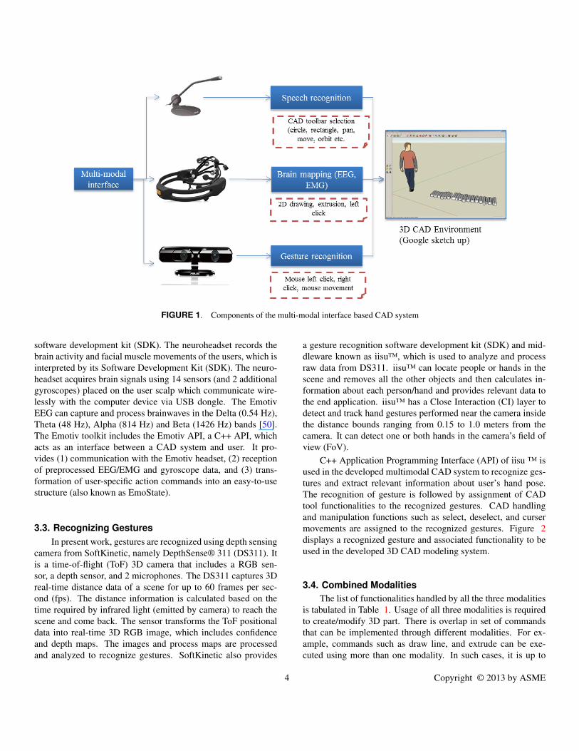
FIGURE 1. Components of the multi-modal interface based CAD system
software development kit (SDK). The neuroheadset records thebrain activity and facial muscle movements of the users, which isinterpreted by its Software Development Kit (SDK). The neuro-headset acquires brain signals using 14 sensors (and 2 additionalgyroscopes) placed on the user scalp which communicate wire-lessly with the computer device via USB dongle. The EmotivEEG can capture and process brainwaves in the Delta (0.54 Hz),Theta (48 Hz), Alpha (814 Hz) and Beta (1426 Hz) bands [50].The Emotiv toolkit includes the Emotiv API, a C++ API, whichacts as an interface between a CAD system and user. It pro-vides (1) communication with the Emotiv headset, (2) receptionof preprocessed EEG/EMG and gyroscope data, and (3) trans-formation of user-specific action commands into an easy-to-usestructure (also known as EmoState).
3.3. Recognizing GesturesIn present work, gestures are recognized using depth sensing
camera from SoftKinetic, namely DepthSense® 311 (DS311). Itis a time-of-flight (ToF) 3D camera that includes a RGB sen-sor, a depth sensor, and 2 microphones. The DS311 captures 3Dreal-time distance data of a scene for up to 60 frames per sec-ond (fps). The distance information is calculated based on thetime required by infrared light (emitted by camera) to reach thescene and come back. The sensor transforms the ToF positionaldata into real-time 3D RGB image, which includes confidenceand depth maps. The images and process maps are processedand analyzed to recognize gestures. SoftKinetic also provides
a gesture recognition software development kit (SDK) and mid-dleware known as iisu™, which is used to analyze and processraw data from DS311. iisu™ can locate people or hands in thescene and removes all the other objects and then calculates in-formation about each person/hand and provides relevant data tothe end application. iisu™ has a Close Interaction (CI) layer todetect and track hand gestures performed near the camera insidethe distance bounds ranging from 0.15 to 1.0 meters from thecamera. It can detect one or both hands in the camera’s field ofview (FoV).
C++ Application Programming Interface (API) of iisu ™ isused in the developed multimodal CAD system to recognize ges-tures and extract relevant information about user’s hand pose.The recognition of gesture is followed by assignment of CADtool functionalities to the recognized gestures. CAD handlingand manipulation functions such as select, deselect, and cursermovements are assigned to the recognized gestures. Figure 2displays a recognized gesture and associated functionality to beused in the developed 3D CAD modeling system.
3.4. Combined ModalitiesThe list of functionalities handled by all the three modalities
is tabulated in Table 1. Usage of all three modalities is requiredto create/modify 3D part. There is overlap in set of commandsthat can be implemented through different modalities. For ex-ample, commands such as draw line, and extrude can be exe-cuted using more than one modality. In such cases, it is up to
4 Copyright © 2013 by ASME
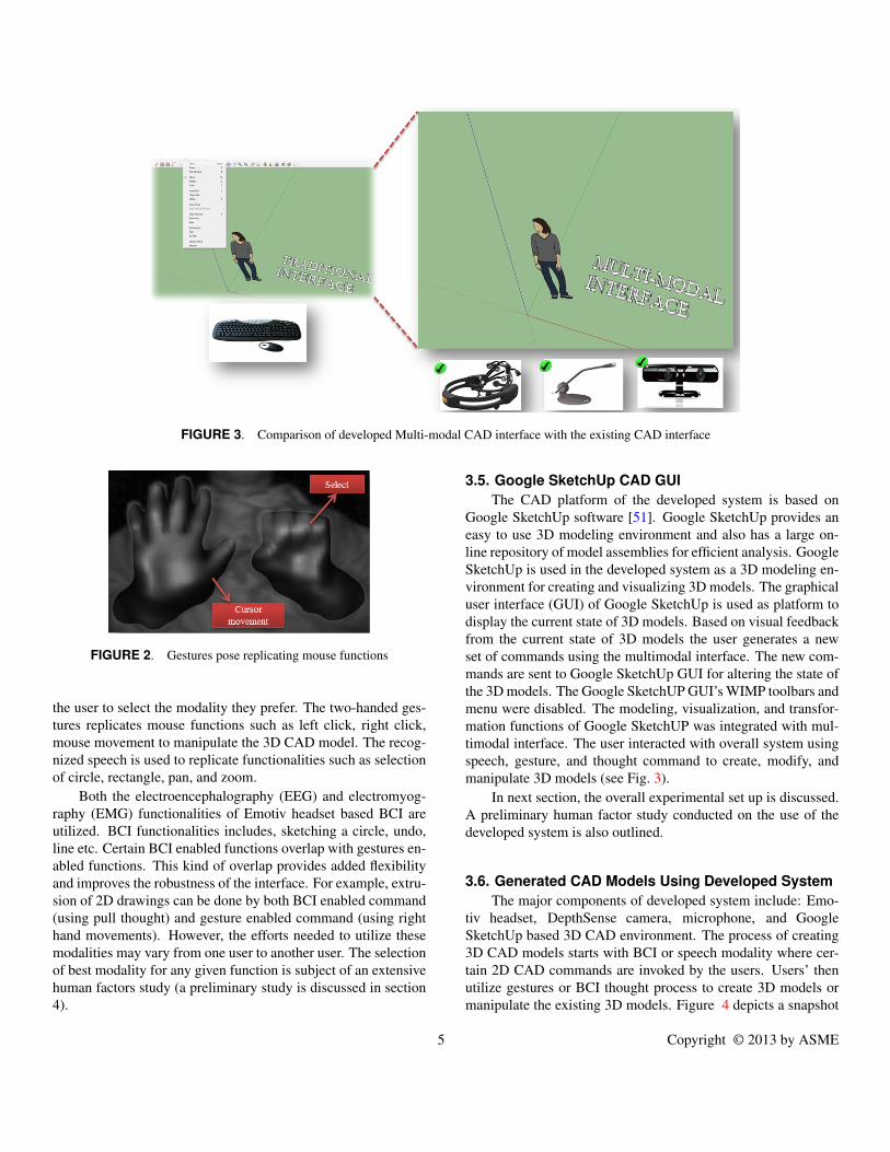
FIGURE 3. Comparison of developed Multi-modal CAD interface with the existing CAD interface
FIGURE 2. Gestures pose replicating mouse functions
the user to select the modality they prefer. The two-handed ges-tures replicates mouse functions such as left click, right click,mouse movement to manipulate the 3D CAD model. The recog-nized speech is used to replicate functionalities such as selectionof circle, rectangle, pan, and zoom.
Both the electroencephalography (EEG) and electromyog-raphy (EMG) functionalities of Emotiv headset based BCI areutilized. BCI functionalities includes, sketching a circle, undo,line etc. Certain BCI enabled functions overlap with gestures en-abled functions. This kind of overlap provides added flexibilityand improves the robustness of the interface. For example, extru-sion of 2D drawings can be done by both BCI enabled command(using pull thought) and gesture enabled command (using righthand movements). However, the efforts needed to utilize thesemodalities may vary from one user to another user. The selectionof best modality for any given function is subject of an extensivehuman factors study (a preliminary study is discussed in section4).
3.5. Google SketchUp CAD GUIThe CAD platform of the developed system is based on
Google SketchUp software [51]. Google SketchUp provides aneasy to use 3D modeling environment and also has a large on-line repository of model assemblies for efficient analysis. GoogleSketchUp is used in the developed system as a 3D modeling en-vironment for creating and visualizing 3D models. The graphicaluser interface (GUI) of Google SketchUp is used as platform todisplay the current state of 3D models. Based on visual feedbackfrom the current state of 3D models the user generates a newset of commands using the multimodal interface. The new com-mands are sent to Google SketchUp GUI for altering the state ofthe 3D models. The Google SketchUP GUI’s WIMP toolbars andmenu were disabled. The modeling, visualization, and transfor-mation functions of Google SketchUP was integrated with mul-timodal interface. The user interacted with overall system usingspeech, gesture, and thought command to create, modify, andmanipulate 3D models (see Fig. 3).
In next section, the overall experimental set up is discussed.A preliminary human factor study conducted on the use of thedeveloped system is also outlined.
3.6. Generated CAD Models Using Developed SystemThe major components of developed system include: Emo-
tiv headset, DepthSense camera, microphone, and GoogleSketchUp based 3D CAD environment. The process of creating3D CAD models starts with BCI or speech modality where cer-tain 2D CAD commands are invoked by the users. Users’ thenutilize gestures or BCI thought process to create 3D models ormanipulate the existing 3D models. Figure 4 depicts a snapshot
5 Copyright © 2013 by ASME
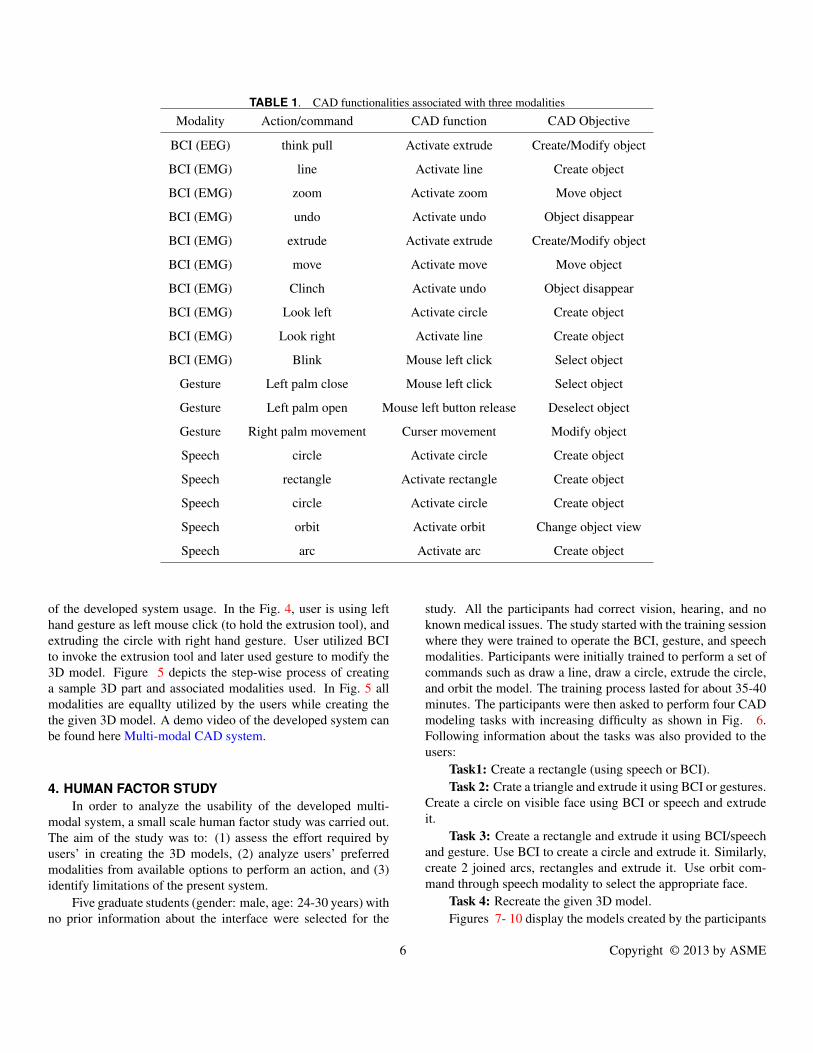
TABLE 1. CAD functionalities associated with three modalities
Modality Action/command CAD function CAD Objective
BCI (EEG) think pull Activate extrude Create/Modify object
BCI (EMG) line Activate line Create object
BCI (EMG) zoom Activate zoom Move object
BCI (EMG) undo Activate undo Object disappear
BCI (EMG) extrude Activate extrude Create/Modify object
BCI (EMG) move Activate move Move object
BCI (EMG) Clinch Activate undo Object disappear
BCI (EMG) Look left Activate circle Create object
BCI (EMG) Look right Activate line Create object
BCI (EMG) Blink Mouse left click Select object
Gesture Left palm close Mouse left click Select object
Gesture Left palm open Mouse left button release Deselect object
Gesture Right palm movement Curser movement Modify object
Speech circle Activate circle Create object
Speech rectangle Activate rectangle Create object
Speech circle Activate circle Create object
Speech orbit Activate orbit Change object view
Speech arc Activate arc Create object
of the developed system usage. In the Fig. 4, user is using lefthand gesture as left mouse click (to hold the extrusion tool), andextruding the circle with right hand gesture. User utilized BCIto invoke the extrusion tool and later used gesture to modify the3D model. Figure 5 depicts the step-wise process of creatinga sample 3D part and associated modalities used. In Fig. 5 allmodalities are equallty utilized by the users while creating thethe given 3D model. A demo video of the developed system canbe found here Multi-modal CAD system.
4. HUMAN FACTOR STUDYIn order to analyze the usability of the developed multi-
modal system, a small scale human factor study was carried out.The aim of the study was to: (1) assess the effort required byusers’ in creating the 3D models, (2) analyze users’ preferredmodalities from available options to perform an action, and (3)identify limitations of the present system.
Five graduate students (gender: male, age: 24-30 years) withno prior information about the interface were selected for the
study. All the participants had correct vision, hearing, and noknown medical issues. The study started with the training sessionwhere they were trained to operate the BCI, gesture, and speechmodalities. Participants were initially trained to perform a set ofcommands such as draw a line, draw a circle, extrude the circle,and orbit the model. The training process lasted for about 35-40minutes. The participants were then asked to perform four CADmodeling tasks with increasing difficulty as shown in Fig. 6.Following information about the tasks was also provided to theusers:
Task1: Create a rectangle (using speech or BCI).Task 2: Crate a triangle and extrude it using BCI or gestures.
Create a circle on visible face using BCI or speech and extrudeit.
Task 3: Create a rectangle and extrude it using BCI/speechand gesture. Use BCI to create a circle and extrude it. Similarly,create 2 joined arcs, rectangles and extrude it. Use orbit com-mand through speech modality to select the appropriate face.
Task 4: Recreate the given 3D model.Figures 7- 10 display the models created by the participants
6 Copyright © 2013 by ASME
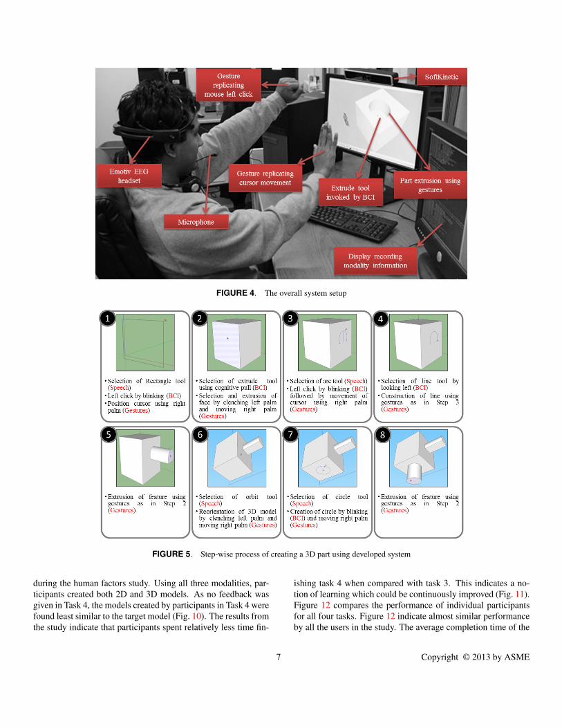
FIGURE 4. The overall system setup
FIGURE 5. Step-wise process of creating a 3D part using developed system
during the human factors study. Using all three modalities, par-ticipants created both 2D and 3D models. As no feedback wasgiven in Task 4, the models created by participants in Task 4 werefound least similar to the target model (Fig. 10). The results fromthe study indicate that participants spent relatively less time fin-
ishing task 4 when compared with task 3. This indicates a no-tion of learning which could be continuously improved (Fig. 11).Figure 12 compares the performance of individual participantsfor all four tasks. Figure 12 indicate almost similar performanceby all the users in the study. The average completion time of the
7 Copyright © 2013 by ASME
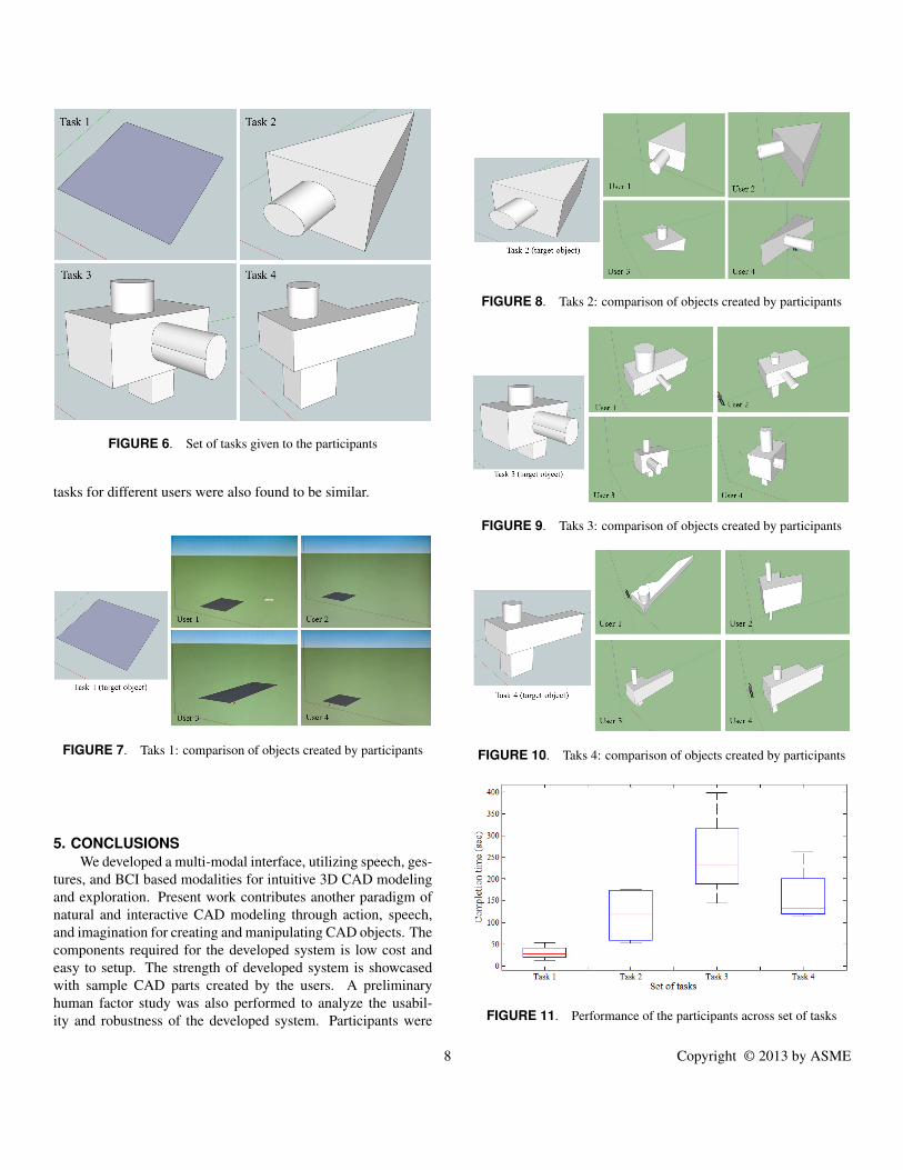
FIGURE 6. Set of tasks given to the participants
tasks for different users were also found to be similar.
FIGURE 7. Taks 1: comparison of objects created by participants
5. CONCLUSIONSWe developed a multi-modal interface, utilizing speech, ges-
tures, and BCI based modalities for intuitive 3D CAD modelingand exploration. Present work contributes another paradigm ofnatural and interactive CAD modeling through action, speech,and imagination for creating and manipulating CAD objects. Thecomponents required for the developed system is low cost andeasy to setup. The strength of developed system is showcasedwith sample CAD parts created by the users. A preliminaryhuman factor study was also performed to analyze the usabil-ity and robustness of the developed system. Participants were
FIGURE 8. Taks 2: comparison of objects created by participants
FIGURE 9. Taks 3: comparison of objects created by participants
FIGURE 10. Taks 4: comparison of objects created by participants
FIGURE 11. Performance of the participants across set of tasks
8 Copyright © 2013 by ASME
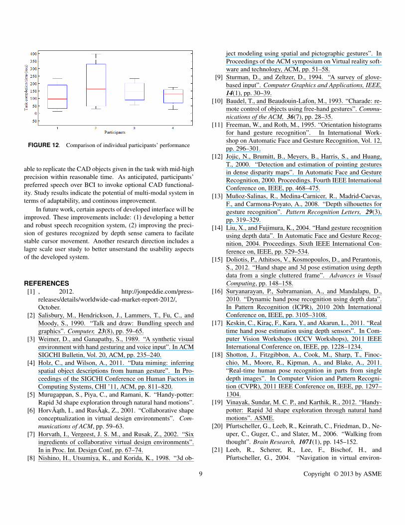
FIGURE 12. Comparison of individual participants’ performance
able to replicate the CAD objects given in the task with mid-highprecision within reasonable time. As anticipated, participants’preferred speech over BCI to invoke optional CAD functional-ity. Study results indicate the potential of multi-modal system interms of adaptability, and continous improvement.
In future work, certain aspects of developed interface will beimproved. These improvements include: (1) developing a betterand robust speech recognition system, (2) improving the preci-sion of gestures recognized by depth sense camera to facilatestable cursor movement. Another research direction includes alagre scale user study to better unserstand the usability aspectsof the developed system.
REFERENCES[1] , 2012. http://jonpeddie.com/press-
releases/details/worldwide-cad-market-report-2012/,October.
[2] Salisbury, M., Hendrickson, J., Lammers, T., Fu, C., andMoody, S., 1990. “Talk and draw: Bundling speech andgraphics”. Computer, 23(8), pp. 59–65.
[3] Weimer, D., and Ganapathy, S., 1989. “A synthetic visualenvironment with hand gesturing and voice input”. In ACMSIGCHI Bulletin, Vol. 20, ACM, pp. 235–240.
[4] Holz, C., and Wilson, A., 2011. “Data miming: inferringspatial object descriptions from human gesture”. In Pro-ceedings of the SIGCHI Conference on Human Factors inComputing Systems, CHI ’11, ACM, pp. 811–820.
[5] Murugappan, S., Piya, C., and Ramani, K. “Handy-potter:Rapid 3d shape exploration through natural hand motions”.
[6] HorvÃath, I., and RusÃak, Z., 2001. “Collaborative shapeconceptualization in virtual design environments”. Com-munications of ACM, pp. 59–63.
[7] Horvath, I., Vergeest, J. S. M., and Rusak, Z., 2002. “Sixingredients of collaborative virtual design environments”.In in Proc. Int. Design Conf, pp. 67–74.
[8] Nishino, H., Utsumiya, K., and Korida, K., 1998. “3d ob-
ject modeling using spatial and pictographic gestures”. InProceedings of the ACM symposium on Virtual reality soft-ware and technology, ACM, pp. 51–58.
[9] Sturman, D., and Zeltzer, D., 1994. “A survey of glove-based input”. Computer Graphics and Applications, IEEE,14(1), pp. 30–39.
[10] Baudel, T., and Beaudouin-Lafon, M., 1993. “Charade: re-mote control of objects using free-hand gestures”. Commu-nications of the ACM, 36(7), pp. 28–35.
[11] Freeman, W., and Roth, M., 1995. “Orientation histogramsfor hand gesture recognition”. In International Work-shop on Automatic Face and Gesture Recognition, Vol. 12,pp. 296–301.
[12] Jojic, N., Brumitt, B., Meyers, B., Harris, S., and Huang,T., 2000. “Detection and estimation of pointing gesturesin dense disparity maps”. In Automatic Face and GestureRecognition, 2000. Proceedings. Fourth IEEE InternationalConference on, IEEE, pp. 468–475.
[13] Muñoz-Salinas, R., Medina-Carnicer, R., Madrid-Cuevas,F., and Carmona-Poyato, A., 2008. “Depth silhouettes forgesture recognition”. Pattern Recognition Letters, 29(3),pp. 319–329.
[14] Liu, X., and Fujimura, K., 2004. “Hand gesture recognitionusing depth data”. In Automatic Face and Gesture Recog-nition, 2004. Proceedings. Sixth IEEE International Con-ference on, IEEE, pp. 529–534.
[15] Doliotis, P., Athitsos, V., Kosmopoulos, D., and Perantonis,S., 2012. “Hand shape and 3d pose estimation using depthdata from a single cluttered frame”. Advances in VisualComputing, pp. 148–158.
[16] Suryanarayan, P., Subramanian, A., and Mandalapu, D.,2010. “Dynamic hand pose recognition using depth data”.In Pattern Recognition (ICPR), 2010 20th InternationalConference on, IEEE, pp. 3105–3108.
[17] Keskin, C., Kiraç, F., Kara, Y., and Akarun, L., 2011. “Realtime hand pose estimation using depth sensors”. In Com-puter Vision Workshops (ICCV Workshops), 2011 IEEEInternational Conference on, IEEE, pp. 1228–1234.
[18] Shotton, J., Fitzgibbon, A., Cook, M., Sharp, T., Finoc-chio, M., Moore, R., Kipman, A., and Blake, A., 2011.“Real-time human pose recognition in parts from singledepth images”. In Computer Vision and Pattern Recogni-tion (CVPR), 2011 IEEE Conference on, IEEE, pp. 1297–1304.
[19] Vinayak, Sundar, M. C. P., and Karthik, R., 2012. “Handy-potter: Rapid 3d shape exploration through natural handmotions”. ASME.
[20] Pfurtscheller, G., Leeb, R., Keinrath, C., Friedman, D., Ne-uper, C., Guger, C., and Slater, M., 2006. “Walking fromthought”. Brain Research, 1071(1), pp. 145–152.
[21] Leeb, R., Scherer, R., Lee, F., Bischof, H., andPfurtscheller, G., 2004. “Navigation in virtual environ-
9 Copyright © 2013 by ASME
ments through motor imagery”. In 9th Computer VisionWinter Workshop, CVWW, Vol. 4, pp. 99–108.
[22] Fabiani, G., McFarland, D., Wolpaw, J., and Pfurtscheller,G., 2004. “Conversion of eeg activity into cursor movementby a brain-computer interface (bci)”. Neural Systems andRehabilitation Engineering, IEEE Transactions on, 12(3),pp. 331–338.
[23] Trejo, L., Rosipal, R., and Matthews, B., 2006. “Brain-computer interfaces for 1-d and 2-d cursor control: designsusing volitional control of the eeg spectrum or steady-statevisual evoked potentials”. Neural Systems and Rehabilita-tion Engineering, IEEE Transactions on, 14(2), pp. 225–229.
[24] Kübler, A., Kotchoubey, B., Kaiser, J., Wolpaw, J., and Bir-baumer, N., 2001. “Brain–computer communication: Un-locking the locked in.”. Psychological bulletin, 127(3),p. 358.
[25] Kosslyn, S., and Osherson, D., 1995. An Invitation to Cog-nitive Science, -Vol. 2: Visual Cognition, Vol. 2. Mit Press.
[26] Moulton, S., and Kosslyn, S., 2009. “Imagining predic-tions: mental imagery as mental emulation”. PhilosophicalTransactions of the Royal Society B: Biological Sciences,364(1521), pp. 1273–1280.
[27] Farah, M., Hammond, K., Levine, D., and Calvanio, R.,1988. “Visual and spatial mental imagery: Dissociablesystems of representation”. Cognitive psychology, 20(4),pp. 439–462.
[28] Kosslyn, S., 1996. Image and brain: The resolution of theimagery debate. MIT press.
[29] Alexiou, K., Zamenopoulos, T., Johnson, J., and Gilbert, S.,2009. “Exploring the neurological basis of design cognitionusing brain imaging: some preliminary results”. DesignStudies, 30(6), pp. 623–647.
[30] Esfahani, E., and Sundararajan, V., 2011. “Classifica-tion of primitive shapes using brain–computer interfaces”.Computer-Aided Design.
[31] Esfahani, E., and Sundararajan, V., 2011. “Using braincomputer interfaces for geometry selection in cad systems:P300 detection approach”. ASME.
[32] Bolt, R., 1980. ÂSPut-that-thereÂT: Voice and gesture atthe graphics interface, Vol. 14. ACM.
[33] Billinghurst, M., 1998. “Put that where? voice and ges-ture at the graphics interface”. ACM SIGGRAPH ComputerGraphics, 32(4), pp. 60–63.
[34] Hauptmann, A., 1989. “Speech and gestures for graphicimage manipulation”. In ACM SIGCHI Bulletin, Vol. 20,ACM, pp. 241–245.
[35] Arangarasan, R., and Gadh, R., 2000. “Geometric model-ing and collaborative design in a multi-modal multi-sensoryvirtual environment”. In Proceeding of the ASME 2000Design Engineering Technical Conferences and Computersand Information in Engineering Conference, pp. 10–13.
[36] Bae, S., Balakrishnan, R., and Singh, K., 2008. “Iloves-ketch: as-natural-as-possible sketching system for creat-ing 3d curve models”. In Proceedings of the 21st annualACM symposium on User interface software and technol-ogy, ACM, pp. 151–160.
[37] Schmidt, R., Wyvill, B., Sousa, M., and Jorge, J., 2006.“Shapeshop: Sketch-based solid modeling with blobtrees”.In ACM SIGGRAPH 2006 Courses, ACM, p. 14.
[38] Fiorentino, M., Monno, G., and Uva, A., 2005. “Thesenstylus: a novel rumble-feedback pen device for cadapplication in virtual reality”. In Proceedings of the13th International Conference in Central Europe on Com-puter Graphics, Visualization and Computer Vision’2005(WSCG 2005), Citeseer.
[39] Kara, L., D’Eramo, C., and Shimada, K., 2006. “Pen-basedstyling design of 3 d geometry using concept sketches andtemplate models”. In ACM Symposium on Solid and Phys-ical Modeling: Proceedings of the 2006 ACM symposiumon Solid and physical modeling, Vol. 6, Citeseer, pp. 149–160.
[40] Kara, L., and Stahovich, T., 2005. “An image-based, train-able symbol recognizer for hand-drawn sketches”. Com-puters & Graphics, 29(4), pp. 501–517.
[41] Kara, L., and Shimada, K., 2007. “Sketch-based 3d-shapecreation for industrial styling design”. Computer Graphicsand Applications, IEEE, 27(1), pp. 60–71.
[42] Varga, E., 2008. “Using hand motions in conceptual shapedesign: theories, methods and tools”. Product Engineering,pp. 367–382.
[43] Scali, S., Wright, M., and Shillito, A., 2003. “3d modellingis not for wimps”. In Proceedings of HCI International.
[44] Schkolne, S., Pruett, M., and Schröder, P., 2001. “Surfacedrawing: creating organic 3d shapes with the hand and tan-gible tools”. In Proceedings of the SIGCHI conference onHuman factors in computing systems, ACM, pp. 261–268.
[45] Fuge, M., Yumer, M., Orbay, G., and Kara, L., 2011. “Con-ceptual design and modification of freeform surfaces us-ing dual shape representations in augmented reality envi-ronments”. Computer-Aided Design.
[46] Sharma, A., Madhvanath, S., Shekhawat, A., andBillinghurst, M., 2011. “Mozart: a multimodal interfacefor conceptual 3d modeling”. In Proceedings of the 13thinternational conference on multimodal interfaces, ACM,pp. 307–310.
[47] Lee, J., 2010. “In search of a natural gesture”. XRDS,16(4), pp. 9–12.
[48] Pentland, A., 2000. “Perceptual user interfaces: perceptualintelligence”. Communications of the ACM, 43(3), pp. 35–44.
[49] Chen, S., Chen, S., Doh, S., Eskenazi, M., Ea, E. G., Raj,B., Ravishankar, M., Rosenfeld, R., Siegler, M., Stern, R.,and Thayer, E., 1998. “The 1997 cmu sphinx-3 english
10 Copyright © 2013 by ASME

broadcast news transcription system”. In In Proceedings ofthe 1998 DARPA Speech Recognition Workshop. DARPA,pp. 55–59.
[50] Gomez-Gil, J., San-Jose-Gonzalez, I., Nicolas-Alonso,L. F., and Alonso-Garcia, S., 2011. “Steering a tractor bymeans of an emg-based human-machine interface”. Sen-sors, 11(7), pp. 7110–7126.
[51] http://sitescontent.google.com/google-sketchup-for-educators/home.
[52] http://www.youtube.com/watch?v=jp44vte5z4kfeature=youtu.be.
11 Copyright © 2013 by ASME