cad redlines - larimer county
TRANSCRIPT
u, 0 .... alS m t .... g .... C U) (I) (I)
Cf)
A ....... 1---+---,
en r-. ro ~ ..... _ (I) 0. "O CG (])~ oO E (I) .... (I)
E~ u, "O o2 .... _!; ... C1l 0 Q. m (I)
I _Q ._,.o 0 Ill .... C1l ~ >,
""' C1l ~E cg? U) ~
. • (I) (I)
~8:l2 0 . . Z-,- N
0: >- w <( (L
co~
(I) C ::J
-e :i 0
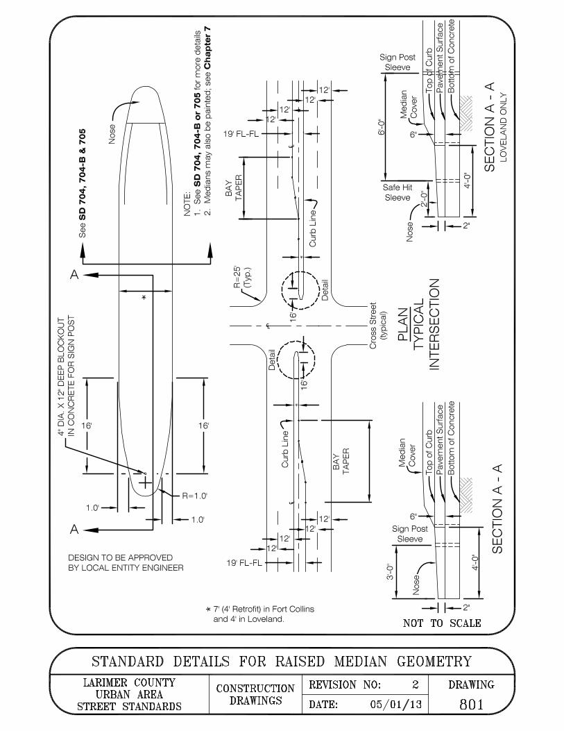
1 .... / ' { \~ \ I © '.T I 0 "t---... " co
Sign Post Sleeve
b I co
Safe Hit Sleeve 9
(C\J ~ ~ ~2"
--m (])~
0 z
z 0
I- I:) (/)
.l=; ro .,.... Cf) 0 -- - r-- - -- - -- en ·o.
_J 1-z <Co <(Ow _J 0.... (/) oO
~ (L
oz QCJ al u5 (L 0: wO W LL ow C\J tiJ .,.... 0: xO . z <( 0 oo = z s;t-_
r 16'
I L
1.0'
A ....... 1----......
7 16'
J R=1.0'
1.0'
DESIGN TO BE APPROVED BY LOCAL ENTITY ENGINEER
----1 / ' = I \
El1 I (]), r, 0' / ' / --
(I) C ::J .0 .... :i 0
19' FL-FL +--+-i
co
+: 7' (4' Retrofit) in Fort Collins and 4' in Loveland.
gi £ --o
0: >- w <( (L
co~
0.... ~ ffi
C C1l .... ·- (I) "O > (I) 0 20
1-z
(I).$ 0 ~ C1l 0 't: C :i 0
.0 (/) 0 :j +-' ~ 0 ffi o 0 E E Q. ~ g 0 C1l 0 I- (L co
b I
s;t-
~~2"
NOT TO SCALE
STANDARD DETAILS FOR RAISED MEDIAN GEOMETRY
<( I ~
<( B zo 0~ -....J I- w o> wS (/)
<(
<(
z 0
b w (/)
LARIMER COUNTY CONSTRUCTION REVISION NO: 2 DRAWING URBAN AREA
STREET STANDARDS DRAWINGS DATE: 05/01/13 801

* ACCESS RAMP
FORCED TURN BARRIER LARIMER COUNTY CONSTRUCTION URBAN AREA
STREET STANDARDS DRAWINGS
b I
i'--
R==1'
* Provide flat platform rest area.
NOT TO SCALE
( SPLITTER ISLAND) REVISION NO: 3 DRAWING
DATE: 05/01/13 802

~ ----·· · ·-- ··-=
r
I
I
I
(;
I
\
~
I/
"No Parking Any Time"
R7-1 (TYP.)
28' (min .)
FL
\ ~
co N
"No Parking Any Time"
R7-1 (TYP.)
~------·=-- .. ~
Note: 28' Flowline to Flowline Cross-Section shall be maintained . For higher densities, larger Cross-Section are recommended .
~ 0 .
I _Q
~ L ·- ::::i
0~ u Cl) L 0 Cl) ·-u t C (1) Cl)>
- L Cf) 0
FL
CENTER ISLAND PARKING IN CUL-DE-SAC LARIMER COUNTY DESIGN REVISION NO: 2
URBAN AREA FIGURE STREET STANDARDS DATE: 04/01/07
FIGURE
19-1
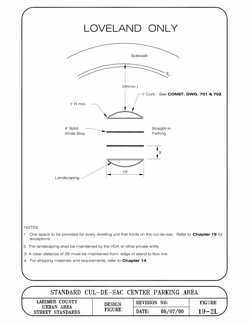
LOVELAND ONLY
Sidewalk
28'(min.)
1' Curb - See CONST. DWG. 701 & 702.
NOTES:
1' R min.
4" Solid White Strip
Landscaping
19'
Straight-in Parking
1 . One space to be provided for every dwelling unit that fronts on the cul-de-sac. Refer to Chapter 19 for exceptions.
2. The landscaping shall be maintained by the HOA or other private entity.
3. A clear distance of 28' must be maintained from edge of island to flow line.
4. For stripping materials and requirements, refer to Chapter 14.
STANDARD CUL-DE-SAC CENTER PARKING AREA LARIMER COUNTY DESIGN REVISION NO:
URBAN AREA FIGURE STREET STANDARDS DATE: 08/07/00
FIGURE
19-2L
co
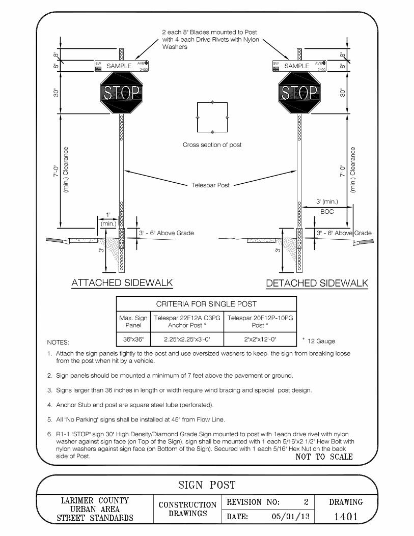
2 each 8" Blades mounted to Post with 4 each Drive Rivets with Nylon Washers
co
co SW SAMPLE SW SAMPLE
AVE♦ co 2400 2400
• ~----- • b C')
0 0
8 0 0
§ 0 0 0 0
0 0
Cross section of post (I) u C cu t.....
b cu (I)
C .E ---------- Telespar Post ---------
I 0 f--. ~
C
I 8 0
1' 8 ..---.,o (min.) 8
8 3' (min.) ------§ BOC
8 ------3" - 6" Above Grade 3" - 6" Above Grade .... " ..... • ~- . ' ...
ATTACHED SIDEWALK DETACHED SIDEWALK
CRITERIA FOR SINGLE POST
Max. Sign Telespar 22F12A O3PG Telespar 20F12P-1 0PG Panel Anchor Post * Post*
NOTES: 36"x36" 2.25"x2.25"x3'-0" 2"x2"x12'-0" * 12 Gauge
1 . Attach the sign panels tightly to the post and use oversized washers to keep the sign from breaking loose from the post when hit by a vehicle.
2. Sign panels should be mounted a minimum of 7 feet above the pavement or ground.
3. Signs larger than 36 inches in length or width require wind bracing and special post design.
4. Anchor Stub and post are square steel tube (perforated).
5. All "No Parking" signs shall be installed at 45° from Flow Line.
6. R1-1 "STOP" sign 30" High Density/Diamond Grade.Sign mounted to post with 1 each drive rivet with nylon washer against sign face (on Top of the Sign). sign shall be mounted with 1 each 5/16"x2 1 /2" Hew Bolt with nylon washers against sign face (on Bottom of the Sign). Secured with 1 each 5/16" Hex Nut on the back side of Post. NOT TO SCALE
SIGN POST LARIMER COUNTY CONSTRUCTION REVISION NO: 2 DRAWING
URBAN AREA STREET STANDARDS DRAWINGS DATE: 05/01/13 1401
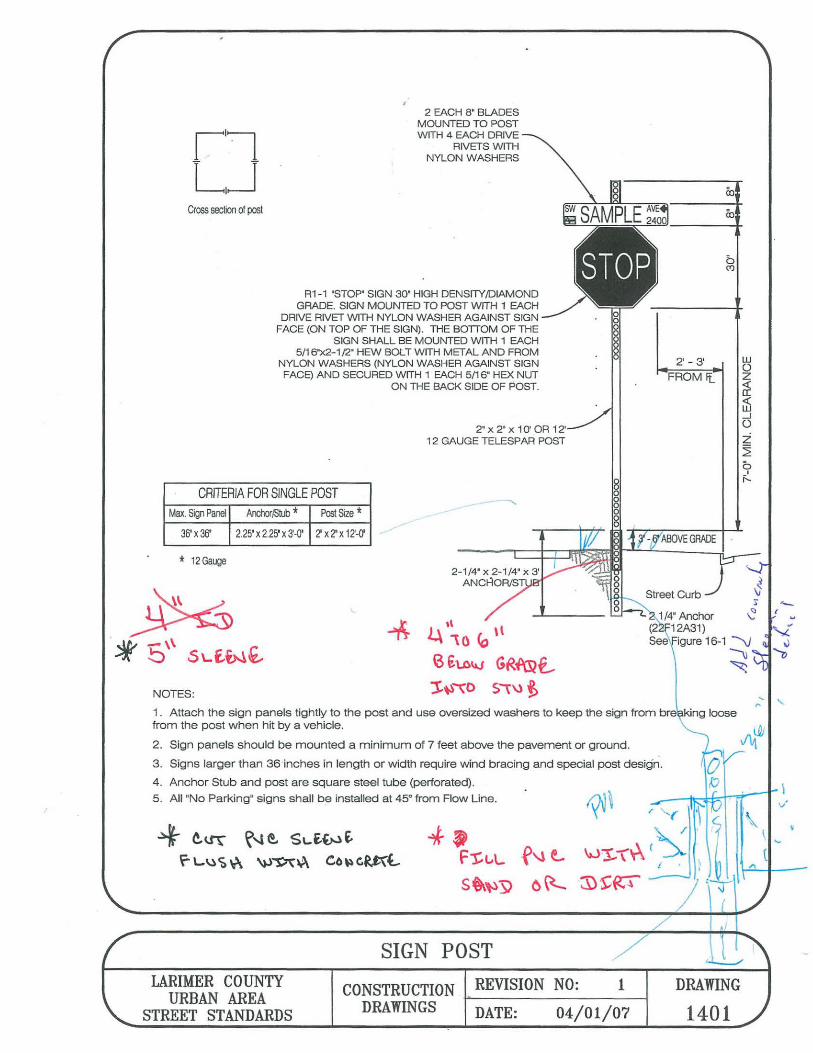
,, l.\ '10 <o ,,
6 tt-o\AJ GR~€...
1/4' Anchor (2 12A31) See igure 16-1 --V
~ ~
,_
2 EACH 8' BLADES MOUNTED TO POST WITH 4 EACH DRIVE
RIVETS WITH NYLON WASHERS
Cross section of post co ----+
R1-1 'STOP" SIGN 30" HIGH DENSITYJ1)1AMOND GRADE. SIGN MOUNTED TO POST WITH 1 EACH ------1-
DRIVE RIVET WITH NYLON WASHER AGAINST SIGN • FACE (ON TOP OF THE SIGN). THE BOTTOM OF THE SIGN SHALL BE MOUNTED WITH 1 EACH
5/16'x2-1 /2.' HEW BOLT WITH MET AL AND FROM w 2' - 3' NYLON WASHERS (NYLON WASHER AGAINST SIGN 0
FACE) AND SECURED WITH 1 EACH 5/16' HEX NUT z FROM Ii_ ON THE BACK SIDE OF POST. ~
~ _J
0 2" x 2· x 1 O' OR 12' 12 GAUGE TELESPAR POST i
~ b _, r--
CRITERIA FOR SINGLE POST Max. Sign Panel ArdloriS!ub * Post Size*
36' X 36' 2.25' X 2.25' X 3'-0' 2'x2'x 12'-0'
§
* 12Gauge
J:~,o S,\l 'f> NOTES: ,..'
1 . Attach the sign panels tightly to the post and use oversized washers to keep the sign from bre king loose from the post when hit by a vehicle.
2. Sign panels should be mounted a minimum of 7 feet above the pavement or ground.
3. Signs larger than 36 inches in length or width require wind bracing and special post design.
4. Anchor Stub and post are square steel tube (perforated).
5. All "No Parking' signs shall be installed at 45° from Flow Line.
4-- ~~ ~'1 ~ SL.£(,..) i,
r \..\) ~ ~ \).)~~ Cb~ GU(l..
SIGN POST
&N SAMPLE ~:oo
./ I 1
/ 'l
'
,,.
~
LARIMER COUNTY URBAN AREA
STREET STANDARDS
CONSTRUCTION DRAWINGS
REVISION NO: 1 DRAWING
1401 DATE: 04/01/07
' 'l

Not Required with lane lengths less than 1 00' +--tt+-i
Broken line 4" white 1 O' Segments
30' Gap (3:1 Ratio)
Line 4" White
Wide Lane 8" White
8" White Extension
b ,-
Ill
b
L Projected Flowline (FU
lil-rri--
_J
I"!
_J
8" White Line 4" White Line
Not Required with lane lengths less than 1 00'.
8" White Extension Line
4" White Extension Line On curves: Dotted extension of line edge with same as solid downstream line,2'segments, 4' gaps.
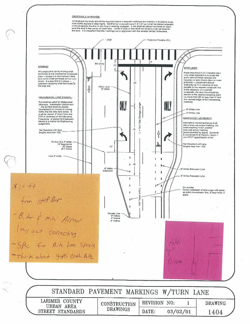
CROSSWALK MARKINGS: An Engineering study should be required before crosswalk markings are installed in locations away from traffic signals or stop signs. Continental crosswalk bars (1.5' x 9'typ) shall be placed adjacent to the projected flowline or abutting to existing crosspan . A bar shall be place centered on each lane line and in the center of each lane line and each lane. Lanes 5' wide or less shall not receive a bar centered in the land. It is important that the markings are in alignment with the access rar:np/sidewalk.
STRIPING: All Longitudinal (lane) striping shall terminate at the Continental crosswalk bars -- except the downstream bike lane which shall terminate at the curb return. If a stop line is in place -- upstream stripping shall terminate at the stop line.
PREFERENTIAL LANE SYMBOL: PLS shall be used for designated bikeways. Intersection placement -- the symbol shall be placed downstream to convey to turning traffic that the bike lane exists. It shall be placed 4" down from the PCR & centered on the bike lane. Frequency of placement between blocks is a matter for Engineering judgement.
STOP LINES: Place stop lines (1 .5' x Variable typ.) only when important to indicate the point behind which vehicles are required to stop (more often on main arterials) -- placement should ordinarily be 4' in advance of and parallel to the nearest crosswalk line in the absence of a marked crosswalk, the stop line should be placed at the desired stopping point no more than 30' or less than 4' from the nearest edge of the intersecting roadway.
MANDATORY MOVEMENT: Mandatory movement lanes shall use a lane-use arrow marking, the word marking "onlY', another lane-use arrow marking (accompanied by signs). Symbols & words are 8' of more in height -- use COOT specification sizes. NOT TO SCALE
STANDARD PAVEMENT MARKINGS W/TURN LANE LARIMER COUNTY CONSTRUCTION REVISION NO: 2 DRAWING
URBAN AREA STREET STANDARDS DRAWINGS DATE: 05/01/13 1404
--
CAOSSWALI< MARKINGS:
An Engineering study should be required before crosswalk mar1<.ings are installed in locations away from tratfic signals or slop s i1.,1ns. Continental crosswalk bars (1.5' x g typ.) shall be p laced adjacent to the projected flow!fne or abutting to exisling crosspan. A bar shall be placed centered on each lane line and In the center of each Jane. Lanes 5' wide or less shall not receive a bSr cenlered In the lane. It is important that the markings are in alignment INith the access ramps/ sidewalks,
STRIPING:
All Longiludinal (lane) slrlping shaU
bars -
return. If a slop line Is in place -upstream stripping shall terminate 'al the stop line.
PREFERENTIAL LANE SYMBOL:
PLS shall be used for designated bikeways. Intersection placement -- the symbol shall be placed dov,mstream to convey lo turning traffic that the bike lane exists. It shall be placed 4" down from the PCA & centered on the bike lane. Frequency of placement between blocks is a matter for Engineel'lng judgement.
Not Required with lane ____ lengths less than 1 00'.
Broken line 4• white 10' Segments
30-Gaps (3:1 Ratio)
Line 4' white
-Jl-f-- 1
l.5'X9' Projected Flowllne (FL)
.4L
Wide Lane 8 ' Whlte
f;
~~u
Double Line 4•ve11ow 4• Space 4' Yv.11ow
I
I °'-y OC-j Corrwf,~
-sP-c ,g,, f-<- tern. s pq,~
jo/-1-5 (:Mt1'. Id,,~
1()'
8" White Extension
ii U)
~ [I)
E :, I-.4L I
..J
.2L
' x Variable typ.)
,prterials) -- pfacement should ordinarily be 4' in advance of and parallel to the nearest crosswalk tine In the absence ol a marked crosswall<, the stop line should be placed at the desired stopping point no more than 30' or less than 4' from the nearest edge of the lntersecling roadway.
8' Whiteline
4•whlte line
MANOATQRY MOVEMENT·
Mandatory movemenl lanes shall use a lane-use arrow marking, the word marking •only", another lane-use arrow marking (accompanied by- signs). Symbols g. words are 6' of more in heigh! -use COOT specification sizes.
Not Required with lar.e Jenglhs less than 100'.
e• While Extension Une
4.' White Extension Line
On curves: Dotted oxlension of lane edge with same as solid downstream line, 2" segments, 4' gaps.
STANDARD PAVEMENT MARKINGS W/TURN LANE LARIMER COUNTY CON·STRUCTION REVISION NO: 1
URBAN AREA STREET STANDARDS DRAWINGS DATE: 03/02/01
DRAWING
1404
terminate at the Conlinen1al crosswalk except lhe downslrcam bike
lane which shall terminate at the curb
~-
Place stop lines (1 .5only when inportant to Wldicale lhe point behind which vehk:les are required to slop {more often on main
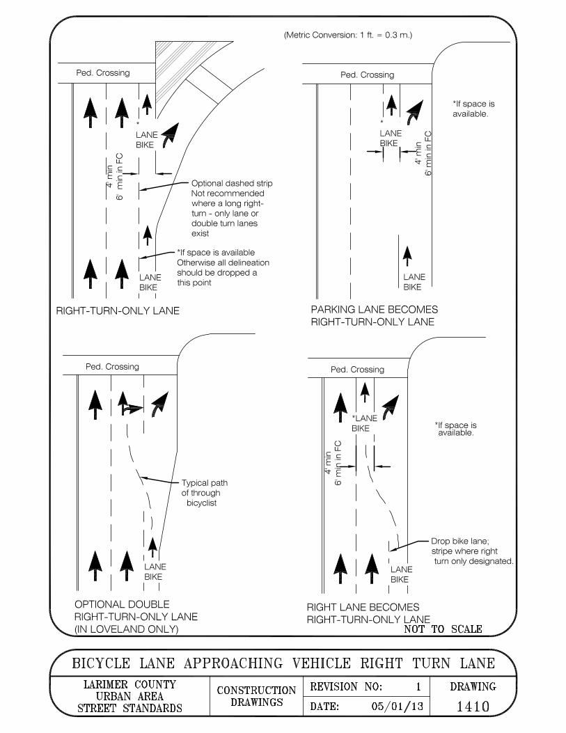
(Metric Conversion : 1 ft . = 0.3 m .)
Ped. Crossing
♦ I ♦ ! ♦ I LANEJ/1
BIKE r 1~W L i! I
I
! I ! LANE
T I T IBIK~
Optional dashed strip Not recommended where a long rightturn - only lane or double turn lanes exist
*If space is available Otherwise all delineation should be dropped a this point
RIGHT-TURN-ONLY LANE
Ped. Crossing
♦ 1~1' I \ I
I \
I
I 1\ I I+
LANE ♦ 1 ♦ 1 I BIKE
I I
Typical path of through
bicyclist
OPTIONAL DOUBLE RIGHT-TURN-ONLY LANE (IN LOVELAND ONLY)
Ped. Crossing
LANE o LL
BIKE C C
-i rl~ :~ 'Sf" E
<D
LANE BIKE
*If space is available.
PARKING LANE BECOMES RIGHT-TURN-ONLY LANE
Ped. Crossing
+ ♦ .LANE 1' BIKE WI
,!;~ l l E ·-
~ ~E \
co I \
I \
I
! I ! 1LANE T T BIKE I I I
RIGHT LANE BECOMES RIGHT-TURN-ONLY LANE
*If space is available.
Drop bike lane; stripe where right turn only designated.
NOT TO SCALE
BICYCLE LANE APPROACHING VEHICLE RIGHT TURN LANE LARIMER COUNTY CONSTRUCTION REVISION NO: 1 DRAWING
URBAN AREA STREET STANDARDS DRAWINGS DATE: 05/01/13 1410
-.....,,
rn ;a ~ t;z:j c:: ~ t;z:j ~ -t-3 t:::J:j is:: rn>~ t-3 z > > n z~o t:I t;z:j c:: > > z ~ t-3 t:I ~ rn
n r.n. 0 ~
t:I z ~ ~rn t:c:l > t-3 t:cj ~~ .......:::l - c:: .....--::1 Zn c;-:i t-3 1-7 rn- ..£...,
0 > z ~
t:I ~ t:cj
~ ~ r.n. t;z:j - ~ .. ~ ~
~ z 0 z C)l 0
............ 0 -............ -~ ~
t:I ~ ~
~ ~ ~ -~ z
c;-:i
~ '
z 0 t-3
t-3 0
rn n
~
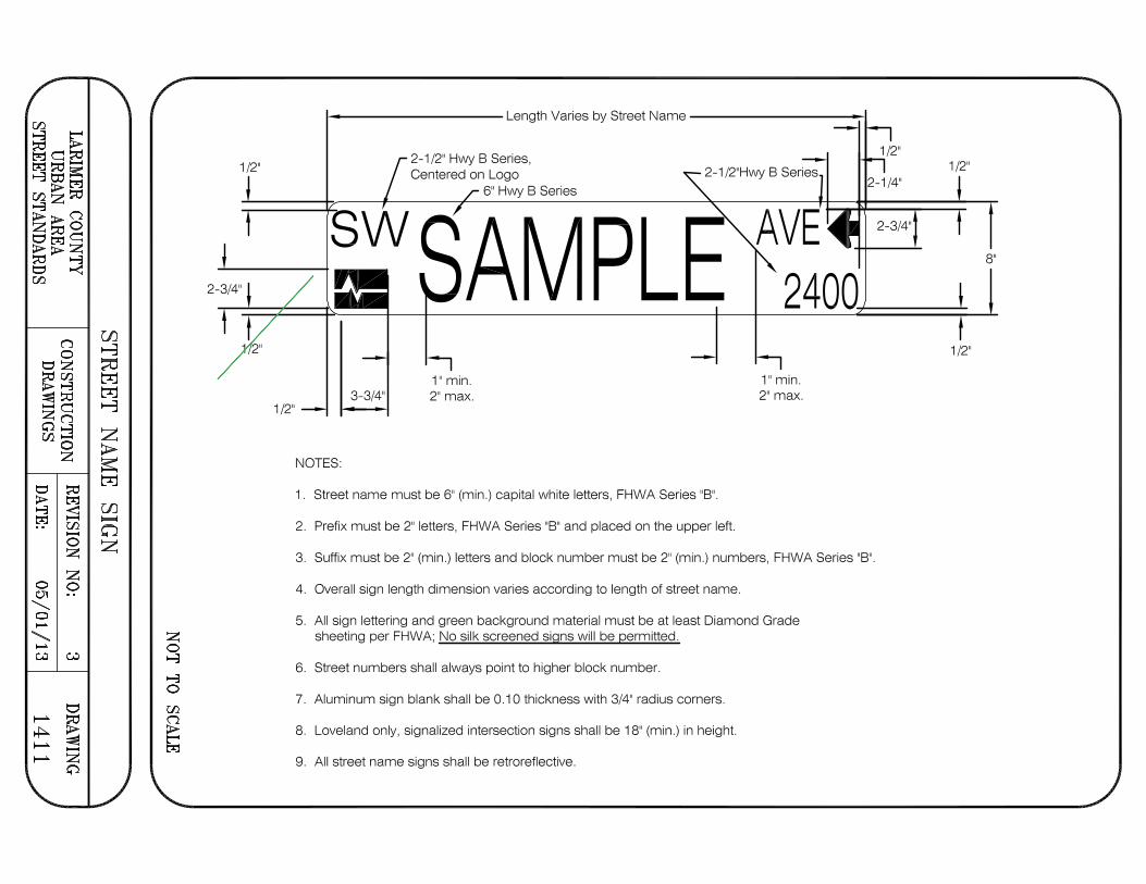
1/2"
2-3/4"
1/2"
1/2"
----------- Length Varies by Street Name -----------i
3-3/4"
NOTES:
2-1 /2" Hwy B Series, Centered on Logo
6" Hwy B Series
AMPL 1" min. 2"max.
1. Street name must be 6" (min.) capital white letters, FHWA Series "B".
2. Prefix must be 2" letters, FHWA Series "B" and placed on the upper left.
1" min. 2"max.
1/2"
2-1/4"
2-3/4"
3. Suffix must be 2" (min.) letters and block number must be 2" (min.) numbers, FHWA Series "B".
4. Overall sign length dimension varies according to length of street name.
5. All sign lettering and green background material must be at least Diamond Grade sheeting per FHWA; No silk screened signs will be permitted.
6. Street numbers shall always point to higher block number.
7. Aluminum sign blank shall be 0.10 thickness with 3/4" radius corners.
8. Loveland only, signalized intersection signs shall be 18" (min.) in height.
9. All street name signs shall be retroreflective.
1/2"
8"
1/2"
......
en ~ s;: t,cj c::: ~ t,cj ~ -t-3 t:c rs:: en > ~ t-3 z > > (j z~o t:::i t,cj c::: ,_ >>Z '----< ~ t-3 ~ 275 --< tc
> z (j ~ o 0
t:::iZ C:::: ~ en >--7 > t-3 .£..,
::ii!~ t::I - c::: > Zn -c;-:i t-3 "->.}
en- 0 ~ e
~
t:::, ~ rr. > t,cj V..I.
t-3 < -t,cj - Cl a z
z t::I 0 z t:rj 01 0 ~
.......... > 0 -- ~ .......... U1 -c..:, c..:,
t:::i ~ ~
~ ~ ~ -NZ
c;-:i
~
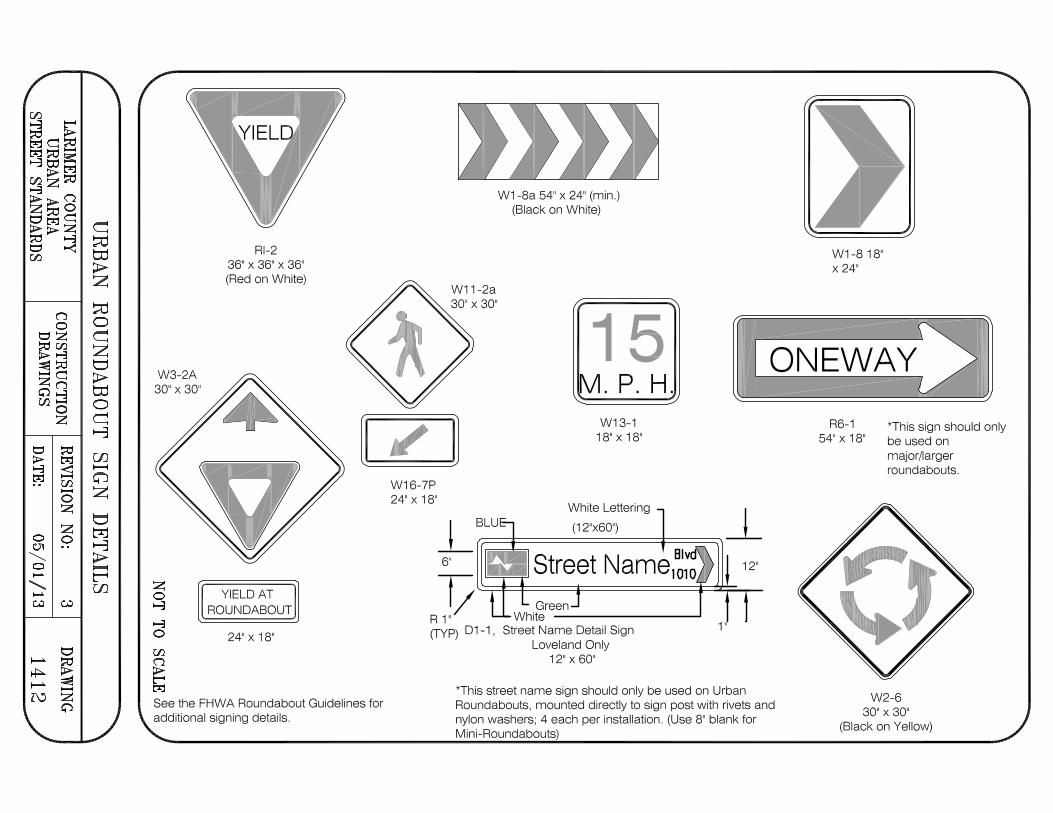
W3-2A 30" X 30"
Rl-2 36" X 36" X 36" (Red on White)
W1 -8a 54" x 24" (min.) (Black on White)
15 . P.H.
W1-818" X 24"
I I ONEWAY>I [I ✓ I]
W13-1 18" X 18"
R6-1 *This sign should only 54" x 18" be used on
major~arger roundabouts .
z 0 t-3
t-3 0
en (j
> ~
I[ YIELD AT ROUNDABOUT
24" X 18"
See the FHWA Roundabout Guidelines for additional signing details.
W16-7P 24" X 18"
6"
White Lettering
(12"x60")
12"
Ry S N Blvd treet ame1010 Green White ________ ___,
1 '; (TYP) 01-1, Street Name Detail Sign
Loveland Only 12" X 60"
*This street name sign should only be used on Urban Roundabouts, mounted directly to sign post with rivets and nylon washers; 4 each per installation. (Use 8" blank for Mini-Roundabouts2
W2-6 30" X 30"
(Black on Yellow)
'CJ)
i-3 ~ g;J c:: ~ t-rj ~ -i-3 t:c a:: 'CJ) > ~ i-3 z >><""::i Z ~ 0 t:::i t-rj c:: >>Z ~ i-3 t:::i --< 'CJ)
n 0
t:::iZ ~ 'CJ)
> i-3 :::::i!l~ - c:: Zn Cj'.l i-3 'CJ) -0
z
t:::i ~ > t-rj i-3 < t-rj -'CJ) -0
z
0 z 0
°' .. -.......... 0 --.......... -c..:> c..:>
t:::i I--'- ~ ~ ~ I--'- -w z
Cj'.l
.....
U"l ~ > z t::, > ~ t::,
~ trj
~ "1j 0 ~ > ~ ~
t::, trj
> t::,
trj
z t::,
to > ~ ~ ~
n > t::, trj U"l
~
z 0 i-3
i-3 0
'CJ) n > ~
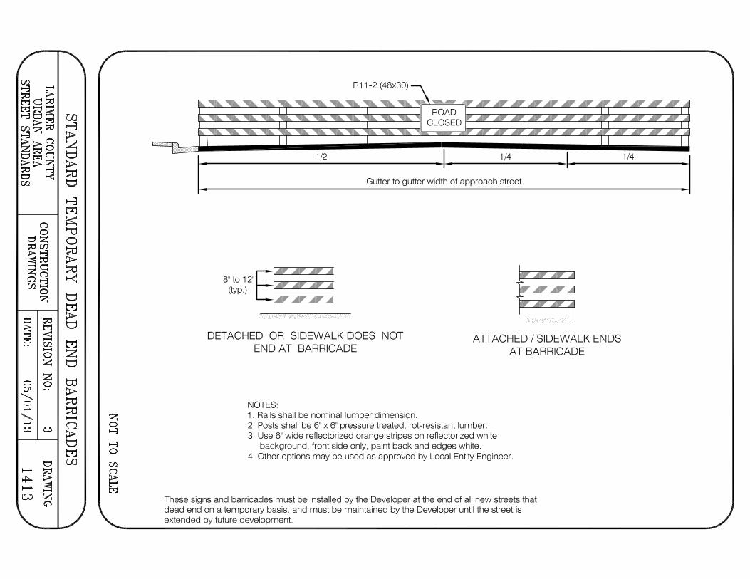
ROAD ,, -, , ,--, ,--, ,--, ,--, , ..- , -, • :, • :, • :, ..--,, ,..--, ,--, ,--, ·1 CLOSED I' er c c p • cz cz cz c ,z , c c c • c • , c ,,
1/2 1/4
Gutter to gutter width of approach street
8" to 12" (typ.)
DETACHED OR SIDEWALK DOES NOT END AT BARRICADE
NOTES: 1 . Rails shall be nominal lumber dimension.
ATTACHED/ SIDEWALK ENDS AT BARRICADE
2. Posts shall be 6" x 6" pressure treated , rot-resistant lumber. 3. Use 6" wide reflectorized orange stripes on reflectorized white
background, front side only, paint back and edges white. 4. Other options may be used as approved by Local Entity Engineer.
These signs and barricades must be installed by the Developer at the end of all new streets that dead end on a temporary basis, and must be maintained by the Developer until the street is extended by future development.
1/4
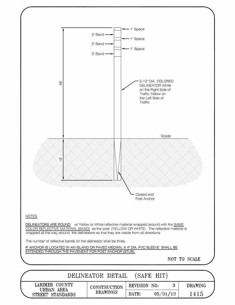
NOTES:
3"Band
3"Band
3"Band
1" Space
1" Space
2-12" DIA. COLORED DELINEATOR White on the Right Side of Traffic Yellow on the Left Side of Traffic
Closed end Post Anchor
Grade
DELINEATORS ARE ROUND w/ Yellow or White reflective material wrapped around with the SAME COLOR REFLECTIVE MATERIAL (BAND) as the post (YELLOW OR WHITE). The reflective material is wrapped all the way around the delineators so that they are visible from all directions.
The number of reflective bands on the delineator shall be three.
IF ANCHOR IS LOCATED IN AN ISLAND OR PAVED MEDIAN, A 4" DIA. PVC SLEEVE SHALL BE EXTENDED THROUGH THE PAVEMENT FOR POST ANCHOR (STUB).
NOT TO SCALE
DELINEATOR DETAIL (SAFE HIT) LARIMER COUNTY CONSTRUCTION REVISION NO: 3 DRAWING
URBAN AREA STREET STANDARDS DRAWINGS DATE: 05/01/13 1415

co
4' Yellow Strip (Latex Paint) Typ.
LOVELAND ONLY WB-130"x30" ~ ~ WB-1 30" X 30" W13-1 18" x 18" ~
/ A/ Spacing Width Varies / (See Details Below)
I ■
■ I I I I I I Roadway <i. 20' 8'
/ WB-1 30" x 30" WB-1 30" x 30"~
8' 10' 8' W13-1 18" X 18"
PLAN VIEW
Leading Edge of Speed Hump
-I 2' I ·
/ 12' White Pavement Markings
{--{--{---~E --~~ ----f ----rf-a· _ 1_ w _1 _ 12 _ 1_ 1• _ 1 _ 15• -1- 1a· .1. 2<Y .I Roadway r.'
'I:'. 12' I · · I
CHEVRON DETAIL
GRADUATED BAR DETAIL
NOTES:
1 . Graduated bars, Chevron and "Bump" markings are centered in the travel lanes.
2. All pavement markings (except the centerline striping) are to be pre-formed thermoplastic (PREMARK by Flint Trading, or equal)
NOT TO SCALE
SIGN & PAVEMENT MARKINGS FOR SPEED TABLES LARIMER COUNTY CONSTRUCTION REVISION NO: 2 DRAWING
URBAN AREA STREET STANDARDS DRAWINGS DATE: 05/01/13 14161

LOVELAND ONLY W11-230"X30" ~
~W11-230"X30" W13-1 18"x18"~
4' Yellow Stripe (Latex Paint) Typ.
I
Detached Sidewalk
I I I I I ~ W11-230"X30" ~
Spacing Width Varies / (See Detail Below)
I
100' 20' 8' 8'
"C/' W11-230"X30" ~ ~ W13-1 18" X 18" -+-,IC--.1'--4--
W1 6-7P 24" X 18" [Z] W11-2 30" X 30"
10] W16-7P 24" X 18" PLAN VIEW
Leading Edge of Speed Hump
., - -f-E -(0 -LO
2' I I 8' I I , 1 O' I 1 . 12'
GRADUATED BAR DETAIL Roadway~
t 12'
Travel
2'
t
2'
{';. I ~ White Mar~ngs
~ionofT~
CHEVRON DETAIL
NOTES:
1 . Graduated bars, Chevron and "PED XING" markings are centered in the travel lanes.
2. All pavement markings (except the centerline striping) are to be pre-formed thermoplastic (PREMARK by Flint Trading, or equal)
NOT TO SCALE
SIGN & PAVEMENT MARKINGS FOR RAISED CROSSINGS LARIMER COUNTY CONSTRUCTION REVISION NO: 3 DRAWING
URBAN AREA STREET STANDARDS DRAWINGS DATE: 05/01/13 14171
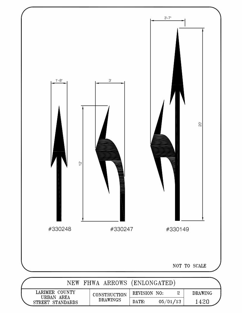
1'-8" 3'
3'-7"
b C\I
#330248 #330247 #330149
NOT TO SCALE
NEW FHWA ARROWS (ENLONGATED) LARIMER COUNTY CONSTRUCTION REVISION NO: 2 DRAWING
URBAN AREA STREET STANDARDS DRAWINGS DATE: 05/01/13 1420