introspection on improper seismic retrofit of basilica santa maria di collemaggio after 2009 italian...
TRANSCRIPT
Vol.10, No.1 EARTHQUAKE ENGINEERING AND ENGINEERING VIBRATION March, 2011
Earthq Eng & Eng Vib (2011) 10: 153-161 DOI: 10.1007/s11803-011-0054-4
Introspection on improper seismic retrofi t of Basilica Santa Maria di Collemaggio after 2009 Italian earthquake
Gian Paolo Cimellaro1†, Andrei M. Reinhorn2‡ and Alessandro De Stefano1§
1. Department of Structural & Geotechnical Engineering (DISTR) Politecnico di Torino, 10129 Turin, Italy
2. Department of Civil, Structural & Environmental Engineering, University at Buffalo, The State University of New York, Buffalo NY
Abstract: The 2009 L’Aquila, Italy earthquake highlighted the seismic vulnerability of historic masonry building structures due to improper “strengthening” retrofi t work that has been done in the last 50 years. Italian seismic standards recommend the use of traditional reinforcement techniques such as replacing the original wooden roof structure with new reinforced concrete (RC) or steel elements, inserting RC tie-beams in the masonry and new RC fl oors, and using RC jacketing on the shear walls. The L’Aquila earthquake revealed the numerous limitations of these interventions, because they led to increased seismic forces (due to greater additional weight) and to deformation incompatibilities of the incorporated elements with the existing masonry walls. This paper provides a discussion of technical issues pertaining to the seismic retrofi t of the Santa Maria di Collemaggio Basilica and in particular, the limitations of the last (2000) retrofi t intervention. Considerable damage was caused to the church because of questionable actions and incorrect and improper technical choices.
Keywords: seismic vulnerability; historic masonry building; wooden roof structure; seismic retrofi t; L’Aquila earthquake
Correspondence to: Gian Paolo Cimellaro, Department of Structural & Geotechnical Engineering (DISTR), Politecnico di Torino, Corso Duca degli Abruzzi 24, 10129 Turin, ItalyTel: +39 011 090 4801; Fax: +39 011 090 4899 E-mail: [email protected]
†Assistant Professor; ‡Eminent Professor; §ProfessorSupported by: European Community’s Seventh Framework
Programme (Marie Curie International Reintegration Actions - FP7/2007-2013) under Grant No. PIRG06-GA-2009-256316 of the project ICRED - Integrated European Disaster Community Resilience
Received June 22, 2010; Accepted December 8, 2010
1 Introduction
The experience following the L’Aquila earthquake (2009) showed that the collapse mechanism of existing masonry structures consists of the activation of cinematic mechanisms with a loss of equilibrium in walls or blocks of walls, with a prevalence of out-of-plane mechanisms both globally and locally. It also highlighted the limitations of traditional, but also innovative retrofi t techniques. Considerable damage was reported in buildings that had previously been seismically retrofi tted, in particular due to questionable actions and improper and incorrect technical choices. The case of the Santa Maria di Collemaggio Basilica represents a clear example of the consequences induced by improper technical choices in the design of a seismic retrofi t intervention, as demonstrated by damage following the April 6, 2009 earthquake in L'Aquila. Indeed, the Santa
Maria di Collemaggio Basilica is the only church in L’Aquila that was retrofi tted after the 1997 earthquake in Central Italy and therefore is an interesting case study that allows considerations about the numerous limitations of the recent retrofi t interventions.
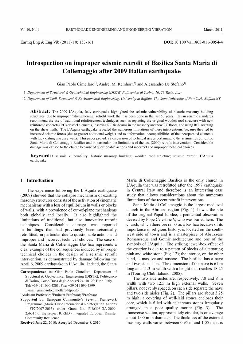
Santa Maria di Collemaggio is the largest medieval church in the Abruzzo region (Fig. 1). It was the site of the original Papal Jubilee, a penitential observation devised by Pope Celestine V, who was buried here. The church, which therefore ranks as a basilica because of its importance in religious history, is located on the south-west side of town and is a masterpiece of Abruzzese Romanesque and Gothic architecture and one of the symbols of L'Aquila. The striking jewel-box effect of the exterior is due to a pattern of blocks of alternating pink and white stone (Fig. 12); the interior, on the other hand, is massive and austere. The basilica has a nave and two side aisles. The dimension of the nave is 61 m long and 11.3 m width with a height that reaches 18.25 m (Touring Club Italiano, 2005).
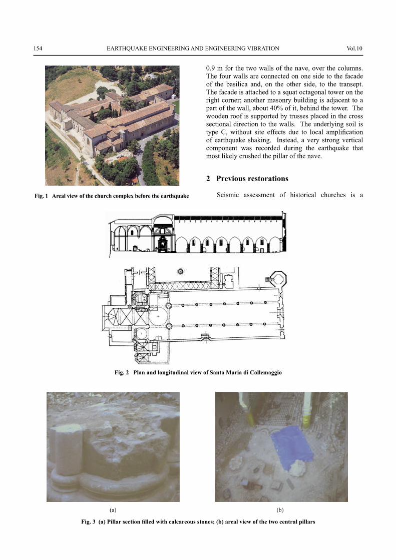
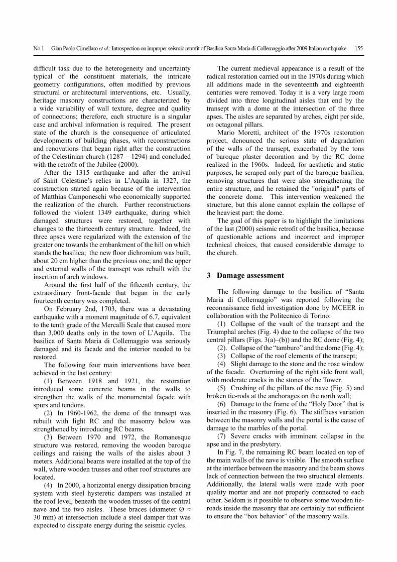
The two side aisles are, respectively, 7.8 and 8 m width with two 12.5 m high external walls. Seven pillars, not evenly spaced, on each side separate the nave and two side aisles (Fig. 2). The pillars are about 5.25 m high; a covering of well-laid stones encloses their core, which is fi lled with calcareous stones irregularly arranged in a poor quality mortar (Fig. 3). The transverse section, approximately circular, is on average about 1.00 m in diameter. The thickness of the external masonry walls varies between 0.95 m and 1.05 m; it is
154 EARTHQUAKE ENGINEERING AND ENGINEERING VIBRATION Vol.10
0.9 m for the two walls of the nave, over the columns. The four walls are connected on one side to the facade of the basilica and, on the other side, to the transept. The facade is attached to a squat octagonal tower on the right corner; another masonry building is adjacent to a part of the wall, about 40% of it, behind the tower. The wooden roof is supported by trusses placed in the cross sectional direction to the walls. The underlying soil is type C, without site effects due to local amplifi cation of earthquake shaking. Instead, a very strong vertical component was recorded during the earthquake that most likely crushed the pillar of the nave.
2 Previous restorations
Seismic assessment of historical churches is a Fig. 1 Areal view of the church complex before the earthquake
(a) (b)
Fig. 3 (a) Pillar section fi lled with calcareous stones; (b) areal view of the two central pillars
Fig. 2 Plan and longitudinal view of Santa Maria di Collemaggio
No.1 Gian Paolo Cimellaro et al.: Introspection on improper seismic retrofi t of Basilica Santa Maria di Collemaggio after 2009 Italian earthquake 155
diffi cult task due to the heterogeneity and uncertainty typical of the constituent materials, the intricate geometry confi gurations, often modifi ed by previous structural or architectural interventions, etc. Usually, heritage masonry constructions are characterized by a wide variability of wall texture, degree and quality of connections; therefore, each structure is a singular case and archival information is required. The present state of the church is the consequence of articulated developments of building phases, with reconstructions and renovations that began right after the construction of the Celestinian church (1287 – 1294) and concluded with the retrofi t of the Jubilee (2000).
After the 1315 earthquake and after the arrival of Saint Celestine’s relics in L’Aquila in 1327, the construction started again because of the intervention of Matthias Camponeschi who economically supported the realization of the church. Further reconstructions followed the violent 1349 earthquake, during which damaged structures were restored, together with changes to the thirteenth century structure. Indeed, the three apses were regularized with the extension of the greater one towards the embankment of the hill on which stands the basilica; the new fl oor dichromium was built, about 20 cm higher than the previous one; and the upper and external walls of the transept was rebuilt with the insertion of arch windows.
Around the fi rst half of the fi fteenth century, the extraordinary front-facade that began in the early fourteenth century was completed.
On February 2nd, 1703, there was a devastating earthquake with a moment magnitude of 6.7, equivalent to the tenth grade of the Mercalli Scale that caused more than 3,000 deaths only in the town of L’Aquila. The basilica of Santa Maria di Collemaggio was seriously damaged and its facade and the interior needed to be restored.
The following four main interventions have been achieved in the last century:
(1) Between 1918 and 1921, the restoration introduced some concrete beams in the walls to strengthen the walls of the monumental façade with spurs and tendons.
(2) In 1960-1962, the dome of the transept was rebuilt with light RC and the masonry below was strengthened by introducing RC beams.
(3) Between 1970 and 1972, the Romanesque structure was restored, removing the wooden baroque ceilings and raising the walls of the aisles about 3 meters. Additional beams were installed at the top of the wall, where wooden trusses and other roof structures are located.
(4) In 2000, a horizontal energy dissipation bracing system with steel hysteretic dampers was installed at the roof level, beneath the wooden trusses of the central nave and the two aisles. These braces (diameter Ø ≈ 30 mm) at intersection include a steel damper that was expected to dissipate energy during the seismic cycles.
The current medieval appearance is a result of the radical restoration carried out in the 1970s during which all additions made in the seventeenth and eighteenth centuries were removed. Today it is a very large room divided into three longitudinal aisles that end by the transept with a dome at the intersection of the three apses. The aisles are separated by arches, eight per side, on octagonal pillars.
Mario Moretti, architect of the 1970s restoration project, denounced the serious state of degradation of the walls of the transept, exacerbated by the tons of baroque plaster decoration and by the RC dome realized in the 1960s. Indeed, for aesthetic and static purposes, he scraped only part of the baroque basilica, removing structures that were also strengthening the entire structure, and he retained the "original" parts of the concrete dome. This intervention weakened the structure, but this alone cannot explain the collapse of the heaviest part: the dome.
The goal of this paper is to highlight the limitations of the last (2000) seismic retrofi t of the basilica, because of questionable actions and incorrect and improper technical choices, that caused considerable damage to the church.
3 Damage assessment
The following damage to the basilica of “Santa Maria di Collemaggio” was reported following the reconnaissance fi eld investigation done by MCEER in collaboration with the Politecnico di Torino:
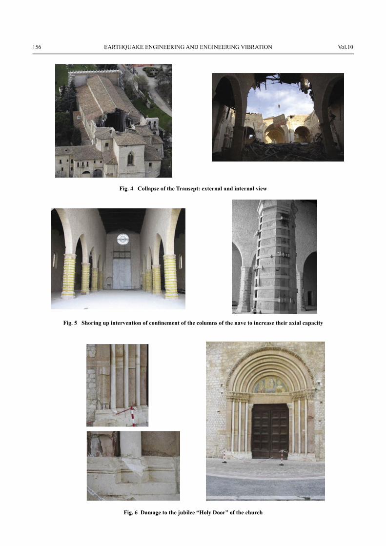
(1) Collapse of the vault of the transept and the Triumphal arches (Fig. 4) due to the collapse of the two central pillars (Figs. 3(a)–(b)) and the RC dome (Fig. 4);
(2). Collapse of the “tamburo” and the dome (Fig. 4);(3) Collapse of the roof elements of the transept;(4) Slight damage to the stone and the rose window
of the facade. Overturning of the right side front wall, with moderate cracks in the stones of the Tower.
(5) Crushing of the pillars of the nave (Fig. 5) and broken tie-rods at the anchorages on the north wall;
(6) Damage to the frame of the “Holy Door” that is inserted in the masonry (Fig. 6). The stiffness variation between the masonry walls and the portal is the cause of damage to the marbles of the portal.
(7) Severe cracks with imminent collapse in the apse and in the presbytery.
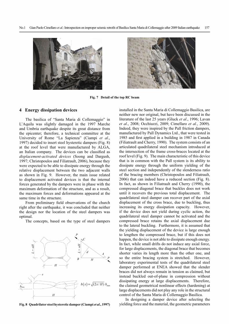
In Fig. 7, the remaining RC beam located on top of the main walls of the nave is visible. The smooth surface at the interface between the masonry and the beam shows lack of connection between the two structural elements. Additionally, the lateral walls were made with poor quality mortar and are not properly connected to each other. Seldom is it possible to observe some wooden tie-roads inside the masonry that are certainly not suffi cient to ensure the “box behavior” of the masonry walls.
156 EARTHQUAKE ENGINEERING AND ENGINEERING VIBRATION Vol.10
Fig. 4 Collapse of the Transept: external and internal view
Fig. 5 Shoring up intervention of confi nement of the columns of the nave to increase their axial capacity
Fig. 6 Damage to the jubilee “Holy Door” of the church
No.1 Gian Paolo Cimellaro et al.: Introspection on improper seismic retrofi t of Basilica Santa Maria di Collemaggio after 2009 Italian earthquake 157
4 Energy dissipation devices
The basilica of “Santa Maria di Collemaggio” in L’Aquila was slightly damaged in the 1997 Marche and Umbria earthquake despite its great distance from the epicenter; therefore, a technical committee at the University of Rome “La Sapienza” (Ciampi et al., 1997) decided to insert steel hysteretic dampers (Fig. 8) at the roof level that were manufactured by ALGA, an Italian company. The devices can be classifi ed as displacement-activated devices (Soong and Dargush, 1997; Christopoulos and Filiatrault, 2006), because they were expected to be able to dissipate energy through the relative displacement between the two adjacent walls as shown in Fig. 9. However, the main issue related to displacement activated devices is that the internal forces generated by the dampers were in phase with the maximum deformation of the structure, and as a result, the maximum forces and deformations appeared at the same time in the structure.
From preliminary fi eld observations of the church right after the earthquake, it was concluded that neither the design nor the location of the steel dampers was optimal.
The concepts, based on the type of steel dampers
installed in the Santa Maria di Collemaggio Basilica, are neither new nor original, but have been discussed in the literature of the last 25 years (Gluck et al., 1996; Lavan et al., 2008; Occhiuzzi, 2009; Cimellaro et al., 2009). Indeed, they were inspired by the Pall friction dampers, manufactured by Pall Dynamics Ltd., that were tested in 1985 and fi rst applied in a building in 1987 in Canada (Filiatrault and Cherry, 1990). The system consists of an articulated quadrilateral steel mechanism introduced at the intersection of the frame cross-braces located at the roof level (Fig. 9). The main characteristic of this device that is in common with the Pall system is its ability to dissipate energy through the uniform yielding of the steel section and independently of the slenderness ratio of the bracing members (Christopoulos and Filiatrault, 2006) that can indeed have a reduced section (Fig. 8). In fact, as shown in Filiatrault and Cherry (1990), the compressed diagonal brace that buckles does not work until it recovers the previous total displacement. The quadrilateral steel damper can recover part of the axial displacement of the cross brace, due to buckling, thus increasing its energy dissipation capacity. However, if the device does not yield during cyclic action, the quadrilateral steel damper cannot be activated and the compressed brace retains the axial displacement due to the lateral buckling. Furthermore, it is assumed that the yielding displacement of the device is large enough to lengthen the compressed brace, but if this does not happen, the device is not able to dissipate enough energy. In fact, while small drifts do not induce any axial force, for large displacements, the diagonal brace that becomes shorter varies its length more than the other one, and so the entire bracing system is stretched. However, laboratory experimental tests of the quadrilateral steel damper performed at ENEA showed that the slender braces did not always remain in tension as claimed, but instead buckled out-of-plane in compression without dissipating energy at large displacements. Therefore, the claimed geometrical nonlinear effects (hardening) at large displacements did not play any role in the structural control of the Santa Maria di Collemaggio Basilica.
In designing a damper device after selecting the yielding force and the material, the geometric parameters
Fig. 7 Detail of the top RC beam
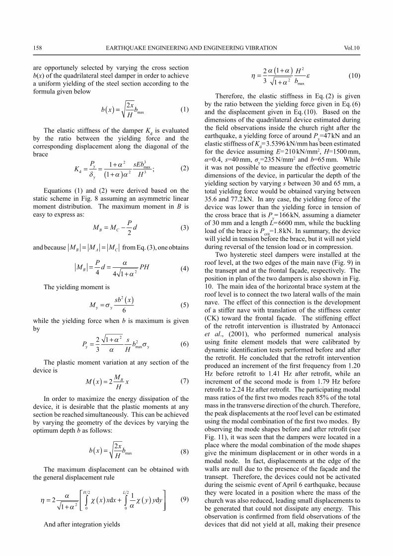
Fig. 8 Quadrilater steel hysteretic damper (Ciampi et al., 1997)
bmax
s
H
H
L =
αH
L =
αH
PC
B
AP
d
H
b x x H b( ) = ( / )2 max
158 EARTHQUAKE ENGINEERING AND ENGINEERING VIBRATION Vol.10
are opportunely selected by varying the cross section b(x) of the quadrilateral steel damper in order to achieve a uniform yielding of the steel section according to the formula given below
b x xH
b( ) = 2max (1)
The elastic stiffness of the damper Kd is evaluated by the ratio between the yielding force and the corresponding displacement along the diagonal of the brace
KP sEb
Hdy
y
= = ++( )
11
2
2
3
3max ; (2)
Equations (1) and (2) were derived based on the static scheme in Fig. 8 assuming an asymmetric linear moment distribution. The maximum moment in B is easy to express as:
M M P dB C= −2
(3)
and because M M MB A C= = from Eq. (3), one obtains
M P d PHB = =+4 4 1 2
(4)
The yielding moment is
Msb x
y y=( )
2
6 (5)
while the yielding force when b is maximum is given by
P sH
by y= +23
1 22
max (6)
The plastic moment variation at any section of the device is M x M
HxB( ) = 2 (7)
In order to maximize the energy dissipation of the device, it is desirable that the plastic moments at any section be reached simultaneously. This can be achieved by varying the geometry of the devices by varying the optimum depth b as follows:
b x xH
b( ) = 2max (8)
The maximum displacement can be obtained with the general displacement rule
=
+( ) + ( )
⎡
⎣⎢⎢
⎤
⎦⎥⎥∫∫2
11
20
2
0
2
x x x y y yLH
d d (9)
And after integration yields
=
+( )+
23
1
1 2
2Hbmax
(10)
Therefore, the elastic stiffness in Eq. (2) is given by the ratio between the yielding force given in Eq. (6) and the displacement given in Eq. (10). Based on the dimensions of the quadrilateral device estimated during the fi eld observations inside the church right after the earthquake, a yielding force of around Py=47 kN and an elastic stiffness of Kd=3.5396 kN/mm has been estimated for the device assuming E=210 kN/mm2, H=1500 mm, α=0.4, s=40 mm, σy=235 N/mm2 and b=65 mm. While it was not possible to measure the effective geometric dimensions of the device, in particular the depth of the yielding section by varying s between 30 and 65 mm, a total yielding force would be obtained varying between 35.6 and 77.2 kN. In any case, the yielding force of the device was lower than the yielding force in tension of the cross brace that is Py=166 kN, assuming a diameter of 30 mm and a length L=6600 mm, while the buckling load of the brace is Pcrit=1.8 kN. In summary, the device will yield in tension before the brace, but it will not yield during reversal of the tension load or in compression.
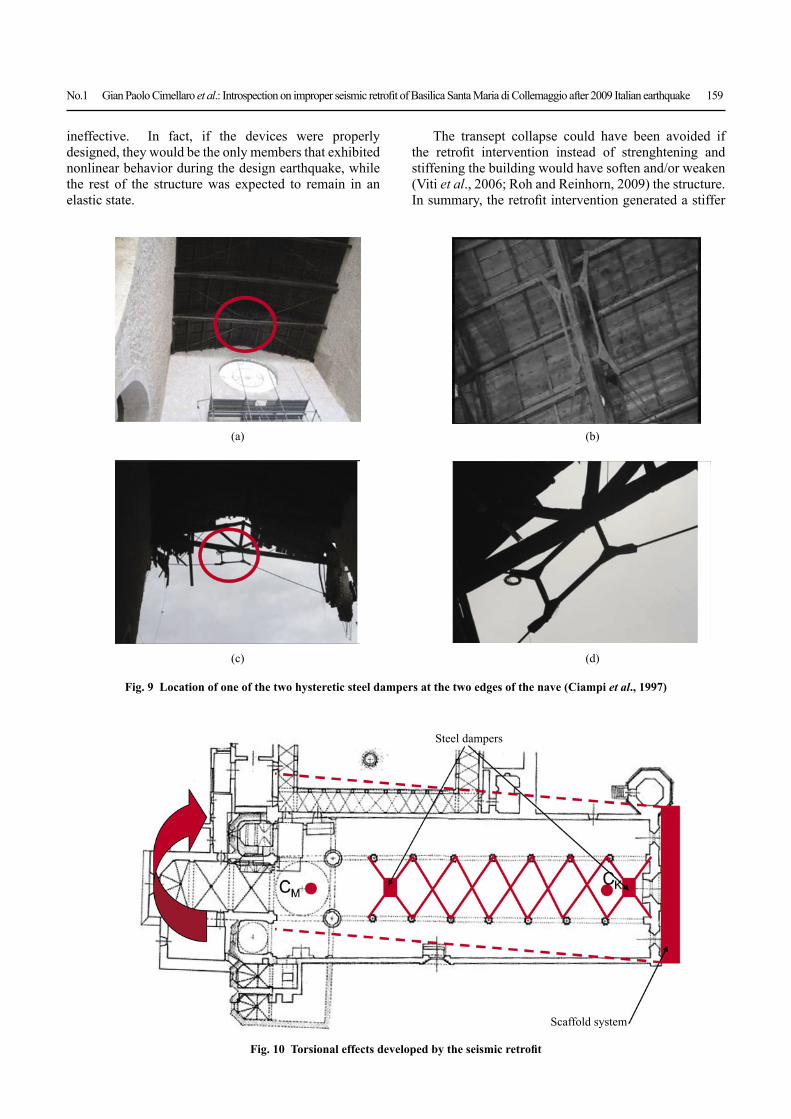
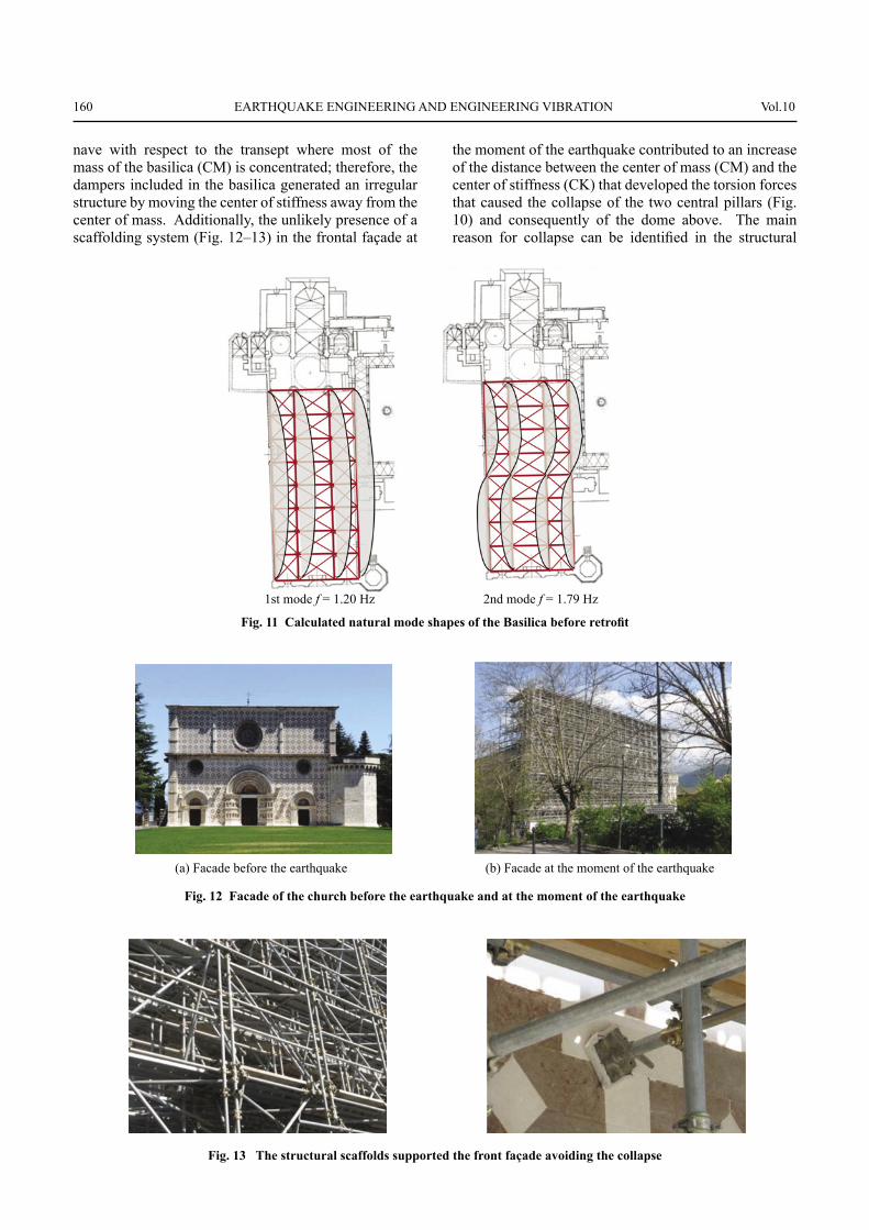
Two hysteretic steel dampers were installed at the roof level, at the two edges of the main nave (Fig. 9) in the transept and at the frontal façade, respectively. The position in plan of the two dampers is also shown in Fig. 10. The main idea of the horizontal brace system at the roof level is to connect the two lateral walls of the main nave. The effect of this connection is the development of a stiffer nave with translation of the stiffness center (CK) toward the frontal façade. The stiffening effect of the retrofi t intervention is illustrated by Antonacci et al., (2001), who performed numerical analysis using fi nite element models that were calibrated by dynamic identifi cation tests performed before and after the retrofi t. He concluded that the retrofi t intervention produced an increment of the fi rst frequency from 1.20 Hz before retrofi t to 1.41 Hz after retrofi t, while an increment of the second mode is from 1.79 Hz before retrofi t to 2.24 Hz after retrofi t. The participating modal mass ratios of the fi rst two modes reach 85% of the total mass in the transverse direction of the church. Therefore, the peak displacements at the roof level can be estimated using the modal combination of the fi rst two modes. By observing the mode shapes before and after retrofi t (see Fig. 11), it was seen that the dampers were located in a place where the modal combination of the mode shapes give the minimum displacement or in other words in a modal node. In fact, displacements at the edge of the walls are null due to the presence of the façade and the transept. Therefore, the devices could not be activated during the seismic event of April 6 earthquake, because they were located in a position where the mass of the church was also reduced, leading small displacements to be generated that could not dissipate any energy. This observation is confi rmed from fi eld observations of the devices that did not yield at all, making their presence
No.1 Gian Paolo Cimellaro et al.: Introspection on improper seismic retrofi t of Basilica Santa Maria di Collemaggio after 2009 Italian earthquake 159
ineffective. In fact, if the devices were properly designed, they would be the only members that exhibited nonlinear behavior during the design earthquake, while the rest of the structure was expected to remain in an elastic state.
The transept collapse could have been avoided if the retrofi t intervention instead of strenghtening and stiffening the building would have soften and/or weaken (Viti et al., 2006; Roh and Reinhorn, 2009) the structure. In summary, the retrofi t intervention generated a stiffer
Fig. 9 Location of one of the two hysteretic steel dampers at the two edges of the nave (Ciampi et al., 1997)
(a) (b)
(c) (d)
Fig. 10 Torsional effects developed by the seismic retrofi t
Steel dampers
Scaffold system
160 EARTHQUAKE ENGINEERING AND ENGINEERING VIBRATION Vol.10
nave with respect to the transept where most of the mass of the basilica (CM) is concentrated; therefore, the dampers included in the basilica generated an irregular structure by moving the center of stiffness away from the center of mass. Additionally, the unlikely presence of a scaffolding system (Fig. 12–13) in the frontal façade at
the moment of the earthquake contributed to an increase of the distance between the center of mass (CM) and the center of stiffness (CK) that developed the torsion forces that caused the collapse of the two central pillars (Fig. 10) and consequently of the dome above. The main reason for collapse can be identifi ed in the structural
Fig. 11 Calculated natural mode shapes of the Basilica before retrofi t
Fig. 12 Facade of the church before the earthquake and at the moment of the earthquake
Fig. 13 The structural scaffolds supported the front façade avoiding the collapse
1st mode f = 1.20 Hz 2nd mode f = 1.79 Hz
(a) Facade before the earthquake (b) Facade at the moment of the earthquake
No.1 Gian Paolo Cimellaro et al.: Introspection on improper seismic retrofi t of Basilica Santa Maria di Collemaggio after 2009 Italian earthquake 161
deformation incompatibility between the transept and the nave that are characterized by two different stiffness values.
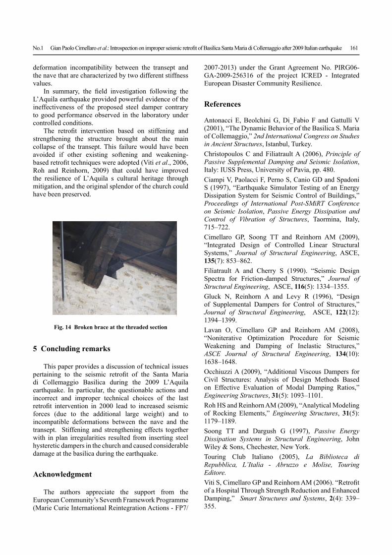
In summary, the fi eld investigation following the L’Aquila earthquake provided powerful evidence of the ineffectiveness of the proposed steel damper contrary to good performance observed in the laboratory under controlled conditions.
The retrofi t intervention based on stiffening and strengthening the structure brought about the main collapse of the transept. This failure would have been avoided if other existing softening and weakening-based retrofi t techniques were adopted (Viti et al., 2006, Roh and Reinhorn, 2009) that could have improved the resilience of L’Aquila s cultural heritage through mitigation, and the original splendor of the church could have been preserved.
5 Concluding remarks
This paper provides a discussion of technical issues pertaining to the seismic retrofi t of the Santa Maria di Collemaggio Basilica during the 2009 L’Aquila earthquake. In particular, the questionable actions and incorrect and improper technical choices of the last retrofi t intervention in 2000 lead to increased seismic forces (due to the additional large weight) and to incompatible deformations between the nave and the transept. Stiffening and strengthening effects together with in plan irregularities resulted from inserting steel hysteretic dampers in the church and caused considerable damage at the basilica during the earthquake.
Acknowledgment
The authors appreciate the support from the European Community’s Seventh Framework Programme (Marie Curie International Reintegration Actions - FP7/
Fig. 14 Broken brace at the threaded section
2007-2013) under the Grant Agreement No. PIRG06-GA-2009-256316 of the project ICRED - Integrated European Disaster Community Resilience.
References
Antonacci E, Beolchini G, Di_Fabio F and Gattulli V (2001), “The Dynamic Behavior of the Basilica S. Maria of Collemaggio,” 2nd International Congress on Studıes in Ancient Structures, Istanbul, Turkey.Christopoulos C and Filiatrault A (2006), Principle of Passive Supplemental Damping and Seismic Isolation, Italy: IUSS Press, University of Pavia, pp. 480. Ciampi V, Paolacci F, Perno S, Canio GD and Spadoni S (1997), “Earthquake Simulator Testing of an Energy Dissipation System for Seismic Control of Buildings,” Proceedings of International Post-SMiRT Conference on Seismic Isolation, Passive Energy Dissipation and Control of Vibration of Structures, Taormina, Italy, 715–722.Cimellaro GP, Soong TT and Reinhorn AM (2009), “Integrated Design of Controlled Linear Structural Systems,” Journal of Structural Engineering, ASCE, 135(7): 853–862.Filiatrault A and Cherry S (1990). “Seismic Design Spectra for Friction-damped Structures,” Journal of Structural Engineering, ASCE, 116(5): 1334–1355.Gluck N, Reinhorn A and Levy R (1996), “Design of Supplemental Dampers for Control of Structures,” Journal of Structural Engineering, ASCE, 122(12): 1394–1399.Lavan O, Cimellaro GP and Reinhorn AM (2008), “Noniterative Optimization Procedure for Seismic Weakening and Damping of Inelastic Structures,” ASCE Journal of Structural Engineering, 134(10): 1638–1648.Occhiuzzi A (2009), “Additional Viscous Dampers for Civil Structures: Analysis of Design Methods Based on Effective Evaluation of Modal Damping Ratios,” Engineering Structures, 31(5): 1093–1101.Roh HS and Reinhorn AM (2009), “Analytical Modeling of Rocking Elements,” Engineering Structures, 31(5): 1179–1189.Soong TT and Dargush G (1997), Passive Energy Dissipation Systems in Structural Engineering, John Wiley & Sons, Chechester, New York.Touring Club Italiano (2005), La Biblioteca di Repubblica, L’Italia - Abruzzo e Molise, Touring Editore.Viti S, Cimellaro GP and Reinhorn AM (2006). “Retrofi t of a Hospital Through Strength Reduction and Enhanced Damping,” Smart Structures and Systems, 2(4): 339–355.