internship report overall cad drawing of the payload of lrx
TRANSCRIPT
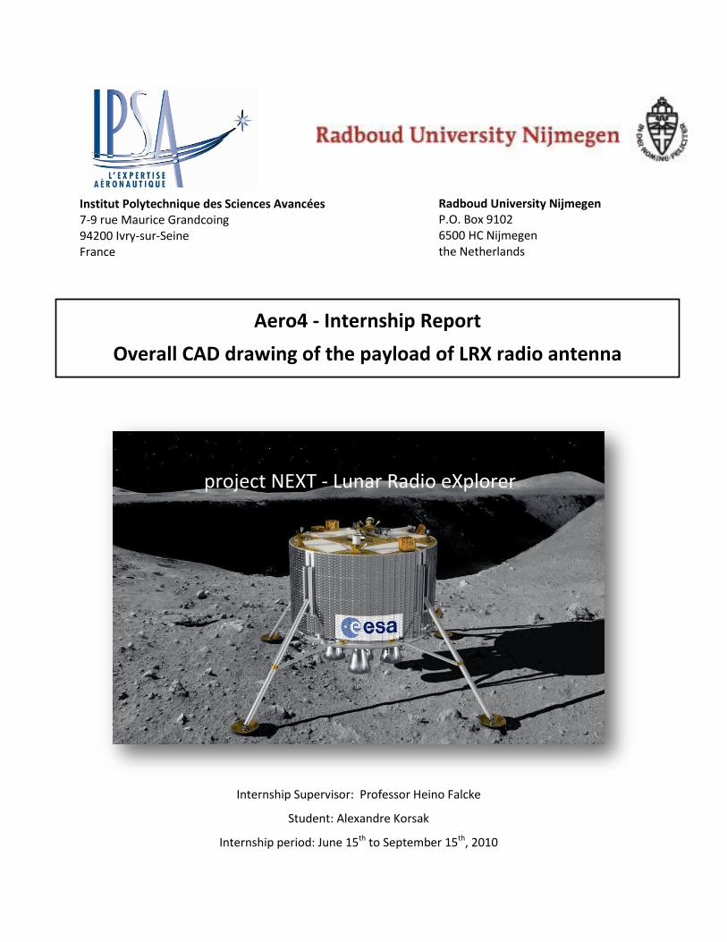
Figure 1
Lunar Radio Explorer 1
Institut Polytechnique des Sciences Avancées 7‐9 rue Maurice Grandcoing 94200 Ivry‐sur‐Seine France
Radboud University Nijmegen P.O. Box 9102 6500 HC Nijmegen the Netherlands
Aero4 ‐ Internship Report
Overall CAD drawing of the payload of LRX radio antenna
Internship Supervisor: Professor Heino Falcke
Student: Alexandre Korsak
Internship period: June 15th to September 15th, 2010
project NEXT ‐ Lunar Radio eXplorer

2 ESA NEXT Lunar Lander ‐ payload of LRX radio antenna
Table of Contents
1. Acknowledgements ‐‐‐‐‐‐‐‐‐‐‐‐‐‐‐‐‐‐‐‐‐‐‐‐‐‐‐‐‐‐‐‐‐‐‐‐‐‐‐‐‐‐‐‐‐‐‐‐‐‐‐‐‐‐‐‐‐‐‐‐‐‐‐‐‐‐‐‐‐‐‐‐‐‐‐‐‐‐‐‐‐‐‐‐‐‐‐‐‐‐‐‐‐‐‐ 3
2. Technical Summary ‐‐‐‐‐‐‐‐‐‐‐‐‐‐‐‐‐‐‐‐‐‐‐‐‐‐‐‐‐‐‐‐‐‐‐‐‐‐‐‐‐‐‐‐‐‐‐‐‐‐‐‐‐‐‐‐‐‐‐‐‐‐‐‐‐‐‐‐‐‐‐‐‐‐‐‐‐‐‐‐‐‐‐‐‐‐‐‐‐‐‐‐‐‐‐ 4
3. Introduction ‐‐‐‐‐‐‐‐‐‐‐‐‐‐‐‐‐‐‐‐‐‐‐‐‐‐‐‐‐‐‐‐‐‐‐‐‐‐‐‐‐‐‐‐‐‐‐‐‐‐‐‐‐‐‐‐‐‐‐‐‐‐‐‐‐‐‐‐‐‐‐‐‐‐‐‐‐‐‐‐‐‐‐‐‐‐‐‐‐‐‐‐‐‐‐‐‐‐‐‐‐‐‐‐ 6
4. Our work ‐‐‐‐‐‐‐‐‐‐‐‐‐‐‐‐‐‐‐‐‐‐‐‐‐‐‐‐‐‐‐‐‐‐‐‐‐‐‐‐‐‐‐‐‐‐‐‐‐‐‐‐‐‐‐‐‐‐‐‐‐‐‐‐‐‐‐‐‐‐‐‐‐‐‐‐‐‐‐‐‐‐‐‐‐‐‐‐‐‐‐‐‐‐‐‐‐‐‐‐‐‐‐‐‐‐‐ 12
4.1. Requirements ‐‐‐‐‐‐‐‐‐‐‐‐‐‐‐‐‐‐‐‐‐‐‐‐‐‐‐‐‐‐‐‐‐‐‐‐‐‐‐‐‐‐‐‐‐‐‐‐‐‐‐‐‐‐‐‐‐‐‐‐‐‐‐‐‐‐‐‐‐‐‐‐‐‐‐‐‐‐‐‐‐‐‐‐‐‐‐‐‐‐‐‐‐‐‐‐‐‐‐ 12
4.1.1. Technical Specifications ‐‐‐‐‐‐‐‐‐‐‐‐‐‐‐‐‐‐‐‐‐‐‐‐‐‐‐‐‐‐‐‐‐‐‐‐‐‐‐‐‐‐‐‐‐‐‐‐‐‐‐‐‐‐‐‐‐‐‐‐‐‐‐‐‐‐‐‐‐‐‐‐‐‐‐‐‐‐‐‐‐‐‐ 12
4.1.2. Environmental specifications ‐‐‐‐‐‐‐‐‐‐‐‐‐‐‐‐‐‐‐‐‐‐‐‐‐‐‐‐‐‐‐‐‐‐‐‐‐‐‐‐‐‐‐‐‐‐‐‐‐‐‐‐‐‐‐‐‐‐‐‐‐‐‐‐‐‐‐‐‐‐‐‐‐‐‐‐ 13
4.2. What has been already proposed? ‐‐‐‐‐‐‐‐‐‐‐‐‐‐‐‐‐‐‐‐‐‐‐‐‐‐‐‐‐‐‐‐‐‐‐‐‐‐‐‐‐‐‐‐‐‐‐‐‐‐‐‐‐‐‐‐‐‐‐‐‐‐‐‐‐‐‐‐‐‐‐‐ 14
4.2.1. Small folded strips ‐‐‐‐‐‐‐‐‐‐‐‐‐‐‐‐‐‐‐‐‐‐‐‐‐‐‐‐‐‐‐‐‐‐‐‐‐‐‐‐‐‐‐‐‐‐‐‐‐‐‐‐‐‐‐‐‐‐‐‐‐‐‐‐‐‐‐‐‐‐‐‐‐‐‐‐‐‐‐‐‐‐‐‐‐‐‐‐‐‐ 14
4.2.2. Umbrella‐‐‐‐‐‐‐‐‐‐‐‐‐‐‐‐‐‐‐‐‐‐‐‐‐‐‐‐‐‐‐‐‐‐‐‐‐‐‐‐‐‐‐‐‐‐‐‐‐‐‐‐‐‐‐‐‐‐‐‐‐‐‐‐‐‐‐‐‐‐‐‐‐‐‐‐‐‐‐‐‐‐‐‐‐‐‐‐‐‐‐‐‐‐‐‐‐‐‐‐‐‐‐ 15
4.2.3. Mobile joints ‐‐‐‐‐‐‐‐‐‐‐‐‐‐‐‐‐‐‐‐‐‐‐‐‐‐‐‐‐‐‐‐‐‐‐‐‐‐‐‐‐‐‐‐‐‐‐‐‐‐‐‐‐‐‐‐‐‐‐‐‐‐‐‐‐‐‐‐‐‐‐‐‐‐‐‐‐‐‐‐‐‐‐‐‐‐‐‐‐‐‐‐‐‐‐‐‐ 16
4.2.4. Tape‐measure ‐‐‐‐‐‐‐‐‐‐‐‐‐‐‐‐‐‐‐‐‐‐‐‐‐‐‐‐‐‐‐‐‐‐‐‐‐‐‐‐‐‐‐‐‐‐‐‐‐‐‐‐‐‐‐‐‐‐‐‐‐‐‐‐‐‐‐‐‐‐‐‐‐‐‐‐‐‐‐‐‐‐‐‐‐‐‐‐‐‐‐‐‐‐‐‐ 17
5. The Tape‐measure design ‐‐‐‐‐‐‐‐‐‐‐‐‐‐‐‐‐‐‐‐‐‐‐‐‐‐‐‐‐‐‐‐‐‐‐‐‐‐‐‐‐‐‐‐‐‐‐‐‐‐‐‐‐‐‐‐‐‐‐‐‐‐‐‐‐‐‐‐‐‐‐‐‐‐‐‐‐‐‐‐‐‐‐‐‐‐ 18
5.1. Advantages / Disadvantages ‐‐‐‐‐‐‐‐‐‐‐‐‐‐‐‐‐‐‐‐‐‐‐‐‐‐‐‐‐‐‐‐‐‐‐‐‐‐‐‐‐‐‐‐‐‐‐‐‐‐‐‐‐‐‐‐‐‐‐‐‐‐‐‐‐‐‐‐‐‐‐‐‐‐‐‐‐‐‐ 18
5.2. Why ball bearings? ‐‐‐‐‐‐‐‐‐‐‐‐‐‐‐‐‐‐‐‐‐‐‐‐‐‐‐‐‐‐‐‐‐‐‐‐‐‐‐‐‐‐‐‐‐‐‐‐‐‐‐‐‐‐‐‐‐‐‐‐‐‐‐‐‐‐‐‐‐‐‐‐‐‐‐‐‐‐‐‐‐‐‐‐‐‐‐‐‐‐‐‐ 19
5.3. Positioning the rolls ‐‐‐‐‐‐‐‐‐‐‐‐‐‐‐‐‐‐‐‐‐‐‐‐‐‐‐‐‐‐‐‐‐‐‐‐‐‐‐‐‐‐‐‐‐‐‐‐‐‐‐‐‐‐‐‐‐‐‐‐‐‐‐‐‐‐‐‐‐‐‐‐‐‐‐‐‐‐‐‐‐‐‐‐‐‐‐‐‐‐‐ 20
5.4. Antenna’s Structure ‐‐‐‐‐‐‐‐‐‐‐‐‐‐‐‐‐‐‐‐‐‐‐‐‐‐‐‐‐‐‐‐‐‐‐‐‐‐‐‐‐‐‐‐‐‐‐‐‐‐‐‐‐‐‐‐‐‐‐‐‐‐‐‐‐‐‐‐‐‐‐‐‐‐‐‐‐‐‐‐‐‐‐‐‐‐‐‐‐‐‐ 24
5.5. Entire Model ‐‐‐‐‐‐‐‐‐‐‐‐‐‐‐‐‐‐‐‐‐‐‐‐‐‐‐‐‐‐‐‐‐‐‐‐‐‐‐‐‐‐‐‐‐‐‐‐‐‐‐‐‐‐‐‐‐‐‐‐‐‐‐‐‐‐‐‐‐‐‐‐‐‐‐‐‐‐‐‐‐‐‐‐‐‐‐‐‐‐‐‐‐‐‐‐‐‐‐‐ 26
5.6. Actuators ‐‐‐‐‐‐‐‐‐‐‐‐‐‐‐‐‐‐‐‐‐‐‐‐‐‐‐‐‐‐‐‐‐‐‐‐‐‐‐‐‐‐‐‐‐‐‐‐‐‐‐‐‐‐‐‐‐‐‐‐‐‐‐‐‐‐‐‐‐‐‐‐‐‐‐‐‐‐‐‐‐‐‐‐‐‐‐‐‐‐‐‐‐‐‐‐‐‐‐‐‐‐‐‐ 29
5.6.1. Magnetic actuator ‐‐‐‐‐‐‐‐‐‐‐‐‐‐‐‐‐‐‐‐‐‐‐‐‐‐‐‐‐‐‐‐‐‐‐‐‐‐‐‐‐‐‐‐‐‐‐‐‐‐‐‐‐‐‐‐‐‐‐‐‐‐‐‐‐‐‐‐‐‐‐‐‐‐‐‐‐‐‐‐‐‐‐‐‐‐‐‐‐‐ 29
5.6.2. Melting wire actuator ‐‐‐‐‐‐‐‐‐‐‐‐‐‐‐‐‐‐‐‐‐‐‐‐‐‐‐‐‐‐‐‐‐‐‐‐‐‐‐‐‐‐‐‐‐‐‐‐‐‐‐‐‐‐‐‐‐‐‐‐‐‐‐‐‐‐‐‐‐‐‐‐‐‐‐‐‐‐‐‐‐‐‐‐‐‐ 30
5.7. Connection to Antenna ‐‐‐‐‐‐‐‐‐‐‐‐‐‐‐‐‐‐‐‐‐‐‐‐‐‐‐‐‐‐‐‐‐‐‐‐‐‐‐‐‐‐‐‐‐‐‐‐‐‐‐‐‐‐‐‐‐‐‐‐‐‐‐‐‐‐‐‐‐‐‐‐‐‐‐‐‐‐‐‐‐‐‐‐‐‐‐ 31
5.8. Materials‐‐‐‐‐‐‐‐‐‐‐‐‐‐‐‐‐‐‐‐‐‐‐‐‐‐‐‐‐‐‐‐‐‐‐‐‐‐‐‐‐‐‐‐‐‐‐‐‐‐‐‐‐‐‐‐‐‐‐‐‐‐‐‐‐‐‐‐‐‐‐‐‐‐‐‐‐‐‐‐‐‐‐‐‐‐‐‐‐‐‐‐‐‐‐‐‐‐‐‐‐‐‐‐‐ 33
6. New possible design ‐‐‐‐‐‐‐‐‐‐‐‐‐‐‐‐‐‐‐‐‐‐‐‐‐‐‐‐‐‐‐‐‐‐‐‐‐‐‐‐‐‐‐‐‐‐‐‐‐‐‐‐‐‐‐‐‐‐‐‐‐‐‐‐‐‐‐‐‐‐‐‐‐‐‐‐‐‐‐‐‐‐‐‐‐‐‐‐‐‐‐‐‐ 35
7. Conclusions and Future work‐‐‐‐‐‐‐‐‐‐‐‐‐‐‐‐‐‐‐‐‐‐‐‐‐‐‐‐‐‐‐‐‐‐‐‐‐‐‐‐‐‐‐‐‐‐‐‐‐‐‐‐‐‐‐‐‐‐‐‐‐‐‐‐‐‐‐‐‐‐‐‐‐‐‐‐‐‐‐‐‐‐ 37
8. References ‐‐‐‐‐‐‐‐‐‐‐‐‐‐‐‐‐‐‐‐‐‐‐‐‐‐‐‐‐‐‐‐‐‐‐‐‐‐‐‐‐‐‐‐‐‐‐‐‐‐‐‐‐‐‐‐‐‐‐‐‐‐‐‐‐‐‐‐‐‐‐‐‐‐‐‐‐‐‐‐‐‐‐‐‐‐‐‐‐‐‐‐‐‐‐‐‐‐‐‐‐‐‐‐‐ 38
9. Appendixes ‐‐‐‐‐‐‐‐‐‐‐‐‐‐‐‐‐‐‐‐‐‐‐‐‐‐‐‐‐‐‐‐‐‐‐‐‐‐‐‐‐‐‐‐‐‐‐‐‐‐‐‐‐‐‐‐‐‐‐‐‐‐‐‐‐‐‐‐‐‐‐‐‐‐‐‐‐‐‐‐‐‐‐‐‐‐‐‐‐‐‐‐‐‐‐‐‐‐‐‐‐‐‐‐ 39
9.1. Glossary ‐‐‐‐‐‐‐‐‐‐‐‐‐‐‐‐‐‐‐‐‐‐‐‐‐‐‐‐‐‐‐‐‐‐‐‐‐‐‐‐‐‐‐‐‐‐‐‐‐‐‐‐‐‐‐‐‐‐‐‐‐‐‐‐‐‐‐‐‐‐‐‐‐‐‐‐‐‐‐‐‐‐‐‐‐‐‐‐‐‐‐‐‐‐‐‐‐‐‐‐‐‐‐‐‐‐ 39
9.2. Appendixes ‐‐‐‐‐‐‐‐‐‐‐‐‐‐‐‐‐‐‐‐‐‐‐‐‐‐‐‐‐‐‐‐‐‐‐‐‐‐‐‐‐‐‐‐‐‐‐‐‐‐‐‐‐‐‐‐‐‐‐‐‐‐‐‐‐‐‐‐‐‐‐‐‐‐‐‐‐‐‐‐‐‐‐‐‐‐‐‐‐‐‐‐‐‐‐‐‐‐‐‐‐‐ 40

3 ESA NEXT Lunar Lander ‐ payload of LRX radio antenna
1. Acknowledgements
I would like to acknowledge and to thank the people in Radboud University from the Department of Astrophysics and the Technical Department for their strong support and assistance during my internship.
I would like to thank Professor Heino Falke, who leads researches on LOFAR Telescope and Astronomy from the Moon. He had the kindness to accept me into his group and let me work with autonomy on the LRX project.
Amin Aminaei, engineer working on LOFAR Telescope and detection of cosmic rays supervised me. His help during my entire internship period has been very useful to me.
Linjie Chen, PHD student, helped me to understand how LNAs works and how to integrate them.
Peter Dolron and Harrie van Brakel, from the Technical Department, helped us to build our first prototype in Nijmegen.
Esther Gebhardt, Cisca Custers and Daisy Maurits helped on paperwork and so many practical things.
Olivier Roussel, also intern from IPSA, with whom I had good teamwork. By mutually sharing some tasks, we could speed up and respect our internship’s deadline.
ESA and ESTEC, for the great opportunity they gave us and Radboud University with the NEXT initiative.
I especially want to thank the entire Astrophysics Department for its great welcoming and friendship during my internship.
I enjoyed a great stay in Nijmegen and was very pleased by their ecological initiatives. I’m proud to have participated to the 4 days walk around the city.
Hartelijk dank.
4 ESA NEXT Lunar Lander ‐ payload of LRX radio antenna
2. Technical Summary
Alexandre Korsak From 15/06/2010 to 15/09/2010
Main topic: Overall CAD drawing of LRX payload
Approached subject:
General mechanic
Material Resistance
CAD
Final Elements Method
Materials/ Alloys
Requirements:
‐ LRX is a six‐arm antenna of 1.25m each which will have to deploy on the moon
‐ Antenna Type: Tripole antenna (three crossed dipoles with x‐shaped orientation), crossed dipole halves can be switched off to make 3 monopoles to use the lander as dust detector ‐ LRX needs to be able to survive on Lunar environment and special constraints as well
‐ It have to be the lightest possible: 1.25 ‐ 1.5 kg for everything (strong upper limit, including margins) ‐ Needs to use less than 5‐10 W (10 W peak) ‐ Each arm need to bend less than 5 degrees
Acquired:
‐ Study of previous and already improved works ‐ Set up a list of possibilities ‐ Compare these possibilities and choose one: we will focus on the Tape‐measure design ‐ Materials resistance calculations in order to characterize constraints ‐ Actual trials and calibrate constraints ‐ Producing of a first prototype ‐ CAD drawing of a complete six antenna model ‐ Study of initials constraints ‐ Mass estimation: order of magnitude seems to be right
5 ESA NEXT Lunar Lander ‐ payload of LRX radio antenna
Next work:
‐ Tests on prototype: measure the stress constraints applied on the structure by the tape antenna, these measure will allow us to optimize the structure’s thickness ‐ Vacuum trials: in order to characterize local soldering phenomena ‐ Vibration trials: in order to make sure LRX system will not resonate during the take off and flight ‐ Study the possibility of a lightest structure ‐ Study the possibility of a structure without rolls.

6 ESA NEXT Lunar Lander ‐ payload of LRX radio antenna
3. Introduction
The Astronomy Department of Radboud University has been working on radio astronomy since years, and especially on low frequencies radio astronomy. They developed a large radio telescope working with interferometers called LOFAR. Its observations provide very useful information about astronomy and astrophysics (cosmic rays, particles showers and earth’s ionosphere).
Actually, radio astronomy in low frequencies is impossible from Earth’s ground, because of ionosphere diffraction and of human activities impacting in Low Earth Orbit. Here is why radio astronomy from outer space has been decided: the moon provides a wonderful shield against human low frequencies activities and allows us by the way to observe brand new unexplored frequencies.
In this context, ESA initiated multigenerational project named NEXT to send a lander with radio antennas on the Moon and on Mars. Professor Heino Falke and his team from Radboud University had proposed scenarios to ESA and sorted out pro& cons. In turn, ESA defined an overall scientific payload on NEXT lunar lander and a specific part was assigned to the Astronomy Department of Radboud University. That project is called LRX, and the radio antenna part is the focus of my internship.
The team in Radboud (cf. Acknowledgments) and the two Interns from IPSA started by purpose to investigate on any ideas and to check best practices that had been already tried by other missions. We started with a vision of multiple rovers that would spread away from the main lander to form a kind of LOFAR with simple antennas. A last minute constraint was to cope with budget limitations due to the current worldwide economical crisis. So we had to deal with the main lander only and think of a more complex antennas system that would spread away from the lander. The Tape‐measure design was chosen as a cornerstone and studied more thoroughly to form a deployable bundle.
In the end of study at Radboud University, ESA’s requirements seem to be fulfilled and a prototype was built for test purposes. It is unclear whether those tests can happen under current economical restrictions. More optimization is anyway still possible and due by ESA’s specialists.
7 ESA NEXT Lunar Lander ‐ payload of LRX radio antenna
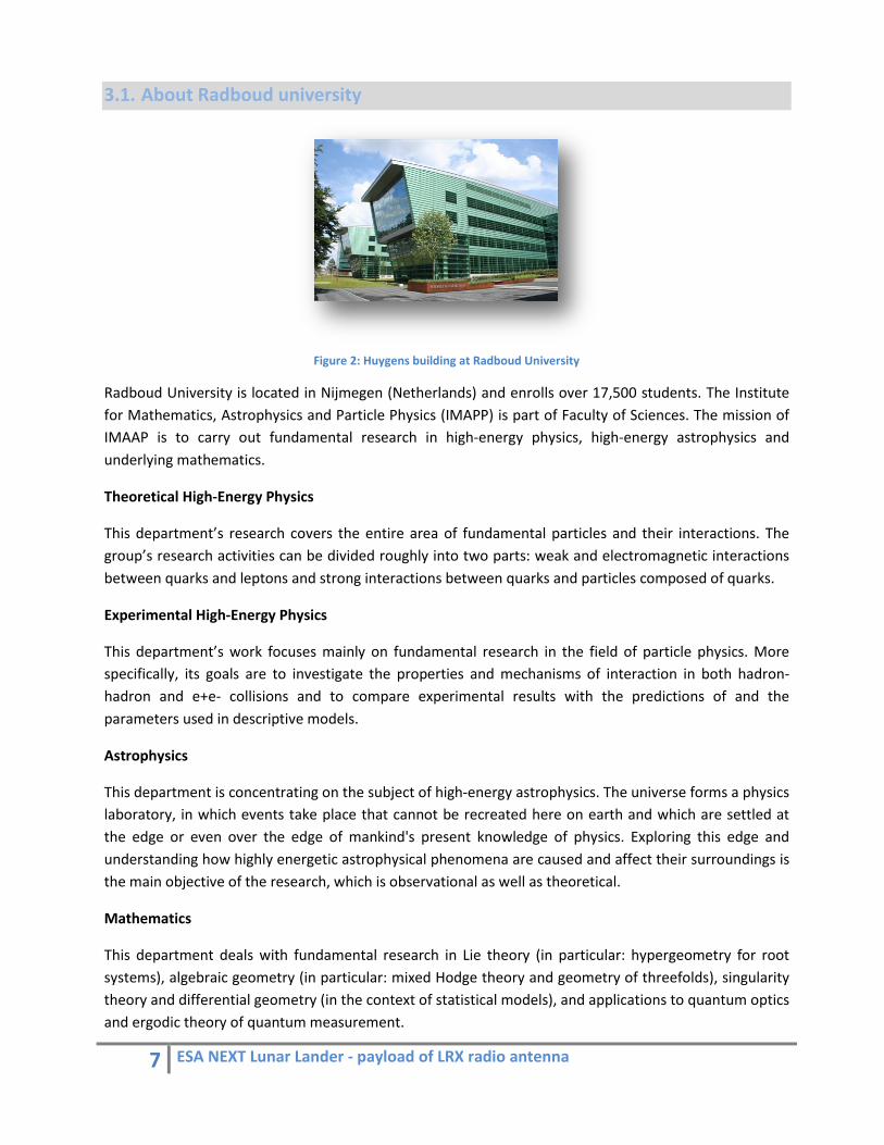
3.1. About Radboud university
Figure 2: Huygens building at Radboud University
Radboud University is located in Nijmegen (Netherlands) and enrolls over 17,500 students. The Institute for Mathematics, Astrophysics and Particle Physics (IMAPP) is part of Faculty of Sciences. The mission of IMAAP is to carry out fundamental research in high‐energy physics, high‐energy astrophysics and underlying mathematics.
Theoretical High‐Energy Physics
This department’s research covers the entire area of fundamental particles and their interactions. The group’s research activities can be divided roughly into two parts: weak and electromagnetic interactions between quarks and leptons and strong interactions between quarks and particles composed of quarks.
Experimental High‐Energy Physics
This department’s work focuses mainly on fundamental research in the field of particle physics. More specifically, its goals are to investigate the properties and mechanisms of interaction in both hadron‐hadron and e+e‐ collisions and to compare experimental results with the predictions of and the parameters used in descriptive models.
Astrophysics
This department is concentrating on the subject of high‐energy astrophysics. The universe forms a physics laboratory, in which events take place that cannot be recreated here on earth and which are settled at the edge or even over the edge of mankind's present knowledge of physics. Exploring this edge and understanding how highly energetic astrophysical phenomena are caused and affect their surroundings is the main objective of the research, which is observational as well as theoretical.
Mathematics
This department deals with fundamental research in Lie theory (in particular: hypergeometry for root systems), algebraic geometry (in particular: mixed Hodge theory and geometry of threefolds), singularity theory and differential geometry (in the context of statistical models), and applications to quantum optics and ergodic theory of quantum measurement.
8 ESA NEXT Lunar Lander ‐ payload of LRX radio antenna
3.2. About NEXT Lunar Lander Mission
The NEXT initiative first goal is to preparing ESA participation in future human exploration.
It will help ESA to develop technologies, increase knowledge about spacecraft and human spaceflight and gain experience as well.
The European Space Agency’s Next Exploration Science and Technology Mission (NEXT) is intended to fill a gap in ESA’s planetary exploration activities between ExoMars (due for launch in 2013) and Mars Sample Return (MSR is envisaged for the 2020 timeframe).
NEXT must demonstrate key technologies for MSR and other future exploration missions, while also performing important scientific investigations. After an internal review process, ESA has now selected two proposed NEXT mission concepts for Phase A study – Mars‐NEXT, which would perform activities at Mars, and Moon‐NEXT, which would land a scientific payload near the South Pole of the Moon.
Following the results of these studies, one concept will be selected for implementation.
Here we report on the scientific, technological and exploration‐related rationale for Moon‐NEXT.
The principal mission objectives of Moon‐NEXT are as follows:
• demonstrate precision soft‐landing and hazard avoidance technologies required for MSR and future exploration missions;
• prepare for future lunar exploration activities by characterizing the lunar surface environment and performing relevant life science investigations;
• advance our understanding of the origin, structure and evolution of the Moon by performing a range of geophysical and geochemical investigations; and
• assess the value of the lunar surface as a site for performing science from the Moon, using radio astronomy as an example.
The precise scientific payload, and its distribution between lander and rover, is still to be decided. However, the science and exploration goals described below will necessitate at least the following core instruments:
• Multispectral imaging system
• Broadband and short‐period seismometers
• Heatflow probe
• Alpha Particle X‐Ray Spectrometer (APXS)
• Dust and micrometeorite detector/analyzer
• Radiation detector
• Low frequency radio detectors (dipoles)
• Laser ranging retro‐reflector
• Life sciences experiment(s)
9 ESA NEXT Lunar Lander ‐ payload of LRX radio antenna
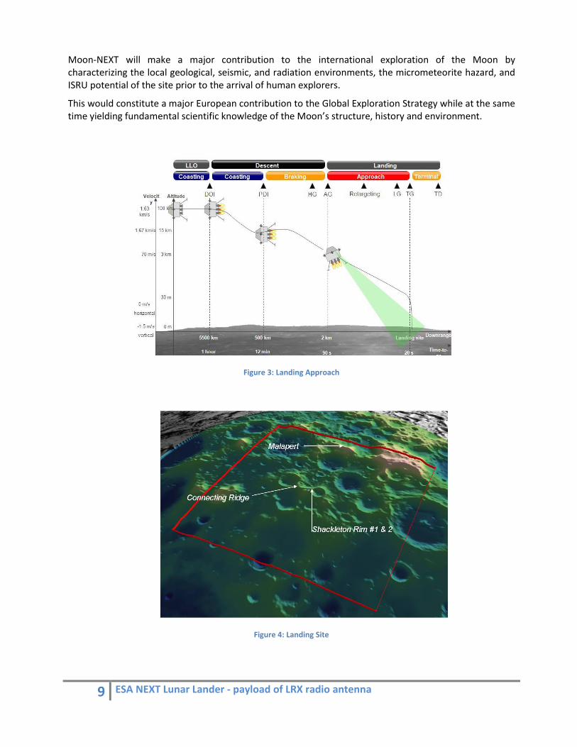
Moon‐NEXT will make a major contribution to the international exploration of the Moon by characterizing the local geological, seismic, and radiation environments, the micrometeorite hazard, and ISRU potential of the site prior to the arrival of human explorers.
This would constitute a major European contribution to the Global Exploration Strategy while at the same time yielding fundamental scientific knowledge of the Moon’s structure, history and environment.
Figure 3: Landing Approach
Figure 4: Landing Site
10 ESA NEXT Lunar Lander ‐ payload of LRX radio antenna
3.3. LRX and Radio astronomy
LRX is a multipurpose‐instrument which will support the objective “to characterize the lunar environment” using radio measurements. It will address a wide range of topics relevant for moon related science and exploration, such as measuring cosmic ray flux, micrometeorites & dust impacts, regolith structures, and the lunar ionosphere. It will also demonstrate for the first time radio interferometry on the moon and thus connect to the theme to “exploit the moon as a base for further research”, e.g., in preparation of future radio telescopes. Finally, it is directly related to the objective to “advance European surface operation capabilities” by deploying and operating a distributed lunar surface installation.
Working principle
The Lunar Radio Explorer is a superset of a range of radio‐related payloads proposed by various groups in Europe. It consists of three broad‐band low‐frequency radio antennas: one on the lander, one on a rover, and one to be deployed on the lunar surface. In addition the antennas are combined with Langmuir probes to measure the electric field. They will measure temporal variations of the plasma density, derived plasma parameters such as temperature, and the electric field near the lunar surface that causes, e.g. dust levitation. The three radio antennas will independently from each other monitor the spectral and temporal radio noise on the lunar surface as well as operate together to form a true radio interferometer. Each antenna receives, digitizes, and processes radio waves independently. Moreover, using a two‐way (RF) data link, the antennas are also time synchronized and the data is transmitted to the lander, where the radio signals are cross‐correlated and integrated. The integrated signal is transmitted to Earth for further processing. Individually the antennas will be able to detect impulsive radio signals from cosmic rays and search for radio signals from micrometeorites. Spectral measurements of strong radio sources (Sun & Jupiter) will allow measuring radio attenuation through the moon surface and the effects of the lunar ionosphere. Together with large existing earth‐based low‐frequency radar transmitter it can also operate as ground penetrating radar (GPR). In interferometric mode, the lunar ionosphere can be measured using the relative phase of radio waves. The impact location of radio pulse events can be determined using triangulation. Finally, the correlated data will be used to make the first radio‐interferometric measurements of the low‐frequency radio sky below 10 MHz and demonstrate the feasibility of operating a radio telescope on the moon. The radio receiver will operate in the frequency range of 0.1‐100 MHz (optimized for 1‐10 MHz). The spectral resolution would be 1024 frequency channels. To optimize the operational use of the antennas they will use hybrid receivers that consist of a low power sweep receiver for radio background measurements in
11 ESA NEXT Lunar Lander ‐ payload of LRX radio antenna
quasi‐stand‐by‐mode and a broadband digital receiver for high‐throughput and hightime‐resolution measurements and interferometry.
The LRX would serve a broad user community of radio scientists, planetary scientists, and astrophysicists, preparing them for moon exploration. It will do the first in‐depth investigation of the radio background noise on the lunar surface. This is not only of relevance for radio surface communication but also allows one to study a broad range of radio phenomena, which have not yet been detected on a planetary surface so far. As such it seeks to test and develop a number of novel methods to investigate the local environment related to meteorite and CR impacts, dust levitation, plasma properties, electric fields, and underground properties, which are of high relevance to human exploration. Finally, LRX would be the first operating radio telescope on the lunar surface and therefore open the way for a future exploitation of the moon as a platform for scientific experiments, providing some highly visible scientific output.
12 ESA NEXT Lunar Lander ‐ payload of LRX radio antenna
4. Our work
4.1. Requirements
4.1.1. Technical Specifications
The main limitation here is the power budget and it was optimistically assumed that up to 10 W power would be provided. The following specifications were set: Mass: 1.25 ‐ 1.5 kg for everything (strong upper limit, including margins)
Power: 5‐10 W (10 W peak)
Antenna Type: Tripole antenna (three crossed dipoles with x‐shaped orientation), crossed dipole halves can be switched off to make 3 monopoles to use the lander as dust detector
Dimensions: 2.5 m arm length (i.e. 1.25 half‐arm lengths)
Analog Electronics: 3‐4 switchable sets of filters, LNAs, and pre‐amps
Digital Processing: Store data for the time when the Earth is not in sight (isn’t that a feature that the lander should provide?)
Antenna Deployment: Self‐unfolding metal foils, investigate possibility to “eject” antenna from the lander Lifetime: 1 year
Other Notes: There may be an additional 3m boom of the Langmuir probe dust experiment that contains at least a wire and would affect reception
Work packages: ‐ Antenna design and simulation ‐ Antenna deployment ‐ Investigate light‐weight outrigger antenna (100g to be deployed by a minirover or spring‐mechanism) for interferometry tests
13 ESA NEXT Lunar Lander ‐ payload of LRX radio antenna
4.1.2. Environmental specifications
Space Vacuum
As this mission will be on the Moon and the orbit will go higher than 350km, external pressure is lower than 10#$MBar.
This vacuum has a lot of consequences on the spacecraft:
‐ Thermal: vacuum means lakes of gas, or heat convection is possible only if there is some gas Pressure under what we consider convection is insignificant is 1.33 x 10#%MBar, which is our case.
‐ Degassing: A component is degassing when its steam tension is higher than environment’s pressure. The gas resulting from this phenomenon can condense of colder part of the spacecraft. This phenomenon is very critical for every optical instrument.
‐ Local soldering: Two soluble materials contacting in a vacuum environment can solder to each other. This phenomenon is caused by the lack of gas. Actually, on Earth, Air is acting like a lubricant between these two surfaces and avoids this phenomenon. This problem needs to be taken into account and some surface treatment will probably be needed.
Micro‐gravity
Gravity on Moon is very lower than on Earth but is still enough to provide important stress on the structure, it needs to be taken into account in every part sizing.
Radiations
There are two main kinds of radiations:
‐ Corpuscular radiations, which are caused by protons, electrons and heavy ions. These particles have a very high kinetic energy and can ionizing. Then, they can damage surfaces and semiconductors. So, it is very important to prevent electronic from theses radiations with some armor plate.
‐ Electromagnetic radiations: visible and infra‐red radiations have a huge effect of the thermal balance and needs to be taken into account. Ultraviolet rays can damage surfaces (especially polymers) and Gamma and X‐Rays can cause troubles in electronic components and needs to be prevented from with armor and redundancy.
14 ESA NEXT Lunar Lander ‐ payload of LRX radio antenna
4.2. What has been already proposed?
4.2.1. Small folded strips
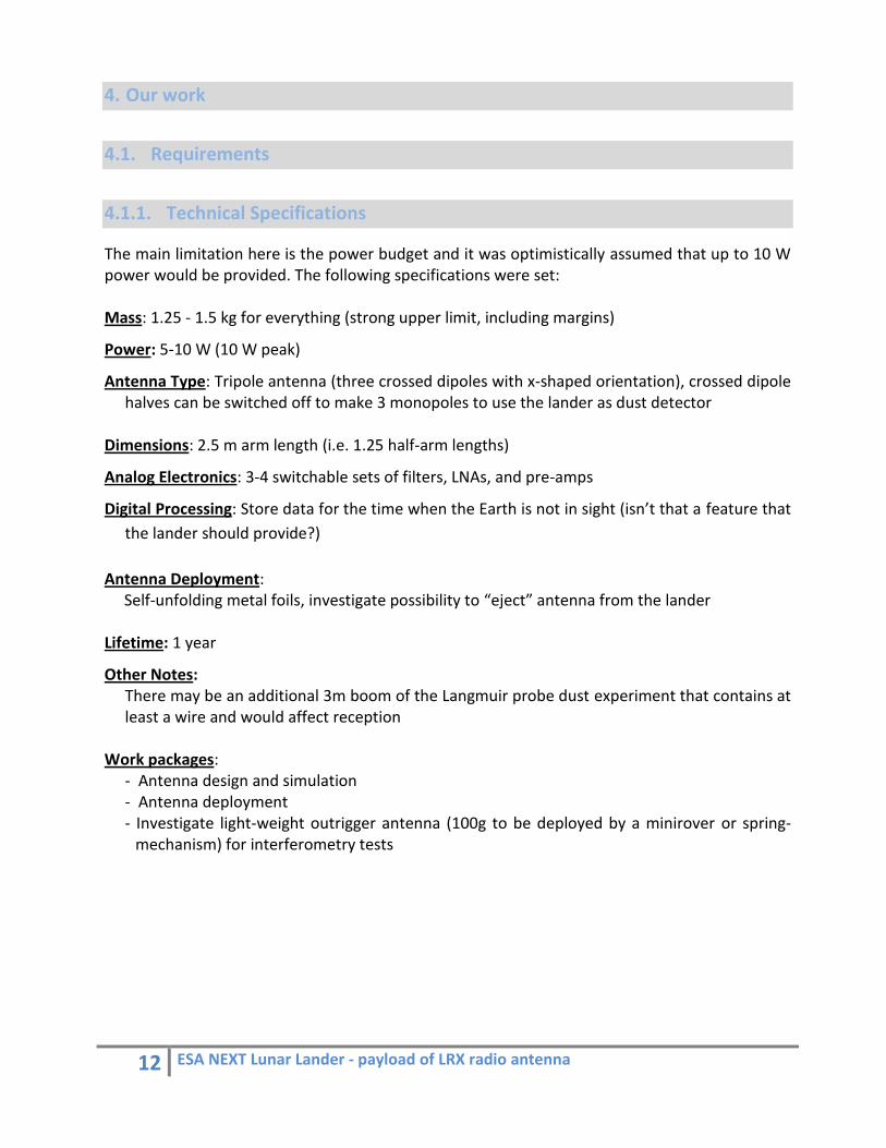
Figure 5: CAD view in stowed configuration
This design consists in simple metallic strips with rectangular section, bent along the side of the boom.
The best advantage of this design is the low mass due to the absence of any mechanical system. Then the energy needed for deployment is only contained in the elastic energy of these folded strips.
However the deployment needs to be controlled and we must make sure that this deployment won’t cause any damage to other equipments of the Lander.
So we have to make sure that these strips will stay folded until we decide that they can deploy. This means that we have to wait for the Lander to be in position, the Boom to be out, and wait long enough to make sure everything is motionless. This function can be provided by many ways which are detailed in the Actuators section. But we can assume that a Nylon wire/Thermal knife system would be the best solution in this case.
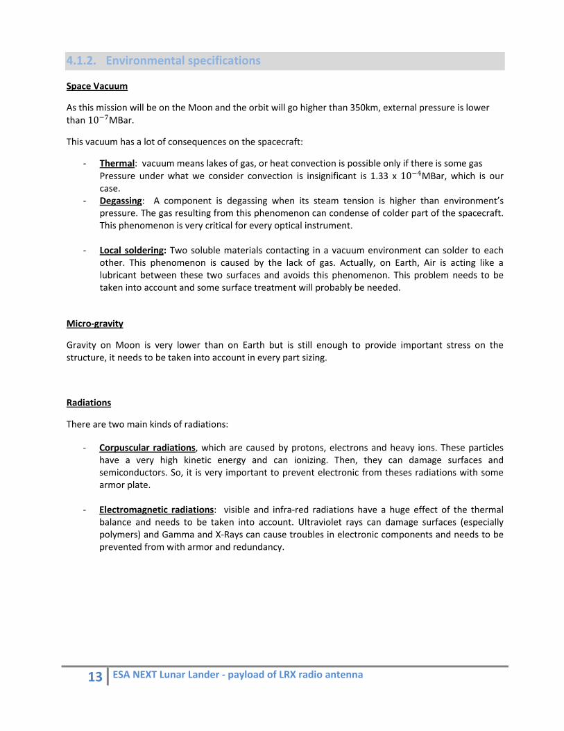
Amongst the drawbacks of this design is relatively uncontrollable and unpredictable kinetic energy dissipated during the deployment. As it could cause a mass surplus in the boom’s structure, we need to strengthen the boom, in order to make sure it can bear theses transitional moves.
Figure 6: CAD view of both configurations: stowed and deployed
15 ESA NEXT Lunar Lander ‐ payload of LRX radio antenna
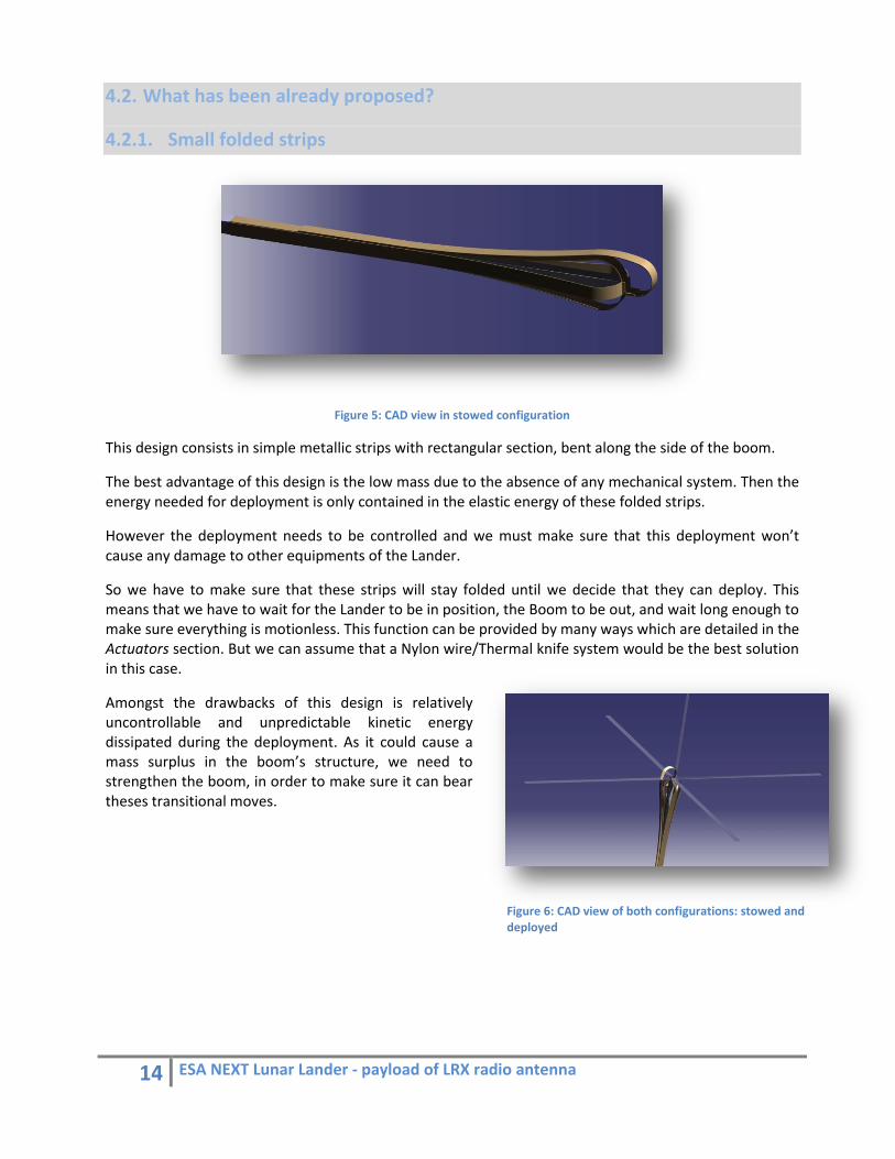
Moreover, this way of bending strips can cause resonance frequencies on the boom, close to those generated by the rocket during the take off. This problem is very serious and has to be checked with vibration tests.
In the end, for the same mass, the flexion of rectangular sections has very lower performances than of U‐sections.
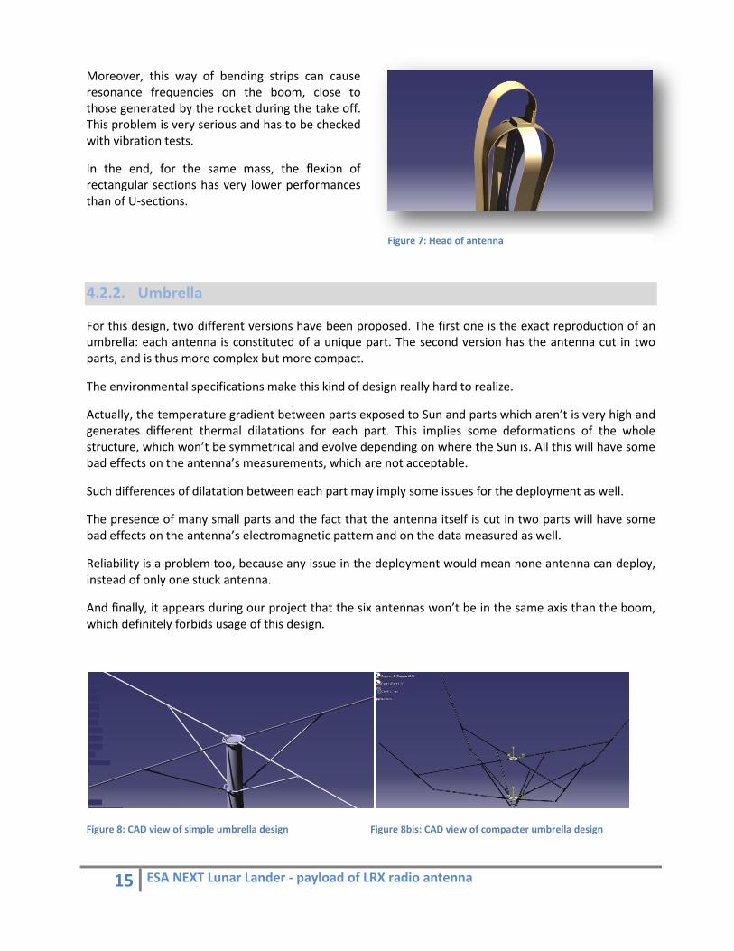
4.2.2. Umbrella
For this design, two different versions have been proposed. The first one is the exact reproduction of an umbrella: each antenna is constituted of a unique part. The second version has the antenna cut in two parts, and is thus more complex but more compact.
The environmental specifications make this kind of design really hard to realize.
Actually, the temperature gradient between parts exposed to Sun and parts which aren’t is very high and generates different thermal dilatations for each part. This implies some deformations of the whole structure, which won’t be symmetrical and evolve depending on where the Sun is. All this will have some bad effects on the antenna’s measurements, which are not acceptable.
Such differences of dilatation between each part may imply some issues for the deployment as well.
The presence of many small parts and the fact that the antenna itself is cut in two parts will have some bad effects on the antenna’s electromagnetic pattern and on the data measured as well.
Reliability is a problem too, because any issue in the deployment would mean none antenna can deploy, instead of only one stuck antenna.
And finally, it appears during our project that the six antennas won’t be in the same axis than the boom, which definitely forbids usage of this design.
Figure 8: CAD view of simple umbrella design Figure 8bis: CAD view of compacter umbrella design
Figure 7: Head of antenna
16 ESA NEXT Lunar Lander ‐ payload of LRX radio antenna
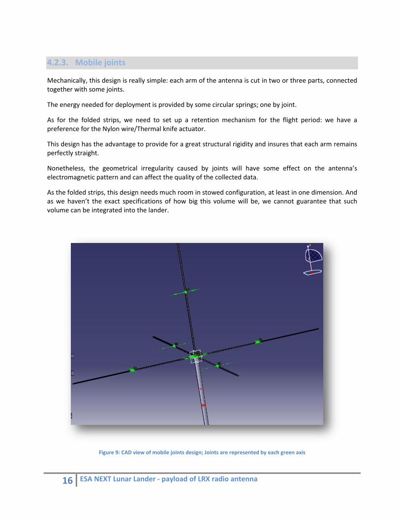
4.2.3. Mobile joints
Mechanically, this design is really simple: each arm of the antenna is cut in two or three parts, connected together with some joints.
The energy needed for deployment is provided by some circular springs; one by joint.
As for the folded strips, we need to set up a retention mechanism for the flight period: we have a preference for the Nylon wire/Thermal knife actuator.
This design has the advantage to provide for a great structural rigidity and insures that each arm remains perfectly straight.
Nonetheless, the geometrical irregularity caused by joints will have some effect on the antenna’s electromagnetic pattern and can affect the quality of the collected data.
As the folded strips, this design needs much room in stowed configuration, at least in one dimension. And as we haven’t the exact specifications of how big this volume will be, we cannot guarantee that such volume can be integrated into the lander.
Figure 9: CAD view of mobile joints design; Joints are represented by each green axis

17 ESA NEXT Lunar Lander ‐ payload of LRX radio antenna
4.2.4. Tape‐measure
This design is very close to actual tape‐measures that you can find in any store.
Each arm of the antenna is a very thin tape with U‐section that is wound around an axis. One of the antenna’s ends is built in this axis and provides then a reliable control of the deployment. Then, we have a linear relation between the revolution of this axis and the length of antenna which is already deployed.
This design has the advantage of using a very small room in stowed configuration and is modular: each arm is independent from each other.
Nonetheless, some mechanism is needed to manage the deployment and this implies a surplus of mass. That’s why this design cannot be the lightest one.
Additionally, a study of materials and section’s dimensions is needed to find the right compromise between mass and sag, which has to be less than 5 degrees.
Controlling deployment via the axis allows for a great choice about holding mechanisms and actuators.
Unfortunately, the fact that the antenna is wound around an axis implies that the whole antenna’s surfaces are in contact. We need to be very careful about local soldering phenomena, and some surface treatment is needed.
Figure 11: Complete six‐antenna system with Tape‐measure design
Figure 10: CAD view of simple umbrella design
18 ESA NEXT Lunar Lander ‐ payload of LRX radio antenna
5. The Tape‐measure design
5.1. Advantages / Disadvantages
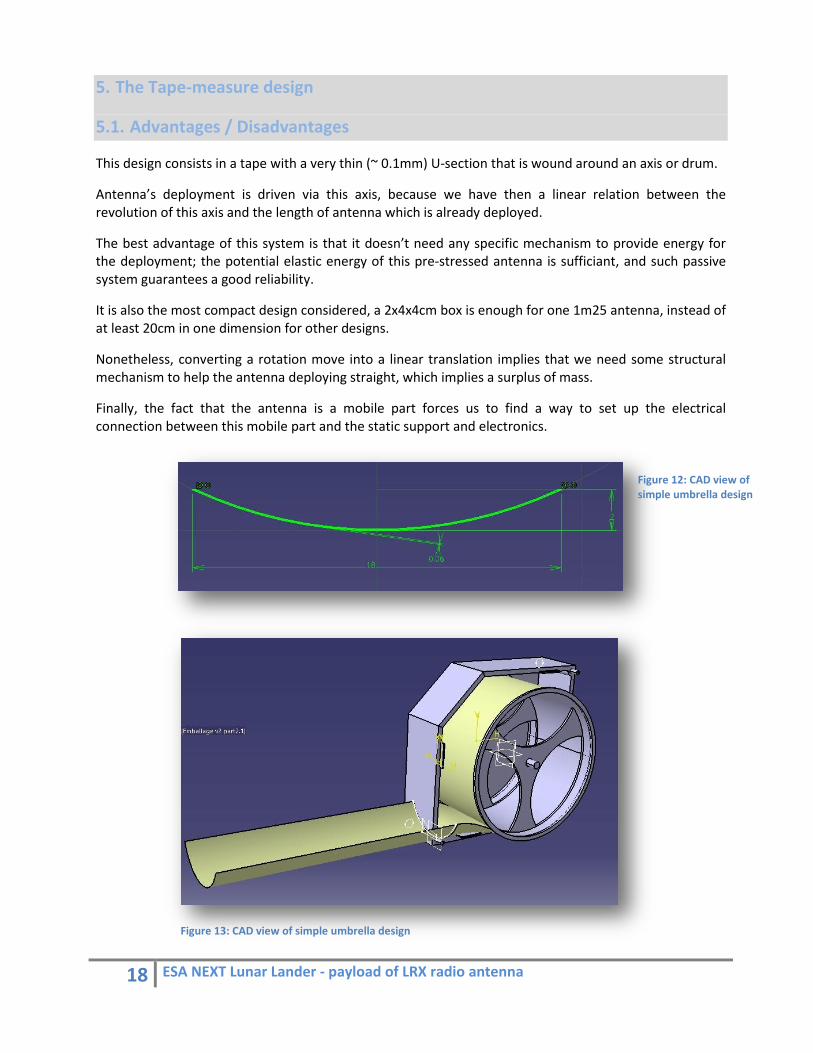
This design consists in a tape with a very thin (~ 0.1mm) U‐section that is wound around an axis or drum.
Antenna’s deployment is driven via this axis, because we have then a linear relation between the revolution of this axis and the length of antenna which is already deployed.
The best advantage of this system is that it doesn’t need any specific mechanism to provide energy for the deployment; the potential elastic energy of this pre‐stressed antenna is sufficiant, and such passive system guarantees a good reliability.
It is also the most compact design considered, a 2x4x4cm box is enough for one 1m25 antenna, instead of at least 20cm in one dimension for other designs.
Nonetheless, converting a rotation move into a linear translation implies that we need some structural mechanism to help the antenna deploying straight, which implies a surplus of mass.
Finally, the fact that the antenna is a mobile part forces us to find a way to set up the electrical connection between this mobile part and the static support and electronics.
Figure 12: CAD view of simple umbrella design
Figure 13: CAD view of simple umbrella design

19 ESA NEXT Lunar Lander ‐ payload of LRX radio antenna
5.2. Why ball bearings?
The first trials of our Tape‐measure prototype showed that it has stable and linear deployment at one condition: the friction which is slowing the mechanism down has to be below a very low limit value.
If some unexpected friction appears that slows the antenna’s deployment over limits, the only possible consequence is that the tape will show a tendency to go away from its guide and will deploy by following an easier way with less friction.
The consequence of this phenomenon will be:
‐ that the tape will stick to the intern side of this box, the contact surface between tape and other surfaces will be very high and the friction will increase as well; eventually it will distort and fold
‐ in the meantime, the central axis will continue to rotate until the antenna’s elastic energy is completely dissipated; then, even if there is no more friction, the antenna will not deploy anymore.
In the case of a terrestrial application, this problem could be solved easily by lubricating the main areas of frictions. But in the case of a space application, local soldering phenomena can cause an unexpected additional friction which makes us unable to guarantee that this stress would stay strictly below this limit value.
So, the only way to make sure this system will be reliable is not to try to avoid it, but to manage it.
This is why a circle of ball bearings has been set up around the wound tape.
Nonetheless, these ball bearings mean a surplus of masse; this is why we need to optimize the position and the quantity of these ball bearings in order to limit this surplus.
Figure 14: The tape ( in red ) is stuck on the intern side of the box ( in white )

20 ESA NEXT Lunar Lander ‐ payload of LRX radio antenna
5.3. Positioning the rolls The function of these ball bearings is to guarantee the good reliability of the antenna’s deployment.
Nonetheless, these ball bearings mean a surplus of mass that we need to limit by optimizing the positions and the quantity of rolls. The distance between each roll is the key parameter:
‐ If too short, it means more rolls to surround a complete circle, and more mass as well.
Figure 15: configuration with 9 rolls
‐ if too long, there is a risk that the tape get stuck between two rolls, what must not happen.
The quantity of rolls will be the result of a compromise between mass and reliability.
After trials and talks with people who were working on a similar concept (project V.O.Y Sat) on a Cubesat, the number of balls needed to surround the antenna has been set at 6.
But we just discovered at the end of this internship another work from Warsaw University dealing with similar problems too and which used only 4 rolls.
So, this parameter is still scalable and is function of the priority between mass and reliability.
Nonetheless, this circle of six rolls is enough to make sure the tape will not get stuck during its deployment, but we still need three more rolls to make sure that the tape will deploy exactly in the right direction and to prevent vibrations during its launch.
At the first look, we could think that only one roll would be enough to provide this function, but the antenna’s geometry is changing during the deployment.
Then, even if one roll is enough for some case, it won’t be for others.
Figure 16: configuration with 4 rolls
Figure 17: Final configuration
21 ESA NEXT Lunar Lander ‐ payload of LRX radio antenna
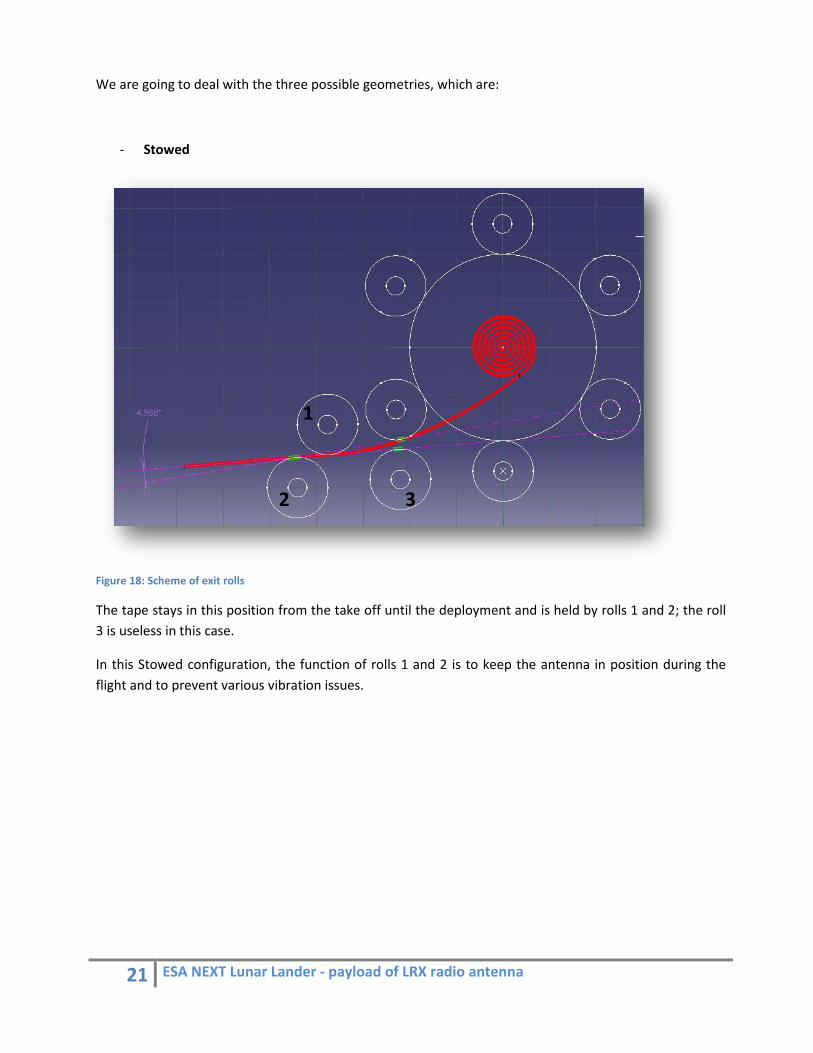
We are going to deal with the three possible geometries, which are:
‐ Stowed
Figure 18: Scheme of exit rolls
The tape stays in this position from the take off until the deployment and is held by rolls 1 and 2; the roll 3 is useless in this case.
In this Stowed configuration, the function of rolls 1 and 2 is to keep the antenna in position during the flight and to prevent various vibration issues.
1
2 3
22 ESA NEXT Lunar Lander ‐ payload of LRX radio antenna
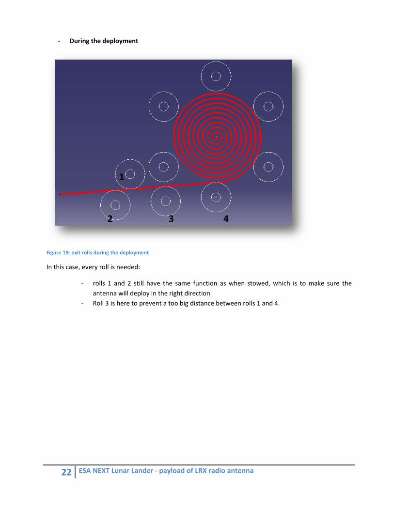
‐ During the deployment
Figure 19: exit rolls during the deployment
In this case, every roll is needed:
‐ rolls 1 and 2 still have the same function as when stowed, which is to make sure the antenna will deploy in the right direction
‐ Roll 3 is here to prevent a too big distance between rolls 1 and 4.
1
2 3 4

23 ESA NEXT Lunar Lander ‐ payload of LRX radio antenna
‐ After the deployment (final position)
Here, antenna is held by rolls 1,2 and 5. We could say that roll 1 is useless, because rolls 2 and 5 could be enough, but they are actually not.
If you remove roll 1, the antenna would go 5 degree lower, which is not acceptable
1 5
2 3 4
Figure 20: Exit rolls in final configuration
24 ESA NEXT Lunar Lander ‐ payload of LRX radio antenna
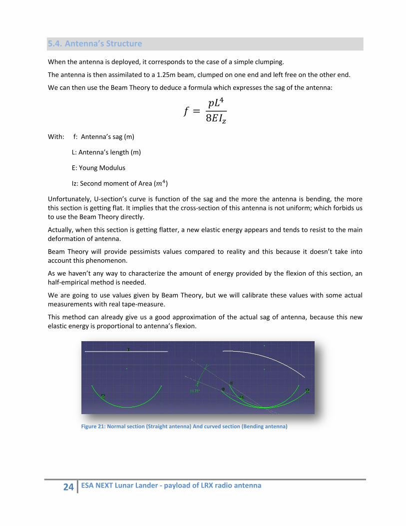
5.4. Antenna’s Structure
When the antenna is deployed, it corresponds to the case of a simple clumping.
The antenna is then assimilated to a 1.25m beam, clumped on one end and left free on the other end.
We can then use the Beam Theory to deduce a formula which expresses the sag of the antenna:
𝑓 = 𝑝𝐿%
8𝐸𝐼.
With: f: Antenna’s sag (m)
L: Antenna’s length (m)
E: Young Modulus
Iz: Second moment of Area (𝑚%)
Unfortunately, U‐section’s curve is function of the sag and the more the antenna is bending, the more this section is getting flat. It implies that the cross‐section of this antenna is not uniform; which forbids us to use the Beam Theory directly.
Actually, when this section is getting flatter, a new elastic energy appears and tends to resist to the main deformation of antenna.
Beam Theory will provide pessimists values compared to reality and this because it doesn’t take into account this phenomenon.
As we haven’t any way to characterize the amount of energy provided by the flexion of this section, an half‐empirical method is needed.
We are going to use values given by Beam Theory, but we will calibrate these values with some actual measurements with real tape‐measure.
This method can already give us a good approximation of the actual sag of antenna, because this new elastic energy is proportional to antenna’s flexion.
Figure 21: Normal section (Straight antenna) And curved section (Bending antenna)

25 ESA NEXT Lunar Lander ‐ payload of LRX radio antenna
In stowed configuration, the antenna is rolled around an axis and we need to know what the maximal curve radius is in order to set the right size of this axis.
This curve radius is function of the kind of material used and the thickness of its section.
So, we can express this formula: 𝑅 = 1.345
With: R: maximal curve radius (m)
E: Young modulus
Re: Yield Strength
h: Section’s thickness
Because the U‐section allows very thin parts, this maximum curve radius is not a problem and is generally very lower than the axis’ radius.
A Final Elements Analysis has also been run on this subject but through lack of a reliable enough software, we haven’t been able to characterize exactly the values which we were looking for.
However, we have still been able to confirm these values’ order of magnitude and the respect of associated requirements.
Figure 22: Final Elements Analysis of a tape antenna. Here, the end of antenna bend less than 1cm

26 ESA NEXT Lunar Lander ‐ payload of LRX radio antenna
5.5. Entire Model
The whole antenna comprises three dipoles following each axis (X, Y, Z). Each dipole is 2.5m long or 1.25m per arm.
This group is placed on the top of a 3m boom and makes an angle with this boom, which hasn’t been characterized yet; this is why an adjustable articulation is favored to link those two parts.
These 3 dipoles are active antennas, it means there will be some electronics which has to be located the closest possible. These electronics box are called LNA and we need one per dipole, so three for the whole system.
The whole system contains:
‐ one boom ‐ one adjustable articulation ‐ three LNAs ‐ six monopole antennas of 1.25m
According to this, several implementations are possible:
The Common Plane
Here, we started from a plane surface, onto which we set up room for the three LNAs.
Antennas are fixed on this plane, so we have four antennas which are in the same plane, and the last two are going vertically, one to the top, one to the down. This means we need to set up a hole to let this last antenna go down.
Figure 23: Complete common plane design
27 ESA NEXT Lunar Lander ‐ payload of LRX radio antenna
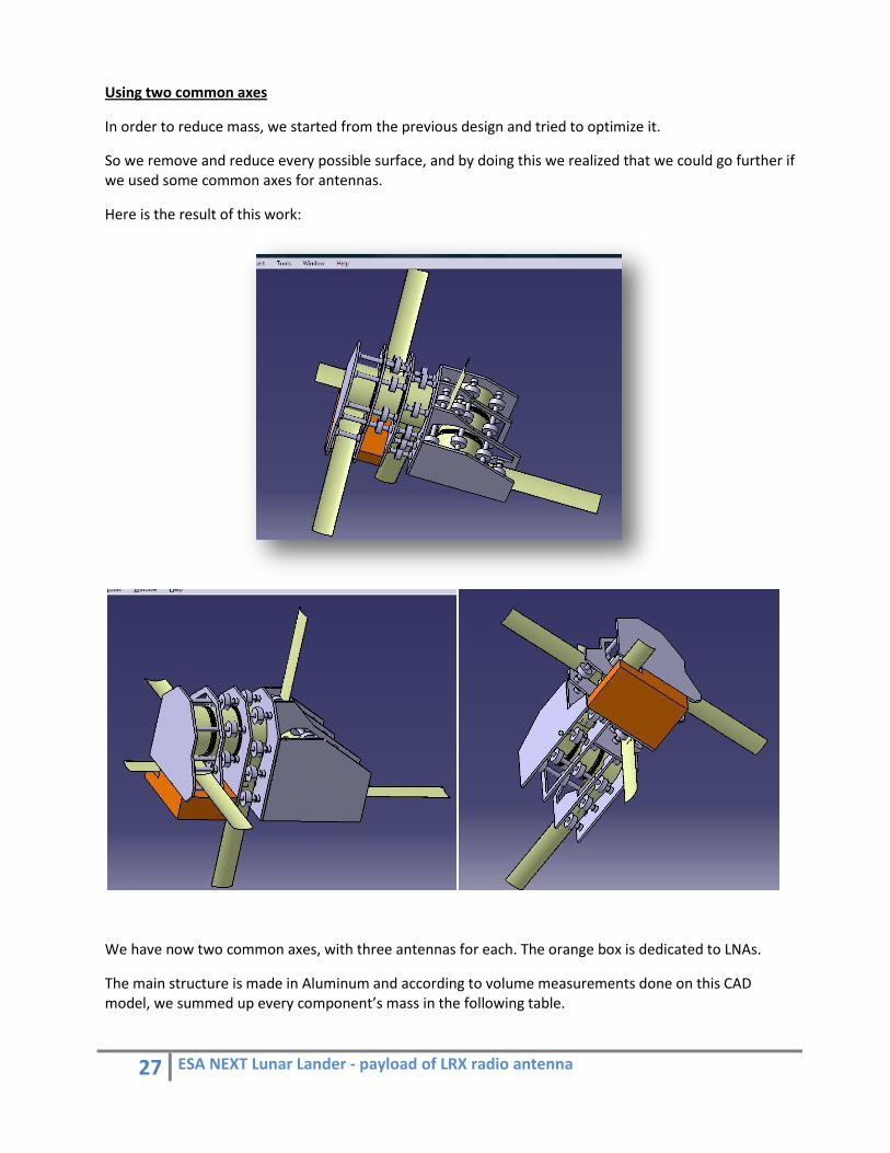
Using two common axes
In order to reduce mass, we started from the previous design and tried to optimize it.
So we remove and reduce every possible surface, and by doing this we realized that we could go further if we used some common axes for antennas.
Here is the result of this work:
We have now two common axes, with three antennas for each. The orange box is dedicated to LNAs.
The main structure is made in Aluminum and according to volume measurements done on this CAD model, we summed up every component’s mass in the following table.

28 ESA NEXT Lunar Lander ‐ payload of LRX radio antenna
As we don’t know yet the weight of LNAs, boom and actuators mechanism, this table is not complete yet and cannot be compared to specifications. But estimations are still possible and seem right. The boom’s mass has been estimated to 20% of what it will support.
We can see in the pie chart bellow that ball bearings are a main part of the total mass, this might be improved by finding some lighter rolls.
Part Quantity Volume (m3)
Density (kg/m3) Mass (g) Total Mass (g)
Ensemble 1 Section 1 1 8.55E‐06 2710 ( Aluminum) 23.1705 23.1705 Ensemble 1 Section 2 1 4.02E‐06 2710 10.90233 10.90233 Ensemble 1 Section 3 1 3.95E‐06 2710 10.70924 10.7092425 Ensemble 1 Section 4 1 8.39E‐06 2710 22.74368 22.743675 Ensemble 2 Section 1 1 8.76E‐06 2710 23.7396 23.7396 Ensemble 2 Section 2 1 7.55E‐06 2710 20.46728 20.467275 Ensemble 2 Section 3 1 3.87E‐06 2710 10.49786 10.4978625 Ensemble 2 Section 4 1 8.24E‐06 2710 22.31685 22.31685 Ball Bearings 54 ‐ ‐ 3 162 Small Axis 24 3.02E‐07 2710 0.817336 19.616064 Medium Axis 6 6.03E‐07 2710 1.634672 9.808032 Big Axes 8 9.05E‐07 2710 2.452008 19.616064 Support 6 3.25E‐06 1300 ( Epoxy ) 4.2276 25.3656 Antennas 6 ‐ ‐ 15 90 TOTAL ‐ ‐ ‐ ‐ 470.953095

29 ESA NEXT Lunar Lander ‐ payload of LRX radio antenna
5.6. Actuators
Around 15 minutes after the landing on the Moon, the antennas have to deploy autonomously. The most critical part is the activation mechanism to start the deployment.
In other Spacecraft projects, mainly 2 different actuators have been used: a magnetic actuator and an actuator by melting wire.
The system has to guarantee a fixation of the antenna during the 15g accelerations of the rocket launch, vibrations and shocks. All this has to happen without any energy consumptions, because the launching conditions specify the complete shutdown of the electrical system.
5.6.1. Magnetic actuator
A permanent magnet is assuring the mechanical connection to a metallic part during the take off.
At the time of the deployment, an electrical magnet is switched on and counteracts the permanent magnetic field.
Together with the spring effect of the antenna, the metallic part will be pulled out of the initial position and the deployment starts.
This system was already studied by a Cubesat team. They were showing that in their case a force of 3.5N was sufficient to guarantee the fixation of the antennas during the vibrations and the shocks of the take off. The counteracting force has to be 2.7N to activate the deployment.
Figure 24: Magnets
30 ESA NEXT Lunar Lander ‐ payload of LRX radio antenna
5.6.2. Melting wire actuator
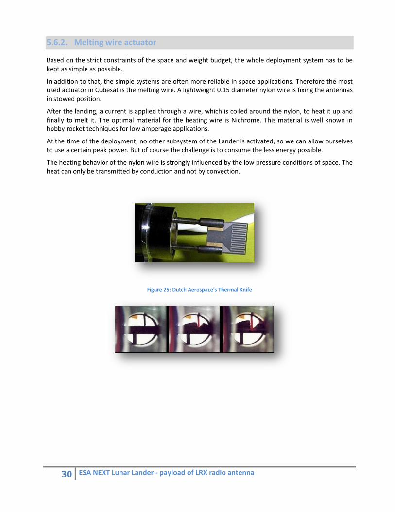
Based on the strict constraints of the space and weight budget, the whole deployment system has to be kept as simple as possible.
In addition to that, the simple systems are often more reliable in space applications. Therefore the most used actuator in Cubesat is the melting wire. A lightweight 0.15 diameter nylon wire is fixing the antennas in stowed position.
After the landing, a current is applied through a wire, which is coiled around the nylon, to heat it up and finally to melt it. The optimal material for the heating wire is Nichrome. This material is well known in hobby rocket techniques for low amperage applications.
At the time of the deployment, no other subsystem of the Lander is activated, so we can allow ourselves to use a certain peak power. But of course the challenge is to consume the less energy possible.
The heating behavior of the nylon wire is strongly influenced by the low pressure conditions of space. The heat can only be transmitted by conduction and not by convection.
Figure 25: Dutch Aerospace's Thermal Knife
31 ESA NEXT Lunar Lander ‐ payload of LRX radio antenna
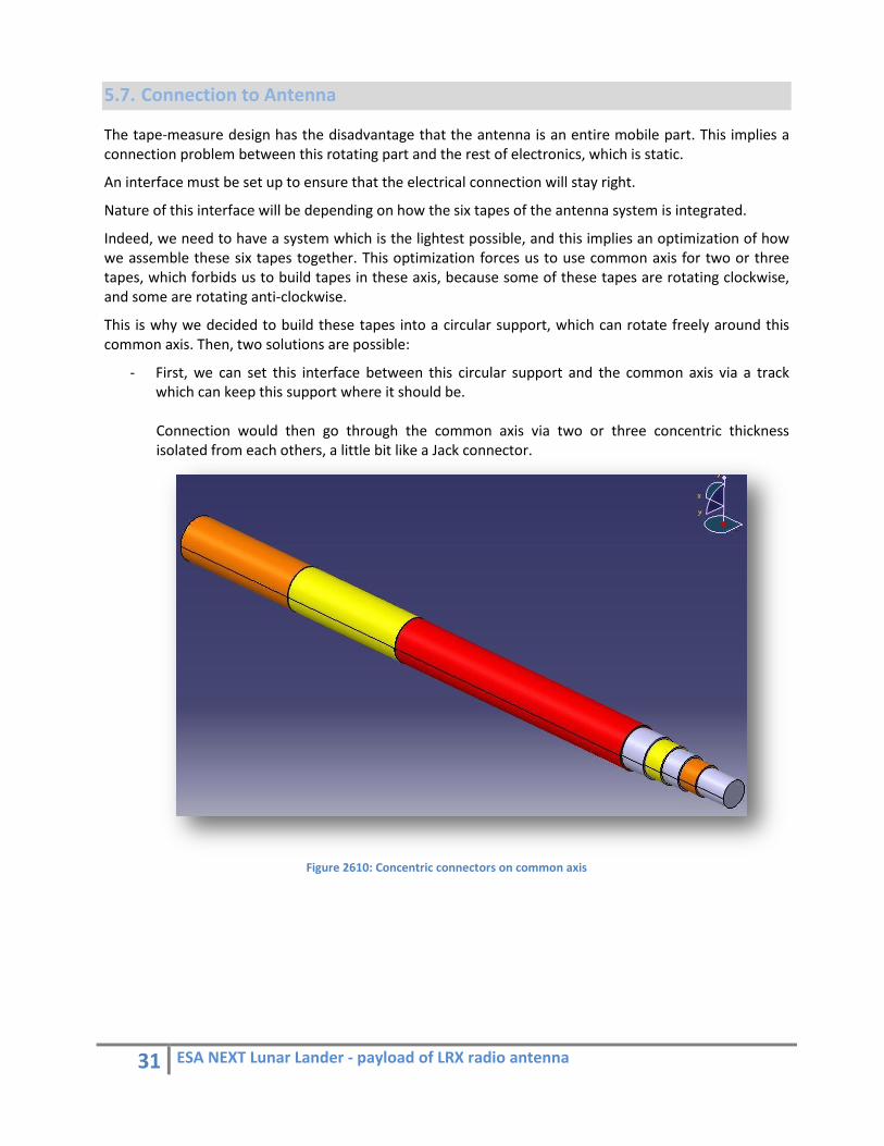
5.7. Connection to Antenna
The tape‐measure design has the disadvantage that the antenna is an entire mobile part. This implies a connection problem between this rotating part and the rest of electronics, which is static.
An interface must be set up to ensure that the electrical connection will stay right.
Nature of this interface will be depending on how the six tapes of the antenna system is integrated.
Indeed, we need to have a system which is the lightest possible, and this implies an optimization of how we assemble these six tapes together. This optimization forces us to use common axis for two or three tapes, which forbids us to build tapes in these axis, because some of these tapes are rotating clockwise, and some are rotating anti‐clockwise.
This is why we decided to build these tapes into a circular support, which can rotate freely around this common axis. Then, two solutions are possible:
‐ First, we can set this interface between this circular support and the common axis via a track which can keep this support where it should be.
Connection would then go through the common axis via two or three concentric thickness isolated from each others, a little bit like a Jack connector.
Figure 2610: Concentric connectors on common axis

32 ESA NEXT Lunar Lander ‐ payload of LRX radio antenna
‐ Or, this interface can be set up below. We use then a thin and elastic metal strip which pushes directly on the antenna. This solution is the simplest to build, but needs some trials because it implies some additional friction in a place where we were trying to avoid friction.
Figure 27: Thin strip connector
33 ESA NEXT Lunar Lander ‐ payload of LRX radio antenna
5.8. Materials
Choosing a material is always a key parameter in a conception project and fixes a lot of variables.
For the antenna’s material, we have two main criteria which will lead our choice.
First, we need the sag of antenna to be the smallest possible, and then we need to remind the formula found via Beam Theory:
𝑓 = 𝑝𝐿%
8𝐸𝐼.
As we need the sag f to be the lowest possible, we need to find a material with the lowest density and the best Young Modulus, or the highest ratio Young Modulus / Density possible.
The second criteria is the maximum curve radius which has to be the smallest possible in order to be able to build the smallest axis possible. We remind here the curve radius formula:
𝑅 = 𝐸. ℎ𝑅𝑒 So, we need here a material with the best ratio Young Modulus / Yield Strength possible.
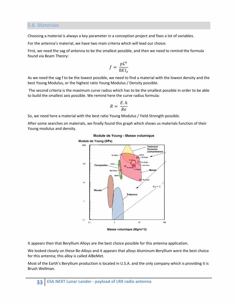
After some searches on materials, we finally found this graph which shows us materials function of their Young modulus and density.
It appears then that Beryllium Alloys are the best choice possible for this antenna application.
We looked closely on these Be‐Alloys and it appears that alloys Aluminum‐Beryllium were the best choice for this antenna; this alloy is called AlBeMet.
Most of the Earth’s Beryllium production is located in U.S.A. and the only company which is providing it is Brush Wellman.

34 ESA NEXT Lunar Lander ‐ payload of LRX radio antenna
After contacting this company, it appears that it is impossible for them to directly build an antenna the way we want.
Actually, we need a 1.25m long thin antenna with a U shape section of 0.1mm thickness.
Or, Brush Wellman can only provide parts down to 0.5mm, so we will need a subcontractor to cut this 0.5mm part further down to 0.1mm.
Anyway, after running some trials, it appears that steel antenna can respect every requirements, then even if this not the most optimized solution, it is still the cheapest.
So, the material choose will be first of all a question of money.
And finally, as the whole antenna will be rolled around an axis, its surface will be in contact with itself and a surface treatment will be needed in order to avoid local soldering phenomena.
35 ESA NEXT Lunar Lander ‐ payload of LRX radio antenna
6. New possible design
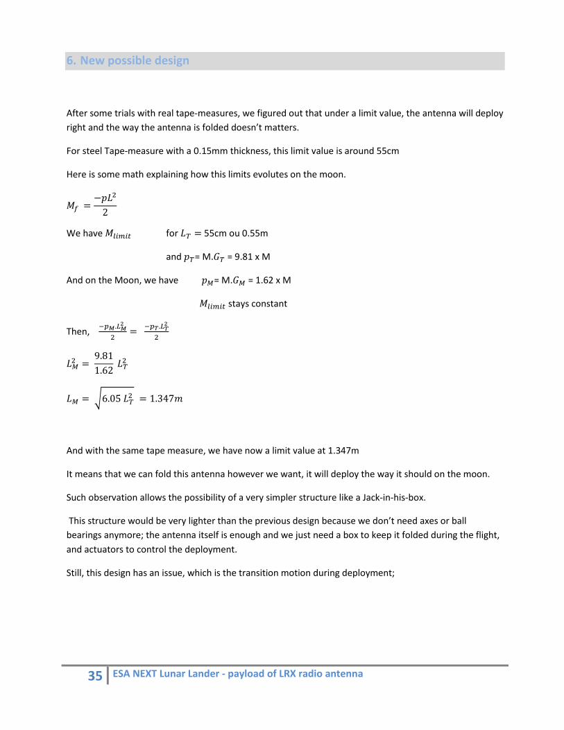
After some trials with real tape‐measures, we figured out that under a limit value, the antenna will deploy right and the way the antenna is folded doesn’t matters.
For steel Tape‐measure with a 0.15mm thickness, this limit value is around 55cm
Here is some math explaining how this limits evolutes on the moon.
𝑀9 =−𝑝𝐿;2
We have 𝑀=>?>@ for 𝐿A = 55cm ou 0.55m
and 𝑝A= M.𝐺A = 9.81 x M
And on the Moon, we have 𝑝C= M.𝐺C = 1.62 x M
𝑀=>?>@ stays constant
Then, #DE.FEG
; = #DH.FHG
;
𝐿C; = 9.811.62 𝐿A;
𝐿C = K6.05 𝐿A; = 1.347𝑚
And with the same tape measure, we have now a limit value at 1.347m
It means that we can fold this antenna however we want, it will deploy the way it should on the moon.
Such observation allows the possibility of a very simpler structure like a Jack‐in‐his‐box.
This structure would be very lighter than the previous design because we don’t need axes or ball bearings anymore; the antenna itself is enough and we just need a box to keep it folded during the flight, and actuators to control the deployment.
Still, this design has an issue, which is the transition motion during deployment;

36 ESA NEXT Lunar Lander ‐ payload of LRX radio antenna
Actually, the antenna contains some potential elastic energy and this energy is completely dissipated during the deployment and is converted into kinetic energy gave to the whole structure.
This kinetic energy implied some motion of the whole structure during the deployment. These motions must be characterized and will be the main constraint in boom conception.
Then, we have got to be careful and make sure the mass we are going to gain with this design will not force us to oversize the boom; then, what we got on one side can be lost on the other side.
Figure 2811: Jack‐in‐his‐box model, Delfi‐C3 design

37 ESA NEXT Lunar Lander ‐ payload of LRX radio antenna
7. Conclusions and Future work
This internship has been a great opportunity for me to find myself confronted to constraints of a conception and design work.
Once again, I need to thank the Radboud University for the autonomy and trust they offered me during this internship.
This autonomy, far from the design office’s coaching allowed me to become aware of numerous issues which a project manager has to face and the importance of developing effective procedures in order to organize work, researches and to increase efficiency.
This internship allowed me to gain a unique experience in Final Elements Method using and the constraints related to spacecraft design.
As I am writing this report, we are still waiting for our new prototype; it will allow us to characterize the stress constraints applied by the tape, in stowed position and transitory during the deployment, on the structure and thus allow optimizing this structure’s size and thickness via FEM analysis.
Anyway, despite pessimist values used for this design, the size and characteristics of LRX system appears to respect the specifications; and the great optimization margin which is still available allow us to be pretty optimistic about compliance with these constraints.
These optimizations concern:
The study of transient motions of Jack‐in‐his‐box model during his deployment in order to characterize its constraints applied on the boom.
The optimization of structure’s thickness via FEM analysis which will need to characterize the tape’s stress applied to the structure, this value has to be measured on the prototype.
The eventual removal of the outer surfaces of the model presented previously.
Finally, the LRX design will have to be tested under vacuum environment and vibrations as well in order to qualify for the NEXT mission.

38 ESA NEXT Lunar Lander ‐ payload of LRX radio antenna
8. References
Simon Robert ‐ V.O.Y Sat Jerome Wertz ‐ Conception et réalisation du système de déploiement des
antennes du nanosatellite OUFTI‐1 AlBeMet Brush wellman J.Santiago‐Prowald ‐ CalTech‐KISS Large Space Apertures Workshop Mario Greber – SwissCube Phase A – Antenna Deployment System Marty Laurent, Ramade Camille – Projet Robusta ‐ Etude & Conception
Antenne (CNES) Prabhakar Subrahmanyam & Robbie Singh Sidhu ‐ Antenna Deployment
Mechanism for Spacecraft Spartnik S. Ananthakrishna and J. E. S. Bergman ‐ GLOBAL ELECTROMAGNETIC
MOON SURVEYOR Jan E. S. Bergman, L. Åhlén, O. Stål, B. Thidé, S. Ananthakrishnan,J.‐E.
Wahlund, R. L. Karlsson, W. Puccio,T. D. Carozzi and P. Kale – Electromagnetic Vector Information Sensor
Jan Otterstad – Antenna system for NCube

39 ESA NEXT Lunar Lander ‐ payload of LRX radio antenna
9. Appendixes
9.1. Glossary
CAD Computer Aided Design
ESA European Space Agency
ESTEC European Space Research and Technology Center
FEM Final Elements Method
GTO Geosynchronous Transfer Orbit
LEO Low Earth Orbit
LNA Low Noise Amplifier
LOFAR Low Frequency Array for radio astronomy
LRX Lunar Radio exPlorer
NEXT Next Exploration Science and Technology
RU Radboud university

40 ESA NEXT Lunar Lander ‐ payload of LRX radio antenna
9.2. Appendixes
Material Density (kg/m3) X (m) Y(m) Mass (g)
Curve radius (cm) Sag (m)
Thickness (mm)
Alu+Beryllium (AlBeMet162) 2100 0.03 0.01 6.00E+00 1.84E+00 4.92E‐03 0.06 Alu+Beryllium (AlBeMet162) 2100 0.03 0.01 7.9989 2.458598726 0.006556741 0.08 Alu+Beryllium (AlBeMet162) 2100 0.03 0.01 9.9918 3.073248408 0.008190332 0.1 Alu+Beryllium (AlBeMet162) 2100 0.03 0.01 11.9784 3.687898089 0.009818758 0.12
Alu+Beryllium (AlBeMet162) 2100 0.02 0.00
7 4.0803 1.843949045 0.014626721 0.06 Alu+Beryllium (AlBeMet162) 2100 0.03 0.01 19.8975 6.146496815 0.016310086 0.2 Acier haute caracteristiques 7860 0.03 0.01 22.47174 0.525 0.016929045 0.06 Alu+Magnesium (Alliage 5086 ) 2660 0.03 0.01 7.60494 1.121052632 0.016945426 0.06 Alu+Magnesium (Alliage 2024 ) 2770 0.03 0.01 7.91943 0.73 0.01716272 0.06 Alu 2710 0.03 0.01 7.74789 2.210526316 0.017510577 0.06 Alu+Magnesium (Alliage 5005 ) 2700 0.03 0.01 7.7193 1.533333333 0.017698803 0.06 Acier ordinaire 7860 0.03 0.01 22.47174 2.4 0.017775497 0.06 Magnesium 1798 0.03 0.01 5.140482 0.488836364 0.018148635 0.06
Alu+Beryllium (AlBeMet162) 2100 0.02 0.00
7 5.4327 2.458598726 0.019474693 0.08 Acier haute caracteristiques 7860 0.03 0.01 29.93874 0.7 0.022554296 0.08 Alu+Magnesium (Alliage 5086 ) 2660 0.03 0.01 10.13194 1.494736842 0.022576121 0.08 Alu+Magnesium (Alliage 2024 ) 2770 0.03 0.01 10.55093 0.973333333 0.022865618 0.08 Alu 2710 0.03 0.01 10.32239 2.947368421 0.023329062 0.08 Alu+Magnesium (Alliage 5005 ) 2700 0.03 0.01 10.2843 2.044444444 0.023579832 0.08 Acier ordinaire 7860 0.03 0.01 29.93874 3.2 0.023682011 0.08 Magnesium 1798 0.03 0.01 6.848582 0.651781818 0.024179136 0.08
Alu+Beryllium (AlBeMet162) 2100 0.02 0.00
7 6.783 3.073248408 0.024315136 0.1 Cuivre‐Beryllium 8200 0.03 0.01 23.4438 0.32195122 0.028097594 0.06 Acier haute caracteristiques 7860 0.03 0.01 37.39788 0.875 0.028173626 0.1 Alu+Magnesium (Alliage 5086 ) 2660 0.03 0.01 12.65628 1.868421053 0.028200888 0.1 Alu+Magnesium (Alliage 2024 ) 2770 0.03 0.01 13.17966 1.216666667 0.028562512 0.1
Alu+Beryllium (AlBeMet162) 2100 0.02 0.00
7 8.1291 3.687898089 0.029140524 0.12 Alu 2710 0.03 0.01 12.89418 3.684210526 0.029141422 0.1 Alu+Magnesium (Alliage 5005 ) 2700 0.03 0.01 12.8466 2.555555556 0.029454671 0.1 Acier ordinaire 7860 0.03 0.01 37.39788 4 0.029582307 0.1 Magnesium 1798 0.03 0.01 8.554884 0.814727273 0.030203289 0.1 Acier haute caracteristiques 7860 0.03 0.01 44.83344 1.05 0.033775192 0.12 Alu+Magnesium (Alliage 5086 ) 2660 0.03 0.01 15.17264 2.242105263 0.033807874 0.12 Alu+Magnesium (Alliage 2024 ) 2770 0.03 0.01 15.80008 1.46 0.034241398 0.12 Alu 2710 0.03 0.01 15.45784 4.421052632 0.034935408 0.12 Alu+Magnesium (Alliage 5005 ) 2700 0.03 0.01 15.4008 3.066666667 0.035310938 0.12

41 ESA NEXT Lunar Lander ‐ payload of LRX radio antenna
Acier ordinaire 7860 0.03 0.01 44.83344 4.8 0.035463952 0.12 Magnesium 1798 0.03 0.01 10.255792 0.977672727 0.036208399 0.12 Cuivre‐Beryllium 8200 0.03 0.01 31.2338 0.429268293 0.037433975 0.08
Alu+Beryllium (AlBeMet162) 2100 0.01
5 0.00
5 2.9946 1.843949045 0.039275032 0.06 Alu+Beryllium (AlBeMet162) 2100 0.03 0.01 49.119 15.36624204 0.040263105 0.5 Cuivre‐Beryllium 8200 0.03 0.01 39.0156 0.536585366 0.046760529 0.1
Alu+Beryllium (AlBeMet162) 2100 0.02 0.00
7 13.4841 6.146496815 0.048336684 0.2
Acier haute caracteristiques 7860 0.02 0.00
7 15.27198 0.525 0.050313931 0.06
Alu+Magnesium (Alliage 5086 ) 2660 0.02 0.00
7 5.16838 1.121052632 0.050362617 0.06
Alu+Magnesium (Alliage 2024 ) 2770 0.02 0.00
7 5.38211 0.73 0.051008424 0.06
Alu 2710 0.02 0.00
7 5.26553 2.210526316 0.052042272 0.06