installation guide - lancomat.cz
TRANSCRIPT
1
Installation GuideAT-OME-EX-RX
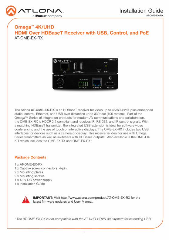
Omega™ 4K/UHD HDMI Over HDBaseT Receiver with USB, Control, and PoEAT-OME-EX-RX
The Atlona AT-OME-EX-RX is an HDBaseT receiver for video up to 4K/60 4:2:0, plus embedded audio, control, Ethernet, and USB over distances up to 330 feet (100 meters). Part of the Omega™ Series of integration products for modern AV communications and collaboration, the OME-EX-RX is HDCP 2.2 compliant and receives IR, RS-232, and IP control signals. With a matching HDBaseT transmitter, the integrated USB extension is ideal for software video conferencing and the use of touch or interactive displays. The OME-EX-RX includes two USB interfaces for devices such as a camera or display. This receiver is ideal for use with Omega Series transmitters as well as switchers with HDBaseT outputs. Also available is the OME-EX-KIT which includes the OME-EX-TX and OME-EX-RX.*
* The AT-OME-EX-RX is not compatible with the AT-UHD-HDVS-300 system for extending USB.
IMPORTANT: Visit http://www.atlona.com/product/AT-OME-EX-RX for the latest firmware updates and User Manual.
1 x AT-OME-EX-RX1 x Captive screw connectors, 4-pin2 x Mounting plates2 x Mounting screws1 x 48 V DC power supply1 x Installation Guide
Package Contents
2
Installation GuideAT-OME-EX-RX
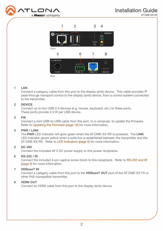
1 LAN Connect a category cable from this port to the display (sink) device. This cable provides IP pass-through transport control to the display (sink) device, from a control system connected to the transmitter.
2 DEVICE Connect up to two USB 2.0 devices (e.g. mouse, keyboard, etc.) to these ports. These ports provide 2.5 W per USB device.
3 FW Connect a mini USB-to-USB cable from this port, to a computer, to update the firmware. Refer to Updating the Firmware (page 10) for more information.
4 PWR / LINK The PWR LED indicator will glow green when the AT-OME-EX-RX is powered. The LINK LED indicator glows yellow when a solid link is established between the transmitter and the AT-OME-EX-RX. Refer to LED Indicators (page 5) for more information.
5 DC 48V Connect the included 48 V DC power supply to this power receptacle.
6 RS-232 / IR Connect the included 4-pin captive screw block to this receptacle. Refer to RS-232 and IR (page 3) for more information.
7 HDBaseT IN Connect a category cable from this port to the HDBaseT OUT port of the AT-OME-EX-TX or other PoE-compatible transmitter.
8 HDMI OUT Connect an HDMI cable from this port to the display (sink) device.
LAN FW
OMEGATM
DEVICE
PWR
LINK
HDMI OUTHDBaseT IN
RX TXTX
RS-232 IR
AT-OME-EX-RX
DC 48V
LAN FW
OMEGATM
DEVICE
PWR
LINK
HDMI OUTHDBaseT IN
RX TXTX
RS-232 IR
AT-OME-EX-RX
DC 48V
Front
Rear
865 7
21 3 4
3
Installation GuideAT-OME-EX-RX
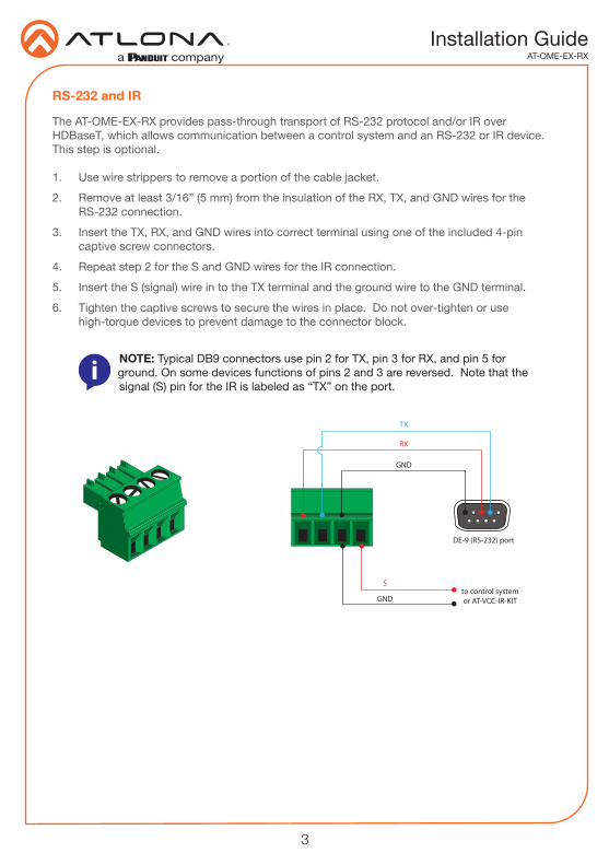
The AT-OME-EX-RX provides pass-through transport of RS-232 protocol and/or IR over HDBaseT, which allows communication between a control system and an RS-232 or IR device. This step is optional.
1. Use wire strippers to remove a portion of the cable jacket.
2. Remove at least 3/16” (5 mm) from the insulation of the RX, TX, and GND wires for the RS-232 connection.
3. Insert the TX, RX, and GND wires into correct terminal using one of the included 4-pin captive screw connectors.
4. Repeat step 2 for the S and GND wires for the IR connection.
5. Insert the S (signal) wire in to the TX terminal and the ground wire to the GND terminal.
6. Tighten the captive screws to secure the wires in place. Do not over-tighten or use high-torque devices to prevent damage to the connector block.
NOTE: Typical DB9 connectors use pin 2 for TX, pin 3 for RX, and pin 5 for ground. On some devices functions of pins 2 and 3 are reversed. Note that the signal (S) pin for the IR is labeled as “TX” on the port.
GND
to control systemor AT-VCC-IR-KIT
DE-9 (RS-232) port
RX
TX
S
GND
RS-232 and IR
4
Installation GuideAT-OME-EX-RX
1. Connect a UHD/HD display to the HDMI OUT port.
2. Connect up to two USB devices (mouse, keyboard, etc.) to the DEVICE ports. These ports provide 2.5 W per USB device.
3. Connect a category cable, from the HDBaseT IN port on the AT-OME-EX-RX, to the HDBaseT OUT port on the transmitter.
4. OPTIONAL: Connect an Ethernet cable from the LAN port on the AT-OME-EX-RX, to the display (sink) device. This cable provide IP pass-through transport control from a control system to the display (sink) device connected to the AT-OME-EX-RX.
5. OPTIONAL: Connect the RS-232 device to the RS-232 port on the AT-OME-EX-RX. Refer to RS-232 and IR (page 3) for more information.
6. OPTIONAL: Connect an IR emitter to the IR port on the transmitter. Connect an IR receiver to the IR port on the AT-OME-EX-RX. Refer to RS-232 and IR (page 3) for more information.
7. Connect the included 48 V DC power supply to the DC 48V power receptacle on the transmitter.
8. Connect the power supply to an available AC outlet.
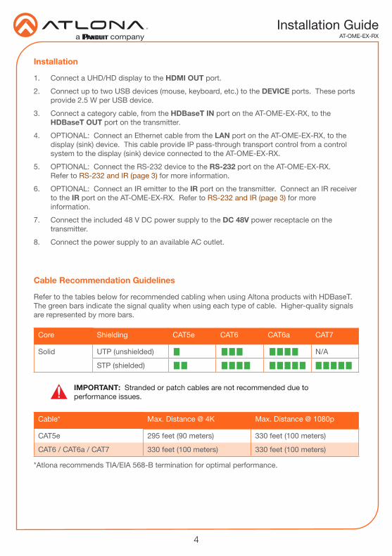
Refer to the tables below for recommended cabling when using Altona products with HDBaseT. The green bars indicate the signal quality when using each type of cable. Higher-quality signals are represented by more bars.
Core Shielding CAT5e CAT6 CAT6a CAT7
Solid UTP (unshielded) N/A
STP (shielded)
*Atlona recommends TIA/EIA 568-B termination for optimal performance.
Cable* Max. Distance @ 4K Max. Distance @ 1080p
CAT5e 295 feet (90 meters) 330 feet (100 meters)
CAT6 / CAT6a / CAT7 330 feet (100 meters) 330 feet (100 meters)
IMPORTANT: Stranded or patch cables are not recommended due to performance issues.
Installation
Cable Recommendation Guidelines
5
Installation GuideAT-OME-EX-RX
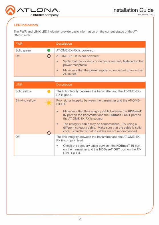
LINK Description
Solid yellow The link integrity between the transmitter and the AT-OME-EX-RX is good.
Blinking yellow Poor signal integrity between the transmitter and the AT-OME-EX-RX.
• Make sure that the category cable between the HDBaseT IN port on the transmitter and the HDBaseT OUT port on the AT-OME-EX-RX is secure.
• The category cable may be compromised. Try using a different category cable. Make sure that the cable is solid core. Stranded or patch cables are not recommended.
Off The link integrity between the transmitter and the AT-OME-EX-RX is compromised.
• Check the category cable between the HDBaseT IN port on the transmitter and the HDBaseT OUT port on the AT-OME-EX-RX.
PWR Description
Solid green AT-OME-EX-RX is powered.
Off AT-OME-EX-RX is not powered.
• Verify that the locking connector is securely fastened to the power receptacle.
• Make sure that the power supply is connected to an active AC outlet.
The PWR and LINK LED indicator provide basic information on the current status of the AT-OME-EX-RX.
LED Indicators
6
Installation GuideAT-OME-EX-RX
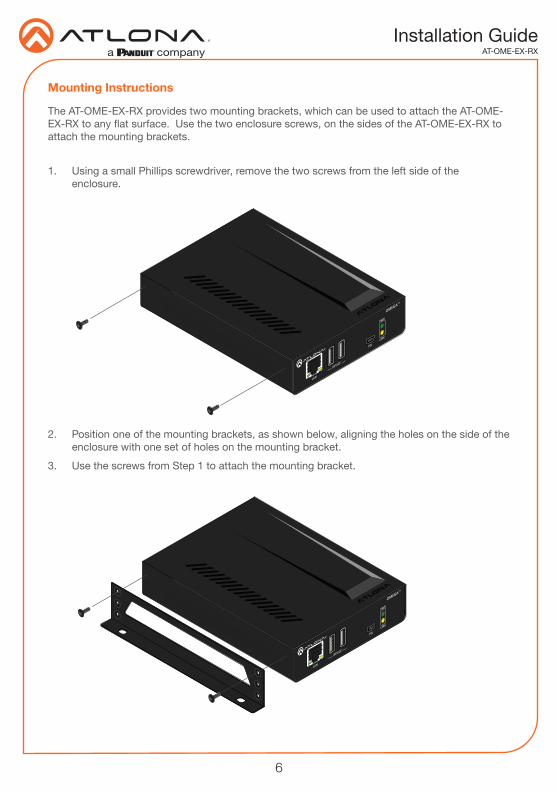
The AT-OME-EX-RX provides two mounting brackets, which can be used to attach the AT-OME-EX-RX to any flat surface. Use the two enclosure screws, on the sides of the AT-OME-EX-RX to attach the mounting brackets.
1. Using a small Phillips screwdriver, remove the two screws from the left side of the enclosure.
2. Position one of the mounting brackets, as shown below, aligning the holes on the side of the enclosure with one set of holes on the mounting bracket.
3. Use the screws from Step 1 to attach the mounting bracket.
Mounting Instructions
LAN
FW
OMEGATM
DEVICE
PWR
LINK
LAN
FW
OMEGATM
DEVICE
PWR
LINK
7
Installation GuideAT-OME-EX-RX
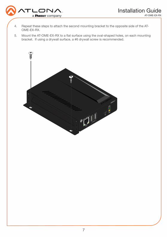
4. Repeat these steps to attach the second mounting bracket to the opposite side of the AT-OME-EX-RX.
5. Mount the AT-OME-EX-RX to a flat surface using the oval-shaped holes, on each mounting bracket. If using a drywall surface, a #6 drywall screw is recommended.
LAN
FW
OMEGATM
DEVICE
PWR
LINK
8
Installation GuideAT-OME-EX-RX
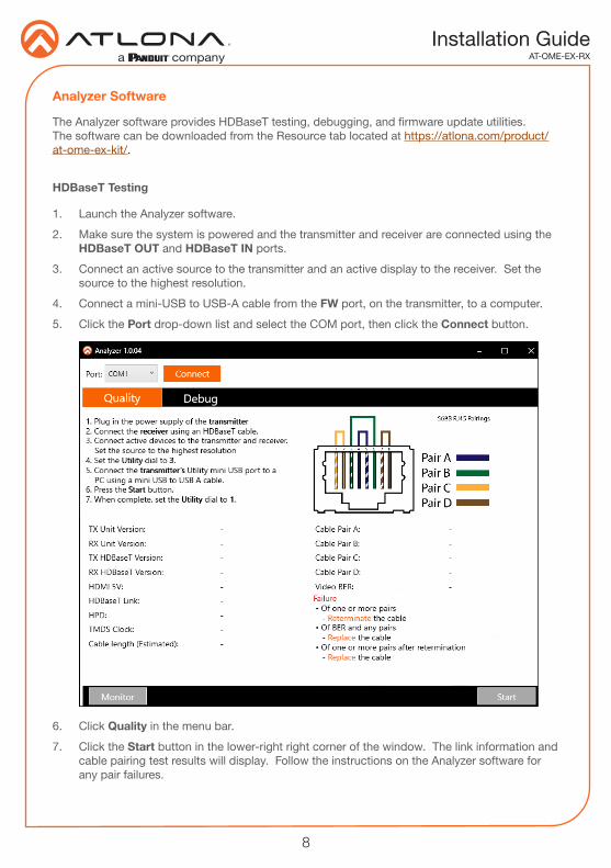
Analyzer Software
HDBaseT Testing
1. Launch the Analyzer software.
2. Make sure the system is powered and the transmitter and receiver are connected using the HDBaseT OUT and HDBaseT IN ports.
3. Connect an active source to the transmitter and an active display to the receiver. Set the source to the highest resolution.
4. Connect a mini-USB to USB-A cable from the FW port, on the transmitter, to a computer.
5. Click the Port drop-down list and select the COM port, then click the Connect button.
The Analyzer software provides HDBaseT testing, debugging, and firmware update utilities. The software can be downloaded from the Resource tab located at https://atlona.com/product/at-ome-ex-kit/.
6. Click Quality in the menu bar.
7. Click the Start button in the lower-right right corner of the window. The link information and cable pairing test results will display. Follow the instructions on the Analyzer software for any pair failures.
9
Installation GuideAT-OME-EX-RX
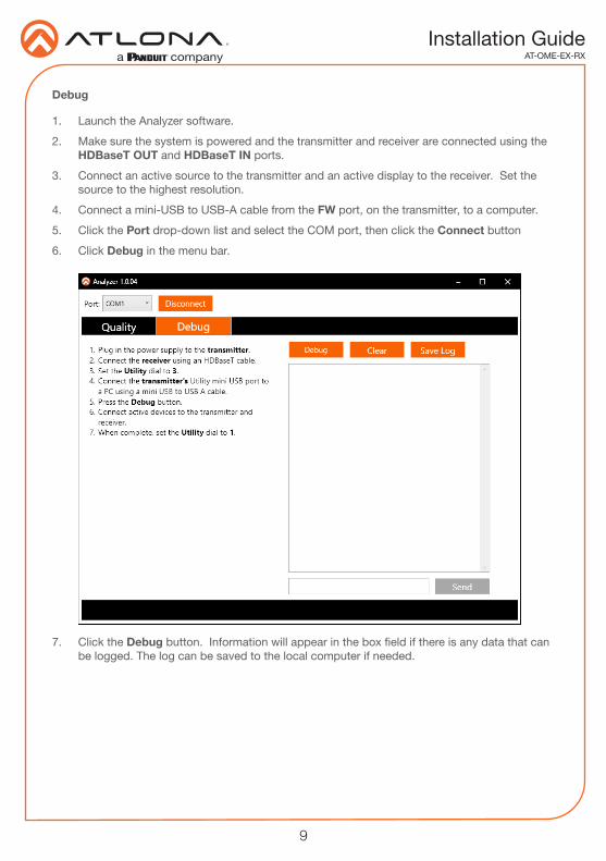
Debug
1. Launch the Analyzer software.
2. Make sure the system is powered and the transmitter and receiver are connected using the HDBaseT OUT and HDBaseT IN ports.
3. Connect an active source to the transmitter and an active display to the receiver. Set the source to the highest resolution.
4. Connect a mini-USB to USB-A cable from the FW port, on the transmitter, to a computer.
5. Click the Port drop-down list and select the COM port, then click the Connect button
6. Click Debug in the menu bar.
7. Click the Debug button. Information will appear in the box field if there is any data that can be logged. The log can be saved to the local computer if needed.
10
Installation GuideAT-OME-EX-RX
Requirements:
• AT-OME-EX-RX• Firmware file• Computer running Windows• USB-A to USB mini-B cable
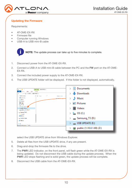
1. Disconnect power from the AT-OME-EX-RX.
2. Connect a USB-A to USB mini-B cable between the PC and the FW port on the AT-OME-EX-RX.
3. Connect the included power supply to the AT-OME-EX-RX.
4. The USB UPDATE folder will be displayed. If this folder is not displayed, automatically,
NOTE: The update process can take up to five minutes to complete.
select the USB UPDATE drive from Windows Explorer.
5. Delete all files from the USB UPDATE drive, if any are present.
6. Drag-and-drop the firmware file to the drive.
7. The PWR LED indicator, on the front panel, will flash green while the AT-OME-EX-RX is being updated. Do not disconnect the USB cable during the update process. When the PWR LED stops flashing and is solid green, the update process will be complete.
8. Disconnect the USB cable from the AT-OME-EX-RX.
Updating the Firmware
11
Installation GuideAT-OME-EX-RX
Notes
12
Installation GuideAT-OME-EX-RX
Version 2
© 2019 Atlona Inc. All rights reserved. “Atlona” and the Atlona logo are registered trademarks of Atlona Inc. All other brand names and trademarks or registered trademarks are the property of their respective owners. Pricing, specifications and availability subject to change without notice. Actual products, product images, and online product images may vary from images shown here.
Toll free US International
atlona.com • 877.536.3976 • 41.43.508.4321