installation and service guide
TRANSCRIPT
Color Controller E-46A
Installation and Service GuideA guide for service technicians
Replacement parts and specifications are subject to change.
For the most current parts list, contact your authorized service/support center.

© 2019 Electronics For Imaging, Inc.
This documentation is protected by copyright, and all rights are reserved. No part of it may be reproduced or transmitted in any form or by any means for any purpose without express prior written consent from Electronics For Imaging, Inc. (“EFI”), except as expressly permitted herein. Information in this documentation is subject to change without notice and does not represent a commitment on the part of EFI. The documentation is further covered by Legal Notices distributed with this product. The documentation may be provided in conjunction with EFI Software (“Software”) and any other EFI product described in the documentation. The Software is furnished under license and may only be used or copied in accordance with the terms of the Software License Agreement, which can be found in the “Legal Notices” distributed with this product.
November 18, 2019 45175436
*45175436*

List of Figures . . . . . . . . . . . . . . . . . . . . . . . . . . . . . . . . . . . . . . . . . . . . . . . . . . . . . . . . . . . . . . . . . . . . . . . . . . . . . . . . . . . . . . . . . . . . . . . . 7
Introduction . . . . . . . . . . . . . . . . . . . . . . . . . . . . . . . . . . . . . . . . . . . . . . . . . . . . . . . . . . . . . . . . . . . . . . . . . . . . . . . . . . . . . . . . . . . . . . . . . . 9
About the E-46A. . . . . . . . . . . . . . . . . . . . . . . . . . . . . . . . . . . . . . . . . . . . . . . . . . . . . . . . . . . . . . . . . . . . . . . . . . . . . . . . . . . . . . . . . . . . . . . . . . 9
About the Fiery NX Station (optional) . . . . . . . . . . . . . . . . . . . . . . . . . . . . . . . . . . . . . . . . . . . . . . . . . . . . . . . . . . . . . . . . . . . . . . . . . . . . . 9
About this document . . . . . . . . . . . . . . . . . . . . . . . . . . . . . . . . . . . . . . . . . . . . . . . . . . . . . . . . . . . . . . . . . . . . . . . . . . . . . . . . . . . . . . . . . . . . 10
Illustrations . . . . . . . . . . . . . . . . . . . . . . . . . . . . . . . . . . . . . . . . . . . . . . . . . . . . . . . . . . . . . . . . . . . . . . . . . . . . . . . . . . . . . . . . . . . . . . . . . . . 10
Terms. . . . . . . . . . . . . . . . . . . . . . . . . . . . . . . . . . . . . . . . . . . . . . . . . . . . . . . . . . . . . . . . . . . . . . . . . . . . . . . . . . . . . . . . . . . . . . . . . . . . . . . . . 10
Document conventions . . . . . . . . . . . . . . . . . . . . . . . . . . . . . . . . . . . . . . . . . . . . . . . . . . . . . . . . . . . . . . . . . . . . . . . . . . . . . . . . . . . . . . . 11
How the E-46A operates . . . . . . . . . . . . . . . . . . . . . . . . . . . . . . . . . . . . . . . . . . . . . . . . . . . . . . . . . . . . . . . . . . . . . . . . . . . . . . . . . . . . . . . . . 11
Before you service the E-46A . . . . . . . . . . . . . . . . . . . . . . . . . . . . . . . . . . . . . . . . . . . . . . . . . . . . . . . . . . . . . . . . . . . . . . . . . . . . . . . . . . . . . 11
Tools you will need . . . . . . . . . . . . . . . . . . . . . . . . . . . . . . . . . . . . . . . . . . . . . . . . . . . . . . . . . . . . . . . . . . . . . . . . . . . . . . . . . . . . . . . . . . . . . . 11
Precautions . . . . . . . . . . . . . . . . . . . . . . . . . . . . . . . . . . . . . . . . . . . . . . . . . . . . . . . . . . . . . . . . . . . . . . . . . . . . . . . . . . . . . . . . . . . . . . . . . . . . . 12
Installing Hardware . . . . . . . . . . . . . . . . . . . . . . . . . . . . . . . . . . . . . . . . . . . . . . . . . . . . . . . . . . . . . . . . . . . . . . . . . . . . . . . . . . . . . . . . 16
About the installation process . . . . . . . . . . . . . . . . . . . . . . . . . . . . . . . . . . . . . . . . . . . . . . . . . . . . . . . . . . . . . . . . . . . . . . . . . . . . . . . . . . . 16
Checking the customer site . . . . . . . . . . . . . . . . . . . . . . . . . . . . . . . . . . . . . . . . . . . . . . . . . . . . . . . . . . . . . . . . . . . . . . . . . . . . . . . . . . . . . . 17
Printer readiness . . . . . . . . . . . . . . . . . . . . . . . . . . . . . . . . . . . . . . . . . . . . . . . . . . . . . . . . . . . . . . . . . . . . . . . . . . . . . . . . . . . . . . . . . . . . . . 17
Setting customer expectations . . . . . . . . . . . . . . . . . . . . . . . . . . . . . . . . . . . . . . . . . . . . . . . . . . . . . . . . . . . . . . . . . . . . . . . . . . . . . . . . 18
Unpacking the E-46A . . . . . . . . . . . . . . . . . . . . . . . . . . . . . . . . . . . . . . . . . . . . . . . . . . . . . . . . . . . . . . . . . . . . . . . . . . . . . . . . . . . . . . . . . . . . 18
Connecting the E-46A . . . . . . . . . . . . . . . . . . . . . . . . . . . . . . . . . . . . . . . . . . . . . . . . . . . . . . . . . . . . . . . . . . . . . . . . . . . . . . . . . . . . . . . . . . . 19
Connecting the E-46A to printer and network . . . . . . . . . . . . . . . . . . . . . . . . . . . . . . . . . . . . . . . . . . . . . . . . . . . . . . . . . . . . . . . . . . 21
Enabling the power synchronization with printer . . . . . . . . . . . . . . . . . . . . . . . . . . . . . . . . . . . . . . . . . . . . . . . . . . . . . . . . . . . . . . 23
Completing the installation . . . . . . . . . . . . . . . . . . . . . . . . . . . . . . . . . . . . . . . . . . . . . . . . . . . . . . . . . . . . . . . . . . . . . . . . . . . . . . . . . . . . . . 26
Configuring a static IP address for the E-46A . . . . . . . . . . . . . . . . . . . . . . . . . . . . . . . . . . . . . . . . . . . . . . . . . . . . . . . . . . . . . . . . . . . 27
Change the language of the E-46A . . . . . . . . . . . . . . . . . . . . . . . . . . . . . . . . . . . . . . . . . . . . . . . . . . . . . . . . . . . . . . . . . . . . . . . . . . . . 28
Using the E-46A. . . . . . . . . . . . . . . . . . . . . . . . . . . . . . . . . . . . . . . . . . . . . . . . . . . . . . . . . . . . . . . . . . . . . . . . . . . . . . . . . . . . . . . . . . . . . 30
Fiery Advanced Controller Interface (FACI) . . . . . . . . . . . . . . . . . . . . . . . . . . . . . . . . . . . . . . . . . . . . . . . . . . . . . . . . . . . . . . . . . . . . . . . . 30
Fiery Ticker . . . . . . . . . . . . . . . . . . . . . . . . . . . . . . . . . . . . . . . . . . . . . . . . . . . . . . . . . . . . . . . . . . . . . . . . . . . . . . . . . . . . . . . . . . . . . . . . . . . . . . 30
Printing the E-46A pages. . . . . . . . . . . . . . . . . . . . . . . . . . . . . . . . . . . . . . . . . . . . . . . . . . . . . . . . . . . . . . . . . . . . . . . . . . . . . . . . . . . . . . . . . 30
Command WorkStation . . . . . . . . . . . . . . . . . . . . . . . . . . . . . . . . . . . . . . . . . . . . . . . . . . . . . . . . . . . . . . . . . . . . . . . . . . . . . . . . . . . . . . . . . . 32
About Configure. . . . . . . . . . . . . . . . . . . . . . . . . . . . . . . . . . . . . . . . . . . . . . . . . . . . . . . . . . . . . . . . . . . . . . . . . . . . . . . . . . . . . . . . . . . . . . . . . 32
Contents

4Installation and Service Guide: Color Controller E-46AContents
Fiery QuickTouch . . . . . . . . . . . . . . . . . . . . . . . . . . . . . . . . . . . . . . . . . . . . . . . . . . . . . . . . . . . . . . . . . . . . . . . . . . . . . . . . . . . . . . . . . . . . . . . . 32
Overview of Fiery QuickTouch menu options. . . . . . . . . . . . . . . . . . . . . . . . . . . . . . . . . . . . . . . . . . . . . . . . . . . . . . . . . . . . . . . . . . . 34
Quick Launch . . . . . . . . . . . . . . . . . . . . . . . . . . . . . . . . . . . . . . . . . . . . . . . . . . . . . . . . . . . . . . . . . . . . . . . . . . . . . . . . . . . . . . . . . . . . . . . . . 36
Quick options. . . . . . . . . . . . . . . . . . . . . . . . . . . . . . . . . . . . . . . . . . . . . . . . . . . . . . . . . . . . . . . . . . . . . . . . . . . . . . . . . . . . . . . . . . . . . . . . . 36
Using the E-46A from printer operation panel . . . . . . . . . . . . . . . . . . . . . . . . . . . . . . . . . . . . . . . . . . . . . . . . . . . . . . . . . . . . . . . . . . . . 37
Main tab . . . . . . . . . . . . . . . . . . . . . . . . . . . . . . . . . . . . . . . . . . . . . . . . . . . . . . . . . . . . . . . . . . . . . . . . . . . . . . . . . . . . . . . . . . . . . . . . . . . . . . 38
Job List tab . . . . . . . . . . . . . . . . . . . . . . . . . . . . . . . . . . . . . . . . . . . . . . . . . . . . . . . . . . . . . . . . . . . . . . . . . . . . . . . . . . . . . . . . . . . . . . . . . . . 38
Tools tab. . . . . . . . . . . . . . . . . . . . . . . . . . . . . . . . . . . . . . . . . . . . . . . . . . . . . . . . . . . . . . . . . . . . . . . . . . . . . . . . . . . . . . . . . . . . . . . . . . . . . . 38
Scan tab . . . . . . . . . . . . . . . . . . . . . . . . . . . . . . . . . . . . . . . . . . . . . . . . . . . . . . . . . . . . . . . . . . . . . . . . . . . . . . . . . . . . . . . . . . . . . . . . . . . . . . 39
Fiery tab . . . . . . . . . . . . . . . . . . . . . . . . . . . . . . . . . . . . . . . . . . . . . . . . . . . . . . . . . . . . . . . . . . . . . . . . . . . . . . . . . . . . . . . . . . . . . . . . . . . . . . 39
Printable Info menu . . . . . . . . . . . . . . . . . . . . . . . . . . . . . . . . . . . . . . . . . . . . . . . . . . . . . . . . . . . . . . . . . . . . . . . . . . . . . . . . . . . . . . . . . . . 40
Using the FACI from printer operation panel . . . . . . . . . . . . . . . . . . . . . . . . . . . . . . . . . . . . . . . . . . . . . . . . . . . . . . . . . . . . . . . . . . . 41
Network status LEDs . . . . . . . . . . . . . . . . . . . . . . . . . . . . . . . . . . . . . . . . . . . . . . . . . . . . . . . . . . . . . . . . . . . . . . . . . . . . . . . . . . . . . . . . . . . . . 42
Starting, shutting down, restarting, and rebooting. . . . . . . . . . . . . . . . . . . . . . . . . . . . . . . . . . . . . . . . . . . . . . . . . . . . . . . . . . . . . . . . 42
Replacing parts . . . . . . . . . . . . . . . . . . . . . . . . . . . . . . . . . . . . . . . . . . . . . . . . . . . . . . . . . . . . . . . . . . . . . . . . . . . . . . . . . . . . . . . . . . . . . 46
Overview. . . . . . . . . . . . . . . . . . . . . . . . . . . . . . . . . . . . . . . . . . . . . . . . . . . . . . . . . . . . . . . . . . . . . . . . . . . . . . . . . . . . . . . . . . . . . . . . . . . . . . . . 46
E-46A hardware . . . . . . . . . . . . . . . . . . . . . . . . . . . . . . . . . . . . . . . . . . . . . . . . . . . . . . . . . . . . . . . . . . . . . . . . . . . . . . . . . . . . . . . . . . . . . . . . . 47
Accessing internal components . . . . . . . . . . . . . . . . . . . . . . . . . . . . . . . . . . . . . . . . . . . . . . . . . . . . . . . . . . . . . . . . . . . . . . . . . . . . . . . . . . 51
Shutting down the system . . . . . . . . . . . . . . . . . . . . . . . . . . . . . . . . . . . . . . . . . . . . . . . . . . . . . . . . . . . . . . . . . . . . . . . . . . . . . . . . . . . . 51
Opening the E-46A. . . . . . . . . . . . . . . . . . . . . . . . . . . . . . . . . . . . . . . . . . . . . . . . . . . . . . . . . . . . . . . . . . . . . . . . . . . . . . . . . . . . . . . . . . . . 51
Fiery QuickTouch display module . . . . . . . . . . . . . . . . . . . . . . . . . . . . . . . . . . . . . . . . . . . . . . . . . . . . . . . . . . . . . . . . . . . . . . . . . . . . . . . . 54
Removing and replacing boards . . . . . . . . . . . . . . . . . . . . . . . . . . . . . . . . . . . . . . . . . . . . . . . . . . . . . . . . . . . . . . . . . . . . . . . . . . . . . . . . . 57
Printer interface board . . . . . . . . . . . . . . . . . . . . . . . . . . . . . . . . . . . . . . . . . . . . . . . . . . . . . . . . . . . . . . . . . . . . . . . . . . . . . . . . . . . . . . . . 58
Motherboard . . . . . . . . . . . . . . . . . . . . . . . . . . . . . . . . . . . . . . . . . . . . . . . . . . . . . . . . . . . . . . . . . . . . . . . . . . . . . . . . . . . . . . . . . . . . . . . . . . . . 59
Motherboard replacement overview. . . . . . . . . . . . . . . . . . . . . . . . . . . . . . . . . . . . . . . . . . . . . . . . . . . . . . . . . . . . . . . . . . . . . . . . . . . 60
Removing the motherboard . . . . . . . . . . . . . . . . . . . . . . . . . . . . . . . . . . . . . . . . . . . . . . . . . . . . . . . . . . . . . . . . . . . . . . . . . . . . . . . . . . . 60
Replacing the motherboard . . . . . . . . . . . . . . . . . . . . . . . . . . . . . . . . . . . . . . . . . . . . . . . . . . . . . . . . . . . . . . . . . . . . . . . . . . . . . . . . . . . 63
Verifying new motherboard installation, and transferring options and BIOS information. . . . . . . . . . . . . . . . . . . . . . . . . 66
Replacing parts on the motherboard . . . . . . . . . . . . . . . . . . . . . . . . . . . . . . . . . . . . . . . . . . . . . . . . . . . . . . . . . . . . . . . . . . . . . . . . . . . . . 68
DIMMs. . . . . . . . . . . . . . . . . . . . . . . . . . . . . . . . . . . . . . . . . . . . . . . . . . . . . . . . . . . . . . . . . . . . . . . . . . . . . . . . . . . . . . . . . . . . . . . . . . . . . . . . 69
CPU . . . . . . . . . . . . . . . . . . . . . . . . . . . . . . . . . . . . . . . . . . . . . . . . . . . . . . . . . . . . . . . . . . . . . . . . . . . . . . . . . . . . . . . . . . . . . . . . . . . . . . . . . . 70
Battery . . . . . . . . . . . . . . . . . . . . . . . . . . . . . . . . . . . . . . . . . . . . . . . . . . . . . . . . . . . . . . . . . . . . . . . . . . . . . . . . . . . . . . . . . . . . . . . . . . . . . . . 74
Jumpers . . . . . . . . . . . . . . . . . . . . . . . . . . . . . . . . . . . . . . . . . . . . . . . . . . . . . . . . . . . . . . . . . . . . . . . . . . . . . . . . . . . . . . . . . . . . . . . . . . . . . . 76
Fan. . . . . . . . . . . . . . . . . . . . . . . . . . . . . . . . . . . . . . . . . . . . . . . . . . . . . . . . . . . . . . . . . . . . . . . . . . . . . . . . . . . . . . . . . . . . . . . . . . . . . . . . . . . . . . 76
Power supply . . . . . . . . . . . . . . . . . . . . . . . . . . . . . . . . . . . . . . . . . . . . . . . . . . . . . . . . . . . . . . . . . . . . . . . . . . . . . . . . . . . . . . . . . . . . . . . . . . . . 78
5Installation and Service Guide: Color Controller E-46AContents
Hard disk drive . . . . . . . . . . . . . . . . . . . . . . . . . . . . . . . . . . . . . . . . . . . . . . . . . . . . . . . . . . . . . . . . . . . . . . . . . . . . . . . . . . . . . . . . . . . . . . . . . . 80
DVD drive . . . . . . . . . . . . . . . . . . . . . . . . . . . . . . . . . . . . . . . . . . . . . . . . . . . . . . . . . . . . . . . . . . . . . . . . . . . . . . . . . . . . . . . . . . . . . . . . . . . . . . . 84
Restoring and verifying functionality after service . . . . . . . . . . . . . . . . . . . . . . . . . . . . . . . . . . . . . . . . . . . . . . . . . . . . . . . . . . . . . . . . 86
Performing Backup and Restore . . . . . . . . . . . . . . . . . . . . . . . . . . . . . . . . . . . . . . . . . . . . . . . . . . . . . . . . . . . . . . . . . . . . . . . . 88
Backup recommendations . . . . . . . . . . . . . . . . . . . . . . . . . . . . . . . . . . . . . . . . . . . . . . . . . . . . . . . . . . . . . . . . . . . . . . . . . . . . . . . . . . . . . . . 91
When backing up an existing E-46A installation . . . . . . . . . . . . . . . . . . . . . . . . . . . . . . . . . . . . . . . . . . . . . . . . . . . . . . . . . . . . . . . . 91
Backing up the system configuration . . . . . . . . . . . . . . . . . . . . . . . . . . . . . . . . . . . . . . . . . . . . . . . . . . . . . . . . . . . . . . . . . . . . . . . . . . . . . 92
Restoring the system configuration . . . . . . . . . . . . . . . . . . . . . . . . . . . . . . . . . . . . . . . . . . . . . . . . . . . . . . . . . . . . . . . . . . . . . . . . . . . . . . 93
Using Fiery System Restore . . . . . . . . . . . . . . . . . . . . . . . . . . . . . . . . . . . . . . . . . . . . . . . . . . . . . . . . . . . . . . . . . . . . . . . . . . . . . . . . . . . . . . 94
Backing up or restoring the E-46A . . . . . . . . . . . . . . . . . . . . . . . . . . . . . . . . . . . . . . . . . . . . . . . . . . . . . . . . . . . . . . . . . . . . . . . . . . . . . 95
Using Fiery System Installer . . . . . . . . . . . . . . . . . . . . . . . . . . . . . . . . . . . . . . . . . . . . . . . . . . . . . . . . . . . . . . . . . . . . . . . . . . . . . . . . . . . . . . 96
Backup with Fiery System Installer . . . . . . . . . . . . . . . . . . . . . . . . . . . . . . . . . . . . . . . . . . . . . . . . . . . . . . . . . . . . . . . . . . . . . . . . . . . . . 97
Restore with Fiery System Installer . . . . . . . . . . . . . . . . . . . . . . . . . . . . . . . . . . . . . . . . . . . . . . . . . . . . . . . . . . . . . . . . . . . . . . . . . . . . . 98
Using bootable USB storage device to restore . . . . . . . . . . . . . . . . . . . . . . . . . . . . . . . . . . . . . . . . . . . . . . . . . . . . . . . . . . . . . . . . . . 99
Platform Utilities . . . . . . . . . . . . . . . . . . . . . . . . . . . . . . . . . . . . . . . . . . . . . . . . . . . . . . . . . . . . . . . . . . . . . . . . . . . . . . . . . . . . . . . . . . . . .100
Installing System Software . . . . . . . . . . . . . . . . . . . . . . . . . . . . . . . . . . . . . . . . . . . . . . . . . . . . . . . . . . . . . . . . . . . . . . . . . . . . . .101
When you reinstall from the System Software DVDs. . . . . . . . . . . . . . . . . . . . . . . . . . . . . . . . . . . . . . . . . . . . . . . . . . . . . . . . . . . . . .101
Installing system software . . . . . . . . . . . . . . . . . . . . . . . . . . . . . . . . . . . . . . . . . . . . . . . . . . . . . . . . . . . . . . . . . . . . . . . . . . . . . . . . . . . . . .102
To install and verify the system software installation. . . . . . . . . . . . . . . . . . . . . . . . . . . . . . . . . . . . . . . . . . . . . . . . . . . . . . . . . . .102
Installing the Fiery QuickTouch software . . . . . . . . . . . . . . . . . . . . . . . . . . . . . . . . . . . . . . . . . . . . . . . . . . . . . . . . . . . . . . . . . . . . . . . .104
After installing or updating the system software . . . . . . . . . . . . . . . . . . . . . . . . . . . . . . . . . . . . . . . . . . . . . . . . . . . . . . . . . . . . . . . . .106
System software installation error messages . . . . . . . . . . . . . . . . . . . . . . . . . . . . . . . . . . . . . . . . . . . . . . . . . . . . . . . . . . . . . . . . . . . . .107
Installing software patches. . . . . . . . . . . . . . . . . . . . . . . . . . . . . . . . . . . . . . . . . . . . . . . . . . . . . . . . . . . . . . . . . . . . . . . . . . . . . . . . . . . . . .108
System update log . . . . . . . . . . . . . . . . . . . . . . . . . . . . . . . . . . . . . . . . . . . . . . . . . . . . . . . . . . . . . . . . . . . . . . . . . . . . . . . . . . . . . . . . . . .109
Troubleshooting. . . . . . . . . . . . . . . . . . . . . . . . . . . . . . . . . . . . . . . . . . . . . . . . . . . . . . . . . . . . . . . . . . . . . . . . . . . . . . . . . . . . . . . . . . .110
Fiery Diagnostic Tool (optional) . . . . . . . . . . . . . . . . . . . . . . . . . . . . . . . . . . . . . . . . . . . . . . . . . . . . . . . . . . . . . . . . . . . . . . . . . . . . . . . . .110
Preliminary on-site checkout . . . . . . . . . . . . . . . . . . . . . . . . . . . . . . . . . . . . . . . . . . . . . . . . . . . . . . . . . . . . . . . . . . . . . . . . . . . . . . . . . . . .110
Checking external connections . . . . . . . . . . . . . . . . . . . . . . . . . . . . . . . . . . . . . . . . . . . . . . . . . . . . . . . . . . . . . . . . . . . . . . . . . . . . . . .111
Checking internal components . . . . . . . . . . . . . . . . . . . . . . . . . . . . . . . . . . . . . . . . . . . . . . . . . . . . . . . . . . . . . . . . . . . . . . . . . . . . . . .111
Inspecting the system. . . . . . . . . . . . . . . . . . . . . . . . . . . . . . . . . . . . . . . . . . . . . . . . . . . . . . . . . . . . . . . . . . . . . . . . . . . . . . . . . . . . . . . .112
Error messages and conditions . . . . . . . . . . . . . . . . . . . . . . . . . . . . . . . . . . . . . . . . . . . . . . . . . . . . . . . . . . . . . . . . . . . . . . . . . . . . . . . . . .116
6Installation and Service Guide: Color Controller E-46AContents
Troubleshooting information . . . . . . . . . . . . . . . . . . . . . . . . . . . . . . . . . . . . . . . . . . . . . . . . . . . . . . . . . . . . . . . . . . . . . . . . . . . . . . . . . . .123
Job Error Report . . . . . . . . . . . . . . . . . . . . . . . . . . . . . . . . . . . . . . . . . . . . . . . . . . . . . . . . . . . . . . . . . . . . . . . . . . . . . . . . . . . . . . . . . . . . .125
System Logs . . . . . . . . . . . . . . . . . . . . . . . . . . . . . . . . . . . . . . . . . . . . . . . . . . . . . . . . . . . . . . . . . . . . . . . . . . . . . . . . . . . . . . . . . . . . . . . . .126
Fiery Click Tool . . . . . . . . . . . . . . . . . . . . . . . . . . . . . . . . . . . . . . . . . . . . . . . . . . . . . . . . . . . . . . . . . . . . . . . . . . . . . . . . . . . . . . . . . . . . . . .126
Specifications . . . . . . . . . . . . . . . . . . . . . . . . . . . . . . . . . . . . . . . . . . . . . . . . . . . . . . . . . . . . . . . . . . . . . . . . . . . . . . . . . . . . . . . . . . . . . .128
Hardware features . . . . . . . . . . . . . . . . . . . . . . . . . . . . . . . . . . . . . . . . . . . . . . . . . . . . . . . . . . . . . . . . . . . . . . . . . . . . . . . . . . . . . . . . . . . . . .128
Physical specifications . . . . . . . . . . . . . . . . . . . . . . . . . . . . . . . . . . . . . . . . . . . . . . . . . . . . . . . . . . . . . . . . . . . . . . . . . . . . . . . . . . . . . . . . . .128
Networking and connectivity . . . . . . . . . . . . . . . . . . . . . . . . . . . . . . . . . . . . . . . . . . . . . . . . . . . . . . . . . . . . . . . . . . . . . . . . . . . . . . . . . . .128
Safety and emissions compliance . . . . . . . . . . . . . . . . . . . . . . . . . . . . . . . . . . . . . . . . . . . . . . . . . . . . . . . . . . . . . . . . . . . . . . . . . . . . . . .128
Safety approvals . . . . . . . . . . . . . . . . . . . . . . . . . . . . . . . . . . . . . . . . . . . . . . . . . . . . . . . . . . . . . . . . . . . . . . . . . . . . . . . . . . . . . . . . . . . . .128
EMI/EMC approvals . . . . . . . . . . . . . . . . . . . . . . . . . . . . . . . . . . . . . . . . . . . . . . . . . . . . . . . . . . . . . . . . . . . . . . . . . . . . . . . . . . . . . . . . . .129
Servicing the E-46A with furniture. . . . . . . . . . . . . . . . . . . . . . . . . . . . . . . . . . . . . . . . . . . . . . . . . . . . . . . . . . . . . . . . . . . . .130
Procedures . . . . . . . . . . . . . . . . . . . . . . . . . . . . . . . . . . . . . . . . . . . . . . . . . . . . . . . . . . . . . . . . . . . . . . . . . . . . . . . . . . . . . . . . . . . . . . . . . . . . .130
Index . . . . . . . . . . . . . . . . . . . . . . . . . . . . . . . . . . . . . . . . . . . . . . . . . . . . . . . . . . . . . . . . . . . . . . . . . . . . . . . . . . . . . . . . . . . . . . . . . . . . . . . . .132

Figure 1: The E-46A. . . . . . . . . . . . . . . . . . . . . . . . . . . . . . . . . . . . . . . . . . . . . . . . . . . . . . . . . . . . . . . . . . . . . . . . . . . . . . . . . . . . . . . . . . . . . 9
Figure 2: Fiery NX Station. . . . . . . . . . . . . . . . . . . . . . . . . . . . . . . . . . . . . . . . . . . . . . . . . . . . . . . . . . . . . . . . . . . . . . . . . . . . . . . . . . . . . . 10
Figure 3: Affixing the EFI/Fiery decal to the printer . . . . . . . . . . . . . . . . . . . . . . . . . . . . . . . . . . . . . . . . . . . . . . . . . . . . . . . . . . . . . 16
Figure 4: Space requirement for the E-46A without optional Fiery NX Station. . . . . . . . . . . . . . . . . . . . . . . . . . . . . . . . . . . . 17
Figure 5: Front panel and connector panel . . . . . . . . . . . . . . . . . . . . . . . . . . . . . . . . . . . . . . . . . . . . . . . . . . . . . . . . . . . . . . . . . . . . . 20
Figure 6: Printer and E-46A cable connections. . . . . . . . . . . . . . . . . . . . . . . . . . . . . . . . . . . . . . . . . . . . . . . . . . . . . . . . . . . . . . . . . . 22
Figure 7: Straight-through and crossover Ethernet cables. . . . . . . . . . . . . . . . . . . . . . . . . . . . . . . . . . . . . . . . . . . . . . . . . . . . . . . 23
Figure 8: USB power cable connection between printer and E-46A . . . . . . . . . . . . . . . . . . . . . . . . . . . . . . . . . . . . . . . . . . . . . . 25
Figure 9: E-46A power switch . . . . . . . . . . . . . . . . . . . . . . . . . . . . . . . . . . . . . . . . . . . . . . . . . . . . . . . . . . . . . . . . . . . . . . . . . . . . . . . . . . 25
Figure 10: Fiery Ticker status bar. . . . . . . . . . . . . . . . . . . . . . . . . . . . . . . . . . . . . . . . . . . . . . . . . . . . . . . . . . . . . . . . . . . . . . . . . . . . . . . 30
Figure 11: Fiery QuickTouch panel features . . . . . . . . . . . . . . . . . . . . . . . . . . . . . . . . . . . . . . . . . . . . . . . . . . . . . . . . . . . . . . . . . . . . 33
Figure 12: Fiery QuickTouch Home screen . . . . . . . . . . . . . . . . . . . . . . . . . . . . . . . . . . . . . . . . . . . . . . . . . . . . . . . . . . . . . . . . . . . . . 34
Figure 13: Queue job window . . . . . . . . . . . . . . . . . . . . . . . . . . . . . . . . . . . . . . . . . . . . . . . . . . . . . . . . . . . . . . . . . . . . . . . . . . . . . . . . . 35
Figure 14: Printed jobs window. . . . . . . . . . . . . . . . . . . . . . . . . . . . . . . . . . . . . . . . . . . . . . . . . . . . . . . . . . . . . . . . . . . . . . . . . . . . . . . . 35
Figure 15: Quick launch menu . . . . . . . . . . . . . . . . . . . . . . . . . . . . . . . . . . . . . . . . . . . . . . . . . . . . . . . . . . . . . . . . . . . . . . . . . . . . . . . . . 36
Figure 16: Quick options menu . . . . . . . . . . . . . . . . . . . . . . . . . . . . . . . . . . . . . . . . . . . . . . . . . . . . . . . . . . . . . . . . . . . . . . . . . . . . . . . . 37
Figure 17: The printer operation panel . . . . . . . . . . . . . . . . . . . . . . . . . . . . . . . . . . . . . . . . . . . . . . . . . . . . . . . . . . . . . . . . . . . . . . . . . 37
Figure 18: Fiery icon on printer operation panel . . . . . . . . . . . . . . . . . . . . . . . . . . . . . . . . . . . . . . . . . . . . . . . . . . . . . . . . . . . . . . . . 38
Figure 19: Fiery Console icon on printer operation panel . . . . . . . . . . . . . . . . . . . . . . . . . . . . . . . . . . . . . . . . . . . . . . . . . . . . . . . 41
Figure 20: Ethernet network port . . . . . . . . . . . . . . . . . . . . . . . . . . . . . . . . . . . . . . . . . . . . . . . . . . . . . . . . . . . . . . . . . . . . . . . . . . . . . . 42
Figure 21: E-46A power switch . . . . . . . . . . . . . . . . . . . . . . . . . . . . . . . . . . . . . . . . . . . . . . . . . . . . . . . . . . . . . . . . . . . . . . . . . . . . . . . . 43
Figure 22: E-46A power switch . . . . . . . . . . . . . . . . . . . . . . . . . . . . . . . . . . . . . . . . . . . . . . . . . . . . . . . . . . . . . . . . . . . . . . . . . . . . . . . . 43
Figure 23: E-46A power button . . . . . . . . . . . . . . . . . . . . . . . . . . . . . . . . . . . . . . . . . . . . . . . . . . . . . . . . . . . . . . . . . . . . . . . . . . . . . . . . 44
Figure 24: Front and connector panel. . . . . . . . . . . . . . . . . . . . . . . . . . . . . . . . . . . . . . . . . . . . . . . . . . . . . . . . . . . . . . . . . . . . . . . . . . 47
Figure 25: Inside the front panel . . . . . . . . . . . . . . . . . . . . . . . . . . . . . . . . . . . . . . . . . . . . . . . . . . . . . . . . . . . . . . . . . . . . . . . . . . . . . . . 48
Figure 26: Exploded view of E-46A . . . . . . . . . . . . . . . . . . . . . . . . . . . . . . . . . . . . . . . . . . . . . . . . . . . . . . . . . . . . . . . . . . . . . . . . . . . . . 49
Figure 27: Power and data cable connections . . . . . . . . . . . . . . . . . . . . . . . . . . . . . . . . . . . . . . . . . . . . . . . . . . . . . . . . . . . . . . . . . . 50
Figure 28: Removing the left panel . . . . . . . . . . . . . . . . . . . . . . . . . . . . . . . . . . . . . . . . . . . . . . . . . . . . . . . . . . . . . . . . . . . . . . . . . . . . 52
List of Figures

8 Installation and Service Guide: Color Controller E-46AList of Figures
Figure 29: Removing the right panel . . . . . . . . . . . . . . . . . . . . . . . . . . . . . . . . . . . . . . . . . . . . . . . . . . . . . . . . . . . . . . . . . . . . . . . . . . . 52
Figure 30: Front bezel anchor screw . . . . . . . . . . . . . . . . . . . . . . . . . . . . . . . . . . . . . . . . . . . . . . . . . . . . . . . . . . . . . . . . . . . . . . . . . . . 53
Figure 31: Front bezel tabs . . . . . . . . . . . . . . . . . . . . . . . . . . . . . . . . . . . . . . . . . . . . . . . . . . . . . . . . . . . . . . . . . . . . . . . . . . . . . . . . . . . . 53
Figure 32: Printer interface board . . . . . . . . . . . . . . . . . . . . . . . . . . . . . . . . . . . . . . . . . . . . . . . . . . . . . . . . . . . . . . . . . . . . . . . . . . . . . . 58
Figure 33: Motherboard . . . . . . . . . . . . . . . . . . . . . . . . . . . . . . . . . . . . . . . . . . . . . . . . . . . . . . . . . . . . . . . . . . . . . . . . . . . . . . . . . . . . . . . 61
Figure 34: Releasing a DIMM . . . . . . . . . . . . . . . . . . . . . . . . . . . . . . . . . . . . . . . . . . . . . . . . . . . . . . . . . . . . . . . . . . . . . . . . . . . . . . . . . . 69
Figure 35: CPU cooling assembly . . . . . . . . . . . . . . . . . . . . . . . . . . . . . . . . . . . . . . . . . . . . . . . . . . . . . . . . . . . . . . . . . . . . . . . . . . . . . . 71
Figure 36: Removing/replacing the CPU . . . . . . . . . . . . . . . . . . . . . . . . . . . . . . . . . . . . . . . . . . . . . . . . . . . . . . . . . . . . . . . . . . . . . . . 73
Figure 37: Motherboard battery . . . . . . . . . . . . . . . . . . . . . . . . . . . . . . . . . . . . . . . . . . . . . . . . . . . . . . . . . . . . . . . . . . . . . . . . . . . . . . . 75
Figure 38: Removing/replacing the fan . . . . . . . . . . . . . . . . . . . . . . . . . . . . . . . . . . . . . . . . . . . . . . . . . . . . . . . . . . . . . . . . . . . . . . . . 77
Figure 39: Removing/replacing the power supply . . . . . . . . . . . . . . . . . . . . . . . . . . . . . . . . . . . . . . . . . . . . . . . . . . . . . . . . . . . . . . 79
Figure 40: Removing/replacing the hard disk drive bracket . . . . . . . . . . . . . . . . . . . . . . . . . . . . . . . . . . . . . . . . . . . . . . . . . . . . . 82
Figure 41: Removing/replacing the hard disk drive from/in the hard disk drive bracket . . . . . . . . . . . . . . . . . . . . . . . . . . 83
Figure 42: Removing/replacing the DVD drive. . . . . . . . . . . . . . . . . . . . . . . . . . . . . . . . . . . . . . . . . . . . . . . . . . . . . . . . . . . . . . . . . . 85
Figure 43: Conceptual diagram of backup and restore. . . . . . . . . . . . . . . . . . . . . . . . . . . . . . . . . . . . . . . . . . . . . . . . . . . . . . . . . . 89
Figure 44: Reset and download buttons on the Fiery QuickTouch . . . . . . . . . . . . . . . . . . . . . . . . . . . . . . . . . . . . . . . . . . . . . .106
Figure 45: E-46A installed on the furniture . . . . . . . . . . . . . . . . . . . . . . . . . . . . . . . . . . . . . . . . . . . . . . . . . . . . . . . . . . . . . . . . . . . .130

9Installation and Service Guide: Color Controller E-46AIntroduction
Introduction
This document includes information about servicing the Color Controller E-46A. In this document, the Color Controller E-46A is referred to as “the E-46A.”
About the E-46AThe E-46A adds computer connectivity and highly efficient PostScript and PCL printing ability to the Pro C7200 series printer.
With the E-46A, customers can use the printer as a PostScript and PCL printer, and scanner, and it provides efficient image processing and printing controls. Once it is connected to the printer through a network, customers can print to the E-46A from supported client computers on the network (Windows or Mac, or a UNIX workstation running TCP/IP).
The E-46A ships with system software pre-installed so that customers can use the E-46A immediately. However, as part of servicing the E-46A, you may need to reinstall system software.
Figure 1: The E-46A
About the Fiery NX Station (optional)Fiery NX Station is an optional feature for E-46A. Fiery NX Station includes a furniture, monitor, wireless keyboard and mouse. With the Fiery NX Station, you can install the E-46A on a furniture, connect the E-46A to a monitor, keyboard and mouse, and use the Fiery Advanced Controller Interface (FACI) options available for the E-46A.

10Installation and Service Guide: Color Controller E-46AIntroduction
For information about installing the Fiery NX Station, see the documentation provided with the Fiery NX Station kit.
Figure 2: Fiery NX Station
About this documentThis service document describes how to install E-46A system software, and how to service the E-46A hardware. It is not intended for customer use. Information about the printer, network, remote computers, software applications, and E-46A operating system is not included in this document.
Illustrations
In this document, illustrations reflect the version of the E-46A being shipped at the time of publication. Components in illustrations are subject to change. For information about E-46A components that do not match illustrations in this document, contact your authorized service/support center.
Terms
In this document, the following terms are used.
• Replace: Refers to reinstallation of existing components. Do not install new components unless necessary.
• Printer operation panel: Refers to the printer user interface that is used to run the Fiery setup.
• Windows: This is the operating system of the E-46A.
• System software: The software installed on the hard disk drive (HDD) of the E-46A. Includes Windows operating system software.

11Installation and Service Guide: Color Controller E-46AIntroduction
• Server software: The E-46A software. Runs on Windows operating system.
Document conventions
Note: The NOTE format highlights important messages and additional information.
How the E-46A operatesWhen a customer prints, the motherboard and printer interface board process image data. The printer interface board is a custom board and allows the E-46A to communicate with the printer. The CPU controls the transfer of image data to and from the motherboard and runs the PostScript interpreter. DIMM holds image data during printing.
The interpreter rasterizes the page description file and compresses the image pattern into memory using compression technology. The interpreter outputs the compressed raster data through the image frame buffer memory to the printer interface board. The raster data is sent to the printer, which then renders the image on paper at maximum speed.
Before you service the E-46ABefore you service the E-46A, it is strongly recommended that you make sure that you have the required tools (see “Tools you will need” on page 11) and carefully review all precautions (see “Precautions” on page 12).
Also, keep in mind that the most common cause of a hardware problem is a faulty or loose connection. Before you replace an expensive component, check internal and external connections (see page 50).
Tools you will needTo install or service the E-46A, you will need the following tools and parts:
• ESD wrist grounding strap and antistatic mat
• Flathead screwdriver
• #0, #1, and #2 Phillips head screwdrivers
When servicing the Fiery QuickTouch, use a screwdriver with a magnetic tip.
• Needlenose pliers
DANGERThe DANGER icon indicates a warning concerning operations which, if not performed correctly, may lead to death or injury. To use the E-46A safely, always pay attention to WARNING icons and messages.
The WARNING icon indicates a caution concerning operations which, if not performed correctly, may lead to injury. To use the E-46A safely, always pay attention to CAUTION icons and messages.
The CAUTION icon indicates operational requirements and restrictions. To operate the E-46A correctly and avoid damage to the E-46A or other property, always pay attention to IMPORTANT icons and messages.
12Installation and Service Guide: Color Controller E-46AIntroduction
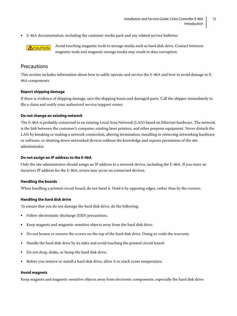
• E-46A documentation, including the customer media pack and any related service bulletins
PrecautionsThis section includes information about how to safely operate and service the E-46A and how to avoid damage to E-46A components.
Report shipping damage
If there is evidence of shipping damage, save the shipping boxes and damaged parts. Call the shipper immediately to file a claim and notify your authorized service/support center.
Do not change an existing network
The E-46A is probably connected to an existing Local Area Network (LAN) based on Ethernet hardware. The network is the link between the customer’s computer, existing laser printers, and other prepress equipment. Never disturb the LAN by breaking or making a network connection, altering termination, installing or removing networking hardware or software, or shutting down networked devices without the knowledge and express permission of the site administrator.
Do not assign an IP address to the E-46A
Only the site administrator should assign an IP address to a network device, including the E-46A. If you enter an incorrect IP address for the E-46A, errors may occur on connected devices.
Handling the boards
When handling a printed circuit board, do not bend it. Hold it by opposing edges, rather than by the corners.
Handling the hard disk drive
To ensure that you do not damage the hard disk drive, do the following:
• Follow electrostatic discharge (ESD) precautions.
• Keep magnets and magnetic-sensitive objects away from the hard disk drive.
• Do not loosen or remove the screws on the top of the hard disk drive. Doing so voids the warranty.
• Handle the hard disk drive by its sides and avoid touching the printed circuit board.
• Do not drop, shake, or bump the hard disk drive.
• Before you remove or install a hard disk drive, allow it to reach room temperature.
Avoid magnets
Keep magnets and magnetic-sensitive objects away from electronic components, especially the hard disk drive.
Avoid touching magnetic tools to storage media such as hard disk drive. Contact between magnetic tools and magnetic storage media may result in data corruption.

13Installation and Service Guide: Color Controller E-46AIntroduction
Avoid fan blades
Attention : ce produit contient des pièces mobiles dangereuses. Veuillez le maintenir à l'écart des pales de ventilateur lors de sa maintenance.
Attenzione: questo prodotto include parti mobili pericolose. Mantenere la distanza dalle pale della ventola quando sono in uso.
Warnung: Dieses Produkt verfügt über gefährliche Teile, die sich bewegen. Halten Sie bei der Instandhaltung Abstand zu den sich bewegenden Ventilatorblättern.
Advertencia: Este producto contiene piezas móviles peligrosas. Cuando realice el mantenimiento de este producto, manténgase alejado de aspas de ventilador en movimiento.
Waarschuwing: dit product bevat gevaarlijke bewegende delen. Blijf uit de buurt van bewegende ventilatorbladen bij het uitvoeren van onderhoudswerkzaamheden aan dit product.
Atenção: Este produto contém partes móveis perigosas. Ao fazer a manutenção deste produto, manter afastado de movimento das pás do ventilador.
Aviso: este produto contém peças removíveis perigosas. Ao realizar a manutenção deste produto, mantenha-se longe das lâminas removíveis do ventilador.
Electrostatic discharge
When you work with electronic components, electrostatic discharge is a concern since it can destroy circuits, or damage them, reducing their life span. The area around the printer is most likely not static-free, and electrostatic discharge could occur.
Do the following to avoid damage due to electrostatic discharge:
• Work on a grounded antistatic mat.
• Wear an antistatic wristband, attached to the same location as the antistatic mat.
• Before you remove an electronic component from the shipping box, touch a metal area of the printer to discharge static from your body.
• After you remove an electronic component from the shipping box, place it face up on a grounded antistatic surface.
• Leave electronic components in antistatic bags until you are ready to use them.
• Do not walk on carpet or vinyl while carrying an electronic component, unless it is in an antistatic bag.
• If you remove an electronic component from the printer, immediately place it in an antistatic bag.
The E-46A contains hazardous moving parts. When servicing the E-46A, keep away from moving fan blades.
14Installation and Service Guide: Color Controller E-46AIntroduction
The power cable
Observe the following guidelines:
• Only use the power cable that shipped with the E-46A or an appropriate replacement power cable. For replacement parts, see your authorized service support center.
• Before you open the E-46A, unplug the E-46A.
• Keep the power cable away from foot traffic.
• Do not place objects on the power cable.
• Do not plug the E-46A into a 2-hole, ungrounded outlet by means of a 3-prong adapter.
• Do not plug the E-46A into a circuit connected to heating or refrigeration equipment (including a water dispenser).
• Do not plug the E-46A into a switchable outlet.
• Do not pull the cable to unplug the E-46A. Instead, pull the plug.
• Do not tamper with or disable the power cable grounding plug.
• Do not use an extension cord.
Do not have liquids near the E-46A
If liquid spills on the E-46A, immediately unplug the E-46A.
Do not open the power supply
For more information about the power supply, see“Power supply” on page 78.
Do not open the hard disk drive
For more information about the hard disk drive, see“Hard disk drive” on page 80.
Use caution with sharp edges
The edges of some E-46A components are sharp.
Power supply cord notice
Lithium battery notice
The power supply cord is used as the main disconnect device. Ensure that the power outlet is located/installed near the equipment and is easily accessible.
DANGERThere is a danger of explosion if the battery is replaced with an incorrect type. Replace a battery only with the same type recommended by the manufacturer. Dispose of used batteries according to local regulations.

15Installation and Service Guide: Color Controller E-46AIntroduction
Short circuit protection
Lift the E-46A carefully
Never lift the E-46A by grasping the top panel. The top panel does not support the weight of the E-46A.
ATTENTION: Ne jamais soulever le serveur d’impression par sa partie supérieure : celle-ci ne peut pas supporter le poids du système.
AVVERTENZA: Il server di stampa non deve essere mai sollevato afferrandolo dal pannello superiore, in quanto quest’ultimo non può sostenere il peso dell’intero sistema.
WARNUNG: Heben Sie den Druckserver nicht an der oberen Gehäuseabdeckung an. Die obere Gehäuseabdeckung ist nicht dafür ausgelegt, das Gesamtgewicht des Systems zu tragen.
ADVERTENCIA: No levante nunca el servidor de impresión agarrándolo por el panel superior. El panel superior no soporta el peso del sistema.
ADVERTÊNCIA: Nunca erga o servidor de impressão pelo painel superior. O painel superior não suporta o peso do sistema.
WAARSCHUWING: Til de afdrukserver nooit op door het bovenpaneel vast te nemen. Het bovenpaneel kan het gewicht van het systeem niet dragen.
This product relies on the building’s installation for short-circuit (overcurrent) protection. Ensure that a fuse or circuit breaker no larger than 120 VAC, 15A U.S. (240 VAC, 10A international) is used on the phase conductors (all current-carrying conductors).
16Installation and Service Guide: Color Controller E-46AInstalling Hardware
Installing Hardware
About the installation processIt is strongly recommended that you review this chapter before you install the E-46A. Also keep in mind that installation problems are easier to avoid and diagnose if you proceed from the component level to the system level, verifying functionality at each step.
Since the E-46A is connected to the customer’s network, be sure to coordinate your installation schedule with the administrator at the customer site. For information about network setup, refer the site administrator to Configuration and Setup, which is part of the user documentation set.
To install the E-46A
1 Check installation requirements and verify site conditions (see page 17).
If possible, obtain verification that the network is operational.
2 Unpack the E-46A (see page 18).
3 If applicable, install the Fiery NX Station (for information about Fiery NX Station, see page 9).
For information about installing the Fiery NX Station, see the documentation provided with the Fiery NX Station kit.
4 Connect the E-46A to power, printer, network, and other optional devices (see page 19).
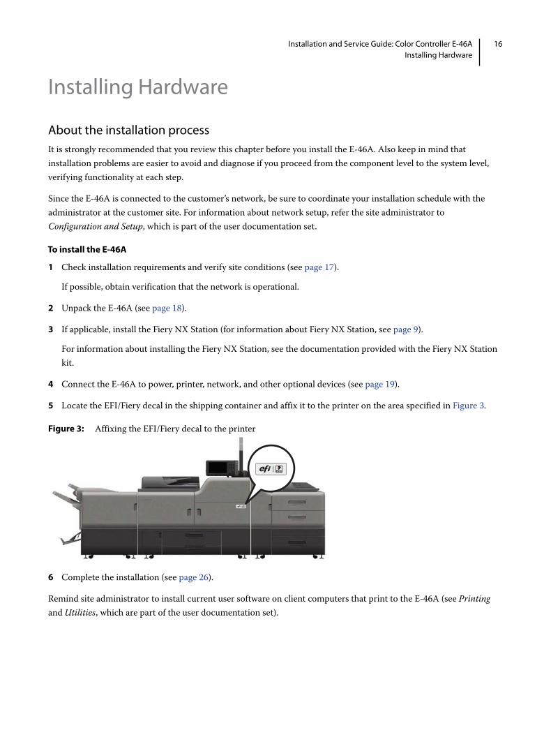
5 Locate the EFI/Fiery decal in the shipping container and affix it to the printer on the area specified in Figure 3.
Figure 3: Affixing the EFI/Fiery decal to the printer
6 Complete the installation (see page 26).
Remind site administrator to install current user software on client computers that print to the E-46A (see Printing and Utilities, which are part of the user documentation set).

17Installation and Service Guide: Color Controller E-46AInstalling Hardware
Checking the customer siteBefore you install the E-46A, check the following conditions at the site and inform the customer of any installation requirements.
Figure 4: Space requirement for the E-46A without optional Fiery NX Station
Printer readiness
• Is the printer configured for use with the E-46A? (For the proper settings, see the documentation that accompanies the printer.)
• Is there a adequate space available near the printer for the E-46A and the optional Fiery NX Station?
Make sure that adequate space is available for the E-46A and the furniture. Allow enough space at the connector panel for the cables to route easily and at the side panel so that the E-46A does not interfere with use of or service to the printer (such as clearing a paper jam). You may need to move the printer away from the wall so that the interface connectors are accessible.
• Does the printer require service or adjustments?
Print the printer Test Page before you install the E-46A.
If the image indicates that the printer needs adjustment, inform the customer. After getting approval, complete the necessary printer service.
Power
• Is a dedicated, grounded electrical outlet for the E-46A available near the printer?
Locate the grounded electrical outlet that will supply power to the E-46A. Do not run the E-46A and the printer on the same circuit. If the customer has provided one, use a surge suppressor for the E-46A.
Network
• Make sure that the network is available at the time set for installation.
1 20cm+ (8 in.) 4 Side panel
2 E-46A 5 Fiery Quick Touch display panel
3 Connector panel 6 Front panel
1
3
4
1 22
1
3 6
6
5
Top view Left view

18Installation and Service Guide: Color Controller E-46AInstalling Hardware
• Verify with the site administrator that the network is functioning before you attach the E-46A.
• Make sure that the configuration requirements specified in Configuration and Setup (which is part of the user documentation set) have been met for remote computers and the network.
Setting customer expectations
When the site is ready, installation of the E-46A takes about one hour. Inform the customer of the following:
• Some nodes on the network may be unavailable during installation.
• The printer may be unavailable for up to one hour.
• The site administrator must be available during the installation for network connectivity.
Equipment downtime and impact on the network can be minimized if the site administrator installs a network connector for the E-46A and confirms network functionality with the connector in place before the date scheduled for the E-46A installation.
• The site administrator must make a networked computer available during the installation. The appropriate software must be installed in advance. Documentation for the networked computer and network operating software should be available.
• The site administrator must install the user software shipped with the E-46A onto networked Windows and Mac OS computers that print to the E-46A. Refer the site administrator to Utilities, which is part of the user documentation set.
Note: This document covers hardware installation and service and provides general information about connecting the E-46A to the customer’s network. Network Setup and configuration information exceeds the scope of this document. For Network Setup and configuration information, refer the site administrator to Configuration and Setup, which is part of the user documentation set.
Unpacking the E-46A
The E-46A is assembled and shipped from the factory with all necessary cables (except the network cable) and documentation. For shipped contents, see the Packing List.
To unpack the E-46A
Note: Do not immediately discard packing materials. It is recommended that you save all packing materials in case you need them later (for example, if you discover something is damaged and need to return it).
1 Open the box and remove the packing material.
Save the original boxes and packing material, in case you need to transport the E-46A at a later date.
2 Remove the contents from the top container. Inspect the contents for visible damage.
DANGER Before you unpack the E-46A, it is strongly recommended that you review all “Precautions” on page 12 to avoid injury or damage to the E-46A.

19Installation and Service Guide: Color Controller E-46AInstalling Hardware
3 Set aside the remaining components from the top container.
4 Remove the top container and any packing material.
5 Carefully lift the E-46A out of the box (see “Lift the E-46A carefully” on page 15).
If you notice shipping damage to any component, save the shipping container, in case the carrier needs to see it. Call the carrier immediately to report the damage and file a claim.
6 Give the media pack to the customer or site administrator.
Let the customer or site administrator know that in order to take full advantage of the E-46A, the user software must be installed on computers that will print to the E-46A.
Connecting the E-46A You are now ready to make the following connections:
• Keyboard, monitor, and mouse (optional) (see page 21)
Note: Monitor, keyboard, and mouse are included with the optional Fiery NX Station kit.
• Power cable (see page 21)
• Printer interface (crossover Ethernet) cable (lower RJ-45) (see page 21)
• Network cable (upper RJ-45) (see page 22)
• USB power cable for power synchronization with printer (see page 24)
20Installation and Service Guide: Color Controller E-46AInstalling Hardware
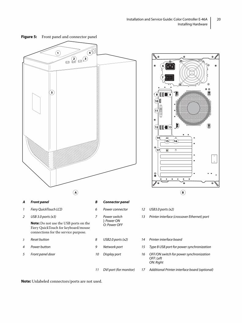
Figure 5: Front panel and connector panel
Note: Unlabeled connectors/ports are not used.
A Front panel B Connector panel
1 Fiery QuickTouch LCD 6 Power connector 12 USB3.0 ports (x2)
2 USB 3.0 ports (x3)
Note: Do not use the USB ports on the Fiery QuickTouch for keyboard/mouse connections for the service purpose.
7 Power switch|: Power ONO: Power OFF
13 Printer interface (crossover Ethernet) port
3 Reset button 8 USB2.0 ports (x2) 14 Printer interface board
4 Power button 9 Network port 15 Type B USB port for power synchronization
5 Front panel door 10 Display port 16 OFF/ON switch for power synchronizationOFF: LeftON: Right
11 DVI port (for monitor) 17 Additional Printer interface board (optional)
1 4
2
A B
6
7
15
8 95
3
10
16
11
12 13
14
17

21Installation and Service Guide: Color Controller E-46AInstalling Hardware
To connect the E-46A to monitor, keyboard, and mouse (optional)
Note: Monitor, keyboard, and mouse are included with the optional Fiery NX Station kit. For information about the monitor, keyboard, and mouse, see the documentation that accompanies those products.
1 Make sure that the E-46A is installed in the Fiery NX Station furniture and the monitor is securely attached to the top of the E-46A.
2 Connect the monitor cable to the DVI port on the connector panel.
3 Connect the monitor power cable to a power outlet on the wall.
4 Place the keyboard and mouse on the furniture table top.
5 Connect the wireless adapter for the keyboard and mouse to one of the USB ports.
Use the USB ports attached at the front of the furniture.
6 Power on the mouse by using the power switch on the bottom side of the mouse.
To connect the E-46A to power
1 Locate the E-46A power cable that is shipped with the E-46A.
Be sure to use the appropriate power cable for your regional outlet type.
2 Connect the recessed end of the E-46A power cable to the power outlet at the customer site.
3 Connect the other end to the E-46A power connector (see Figure 5).
Connecting the E-46A to printer and network
Connect the E-46A to the printer and the network to enable print and network connectivity.
To connect to the printer
1 Make sure that the E-46A and the printer are powered off.
2 Locate the printer interface (crossover Ethernet) cable that is shipped with the E-46A.
The straight-through Ethernet cable at the customer site and the crossover Ethernet cable shipped with the E-46A look similar, but are not interchangeable. Make sure that you connect the printer interface (crossover Ethernet) cable shipped with the E-46A.

22Installation and Service Guide: Color Controller E-46AInstalling Hardware
3 Connect one end of the printer interface (crossover Ethernet) cable to the printer interface (crossover Ethernet) port (lower RJ-45) on the E-46A connector panel.
Figure 6: Printer and E-46A cable connections
4 Connect the other end of the printer interface (crossover Ethernet) cable to the printer.
To connect to the network
1 Make sure that the E-46A is powered off.
2 Obtain the appropriate straight-through Ethernet cable for the customer network connection:
• For 10BaseT link speed, use a cable that is Category 3 or higher.
• For 100BaseTX, use Category 5 or higher (4-pair/8-wire, short-length).
• For 1000BaseT, use Category 5e or higher (4-pair/8-wire, short-length).
Note: To verify the cable type, align the connectors on each end of the cable, as shown in Figure 7. On a straight-through cable, the wire arrangements are identical on both ends; on a crossover cable, the wire arrangements are different.
The straight-through Ethernet cable at the customer site and the crossover Ethernet cable shipped with the E-46A look similar, but are not interchangeable. Make sure that you connect the straight-through Ethernet cable for the network connection.

23Installation and Service Guide: Color Controller E-46AInstalling Hardware
Figure 7: Straight-through and crossover Ethernet cables
3 Connect one end of the network cable to the network port (upper RJ-45) on the E-46A connector panel (see Figure 5).
4 Connect the other end of the cable to the customer network.
After power on, the site administrator should perform Network Setup, verify the network connection, verify that the E-46A appears in the list of printers, and then print a few test documents from a networked computer that will use the E-46A. For more information, see Configuration and Setup, which is part of the user documentation set.
Enabling the power synchronization with printer
During the installation, you can enable the power synchronization feature by using the USB power cable included in the accessory kit and OFF/ON switch on the E-46A connector panel. The default switch position is OFF.
When you enable power synchronization, the E-46A synchronizes power with the printer’s main power off/on status. If the printer is powered off, the E-46A receives signals from the printer through the USB power cable, and automatically starts the shutdown process. If the printer is powered on, the E-46A receives the startup signals from the printer, and automatically powers on and begins the startup sequence.
1 Straight-through cable:Wire arrangements are identical on both connectors
2 Crossover cable:Wire arrangements are different (wire arrangement shown here are an examples; actual arrangements may vary.)
Note: Align cable connectors side by side and examine wires
After the power synchronization is enabled, make sure to control the E-46A power from the printer.
1 2 3 4 1 2 3 4
1 2 3 4 3 4 1 2
=
=
1
2

24Installation and Service Guide: Color Controller E-46AInstalling Hardware
To enable the power synchronization feature at the E-46A
1 Make sure that the E-46A and the printer are powered off.
2 Make sure that the power synchronization switch on the E-46A connector panel is in the OFF position.
3 Remove the port cover that is attached to the Type B USB port on the E-46A connector panel.
4 Locate the USB power cable in the accessory kit that is shipped with the E-46A.
5 Connect one end of the USB power cable to the Type B USB port on the E-46A connector panel (see Figure 8).
6 Connect the other end of the USB power cable to the USB port on the printer.

25Installation and Service Guide: Color Controller E-46AInstalling Hardware
7 Set the power synchronization switch on the E-46A connector panel to ON position.
Figure 8: USB power cable connection between printer and E-46A
8 Make sure that the power switch on the E-46A connector panel is in the ON (|) position.
Figure 9: E-46A power switch
9 Power on the printer.
The E-46A automatically starts up.
Do not change the switch position when the E-46A is powered on.
A Printer connector panel B E-46A connector panel
1 Type A USB port (x2) 3 Type B USB port for power synchronization
2 USB power cable 4 OFF/ON switch for power synchronizationOFF: LeftON: Right
A B
42
13

26Installation and Service Guide: Color Controller E-46AInstalling Hardware
To disable the power synchronization
1 Turn off the printer using the main power switch.
Wait until the E-46A shuts down.
2 Set the switch on the E-46A connector panel to the OFF position (see Figure 8).
3 Disconnect the USB power cable from the Type B USB port on the E-46A connector panel, and from the USB port on the printer.
Completing the installationTo complete the installation of the E-46A at the customer site, do the following:
1 Make sure that the E-46A is turned off and the power switch on the E-46A connector panel is in the ON (|) position.
2 Set the power synchronization switch on the E-46A connector panel to ON position (see Figure 8).
3 Power on the printer.
The E-46A automatically starts up.
4 Print the Configuration page from Fiery QuickTouch to obtain the Fiery ID that is used as a Fiery default password (see page 31).
Note: Fiery ID is referred to the ID field located under BIOS Setup section of the Configuration page.
5 Once the E-46A starts up, follow the on-screen prompts to complete the language selection, license agreement, and enter the server name.
6 If the E-46A requires a static IP address (for example, in a non-DHCP network environment), work with the site administrator to configure it as described on page 27.
7 Print the Test Page and Configuration page, and ask the customer to verify the output (see page 31).
8 Perform any required system software upgrades. For instructions, see the documentation that accompanies the E-46A system upgrade.
Updates to E-46A software may be available from a variety of sources (for example, System Updates (see page 108) or patches downloaded by the customer).
Windows operating system updates should be obtained from Microsoft directly. Because such updates are available directly from Microsoft, EFI does not maintain or provide them via the System Updates feature.
Do not change the switch position when the E-46A is powered on.
Do not change the switch position when the E-46A is powered on.
27Installation and Service Guide: Color Controller E-46AInstalling Hardware
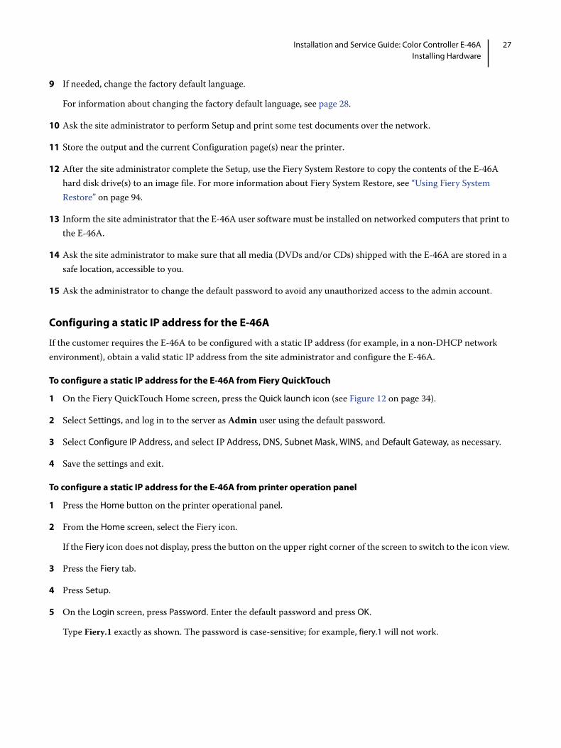
9 If needed, change the factory default language.
For information about changing the factory default language, see page 28.
10 Ask the site administrator to perform Setup and print some test documents over the network.
11 Store the output and the current Configuration page(s) near the printer.
12 After the site administrator complete the Setup, use the Fiery System Restore to copy the contents of the E-46A hard disk drive(s) to an image file. For more information about Fiery System Restore, see “Using Fiery System Restore” on page 94.
13 Inform the site administrator that the E-46A user software must be installed on networked computers that print to the E-46A.
14 Ask the site administrator to make sure that all media (DVDs and/or CDs) shipped with the E-46A are stored in a safe location, accessible to you.
15 Ask the administrator to change the default password to avoid any unauthorized access to the admin account.
Configuring a static IP address for the E-46A
If the customer requires the E-46A to be configured with a static IP address (for example, in a non-DHCP network environment), obtain a valid static IP address from the site administrator and configure the E-46A.
To configure a static IP address for the E-46A from Fiery QuickTouch
1 On the Fiery QuickTouch Home screen, press the Quick launch icon (see Figure 12 on page 34).
2 Select Settings, and log in to the server as Admin user using the default password.
3 Select Configure IP Address, and select IP Address, DNS, Subnet Mask, WINS, and Default Gateway, as necessary.
4 Save the settings and exit.
To configure a static IP address for the E-46A from printer operation panel
1 Press the Home button on the printer operational panel.
2 From the Home screen, select the Fiery icon.
If the Fiery icon does not display, press the button on the upper right corner of the screen to switch to the icon view.
3 Press the Fiery tab.
4 Press Setup.
5 On the Login screen, press Password. Enter the default password and press OK.
Type Fiery.1 exactly as shown. The password is case-sensitive; for example, fiery.1 will not work.

28Installation and Service Guide: Color Controller E-46AInstalling Hardware
6 On the Setup screen, do the following:
• Press WINS. If enabled (yellow), press Use WINS to disable this feature. Press Save.
• Press DNS. If enabled (yellow), press Get DNS address automatically to disable this feature. Press Save.
• Press IP Address. Enter an IP address. Press Save.
• Press IPv4 Address. Press Manual Configuration.
7 On the Manual Configuration screen, do the following:
• In the IP Address field, enter an IPv4 address. Press OK.
• In the Subnet Mask field, enter a subnet mask IP address. Press OK.
• In the Default gateway field, enter a default gateway IP address. Press OK.
• When done, press Save. Press Go Back.
8 On the Setup screen, press Exit Setup.
9 Press Reboot Now.
Change the language of the E-46A
If necessary you can change the language of the E-46A set at the factory.
To change the E-46A language from Fiery QuickTouch
1 On the Fiery QuickTouch Home screen, select Quick Launch > Settings (see Figure 12 on page 34).
2 Log in to the E-46A as Administrator.
Note: The default password will be set after any of the following:
• You re-install the system software
• You restore the recovery partition (from Fiery System Restore)
3 Select Language, and then from the Select language drop-down, select the language you want.
4 Press Save Changes.
5 Press Reboot.
Wait until the E-46A reboots and becomes Idle. It may take up to 15 minutes to complete the system language change.
To change the E-46A language from Configure
1 Access Configure (see page 32).
2 In Configure, click Fiery Server > Regional Settings,
3 In the Server Language drop-down list, select a language.

29Installation and Service Guide: Color Controller E-46AInstalling Hardware
4 Click Save.
5 Click Continue, then click Reboot.
6 Wait until the E-46A reboots and becomes Idle. It may take up to 15 minutes to complete the system language change.

30Installation and Service Guide: Color Controller E-46AUsing the E-46A
Using the E-46A
The following user interfaces are available for the E-46A:
• Fiery Advanced Controller Interface (FACI)
• Fiery QuickTouch on the front of the E-46A
Fiery QuickTouch is a seven-inch LCD color touch screen interface for the E-46A.
• The printer operation panel (see page 37)
Fiery Advanced Controller Interface (FACI)You can access the FACI from the following devices:
• Fiery NX Station monitor (optional)
• Printer operation panel (see page 37)
• Windows client computer using Remote Desktop Connection.
Note: For information about how to use Remote Desktop Connection on your local Windows client computer, refer to the Windows Help.
Fiery TickerWhen you access the FACI, Fiery Ticker automatically starts showing the status bar.
Figure 10: Fiery Ticker status bar
You can perform the following tasks using the Fiery Ticker:
• Monitor the activities of the E-46A and printer using the Fiery Notes
• Manage the E-46A by using Command WorkStation or WebTools
• Shut down, restart, or reboot the E-46A
For details, see the Fiery Ticker Help. To access the Fiery Ticker Help, click “>>” icon at the upper left corner of the FACI screen, and select Help.
Printing the E-46A pagesThis section describes how to print the Test Page, Server Configuration page, and other Fiery pages.
Menu Access

31Installation and Service Guide: Color Controller E-46AUsing the E-46A
• Test Page verifies that all components of the E-46A-to-printer interface work. The Test Page is a color file that resides on the E-46A hard disk drive.
Note: Information regarding Test Page refers to PS Test Page or PCL Test Page. For more information, see Configuration and Setup, which is part of the user documentation set.
• Server Configuration page provides general information about the hardware and software configuration of the E-46A, the customer’s current settings for Setup, the current calibration, and the IP address of the E-46A.
The Server Configuration page also contains the Fiery ID that can be used as a default password when you login for the first time.
Note: Fiery ID is referred to the ID field located under BIOS Setup section of the Server Configuration page.
Printing the Server Configuration page can be helpful during installation, Setup, and service. After installing the E-46A (including connecting to the network) and before default settings are changed in Run Setup, you can obtain a record of the defaults by printing the Server Configuration page.
To print the E-46A pages from Fiery QuickTouch
1 On the Fiery QuickTouch Home screen, select Quick Launch > Print (see Figure 12 on page 34).
2 Choose the page that you want to print.
3 Log in to the E-46A as Administrator.
To log on as Administrator, use the administrator’s password set by the site administrator.
To print the E-46A pages from Fiery Ticker
1 At Fiery Ticker screen, click “>>” icon on the upper left corner, and choose Print Pages.
The Print Pages sub-menu displays the list of available E-46A pages.
2 Choose the page that you want to print from the sub-menu.
The E-46A sends the selected page to the printer.
3 If you printed the E-46A Test Page, examine the quality of the Test Page from the printer.
If the Test Page prints, you know the E-46A is functional and the connection between the E-46A and the printer is working. If the Test Page fails to print, look up printing problems in “Table 4: E-46A error messages and conditions” on page 117.
When you examine the Test Page, keep in mind the following:
• All color patches should be visible, even though they may be very faint in the 5% and 2% range.
• Each color’s patch set should show uniform gradation from patch to patch as the color lightens from 100% to 0%.
Poor image or color quality may indicate a need to calibrate the system or service the printer. Information on the Test Page includes the date and time of the last calibration so the Test Page can be kept for future reference. For more information, look up for printing problems in “Table 4: E-46A error messages and conditions” on page 117, or see Color Printing, which is part of the user documentation set.
32Installation and Service Guide: Color Controller E-46AUsing the E-46A
Command WorkStationAs an E-46A service technician, you will typically log on to the system as Administrator. For more information about using Command WorkStation, see Command WorkStation Help.
About ConfigureYou can access Configure from Command WorkStation or WebTools. For information about using Configure, see Configure Help.
To access Configure from an Internet browser
1 Open an Internet browser and type the IP address of the E-46A.
Note: As a security measure, WebTools is designed to work only over Hyper Text Transfer Protocol Secure (HTTPS). By default, WebTools uses a self-signed certificate created by the Fiery. This causes the web browser to display a untrusted certificate message while accessing WebTools. It is safe to ignore this message and proceed to access WebTools.
2 In WebTools, click the Configure tab.
3 Log on with Administrator privileges.
To log on with the Administrator privileges, use the administrator’s password set by the site administrator.
To access Configure from Command WorkStation
1 In Command WorkStation, as Administrator, do one of the following:
• Click Server > Configure.
• Click Server > Device Center > GENERAL > General Info tab, and then click Configure in the lower right corner.
2 If the Fiery Setup dialog box displays, click Configure.
Fiery QuickTouchThe Fiery QuickTouch on the front of the E-46A allows you to do the following:
• View print job status and alerts
• Use Fiery System Restore to back up and restore the E-46A
• Replace the motherboard (when the motherboard replacement dongle is inserted into a USB port)
• View the IP address of the E-46A
• Shut down, restart, or reboot the E-46A (see page 42).
• Interact with the E-46A during software installation and initial setup (see page 101)
• Run certain diagnostics (for service purposes only) (see page 110)

33Installation and Service Guide: Color Controller E-46AUsing the E-46A
Figure 11: Fiery QuickTouch panel features
1 Fiery QuickTouch LCD 3 USB 3.0 ports (x3)
2 Power button 4 Reset button (requires pin)
1 2
3 4

34Installation and Service Guide: Color Controller E-46AUsing the E-46A
Overview of Fiery QuickTouch menu options
The following options are available from the Fiery QuickTouch:
Figure 12: Fiery QuickTouch Home screen
The Home screen is the main interface for job status, and displays various screen elements.
The Queue job list shows queued jobs and detailed information about each job.
1 E-46A name and status
Pressing the Fiery icon shows more information about the E-46A and the network address.
6 Number of pages and copies that are printing
2 Icon of the print job type
If there are no print jobs being processed, an Idle status displays.
7 Queued jobs list
Pressing the Queue icon shows a list of jobs that are queued.
3 Printing progress of the active print job 8 Printed jobs list
Pressing the Printed icon shows the printed jobs list.
4 File name of the active print job 9 Quick Launch
The Quick Launch displays additional applications.
5 Time left to complete the active print job 10 Shows consumables
11 Quick Options and current local time
1
2 3
4
5
6
7 8
9
11
10

35Installation and Service Guide: Color Controller E-46AUsing the E-46A
Figure 13: Queue job window
The Printed jobs list provides job status and details about the jobs that have been printed.
Figure 14: Printed jobs window
In either the Queue jobs or Printed jobs screen, you can press Back to go back to the Home screen.
36Installation and Service Guide: Color Controller E-46AUsing the E-46A
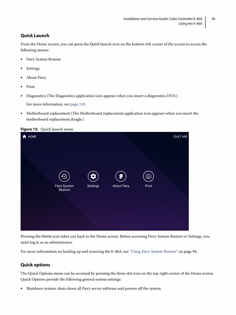
Quick Launch
From the Home screen, you can press the Quick launch icon on the bottom-left corner of the screen to access the following menus:
• Fiery System Restore
• Settings
• About Fiery
• Diagnostics (The Diagnostics application icon appears when you insert a diagnostics DVD.)
For more information, see page 110.
• Motherboard replacement (The Motherboard replacement application icon appears when you insert the motherboard replacement dongle.)
Figure 15: Quick launch menu
Pressing the Home icon takes you back to the Home screen. Before accessing Fiery System Restore or Settings, you must log in as an administrator.
For more information on backing up and restoring the E-46A, see “Using Fiery System Restore” on page 94.
Quick options
The Quick Options menu can be accessed by pressing the three-dot icon on the top-right corner of the Home screen. Quick Options provide the following general system settings:
• Shutdown system: shuts down all Fiery server software and powers off the system.

37Installation and Service Guide: Color Controller E-46AUsing the E-46A
• Reboot system: shuts down all Fiery server software and reboots the system.
• Restart Server: resets the Fiery server software, but does not reboot the entire system.
• Brightness: sets the brightness level of the Fiery QuickTouch screen.
Figure 16: Quick options menu
Using the E-46A from printer operation panelThe “Fiery” icon on the printer operation panel allows you to interact with the E-46A from the printer. The menus provide access to many of the same options available from Command WorkStation.
Figure 17: The printer operation panel
To access the E-46A from printer operation panel
1 Press the Home button on the printer operation panel.
Main
Waiting Jobs:
Idle
Paper Tray Status:
Document 3
Document 4
Document 1
Document 2
Printed Jobs:
Job List Tools
Suspend Printing
Resume Printing
Login

38Installation and Service Guide: Color Controller E-46AUsing the E-46A
2 From the Home screen of the printer operation panel, select the Fiery icon. If the Fiery icon does not display, move to the other screen by swiping the touch screen until the Fiery icon appears.
Figure 18: Fiery icon on printer operation panel
3 Press the Fiery tab.
Main tab
The Main tab is displayed as the starting point. It summarizes waiting and printed jobs and displays paper tray status and other information.
Job List tab
The Job List tab on the printer operation panel provides access to jobs according to the status of the job, similar to the Active and Printed Jobs windows in Command WorkStation. The lists are as follows:
To change from one list to another, press the desired tab at the bottom of the printer operation panel.
On each of these lists, you can scroll up and down one line at a time, or advance to the top or bottom of the job list. Select a job, and choose the appropriate button to Print, Print and Hold, Delete, or display the Properties of the job. On the Properties tab, you can change the number of copies, but not any other job properties.
Tools tab
The Tools tab allows you to perform tray alignment and calibration.
Suspend Printing Suspend print activity between the E-46A and the printer. Use this command to interrupt the current E-46A job, for example, to perform maintenance tasks. Jobs continue to process on the E-46A. After you complete maintenance tasks, choose Resume Printing to continue printing jobs from the E-46A.
Resume Printing Resume print activity between the printer and the E-46A after you select Suspend Printing.
Active Jobs currently waiting to print.
Held Held jobs.
Printed Printed jobs.
Secure Allows you to log on to display secure print jobs.
Tray Alignment Adjust the placement of text and images on a page so that they are correctly aligned on the sheet of paper and both sides of a duplex sheet have the exact same alignment. For more information about this function, see Utilities.

39Installation and Service Guide: Color Controller E-46AUsing the E-46A
Scan tab
The Scan tab allows you to scan documents. Depending on the printer model, Scanning may not be supported and the Scan tab may not appear on the Fiery QuickTouch. For more information, see Utilities, which is part of the user documentation set.
Fiery tab
The Fiery tab provides access to many of the same features available through Command WorkStation.
Calibration Calibrate the E-46A using ColorCal. For more information, see Color Printing.
Fiery Info Displays information about the current configuration of the E-46A.
Printable Info Allows you to print these system pages from the E-46A:
PS Test Page/PCL Test Page: Confirms that the E-46A is properly connected to the printer, and provides color and grayscale samples to troubleshoot problems with the printer or the E-46A. Settings on the Test Page may include: Server Name, color settings, printer model, and date and time the Test Page was printed.
PS Font List/PCL Font List: Prints a list of all fonts currently on the E-46A hard disk drive.
Configuration: Provides general information about the hardware and software configuration of the E-46A, the current settings for Setup, the current calibration, the IP address of the E-46A, and a log of system updates.
Color Charts: Prints samples of the RGB, CMY, and PANTONE colors available from the E-46A.
Custom Paper Instructions: Provides the instructions for setting up custom paper entry.
Calibration Instructions: Prints the information on how to perform the calibration.
Job Log: Prints a log of the last 55 jobs.
E-mail Log: Prints a log listing recent e-mail activity.
FTP Log: Prints a log listing recent FTP activity.
Note: To print the E-mail or FTP log, you must first enable the appropriate service.
Setup Enter the Setup menu and change Setup option settings.
Clear Job Log Clears the job log from the E-46A.
Run Diagnostics To troubleshoot printer interface board, choose this menu

40Installation and Service Guide: Color Controller E-46AUsing the E-46A
Printable Info menu
This section describes how to print pages such as the Test Page and Configuration page from the Printable Info menu (described on page 30). The Printable Info menu is accessed through the Fiery tab (see page 39).
Printing the Configuration page can be helpful during installation, Setup, and service. After installing the E-46A (including connecting to the network), and before default settings are changed in Run Setup, you can obtain a record of the defaults by printing the Configuration page.
Before you perform any service procedure, you should print the E-46A Configuration page, if possible, so you are prepared to return the settings to their former configuration, if necessary.
Printing the Test Page indicates that the E-46A is functional and that the connection between the E-46A and the printer is working.
To print a page from the Printable Info menu
1 If it is not powered on already, power on the printer and allow it to warm up.
2 If it is not powered on already, power on the E-46A using the power button on the front panel and allow it to start up completely (approximately three minutes).
3 Make sure that Idle appears on the Fiery Main menu.
If Busy or Printing appears, the E-46A is processing and you must wait until Idle appears.
4 Touch the Fiery tab.
5 Touch Printable Info and then select the page that you want to print.
The E-46A sends the selected page(s) to the printer.
Clear Server Clear all jobs in all server queues, as well as all jobs archived on the E-46A hard disk, the index of archived jobs (in the Archive window), all FreeForm masters, and the index of FreeForm masters (in the FreeForm window). Consult with your administrator or operator before choosing Clear Server.
Restart Fiery Shut down all E-46A activity in the correct manner and then restart. The following options are available from the submenu that appears:
Restart Fiery Service: Resets the server software but does not reboot the entire system. Network access to the E-46A is temporarily interrupted and all currently processing jobs are aborted and may be lost.
Restart System: Shuts down and then reboots the E-46A. Network access to the E-46A is terminated and all currently processing jobs are aborted and may be lost.
Shut Down: Shuts down all E-46A activity properly.

41Installation and Service Guide: Color Controller E-46AUsing the E-46A
6 If you printed the Test Page, examine the quality of the page.
If the Test Page prints, you know the E-46A is functional and the connection between the E-46A and the printer is working. If the Test Page fails to print, look up for printing problems in the Troubleshooting table on page 117.
When you examine the Test Page, keep in mind the following:
• All color patches should be visible, even though they may be very faint in the 5% and 2% range.
• Each color’s patch set should show uniform gradation from patch to patch as the color lightens from 100% to 0%.
Poor image or color quality may indicate a need to calibrate the system or service the printer. Information on the Test Page includes the date and time of the last calibration, so the Test Page can be kept for future reference. For more information, look up printing problems in “Table 4: E-46A error messages and conditions” on page 117, or see Color Printing on the User Documentation set.
Using the FACI from printer operation panel
To access the FACI from printer operation panel
1 Press the Home button on the printer operation panel.
2 From the Home screen of the printer operation panel, select the Fiery Console icon.If the Fiery Console icon does not display, move to the other screen by swiping the touch screen until the Fiery Console icon appears.
Figure 19: Fiery Console icon on printer operation panel
3 Access FACI as Administrator user.
The default user name is Administrator or Admin, and the password is the administrator’s password set by the site administrator.

42Installation and Service Guide: Color Controller E-46AUsing the E-46A
Network status LEDsTwo LEDs next to the network connector indicate the network link status and speed. For additional information about network setup, see Configuration and Setup, which is part of the user documentation set.
Figure 20: Ethernet network port
Table 1: Network link indicators
Table 2: Network speed indicators
Starting, shutting down, restarting, and rebooting You can leave the E-46A running all the time. Restarting the E-46A resets the E-46A system software, but does not reboot the entire system. Network access to the E-46A is temporarily interrupted and all the jobs processing currently are terminated.
To start or shut down the E-46A when power synchronization is ON
1 Make sure that the power synchronization in enabled (see page 23).
1 Link/Activity LED
2 Speed LED
Link/Activity LED Network link status
Off No link to network
Solid green Valid link to network
Flashing green Data transfer is in progress
Speed LED Network speed
Off 10 Megabits/second
Green 100 Megabits/second
Amber 1000 Megabits/second
Remember that when the E-46A is powered off, network access to the printer is interrupted. Always obtain permission from the network administrator before you take the E-46A off the network.
Unless instructed otherwise by a troubleshooting procedure, always use the procedures in this section to shut down the E-46A. Do not use the power button on the side of the Fiery QuickTouch to shut down the E-46A.
1
2

43Installation and Service Guide: Color Controller E-46AUsing the E-46A
2 Make sure that the power switch on the E-46A connector panel is in the ON (|) position.
Figure 21: E-46A power switch
3 Power on the printer.
The E-46A automatically starts up.
4 Check the activities on the Fiery QuickTouch display panel.
Allow startup to proceed without interruption. Do not press any buttons while the system is starting.
5 To shut down the E-46A, power off the printer.
Note: Make sure that the E-46A is not receiving, processing, or printing any files. If the system has just finished processing, wait at least five seconds after the system reaches Idle state before you power off the printer.
6 If you shut down the E-46A, move the power switch on the E-46A connector panel to the off (O) position for maximum energy savings or service (wait 10 seconds before you proceed).
To start or shut down the E-46A when power synchronization is OFF
1 Make sure that the power synchronization in disabled (see page 23).
2 Make sure that the power switch on the E-46A connector panel is in the ON (|) position.
Figure 22: E-46A power switch
3 Power on the E-46A using the power button ( ) on the side of the Fiery QuickTouch display panel.
Press once and release the button to power on the system. The power supply automatically senses the correct voltage.

44Installation and Service Guide: Color Controller E-46AUsing the E-46A
Figure 23: E-46A power button
4 Check the activities on the Fiery QuickTouch display panel.
Allow startup to proceed without interruption. Do not press any buttons while the system is starting.
5 To shut down the E-46A, do one of the following:
Note: Make sure that the E-46A is not receiving, processing, or printing any files. If the system has just finished processing, wait at least five seconds after the system reaches Idle state before you power off the printer.
• From the Fiery NX Station monitor (Optional) or Windows client computer using Remote Desktop Connection, click the Windows Start button, and select Power > Shut Down.
• From the Fiery QuickTouch Home screen, press the Quick Options menu button and select Shutdown system.
• From the printer operation panel, do the following:
• Press the Home button and select the Fiery icon.
• Press the Fiery tab, select Restart Fiery and then press Shut Down.
6 If you shut down the E-46A, move the E-46A power switch to the off (O) position for maximum energy savings or service (wait 10 seconds before you proceed).
To restart or reboot the E-46A from Fiery NX Station (Optional) or Remote Desktop Connection
1 Make sure that the E-46A is not receiving, processing, or printing any files.
If the system just finished processing, wait at least five seconds after the system reaches Idle before you proceed.
2 Do one of the following:
• To reboot the entire system including the operating system, click the Windows Start button and select Power > Restart.
Restarts both E-46A and Windows operating system.
• To restart only the E-46A system software, Click “>>” icon on the Fiery Ticker and select Server Actions > Restart Fiery and then click OK.
Restarts only the E-46A system software without rebooting the Windows operating system.

45Installation and Service Guide: Color Controller E-46AUsing the E-46A
To restart or reboot the E-46A from Fiery QuickTouch
1 Make sure that the E-46A is not receiving, processing, or printing any files.
If the system just finished processing, wait at least five seconds after the system reaches Idle before you proceed.
2 On the Fiery QuickTouch Home screen, press the Quick Options menu button.
3 Do one of the following:
• To reboot the entire system including the operating system, select Reboot system.
• To restart only the E-46A system software, select Restart server.
4 At the confirmation screen, select OK.
To restart or reboot from printer operation panel
1 Make sure that the E-46A is not receiving, processing, or printing any jobs.
If the system just finished processing, wait at least five seconds after the system reaches Idle before you proceed.
2 Press the Home button and select the Fiery icon.
3 Press the Fiery tab and select Restart Fiery.
4 Do one of the following:
• To reboot the entire system including the operating system, select Reboot system.
• To restart only the E-46A system software, select Restart Fiery.

46Installation and Service Guide Color Controller E-46AReplacing parts
Replacing parts
Generally, the E-46A requires no regular service or maintenance. Use the procedures in this chapter to inspect, remove, reseat, and replace major hardware components.
OverviewThis chapter includes information about servicing the following components:
• Boards and cables
• Fiery QuickTouch display module
• Motherboard components (DIMMs, CPU, and battery)
• Fan
• Power supply
• Hard disk drive
• DVD drive
Replacement parts are available from your authorized service representative. The terms “replace” and “replacing” are used throughout this document to refer to the reinstallation of existing components. Install new components only when necessary. If you determine that a component that you have removed is not faulty, reinstall it.
Note: Replacement parts and specifications are subject to change. Install the correct parts as directed by your service/support center.
For a list of the tools required to service the E-46A, see “Tools you will need” on page 11.
For information about the monitor, keyboard, and mouse, see the documentation that accompanies those products.
When servicing the E-46A, refer to the “Precautions” on page 12.

47Installation and Service Guide Color Controller E-46AReplacing parts
E-46A hardware
Figure 24: Front and connector panel
A Front panel B Connector panel
1 Fiery QuickTouch LCD 6 Power connector 12 USB3.0 ports (x2)
2 USB 3.0 ports (x3)
Note: Do not use the USB ports on the Fiery QuickTouch for keyboard/mouse connections for the service purpose.
7 Power switch|: Power ONO: Power OFF
13 Printer interface (crossover Ethernet) port
3 Reset button 8 USB2.0 ports (x2) 14 Printer interface board
4 Power button 9 Network port 15 Type B USB port for power synchronization
5 Front panel door 10 Display port 16 OFF/ON switch for power synchronizationOFF: LeftON: Right
11 DVI port (for monitor) 17 Additional Printer interface board (optional)
1 4
2
A B
6
7
15
8 95
3
10
16
11
12 13
14
17

48Installation and Service Guide Color Controller E-46AReplacing parts
Figure 25: Inside the front panel
1 DVD drive
2 DVD eject button
1
2

49Installation and Service Guide Color Controller E-46AReplacing parts
Figure 26: Exploded view of E-46A
1 Fiery QuickTouch USB3.0 cable 7 DIMM (x2) 13 Hard disk drive
2 Hard disk drive data cables 8 CPU 14 DVD drive
3 DVD drive data cable 9 Battery 15 Chassis
4 Printer interface board 10 Motherboard 16 Rear fan
5 Fiery QuickTouch power SW/LED cable
11 Front panel 17 Fiery QuickTouch display
6 CPU cooling assembly 12 Power supply 18 Top panel
Note: CPU fan cable, tie-wraps, cable clamps, dongle(s), and external cables are not shown.
16
4
11
7
14 15
13
6
3
5
8
10
12
9
17
18
21

50Installation and Service Guide Color Controller E-46AReplacing parts
Figure 27: Power and data cable connections
Cable key From To
1 Power supply cable Power supply a. 24-pin power connector on motherboard (J18)
b. 8-pin power connector (PWRCONN1)
c. DVD drive power connector
d. Hard disk drive power connector
e. Fiery QuickTouch power connector
2 Fiery QuickTouch USB cable Fiery QuickTouch USB3.0 header connector on motherboard (J26)
3 SATA Data cable DVD drive SATA 0 connector on motherboard (J50)
4 SATA Data cable Hard disk drive SATA 1 connector on motherboard (J41)
5 Rear fan cable Rear fan FRONT FAN connector on motherboard (J20)
6 CPU fan cable CPU fan CPU FAN connector on motherboard (J16)
7 Power switch cables (red, white) Fiery QuickTouch J102 connector on printer interface board (pin 5, 6) Align triangle on cable connector as shown.8 LED cables (white, black) Fiery QuickTouch J102 connector on printer interface board (pin 7, 8)
Note: When polarity (+/-) is right, the LED of the power button turns on.
9 Cable with keyed connectors J103 connector on printer interface board
FP header connector on motherboard (J15)
Note: See the cable connection label attached inside the chassis.
1b
1c
7
1a
1d
3
2
4
5
6
1e
8
9
LED +LED -SW

51Installation and Service Guide Color Controller E-46AReplacing parts
Accessing internal componentsShut down and open the E-46A when you need to inspect or service internal components. Always use the following procedures when opening the E-46A for inspection or service.
Shutting down the system
For accessing the internal components, it is recommended to disable the power synchronization before you shut down the E-46A. For information about how to shut down the E-46A when power synchronization is OFF, see “To start or shut down the E-46A when power synchronization is OFF” on page 43.
When shutting down the E-46A, do the following:
• Remove the power cable from the connector panel before accessing the internal components.
• If you are cycling power, wait at least 10 seconds before powering back on.
• If you are unable to shut down the E-46A, power off by pressing the power button on the side of the Fiery QuickTouch for up to eight seconds.
Opening the E-46A
Before you open the E-46A, it is strongly recommended that you review “Precautions” on page 12 to avoid injury or damage to the E-46A.
To open the E-46A
1 Shut down the E-46A (see page 51).
2 Wait 10 seconds after the E-46A powers off, and then remove all cables from the back of the E-46A.
3 If applicable, Remove the E-46A from the furniture.
4 Remove all external panels necessary to access the component that you need to service.
At the minimum, you must remove the left panel to service the component. You may also need to remove other panels, depending on the component that you need to access. For guidelines on which panels to remove, see the service procedures that accompany a given component.
Note: When removing multiple panels from the E-46A, use the following order:
• Left side panel (see page 52)
• Right side panel (see page 52)
• Front panel (see page 53)
• Top panel with Fiery QuickTouch (see page 54)
Remember that when the E-46A is powered off, network access to the printer is interrupted. Always obtain permission from the site administrator before you take the E-46A off the network.

52Installation and Service Guide Color Controller E-46AReplacing parts
5 Place the E-46A on a flat surface. Carefully position the E-46A so that it is standing in its normal position.
To remove the side panels
1 Remove the two screws at the rear right of the chassis.
Figure 28: Removing the left panel
2 From the back of the unit, slide the right side chassis cover toward the rear of the unit and remove.
3 Remove the two screws at the rear left of the chassis.
Figure 29: Removing the right panel
4 From the back of the unit, slide the left side chassis cover toward the rear of the unit and remove.

53Installation and Service Guide Color Controller E-46AReplacing parts
To remove the front panel
1 Remove the anchor screw from the front bezel.
Figure 30: Front bezel anchor screw
2 Release the six tabs and pull the front bezel off.
Figure 31: Front bezel tabs
To replace the chassis panels
1 Attach the front bezel to the front of the unit snapping tight the six tabs. See Figure 31.
2 Insert the anchor screw to secure the front bezel. See Figure 30.
1 Top tab (one on each side of bezel)
2 Middle tab (one on each side of bezel)
3 Bottom tab (one on each side of bezel)
1
2
3

54Installation and Service Guide Color Controller E-46AReplacing parts
3 Slide the right chassis cover into place and secure with two screws on backside of the unit.
4 Slide the left chassis cover into place and secure with two screws on backside of the unit.
Fiery QuickTouch display moduleFiery QuickTouch is attached to the top panel of the E-46A.
Follow the directions to remove the chassis covers. See “Opening the E-46A” on page 51. You will need to remove the side covers, then the front cover before you will be able to release the top bezel with the Fiery QuickTouch attached.
To remove the Fiery QuickTouch
1 Remove the side and front panels (see page 52).
2 To remove the top bezel, slide the bezel forward and release it from the top of the chassis.
It is highly recommended that you use a screwdriver with a magnetic tip when removing or replacing screws on the Fiery QuickTouch. If you do not, the screws you remove or replace might fall inside the Fiery QuickTouch device.

55Installation and Service Guide Color Controller E-46AReplacing parts
3 Stabilize the unit and set the Fiery QuickTouch on its side atop the unit.
4 Remove the two connectors attached to the Fiery QuickTouch.
a Remove the tie-wrap that bundles the power cable and a tab on the support bracket for USB connector.
b Remove the power harness by unplugging it.

56Installation and Service Guide Color Controller E-46AReplacing parts
c Remove the two screws from the USB connector and then unplug the connector.
5 Turn the unit so it is faced down on the work surface.
6 Remove the single screw in the center, then remove the washer and spring washer.
Use a screwdriver with a magnetic tip so you do not drop a loose screw into the Fiery QuickTouch unit.
1 Power harness connector
2 USB connector
1
2

57Installation and Service Guide Color Controller E-46AReplacing parts
7 Rotate the Fiery QuickTouch 45 degrees.
8 Remove the top bezel.
Replace the Fiery QuickTouch
1 Attach the new Fiery QuickTouch part to the top bezel by rotating the top bezel 45 degrees, then rotate until the bezel and Fiery QuickTouch align. Insert the spring washer, then the screw with washer and tighten.
2 Once attached, ensure that the Fiery QuickTouch moves properly from side to side.
3 Place the top bezel with Fiery QuickTouch atop the unit on its side.
4 Plug in the USB cable and insert the plug so that the mark on the cable and mark on the internal board line up.
5 Insert the two screws to secure the plug and grounding bracket.
6 Insert the power harness and loop it around guides to allow the Fiery QuickTouch to move freely.
7 Use a tie-wrap to secure the power cable to the tab on the supporting bracket for USB connector.
8 Replace the top bezel on top of the unit and slide back in place.
9 Check that the bezel cover extends over the rear sheet metal to be properly in place.
10 Replace the chassis panels (see page 53).
Removing and replacing boardsThis section includes procedures for removing and replacing the following boards:
• Printer interface board
• Motherboard
Use a screwdriver with a magnetic tip so you do not drop a loose screw into the Fiery QuickTouch unit.
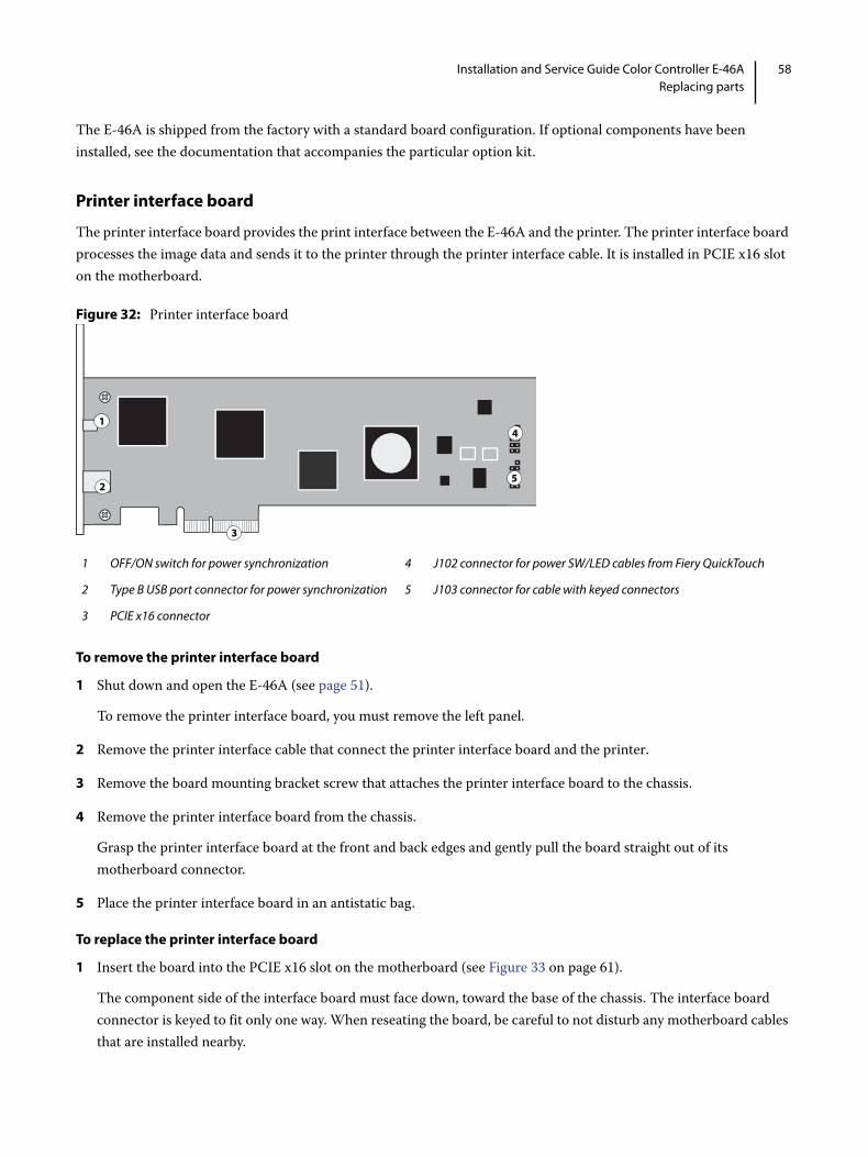
58Installation and Service Guide Color Controller E-46AReplacing parts
The E-46A is shipped from the factory with a standard board configuration. If optional components have been installed, see the documentation that accompanies the particular option kit.
Printer interface board
The printer interface board provides the print interface between the E-46A and the printer. The printer interface board processes the image data and sends it to the printer through the printer interface cable. It is installed in PCIE x16 slot on the motherboard.
Figure 32: Printer interface board
To remove the printer interface board
1 Shut down and open the E-46A (see page 51).
To remove the printer interface board, you must remove the left panel.
2 Remove the printer interface cable that connect the printer interface board and the printer.
3 Remove the board mounting bracket screw that attaches the printer interface board to the chassis.
4 Remove the printer interface board from the chassis.
Grasp the printer interface board at the front and back edges and gently pull the board straight out of its motherboard connector.
5 Place the printer interface board in an antistatic bag.
To replace the printer interface board
1 Insert the board into the PCIE x16 slot on the motherboard (see Figure 33 on page 61).
The component side of the interface board must face down, toward the base of the chassis. The interface board connector is keyed to fit only one way. When reseating the board, be careful to not disturb any motherboard cables that are installed nearby.
1 OFF/ON switch for power synchronization 4 J102 connector for power SW/LED cables from Fiery QuickTouch
2 Type B USB port connector for power synchronization 5 J103 connector for cable with keyed connectors
3 PCIE x16 connector
2
3
14
5
59Installation and Service Guide Color Controller E-46AReplacing parts
2 Secure the board to the chassis with the board mounting bracket screw that you removed earlier.
3 Reassemble the E-46A and verify its functionality (see page 86).
Motherboard
The CPU mounted on the motherboard controls the image data transferred to and from the printer interface board. The motherboard also controls hard disk drive functions and the communication between the E-46A and external devices.
If you are removing the motherboard in order to replace it with a new motherboard, review the troubleshooting and motherboard cautions on page 63.
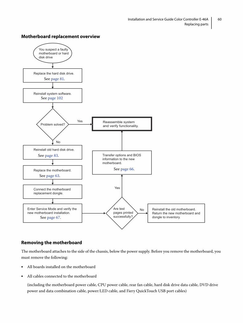
60Installation and Service Guide Color Controller E-46AReplacing parts
Motherboard replacement overview
Removing the motherboard
The motherboard attaches to the side of the chassis, below the power supply. Before you remove the motherboard, you must remove the following:
• All boards installed on the motherboard
• All cables connected to the motherboard
(including the motherboard power cable, CPU power cable, rear fan cable, hard disk drive data cable, DVD drive power and data combination cable, power/LED cable, and Fiery QuickTouch USB port cables)
You suspect a faulty motherboard or hard disk drive
Connect the motherboardreplacement dongle.
Replace the motherboard.
Reinstall old hard disk drive.
Reinstall system software.
Replace the hard disk drive.
Reassemble system and verify functionality.
Transfer options and BIOS information to the newmotherboard.
Enter Service Mode and verify thenew motherboard installation.
Problem solved?
Reinstall the old motherboard. Return the new motherboard and dongle to inventory.
Are test pages printed successfully?
Yes
Yes
No
No
See page 81.
See page 83.
See page 63.
See page 67.
See page 66.
See page 102

61Installation and Service Guide Color Controller E-46AReplacing parts
This section also includes information about the following:
• Replacing or adding DIMMs
• Replacing the CPU
• Replacing the battery
• Jumper configurations
Figure 33: Motherboard
Follow standard ESD and other safety precautions when handling components (see page 12). During service to the motherboard, avoid using excessive force and always place the motherboard on a grounded, non-metallic, static-free surface. Never allow any metal to touch the solder contacts on the underside of the motherboard, especially beneath the battery socket. Improper handling can short-circuit and permanently damage the motherboard.
1 Type A USB 2.0 ports and network port
6 CPU cooling assembly 11 CPU fan power (CPU FAN, J16)
16 SATA 0, DVD drive data cable connector (J50)
2 Monitor port (DisplayPort) 7 Printer interface board (PCIE_X16_SLOT)
12 Rear fan (FRONT FAN, J20) 17 SATA 1, Hard disk drive data cable connector (J41)
3 Monitor port (DVI) 8 Battery (CR1) 13 24-pin power connector (J18)
18 Clear CMOS Jumper (J101)
1
4
8
2
7
3
5
10
6
MH
MH
MH
MH MH
MH MH
MH11
13
14
15
16
1718
12
MH
9

62Installation and Service Guide Color Controller E-46AReplacing parts
To remove boards and cables from the motherboard
1 Shut down and open the E-46A (see page 51).
To access the motherboard, you must remove the left side panel.
2 Remove the printer interface board installed in the PCIE x16 slot on the motherboard.
3 Remove the following cables from the old motherboard:
Note: First remove any plastic cable clamp(s) securing internal cables and tie-wraps.
• Rear fan cable
• Fiery QuickTouch power SW/LED cable
• Fiery QuickTouch USB port cable
• DVD drive cables:
• SATA data cable
• Power and data combination cable
• Hard disk drive cables:
• SATA data cable
• Power supply cable
• 24-pin motherboard power cable
• 8-pin motherboard power cable
• CPU fan cable
For motherboard connector locations, see page 50.
To remove the motherboard
Note: This procedure assumes that you have already performed the procedure “To remove boards and cables from the motherboard” on page 62.
1 Remove all the mounting screws securing the motherboard to the chassis (for screw locations, see Figure 33 on page 61).
4 Type A USB 3.0 ports (x2) 9 DIMM_A0 14 USB 3.0 header connector (J26)
MH Mounting holes
5 8-pin power connector (PWRCONN1)
10 DIMM_B0 15 FP header connector (J15)
Note: Arrows indicate positions for inserting cable and jumper connections.

63Installation and Service Guide Color Controller E-46AReplacing parts
2 Remove the motherboard from the chassis.
Lift the edge of the motherboard. Make sure that the motherboard connectors clear the chassis while you lift it out of the chassis. Do not touch the contacts and avoid using excessive force.
3 If you are replacing the motherboard with a new motherboard, remove the following from the old motherboard:
• DIMMs (see page 69)
• CPU (see page 70)
Replacing the motherboard
Troubleshooting cautions
• Before deciding to install a new motherboard, consult “Troubleshooting” on page 110.
• Inspect all cables and internal components as described on pages “Checking external connections” on page 111 and “Checking internal components” on page 111.
• If troubleshooting strategies (checking cables and connections, reinstalling system software, and so forth) do not solve the problem, and you suspect that the hard disk drive or the motherboard is faulty, always troubleshoot in the following order.
• First, replace the hard disk drive and install system software.
Always replace a faulty hard disk drive with a new hard disk drive. Transferring a hard disk drive from one E-46A to another is incorrect and strongly discouraged.
• If the problem persists, reinstall the original hard disk drive in the system, and then replace the motherboard.
Motherboard cautions
During service, avoid using excessive force and always place the motherboard on a grounded, non-metallic, static-free surface. Never allow any metal to touch the solder contacts on the underside of the motherboard, especially beneath the battery socket. Improper handling can short-circuit and permanently damage the motherboard.
Follow the procedures in this section to replace the motherboard. Failure to follow the instructions in this section may corrupt the system (not easily repaired in the field) or result in an incomplete installation.
Troubleshooting in the wrong order will cause the system to malfunction. In general, it is highly unlikely that both the hard disk drive and the motherboard are defective; therefore, avoid replacing both to solve one problem.
If you have exhausted all other troubleshooting remedies and determined that you need to install a new motherboard, be sure to observe the following cautions:

64Installation and Service Guide Color Controller E-46AReplacing parts
• Do not transfer the BIOS chip from the old motherboard onto the new motherboard.
BIOS chips are not interchangeable.
• Do not reinstall system software at this time.
Reinstalling system software is not necessary when installing a new motherboard and can result in an error if done before transferring options to the new motherboard (described on page 67.)
• Before you use the motherboard replacement dongle to sync the BIOS and options (for example, Fiery Graphic Arts, Premium Edition, if applicable) from the hard disk drive to the new motherboard, enter Service Mode (see page 67) and make sure that the new motherboard solves the problem that you are troubleshooting.
The E-46A can remain in Service Mode indefinitely. Use Service Mode to carefully verify the new motherboard before transferring options to the new motherboard.
Transferring options to the new motherboard permanently customizes the new motherboard. Once customized, the motherboard cannot be returned to inventory or installed in another E-46A. If the new motherboard does not solve the problem in Service Mode, do not transfer options. Return the new motherboard and motherboard replacement dongle to inventory.
• If you can verify in Service Mode that the new motherboard solves the problem that you are troubleshooting, transfer options to the new motherboard using the motherboard replacement dongle included with the new motherboard (see page 67).
• Do not remove the motherboard replacement dongle while transferring options to the new motherboard.
Removing the motherboard replacement dongle prematurely will corrupt the dongle and possibly damage the motherboard. If either become corrupted, you must contact your authorized service/support center and order a new replacement motherboard kit.
To replace the motherboard
1 If you are installing a new motherboard, do the following:
• Unpack the new motherboard.
• Open the load plate covering the CPU socket (see page 72) and remove the protective plastic cover on the CPU socket on the new motherboard. Later, you will transfer the protective plastic cover to the CPU socket of the old motherboard to protect the circuitry.
• Remove the DIMMs from the old motherboard and install them on the new motherboard (see page 69).
• Remove the CPU and cooling assembly from the old motherboard and install them on the new motherboard (see page 70). Make sure that the cable cover (if present) remains on the cooling assembly fan cable when transferring the cooling assembly to the new motherboard.
When transferring the CPU to the new motherboard, make sure to use the fresh thermal compound that came with the new motherboard. For more information about the thermal compound, see page 73.
65Installation and Service Guide Color Controller E-46AReplacing parts
2 Install the motherboard in the chassis.
Angle the motherboard so that the motherboard connectors fit into the cutouts in the back of the chassis.
3 Align the mounting holes on the motherboard with the standoffs located in the base of the chassis.
4 Secure the motherboard to the chassis using all the mounting screws that you removed earlier.
Partially tighten each screw before completing tightening any one screw. Do not overtight the screws; doing so could damage traces on the motherboard.
You are now ready to complete motherboard installation.
To replace boards, cables, and components
1 Replace the hard disk drive bracket, with hard disk drive attached (see page 83).
You removed the hard disk drive bracket to provide clearance for removing the motherboard.
2 Replace the following cables (see page 50 for the connector locations).
• CPU fan cable
• 24-pin motherboard power cable
• 8-pin motherboard power cable
• Fiery QuickTouch power SW/LED cable
• Fiery QuickTouch USB port cable
• Hard disk drive cables:
• SATA data cable
• Power supply cable
• DVD drive cables:
• Power and data combination cable
• SATA data cable
• Rear fan cable
Do not transfer the BIOS chip from the old motherboard onto the new motherboard. Doing so can damage the E-46A. BIOS chips are not interchangeable.
Make sure that the flexible grounding tabs on the cutouts for the network ports make contact with the outside of the ports. Do not allow the tabs to fold over or become bent inside the ports. The ports will not function if the tabs are placed improperly. Take care when lowering the new motherboard into the chassis. Do not strike the motherboard against the metal standoffs attached to the chassis, as doing so can damage the components on the underside of the motherboard.

66Installation and Service Guide Color Controller E-46AReplacing parts
3 Secure cables as necessary with any plastic cable clamp that you may have removed earlier.
4 Replace the printer interface board (see page 61 for the location).
Make sure to install the board mounting bracket screw to secure the board to the chassis. Press down firmly on the top of the board as you insert the screw.
5 If you reinstall the old motherboard, reassemble the E-46A and verify its functionality (see page 86).
6 If you replace the motherboard with a new motherboard, do the following:
• Remove the battery (see page 74).
• Wait two minutes to allow the motherboard electrical components to fully discharge.
• Reinstall the battery.
• Reassemble the E-46A (see page 86).
• Reset the time and date in Setup (see page 76).
Verifying new motherboard installation, and transferring options and BIOS information
After you install a new motherboard and reassemble the system, do the following:
• Verify all functionality by using the motherboard replacement dongle to enter Service Mode. (Service Mode is not indicated on the monitor or Fiery QuickTouch panel, but is entered once you power on with a new motherboard installed and the motherboard replacement dongle installed on a USB port.)
Service Mode is a temporary state that allows you to make sure that the motherboard solves the problem that you are troubleshooting. Service Mode is exited automatically when you expend the motherboard replacement dongle to transfer options to the new motherboard (see “Entering Service Mode” on page 67).
Note: Features of Fiery Impose-Compose are not available while in Service Mode.
Make sure that unused connector panel slots are covered with slot covers. Uncovered slots reduce air flow and may cause the E-46A to overheat.

67Installation and Service Guide Color Controller E-46AReplacing parts
• If the new motherboard solves the problem that you are troubleshooting, use the motherboard replacement dongle to transfer options to the new motherboard.
If you determine while in Service Mode that the problem you are troubleshooting was not fixed by installing a new motherboard, do not expend the motherboard replacement dongle to transfer options to the new motherboard (described below), do not install system software, and do not replace the hard disk drive. Reinstall the old motherboard and return the new motherboard and the unused motherboard replacement dongle to inventory. You may then perform additional service and troubleshooting procedures.
Transferring options (for example, Fiery Graphic Arts, Premium Edition, if applicable) expends the motherboard replacement dongle. For details, see “Entering Service Mode” on page 67.
Entering Service Mode
Use the following procedure to verify that the system functions properly after installing a new motherboard.
To enter Service Mode and verify the system
Note: This procedure assumes that the E-46A is powered off, no media is in the DVD drive, you have installed a new motherboard, and that you have reassembled the E-46A and attached external cables.
1 Make sure the E-46A is connected to the printer.
2 Locate the motherboard replacement dongle provided with the new motherboard and connect it to a USB port.
3 Remove all USB devices that may be currently connected to any other USB port.
4 Power on the E-46A and allow it to boot without interruption.
5 From the Fiery QuickTouch, log on to E-46A with Administrator privileges.
The default user name is Administrator or Admin, and the password is the administrator’s password set by the site administrator. The password is case-sensitive.
At this point the E-46A is in Service Mode, so you can verify that the new motherboard solves the problem that you are trying to troubleshoot. Service Mode is not indicated on the monitor or on the E-46A Fiery QuickTouch.
Reconnect other dongles and USB devices only after you verify that the E-46A starts up successfully in Service Mode.
6 Print the E-46A Test Page (see page 30).
7 Ask the network administrator to connect the E-46A to the network and download a print job over the network (see Configuration and Setup, which is part of the user documentation set).
Do not transfer options to the new motherboard prematurely. Do so only after you verify the new motherboard in Service Mode. Remember that once options are transferred to the new motherboard using the motherboard replacement dongle, the motherboard is customized and cannot be used in another system.

68Installation and Service Guide Color Controller E-46AReplacing parts
If the problem that you are troubleshooting persists, or if you are unable to perform steps 4 through step 7 above while in Service Mode, you may conclude that the old motherboard was not the source of the problem and does not need to be replaced. If so, do not transfer options to the new motherboard (described on page 67), do not install system software, and do not replace the hard disk drive. Reinstall the old motherboard and return the new motherboard with the unexpended motherboard replacement dongle to inventory. For more information about troubleshooting system problems, see “Troubleshooting” on page 110.
If installing a new motherboard solved the problem that you are troubleshooting and you are able to print a Test Page and send a print job over the network, you are ready to transfer options to the new motherboard. Service Mode ends automatically when you transfer options to the new motherboard.
Transferring options and BIOS information to the new motherboard
After you verify that the new motherboard solves the problem that you are troubleshooting, you must use the motherboard replacement dongle to transfer options to the new motherboard.
To transfer options and BIOS information to the new motherboard
Note: This procedure, which takes approximately 15-20 minutes, assumes that the E-46A is fully assembled with the new motherboard, and verified in Service Mode (see page 67).
1 Verify that all power is turned off on the E-46A.
2 Insert the motherboard replacement dongle into a USB port.
3 Turn on the E-46A.
Wait until the E-46A reaches Idle.
4 On the Fiery QuickTouch, press the QuickLaunch menu at the bottom left corner of the display.
5 Select Motherboard Replacement icon.
The Fiery QuickTouch displays “Reading dongle...”, then displays the number of licenses left to apply to the transfer.
6 Select Yes to confirm the license transfer.
The Fiery QuickTouch displays “Applying” to indicate the transfer of options and the backup BIOS from the hard disk drive to the BIOS chip on the replacement motherboard.
Note: If you select “No” the process ends and you return to the Functions menu.
7 Reboot the E-46A.
8 Remove the motherboard replacement dongle after the E-46A reaches Idle.
Replacing parts on the motherboardBefore you remove and replace the DIMMs, CPU, and battery on the motherboard, shut down and open the E-46A (see page 51).

69Installation and Service Guide Color Controller E-46AReplacing parts
DIMMs
When installing DIMMs, note the following:
• Different capacity DIMMs look alike. Make sure that you know the capacity of each DIMM before you install it in a slot.
• Install only approved DIMMs available from your service representative.
• DIMMs must be installed in matched pairs. A matched pair is comprised of two alternate slots. DIMMs within a pair must be identical (same capacity and same number of chips on each side). For example, in a two-DIMM configuration, populate DIMM 1 and DIMM 2 with DIMMs of identical capacity, with the same number of chips on each side.
To replace a DIMM
1 Shut down, and then open the E-46A (see page 51).
To access the DIMMs, you must remove the left panel.
2 Remove the printer interface board from the motherboard (see page 58).
3 To release a DIMM, push the clips outward on each side of the DIMM.
Figure 34: Releasing a DIMM
4 Pull the DIMM straight out of the Slot.
1 Clips
2 DIMM
3 Slot notch
1
2
3
1

70Installation and Service Guide Color Controller E-46AReplacing parts
5 To replace a DIMM, insert the DIMM straight into the slot and close the clips at each side to lock it into place.
Note: The slot is keyed so that the DIMM fits only one way. (See the notches in the preceding figure.)
6 If you install a new DIMM, make sure to reset the time and date in Setup (see page 76).
7 Replace the printer interface board (see page 58).
8 Reassemble the E-46A and verify its functionality (see page 86).
CPU
The CPU is installed in a socket on the motherboard. Before you remove the CPU from its socket, remove the motherboard from the chassis (see page 60), disconnect the CPU fan cable from the motherboard, and then remove the cooling assembly from the E-46A (see page 71). The CPU cooling assembly consists of a fan and a heatsink.
Note: Do not remove the CPU fan from the heatsink.
Make sure that the entire length of the DIMM (ends and center) is fully seated in the slot and that the clips close securely around the ends of the DIMM.
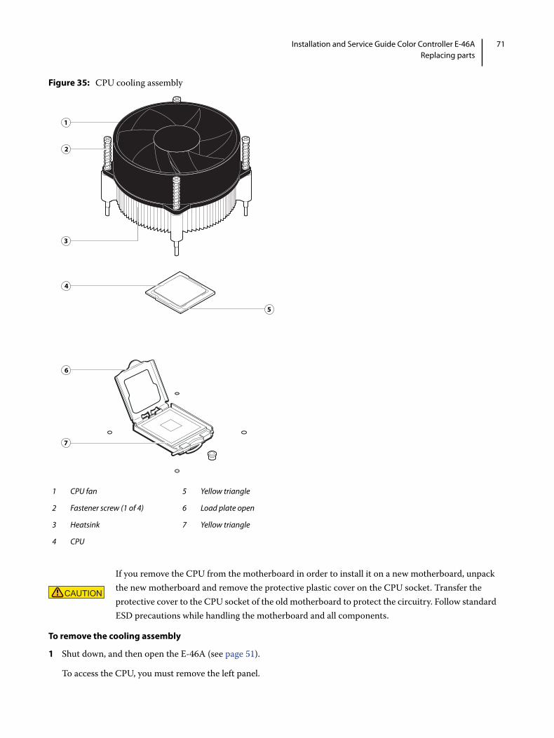
71Installation and Service Guide Color Controller E-46AReplacing parts
Figure 35: CPU cooling assembly
To remove the cooling assembly
1 Shut down, and then open the E-46A (see page 51).
To access the CPU, you must remove the left panel.
1 CPU fan 5 Yellow triangle
2 Fastener screw (1 of 4) 6 Load plate open
3 Heatsink 7 Yellow triangle
4 CPU
If you remove the CPU from the motherboard in order to install it on a new motherboard, unpack the new motherboard and remove the protective plastic cover on the CPU socket. Transfer the protective cover to the CPU socket of the old motherboard to protect the circuitry. Follow standard ESD precautions while handling the motherboard and all components.
1
2
3
4
5
6
7

72Installation and Service Guide Color Controller E-46AReplacing parts
2 Remove the CPU fan cable from motherboard connector CPU FAN (J16).
3 Remove the CPU cooling assembly.
• Loosen the four screws that secure the cooling assembly to the motherboard. Partially loosen all the screws before loosening any one screw all the way.
• Lift the cooling assembly off the CPU socket and set it aside.
4 Lift the cooling assembly off the CPU socket and set it aside.
To remove and replace the CPU
1 Unlock the CPU socket lever and raise it into the open position (flex the lever away from the retention post, and then raise it).
2 Open the load plate.
3 Grasp the CPU by its edges, lift it out of the socket, and then place the CPU in a safe place.
Note: If you remove the CPU from the motherboard to install it on a new motherboard, unpack the new motherboard and remove the protective plastic cover from the CPU socket. Transfer the protective cover to the CPU socket of the old motherboard to protect the circuitry.
4 Wipe the contact surface of the CPU (the smooth, gray side of the chip) with a clean, lint-free cloth to ensure proper contact with the new heatsink.
If you remove the CPU from the motherboard to install it on a new motherboard, make sure that you completely remove any thermal compound residue on the surface of the CPU and at the base of the heatsink. It may help to scrape all the residue off of the surface using the flat edge of something non-conductive.
Be aware that both the cooling assembly and the CPU may be very hot. You may need to allow the components to cool before you attempt to remove them.
1 Screw (1 of 4)
2 Loosen each screw to this position.
1
2

73Installation and Service Guide Color Controller E-46AReplacing parts
5 Prepare the CPU socket by ensuring that:
• The socket lever is in the open position.
• The load plate is open.
6 Place the CPU in the socket.
The CPU and the socket are keyed to ensure correct installation. The notches on the edges of the CPU correspond with the two small posts inside the socket. Align the yellow triangle on the CPU with the yellow triangle on the socket. Do not force the CPU.
7 Close the load plate.
8 Lower the socket lever and place it in the locked position under the retention post.
Figure 36: Removing/replacing the CPU
To replace the CPU cooling assembly
Note: Before you install the cooling assembly, completely remove any thermal compound residue on the surface of the CPU and the base of the heatsink, and then apply a fresh thermal compound square to the base of the heatsink. When installing the thermal compound square, make sure to remove the plastic backing on both sides of the square. Avoid creating any bubbles or wrinkles on the square. Bubbles and wrinkles reduce the heat-transfer efficiency of the cooling assembly.
1 Prepare the CPU cooling assembly for installation.
• Make sure that the motherboard is placed on a padded, static-free work surface.
• Apply a fresh thermal compound square, as described in the note above.
• Align the cooling assembly so that when it is installed, the fan cable easily reaches the CPU fan power connector CPU FAN (J16) on the motherboard.
1 Socket lever in the locked position 4 CPU
2 Load plate open 5 Yellow triangle
3 Yellow triangle 6 Socket lever in the open position
1
4
5
2
36

74Installation and Service Guide Color Controller E-46AReplacing parts
2 Place the cooling assembly on the CPU.
• Make sure that the thermal pad on the underside of the heatsink is positioned on top of the CPU.
Be sure to remove any protective material that may be covering the surface of the thermal pad. Otherwise the CPU may overheat.
• Align the four screws with the four screw posts.
Tighten the screws. Partially tighten all the screws before tightening any one screw all the way.
3 Connect the CPU fan cable to the motherboard connector CPU FAN (J16).
4 If you installed a new CPU, make sure to reset the time and date in Setup (see page 76).
5 Reassemble the E-46A and verify its functionality (see page 86).
Battery
The battery on the motherboard is located at XBT1. To replace it, use a 3V manganese dioxide lithium coin cell battery (Sony CR2032 or equivalent).
ACHTUNG: Es besteht Explosionsgefahr, wenn die Batterie durch eine Batterie falschen Typs ersetzt wird. Als Ersatz dürfen nur vom Hersteller empfohlene Batterien gleichen oder ähnlichen Typs verwendet werden. Verbrauchte Batterien müssen entsprechend den jeweiligen gesetzlichen Bestimmungen entsorgt werden.
ATTENTION : Il y a risque d’explosion si la pile est remplacée par un modèle qui ne convient pas. Remplacez-la uniquement par le modèle recommandé par le constructeur. Débarrassez-vous des piles usées conformément aux réglementations locales en vigueur.
ADVARSEL!: Litiumbatteri - Eksplosionsfare ved fejlagtig håndtering. Batteriet må kun udskiftes med et andet batteri af samme fabrikat og type. Brugte batterier skal bortskaffes i henhold til gældende regler.
VAROITUS: Paristo voi räjähtää, jos se on vaihdetaan väärän tyyppiseen paristoon. Vaihda paristo ainoastaan laitevalmistajan suosittelemaan tyyppiin. Hävitä käytetty paristo paikallisten määräysten mukaisesti.
ADVARSEL: Eksplosjonsfare ved feilaktig skifte av batteri. Benytt samme batteritype eller en tilsvarende type anbefalt av apparatfabrikanten. Brukte batterier kasseres i henhold til lokal lovgivning.
VARNING: Risk för explosion om batteriet byts ut mot en felaktig batterityp! Byt bara ut batteriet mot en batterityp som har godkänts av tillverkaren. Hantera använda batterier enligt lokal miljölagstiftning.
If you are installing a new CPU, secure slack in the fan cable using a tie-wrap. The tie-wrap prevents the fan cable from interfering with the CPU fan. Also, make sure the connector on the cable is securely connected to the motherboard.
DANGER There is danger of explosion if the battery is replaced with an incorrect type. Replace it only with the same type recommended by the manufacturer. Dispose of used batteries according to local regulations.

75Installation and Service Guide Color Controller E-46AReplacing parts
CUIDADO: Existe peligro de explosión si la batería se sustituye por una batería del tipo incorrecto. Sustituya la batería sólo por una batería del mismo tipo que recomienda el fabricante. Deseche las baterías usadas respetando la normativa local.
ATTENZIONE: Esiste pericolo di esplosione se la batteria viene sostituita con una di tipo non corretto. Sostituirla solamente con un tipo raccomandato dal produttore. Lo smaltimento delle batterie usate deve essere eseguito secondo le normative locali.
AVISO: Existe o perigo de explosão se a bateria for substituída por uma do tipo incorreto. Substitua somente por uma do tipo recomendado pelo fabricante. Descarte as baterias conforme as normas locais.
GEVAAR: Er bestaat ontploffingsgevaar indien de batterij door een verkeerd type wordt vervangen. Vervang de batterij uitsluitend door hetzelfde door de fabrikant aanbevolen type. Ruim gebruikte batterijen op volgens de plaatselijke voorschriften.
To replace the battery
1 Shut down, and then open the E-46A (see page 51).
2 Locate the battery on the motherboard (see Figure 33 on page 61).
3 Carefully push the clip away from the battery until the socket ejects the battery.
Figure 37: Motherboard battery
4 Slide the battery out of its socket.
5 Wait two minutes to allow the motherboard electrical components to fully discharge.
6 To insert a new battery, slide it into the socket so that the positive (+) side of the battery faces up.
7 Press the battery down into the socket until it snaps into place.
Make sure that the battery is securely installed in the socket.
8 Reassemble the system and verify its functionality (see page 86).
9 Configure the time and date (see page 76).
1 Clip
2 Battery
3 Socket
Failure to configure the time and date will cause the E-46A to hang when user software is being installed on the E-46A.
1
23

76Installation and Service Guide Color Controller E-46AReplacing parts
To configure the system date and time
1 Access Configure (see page 32).
2 On the left side, select Fiery Server > Regional Settings and specify the current date and time, and click Save.
3 Click Log Out to exit Configure.
Jumpers
Jumper configurations should not be changed.
FanA fan mounted inside the E-46A chassis draws air into the E-46A to cool components. The fan runs continuously when the system is on. You should hear the fan start as soon as you power on the E-46A. If you do not hear the fan, there may be a faulty power connection.
The following procedures describe how to remove and replace the fan.
To remove the fan
1 Shut down, and then open the E-46A (see page 51).
To access the fan, you must remove the left panel.
2 Remove the fan cable from motherboard connector FRONT FAN (J20).
Jumper Description
J101 J101 is the Clear CMOS and Password jumper. Default configuration: Jumper cap installed on pins 1and 2.
Note: It is not necessary to clear the CMOS settings when servicing motherboard components, the DVD drive, and the hard disk drive.
Pin 1

77Installation and Service Guide Color Controller E-46AReplacing parts
3 Remove the four screws from the connector panel, while holding the fan assembly from the inside.
Set aside the screws.
Figure 38: Removing/replacing the fan
4 Remove the fan from the chassis.
To replace the fan
1 Align the fan with the four holes on the connector panel.
2 Install the four screws you removed earlier to secure the fan assembly to the connector panel.
3 Connect the fan cable to motherboard connector FRONT FAN (J20).
4 Reassemble the E-46A and verify its functionality (see page 86).
1 Fan assembly 3 Screw (1/4)
2 Airflow direction
1
3
2

78Installation and Service Guide Color Controller E-46AReplacing parts
Power supplyThis section describes how to remove and replace the power supply. For more information about the power supply, see “Physical specifications” on page 128.
To remove the power supply
1 Shut down the E-46A, remove all cables from the back, and then open the system (see page 51).
To remove the power supply, you must remove the left and right panels.
2 Remove the 24-pin power cable from connector J18 on the motherboard.
3 Remove the 8-pin power cable from connector PWRCONN1 on the motherboard.
4 Remove the SATA power cable from the hard disk drive.
5 Detach the SATA power cable from the power connector of the dual cable for the DVD drive.
6 Detach the 8-pin power cable from the connector from the Fiery QuickTouch.
7 Remove any tie-wraps securing the power cables to the chassis.
8 Place the E-46A in the upright position.
9 Remove the motherboard from the chassis (see page 62).
10 Remove the four connector panel screws that secure the power supply to the back of the chassis (see Figure 39).
11 While squeezing the power supply unit, remove the inside screw with washer.
Do not open the power supply for service or troubleshooting purposes. Opening the power supply will void the warranty.

79Installation and Service Guide Color Controller E-46AReplacing parts
12 Slide the power supply towards the front panel and take the power supply off from under the chassis bar.
Figure 39: Removing/replacing the power supply
To replace the power supply
1 Make sure that the E-46A is in upright position.
2 Position the power supply inside the chassis (see Figure 39 on page 79).
Insert the power supply unit under the chassis bar, and place the power supply on top of the left and right chassis bars. Position the power supply so that it is flush against the connector panel.
3 Install the inside screw with washer to secure the power supply unit to the chassis top.
1 Power supply unit
2 Chassis bar
3 Screw (1 of 4)
4 Inside screw
Note: To service the power supply, place the E-46A in an upright position.
1
3
4
2

80Installation and Service Guide Color Controller E-46AReplacing parts
4 Install the four screws that secure the power supply to the connector panel of the chassis.
5 Replace the motherboard (see page 64).
6 Connect one of the SATA power cables to the power connector on the dual data/power cable that connects to the DVD drive.
7 Connect three of the other SATA power cables to the SATA power connectors on the hard disk drive.
8 Connect the power cables to the motherboard (see Figure 27 on page 50 and Figure 33 on page 61):
• 8-pin power cable to connector PWRCONN1
• 24-pin power cable to connector J18
9 Replace the tie-wraps that you removed earlier.
10 Reassemble the E-46A and verify its functionality (see page 86).
Hard disk driveThe factory-installed hard disk drive is formatted and loaded with system software, network drivers, and printer fonts. The hard disk drive is also used to store spooled print jobs. Available space on the hard disk drive is displayed in Command WorkStation.
If you replace the hard disk drive with a new one, you must restore the backup (see page 88) or install system software as described on page 101. (Spare hard disk drive is not shipped with preinstalled system software.)
It is unlikely that both the hard disk drive and the motherboard are defective. Avoid replacing both to solve one problem. If troubleshooting strategies (such as checking cables and connections; see page 111) do not solve the problem, and you suspect either the hard disk drive or the motherboard is at fault, use the following order to troubleshoot: replace the hard disk drive, install system software, and then check to see if the problem persists. If it does, perform other procedures, such as replacing the motherboard (see page 63).
Proper handling
• Use proper ESD practices when grounding yourself and the E-46A.
• Keep magnets and magnetic-sensitive objects away from the hard disk drive.
• Do not remove the screws on top of the hard disk drive. Loosening these screws voids the warranty.
• Never drop, shake, bump, or put excessive pressure on the hard disk drive.
• Handle the hard disk drive by its sides and avoid touching the printed circuit board.
• Allow the hard disk drive to reach room temperature before installation.
Do not replace the hard disk drive and the motherboard at the same time. Doing so in the wrong order, without updating the system (see page 63), will cause the system to malfunction.
Improper handling can damage a hard disk drive. Handle the hard disk drive with extreme care.

81Installation and Service Guide Color Controller E-46AReplacing parts
Hard disk drive problems may be caused by the following:
• Loose or faulty connections
• Faulty data or power cable
• Faulty hard disk drive
The hard disk drive is mounted inside a bracket (see Figure 41 on page 83).
If you are replacing the hard disk drive with a new one, you will need:
• The appropriate system software and documentation for the E-46A that you are servicing.
• A compatible version of the user software for the networked computers that will print to the E-46A.
To remove the hard disk drive
1 If you are removing the hard disk drive in order to install a new drive, give the site administrator the opportunity to print the Job Log and save any custom simulations. If possible, create a system backup (page 88), and print the Configuration page and Font List.
2 Shut down and open the E-46A (see page 51).
To access the hard disk drive, you must remove the left panel.
3 Remove the power supply cable from the hard disk drive.
4 Remove the hard disk drive data cable from the hard disk drive.
5 Remove the screw securing the hard disk drive bracket to the bracket shelf.
6 Slide the hard disk drive bracket off the shelf and lift it out of the chassis.
Unlock the hard disk drive bracket by moving the latch toward the connector panel, and then sliding the bracket off the bracket shelf.
Note: You will encounter slight resistance as you slide the bracket off the shelf. The resistance is caused by two tension points on the bottom of the bracket. The resistance helps control the bracket’s movement during removal and installation.
Make sure that you attach an ESD grounding wrist strap and follow standard ESD precautions before handling E-46A components.
Avoid striking the DIMMs as you remove the hard disk drive bracket.

82Installation and Service Guide Color Controller E-46AReplacing parts
Figure 40: Removing/replacing the hard disk drive bracket
1 Tension points 4 Shelf
2 Latch 5 Screw
3 Hard disk drive bracket
Note: Printer interface board and internal cables are not shown.
1
2
3
4
5

83Installation and Service Guide Color Controller E-46AReplacing parts
7 Remove the four screws that attach the hard disk drive to the hard disk drive bracket (see below).
Figure 41: Removing/replacing the hard disk drive from/in the hard disk drive bracket
8 Remove the hard disk drive from the hard disk drive bracket and place it in an antistatic bag.
Do not touch the drive with magnetic objects (such as magnetic screwdrivers), and avoid placing magnetic-sensitive objects (such as credit cards and employee ID cards) near the hard disk drive.
Replacement hard disk drive is not shipped with preinstalled system software. After you install the drive, you must install the appropriate system software (see page 101).
To replace the hard disk drive
1 If you are installing a new hard disk drive, unpack the drive.
Do not drop, shake, or bump the hard disk drive. Do not touch the hard disk drive with magnetic objects or place magnetic-sensitive objects near the hard disk drive.
1 2.5 inch HDD
2 Mounting bracket for 2.5 inch HDD
3 Screw with washer (1/4)
4 HDD sled
5 Screw (1/4)
Do not loosen the screws on the hard disk drive cover. Loosening these hard disk drive screws breaks the seal and voids the hard disk drive warranty.
Do not install a new hard disk drive and a new motherboard at the same time. If you suspect that the E-46A needs a new hard disk drive and a new motherboard, first install the new hard disk drive and install system software, then install a new motherboard and transfer options (see pages 63 and 67).
1
2
4
5
3

84Installation and Service Guide Color Controller E-46AReplacing parts
2 Position the hard disk drive inside the hard disk drive bracket and align the front-most mounting holes on the hard disk drive with the four holes in the bracket.
When correctly installed, the hard disk drive extends about an inch past the rear of the bracket.
3 Replace the four screws that you removed earlier to attach the hard disk drive to the bracket.
4 Slide the bracket all the way onto the shelf and lock it by moving the latch toward the front panel.
Note: You will encounter slight resistance as you slide the bracket onto the shelf. The resistance is caused by two tension points on the bottom of the bracket. The resistance helps control the bracket’s movement during removal and installation.
5 Secure the hard disk drive bracket to the hard disk drive shelf using the screws that you removed earlier.
6 Connect one end of the hard disk drive data cable to the hard disk drive and the other end to SATA1 (J41) on the motherboard (see Figure 33 on page 61).
7 Connect the power cable to the hard disk drive.
8 Reassemble the E-46A (see page 86).
9 If you replaced the hard disk drive with a new hard disk drive, install system software (see page 101).
If a startup error displays on the Fiery QuickTouch when you power on the E-46A, check the connections.
10 Verify functionality (see page 86).
DVD driveThe DVD drive is installed in the front of the chassis. The drive is used to install system software and archive data on writable media.
To remove the DVD drive
1 Shut down the E-46A, remove all cables from the back, and then open the system (see page 51).
To access the DVD drive, you must remove the left, right, and front panels from the chassis.
2 Remove the data/power cables from the dual connector on the back of the DVD drive.
If you are removing the cable assembly to replace it with a new cable assembly, detach the other ends of the cables from the motherboard and the power supply.
Avoid striking the DIMMs as you replace the hard disk drive bracket.

85Installation and Service Guide Color Controller E-46AReplacing parts
3 Release the front latches on both side of the DVD drive by squeezing the levers, and pull the DVD drive out of the slot.
Figure 42: Removing/replacing the DVD drive
4 If you are replacing the DVD drive with new one, remove the eight screws on the side of the DVD drive and remove the ears.
Set aside the screws so that you can replace them later.
To replace the DVD drive
1 If you are installing the new DVD drive, attach the ears on both side of the DVD drive using the eight screws you removed earlier.
2 Insert the DVD drive into the front panel cutout until the latch snaps.
3 Connect the power/data cables to the connectors on the back of the DVD drive.
Make sure that the other ends of the power and data cables are connected to the power supply and SATA0 (J50) on the motherboard.
1 Latch lever (1/2)
2 DVD drive
1
2

86Installation and Service Guide Color Controller E-46AReplacing parts
4 Reassemble the E-46A and verify its functionality (see page 86).
Restoring and verifying functionality after serviceBefore you leave the customer site, make sure that you complete the following steps. If you cannot complete a step, determine the reason and correct the problem before continuing. For more information, see Troubleshooting on page 110.
To reassemble the E-46A and verify functionality
1 Reseat all boards, cables, connectors, and other parts loosened or removed during service.
When routing cables inside the E-46A, make sure that:
• Covers are securely installed after routing cables
• Cable routing does not interfere with the operation of internal components nor interfere with removing or replacing components
• Cables are not tangled nor looped around internal circuit boards or components (such as capacitors and resistors)
• Cables do not lie on or against any internal heating element
• Cables do not interfere with opening or closing E-46A panels
• Cable slack is secured with a tie-wrap
2 Restore the E-46A to the upright position.
3 Replace any panels that you removed earlier, as described on page 51.
4 If you replaced the motherboard, make sure that the new motherboard solves the problem that you are troubleshooting, and then transfer options to the new motherboard (see page 67).
5 If the E-46A is to be mounted on the furniture with the monitor, see the reassembly instructions that is provided with the furniture assembly (page 130).
6 Connect the power cable to the E-46A (see page 19).
7 Connect the E-46A to the printer (see page 21).
8 Print the Test Page and Configuration page (see page 30).
• If pages do not print, verify that the interface cables are properly connected.
• If image quality is poor, test the printer (see the service documentation that accompanies the printer).
9 Connect to the network (see page 22).

87Installation and Service Guide Color Controller E-46AReplacing parts
10 Ask the site administrator to download a test job over the network.
If the job does not print, or has poor image quality, see printing problems and the Troubleshooting sections of the user documentation.

88Installation and Service Guide: Color Controller E-46APerforming Backup and Restore
Performing Backup and Restore
This chapter provides information about how to back up or restore information to the system. The E-46A ships with system software pre-installed on the hard disk drive (HDD). A factory-installed backup partition is available for restore if there is no on-site usable backup.
You can use the following features to create backups and restore the backup images:
• Configure from Command WorkStation or WebTools
Using Configure, you can backup the customer settings and data. You can restore the custom settings after you reinstall the system software or upgrade to a newer version.
• Fiery System Restore
You can access Fiery System Restore from WebTools, Fiery QuickTouch, or Command WorkStation. This backup captures all settings and files on the E-46A. You can create a backup and restore a backup when the E-46A is not working. You can also schedule automatic backup.
Note: The backup image created using Fiery System Restore does not include VDP/FreeForm resources. To back up the FreeForm masters 1 and 2, save the configuration settings as described in “Backing up the system configuration” on page 92.
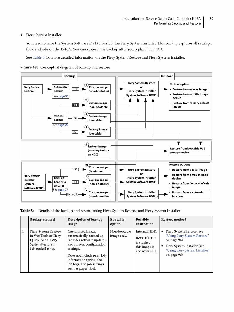
89Installation and Service Guide: Color Controller E-46APerforming Backup and Restore
• Fiery System Installer
You need to have the System Software DVD 1 to start the Fiery System Installer. This backup captures all settings, files, and jobs on the E-46A. You can restore this backup after you replace the HDD.
See Table 3 for more detailed information on the Fiery System Restore and Fiery System Installer.
Figure 43: Conceptual diagram of backup and restore
Table 3: Details of the backup and restore using Fiery System Restore and Fiery System Installer
Backup method Description of backup image
Bootable option
Possible destination
Restore method
1 Fiery System Restore in WebTools or Fiery QuickTouch: Fiery System Restore > Schedule Backup
Customized image, automatically backed up. Includes software updates and current configuration settings.
Does not include print job information (print jobs, job logs, and job settings such as paper size).
Non-bootable image only.
Internal HDD.
Note: If HDD is crashed, this image is not accessible.
• Fiery System Restore (see “Using Fiery System Restore” on page 94)
• Fiery System Installer (see “Using Fiery System Installer” on page 96)
Fiery System Restore
AutomaticBackup
Custom image (non-bootable)
Custom image (non-bootable)
Custom image(bootable)
Manual Backup
Restore options
• Restore from a local image
• Restore from a USB storage device
• Restore from factory default image
Backup
3
1
2
Factory image(bootable)
4
USB
HDD
See page 95
Restore
HDD
See page 95
USB
Fiery System Installer (System Software DVD1)
Custom image (bootable)
Back up hard disk drive(s)
6
Custom image(non-bootable)
USB
Custom image(non-bootable)
6
HDD
Network
Factory image(recovery backup on HDD)
5
Restore options
• Restore from a local image
• Restore from a USB storage device
• Restore from factory default image
7
Restore from bootable USB storage device
See page 97
Fiery System Restoreor
Fiery System Installer (System Software DVD1)
Fiery System Restoreor
Fiery System Installer (System Software DVD1)
Fiery System Installer (System Software DVD1)
• Restore from a network location

90Installation and Service Guide: Color Controller E-46APerforming Backup and Restore
2 Fiery System Restore in WebTools or Fiery QuickTouch: Fiery System Restore > Backup Now> Internal hard drive
Customized image, manually backed up. Includes software updates and current configuration settings.
Does not include print job information (print jobs, job logs, and job settings such as paper size).
Non-bootable image only.
Internal HDD.
Note: If HDD is crashed, this image is not accessible.
• Fiery System Restore (see “Using Fiery System Restore” on page 94)
• Fiery System Installer (see “Using Fiery System Installer” on page 96)
3 Fiery System Restore in WebTools or Fiery QuickTouch: Fiery System Restore > Backup Now> USB > New image
Customized image, manually backed up. Includes same content as automatically backed up customized image (described in previous row).
Bootable option supported.
Can also create a non-bootable image.
USB device. • If bootable, can restore directly from USB (see “Using bootable USB storage device to restore” on page 99)
• Fiery System Restore (see “Using Fiery System Restore” on page 94)
• Fiery System Installer (see “Using Fiery System Installer” on page 96)
4 Fiery System Restore in WebTools or Fiery QuickTouch: Fiery System Restore > Backup Now> USB > Fiery factory image
Factory default image, manually backed up. Includes factory default version of software and configuration settings.
Does not include print job information (print jobs, job logs, and job settings such as paper size).
Bootable image only.
USB device. • Can restore directly from USB (see “Using bootable USB storage device to restore” on page 99)
• Fiery System Restore (see “Using Fiery System Restore” on page 94)
• Fiery System Installer (see “Using Fiery System Installer” on page 96)
5 Preinstalled recovery backup image
Factory default image, factory preinstalled recovery backup. Includes factory default version of software and configuration settings.
Does not include print job information (print jobs, job logs, and job settings such as paper size).
Non-bootable image.
Preinstalled at factory on internal HDD.
Note: If HDD is crashed, this image is not accessible.
• Fiery System Restore (see “Using Fiery System Restore” on page 94)
• Fiery System Installer (see “Using Fiery System Installer” on page 96)
6 Fiery System Installer on System Software DVD1: Fiery System Installer > Backup hard disk drive(s)
Customized image, manually backed up. Includes software updates and current configuration settings.
If Include Fiery job files in backup option selected, also includes print job information (print jobs, job logs, and job settings).
Bootable option supported for USB storage device.
Can also create a non-bootable image.
• USB device• Internal
HDD
Note: If HDD is crashed, this image is not accessible.• Network
location
• If bootable, can restore directly from USB (see “Using bootable USB storage device to restore” on page 99)
• Fiery System Restore (see “Using Fiery System Restore” on page 94)
• Fiery System Installer (see “Using Fiery System Installer” on page 96)
Backup method Description of backup image
Bootable option
Possible destination
Restore method

91Installation and Service Guide: Color Controller E-46APerforming Backup and Restore
Backup recommendationsEven though the server maintains a backup, you can use the Fiery factory default image for recovery of the factory installation. Creating a separate backup provides the ability to retrieve customized settings and job information if a recent backup is needed. You can create a backup by using Fiery System Restore (from Command WorkStation, WebTools (remotely), or Fiery QuickTouch), or Fiery System Installer.
• To create a backup of system configuration settings using Command WorkStation, or from a remote location using WebTools, see “Backing up the system configuration” on page 92.
• To create a backup using Fiery System Restore, see “Using Fiery System Restore” on page 94.
• To create a backup using Fiery System Installer, see “Using Fiery System Installer” on page 96.
When backing up an existing E-46A installation
• For an existing E-46A installation, first check if a backup image exists either on the server or on external location.
• If a backup image exists, check if it is up to date. Compare the date stamp of the existing backup image to the date of the last patch installation (see “System update log” on page 109 to check the date of last patch installation).
• If a backup image does not exist, create a new one after installing all available software updates.
• You can save the backup image to any of the following locations:
• Local Disk
• USB storage device
For information about requirements of the USB storage device, see the instructions provided on page 95.
• Network
7 Fiery System Installer on System Software DVD1: Fiery System Installer > Backup hard disk drive(s)
Customized image, manually backed up. Includes software updates and current configuration settings.
If Include Fiery job files in backup option selected, also includes print job information (print jobs, job logs, and job settings).
Non-bootable image.
Network location
Fiery System Installer (see “Using Fiery System Installer” on page 96)
Backup method Description of backup image
Bootable option
Possible destination
Restore method

92Installation and Service Guide: Color Controller E-46APerforming Backup and Restore
• If you do not have a backup with the system settings and jobs, the system can access a preinstalled recovery backup on the hard disk drive provided with the E-46A. See “To restore the backup image” on page 96.
• If you have a system backup that includes your settings and jobs, you can restore the backup using Fiery System Installer (see “Restore with Fiery System Installer” on page 98) or Fiery System Restore (see“Using Fiery System Restore” on page 94).
• Use a descriptive and consistent naming convention when saving image files (such as date, product name, product version, and short description).
Backing up the system configurationIf you back up the system configuration, you can restore that configuration after reinstalling or upgrading system software.
When you back up the system configuration, you can save a configuration file that includes one or more of the following:
• Fiery System Settings
• Color Settings
• Scan settings
• Preflight Presets
• Command WorkStation settings (if you are using a keyboard, monitor, and mouse)
• FreeForm/VDP resources
• Virtual Printers
• Server Presets
• Fonts
• Job Log
Note: Those settings you do not choose are not saved for restore.
If you cannot create a configuration file, ask the site administrator to archive custom color profiles, preflight presets, FreeForm masters, customer-installed fonts, and the Job Log to removable media or a network location.
If you restore the system using the pre-installed recovery backup, the system and configuration will be reset to the factory default.
Backed up data can be only restored to the same E-46A.
If you select USB storage device as a destination, all the existing data in the drive will be lost when you create a backup on the USB storage device.

93Installation and Service Guide: Color Controller E-46APerforming Backup and Restore
To save the system configuration using Command WorkStation
1 Ask the site administrator to print the Job Log, Server Configuration page, and Font List (if possible).
2 Launch Command WorkStation and connect to the E-46A with Administrator privileges.
3 From the Server menu, click Backup and Restore.
4 In the Backup & Restore dialog box, click Backup > Next, and then select the items you want to back up, click Next.
5 Enter a file name and location, specify if you want to add the date to the file name, and then click Next.
6 Click Finish.
To save the system configuration using WebTools
1 Access Configure (see page 32).
2 On the left side, choose Fiery Server > Backup.
3 In the Backup dialog box, select the settings you want to back up.
4 Enter a file name and location, specify if you want to add the date to the file name, and then click Backup.
5 Click OK.
Restoring the system configurationYou can restore the system configuration of the E-46A to its previous state using a previously-saved system configuration file. For more information about the system configuration file, see page 93.
If you could not save a system configuration file, you must configure the E-46A settings. After you configure the settings, the E-46A reboots. Ask the site administrator to restore any archived settings and files. For more information, see Configuration and Setup, which is part of the user documentation set.
To restore the system configuration from Command WorkStation
1 Launch Command WorkStation and connect to the E-46A with Administrator privilege.
Note: The default password (Fiery.1) will be set after any of the following:
• You re-install the system software
• You restore the recovery partition (from Fiery System Restore)
2 From the Server menu, click Backup and Restore.
3 In the Backup & Restore dialog box, select Restore > Next, select the reference (.fbf ) file or the recent backup you want restore and then click Next.
You can select the backup file using the Browse button, or you can select a recent backup.
4 Select the items you want to restore, and then click Next.
5 Click Finish.
94Installation and Service Guide: Color Controller E-46APerforming Backup and Restore
To restore the system configuration using WebTools
1 Access Configure (see page 32).
2 On the left side, choose Fiery Server > Restore.
3 Select the reference (.fbf ) file and data (.DAT) file, and then click Next.
4 Select the items you want to restore and then click Next.
5 Click Reboot.
Using Fiery System RestoreFiery System Restore allows you to create a backup of the E-46A for quick recovery later when any problem happens. You can restore the E-46A either from images stored on the local hard disk, or from a bootable USB storage device. Fiery System Restore also provides the feature of creating the scheduled backups.
You must log in to the E-46A as a system administrator to use the Fiery System Restore features. You can access the Fiery System Restore from the WebTools, Fiery QuickTouch, or Command WorkStation.
To access Fiery System Restore from Fiery QuickTouch
1 On Fiery QuickTouch, press the Quick launch icon on the bottom-left corner of the screen.
2 Press the Fiery System Restore icon and log in as a system administrator.
3 Follow the on-screen menus to schedule automatic backups, manually back up the E-46A, or restore the E-46A.
To access the Fiery System Restore from Command WorkStation
1 Launch Command WorkStation and login to the E-46A with Administrator privileges.
2 From the Server menu, select Device Center.
3 In Device Center, click Tools on the left side, and then click Fiery System Restore.
The Fiery System Restore will display on the default web browser window.
To access the Fiery System Restore features from WebTools
1 Open an Internet browser and type the IP address of the E-46A.
Note: As a security measure, WebTools is designed to work only over Hyper Text Transfer Protocol Secure (HTTPS). By default, WebTools uses a self-signed certificate created by the Fiery. This causes the web browser to display a untrusted certificate message while accessing WebTools. It is safe to ignore this message and proceed to access WebTools.
2 In WebTools, click the Fiery System Restore tab on the left side.
3 Log on with Administrator privileges and click OK.

95Installation and Service Guide: Color Controller E-46APerforming Backup and Restore
Backing up or restoring the E-46A
The following tasks describe using Fiery System Restore on WebTools. Fiery QuickTouch uses the same menu selections and features for backing up and restoring the E-46A. Refer to the following tasks if you are using Fiery System Restore on Fiery QuickTouch.
To setup automatic scheduled backup
Note: When you set up the scheduled backup, only the latest backup will be stored. Previous backups will be deleted.
1 Access Fiery System Restore (see page 94).
2 In Fiery System Restore window, click Schedule Backup.
If you have not logged in as an Administrator user, you are required to do so. Enter the administrator’s password and click Log In.
3 Select Enable automatic backup, and select when you want to start the backup process on the E-46A.
Note: The backup process takes more than an hour to complete and it requires the E-46A to be Idle status. If the E-46A is not in Idle status, the backup process does not start.
4 Click Save.
To backup manually
1 Access Fiery System Restore (see page 94).
2 In Fiery System Restore, select one of the following options:
• Backup Now> USB: Select this option if you want to create a backup on a USB storage device.
• New image: Select this option if you want to create a backup of the current E-46A. You can select Create bootable image option to make the USB storage device a bootable device.
• Fiery factory image: Select this option if you want to create a backup of the E-46A factory image. When you select this option, the Create bootable image option enables automatically.
If you select Create bootable image option, the USB storage device specified as a destination becomes a bootable device. Select this option when you want to boot the E-46A from the backup device to avoid the situation where the HDD fails and cannot boot the E-46A. See page 99 for booting from the bootable device. Bootable device is used for system restoration when a hardware failure occurs.
Note: The minimum size required for the USB storage device depends on the actual size of the backup file. You can determine the size of the backup file by checking the Estimated size: field in the Create USB Backup dialog box. Prepare a USB storage device with enough capacity.
Note: Due to Windows file system restriction, the maximum size of the USB storage device you can use is 32GB if you enable the Create bootable image option. You can use the USB storage device with more than 32GB capacity without enabling the Create bootable image option.
• Backup Now> Internal hard drive: Select this option if you want to create a backup on the HDD of the E-46A. You must specify the file name of the backup image. The default image name is the server name of the E-46A.

96Installation and Service Guide: Color Controller E-46APerforming Backup and Restore
3 If you selected USB, make sure to connect the USB storage device to one of the USB 3.0 ports on the E-46A.
Note: If the capacity of the USB storage device is less than size of the value listed in Estimated size: field, the backup process will not take place.
4 Click Continue.
To restore the backup image
1 Access Fiery System Restore (see page 94).
2 In Fiery System Restore, click Restore.
If you have not logged in as an Administrator user, you are required to do so. Enter the administrator’s password and click Log In.
3 Make sure that your backup image is accessible from the E-46A.
If you want restore the backup image stored on the USB storage device, be sure to attach the USB storage device to one of the USB 3.0 ports on the E-46A.
4 Select one of the following restore options:
• Restore from a local image
• Restore from a USB storage device
• Restore from the factory default image
5 Click Continue.
6 Follow the on-screen prompts to restore the backup image.
Note: The E-46A must remain powered ON during the backup or restore process.
To restore the system by booting from a bootable USB storage device
• Follow the instructions described in “To restore the system from bootable USB storage device” on page 100.
Using Fiery System InstallerYou can create the system backup or restore from the backup using Fiery System Installer provided with the System Software DVD 1.
You can perform the following tasks from Fiery System Installer;
• New Installation: Installs the system software from the media shipped with the E-46A. Use this option only when the system backup is not available. See also “Installing system software” on page 102.
It is recommended that you create system backups periodically.

97Installation and Service Guide: Color Controller E-46APerforming Backup and Restore
• Restore using a backup image or the recovery partition: You can restore the system by selecting the backups that you created before. If there is no backup available in the system or in any attached devices, you can only perform the restore from the recovery partition.
• Back up hard disk drive(s): Use this option when you create the system backups. You can specify the location of the backup, file name, and other attributes of the backups.
• Platform Utilities: You can perform the backup management tasks from this option such as erasing hard disks or using Windows Task Manager to explore the system.
Note: The Platform Utilities is available only on the monitor.
Note: You can use the E-46A Fiery QuickTouch to operate Fiery System Installer. You can also use a monitor, mouse, and keyboard attached, if available.
Backup with Fiery System Installer
You must back up your system and create a backup image to recover from any unexpected system crashes and the hard disk drive failure.
To create a system backup
1 Start Fiery System Installer.
• Insert the System Software DVD 1 into the DVD drive of the E-46A.
• Reboot the E-46A (see page 42).
• When the server finishes the reboot, select the language you use for the backup or restore session.
2 From “What do you want to do?” screen, select “Back up hard disk drive(s)”

98Installation and Service Guide: Color Controller E-46APerforming Backup and Restore
3 Enter the backup settings.
Because settings vary depending on the destination you select, make sure that you specify valid settings.
The Backup settings window appears. In this window, do the following:
• Select a backup destination from one of the following locations: Local Disk, USB drive, External hard disk drive, or Network.
• Specify the name of the backup file in the Folder Name field.
Fiery System Installer creates a folder with the name containing the file name and a time stamp to help you distinguish the backup images. The default file name is the server name. The installer automatically generates the time stamp.
• If you select “Include Fiery job files in backup”, jobs archived in the server are included in the backup.
• If you select “Create bootable media,” the USB storage device or hard disk drive specified as a destination becomes a bootable media. Select this option when you want to boot the E-46A from the backup media to avoid the situation where the HDD fails and cannot boot the E-46A. See page 98 for booting from the bootable media. Bootable media is used for system restoration when a hardware failure occurs.
• Enter a description of the backup.
• If you select Save in the backup settings, the system saves the specified backup setting for a subsequent Load. Only the specified setting is saved.
4 If you select USB Drive or External Hard Disk as a destination in step 3, make sure you attach the appropriate device to the E-46A.
5 Click Start backup to begin the backup process.
If there is a need to stop the backup process, press the cancel icon. Fiery System Installer displays a message allowing you to restart or shutdown the server. You can specify a backup log to be saved, if desired.
Restore with Fiery System Installer
To recover from a system crash, you must restore the system with a backup image.
Note: Backed-up data can be only restored to the same E-46A.
If you select USB storage device or external hard disk drive as a backup destination, all the existing data in the drive will be lost when you create a backup on these media.
All the existing data in the USB drive or external hard disk drive will be lost when you create a backup on these media.

99Installation and Service Guide: Color Controller E-46APerforming Backup and Restore
To restore the system using Fiery system installer
You will access your backup media (USB drive, local hard disk drive or external hard disk drive) to restore the system.
1 Start the Fiery System Installer.
• Insert System Software DVD 1.
• Reboot the E-46A (see page 42).
• When the menu appears, specify a language.
2 If your backup file is stored in the USB drive or external hard disk, attach the device to the E-46A.
3 From “What do you want to do?” screen, select “Restore from backup or recovery partition”.
The Select backup source dialog appears. You can choose one of the following:
• Backup
If present, previous backups are listed for you to choose.
• Restore from recovery partition
This restores the server from a hard disk drive partition to its factory-built settings.
• Search for backups from this system
This lets you select a backup from a displayed list. Alternatively, you can select Refresh, Import backup history, or Search the network for backups.
If a backup image exists, the installer lists information about each backup image:
• The time and date in which you created the backup.
• The location of the backup image: Local Disk, USB drive, External hard disk drive, or Network.
• Alternatively, you can also choose to Refresh, Import backup history, or Search network.
4 Select the source of the backup and click OK.
When a message appears indicating that all the data will be erased, click Continue to proceed the restore process.
Using bootable USB storage device to restore
Use the following procedure when you restore the system without using the System Software DVD 1, or when the E-46A does not boot from the built-in hard disk drive.
You can restore from the bootable backup media (including the Fiery factory image) created by either Fiery System Restore or Fiery System Installer.
Any custom settings you have specified after installation are over-written.

100Installation and Service Guide: Color Controller E-46APerforming Backup and Restore
To restore the system from bootable USB storage device
To restore from the bootable USB storage device, you must have created a backup with the Create bootable media option. If you have created a backup as bootable backup image, follow these instructions.
Note: You can use this procedure to also install the system software after you replaced the HDD with a new one.
1 Shut down the E-46A (see page 42).
2 Attach the bootable USB backup media to the E-46A.
Make sure to remove any media in the DVD drive. Do not attach other USB devices to the E-46A.
3 Power on the E-46A (see page 42).
The E-46A will boot from the bootable USB storage device.
4 Follow the instructions on the Fiery QuickTouch display or the monitor (if available) to restore the backup image.
Platform Utilities
Use Fiery System Installer for advanced procedures, such as erasing hard disks, or launching Windows Task Manager. These utilities are available when you select Platform Utilities.
Note: The Platform Utilities is available only on the monitor (optional).
Erase data from hard disk drive
If selected, the following methods are provided:
• Randomized erase for writing random data to all disk sectors before writing zero.
• Quick erase for writing zeroes to all disk sectors.
Advanced backup management
Allows the Administrator to:
• Load backup settings from a USB drive to apply to system backup images.
• Save or restore backup history files.
• Search for backup images created on a replaced system to be applied to the current one.
Launch Windows Task Manager
Starts the Windows Task Manager. Windows Task Manager displays the programs, processes, and services that are currently running on the E-46A. You can use Windows Task Manager to monitor performance or to close a program that is not responding.
101Installation and Service Guide: Color Controller E-46AInstalling System Software
Installing System Software
This chapter provides information about how to install the system software.
The E-46A is shipped with system software pre-installed on the hard disk drive (HDD).
A reinstallation of the system software is required if:
• You have replaced the hard disk drive.
• Restoring the system from backup images including the pre-installed recovery backup (factory default image) did not solve the problem you are troubleshooting.
• You are installing a more recent version.
When you reinstall from the System Software DVDsThe following issues apply to the scenario where you reinstall the system from the System Software DVDs.
• Jobs: When you reinstall system software, all jobs in all print queues and all jobs archived locally on the E-46A hard disk are deleted. To save jobs, ask the site administrator to save them to a removable media or a network location, so they can be re-imported to the E-46A after system software installation. For more information, see Command WorkStation Help.
• Job Log: When you reinstall system software, the list of jobs in the Job Log and any jobs in the queues are deleted. The site administrator can use Command WorkStation to export and save current list of jobs (not the actual jobs) from the Job Log. For more information, see Command WorkStation Help.
• Fonts: When you reinstall system software, all fonts on the hard disk drive are deleted. Resident fonts are reinstalled when you reinstall system software. Any customer-supplied fonts must be reinstalled by the site administrator (see Command WorkStation Help).
To determine which additional fonts were downloaded to the E-46A, print the Font List before you reinstall the system software and after you complete the system software installation. Any fonts not listed after installation will need to be reinstalled. For more information about managing fonts, see Command WorkStation Help.
• Server Configuration page: Before you reinstall a new version of system software, print the Server Configuration page. The Server Configuration page provides a record of the customer’s current Setup configurations. For more information, see page 30.
• Backing up and restoring the configuration: All the setup configurations, as well as all custom files and templates stored on the hard disk drive, are deleted when you reinstall system software. Always back up the current E-46A configuration before you reinstall system software. After the installation is completed, be sure to restore the configuration that you saved earlier. For instructions, see page 92.
• Static IP address: If the E-46A requires a static IP address (for example, in a non-DHCP network environment), be aware that the previous IP address configuration is deleted when system software is reinstalled. To reconfigure a static IP address (if applicable), work with the site administrator. For instructions, see page 27.

102Installation and Service Guide: Color Controller E-46AInstalling System Software
• User software: The E-46A ships with preinstalled user software on the hard disk drive. During system software reinstallation, you are prompted to reinstall user software (including Command WorkStation) from WebTools. For more information, see Utilities, which is part of the user documentation set.
• System updates log: When you reinstall system software, the applied system updates are deleted. Print the Server Configuration page (see page 30) to see the list of applied system updates. The applied system updates are listed under the Fiery Updates, Application Updates, and OS Updates sections of the Configuration page. If there have been no patches added to the system software, the System Updates sections will not be listed in the Configuration page nor will the System Updates be listed in the Fiery Ticker.
• Monitor profiles: When you reinstall system software, monitor profiles saved on the hard disk drive are deleted. Monitor profiles for the E-46A monitor are automatically reinstalled when you reinstall Command WorkStation on the system.
• Compatibility: After you upgrade system software, remind the site administrator to upgrade user software on all computers connected to the E-46A. Using old user software with new system software may negatively affect the system.
Installing system softwareInstall both system software DVDs when you replace a hard disk drive or upgrade to the latest version of the E-46A software. You can install software from the following disks:
• System Software DVD 1— Fiery System Software for the E-46A.
• System Software DVD 2 and 3—Windows operating system.
• User Software DVD 4—Fiery User Software for installation on the E-46A and client computers.
To install and verify the system software installation
Follow these instructions to complete the system software installation:
• “Before you install or upgrade system and user software” on page 103.
• “Installing or upgrading the system and user software with Fiery System Installer” on page 103.
• “After installing or updating the system software” on page 106.
• “Verify the E-46A operation” on page 107.
• “Before you leave the customer site” on page 107.

103Installation and Service Guide: Color Controller E-46AInstalling System Software
Before you install or upgrade system and user software
1 Before you proceed, do the following:
• Ask the site administrator to:
• Save the jobs to a removable media or a network location.
• Print the Job Log, Server Configuration page, and Font List (see page 30).
• If any options are activated on the server, you must deactivate them prior to reinstalling.
• Archive and export to an external hard drive, USB storage device or network folder any customer-installed fonts and FreeForm masters, if possible.
• Save and export to an external hard drive USB storage device or network folder any custom simulation profiles and custom spot color settings, if possible.
• Disable the power synchronization (see page 26).
2 If you are installing system software, back up the system configuration (if possible).
For more information, see page 92.
Installing or upgrading the system and user software with Fiery System Installer
The Fiery System Installer is a tool found on System Software DVD 1 that you can use to install system software as well as perform other tasks. You can perform the following tasks using Fiery System Installer;
• New Installation: Installs the system software from the media shipped with the E-46A. Use this option only when the system backup is not available. “Installing system software” on page 102.
• Restore from backup or recovery partition: You can restore the system by selecting the backups that you created before. If there is no backup available in the system or in any attached devices, you can only perform the restore from the recovery partition. “Restoring the system configuration” on page 93.
• Back up hard disk drive(s): Use this option when you create the system backups. You can specify the location of the backup, file name, and other attributes of the backups.“Backup with Fiery System Installer” on page 97.
• Platform Utilities: You can perform the backup management tasks from this option such as erasing hard disks or using Windows Task Manager to explore the system.“Platform Utilities” on page 100.
Note: You can use the Fiery QuickTouch to operate Fiery System Installer. You can also use a monitor, mouse, and keyboard attached if available.
The System Software installation takes approximately 2 hours to complete.
1 Remove any dongles and USB devices attached to the E-46A.
2 Insert System Software DVD 1 into the DVD drive.
Remove all dongles and devices, on the E-46A except the keyboard and mouse. If you do not remove dongles or devices, the system software installation may fail.

104Installation and Service Guide: Color Controller E-46AInstalling System Software
3 Reboot the E-46A (see page 42).
Wait while the system boots from the DVD.
4 When the language selection screen displays, select a language.
5 When “What do you want to do?” screen displays four choices, there are four choices, select New Installation.
6 When “This installation will erase all data on the hard disk drive(s). Continue?” message displays, select Continue.
7 After copying the System Software DVD 1 contents to the hard drive (approximately five to seven minutes), when prompted, eject the DVD and insert the System Software DVD 2.
8 After copying the System Software DVD 2 contents to the hard drive (approximately five to seven minutes), when prompted, eject the DVD and insert the System Software DVD 3.
9 After copying the System Software DVD 3 contents to the hard drive (approximately eight minutes), when prompted, eject the DVD and insert the User Software DVD 4.
When the contents of the User Software DVD 4 are copied to the hard disk (approximately eight minutes after), eject the User Software DVD 4. The E-46A reboots to begin the software installation.
10 Wait while the E-46A complete the installation. This will take about 45 minutes.
Note: The default password (Fiery.1) will be set after any of the following:
• You re-install the system software
• You restore the recovery partition (from Fiery System Restore)
11 Ask the site administrator to follow the on-screen instructions in the Fiery Setup Wizard to configure the E-46A for the customer’s print environment.
Once the configuration in the Fiery Setup Wizard is done, you must restart the server for the changes to take effect. If desired, you can print a Server Configuration page after the restart to confirm the default settings.
12 Shut down the E-46A (see page 42).
Installing the Fiery QuickTouch softwareInstall the Fiery QuickTouch software when you encounter the following:
• The Fiery QuickTouch is not responding.
• You replaced the Fiery QuickTouch with a new one.
Before you reinstall the Fiery QuickTouch software
If the Fiery QuickTouch does not power up after starting the E-46A, or if it is not responding, do the following before you reinstall the Fiery QuickTouch software:
• Restart the E-46A (see page 42).
• Reboot the E-46A (see page 42).

105Installation and Service Guide: Color Controller E-46AInstalling System Software
• Shut down the E-46A, wait one minute, and then power on the E-46A (see page 42).
• Reset the Fiery QuickTouch: press the reset button on side of the Fiery QuickTouch through the pinhole, and hold the button down for two seconds (see Figure 44 on page 106).
After performing these methods, if the Fiery QuickTouch does not start up or not responding, proceed to install the Fiery QuickTouch software.
To install the Fiery QuickTouch software
1 Make sure that the E-46A is in Idle status.
2 From the monitor connected to the E-46A, or from the Remote Desktop Connection session, locate the folder that includes the system update image file by following the steps below:
a Browse “C:\Glance\image\NX-<version_number>-system_update” folder. The image file is located in this folder if the Fiery QuickTouch software installation was incomplete, or if the image file is downloaded but not yet installed.
b If you do not find the above folder, go to the “C:\Glance\image_backup” folder. Copy “NX-<version_number>-system_update” folder and paste it in “C:\Glance\image”.
3 The E-46A detects the update file and starts the update process. Wait until the Fiery QuickTouch update process completes and the E-46A reaches Idle state.
While updating the Fiery QuickTouch, the Fiery Ticker displays “Exited” on the status bar. Once the update is done successfully, Fiery Ticker displays Idle on the status bar. The update process may take approximately 10 to 15 minutes to complete.
If the update process is not complete and the Fiery Ticker continues to display “Exited” on the status bar, proceed with the step 4 to complete the update process manually.

106Installation and Service Guide: Color Controller E-46AInstalling System Software
4 Rotate the Fiery QuickTouch 45 degrees so that the pin hole (download button) at the bottom of the Fiery QuickTouch is accessible.
Figure 44: Reset and download buttons on the Fiery QuickTouch
5 Using two paper clips, press the download button.
While pressing the download button, press the reset button on the right side of the Fiery QuickTouch, next to the USB ports.
The Fiery QuickTouch enters the download mode.
6 Access the “C:\Glance\image\NX-<version_number>-system_update” folder, and double-click the “flash.bat” file.
7 Wait until the Fiery QuickTouch completes the installation and displays the Home screen. The installation may take approximately 10 to 15 minutes to complete.
After installing or updating the system software 1 Restore the dongles and devices that you removed in a previous step, if applicable.
2 If the power synchronization is disabled, enable the power synchronization (see page 23).
3 Start the E-46A (see page 42).
4 Install any required software patches by System Updates (see page 108).
1 Reset button
2 Download button (accessible when Fiery QuickTouch is rotated about 45 degrees)
1
2

107Installation and Service Guide: Color Controller E-46AInstalling System Software
5 (Optional) Set up the proxy configuration if you have a proxy server.
In Configure, click Network > Proxy, select Enable HTTP Proxy. If you choose Manual, enter the following information: Address, Port, User name, Password. Save your changes and reboot the E-46A.
You can also enter the proxy server information in System Updates application if a monitor, mouse, and keyboard are attached to the E-46A.
For more information on setting up proxy configuration, see Configuration and Setup, which is part of the user documentation.
Verify the E-46A operation
1 Print the Test Page and the Server Configuration page.
If the Test Page does not print, verify that the printer interface cables are securely connected and on the correct ports; verify that the printer interface board is securely connected to the motherboard; look up printing problems in “Table 4: E-46A error messages and conditions” on page 117.
If image quality is poor, test the printer (see the service documentation that accompanies the printer).
2 Verify that the E-46A is connected to the network (see page 42).
3 Ask the site administrator to download a test job over the network.
If the job does not print or has poor image quality, look up print problems in “Table 4: E-46A error messages and conditions” on page 117 and the user documentation Troubleshooting topics.
Before you leave the customer site
1 Remind the site administrator to do the following:
• Import archived jobs.
Please note that some archived jobs may not print if you have upgraded the E-46A to the newer version.
• (Optional) Register Adobe Acrobat the first time you use it.
2 Reinstall the following:
• Fonts
• Custom simulations
Note: This upgrade may not be compatible with old user software.
3 Back up the E-46A hard disk drive.
System software installation error messagesIf an error message displays when you install or upgrade system software, do the following:
• If prompted, save the log.
• If you are not prompted to save the log, record the error message.
108Installation and Service Guide: Color Controller E-46AInstalling System Software
• If the network cable and printer interface cables are still connected to the E-46A, disconnect the cables and perform the installation again, starting from “Installing or upgrading the system and user software with Fiery System Installer” on page 103.
If you cannot correct the error, contact your authorized service/support center. A log or error message may help to solve the problem. Provide as much specific information as possible.
Installing software patchesIt is recommended to schedule the system updates from WebTools to automatically download and install the patches. If the customer does not permit to schedule the system updates, install the patches from Command WorkStation. If Internet connection is not available at the customer site, manually download the patches from web updater site and install them according to the order listed on web updater site.
As part of reinstalling system software, you must reinstall the system software patches. For a list of patches that were installed on the E-46A, see the Server Configuration page that you printed before reinstalling. You may also need to reinstall software patches as part of upgrading system software.
To install the patches from WebTools
1 Access Configure (see page 32).
2 Click the Fiery Server tab > System Updates > Enable System Updates and schedule the system updates to automatically check for updates.
3 Choose between the available download options and configure the proxy settings.
To install the patches from Command WorkStation
1 Launch Command WorkStation and login to the E-46A with Administrator privileges.
The default user name is Administrator or Admin, and the password is the administrator’s password set by the site administrator.
2 From the Server menu, select Device Center.
3 In Device Center, click FIERY UPDATES > Patches on the left side.
Note: If System Updates is scheduled to automatically check for updates, Fiery Updates displays a message for disabling the scheduled automatic updates in System Updates. To disable the scheduled automatic updates in System Updates and to enable the Fiery Updates in Command WorkStation, click Continue.
4 Select the patches.
When you select a patch, any required previous patches are also automatically selected.
5 Click Update > Continue to reboot the E-46A and install patches.
Note: E-46A may reboot multiple times to complete the patches installation.
109Installation and Service Guide: Color Controller E-46AInstalling System Software
System update log
To read a list of applied system updates, you must print a system configuration page (see “Printing the E-46A pages” on page 30). The applied system updates are listed in the Configuration page sections: Fiery Updates, Application Updates, and OS Updates. If there have been no patches added to the system software, the System Updates sections will not be listed in the Configuration page nor will the System Updates be listed in the Fiery Ticker.

110Installation and Service Guide: Color Controller E-46ATroubleshooting
Troubleshooting
The E-46A is a server for printers, and is generally part of a configuration that has connectivity to the printer and workstations or computers. Problems may occur in one of three areas:
• Inside the E-46A
• In the interface between the E-46A and the printer
• In the interface between the E-46A and the workstations or computers to which it is connected
This chapter identifies the source of common problems that may occur with the E-46A and suggests ways of correcting them. This chapter does not attempt to provide troubleshooting information for attached computers such as Windows or Mac OS computers, printers, or extensive networks. Refer problems in these areas to the appropriate service departments and network administrators.
If network administrators need to troubleshoot job errors that occur with Command WorkStation, refer them to Configuration and Setup for more information, including how to use the Job Error Report feature to collect error information to send to EFI Technical Support.
Fiery Diagnostic Tool (optional)Fiery Diagnostic Tool is a software utility provided on a DVD to identify potential problems with the E-46A. The DVD containing the Fiery Diagnostic Tool is shipped inside the optional Service Kit for E-46A.
You can operate the Fiery Diagnostic Tool from Fiery QuickTouch. Using the Fiery Diagnostic Tool you can run full set of tests, a quick test that is a subset of full set, or individual tests such as system, memory, video, hard disk drives (HDDs), and miscellaneous tests. For the most efficient troubleshooting, we recommend that you run the quick test first, then run additional tests based upon the initial results. If all the tests complete successfully, and the issue is still occurring, proceed with the troubleshooting instructions provided in this chapter.
Preliminary on-site checkoutMost problems with the E-46A are caused by loose board or cable connections. This section describes the quick checks that you can do to locate and fix obvious problems. It describes how to eliminate any problems with external connections to the back of the E-46A, and then addresses checking internal board and cable connections. Check external and internal connections before replacing any components.
Note: Verify that the network is functioning, no unauthorized software or hardware is installed on the E-46A, and no problems have occurred with a particular print job or application. The on-site administrator can help you verify these issues.
For problems that persist after you check the external and internal connections, this section provides a comprehensive list of external and internal checks that may help you fix the problem.

111Installation and Service Guide: Color Controller E-46ATroubleshooting
Checking external connections
Before removing the side and front panels of the E-46A to check internal components, eliminate the most obvious sources of problems. Verify the following:
• All interface cables to the E-46A are plugged into the proper connectors on the E-46A connector panel (see page 19).
• The power cable is plugged into the wall power outlet.
• The LED on the network port is blinking to indicate network activity (see page 42).
If all the connectors are properly in place and the power is on, proceed to the next stage of troubleshooting.
Checking internal components
To check the internal components, you must remove the side and front panels of the E-46A.
Use the guidelines and procedures in Replacing parts when disassembling, checking, and reassembling the E-46A.
To check internal components
1 Shut down, and then open the E-46A (see page 51).
2 Inspect inside the E-46A
• Make sure that no foreign materials have been dropped into the chassis.
• Make sure that the DVD and hard disk drive data cables are connected to the correct SATA connectors on the motherboard.
• Look for obviously loose boards and reseat each board securely in its connector on the motherboard.
• Look for obviously loose cables and reseat each cable connector firmly.
• Make sure that each connector is properly aligned with its mating connector. If the pins are offset from each other, the affected board will not function properly.
3 Reassemble the E-46A and verify its functionality (see page 86).
Before you remove E-46A panels to inspect and handle internal components, see “Precautions” on page 12. Use standard ESD precautions when handling printed circuit boards and other electronic components.
Before you touch any components inside the E-46A, attach a grounding strap to your wrist and discharge any static electricity on your body by touching a metal part of the E-46A.

112Installation and Service Guide: Color Controller E-46ATroubleshooting
Inspecting the system
If the system you are servicing does not meet a condition, and it is not obvious what action(s) you should take to fix the problem (for example, if the system hangs before reaching Idle), identify the symptom and perform the suggested action(s) for the condition.
If your initial checks of the cable and board connections do not fix the problem, you may need to inspect the system on a component-by-component basis, as described in “Inspecting the system” on page 112. A comprehensive inspection allows you to verify that each hardware component is properly installed and configured, and helps you avoid replacing expensive components unnecessarily.

113Installation and Service Guide: Color Controller E-46ATroubleshooting
Conditions to verify Part and additional page references
When the problem occurs, verify the following: • Power cable is connected properly to the E-46A and to the power outlet.• The E-46A is powered on.• Rear fan is operating.• At least one LED on the network connector is lit.• All external cables required are present, in correct connectors,
well-seated.• Cables, cable connectors, and mating connectors appear undamaged.
External connectors, rear fan, and power button, “Checking external connections” on page 111 and “Checking internal components” on page 111.
When the problem occurs, collect logs by doing the following:1 Log into the E-46A.
You can log into the E-46A with a monitor, keyboard, and mouse, or from a client computer with Remote Desktop.
2 On a web browser, type the following URL:http://10.10.100.2:8080/getlog
Note: You may need to either add the URL to your trusted sites list, or set the URL to bypass proxy depending on your network security settings.3 Save the log file to your local system.
Click File > Save As..., and save the log file as a .txt file.4 Copy the following log files from the following location on the E-46A:
• C:\Glance\GlanceUpdatesMonitor\daemon\glanceupdatesmonitorservice.out.log
• C:\Glance\GlanceUpdatesMonitor\daemon\glanceupdatesmonitorservice.wrapper.log
You can send these log files to EFI technical support.
If the problem occurs at power up or reboot, verify that:• The Fiery QuickTouch is turned on and functional.• The system does not hang, and no error messages occur before the
systems reaches Idle.• After the system reaches Idle, the Fiery QuickTouch LCD touch screen has
functionality.
If the Fiery QuickTouch is not responding or does not power up after a reboot, do one of the following:• Check the Fiery QuickTouch cable connections (see page 50).• Restart the E-46A (see page 42).• Reboot the E-46A (see page 42).• Shut down the E-46A, wait one minute, and then power on the E-46A by
pressing the power button on right side of Fiery QuickTouch (see page 42).• Reset the Fiery QuickTouch: press the reset button on right side of Fiery
QuickTouch through the pinhole, and hold the button down for two seconds (see Figure 24).
Fiery QuickTouch, page 32.

114Installation and Service Guide: Color Controller E-46ATroubleshooting
• All replaceable parts are:
• Present
• Properly aligned
• Installed securely
• Installed on the appropriate site
• The correct part for the system
• Not visibly damaged
• Chassis and contents have not been tampered with (no unauthorized additions or changes have been made).
• Chassis does not contain any foreign objects.
Chassis, page 47.
• Motherboard, including components and traces, appears undamaged and no foreign objects are evident.
• CPU is present, installed in the correct connector, well-seated, and appears undamaged.
• CPU cooling unit is well-aligned and firmly attached.• CPU fan (including fan cable) is well-positioned, installed in the correct
connector, and appears undamaged.• Boards required on the motherboard are present, well-seated, and in the
correct slots.• Battery is installed.
Motherboard (with the motherboard replacement dongle), page 59.
Important: When replacing the motherboard, carefully review the cautions on page 63.
• Each DIMM is well-seated and installed in the correct slot.• DIMM connectors are not oxidized (reseating removes oxidation).
DIMMs for E-46A, page 69
Each board required is:• Present• Installed in the correct slot• Well-seated• Appears undamaged
Required cables (if applicable) are:• Present• Firmly connected in the correct connectors• Not visibly damaged
Printer interface board, page 58
CPU is:• Present• Well-seated• Not visibly damaged
The CPU cooling unit is:• Ready for efficient thermal transfer• Well-aligned• Firmly attached
CPU with cooling assembly, page 70
Conditions to verify Part and additional page references
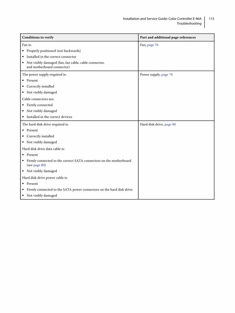
115Installation and Service Guide: Color Controller E-46ATroubleshooting
Fan is:• Properly positioned (not backwards)• Installed in the correct connector• Not visibly damaged (fan, fan cable, cable connector,
and motherboard connector)
Fan, page 76
The power supply required is:• Present• Correctly installed• Not visibly damaged
Cable connectors are:• Firmly connected• Not visibly damaged• Installed in the correct devices
Power supply, page 78
The hard disk drive required is:• Present• Correctly installed• Not visibly damaged
Hard disk drive data cable is:• Present• Firmly connected to the correct SATA connectors on the motherboard
(see page 80)• Not visibly damaged
Hard disk drive power cable is:• Present• Firmly connected to the SATA power connectors on the hard disk drive. • Not visibly damaged
Hard disk drive, page 80
Conditions to verify Part and additional page references
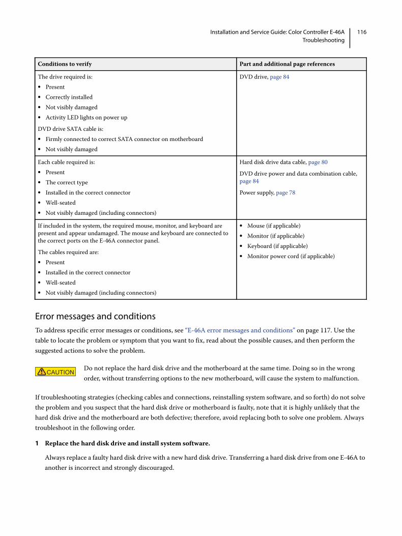
116Installation and Service Guide: Color Controller E-46ATroubleshooting
Error messages and conditionsTo address specific error messages or conditions, see “E-46A error messages and conditions” on page 117. Use the table to locate the problem or symptom that you want to fix, read about the possible causes, and then perform the suggested actions to solve the problem.
If troubleshooting strategies (checking cables and connections, reinstalling system software, and so forth) do not solve the problem and you suspect that the hard disk drive or motherboard is faulty, note that it is highly unlikely that the hard disk drive and the motherboard are both defective; therefore, avoid replacing both to solve one problem. Always troubleshoot in the following order.
1 Replace the hard disk drive and install system software.
Always replace a faulty hard disk drive with a new hard disk drive. Transferring a hard disk drive from one E-46A to another is incorrect and strongly discouraged.
The drive required is:• Present• Correctly installed• Not visibly damaged• Activity LED lights on power up
DVD drive SATA cable is: • Firmly connected to correct SATA connector on motherboard• Not visibly damaged
DVD drive, page 84
Each cable required is:• Present• The correct type• Installed in the correct connector• Well-seated• Not visibly damaged (including connectors)
Hard disk drive data cable, page 80
DVD drive power and data combination cable, page 84
Power supply, page 78
If included in the system, the required mouse, monitor, and keyboard are present and appear undamaged. The mouse and keyboard are connected to the correct ports on the E-46A connector panel.
The cables required are:• Present• Installed in the correct connector• Well-seated• Not visibly damaged (including connectors)
• Mouse (if applicable)• Monitor (if applicable)• Keyboard (if applicable)• Monitor power cord (if applicable)
Do not replace the hard disk drive and the motherboard at the same time. Doing so in the wrong order, without transferring options to the new motherboard, will cause the system to malfunction.
Conditions to verify Part and additional page references

117Installation and Service Guide: Color Controller E-46ATroubleshooting
2 If the problem persists, reinstall the original hard disk drive in the system, and then replace the motherboard.
If replacing a component does not correct the problem, make sure that you reinstall the old component back in the E-46A.
Table 4: E-46A error messages and conditions
Symptom Possible cause Suggested action
Beep codes during Startup
1 beep No error. The E-46A is starting up normally.
None
1 beep, followed by 3 beeps, followed by 3 beeps, followed by 1 beep
Missing, unmatched, incorrect, or faulty DIMMs
Check for missing, unmatched, incorrect or faulty DIMMs and reseat the DIMMs to remove any oxidation on the connector (see page 69).
Startup
E-46A does not start and the Fiery QuickTouch is black.
Possibly one of the following:• The E-46A is powered off• Power cable is not plugged into
the power connector on the E-46A connector panel, or into the wall power outlet
• The connector panel power switch is in the OFF position
• Fiery QuickTouch cables are not connected to the motherboard, the Fiery QuickTouch, or both
• Faulty power cable• Faulty power supply (power supply
may not be supplying power to the motherboard)
• The CMOS jumper is not in the default position
• Faulty motherboard (motherboard power plane may not be supplying power to components)
1 Recheck all cables and connections.2 Make sure the connector panel power switch is in the
ON position (see page 51).3 Listen for the power supply fan and feel for air at the
back of the unit where the power supply is located.If air is not coming from the power supply fan, isolate a possible faulty power cable as follows:• Power on using a different power cable.• Install a new or “known good” power supply.
4 Check the connector panel fan vent and feel for air coming into the system. If air is coming out of the power supply fan vent but is not coming into the connector panel fan vent, the motherboard may be faulty. You may need to replace the motherboard (see page 63).
5 Review the jumper section on page 76 and ensure that the jumper is in the default position.

118Installation and Service Guide: Color Controller E-46ATroubleshooting
E-46A is getting power, but the Fiery QuickTouch is black.
• Fiery QuickTouch cables are not connected to the motherboard, the Fiery QuickTouch, or both
• Faulty LED cable• Faulty Fiery QuickTouch display
module
1 Recheck all cables and connections.2 Use a different power/LED cable.3 If the problem persists and you have verified that the
power supply and motherboard are functioning properly as described earlier, replace the Fiery QuickTouch display module (see page 54).
Fiery Ticker messages
Please check Fiery Hardware.
Possibly one of the followings:• Network port is physically
damaged.• Network driver is disabled.• Wrong system software has been
installed. • Wrong BIOS chip is installed on the
motherboard.
1 If you installed the system software and this error message displays on Fiery Ticker, reinstall the system software using the correct system software media.
2 If the problem persists, ask the site administrator if the BIOS chip has been swapped from different motherboard. If so, replace the BIOS chip with the one from the original motherboard.
3 If the problem persists, replace the motherboard (see page 63).
No service dongle Motherboard replacement dongle is not attached after you replace the motherboard and attempt to transfer options to the new motherboard.
Turn off the E-46A, attached the correct dongle, and restart the option and BIOS transfer procedure (see page 68).
Fiery Quick Touch functions
E-46A is getting power, the Fiery QuickTouch screen is not black, and the Fiery QuickTouch is not responding.
Possibly one of the following:• Problem with the Fiery application• Faulty Fiery QuickTouch display
module
1 Recheck all cables and connections.2 Reboot the E-46A.3 If the problem persists, restore the backup, or reset the
Fiery QuickTouch software (see page 113).4 If the problem persists, restore the backup, or reinstall
the E-46A system software (see page 101).5 If the problem persists, replace the Fiery QuickTouch
display module (see page 54).
Table 4: E-46A error messages and conditions (Continued)
Symptom Possible cause Suggested action

119Installation and Service Guide: Color Controller E-46ATroubleshooting
DVD drive
DVD drive is not responding, cannot be located, or the disk will not eject.
Possibly one of the following:• A disk is stuck in the DVD drive• Cable connections to the DVD
drive are loose or data cable is faulty
• DVD drive is faulty• Motherboard is faulty
1 Press the eject button below the DVD slot on the front of the E-46A.
2 If the problem persists, check the cable connections to the DVD drive (see page 51).
3 If the problem persists, you may need to replace the DVD drive (see page 84).
4 If the problem persists, you may need to replace the motherboard (see page 63).
System performance
System performs slowly and/or hangs periodically.
Possibly one of the following:• Board or cable connections are
loose or faulty• System software is corrupted• Missing or faulty DIMM(s)• CPU is overheated or faulty• Motherboard is faulty
1 Recheck all cables and connections.2 Make sure that the CPU is firmly seated in its socket
and that the fan cable is connected to the motherboard. 3 If the problem persists, restore the backup, or reinstall
the system software (see page 101).4 Check for missing or faulty DIMM and reseat the
DIMM to remove any oxidation on the connector (see page 69).
5 If the problem persists, you may need to replace the motherboard (see page 63).
Clock is slow. Missing or dead battery on the motherboard
Replace the battery on the motherboard and update the time in the Windows (if a monitor is connected), Command WorkStation, or WebTools.page 101
Table 4: E-46A error messages and conditions (Continued)
Symptom Possible cause Suggested action

120Installation and Service Guide: Color Controller E-46ATroubleshooting
The E-46A hangs during the user software installation segment.
Possibly one of the following:• The time and date need to be
configured in the E-46A BIOS. (If the battery was removed from the E-46A motherboard during service and the time and date were not configured in Setup afterward, the E-46A will hang during the user software installation segment.)
• User Software DVD is corrupted• The DVD drive is faulty• The hard disk drive is faulty
1 Set the time and date in the BIOS:• Power off the E-46A and remove the User Software
DVD when it ejects.• If not already connected, connect a keyboard and a
monitor to the E-46A.• Power on the E-46A and immediately press F2
repeatedly to start the BIOS setup utility.• Configure the time and date. (To navigate, use the tab
key and the -/+ keys). • Save changes and exit (F10).• When the E-46A reaches Idle, power off and then
begin a full software installation again, starting with the System Software DVD (see page 101).
2 If the problem persists, obtain another User Software DVD and begin software installation again starting with the System Software DVD (see page 101).
3 If the problem persists, you may need to replace the DVD drive (see page 84).If replacing the DVD drive does not correct the problem, reinstall the old DVD drive in the system.
4 If the problem persists, replace the hard disk drive (see page 80).If replacing the hard disk drive does not correct the problem, reinstall the old hard disk drive in the system.
System performance (continued)
Network
If you suspect a network problem, keep in mind the following:• If the E-46A does not appear in the list of printers on the network, another device on the network may have been assigned the
same Ethernet hardware address. • Conflicting network settings may have been configured in Setup and on the customer’s workstation.• Printing problems may be caused by inappropriate Setup options.• Application-specific printing errors may be caused by missing or incorrectly placed printer description files.• System software may be corrupted.
For additional information, see Configuration and Setup, which is part of the user documentation set.
Table 4: E-46A error messages and conditions (Continued)
Symptom Possible cause Suggested action

121Installation and Service Guide: Color Controller E-46ATroubleshooting
Network (continued)
Unable to connect to the network, or the green LED on the RJ-45 network port is not lit.
Possibly one of the following:• Network cable is connected to the
wrong RJ-45 port• No cable/wrong type of cable is
connected to the network port• Network cable or connection is
faulty• Network is faulty• If the E-46A requires a static IP
address (for example, in a non-DHCP network environment), it may need to be reconfigured. A static IP address is deleted when system software is reinstalled.
• System software is corrupted• Network interface on the E-46A
motherboard is faulty
1 If the problem persists, have the network administrator check Network Setup. To configure a static IP address (if applicable for the customer site), work with the network administrator as described on page 27.
2 If the problem persists, make sure that the network administrator has checked other devices on the network.If other devices are not functioning, the problem may be with the network.
3 If the problem persists, restore the backup, or reinstall the system software (see page 101).Corrupt system software may cause the system to hang.
4 If the rest of the network is functioning properly and the problem persists, replace the motherboard (see page 63).
System starts up slowly then displays one or more DHCP error messages on the Fiery QuickTouch.
Possibly one of the following:• Network cable is connected to the
wrong RJ-45 port• No cable/wrong type of cable is
connected to the network port• Network cable or connection is
faulty• Network is faulty• System searches for a nonexistent
DHCP server because DHCP is enabled by default on the E-46A, but the customer’s network is not using DHCP
• Ethernet interface on the E-46A motherboard is faulty
• System software is corrupted
1 If the problem persists, ask the network administrator to check Network Setup. To configure a static IP address (if applicable for the customer site, as in a non-DHCP environment), work with the network administrator as described on page 27.
2 If the problem persists, ask the network administrator to check other devices on the network.If other devices are not functioning, the problem may be with the network.
3 If the problem persists, restore the backup, or reinstall system software (see page 101).Corrupt system software may cause the system to hang.
4 If the rest of the network is functioning properly and the problem persists, replace the motherboard (see page 63).
Table 4: E-46A error messages and conditions (Continued)
Symptom Possible cause Suggested action

122Installation and Service Guide: Color Controller E-46ATroubleshooting
Printing
Note: Intermittent print quality and color quality problems are difficult to trace. Before you try to troubleshoot print quality problems, print a color Test Page to make sure that the printer does not need servicing or adjusting.
Test Page fails to print. The printer is not ready to print. Make sure that the printer is turned on and ready to print.
A problem exists with the connection between the E-46A and the printer.
1 If the problem persists:• Recycle power on the printer.• Recycle power on the E-46A by shutting down
through the Functions menu, waiting 10 seconds, and then powering the E-46A back on.
2 If the problem persists, replace the printer interface (Data Transfer Unit) cables and board (see page 58).
3 If the problem persists, you may need to service the printer.
The E-46A appears in the list of printers on the customer’s workstation, but certain jobs do not print.
A PostScript error 1 Make sure that Print to PostScript Error in Setup is set to Yes.
2 Check for error messages on the E-46A output.
An application problem 1 Print a job from a different application to determine if the problem is associated with a particular application.
2 Make sure that the connection between the E-46A and the workstation is working by downloading a Test Page from the workstation, or by printing a simple file such as a text file.
3 Resend the problem file.
A print job stalls or stops after one or a few pages.
Possibly one of the following:• A PostScript or application error• System software is corrupted
1 Cancel the E-46A print job.2 If this fails to clear the problem, reboot the E-46A.3 If the problem persists, choose the Clear Server
command from Command WorkStation.4 Set Print Cover Page to Yes and resend the problem job.
The Cover Page will indicate “PS Error.” For more information about the PostScript error, double-click the problem job in the Command WorkStation window.
5 If the problem persists, restore the backup, or reinstall system software (see page 101).Corrupt system software may cause the system to hang.
Incorrect or faulty DIMMor faulty DIMM connection
1 Reseat the DIMMs to remove any oxidation on the connectors (see page 69).
2 Verify memory amount on the Configuration page.3 If the problem persists after replacing the DIMM,
replace the motherboard (see page 63).
Table 4: E-46A error messages and conditions (Continued)
Symptom Possible cause Suggested action

123Installation and Service Guide: Color Controller E-46ATroubleshooting
Troubleshooting informationYou can create the following information.
• Job Error Report
• System Logs
• Windows Error Report and Basic Network Logs
Table 5: Troubleshooting information
Printing (continued)
Color quality is inconsistent.
A printer problem Test the printer and perform service, if necessary. See the service documentation that accompanies the printer.
Print quality is poor. Possibly one of the following:• A file or application problem• A missing or outdated printer
description file• The application cannot find the
appropriate printer description file• The system is out of calibration
1 Print a E-46A Test Page.2 If the quality of the E-46A Test Page is good, the error
condition may be a file or application problem.3 Make sure that the appropriate printer description file
is installed. (For details, see Printing from Windows, which is part of the user documentation set.)
If the user can print the E-46A Test Page, but cannot print a job from a computer on the network, make sure that the network administrator has:• Checked all components of the network, including cables, connectors, terminators, network adapter boards, and network
drivers.• Activated the network and used it to communicate with other printers.• Confirmed that the applicable network settings in Setup (such as an IP address, Subnet mask, and Gateway address) match
the settings used in the network.
Note: EPS file generation is not completely standardized among applications. Some users may encounter problems while printing certain EPS files.
Logs JER System Log Click Tool
Engineering Logs *1 (Latest)
x (1 set) x (1 set) x (1 set, Optional)
Configuration Sheet (Latest)
x (1 set) x (1 set)
Engineering Logs *1 (AutoSaved *2)
x (max 20 set)
Configuration Sheet (AutoSaved*2)
x (max 20 set)
Table 4: E-46A error messages and conditions (Continued)
Symptom Possible cause Suggested action

124Installation and Service Guide: Color Controller E-46ATroubleshooting
*1: Maximum size of Engineering Log (cyclic): 128MB / set
*2: Trigger conditions for AutoSave to Fiery HDD
Print Engine side: SC919 / SC997 / SC899
Fiery Side: Fiery detects error by itself / Fiery reboots (including shut down/power on)
Table 6: Benefits and limitations of JER, System Log, and Click Tool
Note: Please make sure that the print engine and fiery date/time/timezone are correctly adjusted before reproducing the symptom and collecting job error report and system logs.
Windows Error Report
x (Optional)
Basic Network Logs
x (Optional)
CWS Log (from CWS 6.3)
Fiery Job Log x x (Optional)
Fiery Archived Log
x
FTP Logs x x (Optional)
Step txt x
Reason txt x
Original Source File
x (Optional)
Raster Data x (Optional)
Color Profiles x (Optional)
Email Logs x (Optional) x (Optional)
Logs Job Error Report (JER) System Log Click Tool
Benefits Up to 6 GB data are obtained with a single operation.
Engineering logs that contains error information causing the reported issue are obtained.
Collects logs when Fiery server is disconnected, but with the OS running.
Limitations If the data in the Engineering Logs exceeds 128MB, the old information is sequentially deleted.
Error information causing the issue may be overwritten with newer one.
Only Engineering Logs and Configuration Sheet can be obtained. (JER is still needed.)
The total size of the downloaded zip file may reach 2.7GB (128MB files x 21). It may be necessary to select some of the specific files for further investigation.
If the data in the Engineering Logs exceeds 128MB, the old information is sequentially deleted.
Error information causing the issue may be overwritten with newer one.
Logs JER System Log Click Tool

125Installation and Service Guide: Color Controller E-46ATroubleshooting
For the successful problem diagnosis, we recommend that you collect the Job Error Report, System logs, and the Printer Device Logs at the same time,
For the procedure of collecting the Printer device logs, see the service manual of the printer.
Job Error Report
Job Error Report contains the important troubleshooting information that the technical support personnel can use to solve customer issues. When a user encounters a job error, system fault, or any unexpected output while printing a job, the user can generate a report from Command WorkStation. The Job Error Report is a collection of job files, logs, and server information in a zip file, and it is available from both Mac OS and Windows versions of Command WorkStation.
Note: The error log entries are overwritten after a period of time. To ensure the error logs contain the relevant information, create the job error report as soon as possible after the error is observed. Create the job error report before rebooting the E-46A and if possible, before any additional print jobs are processed or printed.
To create a job error report
1 In Command WorkStation, select the job that encountered the error from the Printed or Held list.
Only one job error report can be created at a time. If multiple jobs are selected in Job Center, the Create Error Report button is not available.
Note: If the job that encountered the error is not available in the list, select another job from the same list. The job error report stores all the latest logs, except for the archived jobs.
2 If accessing from a Windows client computer, press Ctrl and right-click the job. If accessing from a Mac OS client computer, press Command and right-click the job.
3 In the shortcut menu, click Create Error Report.
4 Enter information about the job error.
a Enter any comments and additional details in the text field. The followings are recommended:
• Date and time error occurred
• Observed error codes, if any
• Description of expected result
• Description of incorrect result
• Steps for how error occurred
• Frequency of error (such as single event, rarely, sometimes, frequently, always)
• Whether the error has occurred with more than one file
• Whether the file selected for the report is the same file that had the error
• Operating system version, if the print job was sent from a client computer
126Installation and Service Guide: Color Controller E-46ATroubleshooting
• Version of E-46A user software installed
• Description of any other actions performed on the E-46A during the same time period
b Optional: To include the raster in the report, select Rasters.
The raster can be useful to include if the file is not processed correctly. However, it may exceed the allowed size of the report. In this case, it may be useful to provide it separately.
c Optional: To include color profiles in the report, select Color Profiles.
Color profiles can be useful to include if they are custom profiles and the print colors are incorrect.
d Optional: To include the email log in the report, select Email log.
The email log can be useful to include if the file was submitted by email.
e Optional: To include the native source file in the report, click Add +.
The native source file can be useful to include if the job does not process or print. However, it may exceed the allowed size of the report. In this case, it may be useful to provide it separately.
5 Attach any additional related files to the report.
The job error report size can be up to 2GB. If the selections and attachments result in a report larger than 2GB, the report must be reduced in order to be completed.
6 Optionally, if any print jobs are considered confidential, remove the job files before sending the zip file to technical support.
7 Save the job error report.
System Logs
The E-46A provides the ability to download system logs that can be sent to the technical support for diagnostic purposes. The logs are combined into a single, encrypted zip file, which does not contain any original job files.
To download the system logs
1 Access Configure (see page 32).
2 On the left side, choose Fiery Server > System Logs > Download.
3 Specify the location and save the system log file.
Fiery Click Tool
The Fiery Click Tool is used to collect Windows error report or logs when the Fiery server disconnects, reboots, stalls, or during a service call. The extracted information is saved in a zip file.
This tool is installed along with System Software using the System Software DVD 1 and, on successful installation, you can locate the “FieryClick.zip” file in “E:\EFI\” folder.
127Installation and Service Guide: Color Controller E-46ATroubleshooting
To extract the logs
Note: The log entries are overwritten after a period of time. To ensure the error logs contain the relevant information, collect the log immediately after the error is observed.
1 Login to the E-46A with Administrator privileges.
2 Access “E:\EFI\FieryClick.zip” and extract the “FieryClick.exe” file.
3 Double-click the “FieryClick.exe” file.
4 In the FieryClick Window, click Log Path to specify the location to save the log file.
5 Click Collect Logs.

128Installation and Service Guide: Color Controller E-46ASpecifications
Specifications
This chapter provides an overview of the E-46A hardware features.
Hardware features• Intel Core i5-6500, quad core 3.2GHz CPU (up to 3.6GHz with Turbo Boost enabled)
• RAM: 8GB (2 x4GB) DDR4 RAM
• 1TB hard disk drive standard
• DVD-RW drive
• RJ-45 connector for 10BaseT/100BaseTX/1000BaseT Mbs connectivity over twisted pair cable (upper port)
Physical specifications• Operating Environment:
• Temperature: +5°C to +40°C
• Relative Humidity: 10%-85% (non-condensing)
• Power Supply Voltage/Frequency Input: 100-240V @ 50-60Hz
• Power Supply Current Input: 100V @ 6A Max.; 240V @ 3A Max.
• Rated Power Consumption: 350W
• Dimensions (Depth x Height x Width):
46.36 cm (18.25 in.) x 52.71 cm (20.75 in.) x 23.50 cm (9.25 in.)
• Weight: 16.56 kg (36.5 lb.)
Networking and connectivity• Supports AppleTalk and TCP/IP protocols simultaneously.
Note: AppleTalk is supported only for downloading fonts.
Safety and emissions complianceThe E-46A has been certified to meet or surpass the following government standards:
Safety approvals
• IEC 60950-1:2005 (Second Edition) + Am 1:2009 + Am2:2013
129Installation and Service Guide: Color Controller E-46ASpecifications
• UL 60950-1:2007 R10.14 (TUV NRTL)
• CAN/CSA C22.2 No. 60950-1:2007 +A1:2011 +A2:2014 (TUV NRTL)
• T-Mark by TUV, EN 60950-1:2006+A11+A1+A12+A2
EMI/EMC approvals
• FCC Title 47, Part 15 Subpart B- NA - Class A
• Industry Canada, ICES-003 - NA, Class A
• VCCI CIRPR 32-1: 2016, Class A
• EN55032:2012, Class A-(EU)
• AS/NZS CISPR 32: 2015, Class A
• EN61000-3-2: 2014
• EN610003-3: 2013
• EN55024:2010 plus A1:2015 - (EU)

130Installation and Service Guide: Color Controller E-46AServicing the E-46A with furniture
Servicing the E-46A with furniture
This chapter describes how to remove the E-46A from the Fiery NX Station furniture to access internal components for service.
For the assembly instruction on the Fiery NX Station, see the documentation provided with the Fiery NX Station kit.
ProceduresIf the E-46A is installed in the optional furniture, you need to remove it from the furniture before performing most service procedures.
Figure 45: E-46A installed on the furniture
To remove the E-46A from the furniture
1 Make sure the E-46A is powered off and all the cables are removed from the back of the E-46A.
DANGER To avoid injury, do not lift the E-46A without assistance.
131Installation and Service Guide: Color Controller E-46AServicing the E-46A with furniture
2 Open the back door of the NX Station and remove all the cables from the connector panel of the E-46A.
3 Pull the server tray of the NX Station out of the stand.
To replace the E-46A in the furniture
1 Make sure that all the chassis panels are attached.
2 Lift the E-46A and place it on the server tray.
3 Slide the tray into the stand.
4 Reconnect all the cables.
DANGER To avoid injury, do not lift the E-46A without assistance.

132Installation and Service Guide: Color Controller E-46AIndex
AAC connector 111AppleTalk 128
Bback panel
fan 76backing up the configuration 103Backup Fiery Settings 103battery 74, 119boards
motherboard 59bracket
HDD 81, 84
Ccables
back panel fan 76checking 111CPU fan 72, 74DVD drive 50Fiery QuickTouch 50HDD data 50, 81, 84HDD power 81, 84keyboard 21monitor 21mouse 21power supply 80unpacking 18
Calibration command 39checklist for service calls 17, 26, 86Clear Server command 40clearing the CMOS 76clock 119closing the system 86CMOS 76
troubleshooting start up problems 117Color Charts 39components
checking 111configuration
backing up 103restoring 93, 94saving 93
Configuration page 30, 39, 40printing 39
Configure 32browser access 32changing language 28saving system configuration 93
configuring a static IP address 27, 101, 121connections, checking 111connectors
network 111
panel 111power, AC 111printer interface 111USB ports (dongle) 67, 111
Control Paneldisplay window 32
control panelusing 32
cooling assemblyCPU 70, 72
copier operation panel 37CPU 128
connecting the CPU fan power cable 74overview 70removing and replacing 72removing the cooling assembly from 71replacing the cooling assembly on 73type 59
customer site checklist 17
Ddamage, reporting 12, 19DHCP environment 101DHCP network environment 27, 121diagnostics, Ethernet address 120DIMMs
configuration 69, 128removing 69replacing 69
display window, Control Panel 32dongle
for entering Service Mode (motherboard replacement) 66, 67
transferring options (motherboard replacement) 64, 67, 68drives
DVD 84hard disk drive (HDD) 80, 84
DVD drivecables 80power and data cables 50removing 84replacing 85
EE-mail log 39, 40error messages
Fiery Ticker 118Ethernet
address 120cable 18
exploded viewCPU and cooling assembly 70
Index

133Installation and Service Guide: Color Controller E-46AIndex
Ffan
back panel 76CPU 70, 72front panel 76
Fiery pages 30, 39, 40Fiery QuickTouch cable
routing diagram 50Fiery Ticker 30Font list
printing prior to HDD replacement 81fonts
printer fonts on server 39printing font list 39
front panelfan 76layout 32
FTP Log 39Functions menu 37
Hhard disk drive (HDD) 80, 83, 84
bracket 81, 84capacity 128caution about replacing 83, 116data cable 81, 84description 80mounting screws 83, 84proper handling 80removing 81replacing 83
hard disk drivescable 80precautions 12proper handling 12
heatsink, CPU 70, 72
Iinstallation, hardware
sequence 16installing user software on client systems 18IP address 12, 101IP address, static 27, 121
JJob Log
Printable Info menu 39job log 101jumpers 76
LLAN (local area network) 12LCD 32left panel 51
Mmaster installer 18memory
configuration 69, 128removing 69replacing 69
Menu tabs, copier operation panel 37monitor 21monitor profiles 102motherboard
battery 74cautions about replacing 63description 59DIMMs 69removing 60, 62replacing 63snap top standoffs on 63transferring options to 64, 67, 68verifying in Service Mode 63, 66–68
Nnetwork
supported types 128network administrator 18networks
availability during installation 18checklist 17supported 9
Oopening the system 51operation panel, copier 37
Ppanels
left panel 51PANTONE 39power
AC cable 111AC connector 111CPU fan 72, 74front panel fan 76HDD 84precautions 17
power supplycables 80removing 78replacing 79voltages 43, 128
power synchronization 23precautions 12
hard disk drive 12Print Pages command 39printing

134Installation and Service Guide: Color Controller E-46AIndex
Configuration page 30, 31, 39font list 39server information pages 39Test Page 31
Rreassembling the system 86reboot
server 104software install 93
rebooting system 44, 45reporting damage 12restarting server 45restarting system software 44Restore Fiery Settings 93, 94restoring the configuration 93, 94Resume Printing command 38Run Diagnostics command 39
Ssaving the configuration 103server configuration page 30service calls
checklist 17, 26, 86Service Mode 63, 66–68service procedures, overview 46Setup 37Setup options, recording 101shutting down 45snap top standoffs 63software
system 64user 18, 64, 102
specifications 128startup
procedure 42, 43static IP address, configuring 27, 101, 121Suspend Printing command 38system performance 119system software
do not install after installing a new motherboard 64installing or upgrading 103–107
System Software DVD 102system upgrade 103–107
Tterminology 46Test Page 39, 40Test Page, printing 39Test Page, server 30thermal compound 64, 73transferring options (motherboard replacement) 64, 67, 68Tray Alignment command 38troubleshooting
beep codes during startup 117checking external connections 111checking internal connections 111control panel functions 118DVD drive 119error messages and conditions 116network 120, 121preliminary on-site checkout 110printing 122, 123startup problems 117system performance 119, 120
Uupdating the system 66upgrading software 103–107USB ports 111user software 102
do not install after installing a new motherboard 64installing on client systems 18troubleshooting problems during installation 120
User Software DVD 102
Vverifying functionality 86verifying new motherboard installation 66video board
removing 58replacing 58
voltageschecking 43