infusing agility in business processes through an event-centric approach
TRANSCRIPT
1
INFUSING AGILITY IN BUSINESS PROCESSES THROUGH AN EVENT-CENTRIC APPROACH
Nancy Alexopoulou, Department of Informatics and Telecommunications, University of Athens, Greece [email protected]
Mara Nikolaidou, Department of Informatics and Telematics, Harokopio University of Athens, Greece [email protected]
Panagiotis Kanellis, Department of Informatics and Telecommunications, University of Athens, Greece [email protected]
Vasiliki Mantzana, Department of Informatics and Telematics, Harokopio University of Athens, Greece [email protected]
Dimosthenes Anagnostopoulos Department of Informatics and Telematics, Harokopio University of Athens, Greece [email protected]
Drakoulis Martakos, Department of Informatics and Telecommunications, University of Athens, Greece [email protected]
Abstract For business processes we consider agility to be the capability to modify and adjust them in the face of unexpected contingencies even during execution phase. Traditional process-centric approaches dictate action sequence definition within the context of a specific business process designed to cover organizations requirements at some former point in time. To address the phenomenon of business processes that fail to match newly evolved organizational needs we propose an event-centric approach identifying meaningful events that drive action execution. We consider actions as autonomous units being aware of only the events initiating them as well as the events they trigger. In that sense, the notion of business process sequence is eliminated; the needed functionality is modelled in a flexible manner in terms of autonomous actions, events and event combinations, promoting the dynamic formation of process instances at execution time. Our approach materializes through a set of methods, named Actors-Actions-Events (AAE), which can be followed as a guide towards identifying the events and actions representing enterprise functionality. Its practical applicability is demonstrated through a simplified example in a medical setting. Key words: business process modelling, business process management, information systems requirements modelling, organizational agility
1 INTRODUCTION
In modern organizations most business processes are automated and are being conducted under the supervision of information systems driven by explicit process models. Automatic coordination of business processes has increased accuracy and efficiency in their execution (Dumas et al. 2005a). However, as organizational environments grow more and more dynamic, concrete business process models executed by workflow engines prove to be inflexible to change, meaning that their adjustment to new requirements is an arduous procedure requiring much time and resources. As such, business process agility has been recognized as a critical feature of the modern enterprise. Numerous research endeavours have been conducted, proposing methods or techniques that could increase business process agility (ShuiGuang et al. 2004; Reichert & Dadam, 1998; Rinderle et al., 2004; Mangan &
2
Sadiq, 2002; Millie and Balasubramanian, 1997). The major challenge regards the adaptations that need to be performed while a business process is being executed. In addition, there are business processes, which are inherently dynamic and cannot be strictly defined at design time. Thus, a need arises for the definition and prescription of a novel way to model this type of processes which demand timely adaptation upon unpredicted contingencies. According to our point of view, the attainment of agility requires a completely different approach for enterprise functionality modeling. So long as the objective is the construction of a predefined, well-structured business process, agility will be intrinsically hindered. We argue that the objective should instead be to specify autonomous actions that are synthesized into business processes only during execution time, so that changes at run time can be significantly facilitated. Thus, we propose an event-centric modeling approach that dictates the specification of autonomous actions at design time instead of business processes that are designed at a former point in time and model needs that are needs no more.
Events have a long history in the computing field. They have been extensively used in simulation (Paul and Balmer, 1993; Law and Kelton, 2007; Zeigler et al., 2000; Schulz et al., 2000), in software and system engineering (Yourdon 1989; Kumar and Garg, 1994; Faison, 2006; Yochem et al, 2008) and in active databases (Chakravarthy and Mishra, 1993, Gatziu and Dittrich, 1993). The concept of events has been introduced in different aspects of business process management as well. Geppert and Tombros (1996), for example, present an event engine, implementing event-driven execution of distributed workflows. The ARIS framework (Scheer, 1999) models business processes using event-driven process chains. In Cicekli and Yildirim (2000), an event-based formalism is presented for the specification and simulation of workflows.
The paper is organized as follows: Section 2 discusses the event-centric logic in contrast to the current typical process-centric paradigm from the perspective of agility. Section 3 presents the basic concepts of the proposed event-centric modeling approach as well as a set of modeling phases that may guide the designer in applying the approach. In section 5, the overall approach is demonstrated through a simplified example in a medical setting. The final section concludes the paper.
2 AGILE VERSUS TRADITIONAL BUSINESS PROCESS MANAGEMENT
Business process automation is accomplished through the utilization of process-aware information systems (Dumas et al. 2005a) built around Business Process Management (BPM) technology (Nagaraj et al., 2006). BPM provides the means for a systematic and coordinated management of all aspects of the business process lifecycle, such as specification, design, optimization, execution, etc. A number of important standardization efforts have been conducted during the last two decades in an attempt to formalize these aspects.
Workflow Management Coalition (WFMC) was one of the first consortiums with the mission to promote the use of workflows through the establishment of standards for Workflow Management, the ancestor of BPM. Apart from WFMC, there have been other more recent groups, which have defined standards for business process management. Business Process Management Initiative (BPMI) has developed the Business Process Modeling Language (BPML) (Assaf, A., 2001), a meta-language with the ability to also model enterprise data. OMG has specified Business Process Modeling Notation (BPMN) (OMG 2006) for a graphical representation of business processes. The most popular standard for defining business processes in an executable format is Business Process Execution Language (BPEL), which grew out of work done by Microsoft, IBM and BEA Systems (Andrews et. al, 2003). BPEL specification dictates that business processes should be composed of series of interacting Web Services according to the Service-oriented Architecture (SOA) paradigm (IBM, 2006).
All these complementary endeavours have shaped the current trend in business process management.
3
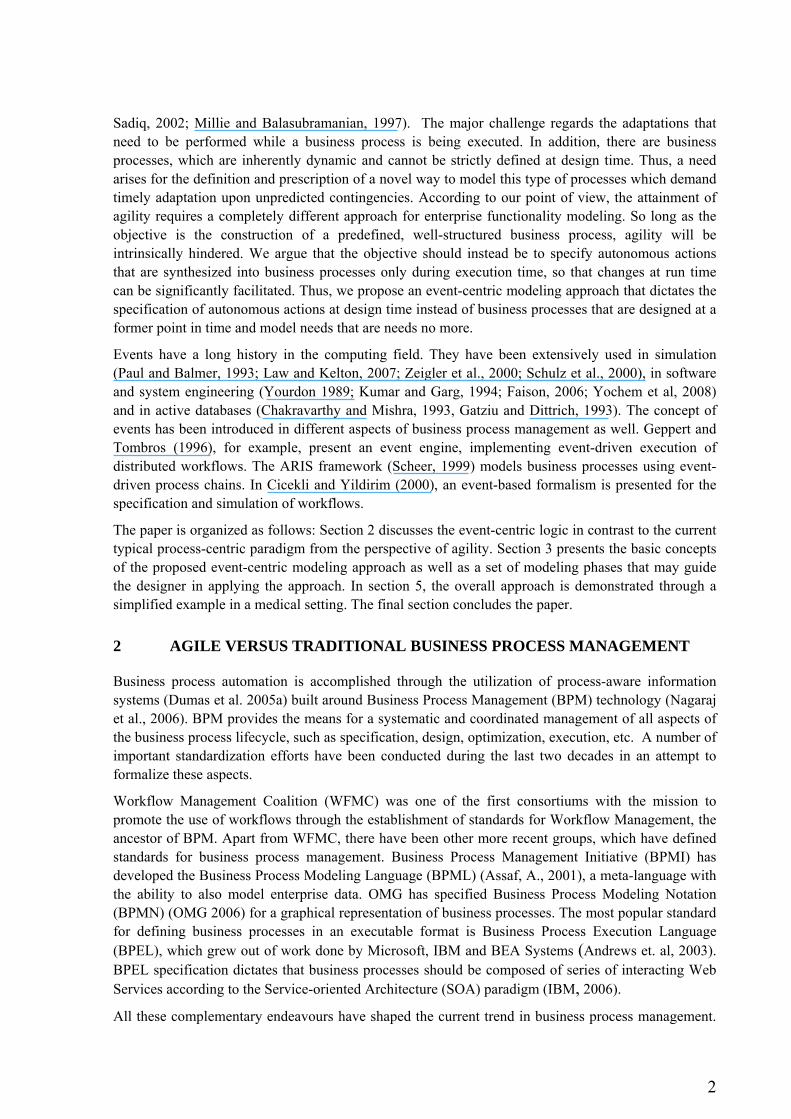
Today, business processes are usually modeled using a UML-like language such as BPMN. The produced business process model is transformed as an integral unit into an executable format using BPEL and is subsequently executed by an Execution Engine (Figure 1). While BPM, as opposed to its ancestor (Workflow Management), has laid more emphasis on the flexible management of dynamic business change (Hollingsworth, 2004), there is still a long way ahead towards the attainment of business process agility. BPEL, though adopted by numerous industrial BPM products, is not suitable for adaptation (Dumas et al., 2005b), since the business process is translated and executed in BPEL as an integral and concrete unit; hence, changes at execution time are prohibited. BPEL was created with the objective to solve the problem of interoperability in heterogeneous B2B environments focusing on well-structured business processes and therefore business processes agility thus far has not been given the attention it deserves.
Figure 1. Current business process management approach
Well-structured processes that do not undergo frequent changes are usually based on a process-centric logic, in the sense that the relative functionality is organized in specific units, i.e. actions, which are tightly coupled in predefined action sequences, depicting the flow of action execution. Although business process agility is a key factor for highly dynamic processes that cannot be easily prescribed during design time, it may be also required for well-structured processes in case a modification during execution phase is necessary. It seems therefore that the attainment of agility imposes a different approach for business process management which will allow design and execution phases to be performed in parallel, as opposed to traditional approaches that impose a strict sequential manner. In traditional approaches, changes in the business process model are feasible only after the completion of execution phase. In contrast, to enable true agility, the process designer should be able to adjust the process model even during execution. Thus, there should be a constant interaction between design and execution phases (Figure 2). In such a case, usually the actor plays the role of the modeler. Such an actor is called knowledgeable (Van der Aalst et al., 2005). Knowledgeable actors are not required in well structured processes where each actor usually needs to know only the information regarding the actions that should be performed by him/her. On the contrary, in case of medical processes, for example, a surgeon should first, be aware of the whole case corresponding to a patient and know additional information, such as the results of laboratory examinations and second, be able to modify the business process model, when he/she is required to perform a specific action.
Design Time:
Business Process
Definition
Business Process
Description in
UML-like
Languages
Execution Engine Execution Time:
Business Process
Execution
Business Process
Execution in BPEL,
in a SOA
Environment
Transformation of Business Process as an Integral Unit
Compiler-like Execution
4
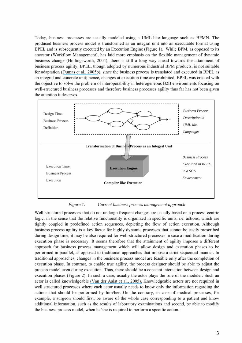
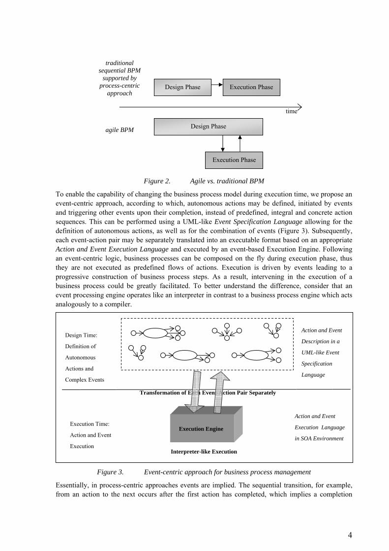
Figure 2. Agile vs. traditional BPM
To enable the capability of changing the business process model during execution time, we propose an event-centric approach, according to which, autonomous actions may be defined, initiated by events and triggering other events upon their completion, instead of predefined, integral and concrete action sequences. This can be performed using a UML-like Event Specification Language allowing for the definition of autonomous actions, as well as for the combination of events (Figure 3). Subsequently, each event-action pair may be separately translated into an executable format based on an appropriate Action and Event Execution Language and executed by an event-based Execution Engine. Following an event-centric logic, business processes can be composed on the fly during execution phase, thus they are not executed as predefined flows of actions. Execution is driven by events leading to a progressive construction of business process steps. As a result, intervening in the execution of a business process could be greatly facilitated. To better understand the difference, consider that an event processing engine operates like an interpreter in contrast to a business process engine which acts analogously to a compiler.
Figure 3. Event-centric approach for business process management
Essentially, in process-centric approaches events are implied. The sequential transition, for example, from an action to the next occurs after the first action has completed, which implies a completion
Design Time:
Definition of
Autonomous
Actions and
Complex Events
Action and Event
Description in a
UML-like Event
Specification
Language
Execution Engine Execution Time:
Action and Event
Execution
Action and Event
Execution Language
in SOA Environment
Transformation of Each Event-Action Pair Separately
Interpreter-like Execution
Design Phase Execution Phase
time
Design Phase
Execution Phase
traditional sequential BPM
supported by process-centric
approach
agile BPM
5
event indicating that the execution of the next action may begin. Likewise, conditions imply the occurrence of specific events determining the action paths that should be followed.
However, by explicitly modeling events and regarding them as separate entities, equally important to actions, it is possible to control action execution, while at the same time ensuring full decoupling between actions. The key difference between the process-centric and the proposed event-centric modeling approaches is that in the latter each action is considered as an autonomous unit being aware of only the events initiating it as well as the events it triggers. In that sense, the notion of business process sequence is eliminated; the enterprise functionality is described in terms of autonomous actions, events and event combinations. The flow of actions is determined at run time according to the triggered events and event interrelations defined at design time. As such, specific event-action chains, which correspond to a business process instance in the traditional process-centric approach, are formed during execution. The structure of these chains is similar, but not identical, to event-driven process chains produced using the EPC (Event-driven Process Chain) modeling method (Keller et al., 1992), as in the latter an event is strictly followed by an action and an action is strictly followed by an event. On the contrary, in our approach, an event in an event-action chain may be followed by another event caused by it. The EPC method, as supported by the ARIS framework (Scheer, 1999), is used for modeling, analyzing, and redesigning business processes and although it uses the concept of events, business processes are conventionally defined at design time as static event-action chains, since the emphasis is not on run-time business process agility. As a result, it does not include the concept of autonomous actions defined in an independent manner.
We posit that action independence promotes agility as it increases modularity in the way enterprise functionality is modeled. Thus, changes concerning the rearrangement of action sequence or the insertion/deletion of actions during run time can be more efficiently accommodated. Moreover, as the dynamic nature of an environment is essentially reflected upon events occurring in an indeterminate manner, an event-centric approach is inherently more eligible to model it. Moreover one should consider that faced with an issue or problem, people usually perform an action as see fit in response to the event occurrence, without adhering to the formal framework imposed by a process. An event-centric approach seems more appropriate for modeling such a human behavior especially in cases of contingencies that demand human intervention through ad hoc actions that promote agility.
Overall, our event-centric modeling approach is eligible for the description of agile processes that a) are highly unstructured, b) the process steps vary considerably according to different instances, c) may be extremely complicated comprising multiple nested conditions leading to a chaotic structure, and d) may include multiple reverses to the same prior actions.
3 EVENT-CENTRIC MODELLING OF ENTERPRISE FUNCTIONALITY
The fundamental concept in an event-driven organizational environment is that of event. An event is a notable thing that happens inside or outside the enterprise (Michelson, 2006). An event may either initiate an action, or cause another event, or both. Consider, for example, the event “Rain started”. This event may not necessarily require an action to be taken. However, it may cause the event “The courtyard flooded”. The latter will probably initiate the action “Remove water from the courtyard”. Although this example presents a simple causality relation, there can be more complex combinations among events. An event, for instance, may occur because two other events happened, or because two events occurred and another did not. For such cases, Luckham (2002) defined the generated event as ‘complex event’. The idea of specifying and utilizing relationships (such as timing, causality, etc.) between events is included in Complex Event Processing (Luckham, 2002).
According to our perspective, the basic concepts of modeling organizational functionality are depicted
6
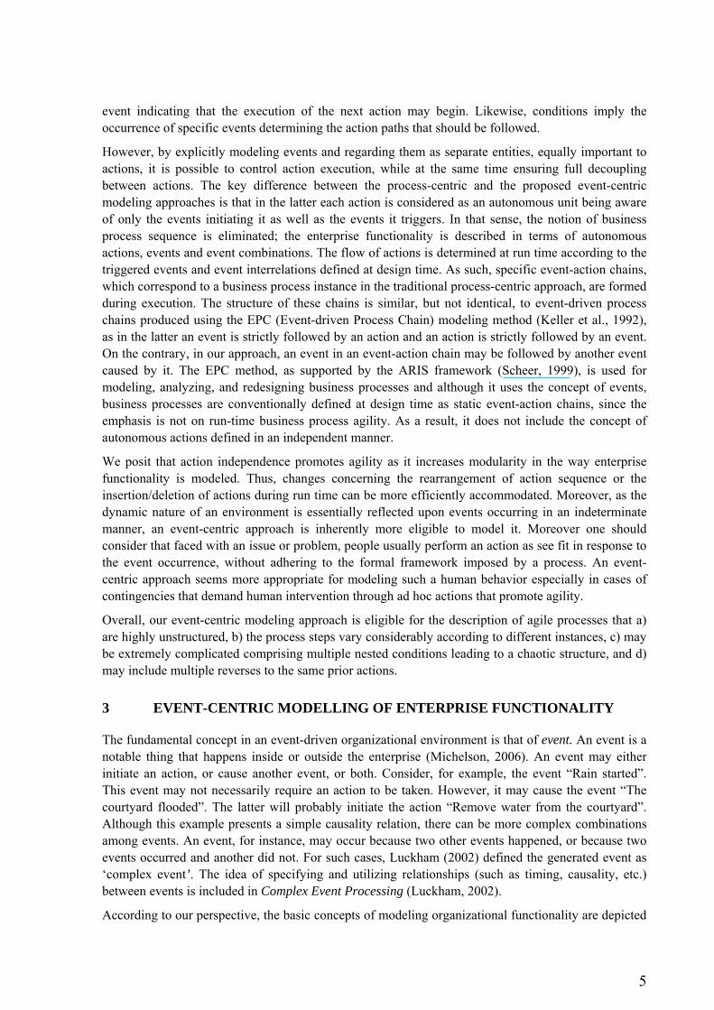
in Figure 4. As indicated, an event may cause another event either directly or indirectly through actions that it may initiate. The approach’s core concepts are further analyzed in the remainder of this section.
Figure 4. The basic concepts of event-centric business process modeling
3.1 Core Concepts
An event is an entity representing a meaningful thing that happens, causing another event or initiating an action that will trigger new events upon its completion. As such, an event may be generated either by another event or by an action. However, there are cases, where the generation of an event may be time-specific, e.g. a bell ring every morning at 10 o’clock. Consequently, we define three event categories distinguishing them in respect to their possible origin: a) events caused by other events, b) events triggered by actions and, c) timing events.
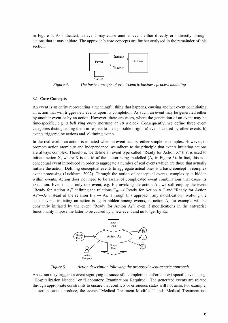
In the real world, an action is initiated when an event occurs, either simple or complex. However, to promote action atomicity and independence, we adhere to the principle that events initiating actions are always complex. Therefore, we define an event type called “Ready for Action X” that is used to initiate action X, where X is the id of the action being modelled (A1 in Figure 5). In fact, this is a conceptual event introduced in order to aggregate a number of real events which are those that actually initiate the action. Defining conceptual events to aggregate actual ones is a basic concept in complex event processing (Luckham, 2002). Through the notion of conceptual events, complexity is hidden within events. Action does not need to be aware of complicated event combinations that cause its execution. Even if it is only one event, e.g. E10 invoking the action A1, we still employ the event “Ready for Action A1” defining the relations E10 →“Ready for Action A1” and “Ready for Action A1”→A1 instead of the relation E10 → A1. Through this approach, any modification involving the actual events initiating an action is again hidden among events, as action A1 for example will be constantly initiated by the event “Ready for Action A1”, even if modifications in the enterprise functionality impose the latter to be caused by a new event and no longer by E10.
Figure 5. Action description following the proposed event-centric approach
An action may trigger an event signifying its successful completion and/or context-specific events, e.g. “Hospitalization Needed” or “Laboratory Examinations Required”. The generated events are related through appropriate constraints to ensure that conflicts or erroneous states will not arise. For example, an action cannot produce, the events “Medical Treatment Modified”` and “Medical Treatment not
Ready For A1
Action A1
E1
E2
Input Data
Output Data
Actor Category
En
. . .
7
Modified” at the same time.
An action is performed by a specific actor category, e.g. a doctor, a secretary etc. Also, an action requires specific data in order to be executed, i.e. input data, while during its execution it produces output data. Such data refer to a specific entity, for example a specific person or a specific case handled through the overall run time event-action chain. We define that events carry data folders containing data for the specific entities handled through the process being executed. Data folders are always associated with events and actions. A data folder is characterized by its structure, which should be compatible to input and output data of all the actions related to it.
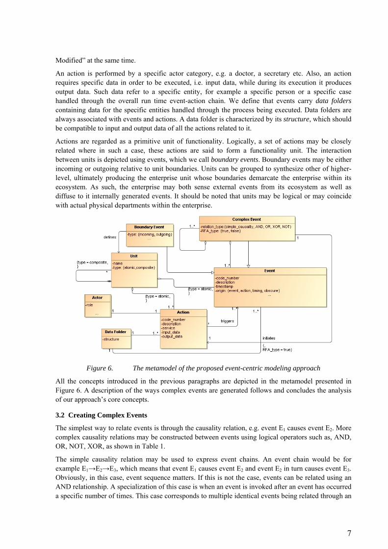
Actions are regarded as a primitive unit of functionality. Logically, a set of actions may be closely related where in such a case, these actions are said to form a functionality unit. The interaction between units is depicted using events, which we call boundary events. Boundary events may be either incoming or outgoing relative to unit boundaries. Units can be grouped to synthesize other of higher-level, ultimately producing the enterprise unit whose boundaries demarcate the enterprise within its ecosystem. As such, the enterprise may both sense external events from its ecosystem as well as diffuse to it internally generated events. It should be noted that units may be logical or may coincide with actual physical departments within the enterprise.
Figure 6. The metamodel of the proposed event-centric modeling approach
All the concepts introduced in the previous paragraphs are depicted in the metamodel presented in Figure 6. A description of the ways complex events are generated follows and concludes the analysis of our approach’s core concepts.
3.2 Creating Complex Events
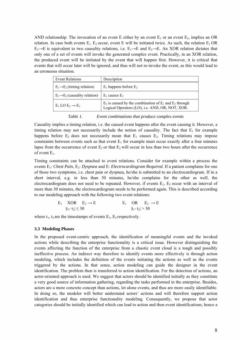
The simplest way to relate events is through the causality relation, e.g. event E1 causes event E2. More complex causality relations may be constructed between events using logical operators such as, AND, OR, NOT, XOR, as shown in Table 1.
The simple causality relation may be used to express event chains. An event chain would be for example E1→E2→E3, which means that event E1 causes event E2 and event E2 in turn causes event E3. Obviously, in this case, event sequence matters. If this is not the case, events can be related using an AND relationship. A specialization of this case is when an event is invoked after an event has occurred a specific number of times. This case corresponds to multiple identical events being related through an
8
AND relationship. The invocation of an event E either by an event E1 or an event E2, implies an OR relation. In case both events E1, E2 occur, event E will be initiated twice. As such, the relation E1 OR E2→E is equivalent to two causality relations, i.e. E1→E and E2→E. An XOR relation dictates that only one of a set of events will invoke the generated complex event. Practically, in an XOR relation, the produced event will be initiated by the event that will happen first. However, it is critical that events that will occur later will be ignored, and thus will not re-invoke the event, as this would lead to an erroneous situation.
Event Relations Description
E1→E2 (timing relation) E1 happens before E2
E1→E2 (causality relation) E1 causes E2
E1 LO E2 → E3 E3 is caused by the combination of E1 and E2 through Logical Operators (LO), i.e. AND, OR, NOT, XOR.
Table 1. Event combinations that produce complex events
Causality implies a timing relation, i.e. the caused event happens after the event causing it. However, a timing relation may not necessarily include the notion of causality. The fact that E1 for example happens before E2 does not necessarily mean that E1 causes E2. Timing relations may impose constraints between events such as that event E1 for example must occur exactly after a four minutes lapse from the occurrence of event E2 or that E2 will occur in less than two hours after the occurrence of event E1.
Timing constraints can be attached to event relations. Consider for example within a process the events E1: Chest Pain, E2: Dyspnea and E: Electrocardiogram Required. If a patient complains for one of those two symptoms, i.e. chest pain or dyspnea, he/she is submitted to an electrocardiogram. If in a short interval, e.g. in less than 30 minutes, he/she complains for the other as well, the electrocardiogram does not need to be repeated. However, if events E1, E2 occur with an interval of more than 30 minutes, the electrocardiogram needs to be performed again. This is described according to our modeling approach with the following two event relations:
E1 XOR E2 → E |t1- t2| ≤ 30
E1 OR E2 → E |t1- t2| > 30
where t1, t2 are the timestamps of events E1, E2 respectively.
3.3 Modeling Phases
In the proposed event-centric approach, the identification of meaningful events and the invoked actions while describing the enterprise functionality is a critical issue. However distinguishing the events affecting the function of the enterprise from a chaotic event cloud is a tough and possibly ineffective process. An indirect way therefore to identify events more effectively is through action modeling, which includes the definition of the events initiating the actions as well as the events triggered by the actions. In that sense, action modeling can guide the designer in the event identification. The problem then is transferred to action identification. For the detection of actions, an actor-oriented approach is used. We suggest that actors should be identified initially as they constitute a very good source of information gathering, regarding the tasks performed in the enterprise. Besides, actors are a more concrete concept than actions, let alone events, and thus are more easily identifiable. In doing so, the modeler will better understand actors’ actions and will therefore support action identification and thus enterprise functionality modeling. Consequently, we propose that actor categories should be initially identified which can lead to action and then event identifications; hence a
9
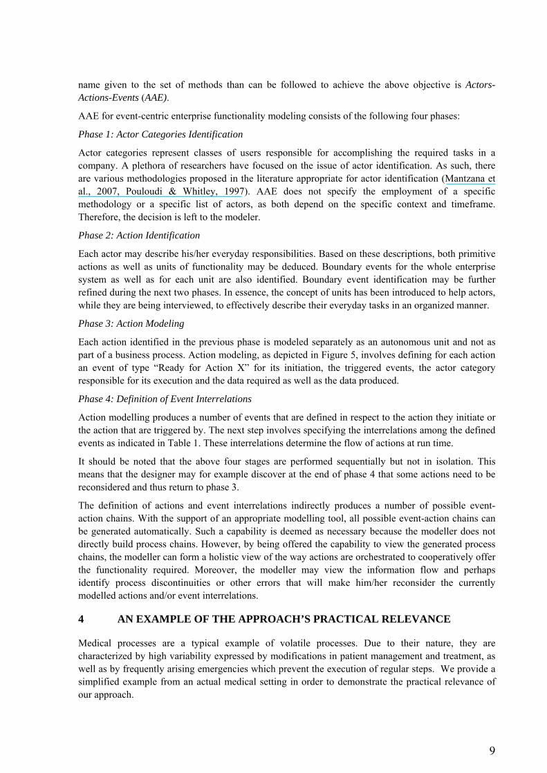
name given to the set of methods than can be followed to achieve the above objective is Actors-Actions-Events (AAE).
AAE for event-centric enterprise functionality modeling consists of the following four phases:
Phase 1: Actor Categories Identification
Actor categories represent classes of users responsible for accomplishing the required tasks in a company. A plethora of researchers have focused on the issue of actor identification. As such, there are various methodologies proposed in the literature appropriate for actor identification (Mantzana et al., 2007, Pouloudi & Whitley, 1997). AAE does not specify the employment of a specific methodology or a specific list of actors, as both depend on the specific context and timeframe. Therefore, the decision is left to the modeler.
Phase 2: Action Identification
Each actor may describe his/her everyday responsibilities. Based on these descriptions, both primitive actions as well as units of functionality may be deduced. Boundary events for the whole enterprise system as well as for each unit are also identified. Boundary event identification may be further refined during the next two phases. In essence, the concept of units has been introduced to help actors, while they are being interviewed, to effectively describe their everyday tasks in an organized manner.
Phase 3: Action Modeling
Each action identified in the previous phase is modeled separately as an autonomous unit and not as part of a business process. Action modeling, as depicted in Figure 5, involves defining for each action an event of type “Ready for Action X” for its initiation, the triggered events, the actor category responsible for its execution and the data required as well as the data produced.
Phase 4: Definition of Event Interrelations
Action modelling produces a number of events that are defined in respect to the action they initiate or the action that are triggered by. The next step involves specifying the interrelations among the defined events as indicated in Table 1. These interrelations determine the flow of actions at run time.
It should be noted that the above four stages are performed sequentially but not in isolation. This means that the designer may for example discover at the end of phase 4 that some actions need to be reconsidered and thus return to phase 3.
The definition of actions and event interrelations indirectly produces a number of possible event-action chains. With the support of an appropriate modelling tool, all possible event-action chains can be generated automatically. Such a capability is deemed as necessary because the modeller does not directly build process chains. However, by being offered the capability to view the generated process chains, the modeller can form a holistic view of the way actions are orchestrated to cooperatively offer the functionality required. Moreover, the modeller may view the information flow and perhaps identify process discontinuities or other errors that will make him/her reconsider the currently modelled actions and/or event interrelations.
4 AN EXAMPLE OF THE APPROACH’S PRACTICAL RELEVANCE
Medical processes are a typical example of volatile processes. Due to their nature, they are characterized by high variability expressed by modifications in patient management and treatment, as well as by frequently arising emergencies which prevent the execution of regular steps. We provide a simplified example from an actual medical setting in order to demonstrate the practical relevance of our approach.
10
Phase 1: Actor Identification As this demonstration is based on a healthcare organization, the authors decided to use IGOHcaps method proposed by Mantzana et al. (Mantzana et al., 2007). Using this method, a list of actors could be identified, such as doctors, managers, medical secretaries, patients, nurses, suppliers etc. However, in this paper we focus only on doctors and secretaries as it is not our intention to perform an exhaustive identification of all actions and events of a hospital ward but merely to demonstrate our approach.
Doctors, as opposed to secretaries, are regarded as knowledgeable actors and are enabled to change on the fly the event-action models when a need for a modification arises.
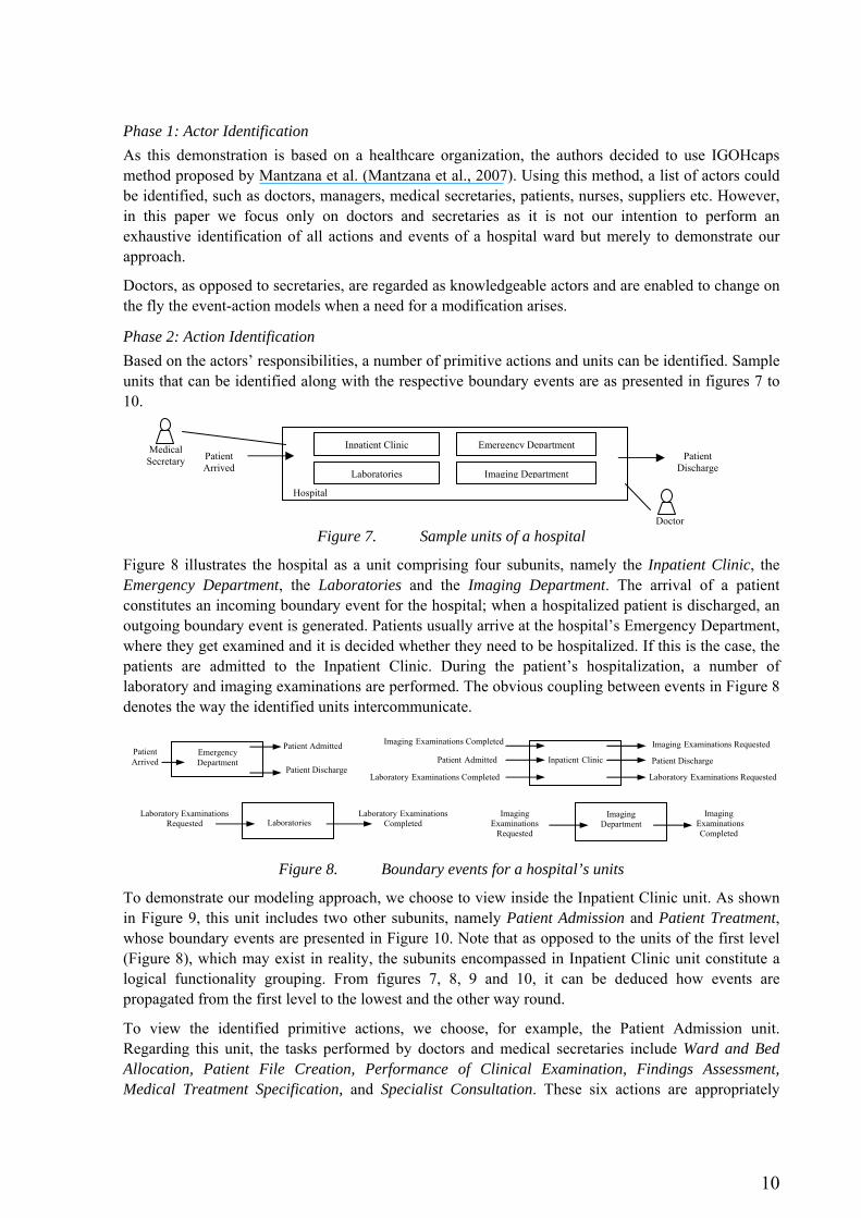
Phase 2: Action Identification Based on the actors’ responsibilities, a number of primitive actions and units can be identified. Sample units that can be identified along with the respective boundary events are as presented in figures 7 to 10.
Figure 7. Sample units of a hospital
Figure 8 illustrates the hospital as a unit comprising four subunits, namely the Inpatient Clinic, the Emergency Department, the Laboratories and the Imaging Department. The arrival of a patient constitutes an incoming boundary event for the hospital; when a hospitalized patient is discharged, an outgoing boundary event is generated. Patients usually arrive at the hospital’s Emergency Department, where they get examined and it is decided whether they need to be hospitalized. If this is the case, the patients are admitted to the Inpatient Clinic. During the patient’s hospitalization, a number of laboratory and imaging examinations are performed. The obvious coupling between events in Figure 8 denotes the way the identified units intercommunicate.
Figure 8. Boundary events for a hospital’s units
To demonstrate our modeling approach, we choose to view inside the Inpatient Clinic unit. As shown in Figure 9, this unit includes two other subunits, namely Patient Admission and Patient Treatment, whose boundary events are presented in Figure 10. Note that as opposed to the units of the first level (Figure 8), which may exist in reality, the subunits encompassed in Inpatient Clinic unit constitute a logical functionality grouping. From figures 7, 8, 9 and 10, it can be deduced how events are propagated from the first level to the lowest and the other way round.
To view the identified primitive actions, we choose, for example, the Patient Admission unit. Regarding this unit, the tasks performed by doctors and medical secretaries include Ward and Bed Allocation, Patient File Creation, Performance of Clinical Examination, Findings Assessment, Medical Treatment Specification, and Specialist Consultation. These six actions are appropriately
Patient Arrived
Emergency Department
Patient Admitted
Patient Discharge Inpatient Clinic Patient Discharge Patient Admitted
Laboratory Examinations Completed
Imaging Examinations Completed Imaging Examinations Requested
Laboratory Examinations Requested
Laboratories Laboratory Examinations
Completed Laboratory Examinations
Requested Imaging
Department Imaging
Examinations Completed
Imaging Examinations
Requested
Patient Arrived
PatientDischarge
Inpatient Clinic Emergency Department
Hospital
Laboratories Imaging Department
Doctor
Medical Secretary

11
modeled in the next phase of the approach.
Figure 9. Decomposition of Inpatient Clinic unit
Figure 10. Boundary events of Patient Admission and Patient Treatment units
Phase 3: Action Modeling
Figure 11. Modeling the identified actions of Patient Admission
Based on the information gathered from the previous phase, the identified actions can be modeled as illustrated in Figure 11. Figure 11 does not include the constraints that should be defined between the triggered events. Regarding action “A3: Perform Clinical Examination”, for example, an AND
Patient Admission Medical Treatment Specified Patient Admitted
Laboratory Examinations Completed
Imaging Examinations Completed Imaging Examinations Requested
Laboratory Examinations Requested
Patient Treatment Patient Discharge
Medical Treatment Specified
Laboratory ExaminationsCompleted
Imaging ExaminationsCompleted
Imaging ExaminationsRequested
Laboratory ExaminationsRequested
Doctor Medical Secretary
Laboratory Examinations Required
Patient Admission
Patient Treatment Patient Discharge Patient Admitted
Imaging Examinations RequestedImaging Examinations Completed
Laboratory Examinations Completed
Doctor Medical Secretary
12
constraint should be defined among events “E3: Clinical Examinations Completed”, “E30: Laboratory Examinations Requested” and “E31: Imaging Examinations Requested” as when a patient is admitted, he/she always submitted to a number of basic laboratory and imaging examinations. Concerning action “A4: Assess Findings to Establish a Running Diagnosis” it triggers the events “E4: Findings Assessment Completed”, “E20: Diagnosis Feasible” and “E20: Diagnosis not Feasible”. The constraint defined for these events may be expressed by the logical expression (E4 AND E20) XOR (E4 AND E21).
Actions such as Assess Findings to Establish a Running Diagnosis and Specify Medical Treatment are difficult to prescribe and document in a formal process manual. Information is provided by the actor who in such a case constitutes the best source for a precise and effective action modeling.
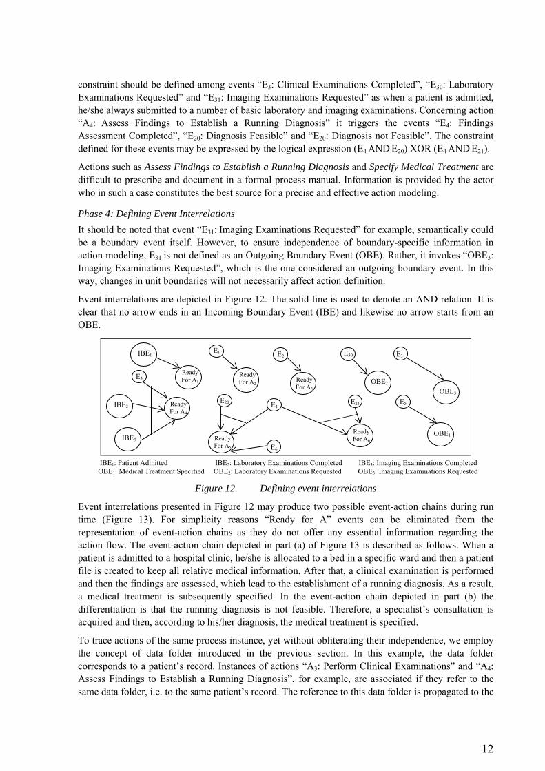
Phase 4: Defining Event Interrelations It should be noted that event “E31: Imaging Examinations Requested” for example, semantically could be a boundary event itself. However, to ensure independence of boundary-specific information in action modeling, E31 is not defined as an Outgoing Boundary Event (OBE). Rather, it invokes “OBE3: Imaging Examinations Requested”, which is the one considered an outgoing boundary event. In this way, changes in unit boundaries will not necessarily affect action definition.
Event interrelations are depicted in Figure 12. The solid line is used to denote an AND relation. It is clear that no arrow ends in an Incoming Boundary Event (IBE) and likewise no arrow starts from an OBE.
IBE1: Patient Admitted IBE2: Laboratory Examinations Completed IBE3: Imaging Examinations Completed OBE1: Medical Treatment Specified OBE2: Laboratory Examinations Requested OBE3: Imaging Examinations Requested
Figure 12. Defining event interrelations
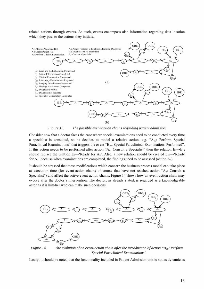
Event interrelations presented in Figure 12 may produce two possible event-action chains during run time (Figure 13). For simplicity reasons “Ready for A” events can be eliminated from the representation of event-action chains as they do not offer any essential information regarding the action flow. The event-action chain depicted in part (a) of Figure 13 is described as follows. When a patient is admitted to a hospital clinic, he/she is allocated to a bed in a specific ward and then a patient file is created to keep all relative medical information. After that, a clinical examination is performed and then the findings are assessed, which lead to the establishment of a running diagnosis. As a result, a medical treatment is subsequently specified. In the event-action chain depicted in part (b) the differentiation is that the running diagnosis is not feasible. Therefore, a specialist’s consultation is acquired and then, according to his/her diagnosis, the medical treatment is specified.
To trace actions of the same process instance, yet without obliterating their independence, we employ the concept of data folder introduced in the previous section. In this example, the data folder corresponds to a patient’s record. Instances of actions “A3: Perform Clinical Examinations” and “A4: Assess Findings to Establish a Running Diagnosis”, for example, are associated if they refer to the same data folder, i.e. to the same patient’s record. The reference to this data folder is propagated to the
Ready For A6 Ready
For A5
Ready For A4
E21
Ready For A2 Ready
For A3
Ready For A1
E1 IBE1
OBE1
E3
E4 E20
E6
OBE2
E30
OBE3
IBE2
IBE3
E5
E31 E2
13
related actions through events. As such, events encompass also information regarding data location which they pass to the actions they initiate.
(a)
(b)
Figure 13. The possible event-action chains regarding patient admission
Consider now that a doctor faces the case where special examinations need to be conducted every time a specialist is consulted, so he decides to model a relative action, e.g. “A10: Perform Special Paraclinical Examinations” that triggers the event “E10: Special Paraclinical Examinations Performed”. If this action needs to be performed after action “A6: Consult a Specialist” then the relation E6→E10 should replace the relation E6→‘Ready for A5’. Also, a new relation should be created E10→‘Ready for A4’ because when examinations are completed, the findings need to be assessed (action A4).
It should be stressed that these modifications which concern the business process model can take place at execution time (for event-action chains of course that have not reached action “A6: Consult a Specialist”) and affect the active event-action chains. Figure 14 shows how an event-action chain may evolve after the doctor’s intervention. The doctor, as already stated, is regarded as a knowledgeable actor as it is him/her who can make such decisions.
Figure 14. The evolution of an event-action chain after the introduction of action “A10: Perform Special Paraclinical Examinations”
Lastly, it should be noted that the functionality included in Patient Admission unit is not as dynamic as
IBE1 A1 E1
E4
E3
OBE1
A2 E2 A3 A4
A5
E20
E5
IBE3 IBE2 OBE2 OBE3
E31 E30
IBE1 A1 E1
E4
E3
OBE1
A2 E2 A4
A5
E21
E5A6 E6
IBE3 IBE2 OBE2 OBE3
E31 E30
A3
E1: Ward and Bed Allocation Completed E2: Patient File Creation Completed E3: Clinical Examination Completed E30: Laboratory Examinations Requested E31: Imaging Examinations Requested E4: Findings Assessment Completed E20: Diagnosis Feasible E21: Diagnosis not Feasible E6: Specialist Consultation Completed
A1: Allocate Ward and Bed A2: Create Patient File A3: Perform Clinical Examination
A4: Assess Findings to Establish a Running Diagnosis A5: Specify Medical Treatment A6: Consult a Specialist
IBE1 A1 E1
E4
E3 A2 E2 A4
E21
A6 E6
IBE3 IBE2 OBE2 OBE3
E31 E30
A3
E10E10 A10
E4
OBE1
E20
E5 A5
A4
14
that encompassed by Patient Treatment. Patient Admission, as opposed to Patient Treatment, could be described by a well-structured process, but here was chosen as a simple example in order to demonstrate the ability of modifications during execution.
5 CONCLUSIONS
Traditional process-centric approaches for business process modelling fall short to support changes of the business process model during execution and, in addition, are not eligible for the description of dynamic unstructured processes. Attempting to address this limitation, we presented an event-centric modeling approach which helps to describe enterprise functionality in such a manner so as to allow business process agility at execution time. The proposed approach empowers specific actors who are termed ‘knowledgeable’ by augmenting their role with modelling capabilities. Such actors can alter the event-action models and consequently intervene in the evolution of event-action chains. As demonstrated in the example provided, the approach supports modifications even during execution time, promoting thus agility.
As expected, agility cannot be attained without cost. It introduces complexity in the implementation of the required infrastructure. Currently, we are exploring important implementation issues, such as the creation/deletion of data folders, targeting the construction of an infrastructure for agile event-driven business process execution, according to the conceptual architecture proposed in Alexopoulou et al. (2008).
Future work includes first, finalizing the experimental application of the approach that is currently in progress in a Greek hospital and then improving it by addressing deficiencies that may be unearthed during this period. Subsequently, we will focus on developing an Event Specification Language using the UML 2.0 (OMG, 2007) extension mechanism.
Acknowledgement
This paper is part of the 03ED470 research project, implemented within the framework of the “Reinforcement Programme of Human Research Manpower” (PENED) and co-financed by National and Community Funds (25% from the Greek Ministry of Development-General Secretariat of Research and Technology and 75% from E.U.-European Social Fund.
References Alexopoulou Nancy, Nikolaidou Mara, Chamodrakas Yannis, Martakos Drakoulis, 2008. ‘Enabling
On-the-fly Business Process Composition through an Event-based Approach’, Proceedings of the 41th Hawaii International Conference On System Sciences (HICSS 2008), Big Island – Hawaii, Jan 7-10, 2008.
Andrews T., Curbera F., Dholakia H., Goland Y., Klein Y., Leymann F., Liu K., Roller D., Smith D., Thatte S., Trickovic I., Weerawarana S., 2003. ‘Business Process Execution Language for Web Services, Version 1.1’. BEA Systems, International Business Machines Corporation, Microsoft Corporation, SAP AG, Siebel Systems
Assaf, A., 2001. ‘Business Process Modeling Language (BPML)’. Business Process Management Initiative, http://www.bpmi.org.
Chakravarthy Sharma and Mishra Deepak, 1993. ‘Snoop: An expressive Event Specification Language For Active Databases’. Technical Report, Dep. Of Computer and Information Sciences, University of Florida.
15
Cicekli, N. K. and Yildirim Y. 2000, ‘Formalizing Workflows using the Event Calculus’, Proceedings of the 11th Intl.Conf., DEXA 2000, London, UK, September 2000, pp. 222-23.
Dumas M., Aalst W., Hofstede A., 2005a. ‘Process-Aware Information Systems’. John Wiley & Sons INC.
Dumas M., Fjellheim T., Milliner S., and Vayssiere J., 2005b. ‘Event-Based Coordination of Process-Oriented Composite Applications’. BPM 2005, LNCS 3649, pp. 236–251.
Gatziu Stella and Dittrich R. Klaus, 1993. ‘Events in an Active Object-Oriented Database System’. Proceedings. of the 1st International Workshop on Rules in Database Systems, Edinburg, August 1993.
Geppert Andreas and Tombros Dimitrios, 1996. ‘Event-based Distributed Workflow Execution with EVE’. Technical Report, Department of Computer Science, University of Zurich.
Hollingsworth David, 2004. ‘The Workflow Reference Model-10 Years On’. chapter extracted from the Workflow Handbook 2004, WFMC. http://www.wfmc.org/standards/downloads/ Ref_Model_10_years_on_Hollingsworth.pdf
IBM, 2006. ‘Patterns: SOA Foundation Service Creation Scenario’. IBM. ibm.com/redbooks. Keller G., Nuttgens M. and Scheer A.W. 1992. ‘Semantische Processmodellierung auf der Grundlage
Ereignisgesteuerter Processketten (EPK)’. Veroffentlichungen des Instituts fur Wirtschaftsinformatik, Heft 89 (in German), University of Saarland, Saarbrucken.
Kumar Ratnesh, Garg K. Vijay 1994. ‘Modeling and Control of Logical Discrete Event Systems (The Springer International Series in Engineering and Computer Science’ Springer; 1 edition.
Law M. Averill and Kelton W. David, 2007. ‘Simulation Modeling and Analysis’, 4th edition, Mc Graw Hill.
Luckham David, 2002. ‘The Power of Events’. Addison-Wesley. Mangan Peter and Sadiq Shazia, 2002. ‘On Building Workflow Models for Flexible Processes’. 13th
Australasian Database Conference (ADC2002), Melbourne, Australia. Vol. 5. Mantzana V., Themistocleous M., Irani Z and Morabito V., 2007. ‘Identifying HealthCare Actors
Involved in the Adoption of Information Systems’. European Journal of Information Systems, 16(01), pp.91-102.
Michelson M. Brenda, 2006. ‘Event-driven Architecture Overview’. Patricia Seybold Group. http://dx.doi.org/10.1571/bda2-2-06cc.
Millie M. Kwan and Balasubramanian P. R. 1997. ‘Dynamic Workflow Management: A Framework for Modeling Workflows’ Proceedings of The Thirtieth Annual Hawaii International Conference on System Sciences IEEE.
Nagaraj N. S., Thonse Srinivas and Balasubraman S., 2001.‘Business Process Management: An Emerging Trend’. SETLabs, Infosys Technologies Ltd.
OMG 2006, ‘Business Process Management Notation, Version 1.0’, OMG. OMG Inc, 2007. ‘Unified Modeling Language: Superstructure’. Version 2.1.1, 3/2/2007, OMG. Paul, Ray, and Balmer, David, 1993. ‘Simulation Modelling’,.Chartwell-Bratt, Lund, Sweden, ISBN 0-
86238-280-7. Pouloudi A. and Whitley E. A., 1997. ‘Stakeholder Identification in Interorganizational Systems:
Gaining Insights for Drug Use Management Systems’, European Journal of Information systems 6(1), pp.1-14.
Reichert, M.; Dadam, P., 1998. ‘ADEPTflex – supporting dynamic changes of workflows without losing control’. Journal of Intelligent Information Systems, 10, pp. 93-129.
Scheer A.W. 1999. ‘ARIS-Business Process Modeling’. 2nd ed. Berlin: Springer. Schulz, S., T. C. Ewing, and J. W. Rozenblit. 2000. ‘Discrete event system specification (DEVS) and
statemate statecharts equivalence for embedded systems modeling’. Proceedings of 7th IEEE
16
International Conference and Workshop on the Engineering of Computer Based Systems, April 2000, pp. 308–316.
ShuiGuang, D., Zhen, Y., ZhaoHui, W., LiCan, H. 2004. ‘Enhancement of Workflow Flexibility by Composing Activities at Run-time’. Proceedings of the ACM Symposium on Applied Computing, pp. 667-673.
Rinderle Stefanie, Reichert Manfred, and Dadam Peter, 2004. ‘On Dealing with Structural Conflicts between Process Type and Instance Changes’. BPM 2004, pp. 274–289.
Van der Aalst Wil M. P., Weske Mathias, Grünbauer Dolf, 2005. ‘Case handling: a new paradigm for business process support’. Data Knowl. Eng. Vol. 53 No. 2, pp 129-162.
Yochem Angela, Phillips Les, Martinez Frank, Taylor Hugh, 2008. ‘Service-Oriented Architecture and Event-Driven Architecture: J2EE Integrated Solutions’ Addison-Wesley Professional; 1 edition.
Yourdon Edward, 1989. ‘Modern Structured Analysis’, Prentice-Hall International Editions. Zeigler, B. P., H. Praehofer, and T. Kim. 2000. ‘Theory of modeling and simulation‘. 2nd ed.
Academic Press.