influence of fcc catalyst steaming on hdpe pyrolysis product distribution
TRANSCRIPT
J. Anal. Appl. Pyrolysis 85 (2009) 359–365
Contents lists available at ScienceDirect
Journal of Analytical and Applied Pyrolysis
journa l homepage: www.e lsev ier .com/ locate / jaap
Influence of FCC catalyst steaming on HDPE pyrolysis product distribution
M. Olazar, G. Lopez, M. Amutio, G. Elordi, R. Aguado, J. Bilbao
University of the Basque Country, P.O. Box 644, 48080 Bilbao, Spain
A R T I C L E I N F O
Article history:
Received 27 May 2008
Accepted 17 October 2008
Available online 5 November 2008
Keywords:
Catalytic pyrolysis
Spouted bed reactor
FCC catalyst
Waste plastics
A B S T R A C T
A commercial FCC catalyst based on a zeolite active phase has been used in the catalytic pyrolysis of
HDPE. The experimental runs have been carried out in a conical spouted bed reactor provided with a
feeding system for continuous operation. Different treatments have been applied to the catalyst to
improve its behaviour. This paper deals with the optimization of catalyst steaming and pyrolysis
temperature in order to maximize the production of diesel-oil fraction. The performance of the fresh
catalyst has been firstly studied at 500 8C. This catalyst gives way to 52 wt% gas yield, 35 wt% light liquid
fraction and a low yield of C10+ fraction (13 wt%). After mild steaming (5 h at 760 8C) the results show a
significant improvement in product distribution. Thus, gas yield decreases to 22 wt%, the yield of light
liquid is similar to that of the fresh one (38 wt%), whereas the yield of the desired C10+ fraction increases
to 38 wt%. Nevertheless, the best results have been obtained when a severe steaming is applied to the
catalyst (8 h at 816 8C) and pyrolysis temperature is reduced to 475 8C. There is a significant reduction in
the gaseous fraction (8 wt%). The light liquid fraction has also been reduced to 22 wt%, but the yield of
diesel fraction increases to 69 wt%. Moreover, the deactivation of the catalyst has also been studied under
the optimum conditions.
� 2008 Elsevier B.V. All rights reserved.
1. Introduction
In recent years, the production and consumption of plasticshave increased continuously and are expected to continueincreasing in the future. Present demand exceeds 70 milliontonnes per year [1]. The thermal degradation of waste plastics in aninert atmosphere has been regarded as one of the most feasiblesolutions at industrial scale. Moreover, the catalytic pyrolysis ofwaste plastics produces hydrocarbons that can be used as eitherfuels or chemicals [2,3].
Thermal cracking of polyolefins can be carried out followingtwo different strategies: (1) operation at low temperatures toobtain important yields of waxes and reduced amounts of gasesand oil; (2) thermal pyrolysis at temperatures above 700 8C toincrease the yield of gases and aromatic compounds with animportant reduction in the yield of waxes [4]. This processconsumes large amounts of energy due to the low thermalconductivity of polyolefins together with the endothermic natureof thermal pyrolysis.
The use of a catalyst allows for modifying the process toproduce a narrower distribution of hydrocarbons with a highermarket value [5–7]. Moreover, process temperature can bereduced, which means an important reduction in energy con-sumption [8].
E-mail address: [email protected].
0165-2370/$ – see front matter � 2008 Elsevier B.V. All rights reserved.
doi:10.1016/j.jaap.2008.10.016
The most widely used catalysts are acid solids, such as HZSM-5zeolite [2,9–13], HY zeolite [12,14], Hb zeolite [13], MCM-41 [9],USY [10] mordenite [15], clinoptilolite [16], etc., which are selectedon the basis of their acid strength and surface characteristics.However, this catalytic process may not be viable due to the highcost of manufacturing the catalysts mentioned above. Therefore,the use of equilibrated fluid catalytic cracking (FCC) catalysts in thepyrolysis process would be economically advantageous, as the FCCprocess generates huge quantities of spent catalyst that is stillactive for other processes. There are a number of studies dealingwith the pyrolysis of different kinds of plastics (low densitypolyethylene, high density polyethylene (HDPE), polypropylene,polystyrene and their mixtures) over FCC catalysts, in thermo-balance [17,18], batch reactors [16,19,20], fixed bed reactors [21]and fluidized bed reactors [22–24].
A conical spouted bed reactor (CSBR) has been used in thispaper for catalytic pyrolysis of HDPE. This reactor is suitable for thetreatment of materials that are irregular or sticky and has alreadybeen used for the pyrolysis of biomass [25–27], scrap tyres [28–30]and waste plastics [14,31]. Besides, the good contact between gasand solid phases in this reactor avoids the defluidization problemsaffecting waste plastics pyrolysis in a fluidized bed [32].
2. Experimental
Based on the hydrodynamics studies carried out in a cold unit[33,34], on the experience acquired in the pyrolyis of other types of

Fig. 1. Scheme of the continuous pyrolysis unit.
M. Olazar et al. / J. Anal. Appl. Pyrolysis 85 (2009) 359–365360
wastes, such as agroforest, tyres and plastic wastes, and on peerinformation, a continuous pyrolysis unit has been set-up and fine-tuned, Fig. 1.
The unit consists of the following components: (1) solid feedingdevice, (2) gas feeding device, (3) pyrolysis reactor, (4) a device forretaining the fine particles from the stream of volatile products, (5)liquid collection section and (6) a system for gaseous productanalysis.
The feeding system is pneumatically actuated and is able to feedup to 300 g/h of plastic. The nitrogen flow is controlled by a massflow meter that allows for feeding up to 30 L/min. Prior to enteringthe reactor, it is heated to the reaction temperature by means of apreheater.
The reactor is the main element of the unit and is a spouted bedof conical geometry with a cylindrical upper section. The totalheight of the reactor is 34 cm, the height of the conical section20.5 cm, and the angle of the conical section 288. The diameter ofthe cylindrical section is 12.3 cm, the bottom diameter 2 cm andthe gas inlet diameter 1 cm. The reactor may operate from theregime of spouted bed to a vigorous regime of jet spouted bed (ordilute spouted bed).
The volatile products leave the reactor together with the inert gasand pass through a high-efficiency cyclone followed by a 25-mmsintered steal filter, both placed at the reactor outlet. The gasesleaving this filter circulate through a volatile condensation systemconsisting of a condenser and two coalescence filters. The condenseris a double shell tube cooled by tap water. The coalescence filtersensure total condensation of volatile hydrocarbons.
2.1. Experimental procedure
Pyrolysis runs have been carried out at 500 8C with the freshand mildly steamed catalysts. Nevertheless, temperature has been
reduced to 475 8C when the severely steamed catalyst is used, inorder to improve product distribution. Temperatures below 475 8Care not advisable, given that the reaction rate is too low anddefluidization may occur.
The bed was initially made up of 30 g of catalyst (particle sizebetween 20 and 90 mm), and the continuous polymer feed rate was0.5 g/min for 6–7 h, which means that 180–210 g of polymer havebeen fed into the catalyst bed. This feed rate used with the threecatalysts is long enough to monitor product distribution through-out reaction time and study catalyst deactivation.
As soon as the polymer is fed into the reactor containing thecatalytic bed at the reaction temperature, it melts and coats thecatalyst particles. The cyclic and vigorous movement of theparticles in the spouted bed is especially suitable for theseprocesses to take place efficiently and almost instantaneously. Infact, feeding rates higher than in fluidized beds may be used inspouted beds without defluidization problems [32]. Thus, deflui-dization has only been observed for polymer flowrates above 2 g/min and temperatures below 425 8C. The polymer is totallydegraded and no solid waste is observed except for the coke oncatalyst particles.
In order to ensure stable spouting, the nitrogen flowrate hasbeen set at 1.2 times the minimum spouting velocity, 0.7 L/min(measured at normal conditions). The reactor outlet stream hasbeen analysed on-line by means of a GC Agilent 6890. The line fromthe reactor outlet to the chromatograph is heated to a temperatureof 250 8C in order to avoid the condensation of heavy hydrocarboncompounds.
The liquid collected has also been analysed by GC/MS ShimadzuUP-2010S, in order to identify individual compounds in the reactoroutlet stream. Non-condensed gases have also been identified bymeans of the same equipment (GC/MS Shimadzu UP-2010S), giventhat it is provided with a port for gas injection.

M. Olazar et al. / J. Anal. Appl. Pyrolysis 85 (2009) 359–365 361
2.2. Raw material and catalyst
The plastic used in this work is HDPE provided by DowChemical (Tarragona, Spain). Its average molecular weight is46,200 g/mol, polydispersity 2.89 and density 940 kg/m3. Heatingvalue was determined by differential scanning calorimetry and bycombustion in a bomb calorimeter, and the average result obtainedis 43 MJ/kg. Particle size is 4 mm, but the excellent performance ofthe CSBR means it is not necessary to reduce the particle size tooperate under stable conditions.
A commercial FCC catalyst based on a zeolite active phase hasbeen used in the catalytic pyrolysis of HDPE. Different treat-ments have been applied to the catalyst to improve its behaviour.The aim is the optimization of catalyst treatment and pyrolysisconditions to maximize the production of diesel-oil fraction.Apart from the fresh catalyst, two different steaming treatmentshave been applied to the catalyst: mild steaming carried out at760 8C for 5 h and severe steaming at 816 8C for 8 h, as suggestedby Degnan et al. [35]. It is known that during steaming,important changes occur on the catalyst composition (deal-umination) and structure (surface area). Moreover, both acid sitedensity and the number of strong acid sites in the structuredrastically decrease [36]. The effect of these changes over theproduct distribution obtained in the catalytic pyrolysis of HDPEhas been studied.
The porous structures of the catalysts have been character-ized by N2 adsorption–desorption (Micromeritics ASAP 2010).Firstly, the sample is subjected to a degasification at 150 8C for8 h and subsequently to N2 adsorption–desorption in multipleequilibrium steps until saturation is reached. Total acidity andthe acid strength distribution of the catalyst have also beendetermined in a calorimeter (Setaram TGDSC111). For thatpurpose, a sweeping at 500 8C for 30 min has been carried out inorder to eliminate adsorbed water and, subsequently, tempera-ture has been stabilized at 150 8C for ammonia adsorptionat constant temperature. Once the sample has been saturated,the amount of ammonia physisorbed on the catalyst isdesorbed at 150 8C and the amount of chemisorbed ammoniais measured by heating it (5 8C/min up to 550 8C). The propertiesof the fresh and two equilibrated FCC catalysts are summarizedin Table 1.
The deactivation of the severely steamed FCC catalysts hasbeen studied by monitoring the product stream over time for 7 h.The yield of coke has been determined by combustion of catalystsamples extracted from the reactor in a SDT 2960 thermobalance(TA Instruments). Prior to combustion, the coke contained in thecatalyst is stabilized and homogenized by sweeping at 550 8C withHe and, subsequently, the coke is burnt with an oxidant mixturecontaining 25% O2 (v/v) by following a temperature ramp from300 to 550 8C. This temperature is maintained until cokecombustion is complete. Moreover, the deactivated catalyst hasbeen characterized, analysing its porous structure and acidproperties.
Table 1Properties of the fresh and equilibrated FCC commercial catalysts used.
Fresh Equilibrated
at 760 8CEquilibrated
at 816 8C
BET surface area (m2/g) 338 192 187
Micropore volume (cm3/g) 0.116 0.061 0.061
Mesopore volume (cm3/g) 0.070 0.078 0.099
Acid strength (kJ/mmol NH3) 123.2 99.2 87.9
Total acidity (mmol NH3/g cat) 0.598 0.057 0.039
3. Results
The continuous pyrolysis process has been studied with thefresh FCC commercial catalyst and those catalysts subjected tosteaming treatments. In all cases, a complex product distribution isobtained. For a systematic analysis of the results, the componentshave been grouped into lumps: gases (containing hydrocarbons inthe C1–C4 range), medium fraction (containing C5–C9) and dieselfraction (containing C10
+ hydrocarbons).The results presented in this section are those corresponding to
the initial performance of the reaction, when the catalyst is notdeactivated. Results corresponding to thermal pyrolysis of thismaterial have also been obtained elsewhere and waxes are themain product fraction, accounting for over 80 wt% at 450 8C [31].Fig. 2 shows the results obtained with each catalyst. The freshcatalyst gives way to a high gas yield, 52 wt%. By means ofsteaming, the acidity of the catalyst is reduced and, consequently,the yield of C1–C4 is also reduced as steaming is more severe.Moreover, in the reaction carried out with the severely treatedcatalyst, a temperature of 475 8C has been used instead of 500 8Cand this reduction contributes to the decrease in the gaseousfraction from 22 to 8 wt%.
In the case of the medium fraction lump, yields are similar usingthe fresh catalyst and the catalyst subjected to mild steaming, 35and 38 wt%, respectively, but it significantly decreases for thecatalyst subjected to severe steaming (22 wt%).
The yield of the diesel fraction obtained with the fresh catalystis low, 13 wt%. Nevertheless, a mild steaming significantlyincreases the yield of this fraction, 40 wt%, and a severe steaminggives way to yields as high as 69 wt%.
Ali et al. [24] obtained a similar result when they compared afresh and equilibrated FCC commercial catalyst. They carried outcatalytic pyrolysis of plastics in a fluidized bed reactor, with freshand equilibrated catalysts. The results obtained by these authors at450 8C using a fresh FCC catalyst are: 55.5 wt% of C1–C4, 40.4 wt% ofC5–C9 and 4.1 wt% of BTX fraction. Nevertheless, pyrolysis withequilibrated catalysts produced an important reduction in thegas yield, obtaining 34.5 wt% of C1–C4, 64.5 wt% of C5–C9 and 1 wt%of BTX.
Mertinkat et al. [8] studied the effect of temperature on productdistribution in the catalytic pyrolysis of polyethylene over freshFCC catalyst in a fluidized bed reactor. The results obtained aresimilar to those presented in this paper for the fresh catalyst. At
Fig. 2. Lump yields obtained with the different catalysts used.
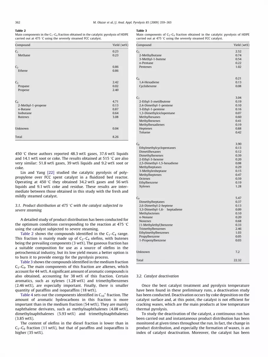
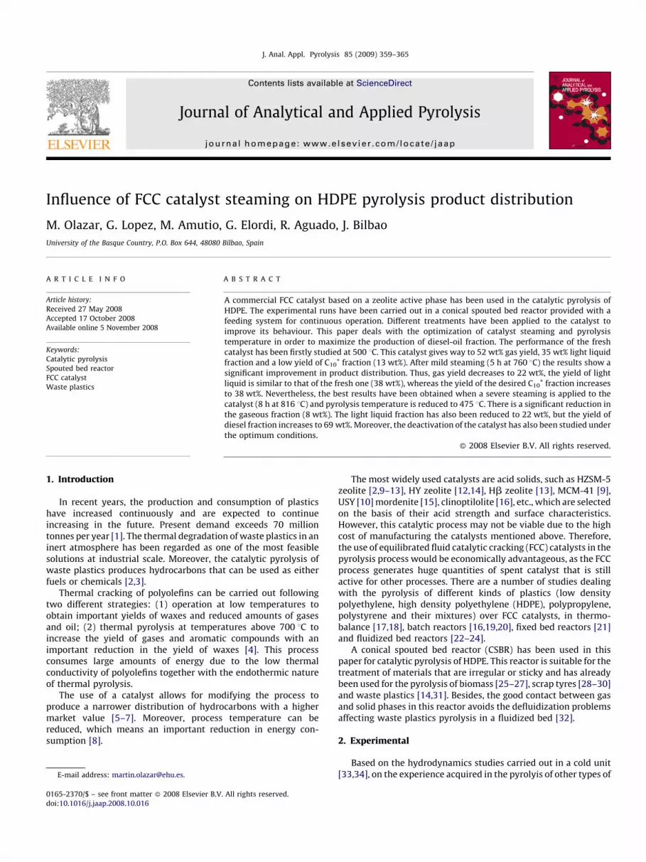
Table 2Main components in the C1–C4 fraction obtained in the catalytic pyrolysis of HDPE
carried out at 475 8C using the severely steamed FCC catalyst.
Compound Yield (wt%)
C1 0.23
Methane 0.23
C2 0.86
Ethene 0.86
C3 2.42
Propane 0.02
Propene 2.40
C4 4.71
2-Methyl-1-propene 0.13
n-Butane 0.87
Isobutane 0.64
Butenes 3.08
Unknown 0.04
Total 8.26
Table 3Main components of C5–C9 fraction obtained in the catalytic pyrolysis of HDPE
carried out at 475 8C using the severely steamed FCC catalyst.
Compound Yield (wt%)
C5 2.52
2-Methylbutane 0.74
3-Methyl-1-butene 0.54
n-Pentane 0.22
Pentenes 1.02
C6 0.21
1,4-Hexadiene 0.13
Cyclohexene 0.08
C7 3.04
2-Ethyl-3-metilbutene 0.19
2,4-Dimethyl-1-pentene 0.10
3-Ethyl-1-pentene 0.16
1,3-Dimethylciclopentane 0.07
Methylhexanes 0.60
Methylhexenes 0.41
Methylhexadienes 0.19
Heptenes 0.88
Toluene 0.42
C8 3.90
Ethylmethylcyclopentanes 0.13
Dimetilhexanes 0.12
Dimethylhexenes 0.39
2-Ethyl-3-hexene 0.20
2,5-Dimethyl-1,5-hexadiene 0.08
Methylheptanes 0.29
3-Methylenheptane 0.15
Methylheptenes 0.47
Octenes 0.59
Ethylbenzene 0.19
Xylenes 1.28
C9 5.47
Dimethylheptanes 0.37
2,6-Dimethyl-2-heptene 0.13
3,3-Dimethyl-1,6- heptadiene 0.09
Methyloctenes 0.10
n-Nonane 0.20
Nonenes 0.68
(1-Methylethyl)benzene 0.33
Trimethylbenzenes 2.46
Ethylmethylbenzenes 1.03
Propylbenzene 0.05
1-Propenylbenzene 0.03
Unknown 7.2
Total 22.32
M. Olazar et al. / J. Anal. Appl. Pyrolysis 85 (2009) 359–365362
450 8C these authors reported 48.3 wt% gases, 37.6 wt% liquidsand 14.1 wt% soot or coke. The results obtained at 515 8C are alsovery similar: 51.8 wt% gases, 39 wt% liquids and 9.2 wt% soot orcoke.
Lin and Yang [22] studied the catalytic pyrolysis of poly-propylene over FCC spent catalyst in a fluidized bed reactor.Operating at 450 8C they obtained 34.2 wt% gases and 56 wt%liquids and 9.1 wt% coke and residue. These results are inter-mediate between those obtained in this study with the fresh andmildly steamed catalyst.
3.1. Product distribution at 475 8C with the catalyst subjected to
severe steaming
A detailed study of product distribution has been conducted forthe optimum conditions corresponding to the reaction at 475 8Cusing the catalyst subjected to severe steaming.
Table 2 shows the compounds identified in the C1–C4 range.This fraction is mainly made up of C2–C4 olefins, with butenesbeing the prevailing components (3 wt%). The gaseous fraction hasa suitable composition for use as a source of olefins in thepetrochemical industry, but its low yield means a better option isto burn it to provide energy for the pyrolysis process.
Table 3 shows the compounds identified in the medium fractionC5–C9. The main components of this fraction are alkenes, whichaccount for 44 wt%. A significant amount of aromatic compounds isalso obtained, accounting for 38 wt% of this fraction. Certainaromatics, such as xylenes (1.28 wt%) and trimethylbenzenes(2.46 wt%), are especially important. Finally, there is smallerquantity of paraffins and isoparaffins (18 wt%).
Table 4 sets out the components identified in C10+ fraction. The
amount of aromatic hydrocarbons in this fraction is moreimportant than in the medium fraction (54 wt%). They are mainlynaphthalene derivates, such as methylnaphthalenes (4.08 wt%),dimethylnaphthalenes (5.93 wt%) and trimethylnaphthalenes(3.85 wt%).
The content of olefins in the diesel fraction is lower than inC5–C9 fraction (11 wt%), but that of paraffins and isoparaffins ishigher (35 wt%).
3.2. Catalyst deactivation
Once the best catalyst treatment and pyrolysis temperaturehave been found in these preliminary runs, a deactivation studyhas been conducted. Deactivation occurs by coke deposition on thecatalyst surface and, at this point, the catalyst is not efficient forcracking waxes, which are the main products at low temperaturethermal pyrolysis.
To study the deactivation of the catalyst, a continuous run hasbeen carried out and instantaneous product distribution has beenmonitored at given times throughout the run. In fact, the change inproduct distribution, and especially the formation of waxes, is anindex of catalyst deactivation. Moreover, the catalyst has been

Table 4Main components in the C10
+ fraction obtained in the catalytic pyrolysis of HDPE
carried out at 475 8C using the severely steamed FCC catalyst.
Compound Yield (wt%)
C10 5.53
2,3,4-Trimethylheptane 0.03
Dimethyloctanes 0.30
Dimethyloctenes 0.16
2,6-Dimethyl-1,3,7-octatetraene 0.17
Methylnonanes 0.17
n-Decane 0.09
Decenes 0.67
1-Methyl-2-(1-methylethyl)benzene 0.35
1-Methyl-3-propylbenzene 0.60
(1-Methyl-1-propenyl)benzene 0.18
Tetramethylbenzenes 1.32
Ethyldimethylbenzenes 1.07
1,2-Diethylbenzene 0.21
Naphthalene 0.23
C11 9.49
2,3,3-Trimethyloctane 0.33
2,5-Dimethylnonane 0.44
Methyldecanes 1.28
2-Methyl-3-decene 0.21
Undecenes 1.26
1-Methyl-4-(1-methylpropyl)benzene 0.12
1-Methyl-3-(1-methyl-2-propenyl)benzene 0.55
(1,1-Dimethylpropyl)benzene 0.32
1,3-Dimethyl-5-(1-methylethyl)benzene 0.06
Pentamethylbenzene 0.30
Ethyltrimethylbenzenes 0.17
1,3-Diethyl-5-methylbenzene 0.16
1,6-Dimethyl-2,3-dihydro-1H-indene 0.45
Methylnaphthalenes 4.08
1,2-Dihydro-6-naphthalene 0.09
C12 13.78
4,6-Trimethyl-1-nonene 0.21
2,3-Dimethyldecane 0.67
Methylundecanes 1.70
Methylundecenes 0.41
Dodecenes 0.79
1-(Methylethenyl)-4-(1- methylethyl)benzene 0.16
3-Ethyl-1,2,4,5-tetramethylbenzene 0.31
1-(1-Ethylpropyl)-4-methylbenzene 0.33
(1-Ethyl-1-methylpropyl)-benzene 0.16
Triethylbenzenes 1.17
(3,3-Dimethylbutyl)benzene 0.43
4-(2-Butenyl)-1,2-dimethylbenzene 0.12
1,2,3-Trimethylindene 0.07
1-Ethyl-2,3-dihydro-1-methyl-1H-indene 0.08
6,7-Dimethyl-1,2,3,5,8,8a- hexahydronaphthalene 0.47
Dimethylnaphthalenes 5.93
1-Ethyl-naphthalene 0.78
C13 10.05
3-Hexyl-1,1-dimethylciclopentane 0.21
2-Methyl-5-propylnonane 0.14
2,6,7-Trimethyldecane 0.07
5-Propyldecane 0.28
Dimethylundecanes 0.21
3-Ethylundecane 0.13
Methyldodecanes 0.36
n-Tridecane 0.25
6-Tridecene 0.41
Methyl-2-hexylbenzenes 0.45
Methylethylnaphthalenes 1.24
(1-Methylethyl)naphthalenes 1.53
Trimethylnaphthalenes 3.85
1-Propylnaphthalene 0.18
4,6,8-Trimethylazulene 0.74
C14 9.03
2,3,5,8-Tetramethyldecane 0.35
Dimethyldodecanes 1.06
Ethyldodecane 0.95
Methyltridecanes 1.85
7-Methyl-6-tridecene 0.15
Table 4 (Continued )
Compound Yield (wt%)
n-Tetradecane 0.17
Tetradecenes 0.58
1-(1-Methyl-2-propenyl)-4-(2- methylpropyl)benzene 0.18
1-(3-Methylbutyl)-2,3,6-trimethylbenzene 0.11
(1-Methylheptyl)benzene 0.30
(1-Ciclohexylethyl)benzene 0.30
Methyl(methyletyl)naphthalenes 0.88
2-Methyl-1-propylnaphthalene 0.29
2-(1,1-Dimethylethyl)naphthalene 0.16
Tetramethylnaphthalenes 0.68
Ethyldimethylazulenes 0.30
2,4-Dimethyl-1,10-biphenyl 0.19
Anthracene 0.20
1,2,3,4-Tetrahydrophenanthrene 0.09
1,2,3,4,5,6-Hexahydroanthracene 0.23
C15 4.14
Trimethyldodecanes 0.32
2-Ethyltridecane 0.47
Methyltetradecanes 1.46
n-Pentadecane 0.62
Pentadecenes 0.98
(2-Methyloctyl)benzene 0.18
1,2,3,4,4a,7-Hexahydro-1,6-dimethyl-4-(1-methylethyl)naphthalene 0.10
C16 6.31
2-Methyl-6-propyldodecane 0.94
Propyltridecanes 0.68
Dimethyltetradecanes 2.19
Ethyltetradecanes 0.62
Methylpentadecanes 1.27
n-Hexadecane 0.23
Hexadecenes 0.39
C17 1.89
2,6,10-Trimetyltetradecane 0.22
Methylhexadecanes 0.93
n-Heptadecane 0.74
Unknown 9.20
Total 69.42
M. Olazar et al. / J. Anal. Appl. Pyrolysis 85 (2009) 359–365 363
characterized at the end of each run, when it has undergone asevere deactivation.
As observed in Fig. 3, product distribution and, consequently,FCC catalyst activity is maintained for a long reaction time. Thus,the equilibrated catalyst is a good option for plastic waste pyrolysisbecause of its stability and relatively slow deactivation. Pyrolysis
Fig. 3. Evolution of the different lumps throughout reaction time.

Table 5Properties of the catalyst steamed at 816 8C and once it has been used for 400 min of
reaction.
Equilibrated at 816 8C Deactivated for 400 min
BET surface area (m2/g) 187 113
Micropore volume (cm3/g) 0.061 0.042
Mesopore volume (cm3/g) 0.099 0.058
Acid strength (kJ/mmol NH3) 87.9 78.5
Total acidity (mmol NH3/g cat) 0.039 0.021
Fig. 4. Mass loss (DTG) during the coke combustion.
M. Olazar et al. / J. Anal. Appl. Pyrolysis 85 (2009) 359–365364
has been continued until 400 min of operation, but at this time thecatalyst is severely deactivated and is not efficient for the crackingof waxes. In fact, waxes account for more than 50% for reactiontimes longer than 400 min. It must be taken into account that theyield of waxes in thermal pyrolysis at 475 8C is around 80%, whichmeans that subsequent to 400 min of reaction the crackingcapacity of the catalyst is considerably diminished. Furthermore,at the beginning of the reaction, until the process reaches steadystate, the yield of gas and medium fractions is higher.
The deactivated catalyst has been characterized in order todeterminate the acidity deterioration undergone during thereaction. The structural properties are summarized in Table 5.Coke deposition involves a reduction in BET surface area and inmicropore and mesopore volumes. This reduction in the surfacearea of the catalyst causes a moderate reduction in activity becauseof the blockage of catalyst active centers.
Catalyst regeneration is carried out by coke combustion. Thecoke content remaining in the catalyst has been determined bythermogravimetric experiments, obtaining an amount of 5.2 wt%of coke. Given that approximately 200 g of HDPE have been fedduring the deactivation process, this coke accounts for less than 1%of the total amount of the polymer fed into the reactor.
The differential thermogravimetric analysis of the coke, Fig. 4,shows a single peak in which combustion occurs at relatively lowtemperatures and in a short period of time. This is evidence that thecoke formed in the pyrolysis reaction is homogeneous and easy toburn.
The experimental results obtained have been fitted to a firstorder kinetics with respect to oxygen and coke content, accordingto the following equation [37]:
� dCC
dt¼ krCCPO2
¼ Ar exp�Er
RT
� �CCPO2
(1)
The frequency factor (Ar) and activation energy (Er) of best fittinghave been calculated by minimizing the sum of residuals betweenthe experimental data of weight loss rate and those calculatedusing Eq. (1). The results obtained are: Ar frequency factor,0.05 Pa�1 s�1 and Er/R, 13,618 K.
4. Conclusions
The spouted bed reactor is a suitable technology for the plasticpyrolysis process due to its high heat transfer rate and excellentperformance with sticky materials. FCC catalysts subjected tosteaming are appropriate for obtaining diesel-oil from plasticspyrolysis. Furthermore, a proper selection of catalyst, steamingconditions and operating conditions allows for tailoring productdistribution. Thus, the more severe the steaming the lower the gasand light oil fraction and the higher the diesel-oil fraction. A severesteaming treatment (8 h at 816 8C) produces 69% diesel-oil fraction(C10
+) with only 8% gases and 22% light oil fraction (C5–C9). Themain components in the gaseous fraction are butenes, and those inthe light oil fraction are alkanes. Aromatics (mainly naphthalenederivatives) are the prevailing compounds in the diesel-oilfraction, accounting for 54% of this fraction. Deactivation is onlyevident subsequent to 6-h operation by the formation of waxes andcoke. Coke burning produces a single peak in which combustionoccurs at low temperatures and in a relatively short period of time.Combustion kinetics is of first order with respect to oxygen andcoke content.
Acknowledgements
This work was carried out with the financial support of theUniversity of the Basque Country (Project GIC0//24-it-220-07) andthe Ministry of Science and Education of the Spanish Government(Project CTQ2007-61167), and of a bursary for University TeacherTraining (AP2005-3123).
References
[1] Prospects for Plastics, Shell Briefing Service, Paper no. 1, 1993.[2] J.F. Mastral, C. Berrueco, M. Gea, J. Ceamanos, Polym. Degrad. Stabil. 91 (2006)
3330.[3] A. Marcilla, M.I. Beltran, F. Hernandez, R. Navarro, Appl. Catal. 278 (2004) 37.[4] F.J. Mastral, E. Esperanza, C. Berrueco, M. Juste, J. Ceamanos, J. Anal. Appl. Pyrol. 70
(2003) 1.[5] R. Bagri, P.T. Williams, J. Anal. Appl. Pyrol. 63 (2002) 29.[6] Y.H. Lin, M.H. Yang, J. Mol. Catal. A: Chem. 231 (2005) 113.[7] M.R. Hernandez, A.N. Garcıa, A. Marcilla, J. Anal. Appl. Pyrol. 73 (2005) 314.[8] J. Mertinkat, A. Kirsten, M. Predel, W. Kamisnky, J. Anal. Appl. Pyrol. 49 (1999) 87.[9] J. Aguado, D.P. Serrano, G. San Miguel, M.C. Castro, S. Madrid, J. Anal. Appl. Pyrol.
79 (2007) 415.[10] A. Marcilla, A. Gomez-Siurana, F.J. Valdes, Micropor. Mesopor. Mater. 109 (2008)
420.[11] M.R. Hernandez, A. Gomez, A.N. Garcıa, J. Agullo, A. Marcilla, Appl. Catal. A: Gen.
317 (2007) 183.[12] J. Schirmer, J.S. Kim, E. Klemm, J. Anal. Appl. Pyrol. 60 (2001) 205.[13] A. Marcilla, A. Gomez-Siurana, F. Valdes, J. Anal. Appl. Pyrol. 79 (2007) 433.[14] G. Elordi, G. Lopez, M. Arabiourrutia, M. Olazar, R. Aguado, J. Bilbao, J. Anal. Appl.
Pyrol. 79 (2007) 450.[15] G. De la Puente, U. Sedran, Appl. Catal. B: Environ. 19 (1998) 305.[16] N. Miskolczi, L. Bartha, G. Deak, Polym. Degrad. Stabil. 91 (2006) 517.[17] A. Marcilla, A. Gomez, J.A. Reyes-Labarta, A. Giner, F. Hernandez, J. Anal. Appl.
Pyrol. 68 (2003) 467.[18] A. Marcilla, J.C. Garcıa-Quesada, S. Sanchez, R. Ruiz, J. Anal. Appl. Pyrol. 74 (2005)
387.[19] S.C. Cardona, A. Corma, Catal. Today 75 (2002) 239.[20] N. Miskolczi, L. Bartha, G. Deak, B. Jover, D. Kallo, J. Anal. Appl. Pyrol. 72 (2004)
235.[21] D.S. Achilias, C. Roupakias, P. Megalokonomos, A.A. Lappas, E.V. Antonakou, J.
Hazard. Mater. 149 (2007) 536.[22] Y.H. Lin, M.H. Yang, Appl. Catal. B: Environ. 69 (2007) 145.[23] Y.H. Lin, M.H. Yang, Appl. Catal. A: Gen. 328 (2007) 132.[24] S. Ali, A.A. Garforth, D.H. Harris, D.J. Rawlence, Y. Uemichi, Catal. Today 75 (2002)
247.

M. Olazar et al. / J. Anal. Appl. Pyrolysis 85 (2009) 359–365 365
[25] R. Aguado, M. Olazar, M.J. San Jose, G. Aguirre, J. Bilbao, Ind. Eng. Chem. Res. 39(2000) 1925.
[26] M. Olazar, R. Aguado, J. Bilbao, A. Barona, AIChE J. 46 (2000) 1025.[27] M. Olazar, R. Aguado, M.J. San Jose, J. Bilbao, J. Chem. Technol. Biotechnol. 76
(2001) 469.[28] M. Arabiourrutia, G. Lopez, G. Elordi, M. Olazar, R. Aguado, J. Bilbao, Chem. Eng.
Sci. 62 (2007) 5271.[29] R. Aguado, M. Olazar, D. Velez, M. Arabiourrutia, J. Bilbao, J. Anal. Appl. Pyrol. 73
(2005) 290.[30] M. Olazar, G. Lopez, M. Arabiourrutia, G. Elordi, R. Aguado, J. Bilbao, J. Anal. Appl.
Pyrol. 81 (2007) 127.[31] R. Aguado, M. Olazar, M.J. San Jose, B. Gaisan, J. Bilbao, Energy Fuels 16 (2002) 1429.
[32] R. Aguado, R. Prieto, M.J. San Jose, S. Alvarez, M. Olazar, J. Bilbao, Chem. Eng. Proc.44 (2005) 231.
[33] M. Olazar, M.J. San Jose, A.T. Aguayo, J.M. Arandes, J. Bilbao, Ind. Eng. Chem. Res. 32(1993) 1245.
[34] M.J. San Jose, M. Olazar, F.J. Penas, J.M. Arandes, J. Bilbao, Chem. Eng. Sci. 50 (1995)2161.
[35] T.F. Degnan, G.K. Chitnis, P.H. Schipper, Micropor. Mesopor. Mater. 35–36 (2000)245.
[36] M.L. Occelli, A. Auroux, A. Petre, M. Kalwei, A. Wolker, H. Eckert, Stud. Surf. Sci.Catal. 134 (2001) 59.
[37] A.G. Gayubo, J.M. Arandes, A.T. Aguayo, M. Olazar, J. Bilbao, Chem. Eng. J. 54 (1994)35.