increasing energy efficiency in electric trains operation - diva
TRANSCRIPT
Nim
a G
ha
viha
INC
REA
SING
ENER
GY EFFIC
IENC
Y IN ELEC
TRIC
TRA
INS O
PER
ATIO
N2018
ISBN 978-91-7485-409-1ISSN 1651-4238
Address: P.O. Box 883, SE-721 23 Västerås. SwedenAddress: P.O. Box 325, SE-631 05 Eskilstuna. SwedenE-mail: [email protected] Web: www.mdh.se
Mälardalen University Doctoral Dissertation 275
Increasing energy efficiency in electric trains operationDriver advisory systems and energy storage
Nima Ghaviha
Mälardalen University Press DissertationsNo. 275
INCREASING ENERGY EFFICIENCYIN ELECTRIC TRAINS OPERATION
DRIVER ADVISORY SYSTEMS AND ENERGY STORAGE
Nima Ghaviha
2018
School of Business, Society and Engineering
1

Copyright © Nima Ghaviha, 2018ISBN 978-91-7485-409-1ISSN 1651-4238Printed by E-Print AB, Stockholm, Sweden
2
Mälardalen University Press DissertationsNo. 275
INCREASING ENERGY EFFICIENCY IN ELECTRIC TRAINS OPERATIONDRIVER ADVISORY SYSTEMS AND ENERGY STORAGE
Nima Ghaviha
Akademisk avhandling
som för avläggande av teknologie doktorsexamen i energi- och miljöteknik vidAkademin för ekonomi, samhälle och teknik kommer att offentligen försvaras
fredagen den 16 november 2018, 13.00 i Pi, Mälardalens högskola, Västerås.
Fakultetsopponent: Professor Rob M.P. Goverde, TU Delft
Akademin för ekonomi, samhälle och teknik
3
AbstractElectric traction is the most efficient traction system in the railway transportation. However, due to the expensive infrastructure and high power demand from the grid, the share of electric trains in the railway transportation is still lower than other trains. Two of the possible solutions to increase the share of electric trains are: optimal train operation to minimize energy consumption, the use of batteries as the energy source for driving electric trains on non-electrified lines. This thesis aims to extend the knowledge in the field of energy optimal operation of electric trains and battery-driven electric trains.
Energy optimal operation of electric trains is supervised using a driver advisory system (DAS), which instructs the driver to operate the train in an energy-efficient manner. This thesis contributes to DAS technology under two topics: the increase of energy efficiency and the design of DAS.
This thesis presents a complete procedure of designing a DAS from the mathematical formulation to application on the train. The designed DAS is in the form of an Android application and is based on a dynamic programming approach. The computational performance of the approach is enhanced using heuristic state reducing rules based on the physical constraints of the system. The application of the DAS shows a potential reduction of 28% in energy consumption.
This thesis considers the detailed energy losses in the whole propulsion system using a regression model that is generated from validated physical models. The application of the regression model instead of a previous constant efficiency factor model results in 2.3% reduction in energy consumption of the optimum speed profiles.
Based on the solution for the normal electric trains, a solution is also offered for the optimal operation of battery-driven electric trains, in which the characteristics of the battery as one of the main components are considered using an electrical model. The solution presented in this thesis, is to combine the popular single mass point train model with an electrical circuit battery model.
Furthermore, this thesis evaluates the performance of the optimization approaches and validates the models against the measurements from actual drives of a real-life battery train. The results show a potential of around 30% reduction in the charge consumption of the battery.
The results of this thesis (algorithms and the Android application) are provided as open source for further research in the field of energy efficient train control.
ISBN 978-91-7485-409-1ISSN 1651-4238
4

To my family!
5

6
Acknowledgement
First I would like express my profound gratitude toward my supervisorsProf. Erik Dahlquist and Prof. Markus Bohlin for their continuous supportduring the past years. This research would not have been fruitful without theirguidance and encouragement. My sincere appreciation to Christer Holmberg,my mentor from Bombardier Transportation; everything I learned in power en-gineering and electric trains was thanks to his guidance and support. I wouldalso like to thank my co-supervisor Dr. Fredrik Wallin. I am grateful to Mag-nus Forsen for providing me with the opportunity to work at Bombardier dur-ing my PhD and also PPC team at Bombardier Transportation for their helpwith this research project, namely: Per Bengtsson, David Lindgren, and KevinBabr. I would also like to thank Dr. Helena Jerregård and Dr. Stig Larssonfrom RISE SICS Västerås for their support during the STREAM project. Spe-cial thanks to Dr. Martin Joborn from RISE SICS for the great discussions andfor reviewing this thesis.
I would also like to thank Prof. Kondo from Chiba University that pro-vided me with the opportunity to work in their lab. Further, I am grateful toProf.Konstantinos Kyprianidis for the opportunity to work with him duringthe last six months of my PhD studies. Special thanks goes to Dr. Jan Sand-berg for reviewing this thesis as well as for the great experiences that I gainedduring teaching in his courses.
Special thanks to my colleagues and dear friends at EST department forall the inspirational conversations, coffee breaks and lots of happy memories.Thanks to my friends outside university, both in Sweden and Iran, that arevery close and dear to me.
Many thanks to Vale for her continuous and unconditional support duringthe past year. Last but foremost, much appreciation to my parents and mybrother, I could not have reached this far in life without their endless supportand love.
This research was conducted at the school of Business, Society and Engi-neering at Mälardalen University, Sweden and was supported financially byEST department at Mälardalen University, and VINNOVA (2014-04319 and2012-01277) as a part of STREAM project lead by RISE SICS.
Nima GhavihaOctober 2018
Västerås, Sweden
7
Summary
Electric traction is the most efficient traction system in the railway trans-portation. However, due to the expensive infrastructure and high power de-mand from the grid, the share of electric trains in railway transportation isstill lower than other trains. Two are the possible solutions to increase theshare of electric trains: to optimize electric train operations to minimize theenergy consumption and to use batteries as the energy source for driving elec-tric trains on non-electrified lines. This thesis aims to extend the knowledgein the field of energy optimal operation of electric trains and battery-drivenelectric trains.
Energy optimal operation of electric trains is supervised using a driver advi-sory system (DAS), which instructs the driver to operate the train in an energy-efficient manner. This thesis contributes to DAS technology under two topics:the increase of energy efficiency and the design of driver advisory systems.
Although there are already DAS systems in use in some railway lines,there are no clear study on the design procedure of such systems. This thesispresents the design procedure of a DAS from the mathematical formulationsto the design of the interface. The application of the designed DAS on a realtrain shows the promising decrease of 28% in energy consumption.
To increase the energy efficiency in the problem of energy optimal train op-eration, this thesis goes deep to the component level in the propulsion systemby considering the detailed power losses in each component. The results ofthis thesis show that the optimum driving styles generated by considering thedetailed power losses are around 2.3% more energy efficient compared to theoptimum driving styles generated using one constant efficiency factor for thewhole train.
Based on the solution for the normal electric trains, a solution is also of-fered for the optimal operation of battery-driven electric trains, in which thecharacteristics of the battery as one of the main components are consideredusing an electrical model. Furthermore, this thesis validates the models andevaluates the optimization performance against the actual drives of a real-lifebattery train. The results show a potential of around 30% reduction in thecharge consumption of the battery.
The results presented in this thesis can be used as a basis for further researchand development in the field of energy optimal operation of electric trains andbattery driven electric trains.
8
Sammanfattning
Elektriska traktionssystem är de mest effektiva traktionssystemen för järn-vägsfordon. Pågrund av den kostsamma infrastrukturen och höga krav på-effekt från elnätet är dock andelen eltåg vid järnvägstransporter fortfarandelägre än andra tågtyper. Optimering av tågets manövrering för att minimeraenergiförbrukningen och användning av batterier som energikälla för att köraeltäg pä icke-elektrifierade linjer är tvåav lösningarna som kan öka andeleneltåg vid järnvägstransporter. Den här Avhandlingen syftar till att utöka kun-skapen inom energioptimering av eltåg och batteridriven eltåg.
Energioptimal drift av eltåg övervakas med hjälp av ett Driver AdvisorySystem (DAS), vilket är ett system som instruerar föraren att driva tågetpåett energieffektivt sätt. Denna avhandling bidrar till DAS-teknologin inomtvåområden: ökad energieffektivitet och utformning av DAS.
Även om det finns DAS-system som används påvissa järnvägslinjerfinns det ingen tydlig studie om designproceduren för sådana system.Den här avhandlingen presenterar designproceduren för en DAS från dematematiska formuleringarna till utformningen av gränssnittet. Verkligtillämpningen av den DAS som designats i anslutning till avhandlingsarbetetvisar en lovande minskning av energiförbrukningen med cirka 30%. Föratt öka energieffektiviteten i koppling till problemet med energioptimaltågets manövrering, går denna avhandling pådjupet rörande komponenteri framdrivningssystemet genom att beakta de detaljerade effektförlusternaför varje komponent. Resultaten av denna avhandling visar att de optimalakörstilarna som genereras genom att överväga de detaljerade effektförlusternaär cirka 2,3% mer energieffektiva jämfört med de optimala körstilarna somgenereras med en konstant effektivitetsfaktor för hela tåget.
Baserat pålösningen för nätdrivna eltåg, erbjuder avhandlingen ocksåen lös-ning för optimal drift av batteridrivna eltåg, där batteriets egenskaper som enav huvudkomponenterna beaktas med hjälp av en elektrisk modell. Dessutomvaliderar denna avhandling modeller och utvärderar den framtagna optimer-ingsmetoden mot mätningar påett verkligt batteridrivet eltåg. Resultaten visarpotential för cirka 30% minskning av batteriets energiförbrukning.
Resultaten som presenteras i denna avhandling kan användas som under-lag för vidare forskning och utveckling inom området energioptimal drift avnätdrivna och batteridrivna eltåg.
9
List of Papers
This thesis is based on the following papers, which are referred to in the textby their Roman numerals.
I Ghaviha, N., Bohlin, M., Wallin, F., & Dahlquist, E. (2015, Novem-ber). Optimal Control of an EMU Using Dynamic Programming andTractive Effort as the Control Variable. In Proceedings of the 56th Con-ference on Simulation and Modelling (SIMS 56), October, 7-9, 2015,Linköping University, Sweden (No. 119, pp. 377-382). Linköping Uni-versity Electronic Press.
II Ghaviha, N., Bohlin, M., & Dahlquist, E. (2016, June). Speed profileoptimization of an electric train with on-board energy storage and con-tinuous tractive effort. In Power Electronics, Electrical Drives, Automa-tion and Motion (SPEEDAM), 2016 International Symposium on (pp.639-644). IEEE.
III Ghaviha, N., Campillo, J., Bohlin, M., & Dahlquist, E. (2017). Reviewof application of energy storage devices in railway transportation. En-ergy Procedia, 105, 4561-4568.
IV Ghaviha, N., Holmberg, C., Bohlin, M., & Dahlquist, E. (2017). Model-ing of Losses in the Motor Converter Module of Electric Multiple Unitsfor Dynamic Simulation Purposes. Energy Procedia, 142, 2303-2309.
V Ghaviha, N., Bohlin, M., Holmberg, C., Dahlquist, E., Skoglund, R.,& Jonasson, D. (2017). A driver advisory system with dynamic lossesfor passenger electric multiple units. Transportation Research Part C:Emerging Technologies, 85, 111-130.
VI Ghaviha, N., Bohlin, M., Holmberg, C., Dahlquist, & E. Speed ProfileOptimization of Catenary-free Electric Trains with Lithium-ion Batter-ies (Manuscript under review)
Reprints were made with permission from the publishers.Part of this thesis (Papers I and II) was previously included in the licenti-
ate thesis "Energy Optimal Operation of Electric Vehicles: Development of adriver advisory system" (Ghaviha, 2016).
10
The following publications by the author are not included in this thesis.
• Ghaviha, N., Wallin, F., Dahlquist, E., & Bohlin, M. (2014, December).An Algorithm for Optimal Control of An Electrical Multiple Unit.In Proceedings of the 55th Conference on Simulation and Modelling(SIMS 55), Modelling, Simulation and Optimization, 21-22 October2014, Aalborg, Denmark (No. 108, pp. 300-307). Linköping UniversityElectronic Press.
• Ghaviha, N., Bohlin, M., Wallin, F., & Dahlquist, E. (2015). Optimalcontrol of an emu using dynamic programming. Energy Procedia, 75,1913-1919.
• Campillo, J., Ghaviha, N., Zimmerman, N., & Dahlquist, E. (2015,March). Flow batteries use potential in heavy vehicles. In ElectricalSystems for Aircraft, Railway, Ship Propulsion and Road Vehicles(ESARS), 2015 International Conference on (pp. 1-6). IEEE.
• Shashaj, A., Bohlin, M., & Ghaviha, N. (2016, June). Joint optimizationof multiple train speed profiles. In Compatibility, Power Electronicsand Power Engineering (CPE-POWERENG), 2016 10th InternationalConference on (pp. 478-483). IEEE.
• Campillo, J., Dahlquist, E., Danilov, D. L., Ghaviha, N., Notten, P. H.,& Zimmerman, N. (2017). Battery Technologies for TransportationApplications. In Technologies and Applications for Smart Charg-ing of Electric and Plug-in Hybrid Vehicles (pp. 151-206). Springer, Cham.
• Ghaviha, N., Energy Optimal Operation of Battery Driven Trains. ORbitmedlemsblad for Dansk Selskab for Operationsanalyse og Svenska Opera-tionsanalysföreningen, (2016)
11

12
Contents
Page
Part I: Thesis1 Introduction . . . . . . . . . . . . . . . . . . . . . . . . . . . . . . . . . . . . . . . . . . 3
1.1 Objective . . . . . . . . . . . . . . . . . . . . . . . . . . . . . . . . . . . . . . . . . 41.2 Outline of the Thesis . . . . . . . . . . . . . . . . . . . . . . . . . . . . . . . . 5
2 Related Works . . . . . . . . . . . . . . . . . . . . . . . . . . . . . . . . . . . . . . . . 72.1 Speed Profile Optimization of Electric Multiple Units . . . . . . . 72.2 Driver Advisory Systems . . . . . . . . . . . . . . . . . . . . . . . . . . . . . 92.3 Catenary-free Operation of Electric Multiple Units . . . . . . . . . 10
3 Research Framework . . . . . . . . . . . . . . . . . . . . . . . . . . . . . . . . . . . 113.1 Research Questions . . . . . . . . . . . . . . . . . . . . . . . . . . . . . . . . . 113.2 Challenges . . . . . . . . . . . . . . . . . . . . . . . . . . . . . . . . . . . . . . . . 113.3 Methodology . . . . . . . . . . . . . . . . . . . . . . . . . . . . . . . . . . . . . . 12
4 Overview of the Papers . . . . . . . . . . . . . . . . . . . . . . . . . . . . . . . . . 145 Mathematical Formulation . . . . . . . . . . . . . . . . . . . . . . . . . . . . . . . 18
5.1 Train Model . . . . . . . . . . . . . . . . . . . . . . . . . . . . . . . . . . . . . . 185.2 Battery Models . . . . . . . . . . . . . . . . . . . . . . . . . . . . . . . . . . . . 20
5.2.1 Simplified battery model . . . . . . . . . . . . . . . . . . . . . . . . . 205.2.2 Generic battery model . . . . . . . . . . . . . . . . . . . . . . . . . . . 21
5.3 Dynamic Programming . . . . . . . . . . . . . . . . . . . . . . . . . . . . . . 226 Results and Discussion . . . . . . . . . . . . . . . . . . . . . . . . . . . . . . . . . . 25
6.1 Energy Optimal Operation of Electric Multiple Units . . . . . . . . 256.1.1 Detailed Power Losses . . . . . . . . . . . . . . . . . . . . . . . . . . . 256.1.2 Driver Advisory System . . . . . . . . . . . . . . . . . . . . . . . . . . 29
6.2 Energy Optimal Operation of Battery Driven Electric MultipleUnits . . . . . . . . . . . . . . . . . . . . . . . . . . . . . . . . . . . . . . . . . . . . 31
6.2.1 Battery Model . . . . . . . . . . . . . . . . . . . . . . . . . . . . . . . . . 326.2.2 Speed Profile Optimization . . . . . . . . . . . . . . . . . . . . . . . 33
6.3 Discussion . . . . . . . . . . . . . . . . . . . . . . . . . . . . . . . . . . . . . . . . 356.4 Contribution to Knowledge . . . . . . . . . . . . . . . . . . . . . . . . . . . 38
7 Conclusion . . . . . . . . . . . . . . . . . . . . . . . . . . . . . . . . . . . . . . . . . . . 418 Future Directions . . . . . . . . . . . . . . . . . . . . . . . . . . . . . . . . . . . . . . 43References . . . . . . . . . . . . . . . . . . . . . . . . . . . . . . . . . . . . . . . . . . . . . . 45
Part II: Included Articles
13
List of Figures
Page
Figure 2.1: A speed profile including coasting phases . . . . . . . . . . 8
Figure 4.1: Relation between articles and research questions . . . . . 17
Figure 5.1: A generic tractive effort curve or the maximum trac-tive effort available in different velocities of an EMU(Paper V) . . . . . . . . . . . . . . . . . . . . . . . . . . . . . . . . . . 19
Figure 5.2: A typical discharge curve of a lithium-ion battery withthe constant current load. The x axis shows the chargetaken from the battery. . . . . . . . . . . . . . . . . . . . . . . . . 21
Figure 5.3: Backward iteration of dynamic programming approach 22Figure 5.4: Forward simulation of dynamic programming approach 23
Figure 6.1: Applicable tractive efforts at each velocity for a cer-tain train configuration . . . . . . . . . . . . . . . . . . . . . . . . 26
Figure 6.2: Example of the applied tractive effort points during adriving cycle (Paper IV) . . . . . . . . . . . . . . . . . . . . . . . 26
Figure 6.3: Comparison of the loss calculation using a constantefficiency factor and detailed electrical equations . . . . 27
Figure 6.4: MCM power loss for all the points under the tractiveeffort curve of a certain electric train configuration(Paper IV) . . . . . . . . . . . . . . . . . . . . . . . . . . . . . . . . . 28
Figure 6.5: Off-line unit of the driver advisory system (Paper V) . . 30Figure 6.6: On-line unit of the driver advisory system (Paper V) . . 31Figure 6.7: Speed profile of an experiment used for the validation
of SoC estimation based on mechanical power (Pa-per VI) . . . . . . . . . . . . . . . . . . . . . . . . . . . . . . . . . . . . 33
Figure 6.8: Measured state of charge compared with the modeledstate of charge (Paper VI) . . . . . . . . . . . . . . . . . . . . . . 34
Figure 6.9: Comparison of the energy consumption between theexperiments and the optimization approach for a tripof a)3 km and b)6.27 km (Paper VI) . . . . . . . . . . . . . . 35
Figure 6.10: Comparison between the speed profiles generatedusing a constant efficiency factor and the regressionmodel (Paper V) . . . . . . . . . . . . . . . . . . . . . . . . . . . . . 36
14

Figure 6.11: Screen shot of the Android DAS during the operation;box 1 shows the current speed and box 2 shows therecommended optimum tractive effort (Paper V) . . . . . 37
15
List of Tables
Page
Table 4.1: Research questions and the papers including the answers 16
Table 6.1: Root mean square error of different polynomials for ac-celeration section (Paper V) . . . . . . . . . . . . . . . . . . . . . . 28
Table 6.2: Root mean square error of different polynomials forbraking section (Paper V) . . . . . . . . . . . . . . . . . . . . . . . . 28
16
Nomenclature
Abbreviations
ATO Automatic Train Operation
C-DAS Connected Driver Advisory System
CATO Computer Aided Train Operation
DAS Driver Advisory System
DC Direct Current
DP Dynamic Programing
EETC Energy Efficient Train Control
EMU Electrtic Multiple Unit
IPEMU Independet Powered Electric Multiple Unit
LRV Light Rail Vehicle
MCM Motor Converter Module
OESS On-board Energy Storage Systems
RAM Random Access Memory
SESS Stationary Energy Storage Systems
Symbols
η Efficiency of the propsulsion system [%]
ηConverter−Modules Efficiency of the converter module [%]
ηGearbox Efficiency of the gearbox [%]
ηMotor Efficiency of the motor [%]
yi Modeled values [−]
ω Motor speed [rpm]
π Series of control variables [−]
17
π∗ Optimum series of control variables [−]
τ Motor torque [Nm]
A Coefficient for the generic battery model [V]
Arr Coefficient of Davis Formula [kN]
B Coefficient for the generic battery model [A−1 h]
Brr Coefficient of Davis Formula [ Nkm/h ]
Crr Coefficient of Davis Formula [ Nkm/h2 ]
E0 Battery open circuit voltage [V]
EAh Charge consumption on battery [Ah]
EkWh Energy consumption on DC Link [kWh]
Emax Maximum energy capacity of the battery [kWh]
Fg Gradient Force [kN]
Ft Tractive Force [kN]
Frr Running Resistance [kN]
fsw Switching frequency [Hz]
g(x,u) Transition cost [−]
h Change in elevation of the track [m]
I ·T Charge consumed from the battery [Ah]
Ibat Current on the battery [V]
J∗(x) Minimum cost-to-go [−]
Jπ(x) Cost-to-go [−]
K Coefficient for the generic battery model [ VAh ]
k Coefficient of the regression model [−]
LossMCM Power loss in MCM [kW]
m Train Mass [ ms ]
n Sample size [−]
P Power [kW]
18
p Coefficient of the regression model [−]
Paux Power consumption of the auxiliary systems [kW]
Ploss Power loss [kW]
Q Maximum charge capacity of the battery [Ah]
q Coefficient of the regression model [−]
R Internal resistance of the battery [Ω]
r Receptivity of the power grid [−]
RMSE Room mean square error [−]
s Distance traveled [m]
SoC State of charge [−]
T Last time step in the horizon [−]
t Time [h]
u Control variable [−]
v Velocity [ms−1]
Vbat Voltage on the battery [V]
Vgrid Line voltage of the grid [V]
Vsim Line voltage of during the simulation [V]
x State of the system [−]
yi Reference values [−]
19

20

Part I:
Thesis
21

22
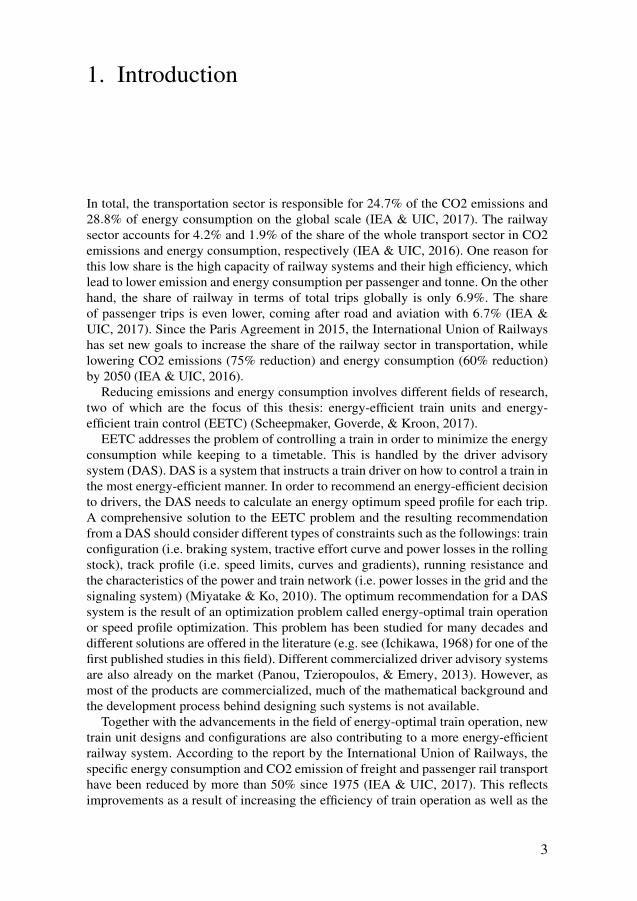
1. Introduction
In total, the transportation sector is responsible for 24.7% of the CO2 emissions and28.8% of energy consumption on the global scale (IEA & UIC, 2017). The railwaysector accounts for 4.2% and 1.9% of the share of the whole transport sector in CO2emissions and energy consumption, respectively (IEA & UIC, 2016). One reason forthis low share is the high capacity of railway systems and their high efficiency, whichlead to lower emission and energy consumption per passenger and tonne. On the otherhand, the share of railway in terms of total trips globally is only 6.9%. The shareof passenger trips is even lower, coming after road and aviation with 6.7% (IEA &UIC, 2017). Since the Paris Agreement in 2015, the International Union of Railwayshas set new goals to increase the share of the railway sector in transportation, whilelowering CO2 emissions (75% reduction) and energy consumption (60% reduction)by 2050 (IEA & UIC, 2016).
Reducing emissions and energy consumption involves different fields of research,two of which are the focus of this thesis: energy-efficient train units and energy-efficient train control (EETC) (Scheepmaker, Goverde, & Kroon, 2017).
EETC addresses the problem of controlling a train in order to minimize the energyconsumption while keeping to a timetable. This is handled by the driver advisorysystem (DAS). DAS is a system that instructs a train driver on how to control a train inthe most energy-efficient manner. In order to recommend an energy-efficient decisionto drivers, the DAS needs to calculate an energy optimum speed profile for each trip.A comprehensive solution to the EETC problem and the resulting recommendationfrom a DAS should consider different types of constraints such as the followings: trainconfiguration (i.e. braking system, tractive effort curve and power losses in the rollingstock), track profile (i.e. speed limits, curves and gradients), running resistance andthe characteristics of the power and train network (i.e. power losses in the grid and thesignaling system) (Miyatake & Ko, 2010). The optimum recommendation for a DASsystem is the result of an optimization problem called energy-optimal train operationor speed profile optimization. This problem has been studied for many decades anddifferent solutions are offered in the literature (e.g. see (Ichikawa, 1968) for one of thefirst published studies in this field). Different commercialized driver advisory systemsare also already on the market (Panou, Tzieropoulos, & Emery, 2013). However, asmost of the products are commercialized, much of the mathematical background andthe development process behind designing such systems is not available.
Together with the advancements in the field of energy-optimal train operation, newtrain unit designs and configurations are also contributing to a more energy-efficientrailway system. According to the report by the International Union of Railways, thespecific energy consumption and CO2 emission of freight and passenger rail transporthave been reduced by more than 50% since 1975 (IEA & UIC, 2017). This reflectsimprovements as a result of increasing the efficiency of train operation as well as the
3
23
increase in the efficiency of the rolling stock. One reason for these improvements isthe increase in popularity of electric traction and catenary systems at the expense ofthe diesel traction system. Electric traction systems have a higher efficiency comparedto diesel traction. Moreover, modern passenger trains that use the catenary system areoften equipped with a regenerative braking system, which converts kinetic energy toelectric energy during the braking mode and feeds it back to the power grid. However,although regenerative brakes are currently still not used efficiently due to the low re-ceptivity of the low utilized lines ((Hoffrichter, Miller, Hillmansen, & Roberts, 2012)),the technology is still able to increase efficiency through the inclusion of energy stor-age devices in the traction system of electric and diesel-electric trains (Shibuya &Kondo, 2011) (note that the presented information is on the train level, a more com-prehensive study would include the whole energy supply chain, from the source tothe wheel, also known as the well-to-wheel analysis (Hoffrichter et al., 2012)). Thereis, however, a financial barrier to the use of electric traction and overhead lines. Theinstallation cost for 1 km of electrified railway line can be on the order of a millionEuros, and there are also yearly maintenance costs (Baumgartner, 2001). Hence, al-though in some countries, such as Sweden, Italy and Korea, around 80% of linesare electrified, the share of electrified lines globally is only around 30% (IEA & UIC,2017). Catenary-free operated electric trains with on-board energy storage devices areanother potential replacement for diesel electric trains; they provide the advantages ofelectric traction on non-electrified lines while minimizing emissions.
Catenary-free operated electric trains are currently mostly in the prototype phase.Catenary-free light rail vehicles (LRV), due to their low weight and short journey dis-tances, are mostly equipped with supercapacitors as the energy storage device (Becker& Dammig, 2016). For electric multiple units (EMUs) with higher mass and longertravel distances, storage devices with higher energy and power capacity are needed.The current concepts presented for catenary-free EMUs consist of a limited numberof EMUs equipped with lithium-ion batteries and hydrogen fuel cells (Campillo etal., 2017; Alstom, 2016). Since the technology of catenary-free operated EMUs isstill in its early phase, not much research is being done in the field of speed profileoptimization for such trains. The limited research in this field focuses on LRVs usingsupercapacitors as the energy storage device (Miyatake & Matsuda, 2008).
1.1 ObjectiveThe EETC problem has been studied for several decades. Scheepmaker et. al presenta review of different methods and solutions for energy-efficient timetabling and traincontrol (Scheepmaker et al., 2017). Panou et. al. assess the different driver advisorysystems on the market (Panou et al., 2013). On the basis of current developments inthe field of energy-efficient train operation, the following issues have been identifiedas knowledge gaps for the problem of energy-efficient single train operation:
• Almost all the research presented in the literature for speed profile optimization orenergy-optimal operation of EMUs uses a constant efficiency factor for calculationof power losses in the propulsion system. The only exception is the research pre-sented by Franke et. al. (Franke, Terwiesch, & Meyer, 2000). Nevertheless, thereare no studies on the effects of detailed loss calculations on the final results.
4
24
• Although many driver advisory systems are already on the market, there are nosignificant publications on the development of a driver advisory system, the vali-dation of such a system and the challenges that accompany it.
• The subject of energy-optimal train operation is well-studied, but the problem ofenergy-efficient operation of catenary-free EMUs is a new topic in the literature aswell as the industry. Most of the research in this field considers a supercapacitor asthe energy storage device. Supercapacitors are, however, used mostly for catenary-free operated LRVs. The main energy storage device used for inter-city regionalEMUs is lithium-ion batteries. A comprehensive energy-optimal driving regimenfor EMUs should consider the characteristics of lithium-ion batteries and theireffects on the optimum speed profile (Miyatake & Ko, 2010).
• Alongside the mathematical formulations and optimization techniques for energy-optimal catenary-free operation of EMUs, an experimental evaluation of the resultsis needed. This includes validation of the models and the potential energy savingsthat can be achieved using energy-optimal driving regimens.It should be noted that the focus of this research is on the EETC problem for EMUs.
Unlike locomotive-hauled trains, EMUs do not use locomotives, and have one or moretraction systems in the same cars that carry the passengers or goods. The problemis different than that in freight and heavy haul trains, as the different train scale andconfiguration, together with the longer journeys lead to different constraints in the op-timization problem. Moreover, the focus of this research is on single train operation.Consideration of the whole train network adds new dimensions to the optimizationproblem, such as losses in the grid and modeling of the receptivity of the line. Fur-thermore, the problem of energy-efficient timetabling is not in the scope of this work.Considering the knowledge gaps, the main contributions of this thesis are as follows:1. Consideration of detailed power losses in the problem of energy-efficient train
control2. Development of a DAS for EMUs as an Android application3. Offering a solution for the problem of energy-efficient control of catenary-free
electric trains4. Studying the effects of properties of the energy storage system on the results of
speed profile optimization for catenary-free electric trains5. Presenting potential energy saving achievable through energy optimal operation
for catenary-free operated EMUs
1.2 Outline of the ThesisThe outline and structure of this thesis is as follows:
Chapter 2 Related Work
This chapter presents a summary of the current state of the art of the EETCproblem for EMUs and catenary-free EMUs. The chapter includes three sec-tions, each dedicated to the literature review of a topic: speed profile optimiza-tion of EMUs, driver advisory system and catenary-free operation of EMUs.
Chapter 3 Research Framework
5
25
This chapter presents the research framework of this thesis. It includes the pre-sentation of the research questions and the methodology used to address eachquestion.
Chapter 4 Overview of the Papers
A summary of the included papers is presented. The chapter also includes apresentation of how the papers relate to the research questions.
Chapter 5 Mathematical Formulation
Mathematical models and the theoretical background of the optimization ap-proach are presented in this chapter. The chapter starts with the presentation ofthe train model and continues with the battery models used in the problem ofspeed profile optimization of battery driven trains. The chapter ends with a pre-sentation of dynamic programing approach and its application for the problemof speed profile optimization and energy efficient train control.
Chapter 6 Results and Discussion
This chapter presents the major results of this research. The chapter is dividedinto two sections: results regarding the EETC for EMUs and results on theEETC for catenary-free operated EMUs. Chapter 6 ends with a discussion onthe contribution of this thesis in the form of answers to the research questions.
Chapter 7 Conclusion
This chapter presents the overall conclusions of the thesis.
Chapter 8 Future Directions
The thesis ends with a short discussion on the possible future directions of theresearch in the field of energy-efficient train control.
The included articles are appended in the second part of the thesis.
6
26
2. Related Works
The problem of energy-optimal train operation has been studied for more than 60years, and many mathematical solutions have been presented. A number of appliedsolutions and commercialized driver advisory systems have also been presented dur-ing the recent years. An overall literature review of the solutions is presented here,organized in three sections: speed profile optimization of EMUs, DAS and catenary-free operation of EMUs.
2.1 Speed Profile Optimization of Electric MultipleUnitsThe problems of optimal control and speed profile optimization of trains have beenstudied for many decades, with one of the first studies dating back to 1968 (Ichikawa,1968). Two approaches have been used to solve the problem: coast control and optimalcontrol. In terms of the operation scale, the problem can be addressed for a single trainoperation or multiple train operation on a network of trains. Furthermore, regardingtrain configuration, three categories of are considered for the problem with EMUs:EMUs operating under catenary, EMUs operated under catenary with a secondaryenergy storage device, and catenary-free operated EMUs.
In coast control the speed profile of the train is considered as one or multiple coast-ing phases during which the applied tractive effort from the traction motor is zero andthe train moves under the influence of its kinetic energy. Figure 2.1 presents a speedprofile including the coasting phases. The problem aims to find the optimum coastinggaps during operation to minimize the total energy consumption while keeping to thetimetable.
Genetic and evolutionary based algorithms are the most common approaches pre-sented in the literature for the coast control problem (see e.g. (Chang & Sim, 1997;Lechelle & Mouneimne, 2010; Erchao, Xin, & Yi, 2014; Bocharnikov, Tobias, &Roberts, 2010; Wong & Ho, 2004) for single train operation and (X. Yang, Chen, Li,Ning, & Tang, 2015) for multiple train operation). Acikbas et. al. (Acikbas & Soyle-mez, 2008) apply the genetic algorithm together with an artificial neural network tosolve the coast control problem for a network of trains. The problem for single trainoperation has also been solved using an artificial neural network (Hui-Jen, Chao-Shun,Chia-Hung, Ching-Ho, & Chin-Yin, 2008). Other approaches such as heuristic searchmethods (Wong & Ho, 2004) and dual heuristic programming (Sheu & Lin, 2011;Jih-Wen & Wei-Song, 2012) have also been applied to the coast control problem.
The problem of speed profile optimization can also be viewed as an optimal controlproblem in which the optimum speed profile is determined regardless of coasting orcruising phases. Different solutions, such as ant colony optimization and fuzzy con-
7
27
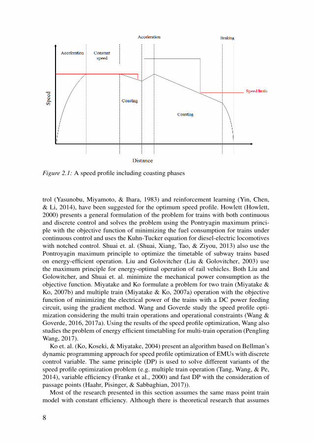
Figure 2.1: A speed profile including coasting phases
trol (Yasunobu, Miyamoto, & Ihara, 1983) and reinforcement learning (Yin, Chen,& Li, 2014), have been suggested for the optimum speed profile. Howlett (Howlett,2000) presents a general formulation of the problem for trains with both continuousand discrete control and solves the problem using the Pontryagin maximum princi-ple with the objective function of minimizing the fuel consumption for trains undercontinuous control and uses the Kuhn-Tucker equation for diesel-electric locomotiveswith notched control. Shuai et. al. (Shuai, Xiang, Tao, & Ziyou, 2013) also use thePontroyagin maximum principle to optimize the timetable of subway trains basedon energy-efficient operation. Liu and Golovitcher (Liu & Golovitcher, 2003) usethe maximum principle for energy-optimal operation of rail vehicles. Both Liu andGolowitcher, and Shuai et. al. minimize the mechanical power consumption as theobjective function. Miyatake and Ko formulate a problem for two train (Miyatake &Ko, 2007b) and multiple train (Miyatake & Ko, 2007a) operation with the objectivefunction of minimizing the electrical power of the trains with a DC power feedingcircuit, using the gradient method. Wang and Goverde study the speed profile opti-mization considering the multi train operations and operational constraints (Wang &Goverde, 2016, 2017a). Using the results of the speed profile optimization, Wang alsostudies the problem of energy efficient timetabling for multi-train operation (PenglingWang, 2017).
Ko et. al. (Ko, Koseki, & Miyatake, 2004) present an algorithm based on Bellman’sdynamic programming approach for speed profile optimization of EMUs with discretecontrol variable. The same principle (DP) is used to solve different variants of thespeed profile optimization problem (e.g. multiple train operation (Tang, Wang, & Pe,2014), variable efficiency (Franke et al., 2000) and fast DP with the consideration ofpassage points (Haahr, Pisinger, & Sabbaghian, 2017)).
Most of the research presented in this section assumes the same mass point trainmodel with constant efficiency. Although there is theoretical research that assumes
8
28
variable efficiency (e.g. (Cheng & Howlett, 1993)), Liu and Golovitcher argue thatincluding variable efficiency makes the problem and solutions too complicated forpractical applications and that constant efficiency is sufficient (Liu & Golovitcher,2003).
Franke et. al. (Franke et al., 2000) examined the variable loss by using a lookuptable of pre-calculated loss values. Additionally, they reconfigured the standard for-mulation for the train energy-optimal control problem by using the kinetic energy permass unit as one of the dimensions of the state variable, arguing that the new formu-lation reduces the nonlinearities of the problem.
Scheepmaker et. al. provide a review of different approaches used for the problemof energy efficient train control (Scheepmaker et al., 2017).
2.2 Driver Advisory SystemsIn order to use the results of the speed profile optimization for minimizing energyconsumption, a DAS needs to be developed based on the mathematical formulation.A DAS is a system that presents instructions to the driver regarding how to drive thetrain based on the solutions of the speed profile optimization or scheduling problem.Different DAS systems are already on the market with instructions based on off-lineprecalculated speed profiles or on-line optimization. Panou et. al. (Panou et al., 2013)provides a list of major DAS systems on the market and evaluates them on differentaspects such as intelligence, user interface and communication.
There are two areas of research relating to designing a DAS: the mathematical so-lution and the implementation of the mathematical solution in the form of a DAS onthe train. Most research in this field is focused on the mathematical formulation ofthe problem and the optimization approaches, and there is little published researchon the implementation procedure or mathematical background of the currently avail-able DAS systems. Exceptions are GreenSpeed by Cubris (Haahr et al., 2017), En-ergymiser by TTG Transportation Technology (A. R. Albrecht, Howlett, Pudney, &Vu, 2013) and ETO (Wang & Goverde, 2017b), for which the mathematical solutionbehind the DAS systems are available in the literature.
Regarding the design and interface, the procedure may vary for different mathe-matical solutions. Zhu et. al. (Zhu, Sun, Chen, Gao, & Dong, 2016) present design ofa DAS based on a genetic algorithm approach. Wang and Goverde (Wang & Goverde,2017a) present their approach of designing a DAS based on their mathematical so-lution. Yang et. al. (L. Yang, Liden, & Leander, 2013) discuss their experiences ofdeploying a CATO DAS, including the human/machine interaction.
According to Panou et. al. (Panou et al., 2013), a complete implementation of adriver advisory system should tackle three issues: drivers’ needs, machine/human in-teraction and technology compliance. Drivers’ needs presents the priorities for thedrivers and their needs, machine/human interaction considers the facilitation of usingthe DAS and technology compliance focuses on the adaptability of the technology tothe current standard technologies (e.g. signaling systems and ERTMS/ETCS1) (Panouet al., 2013). Moreover, to get the best efficiency out of a DAS, it should be connectedto the train control centers and constantly updated by the train network timetable in-
1European Rail Traffic Management System/European Train Control System
9
29
formation. A DAS that is connected to the train control center is called a connecteddriver advisory system (C-DAS). A C-DAS should provide instructions for energyefficient train control considering the railway network traffic and timetable. As an ex-ample, CATO is the only C-DAS in Sweden and one of the first ones developed in theworld. There are already projects going on in Europe to provide standard protocolsfor DAS and C-DAS (e.g. SFERA Project).
2.3 Catenary-free Operation of Electric Multiple UnitsCatenary-free operated EMUs are EMUs that can run without overhead lines. Theseare mostly hybrid EMUs that work both under catenary and without catenary, us-ing an energy storage system. The energy storage system can either be superca-pacitor, battery or fuel-cell based. Supercapacitors are mostly used for catenary-freeLRVs (Becker & Dammig, 2016), whereas among the few recent cases of long dis-tance catenary-free medium sized EMUs, two use lithium ion batteries (Campillo etal., 2017; Kono, Shiraki, Yokoyama, & Furuta, 2014) and one is equipped with fuelcells (Alstom, 2016). There has also been an experiment with a prototype LRV thatuses hydrogen fuel cells as the power source (Yoneyama, Yamamoto, Kondo, Furuya,& Ogawa, 2007). Batteries and fuel cells, compared to supercapacitors, have a dis-advantage with respect to life cycle and cost. Thus, there have also been theoreticalstudies on hybrid energy storage solutions for EMUs (Tsukahara & Kondo, 2013).
Because of the immaturity of the technology, most of the research on speed pro-file optimization of catenary-free operated EMUs is focused on LRVs equipped withsupercapacitors (see e.g. (Miyatake & Matsuda, 2008) for a solution based on DPand (Colak, Czarkowski, & de Leon, 2012) for a solution for the coast control prob-lem). The solution presented in (Miyatake & Matsuda, 2008) and (Colak et al., 2012)cannot be applied to the problem of catenary-free operated EMUs with lithium-ion orfuel cells on board, as in both solutions, voltage of the supercapacitor is a determiningfactor and is used in the objective function and state variable. The only research in thefield of EETC for catenary-free operated EMUs equipped with batteries is presentedby Noda and Miyatake (Noda & Miyatake, 2016), who consider the characteristics ofthe battery using a fitted function from the battery discharge curve.
A well-formulated speed profile optimization solution for battery driven trainsshould consider the characteristics of the batteries. In general, three types of modelsused to monitor the performance of lithium-ion batteries have the potential to be usedfor train applications: mathematical, electro-chemical and electrical equivalent circuitnetwork models. Electrochemical models are complex physics-based models that es-timate the behavior of the battery based on electrochemical equations. Mathematicalmodels model the battery using analytical methods and empirical formulas (Shafiei,Momeni, & Williamson, 2011). Electrical models simulate battery behavior by usingelectrical circuit components. Among the three categories, electrical circuit modelsavoid the complexities of high-fidelity electro-chemical models while providing suffi-cient accuracy for the problem of speed profile optimization (Fotouhi, Auger, Propp,Longo, & Wild, 2016). According to Fotouhi et. al., a comprehensive battery modelshould consider four characteristics of a battery: state of charge, temperature, rate ofcurrent and state of health (Fotouhi et al., 2016).
10
30
3. Research Framework
This chapter starts with the definition of the research questions. The chapter continueswith the challenges for achieving the thesis objectives and answering the researchquestions. The approach used to tackle each research question is discussed in the lastsection of this chapter.
3.1 Research QuestionsBased on the defined objectives and related works presented in the previous chapter,two main areas of research are considered for this thesis and two research questionsare presented for each research area:
I Energy-optimal operation of EMUs1. What is the procedure for designing a DAS from a theoretical solution?2. How can we increase the accuracy of the power loss calculation for the prob-
lem of speed profile optimization and other similar applications?II Energy-optimal operation of catenary-free operated EMUs
1. What are the main energy storage devices used for catenary-free operatedEMUs, and what model is suitable for the speed profile optimization?
2. How can a dynamic programming approach be used for speed profile opti-mization of catenary-free operated EMUs considering the characteristics ofthe energy storage device, and what is the effectiveness of this approach?
3.2 ChallengesThere are different challenges on the way of achieving the objectives of this thesis andto answer the research questions.
A DAS should be able to provide an optimal instruction during the operation andwith the consideration of the fact that drivers might not follow the exact instruction. Inother words, a DAS should be able to provide the optimum speed profile of any stateduring the operation in near real-time and the calculation time on the train should beminimum. Moreover, a newly developed DAS should be adaptable with the previoustechnologies and train configurations.
Speed profile optimization of electric trains are often done using the single masspoint train model that models the mechanical power of the train. An efficiency factoris usually used in this model to consider the power losses of the propulsion systemand train. However, detailed physical models based on electrical equations are neededto calculate accurate power loss values. For instance, losses in motor can be dividedinto different categories: iron loss, copper loss and mechanical loss (Zhang, Shi, Zhao,
11
31
& Wu, 2017). The same issue is also observed for the energy storage modeling. De-tailed electrochemical models that provide a detailed estimation of the energy storagebehavior are too complex for the applications that need fast simulation. Moreover,electrical models are also based on electrical equations. The main challenge in thisregard is to incorporate a more accurate model of the power losses and behavior ofenergy storage device in the single mass point train model.
3.3 MethodologyTo answer research questions I.1 and I.2, a DAS was designed based on developmentof the mathematical solution to the application on the train. For this purpose, an op-timization approach and a train model were selected. Dynamic programming (DP)was used as the optimization technique, as it provides a global solution to the optimalcontrol problem and has proved to be a reliable approach in theory (see e.g. (Frankeet al., 2000) and (Haahr et al., 2017)). Moreover, the single mass point train modelis used to model the train performance. This model, while being simple, provides anoverall view of the mechanical power consumption, and has therefore been widelyused for the problem of speed profile optimization. Panou et. al. notes that portabledevices such as smartphones have the potential to be used for the interface of futuredriver advisory systems (Panou et al., 2013). The DAS was developed as an Androidapplication for smartphones, because current smartphones are capable of providingenough information for the DAS. Furthermore, to answer research question I.2. andto improve the power loss calculations for the speed profile optimization and dynamicsimulation, a regression model is used in place of constant efficiency. In order to testthe reliability and speed of DP, the DAS was tested for a specific train and and linesection. The case studied for this purpose was a Bombardier Regina EMU and the linesection was a part of the Mälaren double track line in Sweden.
Research question II.1 is answered by a review on the application of energy stor-age devices in the railway sector. As a result of the review, batteries are recognized asone of the two main types of energy storage device used in catenary-free operation.Research question II.1 is further answered by incorporating the energy storage char-acteristics using a battery model in the popular mass point train model used in speedprofile optimization. By including the battery model in the train model, state of chargeof the energy storage device is estimated based on the mechanical power.
Electrical circuit models are identified as a suitable model to model the behav-ior of the battery for speed profile optimization. This type of model is less complexthan other battery models, and provides acceptable accuracy. Moreover, electrical cir-cuit battery models have previously been successfully applied to electric and hybridelectric road vehicles. Two battery models that were previously used and validatedfor electric vehicles and hybrid electric vehicles are studied for this purpose. To an-swer research question II.2, the same DP-based approach used for the design of theDAS is adapted for catenary-free operated EMUs. The effectiveness of the approachis presented in the form of the potential energy saving compared to experimental mea-surements from a battery driven EMU during catenary-free operation. The case stud-ied for the catenary-free EMUs is the Bombardier IPEMU battery train. The IPEMU
12
32

train was a prototype battery-driven EMU designed by Bombardier Transportationand tested on a line section in the UK.
13
33
4. Overview of the Papers
This chapter presents an overview of each included paper together with a clarificationof my contributions. The chapter ends with a presentation of the relation between eachof the research questions and the papers.
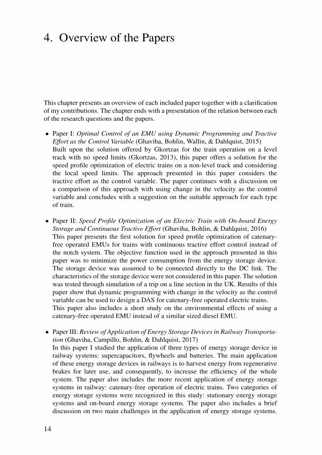
• Paper I: Optimal Control of an EMU using Dynamic Programming and TractiveEffort as the Control Variable (Ghaviha, Bohlin, Wallin, & Dahlquist, 2015)Built upon the solution offered by Gkortzas for the train operation on a leveltrack with no speed limits (Gkortzas, 2013), this paper offers a solution for thespeed profile optimization of electric trains on a non-level track and consideringthe local speed limits. The approach presented in this paper considers thetractive effort as the control variable. The paper continues with a discussion ona comparison of this approach with using change in the velocity as the controlvariable and concludes with a suggestion on the suitable approach for each typeof train.
• Paper II: Speed Profile Optimization of an Electric Train with On-board EnergyStorage and Continuous Tractive Effort (Ghaviha, Bohlin, & Dahlquist, 2016)This paper presents the first solution for speed profile optimization of catenary-free operated EMUs for trains with continuous tractive effort control instead ofthe notch system. The objective function used in the approach presented in thispaper was to minimize the power consumption from the energy storage device.The storage device was assumed to be connected directly to the DC link. Thecharacteristics of the storage device were not considered in this paper. The solutionwas tested through simulation of a trip on a line section in the UK. Results of thispaper show that dynamic programming with change in the velocity as the controlvariable can be used to design a DAS for catenary-free operated electric trains.This paper also includes a short study on the environmental effects of using acatenary-free operated EMU instead of a similar sized diesel EMU.
• Paper III: Review of Application of Energy Storage Devices in Railway Transporta-tion (Ghaviha, Campillo, Bohlin, & Dahlquist, 2017)In this paper I studied the application of three types of energy storage device inrailway systems: supercapacitors, flywheels and batteries. The main applicationof these energy storage devices in railways is to harvest energy from regenerativebrakes for later use, and consequently, to increase the efficiency of the wholesystem. The paper also includes the more recent application of energy storagesystems in railway: catenary-free operation of electric trains. Two categories ofenergy storage systems were recognized in this study: stationary energy storagesystems and on-board energy storage systems. The paper also includes a briefdiscussion on two main challenges in the application of energy storage systems.
14
34
Results of this paper show that catenary-free LRVs are mostly equipped withsupercapacitors, whereas among the three storage systems, batteries are the mainenergy storage systems used for catenary-free EMUs.
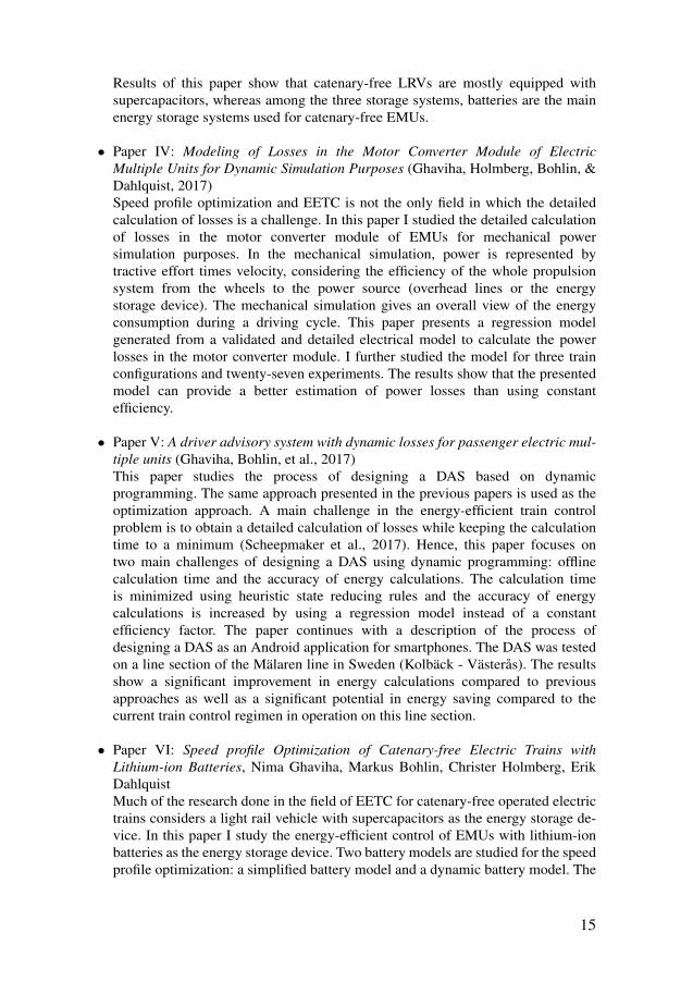
• Paper IV: Modeling of Losses in the Motor Converter Module of ElectricMultiple Units for Dynamic Simulation Purposes (Ghaviha, Holmberg, Bohlin, &Dahlquist, 2017)Speed profile optimization and EETC is not the only field in which the detailedcalculation of losses is a challenge. In this paper I studied the detailed calculationof losses in the motor converter module of EMUs for mechanical powersimulation purposes. In the mechanical simulation, power is represented bytractive effort times velocity, considering the efficiency of the whole propulsionsystem from the wheels to the power source (overhead lines or the energystorage device). The mechanical simulation gives an overall view of the energyconsumption during a driving cycle. This paper presents a regression modelgenerated from a validated and detailed electrical model to calculate the powerlosses in the motor converter module. I further studied the model for three trainconfigurations and twenty-seven experiments. The results show that the presentedmodel can provide a better estimation of power losses than using constantefficiency.
• Paper V: A driver advisory system with dynamic losses for passenger electric mul-tiple units (Ghaviha, Bohlin, et al., 2017)This paper studies the process of designing a DAS based on dynamicprogramming. The same approach presented in the previous papers is used as theoptimization approach. A main challenge in the energy-efficient train controlproblem is to obtain a detailed calculation of losses while keeping the calculationtime to a minimum (Scheepmaker et al., 2017). Hence, this paper focuses ontwo main challenges of designing a DAS using dynamic programming: offlinecalculation time and the accuracy of energy calculations. The calculation timeis minimized using heuristic state reducing rules and the accuracy of energycalculations is increased by using a regression model instead of a constantefficiency factor. The paper continues with a description of the process ofdesigning a DAS as an Android application for smartphones. The DAS was testedon a line section of the Mälaren line in Sweden (Kolbäck - Västerås). The resultsshow a significant improvement in energy calculations compared to previousapproaches as well as a significant potential in energy saving compared to thecurrent train control regimen in operation on this line section.
• Paper VI: Speed profile Optimization of Catenary-free Electric Trains withLithium-ion Batteries, Nima Ghaviha, Markus Bohlin, Christer Holmberg, ErikDahlquistMuch of the research done in the field of EETC for catenary-free operated electrictrains considers a light rail vehicle with supercapacitors as the energy storage de-vice. In this paper I study the energy-efficient control of EMUs with lithium-ionbatteries as the energy storage device. Two battery models are studied for the speedprofile optimization: a simplified battery model and a dynamic battery model. The
15
35
optimization technique is the same as the one presented in paper II, with a newobjective function: minimizing the charge taken from the batteries. Both batterymodels are validated using the measured values from the test runs of a batterydriven EMU prototype designed by Bombardier. The results show that the sim-plified battery model can provide enough accuracy for the purpose of speed pro-file optimization. I further present the potential energy saving achievable throughdynamic programming and show the improvements achieved as a result of thisproblem formulation.
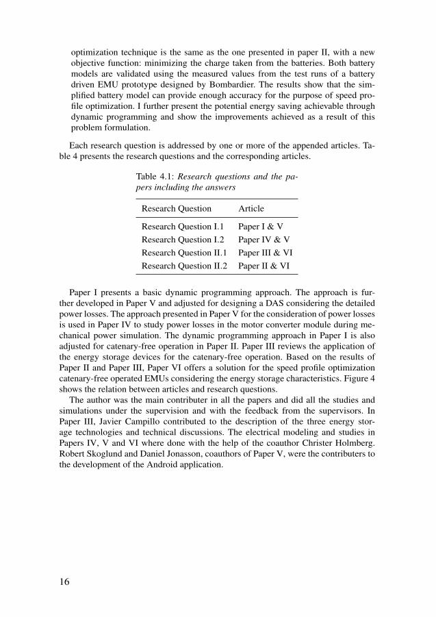
Each research question is addressed by one or more of the appended articles. Ta-ble 4 presents the research questions and the corresponding articles.
Table 4.1: Research questions and the pa-pers including the answers
Research Question Article
Research Question I.1 Paper I & VResearch Question I.2 Paper IV & VResearch Question II.1 Paper III & VIResearch Question II.2 Paper II & VI
Paper I presents a basic dynamic programming approach. The approach is fur-ther developed in Paper V and adjusted for designing a DAS considering the detailedpower losses. The approach presented in Paper V for the consideration of power lossesis used in Paper IV to study power losses in the motor converter module during me-chanical power simulation. The dynamic programming approach in Paper I is alsoadjusted for catenary-free operation in Paper II. Paper III reviews the application ofthe energy storage devices for the catenary-free operation. Based on the results ofPaper II and Paper III, Paper VI offers a solution for the speed profile optimizationcatenary-free operated EMUs considering the energy storage characteristics. Figure 4shows the relation between articles and research questions.
The author was the main contributer in all the papers and did all the studies andsimulations under the supervision and with the feedback from the supervisors. InPaper III, Javier Campillo contributed to the description of the three energy stor-age technologies and technical discussions. The electrical modeling and studies inPapers IV, V and VI where done with the help of the coauthor Christer Holmberg.Robert Skoglund and Daniel Jonasson, coauthors of Paper V, were the contributers tothe development of the Android application.
16
36
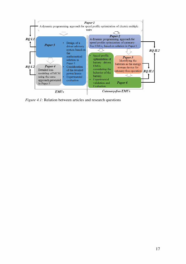
Figure 4.1: Relation between articles and research questions
17
37
5. Mathematical Formulation
This chapter includes an introduction to the models and the optimization techniqueused in this thesis.
5.1 Train ModelThe focus of this research is on energy-optimal operation of EMUs, which are smallerin size than freight trains. This type of train can be represented by a single mass pointmodel ((A. Albrecht, Howlett, Pudney, Vu, & Zhou, 2016)), which has been widelyused for this purpose in the literature (see e.g. (Howlett, 2000)). This section describesthe single mass point model used in this thesis.
We assume that the train has mass m and velocity v at time t; acceleration is dvdt , the
running resistance is Frr and the gradient force applicable on the slope is Fg. Further,Ft is the tractive/braking force needed to move the train that is provided from thetraction motor. Equation 5.1 shows the force balance of the train during operation:
m · dvdt
= Ft −Frr−Fg (5.1)
The running resistance is calculated using the Davis formula, which is widelyused to calculate the rolling resistance and aerodynamic resistance (A. Albrecht etal., 2016). Equation 5.2 presents the Davis formula:
Frr = Arr +Brr · v+Crr · v2, (5.2)
where Arr, Brr and Crr are constants based on the train configuration. Coefficientsmay be determined experimentally or based on physical models, and are dependenton the track geometry and train specifications. The gradient force is calculated usingequation 5.3:
Fg = m · h1000
, (5.3)
where h is the change in elevation for every 1000 m travelled, and h1000 is therefore the
estimated sine of the track slope. There is a limitation on the maximum tractive forceavailable from the traction motor. Figure 5.1 shows the maximum available tractiveforce at different velocities, also known as the tractive effort curve.
The tractive effort curve is designed based on the acceleration and deceleration rateon a level track with no speed limits and is limited by the maximum torque availablefrom the traction motor, the maximum power from the propulsion system and the pull-
18
38
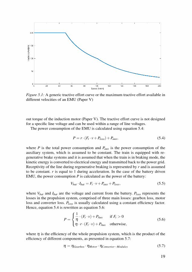
Figure 5.1: A generic tractive effort curve or the maximum tractive effort available indifferent velocities of an EMU (Paper V)
out torque of the induction motor (Paper V). The tractive effort curve is not designedfor a specific line voltage and can be used within a range of line voltages.
The power consumption of the EMU is calculated using equation 5.4:
P = r · (Ft · v+Ploss)+Paux, (5.4)
where P is the total power consumption and Paux is the power consumption of theauxiliary system, which is assumed to be constant. The train is equipped with re-generative brake systems and it is assumed that when the train is in braking mode, thekinetic energy is converted to electrical energy and transmitted back to the power grid.Receptivity of the line during regenerative braking is represented by r and is assumedto be constant. r is equal to 1 during acceleration. In the case of the battery drivenEMU, the power consumption P is calculated as the power of the battery:
Vbat · Ibat = Ft · v+Paux +Ploss, (5.5)
where Vbat and Ibat are the voltage and current from the battery. Ploss represents thelosses in the propulsion system, comprised of three main losses: gearbox loss, motorloss and converter loss. Ploss is usually calculated using a constant efficiency factor.Hence, equation 5.4 is rewritten as equation 5.6:
P =
1η· (Ft · v)+PAux if Ft > 0
η · r · (Ft · v)+PAux otherwise,(5.6)
where η is the efficiency of the whole propulsion system, which is the product of theefficiency of different components, as presented in equation 5.7:
η = ηGearbox ·ηMotor ·ηConverter−Modules (5.7)
19
39
η is the efficiency of the whole propulsion system from the wheels to the powersource, ηGearbox is the efficiency of the gearbox, ηMotor is the efficiency of the motorand ηConverter−Modules represents the efficiency of the converter modules. Besides thethree mentioned losses, there are other minor losses that are negligible compared tothe other three. The efficiency of each component however, is not constant in practiceand varies with the velocity and the applied tractive effort.
5.2 Battery ModelsAmong the different types of battery models, electrical models are most suitable forpower and dynamic simulations and they have been used for different transportationapplications (Mousavi G. & Nikdel, 2014). Although electrochemical models are themost accurate model type, they are based on detailed electrochemical and differentialequations and are too complex for dynamic simulation purposes.
Two electrical circuit equivalent battery models were studied for this research: thesimplified battery model and the generic battery model. Both these models can beused for different types of batteries (Fotouhi et al., 2016). The few design variables ofboth models can be estimated from the manufacturer’s data sheets, making the modelseasy to use (Tremblay & Dessaint, 2009). As well as transportation applications, thetwo battery models have also been used for several other purposes, such as windpower generation (Puleston, Valenciaga, Battaiotto, & Mantz, 2000) and DC microgrid systems (Xu & Chen, 2011). Generic characteristics of these battery models thatmake them applicable for batteries with different chemistries and their ease of usemakes them a suitable option for the speed profile optimization application.
The simplified battery model models the terminal voltage as a function of current,whereas the generic battery model models the terminal voltage based on both currentand state of charge. State of charge in both models is calculated using equations 5.8(also known as the Coulomb Counting method (Rivera-Barrera, Muñoz-Galeano, &Sarmiento-Maldonado, 2017)):
dSoCdt
=− Ibat ·dtQ
(5.8)
where Ibat is the current, dSoCdt is the derivative of state of charge over time, t is the
time in h, SoC is the state of charge and Q is the total battery capacity in Ah.
5.2.1 Simplified battery modelIn the simplified battery model, the battery is modeled as a voltage source and aninternal resistance (Johnson, 2002). Thus, the battery voltage depends on the current.
Vbat = E0− Ibat ·R, (5.9)
where E0 is the battery constant voltage value and R is its internal resistance. Further,Vbat is the voltage of the battery.
20
40
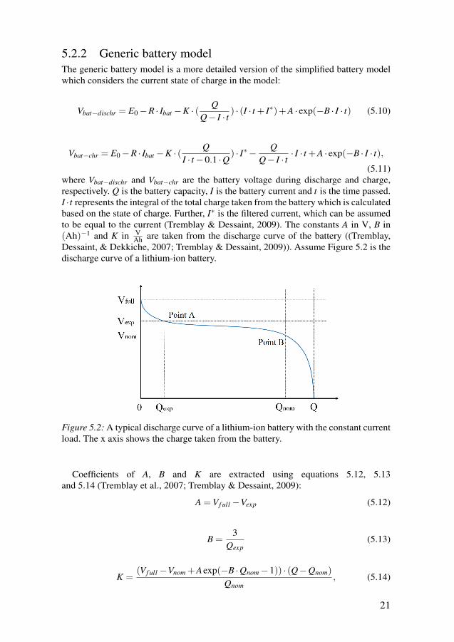
5.2.2 Generic battery modelThe generic battery model is a more detailed version of the simplified battery modelwhich considers the current state of charge in the model:
Vbat−dischr = E0−R · Ibat −K · ( QQ− I · t ) · (I · t + I∗)+A · exp(−B · I · t) (5.10)
Vbat−chr = E0−R · Ibat −K · ( QI · t−0.1 ·Q ) · I∗− Q
Q− I · t · I · t +A · exp(−B · I · t),(5.11)
where Vbat−dischr and Vbat−chr are the battery voltage during discharge and charge,respectively. Q is the battery capacity, I is the battery current and t is the time passed.I ·t represents the integral of the total charge taken from the battery which is calculatedbased on the state of charge. Further, I∗ is the filtered current, which can be assumedto be equal to the current (Tremblay & Dessaint, 2009). The constants A in V, B in(Ah)−1 and K in V
Ah are taken from the discharge curve of the battery ((Tremblay,Dessaint, & Dekkiche, 2007; Tremblay & Dessaint, 2009)). Assume Figure 5.2 is thedischarge curve of a lithium-ion battery.
Figure 5.2: A typical discharge curve of a lithium-ion battery with the constant currentload. The x axis shows the charge taken from the battery.
Coefficients of A, B and K are extracted using equations 5.12, 5.13and 5.14 (Tremblay et al., 2007; Tremblay & Dessaint, 2009):
A =Vf ull−Vexp (5.12)
B =3
Qexp(5.13)
K =(Vf ull−Vnom +Aexp(−B ·Qnom−1)) · (Q−Qnom)
Qnom, (5.14)
21
41
where Vexp and Qexp are the voltage and battery capacity at Point A, and Vnom andQnom are the voltage and capacity at Point B, depicted in Figure 5.2. Further, Vf ullrepresents the maximum voltage of the battery under load.
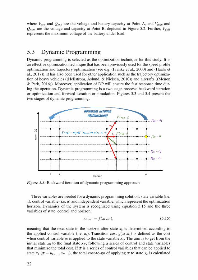
5.3 Dynamic ProgrammingDynamic programming is selected as the optimization technique for this study. It isan effective optimization technique that has been previously used for the speed profileoptimization and trajectory optimization (see e.g. (Franke et al., 2000) and (Haahr etal., 2017)). It has also been used for other application such as the trajectory optimiza-tion of heavy vehicles ((Hellström, Åslund, & Nielsen, 2010)) and aircrafts ((Menon& Park, 2016)). Moreover, application of DP will ensure the fast response time dur-ing the operation. Dynamic programming is a two stage process: backward iterationor optimization and forward iteration or simulation. Figures 5.3 and 5.4 present thetwo stages of dynamic programming.
Figure 5.3: Backward iteration of dynamic programming approach
Three variables are needed for a dynamic programming solution: state variable (i.e.x), control variable (i.e. u) and independent variable, which represent the optimizationhorizon. Dynamics of the system is recognized using equation 5.15 and the threevariables of state, control and horizon:
xi,k+1 = f (xk,ui), (5.15)
meaning that the next state in the horizon after state xk is determined according tothe applied control variable (i.e. ui). Transition cost g(xk,ui) is defined as the costwhen control variable ui is applied to the state variable xk. The aim is to get from theinitial state x0 to the final state xN , following a series of control and state variablesthat minimize the total cost. If π is a series of control variables that can be applied tostate xk (π = uk, ...,uN−1), the total cost-to-go of applying π to state xk is calculated
22
42
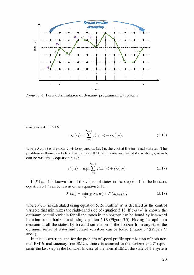
Figure 5.4: Forward simulation of dynamic programming approach
using equation 5.16:
Jπ(xk) =N−1
∑i=k
g(xi,ui)+gN(xN), (5.16)
where Jπ(xk) is the total cost-to-go and gN(xN) is the cost at the terminal state xN . Theproblem is therefore to find the value of π∗ that minimizes the total cost-to-go, whichcan be written as equation 5.17:
J∗(xk) = minπ
N−1
∑i=k
g(xi,ui)+gN(xN) (5.17)
If J∗(xk+1) is known for all the values of states in the step k + 1 in the horizon,equation 5.17 can be rewritten as equation 5.18, :
J∗(xk) = minuig(xk,ui)+ J∗(xi,k+1), (5.18)
where xi,k+1 is calculated using equation 5.15. Further, u∗ is declared as the controlvariable that minimizes the right-hand side of equation 5.18. If gN(xN) is known, theoptimum control variable for all the states in the horizon can be found by backwarditeration in the horizon and using equation 5.18 (Figure 5.3). Having the optimumdecision at all the states, by forward simulation in the horizon from any state, theoptimum series of states and control variables can be found (Figure 5.4)(Papers Vand I).
In this dissertation, and for the problem of speed profile optimization of both nor-mal EMUs and catenary-free EMUs, time t is assumed as the horizon and T repre-sents the last step in the horizon. In case of the normal EMU, the state of the system
23
43
is defined using two discretized variables of distance (i.e. sk) and velocity (i.e. vk),presented in equation 5.19 (Paper V).
xk = (sk,vk) (5.19)
For the battery driven EMU, a third variable is added in the state variable (Equa-tion 5.20):
xk = (sk,vk,sock), (5.20)
where sock presents the state of charge of the battery (Paper II).There are two options for the control variable (i.e. ui) depending on the type of
train. EMUs are equipped with one of two systems for control of the tractive effort:discrete control (i.e. a notch system) or continuous control. In the notch system, thedriver has the option of selecting only certain percentages of the effort from the trac-tion motor, whereas in continuous control, the driver has access to all the values oftractive effort. For trains with the notch system, the notch number or the correspond-ing tractive effort is used as the control variable, whereas for trains with continuouscontrol, change in the velocity is used as the control variable (Paper I). Energy con-sumption in kWh is set as the cost function. For the case of battery driven EMUs,energy consumption at the battery in Ah (i.e. charge taken from the battery) is alsostudied as the cost function.
24
44
6. Results and Discussion
This chapter presents the results of the research and discusses outcomes in the formof answers to the research questions. The chapter starts with a presentation of theresults for the normal EMUs, followed by the results for the battery driven EMUs.The chapter continues with a discussion on the presented results and ends with thediscussion on the contribution of the thesis in the form of the answers to the researchquestions.
For validation and evaluation purposes, data from two trains were used. For thecase of EMUs, a Regina EMU was considered as the case study. This is a 2 car EMUmanufactured by Bombardier, which is in service with several train companies includ-ing SJ. Regina can travel at speeds up to 200 kmh−1 and seat 167 passengers. The testtrack used in this study was a double-track section of the Mälaren line in Sweden fromKolbäck to Västerås where the Regina EMU is in service. For the battery driven EMU,the data from the prototype battery driven EMU (IPEMU) developed by Bombardierwas used. IPEMU was originally a reconfigured 4 car Bombardier Electrostar Class379 EMU equipped with lithium-ion batteries. The train was tested between HarwichInternational and Manningtree stations in Essex, UK.
6.1 Energy Optimal Operation of Electric MultipleUnitsThis section presents the results and solutions for the problem of energy-optimal op-eration of normal EMUs. The section starts with a consideration of detailed powerlosses and continues with the results of implementation of dynamic programming inan Android DAS application.
6.1.1 Detailed Power LossesThe speed profile optimization and energy-efficient train control approach presentedin this research can be viewed as a part of mechanical power simulation. In mechanicalpower simulation, the power is calculated as velocity times tractive effort. This isdifferent from electrical power simulation, in which power is calculated as currenttimes voltage. Mechanical power simulation gives an overall view of the whole energyconsumption in the train, whereas electrical power simulation is used for detailedenergy and loss calculations for each component.
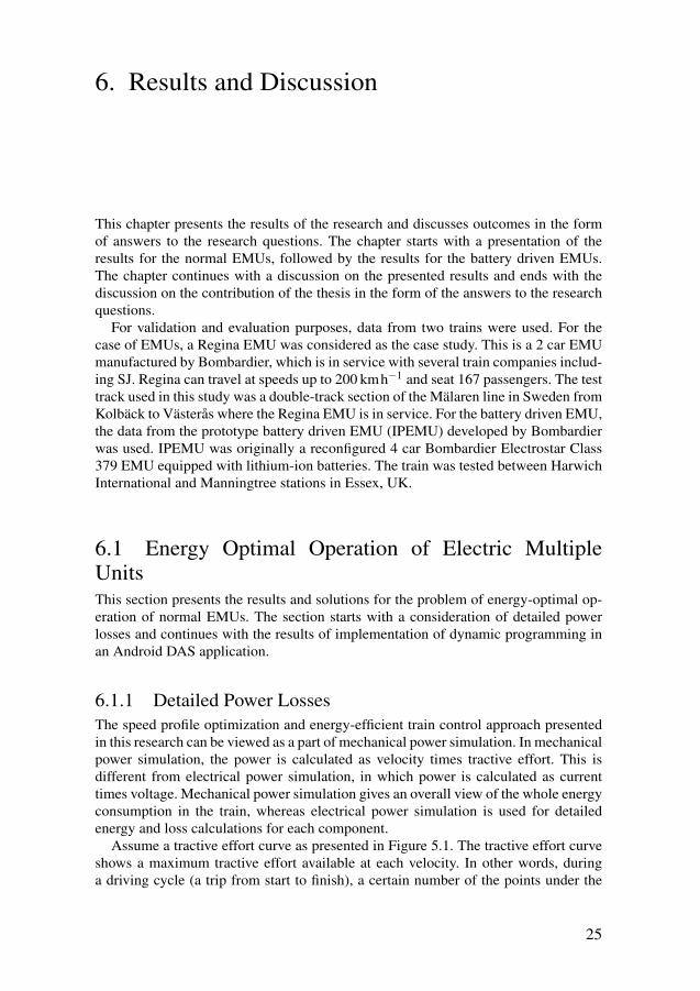
Assume a tractive effort curve as presented in Figure 5.1. The tractive effort curveshows a maximum tractive effort available at each velocity. In other words, duringa driving cycle (a trip from start to finish), a certain number of the points under the
25
45
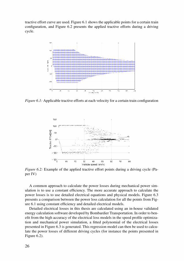
tractive effort curve are used. Figure 6.1 shows the applicable points for a certain trainconfiguration, and Figure 6.2 presents the applied tractive efforts during a drivingcycle.
Figure 6.1: Applicable tractive efforts at each velocity for a certain train configuration
Figure 6.2: Example of the applied tractive effort points during a driving cycle (Pa-per IV)
A common approach to calculate the power losses during mechanical power sim-ulation is to use a constant efficiency. The more accurate approach to calculate thepower losses is to use detailed electrical equations and physical models. Figure 6.3presents a comparison between the power loss calculation for all the points from Fig-ure 6.1 using constant efficiency and detailed electrical models.
Detailed electrical losses in this thesis are calculated using an in-house validatedenergy calculation software developed by Bombardier Transportation. In order to ben-efit from the high accuracy of the electrical loss models in the speed profile optimiza-tion and mechanical power simulation, a fitted polynomial of the electrical lossespresented in Figure 6.3 is generated. This regression model can then be used to calcu-late the power losses of different driving cycles (for instance the points presented inFigure 6.2).
26
46
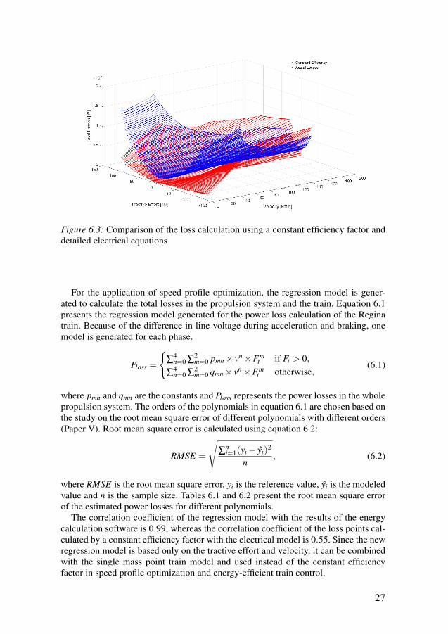
Figure 6.3: Comparison of the loss calculation using a constant efficiency factor anddetailed electrical equations
For the application of speed profile optimization, the regression model is gener-ated to calculate the total losses in the propulsion system and the train. Equation 6.1presents the regression model generated for the power loss calculation of the Reginatrain. Because of the difference in line voltage during acceleration and braking, onemodel is generated for each phase.
Ploss =
∑
4n=0 ∑
2m=0 pmn× vn×Fm
t if Ft > 0,
∑4n=0 ∑
2m=0 qmn× vn×Fm
t otherwise,(6.1)
where pmn and qmn are the constants and Ploss represents the power losses in the wholepropulsion system. The orders of the polynomials in equation 6.1 are chosen based onthe study on the root mean square error of different polynomials with different orders(Paper V). Root mean square error is calculated using equation 6.2:
RMSE =
√∑
ni=1(yi− yi)
2
n, (6.2)
where RMSE is the root mean square error, yi is the reference value, yi is the modeledvalue and n is the sample size. Tables 6.1 and 6.2 present the root mean square errorof the estimated power losses for different polynomials.
The correlation coefficient of the regression model with the results of the energycalculation software is 0.99, whereas the correlation coefficient of the loss points cal-culated by a constant efficiency factor with the electrical model is 0.55. Since the newregression model is based only on the tractive effort and velocity, it can be combinedwith the single mass point train model and used instead of the constant efficiencyfactor in speed profile optimization and energy-efficient train control.
27
47
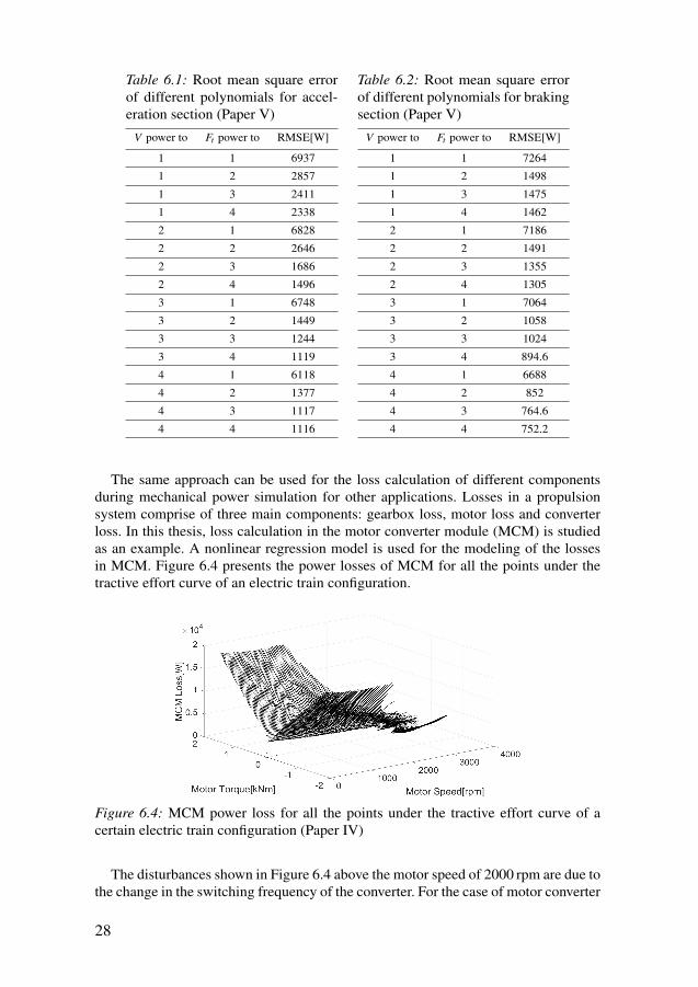
Table 6.1: Root mean square errorof different polynomials for accel-eration section (Paper V)
V power to Ft power to RMSE[W]
1 1 6937
1 2 2857
1 3 2411
1 4 2338
2 1 6828
2 2 2646
2 3 1686
2 4 1496
3 1 6748
3 2 1449
3 3 1244
3 4 1119
4 1 6118
4 2 1377
4 3 1117
4 4 1116
Table 6.2: Root mean square errorof different polynomials for brakingsection (Paper V)
V power to Ft power to RMSE[W]
1 1 7264
1 2 1498
1 3 1475
1 4 1462
2 1 7186
2 2 1491
2 3 1355
2 4 1305
3 1 7064
3 2 1058
3 3 1024
3 4 894.6
4 1 6688
4 2 852
4 3 764.6
4 4 752.2
The same approach can be used for the loss calculation of different componentsduring mechanical power simulation for other applications. Losses in a propulsionsystem comprise of three main components: gearbox loss, motor loss and converterloss. In this thesis, loss calculation in the motor converter module (MCM) is studiedas an example. A nonlinear regression model is used for the modeling of the lossesin MCM. Figure 6.4 presents the power losses of MCM for all the points under thetractive effort curve of an electric train configuration.
Figure 6.4: MCM power loss for all the points under the tractive effort curve of acertain electric train configuration (Paper IV)
The disturbances shown in Figure 6.4 above the motor speed of 2000 rpm are due tothe change in the switching frequency of the converter. For the case of motor converter
28
48

module, the regression model is based on motor torque, motor speed and switchingfrequency variables. Tractive effort and vehicle speed can be used instead of motortorque and motor speed, respectively, as they directly correlate with these variables.
The regression model was generated for a certain line voltage. However, the linevoltage is not always constant during operation, as it increases during braking mode,which causes a decrease in power loss compared to lower voltages. A solution forthis issue is to generate a regression model for every line voltage. The other solutionchosen for this case is to use linear scaling of the regression model based on the linevoltage. Equation 6.3 presents the final regression model including linear scaling withthe line voltage (Paper IV).
LossMCM =Vsim
Vgrid· (
2
∑m=0
1
∑n=0
τm ·ωn +qmn · fsw + pmn · fsw · τ + kmn · fsw ·ω), (6.3)
where LossMCM is the power loss in the motor converter module, fsw is the switch-ing frequency, τ is the motor torque, ω is the motor speed, and qmn, pmn and kmn areconstant coefficients. Further, Vsim is the line voltage during the simulation or oper-ation and Vgrid is the line voltage of the grid from which the regression model wasgenerated.
Three regression models were generated for three types of electric train configura-tions and were used to calculate the total MCM energy loss for around eight drivingcycles for each of the train configurations. MCM losses were also calculated for allthe driving cycles using a constant efficiency factor. Results show that the total MCMlosses calculated using the regression model differ by 2.3%, on average, from thelosses calculated by the energy calculation software, whereas the losses calculatedusing a constant efficiency factor differ by 45.9% from the detailed losses calculatedusing the physical model.
The detailed electrical losses in this study were calculated using a validated energycalculation software. Other validated loss models can be used instead of the energycalculation software to generate the grids and regression models.
6.1.2 Driver Advisory SystemThis thesis studies the application of the presented dynamic programming approachfor designing a DAS for EMUs. There are two types of systems for controlling thetractive effort in EMUs: the notch system and the continuous system. In the notchsystem, the driver has access to specific discrete percentages of tractive effort fromthe traction motor. In the continuous system however, the driver has continuous con-trol over the tractive effort. Both systems are sometimes accompanied by a notch forcruising the train at a constant speed. The dynamic programming approach presentedin Paper I and section 5.3 can be applied for both types of trains. However, it is prefer-able to use tractive effort as the control variable for trains with the notch system,whereas for trains with continuous tractive effort, change in velocity is the preferredcontrol variable (Paper I).
One of the main challenges in the problem of energy-efficient train controlis the conflict between the calculation time and the accuracy of the lossmodel (Scheepmaker et al., 2017). However, dynamic programming is known to
29
49
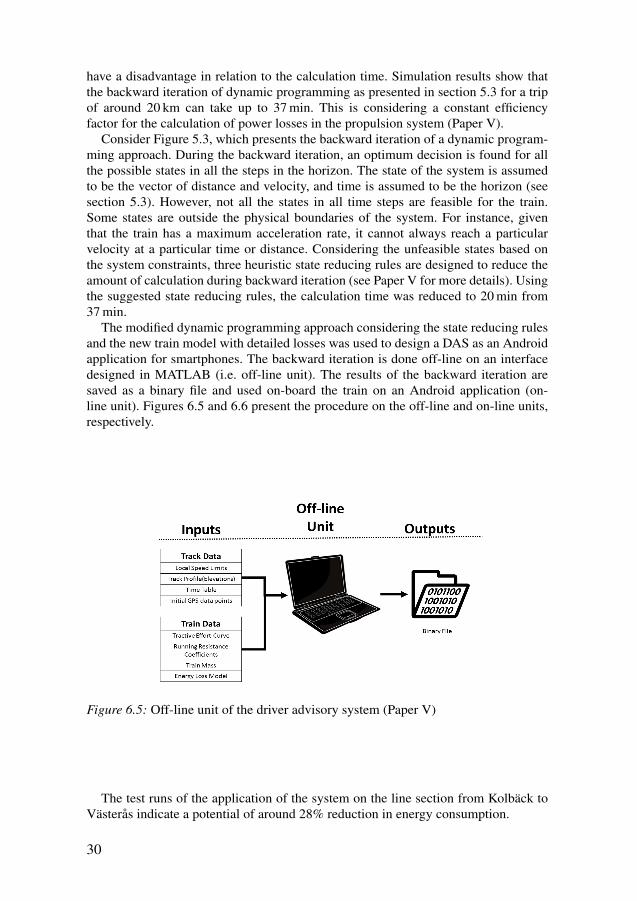
have a disadvantage in relation to the calculation time. Simulation results show thatthe backward iteration of dynamic programming as presented in section 5.3 for a tripof around 20 km can take up to 37 min. This is considering a constant efficiencyfactor for the calculation of power losses in the propulsion system (Paper V).
Consider Figure 5.3, which presents the backward iteration of a dynamic program-ming approach. During the backward iteration, an optimum decision is found for allthe possible states in all the steps in the horizon. The state of the system is assumedto be the vector of distance and velocity, and time is assumed to be the horizon (seesection 5.3). However, not all the states in all time steps are feasible for the train.Some states are outside the physical boundaries of the system. For instance, giventhat the train has a maximum acceleration rate, it cannot always reach a particularvelocity at a particular time or distance. Considering the unfeasible states based onthe system constraints, three heuristic state reducing rules are designed to reduce theamount of calculation during backward iteration (see Paper V for more details). Usingthe suggested state reducing rules, the calculation time was reduced to 20 min from37 min.
The modified dynamic programming approach considering the state reducing rulesand the new train model with detailed losses was used to design a DAS as an Androidapplication for smartphones. The backward iteration is done off-line on an interfacedesigned in MATLAB (i.e. off-line unit). The results of the backward iteration aresaved as a binary file and used on-board the train on an Android application (on-line unit). Figures 6.5 and 6.6 present the procedure on the off-line and on-line units,respectively.
Figure 6.5: Off-line unit of the driver advisory system (Paper V)
The test runs of the application of the system on the line section from Kolbäck toVästerås indicate a potential of around 28% reduction in energy consumption.
30
50
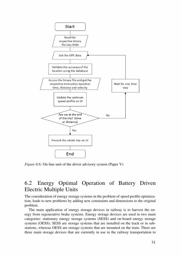
Figure 6.6: On-line unit of the driver advisory system (Paper V)
6.2 Energy Optimal Operation of Battery DrivenElectric Multiple UnitsThe consideration of energy storage systems in the problem of speed profile optimiza-tion, leads to new problems by adding new constraints and dimensions to the originalproblem.
The main application of energy storage devices in railway is to harvest the en-ergy from regenerative brake systems. Energy storage devices are used in two maincategories: stationary energy storage systems (SESS) and on-board energy storagesystems (OESS). SESS are storage systems that are installed on the track or in sub-stations, whereas OESS are storage systems that are mounted on the train. There arethree main storage devices that are currently in use in the railway transportation to
31
51
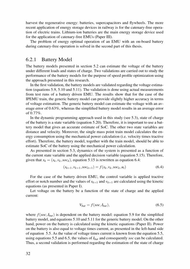
harvest the regenerative energy: batteries, supercapacitors and flywheels. The morerecent application of energy storage devices in railway is for the catenary-free opera-tion of electric trains. Lithium-ion batteries are the main energy storage device usedfor the application of catenary-free EMUs (Paper III).
The problem of energy optimal operation of an EMU with an on-board batteryduring catenary-free operation is solved in the second part of this thesis.
6.2.1 Battery ModelThe battery models presented in section 5.2 can estimate the voltage of the batteryunder different loads and states of charge. Two validations are carried out to study theperformance of the battery models for the purpose of speed profile optimization usingthe approach presented in this research.
In the first validation, the battery models are validated regarding the voltage estima-tion (equations 5.9, 5.10 and 5.11). The validation is done using actual measurementsfrom test runs of a battery driven EMU. The results show that for the case of theIPEMU train, the generic battery model can provide slightly higher accuracy in termsof voltage estimation. The generic battery model can estimate the voltage with an av-erage error of 0.63%, whereas the simplified battery model results in an average errorof 0.77%.
In the dynamic programming approach used in this study (see 5.3), state of chargeof the battery is a state variable (equation 5.20). Therefore, it is important to use a bat-tery model that gives an accurate estimate of SoC. The other two state variables aredistance and velocity. Moreover, the single mass point train model calculates the en-ergy consumption using the mechanical power calculation (i.e. velocity times tractiveeffort). Therefore, the battery model, together with the train model, should be able toestimate SoC of the battery using the mechanical power calculation.
As presented in section 5.3, dynamics of the system is presented as a function ofthe current state variable and the applied decision variable (equation 5.15). Therefore,given that xk = (sk,vk,sock), equation 5.15 is rewritten as equation 6.4:
(sk+1,vk+1,sock+1) = f (sk,vk,sock,ui) (6.4)
For the case of the battery driven EMU, the control variable is applied tractiveeffort or notch number and the values of sk+1 and vk+1 are calculated using the kineticequations (as presented in Paper I).
Let voltage on the battery be a function of the state of charge and the appliedcurrent:
Vbat = f (soc, Ibat), (6.5)
where f (soc, Ibat) is dependent on the battery model: equation 5.9 for the simplifiedbattery model, and equations 5.10 and 5.11 for the generic battery model. On the otherhand, power on the battery is calculated using the kinetic equations (Paper II). Poweron the battery is also equal to voltage times current, as presented in the left-hand sideof equation 5.5. As the value of voltage times current is known from the equation 5.5,using equations 5.5 and 6.5, the values of Ibat and consequently soc can be calculated.Thus, a second validation is performed regarding the estimation of the state of charge
32
52
based on a battery model and a speed profile. We validate both battery models usinga speed profile from a test run of a battery driven EMU. Figure 6.7 shows the speedprofile of the test run, and Figure 6.8 presents a comparison between the measuredstate of charge on the train and the estimated values using both generic and simplebattery models.
Figure 6.7: Speed profile of an experiment used for the validation of SoC estimationbased on mechanical power (Paper VI)
The results of the validation show that both battery models can estimate the stateof charge with similarly high accuracy.
6.2.2 Speed Profile OptimizationSpeed profile optimization of the catenary-free operated battery EMUs is differentthan that of a normal EMU. Having a battery as the only energy source adds newconstraints to the optimization problem. The main constraint is regarding the limitedenergy capacity of the battery. The first step for the consideration of the energy storagerelated constraints is to introduce the state of charge as the new state variable. Havingstate of charge as a state variable facilitates handling of any constraints related to thestate of charge.
The objective function in the case of the battery driven EMU is minimizing theenergy consumption from the battery. The energy consumption however, can be statedeither in the form of the energy consumption on the DC link and in kWh or in the formof the charge consumption from the battery in Ah. Equation 6.6 shows the relationbetween the energy consumption on the DC link and charge consumption from thebattery.
EkWh =Vbat ·EAh
1000, (6.6)
33
53
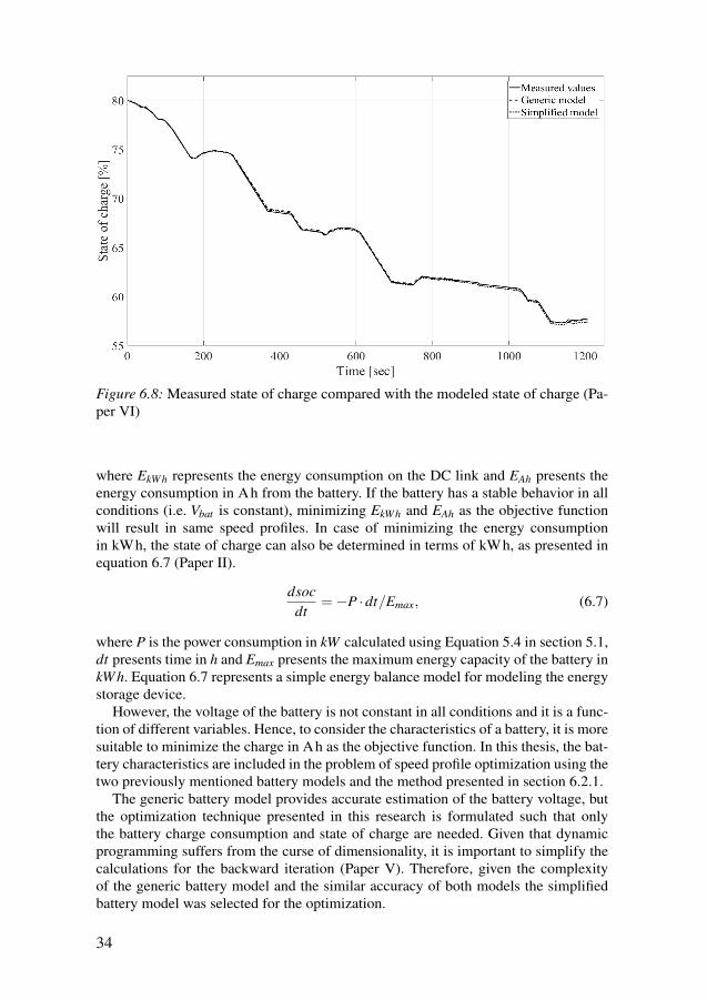
Figure 6.8: Measured state of charge compared with the modeled state of charge (Pa-per VI)
where EkWh represents the energy consumption on the DC link and EAh presents theenergy consumption in Ah from the battery. If the battery has a stable behavior in allconditions (i.e. Vbat is constant), minimizing EkWh and EAh as the objective functionwill result in same speed profiles. In case of minimizing the energy consumptionin kWh, the state of charge can also be determined in terms of kWh, as presented inequation 6.7 (Paper II).
dsocdt
=−P ·dt/Emax, (6.7)
where P is the power consumption in kW calculated using Equation 5.4 in section 5.1,dt presents time in h and Emax presents the maximum energy capacity of the battery inkWh. Equation 6.7 represents a simple energy balance model for modeling the energystorage device.
However, the voltage of the battery is not constant in all conditions and it is a func-tion of different variables. Hence, to consider the characteristics of a battery, it is moresuitable to minimize the charge in Ah as the objective function. In this thesis, the bat-tery characteristics are included in the problem of speed profile optimization using thetwo previously mentioned battery models and the method presented in section 6.2.1.
The generic battery model provides accurate estimation of the battery voltage, butthe optimization technique presented in this research is formulated such that onlythe battery charge consumption and state of charge are needed. Given that dynamicprogramming suffers from the curse of dimensionality, it is important to simplify thecalculations for the backward iteration (Paper V). Therefore, given the complexityof the generic battery model and the similar accuracy of both models the simplifiedbattery model was selected for the optimization.
34
54
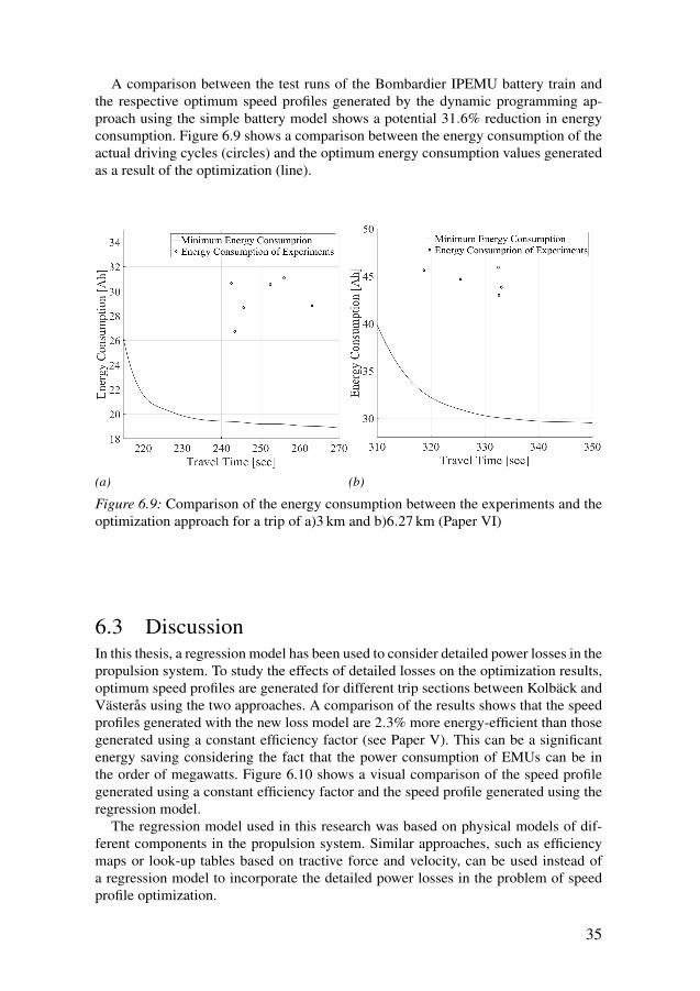
A comparison between the test runs of the Bombardier IPEMU battery train andthe respective optimum speed profiles generated by the dynamic programming ap-proach using the simple battery model shows a potential 31.6% reduction in energyconsumption. Figure 6.9 shows a comparison between the energy consumption of theactual driving cycles (circles) and the optimum energy consumption values generatedas a result of the optimization (line).
(a) (b)
Figure 6.9: Comparison of the energy consumption between the experiments and theoptimization approach for a trip of a)3 km and b)6.27 km (Paper VI)
6.3 DiscussionIn this thesis, a regression model has been used to consider detailed power losses in thepropulsion system. To study the effects of detailed losses on the optimization results,optimum speed profiles are generated for different trip sections between Kolbäck andVästerås using the two approaches. A comparison of the results shows that the speedprofiles generated with the new loss model are 2.3% more energy-efficient than thosegenerated using a constant efficiency factor (see Paper V). This can be a significantenergy saving considering the fact that the power consumption of EMUs can be inthe order of megawatts. Figure 6.10 shows a visual comparison of the speed profilegenerated using a constant efficiency factor and the speed profile generated using theregression model.
The regression model used in this research was based on physical models of dif-ferent components in the propulsion system. Similar approaches, such as efficiencymaps or look-up tables based on tractive force and velocity, can be used instead ofa regression model to incorporate the detailed power losses in the problem of speedprofile optimization.
35
55
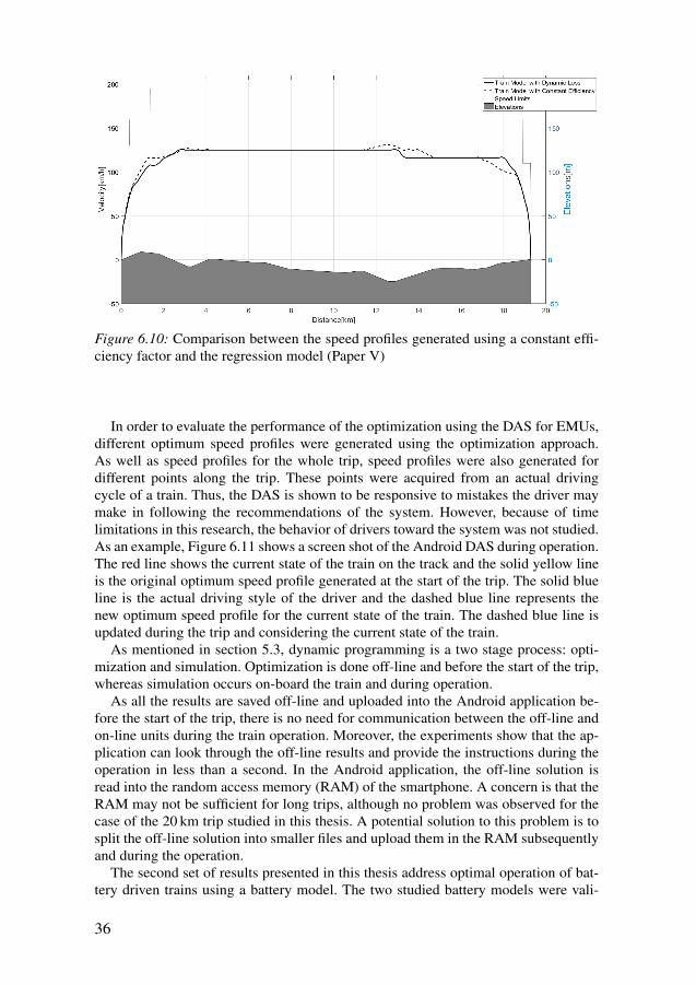
Figure 6.10: Comparison between the speed profiles generated using a constant effi-ciency factor and the regression model (Paper V)
In order to evaluate the performance of the optimization using the DAS for EMUs,different optimum speed profiles were generated using the optimization approach.As well as speed profiles for the whole trip, speed profiles were also generated fordifferent points along the trip. These points were acquired from an actual drivingcycle of a train. Thus, the DAS is shown to be responsive to mistakes the driver maymake in following the recommendations of the system. However, because of timelimitations in this research, the behavior of drivers toward the system was not studied.As an example, Figure 6.11 shows a screen shot of the Android DAS during operation.The red line shows the current state of the train on the track and the solid yellow lineis the original optimum speed profile generated at the start of the trip. The solid blueline is the actual driving style of the driver and the dashed blue line represents thenew optimum speed profile for the current state of the train. The dashed blue line isupdated during the trip and considering the current state of the train.
As mentioned in section 5.3, dynamic programming is a two stage process: opti-mization and simulation. Optimization is done off-line and before the start of the trip,whereas simulation occurs on-board the train and during operation.
As all the results are saved off-line and uploaded into the Android application be-fore the start of the trip, there is no need for communication between the off-line andon-line units during the train operation. Moreover, the experiments show that the ap-plication can look through the off-line results and provide the instructions during theoperation in less than a second. In the Android application, the off-line solution isread into the random access memory (RAM) of the smartphone. A concern is that theRAM may not be sufficient for long trips, although no problem was observed for thecase of the 20 km trip studied in this thesis. A potential solution to this problem is tosplit the off-line solution into smaller files and upload them in the RAM subsequentlyand during the operation.
The second set of results presented in this thesis address optimal operation of bat-tery driven trains using a battery model. The two studied battery models were vali-
36
56
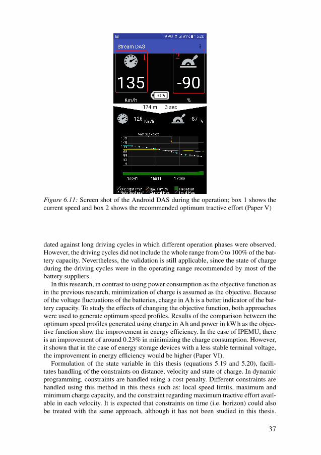
Figure 6.11: Screen shot of the Android DAS during the operation; box 1 shows thecurrent speed and box 2 shows the recommended optimum tractive effort (Paper V)
dated against long driving cycles in which different operation phases were observed.However, the driving cycles did not include the whole range from 0 to 100% of the bat-tery capacity. Nevertheless, the validation is still applicable, since the state of chargeduring the driving cycles were in the operating range recommended by most of thebattery suppliers.
In this research, in contrast to using power consumption as the objective function asin the previous research, minimization of charge is assumed as the objective. Becauseof the voltage fluctuations of the batteries, charge in Ah is a better indicator of the bat-tery capacity. To study the effects of changing the objective function, both approacheswere used to generate optimum speed profiles. Results of the comparison between theoptimum speed profiles generated using charge in Ah and power in kWh as the objec-tive function show the improvement in energy efficiency. In the case of IPEMU, thereis an improvement of around 0.23% in minimizing the charge consumption. However,it shown that in the case of energy storage devices with a less stable terminal voltage,the improvement in energy efficiency would be higher (Paper VI).
Formulation of the state variable in this thesis (equations 5.19 and 5.20), facili-tates handling of the constraints on distance, velocity and state of charge. In dynamicprogramming, constraints are handled using a cost penalty. Different constraints arehandled using this method in this thesis such as: local speed limits, maximum andminimum charge capacity, and the constraint regarding maximum tractive effort avail-able in each velocity. It is expected that constraints on time (i.e. horizon) could alsobe treated with the same approach, although it has not been studied in this thesis.
37
57
These type of constraints include the constraint on the time passage points (Haahr etal., 2017).
The optimization solution presented in this thesis discretizes the variables to ap-proximates the continuous state space. Discretization of variables results in an ap-proximation of the cost-to-go values instead of the actual values of cost-to-go (seesection 5.3). The accuracy of the approximation is dependent on the grid intervals,which means that the optimal cost-to-go may not be the global optima. The suitablegrid intervals in this research are selected based on a compromise in the following cri-teria: calculation time of the backward iteration, time interval for the instruction to thedriver, terminal error on state variables and value of energy consumption. The energyconsumption and terminal error on state variables were assessed using the Bombardierin-house code. It is to be noted that although the assessment of the accuracy and sen-sitivity of the solutions to the grid size was out of the scope of this work, the finalpotential energy consumption reduction is credible as it was measured using a vali-dated in-house tool. It is also because of the discretization errors that it is preferableto use notch number as the control variable for the trains with the notch system.
The dynamic programming approach used in this thesis was a basic dynamic pro-gramming approach; other approximate DP approaches (e.g. the dynamic program-ming approaches presented in (Haahr et al., 2017) and (Franke et al., 2000)) can alsobe used instead of the basic DP presented in this research to design a DAS consideringthe detailed power losses and characteristics of the battery.
6.4 Contribution to KnowledgeBased on the presented results and discussion, the contribution of this thesis is formu-lated as the answers to the research questions:
I Energy optimal operation of electric multiple units1. What is the procedure of designing a driver advisory system from a theoret-
ical solution? (Papers I and V)There is substantial research in the field of energy-optimal train operation,but not much is known regarding the application of mathematical solutionsfor the practical problem of energy-optimal train operation. Therefore, toanswer this research question, the whole procedure of designing a DAS hasbeen studied. In this research, three main issues are realized and addressed:calculation time, detailed power loss models and the communication be-tween the on-board DAS and an off-line unit. Application of dynamic pro-gramming with heuristic state reducing rules as the optimization techniquecan ensure the optimality of the solution, while keeping a relative short cal-culation time. The heuristic state reducing rules in this study are generatedbased on the physical constraints of the system. The state space can be evenfurther reduced by using a reference trajectory.Further, the two-stage procedure of dynamic programming ensures that thereis no need for communication between the off-line unit and on-board unit.It should however be noted, that in order to improve the current DAS, itshould be connected to traffic control systems and constantly updated basedon adjustments to the timetable.
38
58
The Android application and the code for the dynamic programming ap-proach are available as open source code for further research and develop-ment in the field of DAS1.
2. How can we increase the accuracy of power loss calculation for the problemof speed profile optimization and similar applications? (Papers IV and V)Different operating conditions during different driving cycles result inchange in the efficiency of the propulsion system. Each driving cycle canbe realized in a domain under the graph of maximum tractive effort versusvelocity. A solution to this research question is to generate a grid underthe tractive effort curve, calculate the power losses for each point on thegrid and generate a regression model based on the results. The regressionmodel can subsequently be used for simulation purposes. Applicationof this method, in place of a constant efficiency factor, for speed profileoptimization results in more energy-efficient speed profiles. In the specificcase studied in this research the optimum speed profiles generated withthe new loss model were 2.3% more energy-efficient on average. Further,application of this approach instead of a constant efficiency factor for thepower loss calculation of a motor converter module results in significantimprovements in the energy calculations.The experiments and evaluations with the electrical models show that thelosses differ in different line voltages. It is shown that in the case of the motorconverter module, one regression model with linear scaling according to theline voltage provides enough accuracy. A more accurate solution however isto generate one regression model for each line voltage.
II Energy-optimal catenary-free operation of catenary-free operated electric mul-tiple units
1. What are the main energy storage devices used for the catenary-free op-erated electric multiple units and how can they be modeled for the speedprofile optimization purpose? (Papers III and VI)Catenary-free operated EMUs are a recent trend in the railway industry.Thus far, only a few catenary-free EMUs have been developed. These newunits are equipped with lithium-ion batteries or hydrogen fuel cells. Dif-ferent models are available for monitoring the performance of these energystorage technologies. In order to select a suitable battery model for the speedprofile optimization, the characteristics of the train model should also beconsidered. The common train model used for speed profile optimization ofEMUs is the single mass point, which models the mechanical power by con-sidering the total losses in the propulsion system. In the proposed approachpresented in this research, any electrical circuit equivalent battery model thatcan model the battery voltage as a function of current and state of charge issuitable for use in speed profile optimization using the single mass pointtrain model.
2. How can a dynamic programming approach be used for speed profile op-timization of catenary-free operated electric multiple units considering thecharacteristics of the energy storage device? (Papers II and VI)
1https://www.sics.se/projects/stream
39
59
The dynamic programming approach used to design the DAS is adjustedfor catenary-free operated EMUs by introducing state of charge as a newdimension to the state variable. Since the relation between the power at theDC link (i.e. power at the battery) and the state of charge is not linear, anew objective function is used: energy consumption from the battery in Ah.Using the state of charge as a state variable and charge consumption as theobjective function, characteristics of the energy consumption are consideredin the problem of speed profile optimization. Both of the values of state ofcharge and charge consumption are calculated using the single mass pointtrain model and mechanical power calculations.Although the approach and models presented in this research are for thecase of an EMU with a lithium-ion battery, the solution can be generalizedfor EMUs with other types of energy storage device using the same type ofmodel. The results of the optimization for a certain case show a potential31.6% reduction in energy consumption.
40
60
7. Conclusion
In sum, this thesis contributes to the problem of energy-efficient train control in twoways: application and problem formulation.
In the case of problem formulation, the thesis fills knowledge gaps regarding theproblem of single train operation. According to Miyatake, in the optimization of trainoperation, 8 major characteristics should be considered: power losses in the grid, ef-fects of the line voltage on the tractive effort curve, regenerative brake system, run-ning resistance, track profile, energy storage systems, losses in the propulsion sys-tem and signaling systems (Miyatake & Ko, 2010). In this thesis, five of these issuesare covered. The train model considers the regenerative brake system, running re-sistance and the track profile. The thesis also addresses detailed power losses in theproblem of speed profile optimization. The results show that the consideration of thedetailed power losses influences the optimum speed profiles and increases the energyefficiency (2.3% increase on average). Results of the optimization show a potentialincrease of around 28% in energy efficiency.
The thesis also examines the consideration of the energy storage device in the trainconfiguration. The consideration of the energy storage systems in the optimizationproblem adds new dimensions and constraints to the original problem, which leadsto new problems. The energy storage device can be considered as a stationary oron-board energy storage device. On-board energy storage devices can be used as asecondary energy source or as the sole energy source during catenary-free operation.Each of the new configurations is a separate optimization problem. In catenary-freeoperation, lithium-ion batteries are one of the main energy storage devices used forintercity regional trains. This thesis combines the single mass point train model withan electric circuit battery model to consider the characteristics of the battery. The elec-tric circuit model should model the terminal voltage of the battery based on the loadcurrent and the state of charge. Results presented in this thesis show that the consider-ation of the battery characteristics in the problem of speed profile optimization leadsto an increase in energy efficiency. Results of the optimization show an increase ofaround 31% in energy efficiency compared to actual driving cycles of a battery driventrain.
The thesis also investigates the development of a driver advisory system based ona dynamic programming approach. Since current smartphones can provide enoughdata needed for a DAS, the DAS in this thesis is designed as an Android application.Although dynamic programming is an effective optimization approach, it is not effi-cient in terms of calculation time. The results show that the calculation time can bedecreased using heuristic state reducing rules generated from the physical constraintsof the system. As a result, dynamic programming can be used effectively in designinga driver advisory system as an Android application.
41
61

The driver advisory system and the optimization solutions presented here are aimedat single train operation. Therefore, they do not consider the losses in the power gridand signaling system. However, the model used in this thesis includes a constant factorfor receptivity of the line during the regenerative braking mode, which can be viewedas a simplistic model of the losses in the power grid. The model could be improvedby using a more sophisticated factor for line receptivity.
42
62
8. Future Directions
This research examines the problem of EETC for single train operation. The results ofthis thesis contribute to the problem of speed profile optimization by adding dynamicpower losses and characteristics of the energy storage device during catenary-free op-eration. Moreover, it presents the process of designing a DAS from the mathematicalformulation to the application on-board the train.
Based on the study by Panou et. al. (Panou et al., 2013), two directions of futureresearch possibilities are suggested regarding the driver advisory system. The first di-rection follows the integration of the whole network into the optimization problem.This will lead to consideration of the constraints resulting from multiple train opera-tions, which includes consideration of power losses in the grid. Moreover, the driveradvisory system presented in this thesis is a stand-alone system. In order to maximizethe potential energy efficiency of such a system, it should be connected to a trafficmanagement server and be updated in real time with information regarding timetablesand traffic (i.e. C-DAS). Apart from C-DAS, studies are needed to introduce automatictrain operation (ATO) systems for the regional train lines.
The other direction includes aspects of the driver advisory system pertaining tohuman/machine interaction. This includes how the DAS should be integrated into thedriver’s cabin, the information that should be presented to the driver and the level ofdetail of this information. Another aspect of the human/machine interaction is a studyof driver behavior and reaction towards the instructions from a driver advisory system.
The speed profile optimization done in this research is with the objective of min-imizing energy consumption. Life and state of health of batteries however, is a keyfactor in application which determines the performance of the battery. In the futureresearch in the field of speed profile optimization for catenary-free EMUs the objec-tive of optimizing the life of the battery should also be considered. Moreover, one ofthe few catenary-free EMUs on the market is operating with a hybrid fuel cell-batteryenergy storage system. Speed profile optimization of such trains is also an interestingtopic for future research.
Evaluation of the dynamic programming approach used in this thesis using a val-idated energy calculation software shows the potential of saving around 28% in en-ergy consumption. For the future studies it would be interesting to study the effectsof discretization of state space on the energy consumption reduction and the globaloptimality of the solution.
43
63

64
References
Acikbas, S., & Soylemez, M. T. (2008). Coasting point optimisation for massrail transit lines using artificial neural networks and genetic algorithms.Electric Power Applications, IET , 2(3), 172–182. doi: 10.1049/iet-epa:20070381
Albrecht, A., Howlett, P., Pudney, P., Vu, X., & Zhou, P. (2016, dec).The key principles of optimal train control-Part 1 Formulation of themodel, strategies of optimal type, evolutionary lines, location of optimalswitching points. Transportation Research Part B: Methodological, 94,482–508. doi: 10.1016/j.trb.2015.07.023
Albrecht, A. R., Howlett, P. G., Pudney, P. J., & Vu, X. (2013). Energy-efficient train control: From local convexity to global optimization anduniqueness. Automatica, 49(10), 3072–3078. doi: http://dx.doi.org/10.1016/j.automatica.2013.07.008
Alstom. (2016, sep). Alstom unveils Coradia iLint hydrogen fuel cell poweredtrain for European regional market. Fuel Cells Bulletin, 2016(9), 1. doi:10.1016/S1464-2859(16)30228-0
Baumgartner, J. (2001). Prices and costs in the railway sector. Institut destransports et de planification.
Becker, F., & Dammig, A. (2016, sep). Catenary free operation of light railvehicles, Topology and operational concept. In 2016 18th europeanconference on power electronics and applications (epe’16 ecce europe)(pp. 1–10). IEEE. doi: 10.1109/EPE.2016.7695286
Bocharnikov, Y. V., Tobias, A. M., & Roberts, C. (2010). Reduction of trainand net energy consumption using genetic algorithms for Trajectory Op-timisation. In Iet conference on railway traction systems (rts 2010), (pp.1–5). doi: 10.1049/ic.2010.0038
Campillo, J., Dahlquist, E., Danilov, D. L., Ghaviha, N., Notten, P. H. L.,& Zimmerman, N. (2017). Battery Technologies for TransportationApplications. In Technologies and applications for smart charging ofelectric and plug-in hybrid vehicles (pp. 151–206). Cham: SpringerInternational Publishing. doi: 10.1007/978-3-319-43651-7_5
Chang, C. S., & Sim, S. S. (1997). Optimising train movements through coastcontrol using genetic algorithms. IEE Proceedings - Electric PowerApplications, 144(1), 65–73. doi: 10.1049/ip-epa:19970797
Cheng, J., & Howlett, P. (1993). A note on the calculation of optimal strategiesfor the minimization of fuel consumption in the control of trains. IEEE
45
65
Transactions on Automatic Control,, 38(11), 1730–1734. doi: 10.1109/9.262051
Colak, K., Czarkowski, D., & de Leon, F. (2012). Energy minimization forcatenary-free mass transit systems using Particle Swarm Optimization.In Electrical systems for aircraft, railway and ship propulsion (esars),2012 (pp. 1–5). doi: 10.1109/esars.2012.6387414
Erchao, C., Xin, Y., & Yi, D. (2014). An energy-efficient adjustment ap-proach in subway systems. In 2014 ieee 17th international confer-ence on intelligent transportation systems (itsc), (pp. 2774–2779). doi:10.1109/itsc.2014.6958134
Fotouhi, A., Auger, D. J., Propp, K., Longo, S., & Wild, M. (2016, apr). Areview on electric vehicle battery modelling: From Lithium-ion towardLithium-Sulphur (Vol. 56). Pergamon. doi: 10.1016/j.rser.2015.12.009
Franke, R., Terwiesch, P., & Meyer, M. (2000). An algorithm for the optimalcontrol of the driving of trains. In Proceedings of the 39th ieee confer-ence on decision and control, 2000. (Vol. 3, pp. 2123–2128 vol.3). doi:10.1109/cdc.2000.914108
Ghaviha, N. (2016). Energy optimal operation of electric trains : Develop-ment of a driver advisory system (No. 237). Mälardalen University.
Ghaviha, N., Bohlin, M., & Dahlquist, E. (2016, jun). Speed profile optimiza-tion of an electric train with on-board energy storage and continuoustractive effort. In 2016 international symposium on power electron-ics, electrical drives, automation and motion (speedam) (pp. 639–644).IEEE. doi: 10.1109/SPEEDAM.2016.7525913
Ghaviha, N., Bohlin, M., Holmberg, C., Dahlquist, E., Skoglund, R., & Jonas-son, D. (2017, dec). A driver advisory system with dynamic lossesfor passenger electric multiple units. Transportation Research Part C:Emerging Technologies, 85, 111–130. doi: 10.1016/j.trc.2017.09.010
Ghaviha, N., Bohlin, M., Wallin, F., & Dahlquist, E. (2015). Optimal con-trol of an emu using dynamic programming and tractive effort as thecontrol variable. In Proceedings of the 56th conference on simulationand modelling (sims 56), october, 7-9, 2015, linköping university, swe-den (p. 377-382). Linköping University Electronic Press, Linköpingsuniversitet.
Ghaviha, N., Campillo, J., Bohlin, M., & Dahlquist, E. (2017, may). Reviewof Application of Energy Storage Devices in Railway Transportation.Energy Procedia, 105, 4561–4568. doi: 10.1016/j.egypro.2017.03.980
Ghaviha, N., Holmberg, C., Bohlin, M., & Dahlquist, E. (2017, dec). Model-ing of Losses in the Motor Converter Module of Electric Multiple Unitsfor Dynamic Simulation Purposes. Energy Procedia, 142, 2303–2309.doi: 10.1016/j.egypro.2017.12.633
Gkortzas, P. (2013). Study on optimal train movement for minimum en-ergy consumption (Unpublished master’s thesis). Mälardalen Univer-sity, School of Innovation, Design and Engineering.
46
66
Haahr, J. T., Pisinger, D., & Sabbaghian, M. (2017). A dynamic programmingapproach for optimizing train speed profiles with speed restrictions andpassage points. Transportation Research Part B: Methodological, 99,167–182. doi: 10.1016/j.trb.2016.12.016
Hellström, E., Åslund, J., & Nielsen, L. (2010). Design of an efficient algo-rithm for fuel-optimal look-ahead control. Control Engineering Prac-tice, 18(11), 1318–1327. doi: http://dx.doi.org/10.1016/j.conengprac.2009.12.008
Hoffrichter, A., Miller, A. R., Hillmansen, S., & Roberts, C. (2012, jan). Well-to-wheel analysis for electric, diesel and hydrogen traction for railways.Transportation Research Part D: Transport and Environment, 17(1),28–34. doi: 10.1016/J.TRD.2011.09.002
Howlett, P. (2000). The Optimal Control of a Train. Annals of OperationsResearch, 98(1-4), 65–87. doi: 10.1023/a:1019235819716
Hui-Jen, C., Chao-Shun, C., Chia-Hung, L., Ching-Ho, H., & Chin-Yin, H.(2008). Design of optimal coasting speed for saving social cost in MassRapid Transit systems. In Third international conference on electricutility deregulation and restructuring and power technologies, 2008.drpt 2008. (pp. 2833–2839). doi: 10.1109/drpt.2008.4523892
Ichikawa, K. (1968). Application of Optimization Theory for Bounded StateVariable Problems to the Operation of Train. Bulletin of JSME, 11(47),857–865. doi: 10.1299/jsme1958.11.857
IEA & UIC. (2016). Railway handbook 2016. Energy consumption and CO2emissions (Tech. Rep.). International Energy Agency, Union of Rail-ways.
IEA & UIC. (2017). Railway handbook 2017. Energy consumption and CO2emissions (Tech. Rep.). International Energy Agency, Union of Rail-ways.
Jih-Wen, S., & Wei-Song, L. (2012). Energy-Saving Automatic Train Regula-tion Using Dual Heuristic Programming. IEEE Transactions on Vehic-ular Technology,, 61(4), 1503–1514. doi: 10.1109/tvt.2012.2187225
Johnson, V. H. (2002, aug). Battery performance models in ADVISOR. InJournal of power sources (Vol. 110, pp. 321–329). Elsevier. doi: 10.1016/S0378-7753(02)00194-5
Ko, H., Koseki, T., & Miyatake, M. (2004). Application of dynamic pro-gramming to optimization of running profile of a train. Computers inrailways IX, 103–112.
Kono, Y., Shiraki, N., Yokoyama, H., & Furuta, R. (2014). Catenary andstorage battery hybrid system for electric railcar series EV-E301. In2014 international power electronics conference (ipec-hiroshima 2014- ecce-asia), (pp. 2120–2125). doi: 10.1109/ipec.2014.6869881
Lechelle, S. A., & Mouneimne, Z. S. (2010). OptiDrive: A practical approachfor the calculation of energy-optimised operating speed profiles. In Ietconference on railway traction systems (rts 2010) (pp. 1–8). doi: 10
47
67
.1049/ic.2010.0029Liu, R., & Golovitcher, I. M. (2003). Energy-efficient operation of rail ve-
hicles. Transportation Research Part A: Policy and Practice, 37(10),917–932. doi: http://dx.doi.org/10.1016/j.tra.2003.07.001
Menon, P., & Park, S. (2016, jan). Dynamics and control technologies inair traffic management. Annual Reviews in Control, 42, 271–284. doi:10.1016/j.arcontrol.2016.09.012
Miyatake, M., & Ko, H. (2007a). Numerical analyses of minimum energyoperation of multiple trains under DC power feeding circuit. In 2007european conference on power electronics and applications, (pp. 1–10).doi: 10.1109/epe.2007.4417260
Miyatake, M., & Ko, H. (2007b). Numerical Optimization of Speed Profiles ofInverter Trains Considering DC Feeding Circuit. In Power conversionconference - nagoya, 2007. pcc ’07 (pp. 336–341). doi: 10.1109/pccon.2007.372989
Miyatake, M., & Ko, H. (2010). Optimization of Train Speed Profile forMinimum Energy Consumption. IEEJ Transactions on Electrical andElectronic Engineering, 5(3), 263–269. doi: 10.1002/tee.20528
Miyatake, M., & Matsuda, K. (2008). Optimal speed and charge/dischargecontrol of a train with onboard energy storage devices for minimum en-ergy operation. In International symposium on power electronics, elec-trical drives, automation and motion, 2008. speedam 2008. (pp. 1211–1216). doi: 10.1109/speedham.2008.4581323
Mousavi G., S., & Nikdel, M. (2014, apr). Various battery models for varioussimulation studies and applications. Renewable and Sustainable EnergyReviews, 32, 477–485. doi: 10.1016/j.rser.2014.01.048
Noda, Y., & Miyatake, M. (2016, nov). Methodology to apply dynamicprogramming to the energy-efficient driving technique of lithium-ionbattery trains. In 2016 international conference on electrical systemsfor aircraft, railway, ship propulsion and road vehicles & internationaltransportation electrification conference (esars-itec) (pp. 1–6). IEEE.doi: 10.1109/ESARS-ITEC.2016.7841337
Panou, K., Tzieropoulos, P., & Emery, D. (2013). Railway driver advicesystems: Evaluation of methods, tools and systems. Journal of RailTransport Planning & Management, 3(4), 150–162. doi: http://dx.doi.org/10.1016/j.jrtpm.2013.10.005
Pengling Wang. (2017). Train Trajectory Optimization Methods forEnergy-Efficient Railway Operations (Doctoral dissertation, Delft Uni-versity of Technology). doi: 10.4233/uuid:ce04a07d-89fc-470a-9d1a-b6fae9182dae
Puleston, P., Valenciaga, F., Battaiotto, P., & Mantz, R. (2000, nov). Passiv-ity/sliding mode control of a stand-alone hybrid generation system. IEEProceedings - Control Theory and Applications, 147(6), 680–686. doi:10.1049/ip-cta:20000803
48
68
Rivera-Barrera, J., Muñoz-Galeano, N., & Sarmiento-Maldonado, H. (2017,nov). SoC Estimation for Lithium-ion Batteries: Review and FutureChallenges. Electronics, 6(4), 102. doi: 10.3390/electronics6040102
Scheepmaker, G. M., Goverde, R. M., & Kroon, L. G. (2017, mar). Reviewof energy-efficient train control and timetabling. European Journal ofOperational Research, 257(2), 355–376. doi: 10.1016/j.ejor.2016.09.044
Shafiei, A., Momeni, A., & Williamson, S. S. (2011, sep). Battery modelingapproaches and management techniques for Plug-in Hybrid Electric Ve-hicles. In 2011 ieee vehicle power and propulsion conference (pp. 1–5).IEEE. doi: 10.1109/VPPC.2011.6043191
Sheu, J. W., & Lin, W. S. (2011). Automatic train regulation with energysaving using dual heuristic programming. Electrical Systems in Trans-portation, IET , 1(2), 80–89. doi: 10.1049/iet-est.2010.0074
Shibuya, H., & Kondo, K. (2011, sep). Designing Methods of Capacitanceand Control System for a Diesel Engine and EDLC Hybrid PoweredRailway Traction System. IEEE Transactions on Industrial Electronics,58(9), 4232–4240. doi: 10.1109/TIE.2010.2100332
Shuai, S., Xiang, L., Tao, T., & Ziyou, G. (2013). A Subway Train TimetableOptimization Approach Based on Energy-Efficient Operation Strategy.Intelligent Transportation Systems, IEEE Transactions on, 14(2), 883–893. doi: 10.1109/tits.2013.2244885
Tang, H., Wang, Q., & Pe, C. T. D. (2014). Optimizing Train Speed Profiles ToImprove Regeneration Efficiency of Transit Operations. In Proceedingsof the 2014 joint rail conference (pp. 1–8).
Tremblay, O., & Dessaint, L.-A. (2009). Experimental Validation of a BatteryDynamic Model for EV Applications. World Electric Vehicle Journal,3.
Tremblay, O., Dessaint, L.-A., & Dekkiche, A.-I. (2007, sep). A GenericBattery Model for the Dynamic Simulation of Hybrid Electric Vehicles.In 2007 ieee vehicle power and propulsion conference (pp. 284–289).IEEE. doi: 10.1109/VPPC.2007.4544139
Tsukahara, K., & Kondo, K. (2013). A study on methods to design and se-lect energy storage devices for Fuel Cell hybrid powered railway vehi-cles. In 39th annual conference of the ieee industrial electronics society,iecon 2013 (pp. 4534–4539). doi: 10.1109/iecon.2013.6699866
Wang, P., & Goverde, R. M. (2016). Multiple-phase train trajectory opti-mization with signalling and operational constraints. TransportationResearch Part C: Emerging Technologies, 69, 255–275. doi: 10.1016/j.trc.2016.06.008
Wang, P., & Goverde, R. M. (2017a, jun). Development of a train driveradvisory system: ETO. In 5th ieee international conference on modelsand technologies for intelligent transportation systems, mt-its 2017 -proceedings (pp. 140–145). IEEE. doi: 10.1109/MTITS.2017.8005654
49
69
Wang, P., & Goverde, R. M. (2017b, nov). Multi-train trajectory optimizationfor energy efficiency and delay recovery on single-track railway lines.Transportation Research Part B: Methodological, 105, 340–361. doi:10.1016/j.trb.2017.09.012
Wong , K. K., & Ho, T. K. (2004). Dynamic coast control of train move-ment with genetic algorithm. International Journal of Systems Science,35(13-14), 835–846. doi: 10.1080/00207720412331203633
Wong, K. K., & Ho, T. K. (2004). Coast control for mass rapid transit rail-ways with searching methods. IEE Proceedings - Electric Power Appli-cations,, 151(3), 365–376. doi: 10.1049/ip-epa:20040346
Xu, L., & Chen, D. (2011, oct). Control and Operation of a DC Micro-grid With Variable Generation and Energy Storage. IEEE Transactionson Power Delivery, 26(4), 2513–2522. doi: 10.1109/TPWRD.2011.2158456
Yang, L., Liden, T., & Leander, P. (2013, aug). Achieving energy-efficiencyand on-time performance with Driver Advisory Systems. In 2013 ieeeinternational conference on intelligent rail transportation proceedings(pp. 13–18). IEEE. doi: 10.1109/ICIRT.2013.6696260
Yang, X., Chen, A., Li, X., Ning, B., & Tang, T. (2015). An energy-efficientscheduling approach to improve the utilization of regenerative energyfor metro systems. Transportation Research Part C: Emerging Tech-nologies, 57, 13–29. doi: 10.1016/j.trc.2015.05.002
Yasunobu, S., Miyamoto, S., & Ihara, H. (1983). A Fuzzy Control for TrainAutomatic Stop Control. Transactions of the Society of Instrument andControl Engineers, 19(11), 873–880. doi: 10.9746/sicetr1965.19.873
Yin, J., Chen, D., & Li, L. (2014, dec). Intelligent Train Operation Al-gorithms for Subway by Expert System and Reinforcement Learning.IEEE Transactions on Intelligent Transportation Systems, 15(6), 2561–2571. doi: 10.1109/TITS.2014.2320757
Yoneyama, T., Yamamoto, T., Kondo, K., Furuya, T., & Ogawa, K. (2007).Fuel cell powered railway vehicle and experimental test results. In 2007european conference on power electronics and applications (pp. 1–10).IEEE. doi: 10.1109/EPE.2007.4417299
Zhang, D., Shi, J., Zhao, H., & Wu, T. (2017, oct). Loss characteristic anal-ysis of small and medium-sized induction motors fed by PWM inverterbased on the experiment measurements. In Iecon 2017 - 43rd annualconference of the ieee industrial electronics society (Vol. 2017-Janua,pp. 2053–2058). IEEE. doi: 10.1109/IECON.2017.8216345
Zhu, H., Sun, X., Chen, L., Gao, S., & Dong, H. (2016). Analysis and designof Driver Advisory System (DAS) for energy-efficient train operationwith real-time information. doi: 10.1109/ICIRT.2016.7588717
50
70