in vivo dosimetry during external photon beam radiotherapy
TRANSCRIPT

In vivo dosimetry in external beam radiotherapyBen Mijnheera)
Department of Radiation Oncology, The Netherlands Cancer Institute-Antoni van Leeuwenhoek Hospital,Amsterdam 1066 CX, The Netherlands
Sam BeddarDepartment of Radiation Physics, The University of Texas MD Anderson Cancer Center, Houston, Texas 77030
Joanna IzewskaDivision of Human Health, International Atomic Energy Agency, Vienna 1400, Austria
Chester ReftDepartment of Radiation and Cellular Oncology, University of Chicago Medical Center, Chicago,Illinois 60637
(Received 30 November 2012; revised 15 May 2013; accepted for publication 22 May 2013;published 25 June 2013)
In vivo dosimetry (IVD) is in use in external beam radiotherapy (EBRT) to detect major errors, toassess clinically relevant differences between planned and delivered dose, to record dose received byindividual patients, and to fulfill legal requirements. After discussing briefly the main characteristicsof the most commonly applied IVD systems, the clinical experience of IVD during EBRT will besummarized. Advancement of the traditional aspects of in vivo dosimetry as well as the developmentof currently available and newly emerging noninterventional technologies are required for large-scaleimplementation of IVD in EBRT. These new technologies include the development of electronicportal imaging devices for 2D and 3D patient dosimetry during advanced treatment techniques, suchas IMRT and VMAT, and the use of IVD in proton and ion radiotherapy by measuring the decay ofradiation-induced radionuclides. In the final analysis, we will show in this Vision 20/20 paper that inaddition to regulatory compliance and reimbursement issues, the rationale for in vivo measurementsis to provide an accurate and independent verification of the overall treatment procedure. It willenable the identification of potential errors in dose calculation, data transfer, dose delivery, patientsetup, and changes in patient anatomy. It is the authors’ opinion that all treatments with curativeintent should be verified through in vivo dose measurements in combination with pretreatment checks.© 2013 American Association of Physicists in Medicine. [http://dx.doi.org/10.1118/1.4811216]
Key words: in vivo dosimetry, external beam radiotherapy, detector characteristics, patient safety,dose verification
I. BACKGROUND AND INTRODUCTION
The purpose of radiotherapy is to safely, accurately, and ef-ficiently deliver radiation to treat various types of malignantand nonmalignant abnormalities. Recently, a number of ra-diation incidents in various countries have been reported.1–8
In addition to incidents caused by human errors, suboptimalpatient treatments may also occur because one or more ofthe parameters involved in a patient irradiation may have asystematic error (e.g., see Holmberg et al.9). The examplesdiscussed in these reports demonstrate that newly developedradiation treatment techniques and their implementation intothe clinic require an increasing level of alertness to verifythe safe and accurate delivery of the prescribed dose. To ad-dress these issues comprehensive quality assurance (QA) pro-grams have been introduced. These programs should verifythe correct functioning of all components in the radiotherapychain including the treatment planning and treatment deliv-ery system. In addition to these QA programs of the sepa-rate components required for a patient treatment, often addi-tional pretreatment verification checks for individual patientsare performed using, for instance, independent dose or mon-
itor unit (MU) calculation programs, and various QA devicessuch as ionization chamber and diode arrays. With these dif-ferent QA programs in place, one may question the necessityor usefulness for additional in vivo dose measurements dur-ing the actual radiation treatment of an individual patient. Inthis V20/20 paper, we will elucidate the various aspects re-lated to the use of in vivo dosimetry (IVD) in external beamradiotherapy (EBRT) in order to answer this question.
Let us first define what we mean with in vivo dosimetry inthis paper. In vivo is Latin for “within the living” and denotesthe use of a whole, living organism for specific purposes. IVDin radiotherapy means the measurement of the radiation dosereceived by the patient during treatment, as opposed to ex vivoor in vitro dose measurements made either before or after thetreatment using a phantom to represent the patient. IVD dur-ing brachytherapy is generally performed by placing a detec-tor as close as possible to the target volume or organ at risk inwhich the dose delivery should be checked; i.e., by means ofan invasive technique. Also in EBRT, a dosimeter is some-times placed in natural orifices inside a patient. However,IVD does not imply that the detector should always be placed“within the living.” In EBRT, IVD is generally performed by
070903-1 Med. Phys. 40 (7), July 2013 © 2013 Am. Assoc. Phys. Med. 070903-10094-2405/2013/40(7)/070903/19/$30.00

070903-2 Mijnheer et al.: In vivo dosimetry in external beam radiotherapy 070903-2
placing some type of detector on the skin or close to that partof the patient anatomy in which the dose has to be measured.The detector response can then be correlated with the dose in-side the patient using a well-known relationship between thedoses at these different locations. Devices for the in vivo veri-fication of the photon beam fluence exiting the linac by meansof an array detector system positioned at the entrance side ofthe patient are also available. However, these devices do notprovide information on the patient-specific contribution to thedose distribution, and will therefore not be considered as anin vivo dosimetry system in this paper.
The clinical use of in vivo dosimetry in EBRT has been ad-dressed in a large number of studies, which will be discussedfurther on in this paper. Some review papers10–16 identifieda significant number of treatment errors that could not bedetected by other QA checks using independent dose cal-culation programs or pretreatment measurements. They alsodescribe how in vivo dose measurements could have avoidedserious mistreatments. Furthermore, there are a number oftreatment procedures such as total body irradiation (TBI) andtotal skin electron irradiation (TSEI) where measurements areoften performed to assess the actual dose delivery at a num-ber of relevant points in the patient. For these techniques,treatment planning systems are often unable to calculate thedose accurately and during TBI, for instance, in vivo dosime-try can be used to decide when the lungs should be shielded.Furthermore, there are looming regulatory compliance issuesthat may necessitate patient dosimetry17, 18 and national rec-ommendations for in vivo dose measurement during patienttreatment.3, 19, 20 In summary, in vivo dosimetry is in use inexternal beam radiotherapy to detect major errors, to assessclinically relevant differences between planned and delivereddose, to record dose received by individual patients, and tofulfill legal requirements.
In this Vision 20/20 paper, we will first review the clini-cal experience of IVD during EBRT and what we may havelearned from it. Then we will discuss the advancement of thetraditional aspects of in vivo dosimetry as well as the devel-opment of currently available and newly emerging noninter-ventional technologies that do not require the placement ofdevices on or inside a patient. These technologies includethe development of transit dosimetry devices for 2D and 3Dpatient dosimetry to verify the delivery of advanced photonbeam treatment techniques, such as intensity-modulated radi-ation therapy (IMRT) and volumetric-modulated arc therapy(VMAT). Furthermore, the use of IVD in proton and ion ra-diotherapy by measuring the decay of radiation-induced ra-dionuclides will be described. In the final analysis, we willelucidate the future needs for large-scale implementation ofIVD during EBRT, both using point detector systems for en-trance/exit dose verification and of 2D/3D approaches for ver-ifying the complete 3D dose distribution delivered to patients.
Brachytherapy dose distributions are characterized bylarge dose gradients as well as a large dynamic range ofdose and dose rate. In vivo dosimetry during brachyther-apy therefore requires a detector with a small volume, accu-rate knowledge of the position of the detector with respectto the anatomy and source configuration, and a well-known
dose and dose-rate dependence of its response. Furthermore,the energy dependence of the response of a detector in therange of photon energy spectra that are commonly encoun-tered in brachytherapy is another important detector charac-teristic for its use for in vivo dosimetry in brachytherapy. Mostsmall detectors that are used for IVD during EBRT, as dis-cussed in Sec. II of this paper, are in principle also suitable,and have been used, for IVD during brachytherapy. In an ac-companying Vision 20/20 paper,21 the current and future jus-tifications of performing brachytherapy in vivo dosimetry arediscussed. Existing problem areas have also been identified inthat paper that need to be addressed in order to progress thefield over the next decade.
II. DETECTORS APPLIED FOR IN VIVO DOSIMETRY
In vivo dosimeters can be divided into real-time and pas-sive detectors that need some finite time following irradiationfor their analysis. Both types of dosimeter require a calibra-tion generally obtained by comparing their response againsta calibrated ionization chamber (IC) in a known radiationfield. Most of these detectors have a response that is energyand/or dose rate dependent and consequently require adjust-ments of the response to account for changes in the actual ra-diation conditions compared to the calibration situation. Cor-rection factors are therefore necessary to take, for instance,changes in field size, source-detector distance, temperature,pressure, and orientation, including the presence of a build-up cap, into account. The presence of a build-up cap is im-portant for detectors used for entrance or exit IVD. Specialattention should be paid to the selection of appropriate build-up cap material and thickness for entrance dose measurementsduring EBRT because the dose beneath the dosimeter may besignificantly attenuated by the dosimeter build-up material.For that reason entrance dose measurements are often limitedto a few fractions. Furthermore, the material and thickness ofthe build-up cap has an effect on the magnitude of correctionfactors when moving away from reference conditions. Am-ple information is available on the way these corrections canbe obtained for the various types of detectors, as will be dis-cussed further on in this paper. However, these corrections aresometimes ignored when using commercially available detec-tors for patient measurements under conditions different fromthose used for their calibration, thus increasing the uncertaintyin the measurement. It is worth mentioning that some detec-tors can be used both as real-time and passive detectors, de-pending on the specific methodology, and Secs. II.A and II.Breflect the most typical use of these detectors.
II.A. Detectors for real-time in vivo dosimetry
Real-time dosimeters include diodes, metal-oxide semi-conductor field effect transistors (MOSFETs), plastic scintil-lation detectors (PSDs), and electronic portal imaging devices(EPIDs). Real-time detectors are capable of measuring the to-tal dose during a treatment session, but are in principle alsocapable to measure the (4D) time-resolved intrafraction dosedelivery, or dose rate, which may provide additional usefulinformation in some situations.
Medical Physics, Vol. 40, No. 7, July 2013

070903-3 Mijnheer et al.: In vivo dosimetry in external beam radiotherapy 070903-3
Silicon diodes were first introduced in the early 1980s.Diodes for in vivo dosimetry are provided with build-up en-capsulation, which must be appropriately chosen dependingon the type and quality of a specific clinical beam. Overthe years they became typical dosimeters used for routine invivo dosimetry of patients treated with radiotherapy; one ofthe reasons being that some manufacturers provided diodeswith build-up caps for entrance in vivo dose measurements.Diode characteristics and the practical aspects of clinical useof diode-based in vivo dosimetry are described in a large num-ber of publications. In several of these documents the state-of-the-art of in vivo dosimetry with diodes has been comprehen-sively discussed.12, 13, 16, 22 Silicon diodes offer many advan-tages for in vivo dosimetry, such as real-time read-out, highsensitivity, simple instrumentation, reliability and robustness.However, diode plus build-up cap response is subject to anumber of influence factors that need to be corrected for,such as the dependence of the signal on the dose rate,23 thevarying response with irradiation angle, and the energy de-pendence of the response.24 Even for small variations in thespectral composition of radiation beams the diode responsemay change, which is important for the measurement of en-trance and exit dose. Diodes show also a variation in responsewith temperature,25 but some IVD diode systems provide forautomatic patient temperature compensation. Another disad-vantage might be the need to handle the cables connecting thediodes on the patient with the electrometer located outside thetreatment room. However, in newer systems this problem hasbeen overcome with wireless technology. Diodes change theirsensitivity after having accumulated sufficiently large dosesand have to be recalibrated regularly through a period of clin-ical use.
MOSFETs are miniature silicon field-effect transistors.MOSFET dosimetry is based on the measurement of thechange in threshold voltage that is a linear function of dose.They are used with or without additional build-up, depend-ing on the application. MOSFETs, as well as diodes, havean excellent spatial resolution when used without build-up,and exhibit very little attenuation of the beam due to theirsmall size, which is particularly useful for in vivo dosime-try. Generally with MOSFETs the integrated dose after irra-diation is measured in external beam radiotherapy althoughlinear MOSFET-arrays have also been used to monitor thedose rate.16 Their response drifts slightly after the irradiationand the reading must be taken within a specified time afterthe exposure.16 For megavoltage beams, MOSFETs requirean energy correction similar to that for diodes, and a smalldose rate correction. It is recommended to follow the manu-facturer’s specification to always read MOSFETs using a con-sistent time delay after the irradiation, e.g., 2 min. The angulardependence of a MOSFET plus build-up cap when placed onthe surface of a patient is comparable to that of a diode plusbuild-up cap, and should be evaluated before using MOSFETsfor patient measurements.16 Also similar to diodes is the vari-ation of the signal of a MOSFET with temperature, but this ef-fect has been overcome by specially designed double-detectorMOSFET systems. The response of MOSFETs changes withaccumulated dose and for this reason they should be cali-
brated a few times during their lifetime. However, when usedin the high sensitivity mode usually there is no time left forrecalibration because they become useless after 50 Gy. Theiraccuracy and precision is generally lower than that of othertypes of detectors used for in vivo dosimetry. A disadvan-tage is the limited lifetime and relatively high cost of com-mercially available MOSFET dosimeters.26 The use of MOS-FET dosimeters in radiotherapy is more recent than TLDs anddiodes, but they have been used for in vivo dosimetry during avariety of external beam therapy techniques27 including split-beam treatments,28 TBI,29–31 IMRT,32 serial tomotherapy,33
and IGRT.34
Plastic scintillation detectors look promising as dosimetersfor in vivo dosimetry as well as quality assurance applica-tions due to their favorable dosimetric characteristics includ-ing water-equivalence, energy independence, dose linearity,and resistance to radiation damage.35 Preliminary data indi-cate indeed that, once calibrated, these detectors do not re-quire conversion and/or correction factors as needed for someother commonly used detectors to convert the dosimeter read-ing to absorbed dose. Furthermore, due to their small de-tecting volume, plastic scintillation detectors exhibit excellentspatial resolution. The plastic scintillating element in a PSDconsists of organic scintillating molecules in a polymerizedsolvent that emits light proportionally to the ionizing radia-tion dose delivered to its sensitive volume. The light is emittedwithin nanoseconds and therefore PSDs can be used for real-time applications. The scintillation light produced is trans-mitted to a photodetector using a clear optical fiber guide.The use of plastic optical fiber as optical guides makes thePSDs completely water-equivalent and will not perturb theenergy deposition process.36 One drawback concerning thesedetectors is the radiation-induced light arising in the opticalfibers, a combination of Cerenkov emission and fluorescence.This phenomenon has been addressed by several authors37–42
providing different methods to solve this problem. In vivodosimetry has been demonstrated using PSDs, and a differ-ence in the ratio between measured and expected dose val-ues of PSD measurements less than 1% has been achieved.43
These detectors have not yet gained wide clinical use becauseuntil recently they were not commercially available.
EPIDs have been developed for acquiring megavoltageportal images during patient treatment in digital format,mainly for determining setup errors. The image informationis, however, related to the dose delivered to the EPID, andEPIDs are therefore also used for dosimetry purposes. EPIDsare a particularly promising type of in vivo dosimeter becausethey are not only noninterventional, but offer also the possibil-ity of providing two-dimensional (2D) and three-dimensional(3D) dosimetric information of the actual dose delivered toa patient. This is particularly useful for dose verification ofcomplex planning and delivery procedures such as IMRT andVMAT. EPID dosimetry has therefore proliferated in the lastdecade as elucidated in the review by van Elmpt et al.44 Aflat panel detector, based on amorphous silicon (a-Si) pho-todiode technology, is currently the most commonly appliedtype of EPID. The response of a-Si EPIDs is independent ofdose rate and approximately linear with integrated dose. A
Medical Physics, Vol. 40, No. 7, July 2013

070903-4 Mijnheer et al.: In vivo dosimetry in external beam radiotherapy 070903-4
disadvantage of its use as a dosimeter is its oversensitivity tophotons of lower energy, where the signal is influenced by thenonwater equivalence of the materials of the flat panel imager(e.g., see Nijsten et al.45). The a-Si EPID response is there-fore dependent on the off-axis position of a specific pixel dueto the beam hardening effect of the flattening filter, the dis-tance from the patient, and on the thickness of the phantomor patient in the beam. Another problem related to the use ofa-Si EPIDs is “ghosting,” i.e., the continued signal after theirradiation ceased. As a consequence, the EPID response isnot completely linear with dose. Two approaches have beenreported for using EPIDs as an in vivo dosimetry tool in theclinic as discussed in more detail in the review of van Elmptet al.44 In the first approach, portal dose images at the EPIDlevel are predicted using the planning CT data of patients, andare then compared with measured portal dose images. The dif-ficulty with this method is that it is not clear how differencesin dose in the plane of the EPID are related to differences indose in the patient. Several groups have therefore exploredanother approach by using a back-projection method for thederivation of the patient dose distribution from a measuredportal dose image. Piermattei et al.46 reported a simple back-projection method for the in vivo determination of the mid-plane dose along the central beam axis using a transmittedsignal measured by the central pixels of an a-Si type of EPID.Instead of using the EPID signal for this type of transmissiondosimetry, the same group proposed also the use of a smallthimble ionization chamber positioned at the center of theEPID.47 More recently, back-projection models have been ex-tended to reconstruct the 3D dose distribution in patients fromEPID measurements made during IVD of IMRT treatments48
and VMAT irradiations.49 The reconstructed EPID-based 3Ddose distribution inside the patient can then for each treatmentfield directly be compared with the original treatment plan.
II.B. Detectors for passive in vivo dosimetry
Passive detectors include thermoluminescent dosime-ters (TLDs), optically stimulated luminescent dosimeters(OSLDs), radiophotoluminescent dosimeters (RPLDs), im-plantable MOSFET detectors, and film-–radiographic andradiochromic. These detectors do not provide an immedi-ate measurement but require some finite time from min-utes to hours for their read-out. TLDs, OSLDs, RPLDs,and implantable semiconductor detectors provide pointdose measurements, while film offers two-dimensional doseinformation.
The use of TLDs is a well-established technique, used forseveral decades in radiotherapy for instance for postal doseaudit services.50–52 TLDs have also been used for many typesof in vivo dosimetry of EBRT such as during total body irradi-ation and in organs at risk, and for in vivo dose verification inbrachytherapy.21, 22, 53 TLD materials, upon absorption of ra-diation, retain part of the absorbed energy in metastable states.Following the excitation by heat, this energy may be releasedin the form of light, which can be registered by the photo-multiplier tube of a TLD reader. The amount of light is pro-portional to the radiation dose. For in vivo dosimetry, a com-
monly used material is TLD-100 (LiF:Mg,Ti). TL dosimetersare available in various forms, e.g., powder, chips, rods, andribbons. TLDs can be reused several times, but prior to theiruse, TLDs have to be thermally annealed to erase the resid-ual signal. They exhibit favorable characteristics for in vivodosimetry with few correction factors to be applied to de-rive the dose from the TL-reading.16, 22, 54 TLD response islinear over a wide range of doses used in radiotherapy, al-though its response exhibits supralinearity in higher dose re-gions. Also, the energy dependence of the TLD response re-quires attention, in particular for its use in kV x-ray beams andin brachytherapy.21, 55 However, over the photon energy rangefrom 60Co to 25 MV, and electron energies from 6 to 20 MeV,the beam quality dependence factor for LiF varies by only2%.56 The recommended approach is to calibrate TLDs inthe same beam as used for dose determinations during patienttreatments.16, 53 The TL signal decreases in time after irradia-tion due to spontaneous emission of light at room temperature(fading). Fading correction may be overcome if the read-outof TLDs is made always with the same time delay (e.g., 24 h)following the TLD irradiation. For precise TL dosimetry(<2% uncertainty in the dose determination relative to an ICmeasurement), individual calibration of TL dosimeters is re-quired. For entrance and exit dose measurements, TLDs haveto be covered with build-up material unless a skin dose mea-surement is required. The main favorable characteristics ofTLDs for IVD are that they can be reused after annealing, arerelatively unobtrusive, can be placed in patient body cavities ifproperly encapsulated and sealed, and need only few correc-tions. On the other hand, the use of TLDs is labor intensive,and TLD equipment is rather costly compared to diode andMOSFET systems.
Although OSL dosimeters, consisting of carbon-dopedaluminum oxide (Al2O3:C), have been used in radiation pro-tection for a number of years, it is only relatively in recentthat they have been introduced for applications in radiother-apy. OSLDs are very similar to the more familiar TLDs intheir dosimetric properties.16, 57–63 The major differences be-ing that OSLDs can be reread, read-out 10 min postirradia-tion, and light instead of heat is used to read-out and clearthe radiation induced signal. An advantage of OSLDs, simi-lar to TLDs, compared to for instance diodes is that their re-sponse is independent of energy for MeV beams of photons,electrons, and protons.61 However, for kilovoltage irradiationsthey show a significant increase in response, up to 70%.61, 62
Another advantage is that they exhibit only a small angulardependence of about 3%–4% in megavoltage beams.64 A dif-ference with TLDs with respect to the annealing process isthat optical bleaching the OSLDs cannot eliminate the deepertraps resulting in an increase in the background signal andchange in their sensitivity for accumulated doses greater than10–20 Gy, depending on the number of optical bleaching-irradiation cycles.65 One other concern with these detectorsis the sensitivity variation of a group of these detectors whenreceived from the vendor. This uncertainty can be reduced to±1% (1 SD) using the individual sensitivities by irradiatingthem in a uniform radiation field, which makes them rela-tively labor-intensive to use.61 Their use for in vivo dosimetry
Medical Physics, Vol. 40, No. 7, July 2013
070903-5 Mijnheer et al.: In vivo dosimetry in external beam radiotherapy 070903-5
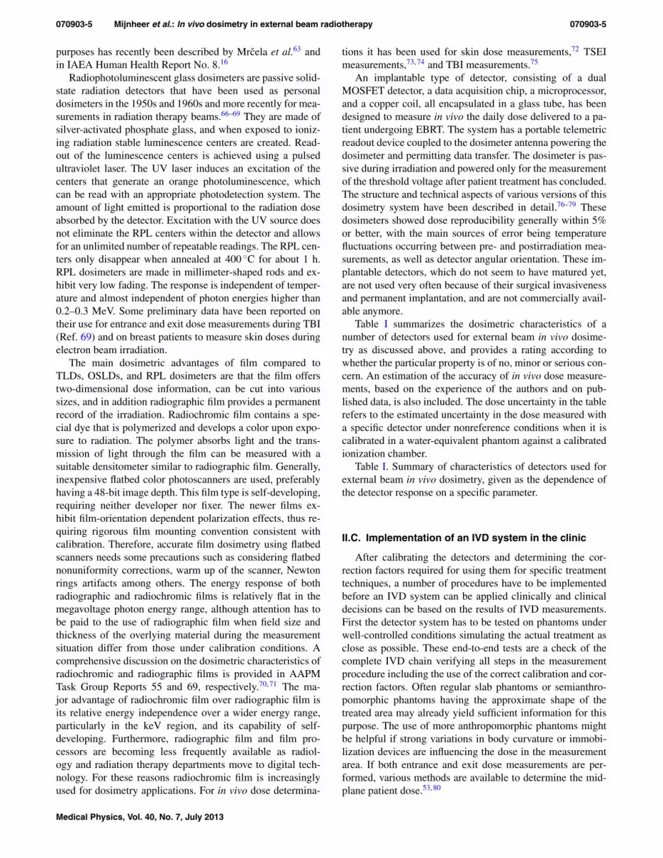
purposes has recently been described by Mrcela et al.63 andin IAEA Human Health Report No. 8.16
Radiophotoluminescent glass dosimeters are passive solid-state radiation detectors that have been used as personaldosimeters in the 1950s and 1960s and more recently for mea-surements in radiation therapy beams.66–69 They are made ofsilver-activated phosphate glass, and when exposed to ioniz-ing radiation stable luminescence centers are created. Read-out of the luminescence centers is achieved using a pulsedultraviolet laser. The UV laser induces an excitation of thecenters that generate an orange photoluminescence, whichcan be read with an appropriate photodetection system. Theamount of light emitted is proportional to the radiation doseabsorbed by the detector. Excitation with the UV source doesnot eliminate the RPL centers within the detector and allowsfor an unlimited number of repeatable readings. The RPL cen-ters only disappear when annealed at 400 ◦C for about 1 h.RPL dosimeters are made in millimeter-shaped rods and ex-hibit very low fading. The response is independent of temper-ature and almost independent of photon energies higher than0.2–0.3 MeV. Some preliminary data have been reported ontheir use for entrance and exit dose measurements during TBI(Ref. 69) and on breast patients to measure skin doses duringelectron beam irradiation.
The main dosimetric advantages of film compared toTLDs, OSLDs, and RPL dosimeters are that the film offerstwo-dimensional dose information, can be cut into varioussizes, and in addition radiographic film provides a permanentrecord of the irradiation. Radiochromic film contains a spe-cial dye that is polymerized and develops a color upon expo-sure to radiation. The polymer absorbs light and the trans-mission of light through the film can be measured with asuitable densitometer similar to radiographic film. Generally,inexpensive flatbed color photoscanners are used, preferablyhaving a 48-bit image depth. This film type is self-developing,requiring neither developer nor fixer. The newer films ex-hibit film-orientation dependent polarization effects, thus re-quiring rigorous film mounting convention consistent withcalibration. Therefore, accurate film dosimetry using flatbedscanners needs some precautions such as considering flatbednonuniformity corrections, warm up of the scanner, Newtonrings artifacts among others. The energy response of bothradiographic and radiochromic films is relatively flat in themegavoltage photon energy range, although attention has tobe paid to the use of radiographic film when field size andthickness of the overlying material during the measurementsituation differ from those under calibration conditions. Acomprehensive discussion on the dosimetric characteristics ofradiochromic and radiographic films is provided in AAPMTask Group Reports 55 and 69, respectively.70, 71 The ma-jor advantage of radiochromic film over radiographic film isits relative energy independence over a wider energy range,particularly in the keV region, and its capability of self-developing. Furthermore, radiographic film and film pro-cessors are becoming less frequently available as radiol-ogy and radiation therapy departments move to digital tech-nology. For these reasons radiochromic film is increasinglyused for dosimetry applications. For in vivo dose determina-
tions it has been used for skin dose measurements,72 TSEImeasurements,73, 74 and TBI measurements.75
An implantable type of detector, consisting of a dualMOSFET detector, a data acquisition chip, a microprocessor,and a copper coil, all encapsulated in a glass tube, has beendesigned to measure in vivo the daily dose delivered to a pa-tient undergoing EBRT. The system has a portable telemetricreadout device coupled to the dosimeter antenna powering thedosimeter and permitting data transfer. The dosimeter is pas-sive during irradiation and powered only for the measurementof the threshold voltage after patient treatment has concluded.The structure and technical aspects of various versions of thisdosimetry system have been described in detail.76–79 Thesedosimeters showed dose reproducibility generally within 5%or better, with the main sources of error being temperaturefluctuations occurring between pre- and postirradiation mea-surements, as well as detector angular orientation. These im-plantable detectors, which do not seem to have matured yet,are not used very often because of their surgical invasivenessand permanent implantation, and are not commercially avail-able anymore.
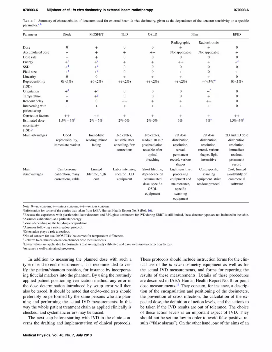
Table I summarizes the dosimetric characteristics of anumber of detectors used for external beam in vivo dosime-try as discussed above, and provides a rating according towhether the particular property is of no, minor or serious con-cern. An estimation of the accuracy of in vivo dose measure-ments, based on the experience of the authors and on pub-lished data, is also included. The dose uncertainty in the tablerefers to the estimated uncertainty in the dose measured witha specific detector under nonreference conditions when it iscalibrated in a water-equivalent phantom against a calibratedionization chamber.
Table I. Summary of characteristics of detectors used forexternal beam in vivo dosimetry, given as the dependence ofthe detector response on a specific parameter.
II.C. Implementation of an IVD system in the clinic
After calibrating the detectors and determining the cor-rection factors required for using them for specific treatmenttechniques, a number of procedures have to be implementedbefore an IVD system can be applied clinically and clinicaldecisions can be based on the results of IVD measurements.First the detector system has to be tested on phantoms underwell-controlled conditions simulating the actual treatment asclose as possible. These end-to-end tests are a check of thecomplete IVD chain verifying all steps in the measurementprocedure including the use of the correct calibration and cor-rection factors. Often regular slab phantoms or semianthro-pomorphic phantoms having the approximate shape of thetreated area may already yield sufficient information for thispurpose. The use of more anthropomorphic phantoms mightbe helpful if strong variations in body curvature or immobi-lization devices are influencing the dose in the measurementarea. If both entrance and exit dose measurements are per-formed, various methods are available to determine the mid-plane patient dose.53, 80
Medical Physics, Vol. 40, No. 7, July 2013
070903-6 Mijnheer et al.: In vivo dosimetry in external beam radiotherapy 070903-6
TABLE I. Summary of characteristics of detectors used for external beam in vivo dosimetry, given as the dependence of the detector sensitivity on a specificparameter.a,b
Parameter Diode MOSFET TLD OSLD Film EPID
Radiographic RadiochromicDose 0 + 0 0 + + 0Accumulated dose + + + ++ Not applicable Not applicable +Dose rate + + 0 0 0 0 0Energy +c +c + + ++ + +c
SSD +d +d 0 0 0 0 0Field size +d +d 0 0 + 0 +Linearity 0 0 + + + + 0Reproducibility(1SD)
0(<1%) +(<2%) +(<2%) +(<2%) +(<2%) +(<3%)e 0(<1%)
Orientation +d +d 0 0 0 +f 0Temperature + +g 0 0 0 + 0Readout delay 0 0 ++ + + ++ 0Intervening withpatient setup
+ + + + + + 0
Correction factors ++ ++ + + + + ++Estimated doseuncertainty(1SD)h
1.5% – 3%i 2% – 5%i 2%–3%i 2%–3%i 3%j 3%e 1.5%–3%i
Main advantages Goodreproducibility,
immediate readout
Immediatereading, minor
fading
No cables,reusable afterannealing, few
corrections
No cables,readout 10 minpostirradiation,reusable after
opticalbleaching
2D dosedistribution,resolution,
reread,permanent
record, variousshapes
2D dosedistribution,resolution,
reread, variousshapes, lightinsensitive
2D and 3D dosedistribution,resolution,immediatereadout,
permanentrecord
Maindisadvantages
Cumbersomecalibration, manycorrections, cable
Limitedlifetime, high
cost
Labor intensive,specific TLD
equipment
Short lifetime,dependence onaccumulateddose, specific
OSDLequipment
Light sensitive,processing
equipment andmaintenance,
specificscanning
equipment
Cost, specificscanning
equipment, strictreadout protocol
Cost, limitedavailability ofcommercial
software
Note: 0—no concern; +—minor concern; ++—serious concern.aInformation for some of the entries was taken from IAEA Human Health Report No. 8 (Ref. 16).bBecause the experience with plastic scintillator detectors and RPL glass dosimeters for IVD during EBRT is still limited, these detector types are not included in the table.cAssumes calibrations at a particular energy.dVaries depending on the build-up encapsulation.eAssumes following a strict readout protocol.fOrientation plays a role at readout.gNot of concern for dual MOSFETs that correct for temperature differences.hRelative to calibrated ionization chamber dose measurements.iLower values are applicable for dosimeters that are regularly calibrated and have well-known correction factors.jAssumes a well-maintained processor.
In addition to measuring the planned dose with such atype of end-to-end measurement, it is recommended to ver-ify the patient/phantom position, for instance by incorporat-ing fiducial markers into the phantom. By using the routinelyapplied patient positioning verification method, any error inthe dose determination introduced by setup error will thenalso be traced. It should be noted that end-to-end tests shouldpreferably be performed by the same persons who are plan-ning and performing the actual IVD measurements. In thisway the whole patient treatment chain as applied clinically ischecked, and systematic errors may be traced.
The next step before starting with IVD in the clinic con-cerns the drafting and implementation of clinical protocols.
These protocols should include instruction forms for the clin-ical use of the in vivo dosimetry equipment as well as forthe actual IVD measurements, and forms for reporting theresults of these measurements. Details of these proceduresare described in IAEA Human Health Report No. 8 for pointdose measurements.16 They concern, for instance, a descrip-tion of the encapsulation and positioning of the dosimeters,the prevention of cross infection, the calculation of the ex-pected dose, the definition of action levels, and the actions tobe taken if the IVD results are out of tolerance. The choiceof these action levels is an important aspect of IVD. Theyshould not be set too low in order to avoid false positive re-sults (“false alarms”). On the other hand, one of the aims of an
Medical Physics, Vol. 40, No. 7, July 2013

070903-7 Mijnheer et al.: In vivo dosimetry in external beam radiotherapy 070903-7
IVD program is to improve the accuracy of a treatment, andtoo broad action levels might miss clinically relevant errors.In Sec. III.B of this paper, and in the accompanying V20/20paper on IVD in brachytherapy,21 the choice of decision crite-ria and issues related to error detection sensitivity/specificityof IVD are further discussed.
In addition, all staff groups involved in IVD programsshould have their roles clearly defined and responsibilities as-signed, correspondingly to their roles. The results of in vivodosimetry need to be routinely reported to radiotherapy staff,including radiation oncologists and radiation therapists whotreat the patients. Any discrepancies between the planned andmeasured doses should be analyzed and resolved, in order tolimit the likelihood of error transmission to many treatmentsor many patients. Analysis of the results of in vivo dosimetrymay identify weak links in the radiotherapy process and thisshould be used to improve the quality management system ofthe radiotherapy center.
III. STATE-OF-THE-ART
III.A. Clinical experience
The purpose of in vivo dosimetry is to provide an over-all assessment of the dose delivery during a radiotherapeuticprocedure. Verification of the target dose during routine typeof treatments will be discussed first. In Sec. III.A.2, a verifica-tion of the dose during special treatment techniques, as well asout-of-field dose determinations to verify the dose in organsat risk and in implanted medical devices, will be elucidated.Verification of the dose during IMRT and VMAT requiresspecial approaches, and is therefore discussed separately inSec. III.A.3.
III.A.1. IVD to verify the target dose
A number of reports have summarized the experience withIVD in centers performing IVD routinely in their clinic. InESTRO Booklet No. 5 (Ref. 12) the IVD experience of fiveEuropean centers with entrance dose determinations duringconventional RT using diodes has been summarized. A num-ber of systematic errors could be traced by performing theseIVD programs. For instance, in one center IVD measurementsof treatments of mastectomy patients showed a significant dif-ference between measured and planned dose values. The dis-tribution had an average deviation of 3.5% with a standard de-viation of 3.1%. An investigation of possible causes revealedan error in the output factor used to calculate monitor unitsin quarter ( 3
4 -blocked) fields. In another center in vivo dosemeasurements on 2001 patients revealed 14 systematic errors;12 (0.6%) were serious, i.e., leading to an under/overdosagelarger than 5%, and 6 (0.3%) were larger than or equal to 10%.
In IAEA Human Health Report No. 8 (Ref. 16) some ma-jor deviations are described, which were discovered when per-forming diode IVD measurements. In one case a wedge wasnot inserted into the beam, and in a few other cases a SSDsetup was wrongly treated as an isocentric treatment. OSLDmeasurements discovered a wrong fractionation scheme thatwas not properly accounted for during the computer treatment
planning, delivering effectively a lower dose per fraction tothe patient than planned. Some of these human errors wouldhave been avoided if a record-and-verify system had been inplace. However, in a large number of patient measurementswith MOSFETs in another center, six errors were detectedwhen the treatment data were entered into the record-and-verify system manually rather than being transferred electron-ically from planning to delivery.
Recently, the first results of a national Italian project for thedevelopment of a generalized in vivo dosimetric procedure inradiotherapy have been published.81 Three centers tested theearlier developed method46, 47 for in vivo reconstruction of theisocenter dose for 3D conformal radiotherapy treatments withopen and wedged x-ray beams supplied by linacs of differentmanufacturers, equipped with a-Si EPIDs. The results of 480tests showed errors exceeding the 5% tolerance level in 10%of the measurements, which were due to incorrect setup, thepresence of an attenuator in the beam, or patient morphologi-cal changes.
III.A.2. IVD to verify the dose during special treatmenttechniques and out-of-field
In vivo dose measurements are often performed during TBIand TSEI. During TBI dose uniformity over the patient’s bodyat the midplane level is frequently desired, which requirescompensation for missing tissue and the lower density of lungtissue. Because treatment planning systems are generally notcommissioned for performing the extended-distance type ofTBI treatment calculations of a patient in a sometimes veryspecific TBI position, knowledge of the dose distribution inthe midplane is often obtained from in vivo dose measure-ments. The use of various detector types for IVD during TBI,such as diodes, TLDs, MOSFETs, and radiochromic film, hasbeen reported. The specific problems related to diode in vivodosimetry of TBI have been discussed in AAPM Report 87.13
Also TLDs have proven to be useful detectors for TBI mea-surements due to the small dependence of their response ondirection, dose (rate), temperature, and beam energy in thetherapeutic range.82, 83 MOSFETs are also suitable, but re-quire larger correction and conversion factors compared to theuse of TLD.29–31 The clinical application of radiochromic filmfor IVD during TBI has been reported by Su et al.75 Someinitial studies comparing OSLDs and TLDs for TBI measure-ments have shown that OSLDs have the same or somewhatbetter accuracy than TLDs, have some advantages such asthe easier handling, and the ability to quickly read and ex-port the results. The use of RPL glass detectors for IVD dur-ing TBI has also been reported, showing that glass dosime-ters can be used as an accurate and reproducible dosimeter forTBI in vivo dose measurements, and therefore are a practicalalternative to TLDs or MOSFETs.69 Because the TBI irra-diation conditions are very different from those for conven-tional treatments, the calibration and determination of correc-tion factors of detectors used for IVD during TBI should beperformed under these specific conditions.
Other examples of applications of in vivo dosimetry aremeasurements of skin dose and matchline dose. Radiation
Medical Physics, Vol. 40, No. 7, July 2013

070903-8 Mijnheer et al.: In vivo dosimetry in external beam radiotherapy 070903-8
oncologists sometimes need to know the dose to the skin, forinstance during stereotactic body radiotherapy where skin canbe an organ at risk. Also knowledge of the skin dose is occa-sionally necessary to limit the dose to an organ at risk closeto the skin, or to ensure that sufficient dose is delivered to thetreatment area such as in the treatment of the chest wall, andduring TSEI to treat superficial lesions covering a large areaof the body. The goal of TSEI is to deliver dose uniformlyto the entire surface region, and IVD during TSEI is thereforeoften employed to determine how closely that goal is met. Thespecific problems related to diode in vivo dosimetry of TSEIhave been discussed in AAPM Report 87,13 such as the doserate during TSEI, which is generally very low and thereforeit is necessary to ensure that the leakage current of the diodesis small. Similar considerations as discussed for IVD duringTBI are valid for IVD during TSEI, except that the angulardependence of the detector response is more important dur-ing TSEI because of the larger variation of angles of beamsincident on the patient for this type of treatment. Due to theirsmall angular dependence, TLDs and OSLDs are often rec-ommended for these measurements.
For skin dose measurements it is necessary to use a thindosimeter with well-known thickness. In one technique84
TLDs with different thicknesses were used to extrapolatethe data to the skin dose of patients treated for breast can-cer. Radiochromic film has also been used to measure theskin dose.72 A number of treatment procedures require docu-menting the matching of photon-photon fields and of photon-electron fields. These include matching the spinal and cranialphoton fields,85 matching the supraclavicular-axillary photonfields to the tangential photon fields for breast treatment,28
matching the internal mammary electron field to the tangen-tial photon fields,86 and total scalp irradiation,87 which re-quires the overlap of photon and electron fields. Treatmentplanning calculations may show a clinically acceptable under-or overdose across the matchline. However, a small patientmisalignment can significantly alter the matchline dose. IVDis therefore used to verify that the actual matchline dose isindeed clinically acceptable. Depending on the type of infor-mation that is required, one of the detector types mentionedin Table I can be used.
Out-of-field in vivo dose measurements are often needed toestimate the dose to organs at risk during radiotherapy, suchas the contralateral breast, eye lens, and scrotum, as well asthe dose to implanted electronic devices such as pacemak-ers and implantable cardioverter-defibrillators (ICDs). Withthe increase in life expectancy there are an increasing numberof patients being treated with these devices which are moresensitive to radiation than the older models.88 Dose valuesare typically below 0.05 Gy with most of the dose comingfrom low energy scattered radiation. Outside the treatmentfield the photon energy spectrum is softer than the primary en-ergy spectrum.89 As a result most solid state detectors requirea correction for out-of-field dose measurements when cali-brated inside the treatment field. Figure 1 shows the change insensitivity, defined as the response per unit dose determinedwith an ionization chamber, as a function of the distance to theedge of a 6 MV photon field.90 The measurements were per-
FIG. 1. Relative sensitivities of various detectors covered with 0, 5, and 15mm bolus material (b) at different off-axis distances from the center of a 10× 10 cm 6 MV x-ray beam. Adapted from Ref. 90.
formed with detectors covered with 0, 5, and 15 mm build-upmaterial. The results indicate a complex behavior of the re-sponse of these detectors when determining the dose to ICDs,depending on many parameters including energy and angu-lar dependence of the response of the detector plus bolus.Out-of-field measurements require dosimeters with high sen-sitivity and a relatively flat energy response, which may limitthe usefulness of diodes, MOSFETs and radiographic filmfor these types of measurements. TLDs and OSLDs gener-ally satisfy these conditions better but do not provide a quickfeedback. However, TLDs containing the natural 6Li isotope,such as TLD 100 and TLD 600, should not be used for out-of-field dose measurements in photon beams with energieshigher than 10 MV because of their sensitivity to thermal neu-trons resulting from neutron capture in 6Li.53, 91 For all de-tector types an out-of-field calibration is recommended underthe circumstances mimicking the clinical situation as much aspossible.
III.A.3. IVD to verify the dose during IMRT and VMAT
The previous discussion involved patient measurements innon-IMRT treatments where the detectors can be located inregions of low dose gradient. With the increasing use of IMRTand VMAT one can ask whether meaningful in vivo dose mea-surements can be performed in regions of high dose gradientusing point detectors. For IMRT treatments of head and neckpatients, MOSFET detectors were used to measure the dosein the oral cavity for patients fitted with a customized mouthplate.92 In other studies of dose measurements during treat-ment of head and neck cancer patients with IMRT, TLDs wereplaced in a flexible plastic tube inserted into the nasopharynxof the patient.93, 94 These studies showed that the use of TLD-loaded, naso-esophageal tubes for in vivo dose verification isstraightforward to implement and well tolerated by patients.Because of the invasive character of the method, and the rel-atively large uncertainty in the positioning of the detector, in-tracavitary verification of IMRT is however not often applied.
Other studies have demonstrated that with careful detec-tor placement useful patient dose information can be obtained
Medical Physics, Vol. 40, No. 7, July 2013

070903-9 Mijnheer et al.: In vivo dosimetry in external beam radiotherapy 070903-9
FIG. 2. Dosimetry reports of the in vivo EPID dosimetry verification (upper part) and phantom measurement (bottom part) of a stereotactic VMAT treatment ofa lung cancer patient using two arcs. Indicated are the γ -evaluations of the EPID-reconstructed and planned dose distributions in three orthogonal planes. Theyellow and red color indicate regions where the EPID dose is higher than the plan, while the green and blue color indicate regions where the EPID dose is equalor lower than the plan. The 50% isodose line is shown in black. The red dot in the upper dosimetry report indicates that at least one of the evaluation criteria isoutside the action level, while the green dot in the lower figure indicates that all evaluation criteria are met.
with entrance dose determinations during IMRT. For thetreatment of prostate cancer patients, MOSFET detectors withbrass build-up caps were positioned on the patient’s skin onthe central axis of each IMRT beam to measure the entrancedose.95 Diode dosimetry was also performed for treatmentsof head and neck cancer by Vinall et al.96 and during IMRTtreatments of tumors in the head and neck and prostate regionsby Kadesjö et al.97 Both groups achieved good agreement be-tween measurements and calculations; 95% and 92.2% of theresults were within the ±5% tolerance level. Analysis of theoutliers illustrated the importance of high accuracy in the de-tector positioning and by selecting points of measurement thatare not close to regions with large dose gradients.
Because EPIDs provide 2D and 3D dose information anincreasing number of groups are using them clinically toperform various types of QA of IMRT treatments.44 IVDof IMRT using EPIDs is in routine clinical use in severalcenters.15, 98, 99 In the following, an example will be given toillustrate what type of information can be obtained with 3Din vivo dosimetry using EPIDs. In The Netherlands CancerInstitute the comparison of EPID-reconstructed and planneddose distributions for VMAT treatments is done in vivo by
a 3D γ -evaluation method (3%/3 mm) using the mean γ -value, the maximum 1% γ -value and the percentage of pointswith γ > 1 within the 50% isodose line of the planned max-imum dose. In addition, the difference between the measuredand predicted isocenter dose is used as an alert criterion.49
Figure 2 shows a dosimetry report of such a 3D in vivodose verification of a lung stereotactic treatment with a 2-arcVMAT technique. The results presented in the upper part ofthe figure indicate that during the second arc of that fractionall four clinical criteria were outside tolerance level. Beforestarting with the next fraction, a phantom measurement wasperformed (see bottom part of the figure) indicating that thetreatment plan was correctly calculated and delivered. Anal-ysis of the cone-beam CT data taken on the same day as theIVD measurement, confirmed that the patient had moved dur-ing the second arc. This example illustrates the importance ofperforming IVD in tracing errors in dose delivery that cannotbe detected by means of pretreatment QA measurements.
Mans et al.15 performed an analysis of the clinical experi-ence of IVD of IMRT using EPID dosimetry. The results ofthat study indicated that approximately one out of 500 IMRTpatient treatments had a serious error in dose delivery. From
Medical Physics, Vol. 40, No. 7, July 2013

070903-10 Mijnheer et al.: In vivo dosimetry in external beam radiotherapy 070903-10
that publication and similar studies98, 100 it can be concludedthat transit dosimetry using a 2D detector in combination witha dose-reconstruction algorithm is a very useful tool for invivo 2D verification of IMRT and 3D verification of VMATdelivery. Considering the relatively large number of centersthat cannot fulfill the clinically acceptable criteria (dose dif-ference of ±7% or distance-to-agreement of 4 mm) duringan external audit using an anthropomorphic head-and-neckphantom,101 2D and 3D in vivo dose verification of IMRTseems to be urgently needed to quantify the accuracy of actualpatient treatments in centers having nonoptimal RPC audit re-sults. It shows in addition that there is a need for more educa-tion of medical physicists on how to perform commissioningmeasurements of their TPS and linac when implementing anew technique. Information about the accuracy of the actualdose delivery during IMRT is of vital importance for the inter-pretation of clinical results. It might in addition lead to a morepowerful program of patient-specific QA of IMRT treatments,with a more pronounced role of IVD.
III.B. Current problem areas
Currently, only limited hard evidence is available to provethe value of in vivo dosimetry as a technique to prevent ma-jor errors in radiation therapy. Therefore, no general consen-sus exists among professionals on the cost effectiveness ofits implementation in clinics. Until recently, the routine useof in vivo dosimetry has not been incorporated into QA pro-grams in many centers, except for the dose determination dur-ing some special treatment techniques such as TBI, TSEI, andfor specific out-of-field measurements. Some clinics make ar-guments that only few errors, which might otherwise remainundetected, are actually uncovered through in vivo dosimetry.Consequently, only a small number of cancer patients maybenefit from IVD, while the majority of patient treatmentsare in fact correct. Following this approach it is sufficient toprevent mistakes in treatment planning and delivery by us-ing pretreatment checking systems such as independent MUverification, confirmation of correct electronic data transferthrough record-and-verify systems, and measurements usingphantoms. However, the recent sequence of severe accidentsin radiotherapy that would have been prevented if in vivodosimetry systems were in place,3, 5, 102 and of serious errorsdetected in a very advanced center,15 have added argumentsin favor of in vivo dosimetry. In some countries, e.g., France5
and Sweden,19 national recommendations require that in vivodosimetry is routinely performed as an integral part of QAprograms for the improved knowledge of the doses actuallydelivered, and to document that patient treatments were safe.In addition to contributing to safer radiotherapy, treatmentdocumentation through in vivo dosimetry has the potential toimprove public perception of safety in radiotherapy as dis-cussed for instance by Williams and McKenzie.103 Interna-tional organizations that recommend in vivo dosimetry, suchas the IAEA, ICRP, and WHO, major professional societies inradiation oncology (AAPM, ESTRO) and some national orga-nizations (e.g., The Swedish Radiation Protection Institute,19
The Royal College of Radiologists20) are of the opinion that
preventing the disastrous consequences of errors for at leastsome patients justifies the effort and costs of in vivo dosimetryprograms. At the same time professional communities arguethat little promotion of safety culture is made at national lev-els and, in a typical clinic, sufficient resources are not avail-able for routine implementation of in vivo dosimetry for everypatient treated with radiotherapy.103, 104 On the other hand, avery strong commitment of the French government105 shouldbe mentioned here, both in organizing the national QA pro-gram for radiation oncology in France and providing adequateresources for the program implementation.
IVD systems should include fully automated data acqui-sition and data analysis thus yielding more time for med-ical physicists to investigate the reasons for observed dif-ferences between measured and planned dose values. Forinstance, checking the patient chart and treatment data of thatparticular fraction, as well as additional phantom measure-ments will often be needed to explain deviations of in vivodosimetry results. Automatic analysis may also allow a morefrequent use of IVD during a series of fractions, for instance atthe same day in-room imaging is performed. IVD may in thefuture also be more often applied during palliative treatments,which is currently very seldom done. There is hardly any in-formation in the literature available on IVD during simple pal-liative treatment techniques, and the tolerance levels mightbe quite generous, but nevertheless IVD might also here re-veal unexpected large differences between delivered and pre-scribed dose distributions.
A general problem when performing QA measurementsin radiotherapy is which decision criteria should be used toaccept a relatively small deviation between intended and ac-tual performance of a specific procedure. For IVD it meanswhich dose difference between planned and delivered dose isallowed in a certain part of the target volume or organ at risk.The accuracy of the dose delivery required in clinical practicewill depend on several factors such as the type of treatment,the dose level and participation in a clinical trial. When per-forming point dose measurements several recommendationson pass/fail criteria are available, for instance as discussed inthe ESTRO, AAPM, and IAEA reports.12, 13, 16 Often an actionlevel for simple treatments of 5% is recommended and a levelof 7% for situations where measurement complications existsuch as during breast treatments or in wedged beams. Whenperforming 2D patient-specific pretreatment verification mea-surements, decision criteria are less intuitive as for instancerecently discussed by Kruse,106 Nelms et al.,107 and Carrascoet al.108 From these studies it could be concluded that themost common acceptance criteria and published action lev-els for perbeam 2D gamma analysis have insufficient, or atleast unproven, predictive power for patient-specific IMRTQA. Similar considerations are valid for 2D gamma analy-sis of IVD measurements. The situation becomes even morecomplex when evaluating dose differences in 3D. The use of3D gamma analysis during pretreatment IMRT and VMATverification has recently been described.108–110 These stud-ies demonstrated that also 3D gamma analysis might have itslimitations when used to detect clinically relevant dose dis-crepancies. Mans et al.49 observed that the results of the 3D
Medical Physics, Vol. 40, No. 7, July 2013
070903-11 Mijnheer et al.: In vivo dosimetry in external beam radiotherapy 070903-11
gamma evaluation of VMAT dose verification using portaldosimetry were similar to their 2D IMRT results, pretreatmentas well as in vivo. According to this group, 3D gamma anal-ysis of in vivo VMAT verification may provide useful infor-mation, as illustrated in Fig. 2. However, at this time there areno pass/fail criteria available for differences between plannedand actual dose values delivered to a (small) part of the targetvolume or organ at risk. Clinical experience based on toolsused for treatment plan evaluation, such as checks of the po-sition of isodose lines in various planes and DVH analysis,is currently probably the only guidance for acceptability ofcertain differences observed with 3D IVD. If no explanationcan be provided, and the deviation is clinically meaningful,further investigation of the origin of the difference is needed.Discussion with the responsible radiation oncologist might re-sult in making a completely new treatment plan of that patient,for instance if changes in patient anatomy are the reason forthe observed deviating IVD result.
In vivo dosimetry is to a certain extent also able to ver-ify the patient position, especially for those situations involv-ing steep dose gradients. In general, the sensitivity of thedose delivery to shifts in patient position depends on the spe-cific anatomy of a patient within the beam. For IMRT thismeans that the sensitivity of IVD for patient setup variationis strongly plan dependent and is a combination of shift di-rection and dose gradient in the plan. Cherpak et al.34 re-cently used a MOSFET dosimeter with an electromagneticpositioning sensor for the simultaneous measurement of real-time dose and spatial coordinates. Combination of setup ver-ification and IVD is certainly a topic that will receive moreattention in the future.
Ultimately, IVD has to be used to adapt a planned treat-ment if deviations between intended and actual dose distribu-tions are clinically unacceptable, and some investigators haveproposed approaches to use IVD for adaptive radiotherapy toimprove clinical results further. An example of such an ap-proach has been presented by van Elmpt et al.100 These au-thors combined megavoltage cone-beam CT scans of the pa-tient anatomy with in vivo measured EPID images. The doseinformation in these images was back-projected through thecone-beam CT scan and used for Monte Carlo simulation ofthe dose distribution inside the cone-beam CT scan. Such averification procedure, which combines in-room imaging withIVD, opens possibilities for offline dose-guided adaptive ra-diotherapy strategies, taking into account the actual dose dis-tribution delivered during treatment.
IV. NEW RT TECHNOLOGY AND NEW IVDAPPROACHES
IV.A. Challenges of new RT technology
The last decade has been a period in which many newtypes of advanced RT technology emerged. These develop-ments concerned treatment techniques that are already ap-plied more or less routinely, such as IMRT, VMAT, and pro-ton therapy, or are still under development such as carbonion therapy. Because it was realized that these more confor-
mal irradiation techniques require increased verification ofpatient setup, numerous in-room imaging modalities were de-veloped and implemented in the clinic. These image-guidanceapproaches vary in sophistication from the use of portal imag-ing to applying 3D or 4D imaging techniques, as summa-rized in several papers.111, 112 In order to validate the dose de-livery of this emerging technology, the role of pretreatmentverification was extended from the commissioning of a treat-ment planning system for these new irradiation techniques, topatient-specific QA measurements. For that purpose a numberof detector-phantom combinations were developed. However,the clinical introduction of IVD techniques for measuring theactual dose delivered with this new technology is lagging be-hind. There is a general belief that if the planned dose dis-tribution is checked with a pretreatment QA procedure andthe patient position is verified just before or during treatmentusing one of the in-room imaging techniques, then the actualdose delivered to the patient is also correct. However, particu-larly when introducing new technology there is an urgent needfor IVD to trace deviations between planned and actually de-livered dose distributions. Because experience with new irra-diation equipment and advanced irradiation techniques has tobe buildup, the limitations of that new technology still have tobe assessed, and many unexpected and unknown errors mayoccur.5, 15 In vivo dosimetry is one of the best ways to gainthis experience and to prevent errors when introducing newRT technology.
IV.B. Innovative IVD techniques
IV.B.1. In vivo dose verification of proton and heavyion therapy using positron emission tomography(PET)
During proton and heavy ion therapy, collisions betweenthe beam particles and the nuclei in tissue produce β+-emitting radionuclides with half-lives on the order of min-utes, including 11C (T1/2 = 20.4 min) and 15O (T1/2 = 122 s).When these radionuclides decay they produce a positron an-nihilation signal similar to that obtained during PET. Manygroups have investigated the use of this induced PET signalas a noninvasive method to verify dose delivery either duringtreatment or immediately afterward.
PET verification during treatment, or in situ, has been stud-ied for both 12C ion and proton therapy. A group at GSIDarmstadt (Ref. 113) modified a traditional PET detector foruse during 12C ion therapy. The in situ monitoring of morethan 300 patients showed that the PET signal provides infor-mation about both the beam range in tissue and the volumeirradiated. Studies using proton beams impinging on poly-methylmethacrylate (PMMA) targets have verified the lateralfield position and the range of both mono- and polyenergeticbeams.114 The longer lived PET radionuclides such as 11Cmake it possible to perform PET imaging on a patient im-mediately after heavy ion or proton therapy. In vivo PET hasbeen shown to be useful for verifying patient setup after treat-ment, but, due to imprecise correlation between β+-emissionand dose delivery, dose verification is difficult as elucidated in
Medical Physics, Vol. 40, No. 7, July 2013
070903-12 Mijnheer et al.: In vivo dosimetry in external beam radiotherapy 070903-12
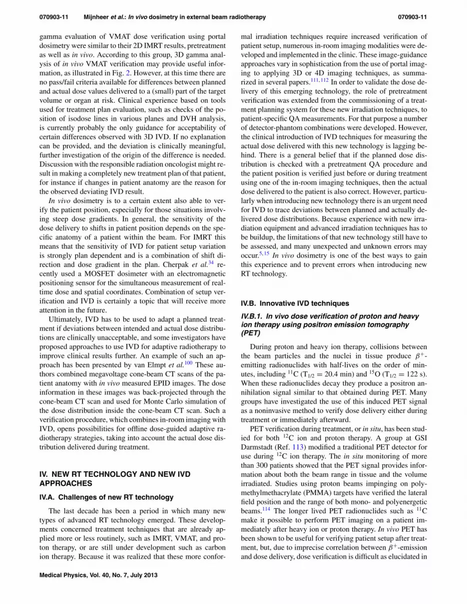
FIG. 3. Axial views for a patient with clival chordoma receiving a posterior–anterior oblique proton field followed by a lateral oblique field at 1 GyE/field,imaged with a delay of 20 and 13 min, respectively. (Top) Treatment-planning (TP) dose (left) and measured (Meas) positron emission tomography (right).(Bottom) Monte Carlo (MC) dose (left) and MC positron emission tomography (right). Range of color wash display is from blue (minimum) to red (maximum).Adapted from Ref. 117.
several studies.115, 116 Further investigation into the feasibilityand value of offline PET for proton therapy is underway.117
Figure 3 shows fairly good agreement between the measuredPET signal and the PET signal simulated with Monte Carlocalculations after a two-field proton beam treatment. The fig-ure also illustrates the differences between the measured PETdistribution and the dose distribution in the treatment plan.These differences need to be understood in order to use PETto verify the actual dose distribution delivered. This techniqueis still under development and seems to have promise in thenear future.
IV.B.2. In vivo dose verification of proton therapyusing prompt gamma-ray imaging (PGI)
Positron emission is only one of the types of radiation pro-duced during hadron therapy. Another signal can be obtainedfrom the imaging of prompt gamma rays emitted by excitednuclei. PGI has several advantages over PET. First, PG raysare emitted immediately (T1/2 <10−9 s) and are in additionproduced at ten times the rate of PET radionuclides.118 Fur-thermore, all elemental nuclei have a characteristic PG energyspectrum, so the detected gamma-ray energy spectrum can be
Medical Physics, Vol. 40, No. 7, July 2013

070903-13 Mijnheer et al.: In vivo dosimetry in external beam radiotherapy 070903-13
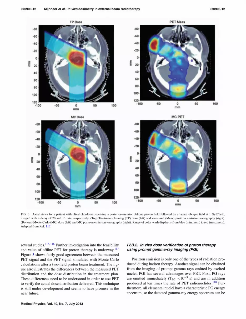
FIG. 4. Comparison of a normalized (a) relative dose distribution deliveredto a patient, and (b) prompt gamma-ray production in the same patient dur-ing irradiation with a single lateral incident 250 MeV proton beam. Adaptedfrom Ref. 127. The colors in (a) indicate isodose lines, while the gamma-rayproduction in (b) was originally expressed as number of prompt gamma raysproduced/incident proton, but these data have been normalized to obtain theisolines shown.
used to measure the relative abundance of each element in theirradiated tissue as demonstrated by Polf et al.119 These au-thors performed direct measurements of the PG spectrum intissue using a high purity germanium detector with a Comp-ton suppression system.120 Min et al.121 measured the PGemission falloff in a water phantom using a CsI(TI) scintil-lator with a pin-hole collimator and demonstrated its correla-tion to dose. More recent simulations122 and measurements123
have demonstrated the effectiveness of slit cameras for rangeverification. Multistage Compton cameras have been shownto have the ability to provide simultaneously both 3D imag-ing and spectroscopy.124–126 This tissue spectroscopy infor-mation, used in combination with the PG emission spatialdistribution, may provide a means of verifying the 3D dosedistribution. Recent Monte Carlo studies have shown that astrong correlation exists between the dose distribution and thenumber of prompt gamma rays produced in each voxel withina patient during proton irradiation, as illustrated in Fig. 4.127
These results are in agreement with other studies in tissuephantoms that showed a correlation between PG-ray emis-sion and delivered dose.116 The main disadvantage of PGIis that the relatively high (>1 MeV) energy of the gammarays leads to a low detection efficiency for existing gammadetectors. Consequently, new detection systems need to bedeveloped. Based on these studies it can be concluded thatprompt gamma-ray imaging has the potential to be used as amethod to verify the accuracy and efficacy of doses delivered
with proton radiotherapy, but more work is needed for clinicalapplications.
V. FUTURE NEEDS AND EVOLVING TECHNOLOGYFOR IVD
Ideally, every treatment session of every patient should bemonitored with in vivo dosimetry so that the dose deliveredis verified and recorded. Otherwise there may be situationswhere a treatment error may go unnoticed. However, takinginto account the manpower and machine time required, thissolution may be unrealistic and not feasible in a busy radio-therapy clinic environment. Nevertheless, it is the authors’opinion that all treatments with curative intent should be ver-ified through an in vivo dose measurement in combinationwith some kind of pretreatment check. These patient-specificpretreatment checks may consist of an independent dose/MUcalculation or a measurement using a particular phantom-detector combination. They should in any case include a con-sistency check of the basic plan properties by the physics teamand/or the therapists at the treatment machine. We thereforerecommend, as various other groups, to perform in vivo dosemeasurements for all treatment beams at least once during oneof the first irradiation sessions in the first week of treatment,and to repeat IVD measurements after any change in the treat-ment procedure. This recommendation is also valid for IMRTand VMAT treatments for which tools are currently under de-velopment and urgently needed, as discussed further on.
Where resource limitations exist, so that performingin vivo dose measurements on every patient treated with cu-rative intent is not achievable, the IAEA (Ref. 16) recom-mends that priorities for in vivo dosimetry should be estab-lished to monitor patient doses for specific situations, forinstance when:
• introducing new treatment protocols or irradiation tech-niques,
• changing treatment equipment,• implementing new software, such as upgrades of plan-
ning systems, machine controlling software, networkcommunication, or patient management systems,
• carrying out total body or total skin irradiations,• delivering single fraction treatments, and• performing treatments with curative intent where the
dose is close to normal tissue tolerance.
In order to validate the IVD procedure used within an insti-tution, it might be worthwhile to perform a comparison of invivo dosimetry systems. In this way it is possible to check ifdoses are correctly derived from detector measurements us-ing a particular phantom and standardized beam arrangementthus minimizing the effects of differences in phantom mate-rial and geometry on the dose measurements. For this pur-pose a dedicated phantom might be sent around and interestedcenters could be asked to apply their IVD system to assessthe dose at specific points in that phantom. Such an activ-ity might be similar to a dosimetric audit, as performed forinstance by the IAEA (Ref. 52) or RPC,101 and will requirephantoms that can accommodate various IVD systems. For
Medical Physics, Vol. 40, No. 7, July 2013

070903-14 Mijnheer et al.: In vivo dosimetry in external beam radiotherapy 070903-14
example, one could envision a simple phantom to be sent tocenters that are often asked to measure skin or surface doseson patients as well as out-of-field doses. Participating cen-ters will be requested to perform a simple irradiation proce-dure, and then asked to measure the infield surface dose atsome locations with their detector of choice, as well as someout-of-field dose measurements at specified locations. Thesemeasurements could then be compared with their treatmentplanning calculations. The next step might be that institutionsperforming IVD send their irradiated dosimeters directly toan organization that could provide the measured dose values.A study of Swinnen et al.128 demonstrated that it is feasible toperform mailed in vivo entrance dosimetry with TLD, whichcould be applied for checking the accuracy of in-home in vivodosimetry systems. Such a type of IVD intercomparisonmight also be useful between centers participating in clinicaltrials. It should however be realized that when it comes to IVDby an external organization, sensitivities may exist regardingtransferring individual patient results outside the hospital.
A large number of point detector systems are currently al-ready available for IVD. Various developments are needed,or are already underway, that may lead to a more extensiveuse of point detectors for IVD in the near future. Uncertain-ties in detector positioning may lead to false positive resultsthat cannot be reproduced. Investigation of the cause of theseevents is time consuming and may initiate less confidencein the use of the IVD system. Simultaneous dose verifica-tion using point detectors with patient setup verification usingan in-room imaging system may provide additional informa-tion on the position of the IVD detector with respect to thepatient anatomy. Most in vivo point detectors that are com-mercially available can be easily located when using appro-priate in-room imaging techniques (i.e., using the right filterfor CBCT). Other IVDs that are more water-equivalent (e.g.,PSDs) need fiducial markers that will allow locating the de-tector itself on kV (CT, CBCT) images, but they might be lessvisible on MV images. That information can then be used fora more accurate comparison of measured and predicted dosevalues. Furthermore OSLDs, RPL glass detectors, and PSDsrecently became commercially available for their use in radio-therapy. Because some of their properties are advantageouscompared to other point detector IVD systems, as elucidatedin Sec. II, these systems are gaining in popularity, which mayresult in a more widespread use of IVD.
Another interesting development that may lead to in-creased use of IVD point detector systems is the combinationof IVD with independent MU verification software. With suchan approach not only the dose calculation of the clinically ap-plied treatment planning system is checked, but also informa-tion is obtained about the actual dose delivered at a specificpoint in a patient. Such a method may also be useful for IVDduring IMRT as demonstrated by Kadesjö et al.97 These au-thors used independent MU verification software to select ap-propriate measurement points located away from large dosegradients in IMRT fields, and to calculate expected detectorreadings at these points. It should be emphasized that large-scale application of IVD using point detectors will only befeasible if the calibration procedure, the QA of the detector
system, and the evaluation of measurement results are per-formed as much as possible using automatic software, andmethods that are simple and robust.
The use of EPIDs for 2D and 3D IVD has matured andis a reliable and accurate dose verification method that canbe used in a large number of situations.49, 98, 100 IVD usingEPIDs is, however, only performed in a routine way in alimited number of centers.15, 44, 49, 84, 98–100 The main reasonthat EPID-based dosimetry is not yet widespread is that com-mercial software is only recently becoming available. Thereare, however, a number of developments that may result ina much larger use of EPID-based dosimetry. First, virtuallyall linacs come equipped with EPIDs, while the availabil-ity of automatic image acquisition and image analysis soft-ware will make it a very attractive tool as real-time dosime-ters. Also the immediate availability of the actual 2D or 3Ddose distribution delivered to a patient treated with IMRTand VMAT may make patient-specific pretreatment verifi-cation for a large part redundant. Not only do EPID-basedin vivo dose measurements provide more clinically usefulinformation than phantom measurements but they are gen-erally faster. Furthermore, EPID-based dosimetry is able toprovide 3D dose information. This is of importance whenimplementing the new ICRU guidelines, which recommendreporting the median dose (D50), the near-maximum dose(D2), and the near-minimum dose (D98) in the target volumefor IMRT treatments.129 Finally, a number of developmentshave been initiated to incorporate 3D in-room imaging with3D in vivo dosimetry. For instance, van Elmpt et al.130 com-bined repeated cone-beam imaging with the verification ofthe actual delivered dose during hypofractionated lung can-cer treatments. At the time of treatment patient anatomy wasimaged with MV cone-beam CT (MV CBCT). The delivereddose was then reconstructed in this MV CBCT scan usinga Monte Carlo code that uses the delivered energy fluenceas input, thus providing 3D dose verification in the patientanatomy during a treatment fraction. Combining 3D in vivodosimetry with the (MV or kV) CBCT of the day is an inter-esting approach and needs further investigation, for instancewith respect to the conversion of kV CBCT pixel values intoelectron densities, which is nontrivial because of the presenceof several artifacts in kV CBCT images. Ling et al.131 and vanHerk et al.132 adapted cone-beam CT scanning approaches insuch a way that it is now also possible to make CBCT scansduring VMAT delivery. 3D in vivo dose verification duringVMAT using EPID dosimetry is already possible49 thus al-lowing the simultaneous 3D verification of both geometry anddosimetry of a VMAT treatment. This is a very exciting devel-opment because many clinicians believe that VMAT will in-creasingly replace “conventional” IMRT. A limitation of theseapproaches is that CBCT data are not always giving the fullvolume required for a 3D dose calculation, particularly forVMAT dose calculations, thus requiring a complex fusion ofCBCT with planning CT data to catch the missing part of theirradiated volume.
In principle the exit radiation received by the MV de-tectors of a helical tomotherapy machine when treatingpatients can be used to reconstruct 3D dose distributions.
Medical Physics, Vol. 40, No. 7, July 2013
070903-15 Mijnheer et al.: In vivo dosimetry in external beam radiotherapy 070903-15
Dose verification using the detector signal during treatmentdoes not rely on the original plan and is an independent checkof the accuracy of dose delivery. Although the feasibility ofin vivo dosimetry using the MV detector system of a helicaltomotherapy machine has been investigated for over a decade,the technology was not practical until recently. New methodsfor in vivo dosimetry of helical tomotherapy treatments arecurrently under development in which the detector signalfrom radiation exiting the patient is analyzed and the 3D dosedistribution in the patient is reconstructed and compared withthe calculated dose distribution. Studies concerning in vivodosimetry during treatments with the CyberKnife machinehave not yet been reported. Research should therefore beundertaken to define the most suitable detector systems andthe relevant in vivo dosimetry methodology for irradiationtechniques using this equipment, as well as for other types ofsmall field irradiations.
In the longer term, the development of time-resolved (4D)in vivo dosimetry as a real-time monitoring device of patientdose may improve the knowledge of the doses actually deliv-ered. Incorporation into IVD determinations of patient move-ment during one fraction, as well as the variation in patientposition during a series of treatments, would contribute toassure patient safety particularly for very complex radiationtreatments. At the time of writing this paper, these tools arestill under development, and therefore most attention shouldbe given to implementing patient-specific 4D dose verifica-tion through in-room imaging and in vivo dose measurementswith available devices.
Proton and ion therapy will in the next decade be appliedin a more accurate and robust way when new developmentsin treatment planning and delivery have been incorporated inclinical practice. However, at the same time there is a needto verify that the theoretically superior dose distributions ofthese types of beams compared to photon beam treatments arein reality also delivered to patients. IVD approaches duringproton and ion therapy, for instance using PET or PGI, shouldtherefore be further explored.
It should be noted that not only protons and heavy ionsare able to produce positron-emitting radionuclides. Also highenergy photon beams, preferably with energies well above 20MeV, can activate body tissues resulting primarily in 11C and15O but also 13N; positron-emitting radionuclides producedby photoneutron reactions in the nuclei of 12C, 16O, and 14N,respectively. A method for dose delivery monitoring based onPET after high energy photon therapy has been described byJanek et al.,133 and was tested using phantom and animal tis-sue measurements. Real patient dose delivery verification bymeans of PET imaging seems to be applicable provided thatbiological transport processes such as capillary blood flowcontaining mobile 15O and 11C in the activated tissue volumecan be accounted for. The possible use of silver as a mate-rial for in vivo dosimetry during photon beam therapy usingPET was investigated by Hansen et al.134 These authors mea-sured with a PET scanner the activity of positron-emittingisotopes produced in silver by photonuclear processes whenirradiating a phantom with silver implants with 15 and 18MV photon beams. Although the physical basis for this
method was found to be sound, its application, for instanceto perform IVD of stereotactic radiotherapy, needs furtherstudy.
In photon radiotherapy with energies higher than 10 MV,and proton radiotherapy, the secondary dose to the patientfrom neutrons produced by photon interactions with high Zmaterials is of concern because of their higher relative biolog-ical effectiveness. By using the two-peak analysis in the LiFTLD glow curve developed in radiation protection,135–137 thehigh (neutron) and low (photon and proton) LET dose com-ponents can be determined. These dose measurements mayprovide useful biological information.
New molecular and biological imaging modalities are be-ing introduced into the clinic providing patient-specific in-formation used to guide the treatment planning process. Theresulting inhomogeneous dose distributions can then be de-livered with advanced treatment modalities to create individ-ualized biologically guided radiation therapy (BGRT) in theclinic. The spatial constraints of these inhomogeneous dosedistributions are rather strict and require continuous verifi-cation of patient setup to deliver the right dose at the rightplace. The question now is if verification of patient setupusing existing in-room imaging modalities is sufficient forverifying BGRT. Ideally verification should be performed ofthe total 3D dose distribution delivered to relevant parts ofthe patient anatomy during a series of fractions. The ulti-mate check should therefore be a combined verification ofthe 3D dose distribution and the position of these partial tar-get volumes during multiple fractions. Such an approach re-quires new methods of IVD in which molecular and biologicalimaging modalities are adapted and optimized for 3D/4D IVDapplications.
VI. CONCLUSIONS
The last decade has seen a number of developments thathave made IVD a relatively simple and accurate method todetect errors in dose delivery during EBRT. Both with respectto IVD applying point detectors and the use of EPID-based2D and 3D dose verification, great progress has been madein understanding the dosimetric characteristics of these de-tector systems and the development of procedures for theirclinical use. Furthermore, IVD is recommended by many na-tional and international organizations as a safety tool to avoidmajor errors. However, except for its use during special treat-ments, IVD during EBRT is not widely routinely applied forthe verification of dose delivery to individual patients. Themain reasons for this situation are the confidence in othermethods of QA, the relatively low frequency of occurrenceof serious errors in dose delivery, and the workload involved.In addition to regulatory compliance and reimbursement is-sues, the rationale for in vivo dose measurements is to pro-vide an accurate and effective independent verification of theoverall treatment procedure. It will enable the identification ofpotential errors in dose calculation, data transfer, dose deliv-ery, patient setup, and changes in patient anatomy. The recentdevelopments in reducing the workload involved in perform-ing IVD using point detectors, for instance by implementing
Medical Physics, Vol. 40, No. 7, July 2013

070903-16 Mijnheer et al.: In vivo dosimetry in external beam radiotherapy 070903-16
modern methods of data collection and analysis, will stimu-late its large-scale implementation. In the coming decade alsoa substantial increase in 3D in vivo dosimetry may be ex-pected during verification of IMRT and VMAT, as well as dur-ing treatment with proton and ion beams. In an era where weare moving toward adaptive RT, 3D in vivo dosimetry couldalso be used as a tool for plan adaptation. Implementation ofIVD in EBRT has the potential to impact clinical outcomeand should therefore in principle be used in each radiotherapycenter in addition to other QA tools. However, more work isneeded to make existing technology more robust and simplefor routine and large-scale clinical implementation.
a)Author to whom correspondence should be addressed. Electronic mail:[email protected]
1W. P. M. Mayles, “The Glasgow incident – a physicist’s reflections,” Clin.Oncol. 19, 4–7 (2007).
2M. V. Williams, “Radiotherapy near misses, incidents and errors: Radio-therapy incident in Glasgow,” Clin. Oncol. 19, 1–3 (2007).
3S. Derreumaux, C. Etard, C. Huet, F. Trompier, I. Clairand, J.-F. Bottollier-Depois, B. Aubert, and P. Gourmelon, “Lessons from recent accidents inradiation therapy in France,” Radiat. Prot. Dosim. 131, 130–135 (2008).
4International Commission on Radiological Protection, “ICRP Publication112: Preventing accidental exposures from new external beam radiationtherapy technologies,” Ann. ICRP 39(4), 1–86 (2009).
5W. Bogdanich, “Radiation offers new cures, and ways to do harm,” NewYork Times, January 23, 2010.
6W. Bogdanich, “A pinpoint beam strays invisibly, harming instead of heal-ing,” New York Times, December 29, 2010.
7W. Bogdanich, “As technology surges, radiation safeguards lag,” NewYork Times, January 26, 2010.
8C. Marajh, “Anatomy of an error: Cancer treatment radiation overdose,”Trinidad Express Newspapers, July 20, 2011 (available URL: http://www.trinidadexpress.com/news/Anatomy_of_an_error-125929808.html).
9O. Holmberg, M. Coffey, T. Knöös, and J. Cunningham, “Spotlight onin-vivo dosimetry,” ROSIS Newsletter, March 2, 2006 (available URL:http://www.rosis.info/docs/spotlight_case2.pdf).
10M. Essers and B. J. Mijnheer, “In vivo dosimetry during external pho-ton beam radiotherapy,” Int. J. Radiat. Oncol., Biol., Phys. 43, 245–259(1999).
11C. Fiorino, D. Corletto, P. Mangili, S. Broggi, A. Bonini, G. Cattaneo,R. Parisi, A. Rosso, P. Signorotto, E. Villa, and R. Calandrino, “Qualityassurance by systematic in vivo dosimetry: Results on a large cohort ofpatients,” Radiother. Oncol. 56, 85–95 (2000).
12European Society of Radiation Oncology, “Practical guidelines for the im-plementation of in vivo dosimetry with diodes in external radiotherapywith photon beams (entrance dose),” ESTRO Booklet No. 5 (EuropeanSociety of Radiation Oncology, ESTRO, Brussels, Belgium, 2001).
13Report of TG 62 of the Radiation Therapy Committee, “Diode in vivodosimetry for patients receiving external beam radiation therapy,” AAPMReport No. 87 (Medical Physics Publishing, Madison, WI, 2005).
14WHO Report, Radiotherapy Risk Profile (World Health Organization,WHO, Geneva, 2008).
15A. Mans, M. Wendling, L. N. McDermott, J.-J. Sonke, B. Mijnheer, M. vanHerk, and J. C. Stroom, “Catching errors with in vivo EPID dosimetry,”Med. Phys. 37, 2638–2644 (2010).
16International Atomic Energy Agency, “Development of procedures for invivo dosimetry in radiotherapy,” IAEA Human Health Report No. 8. (In-ternational Atomic Energy Agency, IAEA, Vienna, Austria, 2013).
17European Commission, 97/43 Council Directive EURATOM, 2007(available URL: http://ec.europa.eu/energy/nuclear/radioprotection/doc/legislation/9743_en.pdf).
18International Atomic Energy Agency, “IAEA radiation protection andsafety of radiation sources: International basic safety standards,” In-terim ed. (International Atomic Energy Agency, IAEA, Vienna, Aus-tria, 2011) (available URL: http://www.pub.iaea.org/MTCD/Publications/PDF/p1531interim_web.pdf).
19The Swedish Radiation Protection Institute (SSI), “Regulations on radia-tion therapy,” Report SSI FS 2000:4 (The Swedish Radiation ProtectionInstitute, Stockholm, Sweden, 2000).
20The Royal College of Radiologists, Society and College of Radiographers,Institute of Physics and Engineering in Medicine, British Institute of Ra-diology, Implementing In Vivo Dosimetry (Royal College of Radiologists,London, 2008).
21K. Tanderup, S. Beddar, C. Andersen, G. Kertzscher, and J. Cygler, “Invivo dosimetry in brachytherapy,” Med. Phys. (in press).
22G. Marinello, “Chapter 16: Radiothermoluminescent dosimeters anddiodes,” Handbook of Radiotherapy Physics: Theory and Practice, editedby P. Mayles, A. E. Nahum, and J.-C. Rosenwald (Taylor & Francis, Lon-don, 2007).
23A. S. Saini and T. C. Zhu, “Dose rate and SDD dependence of commer-cially available diode detectors,” Med. Phys. 31, 914–924 (2004).
24A. S. Saini and T. C. Zhu, “Energy dependence of commercially availablediode detectors for in-vivo dosimetry,” Med. Phys. 34, 1704–1711 (2007).
25A. S. Saini and T. C. Zhu, “Temperature dependence of commerciallyavailable diode detectors,” Med. Phys. 29, 622–630 (2002).
26N. Jornet, P. Carrasco, D. Jurado, A. Ruiz, T. Eudaldo, and M. Ribas,“Comparison study of MOSFET detectors and diodes for entrance in vivodosimetry in 18 MV x-ray beams,” Med. Phys. 31, 2534–2542 (2004).
27R. Ramaseshan, K. S. Kohli, T. J. Zhang, T. Lam, B. Norlinger, A. Hallil,and M. Islam, “Performance characteristics of a microMOSFET as anin vivo dosimeter in radiation therapy,” Phys. Med. Biol. 49, 4031–4048(2004).
28E. J. Bloemen-van Gurp, W. du Bois, P. A. Visser, I. Bruinvis, D. Jalink,J. Hermans, and P. Lambin, “Clinical dosimetry with MOSFET dosimetersto determine the dose along the field junction in a split beam technique,”Radiother. Oncol. 67, 351–357 (2003).
29P. Scalchi, P. Francescon, and P. Rajaguru, “Characterization of a newMOSFET detector configuration for in vivo skin dosimetry,” Med. Phys.32, 1571–1578 (2005).
30E. J. Bloemen-van Gurp, A. W. H. Minken, B. J. Mijnheer, C. J.G. Dehing- Oberye, and P. Lambin, “Total body irradiation, towards op-timal individual delivery: Dose evaluation with MOSFETs, TLDs and atreatment planning system,” Int. J. Radiat. Oncol., Biol., Phys. 69, 1297–1304 (2007).
31T. M. Briere, R. Tailor, N. Tolani, K. Prado, R. Lane, S. Woo, C. Ha,M. T. Gillin, and A. S. Beddar, “Patient dosimetry for total body irradi-ation using single-use MOSFET detectors,” J. Appl. Clin. Med. Phys. 9,200–205 (2008).
32C. F. Chuang, L. J. Verhey, and P. Xia, “Investigation of the use of MOS-FET for clinical IMRT dosimetric verification,” Med. Phys. 29, 1109–1115 (2002).
33Z.-Y. Qi, X-W. Deng, S.-M. Huang, A. Shiu, M. Lerch, P. Metcalfe,A. Rosenfeld, and T. Kron, “Real-time in vivo dosimetry with MOSFETdetectors in serial tomotherapy for head and neck cancer patients,” Int. J.Radiat. Oncol., Biol., Phys. 80, 1581–1588 (2011).
34A. J. Cherpak, J. E. Cygler, S. Andrusyk, J. Pantarotto, R. MacRae, andG. Perry, “Clinical use of a novel in vivo 4D monitoring system for simul-taneous patient motion and dose measurements,” Radiother. Oncol. 102,290–296 (2012).
35A. S. Beddar, T. R. Mackie, and F. H. Attix, “Water-equivalent plasticscintillation detectors for high-energy beam dosimetry: I. Physical charac-teristics and theoretical consideration,” Phys. Med. Biol. 37, 1883–1900(1992).
36A. S. Beddar, T. R. Mackie, and F. H. Attix, “Water-equivalent plasticscintillation detectors for high-energy beam dosimetry: II. Properties andmeasurements,” Phys. Med. Biol. 37, 1901–1913 (1992).
37A. S. Beddar, T. R. Mackie, and F. H. Attix, “Cerenkov light generatedin optical fibers and other light-pipes irradiated by electron beams,” Phys.Med. Biol. 37, 925–935 (1992).
38A. S. Beddar, N. Suchowerska, and S. H. Law, “Plastic scintillationdosimetry for radiation therapy: Minimizing capture of Cerenkov radia-tion noise,” Phys. Med. Biol. 49, 783–790 (2004).
39L. Archambault, A. S. Beddar, L. Gingras, R. Roy, and L. Beaulieu, “Mea-surement accuracy and Cerenkov removal for high performance, high spa-tial resolution scintillation dosimetry,” Med. Phys. 33, 128–135 (2006).
40J. Lambert, Y. Yin, D. R. McKenzie, S. Law, and N. Suchowerska,“Cerenkov-free scintillation dosimetry in external beam radiotherapy withan air core light guide,” Phys. Med. Biol. 53, 3071–3080 (2008).
41A. R. Beierholm, R. O. Ottosson, L. R. Lindvold, C. F. Behrens, andC. E. Andersen, “Characterizing a pulse-resolved dosimetry system forcomplex radiotherapy beams using organic scintillators,” Phys. Med. Biol.56, 3033–3045 (2011).
Medical Physics, Vol. 40, No. 7, July 2013

070903-17 Mijnheer et al.: In vivo dosimetry in external beam radiotherapy 070903-17
42M. Guillot, L. Gingras, L. Archambault, S. Beddar, and L. Beaulieu,“Spectral method for the correction of the Cerenkov light effect in plasticscintillation detectors: A comparison study of calibration procedures andvalidation in Cerenkov light-dominated situations,” Med. Phys. 38, 2140–2150 (2011).
43L. Archambault, T. M. Briere, F. Pönisch, L. Beaulieu, D. Kuban, A. Lee,and S. Beddar, “Toward a real-time in vivo dosimetry system using plasticscintillation detectors,” Int. J. Radiat. Oncol., Biol., Phys. 78, 280–287(2010).
44W. van Elmpt, L. McDermott, S. Nijsten, M. Wendling, P. Lambin, andB. Mijnheer, “A literature review of electronic portal imaging for radio-therapy dosimetry,” Radiother. Oncol. 88, 289–309 (2008).
45S. M. J. J. G. Nijsten, W. J. C. van Elmpt, M. Jacobs, B. J. Mijnheer,A. L. A. J. Dekker, P. Lambin, and A. W. H. Minken, “A global calibrationmodel for a-Si EPIDs used for transit dosimetry,” Med. Phys. 34, 3872–3884 (2007).
46A. Piermattei, A. Fidanzio, G. Stimato, L. Azario, L. Grimaldi,G. D’Onofrio, S. Cilla, M. Balducci, M. A. Gambacorta, N. Di Napoli,and N. Cellini, “In vivo dosimetry by an aSi-based EPID,” Med. Phys. 33,4414–4422 (2006).
47A. Piermattei, A. Fidanzio, L. Azario, L. Grimaldi, G. D’Onofrio,S. Cilla, G. Stimato, D. Gaudino, S. Ramella, R. D’Angelillo, F. Cellini,L. Trodella, A. Russo, L. Iadanza, S. Zucca, V. Fusco, N. Di Napoli,M. A. Gambacorta, M. Balducci, N. Cellini, F. Deodato, G. Macchia, andA. G. Morganti, “Application of a practical method for the isocenter pointin vivo dosimetry by a transit signal,” Phys. Med. Biol. 52, 5101–5117(2007).
48M. Wendling, L. N. McDermott, A. Mans, J.-J. Sonke, M. van Herk, andB. Mijnheer, “A simple back-projection algorithm for 3D EPID dosimetryof IMRT treatments,” Med. Phys. 36, 3310–3321 (2009).
49A. Mans, P. Remeijer, I. Olaciregui-Ruiz, M. Wendling, J.-J. Sonke,B. Mijnheer, M. van Herk, and J. Stroom, “3D dosimetric verification ofvolumetric-modulated arc therapy by portal dosimetry,” Radiother. Oncol.94, 181–187 (2010).
50J. F. Aguirre, R. Tailor, G. Ibbott, M. Stovall, W. Hanson, “Thermolu-minescence dosimetry as a tool for the remote verification of output forradiotherapy beams: 25 years of experience,” in Proceedings of the In-ternational Symposium on Standards and Codes of Practice in MedicalRadiation Dosimetry, IAEA-CN-96/82 (IAEA, Vienna, 2002), pp. 191–199.
51J. Izewska, and P. Andreo, “The IAEA/WHO TLD postal programme forradiotherapy hospitals,” Radiother. Oncol. 54, 65–72 (2000).
52J. Izewska, M. Hultqvist, and P. Bera, “Analysis of uncertainties in theIAEA/WHO TLD postal dose audit system,” Radiat. Meas. 43, 959–963(2008).
53J. Van Dam and G. Marinello, Methods for in vivo Dosimetry in Exter-nal Radiotherapy, ESTRO Booklet No.1, 2nd ed. (European Society forRadiation Oncology, ESTRO, Brussels, Belgium, 2006).
54L. A. DeWerd, L. J. Bartol, and S. D. Davis, “Thermoluminescent dosime-try,” in Clinical Dosimetry Measurements in Radiotherapy, edited byD. Rogers and J. Cygler, Medical Physics Monograph No. 34 (MedicalPhysics, Madison, WI, 2009), Chap. 24, pp. 815–840.
55A. Roué, J. L. M. Venselaar, I. H. Ferreira, A. Bridier, and J. Van Dam,“Development of a TLD mailed system for remote dosimetry audit for192Ir HDR and PDR sources,” Radiother. Oncol. 83, 86–93 (2007).
56P. Mobit, A. Nahum, and P. Mayles, “A Monte Carlo study of the qual-ity dependence factors of common TLD materials in photon and electronbeams,” Phys. Med. Biol. 43, 2015–2032 (1998).
57P. A. Jursinic, “Characterization of optically stimulated luminescentdosimeters, OSLDs, for clinical dosimetric measurements,” Med. Phys.34, 4594–4604 (2007).
58A. Viamonte, L. A. R. da Rosa, L. A. Buckley, A. Cherpak, and J. E.Cygler, “Radiotherapy dosimetry using a commercial OSL system,” Med.Phys. 35, 1261–1266 (2008).
59E. G. Yukihara and S. W. S. McKeever, “Optically stimulated lumines-cence (OSL) dosimetry in medicine,” Phys. Med. Biol. 53, R351–R379(2008).
60C. E. Andersen, S. K. Nielsen, S. Greilich, J. Helt-Hansen, J. C. Linde-gaard, and K. Tanderup, “Characterization of a fiber-coupled Al2O3: Cluminescence dosimetry system for online in vivo dose verification during192Ir brachytherapy,” Med. Phys. 36, 708–718 (2009).
61C. Reft, “The energy dependence and dose response of a commercial opti-cally stimulated luminescent detector for kilovoltage photon, megavoltage
photon, and electron, proton, and carbon beams,” Med. Phys. 36, 1690–1699 (2009).
62R. Al-Senan and M. Hatab, “Characteristics of an OSLD in the diagnosticenergy range,” Med. Phys. 38, 4396–4405 (2011).
63I. Mrcela, T. Bokulic, J. Izewska, M. Budanec, A. Fröbe, and Z. Kusic,“Optically stimulated luminescence in-vivo dosimetry for radiotherapy:Physical characterization and clinical measurements in 60Co beams,”Phys. Med. Biol. 56, 6065–6082 (2011).
64J. Kerns, S. Kry, N. Saho, and D. Followill, “Angular dependence of thenanodot OSL dosimeter,” Med. Phys. 38, 3955–3962 (2011).
65P. A. Jursinic, “Changes in optical stimulated luminescent dosimeter(OSLD) dosimetric characteristics with accumulated dose,” Med. Phys.37, 132–140 (2010).
66F. Araki, T. Ikegami, T. Ishidoya, and H. Kubo, “Measurements ofGamma-Knife helmet output factors using a radiophotoluminescent glassrod dosimeter and a diode detector,” Med. Phys. 30, 1976–1981 (2003).
67F. Araki, N. Moribe, T. Shimonobou, and Y. Yamashita, “Dosimetric prop-erties of radiophotoluminescent glass rod detector in high-energy photonbeams from a linear accelerator and Cyber-Knife,” Med. Phys. 31, 1980–1986 (2004).
68H. Mizuno, T. Kanai, Y. Kusano, S. Ko, M. Ono, A. Fukumura, K. Abe,K. Nishizawa, M. Shimbo, S. Sakata, S. Ishikura, and H. Ikeda, “Feasibil-ity study of glass dosimeter postal dosimetry audit of high-energy radio-therapy photon beams,” Radiother. Oncol. 86, 258–263 (2008).
69J.-E. Rah, U.-J. Hwang, H. Jeong, S.-Y. Lee, D.-H. Lee, D. H. Shin,M. Yoon, S. B. Lee, R. Lee, and S. Y. Park, “Clinical application of glassdosimeter for in vivo dose measurements of total body irradiation treat-ment technique,” Radiat. Meas. 46, 40–45 (2011).
70A. Niroomand-Rad, C. R. Blackwell, B. M. Coursey, K. P. Gall,J. M. Galvin, W. L. McLaughlin, A. S. Meigooni, R. Nath, J. E. Rodgers,and C. G. Soares, “Radiochromic film dosimetry: Recommendations ofAAPM Radiation Therapy Committee Task Group 55,” Med. Phys. 25,2093–2115 (1998).
71S. Pai, I. J. Das, J. F. Dempsey, K. L. Lam, T. J. LoSasso, A. J. Olch,J. R. Palta, L. E. Reinstein, D. Ritt, and E. E. Wilcox, “TG-69: Radio-graphic film for megavoltage beam dosimetry,” Med. Phys. 34, 2228–2258(2007).
72S. Devic, J. Seuntjens, W. Abdel-Rahman, M. Olivares, and E. B.Podgorsak, “Accurate skin dose measurements using radiochromic filmin clinical applications,” Med. Phys. 33, 1116–1123 (2006).
73A. Bufacchi, A. Carosi, N. Adorante, S. Delle Canne, T. Malatesta,R. Capparella, R. Fragomeni, A. Bonanni, M. Leone, L. Marmiroli, andL. Begnozzi, “In vivo EBT radiochromic film dosimetry of electron beamsfor total skin electron therapy (TSET),” Phys. Med. Biol. 23, 67–72(2007).
74P. Schiapparelli, D. Zefiro, F. Massone, and G. Taccini, “Total skinelectron therapy (TSET): A reimplementation using radiochromic filmsand IAEA TRS-398 code of practice,” Med. Phys. 37, 3510–3517(2010).
75F. C. Su, C. Shi, and N. Papanikolaou, “Clinical application ofGAFCHROMIC EBT film for in vivo dose measurements of total bodyirradiation radiotherapy,” Appl. Radiat. Isot. 66, 389–394 (2008).
76C. Scarantino, D. Suslander, C. Rini, G. Mann, and R. Black, “An im-plantable radiation dosimeter for use in external beam radiation therapy,”Med. Phys. 31, 2658–2671 (2004).
77A. S. Beddar, M. Salehpour, T. M. Briere, H. Hamidian, and M. T. Gillin,“Preliminary evaluation of implantable MOSFET radiation dosimeters,”Phys. Med. Biol. 50, 141–149 (2005).
78R. D. Black, C. W. Scarantino, G. G. Mann, M. S. Anscher, R. D. Ornitz,and B. E. Nelms, “An analysis of an implantable dosimeter system forexternal beam therapy,” Int. J. Radiat. Oncol., Biol., Phys. 63, 290–300(2005).
79T. M. Briere, M. T. Gillin, and A. S. Beddar, “Implantable MOSFETdetectors: Evaluation of a new design,” Med. Phys. 34, 4585–4590(2007).
80R. Boellaard, M. Essers, M. van Herk, and B. J. Mijnheer, “A new methodto obtain the midplane dose using portal in vivo dosimetry,” Int. J. Radiat.Oncol., Biol., Phys. 41, 465–474 (1998).
81A. Piermattei, F. Greco, L. Azario, A. Porcelli, S. Cilla, S. Zucca,A. Russo, E. Di Castro, M. Russo, R. Caivano, V. Fusco, A. Morganti,and A. Fidanzio, “A National project for in vivo dosimetry procedures inradiotherapy: First results,” Nucl. Instrum Methods Phys. Res. B 274, 42–50 (2012).
Medical Physics, Vol. 40, No. 7, July 2013

070903-18 Mijnheer et al.: In vivo dosimetry in external beam radiotherapy 070903-18
82L. G. Pacyna, M. Darby, and K. Prado, “Use of thermoluminescentdosimetry to verify dose compensation in total body irradiation,” Med.Dosim. 22, 319–324 (1997).
83M. A. Duch, M. Ginjaume, H. Chakkor, X. Ortega, N. Jornet, andM. Ribas, “Thermoluminescence dosimetry applied to in vivo dose mea-surements for total body irradiation techniques,” Radiother. Oncol. 47,319–324 (1998).
84T. Kron, M. Butson, F. Hunt, and J. Denham, “TLD extrapolation for skindose determination in vivo,” Radiother. Oncol. 41, 119–123 (1996).
85W. Parker and C. Freeman, “A simple technique for craniospinal radio-therapy in the supine position,” Radiother. Oncol. 78, 217–222 (2006).
86J. Jin, E. Klein, F. Kong, and Z. Li, “An improved internal mammary ir-radiation technique in radiation treatment of locally advanced breast can-cer,” J. Appl. Clin. Med. Phys. 6, 1–10 (2005).
87S. S. Tung, A. S. Shiu, G. Starkschall, W. H. Morrison, andK. R. Hogstrom, “Dosimetric evaluation of total scalp irradiation usinga lateral electron-photon technique,” Int. J. Radiat. Oncol., Biol., Phys.27, 153–160 (1993).
88C. Hurkmans, E. Scheepers, B. G. F. Springorum, and H.Uiterwaal, “Influence of radiotherapy on the latest generation of im-plantable cardioverter-defibrillators,” Int. J. Radiat. Oncol., Biol., Phys.63, 282–289 (2005).
89S. Scarboro, D. Followill, R. Howell, and S. Kry, “Variations in photonenergy spectra of a 6 MV beam and their impact on TLD response,” Med.Phys. 38, 2619–2628 (2011).
90M. F. Chan, Y. Song, L. T. Dauer, J. Li, D. Huang, and C. Burman, “Esti-mating dose to implantable cardioverter-defibrillator outside the treatmentfield using a skin QED diode, optically stimulated luminescence dosime-ters, and LiF thermoluminescent dosimeters,” Med. Dosim.. 37, 334–338(2012).
91S. Kry, M. Price, D. Followill, F. Mourtada, and M. Slaehpour, “The useof LiF (TLD-100) as an out-of-field dosimeter,” J. Appl. Clin. Med. Phys.8, 1–7 (2007).
92S. Marcié, E. Charpiot, R.-J. Bensadoun, G. Ciais, J. Hérault, A. Costa,and J.-P. Gérard, “In vivo measurements with MOSFET detectors inoropharynx and nasopharynx intensity-modulated radiation therapy,” Int.J. Radiat. Oncol., Biol., Phys. 61, 1603–1606 (2005).
93P. E. Engström, P. Haraldsson, T. Landberg, H. S. Hansen, S. A.Engelholm, and H. Nyström, “In vivo dose verification of IMRT treatedhead and neck cancer patients,” Acta Oncol. 44, 572–578 (2005).
94F. M. Gagliardi, K. J. Roxby, P. E. Engström, and J. C. Crosbie, “Intra-cavitary dosimetry for IMRT head and neck treatment using thermolu-minescent dosimeters in a naso-oesophageal tube,” Phys. Med. Biol. 54,3649–3657 (2009).
95R. Varadhan, J. Miller, B. Garrity, and M. Weber, “In vivo prostate IMRTdosimetry with MOSFET detectors using brass buildup caps,” J. Appl.Clin. Med. Phys. 7, 22–32 (2006).
96A. J. Vinall, J. Williams, V. E. Currie, A. van Esch, and D. Huyskens,“Practical guidelines for routine intensity-modulated radiotherapy verifi-cation: Pre-treatment verification with portal dosimetry and treatment ver-ification with in vivo dosimetry,” Br. J. Radiol. 83, 949–957 (2010).
97N. Kadesjö, T. Nyholm, and J. Olofsson, “A practical approach to diodebased in vivo dosimetry for intensity modulated radiotherapy,” Radiother.Oncol. 98, 378–381 (2011).
98M. van Zijtveld, M. Dirkx, M. Breuers, J. C. J. de Boer, and B. J.M. Heijmen, “Portal dose image prediction for in vivo treatment verifica-tion completely based on EPID measurements,” Med. Phys. 36, 946–952(2009).
99S. M. J. J. G. Nijsten, B. J. Mijnheer, A. L. A. J. Dekker, Ph. Lambin,and A. W. H. Minken, “Routine individualized patient dosimetry usingelectronic portal imaging devices,” Radiother. Oncol. 83, 65–75 (2007).
100W. van Elmpt, S. Nijsten, S. Petit, B. Mijnheer, P. Lambin, and A. Dekker,“3D in vivo dosimetry using megavoltage cone-beam CT and EPIDdosimetry,” Int. J. Radiat. Oncol., Biol., Phys. 73, 1580–1587 (2009).
101G. S. Ibbott, D. S. Followill, H. A. Molineu, J. R. Lowenstein, P. E. Al-varez, and J. E. Roll, “Challenges in credentialing institutions and par-ticipants in advanced technology multi-institutional clinical trials,” Int. J.Radiat. Oncol., Biol., Phys. 71, S71–S75 (2008).
102IAEA Report, Investigation of an Accidental Exposure of RadiotherapyPatients in Panama/Report of a Team of Experts (International AtomicEnergy Agency, IAEA, Vienna, Austria, 2001).
103M. V. Williams, and A. McKenzie, “Can we afford not to implement invivo dosimetry?,” Br. J. Radiol. 81, 681–684 (2008).
104A. J. Munro, “Hidden danger, obvious opportunity: Error and risk in themanagement of cancer,” Br. J. Radiol. 80, 955–966 (2007).
105R. Bachelot-Narquin, “Measures taken by the French Health Minister toensure safety in radiotherapy treatments,” Safety in External Radiother-apy, Controle Review No. 185, Paris, France, November 5–7, 2009 (avail-able URL: http://www.conference-radiotherapy-asn.com/).
106J. Kruse, “On the insensitivity of single field planar dosimetry to IMRTinaccuracies,” Med. Phys. 37, 2516–2524 (2010).
107B. Nelms, H. Zhen, and W. A. Tomé, “Per-beam, planar IMRT QA passingrates do not predict clinically relevant patient dose errors,” Med. Phys. 38,1037–1044 (2011).
108P. Carrasco, N. Jornet, A. Lathorne, T. Eudaldo, A. Ruiz, and M. Ribas,“3D DVH-based metric analysis versus per-beam planar analysis in IMRTpretreatment verification,” Med. Phys. 39, 5040–5049 (2012).
109H. Zhen, B. E. Nelms, and W. Tomé, “Moving from γ passing rates topatient DVH-based QA metrics in pretreatment dose QA,” Med. Phys. 38,5477–5489 (2011).
110C. Wu, K. E. Hosier, K. E. Beck, M. B. Radevic, J. Lehmann, H. A. Zhang,A. Kroner, S. C. Dutton, S. A. Rosenthal, J. K. Bareng, M. D. Logsdon,and D. R. Asche, “On using 3D γ -analysis for IMRT and VMAT pretreat-ment plan QA,” Med. Phys. 39, 3051–3059 (2012).
111D. Verellen, M. De Ridder, N. Lindhout, K. Tournel, G. Soete, andG. Storme, “Innovations in image-guided radiotherapy,” Nat. Rev. Can-cer 7, 949–960 (2007).
112AAPM, “The role of in-room kV X-ray imaging for patient setup and tar-get localization,” AAPM Task Group 104 Report (American Associationof Physicists in Medicine, College Park, MD, 2009).
113W. Enghardt, P. Crespo, F. Fiedler, R. Hinz, K. Parodi, J. Pawelke, andF. Pönisch, “Charged hadron tumour therapy monitoring by means ofPET,” Nucl. Instrum. Methods A. 525, 284–288 (2004).
114K. Parodi, H. Paganetti, E. Cascio, J. B. Flanz, A. A. Bonab, N. M. Alpert,K. Lohmann, and T. Bortfeld, “PET/CT imaging for treatment verifica-tion after proton therapy: A study with plastic phantoms and metallic im-plants,” Med. Phys. 34, 419–435 (2007).
115S. Vynckier, S. Derreumaux, F. Richard, A. Bol, C. Michel, andA. Wambersie, “Is it possible to verify directly a proton-treatment planusing positron emission tomography?,” Radiother. Oncol. 26, 275–277(1993).
116Y. Hishikawa, K. Kagawa, M. Murakami, H. Sakai, T. Akagi, and M. Abe,“Usefulness of positron-emission tomographic images after proton ther-apy,” Int. J. Radiat. Oncol., Biol., Phys. 53, 1388–1391 (2002).
117K. Parodi, H. Paganetti, H. A. Shih, S. Michaud, J. S. Loeffler, T. F.DeLaney, N. J. Liebsch, J. E. Munzenrider, A. J. Fischman, A. Knopf,and T. Bortfeld, “Patient study of in vivo verification of beam deliveryand range, using positron emission tomography and computed tomogra-phy imaging after proton therapy,” Int. J. Radiat. Oncol., Biol., Phys. 68,920–934 (2007).
118M. Moteabbed, S. Espana, and H. Paganetti, “Monte Carlo patientstudy on the comparison of prompt gamma and PET imaging forrange verification in proton therapy,” Phys. Med. Biol. 56, 1063–1082(2011).
119J. C. Polf, S. Peterson, G. Ciangaru, M. Gillin, and S. Beddar, “Promptgamma-ray emission from biological tissues during proton irradiation: Apreliminary study,” Phys. Med. Biol. 54, 731–743 (2009).
120J. C. Polf, S. Peterson, M. McCleskey, B. T. Roeder, A. Spiridon, S.Beddar, and L. Trache, “Measurement and calculation of characteristicprompt gamma ray spectra emitted during proton irradiation,” Phys. Med.Biol. 54, N519–N527 (2009).
121C. H. Min, C. H. Kim, M. Y. Youn, and J. W. Kim, “Prompt gamma mea-surements for locating the dose falloff region in the proton therapy,” Appl.Phys. Lett. 89, 183517 (2006).
122V. Bom, L. Joulaeizadeh, and F. Beekman, “Real-time prompt gammamonitoring in spot-scanning proton therapy using imaging through aknife-edge-shaped slit,” Phys. Med. Biol. 57, 297–308 (2012).
123J. Smeets, F. Roellinghoff, D. Prieels, F. Stichelbaut, A. Benilov, C.Fiorini, R. Peloso, M. Basilavecchia, T. Frizzi, and J. Dehaes, “Promptgamma imaging with a slit camera for real-time range control in protontherapy,” Phys. Med. Biol. 57, 3371–3405 (2012).
124M. Frandes, A. Zoglauer, V. Maxim, and R. Prost, “A tracking Compton-scattering imaging system for hadron therapy monitoring,” IEEE Trans.Nucl. Sci. 57, 144–150 (2010).
125T. Kormoll, F. Fiedler, S. Schone, J. Wustemann, K. Zuber, and W.Enghardt, “A compton imager for in-vivo dosimetry of proton beams-a
Medical Physics, Vol. 40, No. 7, July 2013
070903-19 Mijnheer et al.: In vivo dosimetry in external beam radiotherapy 070903-19
design study,” Nucl. Instrum. Methods Phys. Res. A 626–627, 114–119(2010).
126D. Mackin, S. Peterson, S. Beddar, and J. Polf, “Evaluation of a stochas-tic reconstruction algorithm for use in compton camera imaging and beamrange verification from secondary gamma emission during proton ther-apy,” Phys. Med. Biol. 57, 3537–3553 (2012).
127J. C. Polf, S. Peterson, D. Robertson, and S. Beddar, “Measuring promptgamma ray emission during proton radiotherapy for assessment of treat-ment delivery and patient response,” AIP Conf. Proc. 1336, 364–368(2011).
128A. A. Swinnen, J. J. Verstraete, and D. P. Huyskens, “Feasibility studyof entrance in vivo dose measurements with mailed thermoluminescencedetectors,” Radiother. Oncol. 73, 89–96 (2004).
129International Commission on Radiation Units and Measurements, “Pre-scribing, recording, and reporting intensity-modulated photon-beam ther-apy (IMRT),” ICRU Report No. 83 (Oxford University Press, Oxford, UK,2010).
130W. van Elmpt, S. Petit, D. De Ruysscher, P. Lambin, and A. Dekker, “3Ddose delivery verification using repeated cone-beam imaging and EPIDdosimetry for stereotactic body radiotherapy of non-small cell lung can-cer,” Radiother. Oncol. 94, 188–194 (2010).
131C. Ling, P. Zhang, T. Etmektzoglou, J. Star-Lack, M. Sun, E. Shapiro,and M. Hunt, “Acquisition of MV-scatter-free kilovoltage CBCT imagesduring RapidArcTM or VMAT,” Radiother. Oncol. 100, 145–149 (2011).
132M. van Herk, L. Ploeger, and J.-J. Sonke, “A novel method for mega-voltage scatter correction in cone-beam CT acquired concurrent with ro-tational irradiation,” Radiother. Oncol. 100, 365–369 (2011).
133S. Janek, R. Svensson, C. Jonsson, and A. Brahme, “Development of dosedelivery verification by PET imaging of photonuclear reactions followinghigh energy photon therapy,” Phys. Med. Biol. 51, 5769–5783 (2006).
134A. T. Hansen, S. B. Hansen, and J. B. Petersen, “The potential applicationof silver and positron emission tomography for in vivo dosimetry duringradiotherapy,” Phys. Med. Biol. 53, 353–360 (2008).
135G. Busuoli, A. Cavallini, A. Fasso, and O. Rimondi, “Mixed radiationdosimetry with LiF (TLD-100),” Phys. Med. Biol. 15, 673–681 (1970).
136D. Youssian and Y. Horowitz, “Estimation of gamma dose in neutrondosimetry using peak 4 to peak 5 ratios in LiF:Mg,Ti (TLD-100/600),”Radiat. Prot. Dosim. 77, 151–158 (1998).
137B. Mukherjee, J. Lambert, R. Hentschel, and J. Farr, “Explicit estimationof out-of-field neutron and gamma dose equivalents during proton ther-apy using thermoluminescence-dosimeters,” Radiat. Meas. 46, 1952–1955(2011).
Medical Physics, Vol. 40, No. 7, July 2013