ijhmt2007 50
TRANSCRIPT
www.elsevier.com/locate/ijhmt
International Journal of Heat and Mass Transfer 50 (2007) 2296–2308
Heat transfer with flow and evaporation in loop heat pipe’swick at low or moderate heat fluxes
Chuan Ren, Qing-Song Wu *, Mao-Bin Hu
Department of Thermal Science and Energy Engineering, University of Science and Technology of China, Hefei, Anhui 230026, China
Received 27 November 2005; received in revised form 21 August 2006Available online 11 January 2007
Abstract
An axisymmetric two-dimensional mathematical model of the cylindrical evaporator’s wick of loop heat pipes is developed to simulateheat transfer with flow and evaporation in the capillary porous structure. Effect of the interaction between the flow field and the liquid–vapor interface on the position of the interface and the curvature of menisci is adequately considered in this model. The flow fields oftransient and steady states are obtained at low or moderate heat fluxes. The dynamic and thermodynamic behavior is discussed in thispaper. The auto-driving mechanism of ‘‘inverted meniscus type” evaporators is validated. Effect of heat flux is investigated in detail.� 2006 Elsevier Ltd. All rights reserved.
Keywords: Loop heat pipe; Axisymmetric; Capillary porous structure; Heat transfer; Evaporation
1. Introduction
The loop heat pipe (LHP) is a two-phase thermal con-trol device with the capillary pump driving a working fluidto flow and transfer heat over long distance, just as the cap-illary pumped loop (CPL). Due to their growing applica-tion to many engineering domains including thermalmanagement of satellites and spacecrafts as well as coolingof electrical and electronic devices, researches to CPLs/LHPs become more active and important in the last decadeafter the researches were revealed in public in 1991 [1–8].Kaya and Hoang [1,2] numerically simulated and experi-mentally validated the steady-state performance of aLHP, Hoang and Ku [3] made researches of hydrodynamicaspects of CPLs, Ku [4] investigated operating characteris-tics of LHPs, Pouzet et al. [5] investigated dynamicresponse of a CPL at various heat loads, Zhang et al. [6]focused on startup behavior of a LHP. Vasiliev [7] andMaydanik [8] reviewed the researches to LHPs in 2005.
0017-9310/$ - see front matter � 2006 Elsevier Ltd. All rights reserved.
doi:10.1016/j.ijheatmasstransfer.2006.10.029
* Corresponding author. Tel.: +86 5513601272; fax: +86 5513606459.E-mail address: [email protected] (Q.-S. Wu).
Most of the previous researches focused on tests or simula-tion of the whole device, many important properties ofevaporators are neglected. The evaporator with the capil-lary porous structure is the primary functional componentwhich accepts heat fluxes, organizes evaporation and pro-duces driving force of the working fluid flowing circularlyin the whole device. Heat transfer with flow and evapora-tion occurs just in the capillary porous structure. For thesecurity and efficiency of LHPs performance, it is impor-tant and necessary to investigate the dynamic and thermo-dynamic behavior of the working fluid in the capillaryporous structure and the auto-driving mechanism of the‘‘inverted meniscus type” evaporator, which was first intro-duced and used in a heat pipe by Feldman and Noreen [9].
Khrustalev and Faghri [10] developed a one-dimensionalmathematical model on the basis of heat transfer with thin-film evaporation theory in a pore and heat transfer in thedry porous media and close-touched heated fins (or flat),and the analytical steady solution was derived. It wasproved that there lies a steady vapor blanket between theliquid-saturated zone in porous media and close-touchedheated fins (or flat) for a definite interval of heat fluxes.Zhao and Liao [11] investigated experimentally heat
Nomenclature
As the area of a close-contacted heated fin, m2
c special thermal capacity, J/(kg K)h enthalpy, J/kgk thermal conductivity, W/(m K)K permeability, m2
_m flux of the working fluid, kg/sn normal vector on the liquid–vapor interfacep pressure, Paq heat flux, W/m2
r position vector of meniscus, mR radii of meniscus’ curvature, mRM gas constant, J/(kg K)s displacement vector of interface, mt time, sT temperature, KU total heat transfer coefficient, W/(m2 K)V velocity vector of infiltration, m/s
Greek symbols
/ porositybT expansion coefficient with constant pressure,
1/Kbp expansion coefficient with constant temperature,
1/Pa
k latent heat of evaporation, J/kgl dynamic viscosity, kg/(m s)m kinematic viscosity, m2/sq density, kg/m3
r coefficient of surface tension, N/m
Subscripts
c capillarye referenceeva evaporationf fluidg vaporin on the entrance/inletl liquidn normal directionout on the exit/outletr in radial directions saturatedt totalwall on the heated wallz in longitudinal direction
C. Ren et al. / International Journal of Heat and Mass Transfer 50 (2007) 2296–2308 2297
transfer in glass-bead-packed cubic porous media with agroovy heated wall on the top at different heated fluxes,and the one-dimensional approximate solutions derivedfrom this paper agreed with the experimental results. Itwas indicated that no macroscopic vapor zone was visuallyobserved at low (or moderate) heat fluxes. Demidov andYatsenko [12], Figus et al. [13], and Takahashi et al. [14]developed two-dimensional steady mathematical modelsand investigated numerically capillary-driven flow and heattransfer in rectangular porous media, where the study of[12] was in the case of a constant temperature on the topheated boundary with convection and the studies of[13,14] were in the cases of a constant heat flux on the topheated boundary without convection.
Although there have been many studies in this field asmentioned above, three shortcomings exist in currentresearches. Firstly, current researches to CPLs/LHPs focuson transient characters [5,6,8] and the previous works in lit-eratures stayed at the simulation or experiments of steadyheat transfer in the capillary wick [10–14]. Steady mathe-matical models cannot simulate the development of flowfield in porous media from start-up to a steady workingstate or the response of flow field on the transition betweendifferent steady working states. Secondly, the literaturesonly considered the interaction between the flow field andthe position of the liquid–vapor interface in porous mediabut not the interaction between the flow field and the cur-vature of menisci, i.e. the capillary force [12–14]. It was
always assumed that the capillary force was equal to themaximum capillary force allowed by menisci. Furthermore,the literatures assumed that the vapor on the liquid–vaporinterface was saturated and obeyed Clausius–Clapeyronequation, so tracing the liquid–vapor interface could berealized by Clausius–Clapeyron equation [12,13] or themass transport equation on the interface [14]. However[15,16] pointed out that both vapor and liquid on theliquid–vapor interface are overheated and that the capillaryforce changes the liquid–vapor thermodynamic equilib-rium, which is presented in Kelvin equation. Thirdly, thesimulation mainly focused on the cubic porous structureswhereas the simulation of the cylindrical porous structure,which is fixed as wicks in most evaporators, was scarce.
In this paper, an axisymmetric two-dimensional mathe-matical model of the cylindrical evaporator’s wick with azi-muthal vapor grooves of LHPs is developed to simulateheat transfer with flow and evaporation in the capillaryporous structure. Effect of the interaction between the flowfield and the liquid–vapor interface on the position of theinterface and the curvature of menisci is adequately consid-ered in this model. Effect of heat flux on steady state isinvestigated in detail.
2. Mathematical model
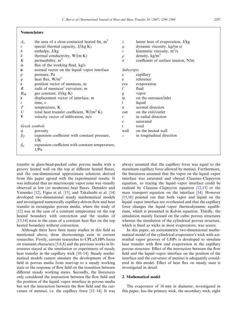
The evaporator of 16 mm in diameter, investigated inthis paper, has the primary wick, the secondary wick, eight
compensation chamber's shell
evaporator's shell
primary wick
secondary wick
liquid line vapor line
compensation chamber
evaporator
azimuthal vapor groove
Fig. 1. Configuration of the evaporator with azimuthal grooves and the compensation chamber.
2298 C. Ren et al. / International Journal of Heat and Mass Transfer 50 (2007) 2296–2308
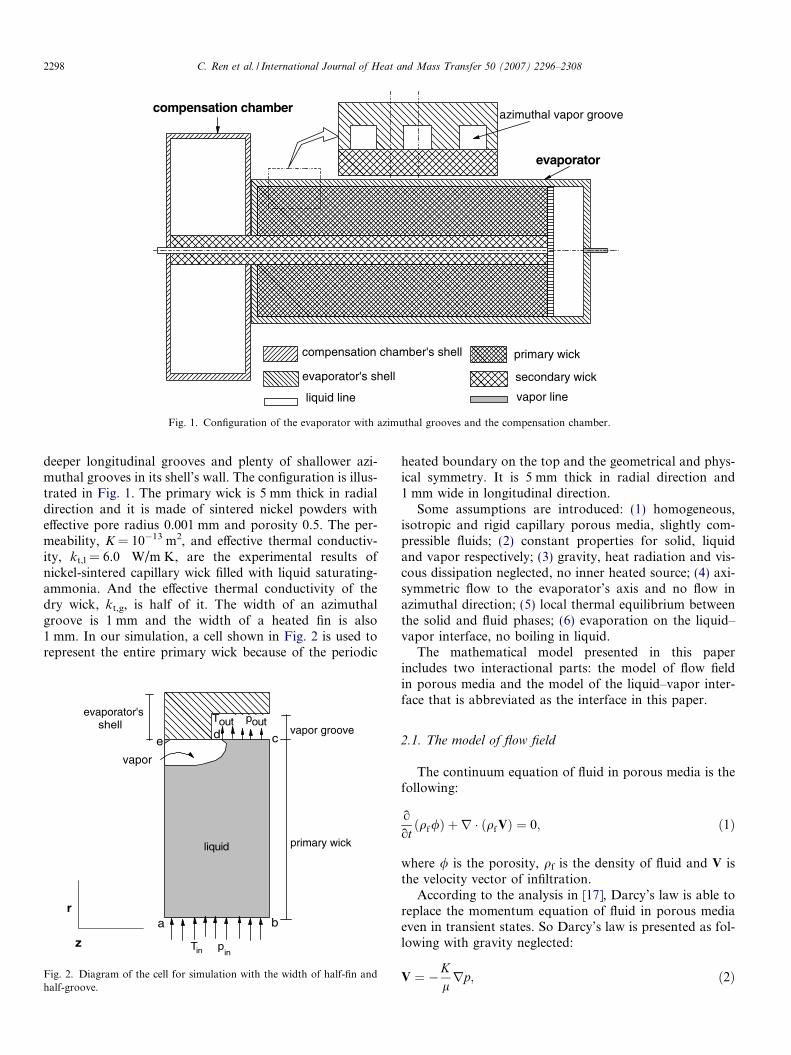
deeper longitudinal grooves and plenty of shallower azi-muthal grooves in its shell’s wall. The configuration is illus-trated in Fig. 1. The primary wick is 5 mm thick in radialdirection and it is made of sintered nickel powders witheffective pore radius 0.001 mm and porosity 0.5. The per-meability, K = 10�13 m2, and effective thermal conductiv-ity, kt,l = 6.0 W/m K, are the experimental results ofnickel-sintered capillary wick filled with liquid saturating-ammonia. And the effective thermal conductivity of thedry wick, kt,g, is half of it. The width of an azimuthalgroove is 1 mm and the width of a heated fin is also1 mm. In our simulation, a cell shown in Fig. 2 is used torepresent the entire primary wick because of the periodic
a b
cde
Tin p
Tout poutvapor groove
primary wick
vapor
liquid
evaporator'sshell
r
zin
Fig. 2. Diagram of the cell for simulation with the width of half-fin andhalf-groove.
heated boundary on the top and the geometrical and phys-ical symmetry. It is 5 mm thick in radial direction and1 mm wide in longitudinal direction.
Some assumptions are introduced: (1) homogeneous,isotropic and rigid capillary porous media, slightly com-pressible fluids; (2) constant properties for solid, liquidand vapor respectively; (3) gravity, heat radiation and vis-cous dissipation neglected, no inner heated source; (4) axi-symmetric flow to the evaporator’s axis and no flow inazimuthal direction; (5) local thermal equilibrium betweenthe solid and fluid phases; (6) evaporation on the liquid–vapor interface, no boiling in liquid.
The mathematical model presented in this paperincludes two interactional parts: the model of flow fieldin porous media and the model of the liquid–vapor inter-face that is abbreviated as the interface in this paper.
2.1. The model of flow field
The continuum equation of fluid in porous media is thefollowing:
o
otðqf/Þ þ r � ðqf VÞ ¼ 0; ð1Þ
where / is the porosity, qf is the density of fluid and V isthe velocity vector of infiltration.
According to the analysis in [17], Darcy’s law is able toreplace the momentum equation of fluid in porous mediaeven in transient states. So Darcy’s law is presented as fol-lowing with gravity neglected:
V ¼ �Klrp; ð2Þ
C. Ren et al. / International Journal of Heat and Mass Transfer 50 (2007) 2296–2308 2299
where K is the permeability, l is the dynamic viscosity andp is the pressure.
The equation of state is derived as following:
qf ¼ q0;f ½1� bT ;fðT � T eÞ þ bp;fðp � peÞ�; f ¼ l; g; ð3Þ
where the subscription l and g present liquid and vaporrespectively. bT,f is the expansion coefficient with constantpressure and bp,f is the expansion coefficient with constanttemperature:
bT ;f � �1
q0;f
oqoT
� �p
; bp;f �1
q0;f
oqop
� �T
; ð4Þ
where bT ;g ¼ 1T and bp;g ¼ 1
p when considering vapor as theideal gas.
Combining (1) with (2) and (3), the pressure equation isderived as following:
/o
ot½q0;fbp;fðp � peÞ� � r �
Kmf
rp� �
¼ �/o
otfq0;f ½1� bT ;fðT � T eÞ�g; f ¼ l; g; ð5Þ
where mf is the kinematic viscosity. The form of (5) incylindrical polar coordinates is the following:
/K
o
ot½q0;fbp;fðp � peÞ� �
1
ro
orrmf
opor
� �� o
oz1
mf
opoz
� �
¼ � /K
o
otfq0;f ½1� bT ;fðT � T eÞ�g: ð6Þ
According to the similar deducing process about theenergy equation in [17] and the above assumptions, theenthalpy equation for coupled solid and fluid phases isderived as following:
o
otðqthfÞ þ r � ðqf VhfÞ ¼ /
opotþ V � rp þr � ðktrT Þ; ð7Þ
where qt is the total density of coupled solid and fluidphases, kt is the effective thermal conductivity and hf isthe enthalpy of fluid, which are determined respectivelyas following:
qt � /qf þ ð1� /Þqs
cs
cp;f; ð8aÞ
kt � /kf þ ð1� /Þks; ð8bÞhf ¼ h0;f þ cp;fðT � T eÞ; ð9Þ
where cs and cp,f are the specific thermal capacity of solidand fluid, respectively. With temperature replaced by en-thalpy, the form of (7) in cylindrical polar coordinates isthe following:
o
otðqthfÞ þ
1
ro
orðrqf V rhfÞ þ
o
ozðqf V zhfÞ
¼ /opotþ V r
oporþ V z
opozþ 1
ro
orrkt
o
orhf � h0;f
cp;f
� �� �
þ o
ozkt
o
ozhf � h0;f
cp;f
� �� �; ð10Þ
where Vr and Vz are the velocity of infiltration in radial andlongitudinal directions respectively.
The boundary conditions with Lr and Lz presenting theradial thickness and the longitudinal width of a cell respec-tively are listed in the following. The saturated liquid lieson the entrance with the inlet temperature Tin = 293 Kand the inlet pressure Pin = 882500 Pa while the outletpressure Pout is simplified to the value of Pout = 882500 Pa.
(1) when z = 0 or z = Lz (the boundary b–c and a–e inFig. 2)
oToz¼ 0;
opoz¼ 0; ð11aÞ
(2) when r = rin (the boundary a–b in Fig. 2)
T ¼ T in; p ¼ pin; ð11bÞ
(3) when r = rout = rin + Lr and 0 < z < Lz/2 (the bound-ary d–e in Fig. 2)8
opor¼ 0if interface does not lie on the boundary d–e;
�qfKlf
opor
���lk¼ q� kt
oTor
��l
if interface lies on the boundary d–e;
>>>>>><>>>>>>:
ð11cÞ
�ktoTor ¼ q
if interface does not lie on the boundary d–e;
�ktoTor
��g¼ q
if interface lies on the boundary d–e;
8>>>>><>>>>>:
ð11dÞ
(4) when r = rout = rin + Lr and Lz/2 < z < Lz (theboundary c–d in Fig. 2)8
p¼ pout
if interface does not lie on the boundary d–e;
qfKlf
opor
���lk¼ kt
oTor
��l
if interface lies on the boundary d–e;
>>>>><>>>>>:
ð11eÞ
oTor ¼ 0
if interface does not lie on the boundary d–e;
oTor
��g¼ 0
if interface lies on the boundary d–e;
8>>>><>>>>:
ð11fÞ
where k is the latent heat of evaporation.
Before start-up, pressure and temperature are homoge-neous in the fully liquid-saturated porous medium andthe working fluid is saturated and resting.
2.2. The model of interface
The conservation and jump of the variants on theliquid–vapor interface in capillary porous media is listedbelow:
2300 C. Ren et al. / International Journal of Heat and Mass Transfer 50 (2007) 2296–2308
T gjsðr;tÞ ¼ T ljsðr;tÞ; ð12aÞ
pgjsðr;tÞ � pljsðr;tÞ ¼2r
Rðr; tÞ ; ð12bÞ
qg /dsðr; tÞ
dt� Vg
� �� n ¼ ql /
dsðr; tÞdt
� Vl
� �� n; ð12cÞ
qghg /dsðr; tÞ
dt� Vg
� �� nþ kt
oTon
� �g
¼ qlhl /dsðr; tÞ
dt� Vl
� �� nþ kt
oTon
� �l
; ð12dÞ
where s(r,t) and ds(r,t)/dt, r and R(r,t) are the displacementand velocity of the interface, the coefficient of surface ten-sion and the radius of menisci’s curvature, respectively.(12a), (12c) and (12d) indicate respectively the conservationof temperature, mass and energy on the liquid–vapor inter-face in capillary porous media with interface moving andfluid convection during evaporation while (12b) presentsthe jump of pressure at the meniscus because of the capil-lary force. When it is stable or quasi-stable, (12c) and(12d) with ds(r,t)/dt equal to zero or neglectable arereduced to the well-known expressions as following:
qgV n;g ¼ qlV n;l; ð12eÞ
kt
oTon
� �g
� kt
oTon
� �l
¼ qlV n;lk: ð12fÞ
The capillary force not only drives the working fluid toflow but also changes the liquid–vapor thermodynamicequilibrium, which is presented in Kelvin equation [15,16]:
pg ¼ psðT Þ exp � pc
qlRMT
� �; ð13Þ
where RM, pc and ps(T) are the gas constant for ammonia,capillary force and saturated pressure with temperature T,respectively. And ps(T) is determined by Clausius–Clapey-ron equation:
psðT Þ ¼ pe expk
RM
1
T e
� 1
T
� �� �; ð14Þ
where pe and Te are the reference pressure and temperature,respectively.
By using (12d), the velocity and displacement of theinterface are presented as following:
dsn
dt¼ðqlhlV n;l � qghgV n;gÞ � kt;l
oTon
��l� kt;g
oTon
��g
� �/ðqlhl � qghgÞ
; ð15Þ
sn ¼ s0n þ
dsn
dt� Dt: ð16Þ
3. Numerical process
In this model, staggered background mesh of 100 � 20with local thin grid in radial direction is introduced. Thenumber of local thin grid in a background grid is deter-
mined by not the possible position of the liquid–vaporinterface but the gradient of temperature near the heatedfin which is greater at higher heat flux and requests morethin grids in the background grids. Finite volume methodis introduced to discretize the pressure equation (6) andthe enthalpy equation (10) respectively in liquid and vaporregion while boundary conditions are treated as in [18]. Thecapillary force is treated as the inner boundary on the basisof (12b). The velocity and temperature on both sides of theinterface are joined together by (12c) and (12a), respec-tively. The discretized Eqs. (6) and (10) are treated sepa-rately by SIP (strong implicit procedure) [18] and coupledtogether in each time step while an explicit front trackingmethod with (15) and (16) is used. The steady state isreached when the maximum relative change of both pres-sure and temperature among continuous transient statesis less than 10�6.
The numerical procedure for each time step is organizedas a sequence of the steps:
(1) The initial fields of pressure, temperature, density andenthalpy are given while the fully liquid-saturatedporous medium is given with no meniscus on theinterface.
(2) Pressure is calculated with Eq. (6) and boundary con-ditions (11a)–(11c) and (11e).
(3) Velocities of infiltration are calculated via formula(2).
(4) Enthalpy is calculated with Eq. (10) and boundaryconditions (11a), (11b), (11d) and (11f).
(5) Temperature is determined via formula (9).(6) Density of fluid is calculated via Eq. (3).(7) Update the properties bp,g and bT,g in Eq. (3).(8) The capillary force is calculated via Eqs. (13) and
(14).(9) Goto Step (10) if both pressure and temperature are
in convergence, otherwise return to Step (2).(10) Velocity and displacement of the interface are calcu-
lated respectively with formulae (15) and (16).(11) Properties of fluid are updated according to new posi-
tion of the interface.(12) The procedure of this time step finishes and the fol-
lowing time step proceeds until the steady state isreached.
4. Results and discussion
4.1. Flow fields of steady states at low and moderate heat
fluxes
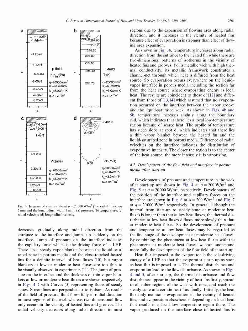
The low or moderate heat flux is defined as the heat fluxat which evaporation only occurs on the liquid–vaporinterface but no boiling occurs in liquid, which is listed inthe assumptions as mentioned above. The patterns ofsteady flow fields at low or moderate heat fluxes are similarqualitatively but there are differences in the magnitude. Anexample at q = 20000 W/m2 is presented in Fig. 3. Pressure
-1.52E4
p-field
p-pin:(Pa)
q=20000w/m2
kt,l=6.0w/m*K
kt,g
=3.0w/m*K
K=1.0e-13m2
r
z
-3.20e3
-4.80e3
-6.40e3
-8.00e3
-9.60e3
-1.12e4
-1.28e4
-1.44e4
T-field
T:(K)
q=20000w/m2
kt,l=6.0w/m*K
kt,g
=3.0w/m*K
K=1.0e-13m2
r
z
293.70
294.40
295.10
295.80
296.50
297.20
297.90298.60299.30
q=20000w/m2
kt,l=6.0w/m*K
kt,g
=3.0w/m*K
K=1.0e-13m2
r
z
3.60e-3
3.20e-3
2.70e-3
2.30e-3
1.80e-3
1.8e-3
1.4e-3
9.0e-42.3e-3 4.5e-4
Vr:(m/s)
q=20000w/m2
kt,l=6.0w/m*K
kt,g
=3.0w/m*K
K=1.0e-13m2
r
z
0.00
-2.40e-4
-2.40e-3
Vz:(m/s)
c d
Fig. 3. Isogram of steady state at q = 20000 W/m2 (the radial thickness5 mm and the longitudinal width 1 mm): (a) pressure; (b) temperature; (c)radial velocity; (d) longitudinal velocity.
C. Ren et al. / International Journal of Heat and Mass Transfer 50 (2007) 2296–2308 2301
decreases gradually along radial direction from theentrance to the interface and jumps up suddenly on theinterface. Jump of pressure on the interface indicatesthe capillary force which is the driving force of a LHP.There lies a steady vapor blanket between the liquid-satu-rated zone in porous media and the close-touched heatedfins for a definite interval of heat fluxes [10], but vaporblankets at low or moderate heat fluxes are too thin tobe visually observed in experiments [11]. The jump of pres-sure on the interface and the thickness of thin vapor blan-kets at low or moderate heat fluxes are shown respectivelyin Figs. 4–7 with Curves (5) representing those of steadystates. Streamlines are perpendicular to isobars. As resultsof the field of pressure, fluid flows fully in radial directionin most regions of the wick whereas two-dimensional flowonly occurs in the vicinity of heated fins and grooves. Theradial velocity decreases along radial direction in most
regions due to the expansion of flowing area along radialdirection, and it increases in the vicinity of heated finsbecause effect of evaporation is stronger than effect of flow-ing area expansion.
As shown in Fig. 3b, temperature increases along radialdirection from the entrance to the heated fin while there aretwo-dimensional patterns of isotherms in the vicinity ofheated fins and grooves. For a metallic wick with high ther-mal conductivity, its metallic framework constitutes achannel-net through which heat is diffused from the heatsource. So evaporation occurs everywhere on the liquid–vapor interface in porous media including the section farfrom the heat source where evaporating energy is localheat. The results are coincident to those of [12] and differ-ent from those of [13,14] which assumed that no evapora-tion occurred on the interface between the vapor grooveand the liquid-saturated wick. As shown in Figs. 4b and5b, temperature increases slightly along the boundaryc–d, which indicates that there lies a local low-temperatureregion because of scarce heat. The profile of temperaturehas steep slope at spot d, which indicates that there liesa thin vapor blanket between the heated fin and theliquid-saturated zone in porous media. Difference of radialvelocities on the interface indicates the distribution ofevaporative intensity. The closer the region is to the centerof the heat source, the more intensely it is vaporizing.
4.2. Development of the flow field and interface in porous
media after start-up
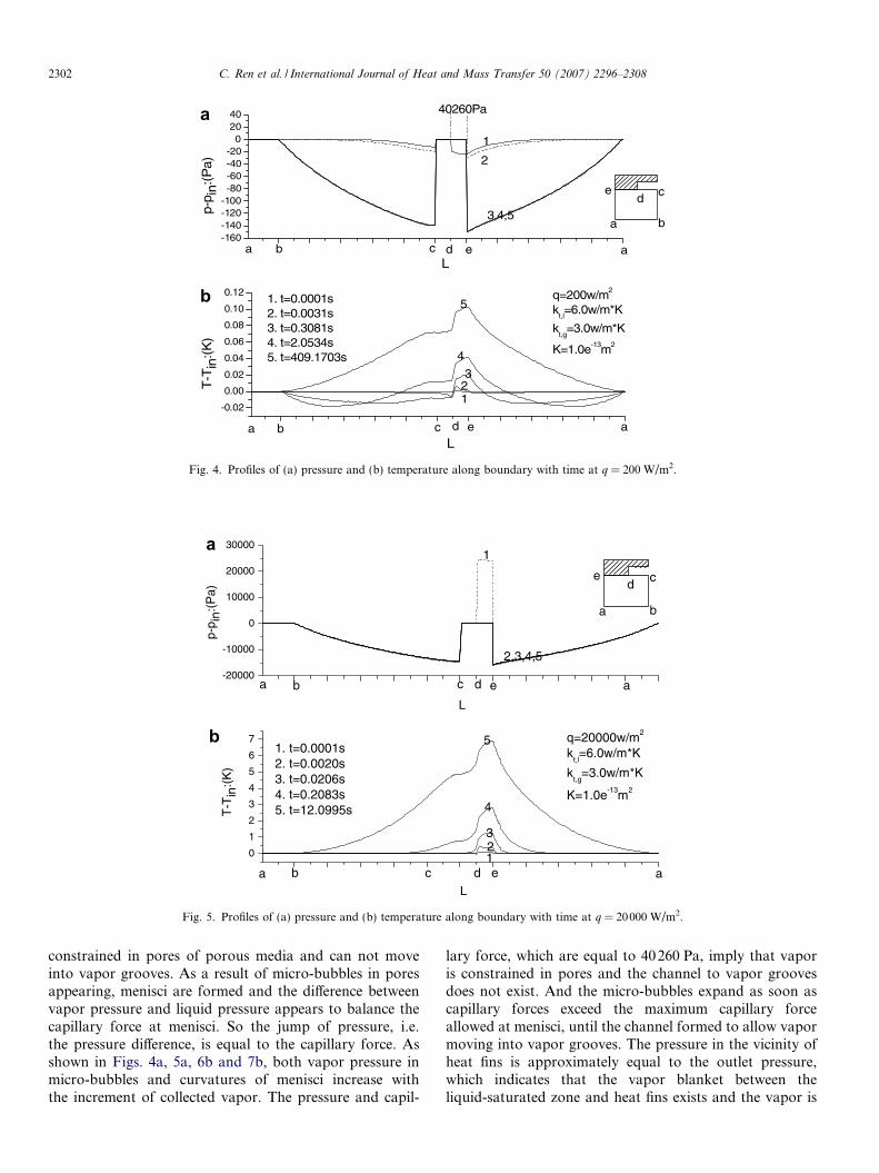
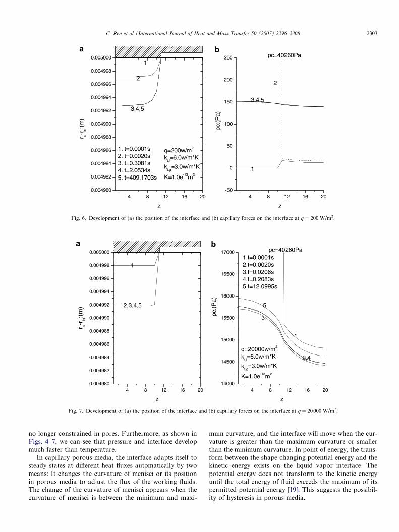
Developments of pressure and temperature in the wickafter start-up are shown in Fig. 4 at q = 200 W/m2 andFig. 5 at q = 20000 W/m2, respectively. Developments ofthe position of the interface and capillary forces on theinterface are shown in Fig. 6 at q = 200 W/m2 and Fig. 7at q = 20000 W/m2 respectively. In general, although theinterval from start-up to steady state at moderate heatfluxes is longer than that at low heat fluxes, the thermal dis-turbance at low heat fluxes diffuses more slowly than thatat moderate heat fluxes. So the development of pressureand temperature at low heat fluxes may be regarded asthe first stage of the development at moderate heat fluxes.By combining the phenomena at low heat fluxes with thephenomena at moderate heat fluxes, we can understandmore fully the development of the flow field after start-up.
Heat flux imposed to the evaporator is the sole drivingenergy of a LHP so that the evaporator starts up as soonas heat flux is imposed to it. The thermal disturbance andevaporation lead to the flow disturbance. As shown in Figs.4 and 5, after start-up, the thermal disturbance and flowdisturbance appear in the vicinity of heat fins firstly, spreadto all other regions of the wick with time, and reach thesteady state at a certain heat flux finally. Initially, the heatflux only maintains evaporation in the vicinity of heatedfins, and evaporation elsewhere is depending on local heatthat results in a local low-temperature region there. Thevapor produced on the interface close to heated fins is
-0.02
0.00
0.02
0.04
0.06
0.08
0.10
0.12 q=200w/m2
kt,l=6.0w/m*K
kt,g
=3.0w/m*K
K=1.0e-13m2
T-T
in:(
K)
L
1. t=0.0001s2. t=0.0031s3. t=0.3081s4. t=2.0534s5. t=409.1703s
123
4
5
a b c ed a
-160-140-120-100-80-60-40-20
02040
p-p i
n:(P
a)
L
1
2
3,4,5
40260Pa
a b
cde
a b c d e a
b
Fig. 4. Profiles of (a) pressure and (b) temperature along boundary with time at q = 200 W/m2.
0
1
2
3
4
5
6
7
T-T
in:(
K)
q=20000w/m2
kt,l=6.0w/m*K
kt,g
=3.0w/m*K
K=1.0e-13m2
L
123
4
51. t=0.0001s2. t=0.0020s3. t=0.0206s4. t=0.2083s5. t=12.0995s
b c e a
a b c ed a
d-20000
-10000
0
10000
20000
30000
p-p i
n:(P
a)
L
1
2,3,4,5
a b
cde
a
b
Fig. 5. Profiles of (a) pressure and (b) temperature along boundary with time at q = 20000 W/m2.
2302 C. Ren et al. / International Journal of Heat and Mass Transfer 50 (2007) 2296–2308
constrained in pores of porous media and can not moveinto vapor grooves. As a result of micro-bubbles in poresappearing, menisci are formed and the difference betweenvapor pressure and liquid pressure appears to balance thecapillary force at menisci. So the jump of pressure, i.e.the pressure difference, is equal to the capillary force. Asshown in Figs. 4a, 5a, 6b and 7b, both vapor pressure inmicro-bubbles and curvatures of menisci increase withthe increment of collected vapor. The pressure and capil-
lary force, which are equal to 40260 Pa, imply that vaporis constrained in pores and the channel to vapor groovesdoes not exist. And the micro-bubbles expand as soon ascapillary forces exceed the maximum capillary forceallowed at menisci, until the channel formed to allow vapormoving into vapor grooves. The pressure in the vicinity ofheat fins is approximately equal to the outlet pressure,which indicates that the vapor blanket between theliquid-saturated zone and heat fins exists and the vapor is
4 8 12 16 200.004980
0.004982
0.004984
0.004986
0.004988
0.004990
0.004992
0.004994
0.004996
0.004998
0.005000
q=200w/m2
kt,l=6.0w/m*K
kt,g
=3.0w/m*K
K=1.0e-13m2
r s-r in
:(m
)
z
1
2
3,4,5
4 8 12 16 20-50
0
50
100
150
200
250
1. t=0.0001s2. t=0.0020s3. t=0.3081s4. t=2.0534s5. t=409.1703s
pc:(
Pa)
z
pc=40260Pa
1
2
3,4,5
Fig. 6. Development of (a) the position of the interface and (b) capillary forces on the interface at q = 200 W/m2.
4 8 12 16 200.004980
0.004982
0.004984
0.004986
0.004988
0.004990
0.004992
0.004994
0.004996
0.004998
0.005000
q=20000w/m2
kt,l=6.0w/m*K
kt,g
=3.0w/m*K
K=1.0e-13m2
r s-rin:(
m)
z
1
2,3,4,5
4 8 12 16 2014000
14500
15000
15500
16000
16500
17000
pc:(
Pa)
z
1
2,4
3
5
pc=40260Pa1.t=0.0001s2.t=0.0020s3.t=0.0206s4.t=0.2083s5.t=12.0995s
Fig. 7. Development of (a) the position of the interface and (b) capillary forces on the interface at q = 20000 W/m2.
C. Ren et al. / International Journal of Heat and Mass Transfer 50 (2007) 2296–2308 2303
no longer constrained in pores. Furthermore, as shown inFigs. 4–7, we can see that pressure and interface developmuch faster than temperature.
In capillary porous media, the interface adapts itself tosteady states at different heat fluxes automatically by twomeans: It changes the curvature of menisci or its positionin porous media to adjust the flux of the working fluids.The change of the curvature of menisci appears when thecurvature of menisci is between the minimum and maxi-
mum curvature, and the interface will move when the cur-vature is greater than the maximum curvature or smallerthan the minimum curvature. In point of energy, the trans-form between the shape-changing potential energy and thekinetic energy exists on the liquid–vapor interface. Thepotential energy does not transform to the kinetic energyuntil the total energy of fluid exceeds the maximum of itspermitted potential energy [19]. This suggests the possibil-ity of hysteresis in porous media.
1E- 4 1E-3 0.01 0.1 1 10 100 1000
293
294
295
296
297
298
299
300
kt,l=6.0w/m*K
kt,g
=3.0w/m*K
K=1.0e-13m2
Tw
all &
Tou
t :(K
)
time:(s)
Twall(q=20w/m2)
Tout(q=20w/m2)
Twall(q=200w/m2)
Tout(q=200w/m2)
Twall(q=2000w/m2)
Tout(q=2000w/m2)
Twall(q=20000w/m2)
Tout(q=20000w/m2)
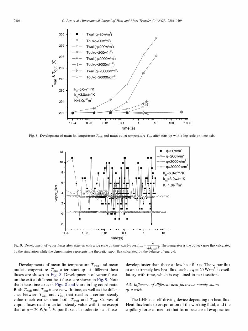
Fig. 8. Development of mean fin temperature Twall and mean outlet temperature Tout after start-up with a log scale on time-axis.
1E-4 1E-3 0.01 0.1 1 10
-2
0
2
4
6
8
10
12
kt,l=6.0w/m*K
kt,g
=3.0w/m*K
K=1.0e-13m2
vapo
r_flu
x
time:(s)
q=20w/m2
q=200w/m2
q=2000w/m2
q=20000w/m2
Fig. 9. Development of vapor fluxes after start-up with a log scale on time-axis (vapor flux ¼ _mqAs;out=k
. The numerator is the outlet vapor flux calculated
by the simulation while the denominator represents the theoretic vapor flux calculated by the balance of energy).
2304 C. Ren et al. / International Journal of Heat and Mass Transfer 50 (2007) 2296–2308
Developments of mean fin temperature Twall and meanoutlet temperature Tout after start-up at different heatfluxes are shown in Fig. 8. Developments of vapor fluxeson the exit at different heat fluxes are shown in Fig. 9. Notethat these time axes in Figs. 8 and 9 are in log coordinate.Both Twall and Tout increase with time, as well as the differ-ence between Twall and Tout that reaches a certain steadyvalue much earlier than both Twall and Tout. Curves ofvapor fluxes reach a certain steady value with time exceptthat at q = 20 W/m2. Vapor fluxes at moderate heat fluxes
develop faster than those at low heat fluxes. The vapor fluxat an extremely low heat flux, such as q = 20 W/m2, is oscil-latory with time, which is explained in next section.
4.3. Influence of different heat fluxes on steady states
of a wick
The LHP is a self-driving device depending on heat flux.Heat flux leads to evaporation of the working fluid, and thecapillary force at menisci that form because of evaporation
2
3
4
5
6
7
8
kt,l=6.0w/m*K
kt,g
=3.0w/m*K
K=1.0e-13m2
T-T
in:(
K)
4.q=10000w/m2
5.q=20000w/m2
6.q=30000w/m2
7.q=40000w/m2
8.q=50000w/m2
L
a b
cde
4
4
4
5
5
5
6
6
6
7
7
7
8
8
8
c d e
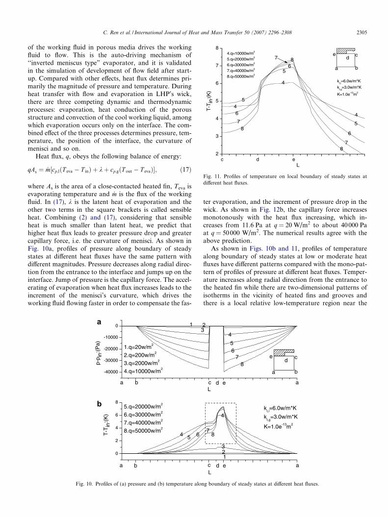
Fig. 11. Profiles of temperature on local boundary of steady states atdifferent heat fluxes.
C. Ren et al. / International Journal of Heat and Mass Transfer 50 (2007) 2296–2308 2305
of the working fluid in porous media drives the workingfluid to flow. This is the auto-driving mechanism of‘‘inverted meniscus type” evaporator, and it is validatedin the simulation of development of flow field after start-up. Compared with other effects, heat flux determines pri-marily the magnitude of pressure and temperature. Duringheat transfer with flow and evaporation in LHP’s wick,there are three competing dynamic and thermodynamicprocesses: evaporation, heat conduction of the porousstructure and convection of the cool working liquid, amongwhich evaporation occurs only on the interface. The com-bined effect of the three processes determines pressure, tem-perature, the position of the interface, the curvature ofmenisci and so on.
Heat flux, q, obeys the following balance of energy:
qAs ¼ _m½cp;lðT eva � T inÞ þ kþ cp;gðT out � T evaÞ�; ð17Þ
where As is the area of a close-contacted heated fin, Teva isevaporating temperature and _m is the flux of the workingfluid. In (17), k is the latent heat of evaporation and theother two terms in the square brackets is called sensibleheat. Combining (2) and (17), considering that sensibleheat is much smaller than latent heat, we predict thathigher heat flux leads to greater pressure drop and greatercapillary force, i.e. the curvature of menisci. As shown inFig. 10a, profiles of pressure along boundary of steadystates at different heat fluxes have the same pattern withdifferent magnitudes. Pressure decreases along radial direc-tion from the entrance to the interface and jumps up on theinterface. Jump of pressure is the capillary force. The accel-erating of evaporation when heat flux increases leads to theincrement of the menisci’s curvature, which drives theworking fluid flowing faster in order to compensate the fas-
0
2
4
6
85.q=20000w/m2
6.q=30000w/m2
7.q=40000w/m2
8.q=50000w/m2
T-T
in:(
K)
4 5 6
a b
-40000
-30000
-20000
-10000
0
1.q=20w/m2
2.q=200w/m2
3.q=2000w/m2
4.q=10000w/m2
p-p i
n:(P
a)
13
a b
b
Fig. 10. Profiles of (a) pressure and (b) temperature alon
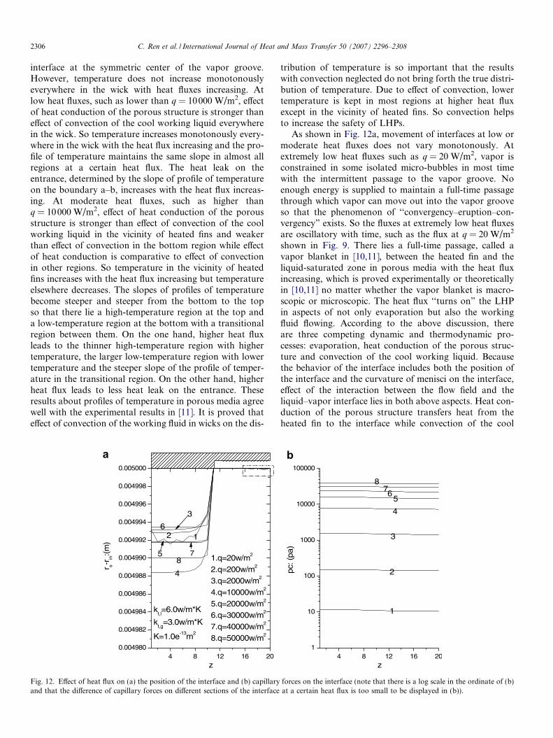
ter evaporation, and the increment of pressure drop in thewick. As shown in Fig. 12b, the capillary force increasesmonotonously with the heat flux increasing, which in-creases from 11.6 Pa at q = 20 W/m2 to about 40 000 Paat q = 50000 W/m2. The numerical results agree with theabove prediction.
As shown in Figs. 10b and 11, profiles of temperaturealong boundary of steady states at low or moderate heatfluxes have different patterns compared with the mono-pat-tern of profiles of pressure at different heat fluxes. Temper-ature increases along radial direction from the entrance tothe heated fin while there are two-dimensional patterns ofisotherms in the vicinity of heated fins and grooves andthere is a local relative low-temperature region near the
kt,l=6.0w/m*K
kt,g
=3.0w/m*K
K=1.0e-13m2
L
123
78
4
c d e a
L
a b
cde
2
4
56
78
c d e a
g boundary of steady states at different heat fluxes.
2306 C. Ren et al. / International Journal of Heat and Mass Transfer 50 (2007) 2296–2308
interface at the symmetric center of the vapor groove.However, temperature does not increase monotonouslyeverywhere in the wick with heat fluxes increasing. Atlow heat fluxes, such as lower than q = 10000 W/m2, effectof heat conduction of the porous structure is stronger thaneffect of convection of the cool working liquid everywherein the wick. So temperature increases monotonously every-where in the wick with the heat flux increasing and the pro-file of temperature maintains the same slope in almost allregions at a certain heat flux. The heat leak on theentrance, determined by the slope of profile of temperatureon the boundary a–b, increases with the heat flux increas-ing. At moderate heat fluxes, such as higher thanq = 10000 W/m2, effect of heat conduction of the porousstructure is stronger than effect of convection of the coolworking liquid in the vicinity of heated fins and weakerthan effect of convection in the bottom region while effectof heat conduction is comparative to effect of convectionin other regions. So temperature in the vicinity of heatedfins increases with the heat flux increasing but temperatureelsewhere decreases. The slopes of profiles of temperaturebecome steeper and steeper from the bottom to the topso that there lie a high-temperature region at the top anda low-temperature region at the bottom with a transitionalregion between them. On the one hand, higher heat fluxleads to the thinner high-temperature region with highertemperature, the larger low-temperature region with lowertemperature and the steeper slope of the profile of temper-ature in the transitional region. On the other hand, higherheat flux leads to less heat leak on the entrance. Theseresults about profiles of temperature in porous media agreewell with the experimental results in [11]. It is proved thateffect of convection of the working fluid in wicks on the dis-
4 8 12 16 200.004980
0.004982
0.004984
0.004986
0.004988
0.004990
0.004992
0.004994
0.004996
0.004998
0.005000
kt,l=6.0w/m*K
kt,g
=3.0w/m*K
K=1.0e-13m2
1.q=20w/m2
2.q=200w/m2
3.q=2000w/m2
4.q=10000w/m2
5.q=20000w/m2
6.q=30000w/m2
7.q=40000w/m2
8.q=50000w/m2
r s-r in
:(m
)
z
12
4
6
3
85 7
Fig. 12. Effect of heat flux on (a) the position of the interface and (b) capillaryand that the difference of capillary forces on different sections of the interface
tribution of temperature is so important that the resultswith convection neglected do not bring forth the true distri-bution of temperature. Due to effect of convection, lowertemperature is kept in most regions at higher heat fluxexcept in the vicinity of heated fins. So convection helpsto increase the safety of LHPs.
As shown in Fig. 12a, movement of interfaces at low ormoderate heat fluxes does not vary monotonously. Atextremely low heat fluxes such as q = 20 W/m2, vapor isconstrained in some isolated micro-bubbles in most timewith the intermittent passage to the vapor groove. Noenough energy is supplied to maintain a full-time passagethrough which vapor can move out into the vapor grooveso that the phenomenon of ‘‘convergency–eruption–con-vergency” exists. So the fluxes at extremely low heat fluxesare oscillatory with time, such as the flux at q = 20 W/m2
shown in Fig. 9. There lies a full-time passage, called avapor blanket in [10,11], between the heated fin and theliquid-saturated zone in porous media with the heat fluxincreasing, which is proved experimentally or theoreticallyin [10,11] no matter whether the vapor blanket is macro-scopic or microscopic. The heat flux ‘‘turns on” the LHPin aspects of not only evaporation but also the workingfluid flowing. According to the above discussion, thereare three competing dynamic and thermodynamic pro-cesses: evaporation, heat conduction of the porous struc-ture and convection of the cool working liquid. Becausethe behavior of the interface includes both the position ofthe interface and the curvature of menisci on the interface,effect of the interaction between the flow field and theliquid–vapor interface lies in both above aspects. Heat con-duction of the porous structure transfers heat from theheated fin to the interface while convection of the cool
4 8 12 16 201
10
100
1000
10000
100000
pc: (
pa)
z
1
2
3
4
56
78
forces on the interface (note that there is a log scale in the ordinate of (b)at a certain heat flux is too small to be displayed in (b)).
2 4 6 8 10 12 14 16 18 20 22 24
0
2
4
6
8
10
5.q=20000w/m2
6.q=30000w/m2
7.q=40000w/m2
8.q=50000w/m2
1.q=20w/m2
2.q=200w/m2
3.q=2000w/m2
4.q=10000w/m2
T-T
s :(
K)
z
12
3
4
56
78
56
78
10 100 1000 10000 100000292
293
294
295
296
297
298
299
300
kt,l=6.0w/m*K
kt,g
=3.0w/m*K
K=1.0e-13m2
Twall Tout
Tw
all &
Tou
t:(K
)q: (w/m2)
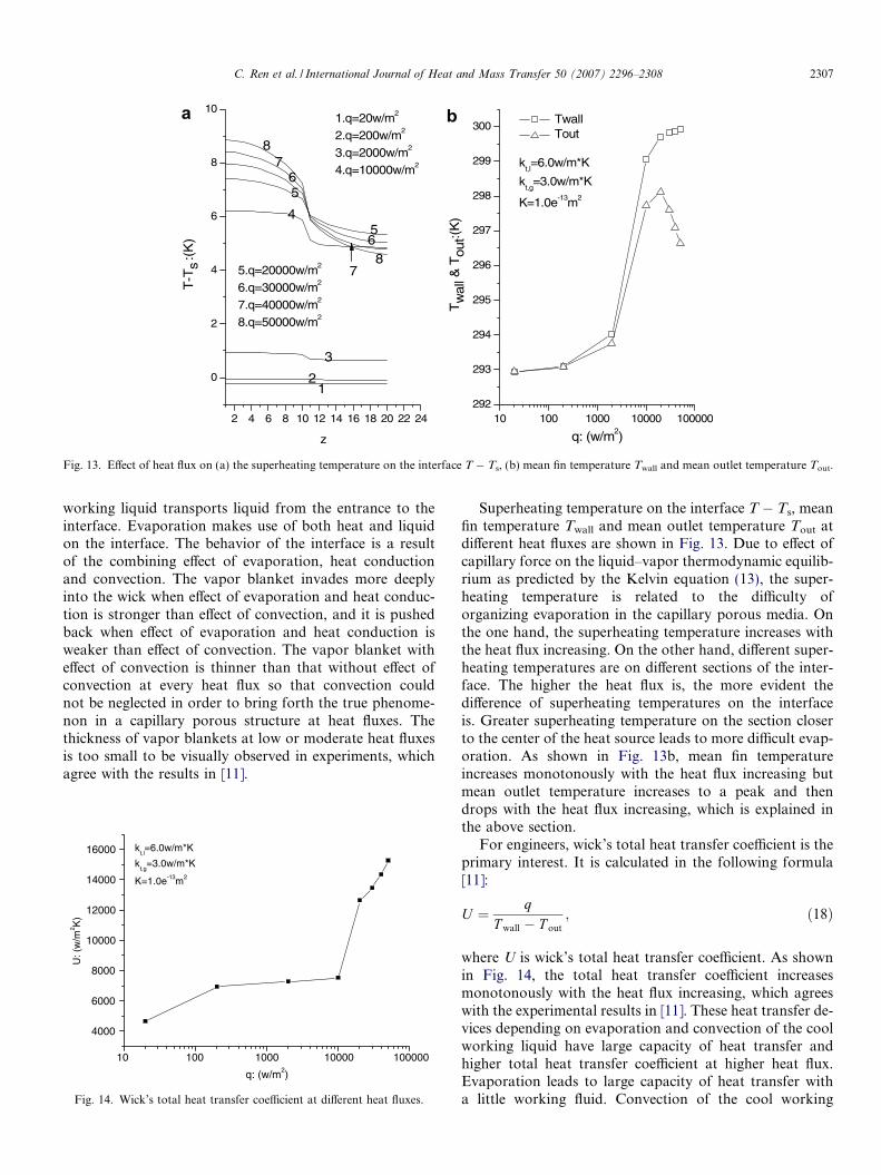
Fig. 13. Effect of heat flux on (a) the superheating temperature on the interface T � Ts, (b) mean fin temperature Twall and mean outlet temperature Tout.
C. Ren et al. / International Journal of Heat and Mass Transfer 50 (2007) 2296–2308 2307
working liquid transports liquid from the entrance to theinterface. Evaporation makes use of both heat and liquidon the interface. The behavior of the interface is a resultof the combining effect of evaporation, heat conductionand convection. The vapor blanket invades more deeplyinto the wick when effect of evaporation and heat conduc-tion is stronger than effect of convection, and it is pushedback when effect of evaporation and heat conduction isweaker than effect of convection. The vapor blanket witheffect of convection is thinner than that without effect ofconvection at every heat flux so that convection couldnot be neglected in order to bring forth the true phenome-non in a capillary porous structure at heat fluxes. Thethickness of vapor blankets at low or moderate heat fluxesis too small to be visually observed in experiments, whichagree with the results in [11].
10 100 1000 10000 100000
4000
6000
8000
10000
12000
14000
16000 kt,l=6.0w/m*K
kt,g
=3.0w/m*K
K=1.0e-13m2
U: (
w/m
2 K)
q: (w/m2)
Fig. 14. Wick’s total heat transfer coefficient at different heat fluxes.
Superheating temperature on the interface T � Ts, meanfin temperature Twall and mean outlet temperature Tout atdifferent heat fluxes are shown in Fig. 13. Due to effect ofcapillary force on the liquid–vapor thermodynamic equilib-rium as predicted by the Kelvin equation (13), the super-heating temperature is related to the difficulty oforganizing evaporation in the capillary porous media. Onthe one hand, the superheating temperature increases withthe heat flux increasing. On the other hand, different super-heating temperatures are on different sections of the inter-face. The higher the heat flux is, the more evident thedifference of superheating temperatures on the interfaceis. Greater superheating temperature on the section closerto the center of the heat source leads to more difficult evap-oration. As shown in Fig. 13b, mean fin temperatureincreases monotonously with the heat flux increasing butmean outlet temperature increases to a peak and thendrops with the heat flux increasing, which is explained inthe above section.
For engineers, wick’s total heat transfer coefficient is theprimary interest. It is calculated in the following formula[11]:
U ¼ qT wall � T out
; ð18Þ
where U is wick’s total heat transfer coefficient. As shownin Fig. 14, the total heat transfer coefficient increasesmonotonously with the heat flux increasing, which agreeswith the experimental results in [11]. These heat transfer de-vices depending on evaporation and convection of the coolworking liquid have large capacity of heat transfer andhigher total heat transfer coefficient at higher heat flux.Evaporation leads to large capacity of heat transfer witha little working fluid. Convection of the cool working
2308 C. Ren et al. / International Journal of Heat and Mass Transfer 50 (2007) 2296–2308
liquid protects most regions of the wick even at high heatfluxes. All these excellences make it applied to more andmore engineering regions.
5. Conclusions
An axisymmetric two-dimensional mathematical modelof the cylindrical evaporator’s wick of LHPs is developedto simulate heat transfer with flow and evaporation inthe capillary porous structure. Effect of the interactionbetween the flow field and the liquid–vapor interface onthe position of the interface and the curvature of menisciis adequately considered in this model. The flow field oftransient and steady states with effect of wick’s cylindricalshape is obtained at low or moderate heat fluxes. Thedynamic and thermodynamic behavior is discussed. Theauto-driving mechanism of ‘‘inverted meniscus type” evap-orators is validated.
Evaporation occurs everywhere on the interface withdifferent intensity of evaporation on different sections ofthe interface. It vaporizes more strongly in the region closerto the center of the heat source. There lies a steady vaporblanket between heated fins and the liquid-saturated zonein porous media for a definite interval of heat fluxes exceptthat there lie isolated micro-bubbles in the vicinity ofheated fins at extremely low heat fluxes. The behavior ofthe interface is a result of the combining effect of evapora-tion, heat conduction of the porous structure and convec-tion of the cool working liquid. The vapor blanketinvades more deeply into the wick when effect of evapora-tion and heat conduction is stronger than effect of convec-tion, and it is pushed back when effect of evaporation andheat conduction is weaker than effect of convection. In cap-illary porous media, the interface adapts itself to steadystates at different heat fluxes automatically by two means:It changes the curvature of menisci or its position in porousmedia to adjust the flux of the working fluids.
Convection of the cool working fluid influences stronglythe flow field and interface in capillary porous media. Dueto effect of convection, lower temperature is kept in mostregions at higher heat flux except in the vicinity of heatedfins, which helps to increase the safety of LHPs. The vaporblanket with effect of convection is thinner than that with-out effect of convection at every heat flux. Investigationwith convection neglected can not bring forth the true phe-nomenon of flow, heat transfer and evaporation in capil-lary porous media.
Heat flux influences strongly the steady flow field andinterface as well as wick’s performances. In the allowedrange of heat fluxes, Higher heat flux leads to stronger con-vection and more intense evaporation, which helps toincrease the device’s safety by keeping lower temperature
in most regions except in the vicinity of heated fins andincreases wick’s total heat transfer coefficient.
Acknowledgements
The authors acknowledge the support of Chinese Acad-emy of Space Technology (CAST), and Chinese Academyof Science (CAS) with a dean excellent fund.
References
[1] T. Kaya, T.T. Hoang, Mathematical modeling of loop heat pipes andexperimental validation, J. Thermophys. Heat Transfer 13 (3) (1999)314–320.
[2] T. Kaya, T.T. Hoang, Mathematical modeling of loop heat pipes withtwo-phase pressure drop, AIAA paper No.99-3448, 1999.
[3] T. Hoang, J. Ku, Hydrodynamic aspects of capillary pumped loops,SAE paper No.961435, 1996.
[4] J. Ku, Operating characteristics of loop heat pipes, SAE paperNo.1999-01-2007, 1999.
[5] E. Pouzet, J.L. Joly, V. Platel, J.Y. Grandpeix, C. Butto, Dynamicresponse of a capillary pumped loop subjected to various heat loadtransients, Int. J. Heat Mass Transfer 47 (10-11) (2004) 2239–2316.
[6] H.X. Zhang, G.P. Lin, T. Ding, W. Yao, X.G. Shao, R.G. Sudalov,Yu. F. Maidanik, Investigation of startup behaviors of a loop heatpipe, J. Thermophys. Heat Transfer 19 (4) (2005) 509–518.
[7] L.L. Vasiliev, Heat pipes in modern heat exchanges, Appl. Therm.Eng. 25 (2005) 1–19.
[8] Yu. F. Maydanik, Loop heat pipes, Appl. Therm. Eng. 25 (2005) 635–657.
[9] K.T. Feldman, D.L. Noreen, Design of heat pipe cooled laser mirrorswith an inverted meniscus evaporator wick, AIAA paper No.92-0148,1980.
[10] D. Khrustalev, A. Faghri, Heat transfer in the inverted meniscus typeevaporator at high heat fluxes, Int. J. Heat Mass Transfer 38 (16)(1995) 3091–3101.
[11] T.S. Zhao, Q. Liao, On capillary-driven flow and phase-change heattransfer in a porous structure heated by a finned surface: measure-ments and modeling, Int. J. Heat Mass Transfer 43 (2000) 1141–1155.
[12] A.S. Demidov, E.S. Yatsenko, Investigation of heat and mass transferin the evaporation zone of a heat pipe operating by the ‘invertedmeniscus’ principle, Int. J. Heat Mass Transfer 37 (14) (1994) 2155–2163.
[13] C. Figus, Y. Le Bray, S. Bories, M. Prat, Heat and mass transfer withphase change in a porous structure partially heated: continuum modeland pore network simulation, Int. J. Heat Mass Transfer 42 (1999)2557–2569.
[14] A.R. Takahashi, A.A. Oliveira, E. Bazzo, Analysis of heat and masstransfer with phase change in the porous wick of a capillary pump, in:The 7th International Heat Pipe Symposium, October 12–16, 2003,Jeju Korea.
[15] K.S. Udell, Heat transfer in porous media heated from above withevaporation, condensation and capillary effects, ASME J. HeatTransfer 105 (1983) 485–492.
[16] D.L. Zeng et al., Engineering Thermodynamics, Higher EducationPress, Beijing China, 1985, pp. 191–198 (in Chinese).
[17] X.Y. Kong, Advanced Fluid Mechanics in Porous Media, USTCPress, Hefei China, 1999, pp. 38–39, pp. 45–49 (in Chinese).
[18] W.Q. Tao, Neoteric Advance in Numerical Heat Transfer, SciencePress, Beijing China, 2001, pp. 233–237, pp. 283–286 (in Chinese).
[19] B.X. Wang, Heat and Mass Transfer in Engineering, vol. 2, SciencePress, Beijing China, 1998, pp. 342–347 (in Chinese).