i. types of containers
TRANSCRIPT

I. Types of containers
Standard containers
Description
Standard containers are also known as general purpose containers. They are closed
containers, i.e. they are closed on all sides. A distinction may be drawn between the
following types of standard container:
Standard containers with doors at one or both end(s)
Standard containers with doors at one or both end(s) and doors over the entire length of one or both sides
Standard containers with doors at one or both end(s) and doors on one or both sides
In addition, the various types of standard container also differ in dimensions and
weight, resulting in a wide range of standard containers.
Standard containers are mainly used as 20' and 40' containers. Containers with smaller
dimensions are very seldom used. Indeed, the trend is towards even longer
dimensions, e.g. 45'. The principal components of a standard container are shown in
following diagram of a 20' plywood container:
Figure 1
Frame and bottom cross members are made of steel profiles, while three different
materials are used for the walls:
1. Steel sheet, corrugated Characteristics:
low material costs
easy to repair
high tare weight

susceptible to corrosion
difficult to clean owing to corrugated walls
2. Aluminum sheet in conjunction with stiffening profiles Characteristics:
low tare weight
high material costs
easily deformed, very quickly dented
3. Plywood with glass fiber-reinforced plastic coating (plywood + GRP) Characteristics:
easy to clean owing to smooth surfaces
easy to repair
strong and resilient, does not dent
moderate material costs
moderate tare weight
The cost advantages have led to the predominant use of steel for container walls.
The floor is generally made of wood, usually planking or plywood. Although wood is
relatively expensive, it has substantial advantages over other materials: it is strong and
resilient, does not dent, may be easily replaced during repairs and, when appropriately
finished, has an adequate coefficient of friction, which is important for cargo securing.
Standard containers may additionally be equipped with certain optional extras:
Forklift pockets: these allow handling of empty containers with forklift
trucks. Packed containers must not be picked up in this way unless
specifically permitted. Forklift pockets are installed only in 20' containers
and are arranged parallel to the center of the container in the bottom side
rails. 40' containers do not have forklift pockets, since the pockets are
relatively close together and such large containers would be difficult to
balance. In addition, the forklift truck travel paths are often not wide
enough.
Gooseneck tunnel: Many 40' containers have a recess in the floor at the front end which serves to center the containers on so-called gooseneck

chassis. These recesses allow the containers to lie lower and therefore to be of taller construction.
Figure 2 Figure 3
Grappler pockets: In general, containers are handled by top spreaders
using the corner fittings or corner castings. However, some containers have
grappler pockets for handling by means of grapplers.
Figure 4
Special fittings are available for transporting special cargoes:
Clothes rails for hanging garments: Special lashing rings attached to the
top side rail serve to accommodate clothes rails on which textiles may be
transported hanging on clothes-hangers. These are often used in the East
Asia import trade. Additional lashing rings are installed on the bottom side
rail and the corner posts.
Inlet (bulk bag or liquid bulk bag): Plastic liners may be suspended in standard containers for transporting bulk cargo or nonhazardous liquids.
The wooden components of most containers are impregnated against insect
infestation, since, when lumber is used, it may, under certain circumstances, be
necessary to comply with the quarantine regulations of the country of destination and
a phytosanitary certificate may have to be enclosed with the shipping documents.
Information may be obtained from the phytosanitary authorities of the countries
concerned.

Figures
Figure 5
Figure 6
Figure 7
Figure 8
Figure 9
Dimensions/weights
The following are some of the most important details relating to standard container
types. The data was taken from Hapag-Lloyd, Hamburg
Standard container of steel: 20' long and 8'6" high with corrugated walls and
wooden floor
Internal dimensions Door
openings
Weights
Volume
[m³]
Length
[mm]
Width
[mm]
Height
[mm]
Width
[mm]
Height
[mm]
Max. gross wt.
[kg]
Tare weight
[kg]
Max. payload
[kg]
5895 2350 2392 2340 2292 30480 2250 28230 33.2
5895 2350 2385 2338 2292 24000 2250 21750 33.2
Standard container of steel: 40' long and 8'6" high with corrugated walls and wooden floor
Internal dimensions Door
openings
Weights
Volume
[m³]
Length
[mm]
Width
[mm]
Height
[mm]
Width
[mm]
Height
[mm]
Max.
gross wt.
[kg]
Tare
weight
[kg]
Max.
payload
[kg]
12029 2350 2392 2340 2292 30480 3780 26700 67.7

Use
Standard containers are used for all types general cargo (dry cargo).
High-cube containers
Description
High-cube containers are similar in structure to standard containers, but taller. In
contrast to standard containers, which have a maximum height of 2591 mm (8'6"),
high-cube containers are 2896 mm, or 9'6", tall. High-cube containers are for the most
part 40' long, but are sometimes made as 45' containers.
A number of lashing rings, capable of bearing loads of at most 1000 kg, are mounted
on the front top end rail and bottom cross member and the corner posts.
Many 40' containers have a recess in the floor at the front end which serves to center
the containers on so-called gooseneck chassis. These recesses allow the containers to
lie lower and therefore to be of taller construction.
Figure 1 Figure 2
Figures
Figure 3 Figure 4
Dimensions/weights
The following are some of the most important details relating to high-cube container

types. The data was taken from Hapag-Lloyd, Hamburg
High-cube container of steel: 40' long and 9'6" high with corrugated walls and
wooden floor
Internal dimensions Door
openings
Weights
Volume
[m³]
Length
[mm]
Width
[mm]
Height
[mm]
Width
[mm]
Height
[mm]
Max. gross wt.
[kg]
Tare weight
[kg]
Max. payload
[kg]
12024 2350 2697 2340 2597 30480 4020 26460 76.3
Use
High-cube containers are used for all types general cargo (dry cargo). However, they
are particularly suitable for transporting light, voluminous cargoes and overheight
cargoes up to a maximum of 2.70 m tall.
Hard-top containers
Description
The walls of hard-top containers are generally made of corrugated steel. The floor is made of wood.
It has two typical distinguishing structural features. On the one hand, it is equipped
with a removable steel roof. In some types, this roof has points for accommodating
forklift trucks, allowing the roof to be lifted by forklift truck. The roof weighs approx. 450 kg. In addition, the door header may be swivelled out.
These two structural features greatly simplify the process of packing and unpacking
the container. In particular, it is very easy to pack and unpack the container from above or through the doors by crane or crab when the roof is open and the door header is swivelled out.
In the case of transport of an overheight cargo, the container roof may be left open and
fastened directly to a side wall on the inside of the container. To do this, the roof only
needs approx. 13 cm (5 1/8") of space.
Lashing rings, to which the cargo may be secured, are installed in the upper and lower

side rails, the corner posts and the middle of the side walls. The lashing rings on the
side rails and corner posts may take loads of up to 2000 kg. The lashing rings in the
middle of the side walls may take loads of up to 500 kg, provided that the roof is
closed.
Usual hard-top container dimensions are 20' and 40'.
Figures
Figure 1 Figure 2 Figure 3
Dimensions/weights
The following are some of the most important details relating to hard-top containers. The data was taken from Hapag-Lloyd, Hamburg
Hard-top container of steel: 20' long and 8'6" high with corrugated walls and wooden floor
Internal dimensions Door Weights
Volume
[m³]
Length
[mm]
Width
[mm]
Height
(middle)
[mm]
Height
(side)
[mm]
Max.
width
[mm]
Max.
gross
wt.
[kg]
Tare
weight
[kg]
Max.
payload
[kg]
5886 2342 2388 2313 2336 30480 2700 27780 32.8
5886 2342 2375 2330 2336 30480 2590 27890 32.8
Hard-top container of steel: 40' long and 8'6" high with corrugated
walls and wooden floor
Internal dimensions Door Weights
Volume
[m³]
Length Width Height (middle)
Height (side)
Max. width
Max. gross
Tare weight
Max. payload

[mm] [mm]
[mm]
[mm]
[mm]
wt.
[kg]
[kg]
[kg]
12020 2342 2388 2313 2336 30480 4700 25780 67.2
12020 2345 2380 2300 2334 30480 4700 25780 65.3
High-cube hard-top container of steel: 40' long and 9'6" high with
corrugated walls and wooden floor
Internal dimensions Door Weights
Volume
[m³]
Length
[mm]
Width
[mm]
Height (middle)
[mm]
Height (side)
[mm]
Max. width
[mm]
Max.
gross
wt.
[kg]
Tare weight
[kg]
Max. payload
[kg]
12020 2342 2693 2618 2336 30480 4900 25580 75.8
12020 2342 2693 2618 2336 32500 5200 27300 76.0
Dimensions of roof and door openings The meaning of the individual letters is clear from the following Figures:
Figure 3 Figure 4

20' hard-top container
Roof
openings
Door openings Reduced widths when
roof is carried inside
Length Width Width Width Width Height Height
Internal
width
[mm]
Roof
opening
width
[mm]
Door
opening
width
[mm]
B
[mm]
C
[mm]
F
[mm]
G
[mm]
H
[mm]
I
[mm]
K
[mm]
5590 2208 2336 1896 2208 2276 2220 2209 2142 2206
5590 2208 2336 1896 2208 2292 2220 2209 2142 2206
5590 2208 2336 1896 2208 2280 2231 2215 2148 2212
40' hard-top container
Roof
openings
Door openings Reduced widths when
roof is carried inside
Length Width Width Width Width Height Height
Internal
width
[mm]
Roof
opening
width
[mm]
Door
opening
width
[mm]
B
[mm]
C
[mm]
F
[mm]
G
[mm]
H
[mm]
I
[mm]
K
[mm]
11724 2208 2336 1896 2208 2292 2220 2209 2142 2206
11724 2208 2336 1896 2208 2276 2220 2209 2142 2206
11724 2208 2334 1882 2208 2290 2125 2205 2102 1996
40' high-cube hard-top container
Roof
openings
Door openings Reduced widths when
roof is carried inside
Length Width Width Width Width Height Height
Internal
width
[mm]
Roof
opening
width
[mm]
Door
opening
width
[mm]
B
[mm]
C
[mm]
F
[mm]
G
[mm]
H
[mm]
I
[mm]
K
[mm]
11724 2208 2336 1896 2208 2597 2525 2230 2163 2227

Use
Hard-top containers are used for all types general cargo (dry cargo). Their principal
uses are as follows:
heavy cargo
tall cargo
loading from above or through the doors by crane or crab
Open-top containers
Description
The walls of open-top containers are generally made of corrugated steel. The floor is made of wood.
It has the following typical distinguishing structural features. The roof consists of removable bows and a removable tarpaulin. The door header may be swivelled out.
These two structural features greatly simplify the process of packing and unpacking
the container. In particular, it is very easy to pack and unpack the container from
above or through the doors by crane or crab when the roof is open and the door
header is swivelled out.
It should be noted, however, that the purpose of the roof bows of an open-top
container is not solely to support the tarpaulin but also to contribute to container
stability. Flatracks are therefore more suitable for overheight cargoes.
Lashing rings, to which the cargo may be secured, are installed in the upper and lower side rails and the corner posts. The lashing rings may take loads of up to 1,000 kg
Usual open-top container dimensions are 20' and 40'.
Figures
Figure 1 Figure 2

Dimensions/weights
The following are some of the most important details relating to open-top container
types. The data was taken from Hapag-Lloyd, Hamburg [68].
Open-top container of steel: 20' long and 8'6" high with corrugated walls,
removable tarpaulin and wooden floor
Internal dimensions Weights
Volume
[m³]
Length
[mm]
Width
[mm]
Height
(middle)
[mm]
Height
(side)
[mm]
Max.
gross
wt.
[kg]
Tare
weight
[kg]
Max.
payload
[kg]
5888 2345 2365 2315 30480 2250 28230 32.0
5897 2350 2377 2347 30480 2350 28130 32.5
Open-top container of steel: 40' long and 8'6" high with corrugated walls,
removable tarpaulin and wooden floor
Internal dimensions Weights
Volume
[m³]
Length
[mm]
Width
[mm]
Height (middle)
[mm]
Height (side)
[mm]
Max.
gross
wt.
[kg]
Tare weight
[kg]
Max. payload
[kg]
12029 2342 2376 2326 30480 3810 26670 65.5
12022 2345 2365 2315 30480 3740 26740 65.3
12030 2350 2377 2347 30480 3850 26630 66.4
Dimensions of roof and door openings The meaning of the individual letters is clear from the following Figures:

Figure 3 Figure 4
20' open-top container
Roof openings Door openings
Length Length Width Width Width Width Width Width Height Height
A
[mm]
B
[mm]
C
[mm]
D
[mm]
E
[mm]
F
[mm]
G
[mm]
H
[mm]
I
[mm]
K
[mm]
5415 5360 2205 - 1880 2335 1880 2205 2280 2125
5439 5338 2230 - 19902 2338 1902 2230 2280 2231
40' open-top container
Roof openings Door openings
Length Length Width Width Width Width Width Width Height Height
A
[mm]
B
[mm]
C
[mm]
D
[mm]
E
[mm]
F
[mm]
G
[mm]
H
[mm]
I
[mm]
K
[mm]
11544 11444 2230 - 1885 2336 1885 2230 2280 2146
11550 11515 2205 - 1880 2335 1880 2205 2280 2125
11573 11472 2210 - 1902 2338 1902 2210 2292 2131
Use
Open-top containers are used for all types of general cargo (dry cargo). Their
principal uses are as follows:
packing and unpacking from above or through the doors by crane or crab

tall cargo
Flatracks
Description
Flatracks consist of a floor structure with a high loading capacity composed of a steel
frame and a softwood floor and two end walls, which may either be fixed or
collapsible. The end walls are stable enough to allow cargo securing means to be
attached and several flatracks to be stacked on top of one another. Flatracks are
available in 20' and 40' sizes.
A number of lashing rings, to which the cargo may be secured, are installed in the side
rails, the corner posts and the floor. The lashing rings may take loads of up to 2000 kg
in the case of 20' flatracks or up to 4000 kg in the case of 40' flatracks.
Some types of 20' flatracks have forklift pockets.
40' flatracks have gooseneck tunnels at each end. In addition, they are sometimes
equipped with lashing winches with 2 metric ton lashing belts.
For transport of certain cargoes, flatracks may be provided with stanchions.
Figures
Figure 1
Figure 2
Figure 3
Figure 4
Dimensions/weights
The following are some of the most important details relating to flatracks. The data was taken from Hapag-Lloyd, Hamburg

Flatrack: steel frame with fixed end walls and softwood floor, 20' long and 8'6" high
Internal dimensions Weights
Floor length
[mm]
Length
between
corner
posts
[mm]
Floor width
[mm]
Width
between
stanchions
[mm]
Height
[mm]
Height
of
floor
[mm]
Max.
gross
wt.
[kg]
Tare
weight
[kg]
Max.
payload
[kg]
5980 5698 2230 2245 2255 336 24000 2500 21500
5962 5672 2242 2242 2261 330 30000 2200 27800
Flatrack: steel frame with collapsible end walls and softwood floor, 20' long and
8'6" high
Internal dimensions Weights
Floor
length
[mm]
Length
between
corner
posts
[mm]
Floor
width
[mm]
Width
between
stanchions
[mm]
Height
[mm]
Height
of
floor
[mm]
Max.
gross
wt.
[kg]
Tare
weight
[kg]
Max.
payload
[kg]
5950 5675 2428 2213 2270 316 33000 2600 30150
Flatrack/Platform: steel frame with flushfolding end walls and softwood floor, 20' long and 8'6" high
Internal dimensions Weights
Floor length
[mm]
Length
between
corner
posts
[mm]
Floor width
[mm]
Width
between
stanchions
[mm]
Height
[mm]
Height
of
floor
[mm]
Max.
gross
wt.
[kg]
Tare
weight
[kg]
Max.
payload
[kg]
6038 5638 2208 2438 2235 370 30480 2520 27960
6038 5612 2210 2438 2213 370 34000 2740 31260

Flatrack: steel frame with fixed end walls and softwood floor, 40' long and 8'6" high
Internal dimensions Weights
Floor length
[mm]
Length
between
corner
posts
[mm]
Floor width
[mm]
Width
between
stanchions
[mm]
Height
[mm]
Height
of
floor
[mm]
Max.
gross
wt.
[kg]
Tare
weight
[kg]
Max.
payload
[kg]
12010 11832 2228 2228 1981 610 45000 4200 40800
12086 11826 2224 2224 1981 610 45000 4200 40800
12010 11826 2244 2204 1981 610 45000 4200 40800
High-cube flatrack: steel frame with collapsible flushfolding end walls, 40' long
and 9'6" high; can be converted to a platform
Internal dimensions Weights
Floor
length
[mm]
Length
between
corner
posts
[mm]
Floor
width
[mm]
Width
between
stanchions
[mm]
Height
[mm]
Height
of
floor
[mm]
Maximum
weight
[kg]
Tare
weight
[kg]
Max.
payload
[kg]
12060 11660 2365 2200 2245 648 45000 5700 39300
12060 11660 2365 2200 2245 648 45000 5950 39050
The maximum payload may be used only if the load is distributed evenly over the
floor structure. However, if the weight of the cargo is applied to only a small
proportion of the floor, it must be distributed and the manufacturer of the flatracks
may have to be consulted on safety issues.

Use
Flatracks are mainly used to transport heavy-lifts and overheight or overwidth
cargoes.
Platforms (Plats)
Description
Platforms consist solely of a floor structure with extremely high loading capacity; they
have no side or end walls. This high loading capacity makes it possible to concentrate
heavy weights on small areas. A platform consists of a steel frame and a wooden floor
structure.
Platforms are available in 20' and 40' sizes. 40' platforms have a gooseneck tunnel at each end.
Lashing rings, to which the cargo may be secured, are installed in the side rails. The lashing rings may take loads of up to 3.000 kg.
Figure
Figure 1 Figure 2 Figure 3
The following are some of the most important details relating to 20' and 40' platforms. The data was taken from Hapag-Lloyd, Hamburg
Platform: steel frame with softwood floor, 20' long and 1' 1 1/4" high
Dimensions Weights
Length
[mm]
Width
[mm]
Floor
height
[mm]
Max.
gross wt.
[kg]
Tare
weight
[kg]
Max.
payload
[kg]
6058 2438 370 30480 2520 27960
6058 2438 370 34000 2740 31260

Platform: steel frame with softwood floor, 40' long and 2'
high
Dimensions Weights
Length
[mm]
Width
[mm]
Floor
height
[mm]
Max.
gross wt.
[kg]
Tare
weight
[kg]
Max.
payload
[kg]
12192 2245 648 45000 5700 39300
Use
Platforms are used principally for oversized and very heavy cargoes.
Ventilated containers
Description
Ventilated containers are also known as passive (naturally) ventilated or coffee
containers. Ventilation is provided by ventilation openings in the top and bottom side
rails. The openings do not let in spray, to prevent depreciation of the cargo by rain or
spray, for example.
If actively ventilated containers are required, i.e. containers with adjustable
ventilation, "porthole" containers may be used, which simultaneously act as insulated
or refrigerated containers. For more detailed information, see under Insulated and
refrigerated containers.
Lashing rings, to which the cargo may be secured, are installed in the upper and lower
side rails and the corner posts. The lashing rings may take loads of up to 1,000 kg. The
common size for ventilated containers is 20'.
Figures

Figure 1
Figure 2
Figure 3
Figure 4
Figure 5
Dimensions/weights
The following are some of the most important details relating to ventilated containers.
The data was taken from Hapag-Lloyd, Hamburg
Ventilated container of steel: 20' long and 8'6" high with corrugated walls and
wooden floor
Internal dimensions Door
openings
Weights
Volume
[m³]
Length
[mm]
Width
[mm]
Height
[mm]
Width
[mm]
Height
[mm]
Max.
gross wt.
[kg]
Tare
weight
[kg]
Max.
payload
[kg]
5888 2325 2392 2334 2290 30480 2400 28080 33.0
5895 2321 2392 2340 2292 30480 2490 27990 33.0
Use
Ventilated containers are used especially for cargoes which have to be ventilated in
transit. One of the most significant of such commodities is green coffee beans, hence
the name coffee container.
Refrigerated and insulated containers
Description
Refrigerated and insulated containers are mainly available as 20' and 40' containers. A distinction may be drawn between two different systems:

1. Integral Unit (Integral Reefer Container, Integrated Unit):
This type of refrigerated container has an integral refrigeration unit for controlling the
temperature inside the container. The refrigeration unit is arranged in such a way that
the external dimensions of the container meet ISO standards and thus fit into the
container ship cell guides, for example. The presence of an integral refrigeration unit
entails a loss of internal volume and payload.
Figure 1
When being transported by ship, integral units have to be connected to the on-board
power supply system. The number of refrigerated containers which may be connected
depends on the capacity of the ship's power supply system. If the aforesaid capacity is
too low for the refrigerated containers to be transported, "power packs" may be used,
which are equipped with relatively large diesel generators and satisfy ISO
requirements with regard to the dimensions of a 20' container. When at the terminal,
the containers are connected to the terminal's power supply system. For transport by
road and rail, most integral unit refrigeration units are operated by a generator set
(genset). This may either be a component of the refrigeration unit or connected to the
refrigeration unit.
Figure 2 Figure 3
Air flows through the container from bottom to top. In general, the "warm" air is
drawn off from the inside of the container, cooled in the refrigeration unit and then
blown back in the container as cold air.

Figure 4
To ensure adequate circulation of the cold air, the floor is provided with gratings.
Pallets form an additional space between container floor and cargo, so also forming a
satisfactory air flow channel. In addition, the side walls of the container are
"corrugated", which ensures satisfactory air flow there too.
Figure 5 Figure 6 Figure 7
In the upper area of the container, adequate space (at least 12 cm) must likewise be
provided for air flow. For this purpose, during packing of the container adequate free
space must be left above the cargo. The maximum load height is marked on the side
walls.
Figure 8 Figure 9
To ensure vertical air flow from bottom to top, packaging must also be appropriately designed and the cargo must be sensibly stowed.
In addition to temperature regulation, integral units also allow a controlled fresh air
exchange, for example for the removal of metabolic products such as CO2 and
ethylene in the case of the transport of fruits.
In the refrigeration units, both the supply and return air temperatures are measured
and, depending on the operating mode, one of these values is used to control the cold
air. Temperature measurement may be performed in various ways. The Partlow
recorder generally records return air temperature, since this provides an indication of
the state or temperature of the cargo. Data loggers are increasingly used, which detect
temperature digitally and indicate it on a display. Once transferred to a PC, the data

may then be evaluated.
The temperature display is attached to the outside of the refrigeration unit, so that
operation of the unit may be checked at any time.
Digital or analog recorders may also be positioned directly in the cargo, so as to
measure temperatures inside the container. The recorder should be accommodated in
such a way that it records the temperatures at risk points in the container (inside the
packaging, top layer at door end).
Figure 10 Figure 11
Integral units may be stowed both above and below deck on a ship. Above deck
stowage has the advantage that the heat from return air may be more readily
dissipated. However, the containers are often exposed to strong solar radiation,
leading to increased refrigeration capacity requirements.
2. Porthole containers:
This type of container is often referred to not as a refrigerated container but as an
insulated container, as it has no integral refrigeration unit. The lack of a refrigeration
unit allows such containers to have a larger internal volume and payload than integral
units. On board, the inside of the container is supplied with cold air via the ship's
central cooling plant. The air flows through the container in the same way as in
integral units. Cold air is blown in at the bottom and the "warm" air is removed at the
top.
Figure 12 Figure 13
Portholes (sealable openings) at the end of a porthole container.

Figure 14
Figure 15
Figure 16
Figure 17
Off the ship, the temperature is controlled by a terminal refrigeration system or "clip-
on units". After completion of transport, the "clip-on units" may be returned using
special frameworks, dimensions of which match those of a 20' container.
Figure 18 Figure 19
On the opposite end wall from the door, the containers are provided with openings for
supply and return air. In general, supply air is blown into the lower opening,
distributed by means of the gratings in the container floor, conveyed upwards through
the cargo and discharged via the return air opening. This type of container also
requires adequate air flow. For this purpose, appropriate air ducts must be provided in
the floor and the ceiling and the cargo must be sensibly packaged and stowed.
Porthole containers do not have an integral temperature display. Either such a display
is installed in the terminal refrigeration systems or the "clip-on units" or the
temperature values may be obtained from the ship's central cooling plant.
If the porthole-containers are provided with "clip-on units" when ashore, they no longer fulfill ISO requirements with regard to dimensions.
3. General: The doors constitute a weak point in both integral units and porthole containers. Wear
to rubber door gaskets or improper handling may result in the doors no longer closing
correctly, so that they are no longer sealed against rainwater and the like. During
transport of chilled goods and frozen goods, water ingress may lead to cargo spoilage
or to ice formation in the door area. In addition, refrigeration capacity has to be
increased to compensate for losses due to cold air leakage.

Figure 20
In the case of frozen cargo and cargo containing non-respiring goods (goods other than
fruit and vegetables), the goods are usually packed using the block stowage method.
The cold air only flows around the goods and does not circulate between the boxes.
Here it is important for the cargo to be pre-chilled to the required temperature before it
is loaded into the container. If a load which is too warm is loaded into a refrigerated
container, the heat is passed to the air and the cooling effect of the refrigeration unit is
not passed to the cargo. If the air cannot pass the available cooling capacity to the
cargo, it is cooled rapidly by the high cooling capacity of the refrigeration unit, and the
actual cargo requires a considerably longer period for refrigeration.
Two examples of how not to do it:
A consignment of frozen goods is to be transported from Izmir to East Asia with
transshipment in Egypt. Required temperature = -18°C. The cargo is too warm. The
refrigerated container is not able to cool the cargo by more than 13°C within 15 days
(see Figure 21).
Figure 21
The same consignment:
The temperature chart (see Figure 22) of a further container shows that at -10°C this
cargo was too warm when it was loaded into the container. After 12 days, the temperature even rose by one degree. The daily variation of the external air temperature can be seen clearly. The reason: The supply air opening was not
completely closed. Warm external air was drawn into the reefer. This was warmer
during the day than by night. Despite automatic, 3-hour defrosting phases, the
refrigeration unit starts to ice up. After the supply air openings are closed and an

additional manual defrosting operation has been carried out, the temperature is
stabilized and automatic defrosting only occurs every 12 hours. The required
temperature is reached after 19 days.
Figure 22
Respiring goods (e.g. fruit, vegetables, plants) require the supply of a certain amount
of fresh air and cooling air, depending on their metabolic activity. This restricts
metabolic processes and draws off the gases produced such as ethylene and carbon
dioxide. Suitable packaging such as crates, perforated plastic containers or perforated
boxes must be used to allow the mixture of cooling air and fresh air to penetrate
directly to the goods. Fresh air is supplied through the fresh air flaps. To allow the
supply air to circulate through the cargo from bottom to top, it is necessary for the
perforations in the packaging to be aligned. If the cargo is loaded on pallets, steps
must be taken to ensure that the containers are arranged in such a way that the
circulation of supply air is not interrupted by the base of the pallet. Steps should also
be taken to avoid spaces on the floor to prevent the supply air from taking the path of
least resistance (circulation bypass), thus threatening correct cooling of the goods in
some areas. Circulation bypass can also be caused by slippage of the load, which
means that any spaces should be filled to prevent the load from slipping. Spaces
between the last row of pallets and the container door can often not be avoided. In this
case, a plastic sheet can be jammed between the stack of pallets and the container door. This returns the cold air under the pallets, allowing it to reach the goods.
Figure 23
Ultra-low temperature refrigerated containers are capable of transporting goods at a
temperature of -60°C. At temperatures of -62°C, the "eutectic point" (EP) is reached
Only once the EP is reached is all the water in the cells of the product completely
frozen and all microbial decomposition brought to a standstill. This means that at
temperatures of below -62°C it is possible to transport or store foodstuffs for an
"infinite" period without loss of quality.

Figures
Figure 24
Figure 25
Figure 26
Figure 27
Figure 28
Dimensions/weights
The following are some of the most important details relating to refrigerated container
types. The data was taken from Hapag-Lloyd, Hamburg
Insulated container: 20' long and 8' high, with steel frame, walls of sandwich
construction
Internal dimensions Door openings Weights
Volume
[m³]
Length
[mm]
Width
[mm]
Max. load
height
[mm]
Width
[mm]
Height
[mm]
Gross
[kg]
Tare
[kg]
Net
[kg]
5724 2286 2014 2286 2067 24000 2550 21450 26,4
5770 2260 2110 2260 2090 24000 2900 21100 27,5
5770 2260 2110 2260 2090 27000 2900 24100 27,5

Insulated container: 40' long and 8'6" high, with steel frame, walls of sandwich construction
Internal dimensions Door openings Weights
Volume
[m³]
Length
[mm]
Width
[mm]
Max. load
height
[mm]
Width
[mm]
Height
[mm]
Gross
[kg]
Tare
[kg]
Net
[kg]
11840 2286 2120 2286 2195 30480 3850 26630 60,6
11810 2286 2210 2286 2300 30480 3650 26830 59,8
Integral Unit: 20' long and 8'6" high, with steel frame, walls of sandwich construction
Internal dimensions Door
openings
Weights
Volum
e
[m³]
Footnot e
Lengt
h
[mm]
Widt
h
[mm]
Heigh
t
[mm]
Max.
load
heigh
t
[mm]
Widt
h
[mm]
Heigh
t
[mm]
Gross
[kg]
Tare
[kg]
Net
[kg]
5479
2286
2257
2157
2286
2220 3048
0
316
0
2732
0
28,3
1)
5459
2295
2268
2168
2291
2259 3048
0
305
0
2743
0
28,4
2)
5448
2290
2264
2164
2286
2260 3048
0 306
0 2742
0
28,3
2)
5534
2316
2331
2231
2316
2290 3048
0 303
0 2745
0
29,9
2)
5529
2316
2331
2290
2316
2290 3048
0 296
0 2752
0
29,9
2)
5535
2284
2270
2224
2290
2264 3048
0
294
2
2753
8
28,7
2)
1) Not suitable for transporting foodstuffs 2) Suitable for clip-on generators

Integral Unit: 40' long and 8'6" high, with steel frame, walls of sandwich construction, not suitable for transporting foodstuffs
Internal dimensions Door openings Weights
Volume
[m³]
Length
[mm]
Width
[mm]
Height
[mm]
Max.
load
height
[mm]
Width
[mm]
Height
[mm]
Gross
[kg]
Tare
[kg]
Net
[kg]
11563 2294 2261 2161 2288 2188 34000 4600 29400 60,0
Integral Unit: 40' long and 9'6" high, with steel frame, walls of sandwich construction
Internal dimensions Door
openings
Weights
Volume
[m³]
Length
[mm]
Width
[mm]
Height
[mm]
Max. load height
[mm]
Width
[mm]
Height
[mm]
Gross
[kg]
Tare
[kg]
Net
[kg]
11643 2288 2498 2378 2288 2517 30480 4180 26300 66,5
11575 2294 2560 2440 2286 2570 32500 4300 28200 68,0
11568 2290 2509 2389 2290 2473 32480 4240 28240 66,4
11580 2288 2498 2378 2288 2517 30480 4180 26300 66,2
11580 2290 2513 2393 2290 2522 30480 4180 26300 67,0
11580 2286 2528 2408 2286 2545 30480 4000 26480 67,0
11580 2286 2515 2395 2286 2535 30480 4150 26330 67,0
11578 2295 2550 2425 2290 2560 30480 4640 25840 67,8
11585 2290 2525 2405 2290 2490 34000 4190 29810 67,0
11577 2286 2525 2400 2286 2490 34000 4110 28890 66,8
11577 2286 2532 2407 2294 2550 34000 4190 29810 67,0
11583 2286 2532 2412 2294 2550 34000 4120 29880 67,0
11595 2296 2542 2402 2294 2550 34000 4190 29810 67,7
11578 2280 2525 2400 2276 2471 34000 4150 29850 66,8

11578 2280 2525 2400 2276 2471 34000 4240 29760 66,8
11578 2296 2542 2402 2294 2550 34000 4300 29700 66,7
Use
Refrigerated containers are used for goods which need to be transported at a constant
temperature above or below freezing point. These goods are divided into chilled goods
and frozen goods, depending on the specified transport temperature. They principally
include fruit, vegetables, meat and dairy products, such as butter and cheese.
High-cube integral units are used in particular for voluminous and light goods (e.g.
fruit, flowers).
Nowadays, goods requiring refrigeration are mostly transported in integral units, which have a markedly higher market share than porthole containers.
Chilled meat is sometimes also transported hanging, for which purpose the ceilings of
refrigerated containers are equipped with special hook rails.
Figure 29
Special controlled atmosphere refrigerated containers are available for transporting
fruit and vegetables which may be stored for a longer period in a controlled or
modified atmosphere.
The atmosphere is usually established by flushing the container with nitrogen and
CO2. During transport, the atmosphere is regulated by nitrogen flushing or CO2 and
ethylene scrubbers. Controlled atmosphere containers must be as gastight as possible
to prevent ambient air (oxygen) from penetrating.
A number of manufacturers supply the refrigerated container market with controlled
atmosphere systems which may be installed in integral refrigerated containers.
Controlled atmosphere systems for porthole containers are also available. In recent
years, the large refrigeration unit manufacturers have acquired an increasing share of
the market for standalone controlled atmosphere containers.
Figure 30 Figure 31
Bulk containers
Description
Bulk (or bulk cargo) containers have three loading hatches in the roof, each of a
diameter of approx. 455 mm (1 3/4'). The distance between the hatches (center to
center) is 1.83 m (6'). On the door side, there are two discharge hatches, which are
sometimes equipped with short discharge tubes for guiding the bulk cargo.
Alternatively, two unloading hatches may be mounted in the doorways, for emptying
the containers.
Such containers may also be used for general cargo. Lashing rings are mounted in the
top side rails for securing the cargo. Some bulk containers are equipped with forklift
pockets, which allow handling by forklift trucks.
Figure
Figure 1
Dimensions/weights
The following are some of the most important details relating to bulk containers
(source: Hapag-Lloyd, Hamburg

Internal dimensions
Door openings
Weights
Volume
[m³]
Length
[mm]
Width
[mm]
Height
[mm]
Width
[mm]
Height
[mm]
Max.
gross
wt.
[kg]
Tare wt.
[kg]
Max.
payload
[kg]
5934
2358
2340
2335
2292
24000
2450
21550
32.9
5931
2358
2326
2335
2292
24000
2370
21630
32.9
Use
Bulk containers are used in particular for transporting bulk cargo, such as grain,
feedstuffs, spices. However, they may also be used for transporting general cargo.
Tank containers
Description
Tank containers must be at least 80% full, to prevent dangerous surging of the liquids
in transit. On the other hand, they must not as a rule be over 95% full, or there will not
be sufficient ullage space for thermal expansion. The extent of thermal expansion may
be calculated for each cargo on the basis of the following formula:
ΔV = Va · γ · ΔT
Ve = Va (1 + γ · ΔT)
ΔV : change in volume
Va : volume at initial temperature a
Ve : final volume at temperature e
γ : coefficient of cubic (thermal) expansion
ΔT : temperature difference in degrees kelvin

Tank containers intended for transporting foodstuffs must be labeled "Potable Liquids
only".
Some hazardous materials must be transported in tank containers with no in- or outlet openings below the surface of the liquid.
Tank containers are generally designed for an operating pressure of up to 3 bar (above atmospheric). The test pressure used is 4.5 bar (above atmospheric).
If the cargo requires temperature-controlled transport, tank containers can be equipped
with insulation or heating. The temperature of the cargo may be precisely controlled
using temperature sensors.
Figure
Figure 1
Dimensions/weights
The following are some of the most important details relating to tank containers.
20' tank container
External dimensions
Weights
Length
External
dimension to
ISO
[mm]
Width
External
dimension to
ISO
[mm]
Height
External
dimension to
ISO
[mm]
Max.
gross
wt.
[kg]
Tare
weight
[kg]
Max.
payload
[kg]

6058
2438
2438
30480
4190
26290
6058
2438
2591
30480
4190
26290
Use
Tank containers are used for liquid cargoes, such as:
Foodstuffs: fruit juices, spirits, sweet oils
Chemicals: hazardous materials, such as fuels, toxic substances, corrosion protection agents
History of Containers
Malcom McLean was born in 1914. After finishing school in 1931, he worked for
several years to save up enough money to purchase a second-hand truck, and in 1934
he launched his transport business. McLean soon scaled up his transport business and
had five trucks running underneath him. During a routine delivery of cotton bales in
1937 from North Carolina to New Jersey, McLean witnessed stevedores loading and
unloading cargo, which took hours on hours, and he contemplated on what a waste of
time and money this was. From 1937 until the start of 1950, McLean focused on his
transportation business, which now had over 1750 trucks and 37 transport terminals.
In fact it was the fifth largest truck transportation business in the whole of America. It
was during this time period that several weight restrictions and levying fees were
introduced to road transportation. It was not uncommon for McLean’s drivers to be
fined for heavy loads of cargo. McLean was now looking for a more efficient way to
transport his clients’ cargo and was reminded of his experience in New Jersey back in
1937. It was now when he had the idea of creating a standard sized trailer which could
be loaded onto boats in the volume of not one or two, like with his trucks, but in
hundreds. He envisaged revolutionising his transportation business by removing most
of his trucks and using boats to transport the goods to ‘strategically’ place trucking
hubs. So now McLean had his containers, the final piece of the jigsaw was designing
ships which could hold the containers. He bought the oil tanker, Ideal X, and modified
it to hold 58 of his newly designed containers, in addition to 15,000 tons of petroleum.
Benefits : The cost to ship cargo has dropped more than 90%. In 1956 cargo cost
$5.86 per ton to load whereas now it only cost around $0.16 per ton. In 1966 around
1% of countries had container ports, this rose to 90% by 1983. Malcom McLean has
been awarded ‘Man Of The Century’ by the International Maritime Hall of Fame. Pre-
containers, cargo could be loaded at around 1.3 tonnes per hour. This increased to
over 30 tonnes per hour by 1970. In 2011 the shipping ports of America received
$1.73 trillion worth of goods. Around 90% of every purchased item has been shipped
inside a container. There are more than 17 million shipping containers in the world,
which make over 200 million trips per year. A sweater can now travel 3,000 miles for
2.5 cents by sea. There are more than 6,000 container vessels currently in service. The
largest shipping in the world, MSC Oscar, has a TEU of 19224.
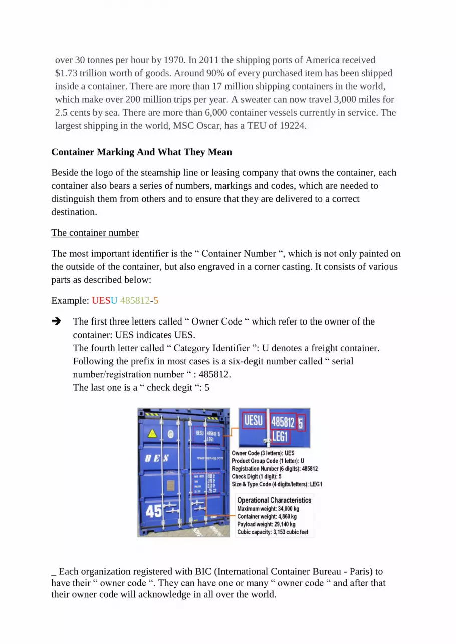
Container Marking And What They Mean
Beside the logo of the steamship line or leasing company that owns the container, each
container also bears a series of numbers, markings and codes, which are needed to
distinguish them from others and to ensure that they are delivered to a correct
destination.
The container number
The most important identifier is the “ Container Number “, which is not only painted on
the outside of the container, but also engraved in a corner casting. It consists of various
parts as described below:
Example: UESU 485812-5
The first three letters called “ Owner Code “ which refer to the owner of the
container: UES indicates UES.
The fourth letter called “ Category Identifier ”: U denotes a freight container.
Following the prefix in most cases is a six-degit number called “ serial
number/registration number “ : 485812.
The last one is a “ check degit “: 5
_ Each organization registered with BIC (International Container Bureau - Paris) to
have their “ owner code “. They can have one or many “ owner code “ and after that
their owner code will acknowledge in all over the world.

_ There are only three possible “ Category Identifier “: U (freight container), J
(detachable freight container-related equipment) and Z (trailer or chassis) based on ISO
6346.
_ “ Serial number “ always have six number, free of choice and each serial number
belong to only one container.
Example: 582324 or 001234 etc.
_ “ Check degit “ be validated by a mathematical process and we can make an online-
checking at www.bid-code.org
How to caculate check degit ?
Step 1: Each letter of the alphabet corresponding to a numerical value, beginning with
10 for the letter A. The individual number in the serial number keep their own value.
A B C D E F G H I J K L M
10 12 13 14 15 16 17 18 19 20 21 23 24
N O P Q R S T U V W X Y Z
25 26 27 28 29 30 31 32 34 35 36 37 38
Step 2: Each of number caculated in step one is multiplied by 2𝑎 and a start at 0 from
left to right.
20 21 22 23 24 25 26 27 28 29
1 2 4 8 16 32 64 128 256 512
Step 3: Sum up all results of step 2 then divide them by 11. Remainder is Check Degit
Example: UESU 485812
Caculate the check degit ?
U E S U 4 8 5 8 1 2 Result
32 15 30 32 4 8 5 8 1 2
x x x x x x x x x x
1 2 4 8 16 32 64 128 256 512
= = = = = = = = = =
32 30 120 256 64 256 320 1024 256 1024 ∑ = 3382
Divided to 11 307,45
Remainder = Check Degit 5
APLU 158076
Caculate the check degit ?

A P L U 1 5 8 0 7 6 Result
10 27 23 32 1 5 8 0 7 6
x x x x x x x x x x
1 2 4 8 16 32 64 128 256 512
= = = = = = = = = =
10 54 92 256 16 160 512 0 1792 3072 ∑
= 5964
Divided to 11 542,18
Remainder = Check Degit 2
Note: when the remainder number is 10, the check degit becomes 0
There are some popular owner code such as:
Owner Code Company name
APL American President Line
CGM CMA-CGM
MAE Maersk
NYK NYK Line
KNL P&O / Nedloyd
There are some Vietnamse owner code (2010) such as:
Owner Code Company name
GMD Gemadept
GMT Gematrans
NSH Nam Trieu Shipping
VCL Vinashin – TGC
VNL Vinalines Container
VNT Vinashin - TGC