hydrophobic gold catalysts: from synthesis on passivated silica to synthesis on few-layer graphene
TRANSCRIPT

Hs
FIa
6b
a
ARRAA
KGGHSR
1
ntnniptae“ats
h0
Catalysis Today 235 (2014) 90–97
Contents lists available at ScienceDirect
Catalysis Today
j o ur na l ho me page: www.elsev ier .com/ locate /ca t tod
ydrophobic gold catalysts: From synthesis on passivated silica toynthesis on few-layer graphene
abrice Vignerona, Alexandre Piqueta, Walid Baaziza, Pascale Ronotb, Anne Boosb,zabela Janowskaa, Cuong Pham-Huua, Corinne Petit a, Valérie Capsa,∗
Institut de Chimie et Procédés pour l’Energie, l’Environnement et la Santé (ICPEES, Université de Strasbourg/CNRS UMR 7515), ECPM, 25 rue Becquerel,7087 Strasbourg Cedex 02, FranceInstitut Pluridisciplinaire Hubert Curien (IPHC, Université de Strasbourg/CNRS UMR 7178), 23 rue du Loess, BP 28, 67037 Strasbourg Cedex, France
r t i c l e i n f o
rticle history:eceived 15 November 2013eceived in revised form 4 March 2014ccepted 2 April 2014vailable online 16 May 2014
eywords:old nanoparticlesraphene
a b s t r a c t
Hydrophobic gold catalysts have recently proven useful in increasing the efficiency of the aerobic oxida-tion of hydrocarbons in apolar liquid media. Catalytically active 3 nm gold nanoparticles can be dispersedon the surface of commercially available methyl-terminated silica by performing chemical reductionof triphenylphosphine gold(I) chloride in the presence of the support in an ethanol/dichloromethanemixture. This method is here applied to a home-made few-layer graphene which displays a pristinegraphitic surface, as shown by thermogravimetric analysis. Since direct application of the protocol leadsto much larger gold particles, the protocol of synthesis is subsequently adapted to the specific nature ofthe graphene support, in particular by performing the reaction under sonication. Further studies of the
ydrophobicityonicationeproducibility
effect of several reaction parameters on both the average gold crystallite size determined by XRD andthe deposition yields determined by elemental analysis reveal (1) the superiority of DMF in minimizingthe gold particle size and (2) the impact of short reduction times on maximizing the deposition yields.Repeatability of the experiment is ensured by the development of an optimized protocol of synthesis,and in particular the identification of the most effective positions in the sonication bath.
© 2014 Elsevier B.V. All rights reserved.
. Introduction
The discovery of the catalytic activity of supported goldanoparticles (NPs) by Haruta [1] triggered various incentivesowards the use of gold as oxidation catalysts from the earlyineties. Initially aimed at replacing Pt in a straight forward man-er, due to the lower and more stable cost of the raw material, the
nterest is still intact nowadays despite the dramatic increase in therice of gold, due to the unequalled activity at low temperature ofhose gold NPs [2]. This low temperature activity in reactions suchs the oxidation of CO [3] or the water-gas shift reaction [4] how-ver relies on the use of supports described in the early stages asactive” due to their role in oxygen activation, i.e. titanium oxidesnd related transition metal oxides [5]. Hence, most methods for
he preparation of gold catalysts initially focused on those reducibleupports [6,7].∗ Corresponding author. Tel.: +33 368 852 733.E-mail address: [email protected] (V. Caps).
ttp://dx.doi.org/10.1016/j.cattod.2014.04.016920-5861/© 2014 Elsevier B.V. All rights reserved.
It was later found that alumina-supported gold catalysts couldalso be active in the oxidation of CO, especially when hydrogenwas present in the feed. In addition to preventing deactivation ofthe catalyst [8] and allowing regeneration of deactivated catalysts[9,10], hydrogen is indeed thought to open up new oxidation path-ways [11], by e.g. the in-situ formation of peroxyl-type species [12],which are basically independent from the support [13,14]. This trig-gered a new field of research in which gold NPs did not need to beassociated with reducible oxides, as long as the oxidation was car-ried out in the presence of a sacrificial reductant which ensuredoxygen activation. This led to the development of Au/Al2O3 cat-alysts [15] for the preferential oxidation of CO in the presence ofhydrogen (PROX reaction), as well as Au/TS-1 bi-functional systemsfor the epoxidation of propylene with H2 and O2 [16].
Such oxide-supported gold catalysts are generally preparedfrom reaction between a gold precursor (mostly HAuCl4) and thehydroxyl groups present on the support surface [17,18], followed by
reduction. Alternative methods in which the gold precursor is firstchemically reduced in solution before the resulting sol is adsorbedon the support also lead to efficient catalysts [19–21]. The resultinghydroxyl-terminated gold catalysts are indeed perfectly suited to
F. Vigneron et al. / Catalysis Today 235 (2014) 90–97 91
Fig. 1. Order of reactivity (a) and selectivity (b) in gold-catalyzed aerobic trans-stilbene (tS) epoxidation in methylcyclohexane (MCH) over soluble Au@SiC8 [36] (♦), a surface-p 3+ e Au/1
g[
obsvAcgTbomRda3drh
tfwisdggstptocaas
o(ttaa
assivated Aup/SiO2 powder [27] (�), nanocrystalline Au/TiO2:Gd [26] (�) and th mmol, MCH 155 mmol, Au 2 �mol, TBHP 50 �mol, 80 ◦C, 700 rpm, air 1 atm.
as phase reactions in which those functions can act as promoters22,23].
However, these oxide-supported gold catalysts turned out to benly poorly dispersed within the aerobic media used for hydrocar-on oxidation in the liquid phase, because the hydrophilic oxideurfaces only have a poor affinity with apolar substrates and sol-ents [24]. As a result, the reaction rates observed in e.g. theu/MOx-catalyzed aerobic co-oxidation of stilbene and methyl-yclohexane appear diffusion-limited [25,26]. Besides, hydroxylroups are known to alter the selectivity of the epoxidation [27].he performances of the gold-catalyzed aerobic epoxidation of stil-ene mediated by methylcyclohexane [28] have been improvedver the years by the design of new catalytic materials, with opti-ized surfaces and affinity for the apolar reaction media (Fig. 1).
ecently, a reference catalyst was prepared for this reaction byeveloping a straightforward method to decorate the surface of
commercially available methyl-terminated silica support with nm gold particles [29]. This method, which is based on theirect chemical reduction of the triphenylphosphine gold(I) chlo-ide complex in an ethanol solution containing a suspension of theydrophobic powder, can in principle be applied to other supports.
In particular, it appeared interesting to evaluate the potential ofhis method to disperse gold particles over pristine graphitic sur-aces. Indeed, the fully aromatized carbon surface could interactith the triphenylphosphine ligand of the gold complex in �–�
nteractions [30], offering a great number of ordered adsorptionites. It could provide an alternative to the typical methods for metalecoration of carbonaceous surfaces, which generally use oxy-enated functions of an oxidized version of the carbon material (e.g.raphite oxide) as adsorption sites [31], such as e.g. “strong electro-tatic adsorption” [32] or covalent grafting [33,34]. It is noted thathe �–� interactions expected between the gold complex and theristine graphitic surface are anticipated to be much weaker thanhat engineered by pyrene functions. It is underlined that the aimf the present work is not to firmly immobilize gold complex andarry out heterogenized catalysis [35] but instead, to make use of
soft interaction between the complex and the surface that mayllow one to control the growth of the metal particle on the supporturface upon reduction.
In this paper, we thus report on the direct chemical reductionf AuPPh3Cl in the presence of a home-made few-layer grapheneFLG) and discuss its potential towards dispersing gold NPs over
he pristine graphitic surface. In particular, we show how the ini-ial contact time (i.e. time of reaction between the gold precursornd FLG prior to reduction), the reduction time (i.e. time of reactionfter the introduction of the chemical reductant) and the solventTiO2-WGC reference gold catalyst for CO oxidation [37] (�). Reaction conditions: tS
of reaction influence the size of the resulting gold NPs supportedon graphene, as well as the gold loading. After observation of lackof reproducibility in the N,N-dimethylformamide solvent, we alsopresent the development of an optimized protocol for the synthe-sis of Au-FLG composites that guarantees repeatability in organicsolvents.
2. Materials and methods
2.1. Synthesis protocols
The synthesis solvents, namely acetonitrile (ACN, 99.99%,ACROS), dichloromethane (DCM, ≥99.8%, Carlo-Erba), N,N-dimethylformamide (DMF, ≥99.8%, Sigma-Aldrich), ethanol (EtOH,≥99.9%, Carlo-Erba), methanol (MeOH, ≥99.9%, Carlo-Erba) andtoluene (99.5%, Carlo Erba), are used without further purification.
2.1.1. Few-layer grapheneFLG is synthesized from expanded graphite by surfactant-
assisted exfoliation in the liquid phase [38,39], via a typicalsonication/sedimentation process using toluene as solvent and Tri-ton X-100 as surfactant. In more details, 3 g of expanded graphite(Mersen, ex-Carbone Lorraine) and 9 g of Triton X-100 (Labora-tory grade, Sigma-Aldrich) are placed in a beaker together with900 mL of toluene. The mixture is then sonicated (Bandelin HD2200probe sonicator, 30% of 200 W, 20 kHz) in 2 cycles of 30 min,with a 10 min sedimentation step between the 2 cycles. After10 min sedimentation, 300 mL of the upper part of the partiallysedimented mixture is extracted. After filtration, the lighter FLGflakes (i.e. those containing the smallest number of layers) arecollected on the filter, while the supernatant is poured back intothe beaker. The 900 mL mixture is submitted to two more soni-cation/sedimentation/extraction/filtration cycles, using the samefilter paper on which the FLG is accumulated. The FLG is thenwashed with 900 mL of ethanol and dried in an oven at 90 ◦Covernight.
The obtained FLG (typically 1.6 ± 0.2 g) is further treated underflowing argon (ca. 200 mL min−1, ramp of 10 ◦C min−1 up to 900 ◦Cfollowed by a 3 h isotherm at 900 ◦C) in order to remove all residualvolatile products and surfactant traces, as set-up in previous work[40].
2.1.2. Au-FLG composites: Decoration of the FLG surface with AuNPs by chemical reduction of AuPPh3Cl in the presence of FLG
Prior to each synthesis, fresh solutions of sodium borohydride(10−2 M) and of the gold precursor (2.5 × 10⁻³ M) are prepared by

92 F. Vigneron et al. / Catalysis To
d2i
stOp(tbobtcdf1
rt(tbMiaia
2
(bto
lri0oih
Ce
Fig. 2. Optimized set-up for the preparation of Au-FLG composites.
issolving 7.6 mg of NaBH4 (ReagentPlus, 99%, Sigma-Aldrich) in0 mL of solvent and 12.4 mg of AuPPh3Cl (≥99.9%, Sigma-Aldrich)
n 10 mL of solvent, respectively.FLG (100 mg) is dispersed in 55 mL of solvent using the tip
onicator (Bandelin HD2200, 30% of 200 W, 20 kHz) for 5 min,hen placed self-standing into a sonication bath (Elma, Elmasonicne, 30 W, 35 kHz), and allowed to cool down to room tem-erature. About 2 mL of the freshly prepared AuPPh3Cl solution2.5 × 10−3 M, 1 mg Au) is added into the FLG dispersion after whichhe sonication bath is turned on. After a given time of contactetween FLG and gold (0 < t1 = initial contact time < 120 min), 5 mLf the freshly prepared NaBH4 solution (10−2 M) is poured into theeaker in order to have a NaBH4/Au molar ratio of 10. After a givenime of reduction (5 < t2 = reduction time < 120 min), the flakes areollected by filtration, washed with 120 mL of solvent and thenried in an oven at 90–130 ◦C (depending on the solvent used: 90 ◦Cor EtOH/DCM, 110 ◦C for MeOH/EtOH, toluene and acetonitrile, and30 ◦C for DMF) for 24 h.
In an optimized protocol, which has proven essential in ensuringepeatability of the syntheses in DMF (as will be explained below),he beakers are held and maintained still inside the sonication bathFig. 2), at fixed positions from the left and right hand-side bot-om corners, the bottom of the beakers touching the bottom of theath. The volume of water filled in the bath is also fixed (200 mL).onitoring of the temperature both in the bath and in the beakers
ndicates that it is constantly rising during the experiment, frombout 20 ◦C to about 60 ◦C after 4 h. In these experiments, the wash-ng step is omitted for simplicity, as its impact on gold loadings andverage crystallite sizes has proven minor.
.2. Characterization of the synthesized material
The purity of FLG is determined by thermogravimetric analysisTGA) using TGA Q5000 from TA Instruments. A few mg of FLG,efore and after Ar treatment at 900 ◦C, is placed on a pan which ishen heated to 900 ◦C at 10 ◦C min−1 under flowing air. Evolutionf the sample weight is monitored by the TA QSeries software.
X-ray diffraction (XRD) patterns of Au-FLG composites are col-ected using a Bruker D8 Advance theta-theta diffractometer (Cu K�
adiation), operated at 40 kV and 40 mA. The datasets are acquiredn step-scan mode over the 2� range 25–46◦, using a step interval of.0132◦ and a counting time of 1s per step. Samples are depositedn a round-shaped glass plate. Average size of the Au crystallitess determined using the Scherrer formula from the full width at
alf-maximum (FWHM) of the Au (1 1 1) reflection at 2� = 38.2◦.Transmission electron microscopy (TEM) is carried out on a TOP-ON 002B microscope working at 200 kV accelerating voltage andquipped with a probe corrector for spherical aberrations, giving
day 235 (2014) 90–97
a point-to-point resolution of 0.18 nm. The sample is dispersed byultrasound in an ethanol solution for 5 min. A drop of the solu-tion is subsequently deposited on a copper grid covered with aholey carbon membrane for observation. The size distribution ofthe observed gold particles is calculated from the size measure-ments of more than 300 nanoparticles using the ImageJ software[41]. The average particle size and the standard deviation on theaverage value are determined from these distributions.
Elemental analysis of the composites is performed as follows:first, the powder samples are digested at about 215 ◦C and 60 barin a microwave digestion system (Multiwave 3000, Anton Paar,Austria) using an aqua regia mixture prepared with 2 mL HNO3(Fluka, TraceSELECT >69%, Germany) and 4 mL HCl (Fluka, Trace-SELECT >37%, Germany). Second, analysis of diluted filtrates iscarried out, after filtration of residual particles, by Inductively Cou-pled Plasma Optical Emission Spectroscopy (ICP-OES, Varian 720ES,France) at 197.742 nm (Au), 249.678 nm (B), 589.592 nm (Na), and213.618 nm (P). Multi-element standards are prepared by dilutionof 1000 mg L−1 certified single element standards (CPI Interna-tional, The Netherlands) in aqua regia media to minimize matrixeffect errors. A spike on a digested sample allows checking thatthe recovered concentrations are 100% ± 10%. The limit of detec-tion of the instrument is 0.1 mg L−1 for Au and B, 0.05 mg L−1 forNa and P. Analysis of the gold component of the Au-FLG compositeallows to calculate deposition yields which are defined as the ratiobetween the mass of gold found in the composite and the mass ofgold reacted with FLG (1 mg).
Raman spectroscopy is performed on a Horiba Scientific LabramAramis Raman Spectrometer (JobinYvon technology) using a laserwavelength of 532.15 nm and incident power of 0.9 mW (1% of thetotal 90 mW power by applying a D2 filter). Spectra are recordedin both 1250–1650 cm−1 and 2600–2800 cm−1 regions with inte-gration time of 100 s for each region. Samples are prepared byhot-spraying FLG dispersion in ethanol on SiO2/Si wafers.
3. Results and discussion
3.1. FLG synthesis and characterization
In this study, the few-layer graphene is synthesized bysonication-assisted liquid phase exfoliation of unfunctionalizedexpanded graphite [42]. It is carried out in a non-oxidative liquidmedium in order to avoid any oxygen incorporation in the grapheneplanes. The initial concentration of expanded graphite (EG) is fixedat 3.33 mg mL−1, which is a typical concentration used in the liquidphase synthesis of FLG. 50 wt.% of the EG precursor is exfoliatedinto few-layer graphene flakes, which can be stabilized at con-centrations estimated at 1–3.33 mg mL−1. The synthesis is indeedcarried out in the presence of the Triton X-100 surfactant in orderto assist the solvent exfoliation and to stabilize the resulting dis-persion of exfoliated FLG flakes in toluene. The surfactant-assistedsolvent exfoliation is performed at ambient temperature using ahigh-power sonication probe, which causes the temperature of thedispersion to rise to about 60 ◦C. Short sonication times are used,as prolonged times may not be needed when surfactant moleculesare present to decrease the size of the FLG flake [43].
The TGA profile of the resulting surfactant/solvent exfoliatedFLG exhibits a weight loss between 200 and 300 ◦C (Fig. 3a), whichis attributed to the decomposition/combustion of residual TritonX-100 molecules (BP 270 ◦C) trapped within the FLG packed struc-ture. Considering the high solubility of toluene in ethanol and
the extensive ethanol wash applied to the FLG flakes, the pres-ence of about 1 wt.% Triton X-100 in the dried material suggeststhat the surfactant does more than just stabilizing the exfoliatedFLG flakes and acts as an exfoliating agent, likely by intercalation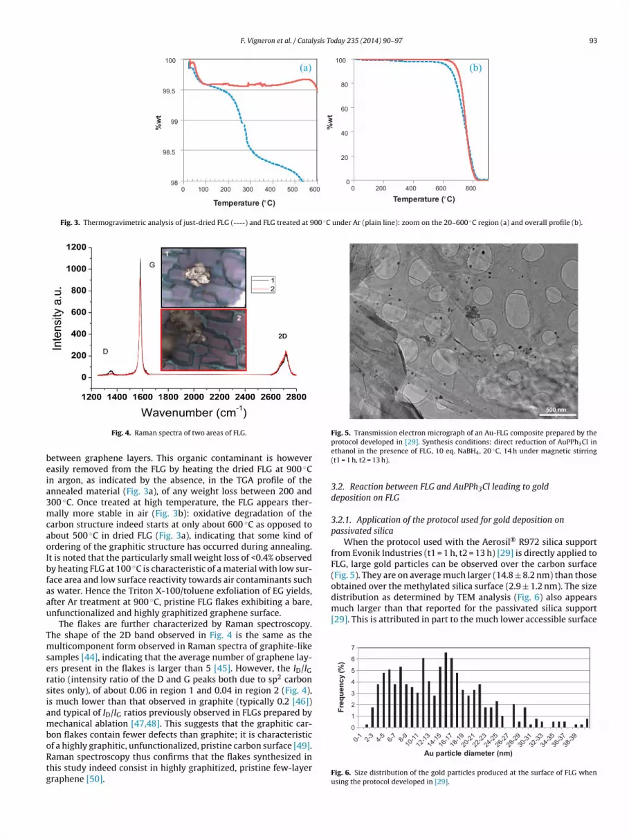
F. Vigneron et al. / Catalysis Today 235 (2014) 90–97 93
98
98.5
99
99.5
100
0 100 200 300 400 500 600
%w
t
Temperature (°C) Temperature (°C)
0
20
40
60
80
100
0 200 400 600 800
%w
t
(a) (b)
Fig. 3. Thermogravimetric analysis of just-dried FLG (----) and FLG treated at 900 ◦C under Ar (plain line): zoom on the 20–600 ◦C region (a) and overall profile (b).
beia3mcaoIbfaau
TmsersiamboRtg
Fig. 5. Transmission electron micrograph of an Au-FLG composite prepared by the
distribution as determined by TEM analysis (Fig. 6) also appearsmuch larger than that reported for the passivated silica support[29]. This is attributed in part to the much lower accessible surface
0
1
2
3
4
5
6
7
Freq
uenc
y (%
)
Fig. 4. Raman spectra of two areas of FLG.
etween graphene layers. This organic contaminant is howeverasily removed from the FLG by heating the dried FLG at 900 ◦Cn argon, as indicated by the absence, in the TGA profile of thennealed material (Fig. 3a), of any weight loss between 200 and00 ◦C. Once treated at high temperature, the FLG appears ther-ally more stable in air (Fig. 3b): oxidative degradation of the
arbon structure indeed starts at only about 600 ◦C as opposed tobout 500 ◦C in dried FLG (Fig. 3a), indicating that some kind ofrdering of the graphitic structure has occurred during annealing.t is noted that the particularly small weight loss of <0.4% observedy heating FLG at 100 ◦C is characteristic of a material with low sur-ace area and low surface reactivity towards air contaminants suchs water. Hence the Triton X-100/toluene exfoliation of EG yields,fter Ar treatment at 900 ◦C, pristine FLG flakes exhibiting a bare,nfunctionalized and highly graphitized graphene surface.
The flakes are further characterized by Raman spectroscopy.he shape of the 2D band observed in Fig. 4 is the same as theulticomponent form observed in Raman spectra of graphite-like
amples [44], indicating that the average number of graphene lay-rs present in the flakes is larger than 5 [45]. However, the ID/IGatio (intensity ratio of the D and G peaks both due to sp2 carbonites only), of about 0.06 in region 1 and 0.04 in region 2 (Fig. 4),s much lower than that observed in graphite (typically 0.2 [46])nd typical of ID/IG ratios previously observed in FLGs prepared byechanical ablation [47,48]. This suggests that the graphitic car-
on flakes contain fewer defects than graphite; it is characteristic
f a highly graphitic, unfunctionalized, pristine carbon surface [49].aman spectroscopy thus confirms that the flakes synthesized inhis study indeed consist in highly graphitized, pristine few-layerraphene [50].protocol developed in [29]. Synthesis conditions: direct reduction of AuPPh3Cl inethanol in the presence of FLG, 10 eq. NaBH4, 20 ◦C, 14 h under magnetic stirring(t1 = 1 h, t2 = 13 h).
3.2. Reaction between FLG and AuPPh3Cl leading to golddeposition on FLG
3.2.1. Application of the protocol used for gold deposition onpassivated silica
When the protocol used with the Aerosil® R972 silica supportfrom Evonik Industries (t1 = 1 h, t2 = 13 h) [29] is directly applied toFLG, large gold particles can be observed over the carbon surface(Fig. 5). They are on average much larger (14.8 ± 8.2 nm) than thoseobtained over the methylated silica surface (2.9 ± 1.2 nm). The size
Au particle diameter (nm)
Fig. 6. Size distribution of the gold particles produced at the surface of FLG whenusing the protocol developed in [29].

94 F. Vigneron et al. / Catalysis Today 235 (2014) 90–97
0123456789
Freq
uenc
y (%
)
Au particle diameter (nm)
Fig. 7. Size distribution of the gold particles produced at the surface of FLG whenthe protocol developed in [29] is modified by using sonication (instead of magneticstirring) and a shorter reaction time (t1 = 0, t2 = 5 min).
19.722.3
12.6
35.9
12.213.4
15.1
7.7%
17.0%
52.0%
5.0%
33.3%35.3%
41.0%
0%
10%
20%
30%
40%
50%
60%
70%
80%
90%
100%
0
5
10
15
20
25
30
35
40
Dep
ositi
on y
ield
Cry
stal
lite
size
(nm
)
t1 (min)
Fig. 8. Effect of the contact time (t1) between FLG and AuPPh3Cl on the averagegFS
odbtpmns
(aaHdaaIf
cetFico
eat
19.6
13.412.2
6.4
0.30 %
70.9%
35.3%
74.0%
53.4%
0%
10%
20%
30%
40%
50%
60%
70%
80%
90%
100%
0
5
10
15
20
25
Dep
ositi
on y
ield
Cry
stal
lite
size
(nm
)
< d.l.
Fig. 9. Solvent effects on the average gold crystallite size (left axis) and the depo-
old crystallite size (left axis) and the deposition yield (right axis) observed in Au-LG composites prepared by direct reduction of AuPPh3Cl in the presence of FLG.ynthesis conditions: t2 = 2 h (under sonication).
f FLG materials, as compared with Aerosil® R972 (110 m2 g−1),ue to stacking of the FLG flakes. It shows that the aromatic car-on surface does not behave like a methylated silica and suggestshat the potential hydrophobic interactions occurring between thehenyl groups of the 3D gold complex and the 2D FLG surface isuch weaker than that obtained with the 3D silica surface. It is
oted however that the gold loading obtained on FLG (0.77 wt.%) isimilar to that found in Au/SiO2-R972 (0.73 wt.%) [29].
When the synthesis mixture is placed under ultra-soundinstead of magnetic stirring) and the reducing agent added straightfter the gold precursor (t1 = 0), similarly large size distributionsre obtained (Fig. 7), even after only 5 min of reaction (t2 = 5 min).owever, the fraction of Au NPs with diameters below 6 nm hasisappeared. The average gold particle size determined by TEMnalysis is consequently larger (20.1 ± 7.1 nm), although the aver-ge crystallite size determined by XRD remains identical (14.3 nm).nterestingly, the gold loading (0.65 wt.%) is again similar to thatound in Au/SiO2-R972.
When we subsequently performed the synthesis of the Au-FLGomposite in methanol/ethanol mixture (90/10 v/v) in order tonhance dispersion of the FLG flakes in the medium, we under-ook to determine the effect of the initial contact time (t1) betweenLG and AuPPh3Cl (i.e. prior to introduction of the NaBH4 reduc-ng agent) on both the average size of gold crystallites found in theomposites and the associated deposition yields obtained after 2 hf reduction.
At shorter contact times (t1 < 45 min), an apparently erraticffect of t1 is observed on the loading of FLG with gold (Fig. 8). It isttributed to a dual effect of the sonication: on one hand, sonica-ion is well-known to assist synthesis of metal nanoparticles in the
sition yield (right axis) observed in Au-FLG composite prepared by direct reductionof AuPPh3Cl in the presence of FLG. Synthesis conditions: t1 = 2 h, t2 = 2 h (undersonication).
presence of alcohols [51], while on the other hand, it is widely usedto remove metal particles from flat surfaces (i.e. low surface areamaterials) [52]. Besides, the protocol used (self-standing beakers)also contributes to this behaviour, as will be discussed below (Sec-tion 3.2.5). A maximum deposition yield of 52% is observed underthese conditions using 30 min of initial reaction between FLG andthe gold precursor. It is noted however that, at prolonged contacttimes (t1 > 60 min), the deposition yield steadily increases whenincreasing the time of reaction between FLG and AuPPh3Cl prior toNaBH4 addition, reaching 41% for t1 = 5 h.
The variation of the average size of the gold crystallites presentin the composites follows the same pattern: it seems erratic forcontact times shorter than 45 min, ranging from 12.6 nm for t1 =30 min to 35.9 nm for t1 = 45 min. It is noted that the larger crystal-lites are associated with the lower deposition yields (5–17%), whichsuggests that the number of smaller crystallites may be too small tocontribute to the average size calculated according to the Scherrerequation. The size might thus intrinsically be overestimated. Nev-ertheless, at prolonged reaction times, the average crystallite sizeappears to steadily increase with increasing initial contact time, upto 15.1 nm.
A minimum (optimum) size of about 12 nm is observed for aninitial contact time between FLG and AuPPh3Cl of 60 min, show-ing that t1 is unable to lower the size down to a “catalytic value”.Furthermore, it is associated with a modest deposition yield of only33.3%. The gold particle size seems determined by the conditions ofsonication, i.e. power of the ultra-sound and temperature of reac-tion [52]. It is worthy to note that gold nanoparticles with sizesabove 12 nm are too large to exhibit any catalytic behaviour [6].Since no kinetic control of the size seems possible under the con-ditions of irradiation used, we undertook to evaluate the effect ofthe solvent of synthesis on the size of the gold particles produced.
3.2.2. Solvent effectsThe different solvents selected for this screening had to ensure
solubility of both NaBH4 and AuPPh3Cl and high dispersion ofthe FLG. The synthesis was thus performed in toluene, ethanol(containing traces of dichloromethane-DCM to ensure AuPPh3Cldissolution), a methanol/ethanol (9/1 v/v) mixture (MeOH/EtOH),acetonitrile (ACN) and dimethylformamide (DMF). The gold crystal-lite sizes and associated deposition yields observed in the resulting
composites are shown in Fig. 9. Solvent are sorted by increasingpolarity from left to right on the x axis. It clearly appears thatsmaller crystallites are obtained with solvents of higher polarity,average sizes ranging from 19.6 nm in ethanol down to 6.4 nm in
F. Vigneron et al. / Catalysis To
6.4
9.6
53.4%
0.52%
21.4%
0%
10%
20%
30%
40%
50%
60%
70%
80%
90%
100%
0
2
4
6
8
10
Dep
ositi
on y
ield
Cry
stal
lite
size
(nm
)
< d.l.
Fig. 10. Evaluation of the repeatability of the direct reduction of AuPPh3Cl in DMF inthe presence of FLG on the average gold crystallite size (left axis) and the depositionyield (right axis) observed in the resulting Au-FLG composites. Synthesis conditions:t
Dtibbtwttmteat
cwTod
3
ettatcrsmtib
3s
bai
slight decrease in both crystallite size (14.3 nm) and deposition
1 = 2 h, t2 = 2 h (under sonication).
MF. The associated yields of deposition vary between 35.3% inhe methanol/ethanol mixture up to 74% in acetonitrile. Consider-ng the quasi-absence of deposition in the toluene solvent, it maye argued that deposition of gold on the FLG surface is controlledy the differential affinity between the gold precursor/particle andhe solvent molecules for the fully aromatized FLG surface. In otherords, gold is competing with the solvent molecules for adsorp-
ion onto the FLG surface; its interaction with FLG is much weakerhan the �–� bonding occurring between the aromatic toluene
olecule and the graphene surface. Subsequently, the smaller crys-allite size obtained in the more polar solvent would result from annhanced interaction between triphenylphosphine gold chloridend FLG, which would limit gold particle growth upon reduction ofhe AuPPh3Cl-FLG precursor.
In conclusion, we did manage to modify the size of the parti-les by varying the nature of the solvent. The smallest particles,hich size is now close to a “catalytic value”, are obtained in DMF.
heir production is associated with a reasonable deposition yieldf 53.4%, which prompted us to focus on these experimental con-itions.
.2.3. Reproducibility issuesHowever, after two unsuccessful attempts of reproducing the
xperiment, we had to face the fact that the protocol used failedo give twice the same composite (Fig. 10). In particular, deposi-ion yields of 0.52 and 21.2% were found in the first and secondttempts respectively, instead of 53.4% found in the original syn-hesis. The peculiar reactivity of DMF towards ultra-sound mayontribute to this lack of reproducibility: DMF has indeed beeneported to produce free radicals [53] which are known to disturbyntheses under sonication and normally require the addition ofolecules acting as radical trap [54]. However, the protocol of syn-
hesis allowing the synthesis media to move over a surface whichs non-homogeneously irradiated with ultra-sounds (self-standingeakers) is likely the main source of these issues.
.2.4. Development of an optimized protocol for repeatableynthesis
We thus undertook to evaluate the effect of the position of theeakers in the sonication bath on the average gold crystallite size
nd associated deposition yield produced by reduction of AuPPh3Cln DMF in the presence of FLG (Fig. 11). We found that:day 235 (2014) 90–97 95
(1) Syntheses performed in the corners of the bath (Fig. 11a) leadto smaller crystallites (< 9.2 nm) than syntheses performed inthe middle of the bath (Fig. 11b, >12.2 nm).
(2) Syntheses performed in the corners of the bath lead to muchhigher deposition yields (>54.2%) than syntheses performed inthe middle of the bath (<12.1%).
(3) The deposition yields are significantly more affected by theposition in the bath than the average size of the gold crystallitesproduced, which validates the results concerning gold particlesizes discussed so far.
In particular:(4) The average gold crystallite size produced in a corner position is
8.88 ± 0.28 nm, i.e. 8.88 (±3%) nm, while the average depositionyields obtained in a corner position is 67.2 ± 7.6 (11% in relativevalue)%.
(5) The average gold crystallite size produced in a central posi-tion is 13.15 ± 0.95 nm, i.e. 13.15 (±7%) nm, with an averagedeposition yield of 10.8 ± 1.4 (13% in relative value)%.
The influence of the position of the beaker on the characteris-tics of the synthesized composite is related to both heterogeneouspower supply within the bath sonicator and shock waves generatedin some peculiar areas of the bath. However, two corner positions(the lower left and lower right) appear to give very similar yieldswhich also happen to be the highest observed for the synthesis ofAu-FLG composites in DMF (74.8 ± 0.7%). The corresponding goldcrystallite size is 8.6 ± 0.2 nm. It is only slightly higher than the opti-mum average crystallite size obtained so far (6.4 nm) and is due tothe absence of washing.
The two positions in the lower corners were thus further testedfor repeatability (Fig. 12). In these experiments, the volume of thewater present in the sonication bath is only 200 mL, which allowedto further decrease the average size of the gold crystallites produceddown to 6.7–7.1 nm. As can be seen, the syntheses in both the lowerleft corner (Fig. 12a) and lower right corner (Fig. 12b) now appearfully reproducible: average crystallite sizes of 6.9 (±2.9%) nm areobtained in both the left and right positions. These are associatedwith deposition yields of 75.5 (±2.9%) % and 86.4 (±2.5%) % in theleft and right positions, respectively.
Hence not only does this optimized protocol provide repro-ducible synthesis, but it also maximizes the yields of depositionassociated with the small size of the supported gold crystallitesobtained in DMF.
Finally, considering that similar sizes of gold crystallites (6.9 nm)are produced in both the left and right positions and that a deposi-tion yield of 80.9 (±6.7%) % is obtained on average between the twopositions, the two positions are considered equivalent for the directreduction of AuPPh3Cl in the presence of FLG leading to Au-FLGcomposites.
3.2.5. Effect of t1 and t2 on the size and loading of gold on FLGThe effect of the initial contact time between AuPPh3Cl and
FLG (t1) in methanol/ethanol, which was discussed in Section3.2.1, is thus revisited by using the optimized protocol of synthesis(Fig. 13a). It is further completed by the study of the effect of thereduction time t2 (Fig. 13b).
It now clearly appears that t1 actually has a very limited influ-ence on the size of the gold crystallites formed in the composite.The crystallite size seems blocked at 15.3 ± 0.5 nm and determinedby the solvent and the conditions of sonication, as previously dis-cussed. The deposition yield on the other hand initially increaseswith increasing contact time, reaching 47.5% at t1 = 60 min. The
yield (45.6%) for t1 = 120 min, although accounted for by the stan-dard deviations described in Section 3.2.4, could well announce ageneral decrease for prolonged t1. This would be consistent with

96 F. Vigneron et al. / Catalysis Today 235 (2014) 90–97
8.8 8.4 9.1 9.2
75.5% 74.1%
65.0%
54.2%
0%
10%
20%
30%
40%
50%
60%
70%
80%
90%
100%
0
2
4
6
8
10
12
14
16
Dep
ositi
on y
ield
Cr y
stal
lite
size
(nm
)14. 1
12.2
9.4% 12.1%
0%
10%
20%
30%
40%
50%
60%
70%
80%
90%
100%
0
2
4
6
8
10
12
14
16
Dep
ositi
on y
ield
Cry
stal
lite
size
(nm
)
(a) (b)
Fig. 11. Impact of the position of the beaker (corner positions (a) and central positions (b)) on the average gold crystallite size (left axis) and the deposition yield (right axis)observed in Au-FLG composites prepared by direct reduction of AuPPh3Cl in DMF in the presence of FLG. Synthesis conditions: fixed beaker positions, sonication bath filledwith 400 mL water, t1 = 2 h, t2 = 2 h, no washing step applied.
6.7 7.0
84.2% 88.5%
0%
10%
20%
30%
40%
50%
60%
70%
80%
90%
100%
0
2
4
6
8
10
Dep
ositi
on y
ield
Cry
stal
lite
size
(nm
)6.77.1
77.6%73.3%
0%
10%
20%
30%
40%
50%
60%
70%
80%
90%
100%
0
2
4
6
8
10
Dep
ositi
on y
ield
Cry
stal
lite
size
(nm
)
)b()a(
Fig. 12. Repeatability of the direct reduction of AuPPh3Cl in DMF in the presence of FLG performed in the lower left corner (a) and lower right corner (b) under optimizedsynthesis conditions (fixed beaker positions, sonication bath filled with 200 mL water, t1 = 2 h, t2 = 2 h, no washing step applied).
15.6 15.4 15.714.3
33.0%40.0%
47.5% 45.6%
0%
10%
20%
30%
40%
50%
60%
70%
80%
90%
100%
0
2
4
6
8
10
12
14
16
18
Dep
ositi
on y
ield
Cr y
stal
lite
size
(nm
)
t1 (min )
12.9
16.8
13.614.783.7%
47.6% 45.1%42.6%
0%
10%
20%
30%
40%
50%
60%
70%
80%
90%
100%
0
2
4
6
8
10
12
14
16
18
Dep
ositi
on y
ield
Cr y
stal
lite
size
(nm
)
t2 (min )
(a) (b) t1 = 1 h t2 = 2 h
Fig. 13. Effect of the initial contact time between FLG and AuPPh3Cl, t1, (a) and the reduction time t2 (b) on the average gold crystallite size (left axis) and on the depositionyield (right axis) observed in Au-FLG composites prepared by direct reduction of AuPPh3Cl in MeOH/EtOH in the presence of FLG using the optimized protocol (fixed beakerpositions, sonication bath filled with 200 mL water, no washing step applied).

ysis To
tatmipt
bcso3ttwotoc
4
sebcstlotew(m
A
ist(
R
[
[
[
[
[[[
[[
[[
[
[
[
[
[
[[
[[[
[
[
[[
[[
[[
[[
[[
[[
[[
[
[
[[[
F. Vigneron et al. / Catal
he dual effect of sonication, which is used for metal leaching,s already mentioned. This will require confirmation by probing1 > 120 min. In the meantime, t1 = 60 min can be considered as a
inimum, if not optimum, contact time to maximize the gold load-ng in the Au-FLG composites obtained in methanol/ethanol. Theotential decrease in gold particle size which could be achieved for1 > 60 min would only be so at the expense of the loading.
The effect of the reduction time (t2) has thus been studiedy keeping the initial contact time between AuPPh3Cl and FLGonstant at 1 h. As can be seen on Fig. 13b, a very high depo-ition yield of 83.7% can be achieved for a short reduction timef only 5 min. When the reduction time is further increased to0 min, the deposition yields drop to from 83.7% to 47.6%. Again,he apparent decrease in gold loadings upon further increasinghe reduction time (t2 > 30 min) will require confirming, as it isell-contained within the standard deviations calculated for the
ptimized protocol. Besides, the effect of t2 on the average size ofhe gold crystallites present in the Au-FLG composite is not obvi-us: it appears to oscillate between 12.9 and 16.8 nm, around whatould be an average value of 14.5 ± 1.3 nm.
. Conclusion
We have shown that pristine few-layer graphene can beynthesized from Triton X100/toluene exfoliation of commercialxpanded graphite, followed by annealing at 900 ◦C. The reactionetween the pristine graphene surface and the AuPPh3Cl gold pre-ursor under reducing conditions depends on the nature of theolvent. The smallest gold particles (6.4 nm) are obtained in DMF,he most polar solvent evaluated in this study. After experiencingack of reproducibility, we have developed an optimized protocolf synthesis, which, in addition to ensure repeatability of the syn-hesis, maximizes the deposition yields achieved in DMF (80%). It isxpected that the gold loadings of the resulting Au-FLG compositesill be further increased by shortening the reduction time to 5 min
instead of 2 h), as shown by the study in the methanol/ethanolixture.
cknowledgements
Dr. O. Ersen (IPCMS, University of Strasbourg/CNRS UMR 7504)s thanked for granting W. B. access to the TOPCON 002B micro-cope and for helpful discussion regarding TEM analysis. Funding byhe IDEX Attractivité 2012 program of the University of StrasbourgGRAPHOGOLD project) is gratefully acknowledged.
eferences
[1] M. Haruta, T. Kobayashi, H. Sano, N. Yamada. Chem. Lett. 10 (1987) 405.[2] V. Caps, L’Actualité Chimique 337 (2010) 18.[3] M. Haruta, N. Yamada, T. Kobayashi, S. Iijima, J. Catal. 115 (1989) 301.[4] R. Burch, Phys. Chem. Chem. Phys. 8 (2006) 5483.[5] M.M. Schubert, S. Hackenberg, A.C. van Veen, M. Muhler, V. Plzak, R.J. Behm, J.
Catal. 197 (2001) 113.
[6] M. Haruta, Gold Bull. 37 (2004) 27.[7] R. Zanella, S. Giorgio, C.R. Henry, C. Louis, J. Phys. Chem. B 106 (2002) 7634.[8] H.-S. Oh, C.K. Costello, C. Cheung, H.H. Kung, M.C. Kung, Stud. Surf. Sci. Catal.139 (2001) 375.[9] H.H. Kung, M.C. Kung, C.K. Costello, J. Catal. 216 (2003) 425.
[
[[
day 235 (2014) 90–97 97
10] M. Azar, V. Caps, F. Morfin, J.-L. Rousset, A. Piednoir, J.-C. Bertolini, L. Piccolo, J.Catal. 239 (2006) 307.
11] E. Quinet, L. Piccolo, F. Morfin, P. Avenier, F. Diehl, V. Caps, J.-L. Rousset, J. Catal.268 (2009) 384.
12] E. Quinet, F. Morfin, F. Diehl, P. Avenier, V. Caps, J.-L. Rousset, Appl. Catal., B:Environ. 80 (2008) 195.
13] C. Rossignol, S. Arrii, F. Morfin, L. Piccolo, V. Caps, J.-L. Rousset, J. Catal. 230(2005) 476.
14] S. Ivanova, V. Pitchon, C. Petit, V. Caps, ChemCatChem 2 (2010) 556.15] S. Ivanova, C. Petit, V. Pitchon, Appl. Catal., A: Gen. 267 (2004) 191.16] J. Huang, T. Akita, J. Faye, T. Fujitani, T. Takei, M. Haruta, Angew. Chem. Int. Ed.
48 (2009) 7862.17] F. Moreau, G.C. Bond, A.O. Taylor, J. Catal. 231 (2005) 105.18] S. Ivanova, V. Pitchon, Y. Zimmermann, C. Petit, Appl. Catal., A: Gen. 298 (2006)
57.19] M. Comotti, W.-C. Li, B. Spliethoff, F. Schüth, J. Am. Chem. Soc. 128 (2006) 917.20] (a) N. Zheng, G.D. Stucky, J. Am. Chem. Soc. 128 (2006) 14278;
(b) N. Zheng, J. Fan, G.D. Stucky, J. Am. Chem. Soc. 128 (2006) 6550.21] Y. Liu, H. Tsunoyama, T. Akita, T. Tsukuda, J. Phys. Chem. C 113 (2009)
13457.22] C.K. Costello, M.C. Kung, H.-S. Oh, Y. Wang, H.H. Kung, Appl. Catal., A: Gen. 232
(2002) 159.23] C.K. Costello, J.H. Yang, H.Y. Law, Y. Wang, J.-N. Lin, L.D. Marks, M.C. Kung, H.H.
Kung, Appl. Catal., A: Gen. 243 (2003) 15.24] P. Lignier, S. Mangematin, F. Morfin, J.-L. Rousset, V. Caps, Catal. Today 138
(2008) 50.25] P. Lignier, F. Morfin, L. Piccolo, J.-L. Rousset, V. Caps, Catal. Today 122 (2007)
284.26] V. Mendez, K. Guillois, S. Daniele, A. Tuel, V. Caps, Dalton Trans. 39 (2010) 8457.27] D. Gajan, K. Guillois, P. Delichère, J.-M. Basset, J.-P. Candy, V. Caps, C. Copéret,
A. Lesage, L. Emsley, J. Am. Chem. Soc. 131 (2009) 14667.28] K. Guillois, S. Mangematin, A. Tuel, V. Caps, Catal. Today 203 (2013) 111.29] K. Guillois, L. Burel, A. Tuel, V. Caps, Appl. Catal., A: Gen. 415–416 (2012) 1.30] R.K. Raju, J.W.G. Bloom, Y. An, S.E. Wheeler, ChemPhysChem 12 (2011)
3116.31] G. Goncalves, P.A.A.P. Marques, C.M. Granadeiro, H.I.S. Nogueira, M.K. Singh, J.
Grácio, Chem. Mater. 21 (2009) 4796.32] N. Job, F. Maillard, M. Chatenet, C.J. Gommes, S. Lambert, S. Hermans, J.R. Regal-
buto, J.-P. Pirard, Stud. Surf. Sci. Catal. (2010) 169.33] S. Hermans, V. Bruyr, M. Devillers, J. Mater. Chem. 22 (2012) 14479.34] C. Vriamont, M. Devillers, O. Riant, S. Hermans, Chem. Commun. 49 (2013)
10504.35] C. Vriamont, M. Devillers, O. Riant, S. Hermans, Chem Eur. J. 19 (2013) 12009.36] M. Boualleg, K. Guillois, B. Istria, L. Burel, L. Veyre, J.-M. Basset, C. Thieuleux, V.
Caps, Chem. Commun. 46 (2010) 5361.37] Reference gold catalysts—World Gold Council, Gold Bull. 36 (2003) 24.38] A.B. Bourlinos, V. Georgakilas, R. Zboril, T.A. Steriotis, A.K. Stubos, Small 5 (2009)
1841.39] X. Cui, C. Zhang, R. Hao, Y. Hou, Nanoscale 3 (2011) 2118.40] I. Janowska, K. Chizari, O. Ersen, S. Zafeiratos, D. Soubane, V. Da Costa, V.
Speisser, C. Boeglin, M. Houllé, D. Bégin, D. Plee, M.-J. Ledoux, C. Pham-Huu,Nano Res. 3 (2010) 126.
41] W. Rasband, 〈http://rsb.info.nih.gov/ij/〉.42] M. Cai, D. Thorpe, D.H. Adamson, H.C. Schniepp, J. Mater. Chem. 22 (2012)
24992.43] J.N. Coleman, Acc. Chem. Res. 46 (2013) 14.44] C. Faugeras, A. Nerrière, M. Potemski, A. Mahmood, E. Dujardin, C. Berger, W.A.
de Heer, Appl. Phys. Lett. 92 (2008) 011914.45] Z. Ni, Y. Wang, T. Yu, Z. Shen, Nano Res. 1 (2008) 273.46] A.C. Ferrari, J.C. Meyer, V. Scardaci, C. Casiraghi, M. Lazzeri, F. Mauri, S. Piscanec,
D. Jiang, K.S. Novoselov, S. Roth, A.K. Geim, Phys. Rev. Lett. 97 (2006) 187401.47] I. Janowska, D. Begin, K. Chizari, O. Ersen, P. Bernhardt, T. Romero, M.J. Ledoux, C.
Pham-Huu, Preparation of graphene by mechanically thinning graphite mate-rials, Patent WO 2011055039 A1, to University of Strasbourg, CNRS.
48] I. Janowska, T. Romero, P. Bernhardt, F. Vigneron, D. Begin, O. Ersen, M.J. Ledoux,C. Pham-Huu, Carbon 50 (2012) 3092.
49] A.C. Ferrari, J. Robertson, Phys. Rev. B: Condens. Matter 64 (2001) 075414.50] A.C. Ferrari, Solid State Commun. 143 (2007) 47.51] K. Okitsu, A. Yue, S. Tanabe, H. Matsumoto, Y. Yobiko, Langmuir 17 (2001) 7717.
52] A. Gutes, B. Hsia, A. Sussman, W. Mickelson, A. Zettl, C. Carraro, R. Maboudian,Nanoscale 4 (2012) 438.53] V. Misík, P. Riesz, Free Radical Biol. Med. 20 (1996) 129.54] M. Quintana, M. Grzelczak, K. Spyrou, B. Kooi, S. Bals, G. Van Tendeloo, P. Rudolf,
M. Prato, Chem. Commun. 48 (2012) 12159.