few more autocad exercises - wordpress.com
TRANSCRIPT
Few more AutoCAD exercises
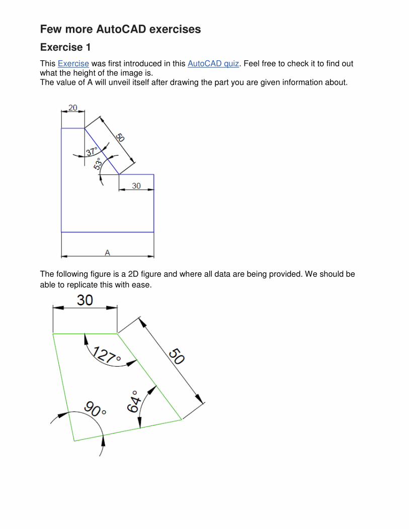
Exercise 1
This Exercise was first introduced in this AutoCAD quiz. Feel free to check it to find out what the height of the image is. The value of A will unveil itself after drawing the part you are given information about.
The following figure is a 2D figure and where all data are being provided. We should be
able to replicate this with ease.
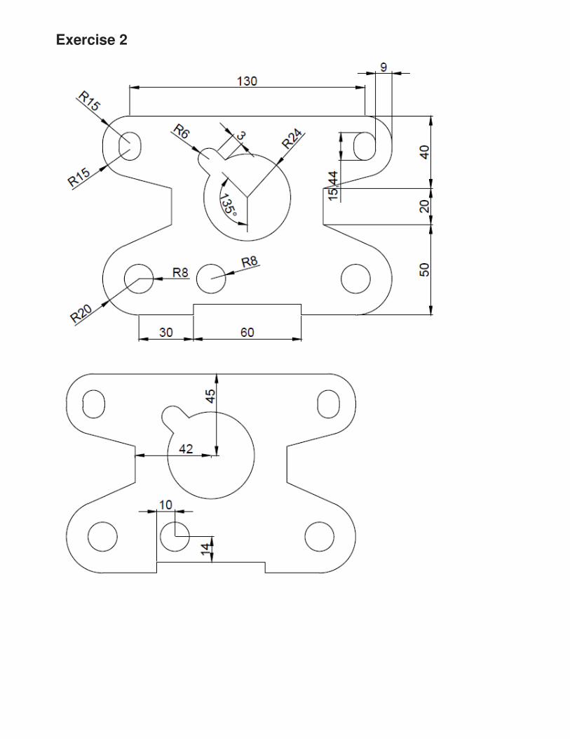
Exercise 2
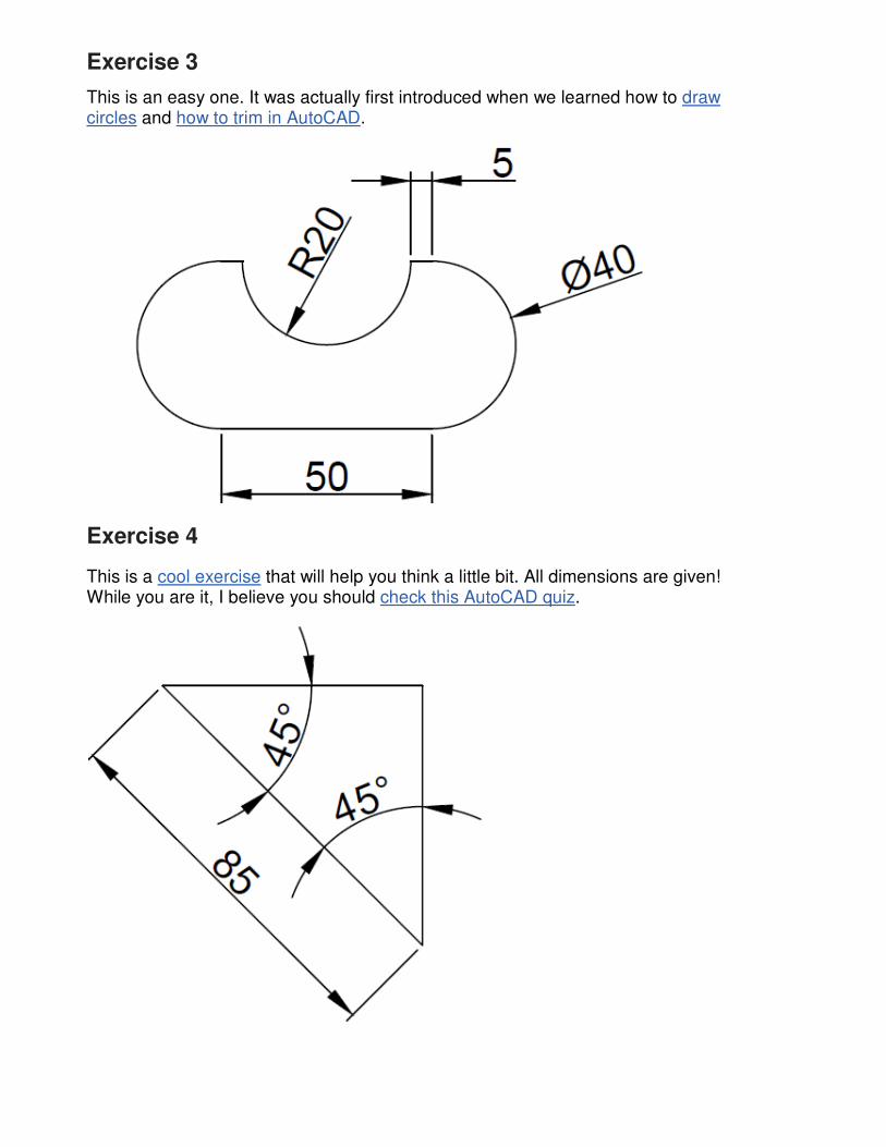
Exercise 3
This is an easy one. It was actually first introduced when we learned how to draw circles and how to trim in AutoCAD.
Exercise 4
This is a cool exercise that will help you think a little bit. All dimensions are given! While you are it, I believe you should check this AutoCAD quiz.
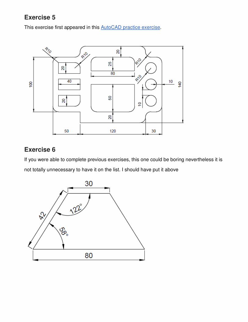
Exercise 5
This exercise first appeared in this AutoCAD practice exercise.
Exercise 6
If you were able to complete previous exercises, this one could be boring nevertheless it is
not totally unnecessary to have it on the list. I should have put it above
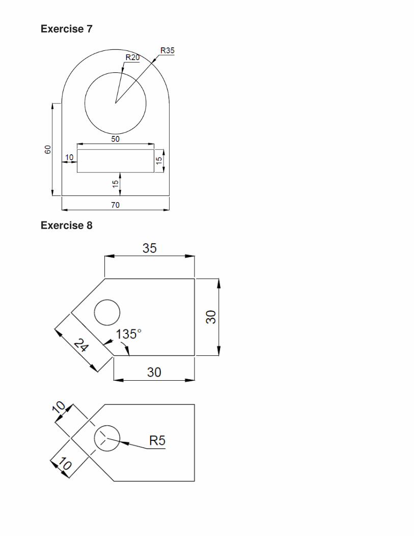
Exercise 7
Exercise 8
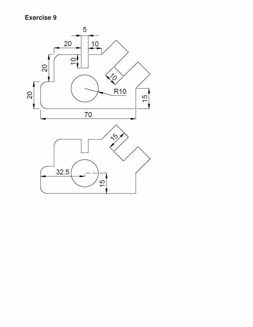
Exercise 9
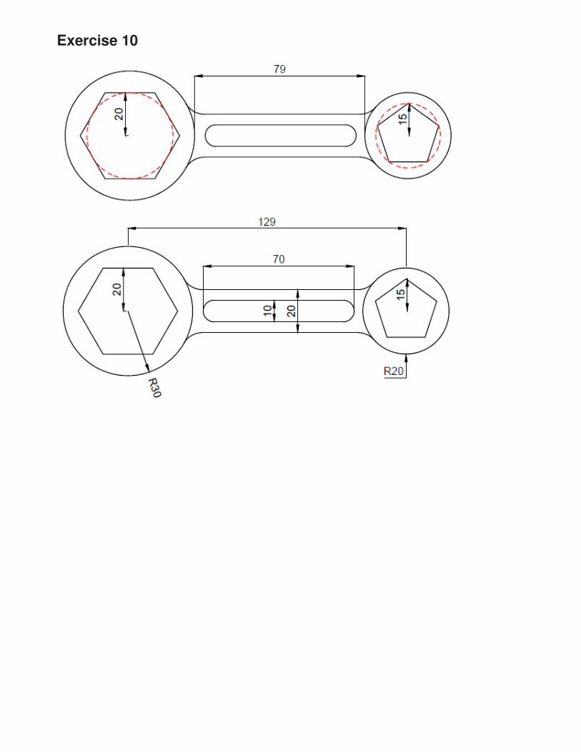
Exercise 10
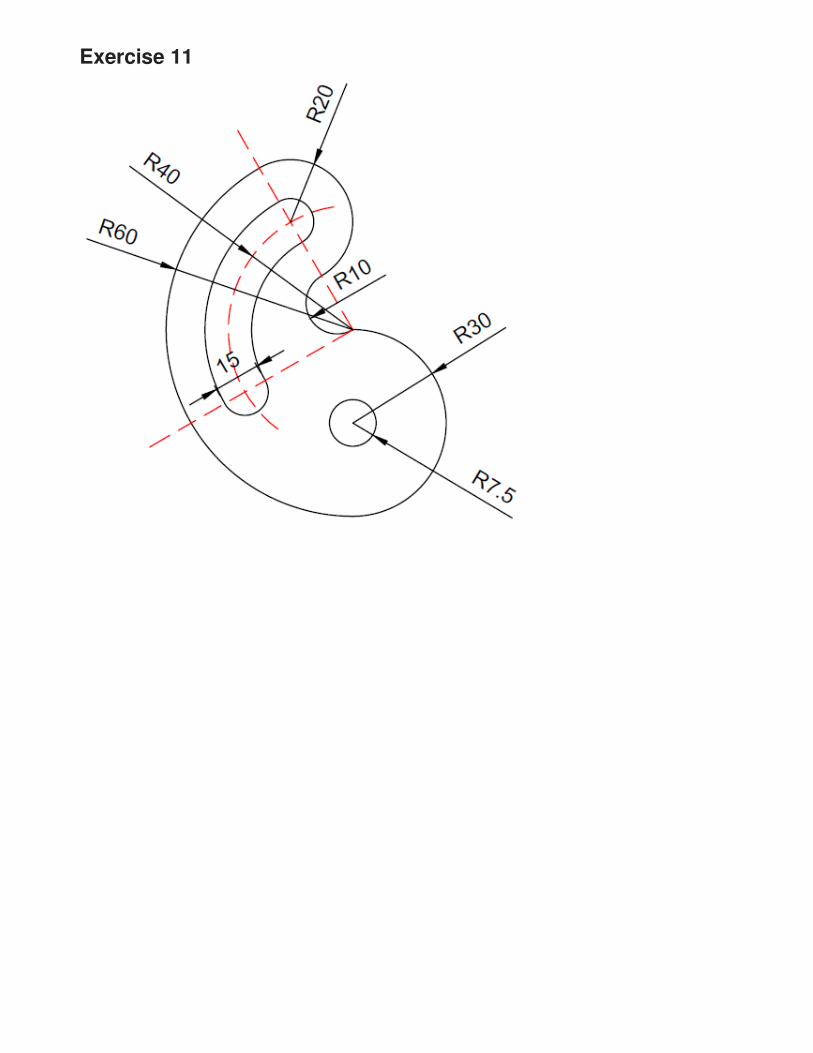
Exercise 11
1-38 AutoCAD 2016 Tutorial: 2D Fundamentals
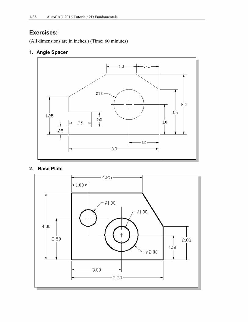
Exercises: (All dimensions are in inches.) (Time: 60 minutes) 1. Angle Spacer
2. Base Plate

AutoCAD Fundamentals 1-39
3. T-Clip
4. Channel Plate
1-40 AutoCAD 2016 Tutorial: 2D Fundamentals
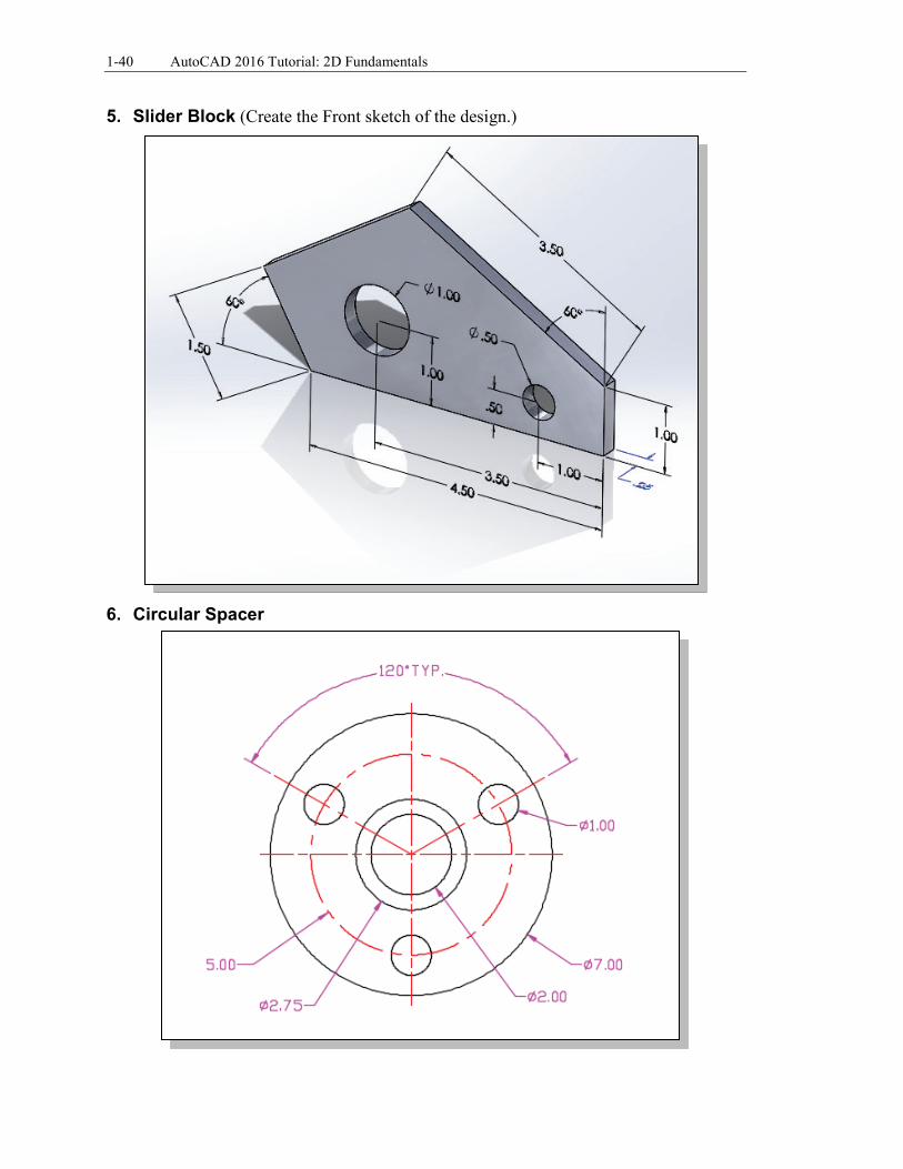
5. Slider Block (Create the Front sketch of the design.)
6. Circular Spacer
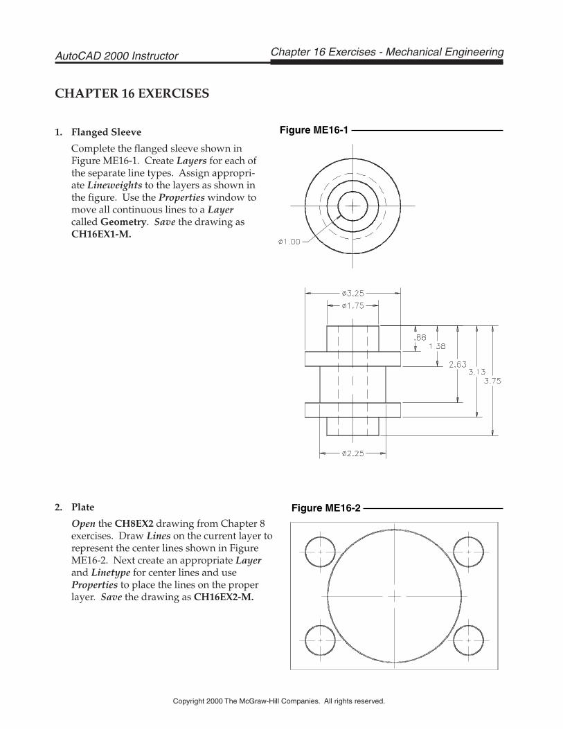
2. Plate
Open the CH8EX2 drawing from Chapter 8exercises. Draw Lines on the current layer torepresent the center lines shown in FigureME16-2. Next create an appropriate Layerand Linetype for center lines and useProperties to place the lines on the properlayer. Save the drawing as CH16EX2-M.
CHAPTER 16 EXERCISES
1. Flanged Sleeve
Complete the flanged sleeve shown inFigure ME16-1. Create Layers for each ofthe separate line types. Assign appropri-ate Lineweights to the layers as shown inthe figure. Use the Properties window tomove all continuous lines to a Layercalled Geometry. Save the drawing asCH16EX1-M.
Chapter 16 Exercises - Mechanical EngineeringAutoCAD 2000 Instructor
Copyright 2000 The McGraw-Hill Companies. All rights reserved.
Figure ME16-1
Figure ME16-2
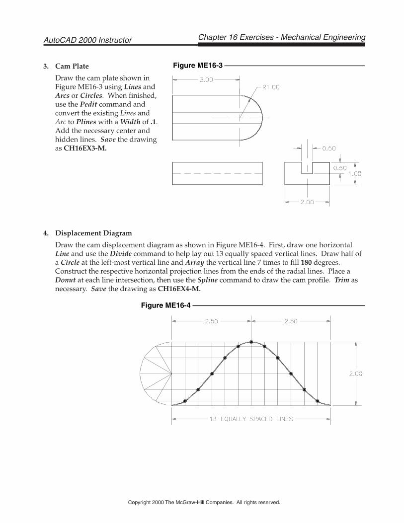
4. Displacement Diagram
Draw the cam displacement diagram as shown in Figure ME16-4. First, draw one horizontalLine and use the Divide command to help lay out 13 equally spaced vertical lines. Draw half ofa Circle at the left-most vertical line and Array the vertical line 7 times to fill 180 degrees.Construct the respective horizontal projection lines from the ends of the radial lines. Place aDonut at each line intersection, then use the Spline command to draw the cam profile. Trim asnecessary. Save the drawing as CH16EX4-M.
3. Cam Plate
Draw the cam plate shown inFigure ME16-3 using Lines andArcs or Circles. When finished,use the Pedit command andconvert the existing Lines andArc to Plines with a Width of .1.Add the necessary center andhidden lines. Save the drawingas CH16EX3-M.
Copyright 2000 The McGraw-Hill Companies. All rights reserved.
Chapter 16 Exercises - Mechanical EngineeringAutoCAD 2000 Instructor
Figure ME16-3
Figure ME16-4
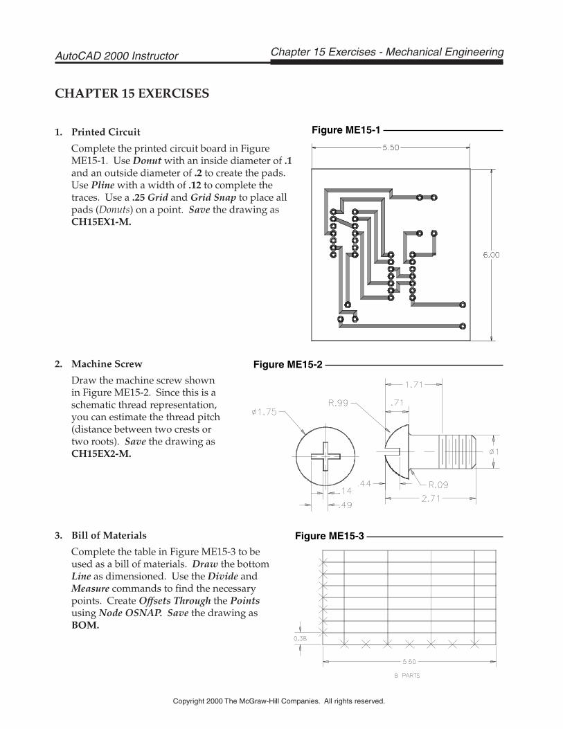
3. Bill of Materials
Complete the table in Figure ME15-3 to beused as a bill of materials. Draw the bottomLine as dimensioned. Use the Divide andMeasure commands to find the necessarypoints. Create Offsets Through the Pointsusing Node OSNAP. Save the drawing asBOM.
2. Machine Screw
Draw the machine screw shown in Figure ME15-2. Since this is aschematic thread representation,you can estimate the thread pitch(distance between two crests or two roots). Save the drawing asCH15EX2-M.
CHAPTER 15 EXERCISES
1. Printed Circuit
Complete the printed circuit board in FigureME15-1. Use Donut with an inside diameter of .1and an outside diameter of .2 to create the pads.Use Pline with a width of .12 to complete thetraces. Use a .25 Grid and Grid Snap to place allpads (Donuts) on a point. Save the drawing asCH15EX1-M.
Chapter 15 Exercises - Mechanical EngineeringAutoCAD 2000 Instructor
Copyright 2000 The McGraw-Hill Companies. All rights reserved.
Figure ME15-1
Figure ME15-2
Figure ME15-3
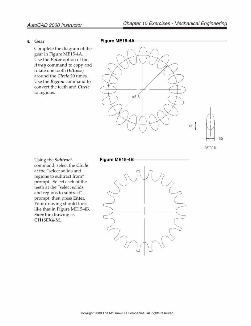
Using the Subtractcommand, select the Circleat the “select solids andregions to subtract from”prompt. Select each of theteeth at the “select solidsand regions to subtract”prompt, then press Enter.Your drawing should looklike that in Figure ME15-4B.Save the drawing asCH15EX4-M.
4. Gear
Complete the diagram of thegear in Figure ME15-4A.Use the Polar option of theArray command to copy androtate one tooth (Ellipse)around the Circle 20 times.Use the Region command toconvert the teeth and Circleto regions.
Copyright 2000 The McGraw-Hill Companies. All rights reserved.
Chapter 15 Exercises - Mechanical EngineeringAutoCAD 2000 Instructor
Figure ME15-4A
Figure ME15-4B
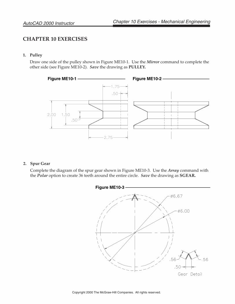
2. Spur Gear
Complete the diagram of the spur gear shown in Figure ME10-3. Use the Array command withthe Polar option to create 36 teeth around the entire circle. Save the drawing as SGEAR.
CHAPTER 10 EXERCISES
1. Pulley
Draw one side of the pulley shown in Figure ME10-1. Use the Mirror command to complete theother side (see Figure ME10-2). Save the drawing as PULLEY.
Chapter 10 Exercises - Mechanical EngineeringAutoCAD 2000 Instructor
Copyright 2000 The McGraw-Hill Companies. All rights reserved.
Figure ME10-1 Figure ME10-2
Figure ME10-3
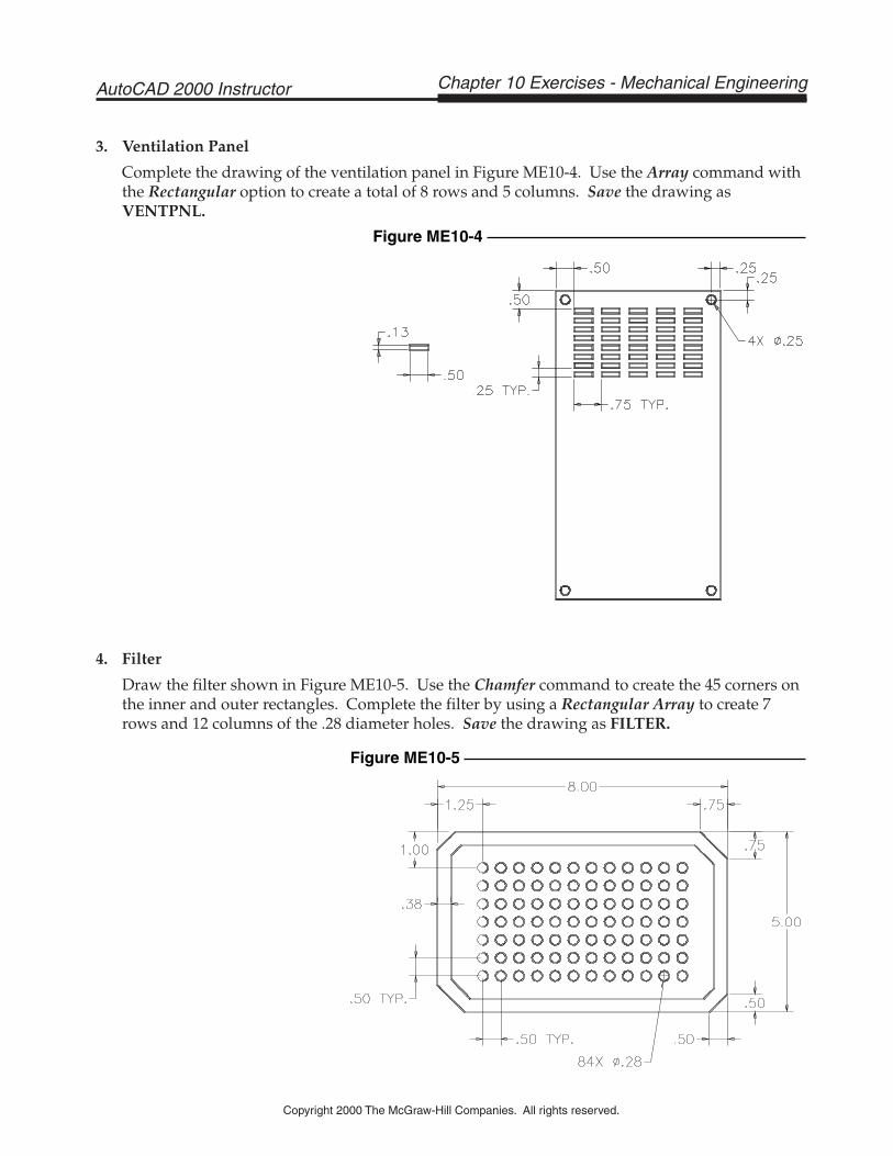
4. Filter
Draw the filter shown in Figure ME10-5. Use the Chamfer command to create the 45 corners onthe inner and outer rectangles. Complete the filter by using a Rectangular Array to create 7rows and 12 columns of the .28 diameter holes. Save the drawing as FILTER.
3. Ventilation Panel
Complete the drawing of the ventilation panel in Figure ME10-4. Use the Array command withthe Rectangular option to create a total of 8 rows and 5 columns. Save the drawing asVENTPNL.
Copyright 2000 The McGraw-Hill Companies. All rights reserved.
Chapter 10 Exercises - Mechanical EngineeringAutoCAD 2000 Instructor
Figure ME10-4
Figure ME10-5
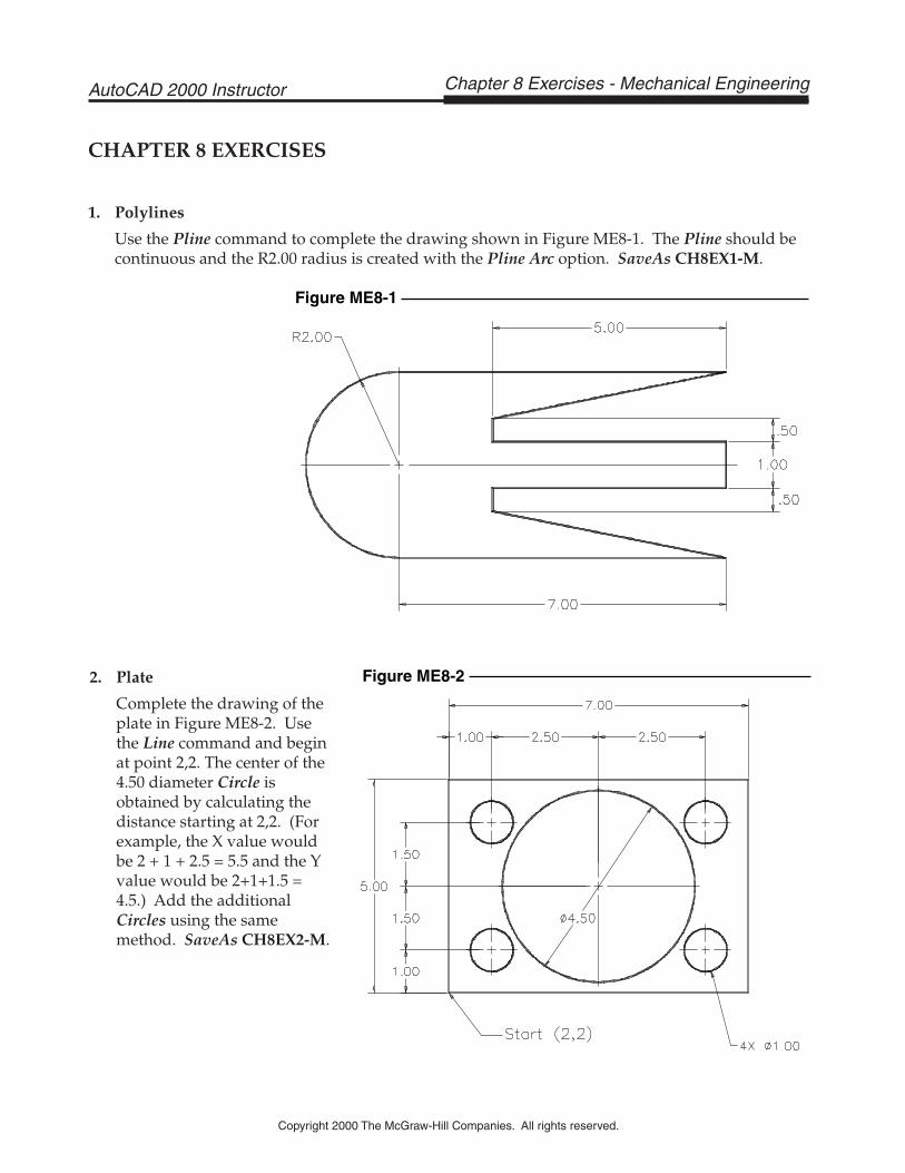
2. Plate
Complete the drawing of theplate in Figure ME8-2. Usethe Line command and beginat point 2,2. The center of the4.50 diameter Circle isobtained by calculating thedistance starting at 2,2. (Forexample, the X value wouldbe 2 + 1 + 2.5 = 5.5 and the Yvalue would be 2+1+1.5 =4.5.) Add the additionalCircles using the samemethod. SaveAs CH8EX2-M.
CHAPTER 8 EXERCISES
1. Polylines
Use the Pline command to complete the drawing shown in Figure ME8-1. The Pline should becontinuous and the R2.00 radius is created with the Pline Arc option. SaveAs CH8EX1-M.
Chapter 8 Exercises - Mechanical EngineeringAutoCAD 2000 Instructor
Copyright 2000 The McGraw-Hill Companies. All rights reserved.
Figure ME8-1
Figure ME8-2
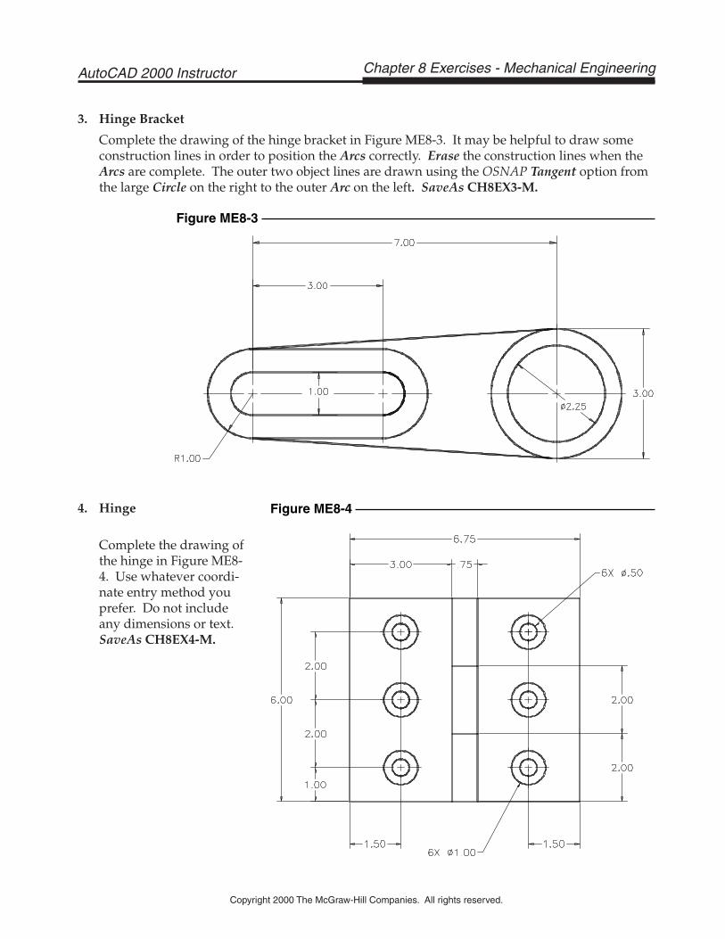
4. Hinge
Complete the drawing ofthe hinge in Figure ME8-4. Use whatever coordi-nate entry method youprefer. Do not includeany dimensions or text.SaveAs CH8EX4-M.
3. Hinge Bracket
Complete the drawing of the hinge bracket in Figure ME8-3. It may be helpful to draw someconstruction lines in order to position the Arcs correctly. Erase the construction lines when theArcs are complete. The outer two object lines are drawn using the OSNAP Tangent option fromthe large Circle on the right to the outer Arc on the left. SaveAs CH8EX3-M.
Copyright 2000 The McGraw-Hill Companies. All rights reserved.
Chapter 8 Exercises - Mechanical EngineeringAutoCAD 2000 Instructor
Figure ME8-4
Figure ME8-3