hydrodynamics of surface-piercing outboard and sterndrive
TRANSCRIPT
11th International Conference on Fast Sea Transportation FAST 2011, Honolulu, Hawaii, USA, September 2011
Hydrodynamics of Surface-Piercing
Outboard and Sterndrive Propulsion Systems
John O. Scherer, S.K.R. Patil
Mercury Marine, Fond du Lac, WI
ABSTRACT
Work has been done recently at Mercury Marine in the area of characterizing the performance of surface piercing drive systems used for outboard and sterndrive propulsion. These drive systems operate behind the boat at the air-water interface and are required to produce steering and vertical forces as well as thrust. The ability to produce these forces efficiently is a primary advantage of this type of drive system. The complexity of the physics presents a significant analytical challenge.
Theoretical, experimental and computational methods are presented. The content should be of particular use to boat designers who would like to integrate these types of drive systems into vessels. Gearcase lift, drag, and side-force are reported as functions of speed, drive trim angle, drive steering angle, and drive height, including the influence of cavitation and ventilation. Some considerations for surface-piercing propellers are reported as well.
KEY WORDS
marine propulsion system, surface-piercing drive system, cavitating propeller, ventilated propeller, surface-piercing strut, cavitating strut
1.0 INTRODUCTION
The hydrodynamics of outboard and sterndrive propulsion systems is unique relative to submerged propulsion systems in that they operate at the air-water interface. This means that additional consideration must be given to free surface effects such as submergence depth, ventilation, spray drag, and wave drag.
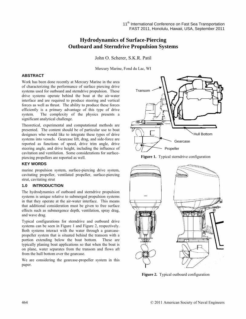
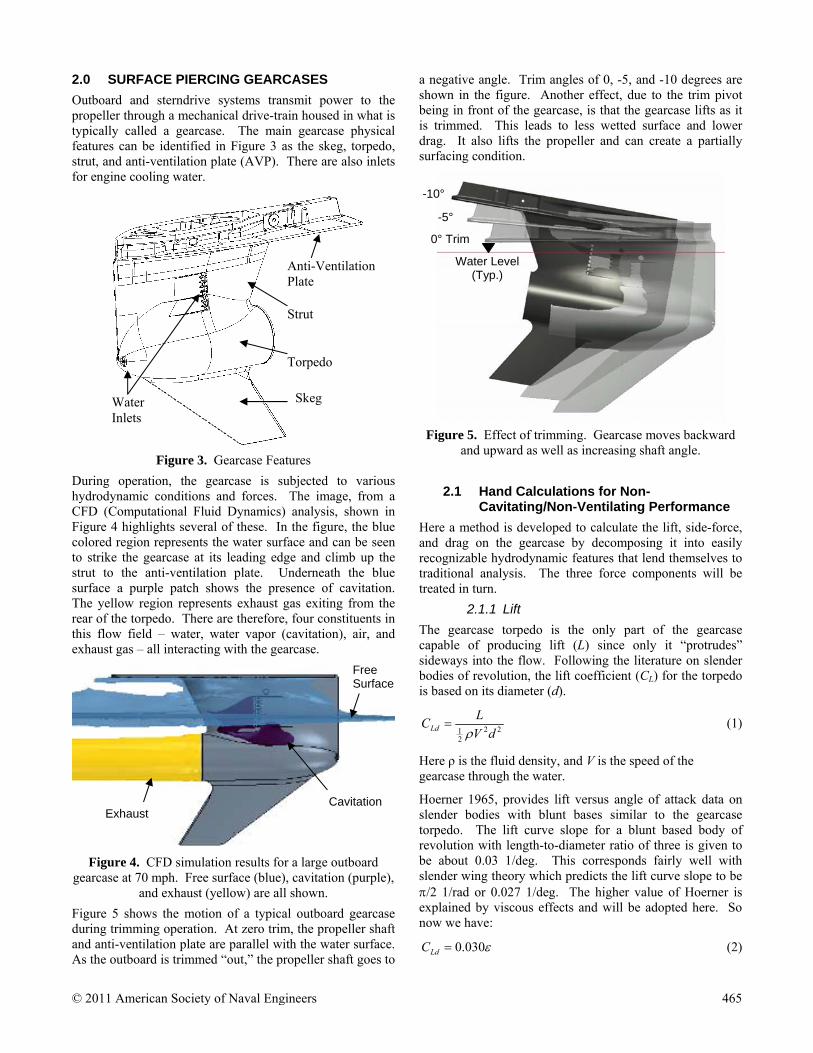
Typical configurations for sterndrive and outboard drive systems can be seen in Figure 1 and Figure 2, respectively. Both systems interact with the water through a gearcase-propeller system that is situated behind the transom with a portion extending below the boat bottom. These are typically planing boat applications so that when the boat is on plane, water separates from the transom and flows aft from the hull bottom over the gearcase.
We are considering the gearcase-propeller system in this paper.
Figure 1. Typical sterndrive configuration
Figure 2. Typical outboard configuration
Gearcase
Propeller
Transom
Hull Bottom
464 © 2011 American Society of Naval Engineers
2.0 SURFACE PIERCING GEARCASES
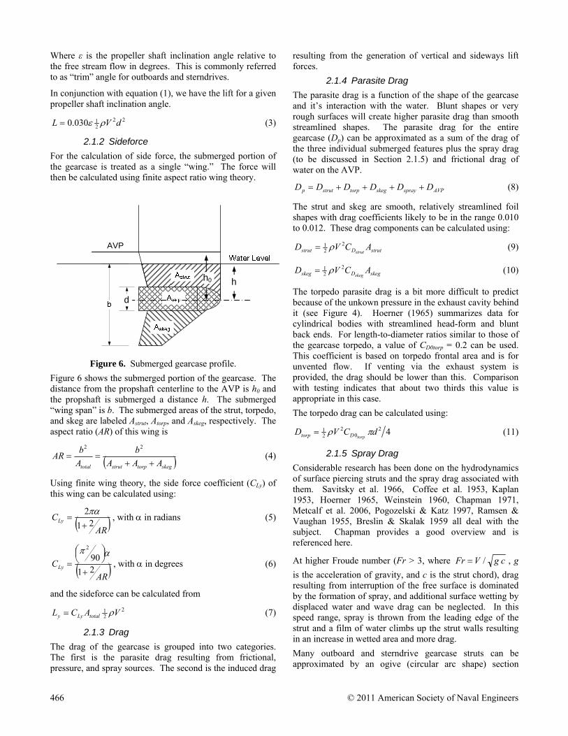
Outboard and sterndrive systems transmit power to the propeller through a mechanical drive-train housed in what is typically called a gearcase. The main gearcase physical features can be identified in Figure 3 as the skeg, torpedo, strut, and anti-ventilation plate (AVP). There are also inlets for engine cooling water.
Figure 3. Gearcase Features
During operation, the gearcase is subjected to various hydrodynamic conditions and forces. The image, from a CFD (Computational Fluid Dynamics) analysis, shown in Figure 4 highlights several of these. In the figure, the blue colored region represents the water surface and can be seen to strike the gearcase at its leading edge and climb up the strut to the anti-ventilation plate. Underneath the blue surface a purple patch shows the presence of cavitation. The yellow region represents exhaust gas exiting from the rear of the torpedo. There are therefore, four constituents in this flow field – water, water vapor (cavitation), air, and exhaust gas – all interacting with the gearcase.
Figure 4. CFD simulation results for a large outboard
gearcase at 70 mph. Free surface (blue), cavitation (purple), and exhaust (yellow) are all shown.
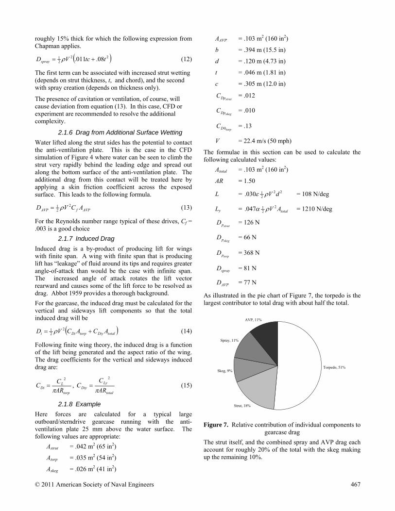
Figure 5 shows the motion of a typical outboard gearcase during trimming operation. At zero trim, the propeller shaft and anti-ventilation plate are parallel with the water surface. As the outboard is trimmed “out,” the propeller shaft goes to
a negative angle. Trim angles of 0, -5, and -10 degrees are shown in the figure. Another effect, due to the trim pivot being in front of the gearcase, is that the gearcase lifts as it is trimmed. This leads to less wetted surface and lower drag. It also lifts the propeller and can create a partially surfacing condition.
Figure 5. Effect of trimming. Gearcase moves backward
and upward as well as increasing shaft angle.
2.1 Hand Calculations for Non-Cavitating/Non-Ventilating Performance
Here a method is developed to calculate the lift, side-force, and drag on the gearcase by decomposing it into easily recognizable hydrodynamic features that lend themselves to traditional analysis. The three force components will be treated in turn.
2.1.1 Lift
The gearcase torpedo is the only part of the gearcase capable of producing lift (L) since only it “protrudes” sideways into the flow. Following the literature on slender bodies of revolution, the lift coefficient (CL) for the torpedo is based on its diameter (d).
2221 dV
LCLd
(1)
Here ρ is the fluid density, and V is the speed of the gearcase through the water.
Hoerner 1965, provides lift versus angle of attack data on slender bodies with blunt bases similar to the gearcase torpedo. The lift curve slope for a blunt based body of revolution with length-to-diameter ratio of three is given to be about 0.03 1/deg. This corresponds fairly well with slender wing theory which predicts the lift curve slope to be /2 1/rad or 0.027 1/deg. The higher value of Hoerner is explained by viscous effects and will be adopted here. So now we have:
030.0LdC (2)
Skeg
Torpedo
Strut
Anti-Ventilation Plate
Water Inlets
Free Surface
Exhaust Cavitation
0° Trim
-5°
-10°
Water Level (Typ.)
© 2011 American Society of Naval Engineers 465
Where ε is the propeller shaft inclination angle relative to the free stream flow in degrees. This is commonly referred to as “trim” angle for outboards and sterndrives.
In conjunction with equation (1), we have the lift for a given propeller shaft inclination angle.
2221030.0 dVL (3)
2.1.2 Sideforce
For the calculation of side force, the submerged portion of the gearcase is treated as a single “wing.” The force will then be calculated using finite aspect ratio wing theory.
Figure 6. Submerged gearcase profile.
Figure 6 shows the submerged portion of the gearcase. The distance from the propshaft centerline to the AVP is h0 and the propshaft is submerged a distance h. The submerged “wing span” is b. The submerged areas of the strut, torpedo, and skeg are labeled Astrut, Atorp, and Askeg, respectively. The aspect ratio (AR) of this wing is
skegtorpstruttotal AAA
b
A
bAR
22
(4)
Using finite wing theory, the side force coefficient (CLy) of this wing can be calculated using:
AR
CLy 21
2
, with in radians (5)
AR
CLy 21
902
, with in degrees (6)
and the sideforce can be calculated from
221 VACL totalLyy (7)
2.1.3 Drag
The drag of the gearcase is grouped into two categories. The first is the parasite drag resulting from frictional, pressure, and spray sources. The second is the induced drag
resulting from the generation of vertical and sideways lift forces.
2.1.4 Parasite Drag
The parasite drag is a function of the shape of the gearcase and it’s interaction with the water. Blunt shapes or very rough surfaces will create higher parasite drag than smooth streamlined shapes. The parasite drag for the entire gearcase (Dp) can be approximated as a sum of the drag of the three individual submerged features plus the spray drag (to be discussed in Section 2.1.5) and frictional drag of water on the AVP.
AVPsprayskegtorpstrutp DDDDDD (8)
The strut and skeg are smooth, relatively streamlined foil shapes with drag coefficients likely to be in the range 0.010 to 0.012. These drag components can be calculated using:
strutDstrut ACVDstrut
221 (9)
skegDskeg ACVDskeg
221 (10)
The torpedo parasite drag is a bit more difficult to predict because of the unkown pressure in the exhaust cavity behind it (see Figure 4). Hoerner (1965) summarizes data for cylindrical bodies with streamlined head-form and blunt back ends. For length-to-diameter ratios similar to those of the gearcase torpedo, a value of CD0torp = 0.2 can be used. This coefficient is based on torpedo frontal area and is for unvented flow. If venting via the exhaust system is provided, the drag should be lower than this. Comparison with testing indicates that about two thirds this value is appropriate in this case.
The torpedo drag can be calculated using:
420
221 dCVD
torpDtorp (11)
2.1.5 Spray Drag
Considerable research has been done on the hydrodynamics of surface piercing struts and the spray drag associated with them. Savitsky et al. 1966, Coffee et al. 1953, Kaplan 1953, Hoerner 1965, Weinstein 1960, Chapman 1971, Metcalf et al. 2006, Pogozelski & Katz 1997, Ramsen & Vaughan 1955, Breslin & Skalak 1959 all deal with the subject. Chapman provides a good overview and is referenced here.
At higher Froude number (Fr > 3, where cgVFr / , g
is the acceleration of gravity, and c is the strut chord), drag resulting from interruption of the free surface is dominated by the formation of spray, and additional surface wetting by displaced water and wave drag can be neglected. In this speed range, spray is thrown from the leading edge of the strut and a film of water climbs up the strut walls resulting in an increase in wetted area and more drag.
Many outboard and sterndrive gearcase struts can be approximated by an ogive (circular arc shape) section
d
h h0
AVP
466 © 2011 American Society of Naval Engineers
roughly 15% thick for which the following expression from Chapman applies.
2221 08.011. ttcVDspray (12)
The first term can be associated with increased strut wetting (depends on strut thickness, t, and chord), and the second with spray creation (depends on thickness only).
The presence of cavitation or ventilation, of course, will cause deviation from equation (13). In this case, CFD or experiment are recommended to resolve the additional complexity.
2.1.6 Drag from Additional Surface Wetting
Water lifted along the strut sides has the potential to contact the anti-ventilation plate. This is the case in the CFD simulation of Figure 4 where water can be seen to climb the strut very rapidly behind the leading edge and spread out along the bottom surface of the anti-ventilation plate. The additional drag from this contact will be treated here by applying a skin friction coefficient across the exposed surface. This leads to the following formula.
AVPfAVP ACVD 221 (13)
For the Reynolds number range typical of these drives, Cf = .003 is a good choice
2.1.7 Induced Drag
Induced drag is a by-product of producing lift for wings with finite span. A wing with finite span that is producing lift has “leakage” of fluid around its tips and requires greater angle-of-attack than would be the case with infinite span. The increased angle of attack rotates the lift vector rearward and causes some of the lift force to be resolved as drag. Abbot 1959 provides a thorough background.
For the gearcase, the induced drag must be calculated for the vertical and sideways lift components so that the total induced drag will be
totalDiytorpDii ACACVD 221 (14)
Following finite wing theory, the induced drag is a function of the lift being generated and the aspect ratio of the wing. The drag coefficients for the vertical and sideways induced drag are:
torp
LDi AR
CC
2
, total
LyDiy AR
CC
2
(15)
2.1.8 Example
Here forces are calculated for a typical large outboard/sterndrive gearcase running with the anti-ventilation plate 25 mm above the water surface. The following values are appropriate:
Astrut = .042 m2 (65 in2)
Atorp = .035 m2 (54 in2)
Askeg = .026 m2 (41 in2)
AAVP = .103 m2 (160 in2)
b = .394 m (15.5 in)
d = .120 m (4.73 in)
t = .046 m (1.81 in)
c = .305 m (12.0 in)
strutDpC = .012
skegDpC = .010
torpDC 0 = .13
V = 22.4 m/s (50 mph)
The formulae in this section can be used to calculate the following calculated values:
Atotal = .103 m2 (160 in2)
AR = 1.50
L = 2221030. dV = 108 N/deg
Ly = totalAV 221047. = 1210 N/deg
strutpD = 126 N
skegpD = 66 N
torppD = 368 N
sprayD = 81 N
AVPD = 77 N
As illustrated in the pie chart of Figure 7, the torpedo is the largest contributor to total drag with about half the total.
Torpedo, 51%
Strut, 18%
Skeg, 9%
Spray, 11%
AVP, 11%
Figure 7. Relative contribution of individual components to
gearcase drag
The strut itself, and the combined spray and AVP drag each account for roughly 20% of the total with the skeg making up the remaining 10%.
© 2011 American Society of Naval Engineers 467
2.2 Experimental Data
Experimental measurements of drag and lift have been made at Mercury Marine using an instrumented fixture that allows a gearcase to be pulled behind a test boat at given speed, depth of submergence, and trim angle. Details of the experimental setup are beyond the scope of this paper but some results are presented here.
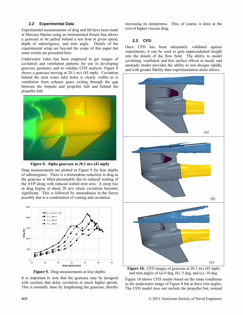
Underwater video has been employed to get images of cavitation and ventilation patterns for use in developing gearcase geometry and to validate CFD analysis. Figure 8 shows a gearcase moving at 20.1 m/s (45 mph). Cavitation behind the strut water inlet holes is clearly visible as is ventilation from exhaust gases exiting through the gap between the torpedo and propeller hub and behind the propeller hub.
Figure 8. Alpha gearcase at 20.1 m/s (45 mph)
Drag measurements are plotted in Figure 9 for four depths of submergence. There is a tremendous reduction in drag as the gearcase is lifted presumably due to reduced wetting of the AVP along with reduced wetted strut area. A steep rise in drag begins at about 20 m/s where cavitation becomes significant. This is followed by unsteadiness in the forces possibly due to a combination of venting and cavitation.
0
500
1000
1500
2000
2500
10 15 20 25 30 35 40
Boat Speed (m/s)
Dra
g (
N)
h = .211 m = h0
h = .185 m
h = .160 m
h = .135 m
Figure 9. Drag measurements at four depths.
It is important to note that the gearcase may be designed with sections that delay cavitation to much higher speeds. This is normally done by lengthening the gearcase, thereby
increasing its slenderness. This, of course, is done at the cost of higher viscous drag.
2.3 CFD
Once CFD has been adequately validated against experiments, it can be used to gain unprecedented insight into the details of the flow field. The ability to model cavitating, ventilated, and free surface effects in steady and unsteady modes provides the ability to test designs rapidly and with greater fidelity than experimentation alone allows.
(a)
(b)
(c)
Figure 10. CFD images of gearcase at 20.1 m/s (45 mph) and trim angles of (a) 0 deg, (b) -5 deg, and (c) -10 deg.
Figure 10 shows CFD results based on the same conditions as the underwater image of Figure 8 but at three trim angles. The CFD model does not include the propeller but, instead
468 © 2011 American Society of Naval Engineers
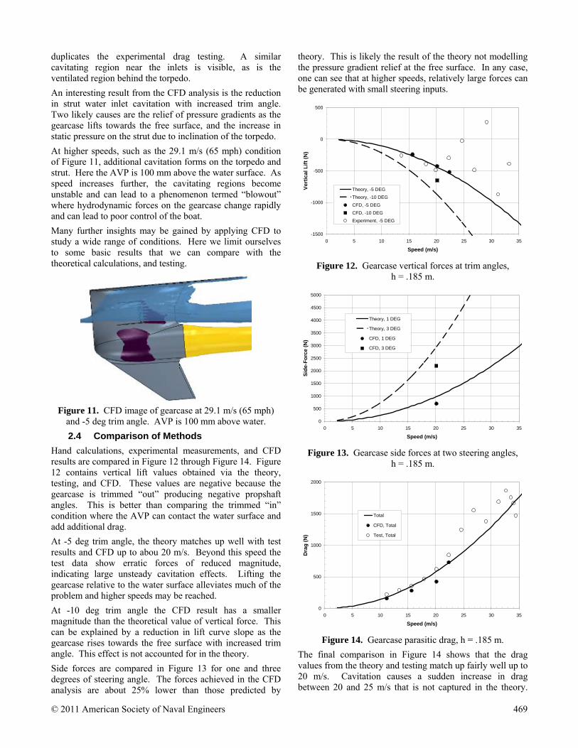
duplicates the experimental drag testing. A similar cavitating region near the inlets is visible, as is the ventilated region behind the torpedo.
An interesting result from the CFD analysis is the reduction in strut water inlet cavitation with increased trim angle. Two likely causes are the relief of pressure gradients as the gearcase lifts towards the free surface, and the increase in static pressure on the strut due to inclination of the torpedo.
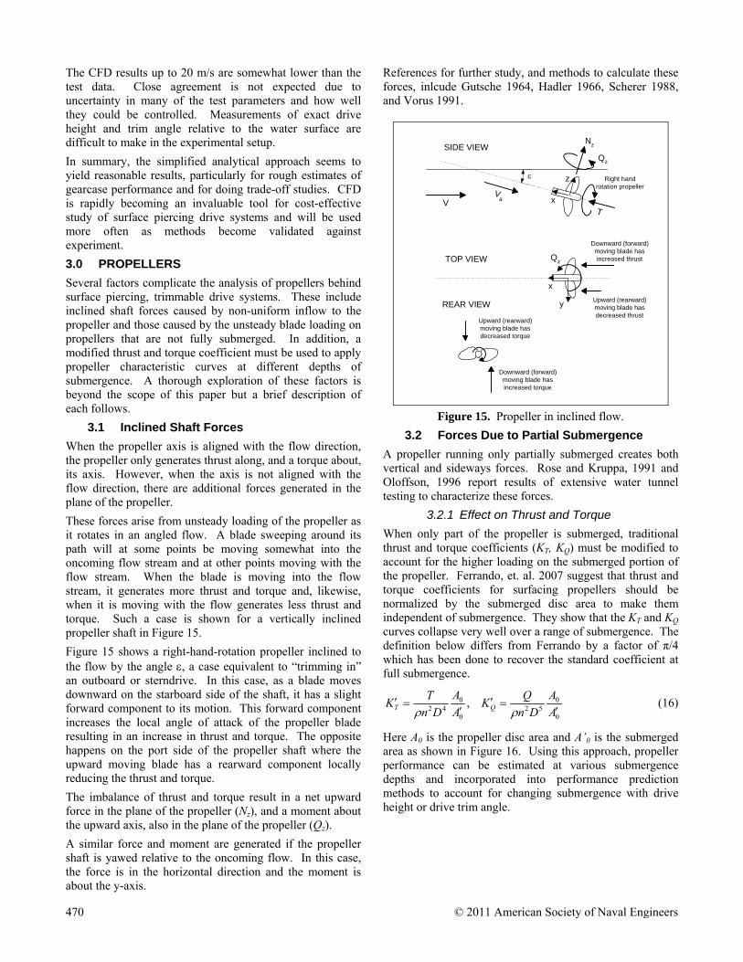
At higher speeds, such as the 29.1 m/s (65 mph) condition of Figure 11, additional cavitation forms on the torpedo and strut. Here the AVP is 100 mm above the water surface. As speed increases further, the cavitating regions become unstable and can lead to a phenomenon termed “blowout” where hydrodynamic forces on the gearcase change rapidly and can lead to poor control of the boat.
Many further insights may be gained by applying CFD to study a wide range of conditions. Here we limit ourselves to some basic results that we can compare with the theoretical calculations, and testing.
Figure 11. CFD image of gearcase at 29.1 m/s (65 mph)
and -5 deg trim angle. AVP is 100 mm above water.
2.4 Comparison of Methods
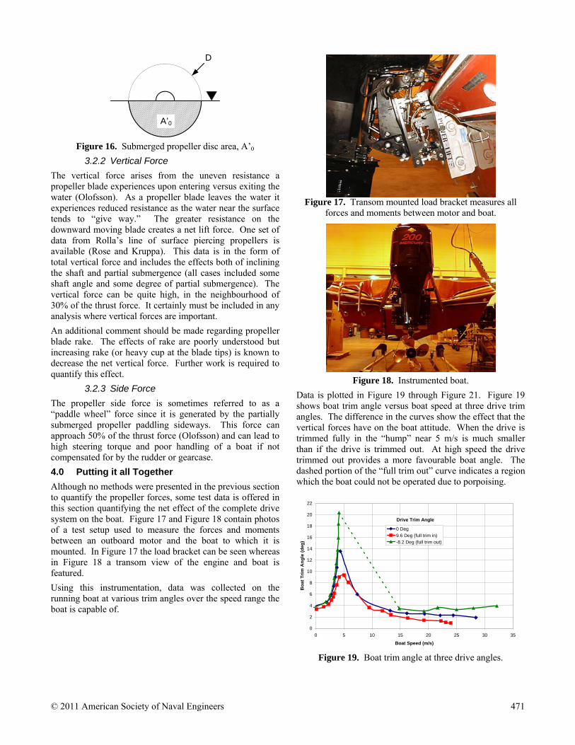
Hand calculations, experimental measurements, and CFD results are compared in Figure 12 through Figure 14. Figure 12 contains vertical lift values obtained via the theory, testing, and CFD. These values are negative because the gearcase is trimmed “out” producing negative propshaft angles. This is better than comparing the trimmed “in” condition where the AVP can contact the water surface and add additional drag.
At -5 deg trim angle, the theory matches up well with test results and CFD up to abou 20 m/s. Beyond this speed the test data show erratic forces of reduced magnitude, indicating large unsteady cavitation effects. Lifting the gearcase relative to the water surface alleviates much of the problem and higher speeds may be reached.
At -10 deg trim angle the CFD result has a smaller magnitude than the theoretical value of vertical force. This can be explained by a reduction in lift curve slope as the gearcase rises towards the free surface with increased trim angle. This effect is not accounted for in the theory.
Side forces are compared in Figure 13 for one and three degrees of steering angle. The forces achieved in the CFD analysis are about 25% lower than those predicted by
theory. This is likely the result of the theory not modelling the pressure gradient relief at the free surface. In any case, one can see that at higher speeds, relatively large forces can be generated with small steering inputs.
-1500
-1000
-500
0
500
0 5 10 15 20 25 30 35
Speed (m/s)
Ve
rtic
al L
ift
(N)
Theory, -5 DEG
Theory, -10 DEG
CFD, -5 DEG
CFD, -10 DEG
Experiment, -5 DEG
Figure 12. Gearcase vertical forces at trim angles,
h = .185 m.
0
500
1000
1500
2000
2500
3000
3500
4000
4500
5000
0 5 10 15 20 25 30 35
Speed (m/s)
Sid
e-F
orc
e (
N)
Theory, 1 DEG
Theory, 3 DEG
CFD, 1 DEG
CFD, 3 DEG
Figure 13. Gearcase side forces at two steering angles,
h = .185 m.
0
500
1000
1500
2000
0 5 10 15 20 25 30 35
Speed (m/s)
Dra
g (
N)
Total
CFD, Total
Test, Total
Figure 14. Gearcase parasitic drag, h = .185 m.
The final comparison in Figure 14 shows that the drag values from the theory and testing match up fairly well up to 20 m/s. Cavitation causes a sudden increase in drag between 20 and 25 m/s that is not captured in the theory.
© 2011 American Society of Naval Engineers 469
The CFD results up to 20 m/s are somewhat lower than the test data. Close agreement is not expected due to uncertainty in many of the test parameters and how well they could be controlled. Measurements of exact drive height and trim angle relative to the water surface are difficult to make in the experimental setup.
In summary, the simplified analytical approach seems to yield reasonable results, particularly for rough estimates of gearcase performance and for doing trade-off studies. CFD is rapidly becoming an invaluable tool for cost-effective study of surface piercing drive systems and will be used more often as methods become validated against experiment.
3.0 PROPELLERS
Several factors complicate the analysis of propellers behind surface piercing, trimmable drive systems. These include inclined shaft forces caused by non-uniform inflow to the propeller and those caused by the unsteady blade loading on propellers that are not fully submerged. In addition, a modified thrust and torque coefficient must be used to apply propeller characteristic curves at different depths of submergence. A thorough exploration of these factors is beyond the scope of this paper but a brief description of each follows.
3.1 Inclined Shaft Forces
When the propeller axis is aligned with the flow direction, the propeller only generates thrust along, and a torque about, its axis. However, when the axis is not aligned with the flow direction, there are additional forces generated in the plane of the propeller.
These forces arise from unsteady loading of the propeller as it rotates in an angled flow. A blade sweeping around its path will at some points be moving somewhat into the oncoming flow stream and at other points moving with the flow stream. When the blade is moving into the flow stream, it generates more thrust and torque and, likewise, when it is moving with the flow generates less thrust and torque. Such a case is shown for a vertically inclined propeller shaft in Figure 15.
Figure 15 shows a right-hand-rotation propeller inclined to the flow by the angle , a case equivalent to “trimming in” an outboard or sterndrive. In this case, as a blade moves downward on the starboard side of the shaft, it has a slight forward component to its motion. This forward component increases the local angle of attack of the propeller blade resulting in an increase in thrust and torque. The opposite happens on the port side of the propeller shaft where the upward moving blade has a rearward component locally reducing the thrust and torque.
The imbalance of thrust and torque result in a net upward force in the plane of the propeller (Nz), and a moment about the upward axis, also in the plane of the propeller (Qz).
A similar force and moment are generated if the propeller shaft is yawed relative to the oncoming flow. In this case, the force is in the horizontal direction and the moment is about the y-axis.
References for further study, and methods to calculate these forces, inlcude Gutsche 1964, Hadler 1966, Scherer 1988, and Vorus 1991.
VV
a
Qz
Nz
T
Downward (forward)moving blade hasincreased thrust
Upward (rearward)moving blade hasdecreased thrust
Qz
SIDE VIEW
TOP VIEW
Right handrotation propeller
Downward (forward)moving blade hasincreased torque
Upward (rearward)moving blade hasdecreased torque
REAR VIEW
x
z
y
x
Figure 15. Propeller in inclined flow.
3.2 Forces Due to Partial Submergence
A propeller running only partially submerged creates both vertical and sideways forces. Rose and Kruppa, 1991 and Oloffson, 1996 report results of extensive water tunnel testing to characterize these forces.
3.2.1 Effect on Thrust and Torque
When only part of the propeller is submerged, traditional thrust and torque coefficients (KT, KQ) must be modified to account for the higher loading on the submerged portion of the propeller. Ferrando, et. al. 2007 suggest that thrust and torque coefficients for surfacing propellers should be normalized by the submerged disc area to make them independent of submergence. They show that the KT and KQ curves collapse very well over a range of submergence. The definition below differs from Ferrando by a factor of π/4 which has been done to recover the standard coefficient at full submergence.
0
052
0
042 ,
A
A
Dn
QK
A
A
Dn
TK QT
(16)
Here A0 is the propeller disc area and A’0 is the submerged area as shown in Figure 16. Using this approach, propeller performance can be estimated at various submergence depths and incorporated into performance prediction methods to account for changing submergence with drive height or drive trim angle.
470 © 2011 American Society of Naval Engineers
D
A’0
Figure 16. Submerged propeller disc area, A’0
3.2.2 Vertical Force
The vertical force arises from the uneven resistance a propeller blade experiences upon entering versus exiting the water (Olofsson). As a propeller blade leaves the water it experiences reduced resistance as the water near the surface tends to “give way.” The greater resistance on the downward moving blade creates a net lift force. One set of data from Rolla’s line of surface piercing propellers is available (Rose and Kruppa). This data is in the form of total vertical force and includes the effects both of inclining the shaft and partial submergence (all cases included some shaft angle and some degree of partial submergence). The vertical force can be quite high, in the neighbourhood of 30% of the thrust force. It certainly must be included in any analysis where vertical forces are important.
An additional comment should be made regarding propeller blade rake. The effects of rake are poorly understood but increasing rake (or heavy cup at the blade tips) is known to decrease the net vertical force. Further work is required to quantify this effect.
3.2.3 Side Force
The propeller side force is sometimes referred to as a “paddle wheel” force since it is generated by the partially submerged propeller paddling sideways. This force can approach 50% of the thrust force (Olofsson) and can lead to high steering torque and poor handling of a boat if not compensated for by the rudder or gearcase.
4.0 Putting it all Together
Although no methods were presented in the previous section to quantify the propeller forces, some test data is offered in this section quantifying the net effect of the complete drive system on the boat. Figure 17 and Figure 18 contain photos of a test setup used to measure the forces and moments between an outboard motor and the boat to which it is mounted. In Figure 17 the load bracket can be seen whereas in Figure 18 a transom view of the engine and boat is featured.
Using this instrumentation, data was collected on the running boat at various trim angles over the speed range the boat is capable of.
Figure 17. Transom mounted load bracket measures all
forces and moments between motor and boat.
Figure 18. Instrumented boat.
Data is plotted in Figure 19 through Figure 21. Figure 19 shows boat trim angle versus boat speed at three drive trim angles. The difference in the curves show the effect that the vertical forces have on the boat attitude. When the drive is trimmed fully in the “hump” near 5 m/s is much smaller than if the drive is trimmed out. At high speed the drive trimmed out provides a more favourable boat angle. The dashed portion of the “full trim out” curve indicates a region which the boat could not be operated due to porpoising.
0
2
4
6
8
10
12
14
16
18
20
22
0 5 10 15 20 25 30 35
Boat Speed (m/s)
Bo
at T
rim
An
gle
(d
eg)
0 Deg
9.6 Deg (full trim in)-8.2 Deg (full trim out)
Drive Trim Angle
Figure 19. Boat trim angle at three drive angles.
© 2011 American Society of Naval Engineers 471
0
500
1000
1500
2000
2500
3000
3500
4000
4500
0 5 10 15 20 25 30 35
Boat Speed (m/s)
Ne
t T
hru
st
(N)
0 Deg
9.6 Deg (full trim in)
-8.2 Deg (full trim out)
Drive Trim Angle
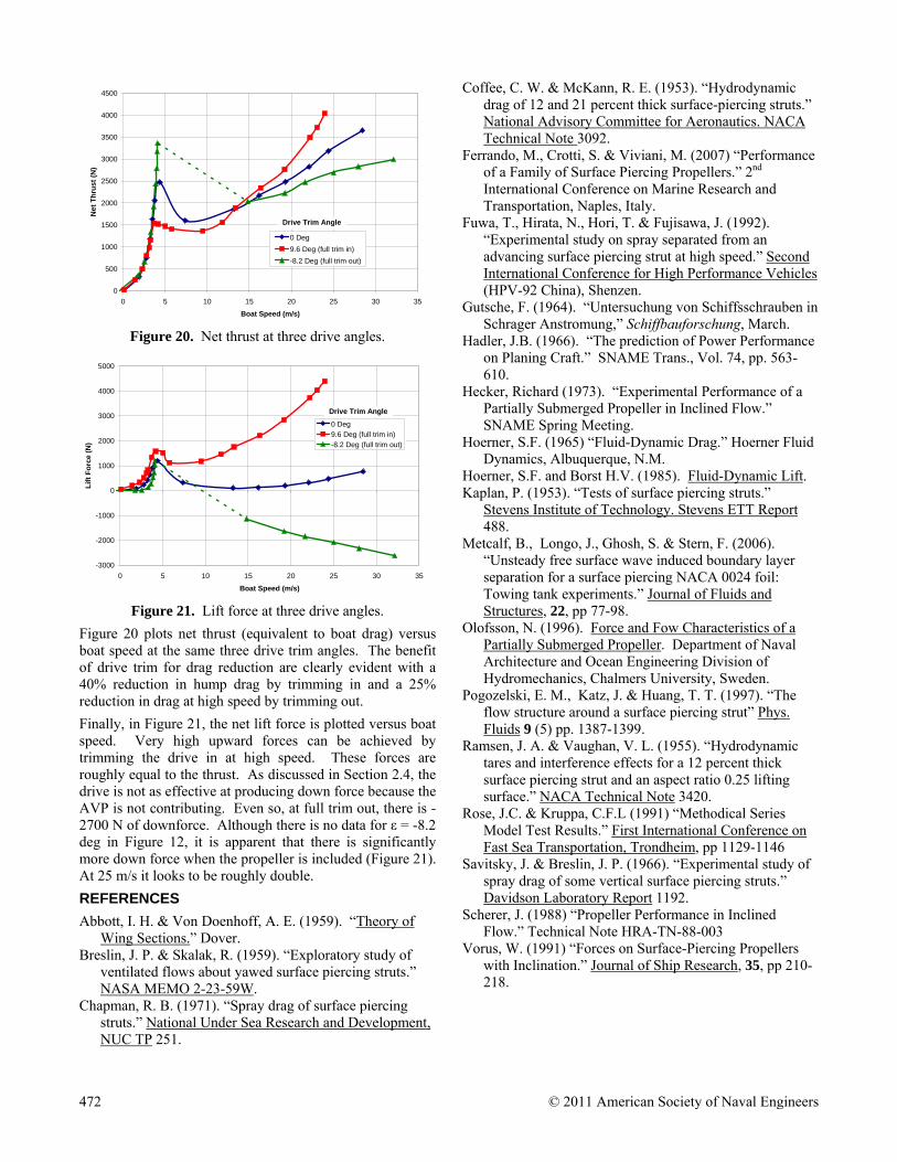
Figure 20. Net thrust at three drive angles.
-3000
-2000
-1000
0
1000
2000
3000
4000
5000
0 5 10 15 20 25 30 35
Boat Speed (m/s)
Lif
t F
orc
e (
N)
0 Deg9.6 Deg (full trim in)
-8.2 Deg (full trim out)
Drive Trim Angle
Figure 21. Lift force at three drive angles.
Figure 20 plots net thrust (equivalent to boat drag) versus boat speed at the same three drive trim angles. The benefit of drive trim for drag reduction are clearly evident with a 40% reduction in hump drag by trimming in and a 25% reduction in drag at high speed by trimming out.
Finally, in Figure 21, the net lift force is plotted versus boat speed. Very high upward forces can be achieved by trimming the drive in at high speed. These forces are roughly equal to the thrust. As discussed in Section 2.4, the drive is not as effective at producing down force because the AVP is not contributing. Even so, at full trim out, there is -2700 N of downforce. Although there is no data for ε = -8.2 deg in Figure 12, it is apparent that there is significantly more down force when the propeller is included (Figure 21). At 25 m/s it looks to be roughly double.
REFERENCES
Abbott, I. H. & Von Doenhoff, A. E. (1959). “Theory of Wing Sections.” Dover.
Breslin, J. P. & Skalak, R. (1959). “Exploratory study of ventilated flows about yawed surface piercing struts.” NASA MEMO 2-23-59W.
Chapman, R. B. (1971). “Spray drag of surface piercing struts.” National Under Sea Research and Development, NUC TP 251.
Coffee, C. W. & McKann, R. E. (1953). “Hydrodynamic drag of 12 and 21 percent thick surface-piercing struts.” National Advisory Committee for Aeronautics. NACA Technical Note 3092.
Ferrando, M., Crotti, S. & Viviani, M. (2007) “Performance of a Family of Surface Piercing Propellers.” 2nd International Conference on Marine Research and Transportation, Naples, Italy.
Fuwa, T., Hirata, N., Hori, T. & Fujisawa, J. (1992). “Experimental study on spray separated from an advancing surface piercing strut at high speed.” Second International Conference for High Performance Vehicles (HPV-92 China), Shenzen.
Gutsche, F. (1964). “Untersuchung von Schiffsschrauben in Schrager Anstromung,” Schiffbauforschung, March.
Hadler, J.B. (1966). “The prediction of Power Performance on Planing Craft.” SNAME Trans., Vol. 74, pp. 563-610.
Hecker, Richard (1973). “Experimental Performance of a Partially Submerged Propeller in Inclined Flow.” SNAME Spring Meeting.
Hoerner, S.F. (1965) “Fluid-Dynamic Drag.” Hoerner Fluid Dynamics, Albuquerque, N.M.
Hoerner, S.F. and Borst H.V. (1985). Fluid-Dynamic Lift. Kaplan, P. (1953). “Tests of surface piercing struts.”
Stevens Institute of Technology. Stevens ETT Report 488.
Metcalf, B., Longo, J., Ghosh, S. & Stern, F. (2006). “Unsteady free surface wave induced boundary layer separation for a surface piercing NACA 0024 foil: Towing tank experiments.” Journal of Fluids and Structures, 22, pp 77-98.
Olofsson, N. (1996). Force and Fow Characteristics of a Partially Submerged Propeller. Department of Naval Architecture and Ocean Engineering Division of Hydromechanics, Chalmers University, Sweden.
Pogozelski, E. M., Katz, J. & Huang, T. T. (1997). “The flow structure around a surface piercing strut” Phys. Fluids 9 (5) pp. 1387-1399.
Ramsen, J. A. & Vaughan, V. L. (1955). “Hydrodynamic tares and interference effects for a 12 percent thick surface piercing strut and an aspect ratio 0.25 lifting surface.” NACA Technical Note 3420.
Rose, J.C. & Kruppa, C.F.L (1991) “Methodical Series Model Test Results.” First International Conference on Fast Sea Transportation, Trondheim, pp 1129-1146
Savitsky, J. & Breslin, J. P. (1966). “Experimental study of spray drag of some vertical surface piercing struts.” Davidson Laboratory Report 1192.
Scherer, J. (1988) “Propeller Performance in Inclined Flow.” Technical Note HRA-TN-88-003
Vorus, W. (1991) “Forces on Surface-Piercing Propellers with Inclination.” Journal of Ship Research, 35, pp 210-218.
472 © 2011 American Society of Naval Engineers