hydraulic equipment general
TRANSCRIPT
Hydraulic equipment
GeneralMore information on hydraulic equipment can be found in the document Power take-off driven hydraulic systems.
GeneralThis document contains information about hydraulic equipment used to drive body-work that can be ordered from the factory.
The document is divided as follows:
• Complete hydraulic system
• Components for the hydraulic system
– Control– Hydraulic pump– Hydraulic oil tank– Hydraulic valve with pressure limiting valve– Hydraulic hoses and couplings– Hydraulic oil
• Parts for connecting components
It is possible to fit the vehicle with a set of components that together constitute a com-plete hydraulic system.
Information on the vehicle's power take-offs can be found in the vehicle's chassis specification, ICS (Individual Chassis Specification).
The vehicle's ICS can be downloaded from the Scania websiteTruck Bodybuilder.
Scania Truck Bodybuilder 22:10-720 Issue 5 2022-02-02© Scania CV AB 2022, Sweden 1 (39)
Actions before starting a new hydraulic system
Hydraulic equipment
Actions before starting a new hydraulic system
IMPORTANT!
When installing hydraulic hoses and filling hydraulic oil, the following applies:
• Check the manufacturer's specifications for the hydraulic pump before commis-sioning the hydraulic pump.
• Make sure that the entire hydraulic system is clean before filling with the recom-mended hydraulic oil. More information can be found under the heading Hydrau-lic oil.
• Ensure sufficient lubrication by making sure that the hydraulic pump is filled to at least 50% before it is started.
The hydraulic system is tested and ready for start without any preparatory action on vehicles factory-fitted with the following specifications:
• Complete hydraulic system
• Controls in the cab
• Filled hydraulic oil tank
In the following cases, the hydraulic system requires a test drive:
• Vehicles factory-fitted without controls in the cab
• Vehicles factory-fitted with complete hydraulic systems without filled hydraulic oil tanks
Scania Truck Bodybuilder 22:10-720 Issue 5 2022-02-02© Scania CV AB 2022, Sweden 2 (39)
Complete hydraulic system
Hydraulic equipment
1
2
3
4
56 7
444
644
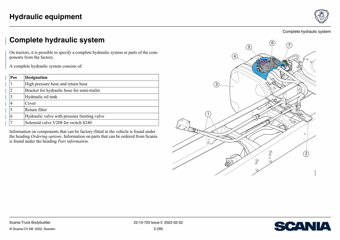
Complete hydraulic systemOn tractors, it is possible to specify a complete hydraulic system or parts of the com-ponents from the factory.
A complete hydraulic system consists of:
Information on components that can be factory-fitted in the vehicle is found under the heading Ordering options. Information on parts that can be ordered from Scania is found under the heading Part information.
Pos Designation
1 High pressure hose and return hose
2 Bracket for hydraulic hose for semi-trailer
3 Hydraulic oil tank
4 Cover
5 Return filter
6 Hydraulic valve with pressure limiting valve
7 Solenoid valve V208 for switch S240
Scania Truck Bodybuilder 22:10-720 Issue 5 2022-02-02© Scania CV AB 2022, Sweden 3 (39)
Complete hydraulic system
Hydraulic equipment
9
10
11 12
8
444
645
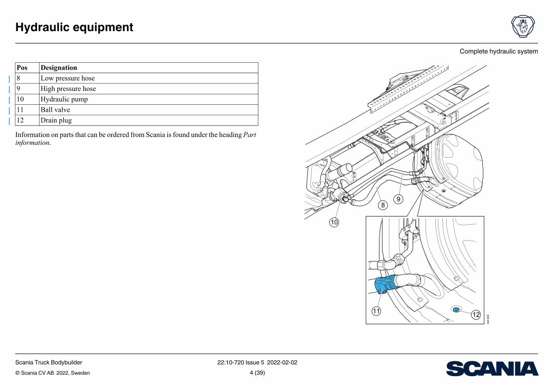
Information on parts that can be ordered from Scania is found under the heading Part information.
Pos Designation
8 Low pressure hose
9 High pressure hose
10 Hydraulic pump
11 Ball valve
12 Drain plug
Scania Truck Bodybuilder 22:10-720 Issue 5 2022-02-02© Scania CV AB 2022, Sweden 4 (39)
Components for the hydraulic system
Hydraulic equipment
Components for the hydraulic systemVehicles can be factory-fitted with various hydraulic components. In some cases, it is possible to combine the components to obtain a complete hydraulic system.
Hoses and couplings can be ordered from Scania dealers. More information and part numbers can be found under the headings Part information.
Scania Truck Bodybuilder 22:10-720 Issue 5 2022-02-02© Scania CV AB 2022, Sweden 5 (39)
Different variants of controls in the cab
Hydraulic equipment
Different variants of controls in the cabIt is possible to order the vehicle from the factory with different control variants for the operation of bodywork equipment from the cab. The following ordering options are available for the option Controlling the wet kit (variant family 4666):
• Prepared (variant code 4666B). Preparation for control lever.
• Switch (variant code 4666C). For operating the tipper body and tailboard spreader on trucks and trailers.
• Control lever (variant code 4666D). For example, to raise or lower the tipper body on the truck.
More information can be found under the heading Ordering options.
Scania Truck Bodybuilder 22:10-720 Issue 5 2022-02-02© Scania CV AB 2022, Sweden 6 (39)
Different variants of controls in the cab
Hydraulic equipment
Vehicles equipped with factory-fitted control lever preparationsVehicles factory-fitted with the option Controlling the wet kit, prepared (variant code 4666B) have 6 pre-tightened compressed air hoses. The option is a preparation for installing a control lever.
1 of the compressed air hoses at the boarding grab handle is intended for supply air. 5 compressed air hoses are routed from the boarding grab handle out onto the chassis frame. All compressed air hoses have a diameter of 6 mm.
Scania Truck Bodybuilder 22:10-720 Issue 5 2022-02-02© Scania CV AB 2022, Sweden 7 (39)
Different variants of controls in the cab
Hydraulic equipment
, rame
To Function
Boarding grab handle in the cab. Loose hose end.
Air supply
Rear cab wall. Loose hose ends. No function from the factory.
Can be connected to any function.
The inside of the right-hand frame side member's third crossmember. Loose hose ends.
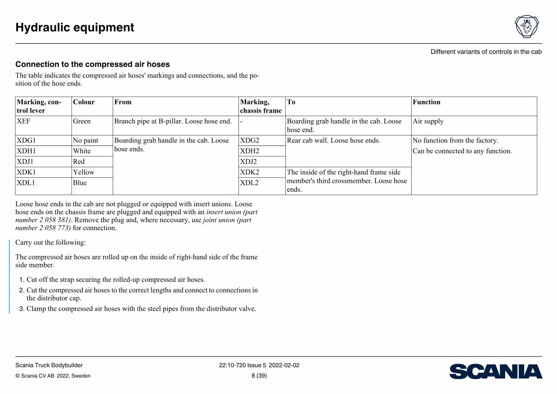
Connection to the compressed air hosesThe table indicates the compressed air hoses' markings and connections, and the po-sition of the hose ends.
Loose hose ends in the cab are not plugged or equipped with insert unions. Loose hose ends on the chassis frame are plugged and equipped with an insert union (part number 2 058 381). Remove the plug and, where necessary, use joint union (part number 2 058 773) for connection.
Carry out the following:
The compressed air hoses are rolled up on the inside of right-hand side of the frame side member.
1. Cut off the strap securing the rolled-up compressed air hoses.
2. Cut the compressed air hoses to the correct lengths and connect to connections in the distributor cap.
3. Clamp the compressed air hoses with the steel pipes from the distributor valve.
Marking, con-trol lever
Colour From Markingchassis f
XEF Green Branch pipe at B-pillar. Loose hose end. -
XDG1 No paint Boarding grab handle in the cab. Loose hose ends.
XDG2
XDH1 White XDH2
XDJ1 Red XDJ2
XDK1 Yellow XDK2
XDL1 Blue XDL2
Scania Truck Bodybuilder 22:10-720 Issue 5 2022-02-02© Scania CV AB 2022, Sweden 8 (39)
Different variants of controls in the cab
Hydraulic equipment
423
043
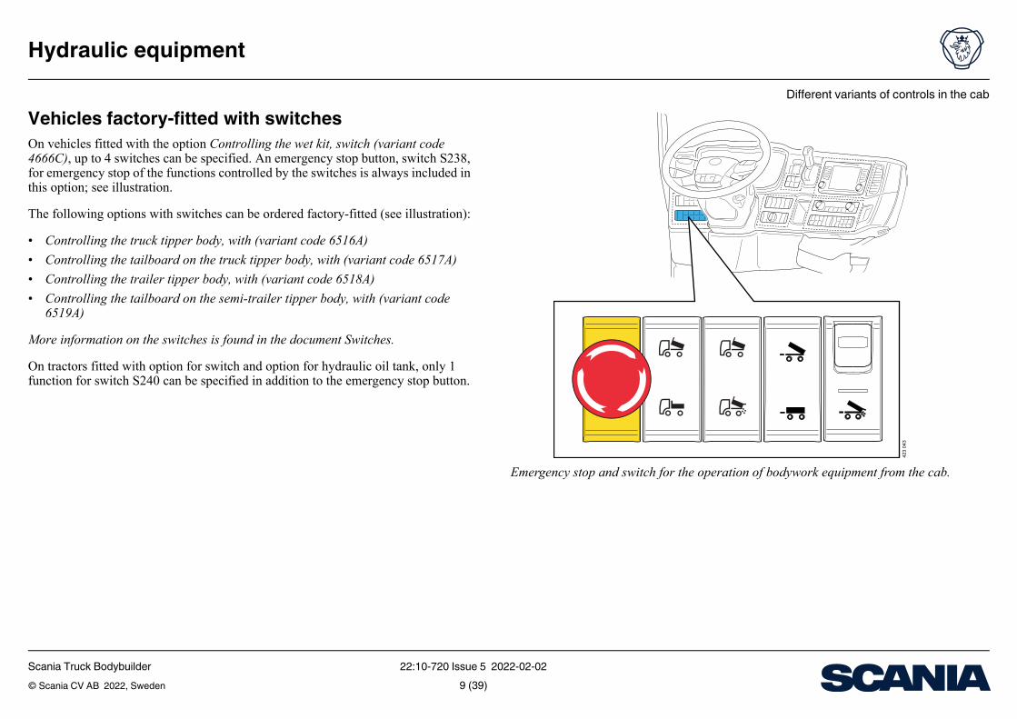
Emergency stop and switch for the operation of bodywork equipment from the cab.
Vehicles factory-fitted with switchesOn vehicles fitted with the option Controlling the wet kit, switch (variant code 4666C), up to 4 switches can be specified. An emergency stop button, switch S238, for emergency stop of the functions controlled by the switches is always included in this option; see illustration.
The following options with switches can be ordered factory-fitted (see illustration):
• Controlling the truck tipper body, with (variant code 6516A)
• Controlling the tailboard on the truck tipper body, with (variant code 6517A)
• Controlling the trailer tipper body, with (variant code 6518A)
• Controlling the tailboard on the semi-trailer tipper body, with (variant code 6519A)
More information on the switches is found in the document Switches.
On tractors fitted with option for switch and option for hydraulic oil tank, only 1 function for switch S240 can be specified in addition to the emergency stop button.
Scania Truck Bodybuilder 22:10-720 Issue 5 2022-02-02© Scania CV AB 2022, Sweden 9 (39)
Different variants of controls in the cab
Hydraulic equipment
427
585
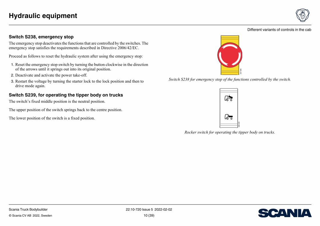
Switch S238 for emergency stop of the functions controlled by the switch.
426
420
Rocker switch for operating the tipper body on trucks.
Switch S238, emergency stopThe emergency stop deactivates the functions that are controlled by the switches. The emergency stop satisfies the requirements described in Directive 2006/42/EC.
Proceed as follows to reset the hydraulic system after using the emergency stop:
1. Reset the emergency stop switch by turning the button clockwise in the direction of the arrows until it springs out into its original position.
2. Deactivate and activate the power take-off.
3. Restart the voltage by turning the starter lock to the lock position and then to drive mode again.
Switch S239, for operating the tipper body on trucksThe switch’s fixed middle position is the neutral position.
The upper position of the switch springs back to the centre position.
The lower position of the switch is a fixed position.
Scania Truck Bodybuilder 22:10-720 Issue 5 2022-02-02© Scania CV AB 2022, Sweden 10 (39)
Different variants of controls in the cab
Hydraulic equipment
426
421
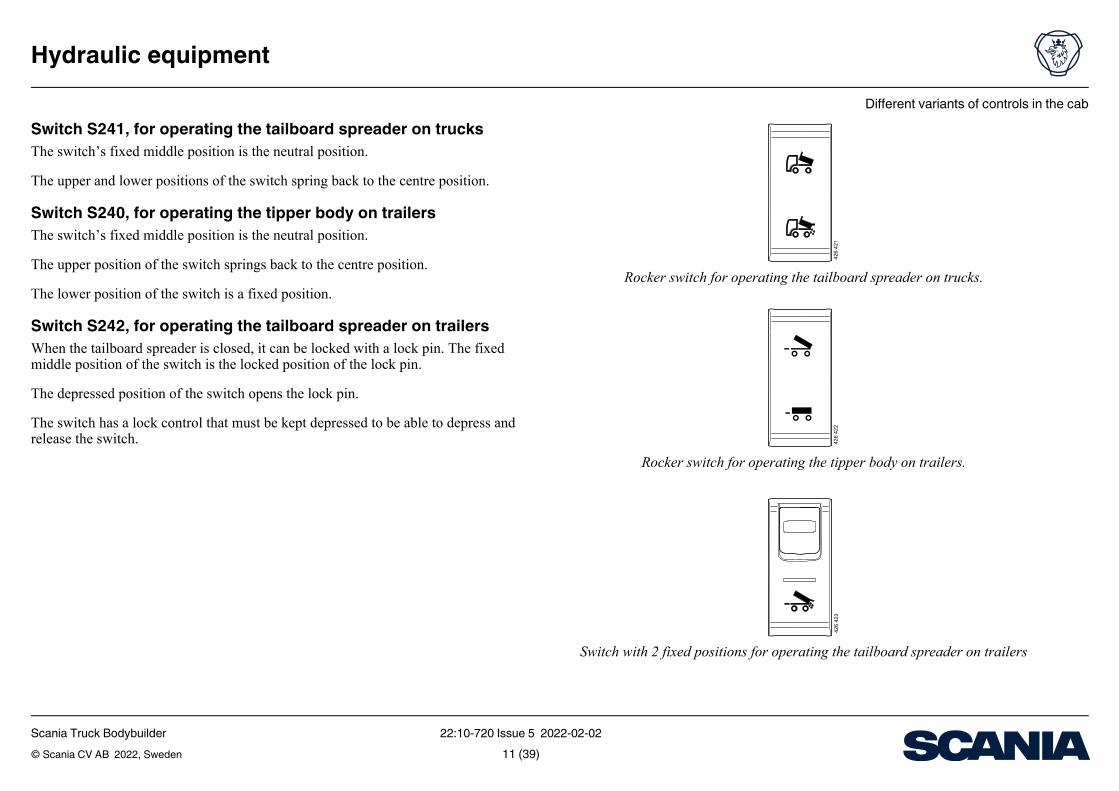
Rocker switch for operating the tailboard spreader on trucks.
426
422
Rocker switch for operating the tipper body on trailers.
426
423
Switch with 2 fixed positions for operating the tailboard spreader on trailers
Switch S241, for operating the tailboard spreader on trucksThe switch’s fixed middle position is the neutral position.
The upper and lower positions of the switch spring back to the centre position.
Switch S240, for operating the tipper body on trailersThe switch’s fixed middle position is the neutral position.
The upper position of the switch springs back to the centre position.
The lower position of the switch is a fixed position.
Switch S242, for operating the tailboard spreader on trailersWhen the tailboard spreader is closed, it can be locked with a lock pin. The fixed middle position of the switch is the locked position of the lock pin.
The depressed position of the switch opens the lock pin.
The switch has a lock control that must be kept depressed to be able to depress and release the switch.
Scania Truck Bodybuilder 22:10-720 Issue 5 2022-02-02© Scania CV AB 2022, Sweden 11 (39)
Different variants of controls in the cab
Hydraulic equipment
Connection position in C487
1
2
3
4
5
6
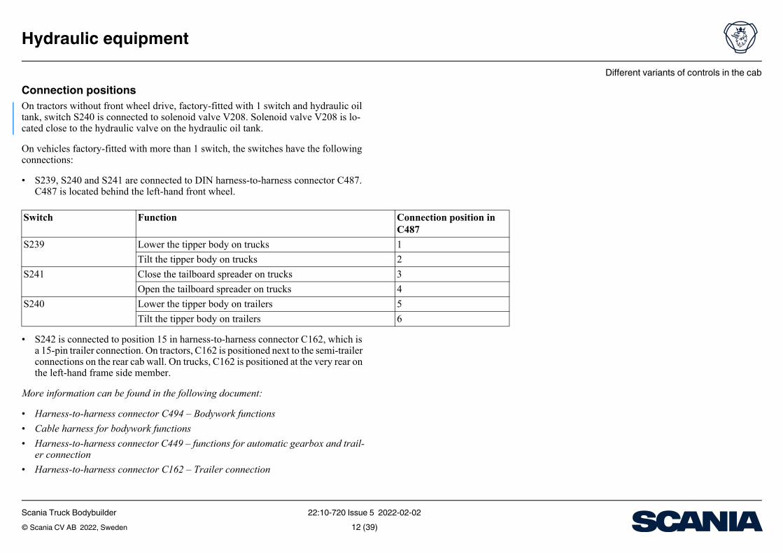
Connection positionsOn tractors without front wheel drive, factory-fitted with 1 switch and hydraulic oil tank, switch S240 is connected to solenoid valve V208. Solenoid valve V208 is lo-cated close to the hydraulic valve on the hydraulic oil tank.
On vehicles factory-fitted with more than 1 switch, the switches have the following connections:
• S239, S240 and S241 are connected to DIN harness-to-harness connector C487. C487 is located behind the left-hand front wheel.
• S242 is connected to position 15 in harness-to-harness connector C162, which is a 15-pin trailer connection. On tractors, C162 is positioned next to the semi-trailer connections on the rear cab wall. On trucks, C162 is positioned at the very rear on the left-hand frame side member.
More information can be found in the following document:
• Harness-to-harness connector C494 – Bodywork functions
• Cable harness for bodywork functions
• Harness-to-harness connector C449 – functions for automatic gearbox and trail-er connection
• Harness-to-harness connector C162 – Trailer connection
Switch Function
S239 Lower the tipper body on trucks
Tilt the tipper body on trucks
S241 Close the tailboard spreader on trucks
Open the tailboard spreader on trucks
S240 Lower the tipper body on trailers
Tilt the tipper body on trailers
Scania Truck Bodybuilder 22:10-720 Issue 5 2022-02-02© Scania CV AB 2022, Sweden 12 (39)
Different variants of controls in the cab
Hydraulic equipment
388 9
47
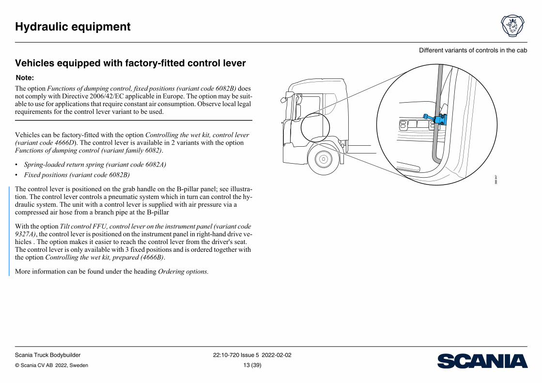
Vehicles equipped with factory-fitted control leverNote:The option Functions of dumping control, fixed positions (variant code 6082B) does not comply with Directive 2006/42/EC applicable in Europe. The option may be suit-able to use for applications that require constant air consumption. Observe local legal requirements for the control lever variant to be used.
Vehicles can be factory-fitted with the option Controlling the wet kit, control lever (variant code 4666D). The control lever is available in 2 variants with the option Functions of dumping control (variant family 6082).
• Spring-loaded return spring (variant code 6082A)
• Fixed positions (variant code 6082B)
The control lever is positioned on the grab handle on the B-pillar panel; see illustra-tion. The control lever controls a pneumatic system which in turn can control the hy-draulic system. The unit with a control lever is supplied with air pressure via a compressed air hose from a branch pipe at the B-pillar
With the option Tilt control FFU, control lever on the instrument panel (variant code 9327A), the control lever is positioned on the instrument panel in right-hand drive ve-hicles . The option makes it easier to reach the control lever from the driver's seat. The control lever is only available with 3 fixed positions and is ordered together with the option Controlling the wet kit, prepared (4666B).
More information can be found under the heading Ordering options.
Scania Truck Bodybuilder 22:10-720 Issue 5 2022-02-02© Scania CV AB 2022, Sweden 13 (39)
Different variants of controls in the cab
Hydraulic equipment
, rame
To Function
Control lever. Connected. Air supply
Rear cab wall. Loose hose ends. No function from the factory. Can be con-nected to any function.
The inside of the right-hand frame side member's third crossmember. Loose hose endsa.
are connected to the hydraulic valve located on top of the hydraulic oil tank.
No function from the factory. Can be con-nected to any functiona.
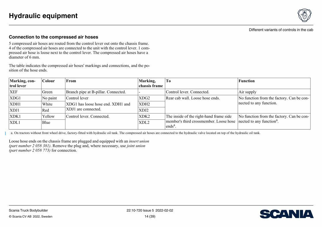
Connection to the compressed air hoses5 compressed air hoses are routed from the control lever out onto the chassis frame. 4 of the compressed air hoses are connected to the unit with the control lever. 1 com-pressed air hose is loose next to the control lever. The compressed air hoses have a diameter of 6 mm.
The table indicates the compressed air hoses' markings and connections, and the po-sition of the hose ends.
Loose hose ends on the chassis frame are plugged and equipped with an insert union (part number 2 058 381). Remove the plug and, where necessary, use joint union (part number 2 058 773) for connection.
Marking, con-trol lever
Colour From Markingchassis f
XEF Green Branch pipe at B-pillar. Connected. -
XDG1 No paint Control lever XDG2
XDH1 White XDG1 has loose hose end. XDH1 and XDJ1 are connected.
XDH2
XDJ1 Red XDJ2
XDK1 Yellow Control lever. Connected. XDK2
a. On tractors without front wheel drive, factory-fitted with hydraulic oil tank. The compressed air hoses
XDL1 Blue XDL2
Scania Truck Bodybuilder 22:10-720 Issue 5 2022-02-02© Scania CV AB 2022, Sweden 14 (39)
Hydraulic oil tank
Hydraulic equipment
Hydraulic oil tankThe vehicle can be factory-fitted with a hydraulic oil tank. The position of the hy-draulic oil tank differs depending on options, the vehicle’s wheel configuration, free space on the chassis and any special orders.
More information can be found under the heading Ordering options.
On vehicles fitted with the options Fuel tank shape, left-mounted tank, large (variant code 4087L) and Fuel tank shape, tank fitted on the right-hand side, large (variant code 4088L), the hydraulic oil tank has the following dimensions:
• Width x Height x Depth: 570 x 700 x 725 mm
• Volume: 235 litres
• Intended quantity of hydraulic oil: 200 litres
On vehicles fitted with the options Fuel tank shape, left-mounted tank, wide (variant code 4087W) and Fuel tank shape, tank fitted on the right-hand side, wide (variant code 4088W), the hydraulic oil tank has the following dimensions:
• Width x Height x Depth: 527 x 670 x 701 mm
• Volume: 210 litres
• Intended quantity of hydraulic oil: 180 litres
Scania Truck Bodybuilder 22:10-720 Issue 5 2022-02-02© Scania CV AB 2022, Sweden 15 (39)
Hydraulic oil tank
Hydraulic equipment
1
23
4
6
5
4
6
447
663
Hydraulic oil tank that follows the shape of the fuel tank, large, on tractors.
1
2 3b3a
4
447
664
Hydraulic oil tank that follows the shape of the fuel tank, large, on trucks.
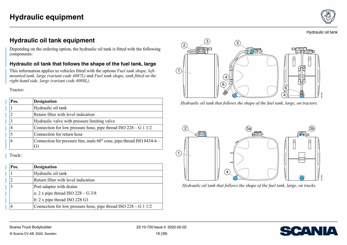
Hydraulic oil tank equipmentDepending on the ordering option, the hydraulic oil tank is fitted with the following components:
Hydraulic oil tank that follows the shape of the fuel tank, largeThis information applies to vehicles fitted with the options Fuel tank shape, left-mounted tank, large (variant code 4087L) and Fuel tank shape, tank fitted on the right-hand side, large (variant code 4088L).
Tractor:
Truck:
Pos. Designation
1 Hydraulic oil tank
2 Return filter with level indication
3 Hydraulic valve with pressure limiting valve
4 Connection for low pressure hose, pipe thread ISO 228 – G 1 1/2
5 Connection for return hose
6 Connection for pressure line, male 60o cone, pipe thread ISO 8434-6 – G1
Pos. Designation
1 Hydraulic oil tank
2 Return filter with level indication
3 Port adapter with drains
a: 2 x pipe thread ISO 228 – G 3/8
b: 2 x pipe thread ISO 228 G1
4 Connection for low pressure hose, pipe thread ISO 228 – G 1 1/2
Scania Truck Bodybuilder 22:10-720 Issue 5 2022-02-02© Scania CV AB 2022, Sweden 16 (39)
Hydraulic oil tank
Hydraulic equipment
23 5
64
1
432
517
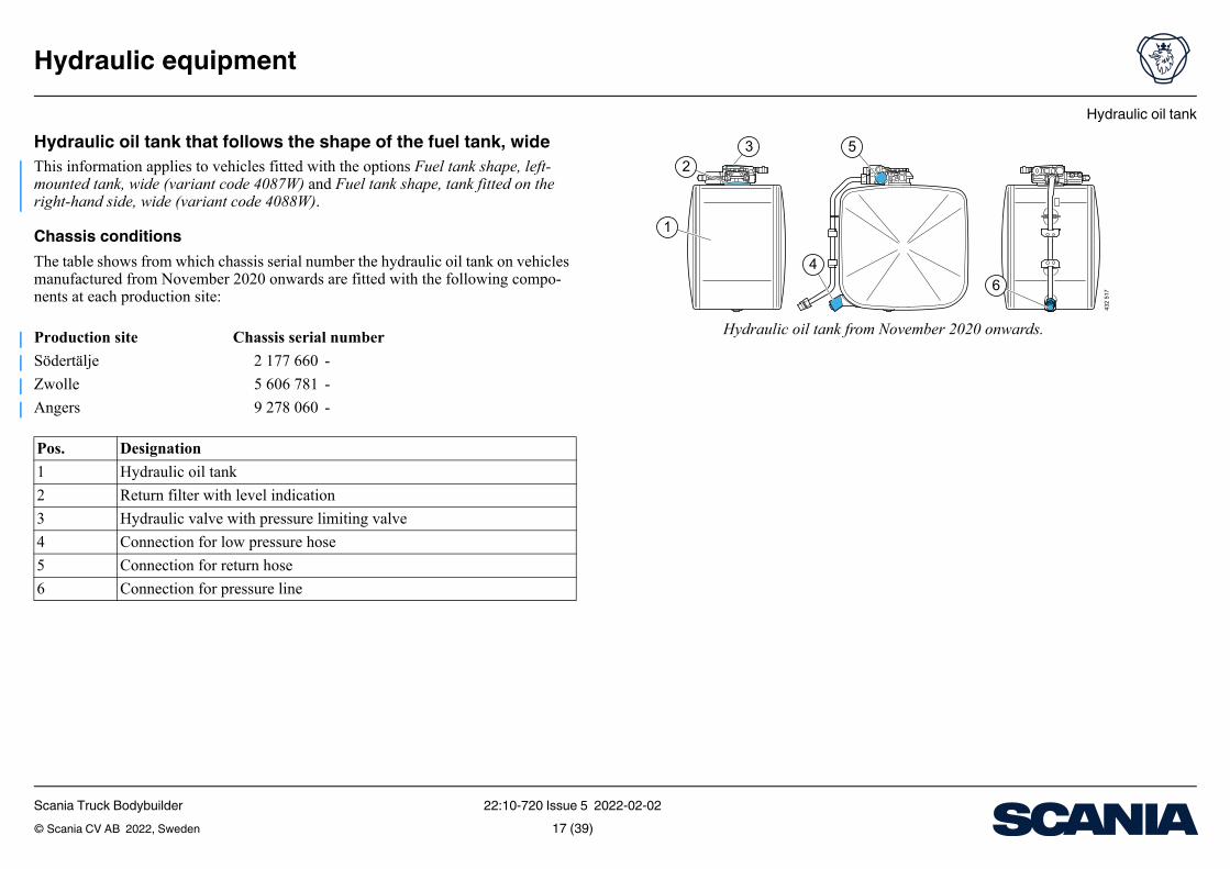
Hydraulic oil tank from November 2020 onwards.
Hydraulic oil tank that follows the shape of the fuel tank, wideThis information applies to vehicles fitted with the options Fuel tank shape, left-mounted tank, wide (variant code 4087W) and Fuel tank shape, tank fitted on the right-hand side, wide (variant code 4088W).
Chassis conditionsThe table shows from which chassis serial number the hydraulic oil tank on vehicles manufactured from November 2020 onwards are fitted with the following compo-nents at each production site:
Production site Chassis serial number
Södertälje 2 177 660 -
Zwolle 5 606 781 -
Angers 9 278 060 -
Pos. Designation
1 Hydraulic oil tank
2 Return filter with level indication
3 Hydraulic valve with pressure limiting valve
4 Connection for low pressure hose
5 Connection for return hose
6 Connection for pressure line
Scania Truck Bodybuilder 22:10-720 Issue 5 2022-02-02© Scania CV AB 2022, Sweden 17 (39)
Hydraulic oil tank
Hydraulic equipment
1
432
5
6
436
238
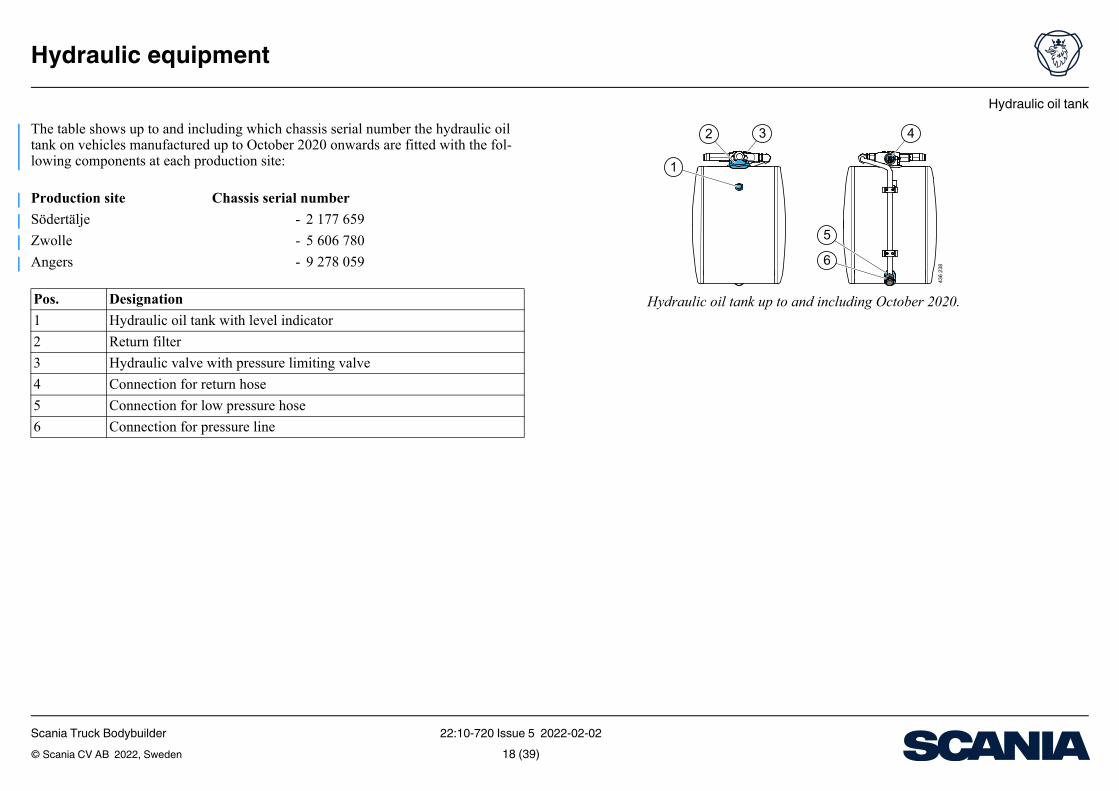
Hydraulic oil tank up to and including October 2020.
The table shows up to and including which chassis serial number the hydraulic oil tank on vehicles manufactured up to October 2020 onwards are fitted with the fol-lowing components at each production site:
Production site Chassis serial number
Södertälje - 2 177 659
Zwolle - 5 606 780
Angers - 9 278 059
Pos. Designation
1 Hydraulic oil tank with level indicator
2 Return filter
3 Hydraulic valve with pressure limiting valve
4 Connection for return hose
5 Connection for low pressure hose
6 Connection for pressure line
Scania Truck Bodybuilder 22:10-720 Issue 5 2022-02-02© Scania CV AB 2022, Sweden 18 (39)
Hydraulic oil tank
Hydraulic equipment
380 1
29
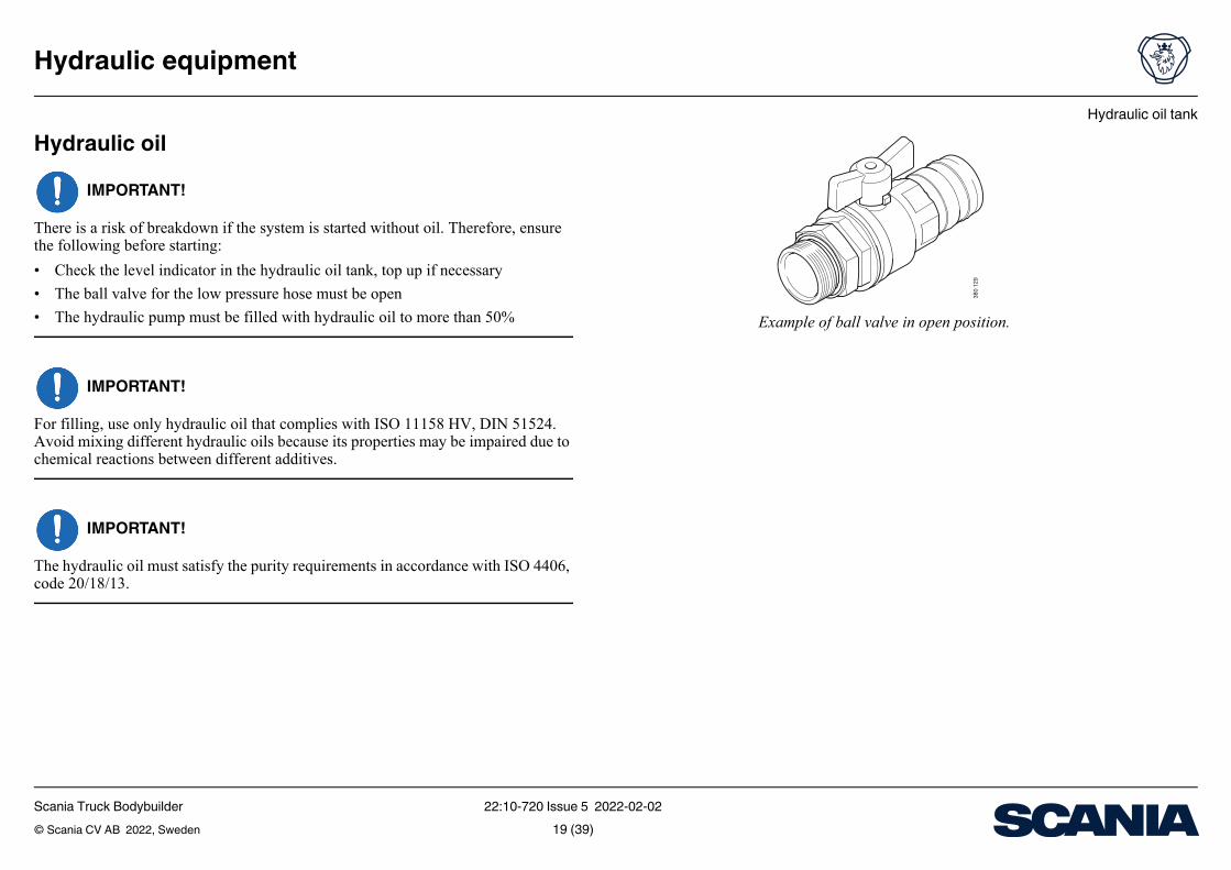
Example of ball valve in open position.
Hydraulic oilIMPORTANT!
There is a risk of breakdown if the system is started without oil. Therefore, ensure the following before starting:
• Check the level indicator in the hydraulic oil tank, top up if necessary
• The ball valve for the low pressure hose must be open
• The hydraulic pump must be filled with hydraulic oil to more than 50%
IMPORTANT!
For filling, use only hydraulic oil that complies with ISO 11158 HV, DIN 51524. Avoid mixing different hydraulic oils because its properties may be impaired due to chemical reactions between different additives.
IMPORTANT!
The hydraulic oil must satisfy the purity requirements in accordance with ISO 4406, code 20/18/13.
Scania Truck Bodybuilder 22:10-720 Issue 5 2022-02-02© Scania CV AB 2022, Sweden 19 (39)
Hydraulic oil tank
Hydraulic equipment
IMPORTANT!
The purity of the hydraulic oil has a direct influence on the service life of the hydrau-lic system. Regularly renew the oil and air filters and change the hydraulic oil to achieve a long service life for the hydraulic pump. To obtain the longest possible ser-vice life, Scania recommends a filtration of 10 µm (absolute separation efficiency). The filter captures 100% of particles larger than 10 µm. Only use hydraulic oils with anti-foaming agents and anti-wear inhibitor.
A dirty air filter means an increased risk of dirt being sucked into the tank. This can also result in impaired venting and a risk of vacuum in the tank, which can lead to hydraulic equipment being damaged.
The hydraulic oil tank should be filled with 50% more hydraulic oil than the nominal pump flow per minute. Certain applications with a short working cycle can be ex-cluded from this rule, for example a one-way tipper truck that is used less frequently and where the hydraulic oil has time to cool down.
Scania Truck Bodybuilder 22:10-720 Issue 5 2022-02-02© Scania CV AB 2022, Sweden 20 (39)
Hydraulic oil tank
Hydraulic equipment
Hydraulic oil from the factoryIt is possible to fit vehicles with a filled hydraulic oil tank, option Hydraulic oil, with (variant code 4851A) if the vehicle is fitted with all the following options:
• Hydraulic hose between tank and pump, with (variant code 6645A)
• Pump type (variant family 4802)
• Hydraulic valve with pressure limiting valve (variant family 4830)
The hydraulic oil from the factory complies with ISO 11158 HV, DIN 51524-3, HVPL with one of the following viscosities depending on manufacturing period:
• VG22, on vehicles manufactured up to and including December 2020
• VG32, on vehicles manufactured from January 2021
Oil properties:– Good ventilation capacity and oxidation stability– Protects against rust and corrosion– Provides good wear protection– The oil is suitable for most markets all year round. Check whether the oil is
suitable if the vehicle is to be used at extreme temperatures.
Scania Truck Bodybuilder 22:10-720 Issue 5 2022-02-02© Scania CV AB 2022, Sweden 21 (39)
Hydraulic oil tank
Hydraulic equipment
Chassis conditionsThe table indicates from which chassis serial number hydraulic oil with viscosity VG32 was introduced in vehicles manufactured from January 2021.
The table indicates to which chassis serial number hydraulic oil with viscosity VG22 was introduced in vehicles manufactured up to and including December 2020.
Contact the supplier of the hydraulic oil for mixability information.
Production site Chassis serial number
Södertälje 2 178 763 -
Zwolle 5 610 349 -
Angers 9 279 428 -
Production site Chassis serial number
Södertälje - 2 178 762
Zwolle - 5 610 348
Angers - 9 279 427
Scania Truck Bodybuilder 22:10-720 Issue 5 2022-02-02© Scania CV AB 2022, Sweden 22 (39)
Hydraulic valve with pressure limiting valve
Hydraulic equipment
Hydraulic valve with pressure limiting valveHydraulic valve with pressure limiting valve on vehicles manufactured up to and in-cluding November 2020 is available in the following 2 variants:
• With fixed pressure limiting value (variant code 4830A-D)
• With 2 selectable pressure limiting values (variant code 4830E)
Hydraulic valve with pressure limiting valve on vehicles manufactured from and in-cluding December 2020 is available in the following 2 variants:
• With fixed pressure limiting value (variant code 4830B, F)
• With 2 selectable pressure limiting values (variant code 4830G)
• With 3 selectable pressure limiting values (variant code 4830H, J)
From November 2020 onwards, the options Hydraulic valve with pressure limiting valve (variant code 4830B, F, G, H, J) can be ordered for tractors when ordering hy-draulic oil tanks from the factory. The hydraulic valve is mainly intended to control a single-action hydraulic cylinder with the option of selecting a return hose. Hydrau-lic valve with combined pressure port and return port factory-fitted to the top of the hydraulic oil tank.
The vehicle can also be fitted without a hydraulic valve with the option Hydraulic valve pressure limiting valve, without (variant code 4830Z).
Information on hydraulic valve with different pressure limiting values can be found under the heading Ordering options.
Scania Truck Bodybuilder 22:10-720 Issue 5 2022-02-02© Scania CV AB 2022, Sweden 23 (39)
Hydraulic valve with pressure limiting valve
Hydraulic equipment
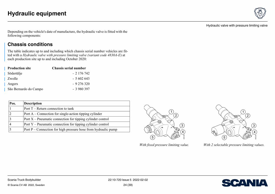
With fixed pressure limiting value. With 2 selectable pressure limiting values.
12
3
4
5 436
239
12
3
4
5 436
240
Depending on the vehicle's date of manufacture, the hydraulic valve is fitted with the following components:
Chassis conditionsThe table indicates up to and including which chassis serial number vehicles are fit-ted with a Hydraulic valve with pressure limiting valve (variant code 4830A-E) at each production site up to and including October 2020:
Production site Chassis serial number
Södertälje - 2 176 742
Zwolle - 5 602 643
Angers - 9 276 320
São Bernardo do Campo - 3 980 397
Pos. Description
1 Port T – Return connection to tank
2 Port A – Connection for single-action tipping cylinder
3 Port X – Pneumatic connection for tipping cylinder control
4 Port Y – Pneumatic connection for tipping cylinder control
5 Port P – Connection for high pressure hose from hydraulic pump
Scania Truck Bodybuilder 22:10-720 Issue 5 2022-02-02© Scania CV AB 2022, Sweden 24 (39)
Hydraulic valve with pressure limiting valve
Hydraulic equipment
1
2
34 5 6 43
2 51
8
a cb
TP T2
1 0 2
436
241
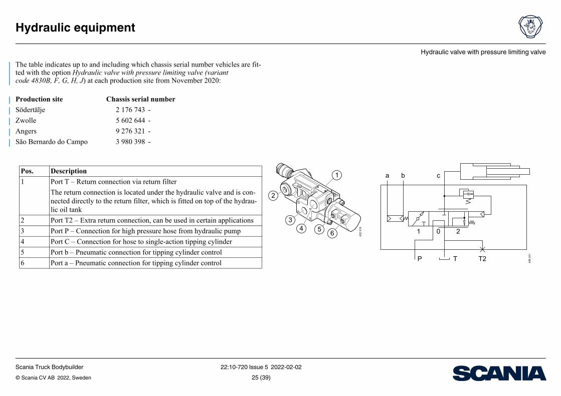
The table indicates up to and including which chassis serial number vehicles are fit-ted with the option Hydraulic valve with pressure limiting valve (variant code 4830B, F, G, H, J) at each production site from November 2020:
Production site Chassis serial number
Södertälje 2 176 743 -
Zwolle 5 602 644 -
Angers 9 276 321 -
São Bernardo do Campo 3 980 398 -
Pos. Description
1 Port T – Return connection via return filter
The return connection is located under the hydraulic valve and is con-nected directly to the return filter, which is fitted on top of the hydrau-lic oil tank
2 Port T2 – Extra return connection, can be used in certain applications
3 Port P – Connection for high pressure hose from hydraulic pump
4 Port C – Connection for hose to single-action tipping cylinder
5 Port b – Pneumatic connection for tipping cylinder control
6 Port a – Pneumatic connection for tipping cylinder control
Scania Truck Bodybuilder 22:10-720 Issue 5 2022-02-02© Scania CV AB 2022, Sweden 25 (39)
Hydraulic valve with pressure limiting valve
Hydraulic equipment
The table indicates from which date the vehicle can be fitted with the option Hydrau-lic valve with pressure limiting valve, without (variant code 4830Z) at each produc-tion site:
Production site Date Chassis serial number
Södertälje 01/06/2022 -
Zwolle 03/08/2022 -
Angers 03/03/2022 -
Scania Truck Bodybuilder 22:10-720 Issue 5 2022-02-02© Scania CV AB 2022, Sweden 26 (39)
Hydraulic valve with pressure limiting valve
Hydraulic equipment
Connection to hydraulic valveNote:The hydraulic valve cannot be used for a double-action cylinder that requires pres-sure in 2 directions.
Note:Put the hydraulic valve in the closed position when loading, otherwise the tipping cylinder may be damaged by heavy impact from, for example, rock mass.
When the hydraulic valve is in neutral, the oil goes from the hydraulic pump directly to the tank. When the valve is opened, the oil flow is directed out to port A1 or port C2, see table, and the tipping cylinder moves upwards. If the valve is put in neutral while the tipping cylinder is moving upwards, the tipping cylinder stops. When the valve is closed, port A1 or port C2 function as a return port and the return flow is di-rected back to the hydraulic oil tank. The tipper body tare weight makes the hydraulic piston move inwards in the cylinder.
The hydraulic valve can only control single-action functions, for example a single-action tipping cylinder that is pressed together in the return movement using the tip-per body's dead weight. The hydraulic valve can also be used to provide system pres-sure/system flow to another hydraulic valve on the truck or trailer bodywork.
1. On hydraulic valves with pressure limiting valves for vehicles manufactured up to and including November 2020.
2. On hydraulic valves with pressure limiting valves for vehicles manufactured from and including December 2020.
Scania Truck Bodybuilder 22:10-720 Issue 5 2022-02-02© Scania CV AB 2022, Sweden 27 (39)
Hydraulic pump
Hydraulic equipment
380 1
15
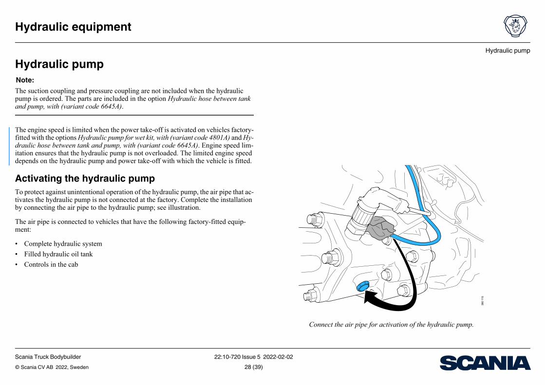
Connect the air pipe for activation of the hydraulic pump.
Hydraulic pumpNote:The suction coupling and pressure coupling are not included when the hydraulic pump is ordered. The parts are included in the option Hydraulic hose between tank and pump, with (variant code 6645A).
The engine speed is limited when the power take-off is activated on vehicles factory-fitted with the options Hydraulic pump for wet kit, with (variant code 4801A) and Hy-draulic hose between tank and pump, with (variant code 6645A). Engine speed lim-itation ensures that the hydraulic pump is not overloaded. The limited engine speed depends on the hydraulic pump and power take-off with which the vehicle is fitted.
Activating the hydraulic pumpTo protect against unintentional operation of the hydraulic pump, the air pipe that ac-tivates the hydraulic pump is not connected at the factory. Complete the installation by connecting the air pipe to the hydraulic pump; see illustration.
The air pipe is connected to vehicles that have the following factory-fitted equip-ment:
• Complete hydraulic system
• Filled hydraulic oil tank
• Controls in the cab
Scania Truck Bodybuilder 22:10-720 Issue 5 2022-02-02© Scania CV AB 2022, Sweden 28 (39)
Hydraulic pump
Hydraulic equipment
Hydraulic oil flow and engine speedNote:The engine speed affects the performance of the hydraulic system. Check with the pump supplier that the engine speed results in the correct hydraulic oil flow.
Note:On vehicles factory-fitted with hydraulic system assemblies, there is a risk that the hydraulic pump will be damaged by cavitation if the engine speed exceeds the facto-ry-set limit.
In the event that a hydraulic system other than the one with which the vehicle was fitted at the factory is connected, the engine speed limitation requirements change.
All vehicles factory-fitted with the options Hydraulic pump for wet kit, with (variant code 4801A) and Hydraulic hose between tank and pump, with (variant code 6645A) have a factory-set engine speed limitation in the event of power take-off activation. It is possible to change the engine speed limitation.
Scania Truck Bodybuilder 22:10-720 Issue 5 2022-02-02© Scania CV AB 2022, Sweden 29 (39)
Hydraulic pump
Hydraulic equipment
Gear pump, displacementa (cm3)
00 80 115
l/min rpm l/min rpm l/min
147 1.200 104 1.200 171
146 1.200 107 1.100 173
123 1.200 99 1.200 142
146 1.200 103 1.200 163
145 1.200 147 1.200 211
143 1.200 172 1.050 216
- 1.200 187 950 213
- 1.200 201 900 216
145 1.200 147 1.200 211
143 1.200 172 1.050 216
- 1.200 187 950 213
- 1.200 201 900 216
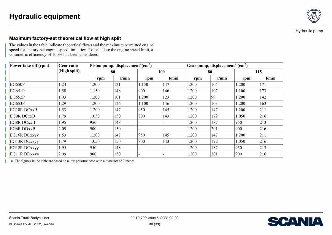
Maximum factory-set theoretical flow at high splitThe values in the table indicate theoretical flows and the maximum permitted engine speed for factory-set engine speed limitation. To calculate the engine speed limit, a volumetric efficiency of 100% has been considered:
Power take-off (rpm) Gear ratio (High split)
Piston pump, displacementa(cm3)
a. The figures in the table are based on a low pressure hose with a diameter of 2 inches.
80 1
rpm l/min rpm
EG650P 1.24 1.200 121 1.150
EG651P 1.58 1.150 148 900
EG652P 1.03 1.200 101 1.200
EG653P 1.29 1.200 126 1.100
EG10R DCxxB 1.53 1.200 147 950
EG9R DCxxB 1.79 1.050 150 800
EG8R DCxxB 1.95 950 148 -
EG6R DDxxB 2.09 900 150 -
EG16R DCxxyy 1.53 1.200 147 950
EG13R DCxxyy 1.79 1.050 150 800
EG12R DCxxyy 1.95 950 148 -
EG11R DDxxyy 2.09 900 150 -
Scania Truck Bodybuilder 22:10-720 Issue 5 2022-02-02© Scania CV AB 2022, Sweden 30 (39)
Hydraulic pump
Hydraulic equipment
3801
16
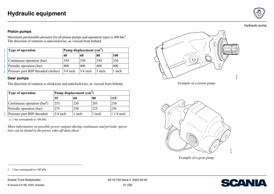
Example of a piston pump.
327 1
00
Example of a gear pump.
Piston pumpsMaximum permissible pressure for all piston pumps and operation types is 400 bar1. The direction of rotation is anticlockwise, as viewed from behind.
Gear pumpsThe direction of rotation is clockwise and anticlockwise, as viewed from behind.
More information on possible power outputs during continuous and periodic opera-tion can be found in the power take-off data sheet.
1. 1 bar corresponds to 100 kPa
Type of operation Pump displacement (cm3)
40 60 80 100
Continuous operation (bar) 350 350 350 350
Periodic operation (bar) 400 400 400 400
Pressure port BSP threaded (inches) 3/4 inch 3/4 inch 1 inch 1 inch
Type of operation Pump displacement (cm3)
35 60 80 115
Continuous operation (bara)
a. 1 bar corresponds to 100 kPa.
255 230 205 230
Periodic operation (bar) 275 250 225 250
Pressure port BSP threaded 3/4 inch 1 inch 1 inch 1 1/4 inch
Scania Truck Bodybuilder 22:10-720 Issue 5 2022-02-02© Scania CV AB 2022, Sweden 31 (39)
Hydraulic pump
Hydraulic equipment
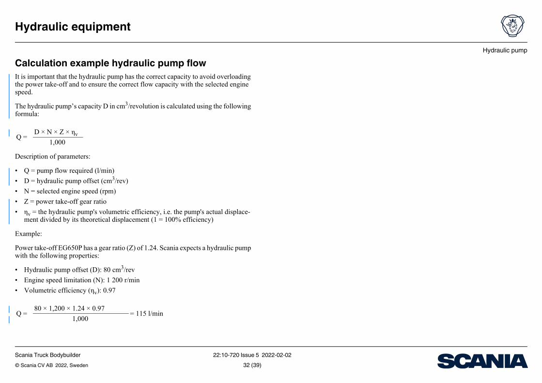
Calculation example hydraulic pump flowIt is important that the hydraulic pump has the correct capacity to avoid overloading the power take-off and to ensure the correct flow capacity with the selected engine speed.
The hydraulic pump’s capacity D in cm3/revolution is calculated using the following formula:
Description of parameters:
• Q = pump flow required (l/min)
• D = hydraulic pump offset (cm3/rev)
• N = selected engine speed (rpm)
• Z = power take-off gear ratio
• ηv = the hydraulic pump's volumetric efficiency, i.e. the pump's actual displace-ment divided by its theoretical displacement (1 = 100% efficiency)
Example:
Power take-off EG650P has a gear ratio (Z) of 1.24. Scania expects a hydraulic pump with the following properties:
• Hydraulic pump offset (D): 80 cm3/rev
• Engine speed limitation (N): 1 200 r/min
• Volumetric efficiency (ηv): 0.97
Q =D × N × Z × ηv
1,000
Q =80 × 1,200 × 1.24 × 0.97
= 115 l/min1,000
Scania Truck Bodybuilder 22:10-720 Issue 5 2022-02-02© Scania CV AB 2022, Sweden 32 (39)
Hydraulic hoses and couplings
Hydraulic equipment
Hydraulic hoses and couplingsFor the installation of hydraulic hoses and couplings, Scania's requirements must be satisfied. The requirements have been developed to ensure that the hydraulic system and other equipment are exposed to the least possible stress and wear during use.
Tractors can be fitted with hydraulic hoses with quick release couplings at the facto-ry.
Diameter of high pressure hose and return hose is 1 inch; maximum permissible op-erating pressure is 250 bar (25 MPa). The high pressure hose and return hose have a G1 inch BSPP thread with a 60o cone.
The diameter of the low pressure hose is 2 inches, and the connection on the tank has a 1.5 inch BSPP thread with a 60o cone.
More information can be found under the heading Ordering options.
Scania Truck Bodybuilder 22:10-720 Issue 5 2022-02-02© Scania CV AB 2022, Sweden 33 (39)
Ordering options
Hydraulic equipment
ode Description
Prepared for control lever
-
-
Clockwise and anticlockwise
Anticlockwise
Combined with option 4802B
Combined with one of the options 4802A or 4802B
Combined with option 4802B
Combined with option 4802A
Tractors and trucks. Positioned at the first available position behind the front axle.
Tractors and trucks. Positioned at the first available position behind the silencer.
Tractor. Positioned at the first available position in front of the front rear axle.
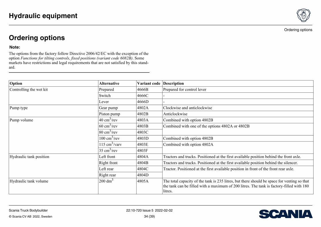
The total capacity of the tank is 235 litres, but there should be space for venting so that the tank can be filled with a maximum of 200 litres. The tank is factory-filled with 180 litres.
Ordering optionsNote:The options from the factory follow Directive 2006/42/EC with the exception of the option Functions for tilting controls, fixed positions (variant code 6082B). Some markets have restrictions and legal requirements that are not satisfied by this stand-ard.
Option Alternative Variant c
Controlling the wet kit Prepared 4666B
Switch 4666C
Lever 4666D
Pump type Gear pump 4802A
Piston pump 4802B
Pump volume 40 cm3/rev 4803A
60 cm3/rev 4803B
80 cm3/rev 4803C
100 cm3/rev 4803D
115 cm3/varv 4803E
35 cm3/rev 4803F
Hydraulic tank position Left front 4804A
Right front 4804B
Left rear 4804C
Right rear 4804D
Hydraulic tank volume 200 dm3 4805A
Scania Truck Bodybuilder 22:10-720 Issue 5 2022-02-02© Scania CV AB 2022, Sweden 34 (39)
Ordering options
Hydraulic equipment
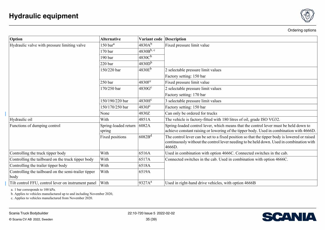
Fixed pressure limit value
2 selectable pressure limit values
Factory setting: 150 bar
Fixed pressure limit value
2 selectable pressure limit values
Factory setting: 170 bar
3 selectable pressure limit values
Factory setting: 150 bar
Can only be ordered for trucks
The vehicle is factory-fitted with 180 litres of oil, grade ISO VG32.
Spring-loaded control lever, which means that the control lever must be held down to achieve constant raising or lowering of the tipper body. Used in combination with 4666D.
The control lever can be set to a fixed position so that the tipper body is lowered or raised continuously without the control lever needing to be held down. Used in combination with 4666D.
Used in combination with option 4666C. Connected switches in the cab.
Connected switches in the cab. Used in combination with option 4666C.
Used in right-hand drive vehicles, with option 4666B
ode Description
Hydraulic valve with pressure limiting valve 150 bara 4830Ab
170 bar 4830Bb, c
190 bar 4830Cb
220 bar 4830Db
150/220 bar 4830Eb
250 bar 4830Fc
170/250 bar 4830Gc
150/190/220 bar 4830Hc
150/170/250 bar 4830Jc
None 4830Z
Hydraulic oil With 4851A
Functions of dumping control Spring-loaded return spring
6082A
Fixed positions 6082Bd
Controlling the truck tipper body With 6516A
Controlling the tailboard on the truck tipper body With 6517A
Controlling the trailer tipper body With 6518A
Controlling the tailboard on the semi-trailer tipper body
With 6519A
Tilt control FFU, control lever on instrument panel With 9327Aa
a. 1 bar corresponds to 100 kPa.b. Applies to vehicles manufactured up to and including November 2020,c. Applies to vehicles manufactured from November 2020.
Option Alternative Variant c
Scania Truck Bodybuilder 22:10-720 Issue 5 2022-02-02© Scania CV AB 2022, Sweden 35 (39)
Ordering options
Hydraulic equipment
r tipper trucks, for example.
code Description
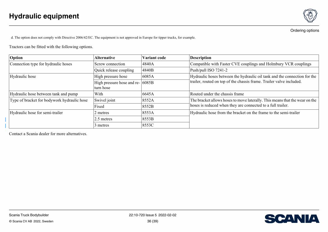
Compatible with Faster CVE couplings and Holmbury VCR couplings
Push/pull ISO 7241-2
Hydraulic hoses between the hydraulic oil tank and the connection for the trailer, routed on top of the chassis frame. Trailer valve included.
Routed under the chassis frame
The bracket allows hoses to move laterally. This means that the wear on the hoses is reduced when they are connected to a full trailer.
Hydraulic hose from the bracket on the frame to the semi-trailer
Tractors can be fitted with the following options.
Contact a Scania dealer for more alternatives.
d. The option does not comply with Directive 2006/42/EC. The equipment is not approved in Europe fo
Option Alternative Variant
Connection type for hydraulic hoses Screw connection 4840A
Quick release coupling 4840B
Hydraulic hose High pressure hose 6085A
High pressure hose and re-turn hose
6085B
Hydraulic hose between tank and pump With 6645A
Type of bracket for bodywork hydraulic hose Swivel joint 8552A
Fixed 8552B
Hydraulic hose for semi-trailer 2 metres 8553A
2.5 metres 8553B
3 metres 8553C
Scania Truck Bodybuilder 22:10-720 Issue 5 2022-02-02© Scania CV AB 2022, Sweden 36 (39)
Part information
Hydraulic equipment
Part number
2 534 174
2 534 170
2 534 175
2 400 067
2 058 381
2 058 773
40 cm3, anticlockwise. Pressure port BSP threaded 3/4 inch.
60 cm3, anticlockwise. Pressure port BSP threaded 3/4 inch.
80 cm3, anticlockwise. Pressure port BSP threaded 1 inch.
100 cm3, anticlockwise. Pressure port BSP threaded 1 inch.
35 cm3, clockwise and anticlockwise. Pressure port BSP threaded 3/4 inch.
60 cm3, clockwise and anticlockwise. Pressure port BSP threaded 1 inch.
80 cm3, clockwise and anticlockwise. Pressure port BSP threaded 1 inch.
115 cm3, clockwise and anticlockwise. Pressure port BSP threaded 1 1/4 inch.
er, minimum bend radius 117 mm
er, minimum bend radius 117 mm
er, minimum bend radius 117 mm
er, minimum bend radius 117 mm
er, minimum bend radius 117 mm
er, minimum bend radius 117 mm
er, minimum bend radius 117 mm
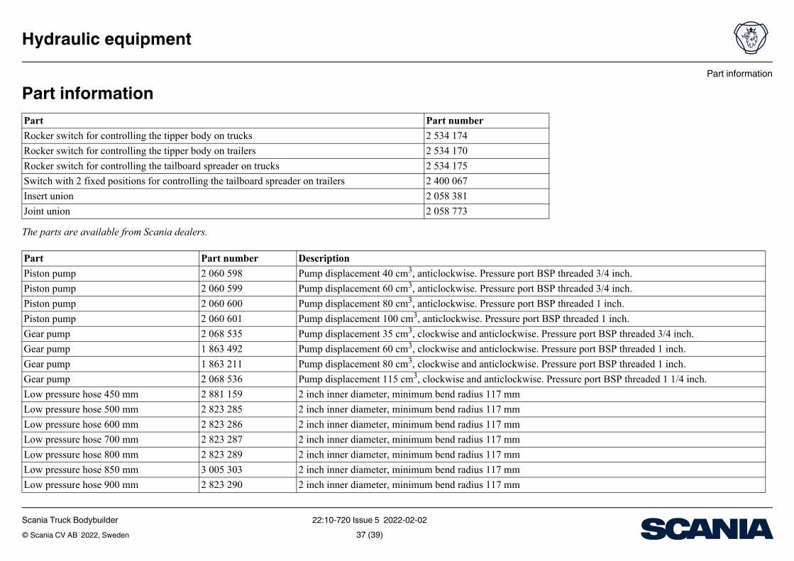
Part information
The parts are available from Scania dealers.
Part
Rocker switch for controlling the tipper body on trucks
Rocker switch for controlling the tipper body on trailers
Rocker switch for controlling the tailboard spreader on trucks
Switch with 2 fixed positions for controlling the tailboard spreader on trailers
Insert union
Joint union
Part Part number Description
Piston pump 2 060 598 Pump displacement
Piston pump 2 060 599 Pump displacement
Piston pump 2 060 600 Pump displacement
Piston pump 2 060 601 Pump displacement
Gear pump 2 068 535 Pump displacement
Gear pump 1 863 492 Pump displacement
Gear pump 1 863 211 Pump displacement
Gear pump 2 068 536 Pump displacement
Low pressure hose 450 mm 2 881 159 2 inch inner diamet
Low pressure hose 500 mm 2 823 285 2 inch inner diamet
Low pressure hose 600 mm 2 823 286 2 inch inner diamet
Low pressure hose 700 mm 2 823 287 2 inch inner diamet
Low pressure hose 800 mm 2 823 289 2 inch inner diamet
Low pressure hose 850 mm 3 005 303 2 inch inner diamet
Low pressure hose 900 mm 2 823 290 2 inch inner diamet
Scania Truck Bodybuilder 22:10-720 Issue 5 2022-02-02© Scania CV AB 2022, Sweden 37 (39)
Part information
Hydraulic equipment
er, minimum bend radius 117 mm
er, minimum bend radius 117 mm
er, minimum bend radius 117 mm
er, minimum bend radius 117 mm
er, minimum bend radius 117 mm
er, minimum bend radius 117 mm
er, minimum bend radius 117 mm
er, minimum bend radius 117 mm
hose
hose
hose
hose
hose
hose
hose
hose
hose
hose
hose
hose
hose
hose
hose
hose
hose
hose
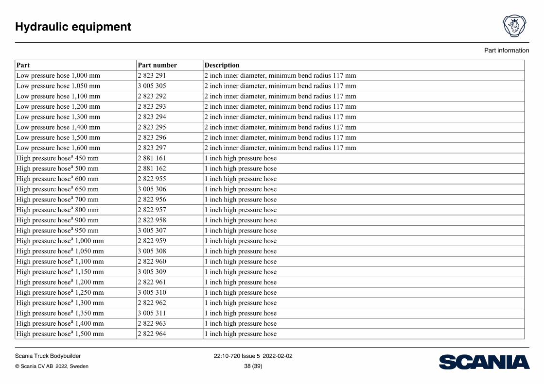
Low pressure hose 1,000 mm 2 823 291 2 inch inner diamet
Low pressure hose 1,050 mm 3 005 305 2 inch inner diamet
Low pressure hose 1,100 mm 2 823 292 2 inch inner diamet
Low pressure hose 1,200 mm 2 823 293 2 inch inner diamet
Low pressure hose 1,300 mm 2 823 294 2 inch inner diamet
Low pressure hose 1,400 mm 2 823 295 2 inch inner diamet
Low pressure hose 1,500 mm 2 823 296 2 inch inner diamet
Low pressure hose 1,600 mm 2 823 297 2 inch inner diamet
High pressure hosea 450 mm 2 881 161 1 inch high pressure
High pressure hosea 500 mm 2 881 162 1 inch high pressure
High pressure hosea 600 mm 2 822 955 1 inch high pressure
High pressure hosea 650 mm 3 005 306 1 inch high pressure
High pressure hosea 700 mm 2 822 956 1 inch high pressure
High pressure hosea 800 mm 2 822 957 1 inch high pressure
High pressure hosea 900 mm 2 822 958 1 inch high pressure
High pressure hosea 950 mm 3 005 307 1 inch high pressure
High pressure hosea 1,000 mm 2 822 959 1 inch high pressure
High pressure hosea 1,050 mm 3 005 308 1 inch high pressure
High pressure hosea 1,100 mm 2 822 960 1 inch high pressure
High pressure hosea 1,150 mm 3 005 309 1 inch high pressure
High pressure hosea 1,200 mm 2 822 961 1 inch high pressure
High pressure hosea 1,250 mm 3 005 310 1 inch high pressure
High pressure hosea 1,300 mm 2 822 962 1 inch high pressure
High pressure hosea 1,350 mm 3 005 311 1 inch high pressure
High pressure hosea 1,400 mm 2 822 963 1 inch high pressure
High pressure hosea 1,500 mm 2 822 964 1 inch high pressure
Part Part number Description
Scania Truck Bodybuilder 22:10-720 Issue 5 2022-02-02© Scania CV AB 2022, Sweden 38 (39)
Part information
Hydraulic equipment
hose
hose
hose
hose
hose
hose
ch BSP male thread and 60° cone end to the same
/4 inch BSP male thread and 60° cone end to 1 inch male BSP thread and 60° cone
1 inch BSP male thread and 60° cone end to female of the same type
1 inch BSP male thread and 60° cone end to female of the same type
ch equipment
/4 inch equipment
g with 1 1/2 inch BSP male thread with nut and O-ring to 1 1/2 inch BSP female thread
g with 2 inch hose for piston pump. Used with 804 668 O-ring, 2x 2 074 437 clamps, 2x 25 868 hose clamp
g with 2 inch hose for piston pump. Used with 804 668 O-ring, 2x 2 074 437 clamps, 2x 25 868 hose clamp
g with 2 inch hose to 1 inch BSP male thread with nut and O-ring
g with 2 inch hose to 1 1/4 inch BSP male thread with nut and O-ring
g with 1 1/2 inch BSP male thread with nut and O-ring to 1 1/2 inch BSP female thread
ith 2 inch hose to 1 1/2 inch BSP male thread with nut and O-ring
ht swivelling hose coupling at both ends. The hose coupling has a 1 inch BSP thread, 60° cone end and O-ring se is 250 mm.
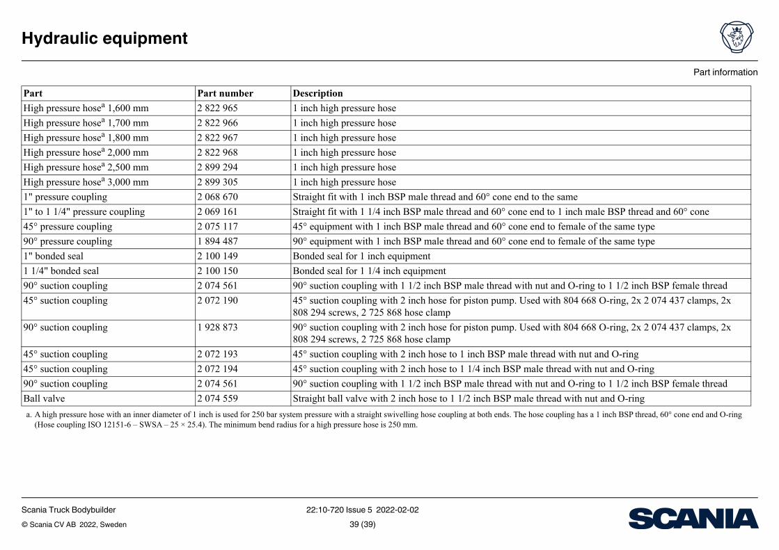
High pressure hosea 1,600 mm 2 822 965 1 inch high pressure
High pressure hosea 1,700 mm 2 822 966 1 inch high pressure
High pressure hosea 1,800 mm 2 822 967 1 inch high pressure
High pressure hosea 2,000 mm 2 822 968 1 inch high pressure
High pressure hosea 2,500 mm 2 899 294 1 inch high pressure
High pressure hosea 3,000 mm 2 899 305 1 inch high pressure
1" pressure coupling 2 068 670 Straight fit with 1 in
1" to 1 1/4" pressure coupling 2 069 161 Straight fit with 1 1
45° pressure coupling 2 075 117 45° equipment with
90° pressure coupling 1 894 487 90° equipment with
1" bonded seal 2 100 149 Bonded seal for 1 in
1 1/4" bonded seal 2 100 150 Bonded seal for 1 1
90° suction coupling 2 074 561 90° suction couplin
45° suction coupling 2 072 190 45° suction couplin808 294 screws, 2 7
90° suction coupling 1 928 873 90° suction couplin808 294 screws, 2 7
45° suction coupling 2 072 193 45° suction couplin
45° suction coupling 2 072 194 45° suction couplin
90° suction coupling 2 074 561 90° suction couplin
Ball valve 2 074 559 Straight ball valve w
a. A high pressure hose with an inner diameter of 1 inch is used for 250 bar system pressure with a straig(Hose coupling ISO 12151-6 – SWSA – 25 × 25.4). The minimum bend radius for a high pressure ho
Part Part number Description
Scania Truck Bodybuilder 22:10-720 Issue 5 2022-02-02© Scania CV AB 2022, Sweden 39 (39)