1. introduction 2. general guidelines 3. hydraulic fluids 4
TRANSCRIPT
Page 1
CIN : L29150KA1976PLC003017
Yuken India Limited Bangalore - 560066
INDEX
1. Introduction
2. General Guidelines
3. Hydraulic Fluids
4. Installation & Start up Procedures
5. Trouble Shooting Guide & Maintenance
6. Trouble Shooting Guide
7. Enclosures
Test Certificates Guarantee Certificates Bill of Materials Circuit Diagram Layout Diagram
8. Engineering Information Sheet
Page 2
CIN : L29150KA1976PLC003017
Yuken India Limited Bangalore - 560066
1. INTRODUCTION
Hydraulics is a topic in applied science and engineering dealing with the mechanical
Properties of liquids. Fluid mechanics provides the theoretical foundation for hydraulics viz.
Lubrication, cooling, damping etc. in order that machines incorporating hydraulics, work trouble
free and for a longer life, it is necessary that requirements of this flexible source of energy
transfer are fulfilled through various stages such as installation, commissioning and routine
maintenance etc.
It is hoped that information provided in this manual would serve to ensure the satisfactory
running of the hydraulic system.

Page 3
CIN : L29150KA1976PLC003017
Yuken India Limited Bangalore - 560066
2. GENERAL GUIDELINES RESERVOIR
The reservoir serves primarily as a storage space and supply point for the hydraulic system fluid. The reservoir design contributes to the proper functioning of the entire system and reduces normal maintenance requirements. It keeps the fluid clean, separates air and contaminants from the fluid, prevents undue contamination of the system and provides easy access to the system and its components for maintenance and servicing. The reservoirs also dissipate the heat of the fluid to the outside atmosphere. The tank is constructed of steel plates with welded joints with a drain plug at the lowest point for easy and complete draining of the tank. The top plate is either welded or bolted to the reservoir with suitable gaskets to prevent entry of contaminants. The top covers are of suitable thickness to support the pump and driving motor to prevent distortion and vibration. The inside surfaces of the reservoir is pickled, thoroughly cleaned and painted with a sealed material compatible with the fluid. Two large removable maintenance covers are provided on each end for medium and large size tanks of permit easy access for cleaning. A vertical baffle plate extending lengthwise through the center of tank separates pump inlet and return lines, prevents turbulence of return fluid and promotes flow circulation of return line oil in reservoir for effective heat dissipation and air separation; it also helps in the precipitation of foreign matter at the bottom of tank. BREATHER CUM FILLER:
An adequately sized breather cum filler is provided on the top plate. The breather, which is incorporated to maintain atmospheric pressure in the reservoir, contains a filter to prevent entry of dust particles in the air. The filter with a fine mesh wire screen keeps out foreign matter while filling new fluid in the reservoir. OIL LEVEL GAUGE:
A flush mounted and protected oil level gauge is provided at the tank side with markings indicating “Maximum” and “Running” and “Minimum” level at oil in the reservoir.
Page 4
CIN : L29150KA1976PLC003017
Yuken India Limited Bangalore - 560066
STRAINER AND FILTER:
To ensure long life and trouble free performance of the system, suction strainer, pressure and return line filters are provided to keep the hydraulic fluid clean. Strainer and filters are used to remove foreign particles from the fluid and are most effective as safeguards against contamination. Suction Strainers and constructed of the mesh wire with a filtration capability of 125 microns and the capacity is about 2 to 2.5 times the pump flow. They are used on pump inlet lines and they offer very little resistance of flow, thus keeping the pressure drop to a minimum. Since these strainers require periodic cleaning they need only be hand tightened, taking care that the entire pump inlet fitting are well submerged in the oil. Pressure line and return line filers are located depending upon the circuit requirements. Pressure line filters are located on the discharge side of the pump and return line filters are located in the rank return lines. The filtration is about 10-25 microns and the filtering element is composed of two layers of paper and filter material. One absorbs contaminants while the other provides fine straining. These filters are usually provided with a by-pass check valve to by-pass flow when the filter element cannot handle the full flow or when the element is clogged with contaminants. The filter elements for these filters should be changed for every 500 hours of operation as a part of maintenance. Inlet line to the pump should end below the minimum oil level of the reservoir, keeping the suction strainer completely submerged to prevent foaming and aeration of the oil. However, the line should clear the bottom of the tank by at least 1.5 times he pipe diameter to prevent picking of the sediments at the bottom of the tank. Return lines enter the reservoir through the top cover and are separated from the suction line by the baffles provided. They end below the minimum oil level to prevent foaming and aeration of the oil. The ends of the return line pipes are cut at an angle of approximately 45 degrees. So that the flow impinges at a slight angle against the wall, thus creating slow circulation of the oil the tan which assists in heat transfer and sedimentation of contaminants. All drain lines end above the maximum level of oil in the reservoir thus reducing the resistance to flow within the drain lines to minimum.
Page 5
CIN : L29150KA1976PLC003017
Yuken India Limited Bangalore - 560066
PRESSURE GAUGE, PULSATION DAMPNER AND ISOLATOR:
Burden tube type panel mounted or bottom entry pressure gauges are used commonly for measuring the pressure at required points in the system. The calibrations are in PSI or KG/CM2 as per requirements and the range is usually 1.25 times the maximum pressure of the system. A pulsation dampener fitted to the gauge dampens surge pressures thereby protecting the gauge from damage and ensure correct and jerk free reading of pressures. Gauge isolators are of single station or multi station type depending upon the number of points where pressure should be read on a single gauge. These isolators are of the push to read type indicating the pressure of a point only when they are pressed.
HYDRAULIC PUMPS
Hydraulic Pumps convert mechanical energy, such as the rotations of motors or engines, to fluid energy. They are called positive displacement pumps and are distinguished from the centrifugal types, such as water pumps and fans, because flow and pressure energies generated in a closed space. These hydraulic pumps fall into three groups:
1. Piston Pump: These pumps have pistons installed in parallel, or axially, or radial to the pump-rotating shaft. These types pump displacement depends on the stroke of the pistons in the cylinder block. The displacement at the maximum angle of the swash plate or bent axis represents the pump size. The displacement of pump can be changed by adjusting the angle of swash plate or bent axis. Since Swash Plate allows easier flow adjustment so it’s called as Variable Displacement Piston Pump.
2. Vane Pump: These pumps intake and discharge fluid according to the change of
space enclosed by the vanes and the cam ring that rotates by means of the rotor. These pumps provide the following advantages:
• Minimized discharge pressure pulsation.
• Compactness and lightweight for high output.
• Less efficiency degradation due to vane wear, and
• Reliability and ease of maintenance.
Page 6
CIN : L29150KA1976PLC003017
Yuken India Limited Bangalore - 560066
These pumps are quieter because of the structure and are less susceptible to working fluid contamination than piston pumps. Therefore, they are conveniently used in a wide range of applications. The pumps typically have a structure where the vane is pressed against the cam ring by including pressurized flow to the bottom of the vane. Vane pumps are categorized into fixed and variable displacement types.
3. Gear Pump: These pumps operate with two gears engaged with each other and
rotating to feed a hydraulic fluid from the suction area to the discharge area. They all have fixed displacement capacities.
By contacting each other at two points, the gears to entrap oil in the engaging parts, resulting in vibration and noise, which are reduced by a groove on the side plate allowing the oil to escape. Gear pumps consist of relatively simple parts. They offer high suction performance at a low cost and are used in various fields: forklifts, industrial platform vehicles, construction machineries such as excavators and wheel loaders, and supporting pumps for primary pumps.
Page 7
CIN : L29150KA1976PLC003017
Yuken India Limited Bangalore - 560066
3. HYDRAULIC FLUIDS
Hydraulic Fluid characteristics have an important effect on the system performance and maintenance. The use of clean high quality fluid helps in achieving efficient system operation and providing good lubrication, thus keeping wear in the system to the minimum. Viscosity, which is the most important property, is measure of the resistance of oil to flow. Low viscosity can increase leakage and high viscosity increases pressure drops through lines and valves, thereby causing faulty operation. The allowable viscosity range should base on the characteristics if the elements like pump and valves and is indicated in our Engineering Information Sheets. Hydraulic fluid must have good lubricity to prevent wear between closely fitted working parts and resist rust, corrosion, foaming etc. The fluid used should be less sensitive to temperature changes if the system is operated over a wide range of temperatures. Petroleum based fluids are the most commonly used with necessary additives to meet above required properties. In addition, additives for high-pressure operation and fire resistant fluids are also used. IMPORTANT NOTE:
Please note, whenever variable displacement piston pumps are used in the system. The oil cleanliness level should b e maintained at NAS CLASS 10 without fail.
TYPES OF OILS BEING USED IN OIL HYDRAULICS:
1. TURBINE OIL
This is the general type of pure mineral oil being used for commercial purposes for lubrication. E.g., Shell Tellus 27, 29, 33 etc.
Flash Point: 200 Dg C. Viscosity Index 28-35.
Page 8
CIN : L29150KA1976PLC003017
Yuken India Limited Bangalore - 560066
2. MINERAL TYPE OIL: R & O TYPE (Rust and Oxidation Inhibitor Type)
Turbine Oil + Additives for anti corrosion, anti acid and to stabilities heat. Viscosity range is same as turbine oil. e.g., Servo Cirol 46. Additives – Silicon, Graphite & Molybdenum. Flash Point-200 degree C. Viscosity index 90-95. 3. ANTIWEAR TYPE OIL: Mineral type oil + antiwar additives for operation up to 400 kg/cm2 Suitable for high temperatures also. Viscosity index – 95. E.g. Servo system 32, Servo System 46.
4. OIL WITH HIGH VISCOSITY INDEX: (Specially specified oils) Consists of mineral oil and additives. Viscosity Index-100. E.g. Servo system HLP 32. Servo system HLP 46. In ordinary oil viscosity comes down rapidly with the increase in temperature. This disadvantage is considerably reduced with an oil of high viscosity index. The latter is specially suited for NC applications as large variations in viscosity are not permissible. 5. AEROSPACE HYDRAULIC OIL:
This is special oil used in aircraft application. Approximate life one year. Suitable for lower temperatures; also up to (-40) degrees C. Range of operation (-40) degrees C to + 50 degrees C. This oil which decomposes beyond 50 degrees C is suitable for NC application also. Viscosity Index: 160.
Page 9
CIN : L29150KA1976PLC003017
Yuken India Limited Bangalore - 560066
6. ANTIFIRE OIL (FIRE RESISTANT OIL):
(I) PHOSPHATE ESTER:
Is fire resistant. Flash point 230 degree C.
(a) Lubrication – very good, same as mineral oil . (b) Viscosity – lower than mineral oil.
(c) Density – 125 to 1.3 times that of mineral oil.
(II) WATER GLYCOLS:
Contents: Glycol ------60% Water ------40% (III) WATER/OIL EMULSION:
Contents: Water ------40% Oil ------60% Oil is a special type of soluble oil to be mixed with water. (IV) OIL IN WATER EMULSION:
Contents: Oil ------5% Water ------95% This is similar to coolant oil.
Page 10
CIN : L29150KA1976PLC003017
Yuken India Limited Bangalore - 560066
4. INSTALLATION & START UP PROCEDURES Keep the Power Pack at the desired place after removing from the packing case and thoroughly cleaning the external parts. Ensure that the location is ventilated and provided easy access for routine maintenances. Connect the power pack of your equipment with seamless tubes and fitting or flexible hoses. It is essential that the installation materials of the right quality are used to suit pressure ratings and the type of fittings used. Care should be taken to avoid unnecessary use of fittings and sudden change indirection of pipe work. Proper mounting brackets to prevent vibration of pipes should be used. The size of the pipes and fittings used should ensure minimum pressure drop and permit required velocity of oil. The tubes pipes and fittings should be thoroughly cleaned and all burrs must be removed. Short lengths of tubes and pipes should be sand-blasted while long lengths with complex bends should be pickled in a suitable solution to remove rust and scale. Clean the reservoir thoroughly to remove all contaminants and flush the entire system and actuators. Fill up the tank with clean oil (Hydraulic Fluids ranging between 160 and 270 SSU at 100 degrees F E.g. Servo system 32/46 Enklo 32/46 etc. Bharat Hydroj 32/46 etc.) By using a clean filter, up to the maximum level on the oil level gauge. Check for any misalignment of electric motor and pump shaft which should be within 0.05 mm. In case there is misalignment, first tighten all the tank top plate bolts equally (to void bending of the plate) and then align the shaft within 0.05 mm. Connect the Electric Motor to the supply line through starter as per the motor specification and other control elements like solenoid valves pressure switches etc. also to suit the exact sequence of operation. It is very important to check that electric supply is compatible with the equipment supplied. Job starts the electric motor and confirms that the rotation is as indicated on the pump repeat the operation 3 or 4 times before running the motor continuously. Check pipe work, fittings and every point in the system of leakage of oil and correct immediately. Adjust the pressure adjustment knob of the relief valve clockwise for increasing the system pressure by brining on the actuator to dead position by actuating a solenoid valve.
Page 11
CIN : L29150KA1976PLC003017
Yuken India Limited Bangalore - 560066
Bleed the actuator by moving the piston to and fro until all the air is removed from the system. If bleeding points are not available loose both inlet and outlet line fittings and then move the actuator to and fro. In case the oil level comes down while filling the actuator and oil line, top up the tank oil level by adding clean oil. The Power Pack is now ready for operation.
5. TROUBLE SHOOTING GUIDE & MAINTENANCE HITS
1. KNOWING THE SYSTEM:
Probably the greatest aid to trouble-shooting is the confidence of knowing the system. Every component has a purpose in the system. The construction and operating characteristics of each one should be understood; knowing that a solenoid controlled directional valve can be manually actuate will save considerable time in isolating a defective solenoid. Some additional information, which will increase your ability and also the useful life of the system, follow:
1.1 Know the capabilities of the system. Each component in the system has a maximum rates speed, torque, pressure of flow. Loading the system beyond the specifications simply increases the possibility of failure.
1.2 Know the correct operating pressures. Always set and check pressure with a gauge.
How else can you know if the operating pressure is above the maximum rating of the components? The question may arise as to what the correct operating pressure is. If it is not correctly specified on the hydraulic, schematic, the following rule should be applied:
The correct operating pressure is the lowest pressure, which will allow adequate performance of the system function and still remain below the maximum rating of the components and machine. Once the correct pressures have been established, note them of the hydraulic schematic for future reference.
2. DEVELOMENT SYSTEMATIC PROCEDURES:
Analyze the system and develop a logical sequence for setting valves, mechanical stops, interlocks and electrical controls. Tracing of flow paths can often be accomplished by listening for flow in the lines or feeling them for warmth. Develop a cause and effect trouble-shooting
Page 12
CIN : L29150KA1976PLC003017
Yuken India Limited Bangalore - 560066
guide similar to the charts appearing in this section. The initial times spend on such project could save hours of system down time.
3. RECOGNISING TROUBLE INDICATIONS:
The ability to recognize trouble indications in a specific system is usually acquired with experience. However, a few general trouble indications can be discussed.
a. Excessive heat means trouble. Misaligned couplings place an excessive loan on bearings and can be readily identified by the heat generated. A valve setting Hydraulic Fluid which has a low viscosity will increase the internal leakage of components resulting in a heat rise. Cavitations slippage in a pump will also generate heat.
b. Excessive noise means wear, mis alignment cavitation or air in the fluid.
Contaminated fluid can cause relief valve to stick and chatter. These noises may be the result of dirty filters or fluid, high fluid viscosity excessive drive speed low reservoir level, loose intake lines or worn couplings.
4. MAINTENANCE:
Simple maintenance procedures have the greatest effect on hydraulic system performance, efficiency, and life. Yet, the very simplicity of they may be the reason they are so often overlooked, what are they? Simply these:
4.1 Maintain a logbook for all the equipment in the system for recording the maintenance reports made at fixed intervals.
4.2 Maintains a clean sufficient quantity of hydraulic fluid of the proper type and viscosity in the system.
4.3 Change filters and clean strainers at regular intervals.
4.4 Keep all connections tight, but not to the point of distortion, so that air excluded from the system.
Page 13
CIN : L29150KA1976PLC003017
Yuken India Limited Bangalore - 560066
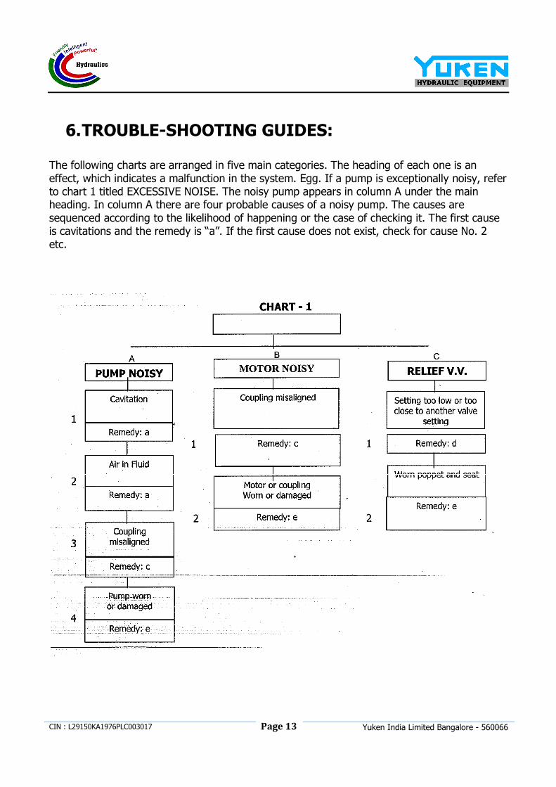
6. TROUBLE-SHOOTING GUIDES:
The following charts are arranged in five main categories. The heading of each one is an effect, which indicates a malfunction in the system. Egg. If a pump is exceptionally noisy, refer to chart 1 titled EXCESSIVE NOISE. The noisy pump appears in column A under the main heading. In column A there are four probable causes of a noisy pump. The causes are sequenced according to the likelihood of happening or the case of checking it. The first cause is cavitations and the remedy is “a”. If the first cause does not exist, check for cause No. 2 etc.
Page 14
CIN : L29150KA1976PLC003017
Yuken India Limited Bangalore - 560066
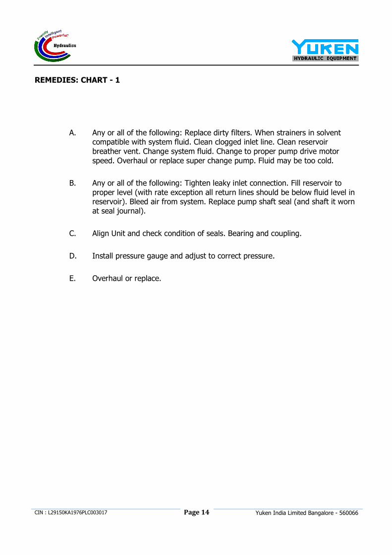
REMEDIES: CHART - 1
A. Any or all of the following: Replace dirty filters. When strainers in solvent compatible with system fluid. Clean clogged inlet line. Clean reservoir breather vent. Change system fluid. Change to proper pump drive motor speed. Overhaul or replace super change pump. Fluid may be too cold.
B. Any or all of the following: Tighten leaky inlet connection. Fill reservoir to proper level (with rate exception all return lines should be below fluid level in reservoir). Bleed air from system. Replace pump shaft seal (and shaft it worn at seal journal).
C. Align Unit and check condition of seals. Bearing and coupling.
D. Install pressure gauge and adjust to correct pressure.
E. Overhaul or replace.
P
ag
e 1
5
CIN
: L29150KA1976PLC003017
Y
uken In
dia
Lim
ited B
angalo
re - 5
60066
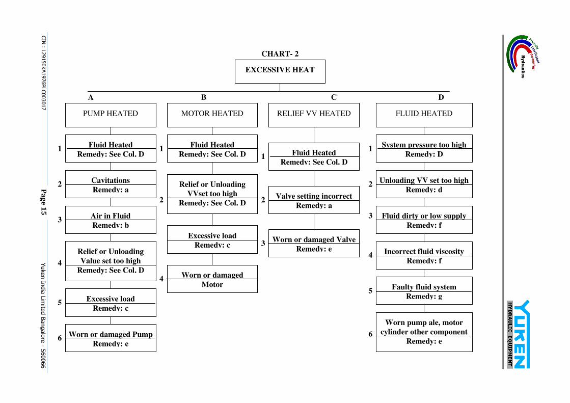
CHART- 2
EXCESSIVE HEAT
A D C B
PUMP HEATED MOTOR HEATED RELIEF VV HEATED FLUID HEATED
Fluid Heated
Remedy: See Col. D
Cavitations
Remedy: a
Air in Fluid
Remedy: b
Relief or Unloading
Value set too high
Remedy: See Col. D
Worn or damaged Pump
Remedy: e
Excessive load
Remedy: c
System pressure too high
Remedy: D
Unloading VV set too high
Remedy: d
Fluid dirty or low supply
Remedy: f
Incorrect fluid viscosity
Remedy: f
Fluid Heated
Remedy: See Col. D
Valve setting incorrect
Remedy: a
Worn or damaged Valve
Remedy: e
Fluid Heated
Remedy: See Col. D
Relief or Unloading
VVset too high
Remedy: See Col. D
Worn or damaged
Motor
Excessive load
Remedy: c
1
6
5
4
3
2
2
1
4
3
2
1 1
4
3
2
Faulty fluid system
Remedy: g
Worn pump ale, motor
cylinder other component
Remedy: e 6
5
Page 16
CIN : L29150KA1976PLC003017
Yuken India Limited Bangalore - 560066
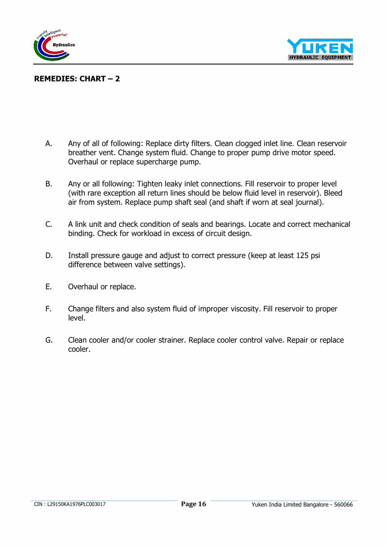
REMEDIES: CHART – 2
A. Any of all of following: Replace dirty filters. Clean clogged inlet line. Clean reservoir breather vent. Change system fluid. Change to proper pump drive motor speed. Overhaul or replace supercharge pump.
B. Any or all following: Tighten leaky inlet connections. Fill reservoir to proper level (with rare exception all return lines should be below fluid level in reservoir). Bleed air from system. Replace pump shaft seal (and shaft if worn at seal journal).
C. A link unit and check condition of seals and bearings. Locate and correct mechanical binding. Check for workload in excess of circuit design.
D. Install pressure gauge and adjust to correct pressure (keep at least 125 psi difference between valve settings).
E. Overhaul or replace.
F. Change filters and also system fluid of improper viscosity. Fill reservoir to proper level.
G. Clean cooler and/or cooler strainer. Replace cooler control valve. Repair or replace cooler.
Page 17
CIN : L29150KA1976PLC003017
Yuken India Limited Bangalore - 560066
Page 18
CIN : L29150KA1976PLC003017
Yuken India Limited Bangalore - 560066
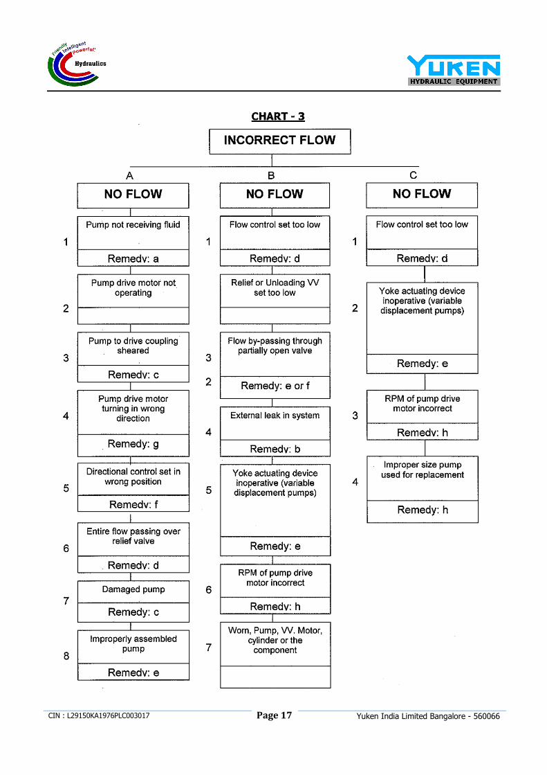
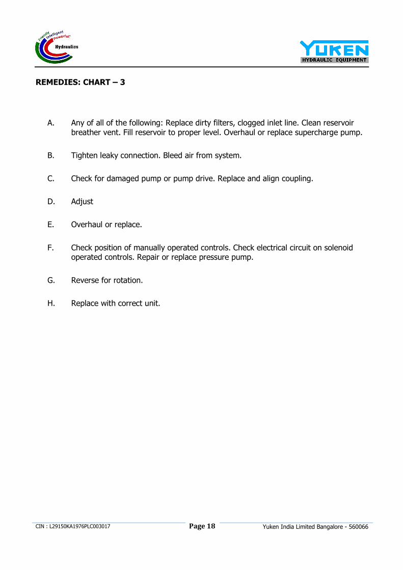
REMEDIES: CHART – 3
A. Any of all of the following: Replace dirty filters, clogged inlet line. Clean reservoir breather vent. Fill reservoir to proper level. Overhaul or replace supercharge pump.
B. Tighten leaky connection. Bleed air from system.
C. Check for damaged pump or pump drive. Replace and align coupling.
D. Adjust
E. Overhaul or replace.
F. Check position of manually operated controls. Check electrical circuit on solenoid operated controls. Repair or replace pressure pump.
G. Reverse for rotation.
H. Replace with correct unit.
P
ag
e 1
9
CIN
: L29150KA1976PLC003017
Y
uken In
dia
Lim
ited B
angalo
re - 5
60066
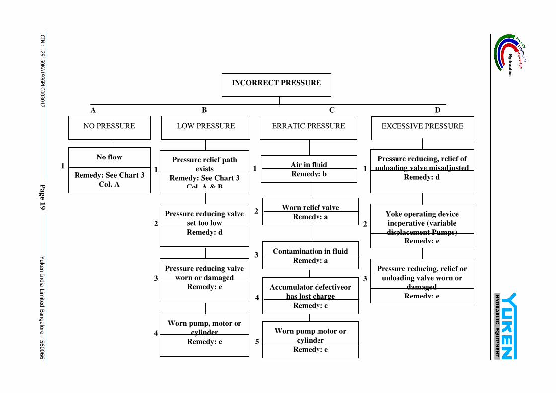
INCORRECT PRESSURE
A D C B
NO PRESSURE LOW PRESSURE ERRATIC PRESSURE
No flow
Remedy: See Chart 3
Col. A
1 Air in fluid
Remedy: b 1
Pressure relief path
exists
Remedy: See Chart 3
Col. A & B
1
Pressure reducing valve
worn or damaged
Remedy: e 3
Worn pump, motor or
cylinder
Remedy: e 4
Pressure reducing valve
set too low
Remedy: d 2
Worn relief valve
Remedy: a 2
Contamination in fluid
Remedy: a 3
Worn pump motor or
cylinder
Remedy: e 5
Accumulator defectiveor
has lost charge
Remedy: c 4
EXCESSIVE PRESSURE
Pressure reducing, relief of
unloading valve misadjusted
Remedy: d 1
Yoke operating device
inoperative (variable
displacement Pumps)
Remedy: e
2
Pressure reducing, relief or
unloading valve worn or
damaged
Remedy: e
3
Page 20
CIN : L29150KA1976PLC003017
Yuken India Limited Bangalore - 560066
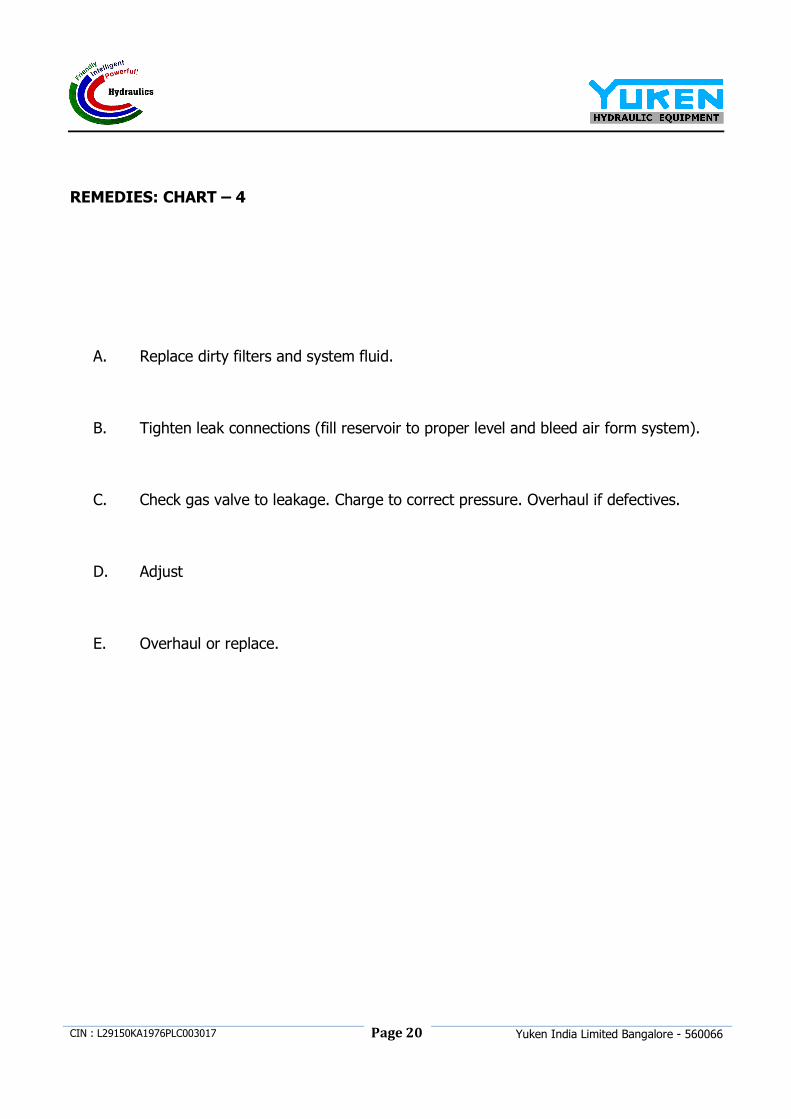
REMEDIES: CHART – 4
A. Replace dirty filters and system fluid.
B. Tighten leak connections (fill reservoir to proper level and bleed air form system).
C. Check gas valve to leakage. Charge to correct pressure. Overhaul if defectives.
D. Adjust
E. Overhaul or replace.
Page 21
CIN : L29150KA1976PLC003017
Yuken India Limited Bangalore - 560066
Page 22
CIN : L29150KA1976PLC003017
Yuken India Limited Bangalore - 560066
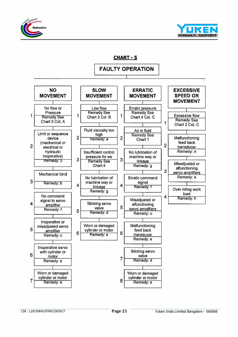
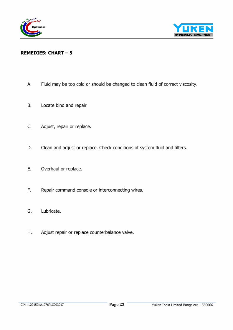
REMEDIES: CHART – 5
A. Fluid may be too cold or should be changed to clean fluid of correct viscosity.
B. Locate bind and repair
C. Adjust, repair or replace.
D. Clean and adjust or replace. Check conditions of system fluid and filters.
E. Overhaul or replace.
F. Repair command console or interconnecting wires.
G. Lubricate.
H. Adjust repair or replace counterbalance valve.
Page 23
CIN : L29150KA1976PLC003017
Yuken India Limited Bangalore - 560066
7. ENCLOSURES
• TEST CERTIFICATE
• GUARANTEE CERTIFICATE
• BILL OF MATERIAL
• CIRCUIT DIAGRAM
• LAYOUT DIAGRAM
Page 24
CIN : L29150KA1976PLC003017
Yuken India Limited Bangalore - 560066
8. ENGINEERING INFORMATION SHEET