hybrid spin-crossover nanostructures
TRANSCRIPT
2230
Hybrid spin-crossover nanostructuresCarlos M. Quintero1, Gautier Félix2, Iurii Suleimanov2,3, José Sánchez Costa2,Gábor Molnár2, Lionel Salmon2, William Nicolazzi2 and Azzedine Bousseksou*2
Review Open Access
Address:1LAAS, CNRS & Université de Toulouse (UPS, INSA, LAES), 7 Av deColonel Roche, 31077 Toulouse, France, 2LCC, CNRS & Universitéde Toulouse (UPS, INPT), 205 route de Narbonne, 31077 Toulouse,France and 3Department of Chemistry, National Taras ShevchenkoUniversity of Kiev, 62 Volodymyrska St. 01601, Ukraine
Email:Azzedine Bousseksou* - [email protected]
* Corresponding author
Keywords:core–shell particle; multifunctionality; nanomaterials; spin-crossover
Beilstein J. Nanotechnol. 2014, 5, 2230–2239.doi:10.3762/bjnano.5.232
Received: 15 July 2014Accepted: 04 November 2014Published: 25 November 2014
This article is part of the Thematic Series "Molecular materials – towardsquantum properties".
Guest Editor: M. Ruben
© 2014 Quintero et al; licensee Beilstein-Institut.License and terms: see end of document.
AbstractThis review reports on the recent progress in the synthesis, modelling and application of hybrid spin-crossover materials, including
core–shell nanoparticles and multilayer thin films or nanopatterns. These systems combine, often in synergy, different physical
properties (optical, magnetic, mechanical and electrical) of their constituents with the switching properties of spin-crossover
complexes, providing access to materials with unprecedented capabilities.
2230
ReviewIntroductionMore than 15 years ago, Olivier Kahn highlighted the great
potential of the so-called spin-crossover (SCO) materials on the
nanoscale [1]. Indeed, there are interesting fundamental ques-
tions with regards to the size effect on the phase transition
temperature, on the hysteresis width, on the kinetics of the spin
transition, etc. On the other hand, SCO nanomaterials are also
attractive candidates for integration into a variety of emerging
micro- and nano-technologies. The notable characteristics of
SCO materials include: i) reversible changes in their various
physical properties (magnetic, optical, electrical and mechan-
ical), ii) diverse external stimuli to drive their transition,
iii) their versatility, i.e., there are multiple complexes with
different transition properties, iv) room temperature operation
and v) their bistability can be kept down to the nanoscale.
In the last few years, diverse pathways for the production of
SCO nanomaterials as colloidal suspensions, thin films and
other types of nanoscale assemblies have been established using
different chemical and/or lithographic approaches for control-
ling the size, shape and even the organization of SCO nano-
objects [2-11]. Furthermore, there is an active quest for devel-
oping novel methods which are sensitive enough to probe
Beilstein J. Nanotechnol. 2014, 5, 2230–2239.
2231
extremely small quantities of SCO materials for a better under-
standing of these materials at the nanoscale. All of these recent
results have been extensively reviewed in [12-16]. In the
present review, we focus on new types of emerging, hybrid
nano-objects that involve SCO nanomaterials in complex struc-
tures, which reveal unique functionalities due to the synergy
between the SCO properties and the physical properties
(magnetic, photonic, charge transport, etc.) of the surrounding
matter. The present review constitutes an overview of these
systems including their synthesis, theoretical modelling and
future possible technological applications.
Indeed, a recent strategy to access the multifunctional potential
of novel nanomaterials was the development of nanohybrid or
nanocomposite structures that are able to combine different ma-
terials with different properties. Typically, in this approach, at
least one of the components is organic while the other is inor-
ganic in nature. A nanocomposite is a multiphase solid material
where one of the phases has one, two or three dimensions in the
size range of 1–100 nm. Additionally, it is worth noting that the
molecular building blocks that constitute these hybrid materials
can be as big as inorganic clusters, typically in the nanometer
range. The most notable advantage of controlling their mutual
arrangement is that they can effectively combine the properties
of both components into one material with the additional possi-
bility to present synergetic effects, and thus properties which
were unattainable in the constituent parent materials [17]. The
properties of these hybrid structures are not only interesting
from a fundamental point of view, but are currently envisaged
to be applied in various fields of technology.
Synthesis of hybrid SCO nanostructuresThe development of functionalized nano-composite materials
with potential applications in the field of switchable materials
has recently attracted great attention mainly due to the develop-
ment of hybrid nanoparticle molecules (HNMs) [18] and hybrid
nanoparticle-coordination network structures (HNCNSs) [19].
Here, some remarkable examples of sophisticated structures
involving SCO activity recently appeared in the literature and
are examined according to a simple classification based on the
position of the active SCO species on the core–shell nanostruc-
ture. One can thus envision a case in which the switchable
active species is placed at the core, a second type where the
active species is at the shell, and finally, a third type where both
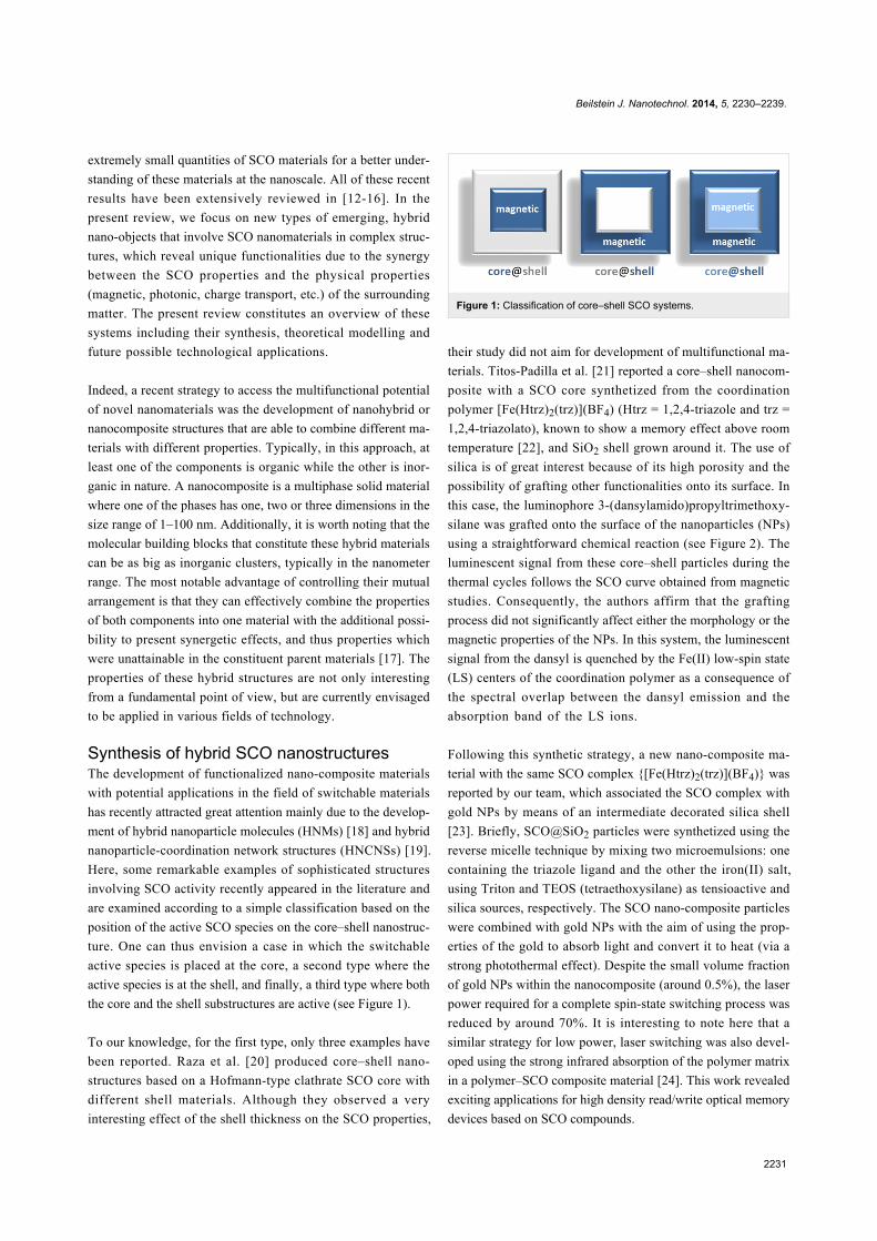
the core and the shell substructures are active (see Figure 1).
To our knowledge, for the first type, only three examples have
been reported. Raza et al. [20] produced core–shell nano-
structures based on a Hofmann-type clathrate SCO core with
different shell materials. Although they observed a very
interesting effect of the shell thickness on the SCO properties,
Figure 1: Classification of core–shell SCO systems.
their study did not aim for development of multifunctional ma-
terials. Titos-Padilla et al. [21] reported a core–shell nanocom-
posite with a SCO core synthetized from the coordination
polymer [Fe(Htrz)2(trz)](BF4) (Htrz = 1,2,4-triazole and trz =
1,2,4-triazolato), known to show a memory effect above room
temperature [22], and SiO2 shell grown around it. The use of
silica is of great interest because of its high porosity and the
possibility of grafting other functionalities onto its surface. In
this case, the luminophore 3-(dansylamido)propyltrimethoxy-
silane was grafted onto the surface of the nanoparticles (NPs)
using a straightforward chemical reaction (see Figure 2). The
luminescent signal from these core–shell particles during the
thermal cycles follows the SCO curve obtained from magnetic
studies. Consequently, the authors affirm that the grafting
process did not significantly affect either the morphology or the
magnetic properties of the NPs. In this system, the luminescent
signal from the dansyl is quenched by the Fe(II) low-spin state
(LS) centers of the coordination polymer as a consequence of
the spectral overlap between the dansyl emission and the
absorption band of the LS ions.
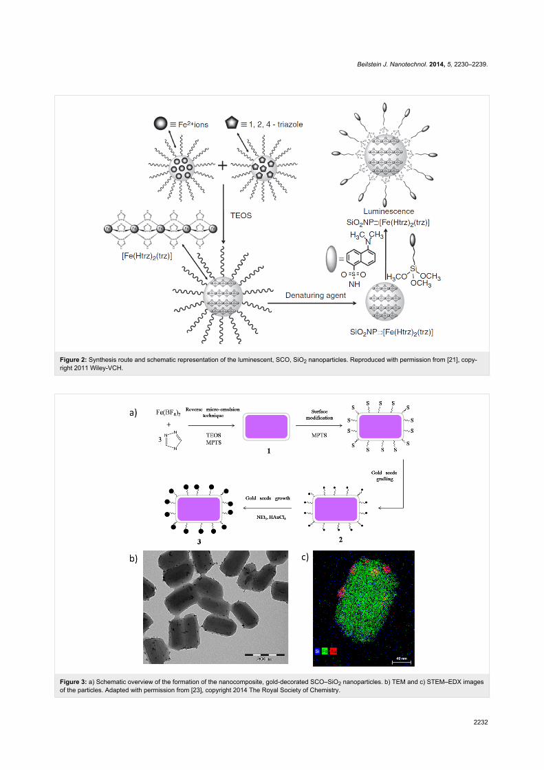
Following this synthetic strategy, a new nano-composite ma-
terial with the same SCO complex {[Fe(Htrz)2(trz)](BF4)} was
reported by our team, which associated the SCO complex with
gold NPs by means of an intermediate decorated silica shell
[23]. Briefly, SCO@SiO2 particles were synthetized using the
reverse micelle technique by mixing two microemulsions: one
containing the triazole ligand and the other the iron(II) salt,
using Triton and TEOS (tetraethoxysilane) as tensioactive and
silica sources, respectively. The SCO nano-composite particles
were combined with gold NPs with the aim of using the prop-
erties of the gold to absorb light and convert it to heat (via a
strong photothermal effect). Despite the small volume fraction
of gold NPs within the nanocomposite (around 0.5%), the laser
power required for a complete spin-state switching process was
reduced by around 70%. It is interesting to note here that a
similar strategy for low power, laser switching was also devel-
oped using the strong infrared absorption of the polymer matrix
in a polymer–SCO composite material [24]. This work revealed
exciting applications for high density read/write optical memory
devices based on SCO compounds.
Beilstein J. Nanotechnol. 2014, 5, 2230–2239.
2232
Figure 2: Synthesis route and schematic representation of the luminescent, SCO, SiO2 nanoparticles. Reproduced with permission from [21], copy-right 2011 Wiley-VCH.
Figure 3: a) Schematic overview of the formation of the nanocomposite, gold-decorated SCO–SiO2 nanoparticles. b) TEM and c) STEM–EDX imagesof the particles. Adapted with permission from [23], copyright 2014 The Royal Society of Chemistry.
Beilstein J. Nanotechnol. 2014, 5, 2230–2239.
2233
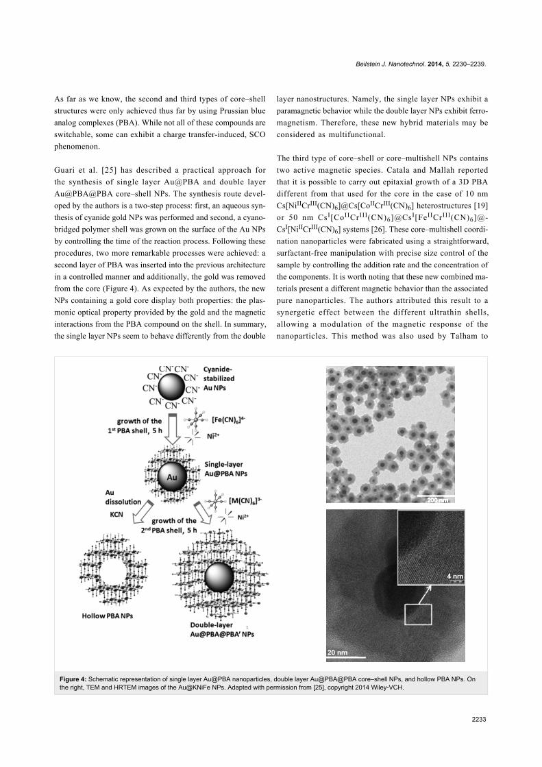
Figure 4: Schematic representation of single layer Au@PBA nanoparticles, double layer Au@PBA@PBA core–shell NPs, and hollow PBA NPs. Onthe right, TEM and HRTEM images of the Au@KNiFe NPs. Adapted with permission from [25], copyright 2014 Wiley-VCH.
As far as we know, the second and third types of core–shell
structures were only achieved thus far by using Prussian blue
analog complexes (PBA). While not all of these compounds are
switchable, some can exhibit a charge transfer-induced, SCO
phenomenon.
Guari et al. [25] has described a practical approach for
the synthesis of single layer Au@PBA and double layer
Au@PBA@PBA core–shell NPs. The synthesis route devel-
oped by the authors is a two-step process: first, an aqueous syn-
thesis of cyanide gold NPs was performed and second, a cyano-
bridged polymer shell was grown on the surface of the Au NPs
by controlling the time of the reaction process. Following these
procedures, two more remarkable processes were achieved: a
second layer of PBA was inserted into the previous architecture
in a controlled manner and additionally, the gold was removed
from the core (Figure 4). As expected by the authors, the new
NPs containing a gold core display both properties: the plas-
monic optical property provided by the gold and the magnetic
interactions from the PBA compound on the shell. In summary,
the single layer NPs seem to behave differently from the double
layer nanostructures. Namely, the single layer NPs exhibit a
paramagnetic behavior while the double layer NPs exhibit ferro-
magnetism. Therefore, these new hybrid materials may be
considered as multifunctional.
The third type of core–shell or core–multishell NPs contains
two active magnetic species. Catala and Mallah reported
that it is possible to carry out epitaxial growth of a 3D PBA
different from that used for the core in the case of 10 nm
Cs[NiIICrIII(CN)6]@Cs[CoIICrIII(CN)6] heterostructures [19]
or 50 nm CsI[CoIICrIII(CN)6]@CsI[FeIICrIII(CN)6]@-
CsI[NiIICrIII(CN)6] systems [26]. These core–multishell coordi-
nation nanoparticles were fabricated using a straightforward,
surfactant-free manipulation with precise size control of the
sample by controlling the addition rate and the concentration of
the components. It is worth noting that these new combined ma-
terials present a different magnetic behavior than the associated
pure nanoparticles. The authors attributed this result to a
synergetic effect between the different ultrathin shells,
allowing a modulation of the magnetic response of the
nanoparticles. This method was also used by Talham to
Beilstein J. Nanotechnol. 2014, 5, 2230–2239.
2234
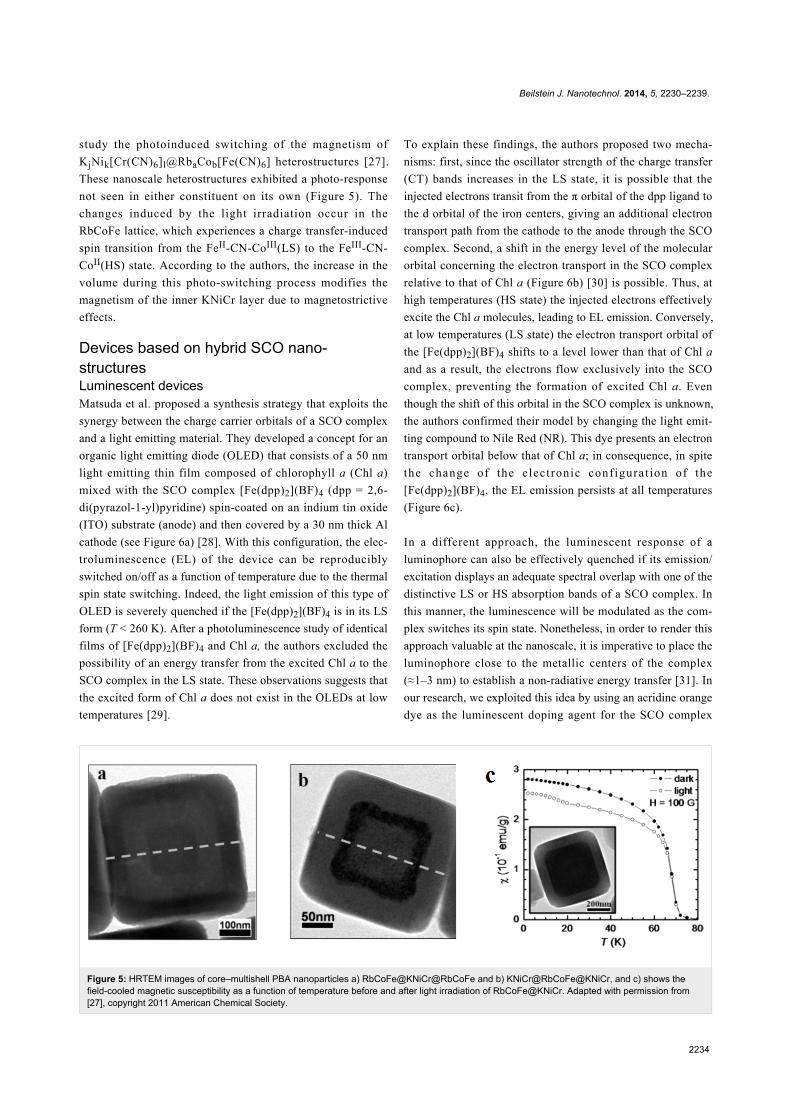
Figure 5: HRTEM images of core–multishell PBA nanoparticles a) RbCoFe@KNiCr@RbCoFe and b) KNiCr@RbCoFe@KNiCr, and c) shows thefield-cooled magnetic susceptibility as a function of temperature before and after light irradiation of RbCoFe@KNiCr. Adapted with permission from[27], copyright 2011 American Chemical Society.
study the photoinduced switching of the magnetism of
KjNik[Cr(CN)6]l@RbaCob[Fe(CN)6] heterostructures [27].
These nanoscale heterostructures exhibited a photo-response
not seen in either constituent on its own (Figure 5). The
changes induced by the light irradiation occur in the
RbCoFe lattice, which experiences a charge transfer-induced
spin transition from the FeII-CN-CoIII(LS) to the FeIII-CN-
CoII(HS) state. According to the authors, the increase in the
volume during this photo-switching process modifies the
magnetism of the inner KNiCr layer due to magnetostrictive
effects.
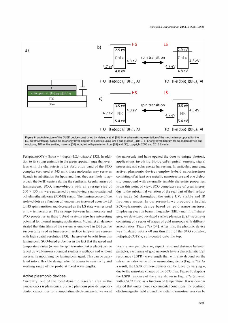
Devices based on hybrid SCO nano-structuresLuminescent devicesMatsuda et al. proposed a synthesis strategy that exploits the
synergy between the charge carrier orbitals of a SCO complex
and a light emitting material. They developed a concept for an
organic light emitting diode (OLED) that consists of a 50 nm
light emitting thin film composed of chlorophyll a (Chl a)
mixed with the SCO complex [Fe(dpp)2](BF)4 (dpp = 2,6-
di(pyrazol-1-yl)pyridine) spin-coated on an indium tin oxide
(ITO) substrate (anode) and then covered by a 30 nm thick Al
cathode (see Figure 6a) [28]. With this configuration, the elec-
troluminescence (EL) of the device can be reproducibly
switched on/off as a function of temperature due to the thermal
spin state switching. Indeed, the light emission of this type of
OLED is severely quenched if the [Fe(dpp)2](BF)4 is in its LS
form (T < 260 K). After a photoluminescence study of identical
films of [Fe(dpp)2](BF)4 and Chl a, the authors excluded the
possibility of an energy transfer from the excited Chl a to the
SCO complex in the LS state. These observations suggests that
the excited form of Chl a does not exist in the OLEDs at low
temperatures [29].
To explain these findings, the authors proposed two mecha-
nisms: first, since the oscillator strength of the charge transfer
(CT) bands increases in the LS state, it is possible that the
injected electrons transit from the π orbital of the dpp ligand to
the d orbital of the iron centers, giving an additional electron
transport path from the cathode to the anode through the SCO
complex. Second, a shift in the energy level of the molecular
orbital concerning the electron transport in the SCO complex
relative to that of Chl a (Figure 6b) [30] is possible. Thus, at
high temperatures (HS state) the injected electrons effectively
excite the Chl a molecules, leading to EL emission. Conversely,
at low temperatures (LS state) the electron transport orbital of
the [Fe(dpp)2](BF)4 shifts to a level lower than that of Chl a
and as a result, the electrons flow exclusively into the SCO
complex, preventing the formation of excited Chl a. Even
though the shift of this orbital in the SCO complex is unknown,
the authors confirmed their model by changing the light emit-
ting compound to Nile Red (NR). This dye presents an electron
transport orbital below that of Chl a; in consequence, in spite
the change of the electronic configurat ion of the
[Fe(dpp)2](BF)4, the EL emission persists at all temperatures
(Figure 6c).
In a different approach, the luminescent response of a
luminophore can also be effectively quenched if its emission/
excitation displays an adequate spectral overlap with one of the
distinctive LS or HS absorption bands of a SCO complex. In
this manner, the luminescence will be modulated as the com-
plex switches its spin state. Nonetheless, in order to render this
approach valuable at the nanoscale, it is imperative to place the
luminophore close to the metallic centers of the complex
(≈1–3 nm) to establish a non-radiative energy transfer [31]. In
our research, we exploited this idea by using an acridine orange
dye as the luminescent doping agent for the SCO complex
Beilstein J. Nanotechnol. 2014, 5, 2230–2239.
2235
Figure 6: a) Architecture of the OLED device constructed by Matsuda et al. [28]. b) A schematic representation of the mechanism proposed for theEL, on/off switching, based on an energy level diagram of a device using Chl a and [Fe(dpp)2](BF)4. c) Energy level diagram for an analog device butemploying NR as the emitting material [30]. Adapted with permission from [28] and [30], copyright 2008 and 2013 Elsevier.
Fe(hptrz)3(OTs)2 (hptrz = 4-heptyl-1,2,4-triazole) [32]. In addi-
tion to its strong emission in the green spectral range that over-
laps with the characteristic LS absorption band of the SCO
complex (centered at 543 nm), these molecules may serve as
ligands in substitution for hptrz and thus, they are likely to ap-
proach the Fe(II) centers during the synthesis. Regular arrays of
luminescent, SCO, nano-objects with an average size of
200 × 150 nm were patterned by employing a nano-patterned
polydimethylsiloxane (PDMS) stamp. The luminescence of the
isolated dots as a function of temperature increased upon the LS
to HS spin transition and decreased as the LS state was restored
at low temperatures. The synergy between luminescence and
SCO properties in these hybrid systems also has interesting
potential for thermal imaging applications. Molnár et al. demon-
strated that thin films of the system as employed in [32] can be
successfully used as luminescent surface temperature sensors
with high spatial resolution [33]. The greatest benefit from this
luminescent, SCO-based probe lies in the fact that the speed and
temperature range (where the spin transition takes place) can be
tuned by well-known chemical synthesis methods and without
necessarily modifying the luminescent agent. This can be trans-
lated into a flexible design when it comes to sensitivity and
working range of the probe at fixed wavelengths.
Active plasmonic devicesCurrently, one of the most dynamic research area in the
nanosciences is plasmonics. Surface plasmons provide unprece-
dented capabilities for manipulating electromagnetic waves at
the nanoscale and have opened the door to unique photonic
applications involving biological/chemical sensors, signal
processing and solar energy harvesting. In particular, emerging,
active, plasmonic devices employ hybrid nanostructures
consisting of at least one metallic nanostructure and one dielec-
tric compound with externally tunable dielectric properties.
From this point of view, SCO complexes are of great interest
due to the substantial variation of the real part of their refrac-
tive index (n) throughout the entire UV, visible and IR
frequency ranges. In our research, we proposed a hybrid,
SCO–plasmonic device based on gold nanostructures.
Employing electron beam lithography (EBL) and lift off strate-
gies, we developed localized surface plasmon (LSP) substrates
consisting of a series of arrays of gold nanorods with different
aspect ratios (Figure 7a) [34]. After this, the photonic device
was finalized with a 60 nm thin film of the SCO complex,
Fe(hptrz)3(OTs)2, spin-coated onto the top.
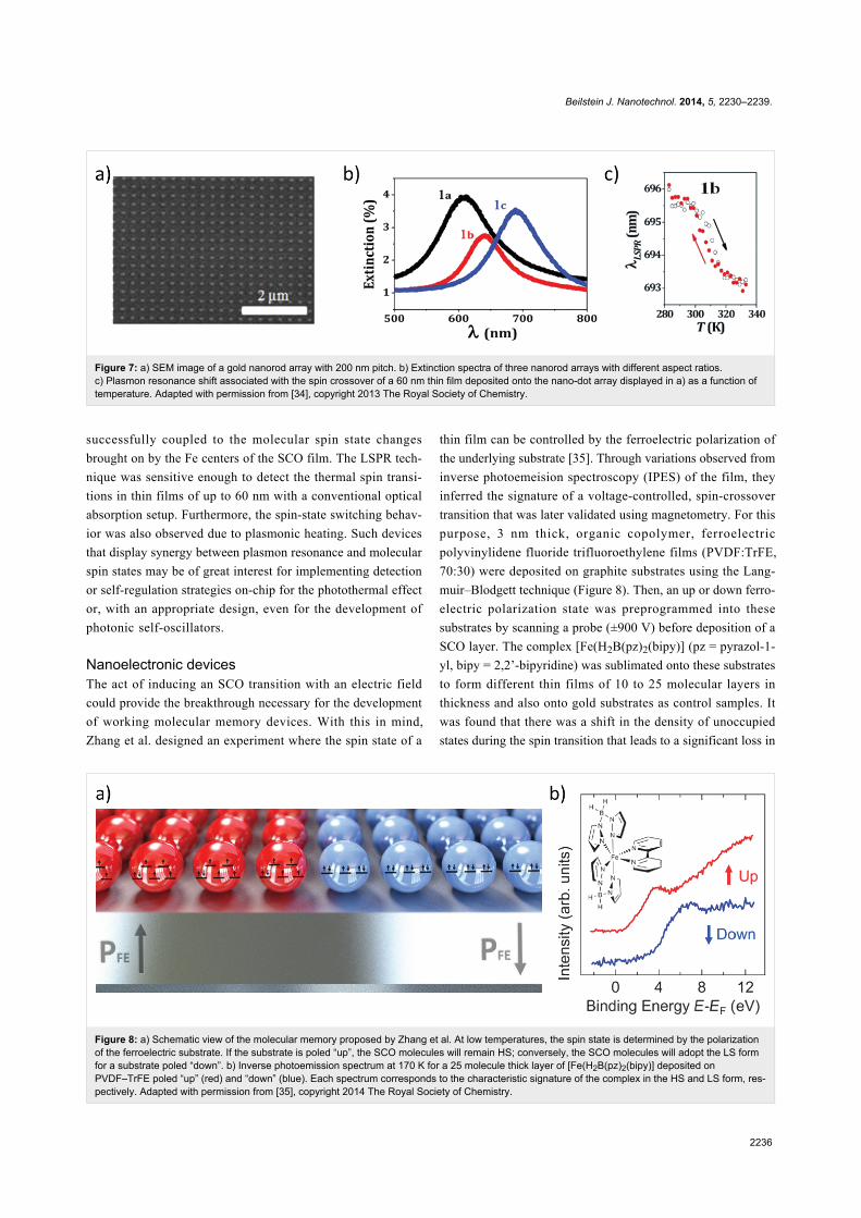
For a given particle size, aspect ratio and distance between
particles, each array of gold nanorods have a characteristic LSP
resonance (LSPR) wavelength that will also depend on the
refractive index value of the surrounding media (Figure 7b). As
a result, the LSPR of these devices can be tuned by varying n,
due to the spin-state change of the SCO film. Figure 7c displays
the LSPR response of the array shown in Figure 7a (covered
with a SCO film) as a function of temperature. It was demon-
strated that under those experimental conditions, the confined
electromagnetic field around the metallic nanostructures can be
Beilstein J. Nanotechnol. 2014, 5, 2230–2239.
2236
Figure 7: a) SEM image of a gold nanorod array with 200 nm pitch. b) Extinction spectra of three nanorod arrays with different aspect ratios.c) Plasmon resonance shift associated with the spin crossover of a 60 nm thin film deposited onto the nano-dot array displayed in a) as a function oftemperature. Adapted with permission from [34], copyright 2013 The Royal Society of Chemistry.
Figure 8: a) Schematic view of the molecular memory proposed by Zhang et al. At low temperatures, the spin state is determined by the polarizationof the ferroelectric substrate. If the substrate is poled “up”, the SCO molecules will remain HS; conversely, the SCO molecules will adopt the LS formfor a substrate poled “down”. b) Inverse photoemission spectrum at 170 K for a 25 molecule thick layer of [Fe(H2B(pz)2(bipy)] deposited onPVDF–TrFE poled “up” (red) and “down” (blue). Each spectrum corresponds to the characteristic signature of the complex in the HS and LS form, res-pectively. Adapted with permission from [35], copyright 2014 The Royal Society of Chemistry.
successfully coupled to the molecular spin state changes
brought on by the Fe centers of the SCO film. The LSPR tech-
nique was sensitive enough to detect the thermal spin transi-
tions in thin films of up to 60 nm with a conventional optical
absorption setup. Furthermore, the spin-state switching behav-
ior was also observed due to plasmonic heating. Such devices
that display synergy between plasmon resonance and molecular
spin states may be of great interest for implementing detection
or self-regulation strategies on-chip for the photothermal effect
or, with an appropriate design, even for the development of
photonic self-oscillators.
Nanoelectronic devicesThe act of inducing an SCO transition with an electric field
could provide the breakthrough necessary for the development
of working molecular memory devices. With this in mind,
Zhang et al. designed an experiment where the spin state of a
thin film can be controlled by the ferroelectric polarization of
the underlying substrate [35]. Through variations observed from
inverse photoemeision spectroscopy (IPES) of the film, they
inferred the signature of a voltage-controlled, spin-crossover
transition that was later validated using magnetometry. For this
purpose, 3 nm thick, organic copolymer, ferroelectric
polyvinylidene fluoride trifluoroethylene films (PVDF:TrFE,
70:30) were deposited on graphite substrates using the Lang-
muir–Blodgett technique (Figure 8). Then, an up or down ferro-
electric polarization state was preprogrammed into these
substrates by scanning a probe (±900 V) before deposition of a
SCO layer. The complex [Fe(H2B(pz)2(bipy)] (pz = pyrazol-1-
yl, bipy = 2,2’-bipyridine) was sublimated onto these substrates
to form different thin films of 10 to 25 molecular layers in
thickness and also onto gold substrates as control samples. It
was found that there was a shift in the density of unoccupied
states during the spin transition that leads to a significant loss in
Beilstein J. Nanotechnol. 2014, 5, 2230–2239.
2237
the density of states just above the Fermi energy level in a HS
to LS transition. This situation was observed in SCO films
deposited on the gold and the graphite substrates where the
ferroelectric PVDF–TrFE film was poled “down”. However, if
the interfacial dipoles of the PVDF–TrFE film are poled “up”
instead, the characteristic inverse photoemission (IPES) signa-
ture of the SCO complex in the HS form persists down to
100 K, well below the thermal spin crossover (Figure 8). These
observations in this hybrid device constitute one of the first
evidences that electric fields can be effectively employed to
address and manipulate spin states in molecular SCO systems
on the nanometer scale.
Theoretical studies of spin-crossover nano-objects:towards modelling hybrid systemsA reduction in dimensions leads to an inevitable change in the
bistability phenomenon for SCO nano-objects [36]. This idea
has been experimentally confirmed with the study of spin-
crossover nanoparticles [2-5]. The main observations include
the shrinking of the thermal hysteresis loop, a downshift in the
transition temperature, and an increase of the high spin (HS)
residual fraction at low temperature. On the other hand, against
all predictions, a surprising cooperative behavior has been
observed in very small nanoparticles (2–4 nm) [6-11]. The
origin of this effect is not well understood and different expla-
nations can be proposed. For instance, the hysteresis loop in
small objects could be the consequence of interactions between
particles through the matrix, an interaction between the particle
and the matrix [20], or a size dependent variation of the
mechanical properties of the particle [37]. Of course all of these
phenomena can be coupled, which leads to considerable
complexity for the study of size effects in spin-crossover
nanoparticles.
In any case, the pervasiveness of the surface-to-volume ratio at
the nanometer scale has a major impact on the spin-crossover
behavior. Thus, the SCO phenomenon can be controlled by
clever engineering of the nanoparticle interface. To this regard,
theoretical studies can be very useful to predict the various
interface effects. In general, the presence of the surface leads to
new energy terms that are added to the internal energy of the
system. As a consequence, the internal energy becomes nonex-
tensive, which leads to the modification of the thermodynamic
properties of the SCO particles [37,38]. The degree to which the
system becomes nonextensive depends on the surface-to-
volume ratio. The modulation of the spin-crossover behavior in
nanoparticles can be realized by modification of the surface
energy terms in the HS and LS states. This energy depends on
two different parameters: the energy per surface, γ, and the area
of the particle, A. The energy per surface term depends on
several complicated phenomena which happen at the surface.
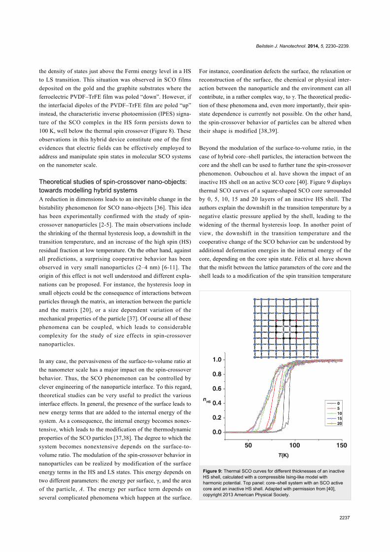
Figure 9: Thermal SCO curves for different thicknesses of an inactiveHS shell, calculated with a compressible Ising-like model withharmonic potential. Top panel: core–shell system with an SCO activecore and an inactive HS shell. Adapted with permission from [40],copyright 2013 American Physical Society.
For instance, coordination defects the surface, the relaxation or
reconstruction of the surface, the chemical or physical inter-
action between the nanoparticle and the environment can all
contribute, in a rather complex way, to γ. The theoretical predic-
tion of these phenomena and, even more importantly, their spin-
state dependence is currently not possible. On the other hand,
the spin-crossover behavior of particles can be altered when
their shape is modified [38,39].
Beyond the modulation of the surface-to-volume ratio, in the
case of hybrid core–shell particles, the interaction between the
core and the shell can be used to further tune the spin-crossover
phenomenon. Oubouchou et al. have shown the impact of an
inactive HS shell on an active SCO core [40]. Figure 9 displays
thermal SCO curves of a square-shaped SCO core surrounded
by 0, 5, 10, 15 and 20 layers of an inactive HS shell. The
authors explain the downshift in the transition temperature by a
negative elastic pressure applied by the shell, leading to the
widening of the thermal hysteresis loop. In another point of
view, the downshift in the transition temperature and the
cooperative change of the SCO behavior can be understood by
additional deformation energies in the internal energy of the
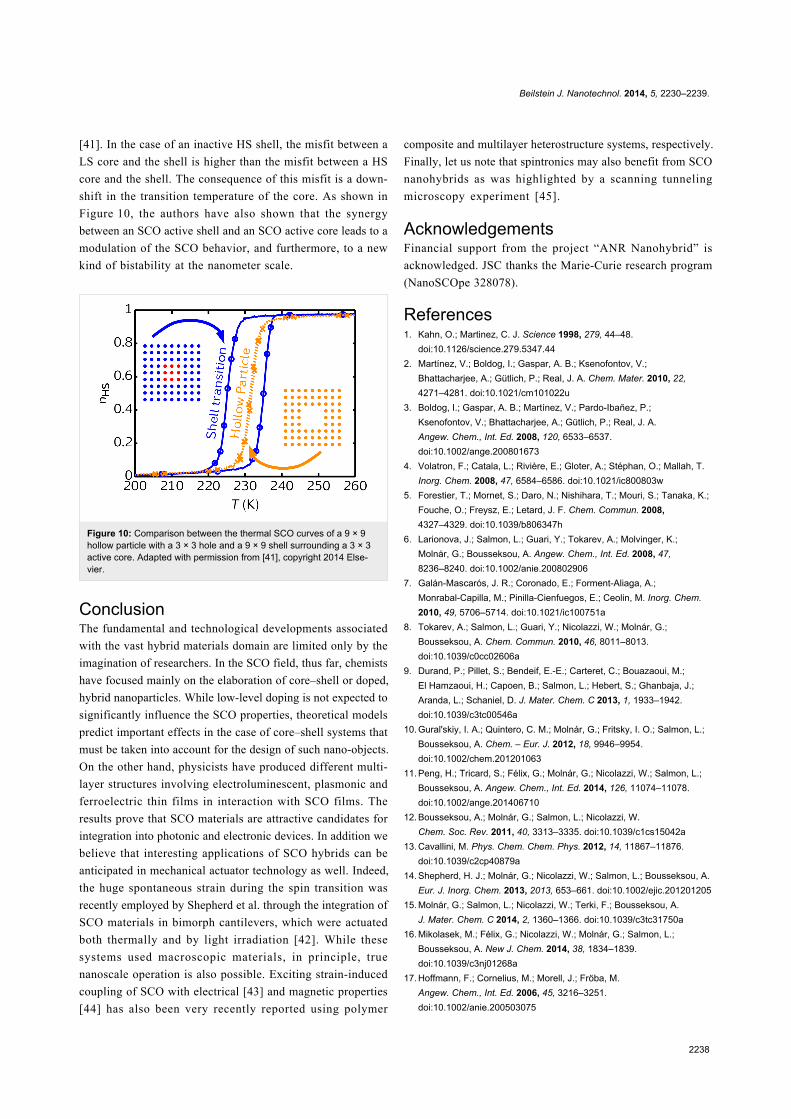
core, depending on the core spin state. Félix et al. have shown
that the misfit between the lattice parameters of the core and the
shell leads to a modification of the spin transition temperature
Beilstein J. Nanotechnol. 2014, 5, 2230–2239.
2238
[41]. In the case of an inactive HS shell, the misfit between a
LS core and the shell is higher than the misfit between a HS
core and the shell. The consequence of this misfit is a down-
shift in the transition temperature of the core. As shown in
Figure 10, the authors have also shown that the synergy
between an SCO active shell and an SCO active core leads to a
modulation of the SCO behavior, and furthermore, to a new
kind of bistability at the nanometer scale.
Figure 10: Comparison between the thermal SCO curves of a 9 × 9hollow particle with a 3 × 3 hole and a 9 × 9 shell surrounding a 3 × 3active core. Adapted with permission from [41], copyright 2014 Else-vier.
ConclusionThe fundamental and technological developments associated
with the vast hybrid materials domain are limited only by the
imagination of researchers. In the SCO field, thus far, chemists
have focused mainly on the elaboration of core–shell or doped,
hybrid nanoparticles. While low-level doping is not expected to
significantly influence the SCO properties, theoretical models
predict important effects in the case of core–shell systems that
must be taken into account for the design of such nano-objects.
On the other hand, physicists have produced different multi-
layer structures involving electroluminescent, plasmonic and
ferroelectric thin films in interaction with SCO films. The
results prove that SCO materials are attractive candidates for
integration into photonic and electronic devices. In addition we
believe that interesting applications of SCO hybrids can be
anticipated in mechanical actuator technology as well. Indeed,
the huge spontaneous strain during the spin transition was
recently employed by Shepherd et al. through the integration of
SCO materials in bimorph cantilevers, which were actuated
both thermally and by light irradiation [42]. While these
systems used macroscopic materials, in principle, true
nanoscale operation is also possible. Exciting strain-induced
coupling of SCO with electrical [43] and magnetic properties
[44] has also been very recently reported using polymer
composite and multilayer heterostructure systems, respectively.
Finally, let us note that spintronics may also benefit from SCO
nanohybrids as was highlighted by a scanning tunneling
microscopy experiment [45].
AcknowledgementsFinancial support from the project “ANR Nanohybrid” is
acknowledged. JSC thanks the Marie-Curie research program
(NanoSCOpe 328078).
References1. Kahn, O.; Martinez, C. J. Science 1998, 279, 44–48.
doi:10.1126/science.279.5347.442. Martínez, V.; Boldog, I.; Gaspar, A. B.; Ksenofontov, V.;
Bhattacharjee, A.; Gütlich, P.; Real, J. A. Chem. Mater. 2010, 22,4271–4281. doi:10.1021/cm101022u
3. Boldog, I.; Gaspar, A. B.; Martínez, V.; Pardo-Ibañez, P.;Ksenofontov, V.; Bhattacharjee, A.; Gütlich, P.; Real, J. A.Angew. Chem., Int. Ed. 2008, 120, 6533–6537.doi:10.1002/ange.200801673
4. Volatron, F.; Catala, L.; Rivière, E.; Gloter, A.; Stéphan, O.; Mallah, T.Inorg. Chem. 2008, 47, 6584–6586. doi:10.1021/ic800803w
5. Forestier, T.; Mornet, S.; Daro, N.; Nishihara, T.; Mouri, S.; Tanaka, K.;Fouche, O.; Freysz, E.; Letard, J. F. Chem. Commun. 2008,4327–4329. doi:10.1039/b806347h
6. Larionova, J.; Salmon, L.; Guari, Y.; Tokarev, A.; Molvinger, K.;Molnár, G.; Bousseksou, A. Angew. Chem., Int. Ed. 2008, 47,8236–8240. doi:10.1002/anie.200802906
7. Galán-Mascarós, J. R.; Coronado, E.; Forment-Aliaga, A.;Monrabal-Capilla, M.; Pinilla-Cienfuegos, E.; Ceolin, M. Inorg. Chem.2010, 49, 5706–5714. doi:10.1021/ic100751a
8. Tokarev, A.; Salmon, L.; Guari, Y.; Nicolazzi, W.; Molnár, G.;Bousseksou, A. Chem. Commun. 2010, 46, 8011–8013.doi:10.1039/c0cc02606a
9. Durand, P.; Pillet, S.; Bendeif, E.-E.; Carteret, C.; Bouazaoui, M.;El Hamzaoui, H.; Capoen, B.; Salmon, L.; Hebert, S.; Ghanbaja, J.;Aranda, L.; Schaniel, D. J. Mater. Chem. C 2013, 1, 1933–1942.doi:10.1039/c3tc00546a
10. Gural'skiy, I. A.; Quintero, C. M.; Molnár, G.; Fritsky, I. O.; Salmon, L.;Bousseksou, A. Chem. – Eur. J. 2012, 18, 9946–9954.doi:10.1002/chem.201201063
11. Peng, H.; Tricard, S.; Félix, G.; Molnár, G.; Nicolazzi, W.; Salmon, L.;Bousseksou, A. Angew. Chem., Int. Ed. 2014, 126, 11074–11078.doi:10.1002/ange.201406710
12. Bousseksou, A.; Molnár, G.; Salmon, L.; Nicolazzi, W.Chem. Soc. Rev. 2011, 40, 3313–3335. doi:10.1039/c1cs15042a
13. Cavallini, M. Phys. Chem. Chem. Phys. 2012, 14, 11867–11876.doi:10.1039/c2cp40879a
14. Shepherd, H. J.; Molnár, G.; Nicolazzi, W.; Salmon, L.; Bousseksou, A.Eur. J. Inorg. Chem. 2013, 2013, 653–661. doi:10.1002/ejic.201201205
15. Molnár, G.; Salmon, L.; Nicolazzi, W.; Terki, F.; Bousseksou, A.J. Mater. Chem. C 2014, 2, 1360–1366. doi:10.1039/c3tc31750a
16. Mikolasek, M.; Félix, G.; Nicolazzi, W.; Molnár, G.; Salmon, L.;Bousseksou, A. New J. Chem. 2014, 38, 1834–1839.doi:10.1039/c3nj01268a
17. Hoffmann, F.; Cornelius, M.; Morell, J.; Fröba, M.Angew. Chem., Int. Ed. 2006, 45, 3216–3251.doi:10.1002/anie.200503075
Beilstein J. Nanotechnol. 2014, 5, 2230–2239.
2239
18. Dadosh, T.; Gordin, Y.; Krahne, R.; Khivrich, I.; Mahalu, D.;Frydman, V.; Sperling, J.; Yacoby, A.; Bar-Joseph, I. Nature 2005, 436,677–680. doi:10.1038/nature03898
19. Prado, Y.; Dia, N.; Lisnard, L.; Rogez, G.; Brisset, F.; Catala, L.;Mallah, T. Chem. Commun. 2012, 48, 11455–11457.doi:10.1039/c2cc35929d
20. Raza, Y.; Volatron, F.; Moldovan, S.; Ersen, O.; Huc, V.; Martini, C.;Brisset, F.; Gloter, A.; Stephan, O.; Bousseksou, A.; Catala, L.;Mallah, T. Chem. Commun. 2011, 47, 11501–11503.doi:10.1039/c1cc14463d
21. Titos-Padilla, S.; Herrera, J. M.; Chen, X.-W.; Delgado, J. J.;Colacio, E. Angew. Chem., Int. Ed. 2011, 50, 3290–3293.doi:10.1002/anie.201007847
22. Kroeber, J.; Audiere, J.-P.; Claude, R.; Codjovi, E.; Kahn, O.;Haasnoot, J. G.; Groliere, F.; Jay, C.; Bousseksou, A. Chem. Mater.1994, 6, 1404–1412. doi:10.1021/cm00044a044
23. Suleimanov, I.; Sánchez Costa, J.; Molnár, G.; Salmon, L.;Bousseksou, A. Chem. Commun. 2014, 50, 13015–13018.doi:10.1039/C4CC02652G
24. Hellel, W.; Ould Hamouda, A.; Degert, J.; Létard, J. F.; Freysz, E.Appl. Phys. Lett. 2013, 103, 143304. doi:10.1063/1.4824028
25. Maurin-Pasturel, G.; Long, J.; Guari, Y.; Godiard, F.; Willinger, M.-G.;Guerin, C.; Larionova, J. Angew. Chem., Int. Ed. 2014, 53, 3872–3876.doi:10.1002/anie.201310443
26. Catala, L.; Brinzei, D.; Prado, Y.; Gloter, A.; Stéphan, O.; Rogez, G.;Mallah, T. Angew. Chem., Int. Ed. 2009, 48, 183–187.doi:10.1002/anie.200804238
27. Dumont, M. F.; Knowles, E. S.; Guiet, A.; Pajerowski, D. M.;Gomez, A.; Kycia, S. W.; Meisel, M. W.; Talham, D. R. Inorg. Chem.2011, 50, 4295–4300. doi:10.1021/ic1022054
28. Matsuda, M.; Isozaki, H.; Tajima, H. Thin Solid Films 2008, 517,1465–1467. doi:10.1016/j.tsf.2008.09.034
29. Matsuda, M.; Isozaki, H.; Tajima, H. Chem. Lett. 2008, 37, 374–375.doi:10.1246/cl.2008.374
30. Matsuda, M.; Kiyoshima, K.; Uchida, R.; Kinoshita, N.; Tajima, H.Thin Solid Films 2013, 531, 451–453. doi:10.1016/j.tsf.2013.01.094
31. Shepherd, H. J.; Quintero, C. M.; Molnár, G.; Salmon, L.;Bousseksou, A. Luminescent Spin-Crossover Materials. InSpin-Crossover Materials: Properties and Applications; Halcrow, M. A.,Ed.; John Wiley & Sons: Oxford, UK, 2013; pp 347–373.doi:10.1002/9781118519301.ch13
32. Quintero, C. M.; Gural'skiy, I. A.; Salmon, L.; Molnár, G.; Bergaud, C.;Bousseksou, A. J. Mater. Chem. 2012, 22, 3745–3751.doi:10.1039/c2jm15662h
33. Molnár, G.; Gural'skiy, I. A.; Salmon, L.; Nicolazzi, W.; Quintero, C.;Akou, A.; Abdul-kader, K.; Félix, G.; Mahfoud, T.; Bergaud, C.;Bartual-Murgui, C.; Thibault, C.; Vieu, C.; Bousseksou, A. Bistablephotonic nanostructures based on molecular spin crossovercomplexes. In Proc. SPIE 8425, Photonic Crystal Materials andDevices X, Brussels, Belgium, April 16–19, 2012; Míguez, H. R.;Romanov, S. G.; Andreani, L. C.; Seassal, C., Eds.; .doi:10.1117/12.921849
34. Abdul-Kader, K.; Lopes, M.; Bartual-Murgui, C.; Kraieva, O.;Hernández, E. M.; Salmon, L.; Nicolazzi, W.; Carcenac, F.;Thibault, C.; Molnár, G.; Bousseksou, A. Nanoscale 2013, 5,5288–5293. doi:10.1039/c3nr01337e
35. Zhang, X.; Palamarciuc, T.; Létard, J.-F.; Rosa, P.; Lozada, E. V.;Torres, F.; Rosa, L. G.; Doudin, B.; Dowben, P. A. Chem. Commun.2014, 50, 2255–2257. doi:10.1039/c3cc46892e
36. Kawamoto, T.; Abe, S. Chem. Commun. 2005, 31, 3933–3935.doi:10.1039/b506643c
37. Félix, G.; Nicolazzi, W.; Salmon, L.; Molnár, G.; Perrier, M.; Maurin, G.;Larionova, J.; Long, J.; Guari, Y.; Bousseksou, A. Phys. Rev. Lett.2013, 110, 235701. doi:10.1103/PhysRevLett.110.235701
38. Félix, G.; Nicolazzi, W.; Mikolasek, M.; Molnár, G.; Bousseksou, A.Phys. Chem. Chem. Phys. 2014, 16, 7358–7367.doi:10.1039/c3cp55031a
39. Chiruta, D.; Jureschi, C.-M.; Linares, J.; Garcia, Y.; Rotaru, A.J. Appl. Phys. 2014, 115, 053523. doi:10.1063/1.4864035
40. Oubouchou, H.; Slimani, A.; Boukheddaden, K. Phys. Rev. B 2013, 87,104104. doi:10.1103/PhysRevB.87.104104
41. Félix, G.; Mikolasek, M.; Molnár, G.; Nicolazzi, W.; Bousseksou, A.Chem. Phys. Lett. 2014, 607, 10–14. doi:10.1016/j.cplett.2014.05.049
42. Shepherd, H. J.; Gural'skiy, I. A.; Quintero, C. M.; Tricard, S.;Salmon, L.; Molnár, G.; Bousseksou, A. Nat. Commun. 2013, 4, 2607.doi:10.1038/ncomms3607
43. Koo, Y.-S.; Galán-Mascarós, J. R. Adv. Mater. 2014, 26, 6785–6789.doi:10.1002/adma.201402579
44. Gros, C. R.; Peprah, M. K.; Hosterman, B. D.; Brinzari, T. V.;Quintero, P. A.; Sendova, M.; Meisel, M. W.; Talham, D. R.J. Am. Chem. Soc. 2014, 136, 9846–9849. doi:10.1021/ja504289p
45. Miyamachi, T.; Gruber, M.; Davesne, V.; Bowen, M.; Boukari, S.;Joly, L.; Scheurer, F.; Rogez, G.; Yamada, T. K.; Ohresser, P.;Beaurepaire, E.; Wulfhekel, W. Nat. Commun. 2012, 3, 938.doi:10.1038/ncomms1940
License and TermsThis is an Open Access article under the terms of the
Creative Commons Attribution License
(http://creativecommons.org/licenses/by/2.0), which
permits unrestricted use, distribution, and reproduction in
any medium, provided the original work is properly cited.
The license is subject to the Beilstein Journal of
Nanotechnology terms and conditions:
(http://www.beilstein-journals.org/bjnano)
The definitive version of this article is the electronic one
which can be found at:
doi:10.3762/bjnano.5.232