hp engage one serial usb and column thermal printers
TRANSCRIPT
Programming Guide
HP Engage One Serial USB and Column Thermal Printers
© Copyright 2017–2019 HP Development Company, L.P.
The information contained herein is subject to change without notice. The only warranties for HP products and services are set forth in the express warranty statements accompanying such products and services. Nothing herin should be construed as constituting an additional warranty. HP shall not be liable for technical or editorial edits or omissions contained herein.
Third Edition: March 2019 First Edition: July 2017
Document Part Number: 937441-003
www.hp.com
*937441-003*937441-003
Contents 3
Chapter 1: About this Guide ..............................................................10
How to use this guide .......................................................................10
Where to find the basics ...................................................................10
Where to find advanced technical information ..............................10
Support ..............................................................................................10
Chapter 2: Diagnostics and Configuration ........................................11
Start-up Diagnostics .........................................................................11
Runtime diagnostics .........................................................................12
Remote diagnostics ..........................................................................12
Indicators ...........................................................................................14
Printer configuration ........................................................................15Configuring the printer ....................................................................16Communication interface settings ..................................................17Diagnostics modes ............................................................................18Enable or disable data scope mode .................................................18Enable or disable receipt test mode ................................................19Electronic Journal Datascope Diagnostic .......................................19Printer emulations ............................................................................19Printer settings and functions .........................................................20
Select the hardware options sub-menu to set: ..................................... 21Select the firmware features sub-menu to set: ...................................... 22
Chapter 3: Programming the Printer .................................................23
Overview of commands ....................................................................23
Comparison to A793 .........................................................................23
Character appearance.......................................................................25Width specifications ..........................................................................25
Standard ............................................................................................................... 25Compressed ......................................................................................................... 25
Print zones .........................................................................................25Print zones for 80mm paper .............................................................25Rotated printing commands ............................................................26
Emulation modes ..............................................................................27Print setup in emulation modes .......................................................27
Chapter 4: Programming Commands ................................................28
Commands listed by function ..........................................................28Printer actions ...................................................................................28Print and paper feed ........................................................................28Vertical and horizontal positioning ................................................29Text characteristics ...........................................................................29Graphics ............................................................................................30
Contents
Contents4
Status .................................................................................................30Batch mode ......................................................................................................... 30Real time ............................................................................................................... 31Automatic status back / Unsolicited status mode ................................. 31
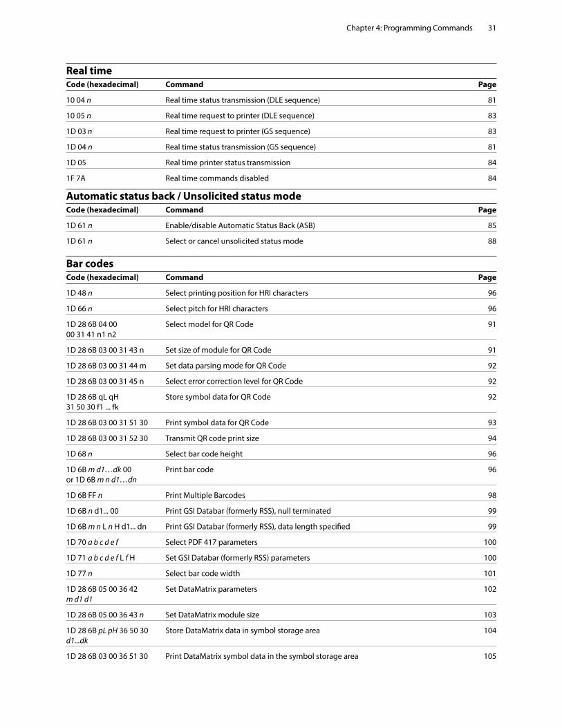
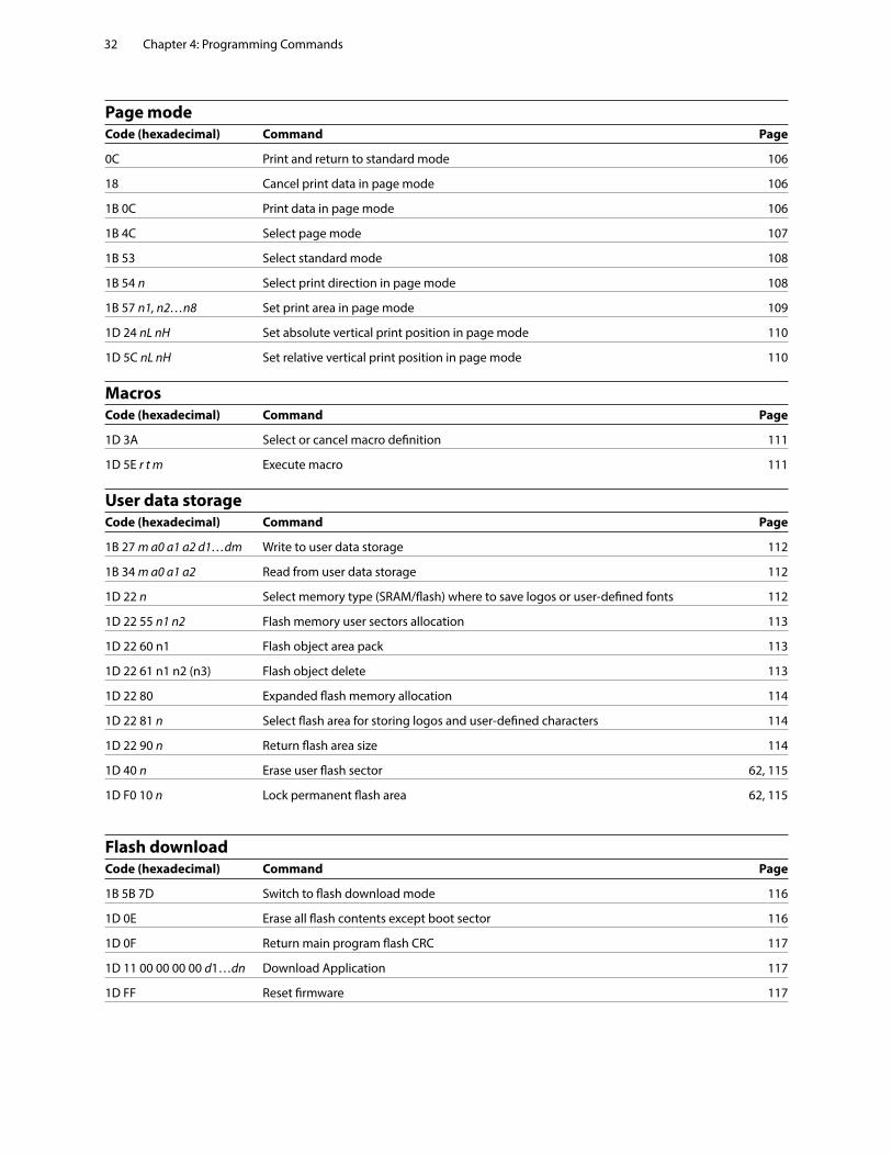
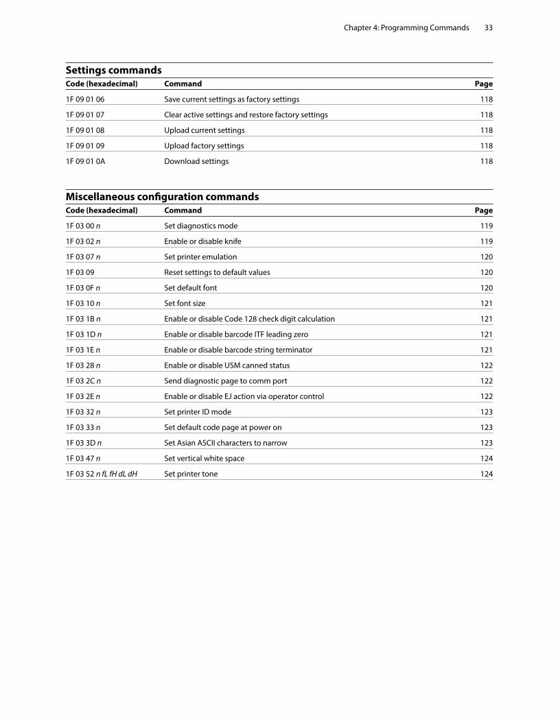
Bar codes ............................................................................................31Page mode ........................................................................................32Macros ................................................................................................32User data storage ..............................................................................32Flash download .................................................................................32Settings commands ..........................................................................33Miscellaneous configuration commands ........................................33
Command conventions .....................................................................34
Command descriptions .....................................................................34Printer actions ...................................................................................34
Clear printer ......................................................................................................... 34Perform full knife cut ........................................................................................ 34Perform partial knife cut ................................................................................. 35Generate tone ..................................................................................................... 35Select peripheral device (for multi-drop) ................................................. 35Initialize printer .................................................................................................. 36Select sensors to stop printing ..................................................................... 36Enable or disable panel button .................................................................... 36Generate pulse to open cash drawer ......................................................... 37Select cut mode and cut paper .................................................................... 37Print test form ..................................................................................................... 38Port Idle Timeout ............................................................................................... 38
Print and paper feed .........................................................................39Print and feed paper one line ....................................................................... 39Print and carriage return ................................................................................. 39Feed n print lines ............................................................................................... 39Feed n dot rows.................................................................................................. 40Add n extra dot rows ........................................................................................ 40Print ........................................................................................................................ 41Print and feed paper ......................................................................................... 41Print and feed n lines ....................................................................................... 41
Vertical and horizontal positioning .................................................42Horizontal tab ..................................................................................................... 42Set horizontal and vertical minimum motion units .............................. 42Set column ........................................................................................................... 42Set absolute starting position ....................................................................... 43Set vertical line spacing to 1/6 inch ............................................................ 43Set vertical line spacing .................................................................................. 44Set horizontal tab positions ........................................................................... 44Set relative print position ............................................................................... 45Select justification ............................................................................................. 46Set left margin .................................................................................................... 46Set printing area width .................................................................................... 47
Contents 5
Text characteristics commands ........................................................48Select double-wide characters ..................................................................... 48Select single-wide characters ....................................................................... 48Select 90 degree counter-clockwise rotated print ................................ 48Select pitch (column width) .......................................................................... 49Set right-side character spacing .................................................................. 49Select print mode .............................................................................................. 50Select or cancel user-defined character set ............................................. 51Define user-defined character set ............................................................... 51Define extended user-defined character set ........................................... 52Select or cancel underline mode ................................................................. 52Copy character set from ROM to RAM ....................................................... 53Cancel user-defined character ...................................................................... 53Select or cancel emphasized mode ............................................................ 53Select or cancel double-strike ...................................................................... 54Select or cancel italic print ............................................................................. 54Select international character code ........................................................... 55Select or cancel 90 degree clockwise rotated print .............................. 56Select international character set ............................................................... 56Select or cancel upside-down print mode ............................................... 57Select character size ......................................................................................... 58Select or cancel white/black reverse print mode .................................. 59Set smoothing .................................................................................................... 59Select superscript or subscript modes ...................................................... 60Select active user-defined character set ................................................... 60Download font list ............................................................................................. 61Configure use of font set ................................................................................ 61Configure line spacing ..................................................................................... 61
Double-byte fonts .............................................................................62Lock permanent font flash area ................................................................... 62Erase user flash sector ...................................................................................... 62Select font ID number ...................................................................................... 63Select font style number ................................................................................. 63Save font ID number as default font at power up ................................. 63Get double-byte font CRC (font ID) ............................................................. 63Get double-byte font CRC (font ID and font style) ................................ 63Download font ................................................................................................... 64
Graphics .............................................................................................64Download BMP logo ........................................................................................ 64Select bit image mode .................................................................................... 65Turn on/off TIFF compression ....................................................................... 65Print advanced raster graphics ..................................................................... 66Select single-density graphics ...................................................................... 66Select double-density graphics ................................................................... 66Select the current logo .................................................................................... 67Define downloaded bit image ...................................................................... 68Print downloaded bit image ......................................................................... 69Print raster graphics ......................................................................................... 69Print Flash Logo .................................................................................................. 70
Contents6
Define Flash Logos ............................................................................................ 70Logo print with knife cut ............................................................................... 70Set temporary max target speed ................................................................. 71Convert 6-dots/mm bitmap to 8-dots/mm bitmap .............................. 71Enable constant speed logos ........................................................................ 71
Status .................................................................................................72Status command introduction ..................................................................... 72
Batch mode ........................................................................................72Transmit peripheral device status (RS-232C printers only) ................ 72Transmit paper sensor status ........................................................................ 73Transmit printer ID ............................................................................................ 73Transmit printer ID, remote diagnostics extension ............................... 75Transmit status ................................................................................................... 78Send printer software version....................................................................... 79
Real time commands .........................................................................79Preferred implementation .............................................................................. 80Alternate implementation ............................................................................. 80Rules for using real time commands .......................................................... 80Moving data through the buffer .................................................................. 80Busy line and fault conditions ....................................................................... 81Real time status transmission ....................................................................... 81Real time request to printer ........................................................................... 83Real time printer status transmission ......................................................... 84Real time commands disabled ..................................................................... 84
Automatic Status Back ......................................................................85Enable/disable Automatic Status Back (ASB) .......................................... 85
Unsolicited status mode ...................................................................88Select or cancel unsolicited status mode (USM) .................................... 88Recognizing data from the printer .............................................................. 90
Bar codes ............................................................................................91QR code Overview............................................................................................. 91Select model for QR code .............................................................................. 91Set size for QR code module ......................................................................... 91Set data parsing mode for QR Code ........................................................... 92Select error correction level for QR Code ................................................ 92Store symbol data for QR Code .................................................................... 92Print symbol data for QR code ...................................................................... 93Transmit QR code print size ........................................................................... 94Select printing position of HRI characters ................................................ 96Select pitch of HRI characters ....................................................................... 96Select bar code height ..................................................................................... 96Print bar code ...................................................................................................... 96Print multiple barcodes ................................................................................... 98Print GS1 DataBar, null terminated ............................................................. 99Print GS1 DataBar, data length specified .................................................. 99Set GS1 DataBar parameters .......................................................................100Select PDF 417 parameters ..........................................................................100Select bar code width ....................................................................................101Set DataMatrix Parameters ..........................................................................102Set DataMatrix module size .........................................................................103
Contents 7
Store DataMatrix data in symbol storage area .....................................104Print DataMatrix symbol data in the symbol storage area ...............105
Page mode .......................................................................................106Print and return to standard mode ...........................................................106Cancel print data in page mode.................................................................106Print data in page mode ...............................................................................106Select page mode ...........................................................................................107Select standard mode ....................................................................................108Select print direction in page mode .........................................................108Set print area in page mode ........................................................................109Set absolute vertical print position in page mode ..............................110Set relative vertical print position in page mode ................................110
Macros ..............................................................................................111Select or cancel macro definition ..............................................................111Execute macro ..................................................................................................111
User data storage ............................................................................112Write to user data storage ............................................................................112Read from user data storage .......................................................................112Select memory type (SRAM/flash) where to save logos or user-defined fonts ......................................................................................112Flash memory user sectors allocation .....................................................113Flash object area pack ...................................................................................113Flash object delete ..........................................................................................113Expanded flash memory allocation ..........................................................114Select flash area for storing logos and user-defined characters ....114Return flash area size .....................................................................................114Erase user flash sector ....................................................................................115Lock permanent font flash area .................................................................115
Flash download ...............................................................................116Switch to flash download mode ................................................................116Erase all flash contents except boot sector ............................................116Return main program flash CRC .................................................................117Download application ...................................................................................117Reset firmware ..................................................................................................117
Settings commands ........................................................................118Save current settings ......................................................................................118Restore factory settings ................................................................................118Upload current settings ................................................................................118Upload factory settings .................................................................................118Download settings ..........................................................................................118
Miscellaneous configuration commands ......................................119Set diagnostics mode ....................................................................................119Enable or disable knife ..................................................................................119Set printer emulation .....................................................................................120Reset settings to default values .................................................................120Set default font .................................................................................................120Set font size .......................................................................................................121Enable or disable Code 128 check digit calculation ...........................121
Contents8
Enable or disable barcode ITF leading zero ...........................................121Enable or disable barcode string terminator.........................................121Enable or disable USM canned status ......................................................122Send diagnostic pages to comm port .....................................................122Enable or disable EJ action via operator control ..................................122Set printer ID mode ........................................................................................123Set default code page at power on ...........................................................123Set Asian ASCII characters to narrow .......................................................123Set vertical white space.................................................................................124Set printer tone ................................................................................................124
Appendix A: Commands listed by hexadecimal code ..........................................125
Appendix B: Resident Character Sets ....................................................................130
Character sets ..................................................................................130Character code table Page 0 (PC437: USA, Standard Europe): ....130Character code table Page 1 (PC850: Multilingual Latin I): .........131Character code table Page 2 (PC852: Latin II): ..............................132Character code table Page 3 (PC860: Portuguese): ......................133Character code table Page 4 (PC863: Canadian French): .............134Character code table Page 5 (PC865: Nordic): ..............................135Character code table Page 6 (PC858: Multilingual I + Euro): .......136Character code table Page 7 (PC866: Russian):.............................137Character code table Page 8 (WPC1252: Latin I): .........................138Character code table Page 9 (PC862: Hebrew): ............................139Character code table Page 10 (PC737: Greek): .............................140Character code table Page 11 (PC874: Thai): ................................141Character code table Page 12 (PC857: Turkish): ...........................142Character code table Page 13 (WPC1251: Cyrillic): ......................143Character code table Page 14 (WPC1255: Hebrew): .....................144Character code table Page 15 (KZ_1048: Kazakh): .......................145Character code table Page 16 (WPC1256: Arabic): .......................146Character code table Page 17 (WPC1250: Central Europe):.........147Character code table Page 18 (WPC28591: Latin 1): ....................148Character code table Page 19 (WPC28592: Latin 2): ....................149Character code table Page 20 (WPC28599: Turkish): ...................150Character code table Page 21 (WPC28605: Latin 9): ....................151Character code table Page 22 (PC864: Arabic): .............................152Character code table Page 23 (PC720: Arabic): .............................153Character code table Page 24 (WPC1254: Turkish): .....................154Character code table Page 25 (WPC28596: Arabic): .....................155Character code table Page 26 (KATAKANA: Asia): ........................156Character code table Page 27 (PC775: Baltic): ..............................157Character code table Page 28 (WPC1257: Baltic): ........................158Character code table Page 29 (WP28594: Baltic): ........................159Character code table Page 30 (WPC1253: Greek): ........................160

This page intentionally left blank
Chapter 1: About this Guide10
Chapter 1: About this Guide
How to use this guideThis is a supplemental guide providing programming information about HP printers. This guide is written for tech-savvy users who are interested in customizing or adjusting printer functionality and is meant to be used in conjunction with the User Guide.
If you experience any difficulties during the programming process or feel unsure of adjustments you have made, contact your HP representative for further assistance.
Where to find the basicsIf you are looking for information about setup or basic operation, see the User Guide. The programming guide assumes that you have the User Guide handy for reference or are already familiar with the printer.
Where to find advanced technical informationThis guide contains the most complete information available on programming the printer. If you cannot find what you need here or would like further guidance on how to program the printer, contact a HP representative for assistance.
SupportFor more advanced procedures and troubleshooting, you may need to refer to the printer’s service guide or speak to a HP technical professional. Your representative is able to provide you with necessary information.
For on-line service, go to www.hp.com/support.
Chapter 2: Diagnostics and Configuration 11
Chapter 2: Diagnostics and Configuration
The printer performs a number of diagnostics that provide useful information about the operating status of the printer. The following diagnostic tests are available.
• Start-up diagnostics Performed during the printer’s start-up cycle.
• Runtime diagnostics Performed during normal printer operation.
• Remote diagnostics Maintained during normal operation and reported in the print test.
• The printer can be configured with the following settings and functions through the configuration menu that is printed on the receipt. For more information about configuring the printer, see “Printer configuration” on page 15.
Communication interfaces
Diagnostic modes
Printer emulations/software options
Hardware options
Paper Type
Firmware features
Start-up DiagnosticsWhen the printer receives power or performs a hardware reset, it automatically performs the startup diagnostics (also known as level 0 diagnostics) during the start-up cycle. The following diagnostics are performed:
• Turn off motors
• Perform boot CRC check of the firmware ROM and test main program CRC
Failure causes Start-up Diagnostics to stop; the printer beeps and the LED flashes a set number of times, indicating the nature of the failure. The table in the “Indicators” section (page 14) describes the specific tone and LED sequences.
• Check if paper is present
• Return the knife to the home position
Failure causes a fault condition. The table in the “Indicators” section (page 14) describes the specific tone and LED sequences.
• Check if receipt cover is closed
Failure does not interrupt the start-up cycle.
At power up, if the LED blinks twice, every four seconds, the object storage areas are being initialized. This process could take up to two minutes. Once the object storage area initialization is complete the printer will continue with its normal startup procedure and operation. DO NOT RESET THE PRINTER UNTIL THIS PROCESS IS COMPLETE.
When the start-up diagnostics are complete, the printer makes a two-tone beep (low then high frequency), the paper feed button is enabled, and the printer is ready for normal operation.
If the printer has not been turned on before, or a new EEPROM has been installed, the default values for the printer functions will be loaded into the EEPROM during start-up diagnostics, and the printer will make a quick four-tone beep (high then low frequency, twice)
Chapter 2: Diagnostics and Configuration12
Runtime diagnosticsRuntime diagnostics (sometimes called level 2 diagnostics) run during normal printer operation. When the following conditions occur, the printer automatically turns off the appropriate motors and disables printing to prevent damage to the printer:
• Paper out
• Receipt cover open
• Knife unable to home
• Printhead too hot
• Voltages out of range
The LED on the operator panel will signal when these conditions occur as well as indicate what state or mode the printer is in.
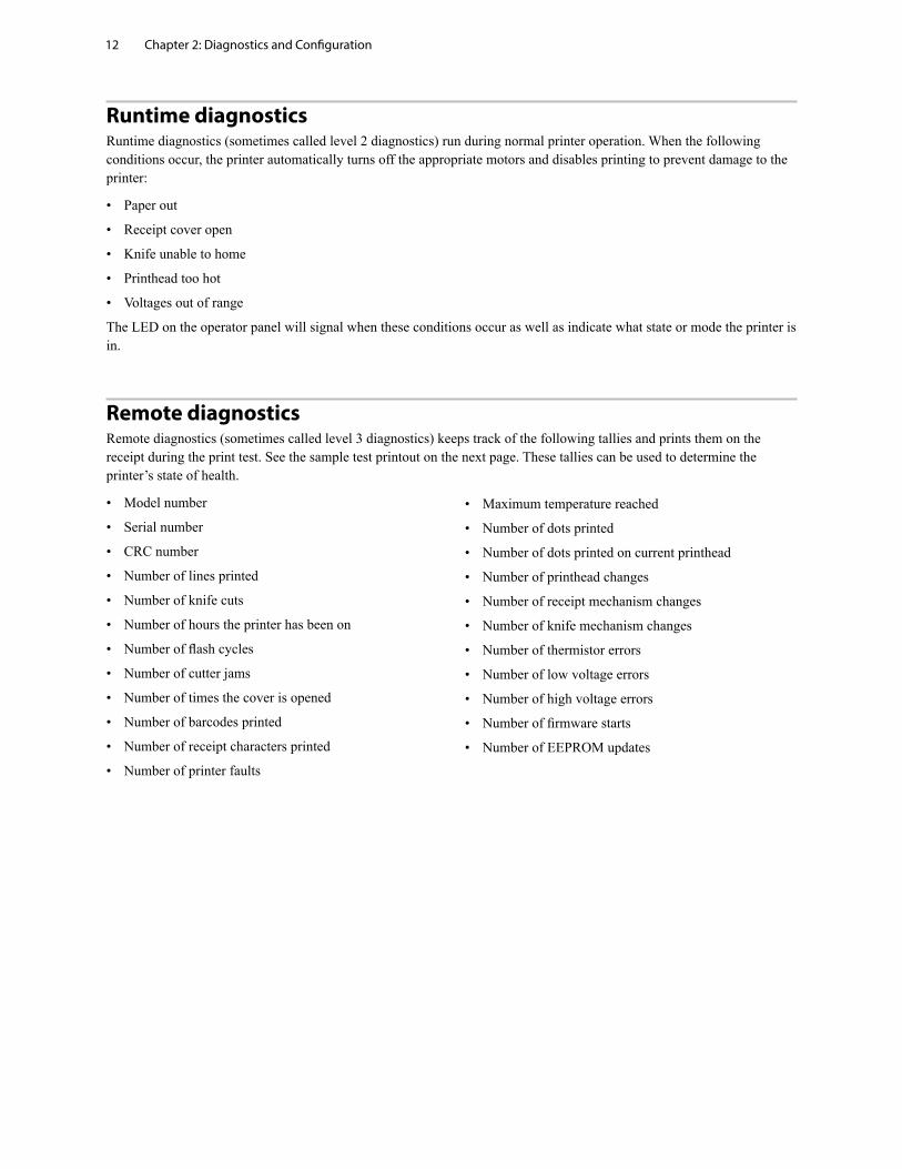
Remote diagnosticsRemote diagnostics (sometimes called level 3 diagnostics) keeps track of the following tallies and prints them on the receipt during the print test. See the sample test printout on the next page. These tallies can be used to determine the printer’s state of health.
• Model number
• Serial number
• CRC number
• Number of lines printed
• Number of knife cuts
• Number of hours the printer has been on
• Number of flash cycles
• Number of cutter jams
• Number of times the cover is opened
• Number of barcodes printed
• Number of receipt characters printed
• Number of printer faults
• Maximum temperature reached
• Number of dots printed
• Number of dots printed on current printhead
• Number of printhead changes
• Number of receipt mechanism changes
• Number of knife mechanism changes
• Number of thermistor errors
• Number of low voltage errors
• Number of high voltage errors
• Number of firmware starts
• Number of EEPROM updates
Chapter 2: Diagnostics and Configuration 13
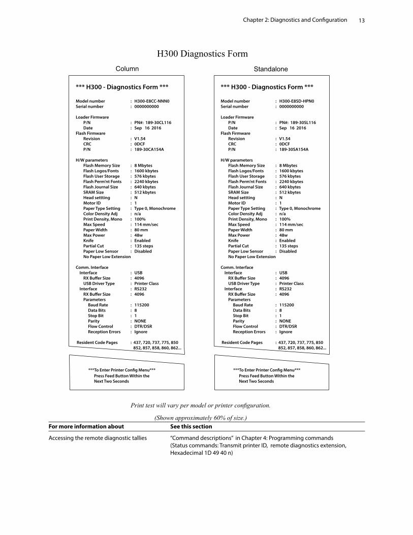
For more information about See this section
Accessing the remote diagnostic tallies “Command descriptions” in Chapter 4: Programming commands (Status commands: Transmit printer ID, remote diagnostics extension, Hexadecimal 1D 49 40 n)
Print test will vary per model or printer configuration.
(Shown approximately 60% of size.)
- Set Firmware Features - > 8 clicks
*** H300 - Diagnostics Form ***
Model number : H300-E8CC-NNN0Serial number : 0000000000
Loader Firmware P/N : PN#: 189-30CL116 Date : Sep 16 2016Flash Firmware Revision : V1.54 CRC : 0DCF P/N : 189-30CA154A
H/W parameters Flash Memory Size : 8 Mbytes Flash Logos/Fonts : 1600 kbytes Flash User Storage : 576 kbytes Flash Perm’nt Fonts : 2240 kbytes Flash Journal Size : 640 kbytes SRAM Size : 512 kbytes Head settting : N Motor ID : 1 Paper Type Setting : Type 0, Monochrome Color Density Adj : n/a Print Density, Mono : 100% Max Speed : 114 mm/sec Paper Width : 80 mm Max Power : 48w Knife : Enabled Partial Cut : 135 steps Paper Low Sensor : Disabled No Paper Low Extension
Comm. Interface Interface : USB RX Bu�er Size : 4096 USB Driver Type : Printer Class Interface : RS232 RX Bu�er Size : 4096 Parameters Baud Rate : 115200 Data Bits : 8 Stop Bit : 1 Parity : NONE Flow Control : DTR/DSR Reception Errors : Ignore
Resident Code Pages : 437, 720, 737, 775, 850 852, 857, 858, 860, 862...
Press Feed Button Within the Next Two Seconds
***To Enter Printer Con�g Menu***
H300 Diagnostics Form
- Set Firmware Features - > 8 clicks
*** H300 - Diagnostics Form ***
Model number : H300-E8SD-HPN0Serial number : 0000000000
Loader Firmware P/N : PN#: 189-30SL116 Date : Sep 16 2016Flash Firmware Revision : V1.54 CRC : 0DCF P/N : 189-30SA154A
H/W parameters Flash Memory Size : 8 Mbytes Flash Logos/Fonts : 1600 kbytes Flash User Storage : 576 kbytes Flash Perm’nt Fonts : 2240 kbytes Flash Journal Size : 640 kbytes SRAM Size : 512 kbytes Head settting : N Motor ID : 1 Paper Type Setting : Type 0, Monochrome Color Density Adj : n/a Print Density, Mono : 100% Max Speed : 114 mm/sec Paper Width : 80 mm Max Power : 48w Knife : Enabled Partial Cut : 135 steps Paper Low Sensor : Disabled No Paper Low Extension
Comm. Interface Interface : USB RX Bu�er Size : 4096 USB Driver Type : Printer Class Interface : RS232 RX Bu�er Size : 4096 Parameters Baud Rate : 115200 Data Bits : 8 Stop Bit : 1 Parity : NONE Flow Control : DTR/DSR Reception Errors : Ignore
Resident Code Pages : 437, 720, 737, 775, 850 852, 857, 858, 860, 862...
Press Feed Button Within the Next Two Seconds
***To Enter Printer Con�g Menu***
Column Standalone
Chapter 2: Diagnostics and Configuration14
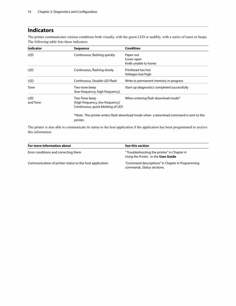
IndicatorsThe printer communicates various conditions both visually, with the green LED or audibly, with a series of tones or beeps. The following table lists these indicators.
Indicator Sequence Condition
LED Continuous, flashing quickly Paper out Cover open Knife unable to home
LED Continuous, flashing slowly Printhead too hot Voltages low/high
LED Continuous, Double LED flash Write to permanent memory in progress
Tone Two-tone beep Start-up diagnostics completed successfully (low frequency, high frequency)
LED Two-Tone beep When entering flash download mode* and Tone (high frequency, low frequency) Continuous, quick blinking of LED *Note: The printer enters flash download mode when a download command is sent to the printer.
The printer is also able to communicate its status to the host application if the application has been programmed to receive this information
For more information about See this section
Error conditions and correcting them “ Troubleshooting the printer” in Chapter 4: Using the Printer, in the User Guide
Communication of printer status to the host application “Command descriptions” in Chapter 4: Programming commands, Status sections.
Chapter 2: Diagnostics and Configuration 15
Printer configurationPrinters are shipped with all the functions and parameters preset at the factory. Settings for various printer parameters can be changed. This menu is printed on the receipt and scrolls through instructions for selecting and changing any of the functions or parameters.
Caution: Be extremely careful changing any of the printer settings to avoid inadvertently changing other settings that might affect the performance of the printer.
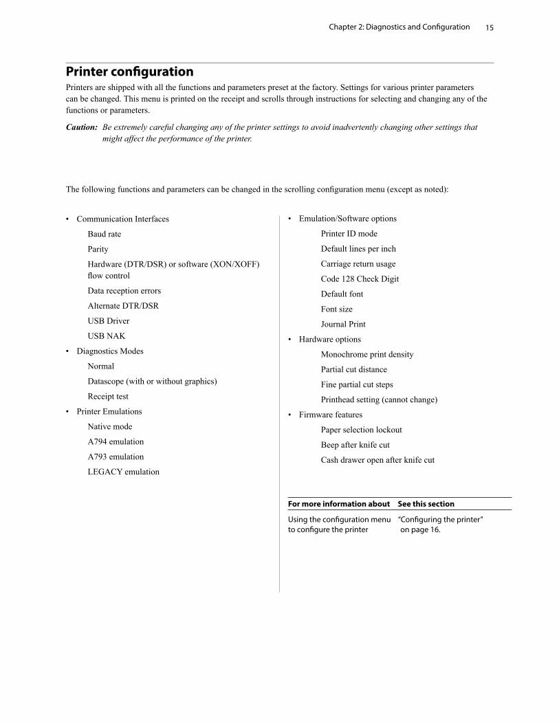
The following functions and parameters can be changed in the scrolling configuration menu (except as noted):
• Communication Interfaces
Baud rate
Parity
Hardware (DTR/DSR) or software (XON/XOFF) flow control
Data reception errors
Alternate DTR/DSR
USB Driver
USB NAK
• Diagnostics Modes
Normal
Datascope (with or without graphics)
Receipt test
• Printer Emulations
Native mode
A794 emulation
A793 emulation
LEGACY emulation
• Emulation/Software options
Printer ID mode
Default lines per inch
Carriage return usage
Code 128 Check Digit
Default font
Font size
Journal Print
• Hardware options
Monochrome print density
Partial cut distance
Fine partial cut steps
Printhead setting (cannot change)
• Firmware features
Paper selection lockout
Beep after knife cut
Cash drawer open after knife cut
For more information about See this section
Using the configuration menu “Configuring the printer” to configure the printer on page 16.
Chapter 2: Diagnostics and Configuration16
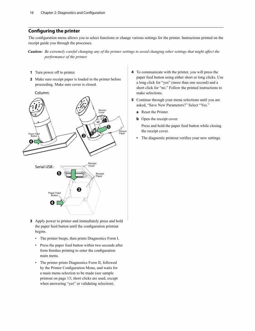
1 Turn power off to printer.
2 Make sure receipt paper is loaded in the printer before proceeding. Make sure cover is closed.
3 Apply power to printer and immediately press and hold the paper feed button until the configuration printout begins.
• The printer beeps, then prints Diagnostics Form I.
• Press the paper feed button within two seconds after form finishes printing to enter the configuration main menu.
• The printer prints Diagnostics Form II, followed by the Printer Configuration Menu, and waits for a main menu selection to be made (see sample printout on page 13; short clicks are used, except when answering “yes” or validating selection).
4 To communicate with the printer, you will press the paper feed button using either short or long clicks. Use a long click for “yes” (more than one second) and a short click for “no.” Follow the printed instructions to make selections.
5 Continue through your menu selections until you are asked, “Save New Parameters?” Select “Yes.”
a Reset the Printer.
b Open the receipt cover.
Press and hold the paper feed button while closing the receipt cover.
• The diagnostic printout verifies your new settings.
Configuring the printerThe configuration menu allows you to select functions or change various settings for the printer. Instructions printed on the receipt guide you through the processes.
Caution: Be extremely careful changing any of the printer settings to avoid changing other settings that might affect the performance of the printer.
Column:
Serial USB :
Chapter 2: Diagnostics and Configuration 17
Communication interface settingsTo change the communication interface settings, enter the configuration menu, select “Set Communication Interface” from the main menu.
Caution: Be extremely careful changing any of the printer settings to avoid inadvertently changing other settings that might affect the performance of the printer.
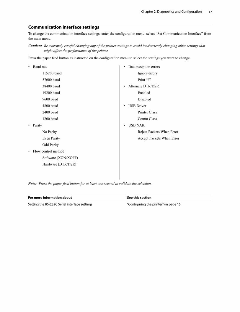
Press the paper feed button as instructed on the configuration menu to select the settings you want to change.
• Baud rate
115200 baud
57600 baud
38400 baud
19200 baud
9600 baud
4800 baud
2400 baud
1200 baud
• Parity
No Parity
Even Parity
Odd Parity
• Flow control method
Software (XON/XOFF)
Hardware (DTR/DSR)
• Data reception errors
Ignore errors
Print “?”
• Alternate DTR/DSR
Enabled
Disabled
• USB Driver
Printer Class
Comm Class
• USB NAK
Reject Packets When Error
Accept Packets When Error
Note: Press the paper feed button for at least one second to validate the selection.
For more information about See this section
Setting the RS-232C Serial interface settings “Configuring the printer” on page 16
Chapter 2: Diagnostics and Configuration18
Diagnostics modesTo change the diagnostic modes enter the configuration menu, select “Set Diagnostics Modes” from the main menu and select one of the following modes:
• Normal: normal operating mode of the printer.
• Datascope: the receipt printer prints incoming commands and data in hexadecimal format to help troubleshoot communication problems. There are DataScope modes for both with and without graphics.
• Receipt test: the receipt printer prints all code pages to verify proper printing of the receipt.
Caution: Be extremely careful changing any of the printer settings to avoid inadvertently changing other settings that might affect the performance of the printer.
See “Configuring the printer,” page 16 for instructions on how to enter the configuration menu.
Enable or disable data scope modeThe data scope mode test prints a hexadecimal dump of all data sent to the printer: “1” prints as hexadecimal 31, “A” as hexadecimal 41 and so on. This helps troubleshoot communication problems and runs during a normal application (after being enabled through printer configuration).
Note: Data scope mode is usually considered a level 1 diagnostic test.
Data scope mode is enabled and disabled by selecting the “Diagnostics Modes” sub-menu of the configuration menu.
Press the paper feed button as instructed on the “Diagnostics Modes Menu” to enable or disable the data scope mode test.
• Off, normal mode (Data scope mode disabled)
• Data scope mode with or without graphics (enabled)
Note: Press the paper feed button for at least one second to validate the selection.
To run the data scope mode:
1 After you have enabled the data scope mode, exit the configuration menu.
2 Run a transaction from the host computer.
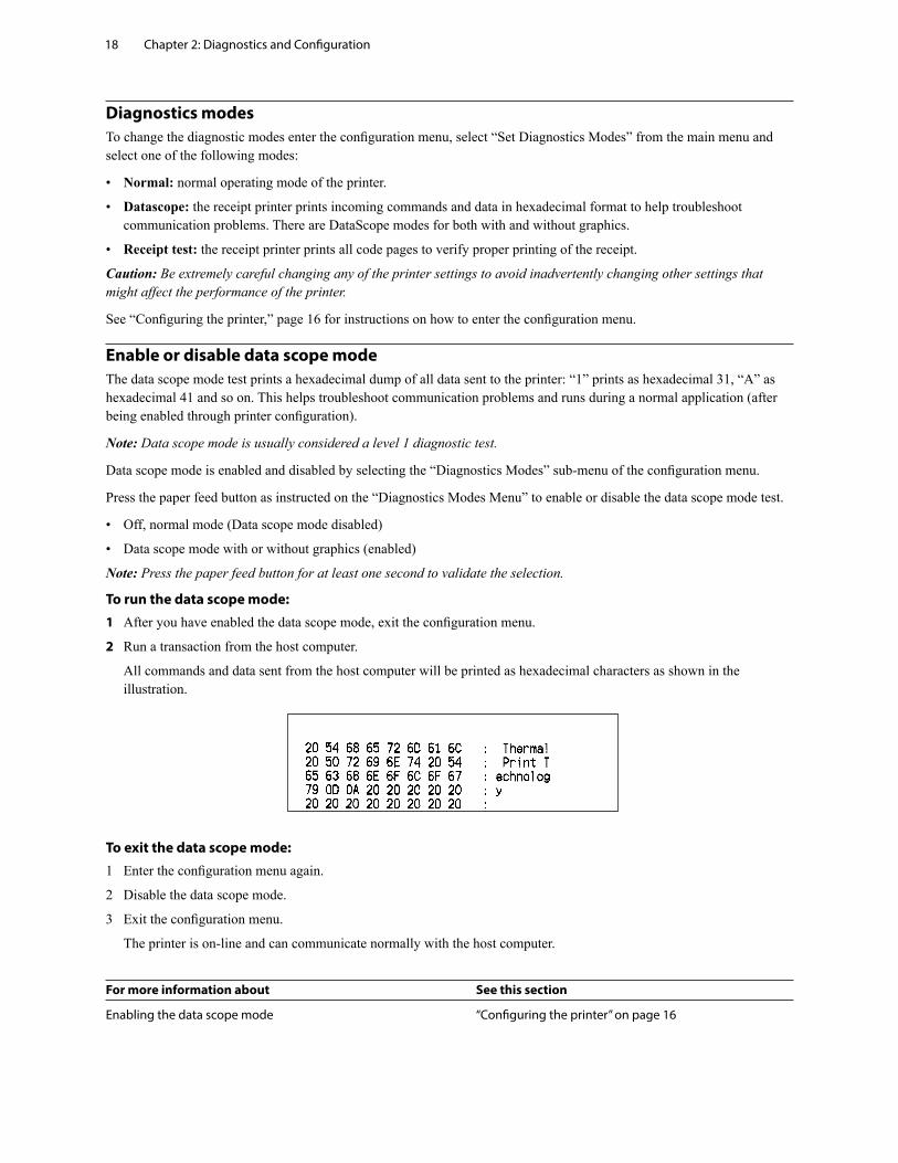
All commands and data sent from the host computer will be printed as hexadecimal characters as shown in the illustration.
To exit the data scope mode:
1 Enter the configuration menu again.
2 Disable the data scope mode.
3 Exit the configuration menu.
The printer is on-line and can communicate normally with the host computer.
For more information about See this section
Enabling the data scope mode “Configuring the printer” on page 16
Chapter 2: Diagnostics and Configuration 19
Enable or disable receipt test modeThe receipt test mode verifies proper receipt printing. Receipt test is enabled and disabled by selecting the “Diagnostics Modes” sub-menu of the configuration menu. See “Configuring the printer”, page 16 for instructions on how to enter the configuration menu.
To run the receipt test mode:
1 Enable the receipt test mode in the configuration menu.
2 Exit the configuration menu.
3 Push the paper feed button. The receipt station prints all code pages and cuts the receipt.
4 To repeat this test, push the paper feed button again.
To exit the receipt test mode:
1 Enter the configuration menu again.
2 Disable the receipt test mode.
3 Exit the configuration menu.
The printer is on-line and can again communicate normally with the host computer.
Electronic Journal Datascope Diagnostic 1F 03 18 02 n=1, turn on electronic journal datascope, run time only
1F 03 18 02 n=0, n>1, turn off electronic journal datascope, run time only
1F 03 18 03 n=1, turn on electronic journal datascope, configuration saved over power cycle
1F 03 18 03 n=0, n>1, turn off electronic journal datascope, configuration saved over power cycle
When enabled, “Auto Journal : Datascope” prints on the second diagnostic page.
This diagnostic is for debugging purposes, and should be used only under the direction of customer support.
Printer emulationsTo change the printer emulations settings, enter the configuration menu, select “Emulation/Software Options” from the main menu and answer “Yes” to “Set printer mode?” printed on the receipt. This will take you to the instructions for setting the printer emulation.
Caution: Be extremely careful changing any of the printer settings to avoid inadvertently changing other settings that might affect the performance of the printer.
Press the paper feed button as instructed to select the printer emulation you want.
• Native mode
• A794 emulation
• A793 emulation
• LEGACY emulation
Note: Press the paper feed button for at least one second to validate the selection.
For more information about See this section
Setting the printer emulation “Configuring the Printer”, page 16
Chapter 2: Diagnostics and Configuration20
Printer settings and functionsTo change the printer settings and functions, enter the configuration menu, select the sub-menu from the main menu and answer the questions printed on the receipt until you come to the instructions for selecting the printer settings.
Caution: Be extremely careful changing any of the printer settings to avoid inadvertently changing other settings that might affect the performance of the printer.
Press the paper feed button as instructed to select the printer settings you want.
Select the emulation/software options sub-menu to set:
• Printer Mode
This function is used to set the printer emulation to Native, A794, A793 or Legacy emulation.
• Printer ID mode
This function is used to determine what printer ID value is returned in response to a Transmit printer ID command (1D 49 n) when the printer is in A794 emulation mode. The printer can be configured to send back the ID of the H300, A794, A793 or Application Compatible Escape Command systems.
• Default lines per inch
This function allows you to set the default for lines per inch to:
• 8.13 lines per inch
• 7.52 lines per inch
• 6.77 lines per inch
• 6.00 lines per inch
• Carriage return usage
This function allows the printer to ignore or use the carriage return (hexadecimal 0D) command depending on the application. Some applications expect the command to be ignored while others use the command as a print command.
• Code 128 Check Digit
Enables or disables the calculation of the check digit.
• Default font
Sets the default for monochrome and LEGACY emulations.
• Font size
Allows user to set font size for the emulation being used.
• Journal Print
Enables or disables operator action.
Chapter 2: Diagnostics and Configuration 21
Select the hardware options sub-menu to set:
• Print density (monochrome papers only)
Adjusts printhead energy level to darken printout or adjust for paper variations. When printer prints high-density print lines (text or graphics), it automatically slows down. Factory setting for the H300 is 100%.
WARNING: Choose a print density setting no higher than necessary to achieve acceptable print density. Failure to observe this rule may result in a printer service call and may void the printer warranty. Running at a higher energy level will reduce the printhead life. Consult your HP technical support specialist if you have questions.
• Partial cut distance
Allows the user to set the distance that the knife will cut across a receipt in 5 step increments between 110-160.
• Fine partial cut steps
Allows the user to set the amount of extra steps the knife will cut across a receipt, between 0 and 4.
For more information about See this section
Setting the printer functions “Configuring the printer” and settings (See page 16)

Chapter 2: Diagnostics and Configuration22
Select the firmware features sub-menu to set:
• Paper selection lockout
• Beep after knife cut
• Cash drawer open after knife cut
Allows the user to enable and set the time-out value to 15, 30, 60, 120, or 240 minutes, or to disable the feature.
Chapter 3: Programming the Printer 23
Chapter 3: Programming the Printer
Overview of commandsCommands control all operations and functions of the printer. This includes selecting the size and placement of characters and graphics on the receipt to feeding and cutting the paper. The programming commands have been organized, in order of hexadecimal code within functional groups. For this reason, “related” commands may not be listed adjacent to one another.
The operation of various printers may be emulated by the commands, including the following:
• A793/A794
• Native
• LEGACY
Any of the commands may be used in any combination to program a host computer to communicate with the printer (unless otherwise noted).
Some commands listed and described here may not be implemented and are identified as “not implemented.” If received, they are ignored and not sent to the print buffer as data.
Any nonlegal commands have their parameter sent to the print buffer as data.
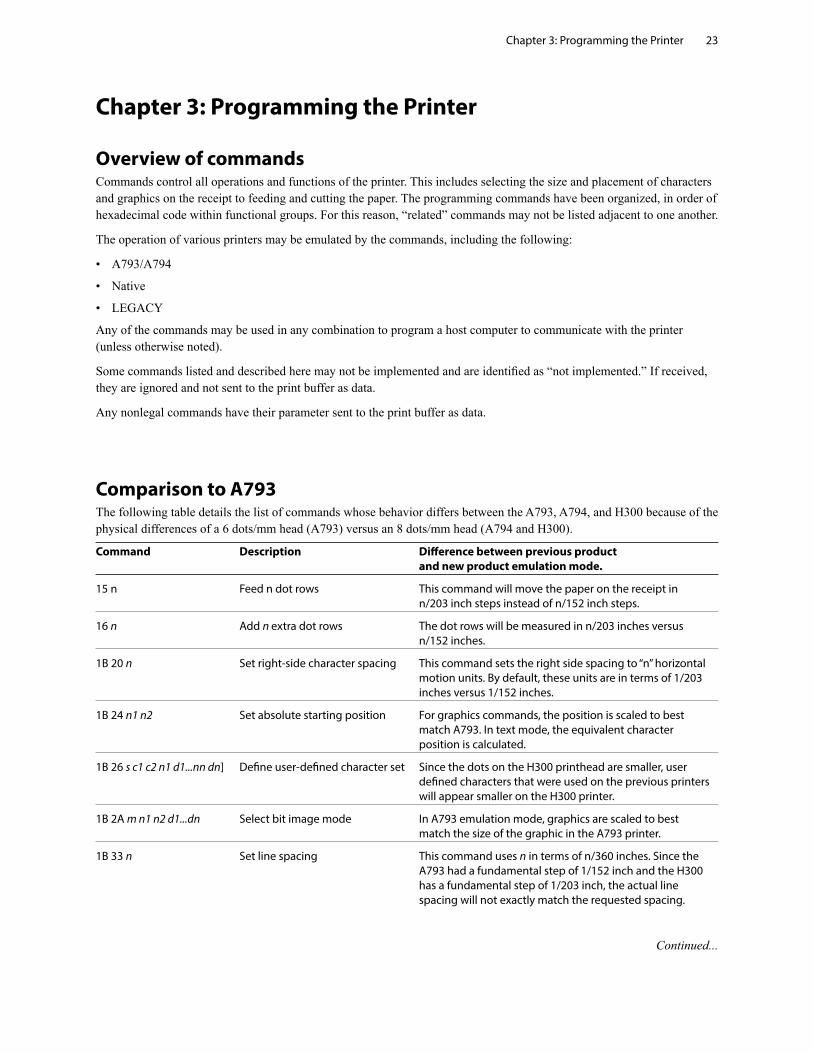
Comparison to A793The following table details the list of commands whose behavior differs between the A793, A794, and H300 because of the physical differences of a 6 dots/mm head (A793) versus an 8 dots/mm head (A794 and H300).
Command Description Difference between previous product and new product emulation mode.
15 n Feed n dot rows This command will move the paper on the receipt in n/203 inch steps instead of n/152 inch steps.
16 n Add n extra dot rows The dot rows will be measured in n/203 inches versus n/152 inches.
1B 20 n Set right-side character spacing This command sets the right side spacing to “n” horizontal motion units. By default, these units are in terms of 1/203 inches versus 1/152 inches.
1B 24 n1 n2 Set absolute starting position For graphics commands, the position is scaled to best match A793. In text mode, the equivalent character position is calculated.
1B 26 s c1 c2 n1 d1...nn dn] Define user-defined character set Since the dots on the H300 printhead are smaller, user defined characters that were used on the previous printers will appear smaller on the H300 printer.
1B 2A m n1 n2 d1...dn Select bit image mode In A793 emulation mode, graphics are scaled to best match the size of the graphic in the A793 printer.
1B 33 n Set line spacing This command uses n in terms of n/360 inches. Since the A793 had a fundamental step of 1/152 inch and the H300 has a fundamental step of 1/203 inch, the actual line spacing will not exactly match the requested spacing.
Continued...
Chapter 3: Programming the Printer24
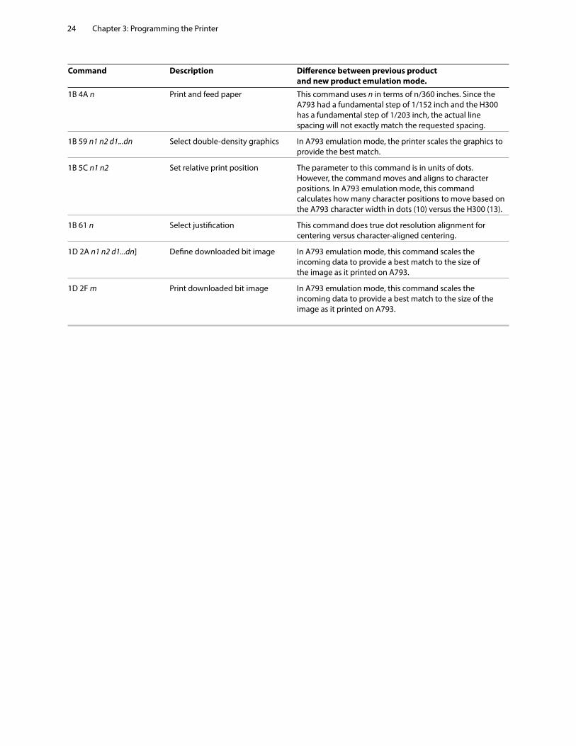
Command Description Difference between previous product and new product emulation mode.
1B 4A n Print and feed paper This command uses n in terms of n/360 inches. Since the A793 had a fundamental step of 1/152 inch and the H300 has a fundamental step of 1/203 inch, the actual line spacing will not exactly match the requested spacing.
1B 59 n1 n2 d1...dn Select double-density graphics In A793 emulation mode, the printer scales the graphics to provide the best match.
1B 5C n1 n2 Set relative print position The parameter to this command is in units of dots. However, the command moves and aligns to character positions. In A793 emulation mode, this command calculates how many character positions to move based on the A793 character width in dots (10) versus the H300 (13).
1B 61 n Select justification This command does true dot resolution alignment for centering versus character-aligned centering.
1D 2A n1 n2 d1...dn] Define downloaded bit image In A793 emulation mode, this command scales the incoming data to provide a best match to the size of the image as it printed on A793.
1D 2F m Print downloaded bit image In A793 emulation mode, this command scales the incoming data to provide a best match to the size of the image as it printed on A793.
Chapter 3: Programming the Printer 25
Character appearanceThe appearance of text can be changed using the following print modes:
• Standard
• Compressed
• Double-high
• Double-wide
• Upside-down
• Rotated
• Underlined
• Bold
• Reverse
• Italic
• Strike-through
• Scaled
• Shading
Width specifications
Standard
• Characters per inch: 15.6
• Characters per line: 44
• Cell size: 13 × 24 dots (default font)
13 × 27 dots (Tall font)
13 × 18 dots (paper-saving font)
Compressed
• Characters per inch: 20.3
• Characters per line: 56
• Cell size: 10 × 24 dots (default font)
10 × 27 dots (Tall font)
10 × 18 dots (paper-saving font)
13 × 21 dots (paper-saving font 2)
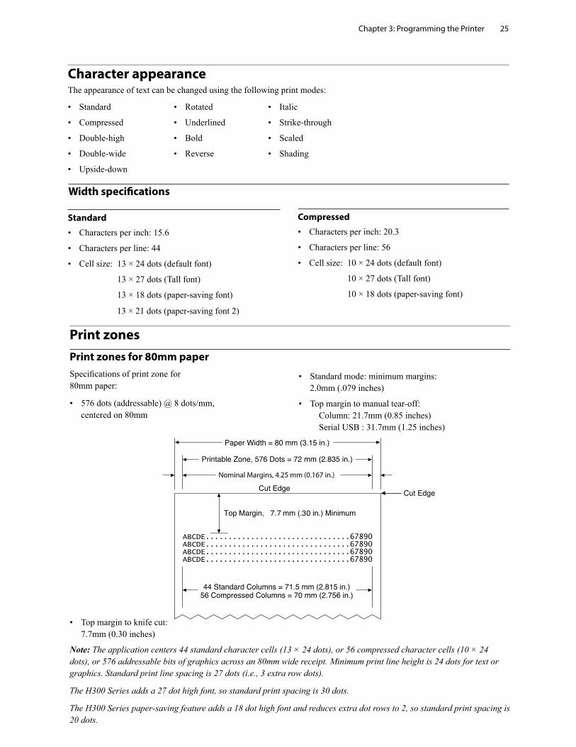
Print zonesPrint zones for 80mm paperSpecifications of print zone for 80mm paper:
• 576 dots (addressable) @ 8 dots/mm, centered on 80mm
• Standard mode: minimum margins: 2.0mm (.079 inches)
• Top margin to manual tear-off: Column: 21.7mm (0.85 inches) Serial USB : 31.7mm (1.25 inches)
• Top margin to knife cut: 7.7mm (0.30 inches)
Note: The application centers 44 standard character cells (13 × 24 dots), or 56 compressed character cells (10 × 24 dots), or 576 addressable bits of graphics across an 80mm wide receipt. Minimum print line height is 24 dots for text or graphics. Standard print line spacing is 27 dots (i.e., 3 extra row dots).
The H300 Series adds a 27 dot high font, so standard print spacing is 30 dots.
The H300 Series paper-saving feature adds a 18 dot high font and reduces extra dot rows to 2, so standard print spacing is 20 dots.
Nominal Margins, 4.25 mm (0.167 in.)
Chapter 3: Programming the Printer26
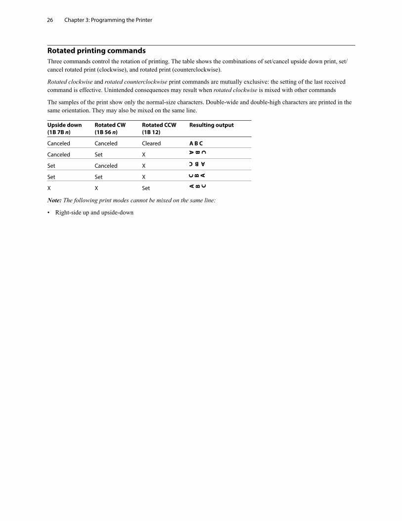
Rotated printing commandsThree commands control the rotation of printing. The table shows the combinations of set/cancel upside down print, set/cancel rotated print (clockwise), and rotated print (counterclockwise).
Rotated clockwise and rotated counterclockwise print commands are mutually exclusive: the setting of the last received command is effective. Unintended consequences may result when rotated clockwise is mixed with other commands
The samples of the print show only the normal-size characters. Double-wide and double-high characters are printed in the same orientation. They may also be mixed on the same line.
Upside down Rotated CW Rotated CCW Resulting output (1B 7B n) (1B 56 n) (1B 12)
Canceled Canceled Cleared A B C
Canceled Set X
Set Canceled X
Set Set X
X X Set
Note: The following print modes cannot be mixed on the same line:
• Right-side up and upside-down
A B C
A B CA B C
ABC
Chapter 3: Programming the Printer 27
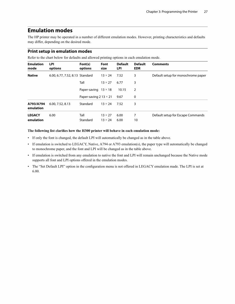
Emulation modesThe HP printer may be operated in a number of different emulation modes. However, printing characteristics and defaults may differ, depending on the desired mode.
Print setup in emulation modesRefer to the chart below for defaults and allowed printing options in each emulation mode.
Emulation LPI Font(s) Font Default Default Comments mode options options size LPI EDR
Native 6.00, 6.77, 7.52, 8.13 Standard 13 × 24 7.52 3 Default setup for monochrome paper
Tall 13 × 27 6.77 3
Paper-saving 13 × 18 10.15 2
Paper-saving 2 13 × 21 9.67 0
A793/A794 6.00, 7.52, 8.13 Standard 13 × 24 7.52 3 emulation
LEGACY 6.00 Tall 13 × 27 6.00 7 Default setup for Escape Commands emulation Standard 13 × 24 6.00 10
The following list clarifies how the H300 printer will behave in each emulation mode:
• If only the font is changed, the default LPI will automatically be changed as in the table above.
• If emulation is switched to LEGACY, Native, A794 or A793 emulation(s), the paper type will automatically be changed to monochrome paper, and the font and LPI will be changed as in the table above.
• If emulation is switched from any emulation to native the font and LPI will remain unchanged because the Native mode supports all font and LPI options offered in the emulation modes.
• The “Set Default LPI” option in the configuration menu is not offered in LEGACY emulation made. The LPI is set at 6.00.
Chapter 4: Programming Commands28
Chapter 4: Programming Commands
Commands listed by function
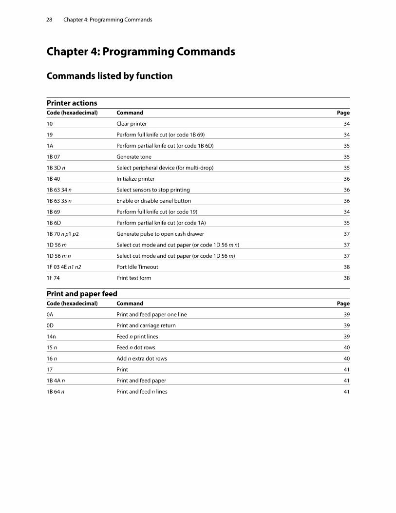
Printer actionsCode (hexadecimal) Command Page
10 Clear printer 34
19 Perform full knife cut (or code 1B 69) 34
1A Perform partial knife cut (or code 1B 6D) 35
1B 07 Generate tone 35
1B 3D n Select peripheral device (for multi-drop) 35
1B 40 Initialize printer 36
1B 63 34 n Select sensors to stop printing 36
1B 63 35 n Enable or disable panel button 36
1B 69 Perform full knife cut (or code 19) 34
1B 6D Perform partial knife cut (or code 1A) 35
1B 70 n p1 p2 Generate pulse to open cash drawer 37
1D 56 m Select cut mode and cut paper (or code 1D 56 m n) 37
1D 56 m n Select cut mode and cut paper (or code 1D 56 m) 37
1F 03 4E n1 n2 Port Idle Timeout 38
1F 74 Print test form 38
Print and paper feed Code (hexadecimal) Command Page
0A Print and feed paper one line 39
0D Print and carriage return 39
14n Feed n print lines 39
15 n Feed n dot rows 40
16 n Add n extra dot rows 40
17 Print 41
1B 4A n Print and feed paper 41
1B 64 n Print and feed n lines 41
Chapter 4: Programming Commands 29
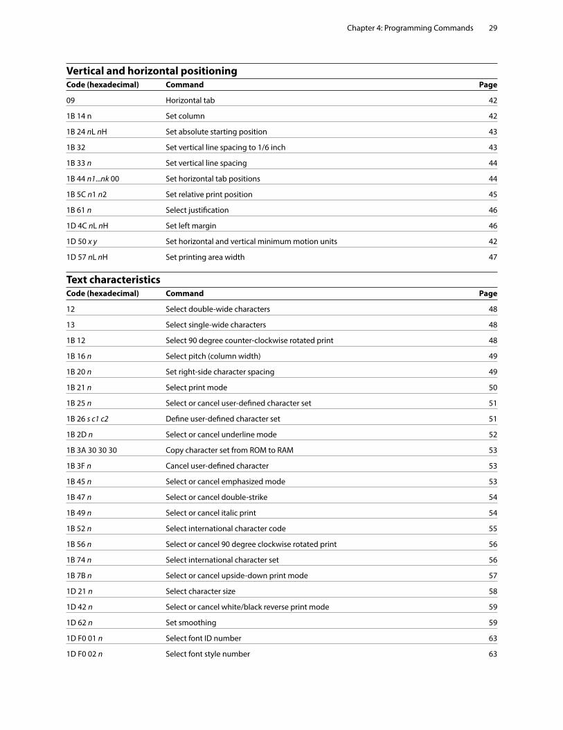
Vertical and horizontal positioning Code (hexadecimal) Command Page
09 Horizontal tab 42
1B 14 n Set column 42
1B 24 nL nH Set absolute starting position 43
1B 32 Set vertical line spacing to 1/6 inch 43
1B 33 n Set vertical line spacing 44
1B 44 n1...nk 00 Set horizontal tab positions 44
1B 5C n1 n2 Set relative print position 45
1B 61 n Select justification 46
1D 4C nL nH Set left margin 46
1D 50 x y Set horizontal and vertical minimum motion units 42
1D 57 nL nH Set printing area width 47
Text characteristicsCode (hexadecimal) Command Page
12 Select double-wide characters 48
13 Select single-wide characters 48
1B 12 Select 90 degree counter-clockwise rotated print 48
1B 16 n Select pitch (column width) 49
1B 20 n Set right-side character spacing 49
1B 21 n Select print mode 50
1B 25 n Select or cancel user-defined character set 51
1B 26 s c1 c2 Define user-defined character set 51
1B 2D n Select or cancel underline mode 52
1B 3A 30 30 30 Copy character set from ROM to RAM 53
1B 3F n Cancel user-defined character 53
1B 45 n Select or cancel emphasized mode 53
1B 47 n Select or cancel double-strike 54
1B 49 n Select or cancel italic print 54
1B 52 n Select international character code 55
1B 56 n Select or cancel 90 degree clockwise rotated print 56
1B 74 n Select international character set 56
1B 7B n Select or cancel upside-down print mode 57
1D 21 n Select character size 58
1D 42 n Select or cancel white/black reverse print mode 59
1D 62 n Set smoothing 59
1D F0 01 n Select font ID number 63
1D F0 02 n Select font style number 63
Chapter 4: Programming Commands30
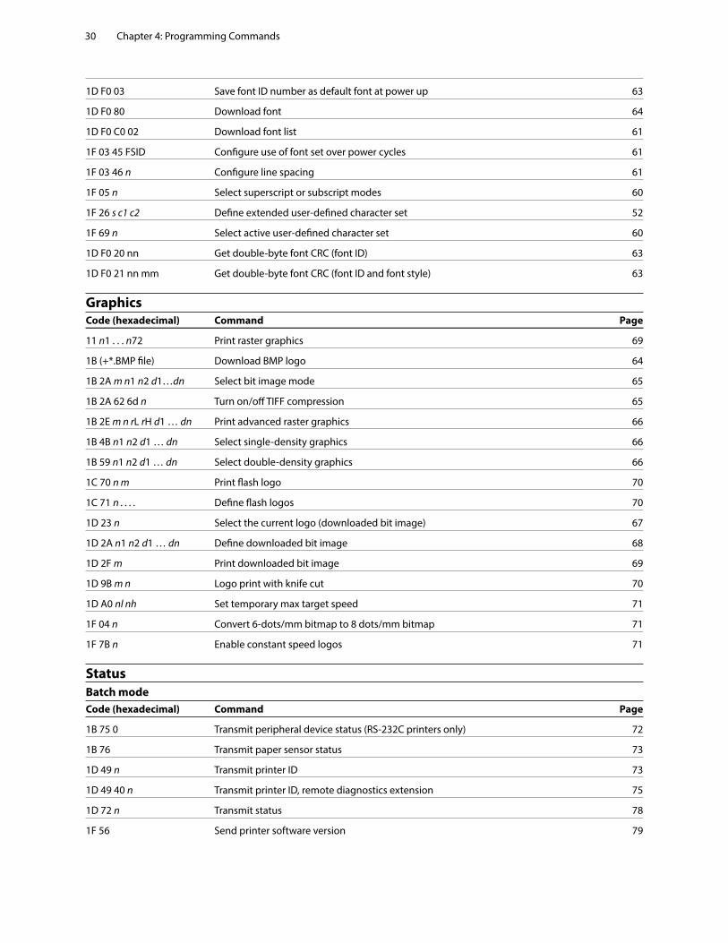
1D F0 03 Save font ID number as default font at power up 63
1D F0 80 Download font 64
1D F0 C0 02 Download font list 61
1F 03 45 FSID Configure use of font set over power cycles 61
1F 03 46 n Configure line spacing 61
1F 05 n Select superscript or subscript modes 60
1F 26 s c1 c2 Define extended user-defined character set 52
1F 69 n Select active user-defined character set 60
1D F0 20 nn Get double-byte font CRC (font ID) 63
1D F0 21 nn mm Get double-byte font CRC (font ID and font style) 63
Graphics Code (hexadecimal) Command Page
11 n1 . . . n72 Print raster graphics 69
1B (+*.BMP file) Download BMP logo 64
1B 2A m n1 n2 d1…dn Select bit image mode 65
1B 2A 62 6d n Turn on/off TIFF compression 65
1B 2E m n rL rH d1 … dn Print advanced raster graphics 66
1B 4B n1 n2 d1 … dn Select single-density graphics 66
1B 59 n1 n2 d1 … dn Select double-density graphics 66
1C 70 n m Print flash logo 70
1C 71 n . . . . Define flash logos 70
1D 23 n Select the current logo (downloaded bit image) 67
1D 2A n1 n2 d1 … dn Define downloaded bit image 68
1D 2F m Print downloaded bit image 69
1D 9B m n Logo print with knife cut 70
1D A0 nl nh Set temporary max target speed 71
1F 04 n Convert 6-dots/mm bitmap to 8 dots/mm bitmap 71
1F 7B n Enable constant speed logos 71
StatusBatch modeCode (hexadecimal) Command Page
1B 75 0 Transmit peripheral device status (RS-232C printers only) 72
1B 76 Transmit paper sensor status 73
1D 49 n Transmit printer ID 73
1D 49 40 n Transmit printer ID, remote diagnostics extension 75
1D 72 n Transmit status 78
1F 56 Send printer software version 79
Chapter 4: Programming Commands 31
Real timeCode (hexadecimal) Command Page
10 04 n Real time status transmission (DLE sequence) 81
10 05 n Real time request to printer (DLE sequence) 83
1D 03 n Real time request to printer (GS sequence) 83
1D 04 n Real time status transmission (GS sequence) 81
1D 05 Real time printer status transmission 84
1F 7A Real time commands disabled 84
Automatic status back / Unsolicited status modeCode (hexadecimal) Command Page
1D 61 n Enable/disable Automatic Status Back (ASB) 85
1D 61 n Select or cancel unsolicited status mode 88
Bar codesCode (hexadecimal) Command Page
1D 48 n Select printing position for HRI characters 96
1D 66 n Select pitch for HRI characters 96
1D 28 6B 04 00 Select model for QR Code 91 00 31 41 n1 n2
1D 28 6B 03 00 31 43 n Set size of module for QR Code 91
1D 28 6B 03 00 31 44 m Set data parsing mode for QR Code 92
1D 28 6B 03 00 31 45 n Select error correction level for QR Code 92
1D 28 6B qL qH Store symbol data for QR Code 92 31 50 30 f1 ... fk
1D 28 6B 03 00 31 51 30 Print symbol data for QR Code 93
1D 28 6B 03 00 31 52 30 Transmit QR code print size 94
1D 68 n Select bar code height 96
1D 6B m d1…dk 00 Print bar code 96 or 1D 6B m n d1…dn
1D 6B FF n Print Multiple Barcodes 98
1D 6B n d1... 00 Print GSI Databar (formerly RSS), null terminated 99
1D 6B m n L n H d1... dn Print GSI Databar (formerly RSS), data length specified 99
1D 70 a b c d e f Select PDF 417 parameters 100
1D 71 a b c d e f L f H Set GSI Databar (formerly RSS) parameters 100
1D 77 n Select bar code width 101
1D 28 6B 05 00 36 42 Set DataMatrix parameters 102 m d1 d1
1D 28 6B 05 00 36 43 n Set DataMatrix module size 103
1D 28 6B pL pH 36 50 30 Store DataMatrix data in symbol storage area 104 d1...dk
1D 28 6B 03 00 36 51 30 Print DataMatrix symbol data in the symbol storage area 105
Chapter 4: Programming Commands32
Page mode Code (hexadecimal) Command Page
0C Print and return to standard mode 106
18 Cancel print data in page mode 106
1B 0C Print data in page mode 106
1B 4C Select page mode 107
1B 53 Select standard mode 108
1B 54 n Select print direction in page mode 108
1B 57 n1, n2…n8 Set print area in page mode 109
1D 24 nL nH Set absolute vertical print position in page mode 110
1D 5C nL nH Set relative vertical print position in page mode 110
MacrosCode (hexadecimal) Command Page
1D 3A Select or cancel macro definition 111
1D 5E r t m Execute macro 111
User data storageCode (hexadecimal) Command Page
1B 27 m a0 a1 a2 d1…dm Write to user data storage 112
1B 34 m a0 a1 a2 Read from user data storage 112
1D 22 n Select memory type (SRAM/flash) where to save logos or user-defined fonts 112
1D 22 55 n1 n2 Flash memory user sectors allocation 113
1D 22 60 n1 Flash object area pack 113
1D 22 61 n1 n2 (n3) Flash object delete 113
1D 22 80 Expanded flash memory allocation 114
1D 22 81 n Select flash area for storing logos and user-defined characters 114
1D 22 90 n Return flash area size 114
1D 40 n Erase user flash sector 62, 115
1D F0 10 n Lock permanent flash area 62, 115
Flash downloadCode (hexadecimal) Command Page
1B 5B 7D Switch to flash download mode 116
1D 0E Erase all flash contents except boot sector 116
1D 0F Return main program flash CRC 117
1D 11 00 00 00 00 d1…dn Download Application 117
1D FF Reset firmware 117
Chapter 4: Programming Commands 33
Settings commandsCode (hexadecimal) Command Page
1F 09 01 06 Save current settings as factory settings 118
1F 09 01 07 Clear active settings and restore factory settings 118
1F 09 01 08 Upload current settings 118
1F 09 01 09 Upload factory settings 118
1F 09 01 0A Download settings 118
Miscellaneous configuration commandsCode (hexadecimal) Command Page
1F 03 00 n Set diagnostics mode 119
1F 03 02 n Enable or disable knife 119
1F 03 07 n Set printer emulation 120
1F 03 09 Reset settings to default values 120
1F 03 0F n Set default font 120
1F 03 10 n Set font size 121
1F 03 1B n Enable or disable Code 128 check digit calculation 121
1F 03 1D n Enable or disable barcode ITF leading zero 121
1F 03 1E n Enable or disable barcode string terminator 121
1F 03 28 n Enable or disable USM canned status 122
1F 03 2C n Send diagnostic page to comm port 122
1F 03 2E n Enable or disable EJ action via operator control 122
1F 03 32 n Set printer ID mode 123
1F 03 33 n Set default code page at power on 123
1F 03 3D n Set Asian ASCII characters to narrow 123
1F 03 47 n Set vertical white space 124
1F 03 52 n fL fH dL dH Set printer tone 124
Chapter 4: Programming Commands34
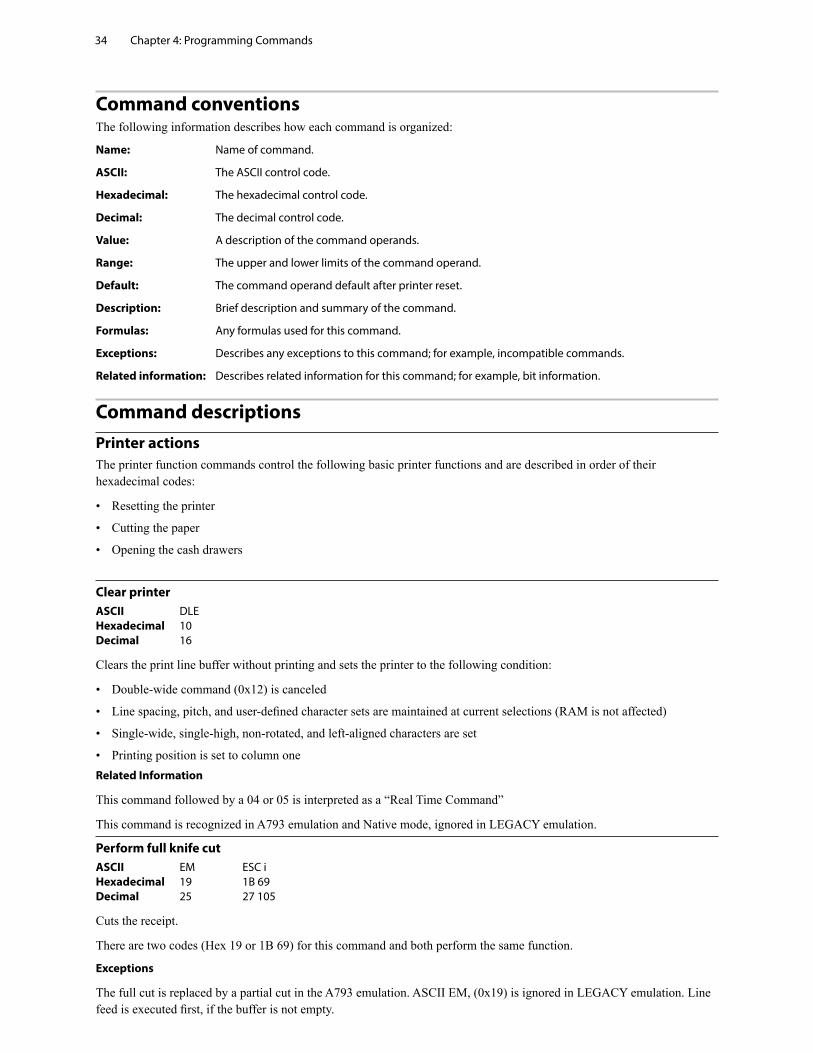
Command conventionsThe following information describes how each command is organized:
Name: Name of command.
ASCII: The ASCII control code.
Hexadecimal: The hexadecimal control code.
Decimal: The decimal control code.
Value: A description of the command operands.
Range: The upper and lower limits of the command operand.
Default: The command operand default after printer reset.
Description: Brief description and summary of the command.
Formulas: Any formulas used for this command.
Exceptions: Describes any exceptions to this command; for example, incompatible commands.
Related information: Describes related information for this command; for example, bit information.
Command descriptionsPrinter actionsThe printer function commands control the following basic printer functions and are described in order of their hexadecimal codes:
• Resetting the printer
• Cutting the paper
• Opening the cash drawers
Clear printerASCII DLE Hexadecimal 10 Decimal 16
Clears the print line buffer without printing and sets the printer to the following condition:
• Double-wide command (0x12) is canceled
• Line spacing, pitch, and user-defined character sets are maintained at current selections (RAM is not affected)
• Single-wide, single-high, non-rotated, and left-aligned characters are set
• Printing position is set to column oneRelated Information
This command followed by a 04 or 05 is interpreted as a “Real Time Command”
This command is recognized in A793 emulation and Native mode, ignored in LEGACY emulation.
Perform full knife cutASCII EM ESC i Hexadecimal 19 1B 69 Decimal 25 27 105
Cuts the receipt.
There are two codes (Hex 19 or 1B 69) for this command and both perform the same function.
Exceptions
The full cut is replaced by a partial cut in the A793 emulation. ASCII EM, (0x19) is ignored in LEGACY emulation. Line feed is executed first, if the buffer is not empty.
Chapter 4: Programming Commands 35
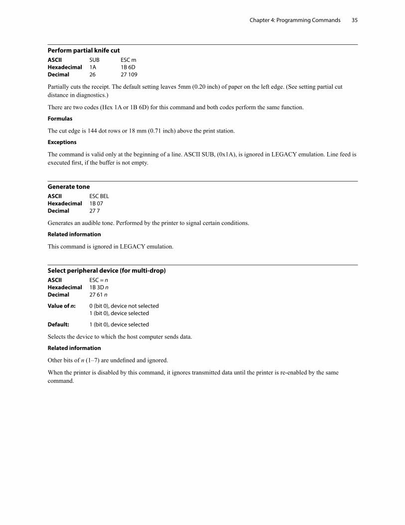
Perform partial knife cutASCII SUB ESC m Hexadecimal 1A 1B 6D Decimal 26 27 109
Partially cuts the receipt. The default setting leaves 5mm (0.20 inch) of paper on the left edge. (See setting partial cut distance in diagnostics.)
There are two codes (Hex 1A or 1B 6D) for this command and both codes perform the same function.
Formulas
The cut edge is 144 dot rows or 18 mm (0.71 inch) above the print station.
Exceptions
The command is valid only at the beginning of a line. ASCII SUB, (0x1A), is ignored in LEGACY emulation. Line feed is executed first, if the buffer is not empty.
Generate toneASCII ESC BEL Hexadecimal 1B 07 Decimal 27 7
Generates an audible tone. Performed by the printer to signal certain conditions.
Related information
This command is ignored in LEGACY emulation.
Select peripheral device (for multi-drop)ASCII ESC = n Hexadecimal 1B 3D n Decimal 27 61 n
Value of n: 0 (bit 0), device not selected 1 (bit 0), device selected
Default: 1 (bit 0), device selected
Selects the device to which the host computer sends data.
Related information
Other bits of n (1–7) are undefined and ignored.
When the printer is disabled by this command, it ignores transmitted data until the printer is re-enabled by the same command.
Chapter 4: Programming Commands36
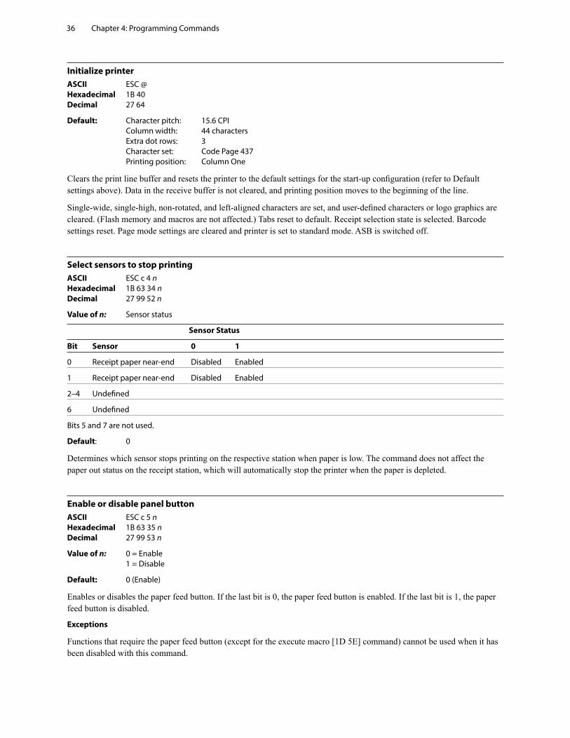
Initialize printerASCII ESC @ Hexadecimal 1B 40 Decimal 27 64
Default: Character pitch: 15.6 CPI Column width: 44 characters Extra dot rows: 3 Character set: Code Page 437 Printing position: Column One
Clears the print line buffer and resets the printer to the default settings for the start-up configuration (refer to Default settings above). Data in the receive buffer is not cleared, and printing position moves to the beginning of the line.
Single-wide, single-high, non-rotated, and left-aligned characters are set, and user-defined characters or logo graphics are cleared. (Flash memory and macros are not affected.) Tabs reset to default. Receipt selection state is selected. Barcode settings reset. Page mode settings are cleared and printer is set to standard mode. ASB is switched off.
Select sensors to stop printingASCII ESC c 4 n Hexadecimal 1B 63 34 n Decimal 27 99 52 n
Value of n: Sensor status
Sensor Status
Bit Sensor 0 1
0 Receipt paper near-end Disabled Enabled
1 Receipt paper near-end Disabled Enabled
2–4 Undefined
6 Undefined
Bits 5 and 7 are not used.
Default: 0
Determines which sensor stops printing on the respective station when paper is low. The command does not affect the paper out status on the receipt station, which will automatically stop the printer when the paper is depleted.
Enable or disable panel buttonASCII ESC c 5 n Hexadecimal 1B 63 35 n Decimal 27 99 53 n
Value of n: 0 = Enable 1 = Disable
Default: 0 (Enable)
Enables or disables the paper feed button. If the last bit is 0, the paper feed button is enabled. If the last bit is 1, the paper feed button is disabled.
Exceptions
Functions that require the paper feed button (except for the execute macro [1D 5E] command) cannot be used when it has been disabled with this command.
Chapter 4: Programming Commands 37
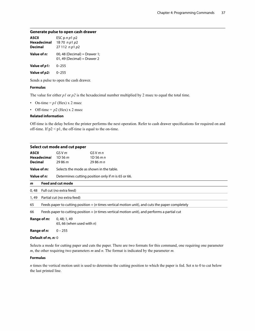
Generate pulse to open cash drawerASCII ESC p n p1 p2 Hexadecimal 1B 70 n p1 p2 Decimal 27 112 n p1 p2
Value of n: 00, 48 (Decimal) = Drawer 1; 01, 49 (Decimal) = Drawer 2
Value of p1: 0–255
Value of p2: 0–255
Sends a pulse to open the cash drawer.
Formulas
The value for either p1 or p2 is the hexadecimal number multiplied by 2 msec to equal the total time.
• On-time = p1 (Hex) x 2 msec
• Off-time = p2 (Hex) x 2 msecRelated information
Off-time is the delay before the printer performs the next operation. Refer to cash drawer specifications for required on and off-time. If p2 < p1, the off-time is equal to the on-time.
Select cut mode and cut paperASCII GS V m GS V m n Hexadecimal 1D 56 m 1D 56 m n Decimal 29 86 m 29 86 m n
Value of m: Selects the mode as shown in the table.
Value of n: Determines cutting position only if m is 65 or 66.
m Feed and cut mode
0, 48 Full cut (no extra feed)
1, 49 Partial cut (no extra feed)
65 Feeds paper to cutting position + (n times vertical motion unit), and cuts the paper completely
66 Feeds paper to cutting position + (n times vertical motion unit), and performs a partial cut
Range of m: 0, 48; 1, 49 65, 66 (when used with n)
Range of n: 0 – 255
Default of m, n: 0
Selects a mode for cutting paper and cuts the paper. There are two formats for this command, one requiring one parameter m, the other requiring two parameters m and n. The format is indicated by the parameter m.
Formulas
n times the vertical motion unit is used to determine the cutting position to which the paper is fed. Set n to 0 to cut below the last printed line.
Chapter 4: Programming Commands38
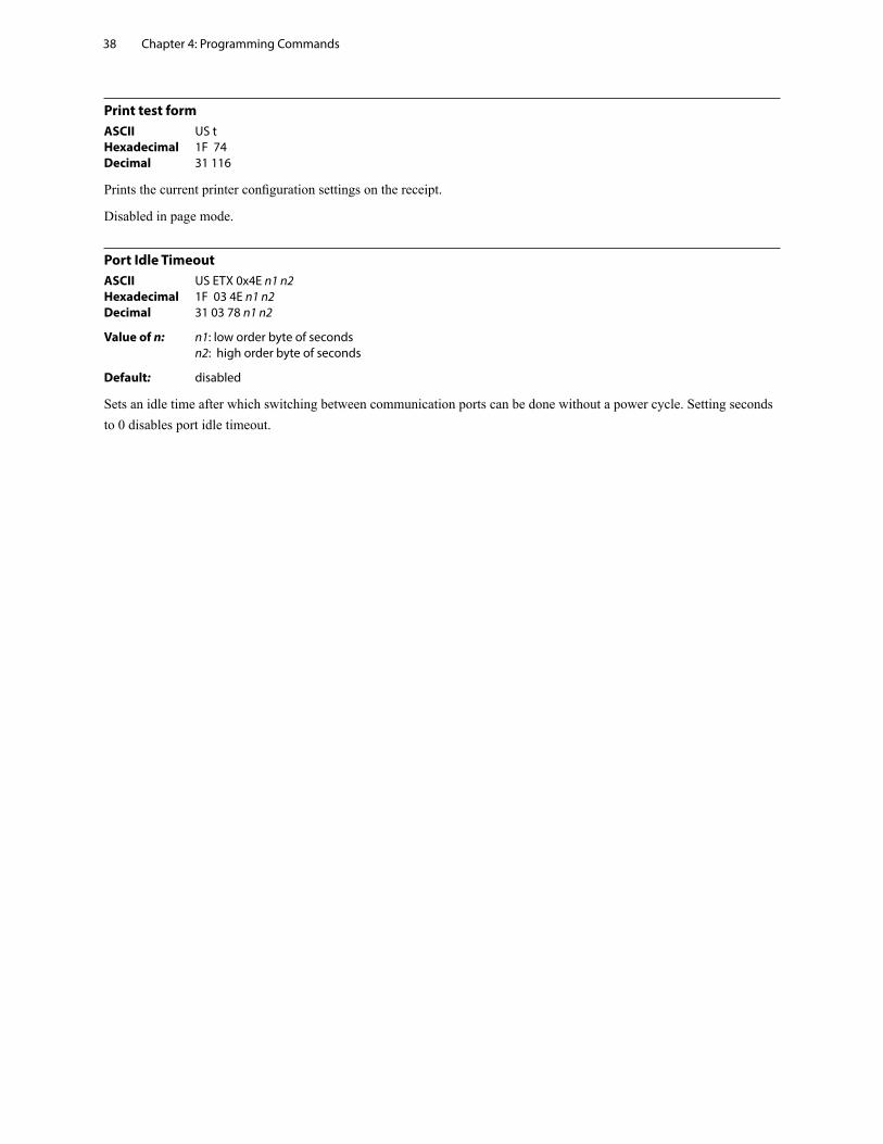
Print test formASCII US t Hexadecimal 1F 74 Decimal 31 116
Prints the current printer configuration settings on the receipt.
Disabled in page mode.
Port Idle TimeoutASCII US ETX 0x4E n1 n2 Hexadecimal 1F 03 4E n1 n2 Decimal 31 03 78 n1 n2
Value of n: n1: low order byte of seconds n2: high order byte of seconds
Default: disabled
Sets an idle time after which switching between communication ports can be done without a power cycle. Setting seconds to 0 disables port idle timeout.
Chapter 4: Programming Commands 39
Print and paper feedThe print and feed commands control printing on the receipt and paper feed by the printer.
Print and feed paper one lineASCII LF Hexadecimal 0A Decimal 10
Prints one line from the buffer and feeds paper one line.
Carriage return/line feed pair prints and feeds only one line.
Print and carriage returnASCII CR Hexadecimal 0D Decimal 13
Prints one line from the buffer and feeds paper one line. The printer can be set through the configuration menu to ignore or use this command. Some applications expect the command to be ignored while others use it as print command.
Related information
See ignoring/using the carriage return in Diagnostics for more information.
This command is ignored in LEGACY emulation.
Carriage return/line feed pair prints and feeds only one line.
Feed n print linesASCII DC4 n Hexadecimal 14 n Decimal 20 n
Value of n: The number of lines to feed at current line height setting.
Range of n: 0–255 in Native mode 0–127 in A793 emulation
Feeds the paper n lines at the current line height without printing. Ignored on receipt if current line is not empty.
Related information
This is ignored in LEGACY emulation and the parameter byte goes into the print buffer.
Chapter 4: Programming Commands40
Feed n dot rowsASCII NAK n Hexadecimal 15 n Decimal 21 n
Value of n: n/203 inch
Range of n: 0–255 in Native mode 0–127 in A793 emulation
Feeds the paper n dot rows (n/8 mm, n/203 inch), without printing. Receipt moves n rows if the print buffer is empty.
Related information
This is ignored in LEGACY emulation and the parameter byte goes into the print buffer.
Add n extra dot rowsASCII SYN n Hexadecimal 16 n Decimal 22 n
Value of n: Number of extra dot rows
Range of n: 0–16
Default: 3 extra dot rows
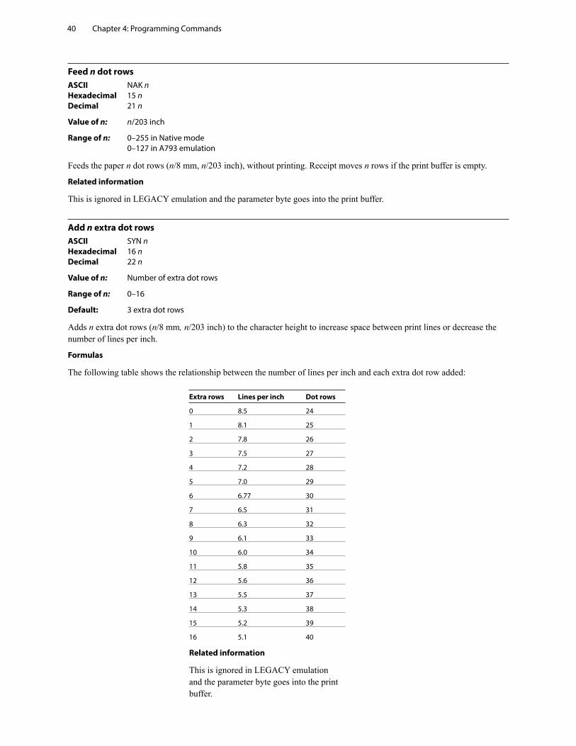
Adds n extra dot rows (n/8 mm, n/203 inch) to the character height to increase space between print lines or decrease the number of lines per inch.
Formulas
The following table shows the relationship between the number of lines per inch and each extra dot row added:
Extra rows Lines per inch Dot rows
0 8.5 24
1 8.1 25
2 7.8 26
3 7.5 27
4 7.2 28
5 7.0 29
6 6.77 30
7 6.5 31
8 6.3 32
9 6.1 33
10 6.0 34
11 5.8 35
12 5.6 36
13 5.5 37
14 5.3 38
15 5.2 39
16 5.1 40
Related information
This is ignored in LEGACY emulation and the parameter byte goes into the print buffer.
Chapter 4: Programming Commands 41
PrintASCII ETB Hexadecimal 17 Decimal 23
Prints one line from the buffer and feeds paper one line. Executes LF on receipt.
Related information
This command is ignored in LEGACY emulation.
Print and feed paperASCII ESC J n Hexadecimal 1B 4A n Decimal 27 74 n
Value of n: n/203 inch in Native mode and Application Compatible Escape Commands emulation mode; n/360 inch in A793 emulation mode
Range of n: 0–255
Prints one line from the buffer and feeds the paper n/8 mm (n/203 inch). The line height equals the character height when n is too small.
If the set horizontal and vertical minimum motion units command (1D 50) is used to change the horizontal and vertical minimum motion units, the parameters of this command (print and feed paper) will be interpreted accordingly.
Related information
For more information, see the description of the set horizontal and vertical minimum motion units command in this document.
Print and feed n linesASCII ESC d n Hexadecimal 1B 64 n Decimal 27 100 n
Range of n: 1–255 (0 is interpreted as 1)
Prints one line from the buffer and feeds paper n lines at the current line height.
Chapter 4: Programming Commands42
Vertical and horizontal positioningThe horizontal positioning commands control the horizontal print positions of characters on the receipt.
The commands describe operation for 80mm paper.
Horizontal tabASCII HT Hexadecimal 09 Decimal 9
Moves the print position to the next tab position set by the set horizontal tab positions (1B 44 n1 n2 ... 00) command. The print position is reset to column one after each line.
Tab treats the left margin as column one, therefore changes to the left margin will move the tab positions.
When no tabs are defined to the right of the current position, or if the next tab is past the right margin, line feed is executed. HT has no effect in page mode. If underline is set, tab spaces skipped by this command are not underlined.
Print initialization sets 32 tabs at column 8, 16, 24…
Set horizontal and vertical minimum motion unitsASCII GS P x y Hexadecimal 1D 50 x y Decimal 29 80 x y
Value of x: Horizontal Range of x: 0 – 255 Default of x: 203 Value of y: Vertical Range of y: 0 – 255 Default of y: 203
Sets the horizontal and vertical motion units to 1/x inch and 1/y inch respectively, until the printer is initialized, reset, or powered off.
When x or y is set to 0, the default setting for that motion unit is used. When combined with other commands, the calculated result is truncated to the minimum value of the mechanical pitch.
Mode Commands using x Commands using y
Standard 1B 20, 1B 24, 1B 5C, 1D 4C, 1D 57 1B 33, 1B 4A, 1B 4B, 1D 56
Page (upper left or lower right) 1B 20, 1B 24, 1B 57, 1B 5C, [1C 53] 1B 33, 1B 4A, 1B 4B, 1B 57, 1D 24, 1D 56, 1D 5C
Page (upper right or lower left) 1B 33, 1B 4A, 1B 4B, 1B 57, 1D 24, 1D 5C 1B 20, 1B 24, 1B 57, 1B 5C, [1C 53], 1D 56
Set columnASCII ESC DC4 n Hexadecimal 1B 14 n Decimal 27 20 n
Value of n: 1 – 44 = Standard pitch 1 – 56 = Compressed pitch
Default of n: 1
Prints the first character of the next print line in column n. It must be sent for each line not printed at column one. The value of n is set to one after each line.
Exceptions
This command cannot be used with single- or double-density graphics.
Related information
This is ignored in LEGACY emulation and the parameter byte goes into the print buffer.
Chapter 4: Programming Commands 43
Set absolute starting positionASCII ESC $ nL nH Hexadecimal 1B 24 nL nH Decimal 27 36 nL nH
Value of n: n = Number of dots to be moved from the beginning of the line. nL = Remainder after dividing n by 256. nH = Integer after dividing n by 256.
The values for nL and nH are two bytes in low byte, high byte word orientation.
Sets the print starting position to the specified number of dots (up to the right margin) from the beginning of the line. The print starting position is reset to the first column after each line.
Formulas
The example shows how to calculate 280 dots as the absolute starting position.
28 × 10 = 280 dots (beginning of column 29) 280/256 = 1, remainder of 24 nL = 24 nH = 1
Related information
If the set horizontal and vertical motion units command (1D 50) is used to change the horizontal and vertical minimum motion unit, the parameters of the set relative print position command will be interpreted accordingly. For more information, see the description of the command set horizontal and vertical minimum motion units command (1D 50) in this document.
Compatibility information (H300 receipt vs. A793 receipt)
There is a difference in the normal behavior of this command in A793 emulation mode as compared to the original A793. The difference exists when the command is used to move to the left. The A793 processes the whole print string prior to putting it in the buffer for the print head. This method of processing allows the A793 to backup in the print string and replace characters and their associated attributes when a “Set relative print position” command instructs the printer to move the print position to the left.
In order to improve the speed of printing, the H300 moves the data into a buffer for the printhead when it receives it. When the “Set relative print position” command contains a move to the left, this causes the new data to overstrike the previous data. This behavior can be used to an application’s advantage to provide the ability to create compound characters on the receipt station.
This command also functions differently in the A793 emulation when used in graphics:
n × 2 = Number of dots to be moved from the beginning of the line when this command is followed by a graphics command.
Set vertical line spacing to 1/6 inchASCII ESC 2 Hexadecimal 1B 32 Decimal 27 50
Default: 3.33 mm (0.13 inch)
Sets the default line spacing to 4.25 mm (1/6 of an inch).
This is set independently of the vertical motion unit (see 1D 50 x y).
Chapter 4: Programming Commands44
Set vertical line spacingASCII ESC 3 n Hexadecimal 1B 33 n Decimal 27 51 n
Value of n: n/406 inch in Native mode n/360 inch in A793 emulation mode n/203 inch in Application Compatible Escape Commands emulation mode
Range of n: 0-255
Default: 3.37 mm (0.13 inch)
Sets the line spacing to n/16 mm (n/406 inch). Note: sending 1B 32 will overwrite this setting.
The minimum line spacing is 8.5 lines per inch. The line spacing equals the character height when n is too small.
If the set horizontal and vertical minimum motion units command (1D 50) is used to change the horizontal and vertical minimum motion unit, the parameters of this command (set line spacing) will be interpreted accordingly.
Related information
For more information, see the description of the set horizontal and vertical minimum motion units command in this document.
In addition, see “Configure line spacing” (1F 03 46 n).
Set horizontal tab positionsASCII ESC D n1…nk NUL Hexadecimal 1B 44 n1…nk 00 Decimal 27 68 n1…nk 0
Value of n: 1 - number of columns in selected pitch (typically 44 for standard, 56 for compressed, but this is affected by paper width, fonts and margins)
Value of k: 0 - 32 (decimal)
Default: n = 8, 16, 24, 32, ... (Every eight characters for the default font set)
Sets a horizontal tab to n columns from the beginning of the line, where k indicates the number of horizontal tab positions to be set.
The horizontal tab position is stored as a value of [character width x n], measured from the beginning of the line. The character width should be set before using this command. The setting of the horizontal tab positions will not be changed if the character width is changed after sending this command.
A maximum of 32 horizontal tab positions can be set. Data exceeding 32 horizontal tab positions are processed as normal data.
This command cancels any previous horizontal tab settings.
n1-nk should be listed in ascending order, followed by a 00. 1b 44 00 changes all horizontal tab positions back to their default positions.
Horizontal tab position settings are effective until the printer is reset, the power is turned off, or a 1b 40 command is sent.
Print position advances to the next tab position on receipt by a 09h.
The horizontal tab position is affected by changes to the left margin.
Chapter 4: Programming Commands 45
Set relative print positionASCII ESC \ n1 n2 Hexadecimal 1B 5C n1 n2 Decimal 27 92 n1 n2
Value of n:
To move the relative starting position right of the current position:
n = Number of dots to be moved right of the current position n1 = Remainder after dividing n by 256 n2 = Integer after dividing n by 256
The values for n1 and n2 are two bytes in low byte, high byte word orientation.
To move the relative starting position left of the current position:
n = Number of dots to be moved left of the current position n1 = Remainder after dividing (65,536-n) by 256 n2 = Integer after dividing (65,536-n) by 256
The values for n1 and n2 are two bytes in low byte, high byte word orientation.
Moves the print starting position the specified number of dots either right (up to the right margin) or left (up to the left margin) of the current position. The print starting position is reset to the first column after each line.
Formulas
To move to the left: Determine the value of n by multiplying the number of columns to move left of the current position by 10 (standard) or 8 (compressed) pitch. The example shows how to set the relative position two columns in standard pitch (10 dots per column) to the left of the current position.
2 × 10 = 20 dots (two columns to be moved left of the current position) 65,536–20 = 65516 65,516/256 = 255, remainder of 236 n1 = 236, n2 = 255
To move to the right: Determine the value of n by multiplying the number of columns to move right of the current position by 10 (standard) or 8 (compressed) pitch. The example shows how to set the relative position two columns in standard pitch (10 dots per column) to the right of the current position.
2 × 10 = 20 dots (two columns to be moved left of the current position) 20/256 = 0, remainder of 20 n1 = 20, n2 = 0
Related information
If the set horizontal and vertical minimum motion units command (1D 50) is used to change the horizontal and vertical minimum motion unit, the parameters of this command (set relative print position) will be interpreted accordingly. In page mode, upper left or lower right uses the horizontal motion unit, and upper right or lower left uses the vertical motion unit. For more information, see the description of the set horizontal and vertical minimum motion units command (1D 50) in this document.
If underline is set, spaces skipped by this command are not underlined.
Compatibility information (H300 receipt vs. A793 receipt)
There is a difference in the normal behavior of this command in A793 emulation mode as compared to the original A793. The difference exists when the command is used to move to the left. The A793 processes the whole print string prior to putting it in the buffer for the print head. This method of processing allows the A793 to backup in the print string and replace characters and their associated attributes when a “Set relative print position” command instructs the printer to move the print position to the left.
Continued...
Chapter 4: Programming Commands46
In order to improve the speed of printing, the H300 moves the data into a buffer for the printhead when it receives it. When the “Set relative print position” command contains a move to the left, this causes the new data to overstrike the previous data. This behavior can be used to an application’s advantage to provide the ability to create compound characters on the receipt station.
This command also functions differently in the A793 emulation when used in graphics:
n × 2 = Number of dots to be moved from the beginning of the line when this command is followed by a graphic command.
Select justificationASCII ESC a n Hexadecimal 1B 61 n Decimal 27 97 n
Value of n: 0, 48 = Left aligned 1, 49 = Center aligned 2, 50 = Right aligned
Range of n: 0–2, 48–50
Default: 0 (Left aligned)
Specifies the alignment of characters, graphics, logos, and bar codes on the receipt station in the print area specified by 1D 4C and 1D 57 according to the above table, until the printer is initialized, reset, or powered off. This justifies an entire line.
Related information
On the LEGACY emulation printer, this command is valid only at the beginning of a line.
Range of n on A793 is 0–255 using low 2 bits only: 00 left aligned 01 center 10 right aligned 11 center
Set left marginASCII GS L nL nH Hexadecimal 1D 4C nL nH Decimal 29 76 nL nH
Range of nL: 0–255
Range of nH: 0–255
Default: 576 dots (the maximum printable area)
Formulas Sets the left margin of the printing area until the printer is initialized, reset, or powered off. The left margin is set to ((nH X 256) + nL) times horizontal motion unit) inches. The horizontal motion units are set by the set horizontal and vertical minimum motion units command (1D 50), described in this manual. If the horizontal motion unit is changed after changing left margin, the left margin setting is not changed.
The width of the printing area is set by the set printing area width command (1D 57), which follows this command. See the set printing area width command in this document for a description of that command.
If the setting exceeds the printable area, the maximum value of the printable area is used. The maximum printable area is 576 dots. See the illustration.
To set the left margin to one inch at the default horizontal motion unit of 1/203 inches, send the four-byte string: GS L 203 0
Or, to set the left margin to two inches at the default horizontal motion unit of 1/203 units per inch, send the four-byte string: GS L 150 1
Where 2 inches = 406/203, and 406 = (1 × 256) + 150.
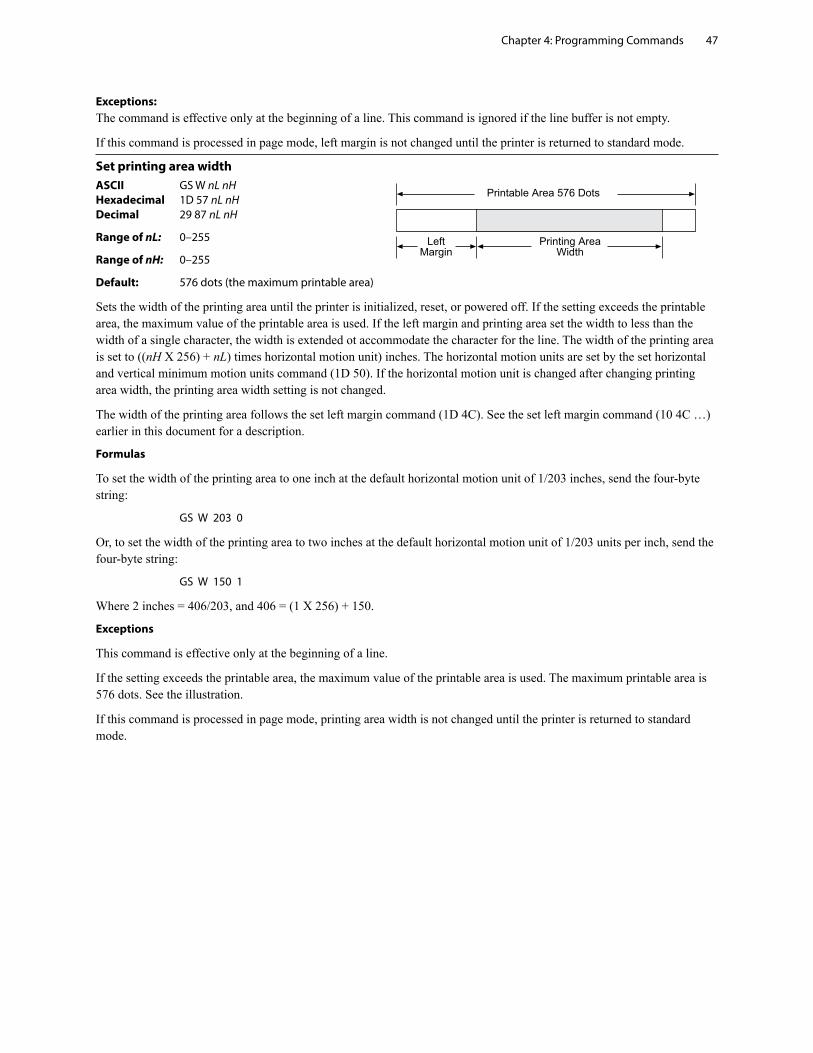
Chapter 4: Programming Commands 47
Exceptions: The command is effective only at the beginning of a line. This command is ignored if the line buffer is not empty.
If this command is processed in page mode, left margin is not changed until the printer is returned to standard mode.
Set printing area widthASCII GS W nL nH Hexadecimal 1D 57 nL nH Decimal 29 87 nL nH
Range of nL: 0–255
Range of nH: 0–255
Default: 576 dots (the maximum printable area)
Sets the width of the printing area until the printer is initialized, reset, or powered off. If the setting exceeds the printable area, the maximum value of the printable area is used. If the left margin and printing area set the width to less than the width of a single character, the width is extended ot accommodate the character for the line. The width of the printing area is set to ((nH X 256) + nL) times horizontal motion unit) inches. The horizontal motion units are set by the set horizontal and vertical minimum motion units command (1D 50). If the horizontal motion unit is changed after changing printing area width, the printing area width setting is not changed.
The width of the printing area follows the set left margin command (1D 4C). See the set left margin command (10 4C …) earlier in this document for a description.
Formulas
To set the width of the printing area to one inch at the default horizontal motion unit of 1/203 inches, send the four-byte string:
GS W 203 0
Or, to set the width of the printing area to two inches at the default horizontal motion unit of 1/203 units per inch, send the four-byte string:
GS W 150 1
Where 2 inches = 406/203, and 406 = (1 X 256) + 150.
Exceptions
This command is effective only at the beginning of a line.
If the setting exceeds the printable area, the maximum value of the printable area is used. The maximum printable area is 576 dots. See the illustration.
If this command is processed in page mode, printing area width is not changed until the printer is returned to standard mode.
�����������������������
�� �������
����������������
Chapter 4: Programming Commands48
Text characteristics commandsThese commands control what the printed information looks like, selection of character sets, definition of custom-defined characters, and setting of margins. The commands are described in order of their hexadecimal codes.
The commands describe operation for 80mm paper.
Select double-wide charactersASCII DC2 Hexadecimal 12 Decimal 18
Prints double-wide characters. The printer is reset to single-wide mode after a line has been printed or the clear printer (0x10) command is received. Double-wide characters may be used in the same line with single-wide characters.
Exceptions
Double-wide characters may not be used in the same line with single or double-density graphics.
Related information
This command is ignored in LEGACY emulation.
Select single-wide charactersASCII DC3 Hexadecimal 13 Decimal 19
Prints single-wide characters. Single-wide characters may be used in the same line with double-wide characters.
Exceptions
Single-wide characters may not be used in the same line with single or double-density graphics.
Related information
This command is ignored in LEGACY emulation.
Select 90 degree counter-clockwise rotated printASCII ESC DC2 Hexadecimal 1B 12 Decimal 27 18
Rotates characters 90 degrees counter-clockwise. The command remains in effect until the printer is reset or until a clear printer (0x10), select or cancel upside down print (1b 7b) or cancel rotated print (1b 56) command is received.
Exceptions
This command is valid only at the beginning of a line.
Rotated print and non-rotated print characters cannot be used together in the same line.
Related information
See “Summary of rotated printing” in this document.
This command is ignored in LEGACY emulation.
Chapter 4: Programming Commands 49
Select pitch (column width)ASCII ESC SYN n Hexadecimal 1B 16 n Decimal 27 22 n
Value of n: 0 = Standard pitch 1 = Compressed pitch
Default: 0 (Standard pitch)
Selects the character pitch for a print line.
Formulas
The following table provides the print characteristics for both pitches on the receipt station.
Pitch Columns, CPI 80mm Paper
Standard 44 15.6
Compressed 56 20.3
Related information
Look in Chapter 3: Programming the Printer, “Character appearance” for a description of both pitches.
This command and the select print modes command (1B 21 n) affect pitch selection.
This is ignored in LEGACY emulation and the parameter byte goes into the print buffer.
Set right-side character spacingASCII ESC SP n Hexadecimal 1B 20 n Decimal 27 32 n
Range of n: 0 – 32 (decimal)
Default: 0
The units of horizontal and vertical motion are specified by the set horizontal and vertical minimum motion units (1D 50 …) command. Changes in the horizontal or vertical units do not affect the current right side character spacing. When the horizontal or vertical motion unit is changed by the set horizontal and vertical minimum motion units (1D 50 …) command the value must be in even units and not less than the minimum amount of horizontal movement.
In standard mode the horizontal motion unit is used.
In page mode the horizontal or vertical motion unit differs and depends on the starting position of the printable area. When the starting printing position is the upper left or lower right of the printable area (set by select print direction in page mode, 1B 54 n) the horizontal motion unit (x) is used. When the starting printing position is the upper right or lower left of the printable area (set by select print direction in page mode, 1B 54 n) the vertical motion unit (y) is used.
This command can be set independently in standard mode and in page mode.
When characters are enlarged, the right-side character spacing is a multiple of its normal value (ex. spacing for double-width mode is twice the normal value).
Related information
This command does not affect HRI characters.
This is ignored in LEGACY emulation and the parameter byte goes into the print buffer. In the A793 emulation, the command and parameter byte are ignored.
Chapter 4: Programming Commands50
Select print modeASCII ESC ! n Hexadecimal 1B 21 n Decimal 27 33 n
Value of n: Pitch selection (standard, compressed, double high, or double wide.)
Value of n
Bit1 Function 0 1
Bit 0 Pitch2 Standard Compressed (See chart below) pitch pitch
Bit 3 Emphasized mode Canceled Set
Bit 4 Double-high Canceled Set
Bit 5 Double-wide Canceled Set
Bit 7 Underlined mode Canceled Set
1Bits 1, 2 and 6 are not used.
2Standard and compressed pitch cannot be used together in the same line.
Default: 0 (for bits 0, 3, 4, 5, 7)
This command and select pitch (column width) command (1B 16 n) affect pitch selection.
Pitch Columns, CPI 80 mm paper
Standard 44 15.6
Compressed 56 20.3
Selects the print mode: standard, compressed, emphasized, underlined, double-high, or double-wide until the printer is initialized, reset, or powered off.
When double-height mode is enabled for some charactes on a line, all characters are aligned on the baseline. When double-width mode is enabled, characters are enlarged to the right, starting from the left side of the character.
Exceptions
Refer to the table in other column for exceptions.
This command does not affect HRI characters.
Related information
In standard mode, when double-height mode is selected, the character is enlarged in the paper feed direction, and when double-width mode is selected it is enlarged perpendicular to the paper feed direction. In 90° clockwise-rotated mode, the relationship between double-height and double-width is reversed. In page mode, double-height and double-width are on the character orientation.
Look in Chapter 3: Programming the Printer, “Character appearance” for a description of standard and compressed character pitches.
The bits in this command perform the same function as the stand-alone functions:
1B 16 n Select pitch 1B 45 n Emphasized 1B 47 n Double-strike 12 Double-wide 13 Single-wide 1B 2D n Underline
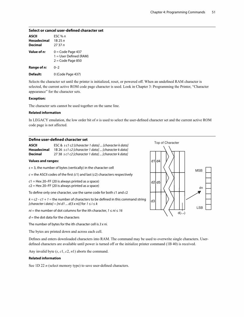
Chapter 4: Programming Commands 51
Select or cancel user-defined character setASCII ESC % n Hexadecimal 1B 25 n Decimal 27 37 n
Value of n: 0 = Code Page 437 1 = User Defined (RAM) 2 = Code Page 850
Range of n: 0–2
Default: 0 (Code Page 437)
Selects the character set until the printer is initialized, reset, or powered off. When an undefined RAM character is selected, the current active ROM code page character is used. Look in Chapter 3: Programming the Printer, “Character appearance” for the character sets.
Exception:
The character sets cannot be used together on the same line.
Related information
In LEGACY emulation, the low order bit of n is used to select the user-defined character set and the current active ROM code page is not affected.
Define user-defined character setASCII ESC & s c1 c2 [character 1 data] ... [character k data] Hexadecimal 1B 26 s c1 c2 [character 1 data] ... [character k data] Decimal 27 38 s c1 c2 [character 1 data] ... [character k data]
Values and ranges:
s = 3, the number of bytes (vertically) in the character cell
c = the ASCII codes of the first (c1) and last (c2) characters respectively
c1 = Hex 20–FF (20 is always printed as a space) c2 = Hex 20–FF (20 is always printed as a space)
To define only one character, use the same code for both c1 and c2
k = c2 – c1 + 1 = the number of characters to be defined in this command string [character i data] = [ni d1 ... d(3 x ni)] for 1 ≤ i ≤ k
ni = the number of dot columns for the ith character, 1 ≤ ni ≤ 16
d = the dot data for the characters
The number of bytes for the ith character cell is 3 x ni.
The bytes are printed down and across each cell.
Defines and enters downloaded characters into RAM. The command may be used to overwrite single characters. User-defined characters are available until power is turned off or the initialize printer command (1B 40) is received.
Any invalid byte (s, c1, c2, n1) aborts the command.
Related information
See 1D 22 n (select memory type) to save user-defined characters.
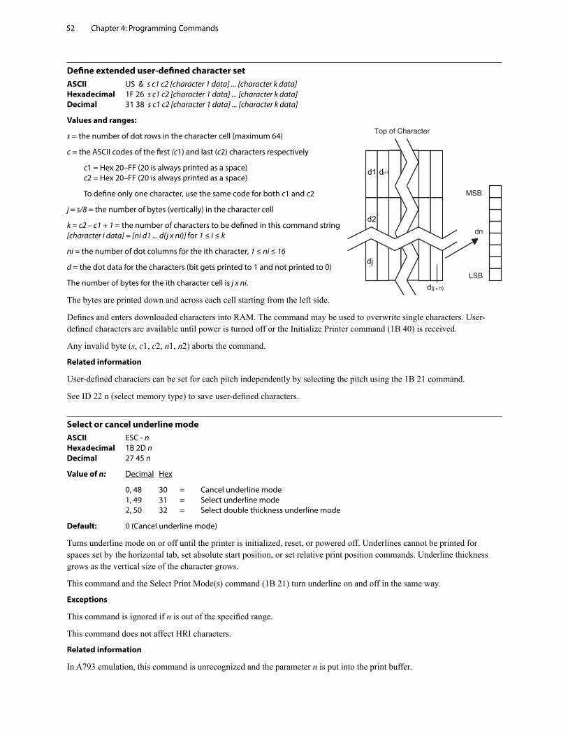
Chapter 4: Programming Commands52
Define extended user-defined character setASCII US & s c1 c2 [character 1 data] ... [character k data] Hexadecimal 1F 26 s c1 c2 [character 1 data] ... [character k data] Decimal 31 38 s c1 c2 [character 1 data] ... [character k data]
Values and ranges:
s = the number of dot rows in the character cell (maximum 64)
c = the ASCII codes of the first (c1) and last (c2) characters respectively
c1 = Hex 20–FF (20 is always printed as a space) c2 = Hex 20–FF (20 is always printed as a space)
To define only one character, use the same code for both c1 and c2
j = s/8 = the number of bytes (vertically) in the character cell
k = c2 – c1 + 1 = the number of characters to be defined in this command string [character i data] = [ni d1 ... d(j x ni)] for 1 ≤ i ≤ k
ni = the number of dot columns for the ith character, 1 ≤ ni ≤ 16
d = the dot data for the characters (bit gets printed to 1 and not printed to 0)
The number of bytes for the ith character cell is j x ni.
The bytes are printed down and across each cell starting from the left side.
Defines and enters downloaded characters into RAM. The command may be used to overwrite single characters. User-defined characters are available until power is turned off or the Initialize Printer command (1B 40) is received.
Any invalid byte (s, c1, c2, n1, n2) aborts the command.
Related information
User-defined characters can be set for each pitch independently by selecting the pitch using the 1B 21 command.
See ID 22 n (select memory type) to save user-defined characters.
Select or cancel underline modeASCII ESC - n Hexadecimal 1B 2D n Decimal 27 45 n
Value of n: Decimal Hex
0, 48 30 = Cancel underline mode 1, 49 31 = Select underline mode 2, 50 32 = Select double thickness underline mode
Default: 0 (Cancel underline mode)
Turns underline mode on or off until the printer is initialized, reset, or powered off. Underlines cannot be printed for spaces set by the horizontal tab, set absolute start position, or set relative print position commands. Underline thickness grows as the vertical size of the character grows.
This command and the Select Print Mode(s) command (1B 21) turn underline on and off in the same way.
Exceptions
This command is ignored if n is out of the specified range.
This command does not affect HRI characters.
Related information
In A793 emulation, this command is unrecognized and the parameter n is put into the print buffer.
Chapter 4: Programming Commands 53
Copy character set from ROM to RAMASCII ESC : 0 0 0 Hexadecimal 1B 3A 30 30 30 Decimal 27 58 0 0 0
Default: Current active ROM code page
Copies characters in the active ROM set to RAM. Use this command to re-initialize the user-defined character set. Code page 437 is copied by default at initialization.
This command is ignored if current font is the user font.
Related information
To modify characters in one of the character set variations, such as rotated print, select one of the rotated print commands, copy to RAM, then use the define user-defined character set command (1B 26).
Cancel user-defined characterASCII ESC ? n Hexadecimal 1B 3F n Decimal 27 63 n
Value of n: Specified character code.
Range of n: 32–255
Cancels the pattern defined for the character code specified by n. After the user-defined character is canceled, the corresponding pattern from current active ROM code page is printed.
User-defined characters can be cancelled for each pitch independently by selecting the pitch using the 1B 21 command.
Exceptions
This command is ignored if n is out of range or if the user-defined character is not defined.
Select or cancel emphasized modeASCII ESC E n Hexadecimal 1B 45 n Decimal 27 69 n
Value of n: 0 (bit 0) not selected 1 (bit 0) selected
(When 0 and 1 are the least significant bit, LSB)
Range of n: 0-255
Default: 0 (Off)
Starts or stops emphasized printing until the printer is initialized, reset, or powered off. The printer is reset to the standard print mode after a clear printer (0x10) command is received.
Exceptions
Only the lowest bit of n is effective. Emphasized printing cannot be used with bit-images or downloaded bit-images.
This command does not affect HRI characters.
Related information
This command and the select print mode(s) command (1B 21) function identically. They should have the same setting when used together.
In A793 emulation, this command is unrecognized and the parameter byte is put into the print buffer.
Chapter 4: Programming Commands54
Select or cancel double-strikeASCII ESC G n Hexadecimal 1B 47 n Decimal 27 71 n
Value of n: 0 = Off 1 = On
(When 0 and 1 are the least significant bit, LSB)
Default: 0 (Off)
Turns double-strike mode on or off until the printer is initialized, reset, or powered off. Identical to emphasized mode. The printer is reset to the standard print mode after a clear printer (0x10) command is received.
Exceptions
Only the lowest bit of n is effective. The settings do not apply in page mode. However they can be set or cleared in page mode.
Double-strike printing cannot be used with bit-images or downloaded bit-images.
This command does not affect HRI characters.
Related information
This command and the select print mode(s) command (1B 21) function identically. They should have the same setting when used together.
In A793 emulation, this command is unrecognized and the parameter byte is put into the print buffer.
Select or cancel italic printASCII ESC I n Hexadecimal 1B 49 n Decimal 27 73 n
Value of n: 0 = Off 1 = On
(When 0 and 1 are the least significant bit, LSB)
Default: 0 (Off)
Turns italic print mode on or off. The printer is reset to the standard print mode after a clear printer (0x10) command is received.
Exceptions
Only the lowest bit of n is valid.
Related information
This command is recognized in Native mode.
In A793 and LEGACY emulations, the parameter byte is put into the buffer.
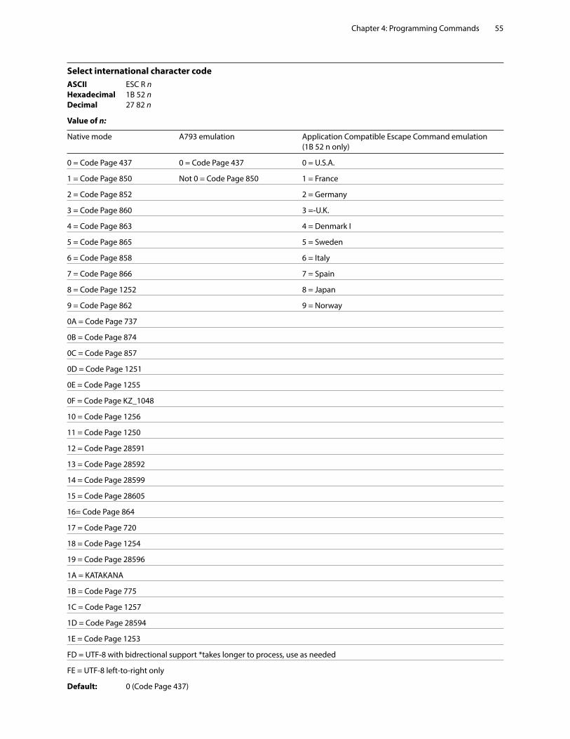
Chapter 4: Programming Commands 55
Select international character code ASCII ESC R n Hexadecimal 1B 52 n Decimal 27 82 n
Value of n:
Native mode A793 emulation Application Compatible Escape Command emulation (1B 52 n only)
0 = Code Page 437 0 = Code Page 437 0 = U.S.A.
1 = Code Page 850 Not 0 = Code Page 850 1 = France
2 = Code Page 852 2 = Germany
3 = Code Page 860 3 =-U.K.
4 = Code Page 863 4 = Denmark I
5 = Code Page 865 5 = Sweden
6 = Code Page 858 6 = Italy
7 = Code Page 866 7 = Spain
8 = Code Page 1252 8 = Japan
9 = Code Page 862 9 = Norway
0A = Code Page 737
0B = Code Page 874
0C = Code Page 857
0D = Code Page 1251
0E = Code Page 1255
0F = Code Page KZ_1048
10 = Code Page 1256
11 = Code Page 1250
12 = Code Page 28591
13 = Code Page 28592
14 = Code Page 28599
15 = Code Page 28605
16= Code Page 864
17 = Code Page 720
18 = Code Page 1254
19 = Code Page 28596
1A = KATAKANA
1B = Code Page 775
1C = Code Page 1257
1D = Code Page 28594
1E = Code Page 1253
FD = UTF-8 with bidrectional support *takes longer to process, use as needed
FE = UTF-8 left-to-right only
Default: 0 (Code Page 437)
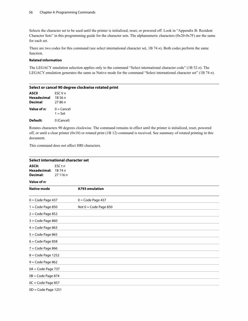
Chapter 4: Programming Commands56
Selects the character set to be used until the printer is initialized, reset, or powered off. Look in “Appendix B: Resident Character Sets” in this programming guide for the character sets. The alphanumeric characters (0x20-0x7F) are the same for each set.
There are two codes for this command (see select international character set, 1B 74 n). Both codes perform the same function.
Related information
The LEGACY emulation selection applies only to the command “Select international character code” (1B 52 n). The LEGACY emulation generates the same as Native mode for the command “Select international character set” (1B 74 n).
Select or cancel 90 degree clockwise rotated printASCII ESC V n Hexadecimal 1B 56 n Decimal 27 86 n
Value of n: 0 = Cancel 1 = Set
Default: 0 (Cancel)
Rotates characters 90 degrees clockwise. The command remains in effect until the printer is initialized, reset, powered off, or until a clear printer (0x10) or rotated print (1B 12) command is received. See summary of rotated printing in this document.
This command does not affect HRI characters.
Select international character set ASCII: ESC t n Hexadecimal: 1B 74 n Decimal: 27 116 n
Value of n:
Native mode A793 emulation
0 = Code Page 437 0 = Code Page 437
1 = Code Page 850 Not 0 = Code Page 850
2 = Code Page 852
3 = Code Page 860
4 = Code Page 863
5 = Code Page 865
6 = Code Page 858
7 = Code Page 866
8 = Code Page 1252
9 = Code Page 862
0A = Code Page 737
0B = Code Page 874
0C = Code Page 857
0D = Code Page 1251
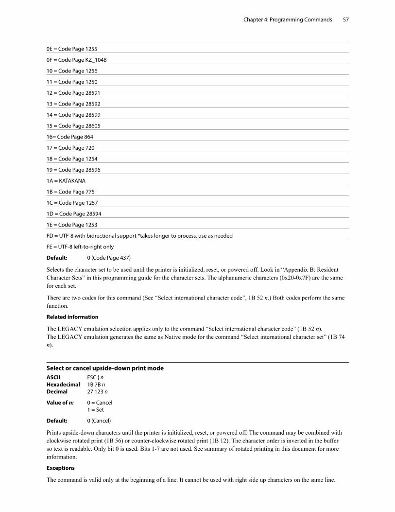
Chapter 4: Programming Commands 57
0E = Code Page 1255
0F = Code Page KZ_1048
10 = Code Page 1256
11 = Code Page 1250
12 = Code Page 28591
13 = Code Page 28592
14 = Code Page 28599
15 = Code Page 28605
16= Code Page 864
17 = Code Page 720
18 = Code Page 1254
19 = Code Page 28596
1A = KATAKANA
1B = Code Page 775
1C = Code Page 1257
1D = Code Page 28594
1E = Code Page 1253
FD = UTF-8 with bidrectional support *takes longer to process, use as needed
FE = UTF-8 left-to-right only
Default: 0 (Code Page 437)
Selects the character set to be used until the printer is initialized, reset, or powered off. Look in “Appendix B: Resident Character Sets” in this programming guide for the character sets. The alphanumeric characters (0x20-0x7F) are the same for each set.
There are two codes for this command (See “Select international character code”, 1B 52 n.) Both codes perform the same function.
Related information
The LEGACY emulation selection applies only to the command “Select international character code” (1B 52 n). The LEGACY emulation generates the same as Native mode for the command “Select international character set” (1B 74 n).
Select or cancel upside-down print modeASCII ESC { n Hexadecimal 1B 7B n Decimal 27 123 n
Value of n: 0 = Cancel 1 = Set
Default: 0 (Cancel)
Prints upside-down characters until the printer is initialized, reset, or powered off. The command may be combined with clockwise rotated print (1B 56) or counter-clockwise rotated print (1B 12). The character order is inverted in the buffer so text is readable. Only bit 0 is used. Bits 1-7 are not used. See summary of rotated printing in this document for more information.
Exceptions
The command is valid only at the beginning of a line. It cannot be used with right side up characters on the same line.
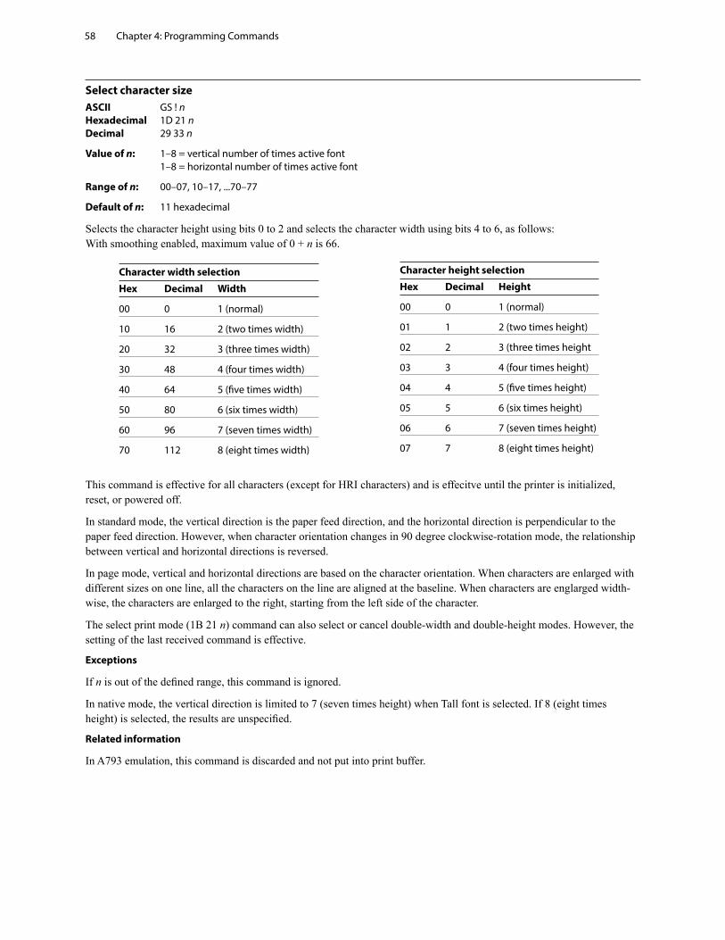
Chapter 4: Programming Commands58
Select character sizeASCII GS ! n Hexadecimal 1D 21 n Decimal 29 33 n
Value of n: 1–8 = vertical number of times active font 1–8 = horizontal number of times active font
Range of n: 00–07, 10–17, ...70–77
Default of n: 11 hexadecimal
Selects the character height using bits 0 to 2 and selects the character width using bits 4 to 6, as follows: With smoothing enabled, maximum value of 0 + n is 66.
Character width selection
Hex Decimal Width
00 0 1 (normal)
10 16 2 (two times width)
20 32 3 (three times width)
30 48 4 (four times width)
40 64 5 (five times width)
50 80 6 (six times width)
60 96 7 (seven times width)
70 112 8 (eight times width)
Character height selection
Hex Decimal Height
00 0 1 (normal)
01 1 2 (two times height)
02 2 3 (three times height
03 3 4 (four times height)
04 4 5 (five times height)
05 5 6 (six times height)
06 6 7 (seven times height)
07 7 8 (eight times height)
This command is effective for all characters (except for HRI characters) and is effecitve until the printer is initialized, reset, or powered off.
In standard mode, the vertical direction is the paper feed direction, and the horizontal direction is perpendicular to the paper feed direction. However, when character orientation changes in 90 degree clockwise-rotation mode, the relationship between vertical and horizontal directions is reversed.
In page mode, vertical and horizontal directions are based on the character orientation. When characters are enlarged with different sizes on one line, all the characters on the line are aligned at the baseline. When characters are englarged width-wise, the characters are enlarged to the right, starting from the left side of the character.
The select print mode (1B 21 n) command can also select or cancel double-width and double-height modes. However, the setting of the last received command is effective.
Exceptions
If n is out of the defined range, this command is ignored.
In native mode, the vertical direction is limited to 7 (seven times height) when Tall font is selected. If 8 (eight times height) is selected, the results are unspecified.
Related information
In A793 emulation, this command is discarded and not put into print buffer.
Chapter 4: Programming Commands 59
Select or cancel white/black reverse print modeASCII GS B n Hexadecimal 1D 42 n Decimal 29 66 n
Value of n: 0 = Off 1 = On
(When 0 and 1 are the least significant bit, LSB)
Range of n: 0–255
Default: 0 (Off)
Turns on white/black reverse print mode. In white/black reverse print mode, print dots and non-print dots are reversed, which means that white characters are printed on a black background. When the white/black reverse print mode is selected it is also applied to character spacing which is set by right-side character spacing (1B 20).
This command can be used with built-in characters and user-defined characters, but does not affect the space between lines.
White/black reverse print mode does not affect bit image, downloaded bit image, bar code, HRI characters, and spacing skipped by horizontal tab (09), set absolute starting position (1B 24 …), and set relative print position (1B 5C).
White/black reverse print mode has a higher priority than underline mode. When underline mode is on and white/black reverse print mode is selected, underline mode is disabled, but not canceled.
Bar codes, logos, and bit images are not affected by this command.
Exceptions
Only the lowest bit of n is valid.
Related information
In A793 emulation, the command is unrecognized and the parameter byte is put into the print buffer.
Set smoothingASCII GS b n Hexadecimal 1D 62 n Decimal 29 98 n
Value of n: 0 = smoothing off 1 = smoothing on
Default: 0 (Off)
Turns smoothing mode on or off for the quadruple or larger sizes of characters.
Chapter 4: Programming Commands60
Select superscript or subscript modesASCII US ENQ n Hexadecimal 1F 05 n Decimal 31 05 n
Value of n: 0 = Normal character size 1 = Select subscript size 2 = Select superscript size
Default: 0 (normal size)
Turns superscript or subscript modes on or off. This attribute may be combined with other characters size settings commands (12, 13, 1B 21 n, 1D 21 n,…)
Exceptions
This command is ignored if n is out of the specified range.
Related information
In A793 emulation, this command is unrecognized and the parameter byte is put into the print buffer.
Select active user-defined character set
Selects user-defined character set number for download or printing. The default at power on is 0.ASCII US i n Hexadecimal 1F 69 n Decimal 31 105 n
n = 0 - 127
Set high order bit of n to configure user-defined character set number as the default. To configure the printer to print from the user-defined character set at power, send 1F 03 0F 01 and reset the printer. Information will print on the first diagnostic page.
Chapter 4: Programming Commands 61
Download font listASCII GS 0xF0 0xC0 Hexadecimal 1D F0 C0 Decimal 29 240 192
Print downloaded font information.
Configure use of font setASCII US ETX 0x45 FSID Hexadecimal 1F 03 45 FSID Decimal 31 03 69 FSID
Value of FSID: font ID
00 = 24 high
01 = Tall font
03 = paper-saving font (18 high)
04 = paper-saving font (21 high)
06 - 0xFF = user configurable
This command configures a font set to be used all of the time (over power cycles).
Configure line spacingASCII US ETX 0x46 n Hexadecimal 1F 03 46 n Decimal 31 03 70 n
Value of n: 1-byte #dot rows per print line
1 = 6 dpi
2 = 6.77 dpi
3 = 7.52 dpi
4 = 8.13 dpi
5 -FF = reserved
This command configures the line spacing for resident and downloaded font sets.
Chapter 4: Programming Commands62
Double-byte fontsFive double-byte fonts are available for use on the H300 Series printer: Simplified Chinese, Traditional Chinese, Kanji, Korean and Thai.
The Thai font (Code Page 874) is already available as a resident code page.
The commands needed for downloading the fonts are described below in the order of use. Before downloading Simplified Chinese, Traditional Chinese, Kanji, or Korean , the expanded flash memory allocation must be set up to expand the size of the permanent font space. For Simplified Chinese, 2.2 Meg of space is required. Traditional Chinese requires 1.3 Meg. Kanji requires 1 Meg, and Korean requires of 1 Meg of space in the permanent font area.
If the H300 is set to Unicode, the Vietnamese character set is available.
Lock permanent font flash areaASCII GS 0xF0 0x10 n Hexadecimal 1D F0 10 n Decimal 29 240 16 n
Value of n: n = 0x00 lock permanent font flash (default) n = 0x01 unlock permanent font flash to erase or delete
This command allows or prevents the permanent font area to be erased.
Note: This only affects the 1D 40 33 commands and downloading a font to permanent font area when a font already exists with the same ID.
Erase user flash sectorASCII GS @ n Hexadecimal 1D 40 n Decimal 29 64 n
Value of n: 51
n = 49 (ASCII n = 1) HEX 31
This command erases all 64K Flash Memory sectors allocated to user-defined character and logos storage in Flash . Those sectors should be erased only in one situation: when the logo definition area is full and an application is attempting to define new logos. In both cases, all logos and character set definitions are erased and must be redefined.
n = 50 (ASCII n = 2) HEX 32
This command erases all sectors available for user data storage.
n = 51 (ASCII n = 3) HEX 33
This command erases all sectors available for permanent fonts. The area must be unlocked first using the 1D F0 10 01 command above.
Erases a page of flash memory and sends a carriage return when the operation is complete, or a NAK if erase fails.
Related information
See command “Flash memory user sectors allocation” (1D 22 55 n1 n2). See also command “Expanded flash memory allocation” (1D 22 80...) and “Select flash area” (1D 22 81 n).
Important: While erasing flash memory, the printer disables all interrupts, including communications. To provide feedback to the application, the printer responds to the application when the erase is complete with a 0D (Hex). After sending the erase user flash sector (1D 40 n) command, an application should wait for the response from the printer before sending data. Otherwise, data will be lost. If an application is unable to receive data, it should wait a minimum of ten seconds after sending the erase user flash sector (1D 40 n) command before sending data.
Chapter 4: Programming Commands 63
Select font ID numberASCII GS 0xF0 0x01 n Hexadecimal 1D F0 01 n Decimal 29 240 1 n Value of n: 128 - 255
Select font ID number for downloaded font.
This command is sent before downloading the map file for a specific font. Each font ID has one map file to download.
This command is also sent to select a downloaded font at run time.
Font ID Font
C3 (hex) Traditional Chinese
D3 (hex) Simplified Chinese
CB (hex) Kanji
CE (hex) Korean
00 (hex) Cancel double byte (when sent with 1F F0 02 00)
Select font style numberASCII GS 0xF0 0x02 n Hexadecimal 1D F0 02 n Decimal 29 240 2 n
Value of n: 0 - 255
Select font style number for downloaded font. After selecting font style number, set the horizontal and vertical character spacing for the characters.
This command is sent before downloading the map file for a specific font. Each font ID can have multiple styles. For example, two different styles could be 16 × 16 Gothic and 24 × 24 Gothic, or three different styles could be 16 × 16 Gothic, 16 × 16 Arial, and 16 × 16 Courier. Each style number within a font has one character definition file.
This command is also sent to select a downloaded font style at run time, and sent with cancel double byte with n = 0.
Save font ID number as default font at power upASCII GS 0xF0 0x03 Hexadecimal 1D F0 03 Decimal 29 240 3
Save current font ID number as default font at power up. All characters will be printed from the downloaded font. Sending this command after canceling double byte restores the standard default font at startup.
Get double-byte font CRC (font ID)ASCII GS 0xF0 0x20 nn Hexadecimal 1D F0 20 nn Decimal 29 240 32 nn
This command queries the double-byte font CRC where nn is the fontset ID. The printer transmits ACK (0x06) followed by the two-byte CRC; otherwise, returns a NAK (0x15) followed by two bytes of zero (0x00).
Get double-byte font CRC (font ID and font style)ASCII GS 0xF0 0x20 nn mm Hexadecimal 1D F0 21 nn mm Decimal 29 240 33 nn mm
This command quires the double-byte font CRC where nn is the font ID and mm is the font style. The printer transmits ACK (0x06) followed by the two-byte CRC; otherwise, returns a NAK (0x15) followed by two bytes of zero (0x00).
Chapter 4: Programming Commands64
Download fontASCII GS 0xF0 0x80 followed by file Hexadecimal 1D F0 80 Decimal 29 240 128
This command is the sequence introducer for downloading existing files.
The downloaded font is always stored in the permanent font area of flash. If there is not enough memory in the permanent font area to store the file the printer returns NACK.
When the file is downloaded the printer returns ACK.
If the file contents are incorrect the printer returns NACK. File format to be described in appendix.
So the full sequence for downloading files as font ID CB would be:
1D F0 01 CB 1D F0 80 followed by map file shftjis.chr 1D F0 02 01 1B 20 n for horizontal character spacing 1B 33 n for vertical character spacing 1D F0 80 followed by character definition file shftj16.chr 1D F0 02 02 1B 20 n for horizontal character spacing 1B 33 n for vertical character spacing 1D F0 80 followed by character definition file shftj24.chr
GraphicsThese commands are used to enter and print graphics data and are described in order of their hexadecimal codes, unless otherwise noted.
These commands describe operation for 80mm paper.
Download BMP logoASCII: ESC (+*.BMP file) Hexadecimal: 1B (+*.BMP file) Decimal: 27 66 77(+*.BMP file)
Value: Maximum width = 576 Maximum height = 512
Enters a downloaded BMP logo into RAM or flash.The downloaded BMP logo can be printed by using the print downloaded bit image (1D 2F m) command.To downloaded BMP file to save it as a logo, send the hexadecimal code 1B followed by the whole BMP file.The printer decodes the BMP file header and will save the image data after checking important parameters, such as: - Width - Height - Number of colors (only monochrome images are accepted)
BMPs and bit images continue to be definable only for the receipt station. However, there is no longer an automatic erasure whenever the user downloads a character set (as happened previously) as well as in the case where the current logo was never set > 0, (the automatic erasure if user flash memory had filled up with inactive logo 0 definitions upon next power cycle). Warnings about the effect of running out of defined logo space during a download apply (i.e. the command is ignored). The application is required to manage user data space, downloaded font space, and logo space.
After downloading a logo to the printer, wait 100ms to allow the printer time to write the logo to flash.
Exceptions
BMP file images that are not monochrome are put into the print buffer.
Related information
Microsoft BMP bitmap file format.
This command is recognized in Native mode.
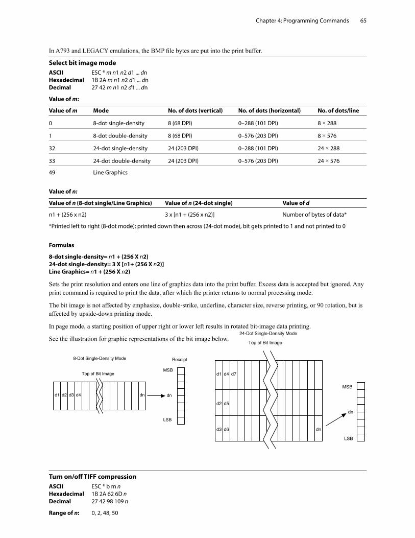
Chapter 4: Programming Commands 65
In A793 and LEGACY emulations, the BMP file bytes are put into the print buffer.
Select bit image modeASCII ESC * m n1 n2 d1 ... dn Hexadecimal 1B 2A m n1 n2 d1 ... dn Decimal 27 42 m n1 n2 d1 ... dn
Value of m:
Value of m Mode No. of dots (vertical) No. of dots (horizontal) No. of dots/line
0 8-dot single-density 8 (68 DPI) 0–288 (101 DPI) 8 × 288
1 8-dot double-density 8 (68 DPI) 0–576 (203 DPI) 8 × 576
32 24-dot single-density 24 (203 DPI) 0–288 (101 DPI) 24 × 288
33 24-dot double-density 24 (203 DPI) 0–576 (203 DPI) 24 × 576
49 Line Graphics
Value of n:
Value of n (8-dot single/Line Graphics) Value of n (24-dot single) Value of d
n1 + (256 x n2) 3 x [n1 + (256 x n2)] Number of bytes of data*
*Printed left to right (8-dot mode); printed down then across (24-dot mode), bit gets printed to 1 and not printed to 0
Formulas
8-dot single-density= n1 + (256 X n2) 24-dot single-density= 3 X [n1+ (256 X n2)] Line Graphics= n1 + (256 X n2)
Sets the print resolution and enters one line of graphics data into the print buffer. Excess data is accepted but ignored. Any print command is required to print the data, after which the printer returns to normal processing mode.
The bit image is not affected by emphasize, double-strike, underline, character size, reverse printing, or 90 rotation, but is affected by upside-down printing mode.
In page mode, a starting position of upper right or lower left results in rotated bit-image data printing.
See the illustration for graphic representations of the bit image below.
Turn on/off TIFF compressionASCII ESC * b m n Hexadecimal 1B 2A 62 6D n Decimal 27 42 98 109 n
Range of n: 0, 2, 48, 50
Chapter 4: Programming Commands66
Turns the TIFF compression on (n = 2, 50), or off (n = 0, 48). Default off (n = 0).
Print advanced raster graphicsASCII ESC . m n rL rH d1 … dn Hexadecimal 1B 2E m n rL rH d1 … dn Decimal 27 46 m n rL rH d1 … dn
Value of m: horizontal offset from left margin = 8 x m dots
Value of n: number of data bytes that compose the raster
Value of r: number of times the raster has to be printed =256 x rH + rL
d1 … dn: data bytes
Range: 0<= m <= 72 0<= n <= 72 0<= r <= 65535 0<= d1 … dn <= 255
Prints a horizontal raster of graphics data one or multiple times. Horizontal offset and number of data bytes are variable and specified by parameters.
Exceptions
Advanced raster graphics is not available in page mode.
Select single-density graphicsASCII ESC K n1 n2 d1 ... dn Hexadecimal 1B 4B n1 n2 d1 ... dn Decimal 27 75 n1 n2 d1 ... dn
Value of n:
Value of n (8-dot single-density mode) Value of d
n1 + (256 x n2) Number of bytes of data (printed down, then across)
Enters one line of 8-dot single-density graphics into the print buffer. Any print command is required to print the line, after which the printer returns to normal processing mode. Single-density mode allows 0–288 dot columns. The number of bytes sent is represented by the formulas in the table.
Each bit corresponds to two horizontal dots. Compare to set bit image mode (1B 2A, m = 0) earlier in this document.
Related information
In LEGACY emulation, this command is unrecognized and the parameters are put into the print buffer.
Select double-density graphicsASCII ESC Y n1 n2 d1 ... dn Hexadecimal 1B 59 n1 n2 d1 ... dn Decimal 27 89 n1 n2 d1 ... dn
Value of n:
Value of n (8-dot single-density mode) Value of d
n1 + (256 x n2) Number of bytes of data (printed down, then across)
Enters one line of 8-dot double-density graphics into the print buffer. Any print command is required to print the line, after which the printer returns to normal processing mode. Double-density mode allows 0–576 dot columns. The number of bytes sent is represented by the formulas in the table.
Each bit corresponds to one horizontal dot. Compare to set bit image mode (1B 2A, m=1) earlier in this document.
Related information
Chapter 4: Programming Commands 67
In LEGACY emulation, this command is unrecognized and the parameters are put into the print buffer.
Select the current logoASCII GS # n Hexadecimal 1D 23 n Decimal 29 35 n
Range of n: 0 – 255
Default: 0
Selects a monochrome logo to be defined or printed. The active logo n remains in use until this command is sent again with a different logo n.
When this command precedes a logo definition, that definition is stored in flash or RAM memory as logo n. If there is already a different definition in flash memory for logo n, the first is inactivated and the new definition is used. The inactive definition is not erased from flash and continues to take up space in flash memory.
When this command precedes a logo print command and n is different from the previously active logo selected, the printer retrieves the logo definition for n from flash or RAM memory and prints it. If there is no definition for logo n, then no logo is printed.
In the case of a previously existing application that expects only one possible logo, the printer will not receive the select current logo (1D 23 n) command. In this case, the printer assigns 0 as the active logo identifier. It automatically stores any new logo definition in flash memory as logo 0, inactivating any previous logo 0 definition. If the flash memory space available for logos fills up with inactive logo 0 definitions, the firmware erases the old definitions at the next power cycle. This is the only case in which the printer erases flash memory without an application command.
In the case of a new application using multiple logos, the select current logo (1D 23 n) command is used. After that, the printer no longer automatically erases the logo definition flash memory page when it fills with multiple definitions. A new application using multiple logos, writing a user-defined character set into flash memory, or both, is responsible for erasing the logo and user-defined character set flash memory page when the logo area is full or before a new character set is defined.
Related information
This command is recognized in Native mode.
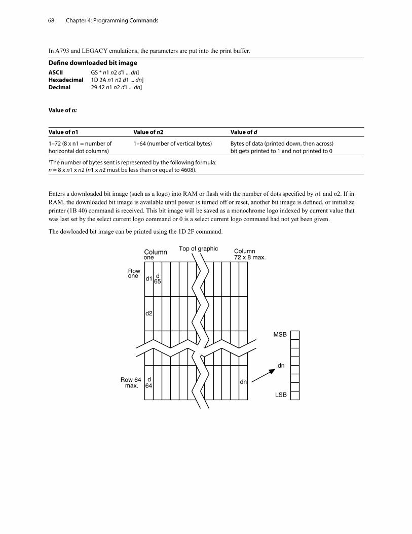
Chapter 4: Programming Commands68
In A793 and LEGACY emulations, the parameters are put into the print buffer.
Define downloaded bit imageASCII GS * n1 n2 d1 ... dn] Hexadecimal 1D 2A n1 n2 d1 ... dn] Decimal 29 42 n1 n2 d1 ... dn]
Value of n:
Value of n1 Value of n2 Value of d
1–72 (8 x n1 = number of 1–64 (number of vertical bytes) Bytes of data (printed down, then across) horizontal dot columns) bit gets printed to 1 and not printed to 0
1The number of bytes sent is represented by the following formula: n = 8 x n1 x n2 (n1 x n2 must be less than or equal to 4608).
Enters a downloaded bit image (such as a logo) into RAM or flash with the number of dots specified by n1 and n2. If in RAM, the downloaded bit image is available until power is turned off or reset, another bit image is defined, or initialize printer (1B 40) command is received. This bit image will be saved as a monochrome logo indexed by current value that was last set by the select current logo command or 0 is a select current logo command had not yet been given.
The dowloaded bit image can be printed using the 1D 2F command.
Chapter 4: Programming Commands 69
See the illustration below for a graphic representation of the downloaded bit image.
Print downloaded bit imageASCII GS / m Hexadecimal 1D 2F m Decimal 29 47 m
Value and range of m:
This command is used to print a previously stored monochrome logo (defined by 1D 2A) from printer memory on the
receipt station. The logo is identified as the one indicated by the most recent select current logo command or 0 if a select current logo command has not yet been given. Parameter m is interpreted as follows:
Value of m Print mode Vertical DPI Horizontal DPI
0 Normal 203 203
1 Double wide 203 101
2 Double high 101 203
3 Double wide/ 101 101 Double high
The indexed downloaded bit image from RAM or flash will be printed on the receipt station at a size specified by m. If doubling or quadrupling exceeds the print paper width maximums (576) the left side of the image is printed and the bits to the right of the maximum column are discarded. If the available width is greater than the bit image, its printing will adhere to any currently set right, left, or center justification. This command is ignored if the index refers to an undefined logo/ bit image.
Print raster graphics
This command is used to enter and print graphics data.
This command describes operation for 80 mm paper.
ASCII DC1 n1 . . . n1
Hexadecimal 11 n1 . . . n72
Decimal 17 n1 . . . n1r
Value and range of n: n1 to n72 /n80 corresponds to one dot row data for a thermal receipt printer.
Each bit defines whether or not a dot will be printed. This command is used for printing a monochrome graphic in real-time. Offsets, page and any other modes or overlays, including watermark do not apply and are overridden by this command. A complete rendering of the intended final image should have been done by the application before sending the dot rows.
Chapter 4: Programming Commands70
Print Flash LogoASCII FS p n m
Hexadecimal 1C 70 n m
Decimal 28 112 n m
Print flash logo ID n using mode m. See command 1D 2F m for description of mode m. See command 1C 71 for description of n.
Define Flash LogosASCII FS q n [xL xH yL yH d1 …dk]1…[xL xH yL yH d1 …dk]n
Hexadecimal 1C 71 n [xL xH yL yH d1 …dk]1…[xL xH yL yH d1 …dk]n
Decimal 28 113 n [xL xH yL yH d1 …dk]1…[xL xH yL yH d1 …dk]n
Define n flash logos specified by IDs 1 through n. Maximum size of logos is determined by amount of flash allocated to logos. See command 1D 22 80… for flash allocation.
0 < xH:xL < 1024 max printable xH:xL = 72 = 576 dots wide
0 < yH:yL < 256
For each logo definition: xH:xL times 8 dots in the horizontal direction, yH:yL times 8 dots in the vertical direction. Total data definition bytes k = xH:xL times yH:yL times 8 bytes. See command 1D 2A x y … for description of data definition bytes arrangement.
During execution of this command printer turns off USM and Real Time status processing. The printer goes busy when writing to flash. At the end of this command the printer resets.
Logo print with knife cutASCII GS 0x9B m n Hexadecimal 1D 9B m n Decimal 29 155 m n
Values of m: 0 = Standard size 1 = Double wide 2 = Double high 3 = Double high/wide
Value of n: 01 - FF (Hex) # dot rows = n × 24 n = 5 is the recommended setting
Because the printhead and cutting knife are physically separated, it is necessary to advance the printed area of a receipt past the knife to avoid the last of the printing from being cut off. This advance of paper however, causes a blank space at the start of the next receipt that could be used. To utilize this space and reduce paper usage, this command starts to print a logo for the next receipt before initiating the cut at the end of the current receipt. At a set location during the printing of the logo, the corresponding paper advance is stopped and a paper cut performed.
The formula “n × 24” is used to determine the number of dot rows to move the paper from the start of the logo to the position of the cut.
Chapter 4: Programming Commands 71
If n × 24 is greater than the height of the logo, the logo height is used to determine the cut position. If n = 0 the cut is eliminated.
In order for this command to function properly, all commands used by legacy applications to move the end of the current receipt past the knife should be removed.
The command is available only in Native mode.
Related information
See “Print downloaded bit image” command.
Set temporary max target speedASCII GS 0xA0 nl nh Hexadecimal 1D A0 nl nh Decimal 29
Values: 15 00 - 5E 01 monochrome Max value is limited by the max speed setting of the printer
Default: 0 - normal speed
This command sets a specific speed for an operation, allowing the user more control of the print environment. The speed is maintained as long as it is less than the speed automatically set by power management. A parameter of zero (0) restores the normal max speed.
Convert 6-dots/mm bitmap to 8-dots/mm bitmapASCII US EOT n Hexadecimal 1F 04 n Decimal 31 04 n
Value: 0 = Off 1 = On
(When 0 and 1 are the LSB)
Default: 0 (Off)
Selects or cancels 6-dot/mm emulation mode.
When the 6-dot/mm emulation is selected, logos and graphics are expanded horizontally and vertically during download to emulate their size on a 6-dot/mm printer. The horizontal positioning commands also emulate positioning on a 6-dot/mm printer.
Enable constant speed logosASCII US { n Hexadecimal 1F 7B n Decimal 31 123 n
Value: 0 = disable 1 = enable
This command allows the firmware to determine the optimal speed to print a logo. It is set prior to downloading the logo and reset after the logo has been downloaded.
In general, “Set max target speed (1D A0 nl nh)” is the preferred command.
Chapter 4: Programming Commands72
StatusStatus command introduction
The H300 has three methods of providing status to the application. These methods are through batch status commands, real time status commands and unsolicited status mode. An application may use one or more of these methods to understand the current status of the printer. A brief description of each of these methods follows.
Batch status commands – These commands are sent to the printer and stored in the printer’s buffer. Once the printer has processed all the previous commands these commands are processed and the proper status is returned to the application. In the event a condition causes the printer to go BUSY, it stops processing commands from the printer buffer. If a batch status command remained in the buffer during this busy condition, it would not be processed. In fact, no batch commands are processed while the printer is in this state.
Real-time commands – These commands are sent to the printer buffer. Periodically, when the printer has time, it scans the input buffer looking for these commands. When found by the printer, these commands are processed immediately. This gives the application the ability to query the printer when it is in a busy state in order to correct whatever fault has occurred.
Automatic status back or Unsolicited status mode– This mechanism allows the application developer to program the printer to automatically respond with a four byte status when certain conditions in the printer change.
Please see the subsequent sections for a more detailed description of these status commands. At the end of this status commands section is a page entitled “Recognizing data from the printer”. This describes how to interpret what command or setting (in the case of unsolicited status mode) triggered a response from the printer.
Batch modeFor RS-232C printers, these commands enable the printer to communicate with the host computer following the selected handshaking protocol, either DTR/DSR or XON/XOFF. They are stored in the printer’s data buffer as they are received, and are handled by the firmware in the order in which they are received.
When a fault occurs, the printer will go busy at the RS-232C interface and not respond to any of the batch mode printer status commands. If the fault causing the busy condition can be cleared, such as by loading paper, or letting the thermal printhead cool down, the printer will resume processing the data in its receive buffer.
Transmit peripheral device status (RS-232C printers only)ASCII ESC u 0 Hexadecimal 1B 75 0 Decimal 27 117 0
Value of returned byte:
Bit 0 Bit 1
1 = Drawer 1 Closed 1 = Drawer 2 Closed
0 = Drawer 1 Open 0 = Drawer 2 Open
Bits 2–7 are not used.
Transmits current status of the cash drawers. One byte is sent to the host computer. In DTR/DSR protocol, the printer waits for DSR = SPACE. If a drawer is not connected, the status will indicate it is closed.
Exceptions
Unlike the A793, that had a dedicated connector and resultant dedicated status reporting for each cash drawer, the H300 has a single connector that shares data reporting from either cash drawer. When either cash drawer is open, an open status is reported by the printer.
Related information
In LEGACY emulation, this command is ignored.
Chapter 4: Programming Commands 73
Transmit paper sensor statusASCII ESC v Hexadecimal 1B 76 Decimal 27 118
Values:
Status Byte (RS-232C)
Bit Function 0 Signifies 1 Signifies
0 Not used Fixed to zero Fixed to zero
1 Receipt cover Closed Open
2 Receipt paper Present Out
3 Knife position Home position Not home position
4 Not used Fixed to zero Fixed to zero
5 Temperature In valid range Too hot or too cold
6 Voltage In valid range Too high or too low
7 Not used Fixed to zero Fixed to zero
Sends status data to the host computer. The printer sends one byte to the host computer when it is not busy or in a fault condition. In DTS/DSR protocol, the printer waits for DSR = SPACE.
Related information
See busy line and fault conditions in the real time commands section of this document for details about fault condition reporting.
In LEGACY emulation, this command is ignored.
Transmit printer IDASCII GS I n Hexadecimal 1D 49 n Decimal 29 73 n
Value of n: 1, 49 = Printer model ID 2, 50 = Type ID 3, 51 = ROM version ID 4, 52 = Logo Definition
Transmits the printer ID specified by n as follows:
n Printer ID Specification ID (Hexadecimal)
1, 49 Printer model ID H300 0x24
2, 50 Type ID Installed options Refer to below
3, 51 ROM version ID ROM version 0x00
4, 52 Logo definition Logo definition Refer to next page
n = 2 or 50: Type ID
Bit Off/On Hex Decimal Function
0 Off 00 0 No two-byte character code installed.
On 01 1 Two-byte character code installed.
1 Off 00 0 No knife installed.
Chapter 4: Programming Commands74
On 02 2 Knife installed.
2 – – – Undefined.
3 – – – Undefined.
4 Off 00 0 Not used. Fixed to Off.
5 – – – Undefined
6 – – – Undefined
7 Off 00 0 Not used. Fixed to Off.
n = 4 or 52: Logo Definition
Bit Off/On Hex Decimal Function
0 Off 00 0 No logo downloaded (SRAM or Flash)
On 01 1 Logo downloaded (SRAM or Flash)
1–7 Off 00 0 Not Used. Fixed to Off.
Transmits the printer ID specified by n. This command is a batch mode command; that is, the response is transmitted after all prior data in the receive buffer has been processed. There may be a time lag between the printer receiving this command and transmitting the response, depending on the receive buffer status.
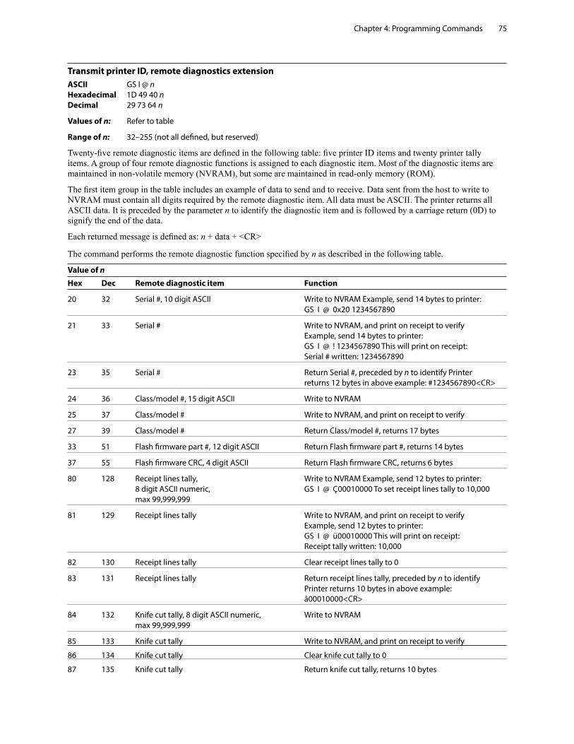
Chapter 4: Programming Commands 75
Transmit printer ID, remote diagnostics extensionASCII GS I @ n Hexadecimal 1D 49 40 n Decimal 29 73 64 n
Values of n: Refer to table
Range of n: 32–255 (not all defined, but reserved)
Twenty-five remote diagnostic items are defined in the following table: five printer ID items and twenty printer tally items. A group of four remote diagnostic functions is assigned to each diagnostic item. Most of the diagnostic items are maintained in non-volatile memory (NVRAM), but some are maintained in read-only memory (ROM).
The first item group in the table includes an example of data to send and to receive. Data sent from the host to write to NVRAM must contain all digits required by the remote diagnostic item. All data must be ASCII. The printer returns all ASCII data. It is preceded by the parameter n to identify the diagnostic item and is followed by a carriage return (0D) to signify the end of the data.
Each returned message is defined as: n + data + <CR>
The command performs the remote diagnostic function specified by n as described in the following table.
Value of n
Hex Dec Remote diagnostic item Function
20 32 Serial #, 10 digit ASCII Write to NVRAM Example, send 14 bytes to printer: GS I @ 0x20 1234567890
21 33 Serial # Write to NVRAM, and print on receipt to verify Example, send 14 bytes to printer: GS I @ ! 1234567890 This will print on receipt: Serial # written: 1234567890
23 35 Serial # Return Serial #, preceded by n to identify Printer returns 12 bytes in above example: #1234567890<CR>
24 36 Class/model #, 15 digit ASCII Write to NVRAM
25 37 Class/model # Write to NVRAM, and print on receipt to verify
27 39 Class/model # Return Class/model #, returns 17 bytes
33 51 Flash firmware part #, 12 digit ASCII Return Flash firmware part #, returns 14 bytes
37 55 Flash firmware CRC, 4 digit ASCII Return Flash firmware CRC, returns 6 bytes
80 128 Receipt lines tally, Write to NVRAM Example, send 12 bytes to printer: 8 digit ASCII numeric, GS I @ Ç00010000 To set receipt lines tally to 10,000 max 99,999,999
81 129 Receipt lines tally Write to NVRAM, and print on receipt to verify Example, send 12 bytes to printer: GS I @ ü00010000 This will print on receipt: Receipt tally written: 10,000
82 130 Receipt lines tally Clear receipt lines tally to 0
83 131 Receipt lines tally Return receipt lines tally, preceded by n to identify Printer returns 10 bytes in above example: â00010000<CR>
84 132 Knife cut tally, 8 digit ASCII numeric, Write to NVRAM max 99,999,999
85 133 Knife cut tally Write to NVRAM, and print on receipt to verify
86 134 Knife cut tally Clear knife cut tally to 0
87 135 Knife cut tally Return knife cut tally, returns 10 bytes
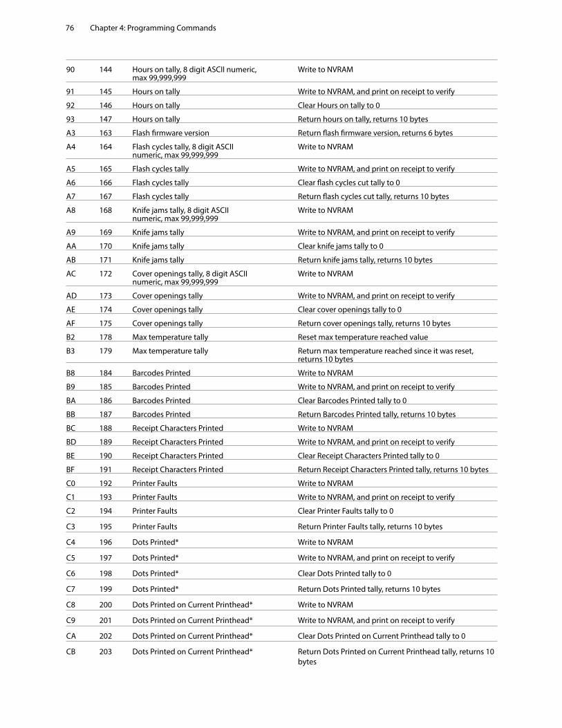
Chapter 4: Programming Commands76
90 144 Hours on tally, 8 digit ASCII numeric, Write to NVRAM max 99,999,999
91 145 Hours on tally Write to NVRAM, and print on receipt to verify
92 146 Hours on tally Clear Hours on tally to 0
93 147 Hours on tally Return hours on tally, returns 10 bytes
A3 163 Flash firmware version Return flash firmware version, returns 6 bytes
A4 164 Flash cycles tally, 8 digit ASCII Write to NVRAM numeric, max 99,999,999
A5 165 Flash cycles tally Write to NVRAM, and print on receipt to verify
A6 166 Flash cycles tally Clear flash cycles cut tally to 0
A7 167 Flash cycles tally Return flash cycles cut tally, returns 10 bytes
A8 168 Knife jams tally, 8 digit ASCII Write to NVRAM numeric, max 99,999,999
A9 169 Knife jams tally Write to NVRAM, and print on receipt to verify
AA 170 Knife jams tally Clear knife jams tally to 0
AB 171 Knife jams tally Return knife jams tally, returns 10 bytes
AC 172 Cover openings tally, 8 digit ASCII Write to NVRAM numeric, max 99,999,999
AD 173 Cover openings tally Write to NVRAM, and print on receipt to verify
AE 174 Cover openings tally Clear cover openings tally to 0
AF 175 Cover openings tally Return cover openings tally, returns 10 bytes
B2 178 Max temperature tally Reset max temperature reached value
B3 179 Max temperature tally Return max temperature reached since it was reset, returns 10 bytes
B8 184 Barcodes Printed Write to NVRAM
B9 185 Barcodes Printed Write to NVRAM, and print on receipt to verify
BA 186 Barcodes Printed Clear Barcodes Printed tally to 0
BB 187 Barcodes Printed Return Barcodes Printed tally, returns 10 bytes
BC 188 Receipt Characters Printed Write to NVRAM
BD 189 Receipt Characters Printed Write to NVRAM, and print on receipt to verify
BE 190 Receipt Characters Printed Clear Receipt Characters Printed tally to 0
BF 191 Receipt Characters Printed Return Receipt Characters Printed tally, returns 10 bytes
C0 192 Printer Faults Write to NVRAM
C1 193 Printer Faults Write to NVRAM, and print on receipt to verify
C2 194 Printer Faults Clear Printer Faults tally to 0
C3 195 Printer Faults Return Printer Faults tally, returns 10 bytes
C4 196 Dots Printed* Write to NVRAM
C5 197 Dots Printed* Write to NVRAM, and print on receipt to verify
C6 198 Dots Printed* Clear Dots Printed tally to 0
C7 199 Dots Printed* Return Dots Printed tally, returns 10 bytes
C8 200 Dots Printed on Current Printhead* Write to NVRAM
C9 201 Dots Printed on Current Printhead* Write to NVRAM, and print on receipt to verify
CA 202 Dots Printed on Current Printhead* Clear Dots Printed on Current Printhead tally to 0
CB 203 Dots Printed on Current Printhead* Return Dots Printed on Current Printhead tally, returns 10 bytes
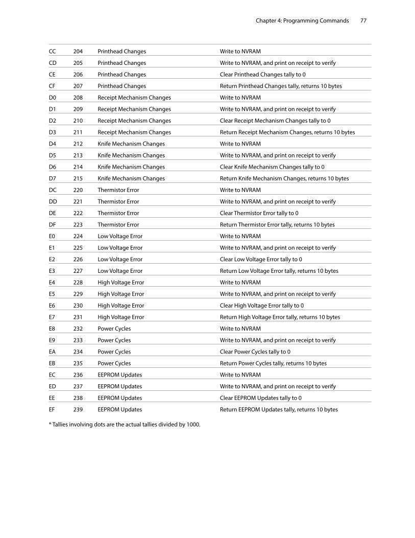
Chapter 4: Programming Commands 77
CC 204 Printhead Changes Write to NVRAM
CD 205 Printhead Changes Write to NVRAM, and print on receipt to verify
CE 206 Printhead Changes Clear Printhead Changes tally to 0
CF 207 Printhead Changes Return Printhead Changes tally, returns 10 bytes
D0 208 Receipt Mechanism Changes Write to NVRAM
D1 209 Receipt Mechanism Changes Write to NVRAM, and print on receipt to verify
D2 210 Receipt Mechanism Changes Clear Receipt Mechanism Changes tally to 0
D3 211 Receipt Mechanism Changes Return Receipt Mechanism Changes, returns 10 bytes
D4 212 Knife Mechanism Changes Write to NVRAM
D5 213 Knife Mechanism Changes Write to NVRAM, and print on receipt to verify
D6 214 Knife Mechanism Changes Clear Knife Mechanism Changes tally to 0
D7 215 Knife Mechanism Changes Return Knife Mechanism Changes, returns 10 bytes
DC 220 Thermistor Error Write to NVRAM
DD 221 Thermistor Error Write to NVRAM, and print on receipt to verify
DE 222 Thermistor Error Clear Thermistor Error tally to 0
DF 223 Thermistor Error Return Thermistor Error tally, returns 10 bytes
E0 224 Low Voltage Error Write to NVRAM
E1 225 Low Voltage Error Write to NVRAM, and print on receipt to verify
E2 226 Low Voltage Error Clear Low Voltage Error tally to 0
E3 227 Low Voltage Error Return Low Voltage Error tally, returns 10 bytes
E4 228 High Voltage Error Write to NVRAM
E5 229 High Voltage Error Write to NVRAM, and print on receipt to verify
E6 230 High Voltage Error Clear High Voltage Error tally to 0
E7 231 High Voltage Error Return High Voltage Error tally, returns 10 bytes
E8 232 Power Cycles Write to NVRAM
E9 233 Power Cycles Write to NVRAM, and print on receipt to verify
EA 234 Power Cycles Clear Power Cycles tally to 0
EB 235 Power Cycles Return Power Cycles tally, returns 10 bytes
EC 236 EEPROM Updates Write to NVRAM
ED 237 EEPROM Updates Write to NVRAM, and print on receipt to verify
EE 238 EEPROM Updates Clear EEPROM Updates tally to 0
EF 239 EEPROM Updates Return EEPROM Updates tally, returns 10 bytes * Tallies involving dots are the actual tallies divided by 1000.
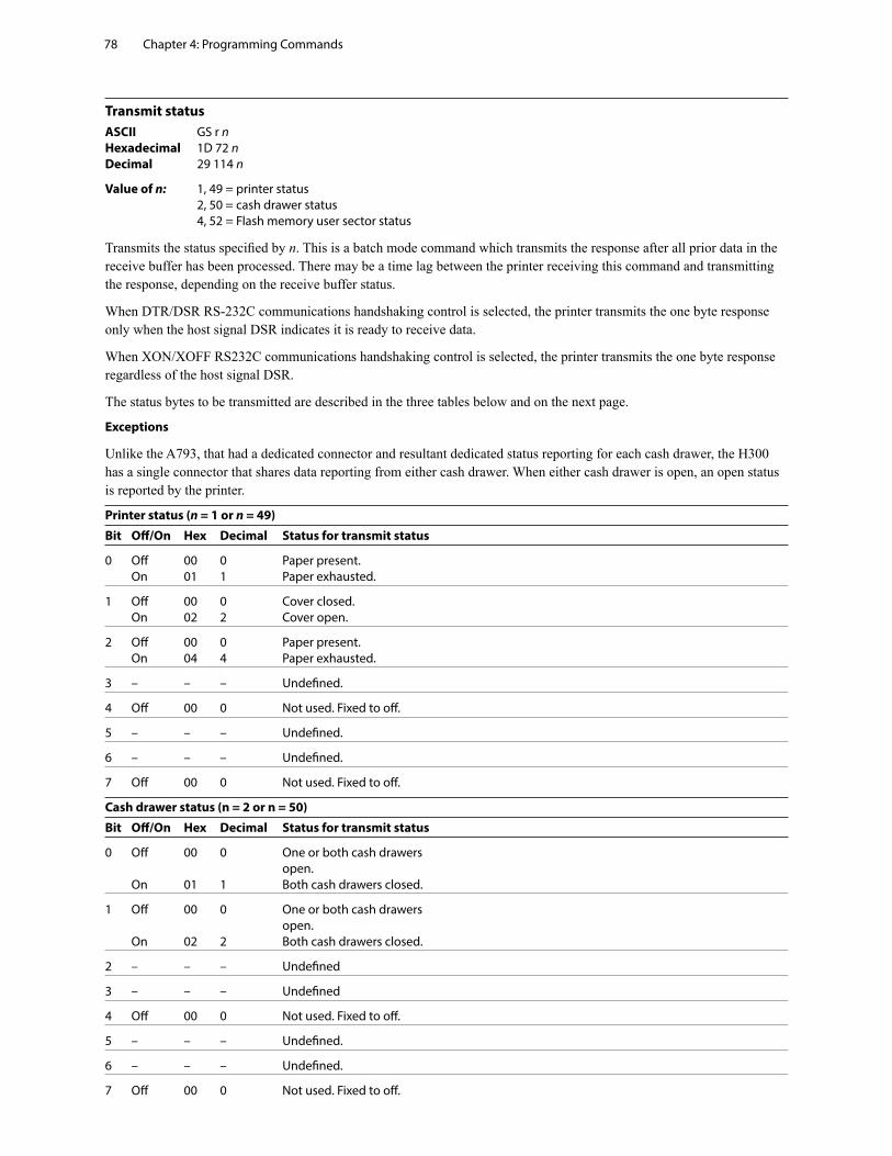
Chapter 4: Programming Commands78
Transmit statusASCII GS r n Hexadecimal 1D 72 n Decimal 29 114 n
Value of n: 1, 49 = printer status 2, 50 = cash drawer status 4, 52 = Flash memory user sector status
Transmits the status specified by n. This is a batch mode command which transmits the response after all prior data in the receive buffer has been processed. There may be a time lag between the printer receiving this command and transmitting the response, depending on the receive buffer status.
When DTR/DSR RS-232C communications handshaking control is selected, the printer transmits the one byte response only when the host signal DSR indicates it is ready to receive data.
When XON/XOFF RS232C communications handshaking control is selected, the printer transmits the one byte response regardless of the host signal DSR.
The status bytes to be transmitted are described in the three tables below and on the next page.
Exceptions
Unlike the A793, that had a dedicated connector and resultant dedicated status reporting for each cash drawer, the H300 has a single connector that shares data reporting from either cash drawer. When either cash drawer is open, an open status is reported by the printer.
Printer status (n = 1 or n = 49)
Bit Off/On Hex Decimal Status for transmit status
0 Off 00 0 Paper present. On 01 1 Paper exhausted.
1 Off 00 0 Cover closed. On 02 2 Cover open.
2 Off 00 0 Paper present. On 04 4 Paper exhausted.
3 – – – Undefined.
4 Off 00 0 Not used. Fixed to off.
5 – – – Undefined.
6 – – – Undefined.
7 Off 00 0 Not used. Fixed to off.
Cash drawer status (n = 2 or n = 50)
Bit Off/On Hex Decimal Status for transmit status
0 Off 00 0 One or both cash drawers open. On 01 1 Both cash drawers closed.
1 Off 00 0 One or both cash drawers open. On 02 2 Both cash drawers closed.
2 – – – Undefined
3 – – – Undefined
4 Off 00 0 Not used. Fixed to off.
5 – – – Undefined.
6 – – – Undefined.
7 Off 00 0 Not used. Fixed to off.
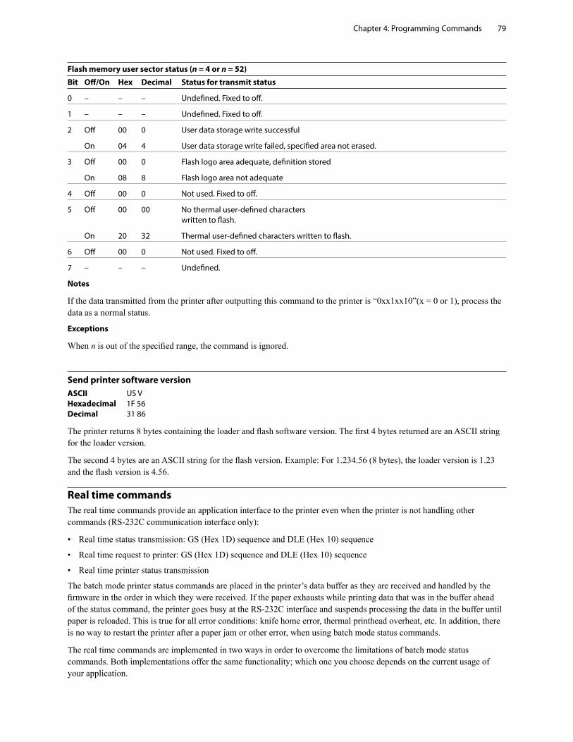
Chapter 4: Programming Commands 79
Flash memory user sector status (n = 4 or n = 52)
Bit Off/On Hex Decimal Status for transmit status
0 – – – Undefined. Fixed to off.
1 – – – Undefined. Fixed to off.
2 Off 00 0 User data storage write successful
On 04 4 User data storage write failed, specified area not erased.
3 Off 00 0 Flash logo area adequate, definition stored
On 08 8 Flash logo area not adequate
4 Off 00 0 Not used. Fixed to off.
5 Off 00 00 No thermal user-defined characters written to flash.
On 20 32 Thermal user-defined characters written to flash.
6 Off 00 0 Not used. Fixed to off.
7 – – – Undefined.
Notes
If the data transmitted from the printer after outputting this command to the printer is “0xx1xx10”(x = 0 or 1), process the data as a normal status.
Exceptions
When n is out of the specified range, the command is ignored.
Send printer software versionASCII US V Hexadecimal 1F 56 Decimal 31 86
The printer returns 8 bytes containing the loader and flash software version. The first 4 bytes returned are an ASCII string for the loader version.
The second 4 bytes are an ASCII string for the flash version. Example: For 1.234.56 (8 bytes), the loader version is 1.23 and the flash version is 4.56.
Real time commandsThe real time commands provide an application interface to the printer even when the printer is not handling other commands (RS-232C communication interface only):
• Real time status transmission: GS (Hex 1D) sequence and DLE (Hex 10) sequence
• Real time request to printer: GS (Hex 1D) sequence and DLE (Hex 10) sequence
• Real time printer status transmission
The batch mode printer status commands are placed in the printer’s data buffer as they are received and handled by the firmware in the order in which they were received. If the paper exhausts while printing data that was in the buffer ahead of the status command, the printer goes busy at the RS-232C interface and suspends processing the data in the buffer until paper is reloaded. This is true for all error conditions: knife home error, thermal printhead overheat, etc. In addition, there is no way to restart the printer after a paper jam or other error, when using batch mode status commands.
The real time commands are implemented in two ways in order to overcome the limitations of batch mode status commands. Both implementations offer the same functionality; which one you choose depends on the current usage of your application.
Chapter 4: Programming Commands80
Preferred implementation
For a new application the GS (1D) sequences are recommended to avoid possible misinterpretation of a DLE (0x10) sequence as a clear printer (0x10 0, ASCII DLE NUL) command.
An application using these GS (1D) sequences, does not need to distinguish for the printer between the new real time commands and the clear printer command. This implementation is ideal for an existing application that already uses the clear printer command or for a new application being developed.
Alternate implementation
The alternate implementation uses the DLE (0x10) sequences as implemented on other printers. An application using these DLE (0x10) sequences and the original clear printer command (0x10) must distinguish for the printer between the new real time commands and the clear printer command by adding a NUL (0x00) to the clear printer command.
An application using these DLE (0x10) sequences must also send the second byte of the sequence within 100 milliseconds of the first, to prevent the first byte being mistaken for a clear printer command.
Rules for using real time commands
Three situations must be understood when using real time commands.
First, the printer executes the real time command within a few msec of detecting it in the input buffer and will transmit status regardless of the condition of the DSR signal.
Second, the printer transmits status whenever it recognizes a real time status transmission command sequence, even if that sequence happens to occur naturally within the data of another command, such as graphics data. In this case the sequence will also be handled correctly as the graphics data it is intended to be when the graphics command is executed from the buffer.
Third, care must be taken not to insert a real time command into the data sequence of another command that consists of two or more bytes.
In this case the printer will use the real time command sequence bytes instead of the other command’s parameter bytes when finally executing that other command from the buffer; the other command will NOT be executed correctly.
These three situations generally preclude use of standard DOS drivers for the serial communication ports when using real time commands.
Moving data through the buffer
Applications should not let the buffer fill up with real time commands when the printer is busy at the RS-232C interface. A busy condition at the RS-232C interface can be determined by bit 3 of the response to 1D 05, or 1D 04 1, or 10 04 1. The reason for a particular busy condition can be determined by other responses to 1D 04 n or 10 04 n.
Although the printer responds to real time commands when it is busy, it will place them into the buffer behind any other data there, and flush them out in the order in which they were received. When the printer is busy due simply to buffer full (that is, it can’t print data as fast as it can receive it), then data continues to be processed out of the buffer at approximately print speed and the real time commands will eventually get flushed out.
When the printer is busy due to an error condition, then data stops being processed to the buffer until the condition clears one way or another. In either case, but more quickly in the case of an error condition, the buffer can fill with real time commands.
When the DLE (0x10) sequences are being used, the last byte stored when the buffer fills up could be the DLE (0x10) code, with no room for the subsequent EOT or ENQ. When this lone DLE (0x10) byte is finally processed out of the buffer it will be interpreted as a clear printer command.
Similarly, when the GS (1D) sequences are being used, the last byte stored when the buffer fills up could be the GS (1D) code, with no room for the subsequent EOT or ETX or ENQ. When this lone GS (1D) byte is finally processed out of the buffer it will use the next byte, whatever it is, as the second byte in its GS (1D) sequence.
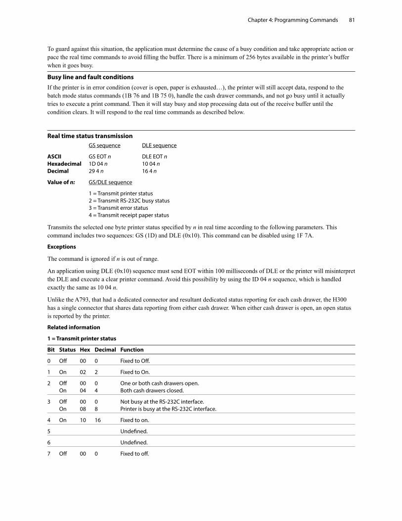
Chapter 4: Programming Commands 81
To guard against this situation, the application must determine the cause of a busy condition and take appropriate action or pace the real time commands to avoid filling the buffer. There is a minimum of 256 bytes available in the printer’s buffer when it goes busy.
Busy line and fault conditions
If the printer is in error condition (cover is open, paper is exhausted…), the printer will still accept data, respond to the batch mode status commands (1B 76 and 1B 75 0), handle the cash drawer commands, and not go busy until it actually tries to execute a print command. Then it will stay busy and stop processing data out of the receive buffer until the condition clears. It will respond to the real time commands as described below.
Real time status transmission GS sequence DLE sequence
ASCII GS EOT n DLE EOT n Hexadecimal 1D 04 n 10 04 n Decimal 29 4 n 16 4 n
Value of n: GS/DLE sequence
1 = Transmit printer status 2 = Transmit RS-232C busy status 3 = Transmit error status 4 = Transmit receipt paper status
Transmits the selected one byte printer status specified by n in real time according to the following parameters. This command includes two sequences: GS (1D) and DLE (0x10). This command can be disabled using 1F 7A.
Exceptions
The command is ignored if n is out of range.
An application using DLE (0x10) sequence must send EOT within 100 milliseconds of DLE or the printer will misinterpret the DLE and execute a clear printer command. Avoid this possibility by using the ID 04 n sequence, which is handled exactly the same as 10 04 n.
Unlike the A793, that had a dedicated connector and resultant dedicated status reporting for each cash drawer, the H300 has a single connector that shares data reporting from either cash drawer. When either cash drawer is open, an open status is reported by the printer.
Related information
1 = Transmit printer status
Bit Status Hex Decimal Function
0 Off 00 0 Fixed to Off.
1 On 02 2 Fixed to On.
2 Off 00 0 One or both cash drawers open. On 04 4 Both cash drawers closed.
3 Off 00 0 Not busy at the RS-232C interface. On 08 8 Printer is busy at the RS-232C interface.
4 On 10 16 Fixed to on.
5 Undefined.
6 Undefined.
7 Off 00 0 Fixed to off.
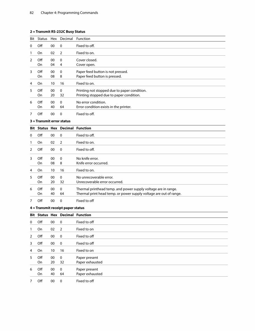
Chapter 4: Programming Commands82
2 = Transmit RS-232C Busy Status
Bit Status Hex Decimal Function
0 Off 00 0 Fixed to off.
1 On 02 2 Fixed to on.
2 Off 00 0 Cover closed. On 04 4 Cover open.
3 Off 00 0 Paper feed button is not pressed. On 08 8 Paper feed button is pressed.
4 On 10 16 Fixed to on.
5 Off 00 0 Printing not stopped due to paper condition. On 20 32 Printing stopped due to paper condition.
6 Off 00 0 No error condition. On 40 64 Error condition exists in the printer.
7 Off 00 0 Fixed to off.
3 = Transmit error status
Bit Status Hex Decimal Function
0 Off 00 0 Fixed to off.
1 On 02 2 Fixed to on.
2 Off 00 0 Fixed to off.
3 Off 00 0 No knife error. On 08 8 Knife error occurred.
4 On 10 16 Fixed to on.
5 Off 00 0 No unrecoverable error. On 20 32 Unrecoverable error occurred.
6 Off 00 0 Thermal printhead temp. and power supply voltage are in range. On 40 64 Thermal print head temp. or power supply voltage are out of range.
7 Off 00 0 Fixed to off
4 = Transmit receipt paper status
Bit Status Hex Decimal Function
0 Off 00 0 Fixed to off
1 On 02 2 Fixed to on
2 Off 00 0 Fixed to off
3 Off 00 0 Fixed to off
4 On 10 16 Fixed to on
5 Off 00 0 Paper present On 20 32 Paper exhausted
6 Off 00 0 Paper present On 40 64 Paper exhausted
7 Off 00 0 Fixed to off
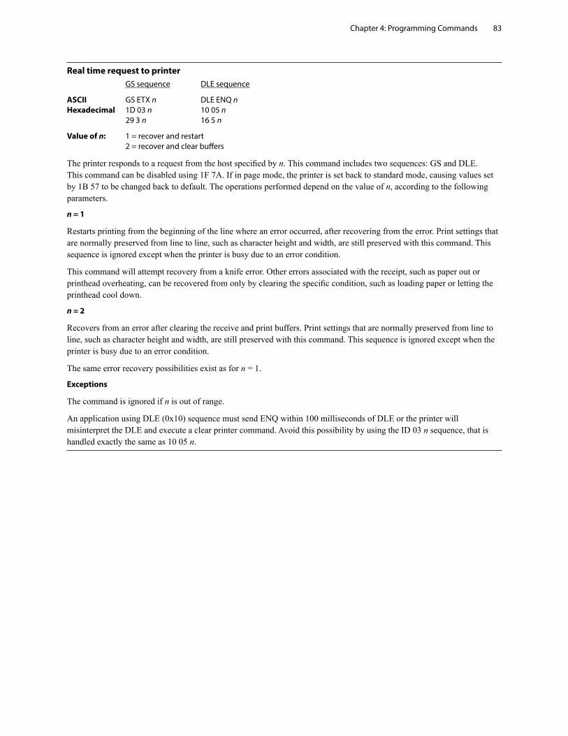
Chapter 4: Programming Commands 83
Real time request to printer GS sequence DLE sequence
ASCII GS ETX n DLE ENQ n Hexadecimal 1D 03 n 10 05 n 29 3 n 16 5 n
Value of n: 1 = recover and restart 2 = recover and clear buffers
The printer responds to a request from the host specified by n. This command includes two sequences: GS and DLE. This command can be disabled using 1F 7A. If in page mode, the printer is set back to standard mode, causing values set by 1B 57 to be changed back to default. The operations performed depend on the value of n, according to the following parameters.
n = 1
Restarts printing from the beginning of the line where an error occurred, after recovering from the error. Print settings that are normally preserved from line to line, such as character height and width, are still preserved with this command. This sequence is ignored except when the printer is busy due to an error condition.
This command will attempt recovery from a knife error. Other errors associated with the receipt, such as paper out or printhead overheating, can be recovered from only by clearing the specific condition, such as loading paper or letting the printhead cool down.
n = 2
Recovers from an error after clearing the receive and print buffers. Print settings that are normally preserved from line to line, such as character height and width, are still preserved with this command. This sequence is ignored except when the printer is busy due to an error condition.
The same error recovery possibilities exist as for n = 1.
Exceptions
The command is ignored if n is out of range.
An application using DLE (0x10) sequence must send ENQ within 100 milliseconds of DLE or the printer will misinterpret the DLE and execute a clear printer command. Avoid this possibility by using the ID 03 n sequence, that is handled exactly the same as 10 05 n.
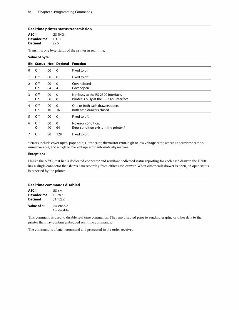
Chapter 4: Programming Commands84
Real time printer status transmissionASCII GS ENQ Hexadecimal 1D 05 Decimal 29 5
Transmits one byte status of the printer in real time.
Value of byte:
Bit Status Hex Decimal Function
0 Off 00 0 Fixed to off
1 Off 00 0 Fixed to off
2 Off 00 0 Cover closed. On 04 4 Cover open.
3 Off 00 0 Not busy at the RS-232C interface. On 08 8 Printer is busy at the RS-232C interface.
4 Off 00 0 One or both cash drawers open. On 10 16 Both cash drawers closed.
5 Off 00 0 Fixed to off.
6 Off 00 0 No error condition. On 40 64 Error condition exists in the printer.*
7 On 80 128 Fixed to on. * Errors include cover open, paper out, cutter error, thermistor error, high or low voltage error, where a thermistor error is unrecoverable, and a high or low voltage error automatically recover
Exceptions
Unlike the A793, that had a dedicated connector and resultant dedicated status reporting for each cash drawer, the H300 has a single connector that shares data reporting from either cash drawer. When either cash drawer is open, an open status is reported by the printer.
Real time commands disabledASCII US z n Hexadecimal 1F 7A n Decimal 31 122 n
Value of n: 0 = enable 1 = disable
This command is used to disable real time commands. They are disabled prior to sending graphic or other data to the printer that may contain embedded real time commands.
The command is a batch command and processed in the order received.
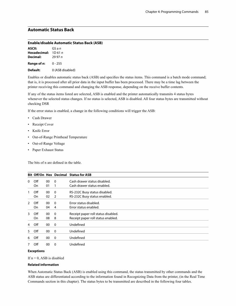
Chapter 4: Programming Commands 85
Automatic Status Back
Enable/disable Automatic Status Back (ASB)ASCII: GS a n Hexadecimal: 1D 61 n Decimal: 29 97 n
Range of n: 0 - 255
Default: 0 (ASB disabled)
Enables or disables automatic status back (ASB) and specifies the status items. This command is a batch mode command; that is, it is processed after all prior data in the input buffer has been processed. There may be a time lag between the printer receiving this command and changing the ASB response, depending on the receive buffer contents.
If any of the status items listed are selected, ASB is enabled and the printer automatically transmits 4 status bytes whenever the selected status changes. If no status is selected, ASB is disabled. All four status bytes are transmitted without checking DSR
If the error status is enabled, a change in the following conditions will trigger the ASB:
• Cash Drawer
• Receipt Cover
• Knife Error
• Out-of-Range Printhead Temperature
• Out-of-Range Voltage
• Paper Exhaust Status
The bits of n are defined in the table.
Bit Off/On Hex Decimal Status for ASB
0 Off 00 0 Cash drawer status disabled. On 01 1 Cash drawer status enabled.
1 Off 00 0 RS-232C Busy status disabled. On 02 2 RS-232C Busy status enabled.
2 Off 00 0 Error status disabled. On 04 4 Error status enabled.
3 Off 00 0 Receipt paper roll status disabled. On 08 8 Receipt paper roll status enabled.
4 Off 00 0 Undefined
5 Off 00 0 Undefined
6 Off 00 0 Undefined
7 Off 00 0 Undefined
Exceptions
If n = 0, ASB is disabled
Related information
When Automatic Status Back (ASB) is enabled using this command, the status transmitted by other commands and the ASB status are differentiated according to the information found in Recognizing Data from the printer, (in the Real Time Commands section in this chapter). The status bytes to be transmitted are described in the following four tables.
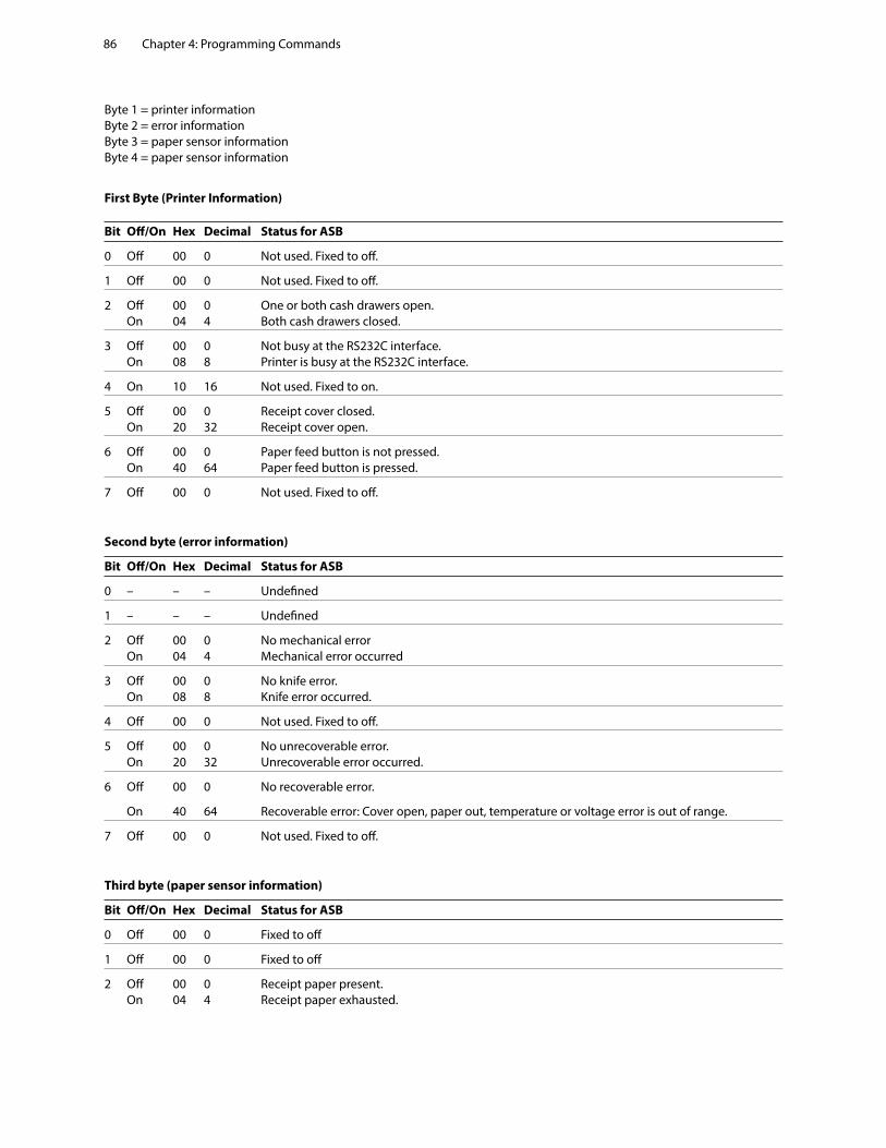
Chapter 4: Programming Commands86
Byte 1 = printer information Byte 2 = error information Byte 3 = paper sensor information Byte 4 = paper sensor information
First Byte (Printer Information)
Bit Off/On Hex Decimal Status for ASB
0 Off 00 0 Not used. Fixed to off.
1 Off 00 0 Not used. Fixed to off.
2 Off 00 0 One or both cash drawers open. On 04 4 Both cash drawers closed.
3 Off 00 0 Not busy at the RS232C interface. On 08 8 Printer is busy at the RS232C interface.
4 On 10 16 Not used. Fixed to on.
5 Off 00 0 Receipt cover closed. On 20 32 Receipt cover open.
6 Off 00 0 Paper feed button is not pressed. On 40 64 Paper feed button is pressed.
7 Off 00 0 Not used. Fixed to off.
Second byte (error information)
Bit Off/On Hex Decimal Status for ASB
0 – – – Undefined
1 – – – Undefined
2 Off 00 0 No mechanical error On 04 4 Mechanical error occurred
3 Off 00 0 No knife error. On 08 8 Knife error occurred.
4 Off 00 0 Not used. Fixed to off.
5 Off 00 0 No unrecoverable error. On 20 32 Unrecoverable error occurred.
6 Off 00 0 No recoverable error.
On 40 64 Recoverable error: Cover open, paper out, temperature or voltage error is out of range.
7 Off 00 0 Not used. Fixed to off.
Third byte (paper sensor information)
Bit Off/On Hex Decimal Status for ASB
0 Off 00 0 Fixed to off
1 Off 00 0 Fixed to off
2 Off 00 0 Receipt paper present. On 04 4 Receipt paper exhausted.
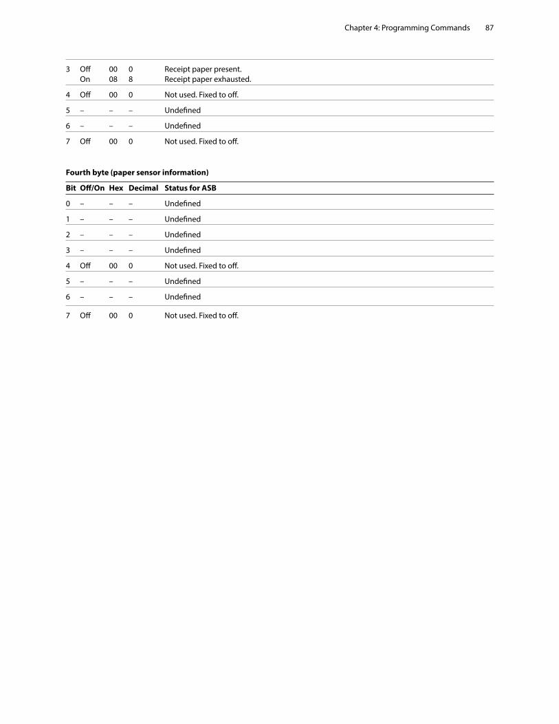
Chapter 4: Programming Commands 87
3 Off 00 0 Receipt paper present. On 08 8 Receipt paper exhausted.
4 Off 00 0 Not used. Fixed to off.
5 – – – Undefined
6 – – – Undefined
7 Off 00 0 Not used. Fixed to off.
Fourth byte (paper sensor information)
Bit Off/On Hex Decimal Status for ASB
0 – – – Undefined
1 – – – Undefined
2 – – – Undefined
3 – – – Undefined
4 Off 00 0 Not used. Fixed to off.
5 – – – Undefined
6 – – – Undefined
7 Off 00 0 Not used. Fixed to off.

Chapter 4: Programming Commands88
Unsolicited status mode
Select or cancel unsolicited status mode (USM)ASCII: GS a n Hexadecimal: 1D 61 n Decimal: 29 97 n
Value of n: 0 turns mode off; any non-zero value turns mode on
Default: 0 (USM disabled)
Enables or disables automatic return of 4 status bytes whenever one or more of the listed changes occurs. This command is a batch mode command; that is, it is processed after all prior data in the input buffer has been processed. There may be a time lag between the printer receiving this command and enabling unsolicited status mode (USM), depending on the pending input buffer contents.
If an immediate return of printer status is desired, then any of the other status commands should be issued following this command. Once this mode is activated, the printer automatically transmits 4 status bytes whenever any of the conditions change. If an RS-232C connection with hardware flow control is used, all four status bytes will be transmitted without checking DSR.
This command is a POS version of general printer unsolicited status functions; it uses the same command code as older versions of the POS command, “automatic status back (ASB)” but has the following differences:
• The parameter n is an on/off switch; it does not select trigger subset
• There is no immediate return when this mode is turned on
• All 4 status bytes are always returned
A change in any of the following conditions will trigger the USM response:
• Cash Drawer
• Receipt Cover
• Knife Error
• Out-of-Range Printhead Temperature
• Out-of-Range Voltage
• Paper Exhaust Status
Related information
When Unsolicited Status Mode is enabled using this command, the status transmitted by other commands and the USM status are differentiated according to the information found in Recognizing Data from the printer, which follows the USM return description.
The status bytes to be transmitted are described in the following four tables.
Byte 1 = printer information Byte 2 = error information Byte 3 = paper sensor information Byte 4 = paper sensor information
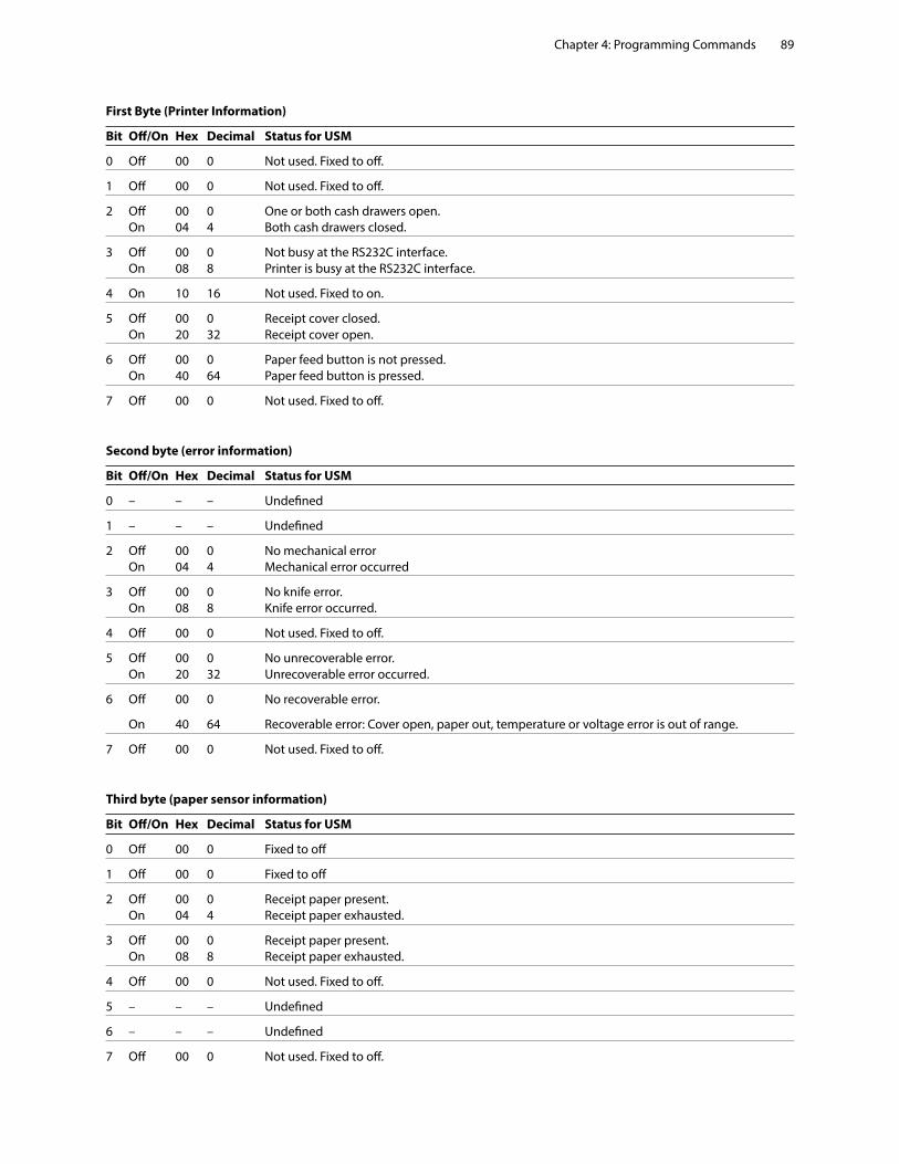
Chapter 4: Programming Commands 89
First Byte (Printer Information)
Bit Off/On Hex Decimal Status for USM
0 Off 00 0 Not used. Fixed to off.
1 Off 00 0 Not used. Fixed to off.
2 Off 00 0 One or both cash drawers open. On 04 4 Both cash drawers closed.
3 Off 00 0 Not busy at the RS232C interface. On 08 8 Printer is busy at the RS232C interface.
4 On 10 16 Not used. Fixed to on.
5 Off 00 0 Receipt cover closed. On 20 32 Receipt cover open.
6 Off 00 0 Paper feed button is not pressed. On 40 64 Paper feed button is pressed.
7 Off 00 0 Not used. Fixed to off.
Second byte (error information)
Bit Off/On Hex Decimal Status for USM
0 – – – Undefined
1 – – – Undefined
2 Off 00 0 No mechanical error On 04 4 Mechanical error occurred
3 Off 00 0 No knife error. On 08 8 Knife error occurred.
4 Off 00 0 Not used. Fixed to off.
5 Off 00 0 No unrecoverable error. On 20 32 Unrecoverable error occurred.
6 Off 00 0 No recoverable error.
On 40 64 Recoverable error: Cover open, paper out, temperature or voltage error is out of range.
7 Off 00 0 Not used. Fixed to off.
Third byte (paper sensor information)
Bit Off/On Hex Decimal Status for USM
0 Off 00 0 Fixed to off
1 Off 00 0 Fixed to off
2 Off 00 0 Receipt paper present. On 04 4 Receipt paper exhausted.
3 Off 00 0 Receipt paper present. On 08 8 Receipt paper exhausted.
4 Off 00 0 Not used. Fixed to off.
5 – – – Undefined
6 – – – Undefined
7 Off 00 0 Not used. Fixed to off.
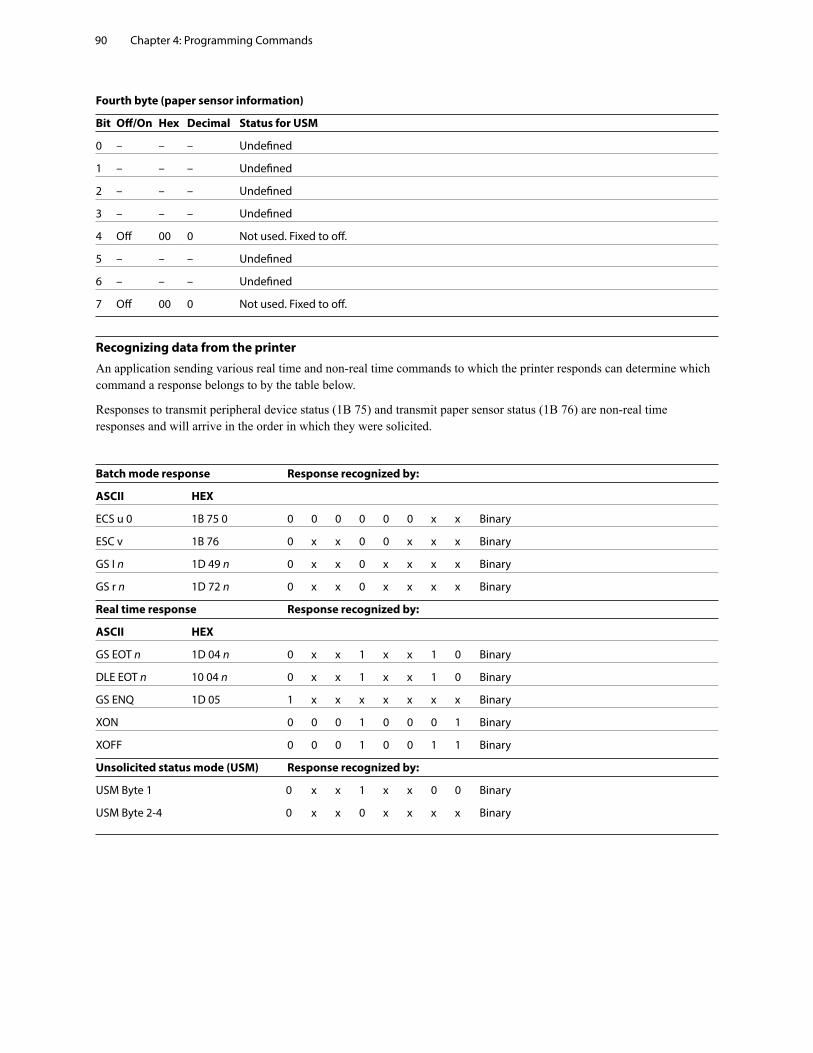
Chapter 4: Programming Commands90
Fourth byte (paper sensor information)
Bit Off/On Hex Decimal Status for USM
0 – – – Undefined
1 – – – Undefined
2 – – – Undefined
3 – – – Undefined
4 Off 00 0 Not used. Fixed to off.
5 – – – Undefined
6 – – – Undefined
7 Off 00 0 Not used. Fixed to off.
Recognizing data from the printer
An application sending various real time and non-real time commands to which the printer responds can determine which command a response belongs to by the table below.
Responses to transmit peripheral device status (1B 75) and transmit paper sensor status (1B 76) are non-real time responses and will arrive in the order in which they were solicited.
Batch mode response Response recognized by:
ASCII HEX
ECS u 0 1B 75 0 0 0 0 0 0 0 x x Binary
ESC v 1B 76 0 x x 0 0 x x x Binary
GS I n 1D 49 n 0 x x 0 x x x x Binary
GS r n 1D 72 n 0 x x 0 x x x x Binary
Real time response Response recognized by:
ASCII HEX
GS EOT n 1D 04 n 0 x x 1 x x 1 0 Binary
DLE EOT n 10 04 n 0 x x 1 x x 1 0 Binary
GS ENQ 1D 05 1 x x x x x x x Binary
XON 0 0 0 1 0 0 0 1 Binary
XOFF 0 0 0 1 0 0 1 1 Binary
Unsolicited status mode (USM) Response recognized by:
USM Byte 1 0 x x 1 x x 0 0 Binary
USM Byte 2-4 0 x x 0 x x x x Binary
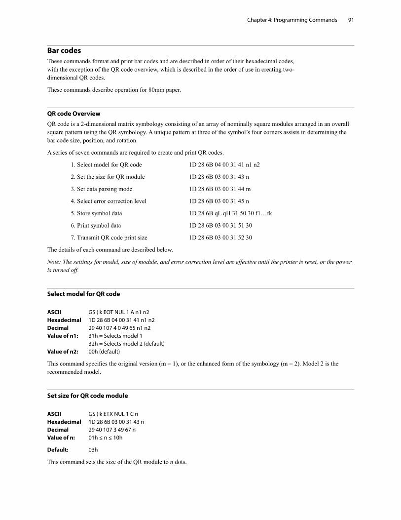
Chapter 4: Programming Commands 91
Bar codesThese commands format and print bar codes and are described in order of their hexadecimal codes, with the exception of the QR code overview, which is described in the order of use in creating two-dimensional QR codes.
These commands describe operation for 80mm paper.
QR code Overview
QR code is a 2-dimensional matrix symbology consisting of an array of nominally square modules arranged in an overall square pattern using the QR symbology. A unique pattern at three of the symbol’s four corners assists in determining the bar code size, position, and rotation.
A series of seven commands are required to create and print QR codes.
1. Select model for QR code 1D 28 6B 04 00 31 41 n1 n2
2. Set the size for QR module 1D 28 6B 03 00 31 43 n
3. Set data parsing mode 1D 28 6B 03 00 31 44 m
4. Select error correction level 1D 28 6B 03 00 31 45 n
5. Store symbol data 1D 28 6B qL qH 31 50 30 f1…fk
6. Print symbol data 1D 28 6B 03 00 31 51 30
7. Transmit QR code print size 1D 28 6B 03 00 31 52 30
The details of each command are described below.
Note: The settings for model, size of module, and error correction level are effective until the printer is reset, or the power is turned off.
Select model for QR code
ASCII GS ( k EOT NUL 1 A n1 n2Hexadecimal 1D 28 6B 04 00 31 41 n1 n2Decimal 29 40 107 4 0 49 65 n1 n2Value of n1: 31h = Selects model 1 32h = Selects model 2 (default)Value of n2: 00h (default)
This command specifies the original version (m = 1), or the enhanced form of the symbology (m = 2). Model 2 is the recommended model.
Set size for QR code module
ASCII GS ( k ETX NUL 1 C nHexadecimal 1D 28 6B 03 00 31 43 nDecimal 29 40 107 3 49 67 nValue of n: 01h ≤ n ≤ 10h
Default: 03h
This command sets the size of the QR module to n dots.
Chapter 4: Programming Commands92
Set data parsing mode for QR Code
ASCII GS ( k ETX NUL 1 D m Hexadecimal 1D 28 6B 03 00 31 44 m Decimal 29 40 107 3 49 68 m Value of m: 30h = Manual Mode 31h = Auto Mode (default)
This command specifies which method of data parsing to use. Auto mode will try to determine the best encoding scheme to use to encode the data based off of the values in the buffer. This mode may not encode the data as desired (data intended to be encoded as one type may be encoded as another due to overlap between the two).
Manual mode allows for more control, as the data can be broken into blocks (up to 200) that are each assigned a type using a leading byte, with each block separated by a comma (0x2C). See store symbol data for QR Code for more details.
Select error correction level for QR Code
ASCII GS ( k ETX NUL 1 E nHexadecimal 1D 28 6B 03 00 31 45 nDecimal 29 40 107 03 00 49 69 n
Value of n: Function Recovery Capacity%
30h Selects Error correction level L 7
31h Selects Error correction level M 15
32h Selects Error correction level Q 25
33h Selects Error correction level H 30
Note: QR code employs Reed-Solomon error correction to generate a series of error correction code words.
Store symbol data for QR Code
ASCII GS ( k qL qH 1 P 0 f1 . . . fkHexadecimal 1D 28 6B qL qH 31 50 30 f1….fk Decimal 29 40 107 qL qH 49 80 48 f1 . . . fk
This command stores the QR code symbol data (f1... fk) in the symbol storage area, which is located in RAM in font memory (command is ignored if no memory is free). qL and qH: 04h < (qL+ qH x 100h) < 1BB4; 0h < qL < FF; 0h < qH < 1B f: 0h < f < FF k = (qL + qH x 100h) – 03hNote:• k bytes of f1…fk are processed as symbol data. • when using manual mode, data size must also account for the leading type byte, the delimiters (0x2C), and any headers (if using binary blocks) • It is possible to encode to a QR code as follows. Be sure not to include anything except the following in the f1…fk data:
Category of data Characters it is possible to specify Type byte (Manual mode)Numerical Mode data “0” ~ “9” ‘N’ (0x4E)Alphanumeric Mode data “0”~“9”, “A”~ “Z”, SP, $, %, *, +, -, ., /, : ‘A’ (0x41)Kanji Mode data Shift JIS value (Shift value from JISX0208) ‘K’ (0x4B)8-bit Byte Mode data 00h ~ FFh ‘B’ (0x42)* *Binary data require a 4-byte field following the type byte to specify length of data block
Continued ...
Chapter 4: Programming Commands 93
Sample Auto Mode Data: 1D 28 6B 03 00 31 44 31 ‘ Set auto parsing
1D 28 6B 0D 00 31 50 30 ‘ Set data size 53 54 31 2D 35 36 37 38 39 30 ‘ Data (letters, symbols, numbers)
Sample Manual Mode Data: 1D 28 6B 03 00 31 44 30 ‘ Set manual parsing
1D 28 6B 31 00 31 50 30 ‘ Set data size 41 ‘ Set alpha-numeric type 54 45 53 54 31 2D 2E 2F 3A ‘ Alpha-Numeric Data 2C ‘ Delimiter 4E ‘ Set numeric type 31 32 33 34 35 36 37 38 39 30 ‘ Numeric Data 2C ‘ Delimiter 4B ‘ Set Kanji 9B 97 82 71 9B 95 82 92 ‘ Kanji Data 2C ‘ Delimiter 42 30 30 30 38 ‘ Set binary and block length (0 0 0 8 = 0x00 0x08 = 8 bytes) 54 2C 45 2C 53 2C 54 2C ‘ Binary Data (0x2Cs are valid data, not delimiters)
Print symbol data for QR code
ASCII GS ( k ETX NUL 1 Q 0 Hexadecimal 1D 28 6B 03 00 31 51 30 Decimal 29 40 107 03 00 49 81 48
This command encodes and prints the QR code symbol data in the symbol storage area, based on the settings in the previous four commands.
In standard mode, use this function when printer is “at the beginning of a line,” or “there is no data in the print buffer.”
The symbol size that exceeds the print area cannot be printed.
If there is no data in storage, or if the data in the storage area is more than the data allowed by specified model and data compaction mode, the QR code cannot be printed.
The following data are added automatically by the encode processing.
Position Detection Patterns Separators for Position Detection Patterns Timing Patterns Format Information Version Information Error Correction code words (employs the Reed-Solomon Error Detection and Correction algorithm) Pad codeword Number of bits in Character Count Indicator Mode Indicator Terminator Alignment Patterns (when model 2 is selected) Extension Patterns (when model 1 is selected)
Printing of symbol is not affected by print mode (emphasized, double-strike, underline, white/black reverse printing, or 90° clockwise-rotated), except for character size and upside-down print mode.
In standard mode, this command executes paper feeding for the amount needed for printing the symbol, regardless of the paper feed amount set by the paper feed setting command, The print position returns to the left side of the printable area after printing the symbol, and printer is in the status “beginning of the line,” or “there is no data in the print buffer.”
In page mode, the printer stores the symbol data in the print buffer without executing actual printing. The printer moves print position to the next dot of the last data of the symbol.
A quiet zone of four times the size of one module is required on all sides of the QR code symbol, but it is not included in the printing data. Be sure to add a quiet zone when using this function.
Chapter 4: Programming Commands94
Transmit QR code print size
ASCII GS ( k ETX NUL 1 R 0 Hexadecimal 1D 28 6B 03 00 31 52 30 Decimal 29 40 107 03 00 49 82 48
Transmits the size information for printing the QR symbol data stored by the store data command in the symbol storage area.
The size information for each data is as follows:
Send data Hex Decimal Number of bytes
Header 37H 55 1 byte
Identifier 59H 89 1 byte
Horizontal size (1) 30H – 39H 48 – 57 3 byte
Separator 1FH 31 1 byte
Vertical size (1) 30H – 39H 48 – 57 3 byte
Separator 1FH 31 1 byte
Fixed value 31H 49 1 byte
Separator 1FH 31 1 byte
Other information (2) 30H or 31H 48 or 49 1 byte
Error information (3) 30H – 39H 48 – 57 4 byte
NUL 00H 0 1 byte
1. Barcode Size
“Horizontal size” and “vertical size” indicate the number of dots of the symbol. The decimal value of the vertical size and horizontal size is converted to text data and sent starting from the high order end.
(ex: When horizontal size is 120 dots, horizontal size is “120” (in hexadecimal: 31H, 32H, and 30H / in decimal: 49, 50, and 48 ), which is 3 bytes of data.)
2. Other Information
“Other information” indicates whether printing of the data in the symbol storage area is possible or impossible. The “Other information” is the following.
Hex Decimal Condition
30H 48 Printing is possible
31H 49 Printing is impossible
Chapter 4: Programming Commands 95
3. Error Information
“Error information” indicates mainly detailed information when “Other information” is Unprintable.
Error information Error content Solution
“0000”. (0x30 30 30 30) No error (printing is possible)
“1001”. (0x31 30 30 31) Encoded data cannot be within one symbol. Check the amount of encoded data.
“1002”. (0x31 30 30 32) Encode processing failed. Check the encoded data.
“2001”. (0x32 30 30 31) No barcode data in the symbol storage area. Put data in the print buffer.
“2002”. (0x32 30 30 32) The symbol size is bigger than the current printing area.
“3001”. (0x33 30 30 31) Too much data. The data being sent is larger than the print buffer.
“3002”. (0x33 30 30 32) Invalid Data Packet. Error receiving QR Code data.
“3003”. (0x33 30 30 33) Memory Allocation Error Failed to allocate memory for plotting.
“9999” (0x39 39 39 39) Internal Error Power Cycle Printer.
Notes
The symbol is bigger than the printing area:
Make the module size smaller.
Change the printing layout (printing area, printing position, etc.)
Size information indicates size of symbol that is printed with Encode Command.
The quiet zone is included in the calculation for the maximum size allowed.
This function does not print.
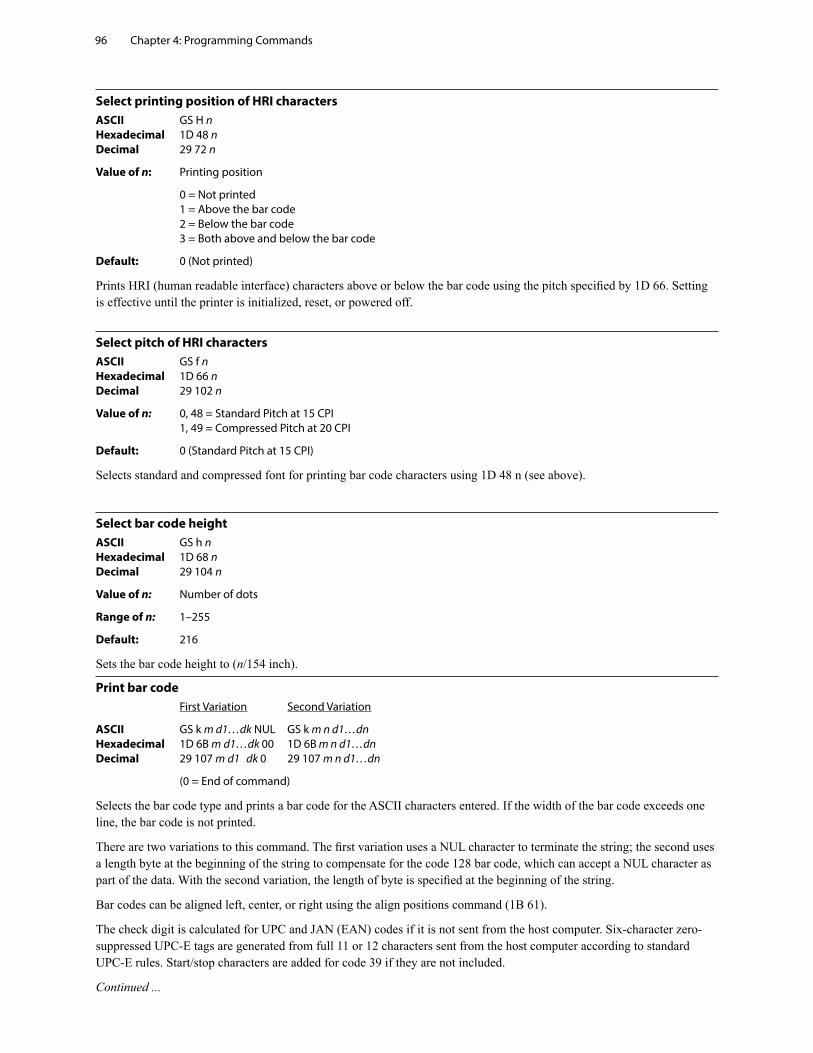
Chapter 4: Programming Commands96
Select printing position of HRI charactersASCII GS H n Hexadecimal 1D 48 n Decimal 29 72 n
Value of n: Printing position
0 = Not printed 1 = Above the bar code 2 = Below the bar code 3 = Both above and below the bar code
Default: 0 (Not printed)
Prints HRI (human readable interface) characters above or below the bar code using the pitch specified by 1D 66. Setting is effective until the printer is initialized, reset, or powered off.
Select pitch of HRI charactersASCII GS f n Hexadecimal 1D 66 n Decimal 29 102 n
Value of n: 0, 48 = Standard Pitch at 15 CPI 1, 49 = Compressed Pitch at 20 CPI
Default: 0 (Standard Pitch at 15 CPI)
Selects standard and compressed font for printing bar code characters using 1D 48 n (see above).
Select bar code heightASCII GS h n Hexadecimal 1D 68 n Decimal 29 104 n
Value of n: Number of dots
Range of n: 1–255
Default: 216
Sets the bar code height to (n/154 inch).
Print bar code First Variation Second Variation
ASCII GS k m d1…dk NUL GS k m n d1…dn Hexadecimal 1D 6B m d1…dk 00 1D 6B m n d1…dn Decimal 29 107 m d1 dk 0 29 107 m n d1…dn
(0 = End of command)
Selects the bar code type and prints a bar code for the ASCII characters entered. If the width of the bar code exceeds one line, the bar code is not printed.
There are two variations to this command. The first variation uses a NUL character to terminate the string; the second uses a length byte at the beginning of the string to compensate for the code 128 bar code, which can accept a NUL character as part of the data. With the second variation, the length of byte is specified at the beginning of the string.
Bar codes can be aligned left, center, or right using the align positions command (1B 61).
The check digit is calculated for UPC and JAN (EAN) codes if it is not sent from the host computer. Six-character zero-suppressed UPC-E tags are generated from full 11 or 12 characters sent from the host computer according to standard UPC-E rules. Start/stop characters are added for code 39 if they are not included.
Continued ...
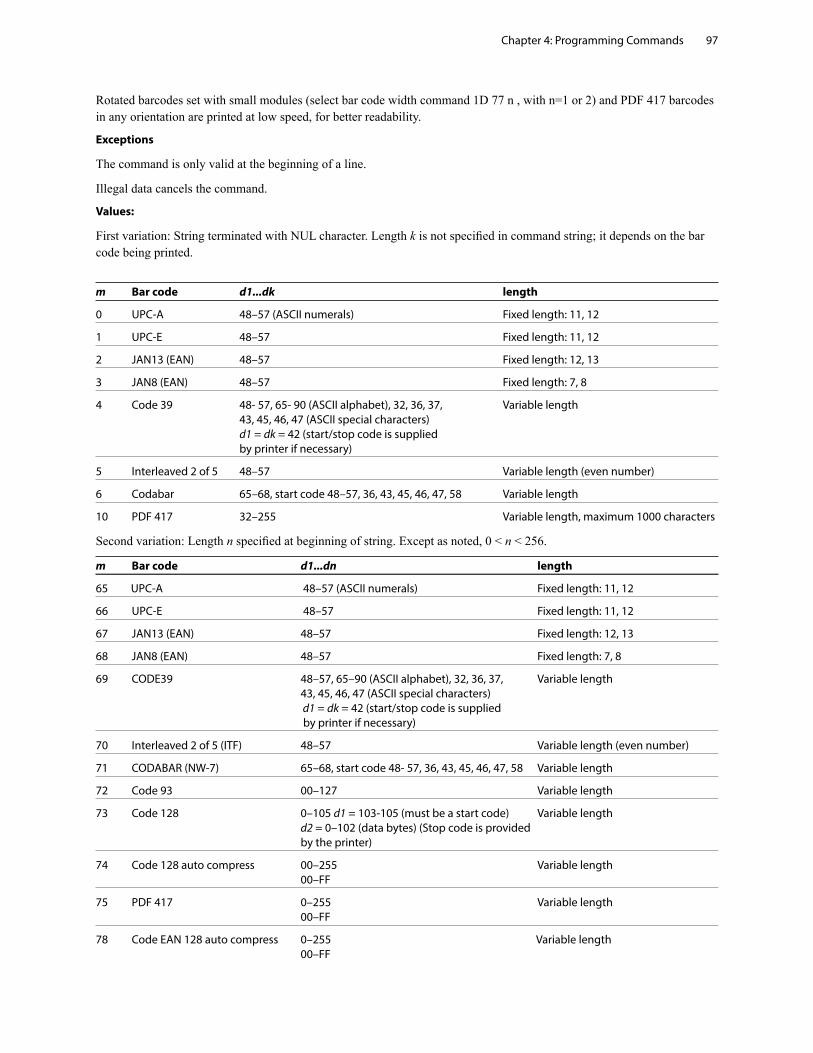
Chapter 4: Programming Commands 97
Rotated barcodes set with small modules (select bar code width command 1D 77 n , with n=1 or 2) and PDF 417 barcodes in any orientation are printed at low speed, for better readability.
Exceptions
The command is only valid at the beginning of a line.
Illegal data cancels the command.
Values:
First variation: String terminated with NUL character. Length k is not specified in command string; it depends on the bar code being printed.
m Bar code d1...dk length
0 UPC-A 48–57 (ASCII numerals) Fixed length: 11, 12
1 UPC-E 48–57 Fixed length: 11, 12
2 JAN13 (EAN) 48–57 Fixed length: 12, 13
3 JAN8 (EAN) 48–57 Fixed length: 7, 8
4 Code 39 48- 57, 65- 90 (ASCII alphabet), 32, 36, 37, Variable length 43, 45, 46, 47 (ASCII special characters) d1 = dk = 42 (start/stop code is supplied by printer if necessary)
5 Interleaved 2 of 5 48–57 Variable length (even number)
6 Codabar 65–68, start code 48–57, 36, 43, 45, 46, 47, 58 Variable length
10 PDF 417 32–255 Variable length, maximum 1000 characters
Second variation: Length n specified at beginning of string. Except as noted, 0 < n < 256.
m Bar code d1...dn length
65 UPC-A 48–57 (ASCII numerals) Fixed length: 11, 12
66 UPC-E 48–57 Fixed length: 11, 12
67 JAN13 (EAN) 48–57 Fixed length: 12, 13
68 JAN8 (EAN) 48–57 Fixed length: 7, 8
69 CODE39 48–57, 65–90 (ASCII alphabet), 32, 36, 37, Variable length 43, 45, 46, 47 (ASCII special characters) d1 = dk = 42 (start/stop code is supplied by printer if necessary)
70 Interleaved 2 of 5 (ITF) 48–57 Variable length (even number)
71 CODABAR (NW-7) 65–68, start code 48- 57, 36, 43, 45, 46, 47, 58 Variable length
72 Code 93 00–127 Variable length
73 Code 128 0–105 d1 = 103-105 (must be a start code) Variable length d2 = 0–102 (data bytes) (Stop code is provided by the printer)
74 Code 128 auto compress 00–255 Variable length 00–FF
75 PDF 417 0–255 Variable length 00–FF
78 Code EAN 128 auto compress 0–255 Variable length 00–FF
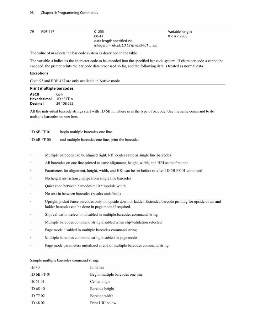
Chapter 4: Programming Commands98
79 PDF 417 0–255 Variable length 00–FF 0 < n < 2800 data length specified via integer n = nH:nL 1D 6B m nL nH d1 . . . dn
The value of m selects the bar code system as described in the table.
The variable d indicates the character code to be encoded into the specified bar code system. If character code d cannot be encoded, the printer prints the bar code data processed so far, and the following data is treated as normal data.
Exceptions
Code 93 and PDF 417 are only available in Native mode.
Print multiple barcodesASCII GS k Hexadecimal 1D 6B FF n Decimal 29 108 255
All the individual barcode strings start with 1D 6B m, where m is the type of barcode. Use the same command to do multiple barcodes on one line.
1D 6B FF 01 begin multiple barcodes one line
1D 6B FF 00 end multiple barcodes one line, print the barcodes
· Multiple barcodes can be aligned right, left, center same as single line barcodes
· All barcodes on one line printed at same alignment, height, width, and HRI as the first one
· Parameters for alignment, height, width, and HRI can be set before or after 1D 6B FF 01 command
· No height restriction change from single line barcodes
· Quiet zone between barcodes = 10 * module width
· No text in between barcodes (results undefined)
· Upright, picket fence barcodes only, no upside down or ladder. Extended barcode printing for upside down and ladder barcodes can be done in page mode if required.
· Slip/validation selection disabled in multiple barcodes command string
· Multiple barcodes command string disabled when slip/validation selected
· Page mode disabled in multiple barcodes command string
· Multiple barcodes command string disabled in page mode
· Page mode parameters initialized at end of multiple barcodes command string
Sample multiple barcodes command string:
1B 40 Initialize
1D 6B FF 01 Begin multiple barcodes one line
1B 61 01 Center align
1D 68 40 Barcode height
1D 77 02 Barcode width
1D 48 02 Print HRI below
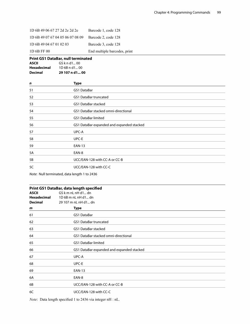
Chapter 4: Programming Commands 99
1D 6B 49 06 67 27 2d 2e 2d 2e Barcode 1, code 128
1D 6B 49 07 67 04 05 06 07 08 09 Barcode 2, code 128
1D 6B 49 04 67 01 02 03 Barcode 3, code 128
1D 6B FF 00 End multiple barcodes, print
Print GS1 DataBar, null terminatedASCII GS k n d1... 00Hexadecimal 1D 6B n d1... 00Decimal 29 107 n d1... 00
n Type
51 GS1 DataBar
52 GS1 DataBar truncated
53 GS1 DataBar stacked
54 GS1 DataBar stacked omni-directional
55 GS1 DataBar limited
56 GS1 DataBar expanded and expanded stacked
57 UPC-A
58 UPC-E
59 EAN-13
5A EAN-8
5B UCC/EAN-128 with CC-A or CC-B
5C UCC/EAN-128 with CC-C
Note: Null terminated, data length 1 to 2436
Print GS1 DataBar, data length specifiedASCII GS k m nL nH d1... dnHexadecimal 1D 6B m nL nH d1... dnDecimal 29 107 m nL nH d1... dn
m Type
61 GS1 DataBar
62 GS1 DataBar truncated
63 GS1 DataBar stacked
64 GS1 DataBar stacked omni-directional
65 GS1 DataBar limited
66 GS1 DataBar expanded and expanded stacked
67 UPC-A
68 UPC-E
69 EAN-13
6A EAN-8
6B UCC/EAN-128 with CC-A or CC-B
6C UCC/EAN-128 with CC-C
Note: Data length specified 1 to 2436 via integer nH : nL.
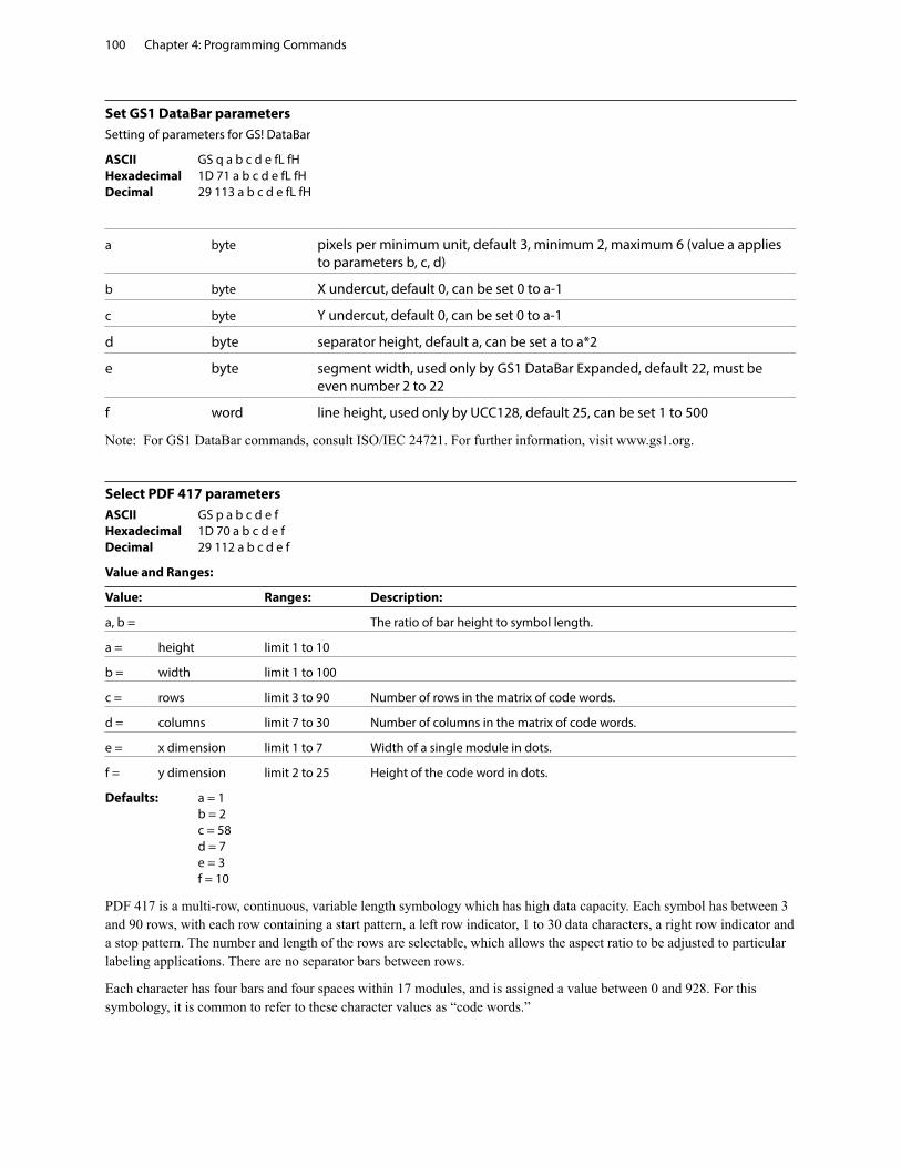
Chapter 4: Programming Commands100
Set GS1 DataBar parametersSetting of parameters for GS! DataBar
ASCII GS q a b c d e fL fH Hexadecimal 1D 71 a b c d e fL fH Decimal 29 113 a b c d e fL fH
a byte pixels per minimum unit, default 3, minimum 2, maximum 6 (value a applies to parameters b, c, d)
b byte X undercut, default 0, can be set 0 to a-1
c byte Y undercut, default 0, can be set 0 to a-1
d byte separator height, default a, can be set a to a*2
e byte segment width, used only by GS1 DataBar Expanded, default 22, must be even number 2 to 22
f word line height, used only by UCC128, default 25, can be set 1 to 500
Note: For GS1 DataBar commands, consult ISO/IEC 24721. For further information, visit www.gs1.org.
Select PDF 417 parametersASCII GS p a b c d e f Hexadecimal 1D 70 a b c d e f Decimal 29 112 a b c d e f
Value and Ranges:
Value: Ranges: Description:
a, b = The ratio of bar height to symbol length.
a = height limit 1 to 10
b = width limit 1 to 100
c = rows limit 3 to 90 Number of rows in the matrix of code words.
d = columns limit 7 to 30 Number of columns in the matrix of code words.
e = x dimension limit 1 to 7 Width of a single module in dots.
f = y dimension limit 2 to 25 Height of the code word in dots.
Defaults: a = 1 b = 2 c = 58 d = 7 e = 3 f = 10
PDF 417 is a multi-row, continuous, variable length symbology which has high data capacity. Each symbol has between 3 and 90 rows, with each row containing a start pattern, a left row indicator, 1 to 30 data characters, a right row indicator and a stop pattern. The number and length of the rows are selectable, which allows the aspect ratio to be adjusted to particular labeling applications. There are no separator bars between rows.
Each character has four bars and four spaces within 17 modules, and is assigned a value between 0 and 928. For this symbology, it is common to refer to these character values as “code words.”
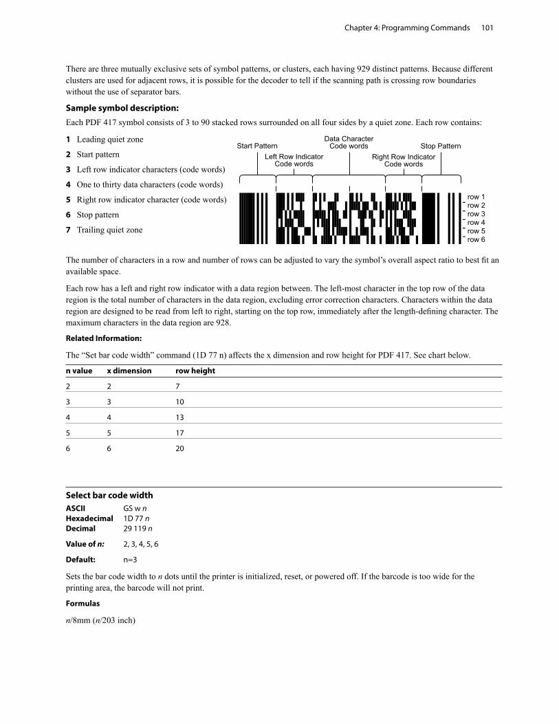
Chapter 4: Programming Commands 101
������������������������������
�����
��������������� �������������
��������
����������������������
������������������������
������������
There are three mutually exclusive sets of symbol patterns, or clusters, each having 929 distinct patterns. Because different clusters are used for adjacent rows, it is possible for the decoder to tell if the scanning path is crossing row boundaries without the use of separator bars.
Sample symbol description:
Each PDF 417 symbol consists of 3 to 90 stacked rows surrounded on all four sides by a quiet zone. Each row contains:
1 Leading quiet zone
2 Start pattern
3 Left row indicator characters (code words)
4 One to thirty data characters (code words)
5 Right row indicator character (code words)
6 Stop pattern
7 Trailing quiet zone
The number of characters in a row and number of rows can be adjusted to vary the symbol’s overall aspect ratio to best fit an available space.
Each row has a left and right row indicator with a data region between. The left-most character in the top row of the data region is the total number of characters in the data region, excluding error correction characters. Characters within the data region are designed to be read from left to right, starting on the top row, immediately after the length-defining character. The maximum characters in the data region are 928.
Related Information:
The “Set bar code width” command (1D 77 n) affects the x dimension and row height for PDF 417. See chart below.
n value x dimension row height
2 2 7
3 3 10
4 4 13
5 5 17
6 6 20
Select bar code widthASCII GS w n Hexadecimal 1D 77 n Decimal 29 119 n
Value of n: 2, 3, 4, 5, 6
Default: n=3
Sets the bar code width to n dots until the printer is initialized, reset, or powered off. If the barcode is too wide for the printing area, the barcode will not print.
Formulas
n/8mm (n/203 inch)
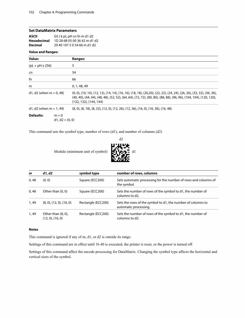
Chapter 4: Programming Commands102
Set DataMatrix ParametersASCII GS ( k pL pH cn fn m d1 d2 Hexadecimal 1D 28 6B 05 00 36 42 m d1 d2 Decimal 29 40 107 5 0 54 66 m d1 d2
Value and Ranges:
Value: Ranges:
(pL + pH x 256) 5
cn 54
fn 66
m 0, 1, 48, 49
d1, d2 (when m = 0, 48) (0, 0), (10, 10), (12, 12), (14, 14), (16, 16), (18, 18), (20,20), (22, 22), (24, 24), (26, 26), (32, 32), (36, 36), (40, 40), (44, 44), (48, 48), (52, 52), (64, 64), (72, 72), (80, 80), (88, 88), (96, 96), (104, 104), (120, 120), (132, 132), (144, 144)
d1, d2 (when m = 1, 49) (8, 0), (8, 18), (8, 32), (12, 0), (12, 26), (12, 36), (16, 0), (16, 36), (16, 48)
Defaults: m = 0 d1, d2 = (0, 0)
This command sets the symbol type, number of rows (d1), and number of columns (d2)
d2
Module (minimum unit of symbol) d1
m d1, d2 symbol type number of rows, columns
0, 48 (0, 0) Square (ECC200) Sets automatic processing for the number of rows and columns of the symbol.
0, 48 Other than (0, 0) Square (ECC200) Sets the number of rows of the symbol to d1, the number of columns to d2.
1, 49 (8, 0), (12, 0), (16, 0) Rectangle (ECC200) Sets the rows of the symbol to d1, the number of columns to automatic processing.
1, 49 Other than (8, 0), Rectangle (ECC200) Sets the number of rows of the symbol to d1, the number of (12, 0), (16, 0) columns to d2.
Notes
This command is ignored if any of m, d1, or d2 is outside its range.
Settings of this command are in effect until 1b 40 is executed, the printer is reset, or the power is turned off.
Settings of this command affect the encode processing for DataMatrix. Changing the symbol type affects the horizontal and vertical sizes of the symbol.
Chapter 4: Programming Commands 103
Set DataMatrix module sizeASCII GS ( k pL pH cn fn n Hexadecimal 1D 28 6B 03 00 36 43 n Decimal 29 40 107 3 0 54 67 n
Value and Ranges:
Value: Ranges:
(pL + pH x 256) 3
cn 54
fn 67
n 2-16
Defaults: n = 3 This command sets the width of one module of DataMatrix to n dots.
Notes
n = width of a module = height of a module (because the DataMatrix modules are square).
If n is outside its range, this command is ignored.
Settings of this command are in effect until 1b 40 is executed, the printer is reset, or the power is turned off.
Settings of this command affect the encode processing for DataMatrix. Changing the symbol type affects the horizontal and vertical sizes of the symbol.
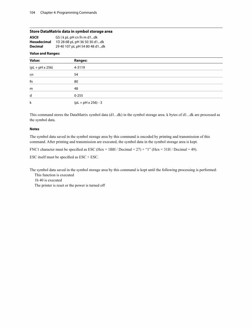
Chapter 4: Programming Commands104
Store DataMatrix data in symbol storage areaASCII GS ( k pL pH cn fn m d1...dk Hexadecimal 1D 28 6B pL pH 36 50 30 d1...dk Decimal 29 40 107 pL pH 54 80 48 d1...dk
Value and Ranges:
Value: Ranges:
(pL + pH x 256) 4-3119
cn 54
fn 80
m 48
d 0-255
k (pL + pH x 256) - 3
This command stores the DataMatrix symbol data (d1...dk) in the symbol storage area. k bytes of d1...dk are processed as the symbol data. Notes
The symbol data saved in the symbol storage area by this command is encoded by printing and transmission of this command. After printing and transmission are executed, the symbol data in the symbol storage area is kept.
FNC1 character must be specified as ESC (Hex = 1BH / Decimal = 27) + “1” (Hex = 31H / Decimal = 49).
ESC itself must be specified as ESC + ESC.
The symbol data saved in the symbol storage area by this command is kept until the following processing is performed: This function is executed 1b 40 is executed The printer is reset or the power is turned off
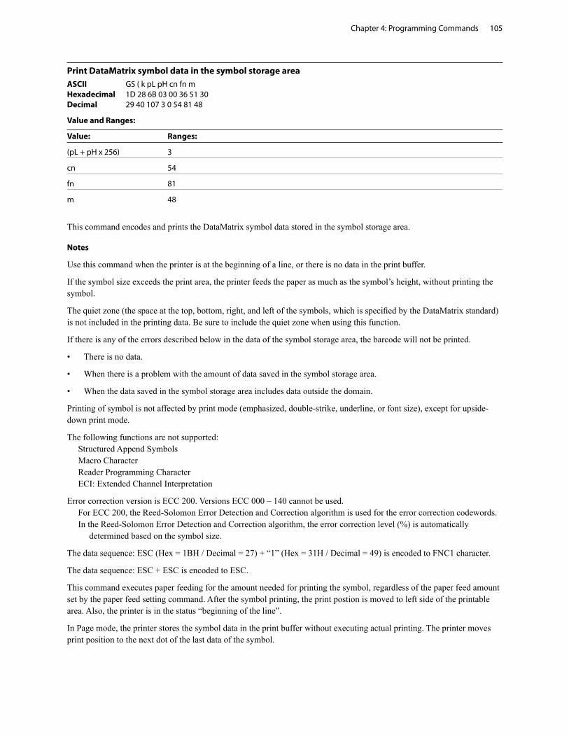
Chapter 4: Programming Commands 105
Print DataMatrix symbol data in the symbol storage areaASCII GS ( k pL pH cn fn m Hexadecimal 1D 28 6B 03 00 36 51 30 Decimal 29 40 107 3 0 54 81 48
Value and Ranges:
Value: Ranges:
(pL + pH x 256) 3
cn 54
fn 81
m 48
This command encodes and prints the DataMatrix symbol data stored in the symbol storage area. Notes
Use this command when the printer is at the beginning of a line, or there is no data in the print buffer.
If the symbol size exceeds the print area, the printer feeds the paper as much as the symbol’s height, without printing the symbol.
The quiet zone (the space at the top, bottom, right, and left of the symbols, which is specified by the DataMatrix standard) is not included in the printing data. Be sure to include the quiet zone when using this function.
If there is any of the errors described below in the data of the symbol storage area, the barcode will not be printed.
• There is no data.
• When there is a problem with the amount of data saved in the symbol storage area.
• When the data saved in the symbol storage area includes data outside the domain.
Printing of symbol is not affected by print mode (emphasized, double-strike, underline, or font size), except for upside-down print mode.
The following functions are not supported: Structured Append Symbols Macro Character Reader Programming Character ECI: Extended Channel Interpretation
Error correction version is ECC 200. Versions ECC 000 – 140 cannot be used. For ECC 200, the Reed-Solomon Error Detection and Correction algorithm is used for the error correction codewords. In the Reed-Solomon Error Detection and Correction algorithm, the error correction level (%) is automatically determined based on the symbol size.
The data sequence: ESC (Hex = 1BH / Decimal = 27) + “1” (Hex = 31H / Decimal = 49) is encoded to FNC1 character.
The data sequence: ESC + ESC is encoded to ESC.
This command executes paper feeding for the amount needed for printing the symbol, regardless of the paper feed amount set by the paper feed setting command. After the symbol printing, the print postion is moved to left side of the printable area. Also, the printer is in the status “beginning of the line”.
In Page mode, the printer stores the symbol data in the print buffer without executing actual printing. The printer moves print position to the next dot of the last data of the symbol.
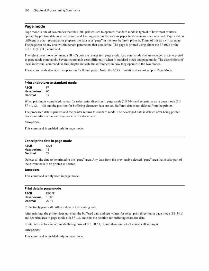
Chapter 4: Programming Commands106
Page modePage mode is one of two modes that the H300 printer uses to operate. Standard mode is typical of how most printers operate by printing data as it is received and feeding paper as the various paper feed commands are received. Page mode is different in that it processes or prepares the data as a “page” in memory before it prints it. Think of this as a virtual page. The page can be any area within certain parameters that you define. The page is printed using either the FF (0C) or the ESC FF (1B 0C) command.
The select page mode command (1B 4C) puts the printer into page mode. Any commands that are received are interpreted as page mode commands. Several commands react differently when in standard mode and page mode. The descriptions of these individual commands in this chapter indicate the differences in how they operate in the two modes.
These commands describe the operation for 80mm paper. Note: the A793 Emulation does not support Page Mode.
Print and return to standard modeASCII FF Hexadecimal 0C Decimal 12
When printing is completed, values for select print direction in page mode (1B 54n) and set print area in page mode (1B 57 n1, n2, …n8) and the position for buffering character data are set. Buffered data is not deleted from the printer.
The processed data is printed and the printer returns to standard mode. The developed data is deleted after being printed. For more information see page mode in this document.
Exceptions
This command is enabled only in page mode.
Cancel print data in page modeASCII CAN Hexadecimal 18 Decimal 24
Deletes all the data to be printed in the “page” area. Any data from the previously selected “page” area that is also part of the current data to be printed is deleted.
Exceptions
This command is only used in page mode.
Print data in page modeASCII ESC FF Hexadecimal 1B 0C Decimal 27 12
Collectively prints all buffered data in the printing area.
After printing, the printer does not clear the buffered data and sets values for select print direction in page mode (1B 54 n) and set print area in page mode (1B 57 …), and sets the position for buffering character data.
Printer returns to standard mode through use of 0C, 1B 53, or initialization (which cancels all settings).
Exceptions
This command is enabled only in page mode.
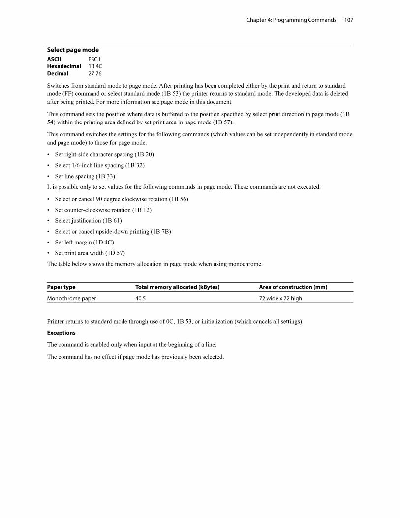
Chapter 4: Programming Commands 107
Select page modeASCII ESC L Hexadecimal 1B 4C Decimal 27 76
Switches from standard mode to page mode. After printing has been completed either by the print and return to standard mode (FF) command or select standard mode (1B 53) the printer returns to standard mode. The developed data is deleted after being printed. For more information see page mode in this document.
This command sets the position where data is buffered to the position specified by select print direction in page mode (1B 54) within the printing area defined by set print area in page mode (1B 57).
This command switches the settings for the following commands (which values can be set independently in standard mode and page mode) to those for page mode.
• Set right-side character spacing (1B 20)
• Select 1/6-inch line spacing (1B 32)
• Set line spacing (1B 33)
It is possible only to set values for the following commands in page mode. These commands are not executed.
• Select or cancel 90 degree clockwise rotation (1B 56)
• Set counter-clockwise rotation (1B 12)
• Select justification (1B 61)
• Select or cancel upside-down printing (1B 7B)
• Set left margin (1D 4C)
• Set print area width (1D 57)
The table below shows the memory allocation in page mode when using monochrome.
Paper type Total memory allocated (kBytes) Area of construction (mm)
Monochrome paper 40.5 72 wide x 72 high
Printer returns to standard mode through use of 0C, 1B 53, or initialization (which cancels all settings).
Exceptions
The command is enabled only when input at the beginning of a line.
The command has no effect if page mode has previously been selected.
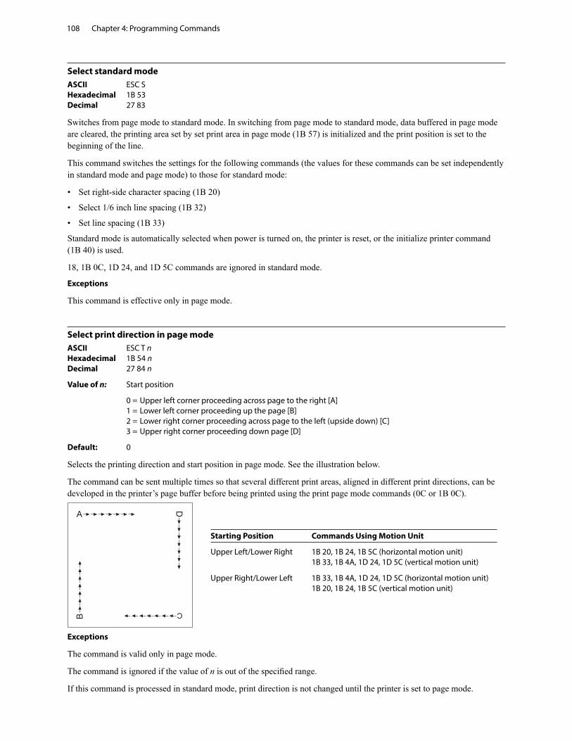
Chapter 4: Programming Commands108
Select standard modeASCII ESC S Hexadecimal 1B 53 Decimal 27 83
Switches from page mode to standard mode. In switching from page mode to standard mode, data buffered in page mode are cleared, the printing area set by set print area in page mode (1B 57) is initialized and the print position is set to the beginning of the line.
This command switches the settings for the following commands (the values for these commands can be set independently in standard mode and page mode) to those for standard mode:
• Set right-side character spacing (1B 20)
• Select 1/6 inch line spacing (1B 32)
• Set line spacing (1B 33)
Standard mode is automatically selected when power is turned on, the printer is reset, or the initialize printer command (1B 40) is used.
18, 1B 0C, 1D 24, and 1D 5C commands are ignored in standard mode.
Exceptions
This command is effective only in page mode.
Select print direction in page modeASCII ESC T n Hexadecimal 1B 54 n Decimal 27 84 n
Value of n: Start position
0 = Upper left corner proceeding across page to the right [A] 1 = Lower left corner proceeding up the page [B] 2 = Lower right corner proceeding across page to the left (upside down) [C] 3 = Upper right corner proceeding down page [D]
Default: 0
Selects the printing direction and start position in page mode. See the illustration below.
The command can be sent multiple times so that several different print areas, aligned in different print directions, can be developed in the printer’s page buffer before being printed using the print page mode commands (0C or 1B 0C).
Exceptions
The command is valid only in page mode.
The command is ignored if the value of n is out of the specified range.
If this command is processed in standard mode, print direction is not changed until the printer is set to page mode.
Starting Position Commands Using Motion Unit
Upper Left/Lower Right 1B 20, 1B 24, 1B 5C (horizontal motion unit) 1B 33, 1B 4A, 1D 24, 1D 5C (vertical motion unit)
Upper Right/Lower Left 1B 33, 1B 4A, 1D 24, 1D 5C (horizontal motion unit) 1B 20, 1B 24, 1B 5C (vertical motion unit)
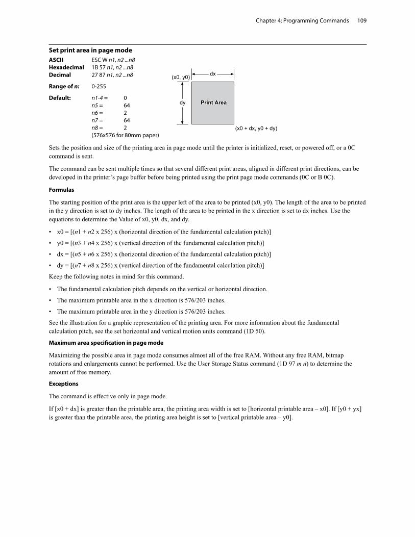
Chapter 4: Programming Commands 109
����������
������������������
�� ����������
Set print area in page modeASCII ESC W n1, n2 ...n8 Hexadecimal 1B 57 n1, n2 ...n8 Decimal 27 87 n1, n2 ...n8
Range of n: 0-255
Default: n1-4 = 0 n5 = 64 n6 = 2 n7 = 64 n8 = 2 (576x576 for 80mm paper)
Sets the position and size of the printing area in page mode until the printer is initialized, reset, or powered off, or a 0C command is sent.
The command can be sent multiple times so that several different print areas, aligned in different print directions, can be developed in the printer’s page buffer before being printed using the print page mode commands (0C or B 0C).
Formulas
The starting position of the print area is the upper left of the area to be printed (x0, y0). The length of the area to be printed in the y direction is set to dy inches. The length of the area to be printed in the x direction is set to dx inches. Use the equations to determine the Value of x0, y0, dx, and dy.
• x0 = [(n1 + n2 x 256) x (horizontal direction of the fundamental calculation pitch)]
• y0 = [(n3 + n4 x 256) x (vertical direction of the fundamental calculation pitch)]
• dx = [(n5 + n6 x 256) x (horizontal direction of the fundamental calculation pitch)]
• dy = [(n7 + n8 x 256) x (vertical direction of the fundamental calculation pitch)]
Keep the following notes in mind for this command.
• The fundamental calculation pitch depends on the vertical or horizontal direction.
• The maximum printable area in the x direction is 576/203 inches.
• The maximum printable area in the y direction is 576/203 inches.
See the illustration for a graphic representation of the printing area. For more information about the fundamental calculation pitch, see the set horizontal and vertical motion units command (1D 50).
Maximum area specification in page mode
Maximizing the possible area in page mode consumes almost all of the free RAM. Without any free RAM, bitmap rotations and enlargements cannot be performed. Use the User Storage Status command (1D 97 m n) to determine the amount of free memory.
Exceptions
The command is effective only in page mode.
If [x0 + dx] is greater than the printable area, the printing area width is set to [horizontal printable area – x0]. If [y0 + yx] is greater than the printable area, the printing area height is set to [vertical printable area – y0].
Chapter 4: Programming Commands110
Set absolute vertical print position in page modeASCII GS $ nL nH Hexadecimal 1D 24 nL nH Decimal 29 36 nL nH
Sets the absolute vertical print starting position for buffer character data in page mode. The absolute print position is set to [(nL + nH X 256) x (vertical or horizontal motion unit)] inches.
The vertical or horizontal motion unit for the paper roll is used and the horizontal starting buffer position does not move.
The reference starting position is set by select print direction in page mode (1B 54). This sets the absolute position in the vertical direction when the starting position is set to the upper left or lower right; and sets the absolute position in the horizontal when the starting position is set to the upper right or lower left. The horizontal and vertical motion unit are specified by the set horizontal and vertical minimum motion units (1D 50) command.
The set horizontal and vertical minimum motion units (1D 50) command can be used to change the horizontal and vertical motion unit. However, the value cannot be less than the minimum horizontal movement amount, and it must be in even units of the minimum horizontal movement amount.
Formulas
[(nL + nH X 256) x (vertical or horizontal motion unit)] inches.
Exceptions
This command is effective only in page mode.
If the [(nL + nH X 256) x (vertical or horizontal motion unit)] exceeds the specified printing area, this command is ignored.
Set relative vertical print position in page modeASCII GS \ nL nH Hexadecimal 1D 5C nL nH Decimal 29 92 nL nH
Value
The value for the horizontal and vertical movement cannot be less than the minimum horizontal movement amount, and must be in even units of the minimum horizontal movement amount.
Sets the relative vertical print starting position from the current position. This command can also change the horizontal and vertical motion unit. The unit of horizontal and vertical motion is specified by this command.
This command functions as follows, depending on the print starting position set by select print direction in page mode (1B 54):
When the starting position is set to the upper right or lower left of the printing area, the vertical motion unit (y) is used. When the starting position is set to the upper left or lower right of the printing area, the horizontal motion unit (x) is used.
Formulas
The distance from the current position is set to [(nL + nH x 256) x vertical or horizontal motion unit] inches. The amount of movement is calculated only for the paper roll.
When pitch n is specified to the movement downward: nL + nH x 256 = n
When pitch n is specified to the movement upward (the negative direction), use the complement of 65536.
When pitch n is specified to the movement upward: nL + nH x 256 – 65536 – N
Exceptions
This command is used only in page mode, otherwise it is ignored.
Any setting that exceeds the specified printing area is ignored.
Chapter 4: Programming Commands 111
MacrosThese commands are used to select and perform a user-defined sequence of printer operations.
Select or cancel macro definitionASCII GS : Hexadecimal 1D 3A Decimal 29 58
Starts or ends macro definition. Macro definition begins when this command is received during normal operation and ends when this command is received during macro definition. The macro definition is cleared, during definition of the macro when the execute macro (1D 5E) command is received.
Normal printing occurs while the macro is defined. When the power is turned on the macro is not defined.
The defined contents of the macro are not cleared by the initialize printer (1B 40), thus, the initialize printer (1B 40) command may be used as part of the macro definition.
If the printer receives a second select or cancel macro definition (1D 3A) command immediately after previously receiving a select or cancel macro definition (1D 3A) the printer remains in the macro undefined state.
Formulas
The contents of the macro can be defined up to 2048 bytes.
Exceptions
If the macro definition exceeds 2048 bytes, excess data is not stored.
Execute macroASCII GS ^ r t m Hexadecimal 1D 5E r t m Decimal 29 94 r t m
Value of r: The number of times to execute the macro.
Value of t: The waiting time for executing the macro.
Executes a macro. After waiting for a specified period the printer waits for the paper feed button to be pressed. After the button is pressed, the printer executes the macro once. The printer repeats this operation the number of specified times.
When the macro is executed by pressing the paper feed button (m = 1), paper cannot be fed by using the paper feed button.
Formulas
The waiting time is t x 100 ms for every macro execution.
m specifies macro executing mode when the LSB (least significant bit) m = 0
The macro executes r times continuously at the interval specified by t when the LSB (least significant bit) of m = 1.
Exceptions
If this command is received while a macro is being defined, the macro definition is aborted and the definition is cleared.
If the macro is not defined or if r is 0, nothing is executed.
Chapter 4: Programming Commands112
User data storageWrite to user data storageASCII ESC ‘ m a0 a1 a2 d1 ... dm Hexadecimal 1B 27 m a0 a1 a2 d1 ... dm Decimal 27 39 m a0 a1 a2 d1 ... dm
Value of m: 0 – 255
Writes m bytes of data to the user data storage flash page at the address specified. The printer waits for m bytes of data following the 3-byte address, addr.
If any of the memory locations addressed by this command are not currently erased, the command is not executed.
Related information
Result of this write is returned in bit 2 of response to transmit status command 1D 72, n = 4.
Read from user data storageASCII ESC 4 m a0 a1 a2 Hexadecimal 1B 34 m a0 a1 a2 Decimal 27 52 m a0 a1 a2
Value of m: 0 – 255
Reads m bytes of data from the user data storage flash page at the address specified. Returns m bytes to the application, followed by a carriage return (0x0D). If the range of requested data exceeds the sector boundary, the printer will only send the data up to the sector boundary.
Select memory type (SRAM/flash) where to save logos or user-defined fontsASCII GS “ n Hexadecimal 1D 22 n Decimal 29 34 n
Value of n: 48 – 53
n = 48 (ASCII n = 0) HEX 30
Loads active logo to RAM only. This is used to print a special logo but not have it take up flash memory. A logo defined following this command is not preserved over a power cycle. The printer disables interrupts while writing to flash. Any command that cause data to be written to flash should be followed by a 50 Msec delay to allow significant time for the write operation.
n = 49 (ASCII n = 1) HEX 31
Loads active logo to flash memory. This is the default condition for logo flash storage. A logo defined following this command is stored in flash memory.
n = 50 (ASCII n = 2) HEX 32
Loads user-defined characters to RAM only. This is the default condition for user-defined character storage. Any user-defined characters defined following this command are not preserved over a power cycle.
n = 51 (ASCII n = 3) HEX 33
Loads user-defined characters to flash memory. An application must use this command to store user-defined characters in flash memory. Any user-defined characters defined following this command are stored in flash memory. A user-defined character cannot be redefined in flash memory. The flash memory page must be erased by an application before redefining user-defined characters. For more information, see the erase user flash sector (1D 40 n) command.
Specifies whether to load the logos or user-defined characters to logo/font flash memory or to RAM (volatile memory). The selection remains in effect until it is changed via this command or until the power cycles. To specify permanent font flash, also send 1D 22 81 01.
Related information
This command is recognized in Native mode. In A793 and LEGACY emulations, parameter bytes go into the print buffer.
Chapter 4: Programming Commands 113
Flash memory user sectors allocationASCII GS “ U n1 n Hexadecimal 1D 22 55 n1 n2 Decimal 29 34 85 n1 n2
Default Value of n1: 1 (see below)
Default Value of n2: 1 (see below)
n1 is the number of 64k sectors used for logos and user-defined characters.
n2 is the number of 64k sectors used for user data storage.
n1 + n2 <= 6 (dec) (1M) n1 + n2 <= 22 (dec) 16 (hex) (2M)
If n1 + n2 is greater than the maximum number of sectors available, the command is ignored. The printer returns NACK.
Issuing this command with parameters different from current parameters will erase all sectors. The printer returns ACK.
Issuing this command with parameters the same as current parameters will do nothing. The printer returns ACK.
Note: Flash memory is made up of user and program code. Therefore, the available flash memory space will vary with the amount of program code utilized.
Flash object area packASCII GS “ ` n1 Hexadecimal 1D 22 60 n1 Decimal 29 34 96 n1
Value of n1: n1 specifies
n1 = 0 pack the permanent font area
n1 = 1 pack the logo and user-defined character area
Issuing this command will pack the objects currently stored in flash memory. Objects that are no longer valid will be removed. This will provide the user the maximum amount of storage in this area for new objects.
Note: Flash memory is made up of user and program code. Therefore, the available flash memory space will vary with the amount of program code utilized.
Flash object deleteASCII GS “ ` n1 n2 (n3) Hexadecimal 1D 22 61 n1 n2 (n3) Decimal 29 34 97 n1 n2 (n3)
Value of n1: n1 specifies
n1 = 01 user-defined character set where n2 is the ID of the user-defined character set to delete. This will delete all characters found that are part of the specified set.
n1 = 02 logo where n2 is the ID of the logo to delete
n1 = 0C double-byte font where n2 is the font ID and n3 is the font style of the font to delete. This will delete the double-byte font of the specified ID and style. If no other fonts of the same ID are found, the double-byte table that corresponds to this ID will be deleted as well.
n1 = 0D POS fontset where n2 is the ID of the fontset to delete. This will delete both fonts specified by the fontset, if they are not used in any other fontset.
n1 = 0F demo script, which takes no following n parameters. Erases all scripts found, not individual scripts.
Issuing this command will delete an individual object or group of objects from flash memory. The parameter n3 is not used for all types. To reuse the space that these objects occupied in flash memory, a flash area pack must be performed after deleting the object(s).
Note: Flash memory is made up of user and program code. Therefore, the available flash memory space will vary with the amount of program code utilized.
Chapter 4: Programming Commands114
Expanded flash memory allocationASCII GS “ 0x80 Hexadecimal 1D 22 80 Decimal 29 34 128
This sequence of commands is used to specify the number of flash sectors to be used for different applications. The begin and end sequence commands must be sent. All areas do not need to have flash sectors specified.
The command to request the number of user sectors is optional.
If more sectors are specified than are available the command sequence is ignored and the printer returns NACK.
If the sectors are available, and different from current parameters, all sectors are erased and the printer returns ACK.
If the sectors specified are the same as current parameters, nothing is erased and the printer returns ACK.
1D 22 80 00 request number of user sectors available, printer returns nL nH 1D 22 80 30 begin expanded flash memory allocation sequence 1D 22 80 31 nL nH n sectors to logo/font area 1D 22 80 32 nL nH n sectors to user data storage area 1D 22 80 33 nL nH n sectors to permanent font area 1D 22 80 34 nL nH n sectors to electronic journal area 1D 22 80 40 end expanded flash memory allocation sequence
n = 0xFFFF means allocate all remaining sectors to this area; only one area can specify this parameter value.
Select flash area for storing logos and user-defined charactersASCII GS” 0x81 Hexadecimal 1D 22 81 n Decimal 29 34 129 n
Value of n: n specifies
n = 0 select logo/font flash
n = 1 select permanent font flash
n > 1 reserved
Logos and user-defined characters can be stored in either flash area.
Return flash area sizeASCII GS” 0x90 Hexadecimal 1D 22 90 n Decimal 29 34 144 n
Value of n: n specifies
n = 0 select logo/font flash
n = 1 select permanent font flash
n > 1 reserved
Returns the size for the selected flash area.
Chapter 4: Programming Commands 115
Erase user flash sectorASCII GS @ n Hexadecimal 1D 40 n Decimal 29 64 n
Value of n: 49 – 51
n = 49 (ASCII n = 1) HEX 31
This command erases all 64K flash memory sectors allocated to user-defined character and logos storage. Those sectors should be erased in two situations: when the logo definition area is full and an application is attempting to define new logos, and when an application wants to replace one user-defined character set with another. In both cases, all logos and character set definitions are erased and must be redefined.
n = 50 (ASCII n = 2) HEX 32
This command erases all sectors available for user data storage.
n = 51 (ASCII n = 3) HEX 33
This command erases all sectors available for permanent fonts.
Erases a page of flash memory and sends a carriage return when the operation is complete.
Related information
See command “Flash memory user sectors allocation” (1D 22 55 n1 n2). See also command “Expanded flash memory allocation” (1D 22 80) and “Select flash area” (1D 22 81 n).
Important: While erasing flash memory, the printer disables all interrupts, including communications. To provide feedback to the application, the printer responds to the application when the erase is complete with a 0D (Hex). After sending the erase user flash sector (1D 40 n) command, an application should wait for the response from the printer before sending data. Otherwise, data will be lost. If an application is unable to receive data, it should wait a minimum of ten seconds after sending the erase user flash sector (1D 40 n) command before sending data.
Lock permanent font flash areaASCII GS 0xF0 0x10 n Hexadecimal 1D F0 10 n Decimal 29 240 16 n
Value of n: n = 0x00 lock permanent font flash (default) n = 0x01 unlock permanent font flash to erase or delete
This command allows or prevents the permanent font area to be erased.
Note: This only affects the 1D 40 33 commands and downloading a font to permanet font area when a font already exists with the same ID.
Chapter 4: Programming Commands116
Flash downloadThese commands are used to load firmware into the printer.
The commands are listed in numerical order according to their hexadecimal codes. Each command is described and the hexadecimal, decimal, and ASCII codes are listed.
There are two ways to enter the download mode.
1. While the printer is running normally, send the command, “Switch to flash download mode” (1B 5B 7D) to leave normal operation and enter the download mode.
2. If the flash if found corrupted during level 0 diagnostics the download mode is automatically entered after the printer has reset.
The printer never goes directly from the download mode to normal printer operation. To return to normal printer operation either the operator must turn the power off and then on to reboot or the application must send a command to cancel download mode and reboot.
When each flash download command is received, the printer returns either ACK or NAK to the host computer when each command is received:
• ACK (hexadecimal 06) Sent when the printer has received a host transmission and has completed the request successfully.
• NAK (hexadecimal 15) Sent when a request is unsuccessful.
Communicates to the printer information downloaded from applications. Data is downloaded to flash memory to query the state of the firmware, calculate the firmware CRC and other functions.
Switch to flash download modeASCII ESC [ } Hexadecimal 1B 5B 7D Decimal 27 91 125
Puts the printer in flash download mode in preparation to receive commands controlling the downloading of objects into flash memory. When this command is received, the printer leaves normal operation and can no longer print transactions until the reboot the printer command (1D FF) is received or the printer is rebooted.
This command does not affect the current communication parameters. Once the printer is in flash download mode, this command is no longer available.
Related information
See entering flash download mode elsewhere in this book to put the printer in flash download mode using the configuration menu.
Erase all flash contents except boot sectorASCII GS SO Hexadecimal 1D 0E Decimal 29 14
Causes the entire flash memory to be erased.
The printer returns ACK if the command is successful; NAK if it is unsuccessful.
Exceptions
Available only in download mode.
Chapter 4: Programming Commands 117
Return main program flash CRCASCII GS SI Hexadecimal 1D 0F Decimal 29 15
Returns the CRC calculated over the flash firmware code space.
The format of the response is ACK <low byte> <high byte>.
Download applicationASCII GS DC1 NUL NUL NUL NUL d1… dn Hexadecimal 1D 11 00 00 00 00 d1… dn Decimal 29 17 0 0 0 0 d1… dn
Value of d: data bytes, 0–255
Sending this command followed by an application will download the application to the printer. This will reprogram the flash.
Related information
Available only in download mode.
For more information, contact your service representative.
Reset firmwareASCII GS (SPACE) Hexadecimal 1D FF Decimal 29 255
Ends the load process and reboots the printer. Before executing this command, the printer should have firmware loaded and external switches set to the runtime settings. Application software for downloading should prompt the user to set the external switches and confirm before sending this command. If the downloading was started from a diagnostic, the reboot will cause the printer to re-enter download state unless the external switches are changed.
Chapter 4: Programming Commands118
Settings commandsThe following commands enable the user to save and restore printer settings.
Save current settingsASCII US HT SOH ACK Hexadecimal 1F 09 01 06 Decimal 31 09 01 06
Saves all current settings as factory settings.
Restore factory settingsASCII US HT SOH BEL Hexadecimal 1F 09 01 07 Decimal 31 09 01 07
Clears active settings and restores factory settings.
Upload current settingsASCII US HT SOH BS Hexadecimal 1F 09 01 08 Decimal 31 09 01 08
Uploads current settings to the current communications port.
Upload factory settingsASCII US HT SOH TAB Hexadecimal 1F 09 01 09 Decimal 31 09 01 09
Uploads factory settings to the current communications port.
Download settingsASCII US HT SOH LF Hexadecimal 1F 09 01 0A Decimal 31 09 01 10
Downloads and merges settings into factory settings and makes these the new settings.
Chapter 4: Programming Commands 119
Miscellaneous configuration commandsSet diagnostics modeASCII US EXT NUL n Hexadecimal 1F 03 00 n Decimal 31 03 00 n
Value of n: 0 = Normal operation/diagnostics mode off 1 = DataScope mode (without graphics) 2 = Receipt test mode 6 = DataScope mode (with graphics)
Default: 0 (Normal operation)
Sets the diagnostics mode to DataScope mode (with or without graphics) or receipt test mode, or sets the printer back to normal operation. See “Diagnostics modes” in chapter two for more information.
Enable or disable knifeASCII US EXT STX n Hexadecimal 1F 03 02 n Decimal 31 03 02 n
Value of n: 0 = Disable 1 = Enable
Default: 1 (Enable)
Enables or disables the knife.
Chapter 4: Programming Commands120
Set printer emulationASCII US EXT BEL n Hexadecimal 1F 03 07 n Decimal 31 03 07 n
Value of n: 0 = Native mode 1 = A794 emulation 2 = A793 emulation 3 = LEGACY emulation
Default: 0 (Native mode)
Sets the printer emulation. See “Printer emulations” in chapter two for more information.
Reset settings to default valuesASCII US EXT TAB Hexadecimal 1F 03 09 Decimal 31 03 09
This command is obsolete. Instead, use Restore factory settings (1F 09 01 07).
Set default fontASCII US EXT SI n Hexadecimal 1F 03 0F n Decimal 31 03 15 n
Value of n: 0 = Standard 13x24 1 = User defined 2 = Compressed 10x24
Sets the default font for monochrome and LEGACY emulations.
Chapter 4: Programming Commands 121
Set font sizeASCII US EXT DLE n Hexadecimal 1F 03 10 n Decimal 31 03 16 n
Value of n: 0 = Standard 24 high 1 = Tall font 3 = Paper-Savings font
Sets font size for the emulation being used.
Enable or disable Code 128 check digit calculationASCII US EXT ESC n Hexadecimal 1F 03 1B n Decimal 31 03 27 n
Value of n: 0 = Disable 1 = Enable
Default: 1 (Enable)
Enables or disables the calculation of the Code 128 check digit.
Enable or disable barcode ITF leading zeroASCII US EXT GS n Hexadecimal 1F 03 1D n Decimal 31 03 29 n
Value of n: 0 = Disable 1 = Enable
Default: 1 (Enable)
Enables or disables the leading zero for barcode ITF. If enabled, a zero is provided to even out an odd number of input characters.
Enable or disable barcode string terminatorASCII US EXT RS n Hexadecimal 1F 03 1E n Decimal 31 03 30 n
Value of n: 0 = Disable 1 = Enable
Default: 0 (Disable)
Enables or disables the barcode string terminator. If disabled, the string terminator will not be looked for when the length is specified.
Chapter 4: Programming Commands122
Enable or disable USM canned statusASCII US EXT 0x28 n Hexadecimal 1F 03 28 n Decimal 31 03 40 n
Value of n: 0 = Disable 1 = Enable
Default: 0 (Disable)
Enables or disables the USM canned status feature.
Send diagnostic pages to comm portASCII US EXT 0x2C n Hexadecimal 1F 03 2C n Decimal 31 03 44 n
Value of n: 0 = Disabled 1 = Enabled
Sends the diagnostic pages to the comm port if enabled.
Enable or disable EJ action via operator controlASCII US EXT 0x2E n Hexadecimal 1F 03 2E n Decimal 31 03 46 n
Value of n: 0 = Disable 1 = Enable
Enables or disables the need for operator control for electronic journaling.
Chapter 4: Programming Commands 123
Set printer ID modeASCII US EXT 0x32 n Hexadecimal 1F 03 32 n Decimal 31 03 50 n
Value of n: 0 = Native or Emulated printer ID 0x01-0xFE = User-defined printer ID
This function is used to determine what printer ID value is returned in response to a Transmit printer ID command (1D 49 n). If n > 0, the printer ID will transmit whaver value of n is selected. If n = 0, the printer can be configured to send back the ID of the H300, A794, A793 or Application Compatible Escape Command systems using the confiuration menu.
Set default code page at power onASCII US EXT 0x33 n Hexadecimal 1F 03 33 n Decimal 31 03 51 n
Value of n: code page value
Default: 00 (Code page 437)
Changes the default code page used at power up. See “Select international character set” command for more information about code page values.
Set Asian ASCII characters to narrowASCII US EXT 0x3D n Hexadecimal 1F 03 3D n Decimal 31 03 61 n
Value of n: 0 = Normal 1 = Narrow
Changes the width of the ASCII characters of the Asian fonts.
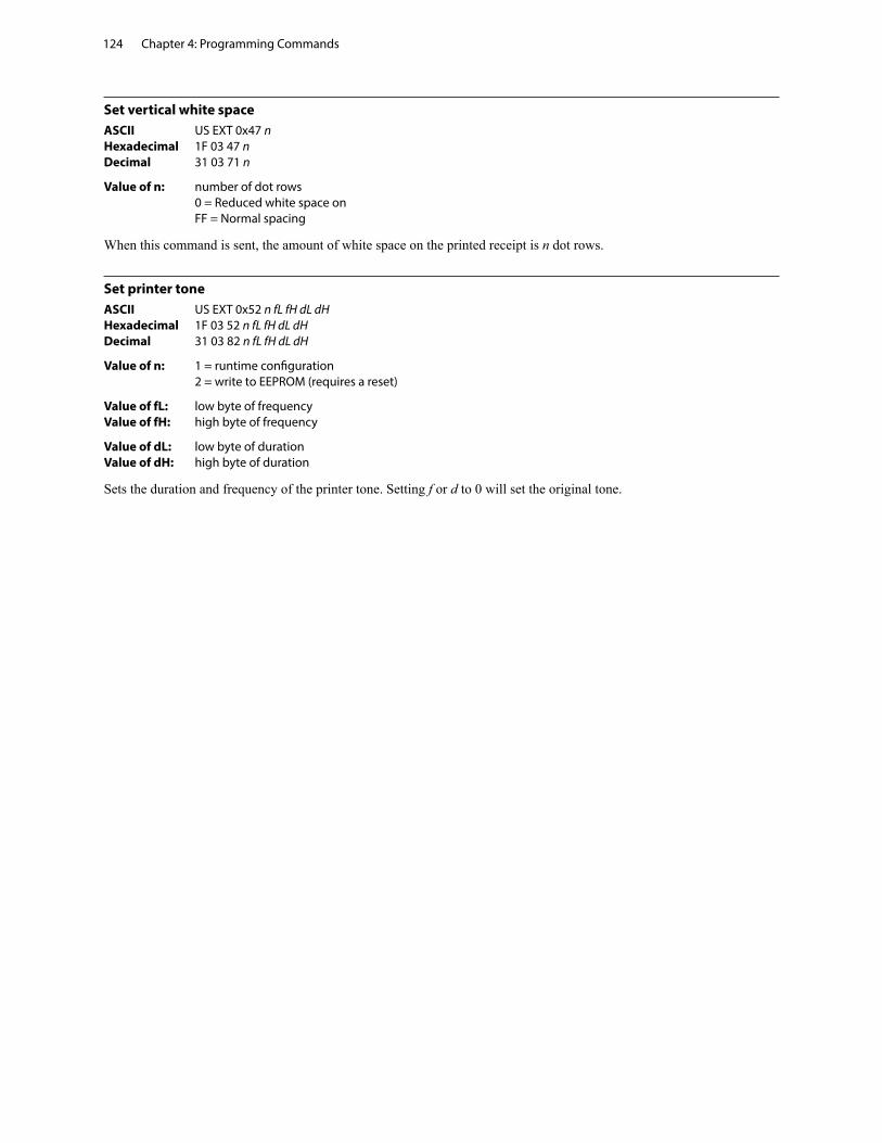
Chapter 4: Programming Commands124
Set vertical white spaceASCII US EXT 0x47 n Hexadecimal 1F 03 47 n Decimal 31 03 71 n
Value of n: number of dot rows 0 = Reduced white space on FF = Normal spacing
When this command is sent, the amount of white space on the printed receipt is n dot rows.
Set printer toneASCII US EXT 0x52 n fL fH dL dH Hexadecimal 1F 03 52 n fL fH dL dH Decimal 31 03 82 n fL fH dL dH
Value of n: 1 = runtime configuration 2 = write to EEPROM (requires a reset)
Value of fL: low byte of frequency Value of fH: high byte of frequency
Value of dL: low byte of duration Value of dH: high byte of duration
Sets the duration and frequency of the printer tone. Setting f or d to 0 will set the original tone.
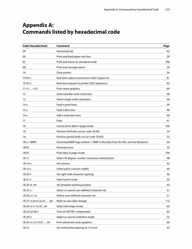
Appendix A: Commands by Hexadecimal Code 125
Appendix A: Commands listed by hexadecimal code
Code (hexadecimal) Command Page
09 Horizontal tab 42
0A Print and feed paper one line 39
0C Print and return to standard mode 106
0D Print and carriage return 39
10 Clear printer 34
10 04 n Real time status transmission (DLE sequence) 81
10 05 n Real time request to printer (DLE sequence) 83
11 n1 . . . n72 Print raster graphics 69
12 Select double-wide characters 48
13 Select single-wide characters 48
14 n Feed n print lines 39
15 n Feed n dot rows 40
16 n Add n extra dot rows 40
17 Print 41
18 Cancel print data in page mode 106
19 Perform full knife cut (or code 1B 69) 34
1A Perform partial knife cut (or code 1B 6D) 35
1B (+*.BMP) Download BMP logo (where +*.BMP is the data from the file, not the filename.) 64
1B 07 Generate tone 35
1B 0C Print data in page mode 106
1B 12 Select 90 degree counter-clockwise rotated print 48
1B 14 n Set column 42
1B 16 n Select pitch (column width) 49
1B 20 n Set right-side character spacing 49
1B 21 n Select print mode 50
1B 24 nL nH Set absolute starting position 43
1B 25 n Select or cancel user-defined character set 51
1B 26 s c1 c2 Define user-defined character set 51
1B 27 m a0 a1 a2 d1 … dm Write to user data storage 112
1B 2A m n1 n2 d1...dn Select bit image mode 65
1B 2A 62 6d n Turn on/off TIFF compression 65
1B 2D n Select or cancel underline mode 52
1B 2E m n rL rH d1 … dn Print advanced raster graphics 66
1B 32 Set vertical line spacing to 1/6 inch 43
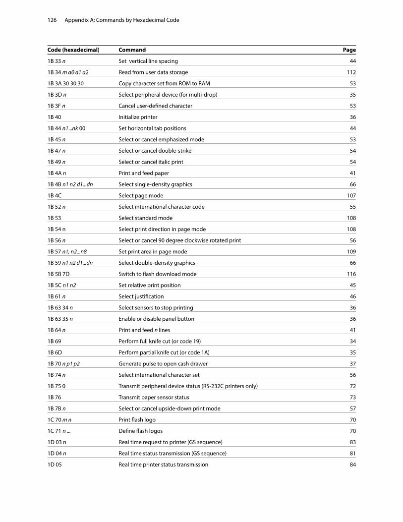
Appendix A: Commands by Hexadecimal Code126
Code (hexadecimal) Command Page
1B 33 n Set vertical line spacing 44
1B 34 m a0 a1 a2 Read from user data storage 112
1B 3A 30 30 30 Copy character set from ROM to RAM 53
1B 3D n Select peripheral device (for multi-drop) 35
1B 3F n Cancel user-defined character 53
1B 40 Initialize printer 36
1B 44 n1...nk 00 Set horizontal tab positions 44
1B 45 n Select or cancel emphasized mode 53
1B 47 n Select or cancel double-strike 54
1B 49 n Select or cancel italic print 54
1B 4A n Print and feed paper 41
1B 4B n1 n2 d1...dn Select single-density graphics 66
1B 4C Select page mode 107
1B 52 n Select international character code 55
1B 53 Select standard mode 108
1B 54 n Select print direction in page mode 108
1B 56 n Select or cancel 90 degree clockwise rotated print 56
1B 57 n1, n2...n8 Set print area in page mode 109
1B 59 n1 n2 d1...dn Select double-density graphics 66
1B 5B 7D Switch to flash download mode 116
1B 5C n1 n2 Set relative print position 45
1B 61 n Select justification 46
1B 63 34 n Select sensors to stop printing 36
1B 63 35 n Enable or disable panel button 36
1B 64 n Print and feed n lines 41
1B 69 Perform full knife cut (or code 19) 34
1B 6D Perform partial knife cut (or code 1A) 35
1B 70 n p1 p2 Generate pulse to open cash drawer 37
1B 74 n Select international character set 56
1B 75 0 Transmit peripheral device status (RS-232C printers only) 72
1B 76 Transmit paper sensor status 73
1B 7B n Select or cancel upside-down print mode 57
1C 70 m n Print flash logo 70
1C 71 n ... Define flash logos 70
1D 03 n Real time request to printer (GS sequence) 83
1D 04 n Real time status transmission (GS sequence) 81
1D 05 Real time printer status transmission 84
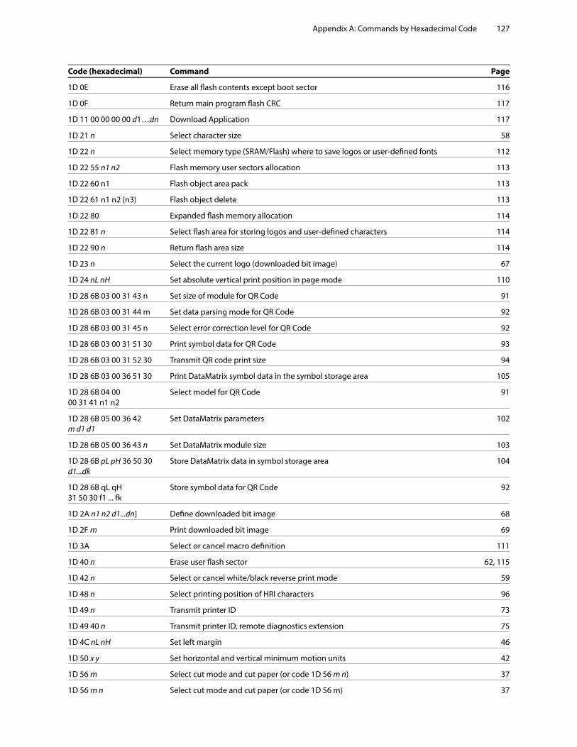
Appendix A: Commands by Hexadecimal Code 127
Code (hexadecimal) Command Page
1D 0E Erase all flash contents except boot sector 116
1D 0F Return main program flash CRC 117
1D 11 00 00 00 00 d1…dn Download Application 117
1D 21 n Select character size 58
1D 22 n Select memory type (SRAM/Flash) where to save logos or user-defined fonts 112
1D 22 55 n1 n2 Flash memory user sectors allocation 113
1D 22 60 n1 Flash object area pack 113
1D 22 61 n1 n2 (n3) Flash object delete 113
1D 22 80 Expanded flash memory allocation 114
1D 22 81 n Select flash area for storing logos and user-defined characters 114
1D 22 90 n Return flash area size 114
1D 23 n Select the current logo (downloaded bit image) 67
1D 24 nL nH Set absolute vertical print position in page mode 110
1D 28 6B 03 00 31 43 n Set size of module for QR Code 91
1D 28 6B 03 00 31 44 m Set data parsing mode for QR Code 92
1D 28 6B 03 00 31 45 n Select error correction level for QR Code 92
1D 28 6B 03 00 31 51 30 Print symbol data for QR Code 93
1D 28 6B 03 00 31 52 30 Transmit QR code print size 94
1D 28 6B 03 00 36 51 30 Print DataMatrix symbol data in the symbol storage area 105
1D 28 6B 04 00 Select model for QR Code 91 00 31 41 n1 n2
1D 28 6B 05 00 36 42 Set DataMatrix parameters 102 m d1 d1
1D 28 6B 05 00 36 43 n Set DataMatrix module size 103
1D 28 6B pL pH 36 50 30 Store DataMatrix data in symbol storage area 104 d1...dk
1D 28 6B qL qH Store symbol data for QR Code 92 31 50 30 f1 ... fk
1D 2A n1 n2 d1...dn] Define downloaded bit image 68
1D 2F m Print downloaded bit image 69
1D 3A Select or cancel macro definition 111
1D 40 n Erase user flash sector 62, 115
1D 42 n Select or cancel white/black reverse print mode 59
1D 48 n Select printing position of HRI characters 96
1D 49 n Transmit printer ID 73
1D 49 40 n Transmit printer ID, remote diagnostics extension 75
1D 4C nL nH Set left margin 46
1D 50 x y Set horizontal and vertical minimum motion units 42
1D 56 m Select cut mode and cut paper (or code 1D 56 m n) 37
1D 56 m n Select cut mode and cut paper (or code 1D 56 m) 37
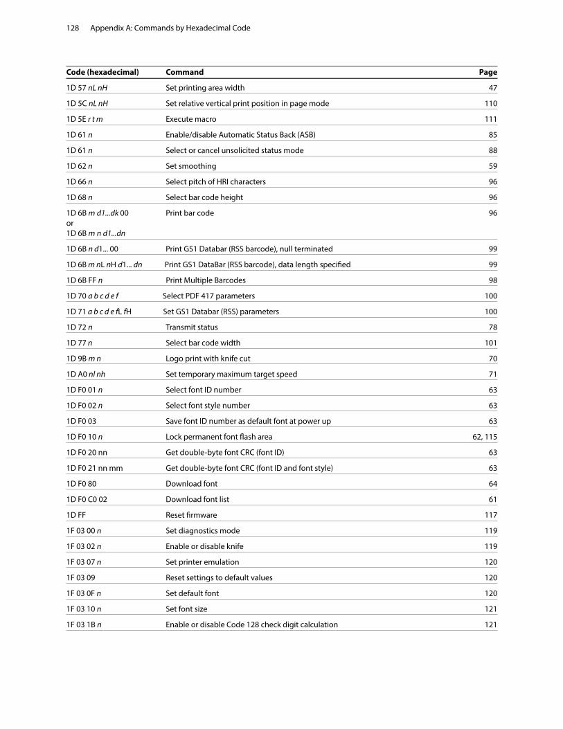
Appendix A: Commands by Hexadecimal Code128
Code (hexadecimal) Command Page
1D 57 nL nH Set printing area width 47
1D 5C nL nH Set relative vertical print position in page mode 110
1D 5E r t m Execute macro 111
1D 61 n Enable/disable Automatic Status Back (ASB) 85
1D 61 n Select or cancel unsolicited status mode 88
1D 62 n Set smoothing 59
1D 66 n Select pitch of HRI characters 96
1D 68 n Select bar code height 96
1D 6B m d1...dk 00 Print bar code 96 or 1D 6B m n d1...dn
1D 6B n d1... 00 Print GS1 Databar (RSS barcode), null terminated 99
1D 6B m nL nH d1... dn Print GS1 DataBar (RSS barcode), data length specified 99
1D 6B FF n Print Multiple Barcodes 98
1D 70 a b c d e f Select PDF 417 parameters 100
1D 71 a b c d e fL fH Set GS1 Databar (RSS) parameters 100
1D 72 n Transmit status 78
1D 77 n Select bar code width 101
1D 9B m n Logo print with knife cut 70
1D A0 nl nh Set temporary maximum target speed 71
1D F0 01 n Select font ID number 63
1D F0 02 n Select font style number 63
1D F0 03 Save font ID number as default font at power up 63
1D F0 10 n Lock permanent font flash area 62, 115
1D F0 20 nn Get double-byte font CRC (font ID) 63
1D F0 21 nn mm Get double-byte font CRC (font ID and font style) 63
1D F0 80 Download font 64
1D F0 C0 02 Download font list 61
1D FF Reset firmware 117
1F 03 00 n Set diagnostics mode 119
1F 03 02 n Enable or disable knife 119
1F 03 07 n Set printer emulation 120
1F 03 09 Reset settings to default values 120
1F 03 0F n Set default font 120
1F 03 10 n Set font size 121
1F 03 1B n Enable or disable Code 128 check digit calculation 121
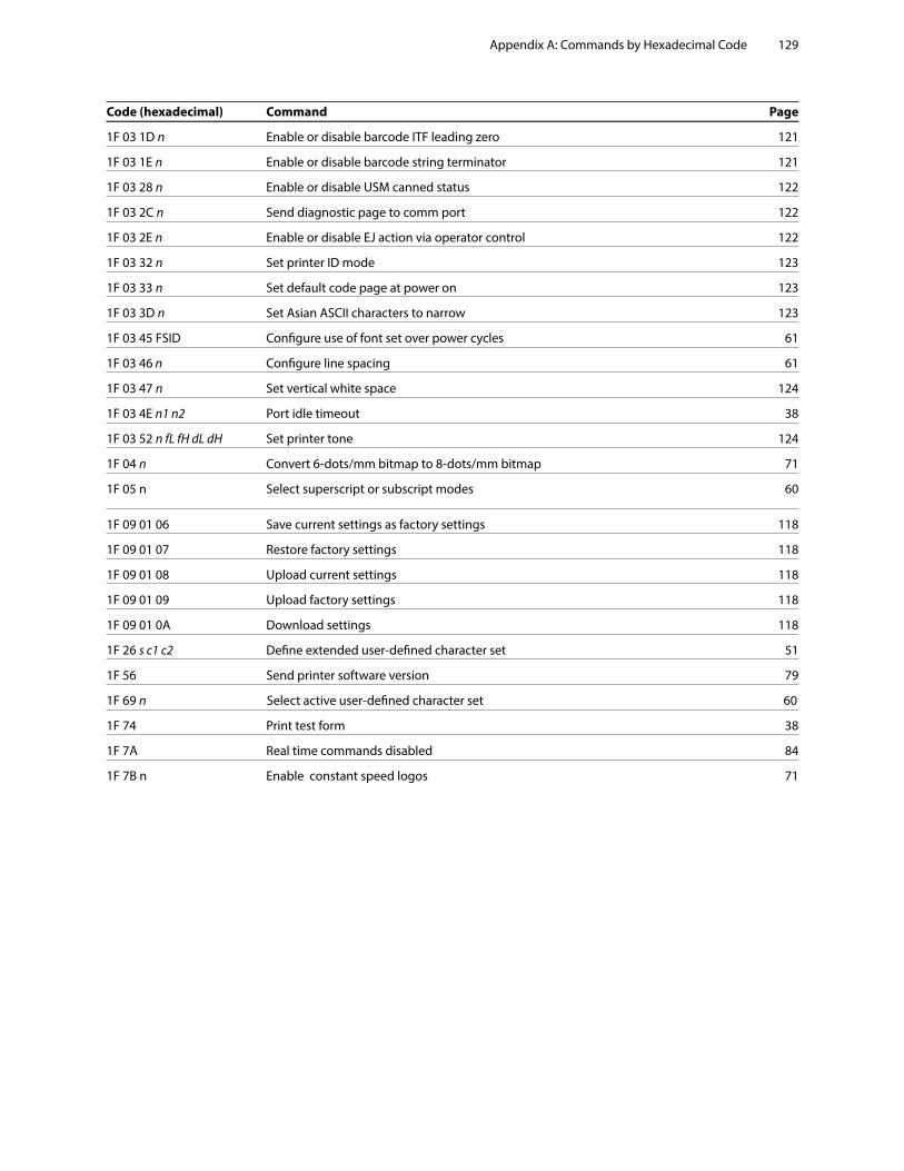
Appendix A: Commands by Hexadecimal Code 129
Code (hexadecimal) Command Page
1F 03 1D n Enable or disable barcode ITF leading zero 121
1F 03 1E n Enable or disable barcode string terminator 121
1F 03 28 n Enable or disable USM canned status 122
1F 03 2C n Send diagnostic page to comm port 122
1F 03 2E n Enable or disable EJ action via operator control 122
1F 03 32 n Set printer ID mode 123
1F 03 33 n Set default code page at power on 123
1F 03 3D n Set Asian ASCII characters to narrow 123
1F 03 45 FSID Configure use of font set over power cycles 61
1F 03 46 n Configure line spacing 61
1F 03 47 n Set vertical white space 124
1F 03 4E n1 n2 Port idle timeout 38
1F 03 52 n fL fH dL dH Set printer tone 124
1F 04 n Convert 6-dots/mm bitmap to 8-dots/mm bitmap 71
1F 05 n Select superscript or subscript modes 60
1F 09 01 06 Save current settings as factory settings 118
1F 09 01 07 Restore factory settings 118
1F 09 01 08 Upload current settings 118
1F 09 01 09 Upload factory settings 118
1F 09 01 0A Download settings 118
1F 26 s c1 c2 Define extended user-defined character set 51
1F 56 Send printer software version 79
1F 69 n Select active user-defined character set 60
1F 74 Print test form 38
1F 7A Real time commands disabled 84
1F 7B n Enable constant speed logos 71
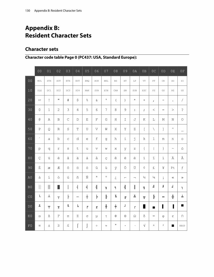
Appendix B: Resident Character Sets130
Appendix B: Resident Character Sets
Character setsCharacter code table Page 0 (PC437: USA, Standard Europe):
00 01 02 03 04 05 06 07 08 09 0A 0B 0C 0D 0E 0F
00 NUL STX SOT ETX EOT ENQ ACK BEL BS HT LF VT FF CR SO SI
10 DLE DC1 DC2 DC3 DC4 NAK SYN ETB CAN EM SUB ESC FS GS RS US
20 SP ! " # $ % & ' ( ) * + , - . /
30 0 1 2 3 4 5 6 7 8 9 : ; < = > ?
40 @ A B C D E F G H I J K L M N O
50 P Q R S T U V W X Y Z [ \ ] ^ _
60 ` a b c d e f g h i j k l m n o
70 p q r s t u v w x y z { | } ~ ⌂
80 Ç ü é â ä à å ç ê ë è ï î ì Ä Å
90 É æ Æ ô ö ò û ù ÿ Ö Ü ¢ £ ¥ Pt ƒ
A0 á í ó ú ñ Ñ ª º ¿ ⌐ ¬ ½ ¼ ¡ « »
B0 ░ ▒ ▓ │ ┤ ╡ ╢ ╖ ╕ ╣ ║ ╗ ╝ ╜ ╛ ┐
C0 └ ┴ ┬ ├ ─ ┼ ╞ ╟ ╚ ╔ ╩ ╦ ╠ ═ ╬ ╧
D0 ╨ ╤ ╥ ╙ ╘ ╒ ╓ ╫ ╪ ┘ ┌ █ ▄ ▌ ▐ ▀
E0 α ß Γ π Σ σ µ τ Φ Θ Ω δ ∞ φ ε ∩
F0 ≡ ± ≥ ≤ ⌠ ⌡ ÷ ≈ ° ∙ · √ ⁿ ² ■ NBSP
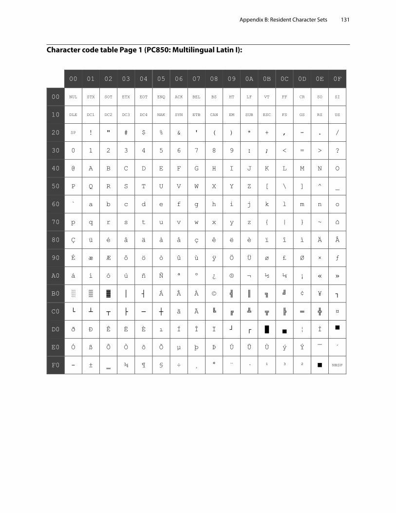
Appendix B: Resident Character Sets 131
Character code table Page 1 (PC850: Multilingual Latin I):
00 01 02 03 04 05 06 07 08 09 0A 0B 0C 0D 0E 0F
00 NUL STX SOT ETX EOT ENQ ACK BEL BS HT LF VT FF CR SO SI
10 DLE DC1 DC2 DC3 DC4 NAK SYN ETB CAN EM SUB ESC FS GS RS US
20 SP ! " # $ % & ' ( ) * + , - . /
30 0 1 2 3 4 5 6 7 8 9 : ; < = > ?
40 @ A B C D E F G H I J K L M N O
50 P Q R S T U V W X Y Z [ \ ] ^ _
60 ` a b c d e f g h i j k l m n o
70 p q r s t u v w x y z { | } ~ ⌂
80 Ç ü é â ä à å ç ê ë è ï î ì Ä Å
90 É æ Æ ô ö ò û ù ÿ Ö Ü ø £ Ø × ƒ
A0 á í ó ú ñ Ñ ª º ¿ ® ¬ ½ ¼ ¡ « »
B0 ░ ▒ ▓ │ ┤ Á Â À © ╣ ║ ╗ ╝ ¢ ¥ ┐
C0 └ ┴ ┬ ├ ─ ┼ ã Ã ╚ ╔ ╩ ╦ ╠ ═ ╬ ¤
D0 ð Ð Ê Ë È ı Í Î Ï ┘ ┌ █ ▄ ¦ Ì ▀
E0 Ó ß Ô Ò õ Õ µ þ Þ Ú Û Ù ý Ý ¯ ´
F0 - ± ‗ ¾ ¶ § ÷ ¸ ° ¨ · ¹ ³ ² ■ NBSP

Appendix B: Resident Character Sets132
Character code table Page 2 (PC852: Latin II):
00 01 02 03 04 05 06 07 08 09 0A 0B 0C 0D 0E 0F
00 NUL STX SOT ETX EOT ENQ ACK BEL BS HT LF VT FF CR SO SI
10 DLE DC1 DC2 DC3 DC4 NAK SYN ETB CAN EM SUB ESC FS GS RS US
20 SP ! " # $ % & ' ( ) * + , - . /
30 0 1 2 3 4 5 6 7 8 9 : ; < = > ?
40 @ A B C D E F G H I J K L M N O
50 P Q R S T U V W X Y Z [ \ ] ^ _
60 ` a b c d e f g h i j k l m n o
70 p q r s t u v w x y z { | } ~ ⌂
80 Ç ü é â ä ů ć ç ł ë Ő ő î Ź Ä Ć
90 É Ĺ ĺ ô ö Ľ ľ Ś ś Ö Ü Ť ť Ł × č
A0 á í ó ú Ą ą Ž ž Ę ę ¬ ź Č ş « »
B0 ░ ▒ ▓ │ ┤ Á Â Ě Ş ╣ ║ ╗ ╝ Ż ż ┐
C0 └ ┴ ┬ ├ ─ ┼ Ă ă ╚ ╔ ╩ ╦ ╠ ═ ╬ ¤
D0 đ Đ Ď Ë ď Ň Í Î ě ┘ ┌ █ ▄ Ţ Ů ▀
E0 Ó ß Ô Ń ń ň Š š Ŕ Ú ŕ Ű ý Ý ţ ´
F0 - ˝ ˛ ˇ ˘ § ÷ ¸ ° ¨ ˙ ű Ř ř ■ NBSP

Appendix B: Resident Character Sets 133
Character code table Page 3 (PC860: Portuguese):
00 01 02 03 04 05 06 07 08 09 0A 0B 0C 0D 0E 0F
00 NUL STX SOT ETX EOT ENQ ACK BEL BS HT LF VT FF CR SO SI
10 DLE DC1 DC2 DC3 DC4 NAK SYN ETB CAN EM SUB ESC FS GS RS US
20 SP ! " # $ % & ' ( ) * + , - . /
30 0 1 2 3 4 5 6 7 8 9 : ; < = > ?
40 @ A B C D E F G H I J K L M N O
50 P Q R S T U V W X Y Z [ \ ] ^ _
60 ` a b c d e f g h i j k l m n o
70 p q r s t u v w x y z { | } ~ ⌂
80 Ç ü é â ã à Á ç ê Ê è Í Ô ì Ã Â
90 É À È ô õ ò Ú ù Ì Õ Ü ¢ £ Ù Pt Ó
A0 á í ó ú ñ Ñ ª º ¿ Ò ¬ ½ ¼ ¡ « »
B0 ░ ▒ ▓ │ ┤ ╡ ╢ ╖ ╕ ╣ ║ ╗ ╝ ╜ ╛ ┐
C0 └ ┴ ┬ ├ ─ ┼ ╞ ╟ ╚ ╔ ╩ ╦ ╠ ═ ╬ ╧
D0 ╨ ╤ ╥ ╙ ╘ ╒ ╓ ╫ ╪ ┘ ┌ █ ▄ ▌ ▐ ▀
E0 α ß Γ π Σ σ µ τ Φ Θ Ω δ ∞ φ ε ∩
F0 ≡ ± ≥ ≤ ⌠ ⌡ ÷ ≈ ° ∙ · √ ⁿ ² ■ NBSP
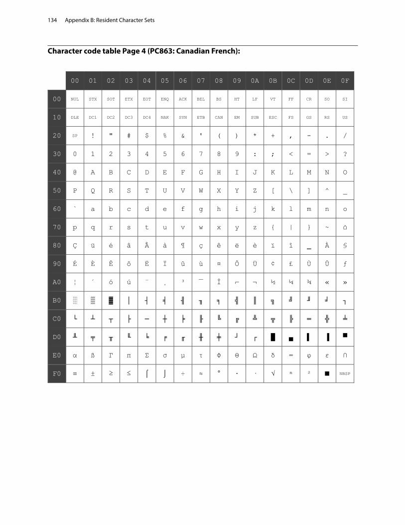
Appendix B: Resident Character Sets134
Character code table Page 4 (PC863: Canadian French):
00 01 02 03 04 05 06 07 08 09 0A 0B 0C 0D 0E 0F
00 NUL STX SOT ETX EOT ENQ ACK BEL BS HT LF VT FF CR SO SI
10 DLE DC1 DC2 DC3 DC4 NAK SYN ETB CAN EM SUB ESC FS GS RS US
20 SP ! " # $ % & ' ( ) * + , - . /
30 0 1 2 3 4 5 6 7 8 9 : ; < = > ?
40 @ A B C D E F G H I J K L M N O
50 P Q R S T U V W X Y Z [ \ ] ^ _
60 ` a b c d e f g h i j k l m n o
70 p q r s t u v w x y z { | } ~ ⌂
80 Ç ü é â Â à ¶ ç ê ë è ï î ‗ À §
90 É È Ê ô Ë Ï û ù ¤ Ô Ü ¢ £ Ù Û ƒ
A0 ¦ ´ ó ú ¨ ¸ ³ ¯ Î ⌐ ¬ ½ ¼ ¾ « »
B0 ░ ▒ ▓ │ ┤ ╡ ╢ ╖ ╕ ╣ ║ ╗ ╝ ╜ ╛ ┐
C0 └ ┴ ┬ ├ ─ ┼ ╞ ╟ ╚ ╔ ╩ ╦ ╠ ═ ╬ ╧
D0 ╨ ╤ ╥ ╙ ╘ ╒ ╓ ╫ ╪ ┘ ┌ █ ▄ ▌ ▐ ▀
E0 α ß Γ π Σ σ µ τ Φ Θ Ω δ ∞ φ ε ∩
F0 ≡ ± ≥ ≤ ⌠ ⌡ ÷ ≈ ° ∙ · √ ⁿ ² ■ NBSP

Appendix B: Resident Character Sets 135
Character code table Page 5 (PC865: Nordic):
00 01 02 03 04 05 06 07 08 09 0A 0B 0C 0D 0E 0F
00 NUL STX SOT ETX EOT ENQ ACK BEL BS HT LF VT FF CR SO SI
10 DLE DC1 DC2 DC3 DC4 NAK SYN ETB CAN EM SUB ESC FS GS RS US
20 SP ! " # $ % & ' ( ) * + , - . /
30 0 1 2 3 4 5 6 7 8 9 : ; < = > ?
40 @ A B C D E F G H I J K L M N O
50 P Q R S T U V W X Y Z [ \ ] ^ _
60 ` a b c d e f g h i j k l m n o
70 p q r s t u v w x y z { | } ~ ⌂
80 Ç ü é â ä à å ç ê ë è ï î ì Ä Å
90 É æ Æ ô ö ò û ù ÿ Ö Ü ø £ Ø Pt ƒ
A0 á í ó ú ñ Ñ ª º ¿ ⌐ ¬ ½ ¼ ¡ « ¤
B0 ░ ▒ ▓ │ ┤ ╡ ╢ ╖ ╕ ╣ ║ ╗ ╝ ╜ ╛ ┐
C0 └ ┴ ┬ ├ ─ ┼ ╞ ╟ ╚ ╔ ╩ ╦ ╠ ═ ╬ ╧
D0 ╨ ╤ ╥ ╙ ╘ ╒ ╓ ╫ ╪ ┘ ┌ █ ▄ ▌ ▐ ▀
E0 α ß Γ π Σ σ µ τ Φ Θ Ω δ ∞ φ ε ∩
F0 ≡ ± ≥ ≤ ⌠ ⌡ ÷ ≈ ° ∙ · √ ⁿ ² ■ NBSP

Appendix B: Resident Character Sets136
Character code table Page 6 (PC858: Multilingual I + Euro):
00 01 02 03 04 05 06 07 08 09 0A 0B 0C 0D 0E 0F
00 NUL STX SOT ETX EOT ENQ ACK BEL BS HT LF VT FF CR SO SI
10 DLE DC1 DC2 DC3 DC4 NAK SYN ETB CAN EM SUB ESC FS GS RS US
20 SP ! " # $ % & ' ( ) * + , - . /
30 0 1 2 3 4 5 6 7 8 9 : ; < = > ?
40 @ A B C D E F G H I J K L M N O
50 P Q R S T U V W X Y Z [ \ ] ^ _
60 ` a b c d e f g h i j k l m n o
70 p q r s t u v w x y z { | } ~ ⌂
80 Ç ü é â ä à å ç ê ë è ï î ì Ä Å
90 É æ Æ ô ö ò û ù ÿ Ö Ü ø £ Ø × ƒ
A0 á í ó ú ñ Ñ ª º ¿ ® ¬ ½ ¼ ¡ « »
B0 ░ ▒ ▓ │ ┤ Á Â À © ╣ ║ ╗ ╝ ¢ ¥ ┐
C0 └ ┴ ┬ ├ ─ ┼ ã Ã ╚ ╔ ╩ ╦ ╠ ═ ╬ ¤
D0 ð Ð Ê Ë È € Í Î Ï ┘ ┌ █ ▄ ¦ Ì ▀
E0 Ó ß Ô Ò õ Õ µ þ Þ Ú Û Ù ý Ý ¯ ´
F0 - ± ‗ ¾ ¶ § ÷ ¸ ° ¨ · ¹ ³ ² ■ NBSP

Appendix B: Resident Character Sets 137
Character code table Page 7 (PC866: Russian):
00 01 02 03 04 05 06 07 08 09 0A 0B 0C 0D 0E 0F
00 NUL STX SOT ETX EOT ENQ ACK BEL BS HT LF VT FF CR SO SI
10 DLE DC1 DC2 DC3 DC4 NAK SYN ETB CAN EM SUB ESC FS GS RS US
20 SP ! " # $ % & ' ( ) * + , - . /
30 0 1 2 3 4 5 6 7 8 9 : ; < = > ?
40 @ A B C D E F G H I J K L M N O
50 P Q R S T U V W X Y Z [ \ ] ^ _
60 ` a b c d e f g h i j k l m n o
70 p q r s t u v w x y z { | } ~ ⌂
80 А Б В Г Д Е Ж З И Й К Л М Н О П
90 Р С Т У Ф Х Ц Ч Ш Щ Ъ Ы Ь Э Ю Я
A0 а б в г д е ж з и й к л м н о п
B0 ░ ▒ ▓ │ ┤ ╡ ╢ ╖ ╕ ╣ ║ ╗ ╝ ╜ ╛ ┐
C0 └ ┴ ┬ ├ ─ ┼ ╞ ╟ ╚ ╔ ╩ ╦ ╠ ═ ╬ ╧
D0 ╨ ╤ ╥ ╙ ╘ ╒ ╓ ╫ ╪ ┘ ┌ █ ▄ ▌ ▐ ▀
E0 р с т у ф х ц ч ш щ ъ ы ь э ю я
F0 Ё ё Є є Ї ї Ў ў ° ∙ · √ № ¤ ■ NBSP

Appendix B: Resident Character Sets138
Character code table Page 8 (WPC1252: Latin I):
00 01 02 03 04 05 06 07 08 09 0A 0B 0C 0D 0E 0F
00 NUL STX SOT ETX EOT ENQ ACK BEL BS HT LF VT FF CR SO SI
10 DLE DC1 DC2 DC3 DC4 NAK SYN ETB CAN EM SUB ESC FS GS RS US
20 SP ! " # $ % & ' ( ) * + , - . /
30 0 1 2 3 4 5 6 7 8 9 : ; < = > ?
40 @ A B C D E F G H I J K L M N O
50 P Q R S T U V W X Y Z [ \ ] ^ _
60 ` a b c d e f g h i j k l m n o
70 p q r s t u v w x y z { | } ~ ⌂
80 € ₹ ‚ ƒ „ … † ‡ ˆ ‰ Š ‹ Œ Ž
90 ‘ ’ “ ” • – — ˜ ™ š › œ ž Ÿ
A0 NBSP ¡ ¢ £ ¤ ¥ ¦ § ¨ © ª « ¬ - ® ¯
B0 ° ± ² ³ ´ µ ¶ · ¸ ¹ º » ¼ ½ ¾ ¿
C0 À Á Â Ã Ä Å Æ Ç È É Ê Ë Ì Í Î Ï
D0 Ð Ñ Ò Ó Ô Õ Ö × Ø Ù Ú Û Ü Ý Þ ß
E0 à á â ã ä å æ ç è é ê ë ì í î ï
F0 ð ñ ò ó ô õ ö ÷ ø ù ú û ü ý þ ÿ

Appendix B: Resident Character Sets 139
Character code table Page 9 (PC862: Hebrew):
00 01 02 03 04 05 06 07 08 09 0A 0B 0C 0D 0E 0F
00 NUL STX SOT ETX EOT ENQ ACK BEL BS HT LF VT FF CR SO SI
10 DLE DC1 DC2 DC3 DC4 NAK SYN ETB CAN EM SUB ESC FS GS RS US
20 SP ! " # $ % & ' ( ) * + , - . /
30 0 1 2 3 4 5 6 7 8 9 : ; < = > ?
40 @ A B C D E F G H I J K L M N O
50 P Q R S T U V W X Y Z [ \ ] ^ _
60 ` a b c d e f g h i j k l m n o
70 p q r s t u v w x y z { | } ~ ⌂
80 א ב ג ד ה ו ז ח ט י ך כ ל ם מ ן
90 נ ס ע ף פ ץ צ ק ר ש ת ¢ £ ¥ Pt ƒ
A0 á í ó ú ñ Ñ ª º ¿ ⌐ ¬ ½ ¼ ¡ « »
B0 ░ ▒ ▓ │ ┤ ╡ ╢ ╖ ╕ ╣ ║ ╗ ╝ ╜ ╛ ┐
C0 └ ┴ ┬ ├ ─ ┼ ╞ ╟ ╚ ╔ ╩ ╦ ╠ ═ ╬ ╧
D0 ╨ ╤ ╥ ╙ ╘ ╒ ╓ ╫ ╪ ┘ ┌ █ ▄ ▌ ▐ ▀
E0 α ß Γ π Σ σ µ τ Φ Θ Ω δ ∞ φ ε ∩
F0 ≡ ± ≥ ≤ ⌠ ⌡ ÷ ≈ ° ∙ · √ ⁿ ² ■ NBSP

Appendix B: Resident Character Sets140
Character code table Page 10 (PC737: Greek):
00 01 02 03 04 05 06 07 08 09 0A 0B 0C 0D 0E 0F
00 NUL STX SOT ETX EOT ENQ ACK BEL BS HT LF VT FF CR SO SI
10 DLE DC1 DC2 DC3 DC4 NAK SYN ETB CAN EM SUB ESC FS GS RS US
20 SP ! " # $ % & ' ( ) * + , - . /
30 0 1 2 3 4 5 6 7 8 9 : ; < = > ?
40 @ A B C D E F G H I J K L M N O
50 P Q R S T U V W X Y Z [ \ ] ^ _
60 ` a b c d e f g h i j k l m n o
70 p q r s t u v w x y z { | } ~ ⌂
80 Α Β Γ Δ Ε Ζ Η Θ Ι Κ Λ Μ Ν Ξ Ο Π
90 Ρ Σ Τ Υ Φ Χ Ψ Ω α β γ δ ε ζ η θ
A0 ι κ λ μ ν ξ ο π ρ σ ς τ υ φ χ ψ
B0 ░ ▒ ▓ │ ┤ ╡ ╢ ╖ ╕ ╣ ║ ╗ ╝ ╜ ╛ ┐
C0 └ ┴ ┬ ├ ─ ┼ ╞ ╟ ╚ ╔ ╩ ╦ ╠ ═ ╬ ╧
D0 ╨ ╤ ╥ ╙ ╘ ╒ ╓ ╫ ╪ ┘ ┌ █ ▄ ▌ ▐ ▀
E0 ω ά έ ή ϊ ί ό ύ ϋ ώ Ά Έ Ή Ί Ό Ύ
F0 Ώ ± ≥ ≤ Ϊ Ϋ ÷ ≈ ° ∙ · √ ⁿ ² ■ NBSP

Appendix B: Resident Character Sets 141
Character code table Page 11 (PC874: Thai):
00 01 02 03 04 05 06 07 08 09 0A 0B 0C 0D 0E 0F
00 NUL STX SOT ETX EOT ENQ ACK BEL BS HT LF VT FF CR SO SI
10 DLE DC1 DC2 DC3 DC4 NAK SYN ETB CAN EM SUB ESC FS GS RS US
20 SP ! " # $ % & ' ( ) * + , - . /
30 0 1 2 3 4 5 6 7 8 9 : ; < = > ?
40 @ A B C D E F G H I J K L M N O
50 P Q R S T U V W X Y Z [ \ ] ^ _
60 ` a b c d e f g h i j k l m n o
70 p q r s t u v w x y z { | } ~ ⌂
80 € …
90 ‘ ’ “ ” • – —
A0 NBSP ก ข ฃ ค ฅ ฆ ง จ ฉ ช ซ ฌ ญ ฎ ฏ
B0 ฐ ฑ ฒ ณ ด ต ถ ท ธ น บ ป ผ ฝ พ ฟ
C0 ภ ม ย ร ฤ ล ฦ ว ศ ษ ส ห ฬ อ ฮ ฯ
D0 ะ ◌◌ั า ◌ํา ◌◌ิ ◌◌ี ◌◌ึ ◌◌ื ◌◌ุ ◌◌ู ◌◌ฺ ฿
E0 เ แ โ ใ ไ ๅ ๆ ◌◌็ ◌◌่ ◌◌้ ◌◌๊ ◌◌๋ ◌◌์ ◌◌ํ ◌◌๎ ๏
F0 ๐ ๑ ๒ ๓ ๔ ๕ ๖ ๗ ๘ ๙ ๚ ๛
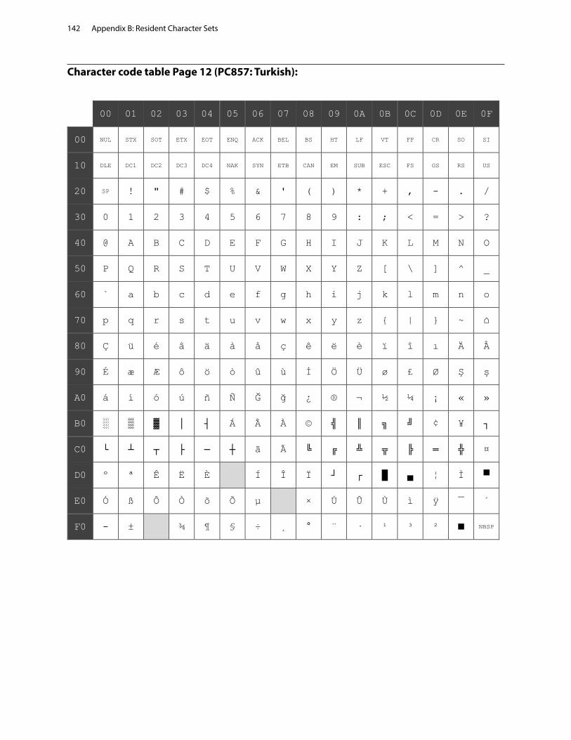
Appendix B: Resident Character Sets142
Character code table Page 12 (PC857: Turkish):
00 01 02 03 04 05 06 07 08 09 0A 0B 0C 0D 0E 0F
00 NUL STX SOT ETX EOT ENQ ACK BEL BS HT LF VT FF CR SO SI
10 DLE DC1 DC2 DC3 DC4 NAK SYN ETB CAN EM SUB ESC FS GS RS US
20 SP ! " # $ % & ' ( ) * + , - . /
30 0 1 2 3 4 5 6 7 8 9 : ; < = > ?
40 @ A B C D E F G H I J K L M N O
50 P Q R S T U V W X Y Z [ \ ] ^ _
60 ` a b c d e f g h i j k l m n o
70 p q r s t u v w x y z { | } ~ ⌂
80 Ç ü é â ä à å ç ê ë è ï î ı Ä Å
90 É æ Æ ô ö ò û ù İ Ö Ü ø £ Ø Ş ş
A0 á í ó ú ñ Ñ Ğ ğ ¿ ® ¬ ½ ¼ ¡ « »
B0 ░ ▒ ▓ │ ┤ Á Â À © ╣ ║ ╗ ╝ ¢ ¥ ┐
C0 └ ┴ ┬ ├ ─ ┼ ã Ã ╚ ╔ ╩ ╦ ╠ ═ ╬ ¤
D0 º ª Ê Ë È Í Î Ï ┘ ┌ █ ▄ ¦ Ì ▀
E0 Ó ß Ô Ò õ Õ µ × Ú Û Ù ì ÿ ¯ ´
F0 - ± ¾ ¶ § ÷ ¸ ° ¨ · ¹ ³ ² ■ NBSP

Appendix B: Resident Character Sets 143
Character code table Page 13 (WPC1251: Cyrillic):
00 01 02 03 04 05 06 07 08 09 0A 0B 0C 0D 0E 0F
00 NUL STX SOT ETX EOT ENQ ACK BEL BS HT LF VT FF CR SO SI
10 DLE DC1 DC2 DC3 DC4 NAK SYN ETB CAN EM SUB ESC FS GS RS US
20 SP ! " # $ % & ' ( ) * + , - . /
30 0 1 2 3 4 5 6 7 8 9 : ; < = > ?
40 @ A B C D E F G H I J K L M N O
50 P Q R S T U V W X Y Z [ \ ] ^ _
60 ` a b c d e f g h i j k l m n o
70 p q r s t u v w x y z { | } ~ ⌂
80 Ђ Ѓ ‚ ѓ „ … † ‡ € ‰ Љ ‹ Њ Ќ Ћ Џ
90 ђ ‘ ’ “ ” • – — ™ љ › њ ќ ћ џ
A0 NBSP Ў ў Ј ¤ Ґ ¦ § Ё © Є « ¬ - ® Ї
B0 ° ± І і ґ µ ¶ · ё № є » ј Ѕ ѕ ї
C0 А Б В Г Д Е Ж З И Й К Л М Н О П
D0 Р С Т У Ф Х Ц Ч Ш Щ Ъ Ы Ь Э Ю Я
E0 а б в г д е ж з и й к л м н о п
F0 р с т у ф х ц ч ш щ ъ ы ь э ю я
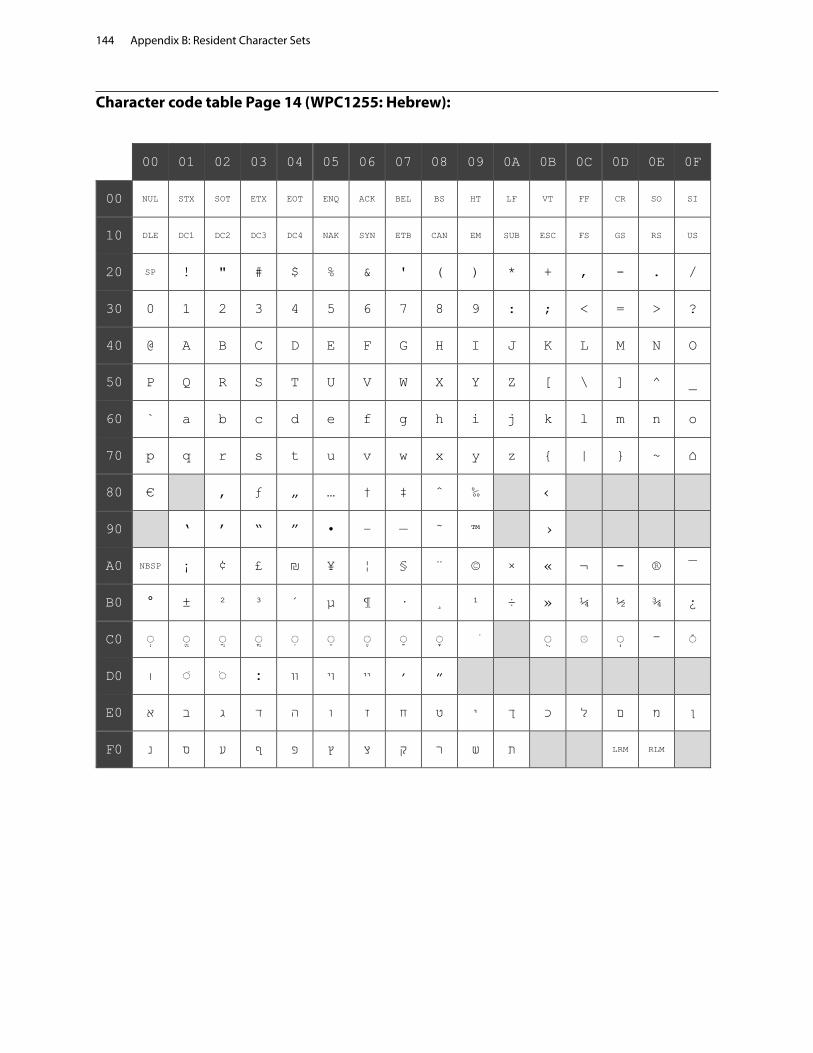
Appendix B: Resident Character Sets144
Character code table Page 14 (WPC1255: Hebrew):
00 01 02 03 04 05 06 07 08 09 0A 0B 0C 0D 0E 0F
00 NUL STX SOT ETX EOT ENQ ACK BEL BS HT LF VT FF CR SO SI
10 DLE DC1 DC2 DC3 DC4 NAK SYN ETB CAN EM SUB ESC FS GS RS US
20 SP ! " # $ % & ' ( ) * + , - . /
30 0 1 2 3 4 5 6 7 8 9 : ; < = > ?
40 @ A B C D E F G H I J K L M N O
50 P Q R S T U V W X Y Z [ \ ] ^ _
60 ` a b c d e f g h i j k l m n o
70 p q r s t u v w x y z { | } ~ ⌂
80 € ‚ ƒ „ … † ‡ ˆ ‰ ‹
90 ‘ ’ “ ” • – — ˜ ™ ›
A0 NBSP ¡ ¢ £ ₪ ¥ ¦ § ¨ © × « ¬ - ® ¯
B0 ° ± ² ³ ´ µ ¶ · ¸ ¹ ÷ » ¼ ½ ¾ ¿
C0 ◌ְ ◌ֱ ◌ֲ ◌ֳ ◌ִ ◌ֵ ◌ֶ ◌ַ ◌ָ ֹ ◌ֻ ּ◌ ◌ֽ ־ ◌ֿ
D0 ׀ ׁ◌ ׂ◌ ׃ װ ױ ײ ׳ ״
E0 א ב ג ד ה ו ז ח ט י ך כ ל ם מ ן
F0 נ ס ע ף פ ץ צ ק ר ש ת LRM RLM

Appendix B: Resident Character Sets 145
Character code table Page 15 (KZ_1048: Kazakh):
00 01 02 03 04 05 06 07 08 09 0A 0B 0C 0D 0E 0F
00 NUL STX SOT ETX EOT ENQ ACK BEL BS HT LF VT FF CR SO SI
10 DLE DC1 DC2 DC3 DC4 NAK SYN ETB CAN EM SUB ESC FS GS RS US
20 SP ! " # $ % & ' ( ) * + , - . /
30 0 1 2 3 4 5 6 7 8 9 : ; < = > ?
40 @ A B C D E F G H I J K L M N O
50 P Q R S T U V W X Y Z [ \ ] ^ _
60 ` a b c d e f g h i j k l m n o
70 p q r s t u v w x y z { | } ~ ⌂
80 Ђ Ѓ ‚ ѓ „ … † ‡ € ‰ Љ ‹ Њ Қ Һ Џ
90 ђ ‘ ’ “ ” • – — ™ љ › њ қ һ џ
A0 Ұ ұ Ә ¤ Ө ¦ § Ё © Ғ « ¬ - ® Ү
B0 ° ± І і ө µ ¶ · ё № ғ » ә Ң ң ү
C0 А Б В Г Д Е Ж З И Й К Л М Н О П
D0 Р С Т У Ф Х Ц Ч Ш Щ Ъ Ы Ь Э Ю Я
E0 а б в г д е ж з и й к л м н о п
F0 р с т у ф х ц ч ш щ ъ ы ь э ю я

Appendix B: Resident Character Sets146
Character code table Page 16 (WPC1256: Arabic):
00 01 02 03 04 05 06 07 08 09 0A 0B 0C 0D 0E 0F
00 NUL STX SOT ETX EOT ENQ ACK BEL BS HT LF VT FF CR SO SI
10 DLE DC1 DC2 DC3 DC4 NAK SYN ETB CAN EM SUB ESC FS GS RS US
20 SP ! " # $ % & ' ( ) * + , - . /
30 0 1 2 3 4 5 6 7 8 9 : ; < = > ?
40 @ A B C D E F G H I J K L M N O
50 P Q R S T U V W X Y Z [ \ ] ^ _
60 ` a b c d e f g h i j k l m n o
70 p q r s t u v w x y z { | } ~ ⌂
80 € پ ‚ ƒ „ … † ‡ ˆ ‰ ٹ ‹ Œ چ ژ ڈ
90 گ ‘ ’ “ ” • – — ک ™ ڑ › œ ZWNJ ZWJ ں
A0 NBSP ، ¢ £ ¤ ¥ ¦ § ¨ © ھ « ¬ - ® ¯
B0 ° ± ² ³ ´ µ ¶ · ¸ ¹ ؛ » ¼ ½ ¾ ؟
C0 ہ ء آ أ ؤ إ ئ ا ب ة ت ث ج ح خ د
D0 ذ ر ز س ش ص ض × ط ظ ع غ ـ ف ق ك
E0 à ل â م ن ـه و ç è é ê ë ى ي î ï
F0 ً◌ ٌ◌ ٍ◌ َ◌ ô ُ◌ ِ◌ ÷ ّ◌ ù ْ◌ û ü LRM RLM ے

Appendix B: Resident Character Sets 147
Character code table Page 17 (WPC1250: Central Europe):
00 01 02 03 04 05 06 07 08 09 0A 0B 0C 0D 0E 0F
00 NUL STX SOT ETX EOT ENQ ACK BEL BS HT LF VT FF CR SO SI
10 DLE DC1 DC2 DC3 DC4 NAK SYN ETB CAN EM SUB ESC FS GS RS US
20 SP ! " # $ % & ' ( ) * + , - . /
30 0 1 2 3 4 5 6 7 8 9 : ; < = > ?
40 @ A B C D E F G H I J K L M N O
50 P Q R S T U V W X Y Z [ \ ] ^ _
60 ` a b c d e f g h i j k l m n o
70 p q r s t u v w x y z { | } ~ ⌂
80 € ‚ „ … † ‡ ‰ Š ‹ Ś Ť Ž Ź
90 ‘ ’ “ ” • – — ™ š › ś ť ž ź
A0 NBSP ˇ ˘ Ł ¤ Ą ¦ § ¨ © Ş « ¬ - ® Ż
B0 ° ± ˛ ł ´ µ ¶ · ¸ ą ş » Ľ ˝ ľ ż
C0 Ŕ Á Â Ă Ä Ĺ Ć Ç Č É Ę Ë Ě Í Î Ď
D0 Đ Ń Ň Ó Ô Ő Ö × Ř Ů Ú Ű Ü Ý Ţ ß
E0 ŕ á â ă ä ĺ ć ç č é ę ë ě í î ď
F0 đ ń ň ó ô ő ö ÷ ř ů ú ű ü ý ţ ˙
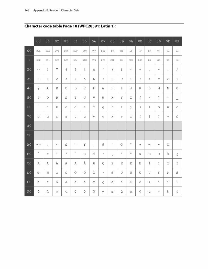
Appendix B: Resident Character Sets148
Character code table Page 18 (WPC28591: Latin 1):
00 01 02 03 04 05 06 07 08 09 0A 0B 0C 0D 0E 0F
00 NUL STX SOT ETX EOT ENQ ACK BEL BS HT LF VT FF CR SO SI
10 DLE DC1 DC2 DC3 DC4 NAK SYN ETB CAN EM SUB ESC FS GS RS US
20 SP ! " # $ % & ' ( ) * + , - . /
30 0 1 2 3 4 5 6 7 8 9 : ; < = > ?
40 @ A B C D E F G H I J K L M N O
50 P Q R S T U V W X Y Z [ \ ] ^ _
60 ` a b c d e f g h i j k l m n o
70 p q r s t u v w x y z { | } ~ ⌂
80
90
A0 NBSP ¡ ¢ £ ¤ ¥ ¦ § ¨ © ª « ¬ - ® ¯
B0 ° ± ² ³ ´ µ ¶ · ¸ ¹ º » ¼ ½ ¾ ¿
C0 À Á Â Ã Ä Å Æ Ç È É Ê Ë Ì Í Î Ï
D0 Ð Ñ Ò Ó Ô Õ Ö × Ø Ù Ú Û Ü Ý Þ ß
E0 à á â ã ä å æ ç è é ê ë ì í î ï
F0 ð ñ ò ó ô õ ö ÷ ø ù ú û ü ý þ ÿ

Appendix B: Resident Character Sets 149
Character code table Page 19 (WPC28592: Latin 2):
00 01 02 03 04 05 06 07 08 09 0A 0B 0C 0D 0E 0F
00 NUL STX SOT ETX EOT ENQ ACK BEL BS HT LF VT FF CR SO SI
10 DLE DC1 DC2 DC3 DC4 NAK SYN ETB CAN EM SUB ESC FS GS RS US
20 SP ! " # $ % & ' ( ) * + , - . /
30 0 1 2 3 4 5 6 7 8 9 : ; < = > ?
40 @ A B C D E F G H I J K L M N O
50 P Q R S T U V W X Y Z [ \ ] ^ _
60 ` a b c d e f g h i j k l m n o
70 p q r s t u v w x y z { | } ~ ⌂
80
90
A0 NBSP Ą ˘ Ł ¤ Ľ Ś § ¨ Š Ş Ť Ź - Ž Ż
B0 ° ą ˛ ł ´ ľ ś ˇ ¸ š ş ť ź ˝ ž ż
C0 Ŕ Á Â Ă Ä Ĺ Ć Ç Č É Ę Ë Ě Í Î Ď
D0 Đ Ń Ň Ó Ô Ő Ö × Ř Ů Ú Ű Ü Ý Ţ ß
E0 ŕ á â ă ä ĺ ć ç č é ę ë ě í î ď
F0 đ ń ň ó ô ő ö ÷ ř ů ú ű ü ý ţ ˙

Appendix B: Resident Character Sets150
Character code table Page 20 (WPC28599: Turkish):
00 01 02 03 04 05 06 07 08 09 0A 0B 0C 0D 0E 0F
00 NUL STX SOT ETX EOT ENQ ACK BEL BS HT LF VT FF CR SO SI
10 DLE DC1 DC2 DC3 DC4 NAK SYN ETB CAN EM SUB ESC FS GS RS US
20 SP ! " # $ % & ' ( ) * + , - . /
30 0 1 2 3 4 5 6 7 8 9 : ; < = > ?
40 @ A B C D E F G H I J K L M N O
50 P Q R S T U V W X Y Z [ \ ] ^ _
60 ` a b c d e f g h i j k l m n o
70 p q r s t u v w x y z { | } ~ ⌂
80
90
A0 NBSP ¡ ¢ £ ¤ ¥ ¦ § ¨ © ª « ¬ - ® ¯
B0 ° ± ² ³ ´ µ ¶ · ¸ ¹ º » ¼ ½ ¾ ¿
C0 À Á Â Ã Ä Å Æ Ç È É Ê Ë Ì Í Î Ï
D0 Ğ Ñ Ò Ó Ô Õ Ö × Ø Ù Ú Û Ü İ Ş ß
E0 à á â ã ä å æ ç è é ê ë ì í î ï
F0 ğ ñ ò ó ô õ ö ÷ ø ù ú û ü ı ş ÿ

Appendix B: Resident Character Sets 151
Character code table Page 21 (WPC28605: Latin 9):
00 01 02 03 04 05 06 07 08 09 0A 0B 0C 0D 0E 0F
00 NUL STX SOT ETX EOT ENQ ACK BEL BS HT LF VT FF CR SO SI
10 DLE DC1 DC2 DC3 DC4 NAK SYN ETB CAN EM SUB ESC FS GS RS US
20 SP ! " # $ % & ' ( ) * + , - . /
30 0 1 2 3 4 5 6 7 8 9 : ; < = > ?
40 @ A B C D E F G H I J K L M N O
50 P Q R S T U V W X Y Z [ \ ] ^ _
60 ` a b c d e f g h i j k l m n o
70 p q r s t u v w x y z { | } ~ ⌂
80
90
A0 NBSP ¡ ¢ £ € ¥ Š § š © ª « ¬ - ® ¯
B0 ° ± ² ³ Ž µ ¶ · ž ¹ º » Œ œ Ÿ ¿
C0 À Á Â Ã Ä Å Æ Ç È É Ê Ë Ì Í Î Ï
D0 Ð Ñ Ò Ó Ô Õ Ö × Ø Ù Ú Û Ü Ý Þ ß
E0 à á â ã ä å æ ç è é ê ë ì í î ï
F0 ð ñ ò ó ô õ ö ÷ ø ù ú û ü ý þ ÿ
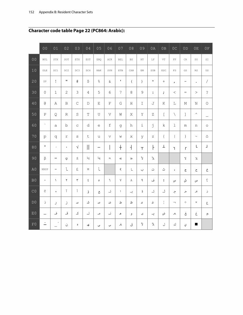
Appendix B: Resident Character Sets152
00 01 02 03 04 05 06 07 08 09 0A 0B 0C 0D 0E 0F
00 NUL STX SOT ETX EOT ENQ ACK BEL BS HT LF VT FF CR SO SI
10 DLE DC1 DC2 DC3 DC4 NAK SYN ETB CAN EM SUB ESC FS GS RS US
20 SP ! " # $ % & ' ( ) * + , - . /
30 0 1 2 3 4 5 6 7 8 9 : ; < = > ?
40 @ A B C D E F G H I J K L M N O
50 P Q R S T U V W X Y Z [ \ ] ^ _
60 ` a b c d e f g h i j k l m n o
70 p q r s t u v w x y z { | } ~ ⌂
80 ° · ∙ √ ▒ ─ │ ┼ ┤ ┬ ├ ┴ ┐ ┌ └ ┘
90 β ∞ φ ± ½ ¼ ≈ أل « » أل ال ال
A0 NBSP - آ أ ¤ £ ا ب ت ث ، ج ح خ
B0 ٠ ١ ٢ ٣ ٤ ٥ ٦ ٧ ٨ ٩ ف ؛ س ش ص ؟
C0 ء ¢ آ أ ؤ ع ئ ا ب ة ت ث ج ح خ د
D0 ذ ر ز س ش ص ض ط ظ ع غ ع × ÷ ¬ ¦
E0 ـ ف ق ك ل م ن ه و ى ي ض ع غ غ م
F0 ّـ _ّ ن ه ه ى ي غ ق آل آل ل ك ي ■
Character code table Page 22 (PC864: Arabic):
€

Appendix B: Resident Character Sets 153
Character code table Page 23 (PC720: Arabic):
00 01 02 03 04 05 06 07 08 09 0A 0B 0C 0D 0E 0F
00 NUL STX SOT ETX EOT ENQ ACK BEL BS HT LF VT FF CR SO SI
10 DLE DC1 DC2 DC3 DC4 NAK SYN ETB CAN EM SUB ESC FS GS RS US
20 SP ! " # $ % & ' ( ) * + , - . /
30 0 1 2 3 4 5 6 7 8 9 : ; < = > ?
40 @ A B C D E F G H I J K L M N O
50 P Q R S T U V W X Y Z [ \ ] ^ _
60 ` a b c d e f g h i j k l m n o
70 p q r s t u v w x y z { | } ~ ⌂
80 é â à ç ê ë è ï î
90 _ّ _ْ ô ¤ ـ û ù ء آ أ ؤ £ إ ئ ا
A0 ب ة ت ث ج ح خ د ذ ر ز س ش ص « »
B0 ░ ▒ ▓ │ ┤ ╡ ╢ ╖ ╕ ╣ ║ ╗ ╝ ╜ ╛ ┐
C0 └ ┴ ┬ ├ ─ ┼ ╞ ╟ ╚ ╔ ╩ ╦ ╠ ═ ╬ ╧
D0 ╨ ╤ ╥ ╙ ╘ ╒ ╓ ╫ ╪ ┘ ┌ █ ▄ ▌ ▐ ▀
E0 ض ط ظ ع غ ف µ ق ك ل م ن ـه و ى ي
F0 ≡ _ً _ٌ _ٍ _َ _ُ _ِ ≈ ° ∙ · √ ⁿ ² ■ NBSP

Appendix B: Resident Character Sets154
Character code table Page 24 (WPC1254: Turkish):
00 01 02 03 04 05 06 07 08 09 0A 0B 0C 0D 0E 0F
00 NUL STX SOT ETX EOT ENQ ACK BEL BS HT LF VT FF CR SO SI
10 DLE DC1 DC2 DC3 DC4 NAK SYN ETB CAN EM SUB ESC FS GS RS US
20 SP ! " # $ % & ' ( ) * + , - . /
30 0 1 2 3 4 5 6 7 8 9 : ; < = > ?
40 @ A B C D E F G H I J K L M N O
50 P Q R S T U V W X Y Z [ \ ] ^ _
60 ` a b c d e f g h i j k l m n o
70 p q r s t u v w x y z { | } ~ ⌂
80 € ‚ ƒ „ … † ‡ ˆ ‰ Š ‹ Œ
90 ‘ ’ “ ” • – — ˜ ™ š › œ Ÿ
A0 NBSP ¡ ¢ £ ¤ ¥ ¦ § ¨ © ª « ¬ - ® ¯
B0 ° ± ² ³ ´ µ ¶ · ¸ ¹ º » ¼ ½ ¾ ¿
C0 À Á Â Ã Ä Å Æ Ç È É Ê Ë Ì Í Î Ï
D0 Ğ Ñ Ò Ó Ô Õ Ö × Ø Ù Ú Û Ü İ Ş ß
E0 à á â ã ä å æ ç è é ê ë ì í î ï
F0 ğ ñ ò ó ô õ ö ÷ ø ù ú û ü ı ş ÿ
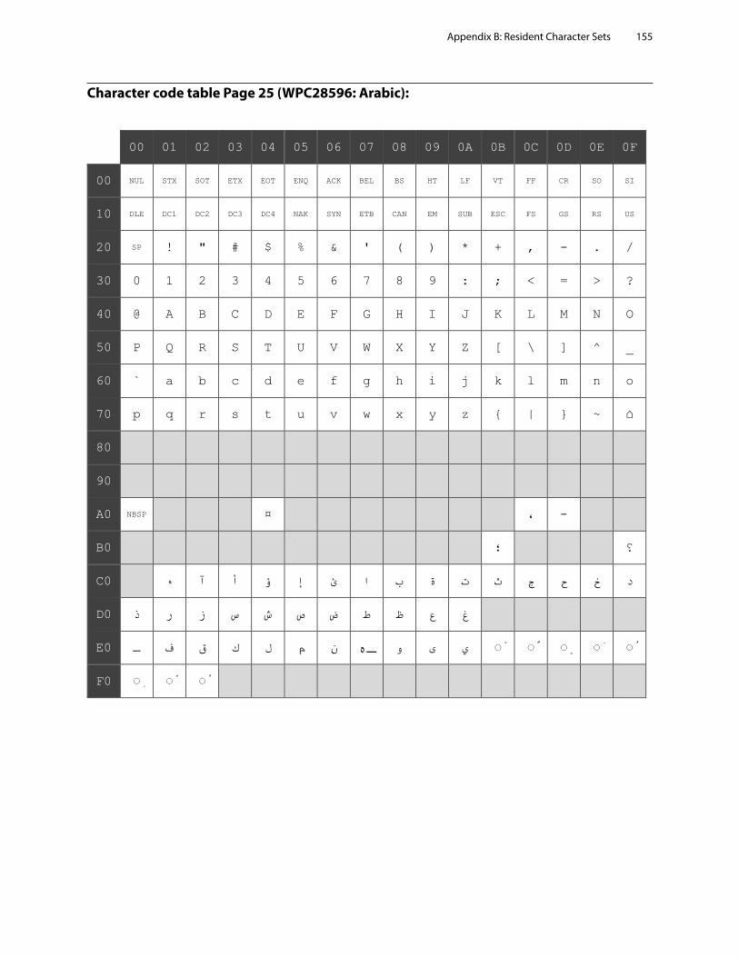
Appendix B: Resident Character Sets 155
Character code table Page 25 (WPC28596: Arabic):
00 01 02 03 04 05 06 07 08 09 0A 0B 0C 0D 0E 0F
00 NUL STX SOT ETX EOT ENQ ACK BEL BS HT LF VT FF CR SO SI
10 DLE DC1 DC2 DC3 DC4 NAK SYN ETB CAN EM SUB ESC FS GS RS US
20 SP ! " # $ % & ' ( ) * + , - . /
30 0 1 2 3 4 5 6 7 8 9 : ; < = > ?
40 @ A B C D E F G H I J K L M N O
50 P Q R S T U V W X Y Z [ \ ] ^ _
60 ` a b c d e f g h i j k l m n o
70 p q r s t u v w x y z { | } ~ ⌂
80
90
A0 NBSP ¤ ، -
B0 ؛ ؟
C0 ء آ أ ؤ إ ئ ا ب ة ت ث ج ح خ د
D0 ذ ر ز س ش ص ض ط ظ ع غ
E0 ـ ف ق ك ل م ن ـه و ى ي ◌ً ◌ٌ ◌ٍ ◌َ ◌ُ
F0 ◌ِ ◌ّ ◌ْ

Appendix B: Resident Character Sets156
Character code table Page 26 (KATAKANA: Asia):
00 01 02 03 04 05 06 07 08 09 0A 0B 0C 0D 0E 0F
00 NUL STX SOT ETX EOT ENQ ACK BEL BS HT LF VT FF CR SO SI
10 DLE DC1 DC2 DC3 DC4 NAK SYN ETB CAN EM SUB ESC FS GS RS US
20 SP ! " # $ % & ' ( ) * + , - . /
30 0 1 2 3 4 5 6 7 8 9 : ; < = > ?
40 @ A B C D E F G H I J K L M N O
50 P Q R S T U V W X Y Z [ \ ] ^ _
60 ` a b c d e f g h i j k l m n o
70 p q r s t u v w x y z { | } ~ ⌂
80 ▁ ▂ ▃ ▄ ▅ ▆ ▇ █ ▏ ▎ ▍ ▌ ▋ ▊ ▉ ┼
90 ┴ ┬ ┤ ├ ▔ ─ │ ▕ ┌ ┐ └ ┘ ╭ ╮ ╰ ╯
A0 。 「 」 、 ・ ヲ ァ ィ ゥ ェ ォ ャ ュ ョ ッ
B0 ー ア イ ウ エ オ カ キ ク ケ コ サ シ ス セ ソ
C0 タ チ ツ テ ト ナ ニ ヌ ネ ノ ハ ヒ フ ヘ ホ マ
D0 ミ ム メ モ ヤ ユ ヨ ラ リ ル レ ロ ワ ン ゙ ゚
E0 ゠ ᅣ ‡ ᅧ ◢ ◣ ◤ ◥ ♠ ♥ ♦ ♣ ● ○ ╱ ╲
F0 ╳ 円 年 月 日 時 分 秒 〒 市 区 町 村 人 ▒

Appendix B: Resident Character Sets 157
Character code table Page 27 (PC775: Baltic):
00 01 02 03 04 05 06 07 08 09 0A 0B 0C 0D 0E 0F
00 NUL STX SOT ETX EOT ENQ ACK BEL BS HT LF VT FF CR SO SI
10 DLE DC1 DC2 DC3 DC4 NAK SYN ETB CAN EM SUB ESC FS GS RS US
20 SP ! " # $ % & ' ( ) * + , - . /
30 0 1 2 3 4 5 6 7 8 9 : ; < = > ?
40 @ A B C D E F G H I J K L M N O
50 P Q R S T U V W X Y Z [ \ ] ^ _
60 ` a b c d e f g h i j k l m n o
70 p q r s t u v w x y z { | } ~ ⌂
80 Ć ü é ā ä ģ å ć ł ē Ŗ ŗ ī Ź Ä Å
90 É æ Æ ō ö Ģ ¢ Ś ś Ö Ü ø £ Ø × ¤
A0 Ā Ī ó Ż ż ź ” ¦ © ® ¬ ½ ¼ Ł « »
B0 ░ ▒ ▓ │ ┤ Ą Č Ę Ė ╣ ║ ╗ ╝ Į Š ┐
C0 └ ┴ ┬ ├ ─ ┼ Ų Ū ╚ ╔ ╩ ╦ ╠ ═ ╬ Ž
D0 ą č ę ė į š ų ū ž ┘ ┌ █ ▄ ▌ ▐ ▀
E0 Ó ß Ō Ń õ Õ µ ń Ķ ķ Ļ ļ ņ Ē Ņ ’
F0 - ± “ ¾ ¶ § ÷ „ ° ∙ · ¹ ³ ² ■ NBSP

Appendix B: Resident Character Sets158
Character code table Page 28 (WPC1257: Baltic):
00 01 02 03 04 05 06 07 08 09 0A 0B 0C 0D 0E 0F
00 NUL STX SOT ETX EOT ENQ ACK BEL BS HT LF VT FF CR SO SI
10 DLE DC1 DC2 DC3 DC4 NAK SYN ETB CAN EM SUB ESC FS GS RS US
20 SP ! " # $ % & ' ( ) * + , - . /
30 0 1 2 3 4 5 6 7 8 9 : ; < = > ?
40 @ A B C D E F G H I J K L M N O
50 P Q R S T U V W X Y Z [ \ ] ^ _
60 ` a b c d e f g h i j k l m n o
70 p q r s t u v w x y z { | } ~ ⌂
80 € ‚ „ … † ‡ ‰ ‹ ¨ ˇ ¸
90 ‘ ’ “ ” • – — ™ › ¯ ˛
A0 NBSP ¢ £ ¤ ¦ § Ø © Ŗ « ¬ - ® Æ
B0 ° ± ² ³ ´ µ ¶ · ø ¹ ŗ » ¼ ½ ¾ æ
C0 Ą Į Ā Ć Ä Å Ę Ē Č É Ź Ė Ģ Ķ Ī Ļ
D0 Š Ń Ņ Ó Ō Õ Ö × Ų Ł Ś Ū Ü Ż Ž ß
E0 ą į ā ć ä å ę ē č é ź ė ģ ķ ī ļ
F0 š ń ņ ó ō õ ö ÷ ų ł ś ū ü ż ž ˙
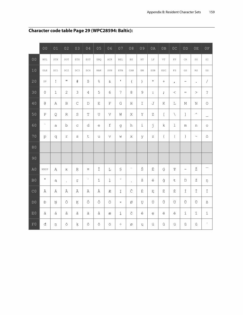
Appendix B: Resident Character Sets 159
Character code table Page 29 (WPC28594: Baltic):
00 01 02 03 04 05 06 07 08 09 0A 0B 0C 0D 0E 0F
00 NUL STX SOT ETX EOT ENQ ACK BEL BS HT LF VT FF CR SO SI
10 DLE DC1 DC2 DC3 DC4 NAK SYN ETB CAN EM SUB ESC FS GS RS US
20 SP ! " # $ % & ' ( ) * + , - . /
30 0 1 2 3 4 5 6 7 8 9 : ; < = > ?
40 @ A B C D E F G H I J K L M N O
50 P Q R S T U V W X Y Z [ \ ] ^ _
60 ` a b c d e f g h i j k l m n o
70 p q r s t u v w x y z { | } ~ ⌂
80
90
A0 NBSP Ą ĸ Ŗ ¤ Ĩ Ļ § ¨ Š Ē Ģ Ŧ - Ž ¯
B0 ° ą ˛ ŗ ´ ĩ ļ ˇ ¸ š ē ģ ŧ Ŋ ž ŋ
C0 Ā Á Â Ã Ä Å Æ Į Č É Ę Ë Ė Í Î Ī
D0 Đ Ņ Ō Ķ Ô Õ Ö × Ø Ų Ú Û Ü Ũ Ū ß
E0 ā á â ã ä å æ į č é ę ë ė í î ī
F0 đ ņ ō ķ ô õ ö ÷ ø ų ú û ü ũ ū ˙
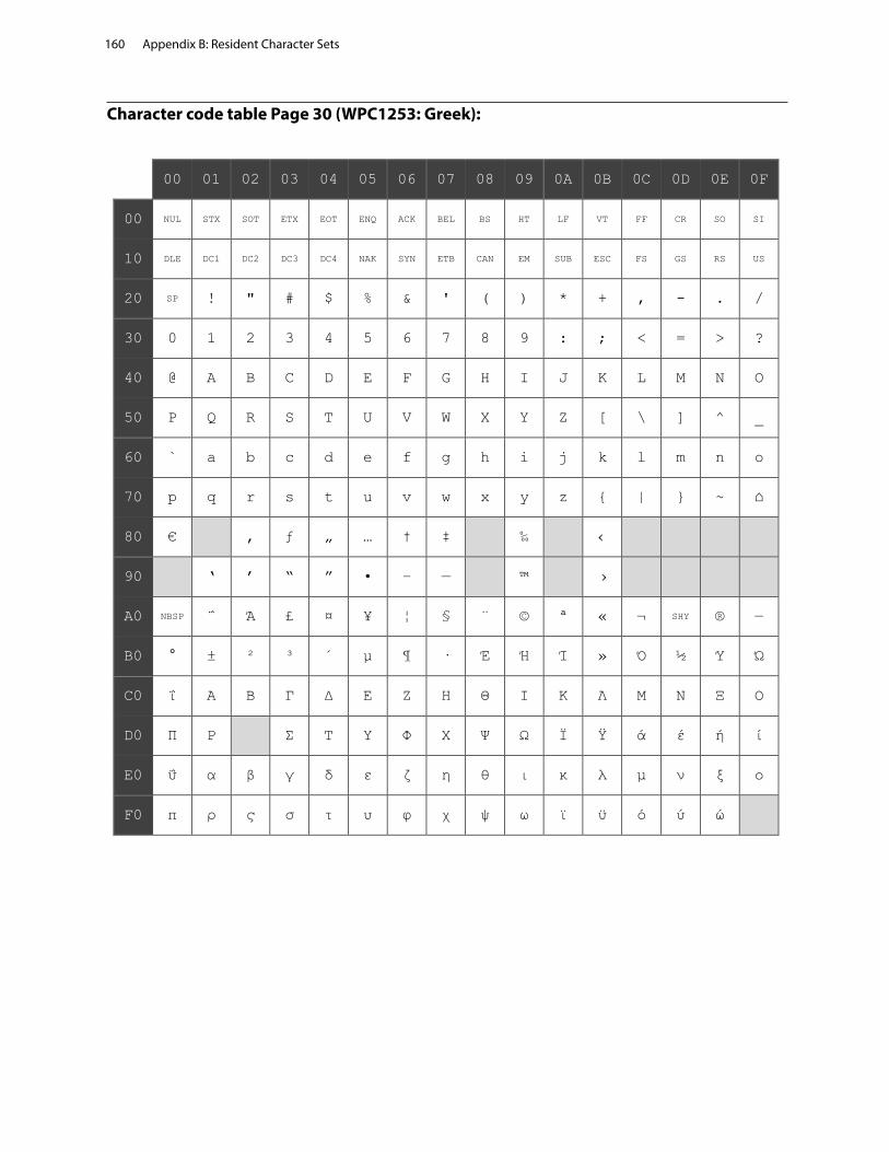
Appendix B: Resident Character Sets160
Character code table Page 30 (WPC1253: Greek):
Appendix B: Resident Character Sets160
H300-PG00002B 6/2018
Character code table Page 30 (WPC1253: Greek):
00 01 02 03 04 05 06 07 08 09 0A 0B 0C 0D 0E 0F
00 NUL STX SOT ETX EOT ENQ ACK BEL BS HT LF VT FF CR SO SI
10 DLE DC1 DC2 DC3 DC4 NAK SYN ETB CAN EM SUB ESC FS GS RS US
20 SP ! " # $ % & ' ( ) * + , - . /
30 0 1 2 3 4 5 6 7 8 9 : ; < = > ?
40 @ A B C D E F G H I J K L M N O
50 P Q R S T U V W X Y Z [ \ ] ^ _
60 ` a b c d e f g h i j k l m n o
70 p q r s t u v w x y z { | } ~ ⌂
80 € ‚ ƒ „ … † ‡ ‰ ‹
90 ‘ ’ “ ” • – — ™ ›
A0 NBSP ΅ Ά £ ¤ ¥ ¦ § ¨ © ª « ¬ SHY ® ―
B0 ° ± ² ³ ΄ µ ¶ · Έ Ή Ί » Ό ½ Ύ Ώ
C0 ΐ Α Β Γ Δ Ε Ζ Η Θ Ι Κ Λ Μ Ν Ξ Ο
D0 Π Ρ Σ Τ Υ Φ Χ Ψ Ω Ϊ Ϋ ά έ ή ί
E0 ΰ α β γ δ ε ζ η θ ι κ λ μ ν ξ ο
F0 π ρ ς σ τ υ φ χ ψ ω ϊ ϋ ό ύ ώ